evolution based structure design for low-pass iir digital
TRANSCRIPT
Evolution Based Structure Design for Low-PassIIR Digital Filters with Fault Tolerance
Lijia Chen, Mingguo Liu, Zhen Dai, Ying Chen
Abstract—Fault-tolerant digital filters are widely expected foruse in modern electronic systems. In this paper, a structureevolution based optimization algorithm (SEOA) for designingan low-pass IIR digital filter is proposed. The filter structureis designed to alleviate the impact of concurrent permanentmultiplier failures. A IIR digital filter structure is created by anew mechanism proposed in this paper, which provides not onlystructural validation and diversity but also a specific structuregeneration. Genetic algorithm (GA) is redesigned to integratethe mechanism for ensuring that structures are evolved validlyand efficiently. In the improved GA, structures with differentsizes are crossed by a single point way, which expands thesolution space of structures. Desirable structures can be createdby adjusting structural parameters, such as the structure sizeor the connection type. Simulation results show that filterperformance is greatly affected by the concurrent short andopen circuit faults of multipliers. Compared with the classicIIR digital filter implementations, SEOA improves the faulttolerance of the filter.
Index Terms—IIR digital filters, structure design, fault tol-erance, genetic algorithm.
I. INTRODUCTION
D IGITAL filter has been widely used [1], [2] in electronicdevices. In some areas, it is expected that the digital
filter has a strong fault tolerance [3]. For example, the outerspace circuit can tolerate a certain degree of cosmic particleimpact [4]; critical computing, such as nuclear computing,can tolerate occasional failures, without affecting results.Some faults transiently change the states of a system [5],[6]. For the transient faults, fault-tolerant techniques havebeen proposed for digital filters [7], [8]. However, certainouter reasons may cause permanent damage to the filterhardware. For instance, environmental humidity, circuit ag-ing, particle and electromagnetic interference, may causeinsulation damage, resulting in circuit faults. In long-termunattended environments, some filter components may bedestroyed permanently.Some evolutionary algorithms, such as genetic algorithm(GA) [9], simulated annealing (SA) [10], differential evo-lutionary (DE) [11], particle swarm optimization (PSO) [12]and their variants, have been employed for the design of IIRdigital filters. They optimize the coefficients of the transferfunction to achieve desired frequency responses. But thesealgorithms can’t deal with fault tolerance of digital filters be-cause they don’t design the filter structure. In this paper, fault
Manuscript received September 7, 2017; revised June 13, 2018. This workwas supported in part by the Foundation of Henan Province, China, with thegrant numbers: 15A510018, 15A510019, 12A510002 and 142102210629.This work was also supported by the Foundation of Henan University, China,with the grant numbers: 2008YBZR028 and ZZJJ20140037.
L. Chen, M. Liu, Z. Dai and Y. Chen are with the Laboratory ofAdvanced Computation Methods and Intelligent Applications, School ofPhysics and Electronics, Henan University, China e-mail: (L. Chen: [email protected]; M. Liu: [email protected]).
tolerance of the digital filter is investigated against permanentcircuit faults of multipliers. A structure evolution basedoptimization algorithm (SEOA) is proposed for designing theIIR low-pass digital filter. This approach creates and evolvesIIR digital filter structures. GA is improved by integratingthe structure generation so that it can validly and efficientlyevolve the filter structure and improves fault tolerance ofthe filter. By comparing with classic implementations ofdigital filters, the simulation results show that the digital filterdesigned in this paper has excellent fault tolerance.The organization of the paper is as follows. In section II, thestructure design of IIR digital low-pass filters is presented.Experimental results are provided in section III. Finally, wegive a conclusion in section IV.
II. ALGORITHM DESCRIPTION
SEOA is designed to generate and evolve IIR digitalfilter structures. A structurally automatic generation algo-rithm (SAGA) is proposed. SAGA allows the IIR digitalfilter structure to be created in a specific way that onlyvalid structures are produced and at the same time thatthe structures are diversified. The evolution of digital filterstructures is such a problem that filters perform distinctivelywhen their structures have different scales. In SEOA, filterstructures with different sizes are investigated and coded aschromosomes according to SAGA. GA has the potential ofholding high performance for those problems with varied-length chromosomes [13, 14], which supports a single pointcrossover for filter structures. GA is improved to integrateSAGA with the code for validly and efficiently evolving filterstructures. The code of GA is one of the key factors influ-encing its performance [15]. An elaborate combined code isdesigned to represent a filter structure. The fitness function isdesigned as a weighed attenuation error between the desiredresponse and the designed response. The fitness decreasesuntil a maximum generation is reached or it satisfies a giventhreshold.SAGA starts the generation of filter structures with one nodethat is the input node of the filter. It grows by attaching thedelay element and the multiplier to it one by one. The delayelement and the multiplier are denoted separately by Td andTm. The adder is determined after the structure has beenfinished. Those nodes with more than one input are adders.Connections of digital elements in a structure are designedin four modes which comply with the following rules. Firstof all, an active node is defined as a node to which any newattached element must be linked. At the beginning of thealgorithm, the input node of the filter is an active node. Anelement is attached to the active node in four modes. Whileits one terminal is connected to the active node, the otherone is allowed to link itself with a newly generated active
Engineering Letters, 26:3, EL_26_3_07
(Advance online publication: 28 August 2018)
______________________________________________________________________________________

Fig. 1. An example of a structure generated by the four connections
node, a previous node, the system input node or the systemoutput node. The four types of connection are denoted asCnew, Cpre, Cin and Cout. After a new active node appears,the old one will not be an active node any more. An exampleshows that elements are connected from x(n) to y(n) in theinstruction order of Cnew-Cin-Cnew-Cpre-Cout-Cout in Fig.1.The system output node always exists during the structuregeneration. A special case is to attach the last element to thestructure. The element is constrained to use Cout so that thesystem output node is definitely linked to the structure.Signal directions are dealt when those elements are appendedto the structure. Every element has a signal direction. In avalid digital structure, the direction of two linked elementsmustn’t collide with each other. For example, if one circuitbranch bears more than one element, these elements musthave the same signal direction. Considering one node withdi signals flowing into it and do signals flowing out of it, thedirection constraint of digital structures can be
di > 0 and do > 0, (1)
where every node must satisfy equation 1 except the inputand output nodes of the system. We define such a node asa middle node. The system input node must have an output,and the system output node must have an input.The structures created by SAGA are always valid, whichis proved as follows. A valid structure requires that allthe middle nodes in the structure must satisfy equation 1.According to the connection modes, a middle node getsat least one input from its previous active node, whichcreates the middle node by using Cnew. The middle nodeis inevitable to advance to the next active node by Cnew orto the output node of the system by Cout. Whether Cnew orCout produces an output from the middle node. Equation 1holds for every middle node and therefore the structure isalways valid.A structure is coded as an instruction sequence in the way ofstructure generation. Each element attached to the structureis dictated by an instruction. An instruction is denoted asTconViVoPcTcom, where Tcon denotes the connection type.Vi and Vo are the nodes to which an attached elementis linked. Signals always flow from Vi to Vo through theelement. Tcom indicates the element type which can be Td orTm. Pc is the element’s parameter. An instruction sequencereflects the generation of a digital structure. The structurecan reappear when elements are driven by following theinstruction sequence. In SEOA, an instruction sequence isa chromosome of GA. Table I shows a 7-element instructionsequence, and Fig. 2 is the structure created by the sequence.
The sequence includes 7 instructions for forming the dig-ital filter. Active nodes are created one by one, numbered by
Fig. 2. The generated filter structure according to Table I
TABLE IAN EXAMPLE FOR THE INSTRUCTION SEQUENCE
ID Tcon Vi Vo Pc Tcom
1 Cnew N1 N2 −1 Td
2 Cin N2 N1 2.0 Tm
3 Cout N2 N4 0.5 Tm
4 Cnew N2 N3 −1 Td
5 Cpre N3 N2 0.3 Tm
6 Cin N3 N1 −0.1 Tm
1 Cout N3 N4 1.0 Tm
1.0z-1y(n)
z-12
0.3
0.5
-0.1
x(n)N1 N2 N3 N4
y(n)-0.1
x(n)z-1z-1
B:
A:
N1 N2 N3
1.0z-1y(n)
z-12
0.3
0.5
-0.1
x(n)N1 N2
N3 N4
y(n)
x(n)z-1
N1 N2
N3
A’:
B’:
-0.1
z-1
Fig. 3. Crossover of two structures with different sizes
Ni incrementally. The final structure includes 5 multipliers,2 delay elements and 3 adders. The adders are node N1, N2
and N4.Digital filter structures are evolved based on GA. GA isimproved to integrate SAGA with code into the genetic op-erations. Crossover, mutation and selection genetic operatorsare improved and the fitness function is defined.First, the crossover operator is elaborately designed for filterstructures. The single-point crossover is adopted throughthe whole evolution. A crossing point divides an instructionsequence into two parts. The crossover causes an exchangeof the front parts between the two sequences. Consideringthe generation process of a digital structure in SAGA, the
Engineering Letters, 26:3, EL_26_3_07
(Advance online publication: 28 August 2018)
______________________________________________________________________________________

new sequences are valid when the two crossing pointshave the same number of Ni. Under the condition, thefront part of one structure grows in the way of the rearpart of the other structure. Two structures produce validdescendants after they cross with each other in the single-point way. An example is shown in Fig. 3. Structure Acorresponds to an instruction sequence of |CnewN1N2 −1Td|CinN2N12.0Tm|CoutN2N40.5Tm|CnewN2N3 − 1Td|CpreN3N20.3Tm|CinN3N1 − 0.1Tm|CoutN3N41.0Tm| andstructure B corresponds to that of |CnewN1N2 −1Td|CoutN2N3 − 1Td|CoutN2N3 − 0.1Tm|. The crossingpoint is N2 which divides A and B into two parts as theblack and red parts described in Fig. 3. A’ and B’ are thecrossed structures from A and B. They are valid when A andB are valid.Second, the mutation operator is designed to change achromosome by replacing it with a newly created chromo-some. The new chromosome has the same length with itspredecessor. The mutation brings more changes than a singleinstruction mutation which only mutates an instruction of thechromosome.Third, the selection operator is designed to sort chromosomesby their fitness values. Ps chromosomes with the smallestfitness values will be kept down as the next generation ofchromosomes, where Ps is the population size.Finally, the fitness function for evaluating digital filter struc-tures is defined. The transfer function of a digital filter isderived from its structure as described in [16]. Each internalsignal in the system is expressed as the output of a node.
W(z) = (I−Q(z))−1P(z). (2)
W records the expressions of internal signals. I is an identitymatrix. Q is a connection matrix, which expresses therelations between internal signals. P denotes a vector whichrecords gains or delay from the system input signal to internalsignals. The transfer function of the structure is
H(z) = Wout(z), (3)
where out is the identified number of the system output node.In SEOA, H(z) is discretized by substituting ejπi/n for z.H(Ki) gets the ith value of n samples of the frequencyresponse as shown in equation 4.
H(Ki) = H(z)|z=ejπi/n . (4)
A chromosome is evaluated through calculating itsfrequency-response error. Fitness, defined as the error, isestimated in
fitness =1
n
∑wilog
2(|H(Ki)||D(Ki)|
), D(Ki) 6= 0, (5)
where D(K) is the desired frequency response in a discreteform. The n is the number of sampling points. wi is theweight for sampling point i.
wi =
{ki/n+ 1/2 0 ≤ i < n/2
λ(k(1− i/n) + 1/2) n/2 ≤ i < n, (6)
where k controls the sharpness of the transition band. λmakes a performance tradeoff between the stopband and thepassband.
TABLE IITHE PARAMETER SETTINGS OF SEOA
Parameter Value Parameter Valuecrossover rate 0.7 mutation rate 0.1
population size 100 chromosome length 50
maximum generation 10000 seed [0.0,1.0]
multiplier gain [-2.0,2.0] sampling rate 128
k 2.0 λ 0.01
z-1 z-1 z-1 z-1 z-1 0.13 z-1 0.43 0.14 z-1
0.09
0.12
x(n)
-0.26 z-1
y(n)
z-1z-1 z-1
z-1z-1
-0.20
-1.31 -0.04 z-1 z-1 z-1-0.09
z-1
z-1
z-1
z-1
-0.01
z-1
1.35
z-1
z-1
z-1-0.88
0.63
z-1
z-1
z-1
0.34
z-1
z-1
z-1
z-1z-1
z-1
-0.25
-0.32
Fig. 4. The structure of the low-pass digital filter designed by SEOA
III. RESULTS AND DISCUSSION
In this section, a low-pass IIR digital filter structure isdesigned by SEOA and fault tolerance of the structure iscompared with classic IIR digital filter implementations. Thetarget filter is set as follows. Passband ranges from 0 radto 0.45π rad, stopband covers from 0.6π rad to π rad, theminimum of passband attenuation is -1 dB and the maximumof stopband attenuation is -60 dB.Simulation parameters are listed in Table II. The chromo-some length is measured in instructions. The seed is used tocreate random digital structures for an instance. There are 30random seeds in [0.0, 1.0] for 30 instances. The multipliergain is a random real number and is confined within therange of [-2.0, 2.0]. Besides, the delay element is set to aunit delay. The desired frequency response and the designedfrequency response are both sampled with 128 points. Eachconnection mode takes the chance of 0.25, and each elementtype takes that of 0.5.The structure designed by SEOA is shown in Fig. 4. 100chromosomes are evolved in 10000 iterations. The 50-element structure as shown in Fig. 4 is obtained, whichconsists of 13 adders, 33 delay elements and 17 multipliers.Its order is 9. The structure is produced by connectionsof 16 Cnews, 21 Cins, 8 Couts and 5 Cpres. They areall randomly created and elements are connected accordingto them. Furthermore, the input node, the output node, theparameter and the element type are randomly generated toconstruct the filter structure.We assume a circuit fault model as follows. Circuit faultsare set to randomly happen on multipliers wherever the mul-tipliers are located in a filter structure. Multiple multiplierscan suffer the circuit faults at the same time and they aren’trepaired after they are damaged. Three types of fault modes,the short circuit, the open circuit and the mixed circuit fault,
Engineering Letters, 26:3, EL_26_3_07
(Advance online publication: 28 August 2018)
______________________________________________________________________________________

0 0.2 0.4 0.6 0.8 1−80
−60
−40
−20
0
20
Normalized Frequency(/π)
Mag
nitu
de R
espo
nse(
/dB
)
ButterworthCheby1Cheby2EllipSEOA
Butterworth
Cheby2
Cheby1
Ellip
SEOA
Fig. 5. The original magnitude frequency responses using different designmethods and SEOA without any fault
are adopted. The mixed circuit fault is the mixture of theshort circuit and the open circuit. The fault rate of multipliersis set to [1%, 7%] for the short circuit, which means thatthe quantity of the short-circuited multipliers is 1% - 7%of the total quantity of multipliers in a filter structure. Thefault rates for the open circuit and the mixed circuit fault are[1%, 5%] and [2%, 10%], respectively. The structure in eachcase has 100 independent tests. Filter errors are composedof two parts, the error when the attenuation in passband isless than -1 dB or greater than 0 dB, and the error when theattenuation in stopband is greater than -60 dB. The errorsare calculated based on equation 5.For comparison, Butterworth, Cheby I, Cheby II and Ellipare utilized to design the same desired IIR digital filter. Theirorders are set to 9. The magnitude frequency responses ofthem and SEOA without any fault are shown in Fig. 5. Thefilter specifications are well catered by these design methodsexcept Butterworth. Butterworth is gradually decreasing inmagnitude and fails to reach a width of 0.15π for thetransition band. Other methods satisfy the design target.Cheby I has ripples in the passband and is monotonous in thestopband, while Cheby II is monotonous in the passband andhas ripples in the stopband. Ellip gives the steepest transitionband among all design methods. SEOA comes with someripples in the passband and stopband.
A. The short circuit tests
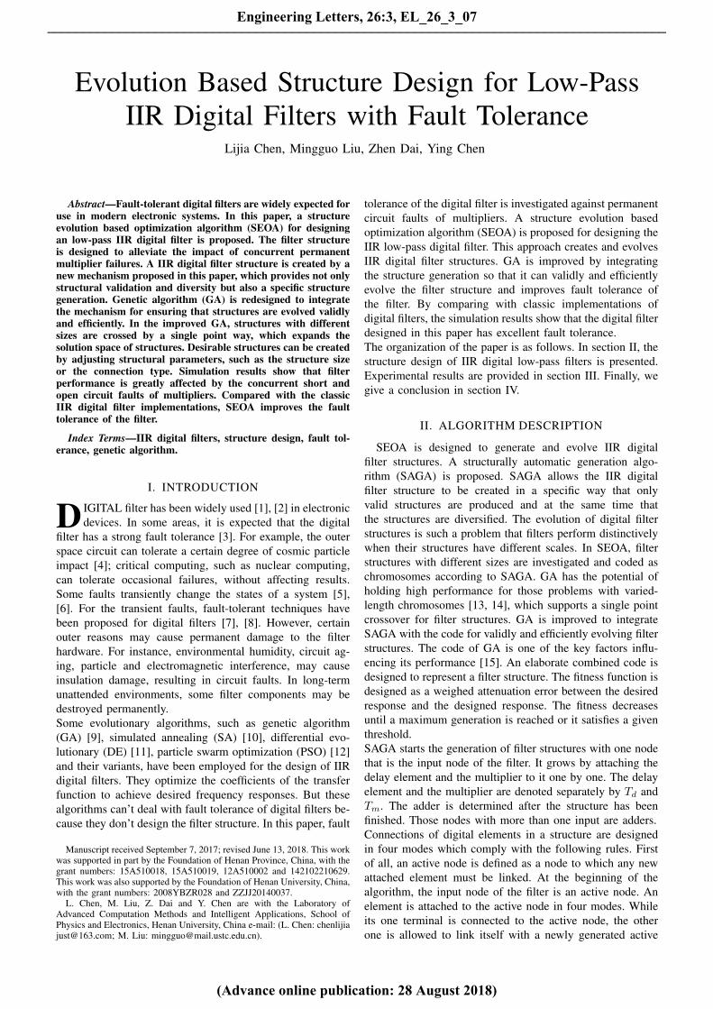
The magnitude frequency responses using Butterworthare shown in Fig. 6. The direct II, cascade, parallel andlattice structures are compared with our structure for faulttolerance. The fault rate is set to 1%, 4% and 7% in thethree subfigures of Fig. 6, respectively. The results showthat errors increase with the increment of the fault rate. Themagnitude responses of the direct II and lattice structuresdepart rapidly from their original positions. Their frequencyresponses have been damaged. The response of the parallelstructure is greatly affected, which is almost all above 20 dB.SEOA and Butterworth with the cascade structure, performbest among all implementations. Compared with the cascadestructure, SEOA excels by a relatively better passband andstopband performance. SEOA meets the specification of thedesired filter when the fault rate is equal to 1% as shown inFig. 6 (a). The passband of the filter surpasses the maximumbound of 0 dB as shown in Fig. 6 (b) when the fault rate
is 3%. Moreover, the passband and the stopband are bothbeyond the desired attenuation when the fault rate is up to7% as shown in Fig. 6 (c).
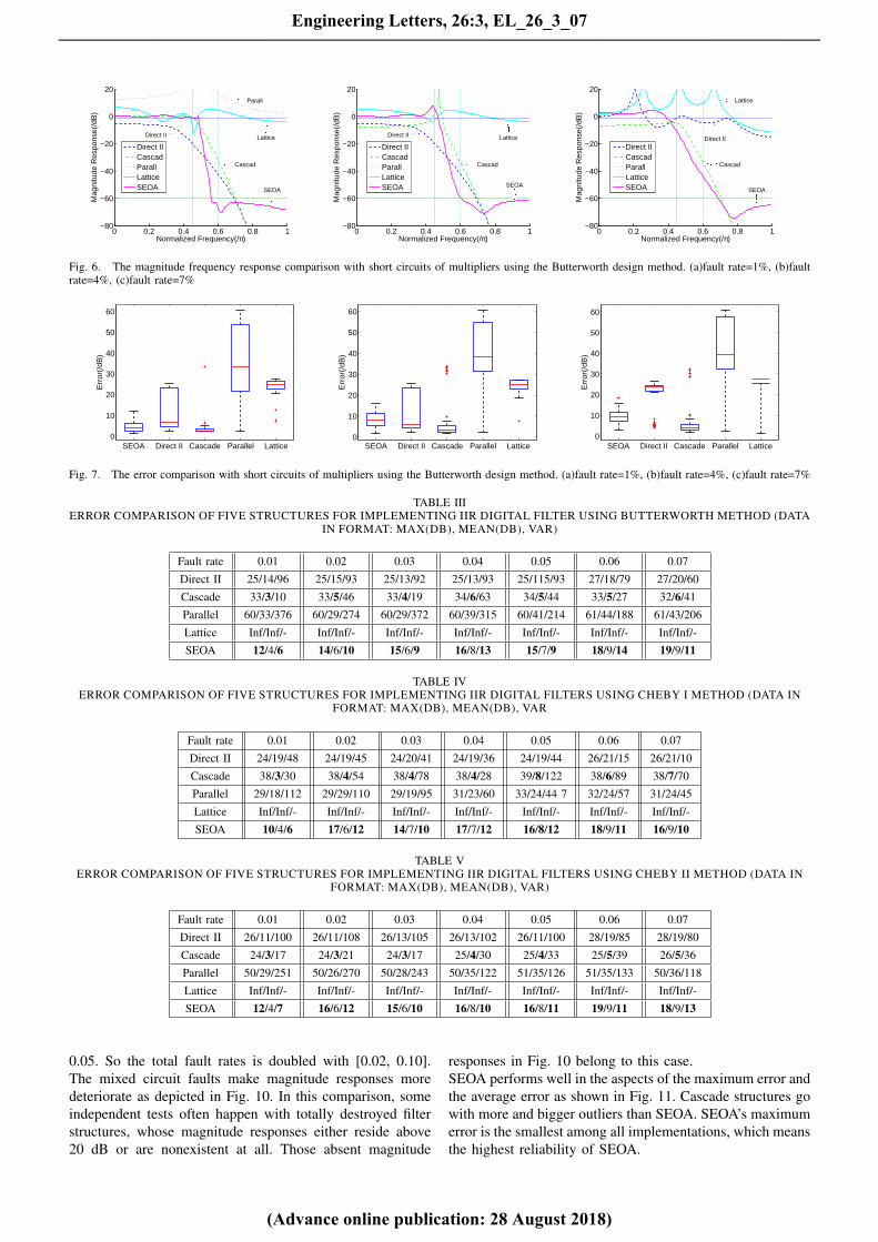
Error comparisons of our structure and the classic imple-mentations of Butterworth are shown in Fig. 7. The filtererrors are counted with their median, lower quartile q1,upper quartile q3, the maximum and minimum non-outliers,and outliers. Outliers are those values which are larger thanq3+1.5∗(q3−q1) or smaller than q1−1.5∗(q3−q1). The worstperformance of the filter is highlighted by the largest value ofthe outliers. In the results, the direct II, parallel and latticestructures have bigger filter errors than our structure. Thelattice structure produces many invalid frequency responses,resulting in the incomplete box in Fig. 7 (c). The cascadestructure takes smaller median values but larger outliers thanour structure.
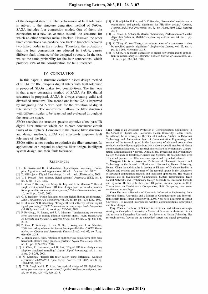
The comparison of our method with the design methodsof Butterworth, Cheby I, Cheby II and Ellip is listed inTable III - VI, where ’Inf’ indicates an infinite number and’-’ indicates the result incalculable. The tables display themaximum, mean and variance of the errors in implementationof the filter with different structures. As it can be seenfrom the statistical results, the average trend of the errors isincreasing when the fault rate increases from 1% to 7%. Thesmallest values of the maximum error, the error variance andthe mean error in their separate columns are in bold in TableIII - VI. The maximum error and the error variance of SEOAare smallest in all structures. The mean error is the secondsmallest among all structures. The results show that SEOAperforms best among all methods when filter structures sufferthe most serious damage at the same fault rate.
B. The open circuit testsThe open circuit faults are set with different fault rates
from 0.01 to 0.05. Open circuits cause breaks in a filterstructure, where signals fail to pass through the brokenparts of the structure. Some structures are sensitive to thebreaks. For instance, the cascade structure has a uniquemultiplier, whose break will cut the whole structure intotwo segments. Other structures are also affected by thebreaks of multipliers to different extents. As depicted inFig. 8, magnitude responses of these structures are greatlysubject to fault rates. In these methods, SEOA is more stablecompared with the other methods. From the statistical data inFig. 9, cascade structures and parallel structures suffer greatdamages under the open circuits. Cascade structures havemany large outliers and parallel structures get into enormousbias. SEOA is prominent in the respect of the average errorand the maximum error.
The error comparison of the classic implementations andSEOA is shown in Table VII. The best performance isemphasized in bold. Our structure obtains the optimums of12 indexes in all 15 indexes. Under the open circuit faults, theperformance of the filters shows different characteristics fromthose under the short circuit faults. The cascade structure isruined with a high probability because the open circuit faultsbreak the structure and make it divided into segments.
C. The mixed fault testsThe mixed circuit faults, including open and short circuit
faults, are set with the same fault rate ranging from 0.01 to
Engineering Letters, 26:3, EL_26_3_07
(Advance online publication: 28 August 2018)
______________________________________________________________________________________
0 0.2 0.4 0.6 0.8 1−80
−60
−40
−20
0
20
Normalized Frequency(/π)
Mag
nitu
de R
espo
nse(
/dB
)
Direct IICascadParallLatticeSEOA
Cascad
Parall
Lattice
SEOA
Direct II
0 0.2 0.4 0.6 0.8 1−80
−60
−40
−20
0
20
Normalized Frequency(/π)
Mag
nitu
de R
espo
nse(
/dB
)
Direct IICascadParallLatticeSEOA
Cascad
Lattice
SEOA
Direct II
0 0.2 0.4 0.6 0.8 1−80
−60
−40
−20
0
20
Normalized Frequency(/π)
Mag
nitu
de R
espo
nse(
/dB
)
Direct IICascadParallLatticeSEOA
Cascad
Lattice
SEOA
Direct II
Fig. 6. The magnitude frequency response comparison with short circuits of multipliers using the Butterworth design method. (a)fault rate=1%, (b)faultrate=4%, (c)fault rate=7%
SEOA Direct II Cascade Parallel Lattice0
10
20
30
40
50
60
Err
or(/
dB)
SEOA Direct II Cascade Parallel Lattice0
10
20
30
40
50
60
Err
or(/
dB)
SEOA Direct II Cascade Parallel Lattice0
10
20
30
40
50
60
Err
or(/
dB)
Fig. 7. The error comparison with short circuits of multipliers using the Butterworth design method. (a)fault rate=1%, (b)fault rate=4%, (c)fault rate=7%
TABLE IIIERROR COMPARISON OF FIVE STRUCTURES FOR IMPLEMENTING IIR DIGITAL FILTER USING BUTTERWORTH METHOD (DATA
IN FORMAT: MAX(DB), MEAN(DB), VAR)
Fault rate 0.01 0.02 0.03 0.04 0.05 0.06 0.07
Direct II 25/14/96 25/15/93 25/13/92 25/13/93 25/115/93 27/18/79 27/20/60
Cascade 33/3/10 33/5/46 33/4/19 34/6/63 34/5/44 33/5/27 32/6/41
Parallel 60/33/376 60/29/274 60/29/372 60/39/315 60/41/214 61/44/188 61/43/206
Lattice Inf/Inf/- Inf/Inf/- Inf/Inf/- Inf/Inf/- Inf/Inf/- Inf/Inf/- Inf/Inf/-
SEOA 12/4/6 14/6/10 15/6/9 16/8/13 15/7/9 18/9/14 19/9/11
TABLE IVERROR COMPARISON OF FIVE STRUCTURES FOR IMPLEMENTING IIR DIGITAL FILTERS USING CHEBY I METHOD (DATA IN
FORMAT: MAX(DB), MEAN(DB), VAR
Fault rate 0.01 0.02 0.03 0.04 0.05 0.06 0.07
Direct II 24/19/48 24/19/45 24/20/41 24/19/36 24/19/44 26/21/15 26/21/10
Cascade 38/3/30 38/4/54 38/4/78 38/4/28 39/8/122 38/6/89 38/7/70
Parallel 29/18/112 29/29/110 29/19/95 31/23/60 33/24/44 7 32/24/57 31/24/45
Lattice Inf/Inf/- Inf/Inf/- Inf/Inf/- Inf/Inf/- Inf/Inf/- Inf/Inf/- Inf/Inf/-
SEOA 10/4/6 17/6/12 14/7/10 17/7/12 16/8/12 18/9/11 16/9/10
TABLE VERROR COMPARISON OF FIVE STRUCTURES FOR IMPLEMENTING IIR DIGITAL FILTERS USING CHEBY II METHOD (DATA IN
FORMAT: MAX(DB), MEAN(DB), VAR)
Fault rate 0.01 0.02 0.03 0.04 0.05 0.06 0.07
Direct II 26/11/100 26/11/108 26/13/105 26/13/102 26/11/100 28/19/85 28/19/80
Cascade 24/3/17 24/3/21 24/3/17 25/4/30 25/4/33 25/5/39 26/5/36
Parallel 50/29/251 50/26/270 50/28/243 50/35/122 51/35/126 51/35/133 50/36/118
Lattice Inf/Inf/- Inf/Inf/- Inf/Inf/- Inf/Inf/- Inf/Inf/- Inf/Inf/- Inf/Inf/-
SEOA 12/4/7 16/6/12 15/6/10 16/8/10 16/8/11 19/9/11 18/9/13
0.05. So the total fault rates is doubled with [0.02, 0.10].The mixed circuit faults make magnitude responses moredeteriorate as depicted in Fig. 10. In this comparison, someindependent tests often happen with totally destroyed filterstructures, whose magnitude responses either reside above20 dB or are nonexistent at all. Those absent magnitude
responses in Fig. 10 belong to this case.SEOA performs well in the aspects of the maximum error andthe average error as shown in Fig. 11. Cascade structures gowith more and bigger outliers than SEOA. SEOA’s maximumerror is the smallest among all implementations, which meansthe highest reliability of SEOA.
Engineering Letters, 26:3, EL_26_3_07
(Advance online publication: 28 August 2018)
______________________________________________________________________________________

TABLE VIERROR COMPARISON OF FIVE STRUCTURES FOR IMPLEMENTING IIR DIGITAL FILTERS USING ELLIPTIC METHOD (DATA IN
FORMAT: MAX(DB), MEAN(DB), VAR)
Fault rate 0.01 0.02 0.03 0.04 0.05 0.06 0.07
Direct II 22/13/51 22/13/44 22/13/55 22/13/51 22/13/51 24/17/33 24/16/33
Cascade 26/3/21 26/3/31 26/3/23 26/6/47 26/5/36 27/5/38 26/6/49
Parallel 29/18/107 29/16/112 29/16/128 34/23/48 31/25/32 31/23/58 34/24/48
Lattice Inf/Inf/- Inf/Inf/- Inf/Inf/- Inf/Inf/- Inf/Inf/- Inf/Inf/- Inf/Inf/-
SEOA 12/5/7 14/6/8 14/6/10 17/8/9 15/8/7 21/9/13 19/9/11
0 0.2 0.4 0.6 0.8 1−80
−60
−40
−20
0
20
Normalized Frequency(/π)
Mag
nitu
de R
espo
nse(
/dB
)
Direct IICascadParallLatticeSEOA
Cascad
Lattice
SEOA
Direct II
0 0.2 0.4 0.6 0.8 1−80
−60
−40
−20
0
20
Normalized Frequency(/π)
Mag
nitu
de R
espo
nse(
/dB
)
Direct IICascadParallLatticeSEOA
Cascad
Lattice
SEOA
Direct II
0 0.2 0.4 0.6 0.8 1−80
−60
−40
−20
0
20
Normalized Frequency(/π)
Mag
nitu
de R
espo
nse(
/dB
)
Direct IICascadParallLatticeSEOA
Cascad
Parall
Lattice
SEOA
Direct II
Fig. 8. The magnitude frequency response comparison with open circuits of multipliers using the Butterworth design method. (a)fault rate=1%, (b)faultrate=3%, (c)fault rate=5%
SEOA Direct II Cascade Parallel Lattice
0
50
100
150
Err
or(/
dB)
SEOA Direct II Cascade Parallel Lattice0
50
100
150
Err
or(/
dB)
SEOA Direct II Cascade Parallel Lattice0
50
100
150
200
250
300
Err
or(/
dB)
Fig. 9. The error comparison with open circuits of multipliers using the Butterworth design method. (a)fault rate=1%, (b)fault rate=3%, (c)fault rate=5%
TABLE VIIERROR COMPARISON OF FOUR STRUCTURES USING DIFFERENT PROTOTYPE FILTERS WITH SEOA WITH OPEN CIRCUIT FAULTS (DATA IN FORMAT:
MAX(DB), MEAN(DB), VAR)
Fault rate 0.01 0.02 0.03 0.04 0.05Butterworth
Direct II 20/8/40 20/7/37 20/8/43 20/8/44 20/8/42Cascade Inf/Inf/− Inf/Inf/− Inf/Inf/− Inf/Inf/− Inf/Inf/−Parallel 82/33/B 82/37/B 82/32/B 83/43/B 83/44/BLattice 23/13/44 23/13/38 23/13/42 23/13/32 23/13/38
Cheby IDirect II 19/8/50 19/9/54 19/9/51 19/9/50 19/9/52Cascade Inf/Inf/− Inf/Inf/− Inf/Inf/− Inf/Inf/− Inf/Inf/−Parallel 21/14/37 21/14/38 21/15/29 23/17/12 23/17/15Lattice 14/7/24 14/7/23 14/7/26 14/7/23 14/7/27
Cheby IIDirect II 25/11/89 25/12/99 25/12/96 25/11/91 25/11/99Cascade Inf/Inf/− Inf/Inf/− Inf/Inf/− Inf/Inf/− Inf/Inf/−Parallel 62/28/B 62/32/B 62/30/B 62/32/B 62/36/BLattice 22/12/46 22/13/43 22/12/45 22/13/42 22/13/39
EllipticDirect II 15/9/13 15/9/14 15/9/12 15/9/14 15/8/15Cascade Inf/Inf/− Inf/Inf/− Inf/Inf/− Inf/Inf/− Inf/Inf/−Parallel 24/12/47 24/12/45 24/13/55 27/17/30 33/17/29Lattice 19/9/42 19/9/41 19/10/41 19/11/36 19/9/39
SEOASEOA 12/4/8 12/5/7 12/6/10 15/7/8 17/8/11
The error comparison of the classic implementations andSEOA is shown in table VIII. The mixed faults cause theperformance deterioration of all the designed filters. Thecascade and parallel structures are almost totally destroyed.
The lattice structure is also ruined when it’s designed byusing Ellip prototype filter at the mixed fault rate of 0.10.SEOA reaches the optimums of 12 indexes in all 15 indexesin the mixed fault tests. The results show that filter structures
Engineering Letters, 26:3, EL_26_3_07
(Advance online publication: 28 August 2018)
______________________________________________________________________________________

0 0.2 0.4 0.6 0.8 1−80
−60
−40
−20
0
20
Normalized Frequency(/π)
Mag
nitu
de R
espo
nse(
/dB
)
Direct IICascadParallLatticeSEOA
Parall
Lattice
SEOA
Direct II
0 0.2 0.4 0.6 0.8 1−80
−60
−40
−20
0
20
Normalized Frequency(/π)
Mag
nitu
de R
espo
nse(
/dB
)
Direct IICascadParallLatticeSEOA
Lattice
SEOA
Direct II
0 0.2 0.4 0.6 0.8 1−80
−60
−40
−20
0
20
Normalized Frequency(/π)
Mag
nitu
de R
espo
nse(
/dB
)
Direct IICascadParallLatticeSEOA Cascad
Lattice
SEOA
Direct II
Fig. 10. The magnitude frequency response comparison with mixed circuit faults of multipliers using the Butterworth design method. (a)fault rate=2%,(b)fault rate=6%, (c)fault rate=10%
SEOA Standard Cascade Parallel Lattice
Err
or(/
dB)
0
10
20
30
40
50
60
SEOA Standard Cascade Parallel Lattice
Err
or(/
dB)
0
10
20
30
40
50
60
SEOA Standard Cascade Parallel Lattice
Err
or(/
dB)
0
10
20
30
40
50
60
Fig. 11. The error comparison with mixed circuit faults of multipliers using the Butterworth design method. (a)fault rate=2%, (b)fault rate=6%, (c)faultrate=10%
TABLE VIIIERROR COMPARISON OF FOUR STRUCTURES USING DIFFERENT PROTOTYPE FILTERS WITH SEOA WITH MIXED CIRCUIT FAULTS (DATA IN FORMAT:
MAX(DB), MEAN(DB), VAR)
Fault rate 0.02 0.04 0.06 0.08 0.10Butterworth
Direct II 29/17/87 28/15/90 28/19/48 29/20/31 28/21/24Cascade Inf/Inf/− Inf/Inf/− Inf/Inf/− Inf/Inf/− Inf/Inf/−Parallel B/92/B B/95/B B/B/B Inf/Inf/− Inf/Inf/−Lattice 28/16/83 30/22/42 31/25/27 32/25/24 32/26/20
Cheby IDirect II 26/10/20 24/19/10 25/19/14 24/20/11 26/20/10Cascade Inf/Inf/− Inf/Inf/− Inf/Inf/− Inf/Inf/− Inf/Inf/−Parallel 27/21/41 Inf/Inf/− Inf/Inf/− Inf/Inf/− Inf/Inf/−Lattice 27/13/69 27/14/66 27/15/77 32/19/51 30/22/39
Cheby IIDirect II 33/20/88 33/19/B 32/20/B 33/20/B 33/24/35Cascade Inf/Inf/− Inf/Inf/− Inf/Inf/− Inf/Inf/− Inf/Inf/−Parallel Inf/Inf/− Inf/Inf/− 50/39/68 Inf/Inf/− Inf/Inf/−Lattice 28/21/35 30/20/27 28/21/26 31/24/21 31/24/19
EllipticDirect II 24/17/22 23/16/22 23/17/23 23/16/24 23/17/22Cascade Inf/Inf/− Inf/Inf/− Inf/Inf/− Inf/Inf/− Inf/Inf/−Parallel Inf/Inf/− 27/22/36 Inf/Inf/− Inf/Inf/− Inf/Inf/−Lattice 27/16/53 27/18/46 27/17/48 26/17/54 Inf/Inf/−
SEOASEOA 16/6/13 19/9/14 21/9/14 23/11/15 22/11/14
are quite different in the aspect of fault tolerance and SEOAhas an excellent property of tolerating circuit faults.
D. Result discussion
In this section, a comparative analysis between differentfault modes is drawn from Table III - VIII. SEOA performsmore stable than other methods when the fault rate is increas-ing, which makes a remarkable advantage in the maximumerror, the mean error and the error variance. Short circuitsand open circuits result in comparable effects on SEOAfilter structures. Mixed faults cause a bigger damage to thestructure at the same fault rate.Traditional implementation methods contribute a little to
tolerating these circuit faults. Lattice structures are sensitiveto short circuits; cascade structures are sensitive to open cir-cuits. Mixed faults lead to additional damages on magnituderesponses.Structure formation is an important factor for tolerating shortand open circuits. Some multipliers whose failure results instructural serious defects are key elements for fault tolerance.Once they suffer damage, the filter structure is destroyed orleads to a huge bias. Such a kind of structures is vulnerableto element failures. SEOA is more robust to resist these faultsbecause backup branches are included in the structure whichis randomly generated but is optimized through the evolutiontechnique. Fault tolerance is fulfilled by the network topology
Engineering Letters, 26:3, EL_26_3_07
(Advance online publication: 28 August 2018)
______________________________________________________________________________________
of the designed structure. The performance of fault toleranceis subject to the structure generation method of SAGA.SAGA includes four connection modes. One of them, theconnection to a new active node extends the structure, forwhich no other branches make a backup. However, the otherthree connections can produce new backup branches betweentwo linked nodes in the structure. Therefore, the probabilitythat the four connections are adopted in SAGA, causesdifferent fault tolerance of the designed structure. In the test,we set the same probability for the four connections, whichprovides 75% of the consideration for fault tolerance.
IV. CONCLUSION
In this paper, a structure evolution based design methodof SEOA for IIR low-pass digital filters with fault toleranceis proposed. SEOA makes two contributions. The first oneis that a new generating method of SAGA for IIR digitalstructures is proposed. SAGA is always creating valid anddiversified structures. The second one is that GA is improvedby integrating SAGA with code for the evolution of digitalfilter structures. The improvement allows the filter structureswith different scales to be searched and evaluated throughoutthe structure space.SEOA searches the structure space to optimize a low-pass IIRdigital filter structure which can tolerate concurrent circuitfaults of multipliers. Compared to the classic filter structuresand design methods, SEOA can effectively improve faulttolerance of the filter.SEOA offers a new routine to optimize the filter structure. Itsapplications can expand to adaptive filter design, intelligentsystem design and their fault tolerance.
REFERENCES
[1] J. G. Proakis and D. G. Manolakis, Digital Signal Processing - Princi-ples, Algorithms, and Applications, 4th ed. Prentice Hall, 2007.
[2] Z. Milivojevic, Digital filter design, 1st ed. mikroElektronika, 2009.[3] V. B. Prasad, “Fault tolerant digital systems,” Potentials, IEEE, vol. 8,
no. 1, pp. 17-21, 1989.[4] G. Zhen, P. Reviriego, Z. Ming, W. Jing, and J. A. Maestro, “Efficient
single event upset-tolerant FIR filter design based on residue numberfor obp satellite communication systems,” China Communications, vol.10, no. 8, pp. 55-67, 2013.
[5] G. R. Redinbo, “Finite field fault-tolerant digital filtering architectures,”IEEE Transactions on Computers, vol. 36, no. 10, pp. 1236-1242, 1987.
[6] B. Shim and N. R. Shanbhag, “Energy-efficient soft error-tolerant digitalsignal processing,” IEEE Transactions on Very Large Scale Integration(VLSI) Systems, vol. 14, no. 4, pp. 336-348, 2006.
[7] P. Reviriego, O. Ruano, and J. A. Maestro, “Implementing concurrenterror detection in infinite-impulse-response filters,” IEEE Transactionson Circuits and Systems-II: Express Briefs, vol. 59, no. 9, pp. 583-586,2012.
[8] Z. Gao, P. Reviriego, Z. Xu, X. Su, J. Wang, and J. A. Maestro,“Efficient coding schemes for fault-tolerant parallel filters,” IEEE Trans-actions on Circuits and Systems-II: Express Briefs, vol. 62, no. 7, pp.666-670, 2015.
[9] V. Manoj and E. Elias, “Design of multiplierless nonuniform filter banktransmulti-plexure using genetic algorithm,” Signal Processing, vol. 89,no. 11, pp. 2274-2285, 2009.
[10] S. Chen, R. Istepanian, and B. Luk, “Digital IIR filter design usingadaptive simulated annealing,” Digital Signal Processing, vol. 11, no.2, pp. 241-251, 2001.
[11] N. Karaboga, “Digital IIR filter design using differential evolutionalgorithm,” EURASIP J. Appl. Signal Process, vol. 2005, no. 8, pp.1269-1276, 2005.
[12] C. R. Singh and S. K. Arya, “An optimal design of IIR digital filterusing particle swarm optimization,” Applied Artificial Intelligence, vol.27, no. 6, pp. 429-440, July 2013.
[13] K. Boudjelaba, F. Ros, and D. Chikouche, “Potential of particle swarmoptimization and genetic algorithms for FIR filter design,” Circuits,Systems, and Signal Processing, vol. 33, no. 10, pp. 3195-3222, October2014.
[14] S. D Dao, K. Abhary, R. Marian, “Maximising Performance of GeneticAlgorithm Solver in Matlab,” Engineering Letters, vol. 24, no. 1, pp.75-83, 2016.
[15] X. Zhang, C. Wu “Energy cost minimization of a compressor stationby modified genetic algorithms,” Engineering Letters, vol. 23, no. 4,pp. 258-268, November 2015.
[16] H. Chen, “The matrix expression of signal flow graph and its applica-tion in system analysis software,” Chinese Journal of Electronics, vol.11, no. 3, pp. 361-363, 2002.
Lijia Chen is an Associate Professor of Communication Engineering inthe School of Physics and Electronics, Henan University, Henan, China.In addition, he is serving as Director of Graduate Studies in DetectionTechnology and Automation, head of Communication Engineering, andmember of the research group in the Laboratory of advanced computationmethods and intelligent applications. He is also a council member of Henancommunication academy. His research interests are in Evolutionary Compu-tation, Communication Network, Digital Signal Processing and EvolutionaryDesign Methods on Electronic Circuits and Systems. He has published over10 journal papers, over 10 conference papers and 3 granted patents.
Mingguo Liu is an Associate Professor of Electronic Science andTechnology in the School of Physics and Electronics, Henan University,Henan, China. In addition, he is serving as Director of Graduate Studies inCircuits and systems and member of the research group in the Laboratoryof advanced computation methods and intelligent applications. His researchinterests are in Evolutionary Computation, System Optimization, DeepNeural Networks and Evolutionary Design Methods on Electronic Circuitsand Systems. He has published over 10 papers, include papers in IEEETransactions on Evolutionary Computation, Soft Computing, and someconference proceedings.
Zhen Dai was a Bachelor of Electronic Information Engineering fromXinyang Normal University and a Master of Communication and informa-tion system from Hunan University in 2006. Now he is a lecturer at HenanUniversity. His research interests are wireless communications, networkingand filter design.
Ying Chen a Bachelor of Science in electronic and information engi-neering in Zhengzhou University, a Master of Science in electronic circuitand system in Zhengzhou University, is a lecturer at Henan University. Herresearch interest focuses on the embedded system and signal processing.
Engineering Letters, 26:3, EL_26_3_07
(Advance online publication: 28 August 2018)
______________________________________________________________________________________