event reports - sel 5601
TRANSCRIPT

EVENT REPORTS/ SEL 5601
Analytic Assistant
By: Jed S. Tedor
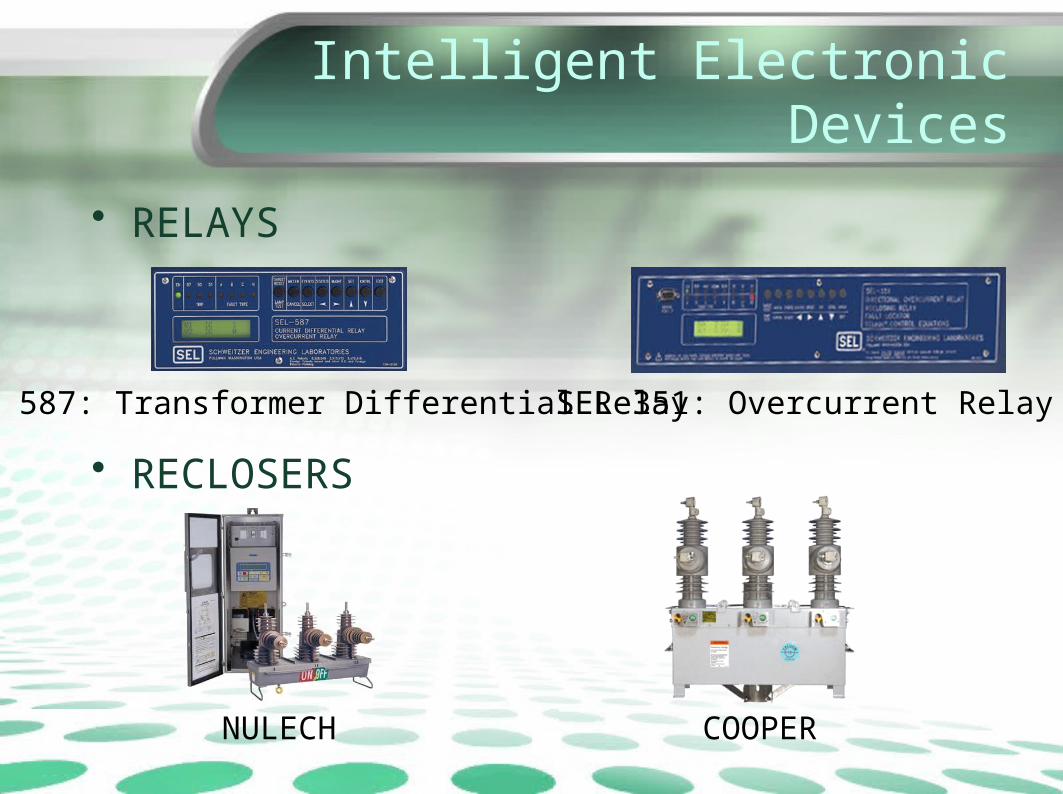
Intelligent Electronic Devices
• RELAYS
• RECLOSERS
SEL 587: Transformer Differential Relay SEL 351: Overcurrent Relay ++
NULECH COOPER

What are EVENT Reports?
• Event reporting is a standard feature in most microprocessor-based protective relays
• The data and information saved in these reports are valuable for testing, measuring performance, analyzing problems, and identifying deficiencies before they cause future misoperations.
• Event reports indicate whether the protective relay operated as expected.
What are EVENT Reports?
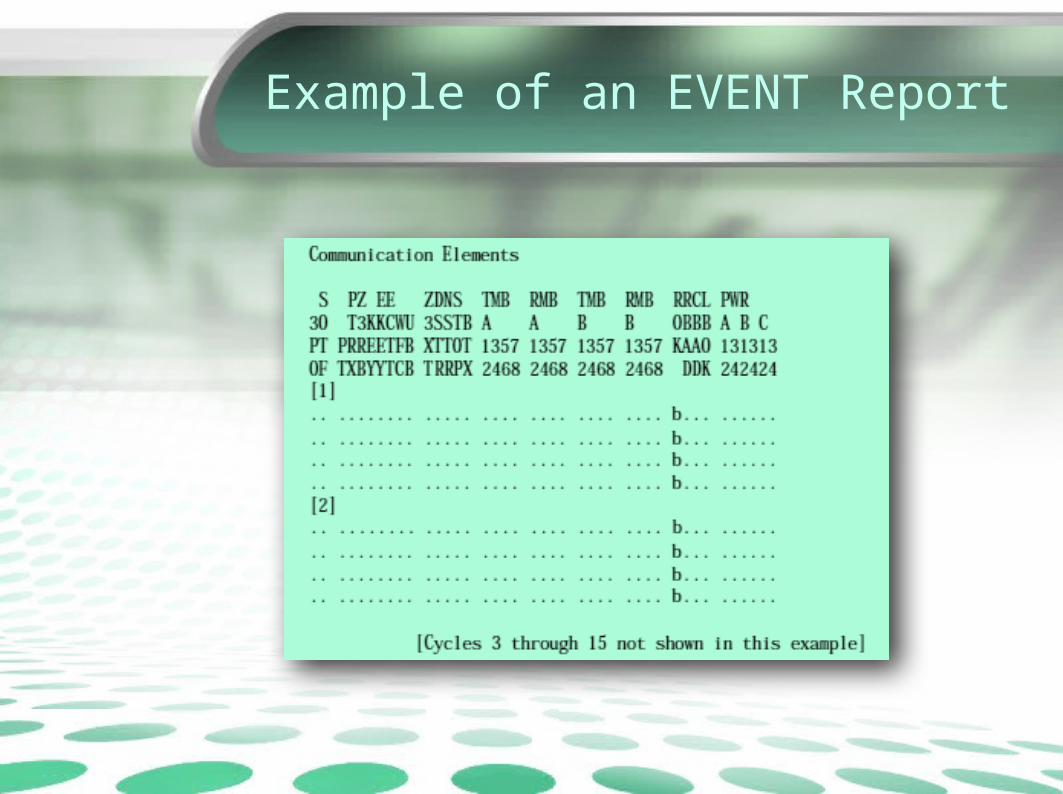
• When faults or other system events occur, protective relays record sampled analog currents and voltages, the status of optoisolated inputs and output contacts, the state of all relay elements and programmable logic, and the relay settings. The result is an event report.
• It is stored in a non-volatile memory in relays.• It is a stored record of what the relay saw and how
it responded.• These reports are formatted ASCII text files that
are read vertically
What are EVENT Reports?
• Commonly, Event reports contains 15 or 30 cycles of data with accuracy of ¼ to 1/16 cycle.
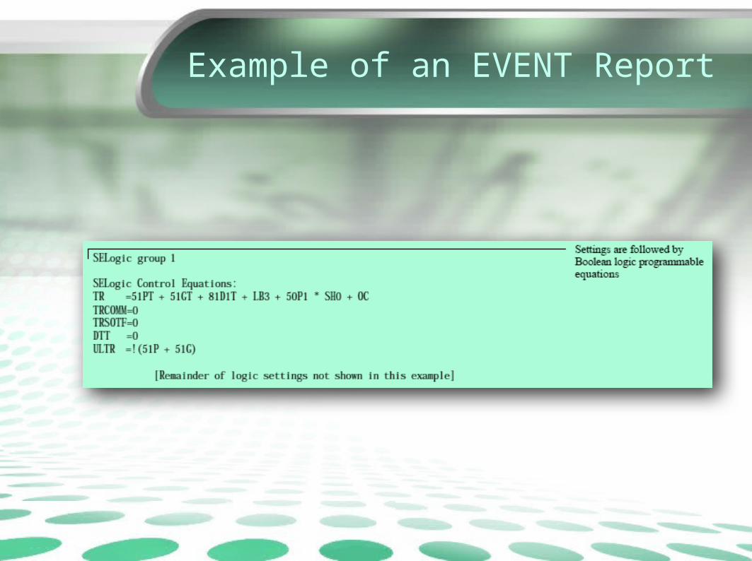
• With readily available information from product instruction manuals, the user is provided with all the necessary tools to determine if the response of the relay and the protection system was correct for the given system conditions
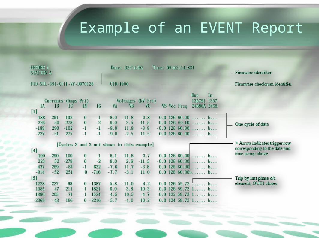
Example of an EVENT Report

Example of an EVENT Report

Example of an EVENT Report
Example of an EVENT Report

Example of an EVENT Report
Example of an EVENT Report

Why is EVENT Report important?
• The ability to quickly and accurately analyze event data can save money.
• Event report analysis can reveal problems with power system models, settings, breakers and auxiliary contacts, instrument transformers, and more.
• In the past, these problems would go undetected until they were either caught during routine maintenance or more serious consequences occurred. It is a good practice to examine every event report to see if the operation was normal or exceptional.
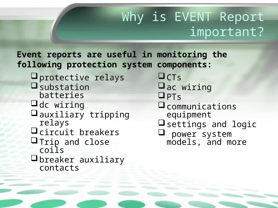
Event reports are useful in monitoring the following protection system components:
protective relayssubstation batteriesdc wiringauxiliary tripping relayscircuit breakersTrip and close coilsbreaker auxiliary contacts
CTsac wiringPTscommunications
equipmentsettings and logic power system models,
and more
Why is EVENT Report important?
Why is EVENT Report important?
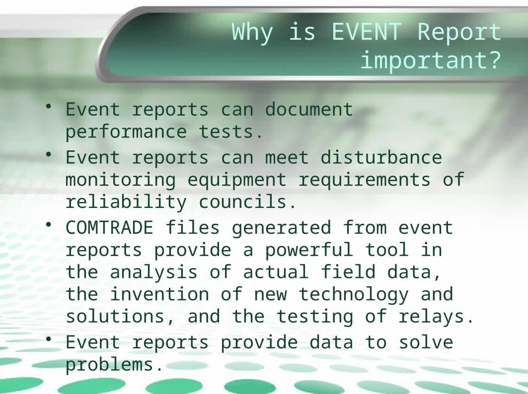
• Event reports can document performance tests.• Event reports can meet disturbance monitoring
equipment requirements of reliability councils.• COMTRADE files generated from event reports
provide a powerful tool in the analysis of actual field data, the invention of new technology and solutions, and the testing of relays.
• Event reports provide data to solve problems.

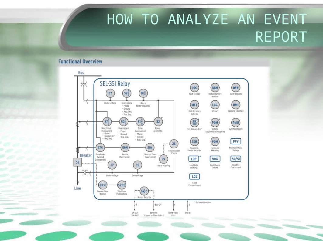
HOW TO ANALYZE AN EVENT REPORT
• Before analyzing the details of any event report, start with a basic understanding of what happened, or what should have happened.
• This generally involves:– reviewing the relay settings and logic– obtaining the relay history report– and gathering any other information that may be helpful
(known fault location, targets from other relays, breaker operations, SCADA, and personnel records)
• Use the event report to investigate whether the actual operation matches the expected operation

HOW TO ANALYZE AN EVENT REPORT
HOW TO ANALYZE AN EVENT REPORT
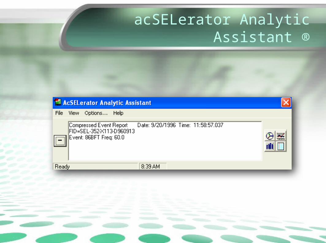
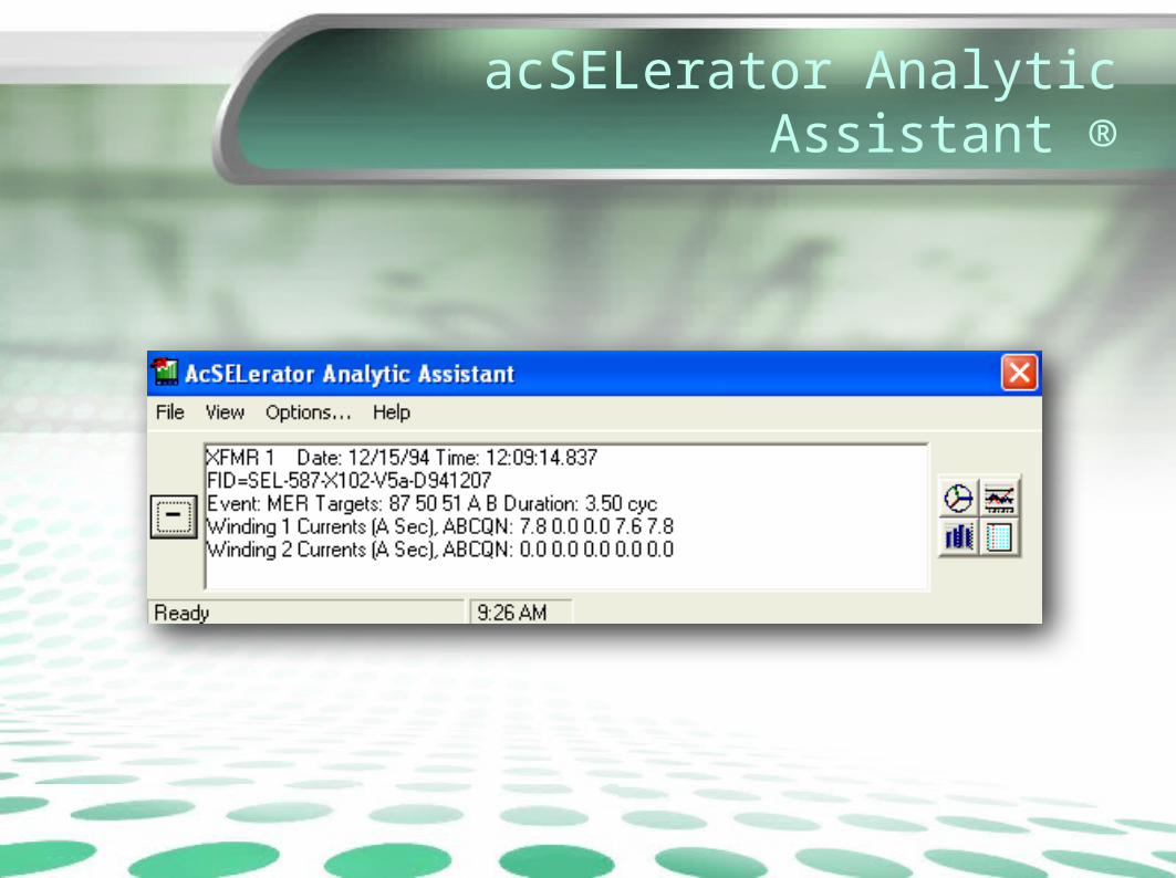
What is AcSELerator Analytic Assistant?
• SEL 5601: AcSELerator Analytic Assistant is a software application that plots the data contained in the EVENT REPORTS generated by the relays.– It aides (visually) in analyzing an event report.
(It does NOT analyze the data for you)
acSELerator Analytic Assistant ®
• Displays oscillograms and vector diagrams to analyze event reports from SEL relays and COMTRADE files (COMmon format for TRAnsient Data Exchange for power systems).
acSELerator Analytic Assistant ®
• Features– Use with SEL relay compressed ASCII event reports,
and some EVE ASCII event reports.– Accepts COMTRADE 1991, COMTRADE 1999, and
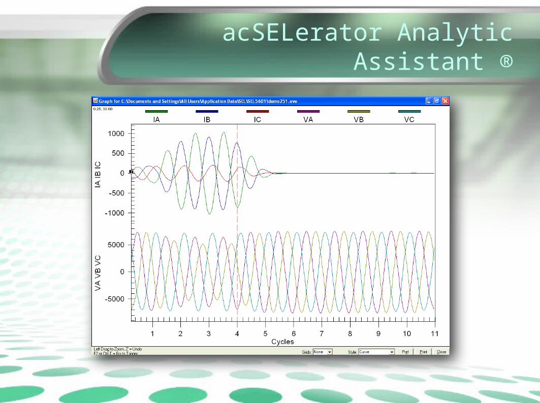
Binary COMTRADE files.– Displays oscillograms with time-coordinated element
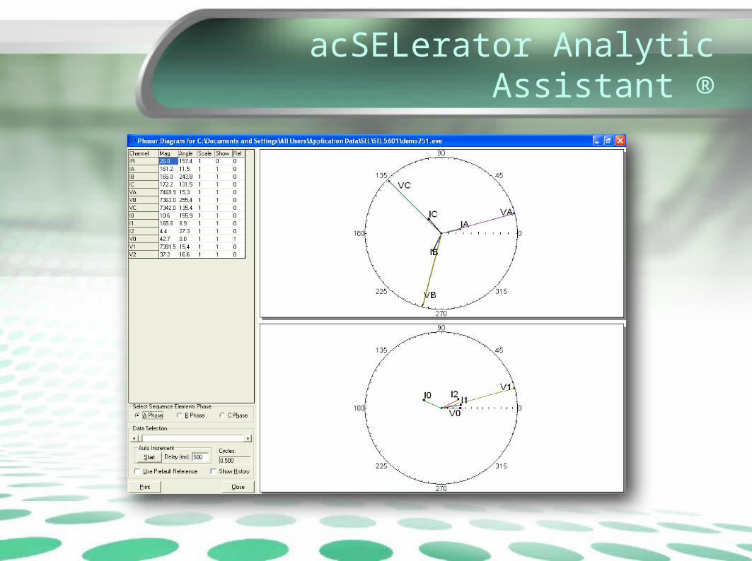
assertion.– Display phase and sequence phasors with manual or
auto advance.– Analyze line current differential events with alpha plane
plots.
acSELerator Analytic Assistant ®
• Features (contd)– Simplify event analysis with point-and-click ease.– Enhance clarity and versatility of synchronized analog
and digital traces in standard SEL relay event reports.– View all aspects of event reports with the click of a
button.– Settings– Oscillographic display – Supports multiple events in a single file.– Supports multiple time-coordinated events from different
relays
acSELerator Analytic Assistant ®
acSELerator Analytic Assistant ®

acSELerator Analytic Assistant ®
• Oscillographic event reports simplify analysis of faults and power quality events, and help improve the user’s understanding of simple and complex protective scheme operations. In response to a user-selected trigger, the voltage, current, frequency, and relay element status information confirms relay, scheme, and system performance for every recorded event.

acSELerator Analytic Assistant ®

acSELerator Analytic Assistant ®
acSELerator Analytic Assistant ®
acSELerator Analytic Assistant ®

Event Report Example 1
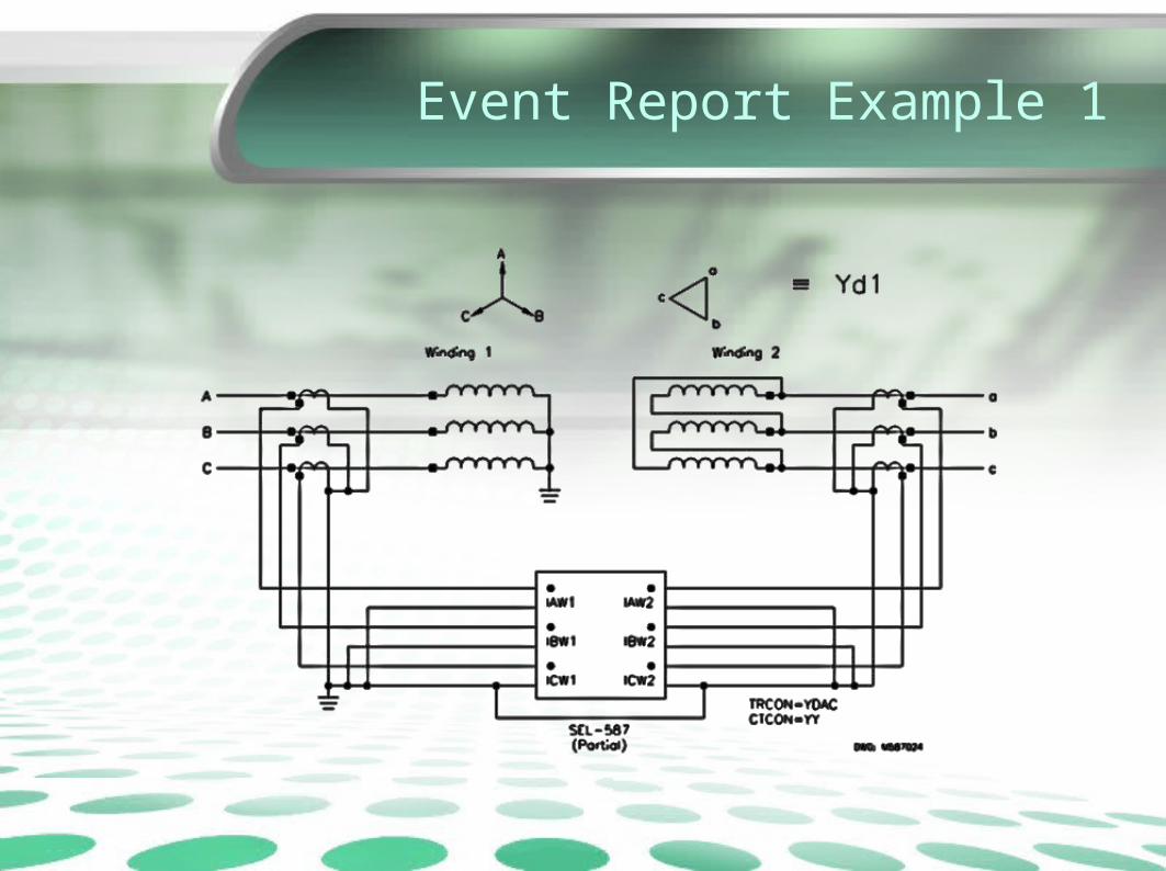
TRANSFORMER CONNECTION COMPENSATION CAUSES TRIP• A transformer differential relay operated for a
distribution feeder fault. The transformer is a wye-delta power bank that uses wye-wye CTs. When conventional CT connections are not used (CTs not connected delta-wye in this case), the current inputs to the differential calculation in the microprocessor relay must be modified internally by settings to compensate for the 30 degree shift of the transformer and to extract zero-sequence current.
Event Report Example 1
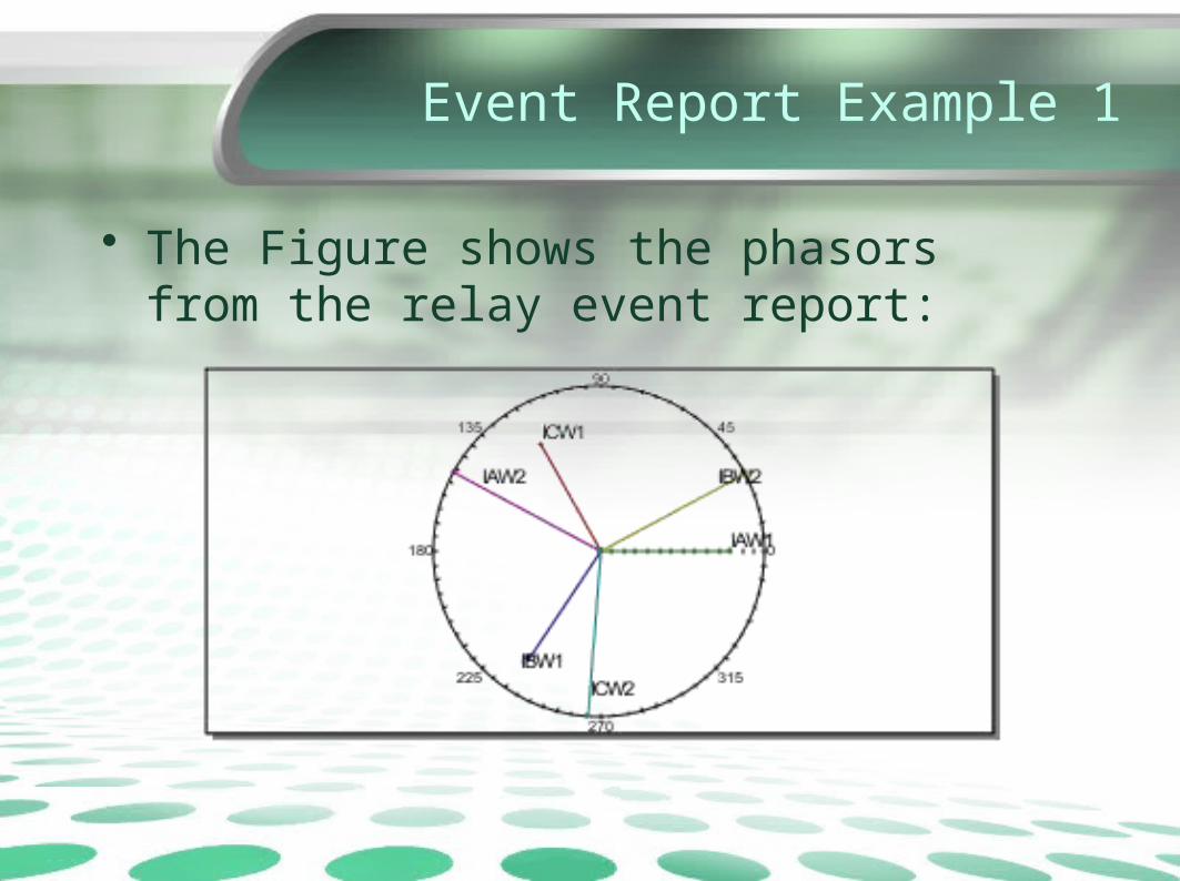
• The Figure shows the phasors from the relay event report:

Event Report Example 1
• For a YDAB transformer (polarity of A-phase connected to the nonpolarity of B-phase), we would expect the Winding 2 currents to lag the Winding 1 currents by 150 degrees.

Event Report Example 1

Event Report Example 1
• Visually, you can determine from the phasors in Figure 41 that these two quantities will not be opposite in phase angle. In fact, the transformer connection compensation should be set to YDAC. In that case, we expect the Winding 2 currents to lead the Winding 1 currents by 150 degrees.
Event Report Example 1
Event Report Example 1
• With this setting, the relay compares for differential operate Element 1 IAW2 with (IAW1 – ICW1)/v3, scaled by the differential tap settings. Now the two quantities will be equal and out of phase, resulting in proper operation.
Event Report Example 2
EVENT REPORT IDENTIFIES INCORRECT CT TAP
A distribution relay tripped by phase instantaneous overcurrent. The upstream transformer differential relay tripped by restrained differential element (87R). The feeder relay operation was correct. The transformer relay should not have tripped for the feeder fault.
Event Report Example
Event Report Example
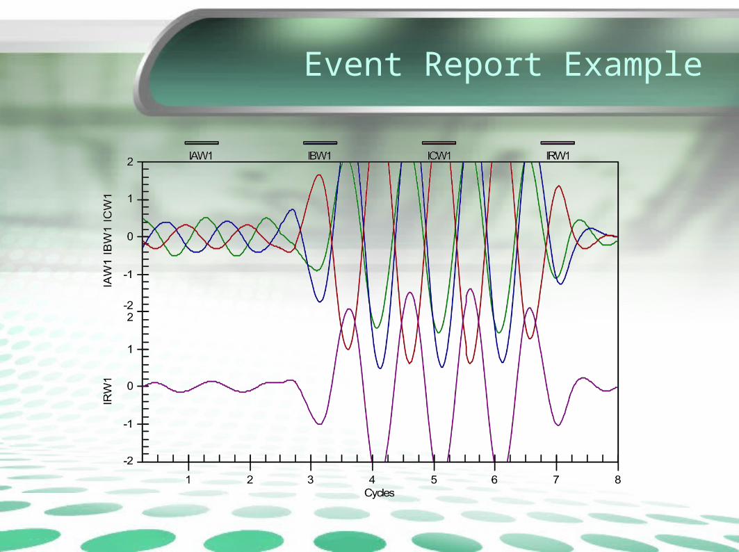
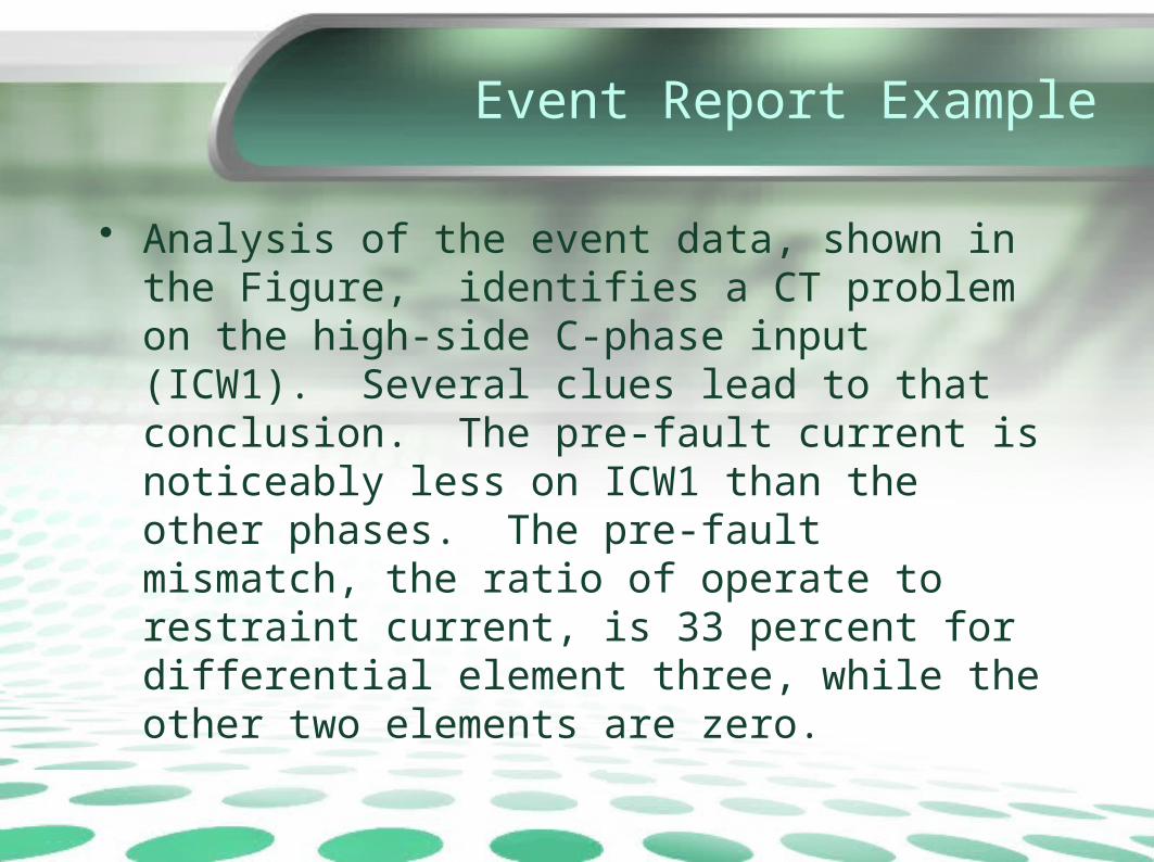
• Analysis of the event data, shown in the Figure, identifies a CT problem on the high-side C-phase input (ICW1). Several clues lead to that conclusion. The pre-fault current is noticeably less on ICW1 than the other phases. The pre-fault mismatch, the ratio of operate to restraint current, is 33 percent for differential element three, while the other two elements are zero.
Event Report Example
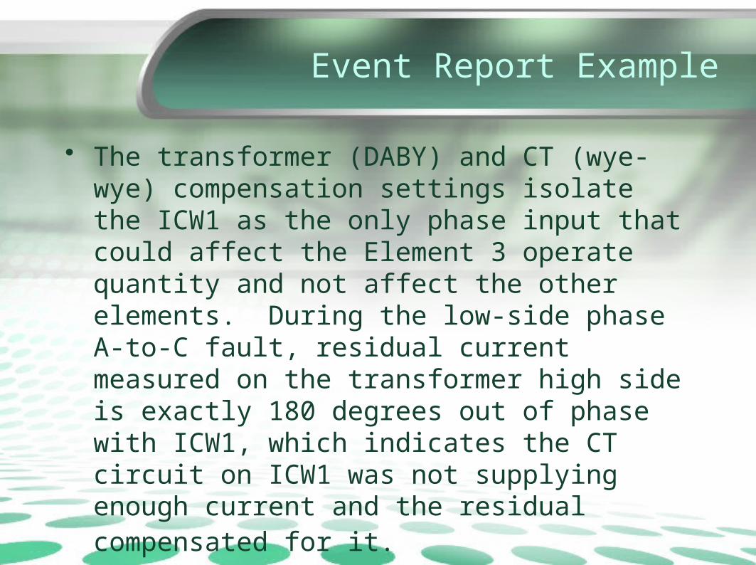
• The transformer (DABY) and CT (wye-wye) compensation settings isolate the ICW1 as the only phase input that could affect the Element 3 operate quantity and not affect the other elements. During the low-side phase A-to-C fault, residual current measured on the transformer high side is exactly 180 degrees out of phase with ICW1, which indicates the CT circuit on ICW1 was not supplying enough current and the residual compensated for it.
Event Report Example
• The relay settings indicated a CT ratio of 600/5 on the transformer high side. The C-phase high-side CT was found tapped at 1200/5. This example also emphasizes the use of triggered event reports during commissioning tests for uncovering incorrect taps, rolled phases, and opposite polarity in CT wiring.