5601 5605.output
TRANSCRIPT

* GB786009 (A)
Description: GB786009 (A) ? 1957-11-06
Improvements in or relating to phenthiazine derivatives
Description of GB786009 (A) Translate this text into Tooltip
[75][(1)__Select language] Translate this text into
The EPO does not accept any responsibility for the accuracy of data and information originating from other authorities than the EPO; in particular, the EPO does not guarantee that they are complete, up-to-date or fit for specific purposes.
COMPLETE SPECIFICATION. Improvements in or relating to Phenthiazine Derivatives. We, SOCIETE DES USINES CHIMIQUES RlloNE-PoULENC, a French body corporate, of 21 rue Jean-Goujon, Paris 8E, France, do hereby declare the invention for which we pray that a patent may be granted to us, and the method by which it is to be performed, to be particularly described in and by the following statement : This invention is for improvements in or relating to phenthiazine derivatives intended for therapeutic application, and is more particularly concerned with 3-chloro-10-(3- dimethylaminopropyl)phenthiazine salts capable of forming aqueous solutions which are stable to actinic light. 3 - Chioro - 10 - (3 - dimethylaminopropyl) phenthiazine is a drug which is widely used for a variety of purposes in clinical medicine. For some applications it is required in the form of an aqueous solution, for which purpose the hydrochloride has been proposed. In practice, however, difficulties arise in the preparation and use of such solutions due to the action of actinic light in bringing about rapid coloration of the solutions with concomitant diminution in activity and increase in toxicity consequent upon the formation of toxic degradation products. These difficulties have been experienced in the case of other phenthiazine compounds and experimentation has

shown that these difficulties are not directly dependent upon the nature of the anion, in the sense that aqueous solutions of different phenthiazine compounds containing, however, the same anion behave differently on exposure to actinic light. In accordance with the present invention, there are provided the - hitherto unknown acid salts of 3 - chioro - 10 - (3 - dimethylaminopropyl)phenthiazine with olefinically- unsaturated aliphatic dicarboxylic acids containing not less than four and not more than five carbon atoms. It has now been unexpectedly discovered that the said salts will form aqueous solutions that possess a much greater stability to light than the known water-soluble salts such as the hydrochloride and can be prepared and used as such in clinical medicine without giving rise to the difficulties hereinbefore referred to. It would have been impossible a priori to predict this result. Of the acids, the salts of which with 3chloro - 10 - (3 - dimethylaminopropyl) phenthiazine are comprehended by the present invention, fumaric acid is preferred not only by reason of the outstanding stability to light of the fumaric formed but also because of its moderate price and of the low toxicity of the fumarate ion. However, other acids of the type hereinbefore defined can be employed, viz. maleic, citraconic mesaconie, itaconic and glutaconic acids. Where the acid salts of the invention are only slightly soluble in water, they are preferably converted into a more soluble neutral, mixed or double, salt by treatment with alkali. It follows that complete conversion of a given quantity of such acid salts is not essential. By way of example, the acid fumarate is relatively but slightly soluble in water and is preferably at least partially transformed into the double fumarate of sodium and 3 - chloro - 10 - (3 dimethylaminopropyl)phenthiazine by the addition of e.g. caustic soda or sodium bicarbonate. A molar quantity of alkali of at least 67% is required to produce a product sufficiently soluble in water for optimum utility; molar equivalents of alkali ranging from 67% to 100%, preferably about 75%, are therefore employed in practice. In an alternative procedure, suitable quantities of 3-chloro -10-(3- dimethylaminopropyl)phenthiazine, fumaric acid and sodium bicarbonate are dissolved in water. Following either of the aforesaid procedures, aqueous solutions are obtained the pH of which is, or by means of the addition of alkali such as caustic soda can readily be adjusted to, between 4.7 and 6.5, and preferably about 5.0. Concentrations of between 0.1 and 5% by weight can be achieved and are adequate for normal purposes. There is no practical advantage in preparing solutions with higher concentrations because they are not so well tolerated on injection. These solutions are stable to light and also to heat, which enables

them to be sterilised. They are rendered isotonic in conventional manner; for example, fumarate solutions are so rendered by the addition of sodium fumarate. The following Example shows how the invention can be put into practice. EXAMPLE. A hot solution of 25.5 g. of 3 - chloro - 10 (3 - dimethylaminopropyl)phenthiazine in 30 cc. of ethanol is added to a hot solution of 9.3 g. of fumaric acid in 220 cc. of ethanol. On cooling, the crystals are filtered and washed with ethanol and dried; 31 g. of the acid fumarate, a white crystalline powder, is thus obtained, m.p. (Kofler) : 180-181 C. To 3.41 g. of the aforesaid acid fumarate there is added a solution of 0.50 g. of sodium bicarbonate in 70 cc. of water. The mixture is heated, with agitation, to 50-60 C. until dissolution is complete and no more carbon dioxide is evolved. It is then cooled to room temperature and diluted to 100 cc. with distilled water. A 2.5% aqueous solution of the double fumarate of sodium and 3 - chloro - 10 - (3 - dimethylamino propyl)phenthiazine is thus obtained having a pH of 5.0. What we claim is 1. An acid salt of 3 - chloro - 10 - (3 dimethylaminopropyl)phenthiazine with an olefinically-unsaturated aliphatic dicarboxylic acid containing not less than four and not more than five carbon atoms. 2. The acid fumarate of 3 - chioro - 10- (3-dimethylaminopropyl)phenthiazine. 3. A light-stable solution suitable for use in clinical medicine in the form of an aqueous solution containing at least 0.1 ?'o' by weight of a salt as defined in Claim 1 or 2.
* Sitemap * Accessibility * Legal notice * Terms of use * Last updated: 08.04.2015 * Worldwide Database * 5.8.23.4; 93p
* GB786010 (A)
Description: GB786010 (A) ? 1957-11-06

Method of applying a protective coating to a heat-sensitive electricalelement
Description of GB786010 (A)
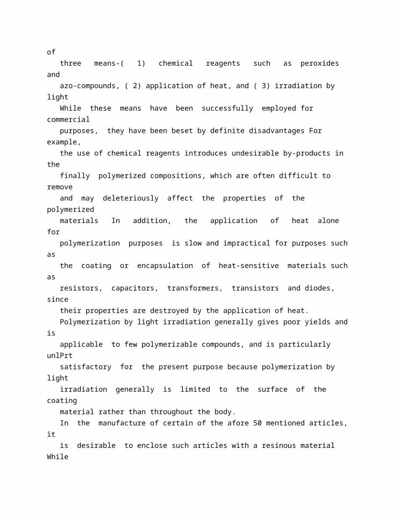
PATENT SPECIFICATION -786,010 Date of Application and filing Complete Specification: Feb 8, 1956. No 3951/56. Application made in United States of America on Feb 8, 1955. 9 / Complete Specification Published: Nov6, 1957. Index at acceptance:-Classes 1 ( 1), C; 2 ( 6), P 4 D( 2: 3 A), P 4 K 9, P 4 P( 5: 6 X), P 7 (D 2 A 1: K 9), P 7 P( 5: 6 X), P 8 D( 2 A: 2 82: 3 A: 5), P 8 P( 5: 6 X), P 9 D(IBI: 3), P 9 K( 4: 7), P 9 P( 5: 6 X); 2 ( 7), T 6 (F 1: G 2); and 37, K( 1 A 1: 2: 5). International Classification:-B Olj CO 8 f, g H 011. COMPLETE SPECIFICATION Method of Applying a Protective Coating to a Heat-Sensitive Electrical Element We, GENERAL ELECTRIC COMPANY, a Corporation of the State of New York, United States of America, having its office at Schenectady 5, State of New York, United States of America, do hereby declare the invention, for which we pray that a patent may be granted to us, and the method by which it is to be performed, to be particularly described in and by the following statement: - This invention relates to a method of applying a protective resinous coating to surfaces by the polymerization of polymerizable organic compounds with high energy electrons or high voltage cathode rays and, more particularly, to the coating or encapsulation of heat-sensitive articles, such as resistors, capacitors, transformers, transistors and diodes, with polymerizable organic compounds, by the polymerization of such compounds by irradiation with high energy electrons or high voltage cathode rays. Heretofore, the polymerization of polymerizable organic compounds, e g, vinyl compounds, has been initiated by one, or a combination, of three means-( 1) chemical reagents such as peroxides and azo-compounds, ( 2) application of heat, and ( 3) irradiation by light While these means have been successfully employed for commercial purposes, they have been beset by definite disadvantages For example, the use of chemical reagents introduces undesirable by-products in the finally polymerized compositions, which are often difficult to remove

and may deleteriously affect the properties of the polymerized materials In addition, the application of heat alone for polymerization purposes is slow and impractical for purposes such as the coating or encapsulation of heat-sensitive materials such as resistors, capacitors, transformers, transistors and diodes, since their properties are destroyed by the application of heat. Polymerization by light irradiation generally gives poor yields and is applicable to few polymerizable compounds, and is particularly unlPrt satisfactory for the present purpose because polymerization by light irradiation generally is limited to the surface of the coating material rather than throughout the body. In the manufacture of certain of the afore 50 mentioned articles, it is desirable to enclose such articles with a resinous material While germanium diodes, for example, may be manufactured inexpensively using cases composed of phenolic resin, these units tend to deteriorate 55 rapidly in a high humidity atmosphere unless they are moisture sealed Up to the present time, no entirely satisfactory method has been found for sealing units of this type The most promising methods involve the coating or en 60 capsulation of the entire structure with a polymeric material A disadvantage of this method is that most polymerizations require the application of heat to attain reasonable curing rates However, materials such as 65 germanium are quite heat-sensitive and are therefore not readily susceptible to coating or encapsulation by this means. Unexpectedly, we have found that in the manufacture of articles requiring the coating 70 or encapsulation of a heat-sensitive material, the coating or encapsulation can be accomplished rapidly and without impairing the properties of the heat-sensitive material by surrounding the material with a monomeric 75 compound and polymerizing the monomer by irradiation with high energy electrons or high voltage cathode rays. Briefly stated, the present invention has application to the coating or encapsulation 80 of articles containing heat-sensitive materials of the foregoing description by the polymerization of olefinic organic compounds containing at least one terminal CH 2 =C< grouping, and selected from the class consisting of mono 85 hydric and polyhydric alcohol esters of acrylic and methacrylic acids, acrylonitrile, mixtures of the aforesaid acrylic and methacrylic acid esters, mixtures of styrene and an unsaturated alkyd resin, mixtures of diallyl phthalate and 90 an unsaturated alkyd resin, and mixtures of (a) monohydric alcohol esters of acrylic and methacrylic acids and (b) an unsaturated alkyd resin Also included within the scope of this invention are the organopolysiloxanes disclosed in Patent Specifications Nos 542,655,

544,143, 551,649, 548,912 and 548,911 By irradiating articles comprising these monomers and a heat-sensitive material in a non-gaseous state with high energy electrons at a dose accumulation rate not exceeding 1 x 10⁷ roentgens per second, coating or encapsulation of the heat-sensitive material is accomplished by means of fast and efficient polymerization of the monomer without deleteriously affecting the properties of the heat-sensitive material. The invention itself, together with further advantages resulting from the process, may best be understood by reference to the following description, taken in connection with the accompanying drawings, in which Fig 1 is a partially sectionalized, simplified view of accelerator apparatus useful in practising the invention; Fig 2 is a view of an electrical element partly in section, showing the coating and Fig 3 is a partially sectionalized view of alternative apparatus which is employed to obtain a desired result in accordance with the invention. Referring particularly now to Fig 1, there is shown high voltage apparatus 1 capable of producing a beam of high energy electrons for irradiating monomers used for coating or encapsulating purposes in accordance with the invention In general, this apparatus comprises a resonant system having an open magnetic circuit inductance coil ({not shown) which is positioned within a tank 2 and energised by a source of alternating voltage to generate a high voltage across the extremities At the upper end (not shown) of a sealed-off, evacuated, tubular envelope 3, is located a source of electrons which is maintained at the potential of the upper extremity of the inductance coil whereby a pulse of electrons is accelerated down envelope 3 once during each cycle of the energizing voltage when the upper extremity of the inductance coil is at a negative potential with respect to the lower end. To permit utilization of the high energy electrons accelerated down envelope 3, there is provided an elongated metal tube 4, the upper portion 5 of which is hermetically sealed totank 2, as illustrated, by any convenient means such as silver solder The lower portion 6 of tube 4 is conical in cross section to permit an increase in angular spread of the electron beam The emergence of high energy electrons from tube 4 is facilitated by an end window 7 which may be hermetically sealed to tube 4 by means of silver solder End window 7 should be thin enough to permit electrons of desired energy to pass therethrough, but thick enough to withstand the force of atmospheric pressure Stainless steel of about 0 002 inch thickness has been found satisfactory for use with electron energies of at least 230,000 electron volts or greater Beryllium and other materials of low stopping power may also be employed with efficacy By forming end 70 window 7 in arcuate shape as

shown, greater strength for resisting the force of atmospheric pressure may be obtained for a given window thickness Desired focusing of the accelerated electrons may be secured by a magnetic field 75 generating winding 8 energized by a source of direct current 91 through a variable resistor 9. In the polymerization of monomeric organic compounds employed as coating or encapsulating materials for articles containing a heat 80 sensitive element with the high voltage apparatus 1, an electrical element 10, shown in Fig 2, containing a heat-sensitive component 11 and having a coating of a liquid monomer 12 may be supported in the path of the 85 electrons emerging from end window 7 as illustrated The high energy electrons penetrate the monomer 12 to a depth dependent upon their energy and initiate polymerization of the monomer with the accompanying encapsulation 90 of the heat-sensitive elements with solid polymer to form an integral unit. The monomeric compound 12 may comprise monohydric and polyhydric alcohol esters of acrylic and methacrylic acids Monohydric 95 alcohols which may be employed in the preparation of esters of acrylic and methacrylic acids are, for example, methyl, ethyl, propyl, isopropyl, butyl, 2-ethylhexyl and decyl Polyhydric alcohols which may be employed also in 100 the preparation of esters of acrylic and methacrylic acids are, for example, ethylene glycol, diethylene glycol, dipropylene glycol, pentamethylene glycol, tetraethylene glycol, glycerine and sorbitol Some of the esters pre 105 pared from the foregoing alcohols are, for example, ethyl acrylate, ethyl methacrylate, butyl acrylate, methyl acrylate, methyl methacrylate, dipropylene glycol dimethacrylate, tetraethylene glycol diacrylate, pentamethylene 110 gglycol dimethacrylate, glyceryl trimethacrylate and tetraethylene glycol dimethacrylate. The monomeric compound 12 may also comprise acrylonitrile and mixtures of an unsaturated alkyd resin with either styrene or 115 diallyl phthalate Unsaturated alkyd resins employed in the practice of the present invention are those commonly obtained by effecting a reaction between a polyhydric alcohol, many examples of which are stated 120 above, and an alpha unsaturated alpha, beta dicarboxylic acid or anhydride, which for brevity will hereinafter be referred to as " unsaturated acid " Examples of such unsaturated acids are maleic acid or anhydride, fumaric 125 acid, itaconic acid or anhydride, and mesaconic acid Modification of the unsaturated alkyd resin with nonpolymerizable dicarboxylic acids, e g, adipic, sebacic and phthalic acids, is also intended to be included within the 130 786,010 monomer is irradiated in the solid state and then warmed to a liquid state, polymerization unexpectedly occurs rapidly In the encapsulation of heat-sensitive elements of the type hereinbefore described, this is a
desirable feature For example, if the heat-sensitive element is positioned in the liquid monomer and the monomer frozen to the solid state by the foregoing means, and the frozen monomer thereafter irradiated in the solid state and then warmed to a liquid state, polymerization unexpectedly occurs rapidly, with resulting encapsulation of the heat-sensitive element maintained in position This "delayed polymerization" phenomenon is obtainable and may be availed of with all the above-mentioned classes of monomers in the encapsulation of heat-sensitive elements. The polymerization of the monomer in the liquid state is inhibited at the surface by oxygen; hence, it is advantageous to place the monomer in an inert atmosphere or in vacuo during irradiation Nitrogen has also proven satisfactory as an atmosphere in which the monomer may be placed. In order that those skilled in the art may better understand how the present invention may be practised, the following example is given by way of illustration and not by way of limitation The apparatus used for effecting the polymerization described below is that shown in Fig 1, and particularly described above. scope of the term "unsaturated alkyd resin " While the invention has been described to this point with particular reference to encapsulation by polymerization at ambient temperatures, we have found in the main that the polymerization temperature is dependent upon the element being encapsulated and may extend up to a point just short of which damage of the heat-sensitive element is realized We have also found that the per cent polymerization for a given total dose administered at a given dose accumulation rate is furthermore dependent upon the initial temperature of the monomer Thus, if the monomer is irradiated is with high energy electrons, the per cent polymerization increases with increases in the initial temperature Apparatus for maintaining the monomer undergoing irradiation at a temperature below ambient is illustrated in Fig 3, wherein numerals employed hereinbefore are utilized to identify like elements. Receptacle 10 a containing an element 10 having a heat-sensitive component (not shown) and a coating 12 is supported with a cupshaped member 13 of conducting material, such as aluminium, by means of a plurality of posts 14 which may consist of wood Cupshaped member 13 is positioned within a thermally insulated vacuum bottle 15, upon a pedestal 16 constructed of a material such as a moulding compound of phenol-aldehyde resin By partially filling the vacuum bottle with a cooling medium 17, such as liquefied nitrogen or air through a filling tube 18, monomer 12 may be maintained at a desired temperature below ambient, and by slowly adding the cooling medium to compensate for evaporation, the temperature may be controlled For the purpose of

preventing atmospheric turbulence within vacuum bottle 15, aluminium foil sheets '19, 20 and 21 are respectively positioned over receptacle 10 a, 13 and vacuum bottle 15, as illustrated A sheet 22 of lead foil is placed over the edge of vacuum bottle 15 to protect it from the damaging effects of radiation. Irradiation of the monomer in the solid state fails to produce significant polymerization We have observed, however, that if the SO EXAMPLE 1 Several germanium diodes were coated with a liquid copolymer of styrene and an un 85 saturated alkyd composition The coated diodes were then irradiated, at ambient temperatures, with 800 KVP (KVP refers to the peak kilovolts generated by the inductance coil within high voltage apparatus 1 and thus 90 is a measure of the energy of electrons emerging from window 7) cathode rays at various dose levels and for various periods of time. The irradiation time, in seconds, and the dose for each are shown in Table I The para 95 meter measured was the reverse current at volts d-c and the values shown in Table I are in microamperes. TABLE I Diode Duration of Irradiation No in Seconds 1 2 3 3 7 17.5 Dose 1.1 x 10⁶ 2.5 x 10 ' 6 x 10⁶ 1 x 10⁶ Reverse Current in Microamperes 230 The reverse current measurements for each of the diodes coated and encapsulated by the method of the invention lie in an acceptable range and thereby show that the properties of 110 the germanium element were not impaired by the irradiation. 786,010 Moisture resistance tests were conducted on germanium diodes coated with a similar liquid copolymer of styrene and an unsaturated alkyd resin This test was conducted in a humidity chamber maintained at a constant relative humidity of approximately 95 % The temperature is raised from room temperature to about 70 C in a 3-hour period The temperature is then allowed to drop back to room temperature and the temperature is thereafter again raised to about 700 C in a 3-hour Duration of Diode Irradiation No in Seconds period The temperature is again allowed to drop to room temperature and is kept at room temperature at the same relative humidity, % for approximately 12 hours making a total of 24 hours or 1 humidity cycle At the end of each 24-hour cycle, the reverse current was measured, the parameter measured being the reverse current at -50 volts d-c and the values, shown in Table II, are in microamperes In Table II, diode 4 is the same as diode 4 in Table I. TABLE II Reverse Current after the Number of Cycles Shown Dose 0 1 2 3 4 7 8 1 x 10⁶ 85 80 95 110 300 1350 820 6 x 10⁶ 330 345 310 450 580 The data of Table II indicates that the humidity resistance of germanium diodes

encapsulated by the method of the invention are within an acceptable range The data further indicates an improvement trend with longer periods of irradiation. While the present invention has been described in more detail with respect to a copolymer of styrene and an unsaturated alkyd resin, it is obvious that the invention may be practised with other monomeric polymerizable compositions of the class herein disclosed.
* Sitemap * Accessibility * Legal notice * Terms of use * Last updated: 08.04.2015 * Worldwide Database * 5.8.23.4; 93p
* GB786011 (A)
Description: GB786011 (A) ? 1957-11-06
Power production from waste heat
Description of GB786011 (A)
A high quality text as facsimile in your desired language may be available amongst the following family members:
DE1020646 (B) DE1020646 (B) less Translate this text into Tooltip
[79][(1)__Select language] Translate this text into
The EPO does not accept any responsibility for the accuracy of data and information originating from other authorities than the EPO; in particular, the EPO does not guarantee that they are complete, up-to-date or fit for specific purposes.
PATENT SPECIFICATION

Date of Application and filing Complete Specification: Feb 10, 1956. No 4246/56. Application made in United States of America on Feb 14, 1955. Complete Specification Published: Nov 6, 1957. Index at acceptance:-Classes 64 ( 3), 55 E( 2: 3: X); 110 ( 3), B 2 M 6; and 122 ( 3), A 7 X. International Classification:-FO 2 h F 25 h. COMPLETE SPECIFICATION Power Production from Waste Heat We, Esso RESEARCH AND ENGINEERING COMPANY, a Corporation duly organised and existing under the laws of the State of Delaware, United States of America, of Elizabeth, New Jersey, United States of America, do hereby declare the invention, for which we pray that a patent may be granted to us, and the method-by which it is to be performed, to be particularly described in and by the following statement: - This invention relates to a process for the recovery of power from a source of waste heat In its preferred embodiment it relates particularly to the production of power from low temperature heat in cycles using ammonia, monomethylamine or dimethylamine or mixtures containing one or more of these compounds as the work producing fluid. Many industrial operations such as petroleum refining or the production of fissionable materials require large amounts of cooling water As a result large amounts of low temperature waste heat are available in such installations In other instances large amounts of waste heat are available in flue gas, low temperature steam, etc Some of this heat has been utilized heretofore for the distillation of low boiling liquids and similar purposes. However, these have generally been quite inefficient operations. It is the purpose of the present invention to utilize waste heat in a more efficient manner A more specific purpose is to convert low temperature heat into mechanical work or electrical power which can be easily transmitted and is adaptable to a wide range of uses These and other purposes as well as the nature and operation of the invention, will become more clearly apparent from the following description. It has now been discovered that low boiling point liquids containing ammonia, monomethylamine or dimethylamine can be used in an unusually effective manner for recovering useful energy by conversion of waste heat available at a low temperature level, i e at from 170 to 5000 F, preferably between 2000 and 3000 F Ammonia and monomethylamine and dimethylamine and also mixtures containing two or more of these compounds, have a particularly favorable combination of chemical, physical and thermodynamic properties for the present purposes, being essentially non-corrosive, chemically stable at the temperatures involved, lowboiling and having a favorable temperatureentropy diagram

The temperature-entropy diagram of monomethylamine is particularly advantageous, for the present purposes, since its saturated vapor line is unusually steep and thus is indicative of the relative absence of undesirable condensation when the saturated vapor is expanded. Water may also be present in the mixtures mentioned. The conversion of waste heat into energy can be accomplished in accordance with the present invention in several different ways. These can be classified into two principal categories, namely, those employing the boiler-condenser type power cycle, and those employing the boiler-absorber type power cycle, the latter being preferred In simplified terms, in the boiler-condenser type cycle the low-boiling working liquid such as ammonia or methylamine is completely vaporized in a boiler by heat exchange with hot water, waste steam or other source of moderate temperature heat, the resulting vapor may be further super-heated, to prevent undue condensation upon expansion, and then expanded through an expansion engine such as a turbine For instance, the vapor being supplied to the turbine may be at a temperature of 2000 to 300 F and a pressure of 150 to 1500 p s i, whereas the expanded vapor coming from the turbine may be at a temperature of 400 to F and a pressure of 20 to 200 psig, depending largely on the temperature of the available fresh cooling water or other heat sink Finally the expanded vapor is totally condensed in a condenser with the aid of cold air or cooling water and recycled to the boiler. In the preferred boiler-absorber type power cycle a liquid such as a mixture of ammonia 786011 SO and monomethylamine, is pumped to a boiler or stripper where the liquid is partially evaporated by heat exchange with the available waste heat stream to produce a saturated ammonia-containing vapor at a temperature of 200 to 3000 F and a pressure of 150 to 1500 psia This ammonia-containing vapor is normally of sufficiently high quality to be passed directly without superheating to a i O turbine and expanded therethrough Where, however, such expansion would result in giving a wet vapor containing more than the permissible content of liquid condensate entrained in the gas, preheating of the vapor may be advisable prior to its use in the turbine In general 15 % by weight of liquid is considered as the maximum liquid content permitting satisfactory turbine operation The expanded fluid may be a mixture of saturated vapor and liquid at 40 to 100 F and 20 to psia A relatively hot lean liquid solution is withdrawn from the boiler-stripper and, preferably after passage through an exchanger where its heat is used to preheat the liquid feed to the boiler, passed at a temperature of to 150 F and a pressure of 5 to 60 psia. to an absorber where it is contacted with the previously described

expanded vapor for the purpose of absorbing the latter The resulting rich solution is then recycled as feed to the boiler-stripper or multi-stage stripping still. In the boiler-absorber type cycle the working fluid or turbine gas preferably is a mixture containing about 15 % to 80 % by weight ammonia and 85 % to 20 % by weight monomethylamine or a hydrocarbon such as butane or pentane. As the ammonia concentration of the turbine gas is increased above about 75 %, both the cycle thermal efficiency and the net work per mole of gas begin to drop off rather noticeably Consequently, turbine gas compositions containing from SQ% O to 75 % ammonia are preferred The corresponding liquid to the boiler may have a composition of from 10 % to 90 % ammonia, or preferably to 60 % ammonia and 85,% to 40 % methylamine Alternatively working fluids containing ammonia admixed with water, with or without a third component such as a light hydrocarbon, can be used similarly Of course, in some of the aforementioned cases the liquid may exist as a plurality of phases in various portions of the cycle Accordingly, for instance, if a separate condensed hydrocarbon layer is formed in the absorber or condenser stage, it is best passed separately to the bottom of a multi-stage stripping still while the rich ammonia solution is passed from the absorber or condenser stage to the top of the stripping still; a settler may be used in connection with the absorber-stage to facilitate separation of phases. More specific illustrative examples will now be described with reference to the attached drawing wherein Figure 1 illustrates a simplified flow diagram of a boiler-condenser type power cycle suitable for use with a working fluid such as ammonia or monomethylamine; Figure 2 illustrates a flow diagram of a boiler-absorber type power cycle suitable for use with a working fluid such as a mixture of ammonia and monomethylamine; Figure 3 illustrates a flow diagram of a boiler-absorber type power cycle particularly suitable for use with a multi-phase working fluid such as ammonia-pentane-water; Figure 4 shows a vertical section through a vessel particularly adapted to serve either as an absorber or a stripper in the present process; Figure 5 shows a horizontal section through the same vessel as taken along line v-v of Figure 4; and Figure 6 shows a vertical section through another vsssel particularly adapted to serve as a high capacity boiler-stripper. It will be understood that all proportions, ratios and percentages are expressed throughout on a weight basis, unless otherwise indicated. BOILER-CONDENSER POWER CYCLES. Referring to Figure 1, a low-boiling liquid such as pure ammonia or pure monomethyl 95 amine is pumped through line 1 into boiler 3 with

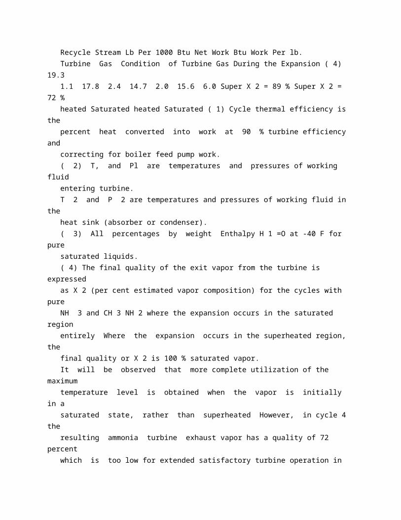
the aid of pump 2 In the boiler the lowboiling liquid is evaporated by indirect heat exchange with a heat source such as hot water being fed through line 5 under pressure at a loo temperature of about 3000 F The vapor or working fluid is withdrawn from the boiler via line 6, e g at a temperature of about 1800 F and a pressure of about 580 psia in the case of ammonia This vapor is then prefer 105 ably passed through superheater 7 where it is superheated to about 2500 F, in order to prevent undue condensation of the fluid in the turbine Hot water fed through line 8 may again be used as a source of heat However, 110 such superheating is usually not necessary in the case of methylamine in view of its unusually favorable temperature-entropy diagram From the superheater the ammonia vapor is passed through line 9 and expanded 115 through turbine 10 to a temperature of about F and a pressure of 180 psia The turbine may be connected to a generator and the recovered energy removed from the system as electricity 120 The expanded vapor is passed from the turbine via line 11 to condenser 12 where it is totally condensed by indirect heat exchange with cooling water circulating through coil 13 or the like The condensed fluid is finally 125 returned to the boiler by pump 2. Data illustrating four different power cycles operated in accordance with the scheme just described are summarized in Table I. r 2 786,011 786,011 TABLE I Comparison of Various Boiler-Condenser Power Cycles Power Cycle No. Working Fluid Temperatures and Pressures ( 2) T 1 (OF) Pl (PSIA) T 2 ( O F) P 2 (PSIA) Turbine Gas ( 3) H 1 Btu/lb. H 2 Btu/lb. Cycle Thermal Eff, % ( 1) Pure Pure Pure CH 3 NH 2 CH 3 NH 2 NH 3 250 300 482 429 13.5 250 580 448 389 5 16.1 250 580 708 638 12.1 Pure NH 3 250 1375 566 496 15.4 Work Rate, Btu Gross Work Per lb. Turbine Gas Per lb -Mole Turbine Gas 1650 58.5 1820 1190 1190 Liquid Recycle Stream Lb Per 1000 Btu Net Work Btu Work Per lb. Turbine Gas Condition of Turbine Gas During the Expansion ( 4) 19.3 1.1 17.8 2.4 14.7 2.0 15.6 6.0 Super X 2 = 89 % Super X 2 = 72 % heated Saturated heated Saturated ( 1) Cycle thermal efficiency is the percent heat converted into work at 90 % turbine efficiency and correcting for boiler feed pump work. ( 2) T, and Pl are temperatures and pressures of working fluid entering turbine. T 2 and P 2 are temperatures and pressures of working fluid in the heat sink (absorber or condenser). ( 3) All percentages by weight Enthalpy H 1 =O at -40 F for pure saturated liquids. ( 4) The final quality of the exit vapor from the turbine is expressed as X 2 (per cent estimated vapor composition) for the cycles with pure

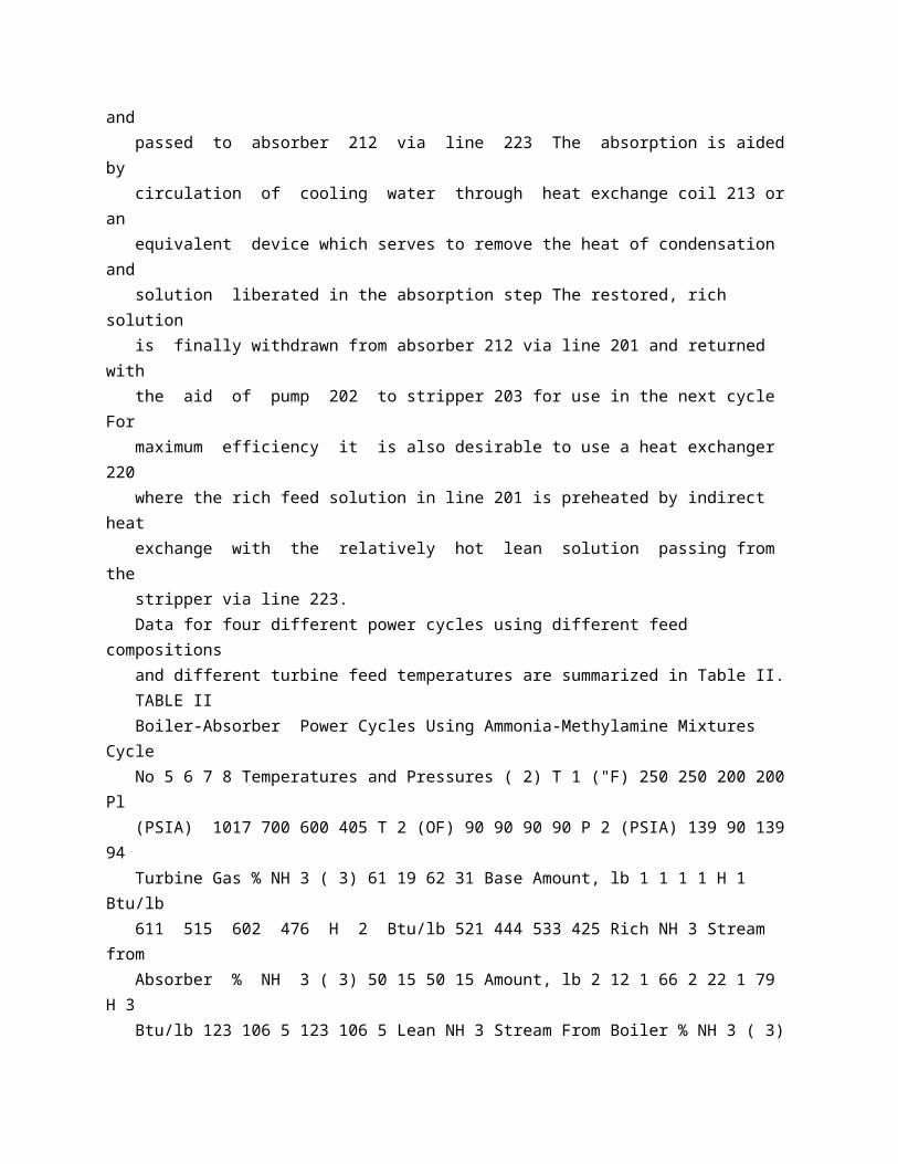
NH 3 and CH 3 NH 2 where the expansion occurs in the saturated region entirely Where the expansion occurs in the superheated region, the final quality or X 2 is 100 % saturated vapor. It will be observed that more complete utilization of the maximum temperature level is obtained when the vapor is initially in a saturated state, rather than superheated However, in cycle 4 the resulting ammonia turbine exhaust vapor has a quality of 72 percent which is too low for extended satisfactory turbine operation in most cases In contrast, the corresponding exhaust vapor of the methylamine cycle 2 has a quality of 89 percent which is entirely satisfactory The thermal efficiency of cycle 2 is excellent, being 16.1 percent as compared with 20 0 percent for the maximum thermal efficiency based on the second law of thermodynamics and 90 % turbine efficiency. BOILER-ABSORBER POWER CYCLES USING NH,-CHN II SOLUTIONS. Referring to Figure 2, a liquid mixture of ammonia and methylamine relatively rich in the more volatile component is pumped into stripper 203 via line 201 In the stripper the liquid is partially evaporated by indirect heat exchange with hot water which is circulated i 5 786,011 through coil 205 under pressure at a suitable elevated temperature, e g 3000 F; instead of hot water other waste heat streams can be used such as hot flue gas or waste steam at moderate pressure The resulting saturated vapor is passed via line 206, e g at a temperature of 250 a F, and expanded through a work producing turbine or turbogenerator 210 to a temperature of about 90 F This produces a mixture of saturated vapor and entrained liquid which is passed to absorber 212 via line 211. In the absorber the expanded gas is reabsorbed by contact with the lean liquid which is withdrawn from the bottom of stripper 203 and passed to absorber 212 via line 223 The absorption is aided by circulation of cooling water through heat exchange coil 213 or an equivalent device which serves to remove the heat of condensation and solution liberated in the absorption step The restored, rich solution is finally withdrawn from absorber 212 via line 201 and returned with the aid of pump 202 to stripper 203 for use in the next cycle For maximum efficiency it is also desirable to use a heat exchanger 220 where the rich feed solution in line 201 is preheated by indirect heat exchange with the relatively hot lean solution passing from the stripper via line 223. Data for four different power cycles using different feed compositions and different turbine feed temperatures are summarized in Table II. TABLE II Boiler-Absorber Power Cycles Using Ammonia-Methylamine Mixtures Cycle No 5 6 7 8 Temperatures and Pressures ( 2) T 1 ("F) 250 250 200 200 Pl (PSIA) 1017 700 600 405 T 2 (OF) 90 90 90 90 P 2 (PSIA) 139 90 139 94

Turbine Gas % NH 3 ( 3) 61 19 62 31 Base Amount, lb 1 1 1 1 H 1 Btu/lb 611 515 602 476 H 2 Btu/lb 521 444 533 425 Rich NH 3 Stream from Absorber % NH 3 ( 3) 50 15 50 15 Amount, lb 2 12 1 66 2 22 1 79 H 3 Btu/lb 123 106 5 123 106 5 Lean NH 3 Stream From Boiler % NH 3 ( 3) 40 9 40 9 Amount, lb 1 12 0 66 1 22 0 79 H, Btu/lb 296 250 249 196 Lean NH 3 Stream From Heat Exchanger H, Btu/lb 126 109 5 126 109 6 Cycle Thermal Eff, % ( 1) 16 7 16 3 13 4 13 1 Work Rate, Btu Gross Work Per lb Turbine Gas 90 71 69 51 Per lb -Mole Turbine Gas 1860 1910 1415 1230 Heat Exchanger Duty, Btu Exchanged Per lb Turbine Gas 190 93 150 69 Per Btu Net Work 2 3 1 4 2 4 1 4 Rich Ammonia Stream Lb per 1000 Btu Net Work 26 2 25 1 34 7 37 0 Btu work per lb. Turbine Gas 8 9 5 0 4 9 2 7 Condition of Turbine Gas During the Expansion Saturated ( 1) Cycle thermal efficiency is the % heat converted into work at 90 % turbine eff. and correcting for boiler feed pump work. ( 2) T 1 and Pl are temps, and pressures of working fluid entering turbine T 2 and P 2 are temps and pressures of working fluid in the heat sink (absorber or condenser). ( 3) All percentages by weight Enthalpy H= O at -40 F for pure saturated liquids. 786,011 6 786,011 The data indicate satisfactory performance in all four instances, the best results being obtained in cycle 5. BOILER-AB So RBER P Ow ER C Yc L Es USING AMMONIA, WATER, PLUS A HYDROCARBON. In the system illustrated in Figure 3 the stripper 303 produces a turbine gas at a temperature of 2500 F and a pressure of 200 psia which has the following composition: Ammonia 28 8 %, Pentane 64 2 %, and Water 7.0 % The enthalpy H 1 of this gas is 433 B.Th U /16, taking H= O for pure saturated liquids at 320 F This gas is passed through line 306 to the turbine 310 through which it is expanded to a pressure of 20 psia and a temperature of 610 F (H 1, = 352) This expanded gas is fed via line 311 to a multistage absorber 312 where the ammonia and water is absorbed from it by contact with a lean solution of ammonia-in-water taken from stripper 303, and after cooling as hereafter described, introduced to the top of the absorber 312 via lines 323 and 324 For each pound of turbine gas in line 311 about 1 51 lb. of lean solution containing 13 O % NII, and 87.0 % 112 O is thus recycled to the top of the condenser 315 at a temperature of 1000 F. and a pressure of 20 psia (H 2 = 25) A cooling agent such as cooling water is circulated through cooling device 313 to maintain the temperature in absorber 312 at about 900 F. The resulting enriched ammonia solution is withdrawn from absorber 312 at 90 F and psia (H = 22) at a rate of about 1 868 lb.

per pound of turbine gas fed in This enriched solution consists of about 25 9 % NH, and 74.1 % H 10, and is passed to the top of stripper 303 via line 349, tubular heat exchanger 350, and line 351 In heat exchanger 350 the solution may be heated to 2400 F. and a pressure of 200 psia (H,= 154) by indirect heat exchange with the hot lean solution passing through line 323 This latter solution may be, for instance, at a temperature of 2500 F and a pressure of 200 psia (H 8 = 190), i e at the conditions prevailing in stripper 303. Returning to the description of the absorption stage 312, the pentane contained in the turbine gas obviously will not become absorbed in the aqueous ammonia but will rise to the top and eventually pass through line 314 into total condenser 315 Here it is scrubbed with the incoming lean ammonia solution and completely condensed An auxiliary cooling coil 319 may be installed in condenser 315 to assure maintenance of a sufficiently low temperature, e g 900 F. From condenser 315 the mixed ammonia solution and pentane are passed via line 316 to settler 317 where the hydrocarbon is separated from the ammonia solution The latter is then passed to absorber 312 to serve as scrubbing liquid therein as already described, whereas the liquid hydrocarbon phase is withdrawn via line 355, still at 90 F and 20 psia (H, = 34) This liquid hydrocarbon phase is removed at a rate of about 0 642 lb pentane per pound of fluid in turbine 310 and passed through heat exchanger 350 and line 356 to the bottom portion of stripper 303 to serve as a stripping gas therein In heat exchanger 350 the pentane stream may be heated to 240 F and 200 psia (H, = 130) by heat exchange with the hot lean solution coming from the stripper The heat necessary for forming the turbine gas is supplied to stripper 303 by indirect heat exchange with hot water or some other waste heat source being introduced via line 305. The essential data relating to the power cycle just described are summarized in Table III. 786,011 786,011 TABLE III Stripper-Absorber Cycle for Multicomponent Fluid (Basis: 1 lb of fluid to turbine) Amount, lb. Composition Physical Condition in Turbine %NH 3 %H 20 %C 5 H 12 T, 'F P, psia T 'F P psia out out Turbine Gas 1.0 1.51 Lean Liquid from Stripper 28.8 7.0 64 2 250 200 61 20 13.0 87 0 1.868 25 9 74 1 0.642 Sink Temperature, To 900 F (P 2 = 20 psia) Sink Temperature, T 2 F (P 2 = 20 psia) Work done by Fluid Btu/lb of fluid Btu/lb mol of fluid Cycle Thermal Efficiency, % 81 2700 (By comparison, pure NH 3 gives 83 Btu/lb) (,,,,,, ,,,, 1410 Btu/lb) 16.5 The table discloses several interesting points While the described multicomponent system and pure ammonia each produce about the same amount of work per pound of fluid to the turbine, on a mole basis the amount of work is almost double in

the ammonia-waterpentane system than with pure ammonia because of the higher molecular weight of the fluid in the former case This is an important advantage since it is synonymous with greater work output per unit volume of working fluid at the same pressure conditions Another important feature is that in the cycle using ammonia plus the hydrocarbon, the exhaust from the turbine is below normal ambient temperatures or below the sink temperatures. This temperature differential can be used for refrigeration This is not so in the pure ammonia cycle. Figures 4 and 5 show a vessel particularly adapted as an absorber for use in the present invention; or, with minor modifications, it can be used as a stripper Referring to the drawings, the vessel comprises an outer cylindrical shell 401 and an inner square shell which comprises perforated side walls or tube sheets 402 spaced from the outer shell wall A vertical solid baffle 403 separates the space between the outer and inner shell into a front and a back section Spaced tubes 404 extend across the entire cross-section of the inner shell between opposite tube sheets and permit passage of liquid from one section of the shell space to the other Alternate layers of tubes 404 preferably are at right angles to each other The vessel also contains a solid horizontal baffle 405 located near the middle of its height and extending from the outer to the inner shell so as to divide the shell space into an upper and a lower compartment. In operation, cooling water or other heat exchange medium is introduced into the upper front portion of the shell space through inlet tube 406, whereupon it passes through the upper layers of tubes 404 to the back of the upper portion of the shell space while in indirect heat exchange relation with the fluid cascading downwardly over the tubes 404 in the inner shell space This fluid, for instance, may comprise a lean aqueous ammonia solution introduced through inlet 407 and ammonia gas introduced through inlet 408, the rich product solution being withdrawn via line 410. The cooling water is passed from the back of the upper shell compartment via U-tube 411 to the back of the lower shell compartment and then through the lower set of tubes 404 to the front of the lower compartment and Rich Liquid to Stripper C 5 Recycle to Stripper finally out through exit pipe 412. Fig 6 shows a vertical cross-section of a boiler unit, any number of which can be joined in series to provide the desired evaporating capacity in the form of a parallel pair of boilers having a common liquid feed conduit 610 and a common vapor drum 620. Such a boiler system is particularly adapted for use with power cycles such as that described in connection with Figure 2 Each boiler consists of an outer shell 601 which in turn contains a bundle of

vertical tubes 602 held between tube sheets 603 While only a few tubes 602 are actually shown in the drawing, it will be understood that in reality they extend across substantially all of the space within the outer shell 601 The outer shell is also provided with a hot water inlet 605, a hot water outlet 606 and preferably also a horizontal baffle 607 which extends partially across the shell space between tubes 602 so as to promote proper circulation of the heating medium in the shell. In operation, the rich solution to be evaporated or stripped is fed into the boiler through conduit 610 whence it passes through pipes 611 into the header spaces 612 and finally through multiple tubes 602 which are in indirect heat exchange relation with the hot water or other heat source The more volatile component is evaporated from the solution while passing through tubes 602 and the resulting vapor is removed by way of the vapor drum 620 which eventually leads to the turbine The remaining lean liquid is withdrawn from the boiler via outlets 615.
* Sitemap * Accessibility * Legal notice * Terms of use * Last updated: 08.04.2015 * Worldwide Database * 5.8.23.4; 93p
* GB786012 (A)
Description: GB786012 (A) ? 1957-11-06
Improvements in and relating to a self-propelled ground-penetrating devicefor laying pipes, drains, cables and the like
Description of GB786012 (A)
A high quality text as facsimile in your desired language may be available amongst the following family members:
FR1122614 (A) FR1122614 (A) less
Translate this text into Tooltip
[79][(1)__Select language] Translate this text into
The EPO does not accept any responsibility for the accuracy of data and information originating from other authorities than the EPO; in particular, the EPO does not guarantee that they are complete, up-to-date or fit for specific purposes.
PATENT SPECIFICATION 786,012 Date of Application and filing Complete Specification: Feb 16, 1956. No 4861/56. Application made in France on Feb 18, 1955. Complete Specification Published: Nov 6, 1957. Index at acceptance:-Classes 69 ( 2), K( 1 B 2: 5 A 4: 5 E), P( 3 X:7 C); 85, A(IB: DX: 5 C); and 122 ( 2), B 15 (A 4: E: J: K), B 16 C 1 B. International Classification:-E 21 b F Og F 03 c. COMPLETE SPECIFICATION Improvements in and relating to a Self-Propelled GroundPenetrating Device for Laying Pipes, Drains, Cables and the like We, L Es TRAVAUX SOUTERRAINS, a French Body Corporate of 36 bis, Avenue de l'Opra, Paris (Seine), France, do hereby declare the invention, for which we pray that a patent may be granted to us, and the method by which it is to be performed, to be particularly described in and by the following statement: - The present invention relates to a groundpenetrating device which permits laying pipes, drains, cables and the like without need to dig trenches or effect a previous boring operation in the ground. It is known that the underlying part of the ground, which is generally composed of more or less compressible earth, and most of the permeable alluvial layers, permit a rigid body to pass therethrough when this body is subjected to pressure, the surrounding earth being displaced laterally of this body as it advances. However, heretofore, it has been difficult to take advantage of this in the laying of underground elements without cutting trenches in the ground The penetration into the ground very easily deviates from its initial direction as work progresses This disadvantage is particularly noticeable in horizontal pipe-laying work and to a lesser degree in, vertical work. Although a passage or tunnel effected by a driving action or thrusts and not by rotation is less likely to wander from its original path, the presently-known devices operating on the thrust principle have

some disadvantages. They are complicated, heavy and expensive, as they comprise a plurality of thrust-applying hydraulic cylinders Furthermore, they do not lend themselves easily to the laying of underground elements. The device embodying the invention overcomes these advantages The invention provides al ground-penetrating device for the underground laying of pipes, drains, cables and the like, characterized in that it comprises a body on the forward end of which is slidably lPrice mounted a ground penetrating member or driving head and on the rear end of which is provided an abutment face, and a thrust rod mounted in this body in such manner that the latter and this thrust rod are capable of being moved relatively to one another by driving means provided in the body, the thrust rod bearing at one end against the driving head and having at its other end an abutment, the driving means causing in succession the advance of the thrust rod, which advances the driving head while the body is held stationary by its abutment face, and the advance of the body while the thrust rod is held stationary by its abutment, the elements to be laid in the ground being attached to the body. In the device of ithe invention, the driving means moves with the device, the latter being self-propelled Hence, that portion of the thrust rod which transmits the driving force to the driving head has a constant length throughout each advance of the head; this length is such that the driving force may be considered to be exerted directly on the driving head. The driving means furthermore exerts its full force in two successive stages, firstly, it urges the driving head into' the ground and secondly, it draws the elements to, be laid into the passage thus formed The resistance offered by the ground in each of these stages is therefore overcome by the full power of the driving means, contrary to what occurs in known devices where these two resistances must be overcome by the driving means simultaneously It is clear, therefore, that the power of the driving means may be substantially halved for the same work. According to another feature of the invention, the driving means consists in a fluid motor or double-acting ram whose body forms the ram cylinder, a piston whose rod is either rigid or forms one piece with the drivj 5 2 786,012 ing head being mounted in this cylinder. According to one embodiment, the distributor distributing fluid to the ram is housed within the piston and is in communication with an external source of fluid through the thrust rod which is made hollow for this purpose. Advantageously, the cylinder of the ram is connected to a skirt on which is formed said abutment face and to which may be attached the

elements to be laid in the ground, this connection being under the control of a locking device, whereby the cylinder can be released from lthe skirt to allow recovery of the cylinder and the costly parts associated therewith at the end of the ground-penetrating or driving operation, the skirt and the elements to be laid being left in ithe ground. Further features and advantages of the invention will be apparent from the ensuing description with reference to the accompanying drawings, to which the invention is in no way limited. In the drawing:Fig 1 is a partial axial sectional view of a device embodying the invention; Figs 2 and 3 are partial axial sectional views of the device illustrating a portion thereof which is not shown on the view of Fig 1, Fig 2 showing the locking device for locking the skirt to the cylinder in its operative position, and Fig 3 showing the locking device in its inoperative position; Figs 4 and 5 are sectional views taken along lines 4-4 and 5-5 of Figs 2 and 3 respectively; Fig 6 is a sectional view, in a plane perpendicular to the axis of the device, of the piston, showing the ram distributor in one of its positions; Figs 7 and 8 are sectional views taken along lines 7-7 and 8-8 of Fig 6; Figs 9, 10 and 11 are views similar to Figs. 6, 7 and 8 respectively showing the distributor in its second position. Figs 10 and 11 being sectional views taken along lines 10-10 and 11-11 of Fig 9; Fig 12 is a perspective view, partly cut away, of a component part of the piston, and Figs 13 to 17 are elevational views, with parts cut away, of a device embodying the invention in the different stages of its operation. In the embodiment shown in the drawings, the ground-penetrating device comprises a double-acting ram whose cylinder 1 (Fig 1) consists of tw 6 parts interconnected at 2 so as to permit introduction of a piston 3 whose rod 4 also constitutes the thrust rod for the device The cylinder is surrounded by a cylindrical skirt 5 which bears at one end against one of the ends of the cylinder 1 The transverse end face of the skirt 5 also bears against a shoulder 6 formed on an 'elongated ground-penetrating member or driving head 7 The latter has on its forward end a boss 8 which facilitates the penetration of the head into the ground The rod 4 bears against the head through the medium of a driving nose 9. At its other end (Fig 13), the thrust rod is 70 provided with a flange 4 a to which may be attached rod sections and which also serves as an abutment for the rod. The skirt 5 is surrounded by a tubular protecting case 10 welded to the rear end of the 75 driving head 7 Provided on this case in the region of the end thereof substantially in line with the rear end of

the cylinder 1 when the device is in its position shown in Fig 13, is an inner shoulder 11 which co-operates, in 80 the manner explained hereinafter, with an outer shoulder 12 formed on the skirt 5 The latter comprises at its other end an outer flange a to which may be connected pipe sections or the like to be laid in the ground and which also 85 provides an abutment face for this skirt. The skirt 5 is connected to the cylinder 1 by a locking device (Figs 2 to 5) The latter comprises a ring 14 connected to a hub 15, mounted on the thrust rod 4 with radial clear 90 ance, by four radial arms 16 welded to ithe ring 14 and fixed to the hub by screws 17. Each of these radial arms is hollow and houses a locking finger 18 spring-loaded by a spring 19 bearing against the hub 15 Provided on 95 the lower part of each finger 18 is a lug 20 downwardly extending from the radial arms 16 through an opening 21 A triangular plate 22 is fixed to each arm 16 from which it depends. A bell-crank 23 pivoted at 24 to the plate 22 100 has the end of one arm bearing against the lug 20 and the end of its other arm pivoted at 25 to a link 26 The latter is pivoted at 27 to an arm 28 pivoted at 29 to the plate 22. As can be seen from Fig 2, the spring 19 105 normally urges the finger 18 outwardly through a corresponding aperture 33 in the wall of the skirt 5 In this position, the finger 18 bears against an abutment plate 34 welded to the wall of the skirt 5, so that the latter is con 110 nected to the cylinder 1. To permit the skirt to be released from the cylinder, the thrust rod 4 comprises, disposed outside the cylinder 1, a flange 35 normally situated in the position shown in the Fig 2 115 This flange 35 is fixed on the part of the rod 4 extending rearwardly of the flange 35, this rear part being telescopically mounted in the forward part of the rod in which it is axially and rearwardly movable to a limited extent 120 When the rear part of the thrust rod is moved rearwardly relative to the skirt this flange encounters each arm 28 at the end of the latter remote from its pivot 29 and causes the bellcranks 23 to pivot about their pivots 24 In 125 this movement the ends of the bell-cranks which bear against the lugs 20 move the latter to ward the axis of the skirt and retract the fingers 18 in opposition to the action of the springs 19 For the purpose of maintaining 130 786,012 786,012 the fingers 18 in their retracted position, eac' lug 20 its provided with a spring blade 36 which in the course of retraction hooks in the hub 15. The various members hereinbefore described may be assembled in the following manner: The piston 3 is easily mounted in the cylinder 1 by separating its two parts, and the cylinder is disposed in the skirt 5 This assemblage is placed in the protecting case 10 to which is welded

the driving head 7 The cylinder 1 and the skirt 5 are then operatively connected by inserting the ring 14 in the latter the fingers 18 being made to extend through the openings 33. The distribution system for the double-acting ram will now be described (Figs 6 to 12). According to one feature of the invention, the distributor is housed in the piston 3 and communicates with a external source of fluid (gas, oil or vapour) through the thrust rod 4 which is made hollow for this purpose Thus the central bore 37 of the rod acts as an exhaust pipe for the fluid, whereas a pipe 38 disposed in this bore acts as the supply pipe for the fluid The pipes 37 and 38 communicate with the interior of the piston respectively through passageways 39 and 40 formed in an enlarged portion of the rod 4 within the piston 3 The latter consists of two hollow parts 33 and 3 b assembled by bolts and nuts (not shown) the bolts extending through holes 41 formed in each part of the piston. A collar 42 is rotatably mounted on the enlarged portion of the rod 4 and between the two parts of the piston by means of antifriction bearings This collar is provided with recesses 43 and 44 which communicate respectively with the passageways 39 and 40 in, the rod 4 These recesses communicate respectively with the exterior of the collar through ports 45 and 46 Depending on the angular position of the collar 42 relative to the axis of the piston, the port 45 may be made to face one or the other of two pipes 47 and 48 provided inside the piston and communicating with opposite sides of this piston. Similarly, the port 46 may be made to face one or the other of two, pipes 49 iand 50 provided in the piston and also communicating with opposite sides of the piston The arrangement is such that the ports 45 and 46 communicate respectively with the pipes that communicate with opposite sides of the piston. When 'the collar 42 is in the position shown in Figs 6 to 8, the port 45 is connected to, the exhaust pipe 37 and to the upwardly directed pipe 47 as seen in Fig 7, whereas the port 46 is connected to the fluid supply pipe 38 and to the downwardly directed pipe 49 The fluid pressure thus acts on the lower face of the piston as iseen in Fig 7 The action of the fluid pressure is reversed in the angular posiltion of the collar 42 shown in Figs 9 to, 11. For the purpose of turning the collar 42 to either of its angular positions, this collar is provided with a toothed portion 51 which meshes with a corresponding toothed portion formed on a wheel 52 rigid with a sleeve 53. Roitatably mounted in the latter is a push pin 70 54 which extends in a direction parallel ito the axis of the piston and forms a journal for the sleeve 53 This pin is slidably keyed in the piston 3 and is

provided with two diametrally opposed lugs 55 which co-operate with two 75 internal helical grooves 56 formed in the sleeve 53 (Fig 12) for the purpose of rotating the latter when the pin 54 is displaced axially. The axial displacement of the pin 54 occurs when one or the other of its ends encounters 80 one or the other of the transverse end walls of the cylinder 1 in the course of the axial movement of the piston in the latter. For ithe purpose of rendering the passage from one of the angular positions of the collar 85 42 to the other substantially instantaneous when the pin 54 enters into contact with one of the end walls of the cylinder 1, there is provided a device which acts on the collar 42 almost as soon as it is caused by the pin 54 to 90 rotate This device consists of a spring blade 57 fixed at one end to the peripheral wall of the piston 3 and pivoted at its other end on a cam follower roller 58 The latter is urged by this spring against one or the other of two con 95 cave 'cam faces 59 separated by a sharp edge Thus, when the collar is moved by the pin 54, the roller 58 rolls along one of the cam faces 59, until it reaches the edge 60 whereupon it suddenly falls into the second cam face 100 and brings te collar 42 rapidly to its new angular position. The operation of the ground-penetrating device in the laying of pipes 'and the like, will now be described with reference to Figs 13 105 to 17, which show the operational stages. To lay an underground pipe, for example, a starting hole is dug and the abutment 5 a 1 of the 'skirt 5 is arranged to bear against the wall of the hole through the medium of suitable 110 wedges or blocks A short passage is then bored in the ground in the direction in which the pipe must extend and the driving head 7 is introduced therein so that this head is oriented in the required direction The piston 115 3 being at the right end of its stroke as seen in Fig 13, fluid under pressure is supplied to the chamber on the right side of piston 3 due to the action of the pin 54 As the cylinder 1 of the ram is connected to the skirt 5 and 120 held stationary by the abutment of the face a of the skirt against the blocks (diagrammatically represented by the arrows, directed toward the right in Fig 13), the piston 3 travels to the left and simultaneously displaces 125 the head 7 bearing against the nose 9 This head 7 is guided in this movement by the telescopic assembly of the protecting case 10 on the skirt 5. Fig 14 shows an intermediate stage in the 130 786,012 advance of the head 7, and Fig 15 the final position of the latter, the shoulder 11 of the case 10 having encountered the shoulder 12 of the skirt. The abutment 4 a of the thrust rod is now supported against the wall of the starting hole through the medium of blocks or wedges.
As the piston 3 is now at the left end of its stroke, as seen in Fig 15, relative to the cylinder 1, the above described distribution system causes the fluid under pressure to act on pthe lefe side of the piston, the right side thereof being connected to the exhaust However, as the piston is held stationary by the abutment 4 a of the thrust rod bearing against the blocks, it is the cylinder 1 which travels to the left displacing with it the skirt 5 Fig. 16 shows an intermediate stage in the travel of the skirt, and Fig 17 the final position of the latter, it having encountered the shoulder 6 of the head 7. The device 5 has therefore travelled through the ground a distance equal to the stroke of the piston Thus it suffices once more to wedge the abutment 5 G and then the abutment 4 a in the above-described manner to cause the device 5 to travel a further identical distance until the total distance travelled through corresponds to the length of one of the sections of the pipe or other elements to be laid in the ground This pipe section is then connected to the skirt and it is the other end of the pipe section which thenceforth performs the function of abutment 5 a Likewise, a section of the thrust rod is connected to the abutment 4 a and it is the other end of this rod section which performs the function of the abutment 4 a. This procedure is continued until the desired length of pipe has been laid the different pipe sections and thrust rod sections being articulated at their connected ends in the well-known manner. If in the course of forming ithe passage in the ground the head 7 encounters a hard obstacle which it cannot penetrate, the sudden pressure increase shown by the pressure gauge connected to the external source of fluid indicates this As the direction and length of the passage are known, a pit is dug at the required point to extract the obstacle. As the ram and its associated parts, are made of costly material such as special steel, it is important to recover them at the end of the pipe-laying operation It is sometimes necessary to recover these parts through the passage formed in the ground and this is the reason for the provision of a locking device formed by the ring 14 and associated parts hereinbefore described. To recover these various parts, it suffices to pull on the rod 4 at the starting hole end so that the flange 35 is moved rearwardly to encounter the end of the corresponding arm of the bell-crank 28 and retract the locking fingers 18, thereby releasing the cylinder T from the skirt 5 The cylinder and the thrust rod can now be extracted from the starting end of the passage together with the locking device comprising the ring 14 and its associated parts 70 Thus it is clear that the device of the invention makes it possible to lay very long

pipes in the ground without need to dig trenches or it O effect an initial boring operation Thus a paved or concrete highway, wall 75 foundations, railway tracks or any other structures or even buildings may be left in position by traversing the area in question at an appropriate depth so that there is no interruption of the circulation and activity on the surface 80 It is also possible to lay pipes, cables, drains and the like in a ground already containing these elements by passing under the existing networks. The device of the invention permits obtain 85 ing passages whose direction remains that originally decided upon, since the force for the ground-penetrating operation is exerted in the immediate vicinity of the driving head, the assembly of pipe sections already laid forming 90 a guide for the advance of the driving head, which is self-propelled owing to the incorporation of the double-acting ram. Further, owing to the alternating or successive forward movements of the head and the 95 elements to be laid, the full power of the ram is utilized for each of these movements Consequently, for the same work the power of the ram may be substantially half that required in a conventional device Thus a 65 ton ram 100 is capable of laying pipes of relatively large diameter. The device of the invention is also capable of driving vertical passages or pits in the ground to lay underground elements therein 105 Although a specific embodiment of the invention has been hereinbefore described, many modifications and changes may be made therein without departing from the scope of the invention as defined in the appended claims 110
* Sitemap * Accessibility * Legal notice * Terms of use * Last updated: 08.04.2015 * Worldwide Database * 5.8.23.4; 93p
* GB786013 (A)
Description: GB786013 (A) ? 1957-11-06
Alkoxy-thiono-fluoro-phosphoric acid derivatives

Description of GB786013 (A) Translate this text into Tooltip
[75][(1)__Select language] Translate this text into
The EPO does not accept any responsibility for the accuracy of data and information originating from other authorities than the EPO; in particular, the EPO does not guarantee that they are complete, up-to-date or fit for specific purposes.
PATENT SPECIFICATION 786,013 Dte of Appli( 7 No 6061/56. Application m Complete Spe, :ation and filing Complete Specification: Feb 27, 1956. ade in Germany on Feb 25, 1955. cification Published: Nov 6, 1957. Index at acceptance:-Class 2 ( 3), C 1 C( 3: 4: 5: 6: 7 A: 9: 11 F). International Classification:-CO 7 f. COMPLETE SPECIFICATION Alkoxy-Thiono-Fluoro-Phosphoric Acid Derivatives We, FARBENFABRIKEN BAYER AKTIENGESELLSCHAFT, a body corporate organised under the laws of Germany, of Leverkusen, Germany, do hereby declare the invention, for which we pray that a patent may be granted to us and the method by which it is to be performed, to be particularly described in and by the following statement:- This invention comprises new alkoxy-thionofluorophosphoric acid derivatives and a process for their production The new compounds are of the formula: S RO-P-F-1 -I 1 X wherein R is an alkyl radical and X is OR 1, wherein R is a substituted or unsubstituted alkyl radical, or is NR 2 R,, wherein R, and R, are alkyl radicals, but R 2 may also be hydrogen, or NR 2 RI forms a heterocyclic radical including the nitrogen atom. Alkoxy-fluoro-phosphoric acid esters and amides are known to be valuable insecticides. The preparation of these compounds is accomplished by reacting alkoxy-phosphotic acid difluorides with appropriate alcohols or amines. Notwithstanding the large amount of work done in this field there has been a demand for compounds similar to alkoxy-fluorophosphoric acid derivatives, which, while having a good insecticidal activity would be less toxic to warm Jblooded animals The present invention supplies this need.
The new compounds may be produced by reacting the readily accessible alkoxy-thionophosphoric acid difluorides with primary or secondary alcohols or primary or secondary amines in the presence of a suitable acidbinding agent Suitable alcohols to be used according to the invention include methanol, ethanol, propanol, butanol, hexanol, dodecyl alcohol, isopropyl alcohol, isobutyl alcohol, isohexyl alcohol etc Other aliphatic alcohols, likewise suitable for this reaction, may be lPrice 3 s 6 d l substituted in their chain by e g alkoxy groups, alkylmercapto groups, or halogens such as chlorine or bromine Suitable amines are, for example, methylamine, dimethylamine, ethylamine, diethylamine, propylamine, dipropylamine, hexylamine, dodecylamine, isopropylamine, diisopropylamine, piperidine, morpholine, and piperazine. The easy exchange of a fluorine atom in alkoxy-thionophosphoric acid difluorides is surprising since the fluorides are stable and are scarcely hydrolysable, for example, by water. In the simple case of reacting ethoxy-thionophosphoric acid fluoride with alcohol the reaction proceeds according to the following scheme: S S li HI C 21, O-P-F >C 2 HO-P-t OCH, F C 2 H 1011 F Suitable acid-binding agents in the exchange of fluorine for an alcohol radical are tertiary amines; especially suitable are for example, triethylamine and pyridine Other acid-binding agents of inorganic nature like sodium hydroxide, potassium hydroxide, sodium carbonate, sodium acetate may also be used. Afs solvents there may be used those in which the hydrofluoride formed in the aforesaid reaction is barely soluble Suitable solvents of this kind are for example benzene, toluene, ether, anisol and lower aliphatic hydrocarbons. The reaction may also be accomplished in other organic solvents such as, for example, alcohols, ketones, and lower aliphatic esters. In the exchange of a fluorine atom in alkoxy-thionophosphoric acid difluorides for the radical of a primary or secondary amine it is expedient to use as acid-binding agent a second mol of the base employed. The process of the invention can be carried out at a temperature between 0-150 C, preferably between 5-50 ' C. The products of the invention are distinguished by a good contact-insecticidal activity combined with only a slight toxic action on warm-blooded animals. The following Examples are given for the purpose of illustrating the invention:EXAMPLE 1. S If C 2 HK 0-P-F 0 C 2 Hj, Grams of ethoxy-thiono-phosphoric acid difluoride (b p 78 C/760 mm Hg) are dissolved in 50 millilitres of benzene in a flask provided with a stirrer A solution of 21 grams of

triethylamine, 10 grams of 98 % ethyl alcohol and 25 millilitres of benzene is added thereto with stirring at 400 C The reaction is vigorous and is restrained by occasional cooling After 20 minutes the content of the flask is emptied into a separating funnel and washed twice with 30 millilitres of ice-water; the benzene solution is separated and dried with sodium sulphate After distilling off the solvent 25 grams of O,0-diethyl-thiono-phosphoric acid fluoride, b p 49 C /10 mm Hg, are obtained. EXAMPLE 2 Grams of ethoxy-thiono-phosphoric acid difluoride are treated in a flask provided with an agitator, with ice-cooling (at 10-15 C), with a sodium ethylate solution prepared from 11.5 grams of sodium When the reaction is completed the reaction product is poured into much water, taken up with chloroform, dried and fractionated 50 Grams of the aforesaid 0,0-diethyl-thiono-phosphoric acid fluoride, b.p 49-50 C /10 mm Hg, are thus obtained. EXAMPLE 3 S F-P-O-CH 2-CH 2-SC-O,5 1 CH Grams of ethoxy-thiono-phosphoric acid difluoride are dissolved in 50 millilitres of benzene A solution of 22 grams of fi L hydroxyethyl-thio-ethyl ether and 21 grams of triethylamine in 25 millilitres of benzene is added thereto with stirring at 40 C The temperature is kept at 400 C by occasional cooling The product is worked up as described in Example 1 23 Grams of the new ester, b p 69 C /0 4 mm Hg, are thus obtained. EXAMPLE 4 S C 2 HO-P-O-CH 2-C Cl, F Grams of ethoxy-thiono-phosphoric acid difluoride are dissolved in 50 millilitres of benzene A solution of 22 grams of triethylamine in 30 grams of trichlorethyl alcohol is added thereto with stirring at 30 C The vigorous reaction is restrained by occasional cooling The mixture is stirred at 30 C for another hour and then worked up in usual manner 31 Grams of the new ester, b p 75 C./3 mm Hg, are thus obtained. EXAMPLE 5 In a similar manner to that described in Example 4 there are thus obtained from 30 grams of ethoxy-thiono-phosphoric acid difluoride, 12 grams of iso-propyl alcohol and 22 grams of triethylamine, 25 grams of the following ester: S C 2 Hp O-P-OCH i F h.p 680 C /12 mm Hg. EXAMPLE 6 From 30 grams of ethoxy-thiono-phosphoric acid difluoride, 15 grams of secondary butyl alcohol and 22 grams of triethylamine there are obtained in a similar manner to that described in Example 4, 33 grams of the following ester:S C Hi 2 HO-P-OCH F C 2 H, b.p 81-82 ' C /13 mm Hg. EXAMPLE 7
From 30 grams of ethoxy-thiono-phosphoric acid difluoride, 18 5 grams of hexyl alcohol 80 and 22 grams of triethylamine there are obtained according to the method described in Example 4, 35 grams of the following ester:S i D C 2 H,O-P-OCIH 13 n F b.p 90-92 C /3 mm Hg. EXAMPLE 8 From 30 grams of ethoxy-thiono-phosphoric acid difluoride, 18 grams of glycol-mono-ethyl ether and 22 grams of triethylamine there are obtained according to the method described in 90 Example 4, 33 grams of the following ester: 786,013 3 A compound of the formula S C,11,0-P-O-CH,-CH,-SCH, F S II C 2 IH 10-P-U-tik 2-CHZ O C 2 H. F b.p 950 C /10 mm Hg. EXAMPLE 9 From 30 grams of ethoxy-thiono-phosphoric acid difluoride, 21 grams of pinacolyl alcohol and 22 grams of triethylamine there are obtained according to the method of Example 4, grams of the following ester: S OH, C 2 H 1 O-P-OCH F C(CH,), b p 65 C /4 mm Hg. EXAMPLE 10 Grams of ethoxy-thiono-phosphoric acid difluoride are dissolved in 100 millilitres of benzene 64 Grams of dodecylamine dissolved in 250 millilitres of benzene are added thereto at 400 C The mixture is stirred for several hours and dodecylamine thydrofluoride is filtered off with suction After removing the solvent by distillation 40 grams of the fluorophosphoric acid amide of the general formula: S C 2 HO-P-NH C 12 H,, F are obtained as a colourless viscous oil The amide may be distilled in a high vacuum at 1300 C /0 1 mm Hg.
* Sitemap * Accessibility * Legal notice * Terms of use * Last updated: 08.04.2015 * Worldwide Database * 5.8.23.4; 93p