evaluation of seismic assessment procedures for existing ...€¦ · evaluation of seismic...
TRANSCRIPT

Evaluation of Seismic Assessment Procedures for
Existing Reinforced Concrete Structures
Damaged in the 2016 Meinong Earthquake
Laura Lowes, University of Washington
Jakob Sumearll, University of Washington
Dawn Lehman, University of Washington
2
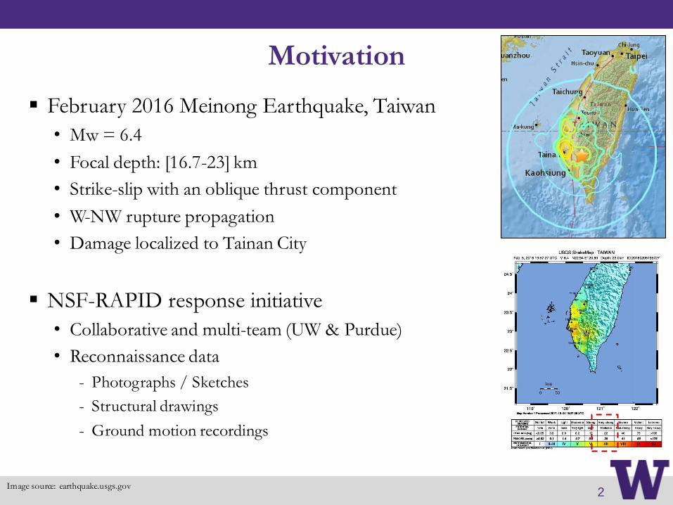
▪ February 2016 Meinong Earthquake, Taiwan
• Mw = 6.4
• Focal depth: [16.7-23] km
• Strike-slip with an oblique thrust component
• W-NW rupture propagation
• Damage localized to Tainan City
▪ NSF-RAPID response initiative
• Collaborative and multi-team (UW & Purdue)
• Reconnaissance data
- Photographs / Sketches
- Structural drawings
- Ground motion recordings
Motivation
Image source: earthquake.usgs.gov
3
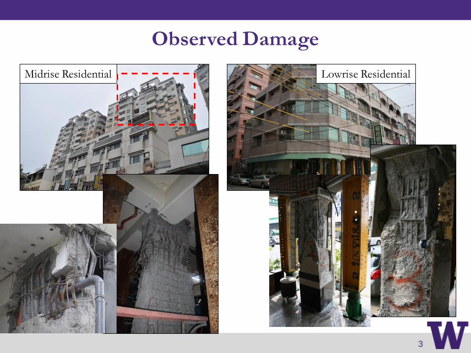
Observed Damage
Midrise Residential Lowrise Residential
4
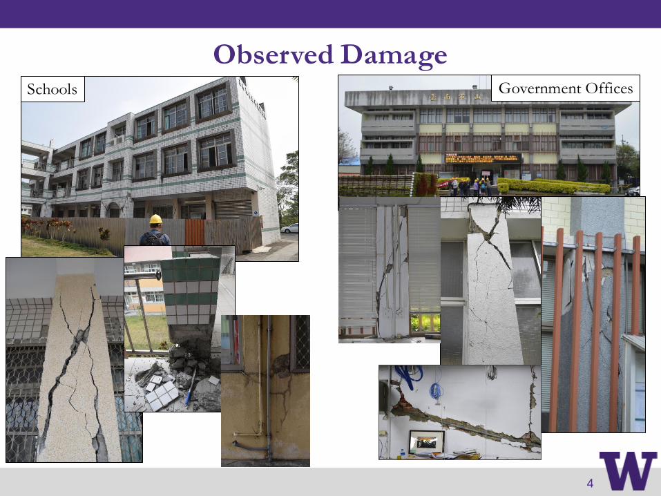
Observed DamageSchools Government Offices

5
Observed Damage
Mixed Use
6
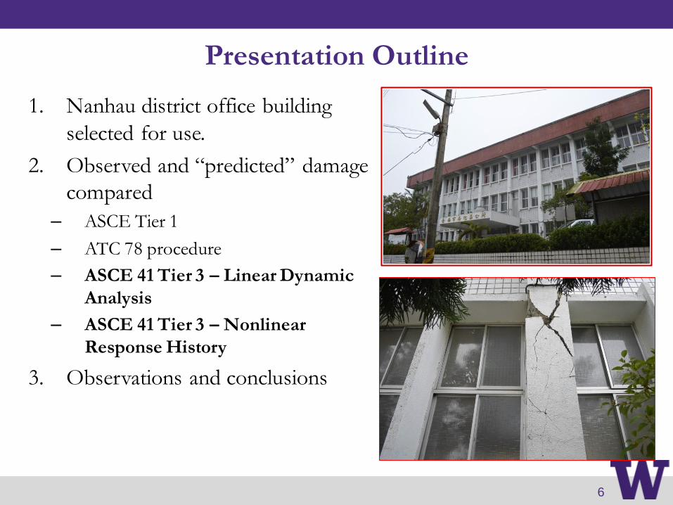
Presentation Outline
1. Nanhau district office building
selected for use.
2. Observed and “predicted” damage
compared
– ASCE Tier 1
– ATC 78 procedure
– ASCE 41 Tier 3 – Linear Dynamic
Analysis
– ASCE 41 Tier 3 – Nonlinear
Response History
3. Observations and conclusions

Nanhau District Office Building
8
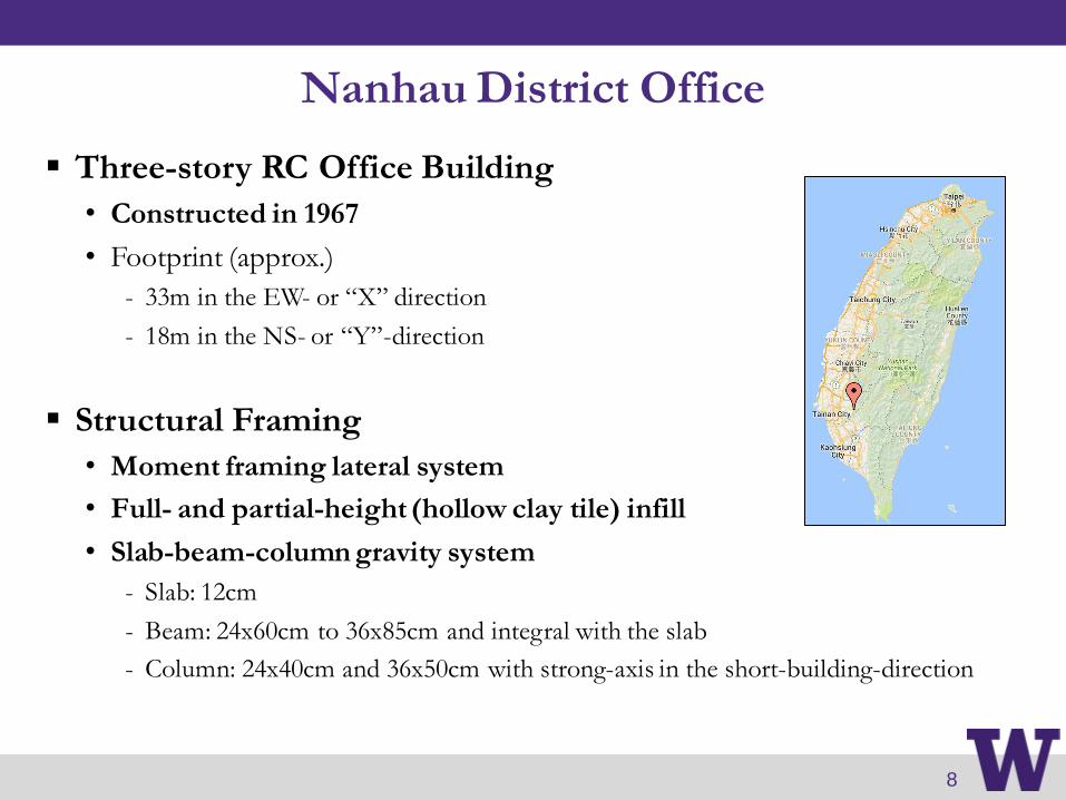
Nanhau District Office
▪ Three-story RC Office Building
• Constructed in 1967
• Footprint (approx.)
- 33m in the EW- or “X” direction
- 18m in the NS- or “Y”-direction
▪ Structural Framing
• Moment framing lateral system
• Full- and partial-height (hollow clay tile) infill
• Slab-beam-column gravity system
- Slab: 12cm
- Beam: 24x60cm to 36x85cm and integral with the slab
- Column: 24x40cm and 36x50cm with strong-axis in the short-building-direction
9
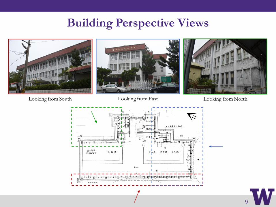
Building Perspective Views
Looking from South Looking from East Looking from North
10
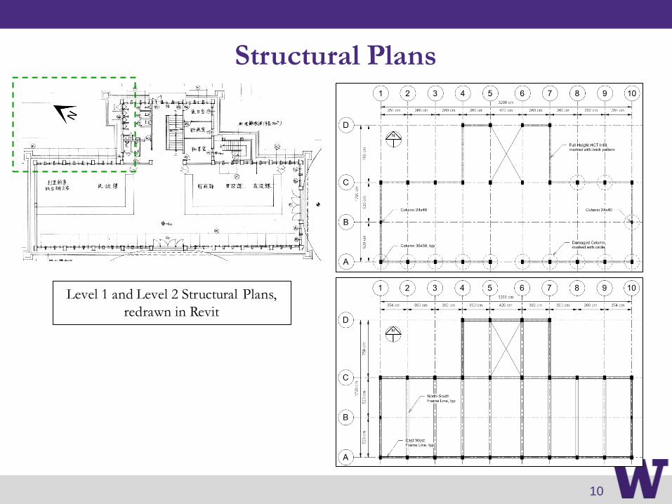
Structural Plans
Level 1 and Level 2 Structural Plans,
redrawn in Revit
11
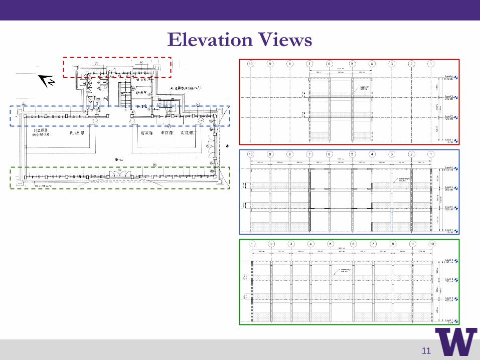
Elevation Views
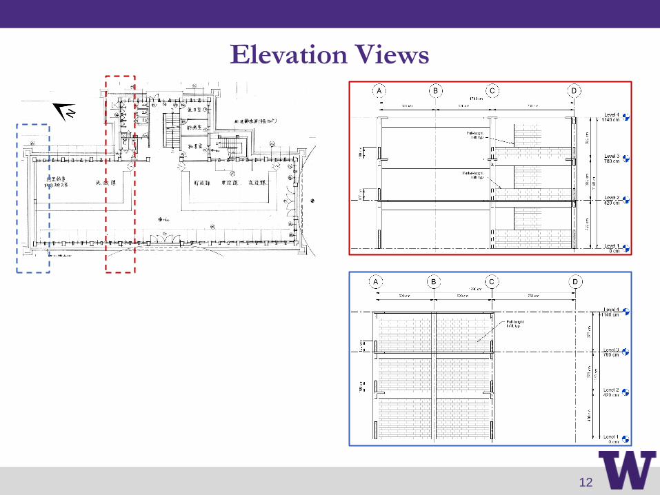
12
Elevation Views
13
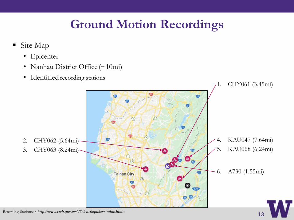
Ground Motion Recordings
▪ Site Map
• Epicenter
• Nanhau District Office (~10mi)
• Identified recording stations
4. KAU047 (7.64mi)
5. KAU068 (6.24mi)
2. CHY062 (5.64mi)
3. CHY063 (8.24mi)
1. CHY061 (3.45mi)
Recording Stations: <http://www.cwb.gov.tw/V7e/earthquake/station.htm>
6. A730 (1.55mi)
14
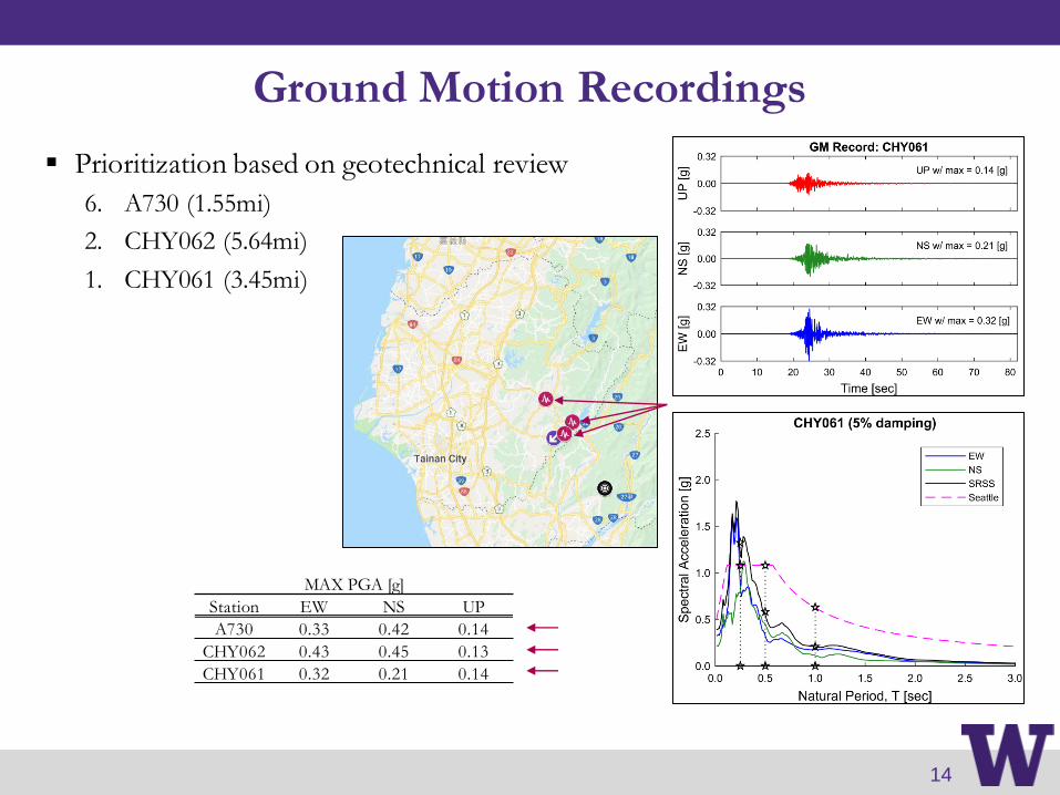
Ground Motion Recordings
▪ Prioritization based on geotechnical review
6. A730 (1.55mi)
2. CHY062 (5.64mi)
1. CHY061 (3.45mi)
MAX PGA [g]
Station EW NS UP
A730 0.33 0.42 0.14
CHY062 0.43 0.45 0.13
CHY061 0.32 0.21 0.14
15
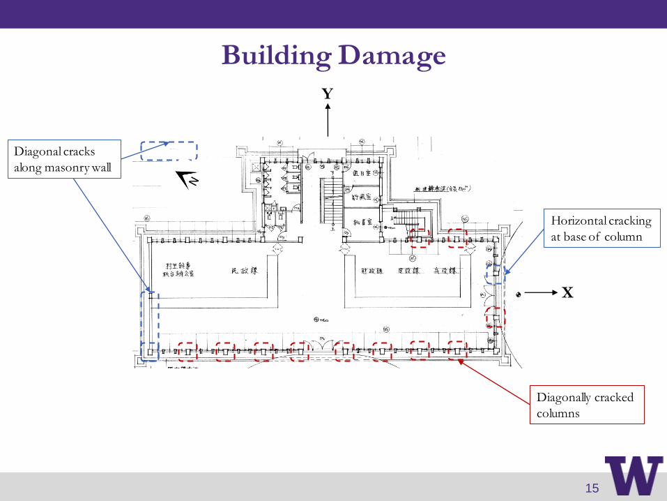
Building Damage
Diagonally cracked
columns
Horizontal cracking
at base of column
Diagonal cracks
along masonry wall
Y
X
16
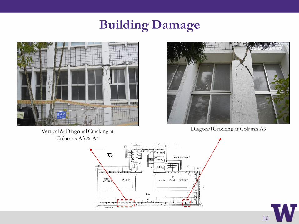
Building Damage
Vertical & Diagonal Cracking at
Columns A3 & A4
Diagonal Cracking at Column A9
17
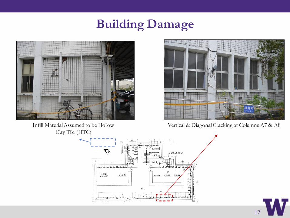
Building Damage
Infill Material Assumed to be Hollow
Clay Tile (HTC)
Vertical & Diagonal Cracking at Columns A7 & A8
18
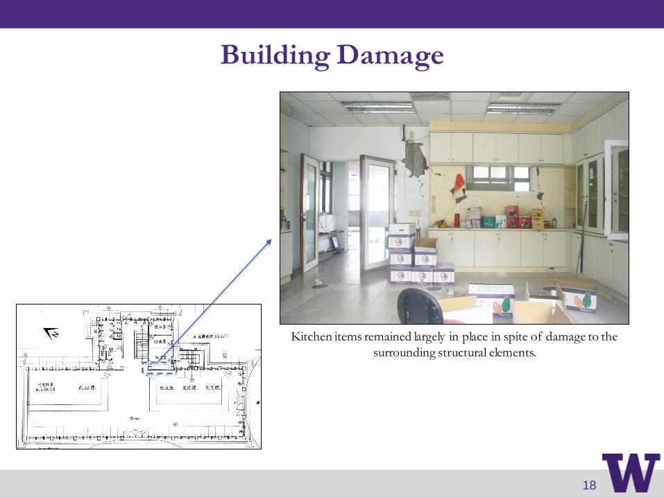
Building Damage
Kitchen items remained largely in place in spite of damage to the
surrounding structural elements.

ASCE 41 Tier 3
Linear Analysis
21
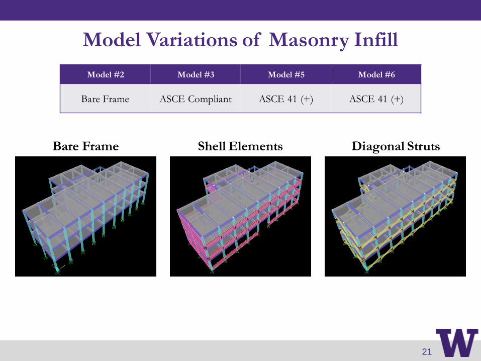
Model Variations of Masonry Infill
Bare Frame Diagonal StrutsShell Elements
Model #2 Model #3 Model #5 Model #6
Bare Frame ASCE Compliant ASCE 41 (+) ASCE 41 (+)
22
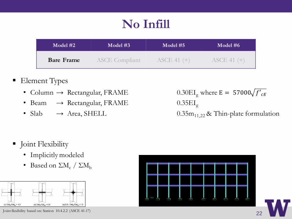
No Infill
▪ Element Types
• Column → Rectangular, FRAME 0.30EIg where E = 57000 𝑓′𝑐𝐸
• Beam → Rectangular, FRAME 0.35EIg
• Slab → Area, SHELL 0.35m11,22 & Thin-plate formulation
▪ Joint Flexibility
• Implicitly modeled
• Based on ΣMc / ΣMb
Model #2 Model #3 Model #5 Model #6
Bare Frame ASCE Compliant ASCE 41 (+) ASCE 41 (+)
Joint flexibility based on: Section 10.4.2.2 (ASCE 41-17)
23
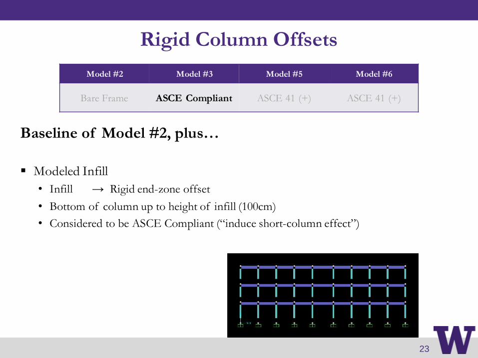
Rigid Column Offsets
Baseline of Model #2, plus…
▪ Modeled Infill
• Infill → Rigid end-zone offset
• Bottom of column up to height of infill (100cm)
• Considered to be ASCE Compliant (“induce short-column effect”)
Model #2 Model #3 Model #5 Model #6
Bare Frame ASCE Compliant ASCE 41 (+) ASCE 41 (+)
24
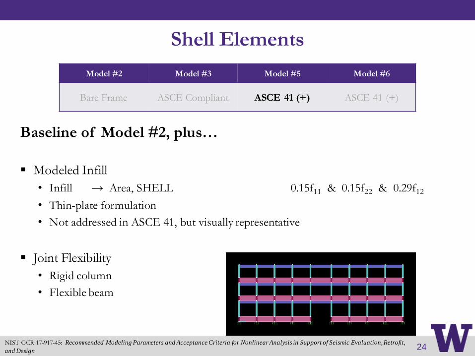
Baseline of Model #2, plus…
▪ Modeled Infill
• Infill → Area, SHELL 0.15f11 & 0.15f22 & 0.29f12
• Thin-plate formulation
• Not addressed in ASCE 41, but visually representative
▪ Joint Flexibility
• Rigid column
• Flexible beam
Shell Elements
Model #2 Model #3 Model #5 Model #6
Bare Frame ASCE Compliant ASCE 41 (+) ASCE 41 (+)
NIST GCR 17-917-45: Recommended Modeling Parameters and Acceptance Criteria for Nonlinear Analysis in Support of Seismic Evaluation, Retrofit,
and Design
25
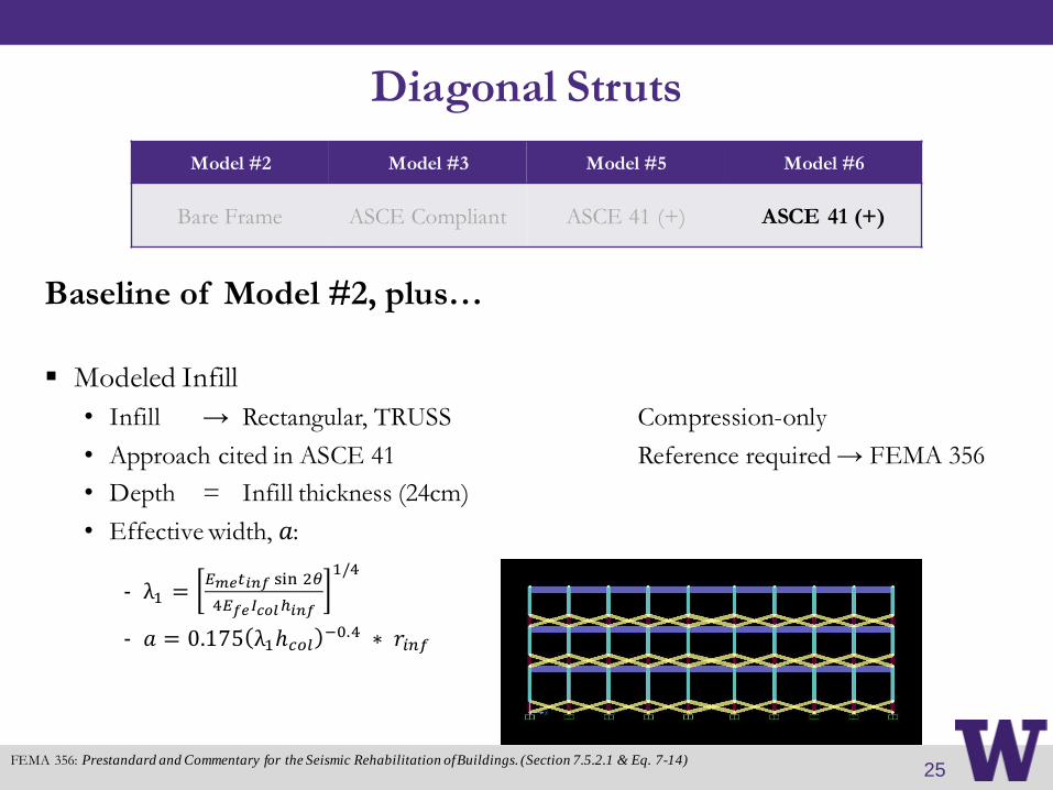
Baseline of Model #2, plus…
▪ Modeled Infill
• Infill → Rectangular, TRUSS Compression-only
• Approach cited in ASCE 41 Reference required → FEMA 356
• Depth = Infill thickness (24cm)
• Effective width, 𝑎:
- λ1 =𝐸𝑚𝑒𝑡𝑖𝑛𝑓 sin 2𝜃
4𝐸𝑓𝑒𝐼𝑐𝑜𝑙ℎ𝑖𝑛𝑓
1/4
- 𝑎 = 0.175 λ1ℎ𝑐𝑜𝑙−0.4 ∗ 𝑟𝑖𝑛𝑓
Model #2 Model #3 Model #5 Model #6
Bare Frame ASCE Compliant ASCE 41 (+) ASCE 41 (+)
FEMA 356: Prestandard and Commentary for the Seismic Rehabilitation of Buildings. (Section 7.5.2.1 & Eq. 7-14)
Diagonal Struts

26
GM: A730 GM: CHY061GM: CHY062
Fundamental Periods and Spectral Acceleration
Model Type T1 Sa
#2 BF 0.92 0.33
#3 C 0.59 0.73
#5 SH 0.67 0.63
#6 DS 0.43 0.59
Model Type T1 Sa
#2 BF 0.92 0.52
#3 C 0.59 1.01
#5 SH 0.67 0.92
#6 DS 0.43 1.05
Model Type T1 Sa
#2 BF 0.92 0.22
#3 C 0.59 0.41
#5 SH 0.67 0.46
#6 DS 0.43 0.82
27
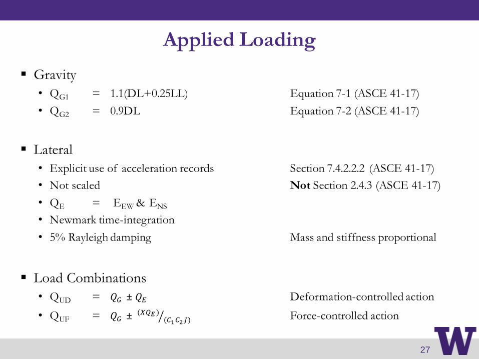
Applied Loading
▪ Gravity
• QG1 = 1.1(DL+0.25LL) Equation 7-1 (ASCE 41-17)
• QG2 = 0.9DL Equation 7-2 (ASCE 41-17)
▪ Lateral
• Explicit use of acceleration records Section 7.4.2.2.2 (ASCE 41-17)
• Not scaled Not Section 2.4.3 (ASCE 41-17)
• QE = EEW & ENS
• Newmark time-integration
• 5% Rayleigh damping Mass and stiffness proportional
▪ Load Combinations
• QUD = 𝑄𝐺 ± 𝑄𝐸 Deformation-controlled action
• QUF = 𝑄𝐺 ± ൗ(𝑋𝑄𝐸)(𝐶1𝐶2𝐽)
Force-controlled action
28
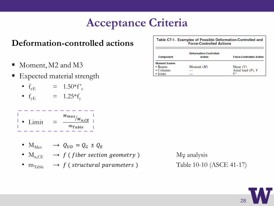
Acceptance Criteria
Deformation-controlled actions
▪ Moment, M2 and M3
▪ Expected material strength
• fcE = 1.50*f ’c
• fyE = 1.25*fy
• Limit =ൗ
𝑀𝑚𝑎𝑥𝑀𝑛,𝐶𝐸
𝑚𝑇𝑎𝑏𝑙𝑒
• MMax → 𝑄𝑈𝐷 = 𝑄𝐺 ± 𝑄𝐸
• Mn,CE → 𝑓 ( 𝑓𝑖𝑏𝑒𝑟 𝑠𝑒𝑐𝑡𝑖𝑜𝑛 𝑔𝑒𝑜𝑚𝑒𝑡𝑟𝑦 ) Mφ analysis
• mTable → 𝑓 ( 𝑠𝑡𝑟𝑢𝑐𝑡𝑢𝑟𝑎𝑙 𝑝𝑎𝑟𝑎𝑚𝑒𝑡𝑒𝑟𝑠 ) Table 10-10 (ASCE 41-17)
29
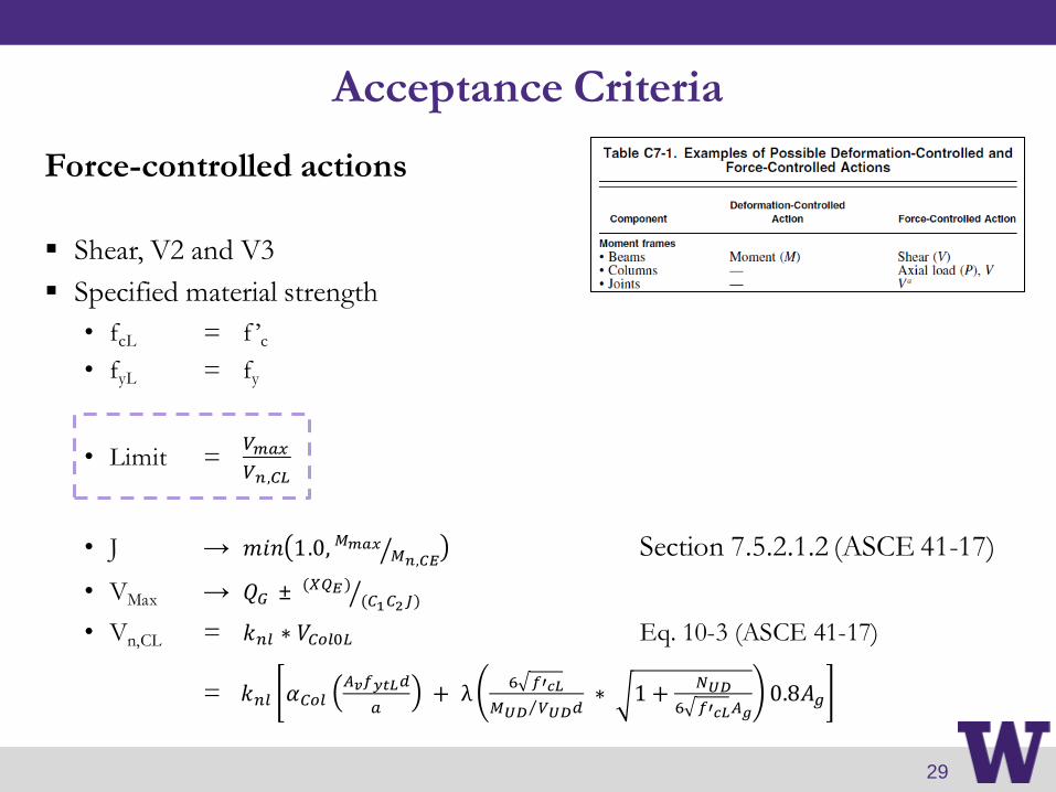
Acceptance Criteria
Force-controlled actions
▪ Shear, V2 and V3
▪ Specified material strength
• fcL = f ’c
• fyL = fy
• Limit =𝑉𝑚𝑎𝑥
𝑉𝑛,𝐶𝐿
• J → 𝑚𝑖𝑛 1.0, ൗ𝑀𝑚𝑎𝑥
𝑀𝑛,𝐶𝐸Section 7.5.2.1.2 (ASCE 41-17)
• VMax → 𝑄𝐺 ± ൗ(𝑋𝑄𝐸)(𝐶1𝐶2𝐽)
• Vn,CL = 𝑘𝑛𝑙 ∗ 𝑉𝐶𝑜𝑙0𝐿 Eq. 10-3 (ASCE 41-17)
= 𝑘𝑛𝑙 𝛼𝐶𝑜𝑙𝐴𝑣𝑓𝑦𝑡𝐿𝑑
𝑎+ λ
6 𝑓′𝑐𝐿
Τ𝑀𝑈𝐷 𝑉𝑈𝐷𝑑∗ 1 +
𝑁𝑈𝐷
6 𝑓′𝑐𝐿𝐴𝑔0.8𝐴𝑔
30
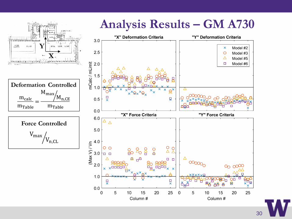
Analysis Results – GM A730
൘Vmax
Vn,CL
mcalc
mTable=
൘Mmax
Mn,CE
mTable
Deformation Controlled
Force Controlled
Y
X

31
Analysis ResultsGM: A730

32
Analysis Results – GM A730
Y
X
൘Vmax
Vn,CL
mcalc
mTable=
൘Mmax
Mn,CE
mTable
Deformation Controlled
Force Controlled
33
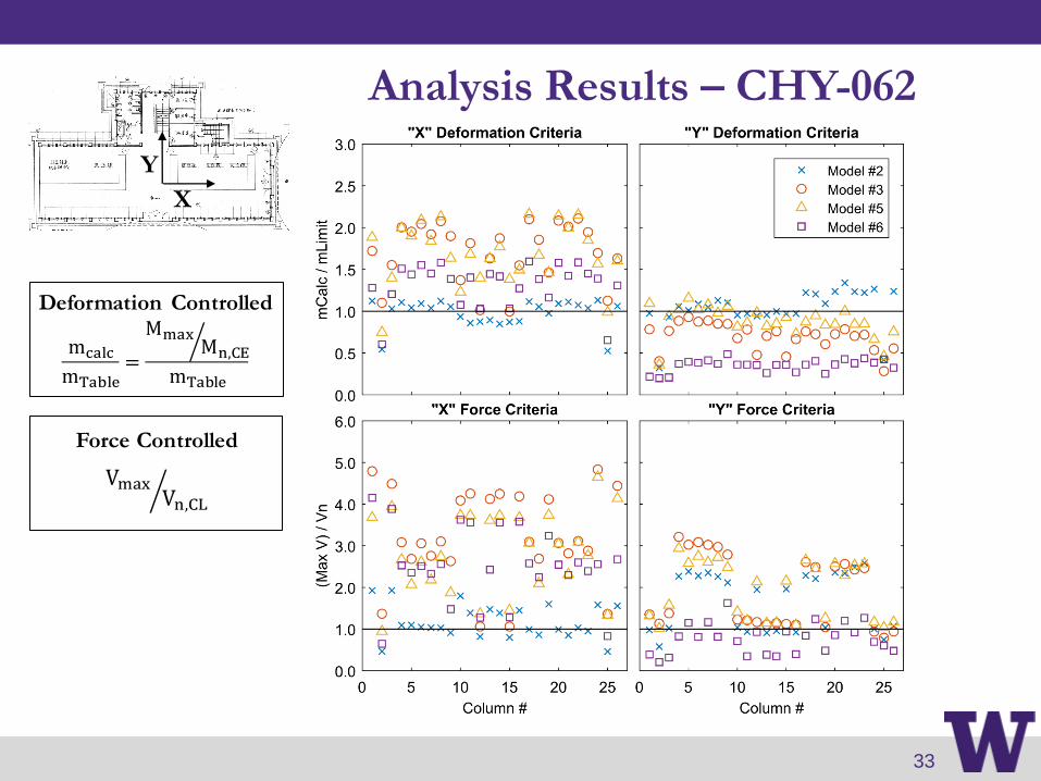
Y
X
൘Vmax
Vn,CL
mcalc
mTable=
൘Mmax
Mn,CE
mTable
Deformation Controlled
Force Controlled
Analysis Results – CHY-062
34
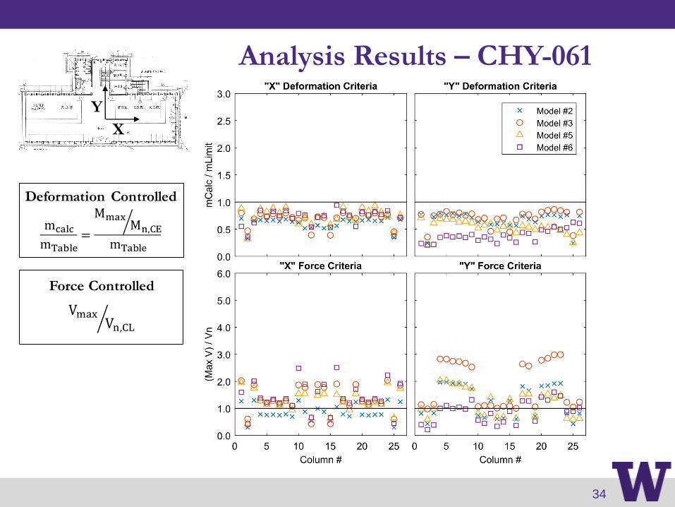
Y
X
൘Vmax
Vn,CL
mcalc
mTable=
൘Mmax
Mn,CE
mTable
Deformation Controlled
Force Controlled
Analysis Results – CHY-061
35
Summary
1. Bare frame model is too flexible to provide a reliable
characterization of structural response
2. All models predict (> 1) shear failure violation to acceptance
criteria, though cases of shear failure identified for columns not
damaged
3. No significant improvement between the ASCE 41 Compliant
model and the variations that exceed code provisions

ASCE 41 Tier 3
Nonlinear Analysis

38
Bare Frame ASCE Compliant
Model Variations of Masonry Infill
Diagonal Struts
Model: CM Model: NM Model: FM Model: CM1EI
Bare Frame ASCE Compliant ASCE (+) ASCE (+)
39
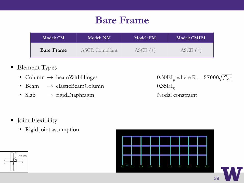
Bare Frame
▪ Element Types
• Column → beamWithHinges 0.30EIg where E = 57000 𝑓′𝑐𝐸
• Beam → elasticBeamColumn 0.35EIg
• Slab → rigidDiaphragm Nodal constraint
▪ Joint Flexibility
• Rigid joint assumption
Model: CM Model: NM Model: FM Model: CM1EI
Bare Frame ASCE Compliant ASCE (+) ASCE (+)

40
Infill Variations
Model: CM Model: NM Model: FM Model: CM1EI
Bare Frame ASCE Compliant ASCE (+) ASCE (+)
Baseline of Bare Frame, but…
▪ Modeled Infill
• FH → truss NL hysteretic response, TBD
• PH → elasticBeamColumn 5.00EIg
• FH infill → truss NL hysteretic response, TBD
• PH infill → truss NL hysteretic response, TBD
▪ Element Modification
• Column → 1.00EIg Differs Table 10-5 (ASCE 41-17)
ASCE
Compliant
Diagonal
Struts
Stiffened
Compliant
41
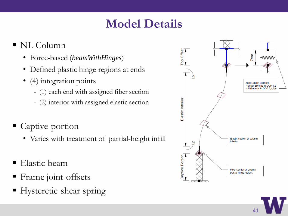
Model Details
▪ NL Column
• Force-based (beamWithHinges)
• Defined plastic hinge regions at ends
• (4) integration points
- (1) each end with assigned fiber section
- (2) interior with assigned elastic section
▪ Captive portion
• Varies with treatment of partial-height infill
▪ Elastic beam
▪ Frame joint offsets
▪ Hysteretic shear spring
43
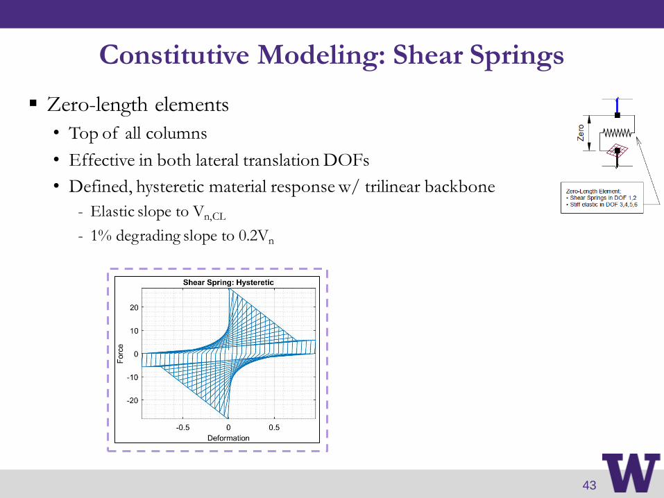
Constitutive Modeling: Shear Springs
▪ Zero-length elements
• Top of all columns
• Effective in both lateral translation DOFs
• Defined, hysteretic material response w/ trilinear backbone
- Elastic slope to Vn,CL
- 1% degrading slope to 0.2Vn
45
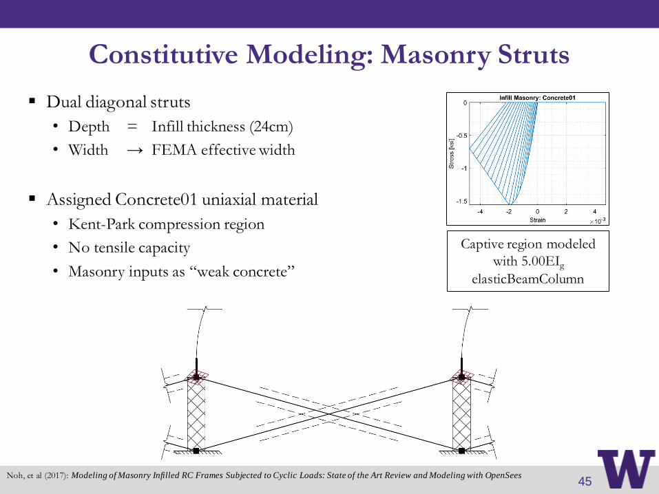
Constitutive Modeling: Masonry Struts
▪ Dual diagonal struts
• Depth = Infill thickness (24cm)
• Width → FEMA effective width
▪ Assigned Concrete01 uniaxial material
• Kent-Park compression region
• No tensile capacity
• Masonry inputs as “weak concrete”
Noh, et al (2017): Modeling of Masonry Infilled RC Frames Subjected to Cyclic Loads: State of the Art Review and Modeling with OpenSees
Captive region modeled
with 5.00EIg
elasticBeamColumn
46
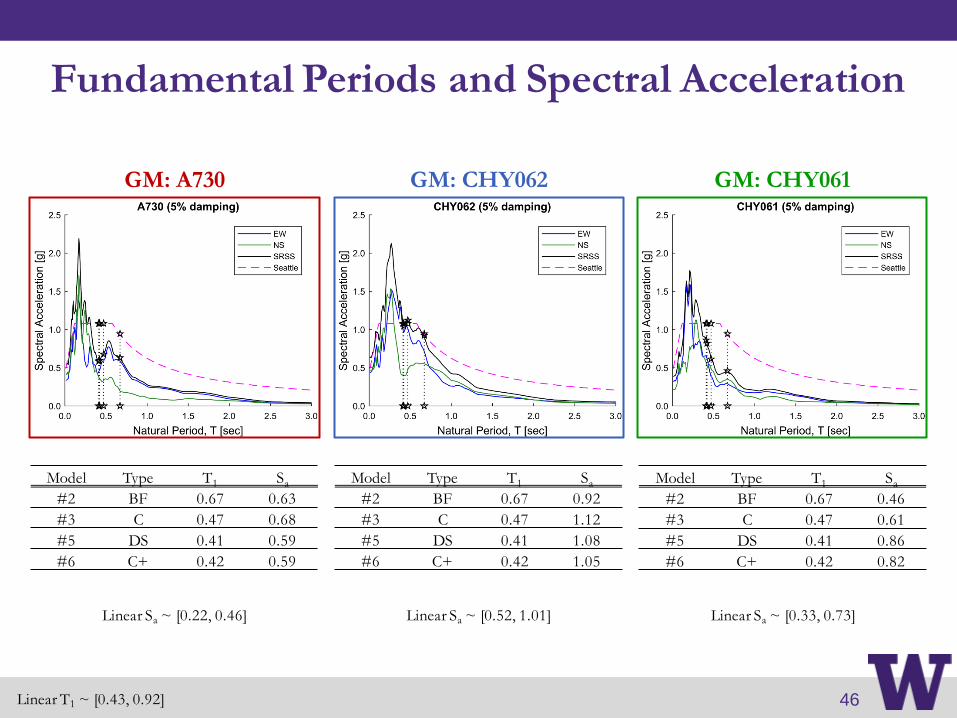
Fundamental Periods and Spectral Acceleration
GM: A730 GM: CHY061GM: CHY062
Linear T1 ~ [0.43, 0.92]
Linear Sa ~ [0.22, 0.46] Linear Sa ~ [0.52, 1.01] Linear Sa ~ [0.33, 0.73]
Model Type T1 Sa
#2 BF 0.67 0.63
#3 C 0.47 0.68
#5 DS 0.41 0.59
#6 C+ 0.42 0.59
Model Type T1 Sa
#2 BF 0.67 0.92
#3 C 0.47 1.12
#5 DS 0.41 1.08
#6 C+ 0.42 1.05
Model Type T1 Sa
#2 BF 0.67 0.46
#3 C 0.47 0.61
#5 DS 0.41 0.86
#6 C+ 0.42 0.82

48
Applied Loading
▪ Gravity
• QG1 = 1.1(DL+0.25LL) Equation 7-1 (ASCE 41-17)
• QG2 → Not considered Equation 7-2 (ASCE 41-17)
▪ Lateral
• Explicit use of acceleration records Section 7.4.2.2.2 (ASCE 41-17)
• Not scaled Not Section 2.4.3 (ASCE 41-17)
• QE = EEW & ENS
• Newmark time-integration
• 2.7% Modal damping† Modes 1, 2, & 3
• 0.3% Rayleigh damping† Mass and stiffness proportional
† (90% | 10%) proportioning of modal damping to Rayleigh damping per recommendation from ATC project lead.

49
Acceptance Criteria
Deformation-controlled actions
▪ Based on column rotation†
▪ Expected material strength
• fcE = 1.50*f ’c
• fyE = 1.25*fy
• Limit = 𝜑𝑚𝑎𝑥 ∗ 𝐿𝑝
𝑏Limited to 0.7b, for CP
• a = 0.42 − 0.043𝑁𝑈𝐷
𝐴𝑔𝑓′𝑐𝐸
+ 0.63ρ𝑡− 0.23𝑉𝑦𝐸
𝑉𝐶𝑜𝑙0𝐸≥ 0.0
• b = 0.5
5 +𝑁𝑈𝐷
𝐴𝑔𝑓′𝑐𝐸
1
ρ𝑡
𝑓′𝑐𝐸𝑓𝑦𝑡𝐸
− 0.01 ≥ 𝑎 ASCE 41-17, Table 10-8
† Elastic curvature, intrinsic to output rotation deformation, was assumed negligible and thus not calculated or removed when compared to plastic rotation
limit “b”
50
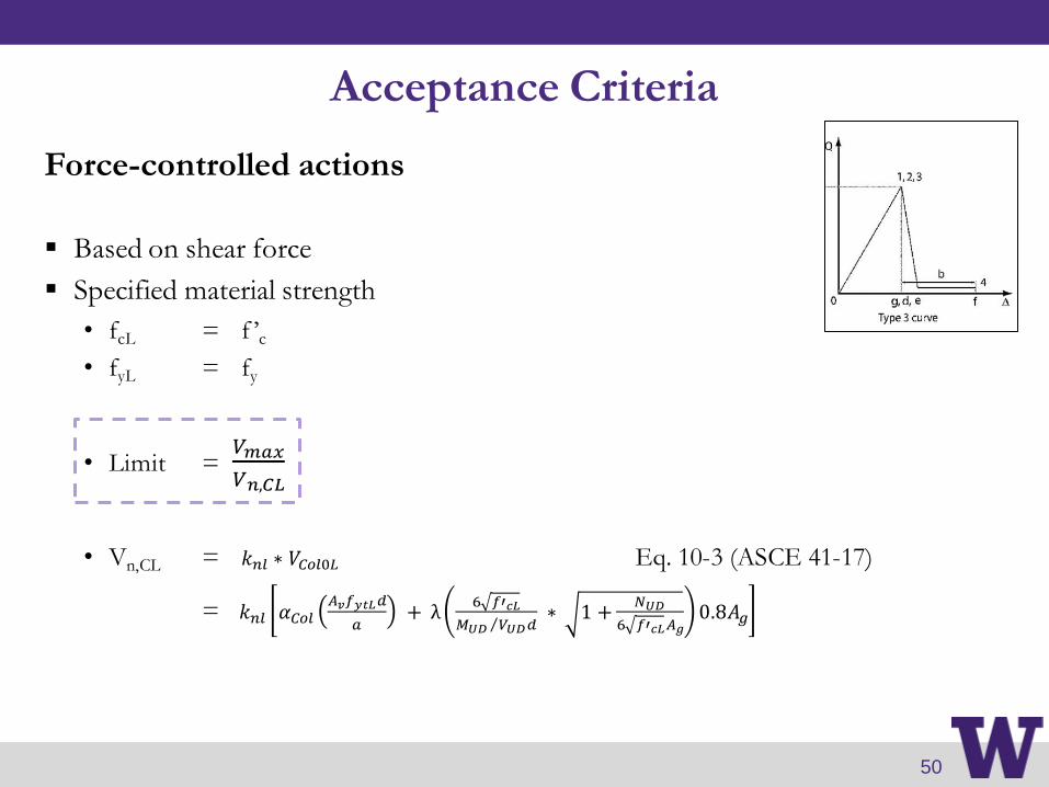
Acceptance Criteria
Force-controlled actions
▪ Based on shear force
▪ Specified material strength
• fcL = f ’c
• fyL = fy
• Limit = 𝑉𝑚𝑎𝑥
𝑉𝑛,𝐶𝐿
• Vn,CL = 𝑘𝑛𝑙 ∗ 𝑉𝐶𝑜𝑙0𝐿 Eq. 10-3 (ASCE 41-17)
= 𝑘𝑛𝑙 𝛼𝐶𝑜𝑙𝐴𝑣𝑓𝑦𝑡𝐿𝑑
𝑎+ λ
6 𝑓′𝑐𝐿Τ𝑀𝑈𝐷 𝑉𝑈𝐷𝑑
∗ 1 +𝑁𝑈𝐷
6 𝑓′𝑐𝐿𝐴𝑔0.8𝐴𝑔

51
Analysis ResultsTH Deformation
ASCE Compliant
GM: A730
ASCE Compliant
GM: CHY062
ASCE Compliant
GM: CHY061
3D 3D3D

52
Analysis Results: Vbase vs Story DriftASCE Compliant

53
Analysis Results: Vbase vs Story DriftDiagonal Struts
54
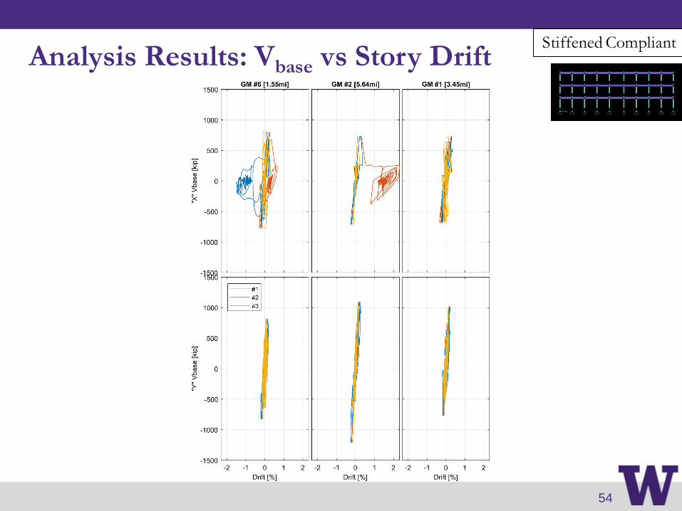
Analysis Results: Vbase vs Story DriftStiffened Compliant
56
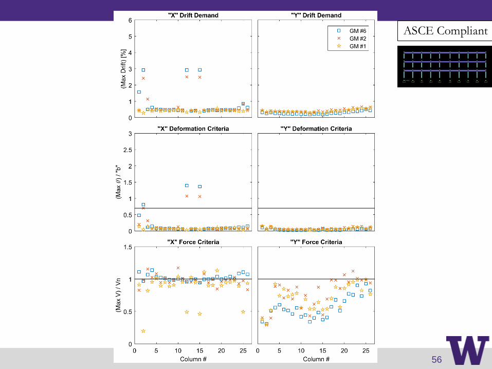
Analysis ResultsASCE Compliant
57
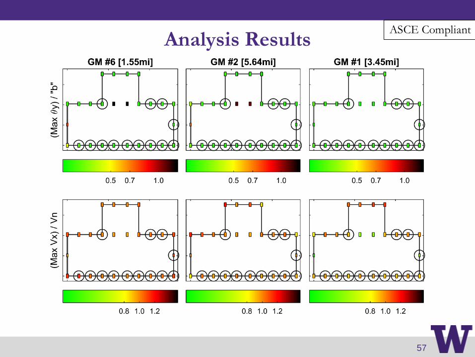
Analysis ResultsASCE Compliant
58
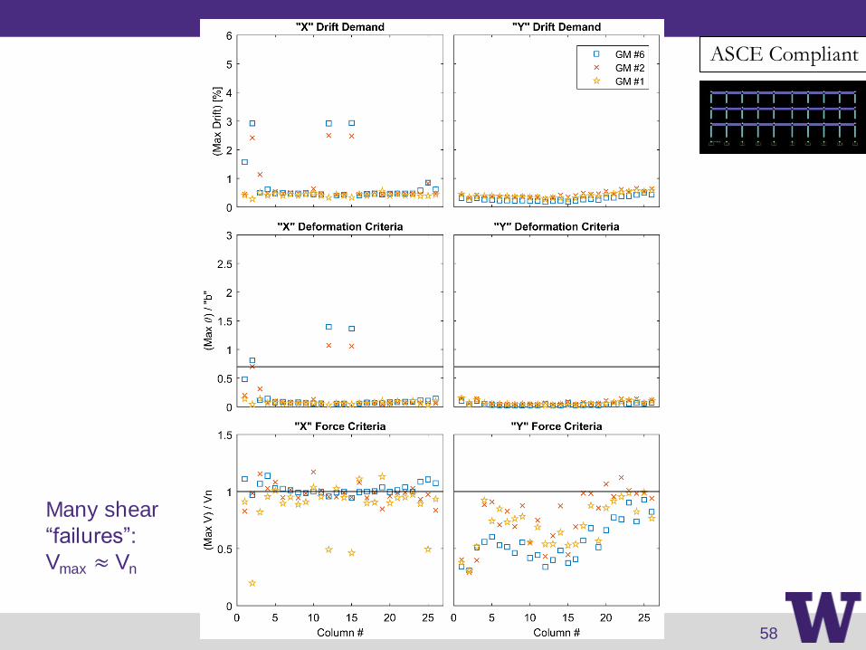
Analysis ResultsASCE Compliant
Many shear
“failures”:
Vmax ≈ Vn
59
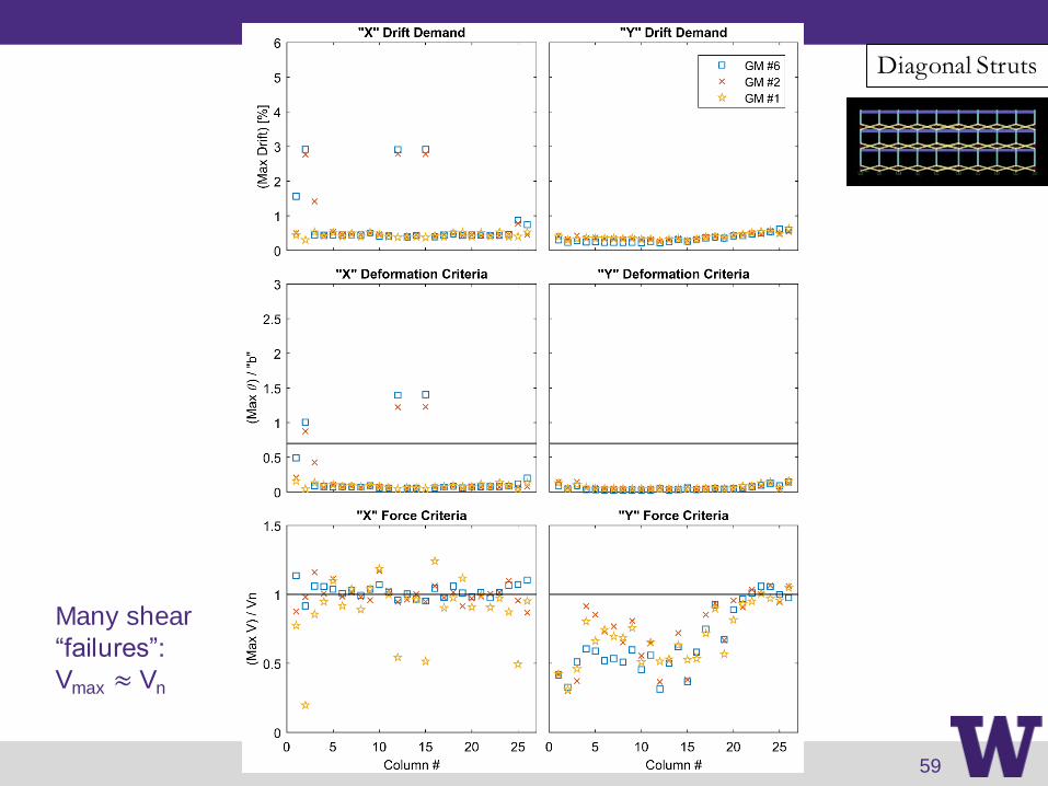
Analysis ResultsDiagonal Struts
Many shear
“failures”:
Vmax ≈ Vn
60
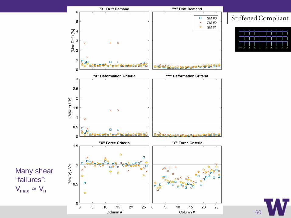
Analysis ResultsStiffened Compliant
Many shear
“failures”:
Vmax ≈ Vn

61
Analysis ResultsBare Frame
Few shear
“failures”
62
Summary
1. “Failure” pattern is not consistent with the observed damage.
Damage suggests limited deformations on the N&NW. One
rationale is that the un-modeled “addition” that would have
otherwise restrained motion
2. No significant improvement between the ASCE 41 Compliant
model and the variations that exceed code provisions
3. Limitations intrinsic to the hysteretic shear model (no
consideration of axial load amplification on shear capacity) pre-
maturely govern response

Conclusion
64
Overarching Conclusions
1. Partial-height infill
– Need to model partial-height infill.
– Neglecting partial-height infill results in model that is too soft (large T) and
under-prediction of demands (small Sa (T).
– ASCE 41 recommendations for modeling infill should be improved; current
recommendations are difficult to understand.
– Different methods for modeling infill produce approximately the same results.
2. Modeling column shear failure
– Need to model column shear failure; shear failure determines system response
– Likely need improved nonlinear response models that include axial load in
calculation of shear capacity, Vn