seismic assessment and retrofitting of an existing rc ... assessment and retrofitting of an existing...
TRANSCRIPT

Seismic assessment and retrofitting of an existing RC building according to the Italian building code
F. Mola1, G. Rebecchi2 & E. Mola2 1Politecnico di Milano, Italy 2ECSD S.r.l., Italy
Abstract
The bulk of Italian building heritage has been designed without considering seismic-induced action and seismic criteria for strength and ductility design, so they represent a risk that must be identified. The importance of seismic risk has coherently been recognized by the Italian authorities, so the current building code (NTC 2008) has been updated, introducing a new seismic hazard map and performance-based approaches for design, assessments and retrofitting of structures. The enhancements included in the code mostly follow the recommendations provided in Eurocode 8, indeed a whole chapter focuses on the knowledge levels to be achieved and on the analysis methods. The case study presented in the paper deals with an eight-storey non-seismically designed RC building located in a low hazard area. Because of the lack of information about the material, geometry and the details of the structural members, widespread surveys on the building have been organized, in order to define the Knowledge Level and the Confidence Factor to use in the analysis. The assessment and the retrofit study hereby presented is based on a thorough application of the recently declared Italian Building Code (NTC 2008), which allows both linear and non-linear analysis techniques for existing structures. In particular, the vulnerability assessment has been based on a dynamic multimodal analysis, which allowed us to identify the more significant seismic demands in terms of displacements and actions on the elements. Subsequently, a retrofit design was developed by reinforcing non-compliant members and validating the retrofit design by means of a non-linear static analysis. Keywords: seismic vulnerability, retrofitting, Italian code, concrete-frame structure, pushover analysis.
Earthquake Resistant Engineering Structures X 197
www.witpress.com, ISSN 1743-3509 (on-line) WIT Transactions on The Built Environment, Vol 152, © 2015 WIT Press
doi:10.2495/ERES150161
1 Introduction
The assessment and the retrofit study hereby presented is based on a thorough application of the recently declared Italian Building Code (NTC 2008), which allows both linear and non-linear analysis techniques for existing structures. The case study deals with an eight-storey non-seismically designed RC building located in a low hazard area.
2 Screening phase
2.1 Description of the studied building
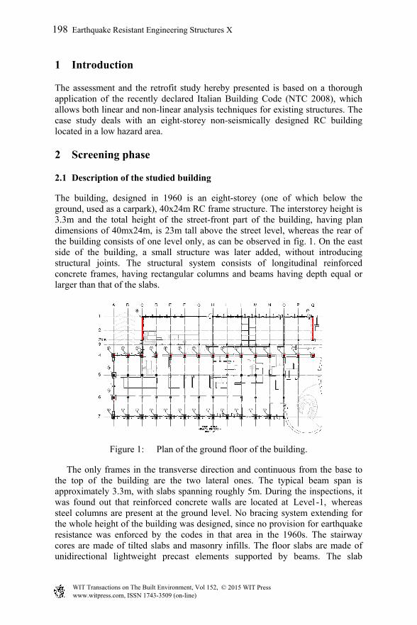
The building, designed in 1960 is an eight-storey (one of which below the ground, used as a carpark), 40x24m RC frame structure. The interstorey height is 3.3m and the total height of the street-front part of the building, having plan dimensions of 40mx24m, is 23m tall above the street level, whereas the rear of the building consists of one level only, as can be observed in fig. 1. On the east side of the building, a small structure was later added, without introducing structural joints. The structural system consists of longitudinal reinforced concrete frames, having rectangular columns and beams having depth equal or larger than that of the slabs.
Figure 1: Plan of the ground floor of the building.
The only frames in the transverse direction and continuous from the base to the top of the building are the two lateral ones. The typical beam span is approximately 3.3m, with slabs spanning roughly 5m. During the inspections, it was found out that reinforced concrete walls are located at Level -1, whereas steel columns are present at the ground level. No bracing system extending for the whole height of the building was designed, since no provision for earthquake resistance was enforced by the codes in that area in the 1960s. The stairway cores are made of tilted slabs and masonry infills. The floor slabs are made of unidirectional lightweight precast elements supported by beams. The slab
198 Earthquake Resistant Engineering Structures X
www.witpress.com, ISSN 1743-3509 (on-line) WIT Transactions on The Built Environment, Vol 152, © 2015 WIT Press
thickness is 16cm. A top layer of structural concrete, having a thickness of 2cm, was observed in the slabs; no reinforcement is present in the top layer. The lateral walls are made of a double layer of bricks (12+8cm) with an airlock having variable thickness. Along the short sides of the building, along axis A in fig. 1, the infills are present everywhere except for the ground floor.
2.2 Survey results
In the vulnerability analysis of existing buildings, the level of confidence in the information gathered about the geometrical configuration of the structure, the properties of the materials and their degradation is an essential factor affecting the results. In NTC 2008 [1], a confidence factor is introduced in order to reduce the material properties used in the safety verifications to take into account the uncertainties in the knowledge of said properties. Moreover, the confidence factor also limits the choice of the type of structural analyses that can be carried out in the vulnerability assessment. According to the approach codified in NTC 2008, the lower the level of knowledge (LC), the higher the uncertainty in the determination of local and global capacity deriving from the analysis. For this reason, in order to make up for this increased uncertainty, a ‘confidence factor’ (FC) is introduced, as a function of LC, which reduces the material properties used in the analysis, thus penalizing the safety verifications. According to NTC 2008, three Knowledge Levels are classified, i.e. ‘Limited Knowledge’, LC1, ‘Adequate Knowledge’, LC2, and ‘Accurate Knowledge’, LC3. The corresponding confidence factors are quantified as: 1.35 for LC1, 1.2 for LC2, 1.0 for LC3. Any kind of non-linear analysis is only allowed for LC2 and LC3. In the present case, the attained level of knowledge was LC1, because no original design reports and drawings were available, so that a complete survey of the geometric dimensions of the structural elements was carried out, followed by a simulated re-design of the elements. This allowed the extent of the invasive experimental survey to be limited. By means of a re-design exercise, following the code prescriptions enforced at the time of construction (in Italy at that time the Code was called ‘Regio Decreto 1939 n. 2229, [2]) and the corresponding analysis methods, and knowing the geometric dimensions of the structural elements, it was thus possible to find out the presumable rebar content. Following this phase, through pacometric tests, radar and micro sampling of the rebar in selected elements, it was possible to confirm if the rebar content derived from the analyses could actually be located in the elements. As for the material properties, concrete strength was derived from compression tests on 10 standard cores. A mean cubic compressive strength, Rcm, of 17.3MPa and a mean cylinder compressive strength, fcm, of 14.6MPa were yielded by the tests. The rebar turned out to be of the non-corrugated type, as commonly used in Italy in the 1960s. Two samples were tested for tension strength: a yield strength of fy, = 448 MPa and an ultimate strength of ft = 576 MPa were derived. In order to correctly quantify the confidence factor, a formulation proposed in [3] was used: in this formulation, different contributions for FC are taken into account, thus providing a more precise quantification with respect to NTC 2008.
Earthquake Resistant Engineering Structures X 199
www.witpress.com, ISSN 1743-3509 (on-line) WIT Transactions on The Built Environment, Vol 152, © 2015 WIT Press
In the present case, a value of FC = 1.29 was thus achieved, which in fact is in-between Knowledge Level 1 and 2. Non-linear analyses were not carried out since it was not possible to attain LC2.
3 Seismic vulnerability evaluation
3.1 Definition of the seismic action
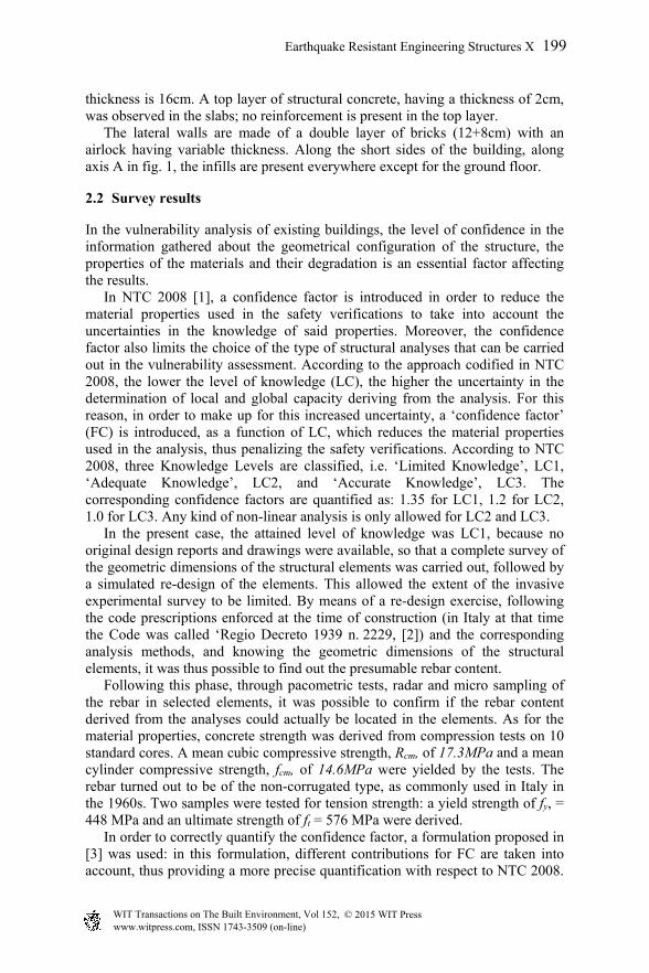
The seismic input is derived based on the seismic hazard, which in the NTC 2008 is defined based on the geographic coordinates of the site. In the present case, the limit state of Life Safety (SLV) was used as the ultimate limit state, corresponding to a probability of exceedance of 10% in the service life (in the present case corresponding to 100 years instead of the usual 50 years, since the building is considered to be strategically relevant). For a soil type B and a topographic category T1, the design spectra for the different limit states were then calculated according to the NTC for the site where the building is located and are plotted in fig. 2.
Figure 2: Response spectra for design earthquake.
3.2 Numerical model
The numerical model implemented for structural analysis is a 3D frame consisting of unidimensional elements representing columns and beams. The elements were assigned a cracked stiffness based on the stress patterns induced to vertical loads only: since the predominant internal action in columns is compressive axial load, the reduction in stiffness due to cracking was assumed to be minimal and a reduction factor of 0.9 was adopted; as for the beams, the bending moments due to vertical loads induce larger tensile stresses, so that a reduction factor of 0.6 was assumed for the stiffness. The slabs were modeled by means of bi-directional orthotropic slab elements, accurately reproducing the stiffness of the slabs both in the main and in the transverse direction. By taking into account the stiffness of the slabs in both directions, the longitudinal frames contribute to the global stiffness of the
200 Earthquake Resistant Engineering Structures X
www.witpress.com, ISSN 1743-3509 (on-line) WIT Transactions on The Built Environment, Vol 152, © 2015 WIT Press
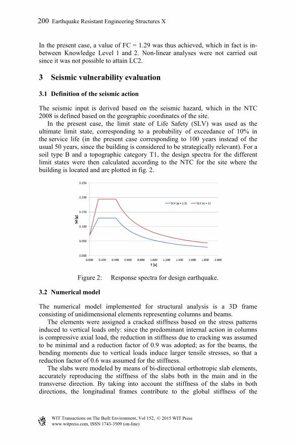
building even when the seismic input acts along the transverse direction, i.e. the weakest one. The maximum lateral displacements under seismic action yielded by the model were less than 10% larger than those obtained assuming the slabs to be infinitely rigid: if this condition is verified, NTC 2008 allow the rigid slab assumption to be used in order to simplify the model. In the model, the reduction in stiffness at the ground floor due to the un-infilled openings along side A (fig. 1) was taken into account (as shown in fig. 3).
(a) (b)
Figure 3: (a) Lateral view of the frame along side A; (b) Definition of limit states for an infill wall.
The infill walls were taken into account by means of a strut-and-tie model. In [4], the suitable deformation limits corresponding to the different limit states of infills of RC frames are defined. From fig. 3(b), it can be observed that for RC frames having a ratio between the length L of the beams and the interstorey net height h between 0.5 and 2.0 (as in the present case), the Damage Limit State for the infill is attained for an interstorey drift of 0.3% and the Life Safety Limit State for an interstorey drift of 1.0%. The analysis yielded a maximum SLV interstorey drift of 0.24%: since this value is lower than the DLS threshold, it can be concluded that the full stiffness contribution of the infill needs to be taken into account. The equivalent thickness of the strut is assumed to be 1/10 of the length of the diagonal, as suggested in [5]. Since the seismic induced internal actions change in sign, both diagonals are included in the model, with each of them only active when compressed. Moreover, in order to correctly estimate their global stiffness, only half of the conventional strut depth in assigned to each of them. The basement of the building is assumed to be on stiff soil and no interaction with soil was taken into account.
3.3 Linear elastic results
The linear response spectrum analysis was carried out according to the prescriptions of NTC 2008. All of the modes having a participating mass higher
Earthquake Resistant Engineering Structures X 201
www.witpress.com, ISSN 1743-3509 (on-line) WIT Transactions on The Built Environment, Vol 152, © 2015 WIT Press
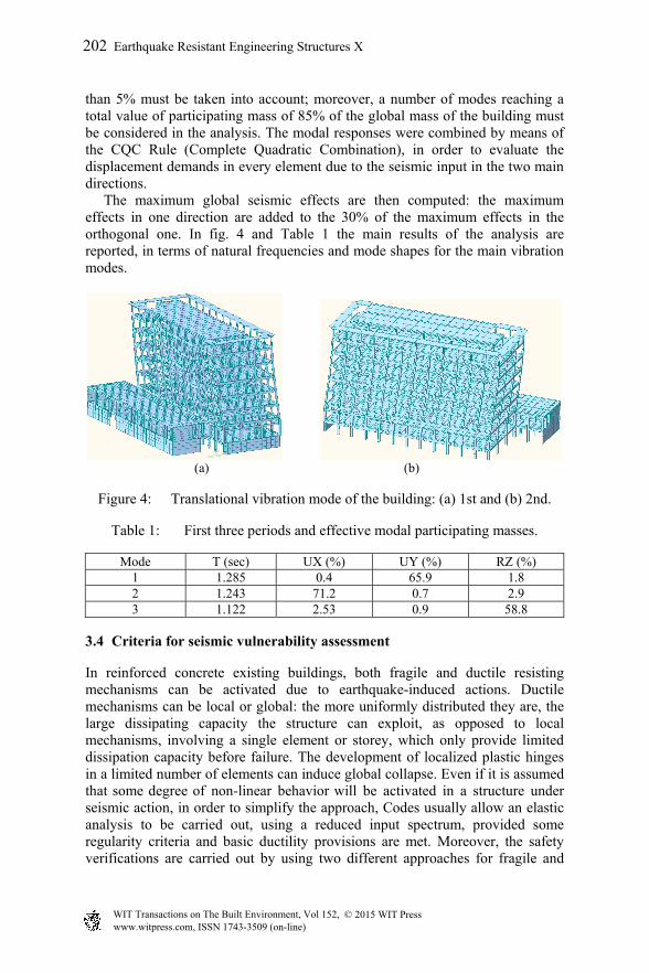
than 5% must be taken into account; moreover, a number of modes reaching a total value of participating mass of 85% of the global mass of the building must be considered in the analysis. The modal responses were combined by means of the CQC Rule (Complete Quadratic Combination), in order to evaluate the displacement demands in every element due to the seismic input in the two main directions. The maximum global seismic effects are then computed: the maximum effects in one direction are added to the 30% of the maximum effects in the orthogonal one. In fig. 4 and Table 1 the main results of the analysis are reported, in terms of natural frequencies and mode shapes for the main vibration modes.
(a) (b)
Figure 4: Translational vibration mode of the building: (a) 1st and (b) 2nd.
Table 1: First three periods and effective modal participating masses.
Mode T (sec) UX (%) UY (%) RZ (%) 1 1.285 0.4 65.9 1.8 2 1.243 71.2 0.7 2.9 3 1.122 2.53 0.9 58.8
3.4 Criteria for seismic vulnerability assessment
In reinforced concrete existing buildings, both fragile and ductile resisting mechanisms can be activated due to earthquake-induced actions. Ductile mechanisms can be local or global: the more uniformly distributed they are, the large dissipating capacity the structure can exploit, as opposed to local mechanisms, involving a single element or storey, which only provide limited dissipation capacity before failure. The development of localized plastic hinges in a limited number of elements can induce global collapse. Even if it is assumed that some degree of non-linear behavior will be activated in a structure under seismic action, in order to simplify the approach, Codes usually allow an elastic analysis to be carried out, using a reduced input spectrum, provided some regularity criteria and basic ductility provisions are met. Moreover, the safety verifications are carried out by using two different approaches for fragile and
202 Earthquake Resistant Engineering Structures X
www.witpress.com, ISSN 1743-3509 (on-line) WIT Transactions on The Built Environment, Vol 152, © 2015 WIT Press
ductile mechanisms. NTC 2008 allow a linear analysis to be carried out using a reduction factor q for the elastic spectrum: the q factor usually ranges between 1.5 and 3, based on regularity criteria and depending on the levels of stresses induced by gravity loads. In the present case study, a reduction factor q=1.5 was assumed (as shown in fig. 2), because the columns exhibit high axial loads under gravity and earthquake loads combined (v = N/A·fcd >0.5). The internal actions used for the safety verifications are those directly derived from this elastic analysis, both for ductile and fragile mechanisms. On the capacity side, in order to compute the strength of ductile elements, the material properties derived from the samples were used, reduced by the above mentioned confidence factor, whereas for fragile elements, the partial reduction coefficient was applied in addition to FC to further penalize the verifications. M-N interaction domains were plotted for the critical sections for flexural verifications. As for shear verifications, the variable angle truss model was used, as defined in NTC 2008. The angle for the compressed concrete struts was prudentially assumed to be 27° (ctgϑ = 2) for columns, due to the cyclic nature of the seismic input. For the beams, the value of ctgϑ = 2.5 was assumed because the dominant shear action is due to gravity loads: for this reason, there is no sign reversal in the shear plots and the bent rebar in the beams is always effective and can be considered in the shear verifications.
3.5 Vulnerability assessment results
The safety verifications were complied with for most of the vertical elements, except for the perimeter columns on the ground floor and those supporting the stairways. In particular, it can be observed in fig. 5(a)) that for the columns that do not comply with flexural verifications (black line), two different failure mechanisms were found to develop. The columns on the back of the building fail because the bending action is slightly higher than their capacity because of the increase of the lateral loads due to the fact that on the ground floor the adjacent line of columns is not present (Line 2 in fig. 1). These columns exhibit a lower rebar content and relatively low axial loads, which makes for a ductile failure, with spalling of concrete cover. The two columns located on the short side of the building, on the contrary, face remarkably increased flexural and axial demands due to the absence of the ground floor infills. A moment-curvature analysis for the critical sections of the above mentioned columns was carried out: sectional ductility is practically non-existent, because the steel rebar deformation at ultimate limit state is below the yield limit (see fig. 5(b)). Moreover, the columns supporting the stairways, the perimeter columns on the street side of the building and the columns on the back, above the roof of the lower part did not comply with the shear verifications. Only a few beams, located near the stairways, where the geometric regularity of the frames is interrupted, showed slightly inadequate flexural capacity. In these particular locations, it was deemed possible to accept this shortcoming, provided that the elements are able to counterbalance a redistribution of the
Earthquake Resistant Engineering Structures X 203
www.witpress.com, ISSN 1743-3509 (on-line) WIT Transactions on The Built Environment, Vol 152, © 2015 WIT Press

stresses. As a consequence, in the safety verifications, a plastic hinge was assumed to develop at the end of the beam and a bending moment corresponding to the flexural capacity of the beam was applied to the adjacent element. The non-linear analysis carried out on the retrofitted structure validated the approach, since no inadequacies were highlighted in the retrofitted configuration.
(a) (b)
Figure 5: (a) Elements with insufficient bending capacity (black line) and with insufficient shear capacity (red line); (b) Moment-curvature plot for the critical sections of the marked columns.
4 Retrofit strategy
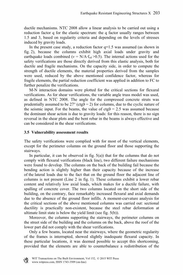
A local strengthening of some elements of the existing structure was designed. The intervention consists in the jacketing of the columns on the building perimeter at the ground floor, the jacketing of the columns supporting the stairs for the whole elevation of the building and the addition of a new shear wall in the back side of the building (as can be seen in fig. 1). For the jacketing, controlled shrinkage fiber-reinforced mortar and B450C steel has been employed (fig. 6). This kind of retrofit attains an increase of both flexural and shear strength of the elements by improving their ductility and confinement. On the other hand, the stiffness of the new shear walls in the back side of the building reduces the displacement demand and the seismic actions on the columns belonging to the ground floor of that area, which were not verified for flexure. According to [1], in order to design the rebar of the strengthened columns, the following assumptions were adopted: full bond between the existing and new concrete; axial load applied to the whole jacked section; mechanical property of the new concrete extended to all section. Furthermore, the values of shear and flexure capacity of the reinforced section were prudentially reduced by 10%. In order to achieve full bond, the steel connections between the existing concrete and the new one were designed according to the procedure reported in EC2 [7].
204 Earthquake Resistant Engineering Structures X
www.witpress.com, ISSN 1743-3509 (on-line) WIT Transactions on The Built Environment, Vol 152, © 2015 WIT Press
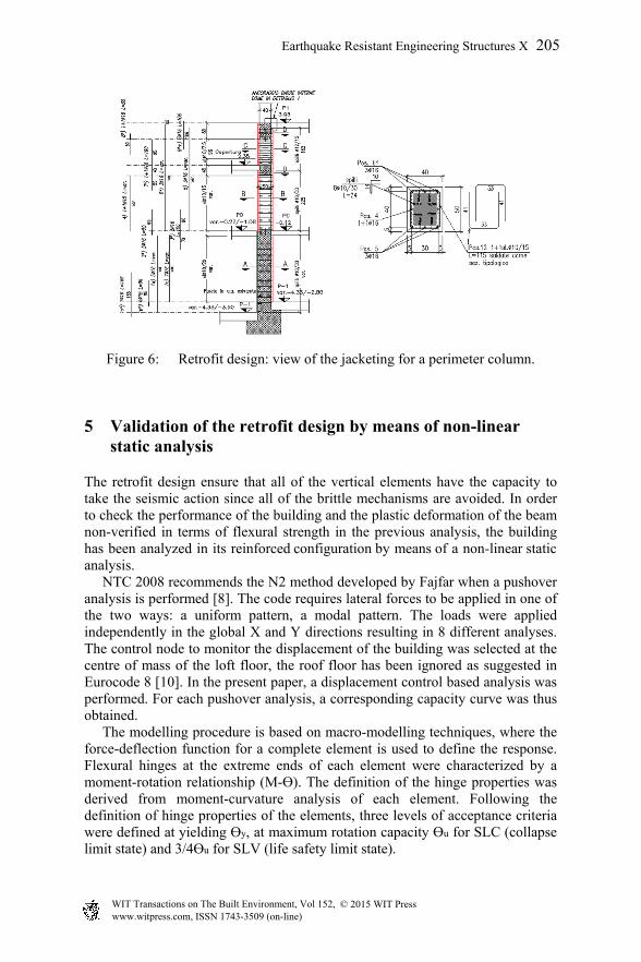
Figure 6: Retrofit design: view of the jacketing for a perimeter column.
5 Validation of the retrofit design by means of non-linear static analysis
The retrofit design ensure that all of the vertical elements have the capacity to take the seismic action since all of the brittle mechanisms are avoided. In order to check the performance of the building and the plastic deformation of the beam non-verified in terms of flexural strength in the previous analysis, the building has been analyzed in its reinforced configuration by means of a non-linear static analysis. NTC 2008 recommends the N2 method developed by Fajfar when a pushover analysis is performed [8]. The code requires lateral forces to be applied in one of the two ways: a uniform pattern, a modal pattern. The loads were applied independently in the global X and Y directions resulting in 8 different analyses. The control node to monitor the displacement of the building was selected at the centre of mass of the loft floor, the roof floor has been ignored as suggested in Eurocode 8 [10]. In the present paper, a displacement control based analysis was performed. For each pushover analysis, a corresponding capacity curve was thus obtained. The modelling procedure is based on macro-modelling techniques, where the force-deflection function for a complete element is used to define the response. Flexural hinges at the extreme ends of each element were characterized by a moment-rotation relationship (M-Ɵ). The definition of the hinge properties was derived from moment-curvature analysis of each element. Following the definition of hinge properties of the elements, three levels of acceptance criteria were defined at yielding Ɵy, at maximum rotation capacity Ɵu for SLC (collapse limit state) and 3/4Ɵu for SLV (life safety limit state).
Earthquake Resistant Engineering Structures X 205
www.witpress.com, ISSN 1743-3509 (on-line) WIT Transactions on The Built Environment, Vol 152, © 2015 WIT Press

In this study, the empirical approach is used and described by means of an empiric expression to state the elastic and plastic rotation, according to [1, 9]. To account for the shear behavior, shear hinges were added in parallel to each flexural hinge. The shear capacity has been assessed at a sectional level with the procedure described in 3.4. A target displacement (Table 2) was then assigned to each capacity curve for the SLV. The deformations and action effects at each member were finally evaluated at the target displacement for each curve. The results of the pushover analysis in X direction are reported in figs 7–9. The structural behavior of the building in Y direction at the target displacement for SLV lies in elastic range (fig. 8). The procedure to estimate the maximum seismic response of the MDOF system loaded by modal lateral forces was carried out according to [1] and [8]. According to the procedure in [1], ductile modes should be checked in terms of chord rotation while the brittle modes should be checked in terms of shear. The ductile mechanisms are checked through the evaluation of the chord rotation demand and the capacity at the ends of each structural element. The chord rotation is the angle between the chord connecting the end section of the member to the section at which M=0 and the tangent to the member axis at the end section. The chord rotation demand for the column ends was calculated as the drift at the point of contraflexure. On the other hand, in beams, the chord rotation
Table 2: Response parameters.
Parameters X direction Y direction F*
y (kN) 3330 2610 T* (sec) 1.07 1.28 Se(T*) (g) 0.075g 0.062 d*
et (m) 0.021 0.025 d*
t (m) 0.021 0.025
(a) (b)
Figure 7: Modal pushover X direction: (a) force deformation relationship of MDOF; (b) capacity curve for SDOF and elastic design spectrum in SLV.
206 Earthquake Resistant Engineering Structures X
www.witpress.com, ISSN 1743-3509 (on-line) WIT Transactions on The Built Environment, Vol 152, © 2015 WIT Press
(a) (b)
Figure 8: Modal pushover Y direction: (a) force deformation relationship of MDOF; (b) capacity curve for SDOF and elastic design spectrum in SLV.
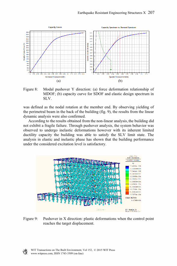
was defined as the nodal rotation at the member end. By observing yielding of the perimetral beam in the back of the building (fig. 9), the results from the linear dynamic analysis were also confirmed. According to the results obtained from the non-linear analysis, the building did not exhibit a fragile failure. Through pushover analysis, the system behavior was observed to undergo inelastic deformations however with its inherent limited ductility capacity the building was able to satisfy the SLV limit state. The analysis in elastic and inelastic phase has shown that the building performance under the considered excitation level is satisfactory.
Figure 9: Pushover in X direction: plastic deformations when the control point reaches the target displacement.
Earthquake Resistant Engineering Structures X 207
www.witpress.com, ISSN 1743-3509 (on-line) WIT Transactions on The Built Environment, Vol 152, © 2015 WIT Press

6 Conclusions
The assessment and the retrofit study hereby presented is based on a thorough application of the recently declared Italian Building Code (NTC 2008), which allows both linear and non-linear analysis techniques for existing structures. The case study dealt with a non-seismically designed RC building located in a low hazard area. A modal response spectrum analysis highlighted some local inadequacies in the bending and shear capacity of a few vertical and horizontal elements. A retrofitting intervention was thus designed, by means of jacketing of the inadequate vertical elements, and validated by means of a non-linear static analysis.
References
[1] D.M. del 14/01/2008 – “Norme Tecniche per le Costruzioni 2008”. NTC 2008 e Circolare 02/02/2009, n. 617 – Istruzioni per l’applicazione delle “Nuove norme tecniche per le costruzioni” di cui al D.M. 14 gennaio 2008. (In Italian.)
[2] Regio Decreto-Legge 16/11/1939-XVIII, n°2229: "Norme per l’esecuzione delle opere in conglomerato cementizio semplice od armato”. (In Italian.)
[3] “Linee guida per la valutazione e la riduzione del rischio sismico del patrimonio culturale con riferimento alle Norme tecniche per le costruzioni”. Testo allegato al parere n°66 dell’Assemblea Generale del Consiglio Superiore dei LL.PP. reso nella seduta del 21 Luglio 2006. (In Italian.)
[4] Morandi P., Hak S., Magenes G. Comportamento sismico delle tamponature in laterizio in telai in c.a.: definizione dei livelli prestazionali e calibrazione di un modello numerico. XIV Congresso Nazionale “L’ingegneria Sismica in Italia”, Bari, 2011. (In Italian.)
[5] Decreto Ministeriale 7 Marzo 1981 “Dichiarazione in zone sismiche nelle regioni Basilicata, Campania e Puglia”. (In Italian.)
[6] Morandi P., Hak S., Magenes G. Comportamento sismico delle tamponature in laterizio in telai in c.a.: definizione dei livelli prestazionali e calibrazione di un modello numerico. XIV Congresso Nazionale “L’ingegneria Sismica in Italia”, Bari, 2011. (In Italian.)
[7] UNI EN 1992-1:2005, Eurocode 2: “Design of concrete structures” [8] Fajfar P. and Gasperic P. The N2 method for the seismic damage analysis
of RC buildings. Earthquake Engineering and Structural Dynamics, 28(1), pp. 31-46, 1996.
[9] Paksoy M, Mola E., Mola F. A comparative study of Italian code-based seismic vulnerability assessment procedures for existing buildings. Second European conference on Earthquake Engineering and Seismology, Istanbul, 2014.
[10] UNI EN 1998-1:2005, Eurocode 8: “Design of structures for earthquake resistance”.
208 Earthquake Resistant Engineering Structures X
www.witpress.com, ISSN 1743-3509 (on-line) WIT Transactions on The Built Environment, Vol 152, © 2015 WIT Press