evaluation board - · pdf file · 2012-11-29vub300 evaluation board 3 vub300 ic...
TRANSCRIPT

VUB300 Evaluation Board www.saelig.com 1
VUB300 USB to SDIO Host Interface
Evaluation Board
Manufacturer: Elan DIGITAL Systems
The VUB Evaluation Board offers the same functionality as VUB300 IC in a multi-chip solution, and is highly recommended when commencing VUB300 development. VUB Evaluation Board is built around two ASICs, with the firmware mask an external flash memory, emulating VUB300 chip behavior.
There are 3 LEDs on the board for power and activity indication.
POWER LED - On when USB Power is supplied. SD POWER - On when power to the SD/SDIO card supplied. ACT - On when driver commands are being processed.
The VUB300 Evaluation Board is USB powered, but can be modified to run from an external 3.3V source. When plugged in to a PC’s USB port, it will immediately allow SD cards to be read. Note: there are several unpopulated lands, since this is a generic demonstration board for several different ICs. VUB300 SDIO host controller drivers are supported on the following operating systems:
Linux Windows 2000 Windows XP Windows Vista 32 Windows Vista 64 Windows 7 Windows Mobile/PocketPC/CE Apple MAC OSX
Linux This driver currently exists only as a Linux kernel external module that has been tested against some 2.6.29, 2.6.30, 2.6.31 and 2.6.32 kernels. Windows As supplied, VUB300 Evaluation Board is USB-powered. When the board is powered up for the first time Windows operating system should bring up Found New Hardware Wizard. VUB300 appears in the Device Manager under Secure Digital host controllers.
VUB300 Evaluation Board www.saelig.com 2

VUB300 Evaluation Board www.saelig.com 3
VUB300 IC Features
Optimized for high speed transfer of data. USB 2.0 Hi-Speed connection - up to 480 Mbps data rate Backward compatibility with Full-Speed USB 2.0 and USB 1.1.
3.3V supply. Low power (< 600mW) operating.
- Suitable for bus powered applications. Integrated USB 2.0 Hi-Speed PHY.
16 kB USB buffer memory. SDIO interface supports - 1bit or 4bit SDIO
- SD Interrupt. Card detection. VUB300 live on power up.
SD Specifications Part 1 Physical Layer Specification Version 2.00. SD Specifications Part E1 SDIO Specification Version 2.00. Single chip solution
Development / Demonstration board available same functionality with multi chip solution.
Package : 36-pin QFN 6x6mm Fully 'green', lead-free and RoHS compliant.
Introduction
Extending the capabilities of SD and SDIO devices into the world of USB, and also allowing expansion of Laptop and Desktop PC's into the world of SD and SDIO devices, VUB300 is a USB to SDIO host controller
bridge chip interface that allows SDIO and SD compliant devices to be connected to any host PC via the
Universal Serial Bus (USB). It is a USB 2.0 compliant device operating at Hi-Speed (480 Mbps). The SDIO Host
function conforms to the SDIO Host specification with a generic USB “wrapped” interface to extend SDIO host
controller support to the USB bus.
Device Support
VUB300 conforms to the SD Specifications Part 1 Physical Layer Specification Version 2.00 and SD Specifications
Part E1 SDIO Specification Version 2.00. The VUB300 supports any SD or SDIO device that conforms to the
SD/SDIO specifications.
Host Support
VUB300 conforms to the USB 2.0 Specification as a Hi-Speed device and will work on any host that supports USB
2.0 or 1.1 host ports. Please note that maximum data throughput is only available with USB 2.0 Hi-Speed hosts.

VUB300 Evaluation Board www.saelig.com 4
Operating System Support
The VUB300 SDIO host controller drivers are supported on the following operating systems:
Linux
Windows 2000 Windows XP
Windows Vista 32
Windows Vista 64
The drivers integrate with the generic SDIO host stack providing seamless functionality with existing SD
and SDIO device drivers.
Functionality and Design
VUB300 offers a unique USB to SDIO host controller interface link with this single chip bridge solution in
the form of an ASIC. VUB300 offers capability and intelligence to handle both USB and SDIO protocol, creating the connection
between the two and seemingly translating the data between the two formats.
Diagram 3: VUB300 Block Diagram

VUB300 Evaluation Board www.saelig.com 5
USB
Integrated USB 2.0 Hi-Speed Transceiver / PHY VUB300 ASIC has integrated USB 2.0 compliant Hi-Speed Transceiver.
SDIO
SDIO Host Controller, SDIO Host Controller Register and DMA Control, all make up the SDIO Function Controller
section within VUB300, see Diagram 3.
DMA Control
By implementing DMA control VUB300 is able to achieve high performance data transfers between an
SD/SDIO data path and the USB bulk data interface.
SDIO Host Controller
SDIO Function Controller is designed according to the SD Association's SD host controller specification.
SDIO Host Controller Registers
All the access to the SD/SDIO bus is made through the standard control register set. DMA, burst access, CRC error
detection, interrupt, timing, etc. are supported by the controller core. SDIO Host Controller Registers are accessed
via the USB control and interrupt pipe.
VUB300 Bridging Logic
VUB300 has IP core with device specific logic that is adapting, organizing and translating data between USB
and SDIO interface. This device specific logic design has been improved by the Elan development team for superior and fast performance.
VUB300 Evaluation Board www.saelig.com 6
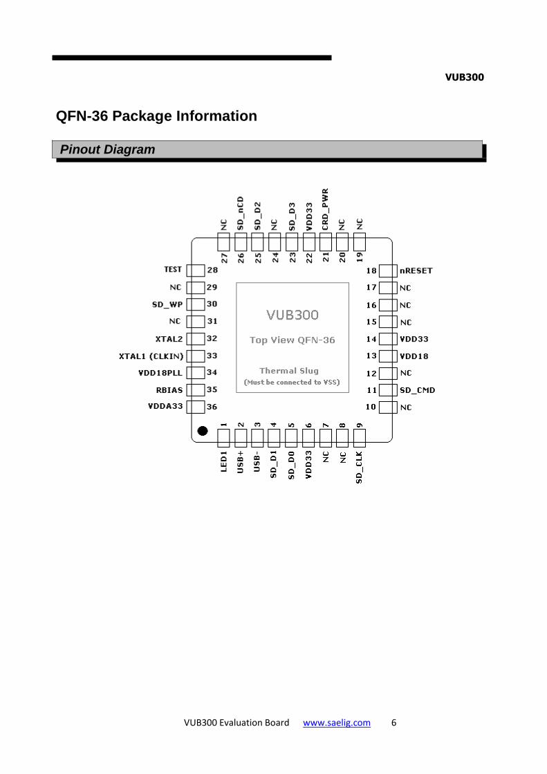
VUB300
QFN-36 Package Information
Pinout Diagram

VUB300 Evaluation Board www.saelig.com 7
Pin Descriptions
SECURE DIGITAL INTERFACE
Pin # Name Type Description
23
25
4
5
SD_D[3:0] SD Data This is a bi-directional bus that connects to the DAT bus of
SD device
9 SD_CLK SD Clock This is an output clock signal to SD/SDIO device
11 SD_CMD SD Command This is a bi-directional signal that connects to the CMD
signal of SD device
30 SD_WP SD Write
Protect This is an IO pin designated as the Secure Digital card
mechanical write protect pin
26 SD_nCD SD Card
Detect This is an IO pin designated as the Secure Digital card
detection pin
USB INTERFACE
Pin # Name Type Description
2
3 USB+
USB- USB Bus Data These pins connect to the USB data bus signals
35 RBIAS USB
Transceiver
Bias
A 12.0k, 1.0% resistor is attached from VSS to this pin in
order to set the transceiver's internal bias currents
33 XTAL1
(CLKIN) 24MHz
Crystal or external clock
input
This pin can be connected to one terminal of the crystal or
it can be connected to an external 24 clock when a crystal is not used
32 XTAL2 24MHz
Crystal This is the other terminal of the crystal, or it is left open
when an external clock source is used to drive
XTAL1(CLKIN). It may not be used to drive any external
circuitry other than the crystal circuit
36 VDDA33 3.3V Analog
Power 3.3V Analog Power
34 VDD18PLL 1.8V PLL
Power This pin in the 1.8V Power for the PLL
+1.8V Filtered analog power for internal PLL. This pin
must have a 1.0 µF (or greater) ±20% (ESR <0.1Ω)
capacitor to VSS

VUB300 Evaluation Board www.saelig.com 8
MISC
Pin # Name Type Description
1 LED1 General
Purpose IO This pin may be used to drive an activity LED
21 CRD_PWR General
Purpose I/O Card Power drive of 3.3V at either 100mA or 200mA
18 nRESET RESET Input This active low signal is used by the system to reset the
chip. The active low pulse should be at least 1µs wide
DIGIGAL / POWER
Pin # Name Type Description
13 VDD18 +1.8V Core
power +1.8V core power. This pin must have a+1.0 µF (or greater) ±20% (ESR <0.1Ω) capacitor to VSS
6
13
22
VDD33 3.3V Power &
Regulator
Input
3.3V power supply input
28 TEST Input This signal is used for testing the chip. When unused tie to
VSS
SLUG VSS Ground reference
SDIO Socket Pin Definitions
Pin Name Description
1 SD_DAT[3]/CD Data line 3 / Card detect
2 SD_CMD Command line
3 VSS1 Ground
4 SD_PWR Supply voltage, should be connected to CRD_PWR
5 SD_CLK Clock
6 VSS2 Ground
7 SD_DAT[0] Data line 0
8 SD_DAT[1]/IRQ Data line 1 / SDIO Interrupt
9 SD_DAT[2]/WAIT Data line 2 / SDIO Read Wait
10 SD_nCD SD/SDIO card detect switch, active LOW
11 SD_WP SD card write protect switch, active HIGH

VUB300 Evaluation Board www.saelig.com 9
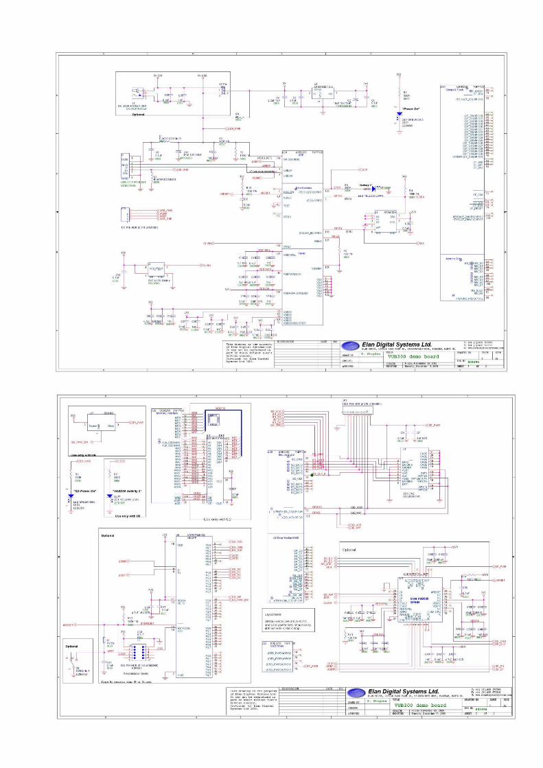
Reference Design
The following schematic provides USB SD/SDIO card reader reference design. VUB300 main block
Power supply block
Clock reference block
SD/SDIO socket block
USB socket block

VUB300 Evaluation Board www.saelig.com 10
QFN-36 Package Dimensions
Symbol Min Nom Max Notes
A '0.80 '1.00 Overall package height
A1 0 0.02 0.05 Standoff
A2 '0.60 '0.80 Mold cap thickness
A3 0.20 REF Leadframe thickness
D/E 5.85 '6.00 '6.15 X/Y body size
D1/E1 5.55 5.95 X/Y mold cap size
D2/E2 '4.00 '4.10 '4.20 X/Y exposed pad size
L '0.50 '0.60 '0.75 Terminal length
b 0.18 0.25 '0.30 Terminal width
e 0.50 BSC Terminal pitch
x 4 X 0° - 12°

VUB300 Evaluation Board www.saelig.com 11
VUB300
Electrical Specifications
Parameter Conditions Min Typ Max Units
Supply Voltage (VDD) 3.0 3.3 3.6 V
Specified Operating Temperature Range
Commercial 0 70 °C
Industrial -40 +85 °C
IDD 165 mA
Recommended Operating Conditions
Parameter Min Max Units
Operating Temperature -40 85 °C
3.3V Supply Voltage (VDD33, VDDA33) '3.0 3.6 °C
3.3V Supply rise time 0 400 °C
Voltage on USB+ and USB- pins -0.3 5.5 V
Voltage on any signal pin -0.3 VDD33 V
Voltage on XTAL1 -0.3 VDDA33 V
Voltage on XTAL2 -0.3 VDD18 V
Absolute Maximum Ratings*
Parameter Min Max Units
Ambient temperature under bias -55 125 °C
Storage Temperature -65 150 °C
Lead Temperature 325 (soldering < 10 seconds)
°C
3.3V supply voltage (VDD33, VDDA33) -0.5 '4.0 V
Voltage on USB+ and USB- pins -0.5 (3.3V supply voltage + 2) ≤ 6 V
Voltage on CRD_PWR -0.5 VDD33 + 0.3 V
Voltage on any signal pin -0.5 VDD33 + 0.3 V
Voltage on XTAL1 -0.5 '4.0 V
Voltage on XTAL2 -0.5 VDD18 + 0.3 V
*Note: Stresses above those listed under “Absolute Maximum Ratings” may cause permanent
damage to the device. This is a stress rating only and functional operation of the devices at those
or any other conditions above those indicated in the operation listings of this specification is not implied. Exposure to maximum rating conditions for extended periods may affect device reliability.

VUB300 Evaluation Board www.saelig.com 12
Further details from: Saelig Co. Inc. 71 Perinton Parkway Fairport NY 14450 USA www.saelig.com