evaluation and selection guide of method of repair for routine...
TRANSCRIPT

Evaluation and Selection Guide of Method of Repair for Routine
MaintenanceMaintenanceFor TxDOT Maintenance Engineers
Product 0-5821-P3Product 0-5821-P3Project 0-5821
Project Title: Develop Guidelines for Routine Maintenance of Concrete PavementPerformed in cooperation with the Texas Department of Transportation
and the Federal Highway AdministrationSubmitted: April 2008
Published: November 2008TEXAS TRANSPORTATION INSTITUTE
The Texas A&M University System, College Station, Texas 77843-3135

Training Session for Engineers
Purpose :
Provide training to identify the distresses
Provide guidelines to select the appropriateProvide guidelines to select the appropriate
methods of repairs
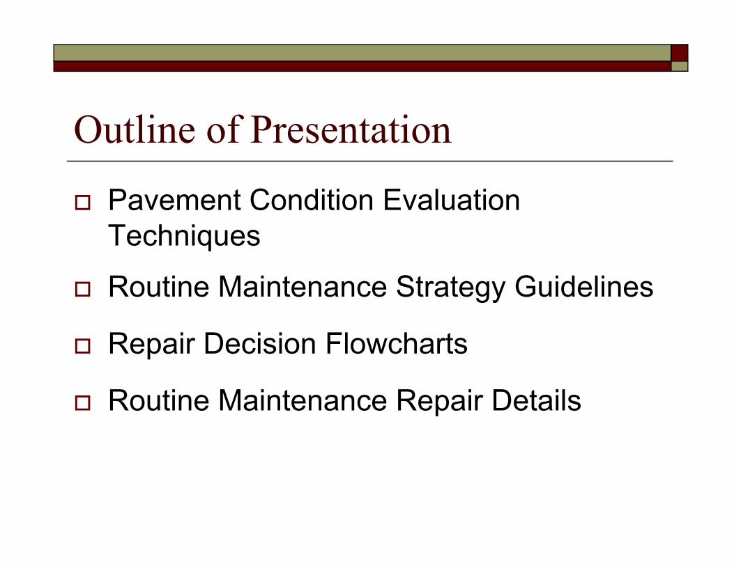
Outline of Presentation
Pavement Condition Evaluation Techniquesq
Routine Maintenance Strategy Guidelines
Repair Decision Flowcharts
R ti M i t R i D t ilRoutine Maintenance Repair Details
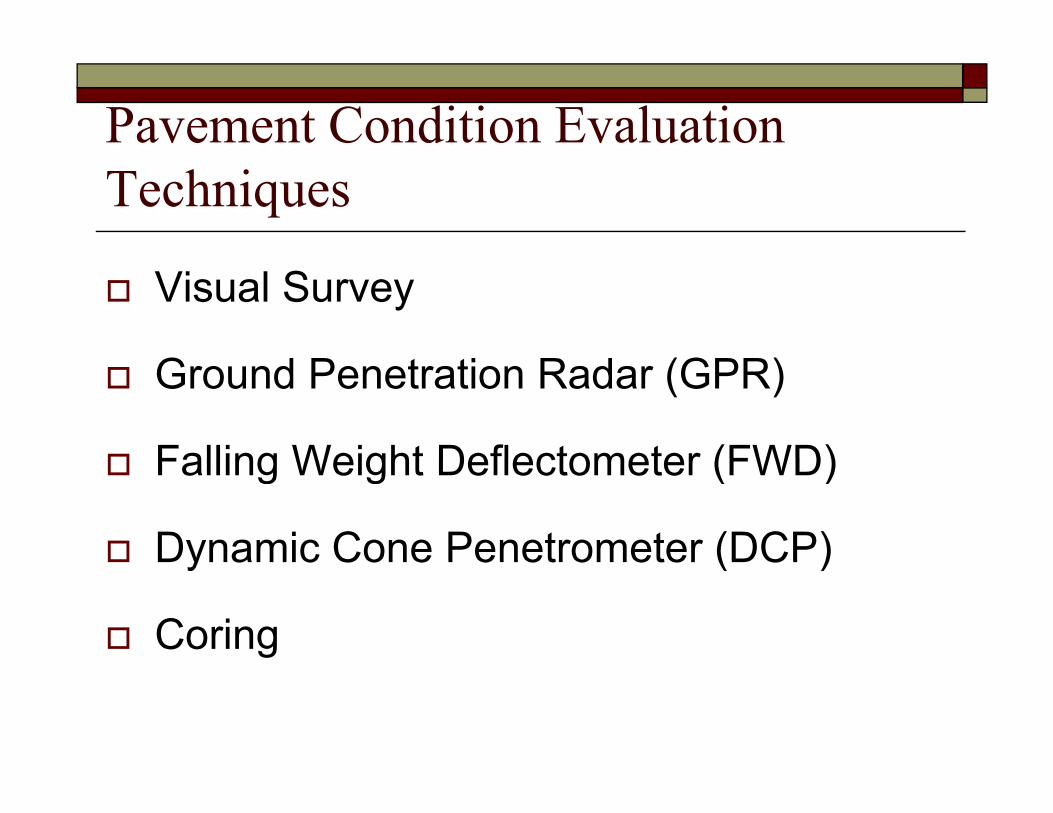
Pavement Condition Evaluation Techniques
Visual Survey
Ground Penetration Radar (GPR)
Falling Weight Deflectometer (FWD)Falling Weight Deflectometer (FWD)
Dynamic Cone Penetrometer (DCP)Dynamic Cone Penetrometer (DCP)
Coring
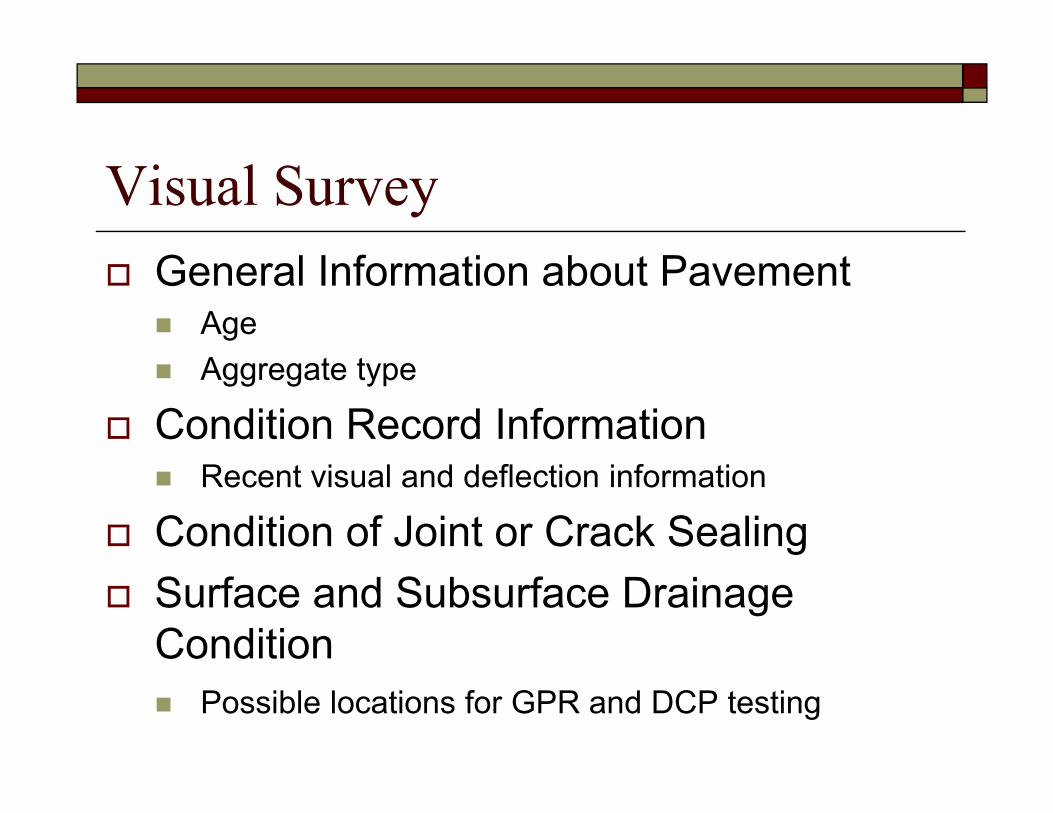
Visual Survey General Information about Pavement
AgeAggregate type
Condition Record InformationRecent visual and deflection information
Condition of Joint or Crack SealingSurface and Subsurface Drainage Condition
Possible locations for GPR and DCP testing

Visual Survey (cont.)Functional Conditions
Factors affecting ride quality (roughness)Possible locations for FWD, GPR, and DCP testing
Structural ConditionsFactors affecting premature failure Possible locations for FWD, GPR, and DCP testing
Identification of Distressed Areas for FDR

Visual Survey Check listF thNo. Check list Notes Further
inspection1 Pavement age (yr.)
2 Aggregate type (hard or soft)2 Aggregate type (hard or soft)
3 Year of recent pavement distress survey (yr.)
4 Year of recent pavement deflection survey (yr.)
5 Joint sealant age (yr )5 Joint sealant age (yr.)
6 Sealant damage of transverse joint or crack (%)
7 Sealant damage of longitudinal joint or crack (%)
8 Sealant damage of sealed crack (%)8 Sealant damage of sealed crack (%)
9 Trapped surface water in depressed area
10 Standing water or slab staining GPR, DCP
11 Pumping with or without staining GPR DCP11 Pumping with or without staining GPR, DCP
12 Bump (stable or unstable, depth, in.) GPR, DCP
13 Settlement (stable or unstable, depth, in.) GPR, DCP
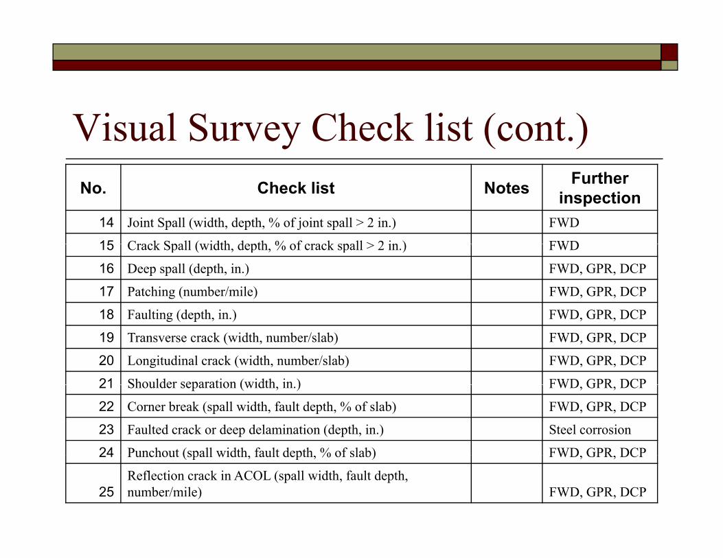
Visual Survey Check list (cont.)F thNo. Check list Notes Further
inspection14 Joint Spall (width, depth, % of joint spall > 2 in.) FWD
15 Crack Spall (width depth % of crack spall > 2 in ) FWD15 Crack Spall (width, depth, % of crack spall > 2 in.) FWD
16 Deep spall (depth, in.) FWD, GPR, DCP
17 Patching (number/mile) FWD, GPR, DCP
18 Faulting (depth in ) FWD GPR DCP18 Faulting (depth, in.) FWD, GPR, DCP
19 Transverse crack (width, number/slab) FWD, GPR, DCP
20 Longitudinal crack (width, number/slab) FWD, GPR, DCP
21 Shoulder separation (width in ) FWD GPR DCP21 Shoulder separation (width, in.) FWD, GPR, DCP
22 Corner break (spall width, fault depth, % of slab) FWD, GPR, DCP
23 Faulted crack or deep delamination (depth, in.) Steel corrosion
24 Punchout (spall width fault depth % of slab) FWD GPR DCP24 Punchout (spall width, fault depth, % of slab) FWD, GPR, DCP
25Reflection crack in ACOL (spall width, fault depth, number/mile) FWD, GPR, DCP

Ground Penetration RadarImage Analysis
Void, ground water, dowel bar detectionDi l t i C t t (DC) A l iDielectric Constant (DC) Analysis
DC value > 9 Check drainage/wet condition
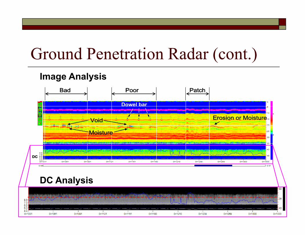
Ground Penetration Radar (cont.)I A l i
Bad Poor PatchBad Poor PatchBad Poor Patch
D l b
Image Analysis
Void Erosion or Moisture
Moisture
Void Erosion or Moisture
Moisture
Void Erosion or Moisture
Moisture
Dowel bar
Moisture
DC
Moisture
DC
Moisture
DC
DC Analysis

Falling Weight Deflectometer Load Transfer Efficiency (LTE)Load Transfer Efficiency (LTE)Deflection (Basin Area)Overall Structural Capacity (Effective Thickness)Overall Structural Capacity (Effective Thickness)
1 2 3 4 5 6 7 8 9 10 11 12 13 14 15 16 17 18 19 20
1 2 3 4 5 6 7
1 2 3 4 5 6 7 8 9 10 11 12 13 14 15 16 17 18 19 20
21 22 23 24 25 26 27 28 29 30 31 32 33 34 35 36 37 38 39 40
8 9 10 11 12
DCP-BC1 Core 1
41 42 43 44 45 46 47 48 49 50 51 52 53
13 14 15 16 17
DCP-BE1
DCP BE2 DCP BE3
Example of FWD Testing Locations
DCP-BE2 DCP-BE3Core 2 Core 3

Falling Weight Deflectometer (cont.) LTE Testing
Measure of independent action
100dd
LTE U ×=
Where, LTE = Load transfer effectiveness, percent
dL
dLdUWhere, LTE Load transfer effectiveness, percent dU = Deflection on the unloaded side of the joint or crack, mils dL = Deflection at the loaded side of the joint or crack, mils
dLdU
LTE < 70% Retrofit load transfer

D fl ti T ti
Falling Weight Deflectometer (cont.) Deflection Testing
)DD2D26(D +++
0
3210
D)DD2D26(D +++
=AREA
Where, AREA = FWD deflection parameter, in.D0 = Deflection at the loading position, mils D1 = Deflection at 12 in. from the loading position, mils D2 = Deflection at 24 in. from the loading position, mils D3 = Deflection at 36 in. from the loading position, mils
B i 25 Ch k b / b d tBasin area < 25 Check base/subgrade support Reference: Ioannides, A. M. “Dimensional Analysis in NDT Rigid Pavement Evaluation,” Journal of Transportation Engineering, Vol. 116, No. 1,
July 1990, pp. 23–36.

Radius of Relative Stiffness vs. Basin Area
100
120
140ne
ss (i
n.)
40
60
80
of R
elat
ive
Stiff
n
0
20
0 10 20 30 40 50 60 70 80
Rad
ius
o
1
7654321
dd)ddddd(2d6 ++++++
=BA 992.02891.00284.0 2 +⋅−⋅= BABA
Basin Area (in.)
1d
BA = Basin area of seven sensors (in.) di = Deflection of ith sensor (mils)
= Radius of relative stiffness (in.)

Eff ti Thi k
Falling Weight Deflectometer (cont.) Effective Thickness
Measure of structural capacityh
( ) 31
24 112
⎥⎥⎦
⎤
⎢⎢⎣
⎡ −⋅= dyn
e Ek
hν
8
10
12
14
ckne
ss (i
n.)
4
5
6
7
n (m
ils)
hc
Where, he = effective slab thickness (in.)di f l i iff (i )
⎥⎦⎢⎣ cE
0
2
4
6
Effe
ctiv
e th
ic
0
1
2
3
Def
lect
io
Effective thickness Deflection
= radius of relative stiffness (in.)= Poison’s ratio of the concrete
kdyn = dynamic modulus of subgrade reaction (psi/in.)E = elastic modulus of the PCC layer (psi)
01 3 5 7 9 11 13 15 17 19 21 23 25 27
Drop location ID
0
ν
Ec = elastic modulus of the PCC layer (psi)
he < hc Check base/subgrade support

Dynamic Cone PenetrometerBase/Subgrade StrengthSoil Modulus Penetration Ratio (PR, mm/blow)
Typical flexible base Ebase = 60 ~ 80 ksi or PRbase of = 1 ~ 2 mm/blow
Soft subgrade or low strengthEsubgrade < 6 ksi or PR 50 /bl ( 2 i /bl )PRsubgrade > 50 mm/blow (= 2 in./blow)

Dynamic Cone Penetrometer (cont.)
Modulus of Soils0 50 100 150 200 250
Blow number
E = 2550 × CBR0.64
CBR = 292 / PR1.12
300
400
m)
Where, E = Elastic modulus, psiCBR = California bearing ratio
y = 0.9x + 356.4500
600
trat
ion
(mm
Base:
CBR = California bearing ratioPR = Penetration ratio, mm/blow y = 19.4x - 3272.5
700
800
Pene
tSubgrade:
900

CoringVoid, Erosion DetectionConcrete Strengthg

Routine Maintenance Strategy Guidelines
Performance Monitoring
PreservativePreservative
Functional CPR
Structural CPR
Remove and Replace
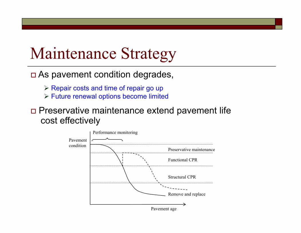
Maintenance StrategyA t diti d dAs pavement condition degrades,
Repair costs and time of repair go upFuture renewal options become limited
Preservative maintenance extend pavement lifecost effectively
P f it i
Pavement condition
Preservative maintenance
Functional CPR
Performance monitoring
Functional CPR
Structural CPR
Pavement age
Remove and replace
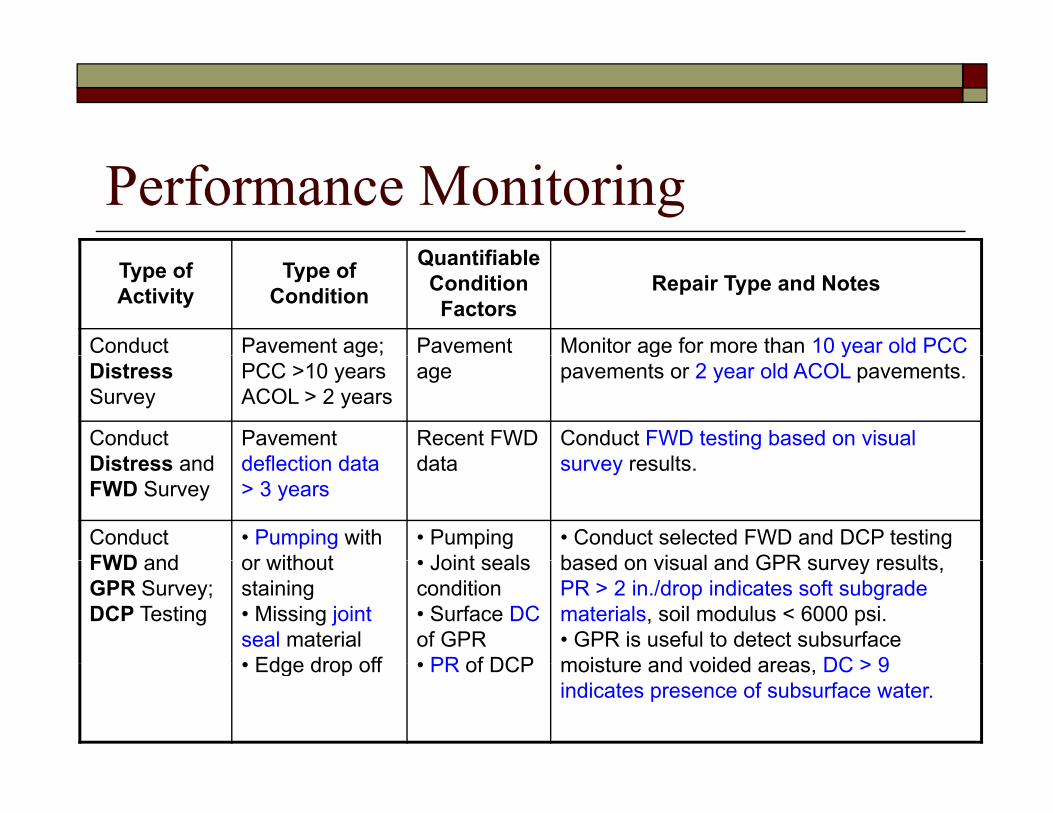
Performance MonitoringQ tifi blType of
ActivityType of
Condition
Quantifiable Condition Factors
Repair Type and Notes
Conduct Pavement age; Pavement Monitor age for more than 10 year old PCCDistressSurvey
g ;PCC >10 yearsACOL > 2 years
ageg y
pavements or 2 year old ACOL pavements.
Conduct Di t d
Pavement d fl ti d t
Recent FWD d t
Conduct FWD testing based on visual ltDistress and
FWD Surveydeflection data > 3 years
data survey results.
Conduct FWD and
• Pumping with or without
• Pumping• Joint seals
• Conduct selected FWD and DCP testing based on visual and GPR survey resultsFWD and
GPR Survey; DCP Testing
or without staining• Missing joint seal material• Edge drop off
• Joint seals condition• Surface DCof GPR• PR of DCP
based on visual and GPR survey results, PR > 2 in./drop indicates soft subgrade materials, soil modulus < 6000 psi.• GPR is useful to detect subsurface moisture and voided areas DC > 9• Edge drop off • PR of DCP moisture and voided areas, DC > 9 indicates presence of subsurface water.

PreservativeType of QuantifiableType of Activity Type of Condition Quantifiable
Condition Factors Repair Type and Notes
Crack sealing (CS)
Working cracks Crack width > 0.03 in.
Crack sealing for working crackin CRC pavement
Reseal joints and cracks (JS)
Visible sealant damage on transverse and longitudinal joints
• Sealant age• Visible sealant damage; cracking and debonding
• Keep joint well width < 1 in.; widened joint wells may be noisy. • Trapped subsurface water should be removed before re-longitudinal joints
and sealed cracksand debonding should be removed before re
sealing operations.Transverse grade
fili
Trapped surface water in depressed
Trapped surface water in depressed
• Depressed area degrade riding quality and cause impact loading
T d f tre-profiling (TGP)
areas areas • Trapped surface water can cause safety problem.
Retrofit edge drains (RED)
• Standing water• Trapped surface
• Presence of standing water
Edge drain is not recommended if the base is unstabilized, the ( ) pp
water• Saturated base layer and subgrade
g• Slab staining• Surface DC• Subgrade strength
base contains > 15% fines, or the pavement structure is undrainable.

Functional CPRQuantifiableType of
ActivityType of
Condition
Quantifiable Condition Factors
Repair Type and Notes
Partial Spalled Density and • Spalling depth less than 1/3 thickness depth repair (PDR)
joint/crack width of spalling of the slab and no reinforcing steel exposure• Spalling 1/2 thickness of the slab and if remaining slab is strong with no other distress and steel is not corroded
Diamond grinding (DG)
• Rough and noisy patches• Faulting
• Density of patching• Depth of
Restore load transfer before grinding if structurally defected
(DG) Faulting• Bump
Depth of faulting
Thin ACOL • Rough and noisy patches
F lti
• Density of patching
D th f
• Employ for hard aggregate pavements• Restore load transfer before the
l if t t ll d f t d• Faulting• Hard aggregate• Settlement
• Depth of faulting• Aggregate type
overlay if structurally defected•Use crack attenuating mix and good aggregate

Structural CPRType of Activity
Type of Condition
Quantifiable Condition Factors Repair Type and Notes
Restore load t f
• High deflectionL LTE
• FaultingD fl ti
• Dowel bar retrofit Ch k th d fl ti b itransfer
(RLT)• Low LTE• Reflection crack in ACOL
• Deflection• LTE• Crack width and density of spalling in ACOL
• Check the deflection basin area and LTE of joint/crack• Employ RLT when 2 in. wide spalled joint in ACOL > 20%
ACOLCross Stitching (CST)
• Longitudinal crack• Separated
• Width of the crack or shoulder joint separation
• Cross stitching and joint seal when shoulder joint separation is between 1/2 in. and 1 in.
shoulder joint• Low LTE
• Lane to shoulder LTE• Pumping
• Slab undersealing where pumping and void detected
Slab • Water-filled • Presence of voids GPR is recommended to locateSlab undersealing (SU)
Water filled voids at or under joints• Settlement
Presence of voids• Slab staining
GPR is recommended to locate holes in a way that will ensure good grout distribution and void filling
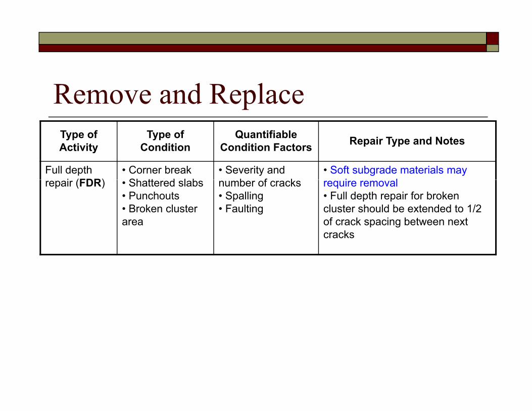
Remove and ReplaceType of Activity
Type of Condition
Quantifiable Condition Factors Repair Type and Notes
Full depth i (FDR)
• Corner breakSh tt d l b
• Severity and b f k
• Soft subgrade materials may i lrepair (FDR) • Shattered slabs
• Punchouts• Broken cluster area
number of cracks• Spalling• Faulting
require removal• Full depth repair for broken cluster should be extended to 1/2 of crack spacing between next
kcracks

Repair Decision FlowchartsAC/Non AC Overlayed Jointed Concrete Pavement
AC/Non AC Overlayed Continuously Reinforced Concrete PavementConcrete Pavement
Based on the pavement condition evaluation
Decision flowchart is self explanatory
Provides guidance for effective routine maintenance

Decision Flowchart for AC/Non AC Overlayed JCP R i M iJCP Routine Maintenance
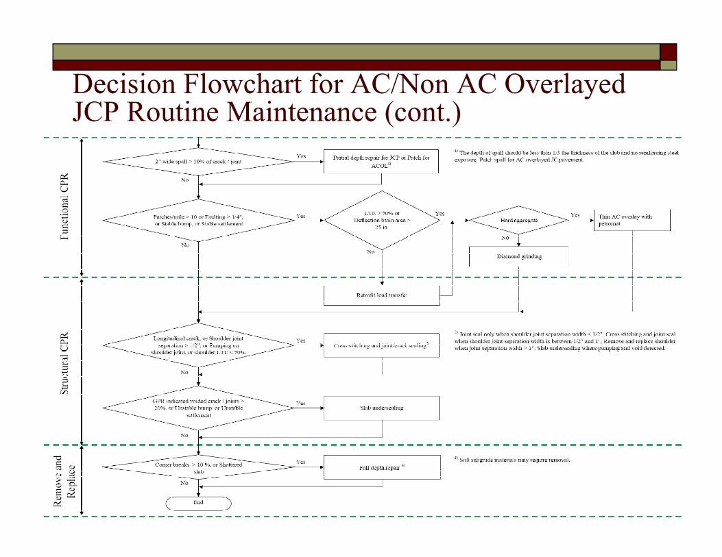
Decision Flowchart for AC/Non AC Overlayed JCP R i M i ( )JCP Routine Maintenance (cont.)

Decision Flowchart for AC/Non AC Overlayed CRCP R i M iCRCP Routine Maintenance

Decision Flowchart for AC/Non AC Overlayed CRCP R i M i ( )CRCP Routine Maintenance (cont.)

Decision Flowchart ExampleDecision Flowchart Example - Performance Monitoring Stage

Decision Flowchart Example (cont.)Decision Flowchart Example (cont.)- Preservative Maintenance

Decision Flowchart Example (cont.)Decision Flowchart Example (cont.)- Functional CPR
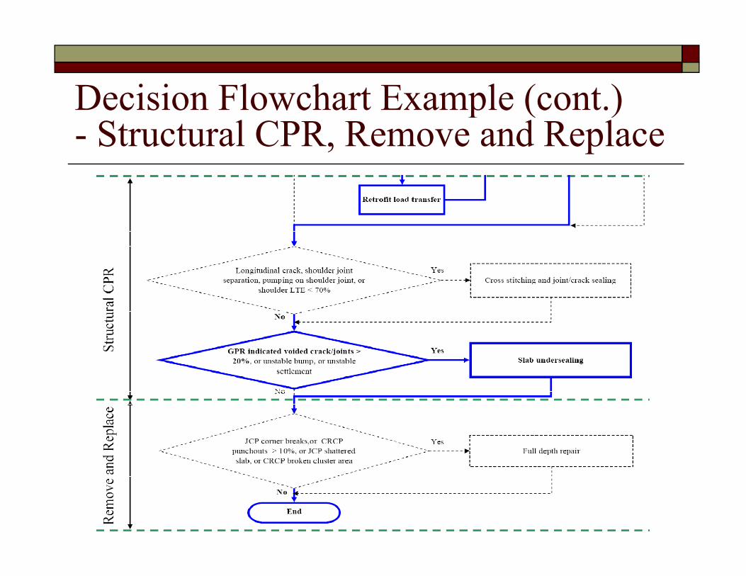
Decision Flowchart Example (cont.)Decision Flowchart Example (cont.)- Structural CPR, Remove and Replace

Routine Maintenance Repair DetailsP tiPreservative
Seal joint and cracksRetrofit edge drains
Functional CPRPartial depth repairDiamond grindingg g
Structural CPRRetrofit load transferCross stitchingCross stitchingSlab undersealing
Remove and ReplaceF ll d th iFull depth repair

Seal Joint and CracksObject of repairObject of repair
Reduce infiltration of moisture and incompressive material, Reduce pumping and faulting
LimitationsLimitationsQuestionable for long-term effectiveness
Unit repair cost * $0 75 - 1 25/ft (hot pour) $1 00 - $2 00/ft (silicon)$0.75 - 1.25/ft (hot pour), $1.00 - $2.00/ft (silicon)
Expected life extension3 - 8 years
Typical repair work timeTypical repair work time5,000 ft / day (hot pour)
RecommendationsSelect proper sealing material based on temperature and moistureSelect proper sealing material based on temperature and moisture conditions
* Reference: Hoerner, T. E., K. D. Smith, H. T. Yu, D. G. Peshkin, and M. J. Wade. “PCC Pavement Evaluation and Rehabilitation,” Reference Manual,NHI Course 131062. National Highway Institute, Arlington, VA, 2001.
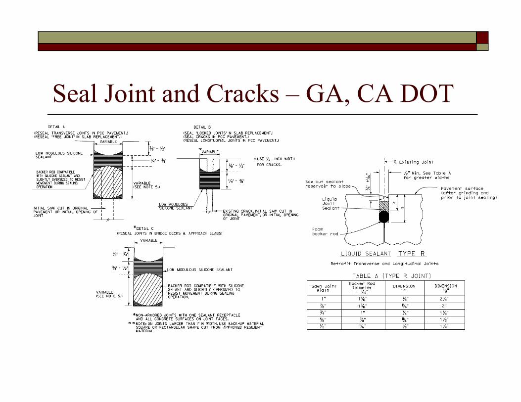
Seal Joint and Cracks – GA, CA DOT

Retrofit Edge DrainsObject of repairObject of repair
Provide drainage of surface water, reduce pumping, faulting, and other moisture damage
LimitationsMay accelerate deterioration if not maintained well, Not recommended if no base or base contains excessive amount of fines (>15% passing No. 200 sieve)
Unit repair cost *Unit repair cost $2.00 - $4.00/ft
Expected life extensionLife of existing pavementg p
Typical repair work time1 mile / day
RecommendationsP d i t ti d i t i ti lProper design, construction, and maintenance is essential
* Reference: Hoerner, T. E., K. D. Smith, H. T. Yu, D. G. Peshkin, and M. J. Wade. “PCC Pavement Evaluation and Rehabilitation,” Reference Manual,NHI Course 131062. National Highway Institute, Arlington, VA, 2001.

Retrofit Edge Drains – CT, IA DOT
Construct edge drain out side of shoulder if PCC shoulder

Partial Depth RepairObject of repairObject of repair
Repair spall and distress without removing entire slabLimitations
Full depth repair is needed if the damage extends below 1/3 the slabFull-depth repair is needed if the damage extends below 1/3 the slab thickness
Unit repair cost *$325 - $500/yd3$325 $500/yd
Expected life extension3 - 10 years
Typical repair work timeyp p4 to 12 repairs / hr, curing time not included
RecommendationsPartial depth repairs should restore the joint face, and joint should be p p j , jsealed properly
Reference: Hoerner, T. E., K. D. Smith, H. T. Yu, D. G. Peshkin, and M. J. Wade. “PCC Pavement Evaluation and Rehabilitation,” Reference Manual,NHI Course 131062. National Highway Institute, Arlington, VA, 2001.

Partial Depth Repair – GA DOT

Partial Depth Repair – TxDOT Lufkin
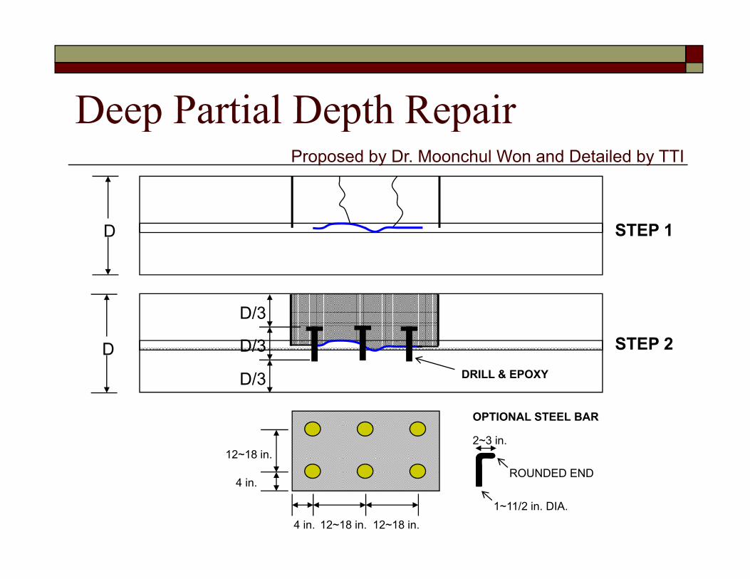
Deep Partial Depth RepairDeep Partial Depth Repair Proposed by Dr. Moonchul Won and Detailed by TTI
STEP 1D
D/3
STEP 2D
D/3
D/3DRILL & EPOXY
12~18 in.
OPTIONAL STEEL BAR
2~3 in.
ROUNDED END
12~18 in.
4 in.
4 in. 12~18 in.1~11/2 in. DIA.
ROUNDED END

Diamond GrindingObject of repairObject of repair
Provide smooth riding surface with good texture, reduce noise Limitations
Roughness will return if underlying causes not addressedRoughness will return if underlying causes not addressedUnit repair cost *
$1.80 - $7.80/yd2
Expected life extensionExpected life extension8 - 12 years
Typical repair work time2 500 yd2/day2,500 yd /day
RecommendationsGrinding should not be employed on pavements with material problemsproblems
* Reference: Hoerner, T. E., K. D. Smith, H. T. Yu, D. G. Peshkin, and M. J. Wade. “PCC Pavement Evaluation and Rehabilitation,” Reference Manual,NHI Course 131062. National Highway Institute, Arlington, VA, 2001.

Diamond Grinding – ACPA

Retrofit Load TransferObject of repairObject of repair
Restore load transfer to reduce faulting, pumping, and crack/joint deterioration
LimitationsPavements exhibiting material related distresses such as D-cracking or reactive aggregate are not good for dowel bar retrofitting
Unit repair cost *$25 $35/d l$25 - $35/dowel
Expected life extension10 - 15 years
Typical repair work timeTypical repair work time150 joint / day
RecommendationsDiamond grinding is needed to remove existing faulting, and Slab stabilization is needed to address loss of support
* Reference: Hoerner, T. E., K. D. Smith, H. T. Yu, D. G. Peshkin, and M. J. Wade. “PCC Pavement Evaluation and Rehabilitation,” Reference Manual,NHI Course 131062. National Highway Institute, Arlington, VA, 2001.

Retrofit Load Transfer – CA DOT

Retrofit Load Transfer – CA DOT

Retrofit Load Transfer – WA DOT

Cross StitchingObject of repairObject of repair
Hold longitudinal crack or joint together and prevent opening of crack or joint
LimitationsApplicable for fair condition and may not prevent secondary cracking or crack propagation
Unit repair cost *$9 - $10/bar$9 $10/bar
Expected life extension3 - 6 years
Typical repair work time1,500 ft / day
RecommendationsCross stitching and joint seal when shoulder joint separation is between ½ in. and 1 in.between ½ in. and 1 in.Rehabilitation is required when secondary cracks develop
* Reference: Hoerner, T. E., K. D. Smith, H. T. Yu, D. G. Peshkin, and M. J. Wade. “PCC Pavement Evaluation and Rehabilitation,” Reference Manual,NHI Course 131062. National Highway Institute, Arlington, VA, 2001.

Cross Stitching – ACPA
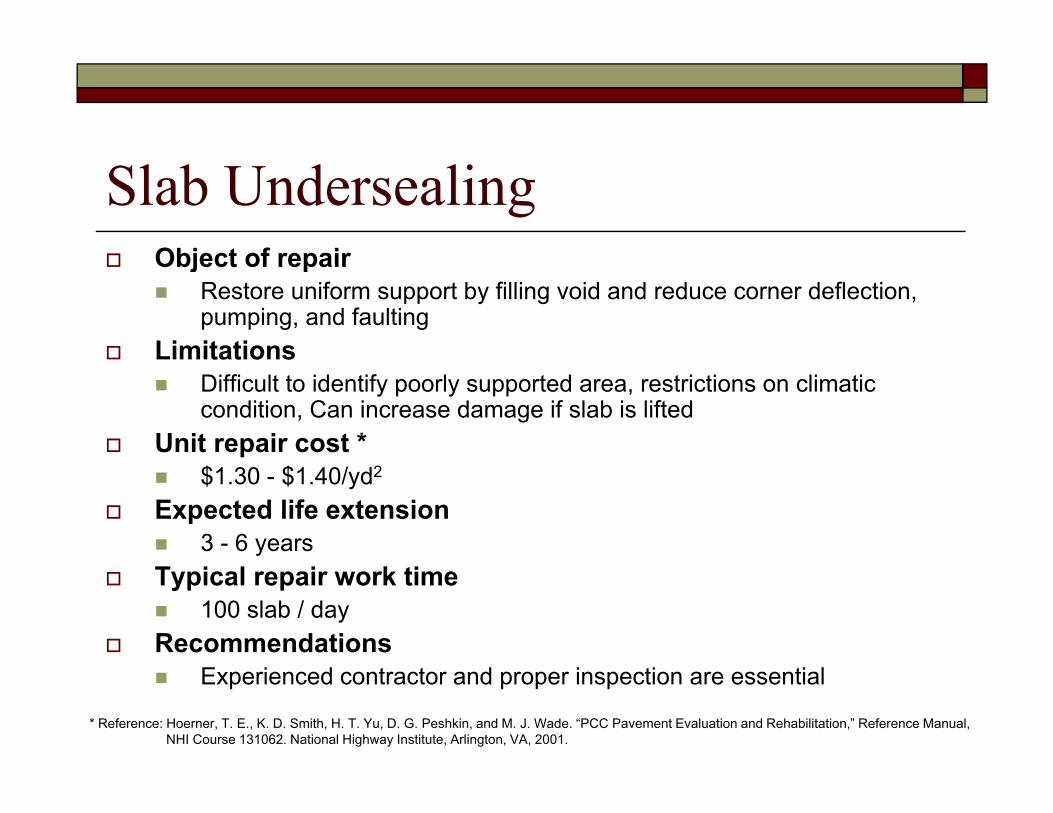
Slab UndersealingObject of repairObject of repair
Restore uniform support by filling void and reduce corner deflection, pumping, and faulting
LimitationsLimitationsDifficult to identify poorly supported area, restrictions on climatic condition, Can increase damage if slab is lifted
Unit repair cost *$1.30 - $1.40/yd2
Expected life extension3 - 6 years
Typical repair work time100 slab / day
RecommendationsExperienced contractor and proper inspection are essential
* Reference: Hoerner, T. E., K. D. Smith, H. T. Yu, D. G. Peshkin, and M. J. Wade. “PCC Pavement Evaluation and Rehabilitation,” Reference Manual,NHI Course 131062. National Highway Institute, Arlington, VA, 2001.

Slab Undersealing – ACPA

Full Depth RepairObject of repairObject of repair
Remove all deterioration in the distressed area, restore load transfer at joints and cracks
LimitationsAdditional joints introduced by full-depth repairs may add to the pavement roughness
Unit repair cost *$90 $100/ d2$90 - $100/yd2
Expected life extension5 - 15 years
Typical repair work timeTypical repair work time4 to 6 repairs / hr, curing time not included
RecommendationsIf the deterioration is widespread over the entire project length, an overlay or reconstruction may be more cost effective
* Reference: Hoerner, T. E., K. D. Smith, H. T. Yu, D. G. Peshkin, and M. J. Wade. “PCC Pavement Evaluation and Rehabilitation,” Reference Manual,NHI Course 131062. National Highway Institute, Arlington, VA, 2001.

Full Depth Repair – ACPA
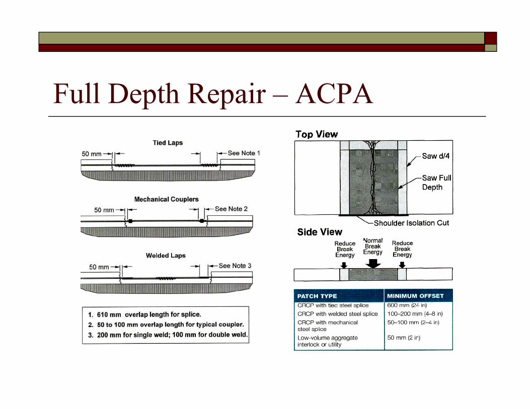
Full Depth Repair – ACPA

Full Depth Repair – TxDOT
TABLE

Full Depth Repair – MI DOT

Full Depth Repair – MI DOT

Precast Concrete Full Depth Repair
1. Precast PCC panel 2. Slab removal 3. Dowel slots
4. Flowable fill 5. PCC panel Installation 6. Finishing
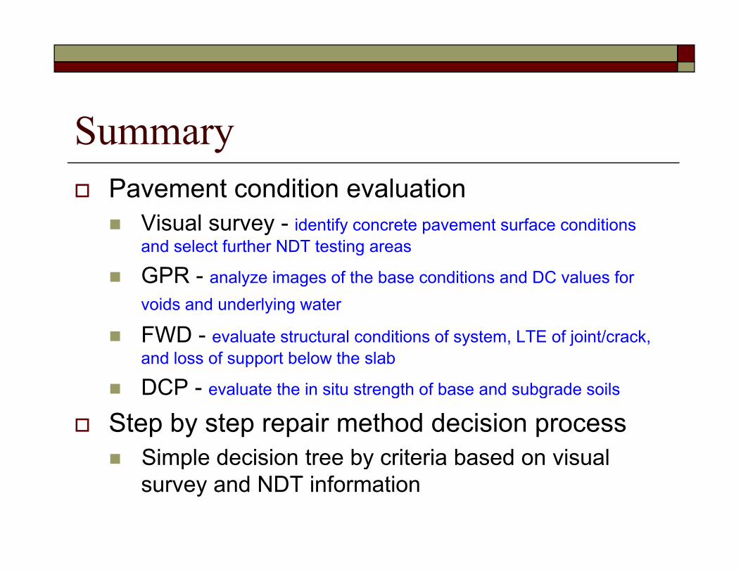
SummaryPavement condition evaluation
Visual survey - identify concrete pavement surface conditions and select further NDT testing areasand select further NDT testing areas
GPR - analyze images of the base conditions and DC values for voids and underlying water
FWD - evaluate structural conditions of system, LTE of joint/crack, and loss of support below the slab
DCP - evaluate the in situ strength of base and subgrade soilsDCP evaluate the in situ strength of base and subgrade soils
Step by step repair method decision processSimple decision tree by criteria based on visual p ysurvey and NDT information
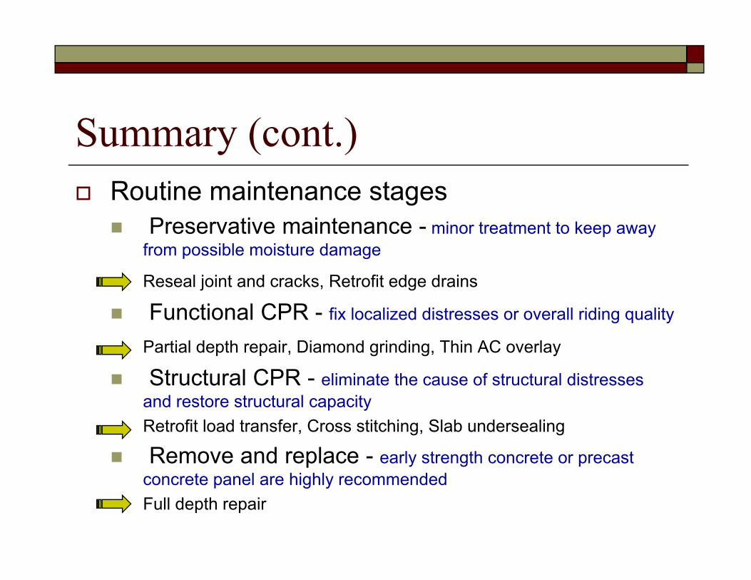
Summary (cont.)Routine maintenance stages
Preservative maintenance - minor treatment to keep away from possible moisture damagefrom possible moisture damage
Reseal joint and cracks, Retrofit edge drains
Functional CPR - fix localized distresses or overall riding quality
Partial depth repair, Diamond grinding, Thin AC overlay
Structural CPR - eliminate the cause of structural distresses and restore structural capacityand restore structural capacityRetrofit load transfer, Cross stitching, Slab undersealing
Remove and replace - early strength concrete or precast l hi hl d dconcrete panel are highly recommended
Full depth repair

Questions ?Questions ?