a comprehensive field guide for reconfiguration of...
TRANSCRIPT

A Comprehensive Field Guide for Reconfiguration of MSE Reinforcement Around Obstructions
Priyantha W. Jayawickrama, Tewodros Ghebrab, and William D. Lawson
Performed in cooperation with the Texas Department of Transportation
and the Federal Highway Administration
Research Project 5-6493-01
Research Report 5-6493-01-P1
http://www.techmrt.ttu.edu/reports.php
Texas Tech University
Multidisciplinary Research in Transportation

T E X A S D E P A R T M E N T O F T R A N S P O R T A T I O N
Study Title
A Comprehensive Field Guide for Reconfiguration of MSE Reinforcement Around Obstructions
Sponsored by Texas Department of Transportation
In Cooperation with U.S. Department of Transportation
Federal Highway Administration
Project Advisory Committee Marcus J. Galvan, P.E.
John G. Delphia, P.E.
Submitted December 12, 2017
Authors
Priyantha W. Jayawickrama, Ph.D. Tewodros Ghebrab, P.E., Ph.D. William D. Lawson, P.E., Ph.D.
Research Product 5-6493-PR1 Research Implementation Project 5-6493-01
Center for Multidisciplinary Research in Transportation (TechMRT) TEXAS TECH UNIVERSITY Lubbock, TX 79409-1023

T E X A S D E P A R T M E N T O F T R A N S P O R T A T I O N
PREFACE
This document provides guidelines for reconfiguration of earth reinforcements to avoid obstructions found within the reinforced fill during Mechanically Stabilized Earth (MSE) wall construction. The guidance provided herein is intended to assist Texas Department of Transportation (TxDOT) design engineers, consultants, MSE wall suppliers, contractors, and TxDOT field inspectors when selecting alternative reinforcement configurations to resolve conflicts between design reinforcement layouts and obstructions. This Field Guide places special emphasis on the types of obstructions and MSE reinforcements that are most commonly encountered in TxDOT MSE wall construction practice.
The following topics are discussed in this Field Guide:
• Scope: Specific types/categories of MSE walls, earth reinforcements and obstructions covered
by this Field Guide
• Policy Documents and Specifications: Policy documents and specifications that govern MSE wall design and construction and also provide guidance on obstruction avoidance
• First Things First: A commentary on the need for proper planning and coordination between MSE design engineers, wall suppliers and contractors including the importance of field personnel training and construction quality control/quality assurance
• General Requirements for MSE Wall Construction: An overview of general requirements applicable to MSE wall construction including material selection, material handling and storage, select backfill placement and compaction, reinforcement protection and connection details
• Obstruction Avoidance Strategies: Guidance on different types of obstructions encountered during MSE wall construction, the design principles governing the choice of an appropriate obstruction avoidance strategy and alternative reinforcement details to address specific MSE reinforcement-obstruction conflict situations
• Reinforcement Details at Wall Corners: Reinforcement details for both Acute Corners and Wide Wall Corners
• Other Types of MSE Reinforcement: Obstruction avoidance for other types of MSE reinforcement.

A COMPREHENSIVE FIELD GUIDE FOR RECONFIGURATION OF MSE REINFORCEMENT AROUND OBSTRUCTIONS
TABLE OF CONTENTS
PREFACE
1. INTRODUCTION 1 1.1 Scope 1 1.2 Policy Documents and Specifications 2
2. FIRST THINGS FIRST 3 2.1 Planning and Coordination 3 2.2 Training Field Personnel 4 2.3 Construction Quality Control 4
3. GENERAL REQUIREMENTS FOR MSE WALL CONSTRUCTION 5 3.1 General 5 3.2 Backfill Quality 5 3.3 Backfill Placement and Compaction 6 3.4 Precast Concrete Facing Panels 7 3.5 MSE Reinforcement 8
4. OBSTRUCTION AVOIDANCE 10 4.1 General 10 4.2 Horizontal Obstructions 10 4.3 Vertical Obstructions 11 4.4 The Fundamental Design Rule for Obstruction Avoidance 11
5. RECONFIGURATION STRATEGIES FOR RIBBED STRIP REINFORCEMENT 13 5.1 General 13 5.2 Skewing 15 5.3 Lateral Shifting 17 5.4 Structural Frame 19 5.5 Backer Panels 20
6. RECONFIGURATION STRATEGIES FOR WELDED GRID REINFORCEMENT 22 6.1 General 22 6.2 Cutting-and-Splaying 22 6.3 Lateral Shifting 25 6.4 Structural Frame 26 6.5 Backer Panels 28
7. REINFORCEMENT DETAIL AT WALL CORNERS 30 7.1 General 30 7.2 Ribbed Strips 33 7.3 Welded Wire Grids 33
8. OBSTRUCTION AVOIDANCE FOR OTHER TYPES OF MSE REINFORCEMENT 36
9. BIBLIOGRAPHY 37

A COMPREHENSIVE FIELD GUIDE FOR RECONFIGURATION OF MSE REINFORCEMENT AROUND OBSTRUCTIONS
1| P a g e
1. INTRODUCTION 1 .1 S C O P E
Mechanically Stabilized Earth (MSE) walls are broadly classified into two major categories: (a) permanent MSE walls and (b) temporary MSE walls. The guidance presented in this document is intended for use with permanent MSE walls only. Permanent MSE walls built by the Texas Department of Transportation (TxDOT) are constructed almost exclusively with precast concrete facing panels and inextensible galvanized steel earth reinforcements. Two types of galvanized steel MSE reinforcement are common in TxDOT MSE wall construction practice: (a) ribbed strip reinforcement (HA-strip reinforcement), and (b) three-wire welded grid reinforcement (See Figure 1.1). The guidance provided herein specifically address these two types of MSE reinforcement. This Field Guide does not directly address other types of MSE reinforcement such as continuous wire mesh or polymeric grids.
(a) (b)
Figure 1.1 Galvanized steel MSE reinforcement Used in TxDOT MSE wall construction: (a) ribbed strip reinforcement, (b) three-wire welded grid reinforcement
Obstructions found within the reinforced soil mass are also divided into two major categories: (a) vertical obstructions and (b) horizontal obstructions. Vertical obstructions are structures that are embedded in or extend vertically through the reinforced soil mass. Examples of vertical obstructions include storm water inlets, drilled shaft or driven pile foundations supporting bridge abutments, roadway sign structures, light poles etc. Horizontal obstructions are structures which are embedded in or extend horizontally through the reinforced soil mass for a substantial length along the wall. Horizontal obstructions are commonly due to utilities such as storm drain pipes. Current TxDOT design practice for MSE walls requires any horizontal obstructions found within the reinforced fill to be relocated away from the wall. As a result of this requirement, problems resulting from conflicts between MSE reinforcement and horizontal obstructions are relatively infrequent. For this reason, reinforcement reconfiguration strategies to deal with horizontal obstructions are not included within the scope of this Field Guide.

T E X A S D E P A R T M E N T O F T R A N S P O R T A T I O N
2| P a g e
1 .2 P O L I C Y D O C U M E N T S A N D S P E C I F I C A T I O N S
The primary policy document that governs the design of MSE structures for transportation applications is AASHTO LRFD Bridge Design Specifications (AASHTO, 2014). Section 11.10.10.4 of the AASHTO design specifications provides guidance related to appropriate strategies for dealing with obstructions embedded within the reinforced soil mass. Guidance related to obstruction avoidance is also found in Section 5.4 of FHWA-NHI-10-024: Design and Construction of Mechanically Stabilized Earth Walls and Reinforced Soil Slopes – Volume I (FHWA, 2009a). The guidance found in the above policy documents has been appropriately incorporated into this Field Guide. Modifications have been made where necessary so that guidance provided in this Field Guide will be consistent with MSE wall construction practice in Texas. In addition to the standard obstruction avoidance details found in policy documents, this Field Guide also presents special reinforcement reconfiguration strategies that have been developed in Texas to resolve more challenging MSE reinforcement conflicts with large obstructions. Specifications for the construction of MSE walls in TxDOT projects are found in ITEM 423: Retaining Walls, Texas Department of Transportation Standard Specifications (TxDOT, 2014). Table 1.1 below provides more complete reference details for these three policy documents.
Table 1.1 Policy Documents and Specifications Governing the Design and Construction of TxDOT MSE Walls
AASHTO (2014), AASHTO LRFD Bridge Design Specifications, Customary U.S. Units, 7th Edition, 2014, with 2015 Interim Revisions, American Association of State and Highway Transportation Officials (AASHTO), Washington DC.
FHWA (2009a), “Design of Mechanically Stabilized Earth Walls and Reinforced Slopes,” Vol. I, Report No. FHWA-NHI-10-024, Federal Highway Administration, US Department of Transportation, Washington D.C.
TxDOT (2014), Texas Department of Transportation Standard Specifications for Construction and Maintenance of Highways, Streets and Bridges, ITEM 423: Retaining Walls.

A COMPREHENSIVE FIELD GUIDE FOR RECONFIGURATION OF MSE REINFORCEMENT AROUND OBSTRUCTIONS
3| P a g e
2. FIRST THINGS FIRST 2 .1 P L A N N I N G A N D C O O R D I N A T I O N
As stated earlier, the primary purpose of this field manual is to provide guidance regarding the selection and implementation of appropriate reinforcement reconfiguration strategies to address specific MSE reinforcement-obstruction conflict situations that arise in the field. Ideally however, potential to have such reinforcement-obstruction conflicts in a given MSE wall construction project must be determined through careful review during project planning stage. Such review may allow necessary revisions to be made in the construction plans prior to wall construction so that the need for reinforcement reconfiguration is minimized or, even completely eliminated. For example, it may be possible to relocate a storm water drainage pipe away from the reinforced fill and hence avoid conflicts with soil reinforcements. Or else, design engineer may select an alternative drainage inlet design (See shallow inlet shown in Figure 2.1 below) and thus avoid interference with the placement of soil reinforcements. The shallow drainage inlet shown in Figure 2.1 is one such example. The shallow depth of the inlet allows the MSE reinforcement layer to be placed below the inlet thus avoiding the potential conflict. Despite careful attention during the planning stage,in some cases, the option of relocating the obstruction to avoid conflict with soil reinforcement may not exist and therefore, an optimum strategy to resolve the conflict must be selected. In extreme cases where the obstructions are too large or too closely spaced, the design engineer may consider using an alternative wall design such as a cantilevered reinforced concrete wall or a drilled shaft wall that does not require placement of reinforcing elements within soil backfill.
From the above discussion, it is clear that careful review during the project planning stage and proper coordination among various entities involved (viz. project planners, design engineers, wall suppliers and contractors) are vital to achieving optimum designs with respect to reinforcement reconfiguration around obstructions found within reinforced fill.
Figure 2.1 Shallow Drainage Inlet

T E X A S D E P A R T M E N T O F T R A N S P O R T A T I O N
4| P a g e
2 . 2 T R A I N I N G F I E L D P E R S O N N E L
Construction of MSE systems is considered to be relatively simple and straight forward. Accordingly, erection of MSE wall systems can be achieved without specialized equipment or construction crew with special expertise. Nevertheless, it is important that construction crew and inspection personnel have sufficient training on the specific steps involved in the MSE wall construction process. They must have intimate knowledge and understanding of site conditions, material specifications, material handling and storage requirements, DO’s and DON’Ts applicable to each stage of construction so that potential performance problems of the wall system can be avoided. Prior to construction, field personnel responsible for supervision and inspection of the construction of the wall should obtain a complete set of most recent issue of approved plans, specifications and contract documents and review them in detail. A comprehensive checklist for review of MSE structure construction documents is presented in Table 11-2 of the FHWA Publication No. FHWA-NHI-10-025 (FHWA, 2009b).
2 . 3 C O N S T R U C T I O N Q U A L I T Y C O N T R O L
Proper quality control and quality assurance during construction of the MSE wall system play a critical role in making sure that the MSE structure is built in strict accordance with plans, specifications and contract documents. A general construction quality control protocol applicable to a generic MSE retaining structure system and construction quality control checklist can be found in Chapter 11 of the FHWA Publication No. FHWA-NHI-10-025 (FHWA, 2009b). Similarly, more specific construction and quality control procedures manuals for specific proprietary wall systems are available through wall suppliers (e.g. RECo, 2011). In addition to the above, TxDOT Bridge Division has developed an MSE Wall Inspection Checklist based on the Department’s experience with MSE wall construction as well as guidance available from other published literature.
This Field Guide is specifically focused on reinforcement reconfiguration around obstructions and therefore, does not attempt to provide guidance on quality control related to all aspects of MSE wall construction in a comprehensive manner. That having been said, standard quality control procedures and practices cover many if not most of the issues associated with obstruction avoidance. Specific quality control measures that are relevant to successful implementation of reinforcement reconfiguration strategies recommended in this field guide are presented in Section 3.

A COMPREHENSIVE FIELD GUIDE FOR RECONFIGURATION OF MSE REINFORCEMENT AROUND OBSTRUCTIONS
5| P a g e
3. GENERAL REQUIREMENTS FOR MSE WALL CONSTRUCTION
3 .1 G E N E R A L
Internal stability of MSE wall systems relies on proper engagement between select backfill and the steel MSE reinforcement. In other words, the galvanized steel strips or welded grids should remain interlocked within the compacted granular fill so that sufficient resistance can develop against potential movements of the facing panels and the reinforcement relative to the backfill. This requires careful control of the select backfill material, its placement and compaction as well as tight connection between the steel reinforcement and the facing panel with no slack. When obstructions are present within the reinforced fill and reinforcements are reconfigured around them, there is greater potential for the integrity of the backfill-reinforcement system to be impaired. Therefore, placement of backfill and reinforcement in the vicinity of obstructions require special care and attention. This section reviews quality control measures that must be taken to ensure that proper engagement between the select backfill and reinforcement is maintained during reinforcement reconfiguration around obstructions.
3 . 2 B A C K F I L L Q U A L I T Y
All MSE walls require select backfill within the reinforced soil zone. Select backfill for TxDOT walls consists of granular, free-draining sand, gravel or crushed rock as prescribed in Standard Specifications for Construction and Maintenance of Highways, Streets and Bridges, ITEM 423: Retaining Walls (TxDOT, 2014). Strict adherence to select backfill gradation limits specified in Table 2 of ITEM 423 is important because backfill gradation has significant impact on the design, construction and performance of the wall system. Select backfill used in MSE wall systems must also meet requirements for electrochemical properties (pH resistivity, chloride and sulfate contents) as these parameters determine the corrosive potential of the backfill. Select backfill should also be tested for soundness using Tex-411-A: 5-cycle magnesium soundness test (TxDOT, 2004) or Tex-461-A: Micro-deval abrasion test (TxDOT, 2005). Figure 3.1 shows select material that appears to contain shale, caliche or other soft particles and therefore, may not meet soundness requirements.
(a) (b) (c) Figure 3.1. Unsound Backfill Materials that do not Meet Soundness Test Requirements

T E X A S D E P A R T M E N T O F T R A N S P O R T A T I O N
6| P a g e
Select backfill materials may show significant variability and therefore, they should be tested prior to construction and then periodically throughout the construction process to ensure compliance with specifications. According to TxDOT Guide Schedule for Sampling and Testing (TxDOT, 2015), select backfill used in MSE wall construction may be sampled during stockpiling operations, from completed stockpiles or at the project site. Gradation, pH and resistivity testing should be performed once per each 5,000 cu.yd. and soundness testing performed at the rate of one test per source. Additional testing should be performed whenever the appearance or behavior of the material noticeably changes.
3 . 3 B A C K F I L L P L A C E M E N T A N D C O M P A C T I O N
ITEM 423 requires select backfill to be placed in loose lifts with thickness of 8 inches or less, sprinkled uniformly for moisture control and then compacted to achieve a minimum of 95% of the maximum dry density as determined in accordance with Tex-114-E. Field density measurements are to be made in accordance with Tex-115-E. Thickness of the lift should be decreased if such reduction is necessary in order to achieve specified density. The backfill should be compacted to produce an even surface that provides uniform support for the MSE reinforcements over the entire length. Figure 3.2 shows examples of non-uniform backfill support for soil reinforcements.
(a) (b)
Figure 3.2 Improperly Placed Backfill Providing Non-Uniform Support for Reinforcement
Compaction of the backfill within a 3-ft wide zone adjacent to the wall panels should be accomplished using small, hand-operated or walk behind compaction equipment. This type of compaction equipment will also be appropriate for use in the vicinity of obstructions where available space tends to be very limited. Outside of the 3-ft wide strip and away from obstructions, compaction may be achieved with large, smooth-drum vibratory rollers. Sheepsfoot, grid type rollers or track equipment should not be used because damage they may cause to the reinforcements.
A COMPREHENSIVE FIELD GUIDE FOR RECONFIGURATION OF MSE REINFORCEMENT AROUND OBSTRUCTIONS
7| P a g e
3 . 4 P R E C A S T C O N C R E T E F A C I N G P A N E L S
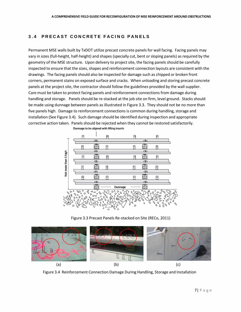
Permanent MSE walls built by TxDOT utilize precast concrete panels for wall facing. Facing panels may vary in sizes (full-height, half-height) and shapes (specially cut, bent or sloping panels) as required by the geometry of the MSE structure. Upon delivery to project site, the facing panels should be carefully inspected to ensure that the sizes, shapes and reinforcement connection layouts are consistent with the drawings. The facing panels should also be inspected for damage such as chipped or broken front corners, permanent stains on exposed surface and cracks. When unloading and storing precast concrete panels at the project site, the contractor should follow the guidelines provided by the wall supplier. Care must be taken to protect facing panels and reinforcement connections from damage during handling and storage. Panels should be re-stacked at the job site on firm, level ground. Stacks should be made using dunnage between panels as illustrated in Figure 3.3. They should not be no more than five panels high. Damage to reinforcement connections is common during handling, storage and installation (See Figure 3.4). Such damage should be identified during inspection and appropriate corrective action taken. Panels should be rejected when they cannot be restored satisfactorily.
Figure 3.3 Precast Panels Re-stacked on Site (RECo, 2011)
(a) (b) (c)
Figure 3.4 Reinforcement Connection Damage During Handling, Storage and Installation

A COMPREHENSIVE FIELD GUIDE FOR RECONFIGURATION OF MSE REINFORCEMENT AROUND OBSTRUCTIONS
8| P a g e
3 . 5 M S E R E I N F O R C E M E N T
Galvanized steel MSE reinforcements (strips, welded grids) are typically delivered at the project site securely bundled or packaged to avoid damage. The reinforcement lengths, wire diameters and spacings can vary at different locations with the same MSE structure. Therefore, the TxDOT Inspector should verify that the lengths and sizes of reinforcement delivered to site are consistent those shown on construction drawings. Grid reinforcement should be checked for wire diameter, length, width, and spacing of longitudinal and transverse members as well as for integrity of welded joints. For strip reinforcements, the length and thickness should be checked. Open storage at the project site is generally permissible. However, reinforcement material should not be stored directly on the ground.
MSE reinforcement should be installed in strict compliance with spacing and length requirements shown on the plans. Reinforcements are placed on compacted backfill and generally positioned perpendicular to the back of the facing panels. Each MSE system has a unique facing connection detail. Connections are manufacturer-specific and must be made in accordance with the specifications furnished by the manufacturer. Standard connection details for the types of steel reinforcement commonly used in TxDOT MSE wall construction (i.e. ribbed strip and three-wire grid reinforcement) are shown in Figure 3.5. When connecting the reinforcement to the facing panel, it is important that any slack in the reinforcement and the connection be completely removed. This is to minimize potential for subsequent lateral outward movement of the facing panel as backfill material is added.
(a) (b)
Figure 3.5 Reinforcement Connection Details (a) Ribbed Strips [RECo, 2011], (b) Welded Grids [Tricon, 1993]
Figure 3.6 shows two examples of improper connections observed in the field. Figure 3.6 (a) shows an incomplete connection in which the locking rod had not been pushed through all three clevis loops. In Figure 3.6(b), proper bearing between the entire length of the locking rod and the transverse bar in the grid has not been achieved. The grid appears to be rotated relative to the wall panel with significant slack on one side of the connection. Thus, there is potential for movement on one side of the panel.

A COMPREHENSIVE FIELD GUIDE FOR RECONFIGURATION OF MSE REINFORCEMENT AROUND OBSTRUCTIONS
9| P a g e
(a) (b)
Figure 3.6 Improper Reinforcement Connections
Once the reinforcement has been placed, care must be taken to avoid direct contact between construction equipment and the reinforcement. Sheepsfoot, grid type rollers or track equipment should not be used because damage they may cause to the reinforcements. Figure 3.7 below shows damage to MSE reinforcement caused by the use of track equipment directly on the reinforcement.
(a) (b)
Figure 3.7 Reinforcement Damage Caused by Use of Track Equipment Directly on Reinforcement

A COMPREHENSIVE FIELD GUIDE FOR RECONFIGURATION OF MSE REINFORCEMENT AROUND OBSTRUCTIONS
10| P a g e
4. OBSTRUCTION AVOIDANCE 4 .1 G E N E R A L
In MSE walls, soil reinforcements such as ribbed strips and welded-grids are designed to anchor the MSE facings panels while stabilizing the soil by increasing its strength and load-bearing capacity. To be able to fulfill these design requirements effectively, the soil reinforcements must fully extend to their design lengths. Many MSE walls, however, encounter structures located within the reinforced soil zone which obstruct and prevent the soil reinforcements from being placed in their proper design configuration. These structures, which obstruct the reinforcement layout, are referred to as “obstructions.” MSE wall reinforcement obstruction can be classified into two main categories: “Vertical Obstructions” and “Horizontal Obstructions.” The main focus of this Field Guide is on vertical obstructions. In other words, primary emphasis will be given to those types of obstructions and problems they pose on wall construction and performance.
4 . 2 H O R I Z O N T A L O B S T R U C T I ON S
Horizontal obstructions are structural elements located within the reinforced soil zone and which run parallel to the MSE wall. These structures, such as drainage pipes, conflict with the vertical alignment of the soil reinforcements. Figure 4.1 shows two examples of such horizontal obstructions. At the present time, according to TxDOT design practice for MSE walls, any horizontal obstructions found within the reinforced fill must be relocated away from reinforced soil zone. As a result of this requirement, problems resulting from conflicts between MSE reinforcement and horizontal obstructions are relatively infrequent. For this reason, reinforcement reconfiguration strategies to deal with horizontal obstructions are not discussed in detail in this Field Guide.
(a) (b)
Figure 4.1 Horizontal Obstructions

T E X A S D E P A R T M E N T O F T R A N S P O R T A T I O N
11| P a g e
4 . 3 V E R T I C A L O B S T R U C T I O N S
Vertical obstructions are structural elements located within the reinforced soil zone and which run vertically into the ground. These structures include vertically oriented reinforced concrete drainage pipes, drainage inlets, reinforced concrete foundation shafts, guard rail and signage piles, etc. (See Figure 4.2). It should be noted that not all vertically oriented structures are treated as vertical obstructions. Vertical structures that are located outside the reinforced soil zone are not characterized as vertical obstructions because they do not conflict with the layout of the soil reinforcements. Those vertical structures that are located fully or partially within the reinforced soil zone are considered as vertical obstructions since they conflict with the reinforcement. The main focus of this document is on such vertical obstructions and strategies used to avoid conflicts they cause with the design layout of reinforcements.
Figure 4.2 Vertical Obstructions

A COMPREHENSIVE FIELD GUIDE FOR RECONFIGURATION OF MSE REINFORCEMENT AROUND OBSTRUCTIONS
12| P a g e
4.4 THE FUNDAMENTAL DESIGN RULE FOR OBSTRUCTION AVOIDANCE
MSE reinforcements play a vital role in achieving internal stability of the wall system. The number of reinforcing elements as well as their lengths and spacings (both in vertical and horizontal directions) are carefully specified by the design engineer to make sure there is adequate safeguard against wall failure by reinforcement pullout and reinforcement rupture. For this reason, these parameters should not be changed arbitrarily in the field during wall construction.
However, when obstructions are encountered within the reinforced backfill zone, reconfiguration of the reinforcements becomes necessary. When selecting an appropriate reconfiguration strategy, the new reinforcement layout should provide the same pullout resistance capacity and reinforcement rupture capacity as the original design layout. That is, the reconfigured MSE layout must provide resistance equal to or greater than the design layout affected by the obstruction. This fundamental rule governs the choice of any alternative reinforcement layout considered for the purpose of resolving reinforcement-obstruction conflicts.
The typical reinforcement reconfiguration strategies presented in the following sections satisfy this fundamental rule. However, field conditions and wall geometries may exist which cannot be accommodated by these typical strategies. In such cases, the reconfiguration will need to be specially designed, and the fundamental design rule provides a method to evaluate these and any other unique situations.

A COMPREHENSIVE FIELD GUIDE FOR RECONFIGURATION OF MSE REINFORCEMENT AROUND OBSTRUCTIONS
13| P a g e
5. RECONFIGURATION STRATEGIES FOR RIBBED STRIP REINFORCEMENT
5 . 1 G E N E R A L
Ribbed strips are among the most commonly used types of reinforcements in TxDOT MSE wall construction (Figure 5.1). Ribbed strips are hot-dipped galvanized to protect them against environmental attack and increase their longevity. They are pin connected to the MSE wall through a galvanized tie strip built into facing panel. The pin connection provides flexibility for the strips to rotate horizontally in order to avoid any obstruction. Figure 5.2 shows a bolted connection that is typically used between ribbed strip reinforcement and a precast concrete facing panel.
Figure 5.1 Ribbed Strip Reinforcement
When MSE walls with ribbed strip anchors encounter vertical obstructions, the most common strategies that can be safely used to avoid the conflict between the strips and the vertical obstructions are either skewing of the strips or laterally shifting the strips. Sometimes, combining both strategies can be the best option. In some projects that involve particularly large sized obstructions, the use of structural frame and backer panels are common.

T E X A S D E P A R T M E N T O F T R A N S P O R T A T I O N
14| P a g e
(a)
(b)
Figure 5.2 Ribbed Strip Connected to MSE wall (a) Actual Image (b) Schematic Detail

A COMPREHENSIVE FIELD GUIDE FOR RECONFIGURATION OF MSE REINFORCEMENT AROUND OBSTRUCTIONS
15| P a g e
5 . 2 S K E W I N G
Skewing the ribbed strip reinforcements to avoid an obstruction is an acceptable approach when the connections are designed to allow rotation (i.e. bolted connections). This type of connection will allow rotation of the reinforcement (i.e. skewing of the reinforcement) without generating undue stresses at the connection. However, it should be noted that AASHTO specifications and FHWA-NHI-10-024 recommend a maximum skew angle (referred to as splay angle in the above policy documents) of 15-degrees. It is further specified that the tensile capacity of the skewed reinforcement to be reduced by the cosine of the skew angle.
Skewing of strip reinforcements reduces the length of reinforcement embedded within the backfill resistance zone. Moreover, skewing has the potential to alter the lateral earth pressure distribution on the wall panel. However, at skew angles of less than 15-degree, these effects are deemed to be insignificant. Accordingly, use of skew angles of 15-degrees or less is considered an acceptable and therefore a commonly used reinforcement reconfiguration strategy for ribbed strip reinforcement. The major limitation in this strategy is that it cannot be used when the obstructions are large and when they are located too close to the wall panel. Figure 5.3 illustrates skewing of ribbed-strip reinforcement to avoid obstructions. When the skew angle is greater than the limiting value (15-degrees), skew up to 30-degrees may be used with necessary review and modification by the design engineer. For layouts requiring larger that 30-degree skew, other strategies such as lateral shifting should be considered.
When using skewing of ribbed strips as a strategy to avoid obstructions, the following guidelines should be followed:
1. The reinforcement should be rotated (skewed) at the pinned connection; 2. The reinforcement should not be cut, twisted or bent to avoid the obstruction; 3. The limiting skew angle (β) is 15-degrees; however, it can be exceeded up to 30-degrees with
the necessary review and modifications by the design engineer. 4. A minimum clearance (ρ) of 3-in should be maintained between the reinforcement and the
obstruction. 5. Special care should be taken when compacting backfill in the vicinity of the obstruction to
ensure that the specified level of compaction is achieved.

T E X A S D E P A R T M E N T O F T R A N S P O R T A T I O N
16| P a g e
(a)
(b)
Figure 5.3 Skewed Ribbed Strips (a) Actual Image (b) Schematic Description

A COMPREHENSIVE FIELD GUIDE FOR RECONFIGURATION OF MSE REINFORCEMENT AROUND OBSTRUCTIONS
17 | P a g e
5 . 3 L A T E R A L S H I F T I N G
Another acceptable strategy involves relocation of the ribbed strip reinforcement by shifting it laterally to avoid the conflict between the ribbed strip reinforcements and the vertical obstruction. When this approach is used, the wall facing is fitted with additional connectors and then the strip soil reinforcing is attached to the connectors away from the obstruction. Figure 5.4 shows a schematic representation of a lateral shifting of ribbed strip reinforcement to avoid an obstruction. To allow more flexibility during construction, it is advisable to cast some wall panels with extra connectors to be located at vertical obstructions. Alternatively, as shown in Figure 5.5, a galvanized steel angle of sufficient stiffness can be used to bridge across two facing panels of an MSE wall system that uses strip reinforcements. The reinforcing strips are then attached to the angle away from the obstruction (i.e. inlet structure).
Figure 5.4 Lateral Shifting of Ribbed Strips

18 | P a g e
T E X A S D E P A R T M E N T O F T R A N S P O R T A T I O N
(a)
(b) Figure 5.5 Lateral Shifting and Bridging Panels using Angle Iron (a) Actual Image (b)
Schematic View

19 | P a g e
A COMPREHENSIVE FIELD GUIDE FOR RECONFIGURATION OF MSE REINFORCEMENT AROUND OBSTRUCTIONS
5 . 4 S T R U C T U R A L F R A M E
Placing a structural frame (yoke) around the obstruction is another alternative that is used for avoiding conflicts between vertical obstructions and MSE reinforcement. The frame shall be capable of transferring the load from the reinforcement in front of the obstruction to the reinforcements behind the obstruction. Figures 5.6 and 5.7 depict two separate alternative reinforcement layouts in which structural frames are used to circumvent obstructions when welded grid reinforcements are used. Figure 5.6 is a strategy applicable when the obstruction is close to the MSE wall and Figure 5.7 shows the alternative that can be used when the obstruction is located further away from the wall.
The structural frame strategy, which is similar to the one identified as Alternative 2 in AASHTO Bridge Design Specifications, appears to be technically sound, particularly from a load transfer viewpoint. However, there are some drawbacks in this approach. First, a structural frame will be required at each and every reinforcement layer where the obstruction exists. This increases cost of construction significantly. Second, the structural frame makes it more difficult for good backfill compaction to be achieved in the vicinity of the obstruction.
Figure 5.6 Structural Frame with Obstruction Close to Wall
20 | P a g e
A COMPREHENSIVE FIELD GUIDE FOR RECONFIGURATION OF MSE REINFORCEMENT AROUND OBSTRUCTIONS
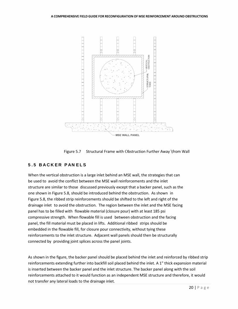
Figure 5.7 Structural Frame with Obstruction Further Away \from Wall
5 . 5 B A C K E R P AN E L S
When the vertical obstruction is a large inlet behind an MSE wall, the strategies that can be used to avoid the conflict between the MSE wall reinforcements and the inlet structure are similar to those discussed previously except that a backer panel, such as the one shown in Figure 5.8, should be introduced behind the obstruction. As shown in Figure 5.8, the ribbed strip reinforcements should be shifted to the left and right of the drainage inlet to avoid the obstruction. The region between the inlet and the MSE facing panel has to be filled with flowable material (closure pour) with at least 185 psi compressive strength. When flowable fill is used between obstruction and the facing panel, the fill material must be placed in lifts. Additional ribbed strips should be embedded in the flowable fill, for closure pour connectivity, without tying these reinforcements to the inlet structure. Adjacent wall panels should then be structurally connected by providing joint splices across the panel joints.
As shown in the figure, the backer panel should be placed behind the inlet and reinforced by ribbed strip reinforcements extending further into backfill soil placed behind the inlet. A 1" thick expansion material is inserted between the backer panel and the inlet structure. The backer panel along with the soil reinforcements attached to it would function as an independent MSE structure and therefore, it would not transfer any lateral loads to the drainage inlet.

21 | P a g e
A COMPREHENSIVE FIELD GUIDE FOR RECONFIGURATION OF MSE REINFORCEMENT AROUND OBSTRUCTIONS
This strategy has some drawbacks. The pour of the flowable material and the subsequent placement of the ribbed strips in the material for every single lift makes the construction time consuming and more expensive.
Figure 5.8 Use of Backer Panel to Avoid Large Obstructions

22 | P a g e
T E X A S D E P A R T M E N T O F T R A N S P O R T A T I O N
6. RECONFIGURATION STRATEGIES FOR WELDED GRID REINFORCEMENT
6 . 1 G E N E R A L
Welded grid reinforcements represent another type of earth reinforcement that is widely used in TxDOT MSE wall construction. Even though this type of grid reinforcement comes in various sizes and configurations, grids consisting of three longitudinal bars are by far the most common in TxDOT MSE wall construction projects (Figure 6.1). Welded grid reinforcements are connected to the wall panels by means of a locking rod which hooks the reinforcement into clevis loops cast into prefabricated facing panels. This type of connection does not allow the reinforcements to rotate in the horizontal plane. For this reason, skewing is not an option in this type of reinforcement.
A number of strategies may be used to resolve conflicts between welded grid reinforcements and vertical obstructions. They include: cutting and splaying, lateral shifting, the use of structural frame, and the use of a backer panels. When large obstructions are encountered, a combination of two or more of these strategies may be used.
Figure 6.1 3-Wire Grid Reinforcement
6 . 2 C U T T I N G A N D S P L A Y I N G
Horizontal rotation of welded grid reinforcement with respect to the wall panel to avoid an obstruction is not possible because of the type of connection used between the grid reinforcement and the wall panel (shown in Figure 6.1) and the finite width of the grid. However, the transverse bars in the grid may be cut, longitudinal bars separated allowing them to be splayed around the obstruction as shown in Figure 6.2. This strategy is commonly referred to as cutting and splaying.
The following guidelines should be followed when cutting and splaying of grid type reinforcement is used to avoid obstructions:
23 | P a g e
A COMPREHENSIVE FIELD GUIDE FOR RECONFIGURATION OF MSE REINFORCEMENT AROUND OBSTRUCTIONS
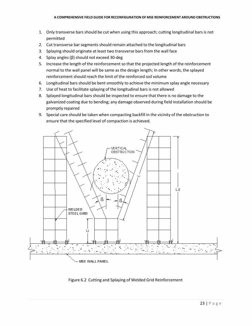
1. Only transverse bars should be cut when using this approach; cutting longitudinal bars is not permitted
2. Cut transverse bar segments should remain attached to the longitudinal bars 3. Splaying should originate at least two transverse bars from the wall face 4. Splay angles (β) should not exceed 30-deg 5. Increase the length of the reinforcement so that the projected length of the reinforcement
normal to the wall panel will be same as the design length; In other words, the splayed reinforcement should reach the limit of the reinforced soil volume
6. Longitudinal bars should be bent smoothly to achieve the minimum splay angle necessary 7. Use of heat to facilitate splaying of the longitudinal bars is not allowed 8. Splayed longitudinal bars should be inspected to ensure that there is no damage to the
galvanized coating due to bending; any damage observed during field installation should be promptly repaired
9. Special care should be taken when compacting backfill in the vicinity of the obstruction to ensure that the specified level of compaction is achieved.
Figure 6.2 Cutting and Splaying of Welded Grid Reinforcement

24 | P a g e
T E X A S D E P A R T M E N T O F T R A N S P O R T A T I O N
Figure 6.3 shows improper use of cut-and-splay strategy. In Figure 6.3(a) the transverse bars have been cut too close to the wall facing. As a result, connection between the grid and the wall panel has been adversely affected. In Figure 6.3(b) the transverse bars have been completely removed. This will reduce the pullout capacity of the grid significantly.
(a)
(b)
Figure 6.3 Improper Use of Cutting and Splaying Strategy
25 | P a g e
A COMPREHENSIVE FIELD GUIDE FOR RECONFIGURATION OF MSE REINFORCEMENT AROUND OBSTRUCTIONS
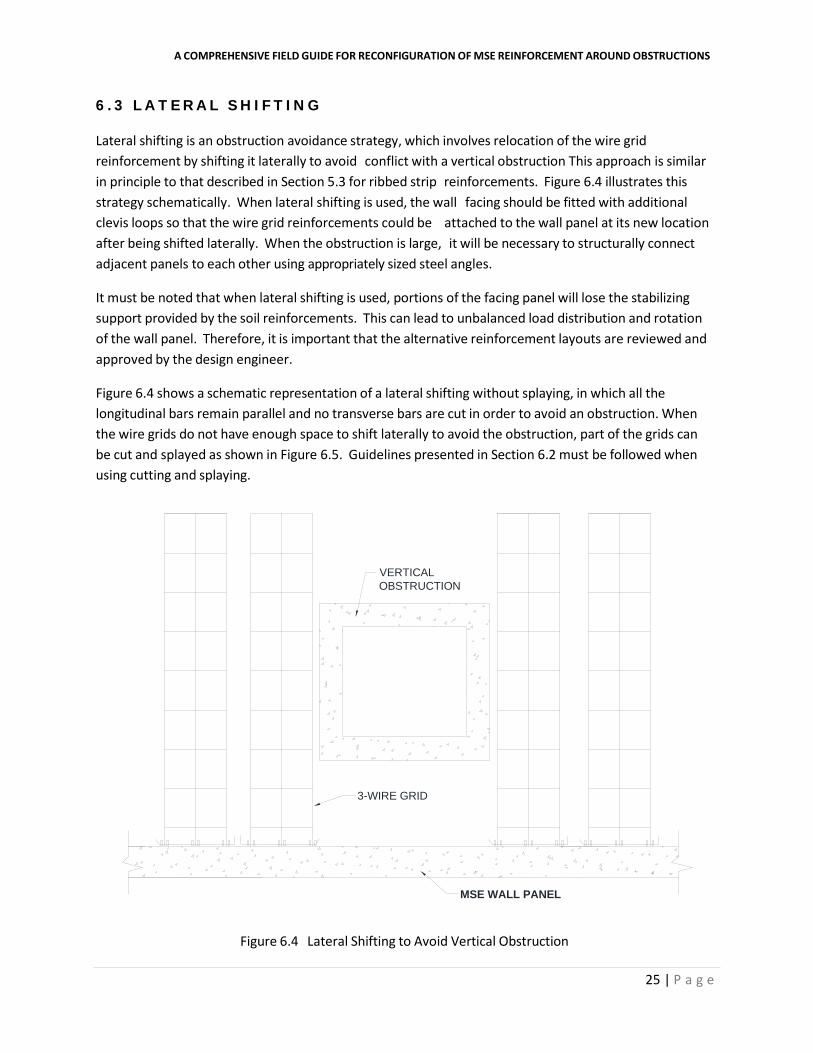
6.3 L A T E R A L S H I F T I N G
Lateral shifting is an obstruction avoidance strategy, which involves relocation of the wire grid reinforcement by shifting it laterally to avoid conflict with a vertical obstruction This approach is similar in principle to that described in Section 5.3 for ribbed strip reinforcements. Figure 6.4 illustrates this strategy schematically. When lateral shifting is used, the wall facing should be fitted with additional clevis loops so that the wire grid reinforcements could be attached to the wall panel at its new location after being shifted laterally. When the obstruction is large, it will be necessary to structurally connect adjacent panels to each other using appropriately sized steel angles.
It must be noted that when lateral shifting is used, portions of the facing panel will lose the stabilizing support provided by the soil reinforcements. This can lead to unbalanced load distribution and rotation of the wall panel. Therefore, it is important that the alternative reinforcement layouts are reviewed and approved by the design engineer.
Figure 6.4 shows a schematic representation of a lateral shifting without splaying, in which all the longitudinal bars remain parallel and no transverse bars are cut in order to avoid an obstruction. When the wire grids do not have enough space to shift laterally to avoid the obstruction, part of the grids can be cut and splayed as shown in Figure 6.5. Guidelines presented in Section 6.2 must be followed when using cutting and splaying.
Figure 6.4 Lateral Shifting to Avoid Vertical Obstruction
MSE WALL PANEL
VERTICALOBSTRUCTION
3-WIRE GRID

26 | P a g e
T E X A S D E P A R T M E N T O F T R A N S P O R T A T I O N
Figure 6.5 Lateral Shifting Used in Conjunction with Cut-and-Splay
6.4 S T R U C T U R A L F R A M E
Placing a structural frame (yoke) around the obstruction is another alternative that can be used for the purpose of avoiding conflicts between vertical obstructions and welded grid MSE reinforcement. The frame shall be capable of transferring the load from the reinforcement in front of the obstruction to the reinforcements behind the obstruction. However, the structural frame should not be in contact with the vertical obstruction. Figure 6.6 depicts two separate alternative reinforcement layouts in which structural frames are used to circumvent obstructions when welded grid reinforcements are used. This strategy, which is similar to the one identified as Alternative 2 in AASHTO Bridge Design Specifications, appears to be technically sound particularly from a load transfer viewpoint. However, as stated in Section 5.4, this approach suffers from two major drawbacks. First, a structural frame will be required at each and every reinforcement layer where the obstruction exists. This increases cost of construction significantly. Second, the structural frame makes it more difficult for good backfill compaction to be achieved in the vicinity of the obstruction.

A COMPREHENSIVE FIELD GUIDE FOR RECONFIGURATION OF MSE REINFORCEMENT AROUND OBSTRUCTIONS
Figure 6.6 Structural Frame (a) Obstruction further away from wall (b) Obstruction close to wall
27 | P a g e

A COMPREHENSIVE FIELD GUIDE FOR RECONFIGURATION OF MSE REINFORCEMENT AROUND OBSTRUCTIONS
28 | P a g e
6.5 B A C K E R P A N E L S
When the vertical obstruction is large, for an example an inlet behind an MSE wall, the strategies that can be used to avoid the conflict between the MSE wall reinforcements and the inlet structure are similar to those discussed previously except that a backer panel should be introduced behind the obstruction. As shown in Figure 6.7, the 3-wire grid reinforcements are shifted to the left and right of the drainage inlet to avoid the obstruction. The region between the inlet and the MSE wall is filled with flowable material (closure pour). Additional 3-wire grid reinforcements are embedded in the flowable fill, for closure pour connectivity, without tying the reinforcements to the inlet structure. Adjacent wall panels are then structurally connected by providing joint splices across the panel joints.
As shown in the figure, the backer panel should be placed behind the inlet and reinforced by 3-wire grid reinforcements extending further into backfill soil placed behind the inlet. A 1-in thick expansion material is inserted between the backer panel and the inlet structure. The backer panel along with the soil reinforcements attached to it function as an independent MSE structure and therefore, it does not transfer any lateral loads to the drainage inlet.
This strategy also has some drawbacks. The pour of the flowable material and the subsequent placement of the 3-wire grid in the material for every small lift makes the construction time-consuming and more expensive.

A COMPREHENSIVE FIELD GUIDE FOR RECONFIGURATION OF MSE REINFORCEMENT AROUND OBSTRUCTIONS
29 | P a g e
Figure 6.7 Use of Backer Panel to Avoid Large Obstructions

T E X A S D E P A R T M E N T O F T R A N S P O R T A T I O N
30 | P a g e
7. REINFORCEMENT DETAIL AT WALL CORNERS 7 . 1 G E N E R A L
At wall corners, the soil reinforcements overlap and as a result, reinforcement density at wall corners tends to be quite high. Therefore, avoiding obstructions near wall corners present unique challenges. When the wall angles are acute, the walls act as obstructions to each other as either wall conflicts with reinforcement of the opposite wall. If a vertical obstruction is encountered close to acute wall corners, the reinforcement layout becomes more congested and very challenging.
7 . 2 R I B B E D S T R I P S
Figure 7.1 shows a possible ribbed strip reinforcement layout to avoid obstructions and stabilize the walls at an acute wall corner. As seen in the figure, wall panels are connected to each other with tie strips. However, obstructions can interfere with the placement of these tie strips. The tie strips should be connected to the wall panel using pin connections and therefore, they can be rotated at the connection to avoid obstructions. Further, the corner element of the panel has to be reinforced by ribbed strip reinforcement and skewed to avoid the obstruction.
When vertical obstructions are located close to a wide wall corner, the strategy used to avoid the conflict between the MSE reinforcement bars and the vertical obstruction involves shifting the ribbed strip reinforcements away from the obstructions and also skewing them by an angle no more than 15 degrees, as shown in Figure 7.2. Further, the corner element of the panel can be reinforced by skewing of the ribbed strip reinforcement. Skewing should conform to guidance on Section 5.2. When a panel joint lies in the unreinforced region of the MSE wall, a joint splice should be used across the panel joints as shown in the figure.

A COMPREHENSIVE FIELD GUIDE FOR RECONFIGURATION OF MSE REINFORCEMENT AROUND OBSTRUCTIONS
31 | P a g e
Figure 7.1 Ribbed Strip Reinforcement Detail on Acute Wall Corner with Obstructions

T E X A S D E P A R T M E N T O F T R A N S P O R T A T I O N
32 | P a g e
Figure 7.2 Ribbed Strip Reinforcement Strategy on Wide Wall Corner with Obstructions

33 | P a g e
A COMPREHENSIVE FIELD GUIDE FOR RECONFIGURATION OF MSE REINFORCEMENT AROUND OBSTRUCTIONS
7 . 2 W E L D E D W I R E G R I D S
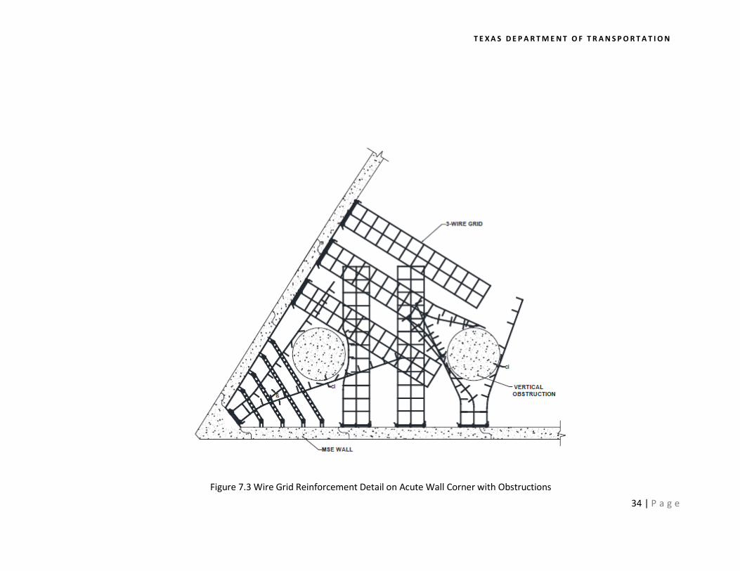
In a manner similar to ribbed strips, welded grid reinforcements at wall corners can become densely placed. Figure 7.3 illustrates an acute wall corner.
Wall panels should be connected to each other with tie strips. These tie strips should be pin connected to the wall panel and able to rotate horizontally when needed to avoid obstructions. Further, the corner element of the panel can be reinforced by a welded wire grid reinforcement that may be cut and splayed around the obstruction. The transvers bars in the reinforcement grid should be cut to enable bending of longitudinal bars. Away from the corner, strategies described earlier, namely cut and splay and lateral shifting, can be used to avoid obstructions. Cut and splay should follow the guidance in Section 6.2.
When vertical obstructions are located close to a wide wall corner, the strategy used to avoid the conflict between the MSE welded grid reinforcement bars and the vertical obstruction involved shifting the three- wire reinforcement mat away from the obstructions and also cutting of the transverse bars and splaying the longitudinal bars by an angle no more than 15 degrees, as shown in Figure 7.4. Further, the corner element of the panel should be reinforced by cutting and splaying of the reinforcement mat if there an obstruction right facing the corner. When a panel joint lies in the unreinforced region of the MSE wall, a joint splice should be used across the panel joints.
7 . 3 STRUCTURAL DESIGN NECESSARY Wall corners clearly are a unique and complex application for obstruction avoidance. In all cases, the wall designer should carefully review and design the obstruction avoidance strategy. The fundamental design rule must be satisfied at all times.
T E X A S D E P A R T M E N T O F T R A N S P O R T A T I O N
34 | P a g e
Figure 7.3 Wire Grid Reinforcement Detail on Acute Wall Corner with Obstructions

A COMPREHENSIVE FIELD GUIDE FOR RECONFIGURATION OF MSE REINFORCEMENT AROUND OBSTRUCTIONS
35 | P a g e
Figure 7.4 Wire Grid Reinforcement Detail on Wide Wall Corner with Obstructions

36 | P a g e
T E X A S D E P A R T M E N T O F T R A N S P O R T A T I O N
8. OBSTRUCTION AVOIDANCE FOR OTHER TYPES OF MSE REINFORCEMENT
TxDOT occasionally uses MSE reinforcements other than those covered in this field guide. Examples include continuous wire mesh, polymeric guides, composite straps, etc.
In some cases, the basic approaches described herein –for example, skewing, lateral shifting—can be appropriated for other types of MSE reinforcement. IN other cases, the alternative reinforcements may allow unique obstruction avoidance properties. In all applications, the avoidance of obstructions must be properly addressed by the MSE supplier/wall designer, and the fundamental design rule of obstruction avoidance must be satisfied.
Successful strategies to avoid obstructions require attention in the planning stage, and coordinated effort during construction by the wall supplier, designers, contractor, and quality control professional.

37 | P a g e
9. BIBLIOGRAPHY AASHTO (2014), AASHTO LRFD Bridge Design Specifications, Customary U.S. Units, 7th Edition, 2014,
with 2015 Interim Revisions, American Association of State and Highway Transportation Officials (AASHTO), Washington DC.
FHWA (2009a), “Design of Mechanically Stabilized Earth Walls and Reinforced Slopes,” Vol. I, Report No.
FHWA-NHI-10-024, Federal Highway Administration, US Department of Transportation, Washington D.C.
FHWA (2009b), “Design of Mechanically Stabilized Earth Walls and Reinforced Slopes,” Vol. II, Report
No. FHWA-NHI-10-025, Federal Highway Administration, US Department of Transportation, Washington D.C.
RECo (2011), “Construction and Quality Control Procedures Manual,” The Reinforced Earth Company, Reston, VA.
TRICON (1993), “Mechanical Stabilized Earth System and Method of Making Same,” United States
Patent, Patent No. 5,259,704.
TxDOT (2004), Texas Department of Transportation Manual of Test Procedures, Test Procedure for Soundness of Aggregate using sodium sulfate or magnesium sulfate, TxDOT Designation Tex-411-A, Effective Date: October 2004.
TxDOT (2005), Texas Department of Transportation Manual of Test Procedures, Test Procedure for Degradation of Coarse Aggregate by Micro-Deval Abrasion, TxDOT Designation Tex-461-A, Effective Date: July 2005.
TxDOT (2014), Texas Department of Transportation Standard Specifications for Construction and
Maintenance of Highways, Streets and Bridges, ITEM 423: Retaining Walls.
TxDOT (2015), Texas Department of Transportation Guide Schedule of Sampling and Testing, ITEM 423: Retaining Walls.