ev-do forward link measurement · ev-do forward link measurement mx269026a demonstration using...
TRANSCRIPT

Application Note
EV-DO Forward Link Measurement
MX269026A
Demonstration using Signal Analyzer and Vector Signal Generator
EV-DO Forward Link Measurement Software
MX269026A-001 All Measure Function
MS2690A/MS2691A/MS2692A/MS2830A Signal Analyzer
MG3710A Vector Signal Generator
1 MX269026A-E-F-1-(1.00)
Introduction This document explains output of the CDMA2000 1xEV-DO Rev. 0 forward link signal from the MG3710A Vector Signal Generator and measurement using the MS2690A/MS2691A/MS2692A/MS2830A Signal Analyzer. The aim of this guide is to provide an understanding of the following items: Output of CDMA2000 1xEV-DO Rev. 0 Forward Link signal using MG3710A Vector Signal Generator and
measurement of Tx characteristics using MS2690A/MS2691A/MS2692A/MS2830A Signal Analyzer High-speed measurement of CDMA2000 1xEV-DO Rev. 0 Forward Link signal Tx characteristics using All
Measure Function Measurement is performed first in the data sending status and then again in the idle status.
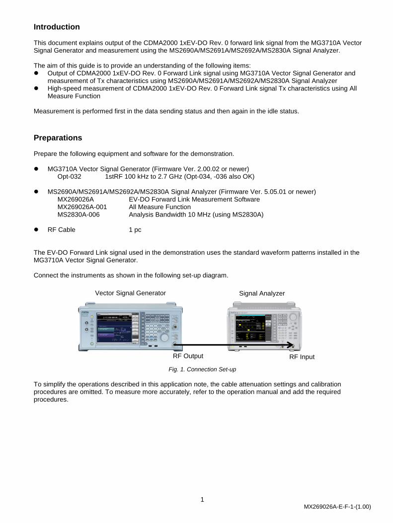
Preparations Prepare the following equipment and software for the demonstration. MG3710A Vector Signal Generator (Firmware Ver. 2.00.02 or newer) Opt-032 1stRF 100 kHz to 2.7 GHz (Opt-034, -036 also OK) MS2690A/MS2691A/MS2692A/MS2830A Signal Analyzer (Firmware Ver. 5.05.01 or newer) MX269026A EV-DO Forward Link Measurement Software MX269026A-001 All Measure Function MS2830A-006 Analysis Bandwidth 10 MHz (using MS2830A) RF Cable 1 pc The EV-DO Forward Link signal used in the demonstration uses the standard waveform patterns installed in the MG3710A Vector Signal Generator. Connect the instruments as shown in the following set-up diagram.
Fig. 1. Connection Set-up
To simplify the operations described in this application note, the cable attenuation settings and calibration procedures are omitted. To measure more accurately, refer to the operation manual and add the required procedures.
RF Output RF Input
Vector Signal Generator Signal Analyzer

2 MX269026A-E-F-1-(1.00)
Outputting Tx Data: Vector Signal Generator Operation Use the following procedure to output the EV-DO Forward Link signal from the MG3710A Vector Signal Generator. [Procedure] 1. Press [Preset] -> [F3] Preset All. 2. Press [Load] to display the Waveform List to Load window. 3. Select CDMA2000_1xEV-DO from the Packages list at the left side of the window. 4. Select FWD_2457_6kbps_1slot from Patterns in Packages list at the right side of the window.
This waveform is the 1xEV-DO Revision 0, 2457.6 kbps data rate, 16QAM modulation signal. 5. Press [F6] Load Pattern. 6. Press [Select] to display the Waveform List to Play window. 7. Select CDMA2000_1xEV-DO from the Packages list at the left side of the window. 8. Select FWD_2457_6kbps_1slot from Patterns in the Packages list at the right side of the window. 9. Press [F6] Select. 10. Press [Frequency] and set the frequency to 870 MHz. 11. Press [Level] and set the level to –10 dBm. 12. Press RF Output [Mod On/Off] and [On/Off] to output the modulation signal. The above procedure outputs the EV-DO Forward Link signal in the data Tx status from the RF Output of the MG3710A Vector Signal Generator.
Fig. 2. Vector Signal Generator Settings (Data Tx Status)

3 MX269026A-E-F-1-(1.00)
Measuring Data Tx Status: Signal Analyzer Operation Use the following procedure to measure the Tx characteristics of the EV-DO Forward Link signal in the Tx (sending) status using the MS2690A/MS2691A/MS2692A/MS2830A Signal Analyzer.
Modulation Accuracy Measurement [Procedure] 1. Press [Application Switch] to select EV-DO Forward. 2. Press [Preset] -> [F1] Preset. 3. Press [Frequency] and set the frequency to 870 MHz. 4. Press [Amplitude] and set the level to –10 dBm. 5. Press [Measure] -> [F1] Code Domain. 6. Press [Single] to start measurement. The above operations measure the frequency error, modulation accuracy and code domain power.
Fig. 3. Frequency Error/Modulation Accuracy/Code Domain Power Measurement Results (Data Tx Status/MAC Channel Code Domain Power)

4 MX269026A-E-F-1-(1.00)
The modulation accuracy measurement results are displayed as numerical values in the lower part of the Code Domain screen. The frequency error is referenced as Frequency Error. The modulation accuracy is referenced as ρoverall1, ρoverall2, and ρpilot. The MAC channel maximum inactive channel power is referenced as Power of Max. MAC Inactive CH Power. The top of the Code Domain screen displays a graph of the code domain power and the power for each channel. Display of each I/Q code for the RMAC channel is performed by setting [Trace] -> [F2] Code Domain Channel Type to MAC. Pressing [Marker] to set [F2] Branch and [F3] Code Number can be used to reference the power and ρ for any code channel. Display of each I/Q code for the traffic channel is performed by setting [Trace] -> [F2] Code Domain Channel Type to Data. Pressing [Marker] to set [F2] Branch and [F3] Code Number can be used to reference the power and ρ for any code channel.
Fig. 4. Frequency Error/Modulation Accuracy/Code Domain Power Measurement Results (Data Tx Status/Data Channel Code Domain Power)

5 MX269026A-E-F-1-(1.00)
Tx Power Measurement 7. Press [Measure] -> [F2] Power vs Time. 8. Press Function Menu Top -> [F3] Common Setting -> [F2] Slot Type to set Active. 9. Press [Trace] -> [F4] Storage -> [F1] Mode to set On. 10. Press [Trace] -> [F4] Storage -> [F2] Count to set 513. 11. Press [Measure] -> [F2] Power vs Time ->[F6]Display Item to set Average. 12. Press [Single] to start measurement.
Fig. 5. Tx Power Measurement Results (Data Tx Status/Data Channel)
The power during data Tx must be obtained in the range of the average power 2.5 dB. The Tx power is averaged for at least 512 measurements. When the obtained waveform comes within the mask template displayed on the signal analyzer Power vs Time screen, the evaluation result is Pass; otherwise, the result is Fail.

6 MX269026A-E-F-1-(1.00)
Occupied Bandwidth Measurement 13. Press [Measure] -> [F7] OBW (FFT) to measure the occupied bandwidth using the signal analyzer function.
Fig. 6. Occupied Bandwidth Measurement Results

7 MX269026A-E-F-1-(1.00)
Emissions Measurement 14. Press [Measure] -> [->] (Function Menu page 2) -> [F6] Spectrum Emission Mask (Swept) to measure
emissions using the spectrum analyzer function.
Fig. 7. Emissions Measurement Results
8 MX269026A-E-F-1-(1.00)
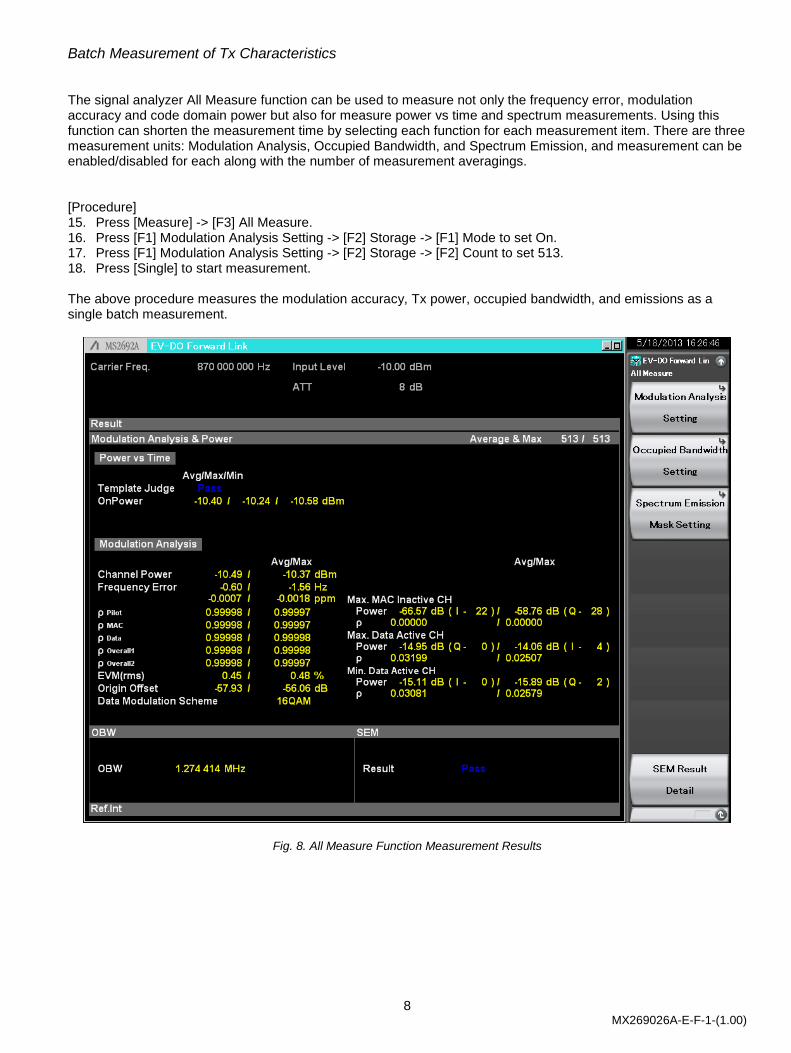
Batch Measurement of Tx Characteristics The signal analyzer All Measure function can be used to measure not only the frequency error, modulation accuracy and code domain power but also for measure power vs time and spectrum measurements. Using this function can shorten the measurement time by selecting each function for each measurement item. There are three measurement units: Modulation Analysis, Occupied Bandwidth, and Spectrum Emission, and measurement can be enabled/disabled for each along with the number of measurement averagings. [Procedure] 15. Press [Measure] -> [F3] All Measure. 16. Press [F1] Modulation Analysis Setting -> [F2] Storage -> [F1] Mode to set On. 17. Press [F1] Modulation Analysis Setting -> [F2] Storage -> [F2] Count to set 513. 18. Press [Single] to start measurement. The above procedure measures the modulation accuracy, Tx power, occupied bandwidth, and emissions as a single batch measurement.
Fig. 8. All Measure Function Measurement Results

9 MX269026A-E-F-1-(1.00)
Outputting Idle Status: Vector Signal Generator Option Next, the pilot and MAC channel measurements are made in the idle status. The following MG3710A Vector Signal Generator operation procedure can be executed after the output procedure in the data Tx status. [Procedure] 1. Press [Load] to display the Waveform List to Load window. 2. Select CDMA2000_1xEV-DO from the Packages list at the left side of the window. 3. Select FWD_Idle from the Pattern in Package list at the right side of the window. 4. Press [F6] Load Pattern. 5. Press [Select] to display the Waveform List to Play window. 6. Select CDMA2000_1xEV-DO from the Packages list at the left side of the window. 7. Select FWD_Idle from Patterns in the Packages list at the right side of the window. 8. Press [F6] Select. The above procedure outputs the EV-DO Forward Link signal in the idle status from the RF Output port of the MG3710A Vector Signal Generator.
Fig. 9. Example of Vector Signal Generator Settings (Idle State)

10 MX269026A-E-F-1-(1.00)
Measuring Idle State: Signal Analyzer Operation Use the following procedure to measure the Tx power of the EV-DO Forward Link signal in the Idle state using the MS2690A/MS2691A/MS2692A/MS2830A Signal Analyzer.
Tx Power Measurement [Procedure] 1. Press [Measure] -> [F2] Power vs Time. 2. Press Function Menu Top -> [F3] Common Setting -> [F2] Slot Type to set Idle. 3. Press [Trace] -> [F4] Storage -> [F1] Mode to set On. 4. Press [Trace] -> [F4] Storage -> [F2] Count to set 513. 5. Press [Measure] -> [F6] Display Item to set Average. 6. Press [Single] to start measurement. The above procedure measures the pilot/MAC Channel Tx power. Setting [Trace] -> [F1] Trace Mode can be used to zoom the Half Slot/On Portion/Ramp displays.
Fig. 10. Tx Power Measurement Results (Idle Status/Pilot/MAC Channel/Half Slot)

11 MX269026A-E-F-1-(1.00)
Fig. 11. Tx Power Measurement Results (Idle Status/Pilot/MAC Channel, On Portion)

12 MX269026A-E-F-1-(1.00)
Fig. 12. Tx Power Measurement Results (Idle Status/Pilot/MAC Channel/Ramp Segments)

• United StatesAnritsu Company1155 East Collins Blvd., Suite 100, Richardson, TX 75081, U.S.A.Toll Free: 1-800-267-4878Phone: +1-972-644-1777Fax: +1-972-671-1877
• CanadaAnritsu Electronics Ltd.700 Silver Seven Road, Suite 120, Kanata, Ontario K2V 1C3, CanadaPhone: +1-613-591-2003 Fax: +1-613-591-1006
• BrazilAnritsu Eletrônica Ltda.Praça Amadeu Amaral, 27 - 1 Andar01327-010 - Bela Vista - São Paulo - SP - BrazilPhone: +55-11-3283-2511Fax: +55-11-3288-6940
• MexicoAnritsu Company, S.A. de C.V.Av. Ejército Nacional No. 579 Piso 9, Col. Granada11520 México, D.F., MéxicoPhone: +52-55-1101-2370Fax: +52-55-5254-3147
• United KingdomAnritsu EMEA Ltd.200 Capability Green, Luton, Bedfordshire, LU1 3LU, U.K.Phone: +44-1582-433200 Fax: +44-1582-731303
• FranceAnritsu S.A.12 avenue du Québec, Bâtiment Iris 1- Silic 612,91140 VILLEBON SUR YVETTE, FrancePhone: +33-1-60-92-15-50Fax: +33-1-64-46-10-65
• GermanyAnritsu GmbHNemetschek Haus, Konrad-Zuse-Platz 1 81829 München, Germany Phone: +49-89-442308-0 Fax: +49-89-442308-55
• ItalyAnritsu S.r.l.Via Elio Vittorini 129, 00144 Roma, ItalyPhone: +39-6-509-9711 Fax: +39-6-502-2425
• SwedenAnritsu ABBorgarfjordsgatan 13A, 164 40 KISTA, SwedenPhone: +46-8-534-707-00 Fax: +46-8-534-707-30
• FinlandAnritsu ABTeknobulevardi 3-5, FI-01530 VANTAA, FinlandPhone: +358-20-741-8100Fax: +358-20-741-8111
• DenmarkAnritsu A/S (Service Assurance)Anritsu AB (Test & Measurement)Kay Fiskers Plads 9, 2300 Copenhagen S, DenmarkPhone: +45-7211-2200Fax: +45-7211-2210
• RussiaAnritsu EMEA Ltd. Representation Office in RussiaTverskaya str. 16/2, bld. 1, 7th floor.Russia, 125009, MoscowPhone: +7-495-363-1694Fax: +7-495-935-8962
• United Arab EmiratesAnritsu EMEA Ltd.Dubai Liaison OfficeP O Box 500413 - Dubai Internet CityAl Thuraya Building, Tower 1, Suit 701, 7th FloorDubai, United Arab EmiratesPhone: +971-4-3670352Fax: +971-4-3688460
• IndiaAnritsu India Private Limited2nd & 3rd Floor, #837/1, Binnamangla 1st Stage, Indiranagar, 100ft Road, Bangalore - 560038, IndiaPhone: +91-80-4058-1300Fax: +91-80-4058-1301
• SingaporeAnritsu Pte. Ltd.60 Alexandra Terrace, #02-08, The Comtech (Lobby A)Singapore 118502Phone: +65-6282-2400Fax: +65-6282-2533
• P.R. China (Shanghai)Anritsu (China) Co., Ltd.Room 2701-2705, Tower A, New Caohejing International Business CenterNo. 391 Gui Ping Road Shanghai, 200233, P.R. ChinaPhone: +86-21-6237-0898Fax: +86-21-6237-0899
• P.R. China (Hong Kong)Anritsu Company Ltd.Unit 1006-7, 10/F., Greenfield Tower, Concordia Plaza,No. 1 Science Museum Road, Tsim Sha Tsui East, Kowloon, Hong Kong, P.R. ChinaPhone: +852-2301-4980Fax: +852-2301-3545
• JapanAnritsu Corporation8-5, Tamura-cho, Atsugi-shi, Kanagawa, 243-0016 JapanPhone: +81-46-296-1221Fax: +81-46-296-1238
• KoreaAnritsu Corporation, Ltd.502, 5FL H-Square N B/D, 681Sampyeong-dong, Bundang-gu, Seongnam-si, Gyeonggi-do, 463-400 KoreaPhone: +82-31-696-7750Fax: +82-31-696-7751
• AustraliaAnritsu Pty. Ltd.Unit 21/270 Ferntree Gully Road, Notting Hill, Victoria 3168, AustraliaPhone: +61-3-9558-8177Fax: +61-3-9558-8255
• TaiwanAnritsu Company Inc.7F, No. 316, Sec. 1, NeiHu Rd., Taipei 114, TaiwanPhone: +886-2-8751-1816Fax: +886-2-8751-1817
Specifications are subject to change without notice.
1306
Printed on Recycled Paper
Please Contact:
No. MX269026A-E-F-1-(1.00) Printed in Japan 2013-6 MG