european technical approval eta-06/0131 - · pdf filethe maurer msm ® spherical or...
TRANSCRIPT
Diese Zulassung umfasst
This Approval contains
32 Seiten einschließlich 5 Anhänge 32 pages including 5 annexes
Diese Zulassung ersetzt This Approval replaces
ETA-06/0131 mit Geltungsdauer vom 19.09.2011 bis 20.06.2016 ETA-06/0131 with validity from 19.09.2011 to 20.06.2016
E u r o p ä i s c h e O r g a n i s a t i o n f ü r T e c h n i s c h e Z u l a s s u n g e n
E u r o p e a n O r g a n i s a t i o n f o r T e c h n i c a l A p p r o v a l s
Z38049.13 8.03.01-8/13
English translation prepared by DIBt - Original version in German language
Handelsbezeichnung Trade name
MAURER MSM® Kalotten- und Zylinderlager
MAURER MSM® Spherical and Cylindrical Bearing
Zulassungsinhaber
Holder of approval Maurer Söhne GmbH & Co. KG Frankfurter Ring 193 80807 München
Zulassungsgegenstand und Verwendungszweck
Kalotten- und Zylinderlager mit besonderem Gleitwerkstoff
Generic type and use of construction product
Spherical and cylindrical bearing with special sliding material
Geltungsdauer:
Validity: vom from
24 May 2013
bis to
24 May 2018
Herstellwerke
Manufacturing plants Maurer Söhne GmbH & Co. KG Frankfurter Ring 193 80807 München
Maurer Bridge Accessories Co.Ltd Fangzhou Road Luhe, Nanjing 211500 Jiangsu, PRC China Sanfield (India) Limited 13-A, D-Sector, Industrial Area Govindpura Bhopal - 462023 India
European Technical Approval ETA-06/0131
Ele
ctro
nic
copy
of t
he E
TA b
y D
IBt:
ETA
-06/
0131
European technical approval ETA-06/0131 English translation prepared by DIBt
Page 2 of 32 | 24 May 2013
Z38049.13 8.03.01-8/13
I LEGAL BASES AND GENERAL CONDITIONS
1 This European technical approval is issued by Deutsches Institut für Bautechnik in accordance with:
- Council Directive 89/106/EEC of 21 December 1988 on the approximation of laws, regulations and administrative provisions of Member States relating to construction products1, modified by Council Directive 93/68/EEC2 and Regulation (EC) N° 1882/2003 of the European Parliament and of the Council3;
- Gesetz über das In-Verkehr-Bringen von und den freien Warenverkehr mit Bauprodukten zur Umsetzung der Richtlinie 89/106/EWG des Rates vom 21. Dezember 1988 zur Angleichung der Rechts- und Verwaltungsvorschriften der Mitgliedstaaten über Bauprodukte und anderer Rechtsakte der Europäischen Gemeinschaften (Bauproduktengesetz - BauPG) vom 28. April 19984, as amended by Article 2 of the law of 8 November 20115;
- Common Procedural Rules for Requesting, Preparing and the Granting of European technical approvals set out in the Annex to Commission Decision 94/23/EC6.
2 Deutsches Institut für Bautechnik is authorized to check whether the provisions of this European technical approval are met. Checking may take place in the manufacturing plant. Nevertheless, the responsibility for the conformity of the products to the European technical approval and for their fitness for the intended use remains with the holder of the European technical approval.
3 This European technical approval is not to be transferred to manufacturers or agents of manufacturers other than those indicated on page 1, or manufacturing plants other than those indicated on page 1 of this European technical approval.
4 This European technical approval may be withdrawn by Deutsches Institut für Bautechnik, in particular pursuant to information by the Commission according to Article 5(1) of Council Directive 89/106/EEC.
5 Reproduction of this European technical approval including transmission by electronic means shall be in full. However, partial reproduction can be made with the written consent of Deutsches Institut für Bautechnik. In this case partial reproduction has to be designated as such. Texts and drawings of advertising brochures shall not contradict or misuse the European technical approval.
6 The European technical approval is issued by the approval body in its official language. This version corresponds fully to the version circulated within EOTA. Translations into other languages have to be designated as such.
1 Official Journal of the European Communities L 40, 11 February 1989, p. 12
2 Official Journal of the European Communities L 220, 30 August 1993, p. 1
3 Official Journal of the European Union L 284, 31 October 2003, p. 25
4 Bundesgesetzblatt Teil I 1998, p. 812
5 Bundesgesetzblatt Teil I 2011, p. 2178
6 Official Journal of the European Communities L 17, 20 January 1994, p. 34
Ele
ctro
nic
copy
of t
he E
TA b
y D
IBt:
ETA
-06/
0131
European technical approval ETA-06/0131 English translation prepared by DIBt
Page 3 of 32 | 24 May 2013
Z38049.13 8.03.01-8/13
II SPECIFIC CONDITIONS OF THE EUROPEAN TECHNICAL APPROVAL
1 Definition of the product and intended use
1.1 Definition of the construction product
The MAURER MSM® Spherical or Cylindrical Bearing is a structural bearing which permits rotation and displacement movements by a plane and a curved sliding surface between bearing plates of steel (see Annex A). The subject of the ETA is the complete bearing, including, if relevant, the necessary guides or restraints. For the purpose of controlling the degree of freedom the bearings may be combined with flat sliding elements, guides and restraining rings described in this ETA. As an alternative to figure A.1 in Annex A, the bearing may also be used upside down, i.e. with flat sliding surfaces lying below (meaningful, for example in the case of steel bridges).
The spherical or cylindrical bearing is designed according to EN 1337-1:2000. MSM®, a special sliding material made of UHMWPE (Ultra high molecular weight polyethylene) suitable for low and high temperatures outside the scope of EN 1337-2:2004 with improved wear resistance and load-bearing capacity is used for the sliding surfaces of the bearing.
Sliding surfaces with a diameter of the circumscribing circle of MSM® sheets less than 75 mm or greater than 2500 mm, or with effective bearing temperatures less than -50°C or greater than 70 °C are outside the scope of this ETA. Effective bearing temperatures above 48 °C shall be limited to short periods as due to climate temperature changes. If composite material is used in guides the maximum effective bearing temperature is limited to 48 °C. Spherical and cylindrical bearings with an included angle 2 ϑ › 60° and 2 ϑ › 75° respectively are beyond the scope of this ETA (see figure 1).
As an alternative to austenitic steel or hard chrome the sliding alloy MSA® may be used as curved mating surface.
Additionally for effective bearing temperatures between -50 °C and 48 °C the sliding coating system MSC® may be used as an alternative to austenitic steel in guides, if the MAURER MSM® Spherical or cylindrical Bearing shall be used for buildings or equivalent types of structure, where the accumulated sliding path is not greater than 200 m per year. The proven corrosivity class is “high” in accordance with EN ISO 12944-1:1998 and the corrosivity category is C4 in accordance with EN ISO 12944-2:1998.
Spherical or cylindrical bearings for use as temporary devices during construction, for example during launching of the super-structure, are also outside the scope of this ETA.
1.2 Intended use
MAURER MSM® Spherical and Cylindrical Bearings are intended to be used for the support of bridges or building works in accordance with the scope of EN 1337-1:2000.
MAURER MSM® Spherical and Cylindrical Bearings are suitable for all types of structures but especially for non-rigid structures with relatively large and frequent displacements caused by variable loads, next for superstructures that induce fast sliding displacements in bearings, e.g. in bridges for the high speed railways, as well as for regions with continuously low and/or high temperatures. Spherical and cylindrical parts made of sliding alloy MSA® are highly corrosion resistant. E
lect
roni
c co
py o
f the
ETA
by
DIB
t: E
TA-0
6/01
31
European technical approval ETA-06/0131 English translation prepared by DIBt
Page 4 of 32 | 24 May 2013
Z38049.13 8.03.01-8/13
MAURER MSM® Spherical and Cylindrical Bearings are mainly used in concrete, steel and composite structures.
The provisions made in this European technical approval are based on an assumed working life of the MAURER MSM® Spherical or Cylindrical Bearing of 50 years. The assumed working life of the bearing is reduced to 10 years if composite material is used in guides.
2 Characteristics of product and methods of verification
2.1 Characteristics of product
2.1.1 General
MAURER MSM® Spherical Bearings shall permit rotational movements about any axis and MAURER MSM® Cylindrical Bearings shall permit rotational movements about one axis. They shall be capable of transferring specified forces between superstructure and substructure.
For design the principles given in clause 5 of EN 1337-1:2000 shall be taken into account.
Note 1: The design values of internal forces and moments as well as of movements should be available from a bearing schedule as shown in Annex B of EN 1337-1:2000
Note 2: In addition to the specific clauses relating to dangerous substances contained in this European Technical Approval, there may be other requirements applicable to the products falling within its scope (e.g. transposed European legislation and national laws, regulations and administrative provisions). In order to meet the provisions of the Construction Products Directive, these requirements need also to be complied with, when and where they apply.
2.1.2 Material combinations
The permissible material combinations for sliding elements are given in Table 1. Only one combination shall be used in a sliding surface. The sliding surface shall be lubricated in accordance with 2.1.8 and 4.1.
Table 1: Permissible combination of materials for permanent applications as sliding surfaces for MAURER MSM® spherical or cylindrical bearings
Plane surface1) Curved surface Guides
austeniticsteel austenitic steel undimpled MSM®
MSC® 2)
hard chromium CM1
dimpled MSM®
austenitic steel dimpled MSM®
MSA® CM2 austeniticsteel
1) The sliding surface may be subdivided in two restrained parts above and below the rotation element permitting in total the design movement, see the example in Fig. A.7 of Annex A.
2) To be used only if the MAURER MSM® Spherical or Cylindrical Bearing shall be used for buildings or equivalent types of structure, where the accumulated sliding path is not greater than 200 m per year
Ele
ctro
nic
copy
of t
he E
TA b
y D
IBt:
ETA
-06/
0131

European technical approval ETA-06/0131 English translation prepared by DIBt
Page 5 of 32 | 24 May 2013
Z38049.13 8.03.01-8/13
2.1.3 MSM® sheets
The composition of the material is confidential7.
The curved MSM® sheet may be attached to either the convex or the concave backing plate. The required geometrical characteristics of MSM® sheets are given in Annex B.
2.1.4 Composite material
As an alternative to MSM® for strips in guides the composite material of type CM1 and CM2 acc. EN 1337-2:2004, Section 5.3 may be used.
2.1.5 Austenitic steel
Stainless steel shall be in accordance with EN 10088-4:2009 (EN 1337-2:2004, clause 5.4)
2.1.6 Hard chromium plated surfaces
Hard chromium plated surfaces shall be in accordance with EN 1337-2:2004, clause 5.5
2.1.7 Ferrous materials for backing plates
Ferrous materials for backing plates shall be in accordance with EN 1337-2:2004, clause 5.6. 2.1.8 Lubricant
Silicon grease according to EN 1337-2:2004, clause 5.8 shall be used as lubricant for sliding surfaces.
2.1.9 Adhesive for bonding austenitic steel sheets
Note: The main function of the adhesive is to join austenitic steel sheets to the backing plate in such a way that shear is transmitted without relative movement.
The adhesive shall be in accordance with clause 5.9 and Annex J of EN 1337-2:2004. 2.1.10 Sliding alloy MSA®
Sliding alloy MSA® with special surface treatment may be used as an alternative to steel for spherical and cylindrical backing plates in accordance with section 2.2.6. The material characteristics and surface treatments of the sliding alloy MSA® are confidential8.
2.1.11 Sliding coating MSC®
Sliding coating MSC® may be used as mating surface as an alternative to austenitic steel. The material, layer and surface characteristics of the sliding coating MSC® are confidential8.
2.2 Methods of verification
2.2.1 General
For basic design features clause 7 of EN 1337-1:2000 applies.
2.2.2 Design verification for sliding surfaces
Note 1: Excessive pressure may cause loss of the sliding function and this may be lead to structural failure or states close to structural failure. Therefore this condition is considered as ultimate limit state.
7 The technical documentation to this European technical approval is deposited with Deutsches Institut für Bautechnik
and, as far as relevant for the task of the approved bodies involved in the attestation of conformity procedure is handed over to the approved bodies.
8 The technical documentation to this European technical approval is deposited with Deutsches Institut für Bautechnik and, as far as relevant for the task of the approved bodies involved in the attestation of conformity procedure is handed over to the approved bodies.
Ele
ctro
nic
copy
of t
he E
TA b
y D
IBt:
ETA
-06/
0131
European technical approval ETA-06/0131 English translation prepared by DIBt
Page 6 of 32 | 24 May 2013
Z38049.13 8.03.01-8/13
When dimensioning sliding surfaces, all the internal forces and moments due to actions and frictional resistance shall be considered. The design values of the action to be taken into account shall be determined in accordance with the basic design criteria given in EN 1337-1:2000.
Deformation of sliding materials shall not be used to accommodate rotations except as permitted in 2.2.3.
The following conditions shall be verified under a fundamental combination of actions:
Af
Af
Nm
kr
m
kSd
⋅λ⋅γ
=⋅γ
≤
where
NSd is the design axial force at ultimate limit state
fk is the characteristic value of compressive strength acc. Table 2
γm partial safety factor for materials in accordance with EN 1990:2002
A is the contact area of the flat sliding surface or the projection of curved surfaces
λ is a coefficient given in Annex C
Ar is the reduced contact area of the sliding surface whose centroid is the point through which NSd acts with the total eccentricity et, which is caused by both mechanical and geometrical effects. Ar shall be calculated on the basis of the theory of plasticity assuming a rectangular stress block (see Annex C). For guides eccentricity can be neglected.
Note 2: The γm value should be given us NDP (national determined parameter). In absence of NDP the recommended value is γm = 1.4.
For MSM® sheets with the smallest dimension "L", "a" or "b" in accordance with clause B.1 of Annex B larger or equal 100 mm, contact areas A and Ar shall be taken as the gross area without deduction for the area of the dimples. For sheets with "L", "a" or "b" smaller than 100 mm the area of the dimples shall be deducted from the gross area.
The characteristic compressive strengths of MSM® are given in Table 2 and are valid for effective bearing temperatures up to 70°C. For bearings exposed to a maximum effective bearing temperature in excess of 35 °C and up to 70° C the characteristic compressive strength shall be estimated by linear interpolation of the values given in table 2.
Table 2: Characteristic compressive strength of MSM®
Effective bearing temperature [°C] ≤ 35 °C 48°C 70°C
Sliding surface Characteristic compressive strength fk
Main sliding surface Dead loads and variable loads
Guides Variable loads
180 MPa 135 MPa 90 MPa
Guides Dead loads
Effects of temperature, shrinkage and creep
60 MPa 45 MPa 30 MPa
For guides with composite material see 6.3 and 6.6 of EN 1337-2:2004.
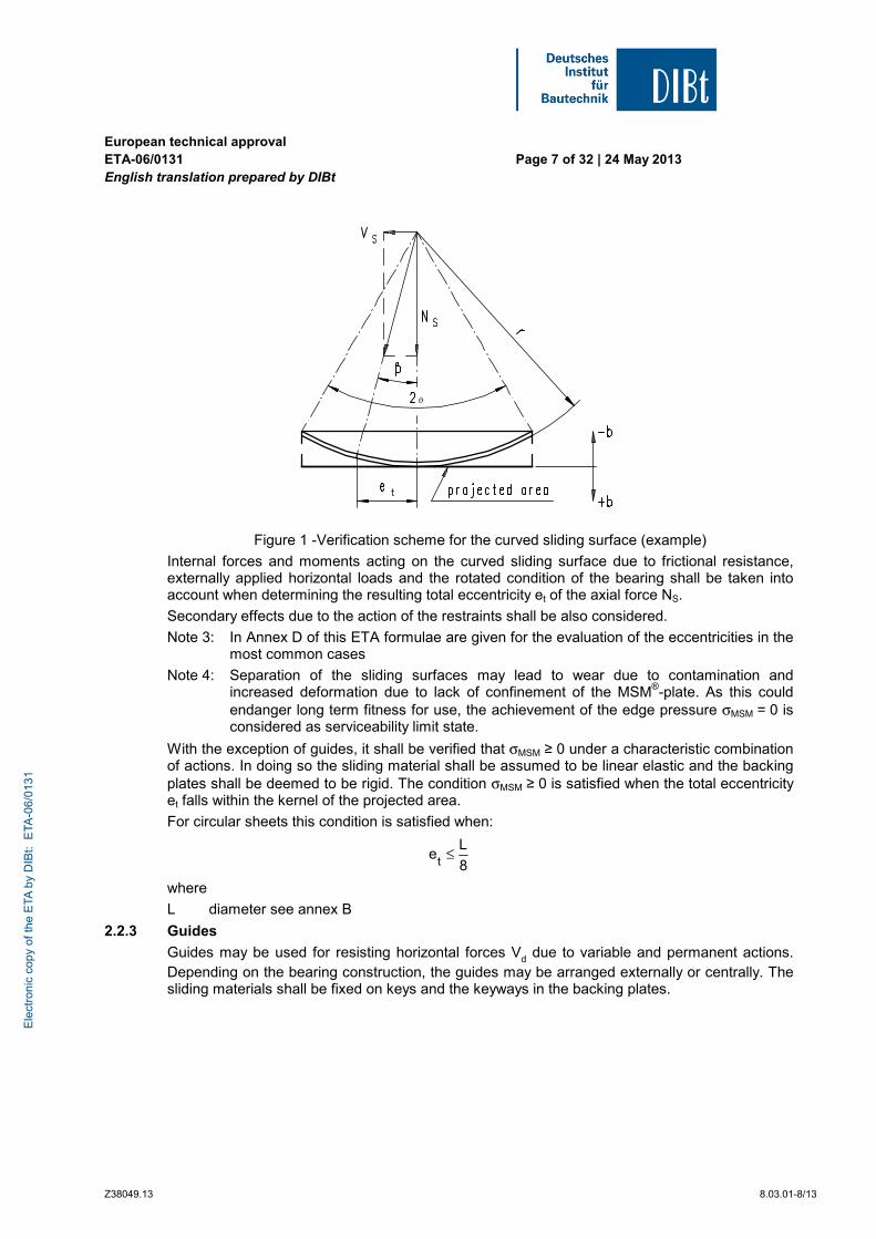
For the purpose of compressive stress verification the curved sliding surface shall be replaced by its projection on a plane surface as shown in figure 1.
Ele
ctro
nic
copy
of t
he E
TA b
y D
IBt:
ETA
-06/
0131
European technical approval ETA-06/0131 English translation prepared by DIBt
Page 7 of 32 | 24 May 2013
Z38049.13 8.03.01-8/13
ϑ
Figure 1 -Verification scheme for the curved sliding surface (example)
Internal forces and moments acting on the curved sliding surface due to frictional resistance, externally applied horizontal loads and the rotated condition of the bearing shall be taken into account when determining the resulting total eccentricity et of the axial force NS.
Secondary effects due to the action of the restraints shall be also considered.
Note 3: In Annex D of this ETA formulae are given for the evaluation of the eccentricities in the most common cases
Note 4: Separation of the sliding surfaces may lead to wear due to contamination and increased deformation due to lack of confinement of the MSM®-plate. As this could endanger long term fitness for use, the achievement of the edge pressure σMSM = 0 is considered as serviceability limit state.
With the exception of guides, it shall be verified that σMSM ≥ 0 under a characteristic combination of actions. In doing so the sliding material shall be assumed to be linear elastic and the backing plates shall be deemed to be rigid. The condition σMSM ≥ 0 is satisfied when the total eccentricity et falls within the kernel of the projected area.
For circular sheets this condition is satisfied when:
8
Le
t≤
where
L diameter see annex B
2.2.3 Guides
Guides may be used for resisting horizontal forces Vd due to variable and permanent actions. Depending on the bearing construction, the guides may be arranged externally or centrally. The sliding materials shall be fixed on keys and the keyways in the backing plates.
Ele
ctro
nic
copy
of t
he E
TA b
y D
IBt:
ETA
-06/
0131
European technical approval ETA-06/0131 English translation prepared by DIBt
Page 8 of 32 | 24 May 2013
Z38049.13 8.03.01-8/13
Clearance c between sliding components in unused condition shall meet the following condition:
mm5.21000
]mm[Lmm0.1c ≤+≤
A typical example of the attachment of guides is shown in figure A.1 of Annex A. In the design of the connection at ultimate limit state in accordance with EN 1993-1-1:2005, the effects of horizontal force Vd, its induced moment and the friction forces shall be considered.
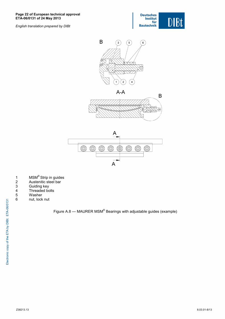
The maximum clearance in guides may be reduced due to adjustable guides. For this purpose high tensile screws in accordance with EN 1993 shall be used. The main principle of adjustable guides is shown in Fig. A.8 of Annex A.
Where, under predict rotation about a transverse axis the differential deformation of the MSM® sheet across its smallest dimension "a" would exceed 0.2 mm, a rotation element shall be included in the backing plate (see figure 1, 3.3 of EN 1337-1:2000). This condition shall be verified for the unfactored characteristic actions. The material combination of this rotation element shall be designed in accordance with the requirements of the mating surfaces of guides given in this ETA or pot to piston contact surfaces given in EN 1337-5:2005.
2.2.4 Restraining rings
The free MAURER MSM® spherical or cylindrical bearing may be fixed by a steel restraining ring. For design and verification, the design rules for pot and piston of pot bearings given in clause 6 of EN-337-5:2005 shall be followed.
2.2.5 Austenitic steel sheets
The minimum thickness of the austenitic steel sheet shall be in accordance with Table 3.
Care shall be taken to ensure that the austenitic steel sheet is fully in contact with the backing plate over the area which will be in contact with the MSM® sheet. When attaching the austenitic steel sheet by screwing, counterpunched screwing and rivetting, corrosion resistant fasteners compatible with the austenitic steel sheet shall be used for securing its edges. They shall be provided at all corners and along the edges outside the area of contact with the MSM® sheet with the maximum spacing listed in Table 4.
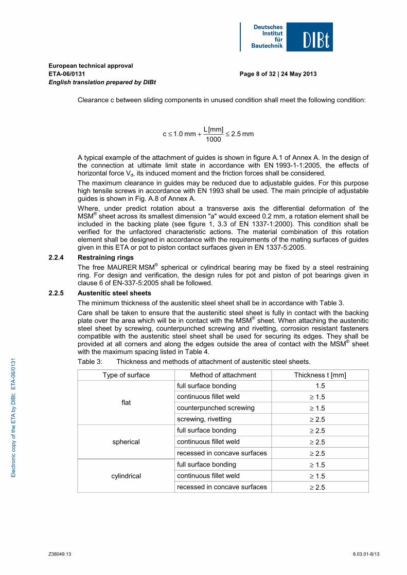
Table 3: Thickness and methods of attachment of austenitic steel sheets.
Type of surface Method of attachment Thickness t [mm]
full surface bonding 1.5
continuous fillet weld ≥ 1.5
counterpunched screwing ≥ 1.5 flat
screwing, rivetting ≥ 2.5
full surface bonding ≥ 2.5
continuous fillet weld ≥ 2.5 spherical
recessed in concave surfaces ≥ 2.5
full surface bonding ≥ 1.5
cylindrical continuous fillet weld ≥ 1.5
recessed in concave surfaces ≥ 2.5
Ele
ctro
nic
copy
of t
he E
TA b
y D
IBt:
ETA
-06/
0131
European technical approval ETA-06/0131 English translation prepared by DIBt
Page 9 of 32 | 24 May 2013
Z38049.13 8.03.01-8/13
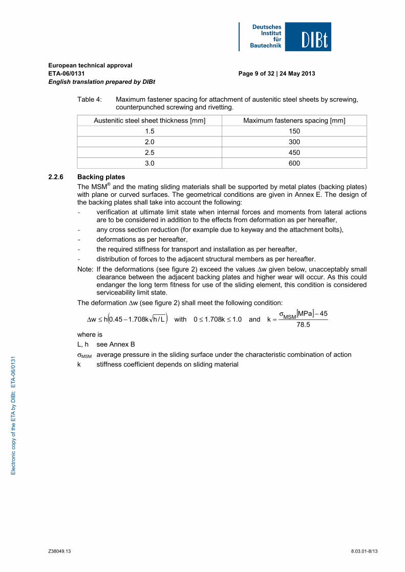
Table 4: Maximum fastener spacing for attachment of austenitic steel sheets by screwing, counterpunched screwing and rivetting.
Austenitic steel sheet thickness [mm] Maximum fasteners spacing [mm]
1.5 150
2.0 300
2.5 450
3.0 600
2.2.6 Backing plates
The MSM® and the mating sliding materials shall be supported by metal plates (backing plates) with plane or curved surfaces. The geometrical conditions are given in Annex E. The design of the backing plates shall take into account the following:
- verification at ultimate limit state when internal forces and moments from lateral actions are to be considered in addition to the effects from deformation as per hereafter,
- any cross section reduction (for example due to keyway and the attachment bolts),
- deformations as per hereafter,
- the required stiffness for transport and installation as per hereafter,
- distribution of forces to the adjacent structural members as per hereafter.
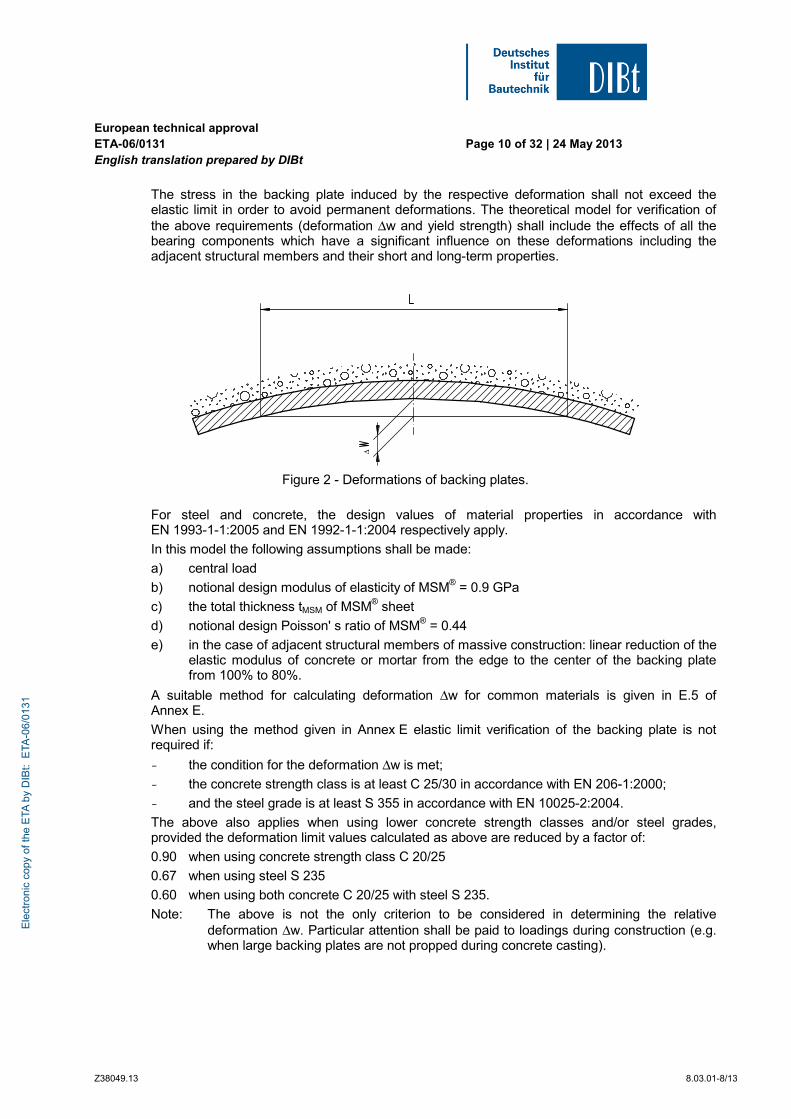
Note: If the deformations (see figure 2) exceed the values Δw given below, unacceptably small clearance between the adjacent backing plates and higher wear will occur. As this could endanger the long term fitness for use of the sliding element, this condition is considered serviceability limit state.
The deformation Δw (see figure 2) shall meet the following condition:
( ) [ ]5.78
45MPakand0.1k708.10withL/hk708.145.0hw MSM
−σ=≤≤−≤Δ
where is
L, h see Annex B
σMSM average pressure in the sliding surface under the characteristic combination of action
k stiffness coefficient depends on sliding material
Ele
ctro
nic
copy
of t
he E
TA b
y D
IBt:
ETA
-06/
0131
European technical approval ETA-06/0131 English translation prepared by DIBt
Page 10 of 32 | 24 May 2013
Z38049.13 8.03.01-8/13
The stress in the backing plate induced by the respective deformation shall not exceed the elastic limit in order to avoid permanent deformations. The theoretical model for verification of the above requirements (deformation Δw and yield strength) shall include the effects of all the bearing components which have a significant influence on these deformations including the adjacent structural members and their short and long-term properties.
Δ
Figure 2 - Deformations of backing plates.
For steel and concrete, the design values of material properties in accordance with EN 1993-1-1:2005 and EN 1992-1-1:2004 respectively apply.
In this model the following assumptions shall be made:
a) central load
b) notional design modulus of elasticity of MSM® = 0.9 GPa
c) the total thickness tMSM of MSM® sheet
d) notional design Poisson' s ratio of MSM® = 0.44
e) in the case of adjacent structural members of massive construction: linear reduction of the elastic modulus of concrete or mortar from the edge to the center of the backing plate from 100% to 80%.
A suitable method for calculating deformation Δw for common materials is given in E.5 of Annex E.
When using the method given in Annex E elastic limit verification of the backing plate is not required if:
- the condition for the deformation Δw is met;
- the concrete strength class is at least C 25/30 in accordance with EN 206-1:2000;
- and the steel grade is at least S 355 in accordance with EN 10025-2:2004.
The above also applies when using lower concrete strength classes and/or steel grades, provided the deformation limit values calculated as above are reduced by a factor of:
0.90 when using concrete strength class C 20/25
0.67 when using steel S 235
0.60 when using both concrete C 20/25 with steel S 235.
Note: The above is not the only criterion to be considered in determining the relative deformation Δw. Particular attention shall be paid to loadings during construction (e.g. when large backing plates are not propped during concrete casting).
Ele
ctro
nic
copy
of t
he E
TA b
y D
IBt:
ETA
-06/
0131
European technical approval ETA-06/0131 English translation prepared by DIBt
Page 11 of 32 | 24 May 2013
Z38049.13 8.03.01-8/13
The calculation of the relative deformation of the backing plate with convex surface shall be omitted.
Square or rectangular plates shall be idealised to circular plates of diameter
db = 1.13 ab
where ab is the side of the square plate or the minor side of the rectangular plate.
The thickness of the backing plate shall be:
2b
2bb
ba04.0t +⋅≥
or 10 mm, whichever is greater, where:
ab is the minor side of backing plate and
bb is the major side of backing plate.
2.2.7 Sliding behaviour
The following coefficients of friction μmax shall be used for verification of the bearing and the structure in which it is incorporated. These values shall not be applied in the presence of high dynamic actions which may occur for instance in seismic zones. The effects of friction shall not be used to relieve the effects of externally applied horizontal loads. The average pressure σMSM shall be estimated using the gross contact area, i. e. neglecting the deduction of the area of the dimples given in clause 2.2.2.
(a) Coefficient of friction at low temperatures
For sliding elements combined with dimpled and lubricated MSM® sheets used in zones where the minimum effective bearing temperature doesn’t fall below -35°C, the coefficient of friction μmax is determined as a function of the average pressure σMSM [MPa], as follows:
08.015
6.1020.0
MSMmax ≤
σ+=μ≤
For guides the coefficient of friction shall be considered to be independent of contact pressure. The coefficient of friction μmax = 0.10 shall be used.
(b) Coefficient of friction at very low temperatures
For sliding elements combined with dimpled and lubricated MSM® sheets used in zones where the minimum effective bearing temperature does fall below -35 °C (down to -50 °C), the coefficient of friction μmax is determined as a function of the average pressure σMSM [MPa], as follows:
08.030
8.2027.0
MSMmax ≤
σ+=μ≤
For guides the coefficient of friction shall be considered to be independent of contact pressure. The coefficient of friction μmax = 0.12 shall be used.
(c) Coefficient of friction at moderate low temperatures
For sliding elements combined with dimpled and lubricated MSM® sheets used in zones where the minimum effective bearing temperature doesn’t fall below -5 °C, the coefficient of friction μmax is determined as a function of the average pressure σMSM [MPa], as follows:
06.015
2.1015.0
MSMmax ≤
σ+=μ≤
For guides the coefficient of friction shall be considered to be independent of contact pressure. The coefficient of friction μmax = 0.07 shall be used.
For composite materials see 6.7 of EN 1337-2:2004.
Ele
ctro
nic
copy
of t
he E
TA b
y D
IBt:
ETA
-06/
0131
European technical approval ETA-06/0131 English translation prepared by DIBt
Page 12 of 32 | 24 May 2013
Z38049.13 8.03.01-8/13
2.2.8 Rotation capability
The sliding surfaces shall meet the requirements given in this ETA.
Under the fundamental combination of actions it shall be shown that
- the metallic surfacing mating with the MSM® material is so proportioned that it completely covers the MSM® sheet,
- there is no contact between the upper and the lower part of the bearing or any other metallic component (see EN 1337-1:2000, Annex A).
For the verification of the above conditions the increase of rotations, specified in clause 5.4 of EN 1337-1:2000, shall be taken into account.
For rotations about a transverse axis of guides see 2.2.3.
For guides with composite material see 6.3 of EN 1337-2:2004.
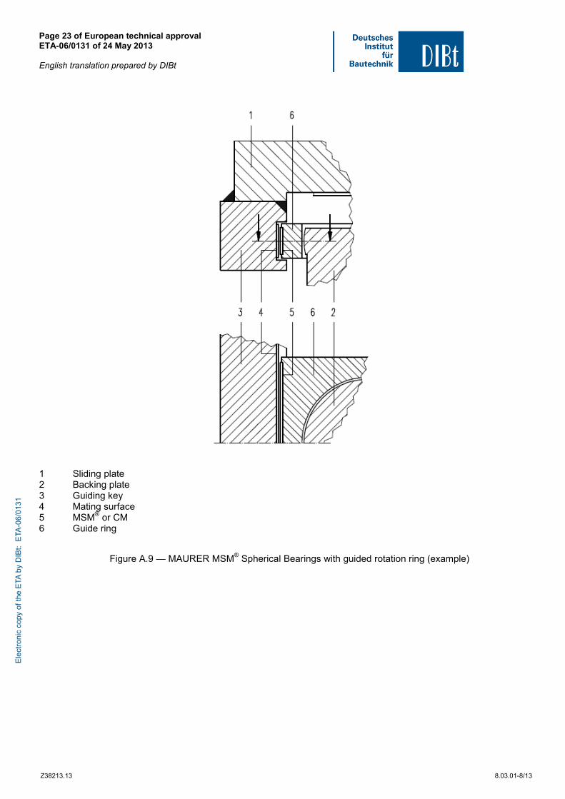
For MAURER MSM® Spherical Bearings with external guides the rotation capability around the vertical axis may be increased using a guide ring, see Fig. A.9 of Annex A. The contact surfaces of this guide ring shall be designed in accordance with the requirements given in clause 2.2.4.
2.2.9 Displacement capacity
By taking into account of the increased movements according to 5.4 in EN 1337-1:2000, it shall be verified under the fundamental combination of actions that the austenitic steel sheets are designed such, that with maximum displacement of the sliding element they completely cover the MSM® and the CM sheets.
Note: The assumed working life of 50 years is based on the assumptions of a maximum accumulated sliding path of c · 50 000 m and a maximum of 15 mm/sec of average sliding speed in the main sliding surfaces (for PTFE acc. EN 1337-2:2004 c · 10 000 m and 2 mm/sec), where c (c ≥ 1) is a factor to correct the difference between the constant amplitude slide path used in the approval tests and the variable amplitude movements which occur due to traffic. If the sliding coating system MSC® is used as mating surface in guides, the accumulated sliding path shall not be greater than 200 m per year.
3 Evaluation and attestation of conformity and CE marking
3.1 System of attestation of conformity
According to the communication of the European Commission9 the system 1 of attestation of conformity applies.
This system of attestation of conformity is defined as follows:
Certification of the conformity of the product by an approved certification body on the basis of:
(a) Tasks for the manufacturer:
(1) factory production control;
(2) further testing of samples taken at the factory by the manufacturer in accordance with a prescribed test plan;
9 Letter of the European Commission of 24/10/1995 to EOTA
Ele
ctro
nic
copy
of t
he E
TA b
y D
IBt:
ETA
-06/
0131
European technical approval ETA-06/0131 English translation prepared by DIBt
Page 13 of 32 | 24 May 2013
Z38049.13 8.03.01-8/13
(b) Tasks for the approved body:
(3) initial typetesting of the product;
(4) initial inspection of factory and of factory production control;
(5) continuous surveillance, assessment and approval of factory production control.
Note: Approved bodies are also referred to as "notified bodies".
3.2 Responsibilities
3.2.1 Tasks of the manufacturer
3.2.1.1 Factory production control
The manufacturer shall exercise permanent internal control of production. All the elements, requirements and provisions adopted by the manufacturer shall be documented in a systematic manner in the form of written policies and procedures, including records of results performed. This production control system shall insure that the product is in conformity with this European technical approval.
The manufacturer may only use constituent parts stated in the technical documentation of this European technical approval.
The factory production control shall be in accordance with the "control plan" relating to this European technical approval which is part of the technical documentation of this European technical approval. The "control plan" is laid down in the context of the factory production control system operated by the manufacturer and deposited at Deutsches Institut für Bautechnik.10
The results of factory production control shall be recorded and evaluated in accordance with the provisions of the "control plan".
3.2.1.2 Other tasks of manufacturer
The manufacturer shall, on the basis of a contract, involve a body which is approved for the tasks referred to in section 3.1 in the field of "spherical and cylindrical bearings with special sliding material" in order to undertake the actions laid down in section 3.2.2. For this purpose, the "control plan" referred to in sections 3.2.1.1 and 3.2.2 shall be handed over by the manufacturer to the approved body involved.
The manufacturer shall make a declaration of conformity, stating that the construction product is in conformity with the provisions of this European technical approval.
3.2.2 Tasks of approved bodies
The approved body shall perform the
- initial type-testing of the product,
- initial inspection of factory and of factory production control,
- continuous surveillance, assessment and approval of factory production control,
- single acceptance or at least 5 % per lot of production for bearings with a diameter L of the special sliding material in the main sliding surface larger than 1500 mm,,
in accordance with the provisions laid down in the "control plan relating to this European technical approval.
The approved body shall retain the essential points of its actions referred to above and state the results obtained and conclusions drawn in a written report.
10
The "control plan" is a confidential part of the documentation of the European technical approval, but not published together with the ETA and only handed over to the approved body involved in the procedure of attestation of conformity. See section 3.2.2.
Ele
ctro
nic
copy
of t
he E
TA b
y D
IBt:
ETA
-06/
0131
European technical approval ETA-06/0131 English translation prepared by DIBt
Page 14 of 32 | 24 May 2013
Z38049.13 8.03.01-8/13
The approved certification body involved by the manufacturer shall issue an EC certificate of conformity of the product stating the conformity with the provisions of this European technical approval.
In cases where the provisions of the European technical approval and its "control plan" are no longer fulfilled the certification body shall withdraw the certificate of conformity and inform Deutsches Institut für Bautechnik without delay.
3.3 CE marking
Regardless of the requirements stated in 7.3 of EN 1337-1:2000, the CE marking shall be affixed on the bearing so that it will be visible throughout the life time of the bearing. The full information given below should be in the relevant accompanying documents. The letters "CE" shall be followed by the identification number of the approved certification body, where relevant, and be accompanied by the following additional information:
- the name and address of the producer (legal entity responsible for the manufacturer),
- the last two digits of the year in which the CE marking was affixed,
- the number of the EC certificate of conformity for the product,
- the number of the European Technical Approval,
- description of the product,
- geometrical data,
- material properties,
- characteristics and declared performances of the product on the basis of the ETA,
- dangerous substances.
4 Assumptions under which the fitness of the product for the intended use was favourably assessed
4.1 Manufacturing
The manufacturing tolerances for backing plates are given in Annex E.
In the case of plane backing plates the MSM® sheets shall be confined in accordance with Annex B. In addition, MSM® sheets for guides shall be bonded to assist assembling.
Where the dimples in MSM® sheets are produced by hot pressing the temperature during the pressing process shall not exceed the melting temperature of MSM®.
Composite materials shall be attached by bonding supplemented by mechanical attachment outside the sliding surface.
Methods of attachment and respective dimensions of austenitic steel sheets are given in 2.2.5.
Note: General requirements for corrosion protection are given in EN 1337-9:1997. This subclause gives additional requirements for sliding elements.
Where the austenitic steel sheet is attached by full area bonding or by continuous fillet weld, provided the area covered by the austenitic steel sheet is free from rust and rust inducing contaminants, no further treatment of the backing plate behind the austenitic steel sheet is required.
Where the austenitic steel sheet is attached by screwing, counterpunched screwing or rivetting the full corrosion protection system shall be applied to the backing plate behind the austenitic steel sheet.
Ele
ctro
nic
copy
of t
he E
TA b
y D
IBt:
ETA
-06/
0131
European technical approval ETA-06/0131 English translation prepared by DIBt
Page 15 of 32 | 24 May 2013
Z38049.13 8.03.01-8/13
When bonding the austenitic steel sheet, an adhesive with characteristics given in 2.1.9 shall be used. Preparation of the adherents shall be in accordance with adhesive manufacturer's recommendations. There shall be no voids in the adhesive layer and a fillet of adhesive shall be formed around the complete periphery of the austenitic sheet during the bonding process. The flatness as required in E.3 of Annex E shall be achieved after bonding.
Areas of the backing plate behind the MSM® and recessed austenitic steel sheets shall be protected by one coat of primer (dry film thickness 20 μm to 100 μm).
Provision against contamination of the sliding surface shall be made by suitable devices. Such protection devices shall be easily removable for the purpose of inspection.
The hard chromium surface shall be visually inspected for cracks and pores. In addition to the visual inspection, the absence of defects shall be verified by a Ferroxyl test in accordance with Annex E of EN 1337-2:2004. If the visual inspection of the surfaces reveals any potential defects, the Ferroxyl test shall be applied over the entire affected area. If any defects are detected by Ferroxyl test, the hard chrome plating shall be rejected.
Since hard chromium plating is not resistant to chlorides in acid solution or to fluorines and can be damaged by air borne particles, such as occur in industrial environment, special provision shall be made to protect the surfaces in those conditions.
Prior to assembly the sliding surfaces shall be cleaned.
Spherical or cylindrical elements made of MSA® do not need an additional corrosion protection.
After cleaning and prior to assembly, the dimpled MSM® sheet shall be lubricated with lubricant according to 2.1.8 in a way which ensures that all the dimples are filled. For guides the sliding material shall be initially lubricated by rubbing a small amount of lubricant into the surface and wiping off the remainder.
During assembly process, provisions shall be taken against contamination of lubricated surfaces.
The European technical approval is issued for the product on the basis of agreed data/information, deposited with Deutsches Institut für Bautechnik, which identifies the product that has been assessed and judged. Changes to the product or production process, which could result in this deposited data/information being incorrect, should be notified to Deutsches Institut für Bautechnik before the changes are introduced. Deutsches Institut für Bautechnik will decide whether or not such changes affect the ETA and consequently the validity of the CE marking on the basis of the ETA and if so whether further assessment or alterations to the ETA shall be necessary.
4.2 Installation
In order to ensure bearing alignment in accordance with EN 1337-11:1997 a reference surface or other suitable device shall be installed on the sliding element.
The deviation from parallel of the reference surface with respect to the plane sliding surface shall not exceed 1‰.
After installation and completion of the superstructure, the deviation of the sliding element from the specified alignment shall not exceed 3‰ in accordance with 6.5 of EN 1337-11:1997.
Ele
ctro
nic
copy
of t
he E
TA b
y D
IBt:
ETA
-06/
0131
European technical approval ETA-06/0131 English translation prepared by DIBt
Page 16 of 32 | 24 May 2013
Z38049.13 8.03.01-8/13
5 Indications to the manufacturer
5.1 Packaging, transport and storage
The stipulations according to 7.4 of EN 1337-1:2000 and EN 1337-11:1997 apply.
The bearing shall be labelled by the manufacturer with the conformity mark (CE mark). The mark may only be applied when the prerequisites, in accordance with section 3, concerning the proof of conformity are fulfilled.
The bearing is additionally to be provided, in accordance with EN 1337-1:2000 with a marking label which, if applicable, is possibly to be fixed in position on the side of the movement indicator.
5.2 Use, maintenance, repair
For the inspection and maintenance of Maurer MSM® Spherical and Cylindrical Bearings see 7.5 of EN 1337-1:2000 and EN 1337-10:2003. For the resetting and replacement 7.6 of EN 1337-1:2000 apply. On installing the bearing, the stipulations of EN 1337-11:1997 are to be observed.
The bearing is to be adjusted horizontally in accordance with the bearing setting plan on the measuring plane, in accordance with section 4.2, using measuring equipment with a precision of at least 0.3‰.
After setting the mortar joints, the deviation in inclination established may not exceed 3‰ on the measuring plane.
During inspection of items listed in EN 1337-10:2003 the following value shall be checked:
- Protrusion h: ≥ 1 mm. (see Annex B, figure B.1)
If the protrusion h of the MSM® sheet is found to be less than 1 mm, or a bulging of the austenitic sheet exceeds the measured protrusion in its vicinity, the sliding element is still deemed to be serviceable but more frequent inspections shall be conducted.
If the protrusion of the MSM® sheet is reduced to zero, the sliding element shall no longer be considered capable of accommodating movement.
Uwe Bender beglaubigt:
Head of Department Hoppe
Ele
ctro
nic
copy
of t
he E
TA b
y D
IBt:
ETA
-06/
0131
Page 17 of European technical approval ETA-06/0131 of 24 May 2013 English translation prepared by DIBt
Z38213.13 8.03.01-8/13
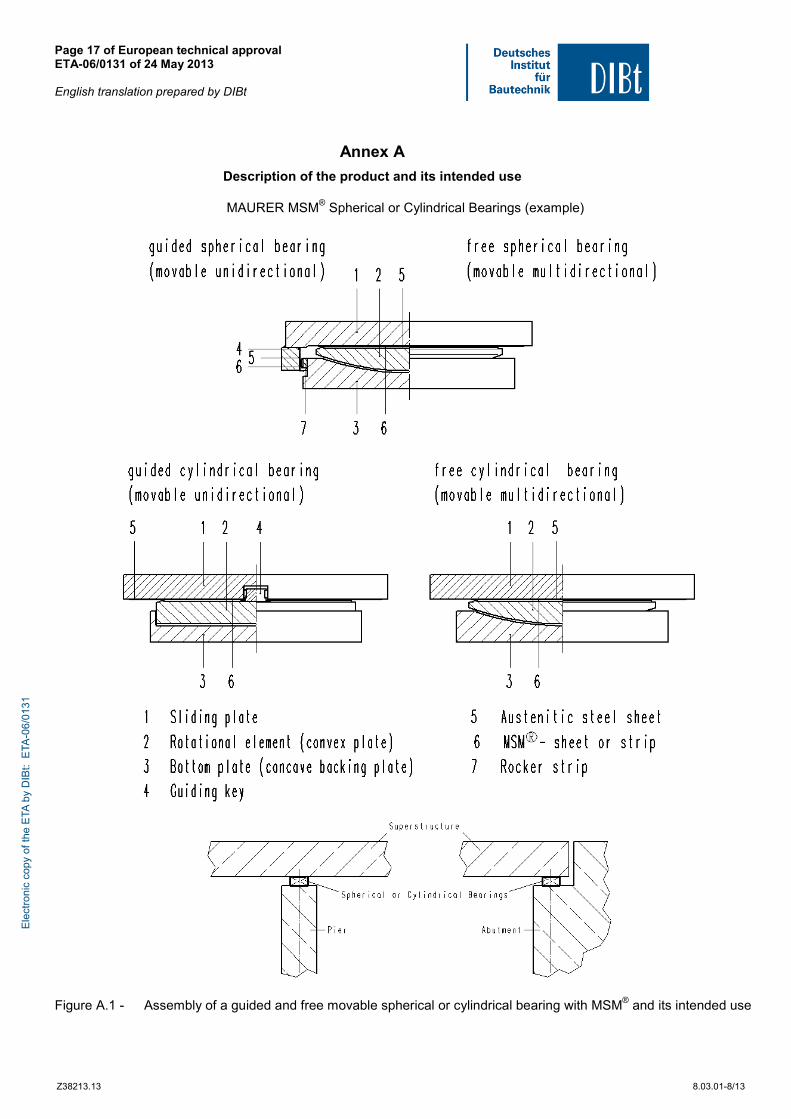
Annex A
Description of the product and its intended use
MAURER MSM® Spherical or Cylindrical Bearings (example)
Figure A.1 - Assembly of a guided and free movable spherical or cylindrical bearing with MSM® and its intended use
Ele
ctro
nic
copy
of t
he E
TA b
y D
IBt:
ETA
-06/
0131
Page 18 of European technical approval ETA-06/0131 of 24 May 2013 English translation prepared by DIBt
Z38213.13 8.03.01-8/13
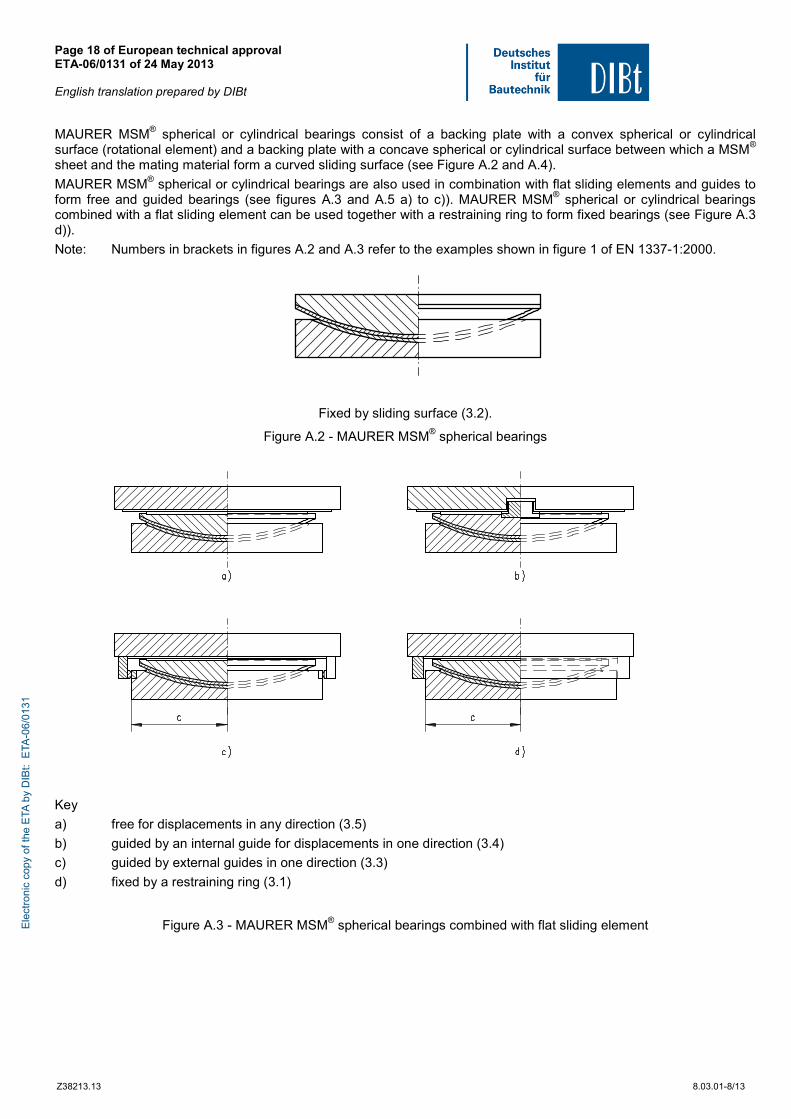
MAURER MSM® spherical or cylindrical bearings consist of a backing plate with a convex spherical or cylindrical surface (rotational element) and a backing plate with a concave spherical or cylindrical surface between which a MSM® sheet and the mating material form a curved sliding surface (see Figure A.2 and A.4).
MAURER MSM® spherical or cylindrical bearings are also used in combination with flat sliding elements and guides to form free and guided bearings (see figures A.3 and A.5 a) to c)). MAURER MSM® spherical or cylindrical bearings combined with a flat sliding element can be used together with a restraining ring to form fixed bearings (see Figure A.3 d)).
Note: Numbers in brackets in figures A.2 and A.3 refer to the examples shown in figure 1 of EN 1337-1:2000.
Fixed by sliding surface (3.2).
Figure A.2 - MAURER MSM® spherical bearings
Key
a) free for displacements in any direction (3.5)
b) guided by an internal guide for displacements in one direction (3.4)
c) guided by external guides in one direction (3.3)
d) fixed by a restraining ring (3.1)
Figure A.3 - MAURER MSM® spherical bearings combined with flat sliding element Ele
ctro
nic
copy
of t
he E
TA b
y D
IBt:
ETA
-06/
0131
Page 19 of European technical approval ETA-06/0131 of 24 May 2013 English translation prepared by DIBt
Z38213.13 8.03.01-8/13
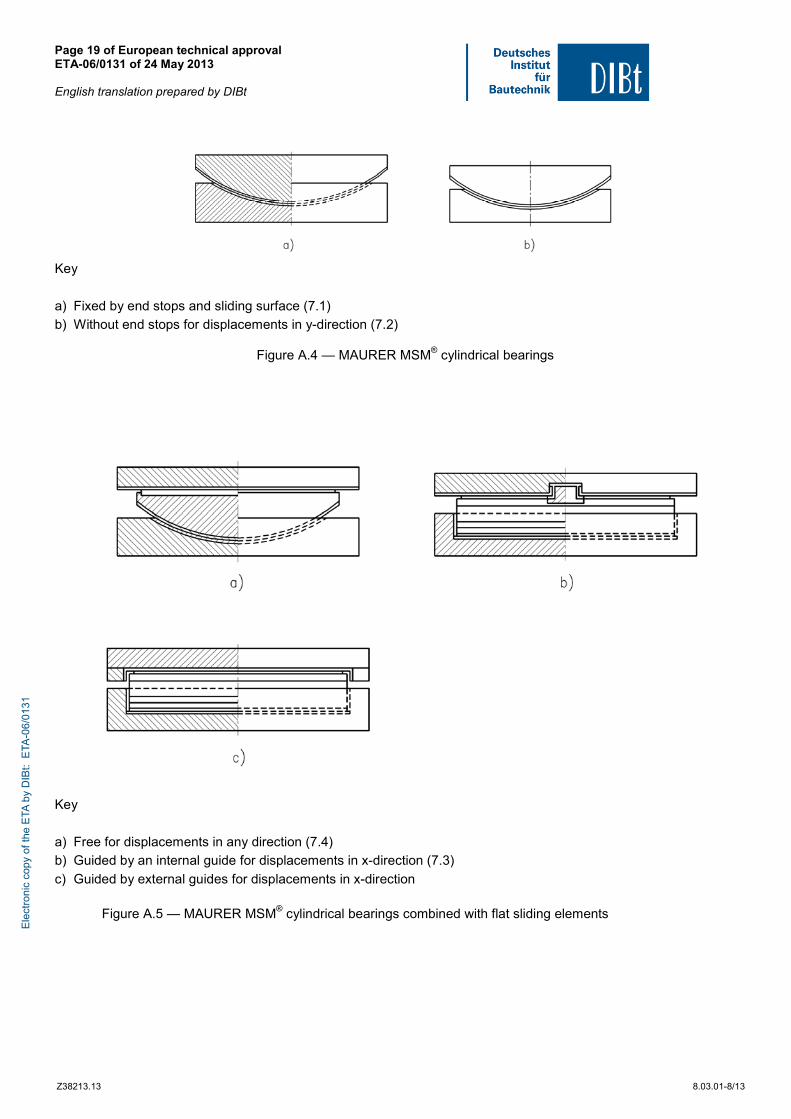
Key
a) Fixed by end stops and sliding surface (7.1)
b) Without end stops for displacements in y-direction (7.2)
Figure A.4 — MAURER MSM® cylindrical bearings
Key
a) Free for displacements in any direction (7.4)
b) Guided by an internal guide for displacements in x-direction (7.3)
c) Guided by external guides for displacements in x-direction
Figure A.5 — MAURER MSM® cylindrical bearings combined with flat sliding elements
Ele
ctro
nic
copy
of t
he E
TA b
y D
IBt:
ETA
-06/
0131
Page 20 of European technical approval ETA-06/0131 of 24 May 2013 English translation prepared by DIBt
Z38213.13 8.03.01-8/13
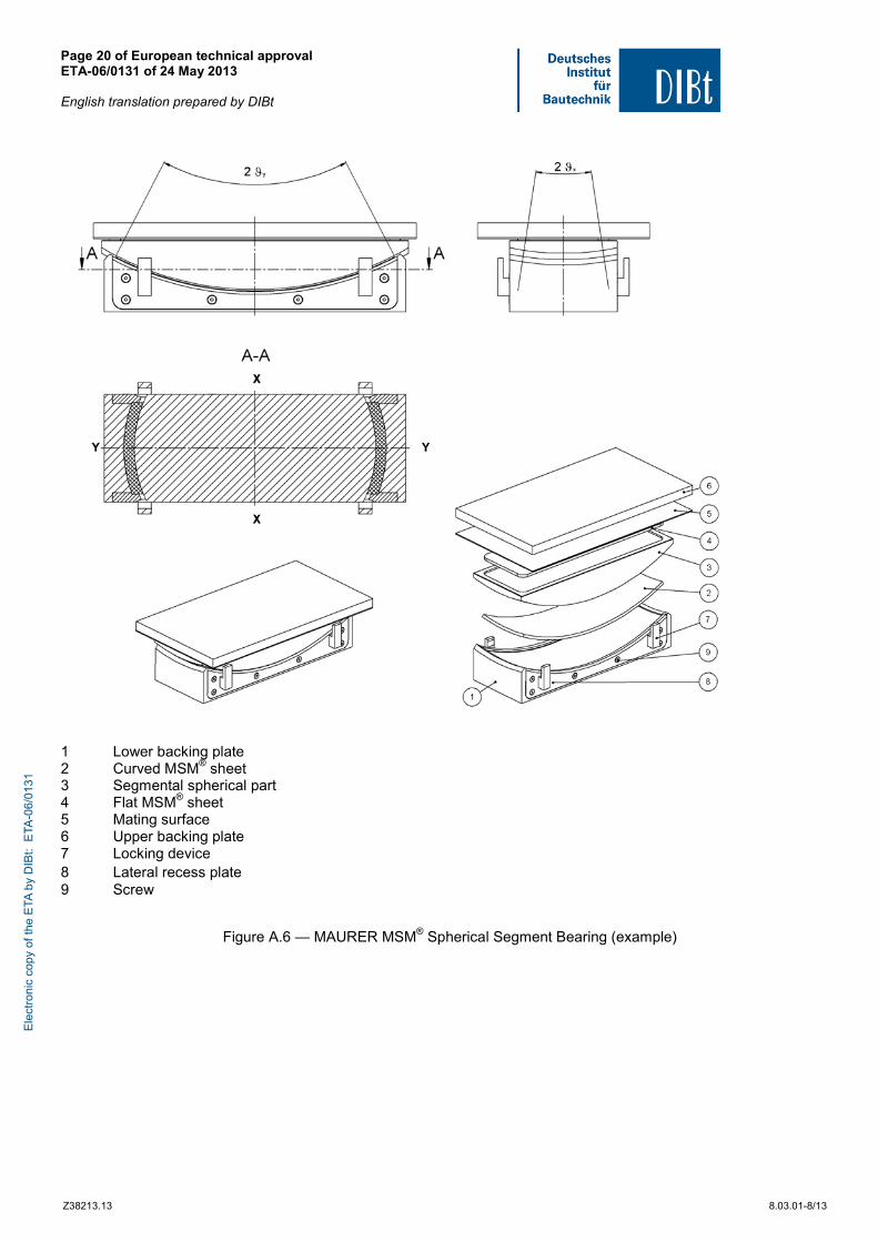
1 Lower backing plate 2 Curved MSM® sheet 3 Segmental spherical part 4 Flat MSM® sheet 5 Mating surface 6 Upper backing plate 7 Locking device 8 Lateral recess plate 9 Screw
Figure A.6 — MAURER MSM® Spherical Segment Bearing (example)
Ele
ctro
nic
copy
of t
he E
TA b
y D
IBt:
ETA
-06/
0131
Page 21 of European technical approval ETA-06/0131 of 24 May 2013 English translation prepared by DIBt
Z38213.13 8.03.01-8/13
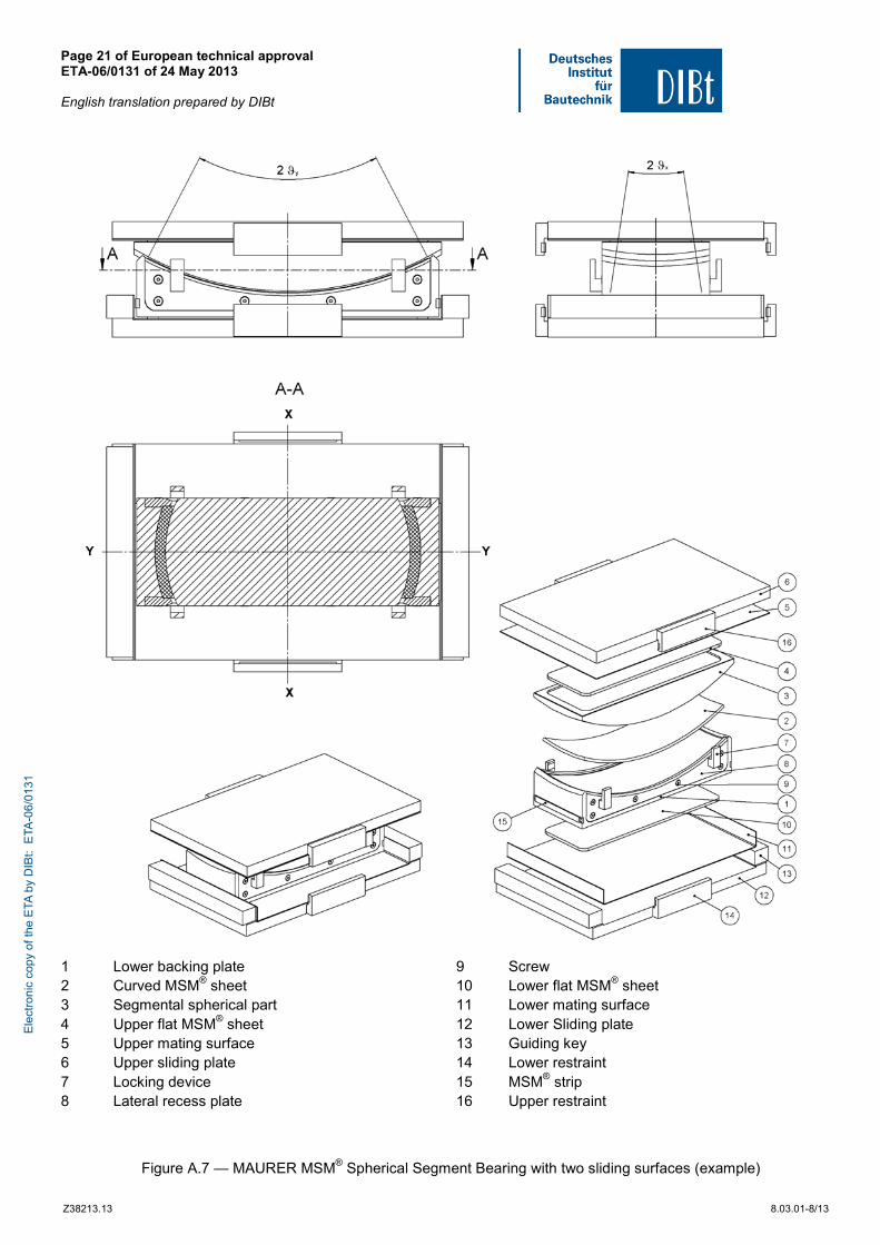
1 Lower backing plate 2 Curved MSM® sheet 3 Segmental spherical part 4 Upper flat MSM® sheet 5 Upper mating surface 6 Upper sliding plate 7 Locking device 8 Lateral recess plate
9 Screw 10 Lower flat MSM® sheet 11 Lower mating surface 12 Lower Sliding plate 13 Guiding key 14 Lower restraint 15 MSM® strip 16 Upper restraint
Figure A.7 — MAURER MSM® Spherical Segment Bearing with two sliding surfaces (example)
Ele
ctro
nic
copy
of t
he E
TA b
y D
IBt:
ETA
-06/
0131
Page 22 of European technical approval ETA-06/0131 of 24 May 2013 English translation prepared by DIBt
Z38213.13 8.03.01-8/13
1 MSM® Strip in guides 2 Austenitic steel bar 3 Guiding key 4 Threaded bolts 5 Washer 6 nut, lock nut
Figure A.8 — MAURER MSM® Bearings with adjustable guides (example)
Ele
ctro
nic
copy
of t
he E
TA b
y D
IBt:
ETA
-06/
0131
Page 23 of European technical approval ETA-06/0131 of 24 May 2013 English translation prepared by DIBt
Z38213.13 8.03.01-8/13
1 Sliding plate 2 Backing plate 3 Guiding key 4 Mating surface 5 MSM® or CM 6 Guide ring
Figure A.9 — MAURER MSM® Spherical Bearings with guided rotation ring (example)
Ele
ctro
nic
copy
of t
he E
TA b
y D
IBt:
ETA
-06/
0131
Page 24 of European technical approval ETA-06/0131 of 24 May 2013 English translation prepared by DIBt
Z38213.13 8.03.01-8/13
Annex B
Geometrical characteristics of MSM® sheets
B.1 Details of recess and relief for sliding elements with MSM®
The performance characteristics of MAUER MSM® spherical and cylindrical bearings given in this ETA are valid only for the following geometrical conditions.
For MAURER MSM® spherical bearings the absence of two symmetrical circular segments for not subdivided sheets is permissible, if the limitation for the included angle given in clause 1.1 and the proof of non separation of the sliding surface given in clause 2.2.2 is fulfilled for both the main axes. The main principle of MAURER MSM® spherical segment bearings is shown in Fig. A.6 and A.7 of Annex A.
B.1.1 Recess of MSM® sheets
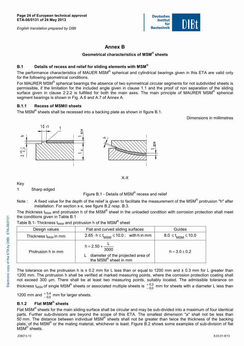
The MSM® sheets shall be recessed into a backing plate as shown in figure B.1.
Dimensions in millimetres
X-X
Key
1 Sharp edged Figure B.1 - Details of MSM® recess and relief
Note : A fixed value for the depth of the relief is given to facilitate the measurement of the MSM® protrusion "h" after installation. For section x-x, see figure B.2 resp. B.3.
The thickness tMSM and protrusion h of the MSM® sheet in the unloaded condition with corrosion protection shall meet the conditions given in Table B.1
Table B.1- Thickness tMSM and protrusion h of the MSM® sheet
Design values Flat and curved sliding surfaces Guides
Thickness tMSM in mm mminhwith;0.10th65.2MSM
≤≤⋅ 0.10t0.8MSM
≤≤
Protrusion h in mm 3000
L50.2h +=
L diameter of the projected area of the MSM® sheet in mm
2.00.3h ±=
The tolerance on the protrusion h is ± 0.2 mm for L less than or equal to 1200 mm and ± 0.3 mm for L greater than 1200 mm. The protrusion h shall be verified at marked measuring points, where the corrosion protection coating shall not exceed 300 μm. There shall be at least two measuring points, suitably located. The admissible tolerance on
thickness tMSM of single MSM® sheets or associated multiple sheets is 3,00,0
+− mm for sheets with a diameter L less than
1200 mm and 4,00,0
+− mm for larger sheets.
B.1.2 Flat MSM® sheets
Flat MSM® sheets for the main sliding surface shall be circular and may be sub-divided into a maximum of four identical parts. Further sub-divisions are beyond the scope of this ETA. The smallest dimension "a" shall not be less than 50 mm. The distance between individual MSM® sheets shall not be greater than twice the thickness of the backing plate, of the MSM® or the mating material, whichever is least. Figure B.2 shows some examples of sub-division of flat MSM® sheets.
Ele
ctro
nic
copy
of t
he E
TA b
y D
IBt:
ETA
-06/
0131
Page 25 of European technical approval ETA-06/0131 of 24 May 2013 English translation prepared by DIBt
Z38213.13 8.03.01-8/13
Dimensions in millimetres
≥ ≥≤
≥≤
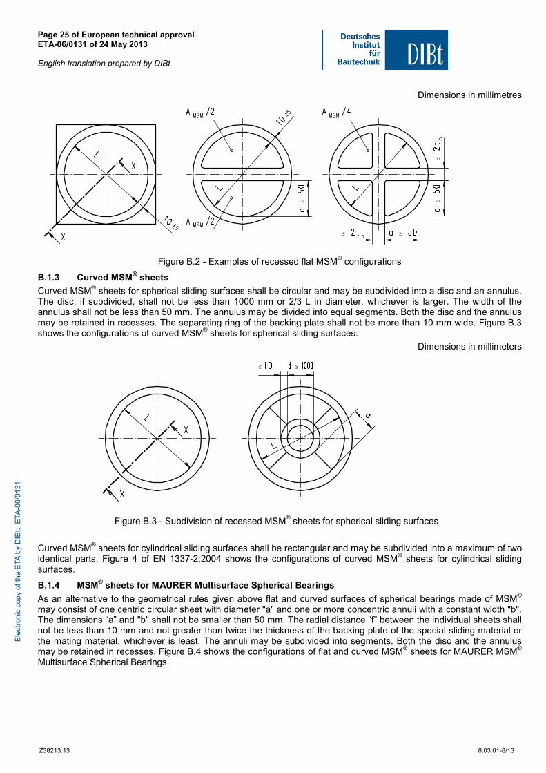
Figure B.2 - Examples of recessed flat MSM® configurations
B.1.3 Curved MSM® sheets
Curved MSM® sheets for spherical sliding surfaces shall be circular and may be subdivided into a disc and an annulus. The disc, if subdivided, shall not be less than 1000 mm or 2/3 L in diameter, whichever is larger. The width of the annulus shall not be less than 50 mm. The annulus may be divided into equal segments. Both the disc and the annulus may be retained in recesses. The separating ring of the backing plate shall not be more than 10 mm wide. Figure B.3 shows the configurations of curved MSM® sheets for spherical sliding surfaces.
Dimensions in millimeters
≤ ≥
Figure B.3 - Subdivision of recessed MSM® sheets for spherical sliding surfaces
Curved MSM® sheets for cylindrical sliding surfaces shall be rectangular and may be subdivided into a maximum of two identical parts. Figure 4 of EN 1337-2:2004 shows the configurations of curved MSM® sheets for cylindrical sliding surfaces.
B.1.4 MSM® sheets for MAURER Multisurface Spherical Bearings
As an alternative to the geometrical rules given above flat and curved surfaces of spherical bearings made of MSM® may consist of one centric circular sheet with diameter "a" and one or more concentric annuli with a constant width "b". The dimensions “a” and "b" shall not be smaller than 50 mm. The radial distance “f” between the individual sheets shall not be less than 10 mm and not greater than twice the thickness of the backing plate of the special sliding material or the mating material, whichever is least. The annuli may be subdivided into segments. Both the disc and the annulus may be retained in recesses. Figure B.4 shows the configurations of flat and curved MSM® sheets for MAURER MSM® Multisurface Spherical Bearings.
Ele
ctro
nic
copy
of t
he E
TA b
y D
IBt:
ETA
-06/
0131
Page 26 of European technical approval ETA-06/0131 of 24 May 2013 English translation prepared by DIBt
Z38213.13 8.03.01-8/13
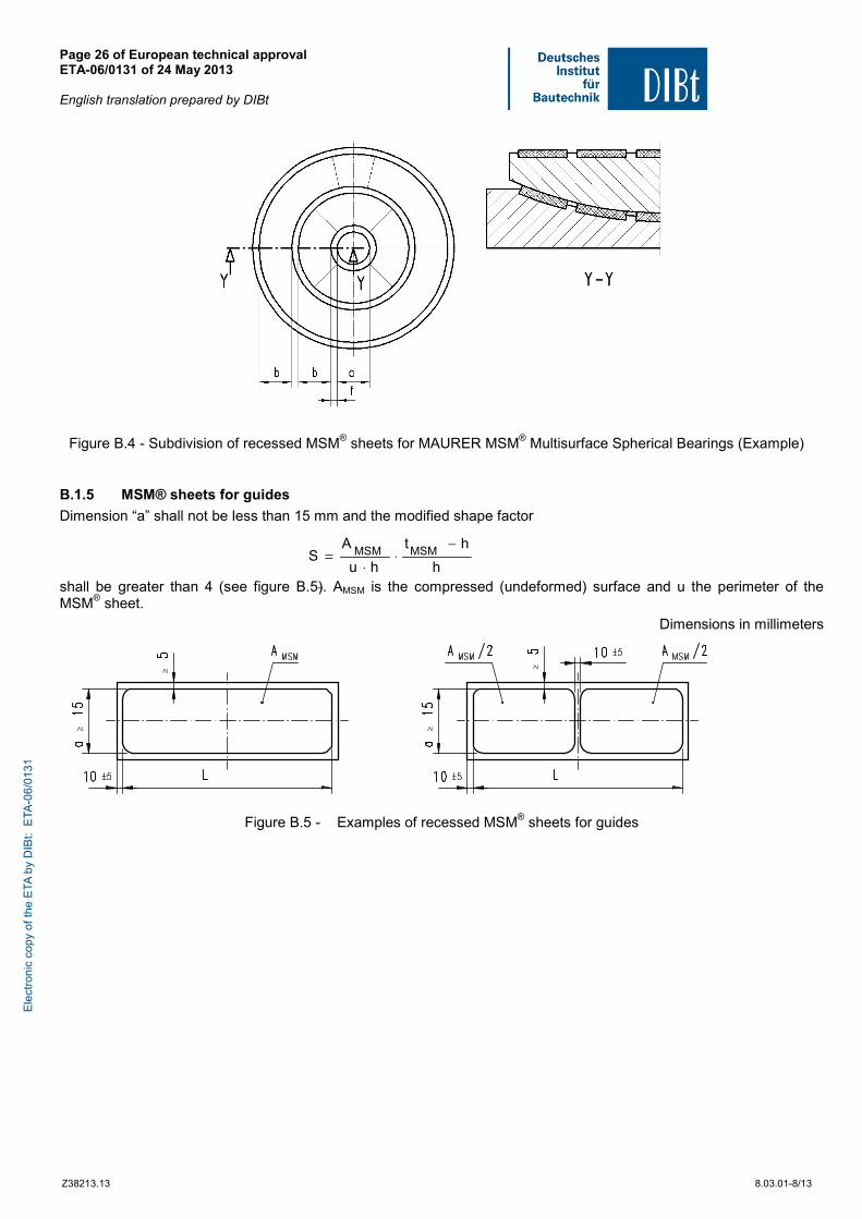
Figure B.4 - Subdivision of recessed MSM® sheets for MAURER MSM® Multisurface Spherical Bearings (Example)
B.1.5 MSM® sheets for guides
Dimension “a” shall not be less than 15 mm and the modified shape factor
shall be greater than 4 (see figure B.5). AMSM is the compressed (undeformed) surface and u the perimeter of the MSM® sheet.
Dimensions in millimeters
≥
≥
≥
≥
Figure B.5 - Examples of recessed MSM® sheets for guides
h
ht
hu
AS MSMMSM
−⋅
⋅=
Ele
ctro
nic
copy
of t
he E
TA b
y D
IBt:
ETA
-06/
0131
Page 27 of European technical approval ETA-06/0131 of 24 May 2013 English translation prepared by DIBt
Z38213.13 8.03.01-8/13
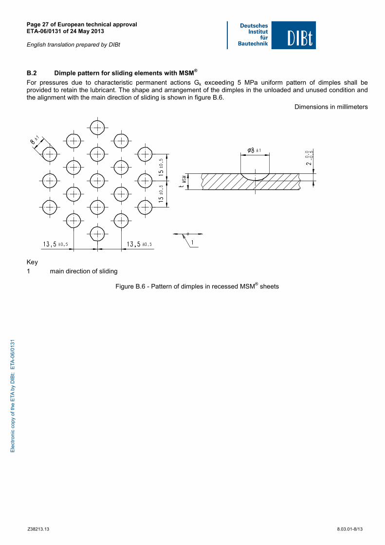
B.2 Dimple pattern for sliding elements with MSM®
For pressures due to characteristic permanent actions Gk exceeding 5 MPa uniform pattern of dimples shall be provided to retain the lubricant. The shape and arrangement of the dimples in the unloaded and unused condition and the alignment with the main direction of sliding is shown in figure B.6.
Dimensions in millimeters
Key
1 main direction of sliding
Figure B.6 - Pattern of dimples in recessed MSM® sheets
Ele
ctro
nic
copy
of t
he E
TA b
y D
IBt:
ETA
-06/
0131

Page 28 of European technical approval ETA-06/0131 of 24 May 2013 English translation prepared by DIBt
Z38213.13 8.03.01-8/13
ANNEX C
Reduced area for circular sliding elements
The values of the coefficient λ have been calculated by means of a mathematical model made with the following assumptions:
1) only compressive stresses are transmitted
2) the stresses in the compressed area are constant and equal to the design value fd of compressive resistance of MSM® sheets (i.e. the stress block theory is adopted)
3) stresses are always normal to the contact surface: a conservative hypothesis justified by the low coefficient of friction of MSM® in contact with polished metal surfaces
4) the adjacent backing plates are perfectly rigid
Figure C.1 - Reduced contact area Ar for circular sliding surfaces.
Figure C.2 - Reduced contact area Ar for rectangular sliding surfaces
Ar = λ · A
Ele
ctro
nic
copy
of t
he E
TA b
y D
IBt:
ETA
-06/
0131

Page 29 of European technical approval ETA-06/0131 of 24 May 2013 English translation prepared by DIBt
Z38213.13 8.03.01-8/13
where is
λ Coefficient given in Table C.1.
A Contact area for flat sliding surfaces or projection area of the curved sliding surface A = πL2/4
As an alternative to the exact values given in Table C.1, the following approximate formula can be used for flat sliding
surfaces of spherical bearings:
λ = 1 - 0.75 π e / L Table C.1 - Coefficient λ = Ar / A
sliding surface spherical cylindrical
ϑ e / L
flat
30° 25° 20° 10° 30° 25° 20° 10° 0.00 0.05 0.990 0.991 0.991 0.990 0.990 0.01 0.979 0.982 0.981 0.980 0.979 0.984 0.983 0.981 0.980 0.02 0.957 0.962 0.961 0.960 0.958 0.968 0.965 0.962 0.961 0.03 0.934 0.942 0.940 0.938 0.936 0.951 0.947 0.943 0.941 0.04 0.912 0.922 0.919 0.916 0.913 0.934 0.929 0.924 0.921 0.05 0.888 0.901 0.898 0.894 0.890 0.917 0.911 0.905 0.901 0.06 0.865 0.880 0.876 0.872 0.867 0.900 0.893 0.886 0.881 0.07 0.841 0.858 0.853 0.849 0.844 0.882 0.874 0.866 0.862 0.08 0.818 0.836 0.831 0.826 0.820 0.864 0.855 0.847 0.842 0.09 0.793 0.814 0.808 0.803 0.796 0.846 0.837 0.827 0.822 0.10 0.769 0.792 0.786 0.780 0.773 0.828 0.818 0.808 0.802 0.11 0.745 0.770 0.763 0.757 0.749 0.809 0.799 0.788 0.782 0.12 0.722 0.747 0.740 0.733 0.724 0.790 0.779 0.768 0.762 0.1255 0.709 0.736 0.729 0.722 0.712 0.780 0.769 0.758 0.752 0.13 0.697 0.725 0.717 0.710 0.700 0.771 0.760 0.749 0.742 0.14 0.673 0.702 0.693 0.686 0.676 0.752 0.740 0.729 0.722 0.15 0.649 0.680 0.670 0.663 0.653 0.733 0.721 0.709 0.702 0.16 0.625 0.657 0.647 0.639 0.628 0.713 0.701 0.689 0.682 0.17 0.601 0.635 0.624 0.616 0.604 0.693 0.681 0.669 0.662 0.18 0.577 0.612 0.601 0.592 0.581 0.673 0.661 0.649 0.642 0.19 0.552 0.590 0.578 0.569 0.557 0.653 0.641 0.629 0.622 0.20 0.529 0.567 0.556 0.546 0.533 0.633 0.621 0.609 0.602 0.21 0.506 0.545 0.533 0.523 0.510 0.612 0.600 0.589 0.582 0.2155 0.500 0.541 0.529 0.518 0.602 0.590 0.579 0.572 0.22 0.482 0.523 0.511 0.500 0.592 0.580 0.569 0.562 0.23 0.458 0.501 0.571 0.559 0.548 0.542
0.24 0.435 0.550 0.539 0.528 0.522
0.25 0.412 0.529 0.518 0.508 0.502
NOTE Intermediate values may be obtained by linear interpolation
Ele
ctro
nic
copy
of t
he E
TA b
y D
IBt:
ETA
-06/
0131
Page 30 of European technical approval ETA-06/0131 of 24 May 2013 English translation prepared by DIBt
Z38213.13 8.03.01-8/13
ANNEX D
Method for calculation the eccentricities in MAURER MSM® spherical and cylindrical bearings
D.1 General
Frictional forces, forces from applied horizontal loads and the rotated condition of the bearing produce eccentricity of the axial force NS, which is used in the verification of MSM® sheets, the adjacent structural members and the anchoring devices. This annex gives methods for calculating the significant eccentricities. Depending on the design features of a particular bearing, additional eccentricities may exist. When several eccentricities occur in a cross-section under consideration, they need to be added.
D.2 Friction resistance
D.2.1 Curved sliding surfaces
In the presence of rotational movements an internal moment occurs due to the frictional resistance. Regardless of whether the bearing has one or two surfaces, the associated eccentricity e1 is:
e1 = μmax · r
The coefficient of friction μmax is given in 2.2.7. D.2.2 Sliding surfaces with external guides and restraining rings
For the spherical and cylindrical bearings of the type shown in figures A.3 c) and d) of Annex A rotational movements produce an eccentricity which affects only the adjacent structural members (i.e. plinth, beam etc) and the anchoring devices, where:
cN
Ve
maxs
s2
⋅μ⋅=
For bearings with sliding elements in guides as per Table 1, the coefficient of friction μmax is given in 2.2.7. For
restraining rings with steel to steel contact μmax should be assumed to be 0.2.
D.3 Rotation
In all the types of bearings with two sliding surfaces a rotation angle α produces an eccentricity e3 of the vertical load on the curved surface equal to:
e3 = α · (r + b)
where b represents the distance between the cross-section under consideration and the sliding surface. At any rate, this eccentricity acts nonetheless in the opposite direction to that given under 4.2. The occurrence of e3 depends on whether the curved MSM® sheet is either attached to the convex or concave backing plate and whether the value α is greater or lesser than μ as well as the bearing clearance is performing its function effectively in the case of guided bearings. In the type of bearings equipped with only one sliding surface e3 occurs only in the curved MSM® sheet and, furthermore, only when said sheet is attached to the convex backing plate.
D.4 Lateral forces
Lateral forces result from horizontal actions and the friction resistance of the other bearings in the structure. In bearings where lateral forces are transmitted by external guides or restraining rings, the eccentricity in the curved sliding surface is equal to zero. In bearings of the fixed type with only one sliding surface or with internal guides the horizontal load Vs produces an eccentricity given by:
)br(N
Ve
s
s4 +⋅=
In all cases where the lines of application of lateral action and reaction are not coincident the resulting couple causes an eccentricity that shall be additionally taken into account. E
lect
roni
c co
py o
f the
ETA
by
DIB
t: E
TA-0
6/01
31
Page 31 of European technical approval ETA-06/0131 of 24 May 2013 English translation prepared by DIBt
Z38213.13 8.03.01-8/13
ANNEX E
Backing plates
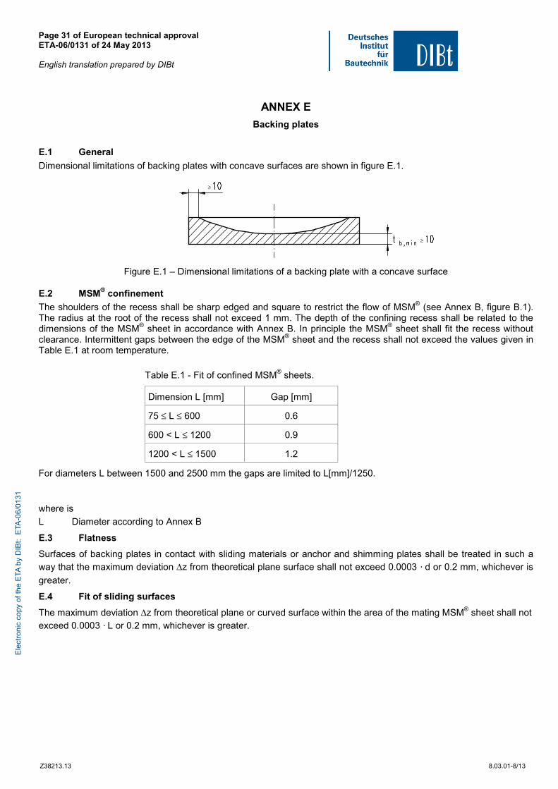
E.1 General
Dimensional limitations of backing plates with concave surfaces are shown in figure E.1.
≥
≥
Figure E.1 – Dimensional limitations of a backing plate with a concave surface
E.2 MSM® confinement
The shoulders of the recess shall be sharp edged and square to restrict the flow of MSM® (see Annex B, figure B.1). The radius at the root of the recess shall not exceed 1 mm. The depth of the confining recess shall be related to the dimensions of the MSM® sheet in accordance with Annex B. In principle the MSM® sheet shall fit the recess without clearance. Intermittent gaps between the edge of the MSM® sheet and the recess shall not exceed the values given in Table E.1 at room temperature.
Table E.1 - Fit of confined MSM® sheets.
Dimension L [mm] Gap [mm]
75 ≤ L ≤ 600 0.6
600 < L ≤ 1200 0.9
1200 < L ≤ 1500 1.2
For diameters L between 1500 and 2500 mm the gaps are limited to L[mm]/1250.
where is
L Diameter according to Annex B
E.3 Flatness
Surfaces of backing plates in contact with sliding materials or anchor and shimming plates shall be treated in such a way that the maximum deviation Δz from theoretical plane surface shall not exceed 0.0003 · d or 0.2 mm, whichever is
greater.
E.4 Fit of sliding surfaces
The maximum deviation Δz from theoretical plane or curved surface within the area of the mating MSM® sheet shall not exceed 0.0003 · L or 0.2 mm, whichever is greater.
Ele
ctro
nic
copy
of t
he E
TA b
y D
IBt:
ETA
-06/
0131
Page 32 of European technical approval ETA-06/0131 of 24 May 2013 English translation prepared by DIBt
Z38213.13 8.03.01-8/13
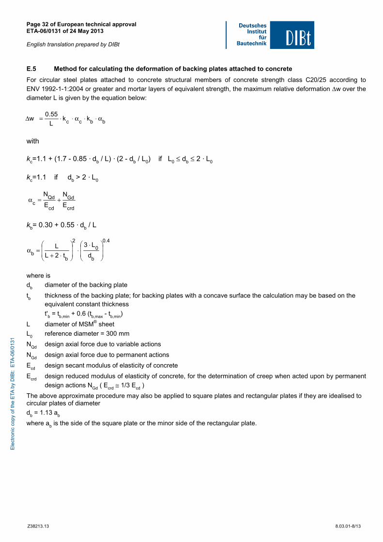
E.5 Method for calculating the deformation of backing plates attached to concrete
For circular steel plates attached to concrete structural members of concrete strength class C20/25 according to
ENV 1992-1-1:2004 or greater and mortar layers of equivalent strength, the maximum relative deformation Δw over the diameter L is given by the equation below:
with kc=1.1 + (1.7 - 0.85 · db / L) · (2 - db / L0) if L0 ≤ db ≤ 2 · L0 kc=1.1 if db > 2 · L0
kb= 0.30 + 0.55 · db / L
where is
db diameter of the backing plate
tb thickness of the backing plate; for backing plates with a concave surface the calculation may be based on the equivalent constant thickness
t'b = tb,min + 0.6 (tb,max - tb,min)
L diameter of MSM® sheet
L0 reference diameter = 300 mm
NQd design axial force due to variable actions
NGd design axial force due to permanent actions
Ecd design secant modulus of elasticity of concrete
Ecrd design reduced modulus of elasticity of concrete, for the determination of creep when acted upon by permanent
design actions NGd ( Ecrd ≅ 1/3 Ecd )
The above approximate procedure may also be applied to square plates and rectangular plates if they are idealised to circular plates of diameter
db = 1.13 ab
where ab is the side of the square plate or the minor side of the rectangular plate.
bbcc kkL
55.0w α⋅⋅α⋅⋅=Δ
crd
Gd
cd
Qdc E
N
E
N+=α
4.0
b
0
2
bb d
L3
t2L
L
⋅⋅
⋅+=α
Ele
ctro
nic
copy
of t
he E
TA b
y D
IBt:
ETA
-06/
0131