european standards tester - ametek programmable power: dc ... · european standards tester software...
TRANSCRIPT
European Standards Tester
Software Manual
ELGAR ELECTRONICS CORPORATION 9250 Brown Deer Road San Diego, CA 92121-2294 1-800-733-5427 Tel: (858) 450-0085 Fax: (858) 458-0267 Email: [email protected] www.elgar.com
©2002 by Elgar Electronics Corporation This document contains information proprietary to Elgar Electronics Corporation. The information contained herein is not to be duplicated or transferred in any manner without prior written permission from Elgar Electronics Corporation.
March 22, 2002 Document No. M161768-01 Rev B


Contents General Information and EST System Requirements ................................................ 1
System Overview................................................................................................................ 3 What's New in Version 1.80 ............................................................................................... 5 System Photos..................................................................................................................... 8 Launching EST ................................................................................................................. 11 European Standard Tester (EST) Main Screen................................................................. 12
The EST Test Wizard................................................................................................... 19 Running the Test Wizard .................................................................................................. 21 Running the Test Wizard (IEC61000-3-2 Harmonics Test) ............................................ 22 Running the Test Wizard (IEC61000-3-3 Flicker Test) .................................................. 26 Running the Test Wizard (IEC61000-4-11 Voltage Dips Test) ...................................... 30 Running the Test Wizard (IEC61000-4-13 Interharmonics Test) ................................... 34 Running the Test Wizard (IEC61000-4-14 Voltage Flux Test)....................................... 38 Running the Test Wizard (IEC61000-4-28 Frequency Flux Test) .................................. 42 Running the Test Wizard (IEC61000-4-17 Voltage Dips Test) ...................................... 47
The IEC 61000-3-2 (Harmonics) Test ......................................................................... 51 IEC 61000-3-2 (Harmonics) Test ..................................................................................... 53 IEC 61000-3-2 (Harmonics) Setup ................................................................................... 56 Adjusting Charts and Plots Scales .................................................................................... 59
The IEC 61000-3-3 (Flicker) Test ................................................................................ 61 IEC 61000-3-3 (Flicker) Test............................................................................................ 63 IEC 61000-3-3 (Flicker) Setup ......................................................................................... 66 Adjusting Charts and Plots Scales .................................................................................... 68
The IEC 61000-4-11 (Voltage Dip) Test ...................................................................... 71 IEC 61000-4-11 (Voltage Dip) Test ................................................................................. 73 IEC 61000-4-11 (Voltage Dip) Setup ............................................................................... 76 Adjusting Charts and Plots Scales .................................................................................... 78
The IEC 61000-4-13 (Interharmonics) Test ................................................................ 78 IEC 61000-4-13 (Interharmonics) Test............................................................................. 83 IEC 61000-4-13 (Interharmonics) Setup .......................................................................... 86 Adjusting Charts and Plots Scales .................................................................................... 96
The IEC 61000-4-14 (Voltage Fluctuation) Test......................................................... 96 IEC 61000-4-14 (Voltage Fluctuation) Test ................................................................... 101 IEC 61000-4-14 (Voltage Fluctuation) Setup................................................................. 104 Adjusting Charts and Plots Scales .................................................................................. 106
i
The IEC 61000-4-17 (DC Ripple) Test....................................................................... 106 IEC 61000-4-17 (DC Ripple) Test.................................................................................. 111 IEC 61000-4-17 (DC Ripple) Setup ............................................................................... 114 Adjusting Charts and Plots Scales .................................................................................. 116
The IEC 61000-4-28 (Frequency Fluctuation) Test.................................................. 116 IEC 61000-4-28 (Frequency Fluctuation) Test............................................................... 121 IEC 61000-4-28 (Frequency Fluctuation) Setup............................................................. 124 Adjusting Charts and Plots Scales .................................................................................. 126
Operation Modes....................................................................................................... 126 Manual Mode Operation ................................................................................................. 131 PA1000 Mode Operation ................................................................................................ 134 Demo Mode Operation ................................................................................................... 135
Replaying Test Files.................................................................................................. 139 Replaying Test Files ....................................................................................................... 141
EST Charts................................................................................................................. 143 IEC 61000-3-2 (Harmonics) Absolute Current Chart..................................................... 145 IEC 61000-3-2 (Harmonics) Absolute Voltage Chart .................................................... 146 IEC 61000-3-2 (Harmonics) Relative Current Chart...................................................... 147 IEC 61000-3-2 (Harmonics) Relative Voltage Chart ..................................................... 148 IEC 61000-3-2 (Harmonics) Current vs. Time Chart ..................................................... 149 IEC 61000-3-2 (Harmonics) Summary Table................................................................. 150 Fundamental and Logarithmic Chart Settings ................................................................ 152 IEC 61000-3-3 (Flicker) Dt Distribution Chart .............................................................. 154 IEC 61000-3-3 (Flicker) Pt Distribution Chart............................................................... 155 IEC 61000-3-3 (Flicker) Summary Table....................................................................... 156 Adjusting Charts and Plots Scales .................................................................................. 157
EST Reports............................................................................................................... 159 Viewing Test Results ...................................................................................................... 161 Opening Reports ............................................................................................................. 162 Editing Reports ............................................................................................................... 164 Exporting Reports ........................................................................................................... 166 Deleting Reports ............................................................................................................. 168 Printing Reports .............................................................................................................. 169 Print Screen..................................................................................................................... 171 Printer Setup.................................................................................................................... 172
ii

General Information and EST System
Requirements
1

2

3
System Overview Welcome to the Elgar European Standards Tester (EST) computer program, which enables you to set up and perform electrical device compliance testing to IEC/EN standards and do general purpose AC+DC power source control and power data logging.
For a "big picture" of the EST System, see the System Photos on page 8.
Features of the EST System • EN61000-3-2 IEC harmonics test. • EN61000-3-2 IEC flicker test. • EN61000-4-11 IEC Voltage Dips test. • EN61000-4-13 IEC Interharmonics test. • EN61000-4-14 IEC Voltage Fluctuation test. • EN61000-4-28 IEC Frequency Fluctuation test. • General Purpose Control of the Elgar SWAC general purpose Power Supply. • Manual Control of the Elgar PA1000 power data logger and analyzer. • Data and test information storage in Microsoft Access a database. • Presentable IEC test reports that may be exported other Windows applications. • Software parameter configuration of IEC test and manual data acquisition and control. • Demo Program for doing offline data processing. • The EST system is currently a single-phase system capable of generating 40 to 400 Hz
test frequencies. • The SW may be programmed to output arbitrary waveforms and sequences of user-
defined waveforms.
EST System Requirements 1. SWAE – provided by Elgar Electronics Corporation 2. PA1000 – provided by Elgar Electronics Corporation 3. EST Microsoft Windows software – provided by Elgar Electronics Corporation 4. PA1000 to SWAE interconnection cabling - provided by Elgar Electronics Corporation 5. Personal Computer. Minimum of Pentium class 133 MHz, 32 MB RAM, 100 Mbytes
Hard Disk space. – provided by customer. 6. Microsoft Windows 95/NT/98 – provided by customer. 7. National Instruments GPIB card or GPIB-ENET (GPIB to Ethernet converter box) or
GPIB-PCMCIA , installation of GPIB drivers on Personal computer– provided by customer.
8. GPIB cabling (2 cables) – provided by customer. GPIB addresses, SWAE = 25, PA1000 = 2, PC board ID = 0.
9. Device to test – provided by customer.

Where do I go for further information? If you should require help or more information, first check the European Standards Tester User Guide. If that guide also does not include the information, contact Elgar Customer Support at:
1-800-733-5427 or 9250 Brown Deer Road San Diego, CA 92121-2294 USA or www.elgar.com
If your question regards specific information from the IEC/EN standards (61000-3-2 and 61000-3-3), first check the documentation for those standards. If you do not have a copy of the standards, contact:
Bureau Central de la Commission Electrotechnique Internationale 3, Rue de Vorembé Genéve, Switzerland or www.iec.ch
Installing the EST Software To install the European Standards Tester:
1. Insert the EST Installation CD into your CD drive.
2. The installation program runs automatically. Please follow the prompts. To install from another drive, simply select the EST/Setup.exe file.
NOTE: When running the installation program, if a previous version of the EST software is already installed, a pop-up window will appear with the options to Repair or Remove the EST program. Do not use the Repair utility on a previous version of the software.
Uninstalling the EST Software There are two ways to uninstall the European Standards Tester program:
1. From the Windows Start button, go to Settings, Control Panel, and select Add/Remove Programs. Select EST from the Install/Uninstall list, then click the Add/Remove button.
2. Rerun the EST Setup program on the EST Installation CD. Select the Remove EST option and follow the prompts.
4
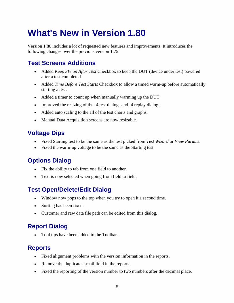
What's New in Version 1.80 Version 1.80 includes a lot of requested new features and improvements. It introduces the following changes over the previous version 1.75:
Test Screens Additions • Added Keep SW on After Test Checkbox to keep the DUT (device under test) powered
after a test completed.
• Added Time Before Test Starts Checkbox to allow a timed warm-up before automatically starting a test.
• Added a timer to count up when manually warming up the DUT.
• Improved the resizing of the -4 test dialogs and -4 replay dialog.
• Added auto scaling to the all of the test charts and graphs.
• Manual Data Acquisition screens are now resizable.
Voltage Dips • Fixed Starting test to be the same as the test picked from Test Wizard or View Params. • Fixed the warm-up voltage to be the same as the Starting test.
Options Dialog • Fix the ability to tab from one field to another.
• Text is now selected when going from field to field.
Test Open/Delete/Edit Dialog • Window now pops to the top when you try to open it a second time.
• Sorting has been fixed.
• Customer and raw data file path can be edited from this dialog.
Report Dialog • Tool tips have been added to the Toolbar.
Reports • Fixed alignment problems with the version information in the reports.
• Remove the duplicate e-mail field in the reports.
• Fixed the reporting of the version number to two numbers after the decimal place.
5
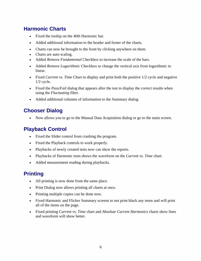
Harmonic Charts • Fixed the tooltip on the 40th Harmonic bar.
• Added additional information to the header and footer of the charts.
• Charts can now be brought to the front by clicking anywhere on them. • Charts are auto scaling. • Added Remove Fundamental Checkbox to increase the scale of the bars.
• Added Remove Logarithmic Checkbox to change the vertical axis from logarithmic to linear.
• Fixed Current vs. Time Chart to display and print both the positive 1/2 cycle and negative 1/2 cycle.
• Fixed the Pass/Fail dialog that appears after the test to display the correct results when using the Fluctuating filter.
• Added additional columns of information to the Summary dialog.
Chooser Dialog • Now allows you to go to the Manual Data Acquisition dialog or go to the main screen.
Playback Control • Fixed the Slider control from crashing the program.
• Fixed the Playback controls to work properly.
• Playbacks of newly created tests now can show the reports.
• Playbacks of Harmonic tests shows the waveform on the Current vs. Time chart.
• Added measurement reading during playbacks.
Printing • All printing is now done from the same place.
• Print Dialog now allows printing all charts at once.
• Printing multiple copies can be done now.
• Fixed Harmonic and Flicker Summary screens to not print black any more and will print all of the items on the page.
• Fixed printing Current vs. Time chart and Absolute Current Harmonics charts show lines and waveform will show better.
6
Test Wizard • Customer information can be updated during use of the Test Wizard.
• When picking a previous customer the last Test ID and Test Description is shown for that customer.
• Tabbing has been fixed in all the fields for the Test Wizard and the text is selected when entering a field.
• Fixed a bug in the Test Wizard screens when using the left and right arrow keys.
Help System • Updated and added help on all the areas of the EST.
• Help is now content sensitive.
Demo Mode • Demo Mode is again part of the EST program and not a separate executable.
• Demo Mode has been update with the EST program.
• Playback capability has been added.
• Manual Harmonics and Flicker test items have been added.
PA1000 Mode • Added PA1000 Mode which allows data acquisition from the PA1000 without the Smart
Wave power source.
Help Screens • Help Screens have been update and are now resizable.
• Help Screens can be turned on and off via menus and remember their last position.
• Help Screens work in all modes.
Miscellaneous Additions • Fixed the Traffic light to abort a started test and restart the last test that had run.
• Fixed the Exit menu item so it would not crash the EST.
• Replace the dancing Armadillo with an animated hourglass.
7

System Photos The following photos illustrate a common EST configuration with a light fixture as the device under test (DUT).
Photo of EST system performing an IEC61000-3-3 Flicker Test.
Photo of EST system identifying components.
8
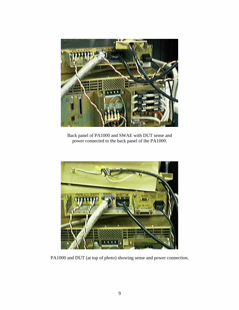
Back panel of PA1000 and SWAE with DUT sense and power connected to the back panel of the PA1000.
PA1000 and DUT (at top of photo) showing sense and power connection.
9
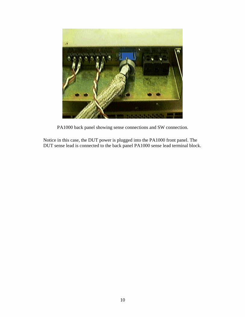
PA1000 back panel showing sense connections and SW connection.
Notice in this case, the DUT power is plugged into the PA1000 front panel. The DUT sense lead is connected to the back panel PA1000 sense lead terminal block.
10

Launching EST 1. With the installed EST software on your Microsoft Windows 95/98/NT/2000 personal
computer, make sure your GPIB card and driver software are installed.
2. Launch EST by selecting Start | Programs | EST | EST
3. The Splash Screen appears, as illustrated below:
4. The Please Choose Dialog appears, as illustrated below:
5. Select the Test Wizard option or Manual Mode.
See also: Harmonics Test Wizard Interharmonics Test Wizard Flicker Test Wizard Voltage Flux Test Wizard Voltage Dip Test Wizard Frequency Flux Test Wizard
11
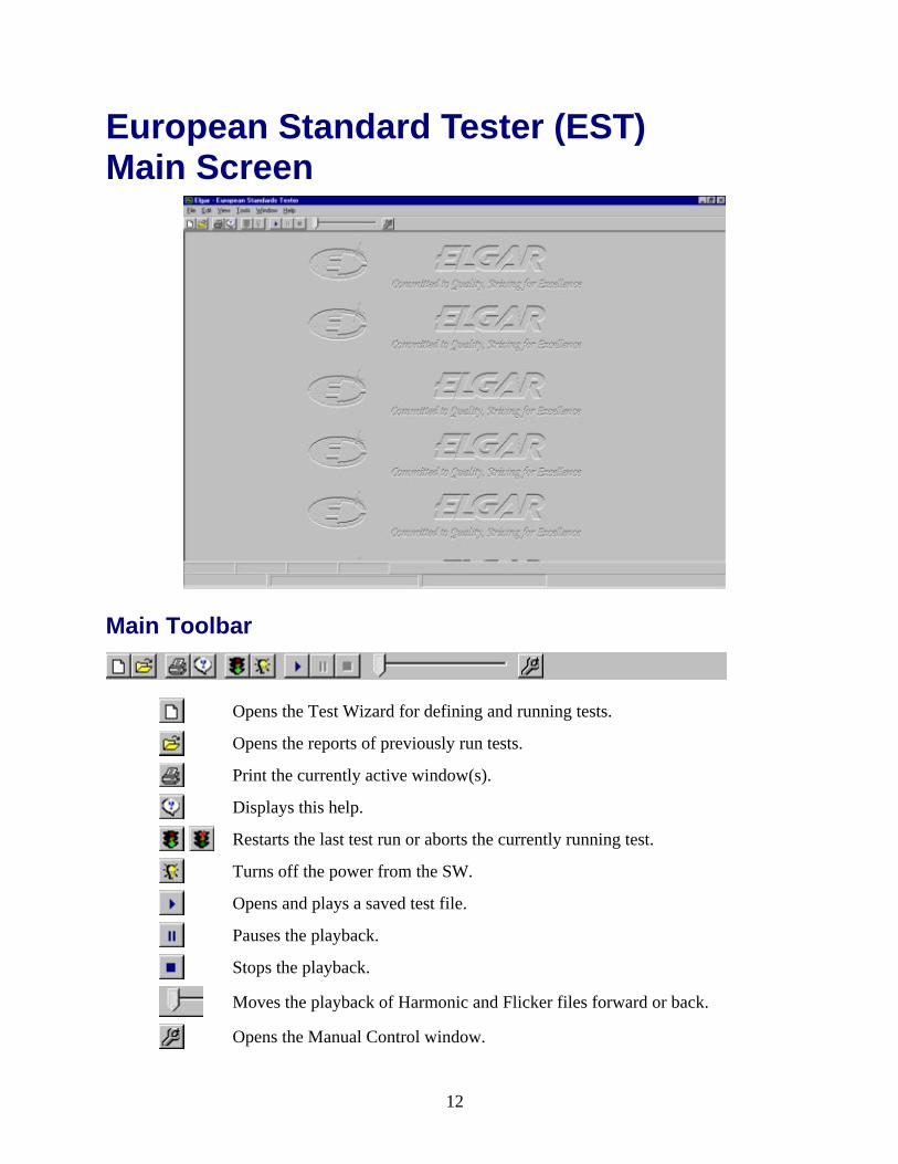
European Standard Tester (EST) Main Screen
Main Toolbar
Opens the Test Wizard for defining and running tests.
Opens the reports of previously run tests.
Print the currently active window(s).
Displays this help.
Restarts the last test run or aborts the currently running test.
Turns off the power from the SW.
Opens and plays a saved test file.
Pauses the playback.
Stops the playback.
Moves the playback of Harmonic and Flicker files forward or back.
Opens the Manual Control window.
12
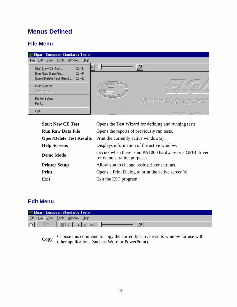
Menus Defined
File Menu
Start New CE Test Opens the Test Wizard for defining and running tests. Run Raw Data File Opens the reports of previously run tests. Open/Delete Test Results Print the currently active window(s). Help Screens Displays information of the active window.
Demo Mode Occurs when there is no PA1000 hardware or a GPIB driver for demonstration purposes.
Printer Setup Allow you to change basic printer settings. Print Opens a Print Dialog to print the active screen(s). Exit Exit the EST program.
Edit Menu
Copy Choose this command to copy the currently active results window for use with other applications (such as Word or PowerPoint).
13

View Menu
Toolbar Turns on and off the toolbar. Status Bar Turns on and off the Status bar.
Tools Menu
Options Opens the Options dialog for setting up -4 tests and basic program settings.
Manual Opens the reports of previously run tests. SW/PA1000 Executes a PA1000 manually. Harmonics 3-2 Executes a Harmonics test manually. Flicker 3-3 Executes a Flicker test manually. Volt Dip 4-11 Executes a Voltage Dip test manually. Interharmonic 4-13 Executes an interharmonics test manually. Volt Flux 4-14 Executes a Voltage Fluctuation test manually. DC Ripple 4-17 Executes a DC Ripple test manually. Freq Flux 4-28 Executes a Frequency Fluctuation test manually.
Update PA1000 Firmware Allows a file to be loaded to PA1000 for a firmware upgrade.
14

Window Menu
Cascade Cascades the opened windows. Tile Horizontal Tiles the opened windows horizontally. Tile Vertical Tiles the opened windows vertically. Arrange Icons Allow to arrange the opened windows.
Help Menu
Help Contents Display the online help contents. Help Index Display the online help index. Whats New Display the online help Whats New section. About Elgar EST Displays the versioning and system information.
15

Options Menu
Test House Options.
Enter your company information here. This information will also show up in the reports.
16

Miscellaneous Options.
Debug Window GPIB messages can be viewed from this window.
SW Current Limit (AMPS) Sets the SmartWave current limit.
Data Refresh Rate (ms) Set the rate at which the Harmonics and Flicker test display their data.
Press this button to access the EST help topic that describes this dialog.
Press this button to exit the Options and return to the main EST window.
Press this button to return to the previous screen.
17
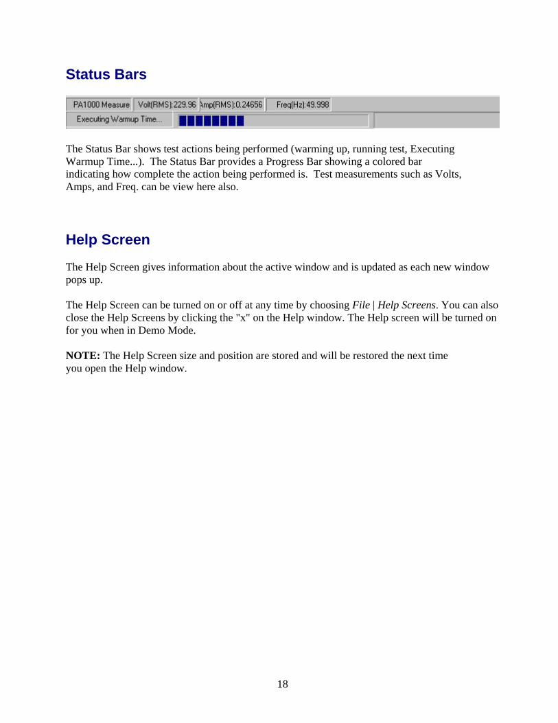
Status Bars
The Status Bar shows test actions being performed (warming up, running test, Executing Warmup Time...). The Status Bar provides a Progress Bar showing a colored bar indicating how complete the action being performed is. Test measurements such as Volts, Amps, and Freq. can be view here also.
Help Screen The Help Screen gives information about the active window and is updated as each new window pops up.
The Help Screen can be turned on or off at any time by choosing File | Help Screens. You can also close the Help Screens by clicking the "x" on the Help window. The Help screen will be turned on for you when in Demo Mode.
NOTE: The Help Screen size and position are stored and will be restored the next time you open the Help window.
18

The EST Test Wizard
19

20

Running the Test Wizard The Test Wizard takes you through a step–by–step process in creating an IEC61000 tests.
Refer to the tests below to take you through the Test Wizard screens:
Running the Test Wizard (IEC61000-3-2 Harmonics Test) Running the Test Wizard (IEC61000-3-3 Flicker Test) Running the Test Wizard (IEC61000-4-11 Voltage Dips Test) Running the Test Wizard (IEC61000-4-13 Interharmonics Test) Running the Test Wizard (IEC61000-4-14 Voltage Fluctuation Test) Running the Test Wizard (IEC61000-4-17 DC Ripple Test) Running the Test Wizard (IEC61000-4-28 Frequency Fluctuation Test)
See also: General Information and System Requirements
21

Running the Test Wizard (IEC61000-3-2 Harmonics Test)
1. Select the Harmonics Test from the Test Wizard. Select the Next Button.
2. Type in the customer information. Select the Next Button.
22

3. Select the Test Parameters. Select the Next Button.
4. Run the Test. Select the Start Test Button.
23

5. Appearance of EST during execution of the harmonics test.
6. Results screen of the harmonics test depending on the outcome.
24

7. Viewing the report.
See also: Running the Test Wizard (IEC61000-3-3 Flicker Test) Running the Test Wizard (IEC61000-4-11 Voltage Dips Test) Running the Test Wizard (IEC61000-4-13 Interharmonics Test) Running the Test Wizard (IEC61000-4-14 Voltage Fluctuation Test) Running the Test Wizard (IEC61000-4-17 DC Ripple Test) Running the Test Wizard (IEC61000-4-28 Frequency Fluctuation Test)
25
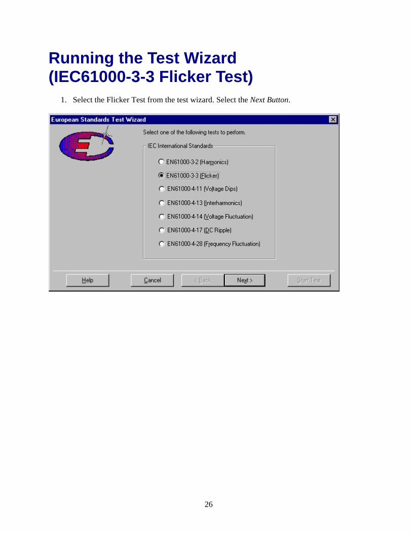
Running the Test Wizard (IEC61000-3-3 Flicker Test)
1. Select the Flicker Test from the test wizard. Select the Next Button.
26

2. Type in the customer information. Select the Next Button.
3. Select the Test Parameters. Select the Next Button.
27

4. Run the Test. Select the Start Test Button.
5. Appearance of the EST during a flicker test.
28

6. Results screen of the harmonics test depending on the outcome.
7. Viewing the report.
See also: Running the Test Wizard (IEC61000-3-3 Flicker Test) Running the Test Wizard (IEC61000-4-11 Voltage Dips Test) Running the Test Wizard (IEC61000-4-13 Interharmonics Test) Running the Test Wizard (IEC61000-4-14 Voltage Fluctuation Test) Running the Test Wizard (IEC61000-4-17 DC Ripple Test) Running the Test Wizard (IEC61000-4-28 Frequency Fluctuation Test)
29

Running the Test Wizard (IEC61000-4-11 Voltage Dips Test)
1. Select the 4-11 Voltage Dip Test from the test wizard. Select the Next Button.
30
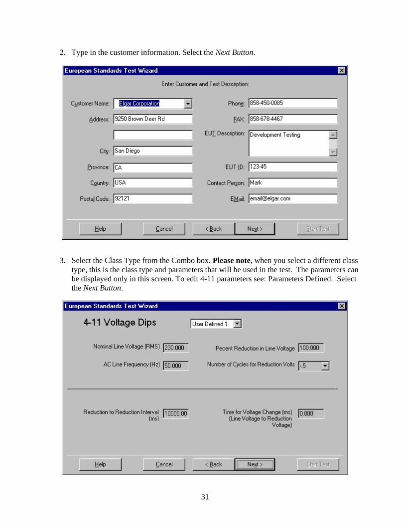
2. Type in the customer information. Select the Next Button.
3. Select the Class Type from the Combo box. Please note, when you select a different class type, this is the class type and parameters that will be used in the test. The parameters can be displayed only in this screen. To edit 4-11 parameters see: Parameters Defined. Select the Next Button.
31
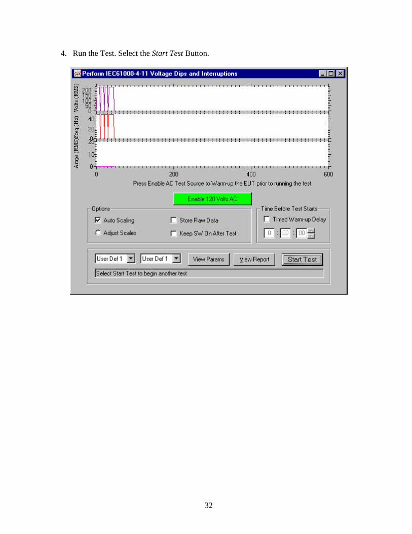
4. Run the Test. Select the Start Test Button.
32

5. Performing a Functionality Test.
See also: Running the Test Wizard (IEC61000-3-2 Harmonics Test) Running the Test Wizard (IEC61000-3-3 Flicker Test) Running the Test Wizard (IEC61000-4-13 Interharmonics Test) Running the Test Wizard (IEC61000-4-14 Voltage Fluctuation Test) Running the Test Wizard (IEC61000-4-17 DC Ripple Test) Running the Test Wizard (IEC61000-4-28 Frequency Fluctuation Test)
33

Running the Test Wizard (IEC61000-4-13 Interharmonics Test)
1. Select the 4-13 Interharmonics Test from the Test Wizard. Select the Next Button.
34

2. Type in the customer information. Select the Next Button.
3. Select the Class Type from the Combo box. Please note, when you select a different class type, this is the class type and parameters that will be used in the test. The parameters can be displayed only in this screen. To edit 4-13 parameters see: Parameters Defined. Select the Next Button.
35
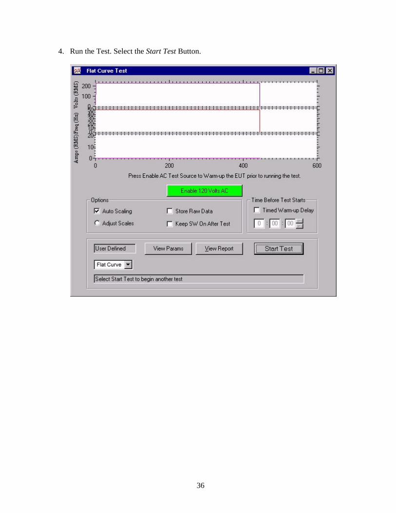
4. Run the Test. Select the Start Test Button.
36

5. Performing Functionality Test.
See also: Running the Test Wizard (IEC61000-3-2 Harmonics Test) Running the Test Wizard (IEC61000-3-3 Flicker Test) Running the Test Wizard (IEC61000-4-11 Voltage Dips Test) Running the Test Wizard (IEC61000-4-14 Voltage Fluctuation Test) Running the Test Wizard (IEC61000-4-17 DC Ripple Test) Running the Test Wizard (IEC61000-4-28 Frequency Fluctuation Test)
37
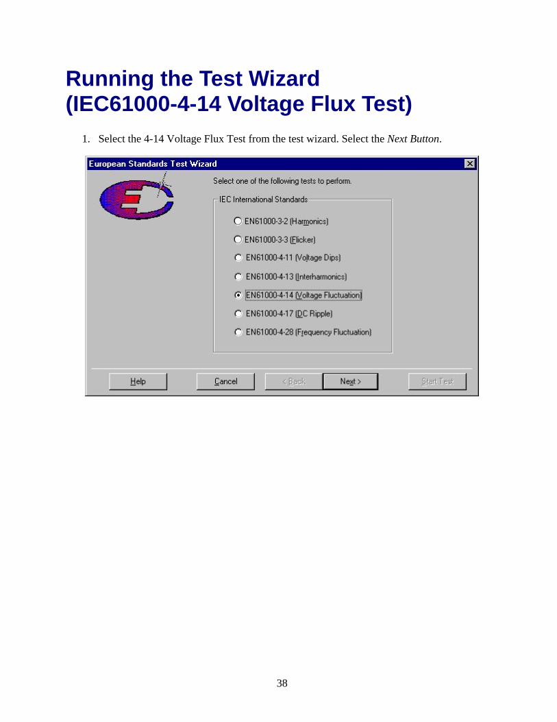
Running the Test Wizard (IEC61000-4-14 Voltage Flux Test)
1. Select the 4-14 Voltage Flux Test from the test wizard. Select the Next Button.
38

2. Type in the customer information. Select the Next Button.
3. Select the Class Type from the Combo box. Please note, when you select a different class type, this is the class type and parameters that will be used in the test. The parameters can be displayed only in this screen. To edit 4-14 parameters see: Parameters Defined. Select the Next Button.
39
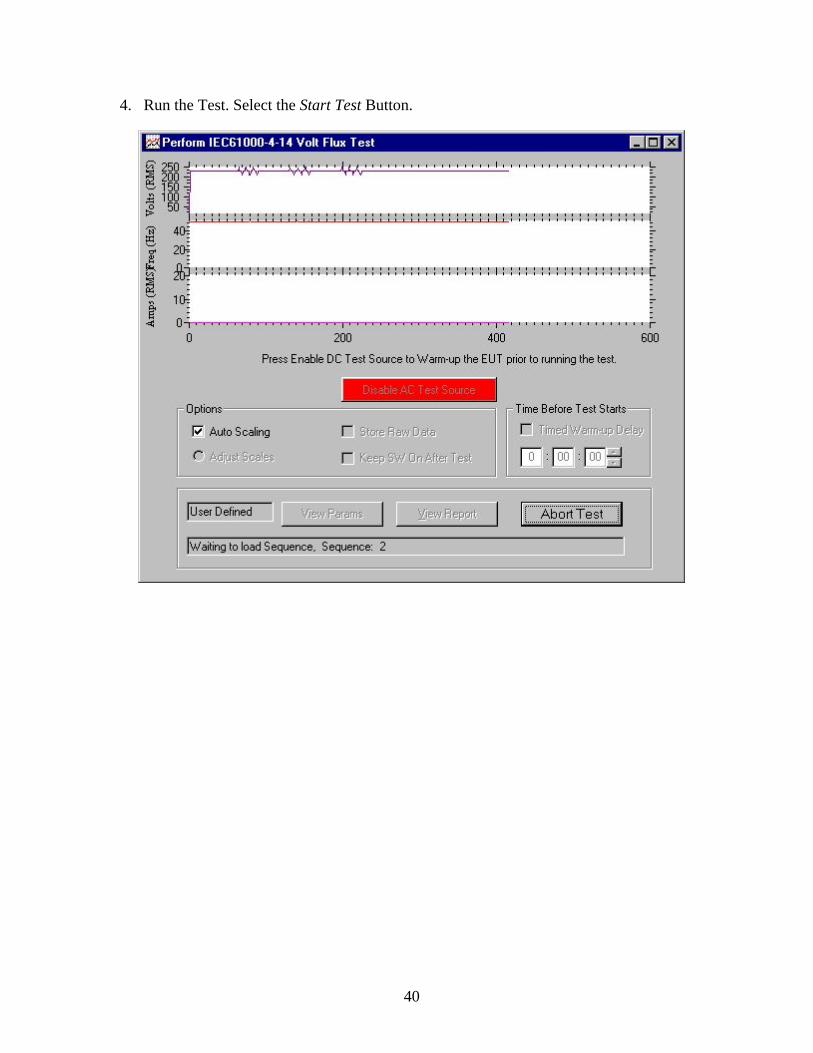
4. Run the Test. Select the Start Test Button.
40

5. Performing Functionality Test.
See also: Running the Test Wizard (IEC61000-3-2 Harmonics Test) Running the Test Wizard (IEC61000-3-3 Flicker Test) Running the Test Wizard (IEC61000-4-11 Voltage Dips Test) Running the Test Wizard (IEC61000-4-13 Interharmonics Test) Running the Test Wizard (IEC61000-4-17 DC Ripple Test) Running the Test Wizard (IEC61000-4-28 Frequency Fluctuation Test)
41

Running the Test Wizard (IEC61000-4-28 Frequency Flux Test)
1. Select the 4-28 Frequency Flux Test from the Test Wizard. Select the Next Button.
42
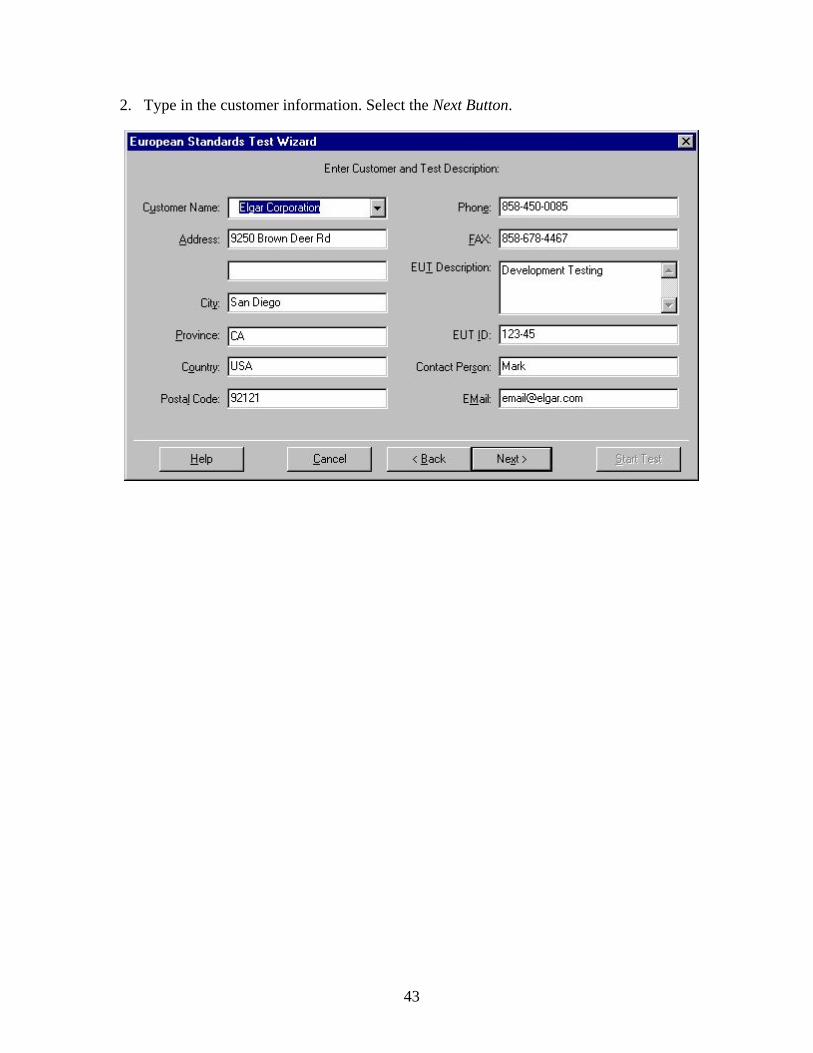
2. Type in the customer information. Select the Next Button.
43
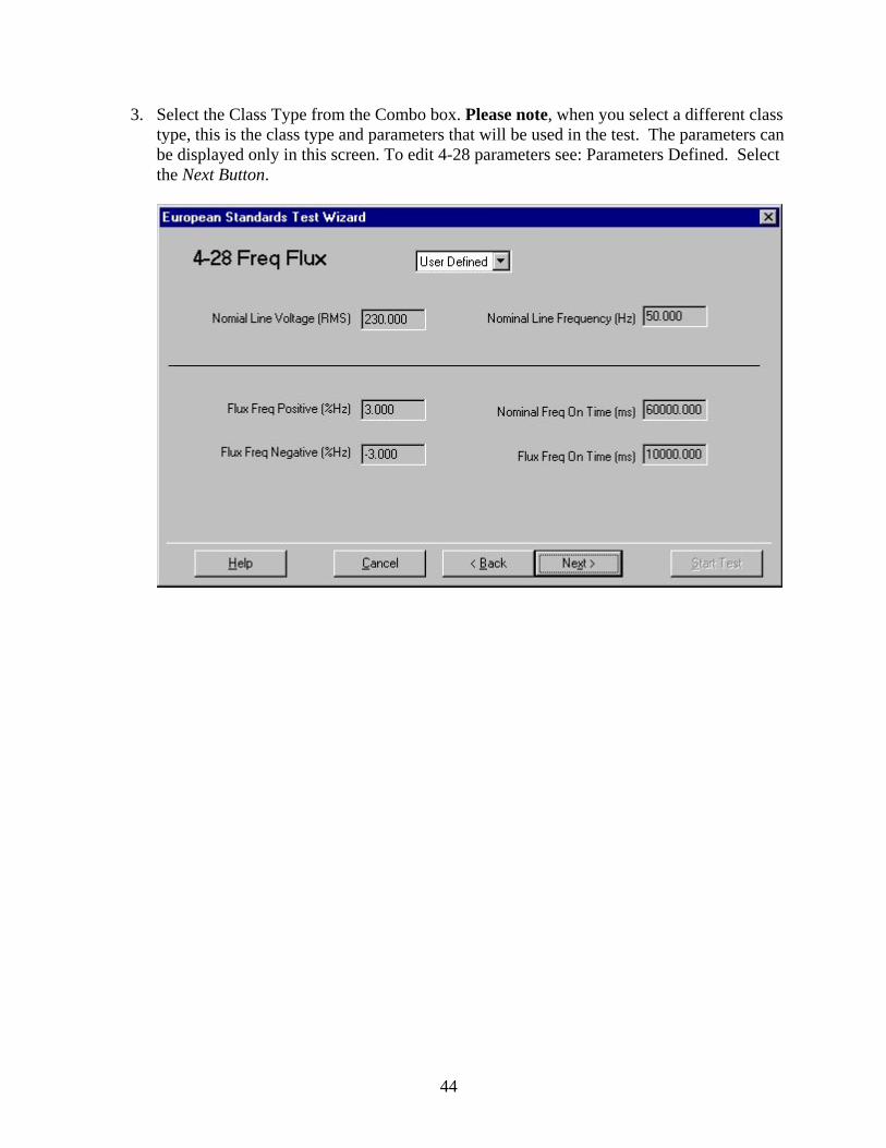
3. Select the Class Type from the Combo box. Please note, when you select a different class type, this is the class type and parameters that will be used in the test. The parameters can be displayed only in this screen. To edit 4-28 parameters see: Parameters Defined. Select the Next Button.
44
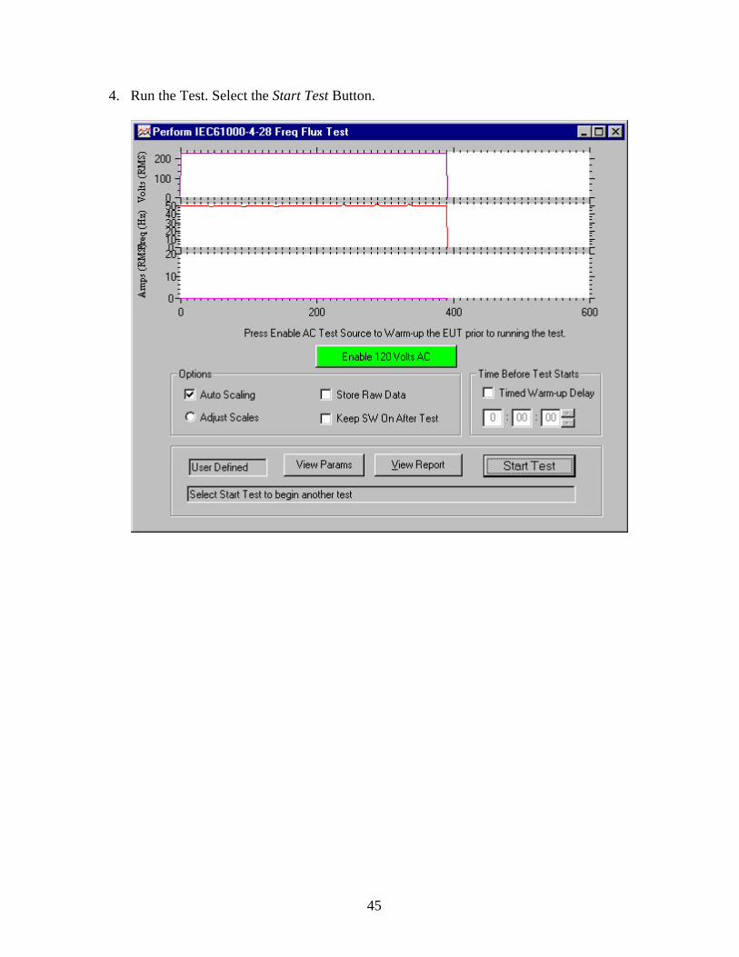
4. Run the Test. Select the Start Test Button.
45

5. Performing Functionality Test.
See also: Running the Test Wizard (IEC61000-3-2 Harmonics Test) Running the Test Wizard (IEC61000-3-3 Flicker Test) Running the Test Wizard (IEC61000-4-11 Voltage Dips Test) Running the Test Wizard (IEC61000-4-13 Interharmonics Test) Running the Test Wizard (IEC61000-4-14 Voltage Fluctuation Test) Running the Test Wizard (IEC61000-4-17 DC Ripple Test)
46

Running the Test Wizard (IEC61000-4-17 Voltage Dips Test)
1. Select the 4-17 Voltage Dip Test from the test wizard. Select the Next Button.
47

2. Type in the customer information. Select the Next Button.
3. Select the Class Type from the Combo box. Please note, when you select a different class type, this is the class type and parameters that will be used in the test. The parameters can be displayed only in this screen. To edit 4-17 parameters see: Parameters Defined. Select the Next Button.
48

4. Run the Test. Select the Start Test Button.
49

5. Performing Functionality Test.
See also: Running the Test Wizard (IEC61000-3-2 Harmonics Test) Running the Test Wizard (IEC61000-3-3 Flicker Test) Running the Test Wizard (IEC61000-4-11 Voltage Dips Test) Running the Test Wizard (IEC61000-4-13 Interharmonics Test) Running the Test Wizard (IEC61000-4-14 Voltage Fluctuation Test) Running the Test Wizard (IEC61000-4-28 Frequency Fluctuation Test)
50

The IEC 61000-3-2
(Harmonics) Test
51

52

IEC 61000-3-2 (Harmonics) Test IEC1000-3-2/EN61000-3-2 specifies the standards for regulating the magnitude of harmonic current devices draw from the AC power line. The standard seeks to regulate the level of harmonic currents to prevent off order harmonics sum (which can cause neutral connectors to overheat). The PA1000 analyzer measures 40 different harmonics against a fundamental harmonic value. Described below are the various screens encountered during a Harmonics test:
53

After you define and start an IEC1000-3-2/EN61000-3-2 (Harmonics) test, EST displays six windows containing test results.
These windows show ongoing, real-time results while the test is running (including during warmup), and a snapshot of the final results after the test is complete. It includes the following windows:
Current vs. Time Tabular View Relative Voltage Harmonics Absolute Voltage Harmonics Relative Current Harmonics Absolute Current Harmonics
54

This dialog appears when a test is complete.
or this dialog appears.
It indicates whether the EUT passed or failed and includes the following elements:
View Report Press this button to open the Report window and view the report for this test. Close Press this button to close the dialog.
Termination of the Harmonics test can be done at any time by selecting on the Main Toolbar.
To turn off the SW AC Power at any time select on the Main Toolbar.
See also: Running the Test Wizard (IEC61000-3-2 Harmonics Test)
55
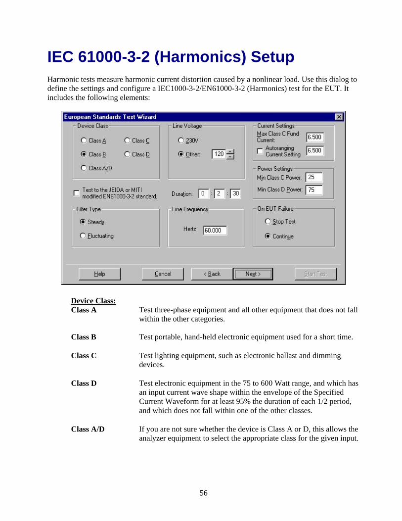
IEC 61000-3-2 (Harmonics) Setup Harmonic tests measure harmonic current distortion caused by a nonlinear load. Use this dialog to define the settings and configure a IEC1000-3-2/EN61000-3-2 (Harmonics) test for the EUT. It includes the following elements:
Device Class: Class A
Test three-phase equipment and all other equipment that does not fall within the other categories.
Class B Test portable, hand-held electronic equipment used for a short time.
Class C Test lighting equipment, such as electronic ballast and dimming devices.
Class D Test electronic equipment in the 75 to 600 Watt range, and which has an input current wave shape within the envelope of the Specified Current Waveform for at least 95% the duration of each 1/2 period, and which does not fall within one of the other classes.
Class A/D If you are not sure whether the device is Class A or D, this allows the analyzer equipment to select the appropriate class for the given input.
56

Line Voltage: 230V Other:
Select 230V or enter the correct voltage the DUT requires. The value must be between 90 and 450V. Since EST is set up for testing to European standards, 230V is the default value.
Filter Type Select a filter type: Steady If the EUT draws power steadily, which means that the test does not require a filter. Fluctuating The EUT does not draw power steadily. During the test EST applies a filter that determines if the fluctuation is out of range for this type of device.
Power Settings: Min Class C Power
If the EUT is a Class C device, enter the minimum wattage the device should draw. The value must be between 1 and 75 W. Enter the power values by using the keyboard, or by using the mouse to click the spin button to the right of the field. If the EUT is not a Class C device, this value is ignored.
Min Class D Power If the EUT is a Class D device, enter the minimum wattage the device should draw. The value must be between 1 and 150 W. Enter the power values by using the keyboard, or by using the mouse to click the spin button to the right of the field. If the EUT is not a Class D device, this value is ignored.
Filter Type: Steady
Select Steady if the EUT draws power steadily, which means that the test does not require a filter.
Fluctuating Select Fluctuating if the EUT does not draw power steadily. During the test EST applies a filter that determines if the fluctuation is out of range for this type of device.
Line Frequency: 50Hz 60Hz
Select the appropriate line frequency.
57

On Test Equip. Failure: Stop Test
Stop Test halts the test immediately upon failure.
Continue Continue continues the test until the test duration has been reached. Select the action that should occur if the test equipment (not the EUT) should fail during the test.
Use Adder Check this box if the EUT must conform to JEIDA or MIDI (Japanese) standards. EST adds the appropriate value to the parameters to accommodate the differing standards. Do not check this box if the EUT must conform to European standards.
Duration Enter the test duration in hours, minutes, and seconds. Press TAB to move from one time increment to the next. Enter the duration values by using the keyboard, or by using the mouse to click the spin button to the right of the field.
Click this button to access the EST help topic that describes this dialog.
Click this button to exit the Test Wizard and return to the main EST window.
Click this button to return to the previous Test Wizard dialog.
Click this button to move to the next Test Wizard dialog.
This will Start the test with the parameters you have defined.
See also: IEC 61000-3-2 (Harmonics) Test
58

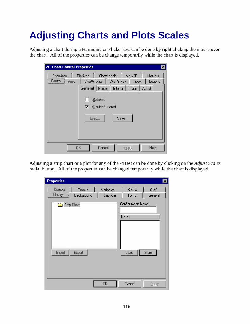
Adjusting Charts and Plots Scales Adjusting a chart during a Harmonic or Flicker test can be done by right clicking the mouse over the chart. All of the properties can be changed temporarily while the chart is displayed.
Adjusting a strip chart or a plot for any of the -4 test can be done by clicking on the Adjust Scales radial button. All of the properties can be changed temporarily while the chart is displayed.
59

60
The IEC 61000-3-3 (Flicker) Test
61

62
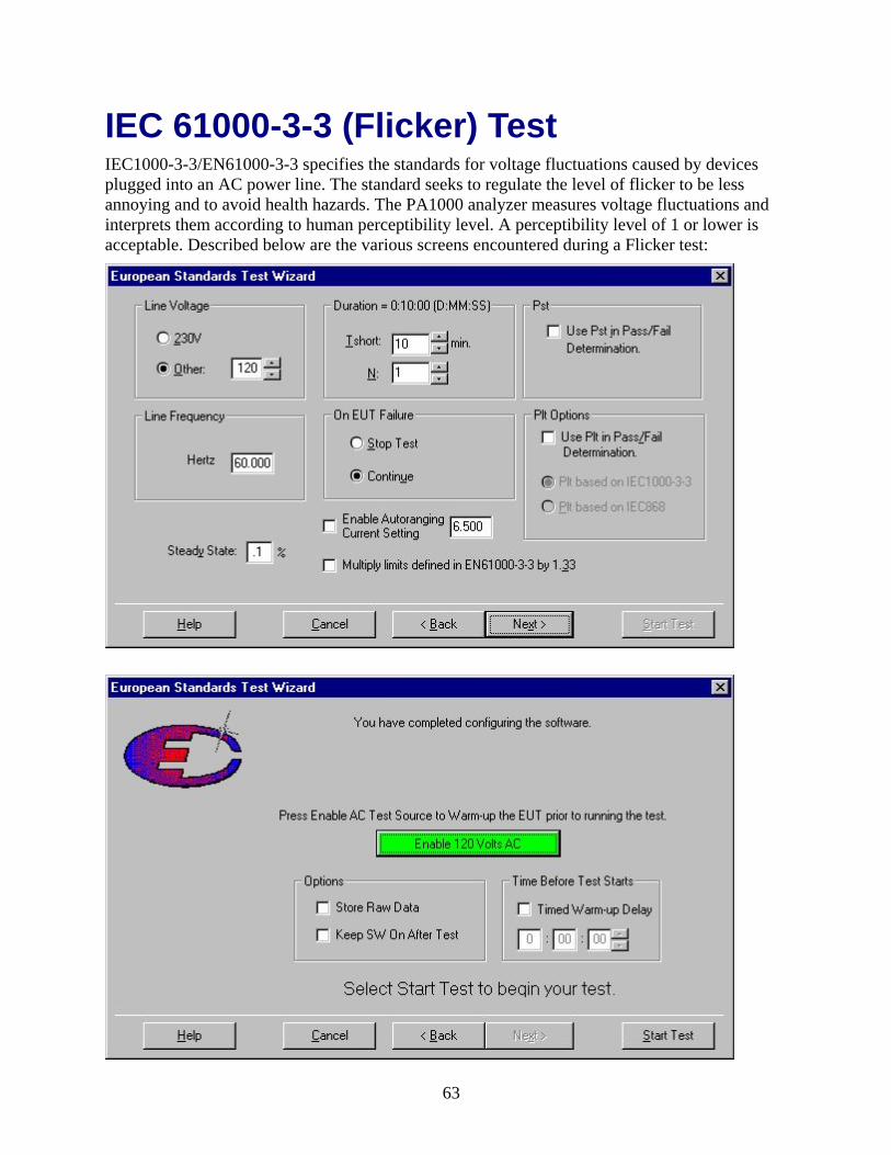
IEC 61000-3-3 (Flicker) Test IEC1000-3-3/EN61000-3-3 specifies the standards for voltage fluctuations caused by devices plugged into an AC power line. The standard seeks to regulate the level of flicker to be less annoying and to avoid health hazards. The PA1000 analyzer measures voltage fluctuations and interprets them according to human perceptibility level. A perceptibility level of 1 or lower is acceptable. Described below are the various screens encountered during a Flicker test:
63
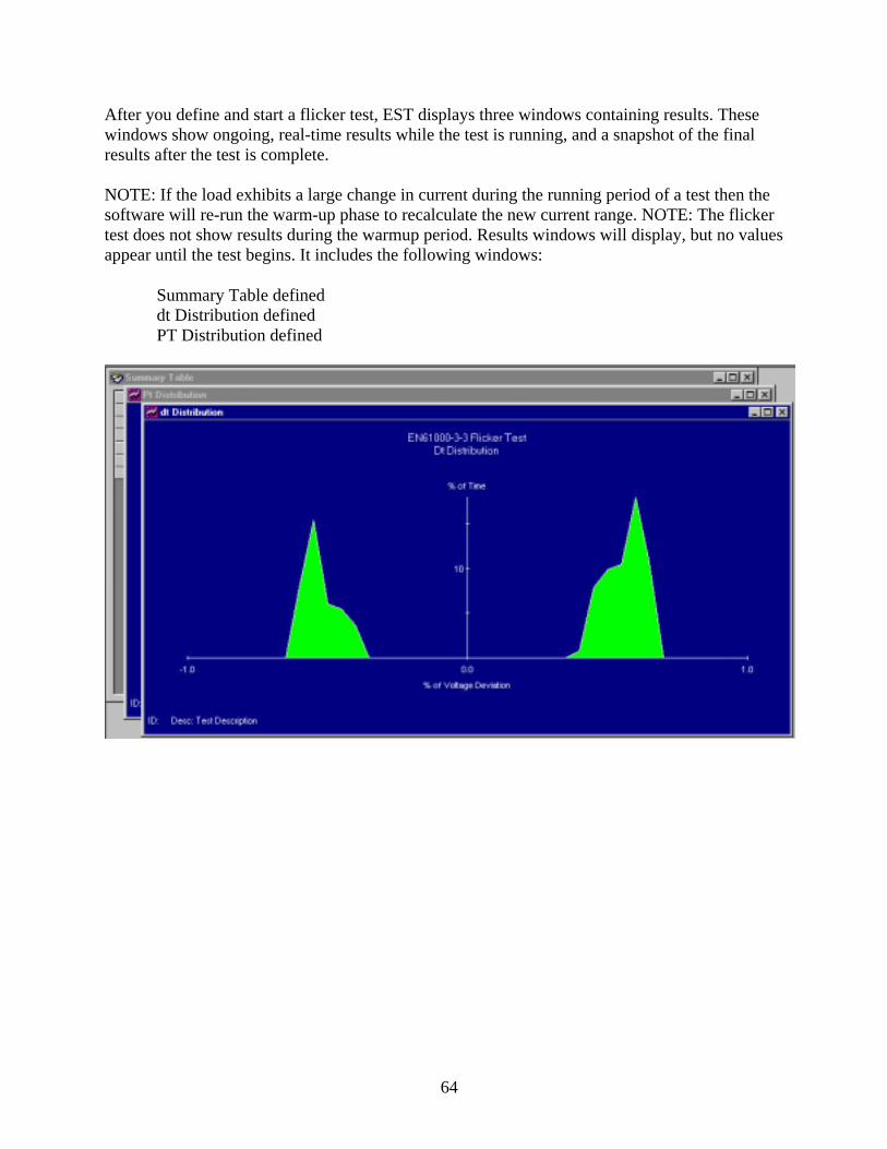
After you define and start a flicker test, EST displays three windows containing results. These windows show ongoing, real-time results while the test is running, and a snapshot of the final results after the test is complete. NOTE: If the load exhibits a large change in current during the running period of a test then the software will re-run the warm-up phase to recalculate the new current range. NOTE: The flicker test does not show results during the warmup period. Results windows will display, but no values appear until the test begins. It includes the following windows:
Summary Table defined dt Distribution defined PT Distribution defined
64

This dialog appears when a test is complete.
or this dialog appears.
It indicates whether the EUT passed or failed and includes the following elements:
View Report Press this button to open the Report window and view the report for this
test. Close Press this button to close the dialog.
Termination of the Flicker test can be done at any time by selecting on the Main Toolbar.
To turn off the SW AC Power at any time select on the Main Toolbar.
See also: Running the Test Wizard (IEC61000-3-3 Flicker Test)
65

IEC 61000-3-3 (Flicker) Setup Flicker tests measure the propensity of electrical equipment to cause electrical disturbances on AC lines. Use this dialog to define the settings and configure a flicker test for the DUT. It includes the following elements:
Line Voltage: 230V Other:
Select 230V or enter the correct voltage the DUT requires. The value must be between 90 and 450V. Since EST is set up for testing to European standards, 230V is the default value.
Duration: Tshort:
Set the duration of the Tshort (defined in the IEC1000-3-3/EN61000-3-3 standard) in minutes.
N: Set the number of repetitions (N) of the Tshort. This combination of settings defines the ultimate duration of the test (Tshort duration x N = duration of test in minutes).
Pst: Pst
Check this box if you want short-term perceptibility statistics to affect the test results.
66

Line Frequency: 50Hz 60Hz
Select the appropriate line frequency.
On EUT Failure: Stop Test
Stop Test halts the test immediately upon failure
Continue Continue continues the test until the test duration has been reached. Select the action that should occur if the test equipment (not the EUT) should fail during the test.
Plt Options: Plt
Check this box if you want long-term perceptibility statistics to affect the test results. If you do, select the standard (EN1000-3-3, a newer standard, or EN868, an older standard) that should be used for this calculation.
Steady State Enter a percentage to indicate the range of transition for flicker. The range should be between 0.01% and 5%. Be sure that the value you enter is less than the limit imposed by the most recent standard.
Use Multiplier of 1.33 against Pst and Plt
Check this box if the EUT must conform to JEIDA or MIDI (Japanese) standards. EST multiplies the parameters by the value shown to accommodate the differing standards. Do not check this box if the EUT must conform to European standards.
Click this button to access the EST help topic that describes this dialog.
Click this button to exit the Test Wizard and return to the main EST window.
Click this button to return to the previous Test Wizard dialog.
Click this button to move to the next Test Wizard dialog.
This will Start the test with the parameters you have defined.
See also: IEC 61000-3-3 (Flicker) Test
67

Adjusting Charts and Plots Scales Adjusting a chart during a Harmonic or Flicker test can be done by right clicking the mouse over the chart. All of the properties can be changed temporarily while the chart is displayed.
Adjusting a strip chart or a plot for any of the -4 test can be done by clicking on the Adjust Scales radial button. All of the properties can be changed temporarily while the chart is displayed.
68

69

70

The IEC 61000-4-11
(Voltage Dip) Test
71

72

IEC 61000-4-11 (Voltage Dip) Test The purpose of this test is to check the performance of a electrical device after subjecting it to Voltage Dip or interruptions.
Described below are the various screens encountered during a Voltage Dip test:
73

74

This dialog appears when a test is complete.
After the application of –4 test voltages to the DUT, the operator is required to perform a functionality test. The functionality test determines if the DUT passes or fails the requirements for the IEC spec. EST prompts the operator to perform a functionality test.
Termination of the Voltage Dip test can be done at any time by selecting on the Main
Toolbar or the button on the test dialog.
To turn off the SW AC Power at any time select on the Main Toolbar.
See also: Running the Test Wizard (IEC61000-4-11 Voltage Dip Test)
75
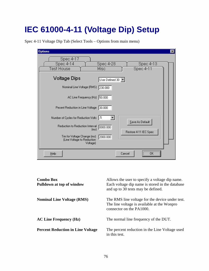
IEC 61000-4-11 (Voltage Dip) Setup Spec 4-11 Voltage Dip Tab (Select Tools – Options from main menu)
Combo Box Pulldown at top of window
Allows the user to specify a voltage dip name. Each voltage dip name is stored in the database and up to 30 tests may be defined.
Nominal Line Voltage (RMS) The RMS line voltage for the device under test. The line voltage is available at the Wonpro connector on the PA1000.
AC Line Frequency (Hz) The normal line frequency of the DUT.
Percent Reduction in Line Voltage The percent reduction in the Line Voltage used in this test.
76

Number of Cycles for Reduction The number of cycles the Percent Reduction in Line Voltage is held at until the nominal voltage returns.
Reduction to Reduction Interval (ms) The number of milliseconds until the next voltage reduction. The IEC specifies 3 voltage reductions for each Percent Reduction in Line Voltage test.
Time for Voltage Change (ms) The ramp up and ramp down time for each Nominal Line Voltage to Percent Reduction in Line Voltage transition in milliseconds.
Save as Default Selection activates storage of the displayed test.
Restore 4-11 IEC Spec Loads and stores the current IEC spec to the defined tests.
Press this button to access the EST help topic that describes this dialog.
Press this button to exit the Options and return to the main EST window.
Press this button to return to the previous screen.
See also: IEC 61000-4-11 (Voltage Dip) Test
77

Adjusting Charts and Plots Scales Adjusting a chart during a Harmonic or Flicker test can be done by right clicking the mouse over the chart. All of the properties can be change temporarily while the chart is displayed.
Adjusting a strip chart or a plot for any of the -4 test can be done by clicking on the Adjust Scales radial button. All of the properties can be changed temporarily while the chart is displayed.
78

79

80

The IEC 61000-4-13
(Interharmonics) Test
81

82
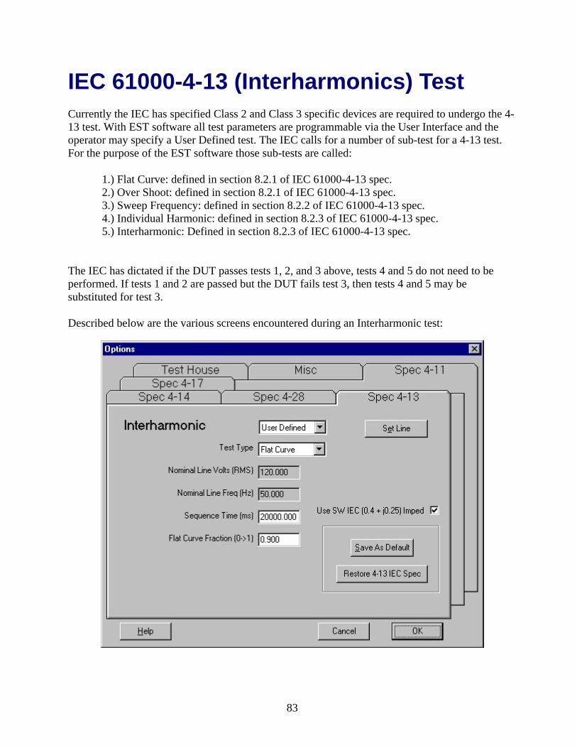
IEC 61000-4-13 (Interharmonics) Test Currently the IEC has specified Class 2 and Class 3 specific devices are required to undergo the 4-13 test. With EST software all test parameters are programmable via the User Interface and the operator may specify a User Defined test. The IEC calls for a number of sub-test for a 4-13 test. For the purpose of the EST software those sub-tests are called:
1.) Flat Curve: defined in section 8.2.1 of IEC 61000-4-13 spec. 2.) Over Shoot: defined in section 8.2.1 of IEC 61000-4-13 spec. 3.) Sweep Frequency: defined in section 8.2.2 of IEC 61000-4-13 spec. 4.) Individual Harmonic: defined in section 8.2.3 of IEC 61000-4-13 spec. 5.) Interharmonic: Defined in section 8.2.3 of IEC 61000-4-13 spec.
The IEC has dictated if the DUT passes tests 1, 2, and 3 above, tests 4 and 5 do not need to be performed. If tests 1 and 2 are passed but the DUT fails test 3, then tests 4 and 5 may be substituted for test 3.
Described below are the various screens encountered during an Interharmonic test:
83

Test 3, Sweep frequency is a more difficult test to pass than 4 and 5. Sweep Frequency dwell time is a minimum of 5 minutes per range and if a resonance point is found, that frequency is dwelled at for 2 minutes. EST software has resonance point checker built in. If a resonance points are found, the operator is provided with an option to dwell. An option for manual dwelling is also provided for.
84

This dialog appears when a test is complete.
After the application of –4 test voltages to the DUT, the operator is required to perform a functionality test. The functionality test determines if the DUT passes or fails the requirements for the IEC spec. EST prompts the operator to perform a functionality test.
Termination of the Interharmonic test can be done at any time by selecting on the Main
Toolbar or the button on the test dialog.
To turn off the SW AC Power at any time select
See also: Running the Test Wizard (IEC61000-4-13 Interharmonic Test)
85

IEC 61000-4-13 (Interharmonics) Setup Spec 4-13 Interharmonics Tab (Select Tools – Options from main menu)
Defining a Flat Curve sub-test:
Combo Box Pulldown at top of window
Allows the user to specify User Defined, Class2, and Class3. These are the names of the set of parameters that are stored in the database.
Test Type Allows the user to specify a Flat Curve, Over Shoot, Sweep Frequency, Individual Harmonic, and Interharmonic. These are various sub-tests that are included in the 4-13 spec. When “Flat Curve” is displayed, Sequence Time and Flat Curve Fraction apply to Flat Curve test only.
Nominal Line Voltage (RMS)
Displays the RMS line voltage for the device under test. The line voltage is available at the Wonpro connector on the PA1000.
86
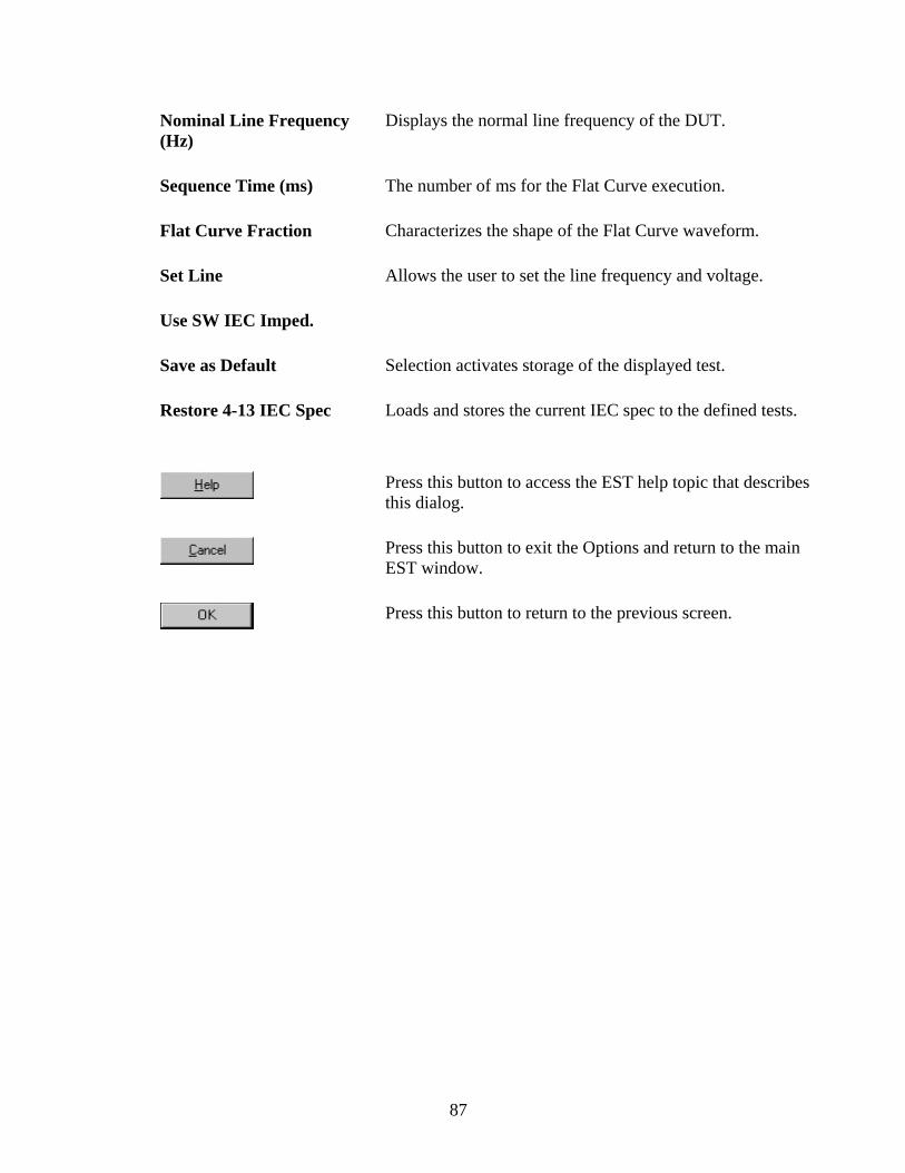
Nominal Line Frequency (Hz)
Displays the normal line frequency of the DUT.
Sequence Time (ms) The number of ms for the Flat Curve execution.
Flat Curve Fraction Characterizes the shape of the Flat Curve waveform.
Set Line Allows the user to set the line frequency and voltage.
Use SW IEC Imped.
Save as Default Selection activates storage of the displayed test.
Restore 4-13 IEC Spec Loads and stores the current IEC spec to the defined tests.
Press this button to access the EST help topic that describes this dialog.
Press this button to exit the Options and return to the main EST window.
Press this button to return to the previous screen.
87
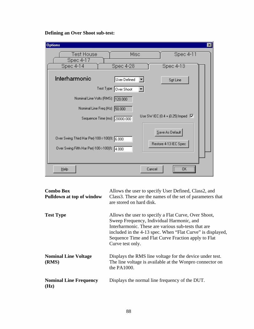
Defining an Over Shoot sub-test:
Combo Box Pulldown at top of window
Allows the user to specify User Defined, Class2, and Class3. These are the names of the set of parameters that are stored on hard disk.
Test Type Allows the user to specify a Flat Curve, Over Shoot, Sweep Frequency, Individual Harmonic, and Interharmonic. These are various sub-tests that are included in the 4-13 spec. When “Flat Curve” is displayed, Sequence Time and Flat Curve Fraction apply to Flat Curve test only.
Nominal Line Voltage (RMS)
Displays the RMS line voltage for the device under test. The line voltage is available at the Wonpro connector on the PA1000.
Nominal Line Frequency (Hz)
Displays the normal line frequency of the DUT.
88
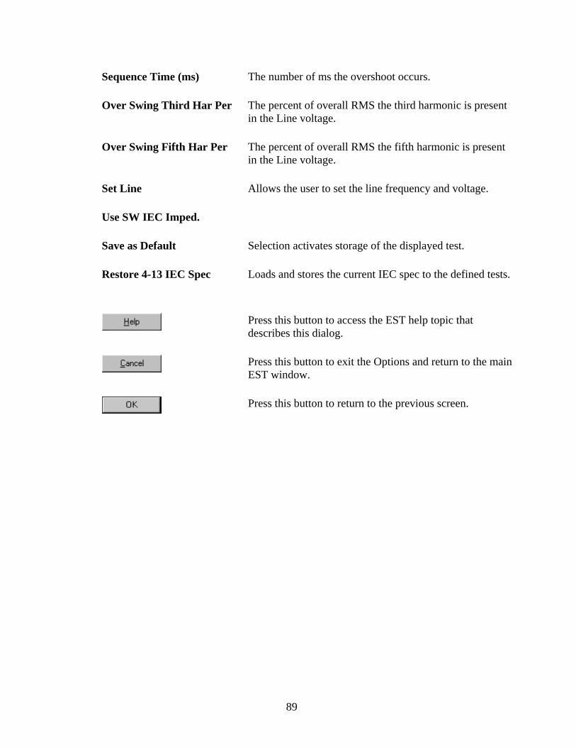
Sequence Time (ms) The number of ms the overshoot occurs.
Over Swing Third Har Per The percent of overall RMS the third harmonic is present in the Line voltage.
Over Swing Fifth Har Per The percent of overall RMS the fifth harmonic is present in the Line voltage.
Set Line Allows the user to set the line frequency and voltage.
Use SW IEC Imped.
Save as Default Selection activates storage of the displayed test.
Restore 4-13 IEC Spec Loads and stores the current IEC spec to the defined tests.
Press this button to access the EST help topic that describes this dialog.
Press this button to exit the Options and return to the main EST window.
Press this button to return to the previous screen.
89

Defining a Sweep Frequency sub-test:
Combo Box Pulldown at top of window
Allows the user to specify User Defined, Class2, and Class3. These are the names of the set of parameters that are stored on hard disk.
Test Type Allows the user to specify a Flat Curve, Over Shoot, Sweep Frequency, Individual Harmonic, and Interharmonic. These are various sub-tests that are included in the 4-13 spec. When “Flat Curve” is displayed, Sequence Time and Flat Curve Fraction apply to Flat Curve test only.
Start Sweep Freq, Frac of Nom Freq The start sweep frequency is specified as a fraction of nominal frequency.
Stop Sweep Freq, Frac of Nom Freq The last swept frequency for the specified sweep number.
Step Sweep Freq, Frac of Nom Freq The steps between each swept frequency.
90

Sweep Volts in Per of Nom The swept frequency small voltage expressed as a percent of line voltage.
Sweep Freq Dwell Time per sweep(s) The number of seconds to dwell for the specified sweep number.
Inter Sweep Delay (ms) Provides for a delay before change to the next sweep. This is a optional parameter used for stop PA1000 acquisition before the next sweep.
Set Line Allows the user to set the line frequency and voltage.
Sweep Number Specifies which sweep number to apply the parameters. The IEC tests call for 4 separate sweeps.
Use SW IEC Imped.
Save as Default Selection activates storage of the displayed test.
Restore 4-13 IEC Spec Loads and stores the current IEC spec to the defined tests.
Press this button to access the EST help topic that describes this dialog.
Press this button to exit the Options and return to the main EST window.
Press this button to return to the previous screen.
91

Defining an Individual Harmonics sub-test:
Combo Box Pulldown at top of window
Allows the user to specify User Defined, Class2, and Class3. These are the names of the set of parameters that are stored on hard disk.
Test Type Allows the user to specify a Flat Curve, Over Shoot, Sweep Frequency, Individual Harmonic, and Interharmonic. These are various sub-tests that are included in the 4-13 spec. When “Flat Curve” is displayed, Sequence Time and Flat Curve Fraction apply to Flat Curve test only.
Harmonic On Time(s) The number of seconds the specified harmonics are on.
Harmonic Off Time(s) The number of seconds nominal voltage is on before the next harmonic is introduced.
Harmonic Number Harmonic of line voltage.
92

Har Amp as frac of Line Volts The amplitude of the harmonic component as a fraction of line voltage.
Set Line Allows the user to set the line frequency and voltage.
Use SW IEC Imped.
Save as Default Selection activates storage of the displayed test.
Restore 4-13 IEC Spec Loads and stores the current IEC spec to the defined tests.
Press this button to access the EST help topic that describes this dialog.
Press this button to exit the Options and return to the main EST window.
Press this button to return to the previous screen.
93

Defining an Interharmonics sub-test:
Combo Box Pulldown at top of window
Allows the user to specify User Defined, Class2, and Class3. These are the names of the set of parameters that are stored on hard disk.
Test Type Allows the user to specify a Flat Curve, Over Shoot, Sweep Frequency, Individual Harmonic, and Interharmonic. These are various sub-tests that are included in the 4-13 spec. When “Flat Curve” is displayed, Sequence Time and Flat Curve Fraction apply to Flat Curve test only.
Start Interharmonic, Frac of Num Freq
The frequency to start the sweep.
Stop Interharmonic, Frac of Nom Freq
The frequency to stop the sweep.
94

Step Interharmonic, Frac of Nom Freq
The step frequency when changing frequency between the start and stop frequency.
Interharmonic Volts in Per of Nom The voltage of the swept frequency as a percent of line voltage.
Interhar Delay per freq step(ms) The dwell time in milliseconds at each swept frequency.
Sweep Number Specifies which sweep number to apply the parameters. The IEC tests call for 4 separate sweeps.
Line Freq(Ht) The line voltage for the device under test. The line voltage is available at the Wonpro connector on the PA1000.
Use SW IEC Imped.
Save as Default Selection activates storage of the displayed test.
Restore 4-13 IEC Spec Loads and stores the current IEC spec to the defined tests.
Press this button to access the EST help topic that describes this dialog.
Press this button to exit the Options and return to the main EST window.
Press this button to return to the previous screen.
See also: IEC 61000-4-13 (Interharmonics) Test
95

Adjusting Charts and Plots Scales Adjusting a chart during a Harmonic or Flicker test can be done by right clicking the mouse over the chart. All of the properties can be change temporarily while the chart is displayed.
Adjusting a strip chart or a plot for any of the -4 test can be done by clicking on the Adjust Scales radial button. All of the properties can be changed temporarily while the chart is displayed.
96

97

98

The IEC 61000-4-14
(Voltage Fluctuation) Test
99

100
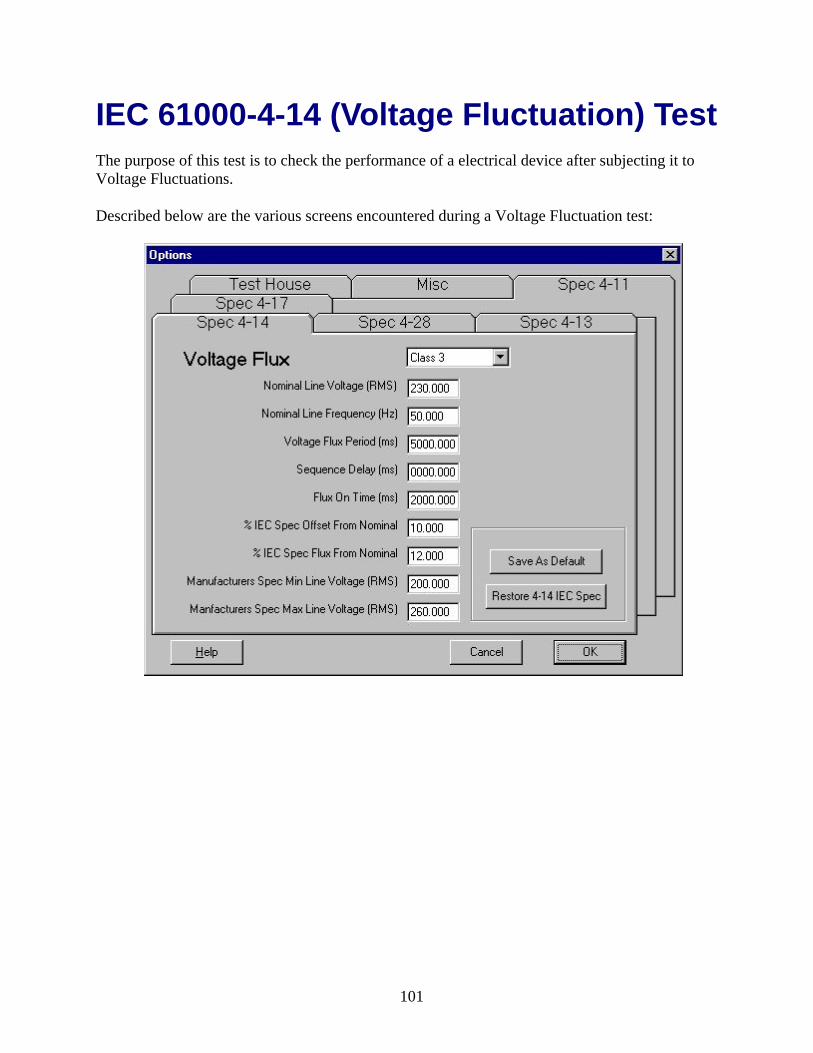
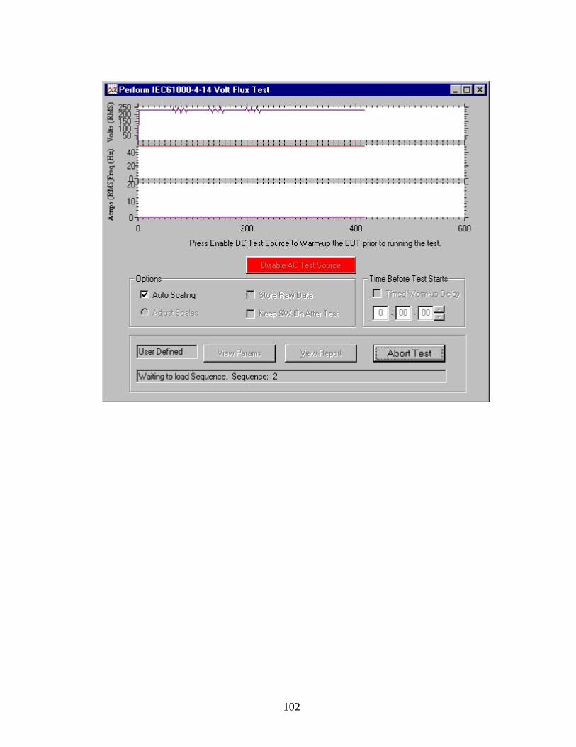
IEC 61000-4-14 (Voltage Fluctuation) Test The purpose of this test is to check the performance of a electrical device after subjecting it to Voltage Fluctuations.
Described below are the various screens encountered during a Voltage Fluctuation test:
101
102

This dialog appears when a test is complete.
After the application of –4 test voltages to the DUT, the operator is required to perform a functionality test. The functionality test determines if the DUT passes or fails the requirements for the IEC spec. EST prompts the operator to perform a functionality test.
Termination of the Voltage Fluctuation test can be done at any time by selecting on the
Main Toolbar or the button on the test dialog.
To turn off the SW AC Power at any time select on the Main Toolbar.
See also: Running the Test Wizard (IEC61000-4-14 Voltage Fluctuation Test)
103

IEC 61000-4-14 (Voltage Fluctuation) Setup Spec 4-14 Voltage Flux Tab (Select Tools – Options from main menu)
The graph below illustrates most of the 4-14 parameters. The vertical scale is Volts RMS and the horizontal scale is time in seconds.
104

Combo Box Pulldown at top of window
Allows the user to choose User Defined, Class 2, or Class 3. Each set of 4-14 parameters are associated with the Voltage Flux. These parameters are stored in the database.
Nominal Line Voltage (RMS)
The RMS line voltage for the device under test. The line voltage is available at the Wonpro connector on the PA1000.
Nominal Line Frequency (Hz)
The normal line frequency of the DUT.
Voltage Flux Period (ms) The time in milliseconds between voltage spikes
Sequence Delay (ms) The time in milliseconds between subsequent sequences.
Flux On Time (ms) The time in milliseconds a voltage spike is on.
%IEC Spec Offset From Nominal
The voltage as a percent of line voltage the base voltage is shifted. (as illustrated in the above graph)
%IEC Spec Flux From Nominal
The voltage as a percent of line voltage the flux (spike) volts is shifted.
Manufacturers Spec Min Line Voltage (RMS)
The manufacturers rated minimum line voltage. The manufacturers spec is compared to the IEC spec. If the manufactures spec is less than the IEC spec, the operator is notified.
Manufactures Spec Max Line Voltage (RMS)
The manufacturers rated maximum line voltage. The manufacturers spec is compared to the IEC spec. If the manufactures spec is less than the IEC spec, the operator is notified.
Save as Default Selection activates storage of the displayed test.
Restore 4-14 IEC Spec Loads and stores the current IEC spec to the defined tests.
Press this button to access the EST help topic that describes this dialog.
Press this button to exit the Options and return to the main EST window.
Press this button to return to the previous screen.
See also: IEC 61000-4-14 (Voltage Fluctuation) Test
105

Adjusting Charts and Plots Scales Adjusting a chart during a Harmonic or Flicker test can be done by right clicking the mouse over the chart. All of the properties can be change temporarily while the chart is displayed.
Adjusting a strip chart or a plot for any of the -4 test can be done by clicking on the Adjust Scales radial button. All of the properties can be changed temporarily while the chart is displayed.
106

107

108

The IEC 61000-4-17
(DC Ripple) Test
109

110
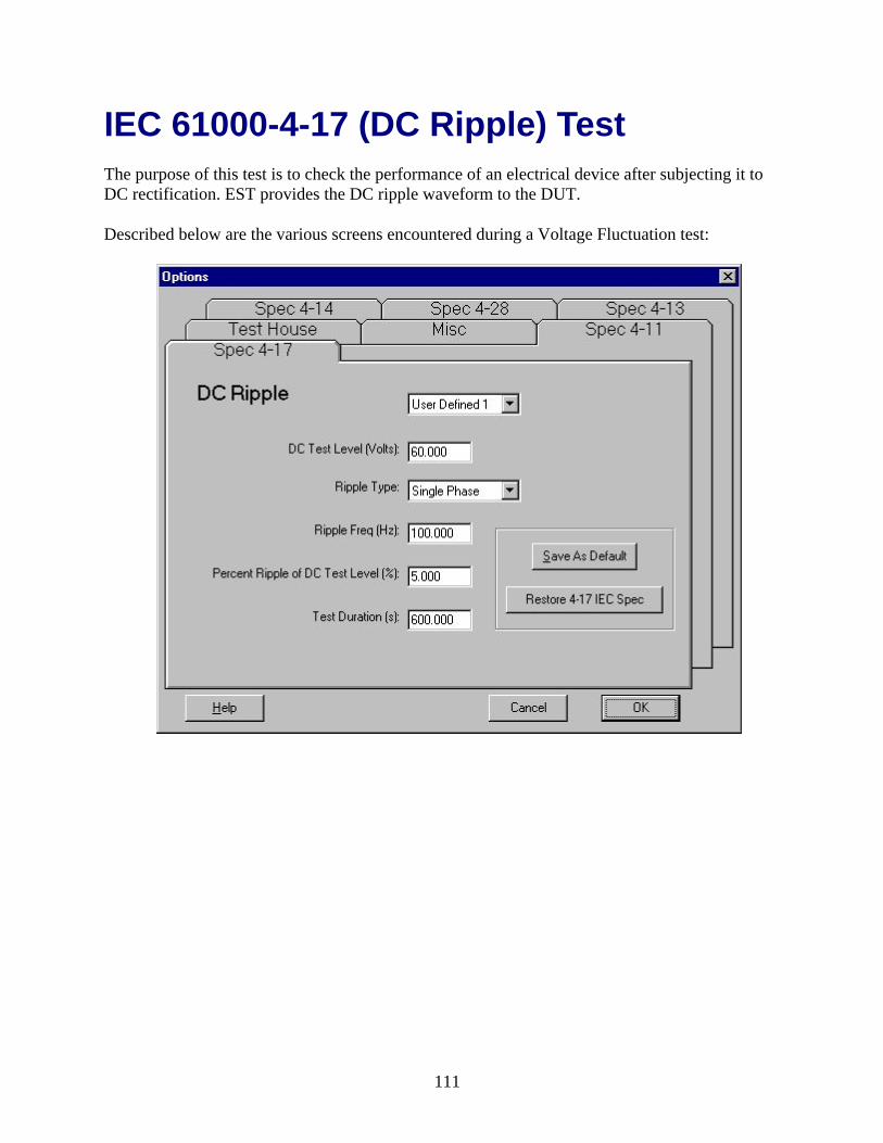
IEC 61000-4-17 (DC Ripple) Test The purpose of this test is to check the performance of an electrical device after subjecting it to DC rectification. EST provides the DC ripple waveform to the DUT.
Described below are the various screens encountered during a Voltage Fluctuation test:
111

112
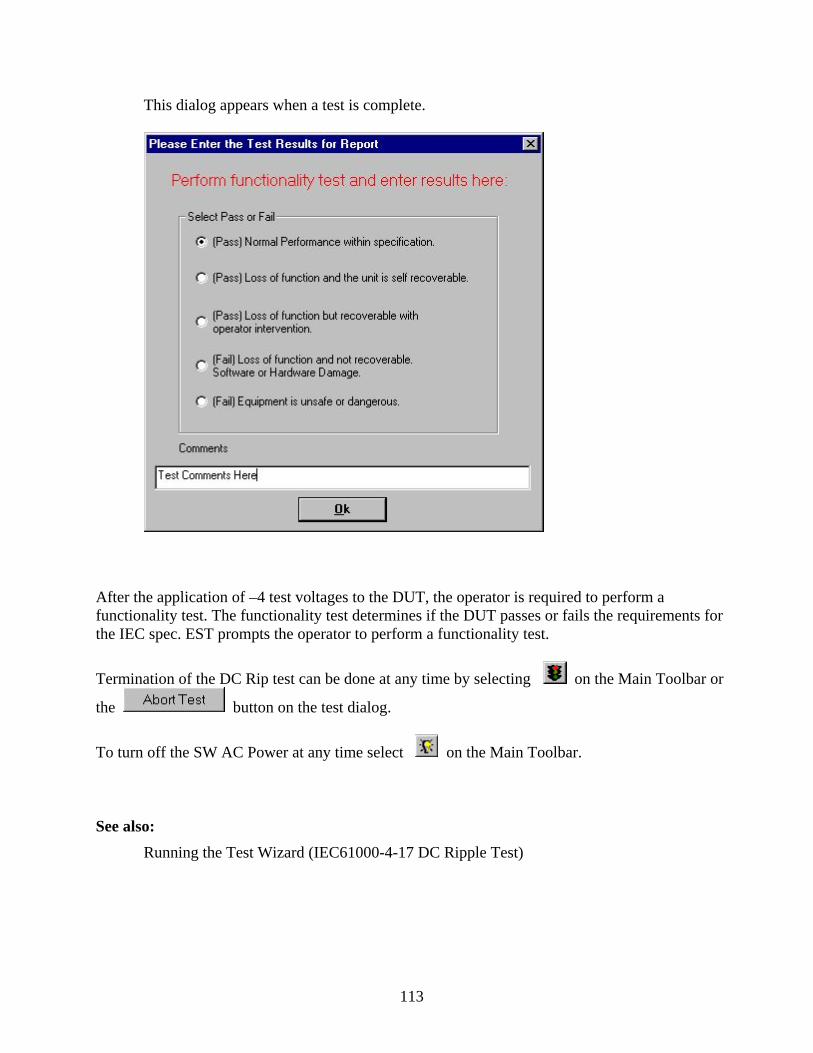
This dialog appears when a test is complete.
After the application of –4 test voltages to the DUT, the operator is required to perform a functionality test. The functionality test determines if the DUT passes or fails the requirements for the IEC spec. EST prompts the operator to perform a functionality test.
Termination of the DC Rip test can be done at any time by selecting on the Main Toolbar or
the button on the test dialog.
To turn off the SW AC Power at any time select on the Main Toolbar.
See also: Running the Test Wizard (IEC61000-4-17 DC Ripple Test)
113

IEC 61000-4-17 (DC Ripple) Setup Spec 4-17 DC Ripple Tab (Select Tools – Options from main menu)
The graphs below illustrate DC rectification used in the 4-17 test:
114

Combo Box Pulldown at top of window
The name of the displayed parameters. These parameters are stored in the database.
DC Test Level (Volts) The RMS line voltage for the device under test. The line voltage is available at the Wonpro connector on the PA1000.
Ripple Type This can be single or three phase. The graph above shows both.
Ripple Frequency (Hz) The ripple frequency as illustrated on the graph above.
Percent Ripple of DC Test Level
TUsing the term shown on the above graph the percent Ripple of DC Test Level = (Umax-Umin)*100.0/Udc.
Test Duration (s) The time the DC ripple waveform is on before the user is prompted to perform a functionality test.
Save as Default Selection activates storage of the displayed test.
Restore 4-17 IEC Spec Loads and stores the current IEC spec to the defined tests.
Click to access the EST help topic that describes this dialog.
Click to exit the Options and return to the main EST window.
Click this button to return to the previous screen.
See also: IEC 61000-4-17 (DC Ripple) Test
115
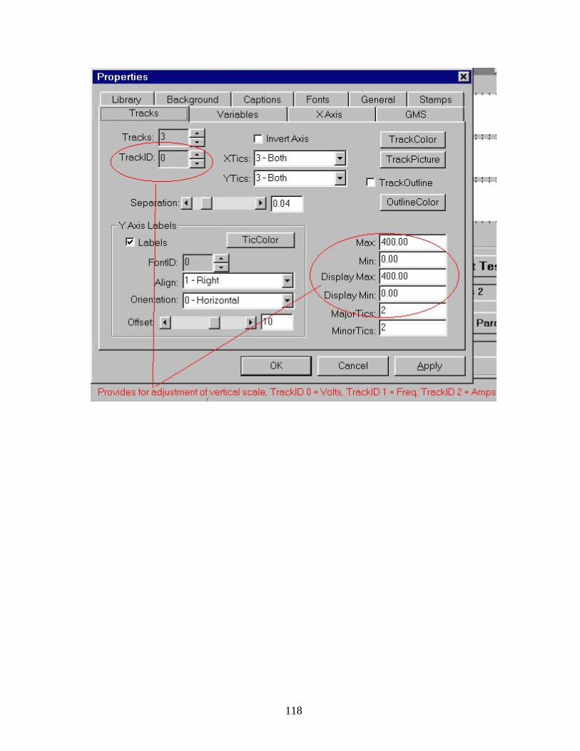
Adjusting Charts and Plots Scales Adjusting a chart during a Harmonic or Flicker test can be done by right clicking the mouse over the chart. All of the properties can be change temporarily while the chart is displayed.
Adjusting a strip chart or a plot for any of the -4 test can be done by clicking on the Adjust Scales radial button. All of the properties can be changed temporarily while the chart is displayed.
116

117
118
The IEC 61000-4-28
(Frequency Fluctuation) Test
119

120
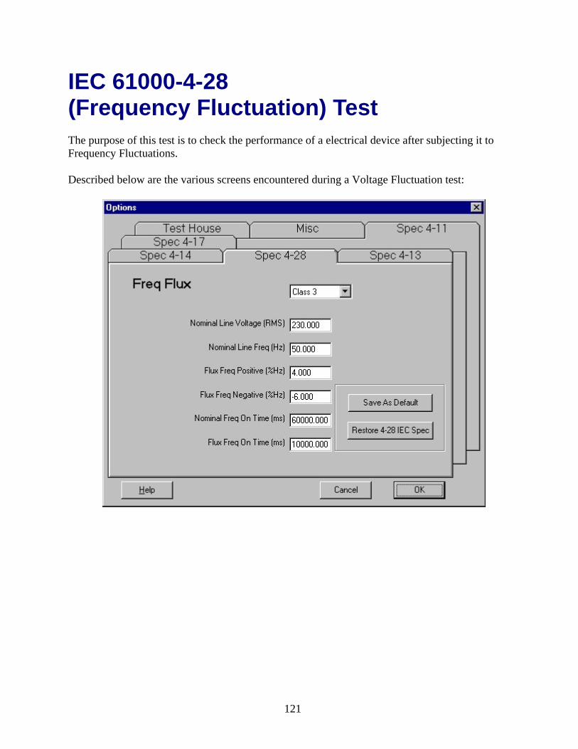
IEC 61000-4-28 (Frequency Fluctuation) Test The purpose of this test is to check the performance of a electrical device after subjecting it to Frequency Fluctuations.
Described below are the various screens encountered during a Voltage Fluctuation test:
121

122
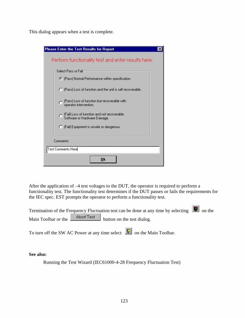
This dialog appears when a test is complete.
After the application of –4 test voltages to the DUT, the operator is required to perform a functionality test. The functionality test determines if the DUT passes or fails the requirements for the IEC spec. EST prompts the operator to perform a functionality test.
Termination of the Frequency Fluctuation test can be done at any time by selecting on the
Main Toolbar or the button on the test dialog.
To turn off the SW AC Power at any time select on the Main Toolbar.
See also: Running the Test Wizard (IEC61000-4-28 Frequency Fluctuation Test)
123

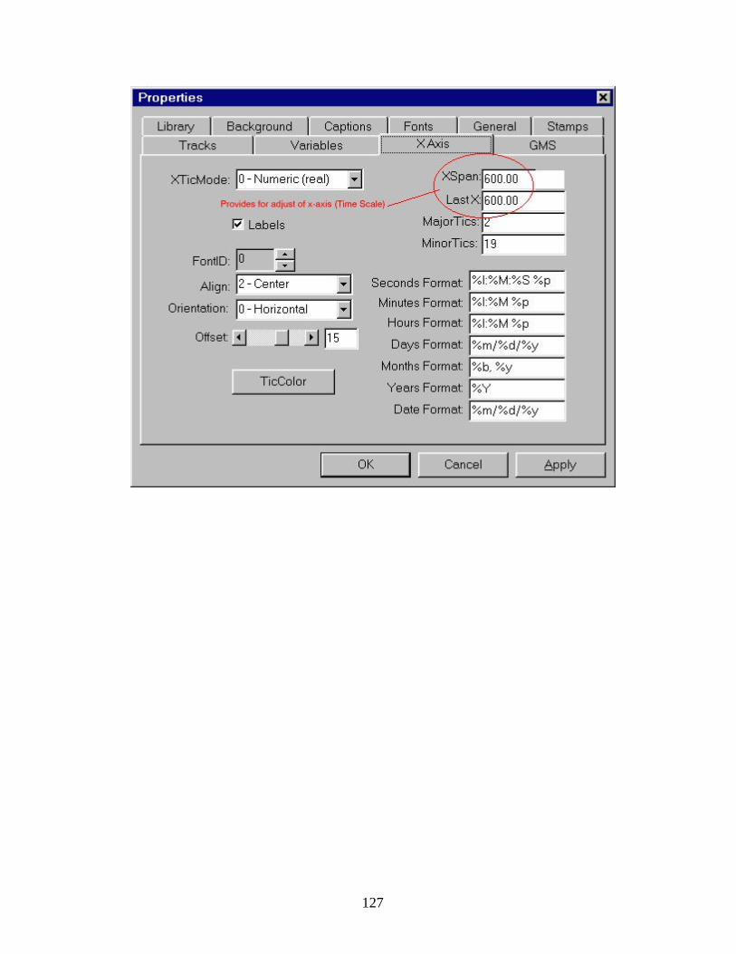
IEC 61000-4-28 (Frequency Fluctuation) Setup Spec 4-28 Frequency Fluctuation Tab (Select Tools – Options from main menu)
The graph below illustrates most of the 4-28 parameters. The vertical scale is Frequency (Hz) and the horizontal scale is time in seconds.
124

Combo Box Pulldown at top of window
Allows the user to specify a User Defined, Class 2, or Class 3. Each set of 4-28 parameters is associated with the Frequency Flux. These parameters are stored in the database.
Nominal Line Voltage (RMS)
The RMS line voltage for the device under test. The line voltage is available at the Wonpro connector on the PA1000.
Flux Freq Positive (%Hz) The positive frequency shift in percent of line frequency.
Flux Freq Negative (%Hz The negative frequency shift in percent of line frequency.
Nominal Freq On Time (ms)
The line frequency on time in milliseconds between frequency shifts as illustrated on the above graph.
Flux Freq On Time (ms) The Flux frequency on time in milliseconds as illustrated on the above graph.
Save as Default Selection activates storage of the displayed test.
Restore 4-28 IEC Spec Loads and stores the current IEC spec to the defined tests.
Press this button to access the EST help topic that describes this dialog.
Press this button to exit the Options and return to the main EST window.
Press this button to return to the previous screen.
See also: IEC 61000-4-28 (Frequency Fluctuation) Test
125

Adjusting Charts and Plots Scales Adjusting a chart during a Harmonic or Flicker test can be done by right clicking the mouse over the chart. All of the properties can be change temporarily while the chart is displayed.
Adjusting a strip chart or a plot for any of the -4 test can be done by clicking on the Adjust Scales radial button. All of the properties can be changed temporarily while the chart is displayed.
126
127

128

Operation Modes
129

130
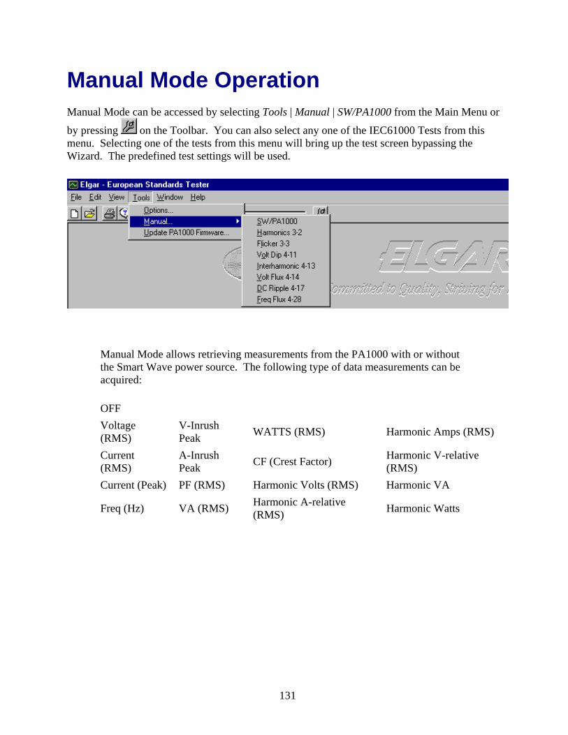
Manual Mode Operation Manual Mode can be accessed by selecting Tools | Manual | SW/PA1000 from the Main Menu or
by pressing on the Toolbar. You can also select any one of the IEC61000 Tests from this menu. Selecting one of the tests from this menu will bring up the test screen bypassing the Wizard. The predefined test settings will be used.
Manual Mode allows retrieving measurements from the PA1000 with or without the Smart Wave power source. The following type of data measurements can be acquired:
OFF Voltage (RMS) V-Inrush
Peak WATTS (RMS) Harmonic Amps (RMS)
Current (RMS) A-Inrush
Peak CF (Crest Factor) Harmonic V-relative (RMS)
Current (Peak) PF (RMS) Harmonic Volts (RMS) Harmonic VA
Freq (Hz) VA (RMS) Harmonic A-relative (RMS) Harmonic Watts
131

132

Turns on and off the power from the SW.
Sets up the Volts, Freq., and Waveform to the SW.
Drop down Combo Box Turns on PA1000 general mode acquisition for Voltage (RMS), Current (RMS) and Frequency (Hz), etc., and then plots the raw data on displayed graphs.
PA1000 Acq. Rate (ms) The rate at which the data is acquired.
Clear Inrush All inrush measurements can be forced to initialize to the next available measurement results by the CLRINRUSH command.
Playback Data Allows you to open a stored and playback a previously stored Manual Mode file.
Pause Pauses the display and PA1000 from retrieving data.
Store Raw Data Saves the raw data into a file for later playback.
Status Bar Operational information or data is displayed here.
See also: European Standard Tester (EST) Main Screen
133

PA1000 Mode Operation PA1000 Mode is entered when the EST system does not detect a Smart Wave power supply. The Status bar at the bottom of the screen will indicate this mode.
In the Manual Mode, most screens cannot be accessed. Some of the functions that can be performed are:
Viewing Reports Replaying any Stored Test Accessing Manual Mode Help Screens Updating PA1000 Firmware
Manual Mode can be accessed by selecting Tools | Manual | SW/PA1000 from the Main Menu or
by pressing on the Toolbar. None of the Smart Wave power supply functions can be accessed.
See also: European Standard Tester (EST) Main Screen
134
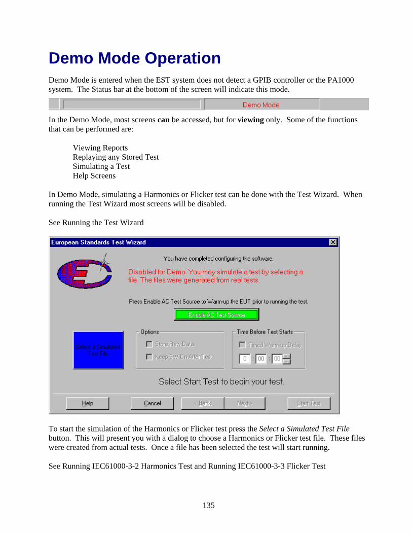
Demo Mode Operation Demo Mode is entered when the EST system does not detect a GPIB controller or the PA1000 system. The Status bar at the bottom of the screen will indicate this mode.
In the Demo Mode, most screens can be accessed, but for viewing only. Some of the functions that can be performed are:
Viewing Reports Replaying any Stored Test Simulating a Test Help Screens
In Demo Mode, simulating a Harmonics or Flicker test can be done with the Test Wizard. When running the Test Wizard most screens will be disabled.
See Running the Test Wizard
To start the simulation of the Harmonics or Flicker test press the Select a Simulated Test File button. This will present you with a dialog to choose a Harmonics or Flicker test file. These files were created from actual tests. Once a file has been selected the test will start running.
See Running IEC61000-3-2 Harmonics Test and Running IEC61000-3-3 Flicker Test
135
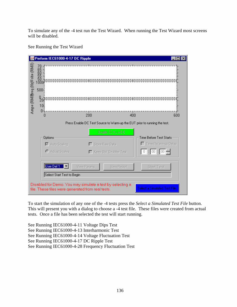
To simulate any of the -4 test run the Test Wizard. When running the Test Wizard most screens will be disabled.
See Running the Test Wizard
To start the simulation of any one of the -4 tests press the Select a Simulated Test File button. This will present you with a dialog to choose a -4 test file. These files were created from actual tests. Once a file has been selected the test will start running.
See Running IEC61000-4-11 Voltage Dips Test See Running IEC61000-4-13 Interharmonic Test See Running IEC61000-4-14 Voltage Fluctuation Test See Running IEC61000-4-17 DC Ripple Test See Running IEC61000-4-28 Frequency Fluctuation Test
136
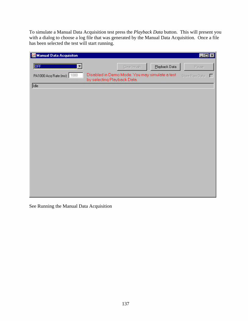
To simulate a Manual Data Acquisition test press the Playback Data button. This will present you with a dialog to choose a log file that was generated by the Manual Data Acquisition. Once a file has been selected the test will start running.
See Running the Manual Data Acquisition
137

In Demo Mode you cannot edit customer information but you can view the test reports.
See Viewing the Test Results
In Demo Mode you can view the various dialog setting in the Options dialog.
See also: European Standard Tester (EST) Main Screen
138
Replaying Test Files
139

140
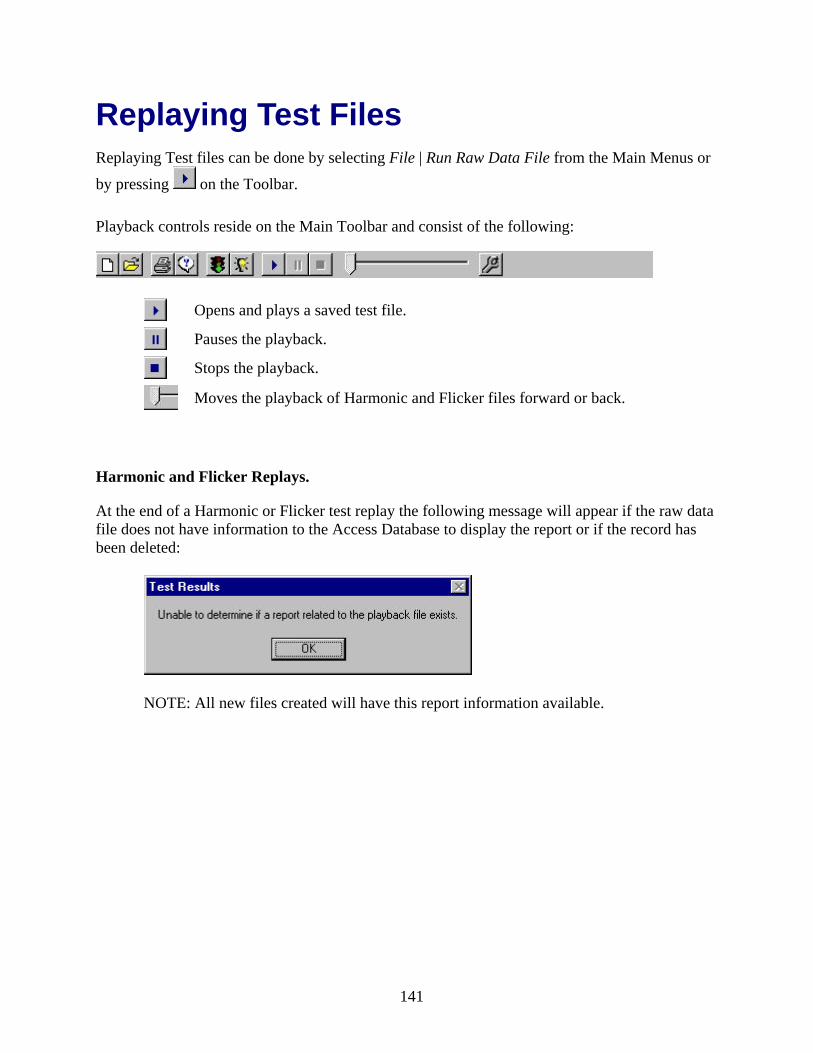
Replaying Test Files Replaying Test files can be done by selecting File | Run Raw Data File from the Main Menus or
by pressing on the Toolbar.
Playback controls reside on the Main Toolbar and consist of the following:
Opens and plays a saved test file.
Pauses the playback.
Stops the playback.
Moves the playback of Harmonic and Flicker files forward or back.
Harmonic and Flicker Replays.
At the end of a Harmonic or Flicker test replay the following message will appear if the raw data file does not have information to the Access Database to display the report or if the record has been deleted:
NOTE: All new files created will have this report information available.
141
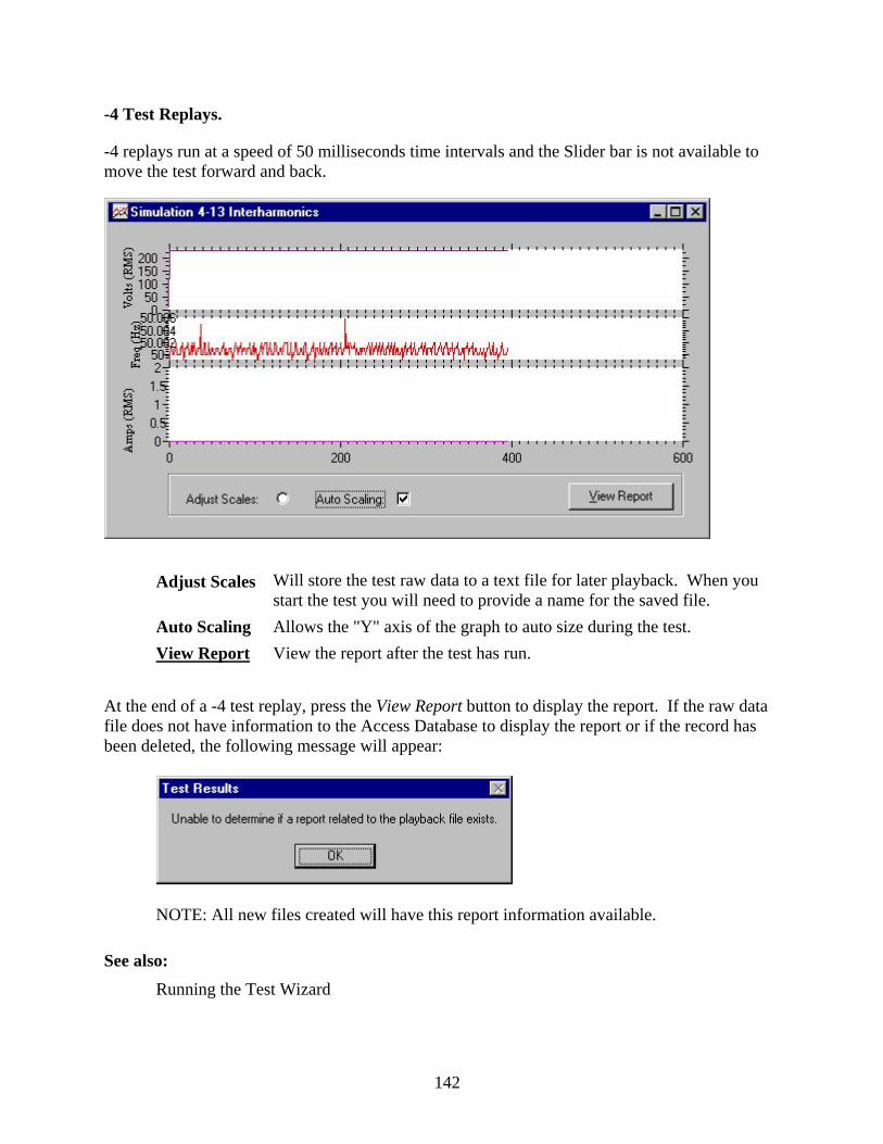
-4 Test Replays.
-4 replays run at a speed of 50 milliseconds time intervals and the Slider bar is not available to move the test forward and back.
Adjust Scales Will store the test raw data to a text file for later playback. When you start the test you will need to provide a name for the saved file.
Auto Scaling Allows the "Y" axis of the graph to auto size during the test. View Report View the report after the test has run.
At the end of a -4 test replay, press the View Report button to display the report. If the raw data file does not have information to the Access Database to display the report or if the record has been deleted, the following message will appear:
NOTE: All new files created will have this report information available.
See also: Running the Test Wizard
142
EST Charts
143

144

IEC 61000-3-2 (Harmonics) Absolute Current Chart The absolute current harmonics window shows a line chart representing the peak absolute harmonic value for each harmonic number.
X Axis 40 bars, each representing a specific harmonic value. Move your mouse over each bar to view:
• Harmonic number • Actual current harmonic value
Y Axis An absolute measurement in amps. The values on the Y axis adjust to show the highest peak value reached.
Remove Fundamental To improve the resolution of the bars on the chart, check the Remove Fundamental box. This redisplays and rescales the charts without showing the Fundamental bar.
Remove Logarithmic To improve the resolution of the bars on the chart, check the Remove Logarithimic box to rediplay and rescale the Y Axis using a linear scale.
See also: Adjust the Chart and Plot Scales Harmonics Test Wizard Flicker Test Wizard
145

IEC 61000-3-2 (Harmonics) Absolute Voltage Chart The relative current harmonics window shows a bar chart with test results comparing the measured current for each harmonic to that of the fundamental harmonic. NOTE: All of the results in this window are relative to the fundamental value (the first harmonic listed in the tabular view) and are shown as a percentage of the fundamental. The fundamental harmonic's measurement will always be 100%.
X Axis 40 bars, each representing a specific harmonic value. Move your mouse over each bar to view:
• Harmonic number • Actual voltage harmonic value
Y Axis The harmonic voltage magnitude. The values on the Y axis adjust to show the highest peak value reached.
Remove Fundamental To improve the resolution of the bars on the chart, check the Remove Fundamental box to redisplay and rescale the charts without showing the Fundamental bar.
Remove Logarithmic To improve the resolution of the bars on the chart, check Remove Logarithimic to rediplay and rescale the Y Axis using a linear scale.
See also: Adjust the Chart and Plot Scales, Harmonics Test Wizard, Flicker Test Wizard
146

IEC 61000-3-2 (Harmonics) Relative Current Chart The relative current harmonics window shows a bar chart with test results comparing the measured current for each harmonic to that of the fundamental harmonic.
NOTE: All of the results in this window are relative to the fundamental value (the first harmonic listed in the tabular view) and are shown as a percentage of the fundamental. The fundamental harmonic's measurement will always be 100%.
X Axis 40 bars, each representing a specific harmonic value. Move your
mouse over each bar to view: • Harmonic number • Actual current harmonic value • % harmonic value relative to the fundamental harmonic
Y Axis The percentage value the specified harmonic reaches compared to the fundamental harmonic. If the harmonic is in spec, the whole line will be green. If the harmonic is our of spec, the portion of the value that is out of spec will be red.
Remove Fundamental To improve the resolution of the bars on the chart check Remove Fundamental. This redisplays and rescales the charts without showing the Fundamental bar.
Remove Logarithmic To improve the resolution of the bars on the chart, check Remove Logarithimic to rediplay and rescale the Y Axis using a linear scale.
See also: Adjust the Chart and Plot Scales, Harmonics Test Wizard, and Flicker Test Wizard
147

IEC 61000-3-2 (Harmonics) Relative Voltage Chart The relative voltage harmonics window shows a bar chart with test results comparing voltage measurement for each harmonic to that of the fundamental harmonic.
NOTE: All results in this window are relative to the fundamental value (the first harmonic listed in the tabular view) and are shown as a percentage of the fundamental. The fundamental harmonic's measurement will always be 100%.
X Axis 40 bars, each representing a specific harmonic value. Move your mouse over each bar to view:
• Harmonic number • Actual harmonic voltage value • % harmonic voltage value relative to the fundamental harmonic
Y Axis The percentage value the specified harmonic reaches compared to the fundamental harmonic. If the harmonic is in spec, the whole line will be green. If the harmonic is our of spec, the portion of the value that is out of spec will be red.
Remove Fundamental To improve the resolution of the bars on the chart, check the Remove Fundamental box. This redisplays and rescales the charts without showing the Fundamental bar.
Remove Logarithmic To improve the resolution of the bars on the chart, check Remove Logarithimic to rediplay and rescale the Y Axis using a linear scale.
See also: Adjust the Chart and Plot Scales, Harmonics Test Wizard, Flicker Test Wizard
148

IEC 61000-3-2 (Harmonics) Current vs. Time Chart The current vs. time window shows a waveform that demonstrates a single complete current cycle, measuring the positive and negative peaks against time. The yellow line illustrates the current, while the green lines represent the allowable range for the class you selected when you defined the test. The composition of this waveform helps determine the waveform class. This is especially helpful if you defined your test using Class A/D.
X Axis Relative time representing the length of a complete cycle.
Y Axis Current flow. The values on the Y axis adjust to show the highest peak value reached. NOTE: There are no tool tips associated with the data displayed in this window.
See also: Adjust the Chart and Plot Scales Harmonics Test Wizard Flicker Test Wizard
149
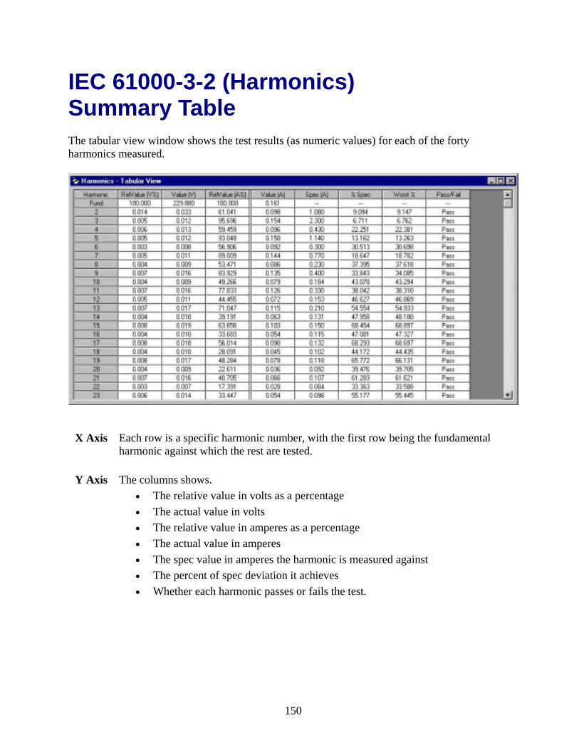
IEC 61000-3-2 (Harmonics) Summary Table The tabular view window shows the test results (as numeric values) for each of the forty harmonics measured.
X Axis Each row is a specific harmonic number, with the first row being the fundamental harmonic against which the rest are tested.
Y Axis The columns shows. • The relative value in volts as a percentage • The actual value in volts • The relative value in amperes as a percentage • The actual value in amperes • The spec value in amperes the harmonic is measured against • The percent of spec deviation it achieves • Whether each harmonic passes or fails the test.
150

If a there is a failure at anytime during the testing a red row will show up in the Summary Table.
NOTE: During Harmonic playback - If a playback is done on a raw data files that was created on a previous version of the EST software then failures will be determined by the Steady filter and will show up as yellow rows since there is no way of determining if the test used a Steady or Fluctuating filter.
See also:
Harmonics Test Wizard Flicker Test Wizard
151

Fundamental and Logarithmic Chart Settings The resolution of the Harmonic charts can be improved by removing the fundamental bar. Also, the chart can be changed to use linear scaling instead of logarithmic.
Normal chart view.
152

Chart viewed without the fundamental bar.
Chart viewed without both the fundamental bar and the logarithmic scaling.
See also: Adjust the Chart and Plot Scales Harmonics Test Wizard
153

IEC 61000-3-3 (Flicker) Dt Distribution Chart The dt distribution window shows a graph representing the distribution of the percent of voltage deviation over time.
X Axis Percent of deviation. The values on the X axis adjust to show the highest peak value reached (with a maximum display of plus or minus 5).
Y Axis Percent of time the deviation lasted.
See also: Adjust the Chart and Plot Scales Harmonics Test Wizard Flicker Test Wizard
154

IEC 61000-3-3 (Flicker) Pt Distribution Chart The Pt distribution results window shows a graph representing the distribution of the percent of perceptibility over time.
X Axis The perceptibility value assigned by the PA1000's flicker meter (a device that measures voltage fluctuations in terms of human perceptibility). A perceptibility level of 100.00 represents a flicker that will be noticed by the average person.
Y Axis Percent of time duration. The values on the X axis adjust to show the highest peak value reached.
See also: Adjust the Chart and Plot Scales Harmonics Test Wizard Flicker Test Wizard
155
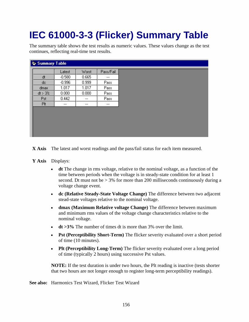
IEC 61000-3-3 (Flicker) Summary Table The summary table shows the test results as numeric values. These values change as the test continues, reflecting real-time test results.
X Axis The latest and worst readings and the pass/fail status for each item measured.
Y Axis Displays:
• dt The change in rms voltage, relative to the nominal voltage, as a function of the time between periods when the voltage is in steady-state condition for at least 1 second. Dt must not be > 3% for more than 200 milliseconds continuously during a voltage change event.
• dc (Relative Steady-State Voltage Change) The difference between two adjacent stead-state voltages relative to the nominal voltage.
• dmax (Maximum Relative voltage Change) The difference between maximum and minimum rms values of the voltage change characteristics relative to the nominal voltage.
• dt >3% The number of times dt is more than 3% over the limit.
• Pst (Perceptibility Short-Term) The flicker severity evaluated over a short period of time (10 minutes).
• Plt (Perceptibility Long-Term) The flicker severity evaluated over a long period of time (typically 2 hours) using successive Pst values.
NOTE: If the test duration is under two hours, the Plt reading is inactive (tests shorter that two hours are not longer enough to register long-term perceptibility readings).
See also: Harmonics Test Wizard, Flicker Test Wizard
156

Adjusting Charts and Plots Scales Adjusting a chart during a Harmonic or Flicker test can be done by right clicking the mouse over the chart. All of the properties can be change temporarily while the chart is displayed.
Adjusting a strip chart or a plot for any of the -4 test can be done by clicking on the Adjust Scales radial button. All of the properties can be changed temporarily while the chart is displayed.
157

158

EST Reports
159

160

Viewing Test Results 1. Select File | Open/Delete Test Results or the Toolbar icon.
2. Select a report. Click on the appropriate button.
Edits the customer information for the selected report.
Deletes the selected report from the database.
Opens the selected report.
Cancels this window.
See also: Edit a Report Print a Report Delete a Report Export a Report Open a Report
161

Opening Reports 1. Select File | Open/Delete Test Results or the Toolbar icon.
2. Select a report. Click on the Open button or double click the file to open.
162

3. Different pages of the report can be viewed from here.
Selects the first page of the report.
Selects the previous page of the report.
Selects the next page of the report.
Selects the last page of the report.
Refreshes the report.
Exports the reports to a files format.
Zooms the page larger or smaller in size.
See also: View Test Results Edit a Report Delete a Report Print a Report Export a Report
163

Editing Reports 1. Select File | Open/Delete Test Results or the Toolbar icon.
2. Select a report. Click on the Edit button.
164

3. Change the Customers information then click on OK.
See also:
View Test Results Delete a Report Open a Report Print a Report Export a Report
165

Exporting Reports 1. Select File | Open/Delete Test Results or the Toolbar icon.
2. Select a report. Click on the Open button or double click the file to open.
166

3. Click on the to export the report.
4. Select the Format for the export and click OK
See also: View Test Results Edit a Report Delete a Report Open a Report Printing a Report
167

Deleting Reports 1. Select File | Open/Delete Test Results or the Toolbar icon.
2. Select a report. Click on the Delete button.
3. Click on OK
See also: View Test Results, Edit a Report, Open a Report, Print a Report, Export a Report
168

Printing Reports 1. Select File | Open/Delete Test Results or the Toolbar icon.
2. Select a report. Click on the Open button or double click the file to open.
169

3. Different pages of the report can be viewed from here.
4. To print the report select File | Print or from the Toolbar icon.
See also: View Test Results Edit a Report Delete a Report Open a Report Export a Report
170

Print Screen Printing can be done by selecting File | Print from the Main Menus or by pressing on the Toolbar.
The Print Screen allows you to specify the printer, number of pages, and whether to print one or all the charts.
See also: European Standard Tester (EST) Main Screen
171
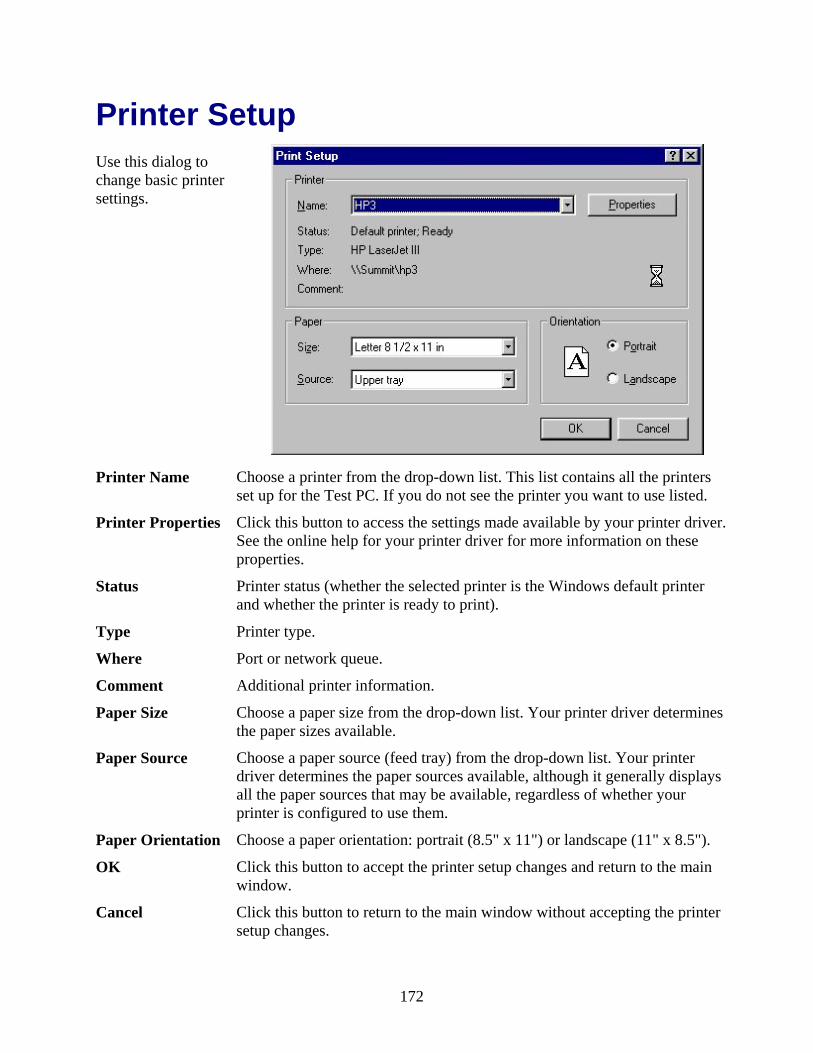
Printer Setup Use this dialog to change basic printer settings.
Printer Name Choose a printer from the drop-down list. This list contains all the printers
set up for the Test PC. If you do not see the printer you want to use listed.
Printer Properties Click this button to access the settings made available by your printer driver. See the online help for your printer driver for more information on these properties.
Status Printer status (whether the selected printer is the Windows default printer and whether the printer is ready to print).
Type Printer type.
Where Port or network queue.
Comment Additional printer information.
Paper Size Choose a paper size from the drop-down list. Your printer driver determines the paper sizes available.
Paper Source Choose a paper source (feed tray) from the drop-down list. Your printer driver determines the paper sources available, although it generally displays all the paper sources that may be available, regardless of whether your printer is configured to use them.
Paper Orientation Choose a paper orientation: portrait (8.5" x 11") or landscape (11" x 8.5").
OK Click this button to accept the printer setup changes and return to the main window.
Cancel Click this button to return to the main window without accepting the printer setup changes.
172