etx-203ax (ver.4.01)
DESCRIPTION
ManualTRANSCRIPT
ETX-203AX Carrier Ethernet Demarcation Device
Version 4.01
INSTA
LLA
TIO
N A
ND
OPER
ATIO
N M
AN
UA
L
The Access Company

ETX-203AX Carrier Ethernet Demarcation Device
Version 4.01
Installation and Operation Manual
Notice
This manual contains information that is proprietary to RAD Data Communications Ltd. ("RAD"). No part of this publication may be reproduced in any form whatsoever without prior written approval by RAD Data Communications.
Right, title and interest, all information, copyrights, patents, know-how, trade secrets and other intellectual property or other proprietary rights relating to this manual and to the ETX-203AX and any software components contained therein are proprietary products of RAD protected under international copyright law and shall be and remain solely with RAD.
The ETX-203AX product name is owned by RAD. No right, license, or interest to such trademark is granted hereunder, and you agree that no such right, license, or interest shall be asserted by you with respect to such trademark. The RAD name, logo, logotype, and the terms EtherAccess, TDMoIP and TDMoIP Driven, and the product names Optimux and IPmux, are registered trademarks of RAD Data Communications Ltd. All other trademarks are the property of their respective holders.
You shall not copy, reverse compile or reverse assemble all or any portion of the Manual or the ETX-203AX. You are prohibited from, and shall not, directly or indirectly, develop, market, distribute, license, or sell any product that supports substantially similar functionality as the ETX-203AX, based on or derived in any way from the ETX-203AX. Your undertaking in this paragraph shall survive the termination of this Agreement.
This Agreement is effective upon your opening of the ETX-203AX package and shall continue until terminated. RAD may terminate this Agreement upon the breach by you of any term hereof. Upon such termination by RAD, you agree to return to RAD the ETX-203AX and all copies and portions thereof.
For further information contact RAD at the address below or contact your local distributor.
International Headquarters RAD Data Communications Ltd.
24 Raoul Wallenberg Street Tel Aviv 69719, Israel Tel: 972-3-6458181 Fax: 972-3-6498250, 6474436 E-mail: [email protected]
North America Headquarters RAD Data Communications Inc.
900 Corporate Drive Mahwah, NJ 07430, USA Tel: (201) 5291100, Toll free: 1-800-4447234 Fax: (201) 5295777 E-mail: [email protected]
© 2011–2012 RAD Data Communications Ltd. Publication No. 530-200-04/12

ETX-203AX Carrier Ethernet Demarcation Device
Version 4.01
Installation and Operation Manual
Notice
This manual contains information that is proprietary to RAD Data Communications Ltd. ("RAD"). No part of this publication may be reproduced in any form whatsoever without prior written approval by RAD Data Communications.
Right, title and interest, all information, copyrights, patents, know-how, trade secrets and other intellectual property or other proprietary rights relating to this manual and to the ETX-203AX and any software components contained therein are proprietary products of RAD protected under international copyright law and shall be and remain solely with RAD.
The ETX-203AX product name is owned by RAD. No right, license, or interest to such trademark is granted hereunder, and you agree that no such right, license, or interest shall be asserted by you with respect to such trademark. The RAD name, logo, logotype, and the terms EtherAccess, TDMoIP and TDMoIP Driven, and the product names Optimux and IPmux, are registered trademarks of RAD Data Communications Ltd. All other trademarks are the property of their respective holders.
You shall not copy, reverse compile or reverse assemble all or any portion of the Manual or the ETX-203AX. You are prohibited from, and shall not, directly or indirectly, develop, market, distribute, license, or sell any product that supports substantially similar functionality as the ETX-203AX, based on or derived in any way from the ETX-203AX. Your undertaking in this paragraph shall survive the termination of this Agreement.
This Agreement is effective upon your opening of the ETX-203AX package and shall continue until terminated. RAD may terminate this Agreement upon the breach by you of any term hereof. Upon such termination by RAD, you agree to return to RAD the ETX-203AX and all copies and portions thereof.
For further information contact RAD at the address below or contact your local distributor.
International Headquarters RAD Data Communications Ltd.
24 Raoul Wallenberg Street Tel Aviv 69719, Israel Tel: 972-3-6458181 Fax: 972-3-6498250, 6474436 E-mail: [email protected]
North America Headquarters RAD Data Communications Inc.
900 Corporate Drive Mahwah, NJ 07430, USA Tel: (201) 5291100, Toll free: 1-800-4447234 Fax: (201) 5295777 E-mail: [email protected]
© 2011–2012 RAD Data Communications Ltd. Publication No. 530-2?0-04/12

Front Matter Installation and Operation Manual
ii ETX-203AX Ver. 4.01
Limited Warranty
RAD warrants to DISTRIBUTOR that the hardware in the ETX-203AX to be delivered hereunder shall be free of defects in material and workmanship under normal use and service for a period of twelve (12) months following the date of shipment to DISTRIBUTOR.
If, during the warranty period, any component part of the equipment becomes defective by reason of material or workmanship, and DISTRIBUTOR immediately notifies RAD of such defect, RAD shall have the option to choose the appropriate corrective action: a) supply a replacement part, or b) request return of equipment to its plant for repair, or c) perform necessary repair at the equipment's location. In the event that RAD requests the return of equipment, each party shall pay one-way shipping costs.
RAD shall be released from all obligations under its warranty in the event that the equipment has been subjected to misuse, neglect, accident or improper installation, or if repairs or modifications were made by persons other than RAD's own authorized service personnel, unless such repairs by others were made with the written consent of RAD.
The above warranty is in lieu of all other warranties, expressed or implied. There are no warranties which extend beyond the face hereof, including, but not limited to, warranties of merchantability and fitness for a particular purpose, and in no event shall RAD be liable for consequential damages.
RAD shall not be liable to any person for any special or indirect damages, including, but not limited to, lost profits from any cause whatsoever arising from or in any way connected with the manufacture, sale, handling, repair, maintenance or use of the ETX-203AX, and in no event shall RAD's liability exceed the purchase price of the ETX-203AX.
DISTRIBUTOR shall be responsible to its customers for any and all warranties which it makes relating to ETX-203AX and for ensuring that replacements and other adjustments required in connection with the said warranties are satisfactory.
Software components in the ETX-203AX are provided "as is" and without warranty of any kind. RAD disclaims all warranties including the implied warranties of merchantability and fitness for a particular purpose. RAD shall not be liable for any loss of use, interruption of business or indirect, special, incidental or consequential damages of any kind. In spite of the above RAD shall do its best to provide error-free software products and shall offer free Software updates during the warranty period under this Agreement.
RAD's cumulative liability to you or any other party for any loss or damages resulting from any claims, demands, or actions arising out of or relating to this Agreement and the ETX-203AX shall not exceed the sum paid to RAD for the purchase of the ETX-203AX. In no event shall RAD be liable for any indirect, incidental, consequential, special, or exemplary damages or lost profits, even if RAD has been advised of the possibility of such damages.
This Agreement shall be construed and governed in accordance with the laws of the State of Israel.
Product Disposal
To facilitate the reuse, recycling and other forms of recovery of waste equipment in protecting the environment, the owner of this RAD product is required to refrain from disposing of this product as unsorted municipal waste at the end of its life cycle. Upon termination of the unit’s use, customers should provide for its collection for reuse, recycling or other form of environmentally conscientious disposal.
Installation and Operation Manual Front Matter
ETX-203AX Ver. 4.01 iii
General Safety Instructions
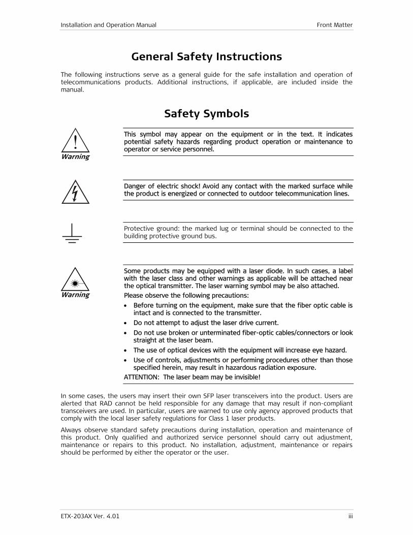
The following instructions serve as a general guide for the safe installation and operation of telecommunications products. Additional instructions, if applicable, are included inside the manual.
Safety Symbols
This symbol may appear on the equipment or in the text. It indicates potential safety hazards regarding product operation or maintenance to operator or service personnel.
Danger of electric shock! Avoid any contact with the marked surface while the product is energized or connected to outdoor telecommunication lines.
Protective ground: the marked lug or terminal should be connected to the building protective ground bus.
Some products may be equipped with a laser diode. In such cases, a label with the laser class and other warnings as applicable will be attached near the optical transmitter. The laser warning symbol may be also attached.
Please observe the following precautions:
• Before turning on the equipment, make sure that the fiber optic cable is intact and is connected to the transmitter.
• Do not attempt to adjust the laser drive current.
• Do not use broken or unterminated fiber-optic cables/connectors or look straight at the laser beam.
• The use of optical devices with the equipment will increase eye hazard.
• Use of controls, adjustments or performing procedures other than those specified herein, may result in hazardous radiation exposure.
ATTENTION: The laser beam may be invisible!
In some cases, the users may insert their own SFP laser transceivers into the product. Users are alerted that RAD cannot be held responsible for any damage that may result if non-compliant transceivers are used. In particular, users are warned to use only agency approved products that comply with the local laser safety regulations for Class 1 laser products.
Always observe standard safety precautions during installation, operation and maintenance of this product. Only qualified and authorized service personnel should carry out adjustment, maintenance or repairs to this product. No installation, adjustment, maintenance or repairs should be performed by either the operator or the user.
Warning
Warning

Front Matter Installation and Operation Manual
iv ETX-203AX Ver. 4.01
Handling Energized Products
General Safety Practices
Do not touch or tamper with the power supply when the power cord is connected. Line voltages may be present inside certain products even when the power switch (if installed) is in the OFF position or a fuse is blown. For DC-powered products, although the voltages levels are usually not hazardous, energy hazards may still exist.
Before working on equipment connected to power lines or telecommunication lines, remove jewelry or any other metallic object that may come into contact with energized parts.
Unless otherwise specified, all products are intended to be grounded during normal use. Grounding is provided by connecting the mains plug to a wall socket with a protective ground terminal. If a ground lug is provided on the product, it should be connected to the protective ground at all times, by a wire with a diameter of 18 AWG or wider. Rack-mounted equipment should be mounted only in grounded racks and cabinets.
Always make the ground connection first and disconnect it last. Do not connect telecommunication cables to ungrounded equipment. Make sure that all other cables are disconnected before disconnecting the ground.
Some products may have panels secured by thumbscrews with a slotted head. These panels may cover hazardous circuits or parts, such as power supplies. These thumbscrews should therefore always be tightened securely with a screwdriver after both initial installation and subsequent access to the panels.
Connecting AC Mains
Make sure that the electrical installation complies with local codes.
Always connect the AC plug to a wall socket with a protective ground.
The maximum permissible current capability of the branch distribution circuit that supplies power to the product is 16A (20A for USA and Canada). The circuit breaker in the building installation should have high breaking capacity and must operate at short-circuit current exceeding 35A (40A for USA and Canada).
Always connect the power cord first to the equipment and then to the wall socket. If a power switch is provided in the equipment, set it to the OFF position. If the power cord cannot be readily disconnected in case of emergency, make sure that a readily accessible circuit breaker or emergency switch is installed in the building installation.
In cases when the power distribution system is IT type, the switch must disconnect both poles simultaneously.
Connecting DC Power
Unless otherwise specified in the manual, the DC input to the equipment is floating in reference to the ground. Any single pole can be externally grounded.
Due to the high current capability of DC power systems, care should be taken when connecting the DC supply to avoid short-circuits and fire hazards.
Make sure that the DC power supply is electrically isolated from any AC source and that the installation complies with the local codes.

Installation and Operation Manual Front Matter
ETX-203AX Ver. 4.01 v
The maximum permissible current capability of the branch distribution circuit that supplies power to the product is 16A (20A for USA and Canada). The circuit breaker in the building installation should have high breaking capacity and must operate at short-circuit current exceeding 35A (40A for USA and Canada).
Before connecting the DC supply wires, ensure that power is removed from the DC circuit. Locate the circuit breaker of the panel board that services the equipment and switch it to the OFF position. When connecting the DC supply wires, first connect the ground wire to the corresponding terminal, then the positive pole and last the negative pole. Switch the circuit breaker back to the ON position.
A readily accessible disconnect device that is suitably rated and approved should be incorporated in the building installation.
If the DC power supply is floating, the switch must disconnect both poles simultaneously.
Connecting Data and Telecommunications Cables
Data and telecommunication interfaces are classified according to their safety status.
The following table lists the status of several standard interfaces. If the status of a given port differs from the standard one, a notice will be given in the manual.
Ports Safety Status
V.11, V.28, V.35, V.36, RS-530, X.21, 10 BaseT, 100 BaseT, Unbalanced E1, E2, E3, STM, DS-2, DS-3, S-Interface ISDN, Analog voice E&M
SELV Safety Extra Low Voltage:
Ports which do not present a safety hazard. Usually up to 30 VAC or 60 VDC.
xDSL (without feeding voltage), Balanced E1, T1, Sub E1/T1
TNV-1 Telecommunication Network Voltage-1:
Ports whose normal operating voltage is within the limits of SELV, on which overvoltages from telecommunications networks are possible.
FXS (Foreign Exchange Subscriber) TNV-2 Telecommunication Network Voltage-2:
Ports whose normal operating voltage exceeds the limits of SELV (usually up to 120 VDC or telephone ringing voltages), on which overvoltages from telecommunication networks are not possible. These ports are not permitted to be directly connected to external telephone and data lines.
FXO (Foreign Exchange Office), xDSL (with feeding voltage), U-Interface ISDN
TNV-3 Telecommunication Network Voltage-3:
Ports whose normal operating voltage exceeds the limits of SELV (usually up to 120 VDC or telephone ringing voltages), on which overvoltages from telecommunication networks are possible.
Always connect a given port to a port of the same safety status. If in doubt, seek the assistance of a qualified safety engineer.
Always make sure that the equipment is grounded before connecting telecommunication cables. Do not disconnect the ground connection before disconnecting all telecommunications cables.
Some SELV and non-SELV circuits use the same connectors. Use caution when connecting cables. Extra caution should be exercised during thunderstorms.

Front Matter Installation and Operation Manual
vi ETX-203AX Ver. 4.01
When using shielded or coaxial cables, verify that there is a good ground connection at both ends. The grounding and bonding of the ground connections should comply with the local codes.
The telecommunication wiring in the building may be damaged or present a fire hazard in case of contact between exposed external wires and the AC power lines. In order to reduce the risk, there are restrictions on the diameter of wires in the telecom cables, between the equipment and the mating connectors.
To reduce the risk of fire, use only No. 26 AWG or larger telecommunication line cords.
Pour réduire les risques s’incendie, utiliser seulement des conducteurs de télécommunications 26 AWG ou de section supérieure.
Some ports are suitable for connection to intra-building or non-exposed wiring or cabling only. In such cases, a notice will be given in the installation instructions.
Do not attempt to tamper with any carrier-provided equipment or connection hardware.
Electromagnetic Compatibility (EMC)
The equipment is designed and approved to comply with the electromagnetic regulations of major regulatory bodies. The following instructions may enhance the performance of the equipment and will provide better protection against excessive emission and better immunity against disturbances.
A good ground connection is essential. When installing the equipment in a rack, make sure to remove all traces of paint from the mounting points. Use suitable lock-washers and torque. If an external grounding lug is provided, connect it to the ground bus using braided wire as short as possible.
The equipment is designed to comply with EMC requirements when connecting it with unshielded twisted pair (UTP) cables. However, the use of shielded wires is always recommended, especially for high-rate data. In some cases, when unshielded wires are used, ferrite cores should be installed on certain cables. In such cases, special instructions are provided in the manual.
Disconnect all wires which are not in permanent use, such as cables used for one-time configuration.
The compliance of the equipment with the regulations for conducted emission on the data lines is dependent on the cable quality. The emission is tested for UTP with 80 dB longitudinal conversion loss (LCL).
Unless otherwise specified or described in the manual, TNV-1 and TNV-3 ports provide secondary protection against surges on the data lines. Primary protectors should be provided in the building installation.
The equipment is designed to provide adequate protection against electro-static discharge (ESD). However, it is good working practice to use caution when connecting cables terminated with plastic connectors (without a grounded metal hood, such as flat cables) to sensitive data lines. Before connecting such cables, discharge yourself by touching ground or wear an ESD preventive wrist strap.
Caution
Attention

Installation and Operation Manual Front Matter
ETX-203AX Ver. 4.01 vii
FCC-15 User Information
This equipment has been tested and found to comply with the limits of the Class A digital device, pursuant to Part 15 of the FCC rules. These limits are designed to provide reasonable protection against harmful interference when the equipment is operated in a commercial environment. This equipment generates, uses and can radiate radio frequency energy and, if not installed and used in accordance with the Installation and Operation manual, may cause harmful interference to the radio communications. Operation of this equipment in a residential area is likely to cause harmful interference in which case the user will be required to correct the interference at his own expense.
Canadian Emission Requirements
This Class A digital apparatus meets all the requirements of the Canadian Interference-Causing Equipment Regulation.
Cet appareil numérique de la classe A respecte toutes les exigences du Règlement sur le matériel brouilleur du Canada.
Warning per EN 55022 (CISPR-22)
This is a class A product. In a domestic environment, this product may cause radio interference, in which case the user will be required to take adequate measures.
Cet appareil est un appareil de Classe A. Dans un environnement résidentiel, cet appareil peut provoquer des brouillages radioélectriques. Dans ces cas, il peut être demandé à l’utilisateur de prendre les mesures appropriées.
Das vorliegende Gerät fällt unter die Funkstörgrenzwertklasse A. In Wohngebieten können beim Betrieb dieses Gerätes Rundfunkströrungen auftreten, für deren Behebung der Benutzer verantwortlich ist.
Warning
Avertissement
Achtung

Front Matter Installation and Operation Manual
viii ETX-203AX Ver. 4.01
Fra
nça
is
Mise au rebut du produit
Afin de faciliter la réutilisation, le recyclage ainsi que d'autres formes de récupération d'équipement mis au rebut dans le cadre de la protection de l'environnement, il est demandé au propriétaire de ce produit RAD de ne pas mettre ce dernier au rebut en tant que déchet municipal non trié, une fois que le produit est arrivé en fin de cycle de vie. Le client devrait proposer des solutions de réutilisation, de recyclage ou toute autre forme de mise au rebut de cette unité dans un esprit de protection de l'environnement, lorsqu'il aura fini de l'utiliser.
Instructions générales de sécurité
Les instructions suivantes servent de guide général d'installation et d'opération sécurisées des produits de télécommunications. Des instructions supplémentaires sont éventuellement indiquées dans le manuel.
Symboles de sécurité
Ce symbole peut apparaitre sur l'équipement ou dans le texte. Il indique des risques potentiels de sécurité pour l'opérateur ou le personnel de service, quant à l'opération du produit ou à sa maintenance.
Danger de choc électrique ! Evitez tout contact avec la surface marquée tant que le produit est sous tension ou connecté à des lignes externes de télécommunications.
Mise à la terre de protection : la cosse ou la borne marquée devrait être connectée à la prise de terre de protection du bâtiment.
Avertissement
Installation and Operation Manual Front Matter
ETX-203AX Ver. 4.01 ix
Fra
nça
is
Certains produits peuvent être équipés d'une diode laser. Dans de tels cas, une étiquette indiquant la classe laser ainsi que d'autres avertissements, le cas échéant, sera jointe près du transmetteur optique. Le symbole d'avertissement laser peut aussi être joint.
Veuillez observer les précautions suivantes :
• Avant la mise en marche de l'équipement, assurez-vous que le câble de fibre optique est intact et qu'il est connecté au transmetteur.
• Ne tentez pas d'ajuster le courant de la commande laser.
• N'utilisez pas des câbles ou connecteurs de fibre optique cassés ou sans terminaison et n'observez pas directement un rayon laser.
• L'usage de périphériques optiques avec l'équipement augmentera le risque pour les yeux.
• L'usage de contrôles, ajustages ou procédures autres que celles spécifiées ici pourrait résulter en une dangereuse exposition aux radiations.
ATTENTION : Le rayon laser peut être invisible !
Les utilisateurs pourront, dans certains cas, insérer leurs propres émetteurs-récepteurs Laser SFP dans le produit. Les utilisateurs sont avertis que RAD ne pourra pas être tenue responsable de tout dommage pouvant résulter de l'utilisation d'émetteurs-récepteurs non conformes. Plus particulièrement, les utilisateurs sont avertis de n'utiliser que des produits approuvés par l'agence et conformes à la réglementation locale de sécurité laser pour les produits laser de classe 1.
Respectez toujours les précautions standards de sécurité durant l'installation, l'opération et la maintenance de ce produit. Seul le personnel de service qualifié et autorisé devrait effectuer l'ajustage, la maintenance ou les réparations de ce produit. Aucune opération d'installation, d'ajustage, de maintenance ou de réparation ne devrait être effectuée par l'opérateur ou l'utilisateur.
Manipuler des produits sous tension
Règles générales de sécurité
Ne pas toucher ou altérer l'alimentation en courant lorsque le câble d'alimentation est branché. Des tensions de lignes peuvent être présentes dans certains produits, même lorsque le commutateur (s'il est installé) est en position OFF ou si le fusible est rompu. Pour les produits alimentés par CC, les niveaux de tension ne sont généralement pas dangereux mais des risques de courant peuvent toujours exister.
Avant de travailler sur un équipement connecté aux lignes de tension ou de télécommunications, retirez vos bijoux ou tout autre objet métallique pouvant venir en contact avec les pièces sous tension.
Sauf s'il en est autrement indiqué, tous les produits sont destinés à être mis à la terre durant l'usage normal. La mise à la terre est fournie par la connexion de la fiche principale à une prise murale équipée d'une borne protectrice de mise à la terre. Si une cosse de mise à la terre est fournie avec le produit, elle devrait être connectée à tout moment à une mise à la terre de protection par un conducteur de diamètre 18 AWG ou plus. L'équipement monté en châssis ne devrait être monté que sur des châssis et dans des armoires mises à la terre.
Branchez toujours la mise à la terre en premier et débranchez-la en dernier. Ne branchez pas des câbles de télécommunications à un équipement qui n'est pas mis à la terre. Assurez-vous que tous les autres câbles sont débranchés avant de déconnecter la mise à la terre.
Avertissement
Front Matter Installation and Operation Manual
x ETX-203AX Ver. 4.01
Fra
nça
is
Connexion au courant du secteur
Assurez-vous que l'installation électrique est conforme à la réglementation locale.
Branchez toujours la fiche de secteur à une prise murale équipée d'une borne protectrice de mise à la terre.
La capacité maximale permissible en courant du circuit de distribution de la connexion alimentant le produit est de 16A (20A aux Etats-Unis et Canada). Le coupe-circuit dans l'installation du bâtiment devrait avoir une capacité élevée de rupture et devrait fonctionner sur courant de court-circuit dépassant 35A (40A aux Etats-Unis et Canada).
Branchez toujours le câble d'alimentation en premier à l'équipement puis à la prise murale. Si un commutateur est fourni avec l'équipement, fixez-le en position OFF. Si le câble d'alimentation ne peut pas être facilement débranché en cas d'urgence, assurez-vous qu'un coupe-circuit ou un disjoncteur d'urgence facilement accessible est installé dans l'installation du bâtiment.
Le disjoncteur devrait déconnecter simultanément les deux pôles si le système de distribution de courant est de type IT.
Connexion d'alimentation CC
Sauf s'il en est autrement spécifié dans le manuel, l'entrée CC de l'équipement est flottante par rapport à la mise à la terre. Tout pôle doit être mis à la terre en externe.
A cause de la capacité de courant des systèmes à alimentation CC, des précautions devraient être prises lors de la connexion de l'alimentation CC pour éviter des courts-circuits et des risques d'incendie.
Assurez-vous que l'alimentation CC est isolée de toute source de courant CA (secteur) et que l'installation est conforme à la réglementation locale.
La capacité maximale permissible en courant du circuit de distribution de la connexion alimentant le produit est de 16A (20A aux Etats-Unis et Canada). Le coupe-circuit dans l'installation du bâtiment devrait avoir une capacité élevée de rupture et devrait fonctionner sur courant de court-circuit dépassant 35A (40A aux Etats-Unis et Canada).
Avant la connexion des câbles d'alimentation en courant CC, assurez-vous que le circuit CC n'est pas sous tension. Localisez le coupe-circuit dans le tableau desservant l'équipement et fixez-le en position OFF. Lors de la connexion de câbles d'alimentation CC, connectez d'abord le conducteur de mise à la terre à la borne correspondante, puis le pôle positif et en dernier, le pôle négatif. Remettez le coupe-circuit en position ON.
Un disjoncteur facilement accessible, adapté et approuvé devrait être intégré à l'installation du bâtiment.
Le disjoncteur devrait déconnecter simultanément les deux pôles si l'alimentation en courant CC est flottante.
ETX-203AX Ver. 4.01 xi
Glossary
Address A coded representation of the origin or destination of data.
Agent In SNMP, this refers to the managed system.
ANSI American National Standards Institute.
APS (Automatic protection switching)
An automatic service restoration function by which a network senses a circuit or node failure and automatically switches traffic over an alternate path.
Attenuation Signal power loss through equipment, lines or other transmission devices. Measured in decibels.
Bandwidth The range of frequencies passing through a given circuit. The greater the bandwidth, the more information can be sent through the circuit in a given amount of time.
Baud Unit of signaling speed equivalent to the number of discrete conditions or events per second. If each signal event represents only one bit condition, baud rate equals bps (bits per second).
Best Effort A QoS class in which no specific traffic parameters and no absolute guarantees are provided.
Bipolar Signaling method in E1/T1 representing a binary “1” by alternating positive and negative pulses, and a binary “0” by absence of pulses.
Bit The smallest unit of information in a binary system. Represents either a one or zero (“1” or “0”).
Bit Interleaving/Multiplexing
A process used in time division multiplexing where individual bits from different lower speed channel sources are combined (one bit from one channel at a time) into one continuous higher speed bit stream.
bps (Bits Per Second) A measure of data transmission rate in serial transmission.
Bridge A device interconnecting local area networks at the OSI data link layer, filtering and forwarding frames according to media access control (MAC) addresses.
Broadband Wideband technology capable of supporting voice, video and data, possibly using multiple channels.
Buffer A storage device. Commonly used to compensate for differences in data rates or event timing when transmitting from one device to another. Also used to remove jitter.
Bus A transmission path or channel. A bus is typically an electrical connection with one or more conductors, where all attached devices receive all transmissions at the same time.
Byte A group of bits (normally 8 bits in length).

Front Matter Installation and Operation Manual
xii ETX-203AX Ver. 4.01
Carrier A continuous signal at a fixed frequency that is capable of being modulated with a second (information carrying) signal.
Cell The 53-byte basic information unit within an ATM network. The user traffic is segmented into cells at the source and reassembled at the destination. An ATM cell consists of a 5-byte ATM header and a 48-byte ATM payload, which contains the user data.
Channel A path for electrical transmission between two or more points. Also called a link, line, circuit or facility.
CLI Command Line Interface (CLI) is a mechanism for interacting with a RAD product by typing commands in response to a prompt.
Clock A term for the source(s) of timing signals used in synchronous transmission.
Congestion A state in which the network is overloaded and starts to discard user data (frames, cells or packets).
Data Information represented in digital form, including voice, text, facsimile and video.
Data Link Layer Layer 2 of the OSI model. The entity, which establishes, maintains, and releases data-link connections between elements in a network. Layer 2 is concerned with the transmission of units of information, or frames, and associated error checking.
Diagnostics The detection and isolation of a malfunction or mistake in a communications device, network or system.
Digital The binary (“1” or “0”) output of a computer or terminal. In data communications, an alternating, non-continuous (pulsating) signal.
E1 Line A 2.048 Mbps line, common in Europe, that supports thirty-two 64 kbps channels, each of which can transmit and receive data or digitized voice. The line uses framing and signaling to achieve synchronous and reliable transmission. The most common configurations for E1 lines are E1 PRI, and unchannelized E1.
E3 The European standard for high speed digital transmission, operating at 34 Mbps.
Ethernet A local area network (LAN) technology which has extended into the wide area networks. Ethernet operates at many speeds, including data rates of 10 Mbps (Ethernet), 100 Mbps (Fast Ethernet), 1,000 Mbps (Gigabit Ethernet), 10 Gbps, 40 Gbps, and 100 Gbps.
Ethernet OAM Ethernet operation, administration and maintenance (OAM) are a set of standardized protocols for measuring and controlling network performance. There are two layers of Ethernet OAM: Service OAM (provides end-to-end connectivity fault management per customer service instance, even in multi-operator networks) and Link or Segment OAM (detailed monitoring and troubleshooting of an individual physical or emulated link).
Flow Control A congestion control mechanism that results in an ATM system implementing flow control.
Frame A logical grouping of information sent as a link-layer unit over a transmission medium. The terms packet, datagram, segment, and
Installation and Operation Manual Front Matter
ETX-203AX Ver. 4.01 xiii
message are also used to describe logical information groupings.
Framing At the physical and data link layers of the OSI model, bits are fit into units called frames. Frames contain source and destination information, flags to designate the start and end of the frame, plus information about the integrity of the frame. All other information, such as network protocols and the actual payload of data, is encapsulated in a packet, which is encapsulated in the frame.
Full Duplex A circuit or device permitting transmission in two directions (sending and receiving) at the same time.
G.703 An ITU standard for the physical and electrical characteristics of various digital interfaces, including those at 64 kbps and 2.048 Mbps.
Gateway Gateways are points of entrance and exit from a communications network. Viewed as a physical entity, a gateway is that node that translates between two otherwise incompatible networks or network segments. Gateways perform code and protocol conversion to facilitate traffic between data highways of differing architecture.
GFP (Generic Framing Procedure)
Defined by ITU-T G.7041, generic framing procedure allows efficient mapping of variable length, higher-layer client signals, such as Ethernet, over a transport network like SDH/SONET. Recently, GFP has been extended to lower speed PDH networks.
Interface A shared boundary, defined by common physical interconnection characteristics, signal characteristics, and meanings of exchanged signals.
IP Address Also known as an Internet address. A unique string of numbers that identifies a computer or device on a TCP/IP network. The format of an IP address is a 32-bit numeric address written as four numbers from 0 to 255, separated by periods (for example, 1.0.255.123).
Jitter The deviation of a transmission signal in time or phase. It can introduce errors and loss of synchronization in high speed synchronous communications.
Laser A device that transmits an extremely narrow and coherent beam of electromagnetic energy in the visible light spectrum. Used as a light source for fiber optic transmission (generally more expensive, shorter lived, single mode only, for greater distances than LED).
Latency The time between initiating a request for data and the beginning of the actual data transfer. Network latency is the delay introduced when a packet is momentarily stored, analyzed and then forwarded.
Loading The addition of inductance to a line in order to minimize amplitude distortion. Used commonly on public telephone lines to improve voice quality, it can make the lines impassable to high speed data, and baseband modems.
Logical MAC
A concept used to describe and map the Ethernet traffic passing over different media (E1/T1, SDH/SONET, etc). Logical MAC represents the MAC layer of the entity. It should be bound to a GFP, HDLC or MLPPP port, which, in its turn, should be bound to the physical layer.
Loopback A type of diagnostic test in which the transmitted signal is returned to the sending device after passing through all or part of a
Front Matter Installation and Operation Manual
xiv ETX-203AX Ver. 4.01
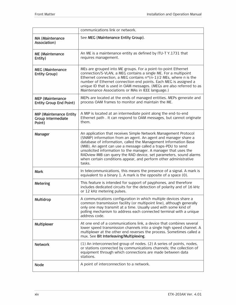
communications link or network.
MA (Maintenance Association)
See MEG (Maintenance Entity Group).
ME (Maintenance Entity)
An ME is a maintenance entity as defined by ITU-T Y.1731 that requires management.
MEG (Maintenance Entity Group)
MEs are grouped into ME groups. For a point-to-point Ethernet connection/S-VLAN, a MEG contains a single ME. For a multipoint Ethernet connection, a MEG contains n*(n-1)/2 MEs, where n is the number of Ethernet connection end points. Each MEG is assigned a unique ID that is used in OAM messages. (MEGs are also referred to as Maintenance Associations or MAs in IEEE language.)
MEP (Maintenance Entity Group End Point)
MEPs are located at the ends of managed entities. MEPs generate and process OAM frames to monitor and maintain the ME.
MIP (Maintenance Entity Group Intermediate Point)
A MIP is located at an intermediate point along the end-to-end Ethernet path . It can respond to OAM messages, but cannot originate them.
Manager An application that receives Simple Network Management Protocol (SNMP) information from an agent. An agent and manager share a database of information, called the Management Information Base (MIB). An agent can use a message called a traps-PDU to send unsolicited information to the manager. A manager that uses the RADview MIB can query the RAD device, set parameters, sound alarms when certain conditions appear, and perform other administrative tasks.
Mark In telecommunications, this means the presence of a signal. A mark is equivalent to a binary 1. A mark is the opposite of a space (0).
Metering This feature is intended for support of payphones, and therefore includes dedicated circuits for the detection of polarity and of 16 kHz or 12 kHz metering pulses.
Multidrop A communications configuration in which multiple devices share a common transmission facility (or multipoint line), although generally only one may transmit at a time. Usually used with some kind of polling mechanism to address each connected terminal with a unique address code.
Multiplexer At one end of a communications link, a device that combines several lower speed transmission channels into a single high speed channel. A multiplexer at the other end reverses the process. Sometimes called a mux. See Bit Interleaving/Multiplexing.
Network (1) An interconnected group of nodes. (2) A series of points, nodes, or stations connected by communications channels; the collection of equipment through which connections are made between data stations.
Node A point of interconnection to a network.
Installation and Operation Manual Front Matter
ETX-203AX Ver. 4.01 xv
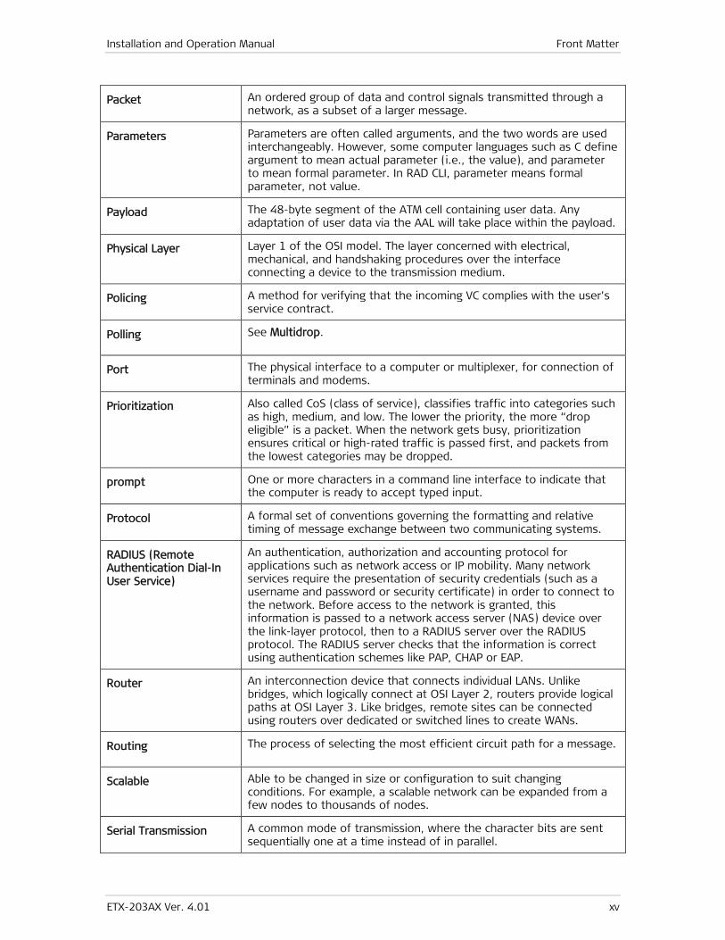
Packet An ordered group of data and control signals transmitted through a network, as a subset of a larger message.
Parameters Parameters are often called arguments, and the two words are used interchangeably. However, some computer languages such as C define argument to mean actual parameter (i.e., the value), and parameter to mean formal parameter. In RAD CLI, parameter means formal parameter, not value.
Payload The 48-byte segment of the ATM cell containing user data. Any adaptation of user data via the AAL will take place within the payload.
Physical Layer Layer 1 of the OSI model. The layer concerned with electrical, mechanical, and handshaking procedures over the interface connecting a device to the transmission medium.
Policing A method for verifying that the incoming VC complies with the user’s service contract.
Polling See Multidrop.
Port The physical interface to a computer or multiplexer, for connection of terminals and modems.
Prioritization Also called CoS (class of service), classifies traffic into categories such as high, medium, and low. The lower the priority, the more “drop eligible” is a packet. When the network gets busy, prioritization ensures critical or high-rated traffic is passed first, and packets from the lowest categories may be dropped.
prompt One or more characters in a command line interface to indicate that the computer is ready to accept typed input.
Protocol A formal set of conventions governing the formatting and relative timing of message exchange between two communicating systems.
RADIUS (Remote Authentication Dial-In User Service)
An authentication, authorization and accounting protocol for applications such as network access or IP mobility. Many network services require the presentation of security credentials (such as a username and password or security certificate) in order to connect to the network. Before access to the network is granted, this information is passed to a network access server (NAS) device over the link-layer protocol, then to a RADIUS server over the RADIUS protocol. The RADIUS server checks that the information is correct using authentication schemes like PAP, CHAP or EAP.
Router An interconnection device that connects individual LANs. Unlike bridges, which logically connect at OSI Layer 2, routers provide logical paths at OSI Layer 3. Like bridges, remote sites can be connected using routers over dedicated or switched lines to create WANs.
Routing The process of selecting the most efficient circuit path for a message.
Scalable Able to be changed in size or configuration to suit changing conditions. For example, a scalable network can be expanded from a few nodes to thousands of nodes.
Serial Transmission A common mode of transmission, where the character bits are sent sequentially one at a time instead of in parallel.
Front Matter Installation and Operation Manual
xvi ETX-203AX Ver. 4.01
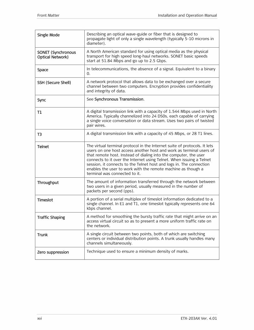
Single Mode Describing an optical wave-guide or fiber that is designed to propagate light of only a single wavelength (typically 5-10 microns in diameter).
SONET (Synchronous Optical Network)
A North American standard for using optical media as the physical transport for high speed long-haul networks. SONET basic speeds start at 51.84 Mbps and go up to 2.5 Gbps.
Space In telecommunications, the absence of a signal. Equivalent to a binary 0.
SSH (Secure Shell) A network protocol that allows data to be exchanged over a secure channel between two computers. Encryption provides confidentiality and integrity of data.
Sync See Synchronous Transmission.
T1 A digital transmission link with a capacity of 1.544 Mbps used in North America. Typically channelized into 24 DS0s, each capable of carrying a single voice conversation or data stream. Uses two pairs of twisted pair wires.
T3 A digital transmission link with a capacity of 45 Mbps, or 28 T1 lines.
Telnet The virtual terminal protocol in the Internet suite of protocols. It lets users on one host access another host and work as terminal users of that remote host. Instead of dialing into the computer, the user connects to it over the Internet using Telnet. When issuing a Telnet session, it connects to the Telnet host and logs in. The connection enables the user to work with the remote machine as though a terminal was connected to it.
Throughput The amount of information transferred through the network between two users in a given period, usually measured in the number of packets per second (pps).
Timeslot A portion of a serial multiplex of timeslot information dedicated to a single channel. In E1 and T1, one timeslot typically represents one 64 kbps channel.
Traffic Shaping A method for smoothing the bursty traffic rate that might arrive on an access virtual circuit so as to present a more uniform traffic rate on the network.
Trunk A single circuit between two points, both of which are switching centers or individual distribution points. A trunk usually handles many channels simultaneously.
Zero suppression Technique used to ensure a minimum density of marks.
ETX-203AX Ver. 4.01 Installing the Unit 1
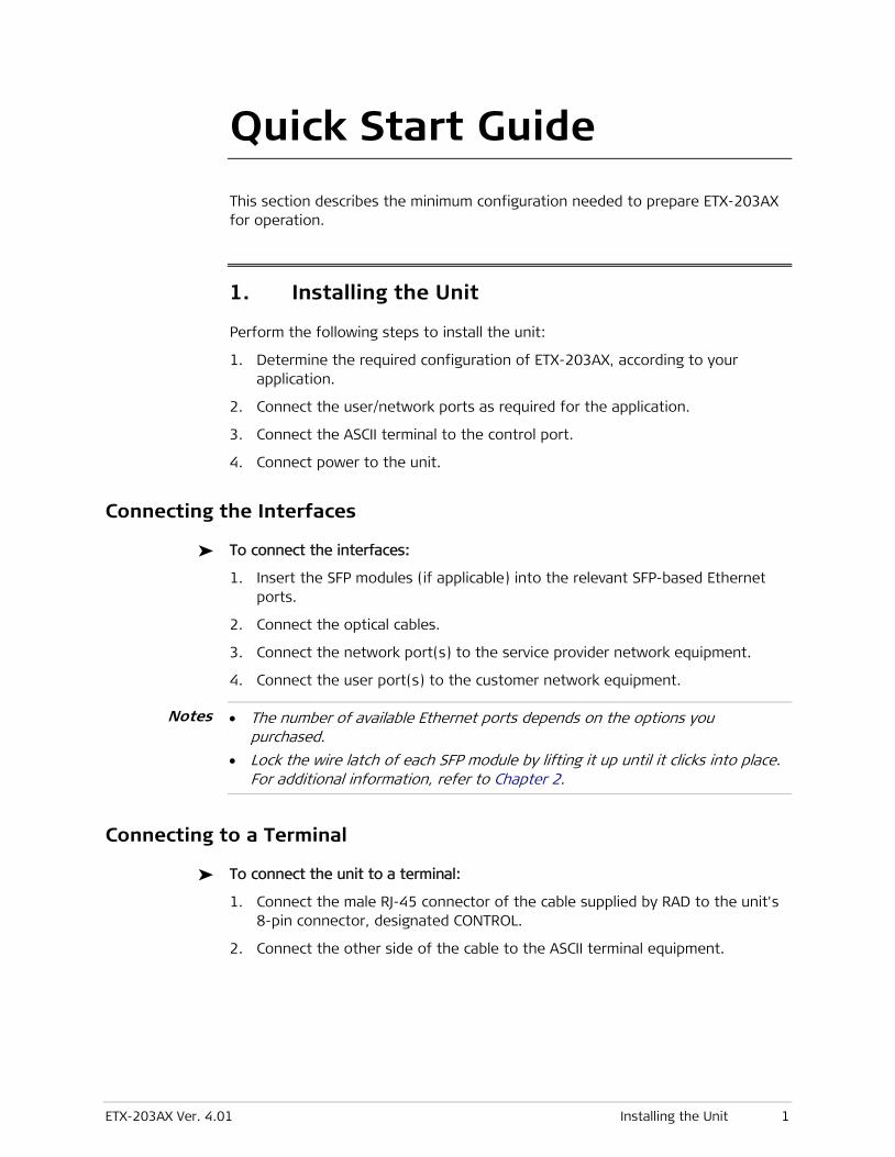
Quick Start Guide This section describes the minimum configuration needed to prepare ETX-203AX for operation.
1. Installing the Unit
Perform the following steps to install the unit:
1. Determine the required configuration of ETX-203AX, according to your application.
2. Connect the user/network ports as required for the application.
3. Connect the ASCII terminal to the control port.
4. Connect power to the unit.
Connecting the Interfaces
To connect the interfaces:
1. Insert the SFP modules (if applicable) into the relevant SFP-based Ethernet ports.
2. Connect the optical cables.
3. Connect the network port(s) to the service provider network equipment.
4. Connect the user port(s) to the customer network equipment.
• The number of available Ethernet ports depends on the options you purchased.
• Lock the wire latch of each SFP module by lifting it up until it clicks into place. For additional information, refer to Chapter 2.
Connecting to a Terminal
To connect the unit to a terminal:
1. Connect the male RJ-45 connector of the cable supplied by RAD to the unit's 8-pin connector, designated CONTROL.
2. Connect the other side of the cable to the ASCII terminal equipment.
Notes
Quick Start Guide Installation and Operation Manual
2 Configuring the Unit for Management ETX-203AX Ver. 4.01
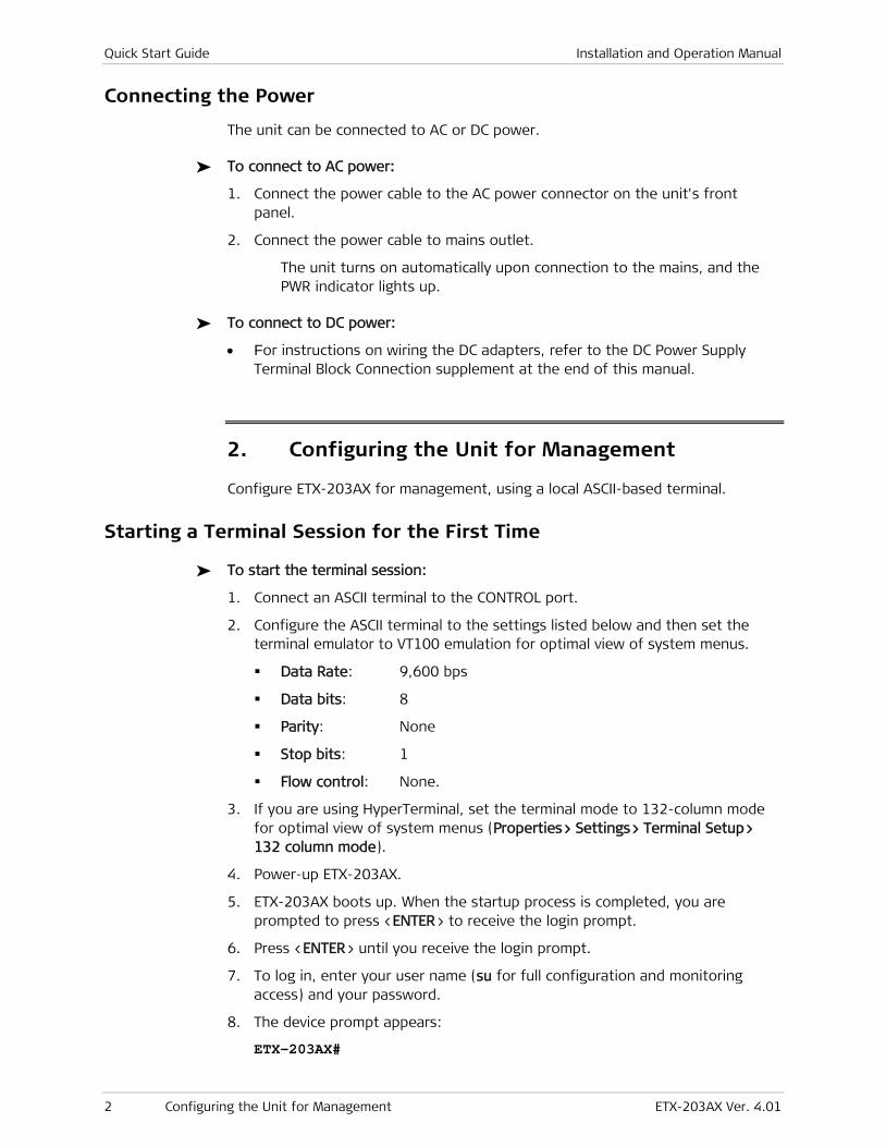
Connecting the Power
The unit can be connected to AC or DC power.
To connect to AC power:
1. Connect the power cable to the AC power connector on the unit's front panel.
2. Connect the power cable to mains outlet.
The unit turns on automatically upon connection to the mains, and the PWR indicator lights up.
To connect to DC power:
• For instructions on wiring the DC adapters, refer to the DC Power Supply Terminal Block Connection supplement at the end of this manual.
2. Configuring the Unit for Management
Configure ETX-203AX for management, using a local ASCII-based terminal.
Starting a Terminal Session for the First Time
To start the terminal session:
1. Connect an ASCII terminal to the CONTROL port.
2. Configure the ASCII terminal to the settings listed below and then set the terminal emulator to VT100 emulation for optimal view of system menus.
Data Rate: 9,600 bps
Data bits: 8
Parity: None
Stop bits: 1
Flow control: None.
3. If you are using HyperTerminal, set the terminal mode to 132-column mode for optimal view of system menus (Properties> Settings> Terminal Setup> 132 column mode).
4. Power-up ETX-203AX.
5. ETX-203AX boots up. When the startup process is completed, you are prompted to press <ENTER> to receive the login prompt.
6. Press <ENTER> until you receive the login prompt.
7. To log in, enter your user name (su for full configuration and monitoring access) and your password.
8. The device prompt appears:
ETX-203AX#
Installation and Operation Manual Quick Start Guide
ETX-203AX Ver. 4.01 Configuring the Unit for Management 3
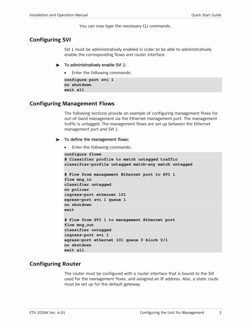
You can now type the necessary CLI commands.
Configuring SVI
SVI 1 must be administratively enabled in order to be able to administratively enable the corresponding flows and router interface.
To administratively enable SVI 1:
• Enter the following commands:
configure port svi 1 no shutdown exit all
Configuring Management Flows
The following sections provide an example of configuring management flows for out-of-band management via the Ethernet management port. The management traffic is untagged. The management flows are set up between the Ethernet management port and SVI 1.
To define the management flows:
• Enter the following commands:
configure flows # Classifier profile to match untagged traffic classifier-profile untagged match-any match untagged # Flow from management Ethernet port to SVI 1 flow mng_in classifier untagged no policer ingress-port ethernet 101 egress-port svi 1 queue 1 no shutdown exit # Flow from SVI 1 to management Ethernet port flow mng_out classifier untagged ingress-port svi 1 egress-port ethernet 101 queue 0 block 0/1 no shutdown exit all
Configuring Router
The router must be configured with a router interface that is bound to the SVI used for the management flows, and assigned an IP address. Also, a static route must be set up for the default gateway.
Quick Start Guide Installation and Operation Manual
4 Verifying Connectivity ETX-203AX Ver. 4.01
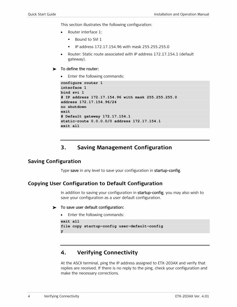
This section illustrates the following configuration:
• Router interface 1:
Bound to SVI 1
IP address 172.17.154.96 with mask 255.255.255.0
• Router: Static route associated with IP address 172.17.154.1 (default gateway).
To define the router:
• Enter the following commands:
configure router 1 interface 1 bind svi 1 # IP address 172.17.154.96 with mask 255.255.255.0 address 172.17.154.96/24 no shutdown exit # Default gateway 172.17.154.1 static-route 0.0.0.0/0 address 172.17.154.1 exit all
3. Saving Management Configuration
Saving Configuration
Type save in any level to save your configuration in startup-config.
Copying User Configuration to Default Configuration
In addition to saving your configuration in startup-config, you may also wish to save your configuration as a user default configuration.
To save user default configuration:
• Enter the following commands:
exit all file copy startup-config user-default-config y
4. Verifying Connectivity
At the ASCII terminal, ping the IP address assigned to ETX-203AX and verify that replies are received. If there is no reply to the ping, check your configuration and make the necessary corrections.
ETX-203AX Ver. 4.01 i
Contents
Chapter 1. Introduction
1.1 Overview ............................................................................................................................ 1-1 Product Options ............................................................................................................... 1-1 Applications ..................................................................................................................... 1-2 Features .......................................................................................................................... 1-2
Service Types .............................................................................................................. 1-2 Service Level Agreement (SLA) Monitoring ................................................................... 1-3 Flow Classification ....................................................................................................... 1-3 Tagging and Marking.................................................................................................... 1-4 Quality of Service (QoS) .............................................................................................. 1-4 Traffic Prioritization ..................................................................................................... 1-4 Queue Mapping and Marking ....................................................................................... 1-5 Hierarchical Scheduling and Shaping Per Flow .............................................................. 1-6 Ethernet OAM ............................................................................................................. 1-6 RFC-2544 Testing and Analysis .................................................................................... 1-6 Jumbo Frames and Egress MTU .................................................................................... 1-6 Link Redundancy ......................................................................................................... 1-6 Ethernet Linear Protection ........................................................................................... 1-6 L2CP Handling ............................................................................................................. 1-7 Fault Propagation ........................................................................................................ 1-7 Smart SFPs .................................................................................................................. 1-7 Management ............................................................................................................... 1-7 DHCP Client ................................................................................................................. 1-8 SFTP ............................................................................................................................ 1-8 Statistics Collection ..................................................................................................... 1-8 Network Time Protocol ................................................................................................ 1-9 Diagnostic Tools .......................................................................................................... 1-9
1.2 New in This Version .......................................................................................................... 1-10 1.3 Physical Description .......................................................................................................... 1-10 1.4 Functional Description ...................................................................................................... 1-10 1.5 Technical Specifications .................................................................................................... 1-12
Chapter 2. Installation and Setup
2.1 Site Requirements and Prerequisites ................................................................................... 2-1 2.2 Package Contents ............................................................................................................... 2-1 2.3 Mounting the Unit .............................................................................................................. 2-2 2.4 Installing SFP Modules ........................................................................................................ 2-2 2.5 Connecting to Ethernet Equipment ..................................................................................... 2-3 2.6 Connecting to a Terminal .................................................................................................... 2-4 2.7 Connecting to Management Station .................................................................................... 2-5 2.8 Connecting to Power .......................................................................................................... 2-5
Connecting to AC Power ................................................................................................... 2-6 Connecting to DC Power ................................................................................................... 2-6
Chapter 3. Operation
3.1 Turning On the Unit ............................................................................................................ 3-1 3.2 Indicators ........................................................................................................................... 3-2 3.3 Startup ............................................................................................................................... 3-2
Table of Contents Installation and Operation Manual
ii ETX-203AX Ver. 4.01
Configuration Files ........................................................................................................... 3-2 Loading Sequence ............................................................................................................ 3-3
3.4 Using a Custom Configuration File....................................................................................... 3-3 3.5 Turning Off the Unit ........................................................................................................... 3-4
Chapter 4. Management and Security
4.1 Working with Terminal ........................................................................................................ 4-2 Logging In ................................................................................................................... 4-6 Using the CLI ............................................................................................................... 4-7 Command Tree ............................................................................................................ 4-9
4.2 Working with Telnet and SSH ............................................................................................ 4-28 4.3 Working with Third-Party Network Management Systems .................................................. 4-29 4.4 SNMP Management .......................................................................................................... 4-29
Standards ...................................................................................................................... 4-30 Benefits ......................................................................................................................... 4-30 Functional Description .................................................................................................... 4-31 Factory Defaults ............................................................................................................ 4-31 Configuring SNMPv3 Parameters ..................................................................................... 4-31 Example ......................................................................................................................... 4-38
4.5 Controlling Management Access ....................................................................................... 4-43 Factory Defaults ............................................................................................................ 4-43 Configuring Management Access .................................................................................... 4-43
4.6 Access Policy .................................................................................................................... 4-44 Factory Defaults ............................................................................................................ 4-44 Configuring Access Policy ............................................................................................... 4-44
4.7 Authentication via RADIUS Server ..................................................................................... 4-45 Standards ...................................................................................................................... 4-45 Benefits ......................................................................................................................... 4-45 Functional Description .................................................................................................... 4-45 Factory Defaults ............................................................................................................ 4-45 Configuring RADIUS Parameters ...................................................................................... 4-45 Displaying RADIUS Statistics ........................................................................................... 4-46
4.8 Authentication via TACACS+ Server ................................................................................... 4-47 Standards ...................................................................................................................... 4-47 Benefits ......................................................................................................................... 4-47 Functional Description .................................................................................................... 4-47 Components .................................................................................................................. 4-47 Accounting ..................................................................................................................... 4-48 Factory Defaults ............................................................................................................ 4-48 Configuring TACACS+ Servers .......................................................................................... 4-48 Example – Defining Server .............................................................................................. 4-49 Configuring Accounting Groups ....................................................................................... 4-50 Example – Defining Accounting Group ............................................................................ 4-50
4.9 Terminal Control Port ....................................................................................................... 4-51 Factory Defaults ............................................................................................................ 4-51 Configuring Control Port Parameters............................................................................... 4-51
4.10 User Access ...................................................................................................................... 4-52 Factory Defaults ............................................................................................................ 4-52 Configuring Users ........................................................................................................... 4-53 Example – Defining Users ............................................................................................... 4-53 Example – Displaying Users ............................................................................................ 4-54
Installation and Operation Manual Table of Contents
ETX-203AX Ver. 4.01 iii
Chapter 5. Services
Ethernet User Traffic ........................................................................................................ 5-1 Network to User .......................................................................................................... 5-1 User to Network .......................................................................................................... 5-2
TDM User Traffic .............................................................................................................. 5-4 TDM Network to Ethernet User .................................................................................... 5-4 TDM User to Network .................................................................................................. 5-7
Chapter 6. Ports
6.1 Ethernet Ports .................................................................................................................... 6-1 Configuring Ethernet Port Parameters .............................................................................. 6-2 Setting Second Network Interface as Network or User Port .............................................. 6-4
Example ...................................................................................................................... 6-4 Displaying Ethernet Port Status ........................................................................................ 6-4
Examples ..................................................................................................................... 6-5 Testing Ethernet Ports ..................................................................................................... 6-5
Example ...................................................................................................................... 6-6 Displaying Ethernet Port Statistics .................................................................................... 6-6
Setting Sampling Interval for Port Statistics .................................................................. 6-6 Displaying Port Statistics ............................................................................................. 6-7 Example ...................................................................................................................... 6-7 Displaying Layer-2 Control Processing Statistics ........................................................... 6-9 Example ...................................................................................................................... 6-9 Clearing Statistics ........................................................................................................ 6-9
6.2 Smart SFPs ......................................................................................................................... 6-9 Benefits ......................................................................................................................... 6-10 Factory Defaults ............................................................................................................ 6-10 Configuring Smart SFPs .................................................................................................. 6-10 Example ......................................................................................................................... 6-11
6.3 E1 Ports ........................................................................................................................... 6-12 Standards and MIBs ....................................................................................................... 6-13 Benefits ......................................................................................................................... 6-13 Functional Description .................................................................................................... 6-13 Factory Defaults ............................................................................................................ 6-13 Configuring E1 Ports ...................................................................................................... 6-13
6.4 T1 Ports ........................................................................................................................... 6-16 Standards and MIBs ....................................................................................................... 6-16 Benefits ......................................................................................................................... 6-16 Functional Description .................................................................................................... 6-16 Factory Defaults ............................................................................................................ 6-17 Configuring T1 Ports ...................................................................................................... 6-17
6.5 E3 Ports ........................................................................................................................... 6-19 Standards and MIBs ....................................................................................................... 6-19 Benefits ......................................................................................................................... 6-19 Functional Description .................................................................................................... 6-19 Factory Defaults ............................................................................................................ 6-19 Configuring E3 Ports ...................................................................................................... 6-19
6.6 T3 Ports ........................................................................................................................... 6-20 Standards and MIBs ....................................................................................................... 6-21 Benefits ......................................................................................................................... 6-21 Functional Description .................................................................................................... 6-21
Table of Contents Installation and Operation Manual
iv ETX-203AX Ver. 4.01
Factory Defaults ............................................................................................................ 6-21 Configuring T3 Ports ...................................................................................................... 6-21
6.7 SDH/SONET Ports ............................................................................................................. 6-23 Standards and MIBs ....................................................................................................... 6-23 Benefits ......................................................................................................................... 6-23 Functional Description .................................................................................................... 6-23 Factory Defaults ............................................................................................................ 6-23 Configuring SDH/SONET Ports ......................................................................................... 6-23
6.8 GFP Ports ......................................................................................................................... 6-24 Factory Defaults ............................................................................................................ 6-24 Configuring GFP Logical Ports ......................................................................................... 6-24 Example ......................................................................................................................... 6-25
6.9 Logical MAC Ports ............................................................................................................. 6-25 Factory Defaults ............................................................................................................ 6-25 Configuring Logical MAC ports ........................................................................................ 6-26 Example ......................................................................................................................... 6-27
6.10 Service Virtual Interfaces .................................................................................................. 6-27 Configuring Service Virtual Interfaces .............................................................................. 6-28
Chapter 7. Resiliency
7.1 Ethernet Linear Protection .................................................................................................. 7-1 Standards ........................................................................................................................ 7-1 Benefits ........................................................................................................................... 7-1 Functional Description ...................................................................................................... 7-1
ETP Flow Attributes ..................................................................................................... 7-2 EVC Protection Switching ............................................................................................. 7-2 Master and Slave ETPs ................................................................................................. 7-3 EVC and OAM .............................................................................................................. 7-3 EVC Fault Propagation.................................................................................................. 7-3 EVC Loopback .............................................................................................................. 7-3
Factory Defaults .............................................................................................................. 7-3 Configuring ETPs .............................................................................................................. 7-4 Configuring ETP Ports ....................................................................................................... 7-4
Example ...................................................................................................................... 7-5 Configuring ETP Protection ............................................................................................... 7-5
Example ...................................................................................................................... 7-6 7.2 Fault Propagation ............................................................................................................... 7-7
Standards ........................................................................................................................ 7-7 Benefits ........................................................................................................................... 7-7 Functional Description ...................................................................................................... 7-7 Factory Defaults .............................................................................................................. 7-8 Configuring Fault Propagation .......................................................................................... 7-8
Adding Fault Propagation Entry .................................................................................... 7-9 Configuring Fault Propagation Parameters ................................................................... 7-9 Example .................................................................................................................... 7-10 Disabling Fault Propagation ....................................................................................... 7-11
7.3 Network Interface Redundancy ......................................................................................... 7-12 Standards and MIBs ....................................................................................................... 7-12 Benefits ......................................................................................................................... 7-12 Functional Description .................................................................................................... 7-12
Link Aggregation ....................................................................................................... 7-12 1:1 Bidirectional Redundancy ..................................................................................... 7-13 Factory Defaults ........................................................................................................ 7-14
Installation and Operation Manual Table of Contents
ETX-203AX Ver. 4.01 v
Configuring LAG ............................................................................................................. 7-14 Example .................................................................................................................... 7-15
Configuring Link Protection ............................................................................................ 7-17 Example .................................................................................................................... 7-19
Chapter 8. Networking
8.1 Flows ................................................................................................................................. 8-1 Standards ........................................................................................................................ 8-1 Benefits ........................................................................................................................... 8-1 Functional Description ...................................................................................................... 8-1 Factory Defaults .............................................................................................................. 8-9 Defining Classifier Profiles ................................................................................................ 8-9
Examples ................................................................................................................... 8-10 Configuring Flows........................................................................................................... 8-10
Examples ................................................................................................................... 8-14 Testing Flows ................................................................................................................. 8-17 Displaying Flow Statistics ............................................................................................... 8-17
Example .................................................................................................................... 8-18 8.2 Layer-2 Control Processing ............................................................................................... 8-19
Standards ...................................................................................................................... 8-20 Benefits ......................................................................................................................... 8-20 Factory Defaults ............................................................................................................ 8-20 Adding Layer 2 Control Processing Profiles ..................................................................... 8-20 Deleting Layer 2 Control Processing Profiles ................................................................... 8-20 Configuring Layer 2 Control Processing Profile Parameters .............................................. 8-21 Example ......................................................................................................................... 8-22
8.3 OAM ................................................................................................................................. 8-23 OAM CFM (Connectivity Fault Management) .................................................................... 8-23
Standards .................................................................................................................. 8-23 Benefits .................................................................................................................... 8-23 Functional Description ............................................................................................... 8-23 Factory Defaults ........................................................................................................ 8-24 Configuring OAM CFM General Parameters ................................................................. 8-25 Configuring Maintenance Domains ............................................................................. 8-27 Configuring Maintenance Associations ....................................................................... 8-28 Configuring Maintenance Endpoints ........................................................................... 8-30 Examples ................................................................................................................... 8-32 Configuring Maintenance Endpoint Services ............................................................... 8-34 Configuring Destination NEs ...................................................................................... 8-35 Example .................................................................................................................... 8-37 Configuring OAM CFM Service Event Reporting ........................................................... 8-37 Example .................................................................................................................... 8-39 Displaying OAM CFM Statistics ................................................................................... 8-41 Examples ................................................................................................................... 8-45 Performing OAM Loopback ........................................................................................ 8-53 Performing OAM Link Trace ........................................................................................ 8-54
OAM EFM ....................................................................................................................... 8-54 Standards .................................................................................................................. 8-55 Benefits .................................................................................................................... 8-55 Functional Description ............................................................................................... 8-55 Factory Defaults ........................................................................................................ 8-55 Configuring OAM EFM ................................................................................................ 8-55 Example .................................................................................................................... 8-57
Table of Contents Installation and Operation Manual
vi ETX-203AX Ver. 4.01
8.4 Quality of Service (QoS) ................................................................................................... 8-57 Standards ...................................................................................................................... 8-58 Benefits ......................................................................................................................... 8-58 Factory Defaults ............................................................................................................ 8-58 Functional Description .................................................................................................... 8-58 Queue Mapping Profiles ................................................................................................. 8-58
Factory Defaults ........................................................................................................ 8-59 Adding Queue Mapping Profiles ................................................................................. 8-60 Configuring Queue Mappings ..................................................................................... 8-60 Examples ................................................................................................................... 8-61
CoS Mapping Profiles ...................................................................................................... 8-62 Factory Defaults ........................................................................................................ 8-63 Configuring CoS Mapping Profiles ............................................................................... 8-63 Example .................................................................................................................... 8-63
Marking Profiles ............................................................................................................. 8-64 Factory Defaults ........................................................................................................ 8-64 Configuring Marking Profiles ...................................................................................... 8-65 Example .................................................................................................................... 8-66
Bandwidth Profiles ......................................................................................................... 8-67 Factory Defaults ........................................................................................................ 8-68 Configuring Shaper Profiles ........................................................................................ 8-68 Configuring Policer Profiles ........................................................................................ 8-69 Configuring Policer Aggregates .................................................................................. 8-71
Queue Block Profiles ...................................................................................................... 8-73 Factory Defaults ........................................................................................................ 8-73 Adding Queue Block Profiles ...................................................................................... 8-73 Configuring Queue Block Profile Parameters ............................................................... 8-74 Example .................................................................................................................... 8-75
Queue Group Profiles ..................................................................................................... 8-75 Adding Queue Group Profiles ..................................................................................... 8-75 Configuring Queue Group Parameters ........................................................................ 8-75 Example .................................................................................................................... 8-76
WRED Profiles ................................................................................................................ 8-77 Factory Defaults ........................................................................................................ 8-77 Configuring WRED Profiles ......................................................................................... 8-78 Example .................................................................................................................... 8-78
8.5 Router ............................................................................................................................. 8-78 Benefits ......................................................................................................................... 8-79 Factory Default .............................................................................................................. 8-79 Functional Description .................................................................................................... 8-79 Configuring the Router ................................................................................................... 8-79
Chapter 9. Timing and Synchronization
9.1 Date and Time .................................................................................................................... 9-1 Setting the Date and Time ............................................................................................... 9-1
Example ...................................................................................................................... 9-1 Displaying the Date and Time ........................................................................................... 9-2 Working with SNTP ........................................................................................................... 9-2
Factory Defaults .......................................................................................................... 9-2 Configuring SNTP Parameters ....................................................................................... 9-2 Defining SNTP Servers ................................................................................................. 9-3 Configuring SNTP Server Parameters ............................................................................ 9-3 Example ...................................................................................................................... 9-4
Installation and Operation Manual Table of Contents
ETX-203AX Ver. 4.01 vii
Chapter 10. Administration
10.1 Confirming Startup Configuration ...................................................................................... 10-1 10.2 Device Information ........................................................................................................... 10-2
Example ......................................................................................................................... 10-2 10.3 Environment ..................................................................................................................... 10-3
Example ......................................................................................................................... 10-3 10.4 CPU and Memory Utilization .............................................................................................. 10-3 10.5 File Operations ................................................................................................................. 10-4
Downloading/Uploading Files .......................................................................................... 10-5 SFTP Application ........................................................................................................ 10-5 TFTP Application ........................................................................................................ 10-7
Using CLI to Download/Upload Files .............................................................................. 10-10 Example – Download via TFTP .................................................................................. 10-10 Example – Download via SFTP .................................................................................. 10-10 Example – Upload via TFTP ....................................................................................... 10-11 Example – Upload via SFTP ....................................................................................... 10-11
Copying Files Within Device .......................................................................................... 10-11 Example .................................................................................................................. 10-11
Displaying Copy Status ................................................................................................. 10-11 Displaying Information on Files ..................................................................................... 10-12
Example .................................................................................................................. 10-12 Example .................................................................................................................. 10-13 Example .................................................................................................................. 10-14
Deleting Files ............................................................................................................... 10-14 Example .................................................................................................................. 10-15
10.6 Inventory ....................................................................................................................... 10-15 Standards and MIBs ..................................................................................................... 10-15 Benefits ....................................................................................................................... 10-15 Displaying Inventory Information .................................................................................. 10-15 Setting Administrative Inventory Information ................................................................ 10-17 Example ....................................................................................................................... 10-17
10.7 Licensing ........................................................................................................................ 10-19 10.8 Reset ............................................................................................................................. 10-20
Resetting to Factory Defaults ....................................................................................... 10-20 Resetting to User Defaults ........................................................................................... 10-21 Restarting the Unit ....................................................................................................... 10-21
10.9 Saving Configuration ...................................................................................................... 10-21 10.10 Statistics Clearing .................................................................................................... 10-22 10.11 Syslog ..................................................................................................................... 10-22
Configuring Syslog Parameters ..................................................................................... 10-22 Displaying Syslog Statistics ........................................................................................... 10-23
Chapter 11. Monitoring and Diagnostics
11.1 Detecting Problems .......................................................................................................... 11-1 LEDs .............................................................................................................................. 11-1 Alarms and Traps ........................................................................................................... 11-1 Statistic Counters ........................................................................................................... 11-1
11.2 Handling Alarms and Events .............................................................................................. 11-2 Configuring Alarm and Event Properties .......................................................................... 11-2 Working with Alarm and Event Logs ................................................................................ 11-4 Alarms and Events Supported by Device ......................................................................... 11-5 Traps Supported by Device ............................................................................................. 11-9
11.3 Troubleshooting ............................................................................................................. 11-13
Table of Contents Installation and Operation Manual
viii ETX-203AX Ver. 4.01
Troubleshooting Chart .................................................................................................. 11-13 11.4 Performing Diagnostic Tests ........................................................................................... 11-15
RFC-2544 Testing ......................................................................................................... 11-15 Standards ................................................................................................................ 11-15 Benefits .................................................................................................................. 11-15 Functional Description ............................................................................................. 11-15 Factory Defaults ...................................................................................................... 11-16 Performing Tests ..................................................................................................... 11-16 Example .................................................................................................................. 11-19
Running a Ping Test ..................................................................................................... 11-23 Tracing the Route ........................................................................................................ 11-24
11.5 Frequently Asked Questions ........................................................................................... 11-25 11.6 Technical Support ........................................................................................................... 11-25
Chapter 12. Software Upgrade
12.1 Software Upgrade Options ............................................................................................... 12-1 12.2 Prerequisites .................................................................................................................... 12-1 12.3 Upgrading the Device Software via CLI .............................................................................. 12-2
Verifying the IP Parameters ............................................................................................ 12-2 Pinging the PC ................................................................................................................ 12-3 Activating the SFTP Server .............................................................................................. 12-3 Activating the TFTP Server .............................................................................................. 12-3 Downloading the Software ............................................................................................. 12-3 Installing Software ......................................................................................................... 12-4 Restoring Previous Active Software ................................................................................ 12-5
12.4 Upgrading the Device Software via the Boot Menu ............................................................ 12-6 Accessing the Boot Menu ............................................................................................... 12-6 Using the XMODEM Protocol ........................................................................................... 12-7 Using FTP ....................................................................................................................... 12-8 Using TFTP ..................................................................................................................... 12-9 Activating Software ........................................................................................................ 12-9
12.5 Verifying Upgrade Results ............................................................................................... 12-10
Appendix A. Connection Data
Appendix B. Operation, Administration, and Maintenance (OAM)
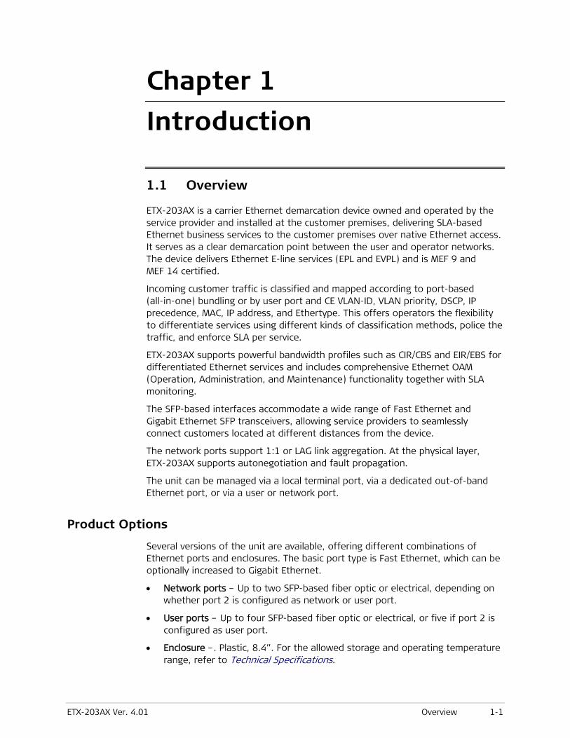
ETX-203AX Ver. 4.01 Overview 1-1
Chapter 1
Introduction
1.1 Overview
ETX-203AX is a carrier Ethernet demarcation device owned and operated by the service provider and installed at the customer premises, delivering SLA-based Ethernet business services to the customer premises over native Ethernet access. It serves as a clear demarcation point between the user and operator networks. The device delivers Ethernet E-line services (EPL and EVPL) and is MEF 9 and MEF 14 certified.
Incoming customer traffic is classified and mapped according to port-based (all-in-one) bundling or by user port and CE VLAN-ID, VLAN priority, DSCP, IP precedence, MAC, IP address, and Ethertype. This offers operators the flexibility to differentiate services using different kinds of classification methods, police the traffic, and enforce SLA per service.
ETX-203AX supports powerful bandwidth profiles such as CIR/CBS and EIR/EBS for differentiated Ethernet services and includes comprehensive Ethernet OAM (Operation, Administration, and Maintenance) functionality together with SLA monitoring.
The SFP-based interfaces accommodate a wide range of Fast Ethernet and Gigabit Ethernet SFP transceivers, allowing service providers to seamlessly connect customers located at different distances from the device.
The network ports support 1:1 or LAG link aggregation. At the physical layer, ETX-203AX supports autonegotiation and fault propagation.
The unit can be managed via a local terminal port, via a dedicated out-of-band Ethernet port, or via a user or network port.
Product Options
Several versions of the unit are available, offering different combinations of Ethernet ports and enclosures. The basic port type is Fast Ethernet, which can be optionally increased to Gigabit Ethernet.
• Network ports – Up to two SFP-based fiber optic or electrical, depending on whether port 2 is configured as network or user port.
• User ports – Up to four SFP-based fiber optic or electrical, or five if port 2 is configured as user port.
• Enclosure –. Plastic, 8.4”. For the allowed storage and operating temperature range, refer to Technical Specifications.
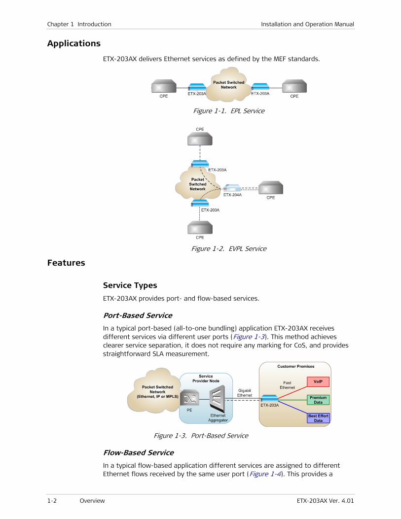
Chapter 1 Introduction Installation and Operation Manual
1-2 Overview ETX-203AX Ver. 4.01
Applications
ETX-203AX delivers Ethernet services as defined by the MEF standards.
Figure 1-1. EPL Service
Figure 1-2. EVPL Service
Features
Service Types
ETX-203AX provides port- and flow-based services.
Port-Based Service
In a typical port-based (all-to-one bundling) application ETX-203AX receives different services via different user ports (Figure 1-3). This method achieves clearer service separation, it does not require any marking for CoS, and provides straightforward SLA measurement.
Figure 1-3. Port-Based Service
Flow-Based Service
In a typical flow-based application different services are assigned to different Ethernet flows received by the same user port (Figure 1-4). This provides a

Installation and Operation Manual Chapter 1 Introduction
ETX-203AX Ver. 4.01 Overview 1-3
cheaper, more scalable solution, with a possibility of mixing different service types.
Figure 1-4. Flow-Based Service
Service Level Agreement (SLA) Monitoring
ETX-203AX is an effective tool for measuring the Service Level Agreement parameters, such as Frame Delay, Frame Delay Variance (jitter), Frame Loss and Availability.
Flow Classification
The ingress user traffic is mapped to the Ethernet flows using the following list of per-port classification criteria. In the classifications, VLAN refers to the service provider (outer) VLAN, previously referred to as SP-VLAN, while inner VLAN refers to the Customer Entity VLAN, previously referred to as CE-VLAN.
• Port-based (All to one bundling)
• VLAN
• VLAN + VLAN priority
• VLAN + IP precedence
• VLAN + DSCP
• VLAN + source/destination MAC
• VLAN + source/destination IP address
• VLAN + inner VLAN
• VLAN + VLAN priority + inner VLAN
• VLAN + non-IP
• VLAN + Ethertype
• VLAN priority
• IP precedence
• DSCP
• Source/destination MAC
• Source/destination IP address
• Non-IP
• Ether Type
• Untagged.

Chapter 1 Introduction Installation and Operation Manual
1-4 Overview ETX-203AX Ver. 4.01
ETX-203AX supports up to 192 Ethernet flows. Flows are unidirectional.
Tagging and Marking
ETX-203AX supports several options for marking and tagging.
You can perform the following marking actions:
• Overwrite inner or outer VLAN with a new value
• Overwrite inner or outer VLAN p-bit with a new value.
You can perform the following tagging actions:
• Add (push) outer VLAN, with p-bit value that can be copied from the original value or set to a new value. When you add a new VLAN, the original outer VLAN becomes the inner VLAN.
• Remove (pop) outer VLAN and p-bit. When you remove a VLAN, the inner VLAN becomes the outer VLAN.
• Add (push) inner VLAN, with p-bit value that can be copied from the original value or set to a new value
• Remove (pop) inner VLAN and p-bit.
Only certain combinations of actions on the outer and inner VLAN are allowed. Refer to Chapter 8 for details on the permitted combinations of actions.
Quality of Service (QoS)
Different service types require different levels of QoS to be provided end-to-end. QoS can be defined per subscriber as well as per flow. QoS has three aspects: rate limitation, traffic shaping, and traffic prioritization.
A single policer can be applied per flow, or a policer aggregate can be applied to a group of flows. The policers operate according to the dual token bucket mechanism (CIR+CBS, EIR+EBS). A special mechanism compensates for Layer 1 headers. Traffic can be limited to the line rate or the data rate.
In addition, ETX-203AX features unique p-bit re-marking capabilities that assign color-specific p-bit values to Ethernet frames at network ingress to ensure metering continuity across the Metro Ethernet network. User traffic that was marked “yellow” according to the CIR/EIR parameters by the device QoS engine is assigned a new p-bit value to signal its status and priority, so that it is dropped first by 802.1Q and 802.1ad network elements in the event of congestion. This is especially useful in color-blind as well as color-aware networks with no “discard eligible” (“yellow”) marking.
As well as assigning color-specific p-bit values, the Drop Eligible Indicator (DEI) bit in the Ethernet frames can be used to indicate that frames marked “yellow” are eligible for dropping, while frames marked “green” are not eligible for dropping.
Traffic Prioritization
Once traffic is classified to a flow, it can be mapped to Strict (Strict Priority) queues or WFQ (Weighted Fair Queues):
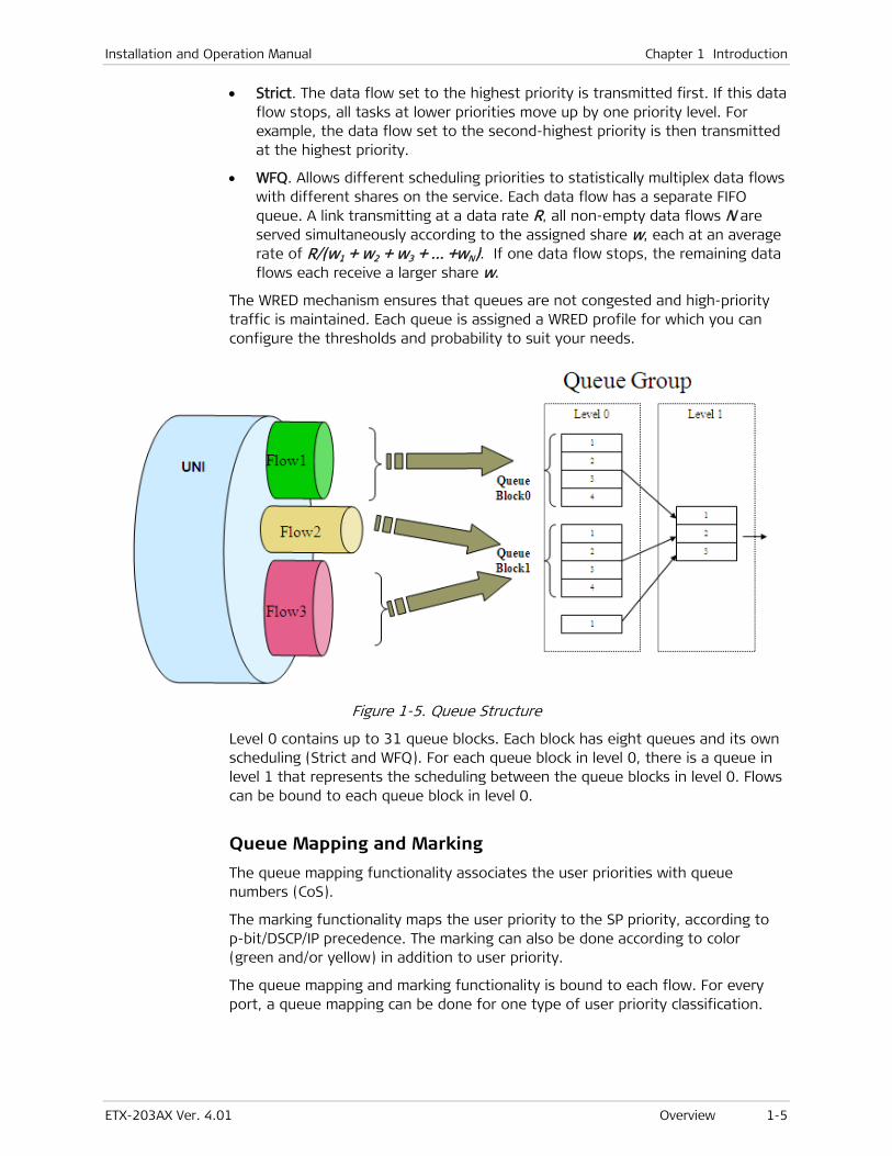
Installation and Operation Manual Chapter 1 Introduction
ETX-203AX Ver. 4.01 Overview 1-5
• Strict. The data flow set to the highest priority is transmitted first. If this data flow stops, all tasks at lower priorities move up by one priority level. For example, the data flow set to the second-highest priority is then transmitted at the highest priority.
• WFQ. Allows different scheduling priorities to statistically multiplex data flows with different shares on the service. Each data flow has a separate FIFO queue. A link transmitting at a data rate R, all non-empty data flows N are served simultaneously according to the assigned share w, each at an average rate of R/(w1 + w2 + w3 + … +wN). If one data flow stops, the remaining data flows each receive a larger share w.
The WRED mechanism ensures that queues are not congested and high-priority traffic is maintained. Each queue is assigned a WRED profile for which you can configure the thresholds and probability to suit your needs.
Figure 1-5. Queue Structure
Level 0 contains up to 31 queue blocks. Each block has eight queues and its own scheduling (Strict and WFQ). For each queue block in level 0, there is a queue in level 1 that represents the scheduling between the queue blocks in level 0. Flows can be bound to each queue block in level 0.
Queue Mapping and Marking
The queue mapping functionality associates the user priorities with queue numbers (CoS).
The marking functionality maps the user priority to the SP priority, according to p-bit/DSCP/IP precedence. The marking can also be done according to color (green and/or yellow) in addition to user priority.
The queue mapping and marking functionality is bound to each flow. For every port, a queue mapping can be done for one type of user priority classification.
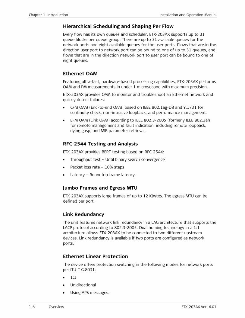
Chapter 1 Introduction Installation and Operation Manual
1-6 Overview ETX-203AX Ver. 4.01
Hierarchical Scheduling and Shaping Per Flow
Every flow has its own queues and scheduler. ETX-203AX supports up to 31 queue blocks per queue group. There are up to 31 available queues for the network ports and eight available queues for the user ports. Flows that are in the direction user port to network port can be bound to one of up to 31 queues, and flows that are in the direction network port to user port can be bound to one of eight queues.
Ethernet OAM
Featuring ultra-fast, hardware-based processing capabilities, ETX-203AX performs OAM and PM measurements in under 1 microsecond with maximum precision.
ETX-203AX provides OAM to monitor and troubleshoot an Ethernet network and quickly detect failures:
• CFM OAM (End-to-end OAM) based on IEEE 802.1ag-D8 and Y.1731 for continuity check, non-intrusive loopback, and performance management.
• EFM OAM (Link OAM) according to IEEE 802.3-2005 (formerly IEEE 802.3ah) for remote management and fault indication, including remote loopback, dying gasp, and MIB parameter retrieval.
RFC-2544 Testing and Analysis
ETX-203AX provides BERT testing based on RFC-2544:
• Throughput test – Until binary search convergence
• Packet loss rate – 10% steps
• Latency – Roundtrip frame latency.
Jumbo Frames and Egress MTU
ETX-203AX supports large frames of up to 12 Kbytes. The egress MTU can be defined per port.
Link Redundancy
The unit features network link redundancy in a LAG architecture that supports the LACP protocol according to 802.3-2005. Dual homing technology in a 1:1 architecture allows ETX-203AX to be connected to two different upstream devices. Link redundancy is available if two ports are configured as network ports.
Ethernet Linear Protection
The device offers protection switching in the following modes for network ports per ITU-T G.8031:
• 1:1
• Unidirectional
• Using APS messages.
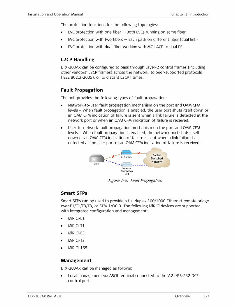
Installation and Operation Manual Chapter 1 Introduction
ETX-203AX Ver. 4.01 Overview 1-7
The protection functions for the following topologies:
• EVC protection with one fiber — Both EVCs running on same fiber
• EVC protection with two fibers — Each path on different fiber (dual link)
• EVC protection with dual fiber working with MC-LACP to dual PE.
L2CP Handling
ETX-203AX can be configured to pass through Layer-2 control frames (including other vendors’ L2CP frames) across the network, to peer-supported protocols (IEEE 802.3-2005), or to discard L2CP frames.
Fault Propagation
The unit provides the following types of fault propagation:
• Network-to-user fault propagation mechanism on the port and OAM CFM levels – When fault propagation is enabled, the user port shuts itself down or an OAM CFM indication of failure is sent when a link failure is detected at the network port or when an OAM CFM indication of failure is received.
• User-to-network fault propagation mechanism on the port and OAM CFM levels – When fault propagation is enabled, the network port shuts itself down or an OAM CFM indication of failure is sent when a link failure is detected at the user port or an OAM CFM indication of failure is received.
Figure 1-6. Fault Propagation
Smart SFPs
Smart SFPs can be used to provide a full duplex 100/1000 Ethernet remote bridge over E1/T1/E3/T3, or STM-1/OC-3. The following MiRICi devices are supported, with integrated configuration and management:
• MiRICi-E1
• MiRICi-T1
• MiRICi-E3
• MiRICi-T3
• MiRICi-155.
Management
ETX-203AX can be managed as follows:
• Local management via ASCII terminal connected to the V.24/RS-232 DCE control port.

Chapter 1 Introduction Installation and Operation Manual
1-8 Overview ETX-203AX Ver. 4.01
• Local management via dedicated out of band (OOB) management port.
• Remote management via a network or user port using Telnet SSH or an SNMP-based management system. ETX-203AX supports the SNMP version 3 entity, providing secure access to the device by authenticating and encrypting packets transmitted over the network.
Management can be performed by creating a flow to/from the host port, thus enabling QoS on the management traffic. Management can be configured to use untagged or tagged frames.
Command Line Interface
You can create data bases and scripts of commonly used commands and easily apply them to multiple units in your infrastructure using RAD’s new command line interface.
Security
To ensure client-server communication privacy and correct user authentication, ETX-203AX supports the security protocols listed below:
• SNMPv3
• RADIUS (client authentication)
• TACACS+ (client authentication)
• SSH for Secure Shell communication session.
Syslog
The syslog protocol is a client/server-type protocol, featuring a standard for forwarding log messages in an IP network and supports up to four syslog servers at present. A syslog sender sends a small text message of less than 1024 bytes to the syslog receiver. Syslog messages are sent via UDP in cleartext.
DHCP Client
When enabled, the DHCP client of ETX-203AX requests an IP address, IP mask, and default gateway from the DHCP server.
SFTP
SFTP (Secure File Transfer Protocol) is supported, to provide secure encrypted file transfer using SSH.
Statistics Collection
ETX-203AX collects performance statistics for the physical layers of the network/user ports, Ethernet flows, OAM CFM, and Radius.
In addition, ETX-203AX provides Rmon Statistics based on RFC 2819. In this scenario, ETX-203AX can send reports when one of the defined counters rises above or drops below specified thresholds within the sampling period of time. These reports can be sent as SNMP traps to defined network management stations and/or written to the event log.

Installation and Operation Manual Chapter 1 Introduction
ETX-203AX Ver. 4.01 Overview 1-9
Network Time Protocol
The Network Time Protocol (NTP) provides the means of synchronizing all managed elements across the network to a reliable clock source provided by multiple servers. ETX-203AX supports the client side of NTP v.3 (RFC 1305).
Diagnostic Tools
ETX-203AX offers several types of diagnostic procedures:
• Ping test –Check IP connectivity by pinging remote IP hosts.
• Trace route –Quickly trace a route from ETX-203AX to any other network device
• Loopback tests:
Layer-1 loopback performed at the PHY of the physical ports. When the loopback is active the data forwarded to a port is looped from the Tx path to the Rx path, disrupting the traffic. This loopback cannot pass through Ethernet bridges.
Layer-2/Layer-3 loopback on flows with optional MAC and/or IP address swapping. When the loopback is active, ETX-203AX can exchange the source and destination MAC/IP addresses of the incoming packets. This loopback passes through Ethernet bridges and routers, and does not disrupt traffic flows that are not being tested.
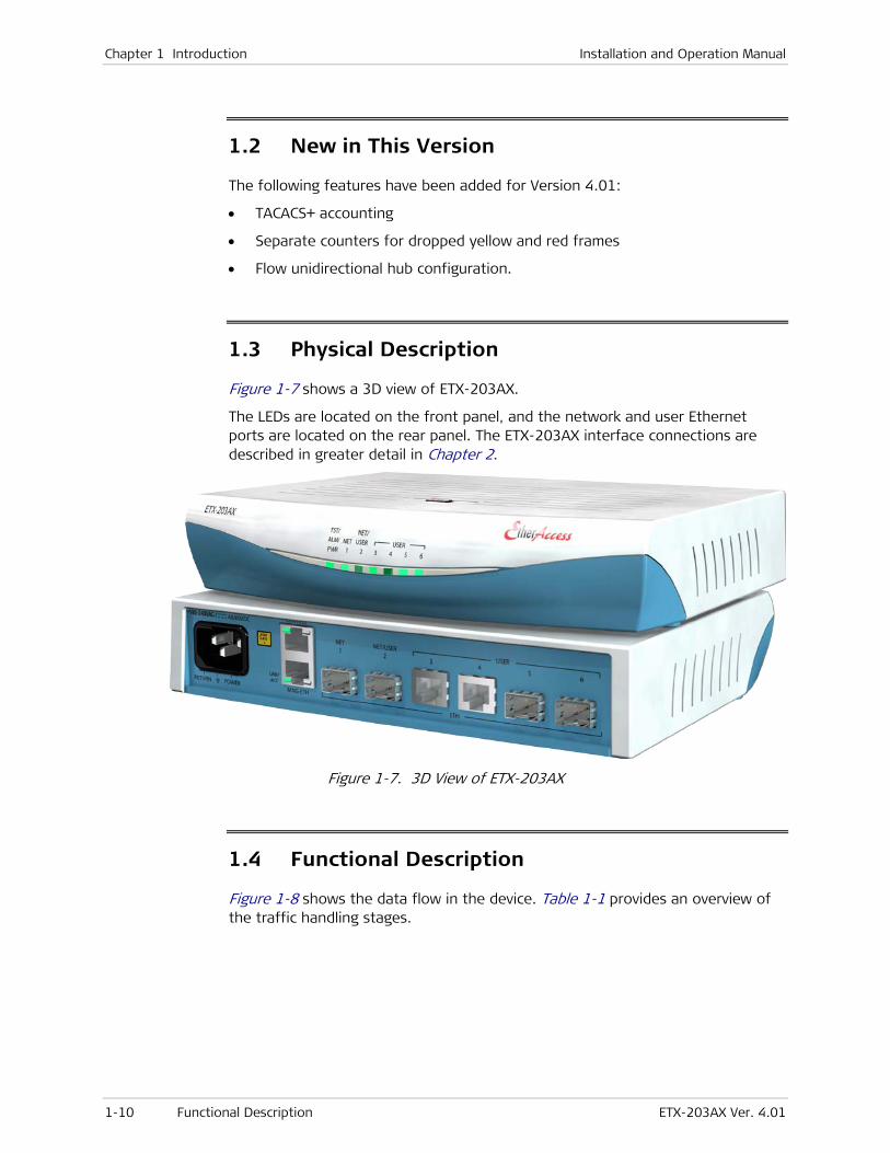
Chapter 1 Introduction Installation and Operation Manual
1-10 Functional Description ETX-203AX Ver. 4.01
1.2 New in This Version
The following features have been added for Version 4.01:
• TACACS+ accounting
• Separate counters for dropped yellow and red frames
• Flow unidirectional hub configuration.
1.3 Physical Description
Figure 1-7 shows a 3D view of ETX-203AX.
The LEDs are located on the front panel, and the network and user Ethernet ports are located on the rear panel. The ETX-203AX interface connections are described in greater detail in Chapter 2.
Figure 1-7. 3D View of ETX-203AX
1.4 Functional Description
Figure 1-8 shows the data flow in the device. Table 1-1 provides an overview of the traffic handling stages.

Installation and Operation Manual Chapter 1 Introduction
ETX-203AX Ver. 4.01 Functional Description 1-11
Figure 1-8. Data Flow
Table 1-1. Traffic Handling Stages
Processing Stage Description
Classification Classifying traffic such as email traffic, content streaming,
large document transmission, etc.
Policer per Flow or
Group of Flows
Policing the traffic within the flow or group of flows
CoS/Services Dividing the services using a 3-bit field, specifying a priority
value between 0 (signifying best-effort) and 7 (signifying
priority real-time data)
Queues ‘Storing’ data that is transmitted according to the CoS level
specified
Rate Limitation/
Shaping
Ensuring that traffic is shaped to the desired rate
Scheduling Scheduling and ‘regulating’ traffic
Editing and Marking Adding or removing VLAN IDs, as well as marking the priority
on the outer VLAN header

Chapter 1 Introduction Installation and Operation Manual
1-12 Technical Specifications ETX-203AX Ver. 4.01
1.5 Technical Specifications
Network Interface Number of Ports Up to 2 (RJ-45 or fiber optic SFPs). The second port can be configured as a network or user port.
Type Fast or Gigabit Ethernet
Fiber Optic Specifications and Ranges
See SFP Transceivers data sheet
Electrical Operation Mode
10/100 Mbps or 10/100/1000 Mbps, full duplex, autonegotiation, MDI/MDIX
User Interface Number of Ports Up to 4 (RJ-45 or fiber optic SFPs). If the second network port is configured as a user port, there are five user ports.
Type Fast or Gigabit Ethernet
Fiber Optic Specifications and Ranges
See SFP Transceivers data sheet
Electrical Operation Mode
10/100 Mbps or 10/100/1000 Mbps
Full duplex, autonegotiation, MDI/MDIX
Standards Compliance
IEEE 802.3, 802.3u, 802.1q, 802.1p, 802.3-2005 (relevant parts), 802.1ag-D8, RFC-2544
MEF MEF 6 (E-Line – EPL and EVPL), MEF 9, MEF 10, MEF 14
ITU-T Y.1731, G.8031
Ethernet Flows Number of Flows 192
Management Local Via dedicated terminal port; V.24/RS-232 DCE; 9.6, 19.2, 38.4, 57.6, 115.2 kbps; RJ-45 connector
Inband Via one of the Ethernet ports
Out-of-band Via dedicated management port
Indicators PWR (green) Power status
TST/ALM (red) Alarm and loopback status
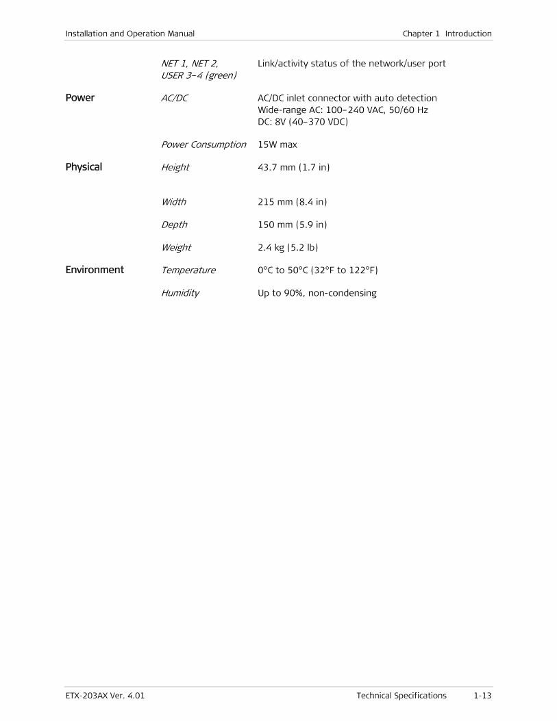
Installation and Operation Manual Chapter 1 Introduction
ETX-203AX Ver. 4.01 Technical Specifications 1-13
NET 1, NET 2, USER 3–4 (green)
Link/activity status of the network/user port
Power AC/DC AC/DC inlet connector with auto detection Wide-range AC: 100–240 VAC, 50/60 Hz DC: 8V (40–370 VDC)
Power Consumption 15W max
Physical
Height 43.7 mm (1.7 in)
Width 215 mm (8.4 in)
Depth 150 mm (5.9 in)
Weight 2.4 kg (5.2 lb)
Environment Temperature 0°C to 50°C (32°F to 122°F)
Humidity Up to 90%, non-condensing

Chapter 1 Introduction Installation and Operation Manual
1-14 Technical Specifications ETX-203AX Ver. 4.01
ETX-203AX Ver. 4.01 Package Contents 2-1
Chapter 2
Installation and Setup This chapter describes installation and setup procedures for the ETX-203AX unit.
After installing the unit, refer to Chapter 3 for operating instructions and Chapter 4 for management instructions.
If a problem is encountered, refer to Chapter 11 for test and diagnostic instructions.
Internal settings, adjustment, maintenance, and repairs may be performed only by a skilled technician who is aware of the hazards involved.
Always observe standard safety precautions during installation, operation, and maintenance of this product.
2.1 Site Requirements and Prerequisites
AC-powered units should be installed within 1.5 m (5 ft) of an easily-accessible grounded AC outlet capable of furnishing the voltage in accordance with the nominal supply voltage.
DC-powered units require a -48 VDC power source, which must be adequately isolated from the main supply.
Refer also to the sections describing connections of AC and DC mains at the beginning of the manual.
Allow at least 90 cm (36 in) of frontal clearance for operating and maintenance accessibility. Allow at least 10 cm (4 in) clearance at the rear of the unit for signal lines and interface cables.
The ambient operating temperature of ETX-203AX is 0 to 50°C (32 to 122°F) at a relative humidity of up to 90%, non-condensing.
2.2 Package Contents
The ETX-203AX package includes the following items:
• One ETX-203AX unit
• Matching SFP module(s) (if ordered)
• CBL-RJ45/D9/F/6FT control port cable
• AC power cord
Warning
Note
Chapter 2 Installation and Setup Installation and Operation Manual
2-2 Installing SFP Modules ETX-203AX Ver. 4.01
• Optional accessories included if ordered:
RM-33-2 rack-mount kit for mounting one or two ETX-203AX units in a 19" rack
DC connection kit.
2.3 Mounting the Unit
ETX-203AX is designed for installation as a desktop unit. It can also be mounted in a 19" rack or on a wall.
• For rack mounting instructions, refer to the associated installation kit manual
• For wall mounting instructions, refer to the drilling template at the end of this manual
• If ETX-203AX is to be used as a desktop unit, place and secure the unit on a stable, non-movable surface.
Refer to the clearance and temperature requirements in Site Requirements and Prerequisites.
2.4 Installing SFP Modules
ETX-203AX uses SFP modules with LC fiber optic connectors.
Third-party SFP optical transceivers must be agency-approved, complying with the local laser safety regulations for Class I laser equipment.
To install the SFP modules:
• Lock the wire latch of each SFP module by lifting it up until it clicks into place, as illustrated in Figure 2-1.
Some SFP models have a plastic door instead of a wire latch.
Note
Warning
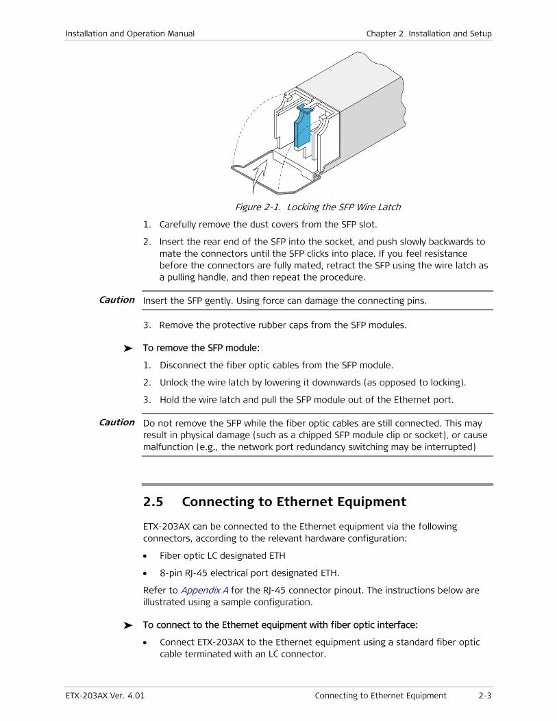
Installation and Operation Manual Chapter 2 Installation and Setup
ETX-203AX Ver. 4.01 Connecting to Ethernet Equipment 2-3
Figure 2-1. Locking the SFP Wire Latch
1. Carefully remove the dust covers from the SFP slot.
2. Insert the rear end of the SFP into the socket, and push slowly backwards to mate the connectors until the SFP clicks into place. If you feel resistance before the connectors are fully mated, retract the SFP using the wire latch as a pulling handle, and then repeat the procedure.
Insert the SFP gently. Using force can damage the connecting pins.
3. Remove the protective rubber caps from the SFP modules.
To remove the SFP module:
1. Disconnect the fiber optic cables from the SFP module.
2. Unlock the wire latch by lowering it downwards (as opposed to locking).
3. Hold the wire latch and pull the SFP module out of the Ethernet port.
Do not remove the SFP while the fiber optic cables are still connected. This may result in physical damage (such as a chipped SFP module clip or socket), or cause malfunction (e.g., the network port redundancy switching may be interrupted)
2.5 Connecting to Ethernet Equipment
ETX-203AX can be connected to the Ethernet equipment via the following connectors, according to the relevant hardware configuration:
• Fiber optic LC designated ETH
• 8-pin RJ-45 electrical port designated ETH.
Refer to Appendix A for the RJ-45 connector pinout. The instructions below are illustrated using a sample configuration.
To connect to the Ethernet equipment with fiber optic interface:
• Connect ETX-203AX to the Ethernet equipment using a standard fiber optic cable terminated with an LC connector.
Caution
Caution
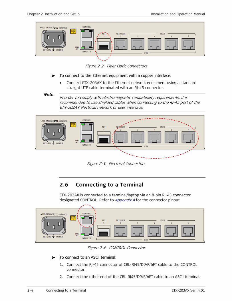
Chapter 2 Installation and Setup Installation and Operation Manual
2-4 Connecting to a Terminal ETX-203AX Ver. 4.01
Figure 2-2. Fiber Optic Connectors
To connect to the Ethernet equipment with a copper interface:
• Connect ETX-203AX to the Ethernet network equipment using a standard straight UTP cable terminated with an RJ-45 connector.
In order to comply with electromagnetic compatibility requirements, it is recommended to use shielded cables when connecting to the RJ-45 port of the ETX-203AX electrical network or user interface.
Figure 2-3. Electrical Connectors
2.6 Connecting to a Terminal
ETX-203AX is connected to a terminal/laptop via an 8-pin RJ-45 connector designated CONTROL. Refer to Appendix A for the connector pinout.
Figure 2-4. CONTROL Connector
To connect to an ASCII terminal:
1. Connect the RJ-45 connector of CBL-RJ45/D9/F/6FT cable to the CONTROL connector.
2. Connect the other end of the CBL-RJ45/D9/F/6FT cable to an ASCII terminal.
Note
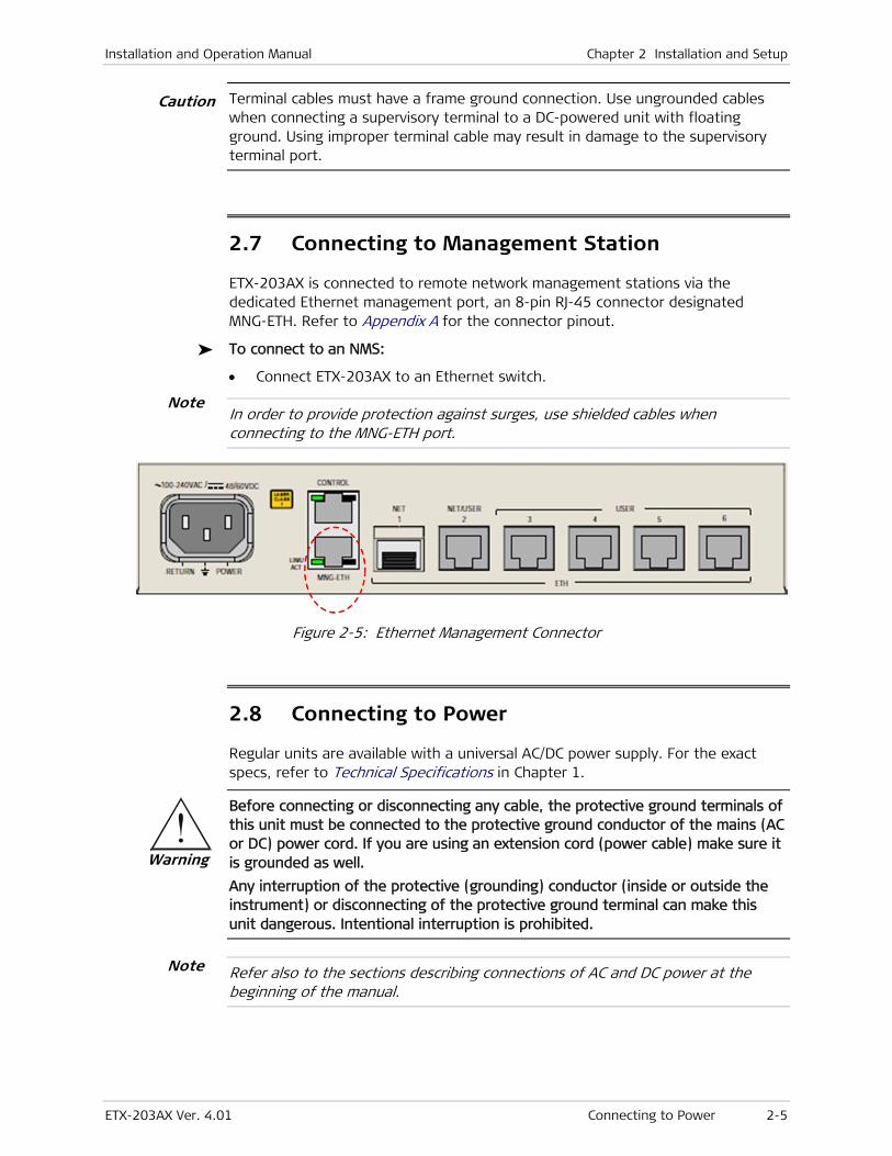
Installation and Operation Manual Chapter 2 Installation and Setup
ETX-203AX Ver. 4.01 Connecting to Power 2-5
Terminal cables must have a frame ground connection. Use ungrounded cables when connecting a supervisory terminal to a DC-powered unit with floating ground. Using improper terminal cable may result in damage to the supervisory terminal port.
2.7 Connecting to Management Station
ETX-203AX is connected to remote network management stations via the dedicated Ethernet management port, an 8-pin RJ-45 connector designated MNG-ETH. Refer to Appendix A for the connector pinout.
To connect to an NMS:
• Connect ETX-203AX to an Ethernet switch.
In order to provide protection against surges, use shielded cables when connecting to the MNG-ETH port.
Figure 2-5: Ethernet Management Connector
2.8 Connecting to Power
Regular units are available with a universal AC/DC power supply. For the exact specs, refer to Technical Specifications in Chapter 1.
Before connecting or disconnecting any cable, the protective ground terminals of this unit must be connected to the protective ground conductor of the mains (AC or DC) power cord. If you are using an extension cord (power cable) make sure it is grounded as well.
Any interruption of the protective (grounding) conductor (inside or outside the instrument) or disconnecting of the protective ground terminal can make this unit dangerous. Intentional interruption is prohibited.
Refer also to the sections describing connections of AC and DC power at the beginning of the manual.
Warning
Note
Caution
Note

Chapter 2 Installation and Setup Installation and Operation Manual
2-6 Connecting to Power ETX-203AX Ver. 4.01
Connecting to AC Power
AC power should be supplied via a 1.5 m (5 ft) standard power cable terminated by a standard 3-prong socket. A cable is provided with the unit.
To connect AC power:
1. Connect the power cable to the power connector on the ETX-203AX rear panel.
2. Connect the power cable to the mains outlet.
The unit turns on automatically once connected to the mains.
Connecting to DC Power
Terminal block connectors with adapters are available for DC power supplies.
To connect DC power:
• Refer to the Terminal Block Connector DC Power Supply Connection supplement for instructions on wiring the DC adapters. This supplement can be found at the end of this manual.

ETX-203AX Ver. 4.0B Turning On the Unit 3-1
Chapter 3
Operation This chapter:
• Explains power-on and power-off procedures
• Provides a detailed description of the front panel controls and indicators and their functions.
For a detailed explanation of parameters, see Chapters 6–10.
3.1 Turning On the Unit
To turn on ETX-203AX:
• Connect the power cord to the mains.
The PWR indicator lights up and remains lit as long as ETX-203AX receives power.
ETX-203AX requires no operator attention once installed, with the exception of occasional monitoring of front panel indicators. Intervention is only required when ETX-203AX must be configured to its operational requirements, or diagnostic tests are performed.

Chapter 3 Operation Installation and Operation Manual
3-2 Startup ETX-203AX Ver. 4.0B
3.2 Indicators
The unit's LEDs are located on the front panel (see Figure 3-1). Table 3-1 lists the functions of the ETX-203AX LED indicators.
Figure 3-1. Device LEDs
Table 3-1. LEDs and Controls
Name Type Function
TST/ALM/PWR Green/Red
LED
ON (green) – Power is ON
ON (red) – There is at least one active alarm
Blinking – Diagnostic loopback is active
NET 1 Green LEDs ON – Corresponding Ethernet link is OK
Blinking – Data is being transmitted or received on the corresponding
Ethernet link
NET/ USER 2 Green LEDs ON – Corresponding Ethernet link is OK
Blinking – Data is being transmitted or received on the corresponding
Ethernet link
USER
3,4,5,6
Green LEDs ON – Corresponding Ethernet link is OK
Blinking – Data is being transmitted or received on the corresponding
Ethernet link
The number of network ports and user ports and the corresponding number of LEDs depend on the hardware configuration.
3.3 Startup
Configuration Files
The following files contain configuration settings:
• factory-default-config – Contains the manufacturer default settings
• rollback-config –Serves as a backup for startup-config. After reboot the device loads rollback-config as running-config if it exists and is valid, and if startup-config is missing or invalid.
Note
Installation and Operation Manual Chapter 3 Operation
ETX-203AX Ver. 4.0B Using a Custom Configuration File 3-3
• running-config – Contains the current configuration that the device is running
• startup-config – Contains saved non-default user configuration. This file is not automatically created. You can use the save or copy command to create it. After reboot the device loads startup-config as running-config if it exists and is valid.
• user-default-config – Contains default user configuration. This file is not automatically created. You can use the copy command to create it.
It is recommended to not use the file name candidate-config, as it is reserved for future use.
Refer to Chapter 10 for details on file operations.
Loading Sequence
At startup, the device attempts to load configuration files in the following sequence until a valid one is found:
• startup-config
• rollback-config
• user-default-config
• factory-default-config.
If an error is encountered while loading a file, the default is to ignore the error and continue loading. You can use the on-configuration-error command to change this behavior, to either stop loading the file and go to the next configuration file, or reject the file and reboot.
To display the parameter values after startup, use the info [detail] command.
3.4 Using a Custom Configuration File
In large deployments, often a central network administrator sends configuration scripts to the remote locations and all that remains for the local technician to do is to replace the IP address in the script or other similar minor changes (using any text editor), and then download the file to the device.
To download the configuration file, use the copy command, as explained in Chapter 10. It is recommended to copy the file to both startup-config and the user-default file.
After downloading the configuration file, the unit must be reset in order to execute the file. After the unit completes its startup, the custom configuration is complete.
Note

Chapter 3 Operation Installation and Operation Manual
3-4 Turning Off the Unit ETX-203AX Ver. 4.0B
3.5 Turning Off the Unit
To power off the unit:
• Remove the power cord from the power source.

ETX-203AX Ver. 4.01 Working with Terminal 4-1
Chapter 4
Management and Security This chapter describes the following:
• Management and configuration options
• Working with a terminal connected to the ETX-203AX control port
• Using the command line interface (CLI)
• CLI command tree
• Management-related features.
Usually, initial configuration of the management parameters is performed via ASCII terminal. Once the management flows and corresponding router interface have been configured, it is possible to access ETX-203AX via Telnet or SNMP for operation configuration. Refer to the Quick Start Guide for an example of management configuration. For details on configuring the router, refer to Chapter 8.
Table 4-1 summarizes management options for ETX-203AX.
Table 4-1. Management Alternatives
Port Manager
Location
Transport Method Management
Protocol
Application
CONTROL Local Out-of-band RS-232 Terminal emulation applications
such as HyperTerminal, Procomm,
Putty, SecureCRT, Tera Term (see
Working with Terminal below)
MNG-ETH Local, remote Out-of-band Telnet, SSH Terminal emulation application
(see Working with Telnet and SSH
below)
SNMP Third-party NMS (see Working with Third-Party Network Management Systems below)
NET
NET/USER
USER
Local, remote Inband Telnet, SSH Terminal emulation application
(see Working with Telnet and SSH
below)
SNMP Third-party NMS (see Working with Third-Party Network Management Systems below)
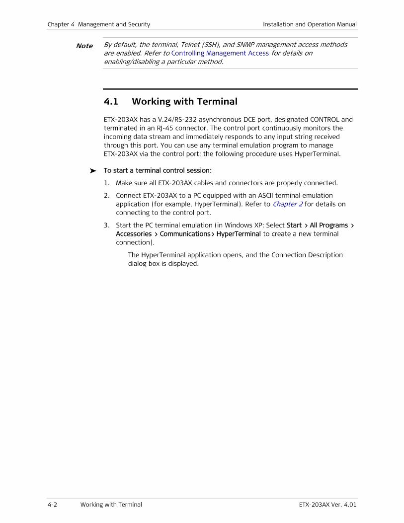
Chapter 4 Management and Security Installation and Operation Manual
4-2 Working with Terminal ETX-203AX Ver. 4.01
By default, the terminal, Telnet (SSH), and SNMP management access methods are enabled. Refer to Controlling Management Access for details on enabling/disabling a particular method.
4.1 Working with Terminal
ETX-203AX has a V.24/RS-232 asynchronous DCE port, designated CONTROL and terminated in an RJ-45 connector. The control port continuously monitors the incoming data stream and immediately responds to any input string received through this port. You can use any terminal emulation program to manage ETX-203AX via the control port; the following procedure uses HyperTerminal.
To start a terminal control session:
1. Make sure all ETX-203AX cables and connectors are properly connected.
2. Connect ETX-203AX to a PC equipped with an ASCII terminal emulation application (for example, HyperTerminal). Refer to Chapter 2 for details on connecting to the control port.
3. Start the PC terminal emulation (in Windows XP: Select Start > All Programs > Accessories > Communications> HyperTerminal to create a new terminal connection).
The HyperTerminal application opens, and the Connection Description dialog box is displayed.
Note
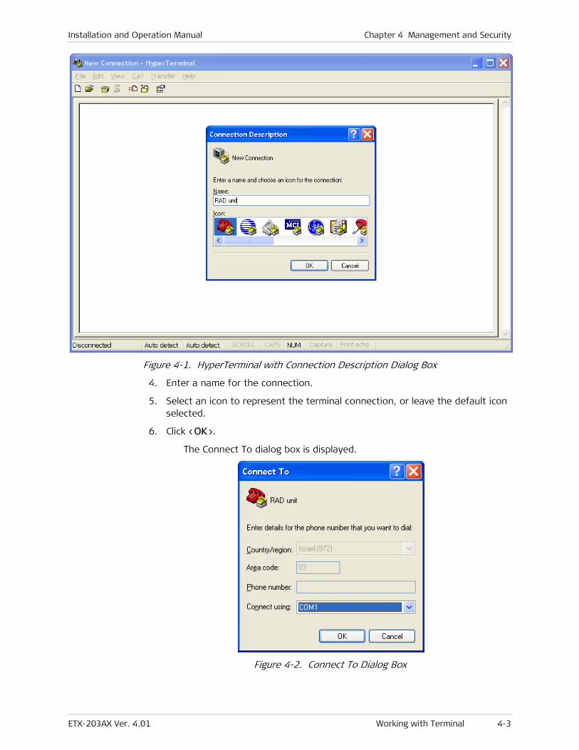
Installation and Operation Manual Chapter 4 Management and Security
ETX-203AX Ver. 4.01 Working with Terminal 4-3
Figure 4-1. HyperTerminal with Connection Description Dialog Box
4. Enter a name for the connection.
5. Select an icon to represent the terminal connection, or leave the default icon selected.
6. Click <OK>.
The Connect To dialog box is displayed.
Figure 4-2. Connect To Dialog Box
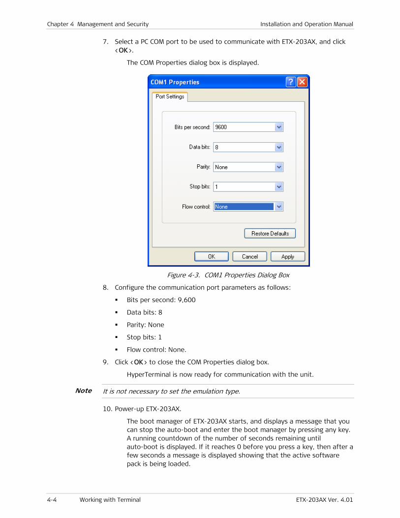
Chapter 4 Management and Security Installation and Operation Manual
4-4 Working with Terminal ETX-203AX Ver. 4.01
7. Select a PC COM port to be used to communicate with ETX-203AX, and click <OK>.
The COM Properties dialog box is displayed.
Figure 4-3. COM1 Properties Dialog Box
8. Configure the communication port parameters as follows:
Bits per second: 9,600
Data bits: 8
Parity: None
Stop bits: 1
Flow control: None.
9. Click <OK> to close the COM Properties dialog box.
HyperTerminal is now ready for communication with the unit.
It is not necessary to set the emulation type.
10. Power-up ETX-203AX.
The boot manager of ETX-203AX starts, and displays a message that you can stop the auto-boot and enter the boot manager by pressing any key. A running countdown of the number of seconds remaining until auto-boot is displayed. If it reaches 0 before you press a key, then after a few seconds a message is displayed showing that the active software pack is being loaded.
Note
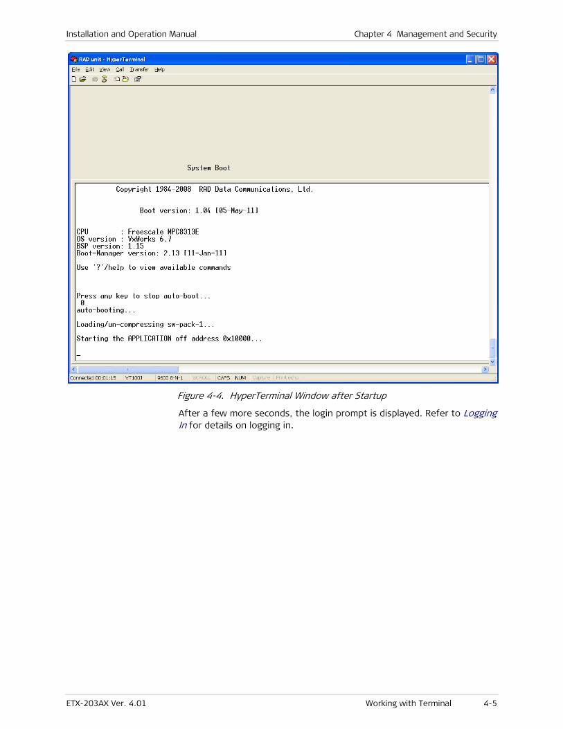
Installation and Operation Manual Chapter 4 Management and Security
ETX-203AX Ver. 4.01 Working with Terminal 4-5
Figure 4-4. HyperTerminal Window after Startup
After a few more seconds, the login prompt is displayed. Refer to Logging In for details on logging in.
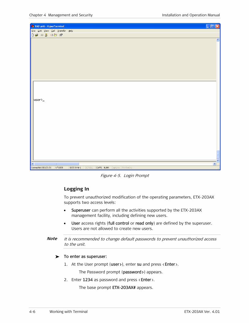
Chapter 4 Management and Security Installation and Operation Manual
4-6 Working with Terminal ETX-203AX Ver. 4.01
Figure 4-5. Login Prompt
Logging In
To prevent unauthorized modification of the operating parameters, ETX-203AX supports two access levels:
• Superuser can perform all the activities supported by the ETX-203AX management facility, including defining new users.
• User access rights (full control or read only) are defined by the superuser. Users are not allowed to create new users.
It is recommended to change default passwords to prevent unauthorized access to the unit.
To enter as superuser:
1. At the User prompt (user>), enter su and press <Enter>.
The Password prompt (password>) appears.
2. Enter 1234 as password and press <Enter>.
The base prompt ETX-203AX# appears.
Note
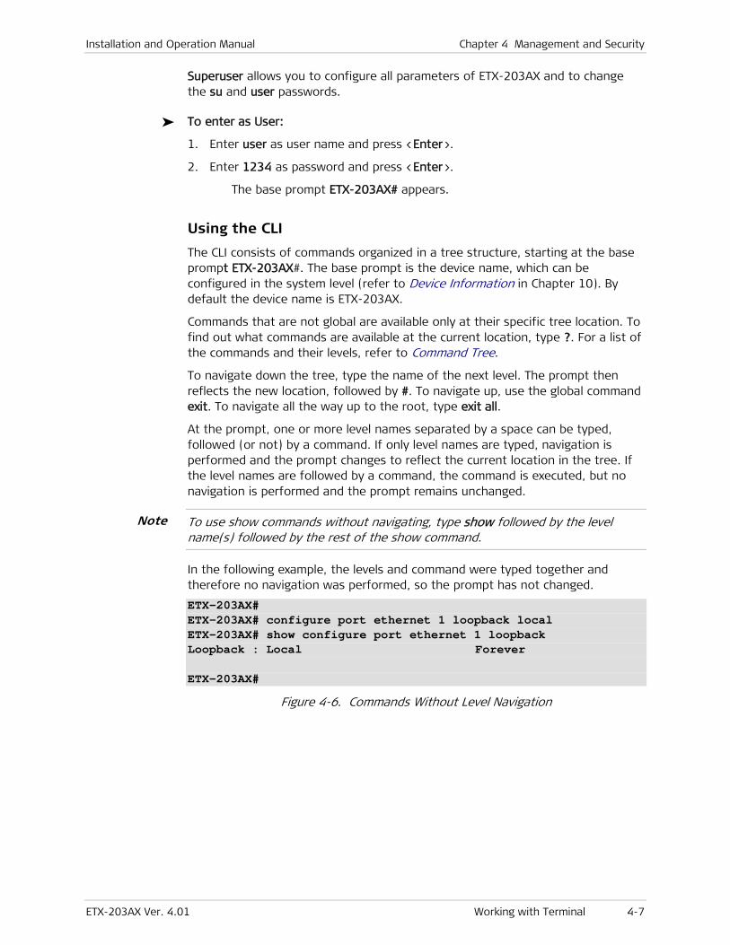
Installation and Operation Manual Chapter 4 Management and Security
ETX-203AX Ver. 4.01 Working with Terminal 4-7
Superuser allows you to configure all parameters of ETX-203AX and to change the su and user passwords.
To enter as User:
1. Enter user as user name and press <Enter>.
2. Enter 1234 as password and press <Enter>.
The base prompt ETX-203AX# appears.
Using the CLI
The CLI consists of commands organized in a tree structure, starting at the base prompt ETX-203AX#. The base prompt is the device name, which can be configured in the system level (refer to Device Information in Chapter 10). By default the device name is ETX-203AX.
Commands that are not global are available only at their specific tree location. To find out what commands are available at the current location, type ?. For a list of the commands and their levels, refer to Command Tree.
To navigate down the tree, type the name of the next level. The prompt then reflects the new location, followed by #. To navigate up, use the global command exit. To navigate all the way up to the root, type exit all.
At the prompt, one or more level names separated by a space can be typed, followed (or not) by a command. If only level names are typed, navigation is performed and the prompt changes to reflect the current location in the tree. If the level names are followed by a command, the command is executed, but no navigation is performed and the prompt remains unchanged.
To use show commands without navigating, type show followed by the level name(s) followed by the rest of the show command.
In the following example, the levels and command were typed together and therefore no navigation was performed, so the prompt has not changed.
ETX-203AX# ETX-203AX# configure port ethernet 1 loopback local ETX-203AX# show configure port ethernet 1 loopback Loopback : Local Forever ETX-203AX#
Figure 4-6. Commands Without Level Navigation
Note

Chapter 4 Management and Security Installation and Operation Manual
4-8 Working with Terminal ETX-203AX Ver. 4.01
In the following example, the levels were typed separately and the navigation is reflected by the changing prompt.
ETX-203AX# ETX-203AX# configure ETX-203AX>config# port ETX-203AX>config>port# ethernet 1 ETX-203AX>config>port>eth(1)# loopback local ETX-203AX>config>port>eth(1)# show loopback Loopback : Local Forever ETX-203AX>config>port>eth(1)#
Figure 4-7. Commands With Level Navigation
Level names are abbreviated in the prompt.
You can type only as many letters of the level or command as required by the system to identify the level or command, for example you can enter config manag to navigate to the management level.
In addition to being the default prompt, the # symbol also indicates a static entity (such as a port) or already configured entity. The $ symbol indicates a new dynamic entity (such as a flow) that takes several commands to configure. The dynamic entity is created as inactive. After the configuration is completed, it is activated by using the no shutdown command, as shown in the following example.
ETX-203AX# ETX-203AX# configure flows flow flow1 ETX-203AX>config>flows>flow(flow1)$ ingress-port ethernet 3 ETX-203AX>config>flows>flow(flow1)$ egress-port ethernet 1 queue 1 block 0/1 ETX-203AX>config>flows>flow(flow1)$ classifier Classifier1 ETX-203AX>config>flows>flow(flow1)$ no shutdown ETX-203AX>config>flows>flow(flow1)$exit ETX-203AX>config>flows#
Figure 4-8. Creating and Activating Flow
The shutdown command is also used to deactivate/disable a hardware element (such as a port), while no shutdown enables/activates it.
For the purposes of illustration, # rather than $ is usually shown at the end of the prompts in the examples in this manual. Examples of dynamic entities include QoS profiles, flows, OAM CFM entities.
CLI commands have the following basic format: command [parameter]{ value1 | value2 | … | valuen } [ optional parameter <value> ]
where:
{} Indicates that one of the values must be selected
[] Indicates an optional parameter
<> Indicates a value to be typed by user according to parameter requirements
Note
Note
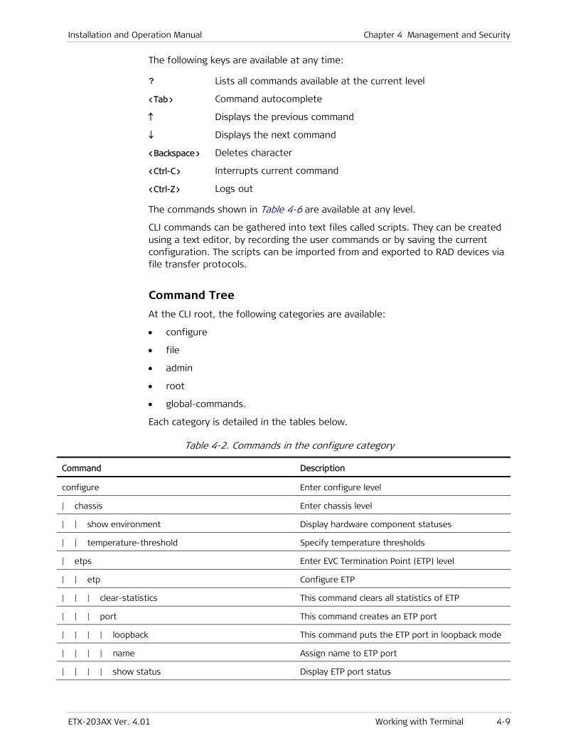
Installation and Operation Manual Chapter 4 Management and Security
ETX-203AX Ver. 4.01 Working with Terminal 4-9
The following keys are available at any time:
? Lists all commands available at the current level
<Tab> Command autocomplete
↑ Displays the previous command
↓ Displays the next command
<Backspace> Deletes character
<Ctrl-C> Interrupts current command
<Ctrl-Z> Logs out
The commands shown in Table 4-6 are available at any level.
CLI commands can be gathered into text files called scripts. They can be created using a text editor, by recording the user commands or by saving the current configuration. The scripts can be imported from and exported to RAD devices via file transfer protocols.
Command Tree
At the CLI root, the following categories are available:
• configure
• file
• admin
• root
• global-commands.
Each category is detailed in the tables below.
Table 4-2. Commands in the configure category
Command Description
configure Enter configure level
| chassis Enter chassis level
| | show environment Display hardware component statuses
| | temperature-threshold Specify temperature thresholds
| etps Enter EVC Termination Point (ETP) level
| | etp Configure ETP
| | | clear-statistics This command clears all statistics of ETP
| | | port This command creates an ETP port
| | | | loopback This command puts the ETP port in loopback mode
| | | | name Assign name to ETP port
| | | | show status Display ETP port status
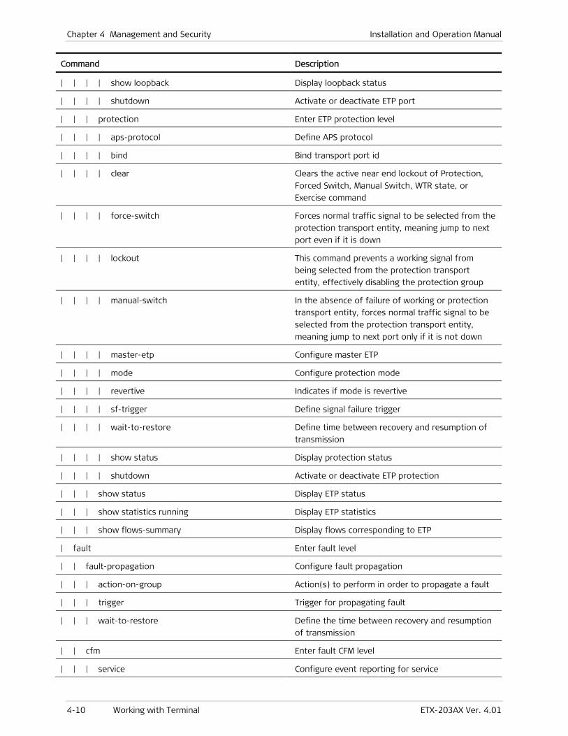
Chapter 4 Management and Security Installation and Operation Manual
4-10 Working with Terminal ETX-203AX Ver. 4.01
Command Description
| | | | show loopback Display loopback status
| | | | shutdown Activate or deactivate ETP port
| | | protection Enter ETP protection level
| | | | aps-protocol Define APS protocol
| | | | bind Bind transport port id
| | | | clear Clears the active near end lockout of Protection,
Forced Switch, Manual Switch, WTR state, or
Exercise command
| | | | force-switch Forces normal traffic signal to be selected from the
protection transport entity, meaning jump to next
port even if it is down
| | | | lockout This command prevents a working signal from
being selected from the protection transport
entity, effectively disabling the protection group
| | | | manual-switch In the absence of failure of working or protection
transport entity, forces normal traffic signal to be
selected from the protection transport entity,
meaning jump to next port only if it is not down
| | | | master-etp Configure master ETP
| | | | mode Configure protection mode
| | | | revertive Indicates if mode is revertive
| | | | sf-trigger Define signal failure trigger
| | | | wait-to-restore Define time between recovery and resumption of
transmission
| | | | show status Display protection status
| | | | shutdown Activate or deactivate ETP protection
| | | show status Display ETP status
| | | show statistics running Display ETP statistics
| | | show flows-summary Display flows corresponding to ETP
| fault Enter fault level
| | fault-propagation Configure fault propagation
| | | action-on-group Action(s) to perform in order to propagate a fault
| | | trigger Trigger for propagating fault
| | | wait-to-restore Define the time between recovery and resumption
of transmission
| | cfm Enter fault CFM level
| | | service Configure event reporting for service
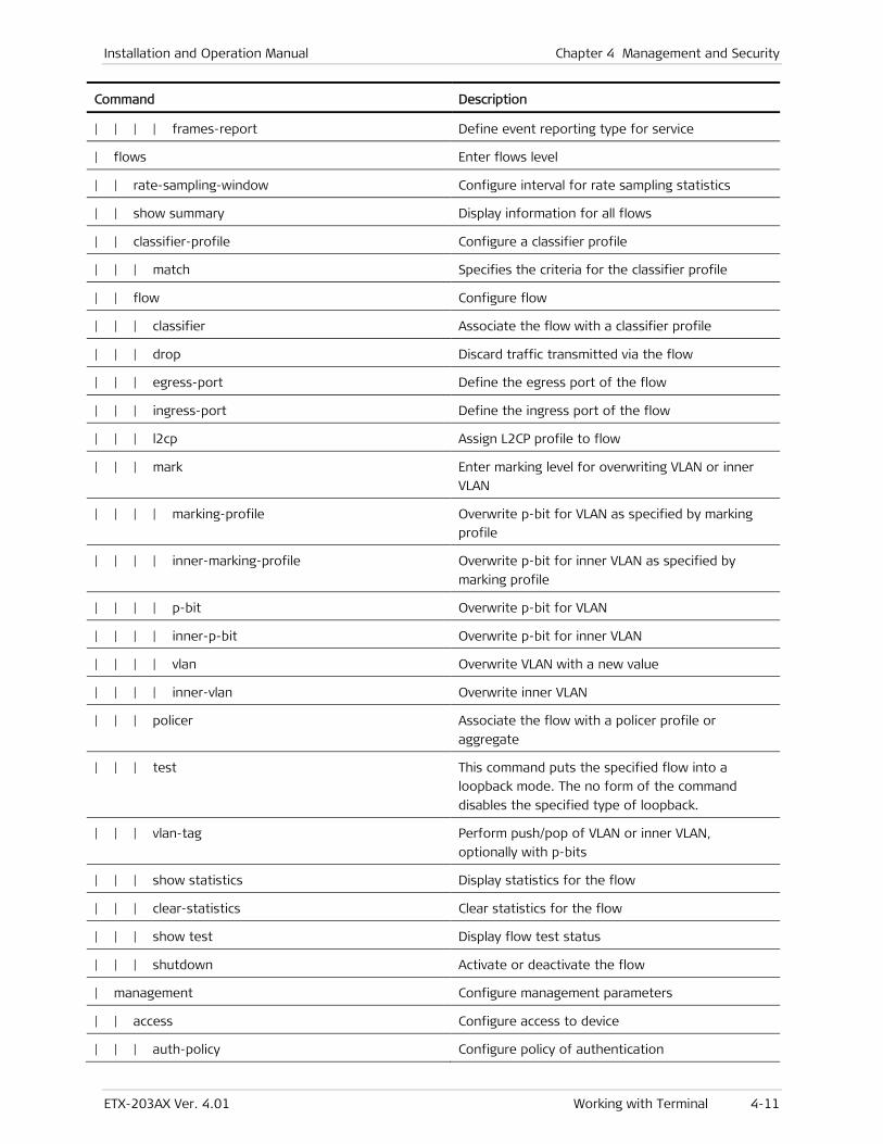
Installation and Operation Manual Chapter 4 Management and Security
ETX-203AX Ver. 4.01 Working with Terminal 4-11
Command Description
| | | | frames-report Define event reporting type for service
| flows Enter flows level
| | rate-sampling-window Configure interval for rate sampling statistics
| | show summary Display information for all flows
| | classifier-profile Configure a classifier profile
| | | match Specifies the criteria for the classifier profile
| | flow Configure flow
| | | classifier Associate the flow with a classifier profile
| | | drop Discard traffic transmitted via the flow
| | | egress-port Define the egress port of the flow
| | | ingress-port Define the ingress port of the flow
| | | l2cp Assign L2CP profile to flow
| | | mark Enter marking level for overwriting VLAN or inner
VLAN
| | | | marking-profile Overwrite p-bit for VLAN as specified by marking
profile
| | | | inner-marking-profile Overwrite p-bit for inner VLAN as specified by
marking profile
| | | | p-bit Overwrite p-bit for VLAN
| | | | inner-p-bit Overwrite p-bit for inner VLAN
| | | | vlan Overwrite VLAN with a new value
| | | | inner-vlan Overwrite inner VLAN
| | | policer Associate the flow with a policer profile or
aggregate
| | | test This command puts the specified flow into a
loopback mode. The no form of the command
disables the specified type of loopback.
| | | vlan-tag Perform push/pop of VLAN or inner VLAN,
optionally with p-bits
| | | show statistics Display statistics for the flow
| | | clear-statistics Clear statistics for the flow
| | | show test Display flow test status
| | | shutdown Activate or deactivate the flow
| management Configure management parameters
| | access Configure access to device
| | | auth-policy Configure policy of authentication
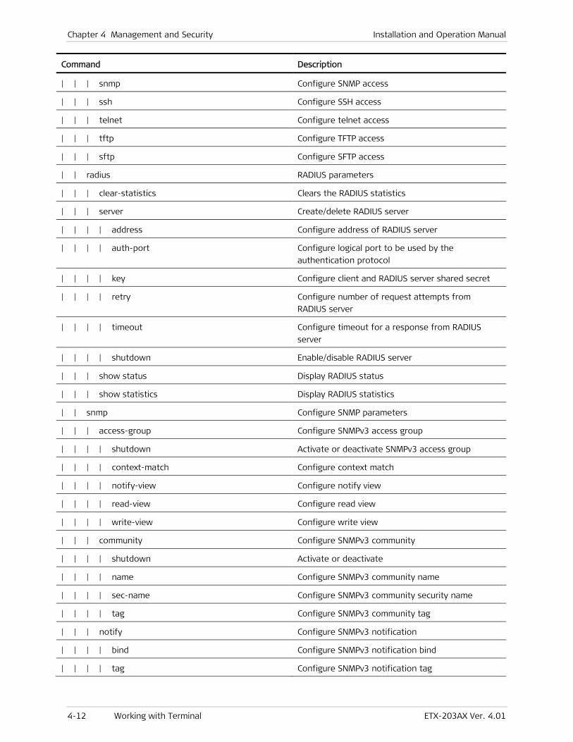
Chapter 4 Management and Security Installation and Operation Manual
4-12 Working with Terminal ETX-203AX Ver. 4.01
Command Description
| | | snmp Configure SNMP access
| | | ssh Configure SSH access
| | | telnet Configure telnet access
| | | tftp Configure TFTP access
| | | sftp Configure SFTP access
| | radius RADIUS parameters
| | | clear-statistics Clears the RADIUS statistics
| | | server Create/delete RADIUS server
| | | | address Configure address of RADIUS server
| | | | auth-port Configure logical port to be used by the
authentication protocol
| | | | key Configure client and RADIUS server shared secret
| | | | retry Configure number of request attempts from
RADIUS server
| | | | timeout Configure timeout for a response from RADIUS
server
| | | | shutdown Enable/disable RADIUS server
| | | show status Display RADIUS status
| | | show statistics Display RADIUS statistics
| | snmp Configure SNMP parameters
| | | access-group Configure SNMPv3 access group
| | | | shutdown Activate or deactivate SNMPv3 access group
| | | | context-match Configure context match
| | | | notify-view Configure notify view
| | | | read-view Configure read view
| | | | write-view Configure write view
| | | community Configure SNMPv3 community
| | | | shutdown Activate or deactivate
| | | | name Configure SNMPv3 community name
| | | | sec-name Configure SNMPv3 community security name
| | | | tag Configure SNMPv3 community tag
| | | notify Configure SNMPv3 notification
| | | | bind Configure SNMPv3 notification bind
| | | | tag Configure SNMPv3 notification tag
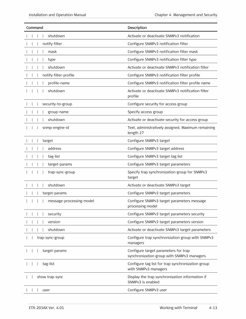
Installation and Operation Manual Chapter 4 Management and Security
ETX-203AX Ver. 4.01 Working with Terminal 4-13
Command Description
| | | | shutdown Activate or deactivate SNMPv3 notification
| | | notify-filter Configure SNMPv3 notification filter
| | | | mask Configure SNMPv3 notification filter mask
| | | | type Configure SNMPv3 notification filter type
| | | | shutdown Activate or deactivate SNMPv3 notification filter
| | | notify-filter-profile Configure SNMPv3 notification filter profile
| | | | profile-name Configure SNMPv3 notification filter profile name
| | | | shutdown Activate or deactivate SNMPv3 notification filter
profile
| | | security-to-group Configure security for access group
| | | | group-name Specify access group
| | | | shutdown Activate or deactivate security for access group
| | | snmp-engine-id Text, administratively assigned. Maximum remaining
length 27
| | | target Configure SNMPv3 target
| | | | address Configure SNMPv3 target address
| | | | tag-list Configure SNMPv3 target tag list
| | | | target-params Configure SNMPv3 target parameters
| | | | trap-sync-group Specify trap synchronization group for SNMPv3
target
| | | | shutdown Activate or deactivate SNMPv3 target
| | | target-params Configure SNMPv3 target parameters
| | | | message-processing-model Configure SNMPv3 target parameters message
processing model
| | | | security Configure SNMPv3 target parameters security
| | | | version Configure SNMPv3 target parameters version
| | | | shutdown Activate or deactivate SNMPv3 target parameters
| | trap-sync-group Configure trap synchronization group with SNMPv3
managers
| | | target-params Configure target parameters for trap
synchronization group with SNMPv3 managers
| | | tag-list Configure tag list for trap synchronization group
with SNMPv3 managers
| | show trap-sync Display the trap synchronization information if
SNMPv3 is enabled
| | | user Configure SNMPv3 user
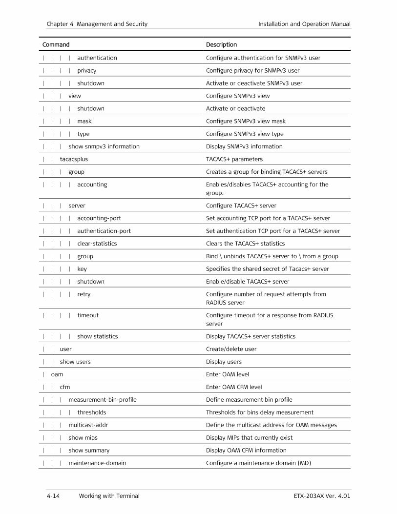
Chapter 4 Management and Security Installation and Operation Manual
4-14 Working with Terminal ETX-203AX Ver. 4.01
Command Description
| | | | authentication Configure authentication for SNMPv3 user
| | | | privacy Configure privacy for SNMPv3 user
| | | | shutdown Activate or deactivate SNMPv3 user
| | | view Configure SNMPv3 view
| | | | shutdown Activate or deactivate
| | | | mask Configure SNMPv3 view mask
| | | | type Configure SNMPv3 view type
| | | show snmpv3 information Display SNMPv3 information
| | tacacsplus TACACS+ parameters
| | | group Creates a group for binding TACACS+ servers
| | | | accounting Enables/disables TACACS+ accounting for the
group.
| | | server Configure TACACS+ server
| | | | accounting-port Set accounting TCP port for a TACACS+ server
| | | | authentication-port Set authentication TCP port for a TACACS+ server
| | | | clear-statistics Clears the TACACS+ statistics
| | | | group Bind \ unbinds TACACS+ server to \ from a group
| | | | key Specifies the shared secret of Tacacs+ server
| | | | shutdown Enable/disable TACACS+ server
| | | | retry Configure number of request attempts from
RADIUS server
| | | | timeout Configure timeout for a response from RADIUS
server
| | | | show statistics Display TACACS+ server statistics
| | user Create/delete user
| | show users Display users
| oam Enter OAM level
| | cfm Enter OAM CFM level
| | | measurement-bin-profile Define measurement bin profile
| | | | thresholds Thresholds for bins delay measurement
| | | multicast-addr Define the multicast address for OAM messages
| | | show mips Display MIPs that currently exist
| | | show summary Display OAM CFM information
| | | maintenance-domain Configure a maintenance domain (MD)
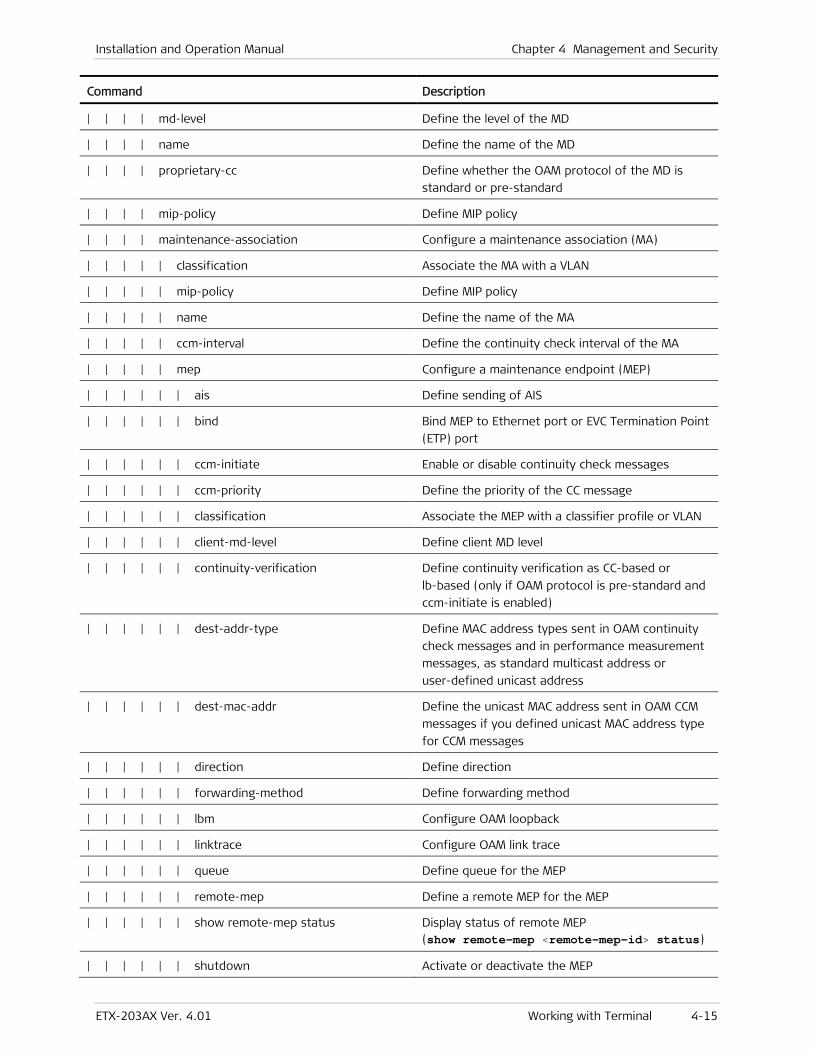
Installation and Operation Manual Chapter 4 Management and Security
ETX-203AX Ver. 4.01 Working with Terminal 4-15
Command Description
| | | | md-level Define the level of the MD
| | | | name Define the name of the MD
| | | | proprietary-cc Define whether the OAM protocol of the MD is
standard or pre-standard
| | | | mip-policy Define MIP policy
| | | | maintenance-association Configure a maintenance association (MA)
| | | | | classification Associate the MA with a VLAN
| | | | | mip-policy Define MIP policy
| | | | | name Define the name of the MA
| | | | | ccm-interval Define the continuity check interval of the MA
| | | | | mep Configure a maintenance endpoint (MEP)
| | | | | | ais Define sending of AIS
| | | | | | bind Bind MEP to Ethernet port or EVC Termination Point
(ETP) port
| | | | | | ccm-initiate Enable or disable continuity check messages
| | | | | | ccm-priority Define the priority of the CC message
| | | | | | classification Associate the MEP with a classifier profile or VLAN
| | | | | | client-md-level Define client MD level
| | | | | | continuity-verification Define continuity verification as CC-based or
lb-based (only if OAM protocol is pre-standard and
ccm-initiate is enabled)
| | | | | | dest-addr-type Define MAC address types sent in OAM continuity
check messages and in performance measurement
messages, as standard multicast address or
user-defined unicast address
| | | | | | dest-mac-addr Define the unicast MAC address sent in OAM CCM
messages if you defined unicast MAC address type
for CCM messages
| | | | | | direction Define direction
| | | | | | forwarding-method Define forwarding method
| | | | | | lbm Configure OAM loopback
| | | | | | linktrace Configure OAM link trace
| | | | | | queue Define queue for the MEP
| | | | | | remote-mep Define a remote MEP for the MEP
| | | | | | show remote-mep status Display status of remote MEP (show remote-mep <remote-mep-id> status)
| | | | | | shutdown Activate or deactivate the MEP
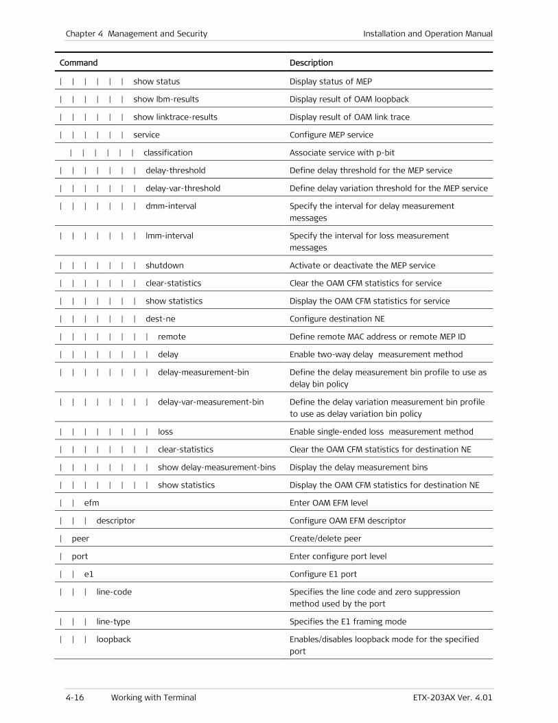
Chapter 4 Management and Security Installation and Operation Manual
4-16 Working with Terminal ETX-203AX Ver. 4.01
Command Description
| | | | | | show status Display status of MEP
| | | | | | show lbm-results Display result of OAM loopback
| | | | | | show linktrace-results Display result of OAM link trace
| | | | | | service Configure MEP service
| | | | | | classification Associate service with p-bit
| | | | | | | delay-threshold Define delay threshold for the MEP service
| | | | | | | delay-var-threshold Define delay variation threshold for the MEP service
| | | | | | | dmm-interval Specify the interval for delay measurement
messages
| | | | | | | lmm-interval Specify the interval for loss measurement
messages
| | | | | | | shutdown Activate or deactivate the MEP service
| | | | | | | clear-statistics Clear the OAM CFM statistics for service
| | | | | | | show statistics Display the OAM CFM statistics for service
| | | | | | | dest-ne Configure destination NE
| | | | | | | | remote Define remote MAC address or remote MEP ID
| | | | | | | | delay Enable two-way delay measurement method
| | | | | | | | delay-measurement-bin Define the delay measurement bin profile to use as
delay bin policy
| | | | | | | | delay-var-measurement-bin Define the delay variation measurement bin profile
to use as delay variation bin policy
| | | | | | | | loss Enable single-ended loss measurement method
| | | | | | | | clear-statistics Clear the OAM CFM statistics for destination NE
| | | | | | | | show delay-measurement-bins Display the delay measurement bins
| | | | | | | | show statistics Display the OAM CFM statistics for destination NE
| | efm Enter OAM EFM level
| | | descriptor Configure OAM EFM descriptor
| peer Create/delete peer
| port Enter configure port level
| | e1 Configure E1 port
| | | line-code Specifies the line code and zero suppression
method used by the port
| | | line-type Specifies the E1 framing mode
| | | loopback Enables/disables loopback mode for the specified
port
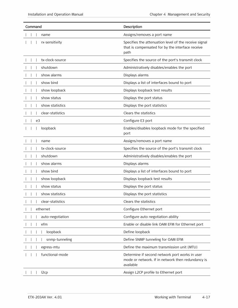
Installation and Operation Manual Chapter 4 Management and Security
ETX-203AX Ver. 4.01 Working with Terminal 4-17
Command Description
| | | name Assigns/removes a port name
| | | rx-sensitivity Specifies the attenuation level of the receive signal
that is compensated for by the interface receive
path
| | | tx-clock-source Specifies the source of the port's transmit clock
| | | shutdown Administratively disables/enables the port
| | | show alarms Displays alarms
| | | show bind Displays a list of interfaces bound to port
| | | show loopback Displays loopback test results
| | | show status Displays the port status
| | | show statistics Displays the port statistics
| | | clear-statistics Clears the statistics
| | e3 Configure E3 port
| | | loopback Enables/disables loopback mode for the specified
port
| | | name Assigns/removes a port name
| | | tx-clock-source Specifies the source of the port's transmit clock
| | | shutdown Administratively disables/enables the port
| | | show alarms Displays alarms
| | | show bind Displays a list of interfaces bound to port
| | | show loopback Displays loopback test results
| | | show status Displays the port status
| | | show statistics Displays the port statistics
| | | clear-statistics Clears the statistics
| | ethernet Configure Ethernet port
| | | auto-negotiation Configure auto negotiation ability
| | | efm Enable or disable link OAM EFM for Ethernet port
| | | | loopback Define loopback
| | | | snmp-tunneling Define SNMP tunneling for OAM EFM
| | | egress-mtu Define the maximum transmission unit (MTU)
| | | functional-mode Determine if second network port works in user
mode or network. If in network then redundancy is
available
| | | l2cp Assign L2CP profile to Ethernet port
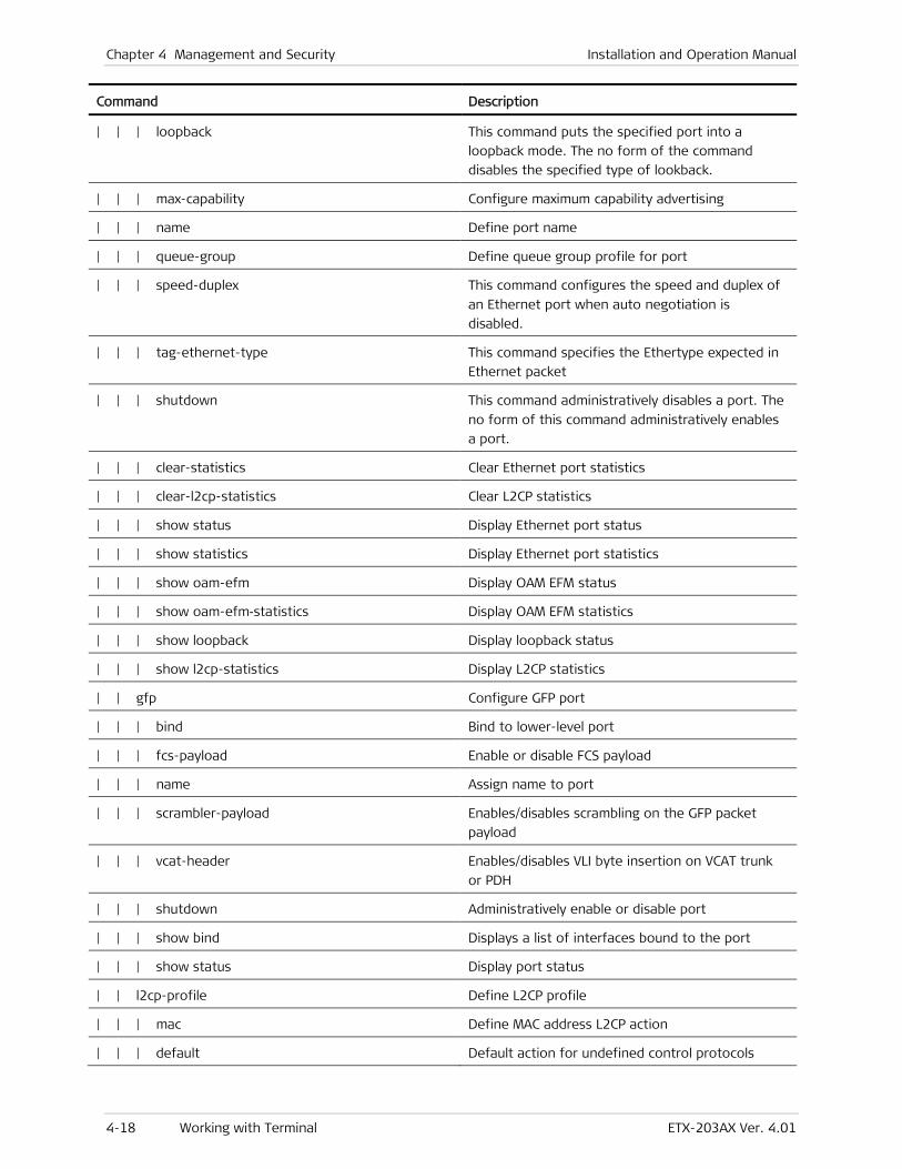
Chapter 4 Management and Security Installation and Operation Manual
4-18 Working with Terminal ETX-203AX Ver. 4.01
Command Description
| | | loopback This command puts the specified port into a
loopback mode. The no form of the command
disables the specified type of lookback.
| | | max-capability Configure maximum capability advertising
| | | name Define port name
| | | queue-group Define queue group profile for port
| | | speed-duplex This command configures the speed and duplex of
an Ethernet port when auto negotiation is
disabled.
| | | tag-ethernet-type This command specifies the Ethertype expected in
Ethernet packet
| | | shutdown This command administratively disables a port. The
no form of this command administratively enables
a port.
| | | clear-statistics Clear Ethernet port statistics
| | | clear-l2cp-statistics Clear L2CP statistics
| | | show status Display Ethernet port status
| | | show statistics Display Ethernet port statistics
| | | show oam-efm Display OAM EFM status
| | | show oam-efm-statistics Display OAM EFM statistics
| | | show loopback Display loopback status
| | | show l2cp-statistics Display L2CP statistics
| | gfp Configure GFP port
| | | bind Bind to lower-level port
| | | fcs-payload Enable or disable FCS payload
| | | name Assign name to port
| | | scrambler-payload Enables/disables scrambling on the GFP packet
payload
| | | vcat-header Enables/disables VLI byte insertion on VCAT trunk
or PDH
| | | shutdown Administratively enable or disable port
| | | show bind Displays a list of interfaces bound to the port
| | | show status Display port status
| | l2cp-profile Define L2CP profile
| | | mac Define MAC address L2CP action
| | | default Default action for undefined control protocols

Installation and Operation Manual Chapter 4 Management and Security
ETX-203AX Ver. 4.01 Working with Terminal 4-19
Command Description
| | | protocol Choose specific protocol
| | lag Configure LAG
| | | shutdown Activate or deactivate the LAG
| | | admin-key Define an admin key that indicates the port speed
| | | bind Bind a port to the LAG
| | | lacp Enable the LACP protocol on the LAG
| | | distribution-method Define the distribution method
| | | show bind Display bind status
| | | show lacp-statistics Displays the LAG members statistics
| | | show lacp-status Displays LAG members status
| | | show status Display the status of the LAG
| | logical-mac Configure logical MAC port
| | | bind Bind to lower-level port
| | | clear-statistics Clear port statistics
| | | efm Enables/disables OAM (EFM) on the port
| | | | loopback Enables/disables loopback operations
| | | | snmp-tunneling Enable/disable tunneling SNMP messages to remote
| | | egress-mtu Define the maximum transmission unit (MTU)
| | | l2cp Assign L2CP profile to port
| | | loopback This command puts the specified port into a
loopback mode. The no form of the command
disables the specified type of lookback.
| | | name Define port name
| | | queue-group Assigns/removes a queue group profile
| | | tag-ethernet-type This command specifies the Ethertype expected in
packets
| | | shutdown Administratively disables/enables the port
| | | show bind Displays a list of interfaces bound to the port
| | | show oam-efm Displays EFM status
| | | show oam-efm-statistics Displays EFM statistics
| | | show statistics Displays port statistics
| | | show status Displays port status
| | rate-sampling-window Configure interval for rate sampling statistics
| | sdh-sonet Configure SDH/SONET port
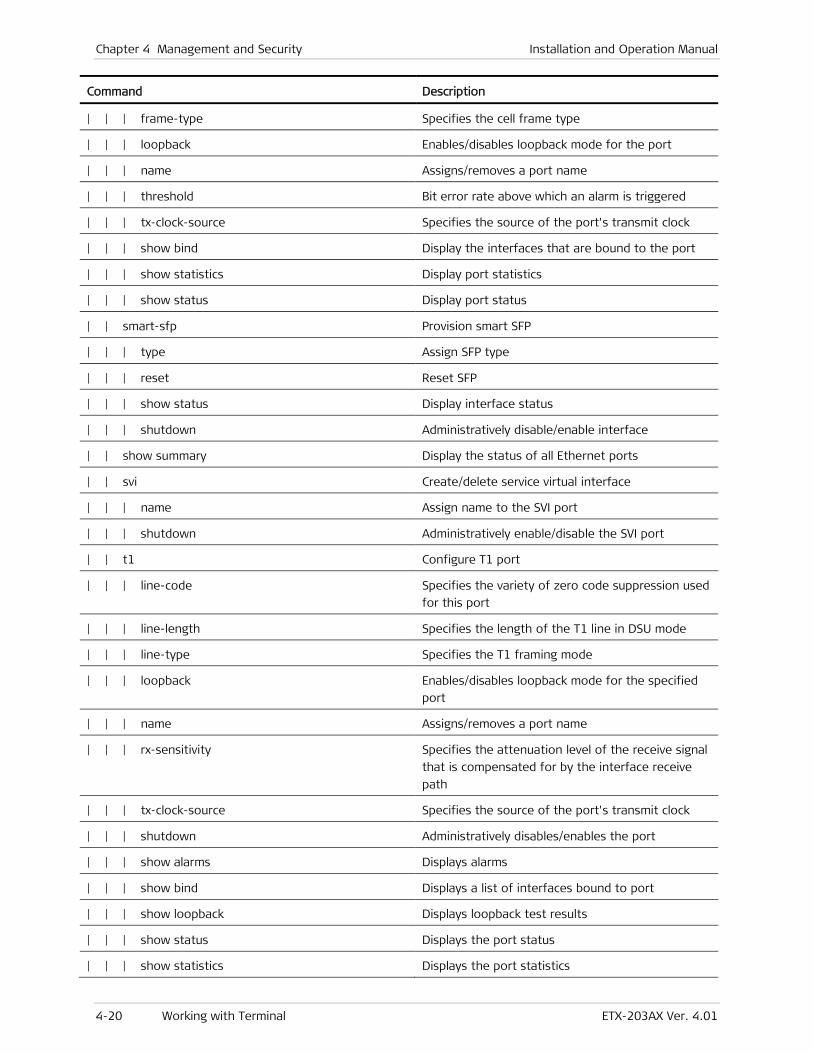
Chapter 4 Management and Security Installation and Operation Manual
4-20 Working with Terminal ETX-203AX Ver. 4.01
Command Description
| | | frame-type Specifies the cell frame type
| | | loopback Enables/disables loopback mode for the port
| | | name Assigns/removes a port name
| | | threshold Bit error rate above which an alarm is triggered
| | | tx-clock-source Specifies the source of the port's transmit clock
| | | show bind Display the interfaces that are bound to the port
| | | show statistics Display port statistics
| | | show status Display port status
| | smart-sfp Provision smart SFP
| | | type Assign SFP type
| | | reset Reset SFP
| | | show status Display interface status
| | | shutdown Administratively disable/enable interface
| | show summary Display the status of all Ethernet ports
| | svi Create/delete service virtual interface
| | | name Assign name to the SVI port
| | | shutdown Administratively enable/disable the SVI port
| | t1 Configure T1 port
| | | line-code Specifies the variety of zero code suppression used
for this port
| | | line-length Specifies the length of the T1 line in DSU mode
| | | line-type Specifies the T1 framing mode
| | | loopback Enables/disables loopback mode for the specified
port
| | | name Assigns/removes a port name
| | | rx-sensitivity Specifies the attenuation level of the receive signal
that is compensated for by the interface receive
path
| | | tx-clock-source Specifies the source of the port's transmit clock
| | | shutdown Administratively disables/enables the port
| | | show alarms Displays alarms
| | | show bind Displays a list of interfaces bound to port
| | | show loopback Displays loopback test results
| | | show status Displays the port status
| | | show statistics Displays the port statistics
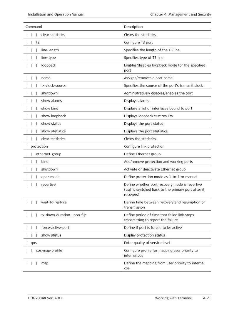
Installation and Operation Manual Chapter 4 Management and Security
ETX-203AX Ver. 4.01 Working with Terminal 4-21
Command Description
| | | clear-statistics Clears the statistics
| | t3 Configure T3 port
| | | line-length Specifies the length of the T3 line
| | | line-type Specifies type of T3 line
| | | loopback Enables/disables loopback mode for the specified
port
| | | name Assigns/removes a port name
| | | tx-clock-source Specifies the source of the port's transmit clock
| | | shutdown Administratively disables/enables the port
| | | show alarms Displays alarms
| | | show bind Displays a list of interfaces bound to port
| | | show loopback Displays loopback test results
| | | show status Displays the port status
| | | show statistics Displays the port statistics
| | | clear-statistics Clears the statistics
| protection Configure link protection
| | ethernet-group Define Ethernet group
| | | bind Add/remove protection and working ports
| | | shutdown Activate or deactivate Ethernet group
| | | oper-mode Define protection mode as 1-to-1 or manual
| | | revertive Define whether port recovery mode is revertive
(traffic switched back to the primary port after it
recovers)
| | | wait-to-restore Define time between recovery and resumption of
transmission
| | | tx-down-duration-upon-flip Define period of time that failed link stops
transmitting to report the failure
| | | force-active-port Define if port is forced to be active
| | | show status Display protection status
| qos Enter quality of service level
| | cos-map-profile Configure profile for mapping user priority to
internal cos
| | | map Define the mapping from user priority to internal
cos

Chapter 4 Management and Security Installation and Operation Manual
4-22 Working with Terminal ETX-203AX Ver. 4.01
Command Description
| | marking-profile Configure a marking profile to map the P-bit, IP
precedence, or DHCP classifications to the egress
priority tags
| | | mark Map the user priority to a priority marking value
| | policer-aggregate Configure policer aggregate that specifies a policer
profile to apply to a group of flows
| | | policer Define policer profile for the policer aggregate
| | | show statistics Display policer aggregate statistics
| | | show flows Display the flows corresponding to policer
aggregate
| | | clear-statistics Clear policer aggregate statistics
| | | rate-sampling-window Configure interval for rate sampling statistics
| | policer-profile Configure a policer profile
| | | bandwidth Define the bandwidth for the policer profile
| | | traffic-type Define the policed traffic type
| | | compensation Define how many bytes to compensate for layer 1
overhead
| | queue-block-profile Configure queue block profile
| | | queue Define queue
| | | | congestion-avoidance Define WRED profile (fixed, cannot be changed)
| | | | depth Define the queue length
| | | | scheduling Define the queue scheduling method
| | queue-group-profile Configure queue group profile
| | | queue-block Configure queue block
| | | | name Define the name of the queue block
| | | | profile Define the queue block profile for the queue block
| | | | bind Bind to next level block in specific queue
| | | | shaper Define the shaper profile for the queue block
| | queue-map-profile Define a queue map profile to map the P-bit, IP
precedence, or DSCP classifications to internal
priority queues (classes of service)
| | | map Define the mapping between the user priority and
the queue id
| | shaper-profile Configure shaper profile
| | | bandwidth Define the bandwidth for the shaper profile
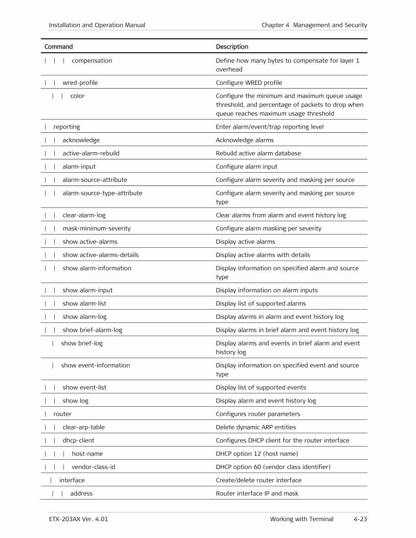
Installation and Operation Manual Chapter 4 Management and Security
ETX-203AX Ver. 4.01 Working with Terminal 4-23
Command Description
| | | compensation Define how many bytes to compensate for layer 1
overhead
| | wred-profile Configure WRED profile
| | color Configure the minimum and maximum queue usage
threshold, and percentage of packets to drop when
queue reaches maximum usage threshold
| reporting Enter alarm/event/trap reporting level
| | acknowledge Acknowledge alarms
| | active-alarm-rebuild Rebuild active alarm database
| | alarm-input Configure alarm input
| | alarm-source-attribute Configure alarm severity and masking per source
| | alarm-source-type-attribute Configure alarm severity and masking per source
type
| | clear-alarm-log Clear alarms from alarm and event history log
| | mask-minimum-severity Configure alarm masking per severity
| | show active-alarms Display active alarms
| | show active-alarms-details Display active alarms with details
| | show alarm-information Display information on specified alarm and source
type
| | show alarm-input Display information on alarm inputs
| | show alarm-list Display list of supported alarms
| | show alarm-log Display alarms in alarm and event history log
| | show brief-alarm-log Display alarms in brief alarm and event history log
| show brief-log Display alarms and events in brief alarm and event
history log
| show event-information Display information on specified event and source
type
| | show event-list Display list of supported events
| | show log Display alarm and event history log
| router Configures router parameters
| | clear-arp-table Delete dynamic ARP entities
| | dhcp-client Configures DHCP client for the router interface
| | | host-name DHCP option 12 (host name)
| | | vendor-class-id DHCP option 60 (vendor class identifier)
| interface Create/delete router interface
| | address Router interface IP and mask
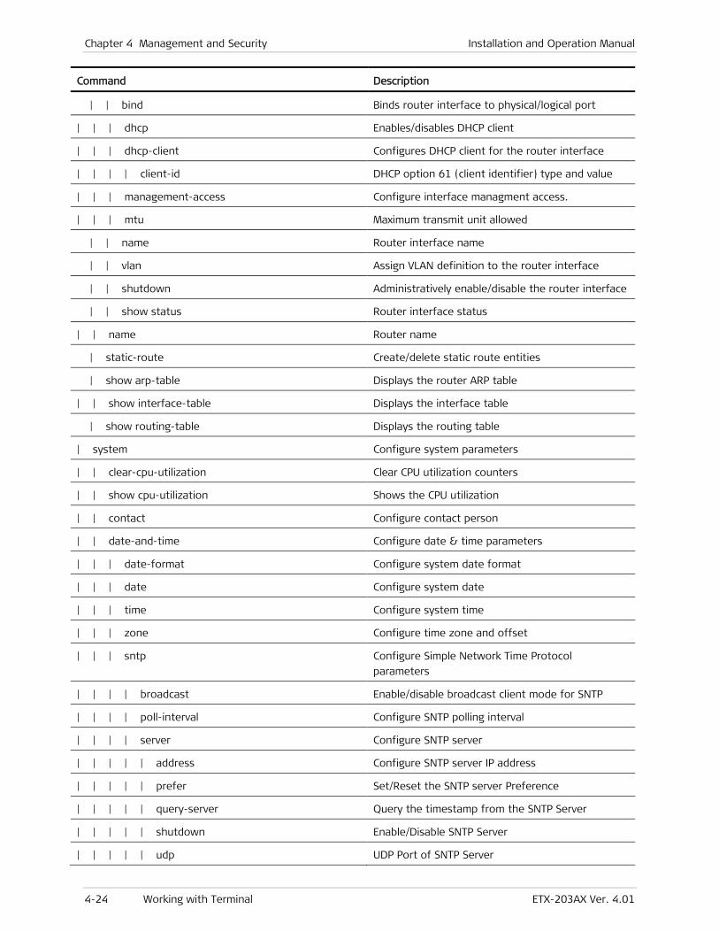
Chapter 4 Management and Security Installation and Operation Manual
4-24 Working with Terminal ETX-203AX Ver. 4.01
Command Description
| | bind Binds router interface to physical/logical port
| | | dhcp Enables/disables DHCP client
| | | dhcp-client Configures DHCP client for the router interface
| | | | client-id DHCP option 61 (client identifier) type and value
| | | management-access Configure interface managment access.
| | | mtu Maximum transmit unit allowed
| | name Router interface name
| | vlan Assign VLAN definition to the router interface
| | shutdown Administratively enable/disable the router interface
| | show status Router interface status
| | name Router name
| static-route Create/delete static route entities
| show arp-table Displays the router ARP table
| | show interface-table Displays the interface table
| show routing-table Displays the routing table
| system Configure system parameters
| | clear-cpu-utilization Clear CPU utilization counters
| | show cpu-utilization Shows the CPU utilization
| | contact Configure contact person
| | date-and-time Configure date & time parameters
| | | date-format Configure system date format
| | | date Configure system date
| | | time Configure system time
| | | zone Configure time zone and offset
| | | sntp Configure Simple Network Time Protocol
parameters
| | | | broadcast Enable/disable broadcast client mode for SNTP
| | | | poll-interval Configure SNTP polling interval
| | | | server Configure SNTP server
| | | | | address Configure SNTP server IP address
| | | | | prefer Set/Reset the SNTP server Preference
| | | | | query-server Query the timestamp from the SNTP Server
| | | | | shutdown Enable/Disable SNTP Server
| | | | | udp UDP Port of SNTP Server
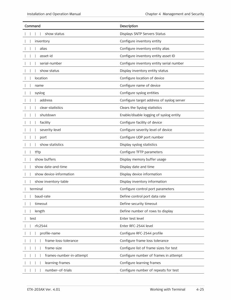
Installation and Operation Manual Chapter 4 Management and Security
ETX-203AX Ver. 4.01 Working with Terminal 4-25
Command Description
| | | | show status Displays SNTP Servers Status
| | inventory Configure inventory entity
| | | alias Configure inventory entity alias
| | | asset-id Configure inventory entity asset ID
| | | serial-number Configure inventory entity serial number
| | | show status Display inventory entity status
| | location Configure location of device
| | name Configure name of device
| | syslog Configure syslog entities
| | | address Configure target address of syslog server
| | | clear-statistics Clears the Syslog statistics
| | | shutdown Enable/disable logging of syslog entity
| | | facility Configure facility of device
| | | severity-level Configure severity level of device
| | | port Configure UDP port number
| | | show statistics Display syslog statistics
| | tftp Configure TFTP parameters
| | show buffers Display memory buffer usage
| | show date-and-time Display date and time
| | show device-information Display device information
| | show inventory-table Display inventory information
| terminal Configure control port parameters
| | baud-rate Define control port data rate
| | timeout Define security timeout
| | length Define number of rows to display
| test Enter test level
| | rfc2544 Enter RFC-2544 level
| | | profile-name Configure RFC-2544 profile
| | | | frame-loss-tolerance Configure frame loss tolerance
| | | | frame-size Configure list of frame sizes for test
| | | | frames-number-in-attempt Configure number of frames in attempt
| | | | learning-frames Configure learning frames
| | | | number–of-trials Configure number of repeats for test
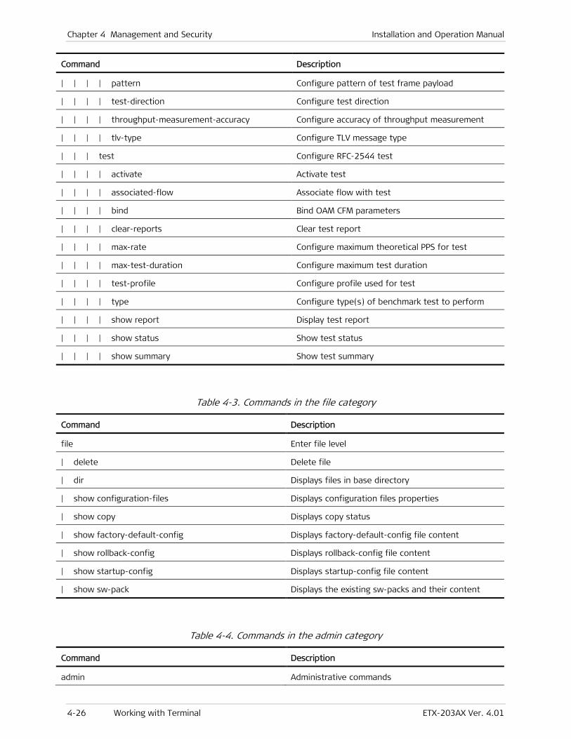
Chapter 4 Management and Security Installation and Operation Manual
4-26 Working with Terminal ETX-203AX Ver. 4.01
Command Description
| | | | pattern Configure pattern of test frame payload
| | | | test-direction Configure test direction
| | | | throughput-measurement-accuracy Configure accuracy of throughput measurement
| | | | tlv-type Configure TLV message type
| | | test Configure RFC-2544 test
| | | | activate Activate test
| | | | associated-flow Associate flow with test
| | | | bind Bind OAM CFM parameters
| | | | clear-reports Clear test report
| | | | max-rate Configure maximum theoretical PPS for test
| | | | max-test-duration Configure maximum test duration
| | | | test-profile Configure profile used for test
| | | | type Configure type(s) of benchmark test to perform
| | | | show report Display test report
| | | | show status Show test status
| | | | show summary Show test summary
Table 4-3. Commands in the file category
Command Description
file Enter file level
| delete Delete file
| dir Displays files in base directory
| show configuration-files Displays configuration files properties
| show copy Displays copy status
| show factory-default-config Displays factory-default-config file content
| show rollback-config Displays rollback-config file content
| show startup-config Displays startup-config file content
| show sw-pack Displays the existing sw-packs and their content
Table 4-4. Commands in the admin category
Command Description
admin Administrative commands
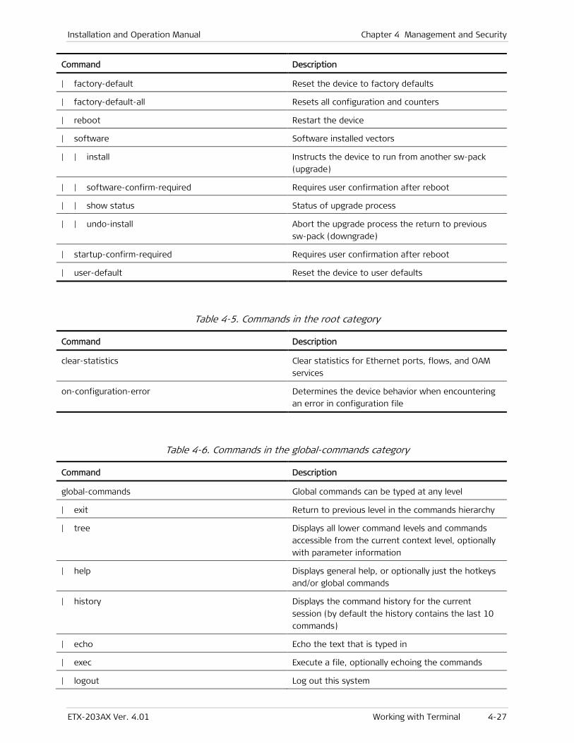
Installation and Operation Manual Chapter 4 Management and Security
ETX-203AX Ver. 4.01 Working with Terminal 4-27
Command Description
| factory-default Reset the device to factory defaults
| factory-default-all Resets all configuration and counters
| reboot Restart the device
| software Software installed vectors
| | install Instructs the device to run from another sw-pack
(upgrade)
| | software-confirm-required Requires user confirmation after reboot
| | show status Status of upgrade process
| | undo-install Abort the upgrade process the return to previous
sw-pack (downgrade)
| startup-confirm-required Requires user confirmation after reboot
| user-default Reset the device to user defaults
Table 4-5. Commands in the root category
Command Description
clear-statistics Clear statistics for Ethernet ports, flows, and OAM
services
on-configuration-error Determines the device behavior when encountering
an error in configuration file
Table 4-6. Commands in the global-commands category
Command Description
global-commands Global commands can be typed at any level
| exit Return to previous level in the commands hierarchy
| tree Displays all lower command levels and commands
accessible from the current context level, optionally
with parameter information
| help Displays general help, or optionally just the hotkeys
and/or global commands
| history Displays the command history for the current
session (by default the history contains the last 10
commands)
| echo Echo the text that is typed in
| exec Execute a file, optionally echoing the commands
| logout Log out this system
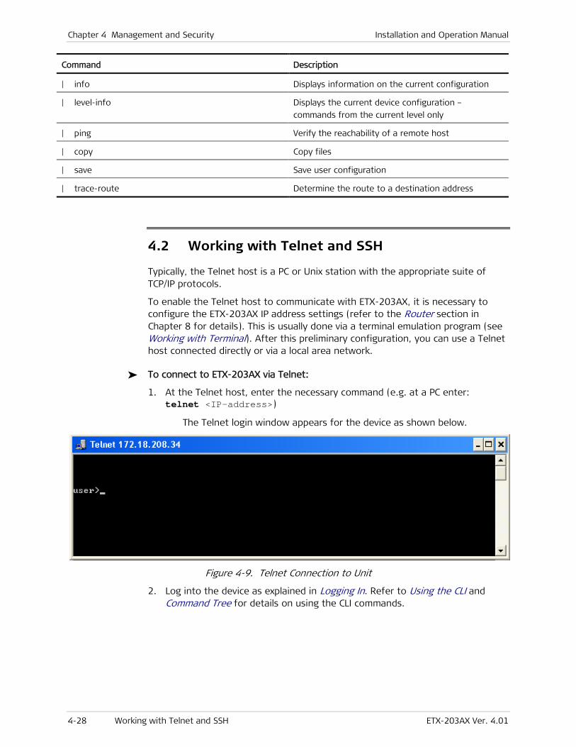
Chapter 4 Management and Security Installation and Operation Manual
4-28 Working with Telnet and SSH ETX-203AX Ver. 4.01
Command Description
| info Displays information on the current configuration
| level-info Displays the current device configuration –
commands from the current level only
| ping Verify the reachability of a remote host
| copy Copy files
| save Save user configuration
| trace-route Determine the route to a destination address
4.2 Working with Telnet and SSH
Typically, the Telnet host is a PC or Unix station with the appropriate suite of TCP/IP protocols.
To enable the Telnet host to communicate with ETX-203AX, it is necessary to configure the ETX-203AX IP address settings (refer to the Router section in Chapter 8 for details). This is usually done via a terminal emulation program (see Working with Terminal). After this preliminary configuration, you can use a Telnet host connected directly or via a local area network.
To connect to ETX-203AX via Telnet:
1. At the Telnet host, enter the necessary command (e.g. at a PC enter: telnet <IP-address>)
The Telnet login window appears for the device as shown below.
Figure 4-9. Telnet Connection to Unit
2. Log into the device as explained in Logging In. Refer to Using the CLI and Command Tree for details on using the CLI commands.
Installation and Operation Manual Chapter 4 Management and Security
ETX-203AX Ver. 4.01 SNMP Management 4-29
4.3 Working with Third-Party Network Management Systems
ETX-203AX can be integrated into third-party network management systems at the following levels:
• Viewing device inventory and receiving traps (see Chapter 11 for trap list)
• Managing device, including configuration, statistics collection, and diagnostics, using the following standard and private MIBs:
CFM MIB (IEEE8021-CFM-MIB)
IANAifType-MIB
IETF Syslog Device MIB
IEEE8023-LAG-MIB
MEF-R MIB
RAD private MIB
RFC 2819 (RMON-MIB)
RFC 2863 (IF-MIB)
RFC 3273 (Remote Network Monitoring MIB)
RFC 3411 (SNMP-FRAMEWORK-MIB)
RFC 3413 (SNMP-TARGET-MIB)
RFC 3414 (SNMP-USER-BASED-SM-MIB)
RFC 3415 (SNMP-VIEW-BASED-ACM-MIB)
RFC 3418 (SNMPv2-MIB)
RFC 3433 (ENTITY-SENSOR-MIB)
RFC 3636 (MAU-MIB)
RFC 4133 (ENTITY-MIB)
RFC 4668 (RADIUS-AUTH-CLIENT-MIB)
RFC 4836.MIB (MAU-MIB)
RFC 4878.MIB (DOT3-OAM-MIB).
4.4 SNMP Management
SNMP stands for Simple Network Management Protocol and is an application layer protocol that provides a message format for communication between managers and agents.
ETX-203AX supports SNMPv3, the latest SNMP version to date. SNMPv3 provides secure access to devices in the network by using authentication and data encryption.
Chapter 4 Management and Security Installation and Operation Manual
4-30 SNMP Management ETX-203AX Ver. 4.01
Standards
The supported SNMP versions are based on the following standards:
• RFC 1901, Introduction to Community-Based SNMPv2. SNMPv2 Working Group.
• RFC 1902, Structure of Management Information for Version 2 of the Simple Network Management Protocol (SNMPv2). SNMPv2 Working Group.
• RFC 1903, Textual Conventions for Version 2 of the Simple Network Management Protocol (SNMPv2). SNMPv2 Working Group.
• RFC 1904, Conformance Statements for Version 2 of the Simple Network Management Protocol (SNMPv2). SNMPv2 Working Group.
• RFC 1905, Protocol Operations for Version 2 of the Simple Network Management Protocol (SNMPv2). SNMPv2 Working Group.
• RFC 1906, Transport Mappings for Version 2 of the Simple Network Management Protocol (SNMPv2).
• RFC 1907, Management Information Base for Version 2 of the Simple Network Management Protocol (SNMPv2). SNMPv2 Working Group.
• RFC 1908, Coexistence between Version 1 and Version 2 of the Internet-standard Network Management Framework. SNMPv2 Working Group.
• RFC 2104, Keyed Hashing for Message Authentication.
• RFC 2271, Architecture for Describing SNMP Management Frameworks.
• RFC 2272, message processing and dispatching for the Simple Network Management Protocol (SNMP).
• RFC 2273, SNMPv3 Applications.
• RFC 2274, User-Based Security Model (USM) for version 3 of the Simple Network Management Protocol (SNMPv3).
• RFC 2275, View-Based Access Control Model (VACM) for the Simple Network Management Protocol (SNMP).
• RFC 3412, Version 3 Message Processing and Dispatching.
• RFC 3414, User-based Security Model for SNMPv3
• RFC 3416, Update for RFC 1904.
Benefits
The SNMP protocol allows you to remotely manage multiple units from a central workstation using a network management system.
The SNMPv3 protocol allows data to be collected securely from SNMP devices. Confidential information such as SNMP commands can thus be encrypted to prevent unauthorized parties from being able to access them.
Installation and Operation Manual Chapter 4 Management and Security
ETX-203AX Ver. 4.01 SNMP Management 4-31
Functional Description
In an SNMP configuration, one or more administrative computers manage a group of hosts or devices. Each managed system continuously executes a software component called agent, which reports information via SNMP back to the managing workstations.
Factory Defaults
The following is the default configuration of the SNMP parameters (refer to Configuring SNMPv3 Parameters for explanations of the parameters):
• SNMP engine ID set to device MAC address
• View named “internet” providing access to IETF MIBs and IEEE MIBs
• User named "initial", with security level no authentication and no privacy
• Group for SNMPv3 named "initial":
Security levels: no authentication and no privacy, authentication and no privacy, authentication and privacy
User: “initial”
Views for read/write/notify: "internet".
• Notifications with tag “unmasked” for the device traps.
Configuring SNMPv3 Parameters
ETX-203AX supports SNMP version 3, providing secure SNMP access to the device by authenticating and encrypting packets transmitted over the network.
The SNMPv3 manager application in RADview-EMS provides a user-friendly GUI interface to configure SNMPv3 parameters. If you intend to use it, you must first use the device CLI to create users with the required encryption method and security level, as the application can create users based only on existing users; the new user has the same encryption method, and the same security level or lower. The ETX-203AX default configuration provides one standard user named “initial” with no encryption and the lowest security level (refer to Factory Defaults for details).
Follow this procedure to configure SNMPv3:
1. Set SNMP engine ID if necessary
1. Add users, specifying authentication protocol and privacy protocol
2. Add groups, specifying security level, protocol, and views
3. Connect users to groups
4. Add notification entries with assigned traps and tags
5. Configure target parameter sets to be used for targets
6. Configure targets (SNMPv3 network management stations to which ETX-203AX should send trap notifications), specifying target parameter sets,

Chapter 4 Management and Security Installation and Operation Manual
4-32 SNMP Management ETX-203AX Ver. 4.01
notification tags, and trap synchronization groups if applicableTo configure SNMPv3 parameters:
1. Navigate to configure management snmp.
The config>mngmnt>snmp# prompt is displayed.
2. Enter all necessary commands according to the tasks listed below.
When you enter password parameters, they should contain at least eight characters.
Task Command Level Comments
Configuring group access-group <group-name> {
snmpv2c | usm }
{ no-auth-no-priv | auth-no-priv | auth-priv }
snmp Using no access-group
deletes the group
Defining how to
match the context
sent in frames by
the NMS
context-match {exact | prefix} snmp>access-group exact – Match the entire
context
prefix – Match the first part
of the context.
Note: ETX-203AX automatically identifies the NMS context, therefore you can configure exact match. Normally prefix is used for devices with multiple instances.
Setting view for
traps notify-view <name> snmp>access-group Refer to the description of
the view command for
information on how to limit
the parts of the MIB
hierarchy that the view can
access
Setting view with
read-only access read-view <name> snmp>access-group
Setting view with
write access write-view <name> snmp>access-group
Administratively
enabling group no shutdown snmp>access-group Using shutdown disables the
group
Configuring
community community <community-index> snmp
Configuring name name <community-string> snmp>community
Configuring security
name sec-name <security-name> snmp>community
Configuring
transport tag tag <transport-tag> snmp>community This should normally be left
set to the default value
Administratively
enabling community no shutdown snmp>community Using shutdown disables
community
Configuring
notification notify <notify-name> snmp>
Note
Note
Installation and Operation Manual Chapter 4 Management and Security
ETX-203AX Ver. 4.01 SNMP Management 4-33
Task Command Level Comments
Assigning trap to
notification bind {authenticationFailure |
systemDeviceTemperatureOra |
systemSoftwareInstallEnd |
systemAlternateConfigLoaded |
systemDyingGasp | systemDeviceStartup |
systemSwUnconfirmed | fanFailure |
systemSuccessfulLogin | systemFailedLogin |
systemLogout | powerDeliveryFailure |
systemTrapHardSyncStart |
systemTrapHardSyncEnd | systemUserReset |
smartSfpMismatch | systemRfc2544TestStart |
systemRfc2544TestEnd | stationClockLos |
epsConfigurationMismatch | epsPortSwitchover
| sfpRemoved | ethLos |
oamEfmRemoteLoopback |
oamEfmRemoteLoopbackOff |
oamEfmLinkFaultIndication |
oamEfmFeLinkFaultIndication |
oamEfmCriticalLinkIndication |
oamEfmFeCriticalLinkIndication |
oamEfmDyingGaspIndication |
oamEfmFeDyingGaspIndication | sdhSonetLos |
e3t3Los | e1t1Los | systemDownloadEnd |
oamCfmMepAis | oamCfmMepLck |
oamCfmMepMismatch | oamCfmRmepLoc |
oamCfmRmepRdi | oamCfmDestNeDelayTca |
oamCfmDestNeDelayTcaOff |
oamCfmDestNeDelayVarTca |
oamCfmDestNeDelayVarTcaOff |
oamCfmDestNeLossRatioTca |
oamCfmDestNeLossRatioTcaOff |
oamCfmDestNeLossRatioTcaFe |
oamCfmDestNeLossRatioTcaFeOff |
oamCfmDestNeUnavailableRatioTca |
oamCfmDestNeUnavailableRatioTcaOff |
oamCfmDestNeUnavailableRatioTcaFe |
oamCfmDestNeUnavailableRatioTcaFeOff}
snmp>notify You can assign more than
one trap to a notification, in
separate commands
Assigning tag to
notification, to be
used to identify the
notification entry
when configuring
target
tag <tag-value> snmp>notify
Administratively
enabling
notification
no shutdown snmp>notify
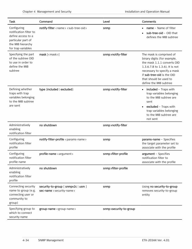
Chapter 4 Management and Security Installation and Operation Manual
4-34 SNMP Management ETX-203AX Ver. 4.01
Task Command Level Comments
Configuring
notification filter to
define access to a
particular part of
the MIB hierarchy
for trap variables
notify-filter <name> <sub-tree-oid> snmp • name – Name of filter
• sub-tree-oid – OID that
defines the MIB subtree
Specifying the part
of the subtree OID
to use in order to
define the MIB
subtree
mask [<mask>] snmp>notify-filter The mask is comprised of
binary digits (for example,
the mask 1.1.1 converts OID
1.3.6.7.8 to 1.3.6). It is not
necessary to specify a mask
if sub-tree-oid is the OID
that should be used to
define the MIB subtree
Defining whether
traps with trap
variables belonging
to the MIB subtree
are sent
type {included | excluded} snmp>notify-filter • included – Traps with
trap variables belonging
to the MIB subtree are
sent
• excluded – Traps with
trap variables belonging
to the MIB subtree are
not sent
Administratively
enabling
notification filter
no shutdown snmp>notify-filter
Configuring
notification filter
profile
notify-filter-profile <params-name> snmp params-name – Specifies
the target parameter set to
associate with the profile
Configuring
notification filter
profile name
profile-name <argument> snmp>filter-profile argument – Specifies
notification filter to
associate with the profile
Administratively
enabling
notification filter
profile
no shutdown snmp>filter-profile
Connecting security
name to group (e.g.
connecting user or
community to
group)
security-to-group { snmpv2c | usm }
sec-name <security-name>
snmp Using no security-to-group
removes security-to-group
entity
Specifying group to
which to connect
security name
group-name <group-name> snmp>security-to-group

Installation and Operation Manual Chapter 4 Management and Security
ETX-203AX Ver. 4.01 SNMP Management 4-35
Task Command Level Comments
Administratively
enabling
security-to-group
entity
no shutdown snmp>security-to-group Using shutdown disables the
security-to-group entity
Setting SNMP
engine ID, as MAC
address or IP
address or string
snmp-engine-id mac [ <mac-address> ]
snmp-engine-id ipv4 [ <ip-address> ]
snmp-engine-id text <string>
snmp If you use the mac option
and don’t specify the MAC
address, the SNMP engine ID
is set to the device MAC
address
If you use the ipv4 option
and don’t specify the IP
address, the SNMP engine ID
is set to the device IP
address
Configuring target
(SNMPv3 network
manager)
target <target-name> snmp Using no target removes
target
Specifying target
address as IP
address or OAM
port
address udp-domain <ip-address>
address oam-domain <oam-port>
snmp>target
Assigning tag(s) to
target (the tag(s)
must be defined in
notification entries)
tag-list <tag>
tag-list [ <tag> ]
tag-list [ <tag1>,<tag2>,…<tagn> ]
snmp>target If you specify more than one
tag, you must enclose the
list with square brackets,
however if you are
specifying just one tag the
brackets are optional
Specifying set of
target parameters
for target
target-params <params-name> snmp>target
Specifying trap
synchronization
group
trap-sync-group <group-id>
[import-trap-masking]
snmp>target • If the group does not
exist, it is created
• If you specify the
import-trap-masking
parameter, the
manager’s trap masking
is imported from the first
manager in the group
• Enter no trap-sync-group
<group-id> to remove
the manager from the
group. If the manager
was the last in the
group, the group is
deleted.

Chapter 4 Management and Security Installation and Operation Manual
4-36 SNMP Management ETX-203AX Ver. 4.01
Task Command Level Comments
Administratively
enabling target no shutdown snmp>target Using shutdown disables
target
Configuring set of
target parameters,
to be assigned to
target
target-params <target-param-name> snmp Using no target-params
removes target parameters
Specifying message
processing model
(SNMP version) to
be used when
generating SNMP
messages for the
set of target
parameters
message-processing-model
{ snmpv2c | snmpv3 }
snmp>target
Specifying user on
whose behalf SNMP
messages are to be
generated for the
set of target
parameters
security [ name <security-name> ]
[ level { no-auth-no-priv | auth-no-priv
| auth-priv } ]
snmp>target
Specifying SNMP
version to be used
when generating
SNMP messages for
the set of target
parameters
version { snmpv2c | usm } snmp>target Use usm for SNMPv3 version
Administratively
enabling target
parameters
no shutdown snmp>target Using shutdown disables
target parameters
Configuring target
parameters and
tags for trap
synchronization
group
trap-sync-group <group-id> snmp The trap synchronization
group must be previously
defined in the target level
Specifying tags tag-list <list> snmp>trap-sync-group To remove the tag list,
enter: no tag-list
Specifying set of
target parameters target-params <params-name> snmp>trap-sync-group To remove the set of target
parameters, enter: no
target-params <params-name>
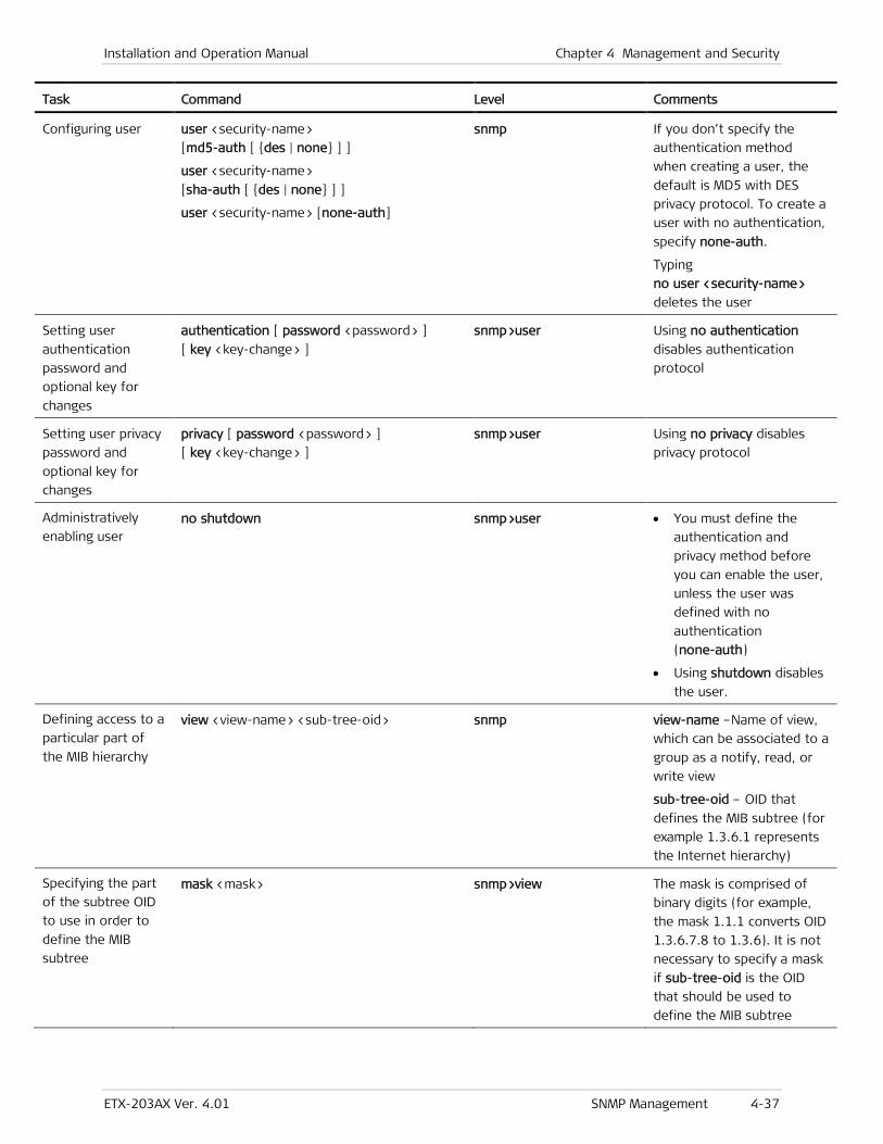
Installation and Operation Manual Chapter 4 Management and Security
ETX-203AX Ver. 4.01 SNMP Management 4-37
Task Command Level Comments
Configuring user user <security-name>
[md5-auth [ {des | none} ] ]
user <security-name>
[sha-auth [ {des | none} ] ]
user <security-name> [none-auth]
snmp If you don’t specify the
authentication method
when creating a user, the
default is MD5 with DES
privacy protocol. To create a
user with no authentication,
specify none-auth.
Typing
no user <security-name>
deletes the user
Setting user
authentication
password and
optional key for
changes
authentication [ password <password> ]
[ key <key-change> ]
snmp>user Using no authentication disables authentication
protocol
Setting user privacy
password and
optional key for
changes
privacy [ password <password> ]
[ key <key-change> ]
snmp>user Using no privacy disables
privacy protocol
Administratively
enabling user no shutdown snmp>user • You must define the
authentication and
privacy method before
you can enable the user,
unless the user was
defined with no
authentication
(none-auth)
• Using shutdown disables
the user.
Defining access to a
particular part of
the MIB hierarchy
view <view-name> <sub-tree-oid> snmp view-name –Name of view,
which can be associated to a
group as a notify, read, or
write view
sub-tree-oid – OID that
defines the MIB subtree (for
example 1.3.6.1 represents
the Internet hierarchy)
Specifying the part
of the subtree OID
to use in order to
define the MIB
subtree
mask <mask> snmp>view The mask is comprised of
binary digits (for example,
the mask 1.1.1 converts OID
1.3.6.7.8 to 1.3.6). It is not
necessary to specify a mask
if sub-tree-oid is the OID
that should be used to
define the MIB subtree
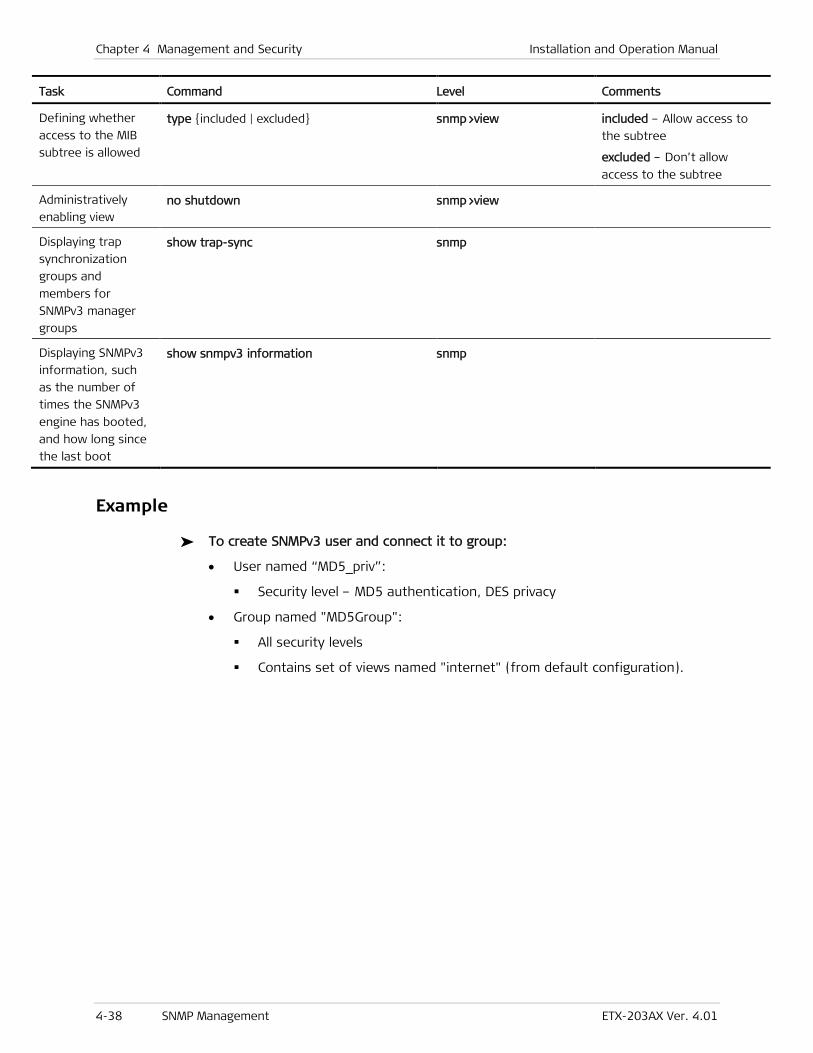
Chapter 4 Management and Security Installation and Operation Manual
4-38 SNMP Management ETX-203AX Ver. 4.01
Task Command Level Comments
Defining whether
access to the MIB
subtree is allowed
type {included | excluded} snmp>view included – Allow access to
the subtree
excluded – Don’t allow
access to the subtree
Administratively
enabling view no shutdown snmp>view
Displaying trap
synchronization
groups and
members for
SNMPv3 manager
groups
show trap-sync snmp
Displaying SNMPv3
information, such
as the number of
times the SNMPv3
engine has booted,
and how long since
the last boot
show snmpv3 information snmp
Example
To create SNMPv3 user and connect it to group:
• User named “MD5_priv”:
Security level – MD5 authentication, DES privacy
• Group named "MD5Group":
All security levels
Contains set of views named "internet" (from default configuration).
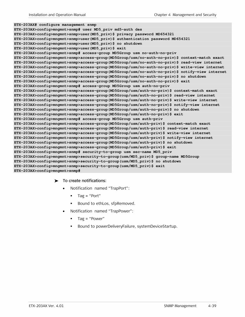
Installation and Operation Manual Chapter 4 Management and Security
ETX-203AX Ver. 4.01 SNMP Management 4-39
ETX-203AX# configure management snmp ETX-203AX>config>mngmnt>snmp# user MD5_priv md5-auth des ETX-203AX>config>mngmnt>snmp>user(MD5_priv)$ privacy password MD654321 ETX-203AX>config>mngmnt>snmp>user(MD5_priv)$ authentication password MD654321 ETX-203AX>config>mngmnt>snmp>user(MD5_priv)$ no shutdown ETX-203AX>config>mngmnt>snmp>user(MD5_priv)$ exit ETX-203AX>config>mngmnt>snmp# access-group MD5Group usm no-auth-no-priv ETX-203AX>config>mngmnt>snmp>access-group(MD5Group/usm/no-auth-no-priv)$ context-match exact ETX-203AX>config>mngmnt>snmp>access-group(MD5Group/usm/no-auth-no-priv)$ read-view internet ETX-203AX>config>mngmnt>snmp>access-group(MD5Group/usm/no-auth-no-priv)$ write-view internet ETX-203AX>config>mngmnt>snmp>access-group(MD5Group/usm/no-auth-no-priv)$ notify-view internet ETX-203AX>config>mngmnt>snmp>access-group(MD5Group/usm/no-auth-no-priv)$ no shutdown ETX-203AX>config>mngmnt>snmp>access-group(MD5Group/usm/no-auth-no-priv)$ exit ETX-203AX>config>mngmnt>snmp# access-group MD5Group usm auth-no-priv ETX-203AX>config>mngmnt>snmp>access-group(MD5Group/usm/auth-no-priv)$ context-match exact ETX-203AX>config>mngmnt>snmp>access-group(MD5Group/usm/auth-no-priv)$ read-view internet ETX-203AX>config>mngmnt>snmp>access-group(MD5Group/usm/auth-no-priv)$ write-view internet ETX-203AX>config>mngmnt>snmp>access-group(MD5Group/usm/auth-no-priv)$ notify-view internet ETX-203AX>config>mngmnt>snmp>access-group(MD5Group/usm/auth-no-priv)$ no shutdown ETX-203AX>config>mngmnt>snmp>access-group(MD5Group/usm/auth-no-priv)$ exit ETX-203AX>config>mngmnt>snmp# access-group MD5Group usm auth-priv ETX-203AX>config>mngmnt>snmp>access-group(MD5Group/usm/auth-priv)$ context-match exact ETX-203AX>config>mngmnt>snmp>access-group(MD5Group/usm/auth-priv)$ read-view internet ETX-203AX>config>mngmnt>snmp>access-group(MD5Group/usm/auth-priv)$ write-view internet ETX-203AX>config>mngmnt>snmp>access-group(MD5Group/usm/auth-priv)$ notify-view internet ETX-203AX>config>mngmnt>snmp>access-group(MD5Group/usm/auth-priv)$ no shutdown ETX-203AX>config>mngmnt>snmp>access-group(MD5Group/usm/auth-priv)$ exit ETX-203AX>config>mngmnt>snmp# security-to-group usm sec-name MD5_priv ETX-203AX>config>mngmnt>snmp>security-to-group(usm/MD5_priv)$ group-name MD5Group ETX-203AX>config>mngmnt>snmp>security-to-group(usm/MD5_priv)$ no shutdown ETX-203AX>config>mngmnt>snmp>security-to-group(usm/MD5_priv)$ exit ETX-203AX>config>mngmnt>snmp#
To create notifications:
• Notification named “TrapPort”:
Tag = “Port”
Bound to ethLos, sfpRemoved.
• Notification named “TrapPower”:
Tag = “Power”
Bound to powerDeliveryFailure, systemDeviceStartup.
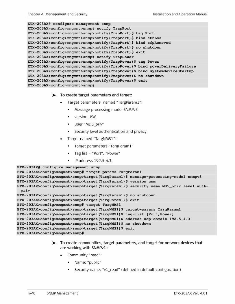
Chapter 4 Management and Security Installation and Operation Manual
4-40 SNMP Management ETX-203AX Ver. 4.01
ETX-203AX# configure management snmp ETX-203AX>config>mngmnt>snmp# notify TrapPort ETX-203AX>config>mngmnt>snmp>notify(TrapPort)$ tag Port ETX-203AX>config>mngmnt>snmp>notify(TrapPort)$ bind ethLos ETX-203AX>config>mngmnt>snmp>notify(TrapPort)$ bind sfpRemoved ETX-203AX>config>mngmnt>snmp>notify(TrapPort)$ no shutdown ETX-203AX>config>mngmnt>snmp>notify(TrapPort)$ exit ETX-203AX>config>mngmnt>snmp# notify TrapPower ETX-203AX>config>mngmnt>snmp>notify(TrapPower)$ tag Power ETX-203AX>config>mngmnt>snmp>notify(TrapPower)$ bind powerDeliveryFailure ETX-203AX>config>mngmnt>snmp>notify(TrapPower)$ bind systemDeviceStartup ETX-203AX>config>mngmnt>snmp>notify(TrapPower)$ no shutdown ETX-203AX>config>mngmnt>snmp>notify(TrapPower)$ exit ETX-203AX>config>mngmnt>snmp#
To create target parameters and target:
• Target parameters named “TargParam1”:
Message processing model SNMPv3
version USM
User “MD5_priv”
Security level authentication and privacy
• Target named “TargNMS1”:
Target parameters “TargParam1”
Tag list = “Port”, “Power”
IP address 192.5.4.3.
ETX-203AX# configure management snmp ETX-203AX>config>mngmnt>snmp# target-params TargParam1 ETX-203AX>config>mngmnt>snmp>target(TargParam1)$ message-processing-model snmpv3 ETX-203AX>config>mngmnt>snmp>target(TargParam1)$ version usm ETX-203AX>config>mngmnt>snmp>target(TargParam1)$ security name MD5_priv level auth-priv
ETX-203AX>config>mngmnt>snmp>target(TargParam1)$ no shutdown ETX-203AX>config>mngmnt>snmp>target(TargParam1)$ exit ETX-203AX>config>mngmnt>snmp# target TargNMS1 ETX-203AX>config>mngmnt>snmp>target(TargNMS1)$ target-params TargParam1 ETX-203AX>config>mngmnt>snmp>target(TargNMS1)$ tag-list [Port,Power] ETX-203AX>config>mngmnt>snmp>target(TargNMS1)$ address udp-domain 192.5.4.3 ETX-203AX>config>mngmnt>snmp>target(TargNMS1)$ no shutdown ETX-203AX>config>mngmnt>snmp>target(TargNMS1)$ exit ETX-203AX>config>mngmnt>snmp#
To create communities, target parameters, and target for network devices that are working with SNMPv1 :
• Community “read”:
Name: “public”
Security name: “v1_read” (defined in default configuration)
Installation and Operation Manual Chapter 4 Management and Security
ETX-203AX Ver. 4.01 SNMP Management 4-41
• Community “write”:
Name: “private”
Security name: “v1_write” (defined in default configuration)
• Community “trap”:
Name: “public”
Security name: “v1_trap” (defined in default configuration)
• Target parameters named “snv1”:
Message processing model SNMPv1
Version SNMPv1
Security name: “v1_trap”
Security: level no authentication and no privacy
• Target named “NMSsnmpv1”:
Target parameters “snv1”
Tag list = “unmasked”
IP address 192.5.6.7.
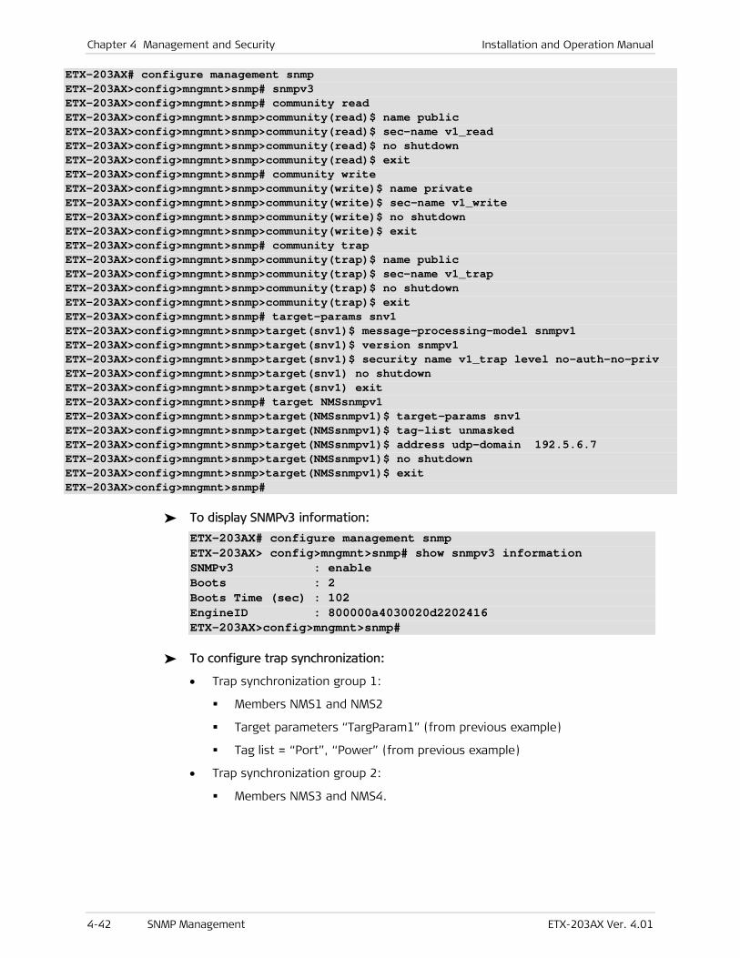
Chapter 4 Management and Security Installation and Operation Manual
4-42 SNMP Management ETX-203AX Ver. 4.01
ETX-203AX# configure management snmp ETX-203AX>config>mngmnt>snmp# snmpv3 ETX-203AX>config>mngmnt>snmp# community read ETX-203AX>config>mngmnt>snmp>community(read)$ name public ETX-203AX>config>mngmnt>snmp>community(read)$ sec-name v1_read ETX-203AX>config>mngmnt>snmp>community(read)$ no shutdown ETX-203AX>config>mngmnt>snmp>community(read)$ exit ETX-203AX>config>mngmnt>snmp# community write ETX-203AX>config>mngmnt>snmp>community(write)$ name private ETX-203AX>config>mngmnt>snmp>community(write)$ sec-name v1_write ETX-203AX>config>mngmnt>snmp>community(write)$ no shutdown ETX-203AX>config>mngmnt>snmp>community(write)$ exit ETX-203AX>config>mngmnt>snmp# community trap ETX-203AX>config>mngmnt>snmp>community(trap)$ name public ETX-203AX>config>mngmnt>snmp>community(trap)$ sec-name v1_trap ETX-203AX>config>mngmnt>snmp>community(trap)$ no shutdown ETX-203AX>config>mngmnt>snmp>community(trap)$ exit ETX-203AX>config>mngmnt>snmp# target-params snv1 ETX-203AX>config>mngmnt>snmp>target(snv1)$ message-processing-model snmpv1 ETX-203AX>config>mngmnt>snmp>target(snv1)$ version snmpv1 ETX-203AX>config>mngmnt>snmp>target(snv1)$ security name v1_trap level no-auth-no-priv ETX-203AX>config>mngmnt>snmp>target(snv1) no shutdown ETX-203AX>config>mngmnt>snmp>target(snv1) exit ETX-203AX>config>mngmnt>snmp# target NMSsnmpv1 ETX-203AX>config>mngmnt>snmp>target(NMSsnmpv1)$ target-params snv1 ETX-203AX>config>mngmnt>snmp>target(NMSsnmpv1)$ tag-list unmasked ETX-203AX>config>mngmnt>snmp>target(NMSsnmpv1)$ address udp-domain 192.5.6.7 ETX-203AX>config>mngmnt>snmp>target(NMSsnmpv1)$ no shutdown ETX-203AX>config>mngmnt>snmp>target(NMSsnmpv1)$ exit ETX-203AX>config>mngmnt>snmp#
To display SNMPv3 information:
ETX-203AX# configure management snmp ETX-203AX> config>mngmnt>snmp# show snmpv3 information SNMPv3 : enable Boots : 2 Boots Time (sec) : 102 EngineID : 800000a4030020d2202416 ETX-203AX>config>mngmnt>snmp#
To configure trap synchronization:
• Trap synchronization group 1:
Members NMS1 and NMS2
Target parameters “TargParam1” (from previous example)
Tag list = “Port”, “Power” (from previous example)
• Trap synchronization group 2:
Members NMS3 and NMS4.
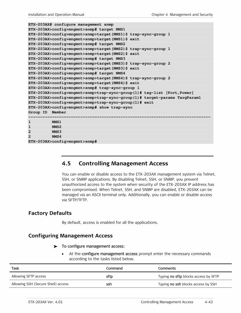
Installation and Operation Manual Chapter 4 Management and Security
ETX-203AX Ver. 4.01 Controlling Management Access 4-43
ETX-203AX# configure management snmp ETX-203AX>config>mngmnt>snmp# target NMS1 ETX-203AX>config>mngmnt>snmp>target(NMS1)$ trap-sync-group 1 ETX-203AX>config>mngmnt>snmp>target(NMS1)$ exit ETX-203AX>config>mngmnt>snmp# target NMS2 ETX-203AX>config>mngmnt>snmp>target(NMS2)$ trap-sync-group 1 ETX-203AX>config>mngmnt>snmp>target(NMS2)$ exit ETX-203AX>config>mngmnt>snmp# target NMS3 ETX-203AX>config>mngmnt>snmp>target(NMS3)$ trap-sync-group 2 ETX-203AX>config>mngmnt>snmp>target(NMS3)$ exit ETX-203AX>config>mngmnt>snmp# target NMS4 ETX-203AX>config>mngmnt>snmp>target(NMS4)$ trap-sync-group 2 ETX-203AX>config>mngmnt>snmp>target(NMS4)$ exit ETX-203AX>config>mngmnt>snmp# trap-sync-group 1 ETX-203AX>config>mngmnt>snmp>trap-sync-group(1)# tag-list [Port,Power] ETX-203AX>config>mngmnt>snmp>trap-sync-group(1)# target-params TargParam1 ETX-203AX>config>mngmnt>snmp>trap-sync-group(1)# exit ETX-203AX>config>mngmnt>snmp# show trap-sync Group ID Member ----------------------------------------------------------------------------- 1 NMS1 1 NMS2 2 NMS3 2 NMS4 ETX-203AX>config>mngmnt>snmp#
4.5 Controlling Management Access
You can enable or disable access to the ETX-203AX management system via Telnet, SSH, or SNMP applications. By disabling Telnet, SSH, or SNMP, you prevent unauthorized access to the system when security of the ETX-203AX IP address has been compromised. When Telnet, SSH, and SNMP are disabled, ETX-203AX can be managed via an ASCII terminal only. Additionally, you can enable or disable access via SFTP/TFTP.
Factory Defaults
By default, access is enabled for all the applications.
Configuring Management Access
To configure management access:
• At the configure management access prompt enter the necessary commands according to the tasks listed below.
Task Command Comments
Allowing SFTP access sftp Typing no sftp blocks access by SFTP
Allowing SSH (Secure Shell) access ssh Typing no ssh blocks access by SSH
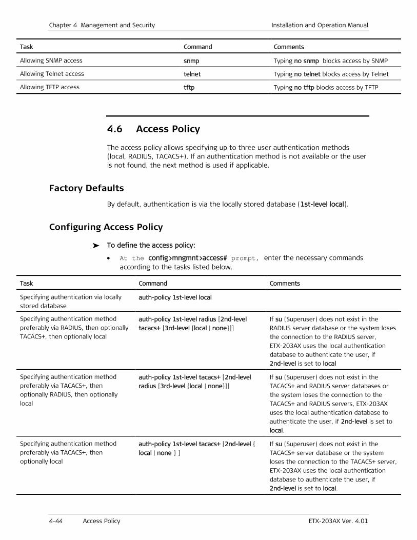
Chapter 4 Management and Security Installation and Operation Manual
4-44 Access Policy ETX-203AX Ver. 4.01
Task Command Comments
Allowing SNMP access snmp Typing no snmp blocks access by SNMP
Allowing Telnet access telnet Typing no telnet blocks access by Telnet
Allowing TFTP access tftp Typing no tftp blocks access by TFTP
4.6 Access Policy
The access policy allows specifying up to three user authentication methods (local, RADIUS, TACACS+). If an authentication method is not available or the user is not found, the next method is used if applicable.
Factory Defaults
By default, authentication is via the locally stored database (1st-level local).
Configuring Access Policy
To define the access policy:
• At the config>mngmnt>access# prompt, enter the necessary commands according to the tasks listed below.
Task Command Comments
Specifying authentication via locally
stored database auth-policy 1st-level local
Specifying authentication method
preferably via RADIUS, then optionally
TACACS+, then optionally local
auth-policy 1st-level radius [2nd-level
tacacs+ [3rd-level {local | none}]]
If su (Superuser) does not exist in the
RADIUS server database or the system loses
the connection to the RADIUS server,
ETX-203AX uses the local authentication
database to authenticate the user, if
2nd-level is set to local
Specifying authentication method
preferably via TACACS+, then
optionally RADIUS, then optionally
local
auth-policy 1st-level tacacs+ [2nd-level
radius [3rd-level {local | none}]]
If su (Superuser) does not exist in the
TACACS+ and RADIUS server databases or
the system loses the connection to the
TACACS+ and RADIUS servers, ETX-203AX
uses the local authentication database to
authenticate the user, if 2nd-level is set to
local.
Specifying authentication method
preferably via TACACS+, then
optionally local
auth-policy 1st-level tacacs+ [2nd-level {
local | none } ]
If su (Superuser) does not exist in the
TACACS+ server database or the system
loses the connection to the TACACS+ server,
ETX-203AX uses the local authentication
database to authenticate the user, if
2nd-level is set to local.
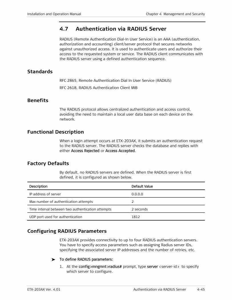
Installation and Operation Manual Chapter 4 Management and Security
ETX-203AX Ver. 4.01 Authentication via RADIUS Server 4-45
4.7 Authentication via RADIUS Server
RADIUS (Remote Authentication Dial-In User Service) is an AAA (authentication, authorization and accounting) client/server protocol that secures networks against unauthorized access. It is used to authenticate users and authorize their access to the requested system or service. The RADIUS client communicates with the RADIUS server using a defined authentication sequence.
Standards
RFC 2865, Remote Authentication Dial In User Service (RADIUS)
RFC 2618, RADIUS Authentication Client MIB
Benefits
The RADIUS protocol allows centralized authentication and access control, avoiding the need to maintain a local user data base on each device on the network.
Functional Description
When a login attempt occurs at ETX-203AX, it submits an authentication request to the RADIUS server. The RADIUS server checks the database and replies with either Access Rejected or Access Accepted.
Factory Defaults
By default, no RADIUS servers are defined. When the RADIUS server is first defined, it is configured as shown below.
Description Default Value
IP address of server 0.0.0.0
Max number of authentication attempts 2
Time interval between two authentication attempts 2 seconds
UDP port used for authentication 1812
Configuring RADIUS Parameters
ETX-203AX provides connectivity to up to four RADIUS authentication servers. You have to specify access parameters such as assigning Radius server IDs, specifying the associated server IP addresses and the number of retries, etc.
To define RADIUS parameters:
1. At the config>mngmnt>radius# prompt, type server <server-id> to specify which server to configure.
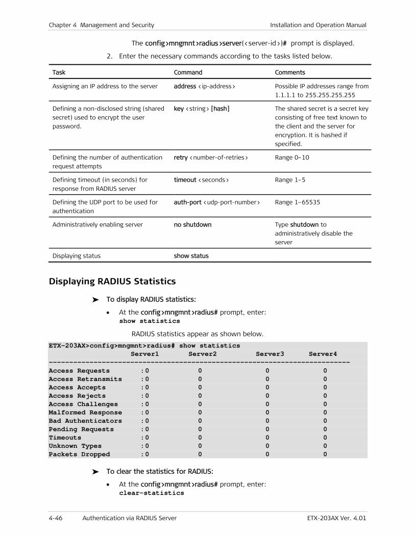
Chapter 4 Management and Security Installation and Operation Manual
4-46 Authentication via RADIUS Server ETX-203AX Ver. 4.01
The config>mngmnt>radius>server(<server-id>)# prompt is displayed.
2. Enter the necessary commands according to the tasks listed below.
Task Command Comments
Assigning an IP address to the server address <ip-address> Possible IP addresses range from
1.1.1.1 to 255.255.255.255
Defining a non-disclosed string (shared
secret) used to encrypt the user
password.
key <string> [hash] The shared secret is a secret key
consisting of free text known to
the client and the server for
encryption. It is hashed if
specified.
Defining the number of authentication
request attempts
retry <number-of-retries> Range 0–10
Defining timeout (in seconds) for
response from RADIUS server
timeout <seconds> Range 1–5
Defining the UDP port to be used for
authentication
auth-port <udp-port-number> Range 1–65535
Administratively enabling server no shutdown Type shutdown to
administratively disable the
server
Displaying status show status
Displaying RADIUS Statistics
To display RADIUS statistics:
• At the config>mngmnt>radius# prompt, enter: show statistics
RADIUS statistics appear as shown below.
ETX-203AX>config>mngmnt>radius# show statistics Server1 Server2 Server3 Server4 -------------------------------------------------------------------------- Access Requests : 0 0 0 0 Access Retransmits : 0 0 0 0 Access Accepts : 0 0 0 0 Access Rejects : 0 0 0 0 Access Challenges : 0 0 0 0 Malformed Response : 0 0 0 0 Bad Authenticators : 0 0 0 0 Pending Requests : 0 0 0 0 Timeouts : 0 0 0 0 Unknown Types : 0 0 0 0 Packets Dropped : 0 0 0 0
To clear the statistics for RADIUS:
• At the config>mngmnt>radius# prompt, enter: clear-statistics
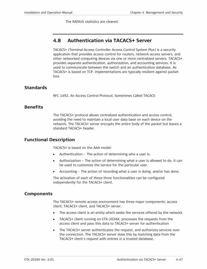
Installation and Operation Manual Chapter 4 Management and Security
ETX-203AX Ver. 4.01 Authentication via TACACS+ Server 4-47
The RADIUS statistics are cleared.
4.8 Authentication via TACACS+ Server
TACACS+ (Terminal Access Controller Access Control System Plus) is a security application that provides access control for routers, network access servers, and other networked computing devices via one or more centralized servers. TACACS+ provides separate authentication, authorization, and accounting services. It is used to communicate between the switch and an authentication database. As TACACS+ is based on TCP, implementations are typically resilient against packet loss.
Standards
RFC 1492, An Access Control Protocol, Sometimes Called TACACS
Benefits
The TACACS+ protocol allows centralized authentication and access control, avoiding the need to maintain a local user data base on each device on the network. The TACACS+ server encrypts the entire body of the packet but leaves a standard TACACS+ header.
Functional Description
TACACS+ is based on the AAA model:
• Authentication – The action of determining who a user is.
• Authorization – The action of determining what a user is allowed to do. It can be used to customize the service for the particular user.
• Accounting – The action of recording what a user is doing, and/or has done.
The activation of each of these three functionalities can be configured independently for the TACACS+ client.
Components
The TACACS+ remote access environment has three major components: access client, TACACS+ client, and TACACS+ server.
• The access client is an entity which seeks the services offered by the network
• TACACS+ client running on ETX-203AX, processes the requests from the access client and pass this data to TACACS+ server for authentication
• The TACACS+ server authenticates the request, and authorizes services over the connection. The TACACS+ server does this by matching data from the TACACS+ client`s request with entries in a trusted database.
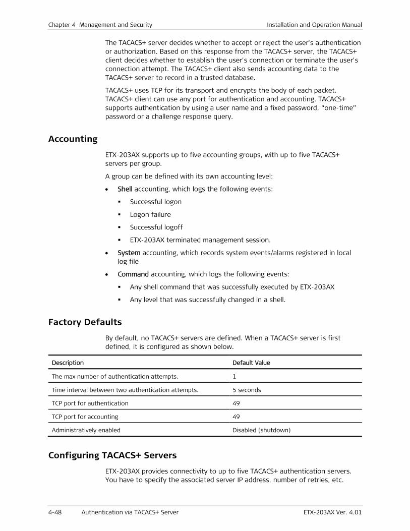
Chapter 4 Management and Security Installation and Operation Manual
4-48 Authentication via TACACS+ Server ETX-203AX Ver. 4.01
The TACACS+ server decides whether to accept or reject the user's authentication or authorization. Based on this response from the TACACS+ server, the TACACS+ client decides whether to establish the user's connection or terminate the user's connection attempt. The TACACS+ client also sends accounting data to the TACACS+ server to record in a trusted database.
TACACS+ uses TCP for its transport and encrypts the body of each packet. TACACS+ client can use any port for authentication and accounting. TACACS+ supports authentication by using a user name and a fixed password, “one-time” password or a challenge response query.
Accounting
ETX-203AX supports up to five accounting groups, with up to five TACACS+ servers per group.
A group can be defined with its own accounting level:
• Shell accounting, which logs the following events:
Successful logon
Logon failure
Successful logoff
ETX-203AX terminated management session.
• System accounting, which records system events/alarms registered in local log file
• Command accounting, which logs the following events:
Any shell command that was successfully executed by ETX-203AX
Any level that was successfully changed in a shell.
Factory Defaults
By default, no TACACS+ servers are defined. When a TACACS+ server is first defined, it is configured as shown below.
Description Default Value
The max number of authentication attempts. 1
Time interval between two authentication attempts. 5 seconds
TCP port for authentication 49
TCP port for accounting 49
Administratively enabled Disabled (shutdown)
Configuring TACACS+ Servers
ETX-203AX provides connectivity to up to five TACACS+ authentication servers. You have to specify the associated server IP address, number of retries, etc.
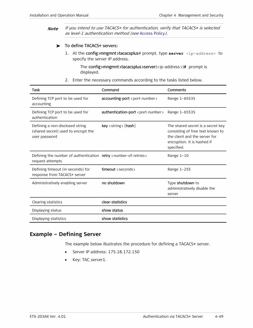
Installation and Operation Manual Chapter 4 Management and Security
ETX-203AX Ver. 4.01 Authentication via TACACS+ Server 4-49
If you intend to use TACACS+ for authentication, verify that TACACS+ is selected as level-1 authentication method (see Access Policy).
To define TACACS+ servers:
1. At the config>mngmnt>tacacsplus# prompt, type server <ip-address> to specify the server IP address.
The config>mngmnt>tacacsplus>server(<ip-address>)# prompt is displayed.
2. Enter the necessary commands according to the tasks listed below.
Task Command Comments
Defining TCP port to be used for
accounting
accounting-port <port-number> Range 1–65535
Defining TCP port to be used for
authentication
authentication-port <port-number> Range 1–65535
Defining a non-disclosed string
(shared secret) used to encrypt the
user password
key <string> [hash] The shared secret is a secret key
consisting of free text known to
the client and the server for
encryption. It is hashed if
specified.
Defining the number of authentication
request attempts
retry <number-of-retries> Range 1–10
Defining timeout (in seconds) for
response from TACACS+ server
timeout <seconds> Range 1–255
Administratively enabling server no shutdown Type shutdown to
administratively disable the
server
Clearing statistics clear-statistics
Displaying status show status
Displaying statistics show statistics
Example – Defining Server
The example below illustrates the procedure for defining a TACACS+ server.
• Server IP address: 175.18.172.150
• Key: TAC_server1.
Note
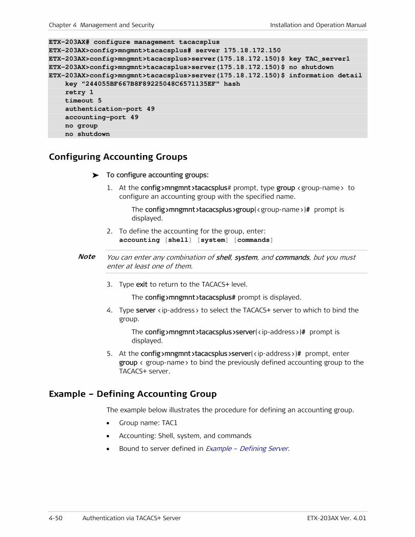
Chapter 4 Management and Security Installation and Operation Manual
4-50 Authentication via TACACS+ Server ETX-203AX Ver. 4.01
ETX-203AX# configure management tacacsplus ETX-203AX>config>mngmnt>tacacsplus# server 175.18.172.150 ETX-203AX>config>mngmnt>tacacsplus>server(175.18.172.150)$ key TAC_server1 ETX-203AX>config>mngmnt>tacacsplus>server(175.18.172.150)$ no shutdown ETX-203AX>config>mngmnt>tacacsplus>server(175.18.172.150)$ information detail key "244055BF667B8F89225048C6571135EF" hash retry 1 timeout 5 authentication-port 49 accounting-port 49 no group no shutdown
Configuring Accounting Groups
To configure accounting groups:
1. At the config>mngmnt>tacacsplus# prompt, type group <group-name> to configure an accounting group with the specified name.
The config>mngmnt>tacacsplus>group(<group-name>)# prompt is displayed.
2. To define the accounting for the group, enter: accounting [shell] [system] [commands]
You can enter any combination of shell, system, and commands, but you must enter at least one of them.
3. Type exit to return to the TACACS+ level.
The config>mngmnt>tacacsplus# prompt is displayed.
4. Type server <ip-address> to select the TACACS+ server to which to bind the group.
The config>mngmnt>tacacsplus>server(<ip-address>)# prompt is displayed.
5. At the config>mngmnt>tacacsplus>server(<ip-address>)# prompt, enter group < group-name> to bind the previously defined accounting group to the TACACS+ server.
Example – Defining Accounting Group
The example below illustrates the procedure for defining an accounting group.
• Group name: TAC1
• Accounting: Shell, system, and commands
• Bound to server defined in Example – Defining Server.
Note
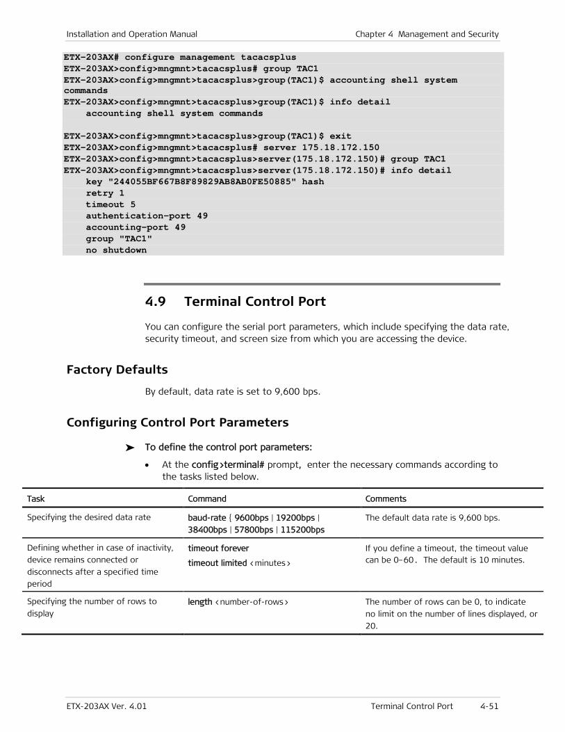
Installation and Operation Manual Chapter 4 Management and Security
ETX-203AX Ver. 4.01 Terminal Control Port 4-51
ETX-203AX# configure management tacacsplus ETX-203AX>config>mngmnt>tacacsplus# group TAC1 ETX-203AX>config>mngmnt>tacacsplus>group(TAC1)$ accounting shell system commands ETX-203AX>config>mngmnt>tacacsplus>group(TAC1)$ info detail accounting shell system commands ETX-203AX>config>mngmnt>tacacsplus>group(TAC1)$ exit ETX-203AX>config>mngmnt>tacacsplus# server 175.18.172.150 ETX-203AX>config>mngmnt>tacacsplus>server(175.18.172.150)# group TAC1 ETX-203AX>config>mngmnt>tacacsplus>server(175.18.172.150)# info detail key "244055BF667B8F89829AB8AB0FE50885" hash retry 1 timeout 5 authentication-port 49 accounting-port 49 group "TAC1" no shutdown
4.9 Terminal Control Port
You can configure the serial port parameters, which include specifying the data rate, security timeout, and screen size from which you are accessing the device.
Factory Defaults
By default, data rate is set to 9,600 bps.
Configuring Control Port Parameters
To define the control port parameters:
• At the config>terminal# prompt, enter the necessary commands according to the tasks listed below.
Task Command Comments
Specifying the desired data rate baud-rate { 9600bps | 19200bps |
38400bps | 57800bps | 115200bps
The default data rate is 9,600 bps.
Defining whether in case of inactivity,
device remains connected or
disconnects after a specified time
period
timeout forever
timeout limited <minutes>
If you define a timeout, the timeout value can be 0–60. The default is 10 minutes.
Specifying the number of rows to
display length <number-of-rows> The number of rows can be 0, to indicate
no limit on the number of lines displayed, or
20.
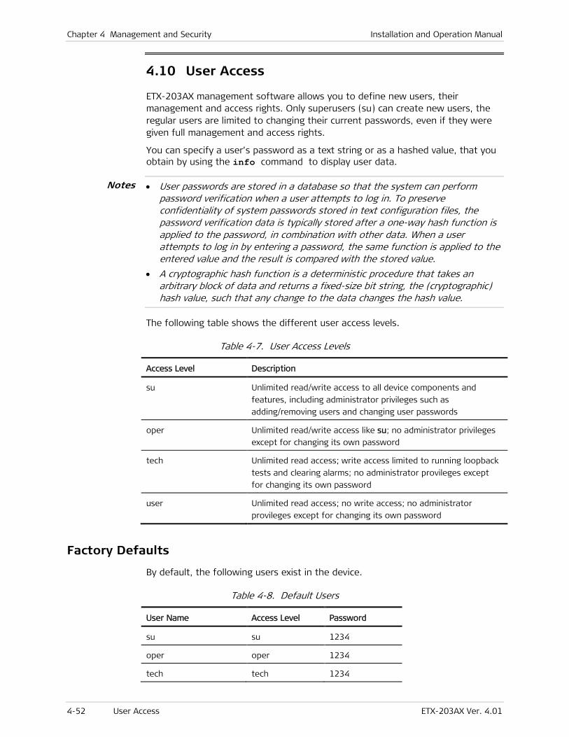
Chapter 4 Management and Security Installation and Operation Manual
4-52 User Access ETX-203AX Ver. 4.01
4.10 User Access
ETX-203AX management software allows you to define new users, their management and access rights. Only superusers (su) can create new users, the regular users are limited to changing their current passwords, even if they were given full management and access rights.
You can specify a user’s password as a text string or as a hashed value, that you obtain by using the info command to display user data.
• User passwords are stored in a database so that the system can perform password verification when a user attempts to log in. To preserve confidentiality of system passwords stored in text configuration files, the password verification data is typically stored after a one-way hash function is applied to the password, in combination with other data. When a user attempts to log in by entering a password, the same function is applied to the entered value and the result is compared with the stored value.
• A cryptographic hash function is a deterministic procedure that takes an arbitrary block of data and returns a fixed-size bit string, the (cryptographic) hash value, such that any change to the data changes the hash value.
The following table shows the different user access levels.
Table 4-7. User Access Levels
Access Level Description
su Unlimited read/write access to all device components and
features, including administrator privileges such as
adding/removing users and changing user passwords
oper Unlimited read/write access like su; no administrator privileges
except for changing its own password
tech Unlimited read access; write access limited to running loopback
tests and clearing alarms; no administrator provileges except
for changing its own password
user Unlimited read access; no write access; no administrator
provileges except for changing its own password
Factory Defaults
By default, the following users exist in the device.
Table 4-8. Default Users
User Name Access Level Password
su su 1234
oper oper 1234
tech tech 1234
Notes

Installation and Operation Manual Chapter 4 Management and Security
ETX-203AX Ver. 4.01 User Access 4-53
User Name Access Level Password
user user 1234
Configuring Users
To add a new user:
1. Make sure that you are logged on as superuser (su).
2. Navigate to the Management context (config>mngmnt).
3. Define a new user:
user <name> [ level { su | oper | tech | user} ] [password <password> [hash]]
Example – Defining Users
To define a new user:
• User name = staff
• User password = 1234.
ETX-203AX# configure management ETX-203AX>config>mngmnt# user staff level su password 1234 # Password is encrypted successfully ETX-203AX>config>mngmnt#
To add a new user with a hashed password:
1. Define a new user with a text password.
2. Use info detail to display the password hash value.
3. Define another user with the hashed password from the info output.
The second user can log in with the text password defined in step 1.
For example, to add the following users:
• User name = staff1
• User password = 4222
• User name = staff2
• User password = hash of 4222 (user staff2 can log in with password 4222).
ETX-203AX# configure management ETX-203AX>config>mngmnt# user staff1 level user password 4222 # Password is encrypted successfully ETX-203AX>config>mngmnt# info detail user "staff1" level user password "3fda26f8cff4123ddcad0c1bc89ed1e79977acef" hash user "su"
:
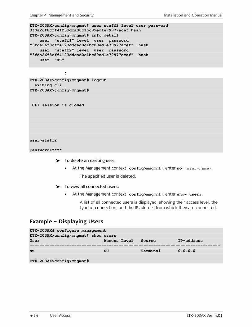
Chapter 4 Management and Security Installation and Operation Manual
4-54 User Access ETX-203AX Ver. 4.01
ETX-203AX>config>mngmnt# user staff2 level user password 3fda26f8cff4123ddcad0c1bc89ed1e79977acef hash ETX-203AX>config>mngmnt# info detail user "staff1" level user password "3fda26f8cff4123ddcad0c1bc89ed1e79977acef" hash user "staff2" level user password "3fda26f8cff4123ddcad0c1bc89ed1e79977acef" hash user "su"
:
ETX-203AX>config>mngmnt# logout exiting cli ETX-203AX>config>mngmnt# CLI session is closed user>staff2 password>****
To delete an existing user:
• At the Management context (config>mngmnt), enter no <user-name>.
The specified user is deleted.
To view all connected users:
• At the Management context (config>mngmnt), enter show users.
A list of all connected users is displayed, showing their access level, the type of connection, and the IP address from which they are connected.
Example – Displaying Users
ETX-203AX# configure management ETX-203AX>config>mngmnt# show users User Access Level Source IP-address ----------------------------------------------------------------------------- su SU Terminal 0.0.0.0 ETX-203AX>config>mngmnt#

ETX-203AX Ver. 4.01 Ethernet Ports 5-1
Chapter 5
Services This chapter shows the data flow and configuration steps for services.
Ethernet User Traffic
Network to User
In Figure 5-1 the rectangles illustrate the data flow for Ethernet user traffic from a network port to a user port. The rounded rectangles indicate the features that need to be configured, numbered according to the order of configuration. Table 5-1 shows the configuration steps corresponding to the numbers.
Figure 5-1. Ethernet User Traffic Data Flow – Network to User
Table 5-1. Ethernet User Traffic Configuration – Network to User
Sequence Step Commands Comments
1 Defining Classifier Profiles classifier-profile
match
The classifier profile defines the
criteria for the network-to-user flow
2 Marking Profiles marking-profile
mark
Necessary only if a profile is needed
for non-default mapping of p-bit, IP
precedence, DSCP, or CoS
classifications to egress priority tags
for the network-to-user flow
3 Queue Mapping Profiles queue-map-profile
map
Necessary only if a profile is needed
for non-default mapping of user
priorities to queues for the
network-to-user flow
4 Configuring Policer Profiles policer-profile
bandwidth
compensation
Necessary only if you need to define
non-default bandwidth limits or
overhead compensation for the
incoming traffic of the
network-to-user flow

Chapter 5 Services Installation and Operation Manual
5-2 Ethernet Ports ETX-203AX Ver. 4.01
Sequence Step Commands Comments
5 Configuring Queue Block Profile Parameters
queue-block-profile
queue
scheduling
depth
Necessary only if you need to define
non-default queue configuration for
the network-to-user flow
6 WRED Profiles wred-profile
color
Necessary only if you need to define
non-default WRED configuration for
the queue blocks
7 Configuring Flows classifier
ingress-port
egress-port
policer
mark
vlan-tag
shutdown
You must define the flow for the user
traffic from the network port to the
user port
8 Configuring Shaper Profiles shaper-profile
bandwidth
compensation
Necessary only if you need to define
non-default bandwidth limits or
overhead compensation for the
outgoing traffic of the
network-to-user flow (via attaching
shaper profile to queue group profile
attached to egress port)
9 Queue Group Profiles queue-group-profile
queue-block
name
profile
shaper
Necessary only if you need to define
non-default queue group
configuration for the egress port
10 Ethernet Ports name
auto-negotiation
max-capability
speed-duplex
queue-group
egress-mtu
tag-ethernet-type
shutdown
Necessary only if you need to define
non-default configuration for the
egress port
User to Network
In Figure 5-2 the rectangles illustrate the data flow for Ethernet user traffic from a network port to a user port. The rounded rectangles indicate the features that need to be configured, numbered according to the order of configuration. Table 5-2 shows the configuration steps corresponding to the numbers.
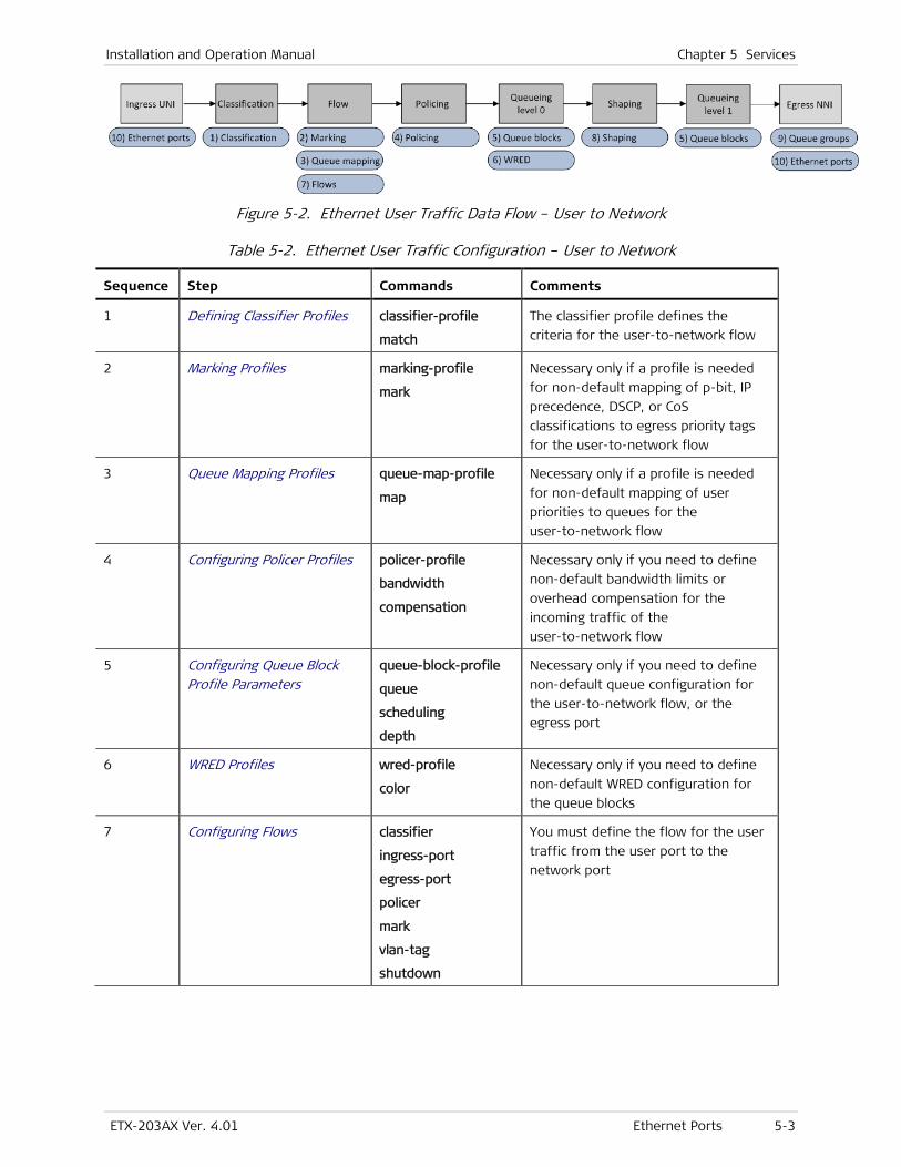
Installation and Operation Manual Chapter 5 Services
ETX-203AX Ver. 4.01 Ethernet Ports 5-3
Figure 5-2. Ethernet User Traffic Data Flow – User to Network
Table 5-2. Ethernet User Traffic Configuration – User to Network
Sequence Step Commands Comments
1 Defining Classifier Profiles classifier-profile
match
The classifier profile defines the
criteria for the user-to-network flow
2 Marking Profiles marking-profile
mark
Necessary only if a profile is needed
for non-default mapping of p-bit, IP
precedence, DSCP, or CoS
classifications to egress priority tags
for the user-to-network flow
3 Queue Mapping Profiles queue-map-profile
map
Necessary only if a profile is needed
for non-default mapping of user
priorities to queues for the
user-to-network flow
4 Configuring Policer Profiles policer-profile
bandwidth
compensation
Necessary only if you need to define
non-default bandwidth limits or
overhead compensation for the
incoming traffic of the
user-to-network flow
5 Configuring Queue Block Profile Parameters
queue-block-profile
queue
scheduling
depth
Necessary only if you need to define
non-default queue configuration for
the user-to-network flow, or the
egress port
6 WRED Profiles wred-profile
color
Necessary only if you need to define
non-default WRED configuration for
the queue blocks
7 Configuring Flows classifier
ingress-port
egress-port
policer
mark
vlan-tag
shutdown
You must define the flow for the user
traffic from the user port to the
network port
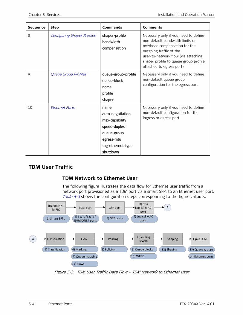
Chapter 5 Services Installation and Operation Manual
5-4 Ethernet Ports ETX-203AX Ver. 4.01
Sequence Step Commands Comments
8 Configuring Shaper Profiles shaper-profile
bandwidth
compensation
Necessary only if you need to define
non-default bandwidth limits or
overhead compensation for the
outgoing traffic of the
user-to-network flow (via attaching
shaper profile to queue group profile
attached to egress port)
9 Queue Group Profiles queue-group-profile
queue-block
name
profile
shaper
Necessary only if you need to define
non-default queue group
configuration for the egress port
10 Ethernet Ports name
auto-negotiation
max-capability
speed-duplex
queue-group
egress-mtu
tag-ethernet-type
shutdown
Necessary only if you need to define
non-default configuration for the
ingress or egress port
TDM User Traffic
TDM Network to Ethernet User
The following figure illustrates the data flow for Ethernet user traffic from a network port provisioned as a TDM port via a smart SFP, to an Ethernet user port. Table 5-3 shows the configuration steps corresponding to the figure callouts.
Figure 5-3. TDM User Traffic Data Flow – TDM Network to Ethernet User
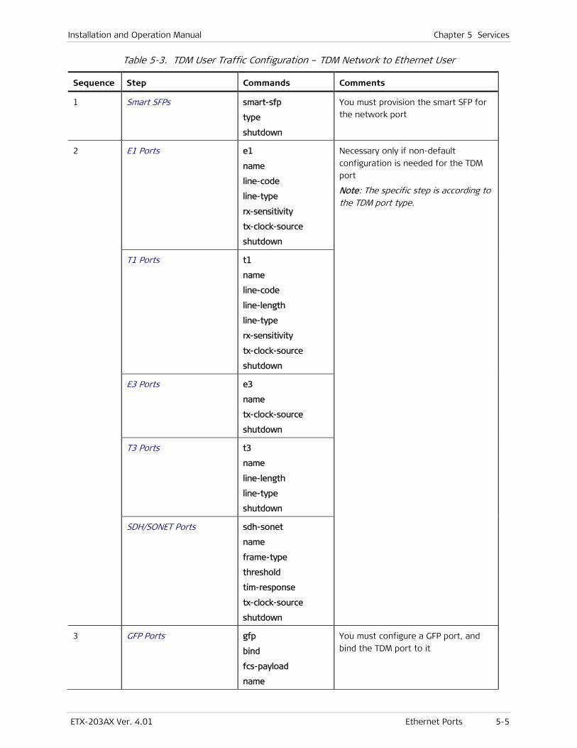
Installation and Operation Manual Chapter 5 Services
ETX-203AX Ver. 4.01 Ethernet Ports 5-5
Table 5-3. TDM User Traffic Configuration – TDM Network to Ethernet User
Sequence Step Commands Comments
1 Smart SFPs smart-sfp
type
shutdown
You must provision the smart SFP for
the network port
2 E1 Ports e1
name
line-code
line-type
rx-sensitivity
tx-clock-source
shutdown
Necessary only if non-default
configuration is needed for the TDM
port
Note: The specific step is according to the TDM port type.
T1 Ports t1
name
line-code
line-length
line-type
rx-sensitivity
tx-clock-source
shutdown
E3 Ports e3
name
tx-clock-source
shutdown
T3 Ports t3
name
line-length
line-type
shutdown
SDH/SONET Ports sdh-sonet
name
frame-type
threshold
tim-response
tx-clock-source
shutdown
3 GFP Ports gfp
bind
fcs-payload
name
You must configure a GFP port, and
bind the TDM port to it
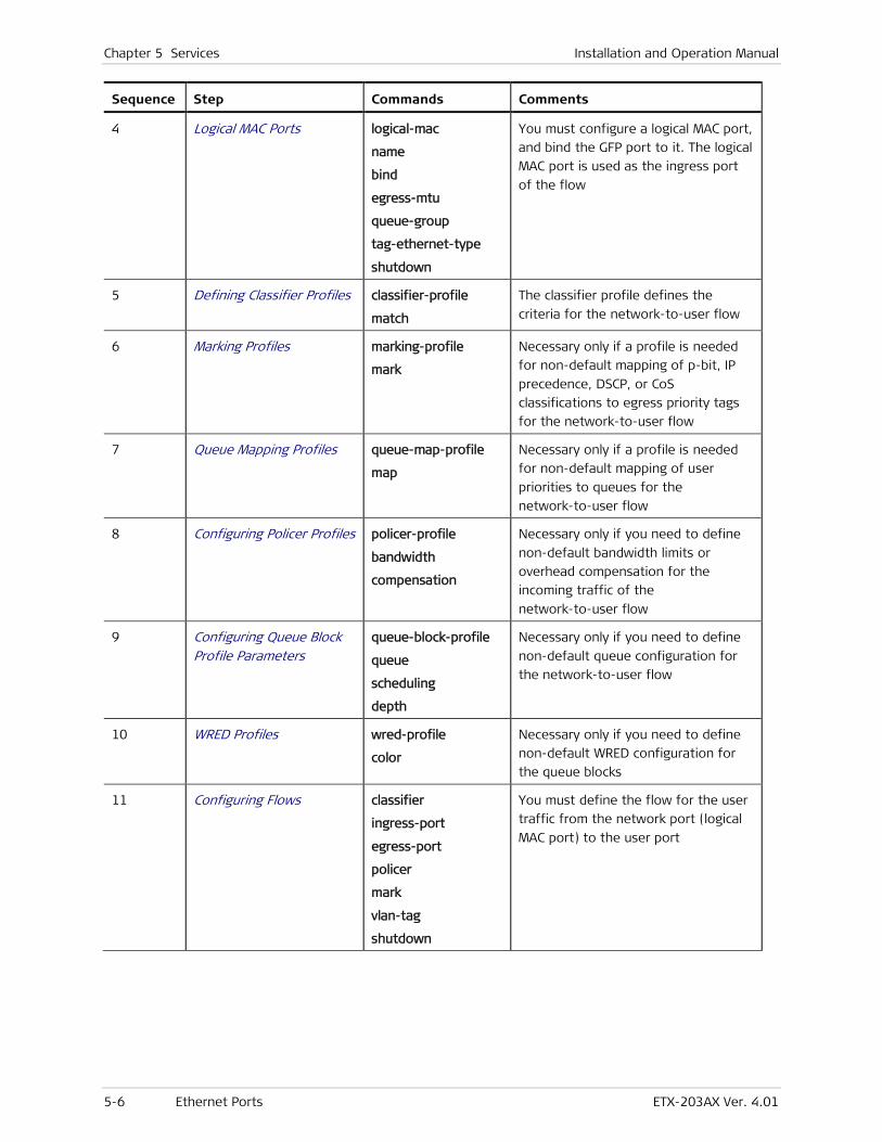
Chapter 5 Services Installation and Operation Manual
5-6 Ethernet Ports ETX-203AX Ver. 4.01
Sequence Step Commands Comments
4 Logical MAC Ports logical-mac
name
bind
egress-mtu
queue-group
tag-ethernet-type
shutdown
You must configure a logical MAC port,
and bind the GFP port to it. The logical
MAC port is used as the ingress port
of the flow
5 Defining Classifier Profiles classifier-profile
match
The classifier profile defines the
criteria for the network-to-user flow
6 Marking Profiles marking-profile
mark
Necessary only if a profile is needed
for non-default mapping of p-bit, IP
precedence, DSCP, or CoS
classifications to egress priority tags
for the network-to-user flow
7 Queue Mapping Profiles queue-map-profile
map
Necessary only if a profile is needed
for non-default mapping of user
priorities to queues for the
network-to-user flow
8 Configuring Policer Profiles policer-profile
bandwidth
compensation
Necessary only if you need to define
non-default bandwidth limits or
overhead compensation for the
incoming traffic of the
network-to-user flow
9 Configuring Queue Block Profile Parameters
queue-block-profile
queue
scheduling
depth
Necessary only if you need to define
non-default queue configuration for
the network-to-user flow
10 WRED Profiles wred-profile
color
Necessary only if you need to define
non-default WRED configuration for
the queue blocks
11 Configuring Flows classifier
ingress-port
egress-port
policer
mark
vlan-tag
shutdown
You must define the flow for the user
traffic from the network port (logical
MAC port) to the user port
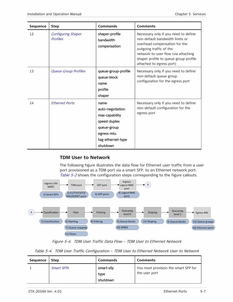
Installation and Operation Manual Chapter 5 Services
ETX-203AX Ver. 4.01 Ethernet Ports 5-7
Sequence Step Commands Comments
12 Configuring Shaper Profiles
shaper-profile
bandwidth
compensation
Necessary only if you need to define
non-default bandwidth limits or
overhead compensation for the
outgoing traffic of the
network-to-user flow (via attaching
shaper profile to queue group profile
attached to egress port)
13 Queue Group Profiles queue-group-profile
queue-block
name
profile
shaper
Necessary only if you need to define
non-default queue group
configuration for the egress port
14 Ethernet Ports name
auto-negotiation
max-capability
speed-duplex
queue-group
egress-mtu
tag-ethernet-type
shutdown
Necessary only if you need to define
non-default configuration for the
egress port
TDM User to Network
The following figure illustrates the data flow for Ethernet user traffic from a user port provisioned as a TDM port via a smart SFP, to an Ethernet network port. Table 5-2 shows the configuration steps corresponding to the figure callouts.
Figure 5-4. TDM User Traffic Data Flow – TDM User to Ethernet Network
Table 5-4. TDM User Traffic Configuration – TDM User to Ethernet Network User to Network
Sequence Step Commands Comments
1 Smart SFPs smart-sfp
type
shutdown
You must provision the smart SFP for
the user port

Chapter 5 Services Installation and Operation Manual
5-8 Ethernet Ports ETX-203AX Ver. 4.01
Sequence Step Commands Comments
2 E1 Ports e1
name
line-code
line-type
rx-sensitivity
tx-clock-source
shutdown
Necessary only if non-default
configuration is needed for the TDM
port
Note: The specific step is according to the TDM port type.
T1 Ports t1
name
line-code
line-length
line-type
rx-sensitivity
tx-clock-source
shutdown
E3 Ports e3
name
tx-clock-source
shutdown
T3 Ports t3
name
line-length
line-type
shutdown
SDH/SONET Ports sdh-sonet
name
frame-type
threshold
tim-response
tx-clock-source
shutdown
3 GFP Ports gfp
bind
fcs-payload
name
You must configure a GFP port, and
bind the TDM port to it
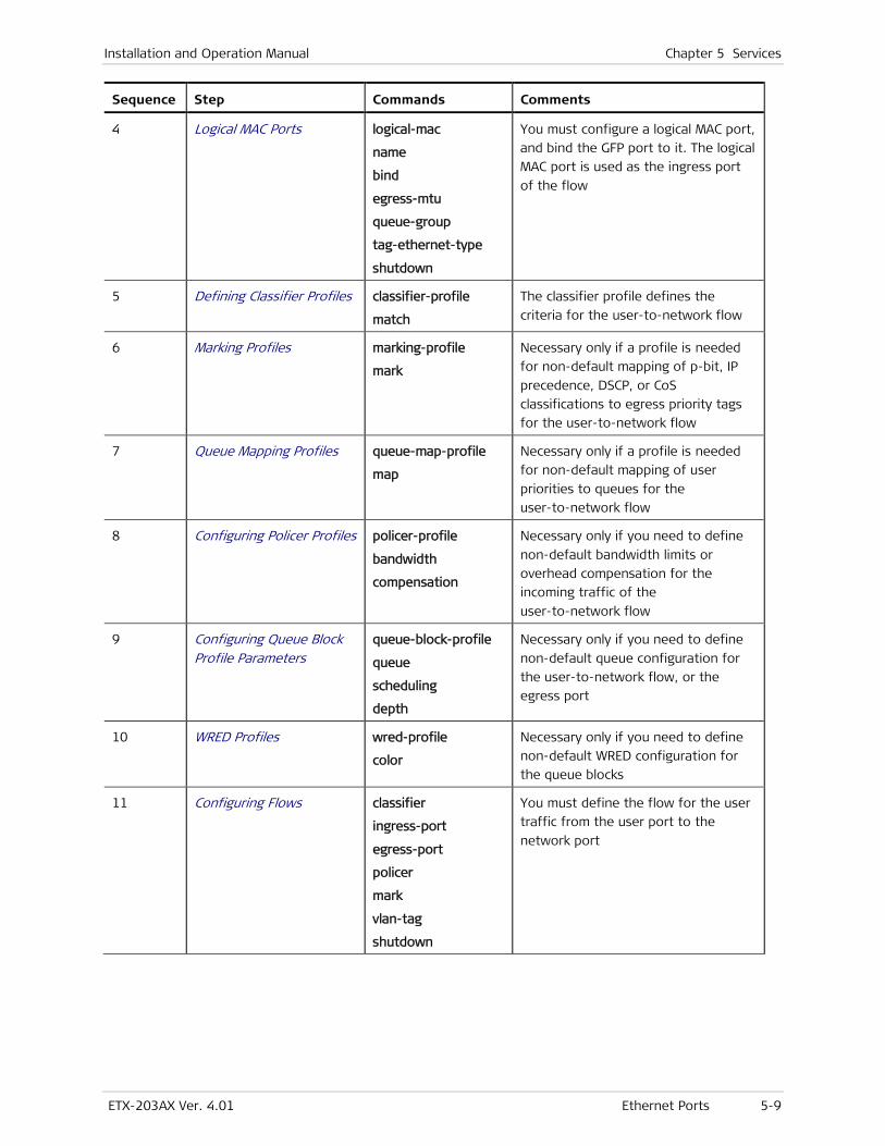
Installation and Operation Manual Chapter 5 Services
ETX-203AX Ver. 4.01 Ethernet Ports 5-9
Sequence Step Commands Comments
4 Logical MAC Ports logical-mac
name
bind
egress-mtu
queue-group
tag-ethernet-type
shutdown
You must configure a logical MAC port,
and bind the GFP port to it. The logical
MAC port is used as the ingress port
of the flow
5 Defining Classifier Profiles classifier-profile
match
The classifier profile defines the
criteria for the user-to-network flow
6 Marking Profiles marking-profile
mark
Necessary only if a profile is needed
for non-default mapping of p-bit, IP
precedence, DSCP, or CoS
classifications to egress priority tags
for the user-to-network flow
7 Queue Mapping Profiles queue-map-profile
map
Necessary only if a profile is needed
for non-default mapping of user
priorities to queues for the
user-to-network flow
8 Configuring Policer Profiles policer-profile
bandwidth
compensation
Necessary only if you need to define
non-default bandwidth limits or
overhead compensation for the
incoming traffic of the
user-to-network flow
9 Configuring Queue Block Profile Parameters
queue-block-profile
queue
scheduling
depth
Necessary only if you need to define
non-default queue configuration for
the user-to-network flow, or the
egress port
10 WRED Profiles wred-profile
color
Necessary only if you need to define
non-default WRED configuration for
the queue blocks
11 Configuring Flows classifier
ingress-port
egress-port
policer
mark
vlan-tag
shutdown
You must define the flow for the user
traffic from the user port to the
network port
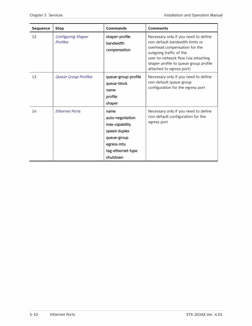
Chapter 5 Services Installation and Operation Manual
5-10 Ethernet Ports ETX-203AX Ver. 4.01
Sequence Step Commands Comments
12 Configuring Shaper Profiles
shaper-profile
bandwidth
compensation
Necessary only if you need to define
non-default bandwidth limits or
overhead compensation for the
outgoing traffic of the
user-to-network flow (via attaching
shaper profile to queue group profile
attached to egress port)
13 Queue Group Profiles queue-group-profile
queue-block
name
profile
shaper
Necessary only if you need to define
non-default queue group
configuration for the egress port
14 Ethernet Ports name
auto-negotiation
max-capability
speed-duplex
queue-group
egress-mtu
tag-ethernet-type
shutdown
Necessary only if you need to define
non-default configuration for the
egress port
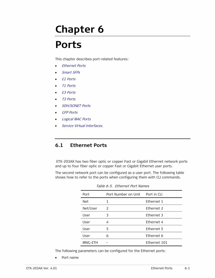
ETX-203AX Ver. 4.01 Ethernet Ports 6-1
Chapter 6
Ports This chapter describes port-related features:
• Ethernet Ports
• Smart SFPs
• E1 Ports
• T1 Ports
• E3 Ports
• T3 Ports
• SDH/SONET Ports
• GFP Ports
• Logical MAC Ports
• Service Virtual Interfaces.
6.1 Ethernet Ports
ETX-203AX has two fiber optic or copper Fast or Gigabit Ethernet network ports and up to four fiber optic or copper Fast or Gigabit Ethernet user ports.
The second network port can be configured as a user port. The following table shows how to refer to the ports when configuring them with CLI commands.
Table 6-5. Ethernet Port Names
Port Port Number on Unit Port in CLI
Net 1 Ethernet 1
Net/User 2 Ethernet 2
User 3 Ethernet 3
User 4 Ethernet 4
User 5 Ethernet 5
User 6 Ethernet 6
MNG-ETH - Ethernet 101
The following parameters can be configured for the Ethernet ports:
• Port name
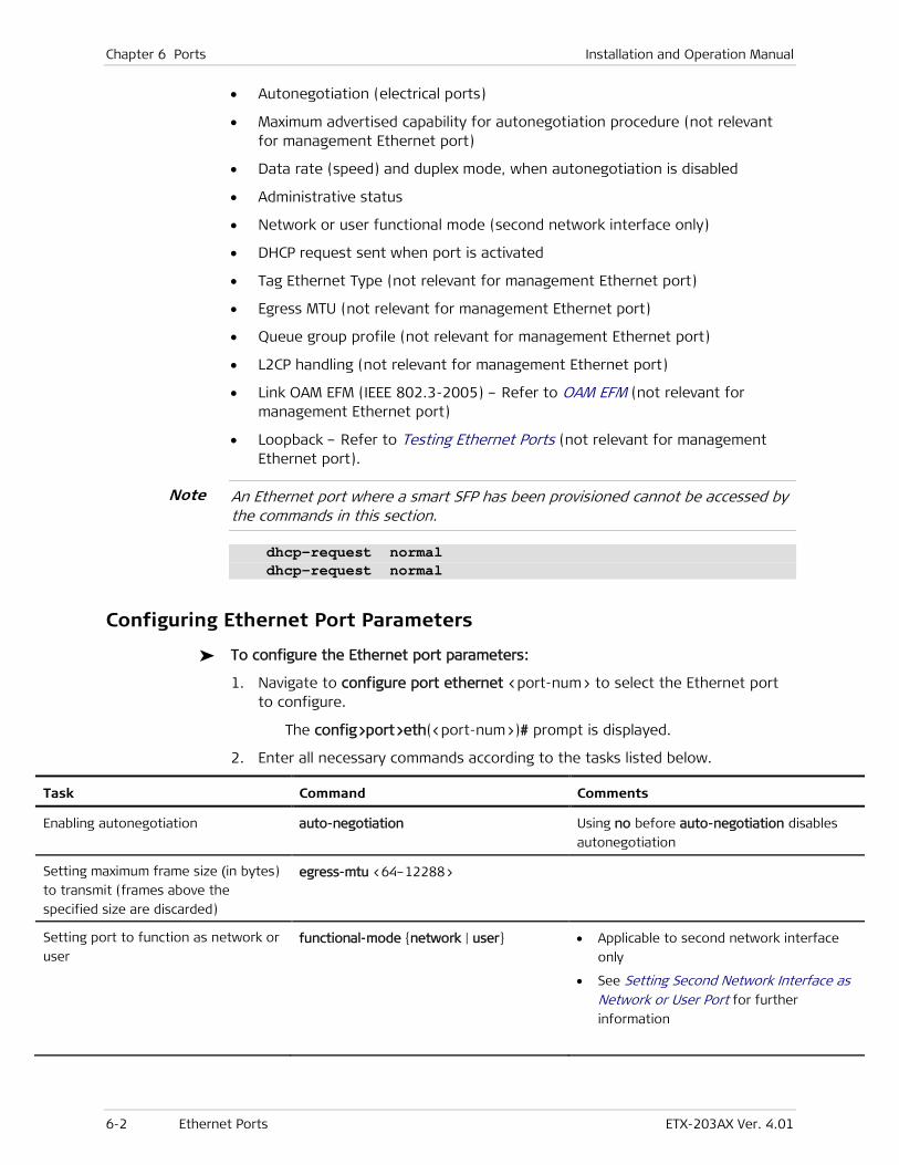
Chapter 6 Ports Installation and Operation Manual
6-2 Ethernet Ports ETX-203AX Ver. 4.01
• Autonegotiation (electrical ports)
• Maximum advertised capability for autonegotiation procedure (not relevant for management Ethernet port)
• Data rate (speed) and duplex mode, when autonegotiation is disabled
• Administrative status
• Network or user functional mode (second network interface only)
• DHCP request sent when port is activated
• Tag Ethernet Type (not relevant for management Ethernet port)
• Egress MTU (not relevant for management Ethernet port)
• Queue group profile (not relevant for management Ethernet port)
• L2CP handling (not relevant for management Ethernet port)
• Link OAM EFM (IEEE 802.3-2005) – Refer to OAM EFM (not relevant for management Ethernet port)
• Loopback – Refer to Testing Ethernet Ports (not relevant for management Ethernet port).
An Ethernet port where a smart SFP has been provisioned cannot be accessed by the commands in this section.
dhcp-request normal dhcp-request normal
Configuring Ethernet Port Parameters
To configure the Ethernet port parameters:
1. Navigate to configure port ethernet <port-num> to select the Ethernet port to configure.
The config>port>eth(<port-num>)# prompt is displayed.
2. Enter all necessary commands according to the tasks listed below.
Task Command Comments
Enabling autonegotiation auto-negotiation Using no before auto-negotiation disables
autonegotiation
Setting maximum frame size (in bytes)
to transmit (frames above the
specified size are discarded)
egress-mtu <64–12288>
Setting port to function as network or
user functional-mode {network | user} • Applicable to second network interface
only
• See Setting Second Network Interface as Network or User Port for further
information
Note
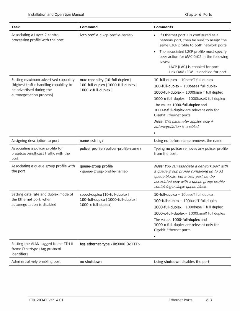
Installation and Operation Manual Chapter 6 Ports
ETX-203AX Ver. 4.01 Ethernet Ports 6-3
Task Command Comments
Associating a Layer-2 control
processing profile with the port l2cp profile <l2cp-profile-name> • If Ethernet port 2 is configured as a
network port, then be sure to assign the
same L2CP profile to both network ports
• The associated L2CP profile must specify
peer action for MAC 0x02 in the following
cases:
-LACP (LAG) is enabled for port
-Link OAM (EFM) is enabled for port.
Setting maximum advertised capability
(highest traffic handling capability to
be advertised during the
autonegotiation process)
max-capability {10-full-duplex |
100-full-duplex | 1000-full-duplex |
1000-x-full-duplex }
10-full-duplex – 10baseT full duplex
100-full-duplex – 100baseT full duplex
1000-full-duplex – 1000base T full duplex
1000-x-full-duplex – 1000baseX full duplex
The values 1000-full-duplex and
1000-x-full-duplex are relevant only for
Gigabit Ethernet ports.
Note: This parameter applies only if autonegotiation is enabled.
•
Assigning description to port name <string> Using no before name removes the name
Associating a policer profile for
broadcast/multicast traffic with the
port
policer profile <policer-profile-name> Typing no policer removes any policer profile
from the port.
Associating a queue group profile with
the port queue-group profile
<queue-group-profile-name>
Note: You can associate a network port with a queue group profile containing up to 31 queue blocks, but a user port can be associated only with a queue group profile containing a single queue block.
Setting data rate and duplex mode of
the Ethernet port, when
autonegotiation is disabled
speed-duplex {10-full-duplex |
100-full-duplex | 1000-full-duplex |
1000-x-full-duplex}
10-full-duplex – 10baseT full duplex
100-full-duplex – 100baseT full duplex
1000-full-duplex – 1000base T full duplex
1000-x-full-duplex – 1000baseX full duplex
The values 1000-full-duplex and
1000-x-full-duplex are relevant only for
Gigabit Ethernet ports
•
Setting the VLAN tagged frame ETH II
frame Ethertype (tag protocol
identifier)
tag-ethernet-type <0x0000-0xFFFF>
Administratively enabling port no shutdown Using shutdown disables the port
Chapter 6 Ports Installation and Operation Manual
6-4 Ethernet Ports ETX-203AX Ver. 4.01
Setting Second Network Interface as Network or User Port
You can change the functional mode of the second network interface from network to user port and vice versa. If it functions as a user port, then redundancy is not possible.
• When you change the functional mode, all flows related to the port are deleted
• The port must be administratively disabled before you can change the functional mode.
To change the functional mode of the second network interface:
1. Navigate to configure port ethernet 2.
The config>port>eth(2)# prompt is displayed.
2. Type shutdown to administratively disable the port.
3. Enter the command to change the functional mode:
To change to user port, enter: functional-mode user
To change to network port, enter: functional-mode network
The functional mode of the port is changed.
4. Type no shutdown to administratively enable the port.
Example
To change the second network interface functional mode to user port:
ETX-204A# configure port ethernet 2 ETX-204A# shutdown ETX-204A>config>port>eth(2)# functional-mode user ETX-204A# no shutdown ETX-204A#
Displaying Ethernet Port Status
You can display the following:
• Summary information showing the status and speed of all Ethernet ports
• Status and configuration of an individual Ethernet port.
To display the status of all Ethernet ports:
• At the prompt config>port#, enter: show summary
The statuses and speeds of the Ethernet ports are displayed. If a port is being tested via the loopback command, it is indicated in the operational status.
Notes
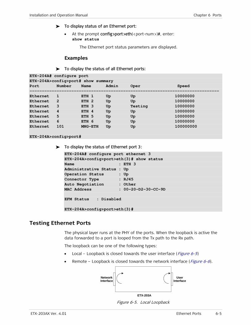
Installation and Operation Manual Chapter 6 Ports
ETX-203AX Ver. 4.01 Ethernet Ports 6-5
To display status of an Ethernet port:
• At the prompt config>port>eth(<port-num>)#, enter: show status
The Ethernet port status parameters are displayed.
Examples
To display the status of all Ethernet ports:
ETX-204A# configure port ETX-204A>config>port# show summary Port Number Name Admin Oper Speed ----------------------------------------------------------------------------- Ethernet 1 ETH 1 Up Up 10000000 Ethernet 2 ETH 2 Up Up 10000000 Ethernet 3 ETH 3 Up Testing 10000000 Ethernet 4 ETH 4 Up Up 10000000 Ethernet 5 ETH 5 Up Up 10000000 Ethernet 6 ETH 6 Up Up 10000000 Ethernet 101 MNG-ETH Up Up 100000000 ETX-204A>config>port#
To display the status of Ethernet port 3:
ETX-204A# configure port ethernet 3 ETX-204A>config>port>eth(3)# show status Name : ETH 3 Administrative Status : Up Operation Status : Up Connector Type : RJ45 Auto Negotiation : Other MAC Address : 00-20-D2-30-CC-9D EFM Status : Disabled ETX-204A>config>port>eth(3)#
Testing Ethernet Ports
The physical layer runs at the PHY of the ports. When the loopback is active the data forwarded to a port is looped from the Tx path to the Rx path.
The loopback can be one of the following types:
• Local – Loopback is closed towards the user interface (Figure 6-5)
• Remote – Loopback is closed towards the network interface (Figure 6-6).
ETX-203A
NetworkInterface
UserInterface
Figure 6-5. Local Loopback
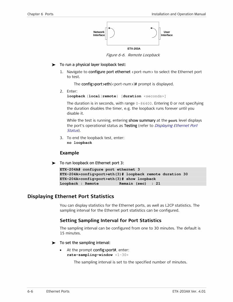
Chapter 6 Ports Installation and Operation Manual
6-6 Ethernet Ports ETX-203AX Ver. 4.01
ETX-203A
NetworkInterface
UserInterface
Figure 6-6. Remote Loopback
To run a physical layer loopback test:
1. Navigate to configure port ethernet <port-num> to select the Ethernet port to test.
The config>port>eth(<port-num>)# prompt is displayed.
2. Enter: loopback {local|remote} [duration <seconds>]
The duration is in seconds, with range 0–86400. Entering 0 or not specifying the duration disables the timer, e.g. the loopback runs forever until you disable it.
While the test is running, entering show summary at the port level displays the port’s operational status as Testing (refer to Displaying Ethernet Port Status).
3. To end the loopback test, enter: no loopback
Example
To run loopback on Ethernet port 3:
ETX-204A# configure port ethernet 3 ETX-204A>config>port>eth(3)# loopback remote duration 30 ETX-204A>config>port>eth(3)# show loopback Loopback : Remote Remain (sec) : 21
Displaying Ethernet Port Statistics
You can display statistics for the Ethernet ports, as well as L2CP statistics. The sampling interval for the Ethernet port statistics can be configured.
Setting Sampling Interval for Port Statistics
The sampling interval can be configured from one to 30 minutes. The default is 15 minutes.
To set the sampling interval:
• At the prompt config>port#, enter: rate-sampling-window <1–30>
The sampling interval is set to the specified number of minutes.
Installation and Operation Manual Chapter 6 Ports
ETX-203AX Ver. 4.01 Ethernet Ports 6-7
Displaying Port Statistics
To display the Ethernet port statistics:
• At the prompt config>port>eth(<port-num>)#, enter: show statistics
Ethernet port statistics are displayed. The counters are described in Table 6-6.
Example
To display the statistics for Ethernet port 2:
ETX-204A# configure port ethernet 2 ETX-204A>config>port>eth(2)# show statistics Rates Sampling Window -------------------------------------------------------------- Window Size [Min.] : 15 Window Remain Time [Min.] : 0 Running -------------------------------------------------------------- Rx Tx Total Frames : 0 5257039970304 Total Octets : 0 0 Total Frames/Sec : 0 0 Total Bits/Sec : 0 0 Min. Bits/Sec : 0 0 Max. Bits/Sec : 0 0 Unicast Frames : 0 0 Multicast Frames : 0 1224 Broadcast Frames : 0 0 Error Frames : 0 -- L2CP Discarded : 0 -- OAM Discarded : 0 -- Unknown Protocol Discarded : 0 -- CRC Errors : 0 -- CRC Errors/Sec : 0 -- Jabber Errors : 0 -- Oversize Frames : 0 0 64 Octets : 0 0 65-127 Octets : 0 0 128-255 Octets : 0 0 256-511 Octets : 0 0 512-1023 Octets : 0 0 1024-1528 Octets : 0 0 1519-2047 Octets : 0 0 2048-Max Octets : 0 0 ETX-204A>config>port>eth(2)#
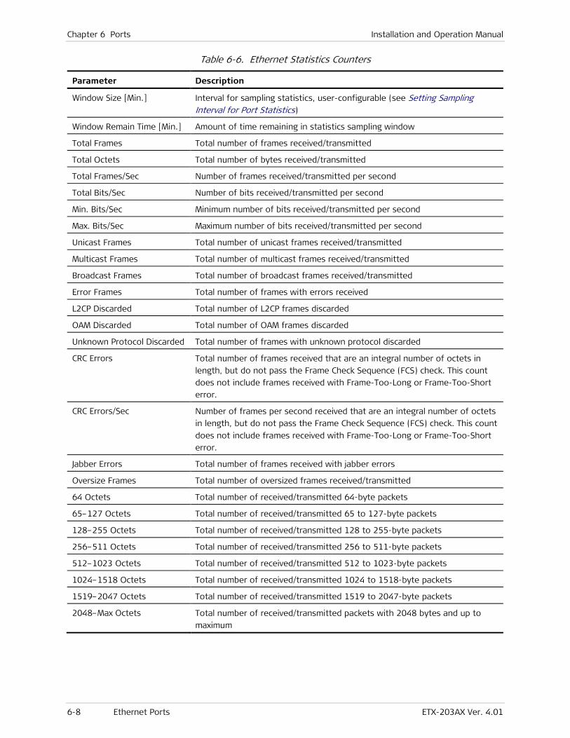
Chapter 6 Ports Installation and Operation Manual
6-8 Ethernet Ports ETX-203AX Ver. 4.01
Table 6-6. Ethernet Statistics Counters
Parameter Description
Window Size [Min.] Interval for sampling statistics, user-configurable (see Setting Sampling Interval for Port Statistics)
Window Remain Time [Min.] Amount of time remaining in statistics sampling window
Total Frames Total number of frames received/transmitted
Total Octets Total number of bytes received/transmitted
Total Frames/Sec Number of frames received/transmitted per second
Total Bits/Sec Number of bits received/transmitted per second
Min. Bits/Sec Minimum number of bits received/transmitted per second
Max. Bits/Sec Maximum number of bits received/transmitted per second
Unicast Frames Total number of unicast frames received/transmitted
Multicast Frames Total number of multicast frames received/transmitted
Broadcast Frames Total number of broadcast frames received/transmitted
Error Frames Total number of frames with errors received
L2CP Discarded Total number of L2CP frames discarded
OAM Discarded Total number of OAM frames discarded
Unknown Protocol Discarded Total number of frames with unknown protocol discarded
CRC Errors Total number of frames received that are an integral number of octets in
length, but do not pass the Frame Check Sequence (FCS) check. This count
does not include frames received with Frame-Too-Long or Frame-Too-Short
error.
CRC Errors/Sec Number of frames per second received that are an integral number of octets
in length, but do not pass the Frame Check Sequence (FCS) check. This count
does not include frames received with Frame-Too-Long or Frame-Too-Short
error.
Jabber Errors Total number of frames received with jabber errors
Oversize Frames Total number of oversized frames received/transmitted
64 Octets Total number of received/transmitted 64-byte packets
65–127 Octets Total number of received/transmitted 65 to 127-byte packets
128–255 Octets Total number of received/transmitted 128 to 255-byte packets
256–511 Octets Total number of received/transmitted 256 to 511-byte packets
512–1023 Octets Total number of received/transmitted 512 to 1023-byte packets
1024–1518 Octets Total number of received/transmitted 1024 to 1518-byte packets
1519–2047 Octets Total number of received/transmitted 1519 to 2047-byte packets
2048–Max Octets Total number of received/transmitted packets with 2048 bytes and up to
maximum
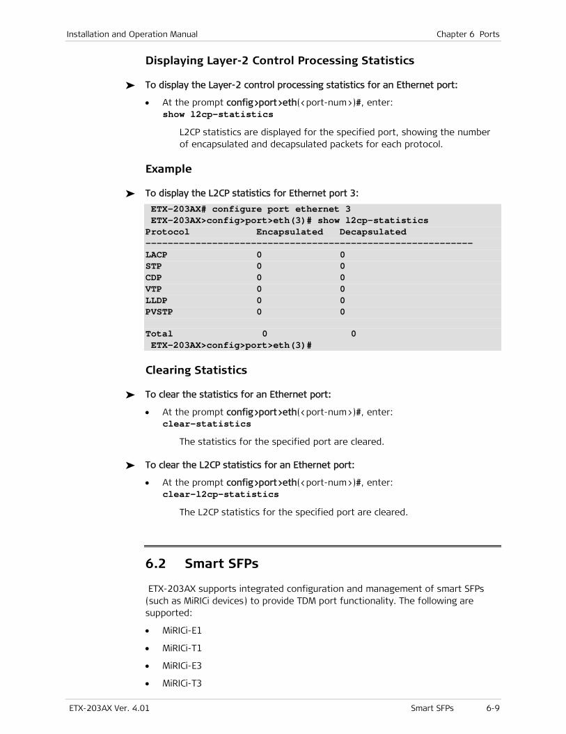
Installation and Operation Manual Chapter 6 Ports
ETX-203AX Ver. 4.01 Smart SFPs 6-9
Displaying Layer-2 Control Processing Statistics
To display the Layer-2 control processing statistics for an Ethernet port:
• At the prompt config>port>eth(<port-num>)#, enter: show l2cp-statistics
L2CP statistics are displayed for the specified port, showing the number of encapsulated and decapsulated packets for each protocol.
Example
To display the L2CP statistics for Ethernet port 3:
ETX-203AX# configure port ethernet 3 ETX-203AX>config>port>eth(3)# show l2cp-statistics Protocol Encapsulated Decapsulated ----------------------------------------------------------- LACP 0 0 STP 0 0 CDP 0 0 VTP 0 0 LLDP 0 0 PVSTP 0 0 Total 0 0 ETX-203AX>config>port>eth(3)#
Clearing Statistics
To clear the statistics for an Ethernet port:
• At the prompt config>port>eth(<port-num>)#, enter: clear-statistics
The statistics for the specified port are cleared.
To clear the L2CP statistics for an Ethernet port:
• At the prompt config>port>eth(<port-num>)#, enter: clear-l2cp-statistics
The L2CP statistics for the specified port are cleared.
6.2 Smart SFPs
ETX-203AX supports integrated configuration and management of smart SFPs (such as MiRICi devices) to provide TDM port functionality. The following are supported:
• MiRICi-E1
• MiRICi-T1
• MiRICi-E3
• MiRICi-T3
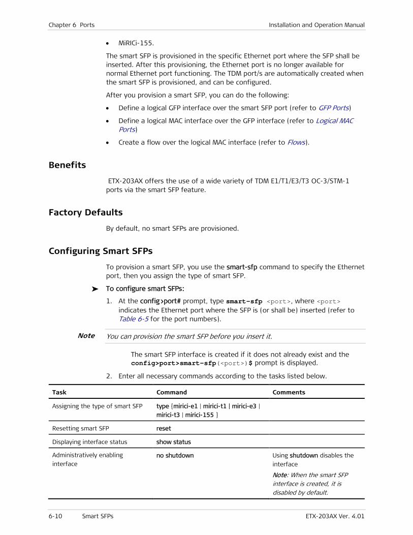
Chapter 6 Ports Installation and Operation Manual
6-10 Smart SFPs ETX-203AX Ver. 4.01
• MiRICi-155.
The smart SFP is provisioned in the specific Ethernet port where the SFP shall be inserted. After this provisioning, the Ethernet port is no longer available for normal Ethernet port functioning. The TDM port/s are automatically created when the smart SFP is provisioned, and can be configured.
After you provision a smart SFP, you can do the following:
• Define a logical GFP interface over the smart SFP port (refer to GFP Ports)
• Define a logical MAC interface over the GFP interface (refer to Logical MAC Ports)
• Create a flow over the logical MAC interface (refer to Flows).
Benefits
ETX-203AX offers the use of a wide variety of TDM E1/T1/E3/T3 OC-3/STM-1 ports via the smart SFP feature.
Factory Defaults
By default, no smart SFPs are provisioned.
Configuring Smart SFPs
To provision a smart SFP, you use the smart-sfp command to specify the Ethernet port, then you assign the type of smart SFP.
To configure smart SFPs:
1. At the config>port# prompt, type smart-sfp <port>, where <port> indicates the Ethernet port where the SFP is (or shall be) inserted (refer to Table 6-5 for the port numbers).
You can provision the smart SFP before you insert it.
The smart SFP interface is created if it does not already exist and the config>port>smart-sfp(<port>)$ prompt is displayed.
2. Enter all necessary commands according to the tasks listed below.
Task Command Comments
Assigning the type of smart SFP type {mirici-e1 | mirici-t1 | mirici-e3 |
mirici-t3 | mirici-155 }
Resetting smart SFP reset
Displaying interface status show status
Administratively enabling
interface no shutdown Using shutdown disables the
interface
Note: When the smart SFP interface is created, it is disabled by default.
Note

Installation and Operation Manual Chapter 6 Ports
ETX-203AX Ver. 4.01 Smart SFPs 6-11
Example
This example shows how a smart SFP can be provisioned, and a flow created over the logical MAC port corresponding to a logical GFP port. The smart SFP can be inserted before or after the provisioning.
To provision a smart SFP and corresponding flow:
• Ethernet port 1
• Smart SFP type = MiRICi-E1
• GFP port 1
• Logical MAC port 1
• Flow = flow1, with classification criterion VLAN 1.
Perform the following steps:
1. Provision the smart SFP.
ETX-204A# configure port smart-sfp 1 ETX-204A>config>port>smart-sfp(1)$ type mirici-e1 ETX-204A>config>port>smart-sfp(1)$ info detail type mirici-e1 no shutdown ETX-204A>config>port>smart-sfp(1)$ exit
2. Create the GFP and bind it to the E1 port.
ETX-204A>config>port# gfp 1 ETX-204A>config>port>gfp(1)# bind e1 1 ETX-204A>config>port>gfp(1)# info detail name "GFP 1" bind e1 1 no fcs-payload ETX-204A>config>port>gfp(1)$ exit
3. Create the logical MAC port and bind it to GFP port 1.
ETX-204A>config>port# logical-mac 1 ETX-204A>config>port>log-mac(1)$ bind gfp 1 ETX-204A>config>port>log-mac(1)$ no shutdown ETX-204A>config>port>log-mac(1)$ info detail name "LOGICAL MAC 1" no shutdown bind gfp 1 tag-ethernet-type 0x8100 egress-mtu 1790 queue-group profile "DefaultQueueGroup" l2cp profile "L2cpDefaultProfile ETX-204A>config>port>log-mac(1)$exit all
4. Create the flow and activate it.
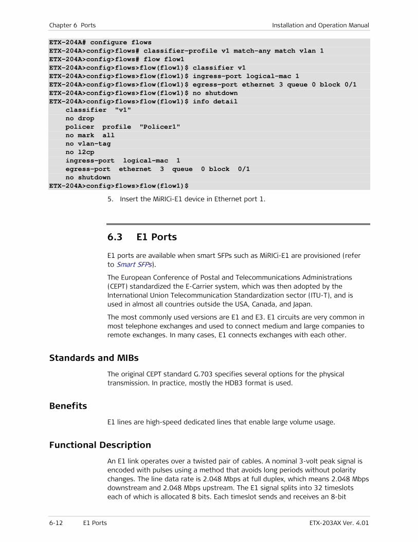
Chapter 6 Ports Installation and Operation Manual
6-12 E1 Ports ETX-203AX Ver. 4.01
ETX-204A# configure flows ETX-204A>config>flows# classifier-profile v1 match-any match vlan 1 ETX-204A>config>flows# flow flow1 ETX-204A>config>flows>flow(flow1)$ classifier v1 ETX-204A>config>flows>flow(flow1)$ ingress-port logical-mac 1 ETX-204A>config>flows>flow(flow1)$ egress-port ethernet 3 queue 0 block 0/1 ETX-204A>config>flows>flow(flow1)$ no shutdown ETX-204A>config>flows>flow(flow1)$ info detail classifier "v1" no drop policer profile "Policer1" no mark all no vlan-tag no l2cp ingress-port logical-mac 1 egress-port ethernet 3 queue 0 block 0/1 no shutdown ETX-204A>config>flows>flow(flow1)$
5. Insert the MiRICi-E1 device in Ethernet port 1.
6.3 E1 Ports
E1 ports are available when smart SFPs such as MiRICi-E1 are provisioned (refer to Smart SFPs).
The European Conference of Postal and Telecommunications Administrations (CEPT) standardized the E-Carrier system, which was then adopted by the International Union Telecommunication Standardization sector (ITU-T), and is used in almost all countries outside the USA, Canada, and Japan.
The most commonly used versions are E1 and E3. E1 circuits are very common in most telephone exchanges and used to connect medium and large companies to remote exchanges. In many cases, E1 connects exchanges with each other.
Standards and MIBs
The original CEPT standard G.703 specifies several options for the physical transmission. In practice, mostly the HDB3 format is used.
Benefits
E1 lines are high-speed dedicated lines that enable large volume usage.
Functional Description
An E1 link operates over a twisted pair of cables. A nominal 3-volt peak signal is encoded with pulses using a method that avoids long periods without polarity changes. The line data rate is 2.048 Mbps at full duplex, which means 2.048 Mbps downstream and 2.048 Mbps upstream. The E1 signal splits into 32 timeslots each of which is allocated 8 bits. Each timeslot sends and receives an 8-bit
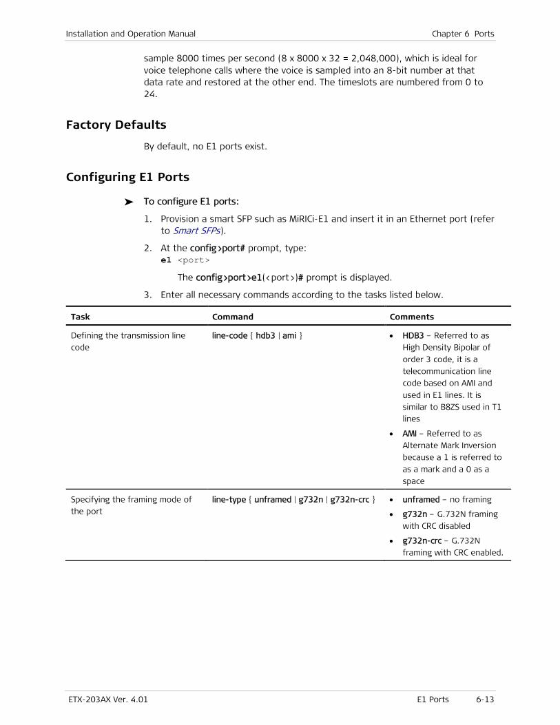
Installation and Operation Manual Chapter 6 Ports
ETX-203AX Ver. 4.01 E1 Ports 6-13
sample 8000 times per second (8 x 8000 x 32 = 2,048,000), which is ideal for voice telephone calls where the voice is sampled into an 8-bit number at that data rate and restored at the other end. The timeslots are numbered from 0 to 24.
Factory Defaults
By default, no E1 ports exist.
Configuring E1 Ports
To configure E1 ports:
1. Provision a smart SFP such as MiRICi-E1 and insert it in an Ethernet port (refer to Smart SFPs).
2. At the config>port# prompt, type: e1 <port>
The config>port>e1(<port>)# prompt is displayed.
3. Enter all necessary commands according to the tasks listed below.
Task Command Comments
Defining the transmission line
code
line-code { hdb3 | ami } • HDB3 – Referred to as
High Density Bipolar of
order 3 code, it is a
telecommunication line
code based on AMI and
used in E1 lines. It is
similar to B8ZS used in T1
lines
• AMI – Referred to as
Alternate Mark Inversion
because a 1 is referred to
as a mark and a 0 as a
space
Specifying the framing mode of
the port
line-type { unframed | g732n | g732n-crc } • unframed – no framing
• g732n – G.732N framing
with CRC disabled
• g732n-crc – G.732N
framing with CRC enabled.

Chapter 6 Ports Installation and Operation Manual
6-14 E1 Ports ETX-203AX Ver. 4.01
Task Command Comments
Running loopback test on E1 port loopback {local | remote | payload }
[start <seconds> ] [duration <seconds>]
[time-slot <slot> ]
• local – Returns the
transmitted data at the
physical layer to the
receiving path
• remote – Returns the
received data at the
physical layer to the
transmitting path
• payload –Adds a header to
the data (reframes the
data) and returns the
received data at the
physical layer to the
transmitting path
• start – Specifies the time
(in seconds) until the
loopback starts. Range is
1 to 3600.
• duration – Specifies the
duration of the loopback
(in seconds). Range is
1 to 3600. If duration is
not specified, the
loopback test runs
forever, until stopped
• time-slot – Specifies the
timeslot on the selected
port to be included in the
loopback
Use no loopback to disable
the loopback test.
Assigning a name to the port name <string>
Specifying the attenuation level
of the received signal,
compensated for by the interface
receive path
rx-sensitivity {short-haul | long-haul} • short-haul – Low
sensitivity
• long-haul – High
sensitivity
Selecting the transmit clock
source
tx-clock-source {loopback | internal } • loopback –Clock retrieved
from the port's incoming
(Rx) data
• internal – Clock provided
by internal oscillator.
Displaying alarms for port show alarms
Displaying list of interfaces bound
to port
show bind
Displaying loopback test status show loopback

Installation and Operation Manual Chapter 6 Ports
ETX-203AX Ver. 4.01 T1 Ports 6-15
Task Command Comments
Displaying the port status show status
Displaying the port statistics show statistics current
show statistics interval <interval-num>
show statistics all-intervals
show statistics all
Clearing the statistics clear-statistics
6.4 T1 Ports
T1 ports are available when smart SFPs such as MiRICi-T1 are provisioned (refer to Smart SFPs).
The T-carrier signaling scheme was devised by Bell Labs and is a widely used standard in telecommunications in the USA, Canada, and Japan to transmit voice and data between devices. T1, also referred to as DS-1, is a dedicated data line that transmits information at the speed of 1.544 megabits per second (mbps).
Standards and MIBs
The G.703 standard specifies several options for the physical transmission. In practice, mostly the B8ZS format is used.
Benefits
T1 lines are high-speed dedicated lines that enable large volume usage.
Functional Description
A T1 link operates over a twisted pair of cables. A nominal 3-volt peak signal is encoded with pulses using a method that avoids long periods without polarity changes. The line data rate is 1.544 Mbps at full duplex, which means 1.544 Mbps for downstream and 1.544 Mbps for upstream. The T1 signal splits into 24 timeslots each which is allocated 8 bits. Each timeslot sends and receives an 8-bit sample 8000 times per second (8 x 8000 x 24 = 1,544,000), which is ideal for voice telephone calls where the voice is sampled into an 8-bit number at that data rate and restored at the other end. The timeslots are numbered from 0 to 24.
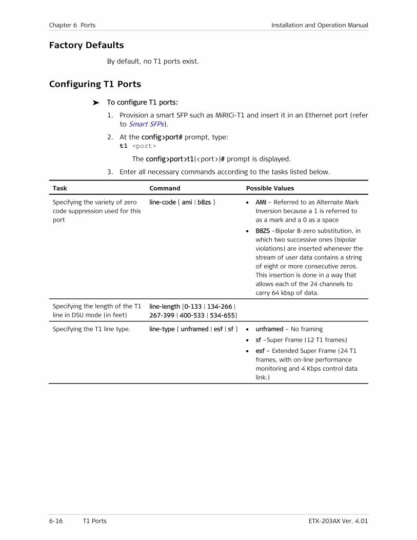
Chapter 6 Ports Installation and Operation Manual
6-16 T1 Ports ETX-203AX Ver. 4.01
Factory Defaults
By default, no T1 ports exist.
Configuring T1 Ports
To configure T1 ports:
1. Provision a smart SFP such as MiRICi-T1 and insert it in an Ethernet port (refer to Smart SFPs).
2. At the config>port# prompt, type: t1 <port>
The config>port>t1(<port>)# prompt is displayed.
3. Enter all necessary commands according to the tasks listed below.
Task Command Possible Values
Specifying the variety of zero
code suppression used for this
port
line-code { ami | b8zs } • AMI – Referred to as Alternate Mark
Inversion because a 1 is referred to
as a mark and a 0 as a space
• B8ZS –Bipolar 8-zero substitution, in
which two successive ones (bipolar
violations) are inserted whenever the
stream of user data contains a string
of eight or more consecutive zeros.
This insertion is done in a way that
allows each of the 24 channels to
carry 64 kbsp of data.
Specifying the length of the T1
line in DSU mode (in feet) line-length {0-133 | 134-266 |
267-399 | 400-533 | 534-655}
Specifying the T1 line type. line-type { unframed | esf | sf } • unframed – No framing
• sf –Super Frame (12 T1 frames)
• esf – Extended Super Frame (24 T1
frames, with on-line performance
monitoring and 4 Kbps control data
link.)

Installation and Operation Manual Chapter 6 Ports
ETX-203AX Ver. 4.01 T1 Ports 6-17
Task Command Possible Values
Running loopback test on T1
port
loopback {local | remote |
payload } [start <seconds> ]
[duration <seconds>]
[time-slot <slot> ]
• local – Returns the transmitted data
at the physical layer to the receiving
path
• remote – Returns the received data
at the physical layer to the
transmitting path
• payload –Adds a header to the data
(reframes the data) and returns the
received data at the physical layer to
the transmitting path
• start – Specifies the time (in
seconds) until the loopback starts.
Range is 1 to 3600.
• duration – Specifies the duration of
the loopback (in seconds). Range is
1 to 3600. If duration is not
specified, the loopback test runs
forever, until stopped
• time-slot – Specifies the timeslot on
the selected port to be included in
the loopback
Use no loopback to disable the loopback
test.
Assigning a name to the port name <string>
Specifying attenuation level of
the receive signal that is
compensated for by the
interface receive path
rx-sensitivity { short-haul |
long-haul }
Selecting the transmit clock
source
tx-clock-source {loopback |
internal }
• loopback –Clock retrieved from the
port's incoming (Rx) data
• internal – Clock provided by internal
oscillator.
Displaying alarms for port show alarms
Displaying list of interfaces
bound to port
show bind
Displaying loopback test status show loopback
Displaying the port status show status
Displaying the port statistics show statistics current
show statistics interval
<interval-num>
show statistics all-intervals
show statistics all
Clearing the statistics clear-statistics

Chapter 6 Ports Installation and Operation Manual
6-18 E3 Ports ETX-203AX Ver. 4.01
6.5 E3 Ports
E3 ports are available when smart SFPs such as MiRICi-E3 are provisioned (refer to Smart SFPs).
Groups of E1 circuits are bundled into higher-capacity E3 links, which are mainly used between exchanges, operators, and/or countries, and have a transmission speed of 34.368 Mbps.
Standards and MIBs
G.703 specifies several options for the physical transmission.
Benefits
E3 lines provide high-capacity circuits.
Functional Description
Each E3 signal has 16 E1 channels, and each channel transmits at 2.048 Mbps. E3 links use all 8 bits of a channel.
Factory Defaults
By default, no E3 ports exist.
Configuring E3 Ports
To configure E3 ports:
1. Provision a smart SFP such as MiRICi-E3 and insert it in an Ethernet port (refer to Smart SFPs).
2. At the config>port# prompt, type: e3 <port>
The config>port>e3(<port>)# prompt is displayed.
3. Enter all necessary commands according to the tasks listed below.
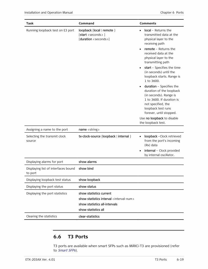
Installation and Operation Manual Chapter 6 Ports
ETX-203AX Ver. 4.01 T3 Ports 6-19
Task Command Comments
Running loopback test on E3 port loopback {local | remote }
[start <seconds> ]
[duration <seconds>]
• local – Returns the
transmitted data at the
physical layer to the
receiving path
• remote – Returns the
received data at the
physical layer to the
transmitting path
• start – Specifies the time
(in seconds) until the
loopback starts. Range is
1 to 3600.
• duration – Specifies the
duration of the loopback
(in seconds). Range is
1 to 3600. If duration is
not specified, the
loopback test runs
forever, until stopped.
Use no loopback to disable
the loopback test.
Assigning a name to the port name <string>
Selecting the transmit clock
source
tx-clock-source {loopback | internal } • loopback –Clock retrieved
from the port's incoming
(Rx) data
• internal – Clock provided
by internal oscillator.
Displaying alarms for port show alarms
Displaying list of interfaces bound
to port
show bind
Displaying loopback test status show loopback
Displaying the port status show status
Displaying the port statistics show statistics current
show statistics interval <interval-num>
show statistics all-intervals
show statistics all
Clearing the statistics clear-statistics
6.6 T3 Ports
T3 ports are available when smart SFPs such as MiRICi-T3 are provisioned (refer to Smart SFPs).
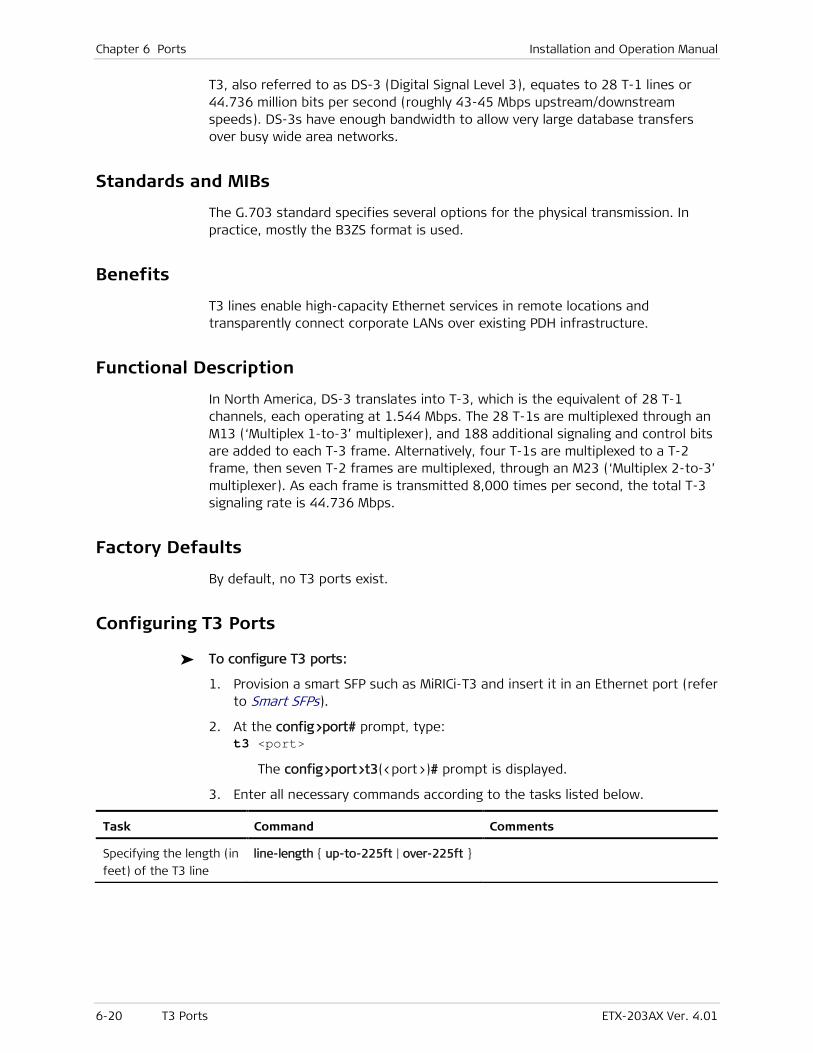
Chapter 6 Ports Installation and Operation Manual
6-20 T3 Ports ETX-203AX Ver. 4.01
T3, also referred to as DS-3 (Digital Signal Level 3), equates to 28 T-1 lines or 44.736 million bits per second (roughly 43-45 Mbps upstream/downstream speeds). DS-3s have enough bandwidth to allow very large database transfers over busy wide area networks.
Standards and MIBs
The G.703 standard specifies several options for the physical transmission. In practice, mostly the B3ZS format is used.
Benefits
T3 lines enable high-capacity Ethernet services in remote locations and transparently connect corporate LANs over existing PDH infrastructure.
Functional Description
In North America, DS-3 translates into T-3, which is the equivalent of 28 T-1 channels, each operating at 1.544 Mbps. The 28 T-1s are multiplexed through an M13 (‘Multiplex 1-to-3’ multiplexer), and 188 additional signaling and control bits are added to each T-3 frame. Alternatively, four T-1s are multiplexed to a T-2 frame, then seven T-2 frames are multiplexed, through an M23 (‘Multiplex 2-to-3’ multiplexer). As each frame is transmitted 8,000 times per second, the total T-3 signaling rate is 44.736 Mbps.
Factory Defaults
By default, no T3 ports exist.
Configuring T3 Ports
To configure T3 ports:
1. Provision a smart SFP such as MiRICi-T3 and insert it in an Ethernet port (refer to Smart SFPs).
2. At the config>port# prompt, type: t3 <port>
The config>port>t3(<port>)# prompt is displayed.
3. Enter all necessary commands according to the tasks listed below.
Task Command Comments
Specifying the length (in
feet) of the T3 line
line-length { up-to-225ft | over-225ft }

Installation and Operation Manual Chapter 6 Ports
ETX-203AX Ver. 4.01 T3 Ports 6-21
Task Command Comments
Specifying type of T3
line
line-type { m13 | m23 | c-bit-parity } • m13 –28 DS1 signals are
multiplexed into one DS3 signal
• m23 –Four DS1 signals are are
multiplexed into one DS2 signal,
then seven DS2 signals are
multiplexed into one DS3 signal
• c-bit-parity – The c-bit parity
framing format is an enhancement
of the original M13 application,
providing greater management and
performance functions.
Running loopback test
on T3 port
loopback {local | remote } [start
<seconds> ] [duration <seconds>]
• local – Returns the transmitted data
at the physical layer to the receiving
path
• remote – Returns the received data
at the physical layer to the
transmitting path
• start – Specifies the time (in
seconds) until the loopback starts.
Range is 1 to 3600.
• duration – Specifies the duration of
the loopback (in seconds). Range is
1 to 3600. If duration is not
specified, the loopback test runs
forever, until stopped.
Use no loopback to disable the
loopback test.
Assigning a name to the
port
name <string>
Selecting the transmit
clock source
tx-clock-source {loopback | internal } • loopback –Clock retrieved from the
port's incoming (Rx) data
• internal – Clock provided by internal
oscillator.
Displaying alarms for
port
show alarms
Displaying list of
interfaces bound to
port
show bind
Displaying loopback test
status
show loopback
Displaying the port
status
show status
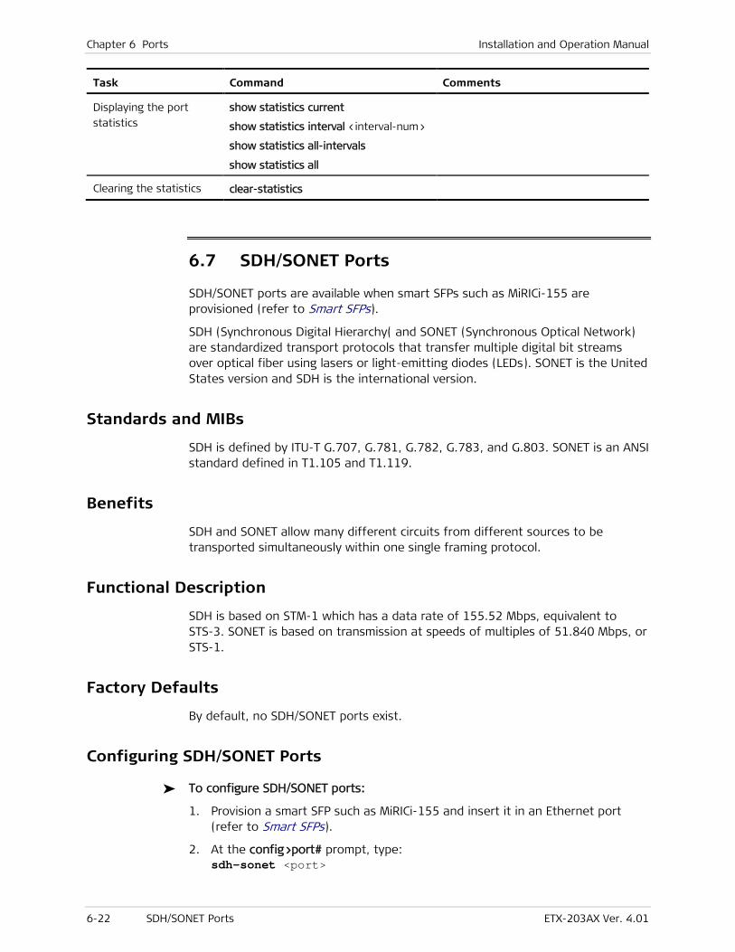
Chapter 6 Ports Installation and Operation Manual
6-22 SDH/SONET Ports ETX-203AX Ver. 4.01
Task Command Comments
Displaying the port
statistics
show statistics current
show statistics interval <interval-num>
show statistics all-intervals
show statistics all
Clearing the statistics clear-statistics
6.7 SDH/SONET Ports
SDH/SONET ports are available when smart SFPs such as MiRICi-155 are provisioned (refer to Smart SFPs).
SDH (Synchronous Digital Hierarchy( and SONET (Synchronous Optical Network) are standardized transport protocols that transfer multiple digital bit streams over optical fiber using lasers or light-emitting diodes (LEDs). SONET is the United States version and SDH is the international version.
Standards and MIBs
SDH is defined by ITU-T G.707, G.781, G.782, G.783, and G.803. SONET is an ANSI standard defined in T1.105 and T1.119.
Benefits
SDH and SONET allow many different circuits from different sources to be transported simultaneously within one single framing protocol.
Functional Description
SDH is based on STM-1 which has a data rate of 155.52 Mbps, equivalent to STS-3. SONET is based on transmission at speeds of multiples of 51.840 Mbps, or STS-1.
Factory Defaults
By default, no SDH/SONET ports exist.
Configuring SDH/SONET Ports
To configure SDH/SONET ports:
1. Provision a smart SFP such as MiRICi-155 and insert it in an Ethernet port (refer to Smart SFPs).
2. At the config>port# prompt, type: sdh-sonet <port>

Installation and Operation Manual Chapter 6 Ports
ETX-203AX Ver. 4.01 SDH/SONET Ports 6-23
The config>port>sdh-sonet(<port>)# prompt is displayed.
3. Enter all necessary commands according to the tasks listed below.
Task Command Comments
Specifying the cell
frame type
frame-type { sdh | sonet }
Running loopback test
on port
loopback {local | remote }
[start <seconds> ] [duration <seconds>] • local – Returns the transmitted data
at the physical layer to the receiving
path
• remote – Returns the received data
at the physical layer to the
transmitting path
• start – Specifies the time (in
seconds) until the loopback starts
• duration – Specifies the duration of
the loopback (in seconds). If
duration is not specified, the
loopback test runs forever, until
stopped.
Use no loopback to disable the
loopback test.
Assigning a name to
the port
name <string>
Defining thresholds:
• EED (Excessive
Error Defect) –
detected if the
equivalent BER (bit
error rate) exceeds
the selected
threshold
parameters
• SD (Degraded
Signal Defect) –
detected if the
equivalent BER
exceeds the
selected threshold
parameter.
threshold [ eed { 1e-3 |1e-4 | 1e-5 }]
[ sd { 1e-5 | 1e-6 | 1e-7 | 1e-8 | 1e-9 }]
Selecting the transmit
clock source
tx-clock-source {internal | l oopback} • internal – Clock provided by internal
oscillator
• loopback –Clock retrieved from the
port's incoming (Rx) data.
Displaying list of
interfaces bound to
port
show bind

Chapter 6 Ports Installation and Operation Manual
6-24 GFP Ports ETX-203AX Ver. 4.01
Task Command Comments
Displaying the port
status
show status
Displaying the port
statistics
show statistics current
show statistics interval <interval-num>
show statistics all-intervals
show statistics all
6.8 GFP Ports
ETX-203AX uses GFP (Generic Framing Procedure) ports to provide a logical link to the TDM ports that become available when smart SFPs are inserted (refer to Smart SFPs).
ETX-203AX supports up to 16 GFP ports.
Factory Defaults
By default, no GFP ports exist. When a GFP port is created, it is configured as shown below.
Description Default Value
Port name GFP <n>
Enabling/disabling CRC-32 sequence of GFP packet payload No FCS payload
Configuring GFP Logical Ports
To configure GFP logical ports:
1. At the config>port# prompt, type: gfp <port>
The port is created if it does not already exist, and the config>port>gfp(<port>)# prompt is displayed.
2. Enter all necessary commands according to the tasks listed below.
Task Command Comments
Binding GFP port to E1 port bind e1 <port> Note: Successful only if a smart SFP that provides the E1 port has been provisioned.
Binding GFP port to T1 port bind t1 <port> Note: Successful only if a smart SFP that provides the T1 port has been provisioned.
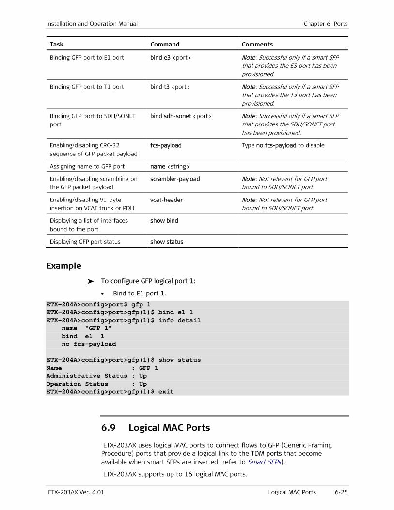
Installation and Operation Manual Chapter 6 Ports
ETX-203AX Ver. 4.01 Logical MAC Ports 6-25
Task Command Comments
Binding GFP port to E1 port bind e3 <port> Note: Successful only if a smart SFP that provides the E3 port has been provisioned.
Binding GFP port to T1 port bind t3 <port> Note: Successful only if a smart SFP that provides the T3 port has been provisioned.
Binding GFP port to SDH/SONET
port
bind sdh-sonet <port> Note: Successful only if a smart SFP that provides the SDH/SONET port has been provisioned.
Enabling/disabling CRC-32
sequence of GFP packet payload
fcs-payload Type no fcs-payload to disable
Assigning name to GFP port name <string>
Enabling/disabling scrambling on
the GFP packet payload
scrambler-payload Note: Not relevant for GFP port bound to SDH/SONET port
Enabling/disabling VLI byte
insertion on VCAT trunk or PDH
vcat-header Note: Not relevant for GFP port bound to SDH/SONET port
Displaying a list of interfaces
bound to the port
show bind
Displaying GFP port status show status
Example
To configure GFP logical port 1:
• Bind to E1 port 1.
ETX-204A>config>port$ gfp 1 ETX-204A>config>port>gfp(1)$ bind e1 1 ETX-204A>config>port>gfp(1)$ info detail name "GFP 1" bind e1 1 no fcs-payload ETX-204A>config>port>gfp(1)$ show status Name : GFP 1 Administrative Status : Up Operation Status : Up ETX-204A>config>port>gfp(1)$ exit
6.9 Logical MAC Ports
ETX-203AX uses logical MAC ports to connect flows to GFP (Generic Framing Procedure) ports that provide a logical link to the TDM ports that become available when smart SFPs are inserted (refer to Smart SFPs).
ETX-203AX supports up to 16 logical MAC ports.
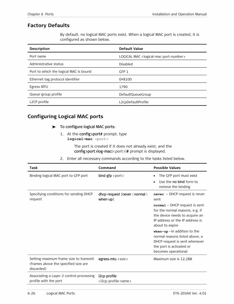
Chapter 6 Ports Installation and Operation Manual
6-26 Logical MAC Ports ETX-203AX Ver. 4.01
Factory Defaults
By default, no logical MAC ports exist. When a logical MAC port is created, it is configured as shown below.
Description Default Value
Port name LOGICAL MAC <logical-mac-port-number>
Administrative status Disabled
Port to which the logical MAC is bound GFP 1
Ethernet tag protocol identifier 0×8100
Egress MTU 1790
Queue group profile DefaultQueueGroup
L2CP profile L2cpDefaultProfile
Configuring Logical MAC ports
To configure logical MAC ports:
1. At the config>port# prompt, type logical-mac <port>
The port is created if it does not already exist, and the config>port>log-mac(<port>)# prompt is displayed.
2. Enter all necessary commands according to the tasks listed below.
Task Command Possible Values
Binding logical MAC port to GFP port bind gfp <port> • The GFP port must exist
• Use the no bind form to
remove the binding
Specifying conditions for sending DHCP
request dhcp-request {never | normal |
when-up}
never – DHCP request is never
sent
normal – DHCP request is sent
for the normal reasons, e.g. if
the device needs to acquire an
IP address or the IP address is
about to expire
when-up –In addition to the
normal reasons listed above, a
DHCP request is sent whenever
the port is activated or
becomes operational
Setting maximum frame size to transmit
(frames above the specified size are
discarded)
egress-mtu <size> Maximum size is 12,288
Associating a Layer-2 control processing
profile with the port l2cp profile
<l2cp-profile-name>

Installation and Operation Manual Chapter 6 Ports
ETX-203AX Ver. 4.01 Service Virtual Interfaces 6-27
Task Command Possible Values
Running loopback test on port loopback {local|remote}
[duration <seconds>]
Use the no loopback command
to stop the test
Assigning a name to the port name <string>
Associating a queue group profile with
the port queue-group profile <queue-
profile-name>
Setting the VLAN tagged frame ETH II
frame Ethertype (tag protocol
identifier)
tag-ethernet-type
<0x0000-0xFFFF>
Ethernet type value:
0x0000–0xFFFF
Administratively enabling port no shutdown Using shutdown disables the
port
Displaying the interfaces that are bound
to the port show bind
Displaying port status show status
Displaying port statistics show statistics
Clearing port statistics clear-statistics
Example
To configure logical MAC port 1:
• Bind to GFP port 1.
ETX-204A>config>port# logical-mac 1 ETX-204A>config>port>log-mac(1)$ bind gfp 1 ETX-204A>config>port>log-mac(1)$ no shutdown ETX-204A>config>port>log-mac(1)$ info detail name "LOGICAL MAC 1" no shutdown bind gfp 1 tag-ethernet-type 0x8100 egress-mtu 1790 queue-group profile "DefaultQueueGroup" l2cp profile "L2cpDefaultProfile ETX-204A>config>port>log-mac(1)$ show status Name : LOGICAL MAC 1 Administrative Status : Up Operational Status : Up ETX-204A>config>port>log-mac(1)$
6.10 Service Virtual Interfaces
Service virtual interfaces (SVIs) are logical ports used for flows. Service virtual interfaces (SVIs) are logical ports used to link router interfaces with Ethernet ports (via Layer-2 flows).
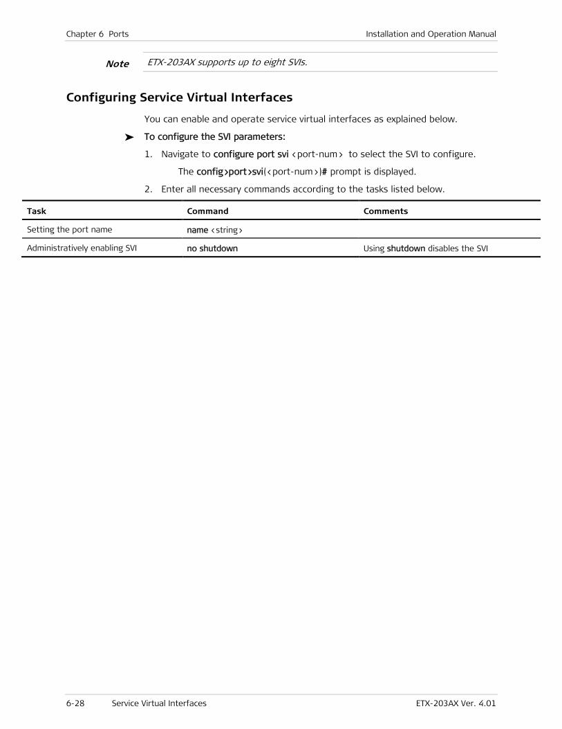
Chapter 6 Ports Installation and Operation Manual
6-28 Service Virtual Interfaces ETX-203AX Ver. 4.01
ETX-203AX supports up to eight SVIs.
Configuring Service Virtual Interfaces
You can enable and operate service virtual interfaces as explained below.
To configure the SVI parameters:
1. Navigate to configure port svi <port-num> to select the SVI to configure.
The config>port>svi(<port-num>)# prompt is displayed.
2. Enter all necessary commands according to the tasks listed below.
Task Command Comments
Setting the port name name <string>
Administratively enabling SVI no shutdown Using shutdown disables the SVI
Note
ETX-203AX Ver. 4.01 Ethernet Linear Protection 7-1
Chapter 7
Resiliency This chapter describes features related to resiliency:
• Ethernet Linear Protection
• Fault Propagation
• Network Interface Redundancy.
7.1 Ethernet Linear Protection
ETX-203AX provides protection switching in the following modes for network ports per ITU-T G.8031:
• 1:1
• Unidirectional
• Using APS messages.
The triggers are:
• Port Signal loss
• CCM LOC
• ETH-AIS.
The protection time is as follows:
• One EVC pair — 50ms protection
• Four EVC pairs — 200ms protection.
Standards
ITU-T G.8031
Benefits
The Ethernet linear protection provides a way to protect the flows belonging to an EVC.
Functional Description
The protection is based on an EVC Termination Point (ETP). An ETP has one subscriber port and one or more transport ports. Multiple transport ports are used for protection only. There are two kinds of flows connected to the ETP ports, subscriber flows and transport flows.
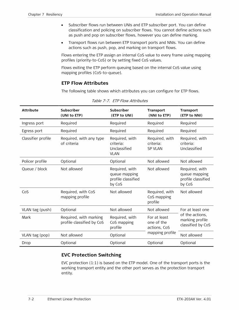
Chapter 7 Resiliency Installation and Operation Manual
7-2 Ethernet Linear Protection ETX-203AX Ver. 4.01
• Subscriber flows run between UNIs and ETP subscriber port. You can define classification and policing on subscriber flows. You cannot define actions such as push and pop on subscriber flows, however you can define marking.
• Transport flows run between ETP transport ports and NNIs. You can define actions such as push, pop, and marking on transport flows.
Flows entering the ETP assign an internal CoS value to every frame using mapping profiles (priority-to-CoS) or by setting fixed CoS values.
Flows exiting the ETP perform queuing based on the internal CoS value using mapping profiles (CoS-to-queue).
ETP Flow Attributes
The following table shows which attributes you can configure for ETP flows.
Table 7-7. ETP Flow Attributes
Attribute Subscriber
(UNI to ETP)
Subscriber
(ETP to UNI)
Transport
(NNI to ETP)
Transport
(ETP to NNI)
Ingress port Required Required Required Required
Egress port Required Required Required Required
Classifier profile Required, with any type of criteria
Required, with criteria: Unclassified VLAN
Required, with criteria: SP VLAN
Required, with criteria: Unclassified
Policer profile Optional Optional Not allowed Not allowed
Queue / block Not allowed Required, with queue mapping profile classified by CoS
Not allowed Required, with queue mapping profile classified by CoS
CoS Required, with CoS mapping profile
Not allowed Required, with CoS mapping profile
Not allowed
VLAN tag (push) Optional Not allowed Not allowed For at least one of the actions, marking profile classified by CoS
Mark Required, with marking profile classified by CoS
Required, with CoS mapping profile
For at least one of the actions, CoS mapping profile
VLAN tag (pop) Not allowed Optional Not allowed
Drop Optional Optional Optional Optional
EVC Protection Switching EVC protection (1:1) is based on the ETP model. One of the transport ports is the working transport entity and the other port serves as the protection transport entity.
Installation and Operation Manual Chapter 7 Resiliency
ETX-203AX Ver. 4.01 Ethernet Linear Protection 7-3
Monitoring both working and protection transport entity is done via MEPs exchanging CCMs. In addition the protection transport optionally runs APS protocol.
Master and Slave ETPs
You can define one master ETP and several slave ETPs. The master ETP must have all the configuration of the protection, same as single ETP. The slave ETPs point to the master ETP via master command and bind each port ID to working/protection.
The master ETP index MUST be lower than the index of the slave ETPs. You must create the master ETP before creating the slave ETPs.
EVC and OAM
On each transport entity you must define a MEP in order to monitor the connection using CCM. The MEPs must be activated so that the protection switching mechanism can monitor both working and protection transport entities. The monitoring is accomplished by exchanging CCMs as defined in ITU-T Rec. Y.1731.
In addition the MEP can be defined to perform other Y.1731 services such as measuring delay and loss on the specific EVC.
EVC Fault Propagation
You can define fault propagation based on EVC failure detection (ETP operation status) to shut down the UNIs that connect to it. The fault trigger can be on of the following:
• In case of protection: the signal failure trigger MEP for ETP transport ports
• In other cases: the NNI operation status.
EVC Loopback
A loopback can be activated on any of the transport ports towards the network and on the subscriber port towards the user or network.
In most cases you would activate a loop on the subscriber port towards the network, thus you can loop the EVC traffic without affecting protection.
If you wish to run a loop on a specific EVC path when you activate the loop on the transport ports, you have two options:
• Loopback on a transport port affects OAM, as any traffic EVC path redundancy is triggered if present.
• Loopback only data without affecting redundancy.
Factory Defaults
By default, no ETPs are configured.
When you create an ETP port, by default it is configured as follows:
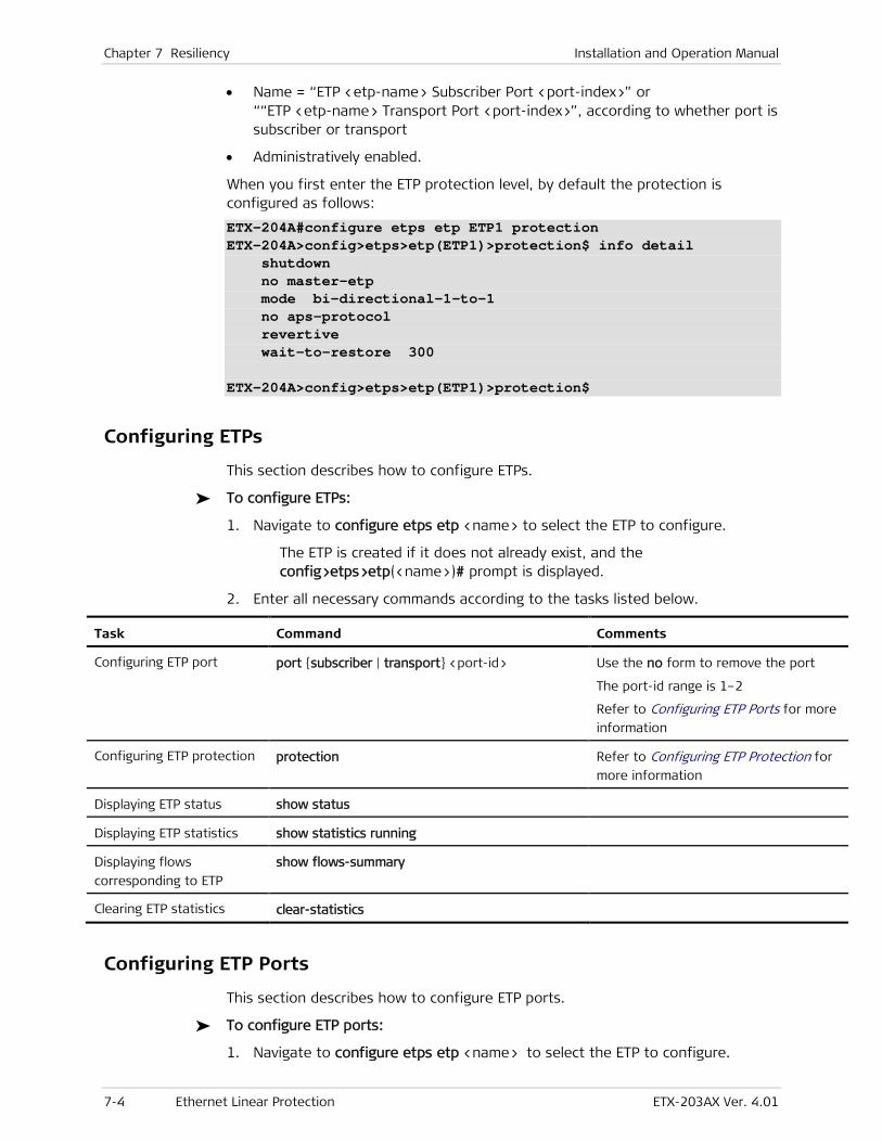
Chapter 7 Resiliency Installation and Operation Manual
7-4 Ethernet Linear Protection ETX-203AX Ver. 4.01
• Name = “ETP <etp-name> Subscriber Port <port-index>” or ““ETP <etp-name> Transport Port <port-index>”, according to whether port is subscriber or transport
• Administratively enabled.
When you first enter the ETP protection level, by default the protection is configured as follows:
ETX-204A#configure etps etp ETP1 protection ETX-204A>config>etps>etp(ETP1)>protection$ info detail shutdown no master-etp mode bi-directional-1-to-1 no aps-protocol revertive wait-to-restore 300 ETX-204A>config>etps>etp(ETP1)>protection$
Configuring ETPs
This section describes how to configure ETPs.
To configure ETPs:
1. Navigate to configure etps etp <name> to select the ETP to configure.
The ETP is created if it does not already exist, and the config>etps>etp(<name>)# prompt is displayed.
2. Enter all necessary commands according to the tasks listed below.
Task Command Comments
Configuring ETP port port {subscriber | transport} <port-id> Use the no form to remove the port
The port-id range is 1–2
Refer to Configuring ETP Ports for more
information
Configuring ETP protection protection Refer to Configuring ETP Protection for
more information
Displaying ETP status show status
Displaying ETP statistics show statistics running
Displaying flows
corresponding to ETP
show flows-summary
Clearing ETP statistics clear-statistics
Configuring ETP Ports
This section describes how to configure ETP ports.
To configure ETP ports:
1. Navigate to configure etps etp <name> to select the ETP to configure.

Installation and Operation Manual Chapter 7 Resiliency
ETX-203AX Ver. 4.01 Ethernet Linear Protection 7-5
The config>etps>etp(<name>)# prompt is displayed.
2. Type the following command to configure a port, where port-index can be 1 for subscriber ports, or 1–2 for transport ports: port {subscriber | transport} <port-index>
The prompt is displayed according to whether you typed subscriber or transport: config>etps>etp(<name>)>port(subscriber/<port-index>)# config>etps>etp(<name>)>port(transport/<port-index>)#
3. Enter all necessary commands according to the tasks listed below.
Task Command Comments
Activating loopback loopback [local | remote] [duration <seconds>]
Assigning name to ETP port name <string>
Displaying loopback status show loopback
Displaying status show status
Administratively enabling
ETP port no shutdown Using shutdown disables the port
Note: When the port is created, it is enabled by default.
Example
To configure an ETP:
• Name = ETP1
• Port members = subscriber 1, transport 1, transport 2.
ETX-204A# configure etps etp ETP1 ETX-204A>config>etps>etp(ETP1)# port subscriber 1 ETX-204A>config>etps>etp(ETP1)>port(subscriber/1)# exit ETX-204A>config>etps>etp(ETP1)# port transport 1 ETX-204A>config>etps>etp(ETP1)>port(transport/1)# exit ETX-204A>config>etps>etp(ETP1)# port transport 2 ETX-204A>config>etps>etp(ETP1)>port(transport/2)# exit ETX-204A>config>etps>etp(ETP1)#
Configuring ETP Protection
To configure ETP protection, you define the working and protection ports, as well as other protection parameters.
To configure ETP protection:
1. Navigate to configure etps etp <name> protection to configure protection for the selected ETP.
The config>etps>etp(<name>)>protection# prompt is displayed.
2. Enter all necessary commands according to the tasks listed below.
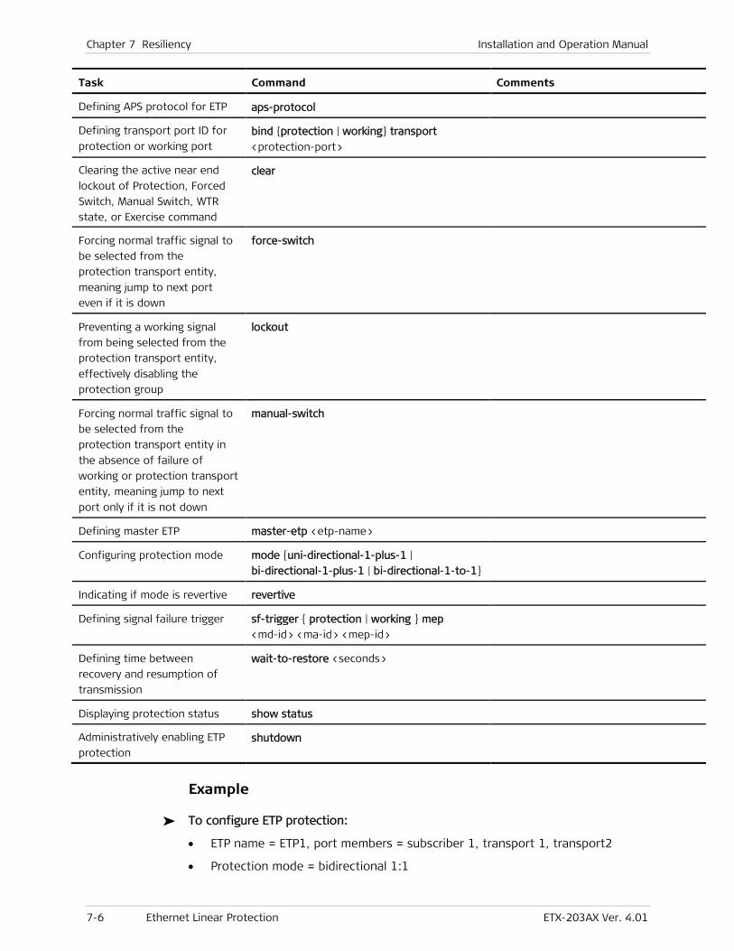
Chapter 7 Resiliency Installation and Operation Manual
7-6 Ethernet Linear Protection ETX-203AX Ver. 4.01
Task Command Comments
Defining APS protocol for ETP aps-protocol
Defining transport port ID for
protection or working port bind {protection | working} transport
<protection-port>
Clearing the active near end
lockout of Protection, Forced
Switch, Manual Switch, WTR
state, or Exercise command
clear
Forcing normal traffic signal to
be selected from the
protection transport entity,
meaning jump to next port
even if it is down
force-switch
Preventing a working signal
from being selected from the
protection transport entity,
effectively disabling the
protection group
lockout
Forcing normal traffic signal to
be selected from the
protection transport entity in
the absence of failure of
working or protection transport
entity, meaning jump to next
port only if it is not down
manual-switch
Defining master ETP master-etp <etp-name>
Configuring protection mode mode {uni-directional-1-plus-1 |
bi-directional-1-plus-1 | bi-directional-1-to-1}
Indicating if mode is revertive revertive
Defining signal failure trigger sf-trigger { protection | working } mep
<md-id> <ma-id> <mep-id>
Defining time between
recovery and resumption of
transmission
wait-to-restore <seconds>
Displaying protection status show status
Administratively enabling ETP
protection shutdown
Example
To configure ETP protection:
• ETP name = ETP1, port members = subscriber 1, transport 1, transport2
• Protection mode = bidirectional 1:1

Installation and Operation Manual Chapter 7 Resiliency
ETX-203AX Ver. 4.01 Fault Propagation 7-7
• APS protocol used for protection
• Working port = transport 1
• Protection port = transport 2
• Signal failure triggers = working MEP: MD 3 MA 2 MEP 1, protection MEP: MD 4 MA 2 MEP 1
The MEPs must be active.
• Revertive mode
• Time to wait before restoring transmission = 300 seconds.
ETX-204A# configure etps etp ETP1 protection ETX-204A>config>etps>etp(ETP1)>protection# mode bi-directional-1-to-1 ETX-204A>config>etps>etp(ETP1)>protection# aps-protocol ETX-204A>config>etps>etp(ETP1)>protection# bind working transport 1 ETX-204A>config>etps>etp(ETP1)>protection# bind protection transport 2 ETX-204A>config>etps>etp(ETP1)>protection# sf-trigger working mep 3 2 1 ETX-204A>config>etps>etp(ETP1)>protection# sf-trigger protection mep 4 2 1 ETX-204A>config>etps>etp(ETP1)>protection# revertive ETX-204A>config>etps>etp(ETP1)>protection# wait-to-restore 300 ETX-204A>config>etps>etp(ETP1)>protection# no shutdown ETX-204A>config>etps>etp(ETP1)>protection#
7.2 Fault Propagation
Fault propagation enables you to specify which interfaces to shut down if link failure occurs.
Standards
IEEE 802.1ag-D8
ITU-T Y.1731
Benefits
You can ensure that you are sending packets via links that have not failed. Failures are propagated end-to-end via OAM CFM messages.
Functional Description
In the network-to-user or user-to-network direction, if a link fails for which fault propagation is enabled, the corresponding port shuts down or OAM CFM failure message is sent, thus signaling the connected CPE to stop forwarding frames through the link.
You can enable fault propagation to be triggered by failure detection on a network/user interface, which causes a user-configurable action (such as deactivation or OAM CFM failure message sent) to be performed on a
Note
Chapter 7 Resiliency Installation and Operation Manual
7-8 Fault Propagation ETX-203AX Ver. 4.01
user/network interface. You can enable fault propagation in the network-to-user or user-to-network direction, for a pair of interfaces such as Ethernet ports, MEPs, and ETPs.
You can define the following when you enable fault propagation for a pair of interfaces:
• Trigger:
If interface where failure is detected is Ethernet port or MEP:
LOS – Link down detected
If interface where failure is detected is MEP:
OAM CFM LOC – Loss of continuity detected
OAM CFM RDI – Remote defect indication detected
OAM CFM Interface status TLV –Remote port failure detected
• Action to take when fault propagation is triggered:
If interface where action is performed is Ethernet port:
Interface-deactivation
If interface where action is performed is MEP:
Send OAM CFM interface status TLV to indicate failure.
• Wait-to-restore time – The time period before enabling the shut-down interface or ceasing to send OAM CFM interface status once the failed interface has been restored.
Factory Defaults
By default, no fault propagation is configured. When you configure fault propagation for a particular interface pair, the default configuration is as follows:
• No trigger defined for fault detection
• No action defined to be performed when fault is detected
• Wait-to-restore time = 0.
Configuring Fault Propagation
Follow this procedure to configure fault propagation:
1. Add a fault propagation entry for a pair of interfaces
2. Configure the fault propagation parameters for the entry:
a. Specify the trigger(s)
b. Specify the action
c. Specify the wait-to-restore time if you do not want the default value 0.
Adding Fault Propagation Entry
To add fault propagation for a pair of interfaces:
1. Navigate to configure fault.

Installation and Operation Manual Chapter 7 Resiliency
ETX-203AX Ver. 4.01 Fault Propagation 7-9
2. Type the command: fault-propagation <from-interface> to <to-interface> and enter the desired interfaces, as shown in Table 7-8.
A prompt is displayed: config>fault>fp(<from-interface>/to/<to-interface>)$
3. Configure the fault propagation parameters as needed (refer to Configuring Fault Propagation Parameters).
Table 7-8. Fault Propagation Command Options
From Interface To Interface Command
MEP Ethernet port fault-propagation mep <md-id> <ma-id> <mep-id> to
port ethernet <port>
ETP Ethernet port fault-propagation etp <etp-name> to port ethernet <port>
Ethernet port MEP fault-propagation port ethernet <port> to
mep <to-mdid> <to-maid> <to-mepid>
ETP MEP fault-propagation etp <etp-name> to
mep <to-mdid> <to-maid> <to-mepid>
MEP MEP fault-propagation mep <md-id> <ma-id> <mep-id> to
mep <to-mdid> <to-maid> <to-mepid>
Ethernet port Ethernet port fault-propagation port ethernet <port> to
port ethernet <port>
Configuring Fault Propagation Parameters
To configure fault propagation parameters:
1. Navigate to configure fault fault-propagation <from-interface> to <to-interface> to select the fault propagation entry to configure.
A prompt is displayed: config>fault>fp(<from-interface>/to/<to-interface>)#
2. Enter all necessary commands according to the tasks listed below.
Task Command Comments
Specifying the trigger(s) trigger { los | oam-cfm-loc | oam-cfm-rdi |
oam-cfm-if-status-tlv }
Typing no before the command removes the
specified trigger
Note: The los trigger is allowed only if the
from-interface is an Ethernet port or ETP. The OAM CFM triggers are allowed only if the from-interface is a MEP.
Specifying the action to take when
fault propagation is triggered action-on-group { interface-deactivation |
oam-cfm-if-status-tlv }
Typing no action-on-group removes the
action
Note: The interface-deactivation action is allowed only if the to-interface is an Ethernet port. The oam-cfm-if-status-tlv action is allowed only if the to-interface is a MEP.
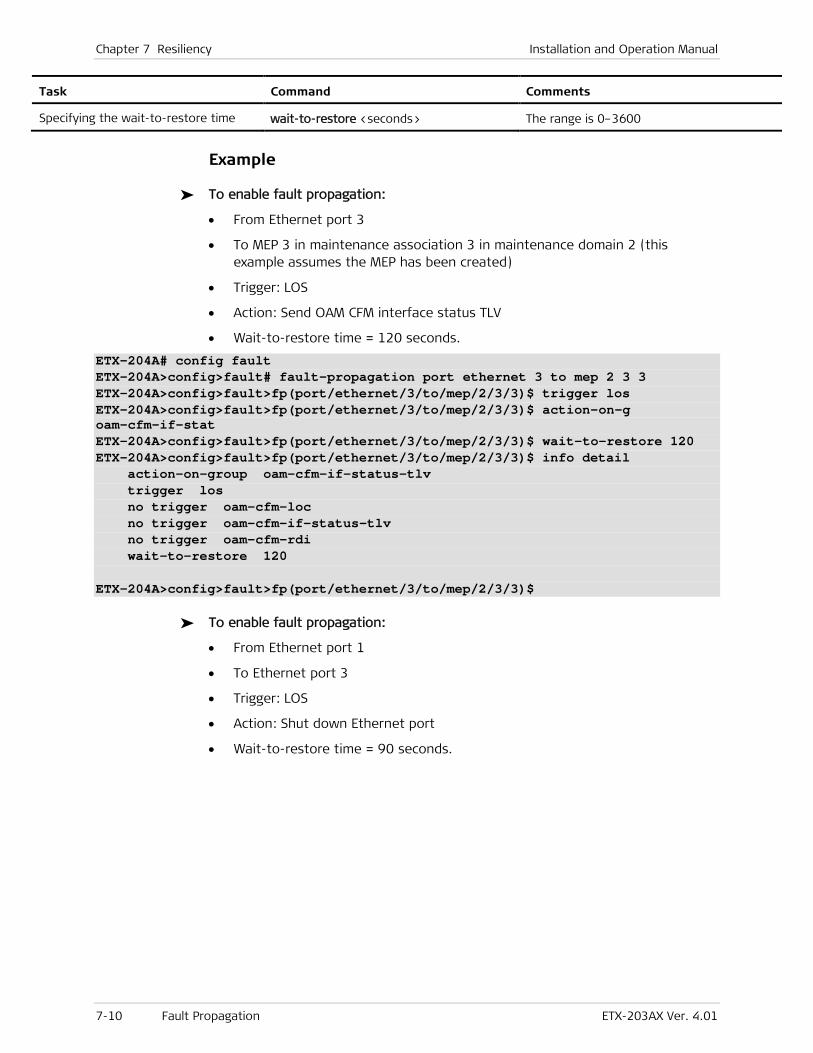
Chapter 7 Resiliency Installation and Operation Manual
7-10 Fault Propagation ETX-203AX Ver. 4.01
Task Command Comments
Specifying the wait-to-restore time wait-to-restore <seconds> The range is 0–3600
Example
To enable fault propagation:
• From Ethernet port 3
• To MEP 3 in maintenance association 3 in maintenance domain 2 (this example assumes the MEP has been created)
• Trigger: LOS
• Action: Send OAM CFM interface status TLV
• Wait-to-restore time = 120 seconds.
ETX-204A# config fault ETX-204A>config>fault# fault-propagation port ethernet 3 to mep 2 3 3 ETX-204A>config>fault>fp(port/ethernet/3/to/mep/2/3/3)$ trigger los ETX-204A>config>fault>fp(port/ethernet/3/to/mep/2/3/3)$ action-on-g oam-cfm-if-stat ETX-204A>config>fault>fp(port/ethernet/3/to/mep/2/3/3)$ wait-to-restore 120 ETX-204A>config>fault>fp(port/ethernet/3/to/mep/2/3/3)$ info detail action-on-group oam-cfm-if-status-tlv trigger los no trigger oam-cfm-loc no trigger oam-cfm-if-status-tlv no trigger oam-cfm-rdi wait-to-restore 120 ETX-204A>config>fault>fp(port/ethernet/3/to/mep/2/3/3)$
To enable fault propagation:
• From Ethernet port 1
• To Ethernet port 3
• Trigger: LOS
• Action: Shut down Ethernet port
• Wait-to-restore time = 90 seconds.
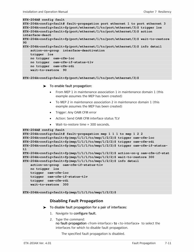
Installation and Operation Manual Chapter 7 Resiliency
ETX-203AX Ver. 4.01 Fault Propagation 7-11
ETX-204A# config fault ETX-204A>config>fault# fault-propagation port ethernet 1 to port ethernet 3 ETX-204A>config>fault>fp(port/ethernet/1/to/port/ethernet/3)$ trigger los ETX-204A>config>fault>fp(port/ethernet/1/to/port/ethernet/3)$ action interface-deact ETX-204A>config>fault>fp(port/ethernet/1/to/port/ethernet/3)$ wait-to-restore 90 ETX-204A>config>fault>fp(port/ethernet/1/to/port/ethernet/3)$ info detail action-on-group interface-deactivation trigger los no trigger oam-cfm-loc no trigger oam-cfm-if-status-tlv no trigger oam-cfm-rdi wait-to-restore 90 ETX-204A>config>fault>fp(port/ethernet/1/to/port/ethernet/3)$
To enable fault propagation:
• From MEP 1 in maintenance association 1 in maintenance domain 1 (this example assumes the MEP has been created)
• To MEP 2 in maintenance association 2 in maintenance domain 1 (this example assumes the MEP has been created)
• Trigger: Any OAM CFM error
• Action: Send OAM CFM interface status TLV
• Wait-to-restore time = 300 seconds.
ETX-204A# config fault ETX-204A>config>fault# fault-propagation mep 1 1 1 to mep 1 2 2 ETX-204A>config>fault>fp(mep/1/1/1/to/mep/1/2/2)$ trigger oam-cfm-loc ETX-204A>config>fault>fp(mep/1/1/1/to/mep/1/2/2)$ trigger oam-cfm-rdi ETX-204A>config>fault>fp(mep/1/1/1/to/mep/1/2/2)$ trigger oam-cfm-if-status-tl ETX-204A>config>fault>fp(mep/1/1/1/to/mep/1/2/2)$ action-on-g oam-cfm-if-stat ETX-204A>config>fault>fp(mep/1/1/1/to/mep/1/2/2)$ wait-to-restore 300 ETX-204A>config>fault>fp(mep/1/1/1/to/mep/1/2/2)$ info detail action-on-group oam-cfm-if-status-tlv no trigger los trigger oam-cfm-loc trigger oam-cfm-if-status-tlv trigger oam-cfm-rdi wait-to-restore 300 ETX-204A>config>fault>fp(mep/1/1/1/to/mep/1/2/2)$
Disabling Fault Propagation
To disable fault propagation for a pair of interfaces:
1. Navigate to configure fault.
2. Type the command: no fault-propagation <from-interface> to <to-interface> to select the interfaces for which to disable fault propagation.
The specified fault propagation is disabled.
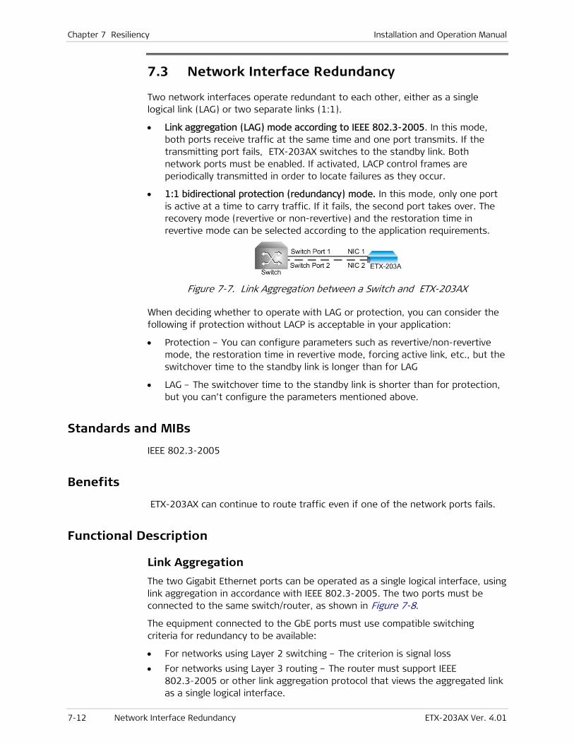
Chapter 7 Resiliency Installation and Operation Manual
7-12 Network Interface Redundancy ETX-203AX Ver. 4.01
7.3 Network Interface Redundancy
Two network interfaces operate redundant to each other, either as a single logical link (LAG) or two separate links (1:1).
• Link aggregation (LAG) mode according to IEEE 802.3-2005. In this mode, both ports receive traffic at the same time and one port transmits. If the transmitting port fails, ETX-203AX switches to the standby link. Both network ports must be enabled. If activated, LACP control frames are periodically transmitted in order to locate failures as they occur.
• 1:1 bidirectional protection (redundancy) mode. In this mode, only one port is active at a time to carry traffic. If it fails, the second port takes over. The recovery mode (revertive or non-revertive) and the restoration time in revertive mode can be selected according to the application requirements.
Figure 7-7. Link Aggregation between a Switch and ETX-203AX
When deciding whether to operate with LAG or protection, you can consider the following if protection without LACP is acceptable in your application:
• Protection – You can configure parameters such as revertive/non-revertive mode, the restoration time in revertive mode, forcing active link, etc., but the switchover time to the standby link is longer than for LAG
• LAG – The switchover time to the standby link is shorter than for protection, but you can’t configure the parameters mentioned above.
Standards and MIBs
IEEE 802.3-2005
Benefits
ETX-203AX can continue to route traffic even if one of the network ports fails.
Functional Description
Link Aggregation
The two Gigabit Ethernet ports can be operated as a single logical interface, using link aggregation in accordance with IEEE 802.3-2005. The two ports must be connected to the same switch/router, as shown in Figure 7-8.
The equipment connected to the GbE ports must use compatible switching criteria for redundancy to be available:
• For networks using Layer 2 switching – The criterion is signal loss
• For networks using Layer 3 routing – The router must support IEEE 802.3-2005 or other link aggregation protocol that views the aggregated link as a single logical interface.

Installation and Operation Manual Chapter 7 Resiliency
ETX-203AX Ver. 4.01 Network Interface Redundancy 7-13
Figure 7-8. Network Link Aggregation Redundancy Mode
Using link aggregation inherently provides redundancy, because if one of the GbE ports fails, the other can continue transferring traffic. Failure of a link is detected by sensing the loss of valid signals, or receiving a failure report via Link Aggregation Control Protocol (LACP) if applicable, in which case all traffic is sent through the other link.
1:1 Bidirectional Redundancy As an alternative to link aggregation, the two ETX-203AX network ports can be configured for 1:1 bidirectional mode. With this mode, two topologies can be used:
• Connection of both ports to the same switch/router, as shown in Figure 7-8.
• Connection of the ports to different switch/routers, as illustrated in Figure 7-9. The main advantage of this topology is its higher availability, because each port can be routed along a different path through the network. This topology is also referred to as dual homing.
Figure 7-9. 1:1 Bidirectional Redundancy Mode (Dual Homing)
With 1:1 bidirectional redundancy mode, at any time only one of the ports is actively carrying traffic, and the other port serves as the backup port. A RAD proprietary redundancy algorithm, based on loss of GbE signal, is used to detect line failure. The protection switching (flipping) time is less than 1 second. It also depends on the network “relearning“ time or aging.
The recovery mode after protection switching can be selected in accordance with the application requirements:
• Non-revertive mode – ETX-203AX does not automatically flip back after the failed port returns to normal operation, but only when the currently used port fails, or after a manual flip command.
• Revertive mode – ETX-203AX flips back to the original port when it returns to normal operation. Flipping back can be delayed by specifying a restoration time, during which alarms are ignored. As a result, ETX-203AX starts evaluating the criteria for protection switching (flipping) only after the restoration time expires, thereby ensuring that another flip cannot occur before the specified time expires.
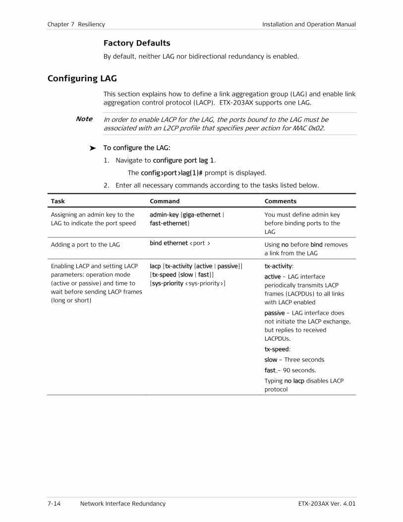
Chapter 7 Resiliency Installation and Operation Manual
7-14 Network Interface Redundancy ETX-203AX Ver. 4.01
Factory Defaults
By default, neither LAG nor bidirectional redundancy is enabled.
Configuring LAG
This section explains how to define a link aggregation group (LAG) and enable link aggregation control protocol (LACP). ETX-203AX supports one LAG.
In order to enable LACP for the LAG, the ports bound to the LAG must be associated with an L2CP profile that specifies peer action for MAC 0x02.
To configure the LAG:
1. Navigate to configure port lag 1.
The config>port>lag(1)# prompt is displayed.
2. Enter all necessary commands according to the tasks listed below.
Task Command Comments
Assigning an admin key to the
LAG to indicate the port speed
admin-key {giga-ethernet |
fast-ethernet}
You must define admin key
before binding ports to the
LAG
Adding a port to the LAG bind ethernet <port > Using no before bind removes
a link from the LAG
Enabling LACP and setting LACP
parameters: operation mode
(active or passive) and time to
wait before sending LACP frames
(long or short)
lacp [tx-activity {active | passive}]
[tx-speed {slow | fast}]
[sys-priority <sys-priority>]
tx-activity:
active – LAG interface
periodically transmits LACP
frames (LACPDUs) to all links
with LACP enabled
passive – LAG interface does
not initiate the LACP exchange,
but replies to received
LACPDUs.
tx-speed:
slow – Three seconds
fast_– 90 seconds.
Typing no lacp disables LACP
protocol
Note
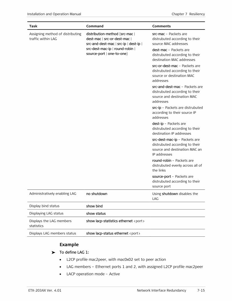
Installation and Operation Manual Chapter 7 Resiliency
ETX-203AX Ver. 4.01 Network Interface Redundancy 7-15
Task Command Comments
Assigning method of distributing
traffic within LAG
distribution-method {src-mac |
dest-mac | src-or-dest-mac |
src-and-dest-mac | src-ip | dest-ip |
src-dest-mac-ip | round-robin |
source-port | one-to-one}
src-mac – Packets are
distrubuted according to their
source MAC addresses
dest-mac – Packets are
distrubuted according to their
destination MAC addresses
src-or-dest-mac – Packets are
distrubuted according to their
source or destination MAC
addresses
src-and-dest-mac – Packets are
distrubuted according to their
source and destination MAC
addresses
src-ip – Packets are distrubuted
according to their source IP
addresses
dest-ip – Packets are
distrubuted according to their
destination IP addresses
src-dest-mac-ip – Packets are
distrubuted according to their
source and destination MAC an
IP addresses
round-robin – Packets are
distrubuted evenly across all of
the links
source-port – Packets are
distrubuted according to their
source port
Administratively enabling LAG no shutdown Using shutdown disables the
LAG
Display bind status show bind
Displaying LAG status show status
Displays the LAG members
statistics
show lacp-statistics ethernet <port>
Displays LAG members status show lacp-status ethernet <port>
Example
To define LAG 1:
• L2CP profile mac2peer, with mac0x02 set to peer action
• LAG members – Ethernet ports 1 and 2, with assigned L2CP profile mac2peer
• LACP operation mode – Active
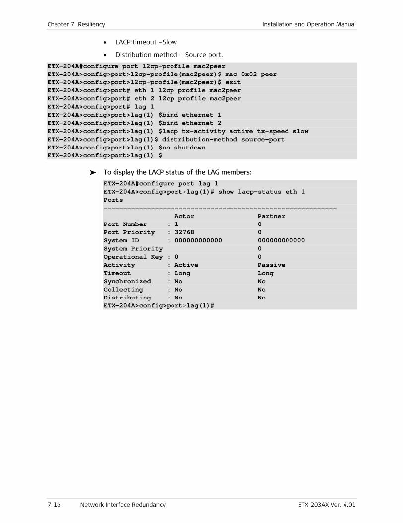
Chapter 7 Resiliency Installation and Operation Manual
7-16 Network Interface Redundancy ETX-203AX Ver. 4.01
• LACP timeout –Slow
• Distribution method – Source port.
ETX-204A#configure port l2cp-profile mac2peer ETX-204A>config>port>l2cp-profile(mac2peer)$ mac 0x02 peer ETX-204A>config>port>l2cp-profile(mac2peer)$ exit ETX-204A>config>port# eth 1 l2cp profile mac2peer ETX-204A>config>port# eth 2 l2cp profile mac2peer ETX-204A>config>port# lag 1 ETX-204A>config>port>lag(1) $bind ethernet 1 ETX-204A>config>port>lag(1) $bind ethernet 2 ETX-204A>config>port>lag(1) $lacp tx-activity active tx-speed slow ETX-204A>config>port>lag(1)$ distribution-method source-port ETX-204A>config>port>lag(1) $no shutdown ETX-204A>config>port>lag(1) $
To display the LACP status of the LAG members:
ETX-204A#configure port lag 1 ETX-204A>config>port>lag(1)# show lacp-status eth 1 Ports ----------------------------------------------------------- Actor Partner Port Number : 1 0 Port Priority : 32768 0 System ID : 000000000000 000000000000 System Priority 0 Operational Key : 0 0 Activity : Active Passive Timeout : Long Long Synchronized : No No Collecting : No No Distributing : No No ETX-204A>config>port>lag(1)#
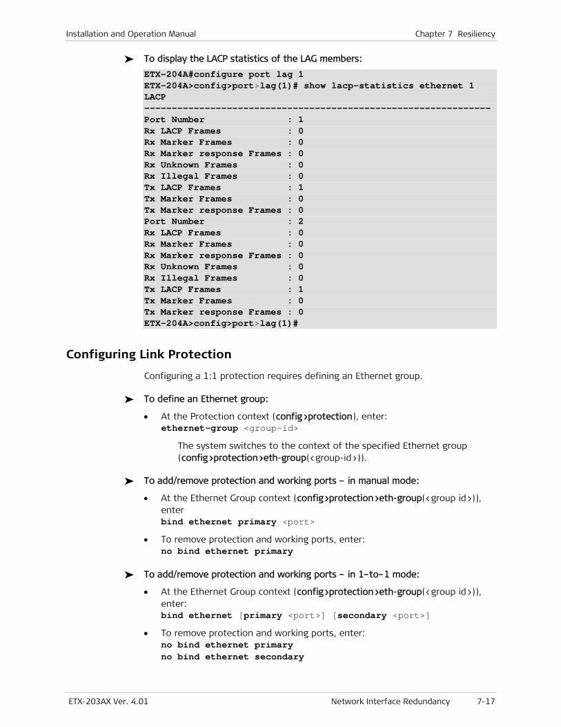
Installation and Operation Manual Chapter 7 Resiliency
ETX-203AX Ver. 4.01 Network Interface Redundancy 7-17
To display the LACP statistics of the LAG members:
ETX-204A#configure port lag 1 ETX-204A>config>port>lag(1)# show lacp-statistics ethernet 1 LACP --------------------------------------------------------------- Port Number : 1 Rx LACP Frames : 0 Rx Marker Frames : 0 Rx Marker response Frames : 0 Rx Unknown Frames : 0 Rx Illegal Frames : 0 Tx LACP Frames : 1 Tx Marker Frames : 0 Tx Marker response Frames : 0 Port Number : 2 Rx LACP Frames : 0 Rx Marker Frames : 0 Rx Marker response Frames : 0 Rx Unknown Frames : 0 Rx Illegal Frames : 0 Tx LACP Frames : 1 Tx Marker Frames : 0 Tx Marker response Frames : 0 ETX-204A>config>port>lag(1)#
Configuring Link Protection
Configuring a 1:1 protection requires defining an Ethernet group.
To define an Ethernet group:
• At the Protection context (config>protection), enter: ethernet-group <group-id>
The system switches to the context of the specified Ethernet group (config>protection>eth-group(<group-id>)).
To add/remove protection and working ports – in manual mode:
• At the Ethernet Group context (config>protection>eth-group(<group id>)), enter bind ethernet primary <port>
• To remove protection and working ports, enter: no bind ethernet primary
To add/remove protection and working ports – in 1–to–1 mode:
• At the Ethernet Group context (config>protection>eth-group(<group id>)), enter: bind ethernet [primary <port>] [secondary <port>]
• To remove protection and working ports, enter: no bind ethernet primary no bind ethernet secondary
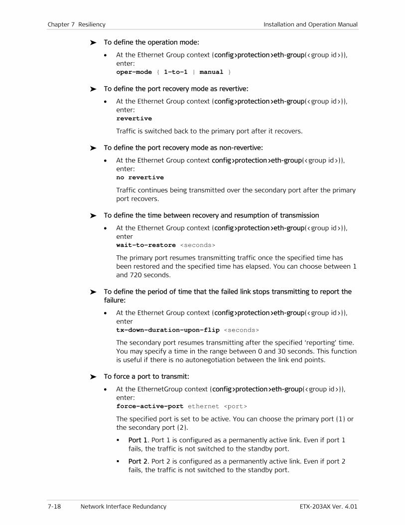
Chapter 7 Resiliency Installation and Operation Manual
7-18 Network Interface Redundancy ETX-203AX Ver. 4.01
To define the operation mode:
• At the Ethernet Group context (config>protection>eth-group(<group id>)), enter: oper-mode { 1-to-1 | manual }
To define the port recovery mode as revertive:
• At the Ethernet Group context (config>protection>eth-group(<group id>)), enter: revertive
Traffic is switched back to the primary port after it recovers.
To define the port recovery mode as non-revertive:
• At the Ethernet Group context config>protection>eth-group(<group id>)), enter: no revertive
Traffic continues being transmitted over the secondary port after the primary port recovers.
To define the time between recovery and resumption of transmission
• At the Ethernet Group context (config>protection>eth-group(<group id>)), enter wait-to-restore <seconds>
The primary port resumes transmitting traffic once the specified time has been restored and the specified time has elapsed. You can choose between 1 and 720 seconds.
To define the period of time that the failed link stops transmitting to report the failure:
• At the Ethernet Group context (config>protection>eth-group(<group id>)), enter tx-down-duration-upon-flip <seconds>
The secondary port resumes transmitting after the specified ‘reporting’ time. You may specify a time in the range between 0 and 30 seconds. This function is useful if there is no autonegotiation between the link end points.
To force a port to transmit:
• At the EthernetGroup context (config>protection>eth-group(<group id>)), enter: force-active-port ethernet <port>
The specified port is set to be active. You can choose the primary port (1) or the secondary port (2).
Port 1. Port 1 is configured as a permanently active link. Even if port 1 fails, the traffic is not switched to the standby port.
Port 2. Port 2 is configured as a permanently active link. Even if port 2 fails, the traffic is not switched to the standby port.
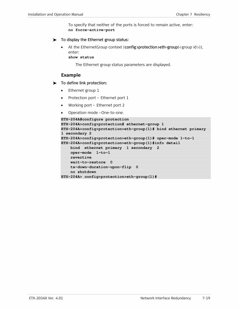
Installation and Operation Manual Chapter 7 Resiliency
ETX-203AX Ver. 4.01 Network Interface Redundancy 7-19
To specify that neither of the ports is forced to remain active, enter: no force-active-port
To display the Ethernet group status:
• At the EthernetGroup context (config>protection>eth-group(<group id>)), enter: show status
The Ethernet group status parameters are displayed.
Example
To define link protection:
• Ethernet group 1
• Protection port – Ethernet port 1
• Working port – Ethernet port 2
• Operation mode –One-to-one.
ETX-204A#configure protection ETX-204A>config>protection# ethernet-group 1 ETX-204A>config>protection>eth-group(1)# bind ethernet primary 1 secondary 2 ETX-204A>config>protection>eth-group(1)# oper-mode 1-to-1 ETX-204A>config>protection>eth-group(1)#info detail bind ethernet primary 1 secondary 2 oper-mode 1-to-1 revertive wait-to-restore 0 tx-down-duration-upon-flip 0 no shutdown ETX-204A> config>protection>eth-group(1)#

ETX-203AX Ver. 4.01 Flows 8-1
Chapter 8
Networking This chapter describes networking features:
• Flows
• Layer-2 Control Processing
• OAM
• Quality of Service (QoS)
• Router.
8.1 Flows
ETX-203AX supports up to 192 unidirectional Ethernet flows, which can be used to provide E-line or E-LAN service delivery over Metro Ethernet networks. Each Ethernet flow is unidirectional and connects two ports.
This section explains how to define the flows according to specific criteria such as VLAN. You can use classifier profiles to specify the criteria for flows. The classification is per port and is applied to the ingress port of the flow.
You can configure a unidirectional hub (UDH) by defining up to five flows with the same ingress port, classifier profile, and policer aggregate, and different egress ports. Up to seven UDH groups can be defined per device. The egress ports must be physical Ethernet ports, not virtual ports such as SVI, ETP, etc. Only one queue-mapping profile and one marking profile can be used for the flows in a UDH group, however VLAN tag editing can be different in the different flows.
Standards
IEEE 802.3x
Benefits
The user traffic can be classified into different Ethernet flows (EVC.CoS) to provide services in a flexible manner.
Functional Description
Packets can be classified by means of their VLAN IDs and other criteria, fully specified in Defining Classifier Profiles.
Classifications that apply to the same port are allowed in the combinations shown in Table 8-9. The priority shown is used to determine which classification

Chapter 8 Networking Installation and Operation Manual
8-2 Flows ETX-203AX Ver. 4.01
is used if incoming packets for the port fit the criteria of more than one classification. Priority 4 is the lowest, priority 1 is the highest. NNI indicates ingress network port, UNI indicates ingress user port.
You can perform marking and tagging actions on the outer and inner VLAN such as adding, replacing, or removing, as well as marking with p-bit. Only certain combinations of actions on the outer and inner VLAN are allowed. If no action is performed for the outer VLAN, then for the inner VLAN there must be no action performed. Table 8-10 shows valid action combinations on ingress frame tags and the resulting egress frame tags and p-bits, according to whether the ingress frame is untagged, contains one VLAN, or is double-tagged. Any combination not shown in the table is not supported.
In the descriptions, VLAN refers to the service provider (outer) VLAN, previously referred to as SP-VLAN, while inner VLAN refers to the Customer Entity VLAN, previously referred to as CE-VLAN.
Table 8-9. Classification Combinations
Classification Other classifications allowed on same ingress port
Range Max number ranges
Priority NNI/UNI
Unclassified (all-to-one bundling)
VLAN VLAN + IP precedence VLAN + DSCP VLAN + VLAN priority VLAN + Non-IP VLAN priority IP precedence DSCP Source MAC address Destination MAC address Source IP address Destination IP address Non-IP Ethertype Untagged
– 1 4 Both
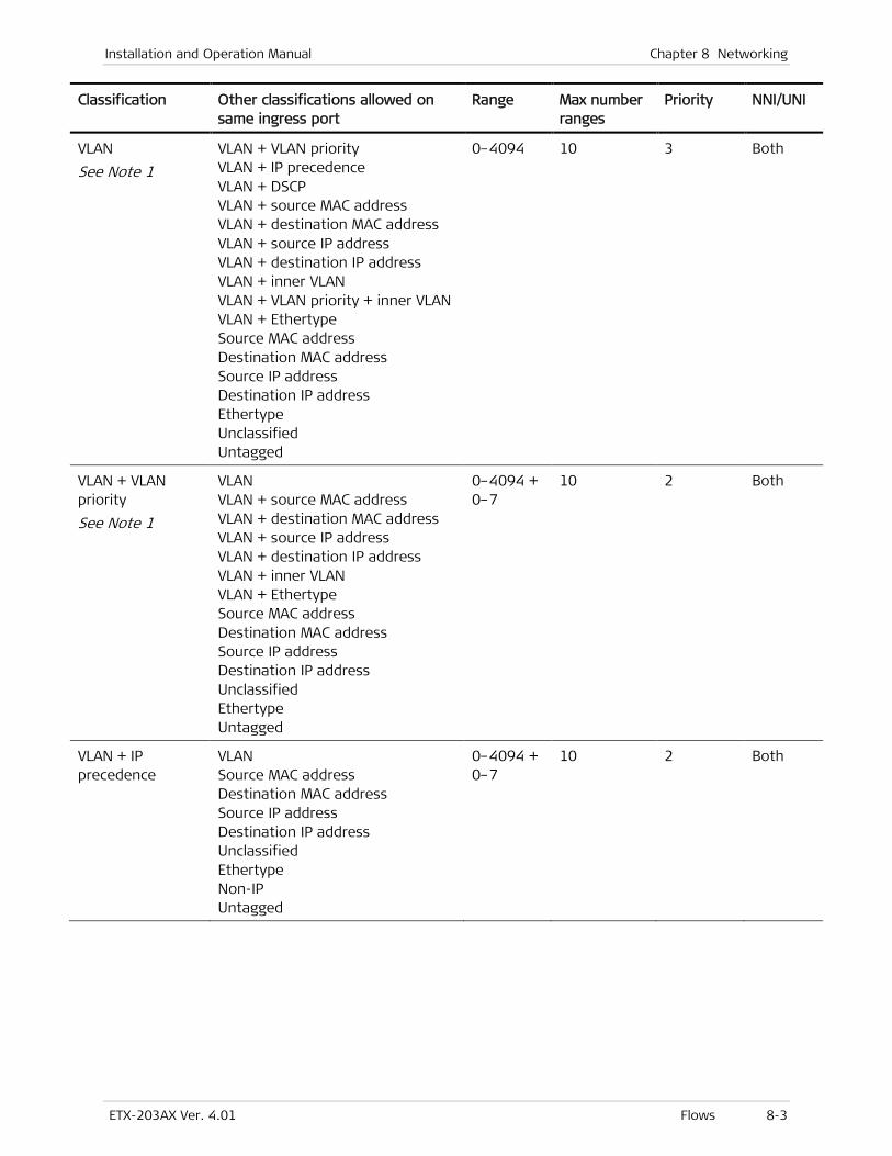
Installation and Operation Manual Chapter 8 Networking
ETX-203AX Ver. 4.01 Flows 8-3
Classification Other classifications allowed on same ingress port
Range Max number ranges
Priority NNI/UNI
VLAN
See Note 1
VLAN + VLAN priority VLAN + IP precedence VLAN + DSCP VLAN + source MAC address VLAN + destination MAC address VLAN + source IP address VLAN + destination IP address VLAN + inner VLAN VLAN + VLAN priority + inner VLAN VLAN + Ethertype Source MAC address Destination MAC address Source IP address Destination IP address Ethertype Unclassified Untagged
0–4094 10 3 Both
VLAN + VLAN priority
See Note 1
VLAN VLAN + source MAC address VLAN + destination MAC address VLAN + source IP address VLAN + destination IP address VLAN + inner VLAN VLAN + Ethertype Source MAC address Destination MAC address Source IP address Destination IP address Unclassified Ethertype Untagged
0–4094 + 0–7
10 2 Both
VLAN + IP precedence
VLAN Source MAC address Destination MAC address Source IP address Destination IP address Unclassified Ethertype Non-IP Untagged
0–4094 + 0–7
10 2 Both
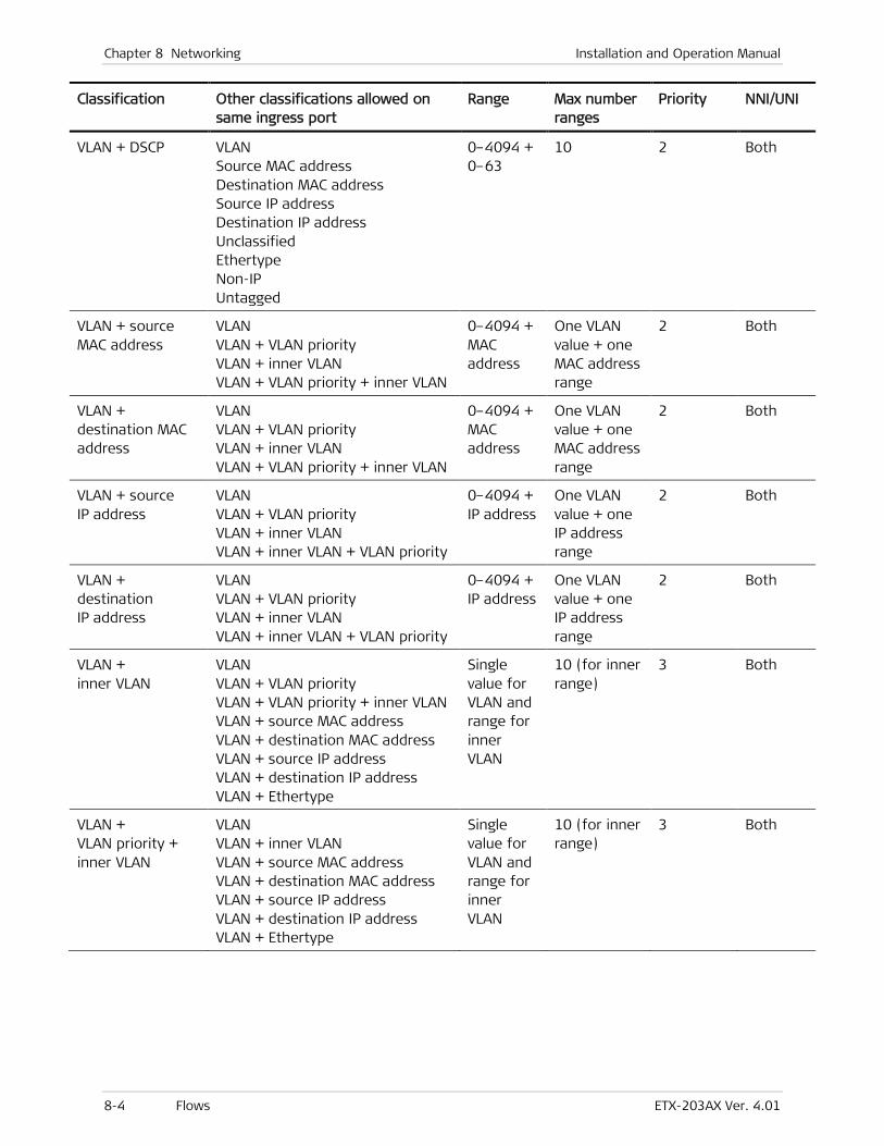
Chapter 8 Networking Installation and Operation Manual
8-4 Flows ETX-203AX Ver. 4.01
Classification Other classifications allowed on same ingress port
Range Max number ranges
Priority NNI/UNI
VLAN + DSCP VLAN Source MAC address Destination MAC address Source IP address Destination IP address Unclassified Ethertype Non-IP Untagged
0–4094 + 0–63
10 2 Both
VLAN + source MAC address
VLAN VLAN + VLAN priority VLAN + inner VLAN VLAN + VLAN priority + inner VLAN
0–4094 + MAC address
One VLAN value + one MAC address range
2 Both
VLAN + destination MAC address
VLAN VLAN + VLAN priority VLAN + inner VLAN VLAN + VLAN priority + inner VLAN
0–4094 + MAC address
One VLAN value + one MAC address range
2 Both
VLAN + source IP address
VLAN VLAN + VLAN priority VLAN + inner VLAN VLAN + inner VLAN + VLAN priority
0–4094 + IP address
One VLAN value + one IP address range
2 Both
VLAN + destination IP address
VLAN VLAN + VLAN priority VLAN + inner VLAN VLAN + inner VLAN + VLAN priority
0–4094 + IP address
One VLAN value + one IP address range
2 Both
VLAN + inner VLAN
VLAN VLAN + VLAN priority VLAN + VLAN priority + inner VLAN VLAN + source MAC address VLAN + destination MAC address VLAN + source IP address VLAN + destination IP address VLAN + Ethertype
Single value for VLAN and range for inner VLAN
10 (for inner range)
3 Both
VLAN + VLAN priority + inner VLAN
VLAN VLAN + inner VLAN VLAN + source MAC address VLAN + destination MAC address VLAN + source IP address VLAN + destination IP address VLAN + Ethertype
Single value for VLAN and range for inner VLAN
10 (for inner range)
3 Both

Installation and Operation Manual Chapter 8 Networking
ETX-203AX Ver. 4.01 Flows 8-5
Classification Other classifications allowed on same ingress port
Range Max number ranges
Priority NNI/UNI
VLAN + non-IP Unclassified VLAN VLAN + IP precedence VLAN + DSCP Source MAC address Destination MAC address Source IP address Destination IP address Ethertype Untagged
0–4094 10 1 Both
VLAN + Ethertype VLAN VLAN + VLAN priority VLAN +inner VLAN VLAN + inner VLAN + VLAN priority
Ethertype + 0–4094
One Ethertype value with one VLAN value
2 Both
VLAN priority Unclassified Source MAC address Destination MAC address Source IP address Destination IP address Ethertype Untagged
0–7 5 2 Both
IP precedence Unclassified Source MAC address Destination MAC address Source IP address Destination IP address Non-IP Ethertype
0–7 5 2 Both
DSCP Unclassified Source MAC address Destination MAC address Source IP address Destination IP address Non-IP Ethertype
0–63 5 2 Both
Source MAC address
VLAN VLAN priority VLAN + VLAN priority VLAN + IP precedence VLAN + DSCP VLAN + Non-IP IP precedence DSCP Unclassified Non-IP Untagged
MAC address
1 1 Both
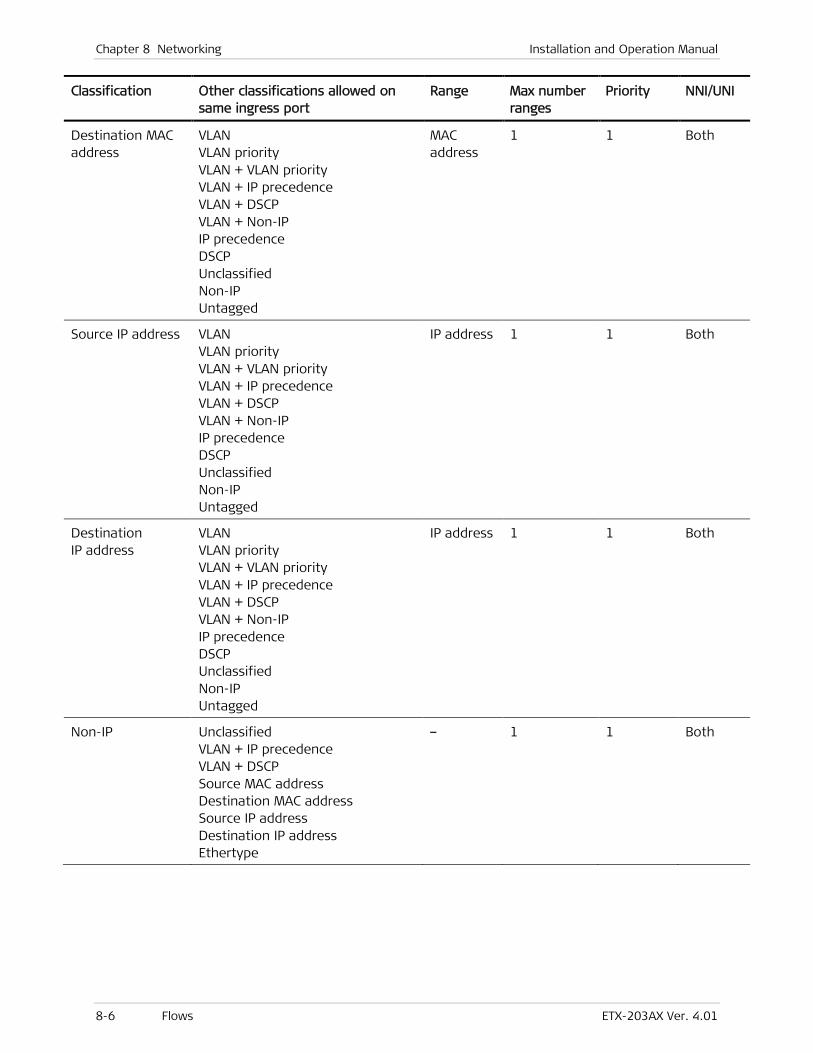
Chapter 8 Networking Installation and Operation Manual
8-6 Flows ETX-203AX Ver. 4.01
Classification Other classifications allowed on same ingress port
Range Max number ranges
Priority NNI/UNI
Destination MAC address
VLAN VLAN priority VLAN + VLAN priority VLAN + IP precedence VLAN + DSCP VLAN + Non-IP IP precedence DSCP Unclassified Non-IP Untagged
MAC address
1 1 Both
Source IP address VLAN VLAN priority VLAN + VLAN priority VLAN + IP precedence VLAN + DSCP VLAN + Non-IP IP precedence DSCP Unclassified Non-IP Untagged
IP address 1 1 Both
Destination IP address
VLAN VLAN priority VLAN + VLAN priority VLAN + IP precedence VLAN + DSCP VLAN + Non-IP IP precedence DSCP Unclassified Non-IP Untagged
IP address 1 1 Both
Non-IP Unclassified VLAN + IP precedence VLAN + DSCP Source MAC address Destination MAC address Source IP address Destination IP address Ethertype
– 1 1 Both
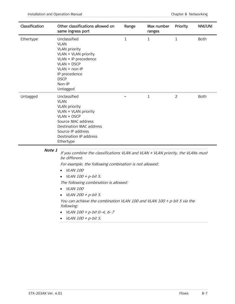
Installation and Operation Manual Chapter 8 Networking
ETX-203AX Ver. 4.01 Flows 8-7
Classification Other classifications allowed on same ingress port
Range Max number ranges
Priority NNI/UNI
Ethertype Unclassified VLAN VLAN priority VLAN + VLAN priority VLAN + IP precedence VLAN + DSCP VLAN + non-IP IP precedence DSCP Non-IP Untagged
1 1 1 Both
Untagged Unclassified VLAN VLAN priority VLAN + VLAN priority VLAN + DSCP Source MAC address Destination MAC address Source IP address Destination IP address Ethertype
– 1 2 Both
If you combine the classifications VLAN and VLAN + VLAN priority, the VLANs must be different.
For example, the following combination is not allowed:
• VLAN 100
• VLAN 100 + p-bit 5.
The following combination is allowed:
• VLAN 100
• VLAN 200 + p-bit 5.
You can achieve the combination VLAN 100 and VLAN 100 + p-bit 5 via the following:
• VLAN 100 + p-bit 0–4, 6–7
• VLAN 100 + p-bit 5.
Note 1
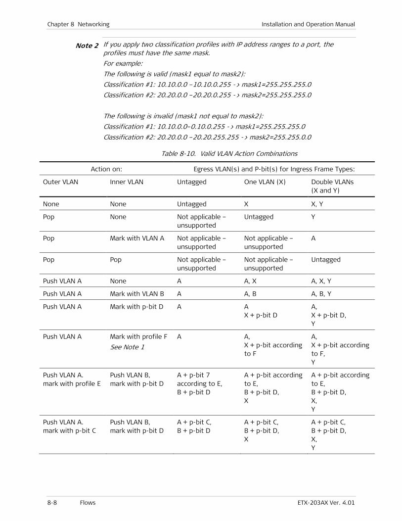
Chapter 8 Networking Installation and Operation Manual
8-8 Flows ETX-203AX Ver. 4.01
If you apply two classification profiles with IP address ranges to a port, the profiles must have the same mask.
For example:
The following is valid (mask1 equal to mask2):
Classification #1: 10.10.0.0 –10.10.0.255 -> mask1=255.255.255.0
Classification #2: 20.20.0.0 –20.20.0.255 -> mask2=255.255.255.0
The following is invalid (mask1 not equal to mask2):
Classification #1: 10.10.0.0–0.10.0.255 -> mask1=255.255.255.0
Classification #2: 20.20.0.0 –20.20.255.255 -> mask2=255.255.0.0
Table 8-10. Valid VLAN Action Combinations
Action on: Egress VLAN(s) and P-bit(s) for Ingress Frame Types:
Outer VLAN Inner VLAN Untagged One VLAN (X) Double VLANs (X and Y)
None None Untagged X X, Y
Pop None Not applicable – unsupported
Untagged Y
Pop Mark with VLAN A Not applicable – unsupported
Not applicable – unsupported
A
Pop Pop Not applicable – unsupported
Not applicable – unsupported
Untagged
Push VLAN A None A A, X A, X, Y
Push VLAN A Mark with VLAN B A A, B A, B, Y
Push VLAN A Mark with p-bit D A A X + p-bit D
A, X + p-bit D, Y
Push VLAN A Mark with profile F
See Note 1
A A, X + p-bit according to F
A, X + p-bit according to F, Y
Push VLAN A. mark with profile E
Push VLAN B, mark with p-bit D
A + p-bit 7 according to E, B + p-bit D
A + p-bit according to E, B + p-bit D, X
A + p-bit according to E, B + p-bit D, X, Y
Push VLAN A. mark with p-bit C
Push VLAN B, mark with p-bit D
A + p-bit C, B + p-bit D
A + p-bit C, B + p-bit D, X
A + p-bit C, B + p-bit D, X, Y
Note 2
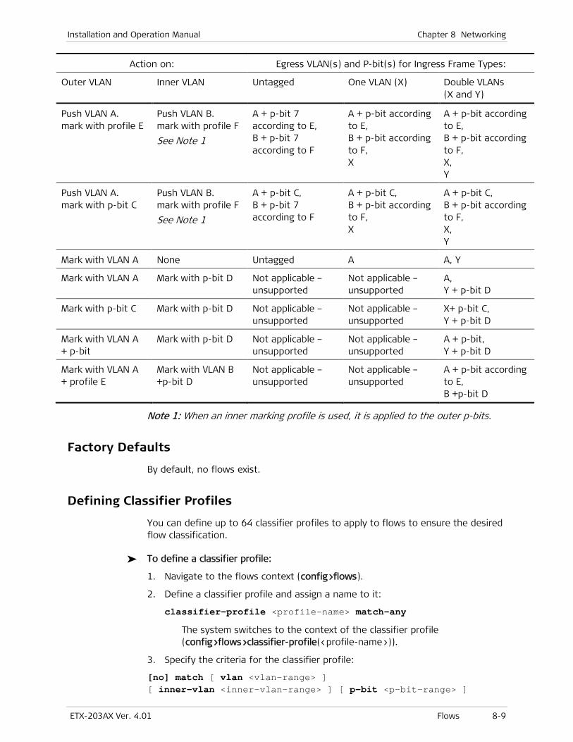
Installation and Operation Manual Chapter 8 Networking
ETX-203AX Ver. 4.01 Flows 8-9
Action on: Egress VLAN(s) and P-bit(s) for Ingress Frame Types:
Outer VLAN Inner VLAN Untagged One VLAN (X) Double VLANs (X and Y)
Push VLAN A. mark with profile E
Push VLAN B. mark with profile F
See Note 1
A + p-bit 7 according to E, B + p-bit 7 according to F
A + p-bit according to E, B + p-bit according to F, X
A + p-bit according to E, B + p-bit according to F, X, Y
Push VLAN A. mark with p-bit C
Push VLAN B. mark with profile F
See Note 1
A + p-bit C, B + p-bit 7 according to F
A + p-bit C, B + p-bit according to F, X
A + p-bit C, B + p-bit according to F, X, Y
Mark with VLAN A None Untagged A A, Y
Mark with VLAN A Mark with p-bit D Not applicable – unsupported
Not applicable – unsupported
A, Y + p-bit D
Mark with p-bit C Mark with p-bit D Not applicable – unsupported
Not applicable – unsupported
X+ p-bit C, Y + p-bit D
Mark with VLAN A + p-bit
Mark with p-bit D Not applicable – unsupported
Not applicable – unsupported
A + p-bit, Y + p-bit D
Mark with VLAN A + profile E
Mark with VLAN B +p-bit D
Not applicable – unsupported
Not applicable – unsupported
A + p-bit according to E, B +p-bit D
Note 1: When an inner marking profile is used, it is applied to the outer p-bits.
Factory Defaults
By default, no flows exist.
Defining Classifier Profiles
You can define up to 64 classifier profiles to apply to flows to ensure the desired flow classification.
To define a classifier profile:
1. Navigate to the flows context (config>flows).
2. Define a classifier profile and assign a name to it:
classifier-profile <profile-name> match-any
The system switches to the context of the classifier profile (config>flows>classifier-profile(<profile-name>)).
3. Specify the criteria for the classifier profile:
[no] match [ vlan <vlan-range> ] [ inner-vlan <inner-vlan-range> ] [ p-bit <p-bit-range> ]

Chapter 8 Networking Installation and Operation Manual
8-10 Flows ETX-203AX Ver. 4.01
[ inner-p-bit <inner-p-bit-range> ] [ ip-precedence <ip-precedence-range> ] [ ip-dscp <ip-dscp-range> ] [src-mac <src-mac-low>] [to-src-mac <src-mac-high>] [dst-mac <dst-mac-low>] [to-dst-mac <dst-mac-high>] [src-ip <src-ip-low>] [to-src-ip <src-ip-high>] [dst-ip <dst-ip-low>] [to-dst-ip <dst-ip-high>] [ether-type <ether-type>] [untagged] [non-ip] [all]
4. When you have completed specifying the criteria, enter exit to exit the classifier profile context.
Examples
To create classifier profile with criteria VLAN 100 to VLAN 150:
ETX-204A# configure flows classifier-profile v100_150 match-any ETX-204A>config>flows>classifier-profile(v100_150)$ match vlan 100..150 ETX-204A>config>flows>classifier-profile(v100_150)$ exit all ETX-204A#
To create classifier profile with criteria VLAN 20 and inner VLAN 30:
ETX-204A# configure flows classifier-profile v20_inner_30 match-any ETX-204A>config>flows>classifier-profile(v20_inner_30)$ match vlan 20 inner-vlan 30 ETX-204A>config>flows>classifier-profile(v20_inner_30)$ exit all ETX-204A#
To create classifier profile that matches all criteria:
ETX-204A# configure flows classifier-profile all match-any ETX-204A>config>flows>classifier-profile(all)$ match all ETX-204A>config>flows>classifier-profile(all)$ exit all ETX-204A#
To create classifier profile with criteria Ethertype 0x8100:
ETX-204A# configure flows classifier-profile e8100 match-any ETX-204A>config>flows>classifier-profile(e8100)$ match ether-type 0x8100 ETX-204A>config>flows>classifier-profile(e8100)$ exit all ETX-204A#
Configuring Flows
To configure flows:
1. Navigate to config>flows.
2. Enter: flow <flow-name>
If the flow already exists, the config>flows>flow(<flow-name>)# prompt is displayed, otherwise the flow is created and the config>flows>flow(<flow-name>)$ prompt is displayed.
3. Enter all necessary commands according to the tasks listed below.
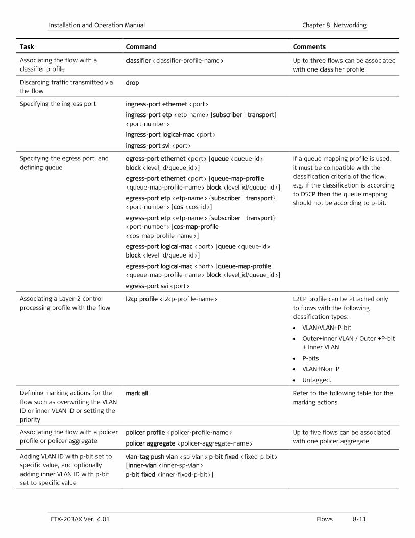
Installation and Operation Manual Chapter 8 Networking
ETX-203AX Ver. 4.01 Flows 8-11
Task Command Comments
Associating the flow with a
classifier profile classifier <classifier-profile-name> Up to three flows can be associated
with one classifier profile
Discarding traffic transmitted via
the flow drop
Specifying the ingress port ingress-port ethernet <port>
ingress-port etp <etp-name> {subscriber | transport}
<port-number>
ingress-port logical-mac <port>
ingress-port svi <port>
Specifying the egress port, and
defining queue egress-port ethernet <port> [queue <queue-id>
block <level_id/queue_id>]
egress-port ethernet <port> [queue-map-profile
<queue-map-profile-name> block <level_id/queue_id>]
egress-port etp <etp-name> {subscriber | transport}
<port-number> [cos <cos-id>]
egress-port etp <etp-name> {subscriber | transport}
<port-number> [cos-map-profile
<cos-map-profile-name>]
egress-port logical-mac <port> [queue <queue-id>
block <level_id/queue_id>]
egress-port logical-mac <port> [queue-map-profile
<queue-map-profile-name> block <level_id/queue_id>]
egress-port svi <port>
If a queue mapping profile is used,
it must be compatible with the
classification criteria of the flow,
e.g. if the classification is according
to DSCP then the queue mapping
should not be according to p-bit.
Associating a Layer-2 control
processing profile with the flow l2cp profile <l2cp-profile-name> L2CP profile can be attached only
to flows with the following
classification types:
• VLAN/VLAN+P-bit
• Outer+Inner VLAN / Outer +P-bit
+ Inner VLAN
• P-bits
• VLAN+Non IP
• Untagged.
Defining marking actions for the
flow such as overwriting the VLAN
ID or inner VLAN ID or setting the
priority
mark all Refer to the following table for the
marking actions
Associating the flow with a policer
profile or policer aggregate policer profile <policer-profile-name>
policer aggregate <policer-aggregate-name>
Up to five flows can be associated
with one policer aggregate
Adding VLAN ID with p-bit set to
specific value, and optionally
adding inner VLAN ID with p-bit
set to specific value
vlan-tag push vlan <sp-vlan> p-bit fixed <fixed-p-bit>
[inner-vlan <inner-sp-vlan>
p-bit fixed <inner-fixed-p-bit>]
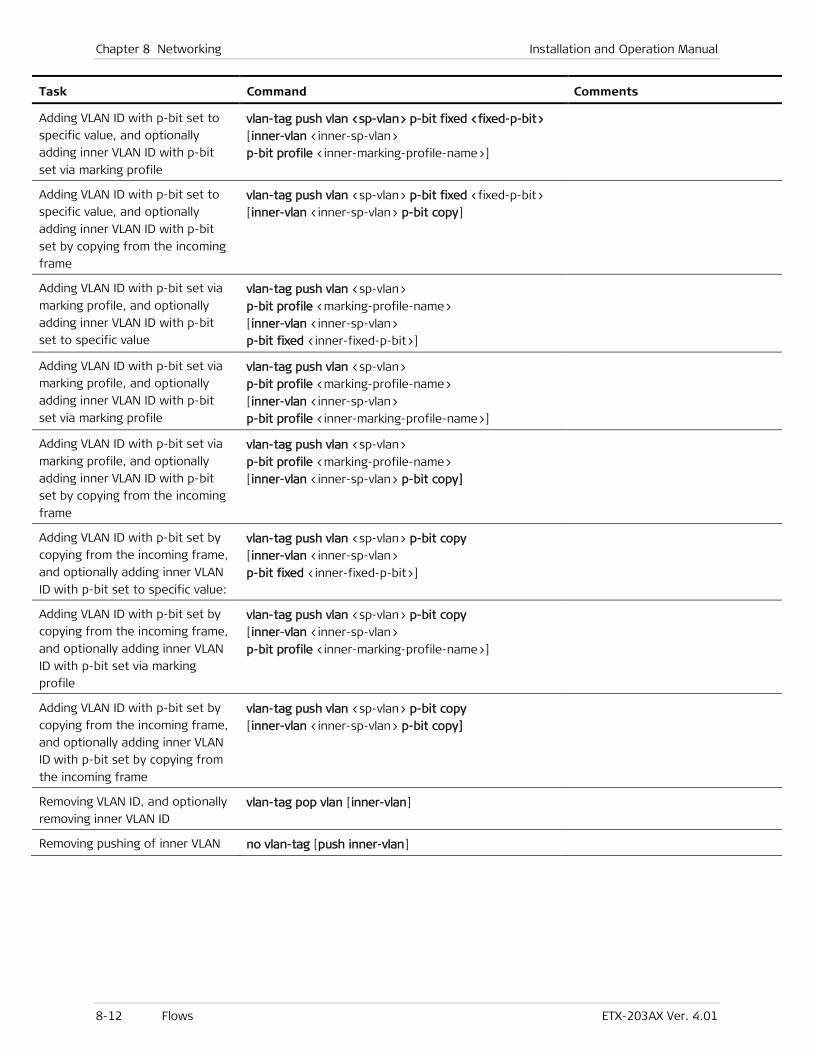
Chapter 8 Networking Installation and Operation Manual
8-12 Flows ETX-203AX Ver. 4.01
Task Command Comments
Adding VLAN ID with p-bit set to
specific value, and optionally
adding inner VLAN ID with p-bit
set via marking profile
vlan-tag push vlan <sp-vlan> p-bit fixed <fixed-p-bit>
[inner-vlan <inner-sp-vlan>
p-bit profile <inner-marking-profile-name>]
Adding VLAN ID with p-bit set to
specific value, and optionally
adding inner VLAN ID with p-bit
set by copying from the incoming
frame
vlan-tag push vlan <sp-vlan> p-bit fixed <fixed-p-bit>
[inner-vlan <inner-sp-vlan> p-bit copy]
Adding VLAN ID with p-bit set via
marking profile, and optionally
adding inner VLAN ID with p-bit
set to specific value
vlan-tag push vlan <sp-vlan>
p-bit profile <marking-profile-name>
[inner-vlan <inner-sp-vlan>
p-bit fixed <inner-fixed-p-bit>]
Adding VLAN ID with p-bit set via
marking profile, and optionally
adding inner VLAN ID with p-bit
set via marking profile
vlan-tag push vlan <sp-vlan>
p-bit profile <marking-profile-name>
[inner-vlan <inner-sp-vlan>
p-bit profile <inner-marking-profile-name>]
Adding VLAN ID with p-bit set via
marking profile, and optionally
adding inner VLAN ID with p-bit
set by copying from the incoming
frame
vlan-tag push vlan <sp-vlan>
p-bit profile <marking-profile-name>
[inner-vlan <inner-sp-vlan> p-bit copy]
Adding VLAN ID with p-bit set by
copying from the incoming frame,
and optionally adding inner VLAN
ID with p-bit set to specific value:
vlan-tag push vlan <sp-vlan> p-bit copy
[inner-vlan <inner-sp-vlan>
p-bit fixed <inner-fixed-p-bit>]
Adding VLAN ID with p-bit set by
copying from the incoming frame,
and optionally adding inner VLAN
ID with p-bit set via marking
profile
vlan-tag push vlan <sp-vlan> p-bit copy
[inner-vlan <inner-sp-vlan>
p-bit profile <inner-marking-profile-name>]
Adding VLAN ID with p-bit set by
copying from the incoming frame,
and optionally adding inner VLAN
ID with p-bit set by copying from
the incoming frame
vlan-tag push vlan <sp-vlan> p-bit copy
[inner-vlan <inner-sp-vlan> p-bit copy]
Removing VLAN ID, and optionally
removing inner VLAN ID vlan-tag pop vlan [inner-vlan]
Removing pushing of inner VLAN no vlan-tag [push inner-vlan]
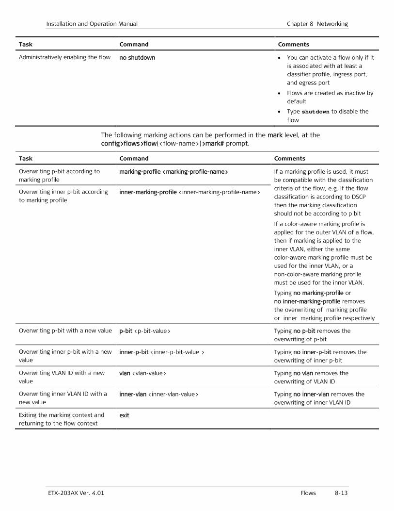
Installation and Operation Manual Chapter 8 Networking
ETX-203AX Ver. 4.01 Flows 8-13
Task Command Comments
Administratively enabling the flow no shutdown • You can activate a flow only if it
is associated with at least a
classifier profile, ingress port,
and egress port
• Flows are created as inactive by
default
• Type shutdown to disable the
flow
The following marking actions can be performed in the mark level, at the config>flows>flow(<flow-name>)>mark# prompt.
Task Command Comments
Overwriting p-bit according to
marking profile marking-profile <marking-profile-name> If a marking profile is used, it must
be compatible with the classification
criteria of the flow, e.g. if the flow
classification is according to DSCP
then the marking classification
should not be according to p bit
If a color-aware marking profile is
applied for the outer VLAN of a flow,
then if marking is applied to the
inner VLAN, either the same
color-aware marking profile must be
used for the inner VLAN, or a
non-color-aware marking profile
must be used for the inner VLAN.
Typing no marking-profile or
no inner-marking-profile removes
the overwriting of marking profile or inner marking profile respectively
Overwriting inner p-bit according
to marking profile inner-marking-profile <inner-marking-profile-name>
Overwriting p-bit with a new value p-bit <p-bit-value> Typing no p-bit removes the
overwriting of p-bit
Overwriting inner p-bit with a new
value inner-p-bit <inner-p-bit-value > Typing no inner-p-bit removes the
overwriting of inner p-bit
Overwriting VLAN ID with a new
value vlan <vlan-value> Typing no vlan removes the
overwriting of VLAN ID
Overwriting inner VLAN ID with a
new value inner-vlan <inner-vlan-value> Typing no inner-vlan removes the
overwriting of inner VLAN ID
Exiting the marking context and
returning to the flow context exit
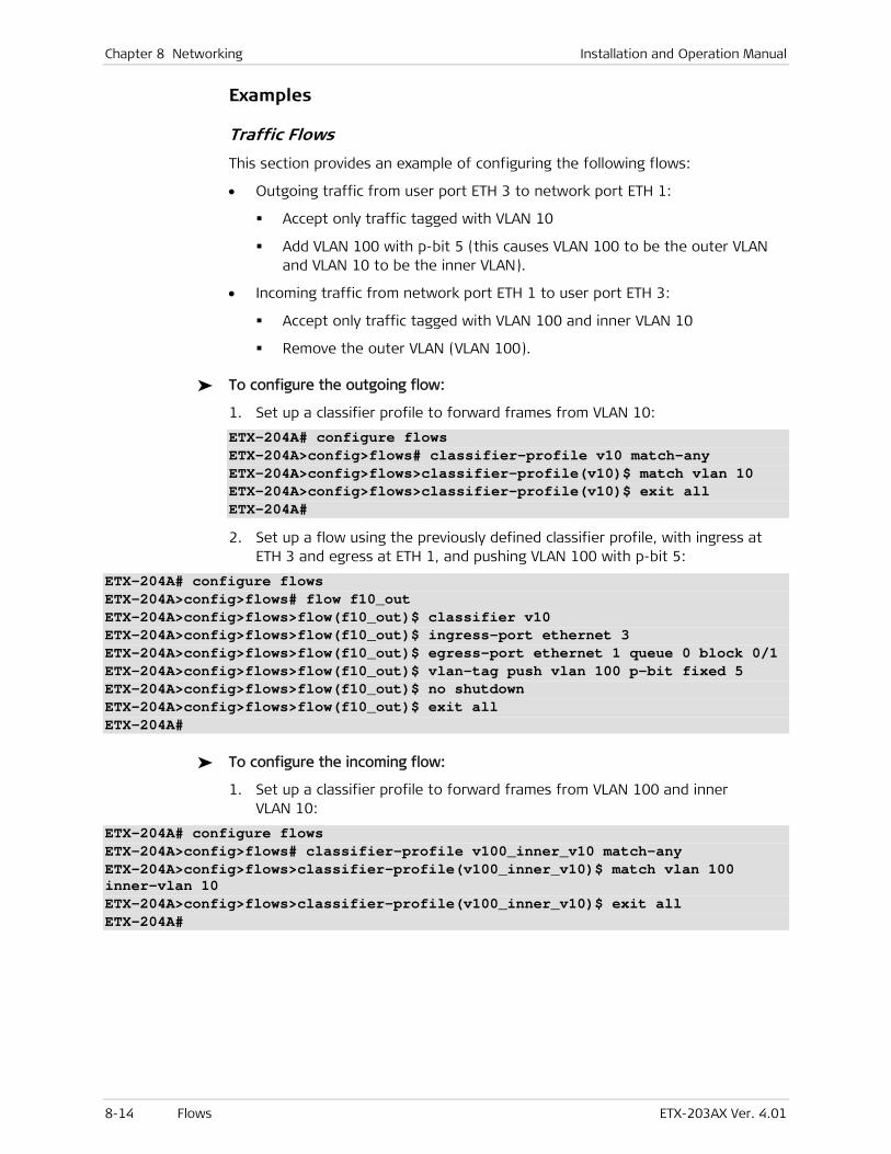
Chapter 8 Networking Installation and Operation Manual
8-14 Flows ETX-203AX Ver. 4.01
Examples
Traffic Flows
This section provides an example of configuring the following flows:
• Outgoing traffic from user port ETH 3 to network port ETH 1:
Accept only traffic tagged with VLAN 10
Add VLAN 100 with p-bit 5 (this causes VLAN 100 to be the outer VLAN and VLAN 10 to be the inner VLAN).
• Incoming traffic from network port ETH 1 to user port ETH 3:
Accept only traffic tagged with VLAN 100 and inner VLAN 10
Remove the outer VLAN (VLAN 100).
To configure the outgoing flow:
1. Set up a classifier profile to forward frames from VLAN 10:
ETX-204A# configure flows ETX-204A>config>flows# classifier-profile v10 match-any ETX-204A>config>flows>classifier-profile(v10)$ match vlan 10 ETX-204A>config>flows>classifier-profile(v10)$ exit all ETX-204A#
2. Set up a flow using the previously defined classifier profile, with ingress at ETH 3 and egress at ETH 1, and pushing VLAN 100 with p-bit 5:
ETX-204A# configure flows ETX-204A>config>flows# flow f10_out ETX-204A>config>flows>flow(f10_out)$ classifier v10 ETX-204A>config>flows>flow(f10_out)$ ingress-port ethernet 3 ETX-204A>config>flows>flow(f10_out)$ egress-port ethernet 1 queue 0 block 0/1 ETX-204A>config>flows>flow(f10_out)$ vlan-tag push vlan 100 p-bit fixed 5 ETX-204A>config>flows>flow(f10_out)$ no shutdown ETX-204A>config>flows>flow(f10_out)$ exit all ETX-204A#
To configure the incoming flow:
1. Set up a classifier profile to forward frames from VLAN 100 and inner VLAN 10:
ETX-204A# configure flows ETX-204A>config>flows# classifier-profile v100_inner_v10 match-any ETX-204A>config>flows>classifier-profile(v100_inner_v10)$ match vlan 100 inner-vlan 10 ETX-204A>config>flows>classifier-profile(v100_inner_v10)$ exit all ETX-204A#
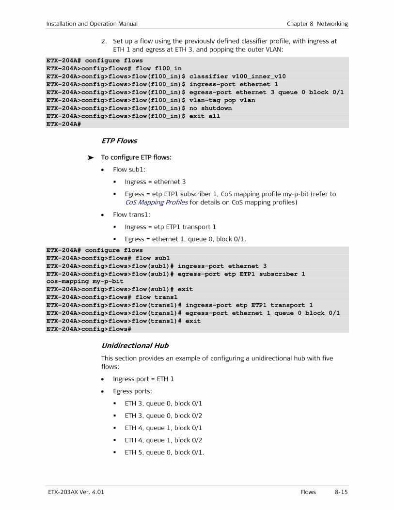
Installation and Operation Manual Chapter 8 Networking
ETX-203AX Ver. 4.01 Flows 8-15
2. Set up a flow using the previously defined classifier profile, with ingress at ETH 1 and egress at ETH 3, and popping the outer VLAN:
ETX-204A# configure flows ETX-204A>config>flows# flow f100_in ETX-204A>config>flows>flow(f100_in)$ classifier v100_inner_v10 ETX-204A>config>flows>flow(f100_in)$ ingress-port ethernet 1 ETX-204A>config>flows>flow(f100_in)$ egress-port ethernet 3 queue 0 block 0/1 ETX-204A>config>flows>flow(f100_in)$ vlan-tag pop vlan ETX-204A>config>flows>flow(f100_in)$ no shutdown ETX-204A>config>flows>flow(f100_in)$ exit all ETX-204A#
ETP Flows
To configure ETP flows:
• Flow sub1:
Ingress = ethernet 3
Egress = etp ETP1 subscriber 1, CoS mapping profile my-p-bit (refer to CoS Mapping Profiles for details on CoS mapping profiles)
• Flow trans1:
Ingress = etp ETP1 transport 1
Egress = ethernet 1, queue 0, block 0/1.
ETX-204A# configure flows ETX-204A>config>flows# flow sub1 ETX-204A>config>flows>flow(sub1)# ingress-port ethernet 3 ETX-204A>config>flows>flow(sub1)# egress-port etp ETP1 subscriber 1 cos-mapping my-p-bit ETX-204A>config>flows>flow(sub1)# exit ETX-204A>config>flows# flow trans1 ETX-204A>config>flows>flow(trans1)# ingress-port etp ETP1 transport 1 ETX-204A>config>flows>flow(trans1)# egress-port ethernet 1 queue 0 block 0/1 ETX-204A>config>flows>flow(trans1)# exit ETX-204A>config>flows#
Unidirectional Hub
This section provides an example of configuring a unidirectional hub with five flows:
• Ingress port = ETH 1
• Egress ports:
ETH 3, queue 0, block 0/1
ETH 3, queue 0, block 0/2
ETH 4, queue 1, block 0/1
ETH 4, queue 1, block 0/2
ETH 5, queue 0, block 0/1.
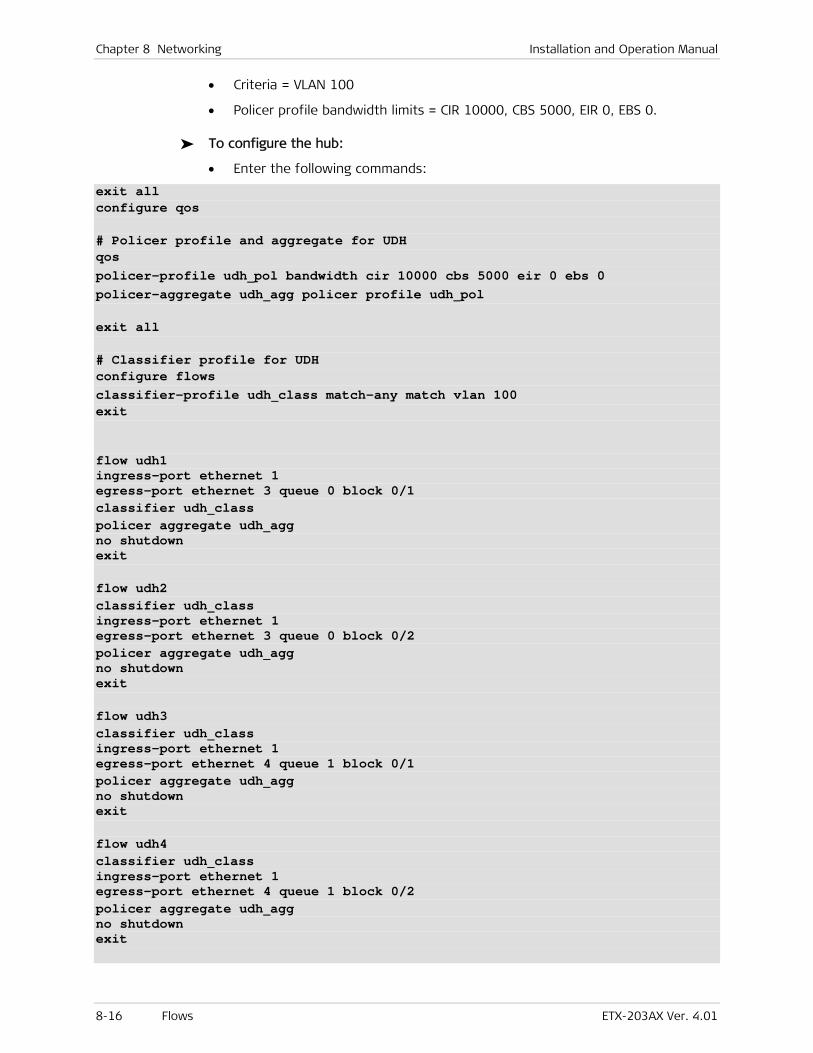
Chapter 8 Networking Installation and Operation Manual
8-16 Flows ETX-203AX Ver. 4.01
• Criteria = VLAN 100
• Policer profile bandwidth limits = CIR 10000, CBS 5000, EIR 0, EBS 0.
To configure the hub:
• Enter the following commands:
exit all configure qos # Policer profile and aggregate for UDH qos policer-profile udh_pol bandwidth cir 10000 cbs 5000 eir 0 ebs 0 policer-aggregate udh_agg policer profile udh_pol exit all # Classifier profile for UDH configure flows classifier-profile udh_class match-any match vlan 100 exit flow udh1 ingress-port ethernet 1 egress-port ethernet 3 queue 0 block 0/1 classifier udh_class policer aggregate udh_agg no shutdown exit flow udh2 classifier udh_class ingress-port ethernet 1 egress-port ethernet 3 queue 0 block 0/2 policer aggregate udh_agg no shutdown exit flow udh3 classifier udh_class ingress-port ethernet 1 egress-port ethernet 4 queue 1 block 0/1 policer aggregate udh_agg no shutdown exit flow udh4 classifier udh_class ingress-port ethernet 1 egress-port ethernet 4 queue 1 block 0/2 policer aggregate udh_agg no shutdown exit
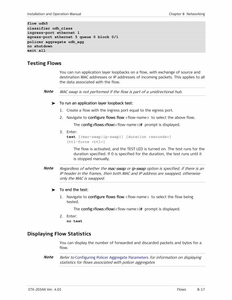
Installation and Operation Manual Chapter 8 Networking
ETX-203AX Ver. 4.01 Flows 8-17
flow udh5 classifier udh_class ingress-port ethernet 1 egress-port ethernet 5 queue 0 block 0/1 policer aggregate udh_agg no shutdown exit all
Testing Flows
You can run application layer loopbacks on a flow, with exchange of source and destination MAC addresses or IP addresses of incoming packets. This applies to all the data associated with the flow.
MAC swap is not performed if the flow is part of a unidirectional hub.
To run an application layer loopback test:
1. Create a flow with the ingress port equal to the egress port.
2. Navigate to configure flows flow <flow-name> to select the above flow.
The config>flows>flow(<flow-name>)# prompt is displayed.
3. Enter: test [{mac-swap|ip-swap}] [duration <seconds>] [ttl-force <ttl>]
The flow is activated, and the TEST LED is turned on. The test runs for the duration specified. If 0 is specified for the duration, the test runs until it is stopped manually.
Regardless of whether the mac-swap or ip-swap option is specified, if there is an IP header in the frames, then both MAC and IP address are swapped, otherwise only the MAC is swapped.
To end the test:
1. Navigate to configure flows flow <flow-name> to select the flow being tested.
The config>flows>flow(<flow-name>)# prompt is displayed.
2. Enter: no test
Displaying Flow Statistics
You can display the number of forwarded and discarded packets and bytes for a flow.
Refer to Configuring Policer Aggregate Parameters for information on displaying statistics for flows associated with policer aggregates
Note
Note
Note
Chapter 8 Networking Installation and Operation Manual
8-18 Flows ETX-203AX Ver. 4.01
To display the statistics for a flow:
• At the relevant flow context (config>flows>flow(<flow-id>)), enter: show statistics running
Flow statistics are displayed.
To clear the statistics for a flow:
• At the relevant flow context (config>flows>flow(<flow-id>)), enter: clear-statistics
The statistics for the flow are cleared.
Example
This example uses flow f10_out, created in the traffic flow example.
Note
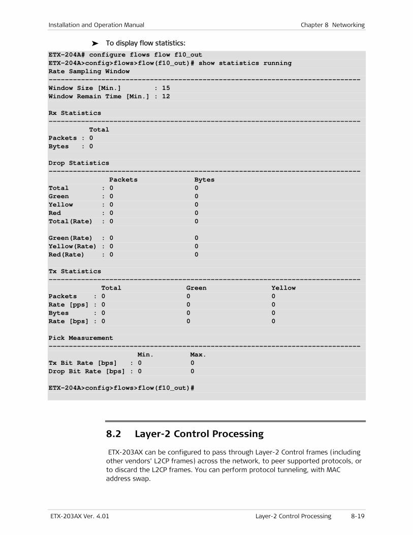
Installation and Operation Manual Chapter 8 Networking
ETX-203AX Ver. 4.01 Layer-2 Control Processing 8-19
To display flow statistics:
ETX-204A# configure flows flow f10_out ETX-204A>config>flows>flow(f10_out)# show statistics running Rate Sampling Window ----------------------------------------------------------------------------- Window Size [Min.] : 15 Window Remain Time [Min.] : 12 Rx Statistics ----------------------------------------------------------------------------- Total Packets : 0 Bytes : 0 Drop Statistics ----------------------------------------------------------------------------- Packets Bytes Total : 0 0 Green : 0 0 Yellow : 0 0 Red : 0 0 Total(Rate) : 0 0 Green(Rate) : 0 0 Yellow(Rate) : 0 0 Red(Rate) : 0 0 Tx Statistics ----------------------------------------------------------------------------- Total Green Yellow Packets : 0 0 0 Rate [pps] : 0 0 0 Bytes : 0 0 0 Rate [bps] : 0 0 0 Pick Measurement ----------------------------------------------------------------------------- Min. Max. Tx Bit Rate [bps] : 0 0 Drop Bit Rate [bps] : 0 0 ETX-204A>config>flows>flow(f10_out)#
8.2 Layer-2 Control Processing
ETX-203AX can be configured to pass through Layer-2 Control frames (including other vendors’ L2CP frames) across the network, to peer supported protocols, or to discard the L2CP frames. You can perform protocol tunneling, with MAC address swap.
Chapter 8 Networking Installation and Operation Manual
8-20 Layer-2 Control Processing ETX-203AX Ver. 4.01
You can create profiles to define the handling of Layer-2 Control Protocol traffic. You then assign the required profile to an Ethernet port or to a flow (refer to Configuring Ethernet Port Parameters and Configuring Flows, respectively).
Standards
IEEE 802.3
Benefits
Layer 2 Control Protocol can be passed or filtered to Ethernet virtual connections.
Factory Defaults
ETX-203AX provides a default L2CP profile named L2cpDefaultProfile, configured as follows:
• For MAC hex byte 0x00 through 0x2f, action = tunnel
• Default action = tunnel.
When a new L2CP profile is created, it has the same configuration as L2cpDefaultProfile.
Adding Layer 2 Control Processing Profiles
To add an L2CP profile:
1. Navigate to configure port.
The config>port# prompt is displayed.
2. Type: l2cp-profile <l2cp-profile-name>
An L2CP profile with the specified name is created and the config>port>l2cp-profile(<l2cp-profile-name>)$ prompt is displayed. The new profile is configured by default as described in Factory Defaults.
3. Configure the L2CP profile as needed (refer to Configuring Layer 2 Control Processing Profile Parameters).
Deleting Layer 2 Control Processing Profiles
You can delete an L2CP profile only if it is not assigned to any port.
To delete an L2CP profile:
1. Navigate to configure port.
The config>port# prompt is displayed.
2. Type: no l2cp-profile <l2cp-profile-name>
The L2CP profile with the specified name is deleted if it is not assigned to any port.

Installation and Operation Manual Chapter 8 Networking
ETX-203AX Ver. 4.01 Layer-2 Control Processing 8-21
Configuring Layer 2 Control Processing Profile Parameters
To configure an L2CP profile:
1. Navigate to configure port l2cp-profile <l2cp-profile-name> to select the L2CP profile to configure.
The config>port>l2cp-profile(<l2cp-profile-name>)# prompt is displayed.
2. Enter all necessary commands according to the tasks listed below.
Task Command Comments
Specifying the default action for
undefined control protocols
default {discard | tunnel}
Specifying the L2CP action for MAC
addresses (discard, tunnel, or peer)
mac <mac-addr-last-byte-value-list> {discard | tunnel |
peer}
discard – L2CP frames are
discarded
tunnel – L2CP frames are
forwarded across the network
as ordinary data
peer – ETX-203AX peers with
the user equipment to run the
protocol. L2CP frames are
forwarded to the ETX-203AX
CPU. Unidentified L2CP frames
are forwarded across the
network as ordinary data.
Typing no mac
<mac-addr-last-byte-value-list>
removes the action for the
specified MAC address
Choosing a protocol for tunneling
and specifying MAC swap if desired protocol { lacp | stp | vtp | cdp | lldp | pvstp }
tunnel mac-change [<mac-address>]
Typing no protocol { lacp | stp |
vtp | cdp | lldp | pvstp| pvstp }
removes the action for the
specified protocol
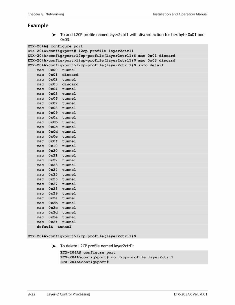
Chapter 8 Networking Installation and Operation Manual
8-22 Layer-2 Control Processing ETX-203AX Ver. 4.01
Example
To add L2CP profile named layer2ctrl1 with discard action for hex byte 0x01 and 0x03:
ETX-204A# configure port ETX-204A>config>port# l2cp-profile layer2ctrl1 ETX-204A>config>port>l2cp-profile(layer2ctrl1)$ mac 0x01 discard ETX-204A>config>port>l2cp-profile(layer2ctrl1)$ mac 0x03 discard ETX-204A>config>port>l2cp-profile(layer2ctrl1)$ info detail mac 0x00 tunnel mac 0x01 discard mac 0x02 tunnel mac 0x03 discard mac 0x04 tunnel mac 0x05 tunnel mac 0x06 tunnel mac 0x07 tunnel mac 0x08 tunnel mac 0x09 tunnel mac 0x0a tunnel mac 0x0b tunnel mac 0x0c tunnel mac 0x0d tunnel mac 0x0e tunnel mac 0x0f tunnel mac 0x10 tunnel mac 0x20 tunnel mac 0x21 tunnel mac 0x22 tunnel mac 0x23 tunnel mac 0x24 tunnel mac 0x25 tunnel mac 0x26 tunnel mac 0x27 tunnel mac 0x28 tunnel mac 0x29 tunnel mac 0x2a tunnel mac 0x2b tunnel mac 0x2c tunnel mac 0x2d tunnel mac 0x2e tunnel mac 0x2f tunnel default tunnel ETX-204A>config>port>l2cp-profile(layer2ctrl1)$
To delete L2CP profile named layer2ctrl1:
ETX-204A# configure port ETX-204A>config>port# no l2cp-profile layer2ctrl1 ETX-204A>config>port#
Installation and Operation Manual Chapter 8 Networking
ETX-203AX Ver. 4.01 OAM 8-23
8.3 OAM
Ethernet OAM (operation, administration, and maintenance) functions provide end-to-end connectivity checks and performance monitoring.
OAM CFM (Connectivity Fault Management)
Ethernet Connectivity Fault Management (CFM) is a service-level OAM protocol that provides tools for monitoring and troubleshooting end-to-end Ethernet services. This includes proactive connectivity monitoring, fault verification, and fault isolation. CFM uses standard Ethernet frames and can be run on any physical media that can transport Ethernet service frames.
ETX-203AX can act as a Maintenance Entity Group Intermediate Point (MIP) or Maintenance Entity Group End Point (MEP). If ETX-203AX is acting as a MIP, it forwards OAM CFM messages transparently, responding only to OAM link trace (LTM) and unicast OAM loopback (LBM).
Standards
IEEE 802.1ag-D8
ITU-T Y.1731
Benefits
Ethernet service providers can monitor their services proactively and guarantee that customers receive the contracted SLA. Fault monitoring and end-to-end performance measurement provide tools for monitoring frame delay, frame delay variation, and frame loss and availability.
Functional Description
OAM enables detection of network faults and measurement of network performance, as well as distribution of fault-related information. OAM functionality ensures that network operators comply with QoS guarantees, detect anomalies before they escalate, and isolate and bypass network defects. As a result, the operators can offer binding service-level agreements.
ETX-203AX provides the OAM (CFM) functions listed below in packet-switched networks:
• End-to-end Connectivity Fault Management (CFM) per IEEE 802.1ag:
Continuity check (CC)
Non-intrusive loopback, used to detect loss of bidirectional continuity
Link Trace for fault localization
• End-to-end service and performance monitoring per ITU-T Y.1731:
Loss measurement
Delay measurement.
OAM messages are always mapped to the queue with the lowest priority.
Note
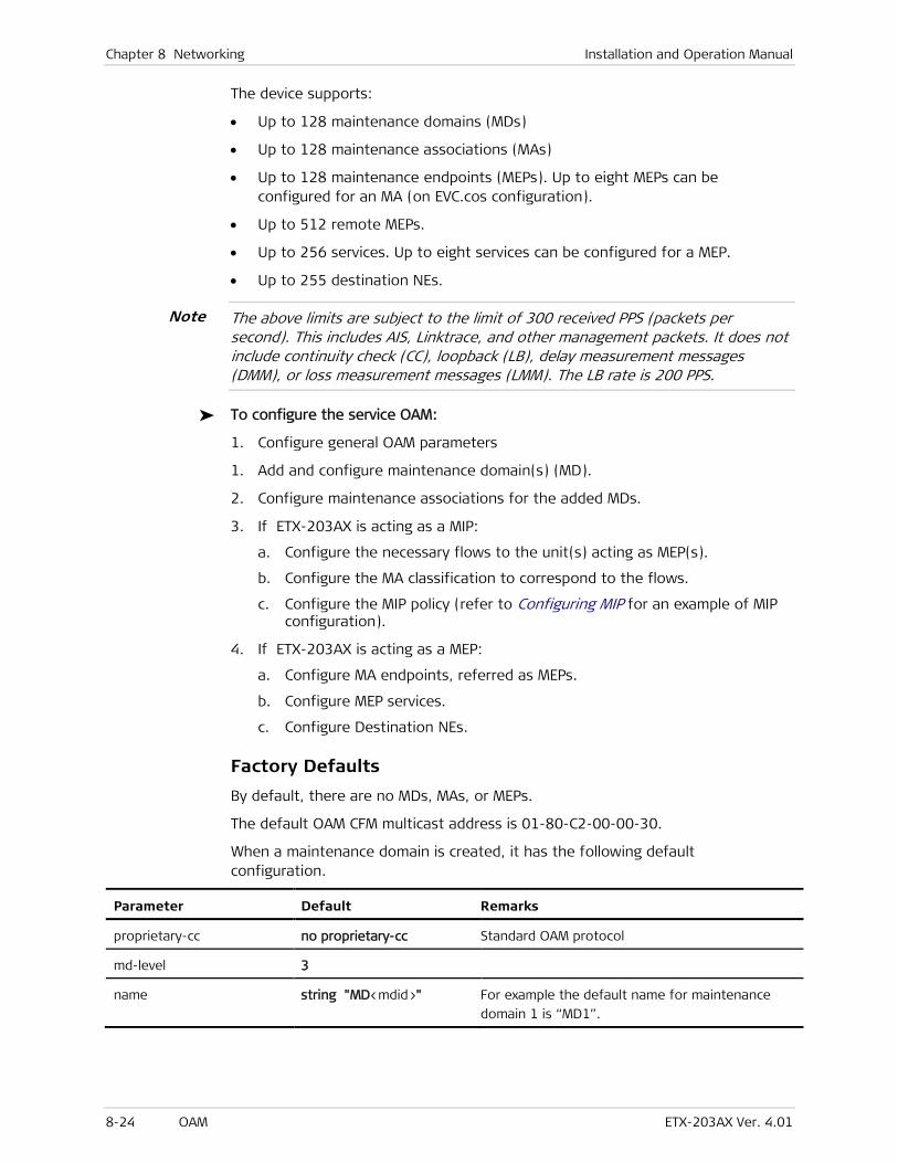
Chapter 8 Networking Installation and Operation Manual
8-24 OAM ETX-203AX Ver. 4.01
The device supports:
• Up to 128 maintenance domains (MDs)
• Up to 128 maintenance associations (MAs)
• Up to 128 maintenance endpoints (MEPs). Up to eight MEPs can be configured for an MA (on EVC.cos configuration).
• Up to 512 remote MEPs.
• Up to 256 services. Up to eight services can be configured for a MEP.
• Up to 255 destination NEs.
The above limits are subject to the limit of 300 received PPS (packets per second). This includes AIS, Linktrace, and other management packets. It does not include continuity check (CC), loopback (LB), delay measurement messages (DMM), or loss measurement messages (LMM). The LB rate is 200 PPS.
To configure the service OAM:
1. Configure general OAM parameters
1. Add and configure maintenance domain(s) (MD).
2. Configure maintenance associations for the added MDs.
3. If ETX-203AX is acting as a MIP:
a. Configure the necessary flows to the unit(s) acting as MEP(s).
b. Configure the MA classification to correspond to the flows.
c. Configure the MIP policy (refer to Configuring MIP for an example of MIP configuration).
4. If ETX-203AX is acting as a MEP:
a. Configure MA endpoints, referred as MEPs.
b. Configure MEP services.
c. Configure Destination NEs.
Factory Defaults
By default, there are no MDs, MAs, or MEPs.
The default OAM CFM multicast address is 01-80-C2-00-00-30.
When a maintenance domain is created, it has the following default configuration.
Parameter Default Remarks
proprietary-cc no proprietary-cc Standard OAM protocol
md-level 3
name string "MD<mdid>" For example the default name for maintenance
domain 1 is “MD1”.
Note
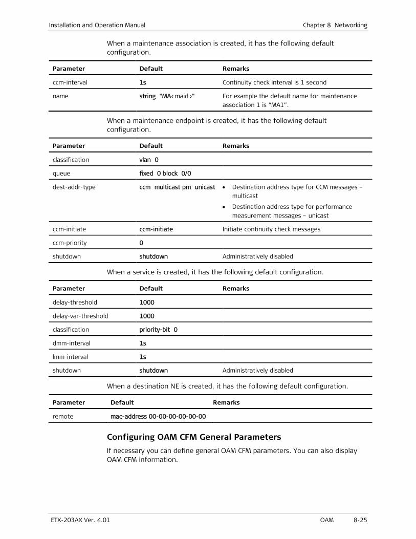
Installation and Operation Manual Chapter 8 Networking
ETX-203AX Ver. 4.01 OAM 8-25
When a maintenance association is created, it has the following default configuration.
Parameter Default Remarks
ccm-interval 1s Continuity check interval is 1 second
name string "MA<maid>" For example the default name for maintenance
association 1 is “MA1”.
When a maintenance endpoint is created, it has the following default configuration.
Parameter Default Remarks
classification vlan 0
queue fixed 0 block 0/0
dest-addr-type ccm multicast pm unicast • Destination address type for CCM messages –
multicast
• Destination address type for performance
measurement messages – unicast
ccm-initiate ccm-initiate Initiate continuity check messages
ccm-priority 0
shutdown shutdown Administratively disabled
When a service is created, it has the following default configuration.
Parameter Default Remarks
delay-threshold 1000
delay-var-threshold 1000
classification priority-bit 0
dmm-interval 1s
lmm-interval 1s
shutdown shutdown Administratively disabled
When a destination NE is created, it has the following default configuration.
Parameter Default Remarks
remote mac-address 00-00-00-00-00-00
Configuring OAM CFM General Parameters
If necessary you can define general OAM CFM parameters. You can also display OAM CFM information.
Chapter 8 Networking Installation and Operation Manual
8-26 OAM ETX-203AX Ver. 4.01
Configuring Multicast MAC Address
To configure the OAM CFM multicast MAC address:
• Navigate to the CFM (Connectivity Fault Management) context (config>oam>cfm) and enter:
multicast-addr <mac-address>
Configuring Measurement Bin Profiles
You can define measurement bin profiles to define sets of threshold ranges for displaying delay measurements in destination NEs. Refer to Configuring and Displaying Delay Measurement Bins for a configuration example.
To define measurement bin profiles:
1. Navigate to configure oam cfm.
The config>oam>cfm prompt is displayed.
2. Enter the measurement profile level:
measurement-bin-profile <name>
The prompt config>oam>cfm>measurement-bin-prof(<name>)# is displayed.
3. Specify the thresholds (single value, or values separated by commas).
thresholds <thresholds-list>
Each value is used as the upper range of a set of thresholds, up to 5,000,000. For instance, entering thresholds 500,1000,15000 results in this set of threshold ranges:
0–500
501–1,000
1,001–15,000
15,001–5,000,000.
Displaying OAM CFM Information
You can display OAM CFM information by typing show summary, as shown in the following.
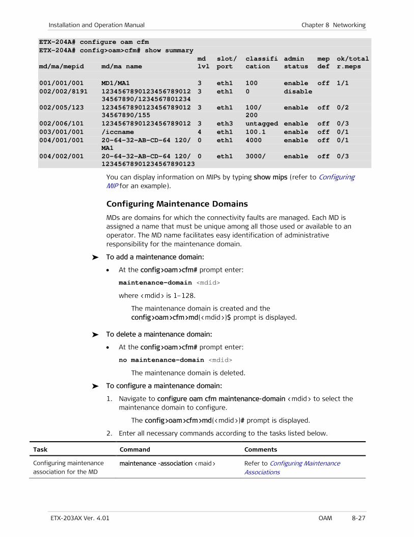
Installation and Operation Manual Chapter 8 Networking
ETX-203AX Ver. 4.01 OAM 8-27
ETX-204A# configure oam cfm ETX-204A# config>oam>cfm# show summary md slot/ classifi admin mep ok/total md/ma/mepid md/ma name lvl port cation status def r.meps 001/001/001 MD1/MA1 3 eth1 100 enable off 1/1 002/002/8191 1234567890123456789012 3 eth1 0 disable 34567890/1234567801234 002/005/123 1234567890123456789012 3 eth1 100/ enable off 0/2 34567890/155 200 002/006/101 1234567890123456789012 3 eth3 untagged enable off 0/3 003/001/001 /iccname 4 eth1 100.1 enable off 0/1 004/001/001 20-64-32-AB-CD-64 120/ 0 eth1 4000 enable off 0/1 MA1 004/002/001 20-64-32-AB-CD-64 120/ 0 eth1 3000/ enable off 0/3 12345678901234567890123
You can display information on MIPs by typing show mips (refer to Configuring MIP for an example).
Configuring Maintenance Domains
MDs are domains for which the connectivity faults are managed. Each MD is assigned a name that must be unique among all those used or available to an operator. The MD name facilitates easy identification of administrative responsibility for the maintenance domain.
To add a maintenance domain:
• At the config>oam>cfm# prompt enter:
maintenance-domain <mdid>
where <mdid> is 1–128.
The maintenance domain is created and the config>oam>cfm>md(<mdid>)$ prompt is displayed.
To delete a maintenance domain:
• At the config>oam>cfm# prompt enter:
no maintenance-domain <mdid>
The maintenance domain is deleted.
To configure a maintenance domain:
1. Navigate to configure oam cfm maintenance-domain <mdid> to select the maintenance domain to configure.
The config>oam>cfm>md(<mdid>)# prompt is displayed.
2. Enter all necessary commands according to the tasks listed below.
Task Command Comments
Configuring maintenance
association for the MD maintenance -association <maid> Refer to Configuring Maintenance
Associations
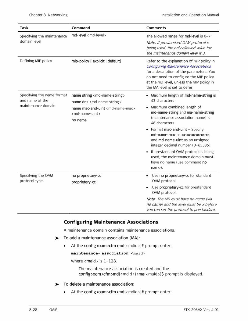
Chapter 8 Networking Installation and Operation Manual
8-28 OAM ETX-203AX Ver. 4.01
Task Command Comments
Specifying the maintenance
domain level
md-level <md-level> The allowed range for md-level is 0–7
Note: If prestandard OAM protocol is being used, the only allowed value for the maintenance domain level is 3.
Defining MIP policy mip-policy { explicit | default} Refer to the explanation of MIP policy in
Configuring Maintenance Associations
for a description of the parameters. You
do not need to configure the MIP policy
at the MD level, unless the MIP policy in
the MA level is set to defer
Specifying the name format
and name of the
maintenance domain
name string <md-name-string>
name dns <md-name-string>
name mac-and-uint <md-name-mac>
<md-name-uint>
no name
• Maximum length of md-name-string is
43 characters
• Maximum combined length of
md-name-string and ma-name-string
(maintenance association name) is
48 characters
• Format mac-and-uint – Specify
md-name-mac as xx-xx-xx-xx-xx-xx,
and md-name-uint as an unsigned
integer decimal number (0–65535)
• If prestandard OAM protocol is being
used, the maintenance domain must
have no name (use command no
name).
Specifying the OAM
protocol type
no proprietary-cc
proprietary-cc
• Use no proprietary-cc for standard
OAM protocol
• Use proprietary-cc for prestandard
OAM protocol.
Note: The MD must have no name (via no name) and the level must be 3 before you can set the protocol to prestandard.
Configuring Maintenance Associations
A maintenance domain contains maintenance associations.
To add a maintenance association (MA):
• At the config>oam>cfm>md(<mdid>)# prompt enter:
maintenance- association <maid>
where <maid> is 1–128.
The maintenance association is created and the config>oam>cfm>md(<mdid>)>ma(<maid>)$ prompt is displayed.
To delete a maintenance association:
• At the config>oam>cfm>md(<mdid>)# prompt enter:
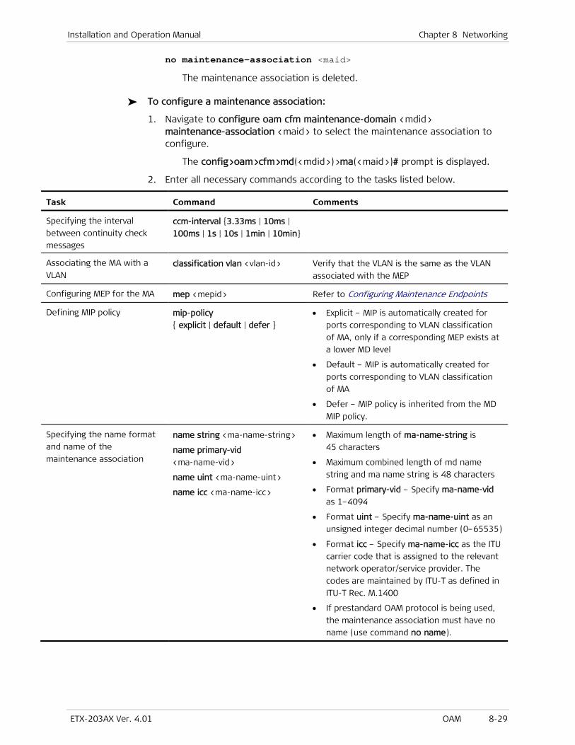
Installation and Operation Manual Chapter 8 Networking
ETX-203AX Ver. 4.01 OAM 8-29
no maintenance-association <maid>
The maintenance association is deleted.
To configure a maintenance association:
1. Navigate to configure oam cfm maintenance-domain <mdid> maintenance-association <maid> to select the maintenance association to configure.
The config>oam>cfm>md(<mdid>)>ma(<maid>)# prompt is displayed.
2. Enter all necessary commands according to the tasks listed below.
Task Command Comments
Specifying the interval
between continuity check
messages
ccm-interval {3.33ms | 10ms |
100ms | 1s | 10s | 1min | 10min}
Associating the MA with a
VLAN classification vlan <vlan-id> Verify that the VLAN is the same as the VLAN
associated with the MEP
Configuring MEP for the MA mep <mepid> Refer to Configuring Maintenance Endpoints
Defining MIP policy mip-policy
{ explicit | default | defer }
• Explicit – MIP is automatically created for
ports corresponding to VLAN classification
of MA, only if a corresponding MEP exists at
a lower MD level
• Default – MIP is automatically created for
ports corresponding to VLAN classification
of MA
• Defer – MIP policy is inherited from the MD
MIP policy.
Specifying the name format
and name of the
maintenance association
name string <ma-name-string>
name primary-vid
<ma-name-vid>
name uint <ma-name-uint>
name icc <ma-name-icc>
• Maximum length of ma-name-string is
45 characters
• Maximum combined length of md name
string and ma name string is 48 characters
• Format primary-vid – Specify ma-name-vid
as 1–4094
• Format uint – Specify ma-name-uint as an
unsigned integer decimal number (0–65535)
• Format icc – Specify ma-name-icc as the ITU
carrier code that is assigned to the relevant
network operator/service provider. The
codes are maintained by ITU-T as defined in
ITU-T Rec. M.1400
• If prestandard OAM protocol is being used,
the maintenance association must have no
name (use command no name).

Chapter 8 Networking Installation and Operation Manual
8-30 OAM ETX-203AX Ver. 4.01
Configuring Maintenance Endpoints
Maintenance endpoints reside at the edge of a maintenance domain. They initiate and respond to CCMs, linktrace requests, and loopbacks to detect, localize, and diagnose connectivity problems.
To add a maintenance endpoint (MEP):
• At the config>oam>cfm>md(<mdid>)>ma(<maid>)# prompt, enter:
mep <mepid>
where <mepid> is 1–8191.
The MEP is created and the prompt config>oam>cfm>md(<mdid>)>ma(<maid>)>mep(<mepid>)$ is displayed.
To delete a maintenance endpoint:
• At the config>oam>cfm>md(<mdid>)>ma(<maid>)# prompt, enter:
no mep <mepid>
The maintenance endpoint is deleted.
You can remove a maintenance endpoint regardless of whether it contains services.
To configure a maintenance endpoint:
1. Navigate to configure oam cfm maintenance-domain <mdid> maintenance-association <maid> mep <mepid>to select the maintenance endpoint to configure.
The prompt config>oam>cfm>md(<mdid>)>ma(<maid>)>mep(<mepid>)# is displayed.
2. Enter all necessary commands according to the tasks listed below.
Task Command Comments
Defining sending of AIS ais [ interval { 1s | 1min }]
[priority <priority>]
Binding the MEP to an
Ethernet port bind ethernet <port>
Binding the MEP to an ETP
transport port if ETP is
used
bind etp <etp-name> transport <port-id>
Binding the MEP to a logical
MAC port
bind logical-mac <port-number>
Enabling initiation of
continuity check messages
(CCM)
ccm-initiate To disable initiating continuity check
messages, enter no ccm-initiate
Specifying the priority of
CCMs and LTMs transmitted
by the MEP
ccm-priority <priority> The allowed range for <priority> is 0–7
Note
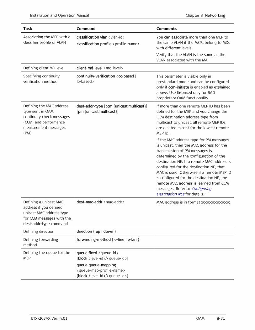
Installation and Operation Manual Chapter 8 Networking
ETX-203AX Ver. 4.01 OAM 8-31
Task Command Comments
Associating the MEP with a
classifier profile or VLAN classification vlan <vlan-id>
classification profile <profile-name>
You can associate more than one MEP to
the same VLAN if the MEPs belong to MDs
with different levels
Verify that the VLAN is the same as the
VLAN associated with the MA
Defining client MD level client-md-level <md-level>
Specifying continuity
verification method
continuity-verification <cc-based |
lb-based> This parameter is visible only in
prestandard mode and can be configured
only if ccm-initiate is enabled as explained
above. Use lb-based only for RAD
proprietary OAM functionality.
Defining the MAC address
type sent in OAM
continuity check messages
(CCM) and performance
measurement messages
(PM)
dest-addr-type [ccm {unicast|multicast}]
[pm {unicast|multicast}]
If more than one remote MEP ID has been
defined for the MEP and you change the
CCM destination address type from
multicast to unicast, all remote MEP IDs
are deleted except for the lowest remote
MEP ID.
If the MAC address type for PM messages
is unicast, then the MAC address for the
transmission of PM messages is
determined by the configuration of the
destination NE. If a remote MAC address is
configured for the destination NE, that
MAC is used. Otherwise if a remote MEP ID
is configured for the destination NE, the
remote MAC address is learned from CCM
messages. Refer to Configuring Destination NEs for details.
Defining a unicast MAC
address if you defined
unicast MAC address type
for CCM messages with the
dest-addr-type command
dest-mac-addr <mac-addr> MAC address is in format xx-xx-xx-xx-xx-xx
Defining direction direction { up | down }
Defining forwarding
method
forwarding-method { e-line | e-lan }
Defining the queue for the
MEP queue fixed <queue-id>
[block <level-id>/<queue-id>]
queue queue-mapping
<queue-map-profile-name>
[block <level-id>/<queue-id>]
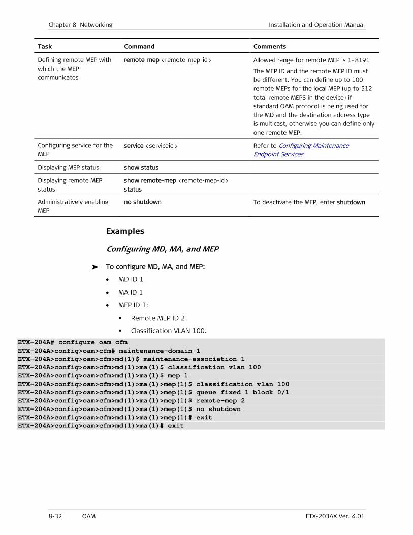
Chapter 8 Networking Installation and Operation Manual
8-32 OAM ETX-203AX Ver. 4.01
Task Command Comments
Defining remote MEP with
which the MEP
communicates
remote-mep <remote-mep-id> Allowed range for remote MEP is 1–8191
The MEP ID and the remote MEP ID must
be different. You can define up to 100
remote MEPs for the local MEP (up to 512
total remote MEPS in the device) if
standard OAM protocol is being used for
the MD and the destination address type
is multicast, otherwise you can define only
one remote MEP.
Configuring service for the
MEP service <serviceid> Refer to Configuring Maintenance
Endpoint Services
Displaying MEP status show status
Displaying remote MEP
status
show remote-mep <remote-mep-id>
status
Administratively enabling
MEP
no shutdown To deactivate the MEP, enter shutdown
Examples
Configuring MD, MA, and MEP
To configure MD, MA, and MEP:
• MD ID 1
• MA ID 1
• MEP ID 1:
Remote MEP ID 2
Classification VLAN 100.
ETX-204A# configure oam cfm ETX-204A>config>oam>cfm# maintenance-domain 1 ETX-204A>config>oam>cfm>md(1)$ maintenance-association 1 ETX-204A>config>oam>cfm>md(1)>ma(1)$ classification vlan 100 ETX-204A>config>oam>cfm>md(1)>ma(1)$ mep 1 ETX-204A>config>oam>cfm>md(1)>ma(1)>mep(1)$ classification vlan 100 ETX-204A>config>oam>cfm>md(1)>ma(1)>mep(1)$ queue fixed 1 block 0/1 ETX-204A>config>oam>cfm>md(1)>ma(1)>mep(1)$ remote-mep 2 ETX-204A>config>oam>cfm>md(1)>ma(1)>mep(1)$ no shutdown ETX-204A>config>oam>cfm>md(1)>ma(1)>mep(1)# exit ETX-204A>config>oam>cfm>md(1)>ma(1)# exit
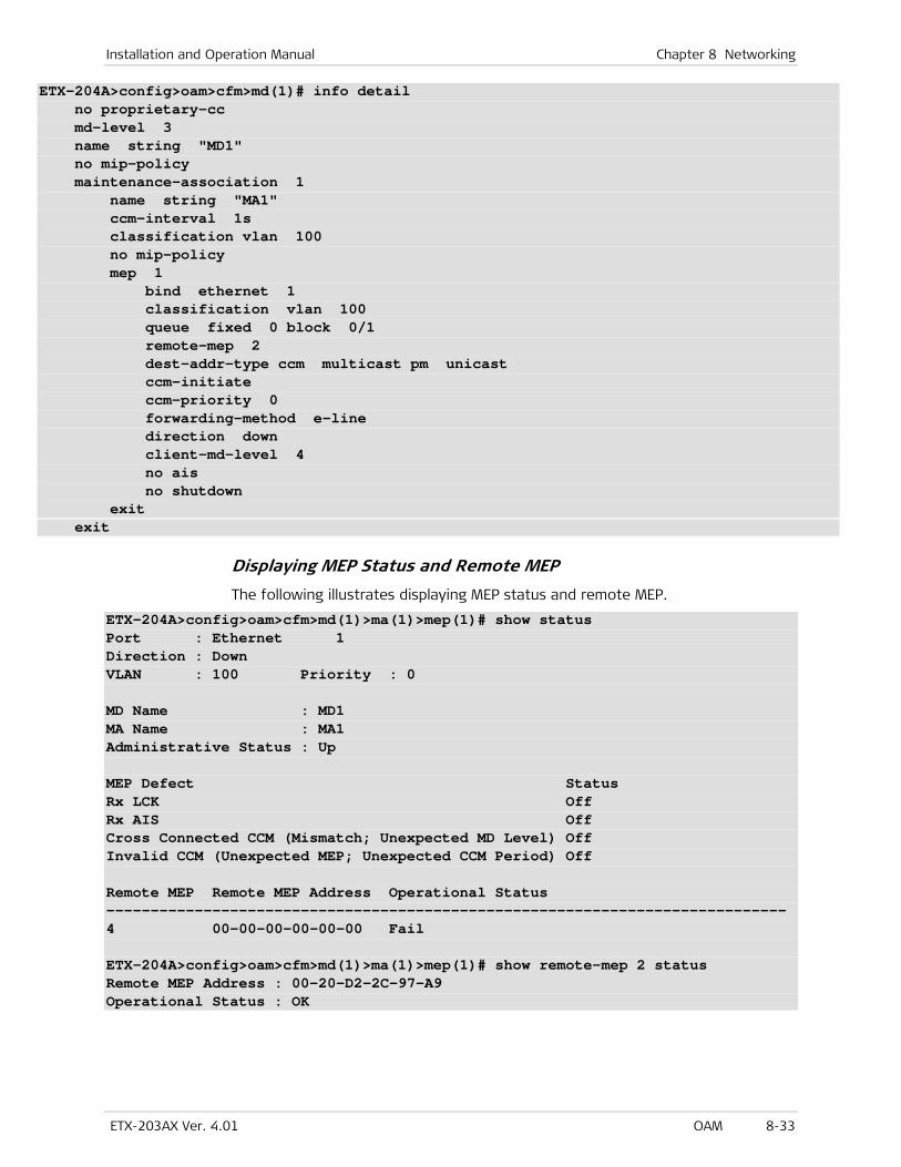
Installation and Operation Manual Chapter 8 Networking
ETX-203AX Ver. 4.01 OAM 8-33
ETX-204A>config>oam>cfm>md(1)# info detail no proprietary-cc md-level 3 name string "MD1" no mip-policy maintenance-association 1 name string "MA1" ccm-interval 1s classification vlan 100 no mip-policy mep 1 bind ethernet 1 classification vlan 100 queue fixed 0 block 0/1 remote-mep 2 dest-addr-type ccm multicast pm unicast ccm-initiate ccm-priority 0 forwarding-method e-line direction down client-md-level 4 no ais no shutdown exit exit
Displaying MEP Status and Remote MEP
The following illustrates displaying MEP status and remote MEP.
ETX-204A>config>oam>cfm>md(1)>ma(1)>mep(1)# show status Port : Ethernet 1 Direction : Down VLAN : 100 Priority : 0 MD Name : MD1 MA Name : MA1 Administrative Status : Up MEP Defect Status Rx LCK Off Rx AIS Off Cross Connected CCM (Mismatch; Unexpected MD Level) Off Invalid CCM (Unexpected MEP; Unexpected CCM Period) Off Remote MEP Remote MEP Address Operational Status ----------------------------------------------------------------------------- 4 00-00-00-00-00-00 Fail ETX-204A>config>oam>cfm>md(1)>ma(1)>mep(1)# show remote-mep 2 status Remote MEP Address : 00-20-D2-2C-97-A9 Operational Status : OK
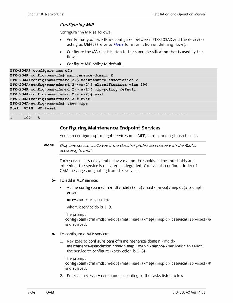
Chapter 8 Networking Installation and Operation Manual
8-34 OAM ETX-203AX Ver. 4.01
Configuring MIP
Configure the MIP as follows:
• Verify that you have flows configured between ETX-203AX and the device(s) acting as MEP(s) (refer to Flows for information on defining flows).
• Configure the MA classification to the same classification that is used by the flows.
• Configure MIP policy to default.
ETX-204A# configure oam cfm ETX-204A>config>oam>cfm# maintenance-domain 2 ETX-204A>config>oam>cfm>md(2)$ maintenance-association 2 ETX-204A>config>oam>cfm>md(2)>ma(2)$ classification vlan 100 ETX-204A>config>oam>cfm>md(2)>ma(2)$ mip-policy default ETX-204A>config>oam>cfm>md(2)>ma(2)# exit ETX-204A>config>oam>cfm>md(2)# exit ETX-204A>config>oam>cfm# show mips Port VLAN MD-level ----------------------------------------------------------------------------- 1 100 3
Configuring Maintenance Endpoint Services
You can configure up to eight services on a MEP, corresponding to each p-bit.
Only one service is allowed if the classifier profile associated with the MEP is according to p-bit.
Each service sets delay and delay variation thresholds. If the thresholds are exceeded, the service is declared as degraded. You can also define priority of OAM messages originating from this service.
To add a MEP service:
• At the config>oam>cfm>md(<mdid>)>ma(<maid>)>mep(<mepid>)# prompt, enter:
service <serviceid>
where <serviceid> is 1–8.
The prompt config>oam>cfm>md(<mdid>)>ma(<maid>)>mep(<mepid>)>service(<serviceid>)$ is displayed.
To configure a MEP service:
1. Navigate to configure oam cfm maintenance-domain <mdid> maintenance-association <maid> mep <mepid> service <serviceid> to select the service to configure (<serviceid> is 1–8).
The prompt config>oam>cfm>md(<mdid>)>ma(<maid>)>mep(<mepid>)>service(<serviceid>)# is displayed.
2. Enter all necessary commands according to the tasks listed below.
Note
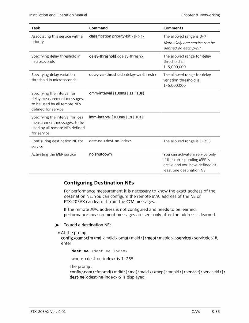
Installation and Operation Manual Chapter 8 Networking
ETX-203AX Ver. 4.01 OAM 8-35
Task Command Comments
Associating this service with a
priority
classification priority-bit <p-bit> The allowed range is 0–7
Note: Only one service can be defined on each p-bit.
Specifying delay threshold in
microseconds
delay-threshold <delay-thresh> The allowed range for delay
threshold is:
1–5,000,000
Specifying delay variation
threshold in microseconds
delay-var-threshold <delay-var-thresh> The allowed range for delay
variation threshold is:
1–5,000,000
Specifying the interval for
delay measurement messages,
to be used by all remote NEs
defined for service
dmm-interval {100ms | 1s | 10s}
Specifying the interval for loss
measurement messages, to be
used by all remote NEs defined
for service
lmm-interval {100ms | 1s | 10s}
Configuring destination NE for
service
dest-ne <dest-ne-index> The allowed range is 1–255
Activating the MEP service no shutdown You can activate a service only
if the corresponding MEP is
active and you have defined at
least one destination NE
Configuring Destination NEs
For performance measurement it is necessary to know the exact address of the destination NE. You can configure the remote MAC address of the NE or ETX-203AX can learn it from the CCM messages.
If the remote MAC address is not configured and needs to be learned, performance measurement messages are sent only after the address is learned.
To add a destination NE:
• At the prompt config>oam>cfm>md(<mdid>)>ma(<maid>)>mep(<mepid>)>service(<serviceid>)#, enter:
dest-ne <dest-ne-index>
where <dest-ne-index> is 1–255.
The prompt config>oam>cfm>md(<mdid>)>ma(<maid>)>mep(<mepid>)>service(<serviceid>)> dest-ne(<dest-ne-index>)$ is displayed.

Chapter 8 Networking Installation and Operation Manual
8-36 OAM ETX-203AX Ver. 4.01
To configure a destination NE:
1. Navigate to configure oam cfm maintenance-domain <mdid> maintenance-association <maid> mep <mepid> service <serviceid> dest-ne <dest-ne-index> to select the destination NE to configure.
The prompt config>oam>cfm>md(<mdid>)>ma(<maid>)>mep(<mepid>)>service(<serviceid>)>dest-ne(<dest-ne-index>)# is displayed.
2. Enter all necessary commands according to the tasks listed below.
Task Command Comments
Defining the MAC address of
the destination NE
remote mac-address <mac> If the MAC address is
00-00-00-00-00-00, the statistic
counters for the destination NE do
not increment
Defining the remote MEP ID of
the destination NE
remote mep-id <remote-mep-id>
Enabling two-way delay
measurement method
delay two-way
[data-tlv-length <length-val>]
Assigning the delay
measurement bin profile
delay-measurement-bin profile <name> The delay measurement bin profiles
are defined in the conf>oam>cfm
level
Assigning the delay variation
measurement bin profile
delay-var-measurement-bin profile
<name> The delay measurement bin profiles
are defined in the conf>oam>cfm
level
Defining single-ended loss
measurement method
loss single-ended [{ synthetic |
user-data | lmm-synthetic }] • user-data – This method
measures user data and CCM
messages.
• synthetic – This method measures
DM frames. It is recommended
when working with devices that
do not count user data frames
• lmm-synthetic – This method
measures synthetic frames as
well. It is recommended for
working with ETX-201A/202A.
Displaying the delay
measurement bins for
measurements via DMRs of
round trip delays and round
trip delay variations
show delay-measurement-bins
show delay-measurement-bins {rt-delay
| rt-delay-var} current
- show delay-measurement-bins
{rt-delay | rt-delay-var} interval
<interval-num>
- show delay-measurement-bins
{rt-delay | rt-delay-var} all
Relevant only if profiles were
assigned via delay-measurement-bin,
delay-var-measurement-bin
Clearing statistics clear-statistics
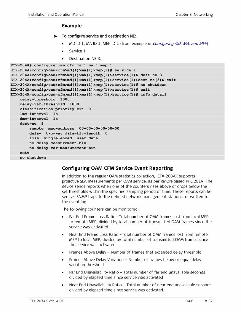
Installation and Operation Manual Chapter 8 Networking
ETX-203AX Ver. 4.01 OAM 8-37
Example
To configure service and destination NE:
• MD ID 1, MA ID 1, MEP ID 1 (from example in Configuring MD, MA, and MEP)
• Service 1
• Destination NE 3.
ETX-204A# configure oam cfm ma 1 ma 1 mep 1 ETX-204A>config>oam>cfm>md(1)>ma(1)>mep(1)# service 1 ETX-204A>config>oam>cfm>md(1)>ma(1)>mep(1)>service(1)$ dest-ne 3 ETX-204A>config>oam>cfm>md(1)>ma(1)>mep(1)>service(1)>dest-ne(3)$ exit ETX-204A>config>oam>cfm>md(1)>ma(1)>mep(1)>service(1)# no shutdown ETX-204A>config>oam>cfm>md(1)>ma(1)>mep(1)>service(1)# exit ETX-204A>config>oam>cfm>md(1)>ma(1)>mep(1)>service(1)# info detail delay-threshold 1000 delay-var-threshold 1000 classification priority-bit 0 lmm-interval 1s dmm-interval 1s dest-ne 3 remote mac-address 00-00-00-00-00-00 delay two-way data-tlv-length 0 loss single-ended user-data no delay-measurement-bin no delay-var-measurement-bin exit no shutdown
Configuring OAM CFM Service Event Reporting
In addition to the regular OAM statistics collection, ETX-203AX supports proactive SLA measurements per OAM service, as per RMON-based RFC 2819. The device sends reports when one of the counters rises above or drops below the set thresholds within the specified sampling period of time. These reports can be sent as SNMP traps to the defined network management stations, or written to the event log.
The following counters can be monitored:
• Far End Frame Loss Ratio –Total number of OAM frames lost from local MEP to remote MEP, divided by total number of transmitted OAM frames since the service was activated
• Near End Frame Loss Ratio –Total number of OAM frames lost from remote MEP to local MEP, divided by total number of transmitted OAM frames since the service was activated
• Frames Above Delay – Number of frames that exceeded delay threshold
• Frames Above Delay Variation – Number of frames below or equal delay variation threshold
• Far End Unavailability Ratio – Total number of far end unavailable seconds divided by elapsed time since service was activated
• Near End Unavailability Ratio – Total number of near end unavailable seconds divided by elapsed time since service was activated.

Chapter 8 Networking Installation and Operation Manual
8-38 OAM ETX-203AX Ver. 4.01
To configure the event reporting for a service:
1. Navigate to configure fault cfm).
2. Specify the service and counter for which you wish to configure event reporting:
service md <mdid> ma <maid> mep <mepid> service <serviceid> {above-delay | above-delay-var | far-end-loss-ratio | near-end-loss-ratio | far-end-unavailability-ratio | near-end-unavailability-ratio}
The prompt config>fault>cfm>service(<mdid>/<maid>/<mepid>/<serviceid>)# is displayed.
3. Specify the type of event reporting for the counter (refer to Table 8-11):
For counters above-delay and above-delay-var: frames-report [event {none | log | trap | logandtrap}] [rising-threshold <rising-threshold>] [falling-threshold <falling-threshold>] [sampling-interval <value>]
For counters near-end-loss-ratio or far-end-loss-ratio: frames-report [event {none | log | trap | logandtrap}] [rising-threshold {1e-3 | 1e-4 | 1e-5 | 1e-6 | 1e-7 | 1e-8 | 1e-9 | 1e-10}] [falling-threshold {1e-3 | 1e-4 | 1e-5 | 1e-6 | 1e-7 | 1e-8 | 1e-9 | 1e-10}]
For counters near-end-unavailability-ratio or far-end-unavailability-ratio: frames-report [event {none | log | trap | logandtrap}] [rising-threshold <rising-threshold>] [falling-threshold <falling-threshold>]
4. Type no shutdown to activate the event reporting for the counter.
Table 8-11. Service Event Reporting Parameters
Parameter Description Possible Values
event Specifies the type of event reporting none – The event is not reported
log – The event is reported via the
event log
trap –An SNMP trap is sent to
report the event
logandtrap –The event is reported
via the event log and an SNMP trap
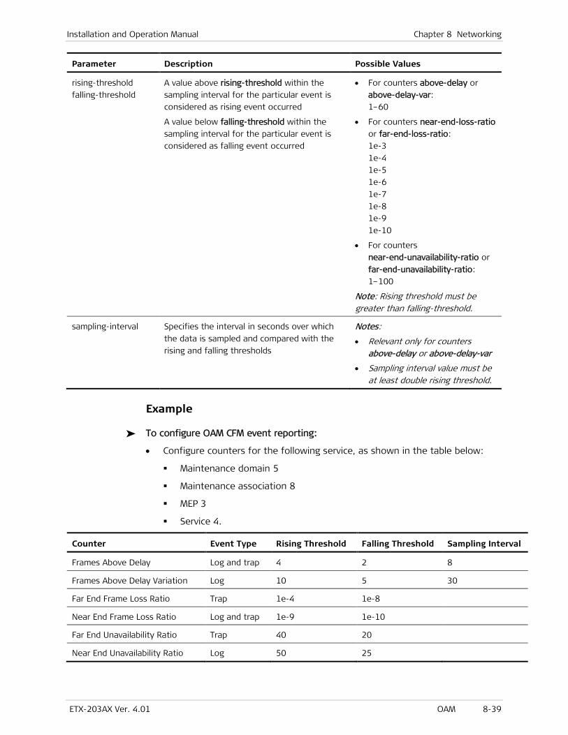
Installation and Operation Manual Chapter 8 Networking
ETX-203AX Ver. 4.01 OAM 8-39
Parameter Description Possible Values
rising-threshold
falling-threshold
A value above rising-threshold within the
sampling interval for the particular event is
considered as rising event occurred
A value below falling-threshold within the
sampling interval for the particular event is
considered as falling event occurred
• For counters above-delay or
above-delay-var:
1–60
• For counters near-end-loss-ratio
or far-end-loss-ratio:
1e-3
1e-4
1e-5
1e-6
1e-7
1e-8
1e-9
1e-10
• For counters
near-end-unavailability-ratio or
far-end-unavailability-ratio:
1–100
Note: Rising threshold must be greater than falling-threshold.
sampling-interval Specifies the interval in seconds over which
the data is sampled and compared with the
rising and falling thresholds
Notes:
• Relevant only for counters above-delay or above-delay-var
• Sampling interval value must be at least double rising threshold.
Example
To configure OAM CFM event reporting:
• Configure counters for the following service, as shown in the table below:
Maintenance domain 5
Maintenance association 8
MEP 3
Service 4.
Counter Event Type Rising Threshold Falling Threshold Sampling Interval
Frames Above Delay Log and trap 4 2 8
Frames Above Delay Variation Log 10 5 30
Far End Frame Loss Ratio Trap 1e-4 1e-8
Near End Frame Loss Ratio Log and trap 1e-9 1e-10
Far End Unavailability Ratio Trap 40 20
Near End Unavailability Ratio Log 50 25
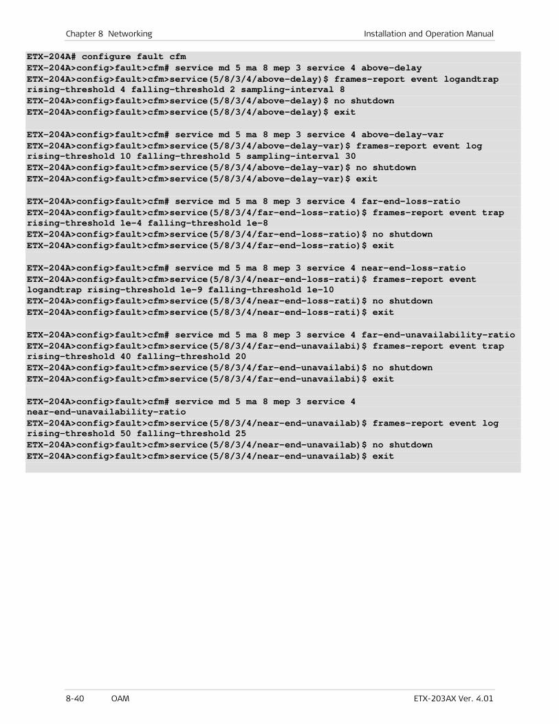
Chapter 8 Networking Installation and Operation Manual
8-40 OAM ETX-203AX Ver. 4.01
ETX-204A# configure fault cfm ETX-204A>config>fault>cfm# service md 5 ma 8 mep 3 service 4 above-delay ETX-204A>config>fault>cfm>service(5/8/3/4/above-delay)$ frames-report event logandtrap rising-threshold 4 falling-threshold 2 sampling-interval 8 ETX-204A>config>fault>cfm>service(5/8/3/4/above-delay)$ no shutdown ETX-204A>config>fault>cfm>service(5/8/3/4/above-delay)$ exit ETX-204A>config>fault>cfm# service md 5 ma 8 mep 3 service 4 above-delay-var ETX-204A>config>fault>cfm>service(5/8/3/4/above-delay-var)$ frames-report event log rising-threshold 10 falling-threshold 5 sampling-interval 30 ETX-204A>config>fault>cfm>service(5/8/3/4/above-delay-var)$ no shutdown ETX-204A>config>fault>cfm>service(5/8/3/4/above-delay-var)$ exit ETX-204A>config>fault>cfm# service md 5 ma 8 mep 3 service 4 far-end-loss-ratio ETX-204A>config>fault>cfm>service(5/8/3/4/far-end-loss-ratio)$ frames-report event trap rising-threshold 1e-4 falling-threshold 1e-8 ETX-204A>config>fault>cfm>service(5/8/3/4/far-end-loss-ratio)$ no shutdown ETX-204A>config>fault>cfm>service(5/8/3/4/far-end-loss-ratio)$ exit ETX-204A>config>fault>cfm# service md 5 ma 8 mep 3 service 4 near-end-loss-ratio ETX-204A>config>fault>cfm>service(5/8/3/4/near-end-loss-rati)$ frames-report event logandtrap rising-threshold 1e-9 falling-threshold 1e-10 ETX-204A>config>fault>cfm>service(5/8/3/4/near-end-loss-rati)$ no shutdown ETX-204A>config>fault>cfm>service(5/8/3/4/near-end-loss-rati)$ exit ETX-204A>config>fault>cfm# service md 5 ma 8 mep 3 service 4 far-end-unavailability-ratio ETX-204A>config>fault>cfm>service(5/8/3/4/far-end-unavailabi)$ frames-report event trap rising-threshold 40 falling-threshold 20 ETX-204A>config>fault>cfm>service(5/8/3/4/far-end-unavailabi)$ no shutdown ETX-204A>config>fault>cfm>service(5/8/3/4/far-end-unavailabi)$ exit ETX-204A>config>fault>cfm# service md 5 ma 8 mep 3 service 4 near-end-unavailability-ratio ETX-204A>config>fault>cfm>service(5/8/3/4/near-end-unavailab)$ frames-report event log rising-threshold 50 falling-threshold 25 ETX-204A>config>fault>cfm>service(5/8/3/4/near-end-unavailab)$ no shutdown ETX-204A>config>fault>cfm>service(5/8/3/4/near-end-unavailab)$ exit
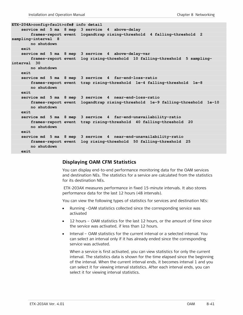
Installation and Operation Manual Chapter 8 Networking
ETX-203AX Ver. 4.01 OAM 8-41
ETX-204A>config>fault>cfm# info detail service md 5 ma 8 mep 3 service 4 above-delay frames-report event logandtrap rising-threshold 4 falling-threshold 2 sampling-interval 8 no shutdown exit service md 5 ma 8 mep 3 service 4 above-delay-var frames-report event log rising-threshold 10 falling-threshold 5 sampling-interval 30 no shutdown exit service md 5 ma 8 mep 3 service 4 far-end-loss-ratio frames-report event trap rising-threshold 1e-4 falling-threshold 1e-8 no shutdown exit service md 5 ma 8 mep 3 service 4 near-end-loss-ratio frames-report event logandtrap rising-threshold 1e-9 falling-threshold 1e-10 no shutdown exit service md 5 ma 8 mep 3 service 4 far-end-unavailability-ratio frames-report event trap rising-threshold 40 falling-threshold 20 no shutdown exit service md 5 ma 8 mep 3 service 4 near-end-unavailability-ratio frames-report event log rising-threshold 50 falling-threshold 25 no shutdown exit
Displaying OAM CFM Statistics
You can display end-to-end performance monitoring data for the OAM services and destination NEs. The statistics for a service are calculated from the statistics for its destination NEs.
ETX-203AX measures performance in fixed 15-minute intervals. It also stores performance data for the last 12 hours (48 intervals).
You can view the following types of statistics for services and destination NEs:
• Running –OAM statistics collected since the corresponding service was activated
• 12 hours – OAM statistics for the last 12 hours, or the amount of time since the service was activated, if less than 12 hours.
• Interval – OAM statistics for the current interval or a selected interval. You can select an interval only if it has already ended since the corresponding service was activated.
When a service is first activated, you can view statistics for only the current interval. The statistics data is shown for the time elapsed since the beginning of the interval. When the current interval ends, it becomes interval 1 and you can select it for viewing interval statistics. After each interval ends, you can select it for viewing interval statistics.
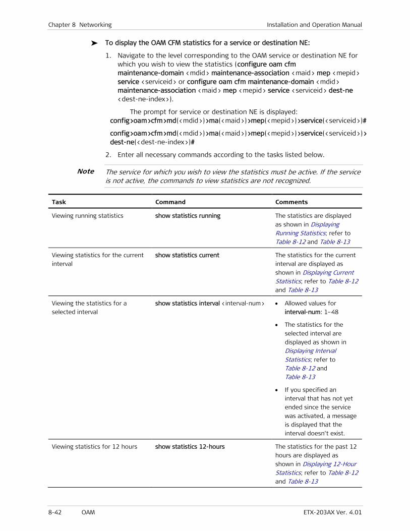
Chapter 8 Networking Installation and Operation Manual
8-42 OAM ETX-203AX Ver. 4.01
To display the OAM CFM statistics for a service or destination NE:
1. Navigate to the level corresponding to the OAM service or destination NE for which you wish to view the statistics (configure oam cfm maintenance-domain <mdid> maintenance-association <maid> mep <mepid> service <serviceid> or configure oam cfm maintenance-domain <mdid> maintenance-association <maid> mep <mepid> service <serviceid> dest-ne <dest-ne-index>).
The prompt for service or destination NE is displayed: config>oam>cfm>md(<mdid>)>ma(<maid>)>mep(<mepid>)>service(<serviceid>)#
config>oam>cfm>md(<mdid>)>ma(<maid>)>mep(<mepid>)>service(<serviceid>)> dest-ne(<dest-ne-index>)#
2. Enter all necessary commands according to the tasks listed below.
The service for which you wish to view the statistics must be active. If the service is not active, the commands to view statistics are not recognized.
Task Command Comments
Viewing running statistics show statistics running The statistics are displayed
as shown in Displaying Running Statistics; refer to
Table 8-12 and Table 8-13
Viewing statistics for the current
interval
show statistics current The statistics for the current
interval are displayed as
shown in Displaying Current Statistics; refer to Table 8-12
and Table 8-13
Viewing the statistics for a
selected interval
show statistics interval <interval-num> • Allowed values for
interval-num: 1–48
• The statistics for the
selected interval are
displayed as shown in
Displaying Interval Statistics; refer to Table 8-12 and
Table 8-13
• If you specified an
interval that has not yet
ended since the service
was activated, a message
is displayed that the
interval doesn’t exist.
Viewing statistics for 12 hours show statistics 12-hours The statistics for the past 12
hours are displayed as
shown in Displaying 12-Hour Statistics; refer to Table 8-12 and Table 8-13
Note
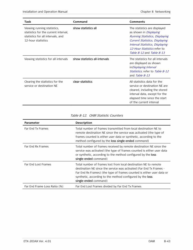
Installation and Operation Manual Chapter 8 Networking
ETX-203AX Ver. 4.01 OAM 8-43
Task Command Comments
Viewing running statistics,
statistics for the current interval,
statistics for all intervals, and
12-hour statistics
show statistics all The statistics are displayed
as shown in Displaying Running Statistics, Displaying Current Statistics, Displaying Interval Statistics, Displaying 12-Hour Statistics refer to
Table 8-12 and Table 8-13
Viewing statistics for all intervals show statistics all-intervals The statistics for all intervals
are displayed as shown
inDisplaying Interval Statistics; refer to Table 8-12
and Table 8-13
Clearing the statistics for the
service or destination NE
clear-statistics All statistics data for the
service or destination NE are
cleared, including the stored
interval data, except for the
elapsed time since the start
of the current interval
Table 8-12. OAM Statistic Counters
Parameter Description
Far End Tx Frames Total number of frames transmitted from local destination NE to
remote destination NE since the service was activated (the type of
frames counted is either user data or synthetic, according to the
method configured by the loss single-ended command)
Far End Rx Frames Total number of frames received by remote destination NE since the
service was activated (the type of frames counted is either user data
or synthetic, according to the method configured by the loss
single-ended command)
Far End Lost Frames Total number of frames lost from local destination NE to remote
destination NE since the service was activated (Far End Tx Frames -
Far End Rx Frames) (the type of frames counted is either user data or
synthetic, according to the method configured by the loss
single-ended command)
Far End Frame Loss Ratio (%) Far End Lost Frames divided by Far End Tx Frames
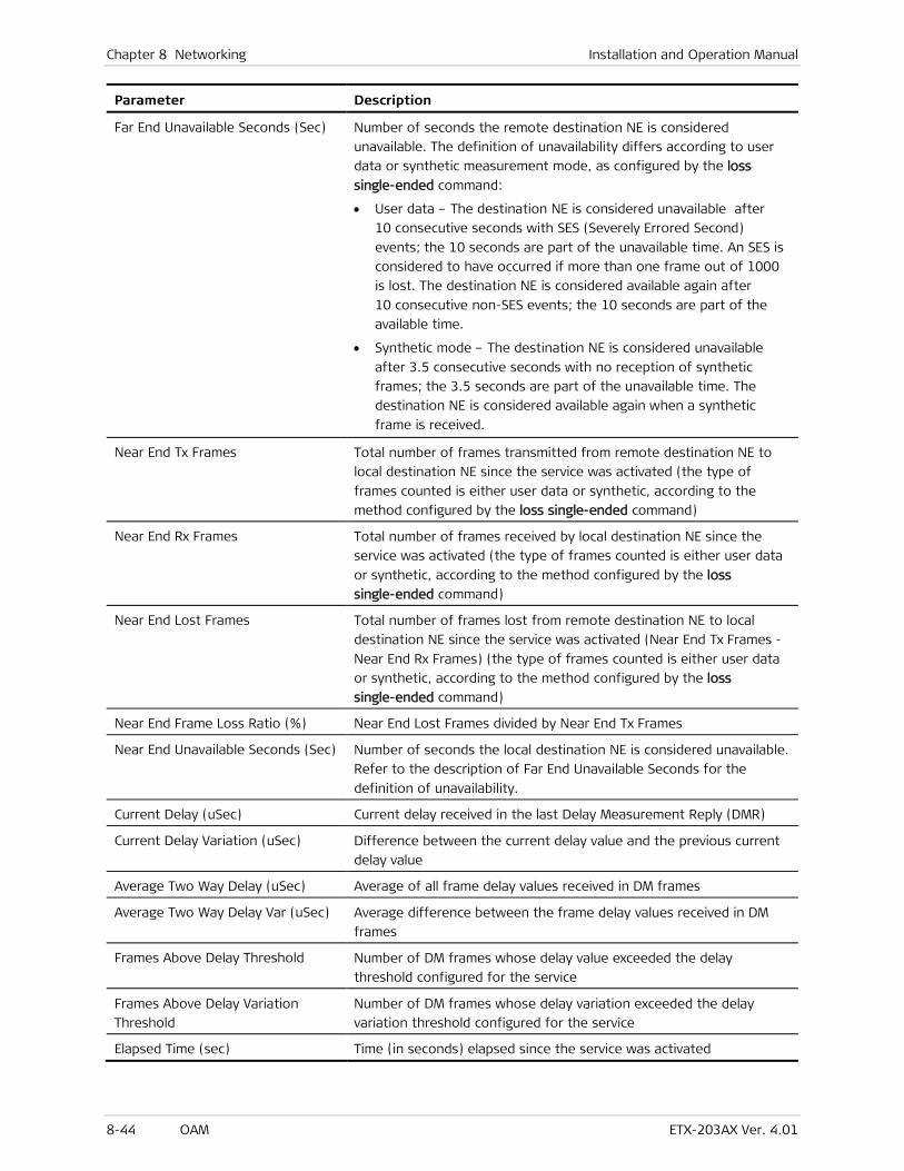
Chapter 8 Networking Installation and Operation Manual
8-44 OAM ETX-203AX Ver. 4.01
Parameter Description
Far End Unavailable Seconds (Sec) Number of seconds the remote destination NE is considered
unavailable. The definition of unavailability differs according to user
data or synthetic measurement mode, as configured by the loss
single-ended command:
• User data – The destination NE is considered unavailable after
10 consecutive seconds with SES (Severely Errored Second)
events; the 10 seconds are part of the unavailable time. An SES is
considered to have occurred if more than one frame out of 1000
is lost. The destination NE is considered available again after
10 consecutive non-SES events; the 10 seconds are part of the
available time.
• Synthetic mode – The destination NE is considered unavailable
after 3.5 consecutive seconds with no reception of synthetic
frames; the 3.5 seconds are part of the unavailable time. The
destination NE is considered available again when a synthetic
frame is received.
Near End Tx Frames Total number of frames transmitted from remote destination NE to
local destination NE since the service was activated (the type of
frames counted is either user data or synthetic, according to the
method configured by the loss single-ended command)
Near End Rx Frames Total number of frames received by local destination NE since the
service was activated (the type of frames counted is either user data
or synthetic, according to the method configured by the loss
single-ended command)
Near End Lost Frames Total number of frames lost from remote destination NE to local
destination NE since the service was activated (Near End Tx Frames -
Near End Rx Frames) (the type of frames counted is either user data
or synthetic, according to the method configured by the loss
single-ended command)
Near End Frame Loss Ratio (%) Near End Lost Frames divided by Near End Tx Frames
Near End Unavailable Seconds (Sec) Number of seconds the local destination NE is considered unavailable.
Refer to the description of Far End Unavailable Seconds for the
definition of unavailability.
Current Delay (uSec) Current delay received in the last Delay Measurement Reply (DMR)
Current Delay Variation (uSec) Difference between the current delay value and the previous current
delay value
Average Two Way Delay (uSec) Average of all frame delay values received in DM frames
Average Two Way Delay Var (uSec) Average difference between the frame delay values received in DM
frames
Frames Above Delay Threshold Number of DM frames whose delay value exceeded the delay
threshold configured for the service
Frames Above Delay Variation
Threshold
Number of DM frames whose delay variation exceeded the delay
variation threshold configured for the service
Elapsed Time (sec) Time (in seconds) elapsed since the service was activated
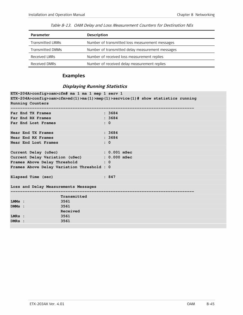
Installation and Operation Manual Chapter 8 Networking
ETX-203AX Ver. 4.01 OAM 8-45
Table 8-13. OAM Delay and Loss Measurement Counters for Destination NEs
Parameter Description
Transmitted LMMs Number of transmitted loss measurement messages
Transmitted DMMs Number of transmitted delay measurement messages
Received LMRs Number of received loss measurement replies
Received DMRs Number of received delay measurement replies
Examples
Displaying Running Statistics ETX-204A>config>oam>cfm# ma 1 ma 1 mep 1 serv 1 ETX-204A>config>oam>cfm>md(1)>ma(1)>mep(1)>service(1)# show statistics running Running Counters ----------------------------------------------------------------------------- Far End TX Frames : 3684 Far End RX Frames : 3684 Far End Lost Frames : 0 Near End TX Frames : 3684 Near End RX Frames : 3684 Near End Lost Frames : 0 Current Delay (uSec) : 0.001 mSec Current Delay Variation (uSec) : 0.000 mSec Frames Above Delay Threshold : 0 Frames Above Delay Variation Threshold : 0 Elapsed Time (sec) : 847 Loss and Delay Measurements Messages ----------------------------------------------------------------------------- Transmitted LMMs : 3561 DMMs : 3561 Received LMRs : 3561 DMRs : 3561
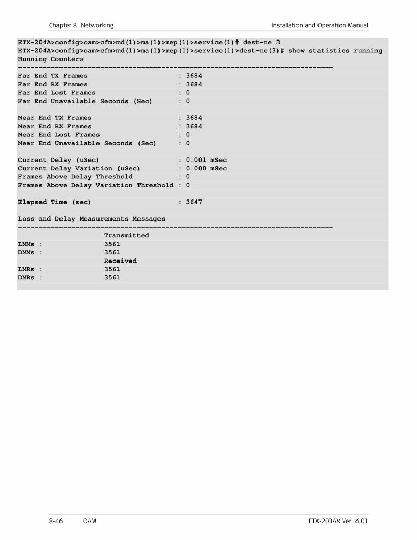
Chapter 8 Networking Installation and Operation Manual
8-46 OAM ETX-203AX Ver. 4.01
ETX-204A>config>oam>cfm>md(1)>ma(1)>mep(1)>service(1)# dest-ne 3 ETX-204A>config>oam>cfm>md(1)>ma(1)>mep(1)>service(1)>dest-ne(3)# show statistics running Running Counters ----------------------------------------------------------------------------- Far End TX Frames : 3684 Far End RX Frames : 3684 Far End Lost Frames : 0 Far End Unavailable Seconds (Sec) : 0 Near End TX Frames : 3684 Near End RX Frames : 3684 Near End Lost Frames : 0 Near End Unavailable Seconds (Sec) : 0 Current Delay (uSec) : 0.001 mSec Current Delay Variation (uSec) : 0.000 mSec Frames Above Delay Threshold : 0 Frames Above Delay Variation Threshold : 0 Elapsed Time (sec) : 3647 Loss and Delay Measurements Messages ----------------------------------------------------------------------------- Transmitted LMMs : 3561 DMMs : 3561 Received LMRs : 3561 DMRs : 3561
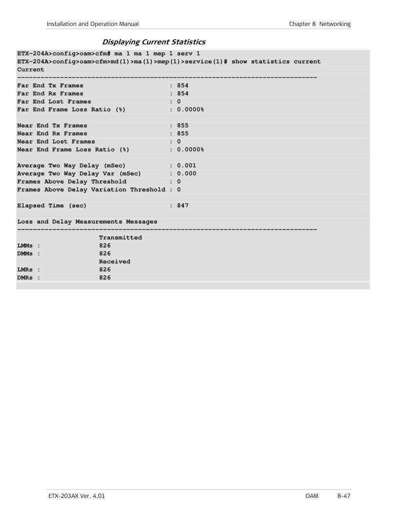
Installation and Operation Manual Chapter 8 Networking
ETX-203AX Ver. 4.01 OAM 8-47
Displaying Current Statistics ETX-204A>config>oam>cfm# ma 1 ma 1 mep 1 serv 1 ETX-204A>config>oam>cfm>md(1)>ma(1)>mep(1)>service(1)# show statistics current Current ----------------------------------------------------------------------------- Far End Tx Frames : 854 Far End Rx Frames : 854 Far End Lost Frames : 0 Far End Frame Loss Ratio (%) : 0.0000% Near End Tx Frames : 855 Near End Rx Frames : 855 Near End Lost Frames : 0 Near End Frame Loss Ratio (%) : 0.0000% Average Two Way Delay (mSec) : 0.001 Average Two Way Delay Var (mSec) : 0.000 Frames Above Delay Threshold : 0 Frames Above Delay Variation Threshold : 0 Elapsed Time (sec) : 847 Loss and Delay Measurements Messages ----------------------------------------------------------------------------- Transmitted LMMs : 826 DMMs : 826 Received LMRs : 826 DMRs : 826
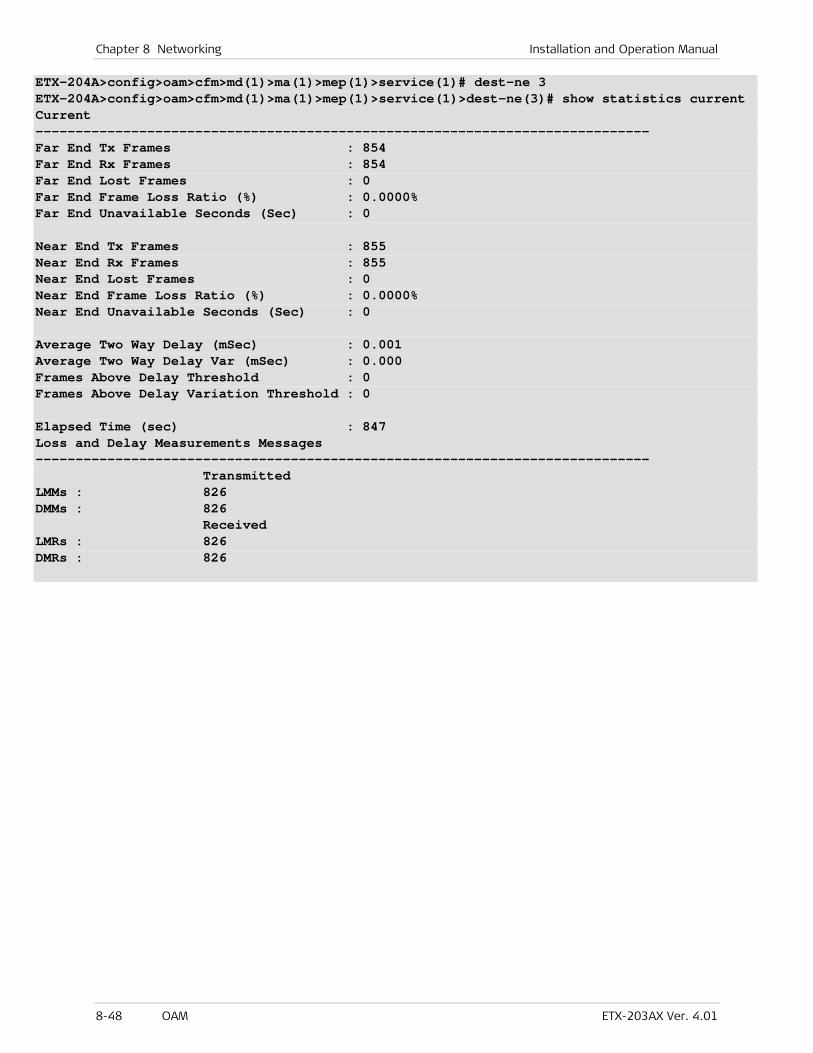
Chapter 8 Networking Installation and Operation Manual
8-48 OAM ETX-203AX Ver. 4.01
ETX-204A>config>oam>cfm>md(1)>ma(1)>mep(1)>service(1)# dest-ne 3 ETX-204A>config>oam>cfm>md(1)>ma(1)>mep(1)>service(1)>dest-ne(3)# show statistics current Current ----------------------------------------------------------------------------- Far End Tx Frames : 854 Far End Rx Frames : 854 Far End Lost Frames : 0 Far End Frame Loss Ratio (%) : 0.0000% Far End Unavailable Seconds (Sec) : 0 Near End Tx Frames : 855 Near End Rx Frames : 855 Near End Lost Frames : 0 Near End Frame Loss Ratio (%) : 0.0000% Near End Unavailable Seconds (Sec) : 0 Average Two Way Delay (mSec) : 0.001 Average Two Way Delay Var (mSec) : 0.000 Frames Above Delay Threshold : 0 Frames Above Delay Variation Threshold : 0 Elapsed Time (sec) : 847 Loss and Delay Measurements Messages ----------------------------------------------------------------------------- Transmitted LMMs : 826 DMMs : 826 Received LMRs : 826 DMRs : 826
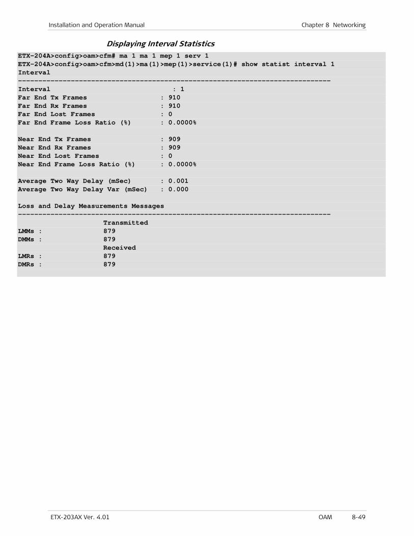
Installation and Operation Manual Chapter 8 Networking
ETX-203AX Ver. 4.01 OAM 8-49
Displaying Interval Statistics ETX-204A>config>oam>cfm# ma 1 ma 1 mep 1 serv 1 ETX-204A>config>oam>cfm>md(1)>ma(1)>mep(1)>service(1)# show statist interval 1 Interval ----------------------------------------------------------------------------- Interval : 1 Far End Tx Frames : 910 Far End Rx Frames : 910 Far End Lost Frames : 0 Far End Frame Loss Ratio (%) : 0.0000% Near End Tx Frames : 909 Near End Rx Frames : 909 Near End Lost Frames : 0 Near End Frame Loss Ratio (%) : 0.0000% Average Two Way Delay (mSec) : 0.001 Average Two Way Delay Var (mSec) : 0.000 Loss and Delay Measurements Messages ----------------------------------------------------------------------------- Transmitted LMMs : 879 DMMs : 879 Received LMRs : 879 DMRs : 879
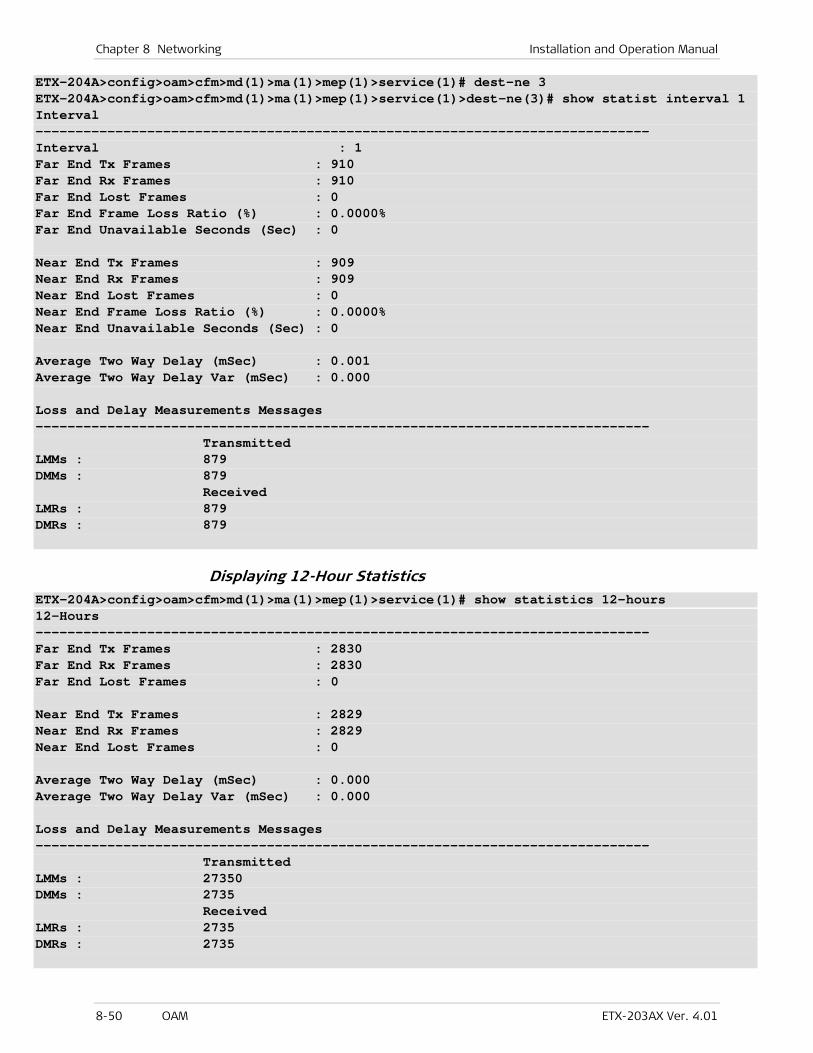
Chapter 8 Networking Installation and Operation Manual
8-50 OAM ETX-203AX Ver. 4.01
ETX-204A>config>oam>cfm>md(1)>ma(1)>mep(1)>service(1)# dest-ne 3 ETX-204A>config>oam>cfm>md(1)>ma(1)>mep(1)>service(1)>dest-ne(3)# show statist interval 1 Interval ----------------------------------------------------------------------------- Interval : 1 Far End Tx Frames : 910 Far End Rx Frames : 910 Far End Lost Frames : 0 Far End Frame Loss Ratio (%) : 0.0000% Far End Unavailable Seconds (Sec) : 0 Near End Tx Frames : 909 Near End Rx Frames : 909 Near End Lost Frames : 0 Near End Frame Loss Ratio (%) : 0.0000% Near End Unavailable Seconds (Sec) : 0 Average Two Way Delay (mSec) : 0.001 Average Two Way Delay Var (mSec) : 0.000 Loss and Delay Measurements Messages ----------------------------------------------------------------------------- Transmitted LMMs : 879 DMMs : 879 Received LMRs : 879 DMRs : 879
Displaying 12-Hour Statistics ETX-204A>config>oam>cfm>md(1)>ma(1)>mep(1)>service(1)# show statistics 12-hours 12-Hours ----------------------------------------------------------------------------- Far End Tx Frames : 2830 Far End Rx Frames : 2830 Far End Lost Frames : 0 Near End Tx Frames : 2829 Near End Rx Frames : 2829 Near End Lost Frames : 0 Average Two Way Delay (mSec) : 0.000 Average Two Way Delay Var (mSec) : 0.000 Loss and Delay Measurements Messages ----------------------------------------------------------------------------- Transmitted LMMs : 27350 DMMs : 2735 Received LMRs : 2735 DMRs : 2735
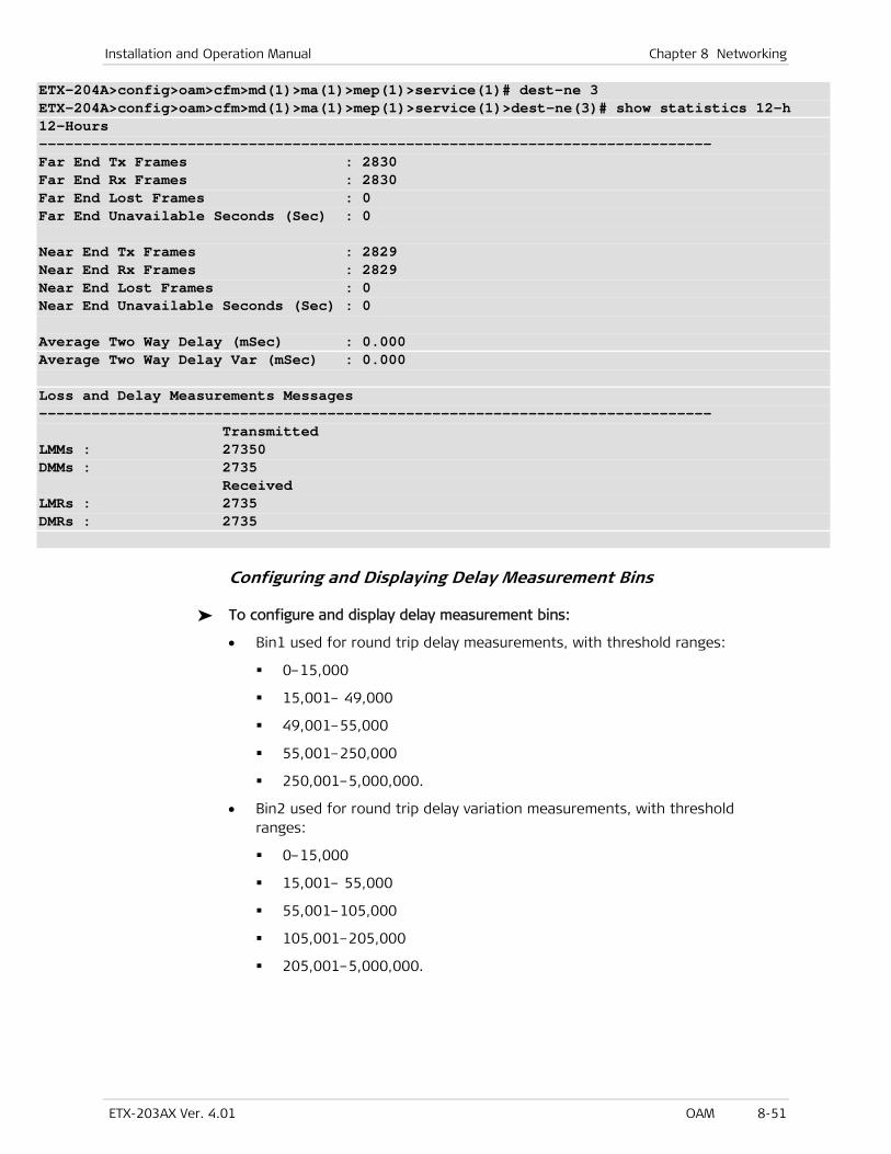
Installation and Operation Manual Chapter 8 Networking
ETX-203AX Ver. 4.01 OAM 8-51
ETX-204A>config>oam>cfm>md(1)>ma(1)>mep(1)>service(1)# dest-ne 3 ETX-204A>config>oam>cfm>md(1)>ma(1)>mep(1)>service(1)>dest-ne(3)# show statistics 12-h 12-Hours ----------------------------------------------------------------------------- Far End Tx Frames : 2830 Far End Rx Frames : 2830 Far End Lost Frames : 0 Far End Unavailable Seconds (Sec) : 0 Near End Tx Frames : 2829 Near End Rx Frames : 2829 Near End Lost Frames : 0 Near End Unavailable Seconds (Sec) : 0 Average Two Way Delay (mSec) : 0.000 Average Two Way Delay Var (mSec) : 0.000 Loss and Delay Measurements Messages ----------------------------------------------------------------------------- Transmitted LMMs : 27350 DMMs : 2735 Received LMRs : 2735 DMRs : 2735
Configuring and Displaying Delay Measurement Bins
To configure and display delay measurement bins:
• Bin1 used for round trip delay measurements, with threshold ranges:
0–15,000
15,001– 49,000
49,001–55,000
55,001–250,000
250,001–5,000,000.
• Bin2 used for round trip delay variation measurements, with threshold ranges:
0–15,000
15,001– 55,000
55,001–105,000
105,001–205,000
205,001–5,000,000.

Chapter 8 Networking Installation and Operation Manual
8-52 OAM ETX-203AX Ver. 4.01
ETX-204A>config>oam>cfm# measurement-bin-profile bin1 ETX-204A>config>oam>cfm>measurement-bin-prof(bin1)# thresholds 15000,49000,55000,250000 ETX-204A>config>oam>cfm>measurement-bin-prof(bin1)# exit ETX-204A>config>oam>cfm# measurement-bin-profile bin2 ETX-204A>config>oam>cfm>measurement-bin-prof(bin2)# thresholds 15000,55000,105000,205000 ETX-204A>config>oam>cfm>measurement-bin-prof(bin2)# exit ETX-204A>config>oam>cfm# ma 1 ma 1 mep 1 serv 1 dest-ne 3 ETX-204A>config>oam>cfm>md(1)>ma(1)>mep(1)>service(1)>dest-ne(3)# delay-measurement-bin profile bin1 ETX-204A>config>oam>cfm>md(1)>ma(1)>mep(1)>service(1)>dest-ne(3)# delay-var-measurement-bin profile bin2 ETX-204A>config>oam>cfm>md(1)>ma(1)>mep(1)>service(1)>dest-ne(3)# show delay-measurement-bins rt-delay all Type : rt Delay Current ----------------------------------------------------------------------------- Bin range Rx DMR (us) ----------------------------------------------------------------------------- 1 0..15000 0 2 15001..49000 0 3 49001..55000 0 4 55001..250000 0 5 250001..5000000 0 Type : rt Delay Interval Bin range Rx DMR (us) ----------------------------------------------------------------------------- 1 1 0..15000 36 1 2 15001..49000 0 1 3 49001..55000 0 1 4 55001..250000 0 1 5 250001..5000000 0 2 1 0..15000 753 2 2 15001..49000 0 2 3 49001..55000 0 2 4 55001..250000 0 2 5 250001..5000000 0 3 1 0..15000 713 3 2 15001..49000 0 3 3 49001..55000 0 3 4 55001..250000 0 3 5 250001..5000000 0
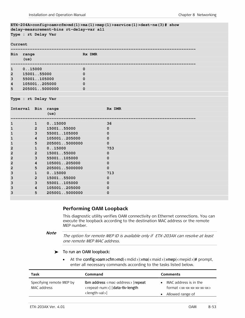
Installation and Operation Manual Chapter 8 Networking
ETX-203AX Ver. 4.01 OAM 8-53
ETX-204A>config>oam>cfm>md(1)>ma(1)>mep(1)>service(1)>dest-ne(3)# show delay-measurement-bins rt-delay-var all Type : rt Delay Var Current ----------------------------------------------------------------------------- Bin range Rx DMR (us) ----------------------------------------------------------------------------- 1 0..15000 0 2 15001..55000 0 3 55001..105000 0 4 105001..205000 0 5 205001..5000000 0 Type : rt Delay Var Interval Bin range Rx DMR (us) ----------------------------------------------------------------------------- 1 1 0..15000 36 1 2 15001..55000 0 1 3 55001..105000 0 1 4 105001..205000 0 1 5 205001..5000000 0 2 1 0..15000 753 2 2 15001..55000 0 2 3 55001..105000 0 2 4 105001..205000 0 2 5 205001..5000000 0 3 1 0..15000 713 3 2 15001..55000 0 3 3 55001..105000 0 3 4 105001..205000 0 3 5 205001..5000000 0
Performing OAM Loopback
This diagnostic utility verifies OAM connectivity on Ethernet connections. You can execute the loopback according to the destination MAC address or the remote MEP number.
The option for remote MEP ID is available only if ETX-203AX can resolve at least one remote MEP MAC address.
To run an OAM loopback:
• At the config>oam>cfm>md(<mdid>)>ma(<maid>)>mep(<mepid>)# prompt, enter all necessary commands according to the tasks listed below.
Task Command Comments
Specifying remote MEP by
MAC address
lbm address <mac-address> [repeat
<repeat-num>] [data-tlv-length
<length-val>]
• MAC address is in the
format <xx-xx-xx-xx-xx-xx>
• Allowed range of
Note

Chapter 8 Networking Installation and Operation Manual
8-54 OAM ETX-203AX Ver. 4.01
Task Command Comments
Specifying remote MEP by
MEP ID
lbm remote-mep <mep-id> [repeat
<repeat-num>] [data-tlv-length
<length-val>]
repeat-num is 1–500
• Allowed range of
data-tlv-length is 0–1900.
Sending LBM messages to
default multicast MAC
address
lbm multicast [repeat <repeat-num>]
Checking OAM loopback
results
show lbm-results
Performing OAM Link Trace
This diagnostic utility traces the OAM route to the destination, specified either by the MAC address or the maintenance end point (MEP).
The option to specify the destination MEP ID is available only if ETX-203AX can resolve at least one remote MEP MAC address.
To run an OAM link trace:
• At the config>oam>cfm>md(<mdid>)>ma(<maid>)>mep(<mepid>)# prompt, enter all necessary commands according to the tasks listed below.
Task Command Comments
Specifying remote MEP by MAC
address
linktrace address
<mac-address> [ttl <ttl-value>]
• MAC address is in the
format <xx-xx-xx-xx-xx-xx>
• Allowed range for ttl-value
is 1–64. This parameter
specifies number of hops.
Each unit in the link trace
decrements the TTL until it
reaches 0, which terminates
the link trace.
Specifying remote MEP by ID linktrace remote-mep <mep-id> [ttl <ttl-value>]
Checking the OAM link trace
results
show linktrace-results
OAM EFM
This section covers the monitoring of the Ethernet links using OAM EFM (OAM Ethernet at the First Mile)
ETX-203AX can act as the active or passive side in an IEEE 802.3-2005 application.
When link OAM (EFM) is enabled for a port, you can view its status by displaying the port status (show status). You can also display the OAM (EFM) parameters and OAM (EFM) statistics.
Note

Installation and Operation Manual Chapter 8 Networking
ETX-203AX Ver. 4.01 OAM 8-55
Standards
IEEE 802.3-2005
Benefits
Ethernet OAM (EFM) provides remote management and fault indication for the Ethernet links. Remote link failure can be detected via OAM (EFM).
Functional Description
The OAM (EFM) discovery process allows a local data terminating entity (DTE) to detect Ethernet OAM capabilities on a remote DTE. Once Ethernet OAM support is detected, both ends of the link exchange state and configuration information, such as mode, PDU size, loopback support, etc. If both DTEs are satisfied with the settings, OAM is enabled on the link. However, the loss of a link or a failure to receive OAMPDUs for five seconds may cause the discovery process to restart.
DTEs may either be in active or passive mode. DTEs in active mode initiate the ETH-OAM (EFM) communications and can issue queries and commands to a remote device. DTEs in passive mode generally wait for the peer device to initiate OAM communications and respond to commands and queries, but do not initiate them.
A flag in the OAMPDU allows an OAM entity to convey the failure condition Link Fault to its peer. Link Fault refers to the loss of signal detected by the receiver; A Link Fault report is sent once per second with the Information OAMPDU.
Factory Defaults
By default, OAM EFM is not enabled for the Ethernet or logical MAC ports.
Configuring OAM EFM
There are two available OAM EFM descriptors. Each can be configured to indicate active or passive OAM EFM.
To configure OAM EFM descriptor:
1. Navigate to configure oam efm.
The config>oam>efm# prompt is displayed.
2. Enter: descriptor <number> {active | passive}
To configure link OAM (EFM) for Ethernet and logical MAC ports:
1. Navigate to configure port ethernet <port-num> or configure port logical-mac <port-num>, respectively.
The prompt config>port>eth(<port-num>)# or config>port>log-mac(<port-num>)# is displayed, respectively.
2. Enter all necessary commands according to the tasks listed below.
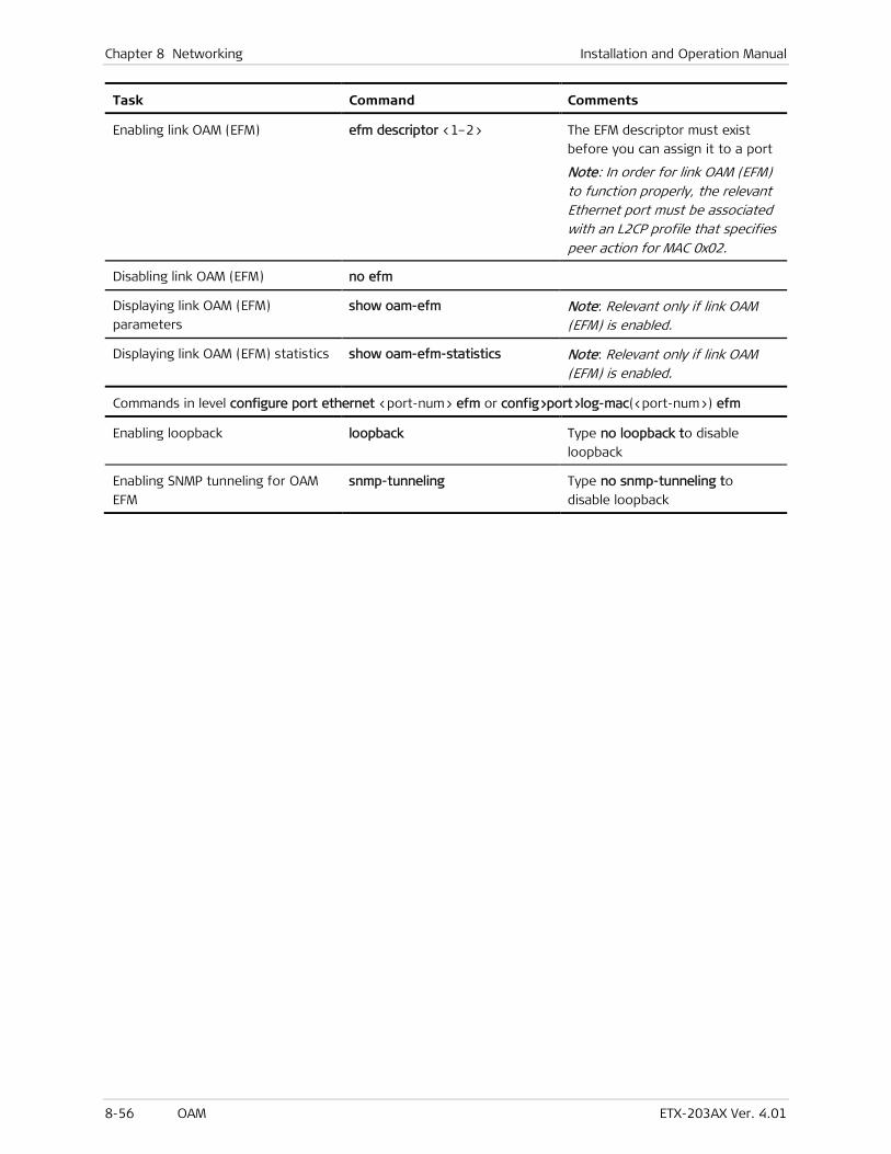
Chapter 8 Networking Installation and Operation Manual
8-56 OAM ETX-203AX Ver. 4.01
Task Command Comments
Enabling link OAM (EFM) efm descriptor <1–2> The EFM descriptor must exist
before you can assign it to a port
Note: In order for link OAM (EFM) to function properly, the relevant Ethernet port must be associated with an L2CP profile that specifies peer action for MAC 0x02.
Disabling link OAM (EFM) no efm
Displaying link OAM (EFM)
parameters
show oam-efm Note: Relevant only if link OAM (EFM) is enabled.
Displaying link OAM (EFM) statistics show oam-efm-statistics Note: Relevant only if link OAM (EFM) is enabled.
Commands in level configure port ethernet <port-num> efm or config>port>log-mac(<port-num>) efm
Enabling loopback loopback Type no loopback to disable
loopback
Enabling SNMP tunneling for OAM
EFM
snmp-tunneling Type no snmp-tunneling to
disable loopback
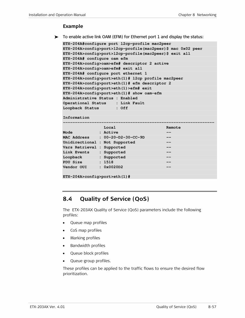
Installation and Operation Manual Chapter 8 Networking
ETX-203AX Ver. 4.01 Quality of Service (QoS) 8-57
Example
To enable active link OAM (EFM) for Ethernet port 1 and display the status:
ETX-204A#configure port l2cp-profile mac2peer ETX-204A>config>port>l2cp-profile(mac2peer)$ mac 0x02 peer ETX-204A>config>port>l2cp-profile(mac2peer)$ exit all ETX-204A# configure oam efm ETX-204A>config>oam>efm# descriptor 2 active ETX-204A>config>oam>efm# exit all ETX-204A# configure port ethernet 1 ETX-204A>config>port>eth(1)# l2cp profile mac2peer ETX-204A>config>port>eth(1)# efm descriptor 2 ETX-204A>config>port>eth(1)>efm# exit ETX-204A>config>port>eth(1)# show oam-efm Administrative Status : Enabled Operational Status : Link Fault Loopback Status : Off Information --------------------------------------------------------------- Local Remote Mode : Active -- MAC Address : 00-20-D2-30-CC-9D -- Unidirectional : Not Supported -- Vars Retrieval : Supported -- Link Events : Supported -- Loopback : Supported -- PDU Size : 1518 -- Vendor OUI : 0x0020D2 -- ETX-204A>config>port>eth(1)#
8.4 Quality of Service (QoS)
The ETX-203AX Quality of Service (QoS) parameters include the following profiles:
• Queue map profiles
• CoS map profiles
• Marking profiles
• Bandwidth profiles
• Queue block profiles
• Queue group profiles.
These profiles can be applied to the traffic flows to ensure the desired flow prioritization.

Chapter 8 Networking Installation and Operation Manual
8-58 Quality of Service (QoS) ETX-203AX Ver. 4.01
Standards
The following standards are supported:
• IEEE 802.1p
• IEEE 802.1Q.
Benefits
QoS allows you to optimize bandwidth, avoiding the need to allocate excessive bandwidth to facilitate the necessary bandwidth for traffic at different requirements of speed and quality.
Factory Defaults
Refer to the following sections for each QoS type’s specific defaults.
Functional Description
To differentiate traffic, the IEEE 802.1p standard specifies eight classes of service per user-defined queue map profile. These classes of service are associated with priority values between 0 and 7, using the 3-bit user priority field in an IEEE 802.1Q header added to VLAN-tagged frames within an Ethernet frame header. The way traffic is treated when assigned to a specific priority value is only generally defined and left to implementation. The general definitions are as follows:
Table 8-14. User Priorities
User Priority Traffic Type
0 Best effort
1 Background
2 Spare
3 Excellent effort
4 Controlled load
5 Video
6 Voice
7 Network control
Queue Mapping Profiles
Queue mapping profiles are used to convert the following user priorities into internal priority queues. ETX-203AX supports up to 12 queue mapping profiles.
• p-bit, when the ingress traffic is prioritized according to the 802.1p requirements
• ip-dscp, when the ingress traffic is prioritized according to DSCP
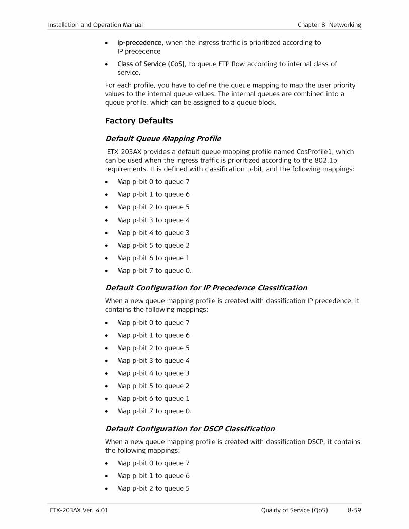
Installation and Operation Manual Chapter 8 Networking
ETX-203AX Ver. 4.01 Quality of Service (QoS) 8-59
• ip-precedence, when the ingress traffic is prioritized according to IP precedence
• Class of Service (CoS), to queue ETP flow according to internal class of service.
For each profile, you have to define the queue mapping to map the user priority values to the internal queue values. The internal queues are combined into a queue profile, which can be assigned to a queue block.
Factory Defaults
Default Queue Mapping Profile
ETX-203AX provides a default queue mapping profile named CosProfile1, which can be used when the ingress traffic is prioritized according to the 802.1p requirements. It is defined with classification p-bit, and the following mappings:
• Map p-bit 0 to queue 7
• Map p-bit 1 to queue 6
• Map p-bit 2 to queue 5
• Map p-bit 3 to queue 4
• Map p-bit 4 to queue 3
• Map p-bit 5 to queue 2
• Map p-bit 6 to queue 1
• Map p-bit 7 to queue 0.
Default Configuration for IP Precedence Classification
When a new queue mapping profile is created with classification IP precedence, it contains the following mappings:
• Map p-bit 0 to queue 7
• Map p-bit 1 to queue 6
• Map p-bit 2 to queue 5
• Map p-bit 3 to queue 4
• Map p-bit 4 to queue 3
• Map p-bit 5 to queue 2
• Map p-bit 6 to queue 1
• Map p-bit 7 to queue 0.
Default Configuration for DSCP Classification
When a new queue mapping profile is created with classification DSCP, it contains the following mappings:
• Map p-bit 0 to queue 7
• Map p-bit 1 to queue 6
• Map p-bit 2 to queue 5
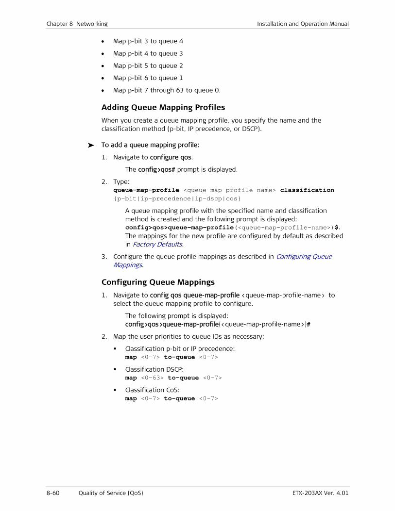
Chapter 8 Networking Installation and Operation Manual
8-60 Quality of Service (QoS) ETX-203AX Ver. 4.01
• Map p-bit 3 to queue 4
• Map p-bit 4 to queue 3
• Map p-bit 5 to queue 2
• Map p-bit 6 to queue 1
• Map p-bit 7 through 63 to queue 0.
Adding Queue Mapping Profiles
When you create a queue mapping profile, you specify the name and the classification method (p-bit, IP precedence, or DSCP).
To add a queue mapping profile:
1. Navigate to configure qos.
The config>qos# prompt is displayed.
2. Type: queue-map-profile <queue-map-profile-name> classification {p-bit|ip-precedence|ip-dscp|cos}
A queue mapping profile with the specified name and classification method is created and the following prompt is displayed: config>qos>queue-map-profile(<queue-map-profile-name>)$. The mappings for the new profile are configured by default as described in Factory Defaults.
3. Configure the queue profile mappings as described in Configuring Queue Mappings.
Configuring Queue Mappings
1. Navigate to config qos queue-map-profile <queue-map-profile-name> to select the queue mapping profile to configure.
The following prompt is displayed: config>qos>queue-map-profile(<queue-map-profile-name>)#
2. Map the user priorities to queue IDs as necessary:
Classification p-bit or IP precedence: map <0-7> to-queue <0-7>
Classification DSCP: map <0-63> to-queue <0-7>
Classification CoS: map <0-7> to-queue <0-7>
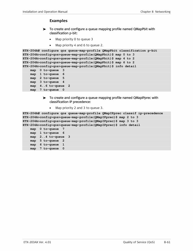
Installation and Operation Manual Chapter 8 Networking
ETX-203AX Ver. 4.01 Quality of Service (QoS) 8-61
Examples
To create and configure a queue mapping profile named QMapPbit with classification p-bit:
• Map priority 0 to queue 3
• Map priority 4 and 6 to queue 2.
ETX-204A# configure qos queue-map-profile QMapPbit classification p-bit ETX-204A>config>qos>queue-map-profile(QMapPbit)$ map 0 to 3 ETX-204A>config>qos>queue-map-profile(QMapPbit)$ map 4 to 2 ETX-204A>config>qos>queue-map-profile(QMapPbit)$ map 6 to 2 ETX-204A>config>qos>queue-map-profile(QMapPbit)$ info detail map 0 to-queue 3 map 1 to-queue 6 map 2 to-queue 5 map 3 to-queue 4 map 4..6 to-queue 2 map 7 to-queue 0
To create and configure a queue mapping profile named QMapIPprec with classification IP precedence:
• Map priority 2 and 3 to queue 3.
ETX-204A# configure qos queue-map-profile QMapIPprec classif ip-precedence ETX-204A>config>qos>queue-map-profile(QMapIPprec)$ map 2 to 3 ETX-204A>config>qos>queue-map-profile(QMapIPprec)$ map 3 to 3 ETX-204A>config>qos>queue-map-profile(QMapIPprec)$ info detail map 0 to-queue 7 map 1 to-queue 6 map 2..4 to-queue 3 map 5 to-queue 2 map 6 to-queue 1 map 7 to-queue 0
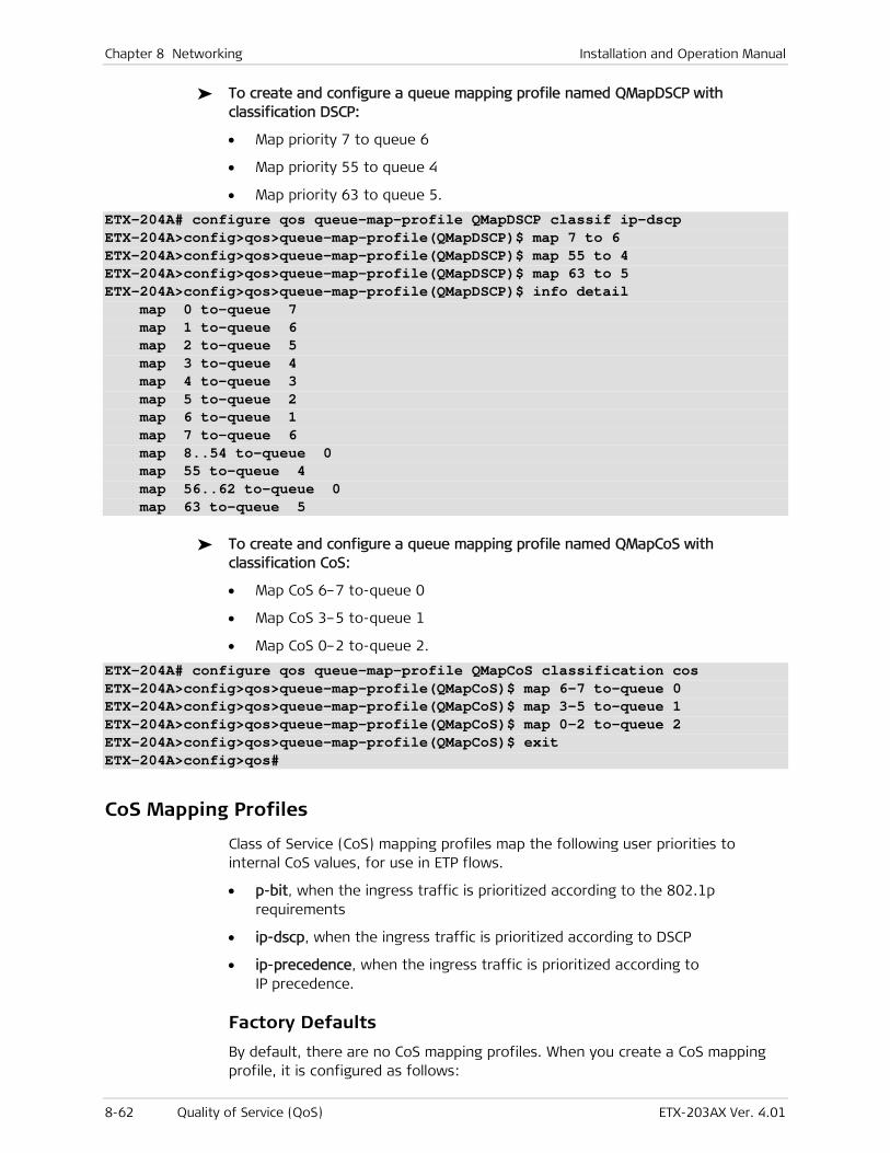
Chapter 8 Networking Installation and Operation Manual
8-62 Quality of Service (QoS) ETX-203AX Ver. 4.01
To create and configure a queue mapping profile named QMapDSCP with classification DSCP:
• Map priority 7 to queue 6
• Map priority 55 to queue 4
• Map priority 63 to queue 5.
ETX-204A# configure qos queue-map-profile QMapDSCP classif ip-dscp ETX-204A>config>qos>queue-map-profile(QMapDSCP)$ map 7 to 6 ETX-204A>config>qos>queue-map-profile(QMapDSCP)$ map 55 to 4 ETX-204A>config>qos>queue-map-profile(QMapDSCP)$ map 63 to 5 ETX-204A>config>qos>queue-map-profile(QMapDSCP)$ info detail map 0 to-queue 7 map 1 to-queue 6 map 2 to-queue 5 map 3 to-queue 4 map 4 to-queue 3 map 5 to-queue 2 map 6 to-queue 1 map 7 to-queue 6 map 8..54 to-queue 0 map 55 to-queue 4 map 56..62 to-queue 0 map 63 to-queue 5
To create and configure a queue mapping profile named QMapCoS with classification CoS:
• Map CoS 6–7 to-queue 0
• Map CoS 3–5 to-queue 1
• Map CoS 0–2 to-queue 2.
ETX-204A# configure qos queue-map-profile QMapCoS classification cos ETX-204A>config>qos>queue-map-profile(QMapCoS)$ map 6-7 to-queue 0 ETX-204A>config>qos>queue-map-profile(QMapCoS)$ map 3-5 to-queue 1 ETX-204A>config>qos>queue-map-profile(QMapCoS)$ map 0-2 to-queue 2 ETX-204A>config>qos>queue-map-profile(QMapCoS)$ exit ETX-204A>config>qos#
CoS Mapping Profiles
Class of Service (CoS) mapping profiles map the following user priorities to internal CoS values, for use in ETP flows.
• p-bit, when the ingress traffic is prioritized according to the 802.1p requirements
• ip-dscp, when the ingress traffic is prioritized according to DSCP
• ip-precedence, when the ingress traffic is prioritized according to IP precedence.
Factory Defaults
By default, there are no CoS mapping profiles. When you create a CoS mapping profile, it is configured as follows:

Installation and Operation Manual Chapter 8 Networking
ETX-203AX Ver. 4.01 Quality of Service (QoS) 8-63
• Classification p-bit
• Mappings:
Map 0 to CoS 7
Map 1 to CoS 6
Map 2 to CoS 5
Map 3 to CoS 4
Map 4 to CoS 3
Map 5 to CoS 2
Map 6 to CoS 1
Map 7 to CoS 0.
Configuring CoS Mapping Profiles
To define a CoS profile:
1. Navigate to the qos context (config>qos).
2. Define a CoS profile and assign a classification to it:
cos-map-profile <cos-mapping-profile-name> [classification {p-bit | ip-precedence | ip-dscp }]
3. Map the user priority to a CoS value (user priority values 0–7 for p-bit and IP precedence, 0–63 for the other priority types; CoS values 0–7):
map <0-7> to <0-7> map <0-63> to <0-7>
Example
To create and configure a CoS mapping profile named my-p-bit with classification p-bit:
• Map priority 6–7 to CoS 0
• Map priority 3–5 to CoS 1
• Map priority 0–2 to CoS 2.
ETX-204A# configure qos cos-map-profile my-p-bit classification p-bit ETX-204A>config>qos>cos-map-profile(my-p-bit)$ map 6..7 to-cos 0 ETX-204A>config>qos>cos-mapping-profile(my-p-bit)# map 3..5 to-cos 1 ETX-204A>config>qos>cos-mapping-profile(my-p-bit)# map 0..2 to-cos 2 ETX-204A>config>qos>cos-mapping-profile(my-p-bit)# exit ETX-204A>config>qos#
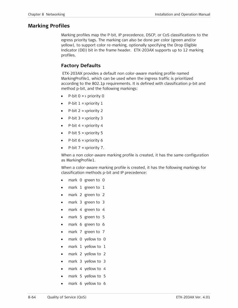
Chapter 8 Networking Installation and Operation Manual
8-64 Quality of Service (QoS) ETX-203AX Ver. 4.01
Marking Profiles
Marking profiles map the P-bit, IP precedence, DSCP, or CoS classifications to the egress priority tags. The marking can also be done per color (green and/or yellow), to support color re-marking, optionally specifying the Drop Eligible Indicator (DEI) bit in the frame header. ETX-203AX supports up to 12 marking profiles.
Factory Defaults
ETX-203AX provides a default non color-aware marking profile named MarkingProfile1, which can be used when the ingress traffic is prioritized according to the 802.1p requirements. It is defined with classification p-bit and method p-bit, and the following markings:
• P-bit 0 => priority 0
• P-bit 1 =>priority 1
• P-bit 2 =>priority 2
• P-bit 3 =>priority 3
• P-bit 4 =>priority 4
• P-bit 5 =>priority 5
• P-bit 6 =>priority 6
• P-bit 7 =>priority 7.
When a non color-aware marking profile is created, it has the same configuration as MarkingProfile1.
When a color-aware marking profile is created, it has the following markings for classification methods p-bit and IP precedence:
• mark 0 green to 0
• mark 1 green to 1
• mark 2 green to 2
• mark 3 green to 3
• mark 4 green to 4
• mark 5 green to 5
• mark 6 green to 6
• mark 7 green to 7
• mark 0 yellow to 0
• mark 1 yellow to 1
• mark 2 yellow to 2
• mark 3 yellow to 3
• mark 4 yellow to 4
• mark 5 yellow to 5
• mark 6 yellow to 6

Installation and Operation Manual Chapter 8 Networking
ETX-203AX Ver. 4.01 Quality of Service (QoS) 8-65
• mark 7 yellow to 7.
When a color-aware marking profile is created, it has the following markings for classification method DSCP:
• mark 0 green to 0
• mark 1 green to 1
• mark 2 green to 2
• mark 3 green to 3
• mark 4 green to 4
• mark 5 green to 5
• mark 6 green to 6
• mark 7 green to 7
• mark 8..63 green to 0
• mark 0..63 yellow to 0.
Configuring Marking Profiles
To define a non color-aware marking profile and assign a priority mark to it:
1. Navigate to the qos context (config>qos).
2. Define a marking profile and assign a classification and a method to it:
marking-profile <marking-profile-name> [classification {p-bit|ip-precedence|ip-dscp|cos} [method p-bit]
3. Map the user priority to a priority marking value (user priority values 0–7 for p-bit, IP precedence, and CoS, 0–63 for DSCP; priority marking values range 0–7):
mark <0-7> to <0-7> mark <0-63> to <0-7>
To define a color-aware marking profile and assign a priority mark to it:
1. Navigate to the qos context (config>qos).
2. Define a color-aware marking profile and assign a classification and a method to it:
marking-profile <marking-profile-name> [classification {p-bit|ip-precedence|ip-dscp} [method p-bit] color-aware green-yellow [dei-set]
If you specify dei-set, then yellow frames transmitted from ETX-203AX are marked via the Drop Eligible Indicator (DEI) bit as eligible to be dropped, and green frames transmitted from ETX-203AX are marked as not eligible to be dropped. If you do not specify dei-set, then green and yellow frames are marked as not eligible to be dropped.
3. Map the packet color and user priority to a priority marking value (user priority values 0–7 for p-bit and IP precedence, 0–63 for DSCP; priority
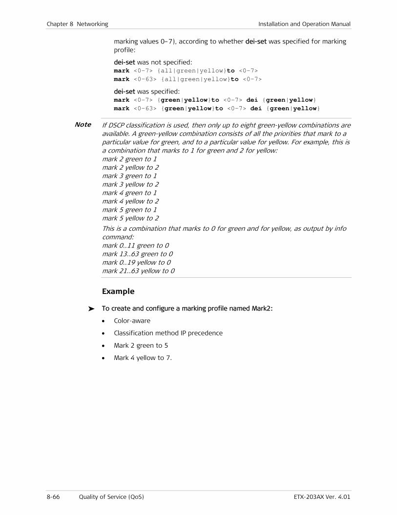
Chapter 8 Networking Installation and Operation Manual
8-66 Quality of Service (QoS) ETX-203AX Ver. 4.01
marking values 0–7), according to whether dei-set was specified for marking profile:
dei-set was not specified: mark <0-7> {all|green|yellow}to <0-7> mark <0-63> {all|green|yellow}to <0-7>
dei-set was specified: mark <0-7> {green|yellow}to <0-7> dei {green|yellow} mark <0-63> {green|yellow}to <0-7> dei {green|yellow}
If DSCP classification is used, then only up to eight green-yellow combinations are available. A green-yellow combination consists of all the priorities that mark to a particular value for green, and to a particular value for yellow. For example, this is a combination that marks to 1 for green and 2 for yellow: mark 2 green to 1 mark 2 yellow to 2 mark 3 green to 1 mark 3 yellow to 2 mark 4 green to 1 mark 4 yellow to 2 mark 5 green to 1 mark 5 yellow to 2
This is a combination that marks to 0 for green and for yellow, as output by info command: mark 0..11 green to 0 mark 13..63 green to 0 mark 0..19 yellow to 0 mark 21..63 yellow to 0
Example
To create and configure a marking profile named Mark2:
• Color-aware
• Classification method IP precedence
• Mark 2 green to 5
• Mark 4 yellow to 7.
Note
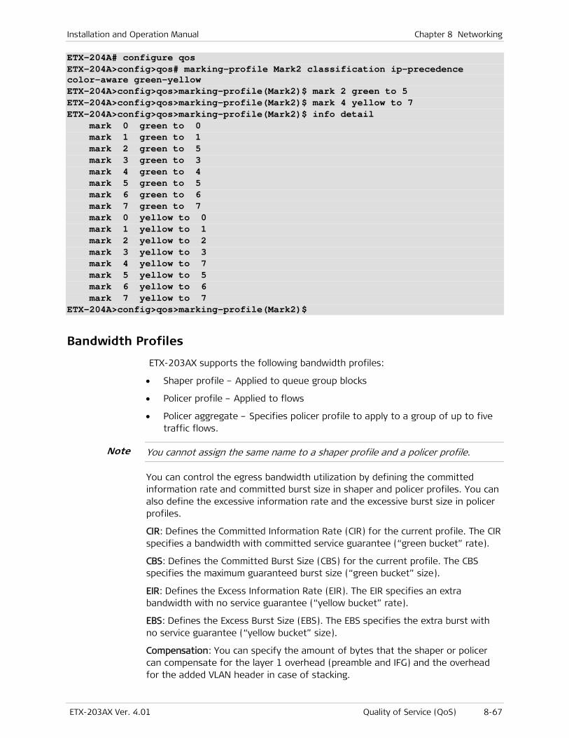
Installation and Operation Manual Chapter 8 Networking
ETX-203AX Ver. 4.01 Quality of Service (QoS) 8-67
ETX-204A# configure qos ETX-204A>config>qos# marking-profile Mark2 classification ip-precedence color-aware green-yellow ETX-204A>config>qos>marking-profile(Mark2)$ mark 2 green to 5 ETX-204A>config>qos>marking-profile(Mark2)$ mark 4 yellow to 7 ETX-204A>config>qos>marking-profile(Mark2)$ info detail mark 0 green to 0 mark 1 green to 1 mark 2 green to 5 mark 3 green to 3 mark 4 green to 4 mark 5 green to 5 mark 6 green to 6 mark 7 green to 7 mark 0 yellow to 0 mark 1 yellow to 1 mark 2 yellow to 2 mark 3 yellow to 3 mark 4 yellow to 7 mark 5 yellow to 5 mark 6 yellow to 6 mark 7 yellow to 7 ETX-204A>config>qos>marking-profile(Mark2)$
Bandwidth Profiles
ETX-203AX supports the following bandwidth profiles:
• Shaper profile – Applied to queue group blocks
• Policer profile – Applied to flows
• Policer aggregate – Specifies policer profile to apply to a group of up to five traffic flows.
You cannot assign the same name to a shaper profile and a policer profile.
You can control the egress bandwidth utilization by defining the committed information rate and committed burst size in shaper and policer profiles. You can also define the excessive information rate and the excessive burst size in policer profiles.
CIR: Defines the Committed Information Rate (CIR) for the current profile. The CIR specifies a bandwidth with committed service guarantee (“green bucket” rate).
CBS: Defines the Committed Burst Size (CBS) for the current profile. The CBS specifies the maximum guaranteed burst size (“green bucket” size).
EIR: Defines the Excess Information Rate (EIR). The EIR specifies an extra bandwidth with no service guarantee (“yellow bucket” rate).
EBS: Defines the Excess Burst Size (EBS). The EBS specifies the extra burst with no service guarantee (“yellow bucket” size).
Compensation: You can specify the amount of bytes that the shaper or policer can compensate for the layer 1 overhead (preamble and IFG) and the overhead for the added VLAN header in case of stacking.
Note
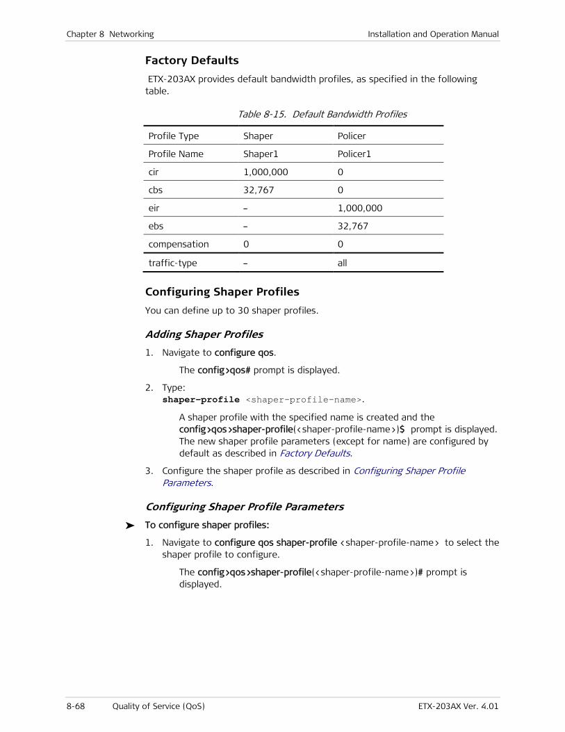
Chapter 8 Networking Installation and Operation Manual
8-68 Quality of Service (QoS) ETX-203AX Ver. 4.01
Factory Defaults
ETX-203AX provides default bandwidth profiles, as specified in the following table.
Table 8-15. Default Bandwidth Profiles
Profile Type Shaper Policer
Profile Name Shaper1 Policer1
cir 1,000,000 0
cbs 32,767 0
eir – 1,000,000
ebs – 32,767
compensation 0 0
traffic-type – all
Configuring Shaper Profiles
You can define up to 30 shaper profiles.
Adding Shaper Profiles
1. Navigate to configure qos.
The config>qos# prompt is displayed.
2. Type: shaper-profile <shaper-profile-name>.
A shaper profile with the specified name is created and the config>qos>shaper-profile(<shaper-profile-name>)$ prompt is displayed. The new shaper profile parameters (except for name) are configured by default as described in Factory Defaults.
3. Configure the shaper profile as described in Configuring Shaper Profile Parameters.
Configuring Shaper Profile Parameters
To configure shaper profiles:
1. Navigate to configure qos shaper-profile <shaper-profile-name> to select the shaper profile to configure.
The config>qos>shaper-profile(<shaper-profile-name>)# prompt is displayed.
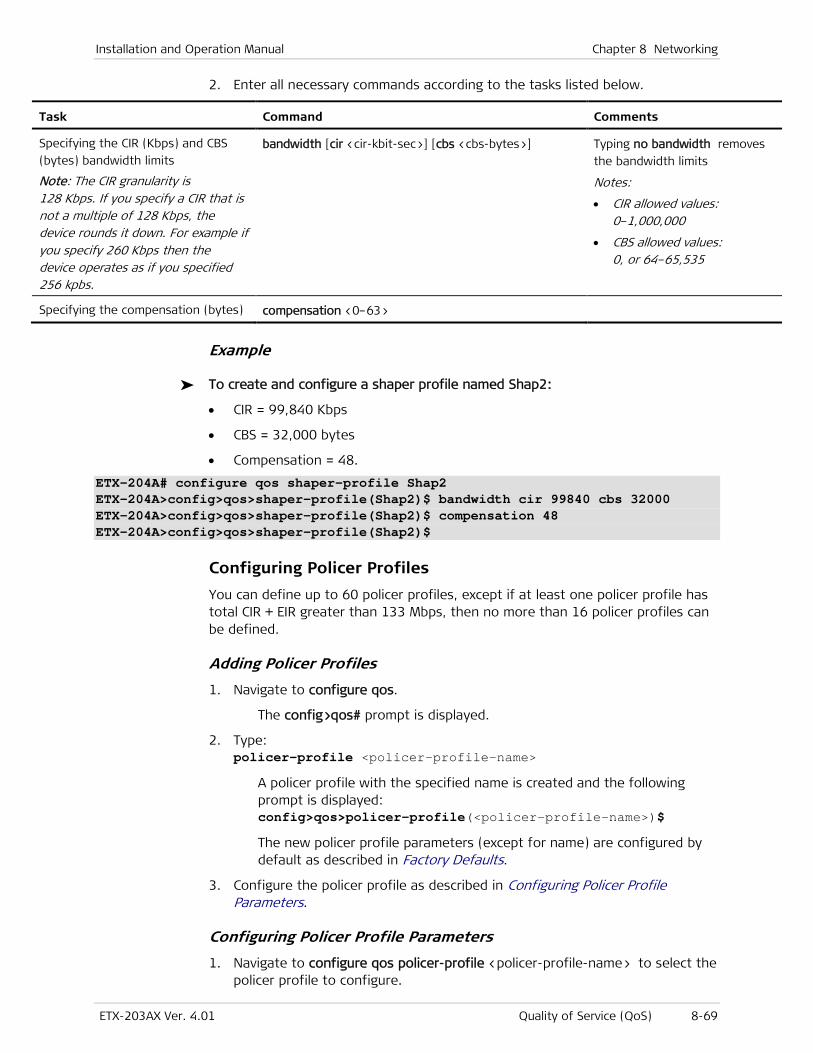
Installation and Operation Manual Chapter 8 Networking
ETX-203AX Ver. 4.01 Quality of Service (QoS) 8-69
2. Enter all necessary commands according to the tasks listed below.
Task Command Comments
Specifying the CIR (Kbps) and CBS
(bytes) bandwidth limits
Note: The CIR granularity is 128 Kbps. If you specify a CIR that is not a multiple of 128 Kbps, the device rounds it down. For example if you specify 260 Kbps then the device operates as if you specified 256 kpbs.
bandwidth [cir <cir-kbit-sec>] [cbs <cbs-bytes>] Typing no bandwidth removes
the bandwidth limits
Notes:
• CIR allowed values: 0–1,000,000
• CBS allowed values: 0, or 64–65,535
Specifying the compensation (bytes) compensation <0–63>
Example
To create and configure a shaper profile named Shap2:
• CIR = 99,840 Kbps
• CBS = 32,000 bytes
• Compensation = 48.
ETX-204A# configure qos shaper-profile Shap2 ETX-204A>config>qos>shaper-profile(Shap2)$ bandwidth cir 99840 cbs 32000 ETX-204A>config>qos>shaper-profile(Shap2)$ compensation 48 ETX-204A>config>qos>shaper-profile(Shap2)$
Configuring Policer Profiles
You can define up to 60 policer profiles, except if at least one policer profile has total CIR + EIR greater than 133 Mbps, then no more than 16 policer profiles can be defined.
Adding Policer Profiles
1. Navigate to configure qos.
The config>qos# prompt is displayed.
2. Type: policer-profile <policer-profile-name>
A policer profile with the specified name is created and the following prompt is displayed: config>qos>policer-profile(<policer-profile-name>)$
The new policer profile parameters (except for name) are configured by default as described in Factory Defaults.
3. Configure the policer profile as described in Configuring Policer Profile Parameters.
Configuring Policer Profile Parameters
1. Navigate to configure qos policer-profile <policer-profile-name> to select the policer profile to configure.

Chapter 8 Networking Installation and Operation Manual
8-70 Quality of Service (QoS) ETX-203AX Ver. 4.01
The config>qos>policer-profile(<policer-profile-name>)# prompt is displayed.
2. Enter all necessary commands according to the tasks listed below.
Task Command Comments
Specifying the CIR (Kbps), CBS
(bytes), EIR (Kbps), and EBS (bytes)
bandwidth limits
bandwidth [cir <cir-kbit-sec>] [cbs <cbs-bytes>]
[eir <eir-kbit-sec>] [ebs <ebs-bytes>]
Typing no bandwidth removes
the bandwidth limits
Notes:
• CIR & EIR allowed values: 0–1,000,000
• CBS & EBS allowed values: 0, or 64–1,048,575
• CIR can be set to zero only if CBS is set to zero
• EIR can be set to zero only if EBS is set to zero
• CIR + EIR must not exceed the maximum available bandwidth
• CBS should be greater than the maximum frame size
• For policer profiles that will be attached to Ethernet ports to limit broadcast/multicast traffic, only the CIR and CBS parameters are relevant (EIR and EBS should be set to 0)
• The CIR and EIR granularity depend on the configured values, as described in Table 8-16
• The CBS must be greater than or equal to the CIR divided by policer granularity.
Specifying the compensation (bytes) compensation <0–63>
Specifying the traffic type traffic-type {all | broadcast | multicast |
unknown-unicast | broadcast-and-multicast }
Note: Traffic types other than all are relevant only for policer profiles attached to ports.
Table 8-16. Granularity Rounding Down of CIR/EIR
Policer Type CBS/EBS <= 64,000 Bytes
64,000 Bytes < CBS/EBS <=
128,000 Bytes
128,000 Bytes < CBS/EBS <=
256,000 Bytes
256,000 Bytes < CBS/EBS <=
512,000 Bytes
512,000 Bytes < CBS/EBS <=
1,048,575 Bytes
Port policer, or
flow policer with
CIR and EIR <
100,000 Kbps
64 Kbps 128 Kbps 256 Kbps 512 Kbps 1 Mbps
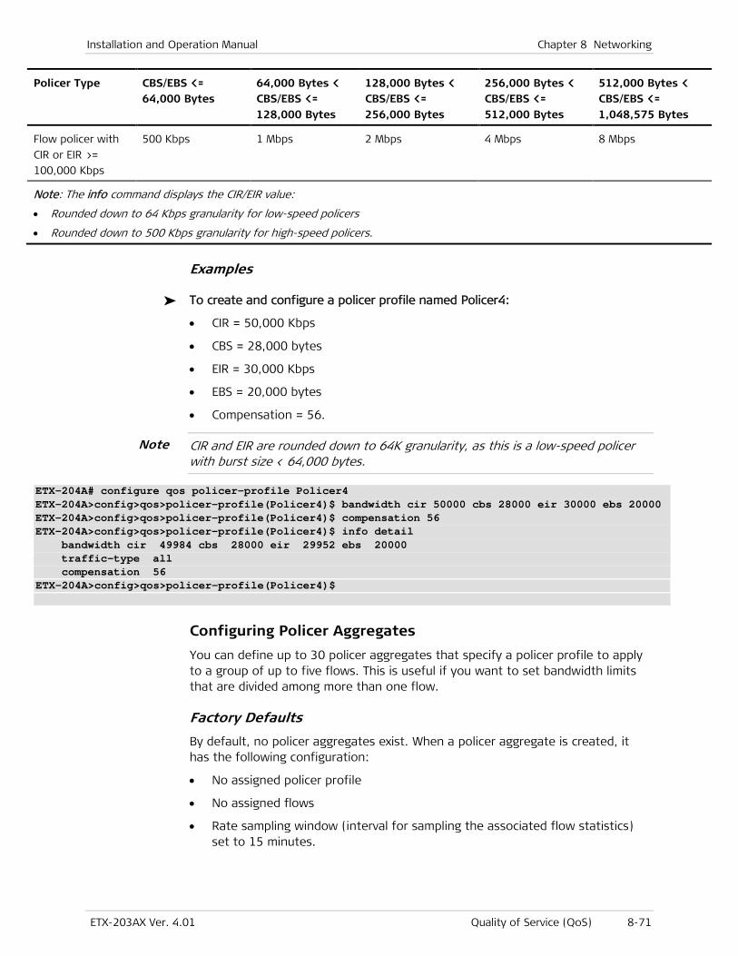
Installation and Operation Manual Chapter 8 Networking
ETX-203AX Ver. 4.01 Quality of Service (QoS) 8-71
Policer Type CBS/EBS <= 64,000 Bytes
64,000 Bytes < CBS/EBS <=
128,000 Bytes
128,000 Bytes < CBS/EBS <=
256,000 Bytes
256,000 Bytes < CBS/EBS <=
512,000 Bytes
512,000 Bytes < CBS/EBS <=
1,048,575 Bytes
Flow policer with
CIR or EIR >=
100,000 Kbps
500 Kbps 1 Mbps 2 Mbps 4 Mbps 8 Mbps
Note: The info command displays the CIR/EIR value:
• Rounded down to 64 Kbps granularity for low-speed policers
• Rounded down to 500 Kbps granularity for high-speed policers.
Examples
To create and configure a policer profile named Policer4:
• CIR = 50,000 Kbps
• CBS = 28,000 bytes
• EIR = 30,000 Kbps
• EBS = 20,000 bytes
• Compensation = 56.
CIR and EIR are rounded down to 64K granularity, as this is a low-speed policer with burst size < 64,000 bytes.
ETX-204A# configure qos policer-profile Policer4 ETX-204A>config>qos>policer-profile(Policer4)$ bandwidth cir 50000 cbs 28000 eir 30000 ebs 20000 ETX-204A>config>qos>policer-profile(Policer4)$ compensation 56 ETX-204A>config>qos>policer-profile(Policer4)$ info detail bandwidth cir 49984 cbs 28000 eir 29952 ebs 20000 traffic-type all compensation 56 ETX-204A>config>qos>policer-profile(Policer4)$
Configuring Policer Aggregates
You can define up to 30 policer aggregates that specify a policer profile to apply to a group of up to five flows. This is useful if you want to set bandwidth limits that are divided among more than one flow.
Factory Defaults
By default, no policer aggregates exist. When a policer aggregate is created, it has the following configuration:
• No assigned policer profile
• No assigned flows
• Rate sampling window (interval for sampling the associated flow statistics) set to 15 minutes.
Note
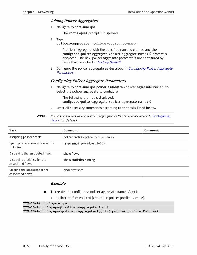
Chapter 8 Networking Installation and Operation Manual
8-72 Quality of Service (QoS) ETX-203AX Ver. 4.01
Adding Policer Aggregates
1. Navigate to configure qos.
The config>qos# prompt is displayed.
2. Type: policer-aggregate <policer-aggregate-name>
A policer aggregate with the specified name is created and the config>qos>policer-aggregate(<policer-aggregate-name>)$ prompt is displayed. The new policer aggregate parameters are configured by default as described in Factory Default.
3. Configure the policer aggregate as described in Configuring Policer Aggregate Parameters.
Configuring Policer Aggregate Parameters
1. Navigate to configure qos policer-aggregate <policer-aggregate-name> to select the policer aggregate to configure.
The following prompt is displayed: config>qos>policer-aggregate(<policer-aggregate-name>)#
2. Enter all necessary commands according to the tasks listed below.
You assign flows to the policer aggregate in the flow level (refer to Configuring Flows for details).
Task Command Comments
Assigning policer profile policer profile <policer-profile-name>
Specifying rate sampling window
(minutes) rate-sampling-window <1–30>
Displaying the associated flows show flows
Displaying statistics for the
associated flows show statistics running
Clearing the statistics for the
associated flows clear-statistics
Example
To create and configure a policer aggregate named Aggr1:
• Policer profile: Policer4 (created in policer profile example).
ETX-204A# configure qos ETX-204A>config>qos# policer-aggregate Aggr1 ETX-204A>config>qos>policer-aggregate(Aggr1)$ policer profile Policer4
Note
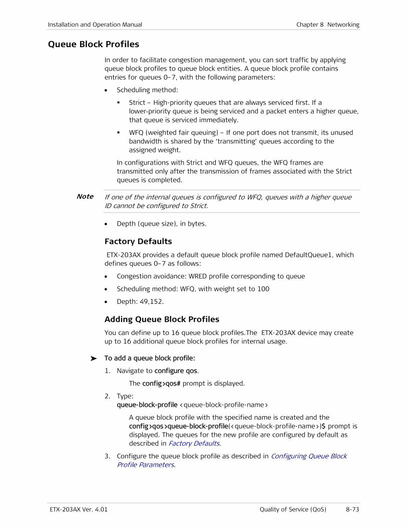
Installation and Operation Manual Chapter 8 Networking
ETX-203AX Ver. 4.01 Quality of Service (QoS) 8-73
Queue Block Profiles
In order to facilitate congestion management, you can sort traffic by applying queue block profiles to queue block entities. A queue block profile contains entries for queues 0–7, with the following parameters:
• Scheduling method:
Strict – High-priority queues that are always serviced first. If a lower-priority queue is being serviced and a packet enters a higher queue, that queue is serviced immediately.
WFQ (weighted fair queuing) – If one port does not transmit, its unused bandwidth is shared by the ‘transmitting’ queues according to the assigned weight.
In configurations with Strict and WFQ queues, the WFQ frames are transmitted only after the transmission of frames associated with the Strict queues is completed.
If one of the internal queues is configured to WFQ, queues with a higher queue ID cannot be configured to Strict.
• Depth (queue size), in bytes.
Factory Defaults
ETX-203AX provides a default queue block profile named DefaultQueue1, which defines queues 0–7 as follows:
• Congestion avoidance: WRED profile corresponding to queue
• Scheduling method: WFQ, with weight set to 100
• Depth: 49,152.
Adding Queue Block Profiles
You can define up to 16 queue block profiles.The ETX-203AX device may create up to 16 additional queue block profiles for internal usage.
To add a queue block profile:
1. Navigate to configure qos.
The config>qos# prompt is displayed.
2. Type: queue-block-profile <queue-block-profile-name>
A queue block profile with the specified name is created and the config>qos>queue-block-profile(<queue-block-profile-name>)$ prompt is displayed. The queues for the new profile are configured by default as described in Factory Defaults.
3. Configure the queue block profile as described in Configuring Queue Block Profile Parameters.
Note
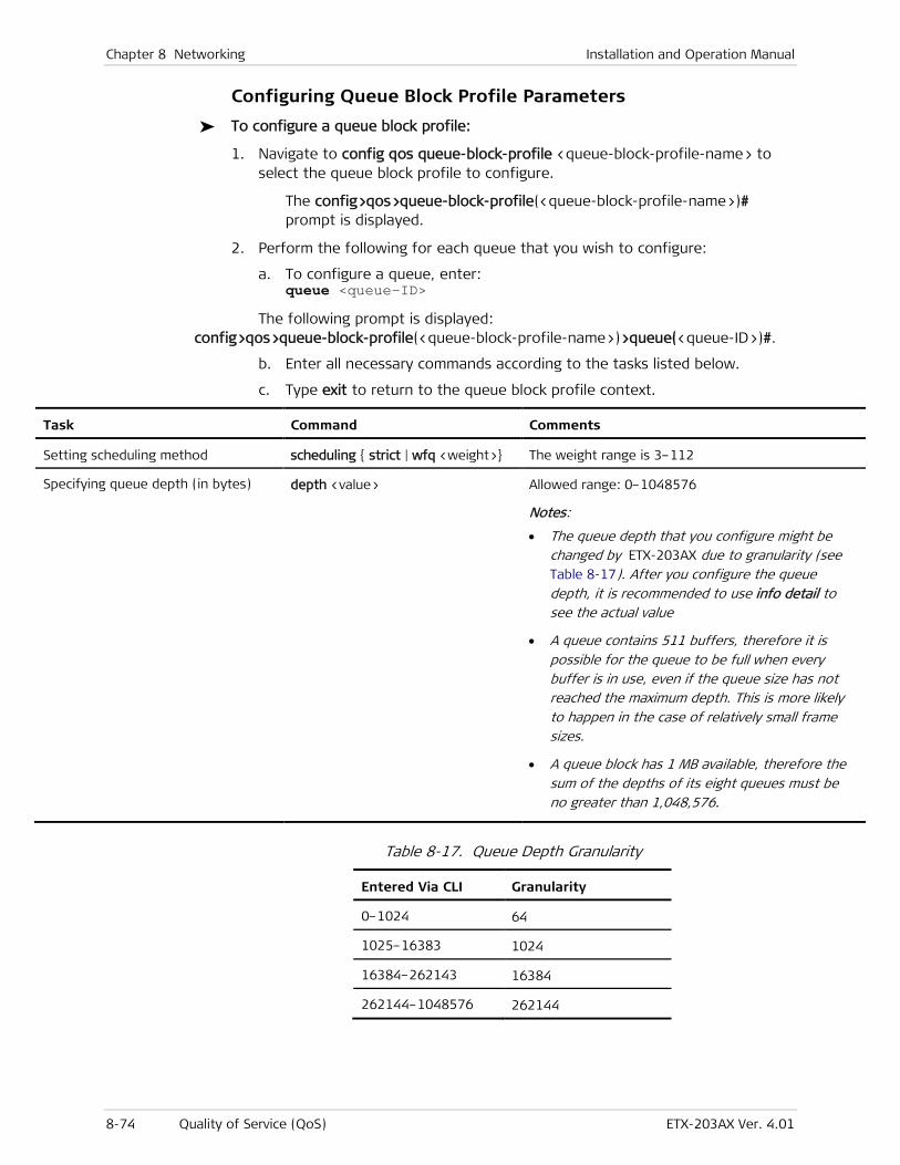
Chapter 8 Networking Installation and Operation Manual
8-74 Quality of Service (QoS) ETX-203AX Ver. 4.01
Configuring Queue Block Profile Parameters
To configure a queue block profile:
1. Navigate to config qos queue-block-profile <queue-block-profile-name> to select the queue block profile to configure.
The config>qos>queue-block-profile(<queue-block-profile-name>)# prompt is displayed.
2. Perform the following for each queue that you wish to configure:
a. To configure a queue, enter: queue <queue-ID>
The following prompt is displayed: config>qos>queue-block-profile(<queue-block-profile-name>)>queue(<queue-ID>)#.
b. Enter all necessary commands according to the tasks listed below.
c. Type exit to return to the queue block profile context.
Task Command Comments
Setting scheduling method scheduling { strict | wfq <weight>} The weight range is 3–112
Specifying queue depth (in bytes) depth <value> Allowed range: 0–1048576
Notes:
• The queue depth that you configure might be changed by ETX-203AX due to granularity (see Table 8-17). After you configure the queue depth, it is recommended to use info detail to see the actual value
• A queue contains 511 buffers, therefore it is possible for the queue to be full when every buffer is in use, even if the queue size has not reached the maximum depth. This is more likely to happen in the case of relatively small frame sizes.
• A queue block has 1 MB available, therefore the sum of the depths of its eight queues must be no greater than 1,048,576.
Table 8-17. Queue Depth Granularity
Entered Via CLI Granularity
0–1024 64
1025–16383 1024
16384–262143 16384
262144–1048576 262144
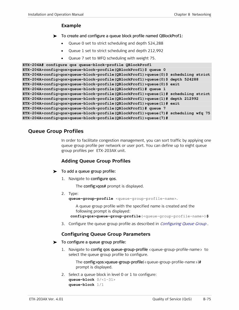
Installation and Operation Manual Chapter 8 Networking
ETX-203AX Ver. 4.01 Quality of Service (QoS) 8-75
Example
To create and configure a queue block profile named QBlockProf1:
• Queue 0 set to strict scheduling and depth 524,288
• Queue 1 set to strict scheduling and depth 212,992
• Queue 7 set to WFQ scheduling with weight 75.
ETX-204A# configure qos queue-block-profile QBlockProf1 ETX-204A>config>qos>queue-block-profile(QBlockProf1)$ queue 0 ETX-204A>config>qos>queue-block-profile(QBlockProf1)>queue(0)$ scheduling strict ETX-204A>config>qos>queue-block-profile(QBlockProf1)>queue(0)$ depth 524288 ETX-204A>config>qos>queue-block-profile(QBlockProf1)>queue(0)$ exit ETX-204A>config>qos>queue-block-profile(QBlockProf1)# queue 1 ETX-204A>config>qos>queue-block-profile(QBlockProf1)>queue(1)# scheduling strict ETX-204A>config>qos>queue-block-profile(QBlockProf1)>queue(1)# depth 212992 ETX-204A>config>qos>queue-block-profile(QBlockProf1)>queue(1)# exit ETX-204A>config>qos>queue-block-profile(QBlockProf1)# queue 7 ETX-204A>config>qos>queue-block-profile(QBlockProf1)>queue(7)# scheduling wfq 75 ETX-204A>config>qos>queue-block-profile(QBlockProf1)>queue(7)#
Queue Group Profiles
In order to facilitate congestion management, you can sort traffic by applying one queue group profile per network or user port. You can define up to eight queue group profiles per ETX-203AX unit.
Adding Queue Group Profiles
To add a queue group profile:
1. Navigate to configure qos.
The config>qos# prompt is displayed.
2. Type: queue-group-profile <queue-group-profile-name>.
A queue group profile with the specified name is created and the following prompt is displayed:
config>qos>queue-group-profile(<queue-group-profile-name>)$
3. Configure the queue group profile as described in Configuring Queue Group .
Configuring Queue Group Parameters
To configure a queue group profile:
1. Navigate to config qos queue-group-profile <queue-group-profile-name> to select the queue group profile to configure.
The config>qos>queue-group-profile(<queue-group-profile-name>)# prompt is displayed.
2. Select a queue block in level 0 or 1 to configure: queue-block 0/<1–31> queue-block 1/1

Chapter 8 Networking Installation and Operation Manual
8-76 Quality of Service (QoS) ETX-203AX Ver. 4.01
The following prompt is displayed: config>qos>queue-group-profile(<q-grp-profile-name>)>queue-block(<level/ID>)#
3. Enter all necessary commands according to the tasks listed below.
4. If you wish to configure another queue block, type exit to return to the queue group profile context, and start again at step 2.
Task Command Comments
Assigning a name to the queue block name <block-name>
Assigning a queue block profile profile <queue-block-profile-name>
Assigning a shaper profile
Note: Only for queue blocks in level 0
shaper profile <shaper-profile-name>
Normally there is no need for you to enter the bind command. When you add a queue block in level 0 to the profile, bind is done automatically.
You cannot use the bind command if the queue group contains a single queue block in level 0.
Example
This example uses the shaper profile and queue block profile created in the examples in the preceding sections.
To create and configure a queue group profile named QGroupProf1:
• Queue block 0/1:
Queue block profile: QBlockProf1
Shaper profile: Shap2.
Queue blocks 1/1 and 0/2 are automatically created.
Note
Note
Note
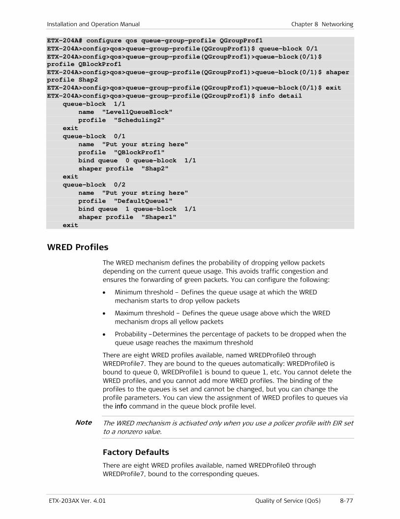
Installation and Operation Manual Chapter 8 Networking
ETX-203AX Ver. 4.01 Quality of Service (QoS) 8-77
ETX-204A# configure qos queue-group-profile QGroupProf1 ETX-204A>config>qos>queue-group-profile(QGroupProf1)$ queue-block 0/1 ETX-204A>config>qos>queue-group-profile(QGroupProf1)>queue-block(0/1)$ profile QBlockProf1 ETX-204A>config>qos>queue-group-profile(QGroupProf1)>queue-block(0/1)$ shaper profile Shap2 ETX-204A>config>qos>queue-group-profile(QGroupProf1)>queue-block(0/1)$ exit ETX-204A>config>qos>queue-group-profile(QGroupProf1)$ info detail queue-block 1/1 name "Level1QueueBlock" profile "Scheduling2" exit queue-block 0/1 name "Put your string here" profile "QBlockProf1" bind queue 0 queue-block 1/1 shaper profile "Shap2" exit queue-block 0/2 name "Put your string here" profile "DefaultQueue1" bind queue 1 queue-block 1/1 shaper profile "Shaper1" exit
WRED Profiles
The WRED mechanism defines the probability of dropping yellow packets depending on the current queue usage. This avoids traffic congestion and ensures the forwarding of green packets. You can configure the following:
• Minimum threshold – Defines the queue usage at which the WRED mechanism starts to drop yellow packets
• Maximum threshold – Defines the queue usage above which the WRED mechanism drops all yellow packets
• Probability –Determines the percentage of packets to be dropped when the queue usage reaches the maximum threshold
There are eight WRED profiles available, named WREDProfile0 through WREDProfile7. They are bound to the queues automatically: WREDProfile0 is bound to queue 0, WREDProfile1 is bound to queue 1, etc. You cannot delete the WRED profiles, and you cannot add more WRED profiles. The binding of the profiles to the queues is set and cannot be changed, but you can change the profile parameters. You can view the assignment of WRED profiles to queues via the info command in the queue block profile level.
The WRED mechanism is activated only when you use a policer profile with EIR set to a nonzero value.
Factory Defaults
There are eight WRED profiles available, named WREDProfile0 through WREDProfile7, bound to the corresponding queues.
Note
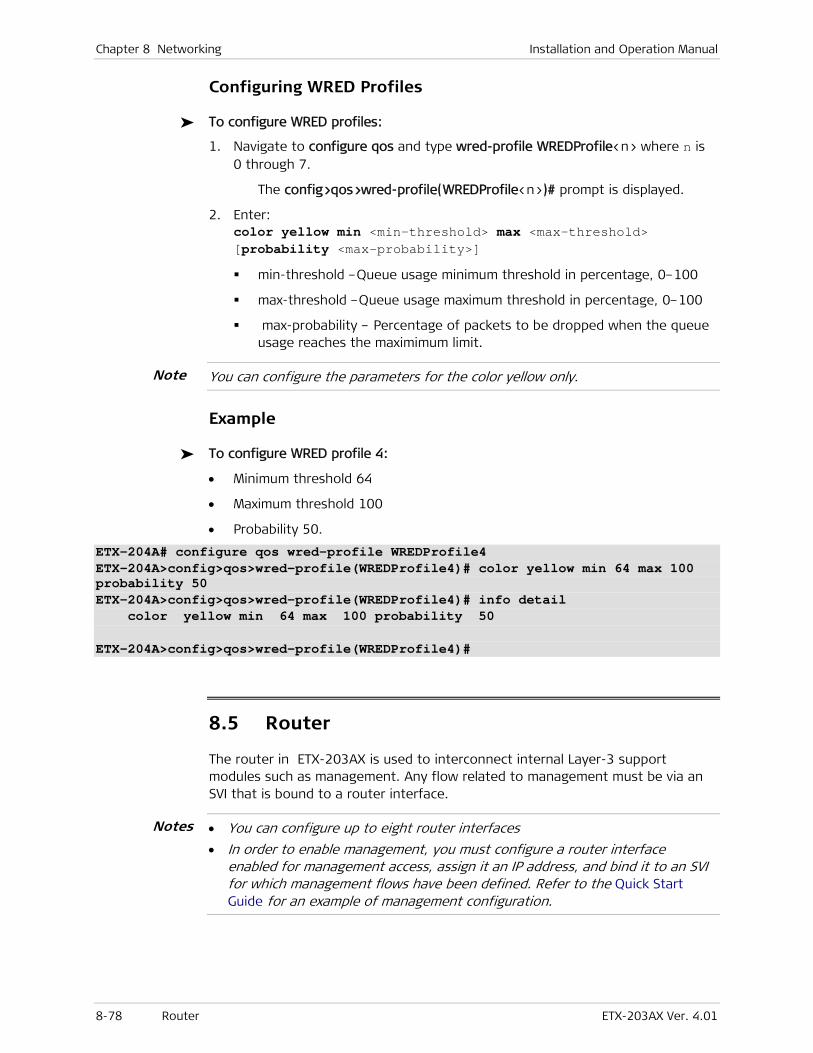
Chapter 8 Networking Installation and Operation Manual
8-78 Router ETX-203AX Ver. 4.01
Configuring WRED Profiles
To configure WRED profiles:
1. Navigate to configure qos and type wred-profile WREDProfile<n> where n is 0 through 7.
The config>qos>wred-profile(WREDProfile<n>)# prompt is displayed.
2. Enter: color yellow min <min-threshold> max <max-threshold> [probability <max-probability>]
min-threshold –Queue usage minimum threshold in percentage, 0–100
max-threshold –Queue usage maximum threshold in percentage, 0–100
max-probability – Percentage of packets to be dropped when the queue usage reaches the maximimum limit.
You can configure the parameters for the color yellow only.
Example
To configure WRED profile 4:
• Minimum threshold 64
• Maximum threshold 100
• Probability 50.
ETX-204A# configure qos wred-profile WREDProfile4 ETX-204A>config>qos>wred-profile(WREDProfile4)# color yellow min 64 max 100 probability 50 ETX-204A>config>qos>wred-profile(WREDProfile4)# info detail color yellow min 64 max 100 probability 50 ETX-204A>config>qos>wred-profile(WREDProfile4)#
8.5 Router
The router in ETX-203AX is used to interconnect internal Layer-3 support modules such as management. Any flow related to management must be via an SVI that is bound to a router interface.
• You can configure up to eight router interfaces
• In order to enable management, you must configure a router interface enabled for management access, assign it an IP address, and bind it to an SVI for which management flows have been defined. Refer to the Quick Start Guide for an example of management configuration.
Notes
Note

Installation and Operation Manual Chapter 8 Networking
ETX-203AX Ver. 4.01 Router 8-79
Benefits
The router provides Layer-3 (IP) connectivity.
Factory Default
By default, the router is configured as shown in the following.
ETX-204A# conf router 1 ETX-204A>config>router(1)# inf d name "Router#1" dhcp-client host-name sys-name vendor-class-id ent-physical-name exit
Functional Description
Any flow into/out of the device, that is related to management, must be via an SVI that is bound to a router interface. A router interface can be associated via binding to only one SVI. If a flow is used for management purposes, the router interface corresponding to the SVI should be enabled for management access.
Figure 8-10. Router and SVIs
Configuring the Router
The router functionality allows ETX-203AX to establish links to Ethernet ports via SVIs.
To configure the router:
1. At the config# prompt, enter: router 1
The config>router(1)# prompt is displayed.
2. Enter all necessary commands according to the tasks listed below.
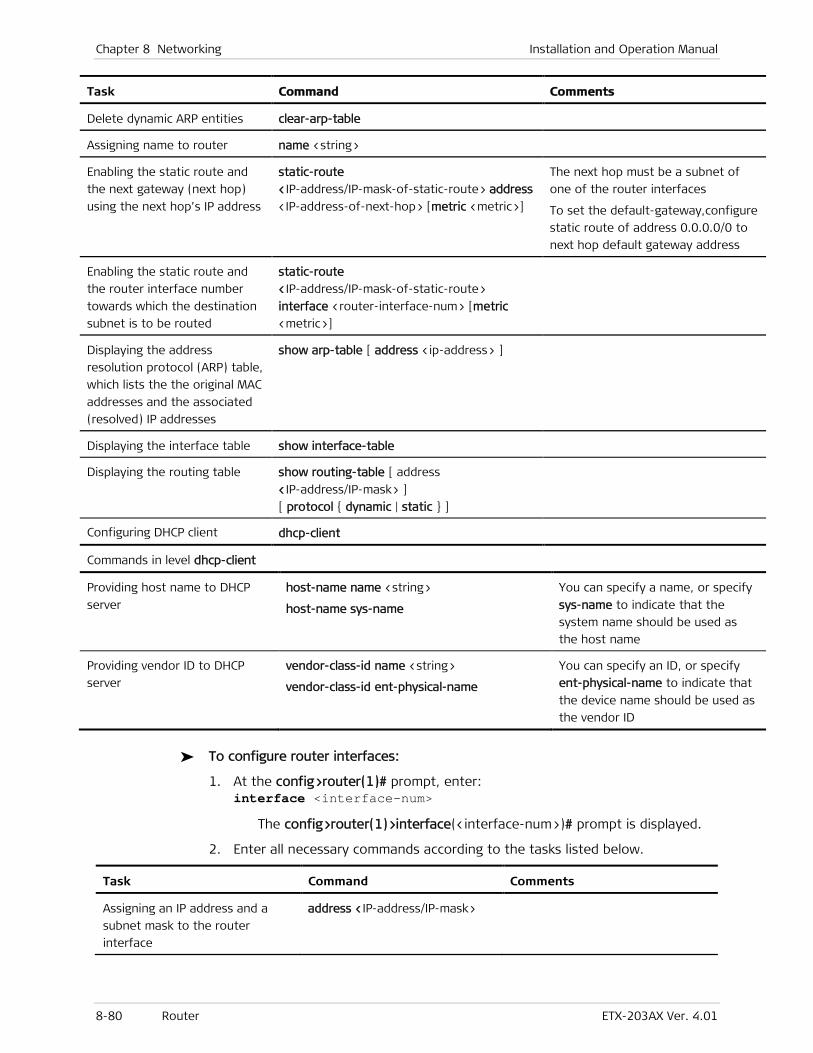
Chapter 8 Networking Installation and Operation Manual
8-80 Router ETX-203AX Ver. 4.01
Task Command Comments
Delete dynamic ARP entities clear-arp-table
Assigning name to router name <string>
Enabling the static route and
the next gateway (next hop)
using the next hop’s IP address
static-route
<IP-address/IP-mask-of-static-route> address
<IP-address-of-next-hop> [metric <metric>]
The next hop must be a subnet of
one of the router interfaces
To set the default-gateway,configure
static route of address 0.0.0.0/0 to
next hop default gateway address
Enabling the static route and
the router interface number
towards which the destination
subnet is to be routed
static-route
<IP-address/IP-mask-of-static-route>
interface <router-interface-num> [metric
<metric>]
Displaying the address
resolution protocol (ARP) table,
which lists the the original MAC
addresses and the associated
(resolved) IP addresses
show arp-table [ address <ip-address> ]
Displaying the interface table show interface-table
Displaying the routing table show routing-table [ address
<IP-address/IP-mask> ]
[ protocol { dynamic | static } ]
Configuring DHCP client dhcp-client
Commands in level dhcp-client
Providing host name to DHCP
server
host-name name <string>
host-name sys-name
You can specify a name, or specify
sys-name to indicate that the
system name should be used as
the host name
Providing vendor ID to DHCP
server
vendor-class-id name <string>
vendor-class-id ent-physical-name
You can specify an ID, or specify
ent-physical-name to indicate that
the device name should be used as
the vendor ID
To configure router interfaces:
1. At the config>router(1)# prompt, enter: interface <interface-num>
The config>router(1)>interface(<interface-num>)# prompt is displayed.
2. Enter all necessary commands according to the tasks listed below.
Task Command Comments
Assigning an IP address and a
subnet mask to the router
interface
address <IP-address/IP-mask>
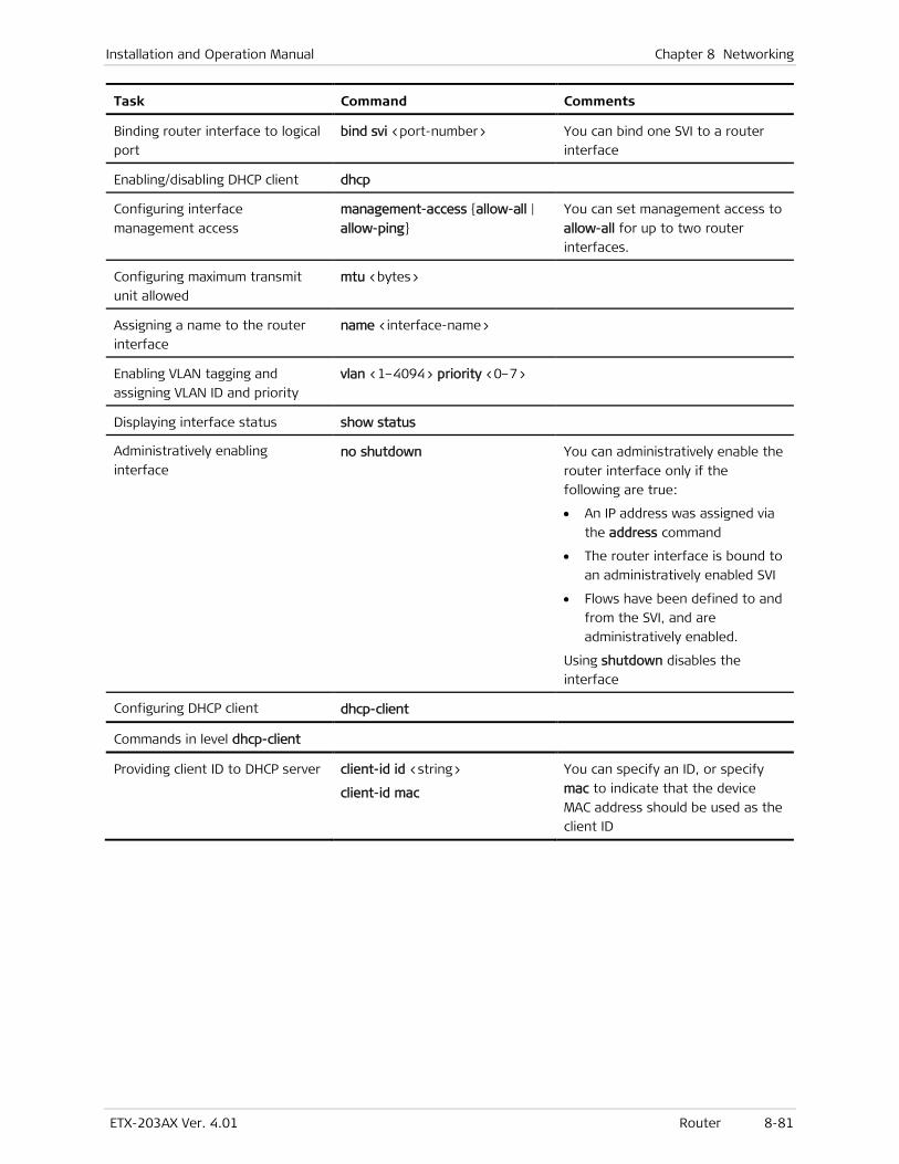
Installation and Operation Manual Chapter 8 Networking
ETX-203AX Ver. 4.01 Router 8-81
Task Command Comments
Binding router interface to logical
port
bind svi <port-number> You can bind one SVI to a router
interface
Enabling/disabling DHCP client dhcp
Configuring interface
management access
management-access {allow-all |
allow-ping}
You can set management access to
allow-all for up to two router
interfaces.
Configuring maximum transmit
unit allowed
mtu <bytes>
Assigning a name to the router
interface
name <interface-name>
Enabling VLAN tagging and
assigning VLAN ID and priority
vlan <1–4094> priority <0–7>
Displaying interface status show status
Administratively enabling
interface no shutdown You can administratively enable the
router interface only if the
following are true:
• An IP address was assigned via
the address command
• The router interface is bound to
an administratively enabled SVI
• Flows have been defined to and
from the SVI, and are
administratively enabled.
Using shutdown disables the
interface
Configuring DHCP client dhcp-client
Commands in level dhcp-client
Providing client ID to DHCP server client-id id <string>
client-id mac
You can specify an ID, or specify
mac to indicate that the device
MAC address should be used as the
client ID

ETX-203AX Ver. 4.01 Date and Time 9-1
Chapter 9
Timing and Synchronization This chapter describes the date and time feature.
9.1 Date and Time
You can set the date and time for the ETX-203AX internal real-time clock or receive the NTP server clock signal.
Setting the Date and Time
To set the system date and time:
1. Navigate to configure system date-and-time.
The config>system>date-time# prompt is displayed.
2. Enter all necessary commands according to the tasks listed below.
Task Command Comments
Specifying the desired date
format date-format {yyyy-mm-dd | dd-mm-yyyy |
mm-dd-yyyy | yyyy-dd-mm}
Defining the date date <date> Date is according to the configured date
format
Defining the time zone relative
to Universal Time Coordinated
(UTC)
zone utc [<[{+|-}]hh[:mm]>] Allowed range of values:
-12:00 to +12:00, in 30-minute increments
Defining the time time <hh:mm[:ss]>
Example
To set the date and time:
• Format = mm-dd-yyyy
• Date = May 17, 2011
• Time = 5:40pm
• Zone = UTC –4 hours and 30 minutes.
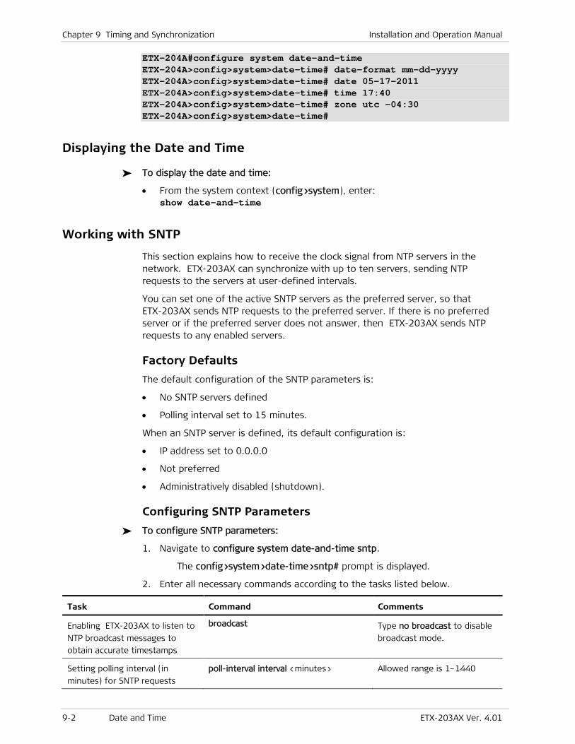
Chapter 9 Timing and Synchronization Installation and Operation Manual
9-2 Date and Time ETX-203AX Ver. 4.01
ETX-204A#configure system date-and-time ETX-204A>config>system>date-time# date-format mm-dd-yyyy ETX-204A>config>system>date-time# date 05-17-2011 ETX-204A>config>system>date-time# time 17:40 ETX-204A>config>system>date-time# zone utc -04:30 ETX-204A>config>system>date-time#
Displaying the Date and Time
To display the date and time:
• From the system context (config>system), enter: show date-and-time
Working with SNTP
This section explains how to receive the clock signal from NTP servers in the network. ETX-203AX can synchronize with up to ten servers, sending NTP requests to the servers at user-defined intervals.
You can set one of the active SNTP servers as the preferred server, so that ETX-203AX sends NTP requests to the preferred server. If there is no preferred server or if the preferred server does not answer, then ETX-203AX sends NTP requests to any enabled servers.
Factory Defaults
The default configuration of the SNTP parameters is:
• No SNTP servers defined
• Polling interval set to 15 minutes.
When an SNTP server is defined, its default configuration is:
• IP address set to 0.0.0.0
• Not preferred
• Administratively disabled (shutdown).
Configuring SNTP Parameters
To configure SNTP parameters:
1. Navigate to configure system date-and-time sntp.
The config>system>date-time>sntp# prompt is displayed.
2. Enter all necessary commands according to the tasks listed below.
Task Command Comments
Enabling ETX-203AX to listen to
NTP broadcast messages to
obtain accurate timestamps
broadcast Type no broadcast to disable
broadcast mode.
Setting polling interval (in
minutes) for SNTP requests
poll-interval interval <minutes> Allowed range is 1–1440
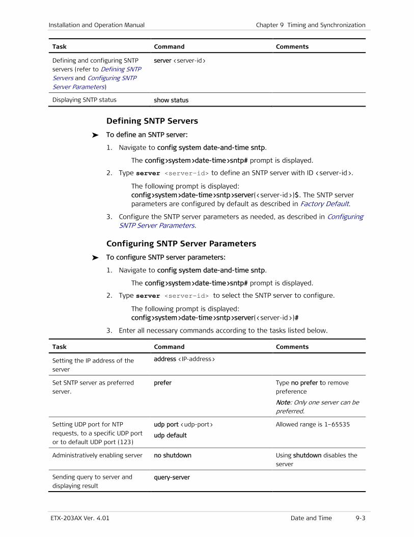
Installation and Operation Manual Chapter 9 Timing and Synchronization
ETX-203AX Ver. 4.01 Date and Time 9-3
Task Command Comments
Defining and configuring SNTP
servers (refer to Defining SNTP Servers and Configuring SNTP Server Parameters)
server <server-id>
Displaying SNTP status show status
Defining SNTP Servers
To define an SNTP server:
1. Navigate to config system date-and-time sntp.
The config>system>date-time>sntp# prompt is displayed.
2. Type server <server-id> to define an SNTP server with ID <server-id>.
The following prompt is displayed: config>system>date-time>sntp>server(<server-id>)$. The SNTP server parameters are configured by default as described in Factory Default.
3. Configure the SNTP server parameters as needed, as described in Configuring SNTP Server Parameters.
Configuring SNTP Server Parameters
To configure SNTP server parameters:
1. Navigate to config system date-and-time sntp.
The config>system>date-time>sntp# prompt is displayed.
2. Type server <server-id> to select the SNTP server to configure.
The following prompt is displayed: config>system>date-time>sntp>server(<server-id>)#
3. Enter all necessary commands according to the tasks listed below.
Task Command Comments
Setting the IP address of the
server
address <IP-address>
Set SNTP server as preferred
server. prefer Type no prefer to remove
preference
Note: Only one server can be preferred.
Setting UDP port for NTP
requests, to a specific UDP port
or to default UDP port (123)
udp port <udp-port>
udp default
Allowed range is 1–65535
Administratively enabling server no shutdown Using shutdown disables the
server
Sending query to server and
displaying result query-server
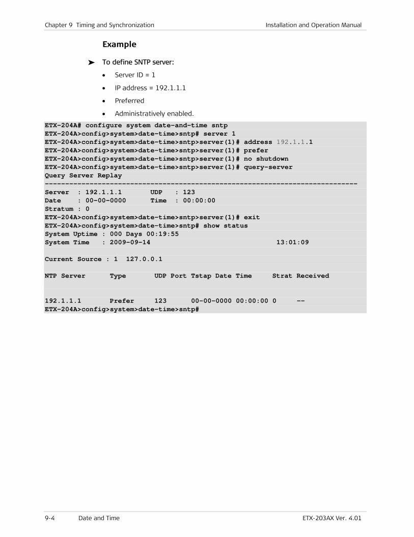
Chapter 9 Timing and Synchronization Installation and Operation Manual
9-4 Date and Time ETX-203AX Ver. 4.01
Example
To define SNTP server:
• Server ID = 1
• IP address = 192.1.1.1
• Preferred
• Administratively enabled.
ETX-204A# configure system date-and-time sntp ETX-204A>config>system>date-time>sntp# server 1 ETX-204A>config>system>date-time>sntp>server(1)# address 192.1.1.1 ETX-204A>config>system>date-time>sntp>server(1)# prefer ETX-204A>config>system>date-time>sntp>server(1)# no shutdown ETX-204A>config>system>date-time>sntp>server(1)# query-server Query Server Replay ----------------------------------------------------------------------------- Server : 192.1.1.1 UDP : 123 Date : 00-00-0000 Time : 00:00:00 Stratum : 0 ETX-204A>config>system>date-time>sntp>server(1)# exit ETX-204A>config>system>date-time>sntp# show status System Uptime : 000 Days 00:19:55 System Time : 2009-09-14 13:01:09 Current Source : 1 127.0.0.1 NTP Server Type UDP Port Tstap Date Time Strat Received 192.1.1.1 Prefer 123 00-00-0000 00:00:00 0 -- ETX-204A>config>system>date-time>sntp#
ETX-203AX Ver. 4.01 Confirming Startup Configuration 10-1
Chapter 10
Administration This chapter describes administrative features:
• Confirming Startup Configuration
• Device Information
• Environment
• CPU and Memory Utilization
• File Operations
• Inventory
• Reset
• Saving Configuration
• Statistics Clearing
• Syslog.
10.1 Confirming Startup Configuration
You can request that startup-config be confirmed after the next reboot. When you execute the request, then the next time the device reboots, if startup-config is loaded successfully, you must confirm startup-config within the configured timeout period. If the confirmation is not received before timeout, the device rejects startup-config, reboots, and attempts to load the next available configuration file (rollback-config, user-default-config, factory-default-config).
To request confirmation of startup-config after next reboot;
• At the admin# prompt enter: startup-confirm-required [time-to-confirm <minutes>] [rollback {startup-config | user-default-config | factory-default-config | running-config}]
The <minutes> parameter defines the confirmation timeout, range 1–65535 (default 5). If rollback <config-file> is specified, the specified configuration file is copied to rollback-config.
To confirm confirmation of startup-config after reboot;
• In any level enter: startup-config-confirm
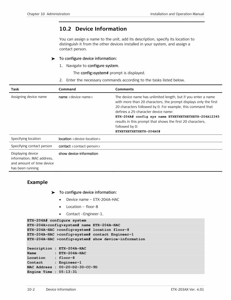
Chapter 10 Administration Installation and Operation Manual
10-2 Device Information ETX-203AX Ver. 4.01
10.2 Device Information
You can assign a name to the unit, add its description, specify its location to distinguish it from the other devices installed in your system, and assign a contact person.
To configure device information:
1. Navigate to configure system.
The config>system# prompt is displayed.
2. Enter the necessary commands according to the tasks listed below.
Task Command Comments
Assigning device name name <device-name> The device name has unlimited length, but if you enter a name
with more than 20 characters, the prompt displays only the first
20 characters followed by 0. For example, this command that
defines a 25-character device name: ETX-204A# config sys name ETXETXETXETXETX-204A12345
results in this prompt that shows the first 20 characters,
followed by 0: ETXETXETXETXETX-204A0#
Specifying location location <device-location>
Specifying contact person contact <contact-person>
Displaying device
information, MAC address,
and amount of time device
has been running
show device-information
Example
To configure device information:
• Device name – ETX-204A-HAC
• Location – floor-8
• Contact –Engineer-1.
ETX-204A# configure system ETX-204A>config>system# name ETX-204A-HAC ETX-204A-HAC >config>system# location floor-8 ETX-204A-HAC >config>system# contact Engineer-1 ETX-204A-HAC >config>system# show device-information Description : ETX-204A-HAC Name : ETX-204A-HAC Location : floor-8 Contact : Engineer-1 MAC Address : 00-20-D2-30-CC-9D Engine Time : 05:13:31

Installation and Operation Manual Chapter 10 Administration
ETX-203AX Ver. 4.01 CPU and Memory Utilization 10-3
10.3 Environment
You can display information about the type and status of the power supplies, and the status of the fans.
To display the information:
1. Navigate to configure chassis.
The config>chassis# prompt is displayed.
2. Enter: show environment
The information is displayed as shown in the example below.
The power supply type is indicated as AC-DC or -- (if it has failed).
The status for the power supply and fan indicates whether the unit is present and functioning properly, or is absent (does not exist), or has failed.
Example
ETX-204A# configure chassis ETX-204A>config>chassis# show environment Power Supply Type Status --------------------------------------------------------------- 1 AC-DC OK FAN Status --------------------------------------------------------------- 1 OK ETX-204A>config>chassis#
10.4 CPU and Memory Utilization
You can view the CPU and memory buffer usage. Refer to Table 10-18 for a description of the memory buffers.
To display CPU usage:
• From the system context (config>system), enter: show cpu-utilization
The CPU usage is displayed.
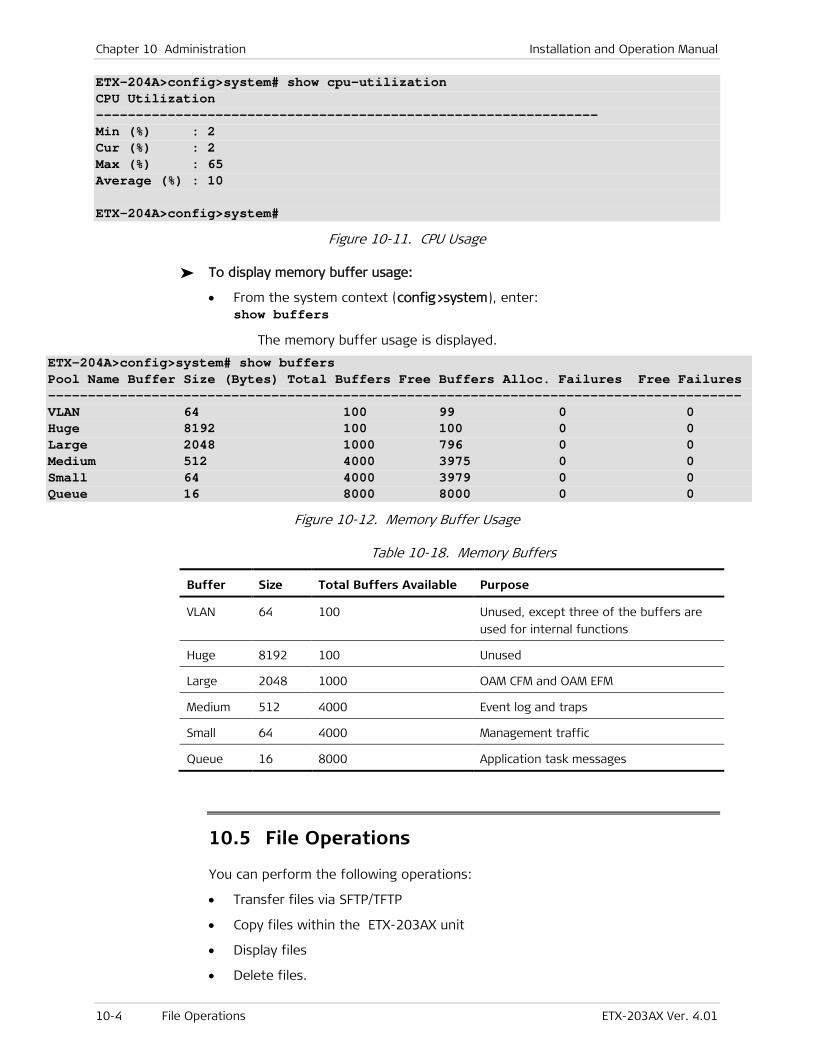
Chapter 10 Administration Installation and Operation Manual
10-4 File Operations ETX-203AX Ver. 4.01
ETX-204A>config>system# show cpu-utilization CPU Utilization --------------------------------------------------------------- Min (%) : 2 Cur (%) : 2 Max (%) : 65 Average (%) : 10 ETX-204A>config>system#
Figure 10-11. CPU Usage
To display memory buffer usage:
• From the system context (config>system), enter: show buffers
The memory buffer usage is displayed.
ETX-204A>config>system# show buffers Pool Name Buffer Size (Bytes) Total Buffers Free Buffers Alloc. Failures Free Failures --------------------------------------------------------------------------------------- VLAN 64 100 99 0 0 Huge 8192 100 100 0 0 Large 2048 1000 796 0 0 Medium 512 4000 3975 0 0 Small 64 4000 3979 0 0 Queue 16 8000 8000 0 0
Figure 10-12. Memory Buffer Usage
Table 10-18. Memory Buffers
Buffer Size Total Buffers Available Purpose
VLAN 64 100 Unused, except three of the buffers are
used for internal functions
Huge 8192 100 Unused
Large 2048 1000 OAM CFM and OAM EFM
Medium 512 4000 Event log and traps
Small 64 4000 Management traffic
Queue 16 8000 Application task messages
10.5 File Operations
You can perform the following operations:
• Transfer files via SFTP/TFTP
• Copy files within the ETX-203AX unit
• Display files
• Delete files.
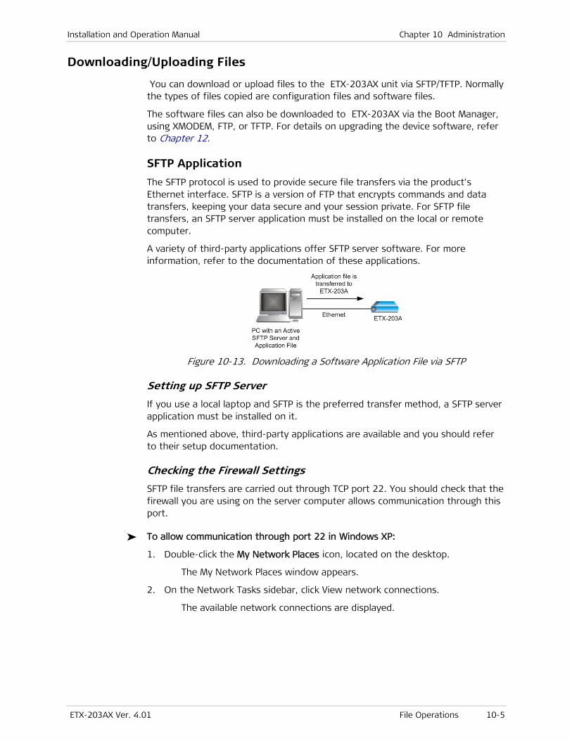
Installation and Operation Manual Chapter 10 Administration
ETX-203AX Ver. 4.01 File Operations 10-5
Downloading/Uploading Files
You can download or upload files to the ETX-203AX unit via SFTP/TFTP. Normally the types of files copied are configuration files and software files.
The software files can also be downloaded to ETX-203AX via the Boot Manager, using XMODEM, FTP, or TFTP. For details on upgrading the device software, refer to Chapter 12.
SFTP Application
The SFTP protocol is used to provide secure file transfers via the product's Ethernet interface. SFTP is a version of FTP that encrypts commands and data transfers, keeping your data secure and your session private. For SFTP file transfers, an SFTP server application must be installed on the local or remote computer.
A variety of third-party applications offer SFTP server software. For more information, refer to the documentation of these applications.
Figure 10-13. Downloading a Software Application File via SFTP
Setting up SFTP Server
If you use a local laptop and SFTP is the preferred transfer method, a SFTP server application must be installed on it.
As mentioned above, third-party applications are available and you should refer to their setup documentation.
Checking the Firewall Settings
SFTP file transfers are carried out through TCP port 22. You should check that the firewall you are using on the server computer allows communication through this port.
To allow communication through port 22 in Windows XP:
1. Double-click the My Network Places icon, located on the desktop.
The My Network Places window appears.
2. On the Network Tasks sidebar, click View network connections.
The available network connections are displayed.
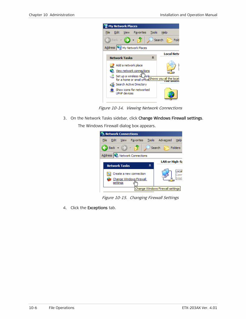
Chapter 10 Administration Installation and Operation Manual
10-6 File Operations ETX-203AX Ver. 4.01
Figure 10-14. Viewing Network Connections
3. On the Network Tasks sidebar, click Change Windows Firewall settings.
The Windows Firewall dialog box appears.
Figure 10-15. Changing Firewall Settings
4. Click the Exceptions tab.
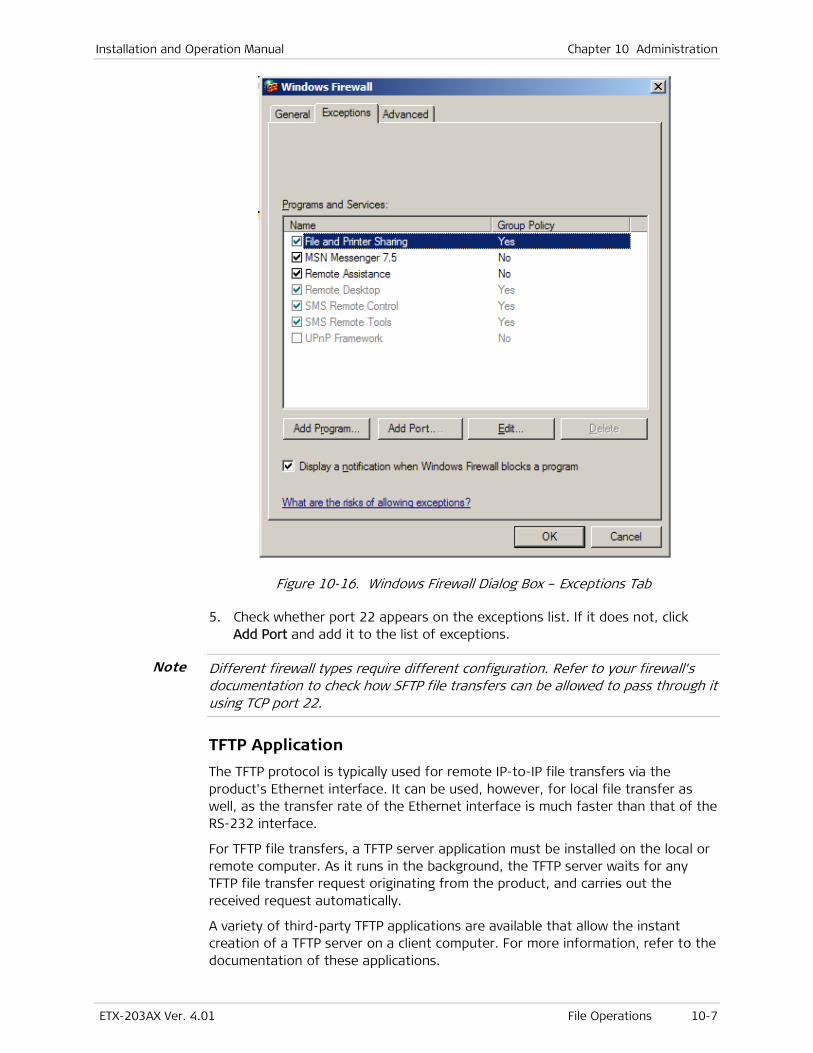
Installation and Operation Manual Chapter 10 Administration
ETX-203AX Ver. 4.01 File Operations 10-7
Figure 10-16. Windows Firewall Dialog Box – Exceptions Tab
5. Check whether port 22 appears on the exceptions list. If it does not, click Add Port and add it to the list of exceptions.
Different firewall types require different configuration. Refer to your firewall's documentation to check how SFTP file transfers can be allowed to pass through it using TCP port 22.
TFTP Application
The TFTP protocol is typically used for remote IP-to-IP file transfers via the product's Ethernet interface. It can be used, however, for local file transfer as well, as the transfer rate of the Ethernet interface is much faster than that of the RS-232 interface.
For TFTP file transfers, a TFTP server application must be installed on the local or remote computer. As it runs in the background, the TFTP server waits for any TFTP file transfer request originating from the product, and carries out the received request automatically.
A variety of third-party TFTP applications are available that allow the instant creation of a TFTP server on a client computer. For more information, refer to the documentation of these applications.
Note
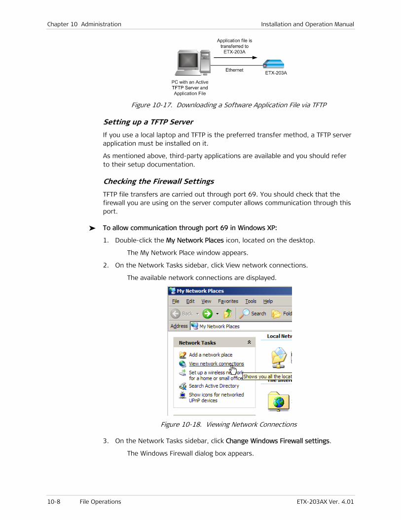
Chapter 10 Administration Installation and Operation Manual
10-8 File Operations ETX-203AX Ver. 4.01
Figure 10-17. Downloading a Software Application File via TFTP
Setting up a TFTP Server
If you use a local laptop and TFTP is the preferred transfer method, a TFTP server application must be installed on it.
As mentioned above, third-party applications are available and you should refer to their setup documentation.
Checking the Firewall Settings
TFTP file transfers are carried out through port 69. You should check that the firewall you are using on the server computer allows communication through this port.
To allow communication through port 69 in Windows XP:
1. Double-click the My Network Places icon, located on the desktop.
The My Network Place window appears.
2. On the Network Tasks sidebar, click View network connections.
The available network connections are displayed.
Figure 10-18. Viewing Network Connections
3. On the Network Tasks sidebar, click Change Windows Firewall settings.
The Windows Firewall dialog box appears.
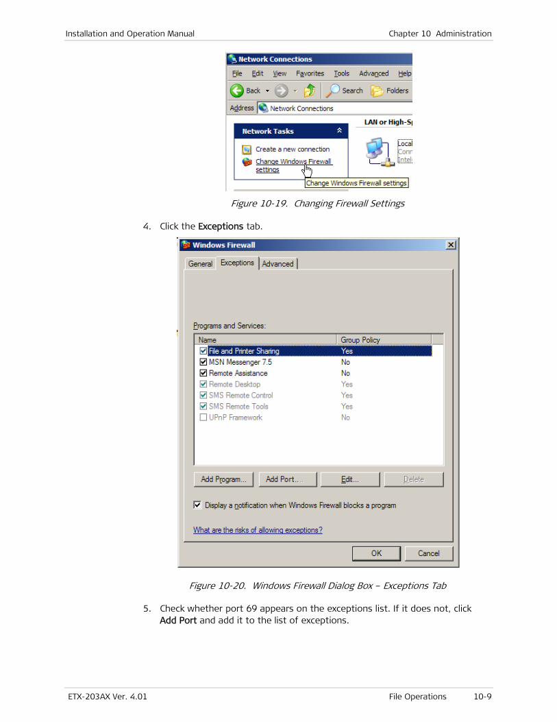
Installation and Operation Manual Chapter 10 Administration
ETX-203AX Ver. 4.01 File Operations 10-9
Figure 10-19. Changing Firewall Settings
4. Click the Exceptions tab.
Figure 10-20. Windows Firewall Dialog Box – Exceptions Tab
5. Check whether port 69 appears on the exceptions list. If it does not, click Add Port and add it to the list of exceptions.
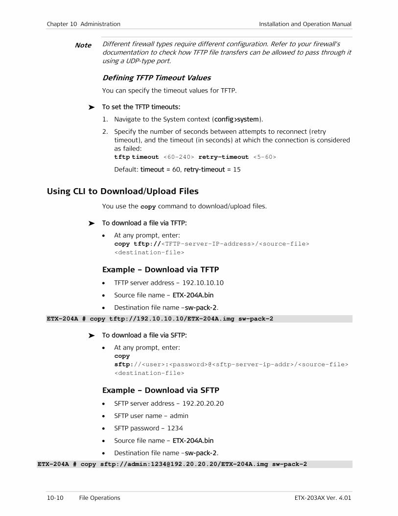
Chapter 10 Administration Installation and Operation Manual
10-10 File Operations ETX-203AX Ver. 4.01
Different firewall types require different configuration. Refer to your firewall's documentation to check how TFTP file transfers can be allowed to pass through it using a UDP-type port.
Defining TFTP Timeout Values
You can specify the timeout values for TFTP.
To set the TFTP timeouts:
1. Navigate to the System context (config>system).
2. Specify the number of seconds between attempts to reconnect (retry timeout), and the timeout (in seconds) at which the connection is considered as failed: tftp timeout <60–240> retry-timeout <5–60>
Default: timeout = 60, retry-timeout = 15
Using CLI to Download/Upload Files
You use the copy command to download/upload files.
To download a file via TFTP:
• At any prompt, enter: copy tftp://<TFTP-server-IP-address>/<source-file> <destination-file>
Example – Download via TFTP
• TFTP server address – 192.10.10.10
• Source file name – ETX-204A.bin
• Destination file name –sw-pack-2.
ETX-204A # copy tftp://192.10.10.10/ETX-204A.img sw-pack-2
To download a file via SFTP:
• At any prompt, enter: copy sftp://<user>:<password>@<sftp-server-ip-addr>/<source-file> <destination-file>
Example – Download via SFTP
• SFTP server address – 192.20.20.20
• SFTP user name – admin
• SFTP password – 1234
• Source file name – ETX-204A.bin
• Destination file name –sw-pack-2.
ETX-204A # copy sftp://admin:[email protected]/ETX-204A.img sw-pack-2
Note
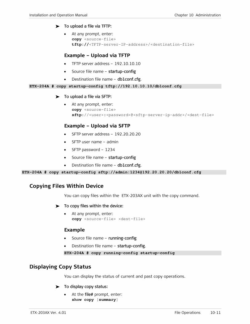
Installation and Operation Manual Chapter 10 Administration
ETX-203AX Ver. 4.01 File Operations 10-11
To upload a file via TFTP:
• At any prompt, enter: copy <source-file> tftp://<TFTP-server-IP-address>/<destination-file>
Example – Upload via TFTP
• TFTP server address – 192.10.10.10
• Source file name – startup-config
• Destination file name – db1conf.cfg.
ETX-204A # copy startup-config tftp://192.10.10.10/db1conf.cfg
To upload a file via SFTP:
• At any prompt, enter: copy <source-file> sftp://<user>:<password>@<sftp-server-ip-addr>/<dest-file>
Example – Upload via SFTP
• SFTP server address – 192.20.20.20
• SFTP user name – admin
• SFTP password – 1234
• Source file name – startup-config
• Destination file name – db1conf.cfg.
ETX-204A # copy startup-config sftp://admin:[email protected]/db1conf.cfg
Copying Files Within Device
You can copy files within the ETX-203AX unit with the copy command.
To copy files within the device:
• At any prompt, enter: copy <source-file> <dest-file>
Example
• Source file name – running-config
• Destination file name – startup-config.
ETX-204A # copy running-config startup-config
Displaying Copy Status
You can display the status of current and past copy operations.
To display copy status:
• At the file# prompt, enter: show copy [summary]
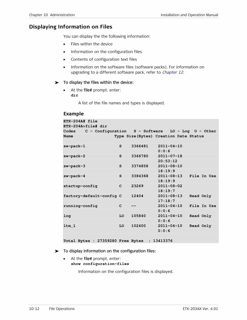
Chapter 10 Administration Installation and Operation Manual
10-12 File Operations ETX-203AX Ver. 4.01
Displaying Information on Files
You can display the the following information:
• Files within the device
• Information on the configuration files
• Contents of configuration text files
• Information on the software files (software packs). For information on upgrading to a different software pack, refer to Chapter 12.
To display the files within the device:
• At the file# prompt, enter: dir
A list of the file names and types is displayed.
Example ETX-204A# file ETX-204A>file# dir Codes C – Configuration S - Software LO - Log O - Other Name Type Size(Bytes) Creation Date Status sw-pack-1 S 3366481 2011-04-10 0:0:6 sw-pack-2 S 3366780 2011-07-18 20:53:12 sw-pack-3 S 3374858 2011-08-10 18:19:9 sw-pack-4 S 3384368 2011-08-13 File In Use 18:19:9 startup-config C 23269 2011-08-02 18:19:7 factory-default-config C 12404 2011-08-13 Read Only 17:18:7 running-config C -- 2011-04-10 File In Use 0:0:6 log LO 105840 2011-04-10 Read Only 0:0:6 ltm_1 LO 102400 2011-04-10 Read Only 0:0:6 Total Bytes : 27359280 Free Bytes : 13413376
To display information on the configuration files:
• At the file# prompt, enter: show configuration-files
Information on the configuration files is displayed.
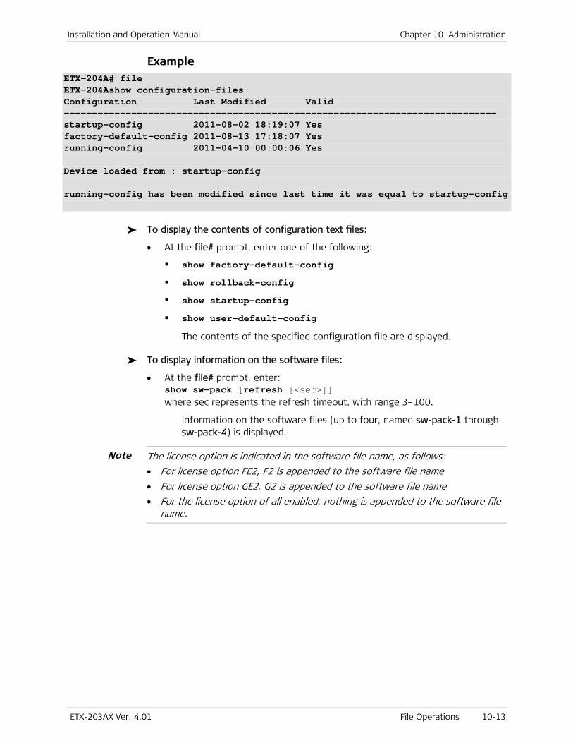
Installation and Operation Manual Chapter 10 Administration
ETX-203AX Ver. 4.01 File Operations 10-13
Example ETX-204A# file ETX-204Ashow configuration-files Configuration Last Modified Valid ----------------------------------------------------------------------------- startup-config 2011-08-02 18:19:07 Yes factory-default-config 2011-08-13 17:18:07 Yes running-config 2011-04-10 00:00:06 Yes Device loaded from : startup-config running-config has been modified since last time it was equal to startup-config
To display the contents of configuration text files:
• At the file# prompt, enter one of the following:
show factory-default-config
show rollback-config
show startup-config
show user-default-config
The contents of the specified configuration file are displayed.
To display information on the software files:
• At the file# prompt, enter: show sw-pack [refresh [<sec>]] where sec represents the refresh timeout, with range 3–100.
Information on the software files (up to four, named sw-pack-1 through sw-pack-4) is displayed.
The license option is indicated in the software file name, as follows:
• For license option FE2, F2 is appended to the software file name
• For license option GE2, G2 is appended to the software file name
• For the license option of all enabled, nothing is appended to the software file name.
Note
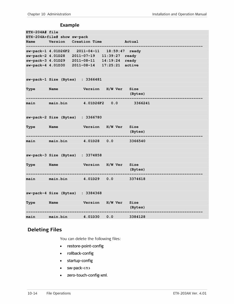
Chapter 10 Administration Installation and Operation Manual
10-14 File Operations ETX-203AX Ver. 4.01
Example ETX-204A# file ETX-204A>file# show sw-pack Name Version Creation Time Actual ----------------------------------------------------------------------------- sw-pack-1 4.01D26F2 2011-04-11 18:59:47 ready sw-pack-2 4.01D28 2011-07-19 11:39:27 ready sw-pack-3 4.01D29 2011-08-11 14:19:24 ready sw-pack-4 4.01D30 2011-08-14 17:25:21 active sw-pack-1 Size (Bytes) : 3366481 Type Name Version H/W Ver Size (Bytes) ----------------------------------------------------------------------------- main main.bin 4.01D26F2 0.0 3366241 sw-pack-2 Size (Bytes) : 3366780 Type Name Version H/W Ver Size (Bytes) ----------------------------------------------------------------------------- main main.bin 4.01D28 0.0 3366540 sw-pack-3 Size (Bytes) : 3374858 Type Name Version H/W Ver Size (Bytes) ----------------------------------------------------------------------------- main main.bin 4.01D29 0.0 3374618 sw-pack-4 Size (Bytes) : 3384368 Type Name Version H/W Ver Size (Bytes) ----------------------------------------------------------------------------- main main.bin 4.01D30 0.0 3384128
Deleting Files
You can delete the following files:
• restore-point-config
• rollback-config
• startup-config
• sw-pack-<n>
• zero-touch-config-xml.
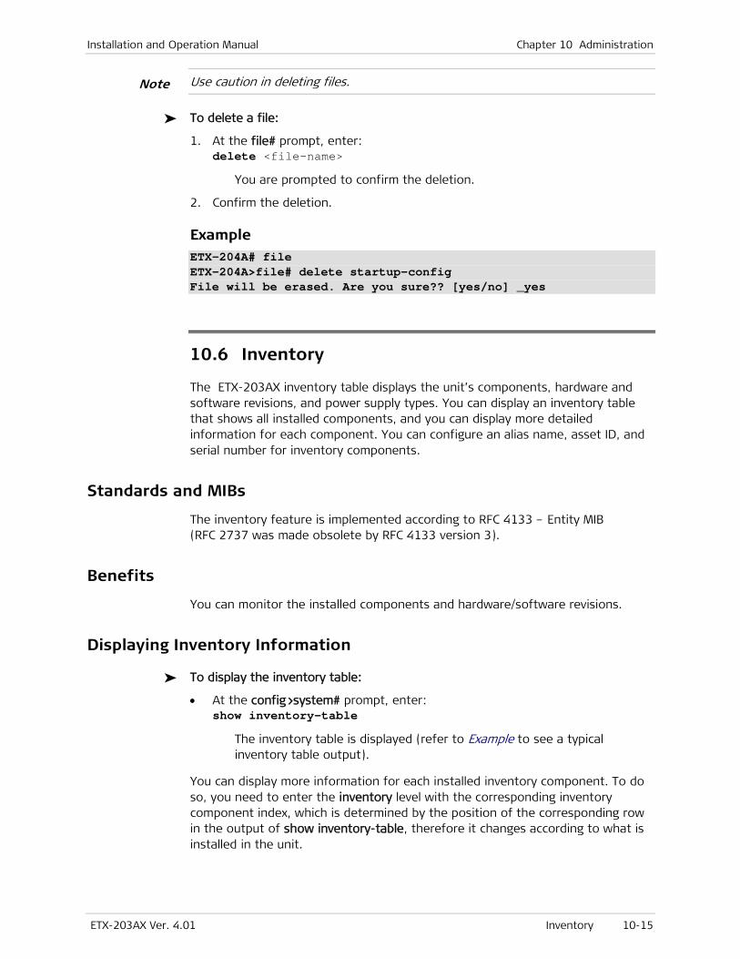
Installation and Operation Manual Chapter 10 Administration
ETX-203AX Ver. 4.01 Inventory 10-15
Use caution in deleting files.
To delete a file:
1. At the file# prompt, enter: delete <file-name>
You are prompted to confirm the deletion.
2. Confirm the deletion.
Example ETX-204A# file ETX-204A>file# delete startup-config File will be erased. Are you sure?? [yes/no] _yes
10.6 Inventory
The ETX-203AX inventory table displays the unit’s components, hardware and software revisions, and power supply types. You can display an inventory table that shows all installed components, and you can display more detailed information for each component. You can configure an alias name, asset ID, and serial number for inventory components.
Standards and MIBs
The inventory feature is implemented according to RFC 4133 – Entity MIB (RFC 2737 was made obsolete by RFC 4133 version 3).
Benefits
You can monitor the installed components and hardware/software revisions.
Displaying Inventory Information
To display the inventory table:
• At the config>system# prompt, enter: show inventory-table
The inventory table is displayed (refer to Example to see a typical inventory table output).
You can display more information for each installed inventory component. To do so, you need to enter the inventory level with the corresponding inventory component index, which is determined by the position of the corresponding row in the output of show inventory-table, therefore it changes according to what is installed in the unit.
Note

Chapter 10 Administration Installation and Operation Manual
10-16 Inventory ETX-203AX Ver. 4.01
To display the inventory component information:
1. Navigate to configure system inventory <index>.
2. Enter: show status
Information for the corresponding inventory component is displayed (refer to Table 10-19 for information on the parameters).
Table 10-19. Inventory Parameters
Parameter Description
Description Description of component type, in the form: RAD.<device-name>.< Physical Class>, e.g. RAD.ETX-204A.Port
Contained In Index of the component that contains the component for which information is being displayed. This is 0 for the chassis, as it is not contained in any component, and 1 for all other components, as they are all contained in the chassis.
Physical Class Class of component
Possible values: Chassis, CPU, Power Supply, Port
Relative Position Contains the relative position of this component among other similar components (with the exception of the relative positions for the chassis, management Ethernet port, and clock port).
Possible values for the various component types:
Chassis –4294967295
CPU –1
Power Supply – 1
Network Port – 1 or 2
User Port –3, 4, 5, 6
Management Ethernet – 101
Name Name of component
Possible values (according to component type): <device-name> –Chassis CPU Power Supply Network Port <n> User Port <n> Management Ethernet
HW Rev Hardware version (relevant only for chassis)
SW Rev Software version (relevant only for chassis)
Note: The license option is indicated in this parameter, as follows:
• For license option FE2, F2 is appended to the software version
• For license option GE2, G2 is appended to the software version
• For the license option of all enabled, nothing is appended to the
software version.
FW Rev Firmware version (relevant only for chassis)
Serial No. Serial number (blank if unknown for component)
MFG Name Manufacturer name (blank if unknown for component)
Model Name Model name (blank if unknown for component)
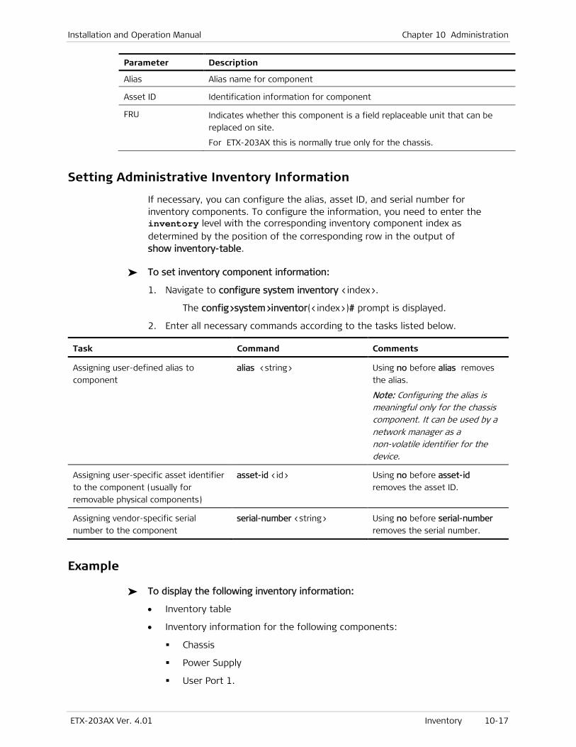
Installation and Operation Manual Chapter 10 Administration
ETX-203AX Ver. 4.01 Inventory 10-17
Parameter Description
Alias Alias name for component
Asset ID Identification information for component
FRU Indicates whether this component is a field replaceable unit that can be
replaced on site.
For ETX-203AX this is normally true only for the chassis.
Setting Administrative Inventory Information
If necessary, you can configure the alias, asset ID, and serial number for inventory components. To configure the information, you need to enter the inventory level with the corresponding inventory component index as determined by the position of the corresponding row in the output of show inventory-table.
To set inventory component information:
1. Navigate to configure system inventory <index>.
The config>system>inventor(<index>)# prompt is displayed.
2. Enter all necessary commands according to the tasks listed below.
Task Command Comments
Assigning user-defined alias to
component
alias <string> Using no before alias removes
the alias.
Note: Configuring the alias is meaningful only for the chassis component. It can be used by a network manager as a non-volatile identifier for the device.
Assigning user-specific asset identifier
to the component (usually for
removable physical components)
asset-id <id> Using no before asset-id
removes the asset ID.
Assigning vendor-specific serial
number to the component
serial-number <string> Using no before serial-number
removes the serial number.
Example
To display the following inventory information:
• Inventory table
• Inventory information for the following components:
Chassis
Power Supply
User Port 1.

Chapter 10 Administration Installation and Operation Manual
10-18 Inventory ETX-203AX Ver. 4.01
ETX-204A# configure system ETX-204A# config>system# show inventory-table Physical ClassName HW Rev SW Rev FW Rev ----------------------------------------------------------------------------- Chassis ETX-204A – Chass 0.00 4.01 1.5.1.0.0.0.0.8 CPU CPU Power Supply Power Supply Port Network Port 1 Port Network Port 2 Port User Port 1 Port User Port 2 Port User Port 3 Port User Port 4 Port Management Ethernet ETX-204A>config>system# inventory 1 ETX-204A>config>system>inventor(1)# show status Description : RAD.ETX-204A.Chassis Contained In : 0 Physical Class : Chassis Relative Position : 4294967295 Name : ETX-204A - Chassis HW Rev : 2.00 SW Rev : 4.01 FW Rev : 1.5.1.0.0.0.0.8 Serial Number : 00-20-D2-30-CC-9D MFG Name : RAD Model Name : Alias : Asset ID : FRU : True ETX-204A>config>system>inventor(1)# exit ETX-204A >config>system# inventory 3 ETX-204A>config>system>inventor(3)# show status Description : RAD.ETX-204A.Power Supply Contained In : 1 Physical Class : Power Supply Relative Position : 1 Name : Power Supply HW Rev : SW Rev : FW Rev : Serial Number : MFG Name : RAD Model Name : Alias : Asset ID : FRU : False ETX-204A>config>system>inventor(3)# exit
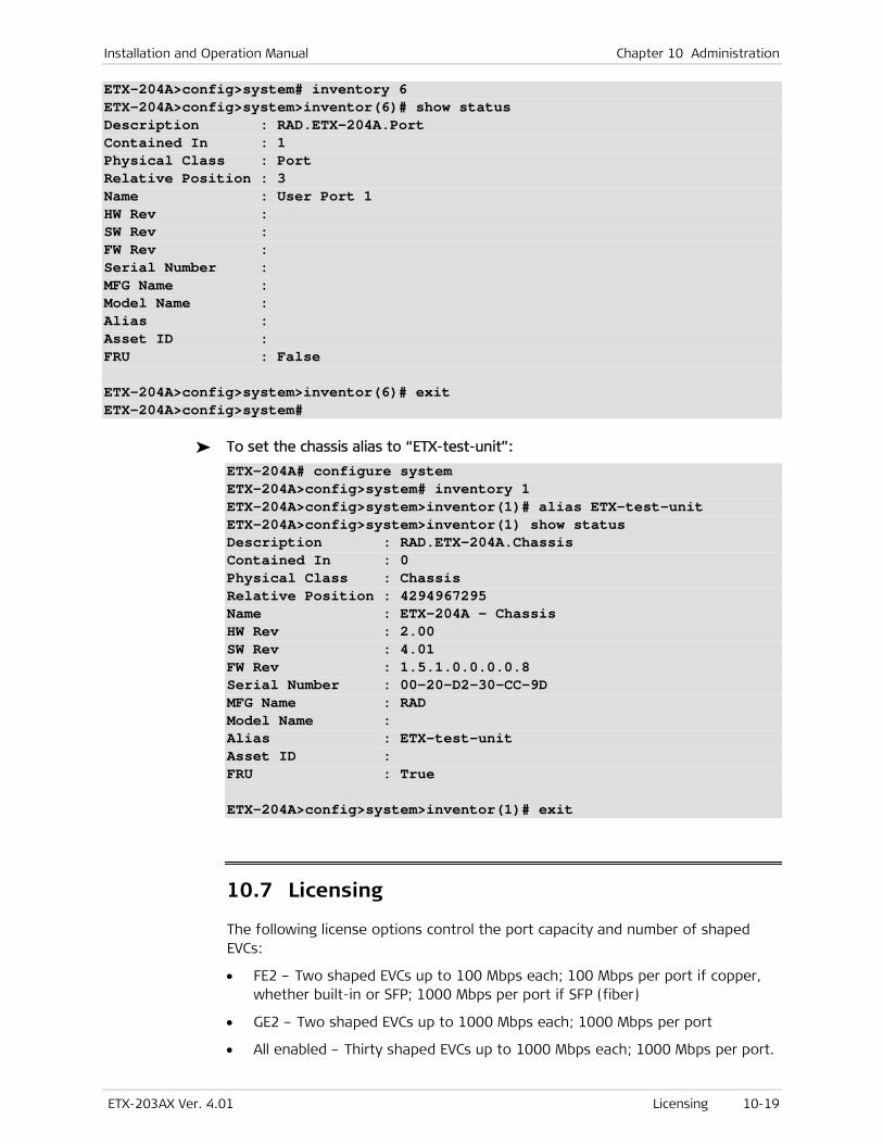
Installation and Operation Manual Chapter 10 Administration
ETX-203AX Ver. 4.01 Licensing 10-19
ETX-204A>config>system# inventory 6 ETX-204A>config>system>inventor(6)# show status Description : RAD.ETX-204A.Port Contained In : 1 Physical Class : Port Relative Position : 3 Name : User Port 1 HW Rev : SW Rev : FW Rev : Serial Number : MFG Name : Model Name : Alias : Asset ID : FRU : False ETX-204A>config>system>inventor(6)# exit ETX-204A>config>system#
To set the chassis alias to “ETX-test-unit”:
ETX-204A# configure system ETX-204A>config>system# inventory 1 ETX-204A>config>system>inventor(1)# alias ETX-test-unit ETX-204A>config>system>inventor(1) show status Description : RAD.ETX-204A.Chassis Contained In : 0 Physical Class : Chassis Relative Position : 4294967295 Name : ETX-204A - Chassis HW Rev : 2.00 SW Rev : 4.01 FW Rev : 1.5.1.0.0.0.0.8 Serial Number : 00-20-D2-30-CC-9D MFG Name : RAD Model Name : Alias : ETX-test-unit Asset ID : FRU : True ETX-204A>config>system>inventor(1)# exit
10.7 Licensing
The following license options control the port capacity and number of shaped EVCs:
• FE2 – Two shaped EVCs up to 100 Mbps each; 100 Mbps per port if copper, whether built-in or SFP; 1000 Mbps per port if SFP (fiber)
• GE2 – Two shaped EVCs up to 1000 Mbps each; 1000 Mbps per port
• All enabled – Thirty shaped EVCs up to 1000 Mbps each; 1000 Mbps per port.
Chapter 10 Administration Installation and Operation Manual
10-20 Reset ETX-203AX Ver. 4.01
You can see an indication of which license option is enabled for the installed software pack by displaying the inventory information; you can see an indication of which license option is enabled for the existing software packs by displaying the software file information.
10.8 Reset
ETX-203AX supports the following types of reset:
• Reset to factory defaults (optionally with configuration and counter reset)
• Reset to user defaults
• Overall reset (restart) of the device.
You can request that the active software pack be confirmed after the next reboot of ETX-203AX. Refer to the description of installing software in Chapter 12 for details.
Resetting to Factory Defaults
You can reset to factory defaults, or to factory defaults with configuration and counter reset.
The configuration and counter reset comprises the following:
• All files removed except factory-default-config, user-default-config, and the device software
• Parameter snmpEngineBoots initialized to 1.
To reset ETX-203AX to factory defaults:
1. At the admin# prompt enter: factory-default
A confirmation message is displayed: Current configuration will be erased and device will reboot with factory default configuration. Are you sure?? [yes/no]
2. Enter yes to confirm the reset to factory defaults.
The factory-default-config file is copied to the startup-config file. The unit resets, and after it completes its startup the factory defaults are loaded. If a startup-config confirm request was active, it is canceled.
To reset ETX-203AX to factory defaults, with configuration and counter reset:
1. At the admin# prompt enter: factory-default-all
A confirmation message is displayed: The device will delete its entire database and reboot. Are you sure? [yes/no]
Note
Installation and Operation Manual Chapter 10 Administration
ETX-203AX Ver. 4.01 Saving Configuration 10-21
2. Enter yes to confirm the reset to factory defaults with configuration and counter reset.
The configuration and counter reset explained above is performed, the unit resets, and after it completes its startup the factory defaults are loaded. If a startup-config confirm request was active, it is canceled.
Resetting to User Defaults
To reset ETX-203AX to user defaults:
1. At the admin# prompt enter: user-default
A confirmation message is displayed: Current configuration will be erased and device will reboot with user default configuration. Are you sure?? [yes/no]
2. Enter yes to confirm the reset to user defaults.
The user-default-config file is copied to the startup-config file. The unit resets, and after it completes its startup the user defaults are loaded. If a startup-config confirm request was active, it is canceled.
Restarting the Unit
If necessary, you can restart ETX-203AX without interrupting the power supply.
To restart ETX-203AX:
1. At the admin# prompt enter: reboot
A confirmation message is displayed: Device will reboot. Are you sure?? [yes/no]
2. Enter yes to confirm the reset.
The unit restarts.
10.9 Saving Configuration
You must save your configuration if you wish to have it available, as it is not saved automatically. You can save your configuration as follows:
• To save the user configuration in startup-config:
In any level prompt enter: save
At the file# prompt enter: copy running-config startup-config
Chapter 10 Administration Installation and Operation Manual
10-22 Syslog ETX-203AX Ver. 4.01
• To save the user default configuration in user-default-config, at the file# prompt enter: copy running-config user-default-config
10.10 Statistics Clearing
You can clear the statistics for Ethernet ports, flows, and OAM services.
To clear the statistics:
• At the device prompt, enter: clear-statistics
The statistics for Ethernet ports, flows, and OAM services are cleared.
10.11 Syslog
ETX-203AX uses the Syslog protocol to generate and transport event notification messages over IP networks to Syslog servers. The Syslog operation is compliant with the RFC 3164 requirements.
Configuring Syslog Parameters
To configure syslog parameters:
1. Navigate to the system context (config>system).
2. Define syslog device parameters:
a. Enter: syslog device
The system switches to the syslog device context (config>system>syslog(device))
b. Specify the module, task, or function from which syslog messages are sent:
facility {local1 | local2 | local3 | local4 | local5 | local6 | local7}
Default: local1
c. Specify the UDP port that transmits syslog messages (allowed only if syslog message transmitting is administratively disabled):
port <udp-port-number>
Allowed values: 1–65535 Default: 514
d. Specify the severity level. The log messages that contain severity level up to the specified level are transmitted:
Installation and Operation Manual Chapter 10 Administration
ETX-203AX Ver. 4.01 Syslog 10-23
severity-level {critical | major | minor | warning | event | info | debug}
e. Administratively enable the transmitting of syslog messages:
no shutdown
3. Define syslog server parameters:
a. Specify the syslog server to receive syslog messages, from 1 to 5: syslog server <server-id>
The system switches to the context of the specified syslog server (config>system>syslog(server <server-ID>)).
b. Specify the IP address of the server (allowed only if the server is administratively disabled):
address <0.0.0.0–255.255.255.255>
c. Specify the UDP port on the server that receives syslog messages (allowed only if the server is administratively disabled):
port <udp-port-number>
Allowed values: 1–65535
d. Administratively enable the server (allowed only if IP address is not 0.0.0.0):
no shutdown
e. Enter exit to exit the server context.
The system switches to the system context (config>system).
Displaying Syslog Statistics
To display syslog statistics:
1. At the system context (config>system), enter: syslog device
The system switches to the syslog device context (config>system>syslog(device))
2. Enter: show statistics
3. Syslog statistics appear as shown below. The counters are described in Table 10-20.
ETX-204A>config>system>syslog(device)# show statistics Total Tx Messages : 356 Non-queued Dropped Messages : 265
4. To clear the statistics, enter: clear-statistics
Table 10-20. Syslog Statistic Parameters
Parameter Description
Total Tx Messages The total number of syslog messages transmitted
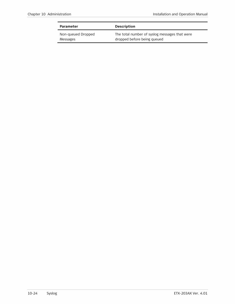
Chapter 10 Administration Installation and Operation Manual
10-24 Syslog ETX-203AX Ver. 4.01
Parameter Description
Non-queued Dropped
Messages
The total number of syslog messages that were
dropped before being queued
ETX-203AX Ver. 4.01 Detecting Problems 11-1
Chapter 11
Monitoring and Diagnostics The following are described in this chapter:
• Detecting problems
• Alarms and traps
• Performing diagnostic tests.
11.1 Detecting Problems
The LED indicators indicate errors on the hardware level.
LEDs
If an LED is red, that usually indicates there is a problem. Check the port that is associated with the LED to further investigate the problem. Refer to Chapter 3 for a description of the unit LEDs.
Alarms and Traps
Alarms serve as notification of a fault in the device, and are indicated by an entry in the alarm and event history log, and/or an SNMP trap to a management station. Refer to Handling Alarms and Events for further details on alarms, events, and traps.
Statistic Counters
Statistic counters provide information on possible abnormal behavior and failures. You can collect statistics on the following:
• Ethernet ports
• Flows
• RADIUS server
• OAM CFM.
For further information, refer to the relevant sections in Chapter 6 –10 and the relevant sections in the troubleshooting chart.
Chapter 11 Monitoring and Diagnostics Installation and Operation Manual
11-2 Handling Alarms and Events ETX-203AX Ver. 4.01
11.2 Handling Alarms and Events
An alarm is an indication of a fault in the device. An event is an occurrence in the device that may be a fault or may be a user login, change in port status, etc. Alarms and events can be written in the alarm and event history log. In addition to the history log containing alarms and events, the device maintains statistics for alarms and events in a brief log. Alarms can also be written in the active alarm table. An SNMP trap can be sent to management stations as the result of an alarm/event.
Alarms and events have the following properties:
• Source –An entity for which alarms and events can be generated. The source consists of a source ID, source type (e.g. system, fan, ethernet), and source name.
• ID – Unique numeric identification of the alarm/event
• Name – Unique alphanumeric identification of the alarm/event, up to 32 characters
• Description –Alphanumeric description that provides details on the alarm/event
• Severity (alarms only) – Critical, Major, or Minor.
Alarms and events can be masked per source type, source ID, or minimum severity. When an alarm/event is masked, it is not written to the history log, and any corresponding traps are not sent to management stations, regardless of masking in the SNMP manager configuration. When an alarm/event is not masked, any corresponding traps are sent only to management station for which the traps are not masked in the SNMP manager configuration.
Configuring Alarm and Event Properties
This section explains how to configure alarm/event properties.
To configure alarm/event properties:
1. Navigate to configure reporting.
The config>reporting# prompt is displayed.
2. Enter all necessary commands according to the tasks listed below.
Task Command Comments
Configuring alarm input alarm-input <port-number> [active {high | low |
off}] [description <description>]
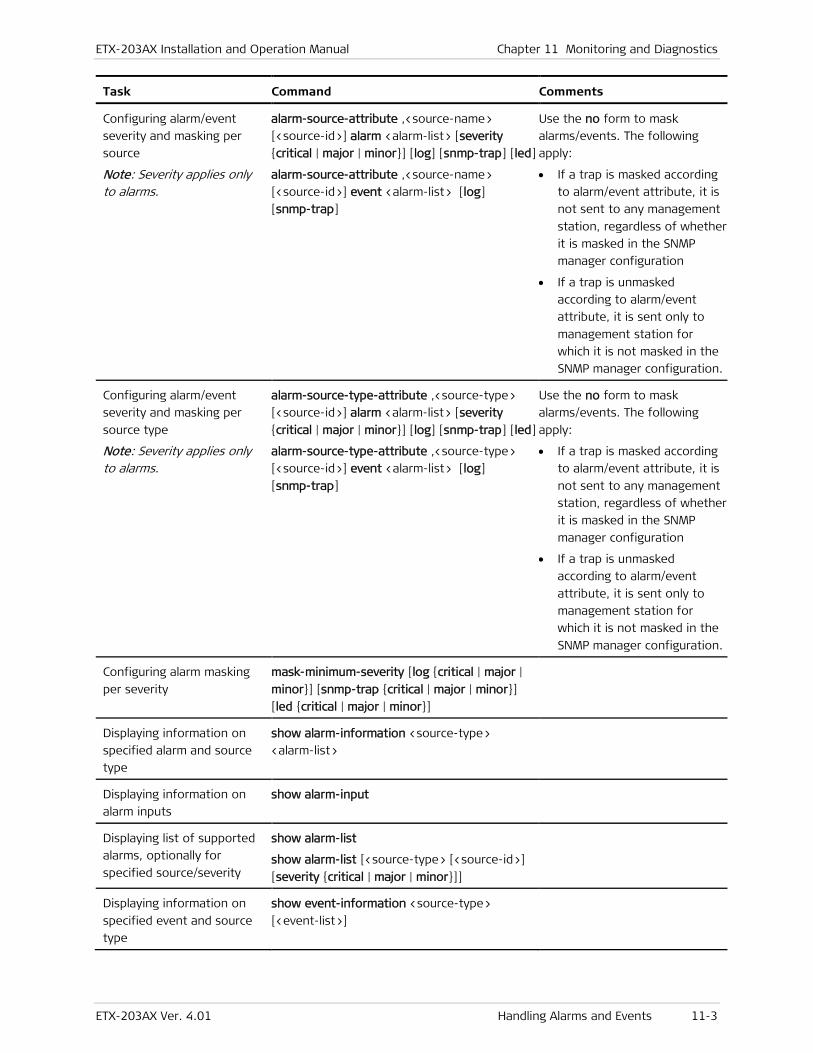
ETX-203AX Installation and Operation Manual Chapter 11 Monitoring and Diagnostics
ETX-203AX Ver. 4.01 Handling Alarms and Events 11-3
Task Command Comments
Configuring alarm/event
severity and masking per
source
Note: Severity applies only to alarms.
alarm-source-attribute ,<source-name>
[<source-id>] alarm <alarm-list> [severity
{critical | major | minor}] [log] [snmp-trap] [led]
alarm-source-attribute ,<source-name>
[<source-id>] event <alarm-list> [log]
[snmp-trap]
Use the no form to mask
alarms/events. The following
apply:
• If a trap is masked according
to alarm/event attribute, it is
not sent to any management
station, regardless of whether
it is masked in the SNMP
manager configuration
• If a trap is unmasked
according to alarm/event
attribute, it is sent only to
management station for
which it is not masked in the
SNMP manager configuration.
Configuring alarm/event
severity and masking per
source type
Note: Severity applies only to alarms.
alarm-source-type-attribute ,<source-type>
[<source-id>] alarm <alarm-list> [severity
{critical | major | minor}] [log] [snmp-trap] [led]
alarm-source-type-attribute ,<source-type>
[<source-id>] event <alarm-list> [log]
[snmp-trap]
Use the no form to mask
alarms/events. The following
apply:
• If a trap is masked according
to alarm/event attribute, it is
not sent to any management
station, regardless of whether
it is masked in the SNMP
manager configuration
• If a trap is unmasked
according to alarm/event
attribute, it is sent only to
management station for
which it is not masked in the
SNMP manager configuration.
Configuring alarm masking
per severity
mask-minimum-severity [log {critical | major |
minor}] [snmp-trap {critical | major | minor}]
[led {critical | major | minor}]
Displaying information on
specified alarm and source
type
show alarm-information <source-type>
<alarm-list>
Displaying information on
alarm inputs
show alarm-input
Displaying list of supported
alarms, optionally for
specified source/severity
show alarm-list
show alarm-list [<source-type> [<source-id>]
[severity {critical | major | minor}]]
Displaying information on
specified event and source
type
show event-information <source-type>
[<event-list>]
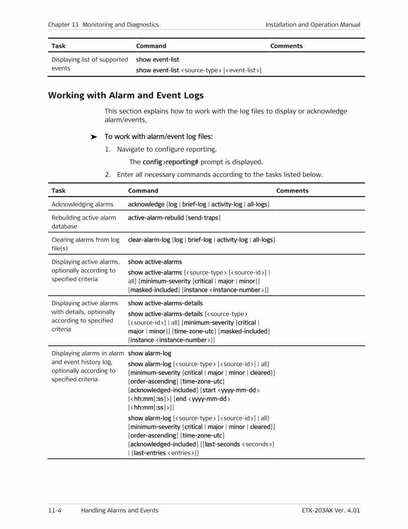
Chapter 11 Monitoring and Diagnostics Installation and Operation Manual
11-4 Handling Alarms and Events ETX-203AX Ver. 4.01
Task Command Comments
Displaying list of supported
events
show event-list
show event-list <source-type> [<event-list>]
Working with Alarm and Event Logs
This section explains how to work with the log files to display or acknowledge alarm/events,
To work with alarm/event log files:
1. Navigate to configure reporting.
The config>reporting# prompt is displayed.
2. Enter all necessary commands according to the tasks listed below.
Task Command Comments
Acknowledging alarms acknowledge {log | brief-log | activity-log | all-logs}
Rebuilding active alarm
database
active-alarm-rebuild [send-traps]
Clearing alarms from log
file(s)
clear-alarm-log {log | brief-log | activity-log | all-logs}
Displaying active alarms,
optionally according to
specified criteria
show active-alarms
show active-alarms {<source-type> [<source-id>] |
all} [minimum-severity {critical | major | minor}]
[masked-included] [instance <instance-number>]]
Displaying active alarms
with details, optionally
according to specified
criteria
show active-alarms-details
show active-alarms-details {<source-type>
[<source-id>] | all} [minimum-severity {critical |
major | minor}] [time-zone-utc] [masked-included]
[instance <instance-number>]]
Displaying alarms in alarm
and event history log,
optionally according to
specified criteria
show alarm-log
show alarm-log {<source-type> [<source-id>] | all}
[minimum-severity {critical | major | minor | cleared}]
[order-ascending] [time-zone-utc]
[acknowledged-included] [start <yyyy-mm-dd>
[<hh:mm[:ss]>] [end <yyyy-mm-dd>
[<hh:mm[:ss]>]]
show alarm-log {<source-type> [<source-id>] | all}
[minimum-severity {critical | major | minor | cleared}]
[order-ascending] [time-zone-utc]
[acknowledged-included] {[last-seconds <seconds>]
| [last-entries <entries>]}
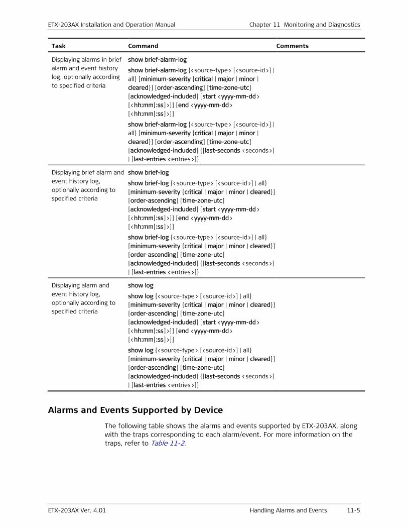
ETX-203AX Installation and Operation Manual Chapter 11 Monitoring and Diagnostics
ETX-203AX Ver. 4.01 Handling Alarms and Events 11-5
Task Command Comments
Displaying alarms in brief
alarm and event history
log, optionally according
to specified criteria
show brief-alarm-log
show brief-alarm-log {<source-type> [<source-id>] |
all} [minimum-severity {critical | major | minor |
cleared}] [order-ascending] [time-zone-utc]
[acknowledged-included] [start <yyyy-mm-dd>
[<hh:mm[:ss]>]] [end <yyyy-mm-dd>
[<hh:mm[:ss]>]]
show brief-alarm-log {<source-type> [<source-id>] |
all} [minimum-severity {critical | major | minor |
cleared}] [order-ascending] [time-zone-utc]
[acknowledged-included] {[last-seconds <seconds>]
| [last-entries <entries>]}
Displaying brief alarm and
event history log,
optionally according to
specified criteria
show brief-log
show brief-log {<source-type> [<source-id>] | all}
[minimum-severity {critical | major | minor | cleared}]
[order-ascending] [time-zone-utc]
[acknowledged-included] [start <yyyy-mm-dd>
[<hh:mm[:ss]>]] [end <yyyy-mm-dd>
[<hh:mm[:ss]>]]
show brief-log {<source-type> [<source-id>] | all}
[minimum-severity {critical | major | minor | cleared}]
[order-ascending] [time-zone-utc]
[acknowledged-included] {[last-seconds <seconds>]
| [last-entries <entries>]}
Displaying alarm and
event history log,
optionally according to
specified criteria
show log
show log {<source-type> [<source-id>] | all}
[minimum-severity {critical | major | minor | cleared}]
[order-ascending] [time-zone-utc]
[acknowledged-included] [start <yyyy-mm-dd>
[<hh:mm[:ss]>]] [end <yyyy-mm-dd>
[<hh:mm[:ss]>]]
show log {<source-type> [<source-id>] | all}
[minimum-severity {critical | major | minor | cleared}]
[order-ascending] [time-zone-utc]
[acknowledged-included] {[last-seconds <seconds>]
| [last-entries <entries>]}
Alarms and Events Supported by Device
The following table shows the alarms and events supported by ETX-203AX, along with the traps corresponding to each alarm/event. For more information on the traps, refer to Table 11-2.

Chapter 11 Monitoring and Diagnostics Installation and Operation Manual
11-6 Handling Alarms and Events ETX-203AX Ver. 4.01
Table 11-1. Alarms and Events
Name Description A=Alarm
E=Event
ID Sourc
e
Trap
device_startup Device startup due
to cold start E 1020018 system coldStart
systemDeviceStartup
user_reset System user reset) E 1020004 system systemUserReset
alternate_configuration_loaded {startup-config |
user-default-config
|
factory-default-conf
ig | rollback-config}
loaded as
running-config
E 1020005 system systemAlternateConfigLoaded
successful_login Successful login E 1020022 system systemSuccessfulLogin
failed_login Failed login E 1020023 system systemFailedLogin
logout Logout due to
inactivity E
1020024 system systemLogout
fan_failure Fan failure start or
end A
20009 fan fanFailure
power_delivery_failure Power supply <n>
failure start or end A
20201 power-
supply
powerDeliveryFailure
device_temperature_ora Device temperature
has crossed
threshold
A
20002 system systemDeviceTemperatureOra
dying_gasp Dying gasp E 1020012 system systemDyingGasp
configuration_sanity Configuration sanity
in <configuration
file>: configuration
<loaded/rejected/
loaded till first
error>
E
1020007 system systemConfigurationSanity
trap_hard_sync_start Trap
synchronization
hard sync process
started
E
1020008 system systemTrapHardSyncStart
trap_hard_sync_end Trap
synchronization
hard sync process
ended
E
1020009 system systemTrapHardSyncEnd
download_end End download E 1020003 system systemDownloadEnd
sw_install_end End software install E 1020002 system systemSoftwareInstallEnd
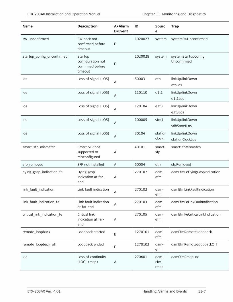
ETX-203AX Installation and Operation Manual Chapter 11 Monitoring and Diagnostics
ETX-203AX Ver. 4.01 Handling Alarms and Events 11-7
Name Description A=Alarm E=Event
ID Source
Trap
sw_unconfirmed SW pack not
confirmed before
timeout
E
1020027 system systemSwUnconfirmed
startup_config_unconfirmed Startup
configuration not
confirmed before
timeout
E
1020028 system systemStartupConfig
Unconfirmed
los Loss of signal (LOS) A
50003 eth linkUp/linkDown
ethLos
los Loss of signal (LOS) A
110110 e1t1 linkUp/linkDown
e1t1Los
los Loss of signal (LOS) A
120104 e3t3 linkUp/linkDown
e3t3Los
los Loss of signal (LOS) A
100005 stm1 linkUp/linkDown
sdhSonetLos
los Loss of signal (LOS) A
30104 station
clock
linkUp/linkDown
stationClockLos
smart_sfp_mismatch Smart SFP not
supported or
misconfigured
A
40101 smart-
sfp
smartSfpMismatch
sfp_removed SFP not installed A 50004 eth sfpRemoved
dying_gasp_indication_fe Dying gasp
indication at far-
end
A
270107 oam-
efm
oamEfmFeDyingGaspIndication
link_fault_indication Link fault indication A
270102 oam-
efm
oamEfmLinkFaultIndication
link_fault_indication_fe Link fault indication
at far-end A
270103 oam-
efm
oamEfmFeLinkFaultIndication
critical_link_indication_fe Critical link
indication at far-
end
A
270105 oam-
efm
oamEfmFeCriticalLinkIndication
remote_loopback Loopback started E
1270101 oam-
efm
oamEfmRemoteLoopback
remote_loopback_off Loopback ended E
1270102 oam-
efm
oamEfmRemoteLoopbackOff
loc Loss of continuity
(LOC) <mep> A
270601 oam-
cfm-
rmep
oamCfmRmepLoc
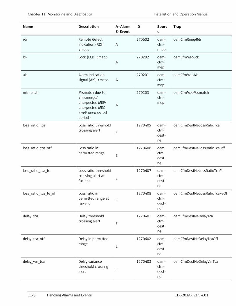
Chapter 11 Monitoring and Diagnostics Installation and Operation Manual
11-8 Handling Alarms and Events ETX-203AX Ver. 4.01
Name Description A=Alarm E=Event
ID Source
Trap
rdi Remote defect
indication (RDI)
<mep>
A
270602 oam-
cfm-
rmep
oamCfmRmepRdi
lck Lock (LCK) <mep>
A
270202 oam-
cfm-
mep
oamCfmMepLck
ais Alarm indication
signal (AIS) <mep> A
270201 oam-
cfm-
mep
oamCfmMepAis
mismatch Mismatch due to
<mismerge/
unexpected MEP/
unexpected MEG
level/ unexpected
period>
A
270203 oam-
cfm-
mep
oamCfmMepMismatch
loss_ratio_tca Loss ratio threshold
crossing alert E
1270405 oam-
cfm-
dest-
ne
oamCfmDestNeLossRatioTca
loss_ratio_tca_off Loss ratio in
permitted range E
1270406 oam-
cfm-
dest-
ne
oamCfmDestNeLossRatioTcaOff
loss_ratio_tca_fe Loss ratio threshold
crossing alert at
far-end E
1270407 oam-
cfm-
dest-
ne
oamCfmDestNeLossRatioTcaFe
loss_ratio_tca_fe_off Loss ratio in
permitted range at
far-end E
1270408 oam-
cfm-
dest-
ne
oamCfmDestNeLossRatioTcaFeOff
delay_tca Delay threshold
crossing alert E
1270401 oam-
cfm-
dest-
ne
oamCfmDestNeDelayTca
delay_tca_off Delay in permitted
range E
1270402 oam-
cfm-
dest-
ne
oamCfmDestNeDelayTcaOff
delay_var_tca Delay variance
threshold crossing
alert E
1270403 oam-
cfm-
dest-
ne
oamCfmDestNeDelayVarTca
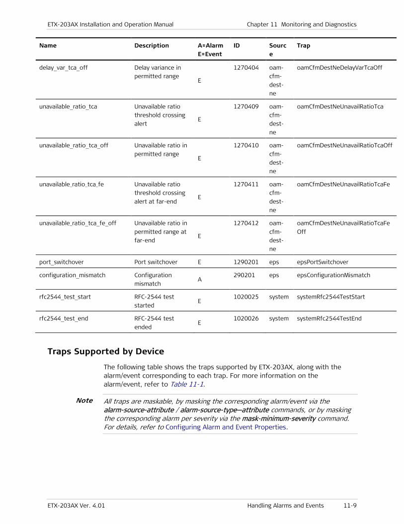
ETX-203AX Installation and Operation Manual Chapter 11 Monitoring and Diagnostics
ETX-203AX Ver. 4.01 Handling Alarms and Events 11-9
Name Description A=Alarm E=Event
ID Source
Trap
delay_var_tca_off Delay variance in
permitted range E
1270404 oam-
cfm-
dest-
ne
oamCfmDestNeDelayVarTcaOff
unavailable_ratio_tca Unavailable ratio
threshold crossing
alert E
1270409 oam-
cfm-
dest-
ne
oamCfmDestNeUnavailRatioTca
unavailable_ratio_tca_off Unavailable ratio in
permitted range E
1270410 oam-
cfm-
dest-
ne
oamCfmDestNeUnavailRatioTcaOff
unavailable_ratio_tca_fe Unavailable ratio
threshold crossing
alert at far-end E
1270411 oam-
cfm-
dest-
ne
oamCfmDestNeUnavailRatioTcaFe
unavailable_ratio_tca_fe_off Unavailable ratio in
permitted range at
far-end E
1270412 oam-
cfm-
dest-
ne
oamCfmDestNeUnavailRatioTcaFe
Off
port_switchover Port switchover E 1290201 eps epsPortSwitchover
configuration_mismatch Configuration
mismatch A
290201 eps epsConfigurationMismatch
rfc2544_test_start RFC-2544 test
started E
1020025 system systemRfc2544TestStart
rfc2544_test_end RFC-2544 test
ended E
1020026 system systemRfc2544TestEnd
Traps Supported by Device
The following table shows the traps supported by ETX-203AX, along with the alarm/event corresponding to each trap. For more information on the alarm/event, refer to Table 11-1.
All traps are maskable, by masking the corresponding alarm/event via the alarm-source-attribute / alarm-source-type—attribute commands, or by masking the corresponding alarm per severity via the mask-minimum-severity command. For details, refer to Configuring Alarm and Event Properties.
Note
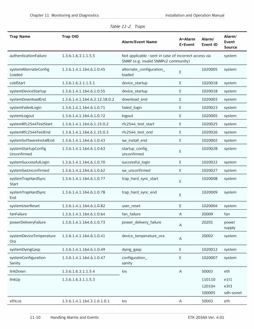
Chapter 11 Monitoring and Diagnostics Installation and Operation Manual
11-10 Handling Alarms and Events ETX-203AX Ver. 4.01
Table 11-2. Traps
Trap Name Trap OID
Alarm/Event Name A=Alarm
E=Event
Alarm/
Event ID
Alarm/
Event Source
authenticationFailure 1.3.6.1.6.3.1.1.5.5 Not applicable –sent in case of incorrect access via
SNMP (e.g. invalid SNMPv2 community)
system
systemAlternateConfig
Loaded
1.3.6.1.4.1.164.6.1.0.45 alternate_configuration_ loaded
E 1020005 system
coldStart 1.3.6.1.6.3.1.1.5.1 device_startup E 1020018 system
systemDeviceStartup 1.3.6.1.4.1.164.6.1.0.55 device_startup E 1020018 system
systemDownloadEnd 1.3.6.1.4.1.164.6.2.12.18.0.2 download_end E 1020003 system
systemFailedLogin 1.3.6.1.4.1.164.6.1.0.71 failed_login E 1020023 system
systemLogout 1.3.6.1.4.1.164.6.1.0.72 logout E 1020005 system
systemRfc2544TestStart 1.3.6.1.4.1.164.6.1.15.0.2 rfc2544_test_start E 1020025 system
systemRfc2544TestEnd 1.3.6.1.4.1.164.6.1.15.0.3 rfc2544_test_end E 1020026 system
systemSoftwareInstallEnd 1.3.6.1.4.1.164.6.1.0.43 sw_install_end E 1020002 system
systemStartupConfig
Unconfirmed
1.3.6.1.4.1.164.6.1.0.63 startup_config_ unconfirmed
E 1020028 system
systemSuccessfulLogin 1.3.6.1.4.1.164.6.1.0.70 successful_login E 1020022 system
systemSwUnconfirmed 1.3.6.1.4.1.164.6.1.0.62 sw_unconfirmed E 1020027 system
systemTrapHardSync
Start
1.3.6.1.4.1.164.6.1.0.77 trap_hard_sync_start E
1020008 system
systemTrapHardSync
End
1.3.6.1.4.1.164.6.1.0.78 trap_hard_sync_end E
1020009 system
systemUserReset 1.3.6.1.4.1.164.6.1.0.82 user_reset E 1020004 system
fanFailure 1.3.6.1.4.1.164.6.1.0.64 fan_failure A 20009 fan
powerDeliveryFailure 1.3.6.1.4.1.164.6.1.0.73 power_delivery_failure A
20201 power
supply
systemDeviceTemperature
Ora
1.3.6.1.4.1.164.6.1.0.41 device_temperature_ora A
20002 system
systemDyingGasp 1.3.6.1.4.1.164.6.1.0.49 dying_gasp E 1020012 system
systemConfiguration
Sanity
1.3.6.1.4.1.164.6.1.0.47 configuration_ sanity
E 1020007 system
linkDown 1.3.6.1.6.3.1.1.5.4 los A 50003 eth
linkUp 1.3.6.1.6.3.1.1.5.3 110110
120104
100005
e1t1
e3t3
sdh-sonet
ethLos 1.3.6.1.4.1.164.3.1.6.1.0.1 los A 50003 eth
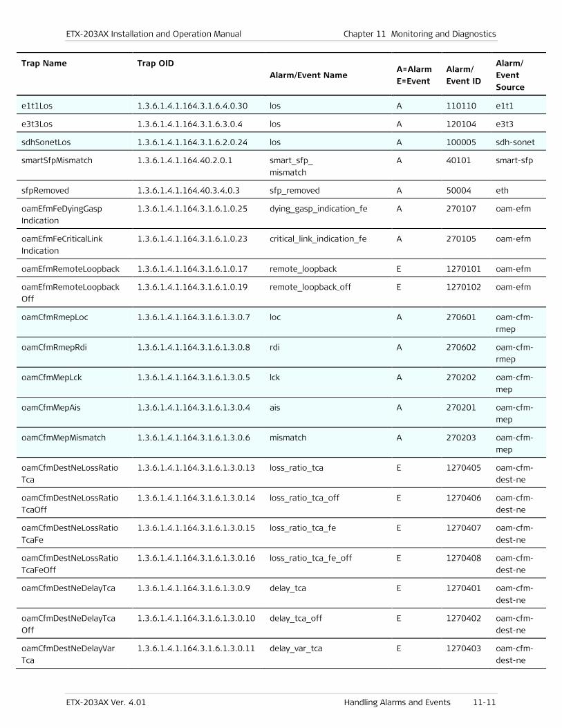
ETX-203AX Installation and Operation Manual Chapter 11 Monitoring and Diagnostics
ETX-203AX Ver. 4.01 Handling Alarms and Events 11-11
Trap Name Trap OID Alarm/Event Name
A=Alarm E=Event
Alarm/ Event ID
Alarm/ Event
Source
e1t1Los 1.3.6.1.4.1.164.3.1.6.4.0.30 los A 110110 e1t1
e3t3Los 1.3.6.1.4.1.164.3.1.6.3.0.4 los A 120104 e3t3
sdhSonetLos 1.3.6.1.4.1.164.3.1.6.2.0.24 los A 100005 sdh-sonet
smartSfpMismatch 1.3.6.1.4.1.164.40.2.0.1 smart_sfp_ mismatch
A 40101 smart-sfp
sfpRemoved 1.3.6.1.4.1.164.40.3.4.0.3 sfp_removed A 50004 eth
oamEfmFeDyingGasp
Indication
1.3.6.1.4.1.164.3.1.6.1.0.25 dying_gasp_indication_fe A 270107 oam-efm
oamEfmFeCriticalLink
Indication
1.3.6.1.4.1.164.3.1.6.1.0.23 critical_link_indication_fe A 270105 oam-efm
oamEfmRemoteLoopback 1.3.6.1.4.1.164.3.1.6.1.0.17 remote_loopback E 1270101 oam-efm
oamEfmRemoteLoopback
Off
1.3.6.1.4.1.164.3.1.6.1.0.19 remote_loopback_off E 1270102 oam-efm
oamCfmRmepLoc 1.3.6.1.4.1.164.3.1.6.1.3.0.7 loc A 270601 oam-cfm-
rmep
oamCfmRmepRdi 1.3.6.1.4.1.164.3.1.6.1.3.0.8 rdi A 270602 oam-cfm-
rmep
oamCfmMepLck 1.3.6.1.4.1.164.3.1.6.1.3.0.5 lck A 270202 oam-cfm-
mep
oamCfmMepAis 1.3.6.1.4.1.164.3.1.6.1.3.0.4 ais A 270201 oam-cfm-
mep
oamCfmMepMismatch 1.3.6.1.4.1.164.3.1.6.1.3.0.6 mismatch A 270203 oam-cfm-
mep
oamCfmDestNeLossRatio
Tca
1.3.6.1.4.1.164.3.1.6.1.3.0.13 loss_ratio_tca E 1270405 oam-cfm-
dest-ne
oamCfmDestNeLossRatio
TcaOff
1.3.6.1.4.1.164.3.1.6.1.3.0.14 loss_ratio_tca_off E 1270406 oam-cfm-
dest-ne
oamCfmDestNeLossRatio
TcaFe
1.3.6.1.4.1.164.3.1.6.1.3.0.15 loss_ratio_tca_fe E 1270407 oam-cfm-
dest-ne
oamCfmDestNeLossRatio
TcaFeOff
1.3.6.1.4.1.164.3.1.6.1.3.0.16 loss_ratio_tca_fe_off E 1270408 oam-cfm-
dest-ne
oamCfmDestNeDelayTca 1.3.6.1.4.1.164.3.1.6.1.3.0.9 delay_tca E 1270401 oam-cfm-
dest-ne
oamCfmDestNeDelayTca
Off
1.3.6.1.4.1.164.3.1.6.1.3.0.10 delay_tca_off E 1270402 oam-cfm-
dest-ne
oamCfmDestNeDelayVar
Tca
1.3.6.1.4.1.164.3.1.6.1.3.0.11 delay_var_tca E 1270403 oam-cfm-
dest-ne
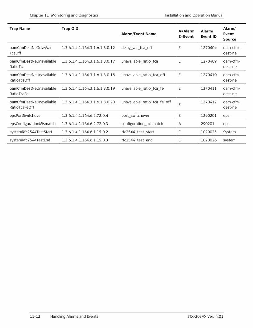
Chapter 11 Monitoring and Diagnostics Installation and Operation Manual
11-12 Handling Alarms and Events ETX-203AX Ver. 4.01
Trap Name Trap OID Alarm/Event Name
A=Alarm E=Event
Alarm/ Event ID
Alarm/ Event
Source
oamCfmDestNeDelayVar
TcaOff
1.3.6.1.4.1.164.3.1.6.1.3.0.12 delay_var_tca_off E 1270404 oam-cfm-
dest-ne
oamCfmDestNeUnavailable
RatioTca
1.3.6.1.4.1.164.3.1.6.1.3.0.17 unavailable_ratio_tca E 1270409 oam-cfm-
dest-ne
oamCfmDestNeUnavailable
RatioTcaOff
1.3.6.1.4.1.164.3.1.6.1.3.0.18 unavailable_ratio_tca_off E 1270410 oam-cfm-
dest-ne
oamCfmDestNeUnavailable
RatioTcaFe
1.3.6.1.4.1.164.3.1.6.1.3.0.19 unavailable_ratio_tca_fe E 1270411 oam-cfm-
dest-ne
oamCfmDestNeUnavailable
RatioTcaFeOff
1.3.6.1.4.1.164.3.1.6.1.3.0.20 unavailable_ratio_tca_fe_off E
1270412 oam-cfm-
dest-ne
epsPortSwitchover 1.3.6.1.4.1.164.6.2.72.0.4 port_switchover E 1290201 eps
epsConfigurationMismatch 1.3.6.1.4.1.164.6.2.72.0.3 configuration_mismatch A 290201 eps
systemRfc2544TestStart 1.3.6.1.4.1.164.6.1.15.0.2 rfc2544_test_start E 1020025 System
systemRfc2544TestEnd 1.3.6.1.4.1.164.6.1.15.0.3 rfc2544_test_end E 1020026 system
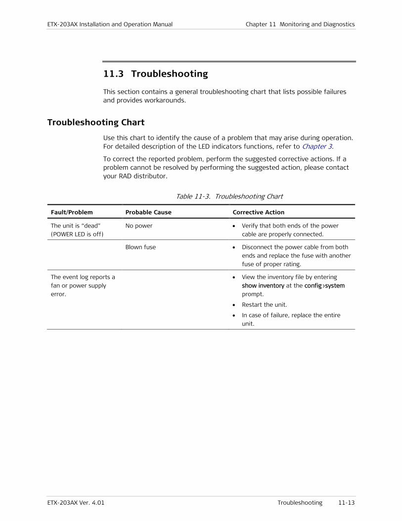
ETX-203AX Installation and Operation Manual Chapter 11 Monitoring and Diagnostics
ETX-203AX Ver. 4.01 Troubleshooting 11-13
11.3 Troubleshooting
This section contains a general troubleshooting chart that lists possible failures and provides workarounds.
Troubleshooting Chart
Use this chart to identify the cause of a problem that may arise during operation. For detailed description of the LED indicators functions, refer to Chapter 3.
To correct the reported problem, perform the suggested corrective actions. If a problem cannot be resolved by performing the suggested action, please contact your RAD distributor.
Table 11-3. Troubleshooting Chart
Fault/Problem Probable Cause Corrective Action
The unit is “dead”
(POWER LED is off)
No power • Verify that both ends of the power
cable are properly connected.
Blown fuse • Disconnect the power cable from both
ends and replace the fuse with another
fuse of proper rating.
The event log reports a
fan or power supply
error.
• View the inventory file by entering
show inventory at the config>system
prompt.
• Restart the unit.
• In case of failure, replace the entire
unit.
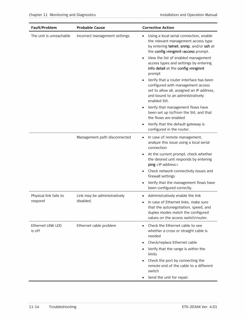
Chapter 11 Monitoring and Diagnostics Installation and Operation Manual
11-14 Troubleshooting ETX-203AX Ver. 4.01
Fault/Problem Probable Cause Corrective Action
The unit is unreachable Incorrect management settings • Using a local serial connection, enable
the relevant management access type
by entering telnet, snmp, and/or ssh at
the config>mngmnt>access prompt.
• View the list of enabled management
access types and settings by entering
info detail at the config>mngmnt
prompt
• Verify that a router interface has been
configured with management access
set to allow all, assigned an IP address,
and bound to an administratively
enabled SVI.
• Verify that management flows have
been set up to/from the SVI, and that
the flows are enabled
• Verify that the default gateway is
configured in the router.
Management path disconnected • In case of remote management,
analyze this issue using a local serial
connection
• At the current prompt, check whether
the desired unit responds by entering
ping <IP address>
• Check network connectivity issues and
firewall settings
• Verify that the management flows have
been configured correctly.
Physical link fails to
respond
Link may be administratively
disabled.
• Administratively enable the link
• In case of Ethernet links, make sure
that the autonegotiation, speed, and
duplex modes match the configured
values on the access switch/router.
Ethernet LINK LED
is off
Ethernet cable problem • Check the Ethernet cable to see
whether a cross or straight cable is
needed
• Check/replace Ethernet cable
• Verify that the range is within the
limits
• Check the port by connecting the
remote end of the cable to a different
switch
• Send the unit for repair.
ETX-203AX Installation and Operation Manual Chapter 11 Monitoring and Diagnostics
ETX-203AX Ver. 4.01 Performing Diagnostic Tests 11-15
11.4 Performing Diagnostic Tests
This section describes general diagnostic tests and RFC-2544 testing. For information on testing ports, refer to Chapter 6. For information on testing flows and OAM CFM, refer to Chapter 8.
RFC-2544 Testing
You can perform BERT testing based on RFC-2544:
• Throughput test – Detect the maximum frame rate without lost frames
• Packet loss – Detect the point at which frame loss does not occur
• Latency – Determine average frame roundtrip time.
You can run the RFC-2544 tests up to 1 GbE at a time.
Standards
RFC-2544, Benchmarking Methodology for Carrier Ethernet Networks
Benefits
You can evaluate the performance of network devices to provide performance metrics of the Ethernet network and validate the SLA.
Functional Description
RFC-2544 testing uses OAM CFM messages such as Loopback (LB), Loss Measurements (LM), and Delay Measurements (DM) frames. Therefore, end-to-end OAM CFM is necessary for the testing. User data can’t be transmitted via associated OAM service data/flows while an RFC-2544 test is running.
In a bidirectional throughput test, the local ETX-203AX generates LBM + data TLV messages towards the far-end device, which responds with LBR messages. The local ETX-203AX calculates the round trip throughput.
In a unidirectional throughput test, the local ETX-203AX generates 1DM messages towards the far-end device, which verifies the frames and calculates unidirectional throughput. The convergence algorithm is based on a binary search using LMM and LMR messages.
The packet loss test is performed as follows for all selected frame sizes:
• Transmit x frames at a rate of 100% throughput
• Calculate frame loss with the formula: (tx - rx) / 100 * tx
• Decrease rate by 10% and repeat the test until two trials result in no frame loss.
The latency test is performed as follows:
• Transmit DMM frames at a rate of throughput for 10 seconds
• Calculate the latency using DMM and DMR frames that are transmitted after 5 seconds
Note

Chapter 11 Monitoring and Diagnostics Installation and Operation Manual
11-16 Performing Diagnostic Tests ETX-203AX Ver. 4.01
• The test result is the average of the number of iterations per frame size (up to 5 minutes per frame size)
• Applicable for round-trip mode.
Factory Defaults
By default, no profiles or tests are defined.
When you create a test profile, it is configured by default as shown below.
ETX-203AX# config test rfc2544 ETX-203AX>config>test>rfc2544# profile-name Testprf ETX-203AX>config>test>rfc2544>profile-nam(Testprf)$ inf d frame-size 64 pattern all-ones tlv-type data test-direction bidirectional frames-number-in-attempt 200000 frame-loss-tolerance 20 throughput-measurement-accuracy 100000 number-of-trials 1 no learning-frames ETX-203AX>config>test>rfc2544>profile-nam(Testprf)$
When you create a test, it is configured by default as shown below.
ETX-203AX# config test rfc2544 ETX-203AX>config>test>rfc2544# test 1 ETX-203AX>config>test>rfc2544>test(1)$ inf d no bind max-rate 0 convention data-rate compensation 0 type throughput no max-test-duration no associated-flow ETX-203AX>config>test>rfc2544>test(1)$
Performing Tests
In order to perform RFC-2544 tests, you must configure:
• Bidirectional data flows that are administratively enabled. If one of the flows is associated with the test, its egress port and queue block must be identical to the associated port and queue block of the MEP to which the test is bound
• MEP and Destination NE
• RFC-2544 profile – Template to create test runs. You can configure up to eight test profiles.
• RFC-2544 test – Associated with RFC-2544 profile. Up to eight tests can use the same test profile. In one RFC-2544 test, you can perform one or more of the three test types.
Up to eight RFC-2544 tests can run concurrently.
Note
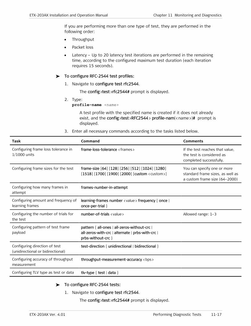
ETX-203AX Installation and Operation Manual Chapter 11 Monitoring and Diagnostics
ETX-203AX Ver. 4.01 Performing Diagnostic Tests 11-17
If you are performing more than one type of test, they are performed in the following order:
• Throughput
• Packet loss
• Latency – Up to 20 latency test iterations are performed in the remaining time, according to the configured maximum test duration (each iteration requires 15 seconds).
To configure RFC-2544 test profiles:
1. Navigate to configure test rfc2544.
The config>test>rfc2544# prompt is displayed.
2. Type: profile-name <name>
A test profile with the specified name is created if it does not already exist, and the config>test>RFC2544> profile-nam(<name>)# prompt is displayed.
3. Enter all necessary commands according to the tasks listed below.
Task Command Comments
Configuring frame loss tolerance in
1/1000 units frame-loss-tolerance <frames> If the test reaches that value,
the test is considered as
completed successfully.
Configuring frame sizes for the test frame-size [64] [128] [256] [512] [1024] [1280]
[1518] [1700] [1900] [2000] [custom <custom>]
You can specify one or more
standard frame sizes, as well as
a custom frame size (64–2000)
Configuring how many frames in
attempt frames-number-in-attempt
Configuring amount and frequency of
learning frames learning-frames number <value> frequency { once |
once-per-trial }
Configuring the number of trials for
the test number-of-trials <value> Allowed range: 1–3
Configuring pattern of test frame
payload pattern { all-ones | all-zeros-without-crc |
all-zeros-with-crc | alternate | prbs-with-crc |
prbs-without-crc }
Configuring direction of test
(unidirectional or bidirectional) test-direction { unidirectional | bidirectional }
Configuring accuracy of throughput
measurement throughput-measurement-accuracy <bps>
Configuring TLV type as test or data tlv-type { test | data }
To configure RFC-2544 tests:
1. Navigate to configure test rfc2544.
The config>test>rfc2544# prompt is displayed.
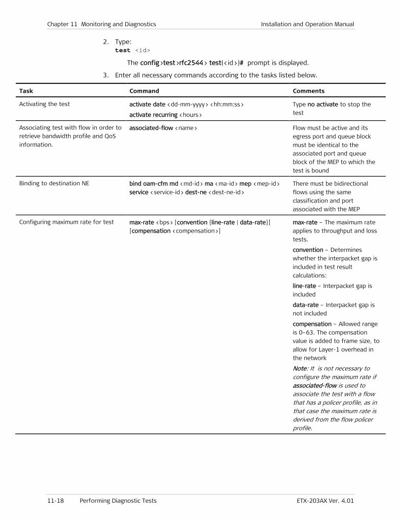
Chapter 11 Monitoring and Diagnostics Installation and Operation Manual
11-18 Performing Diagnostic Tests ETX-203AX Ver. 4.01
2. Type: test <id>
The config>test>rfc2544> test(<id>)# prompt is displayed.
3. Enter all necessary commands according to the tasks listed below.
Task Command Comments
Activating the test activate date <dd-mm-yyyy> <hh:mm:ss>
activate recurring <hours>
Type no activate to stop the
test
Associating test with flow in order to
retrieve bandwidth profile and QoS
information.
associated-flow <name> Flow must be active and its
egress port and queue block
must be identical to the
associated port and queue
block of the MEP to which the
test is bound
Binding to destination NE bind oam-cfm md <md-id> ma <ma-id> mep <mep-id>
service <service-id> dest-ne <dest-ne-id>
There must be bidirectional
flows using the same
classification and port
associated with the MEP
Configuring maximum rate for test max-rate <bps> [convention {line-rate | data-rate}]
[compensation <compensation>]
max-rate – The maximum rate
applies to throughput and loss
tests.
convention – Determines
whether the interpacket gap is
included in test result
calculations:
line-rate – Interpacket gap is
included
data-rate – Interpacket gap is
not included
compensation – Allowed range
is 0–63. The compensation
value is added to frame size, to
allow for Layer-1 overhead in
the network
Note: It is not necessary to configure the maximum rate if associated-flow is used to associate the test with a flow that has a policer profile, as in that case the maximum rate is derived from the flow policer profile.
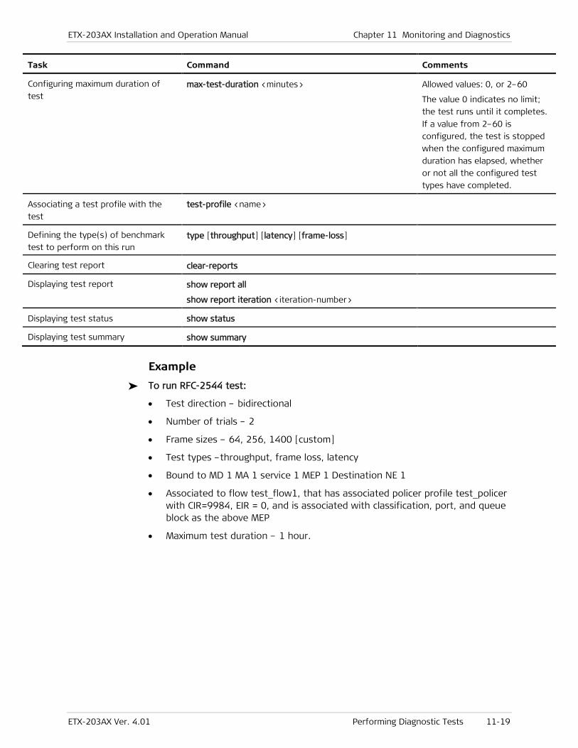
ETX-203AX Installation and Operation Manual Chapter 11 Monitoring and Diagnostics
ETX-203AX Ver. 4.01 Performing Diagnostic Tests 11-19
Task Command Comments
Configuring maximum duration of
test max-test-duration <minutes> Allowed values: 0, or 2–60
The value 0 indicates no limit;
the test runs until it completes.
If a value from 2–60 is
configured, the test is stopped
when the configured maximum
duration has elapsed, whether
or not all the configured test
types have completed.
Associating a test profile with the
test test-profile <name>
Defining the type(s) of benchmark
test to perform on this run type [throughput] [latency] [frame-loss]
Clearing test report clear-reports
Displaying test report show report all
show report iteration <iteration-number>
Displaying test status show status
Displaying test summary show summary
Example
To run RFC-2544 test:
• Test direction – bidirectional
• Number of trials – 2
• Frame sizes – 64, 256, 1400 [custom]
• Test types –throughput, frame loss, latency
• Bound to MD 1 MA 1 service 1 MEP 1 Destination NE 1
• Associated to flow test_flow1, that has associated policer profile test_policer with CIR=9984, EIR = 0, and is associated with classification, port, and queue block as the above MEP
• Maximum test duration – 1 hour.

Chapter 11 Monitoring and Diagnostics Installation and Operation Manual
11-20 Performing Diagnostic Tests ETX-203AX Ver. 4.01
ETX-203AX# configure test rfc2544 ETX-203AX>config>test>rfc2544# profile-name p1 ETX-203AX>config>test>rfc2544>profile-nam(p1)$ ETX-203AX>config>test>rfc2544>profile-nam(p1)$ frame-size 64 256 custom 1400 ETX-203AX>config>test>rfc2544>profile-nam(p1)$ pattern all-ones ETX-203AX>config>test>rfc2544>profile-nam(p1)$ tlv-type data ETX-203AX>config>test>rfc2544>profile-nam(p1)$ test-direction bidirectional ETX-203AX>config>test>rfc2544>profile-nam(p1)$ frames-number-in-attempt 5000 ETX-203AX>config>test>rfc2544>profile-nam(p1)$ frame-loss-tolerance 10 ETX-203AX>config>test>rfc2544>profile-nam(p1)$ number-of-trials 2 ETX-203AX>config>test>rfc2544>profile-nam(p1)$ no learning-frames ETX-203AX>config>test>rfc2544>profile-nam(p1)$ exit ETX-203AX>config>test>rfc2544# test 1 ETX-203AX>config>test>rfc2544>test(1)$ test-profile p1 ETX-203AX>config>test>rfc2544>test(1)$ type throughput latency frame-loss ETX-203AX>config>test>rfc2544>test(1)$ bind oam-cfm md 1 ma 1 mep 1 service 1 dest-ne 1 ETX-203AX>config>test>rfc2544>test(1)$ associated-flow test_flow1 ETX-203AX>config>test>rfc2544>test(1)$ max-test-duration 60 ETX-203AX>config>test>rfc2544>test(1)$ activate ETX-203AX>config>test>rfc2544>test(1)$ show status Activity Status : In Progress Elapsed Time <dd:hh:mm:ss> : <00:00:15:24> ETX-203AX>config>test>rfc2544>test(1)$ show status Activity Status : Completed ETX-203AX>config>test>rfc2544>test(1)$ show summary Iteration Start Start Duration Duration Date Time Days Time ----------------------------------------------------------------------------- 1 08-01-2012 11:31:43 0 <00:38:25> ETX-203AX>config>test>rfc2544>test(1)$ show report all Test ID : 1 Iteration Number : 1 Date & Time : 08-01-2012 11:31:43 Profile Name : p1 Number of Trials : 2 Duration <dd:hh:mm:ss> : <00:00:38:25> Test Parameters ----------------------------------------------------------------------------- Bind: MD : 1 MA : 1 MEP : 1 P-Bit : 0 VLAN : 200 Max Rate (bps) : 1000000000 Convention : Data Rate Compensation : 0 Frames in Burst : 200000 Pattern : All Ones Frame Type : Data Search Resolution : 1 Tolerance : 5 Learning Frames: : 0 Frequency : Direction : Bidirectional
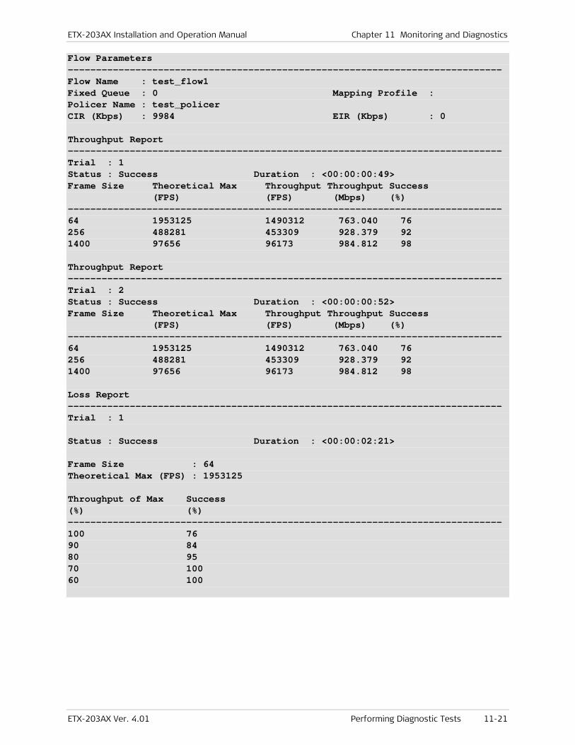
ETX-203AX Installation and Operation Manual Chapter 11 Monitoring and Diagnostics
ETX-203AX Ver. 4.01 Performing Diagnostic Tests 11-21
Flow Parameters ----------------------------------------------------------------------------- Flow Name : test_flow1 Fixed Queue : 0 Mapping Profile : Policer Name : test_policer CIR (Kbps) : 9984 EIR (Kbps) : 0 Throughput Report ----------------------------------------------------------------------------- Trial : 1 Status : Success Duration : <00:00:00:49> Frame Size Theoretical Max Throughput Throughput Success (FPS) (FPS) (Mbps) (%) ----------------------------------------------------------------------------- 64 1953125 1490312 763.040 76 256 488281 453309 928.379 92 1400 97656 96173 984.812 98 Throughput Report ----------------------------------------------------------------------------- Trial : 2 Status : Success Duration : <00:00:00:52> Frame Size Theoretical Max Throughput Throughput Success (FPS) (FPS) (Mbps) (%) ----------------------------------------------------------------------------- 64 1953125 1490312 763.040 76 256 488281 453309 928.379 92 1400 97656 96173 984.812 98 Loss Report ----------------------------------------------------------------------------- Trial : 1 Status : Success Duration : <00:00:02:21> Frame Size : 64 Theoretical Max (FPS) : 1953125 Throughput of Max Success (%) (%) ----------------------------------------------------------------------------- 100 76 90 84 80 95 70 100 60 100
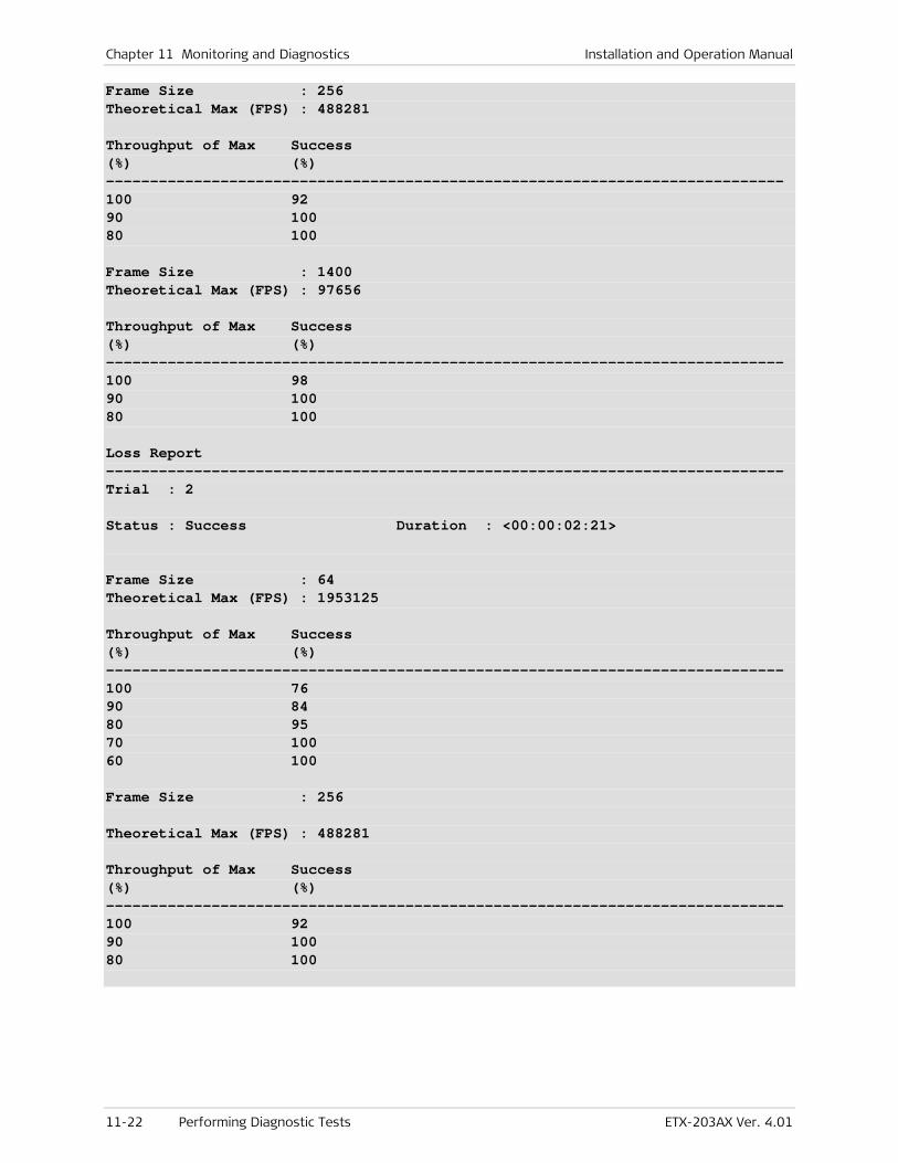
Chapter 11 Monitoring and Diagnostics Installation and Operation Manual
11-22 Performing Diagnostic Tests ETX-203AX Ver. 4.01
Frame Size : 256 Theoretical Max (FPS) : 488281 Throughput of Max Success (%) (%) ----------------------------------------------------------------------------- 100 92 90 100 80 100 Frame Size : 1400 Theoretical Max (FPS) : 97656 Throughput of Max Success (%) (%) ----------------------------------------------------------------------------- 100 98 90 100 80 100 Loss Report ----------------------------------------------------------------------------- Trial : 2 Status : Success Duration : <00:00:02:21> Frame Size : 64 Theoretical Max (FPS) : 1953125 Throughput of Max Success (%) (%) ----------------------------------------------------------------------------- 100 76 90 84 80 95 70 100 60 100 Frame Size : 256 Theoretical Max (FPS) : 488281 Throughput of Max Success (%) (%) ----------------------------------------------------------------------------- 100 92 90 100 80 100
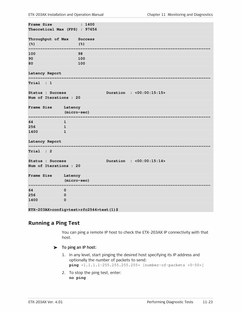
ETX-203AX Installation and Operation Manual Chapter 11 Monitoring and Diagnostics
ETX-203AX Ver. 4.01 Performing Diagnostic Tests 11-23
Frame Size : 1400 Theoretical Max (FPS) : 97656 Throughput of Max Success (%) (%) ----------------------------------------------------------------------------- 100 98 90 100 80 100 Latency Report ----------------------------------------------------------------------------- Trial : 1 Status : Success Duration : <00:00:15:15> Num of Iterations : 20 Frame Size Latency (micro-sec) ----------------------------------------------------------------------------- 64 1 256 1 1400 1 Latency Report ----------------------------------------------------------------------------- Trial : 2 Status : Success Duration : <00:00:15:14> Num of Iterations : 20 Frame Size Latency (micro-sec) ----------------------------------------------------------------------------- 64 0 256 0 1400 0 ETX-203AX>config>test>rfc2544>test(1)$
Running a Ping Test
You can ping a remote IP host to check the ETX-203AX IP connectivity with that host.
To ping an IP host:
1. In any level, start pinging the desired host specifying its IP address and optionally the number of packets to send: ping <1.1.1.1–255.255.255.255> [number-of-packets <0–50>]
2. To stop the ping test, enter: no ping
Chapter 11 Monitoring and Diagnostics Installation and Operation Manual
11-24 Performing Diagnostic Tests ETX-203AX Ver. 4.01
Tracing the Route
This diagnostic utility traces the route through the network from ETX-203AX to the destination host. The trace route utility supports up to 30 hops.
To trace a route:
• In any level, start the trace route and specify the IP address of the host to which you intend to trace route: trace-route <1.1.1.1–255.255.255.255>

ETX-203AX Installation and Operation Manual Chapter 11 Monitoring and Diagnostics
ETX-203AX Ver. 4.01 Technical Support 11-25
11.5 Frequently Asked Questions
Q How should ETX-203AX be configured for management?
A You need to configure a router interface for management by assigning it an IP address, and binding it to an SVI for which management flows have been configured. Additionally, you need to configure the default gateway address in the router. Refer to the Quick Start Guide for an example of configuring ETX-203AX for management.
Q If I change the second Ethernet port from network to user, what happens to the associated flows?
A When you change the functional mode, all flows related to the port are deleted.
11.6 Technical Support
Technical support for this product can be obtained from the local partner from whom it was purchased.
RADcare Global Professional Services offers a wide variety of service, support and training options, including expert consulting and troubleshooting assistance, online tools, regular training programs, and various equipment coverage options.
For further information, please contact the RAD partner nearest you or one of RAD's offices worldwide.
RAD Data Communications would like your help in improving its product documentation. Please send us an e-mail with your comments.
Thank you for your assistance!

Chapter 11 Monitoring and Diagnostics Installation and Operation Manual
11-26 Technical Support ETX-203AX Ver. 4.01
ETX-203AX Ver. 4.01 Prerequisites 12-1
Chapter 12
Software Upgrade This chapter explains how to upgrade ETX-203AX for software version 4.01.
Software upgrade is required to fix product limitations, enable new features, or to make the unit compatible with other devices that are already running the new software version.
The device can store up to four software images, referred to as software packs and named sw-pack-1 through sw-pack-4. You can designate any of the software packs as active. The non-active software packs serve as backups that can be used if the active software becomes corrupted.
The information in this chapter includes the following:
• Detailed conditions required for the upgrade
• Any impact the upgrade may have on the system
• Description of downloading options.
12.1 Software Upgrade Options
Application software can be downloaded to ETX-203AX via SFTP/TFTP with the file copy command, or via XMODEM, FTP, or TFTP, using the boot menu.
The downloaded software pack can be installed as the active software via the admin software install command, or by using the boot menu.
12.2 Prerequisites
Before starting the upgrade, verify that you have the following:
• For upgrade via SFTP/FTP/TFTP:
Operational ETX-203AX unit with valid IP parameters configured
Connection to a PC with an SFTP/FTP/TFTP server application and a valid IP address
Software image file stored on the PC. The image file (and exact name) can be obtained from the local RAD business partner from whom the device was purchased.
• For upgrade via XMODEM:
Operational ETX-203AX unit
Connection to a PC via a terminal emulation program
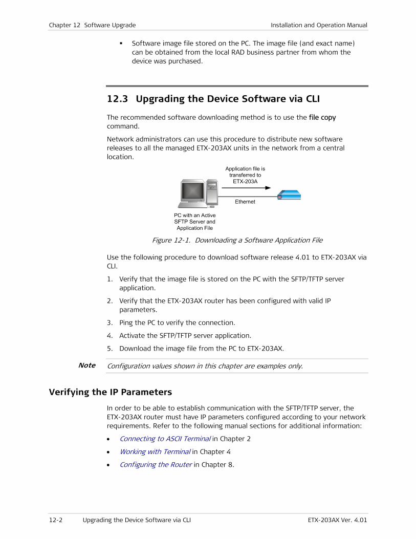
Chapter 12 Software Upgrade Installation and Operation Manual
12-2 Upgrading the Device Software via CLI ETX-203AX Ver. 4.01
Software image file stored on the PC. The image file (and exact name) can be obtained from the local RAD business partner from whom the device was purchased.
12.3 Upgrading the Device Software via CLI
The recommended software downloading method is to use the file copy command.
Network administrators can use this procedure to distribute new software releases to all the managed ETX-203AX units in the network from a central location.
Figure 12-1. Downloading a Software Application File
Use the following procedure to download software release 4.01 to ETX-203AX via CLI.
1. Verify that the image file is stored on the PC with the SFTP/TFTP server application.
2. Verify that the ETX-203AX router has been configured with valid IP parameters.
3. Ping the PC to verify the connection.
4. Activate the SFTP/TFTP server application.
5. Download the image file from the PC to ETX-203AX.
Configuration values shown in this chapter are examples only.
Verifying the IP Parameters
In order to be able to establish communication with the SFTP/TFTP server, the ETX-203AX router must have IP parameters configured according to your network requirements. Refer to the following manual sections for additional information:
• Connecting to ASCII Terminal in Chapter 2
• Working with Terminal in Chapter 4
• Configuring the Router in Chapter 8.
Note

Installation and Operation Manual Chapter 12 Software Upgrade
ETX-203AX Ver. 4.01 Upgrading the Device Software via CLI 12-3
Pinging the PC
Check the integrity of the communication link between ETX-203AX and the PC by pinging the PC from ETX-203AX.
To ping the PC:
1. In any level, start pinging the PC specifying its IP address and optionally the number of packets to send:
ping <ip-address> [number-of-packets <num-packets>]
A reply from the PC indicates a proper communication link.
2. If the ping request times out, check the link between ETX-203AX and the PC (physical path, configuration parameters, etc.)
Activating the SFTP Server
Once the SFTP server is activated on the PC, it waits for any SFTP file transfer request originating from the product, and carries out the received request automatically.
SFTP file transfers are carried out through TCP port 22. Make sure that the firewall you are using on the server allows communication through this port (refer to Chapter 10 for details).
Activating the TFTP Server
Once the TFTP server is activated on the PC, it waits for any TFTP file transfer request originating from the product, and carries out the received request automatically.
TFTP file transfers are carried out through port 69. Make sure that the firewall you are using on the server allows communication through this port (refer to Chapter 10 for details).
Configure the connection timeout of the TFTP server to be more than 30 seconds to prevent an automatic disconnection during the backup partition deletion (about 25 seconds).
Downloading the Software
This procedure is used to download the new software release.
To copy the image file to the ETX-203AX unit:
1. Navigate to the file context.
2. Enter:
copy sftp://<username>:<password>@<ip-address>/<image-file-name> <sw-pack-n>
Note
Chapter 12 Software Upgrade Installation and Operation Manual
12-4 Upgrading the Device Software via CLI ETX-203AX Ver. 4.01
Where <ip-address> is the IP address of the PC where the SFTP server is installed, and <n> is the index of the desired software pack, from 1 to 4.
Or
copy tftp://<tftp-ip-address>/<image-file-name> <sw-pack-n>
Where tftp-ip-address is the IP address of the PC where the TFTP server is installed, and <n> is the index of the desired software pack, from 1 to 4.
Choose an index that is not being used by the active software, or by a software pack that you do not want to overwrite.
The software download is performed. Refer to Installing Software for instructions on installing the downloaded software as the active software.
Installing Software
After software is downloaded to ETX-203AX, it has to be installed via the install command as the active software. When you install software, by default ETX-203AX creates a restore point, so that if there is a problem with the new software pack, you can perform a rollback to the previous software pack.
The file startup-config must exist before you can install software with creation of a restore point.
You can request (via command software-confirm-required) that the next installed software be confirmed after the next reboot. When you execute the request, then the next time ETX-203AX reboots and loads the new software, you must confirm the software (via command software-confirm) within the configured timeout period. If the confirmation is not received before timeout, ETX-203AX automatically falls back to its previous software.
To request software confirmation:
• At the admin>software# prompt, enter: software-confirm-required [time-to-confirm <minutes>] The confirmation timeout can be from five minutes to 24 hours. If you do not specify it, the default is five minutes.
You can cancel the software confirmation request by entering no software-confirm-required.
Next time ETX-203AX reboots and loads new software, it starts a confirmation timer. Refer to the next procedure for more details on the confirmation.
To install a software pack as active:
If startup-config does not exist, you must install the software pack without creating a restore point.
Note
Note
Note
Note
Installation and Operation Manual Chapter 12 Software Upgrade
ETX-203AX Ver. 4.01 Upgrading the Device Software via CLI 12-5
1. At the admin>software# prompt, enter: install <filename> [no-restore-point] The parameter <filename> can be any of the non-active software packs (sw-pack-1 through sw-pack-4). If you specify no-restore-point, then after the software is installed, it is not possible to rollback to the previous software.
You are prompted to confirm the operation.
!Device will install file and reboot. Are you sure? [yes/no] _
2. Type yes to confirm.
If a restore point is being created, then startup-config is copied to restore-point-config. ETX-203AX designates the specified software pack as active, then reboots.
3. If a software confirmation request is active, ETX-203AX starts a timer with the specified timeout period.
While the confirmation timer is running, ETX-203AX does not allow any commands that change its configuration.
4. If the software-confirm command is entered before the timer expires, the software is considered to be confirmed.
5. If the software-confirm command is not entered before the timer expires, then restore-point-config is deleted, ETX-203AX designates the previously active software pack as active, then reboots.
Restoring Previous Active Software
If the installed software malfunctions and was installed with a restore point, you can perform rollback to the previous active software.
To rollback to the previous active software pack:
1. At the admin>software# prompt, enter: undo-install
You are prompted to confirm the operation.
! Falling back to restore point ! Are you sure? [yes/no] _
2. Type yes to confirm.
The file restore-point-config is renamed to startup-config. ETX-203AX designates the previously active software pack as active, then reboots.
Note

Chapter 12 Software Upgrade Installation and Operation Manual
12-6 Upgrading the Device Software via the Boot Menu ETX-203AX Ver. 4.01
12.4 Upgrading the Device Software via the Boot Menu
Software downloading can also be performed using the Boot menu. The Boot menu can be reached while ETX-203AX performs initialization, for example, after power-up.
You may need to start the loading from the Boot menu if you are unable to use the file copy command (for example, because the ETX-203AX software has not yet been downloaded or is corrupted).
The Boot menu procedures are recommended only for use by authorized personnel, because this menu provides many additional options that are intended for use only by technical support personnel.
The following software downloading options are available from the Boot menu:
• Downloading using the XMODEM protocol. This is usually performed by downloading from a PC directly connected to the CONTROL DCE port of the unit.
Figure 12-2. Downloading a Software Application File via XMODEM
• Downloading using FTP/TFTP. This is usually performed by downloading from a remote location that provides an IP communication path to an Ethernet port of ETX-203AX.
Accessing the Boot Menu
The boot menu can be accessed when the device is powered up, before logging in.
To access the Boot menu:
1. Configure the communication parameters of the selected PC serial port for asynchronous communication with 9,600 bps, no parity, one start bit, eight data bits and one stop bit. Turn all types of flow control off.
2. Turn off ETX-203AX.
3. Activate the terminal application.
4. Turn on ETX-203AX and immediately start pressing the <Enter> key several times in sequence until you see the prompt to press any key to stop the autoboot.
5. Press any key.
Caution

Installation and Operation Manual Chapter 12 Software Upgrade
ETX-203AX Ver. 4.01 Upgrading the Device Software via the Boot Menu 12-7
The boot screen appears. A typical boot screen is shown below (the exact version and date displayed by your ETX-203AX unit may be different). You can type ? to display the available commands.
If you miss the timing, ETX-203AX performs a regular reboot process (this process starts with Loading and ends with the login screen).
System Boot Copyright 1984-2008 RAD Data Communications, Ltd. Boot version: 1.04 [05-May-11] CPU : Freescale MPC8313E OS version : VxWorks 6.7 BSP version: 1.15 Boot-Manager version: 2.13 [11-Jan-11] Use '?'/help to view available commands Press any key to stop auto-boot... 7 [boot]:
Figure 12-3. Boot Menu
[boot]: ? Commands: ?/help - print this list p - print boot parameters c [param] - change boot parameter(s) v - print boot logo with versions information run - load active sw pack and execute delete <FileName> - delete a file dir - show list of files show <index> - show sw pack info download <index> [,<FileName|x>] - download a sw pack to specific index (x - by Xmodem) set-active <index> - Set a sw pack index to be the active application control-x/reset - reboot/reset
Figure 12-4. Displaying Boot Commands
Using the XMODEM Protocol
Use the following procedure to download software release 4.01 to ETX-203AX via XMODEM.
Note
Chapter 12 Software Upgrade Installation and Operation Manual
12-8 Upgrading the Device Software via the Boot Menu ETX-203AX Ver. 4.01
To download software release via XMODEM:
1. Verify that the image file is stored on the PC with the terminal application.
2. At the boot prompt, enter: download <index>, x Where <index> can be 1–4 and corresponds to the desired software pack number.
Choose an index that is not being used by the active software, or by a software pack that you do not want to overwrite.
The process starts, and the following is displayed:
The terminal will become disabled !!! Please send the file in XMODEM
3. Start the transfer in accordance with the program you are using. For example, if you are using the Windows HyperTerminal utility:
Select Transfer in the HyperTerminal menu bar, and then select Send File on the Transfer menu.
The Send File window is displayed:
Select the prescribed ETX-203AX software file name (you may use the Browse function to find it).
In the Protocol field, select Xmodem.
When ready, press Send in the Send File window.
You can now monitor the progress of the downloading in the Send File window.
If downloading fails, repeat the whole procedure.
When the downloading process has successfully completed, a sequence of messages similar to the following is displayed:
File writing to flash: - 4030KB File downloaded successfully to :3
4. Refer to Activating Software for instructions on activating the downloaded software.
Using FTP
Use the following procedure to download software release 4.01 to ETX-203AX via FTP.
To download software release via FTP:
1. At the boot prompt, use the c command to configure the FTP parameters as needed.
2. At the boot prompt, enter: download <index>,sw-pack-<index>
Note
Note

Installation and Operation Manual Chapter 12 Software Upgrade
ETX-203AX Ver. 4.01 Upgrading the Device Software via the Boot Menu 12-9
Where <index> can be 1–4 and corresponds to the desired software pack number.
Choose an index that is not being used by a software pack that you do not want to overwrite.
If no errors are detected, the downloading process starts, and the file is downloaded via FTP.
3. Refer to Activating Software for instructions on activating the downloaded software.
Using TFTP
Use the following procedure to download software release 4.01 to ETX-203AX via TFTP.
To download software release via TFTP:
1. At the boot prompt, use the c command to configure the TFTP parameters as needed.
2. At the boot prompt, enter: download <index>,sw-pack-<index> Where <index> can be 1–4 and corresponds to the desired software pack number.
Choose an index that is not being used by a software pack that you do not want to overwrite.
If no errors are detected, the downloading process starts, and the file is downloaded via TFTP.
3. Refer to Activating Software for instructions on activating the downloaded software.
Activating Software
To activate a software pack, you need to designate it as active and load it.
To activate a software pack:
1. To set the software as active, enter: set-active <index>.
A confirmation similar to the following is displayed:
SW set active 3 completed successfully.
2. To load the active software, type: run.
A sequence of messages similar to the following is displayed:
Loading/un-compressing sw-pack-3... Starting the APPLICATION off address 0x10000...
After a few more seconds, the login prompt is displayed.
Note
Note
Chapter 12 Software Upgrade Installation and Operation Manual
12-10 Verifying Upgrade Results ETX-203AX Ver. 4.01
12.5 Verifying Upgrade Results
To verify that the upgrade was successful, log on to ETX-203AX via a terminal emulation program to view the Inventory table (show inventory-table at prompt config>system#), and verify the active software version in the SW Rev column.
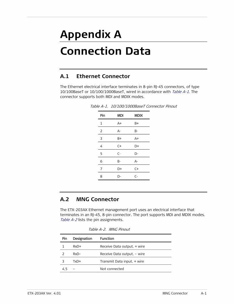
ETX-203AX Ver. 4.01 MNG Connector A-1
Appendix A
Connection Data
A.1 Ethernet Connector
The Ethernet electrical interface terminates in 8-pin RJ-45 connectors, of type 10/100BaseT or 10/100/1000BaseT, wired in accordance with Table A-1. The connector supports both MDI and MDIX modes.
Table A-1. 10/100/1000BaseT Connector Pinout
Pin MDI MDIX
1 A+ B+
2 A- B-
3 B+ A+
4 C+ D+
5 C- D-
6 B- A-
7 D+ C+
8 D- C-
A.2 MNG Connector
The ETX-203AX Ethernet management port uses an electrical interface that terminates in an RJ-45, 8-pin connector. The port supports MDI and MDIX modes. Table A-2 lists the pin assignments.
Table A-2. MNG Pinout
Pin Designation Function
1 RxD+ Receive Data output, + wire
2 RxD– Receive Data output, – wire
3 TxD+ Transmit Data input, + wire
4,5 – Not connected
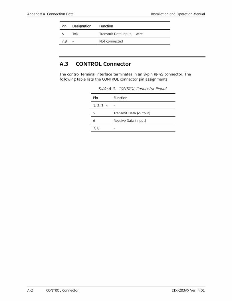
Appendix A Connection Data Installation and Operation Manual
A-2 CONTROL Connector ETX-203AX Ver. 4.01
Pin Designation Function
6 TxD- Transmit Data input, – wire
7,8 – Not connected
A.3 CONTROL Connector
The control terminal interface terminates in an 8-pin RJ-45 connector. The following table lists the CONTROL connector pin assignments.
Table A-3. CONTROL Connector Pinout
Pin Function
1, 2, 3, 4 –
5 Transmit Data (output)
6 Receive Data (input)
7, 8 –
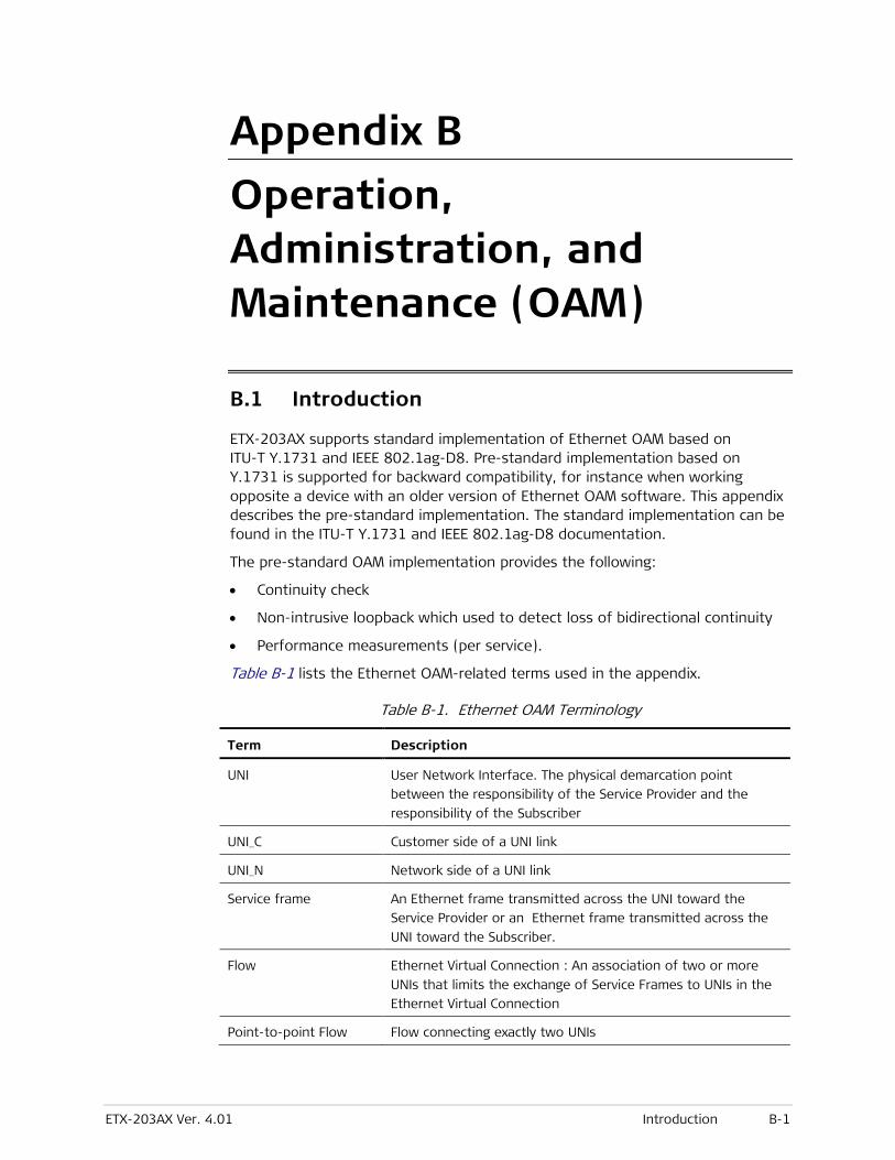
ETX-203AX Ver. 4.01 Introduction B-1
Appendix B
Operation, Administration, and Maintenance (OAM)
B.1 Introduction
ETX-203AX supports standard implementation of Ethernet OAM based on ITU-T Y.1731 and IEEE 802.1ag-D8. Pre-standard implementation based on Y.1731 is supported for backward compatibility, for instance when working opposite a device with an older version of Ethernet OAM software. This appendix describes the pre-standard implementation. The standard implementation can be found in the ITU-T Y.1731 and IEEE 802.1ag-D8 documentation.
The pre-standard OAM implementation provides the following:
• Continuity check
• Non-intrusive loopback which used to detect loss of bidirectional continuity
• Performance measurements (per service).
Table B-1 lists the Ethernet OAM-related terms used in the appendix.
Table B-1. Ethernet OAM Terminology
Term Description
UNI User Network Interface. The physical demarcation point
between the responsibility of the Service Provider and the
responsibility of the Subscriber
UNI_C Customer side of a UNI link
UNI_N Network side of a UNI link
Service frame An Ethernet frame transmitted across the UNI toward the
Service Provider or an Ethernet frame transmitted across the
UNI toward the Subscriber.
Flow Ethernet Virtual Connection : An association of two or more
UNIs that limits the exchange of Service Frames to UNIs in the
Ethernet Virtual Connection
Point-to-point Flow Flow connecting exactly two UNIs
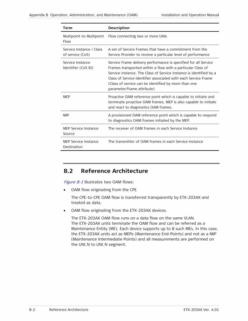
Appendix B Operation, Administration, and Maintenance (OAM) Installation and Operation Manual
B-2 Reference Architecture ETX-203AX Ver. 4.01
Term Description
Multipoint-to-Multipoint
Flow
Flow connecting two or more UNIs
Service Instance / Class
of service (CoS)
A set of Service Frames that have a commitment from the
Service Provider to receive a particular level of performance
Service Instance
Identifier (CoS ID)
Service Frame delivery performance is specified for all Service
Frames transported within a flow with a particular Class of
Service instance. The Class of Service instance is identified by a
Class of Service Identifier associated with each Service Frame
(Class of service can be identified by more than one
parameter/frame attribute)
MEP Proactive OAM reference point which is capable to initiate and
terminate proactive OAM frames. MEP is also capable to initiate
and react to diagnostics OAM frames.
MIP A provisioned OAM reference point which is capable to respond
to diagnostics OAM frames initiated by the MEP.
MEP Service Instance
Source
The receiver of OAM frames in each Service Instance
MEP Service Instance
Destination
The transmitter of OAM frames in each Service Instance
B.2 Reference Architecture
Figure B-1 illustrates two OAM flows:
• OAM flow originating from the CPE
The CPE-to-CPE OAM flow is transferred transparently by ETX-203AX and treated as data.
• OAM flow originating from the ETX-203AX devices.
The ETX-203AX OAM flow runs on a data flow on the same VLAN. The ETX-203AX units terminate the OAM flow and can be referred as a Maintenance Entity (ME). Each device supports up to 8 such MEs. In this case, the ETX-203AX units act as MEPs (Maintenance End-Points) and not as a MIP (Maintenance Intermediate Points) and all measurements are performed on the UNI_N to UNI_N segment.
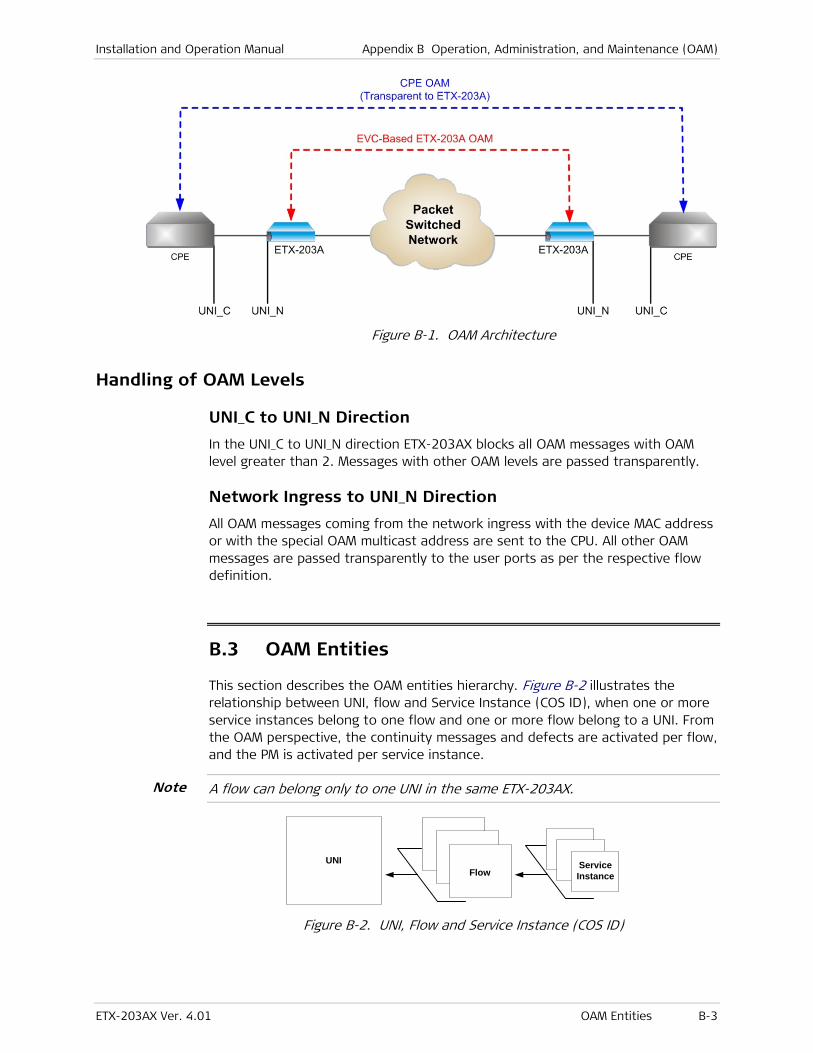
Installation and Operation Manual Appendix B Operation, Administration, and Maintenance (OAM)
ETX-203AX Ver. 4.01 OAM Entities B-3
Figure B-1. OAM Architecture
Handling of OAM Levels
UNI_C to UNI_N Direction
In the UNI_C to UNI_N direction ETX-203AX blocks all OAM messages with OAM level greater than 2. Messages with other OAM levels are passed transparently.
Network Ingress to UNI_N Direction
All OAM messages coming from the network ingress with the device MAC address or with the special OAM multicast address are sent to the CPU. All other OAM messages are passed transparently to the user ports as per the respective flow definition.
B.3 OAM Entities
This section describes the OAM entities hierarchy. Figure B-2 illustrates the relationship between UNI, flow and Service Instance (COS ID), when one or more service instances belong to one flow and one or more flow belong to a UNI. From the OAM perspective, the continuity messages and defects are activated per flow, and the PM is activated per service instance.
A flow can belong only to one UNI in the same ETX-203AX.
UNIFlow
ServiceInstance
Figure B-2. UNI, Flow and Service Instance (COS ID)
Note
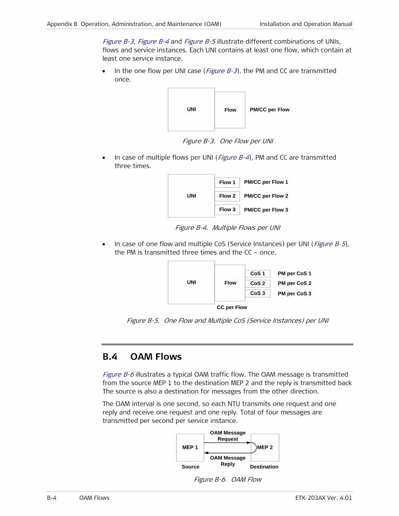
Appendix B Operation, Administration, and Maintenance (OAM) Installation and Operation Manual
B-4 OAM Flows ETX-203AX Ver. 4.01
Figure B-3, Figure B-4 and Figure B-5 illustrate different combinations of UNIs, flows and service instances. Each UNI contains at least one flow, which contain at least one service instance.
• In the one flow per UNI case (Figure B-3), the PM and CC are transmitted once.
UNI Flow PM/CC per Flow
Figure B-3. One Flow per UNI
• In case of multiple flows per UNI (Figure B-4), PM and CC are transmitted three times.
UNI
PM/CC per Flow 1
Flow 2
Flow 1
Flow 3
PM/CC per Flow 2
PM/CC per Flow 3
Figure B-4. Multiple Flows per UNI
• In case of one flow and multiple CoS (Service Instances) per UNI (Figure B-5), the PM is transmitted three times and the CC – once.
UNI Flow
CC per Flow
CoS 1
CoS 2
CoS 3
PM per CoS 1
PM per CoS 2
PM per CoS 3
Figure B-5. One Flow and Multiple CoS (Service Instances) per UNI
B.4 OAM Flows
Figure B-6 illustrates a typical OAM traffic flow. The OAM message is transmitted from the source MEP 1 to the destination MEP 2 and the reply is transmitted back The source is also a destination for messages from the other direction.
The OAM interval is one second, so each NTU transmits one request and one reply and receive one request and one reply. Total of four messages are transmitted per second per service instance.
MEP 1 MEP 2
Source Destination
OAM MessageRequest
OAM MessageReply
Figure B-6. OAM Flow
Installation and Operation Manual Appendix B Operation, Administration, and Maintenance (OAM)
ETX-203AX Ver. 4.01 OAM Flows B-5
OAM Message Addressing
The OAM defines two modes of addressing, unicast and multicast. Unicast addressing is used for point-to-point connections, while multicast addressing is used in cases where the MAC address of the destination MEP is not known. Currently ETX-203AX supports point-to-point flows in proprietary mode.
OAM Message Association
On the receiver side the OAM frame is associated with a flow and a service.
Flow Association
When an OAM frame is associated with a flow, the following steps are performed:
• Request message reception
When a request message is received, the VLAN is extracted to find the Flow ID. The Flow ID found at the receiver is compared against the Flow ID in the frame. If the IDs are equal, further service association is made. If it is not found, the “Flow ID no match” notification is returned in the reply message.
• Reply message reception
When a reply message is received, the VLAN is extracted to find the Flow ID. The Flow ID found at the receiver is compared against the Flow ID in the frame. If the IDs are equal, further service association is made. If it is not found, the frame is discarded and connectivity alarm is issued.
Service Association
When an OAM frame is associated with a service, the following steps are performed:
• Request message reception
The class of service characteristics are extracted from the frame and must be matched to an entry in the flows <-> services table at the receiver. If they are matched, the frame is processed. If not, the service ID is returned with the “Not Found” notification.
• Reply message reception
The class of service characteristics are extracted from the frame and must be matched to an entry in the flow <-> services table at the receiver. If they are matched, the frame is processed. If not, the frame is discarded.
Ethernet Loopback (ETH-LB)
The ETH-LB can be used to verify connectivity. The ETH-LB is performed by sending a request ETH-LB message to the remote unit and expecting an ETH-LB reply message back to verify connectivity. When the insertion rate of ETH-LB messages is much slower compared to data rate between the flow points.
Unicast ETH-LB request message is sent from a MEP to a specific MEP (remote device). The DA of the request message is a unicast MAC address of destination device. Upon receipt of the request message, the MEP responds with unicast ETH-

Appendix B Operation, Administration, and Maintenance (OAM) Installation and Operation Manual
B-6 OAM Flows ETX-203AX Ver. 4.01
LB reply message. The DA of the reply message is a unicast MAC address of requesting device, learned from request message.
Continuity Check (ETH-CC)
Ethernet Continuity Check (ETH-CC) can be used to detect continuity failures across flows between a given pair of edge service point on a flow. Continuity failures are caused by:
• Major failures (link failure, device failure, network path failure etc)
• Minor failures (software failure, memory corruption, incorrect configuration etc).
The ETH-CC signal is generated by one MEP. Upon receipt of the first ETH-CC signal from a sending MEP, the receiving MEP detects continuity with sending MEP and expects to receive further periodic ETH-CC signals. Once the receiving MEP stops receiving periodic ETH-CC signals from sending MEP, it declares continuity failure.
OAM Procedures
This section discusses the continuity check (CC) and the performance measurement (PM) procedures.
Continuity Check Procedure
The loopback message and the ETH-CC messages are used for continuity check. In case the services are defined and PM collection is enabled, they are also used to carry PM messages. If PM collection is disabled, the messages are used for continuity check only.
If the RX CC mode of the receiver is configured to CC-based, the continuity detection is based on ETH-CC. If the mode is set to LB-based, the continuity detection is based on ETH-LB. If the mode is disabled, the continuity detection is not performed.
ETH-LB Method
The ETH-LB method includes the following elements:
• Unicast ETH-LB transmission
Unicast ETH-LB request message is transmitted by a MEP (ETX-203AX) every 1 second. The transmitted Transaction Identifier is retained for at least 5 seconds after the unicast ETH-LB signal is transmitted. The Transaction Identifier must be changed for every unicast ETH-LB message, and no Transaction Identifier from the same MEP is allowed to be repeated within 1 minute.
• Unicast ETH-LB reception and reply transmission
Whenever a valid unicast ETH-LB request message is received by MEP (ETX-203AX), a unicast ETH-LB reply message is generated and transmitted to the requesting MEP. Every field in the unicast ETH-LB request message is copied to the unicast ETH-LB reply message with the following exceptions:
Installation and Operation Manual Appendix B Operation, Administration, and Maintenance (OAM)
ETX-203AX Ver. 4.01 OAM Flows B-7
The source and destination MAC addresses are swapped.
The OpCode field is vendor-specific 0xFE.
The Flow and MEP ID are processed as follows: if the Flow/MEP ID do not exist in the device, it changes them to “No Match” otherwise they are left intact.
• Unicast ETH-LB reply receipt
When a unicast ETH-LB reply message is received by a MEP (ETX-203AX) diagnostic flow termination function, it examines the TLVs returned in the unicast ETH-LB reply message. The signal is declared invalid if the TLVs do not match those sent in the corresponding unicast ETH-LB request signal, including MEP ID and Flow ID.
• Continuity declarations
Loss of Continuity and Connectivity Mismatch states are declared by the ETH-LB mechanism.
Loss of continuity declaration
After the source device sends an ETH-LB message a timer is set with a 3.52 second timeout. If the destination device does send reply within the timeout, the source enters the loss of continuity state. Upon reply from the destination, the source resets the timer to 3.52 seconds. Regarding the continuity check message, the source checks only the Flow ID with the MEP ID. When the source enters the loss of continuity state, it adds 24 to Unavailable Seconds counter. The 3.52 second period is calculated as a sliding window.
Loss of continuity state is cleared after 3.52 seconds with at least 21 reply messages from the destination. In this case the Unavailable Seconds counter decreased by 24.
Connectivity mismatch declaration
If the source Flow ID is not equal to the destination Flow ID as recorded in the reply message for 10 consecutive times, the source enters in to misconnection state.
Misconnection state is cleared after 10 consecutive reply messages with the correct flow name from the destination.
The Unavailable counter is maintained by the service according to the number of PM messages that did not receive replies. If a mismatch notification is received to the LB request, the frame is dropped and reply message is not sent. This is why the service becomes unavailable (no reply) in case of mismatch and the unavailable counter is raised.
ETH-CC Method
The ETH-CC method includes the following elements:
• ETH-CC transmission
Unicast ETH-CC request message is transmitted by a MEP (ETX-203AX) every 1 second. The transmitted Transaction Identifier is retained for at least 5 seconds after the unicast ETH-CC signal is transmitted. The Transaction Identifier must be changed for every Unicast ETH-CC message, and no

Appendix B Operation, Administration, and Maintenance (OAM) Installation and Operation Manual
B-8 OAM Flows ETX-203AX Ver. 4.01
Transaction Identifier from the same MEP is allowed to be repeated within 1 minute.
• Unicast ETH-CC reply receipt
When a unicast ETH-CC message is received by a MEP (ETX-203AX) diagnostic flow termination function, it examines the TLVs returned in the unicast ETH-CC message, and declares the signal invalid if the TLVs do not match those sent in the corresponding exiting MEP ID and Flow ID.
• Continuity declarations
Loss of Continuity and Connectivity Mismatch states are declared by the ETH-CC mechanism.
Loss of continuity declaration
When the MEP receives the ETH-CC message a timer is set with a 3.5 seconds timeout. If the source does send another message during this period, the destination enters the loss of continuity state. Upon receipt of the ETH-CC message, the destination resets the timer to 3.5 seconds. Regarding the continuity check message, the destination check the Flow ID and the MEP ID. When the destination enters the loss of continuity state, it adds 4 to the Unavailable Seconds counter. The 3.5 second period is calculated as a sliding window.
Loss of continuity state is cleared after 3.5 seconds with at least 2 messages from the source. In this case the Unavailable Seconds counter is decreased by 4.
Connectivity mismatch declaration
If the source Flow ID is not equal to the destination Flow ID for 10 consecutive times, the destination enters in to misconnection state.
Misconnection state is cleared after 10 consecutive reply messages with the correct flow name from the source.
The Unavailable counter is maintained by the service according to the number of PM messages that did not receive replies. If a mismatch notification is received to the LB request, the frame is dropped and reply message is not sent. This is why the service becomes unavailable (no reply) in case of mismatch and the unavailable counter is raised.
Performance Measurement
For details on OAM statistic counters, refer to Chapter 8.
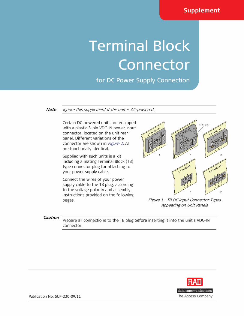
Publication No. SUP-220-09/11
The Access Company
Terminal BlockConnector
for DC Power Supply Connection
Supplement
5
Ignore this supplement if the unit is AC-powered.
Certain DC-powered units are equipped with a plastic 3-pin VDC-IN power input connector, located on the unit rear panel. Different variations of the connector are shown in 0Figure 1. All are functionally identical.
Supplied with such units is a kit including a mating Terminal Block (TB) type connector plug for attaching to your power supply cable.
Connect the wires of your power supply cable to the TB plug, according to the voltage polarity and assembly instructions provided on the following pages.
Figure 1. TB DC Input Connector Types Appearing on Unit Panels
Prepare all connections to the TB plug before inserting it into the unit’s VDC-IN connector.
Caution
Note
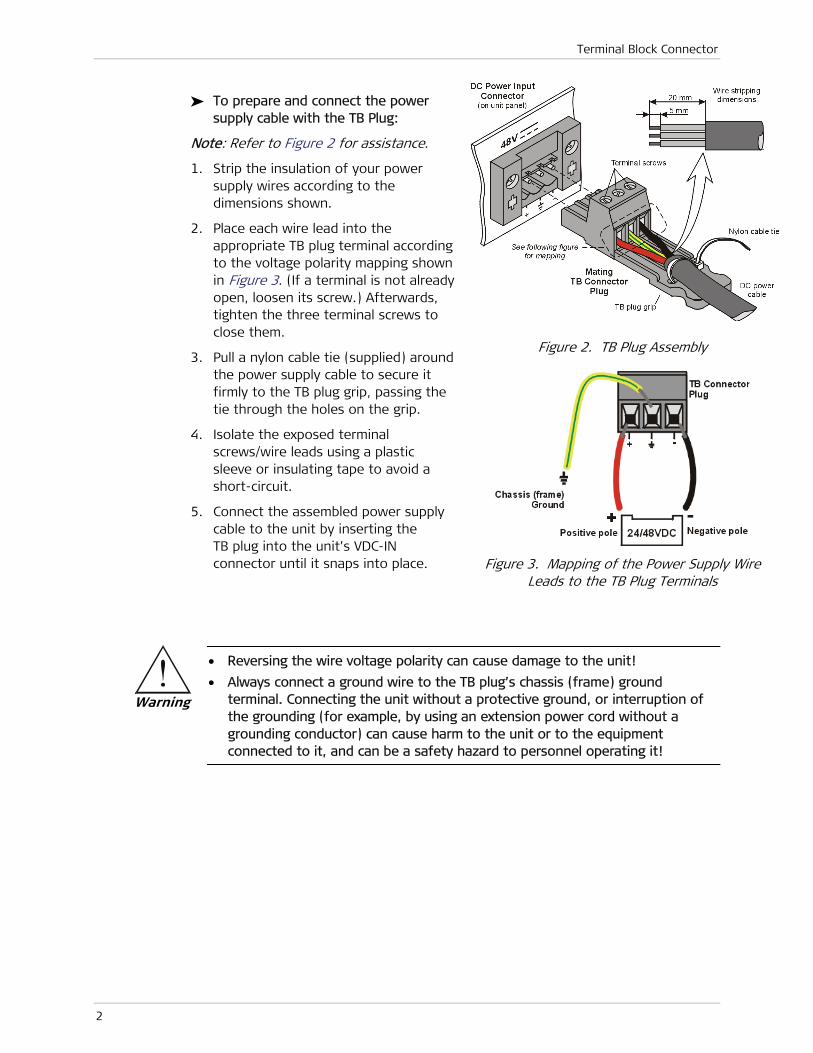
Terminal Block Connector
2
To prepare and connect the power supply cable with the TB Plug:
Note: Refer to 1Figure 2 for assistance.
1. Strip the insulation of your power supply wires according to the dimensions shown.
2. Place each wire lead into the appropriate TB plug terminal according to the voltage polarity mapping shown in 2Figure 3. (If a terminal is not already open, loosen its screw.) Afterwards, tighten the three terminal screws to close them.
3. Pull a nylon cable tie (supplied) around the power supply cable to secure it firmly to the TB plug grip, passing the tie through the holes on the grip.
4. Isolate the exposed terminal screws/wire leads using a plastic sleeve or insulating tape to avoid a short-circuit.
5. Connect the assembled power supply cable to the unit by inserting the TB plug into the unit’s VDC-IN connector until it snaps into place.
Figure 2. TB Plug Assembly
Figure 3. Mapping of the Power Supply Wire Leads to the TB Plug Terminals
• Reversing the wire voltage polarity can cause damage to the unit!
• Always connect a ground wire to the TB plug’s chassis (frame) ground terminal. Connecting the unit without a protective ground, or interruption of the grounding (for example, by using an extension power cord without a grounding conductor) can cause harm to the unit or to the equipment connected to it, and can be a safety hazard to personnel operating it!
Warning
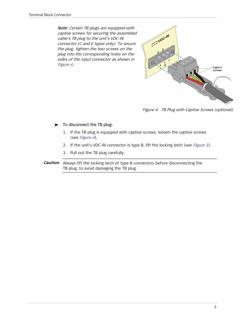
Terminal Block Connector
3
Note: Certain TB plugs are equipped with captive screws for securing the assembled cable’s TB plug to the unit’s VDC-IN connector (C and E types only). To secure the plug, tighten the two screws on the plug into the corresponding holes on the sides of the input connector as shown in 3Figure 4.
Figure 4. TB Plug with Captive Screws (optional)
To disconnect the TB plug:
1. If the TB plug is equipped with captive screws, loosen the captive screws (see 4Figure 4).
2. If the unit’s VDC-IN connector is type B, lift the locking latch (see 5Figure 1).
3. Pull out the TB plug carefully.
Always lift the locking latch of type B connectors before disconnecting the TB plug, to avoid damaging the TB plug.
Caution

Terminal Block Connector
4


Publication No. 530-210-04/12
Order this publication by Catalog No. 805009
International Headquarters 24 Raoul Wallenberg Street
Tel Aviv 69719, Israel
Tel. 972-3-6458181
Fax 972-3-6498250, 6474436
E-mail [email protected]
North America Headquarters 900 Corporate Drive
Mahwah, NJ 07430, USA
Tel. 201-5291100 Toll free 1-800-4447234
Fax 201-5295777
E-mail [email protected]
www.rad.com The Access Company