etsi en 301 893 v2.1 · 2017-05-24 · etsi 2 etsi en 301 893 v2.1.1 (2017-05) reference...
TRANSCRIPT

ETSI EN 301 893 V2.1.1 (2017-05)
Broadband Radio Access Networks (BRAN); 5 GHz high performance RLAN;
Harmonized ENHarmonised Standard covering the essential requirements
of article 3.2 of the R&TTE Directive 2014/53/EU
HARMONISED EUROPEAN STANDARD

ETSI
ETSI EN 301 893 V2.1.1 (2017-05) 2
Reference
REN/BRAN-00600110060015
Keywords
access, broadband, LAN, layer 1, radio, regulation, testing
ETSI
650 Route des Lucioles F-06921 Sophia Antipolis Cedex - FRANCE
Tel.: +33 4 92 94 42 00 Fax: +33 4 93 65 47 16
Siret N° 348 623 562 00017 - NAF 742 C
Association à but non lucratif enregistrée à la Sous-Préfecture de Grasse (06) N° 7803/88
Important notice
The present document can be downloaded from: http://www.etsi.org/standards-search
The present document may be made available in electronic versions and/or in print. The content of any electronic and/or print versions of the present document shall not be modified without the prior written authorization of ETSI. In case of any
existing or perceived difference in contents between such versions and/or in print, the only prevailing document is the print of the Portable Document Format (PDF) version kept on a specific network drive within ETSI Secretariat.
Users of the present document should be aware that the document may be subject to revision or change of status. Information on the current status of this and other ETSI documents is available at
https://portal.etsi.org/TB/ETSIDeliverableStatus.aspx
If you find errors in the present document, please send your comment to one of the following services: https://portal.etsi.org/People/CommiteeSupportStaff.aspx
Copyright Notification
No part may be reproduced or utilized in any form or by any means, electronic or mechanical, including photocopying and microfilm except as authorized by written permission of ETSI.
The content of the PDF version shall not be modified without the written authorization of ETSI. The copyright and the foregoing restriction extend to reproduction in all media.
© European Telecommunications Standards Institute 2017.
All rights reserved.
DECTTM, PLUGTESTSTM, UMTSTM and the ETSI logo are Trade Marks of ETSI registered for the benefit of its Members. 3GPPTM and LTE™ are Trade Marks of ETSI registered for the benefit of its Members and
of the 3GPP Organizational Partners. oneM2M logo is protected for the benefit of its Members
GSM® and the GSM logo are Trade Marks registered and owned by the GSM Association.

ETSI
ETSI EN 301 893 V2.1.1 (2017-05) 3
Contents
Intellectual Property Rights ................................................................................................................................ 8
Foreword............................................................................................................................................................. 8
Modal verbs terminology ................................................................................................................................... 8
Introduction ........................................................................................................................................................ 9
1 Scope ...................................................................................................................................................... 11
2 References .............................................................................................................................................. 11 2.1 Normative references ....................................................................................................................................... 11 2.2 Informative references ..................................................................................................................................... 12
3 Definitions, symbols and abbreviations ................................................................................................. 13 3.1 Definitions ....................................................................................................................................................... 13 3.2 Symbols ........................................................................................................................................................... 16 3.3 Abbreviations ................................................................................................................................................... 17
4 Technical requirements specifications ................................................................................................... 17 4.1 Environmental profile ...................................................................................................................................... 18 4.2 Conformance requirements .............................................................................................................................. 18 4.2.1 Nominal Centre frequencies ....................................................................................................................... 18 4.2.1.1 General ................................................................................................................................................. 18 4.2.1.2 Definition .............................................................................................................................................. 18 4.2.1.3 Limits.................................................................................................................................................... 18 4.2.1.4 Conformance ........................................................................................................................................ 18 4.2.2 Nominal Channel Bandwidth and Occupied Channel Bandwidth ............................................................. 19 4.2.2.1 Definition .............................................................................................................................................. 19 4.2.2.2 Limits.................................................................................................................................................... 19 4.2.2.3 Conformance ........................................................................................................................................ 19 4.2.3 RF output power, Transmit Power Control (TPC) and Power Density ...................................................... 19 4.2.3.1 Definitions ............................................................................................................................................ 19 4.2.3.1.1 RF Output Power ............................................................................................................................ 19 4.2.3.1.2 Transmit Power Control (TPC) ....................................................................................................... 19 4.2.3.1.3 Power Density ................................................................................................................................. 19 4.2.3.2 Limits.................................................................................................................................................... 20 4.2.3.2.1 General ............................................................................................................................................ 20 4.2.3.2.2 Limits for RF output power and Power Density at the highest power level ................................... 20 4.2.3.2.3 Limit for RF output power at the lowest power level (PL) of the TPC range .................................. 20 4.2.3.3 Conformance ........................................................................................................................................ 21 4.2.4 Transmitter unwanted emissions ................................................................................................................ 21 4.2.4.1 Transmitter unwanted emissions outside the 5 GHz RLAN bands....................................................... 21 4.2.4.1.1 Definition ........................................................................................................................................ 21 4.2.4.1.2 Limits .............................................................................................................................................. 21 4.2.4.1.3 Conformance ................................................................................................................................... 21 4.2.4.2 Transmitter unwanted emissions within the 5 GHz RLAN bands ........................................................ 21 4.2.4.2.1 Definition ........................................................................................................................................ 21 4.2.4.2.2 Limits .............................................................................................................................................. 22 4.2.4.2.3 Conformance ................................................................................................................................... 23 4.2.5 Receiver spurious emissions ...................................................................................................................... 23 4.2.5.1 Definition .............................................................................................................................................. 23 4.2.5.2 Limits.................................................................................................................................................... 23 4.2.5.3 Conformance ........................................................................................................................................ 23 4.2.6 Dynamic Frequency Selection (DFS) ......................................................................................................... 23 4.2.6.1 Introduction .......................................................................................................................................... 23 4.2.6.1.1 General ............................................................................................................................................ 23 4.2.6.1.2 DFS applicable frequency range ..................................................................................................... 24 4.2.6.1.3 DFS operational modes ................................................................................................................... 24 4.2.6.1.4 DFS operation ................................................................................................................................. 24 4.2.6.2 DFS technical requirements specifications ........................................................................................... 25

ETSI
ETSI EN 301 893 V2.1.1 (2017-05) 4
4.2.6.2.1 Applicability ................................................................................................................................... 25 4.2.6.2.2 Channel Availability Check ............................................................................................................ 26 4.2.6.2.3 Off-Channel CAC (Off-Channel Channel Availability Check) ...................................................... 26 4.2.6.2.4 In-Service Monitoring ..................................................................................................................... 27 4.2.6.2.5 Channel Shutdown .......................................................................................................................... 27 4.2.6.2.6 Non-Occupancy Period ................................................................................................................... 27 4.2.6.2.7 Uniform Spreading.......................................................................................................................... 28 4.2.7 Adaptivity (Channel Access Mechanism) .................................................................................................. 28 4.2.7.1 Applicability ......................................................................................................................................... 28 4.2.7.2 Definition .............................................................................................................................................. 29 4.2.7.3 Requirements and limits ....................................................................................................................... 29 4.2.7.3.1 Frame Based Equipment (FBE) ...................................................................................................... 29 4.2.7.3.2 Load Based Equipment (LBE) ........................................................................................................ 33 4.2.7.3.3 Short Control Signalling Transmissions (FBE and LBE) ............................................................... 38 4.2.7.4 Conformance ........................................................................................................................................ 38 4.2.8 Receiver Blocking ...................................................................................................................................... 39 4.2.8.1 Applicability ......................................................................................................................................... 39 4.2.8.2 Definition .............................................................................................................................................. 39 4.2.8.3 Performance Criteria............................................................................................................................. 39 4.2.8.4 Limits.................................................................................................................................................... 39 4.2.8.5 Conformance ........................................................................................................................................ 39 4.2.9 User Access Restrictions ............................................................................................................................ 39 4.2.9.1 Definition .............................................................................................................................................. 39 4.2.9.2 Requirement ......................................................................................................................................... 40 4.2.10 Geo-location capability .............................................................................................................................. 40 4.2.10.1 Applicability ......................................................................................................................................... 40 4.2.10.2 Definition .............................................................................................................................................. 40 4.2.10.3 Requirements ........................................................................................................................................ 40 4.2.10.4 Conformance ........................................................................................................................................ 40
5 Testing for compliance with technical requirements.............................................................................. 41 5.1 Environmental conditions for testing ............................................................................................................... 41 5.1.1 Introduction ................................................................................................................................................ 41 5.1.2 Normal test conditions ............................................................................................................................... 41 5.1.2.1 Normal temperature and humidity ........................................................................................................ 41 5.1.2.2 Normal power source............................................................................................................................ 41 5.1.3 Extreme test conditions .............................................................................................................................. 41 5.2 Interpretation of the measurement results ........................................................................................................ 41 5.3 Definition of other test conditions ................................................................................................................... 42 5.3.1 Test sequences and traffic load .................................................................................................................. 42 5.3.1.1 General test transmission sequences ..................................................................................................... 42 5.3.1.2 Test transmission sequences for DFS tests ........................................................................................... 42 5.3.2 Test channels .............................................................................................................................................. 43 5.3.3 Antennas ..................................................................................................................................................... 44 5.3.3.1 Integrated and dedicated antennas ........................................................................................................ 44 5.3.3.2 Transmit operating modes .................................................................................................................... 44 5.3.3.2.1 Operating mode 1 (single antenna) ................................................................................................. 44 5.3.3.2.2 Operating mode 2 (multiple antennas, no beamforming) ................................................................ 44 5.3.3.2.3 Operating mode 3 (multiple antennas, with beamforming) ............................................................ 44 5.3.4 Presentation of equipment .......................................................................................................................... 44 5.3.5 Conducted measurements, radiated measurements, relative measurements ............................................... 45 5.4 Essential radio test suites ................................................................................................................................. 46 5.4.1 Product information ................................................................................................................................... 47 5.4.2 Carrier frequencies ..................................................................................................................................... 49 5.4.2.1 Test conditions...................................................................................................................................... 49 5.4.2.2 Test methods ......................................................................................................................................... 49 5.4.2.2.1 Conducted measurement ................................................................................................................. 49 5.4.2.2.2 Radiated measurement .................................................................................................................... 50 5.4.3 Occupied Channel Bandwidth .................................................................................................................... 50 5.4.3.1 Test conditions...................................................................................................................................... 50 5.4.3.2 Test method .......................................................................................................................................... 50 5.4.3.2.1 Conducted measurement ................................................................................................................. 50

ETSI
ETSI EN 301 893 V2.1.1 (2017-05) 5
5.4.3.2.2 Radiated measurement .................................................................................................................... 51 5.4.4 RF output power, Transmit Power Control (TPC) and Power Density ...................................................... 51 5.4.4.1 Test conditions...................................................................................................................................... 51 5.4.4.2 Test method .......................................................................................................................................... 51 5.4.4.2.1 Conducted measurement ................................................................................................................. 51 5.4.4.2.2 Radiated measurement .................................................................................................................... 61 5.4.5 Transmitter unwanted emissions outside the 5 GHz RLAN bands ............................................................ 62 5.4.5.1 Test conditions...................................................................................................................................... 62 5.4.5.2 Test method .......................................................................................................................................... 62 5.4.5.2.1 Conducted measurement ................................................................................................................. 62 5.4.5.2.2 Radiated measurement .................................................................................................................... 65 5.4.6 Transmitter unwanted emissions within the 5 GHz RLAN bands.............................................................. 65 5.4.6.1 Test conditions...................................................................................................................................... 65 5.4.6.2 Test method .......................................................................................................................................... 65 5.4.6.2.1 Conducted measurement ................................................................................................................. 65 5.4.6.2.2 Radiated measurement .................................................................................................................... 67 5.4.7 Receiver spurious emissions ...................................................................................................................... 67 5.4.7.1 Test conditions...................................................................................................................................... 67 5.4.7.2 Test method .......................................................................................................................................... 67 5.4.7.2.1 Conducted measurement ................................................................................................................. 67 5.4.7.2.2 Radiated measurement .................................................................................................................... 69 5.4.8 Dynamic Frequency Selection (DFS) ......................................................................................................... 69 5.4.8.1 Test conditions...................................................................................................................................... 69 5.4.8.1.1 General ............................................................................................................................................ 69 5.4.8.1.2 Selection of radar test signals .......................................................................................................... 70 5.4.8.1.3 Test set-ups ..................................................................................................................................... 70 5.4.8.2 Test method .......................................................................................................................................... 71 5.4.8.2.1 Conducted measurement ................................................................................................................. 71 5.4.8.2.2 Radiated measurement .................................................................................................................... 79 5.4.9 Adaptivity (channel access mechanism) .................................................................................................... 79 5.4.9.1 Test conditions...................................................................................................................................... 79 5.4.9.2 Test method for Frame Based Equipment ............................................................................................ 79 5.4.9.2.1 Additional test conditions ............................................................................................................... 79 5.4.9.2.2 Conducted measurements ............................................................................................................... 80 5.4.9.2.3 Generic test procedure for measuring channel/frequency usage ..................................................... 83 5.4.9.2.4 Radiated measurements .................................................................................................................. 84 5.4.9.3 Test method for Load Based Equipment .............................................................................................. 84 5.4.9.3.1 Additional test conditions ............................................................................................................... 84 5.4.9.3.2 Conducted measurements ............................................................................................................... 85 5.4.9.3.3 Generic test procedure for measuring channel/frequency usage ..................................................... 93 5.4.9.3.4 Radiated measurements .................................................................................................................. 94 5.4.10 Receiver Blocking ...................................................................................................................................... 95 5.4.10.1 Test conditions...................................................................................................................................... 95 5.4.10.2 Test Method .......................................................................................................................................... 96 5.4.10.2.1 Conducted measurements ............................................................................................................... 96 5.4.10.2.2 Radiated measurements .................................................................................................................. 97
Annex A (informative): Relationship between the present document and the essential
requirements of Directive 2014/53/EU ......................................................... 98
Annex B (normative): Test sites and arrangements for radiated measurements ........................ 101
B.1 Introduction .......................................................................................................................................... 101
B.2 Radiation test sites ................................................................................................................................ 101 B.2.1 Open Area Test Site (OATS) ......................................................................................................................... 101 B.2.2 Semi Anechoic Room .................................................................................................................................... 102 B.2.3 Fully Anechoic Room (FAR)......................................................................................................................... 103 B.2.4 Measurement Distance ................................................................................................................................... 104
B.3 Antennas ............................................................................................................................................... 105 B.3.1 Introduction.................................................................................................................................................... 105 B.3.2 Measurement antenna .................................................................................................................................... 105

ETSI
ETSI EN 301 893 V2.1.1 (2017-05) 6
B.3.3 Substitution antenna ....................................................................................................................................... 105
B.4 Test fixture ........................................................................................................................................... 105 B.4.1 Introduction.................................................................................................................................................... 105 B.4.2 Description of the test fixture ........................................................................................................................ 106 B.4.3 Using the test fixture for relative measurements ............................................................................................ 106
B.5 Guidance on the use of radiation test sites ........................................................................................... 106 B.5.1 Introduction.................................................................................................................................................... 106 B.5.2 Power supplies for the battery powered UUT ................................................................................................ 106 B.5.3 Site preparation .............................................................................................................................................. 107
B.6 Coupling of signals............................................................................................................................... 107 B.6.1 General ........................................................................................................................................................... 107 B.6.2 Data Signals ................................................................................................................................................... 107
B.7 Interference Signals used for Adaptivity Tests .................................................................................... 108 B.7.1 Additive white Gaussian noise (AWGN)....................................................................................................... 108 B.7.2 OFDM test signal ........................................................................................................................................... 108 B.7.3 LTE test signal ............................................................................................................................................... 108 B.7.4 Test procedure ............................................................................................................................................... 108 B.7.5 Waveforms for test signals ............................................................................................................................ 109
Annex C (normative): Procedures for radiated measurements ..................................................... 110
C.1 Introduction .......................................................................................................................................... 110
C.2 Radiated measurements in an OATS or SAR ...................................................................................... 110
C.3 Radiated measurements in a FAR ........................................................................................................ 110
C.4 Substitution measurement .................................................................................................................... 111
C.5 Guidance for testing technical requirements ........................................................................................ 111 C.5.1 Radio test suites and corresponding test sites ................................................................................................ 111 C.5.2 Guidance for testing Adaptivity (Channel Access Mechanism) .................................................................... 112 C.5.2.1 Introduction .............................................................................................................................................. 112 C.5.2.2 Measurement Set-up ................................................................................................................................. 112 C.5.2.3 Calibration of the measurement Set-up .................................................................................................... 112 C.5.2.4 Test method .............................................................................................................................................. 113 C.5.3 Guidance for testing Receiver Blocking ........................................................................................................ 113 C.5.3.1 Introduction .............................................................................................................................................. 113 C.5.3.2 Measurement Set-up ................................................................................................................................. 113 C.5.3.3 Calibration of the measurement Set-up .................................................................................................... 113 C.5.3.4 Test method .............................................................................................................................................. 114
Annex D (normative): DFS parameters ........................................................................................... 115
Annex E Void ...................................................................................................................................... 118
Annex F (informative): Adaptivity Flowchart ................................................................................... 118
Annex G (informative): Application form for testing ....................................................................... 122
G.0 The right to copy .................................................................................................................................. 122
G.1 Introduction .......................................................................................................................................... 122
G.2 Information as required by ETSI EN 301 893 (V2.1.1), clause 5.4.1 .................................................. 122
G.3 Additional information provided by the manufacturer ......................................................................... 131 G.3.1 Modulation ..................................................................................................................................................... 131 G.3.2 Duty Cycle ..................................................................................................................................................... 131 G.3.3 About the UUT .............................................................................................................................................. 131 G.3.4 List of ancillary and/or support equipment provided by the manufacturer .................................................... 132
Annex H (informative): Bibliography ................................................................................................. 133

ETSI
ETSI EN 301 893 V2.1.1 (2017-05) 7
Annex I (informative): Change history ............................................................................................. 134
History ............................................................................................................................................................ 135

ETSI
ETSI EN 301 893 V2.1.1 (2017-05) 8
Intellectual Property Rights
IPRs essential or potentially essential to the present document may have been declared to ETSI. The information
pertaining to these essential IPRs, if any, is publicly available for ETSI members and non-members, and can be found
in ETSI SR 000 314: "Intellectual Property Rights (IPRs); Essential, or potentially Essential, IPRs notified to ETSI in
respect of ETSI standards", which is available from the ETSI Secretariat. Latest updates are available on the ETSI Web
server (https://ipr.etsi.org/).
Pursuant to the ETSI IPR Policy, no investigation, including IPR searches, has been carried out by ETSI. No guarantee
can be given as to the existence of other IPRs not referenced in ETSI SR 000 314 (or the updates on the ETSI Web
server) which are, or may be, or may become, essential to the present document.
Foreword
This HarmonizedHarmonised European Standard (EN) has been produced by ETSI Technical Committee Broadband
Radio Access Networks (BRAN).
The present document has been produced by ETSI in response to mandate M/284 issued from the European
Commissionprepared under the Commission's standardisation request C(2015) 5376 final [i.4] to provide one voluntary
means of conforming to the essential requirements of Directive 98/34/EC [i.3] as amended by2014/53/EU on the
harmonisation of the laws of the Member States relating to the making available on the market of radio equipment and
repealing Directive 98/481999/5/EC [i.1i.1].
The title and reference toOnce the present document are intended to be included in the publicationis cited in the Official
Journal of the European Union of titles and references of Harmonized Standard under the Directive 1999/5/EC [1].
The requirements relevant tothat Directive, compliance with the normative clauses of the present document given in
table A.1 confers, within the limits of the scope of the present document, a presumption of conformity with the
corresponding essential requirements of that Directive 1999/5/EC [1] are summarized in annex A., and associated
EFTA regulations.
National transposition dates
Date of adoption of this EN: 20 March 201523 May 2017
Date of latest announcement of this EN (doa): 30 June 201531 August 2017
Date of latest publication of new National Standard
or endorsement of this EN (dop/e):
31 December 2015
28 February 2018
Date of withdrawal of any conflicting National Standard (dow): 31 December 201628 February 2019
Modal verbs terminology
In the present document "shall", "shall not", "should", "should not", "may", "need not", "will", "will not", "can" and
"cannot" are to be interpreted as described in clause 3.2 of the ETSI Drafting Rules (Verbal forms for the expression of
provisions).
"must" and "must not" are NOT allowed in ETSI deliverables except when used in direct citation.

ETSI
ETSI EN 301 893 V2.1.1 (2017-05) 9
Introduction
The present document is part of a set of standards developed by ETSI and is designed to fit in a modular structure to
cover all radio and telecommunications terminal equipment within the scope of the R&TTE Directive [1]. The modular
structure is shown in ETSI EG 201 399 [i.2].

ETSI
ETSI EN 301 893 V2.1.1 (2017-05) 10
1 Scope
The present document applies to 5 GHz high performance wireless access systems (WAS) including RLAN equipment
which isare used in wireless local area networks. Such networks which provide high speed data communications in
between devices connected to the wireless infrastructure. The present document also applies toaddresses ad-hoc
networking where these devices communicate directly with each other, without the use of a wireless infrastructure.
The spectrum usage conditions for equipment within the scope of the present document are set in the ECC
Decision (04)08 [i.8] and the Commission Decision 2005/513/EC [i.9] as amended by the Commission
Decision 2007/90/EC [i.10].

ETSI
ETSI EN 301 893 V2.1.1 (2017-05) 11
1 Scope
The present document specifies technical characteristics and methods of measurements for 5 GHz wireless access
systems (WAS) including RLAN equipment.
The present document also describes spectrum access requirements to facilitate spectrum sharing with other equipment.
5 GHz high performance wireless access systems (WAS) including RLANThese radio equipment are further referred to
as RLAN devicescapable of operating in all or parts of the frequency bands given in table 1.
Table 1: Service frequency bands
Service frequency bands
Transmit 5 150 MHz to 5 350 MHz
Receive 5 150 MHz to 5 350 MHz
Transmit 5 470 MHz to 5 725 MHz
Receive 5 470 MHz to 5 725 MHz
The present document.
The spectrum usage conditions for this RLAN equipment are set in covers the ECC Decision (04)08 [5] and the
Commission Decision 2005/513/EC [6] as amended by the Commission Decision 2007/90/EC [7].
The equipment is intended to operate in the frequency ranges 5 150 MHz to 5 350 MHz and 5 470 MHz to 5 725 MHz
which have been allocated by WRC-03 to the mobile service on a primary basis for the implementation of
WAS/RLANs covered by the present document.
The present document is intended to cover the provisionsessential requirements of article 3.2 of the R&TTE
Directive [1], which states that: "…radio equipment shall be so constructed that it effectively uses the spectrum
allocated to terrestrial/space radio communications and orbital resources so as to avoid harmful interference".
2014/53/EU under the conditions identified in annex A.
2 References
2.1 Normative references
References are specific, identified by date of publication and/or edition number or version number. Only the cited
version applies.
Referenced documents which are not found to be publicly available in the expected location might be found at
https://docbox.etsi.org/Reference.
NOTE: While any hyperlinks included in this clause were valid at the time of publication, ETSI cannot guarantee
their long term validity.
The following referenced documents are necessary for the application of the present document.
[1] Void.
[2] Void.
[3] Void.
[4] Void.
[5] Void.
[6] Void.
[7] Void.

ETSI
ETSI EN 301 893 V2.1.1 (2017-05) 12
[8] ETSI TS 136 141 (V13.5.0) (10-2016): "LTE; Evolved Universal Terrestrial Radio Access
(E-UTRA); Base Station (BS) conformance testing (3GPP TS 36.141 version 13.5.0 Release 13)".
[9] IEEE 802.11™-2016: "IEEE Standard for Information Technology - Telecommunications and
information exchange between systems - Local and metropolitan area networks - Specific
requirements - Part 11: Wireless LAN Medium Access Control (MAC) and Physical Layer (PHY)
Specifications".
2.2 Informative references
References are either specific (identified by date of publication and/or edition number or version number) or
non-specific. For specific references, only the cited version applies. For non-specific references, the latest version of the
referenced document (including any amendments) applies.
NOTE: While any hyperlinks included in this clause were valid at the time of publication, ETSI cannot guarantee
their long term validity.
The following referenced documents are not necessary for the application of the present document but they assist the
user with regard to a particular subject area.
[i.1] Directive 1999/5/EC2014/53/EU of the European Parliament and of the Council of 9 March
199916 April 2014 on the harmonisation of the laws of the Member States relating to the making
available on the market of radio equipment and repealing Directive 1999/5/EC.
[i.2] telecommunications terminalVoid.
[i.3] Void.
[i.4] Commission Implementing Decision C(2015) 5376 final of 4.8.2015 on a standardisation request
to the European Committee for Electrotechnical Standardisation and to the European
Telecommunications Standards Institute as regards radio equipment and the mutual recognitionin
support of their conformity (R&TTE Directive). 2014/53/EU of the European Parliament and of
the Council.
[2[i.5] ETSI EG 203 367 (V1.1.1) (06-2016): "Guide to the application of harmonised standards covering
articles 3.1b and 3.2 of the Directive 2014/53/EU (RED) to multi-radio and combined radio and
non-radio equipment".
[i.6] ETSI TR 100 028-1 (V1.4.1) (12-2001): "Electromagnetic compatibility and Radio spectrum
Matters (ERM); Uncertainties in the measurement of mobile radio equipment characteristics;
Part 1".
[3[i.7] ETSI TR 100 028-2 (V1.4.1) (12-2001): "Electromagnetic compatibility and Radio spectrum
Matters (ERM); Uncertainties in the measurement of mobile radio equipment characteristics;
Part 2".
[4] Void.
[5[i.8] ECC/DEC/(04)08: "ECC Decision of 9 July 2004 on the harmonised use of the 5 GHz frequency
bands for the implementation of Wireless Access Systems including Radio Local Area Networks
(WAS/RLANs) (30/10/2009).)".
[6[i.9] Commission Decision 2005/513/EC of 11 July 2005 on the harmonised use of radio spectrum in
the 5 GHz frequency band for the implementation of Wireless Access Systems including Radio
Local Area Networks (WAS/RLANs).
[7[i.10] Commission Decision 2007/90/EC of 12 February 2007 amending Decision 2005/513/EC on the
harmonised use of radio spectrum in the 5 GHz frequency band for the implementation of Wireless
Access Systems including Radio Local Area Networks (WAS/RLANs).
[8] IEEE Std. 802.11™-2012: "IEEE Standard for Information Technology - Telecommunications and
information exchange between systems - Local and metropolitan area networks - Specific
requirements - Part 11: Wireless LAN Medium Access Control (MAC) and Physical Layer (PHY)
Specifications".
ETSI
ETSI EN 301 893 V2.1.1 (2017-05) 13
[9] IEEE Std. 802.11ac™-2013: "IEEE Standard for Information Technology - Telecommunications
and information exchange between systems - Local and metropolitan area networks - Specific
requirements - Part 11: Wireless LAN Medium Access Control (MAC) and Physical Layer (PHY)
Specifications - Amendment 4: Enhancements for Very High Throughput for Operation in Bands
below 6 GHz".
[10[i.11] ETSI TR 102 273-2 (V1.2.1) (12-2001): "Electromagnetic compatibility and Radio spectrum
Matters (ERM); Improvement on Radiated Methods of Measurement (using test site) and
evaluation of the corresponding measurement uncertainties; Part 2: Anechoic chamber".
[11[i.12] ETSI TR 102 273-3 (V1.2.1) (12-2001): "Electromagnetic compatibility and Radio spectrum
Matters (ERM); Improvement on Radiated Methods of Measurement (using test site) and
evaluation of the corresponding measurement uncertainties; Part 3: Anechoic chamber with a
ground plane".
[12[i.13] ETSI TR 102 273-4 (V1.2.1) (12-2001): "Electromagnetic compatibility and Radio spectrum
Matters (ERM); Improvement on Radiated Methods of Measurement (using test site) and
evaluation of the corresponding measurement uncertainties; Part 4: Open area test site".
NOTE: While any hyperlinks included in this clause [i.1] Directive 98/48/EC of the European Parliament
and of the Council of 20 July 1998 amending Directive 98/34/EC laying down a procedure for the
provision of information in the field of technical standards and regulations.
[i.2] ETSI EG 201 399 (V2.1.1): "Electromagnetic compatibility and Radio spectrum Matters (ERM);
A guide to the production of candidate Harmonized Standards for application under the R&TTE
Directive".
[i.3] Directive 98/34/EC of the European Parliament and of the Council of 22 June 1998 laying down a
procedure for the provision of information in the field of technical standards and regulations.
3 Definitions, symbols and abbreviations
3.1 Definitions
For the purposes of the present document, the terms and definitions given in the R&TTE Directive 2014/53/EU [1i.1]
and the following apply:
5 GHz RLAN bands: total frequency range that consists of the 5 150 MHz to 5 350 MHz and the 5 470 5470 MHz
to 5 725 MHz sub-bands
adaptive equipment: equipment operating in an adaptive mode
adaptive mode: mechanism by which equipment can adapt to its environment by identifying other transmissions
present in the band
ad-hoc mode: operating mode in which an RLAN device establishes a temporary wireless connection with other RLAN
devices without a controlling network infrastructure
antenna array: two or more antennas connected to a single device and operating simultaneously
antenna assembly: combination of the antenna (integral or dedicated), its coaxial cable and if applicable, its antenna
connector and associated switching components
NOTE 1: This term (antenna assembly) refers to an antenna connected to one transmit chain.
NOTE 2: The gain of an antenna assembly G in dBi, does not include the additional gain that may result out of
beamforming.
available channel: channel identified as available for immediate use as an Operating Channel
NOTE: Usable Channels whose nominal bandwidth falls completely within the band 5 150 MHz to 5 250 MHz
can be considered as Available Channels without further testing.

ETSI
ETSI EN 301 893 V2.1.1 (2017-05) 14
backoff procedure: procedure that facilitates the sharing of the medium by randomizing the transmission attempts
from multiple devices competing for access to an Operating Channel
beamforming gain: additional (antenna) gain realized by using beamforming techniques in smart antenna systems
NOTE: Beamforming gain as used in the present document does not include the gain of the antenna assembly.
burst: period during which radio waves are intentionally transmitted, preceded and succeeded by periods during which
no intentional transmission is made
channel: minimum amount of spectrum used by a single RLAN device
NOTE: An RLAN device is permitted to operate (transmit/receive) in one or more adjacent or non-adjacent
channels simultaneously.
EXAMPLE: For the purpose of the present document, an IEEE 802.11™ [89] device operating in a 40 MHz
mode may be considered as operating in 2 adjacent 20 MHz channels simultaneously.
Channel Access Engine (CAE): mechanism that determines when a transmission attempt is permitted
channel plan: combination of the centre frequencies and for each of the centre frequencies, the declared nominal
bandwidth(s)
clear channel assessment: mechanism used by an equipment to identify other transmissions in the channel
combined equipment: any combinationequipment consisting of non-two or more products where at least one of which
is radio equipment within the scope of the present document
Contention Window (CW): main parameter that requires a plug-in radio device to offer full functionalitydetermines
the duration of the Backoff Procedure
dedicated antenna: antenna external to the equipment, using an antenna connector with a cable or a wave-guide and
which has been designed or developed for one or more specific types of equipment
NOTE: It is the combination of dedicated antenna and radio equipment that is expected to be compliant with the
regulations.
energy detect: mechanism used by an adaptive system to determine the presence of another device operating on the
channel based on detecting the signal level of that other device
environmental profile: range of environmental conditions under which equipment within the scope of the present
document is required to comply with the provisions of the present document
Frame Based Equipment (FBE): equipment where the transmit/receive structure is not directly demand-driven but has
fixeda periodic timing with a periodicity equal to the Fixed Frame Period
NOTE: I.e. it may be altered by configuration changes but there is always a minimum Idle Period following a
transmit period.
host equipment: any equipment which has complete user functionality when not connected to the radio equipment part
and to which the radio equipment part provides additional functionality and to which connection is necessary for the
radio equipment part to offer functionality
integral antenna: antenna designed as a fixed part of the equipment (without the use of an external connector) which
cannot be disconnected from the equipment by a user with the intent to connect another antenna
NOTE: An integral antenna may be fitted internally or externally. In the case where the antenna is external, a
non-detachable cable or wave-guide can be used.
Listen Before Talk (LBT): mechanism by which an equipment applies clear channel assessment (CCA) before using
the channel
Load Based Equipment (LBE): equipment where the transmit/receive structure is not fixed in time but demand-driven

ETSI
ETSI EN 301 893 V2.1.1 (2017-05) 15
manufacturer: company that has manufactured the equipment and who submits it for test
NOTE: Alternatively, the importer or any other person or entity that submits the equipment for test can be
considered as the manufacturer for the purpose of the present document.
master mode: mode which relates to the DFS functionality where the RLAN device uses a Radar Interference
Detection function and controls the transmissions of RLAN devices operating in slave mode
NOTE: In this mode it is able to select a channel and initiate a network by sending enabling signals to other
RLAN devices. An RLAN network always has at least one RLAN device operating in master mode when
operating in the bands 5 250 MHz to 5 350 MHz and 5 470 MHz to 5 725 MHz.
multi-radio equipment: radio, host or combined equipment using consisting of two or more than oneradio products
(transmitters, receivers or transceivers) or a single radio transceiverproduct operating in two or more bands
simultaneously
Observation Slot: period during which the operating channel is checked for the presence of other RLAN transmissions
operating channel: Available Channel on which the RLAN has started transmissions
NOTE: An Post Backoff : Backoff procedure that is applied after every successful transmission
Prioritization Period: period consisting of an initial deferral period followed by an observation period during which
the Operating Channel becomes again an Available Channel if the is checked for the presence of other RLAN stopped
all transmissions on that channel and no radar signal was detected by the In-Service Monitoring.
plug-in radio device: radio equipment module intended to be used with or within host, combined or multi-radio
equipment, using their control functions and power supply
receive chain: receiver circuit with an associated antenna
NOTE: Two or more receive chains are combined in a smart antenna system.
RLAN devices: 5 GHz high performance wireless access systems (WAS) including RLAN equipment
simulated radar burst: series of periodic radio wave pulses for test purposes
slave mode: mode which relates to the DFS functionality where the transmissions of the RLAN are under control of an
RLAN device operating in master mode
NOTE: An RLAN device in slave mode may use a Radar Interference Detection function.
smart antenna systems: equipment that combines multiple transmit and/or receive chains with a signal processing
function to increase the throughput and/or to optimize its radiation and/or reception capabilities
NOTE: These are techniques such as spatial multiplexing, beamforming, cyclic delay diversity, MIMO, etc.
stand-alone radio equipment: equipment that is intended primarily as radio communications equipment and that is
normally used on a stand-alone basis
sub-band: portion of the 5 GHz RLAN bands
NOTE: See definition for "5 GHz RLAN bands".
total occupied bandwidth: total of the Nominal Channel Bandwidths in case of simultaneous transmissions in adjacent
or non-adjacent channels
NOTE: The Total Occupied Bandwidth may change with time/payload.
transmit chain: transmitter circuit with an associated antenna
NOTE: Two or more transmit chains are combined in a smart antenna system.
Transmit Power Control (TPC): technique in which the transmitter output power is controlled resulting in reduced
interference to other systems

ETSI
ETSI EN 301 893 V2.1.1 (2017-05) 16
unavailable channel: channel which cannot be considered by the RLAN device for a certain period of time
(Non Occupancy Period) after a radar signal was detected on that channel
unusable channel: channel from the declared channel plan which may be declared as permanently unavailable due to
one or more radar detections on the channel
usable channel: any channel from the declared channel plan, which may be considered by the RLAN for possible use
3.2 Symbols
For the purposes of the present document, the following symbols apply:
A Measured power output
AC Alternating Current
Tch Number of active transmit chains
B Radar burst period
Chr Channel in which radar test signals are inserted to simulate the presence of a radar
CWmin Minimum Contention Window size
CWmax Maximum Contention Window size
D Measured power densityPower Density
dB decibel
dBm dB relative to 1 milliwattmW
DC Direct Current
E Field strength
Eo Reference field strength
fc Carrier frequency
G Antenna gain
GHz GigaHertzgigahertz
Hz Hertzhertz
kHz kiloHertzkilohertz
L Radar burst length
MHz MegaHertzmegahertz
ms millisecond
MSSamples/s Mega Samples per second
mW milliWattmilliwatt
n Number of channels
p Pioritization period related counter
PH Calculated e.i.r.p. at highest power level
PL Calculated e.i.r.p. at lowest power level
Pburst RMS (mean) power over the transmission burst
PD Calculated power densityPower Density
Pd Detection Probability
q Backoff procedure related counter
R Distance
Rch Number of active receive chains
Ro Reference distance
S0 Signal power
T0 Time instant
T1 Time instant
T2 Time instant
T3 Time instant
W Radar pulse width
x Observed duty cycle
Y Beamforming (antenna) gain

ETSI
ETSI EN 301 893 V2.1.1 (2017-05) 17
3.3 Abbreviations
For the purposes of the present document, the following abbreviations apply:
AC Alternating Current
ACK AcknowledgementACKnowledgement
AWGN Additive White Gaussian Noise
BIT Burst Interval Time
BW BandWidth
CAC Channel Availability Check
CCA Clear Channel Assessment
CSD Cyclic Shift Diversity
COT Channel Occupancy Time
CW Contention Window
DC Direct Current
DFS Dynamic Frequency Selection
e.i.r.p. equivalent isotropically radiated power
ECCA Extended CCA
EMC Electro-Magnetic Compatibility
e.r.p. effective radiated power
ED Energy Detect
FAR Fully Anechoic Room
HT20 High Throughput in a 20 MHz channel
HT40 High Throughput in a 40 MHz channel
FBE Frame Based Equipment
IEEE Institute of Electrical and Electronic Engineers
IF Intermediate Frequency
LBE Load Based Equipment
LBT Listen Before Talk
LPDA Logarithmic Periodic Dipole Antenna
MCS Modulation Coding Scheme
MIMO Multiple Input, Multiple Output
NACK Not Acknowledged
OATS Open Area Test Site
OFDM Orthogonal Frequency Division Multiplexing
PER Packet Error Rate
PHY Physical Layer
PPB Pulses Per Burst
ppm parts per million
PPS Pulses Per Second
PRF Pulse Repetition Frequency
R&TTE Radio and Telecommunications Terminal Equipment
RBW Resolution BandwidthBandWidth
RF Radio Frequency
RLAN Radio Local Area Network
RMS Root Mean Square
SAR Semi Anechoic Room
TL Threshold Level
TPC Transmit Power Control
Tx Transmit, Transmitter
UDP User Datagram Protocol
UUT Unit Under Test
VBW Video BandwidthBandWidth
VSWR Voltage Standing Wave Ratio
WAS Wireless Access Systems
WRC-03 World Radiocommunications Conference 2003
ETSI
ETSI EN 301 893 V2.1.1 (2017-05) 18
4 Technical requirements specifications
4.1 Environmental profile
The technical requirements of the present document apply under the environmental profile for operation of the
equipment, which shall be stateddeclared by the manufacturer.
The equipment shall comply in any of the operating modes with all the technical requirements of the present document
which are identified as applicable in annex A at all times when operating within the boundary limits of the
stateddeclared operational environmental profile.
Where multiple combinations of radio equipment and antenna (antenna assemblies) are intended, each combination
shall comply with all the technical requirements of the present document.
4.2 Conformance requirements
4.2.1 Nominal Centre frequencies
4.2.1.1 General
RLAN equipment typically operates on aone or more fixed frequencyfrequencies. The equipment is allowed to change
its normal operating frequency when interference is detected, or to prevent causing interference intoto other equipment
or for frequency planning purposes.
4.2.1.2 Definition
The centre frequency Nominal Centre Frequency is the centre of the channel declared Operating Channel.
4.2.1.3 Limits
The Nominal Centre Frequencies (fc) for a Nominal Channel Bandwidth of 20 MHz are defined by equation (1). See
also figure 3.
fc = 5 160 + (g × 20) MHz, where 0 ≤ g ≤ 9 or 16 ≤ g ≤ 27 and where g shall be an integer. (1)
A maximum offset of the Nominal Centre Frequency of ±200 kHz is permitted. Where the manufacturer as part of the
declared channel plan(sdecides to make use of this frequency offset, the manufacturer shall declare the actual centre
frequencies used by the equipment. See clause 5.4.1, item a).
4.2.3 Limits
The actual centre frequency for any given channel declared by the manufacturer shall be maintained within the range
fc ± 20 ppm.
Equipment may have simultaneous transmissions on more than one Operating Channel with a Nominal Channel
Bandwidth of 20 MHz.
4.2.1.4 Conformance
Conformance tests as defined in clause 5.34.2 shall be carried out.

ETSI
ETSI EN 301 893 V2.1.1 (2017-05) 19
4.32.2 Nominal Channel Bandwidth and Occupied Channel Bandwidth
4.32.2.1 Definition
The Nominal Channel Bandwidth is the widest band of frequencies, inclusive of guard bands, assigned to a single
channel.
The Occupied Channel Bandwidth is the bandwidth containing 99 % of the power of the signal.
NOTE: A device is permitted to operate in one or more adjacent or non-adjacent channels simultaneously.
When equipment has simultaneous transmissions in adjacent channels, these transmissions may be considered as one
signal with an actual Nominal Channel Bandwidth of "n" times the individual Nominal Channel Bandwidth where "n" is
the number of adjacent channels. When equipment has simultaneous transmissions in non-adjacent channels, each
power envelope shall be considered separately.
4.32.2.2 Limits
The Nominal Channel Bandwidth for a single Operating Channel shall be at least 5 20 MHz at all times..
Alternatively, equipment may implement a lower Nominal Channel Bandwidth with a minimum of 5 MHz, providing
they still comply with the Nominal Centre Frequencies defined in clause 4.2.1 (20 MHz raster).
The Occupied Channel Bandwidth shall be between 80 % and 100 % of the declared Nominal Channel
Bandwidth. In case of smart antenna systems (devices with multiple transmit chains) each of the transmit chains shall
meet this requirement. The Occupied Channel Bandwidth might change with time/payload.
During an established communication, the device is allowed toa Channel Occupancy Time (COT), equipment may
operate temporarily with an Occupied Channel Bandwidth belowof less than 80 % of its Nominal Channel Bandwidth
with a minimum of 4 2 MHz.
4.32.2.3 Conformance
Conformance tests as defined in clause 5.34.3 shall be carried out to determine the occupied channel
bandwidthOccupied Channel Bandwidth.
4.42.3 RF output power, Transmit Power Control (TPC) and power densityPower Density
4.42.3.1 Definitions
4.42.3.1.1 RF Output Power
The RF Output Power is the mean equivalent isotropically radiated power (e.i.r.p.) during a transmission burst.
4.42.3.1.2 Transmit Power Control (TPC)
Transmit Power Control (TPC) is a mechanism to be used by the RLAN device to ensure a mitigation factor of at least
3 dB on the aggregate power from a large number of devices. This requires the RLAN device to have a TPC range from
which the lowest value is at least 6 dB below the values for mean e.i.r.p. given in table 1 2 for devices with TPC.
4.42.3.1.3 Power Density
The Power Density is the mean equivalent isotropically radiated power (e.i.r.p.) density during a transmission burst.

ETSI
ETSI EN 301 893 V2.1.1 (2017-05) 20
4.4.2.3.2 Limits
4.42.3.2.1 General
The limits below are applicable to the system as a whole and in any possible configuration. This includesThis means
that the antenna gain of the integral or dedicated antenna has to be taken into account as well as the additional
(beamforming) gain in case of smart antenna systems (devices with multiple transmit chains).
In case of multiple (adjacent or non-adjacent) channels within the same sub-band, the total RF output powerOutput
Power of all channels in that sub-band shall not exceed the limits defined belowin table 2 and table 3.
In case of multiple, non-adjacent channels operating in separate sub-bands, the total RF output powerOutput Power in
each of the sub-bands shall not exceed the limits defined belowin table 2 and table 3.
4.42.3.2.2 Limits for RF output power and power densityPower Density at the highest power level
TPC is not required for channels whose nominal bandwidth falls completely within the band 5 150 MHz to 5 250 MHz.
For devices with TPC, the RF output power and the power densityPower Density when configured to operate at the
highest stated power level (PH) of the TPC range shall not exceed the levels given in table 1 2.
Devices are allowed to operate without TPC. See table 1 2 for the applicable limits that shall apply in this case.
Table 1 2: Mean e.i.r.p. limits for RF output power and power densityPower Density at the highest power level (PH)
Frequency range
[(MHz])
Mean e.i.r.p. limit [ for PH
(dBm])
Mean e.i.r.p. density limit [(dBm/MHz])
with TPC without TPC with TPC without TPC
5 150 to 5 350 23 20/23 (see note 1) 10 7/10 (see note 2)
5 470 to 5 725 30 (see note 3) 27 (see note 3) 17 (see note 3) 14 (see note 3)
NOTE 1: The applicable limit is 20 dBm, except for transmissions whose nominal bandwidth falls completely within the band 5 150 MHz to 5 250 MHz, in which case the applicable limit is 23 dBm.
NOTE 2: The applicable limit is 7 dBm/MHz, except for transmissions whose nominal bandwidth falls completely within the band 5 150 MHz to 5 250 MHz, in which case the applicable limit is 10 dBm/MHz.
NOTE 3: Slave devices without a Radar Interference Detection function shall comply with the limits for the
bandfrequency range 5 250 MHz to 5 350 MHz.
4.42.3.2.3 Limit for RF output power at the lowest power level (PL) of the TPC range
For devices using TPC, the RF output powerOutput Power during a transmission burst when configured to operate at
the lowest stated power level (PL) of the TPC range shall not exceed the levels given in table 2 3. For devices without
TPC, the limits in table 23 do not apply.
Table 2 3: Mean e.i.r.p. limits for RF output powerOutput Power at the lowest power level of the TPC range
Frequency range Mean e.i.r.p. [(dBm]) limit for PL
5 250 MHz to 5 350 MHz 17
5 470 MHz to 5 725 MHz 24 (see note)
NOTE: Slave devices without a Radar Interference Detection function shall comply with the limits for the band 5 250 MHz to 5 350 MHz.

ETSI
ETSI EN 301 893 V2.1.1 (2017-05) 21
4.42.3.3 Conformance
Conformance tests as defined in clause 5.34.4 shall be carried out.
4.52.4 Transmitter unwanted emissions
4.52.4.1 Transmitter unwanted emissions outside the 5 GHz RLAN bands
4.52.4.1.1 Definition
Transmitter unwanted emissions outside the 5 GHz RLAN bands are radio frequency emissions outside the 5 GHz
RLAN bands defined in clause 3.1.
4.52.4.1.2 Limits
The level of transmitter unwanted emissions outside the 5 GHz RLAN bands shall not exceed the limits given in table
3. 4.
In case of equipment with antenna connectors, these limits apply to emissions at the antenna port (conducted) and to
the). For emissions radiated by the cabinet. In case of or emissions radiated by integral antenna equipment (without
temporary antenna connectors), these limits apply to emissions radiated by the equipmentare e.r.p. for emissions up to 1
GHz and e.i.r.p. for emissions above 1 GHz.
Table 3 4: Transmitter unwanted emission limits outside the 5 GHz RLAN bands
Frequency range Maximum power Bandwidth
30 MHz to 47 MHz -36 dBm 100 kHz
47 MHz to 74 MHz -54 dBm 100 kHz
74 MHz to 87,5 MHz -36 dBm 100 kHz
87,5 MHz to 118 MHz -54 dBm 100 kHz
118 MHz to 174 MHz -36 dBm 100 kHz
174 MHz to 230 MHz -54 dBm 100 kHz
230 MHz to 470 MHz -36 dBm 100 kHz
470 MHz to 862 MHz -54 dBm 100 kHz
862 MHz to 1 GHz -36 dBm 100 kHz
1 GHz to 5,15 GHz -30 dBm 1 MHz
5,35 GHz to 5,47 GHz -30 dBm 1 MHz
5,725 GHz to 26 GHz -30 dBm 1 MHz
4.52.4.1.3 Conformance
Conformance tests as defined in clause 5.34.5 shall be carried out.
4.52.4.2 Transmitter unwanted emissions within the 5 GHz RLAN bands
4.52.4.2.1 Definition
Transmitter unwanted emissions within the 5 GHz RLAN bands are radio frequency emissions within the 5 GHz
RLAN bands defined in clause 3.1.

ETSI
ETSI EN 301 893 V2.1.1 (2017-05) 22
4.52.4.2.2 Limits
NOTE: dBc is the spectral density relative to the maximum spectral power density of the transmitted signal.
Figure 1: Transmit spectral power mask
The average level of mean Power Density (measured with a 1 MHz measurement bandwidth) of the transmitter
unwanted emissions within the 5 GHz RLAN bands shall not exceed the limitlimits of the mask provided in figure 1 or
the limit for unwanted emissions provided in table 3an absolute level of -30 dBm/MHz, whichever is the highergreater.
The limits in figure 1 are relative to the maximum Power Density of the RLAN device when measured with a reference
bandwidth of 1 MHz.
The mask is only applicable within the band of operation. Beyond the band edges the requirements of clause 4.52.4.1
apply.
In case of smart antenna systems (devices with multiple transmit chains) each of the transmit chains shall meet this
requirementthe limits provided in figure 1.
0
0,5 N-0,5 N
N-N 1,5 N-1,5 N 9 N-9 N 10,8 N-10,8 N
0 dB = Reference Level
-20 dB
-28 dB
-40 dB-42 dB
-47 dB
0,55 N-0,55 N Frequency offset (MHz)
Relative Level (dB)
N = Nominal Channel Bandwidth [MHz]

ETSI
ETSI EN 301 893 V2.1.1 (2017-05) 23
For transmitter unwanted emissions within the 5 GHz RLAN bands, simultaneous transmissions in adjacent channels
may be considered as one signal with an actual Nominal Channel Bandwidth of "n" times the individual Nominal
Channel Bandwidth where "n" is the number of adjacent channels used simultaneously.
For simultaneous transmissions in multiple non-adjacent channels, the overall transmit spectral power mask is
constructed in the following manner. First, a mask as provided in figure 1 is applied to each of the channels. Then, for
each frequency point, the highestgreatest value from the spectral masks of all the channels assessed shall be taken as the
overall spectral mask requirement at that frequency.
4.52.4.2.3 Conformance
Conformance tests as defined in clause 5.34.6 shall be carried out.
4.62.5 Receiver spurious emissions
4.62.5.1 Definition
Receiver spurious emissions are emissions at any frequency when the equipment is in receive mode.
4.62.5.2 Limits
The spurious emissions of the receiver shall not exceed the limits given in table 4 5.
In case of equipment with antenna connectors, these limits apply to emissions at the antenna port (conducted) and to
the). For emissions radiated by the cabinet. In case of or emissions radiated by integral antenna equipment (without
temporary antenna connectors), these limits apply to emissions radiated by the equipmentare e.r.p. for emissions up to 1
GHz and e.i.r.p. for emissions above 1 GHz.
Table 4 5: Spurious radiated emission limits
Frequency range Maximum power
Measurement bandwidth
30 MHz to 1 GHz -57 dBm 100 kHz
1 GHz to 26 GHz -47 dBm 1 MHz
4.62.5.3 Conformance
Conformance tests as defined in clause 5.34.7 shall be carried out.
4.72.6 Dynamic Frequency Selection (DFS)
4.72.6.1 Introduction
4.72.6.1.1 General
An RLAN shall employ a Dynamic Frequency Selection (DFS) function to:
detect interference from radar systems (radar detection) and to avoid co-channel operation with these systems;
provide on aggregate a near-uniform loading of the spectrum (Uniform Spreading).
The DFS function as described in the present document is not tested for its ability to detect frequency hopping radar
signals.
Whilst the DFS function described in this clause defines conditions under which the equipment may transmit,
transmissions are only allowed providing they are not prohibited by the Adaptivity requirement in clause 4.82.7.

ETSI
ETSI EN 301 893 V2.1.1 (2017-05) 24
4.72.6.1.2 ApplicableDFS applicable frequency range
Radar detection is requiredshall be used when operating on channels whose nominal bandwidth falls partly or
completely within the frequency ranges 5 250 MHz to 5 350 MHz or 5 470 MHz to 5 725 MHz. This requirement
applies to all types of RLAN devices regardless of the type of communication between these devices.
Uniform Spreading is required across the frequency ranges 5 150 MHz to 5 350 MHz and 5 470 MHz to 5 725 MHz.
Uniform Spreading is not applicable for equipment that only operates in the band 5 150 MHz to 5 250 MHz.
4.72.6.1.3 DFS operational modes
Within the context of the operation of the DFS function, an RLAN device shall operate as either a master or a slave.
RLAN devices operating as a slave shall only operate in a network controlled by an RLAN device operating as a
master. A device which is capable of operating as either a master or a slave shall comply with the requirements
applicable to the mode in which it operates.
Some RLAN devices are capable of communicating in ad-hoc manner without being attached to a network. RLAN
devices operating in this manner on channels whose nominal bandwidth falls partly or completely within the frequency
ranges 5 250 MHz to 5 350 MHz or 5 470 MHz to 5 725 MHz shall employ DFS and shall be tested against the
requirements applicable to a master.
Slave devices used in fixed outdoor point to point or fixed outdoor point to multipoint applications shall behave as slave
with radar detection independent of their output power. See table 5 6.
4.72.6.1.4 DFS operation
The operational behaviour and individual DFS requirements that are associated with master and slave devices are as
follows:
Master devices:
a) The master device shall use a Radar Interference Detection function in order to detect radar signals.
The master device may rely on another device, associated with the master, to implement the Radar
Interference Detection function. In such a case, the combination shall comply with the requirements applicable
to a master.
An RLAN network always has at least one RLAN device operating in master mode when operating in the
bands 5 250 MHz to 5 350 MHz and 5 470 MHz to 5 725 MHz.
b) A master device shall only start operations on Available Channels. At installation (or reinstallation) of the
equipment, the RLAN is assumed to have no Available Channels within the band 5 250 MHz to 5 350 MHz
and/or 5 470 MHz to 5 725 MHz. In such a case, before starting operations on one or more of these
channels, the master device shall perform either a Channel Availability Check or an Off-Channel CAC to
ensure that there are no radars operating on any selected channel. If no radar has been detected, the channel(s)
becomes an Available Channel(s) and remains as such until a radar signal is detected during the In-Service
Monitoring. after the channel became an Operating Channel. The Channel Availability Check or the Off-
Channel CAC may be performed over a wider bandwidth such that all channels within the tested bandwidth
become Available Channels.
NOTE 1: The initial Channel Availability Check may be activated manually at installation or reinstallation of the
equipment.
c) c) A master device may initiate a network by sending enabling signals to other RLAN (slave) devices. Once
the RLAN has started operations on an Available Channel, then that channel becomes an Operating Channel.
During normal operation, the master device shall monitor all Operating Channels (In-Service Monitoring) to
ensure that there is no radar operating within these channel(s). If no radar was detected on an Operating
Channel by the In-Service Monitoring but the RLAN stops operating on that channel, then the channel
becomes again an Available Channel.
NOTE 2: An RLAN is allowed to start transmissions on multiple (adjacent or non-adjacent) Available Channels.
In this case all these channels become Operating Channels.

ETSI
ETSI EN 301 893 V2.1.1 (2017-05) 25
d) If the master device has detected a radar signal on an Operating Channel during In-Service Monitoring, the
master device shall instruct all its associated slave devices to stop transmitting on this channel which becomes
an Unavailable Channel. When operating on multiple (adjacent or non-adjacent) Operating Channels
simultaneously, only the Operating Channel containing the frequency on which radar was detected shall
become an Unavailable Channel.
e) An Unavailable Channel can become a Usable Channel again after the Non-Occupancy Period. A new
Channel Availability Check or an Off-Channel CAC is required to verify there is no radar operating on this
channel before it becomes an Available Channel again.
f) In all cases, if radar detection has occurred, then the channel containing the frequency on which radar was
detected becomes an Unavailable Channel. Alternatively, the channel may be marked as an Unusable
Channel.
Slave devices:
a) A slave device shall not transmit before receiving an appropriate enabling signal from an associated master
device.
b) A slave device shall stop its transmissions on a channel whenever instructed by a master device. The slave
device shall not resume any transmissions on this channel until it has received an appropriate enabling signal
from an associated master device.
c) A slave device which is required to perform radar detection (see table D.2, note 2), shall stop its own
transmissions on an Operating Channel if it has detected a radar on that channel. That Operating Channel
becomes an Unavailable Channel for the slave device. It shall not resume any transmissions on this
Unavailable Channel for a period of time equal to the Non-Occupancy Period. A Channel Availability Check
or an Off-Channel CAC is required by the slave device to verify there is no radar operating on this channel
before the slave may use it again.
4.72.6.2 DFS technical requirements specifications
4.72.6.2.1 Applicability
Table 5 6 lists the DFS related technical requirements and their applicability for every operational mode. If the RLAN
device is capable of operating in more than one operational mode then every operating mode shall be assessed
separately.
Table 5 6: Applicability of DFS requirements
Requirement DFS Operational mode
Master Slave without radar detection
(see table D.2, note 2)
Slave with radar detection
(see table D.2, note 2)
Channel Availability Check Required
Not required (Required(see note 2)
Off-Channel CAC (see note 1) Required
Not required (Required(see note 2)
In-Service Monitoring Required
Not required Required
Channel Shutdown Required
Required Required
Non-Occupancy Period Required
Not required Required
Uniform Spreading Required
Not required Not required
NOTE 1: Where implemented by the manufacturer. NOTE 2: A slave with radar detection is not required to perform a CAC or Off-Channel CAC at initial
use of the channel but only after the slave has detected a radar signal on the Operating Channel by In-Service Monitoring. and the Non-Occupancy Period resulting from this detection has elapsed.

ETSI
ETSI EN 301 893 V2.1.1 (2017-05) 26
The radar detection requirements specified in clauses clause 4.72.6.2.2 to clause 4.72.6.2.4 assume that the centre
frequencies of the radar signals fall within the central 80 % of the Occupied Channel Bandwidth of the RLAN channel
(see clause 4.32.2).
4.72.6.2.2 Channel Availability Check
4.72.6.2.2.1 Definition
The Channel Availability Check (CAC) is defined as a mechanism by which an RLAN device checks channels for the
presence of radar signals. This mechanism is used for identifying Available Channels.
There shall be no transmissions by the RLAN device on the channels being checked during this process.
If no radars have been detected on a channel, then that channel becomes an Available Channel.
For devices that support multiple Nominal Channel Bandwidths, the Channel Availability Check may be performed
once using the widest Nominal Channel Bandwidth. All narrower channels within the tested bandwidth become
Available Channels providing no radar was detected.
4.72.6.2.2.2 Limit
The Channel Availability Check shall be performed during a continuous period in time (Channel Availability Check
Time) which shall not be less than the value defined in table D.1.
During the Channel Availability Check, the RLAN device shall be capable of detecting any of the radar test signals that
fall within the ranges given by table D.4 with a level above the Radar Detection Threshold Level defined in table D.2.
The RLAN device shall comply with the minimum required detection probability isas defined in table D.5.
4.72.6.2.2.3 Conformance
Conformance tests for this requirement are defined in clause 5.34.8.
4.72.6.2.3 Off-Channel CAC (Off-Channel Channel Availability Check)
4.72.6.2.3.1 Definition
Off-Channel CAC is defined as an optional mechanism by which an RLAN device monitors channel(s), different from
the Operating Channel(s), for the presence of radar signals. The Off-Channel CAC may be used in addition to the
Channel Availability Check defined in clause 4.72.6.2.2, for identifying Available Channels.
Off-Channel CAC is performed by a number of non-continuous checks spread over a period in time. This period, which
is required to determine the presence of radar signals, is defined as the Off-Channel CAC Time.
If no radars have been detected in a channel, then that channel becomes an Available Channel.
4.72.6.2.3.2 Limit
Where implemented, the Off-Channel CAC Time shall be declared by the manufacturer. However, the declared
Off-Channel CAC Time shall be within the range specified in table D.1.
During the Off-Channel CAC, the RLAN device shall be capable of detecting any of the radar test signals that fall
within the ranges given by table D.4 with a level above the Radar Detection Threshold Level defined in table D.2.
The RLAN device shall comply with the minimum required detection probability isas defined in table D.5.
4.72.6.2.3.3 Conformance
Conformance tests for this requirement are defined in clause 5.34.8.

ETSI
ETSI EN 301 893 V2.1.1 (2017-05) 27
4.72.6.2.4 In-Service Monitoring
4.72.6.2.4.1 Definition
The In-Service Monitoring is defined as the process by which an RLAN device monitors each Operating Channel for
the presence of radar signals.
4.72.6.2.4.2 Limit
The In-Service Monitoring shall be used to monitor each Operating Channel.
The In-Service-Monitoring shall start immediately after the RLAN device has started transmissions on a channel.
During the In-Service Monitoring, the RLAN device shall be capable of detecting any of the radar test signals that fall
within the ranges given by table D.4 with a level above the Radar Detection Threshold Level defined in table D.2.
The RLAN device shall comply with the minimum required detection probability associated with a given radar test
signal isas defined in table D.5.
4.72.6.2.4.3 Conformance
Conformance tests for this requirement are defined in clause 5.34.8.
4.72.6.2.5 Channel Shutdown
4.72.6.2.5.1 Definition
The Channel Shutdown is defined as the process initiated by the RLAN device on an Operating Channel after a radar
signal has been detected during the In-Service Monitoring on that channel.
The master device shall instruct all associated slave devices to stop transmitting on this channel, which they shall do
within the Channel Move Time.
Slave devices with a Radar Interference Detection function, shall stop their own transmissions on an Operating Channel
within the Channel Move Time upon detecting a radar signal within this channel.
The aggregate duration of all transmissions of the RLAN device on this channel during the Channel Move Time shall be
limited to the Channel Closing Transmission Time. The aggregate duration of all transmissions shall not include quiet
periods in between transmissions.
For equipment having simultaneous transmissions on multiple (adjacent or non-adjacent) operating channels, only the
channel(s) containing the frequency on which radar was detected is subject to the Channel Shutdown requirement. The
equipment is allowed to continue transmissions on other Operating Channels.
4.72.6.2.5.2 Limit
The Channel Move Time shall not exceed the limit defined in table D.1.
The Channel Closing Transmission Time shall not exceed the limit defined in table D.1.
4.72.6.2.5.3 Conformance
Conformance tests for this requirement are defined in clause 5.34.8.
4.72.6.2.6 Non-Occupancy Period
4.72.6.2.6.1 Definition
The Non-Occupancy Period is defined as the time during which the RLAN device shall not make any transmissions on
a channel after a radar signal was detected on that channel.

ETSI
ETSI EN 301 893 V2.1.1 (2017-05) 28
For equipment having simultaneous transmissions on multiple (adjacent or non-adjacent) operating channels, only the
channel(s) containing the frequency on which radar was detected is subject to the Non-Occupancy Period requirement.
The equipment is allowed to continue transmissions on other Operating Channels.
After the Non-Occupancy Period, the channel needs to be identified again as an Available Channel before the RLAN
device may start transmitting again on this channel.
4.7.2.6.2.6.2 Limit
The Non-Occupancy Period shall not be less than the value defined in table D.1.
4.72.6.2.6.3 Conformance
Conformance tests for this requirement are defined in clause 5.34.8.
4.72.6.2.7 Uniform Spreading
4.72.6.2.7.1 Definition
The Uniform Spreading is a mechanism to be used by the RLAN to provide, on aggregate, a uniform loading of the
spectrum across all devices. The Uniform Spreading is limited to the usable channels being declared as part of the
channel plan.
The required spreading may be achieved by various means. These means include network management functions
controlling large numbers of RLAN devices as well as the channel selection function in an individual RLAN device.
4.72.6.2.7.2 Limit
Each of the declared Channel Plans (see clause 3.1) shall make use of at least 60 % of the spectrum available in the
applicable sub-band(s).
The Uniform Spreading is limited to the usable channels being declared as part of the channel plan.
Usable channels do not include channels which are precluded by either:
1) the intended outdoor usage of the RLAN; or
2) previous detection of a radar on the channel (Unavailable Channel or Unusable Channel); or
3) national regulations; or
4) the restriction to only operate in the band 5 150 MHz to 5 250 MHz for RLAN devices without a radar
detection capability.
Each of the Usable Channels shall be used with approximately equal probability. RLAN equipment for which the
declared channel plan includes channels whose nominal bandwidth falls completely or partly within the band
5 600 MHz to 5 650 MHz may omit these channels from the list of Usable Channels at initial power up or at initial
installation. Channels being used by other RLAN equipment may be omitted from the list of Usable Channels.
4.82.7 Adaptivity (Channel Access Mechanism)
4.82.7.1 Applicability
The present requirement applies to all equipment within the scope of the present document.
The present document defines two types of adaptive equipment:
Frame Based Equipment;
Load Based Equipment.
Whilst the mechanisms described in this clause define conditions under which the equipment may transmit,
transmissions are only allowed providing they are not prohibited by any of the DFS requirements in clause 4.72.6.

ETSI
ETSI EN 301 893 V2.1.1 (2017-05) 29
4.82.7.2 Definition
Adaptivity (Channel Access Mechanism) is an automatic channel access mechanism by which a device avoidslimits its
transmissions in a channel in the presence of transmissions from other RLAN devices in that channeland gains access to
an Operating Channel.
NOTE: Adaptivity is not intended to be used as an alternative to DFS to detect radar transmissions, but to detect
transmissions from other RLAN devices operating in the band. DFS requirements are covered by clause 4.72.6.
4.82.7.3 Requirements and limits
4.82.7.3.1 Frame Based Equipment (FBE)
4.2.7.3.1.1 Introduction
Frame Based Equipment shall complyimplement a Listen Before Talk (LBT) based Channel Access Mechanism to
detect the presence of other RLAN transmissions on an Operating Channel.
Frame Based Equipment is equipment where the transmit/receive structure has a periodic timing with the a periodicity
equal to the Fixed Frame Period. A single Observation Slot as defined in clause 3.1 and as referenced by the procedure
in clause 4.2.7.3.1.4 shall have a duration of not less than 9 µs.
4.2.7.3.1.2 Device Types (Adaptivity)
A device that initiates a sequence of one or more transmissions is denoted as the Initiating Device. Otherwise, the
device is denoted as a Responding Device. Frame Based Equipment may be an Initiating Device, a Responding Device,
or both.
The Initiating Device shall implement a Channel Access Mechanism as further described in clause 4.2.7.3.1.4.
A Responding Device shall implement a Channel Access Mechanism as further described in clause 4.2.7.3.1.5.
4.2.7.3.1.3 Multi-channel Operation
Frame Based Equipment being capable of simultaneous transmissions in adjacent or non-adjacent Operating Channels
(see clause 4.2.1) may use any combination/grouping of 20 MHz Operating Channels out of the list of channels
(Nominal Centre Frequencies) provided in clause 4.2.1, if it satisfies the channel access requirements (Channel Access
Mechanism) for an Initiating Device as described in clause 4.2.7.3.1.4 on each such 20 MHz Operating Channel.
4.2.7.3.1.4 Initiating Device Channel Access Mechanism
The Initiating Device (Frame Based Equipment) shall implement a Channel Access Mechanism that complies with the
following requirements:
1) Before The Fixed Frame Periods supported by the equipment shall be declared by the manufacturer. See
clause 5.4.1, item q). This shall be within the range of 1 ms to 10 ms. Transmissions can start only at the
beginning of a Fixed Frame Period. See figure 2 below. An equipment may change its Fixed Frame Period
but it shall not do more than once every 200 ms.
5)2) Immediately before starting transmissions on an Operating Channel, the equipment at the start of a Fixed
Frame Period, the Initiating Device shall perform a Clear Channel Assessment (CCA) check using "energy
detect". The equipment shall observe the Operating Channel(s) for the duration of the CCA observation time
which shall be not less than 20 µs.during a single Observation Slot. The Operating Channel shall be
considered occupied if the energy level in the channel exceeds the threshold corresponding to the power
levelED Threshold Level (TL) given in point 56) below. If the equipment Initiating Device finds the Operating
Channel(s) to be clear, it may transmit immediately. See figure 2 below. .
1) If the equipmentInitiating Device finds an Operating Channel occupied, itthen there shall not transmitbe no
transmissions on that channel during the next Fixed Frame Period.
The equipmentFrame Based Equipment is allowed to continue Short Control Signalling Transmissions on this
channel providing it complies with the requirements given in clause 4.82.7.3.3.

ETSI
ETSI EN 301 893 V2.1.1 (2017-05) 30
For equipment having simultaneous transmissions on multiple (adjacent or non-adjacent) Operating Channels,
the equipment is allowed to continue transmissions on other Operating Channels providing the CCA check did
not detect any signals on those channels.
The total time during which an equipment hasFrame Based Equipment can have transmissions on a given
channel without re--evaluating the availability of that channel, is defined as the Channel Occupancy Time.
(COT).
The equipment can have multiple transmissions within a Channel Occupancy Time shall be inwithout
performing an additional CCA on this Operating Channel providing the range 1 ms to 10 ms and gap between
such transmissions does not exceed 16 µs.
If the minimum Idle Period shall be at least 5 % of the Channel Occupancy Time used by gap exceeds 16 µs,
the equipment formay continue transmissions provided that an additional CCA detects no RLAN transmissions
with a level above the threshold defined in point 6). The additional CCA shall be performed within the gap and
within the observation slot immediately before transmission. All gaps are counted as part of the Channel
Occupancy Time.
3) An Initiating Device is allowed to grant an authorization to one or more associated Responding Devices to
transmit on the current Operating Channel within the current Channel Occupancy Time. A Responding Device
that receives such a grant shall follow the procedure described in clause 4.2.7.3.1.5.
2)4) The Channel Occupancy Time shall not be greater than 95 % of the Fixed Frame Period. Towards the end of
the defined in point 1) and shall be followed by an Idle Period until the start of the next Fixed Frame Period
such that the Idle Period, the equipment shall perform a new CCA as described in point 1) above. is at least
5 % of the Channel Occupancy Time, with a minimum of 100 µs.
3)5) The equipment, upon correct reception of a packet which was intended for this equipment, can skip CCA and
immediately (see note) proceed with the transmission of management and control frames (e.g. ACK and Block
ACK frames). A consecutive sequence of such transmissions by the equipment, without it performing a new
CCA, shall not exceed the Maximum Channel Occupancy Time as defined in point 34) above.
NOTE: For the purpose of multi-cast, the ACK transmissions (associated with the same data packet) of the
individual devices are allowed to take place in a sequence.
4) For transmit power levels of 23 dBm e.i.r.p. or above, the CCA threshold level (TL), at the input to the
receiver, shall be a minimum of -73 dBm/MHz assuming a 0 dBi receive antenna.
For transmit power levels below 23 dBm e.i.r.p., the CCA threshold level (TL), at the input of the receiver,
shall be proportional to the maximum transmit power (PH) according to the formula which assumes a 0 dBi
receive antenna and PH to be specified in dBm e.i.r.p.
TL = -73 dBm / MHz + (23 dBm - PH) / (1 MHz)

ETSI
ETSI EN 301 893 V2.1.1 (2017-05) 31
Figure 2: Example of timing for Frame Based Equipment
4.8.3.2 Load Based Equipment
Load based Equipment may implement an LBT based spectrum sharing mechanism based on the Clear Channel
Assessment (CCA) mode using "energy detect", as described in IEEE 802.11™-2012 [8], clause 9, clause 10, clause 18
and clause 20 or as described in IEEE 802.11ac™-2013 [9], clause 8, clause 9, clause 10 and clause 22, providing these
devices comply with the conformance requirements referred to in clause 4.8.4.
Load Based Equipment not using any of the mechanisms referenced above shall comply with the minimum set of
requirements contained in either option A or option B below. When selecting option B, the value of q shall be declared
by the manufacturer. See clause 5.3.1 q).
Option A
5) Before a transmission or a burst of transmissions on an Operating Channel, the equipment shall perform a
Clear Channel Assessment (CCA) check using "energy detect". The equipment shall observe the Operating
Channel(s) for the duration of the CCA observation time which shall be not less than 20 µs. The Operating
Channel shall be considered occupied if the energy level in the channel exceeds the threshold corresponding to
the power level given in point 5) below. If the equipment finds the channel to be clear, it may transmit
immediately (see point 3) below).
6) If the equipment finds an Operating Channel occupied, it shall not transmit in that channel (see paragraphs
below). The equipment shall perform an Extended CCA check in which the Operating Channel is observed for
the duration of an observation period of q Observation Slots. An Observation Slot is either an Unoccupied Idle
Slot of 18 µs (ECCA slot time) or a Busy Slot. A Busy Slot is the total time the Operating Channel was found
occupied in between two unoccupied ECCA slots and which shall be considered as a single Observation Slot.
The initial value of q is 16 and shall be doubled for every new Extended CCA check that has to be performed
because the previous one failed to find N unoccupied ECCA slots. Once q has reached a value of 1 024 and the
Extended CCA check still failed to find N unoccupied ECCA slots, the value of q may be reset to the initial
value of 16 for the start of the next Extended CCA check. The value of N shall be randomly selected in the
range 1 to q every time an Extended CCA is required.
If an Extended CCA check has found N unoccupied ECCA slots, the equipment may resume transmissions on
this channel and the value of q shall be reset to its initial value.
The equipment is allowed to continue Short Control Signalling Transmissions on this channel providing it
complies with the requirements in clause 4.8.3.3.
For equipment having simultaneous transmissions on multiple (adjacent or non-adjacent) operating channels,
the equipment is allowed to continue transmissions on other Operating Channels providing the CCA check did
not detect any signals on those channels.
NOTE 1: The total Idle Period is equal to the total of any CCA (initial or extended) checks which have been
performed since the last transmission.
7) The total time that an equipment makes use of an Operating Channel is the Maximum Channel Occupancy
Time which shall be less than 10 ms, after which the device shall perform a new Extended CCA as described in
point 2) above.
8) The equipment, upon correct reception of a packet which was intended for this equipment, can skip CCA and
immediately (see note 2) proceed with the transmission of management and control frames (e.g. ACK and
Block ACK frames). A consecutive sequence of transmissions by the equipment, without it performing a new
CCA, shall not exceed the Maximum Channel Occupancy Time as defined in point 3) above.
NOTE 2: For the purpose of multi-cast, the ACK transmissions (associated with the same data packet) of the
individual devices are allowed to take place in a sequence.
9) For transmit power levels of 23 dBm e.i.r.p. or above, the CCA threshold level (TL), at the input to the
receiver, shall be -73 dBm/MHz assuming a 0 dBi receive antenna.

ETSI
ETSI EN 301 893 V2.1.1 (2017-05) 32
10)6) For transmit power levels below 23 dBm e.i.r.p., the CCA threshold levelThe ED Threshold Level (TL), at the
input of the receiver, shall be proportional to the maximum transmit power (PH) according to the formula
which assumes a 0 dBi receive antenna and PH to be specified in dBm e.i.r.p.
TL = -73 For PH ≤ 13 dBm / : TL = -75 dBm/MHz + (
For 13 dBm < PH < 23 dBm - PH) / (1 : TL = -85 dBm/MHz + (23 dBm - PH)
Option B
Before For PH ≥ 23 dBm: TL = -85 dBm/MHz
Figure 2: Example of timing for Frame Based Equipment
4.2.7.3.1.5 Responding Device Channel Access Mechanism
Clause 4.2.7.3.1.4, point 3) describes the possibility whereby an Initiating Device grants an authorization to one or more
associated Responding Devices to transmit on the current Operating Channel within the current Fixed Frame Period. A
Responding Device that receives such a grant shall follow the procedure described in step 1) to step 3):
1) A Responding Device that received a transmission or a burst of grant from an associated Initiating Device may
proceed with transmissions on anthe current Operating Channel, the equipment:
a) The Responding Device may proceed with such transmissions without performing a Clear Channel
Assessment (CCA) if these transmissions are initiated at most 16 µs after the last transmission by the
Initiating Device that issued the grant.
b) The Responding Device that does not proceed with such transmissions within 16 µs after the last
transmission from the Initiating Device that issued the grant, shall perform a Clear Channel Assessment
(CCA) check using "energy detect". The on the Operating Channel during a single observation slot
within a 25 µs period ending immediately before the granted transmission time. If energy was detected
with a level above the ED Threshold Level (TL) defined in clause 4.2.7.3.1.4, point 6), the Responding
Device shall proceed with step 3). Otherwise, the Responding Device shall proceed with step 2).
2) The Responding Device may perform transmissions on the current Operating Channel for the remaining
Channel Occupancy Time of the current Fixed Frame Period. The Responding Device may have multiple
transmissions on this Operating Channel provided that the gap in between such transmissions does not exceed
16 µs. When the transmissions by the Responding Device are completed the Responding Device shall proceed
with step 3).
3) The transmission grant for the Responding Device is withdrawn.

ETSI
ETSI EN 301 893 V2.1.1 (2017-05) 33
4.2.7.3.2 Load Based Equipment (LBE)
4.2.7.3.2.1 Introduction
Load based Equipment shall implement a Listen Before Talk (LBT) based Channel Access Mechanism to detect the
presence of other RLAN transmissions on an Operating Channel.
4.2.7.3.2.2 Device Types (Adaptivity)
With regard to Adaptivity for Load Based Equipment, a device that initiates a sequence of one or more transmissions is
denoted as the Initiating Device. Otherwise, the device is denoted as a Responding Device. Load Based Equipment may
be an Initiating Device, a Responding Device, or both.
The Initiating Device shall implement a Channel Access Mechanism with prioritized, truncated exponential back off
mechanism as further described in clause 4.2.7.3.2.6.
A Responding Device shall implement a Channel Access Mechanism as further described in clause 4.2.7.3.2.7.
Each transmission belongs to a single Channel Occupancy Time (COT). A Channel Occupancy Time (COT) consists of
one or more transmissions of an Initiating Device and zero or more transmissions of one or more Responding Devices.
An equipment that controls (non-DFS related) operating parameters of one or more other equipment shall observe the
Operating Channel(s) for the duration of the CCA observation time which shall be not less than 20 µs. The CCA
observation time used by the is denoted as a Supervising Device. Otherwise, the equipment shall is denoted as a
Supervised Device. The roles of a Supervising Device and Supervised Device has only to be declared by the
manufacturer. The Operating Channel shall be considered occupied if the energy level in the seen in relation to
Adaptivity and are different from the roles of a Master device and a Slave Device in the context of DFS as defined in
clause 4.2.6.
EXAMPLE: Examples of Supervising Devices are an RLAN Access Point or a mobile phone operating as an
RLAN hotspot.
4.2.7.3.2.3 Multi-channel exceeds the threshold corresponding to the power level given in point 5) below. If the equipment finds the channel to be clear, it may transmit immediately (see point 3) below). Operation
11) If the equipment finds an Operating Channel occupied, it shall not transmit in that channel. The equipment
shall perform an Extended CCA check in which the Operating Channel is observed for the duration
(observation period) of a random factor N multiplied by the CCA observation time. N defines the number of
unoccupied idle slots resulting in a total Idle Period that needs to be observed before initiation of the
transmission. The value of N shall be randomly selected in the range 1 to q every time an Extended CCA is
required and the value stored in a counter. The value of q is selected by the manufacturer in the range 4 to 32.
This selected value shall be declared by the manufacturer (see clause 5.3.1 q)). The counter is decremented
every time a CCA slot is considered to be "unoccupied". When the counter reaches zero, the equipment may
transmit.
The equipment is allowed to continue Short Control Signalling Transmissions on this channel providing it
complies with the requirements in clause 4.8.3.3.
For equipment having Load Based Equipment being capable of simultaneous transmissions on multiple (in adjacent or
non-adjacent) operating channels, the equipment is allowed to continue transmissions on other Operating Channels
providing the CCA check did not detect any signals on those channels.(see clause 4.2.1) shall implement either option 1
or option 2 below:
12) The total time that an equipment makes use of an Operating Channel is the Maximum Channel Occupancy
Time which shall be less than (13 / 32) × q ms, with q as defined in point 2) above, after which the device shall
perform the Extended CCA described in point 2) above.
13) The equipment, upon correct reception of a packet which was intended for this equipment, can skip CCA and
immediately (see note 3) proceed with the transmission of management and control frames (e.g. ACK and
Block ACK frames). A consecutive sequence of transmissions by the equipment, without it performing a new
CCA, shall not exceed the Maximum Channel Occupancy Time as defined in point 3) above.

ETSI
ETSI EN 301 893 V2.1.1 (2017-05) 34
NOTE 3: For the purpose of multi-cast, the ACK transmissions (associated with the same data packet) of the
individual devices are allowed to take place in a sequence.
14) For transmit power levels of 23 dBm e.i.r.p. or above, the CCA threshold level (TL), at the input to the
receiver, shall be -73 dBm/MHz assuming a 0 dBi receive antenna.
For transmit power levels below 23 dBm e.i.r.p., the CCA threshold level (TL), at the inputOption 1: Load Based
Equipment may use any combination/grouping of 20 MHz Operating Channels out of the
receiver,list of channels (Nominal Centre Frequencies) provided in clause 4.2.1, if it satisfies the
channel access requirements (Channel Access Mechanism) for an Initiating Device as described in
clause 4.2.7.3.2.6 on each such 20 MHz Operating Channel.
Option 2: Figure 3 defines bonded 40 MHz, 80 MHz or 160 MHz channels (see also clause 4.2.1.3 for the
channel number). Load Based Equipment that uses a combination/grouping of 20 MHz Operating
Channels that is a subset of bonded 40 MHz, 80 MHz or 160 MHz channels, may transmit on any
of the 20 MHz Operating Channels, if:
the equipment satisfies the channel access requirements (Channel Access Mechanism) for
an Initiating Device as defined in clause 4.2.7.3.2.6 on one of the 20 MHz Operating
Channels (Primary Operating Channel), and
the equipment performs a Clear Channel Assessment (CCA) of at least 25 µs immediately
before the intended transmissions on each of the other Operating Channels on which
transmissions are intended, and no energy was detected with a level above the ED
Threshold Level (TL) defined in clause 4.2.7.3.2.5.
The choice of the Primary Operating Channel shall follow one of the following procedures:
The Primary Operating Channel is chosen uniformly randomly whenever the contention
window (CW), corresponding to a completed transmission on the current Primary
Operating Channel is set to its minimum value (CWmin). For this procedure, a contention
window (CW) is maintained for each Priority Class (see clause 4.2.7.3.2.4) within each
20 MHz Operating Channel within the bonded channel.
The Primary Operating Channel is arbitrarily determined and not changed more than once
per second.
The bonded 40 MHz, 80 MHz or 160 MHz channel that the combination/grouping of 20 MHz operating channels is a
subset of shall not be changed more than once per second.
Figure 3: Channel Bonding for option 2
4.2.7.3.2.4 Priority Classes
Table 7 and table 8 each contain four different sets of Channel Access parameters for Supervising Devices and
Supervised Devices respectively, resulting in different Priority Classes and different maximum Channel Occupancy
Times. These parameters are used by the Channel Access Mechanism for the Initiating Device described in
clause 4.2.7.3.2.6 to gain access to an Operating Channel.

ETSI
ETSI EN 301 893 V2.1.1 (2017-05) 35
If a Channel Occupancy consists of more than one transmission the transmissions may be separated by gaps. The
Channel Occupancy Time is the total duration of all transmissions and all gaps of 25 µs duration or less within a
Channel Occupancy and shall not exceed the maximum Channel Occupancy Time in table 7 and table 8. The duration
from the start of the first transmission within a Channel Occupancy until the end of the last transmission in that same
Channel Occupancy shall not exceed 20 ms.
The Initiating Device may have data to be transmitted in different Priority Classes and therefore the Channel Access
Mechanism is allowed to operate different Channel Access Engines as described in clause 4.2.7.3.2.6 simultaneously
(one for each implemented Priority Class).
Table 7: Priority Class dependent Channel Access parameters for Supervising Devices
Class # p0 CWmin CWmax Maximum Channel Occupancy Time (COT)
4 1 3 7 2 ms
3 1 7 15 4 ms
2 3 15 63 6 ms
(see note 1 and note 2)
1 7 15 1 023 6 ms
(see note 1)
NOTE 1: The maximum Channel Occupancy Time (COT) of 6 ms may be increased to 8 ms by inserting one or more pauses. The minimum duration of a pause shall be 100 µs. The maximum duration (Channel Occupancy) before including any such pause shall be 6 ms. Pause duration is not included in the channel occupancy time.
NOTE 2: The maximum Channel Occupancy Time (COT) of 6 ms may be increased to 10 ms by extending CW to CW × 2 + 1 when selecting the random number q for any backoff(s) that precede the Channel Occupancy that may exceed 6 ms or which follow the Channel Occupancy that exceeded 6 ms. The choice between preceding or following a Channel Occupancy shall remain unchanged during the operation time of the device.
NOTE 3: The values for p0, CWmin, CWmax are minimum
values. Greater values are allowed.
Table 8: Priority Class dependent Channel Access parameters for Supervised Devices
Class # p0 CWmin CWmax Maximum Channel Occupancy Time (COT)
4 2 3 7 2 ms
3 2 7 15 4 ms
2 3 15 1 023 6 ms
(see note 1)
1 7 15 1 023 6 ms
(see note 1)
NOTE 1: The maximum Channel Occupancy Time (COT) of 6 ms may be increased to 8 ms by
inserting one or more pauses. The minimum duration of a pause shall be 100 µs. The maximum duration (Channel Occupancy) before including any such pause shall be 6 ms. Pause duration is not included in the channel occupancy time.
NOTE 2: The values for p0, CWmin, CWmax are minimum values. Greater values are allowed.
4.2.7.3.2.5 ED Threshold Level (Energy Detection Threshold Level)
Equipment shall consider a channel to be occupied as long as other RLAN transmissions are detected at a level greater
than the ED Threshold Level (TL). The ED Threshold Level (TL) is integrated over the total Nominal Channel
Bandwidth of all Operating Channels used by the equipment.
The ED Threshold level (TL) depends on the type of equipment:
Option 1: For equipment that for its operation in the 5 GHz bands is conforming to IEEE 802.11™-2016 [9],
clause 17, clause 19 or clause 21, or any combination of these clauses, the ED Threshold Level
(TL) is independent of the equipment's maximum transmit power (PH). Assuming a 0 dBi receive
antenna the ED Threshold Level (TL) shall be:
TL = -75 dBm/MHz (2)

ETSI
ETSI EN 301 893 V2.1.1 (2017-05) 36
Option 2: For equipment conforming to one or more of the clauses listed in Option 1, and to at least one
other operating mode, and for equipment conforming to none of the clauses listed in Option 1, the
ED Threshold Level (TL) shall be proportional to the equipment's maximum transmit power (PH)
according to the formula which assumes). Assuming a 0 dBi receive antenna andthe ED Threshold
Level (TL) shall be:
For PH
≤ 13 dBm: TL = -75 dBm/MHz
For 13 dBm < PH < 23 dBm: TL = -85 dBm/MHz + (23 dBm - P
H) (3)
For PH ≥ 23 dBm: TL = -85 dBm/MHz
Equipment shall consider a channel to be occupied as long as other RLAN transmissions are detected at a level greater
than the TL.
4.2.7.3.2.6 Initiating Device Channel Access Mechanism
Before a transmission or a burst of transmissions on an Operating Channel, the Initiating Device shall operate at least
one Channel Access Engine that executes the procedure described in step 1) to step 8) below. This Channel Access
Engine makes use of the parameters defined in table 7 or table 8 in clause 4.2.7.3.2.4.
A single Observation Slot as defined in clause 3.1 and as referenced by the procedure in the present clause shall have a
duration of not less than 9 µs.
An Initiating Device shall operate at least one and no more than four different Channel Access Engines each with a
different Priority Class as defined in clause 4.2.7.3.2.4:
1) The Channel Access Engine shall set CW to CWmin.
15)2) The Channel Access Engine shall select a random number q from a uniform distribution over the range 0 to
CW. Note 2 in table 7 defines an alternative range for q when the previous or next Channel Occupancy Time is
greater than the maximum Channel Occupancy Time specified in dBm e.i.r.ptable 7.
TL = -73 dBm / MHz + (23 dBm - PH) / (1 MHz)
3) 4.8.3.3 The Channel Access Engine shall initiate a Prioritization Period as described in step 3) a) to step 3)
c):
a) The Channel Access Engine shall set p according to the Priority Class associated with this Channel
Access Engine. See clause 4.2.7.3.2.4.
b) The Channel Access Engine shall wait for a period of 16 µs.
c) The Channel Access Engine shall perform a Clear Channel Assessment (CCA) on the Operating Channel
during a single Observation Slot:
i) The Operating Channel shall be considered occupied if other transmissions within this channel are
detected with a level above the ED threshold defined in clause 4.2.7.3.2.5. In this case, the Channel
Access Engine shall initiate a new Prioritization Period starting with step 3) a) after the energy
within the channel has dropped below the ED threshold defined in clause 4.2.7.3.2.5.
ii) In case no energy within the Operating Channel is detected with a level above the ED threshold
defined in clause 4.2.7.3.2.5, p may be decremented by not more than 1. If p is equal to 0, the
Channel Access Engine shall proceed with step 4), otherwise the Channel Access Engine shall
proceed with step 3) c).
4) The Channel Access Engine shall perform a Backoff Procedure as described in step 4) a) to step 4) d):
a) This step verifies if the Channel Access Engine satisfies the Post Backoff condition. If q < 0 and the
Channel Access Engine is ready for a transmission, the Channel Access Engine shall set CW equal to
CWmin and shall select a random number q from a uniform distribution over the range 0 to CW before
proceeding with step 4) b). Note 2 in table 7 defines an alternative range for q when the previous or next
Channel Occupancy Time is greater than the maximum Channel Occupancy Time specified in table 7.

ETSI
ETSI EN 301 893 V2.1.1 (2017-05) 37
b) If q < 1 the Channel Access Engine shall proceed with step 4) d). Otherwise, the Channel Access Engine
may decrement the value q by not more than 1 and the Channel Access Engine shall proceed with
step 4) c).
c) The Channel Access Engine shall perform a Clear Channel Assessment (CCA) on the Operating Channel
during a single Observation Slot:
i) The Operating Channel shall be considered occupied if energy was detected with a level above the
ED threshold defined in clause 4.2.7.3.2.5. In this case, the Channel Access Engine shall continue
with step 3).
ii) If no energy was detected with a level above the ED threshold defined in clause 4.2.7.3.2.5, the
Channel Access Engine shall continue with step 4) b).
d) If the Channel Access Engine is ready for a transmission the Channel Access Engine shall continue with
step 5). Otherwise, the Channel Access Engine shall decrement the value q by 1 and the Channel Access
Engine shall proceed with step 4) c). It should be understood that q can become negative and keep
decrementing as long as the Channel Access Engine is not ready for a transmission.
5) If only one Channel Access Engine of the Initiating Device is in this stage (see note 1) the Channel Access
Engine shall proceed with step 6). If the Initiating Device has a multitude of Channel Access Engines in this
stage (see note 2), the Channel Access Engine with highest Priority Class in this multitude shall proceed with
step 6) and all other Channel Access Engines in the current stage shall proceed with step 8).
NOTE 1: This is equivalent to the equipment having no internal collision.
NOTE 2: This is equivalent to the equipment having one or more internal collisions.
6) The Channel Access Engine may start transmissions belonging to the corresponding or higher Priority Classes,
on one or more Operating Channels. If the initiating device transmits in more than one Operating Channels, it
shall comply with the requirements contained in clause 4.2.7.3.2.3:
a) The Channel Access Engine can have multiple transmissions without performing an additional CCA on
this Operating Channel providing the gap in between such transmissions does not exceed 16 µs.
Otherwise, if this gap exceeds 16 µs and does not exceed 25 µs, the Initiating Device may continue
transmissions provided that no energy was detected with a level above the ED threshold defined in
clause 4.2.7.3.2.5 for a duration of one Observation Slot.
b) The Channel Access Engine may grant an authorization to transmit on the current Operating Channel to
one or more Responding Devices. If the Initiating Device issues such a transmission grant to a
Responding Device, the Responding Device shall operate according to the procedure described in
clause 4.2.7.3.2.7.
c) The Initiating Device may have simultaneous transmissions of Priority Classes lower than the Priority
Class of the Channel Access Engine, provided that the corresponding transmission duration (Channel
Occupancy Time) is not extended beyond the time that is needed for the transmission(s) corresponding to
the Priority Class of the Channel Access Engine.
7) When the Channel Occupancy has completed, and it has been confirmed that at least one transmission that
started at the beginning of the Channel Occupancy was successful, the Initiating Device proceeds with step 1)
otherwise the Initiating Device proceeds with step 8).
8) The Initiating Device may retransmit. If the Initiating Device does not retransmit the Channel Access Engine
shall discard all data packets associated with the unsuccessful Channel Occupancy and the Channel Access
Engine shall proceed with step 1). Otherwise, the Channel Access Engine shall adjust CW to
((CW + 1) × m) - 1 with m ≥ 2. If the adjusted value of CW is greater than CWmax
the Channel Access Engine
may set CW equal to CWmax
. The Channel Access Engine shall proceed with step 2).
According to clause 4.2.7.3.2.4 where four different Priority Classes are defined, an Initiating Device shall operate only
one Channel Access Engine for each Priority Class implemented.
CW may take values that are greater than the values of CW in step 1) to step 8).

ETSI
ETSI EN 301 893 V2.1.1 (2017-05) 38
4.2.7.3.2.7 Responding Device Channel Access Mechanism
Clause 4.2.7.3.2.6, step 6) b) describes the possibility whereby an Initiating Device grants an authorization to one or
more associated Responding Devices to transmit on the current Operating Channel. A Responding Device that receives
such a grant shall follow the procedure described in step 1) to step 3):
1) A Responding Device that received a transmission grant from an associated Initiating Device may proceed
with transmissions on the current Operating Channel.
a) The Responding Device may proceed with such transmissions without performing a Clear Channel
Assessment (CCA) if these transmissions are initiated at most 16 µs after the last transmission by the
Initiating Device that issued the grant.
b) The Responding Device that does not proceed with such transmissions within 16 µs after the last
transmission from the Initiating Device that issued the grant, shall perform a Clear Channel Assessment
(CCA) on the Operating Channel during a single observation slot within a 25 µs period ending
immediately before the granted transmission time. If energy was detected with a level above the ED
Threshold defined in clause 4.2.7.3.2.5, the Responding Device shall proceed with step 3). Otherwise, the
Responding Device shall proceed with step 2).
2) The Responding Device may perform transmissions on the current Operating Channel for the remaining
Channel Occupancy Time. The Responding Device may have multiple transmissions on this Operating
Channel provided that the gap in between such transmissions does not exceed 16 µs. When the transmissions
by the Responding Device are completed the Responding Device shall proceed with step 3).
3) The transmission grant for the Responding Device is withdrawn.
4.2.7.3.3 Short Control Signalling Transmissions (FBE and LBE)
4.2.7.3.3.1 General
Frame Based Equipment and Load Based Equipment are allowed to have Short Control Signalling Transmissions
4.8.3.3.1 Definition
Short Control Signalling Transmissions are transmissions used by Adaptive equipment to send management and control
frames (e.g. ACK/NACK signals) without sensing the channel for the presence of other signals.
NOTE: on the Operating Channel providing these transmissions comply with the requirements in clause 4.2.7.3.3. It
is not required for adaptive equipment to implement Short Control Signalling Transmissions.
4.82.7.3.3.2 Definition
Short Control Signalling Transmissions are transmissions used by the equipment to send management and control
frames without sensing the channel for the presence of other signals.
4.2.7.3.3.3 Limits
If implemented,The use of Short Control Signalling Transmissions of Adaptive equipment shall have a maximum duty
cycle of 5 % within is constrained as follows:
within an observation period of 50 ms. , the number of Short Control Signalling Transmissions by the
equipment shall be equal to or less than 50; and
the total duration of the equipment's Short Control Signalling Transmissions shall be less than 2 500 µs within
said observation period.
4.82.7.4 Conformance
The conformance tests for this requirement are defined in clause 5.34.9.

ETSI
ETSI EN 301 893 V2.1.1 (2017-05) 39
44.2.8 Receiver Blocking
4.2.8.1 Applicability
The present requirement applies to all equipment within the scope of the present document.
4.2.8.2 Definition
Receiver blocking is a measure of the capability of the equipment to receive a wanted signal on its operating channel
without exceeding a given degradation due to the presence of an unwanted input signal (blocking signal) on frequencies
other than those of the operating bands provided in table 1.
4.2.8.3 Performance Criteria
The minimum performance criterion shall be a PER of less than or equal to 10 %. The manufacturer may declare
alternative performance criteria as long as that is appropriate for the intended use of the equipment (see clause 5.4.1,
item t)).
4.2.8.4 Limits
While maintaining the minimum performance criteria as defined in clause 4.2.8.3, the blocking levels at specified
frequency offsets shall be equal to or greater than the limits defined in table 9.
Table 9: Receiver Blocking parameters
Wanted signal mean power
from companion device (dBm)
Blocking signal frequency
(MHz)
Blocking signal power (dBm) (see note 2)
Type of blocking
signal Master or Slave with radar detection
(see table D.2, note 2)
Slave without radar detection (see table D.2,
note 2)
Pmin + 6 dB 5 100 -53 -59 Continuous
Wave
Pmin + 6 dB 4 900 5 000 5 975
-47 -53 Continuous
Wave
NOTE 1: Pmin
is the minimum level of the wanted signal (in dBm) required to meet the minimum
performance criteria as defined clause 4.2.8.3 in the absence of any blocking signal. NOTE 2: The levels specified are levels in front of the UUT antenna. In case of conducted
measurements, the same levels should be used at the antenna connector irrespective of antenna gain.
4.2.8.5 Conformance
The conformance tests for this requirement are defined in clause 5.4.10.
4.2.9 User Access Restrictions
4.2.9.1 Definition
User Access Restrictions are constraints implemented in the RLAN device to restrict access of the user to any hardware
and/or software settings of the equipment, including software replacement(s), which may impact (directly or indirectly)
the compliance of the equipment with the requirements in the present document.
NOTE: The user should be understood as the end user, the operator or any person not responsible for the
compliance of the equipment against the requirements in the present document.

ETSI
ETSI EN 301 893 V2.1.1 (2017-05) 40
4.2.9.2 Requirement
The equipment shall be so constructed that settings (hardware and/or software) related to DFS shall not be accessible to
the user if changing those settings result in the equipment no longer being compliant with the DFS requirements in
clause 4.72.6.
The above requirement includes the prevention of indirect access to any setting that impacts DFS. The following is a
non-exhaustive list of examples of such indirect access: .
EXAMPLE 1: The equipment should not allow the user to change the country of operation and/or the operating
frequency band if that results in the equipment no longer being compliant with the DFS
requirements.
EXAMPLE 2: The equipment should not accept software and/or firmware which results in the equipment no
longer being compliant with the DFS requirements, e.g.:
- software and/or firmware provided by the manufacturer but intended for other regulatory
regimes;
- modified software and/or firmware where the software and/or firmware is available as open
source code;
- previous versions of the software and/or firmware (downgrade).
4.2.10 Geo-location capability
4.2.10.1 Applicability
This requirement only applies to equipment with geo-location capability as defined in clause 4.2.10.2.
4.2.10.2 Definition
Geo-location capability is a feature of the RLAN device to determine its geographical location at installation, at
reinstallation and at each power up of the equipment, with the purpose to configure itself according to the regulatory
requirements applicable at the geographical location where it operates.
The geo-location capability may be present in the equipment or in an external device (temporary) associated with the
equipment operating at the same geographicalgeographic location during the initial power up of the equipment. The
geographicalgeographic location may also be available in equipment already installed and operating at the same
geographicalgeographic location.
4.2.10.3 Requirements
The geographicalgeographic location determined by the equipment as defined in clause 4.2.10.2 shall not be accessible
to the user.
If the equipment cannot determine the geographic location, it shall operate in a mode compliant with the requirements
applicable in any of the geographic locations where the equipment is intended to operate.
4.2.10.4 Conformance
The manufacturer shall declare whether the equipment complies with the requirements contained in clause 4.2.10.3. See
clause 5.4.1.

ETSI
ETSI EN 301 893 V2.1.1 (2017-05) 41
5 Testing for compliance with technical requirements
5.1 Conditions for testing
5.1.1 Normal and extreme test Environmental conditions for testing
Unless otherwise stated in the test procedures for essential radio test suites (see clause 5.3), the tests
5.1.1 Introduction
Tests defined in the present document shall be carried out at representative points within the boundary limits of the
declared operational environmental profile (, see clause 5.34.1, item m)).).
Where technical performance varies subject to environmental conditions, tests shall be carried out under a sufficient
variety of environmental conditions (within the boundary limits of the declared operational environmental profile) to
give confidence of compliance for the affected technical requirements.
For each test defined in the present document, the environmental condition(s) at which the test has to be performed is
specified in the clause on test conditions for that particular test.
5.1.2 Normal test conditions
5.1.2.1 Normal temperature and humidity
Unless otherwise declared by the manufacturer, the normal temperature and humidity conditions for tests shall be any
convenient combination of temperature and humidity within the following ranges:
temperature: +15 °C to +35 °C;
relative humidity: 20 % to 75 %.
The actual values during the tests shall be recorded.
5.1.2.2 Normal power source
The normal test voltage for the equipment shall be the nominal voltage for which the equipment was designed.
5.1.3 Extreme test conditions
Some tests in the present document need to be repeated at extreme temperatures. Where that is the case, measurements
shall be made over the extremes of the operating temperature range as declared by the manufacturer.
5.2 Interpretation of the measurement results
The interpretation of the results recorded in a test report for the measurements described in the present document shall
be as follows:
the measured value related to the corresponding limit will be used to decide whether an equipment meets the
requirements of the present document;
the value of the measurement uncertainty for the measurement of each parameter shall be included in the test
report;
the recorded value of the measurement uncertainty shall be, for each measurement, equal to or less than the
figures in table 10.

ETSI
ETSI EN 301 893 V2.1.1 (2017-05) 42
For the test methods, according to the present document, the measurement uncertainty figures shall be calculated and
shall correspond to an expansion factor (coverage factor) k = 1,96 or k = 2 (which provide confidence levels of
respectively 95 % and 95,45 % in the case where the distributions characterizing the actual measurement uncertainties
are normal (Gaussian)). Principles for the calculation of measurement uncertainty are contained in ETSI
TR 100 028-1 [i.6] and ETSI TR 100 028-2 [i.7], in particular in annex D of the ETSI TR 100 028-2 [i.7].
Table 10 is based on such expansion factors.
Table 10: Maximum measurement uncertainty
Parameter Uncertainty
Radio frequency ±10 ppm
RF power conducted ±1,5 dB
RF power radiated ±6 dB
Spurious emissions, conducted ±3 dB
Spurious emissions, radiated ±6 dB
Humidity ±5 %
Temperature ±2 C
Time ±10 %
5.3 Definition of other test conditions
5.3.1 Test sequences and traffic load
5.3.1.2.1 General test transmission sequences
Except for the DFS tests or if mentioned otherwise, all the tests in the present document shall be performed by using a
test transmission sequence that shall consist of regularly transmitted packets (e.g. with an interval of 2 ms). The test
transmissions shall be fixed in length in a sequence and shall exceed the transmitter minimum activity ratio of 10 %.
The general structure of the test transmission sequence is shown in figure 3 4.
Figure 3 4: General structure of the test transmission sequences
5.3.1.2.2 Test transmission sequences for DFS tests
The DFS tests related to the Off-Channel CAC Check (clause 5.34.8.2.1.4) and the In-Service Monitoring
(clause 5.34.8.2.1.5) shall be performed by using a test transmission sequence on the Operating Channel that shall
consist of packet transmissions that together exceed the transmitter minimum activity ratio of 30 % measured over an
interval of 100 ms.
There shall be no transmissions on channels being checked during a Channel Availability Check or during an
Off Channel CAC check.

ETSI
ETSI EN 301 893 V2.1.1 (2017-05) 43
5.1.3.2 Test channels
Unless otherwise stated in the test procedures for essential radio test suites (see clause 5.34), the channels to be used for
testing shall be as given in table 6 11.
When testing devices that support simultaneous transmissions in adjacent or non-adjacent channels, DFS testing does
not need to be performed simultaneously in these different channels.
Table 6 11: Test channels
Test Claus
e
Test channels
Lower sub-band (5 150 MHz to 5 350 MHz) Higher sub-band
5 470 MHz to 5 725 MHz
5 150 MHz to 5 250 MHz
5 250 MHz to 5 350 MHz
Centre frequencies 5.34.2 C7 (see note 1) C8 (see note 1)
Occupied Channel Bandwidth
5.4.3.3 C7 C8
Power, power densityPower Density
5.34.4 C1 C2 C3, C4
Transmitter unwanted emissions outside the 5 GHz RLAN bands
5.34.5 C7 (see note 1) C8 (see note 1)
Transmitter unwanted emissions within the 5 GHz RLAN bands
5.34.6 C1 C2 C3, C4
Receiver spurious emissions
5.34.7 C7 (see note 1) C8 (see note 1)
Transmit Power Control (TPC)
5.34.4 n.a. (see note 2) C2 (see note 1) C3, C4 (see note 1)
Dynamic Frequency Selection (DFS)
5.34.8 n.a. (see note 2) C5 C6 (see note 3)
Adaptivity 5.34.9 C7C9 C8
Receiver Blocking 5.4.10 C7 C8
C1, C3: The lowest declared channel for every declared nominal channel bandwidthNominal Channel Bandwidth within this band. For the power densityPower Density testing, it is sufficient to only perform this test using the lowest nominal channel bandwidthNominal Channel Bandwidth.
C2, C4: The highest declared channel for every declared nominal channel bandwidthNominal Channel Bandwidth
within this band. For the power densityPower Density testing, it is sufficient to only perform this test using the lowest nominal channel bandwidthNominal Channel Bandwidth.
C5, C6: One channel out of the declared channels for this frequency range. If more than one nominal channel bandwidthNominal Channel Bandwidth has been declared for this sub-band, testing shall be performed using the lowest and highest nominal channel bandwidthNominal Channel Bandwidth.
C7, C8: One channel out of the declared channels for this sub-band. For Occupied Channel Bandwidth, testing shall be repeated for every declared nominal channel bandwidthNominal Channel Bandwidth within this sub-band. For Adaptivity,
C9: One channel (in case of single-channel testing shall be performed using) or a group of channels (in case of multi-channel testing) out of the highest nominal channel bandwidth.declared channels.
NOTE 1: In case of more than one channel plan has been declared, testing of these specific requirements need only be performed using one of the declared channel plans.
NOTE 2: Testing is not required for nominal channel bandwidthsNominal Channel Bandwidths that fall completely within the frequency range 5 150 MHz to 5 250 MHz.
NOTE 3: Where the declared channel plan includes channels whose nominal channel bandwidthNominal Channel Bandwidth falls completely or partly within the 5 600 MHz to 5 650 MHz band, the tests for the Channel Availability Check (and where implemented, for the Off-Channel CAC) shall be performed on one of these channels in addition to a channel within the band 5 470 MHz to 5 600 MHz or within the band 5 650 MHz to 5 725 MHz.
ETSI
ETSI EN 301 893 V2.1.1 (2017-05) 44
5.1.43.3 Antennas
5.1.43.3.1 Integrated and dedicated antennas
The equipment can have either integral antennas or dedicated antennas. Dedicated antennas, further referred to as
dedicated external antennas, are antennas that are physically external to the equipment and are assessed in combination
with the equipment against the requirements in the present document.
NOTE: It should be noted that assessment does not necessarily lead to testing.
An antenna assembly referred to in the present document is understood as the combination of the antenna (integral or
dedicated), its coaxial cable and if applicable, its antenna connector and associated switching components. The gain of
an antenna assembly G in dBi, does not include the additional gain that may result out of beamforming.
Smart antenna systems may use beamforming techniques which may result in additional (antenna) gain. This
beamforming gain Y is specified in dB. Beamforming gain does not include the gain of the antenna assembly G.
Although the measurement methods in the present document allow conducted measurements to be performed, it should
be noted that the equipment together with all its intended antenna assemblies shall comply with the applicable technical
requirements defined in the present document.
5.1.43.3.2 Transmit operating modes
5.1.43.3.2.1 Operating mode 1 (single antenna)
The equipment uses only one antenna when operating in this mode.
The following types of equipment and/or operating modes are examples covered by this category:
Equipment with only one antenna.
Equipment with two diversity antennas but at any moment in time only one antenna is used.
Smart antenna system with two or more antennas, but operating in a mode where only one antenna is used.
5.1.43.3.2.2 Operating mode 2 (multiple antennas, no beamforming)
The equipment that can operate in this mode contains a smart antenna system using two or more transmit chains
simultaneously but without beamforming.
5.1.43.3.2.3 Operating mode 3 (multiple antennas, with beamforming)
The equipment that can operate in this mode contains a smart antenna system using two or more transmit chains
simultaneously with beamforming.
In addition to the antenna assembly gain G, the beamforming gain Y may have to be taken into account when
performing the measurements described in the present document.
5.1.53.4 Presentation of equipment
5.1.5.1 Testing of host connectedStand-alone equipment and plug-in radio devices
For combined equipment and for radio parts for which connection to or integration with host equipment is required to
offer functionality to the radio, different alternative test approaches are permitted. Where more than one such
combination is intended, testing shall not be repeated for combinations of the radio part and various host equipment
where the latter are substantially similar.
Where more than one such combination is intended and the combinations are not substantially similar, one combination
shall be tested against all requirements of the present document and all other combinations shall be tested separately for
radiated spurious emissions only..

ETSI
ETSI EN 301 893 V2.1.1 (2017-05) 45
5.1.5.1.1 The use of a host or test jig for For testing plug-in radio devices
Where the radio part is a plug-in radio device which is intended to be used within a variety of combinations, a suitable
test configuration consisting of either a test jig or a typical host equipment shall be used. This shall be representative for
the range of combinations in which the device may be used. The test jig shall allow the radio equipment part to be
powered and stimulated as if connected to or inserted into host or combined or multi-radio equipment. Measurements
shall be made to all against the requirements of the present document.
5.1.5.1.2 Testing of combinations
5.1.5.1.2.1 Alternative A: General approach for combinations
Combined equipment or a combination of a plug-in radio device and a, specific type of host equipment may be used for
testing according to the full requirements of the present document. guidance is given by ETSI EG 203 367 [i.5],
clause 6.
5.1.5.1.2.2 Alternative B: For host equipment with a plug-in radio device
A combination of a plug-in radio device and a specific type of host equipment may be used for testing according to the
full requirements of the present document.
For radiated spurious emission tests the most appropriate standardThe manufacturer shall be applied to the host
equipment. The plug-in radio device shall meet the radiated spurious emissions requirements as described in the present
document.
5.1.5.1.2.3 Alternative C: Fordeclare whether his equipment is stand-alone equipment, combined equipment with a plug-in radio device
Combined equipment may be used for testing according to the full requirements of the present document.
For radiated spurious emissions the requirements of the most appropriate harmonized EMC standard shall be applied to
the non-radio equipment. The plug-in radio device shall meet the radiated spurious emissions requirements as described
in the present document.
In the case where the plug-in radio device is totally integrated and cannot operate independently, radiated spurious
emissions for the combination shall be tested using the most appropriate harmonized standard with the radio part in
receive and/or standby mode. If the frequency range is less than the one defined in the present document, additional
measurements according to the requirements in the present document shall be performed to cover the remaining parts of
the frequency range. With the radio in transmit mode, the radiated spurious emissions requirements of the present
document shall be applied.
5.1.5.1.2.4 Alternative D: For equipment with multiple radios
5.1.5.1.2.4.1 Introduction
Multi-radio equipment, where at least one of the radio parts is within the scope of the present document, may be used
for testing according to the full requirements of the present document. Additional requirements and limits for multi-
radio equipment are set out in the relevant harmonized radio product standards applicable to the other radio parts. . See
clause 5.4.1, item o).
When measuring spurious emissions in the receive and/or standby mode, it is essential that none of the transmitters
within the combined equipment are transmitting.
5.1.5.1.2.4.2 The spurious emissions from each radio can be identified
Where the spurious emissions from each radio can be identified, then the spurious emissions from each radio are
assessed to the relevant harmonized radio standard.
5.1.5.1.2.4.3 The spurious emissions from each radio cannot be identified

ETSI
ETSI EN 301 893 V2.1.1 (2017-05) 46
Where the spurious emissions from each radio cannot be identified, then the combined equipment is assessed to the
spurious emission requirements contained in all of the relevant harmonized radio standards applicable to the radios
contained within the combined product.
Where the applicable harmonized radio standards contain different limits and measuring conditions, then the combined
product is assessed to the harmonized radio standard that specifies the least stringent limits for the common part of the
frequency measurement ranges. To assess the remaining parts of the frequency measurement ranges the limits from the
relevant harmonized radio standard should be used.
5.2 Interpretation of the measurement results
The interpretation of the results recorded in a test report for the measurements described in the present document shall
be as follows:
The measured value related to the corresponding limit will be used to decide whether an equipment meets the
requirements of the present document.
The value of the measurement uncertainty for the measurement of each parameter shall be included in the test
report.
The recorded value of the measurement uncertainty shall be, for each measurement, equal to or lower than the
figures in table 7.
The shared risk approach shall be applied for the interpreting of all measurement results.
For the test methods to determine RF power levels, according to the present document, the measurement uncertainty
figures shall be calculated in accordance with ETSI TR 100 028-1 [2] and ETSI TR 100 028-2 [3] and shall correspond
to an expansion factor (coverage factor) k = 1,96 or k = 2 (which provide confidence levels of respectively 95 % and
95,45 % in the case where the distributions characterizing the actual measurement uncertainties are normal (Gaussian)).
Table 7 is based on such expansion factors.
5.3.5 Conducted measurements, radiated measurements, relative measurements
Unless otherwise specified, either conducted or radiated measurements may be used.
For integral antenna equipment, connectors may be provided to allow conducted measurements to be performed.
In the case of integral antenna equipment that has no antenna connector(s), the manufacturer may be required to supply
a test fixture, to allow relative measurements to be made.
The test fixture and its use are further described in clause B.4.
Table 7: Maximum measurement uncertainty
Parameter Uncertainty
RF frequency ±1 × 10⁻⁵
RF power conducted ±1,5 dB
RF power radiated ±6 dB
Spurious emissions, conducted ±3 dB
Spurious emissions, radiated ±6 dB
Humidity ±5 %
Temperature ±1 C
Time ±10 %

ETSI
ETSI EN 301 893 V2.1.1 (2017-05) 47
5.3 Essential radio test suites
5.34.1 Product information
The following information requested in the present clause shall be stateddeclared by the manufacturer and shall be
included in the test report. The form included in annex FG can be used for this purpose. This information is required in
order to carry out the test suites and/or to declare compliance to technical requirements (e.g. technical requirements for
which no conformance test is included in the present document):
a) The channel plan(s), being the centre frequenciesNominal Centre Frequencies and the associated Nominal
Channel Bandwidth(s).
b) If the equipment Load Based Equipment can support simultaneous transmissions in one or more
channels,multi-channel operation (see clause 4.2.7.3.2.3), the following shall be provided:
- thewhether the LBE equipment uses Option 1 and/or Option 2 (see clause 4.2.7.3.2.3) for its multi-
channel operation;
- the maximum number of channels that can be used for these simultaneous transmissionsthe multi-
channel operation;
- whether or not these channels are adjacent or non-adjacent;
- whether or not these channels are in different sub-bands. ;
- for equipment implementing option 1 (see clause 4.2.7.3.2.3), the number of channels used for
multi-channel operation when performing the test described in clause 5.4.9.3.2.3.1.
c) The different transmit operating modes in which the equipment can operate (see clause 5.1.43.3.2).
d) For each of the modes declared under c) the following shall be provided:
- the number of transmit chains;
- if more than one transmit chain is active, whether the power is distributed equally or not;
- the number of receive chains;
- whether or not antenna beamforming is implemented, and if so the maximum beamforming gain Y for
this transmit operating mode.
e) Whether or not the device has a TPC feature containing one or more TPC ranges.
NOTE: The equipment can have more than one TPC range to accommodate different antennas and/or the
different applicable power limits.
The manufacturer may decide to declare that the equipment can operate both with and without a TPC
feature in which case the manufacturer may provide details in response to both point f) and point g).
f) For devices with a TPC feature, for each TPC range:
- Thethe lowest and highest transmitter output power level (or lowest and highest e.i.r.p. level in case of
integrated antenna equipment). If the equipment supports simultaneous transmissions in both sub-bands,
the lowest and highest transmitter output power or e.i.r.p. level for each of the sub-bands. ;
Inin case of smart antenna systems with different transmit operating modes (see clause 5.1.43.3.2) the
transmitter power levels may differ depending on the transmitter operating mode.;
- Thethe intended antenna assembly(ies), their corresponding maximum gain(s) G, the resulting e.i.r.p.
values (taking also into account the beamforming gain Y if applicable) and the corresponding DFS
threshold levelThreshold Level(s).);
- Thethe applicable operating frequency range(s).
g) For devices operating in a mode without a TPC feature:

ETSI
ETSI EN 301 893 V2.1.1 (2017-05) 48
- Thethe maximum transmitter output power level (or maximum e.i.r.p. level in case of integrated antenna
equipment). If the equipment supports simultaneous transmissions in both sub-bands, the maximum
transmitter output power or e.i.r.p. level for each of the sub-bands.;
In in case of smart antenna systems with different transmitter operating modes (see clause 5.1.43.3.2) the
transmitter output power levels may differ depending on the operating mode.;
- Thethe intended antenna assembly(ies), their corresponding maximum gain(s) G, the resulting e.i.r.p.
values (taking also into account the beamforming gain Y if applicable) and the corresponding DFS
threshold levelThreshold Level(s).);
- Thethe applicable operating frequency range(s).
h) With regards to DFS, the DFS operational modes in which the equipment can operate (master, slave with radar
detection, slave without radar detection).
i) With regards to User Access Restrictions, to confirm that the equipment is constructed to comply with the
requirements contained in clause 4.2.9.
j) With regards to DFS, to confirm if the equipment has implemented the Off-Channel CAC function as given in
clause 4.72.6.2.3. If an Off-Channel CAC function is implemented, the manufacturer shall specify the
Off-Channel CAC Time required to determine the presence of a radar on a given channel. The Off-Channel
CAC Time for channels whose nominal bandwidth falls partly or completely within the band 5 600 MHz to
5 650 MHz (equivalent to the 10 minutes CAC) may be different than for other channels (equivalent to the
60 s CAC) in which case both values shall be specified.
k) Whether or not the device can operate in ad-hoc mode, and if so, the operating frequency range when
operating in ad-hoc mode.
l) The operating frequency range(s) of the equipment.
m) The operational environmental profile (e.g. the normal test conditions and the extreme operatingtest conditions
(e.g. voltage and temperature) that applyapplies to the equipment.
n) The test sequence/test software used by the UUT.
o) Type of Equipment, for example: stand-alone equipment, plug-in radio device, combined equipment, etc or
multi-radio equipment.
p) With regards to Adaptivity, whether the equipment is Frame Based Equipment, (FBE) or Load Based
Equipment implementing Option A, or Load(LBE).
q) With regards to Adaptivity for Frame Based Equipment implementing Option B (:
- whether the FBE equipment operates as an Initiating Device and/or as a Responding Device, see
clause 4.82.7.3.1 and clause 4.8.3.2)..2;
- The CCA timethe Fixed Frame Period(s) implemented by the FBE equipment. For
r) With regards to Adaptivity for Load Based Equipment implementing option B from:
- whether the LBE equipment operates as a Supervising Device and/or as a Supervised Device, see
clause 4.2.7.3.2.2;
- whether the LBE equipment makes use of note 1 in table 7 or note 1 in table 8;
- if the LBE equipment is a Supervising Device, whether the equipment is capable to make use of note 2 in
table 7;
- whether the LBE equipment operates as an Initiating Device and/or as a Responding Device, see
clause 4.82.7.3.2, the value q referred to in point 2)..6 and clause 4.2.7.3.2.7;
- 5.3.2all the Priority Classes implemented by the LBE equipment, see clause 4.2.7.3.2.4;

ETSI
ETSI EN 301 893 V2.1.1 (2017-05) 49
- whether the LBE equipment implemented option 1 or option 2 for the Energy Detection Threshold (see
clause 4.2.7.3.2.5).Where the procedures contained in clause 5.4.9.3.2.4.1 and clause 5.4.9.3.2.5.1 have
not been performed:
i) whether the LBE equipment complies with the requirements contained in clause 4.2.7.3.2.6 and
clause 4.2.7.3.2.7;
ii) whether the LBE equipment complies with the maximum Channel Occupancy Time(s) defined in
clause 4.2.7.3.2.4.
s) Whether or not the equipment supports a geo-location capability as defined in clause 4.2.10:
i) If the equipment supports a geo-location capability, whether the equipment complies with the
requirements contained in clause 4.2.10.3.
t) Where applicable, the minimum performance criteria (see clause 4.2.8.3) that corresponds to the intended use
of the equipment.
u) The theoretical maximum radio performance of the equipment (e.g. maximum throughput).
5.4.2 Carrier frequencies
5.34.2.1 Test conditions
These measurements shall be performed under both normal and extreme test conditions (see clause 5.1.13).
The channels on which the conformance requirements in clause 4.2.1 shall be verified are defined in clause 5.1.3.2.
The UUT shall be configured to operate at a normal RF Output Power level. In addition, the UUT shall be configured to
operate on a single channel.
For a UUT with antenna connector(s) and using dedicated external antenna(s), or for a UUT with integral antenna(s) but
with a temporary antenna connector(s) provided, conducted measurements shall be used.
In case of conducted measurements on smart antenna systems (devices with multiple transmit chains) the measurements
shall be performed on only one of the active transmit chains.
For a UUT with integral antenna(s) and without a temporary antenna connector(s), radiated measurements shall be used.
5.34.2.2 Test methods
5.34.2.2.1 Conducted measurement
5.34.2.2.1.1 Equipment operating without modulation
This test method requires that the UUT can be operated in an unmodulated test mode.
The UUT shall be connected to a suitable frequency measuring device (e.g. a frequency counter or a spectrum analyser)
and operated in an unmodulated mode.
The result shall be recorded.
5.34.2.2.1.2 Equipment operating with modulation
This method is an alternative to the above method in case the UUT cannot be operated in an un-modulated mode.
The UUT shall be connected to spectrum analyser.
Max Hold shall be selected and the centre frequency adjusted to that of the UUT.
The peak value of the power envelope shall be measured and noted. The span shall be reduced and the marker moved in
a positive frequency increment until the upper, (relative to the centre frequency), -10 dBc point is reached. This value
shall be noted as f1.

ETSI
ETSI EN 301 893 V2.1.1 (2017-05) 50
The marker shall then be moved in a negative frequency increment until the lower, (relative to the centre
frequency), -10 dBc point is reached. This value shall be noted as f2.
The centre frequency is calculated as (f1 + f2) / 2.
5.34.2.2.2 Radiated measurement
The test set up as described in annex B shall be used with a spectrum analyser of sufficient accuracy attached to the test
antenna (see clause 5.2)..
The test procedure is as described under clause 5.34.2.2.1.
5.34.3 Occupied Channel Bandwidth
5.34.3.1 Test conditions
The conformance requirements in clause 4.32.2 shall be verified only under normal operating conditions, and on those
channels and channel bandwidths defined in clause 5.1.3.2.
The measurements shall be performed using normal operation of the equipment with the test signal applied
(see clause 5.3.1.2.1).
The UUT shall be configured to operate at a typical RF power output level used for normal operation.
When equipment has simultaneous transmissions in adjacent channels, these transmissions may be considered as one
signal with an actual Nominal Channel Bandwidth of "n" times the individual Nominal Channel Bandwidth where "n" is
the number of adjacent channels. When equipment has simultaneous transmissions in non-adjacent channels, each
power envelope shall be considered separately.
For a UUT with antenna connector(s) and using dedicated external antenna(s), or for a UUT with integral antenna(s) but
with a temporary antenna connector(s) provided, conducted measurements shall be used.
In case of conducted measurements on smart antenna systems (devices with multiple transmit chains) measurements
need only to be performed on one of the active transmit chains (antenna outputs).
For a UUT with integral antenna(s) and without a temporary antenna connector(s), radiated measurements shall be used.
5.34.3.2 Test method
5.34.3.2.1 Conducted measurement
The measurement procedure shall be as follows:
Step 1:
Connect the UUT to the spectrum analyser and use the following settings:
- Centre Frequency: The centre frequency of the channel under test
- Resolution Bandwidth: 100 kHz
- Video Bandwidth: 300 kHz
- Frequency Span: 2 × × Nominal Bandwidth (e.g. 40 MHz for a 20 MHz channel)
- Sweep time: > 1 s; for larger Nominal Bandwidths, the sweep time may be increased until
a value where the sweep time has no impact on the RMS value of the signal
- Detector Mode: RMS
- Trace Mode: Max Hold
Step 2:

ETSI
ETSI EN 301 893 V2.1.1 (2017-05) 51
Wait for the trace to stabilize.
Step 3:
Make sure that the power envelope is sufficiently above the noise floor of the analyser to avoid the noise
signals left and right from the power envelope being taken into account by this measurement.
Use the 99 % bandwidth function of the spectrum analyser to measure the Occupied Channel Bandwidth of the
UUT. This value shall be recorded.
The measurement described in step 1 to step 3 above shall be repeated in case of simultaneous transmissions in
non-adjacent channels.
5.34.3.2.2 Radiated measurement
The test set up as described in annex B and the applicable measurement procedures described in annex C shall be used.
The test procedure is as described under clause 5.34.3.2.1.
5.34.4 RF output power, Transmit Power Control (TPC) and power densityPower Density
5.34.4.1 Test conditions
The conformance requirements in clause 4.42.3 shall be verified on those channels and channel bandwidths defined in
clause 5.1.3.2.
The measurements described in the present clause may need to be repeated to cover:
each of the TPC ranges (or transmitter output power levels for equipment without TPC) and corresponding
antenna assemblies declared by the manufacturer (see clause 5.34.1, item e), item f) and item g));
each of the transmit operating modes declared by the manufacturer (see clauses clause 5.1.43.3.2 and
clause 5.34.1 , item c)).
The measurements shall be performed with test signal specified in clause 5.3.1.2.1 applied. Alternatively, if special test
functions are available, the equipment may also be configured in a continuous transmit mode or with a constant duty
cycle (e.g. frame based systems) which is at least 10 %.
For a UUT with antenna connector(s) and using dedicated external antenna(s), or for a UUT with integral antenna(s) but
with a temporary antenna connector(s) provided, conducted measurements shallmay be used in conjunction with the
stated antenna assembly gain(s).
In the case of equipment intended for use with an integral antenna and where no external (temporary) antenna
connectors are provided, a test fixture as described in clause B.4 may be used to perform relative measurements at the
extremes of the operating temperature range.
5.34.4.2 Test method
5.34.4.2.1 Conducted measurement
5.34.4.2.1.1 RF output power at the highest power - PH
5.34.4.2.1.1.1 Additional test conditions
These measurements shall be performed under both normal and extreme test conditions (see clause 5.1.13).
The UUT shall be configured to operate at:
the highest stated transmitter output power level of the TPC range; or

ETSI
ETSI EN 301 893 V2.1.1 (2017-05) 52
the maximum stated transmitter output power level in case the equipment has no TPC feature.
5.34.4.2.1.1.2 Option 1: For equipment with continuous transmission capability or for equipment operating (or with the capability to operate) with a constant duty cycle (e.g. Frame Based equipment)
This option is for equipment that operates only in one sub-band or that is capable for operation in two sub-bands
simultaneously but, for the purpose of the testing, the equipment can be configured to:
operate in a continuous transmit mode or with a constant duty cycle (x), and
operate only in one sub-band.
Step 1:
For equipment configured into a continuous transmit mode (x = = 1), proceed immediately with step 2.
The output power of the transmitter shall be coupled to a matched diode detector or equivalent thereof. The
output of the diode detector shall be connected to the vertical channel of an oscilloscope.
The combination of the diode detector and the oscilloscope shall be capable of faithfully reproducing the duty
cycle of the transmitter output signal.
The observed duty cycle of the transmitter (Tx on / (Tx on + + Tx off)) shall be noted as x (0 < x 1), and
recorded in the test report.
Step 2:
The RF output power shall be determined using a wideband RF power meter with a thermocouple detector or
an equivalent thereof and with an integration period that exceeds the repetition period of the transmitter by a
factor 5 or more. The observed value shall be noted as A (in dBm).
In case of conducted measurements on smart antenna systems operating in a mode with multiple transmit
chains active simultaneously, the output power of each transmit chain shall be measured separately to calculate
the total power (value A in dBm) for the UUT.
Step 3:
The RF output power at the highest power level PH (e.i.r.p.) shall be calculated from the above measured
power output A (in dBm), the observed duty cycle x, the stated antenna gain G in dBi and if applicable the
beamforming gain Y in dB, according to the formula below. This value shall be recorded in the test report.
If more than one antenna assembly is intended for this power setting or TPC range, the gain of the antenna
assembly with the highest gain shall be used.
PH = A + G + Y + 10 × log (1 / x) (dBm). (5)
This value PH shall be compared to the applicable limit contained in table 1 2 of clause 4.4.2.
5.3.2.2.
5.4.4.2.1.1.3 Option 2: For equipment without continuous transmission capability and operating (or with the capability to operate) in only one sub-band
This option is for equipment that is either:
equipment capable of operation in both sub-bands, but not simultaneously; or
equipment capable of operation in both sub-bands simultaneously but which, for the purpose of the testing, can
be configured to transmit only in one sub-band.
Equipment having simultaneous transmissions in both sub-bands and which cannot be configured to transmit only in
one sub-band, shall be tested using option 3 given in clause 5.34.4.2.1.1.4.
The test procedure shall be as follows:

ETSI
ETSI EN 301 893 V2.1.1 (2017-05) 53
Step 1:
Sample the transmit signal from the device using a fast power sensor suitable for 6 GHz. Save the raw
samples. The samples shall represent the RMS power of the signal.
Settings:
- Sample speed: 1 MS≥ 106 Samples/s or faster.
- Measurement duration: Sufficient to capture a minimum of 10 transmitter bursts (see
clause 5.3.1.2.1).
Step 2:
For conducted measurements on devices with one transmit chain:
- Connect the power sensor to the transmit port, sample the transmit signal and store the raw data. Use
these stored samples in all following steps.
For conducted measurements on devices with multiple transmit chains:
- Connect a power sensor to each transmit port for a synchronous measurement on all transmit ports.
- Trigger the power sensors so that they start sampling at the same time. Make sure the time difference
between the samples of all sensors is less than 500 ns.
- For each individual sampling point (time domain), sum the coincident power samples of all ports and
store them. Use these summed samples in the following steps.
Step 3:
Find the start and stop times of each burst in the stored measurement samples.
The start and stop times are defined as the points where the power is at least 30 dB below the highest value of
the stored samples in step 2.
In case of insufficient dynamic range, the value of 30 dB may need to be reduced appropriately.
Step 4:
Between the start and stop times of each individual burst, calculate the RMS (mean) power over the burst
(Pburst) using the formula below:
𝑷burst
=𝟏
𝒌∑ 𝑷
sample𝒌𝒏=𝟏 (𝒏) (6)
with 'k' being the total number of samples and 'n' the actual sample number
The highest of all Pburst values is the value A in dBm.
Step 5:
The RF output power (e.i.r.p) at the highest power level PH shall be calculated from the above measured power
output A (in dBm), the stated antenna assembly gain G in dBi and if applicable the beamforming gain Y in dB,
according to the formula below. If more than one antenna assembly is intended for this power setting, the gain
of the antenna assembly with the highest gain shall be used:
PH = = A + + G + + Y (dBm).) (7)
This value PH shall be compared to the applicable limit contained in table 1 2 of clause 4.42.3.2.2 and shall be
recorded in the report.

ETSI
ETSI EN 301 893 V2.1.1 (2017-05) 54
5.34.4.2.1.1.4 Option 3: For equipment without continuous transmission capability and having simultaneous transmissions in both sub-bands
This option is for equipment having simultaneous transmissions in both sub-bands but which cannot be
configured to transmit only in one sub-band.
This procedure first measures the peak power in each sub-band separately, then measures the Peak to Mean
Power ratio for the overall transmission and uses this to calculate the RF Output Power (e.i.r.p.) in each
sub--band separately using the measured values for peak power.
The test procedure shall be as follows:
Step 1: Measuring the Total Peak Power within the lower sub-band.
Connect the UUT to the spectrum analyser and use the following settings:
- Start Frequency: 5 100 MHz
- Stop Frequency: 5 400 MHz
- RBW: 1 MHz
- VBW: 3 MHz
- Detector Mode: Peak
- Trace Mode: Max Hold
- Sweep Time: Auto
Ensure that the noise floor of the spectrum analyser is at least 30 dB to 40 dB below the peak of the power
envelope. If this is not possible (e.g. radiated measurements) reduce the bandwidth of the channel power
function to a value which is still slightly above the Nominal Channel Bandwidth (e.g. +10 %) to avoid the
noise floor influencing the measurement result.
When the trace is complete, use the "Channel Power" function to measure the total peak power of the
transmissions within the band 5 150 MHz to 5 350 MHz.
For conducted measurements on devices with multiple transmit chains, the procedure above shall be repeated
for each of the active transmit chains. The results shall be summed to provide the total peak power of the
transmissions within the band 5 150 MHz to 5 350 MHz.
Step 2: Measuring the Total Peak Power within the upper sub-band.
Change the Start Frequency to 5 420 MHz and the Stop Frequency to 5 775 MHz.
Ensure that the noise floor of the spectrum analyser is at least 30 dB to 40 dB below the peak of the power
envelope. If this is not possible (e.g. radiated measurements) reduce the bandwidth of the channel power
function to a value which is still slightly above the Nominal Channel Bandwidth (e.g. +10 %) to avoid the
noise floor influencing the measurement result.
When the trace is complete, use the "Channel Power" function to measure the total peak power of all
transmissions with the band 5 470 MHz to 5 725 MHz.
For conducted measurements on devices with multiple transmit chains, the procedure above shall be repeated
for each of the active transmit chains. The results shall be summed to provide the total peak power of the
transmissions within the band 5 470 MHz to 5 725 MHz.
Step 3: Calculating the Total Peak Power.
Calculate the total peak power by adding the measured value for the band 5 150 MHz to 5 350 MHz in step 1
to the value measured for the band 5 470 MHz to 5 725 MHz in step 2.
Modern spectrum analysers may be able to measure the peak power in both sub-bands in one measurement in
which case step 1 and step 2 can be combined.

ETSI
ETSI EN 301 893 V2.1.1 (2017-05) 55
Step 4: Measuring Total Mean Output Power.
Sample the transmit signal from the device using a fast power sensor suitable for 6 GHz. Save the raw
samples. The samples shall represent the RMS power of the signal.
Settings:
- Sample speed: 1 MS≥ 106 Samples/s or faster.
- Measurement duration: Sufficient to capture a minimum of 10 transmitter bursts (see
clause 5.3.1.2.1).
For conducted measurements on devices with one transmit chain:
- Connect the power sensor to the transmit port, sample the transmit signal and store the raw data. Use
these stored samples in all following steps.
For conducted measurements on devices with multiple transmit chains:
- Connect one power sensor to each transmit port for a synchronous measurement on all transmit ports.
- Trigger the power sensors so that they start sampling at the same time. Make sure the time difference
between the samples of all sensors is less than 500 ns.
- For each individual sampling point (time domain), sum the coincident power samples of all ports and
store them. Use these summed samples in all following steps.
Find the start and stop times of each burst in the stored measurement samples.
The start and stop times are defined as the points where the power is at least 30 dB below the highest value of
the stored samples. In case of insufficient dynamic range, the value of 30 dB may need to be reduced
appropriately.
Between the start and stop times of each individual burst, calculate the RMS (mean) power over the burst
(Pburst) using the formula below:
𝑷burst
=𝟏
𝒌∑ 𝑷
sample
𝒌𝒏=𝟏 (𝒏) (8)
with 'k' being the total number of samples and 'n' the actual sample number
The highest of all Pburst values is the Total Mean Output Power and this value will be used for further
calculations.
Step 5: Calculating the Peak to Mean Power Ratio.
Using the value for Total Peak Power calculated in step 3 and the highest value for Total Mean Output Power
measured in step 4, calculate the Peak to Average Power ratio in dB.
Step 6: Calculating the RF Output Power (e.i.r.p.) for each sub-band.
The RF output power (e.i.r.p.) at the highest power level PH shall be calculated for each of the sub-bands from
the Peak to Mean Power Ratio obtained in step 5 and the measured values for Peak Power in each of the
sub-bands (see step 1 and step 2). These values (values A in dBm) will be used for maximum e.i.r.p.
calculations.:
- Add the (stated) antenna assembly gain G in dBi of the individual antenna element.
- If applicable, add the additional beamforming gain Y in dB.
- If more than one antenna assembly is intended for this power setting, the maximum overall antenna gain
(G or G + Y) shall be used:
For each sub-band, PH (e.i.r.p.) shall be calculated using the formula below. :
PH = = A + G + Y (dBm). (9)

ETSI
ETSI EN 301 893 V2.1.1 (2017-05) 56
These values for PH shall be compared to the applicable limits contained in table 1 2 of
clause 4.42.3.2.2 and shall be recorded in the report.
5.34.4.2.1.2 RF output power at the lowest power level of the TPC range - PL
5.34.4.2.1.2.1 Additional test conditions
This test is only required for equipment with a TPC feature.
These measurements shall be performed under both normal and extreme test conditions (see clause 5.1.13).
The UUT shall be configured to operate at the lowest stated transmitter output power level of the TPC range.
5.34.4.2.1.2.2 Option 1: For equipment with continuous transmission capability or for equipment operating (or with the capability to operate) with a constant duty cycle (e.g. Frame Based equipment)
This option is for equipment that operates only in one sub-band or that is capable for operation in two sub-bands
simultaneously but, for the purpose of the testing, the equipment can be configured to:
operate in a continuous transmit mode or with a constant duty cycle (x); and
operate only in one sub-band.
Step 1 and step 2:
See step 1 and step 2 in clause 5.34.4.2.1.1.2.
The duty cycle measurement done in step 1 of clause 5.34.4.2.1.1.2 may not need to be repeated.
Step 3:
The RF output power at the lowest power level PL (e.i.r.p.) shall be calculated from the above measured power
output A (in dBm), the observed duty cycle x, the stated antenna gain G in dBi and if applicable the
beamforming gain Y in dB, according to the formula below. This value shall be recorded in the test report. If
more than one antenna assembly is intended for this power setting or TPC range, the gain of the antenna
assembly with the highest gain shall be used. :
PL = = A + + G + + Y + + 10 × log (1 / x) (dBm). (10)
This value PL shall be compared to the applicable limit contained in table 2 3 of clause 4.42.3.2.3.
5.34.4.2.1.2.3 Option 2: For equipment without continuous transmission capability and operating (or with the capability to operate) in only one sub-band
This option is for equipment that is either:
equipment capable of operation in both sub-bands, but not simultaneously; or
equipment capable of operation in both sub-bands simultaneously but which, for the purpose of the testing, can
be configured to transmit only in one sub-band.
Equipment having simultaneous transmissions in both sub-bands and which cannot be configured to transmit only in
one sub-band, shall be tested using option 3 given in clause 5.34.4.2.1.2.4.
The test procedure shall be as follows:
Step 1 to step 4:
See step 1 to step 4 in clause 5.34.4.2.1.1.3.
Step 5:

ETSI
ETSI EN 301 893 V2.1.1 (2017-05) 57
The RF output power (e.i.r.p.) at the lowest power level PL shall be calculated from the above measured power
output A (in dBm), the stated antenna assembly gain G in dBi and if applicable the beamforming gain Y in dB,
according to the formula below. This value shall be recorded in the test report. If more than one antenna
assembly is intended for this TPC range, the gain of the antenna assembly with the highest gain shall be used:
PL = = A + + G + + Y (dBm). (11)
This value PL shall be compared to the applicable limit contained in table 2 3 of clause 4.42.3.2.3 and shall be
recorded in the report.
5.34.4.2.1.2.4 Option 3: For equipment without continuous transmission capability and having simultaneous transmissions in both sub-bands
This option is for equipment having simultaneous transmissions in both sub-bands but which cannot be configured to
transmit only in one sub-band.
This procedure first measures the peak power in each sub-band separately, then measures the Peak to Mean Power ratio
for the overall transmission and uses this to calculate the RF Output Power (e.i.r.p.) in each sub-band separately using
the measured values for peak power.
The test procedure shall be as follows:
Step 1: Measuring the Total Peak Power within the lower sub-band.
Connect the UUT to the spectrum analyser and use the following settings:
- Start Frequency: 5 100 MHz
- Stop Frequency: 5 400 MHz
- RBW: 1 MHz
- VBW: 3 MHz
- Detector Mode: Peak
- Trace Mode: Max Hold
- Sweep Time: Auto
Ensure that the noise floor of the spectrum analyser is at least 30 dB to 40 dB below the peak of the power
envelope. If this is not possible (e.g. radiated measurements) reduce the bandwidth of the channel power
function to a value which is still slightly above the Nominal Channel Bandwidth (e.g. +10 %) to avoid the
noise floor influencing the measurement result.
When the trace is complete, use the "Channel Power" function to measure the total peak power of all
transmissions with the band 5 150 MHz to 5 350 MHz.
For conducted measurements on devices with multiple transmit chains, the procedure above shall be repeated
for each of the active transmit chains. The results shall be summed to provide the total peak power of the
transmissions within the band 5 150 MHz to 5 350 MHz.
Step 2: Measuring the Total Peak Power within the upper sub-band.
Change the Start Frequency to 5 420 MHz and the Stop Frequency to 5 775 MHz.
Ensure that the noise floor of the spectrum analyser is at least 30 dB to 40 dB below the peak of the power
envelope. If this is not possible (e.g. radiated measurements) reduce the bandwidth of the channel power
function to a value which is still slightly above the Nominal Channel Bandwidth (e.g. +10 %) to avoid the
noise floor influencing the measurement result.
When the trace is complete, use the "Channel Power" function to measure the total peak power of all
transmissions with the band 5 470 MHz to 5 725 MHz.

ETSI
ETSI EN 301 893 V2.1.1 (2017-05) 58
For conducted measurements on devices with multiple transmit chains, the procedure above shall be repeated
for each of the active transmit chains. The results shall be summed to provide the total peak power of the
transmissions within the band 5 470 MHz to 5 725 MHz.
Step 3: Calculating the Total Peak Power.
Calculate the total peak power by adding the measured value for the band 5 150 MHz to 5 350 MHz in step
1 to the value measured for the band 5 470 MHz to 5 725 MHz in step 2. Modern spectrum analysers may
be able to measure the peak power in both sub-bands in one measurement in which case step 1 and step 2 can
be combined.
Step 4: Measuring Total Mean Output Power.
Sample the transmit signal from the device using a fast power sensor suitable for 6 GHz. Save the raw
samples. The samples shall represent the RMS power of the signal.
Settings:
- Sample speed: 1 MS≥ 106 Samples/s or faster.
- Measurement duration: Sufficiently to capture a minimum of 10 transmitter bursts (see
clause 5.3.1.2.1).
For conducted measurements on devices with one transmit chain:
- Connect the power sensor to the transmit port, sample the transmit signal and store the raw data. Use
these stored samples in all following steps.
For conducted measurements on devices with multiple transmit chains:
- Connect one power sensor to each transmit port for a synchronous measurement on all transmit ports.
- Trigger the power sensors so that they start sampling at the same time. Make sure the time difference
between the samples of all sensors is less than 500 ns.
- For each individual sampling point (time domain), sum the coincident power samples of all ports and
store them. Use these summed samples in all following steps.
Find the start and stop times of each burst in the stored measurement samples.
The start and stop times are defined as the points where the power is at least 30 dB below the highest value of
the stored samples. In case of insufficient dynamic range, the value of 30 dB may need to be reduced
appropriately.
Between the start and stop times of each individual burst calculate the RMS (mean) power over the burst
(Pburst) using the formula below. :
𝑷burst
=𝟏
𝒌∑ 𝑷
sample𝒌𝒏=𝟏 (𝒏) (12)
with 'k' being the total number of samples and 'n' the actual sample number
The highest of all Pburst values is the Total Mean Output Power and this value will be used for further
calculations.
Step 5: Calculating the Peak to Mean Power ratio.
Using the value for Total Peak Power calculated in step 3 and the highest value for Total Mean Output Power
measured in step 4, calculate the Peak to Average Power ratio in dB.
Step 6: Calculating the RF Output Power (e.i.r.p.) for each sub-band.
The RF output power (e.i.r.p.) at the lowest power level PL of the TPC range shall be calculated for each of the
sub-bands from the Peak to Mean Power Ratio obtained in step 5 and the measured values for Peak Power in
each of the sub-bands (see step 1 and step 2). These values (values A in dBm) will be used for maximum
e.i.r.p. calculations.:

ETSI
ETSI EN 301 893 V2.1.1 (2017-05) 59
- Add the (stated) antenna assembly gain G in dBi of the individual antenna element.
- If applicable, add the additional beamforming gain Y in dB.
- If more than one antenna assembly is intended for this power setting, the maximum overall antenna gain
(G or G + + Y) shall be used.
- For each sub-band, PL (e.i.r.p.) shall be calculated using the formula below. These values shall be
recorded in the test report.:
PL = = A + G + Y (dBm) (13)
These values shall be compared to the applicable limits contained in table 2 3 of clause 4.42.3.2.3.
5.34.4.2.1.3 Power densityDensity
5.34.4.2.1.3.1 Additional test conditions
These measurements shall only be performed at normal test conditions (see clause 5.1.12).
The UUT shall be configured to operate at the lowest nominalNominal Channel Bandwidth with:
the highest stated transmitter output power level of its TPC range; or
the maximum stated transmitter output power level in case the equipment has no TPC feature.
5.34.4.2.1.3.2 Option 1: For equipment with continuous transmission capability or for equipment operating (or with the capability to operate) with a constant duty cycle (e.g. Frame Based equipment)
This option is for equipment that can be configured to operate in a continuous transmit mode or with a constant duty
cycle (x).
Step 1:
Connect the UUT to the spectrum analyser and use the following settings:
- Centre Frequency: The centre frequency of the channel under test
- RBW: 1 MHz
- VBW: 3 MHz
- Frequency Span: 2 × × Nominal Bandwidth (e.g. 40 MHz for a 20 MHz channel)
- Detector Mode: Peak
- Trace Mode: Max Hold
Step 2:
When the trace is complete, find the peak value of the power envelope and record the frequency.
Step 3:
Make the following changes to the settings of the spectrum analyser:
- Centre Frequency: Equal to the frequency recorded in step 2
- Frequency Span: 3 MHz
- RBW: 1 MHz
- VBW: 3 MHz
- Sweep Time: 1 minute

ETSI
ETSI EN 301 893 V2.1.1 (2017-05) 60
- Detector Mode: RMS
- Trace Mode: Max Hold
Step 4:
When the trace is complete, the trace shall be captured using the "Hold" or "View" option on the spectrum
analyser.
Find the peak value of the trace and place the analyser marker on this peak. This level is recorded as the
highest mean power (power densityPower Density) D in a 1 MHz band.
Alternatively, where a spectrum analyser is equipped with a function to measure spectral power densityPower
Density, this function may be used to display the power densityPower Density D in dBm / MHz.
In case of conducted measurements on smart antenna systems operating in a mode with multiple transmit
chains active simultaneously, the power densityPower Density of each transmit chain shall be measured
separately to calculate the total power densityPower Density (value D in dBm / MHz) for the UUT.
Step 5:
The maximum spectral power densityPower Density e.i.r.p. is calculated from the above measured power
densityPower Density D, the observed duty cycle x (see clause 5.34.4.2.1.1.2, step 1), the applicable antenna
assembly gain G in dBi and if applicable the beamforming gain Y in dB, according to the formula below. This
value shall be recorded in the test report. If more than one antenna assembly is intended for this power setting,
the gain of the antenna assembly with the highest gain shall be used.:
PD = = D + + G + + Y + + 10 × log (1 / x) (dBm / MHz) (14)
5.34.4.2.1.3.3 Option 2: For equipment without continuous transmission capability and without the capability to transmit with a constant duty cycle
This method can be used if the equipment has non-continuous transmissions and cannot be configured to transmit
continuously or with a constant duty cycle.
For devices having simultaneous transmissions in both sub-bands, the Power Density in each of the sub-bands shall be
measured separately and compared with the applicable limits contained in table 1 2 of clause 4.42.3.2.2.
The test procedure shall be as follows:
Step 1:
Connect the UUT to the spectrum analyser and use the following settings:
- Start Frequency: lower band edge of applicable sub-band (e.g. 5 150 MHz or 5 470 MHz)
- Stop Frequency: upper band edge of applicable sub-band (e.g. 5 350 MHz or 5 725 MHz)
- RBW: 10 kHz
- VBW: 30 kHz
- Sweep Points: > 20 000 (for 5 150 MHz to 5 350 MHz)
> 25 500 (for 5 470 MHz to 5 725 MHz)
For spectrum analysers not supporting this number of sweep points, the
frequency band may be segmented.
- Detector: RMS
- Trace Mode: Max Hold
- Sweep time: 30 s
For non-continuous signals, wait for the trace to be stabilized. Save the (trace) data set to a file.

ETSI
ETSI EN 301 893 V2.1.1 (2017-05) 61
Step 2:
For conducted measurements on smart antenna systems using either operating mode 2 or operating mode 3
(see clause 5.1.43.3.2), repeat the measurement for each of the transmit ports. For each sampling point
(frequency domain), add up the coincident power values (in mW) for the different transmit chains and use this
as the new data set.
Step 3:
Add up the values of power for all the samples in the file using the formula below. :
𝑷Sum
= ∑ 𝑷sample
𝒌𝒏=𝟏 (𝒏) (15)
with 'k' being the total number of samples and 'n' the actual sample number
Step 4:
Normalize the individual values for power (in dBm) so that the sum is equal to the RF Output Power (e.i.r.p.)
(PH) measured in clause 5.34.4.2.1.1 for this sub-band. The following formulas can be used:
𝑪Corr
= 𝑷Sum
− 𝑷𝑯e.i.r.p (16)
𝑷Samplecorr
(𝒏) = 𝑷Sample
(𝒏) − 𝑪Corr
(17)
with 'n' being the actual sample number
Step 5:
Starting from the first sample 𝑷Samplecorr
(𝒏) in the file (lowest frequency), add up the power (in mW) of the
following samples representing a 1 MHz segment and record the results for power and position (i.e. sample #1
to sample #100). This is the Power Density (e.i.r.p.) for the first 1 MHz segment which shall be saved.
Step 6:
Shift the start point of the samples added up in step 5 by one sample and repeat the procedure in step 5
(i.e. sample #2 to sample #101).
Step 7:
Repeat step 6 until the end of the data set and save the radiated power densityPower Density values for each of
the 1 MHz segments.
From all the saved results, the highest value is the maximum Power Density (e.i.r.p.) for the UUT. This value,
which shall comply with the limit contained in table 1 2 of clause 4.42.3.2.2, shall be recorded in the test
report.
5.34.4.2.2 Radiated measurement
When performing radiated measurements on a UUT with a directional antenna (including smart antenna systems and
systems capable of beamforming), the UUT shall be configured/positioned for maximum e.i.r.p. in the horizontal plane.
This configuration/position shall be recorded for future use (see clause C.5.2.34).
A test site as described in annex B and using the applicable measurement procedures as described in annex C shall be
used.
The test procedure is further as described under clause 5.3.4.2.1 5.4.4.2.1. However, the following shall be taken into
account when performing radiated measurements.
For measuring Output Power:
When using Option 1 as in clause 5.4.4.2.1.1.2 and clause 5.4.4.2.1.2.2, the values G and Y used in step 3 shall
be ignored.
When using Option 2 as in clause 5.4.4.2.1.1.3 and clause 5.4.4.2.1.2.3, the values G and Y used in step 5 shall
be ignored.

ETSI
ETSI EN 301 893 V2.1.1 (2017-05) 62
When using Option 3 as in clause 5.4.4.2.1.1.4 and clause 5.4.4.2.1.2.4, the values G and Y used in step 6 shall
be ignored.
For measuring Power Density:
When using Option 1 as in clause 5.4.4.2.1.3.2, the values G and Y used in step 5 shall be ignored.
For measuring the RF output power at the highest and lowest power level, it is likely that a radiated measurement would
be performed using a spectrum analyser or measurement receiver, rather than a wide band power sensor. If this is the
case and if the resolution bandwidth capability of the measurement device is narrower than the Occupied Channel
Bandwidth of the UUT signal measured, then the method of measurement shall be documented in the test report.
5.34.5 Transmitter unwanted emissions outside the 5 GHz RLAN bands
5.34.5.1 Test conditions
The conformance requirements in clause 4.52.4.1 shall be verified only under normal operating conditions, and when
operating on those channels defined in clause 5.1.3.2.
The equipment shall be configured to operate under its worst case situation with respect to unwanted emissions outside
the 5 GHz RLAN bands.
If possible, the UUT shall be set to continuous transmit (duty cycle = 1) for the duration of this test.
If continuous transmit is not possible, the UUT should be configured to operate at its maximum duty cycle.
The level of transmitter unwanted emissions shall be measured as, either:
a) their power in a specified load (conducted emissions) and their effective radiated power (e.r.p. or e.i.r.p as
given in clause 4.2.4.1.2) when radiated by the cabinet or structure of the equipment (cabinet radiation); or
b) their effective radiated power (e.r.p. or e.i.r.p as given in clause 4.2.4.1.2) when radiated by cabinet and
antenna in case of integral antenna equipment with no temporary antenna connectors.
5.34.5.2 Test method
5.34.5.2.1 Conducted measurement
5.34.5.2.1.1 Pre-scan
The UUT shall be connected to a spectrum analyser capable of RF power measurements.
This pre-scan test procedure shall be used to identify potential unwanted emissions of the UUT.
Step 1:
The sensitivity of the spectrum analyser should be such that the noise floor is at least 12 dB below the limits
given in clause 4.52.4.1.2, table 34.
Step 2:
The unwanted emissions over the range 30 MHz to 1 000 MHz shall be identified.
Spectrum analyser settings:
- Resolution bandwidth: 100 kHz
- Video bandwidth: 300 kHz
- Detector mode: Peak
- Trace Mode: Max Hold
- Sweep Points: ≥ 9 700
ETSI
ETSI EN 301 893 V2.1.1 (2017-05) 63
For spectrum analysers not supporting this number of sweep points, the
frequency band may be segmented. For spectrum analysers capable of
supporting twice this number of sweep points, the frequency adjustment in
clause 5.4.5.2.1.2 (step 1, last bullet) may be omitted.
- Sweep time: For non-continuous transmissions (duty cycle less than 100 %), the sweep
time shall be sufficiently long, such that for each 100 kHz frequency step, the
measurement time is greater than two transmissions of the UUT.
EXAMPLE 1: For non-continuous transmissions, if the UUT is using a test sequence as described in
clause 5.3.1.1 with a transmitter on + off time of 2 ms, then the sweep time has to be greater than
4 ms per 100 kHz.
Allow the trace to stabilize. Any emissions identified that have a margin of less than 6 dB with respect to the
limits given in clause 4.2.4.1.2, table 4 shall be individually measured using the procedure in clause 5.4.5.2.1.2
and compared to the limits given in clause 4.2.4.1.2, table 4.
Step 3:
The unwanted emissions over the range 1 GHz to 26 GHz shall be identified.
Spectrum analyser settings:
- Resolution bandwidth: 1 MHz
- Video bandwidth: 3 MHz
- Detector mode: Peak
- Trace Mode: Max Hold
- Sweep points: ≥ 25 000
For spectrum analysers not supporting this number of sweep points, the
frequency band may be segmented. For spectrum analysers capable of
supporting twice this number of sweep points, the frequency adjustment in
clause 5.34.5.2.1.2 (step 1, last bullet) may be omitted.
- Sweep time: For non-continuous transmissions (duty cycle less than 100 %), the sweep
time shall be sufficiently long, such that for each 100 kHz1 MHz frequency
step, the measurement time is greater than two transmissions of the UUT.
EXAMPLE 2: For non-continuous transmissions, if the UUT is using a test sequence as described in
clause 5.3.1.2.1 with a transmitter on + off time of 2 ms, then the sweep time has to be greater
than 4 ms per 100 kHz.
Allow the trace to stabilize. 1 MHz.
Allow the trace to stabilize. Any emissions identified that have a margin of less than 6 dB with respect to the
limits given in clause 4.52.4.1.2, table 3 4 shall be individually measured using the procedure in clause
5.3.5.2.1.2 and compared to the limits given in clause 4.5.1.2, table 3.
Step 3:
The unwanted emissions over the range 1 GHz to 26 GHz shall be identified.
Spectrum analyser settings:
- Resolution bandwidth: 1 MHz
- Video bandwidth: 3 MHz
- Detector mode: Peak
- Trace Mode: Max Hold

ETSI
ETSI EN 301 893 V2.1.1 (2017-05) 64
- Sweep points: ≥ 25 000
5.4For spectrum analysers not supporting this number of sweep points, the
frequency band may be segmented. For spectrum analysers capable of
supporting twice this number of sweep points, the frequency adjustment in
clause 5.3.5.2.1.2 (step 1, last bullet) may be omitted.
- Sweep time: For non-continuous transmissions (duty cycle less than 100 %), the sweep
time shall be sufficiently long, such that for each 1 MHz frequency step, the
measurement time is greater than two transmissions of the UUT.
EXAMPLE: For non-continuous transmissions, if the UUT is using a test sequence as described in clause
5.1.2.1 with a transmitter on + off time of 2 ms, then the sweep time has to be greater than 4 ms
per 1 MHz.
Allow the trace to stabilize. Any emissions identified that have a margin of less than 6 dB with respect to the
limits given in clause 4.5.1.2, table 3 shall be individually measured using the procedure in clause 5.3.5.2.1.2
and compared to the limits given in clause 4.52.4.1.2, table 3 4.
5.34.5.2.1.2 Measurement of the emissions identified during the pre-scan
The limits for transmitter unwanted emissions in clause 4.52.4.1 refer to average power levels.
The steps below shall be used to accurately measure the individual unwanted emissions identified during the pre-scan
measurements above.
Continuous transmit signals:
For continuous transmit signals, a simple measurement using the RMS detector of the spectrum analyser is permitted.
The measured values shall be recorded and compared with the limits in clause 4.52.4.1.2, table 3 4.
Non-continuous transmit signals:
For non-continuous transmit signals, the measurement shall be made only over the "on" part of the burst.
Step 1:
The level of the emissions shall be measured in the time domain, using the following spectrum analyser
settings:
- Centre Frequency: Frequency of emission identified during the pre-scan
- RBW: 100 kHz (< 1 GHz) / / 1 MHz (> 1 GHz)
- VBW: 300 kHz (< 1 GHz) / / 3 MHz (> 1 GHz)
- Frequency Span: 0 Hz
- Sweep mode: Single Sweep
- Sweep Time: Suitable to capture one transmission burst. Additional measurements may be
needed to identify the length of the transmission burst. In case of continuous
signals, the Sweep Time shall be set to 30 ms
- Sweep points: Sweeptime [µs] / / 1 µs with a maximum of 30 000
- Trigger: Video (burst signals) or Manual (continuous signals)
- Detector: RMS
- Trace Mode: Clear/Write
Adjust the centre frequency (fine tune) to capture the highest level of one burst of the emission to be measured.
This fine tuning can be omitted for spectrum analysers capable of supporting twice this number of sweep
points required in step 2 and step 3 from the pre-scan procedure in clause 5.34.5.2.1.1.

ETSI
ETSI EN 301 893 V2.1.1 (2017-05) 65
Step 2:
Adjust the trigger level to select the transmissions with the highest power level.
Set a window (start and stop lines) to match with the start and end of the burst and in which the RMS power
shall be measured using the Time Domain Power function. If the spurious emission to be measured is a
continuous signal, the measurement window shall be set to match the start and stop times of the sweep.
Select RMS power to be measured within the selected window and note the result which is the RMS power of
this particular spurious emission. Compare this value with the applicable limit provided by clause 4.52.4.1.2,
table 34.
Repeat this procedure for every emission identified during the pre-scan. The values and corresponding frequencies shall
be recorded.
In case of conducted measurements on smart antenna systems (equipment with multiple transmit chains), the
measurements shall be repeated for each of the active transmit chains. Comparison with the applicable limits shall be
done using either of the options given below:
Option 1: the results for each of the transmit chains for the corresponding 1 MHz segments shall be added and
compared with the limits provided by table 3 4 in clause 4.52.4.1.2.
Option 2: the results for each of the transmit chains shall be individually compared with the limits provided by
table 3 4 in clause 4.52.4.1.2 after these limits have been reduced by 10 × log10 (Tch) (number of active
transmit chains).
5.34.5.2.2 Radiated measurement
The test set up as described in annex B shall be used with a spectrum analyser attached to the test antenna (see
clause 5.2)..
The test procedure is as described under clause 5.34.5.2.1.
5.34.6 Transmitter unwanted emissions within the 5 GHz RLAN bands
5.34.6.1 Test conditions
The conformance requirements in clause 4.52.4.2 shall be verified only under normal operating conditions, and when
operating on those channels and channel bandwidths defined in clause 5.1.3.2.
The equipment shall be configured to operate under its worst case situation with respect to unwanted emissions within
the 5 GHz RLAN bands.
For UUT without an integral antenna and for a UUT with an integral antenna but with a temporary antenna
connector(s), conducted measurements shallshould be performed. Alternatively, if UUT has an integral antenna(s), but
no temporary antenna connector(s), radiated measurements canmay be used.
In case of conducted measurements on smart antenna systems (devices with multiple transmit chains) operating in a
mode with more than one transmit chain being active simultaneously, measurements shall only be performed on one of
the transmit chains (antenna outputs).
5.34.6.2 Test method
5.34.6.2.1 Conducted measurement
5.34.6.2.1.1 Option 1: For equipment with continuous transmission capability
The UUT shall be configured for continuous transmit mode (duty cycle equal to 100 %). If this is not possible, then
option 2 shall be used.

ETSI
ETSI EN 301 893 V2.1.1 (2017-05) 66
Step 1: Determination of the reference average power level.
Spectrum analyser settings:
- Resolution bandwidth: 1 MHz
- Video bandwidth: 30 kHz
- Detector mode: Peak
- Trace mode: Video Average
- Sweep Time: Coupled
- Centre Frequency: Centre frequency of the channel being tested
- Span: 2 × × Nominal Channel Bandwidth
Use the marker to find the highest average power level of the power envelope of the UUT. This level shall be
used as the reference level for the relative measurements.
Step 2: Determination of the relative average power levels.
Adjust the frequency range of the spectrum analyser to allow the measurement to be performed within the
sub-bands 5 150 MHz to 5 350 MHz and 5 470 MHz to 5 725 MHz. No other parameter of the spectrum
analyser should be changed.
Compare the relative power envelope of the UUT with the limits defined in clause 4.52.4.2.2.
5.34.6.2.1.2 Option 2: For equipment without continuous transmission capability
This method shall be used if the UUT is not capable of operating in a continuous transmit mode (duty cycle less than
100 %). In addition, this option can also be used as an alternative to option 1 for systems operating in a continuous
transmit mode.
Step 1: Determination of the reference average power level.
Spectrum analyser settings:
- Resolution bandwidth: 1 MHz
- Video bandwidth: 30 kHz
- Detector mode: RMS
- Trace Mode: Max Hold
- Detector mode: RMS
- Trace Mode: Max Hold
- Sweep time: 1 minute min
- Centre Frequency: Centre frequency of the channel being tested
- Centre Frequency: Centre frequency of the channel being tested
- Span: 2 × × Nominal Channel Bandwidth
Use the marker to find the highest average power level of the power envelope of the UUT. This level shall be
used as the reference level for the relative measurements.
Step 2: Determination of the relative average power levels.
Adjust the frequency range of the spectrum analyser to allow the measurement to be performed within the
sub-bands 5 150 MHz to 5 350 MHz and 5 470 MHz to 5 725 MHz. No other parameter of the spectrum
analyser should be changed.

ETSI
ETSI EN 301 893 V2.1.1 (2017-05) 67
Compare the relative power envelope of the UUT with the limits defined in clause 4.52.4.2.2.
5.34.6.2.2 Radiated measurement
The test set up as described in annex B shall be used with a spectrum analyser of sufficient accuracy attached to the test
antenna.
The test procedure is as described under clause 5.34.6.2.1.
5.34.7 Receiver spurious emissions
5.34.7.1 Test conditions
The conformance requirements in clause 4.62.5 shall be verified only under normal operating conditions, and when
operating on those channels defined in clause 5.1.3.2.
For equipment having different operating modes (see clause 5.1.43.3.2) the measurements described in the present
clause may not need to be repeated for all the operating modes.
The level of receiver spurious emissions shall be measured as, either:
a) their power in a specified load (conducted emissions) and their effective radiated power (e.r.p. or e.i.r.p as
given in clause 4.2.5.2) when radiated by the cabinet or structure of the equipment (cabinet radiation); or
b) their effective radiated power (e.r.p. or e.i.r.p as given in clause 4.2.5.2) when radiated by cabinet and antenna
in case of integral antenna equipment with no temporary antenna connectors.
The test method in clause 5.34.7.2 below assumes, that for the duration of the test, the UUT is configured into a
continuous receive mode, or is operated in a mode where no transmissions occur.
5.34.7.2 Test method
5.34.7.2.1 Conducted measurement
5.34.7.2.1.1 Pre-scan
The test procedure below shall be used to identify potential receiver spurious emissions of the UUT.
Step 1:
The sensitivity of the spectrum analyser should be such that the noise floor is at least 12 dB below the limits
given in clause 4.62.5.2, table 45.
Step 2:
The emissions shall be measured over the range 30 MHz to 1 000 MHz.
Spectrum analyser settings:
- Resolution bandwidth: 100 kHz
- Video bandwidth: 300 kHz
- Detector mode: Peak
- Trace Mode: Max Hold
- Sweep Points: ≥ 9 700
For spectrum analysers not supporting this number of sweep points, the
frequency band may be segmented. For spectrum analysers capable of
supporting twice this number of sweep points, the frequency adjustment in
clause 5.34.7.2.1.2 (step 1, last bullet) may be omitted.

ETSI
ETSI EN 301 893 V2.1.1 (2017-05) 68
- Sweep time: Auto
Wait for the trace to stabilize. Any emissions identified that have a margin of less than 6 dB with respect to the
limits given in clause 4.62.5.2, table 4 5, shall be individually measured using the procedure in
clause 5.34.7.2.1.2 and compared to the limits given in clause 4.62.5.2, table 4 5.
Step 3:
The emissions shall now be measured over the range 1 GHz to 26 GHz.
Spectrum analyser settings:
- Resolution bandwidth: 1 MHz
- Video bandwidth: 3 MHz
- Detector mode: Peak
- Trace mode: Max Hold
- Sweep Points: ≥ 25 000
For spectrum analysers not supporting this high number of sweep points, the
frequency band may need to be segmented. For spectrum analysers capable
of supporting twice this number of sweep points, the frequency adjustment in
clause 5.34.7.2.1.2 (step 1, last bullet) may be omitted.
- Sweep time: Auto
Wait for the trace to stabilize. Any emissions identified that have a margin of less than 6 dB with respect to the
limits given in clause 4.62.5.2, table 4 5, shall be individually measured using the procedure in
clause 5.34.7.2.1.2 and compared to the limits given in clause 4.62.5.2, table 4 5.
5.34.7.2.1.2 Measurement of the emissions identified during the pre-scan
The limits for receiver spurious emissions in clause 4.62.5 refer to average power levels.
The steps below shall be used to accurately measure the individual unwanted emissions identified during the pre-scan
measurements above. This method assumes the spectrum analyser has a Time Domain Power function.
Step 1:
The level of the emissions shall be measured using the following spectrum analyser settings:
- Measurement Mode: Time Domain Power
- Centre Frequency: Frequency of the emission identified during the pre-scan
- Resolution Bandwidth: 100 kHz (emissions < 1 GHz) / 1 MHz (emissions > 1 GHz)
- Video Bandwidth: 300 kHz (emissions < 1 GHz) / 3 MHz (emissions > 1 GHz)
- Frequency Span: Zero Span
- Sweep mode: Single Sweep
- Sweep time: 30 ms
- Sweep points: ≥ 30 000
- Trigger: Video (for burst signals) or Manual (for continuous signals)
- Detector: RMS
Adjust the centre frequency (fine tune) to capture the highest level of one burst of the emission to be measured.

ETSI
ETSI EN 301 893 V2.1.1 (2017-05) 69
This fine tuning can be omitted for spectrum analysers capable of supporting twice this number of sweep
points required in step 2 and step 3 from the pre-scan procedure in clause 5.34.7.2.1.1.
Step 2:
Set a window where the start and stop indicators match the start and end of the burst with the highest level and
record the value of the power measured within this window.
If the spurious emission to be measured is a continuous transmission, the measurement window shall be set to
the start and stop times of the sweep.
Step 3:
In case of conducted measurements on smart antenna systems (equipment with multiple receive chains), step 2
shall be repeated for each of the active receive chains.
Sum the measured power (within the observed window) for each of the active receive chains.
Step 4:
The value defined in step 3 shall be compared to the limits defined in clause 4.62.5.2, table 4 5.
5.34.7.2.2 Radiated measurement
The test set up as described in annex B shall be used with a spectrum analyser attached to the test antenna (see
clause 5.2)..
The test procedure is as described under clause 5.34.7.2.1.
5.34.8 Dynamic Frequency Selection (DFS)
5.34.8.1 Test conditions
5.34.8.1.1 General
The conformance requirements in clause 4.72.6 shall be verified only under normal operating conditions.
The channels and the channel bandwidths to be used for testing are defined in clause 5.1.3.2.
Some of the tests may be facilitated by disabling certain operational features of the UUT for the duration of the test.
It should be noted that once a UUT is powered on, it will not start its normal operating functions immediately, as it will
have to finish its power-up cycle first (Tpower_up). As such, the UUT, as well as any other device used in the set-up, may
be equipped with a feature that will indicate its status during the testing, e.g. power-up mode, normal operation mode,
channel check status, radar detection event, etc.
The UUT is capable of transmitting a test transmission sequence as described in clause 5.1.2.2. The signal generator is
capable of generating any of the radar test signals defined in table D.3 and table D.4. 5.3.1.2. The UUT shall be
configured to operate at its maximum Channel Occupancy Time without the use of any pauses in between
transmissions. This is defined in clause 4.2.7.3.1 for Frame Based Equipment and in clause 4.2.7.3.2 for Load Based
Equipment.
The signal generator is capable of generating any of the radar test signals defined in table D.3 and table D.4.
A spectrum analyser or equivalent shall be used to measure the aggregate transmission time of the UUT.
Clause 5.34.8.1.3.1 to clause 5.34.8.1.3.3 describe the different set-ups to be used during the measurements.

ETSI
ETSI EN 301 893 V2.1.1 (2017-05) 70
5.34.8.1.2 Selection of radar test signals
The radar test signals to be used during the DFS testing are defined in table D.3 and table D.4.
For each of the variable radar test signals in table D.4, an arbitrary combination of Pulse Width, Pulse Repetition
Frequency and if applicable the number of different PRFs, shall be chosen from the ranges given in table D.4 and
recorded in the test report.
The radar test signals given in table D.4 simulate real radar systems. They take into account the combined effect of
antenna rotation speed, antenna beam width and pulse repetition frequency for a particular type of radar. The given
values for Pulses Per Burst (PPB) represent the number of pulses for a given PRF, seen at the RLAN device for each
scan of the radar.
NOTE: PPB = [{antenna beamwidth (deg)} × {pulse repetition rate (PPS)}] / [{scan rate (deg/s)}].)}] (18)
Table D.5 provides for each radar test signal the required detection probability (Pd). Pd represents a minimum level of
detection performance under defined conditions. Therefore Pd does not represent the overall detection probability for
any particular radar under real life conditions.
The pulse widths given in the table D.3 and table D.4 shall have an accuracy of ±5 %.
The tests related to the Channel Availability Check, In-Service Monitoring, Channel Shut Down and Non-Occupancy
Period (see clause 5.34.8.2.1.2, clause 5.34.8.2.1.3, clause 5.34.8.2.1.5 and clause 5.34.8.2.1.6) are performed with a
single burst radar test signal while the tests related to the Off-Channel CAC (see clause 5.34.8.2.1.4) are performed
with a repetitive burst radar test signal (see note 4 in table D.4).
5.34.8.1.3 Test set-ups
5.34.8.1.3.1 Set-up A
Set-up A is a set-up whereby the UUT is an RLAN device operating in master mode. Radar test signals are injected into
the UUT. This set-up also contains an RLAN device operating in slave mode which is associated with the UUT.
Figure 4 5 shows an example for Set-up A. The set-up used shall be documented in the test report.
Figure 4 5: Set-up A
5.34.8.1.3.2 Set-up B
Set-up B is a set-up whereby the UUT is an RLAN device operating in slave mode, with or without Radar Interference
Detection function. This set-up also contains an RLAN device operating in master mode. The radar test signals are
injected into the master device. The UUT (slave device) is associated with the master device.
Figure 5 6 shows an example for Set-up B. The set-up used shall be documented in the test report.

ETSI
ETSI EN 301 893 V2.1.1 (2017-05) 71
Figure 5 6: Set-up B
5.34.8.1.3.3 Set-up C
The UUT is an RLAN device operating in slave mode with Radar Interference Detection function. Radar test signals are
injected into the slave device. This set-up also contains an RLAN device operating in master mode. The UUT (slave
device) is associated with the master device.
Figure 6 7 shows an example for Set-up C. The set-up used shall be documented in the test report.
Figure 6 7: Set-up C
5.34.8.2 Test method
5.34.8.2.1 Conducted measurement
5.34.8.2.1.1 Additional test conditions
For a UUT with antenna connector(s) and using dedicated external antenna(s), or for a UUT with integral antenna(s) but
with a temporary antenna connector(s) provided, conducted measurements shall be used.
When performing DFS testing on smart antenna systems, a power splitter/combiner shall be used to combine all the
receive chains (antenna inputs) into a single test point. The insertion loss of the splitter/combiner shall be taken into
account.
The UUT shall be configured to operate at the highest transmitter output power setting.
If the UUT has a Radar Interference Detection function, the output power of the signal generator producing the radar
test signals, as selected using clause 5.34.8.1.2, shall (unless otherwise specified) provide a received signal power at the
antenna connector of the UUT with a level equal to applicable Radar Detection Threshold levelLevel defined in
table D.2. Parameter G [dBi] in table D.2 corresponds to the gain of the antenna assembly stated by the manufacturer.
If more than one antenna assembly is intended for this power setting, the gain of the antenna assembly with the lowest
gain shall be used.
NOTE: Beamforming gain Y of smart antenna systems, operating in a mode where beamforming is active, is ignored
in order to test the worst case.
The centre frequencies of the radar test signals used in the test procedures below shall fall within the central 80 % of
the Occupied Channel Bandwidth of the RLAN channel under test.

ETSI
ETSI EN 301 893 V2.1.1 (2017-05) 72
5.34.8.2.1.2 Channel Availability Check
5.34.8.2.1.2.1 Additional Test Conditions
The clauses below define the procedure to verify the Channel Availability Check and the Channel Availability Check
Time (Tch_avail_check) on the selected channel Chr by ensuring that the UUT is capable of detecting radar pulses at the
beginning and at the end of the Channel Availability Check Time. This is illustrated in figure 7 8. There shall be no
transmissions by the UUT on Chr during this time.
A test channel shall be identified in accordance with clause 5.1.3.2. This channel is designated as Chr (see clause 3.2).
For the purpose of the test, the UUT shall be configured to ensure that the Channel Availability Check is performed on
Chr.
5.34.8.2.1.2.2 Tests with a radar burst at the beginning of the Channel Availability Check Time
The steps below define the procedure to verify the radar detection capability on the selected channel Chr when a radar
burst occurs at the beginning of the Channel Availability Check Time. :
a) The signal generator and UUT are connected using Set-up A as described in clause 5.34.8.1.3.1. The power of
the UUT is switched off.
b) The UUT is powered on at T0. T1 denotes the instant when the UUT has completed its power-up sequence
(Tpower_up) and is ready to start the radar detection. The Channel Availability Check is expected to commence
on Chr at instant T1 and is expected to end no sooner than T1 + Tch_avail_check unless the radar test signal is
detected sooner.
Additional verification may be needed to define T1 in case it is not exactly known or indicated by the UUT.
c) A single radar burst is generated on Chr using the reference test signal defined in table D.3 at a level of up to
10 dB above the level defined in clause 5.34.8.2.1.1. This single-burst radar test signal shall commence within
2 s after time T1.
d) It shall be recorded if the radar test signal was detected.
e) A timing trace or description of the observed timing and behaviour of the UUT shall be recorded.
ETSI
ETSI EN 301 893 V2.1.1 (2017-05) 73
Figure 7 8: Example of timing for radar testing at the beginning of the Channel Availability Check Time
5.34.8.2.1.2.3 Tests with radar burst at the end of the Channel Availability Check Time
The steps below define the procedure to verify the radar detection capability on the selected channel Chr when a radar
burst occurs at the end of the Channel Availability Check Time (see note). This is illustrated in figure 8 9.
NOTE: The applicable Channel Availability Check Times are given by table D.1.
a) The signal generator and UUT are connected using Set-up A described in clause 5.34.8.1.3.1. The power of
the UUT is switched off.
b) The UUT is powered up at T0. T1 denotes the instant when the UUT has completed its power-up sequence
(Tpower_up) and is ready to start the radar detection. The Channel Availability Check is expected to commence
on Chr at instant T1 and is expected to end no sooner than T1 + Tch_avail_check unless the radar test signal is
detected sooner.
Additional verification may be needed to define T1 in case it is not exactly known or indicated by the UUT.
c) A single radar burst is generated on Chr using the reference test signal defined in table D.3 at a level of up to
10 dB above the level defined in clause 5.34.8.2.1.1. This single-burst radar test signal shall commence
towards the end of the minimum required Channel Availability Check Time but not before time
T1 + Tch_avail_check - 2 s.
d) It shall be recorded if the radar test signal was detected.
e) A timing trace or description of the observed timing and behaviour of the UUT shall be recorded.

ETSI
ETSI EN 301 893 V2.1.1 (2017-05) 74
Figure 8 9: Example of timing for radar testing towards the end of the Channel Availability Check Time
5.34.8.2.1.3 Radar Detection Threshold Level (during the Channel Availability Check)
The different steps below define the procedure to verify the Radar Detection Threshold Level during the Channel
Availability Check Time for channels outside the 5 600 MHz to 5 650 MHz band. This is illustrated in figure 9. 10.
a) The signal generator and UUT are connected using Set-up A described in clause 5.34.8.1.3.1. The power of
the UUT is switched off.
b) The UUT is powered on at T0. T1 denotes the instant when the UUT has completed its power-up sequence
(Tpower_up) and is ready to start the radar detection. The Channel Availability Check on Chr is expected to
commence at instant T1 and is expected to end no sooner than T1 + Tch_avail_check unless the radar test signal
is detected sooner.
Additional verification may be needed to define T1 in case it is not exactly known or indicated by the UUT.
c) A single burst radar test signal is generated on Chr using any of the radar test signals defined in table D.4 at a
level defined in clause 5.34.8.2.1.1. This single-burst radar test signal may commence at any time within the
applicable Channel Availability Check Time.
NOTE 1: For the purpose of reducing test time, it is recommended that the single-burst radar test signal starts
approximately 10 s after T1.
d) It shall be recorded if the radar test signal was detected.
e) The stepsStep c) to step d) shall be performed 20 times and each time a unique radar test signal shall be
generated from options provided in table D.4. When selecting these 20 unique radar test signals, the radar test
signals #1 to #6 from table D.4 shall be included as well as variations of pulse width, pulse repetition
frequency and number of different PRFs (if applicable) within the ranges given. The radar test signals used
shall be recorded in the report. The radar test signal shall be detected at least 12 times out of the 20 trials in
order to comply with the detection probability specified for this frequency range in table D.5.

ETSI
ETSI EN 301 893 V2.1.1 (2017-05) 75
Where the declared channel plan includes channels whose nominal bandwidth falls completely or partly within
the 5 600 MHz to 5 650 MHz band, additional testing as described in the steps below shall be performed on
a channel within this band.
f) A single burst radar test signal is generated on Chr using any of the radar test signals defined in table D.4
(except signals #3 and #4) at a level of 10 dB above the level defined in clause 5.34.8.2.1.1. This single burst
radar test signal may commence at any time within the applicable Channel Availability Check Time.
NOTE 2: For the purpose of reducing test time, it is recommended that the single burst radar test signal starts
approximately 10 s after T1.
g) Step f) shall be performed 20 times, each time a different radar test signal shall be generated from options
provided in table D.4 (except signals #3 and #4). The radar test signals used shall be recorded in the report.
The radar test signal shall be detected during each of these tests and this shall be recorded.
Figure 9 10: Example of timing for radar testing during the Channel Availability Check
5.34.8.2.1.4 Off-Channel CAC
5.34.8.2.1.4.1 Additional Test Conditions
The channel, on which the Off-Channel CAC test will be performed, shall be selected in accordance with clause 5.1.3.2.
This channel is designated as Chr.
For the purpose of the test, the UUT shall be configured to select the Operating Channel(s) different from Chr. There
shall be no transmissions by the UUT on Chr during the Off-Channel CAC Time.
5.34.8.2.1.4.2 Radar Detection Threshold Level (during Off-Channel CAC)
The different steps below define the procedure to verify the Radar Detection Threshold Level during the Off-Channel
CAC.
Where the declared channel plan includes channels whose nominal bandwidth falls completely or partly within the
5 600 MHz to 5 650 MHz band, the test shall be performed on one of these channels in addition to a channel outside
this band. See clause 5.1.3.2.
a) The signal generator, the UUT (master device) and a slave device associated with the UUT, are connected
using Set-up A described in clause 5.34.8.1.3.1.
b) The UUT shall transmit a test transmission sequence in accordance with clause 5.3.1.2.2 on (all) the
Operating Channel(s).

ETSI
ETSI EN 301 893 V2.1.1 (2017-05) 76
c) A multi burst radar test signal is generated on Chr using any of the radar test signals defined in table D.4 at a
level defined in clause 5.34.8.2.1.1. The radar test signal used shall be recorded in the report. This multi burst
radar test signal shall commence at T3 and shall continue for the total duration of the Off-Channel CAC Time
(TOff-Channel_CAC) as declared by the manufacturer in accordance with table D.1. For channels within the
5 600 MHz to 5 650 MHz band test signals #3 and #4 shall not be used and the Burst Interval Time (BIT)
during the test shall be varied between 8 minutes min and 10 minutes min. For channels outside this band, the
Burst Interval Time (BIT) during the test shall be varied between 45 s and 60 s.
d) The UUT shall detect the radar test signal before the end of the Off-Channel CAC Time and this shall be
recorded.
For the purpose of reducing test time, the test may be terminated immediately once the UUT has reported detection of
the radar test signal.
5.34.8.2.1.4.3 Detection Probability (Pd)
This test may be facilitated by disabling the Channel Shutdown feature for the duration of the test.
For channels outside the 5 600 MHz to 5 650 MHz band, the test in clause 5.34.8.2.1.4.2 is sufficient to demonstrate
that the UUT meets the Detection Probability (Pd) defined in table D.5.
Where the declared channel plan includes channels whose nominal bandwidth falls completely or partly within the
5 600 MHz to 5 650 MHz band, the procedure in the steps below has to be performed on one of these channels. See
clause 5.1.3.2.
a) A multi burst radar test signal is generated on Chr using any of the radar test signals defined in table D.4
(except signals #3 and #4) at a level of 10 dB above the level defined in clause 5.34.8.2.1.1. The radar test
signal used shall be recorded in the report. This multi burst radar test signal shall commence at T3 and shall
continue for the total duration of the Off-Channel CAC Time (TOff-Channel_CAC) as declared by the
manufacturer in accordance with table D.1. The Burst Interval Time (BIT) during the test shall be varied
between 8 minutes and 10 minutes.
b) It shall be recorded how many bursts have been detected by the UUT at the end of the Off-Channel CAC Time.
The minimum number of bursts that the UUT shall detect in order to comply with the detection probability
defined for this frequency range in table D.5 is given by table 8 12.
Table 8 12: Minimum number of burst detections for channels within the 5 600 MHz to 5 650 MHz band
Off-Channel CAC Time (Minutes)
Number of Bursts generated assuming a BIT of 10 minutes
Minimum Number of burst detections
60 6 5
90 9 6
160 16 7
320 32 8
1 440 144 9
For the purpose of reducing test time, the test may be terminated immediately the UUT has reported the minimum
number of burst detections required.
Figure 10 11 provides an example of the timing of a UUT when radar signals are detected during the Off-Channel CAC
testing.

ETSI
ETSI EN 301 893 V2.1.1 (2017-05) 77
Figure 10 11: Example of timing for radar testing during the Off-Channel CAC
5.34.8.2.1.5 In-Service Monitoring
The steps below define the procedure to verify the In-Service Monitoring and the Radar Detection Threshold Level
during the In-Service Monitoring.
The channel, on which the In-Service Monitoring test will be performed, shall be selected in accordance with
clause 5.1.3.2. This channel, designated as Chr, is an Operating Channel.
a) When the UUT is a master device, a slave device will be used that associates with the UUT. The signal
generator and the UUT are connected using Set-up A described in clause 5.34.8.1.3.1.
When the UUT is a slave device with a Radar Interference Detection function, the UUT shall associate with a
master device. The signal generator and the UUT are connected using Set-up C described in
clause 5.34.8.1.3.3.
b) The UUT shall transmit a test transmission sequence in accordance with clause 5.3.1.2.2 on the selected
channel Chr. While the testing is performed on Chr, the equipment is allowed to have simultaneous
transmissions on other adjacent or non-adjacent operating channelsOperating Channels.
c) At a certain time T0, a single burst radar test signal is generated on Chr using radar test signal #1 defined in
table D.4 and at a level defined in clause 5.34.8.2.1.1. T1 denotes the end of the radar burst.
d) It shall be recorded if the radar test signal was detected.
e) Step b) to step d) shall be performed 20 times, each time a random value shall be chosen for pulse width and
pulse repetition frequency from the corresponding ranges provided in table D.4. For radar test signal #5 and
radar test signal #6 provided in table D.4 the number of PRF values shall vary between 2 or 3. The radar test
signal shall be detected at least 12 times out of the 20 trials in order to comply with the detection probability
specified in table D.5.

ETSI
ETSI EN 301 893 V2.1.1 (2017-05) 78
f) Step b) to step e) shall be repeated for each of the radar test signals defined in table D.4 and as described in
clause 5.34.8.1.2.
Figure 11 12 provides an example of the timing of a UUT when radar signals are detected during the In-Service
Monitoring.
Figure 11 12: Example of timing for radar testing during In-Service Monitoring
5.34.8.2.1.6 Channel Shutdown and Non-Occupancy period
The steps below define the procedure to verify the Channel Shutdown process and to determine the Channel Closing
Transmission Time, the Channel Move Time and the Non-Occupancy Period. This is illustrated in figure 12 13.
The channel, on which these tests will be performed, shall be selected in accordance with clause 5.1.3.2. This channel,
designated as Chr, is an Operating Channel.
a) When the UUT is a master device, a slave device will be used that associates with the UUT. The signal
generator and the UUT shall be connected using Set-up A described in clause 5.34.8.1.3.1.
When the UUT is a slave device (with or without a Radar Interference Detection function), the UUT shall
associate with a master device. The signal generator and the UUT shall be connected using Set-up B described
in clause 5.34.8.1.3.2.
In both cases, it is assumed that the channel selection mechanism for the Uniform Spreading requirement is
disabled in the master.
b) The UUT shall transmit a test transmission sequence in accordance with clause 5.3.1.2.2 on the selected
channel Chr. While the testing is performed on Chr, the equipment is allowed to have simultaneous
transmissions on other adjacent or non-adjacent operating channelsOperating Channels.
c) At a certain time T0, a single burst test signal is generated on Chr using the reference DFS test signal defined
in table D.3 and at a level of up to 10 dB above the level defined in clause 5.34.8.2.1.1 on the selected
channel. T1 denotes the end of the radar burst.
d) The transmissions of the UUT following instant T1 on the selected channel Chr shall be observed for a period
greater than or equal to the Channel Move Time defined in table D.1. The aggregate duration (Channel
Closing Transmission Time) of all transmissions from the UUT on Chr during the Channel Move Time shall be
compared to the limit defined in table D.1. For equipment capable of having simultaneous transmissions on
multiple (adjacent or non-adjacent) operating channelsOperating Channels, the equipment is allowed to
continue transmissions on other Operating Channels (different from Chr).
NOTE: The aggregate duration of all transmissions of the UUT does not include quiet periods in between
transmissions of the UUT.
e) T2 denotes the instant when the UUT has ceased all transmissions on the channel Chr. The time difference
between T1 and T2 shall be measured. This value (Channel Move Time) shall be noted and compared with the
limit defined in table D.1.
f) Following instant T2, the selected channel Chr shall be observed for a period equal to the Non-Occupancy
Period (T3-T2) to verify that the UUT does not resume any transmissions on this channel.

ETSI
ETSI EN 301 893 V2.1.1 (2017-05) 79
g) When the UUT is a slave device with a Radar Interference Detection function step b) to step f) shall be
repeated with the generator connected to the UUT using Set-up C as described in clause 5.34.8.1.3.3. See also
note 2 in table D.2.
Figure 12 13: Channel Closing Transmission Time, Channel Move Time and Non-Occupancy Period
5.34.8.2.2 Radiated measurement
For a UUT with integral antenna(s) and without temporary antenna connector(s), radiated measurements shall be used.
For a UUT with integral antenna(s) and without temporary antenna connector(s), radiated measurements shall be used.
If the UUT has a Radar Interference Detection function, the output power of the signal generator shall (unless otherwise
specified) provide a signal power at the antenna of the UUT with a level equal to Radar Detection Threshold levelLevel
defined in table D.2.
When performing radiated DFS testing on a UUT with a directional antenna (including smart antenna systems and
systems capable of beamforming), the wanted communications link (between the UUT and the associated device) and
the DFS radar test signals shall be aligned to the direction corresponding to the UUT's maximum antenna gain.
The test set up as described in annex B and applicable measurement procedures as described in annex C shall be used to
test the different DFS features of the UUT. The test procedure is further as described under clause 5.34.8.2.1.
5.34.9 Adaptivity (channel access mechanism)
5.34.9.1 Test conditions
See clause 5.1 for the test conditions. These measurements shall only be performed at normal test conditions.
The channels and the channel bandwidths(s) to be used for testing areis defined in clause 5.1.3.2. The device shall be
configured to operate at its maximum output power level.
5.34.9.2 Test method for Frame Based Equipment
5.34.9.2.1 Additional test conditions
The manufacturer shall declare if the UUT is an Initiating Device and/or a Responding Device (see also clause 5.4.1,
item q)).
The manufacturer shall declare the Fixed Frame Period(s) implemented by the Frame Based Equipment (see also
clause 5.4.1, item q)).
All measurements shall have temporal resolution of less than or equal to 1 µs.
The measurement equipment shall be able to observe the UUT behaviour for a duration of at least 250 ms at the
aforementioned temporal resolution. If the data is recorded in segments then the Fixed Frame Periods shall be extracted
from each data segment. The combined set of all Fixed Frame Periods shall be analysed as described in
clause 5.4.9.2.2.4.

ETSI
ETSI EN 301 893 V2.1.1 (2017-05) 80
5.4.9.2.2 Conducted measurements
5.4.9.2.2.1 Initialization of the test
Figure 1314 shows an example of the test set-up.
Figure 13 14: Example Test Set-up for verifying the adaptivity of an equipment
The different steps below define the procedure to verify the efficiency of the adaptivity mechanism of the equipment.
Step 1:
The UUT shall connect to a companion device during the test. The signal generator, the spectrum analyser, the
UUT, the traffic source and the companion device are connected using a Setset-up equivalent to the example
given by figure 1314 although the interference source is switched off at this point in time. The spectrum
analyser is used to monitor the transmissions of the UUT in response to the interference signal. The traffic
source might be part of the UUT itself.
The received signal level (wanted signal from the companion device) at the UUT shall be sufficient to maintain
a reliable link for the duration of the test. A typical value for the received signal level which can be used in
most cases is -50 dBm/MHz.
The analyser shall be set as follows:
- RBW: ≥ Occupied Channel Bandwidth (if the analyser does not support this setting,
the highest available setting shall be used)
- VBW: ≥ RBW (if the analyser does not support this setting, the highest available
setting shall be used)
- Detector Mode: RMS
- Centre Frequency: Equal to the centre frequency of the operating channel
- Span: 0 Hz
- Sweep time: > 2 × Channel Occupancy Time
UUTCompanion
DeviceSplitter/
Combiner
Traffic Source
Splitter/Combiner
ATT.
SpectrumAnaly erz
SpectrumAnaly erz
SignalGenerator(Interferer)

ETSI
ETSI EN 301 893 V2.1.1 (2017-05) 81
- Trace Mode: Clear/Write
- Trigger Mode: Video or RF/IF Power
Step 2:
Configure the traffic source so that it fills the UUT's buffers to a level causing the UUT to always have
transmissions queued (buffer-ready-for-transmission condition) towards the companion device. Where this is
not possible, the UUT shall be configured to occupy the Channel Occupancy Time of the Fixed Frame Period
to the highest extent possible.
To avoid adverse effects on the measurement results, a unidirectional traffic source should be used. An
example of such a unidirectional traffic source not triggering reverse traffic on higher layer protocols is UDP.
5.4.9.2.2.2 Procedure to verify the capability to detect other RLAN transmissions on the Operating Channel when operating on a single channel
Step 1: Setting up the communications link.
The UUT shall be configured to operate on a single Operating Channel.
Step 2: Adding the interference signal.
One of the three interference signals as defined in clause B.7 is injected on the current Operating Channel of
the UUT. The bandwidth of this signal shall be such that it covers the current Operating Channel. The level (at
the input of the UUT) of this interference signal shall be equal to the applicable ED Threshold Level defined in
clause 4.2.7.3.1.4.
Step 3: Verification of reaction to the interference signal.
The spectrum analyser shall be used to monitor the transmissions of the UUT on the selected Operating
Channel after the interference signal was injected. This may require the spectrum analyser sweep to be
triggered by the start of the interfering signal.
Using the procedure defined in clause 5.4.9.2.3, it shall be verified that:
i) The UUT shall not have transmissions on the current Operating Channel during the Fixed Frame Period
following the first Clear Channel Assessment after the interference signal was injected. The UUT is
allowed to have Short Control Signalling Transmissions on the current operating channel, see ii) and iii).
ii) Apart from Short Control Signalling Transmissions there shall be no subsequent transmissions while the
interfering signal is present.
iii) The Short Control Signalling Transmissions shall comply with the limits defined in clause 4.2.7.3.3.
The verification of the Short Control Signalling Transmissions may require the analyser settings to be
changed (e.g. sweep time).
To verify that the UUT is not resuming normal transmissions as long as the interference signal is present, the
monitoring time may need to be 60 s or more, in which case a segmented measurement may need to be
performed in order to achieve the required resolution.
Once the test is completed and the interference signal is removed, the UUT may start transmissions again on
this channel; however, this is not a requirement and therefore does not require testing.
Step 4:
Step 2 and step 3 shall be repeated for each of the interference signals defined in clause B.7.
5.4.9.2.2.3 Procedure to verify the capability to detect other RLAN transmissions in case of multi-channel operation
Step 1: Setting up the communications link.

ETSI
ETSI EN 301 893 V2.1.1 (2017-05) 82
The UUT shall be configured to operate on a set of at least two and at most on six adjacent 20 MHz Operating
Channels. The number of channels used for the multi-channel operation during this test shall be declared and
be noted in the test report. See clause 5.4.1, item b).
It shall be verified that the UUT started transmissions on all these channels.
Step 2: Adding the interference signal.
The interference signal as defined in clause B.7.1 is switched on.
The centre frequency and the bandwidth of this signal shall be such that it covers all Operating Channels used
for the multi-channel operation during this test. Alternatively, this test may be performed sequentially by
which each of the Operating Channels is tested separately using an interference signal that only covers a single
Operating Channel.
The level (at the input of the UUT) of this interference signal shall be equal to the applicable ED Threshold
Level (TL) defined in clause 4.2.7.3.1.4.
Step 3: Verification of reaction to the interference signal.
The spectrum analyser shall be used to monitor the transmissions of the UUT after the interference signal was
injected. This may require the spectrum analyser sweep to be triggered by the start of the interfering signal.
Using the procedure defined in clause 5.4.9.2.3, it shall be verified that:
i) The UUT shall not have transmissions on any of the Operating Channels configured in step 1 and on
which the interference signal was inserted during the Fixed Frame Period following the first Clear
Channel Assessment after the interference signal was detected. The UUT is allowed to have Short
Control Signalling Transmissions on any of the current operating channels, see ii) and iii).
ii) Apart from Short Control Signalling Transmissions there shall be no subsequent transmissions of the
UUT on any of the Operating Channels configured in step 1 and on which the interference signal was
inserted, while the interfering signal is present in those channels.
iii) The Short Control Signalling Transmissions shall comply with the limits defined in clause 4.2.7.3.3.
The verification of the Short Control Signalling Transmissions may require the analyser settings to be
changed (e.g. sweep time).
To verify that the UUT is not resuming normal transmissions on any of the Operating Channels configured in
step 1 as long as the interference signal is present, the monitoring time may need to be 60 s or more, in which
case a segmented measurement may need to be performed in order to achieve the required resolution.
Once the test is completed and the interference signal is removed, the UUT may start transmissions again on
any of the Operating Channels used for the multi-channel operation configured in step 1; however, this is not a
requirement and therefore does not require testing.
5.4.9.2.2.4 Channel Access Mechanism
The below steps define the test procedure to verify the Channel Occupancy Time and Idle Period as part of the Channel
Access Mechanism.
Step 1:
See clause 5.4.9.2.2.1, step 1.
Step 2:
See clause 5.4.9.2.2.1, step 2.
Step 3: Recording transmissions.
Record start time and duration of every transmission on the Operating Channel and record start time and
duration of every gap in between transmissions on the Operating Channel.

ETSI
ETSI EN 301 893 V2.1.1 (2017-05) 83
Let tx denote a point in time the Operating Channel becomes occupied and let d
x denote the duration the
Operating Channel is subsequently occupied. Let iy denote a point in time the Operating Channel becomes
unoccupied and let gy denote the duration the Operating Channel is subsequently unoccupied. Figure 15
presents an example.
Figure 15: Example of UUT transmissions
Step 4: Measurement of Unoccupied Periods and Channel Occupancy Times.
Any Channel Occupancy Time (COT) Ox is defined as (t
h + d
h − t
e) with t
e < t
h if within the interval [t
e, t
h + d
h]
all periods gy that the Operating Channel is unoccupied have duration of less than or equal to 16 µs. As
defined in clause 4.2.7.3.1.4, any Channel Occupancy Time may consist of one or more transmissions of the
UUT. If the companion device acts as a responding device (see clause 4.2.7.3.1.4), any Channel Occupancy
Time may consist of one or more transmissions of the UUT and zero or more transmissions of the companion
device.
Using the values recorded in step 3, the duration of any of the Channel Occupancy Times shall be determined
and the duration of any of the Unoccupied Periods between such Channel Occupancy Times shall be
determined. An Unoccupied Period is defined as any period gy in between transmissions that has a duration
greater than 18 µs (corresponds to 16 µs gap duration plus measurement tolerance). All other gaps in between
transmissions are considered as part of the Channel Occupancy Time.
Step 5: Identification of the Fixed Frame Period.
Based on the measurement results of step 4 and the declared Fixed Frame Period(s) of UUT, identify the start
point and duration of each Fixed Frame Period.
The contiguous Unoccupied Period immediately before the start of a Fixed Frame Period is classified as Idle
Period that belongs to the preceding Fixed Frame Period as defined in clause 4.2.7.3.1.4.
Step 6: Verification of Requirements.
Using the results of step 5 it shall be verified that the UUT complies with the maximum Channel Occupancy
Time and the minimum Idle Period for each of the Fixed Frame Periods implemented and as defined in
clause 4.2.7.3.1.4.
5.4.9.2.3 Generic test procedure for measuring channel/frequency usage
This is a generic test method to evaluate transmissions on the operating channel being investigated. This test is only
performed as part of the procedure described in clause 5.4.9.2.2.2.
The test procedure shall be as follows:
Step 1:
The analyser shall be set as follows:
- Centre Frequency: equal to the centre frequency of the channel being investigated

ETSI
ETSI EN 301 893 V2.1.1 (2017-05) 84
- Frequency Span: 0 Hz
- RBW: approximately 50 % of the Occupied Channel Bandwidth (if the analyser
does not support this setting, the highest available setting shall be used)
- VBW: ≥ RBW (if the analyser does not support this setting, the highest available
setting shall be used)
- Detector Mode: RMS
- Sweep time: > 2 × the Channel Occupancy Time
- Sweep points: at least one sweep point per µs
- Trace mode: Clear/Write
- Trigger: Video or RF/IF Power
Step 2:
Save the trace data to a file for further analysis by a computing device using an appropriate software
application or program.
Step 3:
Identify the data points related to the channel being investigated by applying a threshold.
Count the number of consecutive data points identified as resulting from a single transmission on the channel
being investigated and multiply this number by the time difference between two consecutive data points.
Repeat this for all the transmissions within the measurement window.
For measuring idle or silent periods, count the number of consecutive data points identified as resulting from a
single transmitter off period on the channel being investigated and multiply this number by the time difference
between two consecutive data points. Repeat this for all the transmitter off periods within the measurement
window.
5.4.9.2.4 Radiated measurements
The output power of the signal generator simulating the interference signal shall provide a signal power at the antenna
of the UUT with a level equal to ED Threshold Level defined in clause 4.2.7.3.1.4.
When performing radiated testing on a UUT with a directional antenna (including smart antenna systems and systems
capable of beamforming), the wanted communications link (between the UUT and the companion device) and the
interference test signals shall be aligned to the direction corresponding to the UUT's maximum antenna gain.
The test set up as described in annex B and applicable measurement procedures as described in annex C shall be used to
test the adaptivity of the UUT. The test procedure is further as described under clausedoes not generate any
signals 5.4.9.2.2.
5.4.9.3 Test method for Load Based Equipment
5.4.9.3.1 Additional test conditions
A UUT that can operate as a Supervising and as a Supervised Device (see clause 4.2.7.3.2.2, last paragraph) shall be
tested for both functionalities.
The manufacturer shall declare if the UUT is capable to make use of note 1 in table 7 or note 1 in table 8, see also
clause 5.4.1, item r).
If the UUT is a Supervising Device the manufacturer shall declare if the UUT is capable to make use of note 2 in table 7
in clause 4.2.7.3.2.4, see also clause 5.4.1, item r).
The manufacturer shall declare if the UUT is an Initiating Device and/or a Responding Device, see also clause 5.4.1,
item r).

ETSI
ETSI EN 301 893 V2.1.1 (2017-05) 85
The manufacturer shall declare the UUT's theoretical maximum radio performance, see also clause 5.4.1, item u).
The manufacturer shall declare all Priority Classes the UUT implements, see also clause 5.4.1, item r).
All measurements shall have temporal resolution of less than or equal to 1 µs.
The measurement equipment shall be able to observe UUT behaviour of at least 10 000 Channel Occupancy Times
(COTs) at the aforementioned temporal resolution. This data may be recorded in segments. In that case, the COTs shall
be extracted from each data segment. The combined set of all COTs shall be analysed as described in clause 5.4.9.3.2.4.
The Priority Class used for testing is selected as follows:
If the UUT implements Priority Class 2 (and potentially other classes), the UUT shall be tested against the
requirements of Priority Class 2 as outlined in table 7 or table 8 in clause 4.2.7.3.2.4.
If the UUT does not implement Priority Class 2 but the UUT implements Priority Class 1 (and potentially
other Priority Classes), the UUT shall be tested against the requirements of Priority Class 1 as outlined in
table 7 or table 8 in clause 4.2.7.3.2.4.
If the UUT implements neither Priority Class 2 nor Priority Class 1 but the UUT implements Priority Class 3
(and optionally Priority Class 4), the UUT shall be tested against the requirements of Priority Class 3 as
outlined in table 7 or table 8 in clause 4.2.7.3.2.4.
If the UUT implements no Priority Classes other than Priority Class 4, the UUT shall be tested against the
requirements of Priority Class 4 as outlined in table 7 or table 8 in clause 4.2.7.3.2.4.
5.4.9.3.2 Conducted measurements
5.4.9.3.2.1 Initialization of the test
Figure 16 shows an example of the test set-up.
Figure 16: Example Test Set-up for verifying the adaptivity of an equipment
The different steps below define the procedure to verify the efficiency of the adaptivity mechanism of the equipment.
Step 1:
The UUT shall connect to a companion device during the test. The signal generator, the spectrum analyser, the
UUT, the traffic source and the companion device are connected using a Set-up equivalent to the example
given by figure 16 although the interference source is switched off at this point in time. The spectrum analyser
is used to monitor the transmissions of the UUT in response to the interference signal. The traffic source might
be part of the UUT itself.
The received signal level (wanted signal from the companion device) at the UUT shall be sufficient to
maintain a reliable link for the duration of the test. A typical value for the received signal level which can be
used in most cases is -50 dBm/MHz.
UUTCompanion
DeviceSplitter/
Combiner
Traffic Source
Splitter/Combiner
ATT.
SpectrumAnaly erz
SpectrumAnaly erz
SignalGenerator(Interferer)

ETSI
ETSI EN 301 893 V2.1.1 (2017-05) 86
The analyser shall be set as follows:
- RBW: ≥ Occupied Channel Bandwidth (if the analyser does not support this setting,
the highest available setting shall be used)
- VBW: 3 × RBW (if the analyser does not support this setting, the highest available
setting shall be used)
- Detector Mode: RMS
- Centre Frequency: Equal to the centre frequency of the operating channel
- Span: 0 Hz
- Sweep time: > 2 × Channel Occupancy Time
- Trace Mode: Clear/Write
- Trace Mode: Clear/Write
- Trigger Mode: Video or ExternalRF/IF power
Step 2:
Step 2:
Configure the traffic source so that it exceeds the UUT's theoretical radio performance. The traffic source shall
fill the UUT's buffers causing the UUT for normalto always have transmissions withqueued (full buffer
condition) towards the companion device. To avoid adverse effects on the measurement results, a payload
resulting inunidirectional traffic source should be used. An example of such a minimum transmitter activity
ratio of 30 %. Where this is unidirectional traffic source not possible, the triggering reverse traffic on higher
layer protocols is UDP.
5.4.9.3.2.2 Procedure to verify the capability to detect other RLAN transmissions on the Operating Channel when operating on a single channel
Step 1: Setting up the communications link
The UUT shall be configured to the maximum payload possibleoperate on a single Operating Channel.
Using the procedure defined in clause 5.3.9.2.2, it shall be verified that the UUT complies with the maximum
Channel Occupancy Time and the (minimum) Idle Period defined in clause 4.8.3.1 for Frame Based
Equipment and defined in clause 4.8.3.2 for Load Based Equipment.
NOTE 1: For IEEE 802.11™ [8] and IEEE 802.11ac™ [9] equipment (see first paragraph of clause 4.8.3.2), the
limits to be applied for the (minimum) Idle Period and the maximum Channel Occupancy Time are as
defined for other types of Load Based Equipment (see clause 4.8.3.2, Option A point 2) and point 3) or
Option B point 2) and point 3).
Step 32: Adding the interference signal.
An One of the three interference signalsignals as defined in clause B.7 is injected on the current operating
channelOperating Channel of the UUT. The power spectral densityThe bandwidth of this signal shall be such
that it covers the current Operating Channel. The level (at the input of the UUT) of this interference signal
shall be equal to the applicable CCA threshold levelED Threshold Level (TL) defined in clause 4.82.7.3.1 or
clause 4.8.3.22.5.
Step 43: Verification of reaction to the interference signal.
The spectrum analyser shall be used to monitor the transmissions of the UUT on the selected operating
channelOperating Channel after the interference signal was injected. This may require the spectrum analyser
sweep to be triggered by the start of the interfering signal.
Using the procedure defined in clause 5.3.9.2.2This may require the spectrum analyser sweep to be triggered
by the start of the interfering signal.

ETSI
ETSI EN 301 893 V2.1.1 (2017-05) 87
Using the procedure defined in clause 5.4.9.3.3, it shall be verified that:
i) The UUT stops transmissions on the current operating channelOperating Channel.
NOTE 2: The UUT is assumed to stop transmissions within a period equal to the Maximummaximum
Channel Occupancy Time defined in clause 4.that corresponds to the Priority Class being tested (see
table 7 and table 8.3.1 for Frame Based Equipment or clause 4.8.3.2 for Load Based Equipment.). The
UUT is allowed to have Short Control Signalling Transmissions on the current operating channel, see ii)
and iii).
NOTE 3: For equipment having simultaneous transmissions on multiple (adjacent or non-adjacent) operating
channels, the equipment is allowed to continue transmissions on other Operating Channels.
ii) Apart from Short Control Signalling Transmissions there shall be no subsequent transmissions while the
interfering signal is present.
iii) The Short Control Signalling Transmissions shall comply with the limits defined in clause 4.8.3.3.
ii) Apart from Short Control Signalling Transmissions there shall be no subsequent transmissions while the
interfering signal is present.
iii) The Short Control Signalling Transmissions shall comply with the limits defined in clause 4.2.7.3.3.
The verification of the Short Control Signalling transmissionsTransmissions may require the analyser
settings to be changed (e.g. sweep time).
To verify that the UUT is not resuming normal transmissions as long as the interference signal is present, the
monitoring time may need to be 60 s or more, in which case a segmented measurement may need to be
performed in order to achieve the required resolution.
Once the test is completed and the interference signal is removed, the UUT may start transmissions again on
this channel however this is not a requirement and therefore does not require testing.
Step 54:
Step 2 toand step 43 shall be repeated for each of the interference signals defined in clause B.7.
5.4.9.3.2.3 Procedure to verify the capability to detect other RLAN transmissions in case of multi-channel operation
5.4.9.3.2.3.1 Equipment implementing Option 1 for multi-channel operation
Step 1: Setting up the communications link.
The UUT shall be configured to operate on a set of at least two and at most on six adjacent 20 MHz Operating
Channels. The number of channels to be used for the multi-channel operation during this test shall be declared
and be noted in the test report, see clause 5.4.1, item b).
It shall be verified that the UUT started transmissions on all these channels.
Step 2: Adding the interference signal.
The interference signal as defined in clause B.7.1 is switched on.
The centre frequency and the bandwidth of this signal shall be such that it covers all Operating Channels used
for the multi-channel operation during this test. Alternatively, this test may be performed sequentially by
which each of the Operating Channels is tested separately using an interference signal that only covers a
single Operating Channel.
5.3.9.2.2 Generic test procedure for measuring channel/frequency usage
This is a generic test method to evaluate transmissions on the operating channel being investigated. This test is only
performed as part of the procedure described in clause 5.3.9.2.1.

ETSI
ETSI EN 301 893 V2.1.1 (2017-05) 88
The test procedure shall be as follows:
Step 1:
The analyser shall be set as follows:
- Centre Frequency: equal to the centre frequency of the channel being investigated
- Frequency Span: 0 Hz
- RBW: approximately 50 % of the Occupied Channel Bandwidth (if the analyser
does not support this setting, the highest available setting shall be used)
- VBW: ≥ RBW (if the analyser does not support this setting, the highest available
setting shall be used)
- Detector Mode: RMS
The level (at the input of the UUT) of this interference signal shall be equal to the applicable ED Threshold
Level (TL) defined in clause 4.2.7.3.2.5.
Step 3: Verification of reaction to the interference signal.
The spectrum analyser shall be used to monitor the transmissions of the UUT after the interference signal was
injected. This may require the spectrum analyser sweep to be triggered by the start of the interfering signal.
Using the procedure defined in clause 5.4.9.3.3, it shall be verified that:
i) The UUT stops transmissions on any of the Operating Channels configured in step 1 and on which the
interference signal was inserted.
The UUT is assumed to stop transmissions on any of the Operating Channels used for the multi-channel
operation (see step 1) during this test, and on which the interference signal was inserted, within a period
equal to the maximum Channel Occupancy Time that corresponds to the Priority Class being tested (see
table 7 and table 8). The UUT is allowed to have Short Control Signalling Transmissions on any of the
Operating Channels configured in step 1, see also ii) and iii) below.
ii) Apart from Short Control Signalling Transmissions there shall be no subsequent transmissions of the
UUT on the Operating Channels while the interfering signal is present in those channels.
iii) The Short Control Signalling Transmissions shall comply with the limits defined in clause 4.2.7.3.3.
The verification of the Short Control Signalling Transmissions may require the analyser settings to be
changed (e.g. sweep time).
To verify that the UUT is not resuming normal transmissions in an Operating Channel as long as the
interference signal is present in that channel, the monitoring time may need to be 60 s or more, in which case a
segmented measurement may need to be performed in order to achieve the required resolution.
Once the test is completed and the interference signal is removed, the UUT may start transmissions again on
any of the Operating Channels used for the multi-channel operation configured in step 1; however, this is not a
requirement and, therefore, does not require testing.
5.4.9.3.2.3.2 Equipment implementing Option 2 for multi-channel operation
Step 1: Setting up the communications link.
The UUT shall be configured to operate on a bonded 40 MHz channel. One of the two adjacent 20 MHz
channels within this bonded channel is configured as the Primary Operating Channel (see clause 4.2.7.3.2.3,
Option 2).
It shall be verified that the UUT started transmissions within the bonded 40 MHz channel.
Step 2: Adding the interference signal.
The interference signal as defined in clause B.7.1 is switched on.

ETSI
ETSI EN 301 893 V2.1.1 (2017-05) 89
The centre frequency and the bandwidth of the interference signal shall be as such that it covers only the
adjacent (non-Primary) Operating Channel, it shall not cover the Primary Operating Channel. See clause B.7.
The level (at the input of the UUT) of this interference signal shall be equal to the applicable ED Threshold
Level (TL) level defined in clause 4.2.7.3.2.5.
Step 3: Verification of reaction to the interference signal.
The spectrum analyser shall be used to monitor the transmissions of the UUT after the interference signal was
injected. This may require the spectrum analyser sweep to be triggered by the start of the interfering signal.
Using the procedure defined in clause 5.4.9.3.3, it shall be verified that:
i) The UUT stops transmissions on the adjacent (non-Primary) Operating Channel.
The UUT is assumed to stop transmissions on the adjacent (non-Primary) Operating Channel within a
period equal to the maximum Channel Occupancy Time that corresponds to the Priority Class being
tested (see table 7 and table 8). The UUT is allowed to have Short Control Signalling Transmissions on
the adjacent (non-Primary) Operating Channel, see ii) and iii).
ii) Apart from Short Control Signalling Transmissions there shall be no subsequent transmissions on the
adjacent (non-Primary) Operating Channel while the interfering signal is present.
iii) The Short Control Signalling Transmissions shall comply with the limits defined in clause 4.2.7.3.3.
The verification of the Short Control Signalling Transmissions may require the analyser settings to be
changed (e.g. sweep time).
To verify that the UUT is not resuming normal transmissions on the adjacent (non-Primary) Operating
Channel as long as the interference signal is present, the monitoring time may need to be 60 s or more, in
which case a segmented measurement may need to be performed in order to achieve the required resolution.
Once the test is completed and the interference signal is removed, the UUT may start transmissions again on
the adjacent (non-Primary) Operating Channel, however, this is not a requirement and, therefore, does not
require testing.
5.4.9.3.2.4 Channel Access Mechanism
5.4.9.3.2.4.1 Option A: Procedure to verify the Channel Access Mechanism
The below steps define the test procedure to verify the Channel Access Mechanism implemented by the UUT.
Step 1:
See clause 5.4.9.3.2.1, step 1).
Step 2:
See clause 5.4.9.3.2.1, step 2).
If the UUT is making use of note 1 in table 7 in clause 4.2.7.3.2.4, the following additionally applies:
- Configure a second traffic source so that it exceeds the companion device's theoretical radio
performance. The second traffic source shall fill the companion device's buffers causing the companion
device to always have transmissions queued (full buffer condition) towards the UUT.
- In this test, the Supervising device shall issue one or more grants with each Channel Occupancy Time
(COT). Per Channel Occupancy Time (COT) one and not more than one grant shall foresee inserting a
single pause of at least 100 µs, see clause 4.2.7.3.2.4, table 7, note 1.
Step 3: Recording transmissions.
Record start time and duration of every transmission (energy) on the Operating Channel and record start time
and duration of every idle period on the Operating Channel.

ETSI
ETSI EN 301 893 V2.1.1 (2017-05) 90
Let tx denote a point in time the Operating Channel becomes occupied and let d
x denote the duration the
Operating Channel is subsequently occupied. Let iy denote a point in time the Operating Channel becomes
unoccupied and let gy denote the duration the Operating Channel is subsequently unoccupied. Figure 17
presents an example.
Figure 17: Example of UUT transmissions
Step 4: Measurement of Idle Periods and Channel Occupancy Times.
Any Channel Occupancy Time (COT) Ox is defined as (t
h + d
h − t
e) with t
e < t
h if within the interval [t
e, t
h + d
h]
all periods gy that the Operating Channel is unoccupied have duration of less than or equal to 25 µs. As
defined in clause 4.2.7.3.2.2, any Channel Occupancy Time may consist of one or more transmissions of the
UUT and zero or more transmissions of the companion device.
Using the values recorded in step 3, the duration of any of the Channel Occupancy Times shall be determined
and the duration of any of the Idle Periods between such Channel Occupancy Times shall be determined. An
Idle Period is defined as any period gy that has a duration greater than 27 µs.
The definition for the Idle Period is adjusted from 25 µs defined in clause 4.2.7.3.2.6 step 6 to 27 µs to account
for measurement inaccuracies.
Step 5: Classification of Idle Periods.
k shall be an integer greater than or equal to zero.
Assign all Idle Periods to one of k + 1 different bins. The value of k depends on the Priority Class used for the
test. A bin is denoted as Bn
with 0 ≤ n ≤ k.
- If the Priority Class used for the test is 1, then 𝑘 = 16 and the bins are denoted B0 … B
16.
- If the Priority Class used for the test is 2, the following applies:
i) If the UUT makes use of note 2 in table 7 in clause 4.2.7.3.2.4, then 𝑘 = 32 and the bins are
denoted B0 … B
32.
ii) If the UUT does not make use of note 2 in table 7 in clause 4.2.7.3.2.4, then 𝑘 = 16 and the bins
are denoted B0 … B
16.
- If the Priority Class used for the test is 3, then 𝑘 = 8 and the bins are denoted B0 … B
8.
- If the Priority Class used for the test is 4, then 𝑘 = 4 and the bins are denoted B0 … B
4.
If the Priority Class used for the test is 1, bin Bn is defined as:
𝐵𝑛 = {
[0, 77[ µs, 𝑛 = 0
[77 + 9 × (𝑛 − 1), 77 + 9 × 𝑛[ µs, 1 ≤ 𝑛 ≤ 15
[212, ∞[ µs, 𝑛 = 16
t0 t0 + d0 te te + de tf tf + df tg tg + dg th th + dh
A single Channel Occupancy Oy consisting of multiple transmissions.The duration of Channel Occupancy Oy is (th + dh – te).
tj
gh > 25 µsge > 25 µs
ie ie + ge if if + gf ig ig + gg ig ig + gg ih ih + ghOccupancy
t
occupied
unoccupied

ETSI
ETSI EN 301 893 V2.1.1 (2017-05) 91
If the Priority Class used for the test is 2, bin Bn is defined as below:
- If the UUT is a Supervising Device making use of note 2 in table 7 in clause 4.2.7.3.2.4, bin Bn is defined
as:
𝐵𝑛 = {
[0, 41[ µs, 𝑛 = 0
[41 + 9 × (𝑛 − 1), 41 + 9 × 𝑛[ µs, 1 ≤ 𝑛 ≤ 31
[320, ∞[ µs, 𝑛 = 32
- If the UUT is a Supervised Device or if the UUT is a Supervising Device not making use of note 2 in
table 7 in clause 4.2.7.3.2.4, bin Bn is defined as:
𝐵𝑛 = {
[0, 41[ µs, 𝑛 = 0
[41 + 9 × (𝑛 − 1), 41 + 9 × 𝑛[ µs, 1 ≤ 𝑛 ≤ 15
[176, ∞[ µs, 𝑛 = 16
If the Priority Class used for the test is 3, bin Bn is defined as below:
- If the UUT is a Supervised Device, bin Bn is defined as:
𝐵𝑛 = {
[0, 32[ µs, 𝑛 = 0
[32 + 9 × (𝑛 − 1), 32 + 9 × 𝑛[ µs, 1 ≤ 𝑛 ≤ 7
[95, ∞[ µs, 𝑛 = 8
- If the UUT is a Supervising Device, bin Bn is defined as:
𝐵𝑛 = {
[0, 23[ µs, 𝑛 = 0
[23 + 9 × (𝑛 − 1), 23 + 9 × 𝑛[ µs, 1 ≤ 𝑛 ≤ 7
[86, ∞[ µs, 𝑛 = 8
If the Priority Class used for the test is 4, bin Bn is defined as below:
- If the UUT is a Supervised Device, bin Bn is defined as:
𝐵𝑛 = {
[0, 32[ µs, 𝑛 = 0
[32 + 9 × (𝑛 − 1), 32 + 9 × 𝑛[ µs, 1 ≤ 𝑛 ≤ 3
[59, ∞[ µs, 𝑛 = 4
- If the UUT is a Supervising Device, bin Bn is defined as:
𝐵𝑛 = {
[0, 23[ µs, 𝑛 = 0
[23 + 9 × (𝑛 − 1), 23 + 9 × 𝑛[ µs, 1 ≤ 𝑛 ≤ 3
[50, ∞[ µs, 𝑛 = 4
Step 6: Idle Period probability evaluation.
Let H(Bn) define the number of Idle Periods assigned to bin B
n.
Let E define the total number of Idle Periods observed. Then E is the sum of events in all bins:
𝐸 = ∑ 𝐻(𝐵𝑛)𝑘𝑛=0
Calculate the observed cumulative probabilities as follows:
- Let p(n) define the probability that idle periods of duration less than the upper limit specified for bin Bn
occurred, p(n) = p (Idle Period < upper limit of bin Bn).
- Then, for each n, 0 ≤ 𝑛 ≤ 𝑘, calculate p(n) as:
𝑝(𝑛) =∑ 𝐻(𝐵𝑖)𝑛
𝑖=0
𝐸

ETSI
ETSI EN 301 893 V2.1.1 (2017-05) 92
It shall be verified whether the UUT complies with the below maximum probabilities:
- If the Priority Class used for the test is 1, each cumulative probability p(n) of all Idle Periods recorded in
bins [B0 … B
n] shall not exceed the following maximum probability:
𝑝(𝑛) ≤ {
0,05, 𝑛 = 00,12, 𝑛 = 1
0,12 + (𝑛 − 1) × 0,0625, 2 ≤ 𝑛 ≤ 151, 𝑛 > 15
- If the Priority Class used for the test is 2, each cumulative probability p(n) of all Idle Periods recorded in
bins [B0 … B
n] shall not exceed the following maximum probability.
If the UUT makes use of note 2 in table 7 in clause 4.2.7.3.2.4:
𝑝(𝑛) ≤ {
0,05, 𝑛 = 00,12, 𝑛 = 1
0,12 + (𝑛 − 1) × 0,03125, 2 ≤ 𝑛 ≤ 291, 𝑛 > 29
If the UUT does not make use of note 2 in table 7 in clause 4.2.7.3.2.4:
𝑝(𝑛) ≤ {
0,05, 𝑛 = 00,12, 𝑛 = 1
0,12 + (𝑛 − 1) × 0,0625, 2 ≤ 𝑛 ≤ 151, 𝑛 > 15
If the UUT makes use of note 1 in table 7 in clause 4.2.7.3.2.4:
𝑝(𝑛) ≤ {
0,05, 𝑛 = 00,09 + (𝑛 − 1) × 0,03125, 1 ≤ 𝑛 ≤ 7
0,59 + (𝑛 − 1) × 0,03125, 8 ≤ 𝑛 ≤ 141, 𝑛 > 14
- If the Priority Class used for the test is 3, each cumulative probability p(n) of all Idle Periods recorded in
bins [B0 … B
n] shall not exceed the following maximum probability:
𝑝(𝑛) ≤ {
0,05, 𝑛 = 00,18, 𝑛 = 1
0,18 + (𝑛 − 1) × 0,125, 2 ≤ 𝑛 ≤ 61, 𝑛 > 6
- If the Priority Class used for the test is 4, each cumulative probability p(n) of all Idle Periods recorded in
bins [B0 … B
n] shall not exceed the following maximum probability:
𝑝(𝑛) ≤ {0,05, 𝑛 = 0
0,05 + 𝑛 × 0,25, 1 ≤ 𝑛 ≤ 31, 𝑛 > 3
5.4.9.3.2.4.2 Option B: Compliance by declaration for the Channel Access Mechanism
As an alternative to performing the procedure described in clause 5.4.9.3.2.4.1, the manufacturer is allowed to declare
compliance with the requirements contained in clause 4.2.7.3.2.6 and clause 4.2.7.3.2.7, see clause 5.4.1, item r).
5.4.9.3.2.5 Maximum Channel Occupancy Time(s)
5.4.9.3.2.5.1 Option A: Procedure to verify the maximum Channel Occupancy Time(s)
The below steps define the test procedure to verify the maximum Channel Occupancy Time(s) implemented by the
UUT.
A Channel Occupancy consists of transmissions from the UUT and may contain transmissions of the companion device.
See clause 4.2.7.3.2.2, last paragraph.

ETSI
ETSI EN 301 893 V2.1.1 (2017-05) 93
The Channel Occupancy Times shall be determined using the results of step 4 in clause 5.4.9.3.2.4. These Channel
Occupancy Times shall be noted in the test report.
The configuration in step 2 of clause 5.4.9.3.2.1 is assumed to result in an operational mode that enables the longest
Channel Occupancy Time for the UUT to occur.
The UUT complies with the limit for the maximum Channel Occupancy Time under the following conditions:
If the Priority Class used for the test is 1, none of the Channel Occupancy Times shall exceed 6 ms.
If the Priority Class used for the test is 2, none of the Channel Occupancy Times shall exceed the following
limits:
- 6 ms if the UUT makes use of note 1 in table 7 in clause 4.2.7.3.2.4.
- 10 ms if the UUT makes use of note 2 in table 7 in clause 4.2.7.3.2.4.
- 6 ms if the UUT does not make use of note 2 in table 7 in clause 4.2.7.3.2.4.
If the Priority Class used for the test is 3, none of the Channel Occupancy Times shall exceed 4 ms.
If the Priority Class used for the test is 4, none of the Channel Occupancy Times shall exceed 2 ms.
5.4.9.3.2.5.2 Option B: Compliance by declaration for the maximum Channel Occupancy Time(s)
As an alternative to performing the procedure described in clause 5.4.9.3.2.5.1, the manufacturer is allowed to declare
compliance with the maximum Channel Occupancy Time(s) defined in clause 4.2.7.3.2.4, see clause 5.4.1, item r).
5.4.9.3.3 Generic test procedure for measuring channel/frequency usage
This is a generic test method to evaluate transmissions on the Operating Channel being investigated. This test is only
performed as part of the procedure described in clause 5.4.9.3.2.2, clause 5.4.9.3.2.3.1 and clause 5.4.9.3.2.3.2.
The test procedure shall be as follows:
Step 1:
The analyser shall be set as follows:
- Centre Frequency: equal to the centre frequency of the channel being investigated
- Frequency Span: 0 Hz
- RBW: approximately 50 % of the Occupied Channel Bandwidth (if the analyser
does not support this setting, the highest available setting shall be used)
- VBW: ≥ RBW (if the analyser does not support this setting, the highest available
setting shall be used)
- Detector Mode: RMS
- Sweep time: > the Channel Occupancy Time
- Sweep points: at least one sweep point per µs
- Trace mode: Clear/Write
- Trigger: Video or External
- 2 × the Channel Occupancy Time
- Sweep points: at least one sweep point per µs
- Trace mode: Clear/Write
- Trigger: Video or RF/IF power
ETSI
ETSI EN 301 893 V2.1.1 (2017-05) 94
Step 2:
Save the trace data to a file for further analysis by a computing device using an appropriate software
application or program.
Step 3:
Identify the data points related to the channel being investigated by applying a threshold.
Count the number of consecutive data points identified as resulting from a single transmission on the channel
being investigated and multiply this number by the time difference between two consecutive data points.
Repeat this for all the transmissions within the measurement window.
For measuring idle or silent periods, count the number of consecutive data points identified as resulting from a
single transmitter off period on the channel being investigated and multiply this number by the time difference
between two consecutive data points. Repeat this for all the transmitter off periods within the measurement
window.
5.4.9.3.9.2.34 Radiated measurements
For a UUT with integral antenna(s) and without temporary antenna connector(s), radiated measurements shall be used.
The output power of the signal generator simulating the interference signal shall provide a signal power at the antenna
of the UUT with a level equal to CCAthe applicable ED Threshold Level (TL) defined in clause 4.82.7.3.1 or clause
4.8.3.2.5.
When performing radiated testing on a UUT with a directional antenna (including smart antenna systems and systems
capable of beamforming), the wanted communications link (between the UUT and the companion device) and the
interference test signals shall be aligned to the direction corresponding to the UUT's maximum antenna gain.
The test set up as described in annex B and applicable measurement procedures as described in annex C shall be used to
test the adaptivity of the UUT. The test procedure is further as described under clause 5.3.9.2.1.

ETSI
ETSI EN 301 893 V2.1.1 (2017-05) 95
Annex A (normative):
HS Requirements and When performing radiated testing on a UUT with a directional antenna (including smart antenna
systems and systems capable of beamforming), the wanted communications link (between the UUT and the companion
device) and the interference test signals shall be aligned to the direction corresponding to the UUT's maximum antenna
gain.
The test set up as described in annex B and applicable measurement procedures as described in annex C shall be used to
test the adaptivity of the UUT. The test procedure is further as described under clause 5.4.9.3.2.
5.4.10 Receiver Blocking
5.4.10.1 Test conditions
See clause 5.3 for the environmental test conditions. These measurements shall only be performed at normal test
conditions.
The channels on which the conformance Test specifications Table (HS-RTT)
The HS Requirements and conformance Test specifications Table (HS-RTT) in table A.1 serves a number of purposes,
as follows:
it provides a statement of all the requirements in words and by cross reference to (a) specific clause(s) in the present
document or to (a) specific clause(s) in (a) specific referenced document(s);clause 4.2.8 shall be verified are defined in
clause 5.3.2.
it provides a statement of all the test procedures corresponding to those requirements by cross reference to (a)
specific clause(s) in the present document or to (a) specific clause(s) in (a) specific referenced document(s);
it qualifies each requirement to be either:
- Unconditional: meaning that the requirement applies in all circumstances; or
- Conditional: meaning that the requirement is dependent on the manufacturer having chosen to support
optional functionality defined within the schedule.
in the case of Conditional requirements, it associates the requirement with the particular optional service or
functionality;
it qualifies each test procedure to be either:
- Essential: meaning that it is included with the Essential Radio Test Suite and therefore the requirement
shall be demonstrated to be met in accordance with the referenced procedures;
Other: meaning that theThe UUT shall operate in its normal operational mode.
Devices which can change their operating frequency automatically (adaptive channel allocation), this function shall be
disabled.
If the equipment can be configured to operate with different Nominal Channel Bandwidths (e.g. 20 MHz and 40 MHz)
and different data rates, then the combination of the smallest channel bandwidth and the lowest data rate for this
channel bandwidth which still allows the equipment to operate as intended shall be used. This mode of operation shall
be aligned with the performance criteria defined in clause 4.2.8.3 as declared by the manufacturer (see clause 5.4.1,
item t) and shall be described in the test report.
It shall be verified that this performance criteria as defined by the manufacturer is achieved during the blocking test.

ETSI
ETSI EN 301 893 V2.1.1 (2017-05) 96
5.4.10.2 Test Method
5.4.10.2.1 Conducted measurements
For systems using multiple receive chains only one chain need to be tested. All other receiver inputs shall be terminated.
Figure 18 shows the test set-up which can be used for performing the receiver blocking test. The companion device may
require appropriate shielding or may need to be put in a shielded room to prevent it may have a negative impact on the
measurement.
Figure 18: Test Set-up for receiver blocking
The steps below define the procedure to verify the receiver blocking requirement as described in clause 4.2.8.
Step 1:
The UUT shall be set to the first operating frequency to be tested (see clause 5.3.2).
Step 2:
The blocking signal generator is set to the first frequency as defined in table 9.
Step 3:
With the blocking signal generator switched off a communication link is set up between the UUT and the
associated companion device using the test setup shown in figure 18. The attenuation of the variable attenuator
shall be increased in 1 dB steps to a value at which the minimum performance criteria as specified in
clause 4.2.8.3 is still met. The resulting level for the wanted signal at the input of the UUT is Pmin
.
This signal level (Pmin
) is increased by 6 dB resulting in a new level (Pmin + 6 dB) of the wanted signal at the
UUT receiver input.
Step 4:
The level of the blocking signal at the UUT input is set to the level provided in table 9. It shall be verified and
recorded in the test report that the performance criteria as specified in clause 4.2.8.3 are met.
If the performance criteria as specified in clause 4.2.8.3 are met, the level of the blocking signal at the UUT
may be further increased (e.g. in steps of 1 dB) until the level whereby the performance criteria as specified in
clause 4.2.8.3 are no longer met. The highest level at which the performance criteria are met is recorded in the
test report.
Step 5:
Repeat step 4 for each remaining combination of frequency and level as specified in table 9.
Direct. CouplerUUT
Splitter/Combiner
PerformanceMonitoring
Device
Optional
ATT.
ATT.
SpectrumAnaly erz
SpectrumAnaly erz
Signalling Unitor
CompanionDevice
Variable attenuatorstep size 1 dB≤
Shielding or Shielded Room
Blocking Signal
Generator
ETSI
ETSI EN 301 893 V2.1.1 (2017-05) 97
Step 6:
Repeat step 2 to step 5 with the UUT operating at the other operating frequencies at which the blocking test
has to be performed. See clause 5.3.2.
5.4.10.2.2 Radiated measurements
When performing radiated measurements on equipment with dedicated antennas, measurements shall be repeated for
each alternative dedicated antenna.
A test site as described in annex B and applicable measurement procedures as described in annex C shall be used.
The test procedure is illustrative but other further as described under clause 5.4.10.2.1.
The level of the blocking signal at the UUT referred to in step 4 is assumed to be the level in front of the UUT
antenna(s). The UUT shall be positioned with its main beam pointing towards the antenna radiating the blocking signal.
The position recorded in clause 5.4.4.2.2 can be used.

ETSI
ETSI EN 301 893 V2.1.1 (2017-05) 98
Annex A (informative): Relationship between the present document and the essential requirements of Directive 2014/53/EU
The present document has been prepared under the Commission's standardisation request C(2015) 5376 final [i.4] to
provide one voluntary means of demonstratingconforming to the essential requirements of Directive 2014/53/EU on the
harmonisation of the laws of the Member States relating to the making available on the market of radio equipment and
repealing Directive 1999/5/EC [i.1].
Once the present document is cited in the Official Journal of the European Union under that Directive, compliance with
the requirement are permittednormative clauses of the present document given in table A.1 confers, within the limits of
the scope of the present document, a presumption of conformity with the corresponding essential requirements of that
Directive, and associated EFTA regulations.
Table A.1: HS Requirements and conformance Test specifications Table (HS-RTT)
Harmonized Standard ETSI EN 301 893
The following requirements and test specifications are relevant to the presumption of conformity under the article 3.2 of the R&TTE Directive [1]
Requirement Requirement Conditionality Test Specification
No Description Reference: Clause No
U/C Condition E/O Reference: Clause No
1 Carrier frequencies 4.2 U E 5.3.2
2 Nominal, and occupied, channel bandwidth
4.3 U E 5.3.3
3 RF output power 4.4 U E 5.3.4
Transmit Power Control (TPC) 4.4 C Note 1 E 5.3.4
Power Density 4.4 U E 5.3.4
4 Transmitter unwanted emissions outside the 5 GHz RLAN bands
4.5.1 U E 5.3.5
5 Transmitter unwanted emissions within the 5 GHz RLAN bands
4.5.2 U E 5.3.6
6 Receiver spurious emissions 4.6 U E 5.3.7
7 DFS: Channel Availability Check 4.7.2.2 C Notes 2 and 3 E 5.3.8.2.1.2 and 5.3.8.2.1.3
8 DFS: Off-Channel CAC - Radar Detection Threshold
4.7.2.3 C Notes 2, 3 and 4 E 5.3.8.2.1.4.2
9 DFS: Off-Channel CAC - Detection Probability
4.7.2.3 C Notes 2, 3 and 4 O 5.3.8.2.1.4.3
10 DFS: In service Monitoring 4.7.2.4 C Notes 2 and 3 E 5.3.8.2.1.5
11 DFS: Channel shutdown 4.7.2.5 C Note 2 E 5.3.8.2.1.6
12 DFS: Non-occupancy period 4.7.2.6 C Notes 2 and 3 E 5.3.8.2.1.6
13 DFS: Uniform spreading 4.7.2.7 C Notes 2 and 5 X
14 Adaptivity 4.8 U E 5.3.9
15 User Access Restrictions 4.9 U X
16 Geo-location capability 4.10 C Note 4 X
NOTE 1: Transmit Power Control (TPC) is not required for channels whose nominal bandwidth falls completely within the band 5 150 MHz to 5 250 MHz. TPC is also not required for devices that operate at a maximum mean e.i.r.p. of 3 dB below the limits defined in table 1.
NOTE 2: DFS is not required for channels whose nominal bandwidth falls completely within the band 5 150 MHz to 5 250 MHz.
NOTE 3: Slave devices with a maximum transmit power of less than 200 mW e.i.r.p. do not have to implement the Channel Availability Check, the Off-Channel CAC, the In-service Monitoring and the Non-Occupancy Period. Slave devices with a maximum transmit power of 200 mW e.i.r.p. or more do not have to perform Channel Availability Check or Off-Channel CAC at initial use of a channel.
NOTE 4: Where implemented by the manufacturer. NOTE 5: Uniform Spreading is not required for Slave devices.
Table A.1: Relationship between the present document and the essential requirements of Directive 2014/53/EU

ETSI
ETSI EN 301 893 V2.1.1 (2017-05) 99
Harmonised Standard ETSI EN 301 893
Requirement Requirement Conditionality
No Description Reference: Clause No
U/C Condition
1 Carrier frequencies 4.2.1 U
2 Nominal, and occupied, channel bandwidth
4.2.2 U
3 RF output power 4.2.3 U
Transmit Power Control (TPC) 4.2.3 C 1) Not required for channels whose nominal bandwidth falls completely within the band 5 150 MHz to 5 250 MHz.
2) Not required for devices that operate at a maximum mean e.i.r.p. of 20 dBm when operating in 5 250 MHz to 5 350 MHz or 27 dBm when operating in 5 470 MHz to 5 725 MHz.
Power Density 4.2.3 U
4 Transmitter unwanted emissions outside the 5 GHz RLAN bands
4.2.4.1 U
5 Transmitter unwanted emissions within the 5 GHz RLAN bands
4.2.4.2 U
6 Receiver spurious emissions 4.2.5 U
7 DFS: Channel Availability Check 4.2.6.2.2 C 1) Not required for channels whose nominal bandwidth falls completely within the band 5 150 MHz to 5 250 MHz.
2) Not required for Slave devices with a maximum transmit power of less than 200 mW e.i.r.p.
3) Not required at initial use of a channel for slave devices with a maximum transmit power of 200 mW e.i.r.p.
8 DFS: Off-Channel CAC - Radar Detection Threshold Level
4.2.6.2.3 C 1) Where implemented by the manufacturer.
2) Not required for channels whose nominal bandwidth falls completely within the band 5 150 MHz to 5 250 MHz.
3) Not required for slave devices with a maximum transmit power of less than 200 mW e.i.r.p.
4) Not required at initial use of a channel for Slave devices with a maximum transmit power of 200 mW e.i.r.p.
9 DFS: Off-Channel CAC - Detection Probability
4.2.6.2.3 C 1) Where implemented by the manufacturer.
2) Not required for channels whose nominal bandwidth falls completely within the band 5 150 MHz to 5 250 MHz.
3) Not required for slave devices with a maximum transmit power of less than 200 mW e.i.r.p.
4) Not required at initial use of a channel for Slave devices with a maximum transmit power of 200 mW e.i.r.p.
10 DFS: In service Monitoring 4.2.6.2.4 C 1) Not required for channels whose nominal bandwidth falls completely within the band 5 150 MHz to 5 250 MHz.
2) Not required for Slave devices with a maximum transmit power of less than 200 mW e.i.r.p.
11 DFS: Channel shutdown 4.2.6.2.5 C Not required for channels whose nominal bandwidth falls completely within the band 5 150 MHz to 5 250 MHz.

ETSI
ETSI EN 301 893 V2.1.1 (2017-05) 100
Harmonised Standard ETSI EN 301 893
Requirement Requirement Conditionality
No Description Reference: Clause No
U/C Condition
12 DFS: Non-occupancy period 4.2.6.2.6 C 1) Not required for channels whose nominal bandwidth falls completely within the band 5 150 MHz to 5 250 MHz.
2) Not required for Slave devices with a maximum transmit power of less than 200 mW e.i.r.p.
13 DFS: Uniform spreading 4.2.6.2.7 C 1) Not required for channels whose nominal bandwidth falls completely within the band 5 150 MHz to 5 250 MHz.
2) Not required for slave devices.
14 Adaptivity 4.2.7 U
15 Receiver Blocking 4.2.8 U
16 User Access Restrictions 4.2.9 U
17 Geo-location capability 4.2.10 C Where implemented by the manufacturer.
Key to columns:
Requirement:
No A unique identifier for one row of the table which may be used to identify a requirement or its test
specification.
Description A textual reference to the requirement.
Clause Number Identification of clause(s) defining the requirement in the present document unless another
document is referenced explicitly.
Requirement Conditionality:
U/C Indicates whether the requirement is to be unconditionally applicable (U) or is conditional upon
the manufacturersmanufacturer's claimed functionality of the equipment (C).
Condition Explains the conditions when the requirement shallis or shallis not be applicable for a requirement
which is classified "conditional".
Test Specification:
E/O Indicates whether the test specification forms part of the Essential Radio Test Suite (E) or
whether it is one of the Other Test Suite (O).
NOTE: All tests whether "E" or "O" are relevant to the requirements. Rows designated "E" collectively make up
the Essential Radio Test Suite; those designated "O" make up the Other Test Suite; for those designated
"X" there is no test specified corresponding to the requirement. The completion of all tests classified "E"
as specified with satisfactory outcomes is a necessary condition for a presumption of conformity.
Compliance with requirements associated with tests classified "O" or "X" is a necessary condition for
presumption of conformity, although conformance with the requirement may be claimed by an equivalent
test or by manufacturer's assertion supported by appropriate entries in the technical construction file.
Clause Number Identification of clause(s) defining the test specification in the present document unless
another document is referenced explicitly. Where no test is specified (that is, where the
previous field is "X") this field remains blank.
Presumption of conformity stays valid only as long as a reference to the present document is maintained in the list
published in the Official Journal of the European Union. Users of the present document should consult frequently the
latest list published in the Official Journal of the European Union.
Other Union legislation may be applicable to the product(s) falling within the scope of the present document.

ETSI
ETSI EN 301 893 V2.1.1 (2017-05) 101
Annex B (normative): Test sites and arrangements for radiated measurements
B.1 Introduction
This annex describes the use of test sites (including antennas) to perform radiated measurements in accordance with the
present document.
In addition this annex describes the use of a test fixture to perform conducted (relative) measurements on equipment
with integral antennas. It also defines the interference signal to be used in the adaptivity tests.
Subsequently the following items will be described:
Open Area Test Site (OATS).
Semi Anechoic Room (SAR).
Fully Anechoic Room (FAR).
Test fixture for relative measurements.
Interference Signal used for Adaptivity Tests.
The first three are generally referred to as free field test sites. Both absolute and relative measurements can be
performed on these sites. They will be described in clause B.2. Clause B.3 describes the antennas used in these test
sites.
Where absolute measurements are to be carried out, the chamber should be verified. A detailed verification procedure is
described in clause 6 of ETSI TR 102 273-4 [12i.13] for the OATS, in clause 6 of ETSI TR 102 273-3 [11i.12] for the
SAR, and in clause 6 of ETSI TR 102 273-2 [10i.11] for the FAR.
Information for calculating the measurement uncertainty of measurements on one of these test sites can be found in
ETSI TR 100 028-1 [2i.6] and ETSI TR 100 028-2 [3i.7], ETSI TR 102 273-2 [i.11], ETSI TR 102 273-3 [i.12] and
ETSI TR 102 273-4 [i.13].
B.2 Radiation test sites
B.2.1 Open Area Test Site (OATS)
An Open Area Test Site comprises a turntable at one end and an antenna mast of variable height at the other end above
a ground plane which, in the ideal case, is perfectly conducting and of infinite extent. In practice, while good
conductivity can be achieved, the ground plane size has to be limited. A typical Open Area Test Site is shown in
figure B.1.

ETSI
ETSI EN 301 893 V2.1.1 (2017-05) 102
Figure B.1: A typical Open Area Test Site
The ground plane creates a wanted reflection path, such that the signal received by the receiving antenna is the sum of
the signals received from the direct and reflected transmission paths. The phasing of these two signals creates a unique
received level for each height of the transmitting antenna (or UUT) and the receiving antenna above the ground plane.
The antenna mast provides a variable height facility (from 1 m to 4 m) so that the position of the measurement antenna
can be optimized for maximum coupled signal between antennas or between a UUT and the measurement antenna.
A turntable is capable of rotation through 360° in the horizontal plane and it is used to support the test sample (UUT) at a
height of usually 1,5 m above the ground plane.
The measurement distance and minimum chamber dimensions can be found in clause B.2.4. The distance used in actual
measurements shall be recorded with the test results.
Further information on Open Area Test Sites can be found in ETSI TR 102 273-4 [i.13].
B.2.2 Semi Anechoic Room
A Semi Anechoic Room is - or anechoic chamber with a conductive ground plane - is an enclosure, usually shielded,
whose internal walls and ceiling are covered with radio absorbing material. The floor, which is metallic, is not covered
by absorbing material and forms the ground plane. The chamber usually contains an antenna mast at one end and a
turntable at the other end. A typical anechoic chamber with a conductive ground plane is shown in figure B.2.
This type of test chamber attempts to simulate an ideal Open Area Test Site, whose primary characteristic is a perfectly
conducting ground plane of infinite extent.

ETSI
ETSI EN 301 893 V2.1.1 (2017-05) 103
Figure B.2: A typical Semi Anechoic Room
In this facility the ground plane creates a wanted reflection path, such that the signal received by the receiving antenna
is the sum of the signals received from the direct and reflected transmission paths. The phasing of these two signals
creates a unique received level for each height of the transmitting antenna (or UUT) and the receiving antenna above the
ground plane.
The antenna mast provides a variable height facility (from 1 m to 4 m) so that the position of the measurement antenna
can be optimized for maximum coupled signal between antennas or between a UUT and the measurement antenna.
A turntable is capable of rotation through 360° in the horizontal plane and it is used to support the test sample (UUT) at a
height of usually 1,5 m above the ground plane.
The measurement distance and minimum chamber dimensions can be found in clause B.2.4. The distance used in actual
measurements shall be recorded with the test results.
Further information on Semi Anechoic Rooms can be found in ETSI TR 102 273-3 [i.12].
B.2.3 Fully Anechoic Room (FAR)
A Fully Anechoic Room is an enclosure, usually shielded, whose internal walls, floor and ceiling are covered with radio
absorbing material. The chamber usually contains an antenna support at one end and a turntable at the other end. A
typical Fully Anechoic Room is shown in figure B.3.

ETSI
ETSI EN 301 893 V2.1.1 (2017-05) 104
Figure B.3: A typical Fully Anechoic Room
The chamber shielding and radio absorbing material provide a controlled environment for testing purposes. This type of
test chamber attempts to simulate free space conditions.
The shielding provides a test space, with reduced levels of interference from ambient signals and other outside effects,
whilst the radio absorbing material minimizes unwanted reflections from the walls and ceiling which can influence the
measurements. The shielding should be sufficient to eliminate interference from the external environment that would
mask any signals that have to be measured.
A turntable is capable of rotation through 360° in the horizontal plane and it is used to support the UUT at a height of usually
1 m above the absorbing material.
The measurement distance and minimum chamber dimensions can be found in clause B.2.4. The distance used in actual
measurements shall be recorded with the test results.
Further information on Fully Anechoic Rooms can be found in ETSI TR 102 273-2 [i.11].
B.2.4 Measurement Distance
The measurement distance should be chosen in order to measure the UUT at far-field conditions. The minimum
measurement distance between the equipment and the measurement antenna should be λ or rm >>
2D, whichever is the
greater.
λ = wavelength in m
rm = minimum measurement distance between UUT and measurement antenna in m
D = largest dimension of physical aperture of the largest antenna in the measurement setup, in m

ETSI
ETSI EN 301 893 V2.1.1 (2017-05) 105
2D= distance between outer boundary of radiated near field (Fresnel region) and inner boundary of the
radiated far-field (Fraunhofer region) in m, also known as Rayleigh distance
For those measurements, where these conditions cannot be fulfilled and where the measurement distance would result in
measurements in the near field (e.g. while measuring spurious emissions), this should be noted in the test report and the
additional measurement uncertainty should be incorporated into the results.
B.3 Antennas
B.3.1 Introduction
Antennas are needed for the radiated measurements on the three test sites described in clause B.2. Depending on its
use, the antenna will be designated as "measurement antenna" or "substitution antenna".
B.3.2 Measurement antenna
The measurement antenna is used to determine the field from the UUT and from the substitution antenna. When the test
site is used for the measurement of receiver characteristics, the antenna is used as the transmitting device.
The measurement antenna should be mounted on a support capable of allowing the antenna to be used in either
horizontal or vertical polarization. Additionally, on an OATS or SAR, the height of the centre of the antenna above the
ground should be variable over the specified range (usually 1 m to 4 m).
In the frequency band 30 MHz to 1 000 MHz, biconical or logarithmic periodic dipole antennas (LPDA) are
recommended. Above 1 GHz, horn antennas or logarithmic periodic dipole antennas are recommended.
The measurement antenna does not require an absolute calibration.
B.3.3 Substitution antenna
The substitution antenna shall be used to replace the equipment under test in substitution measurements.
The substitution antenna shall be suitable for the frequency range and the return loss of the antenna shall be taken into
account when calculating the measurement uncertainty.
The reference point of the substitution antenna shall coincide with the volume centre of the UUT when its antenna is
internal, or the point where an external antenna is connected to the UUT.
The distance between the lower extremity of the antenna and the ground shall be at least 30 cm.
The substitution antenna shall be calibrated. For below 1 GHz, the calibration is relative to a half wave dipole, while
above 1 GHz, an isotropic radiator is the reference.
B.4 Test fixture
B.4.1 Introduction
Conducted measurements may be applied to equipment provided with a (temporary) antenna connector, e.g. by means
of a spectrum analyser.
In the case of integral antenna equipment with no external (temporary) antenna connector(s) provided, a test fixture can
be used to allow relative measurements to be performed at the extremes of temperature.

ETSI
ETSI EN 301 893 V2.1.1 (2017-05) 106
B.4.2 Description of the test fixture
The test fixture shall provide a means of coupling to the radio frequency output(s) of the UUT.
The impedance of the external connection to the test fixture shall be 50 Ω at the working frequencies of the equipment.
The performance characteristics of this test fixture under normal and extreme conditions shall be such that:
a) the coupling loss shall be limited to ensure a sufficient dynamic range of the setup;
b) the variation of coupling loss with frequency shall not cause errors exceeding ±2 dB;
c) the coupling device shall not include any non-linear elements.
B.4.3 Using the test fixture for relative measurements
The different steps below describe the principle for performing relative measurements for those requirements where
testing needs to be repeated at the extremes of the temperature.
Step 1:
Perform the measurement under normal conditions on a test site for radiated measurements as described in clause B.2.
This will result in an absolute value for the requirement being tested. This value shall be recorded.
Step 2:
Put the equipment with the test fixture in the temperature chamber. Perform the same measurement at normal conditions
in this environment and normalize the measuring equipment to get the same reading as before in step 1.
Step 3:
Ensure that the RF coupling accuracy remains within the range specified in clause B.4.2, item b).
Step 4:
Change the temperature in the temperature chamber and perform the measurement again. Due to the normalization done
in step 2, the result will be the value for this requirement at the extreme condition.
B.5 Guidance on the use of radiation test sites
B.5.1 Introduction
This clause details procedures, test equipment arrangements and verification that should be carried out before any of the
radiated test are undertaken. These schemes are common to all types of test sites described in clause B.2.
Where necessary, a mounting bracket of minimal size should be available for mounting the UUT on the turntable. This
bracket should be made from low conductivity, low relative permittivity (i.e.. 0
< 1,5) material(s) such as expanded
polystyrene, balsawood, etc.
B.5.2 Power supplies for the battery powered UUT
All tests should be performed using power supplies wherever possible, including tests on UUT designed for
battery--only use. For battery powered equipment, power leads should be connected to the UUT's supply terminals (and
monitored with a digital voltmeter) but the battery should remain present, electrically isolated from the rest of the
equipment, possibly by putting tape over its contacts.

ETSI
ETSI EN 301 893 V2.1.1 (2017-05) 107
The presence of these power cables can, however, affect the measured performance of the UUT. For this reason, they
should be made to be "transparent" as far as the testing is concerned. This can be achieved by routing them away from
the UUT and down to the either the screen, ground plane or facility wall (as appropriate) by the shortest possible paths.
Precautions should be taken to minimize pick-up on these leads (e.g. the leads could be twisted together, loaded with
ferrite beads at 0,15 m spacing or otherwise loaded).
B.5.3 Site preparation
The cables to the measuring and substitution antenna should be routed horizontally away from the testing area for a
minimum of 2 m (unless, in the case both types of anechoic chamber, a back wall is reached) and then allowed to drop
vertically and out through either the ground plane or screen (as appropriate) to the test equipment. Precautions should be
taken to minimize pick up on these leads (e.g. dressing with ferrite beads, or other loading). The cables, their routing
and dressing should be identical to the verification set-up.
NOTE: For ground reflection test sites (i.e. anechoic chambers with ground planes and Open Area Test Sites)
which incorporate a cable drum with the antenna mast, the 2 m requirement may be impossible to comply
with.
Calibration data for all items of test equipment should be available and valid. For test, substitution and measuring
antennas, the data should include gain relative to an isotropic radiator (or antenna factor) for the frequency of test. Also,
the VSWR of the substitution and measuring antennas should be known.
The calibration data on all cables and attenuators should include insertion loss and VSWR throughout the entire
frequency range of the tests. All VSWR and insertion loss figures should be recorded in the log book results sheet for
the specific test.
Where correction factors/tables are required, these should be immediately available.
For all items of test equipment, the maximum errors they exhibit should be known along with the distribution of the
error, e.g.:
cable loss: 0,5 dB with a rectangular distribution;
measuring receiver: 1,0 dB (standard deviation) signal level accuracy with a Gaussian error distribution.
At the start of measurements, system checks should be made on the items of test equipment used on the test site.
B.6 Coupling of signals
B.6.1 General
The presence of leads in the radiated field may cause a disturbance of that field and lead to additional measurement
uncertainty. These disturbances can be minimized by using suitable coupling methods, offering signal isolation and
minimum field disturbance (e.g. optical coupling).
B.6.2 Data Signals
Isolation can be provided by the use of optical, ultrasonic or infra-red means. Field disturbance can be minimized by
using a suitable fibre optic connection. Ultrasonic or infra-red radiated connections require suitable measures for the
minimization of ambient noise.

ETSI
ETSI EN 301 893 V2.1.1 (2017-05) 108
B.7 Interference SignalSignals used for Adaptivity Tests
The inference B.7.1 Additive white Gaussian noise (AWGN)
This test signal used in the adaptivity test described in clause 5.3.9, shall be a band limited noise signal with a
continuous (100 % duty cycle) Gaussian noise signal of 20 MHz channel bandwidth.
When testing the capability to detect other RLAN transmissions in case of Multi-Channel Operation using
Option 1 (see clause 5.4.9.3.2.3.1), the Gaussian noise test signal shall be present in any of the Operating
Channels used for the Multi-Channel Operation. However, if the test is performed sequentially (see
clause 5.4.9.3.2.3.1, step 2, second bullet point), the Gaussian noise test signal shall only be present in the
Operating Channel being tested.
When testing the capability to detect other RLAN transmissions in case of Multi-Channel Operation using
Option 2 (see clause 5.4.9.3.2.3.2), the Gaussian noise test signal shall only be present in the adjacent (non-
Primary) Operating Channel.
B.7.2 OFDM test signal
The OFDM test signal shall consist of a continuous sequence (100 % duty cycle) of OFDM data symbols as defined in
IEEE 802.11™-2016 [9], clause 17. This implies that the OFDM test signal does not contain any OFDM PHY
preambles as defined in IEEE 802.11™-2016 [9], clause 17.3.3.
When testing the capability to detect other RLAN transmissions in case of Multi-Channel Operation using
Option 1 (see clause 5.4.9.3.2.3.1), the OFDM test signal shall be present in any of the Operating Channels
used for the Multi-Channel Operation. However, if the test is performed sequentially (see clause 5.4.9.3.2.3.1,
step 2, second bullet point), the OFDM test signal shall only be present in the Operating Channel being tested.
When testing the capability to detect other RLAN transmissions in case of Multi-Channel Operation using
Option 2 (see clause 5.4.9.3.2.3.2), the OFDM test signal shall only be present in the adjacent (non-Primary)
Operating Channel.
B.7.3 LTE test signal
This test signal shall be a continuous (100 % duty cycle) LTE-type signal of 20 MHz channel bandwidth as described in
ETSI TS 136 141 [8], clause 6.1.1.1.
When testing the capability to detect other RLAN transmissions in case of Multi-Channel Operation using
Option 1 (see clause 5.4.9.3.2.3.1), the LTE test signal shall be present in any of the Operating Channels used
for the Multi-Channel Operation. However, if the test is performed sequentially (see clause 5.4.9.3.2.3.1,
step 2, second bullet point), the LTE test signal shall only be present in the Operating Channel being tested.
When testing the capability to detect other RLAN transmissions in case of Multi-Channel Operation using
Option 2 (see clause 5.4.9.3.2.3.2), the LTE test signal shall only be present in the adjacent (non-Primary)
Operating Channel.
B.7.4 Test procedure
The flatness, bandwidth and power spectral densitythe bandwidth of the interference signal can be verified with the
following procedure:
Connect the signal generator for generating the interference signal to a spectrum analyser.
Centre Frequency: Equal to the channelNominal centre frequency to be testedof the interference signal
Span: 2 × nominal channelinterference signal bandwidth
Resolution BW: ~ 1 % of the nominal channelinterference signal bandwidth

ETSI
ETSI EN 301 893 V2.1.1 (2017-05) 109
Video BW: 3 × Resolution BW
Sweep Points: 2 × the Span divided by the Resolution BW. For spectrum analysers not supporting
this number of sweep points, the frequency band may be segmented
Detector: Peak
Trace Mode: Trace Averaging
Number of sweeps: Sufficient to let the signal stabilize
Sweep time: Auto
The 99 % bandwidth (the bandwidth containing 99 % of the power) of this inference signal shall be equalwithin a
range from
80 % to 120 100 % of the OccupiedNominal Channel Bandwidth of the UUT, while. To ensure the difference between
the lowest level and the highest level within the Occupied Channel Bandwidthflatness of the UUT shall be a maximum
of interference signal, the 4 dB.
The level bandwidth of this signal (ignoring the DC notch at the centre frequency) shall cover at least 80 % of the 99 %
bandwidth of the inference signal.
When testing the capability to detect other RLAN transmissions in case of Multi-Channel Operation using Option 1
(see clause 5.4.9.3.2.3.1), the requirement in the above paragraph shall apply to each channel used for the multi-channel
operation. When testing the capability to detect other RLAN transmissions in case of Multi-Channel Operation using
Option 2 (see clause 5.4.9.3.2.3.2), the requirement in the above paragraph shall apply to the adjacent (non-Primary)
Operating Channel.
The power density of the interference signal can be measuredverified with a spectrum analyser using the following
settingsprocedure:
Centre Frequency: Equal to the channelNominal centre frequency to be testedof the interference signal
Span: ZeroNominal Channel Bandwidth
Resolution BW: 1 MHz
Video BW: 3 × Resolution BW
Filter: Channel
Detector: RMS
Trace Mode: Clear Write
Number of sweeps: Single
Sweep time: 1 s; the sweep time may be increased until a value where the sweep time has no
impact on the RMS value of the signal
The peak value within the trace measured above is the power density of the interference signal.
When combining multiple interference signals for verifying multi-channel operation, the above procedure shall apply
for each of the Nominal Channel Bandwidths within the combined channel.
B.7.5 Waveforms for test signals
The test signals described in clause B.7.1, clause B.7.2 and clause B.7.3 can be generated by a vector signal generator
using the waveform files contained in archive en_301893v020101p0.zip which accompanies the present document.
In case the test signal needs to cover multiple 20 MHz channels, appropriate tools have to be used in order to combine
multiple (adjacent) 20 MHz signals into a single signal.

ETSI
ETSI EN 301 893 V2.1.1 (2017-05) 110
Annex C (normative): Procedures for radiated measurements
C.1 Introduction
This annex gives the general procedures for radiated measurements using the test sites and arrangements described in
annex B.
Preferably, radiated measurements shall be performed in a FAR, see clause C.3. Radiated measurements in an OATS or
SAR are described in clause C.2.
C.2 Radiated measurements in an OATS or SAR
Radiated measurements shall be performed with the aid of a measurement antenna and a substitution antenna, in test
sites described in annex B. The measurement set-up shall be calibrated according to the procedure defined in the present
annex. The UUT and the measurement antenna shall be oriented such as to obtain the maximum emitted power level.
This position shall be recorded in the measurement report.
a) The measurement antenna (device 2 in figure C.1) shall be oriented initially for vertical polarization unless
otherwise stated and the UUT (device 1 in figure C.1) shall be placed on the support in its standard position
and switched on.
b) The measurement equipment (device 3 in figure C.1) shall be connected to the measurement antenna and
set-up according to the specifications of the test.
1
2
3
ground plane
1,5 m
specified height range 1 m to 4 m
1) UUT 2) Measurement antenna 3) Measurement equipment
Figure C.1: Measurement arrangement
c) The UUT shall be rotated through 360° in a horizontal plane until a higher maximum signal is received.
d) The measurement antenna shall be raised or lowered again through the specified height range until a maximum
is obtained. This level shall be recorded.
d) This maximum may be a lower value than the value obtainable at heights outside the specified limits.
e) This measurement procedure in step c) and step d) above shall be repeated for horizontal polarization.
f)a) NOTE: This maximum may be a lower value than the value obtainable at heights outside the specified limits.

ETSI
ETSI EN 301 893 V2.1.1 (2017-05) 111
C.3 Radiated measurements in a FAR
For radiated measurements using a FAR, the procedure is identical to the one described in clause C.2, except that the
height scan in step d) is omitted.
C.4 Substitution measurement
To determine the absolute measurement value a substitution measurement is performed. The following steps have to be
performed:
1) Replacing the UUT with the substitution antenna that is depicted as device 1 in figure C.1. The substitution
antenna shall have vertical polarization.
2) Connect a signal generator to the substitution antenna, and adjust it to the measurement frequency.
3) If an OATS or a SAR is used, the measurement antenna height shall be varied within the range provided in
figure C.1, to ensure that the maximum signal is received.
4) Subsequently, the power of the signal generator is adjusted until the same level is obtained again at the
measurement equipment.
5) The radiated power is equal to the power supplied by the signal generator, increased with the substitution
antenna gain minus the cable losses (values in dB).
6) This measurement procedure described in step 2) to step 5) above shall be repeated with horizontal
polarization for the substitution antenna.
For test sites with a fixed setup of the measurement antenna(s) and a reproducible positioning of the UUT, correction
values from a verified site calibration can be used alternatively.
C.5 Guidance for testing technical requirements
C.5.1 Essential radioRadio test suites and corresponding test sites
Table C.1 provides guidance on the test site to be used for each of the essential radio test suites when performing
radiated measurements on integral antenna equipment.
Table C.1: Essential radioRadio test suites and corresponding test sites
Essential radioRadio test suite Clause Corresponding test site -Clause number(s)
Carrier frequencies 5.34.2 B.2.1, B.2.2, B.2.3
Occupied Channel Bandwidth 5.4.3.3 B.4.3
RF output power, Transmit Power Control (TPC) and power densityPower Density
5.34.4 B.2.1, B.2.2, B.2.3
Transmitter unwanted emissions outside the 5 GHz RLAN bands
5.34.5 B.2.1, B.2.2, B.2.3
Transmitter unwanted emissions within the 5 GHz RLAN bands
5.34.6 B.2.1, B.2.2, B.2.3
Receiver spurious emissions 5.34.7 B.2.1, B.2.2, B.2.3
Dynamic Frequency Selection (DFS) 5.34.8
Adaptivity (channel access mechanism) 5.34.9 C.5.2
Receiver Blocking 5.4.10 C.5.3

ETSI
ETSI EN 301 893 V2.1.1 (2017-05) 112
C.5.2 Guidance for testing Adaptivity (Channel Access Mechanism)
C.5.2.1 Introduction
This clause provides guidance on how the Adaptivity requirement (see clause 4.82.7) can be verified on integral
antenna equipment using radiated measurements.
C.5.2.2 Measurement Set-up
Figure C.2 describes an example of a set-up that can be used to perform radiated adaptivity tests. This set-up may need
to be made inside a Semi-Anechoic Room (see clause B.2.2) or inside a Fully Anechoic Room (see clause B.2.3) to
avoid any external signal to have an impact on the measurement.
Figure C.2: Measurement Set-up
C.5.2.3 Calibration of the measurement Set-up
Before starting the actual measurement, the setup shall be calibrated. Figure C.3 shows an example of a set-up that can
be used for calibrating the set-up given in figure C.2 using a substitution antenna and a spectrum analyser. It shall be
verified that the level of the interference signal at input of the substitution antenna correspond with the level used for
conductive measurements assuming a 0 dBi antenna gain for the UUT (see clause 5.34.9).
For test sites with a fixed setup of the measurement antenna(s) and a reproducible positioning of the UUT, correction
values from a verified site calibration can be used alternatively.
Figure C.3: Measurement Set-up - Calibration

ETSI
ETSI EN 301 893 V2.1.1 (2017-05) 113
C.5.2.4 Test method
The test procedure shall be as follows:
Replace the substitution antenna with the UUT once the calibration is performed.
The UUT shall be positioned for maximum e.i.r.p. towards the horn antenna.
NOTE: This position was recorded as part of the procedure in clause 5.34.4.2.2 (, second paragraph)..
The test method is further as described under clause 5.34.9.2.1.
C.5.3 Guidance for testing Receiver Blocking
C.5.3.1 Introduction
This clause provides guidance on how the Receiver Blocking (see clause 4.2.8) requirement can be verified on integral
antenna equipment using radiated measurements.
C.5.3.2 Measurement Set-up
Figure C.4 describes an example of a set-up that can be used to perform radiated receiver blocking tests. This set-up
may need to be made inside a Semi-Anechoic Room (see clause B.2.2) or inside a Fully Anechoic Room (see
clause B.2.3) to avoid any external signal to have an impact on the measurement.
Figure C.4: Measurement Set-up
C.5.3.3 Calibration of the measurement Set-up
Before starting the actual measurement, the setup shall be calibrated. Figure C.5 shows an example of a set-up that can
be used for calibrating the set-up given in figure C.4 using a substitution antenna and a spectrum analyser. It shall be
verified that the level of the blocking signal at the input of the substitution antenna corresponds to the levels used for
conducted measurements (see clause 5.4.10).
For test sites with a fixed setup of the measurement antenna(s) and a reproducible positioning of the UUT, correction
values from a verified site calibration may be used alternatively.
ETSI
ETSI EN 301 893 V2.1.1 (2017-05) 114
Figure C.5: Measurement Set-up - Calibration
C.5.3.4 Test method
The test procedure shall be as follows:
Replace the substitution antenna with the UUT once the calibration is performed.
The UUT shall be positioned for maximum e.i.r.p. towards the horn antenna.
The test method is further as described under clause 5.4.10.2.1.

ETSI
ETSI EN 301 893 V2.1.1 (2017-05) 115
Annex D (normative): DFS parameters
Table Table D.1 to table D.5 contain the values and limits for the DFS specific parameters referred to in clause 4.2.6
and clause 5.4.8.
Figure D.1 shows a single burst for a radar test signal using a constant PRF which is representative for the radar test
signal 1 to signal 3 from table D.4. Figure D.2 shows multiple bursts of these same test signals.
Figure D.2 shows the general structure of a single burst radar test signal using a constant PRF. This structure is
representative for the radar test signal 1 to signal 3 from table D.4.
Figure D.3 shows a single burst of a pulse based staggered PRF radar test signal. Figure D.4 shows a single burst of a
packet based staggered PRF radar test signal which is representative for the radar test signal 5 and signal 6 from
table D.4. Figure D.5 shows multiple bursts of these same test signals.
Table D.1: DFS requirement values
Parameter Value
Channel Availability Check Time 60 s (see note 1)
Minimum Off-Channel CAC Time 6 minutes (see note 2)
Maximum Off-Channel CAC Time 4 hours (see note 2)
Channel Move Time 10 s
Channel Closing Transmission Time 1 s
Non-Occupancy Period 30 minutes
NOTE 1: For channels whose nominal bandwidth falls completely or partly within the band 5 600 MHz to 5 650 MHz, the Channel Availability Check Time shall be
10 minutes. NOTE 2: For channels whose nominal bandwidth falls completely or partly within the
band 5 600 MHz to 5 650 MHz, the Off-Channel CAC Time shall be within the range 1 hour to 24 hours.
Table D.2: Interference threshold valuesRadar Detection Threshold Levels
e.i.r.p. Spectral Density (dBm/MHz)
Value (see notesnote 1 and note 2)
10 -62 dBm
NOTE 1: This is the level at the input of the receiver of an RLAN device with a maximum e.i.r.p. density of 10 dBm/MHz and assuming a 0 dBi receive antenna. For devices employing different e.i.r.p. spectral density and/or a different receive antenna gain G (dBi) the DFS threshold levelRadar Detection Threshold Level at the receiver input follows the following relationship: DFS Detection Threshold (dBm) = -62 + 10 - e.i.r.p. Spectral Density (dBm/MHz) + G (dBi); however the DFS threshold levelRadar Detection Threshold Level shall not be less than --64 dBm assuming a 0 dBi receive antenna gain.
NOTE 2: Slave devices with a maximum e.i.r.p. of less than 23 dBm do not have to implement radar detection unless these devices are used in fixed outdoor point to point or fixed outdoor point to multipoint applications (see clause 4.72.6.1.3).
Table D.3: Parameters of the reference DFS test signal
Pulse width W [(µs])
Pulse repetition frequency PRF [(PPS])
Pulses per burst [(PPB])
1 700 18

ETSI
ETSI EN 301 893 V2.1.1 (2017-05) 116
Table D.4: Parameters of radar test signals
Radar test signal #
(see note 1 to note 3)
Pulse width W [(µs])
Pulse repetition frequency PRF (PPS)
Number of different
PRFs
Pulses per burst for each
PRF (PPB) (see note 5)
Min Max Min Max
1 0,5 5 200 1 000 1 10
(see note 6)
2 0,5 15 200 1 600 1 15
(see note 6)
3 0,5 15 2 300 4 000 1 25
4 20 30 2 000 4 000 1 20
5 0,5 2 300 400 2/3 10
(see note 6)
6 0,5 2 400 1 200 2/3 15
(see note 6)
NOTE 1: Radar test signals #1 to #4 are constant PRF based signals. See figure D.1. These radar test signals are intended to simulate also radars using a packet based Staggered PRF. See figure D.2.
NOTE 2: Radar test signal #4 is a modulated radar test signal. The modulation to be used is a chirp modulation with a ±2,5 MHz frequency deviation which is described below.
NOTE 3: Radar test signals #5 and #6 are single pulse based Staggered PRF radar test signals using 2 or 3 different PRF values. For radar test signal #5, the difference between the PRF values chosen shall be between 20 PPS and 50 PPS. For radar test signal #6, the difference between the PRF values chosen shall be between 80 PPS and 400 PPS. See figure D.3.
NOTE 4: Apart for the Off-Channel CAC testing, the radar test signals above shall only contain a single burst of pulses. See figure D.1, figure D.3 and figure D.4.
For the Off-Channel CAC testing, repetitive bursts shall be used for the total duration of the test. See figure D.2 and figure D.5. See also clause 4.72.6.2.3, clause 5.34.8.2.1.4.2 and clause 5.34.8.2.1.4.3.
NOTE 5: The total number of pulses in a burst is equal to the number of pulses for a single PRF multiplied by the number of different PRFs used.
NOTE 6: For the CAC and Off-Channel CAC requirements, the minimum number of pulses (for each PRF) for any of the radar test signals to be detected in the band 5 600 MHz to 5 650 MHz shall be 18.
Table D.5: Detection probability
Parameter
Detection Probability (Pd)
Channels whose nominal bandwidth falls partly or completely within the 5 600 MHz
to 5 650 MHz band Other channels
CAC, Off-Channel CAC 99,99 % 60 %
In-Service Monitoring 60 % 60 %
NOTE: Pd gives the probability of detection per simulated radar burst and represents a minimum
level of detection performance under defined conditions. Therefore Pd does not
represent the overall detection probability for any particular radar under real life conditions.
0; -2,5
50; 0
100; 2,5
-3
-2
-1
0
1
2
3
0 20 40 60 80 100
% of time (of width pulse)
F (
MH
z)

ETSI
ETSI EN 301 893 V2.1.1 (2017-05) 117
Figure D.1: General structure of a single burst/constant PRF based radar test signal
Figure D.2: General structure of a multiple burst/constant PRF based radar test signal
Figure D.3: General structure of a single burst/single pulse based staggered PRF radar test signal
Figure D.4: General structure of a single burst/packet based staggered PRF radar test signal
Figure D.5: General structure of a multiple burst/packet based staggered PRF based radar test signal

ETSI
ETSI EN 301 893 V2.1.1 (2017-05) 118
Annex E Void
(informative): Guidance
E.1 Introduction
The following guidance may be used by test labs and manufacturers when evaluating compliance of
IEEE 802.11™ [8] radio devices to the present document. The technology-specific information in this annex does not
constitute additional requirements and does not modify the technical requirements of the present document.
In addition to the mandatory and optional modes defined in the IEEE 802.11™ [8] technology standard, Smart Antenna
Systems may utilize additional modes of operation not defined in the IEEE 802.11™ [8] standard. Therefore, this annex
presents a non-exhaustive list of the most commonly expected modes and operating states for IEEE 802.11™-based
devices [8] with the associated references to the appropriate categories for testing in the present document.
The guidance provided in this informative annex assumes that the product utilizes two or more transmit and receive
chains.
E.2 Possible Modulations
E.2.1 Most commonly used modulation types and channel widths
Listed below are the most common modulation types and channel widths used by 5 GHz IEEE 802.11™ [8] devices:
IEEE 802.11™ [8] non-HT modulations using a single or multiple transmitters with or without transmit CSD.
IEEE 802.11™ [8] HT20: 20 MHz channels with one to four spatial streams (MCS 0 through MCS 76).
IEEE 802.11™ [8] HT40: 40 MHz channels with one to four spatial streams (MCS 0 through MCS 76).
NOTE: A spatial stream is a stream of bits transmitted over a separate spatial dimension. The number of spatial
streams is not necessarily equivalent to the number of transmit chains.
E.2.2 Guidance for Testing
E.2.2.1 Objective
The objective is to test the equipment in configurations which result in the highest e.i.r.p. and e.i.r.p. density. These
configurations are further referred to as the worst-case.
E.2.2.2 Modulation Used for Conformance Testing
One worst case modulation type for 20 MHz operation (and one worst case modulation type for 40 MHz operation, if
supported) should be identified and used for conformance testing per the present document.
Where the 20 MHz and 40 MHz modes support different numbers of transmit chains and spatial streams, testing may
need to be performed to identify the worst case modes.

ETSI
ETSI EN 301 893 V2.1.1 (2017-05) 119
Comparison measurements of mean RF output power (or mean e.i.r.p.) and power density (or e.i.r.p. density), across all
modulations can be used to establish the worst case modulation type for 20 MHz operation (and the worse case
modulation type for 40 MHz if supported).
EXAMPLE: If comparison measurements determine that HT20 MCS 0 (6,5 Mbit/s, one spatial stream) is
worst-case, then this mode should be used for conformance testing (and not any of the other
modulations defined in IEEE 802.11™ [8]). One worst-case modulation for HT40 operation
should be identified and used for the conformance testing.
However, if the product has transmit power levels different for non-HT vs. HT20 operation, then the worst-case
modulation type should be identified for both modes and used for testing the e.i.r.p. and e.i.r.p. density which need to be
repeated for both the non-HT and HT20 operation. If in addition, the equipment supports 40 MHz operation, then in
total three sets of Output Power and the Power Spectral Density conformance tests should be performed:
- Worst-case non-HT modulation.
- Worst-case HT20 modulation.
- Worst-case HT40 modulation.
NOTE 1: Non-HT operation means any of the modulations defined in table 7 in clause 18 of IEEE 802.11™ [8].
NOTE 2: In some operating modes, the CSD feature may be disabled. Comparison testing between CSD enabled
and CSD disabled will determine the worse-case configuration, and this configuration will then be used
during the conformance testing.
E 4.2.7.3 Possible Operating Modes.2.4.
E.3.1 Most commonly used operating modes of Smart Antenna Systems
Listed below are the most common operating states of multiple transmit/receive chains within Smart Antenna Systems:
Beamforming feature implemented and enabled or disabled.
All available transmit and receive chains enabled.
A subset of the present transmit/receive chains temporarily disabled during normal operation (i.e. dynamically,
based on link conditions or power requirements). In this case, a vendor may implement higher transmit power
settings (dynamically) for the active transmit chains.
Although not commonly expected, it is possible that a device may utilize different transmit power settings
between one or more of the present transmit chains.
E.3.2 Guidance for Testing
The e.i.r.p. and e.i.r.p. density tests should be repeated using the worst-case modulations described above and in the
following operating states when supported by the equipment:
Where one or more of the transmit chains is manually or automatically disabled during normal operation and
different target RF output power levels are used depending on the number of active transmit chains, then
e.i.r.p. and e.i.r.p. density conformance testing should be performed using each configuration.
EXAMPLE 1: A device with three transmit chains may support an operating mode using three transmit chains at
one power level and another operating mode in which one transmit chain is using a higher power
level while the other transmit chains are disabled. The e.i.r.p. and e.i.r.p. density conformance
testing should be repeated (using the worst-case modulation types described above) for both of the
above mentioned (three-transmit and single-transmit) operating modes.
EXAMPLE 2: For a device with three transmit chains, testing does not need to be repeated for all the transmit
chains if that device does not change its (per transmit chain) RF output power based on the number
of active chains.

ETSI
ETSI EN 301 893 V2.1.1 (2017-05) 120
Where a beamforming feature is implemented, conformance testing should be performed as indicated for a
device with a beamforming feature:
- Where the beamforming feature may be disabled manually or automatically, conformance testing does
not need to be repeated if the (per transmit chain) RF output power settings remain unchanged.
- Where the beamforming feature may be disabled manually or automatically, conformance testing needs
to be repeated if different (per transmit chain) RF output power settings will be used.

ETSI
ETSI EN 301 893 V2.1.1 (2017-05) 121
Annex F (informative): Adaptivity Flowchart
The flowchart contained in figure F.1 illustrates the Channel Access Mechanism (Adaptivity) for Load Based
Equipment as defined in clause 4.2.7.3.2, and more in particular the mechanism defined in clause 4.2.7.3.2 (Initiating
Device Channel Access Mechanism).
Figure F.1 does not consider note 2 in table 7 in clause 4.2.7.3.2.4.
Figure F.1: Flowchart for Adaptivity (Initiating Device)
Set CW to CWmin
Set q to a random number drawn from the uniform distribution [0 … CW]
Set p equal to or greater than p0
t = Now + 16 µs
p 0
Packet in queue?
Equipment transmits
Yes
Transmission successful or withdrawn?
YesSet CW to
((CW + 1) × m) – 1
ElseCW
< CWmax
Else
Now < t
Yes
t = Now + Observation Slot
ElseChannel
occupied?
Now < t
Else
Else
Yes
Else
t = Now +Observation Slot
Channel occupied?
Now < tElse
Yes
Yes
q
q
> 0
Else
Else
= 0
Else
Else
Packet in queue?
< 0Yes
Else
Set q toq − 1
Pri
ori
tiza
tio
n P
erio
d
Channel occupied?
Yes
Yes
Ba
cko
ff P
roce
du
re
Is highest priority CAE in this stage
Else
YesElse
Set p top − 1
Set CW to CWmin
Set q to a random number drawn from the uniform distribution [0 … CW]
Initialization

ETSI
ETSI EN 301 893 V2.1.1 (2017-05) 122
Annex FG (informative): Application form for testing
G.0 The right to copy
Notwithstanding the provisions of the copyright clause related to the text of the present document, ETSI grants that
users of the present document may freely reproduce the application form for testing so that it can be used for its
intended purposes and may further publish the completed application form.
FG.1 Introduction
The form contained in this annex may be used by the manufacturer to comply with the requirements contained in
clause 5.34.1 to provide the necessary information about the equipment to the test laboratory prior to the testing. It
contains product information as well as other information which might be required to define which configurations are
expected to be tested, which tests are expected to be performed as well as the test conditions.
If used, this application form should form an integral part of the test report.
FG.2 Information as required by ETSI EN 301 893 (V1.8V2.1.1), clause 5.34.1
In accordance with ETSI EN 301 893, clause 5.34.1, the following information is provided by the manufacturer.
a) The Nominal Channel Bandwidth(s):
Nominal Channel Bandwidth 1: ...... ...... MHz
Nominal Channel Bandwidth 2: ...... ...... MHz
Nominal Channel Bandwidth 3: ...... ...... MHz
The associated centre frequencies:
For Nominal Channel Bandwidth 1:
for the band 5 150 MHz to 5 350 MHz: ...... MHz; ...... MHz; ...... MHz; ...... MHz;
for the band 5 470 MHz to 5 725 MHz: ...... MHz; ...... MHz; ...... MHz; ...... MHz;
For Nominal Channel Bandwidth 2:
for the band 5 150 MHz to 5 350 MHz: ...... MHz; ...... MHz; ...... MHz; ...... MHz;
for the band 5 470 MHz to 5 725 MHz: ...... MHz; ...... MHz; ...... MHz; ...... MHz;
For Nominal Channel Bandwidth 3:
for the band 5 150 MHz to 5 350 MHz: ...... MHz; ...... MHz; ...... MHz; ...... MHz;
for the band 5 470 MHz to 5 725 MHz: ...... ...... MHz; ...... MHz; ...... MHz; ...... MHz;
b) For Load Based Equipment that supports multi-channel operation:
The LBE equipment that support simultaneous transmissionssupports Option 1 as described in one or
more channels:clause 4.2.7.3.2.3
The LBE equipment supports Option 2 as described in clause 4.2.7.3.2.3
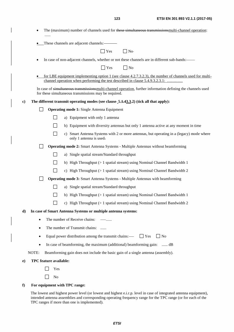
ETSI
ETSI EN 301 893 V2.1.1 (2017-05) 123
The (maximum) number of channels used for these simultaneous transmissionsmulti-channel operation:
......
These channels are adjacent channels:
Yes No
In case of non-adjacent channels, whether or not these channels are in different sub-bands:
Yes No
for LBE equipment implementing option 1 (see clause 4.2.7.3.2.3), the number of channels used for multi-
channel operation when performing the test described in clause 5.4.9.3.2.3.1: …………
In case of simultaneous transmissionsmulti-channel operation, further information defining the channels used
for these simultaneous transmissions may be required.
c) The different transmit operating modes (see clause 5.1.43.3.2) (tick all that apply):
Operating mode 1: Single Antenna Equipment
a) Equipment with only 1 antenna
b) Equipment with diversity antennas but only 1 antenna active at any moment in time
c) Smart Antenna Systems with 2 or more antennas, but operating in a (legacy) mode where
only 1 antenna is used.
Operating mode 2: Smart Antenna Systems - Multiple Antennas without beamforming
a) Single spatial stream/Standard throughput
b) High Throughput (> 1 spatial stream) using Nominal Channel Bandwidth 1
c) High Throughput (> 1 spatial stream) using Nominal Channel Bandwidth 2
Operating mode 3: Smart Antenna Systems - Multiple Antennas with beamforming
a) Single spatial stream/Standard throughput
b) High Throughput (> 1 spatial stream) using Nominal Channel Bandwidth 1
c) High Throughput (> 1 spatial stream) using Nominal Channel Bandwidth 2
d) In case of Smart Antenna Systems or multiple antenna systems:
The number of Receive chains: ......
The number of Transmit chains: ......
Equal power distribution among the transmit chains: Yes No
In case of beamforming, the maximum (additional) beamforming gain: ...... dB
NOTE: Beamforming gain does not include the basic gain of a single antenna (assembly).
e) TPC feature available:
Yes
No
f) For equipment with TPC range:
The lowest and highest power level (or lowest and highest e.i.r.p. level in case of integrated antenna equipment),
intended antenna assemblies and corresponding operating frequency range for the TPC range (or for each of the
TPC ranges if more than one is implemented).
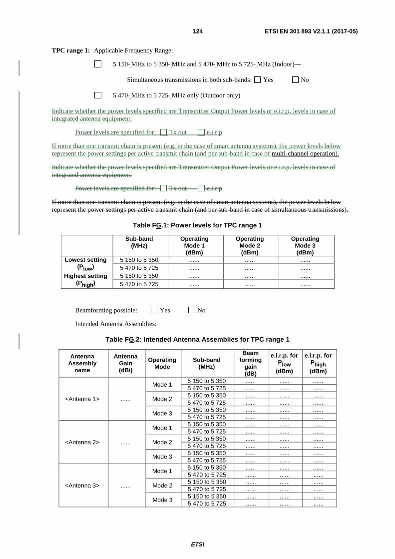
ETSI
ETSI EN 301 893 V2.1.1 (2017-05) 124
TPC range 1: Applicable Frequency Range:
5 150 MHz to 5 350 MHz and 5 470 MHz to 5 725 MHz (Indoor)
Simultaneous transmissions in both sub-bands: Yes No
5 470 MHz to 5 725 MHz only (Outdoor only)
Indicate whether the power levels specified are Transmitter Output Power levels or e.i.r.p. levels in case of
integrated antenna equipment.
Power levels are specified for: Tx out e.i.r.p
If more than one transmit chain is present (e.g. in the case of smart antenna systems), the power levels below
represent the power settings per active transmit chain (and per sub-band in case of multi-channel operation).
Indicate whether the power levels specified are Transmitter Output Power levels or e.i.r.p. levels in case of
integrated antenna equipment.
Power levels are specified for: Tx out e.i.r.p
If more than one transmit chain is present (e.g. in the case of smart antenna systems), the power levels below
represent the power settings per active transmit chain (and per sub-band in case of simultaneous transmissions).
Table FG.1: Power levels for TPC range 1
Sub-band
(MHz) Operating
Mode 1 (dBm)
Operating Mode 2 (dBm)
Operating Mode 3 (dBm)
Lowest setting (Plow)
5 150 to 5 350 ...... ...... ......
5 470 to 5 725 ...... ...... ......
Highest setting (Phigh)
5 150 to 5 350 ...... ...... ......
5 470 to 5 725 ...... ...... ......
Beamforming possible: Yes No
Intended Antenna Assemblies:
Table FG.2: Intended Antenna Assemblies for TPC range 1
Antenna Assembly
name
Antenna Gain (dBi)
Operating Mode
Sub-band (MHz)
Beam forming
gain (dB)
e.i.r.p. for Plow
(dBm)
e.i.r.p. for Phigh
(dBm)
<Antenna 1> ......
Mode 1 5 150 to 5 350 ...... ...... ......
5 470 to 5 725 ...... ...... ......
Mode 2 5 150 to 5 350 ...... ...... ......
5 470 to 5 725 ...... ...... ......
Mode 3 5 150 to 5 350 ...... ...... ......
5 470 to 5 725 ...... ...... ......
<Antenna 2> ......
Mode 1 5 150 to 5 350 ...... ...... ......
5 470 to 5 725 ...... ...... ......
Mode 2 5 150 to 5 350 ...... ...... ......
5 470 to 5 725 ...... ...... ......
Mode 3 5 150 to 5 350 ...... ...... ......
5 470 to 5 725 ...... ...... ......
<Antenna 3> ......
Mode 1 5 150 to 5 350 ...... ...... ......
5 470 to 5 725 ...... ...... ......
Mode 2 5 150 to 5 350 ...... ...... ......
5 470 to 5 725 ...... ...... ......
Mode 3 5 150 to 5 350 ...... ...... ......
5 470 to 5 725 ...... ...... ......

ETSI
ETSI EN 301 893 V2.1.1 (2017-05) 125
DFS Threshold levelLevel: ...... dBm at the antenna connector
in front of the antenna
TPC range 2: Applicable Frequency Range:
5 150 MHz to 5 350 MHz and 5 470 MHz to 5 725 MHz (Indoor)
Simultaneous transmissions in both sub-bands: Yes No
5 470 MHz to 5 725 MHz only (Outdoor only)
Indicate whether the power levels specified are Transmitter Output Power levels or e.i.r.p. levels in case of
integrated antenna equipment.
Power levels are specified for: Tx out e.i.r.p
If more than one transmit chain is present (e.g. in the case of smart antenna systems), the power levels below
represent the power settings per active transmit chain (and per sub-band in case of Indicate whether the power
levels specified are Transmitter Output Power levels or e.i.r.p. levels in case of integrated antenna equipment.
Power levels are specified for: Tx out e.i.r.psimultaneous transmissions).
If more than one transmit chain is present (e.g. in the case of smart antenna systems), the power levels below
represent the power settings per active transmit chain (and per sub-band in case of simultaneous transmissions).
Table FG.3: Power levels for TPC range 2
Sub-band
(MHz) Operating
Mode 1 (dBm)
Operating Mode 2 (dBm)
Operating Mode 3 (dBm)
Lowest setting (Plow)
5 150 to 5 350 ...... ...... ......
5 470 to 5 725 ...... ...... ......
Highest setting (Phigh)
5 150 to 5 350 ...... ...... ......
5 470 to 5 725 ...... ...... ......
Beamforming possible: Yes No
Intended Antenna Assemblies:

ETSI
ETSI EN 301 893 V2.1.1 (2017-05) 126
Table FG.4: Intended Antenna Assemblies for TPC range 2
Antenna Assembly
name
Antenna Gain (dBi)
Operating Mode
Sub-band (MHz)
Beam forming
gain (dB)
e.i.r.p. for Plow
(dBm)
e.i.r.p. for Phigh
(dBm)
<Antenna 1> ......
Mode 1 5 150 to 5 350 ...... ...... ......
5 470 to 5 725 ...... ...... ......
Mode 2 5 150 to 5 350 ...... ...... ......
5 470 to 5 725 ...... ...... ......
Mode 3 5 150 to 5 350 ...... ...... ......
5 470 to 5 725 ...... ...... ......
<Antenna 2> ......
Mode 1 5 150 to 5 350 ...... ...... ......
5 470 to 5 725 ...... ...... ......
Mode 2 5 150 to 5 350 ...... ...... ......
5 470 to 5 725 ...... ...... ......
Mode 3 5 150 to 5 350 ...... ...... ......
5 470 to 5 725 ...... ...... ......
<Antenna 3> ......
Mode 1 5 150 to 5 350 ...... ...... ......
5 470 to 5 725 ...... ...... ......
Mode 2 5 150 to 5 350 ...... ...... ......
5 470 to 5 725 ...... ...... ......
Mode 3 5 150 to 5 350 ...... ...... ......
5 470 to 5 725 ...... ...... ......
DFS Threshold levelLevel: ...... dBm at the antenna connector
in front of the antenna
g) For equipment without a TPC range:
Power Setting 1: Applicable Frequency Range:
5 150 MHz to 5 350 MHz and 5 470 MHz to 5 725 MHz (Indoor)
Simultaneous transmissions in both sub-bands: Yes No
5 470 MHz to 5 725 MHz only (Outdoor only)
Indicate whether the power levels specified are Transmitter Output Power levels or e.i.r.p. levels in case of
integrated antenna equipment.
Power levels are specified for: Tx out e.i.r.p.
If more than one transmit chain is present (e.g. in the case of smart antenna systems), the power levels below
represent the power settings per active transmit chain (and per sub-band in case of simultaneous transmissions).
Table FG.5: Maximum Transmitter Output Power for Power Setting 1
Sub-band (MHz)
Operating Mode 1 (dBm)
Operating Mode 2 (dBm)
Operating Mode 3 (dBm)
5 150 to 5 350 ...... ...... ......
5 470 to 5 725 ...... ...... ......
Beamforming possible: Yes No
Intended Antenna Assemblies:

ETSI
ETSI EN 301 893 V2.1.1 (2017-05) 127
Table FG.6: Intended Antenna Assemblies for Power Setting 1
Antenna Assembly
name
Antenna Gain (dBi)
Operating Mode
Sub-band (MHz)
Beam forming
gain (dB)
e.i.r.p. (dBm)
<Antenna 1> ......
Mode 1 5 150 to 5 350 ...... ......
5 470 to 5 725 ...... ......
Mode 2 5 150 to 5 350 ...... ......
5 470 to 5 725 ...... ......
Mode 3 5 150 to 5 350 ...... ......
5 470 to 5 725 ...... ......
<Antenna 2> ......
Mode 1 5 150 to 5 350 ...... ......
5 470 to 5 725 ...... ......
Mode 2 5 150 to 5 350 ...... ......
5 470 to 5 725 ...... ......
Mode 3 5 150 to 5 350 ...... ......
5 470 to 5 725 ...... ......
<Antenna 3> ......
Mode 1 5 150 to 5 350 ...... ......
5 470 to 5 725 ...... ......
Mode 2 5 150 to 5 350 ...... ......
5 470 to 5 725 ...... ......
Mode 3 5 150 to 5 350 ...... ......
5 470 to 5 725 ...... ......
DFS Threshold levelLevel: ...... dBm at the antenna connector
in front of the antenna
Power Setting 2: Applicable Frequency Range:
5 150 MHz to 5 350 MHz and 5 470 MHz to 5 725 MHz (Indoor)
Simultaneous transmissions in both sub-bands: Yes No
5 470 MHz to 5 725 MHz only (Outdoor only)
Indicate whether the power levels specified are Transmitter Output Power levels or e.i.r.p. levels in case of
integrated antenna equipment.
Power levels are specified for: Tx-out e.i.r.p.
If more than one transmit chain is present (e.g. in the case of smart antenna systems), the power levels below
represent the power settings per active transmit chain (and per sub-band in case of simultaneous
transmissions).
Table FG.7: Maximum Transmitter Output Power for Power Setting 2
Sub-band (MHz)
Operating Mode 1 (dBm)
Operating Mode 2 (dBm)
Operating Mode 3 (dBm)
5 150 to 5 350 ...... ...... ......
5 470 to 5 725 ...... ...... ......
Beamforming possible: Yes No
Intended Antenna Assemblies:

ETSI
ETSI EN 301 893 V2.1.1 (2017-05) 128
Table FG.8: Intended Antenna Assemblies for Power Setting 2
Antenna Assembly
name
Antenna Gain (dBi)
Operating Mode
Sub-band (MHz)
Beam forming
gain (dB)
e.i.r.p. (dBm)
<Antenna 1> ......
Mode 1 5 150 to 5 350 ...... ......
5 470 to 5 725 ...... ......
Mode 2 5 150 to 5 350 ...... ......
5 470 to 5 725 ...... ......
Mode 3 5 150 to 5 350 ...... ......
5 470 to 5 725 ...... ......
<Antenna 2> ......
Mode 1 5 150 to 5 350 ...... ......
5 470 to 5 725 ...... ......
Mode 2 5 150 to 5 350 ...... ......
5 470 to 5 725 ...... ......
Mode 3 5 150 to 5 350 ...... ......
5 470 to 5 725 ...... ......
<Antenna 3> ......
Mode 1 5 150 to 5 350 ...... ......
5 470 to 5 725 ...... ......
Mode 2 5 150 to 5 350 ...... ......
5 470 to 5 725 ...... ......
Mode 3 5 150 to 5 350 ...... ......
5 470 to 5 725 ...... ......
DFS Threshold levelLevel: ...... dBm at the antenna connector
in front of the antenna
h) The DFS related operating mode(s) of the equipment:
Master
Slave with radar detection
Slave without radar detection
If the equipment has more than one operating mode, tick all that apply.
i) User access restrictions (please check box below to confirm):
theThe equipment is constructed to comply with the requirements contained in clause 4.102.9 in
ETSI EN 301 893 V1.8V2.1.1
j) For equipment with Off-Channel CAC functionality:
The equipment has an "Off-Channel CAC" function: Yes No
If yes, specify the "Off-Channel CAC Time"
- For channels outside the 5 600 MHz to 5 650 MHz range:
......... hours
- If applicable, for channels (partially) within the 5 600 MHz to 5 650 MHz range: ......... hours
k) The equipment can operate in ad-hoc mode:
no ad-hoc operation
ad-hoc operation in the frequency range 5 150 MHz to 5 250 MHz without DFS
ad-hoc operation with DFS
If more than 1 is applicable, tick all that apply.
l) Operating Frequency Range(s):

ETSI
ETSI EN 301 893 V2.1.1 (2017-05) 129
Range 1: 5 150 MHz to 5 350 MHz and 5 470 MHz to 5 725 MHz
Range 2: 5 470 MHz to 5 725 MHz
Range 3: 5 150 MHz to 5 250 MHz (ad-hoc without DFS)
Range 4: other, please specify: ……………..
If the equipment has more than one Operating Frequency Range, tick all that apply.
m) The extreme operating temperature and supply voltage range that apply to the equipment:
-20 °C to +55 °C (Outdoor & Indoor usage)
0 °C to +35 °C (Indoor usage only)
Other: ..................................................................................
The supply voltages of the stand-alone radio equipment or the supply voltages of the combined (host) equipment
or test jig in case of plug-in devices:
Details provided are for the: stand-alone equipment
combined (or host) equipment
test jig
Supply Voltage AC mains State AC voltage: Minimum: … Nominal: ... Maximum: ...
DC State DC voltage Minimum: … Nominal: ... Maximum: ...
In case of DC, indicate the type of power source:
Internal Power Supply
External Power Supply or AC/DC adapter
Battery Nickel Cadmium
Alkaline
Nickel-Metal Hydride
Lithium-Ion
Lead acid (Vehicle regulated)
Other ..............................
n) The test sequence/test software used (see also ETSI EN 301 893 (V1.8V2.1.1), clause 5.3.1.2):
..................................................................................
..................................................................................
..................................................................................
o) Type of Equipment:
Stand-alone
Combined Equipment (Equipment where the radio part is fully integrated within another type of
equipment)
Plug-in radio device (Equipment intended for a variety of host systems)
Other ..................................................................................
p) Adaptivity (Channel Access Mechanism):

ETSI
ETSI EN 301 893 V2.1.1 (2017-05) 130
Frame Based Equipment
Load Based Equipment – Option A
q) With regards to Adaptivity for Frame Based Equipment/
The Frame Based Equipment operates as an Initiating Device
The Frame Based Equipment operates as an Responding Device
The Frame Based Equipment can operate as an Initiating Device and as a Responding Device
The Frame Based Equipment has implemented the following Fixed Frame Period(s):
………. ms
………. ms
………. ms
r) With regards to Adaptivity for Load Based Equipment –/
The Load Based Equipment operates as a Supervising Device
The Load Based Equipment operates as a Supervised Device
The Load Based Equipment can operate as a Supervising and as a Supervised Device
The Load Based Equipment makes use of note 1 in table 7 or note 1 in table 8 of ETSI EN 301 893
V2.1.1
The Load Based Equipment , when operating as a Supervising Device, makes use of note 2 in table 7 of
ETSI EN 301 893 V2.1.1
The Priority Classes implemented by the Load Based Equipment
When operating as a Supervising Device
Priority Class 4 (Highest priority)
Priority Class 3
Priority Class 2
Priority Class 1 (Lowest priority)
When operating as a Supervised Device
Priority Class 4 (Highest priority)
Priority Class 3
Priority Class 2
Priority Class 1 (Lowest priority)
The Load Based Equipment operates as an Initiating Device
The Load Based Equipment operates as an Responding Device
The Load Based Equipment can operate as an Initiating Device and as a Responding Device
With regard to Energy Detection Threshold, the Load Based Equipment has implemented either option 1 of
clause 4.2.7.3.2.5 of ETSI EN 301 893 V2.1.1 or option 2 of clause 4.2.7.3.2.5 of ETSI EN 301 893 V2.1.1:
Option 1
Option B2

ETSI
ETSI EN 301 893 V2.1.1 (2017-05) 131
Specify which protocol has been implemented: IEEE 802.11™ Other: ............
qs) The CCA time implemented by the equipment: …….
In case of Load Based Equipment implementing Option B (see supports a geo-location capability as defined
in clause 4.8.3.2) the value q: ……2.10 of ETSI EN 301 893 V2.1.1:
F Yes No
t) The minimum performance criteria (see ETSI EN 301 893 V2.1.1, clause 4.2.8.3) that corresponds to the
intended use of the equipment:
..................................................................................
..................................................................................
..................................................................................
u) The theoretical maximum radio performance of the equipment (e.g. maximum throughput) (see ETSI
EN 301 893 V2.1.1, clause 5.4.9.3.1):
..................................................................................
G.3 Additional information provided by the manufacturer
FG.3.1 Modulation
Can the transmitter operate un-modulated? Yes No
FG.3.2 Duty Cycle
The transmitter is intended for : Continuous duty
Intermittent duty
Continuous operation possible for testing purposes
FG.3.3 About the UUT
The equipment submitted are representative production models.
If not, the equipment submitted are pre-production models?
If pre-production equipment are submitted, the final production equipment will be identical in all respects
with the equipment tested.
If not, supply full details:
..................................................................................
..................................................................................
The equipment submitted is CE marked:
The CE marking does include the Class-II identifier (Alert Sign).
The CE marking does include a 4 digit number referring to the Notified Body involved.
F ..................................................................................
..................................................................................

ETSI
ETSI EN 301 893 V2.1.1 (2017-05) 132
G.3.4 List of ancillary and/or support equipment provided by the manufacturer
Spare batteries (e.g. for portable equipment)
Battery charging device
External Power Supply or AC/DC adapter
Test Jig or interface box
RF test fixture (for equipment with integrated antennas)
Host System Manufacturer: ....................
Model #: . ....................
Model name: ....................
Combined equipment Manufacturer: ....................
Model #: ....................
Model name: ....................
User manual
Technical documentation (Handbook and circuit diagrams)

ETSI
ETSI EN 301 893 V2.1.1 (2017-05) 133
Annex GH (informative): Bibliography
Recommendation ITU-R M.1652: "Dynamic frequency selection (DFS) in wireless access systems including
radio local area networks for the purpose of protecting the radiodeterminationradio determination service in
the 5 GHz band".
Directive 2004/108/EC of the European Parliament and of the Council of 15 December 2004 on the
approximation of the laws of the Member States relating to electromagnetic compatibility and repealing
Directive 89/336/EEC (EMC Directive).
Directive 2006/95/EC of the European Parliament and of the Council of 12 December 2006 on the harmonisation of the
laws of Member States relating to electrical equipment designed for use within certain voltage limits (LV Directive).

ETSI
ETSI EN 301 893 V2.1.1 (2017-05) 134
Annex I (informative): Change history
Version Information about changes
2.1.1
First published version covering Directive 2014/53/EU. Major changes are:
Inclusion of Receiver Blocking as a new requirement.
Revision of the Adaptivity Requirement to accommodate multiple technologies.
Revised test method for Adaptivity.
Modifications required for alignment with Directive 2014/53/EU.

ETSI
ETSI EN 301 893 V2.1.1 (2017-05) 135
History
Document history
V1.2.3 August 2003 Publication
V1.3.1 August 2005 Publication
V1.4.1 July 2007 Publication
V1.5.1 December 2008 Publication
V1.6.1 November 2011 Publication
V1.7.1 June 2012 Publication
V1.8.1 March 2015 Publication
V2.0.7 November 2016 EN Approval Procedure AP 20170227: 2016-11-29 to 2017-02-27
V2.1.0 March 2017 Vote V 20170523: 2017-03-24 to 2017-05-23
V2.1.1 May 2017 Publication