etsi en 301 489-27 v2.1 301 489... · etsi en 301 489-27 v2.1.1 ... directive 1999/5/ec of the...
TRANSCRIPT
ETSI EN 301 489-27 V2.1.1 (2016-12)
Candidate Harmonized European Standard (Telecommunications series)
Electromagnetic compatibility and Radio spectrum Matters (ERM);
ElectroMagnetic Compatibility (EMC) standard for radio equipment and services;
Part 27: Specific conditions for Ultra Low Power Active Medical Implants (ULP-AMI) and
related peripheral devices (ULP-AMI-P); Harmonised Standard covering the essential requirements
of article 3.1(b) of Directive 2014/53/EU
HARMONISED EUROPEAN STANDARD
ETSI
ETSI EN 301 489-27 V2.1.1 (2016-12) 2
Reference
DENREN/ERM-EMC-235-27352
Keywords
EMC, harmonised standard, radio, regulation, RTTT, short range
ETSI
650 Route des Lucioles F-06921 Sophia Antipolis Cedex - FRANCE
Tel.: +33 4 92 94 42 00 Fax: +33 4 93 65 47 16
Siret N° 348 623 562 00017 - NAF 742 C
Association à but non lucratif enregistrée à la Sous-Préfecture de Grasse (06) N° 7803/88
Important notice
The present document can be downloaded from: http://www.etsi.org/standards-search
The present document may be made available in electronic versions and/or in print. The content of any electronic and/or print versions of the present document shall not be modified without the prior written authorization of ETSI. In case of any
existing or perceived difference in contents between such versions and/or in print, the only prevailing document is the print of the Portable Document Format (PDF) version kept on a specific network drive within ETSI Secretariat.
Users of the present document should be aware that the document may be subject to revision or change of status. Information on the current status of this and other ETSI documents is available at
https://portal.etsi.org/TB/ETSIDeliverableStatus.aspx
If you find errors in the present document, please send your comment to one of the following services: https://portal.etsi.org/People/CommiteeSupportStaff.aspx
Copyright Notification
No part may be reproduced or utilized in any form or by any means, electronic or mechanical, including photocopying and microfilm except as authorized by written permission of ETSI.
The content of the PDF version shall not be modified without the written authorization of ETSI. The copyright and the foregoing restriction extend to reproduction in all media.
© European Telecommunications Standards Institute 2016.
All rights reserved.
DECTTM, PLUGTESTSTM, UMTSTM and the ETSI logo are Trade Marks of ETSI registered for the benefit of its Members. 3GPPTM and LTE™ are Trade Marks of ETSI registered for the benefit of its Members and
of the 3GPP Organizational Partners. GSM® and the GSM logo are Trade Marks registered and owned by the GSM Association.
ETSI
ETSI EN 301 489-27 V2.1.1 (2016-12) 3
Contents
Intellectual Property Rights ................................................................................................................................ 5
Foreword............................................................................................................................................................. 5
Modal verbs terminology ................................................................................................................................... 5
1 Scope ........................................................................................................................................................ 6
2 References ................................................................................................................................................ 6 2.1 Normative references ......................................................................................................................................... 6 2.2 Informative references ....................................................................................................................................... 7
3 Definitions and abbreviations ................................................................................................................... 8 3.0 Applicability ...................................................................................................................................................... 8 3.1 Definitions ......................................................................................................................................................... 8 3.2 Abbreviations ..................................................................................................................................................... 8
4 Test conditions ......................................................................................................................................... 9 4.1 General ............................................................................................................................................................... 9 4.2 Arrangements for test signals............................................................................................................................. 9 4.2.0 General ......................................................................................................................................................... 9 4.2.1 Arrangements for test signals at the input of transmitters ............................................................................ 9 4.2.2 Arrangements for test signals at the RF output of transmitters .................................................................. 10 4.2.2.1 General ................................................................................................................................................. 10 4.2.2.2 ULP-AMI transmitters .......................................................................................................................... 10 4.2.2.3 ULP-AMI-P transmitters ...................................................................................................................... 10 4.2.3 Arrangements for test signals at the RF input of receivers ......................................................................... 10 4.2.4 Arrangements for test signals at the output of receivers............................................................................. 10 4.2.5 Arrangements for testing transmitter and receiver together (as a system: ULP-AMI together with an
associated ULP-AMI-P) ............................................................................................................................. 10 4.3 RF exclusion band of radio equipment ............................................................................................................ 11 4.3.0 General ....................................................................................................................................................... 11 4.3.1 Exclusion bands for receivers..................................................................................................................... 11 4.3.2 Exclusion band for transmitters .................................................................................................................. 11 4.4 Narrow band responses of receivers or receivers which are part of transceivers ............................................. 12 4.5 Normal test modulation ................................................................................................................................... 12
5 Performance assessment ......................................................................................................................... 12 5.1 General ............................................................................................................................................................. 12 5.2 Equipment which can provide a continuous communication link ................................................................... 12 5.3 Equipment which does not provide a continuous communication link ............................................................ 12 5.4 Ancillary equipment ........................................................................................................................................ 12 5.5 Equipment classification .................................................................................................................................. 13
6 Performance criteria ............................................................................................................................... 13 6.1 classification of ULP-AMI and ULP-AMI-P devices ...................................................................................... 13 6.2 General performance criteria ........................................................................................................................... 13 6.3 Performance criteria and table ......................................................................................................................... 14 6.4 Performance criteria for continuous phenomena applied to transmitters ......................................................... 15 6.5 Performance criteria for transient phenomena applied to transmitters ............................................................. 15 6.6 Performance criteria for continuous phenomena applied to receivers ............................................................. 15 6.7 Performance criteria for transient phenomena applied to receivers ................................................................. 16
7 Applicability overview ........................................................................................................................... 16 7.1 EMC emission ................................................................................................................................................. 16 7.1.1 General ....................................................................................................................................................... 16 7.1.2 Special conditions ...................................................................................................................................... 16 7.2 Immunity ......................................................................................................................................................... 17 7.2.1 General ....................................................................................................................................................... 17 7.2.2 Special conditions ...................................................................................................................................... 17
ETSI
ETSI EN 301 489-27 V2.1.1 (2016-12) 4
Annex A (normative): Relationship between the present document and the essential
requirements of Directive 2014/53/EU ......................................................... 21
Annex B (normative): Definitions of types of ULP-AMI and ULP-AMI-P devices in the
scope of the present document ...................................................................... 23
B.1 ULP-AMI and ULP-AMI-P devices intended for operation in the frequency range 402 MHz to
405 MHz ................................................................................................................................................. 23
Annex C (normative): Test fixture for ULP-AMI (Simulated man) ............................................... 24
History .............................................................................................................................................................. 28
ETSI
ETSI EN 301 489-27 V2.1.1 (2016-12) 5
Intellectual Property Rights
IPRs essential or potentially essential to the present document may have been declared to ETSI. The information
pertaining to these essential IPRs, if any, is publicly available for ETSI members and non-members, and can be found
in ETSI SR 000 314: "Intellectual Property Rights (IPRs); Essential, or potentially Essential, IPRs notified to ETSI in
respect of ETSI standards", which is available from the ETSI Secretariat. Latest updates are available on the ETSI Web
server (https://ipr.etsi.org/).
Pursuant to the ETSI IPR Policy, no investigation, including IPR searches, has been carried out by ETSI. No guarantee
can be given as to the existence of other IPRs not referenced in ETSI SR 000 314 (or the updates on the ETSI Web
server) which are, or may be, or may become, essential to the present document.
Foreword
This Candidate HarmonizedHarmonised European Standard (Telecommunications seriesEN) has been produced by
ETSI Technical Committee Electromagnetic compatibility and Radio spectrum Matters (ERM).
The present document has been produced by ETSI in response to a mandate from the European Commission
issuedprepared under the Council Directive 98/34/ECCommission's standardisation request C(2015) 5376 final [i.4] (as
amended) laying down a procedure for the provision of information in the field of technical standards and regulation.
The] to provide one voluntary means of conforming to the essential requirements of Directive 2014/53/EU on the
harmonisation of the laws of the Member States relating to the making available on the market of radio equipment and
repealing Directive 1999/5/EC [i.1].
Once the present document, together with EN 301 489-1 [1], is intended to become a Harmonized Standard, the
reference of which will be publishedcited in the Official Journal of the European Communities referencing the Council
Directive on the approximation of the laws of the Member States relating to electromagnetic compatibility ("the
EMCUnion under that Directive") (89/336/EEC [3] as amended), and Directive 1999/5/EC , compliance with the
normative clauses of the European Parliament andpresent document given in table A.1 confers, within the limits of the
Councilscope of 9 March 1999 on radio equipment and telecommunications terminal equipment and the mutual
recognitionpresent document, a presumption of their conformity ("with the R&TTE Directive" [2]).corresponding
essential requirements of that Directive and associated EFTA regulations.
The present document is part 27 of a multi-part deliverable. Full details of the entire series can be found in part ETSI
EN 301 489-1 [11].
National transposition dates
Date of adoption of this EN: 12 December 2016
Date of latest announcement of this EN (doa): 31 March 2017
Date of latest publication of new National Standard
or endorsement of this EN (dop/e):
30 September 2017
Date of withdrawal of any conflicting National Standard (dow): 30 September 2018
Modal verbs terminology
In the present document "shall", "shall not", "should", "should not", "may", "need not", "will", "will not", "can" and
"cannot" are to be interpreted as described in clause 3.2 of the ETSI Drafting Rules (Verbal forms for the expression of
provisions).
"must" and "must not" are NOT allowed in ETSI deliverables except when used in direct citation.
ETSI
ETSI EN 301 489-27 V2.1.1 (2016-12) 6
1 Scope
The present document together with ETSI EN 301 489-1 [1], covers the assessment of all radio transceivers associated
with Ultra Low Power Active Medical Implants (ULP-AMIs) and associated Peripheral ULP-AMI-Ps) in respect of
ElectroMagnetic Compatibility (EMC).
The present document covers the EMC requirements for the radio functions of ULP-AMI and ULP-AMI-P devices.
Technical specifications related to the antenna port and emissions from the enclosure port of the ULP-AMI and ULP-
AMI-P devices radio system are not included in the present document. Such technical specifications are found in the
relevant product standards for the effective use of the radio spectrum.
The present document specifies the applicable test conditions, performance assessment, and performance criteria for
ULP-AMIs and associated Peripheral devices (ULP-AMI-Ps).
Definitions of types of ULP-AMIs and ULP-AMI-Ps covered by present document are given in annex A B.
In case of differences (for instance concerning special conditions, definitions, abbreviations) between the present
document and ETSI EN 301 489-1 [1], the provisions of the present document take precedence.
The environmental classification and the emission and immunity requirements used in the present document are as
stated in theETSI EN 301 489-1 [1], except for any special conditions included in the present document.
The present document, together with ETSI EN 301 489-1 [1], contains requirements to demonstrate an adequate level of
electromagnetic compatibility as set out in Directive 2014/53/EU [i.1].
2 References
2.1 Normative references
References are either specific (identified by date of publication and/or edition number or version number) or
non-specific. For specific references, only the cited version applies. For non-specific references, the latest version of the
referenced document (including any amendments) applies.
For a specific reference, subsequent revisions do not apply.
For a non-specific reference, the latest version applies.
Referenced documents which are not found to be publicly available in the expected location might be found at
httphttps://docbox.etsi.org/Reference/.
NOTE: While any hyperlinks included in this clause were valid at the time of publication, ETSI cannot guarantee
their long term validity.
The following referenced documents are necessary for the application of the present document.
[1] ETSI EN 301 489-1 (V1.4V2.1): "Electromagnetic compatibility and Radio spectrum Matters
(ERM); .1) (11-2016): "ElectroMagnetic Compatibility (EMC) standard for radio equipment and
services;
Part 1: Common technical requirements; Harmonised Standard covering the essential requirements
of article 3.1(b) of Directive 2014/53/EU and the essential requirements of article 6 of Directive
2014/30/EU".
NOTE: Available at
http://www.etsi.org/deliver/etsi_en/301400_301499/30148901/02.01.01_30/en_30148901v020101v.pdf.
[2] Directive 1999/5/EC of the European ParliamentETSI EN 301 839 (V2.1.1) (04-2016): "Ultra Low
Power Active Medical Implants (ULP-AMI) and of the Council of 9 March 1999 on radio
equipment and telecommunications terminal equipment and the mutual recognition of their
conformity (R&TTE Directive).
ETSI
ETSI EN 301 489-27 V2.1.1 (2016-12) 7
[3] Council Directive 89/336/EEC of 3 May 1989 on the approximation of the laws of the Member
States relating to electromagnetic compatibility (EMC Directive).
[4] Directive 98/34/EC of the European Parliament and of the Council of 22 June 1998 laying down a
procedure for the provision of information in the field of technical standards and regulations.
[5] ETSI EN 301 839-1 (V1.1.1): "Electromagnetic compatibility and Radio spectrum Matters (ERM);
Radio equipmentassociated Peripherals (ULP-AMI-P) operating in the frequency range 402 MHz
to 405 MHz for Ultra Low Power Active Medical Implants and Accessories; Part 1: Technical
characteristics, including electromagnetic compatibility requirements, and test methods;
Harmonised Standard covering the essential requirements of article 3.2 of the Directive
2014/53/EU".
[3] ETSI EN 301 839-2 (V1.1.1): "Electromagnetic compatibility and Radio spectrum Matters (ERM);
Radio equipment in the frequency range 402 MHz to 405 MHz for Ultra Low Power Active
Medical Implants and Accessories; Part 2: Harmonized EN covering essential requirements of
article 3.2 of the R&TTE Directive".
[7] EN ] IEC EN 60601-1-2: (2007): "Medical electrical equipment - Part 1-2: General requirements
for safety - Collateral standard: Electromagnetic compatibility - Requirements and tests".
[4] CEPT/ERC/REC 70-03: "Relating to the use of Short Range Devices (SRD)".
[9] ] IEC EN 61000-4-5: (2006): "Electromagnetic compatibility (EMC) - Part 4-5: Testing and
measurement techniques - Surge immunity test".
2.2 Informative references
References are either specific (identified by date of publication and/or edition number or version number) or
non-specific. For specific references, only the cited version applies. For non-specific references, the latest version of the
referenced document (including any amendments) applies.
NOTE: While any hyperlinks included in this clause were valid at the time of publication, ETSI cannot guarantee
their long term validity.
The following referenced documents are not necessary for the application of the present document but they assist the
user with regard to a particular subject area.
[i.1] Directive 2014/53/EU of the European Parliament and of the council of 16 April 2014 on the
harmonisation of the laws of the Member States relating to the making available on the market of
radio equipment and repealing Directive 1999/5/EC.
[i.2] CEPT/ERC/REC 70-03: "Relating to the use of Short Range Devices (SRD)".
[i.3] Camelia Gabriel: "Compilation of the dielectric properties of body tissues at RF and Microwave
Frequencies", Physics Department, King's College, London WC2R 2LS, UK. February 1996.
NOTE: Available at http://www.dtic.mil/dtic/tr/fulltext/u2/a305826.pdf.
[i.4] Commission Implementing Decision C(2015) 5376 final of 4.8.2015 on a standardisation request
to the European Committee for Electrotechnical Standardisation and to the European
Telecommunications Standards Institute as regards radio equipment in support of Directive
2014/53/EU of the European Parliament and of the Council.
[i.5] Italian National Research Council, Institute for Applied Physics.
NOTE: Available at http://niremf.ifac.cnr.it/.

ETSI
ETSI EN 301 489-27 V2.1.1 (2016-12) 8
3 Definitions and abbreviations
3.0 Applicability
For the purposes of the present document, definitions and abbreviations have the meanings ascribed herein in clause 3.
Where such meanings are not so ascribed the meanings in ETSI EN 301 489-1 [1], clause 3, apply.
Where such meanings are not so ascribed the meanings in ETSI EN 301 839 [2], clause 3, apply.
Where such meanings are not so ascribed the meanings in the Directive 2014/53/EU [i.1] apply.
3.1 Definitions
For the purposes of the present document, the following terms and definitions given in EN 301 489-1 [1] and the
following apply:
Active Medical Implant (AMI): diagnostic or therapeutic device designed to be implanted in a human body containing
a power source and a transceiver using the 402 MHz to 405 MHz frequency band for the purpose of providing a
two-way digital communications link
environmental profile: range of environmental conditions under which equipment within the scope of the present
document is required to comply with the provisions of the present document
life supporting equipment: equipment whose continued normal operation is required in order to sustain life
Medical Implant Communications Link (MICL): collections of transmission that may or may not be continuous,
between co-operating medical implant devices and accessories, including programmer/controllers, transferring patient
related information in communications service
Medical Implant Communications System (MICS): specific system providing radiocommunications between an
ULP-AMI and an associated ULP-AMI-P
Ultra Low Power Active Medical Implant (ULP-AMI): transmitter or receiver or transceiver forming part of an
active medical implant, that is used in a medical implant communications system radio link set up by the peripheral
device (ULP-AMI-P)
Ultra Low Power Active Medical Implant Peripheral device (ULP-AMI-P): radio part of equipment outside the
human body, including body worn devices, used to program and/or control an ULP-AMI by means of a Medical
Implant (radio) Communications Link (MICL), such as an external programmer or control transceiver
environmental profile: range of environmental conditions under which equipment within the scope of EN 301 489-27
is required to comply with the provisions of EN 301 489-27
life supporting equipment: equipment whose continued normal operation is required in order to sustain life
Medical Implant Communications Link (MICL): collections of transmission that may or may not be continuous,
between co-operating medical implant devices and accessories, including programmer/controllers, transferring patient
related information in communications service
Medical Implant Communications System (MICS): specific system providing radiocommunications between an
ULP-AMI and an associated ULP-AMI-P
Active Medical Implant (AMI): diagnostic or therapeutic device designed to be implanted in a human body containing
a power source and a transceiver using the 402 MHz to 405 MHz frequency band for the purpose of providing a
two-way digital communications link
ETSI
ETSI EN 301 489-27 V2.1.1 (2016-12) 9
3.2 Abbreviations
For the purposes of the present document, the following abbreviations apply:
AC Alternating Current
AIMD Active Implantable Medical Device
AMI Active Medical Implant
DC Direct Current
EMC ElectroMagnetic Compatibility
ERP Effective Radiated Power
EUT Equipment Under Test
ISM Industrial, Scientific and Medical
MICL Medical Implant Communications Link
MICS Medical Implant Communications System
R&TTE Radio and Telecommunications Terminal Equipment
RF Radio Frequency
ULP-AMI Ultra Low Power Active Medical Implant
ULP-AMI-P Ultra Low Power Active Medical Implant Peripheral device
4 Test conditions
4.1 General
For the purposes of the present document, the test conditions of the ETSI EN 301 489-1 [1], clause 4, shall apply as
appropriate. Further product related test conditions for ULP-AMI and associated ULP-AMI-P are specified in the
present document.
4.1 General
For emission and immunity tests the normal test modulation, test arrangements, etc., as specified in the present
document, clauses 4.1 to 4.5 shall apply.
Whenever the Equipment Under Test (EUT) is provided with a detachable antenna, the EUT shall be tested with the
antenna fitted in a manner typical of normal intended use, unless otherwise specified. If the EUT can be used with
several types of antenna the test shall be repeated for each type of antenna.
ULP-AMI devices (active medical implants) are designed to be implanted within a human body. These radio systems
are isolated from disturbances by the surrounding body tissue. In order to adequately assess the EMC characteristics of
active medical implants devices , the use of a simulated man is necessary. See annex BC for additional details. The
provisions of annex BC are intended to provide an operational environment that simulates, to the extent possible, actual
usage conditions for internal implanted devices. It is necessary to use this or another appropriate special fixture when
making emission measurements and immunity tests with radiated RF fields.
4.2 Arrangements for test signals
4.2.0 General
The provisions of the ETSI EN 301 489-1 [1], clause 4.2 shall apply.
4.2.1 Arrangements for test signals at the input of the transmittertransmitters
The provisions of the ETSI EN 301 489-1 [1], clause 4.2.1 shall apply with the following modifications:
The transmitter shall be modulated with normal test modulation as specified for that type of equipment (see clause 4.5).
Where transmitters do not have a modulation input port, the internal equipment modulation shall be used.
ETSI
ETSI EN 301 489-27 V2.1.1 (2016-12) 10
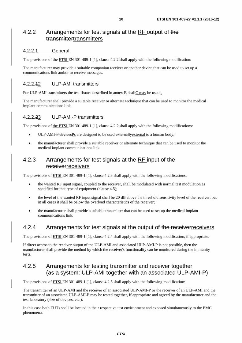
4.2.2 Arrangements for test signals at the RF output of the transmittertransmitters
4.2.2.1 General
The provisions of the ETSI EN 301 489-1 [1], clause 4.2.2 shall apply with the following modification:
The manufacturer may provide a suitable companion receiver or another device that can be used to set up a
communications link and/or to receive messages.
4.2.2.12 ULP-AMI transmitters
For ULP-AMI transmitters the test fixture described in annex B shallC may be used:.
The manufacturer shall provide a suitable receiver or alternate technique that can be used to monitor the medical
implant communications link.
4.2.2.23 ULP-AMI-P transmitters
The provisions of the ETSI EN 301 489-1 [1], clause 4.2.2 shall apply with the following modifications:
ULP-AMI-P devicesPs are designed to be used externallyexternal to a human body;
the manufacturer shall provide a suitable receiver or alternate technique that can be used to monitor the
medical implant communications link.
4.2.3 Arrangements for test signals at the RF input of the receiverreceivers
The provisions of ETSI EN 301 489-1 [1], clause 4.2.3 shall apply with the following modifications:
the wanted RF input signal, coupled to the receiver, shall be modulated with normal test modulation as
specified for that type of equipment (clause 4.5);
the level of the wanted RF input signal shall be 20 dB above the threshold sensitivity level of the receiver, but
in all cases it shall be below the overload characteristics of the receiver;
the manufacturer shall provide a suitable transmitter that can be used to set up the medical implant
communications link.
4.2.4 Arrangements for test signals at the output of the receiverreceivers
The provisions of ETSI EN 301 489-1 [1], clause 4.2.4 shall apply with the following modification, if appropriate:
If direct access to the receiver output of the ULP-AMI and associated ULP-AMI-P is not possible, then the
manufacturer shall provide the method by which the receiver's functionality can be monitored during the immunity
tests.
4.2.5 Arrangements for testing transmitter and receiver together (as a system: ULP-AMI together with an associated ULP-AMI-P)
The provisions of ETSI EN 301 489-1 [1], clause 4.2.5 shall apply with the following modification:
The transmitter of an ULP-AMI and the receiver of an associated ULP-AMI-P or the receiver of an ULP-AMI and the
transmitter of an associated ULP-AMI-P may be tested together, if appropriate and agreed by the manufacturer and the
test laboratory (size of devices, etc.).
In this case both EUTs shall be located in their respective test environment and exposed simultaneously to the EMC
phenomena.
ETSI
ETSI EN 301 489-27 V2.1.1 (2016-12) 11
4.3 Exclusion bands
4.3 RF exclusion band of radio equipment
4.3.0 General
The emission measurement and immunity test exclusions are referred to as "exclusion bands" and are defined in the
clauses 4.3.1 and 4.3.2 of the present document.
The frequencies on which the EUT is intended to operate, shall be excluded from conducted and radiated RF immunity
tests.
The frequencies on which the transmitter part of the EUT is intended to operate shall be excluded from emission
measurements when performed in transmit mode of operation.
During emission measurements, a frequency exclusion band does not apply for the receiver part of ULP-AMIs and/or
associated ULP-AMI-Ps.
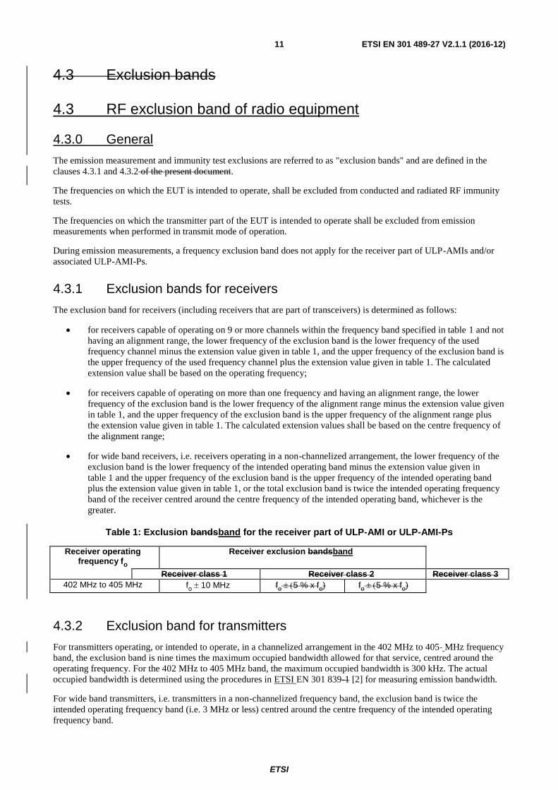
4.3.1 Exclusion bands for receivers
The exclusion band for receivers (including receivers that are part of transceivers) is determined as follows:
for receivers capable of operating on 9 or more channels within the frequency band specified in table 1 and not
having an alignment range, the lower frequency of the exclusion band is the lower frequency of the used
frequency channel minus the extension value given in table 1, and the upper frequency of the exclusion band is
the upper frequency of the used frequency channel plus the extension value given in table 1. The calculated
extension value shall be based on the operating frequency;
for receivers capable of operating on more than one frequency and having an alignment range, the lower
frequency of the exclusion band is the lower frequency of the alignment range minus the extension value given
in table 1, and the upper frequency of the exclusion band is the upper frequency of the alignment range plus
the extension value given in table 1. The calculated extension values shall be based on the centre frequency of
the alignment range;
for wide band receivers, i.e. receivers operating in a non-channelized arrangement, the lower frequency of the
exclusion band is the lower frequency of the intended operating band minus the extension value given in
table 1 and the upper frequency of the exclusion band is the upper frequency of the intended operating band
plus the extension value given in table 1, or the total exclusion band is twice the intended operating frequency
band of the receiver centred around the centre frequency of the intended operating band, whichever is the
greater.
Table 1: Exclusion bandsband for the receiver part of ULP-AMI or ULP-AMI-Ps
Receiver operating frequency fo
Receiver exclusion bandsband
Receiver class 1 Receiver class 2 Receiver class 3
402 MHz to 405 MHz fo 10 MHz fo5 % x fo) fo5 % x fo)
4.3.2 Exclusion band for transmitters
For transmitters operating, or intended to operate, in a channelized arrangement in the 402 MHz to 405 MHz frequency
band, the exclusion band is nine times the maximum occupied bandwidth allowed for that service, centred around the
operating frequency. For the 402 MHz to 405 MHz band, the maximum occupied bandwidth is 300 kHz. The actual
occupied bandwidth is determined using the procedures in ETSI EN 301 839-1 [2] for measuring emission bandwidth.
For wide band transmitters, i.e. transmitters in a non-channelized frequency band, the exclusion band is twice the
intended operating frequency band (i.e. 3 MHz or less) centred around the centre frequency of the intended operating
frequency band.
ETSI
ETSI EN 301 489-27 V2.1.1 (2016-12) 12
In case the receiver and transmitter are tested together as a system (see clause 4.2.5) the exclusion band defined for
receivers or the exclusion band defined for transmitters shall be used, whichever is greater.
4.4 Narrow band responses of receivers or receivers which are part of transceivers
The provision of ETSI EN 301 489-1 [1], clause 4.4 shall apply.
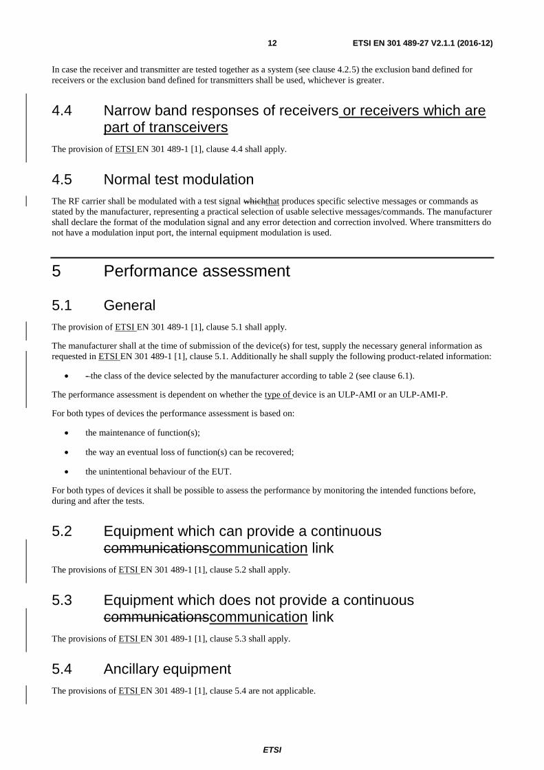
4.5 Normal test modulation
The RF carrier shall be modulated with a test signal whichthat produces specific selective messages or commands as
stated by the manufacturer, representing a practical selection of usable selective messages/commands. The manufacturer
shall declare the format of the modulation signal and any error detection and correction involved. Where transmitters do
not have a modulation input port, the internal equipment modulation is used.
5 Performance assessment
5.1 General
The provision of ETSI EN 301 489-1 [1], clause 5.1 shall apply.
The manufacturer shall at the time of submission of the device(s) for test, supply the necessary general information as
requested in ETSI EN 301 489-1 [1], clause 5.1. Additionally he shall supply the following product-related information:
- the class of the device selected by the manufacturer according to table 2 (see clause 6.1).
The performance assessment is dependent on whether the type of device is an ULP-AMI or an ULP-AMI-P.
For both types of devices the performance assessment is based on:
the maintenance of function(s);
the way an eventual loss of function(s) can be recovered;
the unintentional behaviour of the EUT.
For both types of devices it shall be possible to assess the performance by monitoring the intended functions before,
during and after the tests.
5.2 Equipment which can provide a continuous communicationscommunication link
The provisions of ETSI EN 301 489-1 [1], clause 5.2 shall apply.
5.3 Equipment which does not provide a continuous communicationscommunication link
The provisions of ETSI EN 301 489-1 [1], clause 5.3 shall apply.
5.4 Ancillary equipment
The provisions of ETSI EN 301 489-1 [1], clause 5.4 are not applicable.
ETSI
ETSI EN 301 489-27 V2.1.1 (2016-12) 13
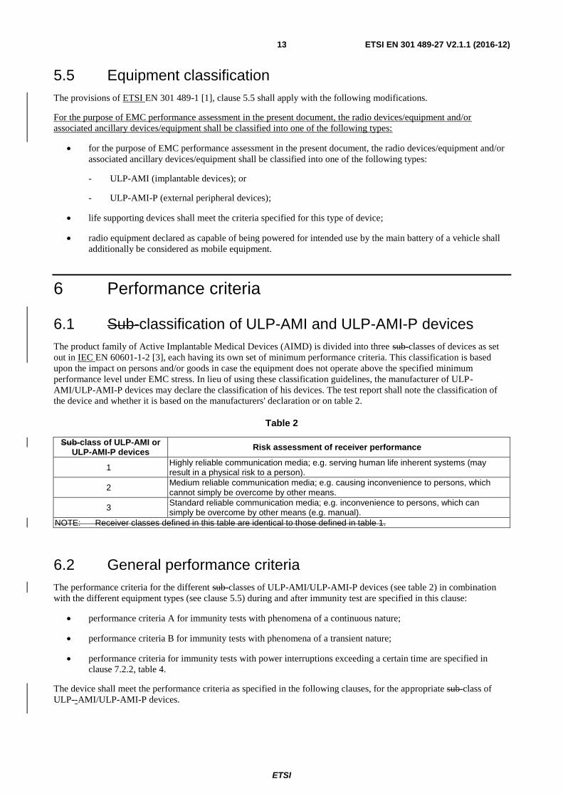
5.5 Equipment classification
The provisions of ETSI EN 301 489-1 [1], clause 5.5 shall apply with the following modifications.
For the purpose of EMC performance assessment in the present document, the radio devices/equipment and/or
associated ancillary devices/equipment shall be classified into one of the following types:
for the purpose of EMC performance assessment in the present document, the radio devices/equipment and/or
associated ancillary devices/equipment shall be classified into one of the following types:
- ULP-AMI (implantable devices); or
- ULP-AMI-P (external peripheral devices);
life supporting devices shall meet the criteria specified for this type of device;
radio equipment declared as capable of being powered for intended use by the main battery of a vehicle shall
additionally be considered as mobile equipment.
6 Performance criteria
6.1 Sub-classification of ULP-AMI and ULP-AMI-P devices
The product family of Active Implantable Medical Devices (AIMD) is divided into three sub-classes of devices as set
out in IEC EN 60601-1-2 [3], each having its own set of minimum performance criteria. This classification is based
upon the impact on persons and/or goods in case the equipment does not operate above the specified minimum
performance level under EMC stress. In lieu of using these classification guidelines, the manufacturer of ULP-
AMI/ULP-AMI-P devices may declare the classification of his devices. The test report shall note the classification of
the device and whether it is based on the manufacturers' declaration or on table 2.
Table 2
Sub-class of ULP-AMI or ULP-AMI-P devices
Risk assessment of receiver performance
1 Highly reliable communication media; e.g. serving human life inherent systems (may result in a physical risk to a person).
2 Medium reliable communication media; e.g. causing inconvenience to persons, which cannot simply be overcome by other means.
3 Standard reliable communication media; e.g. inconvenience to persons, which can simply be overcome by other means (e.g. manual).
NOTE: Receiver classes defined in this table are identical to those defined in table 1.
6.2 General performance criteria
The performance criteria for the different sub-classes of ULP-AMI/ULP-AMI-P devices (see table 2) in combination
with the different equipment types (see clause 5.5) during and after immunity test are specified in this clause:
performance criteria A for immunity tests with phenomena of a continuous nature;
performance criteria B for immunity tests with phenomena of a transient nature;
performance criteria for immunity tests with power interruptions exceeding a certain time are specified in
clause 7.2.2, table 4.
The device shall meet the performance criteria as specified in the following clauses, for the appropriate sub-class of
ULP--AMI/ULP-AMI-P devices.
ETSI
ETSI EN 301 489-27 V2.1.1 (2016-12) 14
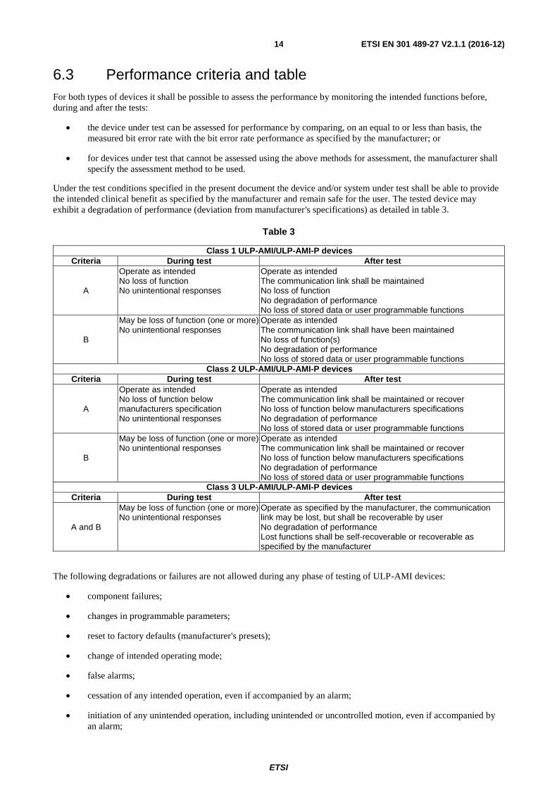
6.3 Performance criteria and table
For both types of devices it shall be possible to assess the performance by monitoring the intended functions before,
during and after the tests:
the device under test can be assessed for performance by comparing, on an equal to or less than basis, the
measured bit error rate with the bit error rate performance as specified by the manufacturer; or
for devices under test that cannot be assessed using the above methods for assessment, the manufacturer shall
specify the assessment method to be used.
Under the test conditions specified in the present document the device and/or system under test shall be able to provide
the intended clinical benefit as specified by the manufacturer and remain safe for the user. The tested device may
exhibit a degradation of performance (deviation from manufacturer's specifications) as detailed in table 3.
Table 3
Class 1 ULP-AMI/ULP-AMI-P devices
Criteria During test After test
A
Operate as intended No loss of function No unintentional responses
Operate as intended The communication link shall be maintained No loss of function No degradation of performance No loss of stored data or user programmable functions
B
May be loss of function (one or more) No unintentional responses
Operate as intended The communication link shall have been maintained No loss of function(s) No degradation of performance No loss of stored data or user programmable functions
Class 2 ULP-AMI/ULP-AMI-P devices
Criteria During test After test
A
Operate as intended No loss of function below manufacturers specification No unintentional responses
Operate as intended The communication link shall be maintained or recover No loss of function below manufacturers specifications No degradation of performance No loss of stored data or user programmable functions
B
May be loss of function (one or more) No unintentional responses
Operate as intended The communication link shall be maintained or recover No loss of function below manufacturers specifications No degradation of performance No loss of stored data or user programmable functions
Class 3 ULP-AMI/ULP-AMI-P devices
Criteria During test After test
A and B
May be loss of function (one or more) No unintentional responses
Operate as specified by the manufacturer, the communication link may be lost, but shall be recoverable by user No degradation of performance Lost functions shall be self-recoverable or recoverable as specified by the manufacturer
The following degradations or failures are not allowed during any phase of testing of ULP-AMI devices:
component failures;
changes in programmable parameters;
reset to factory defaults (manufacturer's presets);
change of intended operating mode;
false alarms;
cessation of any intended operation, even if accompanied by an alarm;
initiation of any unintended operation, including unintended or uncontrolled motion, even if accompanied by
an alarm;
ETSI
ETSI EN 301 489-27 V2.1.1 (2016-12) 15
error of a displayed numerical value sufficiently large to affect diagnosis or treatment;
failure of automatic diagnosis or treatment devices and/or systems to diagnose or treat, even if accompanied by
an alarm.
In addition for ULP-AMI-P devices the following degradations are not allowed:
artefact or distortion in an image in which the artefact is indistinguishable from physiologically-produced
signals or the distortion interferes with interpretation of physiologically-produced signals;
noise on a waveform in which the noise is indistinguishable from physiologically-produced signals or the
noise interferes with interpretation of physiologically-produced signals.
6.4 Performance criteria for continuous phenomena applied to transmitters
For both, the transmitter part of ULP-AMI and ULP-AMI-P devices the performance criteria A of the applicable class
as given in clause 6.3 shall apply.
For both, the transmitter part of ULP-AMI and ULP-AMI-P devices which require a communication link to be
maintained during the test, it shall be verified that the link is maintained during each individual exposure in the test
sequence, by appropriate means supplied by the manufacturer.
The test shall be repeated with the EUT in standby mode to ensure that no unintended transmission occurs as a result of
transmitter operation.
6.5 Performance criteria for transient phenomena applied to transmitters
For both, the transmitter part of ULP-AMI and ULP-AMI-P devices the performance criteria B of the applicable class
as given in clause 6.3 shall apply, except for power interruptions exceeding a certain time the performance criteria
deviations are specified in clause 7.2.2.
For both, the transmitter part of ULP-AMI and ULP-AMI-P devices which require a communication link to be
maintained during the test, it shall be verified that the link is maintained during each individual exposure in the test
sequence, by appropriate means supplied by the manufacturer.
The test shall be repeated with the EUT in standby mode to ensure that no unintended transmission occurs as a result of
transmitter operation.
6.6 Performance criteria for continuous phenomena applied to receivers
For both, the receiver part of ULP-AMI and ULP-AMI-P devices, the performance criteria A of the applicable class as
given in clause 6.3 shall apply.
For both, the receiver part of ULP-AMI and ULP-AMI-P devices which require a communication link to be maintained
during the test, it shall be verified that the communication link is maintained during each individual exposure in the test
sequence, by appropriate means supplied by the manufacturer.
Where the EUT is a transceiver, under no circumstances shall the transmitter operate unintentionally during the test.
ETSI
ETSI EN 301 489-27 V2.1.1 (2016-12) 16
6.7 Performance criteria for transient phenomena applied to receivers
For both, the receiver part of ULP-AMI and ULP-AMI-P devices, the performance criteria B of the applicable class as
given in clause 6.3 shall apply, except for power interruptions exceeding a certain time where the performance criteria
are as specified in clause 7.2.2.
For both, the receiver part of ULP-AMI and ULP-AMI-P devices which require a communication link to be maintained
during the test, it shall be verified that the communication link is maintained during each individual exposure in the test
sequence, by appropriate means supplied by the manufacturer.
Where the EUT is a transceiver, under no circumstances shall the transmitter operate unintentionally during the test.
7 Applicability overview
7.1 Emission
Equipment covered by the present document is intended to be used to provide diagnostic information to medical professionals and/or deliver therapeutic benefits to patients in a medical/hospital environment. This equipment typically utilizes a wireless communication link for the purpose of programming (telecommand) and retrieving data (telemetry) from various implanted devices such as pacemakers, defibrillators, nerve stimulators, drug pumps, and others. For devices of the type covered by the present document, it is reasonable that the EMC performance levels of each section (medical and communications) should correspond to the same EMC values. Studies have shown that medical environments have higher levels of disturbances that impact on the performance of this equipment than are normally associated with a non-medical environment. Accordingly, the performance levels specified for equipment covered by the present document reflect the expected environmental disturbances associated with medical facilities.emission
7.1.1 General
ETSI EN 301 489-1 [1], table 21 contains the applicability of EMC emission measurements to the relevant ports of
radio and/or associated ancillary equipment.
7.1.2 Special conditions
The following special conditions relate to the emission test methods used in the ETSI EN 301 489-1 [1], clause 8.
ETSI
ETSI EN 301 489-27 V2.1.1 (2016-12) 17
The emission measurements applicable to the antenna or enclosure port of ULP-AMI or ULP-AMI-P devices are
specified in the harmonized productharmonised standard ETSI EN 301 839-2 [62].
7.2 Immunity
7.2.1 General
Table 2 of ETSI EN 301 489-1 [1] contains the applicability of EMC immunity tests to the relevant ports of radio and/or
associated ancillary equipment.
Equipment covered by the present document is intended to be used in both, medical and residential areas and will have
both life supporting and non-life supporting applications. Accordingly, the immunity test levels and conditions specified
in the present document are based on the levels associated with the above applications.
Further, the immunity of these systems to radiated ambient fields is subject to their usage condition and, for example,
implanted equipment should be tested using an appropriate test fixture as described in annex BC.
For some applications, it may be appropriate to devise other types of specialized test fixtures. Where such a specialized
test fixture is used, details of the fixture shall be provided by the manufacturer and recorded in the subsequent test
documentation.
It is intended that the performance criteria and immunity requirements in the present document and in IEC
EN 60601-1-2 [3] be essentially equivalent. For ULP-AMI devicesand ULP-AMI-P, guidance is given as to
applicability of the test in table 4.
7.2.1 General
EN 301 489-1 [1], table 3 contains the applicability of EMC immunity tests to the relevant ports of radio and/or
associated ancillary equipment.
7.2.2 Special conditions
The following special conditions set out in table 4 relate to the immunity test methods and performance criteria used in
ETSI EN 301 489-1 [1], clause 9.
ETSI
ETSI EN 301 489-27 V2.1.1 (2016-12) 18
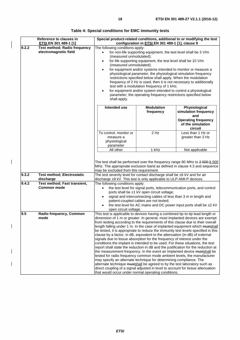
Table 4: Special conditions for EMC immunity tests
Reference to clauses in ETSI EN 301 489-1 [1]
Special product-related conditions, additional to or modifying the test configuration in ETSI EN 301 489-1 [1], clause 9
9.2.2 Test method; Radio frequency electromagnetic field
The following conditions apply:
for non-life supporting equipment, the test level shall be 3 V/m (measured unmodulated);
for life supporting equipment, the test level shall be 10 V/m (measured unmodulated);
for equipment and/or systems intended to monitor or measure a physiological parameter, the physiological simulation frequency restrictions specified below shall apply. When the modulation frequency of 2 Hz is used, then it is not necessary to additionally test with a modulation frequency of 1 kHz;
for equipment and/or system intended to control a physiological parameter, the operating frequency restrictions specified below shall apply.
Intended use Modulation frequency
Physiological simulation frequency
and Operating frequency
of the simulation circuit
To control, monitor or measure a
physiological parameter
2 Hz Less than 1 Hz or greater than 3 Hz
All other 1 kHz Not applicable
The test shall be performed over the frequency range 80 MHz to 2 500 6 000 MHz. The appropriate exclusion band as defined in clause 4.3 and sequence may be excluded from this requirement.
9.3.2 Test method; Electrostatic discharge
The test severity level for contact discharge shall be ±6 kV and for air discharge ±8 kV. This test is only applicable to ULP-AMI-P devices.
9.4.2 Test method; Fast transient, Common mode
The following conditions apply:
the test level for signal ports, telecommunication ports, and control ports shall be ±1 kV open circuit voltage;
signal and interconnecting cables of less than 3 m in length and patient-coupled cables are not tested;
the test level for AC mains and DC power input ports shall be ±2 kV open circuit voltage.
9.5 Radio frequency, Common mode
This test is applicable to devices having a combined tip-to-tip lead length or dimension of 1 m or greater. In general, most implanted devices are exempt from testing according to the requirements of this clause due to their overall length falling under 1 m. In the case of implanted equipment which mustshall be tested, it is appropriate to reduce the immunity test levels specified in this clause by a factor, in dB, equivalent to the attenuation (in dB) of external signals due to tissue absorption for the frequency of interest under the conditions the implant is intended to be used. For these situations, the test report shall state the reduction in dB and the justification for the reduction at the measurement frequency. In the event an implanted device mustshall be tested for radio frequency common mode ambient levels, the manufacturer may specify an alternate technique for determining compliance. The alternate technique mustshall be agreed to by the test laboratory such as direct coupling of a signal adjusted in level to account for tissue attenuation that would occur under normal operating conditions.
ETSI
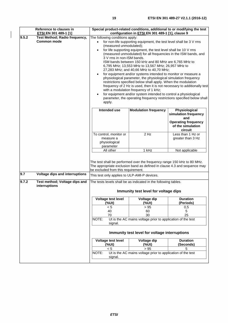
ETSI EN 301 489-27 V2.1.1 (2016-12) 19
Reference to clauses in ETSI EN 301 489-1 [1]
Special product-related conditions, additional to or modifying the test configuration in ETSI EN 301 489-1 [1], clause 9
9.5.2 Test Method; Radio frequency, Common mode
The following conditions apply:
for non-life supporting equipment, the test level shall be 3 V rms (measured unmodulated);
for life supporting equipment, the test level shall be 10 V rms (measured unmodulated) for all frequencies in the ISM bands, and 3 V rms in non-ISM bands. ISM bands between 150 kHz and 80 MHz are 6,765 MHz to 6,795 MHz; 13,553 MHz to 13,567 MHz; 26,957 MHz to 27,283 MHz; and 40,66 MHz to 40,70 MHz;
for equipment and/or systems intended to monitor or measure a physiological parameter, the physiological simulation frequency restrictions specified below shall apply. When the modulation frequency of 2 Hz is used, then it is not necessary to additionally test with a modulation frequency of 1 kHz;
for equipment and/or system intended to control a physiological parameter, the operating frequency restrictions specified below shall apply.
Intended use Modulation frequency Physiological simulation frequency
and Operating frequency
of the simulation circuit
To control, monitor or measure a
physiological parameter
2 Hz Less than 1 Hz or greater than 3 Hz
All other 1 kHz Not applicable
The test shall be performed over the frequency range 150 kHz to 80 MHz. The appropriate exclusion band as defined in clause 4.3 and sequence may be excluded from this requirement.
9.7 Voltage dips and interruptions This test only applies to ULP-AMI-P devices.
9.7.2 Test method; Voltage dips and interruptions
The tests levels shall be as indicated in the following tables.
Immunity test level for voltage dips
Voltage test level (%Ut)
Voltage dip (%Ut)
Duration (Periods)
< 5 40 70
> 95 60 30
0,5 5
25
NOTE: Ut is the AC mains voltage prior to application of the test signal.
Immunity test level for voltage interruptions
Voltage test level (%Ut)
Voltage dip (%Ut)
Duration (Seconds)
< 5 > 95 5
NOTE: Ut is the AC mains voltage prior to application of the test signal.
ETSI
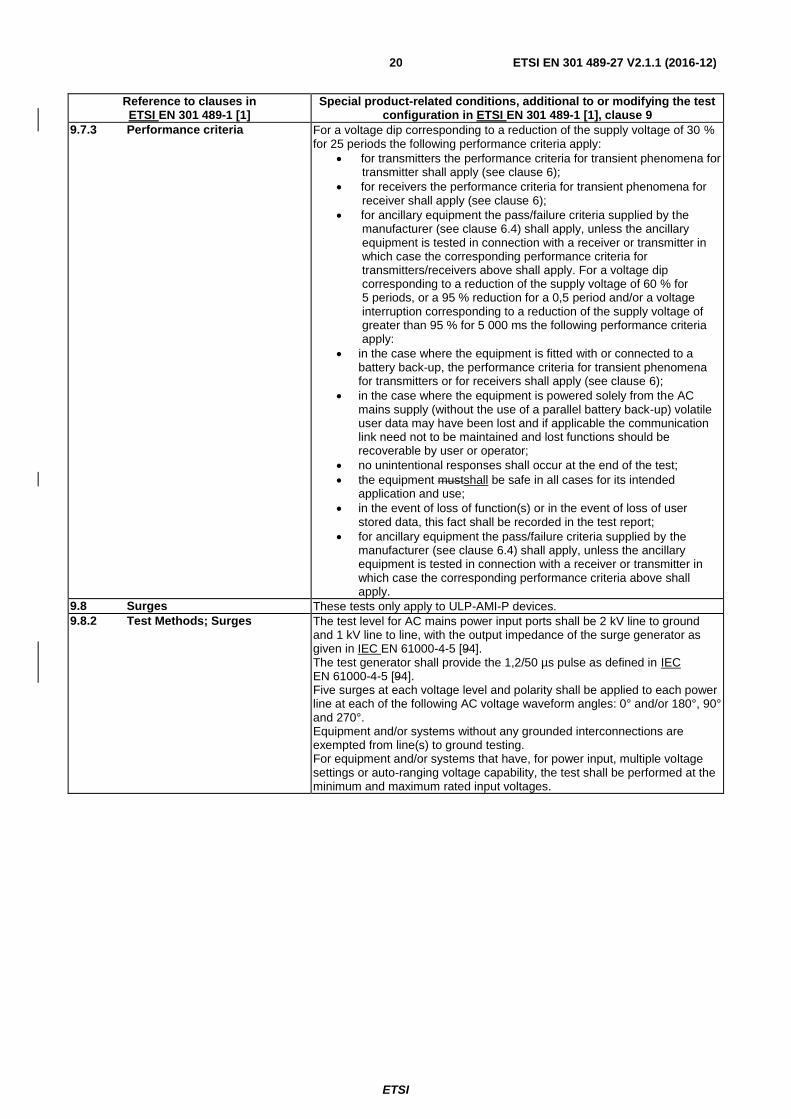
ETSI EN 301 489-27 V2.1.1 (2016-12) 20
Reference to clauses in ETSI EN 301 489-1 [1]
Special product-related conditions, additional to or modifying the test configuration in ETSI EN 301 489-1 [1], clause 9
9.7.3 Performance criteria For a voltage dip corresponding to a reduction of the supply voltage of 30 % for 25 periods the following performance criteria apply:
for transmitters the performance criteria for transient phenomena for transmitter shall apply (see clause 6);
for receivers the performance criteria for transient phenomena for receiver shall apply (see clause 6);
for ancillary equipment the pass/failure criteria supplied by the manufacturer (see clause 6.4) shall apply, unless the ancillary equipment is tested in connection with a receiver or transmitter in which case the corresponding performance criteria for transmitters/receivers above shall apply. For a voltage dip corresponding to a reduction of the supply voltage of 60 % for 5 periods, or a 95 % reduction for a 0,5 period and/or a voltage interruption corresponding to a reduction of the supply voltage of greater than 95 % for 5 000 ms the following performance criteria apply:
in the case where the equipment is fitted with or connected to a battery back-up, the performance criteria for transient phenomena for transmitters or for receivers shall apply (see clause 6);
in the case where the equipment is powered solely from the AC mains supply (without the use of a parallel battery back-up) volatile user data may have been lost and if applicable the communication link need not to be maintained and lost functions should be recoverable by user or operator;
no unintentional responses shall occur at the end of the test;
the equipment mustshall be safe in all cases for its intended application and use;
in the event of loss of function(s) or in the event of loss of user stored data, this fact shall be recorded in the test report;
for ancillary equipment the pass/failure criteria supplied by the manufacturer (see clause 6.4) shall apply, unless the ancillary equipment is tested in connection with a receiver or transmitter in which case the corresponding performance criteria above shall apply.
9.8 Surges These tests only apply to ULP-AMI-P devices.
9.8.2 Test Methods; Surges The test level for AC mains power input ports shall be 2 kV line to ground and 1 kV line to line, with the output impedance of the surge generator as given in IEC EN 61000-4-5 [94]. The test generator shall provide the 1,2/50 µs pulse as defined in IEC EN 61000-4-5 [94]. Five surges at each voltage level and polarity shall be applied to each power line at each of the following AC voltage waveform angles: 0° and/or 180°, 90° and 270°. Equipment and/or systems without any grounded interconnections are exempted from line(s) to ground testing. For equipment and/or systems that have, for power input, multiple voltage settings or auto-ranging voltage capability, the test shall be performed at the minimum and maximum rated input voltages.
ETSI
ETSI EN 301 489-27 V2.1.1 (2016-12) 21
Annex A
Annex A (normative): Relationship between the present document and the essential requirements of Directive 2014/53/EU
The present document has been prepared under the Commission's standardisation request C(2015) 5376 final [i.4] to
provide one voluntary means of conforming to the essential requirements of Directive 2014/53/EU on the harmonisation
of the laws of the Member States relating to the making available on the market of radio equipment and repealing
Directive 1999/5/EC [i.1].
Once the present document is cited in the Official Journal of the European Union under that Directive, compliance with
the normative clauses of the present document given in table A.1 confers, within the limits of the scope of the present
document, a presumption of conformity with the corresponding essential requirements of that Directive and associated
EFTA regulations.
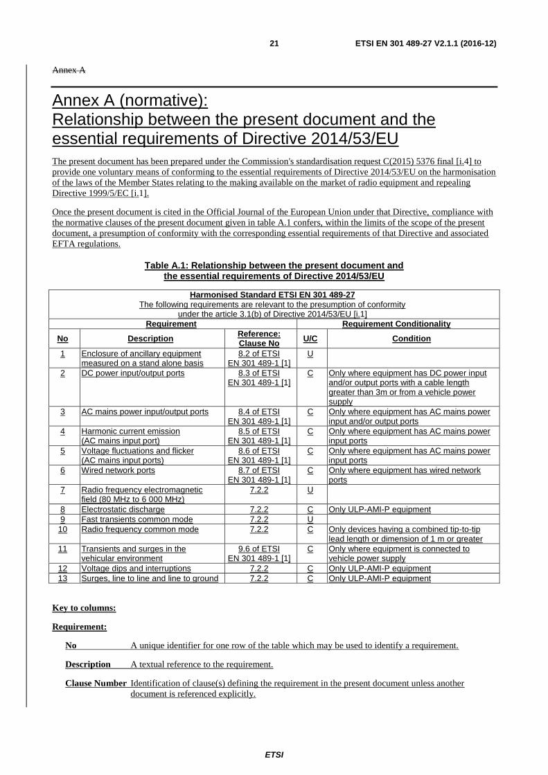
Table A.1: Relationship between the present document and the essential requirements of Directive 2014/53/EU
Harmonised Standard ETSI EN 301 489-27
The following requirements are relevant to the presumption of conformity under the article 3.1(b) of Directive 2014/53/EU [i.1]
Requirement Requirement Conditionality
No Description Reference: Clause No
U/C Condition
1 Enclosure of ancillary equipment measured on a stand alone basis
8.2 of ETSI EN 301 489-1 [1]
U
2 DC power input/output ports 8.3 of ETSI EN 301 489-1 [1]
C Only where equipment has DC power input and/or output ports with a cable length greater than 3m or from a vehicle power supply
3 AC mains power input/output ports 8.4 of ETSI EN 301 489-1 [1]
C Only where equipment has AC mains power input and/or output ports
4 Harmonic current emission (AC mains input port)
8.5 of ETSI EN 301 489-1 [1]
C Only where equipment has AC mains power input ports
5 Voltage fluctuations and flicker (AC mains input ports)
8.6 of ETSI EN 301 489-1 [1]
C Only where equipment has AC mains power input ports
6 Wired network ports 8.7 of ETSI EN 301 489-1 [1]
C Only where equipment has wired network ports
7 Radio frequency electromagnetic field (80 MHz to 6 000 MHz)
7.2.2 U
8 Electrostatic discharge 7.2.2 C Only ULP-AMI-P equipment
9 Fast transients common mode 7.2.2 U
10 Radio frequency common mode 7.2.2 C Only devices having a combined tip-to-tip lead length or dimension of 1 m or greater
11 Transients and surges in the vehicular environment
9.6 of ETSI EN 301 489-1 [1]
C Only where equipment is connected to vehicle power supply
12 Voltage dips and interruptions 7.2.2 C Only ULP-AMI-P equipment
13 Surges, line to line and line to ground 7.2.2 C Only ULP-AMI-P equipment
Key to columns:
Requirement:
No A unique identifier for one row of the table which may be used to identify a requirement.
Description A textual reference to the requirement.
Clause Number Identification of clause(s) defining the requirement in the present document unless another
document is referenced explicitly.

ETSI
ETSI EN 301 489-27 V2.1.1 (2016-12) 22
Requirement Conditionality:
U/C Indicates whether the requirement shall be unconditionally applicable (U) or is conditional upon
the manufacturer's claimed functionality of the equipment (C).
Condition Explains the conditions when the requirement shall or shall not be applicable for a requirement
which is classified "conditional".
Presumption of conformity stays valid only as long as a reference to the present document is maintained in the list
published in the Official Journal of the European Union. Users of the present document should consult frequently the
latest list published in the Official Journal of the European Union.
Other Union legislation may be applicable to the product(s) falling within the scope of the present document.
ETSI
ETSI EN 301 489-27 V2.1.1 (2016-12) 23
Annex B (normative): Definitions of types of ULP-AMI and ULP-AMI-P devices in the scope of the present document
AB.1 ULP-AMI and ULP-AMI-P devices intended for operation in the frequency range 402 MHz to 405 MHz
The present document applies to ULP-AMI and ULP-AMI-P devices with RF power levels ranging up to 25 µW ERP
and intended for operation in the frequency range 402 MHz to 405 MHz in accordance with the provisions of annex 12,
band (a), to CEPT/ERC/REC 70-03 [i.2]. Definitions of such ULP-AMI and ULP-AMI-P radio equipment are found in
the following functional radio standards:
- EN 301 839-1 (V1.1.1): "Electromagnetic compatibility and Radio spectrum Matters (ERM); Radio
equipment in the frequency range 402 MHz to 405 MHz for Ultra Low Power Active Medical Implants and
Accessories; Part 1: Technical characteristics, including electromagnetic compatibility requirements, and test
methods" [ETSI EN 301 839 (V2.1.1) [2].
- EN 301 839-2 (V1.1.1): "Electromagnetic compatibility and Radio spectrum Matters (ERM); Radio equipment
in the frequency range 402 MHz to 405 MHz for Ultra Low Power Active Medical Implants and Accessories;
Part 2: Harmonized EN covering essential requirements of article 3.2 of the R&TTE Directive" [6].
ETSI
ETSI EN 301 489-27 V2.1.1 (2016-12) 24
Annex BC (normative): Test fixture for ULP-AMI devices (Simulated man)
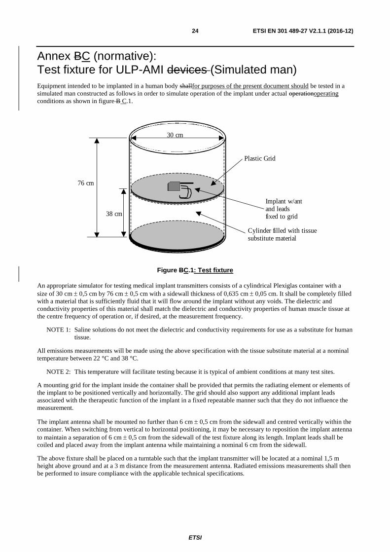
Equipment intended to be implanted in a human body shallfor purposes of the present document should be tested in a
simulated man constructed as follows in order to simulate operation of the implant under actual operationoperating
conditions as shown in figure B C.1.
30 cm
76 cm
38 cm
Plastic Grid
Implant w/ant and leads fixed to grid
Cylinder filled with tissue substitute material
Figure BC.1: Test fixture
An appropriate simulator for testing medical implant transmitters consists of a cylindrical Plexiglas container with a
size of 30 cm 0,5 cm by 76 cm 0,5 cm with a sidewall thickness of 0,635 cm 0,05 cm. It shall be completely filled
with a material that is sufficiently fluid that it will flow around the implant without any voids. The dielectric and
conductivity properties of this material shall match the dielectric and conductivity properties of human muscle tissue at
the centre frequency of operation or, if desired, at the measurement frequency.
NOTE 1: Saline solutions do not meet the dielectric and conductivity requirements for use as a substitute for human
tissue.
All emissions measurements will be made using the above specification with the tissue substitute material at a nominal
temperature between 22 °C and 38 °C.
NOTE 2: This temperature will facilitate testing because it is typical of ambient conditions at many test sites.
A mounting grid for the implant inside the container shall be provided that permits the radiating element or elements of
the implant to be positioned vertically and horizontally. The grid should also support any additional implant leads
associated with the therapeutic function of the implant in a fixed repeatable manner such that they do not influence the
measurement.
The implant antenna shall be mounted no further than 6 cm 0,5 cm from the sidewall and centred vertically within the
container. When switching from vertical to horizontal positioning, it may be necessary to reposition the implant antenna
to maintain a separation of 6 cm 0,5 cm from the sidewall of the test fixture along its length. Implant leads shall be
coiled and placed away from the implant antenna while maintaining a nominal 6 cm from the sidewall.
The above fixture shall be placed on a turntable such that the implant transmitter will be located at a nominal 1,5 m
height above ground and at a 3 m distance from the measurement antenna. Radiated emissions measurements shall then
be performed to insure compliance with the applicable technical specifications.

ETSI
ETSI EN 301 489-27 V2.1.1 (2016-12) 25
Tissue parameters for various frequencies maybe obtained from the following website: http://niremf.ifac.cnr.it/,
maintained by the Italian National Research Council, Institute for Applied Physics. [i.5]. Other sources can be used
provided they are based on the 4-Cole-Cole equations developed by Gabriel (see bibliography).[i.3]. In most instances it
may be advisable to make preliminary measurements to identify potential problem frequencies and use tissue material
corresponding to human tissue characteristics at that frequency. In severe cases, tissue substitute material may be used
that has conductivity and dielectric parameters that correspond to the human tissue at a problem frequency.

ETSI
ETSI EN 301 489-27 V2.1.1 (2016-12) 26
Annex C (informative): Bibliography
Camelia Gabriel: "Compilation of the dielectric properties of body tissues at RF and Microwave Frequencies",
appendix B1 and B2 (Physics Department, Kings College, London WC2R 2LS, UK).

ETSI
ETSI EN 301 489-27 V2.1.1 (2016-12) 27
Annex D (informative): The EN title in the official languages
Language EN title
Czech
Danish
Dutch
English Electromagnetic compatibility and Radio spectrum Matters (ERM); ElectroMagnetic Compatibility (EMC) standard for radio equipment and services; Part 27: Specific conditions for Ultra Low PowerActive Medical Implants (ULP-AMI) and related peripheral devices (ULP-AMI-P)
Estonian
Finnish
French
German
Greek
Hungarian
Icelandic
Italian
Latvian
Lithuanian
Maltese
Polish
Portuguese
Slovak
Slovenian
Spanish
Swedish
ETSI
ETSI EN 301 489-27 V2.1.1 (2016-12) 28
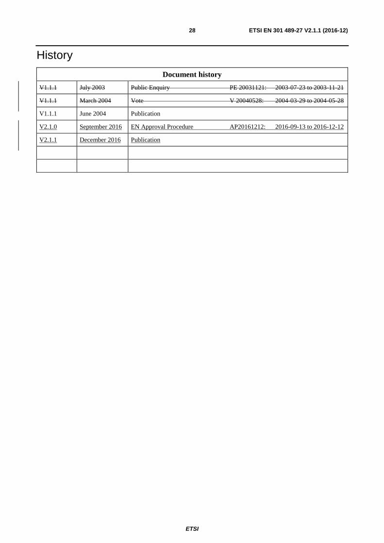
History
Document history
V1.1.1 July 2003 Public Enquiry PE 20031121: 2003-07-23 to 2003-11-21
V1.1.1 March 2004 Vote V 20040528: 2004-03-29 to 2004-05-28
V1.1.1 June 2004 Publication
V2.1.0 September 2016 EN Approval Procedure AP20161212: 2016-09-13 to 2016-12-12
V2.1.1 December 2016 Publication