ethernet to midi&rs232 + dmx512 interfacemidi-and-more.de/ethermidi/ethermidi-manual.pdf ·...
TRANSCRIPT

Ethernet to MIDI&RS232 + DMX512 Interface ©2015-17 Wolfgang Schemmert Status 28 December 2017
The hardware of this interface provides a conventional MIDI or RS-232 interface plus a DMX512 transmitter, and it is connected with an appropriate counterpart by wired LAN .
Primarily transfer of MIDI or RS-232 data is handled bidirect ionally 1:1 as byte stream.
To control MIDI by text oriented software or by manual terminal input, an alternative mode is available, where every binary byte is sent via Ethernet as ASCII text representing its hexadecimal code. Vice versa, MIDI input is sent back on the ethernet as ASCII text too.
Furthermore a DMX512 transmitter is available onboa rd , supporting up to 512 DMX channels and up to 128 presets (= user defined lighting scenes). Different command sets are supported by firmware for DMX OUT: --- an ASCII text based one --- as a special case the MiniDMX protocol is supported . --- a MIDI channel message based one. DMX may be operated via Ethernet as well as by classical RS-232 or MIDI connectors driving the CPU USART.
Additional features of the OSC capable firmware: (preferably described in this manual) --- for control of conventional MIDI devices by an app installed on a smartphone or mobile tablet, a set of OSC (Open Sound Control) methods is provided. --- a special set of OSC methods allows to operate DMX OUT simultaneously with MIDI I/O.
A special firmware version supports Art-Net DMX instead of OSC. To align both command sets, some commands are changed in the OSC version with respect to older ones. Changed commands & manual addendum of the Art-Net c apable firmware see page 37
It is NOT allowed to use this interface together with any safety critical applications , where misfunction could result in personal injury or noticeable material damage ! All information about this project is provided 'as is' – without any warranty nor responsibility !
Hardware
At one of the next pages a reference schematic and a corresponding PCB layout is shown. To keep reproduction as easy as possible, this is a single layer PCB with a number of jumper wires. User modifications of the circuit layout are possible but the firmware is designed to work with exactly this circuit !! .
Layout of the combined MIDI&RS232 interface: Physically, a conventional optoisolated MIDI IN and a conventional RS-232 input are hardwired together and share the same microcontroller USART. The serial output driver is connected with MIDI OUT and with RS-232 TxD too. Pinheads for external MIDI and RS-232 connectors are provided on the PCB. The USART baud rate may be set to PC standard 9600, 19200, 38400, 57600 or 115200 baud in addition to MIDI standard 31250 baud.
The power supply is designed for unregulated or regulated DC supplies with output voltages 8 to 28 Volt and min. 300 mA output. The DC input CN1 is designed for a concentric low voltage connector, external 5,0 - 5,5mm, internal 2,1mm. The positive polarity has to be connected with the inner contact - it is protected against wrong polarity .

2
Primarily IC2 converts the external voltage into a regulated 5V supply which provides sufficient voltage for the MIDI interface. The secondary 3.3 V supply (IC3) is necessary for the Wiznet WIZ810MJ Ethernet module and powers the microcontroller too.
Setting different modes of operation: Some jumpers may be placed (after programming) at the Atmel programming connector to select different modes of operation. If these have to be changed oftenly, a set of switches may be attached with an 6 pin IDC connector, examples see below. Change of jumper settings will cause a reset and restart with the new mode within about one second.
no jumper (default) 1:1 bidirectional transparent MIDI I/O. LAN mode UDP (default) or TCP (configured). J1: MIDI I/O bytes transferred bidirectionally as ASCII text via Ethernet J2: OSC (Open Sound Control) methods (on UDP Ethernet) handle MIDI I/O plus OSC based DMX control J1 + J2 : same as J2 alone, but editing of user defined OSC methods is possible via RS-232 port instead of I/O. J3: ASCII text based DMX control and module configuration (control through TCP, UDP or RS-232) J1 + J3 : DMX control by MIDI channel message style commands (control through TCP, UDP or MIDI I/O) With standard jumpers it is impossible to set J2 and J3 simultaneaously. If done anyhow, J2 overrides J3.
LED color : The LED is triggered when bytes are received at the Serial and/or Ethernet data port. Transparent and OSC mode : idle yellow. While TCP is disconnected, in idle state the LED flashes yellow / red. Flashes green when bytes are received at MIDI/RS-232. Flashes red when bytes are received via Ethernet. DMX/ASCII Config: idle green. While TCP is disconnected, in idle state the LED flashes yellow / red. Flashes red when a valid command is received. Flashes dark when garbage is received.
The WIZ810MJ module includes the RJ45 Ethernet socket The connection to the network is established with a standard Ethernet patch cable. At the RJ45 socket 2 small LEDs are integrated. The green LED is the "Link LED", it shines as long as a physical connection with the network is present. The yellow LED goes off while data are transferred over the network. According to the type of the connected network a connection with 10MBit/s or 100MBit/s is established.
The WIZ810MJ module is not fixed tightly at the soc ket. When "looking through" a front panel, its position is stablilized. If used on an open PCB, it should be fixed by a thin cable tie with an underlayed wood or plastic block. For this purpose two holes are provided at the reference PCB. Avoid to bend the WIZ810MJ board !
List of special parts: All resistors are carbon or metal film types, min 0.25W, max 5% tolerance. Capacitors C1, C2 should be ceramic 2.54mm raster 50V Capacitor C5 should be mylar film, 5.08 or 7.12mm raster, 50V Capacitors else should be multilayer ceramic 5.08mm raster, 50V Electrolytic capacitors E1, E2 should be 35V types with 2.54 mm pin raster. WIZ810MJ: source <www.tme.eu> or <www.shopwiznet.com> or RS-ComponentsI Socket for WIZ810MJ: 2pcs each 14x2 pins, 2.00mm raster.
Recommended: Reichelt order code BL2x32G 2.00 – tailored to 2 appropriate pieces IC1: ATmega1284P PU, 40p DIL case. Source Reichelt, RS-Components IC2: TSR-1-2450 (Traco Power, source Conrad or Reichelt) or R-78(E)5.0-0.5 (Recom) IC3: LF33 DPAK case (= TO252AA). Soldered at bottom side ! IC4: PC900V, 6pDIL IC5: 74HCT00, 14pDIL IC6: preferably MAX487, 8p DIL - also useable MAX3085, MAX485 or equivalent types. LED: V-L-115-WEGW (source Conrad part no 187496).
Other red/green dual LED types may be used, but then values of R1 and R2 have to be adjusted CN1: DC connector ROKA brand, source Conrad part no. 737992 CN2, CN3, CN4: source Reichelt (PS 25/2G BR, PS 25/3G BR) or Conrad

3

4
Reference PCB layout
Reference Board assembly

5
Configuration of the Ethernet interface Before practical use the Ethernet interface has to be configured by one of the methods described below. For configuration via LAN, a PC-sided network configuration is required which allows access to IP address 192.168.0.240 (default after programming, IP may have been changed by configuration). For all configuration methods, place J3 exclusivel y. In case of typing error: repeat the complete command. Backspace is not supported . If the terminal line gets overwritten permanently, configure your terminal to insert a "Line Feed" after every received "Carriage Return". Configuration by RS-232 provides most secure access when the actual configuration is unknown or Ethernet communication is complicated. The 9 pin subD connector or a specially configured cable MIDI toSubD (see Appendix B, p.39) is needed. The default baud rate is 115200. This may be changed by configuration or semi-automatically, see page 38.
Configuration using Ethernet UDP On the PC a UDP terminal software is started (e.g. DTerm, see <www.midi-and-more.de/more/dterm.htm>). By default, DTerm uses compatible IP address and ports.
Configuration using Ethernet TCP On the PC a Telnet terminal software is started (e.g. Teraterm) and a TCP connection is established to the actual IP address and default port 23 (or user configured TCP port).
Emergency Reset configuration to state of delivery (if nothing is possible) Remove power, connect the "Factory Reset" pin with ground pin "TP" by something metallic. Power on. After reset, the device remains in an endless loop. Remove the short and cycle power. Only communication relevant items are reset, no user defined OSC and DMX setup.
After '?' is typed into the terminal, a list of the briefly explained configuration commands is returned: (has been changed with respect to previous versions !)
List of Setup Commands: ! list actual setup entries \M (hex)m5.m4.m3.m2.m1.m0. set your Ethernet MAC ID \G hh.hl.lh.ll set gateway IP \I hh.hl.lh.ll set IP of this module \S hh.hl.lh.ll set subnet mask of this module \L set LAN mode: U or 1=UDP(default), T or 0=TCP \P set TCP port number \X set server idle disconnect timeout (1-255s). 0=permanent \D hh.hl.lh.ll set UDP default destination IP (incl.broadcast,multicast) \T set UDP destination(Tx) port number \R set UDP source/local(Rx) port number \B set RS-232/MIDI baudrate \o config OSC path handling(0-9). 0=ignore (default) \F format of OSC msg after MIDI IN: 0=b tag, 1=b/m tag mix
Commands and their subsequent parameters may be entered in arbitrary order or as a single item. Every input is finished with a "Carriage Return" (= dec13=hexD). New settings are primarily stored in a permanent shadow memory inside the interface (and aleady returned by '!' command, though they are not yet active). The shadow memory is copied into the active setting during the next power cycle. This protects you from running into a connection deadlock during the session.
Command \M changes the Ethernet MAC address of this Ethernet interface After programming the microcontroller firmware, always the following provisional MAC ID (hex) 00.50.C2.92.8F.FF is active (registered for and provided by courtesy of Cinetix). This is intended to allow a simple first test, configuration and startup. It is not allowed to distribute products with this MAC address! You have to register and configure your individual MAC address for every product you bring out of your lab!
6
To set your individual MAC address, proceed as follows: Enter "\M" followed by six hexadecimal bytes , which represent your MAC ID, each item written in ASCII text as two hex digits (0..9,A,B,C,D,E,F case independent) separated by a dot ("."). The last byte is terminated by a <carriage return>.
Commands \G,\I,\S and \P define the network address of this Ethernet / MIDI interface. Ethernet IP addresses are entered as 4 decimal numbers 0 to 255 separated by periods. Port numbers are entered as a decimal number 0 to 65535..
To make the first operation as easy as possible, after programming following default parameters are configured , which are compatible with many small networks: UDP mode active, local IP address 192.168.0.240, su bnet mask 255.255.255.0, TCP port 23 UDP destination IP address 192.168.0.255 (=C-net br oadcast), transmit port 9000, receicve port 8000.
When in UDP mode (default after programming), the command \D sets the destination network address(IP) and \T (transmit) sets the port where UDP datagrams are sent to . The command \R (receive) sets the local port for reception of UDP messages combined with the local IP address set by parameter \I.
In complex installation with a number of UDP serving nodes and controllers, the flexibility may be enhanced when UDP parameters are set specifically:
Some UDP special cases should be mentioned to operate the Ethernet / MIDI+RS232 interface by several "clients" (i.e. controllers) during the same session. --- UDP datagrams can be transmitted by broadcast . To use this mode, in simple class C networks
the last IP byte is set to 255 by configuration command \D --- with broadcast IP (and multicast too) simultanenously compilation of user defined OSC methods and
configuration is possible with a PC (use "DTerm" from my website) while OSC operations are performed with a smartphone or tablet.
--- with multicast-configuration (IP address for UDP set to 225.0.0.37 by command \D and both UDP port numbers to 21928) the interface is compatible with the "ipMidi" virt ual MIDI to Ethernet cable (see www.nerds.de). Unfortunatly actual smartphones and tablets don't support multicast.
--- if the last IP byte is set= 254 , the Ethernet / MIDI interface always responds to the IP address of the last received datagram (i.e. to the sender of the last command - only class C networks)
The Parameter \B sets the MIDI and RS-232 baud rate at CN2 and CN3 Enter the first 2 digits of a standard baud rate as ASCII text in decimal format (i.e. '96' to '11'), terminated by carriage return. The MIDI baud rate has to be entered as text '31'. This setting may be overriden "on the run" by semi-automatic baudrate detection. Details see page 38. Special case: If jumpers J1 + J3 both are placed, the baud rate is always 31250 (MIDI)
Parameter \X defines the timing behaviour of transmitted Ethernet packets. Default after programming is X = 255s.
The parameter "\X" controls the timing of auto-disc onnect in all modes of TCP operation. While at the client side the presence of a control software or human operator may be assumed to manage and control the TCP connection, this is not evident with a remotely located server. Due to certain errors of connection (e.g. client terminates the connection irregulary when power fails) deadlock situations are possible if the server does not break after a while. 5 seconds before fallback into "listen" state the text sequence "EX5s" is sent to the client. Whenever a data packet is received (in most simple case a MIDI Timing Clock or Active Sensing), the Ethernet / MIDI interface resets timeout. If this parameter is set to zero, the server keeps the connection permanentl y until it is terminated by the client.
The Ethernet packet delay time is fixed to 5 millis econds .
Parameter \o specifies handling of OSC method based commands. Default is o=0 Parameter \F specifies OSC encoding format of MIDI IN data (MIDI msg or BLOB) Default is F=0. More details see pages 7,26 and 31

7
DMX Control with ASCII command set (Jumper 3 placed)
For flexible practical handling, this mode uses both communication channels (RS-232 port and Ethernet) simultaneously . Command input from both data channnels is merged byte by byte . So be sure to send complete commands inclusive parameters exclusively from one channel per moment. Feedback always comes to every active data channel.
Additionallly, communication parameters for the Ethernet, the serial baud rate and the treatment of OSC methods (=OSC commands) are configured with this jumper setting (details see page 6). In contrast to the DMX commands, these configuration commands have to be sent with a prefixed backslash '\'.
Short reference of all ASCII commands Sn address DMX channel (write SLOT register) for subseqent action (n=1 - 512) p.8 Vn set DMX level at DMX channel=SLOT (n=0 - 255) p.8 ,n (comma) increment SLOT first then set level at new DMX channel (n=0 - 255) p.8 =n fill block of n DMX channels starting from SLOT+1 with level of SLOT (n=1-256) p.8 #n set DMX channel no. n (n=1-512) to DMX level entered by previous command p.9 + increase transmit buffer level DMX channel=SLOT by one p9 - decrease transmit buffer level DMX channel=SLOT by one p.9 ^n add n to transmit buffer level DMX channel=SLOT (n=0 - 255) p.9 _n subtract n from transmit buffer level DMX channel=SLOT (n=0 - 255) p.9 $ from now DMX level in HEX (only V- , comma- , ^- , _- , R and Q- command) p.9 & from now DMX level DECIMAL (only V , comma , ^ , _ , R and Q-command) p10 Hn set hue (spectral color) for RGB lamp p.10 Wn set color saturation for RGB lamp p.10 Ln set brightness (luminance) for RGB lamp p.10 Ts.t set FADETIME s=seconds t=tenths p.11 X stop fade processes and freeze them at actual DMX level p.11 Mn set the masterfader: n=0 to 200 (in percent, see detailled description below) p.11 in set length of chaser cycle (n=2 to 127) and start the chaser p.11 Pt set duration of chaser step in 1/10 s units p.11 Gn enter start scene (preset no.) of chaser cycle . See detailled description p.11 N forward chaser immediately by one step p.12 Q show content of all DMX registers at DMX channel=SLOT p.12 Rn read n bytes starting at DMX channel=SLOT from transmit buffer p.12
Kn restrict DMX transmission cycle to n channels (n=24-512) (new as of version 2.9) p.12 ~n save transmit buffer a as preset no. n (=0 to 127) p.12 @n load preset Nr. n into buffers (n=0 to 127) p.13 ; (semicolon) dummy command terminates number input (new as of version 2.8) p.36 | reset all buffers and configuration to default (=delivery) state p.13
MiniDMX protocol p.13
special commands for configuration:
! list actual configuration p.5 \ Bn set baud rate of the MIDI/COM port (except jumpers J1+J3 are placed) p.6 \ on specify handling of OSC method based commands p.26 \ Fn specify OSC encoding format of MIDI IN data (MIDI msg or BLOB) p.31

8
Detailled description of all ASCII commands: Every control command and every state message is as signed with a single characteristic letter. If a command expects a parameter, it is listed after the command letter in acute angular brackets <..:>. Number values are sent to the box as ASCII text. This compact format is suitable to enter commands manually, to be transmitted from hardware based multimedia controllers or industrial PLC as well as for automatic generation and parsing in an application software.
Address the DMX channel ("slot") to be operated with following commands: S <channel number>
The parameter addresses a DMX channel , on which many of the subsequently described commands have an effect. Internally the parameter value is stored in the SLOT register.
In DMX slang sometimes the word 'slot' is used as s ynononym for 'DMXchannel' because during DMX transmission every DMX channel is represented b y a specific time slot in the transmission cycle.
Parameter: slot number (range 1 to 256) is the number of the DMX channel to be manipulated with subsequent commands Comment: No action is started immediately. But the SLOT register content will be applied to subsequently given commands.
Example: S123 writes 123 into register SLOT
Transmit buffer manipulation: V <level> Write parameter into the transmit buffer of DMX cha nnel = "SLOT" .
Parameter: level (range 0 to 255) is the value (lamp intensity, e.g.) which will be transmitted at the DMX channel addressed by SLOT. Comment: Changes the transmitted DMX packet sequence in accordance with previously entered values in the SLOT and FADETIME register. It depends on the selected merge method of the addressed DMX channel if this new level gets actual ly transmitted.
If FADETIME is equal to zero, the value of the addressed DMX channel is immediately set to <level >
If FADETIME is nonzero, a fade process is started, which begins at the actual value of the adressed DMX channel and finishes, when the value of the addressed DMX slot is equal to <level>.
Example: V34 sets the DMX level to 34 at the DMX channel which is actually addressed by SLOT (i.e. seleceted before with the "S" command). The parameter is interpreted in the active number base .
, (comma) <level>
First this command increases the SLOT register auto matically, then it writes the parameter into the transmit buffer for the new DMX channel = 'SLOT' .
Parameter: level (range 0 to 255) is the value or intensity which will be transmitted at the DMX slot addressed by the new, incremented SLOT. Comment: except the fact that the SLOT register is pre-incremented, the ',' (comma) command does the same as the V command .
= <block length>
This command writes the final level of the DMX chan nel addressed by SLOT into the number of <block length> DMX channels starting from (SLOT+1). Starting from the

9
actual level of each of these channels a new fade to this final level is started. The fade time is given by the actual content of the FADETIME register.
Parameter: <block length> (1 to 256) is the number of DMX channels into which the same level is copied. Independent of the value of <block length> DMX channel no.256 is not exceeded.
# <channel number> The parameter (range 1 to 512) addresses the DMX channel , where the same DMX level is set which was entered by any previous command. If the fade time is nonzero, a fade process is started, which begins at the actual level of the addressed DMX channel and finishes, when the level is equal to the previously entered level.
Example: S1v35 #5 first sets DMX channel no 1 to level 35 and next channel no 5 to level 35, too.
+ (no parameter) Increase (add 1 to the) level of the actually addressed DMX channel
Comment: The byte cannot be made greater than decimal 255. If it is already equal to 255, the + command is ignored. If a fade process is active at this DMX channel, only the final value is increased.
- (minus, no parameter)
Decrease (subtract 1 from the) level of the actually addressed DMX channel T
Comment: The byte cannot be made less than 0. If it is already zero, the - command is ignored. If a fade process is active at this DMX channel, only the final value is decreased.
^ <summand> Add summand to the transmit buffer of the actually addressed DMX channel (and start a fade process)
Comment: The final value cannot be made greater than decimal 255. If the addition would make an overflow, the result is fixed to 255. The effect is similar to the V command. But instead of an absolute DMX level the sum of (previous entry of VALUE plus <summand>) is restored in the VALUE register and taken as the final level of a new triggered fade proces. Any active fade process of this DMX channel is overwritten with the new final level and the actual fade time and restarted.
_ <subtrahend> subtract subtrahend from the transmit buffer of the actually addressed DMX channel (and start a fade process)
Comment: The final value cannot be made less than 0. If the subtraction would make a borrow, the result is fixed to 0. The effect is similar to the V command. But instead of an absolute DMX level the difference of (previous entry of VALUE minus <subtrahend>) is restored in the VALUE register and taken as the final level of a new triggered fade proces. Any active fade process of this DMX channel is overwritten with the new final level and the actual fade time and restarted.
$ (no parameter)
Set number base for input/output of VALUE as hexadecimal

10
Comment: All following parameter values of the commands V, ',' (comma), ^ and _ are interpreted as hexadecimal numbers (0 to FF). This behavious remains active until the decimal number base is set. Because the number base is stored in preset no. 0, loading of this preset may change the active number base. All messaged DMX level values are coded as hexadecimal numbers with a prefix "$".
& (no parameter)
Set number base for input/output of DMX levels as decimal Comment: All following parameter values of the commands V, ',' (comma), ^ and _ are interpreted as decimal numbers (0 to 255). This behavious remains active until the hex number base is set. Because the number base is stored in preset no. 0, loading of this preset may change the active number base. All messaged DMX level values are coded as decimal numbers without specifier symbol.
H <hue> Sets the spectral color (hue) for a group of 3 subs equent DMX channels (RGB lamp)
Comment: The hue may be entered in the range 0 to 255. This will approximately result in following colors. Intermediate hue values will result in intermediate colors: H0:red, H43:yellow, H85:green, H128:cyan, H170:blue, H213:magenta, H255:red again. In correspondence with the model of the driven lamp and setting of saturation and brightness the resulting color tone may differ somewhat.
The H command influences the actually addressed DMX channel (actual entry to the SLOT register, for example set with command S) and the two next higher neighbours. It is provided that the RGB setting of the respective lamp is done on these 3 successive DMX channels. All features else of a complex lamp ("fixture") may be used independently.
Every new setting of RGB-hue, color saturation and luminance is applied immediately to the 3 DMX channels addressed by SLOT, furthermore each is stored in a global register (not individuall per DMX channel). During every new setting of hue, saturation and luminance, the stored global values ot the other color components are applied, too. If set, the fade time gets also also applied in combination with the H command. But the fade transition from the previous color tone to the new one is performed along a straight line through the color space, not along the spectral color circle. So, if is faded between very different colors, disagreable desaturated color tones may appear. To get a perfect color transition, up tp 6 subsequent fade steps between neighboured colors have to be performed.The technical handling can be simplified by use of the chaser effect.
W <saturation> Sets the color saturation for a group of 3 subseque nt DMX channels (RGB lamp).
Comment: The parameter of <saturation> may take values between 0 and 255. The maximum value 255 sets a pure spectral color, at lower parameter values other color components are partially added which results in a pastel light. When the saturation is set to 0, independently of the hue setting a white or grey light is composed.
L <brightness> Sets the resulting brightness for a group of 3 subs equent DMX channels (RGB lamp).
Comment: the <brightness> parameter may take values between 0 and 255. The value 255 sets maximum light intensity, the value 0 switches the light intensity off. Fading down is performed linear, without taking the gamma characteristics of the driven lamp into account. Specially when high performance LEDs are driven most times very strong changes of light intensity are observed at low brightness. So in this range small parameter steps may result heavy changes of the RGB composition.

11
T <seconds.tenths> Enter parameter into FADETIME . No action is started directly.
Parameter: FADETIME is always entered in seconds. Optionally - separated by a period - tenths of seconds can be added. Maximum fadetime is 31 seconds plus 9 tenths of a second.
Example: T13.4 sets the fade time to 13.4 seconds
X (no parameter)
All fade processes are stopped immediately and all DMX channels are freezed on their present levels
M <percent> Enter parameter for the masterfader . All DMX levels are modulated immediately
Parameter: The masterfader is always entered in decimal percentage scale (without postponed % sign and independent of the number base for DMX levels). Default =100, maximum = 200, minimum = 0. Comment: The masterfader works like a digital signal processor when the transmit buffer is written into the DMX transmitter hardware . It is useful for global adjustment of lighting scenes. It does not change or influence any internal data of the DMX de vice.
The actually transmitted level of every DMX channel is the transmit buffer value multiplied by the masterfader factor, i.e. up to 200%. Due to internal fast integer arithmetics, the transmitted level may be slightly lower than exactly calculated (intermediate fractionals lost). Changes of the parameter are applied immediately, not influenced by FADETIME. The masterfader parameter is not stored in presets.
i <cycle length> Set the length of the chaser cycle (n=2 to 127) and start the chaser <cycle length> = 0 switches the chaser OFF
Comment: The chaser feature works as follows: a seq uence of presets (=lighting scenes) is loaded in a cyclic manner to DMX channel s 1 to 128.
Before the chaser can be started, the step duration (command P) as well as the start scene (command G ) has to be adjusted. Start at scene 80 and step duration 20 is loaded b y default. DMX channels 129 to 256 are not modified by the chaser and may be used for chaser indepent steady lighting. The actual settings of the fade time and master fad er are applied by the chaser.
Example: if the chaser cycle is set to 4 and the the chaser start is set to 64, then presets no. 64,65,66,67 are loaded partially, then preset no. 64 again and so on
P <chaser step duration> Set duration of chaser step in 1/10 s units (step duration = 0 to 25.5 seconds)
Comment: Default at power on: 20 (= 2 seconds). After the duration of a chaser step is over, the chaser automatically loads the next preset in the cycl. After <cycle length> presets were loaded in sequence, the procedure is repeated form <chaser start> . Step duration 0 only virtually stops the chaser. It can be forwarded by one step with command "N".
G <chaser start>
Enter start scene (preset no.) of the chaser cycle
12
Accepted start values: 0 to 127. Default at power on=80. If the chaser would access a preset beyond 127, the sequence continues with loading preset no. 0 etc..
N (no parameter)
Forward the chaser immediately (asynchronously) by one step
Q (no parameter)
Returns actual settings of all registers of the DMX channel addressed by SLOT. The response is sent as readable ASCII text
Example of a typical message: CH=1 TX=27 R=13 G=0 B=0 MF=50% CS=50/0/20 T=3.2 K=512
Comment about example: TX reports the present level of the DMX transmit buffer at the channel addressed by CH= SLOT, R shows the actually transmitted level, modified by the Master Fader , G and B show the levels of the next 2 subsequent DMX channels (i.e. RGB show the output of a RGB fixture mit DMX start address= SLOT). MF reflects the acual setting of the masterfader. CS describes the actual setting of the chaser in the order: start scene, cycle length, step duration. T reports the fade time, K shows the number of actually transmitted DMX channels.
Poll the transmit buffer: R <number of bytes>
Poll / read <number of bytes> of the DMX transmit b uffer starting from the DMX channel = SLOT and send them via MIDI OUT.
Parameter: number of polled bytes (1 to max. 128) Syntax of the resulting state message: s <1st channel no.> v [$]DMX level [,[$]DMX level ] <CR >
Restrict DMX transmission cycle: New as of version 2.9 K <number of transmitted DMX channels>
Parameter: number of transmitted DMX channels (min 24 to max. 512). Default = 512 Comment: Levels of DMX channels beyond this maximum may be changed and stored, but are simply not transmitted. This setting is stored permanently together with preset no.0, i.e. it is restored after every power cycle.
~ <preset#> save current content of the transmit buffer preset (=lighting scene) number <preset#>.
Parameter: preset number (range 0 to 127) Comment: The parameter value of FADETIME, the number base and the number of transmitted DMX channels (command 'K') is exclusively stored in preset no. 0. Because this preset is automatically loaded when the device is powered on, this way a "soft start" may be configured.
With all presets else only the actual lighting scene of the transmit buffer is saved, so these may be reloaded universally without change of system parameters.

13
@ <preset#> Recalls and activates preset (= lighting scene) num ber <preset#>
Parameter: preset number (range 0 to 127) Comment: After switching power on or after a reset automatic ally preset no. 0 is loaded.
When the fade time is set different from 0, the actual lighting scene is faded over into the loading one with this time constant.
Exception: when preset no. 0 is loaded (switching the device on, for example), the permanently stored value of the fade time and the number base are updated.
; (Semicolon, no parameter) New as of version 2.8 Comment: Dummy command.Terminates number input for immediate execution, no effect else. .
| (no parameter)
"clear all memory": all buffers and modes of operat ion are reset to default This command has to be entered twice to protect the ligting scene against lapse of command entry
Comment: this is a kind of warm start, not a reset! All DMX levels of the transmit buffer are reset to "0". Number base = "decimal". Masterfader = 100% The chaser is switched OFF and parameters are reset to their default values Fade time = 0.0. Presets are not deleted or changed otherwise.
Operation with MiniDMX protocol The MiniDMX protocol is formally implemented as ASC II command 'Z' here.
The practical reason is that each MiniDMX data packet starts with the character hex5A='Z'. This way, no switch or other configuration is necessary to s tart or terminate operation of the MiniDMX protocol.
When the data packet is received and processed successfully (i.e. put into the DMX transmission cycle), the firmware returns back to the ASCII command main loop and waits for the next ASCII command (or MiniDMX data packet).
If no MiniDMX compatible data byte is received within max. 100 milliseconds, processing of this data packet is cancelled, the firmware jumps back to the main ASCII command interpreter and waits for the next 'Z'. Once active in MiniDMX mode, this mode is locked for about 1/2 sec as safety against faulty ASCII commands released by incomplete or corrupted MiniDMX packets.
When MiniDMX data packets are received, each active internally controlled fade process is terminated immediately, the chaser is stopped.
(For a detailled description of the MiniDMX protocol see <https://www.dzionsko.de/pmwiki.php?n=MiniDMX.Startseite>)
The MiniDMX protocol is supported by a number of go od PC based DMX software products like DMXControl and Freestyler. While such a software is active, it occupies the corresponding COM port or Ethernet socket. Parallel data input by terminal software etc. is impossible then. This way, the 'Z' command differs from the other ASCII commands and effectively constitutes its own mode of operation.
While the MiniDMX mode is active, the LEDs signal permanent data reception, i.e. will change color.

14
MIDI Channel Message protocol of the DMX512 transmitter (Jumpers 1+3 placed) By default MIDI channel no. 1 is the base channel for command input. This may be changed at any time by sending a MIDI CONTROL CHANGE message to controller no.124 (hex7C) with controller value equal to the new MIDI base channel (1 to 16 (hex10)) twice in immediate sequence : Not to cut the current session, this new channel will become active not before the next power cycle or microcontroller reset else. Details see page 22.
Quick start and basic commands: The most frequently used application is lighting control with NOTE ON messages from a sequencer . Precision is improved by additional use of POLY KEY PRESSURE messages.
Depending on available equipment and personal liking the POLY KEY PRESSURE messages may be exchanged with CONTROL CHANGE messages. See description of PROGRAM CHANGE 62 and 63 below.
To address any of the DMX channels 1 to 127 , control data have to be sent on the selected MIDI base channel. How to access DMX channels 128 to 512 see below.
The 1st data byte of the MIDI command defines the D MX channel to be addressed. The 2nd data byte of the command describes the DMX level (light intensity) to be set. the 2nd MIDI data byte is multiplied by 2 inside the Ethernet/MIDI to DMX interface.
Following exceptions have to be taken into account: If a POLY KEY PRESSURE command was sent, the resulting 8 bit DMX level is additionally incremented , i.e. the next higher odd level is set . This behaviour can be modified (use a PROGRAM CHANGE command with data byte=60) then for NOTE ON the DMX level will be 255 if the 2nd MIDI data byte is 127 (hex7F)
and for POLY KEY PRESSURE the DMX level will be 0 if the 2nd MIDI data byte is 0
Or described in the opposite way of thinking: to set a certain DMX level ( 0 to 255) with a simpl e MIDI command, HALF OF the intended DMX level has to be e ntered in the 2nd MIDI data byte. Odd DMX levels are set with POLY KEY PRESSURE, even DMX levels are set with NOTE ON.
Example: To set DMX channel no. 35 to level 200 send NOTE ON, note 35, velocity 100. To set DMX channel no. 35 to level 201 send POLY KEY PRESSURE, note 35, velocity 100.
To write data into DMX channels 128 to 512 with these commands, the MIDI commands are sent on one of the next higher MIDI channel as described in the table: coded MIDI channel 1 st data byte sets SLOT address to- calculation of 1 st data byte as selectred base channel 1 to 127 1 to 127 = DMX channel as base channel + 1 0 to 127 128 to 255 = DMX channel minus 128
as base channel + 1 0 to 127 256 to 383 = DMX channel minus 256
as base channel + 1 0 to 127 384 to 511 = DMX channel minus 384
as base channel 0 special case ! 512 = 0
This means: on a sequencer program you have to reserve a block of 4 MIDI channels for full control of the Ethernet to MIDI&RS232 + DMX512 Interface and the corresponding edit tracks have to be initialized. Attention: data which are meant for other MIDI equipment which works on these channels may be misinterpreted.
This limitation can be worked around with somewhat more complex commands, which allow to adjust any DMX channel 1 to 512 with full 8 bit accuracy . See description of the appropriate CONTROL CHANGE and PITCH WHEEL CHANGE commands below.

15
The response of the DMX Interface to NOTE ON messages with velocity=0 or to any NOTE OFF messages is prevented with PROGRAM CHANGE command 121. This way you can "play in" DMX level timing with NOTE ON on a keyboard without care about note ends.
Survey of all MIDI Channel Commands (MIDI Implementation Chart)
With PROGRAM CHANGE 62 the functions of CONTROL CHANGE and POLY KEY PRESSURE commands (as they are described in this manual) may be exchanged. This option provides better flexibility to work with different kind of MIDI control equipment.
Abbreviations: DB means "data byte", DB1 means "1st data byte" (note value, controller number), DB2 means "2nd data byte" (velocity, controller value)
When using PROGRAM CHANGE commands you should take into account, that most MIDI devices and software send the data byte value "0" when "program no.1" is selected! In the table "DB" denotes the physically transferred data byte. MIDI message and coded MIDI channel
special data values function /effect p.
NOTE OFF see detailled description DMX level --> 0. May be blocked with PROGRAM CHANGE 121
23
NOTE ON MIDI channel = base channel.+ next channel
DB1 = DMX channel DB2 = DMX level ./. 2
set DMX channel and level (only 1 MIDI message / 7bit resolution) DMX level = DB2 * 2
17
MIDI channel = base ch. see detailled description load preset 0-127 by MIDI note (i.e. directly with a keyboard key stroke).
23
POLY KEY PRESSURE MIDI channel = base channel.+ next channel
DB1 = DMX channel DB2 = DMX level ./. 2+1
set DMX channel and level (only 1MIDI message / 7bit resolution) DMX level = DB2 * 2 +1
17
CONTROL CHANGE MIDI channel = base ch.
DB1= 1 DB2= tenth sec.0-127
set fade time 0 to 12.7 seconds fade time = DB2 ./.10
20
notice PROGRAM CHANGE 62 !
DB1= 2 DB2= tenth sec.0-127
set fade time 10 to 22.7 seconds fade time = 10 + DB2 ./.10 seconds
20
DB1= 3 DB2= seconds 0-32
set fade time in whole seconds. DB2 = seconds (0 to 31,9 seconds)
20
DB1= 4 DB2= quarter sec.0-127
set fade time in the range 0 to 31.8 seconds with a single controller. Fade time = DB2 ./.4 seconds
20
DB1 = 7 DB2 = masterfader %
set masterfader in the range 0 – 127 % 20
DB1 = 8 DB2 = masterfader-100
set masterfader in the range 100-200 % 20
DB1 = 16 (hex 10) DB2 = step in 1/10 sec
set step duration of the chaser. 0 = chaser OFF. Controlled by an internal timer.
20
DB1 = 18 (hex 12) DB2 = count of scenes per cycle
set cycle length of the chaser and start it: display any preset (scene) 'step duration' long, then next preset is loaded. Repeat cycle after 'count' steps
21
DB1 = 19 (hex 13) DB2 = start preset
set start scene (preset no.) 0-127 of the chaser cycle. See detailled description
21
DB1 = 21 (hex 15) DB2 = 1 -127
DB2 specifies a note value, which is used to forward the chaser by 1 step (with a MIDI Base Drum for example) instead of setting a DMX level
21
DB1 = 40 (hex 28) fill a block of DB2 DMX channels starting from ch. SLOT+1 with the final level of DMX ch. "SLOT"
19

16
MIDI message and coded MIDI channel
special data values function /effect p.
CONTROL CHANGE MIDI channel = base ch.
DB1 = 64 (hex 40) DB2 = 0 to 127
set hue (color tone) of an RGB lamp (3 consecutive DMX channels) see detailled description !
18
notice PROGRAM CHANGE 62 !
DB1 = 65 (hex 41) DB2 = 0 to 127
set color saturation of an RGB lamp i.e.add grey- or white component (3 consecutive DMX channels) see detailled description !
19
DB1 = 66 (hex42) DB2 = 0 to 127
set brightness/luminance of an RGB lamp (3 consecutive DMX channels) see detailled description !
19
DB1= 80 – 83 (hex 50 – 53)
address DMX channel(SLOT) using only one single MIDI channel. For loading data see below
17
DB1 = 84 ( hex 54) set DMX level (@SLOT) to DB2 *2 adjust DMX level with 8 bit resolution to even value
18
DB1 = 85 ( hex 55) set DMX level (@SLOT) to DB2 *2 + 1 adjust DMX level with 8 bit resolution to odd value
18
DB1 = 86 ( hex 56) First increase DMX channel (SLOT reg.) there set DMX level (@SLOT) to DB2 *2. adjust DMX level with 8 bit resolution to even value
18
DB1 = 87 ( hex 57) First increase DMX channel (SLOT reg.) there set DMX level (@SLOT) to DB2 *2 + 1 adjust DMX level with 8 bit resolution to odd value
18
DB1 = 96 (hex 60) DB2 = preset no.
load preset no. 0 – 127. The fade time is exclusively loaded with preset no. 0
23
DB1 = 112 (hex 70) DB2 = preset no.
save preset no. 0 - 127. The fade time is exclusively saved with preset no. 0
22
DB1 =122 (hex7A) DB2 = 0 to 127
poll (entry of DB2) levels of DMX OUT starting from DMX channel=SLOT (DB2=0: poll 128 channels)
21/ 22
DB1 = 127 (hex 7F) DB2 has the same meaning as the data byte of the corresponding PROGRAM CHANGE command.
PROGRAM CHANGE DB = 8 decrease DMX level (minus 1) at channel "SLOT" 19 MIDI channel = base ch. DB = 9 increase DMX level (plus 1) at channel "SLOT" 19 DB = 16 (hex 10) forward chaser immediately by 1 step 21 DB = 60 (hex 3C) Special behaviour NOTE ON:velocity127>DMX 255
and POLY KEY PRESSURE: velocity 0� DMX 0 22
DB = 61 (hex 3D) default: NOTE ON sets DMX even DMX level POLY KEY PRESSURE sets DMX odd DMX level
22
DB = 62 (hex 3E) exchange functions of CONTROL CHANGE and POLY KEY PRESSURE
22
DB = 63 (hex 3F) don 't exchange CONTROL CHANGE and POLY KEY PRESSURE (default)
22
DB = 72 (hex 48) Stop all fade processes, freeze at momentary level 19 DB = 96 (hex 60) NOTE ON 0-127 (keyboard) loads preset no 0-127 23 DB = 120 (hex78) NOTE ON sets the level of a DMX channel
Velocity=0 and NOTE OFF are accepted (default) 23
DB = 121 (hex79) NOTE ON sets the level of a DMX channel Velocity=0 is ignored
23
DB = 122 (hex7A) ask actual channel configuration (get SysEx messsage as response)
23
DB = 127 (hex7F) Clear All Memory 24 CHANNEL PRESSURE MIDI channel = base ch.
DB= DMX level ./.2 increase adressed DMX channel and set there DMX level = DB*2.
18
CHANNEL PRESSURE MIDI ch.= base channel +1
DB= DMX level ./. 2 increase adressed DMX channel and set there DMX level = DB*2 +1.
18
PITCH CHANGE MIDI channel = base ch.
DB1 = less than 64 ? DB2 = DMX level ./. 2
set DMX level at position SLOT (8bit resolution) If DB1 >= 64, then DMX level = DB2*2 + 1
17

17
Express setting of DMX channel (="SLOT") and DMX transmit level with a single MIDI message: NOTE ON or POLY KEY PRESSURE (=POLYPHONIC AFTERTOUCH)
The first MIDI data byte (controller number or note value/pitch) sets the DMX channel.
The 2nd data byte (controller value / note velocity) describes the light intensity to be set. The DMX level is twice of the second MIDI databyte. Or vice versa: the the 2nd MIDI data byte is HALF OF the intended DM X level ( 0 to 255).
Following exceptions do apply: If the status byte is a POLY KEY PRESSURE,
then the DMX level is incremented by one, i.e. the next higher odd DMX level is sent.
This behaviour may be deactivated with a PROGRAM CHANGE (data byte = 60). Exclusively then POLY KEY PRESSURE behaves like NOTE ON:
if the 2nd. data byte is equal to 127, the DMX level is set to 255.
This simple method works only for DMX channels 1 to 127. To address DMX slots 128 to 512 , the MIDI / DMX Interface expects control commands on a higher MIDI channel corresponding with following table (only valid for MIDI base channels 1 - 13):
coded MIDI channel 1 st data byte addresses DMX channel- calculation of 1 st data byte as selected base channel 1 to 127 1 to 127 = DMX channel as base channel + 1 0 to 127 128 to 255 = DMX channel minus 128 as base channel + 2 0 to 127 256 to 383 = DMX channel minus 256 as base channel + 3 0 to 127 384 to 511 = DMX channel minus 384 as base channel 0 special case ! 512 = 0
Special reaction on NOTE ON messages with velocity=0 and on NOTE OFF messages see PROGRAM CHANGE commands 120 and 121.
Address the active DMX channel (= "SLOT" register) with: CONTROL CHANGE
This alternative command version is used, when all MIDI messages shall be sent on the MIDI channel = selected base channel . The coarse range is selected by the first data byte , which has to be chosen according to this table:
1st data byte addresses DMX chan.= SLOT 2nd data b yte calculation of 2nd data byte 80 (hex50) 1 to 127 1 to 127 = DMX channel 81 (hex51) 128 to 255 0 to 127 = DMX channel minus 128 82 (hex52) 256 to 383 0 to 127 = DMX channel minus 256 83 (hex53) 384 to 511 0 to 127 = DMX channel minus 383 80 (hex50) 512 0 (special case!) = 0
Comment: This command does not directly trigger any action. But the updated content of the SLOT register will be executed together with subsequent commands. In DMX slang a DMX channel is called a "SLOT" (physically it denotes a time slot in the DMX transmit cycle, therefore this strange name)
Set DMX level with 8 bit resolution at DMX channel = SLOT with: Method 1: PITCH WHEEL CHANGE
MIDI channel as selected base channel 1st data byte: if equal or greater than 64, "1" is added to the DMX level
if less than 64 (hex40), nothing is added to the DMX level

18
2nd data byte: desired DMX level divided by 2 inside the MIDI / DMX Interface, this data is multiplied by 2 before it is written into the DMX transmit buffer
Comment: This coding scheme looks strange at first glance. But it is compatible with the standard MIDI method to put the 7 "most significant bits" of 14bit data into the second data byte zu. So it can be used together with simple MIDI equipment, which has only 7 bit capability of PITCH WHEEL CHANGE operation.
Method 2: CONTROL CHANGE
MIDI channel as selected base channel 1st data byte = 84 (hex54) adjusts to an even DMX level 2nd data byte: desired DMX level divided by 2 i.e vice versa: DMX level= 2nd data byte * 2
1st data byte = 85 (hex55) adjusts to next odd DMX level 2nd data byte: desired DMX level divided by 2 i.e vice versa: DMX level= 2nd data byte * 2 plus 1
1st data byte = 86 (hex56) first increases the addressed DMX channel and adjusts this one to an even DMX level
2nd data byte: desired DMX level divided by 2 i.e vice versa: DMX level= 2nd data byte * 2
1st data byte = 87 (hex57) first increases the addressed DMX channel and adjusts this one to next odd DMX level
2nd data byte: desired DMX level divided by 2 i.e vice versa: DMX level= 2nd data byte * 2 plus 1
Increase addressed DMX channel ("SLOT") and set DMX level with: CHANNEL PRESSURE
MIDI channel as base channel: DMX level = data byte*2 MIDI channel as base channel +1: DMX level = data byte*2 +1 Comment: with this method a block of consecutive DMX channels can be set with different levels in a quite compact way. To set the start channel, the first DMX channel is addressed with NOTE ON, POLY KEY PRESSURE or CONTROL CHANGE, all following ones with a CHANNEL PRESSURE command.
If it is sufficient to set the DMX levels to the nearest even value, any number of DMX channels can be set without repetition of the status byte.
Set hue (color tone) of a RGB lamp with : CONTROL CHANGE
MIDI channel as selected base channel 1st data byte = 64 (hex 40): set hue at the addressed DMX channel + next 2 2nd databyte = hue (color tone) 0 - 127 This will approximately result in following colors. Intermediate hue values will result in intermediate colors: 2nd databyte = 0:red, 22:yellow, 43:green, 64:cyan, 85:blue, 106:magenta, 127:red again. In correspondence with the model of the driven lamp and setting of saturation and brightness the resulting color tone may differ somewhat.
19
Comment: The command to controller number 76 influences the actually addressed DMX channel (actual entry to the SLOT register set first by a NOTE ON, CONTROL CHANGE or POLY KEY PRESSURE message) and the two next higher DMX channels. It is provided that the RGB setting of the respective lamp is done on these 3 subsequent DMX channels. All features else of a complex lamp ("fixture") may be used independently.
If set, the fade time gets also also applied in combination with these commands. But the fade transition from the previous color tone to the new one is performed along a straight line through the color space, not along the color circle. So, if is faded between very different colors, disagreable intermediate color tones may appear. To get a perfect color transition, up tp 6 subsequent fade steps between neighboured colors have to be performed.The technical handling can be simplified by use of the chaser effect.
Set color saturation of a RGB lamp with : CONTROL CHANGE
MIDI channel as selected base channel 1st data byte = 65 (hex 41): set saturation at the addressed DMX channel + next 2 2nd databyte = color saturation 0 - 127
Comment: "Saturation" describes the amount of white or grey in a color tone (pastel shade). Saturation=127 gets a pure color, saturation=0 gets white or grey without specific color tone.
Set brightness/luminance of a RGB lamp with : CONTROL CHANGE
MIDI channel as selected base channel 1st data byte = 66 (hex 42): set luminance at the addressed DMX channel + next 2 2nd databyte = brightness/luminance 0 - 127
Fill block of DMX channels starting from "SLOT+1" with the final level of DMX channel "SLOT" with: CONTROL CHANGE
MIDI channel as selected base channel 1st data byte = 40 (hex28) 2nd data byte: block length (1 to 127) Comment: Every DMX channel in the commanded range is faded or switched from its present level to the final state of the DMX channel wich is preselected by the SLOT register. The fade duration is given by the actual setting of the FADETIME register.
Simple modifications of the DMX level with: PROGRAM CHANGE
MIDI channel as selected base channel data byte = 8 decrease (subtract 1 from) the level of DMX channel "SLOT" data byte = 9 increase (add 1 to) the level of DMX channel "SLOT" Comment: With these comands the disadvantage of lower accuray of 7 bit MIDI data can be compensated. Furthermore it is useful to perform extremely slow fade transitions. If a fade process is active at the addressed DMX channel, only the final DMX level is decreased or increased
data byte = 72 (hex48) Stop all fade processes immediately. Freeze all DMX levels at their present state.

20
Set the Fade Time with: CONTROL CHANGE
MIDI channel as selected base channel 1st data byte = 1, then
2nd data byte = 0 – 127: fade time in 1/10 second units (setting range 0 –12.7 seconds).
1st data byte = 2, then 2nd data byte = 0 – 127: fade time in 1/10 second units
plus 10 seconds (setting range 10 – 22.7 seconds). 1st data byte = 3, then
2nd data byte = 0 – 32: fade time in whole seconds (0 – 31.97 sec.) if the 2nd data byte = 32, it is internally limited to 31.9
1st data byte = 4, then 2nd data byte = 0 – 127: fade time in 1/4 second units (0 – 31.7 sec.)
This variant makes it possible to handle the complete range of fading time with a single MIDI controller.
Comment: The actual value of the fade time is copied into the respective resource when the fade process is started. Immediately after then the fade time can be modified without retroactivity on running fade processes. Any number of fade processes can be active simultaneously.
Set the MASTERFADER with: CONTROL CHANGE
MIDI channel as selected base channel 1st data byte = 7
then 2nd data byte = 0-127 (hex 7F) masterfader setting in % 1st data byte = 8
then 2nd data byte = 0-100 (hex 64) masterfader setting 100-200% (internally 100 is added to the data byte)
Comment: The masterfader works like a digital signal processor when the transmit buffer is written into the DMX transmitter hardware . It is useful for global adjustment of lighting scenes. It does not change or influence any internal buffer of the DMX interface.
Set chaser step duration with : CONTROL CHANGE
MIDI channel as selected base channel 1st data byte = 16 (hex 10) 2nd data byte = (1 - 127) chaser step duration in 1/10 second units or = 0 switches the chaser OFF by default step duration of 2 seconds is active to provide an easy start Comment: After the duration of any chaser step is over, the chaser automatically loads the next preset in the cycle. Step duration 0 only virtually stops the chaser. It can be forwarded by one step with PROGRAM CHANGE 16
21
Set chaser cycle length and start it with : CONTROL CHANGE
MIDI channel as selected base channel 1st data byte = 18 (hex12) 2nd data byte = 2 - 127 (hex 7B) sets chaser cycle length or = 0: switches the chaser OFF Comment: before the chaser can be started, the step duration (CONTROL CHANGE, 1st data byte= 16) as well as the start scene (CONTROL CHANGE 1st data byte= 19) has to be adjusted – Details see description of these commands . As soon as <cycle length> presets are loaded in sequence, the procedure repeats form <chaser start>. If the chaser would access a preset beyond 90, the sequence continues with loading preset no. 0 etc..
Example: if the chaser cycle is set to 4 and the the chaser start is set to 64, then presets no. 64,65,66,67 are loaded partially, then preset no. 64 again and so on
Set chaser start preset (lighting scene) with : CONTROL CHANGE
MIDI channel as selected base channel 1st data byte = 19 (hex13) , 2nd data byte: = chaser cylcle start preset (0 - 127) Comment: For an easy start, start at scene 50 and step duration 20 (= 2 seconds) is preset as default. The chaser loads only the first 128 DMX channels of the preset . The remaining upper DMX channels can be used for chaser-independent steady light.
Forward chaser immediately (asynchronously) by 1 step with : PROGRAM CHANGE
MIDI channel as selected base channel data byte = 16 (hex 10) forward chaser immediately (asynchronously) by 1 step
or activation of a special feature with
CONTROL CHANGE
MIDI channel as selected base channel 1st data byte = 21 (hex15) , 2nd data byte = 1 – 126: this note value is reserved to forward the chaser = 127 deactivates the feature Comment: Controller value 1-126 of this command specifies, by which MIDI NOTE ON value (pitch) 1-126 the chaser shall be forwarded by one step (use of this feature disables setting DMX levels with NOTE ON at this DMX channel !) . Velocity of the NOTE ON command does not matter, only velocity=0 is ignored. May be used to lock the chaser to a GM Drum and Per cussion Set.
Poll DMX transmit buffer at DMX channel ="SLOT" and subsequent ones with : CONTROL CHANGE
MIDI channel as selected base channel 1st data byte = 122 (hex 7A) 2nd data byte = (0 bis 127) count of DMX channels to be polled.
= 0: poll 128 DMX channels

22
This command is essentially used for tests. For better readability, the response comes as a SysEx message which reports the actual DMX levels in ASCII text format.
The content of the SysEx message is idential with the response to the ASCII command 'Z', which has the following syntax:
s <1st channel no.> v [$]DMX level [,[$]DMX level ] <CR >
Specific behaviour of POLY KEY PRESSURE and NOTE ON: PROGRAM CHANGE
MIDI channel as selected base channel data byte = 60 (hex3C) Special behaviour of NOTE ON (Velocity127-->DMX level 255) and POLY KEY PRESSURE (Velocity0-->DMX level 0) data byte = 61 (hex3D) Default behaviour of NOTE ON (DMX level = Velocity*2) and POLY KEY PRESSURE (DMX level = Velocity*2+1)
Comment : in some cases, the final DMX levels 0 and 255 have special meaning at lamp fixtures. IF activated, the special behaviour described above provides better fitness for these situations.
Exchange CONTROL CHANGE and POLY KEY PRESSURE functionally with: PROGRAM CHANGE
MIDI channel as selected base channel
data byte = 62 (hex3E) all functions of CONTROL CHANGE and POLY KEY PRESSURE are exchanged with respect to the decription in this manual data byte = 63 (hex3F) CONTROL CHANGE and POLY KEY PRESSURE have the same meaning as described in this manual
(default) Comment : With this option, the command set may be better fitted to the particular control task or features of the given control equipment. The default setting as described in the manual is most appropriate when many settings are made preferably with a controller pad or with a programmable keyboard - especially when the POLY KEY PRESSURE messages, which are less frequently used in normal MIDI operation, are not or badly supported. Recommended for control by keyboard or controller pad and evaluation of lighting scenes. The alternative setup with exchanged functions shows advantages if the control equipment (sequencer for example) provides good possibilities to work with POLY KEY PRESSURE messages and/or simultaneous fade ramps shall be (graphically) executed on a sequencer with CONTROL CHANGE messages. Recommended for recording and control with sequencer.
Save, store presets (= lighting scenes) with: CONTROL CHANGE
MIDI channel as selected base channel 1st data byte = 112 (hex70) 2nd data byte = 0 to 127 (hex7F): preset number to be saved Comment : Together with preset no.0, the actual fade time, special behaviour of POLY KEY PRESSURE and NOTE ON messages (see PROGRAM CHANGE 60,61,62,63,96,120,121) and the ASCII number base (see PROGRAM CHANGE 122 and ASCII commands) is stored permanently.
23
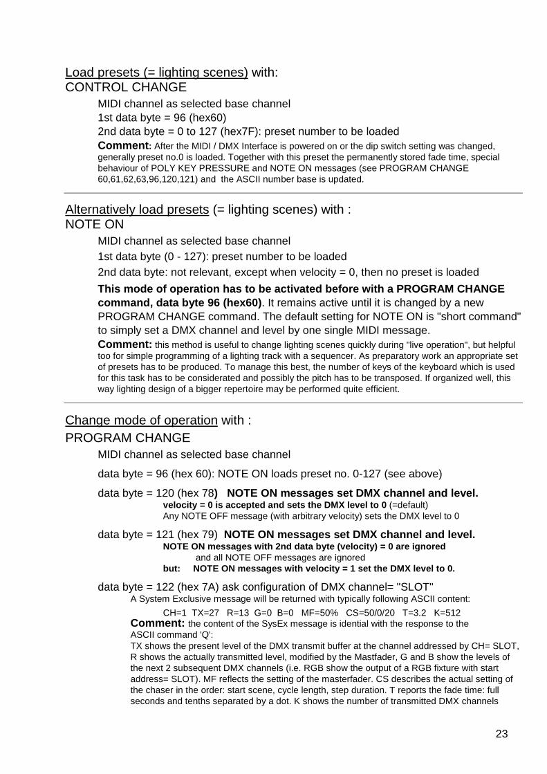
Load presets (= lighting scenes) with: CONTROL CHANGE
MIDI channel as selected base channel 1st data byte = 96 (hex60) 2nd data byte = 0 to 127 (hex7F): preset number to be loaded Comment : After the MIDI / DMX Interface is powered on or the dip switch setting was changed, generally preset no.0 is loaded. Together with this preset the permanently stored fade time, special behaviour of POLY KEY PRESSURE and NOTE ON messages (see PROGRAM CHANGE 60,61,62,63,96,120,121) and the ASCII number base is updated.
Alternatively load presets (= lighting scenes) with : NOTE ON
MIDI channel as selected base channel 1st data byte (0 - 127): preset number to be loaded 2nd data byte: not relevant, except when velocity = 0, then no preset is loaded
This mode of operation has to be activated before w ith a PROGRAM CHANGE command, data byte 96 (hex60) . It remains active until it is changed by a new PROGRAM CHANGE command. The default setting for NOTE ON is "short command" to simply set a DMX channel and level by one single MIDI message. Comment: this method is useful to change lighting scenes quickly during "live operation", but helpful too for simple programming of a lighting track with a sequencer. As preparatory work an appropriate set of presets has to be produced. To manage this best, the number of keys of the keyboard which is used for this task has to be considerated and possibly the pitch has to be transposed. If organized well, this way lighting design of a bigger repertoire may be performed quite efficient.
Change mode of operation with : PROGRAM CHANGE
MIDI channel as selected base channel
data byte = 96 (hex 60): NOTE ON loads preset no. 0-127 (see above)
data byte = 120 (hex 78) NOTE ON messages set DMX channel and level. velocity = 0 is accepted and sets the DMX level t o 0 (=default) Any NOTE OFF message (with arbitrary velocity) sets the DMX level to 0
data byte = 121 (hex 79) NOTE ON messages set DMX channel and level. NOTE ON messages with 2nd data byte (velocity) = 0 are ignored
and all NOTE OFF messages are ignored but: NOTE ON messages with velocity = 1 set the DMX level to 0.
data byte = 122 (hex 7A) ask configuration of DMX channel= "SLOT" A System Exclusive message will be returned with typically following ASCII content:
CH=1 TX=27 R=13 G=0 B=0 MF=50% CS=50/0/20 T=3.2 K=512 Comment: the content of the SysEx message is idential with the response to the ASCII command 'Q':
TX shows the present level of the DMX transmit buffer at the channel addressed by CH= SLOT, R shows the actually transmitted level, modified by the Mastfader, G and B show the levels of the next 2 subsequent DMX channels (i.e. RGB show the output of a RGB fixture with start address= SLOT). MF reflects the setting of the masterfader. CS describes the actual setting of the chaser in the order: start scene, cycle length, step duration. T reports the fade time: full seconds and tenths separated by a dot. K shows the number of transmitted DMX channels

24
data byte = 127 (hex 7F) clears all buffers and working registers This command has to be entered twice to avoid destr uction of setup by lapse of command entry
Comment: this is a kind of warm start, not a reset! All DMX levels of the transmit buffer are reset to "0". Number base = "decimal". Masterfader = 100% The chaser is switched OFF and parameters are reset to their default values Fade time = 0.0. Presets are not deleted or changed otherwise.
General comment on PROGRAM CHANGE messages:
As an alternative, all commands which can be perfor med with a PROGRAM CHANGE can be sent as a CONTROL CHANGE command with 1st data byte = 12 7 (hex 7F). Then its 2nd data byte is equal to the data byte of the corresponding PROGRAM CHANGE command.
When formatting a PROGRAM CHANGE message, many MIDI sequencers and other MIDI control equipment demand that the data value (program number) has to be entered one higher than the physically transmitted data byte.(Example: user entered program #1 is transmitted as hex C0 00), The MIDI/DMX Interface evaluates PROGRAM CHANGE message s with the physical parameter as described in the manual. Check your equipment if the parameter has to be ent ered by 1 higher
Some MIDI devices send together with a PROGRAM CHANGE Befehl automatically a BANK SELECT command (=CONTROL CHANGE to controller no.32(hex20)). If you notice this conflict: don't address any DMX receiver at DMX channel no 32.

25
OSC ("Open Sound Control") methods for MIDI I/O (jumper J2 placed) All OSC capable software known here uses UDP for Et hernet communication Most OSC- featuring devices like iPads, Android tab lets, smartphones and PureData, are not multicasting capable. A preferred OSC default port for received and transmitted datagrams is 8000. Sometimes 8080 or 9000 is more appropriate. This may be changed for differently configured networks.
Every command string (OSC slang "methods") of the subsequently described predefined standard commands esentially consists of 2 letters, which may be entered case insensitive. This restriction is not as strong as it may look:
Preceeding path descriptions , which contain a mixture of slashes '/' and decimal ciphers, are ignored by the default configuration (config parameter '\o' set to ASCII '0'). If a different decimal cipher is configured with \o , the first character following the first slash in the received comand/method is taken as filter criterion: if it matches, the command passes, else it is ignored. When it passes, everything of the path is ignored until the next slash appears which is followed by a literal character (A to Z, case insensitive). If any sequence like this is contained in your path description this will be interpreted as method name or configure \o=0.
Apart from a preceeding path every OSC command (=method) string is definitively parsed and selected concerning the first 2 alphabetic letters (exception MULTI… , see below). All subsequent letters are omitted until the first ASCII representation of a decimal cipher (0...9) appears.
This "numerical" sequence is parsed as an integer number and temporarily stored as the "item number " of this command which is handled in some way like an OSC argument. This parsing procedure is finished when a null byte or the comma in the OSC command string appears. The rest is parsed in conformance with general OSC standards.
The order of processing is organized as follows: When a new OSC command/message is received and passed the simple path filter, first the command/method name, followed by the item number and all OSC arguments are stored in a temporary memory before anything is processed. Up to 5 arguments are allowed per command/method. "Temporary" means that these numerical values are stored and referenced as long as the actual command/method is processed. Will be overwritten by the next command/method.
Next the validity of the command/method name is parsed, checked and transferred to the routine which evaluates and executes the parameters according to the specific features of this command/method. If an OSC MIDI, STRING or BLOB argument is contained in the message, which has no correspondence to the respective command, it is ignored and the remaining arguments (i and f) are "consumed" in the order of appearance. Integer arguments (type i) are always consumed and executed "as received". Values greater than (context given) maximum values are limited to the max. allowed value (in most cases 127 or 255) .Negative values are limited to zero. Float arguments (type f) in the range 0.000 <= 1.000, are recalculated to an integer ranged from 0 to 127 (or the max. range allowed by the actual context). Float 1.000 is rounded down to the highest context conformant integer (in most cases to 127 or 255). If the float argument is greater than 1.000, it is rounded down to the next integer value. This latter kind of coding is possible but not recommended, because there is an ambiguousity when the argument is the range: greater than exactly 0.000 and less or equal 1.000.

26
Data to be transmitted from MIDI OUT (respectively RS-232): The OSC feature of this Ethernet to MIDI and DMX interface seems to be most useful in combination with handheld devices like iPad, iPhone or Android based ones. For users which won't build their personal interface, the patch "MIX2" included by default in TouchOSC and the default interfaces downloaded with "Control" seem to be most useable for the applications intended here and are used for reference as far as possible.
An inherent problem of this kind of signalling is that there is no generally useable communication channel to handle error messages easily. Consequently, faulty commands are handled as smooth as possible. Context oriented details are discussed below.
There are different levels of complexity (= freedom) of operation. This description starts from the most simple methods to more complex and general ones. As explained above, for every command/method only the first two significant letters are parsed. The rest is ignored until a decimal cipher (0…9) does appear in the string. As a consequence, no decimal ciphers are allowed in side the method string itself! Exceptionally any string beginning with "MULTI.. " is parsed up to the next letter following the "I". If it is an "F", the TouchOSC "Multifader" method is assumed and two subsequent numerical "item numbers" are parsed. The first "item number" is the "group", the second one is the "member" in the group. Internally this two-dimensional array is recalculated into a single "item number" and then processed like a single FADER. The recalculation is done as follows: item number = (group-1)*MembersPerGroup + member. Default MembersPerGroup=16. The same way, a following "P" is handled as TouchOSC "Multipush" (default ColumnsPerRow=12) and a following "T" is handled as "Multitoggle" (default ColumnsPerRow=8). Columns and rows are changed here in contrast to normal "mathematical feeling".
If the letter following "I" is a "B", the method string is interpreted as method "Multibutton" supplied by "Control" with only one numerical "item number" processed the same way as PUSH, correspondingly a following "S" is interpreted as "Multislider" processed the same way as FADER.
The least complex and most common methods: (all letters case insensitive!!) Any message (with any item number) received from TouchOSC or others like
/1/PUSH47 + argument (type i or f) or shorted as /PU47 + argument (i or f) or short form of "BUTTON": /BU47 + argument (i or f)
will be forwarded to MIDI OUT as NOTE ON, preset MIDI channel (see command /SC below, default channel 1), "item number" = Note Value (47 in the example). If the argument is an integer, it will be retransmitted as velocity of this note. If the argument is a float = 1.000, the velocity is sent corresponding to the actually stored value (see command /SV below, default = 127). If the argument is integer 0 or float 0.0000, it is always sent as NOTE ON, Note Value 47, velocity=0. Any float value in between (if possible with your personal PUSH version) will be scaled 0 to 127. This way different kinds of virtual MIDI keyboard may be installed easily on the mobile device.
/1/FADER7 + argument (type i or f ) or shorted as /FA7 + argument (i or f ) or short form of "SLIDER": /SL7 + argument (i or f )
will be forwarded to MIDI OUT as CONTROL CHANGE, preset MIDI channel (see command /SC below, default channel 1), "item number" = Controller Number (7 in the example), Controller Value as argument, internally scaled to 0-127 how ever possible – see above. This way different kinds of MIDI 7 bit controllers may be installed easily on the mobile device.
/1/TOGGLE3 + argument (type i or f ) shorted as /TO3 + argument (type i or f ) will be forwarded to MIDI OUT as PROGRAM CHANGE, preset MIDI channel (see command /SC below, default channel 1), "item number" = Program Number 3 (i.e. data byte = 2 in the MIDI message!) The PROGRAM CHANGE message will only be sent if the argument is greater than 0.000 .
All commands (OSC "methods" including the "path") and OSC "Type Tag Strings" have to be filled up - if necessary - with postponed nullbytes to fit into a 32 bit raster accorcding to the OSC specification. Non accepted or faulty coded commands are ignored without error message. Faultly arguments are rounded to max context conformant value.

27
Regarded from the perspective of practical operation, a sequence of UDP datagrams with OSC content is processed by the Ethernet to MIDI&RS232 + DMX512 Interface as a continous stream.
Trigger more specific MIDI channel messages: The names of the subsequently described methods are chosen result oriented but short and neutral – preferably to be used for user-written OSC method generators and to be used as substitutes and arguments in the simple OSC method compiler described below.
/NZn + (optional) argument1 =MIDI channel 1-16 triggers transmission of a NOTE OFF message. The Note Value (pitch) is given by n (0..127) The optional argument1 inserts a particular MIDI channel (1..16) into the message. If no argument is received, the preset MIDI channel (see method /SC below) is inserted into the message (default=1)
/NOn + (optional) argument1 =velocity + (optional) argument2 =MIDI channel 1-16 triggers transmission of a NOTE ON message. The Note Value (pitch) is given by n (0..127). The optional argument1 inserts a particular velocity (0..127) into the message. If missing, the default velocity is used (see method /SV below). The optional argument2 inserts a particular MIDI channel (1..16) into the message. If no argument2 is received, the preset MIDI channel (see method /SC below) is inserted into the message (default=1). If no arguments (1 and 2) are received, the MIDI message is sent with the preset MIDI channel and velocity.
/NDn + (optional) argument1 =velocity + (optional) argument2 =MIDI channel 1-16 triggers transmission of a NOTE ON message to the General MIDI Drum Set. The Note Value (selects drum/percussion instrument) is given by n (0..127). The optional argument1 inserts a particular velocity (0..127) into the message. The optional argument2 inserts a particular MIDI channel (1..16) into the message. If no argument2 is received, the preset MIDI Drum Set channel (see method /SD below) is inserted into the message (default=10). If no arguments (1 and 2) are received, the MIDI message is sent with the preset MIDI channel and velocity.
/CCn + argument1 = controller value+ (optional) argument2 =MIDI channel 1-16 triggers transmission of a CONTROL CHANGE message. The controller number is given by n (0..127). Mandatory argument1 inserts the controller value (0..127) into the message. The optional argument2 inserts a particular MIDI channel (1..16) into the message. If no argument2 is received, the preset MIDI channel (see method /SC below) is inserted into the message (default=1). If no argument 2 is received, this command is equivalent to command FADER as described above.
/PRn + (optional) argument1 =MIDI channel 1-16 triggers transmission of a PROGRAM CHANGE message. The program mumber is given by n (1..128). This is the data byte to be inserted in the MIDI message plus 1 ! Please note, that most MIDI software and other MIDI equipment formally use program numbers in the range 1 to 128, i.e. one higher as the one which is actually sent as MIDI data byte. The optional argument1 inserts a particular MIDI channel (1..16) into the message. If no argument is received, the preset MIDI channel (see method /SC below ) is inserted into the message (default=1)
/POn + (optional) argument1 =velocity + (optional) argument2 =MIDI channel 1-16 triggers transmission of a POLY KEY PRESSURE (=POLYPHONIC AFTERTOUCH) message. The Note Value (pitch) is given by n (0..127). The optional argument1 inserts a particular velocity (0..127) into the message. If missing, the default velocity is used (see method /SC below). The optional argument2 inserts a particular MIDI channel (1..16) into the message. If no argument2 is received, the preset MIDI channel (see method /SC below ) is inserted into the message (default=1). If no arguments (1 and 2) are received, the MIDI message is sent with the preset MIDI channel and velocity.
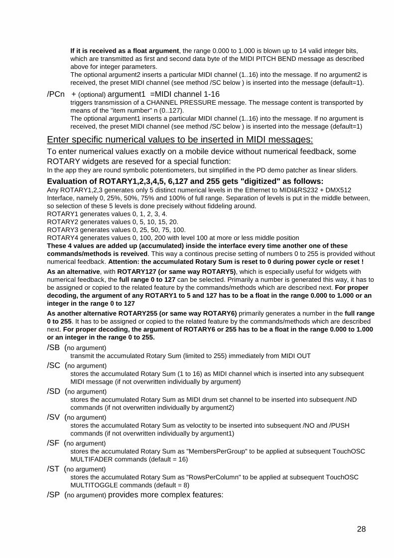
/PB +argument1 + (optional) argument2 = MIDI channel 1-16) /PIT +argument1 + (optional) argument2 = MIDI channel 1-16) (syntax exeption , see "/ping", p.21)
both trigger transmission of a PITCH BEND message (7, 8 or 14 bit accuracy). Any numerical "item number" appended to the method name is ignored. Mandatory argument1 inserts the pitch bend into the message. If it is received as an integer argument , any value between 0 and 16383 (14 bit) is accepted, which is processed in conformance with the MIDI standard: the 7 most significant bits are transmitted as second MIDI data byte. All less significant bits (if the integer is greater than 127) are transmitted in the first MIDI data byte "7 bit left adjusted". Else the first MIDI data byte is transmitted as zero.
28
If it is received as a float argument , the range 0.000 to 1.000 is blown up to 14 valid integer bits, which are transmitted as first and second data byte of the MIDI PITCH BEND message as described above for integer parameters. The optional argument2 inserts a particular MIDI channel (1..16) into the message. If no argument2 is received, the preset MIDI channel (see method /SC below ) is inserted into the message (default=1).
/PCn + (optional) argument1 =MIDI channel 1-16 triggers transmission of a CHANNEL PRESSURE message. The message content is transported by means of the "item number" n (0..127). The optional argument1 inserts a particular MIDI channel (1..16) into the message. If no argument is received, the preset MIDI channel (see method /SC below ) is inserted into the message (default=1)
Enter specific numerical values to be inserted in MIDI messages: To enter numerical values exactly on a mobile device without numerical feedback, some ROTARY widgets are reseved for a special function: In the app they are round symbolic potentiometers, but simplified in the PD demo patcher as linear sliders.
Evaluation of ROTARY1,2,3,4,5, 6,127 and 255 gets " digitized" as follows: Any ROTARY1,2,3 generates only 5 distinct numerical levels in the Ethernet to MIDI&RS232 + DMX512 Interface, namely 0, 25%, 50%, 75% and 100% of full range. Separation of levels is put in the middle between, so selection of these 5 levels is done precisely without fiddeling around. ROTARY1 generates values 0, 1, 2, 3, 4. ROTARY2 generates values 0, 5, 10, 15, 20. ROTARY3 generates values 0, 25, 50, 75, 100. ROTARY4 generates values 0, 100, 200 with level 100 at more or less middle position These 4 values are added up (accumulated) inside th e interface every time another one of these commands/methods is reveived . This way a continous precise setting of numbers 0 to 255 is provided without numerical feedback. Attention: the accumulated Rotary Sum is reset to 0 during power cycle or reset !
As an alternative , with ROTARY127 (or same way ROTARY5) , which is especially useful for widgets with numerical feedback, the full range 0 to 127 can be selected. Primarily a number is generated this way, it has to be assigned or copied to the related feature by the commands/methods which are described next. For proper decoding, the argument of any ROTARY1 to 5 and 127 has to be a float in the range 0.000 to 1.000 or an integer in the range 0 to 127
As another alternative ROTARY255 (or same way ROTARY6) primarily generates a number in the full range 0 to 255 . It has to be assigned or copied to the related feature by the commands/methods which are described next. For proper decoding, the argument of ROTARY6 or 25 5 has to be a float in the range 0.000 to 1.000 or an integer in the range 0 to 255.
/SB (no argument) transmit the accumulated Rotary Sum (limited to 255) immediately from MIDI OUT
/SC (no argument) stores the accumulated Rotary Sum (1 to 16) as MIDI channel which is inserted into any subsequent MIDI message (if not overwritten individually by argument)
/SD (no argument) stores the accumulated Rotary Sum as MIDI drum set channel to be inserted into subsequent /ND commands (if not overwritten individually by argument2)
/SV (no argument) stores the accumulated Rotary Sum as veloctity to be inserted into subsequent /NO and /PUSH commands (if not overwritten individually by argument1)
/SF (no argument) stores the accumulated Rotary Sum as "MembersPerGroup" to be applied at subsequent TouchOSC MULTIFADER commands (default = 16)
/ST (no argument) stores the accumulated Rotary Sum as "RowsPerColumn" to be applied at subsequent TouchOSC MULTITOGGLE commands (default = 8)
/SP (no argument) provides more complex features:
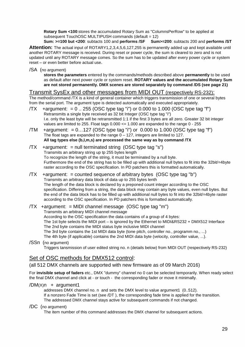
29
Rotary Sum <100 :stores the accumulated Rotary Sum as "ColumnsPerRow" to be applied at subsequent TouchOSC MULTIPUSH commands (default = 12) Sum: >=100 but <200 : subtacts 100 and performs /SF Sum>=200 : subtacts 200 and performs /ST
Attention: The actual input of ROTARY1,2,3,4,5,6,127,255 is permanently added up and kept available until another ROTARY message is received. During reset or power cycle, the sum is cleared to zero and is not updated until any ROTARY message comes. So the sum has to be updated after every power cycle or system reset – or even better before actual use.
/SA (no argument) stores the parameters entered by the commands/methods described above permanently to be used as default after next power cycle or system reset. ROTARY values and the accumulated Rotary Sum are not stored permanently. DMX scenes are stored s eparately by command /DS (see page 21)
Transmit SysEx and other messages from MIDI OUT (respectively RS-232): The method/command /TX is a kind of general container which triggers transmission of one or several bytes from the serial port. The argument type is detected automatically and executed appropriately.
/TX +argument: = 0 .. 255 (OSC type tag "i") or 0.000 to 1.000 (OSC type tag "f") Retransmits a single byte received as 32 bit Integer (OSC type tag "i") I.e. only the least byte will be retransmitted 1:1 if the first 3 bytes are all zero. Greater 32 bit integer values are limited to 255. Float tags 0.000 <= 1.000 are expanded to the range 0 - 255
/TM +argument: = 0…127 (OSC type tag "i") or 0.000 to 1.000 (OSC type tag "f") The float tags are expanded to the range 0 – 127, integers are limited to 127. All tag types else (b,I,m,s) are processed the same way as by command /TX
/TX +argument: = null terminated string (OSC type tag "s") Transmits an arbitrary string up tp 255 bytes length To recognize the length of the string, it must be terminated by a null byte. Furthermore the end of the string has to be filled up with additional null bytes to fit into the 32bit/=4byte raster according to the OSC specification. In PD patchers this is formatted automatically.
/TX +argument: = counted sequence of arbitrary bytes (OSC type tag "b") Transmits an arbitrary data block of data up to 255 bytes lenth The length of the data block is declared by a preponed count integer according to the OSC specification. Differing from a string, the data block may contain any byte values, even null bytes. But the end of the data block has to be filled up with additional null bytes to fit into the 32bit/=4byte raster according to the OSC specification. In PD patchers this is formatted automatically.
/TX +argument: = MIDI channel message (OSC type tag "m") Transmits an arbitrary MIDI channel message According to the OSC specification the data contains of a group of 4 bytes: The 1st byte selects the MIDI port – is ignored by the Ethernet to MIDI&RS232 + DMX512 Interface The 2nd byte contains the MIDI status byte inclusive MIDI channel The 3rd byte contains the 1st MIDI data byte (tone pitch, controller no., programm no., ...) The 4th byte (if applicable) contains the 2nd MIDI data byte (velocity, controller value, ...).
/SSn (no argument) Triggers tansmission of user edited string no. n (details below) from MIDI OUT (respectively RS-232)
Set of OSC methods for DMX512 control: (all 512 DMX channels are supported with new firmware as of 09 March 2016)
For invisible setup of faders etc., DMX "dummy" channel no 0 can be selected temporarily. When ready select the final DMX channel and click at - or touch - the corresponding fader or move it minimally.
/DM(X)n + argument1 addresses DMX channel no. n and sets the DMX level to value argument1 (0..512). If a nonzero Fade Time is set (see /DT ), the corresponding fade time is applied for the transition. The addressed DMX channel stays active for subsequent commands if not changed.
/DC (no argument) The item number of this command addresses the DMX channel for subsequent actions.
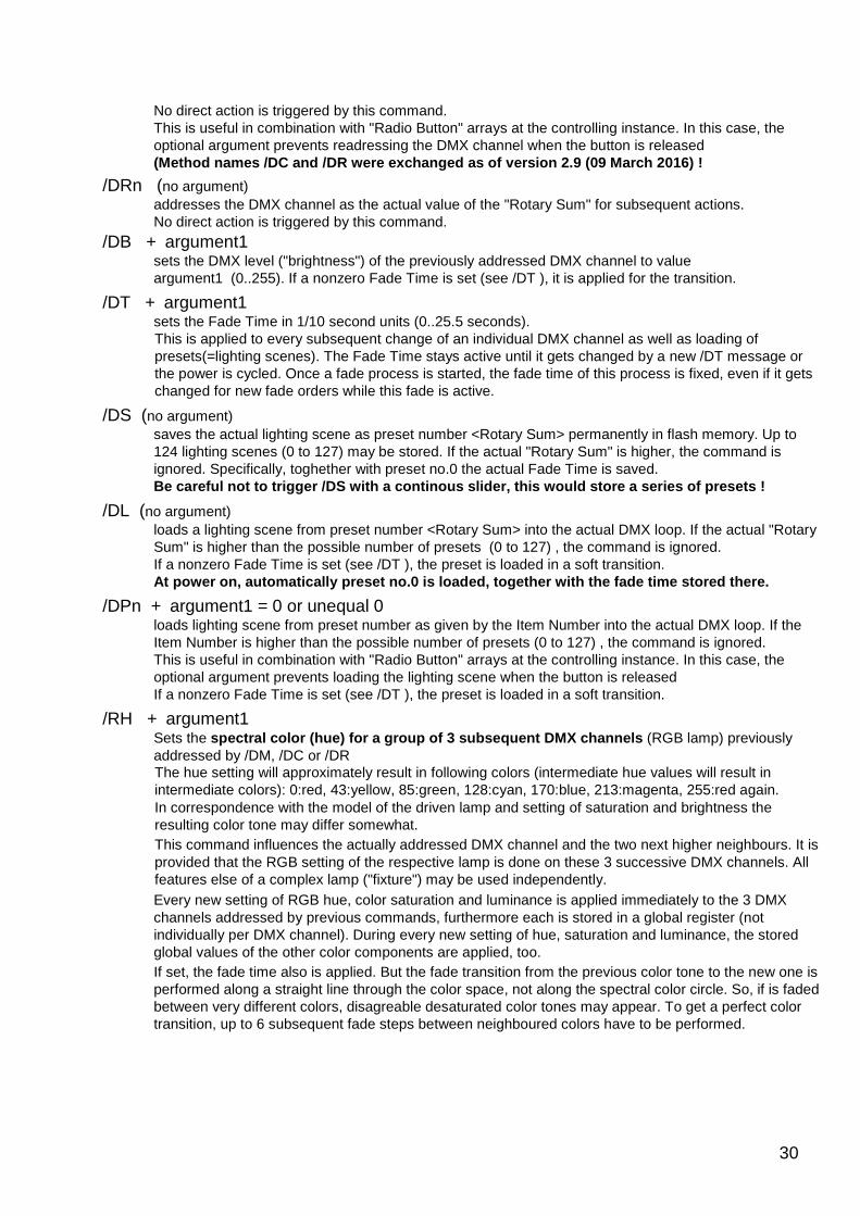
30
No direct action is triggered by this command. This is useful in combination with "Radio Button" arrays at the controlling instance. In this case, the optional argument prevents readressing the DMX channel when the button is released (Method names /DC and /DR were exchanged as of vers ion 2.9 (09 March 2016) !
/DRn (no argument) addresses the DMX channel as the actual value of the "Rotary Sum" for subsequent actions. No direct action is triggered by this command.
/DB + argument1 sets the DMX level ("brightness") of the previously addressed DMX channel to value argument1 (0..255). If a nonzero Fade Time is set (see /DT ), it is applied for the transition.
/DT + argument1 sets the Fade Time in 1/10 second units (0..25.5 seconds). This is applied to every subsequent change of an individual DMX channel as well as loading of presets(=lighting scenes). The Fade Time stays active until it gets changed by a new /DT message or the power is cycled. Once a fade process is started, the fade time of this process is fixed, even if it gets changed for new fade orders while this fade is active.
/DS (no argument) saves the actual lighting scene as preset number <Rotary Sum> permanently in flash memory. Up to 124 lighting scenes (0 to 127) may be stored. If the actual "Rotary Sum" is higher, the command is ignored. Specifically, toghether with preset no.0 the actual Fade Time is saved. Be careful not to trigger /DS with a continous slid er, this would store a series of presets !
/DL (no argument) loads a lighting scene from preset number <Rotary Sum> into the actual DMX loop. If the actual "Rotary Sum" is higher than the possible number of presets (0 to 127) , the command is ignored. If a nonzero Fade Time is set (see /DT ), the preset is loaded in a soft transition. At power on, automatically preset no.0 is loaded, t ogether with the fade time stored there.
/DPn + argument1 = 0 or unequal 0 loads lighting scene from preset number as given by the Item Number into the actual DMX loop. If the Item Number is higher than the possible number of presets (0 to 127) , the command is ignored. This is useful in combination with "Radio Button" arrays at the controlling instance. In this case, the optional argument prevents loading the lighting scene when the button is released If a nonzero Fade Time is set (see /DT ), the preset is loaded in a soft transition.
/RH + argument1 Sets the spectral color (hue) for a group of 3 subsequent DM X channels (RGB lamp) previously addressed by /DM, /DC or /DR The hue setting will approximately result in following colors (intermediate hue values will result in intermediate colors): 0:red, 43:yellow, 85:green, 128:cyan, 170:blue, 213:magenta, 255:red again. In correspondence with the model of the driven lamp and setting of saturation and brightness the resulting color tone may differ somewhat. This command influences the actually addressed DMX channel and the two next higher neighbours. It is provided that the RGB setting of the respective lamp is done on these 3 successive DMX channels. All features else of a complex lamp ("fixture") may be used independently. Every new setting of RGB hue, color saturation and luminance is applied immediately to the 3 DMX channels addressed by previous commands, furthermore each is stored in a global register (not individually per DMX channel). During every new setting of hue, saturation and luminance, the stored global values of the other color components are applied, too. If set, the fade time also is applied. But the fade transition from the previous color tone to the new one is performed along a straight line through the color space, not along the spectral color circle. So, if is faded between very different colors, disagreable desaturated color tones may appear. To get a perfect color transition, up to 6 subsequent fade steps between neighboured colors have to be performed.
31
/RS + argument1 Sets the color saturation for a group of 3 subsequent DMX c hannels (RGB lamp) previously addressed by /DM, /DC or /DR The argument1 may take values between 0 and 255. The maximum value 255 sets a pure spectral color, at lower parameter values other color components are partially added which results in a pastel light. When the saturation is set to 0, independently of the hue setting a white or grey light is composed.
/RB + argument1 Sets the resulting brightness for a group of 3 subsequent D MX channels (RGB lamp) previously addressed by /DM, /DC or /DR Value 255 sets maximum light intensity, value 0 switches the light intensity off. Fading down is performed linear, not taking the gamma characteristics of the lamp into account. Specially when high performance LEDs are driven most times very strong changes of light intensity are observed at low brightness. So in this range small parameter steps may result in heavy changes of the RGB composition.
Data received at MIDI IN are automatically transmitted via network as a stream of OSC messages. Depending on configuration parameter \F, messages are styled dif ferently:
--- F= 0: all bytes received at MIDI IN are sent as a continous stream of OSC "blobs", no care for syntactic correspondence of any bytes.
--- F= 1: MIDI channel messages and System Common Messages (except SysEx) are sent as OSC m tag formatted /TX or /midi packets. Received bytes in "running state" are completed with the corresponding status byte. SysEx messages (any starting with 0xF0 and ending with EOX=0xF7 and max 256 bytes long) are sent as coherent OSC b tag formatted "blobs". Everything which cannot be put into this scheme or when synchronisation gets lost is forwarded as a continous stream of OSC "blobs" until a new synchronisation point is found. /TX +argument: = OSC "blob"
The input buffer of the MIDI IN interface is polled in short time intervals. All bytes received since last polling (max.255) are packed into the OSC-"blob". The payload count is declared in a preponed 32 bit integer as specified by OSC. The end of the data block is filled up with additional null bytes to fit into the 32 bit raster according to the OSC specification. This way, data received at MIDI IN are effectively forwarded as a stream. A message containing a NOTE ON message would look in the OSC packet as follows, for example:
/TX<0> ,b<0><0> <0><0><0><3> <144><55><64><0> ( M = 0)
This data format is not limited to MIDI channel messages, any arbitrary Sysex messages, strings and even single bytes can be transferred.
/TX +argument: = OSC "m" tag This is the standard format when parameter M is set to 1.
Every single MIDI channel message is sent as a short OSC message with a single m tag. As long as possible, incoming bytes are interpreted as MIDI Status Bytes to start a new message or interpreted as MIDI Data Bytes, as long as possible as in "running state. If a new status byte is received before the last message has gathered the corresponding number of data bytes, the incomplete message is cancelled and the new one initiated. A message containing a NOTE ON message would look in the OSC /midi packet as follows, for example:
/TX<0> ,m<0><0> <0><144><55><64> ( M = 1)
Editor for user defined strings ( transmission of string no.n is triggered by OSC command/method /SSn)
This editor can be operated with a terminal software via Ethernet when Jumper2 is placed. Unfortunately, most times it cannot be used simultaneously with OSC capable software because only one socket is supported.

32
When both jumpers 1 + 2 are placed, this editor can be operated additionally via the serial port with a terminal software. Provisionally, all serial data sent by OSC commands (via Ethernet) are transformed then into readable ASCII text at the serial port for debugging purpose. No serial input is sent via Ethernet to the OSC client then.
User defined strings are helpful to store System Exclusive or similar messages which are needed / triggered repeatedly. User defined strings are stored permanently in flash memory, ie. will be present after power cycle or system reset. Any string may be deleted or overwritten up to 10000 times.
ES n <return> starts the editor for string entry no. n (n =0 to 43).
The "entry number" n is entered as a one to three digit decimal number in ASCII text format. Next the user defined string is entered.
A "string" usually contains "printable letters", which have a correspondence on a typewriter or similar keyboard. "Nonprintable letters " - represented by a binary byte - may be entered as follows: first enter a backslash \ next enter the binary value as a 2 digit hexadecimal number (without type specifier like 0x). Leading zeroes for byte values less than hex10 have to be entered explicitly!
Each string may contain max. 253 characters (nonprintables=3 characters). String input is terminated by <return> . Consequently, if the string shall contain a Carriage Return or a Backslash, this has to be entered as a binary hex byte as described above.
ES n <return><return> deletes string no. n (n =0 to 47). Technically this is a redefinition of the string with a zero length content. "Editing" of existing strings is not possible.
CS n <return> returns string no. n (n =0 to 47) for check via control interface . If no valid user string is stored, the sequence n:xxx is responded.
LS responds a list with all valid string entries. After each 20 lines, the output stops and has to be retriggered with a <return> keystroke
Compiler for user defined OSC-commands ("methods")
OSC has the disadvantage (in contrast to MIDI) that no general command set is specified. So any OSC application has its individual set of commands. To compensate this disadvantage, the Ethernet to MIDI&RS232 + DMX512 Interface is supplied with a simple compiler to generate user specific OSC commands/methods. Up to 128 methods may be created this way, each of them may call a complete sequence of OSC commands as described above. This compiler is active as a specially operated feature in the OSC command mode when Jumper2 is placed. It can be operated with a terminal software via Ethernet. Unfortunately, most times it cannot be used simultaneously with OSC capable software because only one socket is supported. When both jumpers 1 and 2 are placed, this editor can be operated additionally via the serial port with a terminal software. Provisionally, all serial data sent by OSC commands (via Ethernet) are transformed then into readable ASCII text at the serial port for debugging purpose. No serial input is sent via Ethernet to the OSC client then.
Input is case insensitive, letters are always converted into upper case (except content of inline characters and strings to be transmitted at runtime).
At runtime, user defined methods/commands may be mixed arbitrarily with predefined commands described above. User defined commands are generally evaluated with higher priority than those which are preprogrammed in firmware. This provides an

33
option to redirect a method/command which usually starts a predefined command into a user defined one with the same name.
Every received OSC command has to be compared with all user edited name entries. This takes some time of computation: at least a few microseconds, but in worst case up to 10 milliseconds. To keep search time low, put all user defined commands into entry slots with low numbers. Short command names with quite different first letters will shorten the search time. Path descriptions: Together with user defined command names path information like /../ is handled the same way as described above for built-in methods/commands.
EM n <return> starts the compiler for command entry no. n (n =0 to 127).
The "entry number" n is entered as a one to three digit decimal number in ASCII text format and terminated with <return> . Next enter your command/method name (without preceeding slash, which is inserted automatically) including the "item number". If desired, the name may contain an OSC path styled like ../. Spaces will get part of the command name. Instead of a definitive "item number" the star char acter * may be used as a wildcard. If the command name is terminated by the star *, during runtime parsing of every command name is terminated here. All following letters are ignored. This means especially, that the following user defined command sequence will be performed at runtime with every "item number", which may be copied into the user sequence by the same wildcard (see below). The name input (including "item number") is terminated by a comma .
Next, an appropriately structured sequence of ASCII written commands is entered . Only those method/command names which are predefined in the firmware are allowed. No recursive call of user defined command sequences is possible. The command name is followed by obligatory and voluntary arguments as described above. In the compiler, arguments are entered as numerical ASCII text or as a placeholder (details see below). The first argument follows directly after the method/command name. Additional arguments are automatically separated by special characters. Any non-numerical ASCII character terminates the input of an argument. Examples see below. The compiler entry is terminated by <return> . Max. 253 characters per entry are allowed, incl command name.
EM n <return><return> deletes command entry no. n (n =0 to 127) Due to the nature of flash memory, every command entry may be deleted and rewritten up to 10000 times. User commands may be overwritten with differing ones without beeing deleted explicitly before. "Editing" of existing methods/commands is not possible.
CM n <return> returns command sequence no. n (n =0 to 127) for check via control interface . If a nonconfigured command number is checked, the text "/xxx" is responded.
LM responds a list with all valid user defined methods. After each 20 lines, the output stops and has to be retriggered with a <return> keystroke
Parameters of command sequences are entered to the compiler as follows:
The leading slash / of every OSC method/command name is inserted autom atically. Enter method/command name to be executed next:
Most simple case: if no additional "opcodes" follow the redirected method, all originally received arguments are adopted from the originally received argument list to the redirected one. Compare with example at # below. Example: EM1<return>/ROTARY5,/CC7<return> At runtime it directs every OSC message from ROTARY5 method – explicitly the float argument – to CC7 method. This way the function of ROTARY5 is changed into a continous MIDI volume control.

34
More than one command name may be added in a user c ompiled method/command , these will be worked off in order of appearance including their attached arguments. But the user has to decide how far this makes sense for him.
Apart from inserting command names, the compiler roughly works as follows : when a received OSC method is "grabbed" at runtime by the interpreter for user compiled OSC methods, first all of its arguments are stored in a temporary argument buffer. Next for the user defined OSC method another temporary argument buffer is opened at runtime. "Temporary" means: valid until this user compiled method is worked off during runtime. The set of "opcodes" (as described below) first transfers arguments from the argument buffer of the received OSC method to the new generated in sequence of request. This means, in general the received OSC method must contain as many arguments (max. 5, most times less) as will be consumed by the corresponding user generated one.
_ (underline) prevents adoption of original arguments to a user defined method (only to prevent adoption completely. A problem may arise , when mandatory arguments are missing. For custom construction, preferably use operations described below) Example: EM3<return>/PUSH1,/NO63_<return> PUSH1 triggers transmission of NOTE ON 63 with default velocity. The argument of PUSH1 is ignored.
* append received item number as item number to a use r defined command Example: EM4<return>/ROTARY*,/FADER*<return> At runtime it directs every OSC message from any ROTARY method – explicitly the float argument – to the corresponding FADER method with the same intem number.
= append accumulated Rotary Sum as item number to a u ser defined command Example: EM4<return>/ROTARY3,/FADER=<return> At runtime it directs every OSC message from ROTARY3 method – explicitly the float argument – to the corresponding FADER method with the accumulated Rotary Sum as intem number.
# insert next originally received argument as next ar gument to actually sent message Exclusively integer and float arguments can be "consumed" this way. Other argument types like blob, string and MIDI are ignored and the next appropriate argument of the originally received list is used. Example: EM43<return>/ROTARY5,/CC7#&9 <return> At runtime it directs every OSC message from ROTARY5 method – by use of "opcode" # explicitly the float argument – to CC7 method. The optional second argument &9 transmits MIDI channel no. 9.
The following "opcodes" are no placeholders to insert received arguments to OSC methods during runtime, but insert static values to arguments into user defined methods (optional arguments for example) or trigger immediate transmission of different kind of data from MIDI OUT (respectively RS-232):
& insert inline decimal number as next argument Inserted as mandatory or optional argument with the respective method name. This differs from opcode % as far as the argument may be "built" into the method.
@ insert inline hex number as next argument Inserted as mandatory or optional argument with the respective method name. This differs from opcode % as far as the argument may be "built" into the method. See example above
( insert accumulated Rotary Sum as next argument
This is hermaphrodite in the sense that an argument which is variable during runtime is inserted statically. Example: EM7<return>/PUSH1,?/CC7( <return>

35
At runtime this example directs every OSC message from the PUSH1 method to the CC7 method. The PUSH1 button works as a trigger now to send a CONTROL CHANGE message to controller number 7 with value given by the actually accumulated settings of ROTARY1-5. The question mark before /CC7 causes transmission of the CC message only when the button is pushed down, not when it gets released. See "opcode" ? below.
~ (tilde) replace (fake) the Rotary Sum by inline decimal num ber exclusively in a user compiled command string. This simplifies and expands capabilities of some commands/methods described here. Replacement is valid until another accumulating ROTARY command is received or the last accumulated value is restored by the oppo site "opcode" ^ . Example: EM3<return>/BUTTON16,?~16/SC ^ <return> /BUTTON16 sets the default MIDI channel to 16 and then restores the accumulated Rotary Sum.
% send decimal inline byte immediately
$ send hex inline byte immediately Example: EM4<return>/PUSH1,?$F8 <return> triggers transmission of a MIDI Timing Clock message
> send accumulated Rotary Sum as MIDI byte
" send inline string until next ". Enter nonprintable byte as \ followed by 2 digit hex number Example: EM2<return>/PUSH1,?"\F0\7Dhello world\F7" <return>
:n (colon) send user edited string no. n as MIDI sequence this replaces (i.e.simplifies) use of method /SSn in user edited command sequences.
; (semicolon) send user edited string no. = (accumulated Rotary S um) as MIDI sequence
The following "opcodes" provide some limited options to handle flow control:
- (minus sign) decrease argument pointer "Opcodes" #, ( ,< and ? each copy one argument from the originally received argument list and append it to a temporary argument list for the actually sent message (method). Then the argument pointer of the originally received argument list is increased to point to the next originally received argument. By means of the minus sign "opcode" – the argument pointer is decreased by one. This may be useful in some cases to use an originally received argument for several messages. Example: EM1<return>/FADER1,? – /NO65# ! NZ65 <return> transmits NOTE ON with velocity sent with the FADER method, but NOTE OFF instead of NOTE ON with zero velocity.
+ increase argument pointer this increases the argument pointer by one, possibly to leave out one originally received argument from retransmission. Only useful in very special cases.
? conditional branch of execution: if next argument = TRUE i.e. unequal 0: execute following sequence u ntil ! or end. Exit then = FALSE i.e. = 0: jump after ! and execute followin g until end
! marks end of TRUE branch after ?
If ? is compiled as "opcode" into a command sequence, at runtime the next orignally received OSC integer- or float-argument will be checked and "consumed" (i.e. argument pointer will be increased):
--- if it is equal to 0 , execution of the command sequence will be interrupted at this point, the list of commands will be scanned until entry ! is found . From here the sequence will be executed normally until end of the command sequence. If no ! does follow, execution will be terminated i mmediately.
--- If it is unequal to 0 (i.e. unequal 0.000 !!), execution of the sequence will be continued normally with subsequent command entries until "opcode" ! or the end of the sequence is found. Execution of the list will be terminated at this point.

36
By use of this feature it is possible, that different actions specifically take place during "push" or "release" of a "Push"-or "Toggle-" object , or release of the button becomes ignored totally.
--- "opcode" ! may be put directly after ? . Commands which are put after the sequence ?! will be performed only when the button is released.
All commands before the question mark are executed independently of the value of the OSC argument checked by ?.
Attention , unconsidered use of control characters ? and ! may cause hard explainable malfunction ! During runtime, the question mark "consumes" an OSC argument. This is easily overlooked, when the sequence has to evaluate several arguments at runtime. When a button is released, placeholders of the type #, which are put between the ? and ! mark, are not evaluated. If necessary, at runtine OSC arguments are "delete d" by the + "opcode" or used multiply by the – "opcode".
For example and as a practical assistance, the following 4 methods are programmed together with the firmware, but can be changed by user input:
M1: /TOGGLE1,?/SB M2: /TOGGLE2,?/SC M3: /TOGGLE3,?/SV M4: /TOGGLE4,?/SP/SA (take care of the "Rotary Sum" depending effect of /SP!) M5: /FADER1,/CC7#3 M6: /PUSH1,?/SS0
Additionally, two test strings are programmed with the firmware , they can be changed by user input too:
S0: HelloWorld! S47: Last String

37
Manual Addendum for special firmware supporting Art-Net This firmware version is identical with the standar d firmware as described above with the only but essential change that it supports Art- Net DMX instead of OSC. It is used with the same hardware without any modification, so the firmware version can be changed easily.
Art-NetTM is Designed by and Copyright Artistic Licence (UK) Ltd.
Only the most basic features of the Art-Net protocol are implemented: ArtPoll, ArtPollReply and ArtDmx. This is sufficient to operate the device with lighting software like DMX-Control. The firmware uses the default MAC ID 00.50.C2.92.8F.FE (only granted for test, not for public use !), furthermore ESTA and Art-Net IDs, all registered for and used by courtesy of Cinetix, ie. it will be identified as "Cinetix" by appropriate software.
Consequently the function of jumper J2 is different with this firmware: Only J2 placed : Art-Net DMX is communicated over Ethernet/UDP. The ASCII and MIDI command interpreters are out of action. J1 + J2 placed : Art-Net DMX is communicated over Ethernet/UDP. Simultaneously the ASCII command interpreter is active (including MiniDMX), but can only be operated with the RS-232 interface, not via Ethernet, of course.
All commands supporting the OSC interpreter are not implemented in this firmware
Else all commands and jumper settings are the same as in the version with OSC.
Because the Art-Net lighting pattern is automatically updated every few seconds, the ASCII command interpreter would be permanently overridden by Art-Net when J1+J2 is placed. To block this, a new ASCII command was introduced: * <0 or 1> *0 blocks Art-Net. Art-Net is received furthermore in the background, but its data are not copied into the DMX buffer. *1 allows Art-Net to change the lighting pattern
The *0 command is useful to intervene manually into a computer controlled lighting show. Control is given back to Art-Net with command *1.
Furthermore, some Art-Net specific configuration commands are introduced:
/A sets the Art-Net IP address 'A' <0, 1, 2> default = 0
With /A0 a user defined Art-Net IP address ("custom IP") is active . This is the IP address of the device (see command /I), but all bits are set, whose corresponding bits in the Subnet Mask are zero. I.e. the resulting Art-Net IP is the maximum broadcast address, which is possible in the actual network. With default settings, this way the Art-Net IP will be 192.168.0.255. Differing from the recommendation given in the Art-Net manual, this configuration fits most easily with known lighting software like DMX-Control.
With /A2 the Art-Net IP (2. plus bytes B.C.D as defined in the Art-Net manual) is active and the SubnetMask is 255.0.0.0. With /A1 the Art-Net IP (10. plus bytes B.C.D defined in the Art-Net manual) is active and the SubnetMask is 255.0.0.0
Independent of the configured UDP ports, Art-Net always uses its reserved port 0x1936
/N sets the Art-Net "Subnet" (0---15) (not to be confused with the network Subnet Mask!!)
/U sets the Art-Net "Universe" for DMX OUT (0---15)

38
Appendix A Structure of MIDI channel messages (super compact crash course) The first byte is the status byte, only this one has bit 7 set . It is composed of 2 hex nibbles. The most significant (high) nibble describes the message type, the least significant (low) nibble contains the MIDI channel. The MIDI channel is always physically coded one less than written in any MIDI manual or litterature. Putting both together: (MIDI channel-1) has to be added to the message type status body. For MIDI channel no. 1 the different types of MIDI messages show following status byte (=status body):
NOTE OFF:hex80,dec128 NOTE ON:hex90,dec144 POLY KEY PRESSURE(=POLY KEY AFTERTOUCH) :hexA0,dec160 CONTROL CHANGE :hexB0,dec176 PROGRAM CHANGE :hexC0,dec192 CHANNEL PRESSURE :hexD0,dec208 PITCH CHANGE:hexE0,dec224 The status byte of PROGRAM CHANGE and CHANNEL PRESSURE is followed by exactly 1 data byte The status byte of all other message types is followed by exactly 2 data bytes In all data bytes the most significant bit7 is cleared , the other bits are content specific.
Determination of MIDI note values from common note names: C C# D D# E F F# G G# A B H
-2 0 1 2 3 4 5 6 7 8 9 10 11 -1 12 13 14 15 16 17 18 19 20 21 22 23 24 25 26 27 28 29 30 31 32 33 34 35
1 36 37 38 39 40 41 42 43 44 45 46 47 2 48 49 50 51 52 53 54 55 56 57 58 59 3 60 61 62 63 64 65 66 67 68 69 70 71 4 72 73 74 75 76 77 78 79 80 81 82 83 5 84 85 86 87 88 89 90 91 92 93 94 95 6 96 97 98 99 100 101 102 103 104 105 106 107 7 108 109 110 111 112 113 114 115 116 117 118 119 8 120 121 122 123 124 125 126 127 - - - -
This scheme is used by several MIDI sequencers. But deviating names of the different octaves are in use, too. Following unique relationship may be helpful: the concert pitch a (440Hz) -- in the table above "A3" - is always corresponding with MIDI note value 69 (hex 45).
Appendix B
Semi-Automatic baud rate detection: During the first second after power-up the timing pattern of data received at the serial input (MIDI or RS-232) is analyzed. If the baudrate is correctly detected, the string "Autobaud: <+actual baudrate> " is sent to the serial port with the new baudrate. Exclusively baud rates 9600, 19200, 31250(MIDI), 38400, 57600 and 115200 are detected.
Practically this may be handled as follows: Connect a data source (e.g. terminal or MIDI keyboard) with the serial input. Disconnect power. Send a permanent sequence of bytes with as much level changes as possible. Best suited is "U" (decimal 85) or "Z" (decimal 90). When a MIDI interface is used, preferably send Note On, note C#5 or F#5. Most times any input works. While the bytes are sent permanently, connect power and wait for the response text as described above.

39
RS-232 cable for MIDI I/O connectors: The MIDI OUT of this device works with idle (= no current, 'Mark' ) state ca. 0 Volt, thus it is signal compatible with RS-232. The cable proposed here works only with this kind of interface design. It is proposed to use two pieces of single wire shielded audio cable, length up to 5 meters. The resistors are mounted inside the SubD hood. Don't forget to strip the hood of the DIN connectors over the cable before soldering, later it is not possible. The connection between pin 7 and 8 simulates a hardware handshake to the PC, in very most cases it is not necessary. Other MIDI interfaces work with idle state ca. 5 Volt and are pulled down to 0 Volt to activate current flow. Latter ones cannot be made RS-232 compatible, but their advantage is that they can supply some attached MIDI appliances with a small supply current. This is impossible with the design used here. contact: [email protected]
* Right of technical modifications reserved. Provided 'as is' - without any warranty. Any responsibility is excluded. * This description is for information only, no product specifications are assured in juridical sense. * Trademarks and product names cited in this text are property of their respective owners