ess user guide
TRANSCRIPT

Avaya Enterprise Survivable Servers (ESS) User Guide
03-300428Issue 1.1
June 2005

Copyright 2005, Avaya Inc.All Rights Reserved
NoticeEvery effort was made to ensure that the information in this document was complete and accurate at the time of printing. However, information is subject to change.
WarrantyAvaya Inc. provides a limited warranty on this product. Refer to your sales agreement to establish the terms of the limited warranty. In addition, Avaya’s standard warranty language as well as information regarding support for this product, while under warranty, is available through the following Web site: http://www.avaya.com/support.
Preventing Toll Fraud"Toll fraud" is the unauthorized use of your telecommunications system by an unauthorized party (for example, a person who is not a corporate employee, agent, subcontractor, or is not working on your company's behalf). Be aware that there may be a risk of toll fraud associated with your system and that, if toll fraud occurs, it can result in substantial additional charges for your telecommunications services.
Avaya Fraud InterventionIf you suspect that you are being victimized by toll fraud and you need technical assistance or support, in the United States and Canada, call the Technical Service Center's Toll Fraud Intervention Hotline at1-800-643-2353.
DisclaimerAvaya is not responsible for any modifications, additions or deletions to the original published version of this documentation unless such modifications, additions or deletions were performed by Avaya. Customer and/or End User agree to indemnify and hold harmless Avaya, Avaya's agents, servants and employees against all claims, lawsuits, demands and judgments arising out of, or in connection with, subsequent modifications, additions or deletions to this documentation to the extent made by the Customer or End User.
How to Get HelpFor additional support telephone numbers, go to the Avaya support Web site: http://www.avaya.com/support. If you are:
• Within the United States, click the Escalation Contacts link that is located under the Support Tools heading. Then click the appropriate link for the type of support that you need.
• Outside the United States, click the Escalation Contacts link that is located under the Support Tools heading. Then click the International Services link that includes telephone numbers for the international Centers of Excellence.
Providing Telecommunications SecurityTelecommunications security (of voice, data, and/or video communications) is the prevention of any type of intrusion to (that is, either unauthorized or malicious access to or use of) your company's telecommunications equipment by some party.Your company's "telecommunications equipment" includes both this Avaya product and any other voice/data/video equipment that could be accessed via this Avaya product (that is, "networked equipment").An "outside party" is anyone who is not a corporate employee, agent, subcontractor, or is not working on your company's behalf. Whereas, a "malicious party" is anyone (including someone who may be otherwise authorized) who accesses your telecommunications equipment with either malicious or mischievous intent.Such intrusions may be either to/through synchronous (time-multiplexed and/or circuit-based), or asynchronous (character-, message-, or packet-based) equipment, or interfaces for reasons of:
• Utilization (of capabilities special to the accessed equipment)• Theft (such as, of intellectual property, financial assets, or toll
facility access)• Eavesdropping (privacy invasions to humans)• Mischief (troubling, but apparently innocuous, tampering)• Harm (such as harmful tampering, data loss or alteration,
regardless of motive or intent)Be aware that there may be a risk of unauthorized intrusions associated with your system and/or its networked equipment. Also realize that, if such an intrusion should occur, it could result in a variety of losses to your company (including but not limited to, human/data privacy, intellectual property, material assets, financial resources, labor costs, and/or legal costs).
Responsibility for Your Company’s Telecommunications SecurityThe final responsibility for securing both this system and its networked equipment rests with you - Avaya’s customer system administrator, your telecommunications peers, and your managers. Base the fulfillment of your responsibility on acquired knowledge and resources from a variety of sources including but not limited to:
• Installation documents• System administration documents• Security documents• Hardware-/software-based security tools• Shared information between you and your peers• Telecommunications security experts
To prevent intrusions to your telecommunications equipment, you and your peers should carefully program and configure:
• Your Avaya-provided telecommunications systems and their interfaces
• Your Avaya-provided software applications, as well as their underlying hardware/software platforms and interfaces
• Any other equipment networked to your Avaya products
TCP/IP FacilitiesCustomers may experience differences in product performance, reliability and security depending upon network configurations/design and topologies, even when the product performs as warranted.
Standards ComplianceAvaya Inc. is not responsible for any radio or television interference caused by unauthorized modifications of this equipment or the substitution or attachment of connecting cables and equipment other than those specified by Avaya Inc. The correction of interference caused by such unauthorized modifications, substitution or attachment will be the responsibility of the user. Pursuant to Part 15 of the Federal Communications Commission (FCC) Rules, the user is cautioned that changes or modifications not expressly approved by Avaya Inc. could void the user’s authority to operate this equipment.
Product Safety StandardsThis product complies with and conforms to the following international Product Safety standards as applicable:Safety of Information Technology Equipment, IEC 60950, 3rd Edition, or IEC 60950-1, 1st Edition, including all relevant national deviations as listed in Compliance with IEC for Electrical Equipment (IECEE) CB-96A.Safety of Information Technology Equipment, CAN/CSA-C22.2No. 60950-00 / UL 60950, 3rd Edition, or CAN/CSA-C22.2 No. 60950-1-03 / UL 60950-1.Safety Requirements for Information Technology Equipment, AS/NZS 60950:2000.One or more of the following Mexican national standards, as applicable: NOM 001 SCFI 1993, NOM SCFI 016 1993, NOM 019 SCFI 1998.The equipment described in this document may contain Class 1 LASER Device(s). These devices comply with the following standards:
• EN 60825-1, Edition 1.1, 1998-01• 21 CFR 1040.10 and CFR 1040.11.
The LASER devices used in Avaya equipment typically operate within the following parameters:
Luokan 1 LaserlaiteKlass 1 Laser ApparatUse of controls or adjustments or performance of procedures other than those specified herein may result in hazardous radiation exposures. Contact your Avaya representative for more laser product information.
Typical Center Wavelength Maximum Output Power
830 nm - 860 nm -1.5 dBm
1270 nm - 1360 nm -3.0 dBm
1540 nm - 1570 nm 5.0 dBm

Electromagnetic Compatibility (EMC) StandardsThis product complies with and conforms to the following international EMC standards and all relevant national deviations:Limits and Methods of Measurement of Radio Interference of Information Technology Equipment, CISPR 22:1997, EN55022:1998, and AS/NZS 3548.Information Technology Equipment - Immunity Characteristics - Limits and Methods of Measurement, CISPR 24:1997 and EN55024:1998, including:
• Electrostatic Discharge (ESD) IEC 61000-4-2• Radiated Immunity IEC 61000-4-3• Electrical Fast Transient IEC 61000-4-4• Lightning Effects IEC 61000-4-5• Conducted Immunity IEC 61000-4-6• Mains Frequency Magnetic Field IEC 61000-4-8• Voltage Dips and Variations IEC 61000-4-11
Power Line Emissions, IEC 61000-3-2: Electromagnetic compatibility (EMC) - Part 3-2: Limits - Limits for harmonic current emissions.Power Line Emissions, IEC 61000-3-3: Electromagnetic compatibility (EMC) - Part 3-3: Limits - Limitation of voltage changes, voltage fluctuations and flicker in public low-voltage supply systems.
Federal Communications Commission Statement
Part 15:
Part 68: Answer-Supervision SignalingAllowing this equipment to be operated in a manner that does not provide proper answer-supervision signaling is in violation of Part 68 rules. This equipment returns answer-supervision signals to the public switched network when:
• answered by the called station,• answered by the attendant, or• routed to a recorded announcement that can be administered
by the customer premises equipment (CPE) user.This equipment returns answer-supervision signals on all direct inward dialed (DID) calls forwarded back to the public switched telephone network. Permissible exceptions are:
• A call is unanswered.• A busy tone is received.• A reorder tone is received.
Avaya attests that this registered equipment is capable of providing users access to interstate providers of operator services through the use of access codes. Modification of this equipment by call aggregators to block access dialing codes is a violation of the Telephone Operator Consumers Act of 1990.
REN Number
For MCC1, SCC1, CMC1, G600, and G650 Media Gateways:This equipment complies with Part 68 of the FCC rules. On either the rear or inside the front cover of this equipment is a label that contains, among other information, the FCC registration number, and ringer equivalence number (REN) for this equipment. If requested, this information must be provided to the telephone company.
For G350 and G700 Media Gateways:This equipment complies with Part 68 of the FCC rules and the requirements adopted by the ACTA. On the rear of this equipment is a label that contains, among other information, a product identifier in the format US:AAAEQ##TXXXX. The digits represented by ## are the ringer equivalence number (REN) without a decimal point (for example, 03 is a REN of 0.3). If requested, this number must be provided to the telephone company.
For all media gateways:The REN is used to determine the quantity of devices that may be connected to the telephone line. Excessive RENs on the telephone line may result in devices not ringing in response to an incoming call. In most, but not all areas, the sum of RENs should not exceed 5.0. To be certain of the number of devices that may be connected to a line, as determined by the total RENs, contact the local telephone company.REN is not required for some types of analog or digital facilities.
Means of ConnectionConnection of this equipment to the telephone network is shown in the following tables.
For MCC1, SCC1, CMC1, G600, and G650 Media Gateways:
For G350 and G700 Media Gateways:
For all media gateways:If the terminal equipment (for example, the media server or media gateway) causes harm to the telephone network, the telephone company will notify you in advance that temporary discontinuance of service may be required. But if advance notice is not practical, the telephone company will notify the customer as soon as possible. Also, you will be advised of your right to file a complaint with the FCC if you believe it is necessary.The telephone company may make changes in its facilities, equipment, operations or procedures that could affect the operation of the equipment. If this happens, the telephone company will provide advance notice in order for you to make necessary modifications to maintain uninterrupted service.If trouble is experienced with this equipment, for repair or warranty information, please contact the Technical Service Center at1-800-242- 2121 or contact your local Avaya representative. If the equipment is causing harm to the telephone network, the telephone company may request that you disconnect the equipment until the problem is resolved.
Note: This equipment has been tested and found to comply with the limits for a Class A digital device, pursuant to Part 15 of the FCC Rules. These limits are designed to provide reasonable protection against harmful interference when the equipment is operated in a commercial environment. This equipment generates, uses, and can radiate radio frequency energy and, if not installed and used in accordance with the instruction manual, may cause harmful interference to radio communications. Operation of this equipment in a residential area is likely to cause harmful interference in which case the user will be required to correct the interference at his own expense.
Manufacturer’s PortIdentifier
FIC Code SOC/REN/A.S. Code
Network Jacks
Off premises station OL13C 9.0F RJ2GX, RJ21X, RJ11C
DID trunk 02RV2-T 0.0B RJ2GX, RJ21X
CO trunk 02GS2 0.3A RJ21X
02LS2 0.3A RJ21X
Tie trunk TL31M 9.0F RJ2GX
Basic Rate Interface 02IS5 6.0F, 6.0Y RJ49C
1.544 digital interface 04DU9-BN 6.0F RJ48C, RJ48M
04DU9-IKN 6.0F RJ48C, RJ48M
04DU9-ISN 6.0F RJ48C, RJ48M
120A4 channel service unit
04DU9-DN 6.0Y RJ48C
Manufacturer’s PortIdentifier
FIC Code SOC/REN/A.S. Code
Network Jacks
Ground Start CO trunk 02GS2 1.0A RJ11C
DID trunk 02RV2-T AS.0 RJ11C
Loop Start CO trunk 02LS2 0.5A RJ11C
1.544 digital interface 04DU9-BN 6.0Y RJ48C
04DU9-DN 6.0Y RJ48C
04DU9-IKN 6.0Y RJ48C
04DU9-ISN 6.0Y RJ48C
Basic Rate Interface 02IS5 6.0F RJ49C

A plug and jack used to connect this equipment to the premises wiring and telephone network must comply with the applicable FCC Part 68 rules and requirements adopted by the ACTA. A compliant telephone cord and modular plug is provided with this product. It is designed to be connected to a compatible modular jack that is also compliant. It is recommended that repairs be performed by Avaya certified technicians.The equipment cannot be used on public coin phone service provided by the telephone company. Connection to party line service is subject to state tariffs. Contact the state public utility commission, public service commission or corporation commission for information.This equipment, if it uses a telephone receiver, is hearing aid compatible.
Canadian Department of Communications (DOC) Interference InformationThis Class A digital apparatus complies with Canadian ICES-003.Cet appareil numérique de la classe A est conforme à la normeNMB-003 du Canada.This equipment meets the applicable Industry Canada Terminal Equipment Technical Specifications. This is confirmed by the registration number. The abbreviation, IC, before the registration number signifies that registration was performed based on a Declaration of Conformity indicating that Industry Canada technical specifications were met. It does not imply that Industry Canada approved the equipment.
Installation and RepairsBefore installing this equipment, users should ensure that it is permissible to be connected to the facilities of the local telecommunications company. The equipment must also be installed using an acceptable method of connection. The customer should be aware that compliance with the above conditions may not prevent degradation of service in some situations.Repairs to certified equipment should be coordinated by a representative designated by the supplier. Any repairs or alterations made by the user to this equipment, or equipment malfunctions, may give the telecommunications company cause to request the user to disconnect the equipment.
Declarations of ConformityUnited States FCC Part 68 Supplier’s Declaration of Conformity (SDoC)Avaya Inc. in the United States of America hereby certifies that the equipment described in this document and bearing a TIA TSB-168 label identification number complies with the FCC’s Rules and Regulations 47 CFR Part 68, and the Administrative Council on Terminal Attachments (ACTA) adopted technical criteria.Avaya further asserts that Avaya handset-equipped terminal equipment described in this document complies with Paragraph 68.316 of the FCC Rules and Regulations defining Hearing Aid Compatibility and is deemed compatible with hearing aids.Copies of SDoCs signed by the Responsible Party in the U. S. can be obtained by contacting your local sales representative and are available on the following Web site: http://www.avaya.com/support.All Avaya media servers and media gateways are compliant with FCC Part 68, but many have been registered with the FCC before the SDoC process was available. A list of all Avaya registered products may be found at: http://www.part68.org by conducting a search using "Avaya" as manufacturer.
European Union Declarations of Conformity
Avaya Inc. declares that the equipment specified in this document bearing the "CE" (Conformité Europeénne) mark conforms to the European Union Radio and Telecommunications Terminal Equipment Directive (1999/5/EC), including the Electromagnetic Compatibility Directive (89/336/EEC) and Low Voltage Directive (73/23/EEC).Copies of these Declarations of Conformity (DoCs) can be obtained by contacting your local sales representative and are available on the following Web site: http://www.avaya.com/support.
JapanThis is a Class A product based on the standard of the Voluntary Control Council for Interference by Information Technology Equipment (VCCI). If this equipment is used in a domestic environment, radio disturbance may occur, in which case, the user may be required to take corrective actions.
To order copies of this and other documents:Call: Avaya Publications Center
Voice 1.800.457.1235 or 1.207.866.6701FAX 1.800.457.1764 or 1.207.626.7269
Write: Globalware Solutions200 Ward Hill AvenueHaverhill, MA 01835 USAAttention: Avaya Account Management
E-mail: [email protected] the most current versions of documentation, go to the Avaya support Web site: http://www.avaya.com/support.
Issue 1.1 June 2005 5
About This Book. . . . . . . . . . . . . . . . . . . . . . . . . . . . . . . 11Overview . . . . . . . . . . . . . . . . . . . . . . . . . . . . . . . . . . . . . . . . 11Audience . . . . . . . . . . . . . . . . . . . . . . . . . . . . . . . . . . . . . . . . 11Downloading this book and updates from the Web . . . . . . . . . . . . . . . . . 11
Downloading this book . . . . . . . . . . . . . . . . . . . . . . . . . . . . . . 12Conventions . . . . . . . . . . . . . . . . . . . . . . . . . . . . . . . . . . . . . . 12
General . . . . . . . . . . . . . . . . . . . . . . . . . . . . . . . . . . . . . . . 12Typography . . . . . . . . . . . . . . . . . . . . . . . . . . . . . . . . . . . . 12
Commands . . . . . . . . . . . . . . . . . . . . . . . . . . . . . . . . . . . 12User input . . . . . . . . . . . . . . . . . . . . . . . . . . . . . . . . . . . 13System output and field names. . . . . . . . . . . . . . . . . . . . . . . . 13
Trademarks. . . . . . . . . . . . . . . . . . . . . . . . . . . . . . . . . . . . . . . 13Trademarks and Service Marks . . . . . . . . . . . . . . . . . . . . . . . . . . . 13Technical assistance . . . . . . . . . . . . . . . . . . . . . . . . . . . . . . . . . 15
Within the United States. . . . . . . . . . . . . . . . . . . . . . . . . . . . . . 15International . . . . . . . . . . . . . . . . . . . . . . . . . . . . . . . . . . . . 15
Sending us comments. . . . . . . . . . . . . . . . . . . . . . . . . . . . . . . . . 16
Chapter 1: ESS Overview . . . . . . . . . . . . . . . . . . . . . . . . . . 17Avaya survivability . . . . . . . . . . . . . . . . . . . . . . . . . . . . . . . . . . 17High-Level ESS Overview . . . . . . . . . . . . . . . . . . . . . . . . . . . . . . . 17Detailed ESS Overview . . . . . . . . . . . . . . . . . . . . . . . . . . . . . . . . 18
No service timer . . . . . . . . . . . . . . . . . . . . . . . . . . . . . . . . . . 18Failover to an ESS server . . . . . . . . . . . . . . . . . . . . . . . . . . . . . 19LSP and ESS . . . . . . . . . . . . . . . . . . . . . . . . . . . . . . . . . . . . 21
ESS requirements . . . . . . . . . . . . . . . . . . . . . . . . . . . . . . . . . . . 22ESS failover examples. . . . . . . . . . . . . . . . . . . . . . . . . . . . . . . . . 23
Example 1: Main servers fail . . . . . . . . . . . . . . . . . . . . . . . . . . . 23Example 2: Network failure . . . . . . . . . . . . . . . . . . . . . . . . . . . . 27Example 3: Combined IP connected Port Networks with CSS or ATM connected Port Networks . . . . . . . . . . . . . . . . . . . . . . . . 35
Example 4: ESS with Center Stage Switch (CSS) . . . . . . . . . . . . . . 38Example 5: CSS with DS1C . . . . . . . . . . . . . . . . . . . . . . . . . . . . 41Example 6: CSS with multiple nodes . . . . . . . . . . . . . . . . . . . . . . . 44Example 7: ESS with ATM. . . . . . . . . . . . . . . . . . . . . . . . . . . . . 47
ATM - single ESS takeover examples . . . . . . . . . . . . . . . . . . . . 49Example 8: Distributed ATM Switches . . . . . . . . . . . . . . . . . . . . . . 52Example 9: LSPs working in an ESS environment . . . . . . . . . . . . . . . 55
Contents
Contents
6 Avaya Enterprise Survivable Servers (ESS) Users Guide
Chapter 2: ESS Design and Planning . . . . . . . . . . . . . . . . . . . 63ESS design strategy . . . . . . . . . . . . . . . . . . . . . . . . . . . . . . . . . . 63ESS prerequisites . . . . . . . . . . . . . . . . . . . . . . . . . . . . . . . . . . . 64CLAN access for ESS registration . . . . . . . . . . . . . . . . . . . . . . . . . . 65Network port considerations . . . . . . . . . . . . . . . . . . . . . . . . . . . . . 66Main server(s) and ESS server differences . . . . . . . . . . . . . . . . . . . . . 67Trunking considerations . . . . . . . . . . . . . . . . . . . . . . . . . . . . . . . 68
ISDN PRI Non Facility Associated Signaling. . . . . . . . . . . . . . . . . . . 68Synchronization . . . . . . . . . . . . . . . . . . . . . . . . . . . . . . . . . . 69E911. . . . . . . . . . . . . . . . . . . . . . . . . . . . . . . . . . . . . . . . . 69Inter-Gateway Alternate Routing (IGAR) . . . . . . . . . . . . . . . . . . . . . 69Personal Central Office Line (PCOL) . . . . . . . . . . . . . . . . . . . . . . . 70Separation of Bearer and Signaling (SBS) . . . . . . . . . . . . . . . . . . . . 70
Network addressing considerations . . . . . . . . . . . . . . . . . . . . . . . . . 70Data Networking . . . . . . . . . . . . . . . . . . . . . . . . . . . . . . . . . . . . 70CSS considerations when using ESS . . . . . . . . . . . . . . . . . . . . . . . . 71ATM considerations when using ESS . . . . . . . . . . . . . . . . . . . . . . . . 71IPSI Priority List . . . . . . . . . . . . . . . . . . . . . . . . . . . . . . . . . . . . 71
Advertising priority to an IPSI . . . . . . . . . . . . . . . . . . . . . . . . . . 74Changes to a priority list . . . . . . . . . . . . . . . . . . . . . . . . . . . . . 74
Examples of how the priority list works . . . . . . . . . . . . . . . . . . . . . . . 76IP connected Port Networks . . . . . . . . . . . . . . . . . . . . . . . . . 76
Multi-connected configuration using ATM PNC . . . . . . . . . . . . . . . . . 80Timing considerations. . . . . . . . . . . . . . . . . . . . . . . . . . . . . . . . . 83
ESS no service timer . . . . . . . . . . . . . . . . . . . . . . . . . . . . . . . 84Link Recovery . . . . . . . . . . . . . . . . . . . . . . . . . . . . . . . . . . . 84
H.248 server-to-gateway Link Recovery . . . . . . . . . . . . . . . . . . . 84H.323 gateway-to-endpoint Link Recovery. . . . . . . . . . . . . . . . . . 87
Feature considerations . . . . . . . . . . . . . . . . . . . . . . . . . . . . . . . . 88Announcements . . . . . . . . . . . . . . . . . . . . . . . . . . . . . . . . . . 89Attendant Console . . . . . . . . . . . . . . . . . . . . . . . . . . . . . . . . . 89Best Service Routing (BSR). . . . . . . . . . . . . . . . . . . . . . . . . . . . 89Call Classification . . . . . . . . . . . . . . . . . . . . . . . . . . . . . . . . . 89Call Coverage . . . . . . . . . . . . . . . . . . . . . . . . . . . . . . . . . . . 89Call Vectoring . . . . . . . . . . . . . . . . . . . . . . . . . . . . . . . . . . . 89Centralized Attendant Service (CAS) . . . . . . . . . . . . . . . . . . . . . . . 90Crisis Alert . . . . . . . . . . . . . . . . . . . . . . . . . . . . . . . . . . . . . 90CVLAN links . . . . . . . . . . . . . . . . . . . . . . . . . . . . . . . . . . . . 90Facility Busy Indication . . . . . . . . . . . . . . . . . . . . . . . . . . . . . . 90
Contents
Issue 1.1 June 2005 7
Hunt Groups . . . . . . . . . . . . . . . . . . . . . . . . . . . . . . . . . . . . 90Leave Word Calling . . . . . . . . . . . . . . . . . . . . . . . . . . . . . . . . 90Music on Hold . . . . . . . . . . . . . . . . . . . . . . . . . . . . . . . . . . . 91
Adjunct considerations . . . . . . . . . . . . . . . . . . . . . . . . . . . . . . . . 91Call Detail Recording (CDR). . . . . . . . . . . . . . . . . . . . . . . . . . . . 91Call Management System (CMS) . . . . . . . . . . . . . . . . . . . . . . . . . 92EC500 . . . . . . . . . . . . . . . . . . . . . . . . . . . . . . . . . . . . . . . . 92Property Management System (PMS) . . . . . . . . . . . . . . . . . . . . . . 92Voice Mail (Audix, Intuity, Octel, Modular Messaging) . . . . . . . . . . . . . 92Voice Response Systems (Conversant) . . . . . . . . . . . . . . . . . . . . . 92
Chapter 3: ESS Installation . . . . . . . . . . . . . . . . . . . . . . . . . 93ESS Installation Checklist. . . . . . . . . . . . . . . . . . . . . . . . . . . . . . . 93
About this section . . . . . . . . . . . . . . . . . . . . . . . . . . . . . . . . . 93Overview . . . . . . . . . . . . . . . . . . . . . . . . . . . . . . . . . . . . . . 93Installing ESS With Existing Servers . . . . . . . . . . . . . . . . . . . . . . . 94Installing ESS With New Servers . . . . . . . . . . . . . . . . . . . . . . . . . 104
ESS Server License Files . . . . . . . . . . . . . . . . . . . . . . . . . . . . . . . 110License files . . . . . . . . . . . . . . . . . . . . . . . . . . . . . . . . . . . . 110Module IDs and Cluster IDs . . . . . . . . . . . . . . . . . . . . . . . . . . . . 111System Identification numbers (SID) . . . . . . . . . . . . . . . . . . . . . . . 111Serial numbers . . . . . . . . . . . . . . . . . . . . . . . . . . . . . . . . . . . 112IPSI maintenance replacement . . . . . . . . . . . . . . . . . . . . . . . . . . 112Activating ESS through the RFA license file. . . . . . . . . . . . . . . . . . . 113
Feature Keywords . . . . . . . . . . . . . . . . . . . . . . . . . . . . . . . 113Obtaining a RFA license. . . . . . . . . . . . . . . . . . . . . . . . . . . . . . 113
What you need . . . . . . . . . . . . . . . . . . . . . . . . . . . . . . . . . 113Creating the license file . . . . . . . . . . . . . . . . . . . . . . . . . . . . 114
License error modes with ESS servers . . . . . . . . . . . . . . . . . . . . . 114License files for replacement servers . . . . . . . . . . . . . . . . . . . . . . 115
Configuring the Servers . . . . . . . . . . . . . . . . . . . . . . . . . . . . . . . . 116What you need . . . . . . . . . . . . . . . . . . . . . . . . . . . . . . . . . . . 116Before you start . . . . . . . . . . . . . . . . . . . . . . . . . . . . . . . . . . 116Configuring the Main server and each ESS server . . . . . . . . . . . . . . . 119After the ESS server is configured . . . . . . . . . . . . . . . . . . . . . . . . 121
Administering ESS. . . . . . . . . . . . . . . . . . . . . . . . . . . . . . . . . . . 122Administering ESS server on the Main server . . . . . . . . . . . . . . . . . . 122
System-parameters ess form - pages one through five . . . . . . . . . . . 122System-parameters ess form - page six: Assigning Port Networks to Communities . . . . . . . . . . . . . . . . . . . . . . . . . . . . . . . . 125

Contents
8 Avaya Enterprise Survivable Servers (ESS) Users Guide
System-parameters ess form - page seven . . . . . . . . . . . . . . . . . 126After administering the ESS servers . . . . . . . . . . . . . . . . . . . . . . . 127Check the administration on the Main server . . . . . . . . . . . . . . . . . . 127
Saving translations . . . . . . . . . . . . . . . . . . . . . . . . . . . . . . . . . . 130
Chapter 4: Enterprise Survivable Server Conversions . . . . . . . . . 133Basic guidelines for conversions . . . . . . . . . . . . . . . . . . . . . . . . . . 133Existing ESS server to Main server . . . . . . . . . . . . . . . . . . . . . . . . . 134Existing media server to ESS server . . . . . . . . . . . . . . . . . . . . . . . . 137Manual Backup Server to ESS server . . . . . . . . . . . . . . . . . . . . . . . . 140ESS server to Manual Backup Server . . . . . . . . . . . . . . . . . . . . . . . 142
Chapter 5: Running In ESS Mode . . . . . . . . . . . . . . . . . . . . . 143Administering and saving translations. . . . . . . . . . . . . . . . . . . . . . . . 143User Enabled telephone features . . . . . . . . . . . . . . . . . . . . . . . . . . . 144Alarming . . . . . . . . . . . . . . . . . . . . . . . . . . . . . . . . . . . . . . . . 144Unplanned fall-back or failover . . . . . . . . . . . . . . . . . . . . . . . . . . . . 145
Unplanned fall-back to the Main server . . . . . . . . . . . . . . . . . . . . . 145Unplanned failover to another ESS server . . . . . . . . . . . . . . . . . . . . 146
Updating the Main server . . . . . . . . . . . . . . . . . . . . . . . . . . . . . . . 146After a fall-back to the Main server . . . . . . . . . . . . . . . . . . . . . . . . . . 146
Chapter 6: Maintenance . . . . . . . . . . . . . . . . . . . . . . . . . . . 147Enterprise Survivable Servers - Maintenance Commands . . . . . . . . . . . . 147
disable ess . . . . . . . . . . . . . . . . . . . . . . . . . . . . . . . . . . . . 147disable ess command Error Codes . . . . . . . . . . . . . . . . . . . . . . 149
enable ess . . . . . . . . . . . . . . . . . . . . . . . . . . . . . . . . . . . . 149enable ess command Error Codes . . . . . . . . . . . . . . . . . . . . . . 151
get forced-takeover ipserver-interface . . . . . . . . . . . . . . . . . . . . . 152get forced-takeover ipserver-interface command Error Codes. . . . . . . 153
status ess clusters . . . . . . . . . . . . . . . . . . . . . . . . . . . . . . . . 153status ess clusters field descriptions . . . . . . . . . . . . . . . . . . . . 155
status ess port-networks . . . . . . . . . . . . . . . . . . . . . . . . . . . . 157status ess port-networks field descriptions . . . . . . . . . . . . . . . . . 158
cnc [on | off | status] . . . . . . . . . . . . . . . . . . . . . . . . . . . . . . . 161ESS Maintenance Procedures . . . . . . . . . . . . . . . . . . . . . . . . . . . . 162
Lock a Center Stage Switch (CSS) to one Port Network Connectivity (PNC) 162Removing an ESS . . . . . . . . . . . . . . . . . . . . . . . . . . . . . . . . 163Checking ESS status . . . . . . . . . . . . . . . . . . . . . . . . . . . . . . . 163
Contents
Issue 1.1 June 2005 9
Enterprise Survivable Server - Troubleshooting . . . . . . . . . . . . . . . . . . 164General . . . . . . . . . . . . . . . . . . . . . . . . . . . . . . . . . . . . . . . 164Registration . . . . . . . . . . . . . . . . . . . . . . . . . . . . . . . . . . . . 165
ESS server is not registered with the Main server . . . . . . . . . . . . . 165list trace ras command example . . . . . . . . . . . . . . . . . . . . . . . 167
IPSI is not connected to a server . . . . . . . . . . . . . . . . . . . . . . . . 171
Chapter 7: ESS Maintenance Object . . . . . . . . . . . . . . . . . . . 173ESS (Enterprise Survivable Server) . . . . . . . . . . . . . . . . . . . . . . . . 173
Error Log Entries and Test to Clear Values . . . . . . . . . . . . . . . . . . . 174System Technician-Demanded Tests:Descriptions and Error Codes . . . . . . . . . . . . . . . . . . . . . . . . . . 179
Chapter 8: Enterprise Survivable Server Acceptance Testing . . . . . . 181Testing transfer of control from Main server to ESS server . . . . . . . . . . . . 181
What to expect . . . . . . . . . . . . . . . . . . . . . . . . . . . . . . . . . . . 181What this test is used for . . . . . . . . . . . . . . . . . . . . . . . . . . . . . 181Acceptance criteria . . . . . . . . . . . . . . . . . . . . . . . . . . . . . . . . 182
Testing transfer of control from ESS server to Main server . . . . . . . . . . . . 182What to expect . . . . . . . . . . . . . . . . . . . . . . . . . . . . . . . . . . . 182What this test is used for . . . . . . . . . . . . . . . . . . . . . . . . . . . . . 183Acceptance criteria . . . . . . . . . . . . . . . . . . . . . . . . . . . . . . . . 183
Disable an ESS server from the Main server. . . . . . . . . . . . . . . . . . . . . 184What to expect . . . . . . . . . . . . . . . . . . . . . . . . . . . . . . . . . . . 184What this test is used for . . . . . . . . . . . . . . . . . . . . . . . . . . . . . 184Acceptance criteria . . . . . . . . . . . . . . . . . . . . . . . . . . . . . . . . 184
Enable an ESS server from the Main server . . . . . . . . . . . . . . . . . . . . . 185What to expect . . . . . . . . . . . . . . . . . . . . . . . . . . . . . . . . . . . 185What this test is used for . . . . . . . . . . . . . . . . . . . . . . . . . . . . . 185Acceptance criteria . . . . . . . . . . . . . . . . . . . . . . . . . . . . . . . . 185
Glossary . . . . . . . . . . . . . . . . . . . . . . . . . . . . . . . . . . 187
Index . . . . . . . . . . . . . . . . . . . . . . . . . . . . . . . . . . 189

Contents
10 Avaya Enterprise Survivable Servers (ESS) Users Guide
Issue 1.1 June 2005 11
About This Book
OverviewThis book, Avaya Enterprise Survivable Servers (ESS) Users Guide provides details on:
● The ESS feature
● Designing ESS
● Configuring and administering ESS
● Maintenance and troubleshooting ESS
AudienceThis book is for the customer, sales person, technician, or other personnel requiring knowledge on ESS.
Downloading this book and updates from the WebYou can download the latest version of this book from the Avaya web site. You must have access to the Internet, and a copy of Acrobat Reader must be installed on your personal computer.Avaya makes every effort to ensure that the information in this book is complete and accurate. However, information can change after the book is published. Therefore, the Avaya web site might also contain new product information and a newer version (issue) of this book. You can download these updates from the Avaya web site at, http://support.avaya.com.
About This Book
12 Avaya Enterprise Survivable Servers (ESS) Users Guide
Downloading this bookTo download the latest version of this book:
1. Access the Avaya Web site at http://support.avaya.com.
2. A search box is located at the top right hand corner of the support page. Enter Enterprise Survivable Servers in the search box and hit enter.
A list of documents appear matching the search.
3. Look for the Avaya Enterprise Survivable Servers User Guide on the list. Click on the title of the book to download.
Conventions This section describes the conventions used in this book.
GeneralThe commands and screens are from the newest Avaya systems. The books referenced are the most current books at the time of this writing. You can substitute the appropriate commands for your system and see the books that you have available.
TypographyThis section describes the typographical conventions for commands, keys, user input, system output, and field names.
Commands
● Commands are in bold type.
Example
Type statuslicense and press Enter.● Command options are in bold type inside square brackets.
Example
At the bash prompt type, statuslicense [-v].
Trademarks
Issue 1.1 June 2005 13
User input
● User input is in bold type, whether you must type the input, select the input from a menu, or click a button or similar element on a screen or a Web page.
Examples
- Type exit, and then press Enter.- On the File menu, click Save.
- On the Network Gateway page, click Configure > Hardware.
System output and field names
● System output and field names on the screen are in monospaced type.
Examples
- The system displays the following message:
The installation is in progress.
- Type y in the Message Transfer? field.
Trademarks All trademarks identified by the ® or ™ are registered trademarks or trademarks, respectively, of Avaya Inc. All other trademarks are the property of their respective owners.
Trademarks and Service Marks The following are trademarks or registered trademarks of Avaya:
● AUDIX®
● Cajun®
● Callvisor®
● Callmaster®
● CentreVu™
● COMMUNICATION MANAGER®
● CONVERSANT®

About This Book
14 Avaya Enterprise Survivable Servers (ESS) Users Guide
● DEFINITY®
● DIMENSION®
● INTUITY™
● MERLIN®
● MultiVantage™
● Softconsole™
● TransTalk®
● VOICE POWER®
The following are trademarks or registered trademarks of Lucent Technologies:
● 5ESS™, 4ESS™
The following are trademarks or registered trademarks of AT&T:
● ACCUNET®
● DATAPHONE®
● MEGACOM®
● MULTIQUEST®
● TELESEER®
The following are trademarks or registered trademarks of other companies:
● Acrobat® (registered trademark of Adobe Systems Incorporated)
● Ascend® (registered trademark of Ascend, Inc.)
● Audichron® (registered trademark of Audichron Company)
● MS-DOS® (registered trademark of the Microsoft Corporation)
● MicroChannel® (registered trademark of IBM Systems)
● Microsoft® (registered trademark of Microsoft Corporation)
● MULTIQUEST® (registered trademark of Telecommunications Service)
● NetMeeting® (registered trademark of Microsoft Corporation)
● PagePac® (trademark of the Dracon Division of the Harris Corporation)
● PictureTel® (registered trademark of PictureTel Corporation)
● ProShare® (registered trademark of Intel Corporation)
● UNIX® (trademark of the Novell Corporation)
● Zydacron (registration pending for Zydacron Corporation)

Technical assistance
Issue 1.1 June 2005 15
Technical assistance Avaya provides the following resources for technical assistance.
Within the United StatesFor help with:
● Feature administration and system applications, call the Avaya DEFINITY Helpline at1-800-225-7585
● Maintenance and repair, call the Avaya National Customer Care Support Line at1-800-242-2121
● Toll fraud, call Avaya Toll Fraud Intervention at 1-800-643-2353
International For all international resources, contact your local Avaya authorized dealer for additional help.

About This Book
16 Avaya Enterprise Survivable Servers (ESS) Users Guide
Sending us comments Avaya welcomes your comments about this book. You can reach us by:
● Mail: send your comments to:
Avaya Inc.
Product Documentation Group
Room B3-H13
1300 W. 120th Ave.
Westminster, CO 80234 USA
● E-mail: send your comments to:
● Fax: send your comments to:
1-303-538-1741
Be sure that you mention the name, number, and issue of this book, Avaya Enterprise Survivable Server (ESS) User Guide, 03-300428.

Avaya survivability
Issue 1.1 June 2005 17
Chapter 1: ESS Overview
Avaya survivabilityEnterprise Survivable Server (ESS) is a survivability option available with the Communication Manger release 3.0 and later. Prior to Communication Manger 3.0, Avaya offered the following survivability options:
● Survivable Remote Processor (SRP): In a SRP option, DEFINITY server SI provides continued service for a single Multi-Connected CSS Port Network. The SRP option is not available in Communication Manager 3.0 and later releases.
● ATM WAN Spare Processor (WSP): In the WSP option, multiple DEFINITY server R processor Port Networks provide continued service for systems with ATM Port Network connectivity.The WSP offer is not supported in Communication Manager 3.0 and later releases.
● S8300 Local Spare Processor (LSP): When communication to the Primary Controller (Main server) is lost, the LSP option allows the IP telephones and one or more G250, G350, and G700 Media Gateways to register with one or more S8300 Media Servers. To understand the difference between the LSP and ESS offers see LSP and ESS on page 21.
● Manual Backup Server (MBS): The MBS option uses an S8700 or S8500 Media Server to backup the Main server(s). The takeover of the Port Networks by the backup server and the recovery back to the Main server(s) are manual processes and require customer intervention. This was an interim offer, made available until the ESS offer was released. MBS will not be offered in Communication Manager 3.0 and later releases.
High-Level ESS OverviewThe Enterprise Survivable Servers (ESS) option provides survivability to an Avaya configuration by allowing backup servers to be placed in various locations in the customer’s network. The backup servers (ESS servers) are given administered values that are advertised to each IPSI in the configuration. The IPSI places the ESS server on a priority list based on the administered values. If for any reason, the IPSI can no longer communicate with the Main server, the IPSI requests service from the next highest priority ESS server on its list. The ESS server accepts the request and assumes control of the IPSI controlled Port Network.

ESS Overview
18 Avaya Enterprise Survivable Servers (ESS) Users Guide
Detailed ESS OverviewIn an ESS environment, there is one Main server. The Main server can be a simplex server (S8500 Media Server), or a duplex server (S8700 series media server). If the Main server is an S8500 Media Server, all ESS servers in the configuration must also be S8500 Media Servers. Through careful planning and consideration, S8700 and/or S8500 Media Servers are placed in various locations in the customer’s network (see Chapter 2: ESS Design and Planning on page 63). Each ESS server is administered on the Main server. During administration, values are assigned to the ESS server. After administration, system translations are synchronized between the Main server and the ESS server. Once the ESS server receives the translations, it advertises its values to every IPSI in the configuration, unless it was administered with as a Local Only server. Local Only servers only advertise to IPSIs in their same community. For more information on administering the values for ESS see Administering ESS on page 122.The IPSIs in the configuration contain a list (called a priority list) of ESS servers. The Main server is always the highest ranking server on an IPSI’s priority list. The IPSI prioritizes the ESS servers on its list using the administered values advertised by the ESS server. The priority list is dynamic. Changes to the IPSI’s priority list may be caused by changes in an ESS server’s advertised value(s), or loss of communication with an ESS server.
No service timerDuring ESS administration, a value is entered for the no service timer. The value of the no service timer determines the amount of time the IPSI waits to request service from an ESS server, after losing communication with the Main server, or the controlling ESS server. The interval from when the no service timer actives, to the time the IPSI requests service of an ESS server, is called the no service time out interval. The value for the no service timer is administrable from three to 15 minutes, with a default of five minutes. For more information on the no service timer see, System-parameters ess form - page seven on page 126.

Detailed ESS Overview
Issue 1.1 June 2005 19
Failover to an ESS serverExisting Communication Manager recovery mechanisms still occur prior to any failover to an ESS server. For example, if a Main server loses control of a majority of Port Networks it may attempt to switch to its standby server. This would happen before an IPSI would request service from an ESS server. The response to a typical failover is:
● The Main fails:
- Duplex servers:
a. Failure of the active server causes a server interchange. IPSI is still under control of the Main server(s).
b. Failure of both servers causes a loss of communication to the IPSI. IPSI’s no service timer activates.
- Simplex server:
a. Failure of the Main server causes loss of communication to the IPSIs. IPSI’s no service timer activates.
● The IPSI:
- Duplex IPSI:
a. Loss of communication between the active IPSI and the Main server(s) causes the IPSI to interchange.
b. Loss of communication between both IPSIs and the Main server(s) causes the IPSI’s no service timer to activate.
- Simplex IPSI:
a. Loss of communication between the IPSI and the Main server(s) causes the IPSI’s no service timer to activate.
Note:Note: When an IPSI fails in an ATM environment, control falls over to an IPSI in another
Port Network without loss of service.
When an IPSI fails in a CSS environment, the Port Network is out of service.
● During the no service time out interval, other existing failure recovery mechanisms continue to be exercised.
- If the server(s) that last controlled the IPSI reconnects with the IPSI before the no service timer expires, the IPSI will immediately request service from it.
● If the no service timer expires, the IPSI requests service from the highest ranking ESS server on its priority list.

ESS Overview
20 Avaya Enterprise Survivable Servers (ESS) Users Guide
As part of a failover, the ESS resets the Port Networks that it now controls. The Port Network preforms a restart. During a restart:
● Every call is dropped
● Administrative sessions are dropped
● Every application and system link is dropped and re-established
● Non-translation feature data, such as Automatic Wakeup calls, are lost and must be re-entered.
● Every login, including remote access and system port logins, is dropped
● Every hardware component is reset except:
- Active TN2312 IPSI in any Port Network.
- Active EI in a non-IPSI connected PN
- SNIs.
- SNCs.
- DS1 clocks.
● Every busied-out MO is released and can be re-busied.
● Circuit packs are re-initialized and translations are verified.
● For a critical-reliability system (duplicated PNC), a global refresh of the standby PNC is performed after the reset.
Depending on the type of failure and how the ESS servers are configured, an individual ESS server may accept control of all Port Networks, several Port Networks, a single Port Network, or no Port Networks. When a LAN or WAN failure occurs in configurations where Port Networks are widely dispersed, multiple ESS servers may be required to collectively accept control with each ESS server controlling some portion of the set of Port Networks.When an ESS server accepts control, it communicates directly with each MCC1, CMC1, SCC1, G600, or G650 Media Gateway through the gateway’s IPSI board. The ESS server can also control non-IPSI controlled Port Networks through an ATM Expansion Interface board. The ESS server communicates indirectly with each G250, G350, or G700 Media Gateway through CLAN connections in the Port Networks.Once the issue that caused the failover is resolved, it is possible to resume control of IPSI Port Networks back to the Main server(s). The Main server(s) can resume control of Port Networks:
● All at once:
- Auto Return: The Auto Return functionality allows the scheduling of a day and a time for the return of all IPSI Port Networks to the control of the Main server(s). This option is administered on the Main server(s) up to seven days before the requested fall-back occurs. See Administering ESS on page 122 for more information.
- get forced-takeover ipserver-interface all : The get forced-takeover ipserver-interface SAT command with the all parameter provides the capability for an ESS server or Main server(s) to manually take control of all
Detailed ESS Overview
Issue 1.1 June 2005 21
IPSI Port Networks at once. This command must be issued from the ESS server or the Main server(s) that intends to take control of the Port Network(s). For more information see, get forced-takeover ipserver-interface on page 152.
● One at a time:
- get forced-takeover ipserver-interface port-network [1-64]: The get forced-takeover ipserver-interface port-network SAT command followed by the Port Network number provides the capability for an ESS server or Main server(s) to manually take control of one IPSI Port Network. The command must be issued from the ESS server or the Main server(s) that intends to take control of the Port Network(s). For more information see, get forced-takeover ipserver-interface on page 152.
When the Main server resumes control of a Port Network, the Port Network preforms a restart.
LSP and ESSIn the LSP option, based on network region settings, each IP endpoint and each G250, G350, or G700 Media Gateway, are manually configured with a list of call controllers during initialization. If for any reason, the communication between a G250, G350, or G700 Media Gateway, and its primary controller stops, the media gateways and IP endpoints register with a call controller on its list. If the LSP is in the list of call controllers, the media gateway and IP endpoint register with the LSP. The media gateway must first register with a LSP prior to an IP phone being able to register with the LSP. The LSP does not control other types of media gateways such as the CMC1, G600, and G650 Media Gateways and has less capacity then an ESS server.In an ESS environment, the IPSI contains a priority list of ESS servers. If for any reason, the communication between the IPSI and the Main server is lost, the IPSI requests service from the highest ranking ESS server on its list. The ESS server accepts the request and assumes control of the IPSI connected Port Networks. The ESS server provides the same functionality and the same capacity as the Main server. Through the Port Network’s IPSI board, the ESS server can provide service to MCC1, CMC1, SCC1, G600, and G650 Media Gateways. The ESS server can also provide service to each G250, G350, or G700 Media Gateway through CLAN connections in the Port Networks.LSPs are supported in an ESS environment.

ESS Overview
22 Avaya Enterprise Survivable Servers (ESS) Users Guide
ESS requirementsAn ESS configuration requires the following:
● The Main server(s) and each ESS server must be running Communication Manager 3.0 or later.
● The Main server(s) can either be an S8500 Media Server, or an S8700 series media server. If the Main server is an S8500 Media Server, all ESS servers must be S8500 Media Servers.
● Minimum vintage IPSI firmware: To identify the firmware needed for an IPSI in an ESS environment see, the Minimum Firmware/Hardware Vintages document found at: http://support.avaya.com
● A separate license file for the Main server and each ESS server. Each license file must contain a unique serial number of a reference IPSI, a unique MID and a common SID.
● An IP network that provides connectivity for all IPSIs and servers.
● In a CSS environment:
a. There must be an IPSI and IP Media Processor boards for each survivable CSS Port Network.
b. In all survivable Port Networks, the TN570 board must be upgraded to the TN570D board.
- Any Port Network that contains one or more IPSIs must have a minimum of the TN570D. Port Networks that do not have IPSIs, and therefore are not survivable, my use the TN570B version 7 or later.
● For duplex IPSI control, the S8500 Media Server must be equipped with a dual NIC card.
● In an ATM environment, all PNC and CES boards must be upgraded to TN2305B or TN2306B.
ESS failover examples
Issue 1.1 June 2005 23
ESS failover examplesThe following examples are fabricated to illustrate ESS functionality. The examples illustrate LAN/WAN and server failures in different configurations.
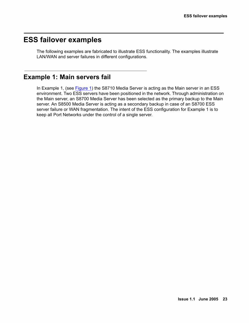
Example 1: Main servers failIn Example 1, (see Figure 1) the S8710 Media Server is acting as the Main server in an ESS environment. Two ESS servers have been positioned in the network. Through administration on the Main server, an S8700 Media Server has been selected as the primary backup to the Main server. An S8500 Media Server is acting as a secondary backup in case of an S8700 ESS server failure or WAN fragmentation. The intent of the ESS configuration for Example 1 is to keep all Port Networks under the control of a single server.

ESS Overview
24 Avaya Enterprise Survivable Servers (ESS) Users Guide
Figure 1: S8710 Media Server with ESS servers in normal operation
UID
2
1
01
10
32
32
discCOMPACT
54
54
Sim
ple
xD
up
lex
ch
ch
21
UID
2
1
01
10
32
32
discCOMPACT
54
54
Sim
ple
xD
up
lex
ch
ch
21
S8710 Media Server(Main Server)
cycmsrv3 KLC 031505
disc
S8500 ESS Server(2nd Alternative)
PN #1 PN #5
PN #2 PN #6PN #3 PN #7
PN #4 PN #8
S8700 ESS Server(1st Alternative)
Out of Service
CSS / EI (Fiber)ATM / ATM-EI (Fiber)Dup Link
Port Network Control Link (EAL)IP Connection into Control NetworkServer or Network FailureVoIP PathDSIC LInk
ESS failover examples
Issue 1.1 June 2005 25
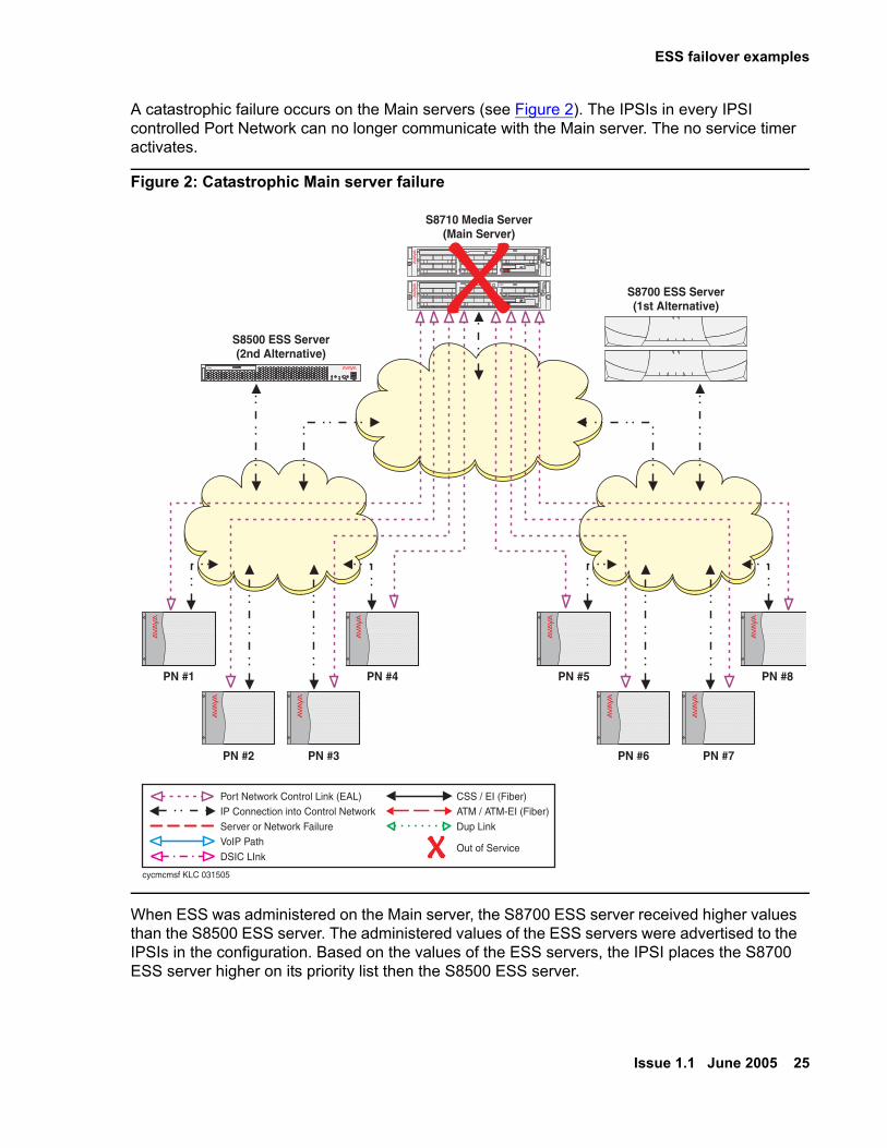
A catastrophic failure occurs on the Main servers (see Figure 2). The IPSIs in every IPSI controlled Port Network can no longer communicate with the Main server. The no service timer activates.
Figure 2: Catastrophic Main server failure
When ESS was administered on the Main server, the S8700 ESS server received higher values than the S8500 ESS server. The administered values of the ESS servers were advertised to the IPSIs in the configuration. Based on the values of the ESS servers, the IPSI places the S8700 ESS server higher on its priority list then the S8500 ESS server.
UID
2
1
01
10
32
32
discCOMPACT
54
54
Sim
ple
xD
up
lex
ch
ch
21
UID
2
1
01
10
32
32
discCOMPACT
54
54
Sim
ple
xD
up
lex
ch
ch
21
S8710 Media Server(Main Server)
cycmcmsf KLC 031505
disc
S8500 ESS Server(2nd Alternative)
PN #1 PN #5
PN #2 PN #6PN #3 PN #7
PN #4 PN #8
S8700 ESS Server(1st Alternative)
Out of Service
CSS / EI (Fiber)ATM / ATM-EI (Fiber)Dup Link
Port Network Control Link (EAL)IP Connection into Control NetworkServer or Network FailureVoIP PathDSIC LInk
ESS Overview
26 Avaya Enterprise Survivable Servers (ESS) Users Guide
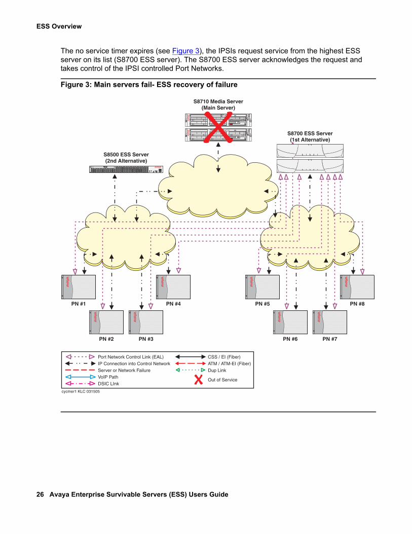
The no service timer expires (see Figure 3), the IPSIs request service from the highest ESS server on its list (S8700 ESS server). The S8700 ESS server acknowledges the request and takes control of the IPSI controlled Port Networks.
Figure 3: Main servers fail- ESS recovery of failure
UID
2
1
01
10
32
32
discCOMPACT
54
54
Sim
ple
xD
up
lex
ch
ch
21
UID
2
1
01
10
32
32
discCOMPACT
54
54
Sim
ple
xD
up
lex
ch
ch
21
S8710 Media Server(Main Server)
cycmer1 KLC 031505
disc
S8500 ESS Server(2nd Alternative)
PN #1 PN #5
PN #2 PN #6PN #3 PN #7
PN #4 PN #8
S8700 ESS Server(1st Alternative)
Out of Service
CSS / EI (Fiber)ATM / ATM-EI (Fiber)Dup Link
Port Network Control Link (EAL)IP Connection into Control NetworkServer or Network FailureVoIP PathDSIC LInk
ESS failover examples
Issue 1.1 June 2005 27
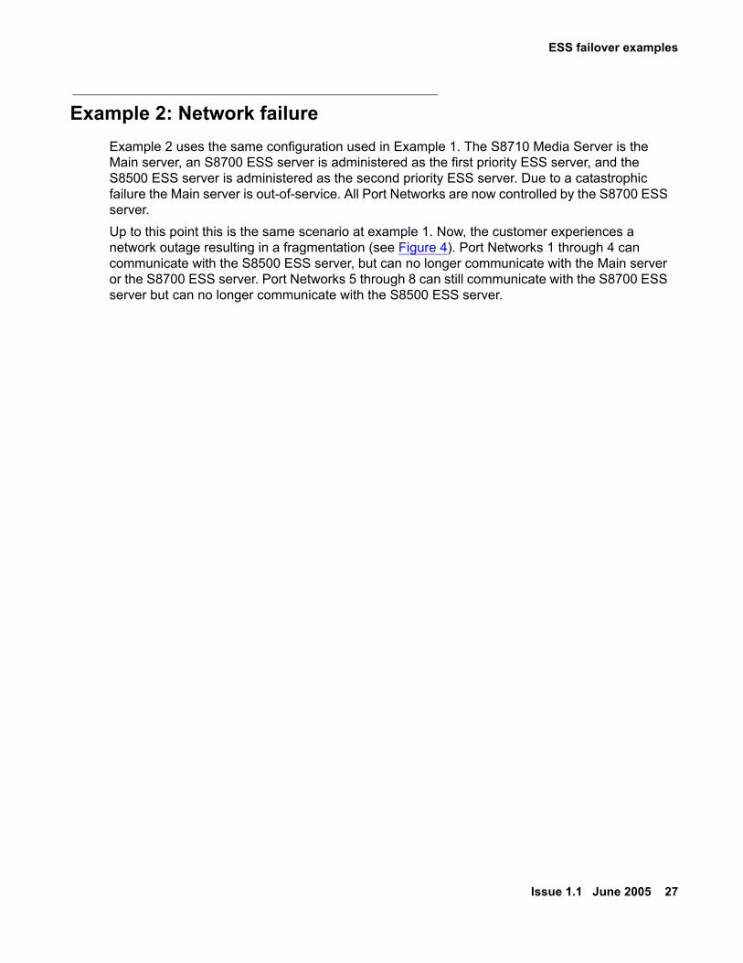
Example 2: Network failureExample 2 uses the same configuration used in Example 1. The S8710 Media Server is the Main server, an S8700 ESS server is administered as the first priority ESS server, and the S8500 ESS server is administered as the second priority ESS server. Due to a catastrophic failure the Main server is out-of-service. All Port Networks are now controlled by the S8700 ESS server. Up to this point this is the same scenario at example 1. Now, the customer experiences a network outage resulting in a fragmentation (see Figure 4). Port Networks 1 through 4 can communicate with the S8500 ESS server, but can no longer communicate with the Main server or the S8700 ESS server. Port Networks 5 through 8 can still communicate with the S8700 ESS server but can no longer communicate with the S8500 ESS server.

ESS Overview
28 Avaya Enterprise Survivable Servers (ESS) Users Guide
Figure 4: Network fragmentation failure
UID
2
1
01
10
32
32
discCOMPACT
54
54
Sim
ple
xD
up
lex
ch
ch
21
UID
2
1
01
10
32
32
discCOMPACT
54
54
Sim
ple
xD
up
lex
ch
ch
21
S8710 Media Server(Main Server)
cycmnff KLC 031505
disc
S8500 ESS Server(2nd Alternative)
PN #1 PN #5
PN #2 PN #6PN #3 PN #7
PN #4 PN #8
S8700 ESS Server(1st Alternative)
Out of Service
CSS / EI (Fiber)ATM / ATM-EI (Fiber)Dup Link
Port Network Control Link (EAL)IP Connection into Control NetworkServer or Network FailureVoIP PathDSIC LInk

ESS failover examples
Issue 1.1 June 2005 29
Because the IPSIs in Port Networks 1 through 4 cannot communicate with the Main server or the S8700 ESS server, they adjust their priority list and move the S8500 ESS server to the top of the list. The no service timer activates for Port Networks 1 through 4. When the no service timer expires, the IPSIs in Port Networks 1 through 4 request service from the S8500 ESS server. The S8500 ESS server acknowledges the request and assumes control of Port Network 1 through 4 (see Figure 5). Note that Port Networks 5 through 8 did not experience any service outage from the failure.
Figure 5: Network failure - ESS recovery
UID
2
1
01
10
32
32
discCOMPACT
54
54
Sim
ple
xD
up
lex
ch
ch
21
UID
2
1
01
10
32
32
discCOMPACT
54
54
Sim
ple
xD
up
lex
ch
ch
21
S8710 Media Server(Main Server)
cycmerf2 KLC 031505
disc
S8500 ESS Server(2nd Alternative)
PN #1 PN #5
PN #2 PN #6PN #3 PN #7
PN #4 PN #8
S8700 ESS Server(1st Alternative)
Out of Service
CSS / EI (Fiber)ATM / ATM-EI (Fiber)Dup Link
Port Network Control Link (EAL)IP Connection into Control NetworkServer or Network FailureVoIP PathDSIC LInk

ESS Overview
30 Avaya Enterprise Survivable Servers (ESS) Users Guide
The users in Port Network 1 through 4 experience the following:
● During the no service timer interval:
- Stable calls remain up in the same state as they were before the outage occurred. The stable calls do not have access to any features such as hold, conference, etc. The state of the stable call cannot be changed.
- Users attempting to originate a telephone call do not get dial tone.
- Incoming calls to the system receive a fast busy (reorder tone) or an announcement from the facility provider saying all circuits are busy.
● After the no service timer expires
- Users on an IP connected phone call: Shuffled IP calls will stay up. Once the call terminates, the user of the IP telephone will not be able to make another call until the IP telephone re-registers with a gatekeeper.
- Calls on DCP or analog phones terminates
The customer is now in the process of recovering from both the network failure and the Main server failure (see Figure 6). As the network failure is fixed, the IPSIs in Port Network 1 through 4 can now communicate with the S8700 ESS server. The IPSI priority list adjusts to reflect the S8700 ESS server as the highest priority ESS server. Even though the IPSI priority list now shows the S8700 ESS server as its highest priority ESS server, the Port Networks do not automatically return to the control of the S8700 ESS server. Moving the Port Networks from the S8500 ESS server to another ESS server requires manual intervention using the get forced-takeover ipsi-interface command or scheduling the Auto Return functionality. For information on the get forced-takeover ipsi-interface command see, get forced-takeover ipserver-interface on page 152. For information on the Auto Return functionality see, System-parameters ess form - page seven on page 126.

ESS failover examples
Issue 1.1 June 2005 31
Figure 6: Network fragmentation recovery
UID
2
1
01
10
32
32
discCOMPACT
54
54
Sim
ple
xD
up
lex
ch
ch
21
UID
2
1
01
10
32
32
discCOMPACT
54
54
Sim
ple
xD
up
lex
ch
ch
21
S8710 Media Server(Main Server)
cycmnfr KLC 031505
disc
S8500 ESS Server(2nd Alternative)
PN #1 PN #5
PN #2 PN #6PN #3 PN #7
PN #4 PN #8
S8700 ESS Server(1st Alternative)
Out of Service
CSS / EI (Fiber)ATM / ATM-EI (Fiber)Dup Link
Port Network Control Link (EAL)IP Connection into Control NetworkServer or Network FailureVoIP PathDSIC LInk

ESS Overview
32 Avaya Enterprise Survivable Servers (ESS) Users Guide
The Main server has been restored (see Figure 7). All IPSIs in each Port Network can now communicate with the Main server and each ESS server. The Main server is always the highest priority on any IPSI priority list.
Figure 7: Main server recovery
UID
2
1
01
10
32
32
discCOMPACT
54
54
Sim
ple
xD
up
lex
ch
ch
21
UID
2
1
01
10
32
32
discCOMPACT
54
54
Sim
ple
xD
up
lex
ch
ch
21
S8710 Media Server(Main Server)
cycmsrv2 KLC 031505
disc
S8500 ESS Server(2nd Alternative)
PN #1 PN #5
PN #2 PN #6PN #3 PN #7
PN #4 PN #8
S8700 ESS Server(1st Alternative)
Out of Service
CSS / EI (Fiber)ATM / ATM-EI (Fiber)Dup Link
Port Network Control Link (EAL)IP Connection into Control NetworkServer or Network FailureVoIP PathDSIC LInk
ESS failover examples
Issue 1.1 June 2005 33
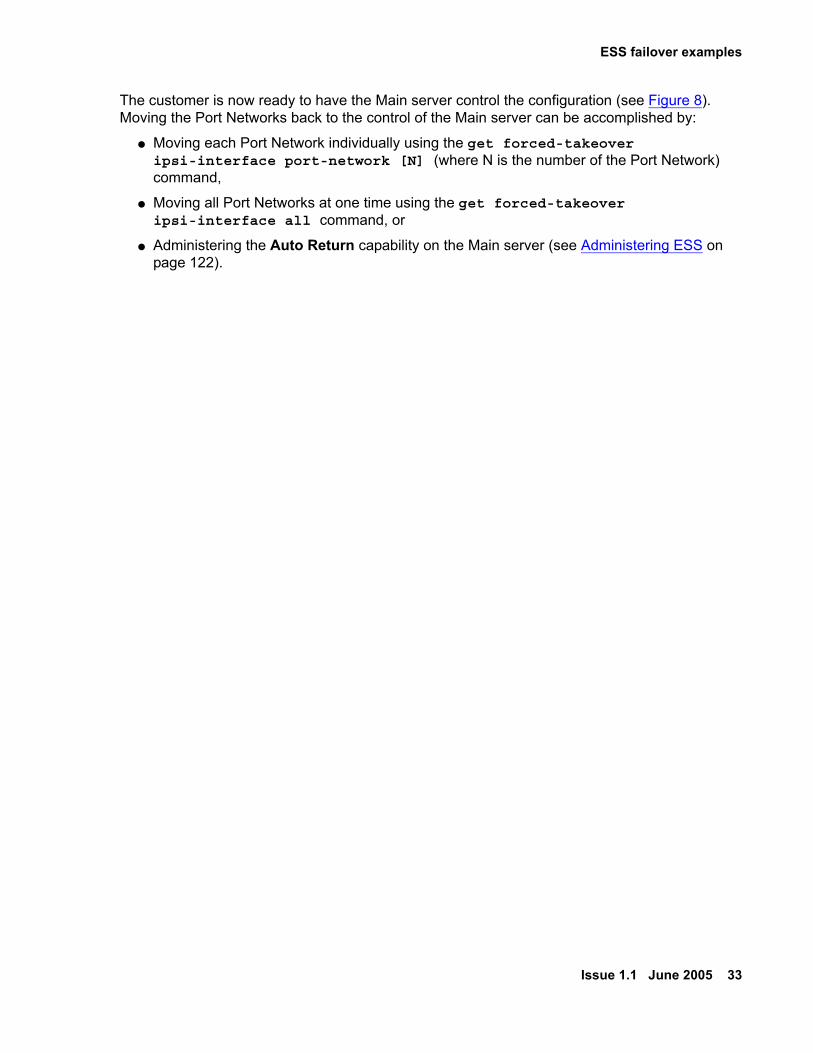
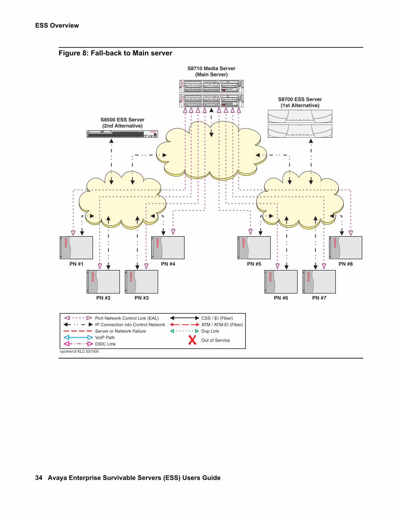
The customer is now ready to have the Main server control the configuration (see Figure 8). Moving the Port Networks back to the control of the Main server can be accomplished by:
● Moving each Port Network individually using the get forced-takeover ipsi-interface port-network [N] (where N is the number of the Port Network) command,
● Moving all Port Networks at one time using the get forced-takeover ipsi-interface all command, or
● Administering the Auto Return capability on the Main server (see Administering ESS on page 122).
ESS Overview
34 Avaya Enterprise Survivable Servers (ESS) Users Guide
Figure 8: Fall-back to Main server
UID
2
1
01
10
32
32
discCOMPACT
54
54
Sim
ple
xD
up
lex
ch
ch
21
UID
2
1
01
10
32
32
discCOMPACT
54
54
Sim
ple
xD
up
lex
ch
ch
21
S8710 Media Server(Main Server)
cycmsrv3 KLC 031505
disc
S8500 ESS Server(2nd Alternative)
PN #1 PN #5
PN #2 PN #6PN #3 PN #7
PN #4 PN #8
S8700 ESS Server(1st Alternative)
Out of Service
CSS / EI (Fiber)ATM / ATM-EI (Fiber)Dup Link
Port Network Control Link (EAL)IP Connection into Control NetworkServer or Network FailureVoIP PathDSIC LInk

ESS failover examples
Issue 1.1 June 2005 35
Example 3: Combined IP connected Port Networks with CSS or ATM connected Port Networks
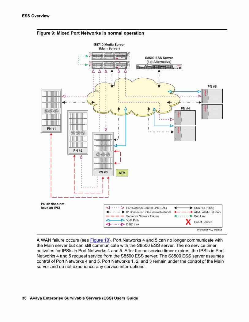
In Communication Manager 3.0 and later releases, mixed configurations that combine IP-connected Port Networks with CSS-connected, or ATM-connected Port Networks are supported. Additionally, Communication Manager 3.0 and later releases allow media servers to support both single control networks and duplicated control networks in the same configuration, as well as single bearer networks and duplicated bearer networks. Simultaneous simplex and duplex control/bearer connectivity cannot be achieved in traditional CSS and ATM connected Port Networks. In Example 3 (see Figure 9), the customer has an environment where:
● Port Network 1 through 3 are part of a Center Stage Switch
- Port Network 2 connects to the Main server through Port Network 3.
- IPSIs are installed in Port Network 1 and 3.
● Port Networks 4 and 5 use IP connect.
ESS Overview
36 Avaya Enterprise Survivable Servers (ESS) Users Guide
Figure 9: Mixed Port Networks in normal operation
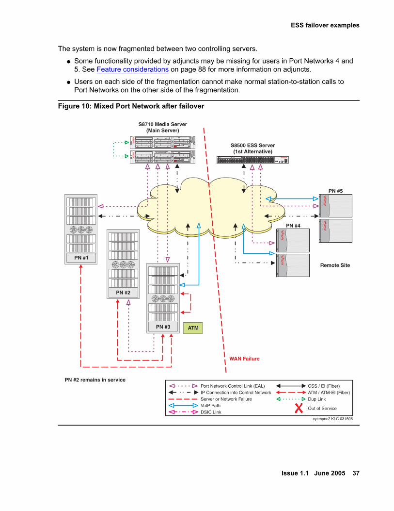
A WAN failure occurs (see Figure 10). Port Networks 4 and 5 can no longer communicate with the Main server but can still communicate with the S8500 ESS server. The no service timer activates for IPSIs in Port Networks 4 and 5. After the no service timer expires, the IPSIs in Port Networks 4 and 5 request service from the S8500 ESS server. The S8500 ESS server assumes control of Port Networks 4 and 5. Port Networks 1, 2, and 3 remain under the control of the Main server and do not experience any service interruptions.
UID
2
1
01
10
32
32
discCOMPACT
54
54
Sim
ple
xD
up
lex
ch
ch
21
UID
2
1
01
10
32
32
discCOMPACT
54
54
Sim
ple
xD
up
lex
ch
ch
21
S8710 Media Server(Main Server)
PN #1
PN #2
PN #3
cycmpnc1 KLC 031505
disc
S8500 ESS Server(1st Alternative)
PN #4
PN #5
ATM
PN #2 does nothave an IPSI
Out of Service
CSS / EI (Fiber)ATM / ATM-EI (Fiber)Dup Link
Port Network Control Link (EAL)IP Connection into Control NetworkServer or Network Failure
VoIP PathDSIC LInk
ESS failover examples
Issue 1.1 June 2005 37
The system is now fragmented between two controlling servers.
● Some functionality provided by adjuncts may be missing for users in Port Networks 4 and 5. See Feature considerations on page 88 for more information on adjuncts.
● Users on each side of the fragmentation cannot make normal station-to-station calls to Port Networks on the other side of the fragmentation.
Figure 10: Mixed Port Network after failover
UID
2
1
01
10
32
32
discCOMPACT
54
54
Sim
ple
xD
up
lex
ch
ch
21
UID
2
1
01
10
32
32
discCOMPACT
54
54
Sim
ple
xD
up
lex
ch
ch
21
S8710 Media Server(Main Server)
PN #1
PN #2
PN #3
cycmpnc2 KLC 031505
disc
S8500 ESS Server(1st Alternative)
PN #4
PN #5
ATM
PN #2 remains in service
WAN Failure
Remote Site
Out of Service
CSS / EI (Fiber)ATM / ATM-EI (Fiber)
Dup Link
Port Network Control Link (EAL)
IP Connection into Control NetworkServer or Network FailureVoIP PathDSIC LInk

ESS Overview
38 Avaya Enterprise Survivable Servers (ESS) Users Guide
Example 4: ESS with Center Stage Switch (CSS)
ESS requires that all survivable Port Networks in a CSS environment, connect to the network using an IP Media Processor board. The following must be considered for an ESS in a CSS environment:
● ESS requires that all Port Networks within a CSS environment must have the ability to transition to IP bearer to be survivable. To transition to IP bearer the designated survivable Port Networks must have an IPSI for control and IP Media Processor board for bearer communication.
● All IPSI connected Port Networks must have a TN570D EI board.
- Any Port Network that contains one or more IPSIs must have a minimum of the TN570D. Port Networks that do not have IPSIs, and therefore are not survivable, my use the TN570B version 7 or later.
● While the former MBS option utilized the CSS during a failover, the ESS server never controls the CSS.
! Important:Important: When an CSS system fails over to an ESS server, the Port Network connectivity
transitions to IP-Connect.
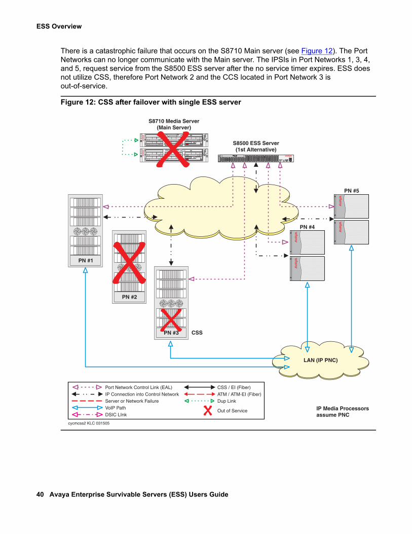
In example 4 (Figure 11), the S8710 Main server provides service to IPSI connected Port Networks 1, 3, 4, and 5. Port Network 2 communicates with the Main servers through its EI board, the CSS, and the EI and IPSI board in Port Network 3. There is only one ESS server in this example.

ESS failover examples
Issue 1.1 June 2005 39
Figure 11: Normal operation CSS with single ESS server
CSS
UID
2
1
01
10
32
32
discCOMPACT
54
54
Sim
ple
xD
up
lex
ch
ch
21
UID
2
1
01
10
32
32
discCOMPACT
54
54
Sim
ple
xD
up
lex
ch
ch
21
S8710 Media Server(Main Server)
PN #1
PN #2
PN #3
disc
S8500 ESS Server(1st Alternative)
PN #4
PN #5
PN #2 does nothave an IPSI
Recommended for survivability:- IPSI in every PN- IP Media Processor in every PN
cycmcss1 KLC 031505
Out of Service
CSS / EI (Fiber)ATM / ATM-EI (Fiber)Dup Link
Port Network Control Link (EAL)
IP Connection into Control NetworkServer or Network FailureVoIP PathDSIC LInk
ESS Overview
40 Avaya Enterprise Survivable Servers (ESS) Users Guide
There is a catastrophic failure that occurs on the S8710 Main server (see Figure 12). The Port Networks can no longer communicate with the Main server. The IPSIs in Port Networks 1, 3, 4, and 5, request service from the S8500 ESS server after the no service timer expires. ESS does not utilize CSS, therefore Port Network 2 and the CCS located in Port Network 3 is out-of-service.
Figure 12: CSS after failover with single ESS server
LAN (IP PNC)
CSS
UID
2
1
01
10
32
32
discCOMPACT
54
54
Sim
ple
xD
up
lex
ch
ch
21
UID
2
1
01
10
32
32
discCOMPACT
54
54
Sim
ple
xD
up
lex
ch
ch
21
S8710 Media Server(Main Server)
PN #1
PN #2
PN #3
cycmcss2 KLC 031505
disc
S8500 ESS Server(1st Alternative)
PN #4
PN #5
IP Media Processorsassume PNC
Out of Service
CSS / EI (Fiber)ATM / ATM-EI (Fiber)Dup Link
Port Network Control Link (EAL)IP Connection into Control Network
Server or Network FailureVoIP PathDSIC LInk
ESS failover examples
Issue 1.1 June 2005 41
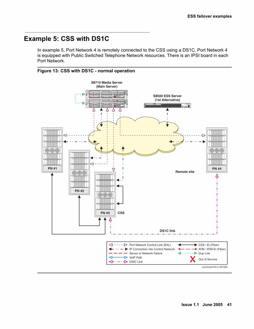
Example 5: CSS with DS1CIn example 5, Port Network 4 is remotely connected to the CSS using a DS1C. Port Network 4 is equipped with Public Switched Telephone Network resources. There is an IPSI board in each Port Network.
Figure 13: CSS with DS1C - normal operation
CSS
UID
2
1
01
10
32
32
discCOMPACT
54
54
Sim
ple
xD
up
lex
ch
ch
21
UID
2
1
01
10
32
32
discCOMPACT
54
54
Sim
ple
xD
up
lex
ch
ch
21
S8710 Media Server(Main Server)
PN #1
PN #2
PN #3
PN #4
cycmcss3 KLC 031505
disc
S8500 ESS Server(1st Alternative)
Remote site
DS1C link
Out of Service
CSS / EI (Fiber)ATM / ATM-EI (Fiber)Dup Link
Port Network Control Link (EAL)IP Connection into Control Network
Server or Network FailureVoIP PathDSIC LInk

ESS Overview
42 Avaya Enterprise Survivable Servers (ESS) Users Guide
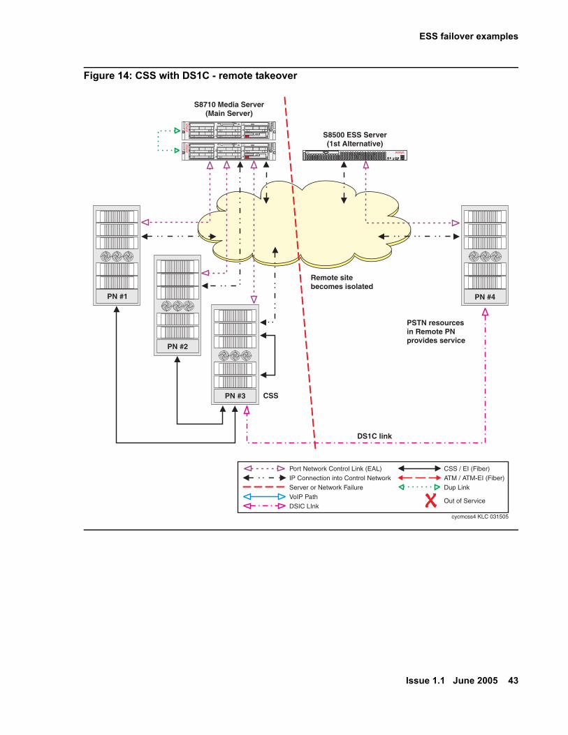
A network problem occurs where Port Network 4 is isolated from the CSS and the DS1C link (see Figure 14).
Note:Note: If only the DS1C link was lost, Port Network 4 would not transition to the ESS
server. Communication between the DS1C location and the main location would be disrupted since there is no bearer path.
After the no service time out interval expires, the IPSI in Port Network 4 requests service from the S8500 ESS server. The Public Switched Telephone Network resources enable local and long distance calling.
ESS failover examples
Issue 1.1 June 2005 43
Figure 14: CSS with DS1C - remote takeover
CSS
UID
2
1
01
10
32
32
discCOMPACT
54
54
Sim
ple
xD
up
lex
ch
ch
21
UID
2
1
01
10
32
32
discCOMPACT
54
54
Sim
ple
xD
up
lex
ch
ch
21
S8710 Media Server(Main Server)
PN #1
PN #2
PN #3
PN #4
cycmcss4 KLC 031505
disc
S8500 ESS Server(1st Alternative)
Remote sitebecomes isolated
PSTN resourcesin Remote PNprovides service
DS1C link
Out of Service
CSS / EI (Fiber)ATM / ATM-EI (Fiber)Dup Link
Port Network Control Link (EAL)IP Connection into Control NetworkServer or Network Failure
VoIP PathDSIC LInk

ESS Overview
44 Avaya Enterprise Survivable Servers (ESS) Users Guide
Example 6: CSS with multiple nodesIn example 6, there is a multiple node CSS controlled by the S8710 Main server. Port Network 2 is connected to the CSS node in Port Network 3. Port Network 5 is connected to the CSS node in Port Network 4. There is no IPSI in either Port Network 2 or Port Network 5 (see Figure 15).
Figure 15: CSS with multiple nodes in normal operation
CSS CSS
UID
2
1
01
10
32
32
discCOMPACT
54
54
Sim
ple
xD
up
lex
ch
ch
21
UID
2
1
01
10
32
32
discCOMPACT
54
54
Sim
ple
xD
up
lex
ch
ch
21
S8710 Media Server(Main Server)
PN #1
PN #2
PN #3
PN #6
PN #5
PN #4
S8700 ESS Server(1st Alternative)
cycmcss5 KLC 031505
PN #2 does nothave an IPSI
PN #5 does nothave an IPSI
Out of Service
CSS / EI (Fiber)ATM / ATM-EI (Fiber)
Dup Link
Port Network Control Link (EAL)
IP Connection into Control NetworkServer or Network FailureVoIP PathDSIC LInk

ESS failover examples
Issue 1.1 June 2005 45
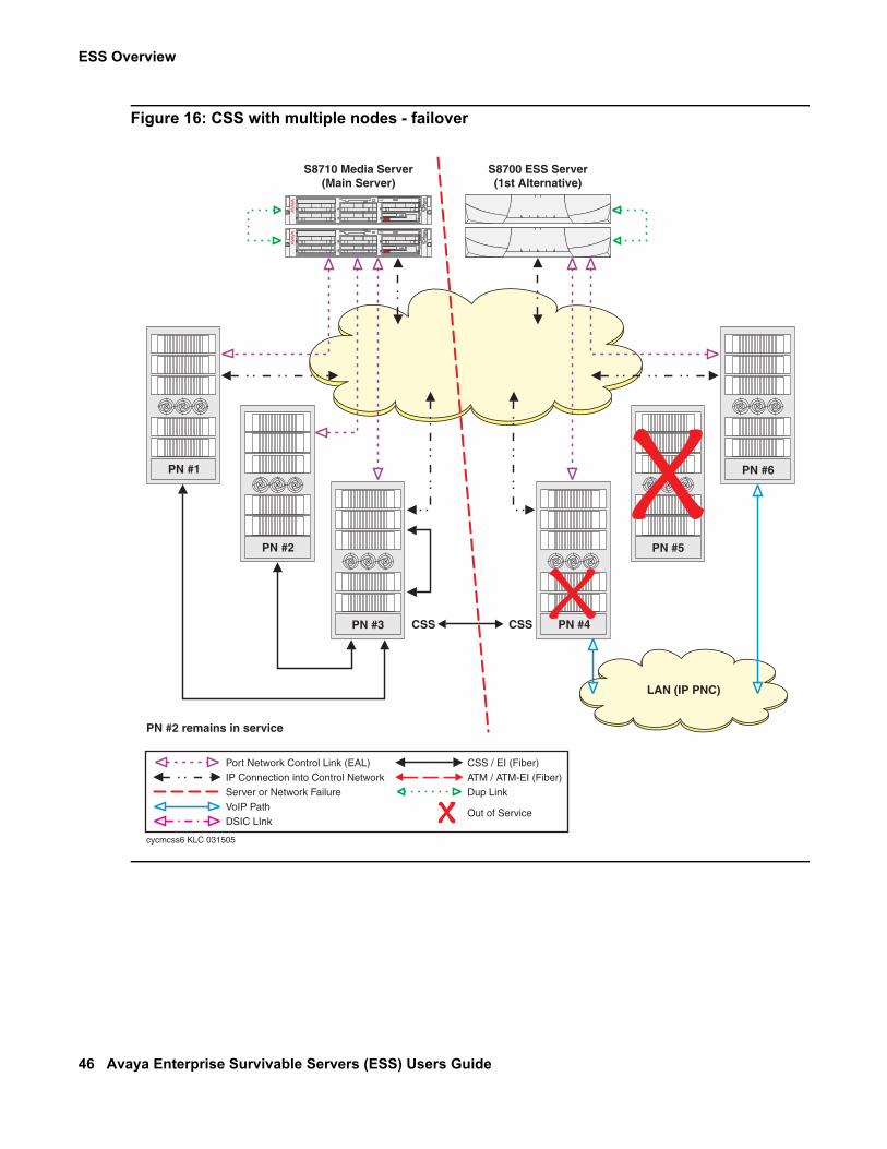
A network outage occurs that stops communication from the Main server to Port Networks 4 through 6 (see Figure 16). The Main server continues to provide service to Port Networks 1 through 3. The no service timer activates for Port Networks 4 and 6. After the no service timer expires, the IPSI in Port Network 4 and Port Network 6 request, and receive service from the S8700 ESS server. The ESS server cannot take control of the CSS node in Port Network 4. The CSS node in Port Network 4 is not utilized. Port Network 5 is also not utilized as it does not have an IPSI and can no longer communicate with the CSS node in Port Network 4. Port Networks 1, 2, and 3, are not affected by the outage.
ESS Overview
46 Avaya Enterprise Survivable Servers (ESS) Users Guide
Figure 16: CSS with multiple nodes - failover
LAN (IP PNC)
CSS CSS
UID
2
1
01
10
32
32
discCOMPACT
54
54
Sim
ple
xD
up
lex
ch
ch
21
UID
2
1
01
10
32
32
discCOMPACT
54
54
Sim
ple
xD
up
lex
ch
ch
21
S8710 Media Server(Main Server)
PN #1
PN #2
PN #3
PN #6
PN #5
PN #4
S8700 ESS Server(1st Alternative)
cycmcss6 KLC 031505
PN #2 remains in service
Out of Service
CSS / EI (Fiber)ATM / ATM-EI (Fiber)
Dup Link
Port Network Control Link (EAL)IP Connection into Control Network
Server or Network FailureVoIP PathDSIC LInk
ESS failover examples
Issue 1.1 June 2005 47
Example 7: ESS with ATMFor Port Networks that do not have an IPSI but are controlled by the Main server(s) through ATM connections, an ESS server similarly communicates indirectly through an IPSI controlled Port Network, and then through an ATM connection (TN2305B or TN2306B ATM Expansion Interface board).In example 7 (see Figure 17), there is a single ESS server in an ATM configuration. The S8710 is the Main server with the S8500 Media Server as the ESS server. IPSIs are installed in all Port Networks except for Port Network 2 and Port Network 5.

ESS Overview
48 Avaya Enterprise Survivable Servers (ESS) Users Guide
Figure 17: ATM with a single ESS server in normal operation
UID
2
1
01
10
32
32
discCOMPACT
54
54
Sim
ple
xD
up
lex
ch
ch
21
UID
2
1
01
10
32
32
discCOMPACT
54
54
Sim
ple
xD
up
lex
ch
ch
21
S8710 Media Server(Main Server)
PN #1 PN #6
PN #2 PN #5
PN #3 PN #4
cycmatm1 KLC 031605
disc
S8500 ESS Server(1st Alternative)
ATM
Out of Service
CSS / EI (Fiber)ATM / ATM-EI (Fiber)Dup Link
Port Network Control Link (EAL)IP Connection into Control NetworkServer or Network FailureVoIP Path
DSIC LInk
PN #2 does not havean IPSI but remains inservice via PN #3
PN #5 does not havean IPSI but remains inservice via PN #4

ESS failover examples
Issue 1.1 June 2005 49
ATM - single ESS takeover examples
In the first takeover example (see Figure 18), a catastrophic failure happens to the S8710 Main server. The IPSIs request service of the S8500 Media Server after the no service timer expires. The S8500 Media Server assumes control of Port Network 1, 3, 4, and 5. Once the S8500 ESS server assumes control of the Port Network, it will attempt to take over all other Port Networks in the system through the ATM Expansion Interface (EI) board (TN2305B or TN2306B). Since no other servers are controlling Port Network 2 and Port Network 5, the attempt by the S8500 ESS server to control it through ATM EI is successful.
! Important:Important: Port Networks in an ATM environment do not transition to IP during a failover to
an ESS server.
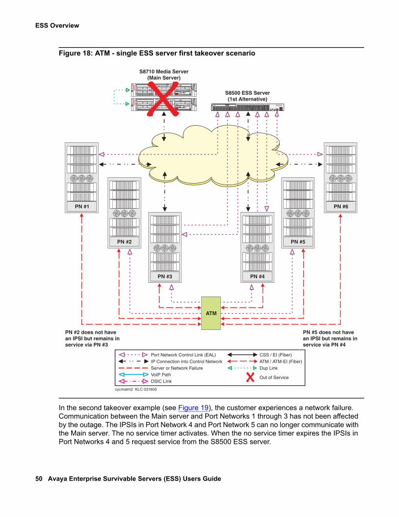
ESS Overview
50 Avaya Enterprise Survivable Servers (ESS) Users Guide
Figure 18: ATM - single ESS server first takeover scenario
In the second takeover example (see Figure 19), the customer experiences a network failure. Communication between the Main server and Port Networks 1 through 3 has not been affected by the outage. The IPSIs in Port Network 4 and Port Network 5 can no longer communicate with the Main server. The no service timer activates. When the no service timer expires the IPSIs in Port Networks 4 and 5 request service from the S8500 ESS server.
UID
2
1
01
10
32
32
discCOMPACT
54
54
Sim
ple
xD
up
lex
ch
ch
21
UID
2
1
01
10
32
32
discCOMPACT
54
54
Sim
ple
xD
up
lex
ch
ch
21
S8710 Media Server(Main Server)
PN #1 PN #6
PN #2 PN #5
PN #3 PN #4
cycmatm2 KLC 031605
disc
S8500 ESS Server(1st Alternative)
ATM
PN #2 does not havean IPSI but remains inservice via PN #3
PN #5 does not havean IPSI but remains inservice via PN #4
Out of Service
CSS / EI (Fiber)ATM / ATM-EI (Fiber)
Dup Link
Port Network Control Link (EAL)
IP Connection into Control NetworkServer or Network FailureVoIP PathDSIC LInk
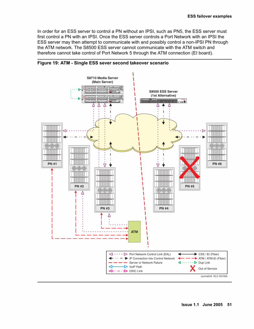
ESS failover examples
Issue 1.1 June 2005 51
In order for an ESS server to control a PN without an IPSI, such as PN5, the ESS server must first control a PN with an IPSI. Once the ESS server controls a Port Network with an IPSI the ESS server may then attempt to communicate with and possibly control a non-IPSI PN through the ATM network. The S8500 ESS server cannot communicate with the ATM switch and therefore cannot take control of Port Network 5 through the ATM connection (EI board).
Figure 19: ATM - Single ESS sever second takeover scenario
UID
2
1
01
10
32
32
discCOMPACT
54
54
Sim
ple
xD
up
lex
ch
ch
21
UID
2
1
01
10
32
32
discCOMPACT
54
54
Sim
ple
xD
up
lex
ch
ch
21
S8710 Media Server(Main Server)
PN #1 PN #6
PN #2 PN #5
PN #3 PN #4
cycmatm5 KLC 031505
disc
S8500 ESS Server(1st Alternative)
ATM
Out of Service
CSS / EI (Fiber)ATM / ATM-EI (Fiber)Dup Link
Port Network Control Link (EAL)IP Connection into Control Network
Server or Network FailureVoIP PathDSIC LInk

ESS Overview
52 Avaya Enterprise Survivable Servers (ESS) Users Guide
Example 8: Distributed ATM SwitchesIn example 8 (see Figure 20), there is a single ESS server with multiple ATM nodes. Port Network 2 connects using an ATM Expansion Interface board, to the ATM node on the left side of the following figure and does not have an IPSI. Port Network 5 connects using an ATM EI board, to the ATM node on the right side of the following figure and also does not have an IPSI.

ESS failover examples
Issue 1.1 June 2005 53
Figure 20: ATM, single ESS server, multiple nodes in normal operation
A network outage occurs that fragments the two ATM and IP networks (see Figure 21). The Main server continues to provide service to Port Networks 1 through 3 with no service interruption. The IPSIs in Port Network 4 and 6 requests service of the S8700 ESS server after the no service timer expires. The S8700 ESS server assumes control of Port Network 4 first.
ATM ATM
UID
2
1
01
10
32
32
discCOMPACT
54
54
Sim
ple
xD
up
lex
ch
ch
21
UID
2
1
01
10
32
32
discCOMPACT
54
54
Sim
ple
xD
up
lex
ch
ch
21
S8710 Media Server(Main Server)
PN #1
PN #2
PN #3
PN #6
PN #5
PN #4
S8700 ESS Server(1st Alternative)
cycmatm3 KLC 031505
PN #2 does nothave an IPSI
PN #5 does nothave an IPSI
Out of Service
CSS / EI (Fiber)
ATM / ATM-EI (Fiber)Dup Link
Port Network Control Link (EAL)IP Connection into Control NetworkServer or Network Failure
VoIP PathDSIC LInk

ESS Overview
54 Avaya Enterprise Survivable Servers (ESS) Users Guide
Once in control on Port Network 4, the ESS server assumes control of Port Network 5 through the EI board.
Figure 21: ATM, single ESS server, multiple nodes in a takeover scenario
The Users in Port Network 1 through 3 can make station-to-station calls to each other but cannot make station-to-station calls to users in Port Networks 4 through 6. The reverse is also true, where users in Port Networks 4 through 6 cannot make calls to users in Port Networks 1 through 3.
ATM ATM
UID
2
1
01
10
32
32
discCOMPACT
54
54
Sim
ple
xD
up
lex
ch
ch
21
UID
2
1
01
10
32
32
discCOMPACT
54
54
Sim
ple
xD
up
lex
ch
ch
21
S8710 Media Server(Main Server)
PN #1
PN #2
PN #3
PN #6
PN #5
PN #4
S8700 ESS Server(1st Alternative)
Out of Service
CSS / EI (Fiber)ATM / ATM-EI (Fiber)
Dup Link
Port Network Control Link (EAL)
IP Connection into Control NetworkServer or Network FailureVoIP PathDSIC LInk
ESS failover examples
Issue 1.1 June 2005 55
Example 9: LSPs working in an ESS environmentIn example 9 (Figure 22), there is an S8300 LSP residing in a G350 Media Gateway. In a normal operation the S8700 Main server communicates with the G350 through a CLAN board in Port Network 1. There are two ESS servers administered. The S8700 ESS server has the highest priority and is the first ESS the IPSI’s request service from if they can no longer communicate with the Main server. If the IPSI can no longer communicate with either the Main server or the S8700 ESS server, they will request service from the S8500 ESS server. In the event of a failure, the goal of this configuration is to have all Port Networks and gateways under the control of one ESS server.

ESS Overview
56 Avaya Enterprise Survivable Servers (ESS) Users Guide
Figure 22: LSP working in an ESS environment - normal operation
UID
2
1
01
10
32
32
discCOMPACT
54
54
Sim
ple
xD
up
lex
ch
ch
21
UID
2
1
01
10
32
32
discCOMPACT
54
54
Sim
ple
xD
up
lex
ch
ch
21
S8710 Media Server(Main Server)
cycmlsp1 KLC 031505
disc
S8500 ESS Server(2nd Alternative)
PN #1 PN #8PN #4 PN #5
S8700 ESS Server(1st Alternative)
PN #2 PN #3 PN #7PN #6
S8300 LSPG350
Out of Service
CSS / EI (Fiber)ATM / ATM-EI (Fiber)Dup Link
Port Network Control Link (EAL)IP Connection into Control NetworkServer or Network FailureVoIP PathDSIC LInk

ESS failover examples
Issue 1.1 June 2005 57
In an ESS environment, a no service timer activates when the IPSI can no longer communicate with the Main server or controlling ESS server. The no service timer is administrable and can be set from 3 to 15 minutes. The media gateway recovery variable timer design incorporates three separate timers that monitor the period of time that the server or gateway spends in specific Link Recovery processes. If the timers expires before the ESS no service timer, the G350 Media Gateway and IP telephones will automatically attempt to connect with an alternate CLAN circuit pack within the original server’s configuration, or to a LSP.Because of a catastrophic Main server failure, Port Networks 1 through 8 can no longer communicate with the Main server. The no service timer activates. After the no service time out interval expires, the IPSIs in Port Networks 1 through 8 request service of the S8700 ESS server.In Figure 23 the Link Recovery was able to re-establish the link through the CLAN board in Port Network 1 to the S8700 ESS server before the Link Recovery timers expired. For more information on Link Recovery see, Link Recovery on page 84.

ESS Overview
58 Avaya Enterprise Survivable Servers (ESS) Users Guide
Figure 23: LSP working in an ESS environment - ESS timer before Link Recovery timer
UID
2
1
01
10
32
32
discCOMPACT
54
54
Sim
ple
xD
up
lex
ch
ch
21
UID
2
1
01
10
32
32
discCOMPACT
54
54
Sim
ple
xD
up
lex
ch
ch
21
S8710 Media Server(Main Server)
cycmlsp2 KLC 031505
disc
S8500 ESS Server(2nd Alternative)
PN #1 PN #8PN #4 PN #5
S8700 ESS Server(1st Alternative)
PN #2 PN #3 PN #7PN #6
S8300 LSPG350
Out of Service
CSS / EI (Fiber)ATM / ATM-EI (Fiber)Dup Link
Port Network Control Link (EAL)IP Connection into Control NetworkServer or Network FailureVoIP PathDSIC LInk

ESS failover examples
Issue 1.1 June 2005 59
Using a different scenario, in Figure 24 the Link Recovery timers expired before the ESS no service timer. The IP telephones and G350 Media Gateway connect with the alternate gatekeeper, in this case the LSP. The no service timer expires and the IPSIs in Port Networks 1 through 8 request service from the S8700 ESS server.The system is now fragmented between two controlling servers.
● Some functionality provided by adjuncts may be missing for users registered with the LSP. See Feature considerations on page 88 for more information on adjuncts.
● Users registered with the LSP may not be able to make normal station-to-station calls to Port Networks controlled by the S8700 ESS server.

ESS Overview
60 Avaya Enterprise Survivable Servers (ESS) Users Guide
Figure 24: LSP working in an ESS environment - Link Recovery timer before ESS timer
UID
2
1
01
10
32
32
discCOMPACT
54
54
Sim
ple
xD
up
lex
ch
ch
21
UID
2
1
01
10
32
32
discCOMPACT
54
54
Sim
ple
xD
up
lex
ch
ch
21
S8710 Media Server(Main Server)
cycmlsp3 KLC 031505
disc
S8500 ESS Server(2nd Alternative)
PN #1 PN #8PN #4 PN #5
S8700 ESS Server(1st Alternative)
PN #2 PN #3 PN #7PN #6
S8300 LSPG350
Out of Service
CSS / EI (Fiber)ATM / ATM-EI (Fiber)Dup Link
Port Network Control Link (EAL)IP Connection into Control NetworkServer or Network FailureVoIP PathDSIC LInk

ESS failover examples
Issue 1.1 June 2005 61
The problem that caused the Main server outage has been fixed (see Figure 25). All Port Networks can now communicate with the Main Server. Using the Auto Return functionality, the administrator scheduled the return of all Port Networks to the Main server. If the Auto Fallback to Primary feature (Communication Manager 3.0 or later) is being used, the G350 automatically re-registers with the Main server when it becomes available. If the Auto Primary feature is not being used (as shown in Figure 25), a manual reset must be performed on the G350.
Figure 25: LSP working in an ESS environment - fall-back to the Main server
UID
2
1
01
10
32
32
discCOMPACT
54
54
Sim
ple
xD
up
lex
ch
ch
21
UID
2
1
01
10
32
32
discCOMPACT
54
54
Sim
ple
xD
up
lex
ch
ch
21
S8710 Media Server(Main Server)
cycmlsp4 KLC 031505
disc
S8500 ESS Server(2nd Alternative)
PN #1 PN #8PN #4 PN #5
S8700 ESS Server(1st Alternative)
PN #2 PN #3 PN #7PN #6
S8300 LSPG350
Out of Service
CSS / EI (Fiber)ATM / ATM-EI (Fiber)Dup Link
Port Network Control Link (EAL)IP Connection into Control NetworkServer or Network FailureVoIP PathDSIC LInk

ESS Overview
62 Avaya Enterprise Survivable Servers (ESS) Users Guide

ESS design strategy
Issue 1.1 June 2005 63
Chapter 2: ESS Design and Planning
ESS design strategyDuring the design and planning phase of an ESS implementation, it is important to understand the customer goals for survivability, including prioritization. This is done by determining the strategy of ESS support for the Port Networks in the system. Goals for deploying and administering the ESS servers are:
1. Avoiding fragmentation of the system: The ESS server controls as much of the system as possible.
2. Avoiding overload of network resources with excessive call traffic: Each ESS server controls only limited portions of the system. Multiple ESS servers may be needed to support the number of Port Networks. In this way, an ESS server can potentially assume control of a single Port Network or group of Port Networks while the WAN traffic is unaffected or even reduced.
During initial design, and whenever additional capacity is added, these priorities should be taken into account. Once a plan is developed to allow an ESS server to take control of a configuration, or parts of a configuration, priority parameters are administered implementing the strategy. After an overall strategy is selected, determine the placement of the ESS servers in the network. Determine the administered values and communities for each ESS server. For further details on administered values and communities see, Administering ESS server on the Main server on page 122.
ESS Design and Planning
64 Avaya Enterprise Survivable Servers (ESS) Users Guide
ESS prerequisitesDetailed planning for the ESS is mandatory. Certain information must be gathered to facilitate the implementation of this feature:
● IP address(es): Obtain the following IP address(es):
- Main server(s)
- ESS server(s)
- CLAN board(s)
- Default gateway(s)
- Control network
- NIC card(s)
- IPSI(s)
- Subnet mask(s)
Note:Note: For a more complete list of addresses, see ESS Installation Checklist on
page 93.
The IP addresses listed above are used when configuring the Main server(s) and the ESS server(s). For more information on configuring and administering the Main server(s) and the ESS server(s) see, Administering ESS on page 122.
● Server ID: The system administrator assigns a unique Server Identification number (SVID) to each server. The SVID must be in the range of 1 to 99. Each server in a server pair (S8700 series media servers) requires a different SVID. Each SVID must be unique within the enterprise. The administrator can assign the SVID sequentially or allow gaps in the numbering such as 10, 20, 30, etc.
● License files: The Main server and each ESS server requires its own license file. For security purposes, RFA requires that each license file have a unique serial number. Prior to ESS, the serial number of one reference IPSI was used for the entire enterprise. For an ESS implementation, each license file for an ESS server and a Main server(s) must have a unique serial number from a separate reference IPSI. For more information on ESS license files see, ESS Server License Files on page 110.
● Module Identification Number (MID): This is a unique value assigned by RFA and found in each license file. The MID is administered as the Cluster Identification Number (CLID) in the system-parameters ess form. To find the MID for an ESS server use the instructions in step 2 of, Administering ESS on page 122.
CLAN access for ESS registration
Issue 1.1 June 2005 65
CLAN access for ESS registrationDuring the ESS server configuration, an IP address of a CLAN is used. The ESS server uses this configured CLAN IP address during the initial registration with the Main server(s). Careful consideration should be used in selecting the CLAN that will be used in the ESS server configuration. This CLAN should be local to the ESS server or of high availability to the ESS server. During the initial registration to the Main server(s), the ESS server does not contain translations, and therefore has no knowledge of other CLAN boards in the configuration. If the ESS server cannot communicate with the configured CLAN board it will be unable to register with the Main server.When an ESS server registers with the Main server through the CLAN, the Main server validates the ESS server’s Module ID, System ID, platform type, and IP address with that of the administered values. Only the active server of an S8700 series media server pair registers with the Main server. Once registered, the ESS server uses the same CLAN it used to register, to send Keep-Alive messages to the Main server. The ESS server re-registers with the Main server when:
● Translations are received from the Main server(s): The ESS server performs a reset after receiving translations from the Main server. During the reset the ESS server stops sending Keep-Alive messages.
Once translations are loaded on the ESS server, the ESS server re-registers with the Main server. The ESS server attempts to use the CLAN in its configuration for the registration process. If communication with the configured CLAN is not available, the ESS server selects a CLAN from its list of available CLANs. The ESS server re-registers to the Main server through the available CLAN and, after registration, uses the CLAN to send Keep-Alive messages to the Main server.
Note:Note: If an ESS server is still registered with the Main server while controlling Port
Networks, the ESS server can receive translation downloads from the Main server. In this case, the ESS server accepts the translation download but does not reset until it no longer controls any Port Networks.
● The CLAN reboots or fails: If the CLAN that the ESS server used to register to the Main server reboots or fails, the Keep-Alive messages from the ESS server to the Main server stops. The Main server shows the status of the ESS server as unregistered in the status ess cluster window. The ESS server attempts to communicate with the lost CLAN. If attempts to communicate with the lost CLAN fails, the ESS server selects another CLAN from its list of CLANs.
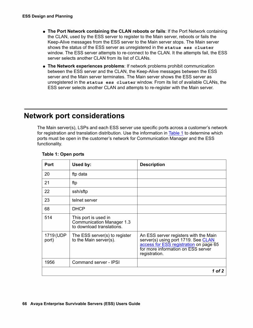
ESS Design and Planning
66 Avaya Enterprise Survivable Servers (ESS) Users Guide
● The Port Network containing the CLAN reboots or fails: If the Port Network containing the CLAN, used by the ESS server to register to the Main server, reboots or fails the Keep-Alive messages from the ESS server to the Main server stops. The Main server shows the status of the ESS server as unregistered in the status ess cluster window. The ESS server attempts to re-connect to the CLAN. It the attempts fail, the ESS server selects another CLAN from its list of CLANs.
● The Network experiences problems: If network problems prohibit communication between the ESS server and the CLAN, the Keep-Alive messages between the ESS server and the Main server terminates. The Main server shows the ESS server as unregistered in the status ess cluster window. From its list of available CLANs, the ESS server selects another CLAN and attempts to re-register with the Main server.
Network port considerationsThe Main server(s), LSPs and each ESS server use specific ports across a customer’s network for registration and translation distribution. Use the information in Table 1 to determine which ports must be open in the customer’s network for Communication Manager and the ESS functionality.
Table 1: Open ports
Port Used by: Description
20 ftp data
21 ftp
22 ssh/sftp
23 telnet server
68 DHCP
514 This port is used in Communication Manager 1.3 to download translations.
1719 (UDP port)
The ESS server(s) to register to the Main server(s).
An ESS server registers with the Main server(s) using port 1719. See CLAN access for ESS registration on page 65 for more information on ESS server registration.
1956 Command server - IPSI
1 of 2

Main server(s) and ESS server differences
Issue 1.1 June 2005 67
Main server(s) and ESS server differencesFor the most part, capabilities of the Main server(s) and the ESS server will be the same if both are of the same platform type.There are some important differences between the Main server(s) and the ESS server that should be taken into consideration when planning and designing an ESS configuration:
● The license file: The license file of the Main server(s) must have ESS Administration turned on and Enterprise Survivable Server turned off. The license file for an ESS server must have both ESS Administration and Enterprise Survivable Server turned on. For more information on license files see ESS Server License Files on page 110.
● Translations: You can change translations on an ESS server but you cannot save them. This is true even if the ESS server is providing service to an IPSI.
● Center Stage Switch (CSS): An ESS server can never take control of an CSS.
2312 Telnet firmware monitor
5010 IPSI/Server control channel
5011 IPSI/Server IPSI version channel
5012 IPSI/Server serial number channel
21873 (TCP port)
The Main server(s) running Communication Manager 2.0 to download translations to the LSP(s).
Prior to an upgrade to Communication Manager 3.0 or later, a server(s) running Communication Manager 2.x uses port 21873 to download translations to the LSP(s). Once the upgrade to 3.0 is complete and all servers are running versions of Communication Manager 3.0 or later, the Main server(s) uses port 21874 to download translations and port 21873 will no longer be needed.
21874 (TCP port)
The Main server(s) to download translations to the ESS server(s).
A Main server(s) uses port 21874 to download translations to the ESS server(s) and the LSP(s) on Communication Manager 3.0 and later loads.
Table 1: Open ports (continued)
Port Used by: Description
2 of 2
ESS Design and Planning
68 Avaya Enterprise Survivable Servers (ESS) Users Guide
● Administrative value: The value of the Main server(s) is always the highest ranking value on an IPSI’s priority list. The value for the Main server cannot be administered. However, the value of each ESS server is administrable. For information on administration see Administering ESS on page 122.
● ESS server capacity: When used as an ESS server, the S8500 Media Servers matches the capacity of the S8700 series media server used as a Main server.
● S8500 ESS server: When the S8500 Media Server is used as an ESS server, the S8500 Media Server can support a duplicated network with the addition of a dual NIC card. The dual NIC card is not supported if the S8500 Media Server is used as the Main server.
Trunking considerations
ISDN PRI Non Facility Associated SignalingCustomers can have up to 479 B channels with one D channel. In North America a backup D channel is offered. The backup D channel is located on channel 24 of a second DS1 interface. While both DS1 interfaces are connected to the same Central Office, only one is used for signaling at a time.In the event of a failover, if a different ESS server controls the primary and the backup D channels, each ESS server will think the D channel it does not control is out of service and will try to bring the D channel that it controls into service. The Service Provider will only use one of the D channels for signaling. When the D channel is not in service, the associated B channels of the DS1 will be out of service.
Guidelines1. Whenever possible place both D-channels in one Port Network.
2. If it is not possible to place both D-channels in one Port Network, place the D-channels within Port Networks where:
- The Port Network has an IPSI
- The Port Networks are most likely to failover to the same ESS server
3. After failover, if the D-channels are being serviced by two different ESS servers:
- Perform the get forced-takeover ipserver-interface command if the network conditions allow bringing both Port Networks under the same ESS server.
- Busy out one D-channel to prevent thrashing with the Central Office if network fragmentation will not allow one ESS server to provide service to the Port Networks containing both D-channels. On the SAT of the server, use the busyout port X (where X is the location of the port) to busy-out the D-channel.
Trunking considerations
Issue 1.1 June 2005 69
SynchronizationIn an IP connected environment, each Port Network may have its own primary and secondary external source that provides synchronization for the DS1. Synchronization is not supported across IP networks.In a CSS or ATM-PNC environment, there is only one primary and secondary synchronization source for all DS1s in the CSS/ATM-PNC Port Networks. If a DS1 looses the primary and secondary synchronization source, it uses the Tone Clock in the Port Network where it resides. Use of Tone Clock synchronization may result in audible artifacts due to slips. H.320 Video applications require synchronization. In the event that the H.320 Video application looses synchronization, the call would be expected to drop.
E911An E-911 call or other emergency call handling can only be routed if the trunk facility is under the control of the same ESS server as the person originating the call.
Inter-Gateway Alternate Routing (IGAR)Inter-Gateway Alternate Routing (IGAR) provides an alternate inter-region routing mechanism that is used when the IP network cannot, or should not, carry bearer. IGAR preserves the internal makeup of a call, so the call’s use of non-IP bearer facilities is transparent to the end user. IGAR can be triggered by Call Access Control via Bandwidth Limitation (CAC-BL), or can be forced to use an alternate route. IGAR can use Public Switched Telephone Network (PSTN) facilities, or private switched facilities to carry the inter-region audio bearer.After failover, if an ESS server controls Port Networks or media gateways in one or more network regions where IGAR is administered, IGAR continues to work. However, if Port Networks or media gateways across different network regions are controlled by separate ESS servers, calls between these systems are not seen as internal calls and therefore, IGAR does not apply.For example, an ESS customer with 8 Port Networks, administers each Port Network in a separate network region (1 through 8). IGAR is administered between all 8 regions. A network fragmentation failure occurs. Port Networks 1 through 4 failover to ESS server 1. Port Networks 5 through 8 failover to Local Only ESS servers. ESS server 1 uses IGAR to establish inter-port network bearer between Port Networks 1 through 4. Each Local Only ESS server controls one Port Network (5 through 8). IGAR does not apply for the Local Only servers.All Port Networks within a CSS must be in network region 1. When an ESS server obtains control of Port Network from the CSS, all Port Networks remain in network region 1. IGAR does not apply within the same network region.

ESS Design and Planning
70 Avaya Enterprise Survivable Servers (ESS) Users Guide
Personal Central Office Line (PCOL)A Personal Central Office Line (PCOL) consists of a Central Office trunk that terminates on a telephone or in a PCOL group shared by a number of telephones. During a failover, PCOL calls can only be handled if the trunk and the station administered with it are under control of the same ESS server.
Separation of Bearer and Signaling (SBS)Separation of Bearer and Signaling (SBS) provides a low-cost, virtual private network over IP trunks. During a failover, SBS calls will fail unless the CLAN for the signaling call and the bearer trunks are under the control of the same ESS server. Alternate routes may be used if under the control of the same ESS server as the originator.
Network addressing considerationsWhen implementing ESS, it is necessary that all Network Control Elements such as the Main server(s), ESS servers, and IPSIs, be assigned static IP addresses. When a customer is converting to an ESS environment, and normally receives IP addresses from a DHCP server, the Network Control Elements must be given static IP addresses before adding ESS. For information on assigning static IP addresses see:
● Installing and Configuring the S8500 Media Server (03-300143), or● Installing and Configuring the S8700 Series Media Server (03-300145).
Both documents can be found at, http://support.avaya.com.
Data NetworkingIn an Avaya solution, IP connectivity is required for call control between an Avaya S8500 or S8700 series servers and a reference IPSI. There can be a single call control connection called Control Network A (CNA) or duplicated call control connections called CNA and CNB. CNA and CNB can be on either a public or private network. With the introduction of 3.0, a third call control connection called CNC is introduced. Using CNC allows control to be passed through the customer LAN interface. This option allows customers with local private control networks (CNA and CNB), to also use their enterprise (public) network to support remote IPSI controlled Port Networks.For more information on control networks see, Administration for Network Connectivity for Avaya Communication Manager, issue 10, at, http://support.avaya.com.

CSS considerations when using ESS
Issue 1.1 June 2005 71
CSS considerations when using ESSAn ESS server cannot take control of a CSS, but can control a CSS connected Port Network where an IPSI and an IP Media Processor reside. Once an IPSI in a CSS Port Network requests and obtains service from an ESS server, it enters into an IP-Connect mode.The following is true for CSS in an ESS environment:
● In the event of a Main server failure, the CSS will be out-of-service. This is true because the CSS is enabled only for the Main server(s) and disabled for all other servers.
● The number and vintage of the IP Media Processor resource will have an impact on the traffic volume for the failed-over Port Network. Traffic engineering should consider the use of multiple IP Media Processors to allow for adequate call volume of failed-over Port Networks.
● An ESS server can provide service to an IPSI in a mixed Port Network configuration such as:
- CSS and IP-Connected
- ATM-PNC and IP-Connected
Note:Note: CSS and ATM-PNC mixed configurations are not supported.
ATM considerations when using ESSIn an ATM environment, all ATM Expansion Interface (EI) boards must be either the TN2305B or the TN2306B. An ESS server can control ATM Port Networks without an IPSI by communicating indirectly through an IPSI controlled Port Network, and then through the TN2305B or TN2306B ATM EI board.Port Networks in an ATM environment do not transition to IP during a failover to an ESS server.
IPSI Priority ListIn an ESS environment, every IPSI has a priority list that contains up to eight servers, one Main server(s) and seven ESS servers. The IPSI uses its priority list to determine possible available ESS servers to failover to in the event of communication loss to the Main server(s). The IPSI places the ESS server on the priority list as each ESS server advertises its values to the IPSI.

ESS Design and Planning
72 Avaya Enterprise Survivable Servers (ESS) Users Guide
An ESS server receives its values when it is administered on the Main server using the system-parameters ess command. See Figure 26 for an example of the system-parameters ess screen.
Figure 26: Administering the ESS servers
Each IPSI maintains its own priority list of available ESS servers in order of highest priority. Based on the administered community of a particular IPSI Port Network, each IPSI may have a different list of available ESS servers. Since the Main server defaults to the highest priority in a system, the Main server holds the highest position on any IPSI’s list. The value for the Main server is not administrable and can never be changed.In the system-parameters ess form, each ESS server is administered with one of two preference settings, System Preferred (Sys Prf field) and Local Preferred (Loc Prf field). An ESS server administered with either the System Preferred or the Local Preferred preference, can advertise to all IPSIs in the configuration. The preference setting (System Preferred/Local Preferred), along with a community (Comm field) and a priority value (Pri Scr field), determine the server’s priority on the IPSI’s list. The System Preferred preference has the highest administered value, followed by the Local Preferred preference, and then an ESS server with no preference setting. The value for the Local Preferred preference is only used by the IPSIs within the same community as the ESS server. When the ESS server with a Local Preferred preference advertises to an IPSI outside of its community, the preference value is the same as an ESS server with no preference.Local Only works differently than preferences. While the System Preferred preference, the Local Preferred preference, and an ESS server with no preference, can advertise to IPSIs in all communities, an ESS server with Local Only administered, can only advertise to IPSIs within its community. If there are multiple Local Only servers within one community, either the priority value or setting the Local Preferred preference, can be used to rank one Local Only server above the other on the IPSI’s list. An ESS server administering with both Local Only and the Local Preferred preference will:
● Act like a Local Only server and only advertise to IPSIs within its community.
● Have the preference value of a Local Preferred server.
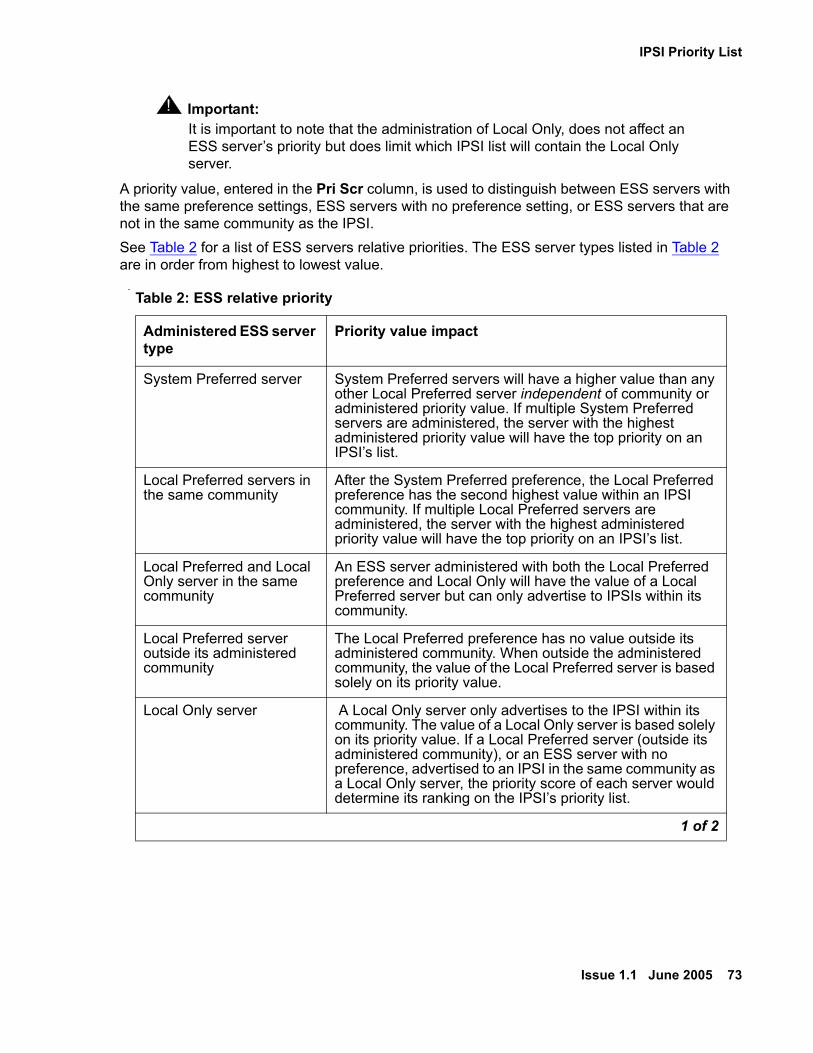
IPSI Priority List
Issue 1.1 June 2005 73
! Important:Important: It is important to note that the administration of Local Only, does not affect an
ESS server’s priority but does limit which IPSI list will contain the Local Only server.
A priority value, entered in the Pri Scr column, is used to distinguish between ESS servers with the same preference settings, ESS servers with no preference setting, or ESS servers that are not in the same community as the IPSI.See Table 2 for a list of ESS servers relative priorities. The ESS server types listed in Table 2 are in order from highest to lowest value.
.Table 2: ESS relative priority
Administered ESS server type
Priority value impact
System Preferred server System Preferred servers will have a higher value than any other Local Preferred server independent of community or administered priority value. If multiple System Preferred servers are administered, the server with the highest administered priority value will have the top priority on an IPSI’s list.
Local Preferred servers in the same community
After the System Preferred preference, the Local Preferred preference has the second highest value within an IPSI community. If multiple Local Preferred servers are administered, the server with the highest administered priority value will have the top priority on an IPSI’s list.
Local Preferred and Local Only server in the same community
An ESS server administered with both the Local Preferred preference and Local Only will have the value of a Local Preferred server but can only advertise to IPSIs within its community.
Local Preferred server outside its administered community
The Local Preferred preference has no value outside its administered community. When outside the administered community, the value of the Local Preferred server is based solely on its priority value.
Local Only server A Local Only server only advertises to the IPSI within its community. The value of a Local Only server is based solely on its priority value. If a Local Preferred server (outside its administered community), or an ESS server with no preference, advertised to an IPSI in the same community as a Local Only server, the priority score of each server would determine its ranking on the IPSI’s priority list.
1 of 2

ESS Design and Planning
74 Avaya Enterprise Survivable Servers (ESS) Users Guide
For information on how to administer an ESS server see, Administering ESS server on the Main server on page 122.
Advertising priority to an IPSIAn ESS server advertises its priority to an IPSI:
● Every time it disconnects and reconnects to the Main server, such as resets after the ESS server receives translations from the Main server, network outages, etc.
● When its priority changes
● At periodic intervals if rejected by the IPSI
Changes to a priority listThe IPSI priority list is dynamic and may change when:
● Communication is lost between an ESS server and the IPSI: The ESS server resets after receiving translations from the Main server. When the ESS server resets, communication between the ESS server and the IPSI is lost. The IPSI adjusts its priority list, removing the ESS server from the list. When the ESS server re-establishes communication with the IPSI, the ESS server will regain its proper order on the list.
● An ESS server is deleted: The ESS server was removed from translations.
No preference server The value of an ESS server administered with no preference is based solely on its priority value. It is possible to administer all ESS servers with no preferences. In this case, all ESS servers would start out with the same value and a priority value would be used to rank the importance of the ESS servers independent of communities.
Table 2: ESS relative priority (continued)
Administered ESS server type
Priority value impact
2 of 2
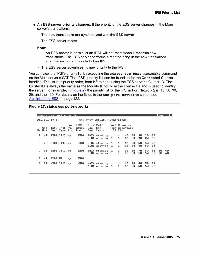
IPSI Priority List
Issue 1.1 June 2005 75
● An ESS server priority changes: If the priority of the ESS server changes in the Main server’s translations:
- The new translations are synchronized with the ESS server
- The ESS server resets
Note:Note: An ESS server in control of an IPSI, will not reset when it receives new
translations. The ESS server performs a reset to bring in the new translations after it is no longer in control of an IPSI.
- The ESS server advertises its new priority to the IPSI.
You can view the IPSI’s priority list by executing the status ess port-networks command on the Main server’s SAT. The IPSI’s priority list can be found under the Connected Cluster heading. The list is in priority order, from left to right, using the ESS server’s Cluster ID. The Cluster ID is always the same as the Module ID found in the license file and is used to identify the server. For example, in Figure 27 the priority list for the IPSI in Port Network 2 is, 10, 50, 90, 20, and then 60. For details on the fields in the ess port-networks screen see, Administering ESS on page 122.
Figure 27: status ess port-networks

ESS Design and Planning
76 Avaya Enterprise Survivable Servers (ESS) Users Guide
Examples of how the priority list worksThe following examples demonstrate how the IPSI priority list is used during failover scenarios.
IP connected Port Networks
In this example, an IP connected system has five IPSI connected Port Networks and four ESS servers. During the planning phase, the administrator decided that:
● The primary goal was to keep as much of the system in-tact as possible. In order to achieve that objective, two ESS servers (ESS server 1 and ESS server 2) were placed in the network. Both ESS servers backup the Main server if the Main server fails, or if communication from the Port Networks to the Main server fails.
● If the WAN fails where Port Networks 3, 4, 5, and 6, can no longer communicate with the Main server or ESS server 1:
- The Main server will control Port Networks 1 and 2
- ESS server 2 will control Port Networks 3, 4, 5, and 6.
● If LAN 3 fails where Port Network 3 can no longer communicate to LAN 2, ESS server 3 will service Port Network 3.
● If the WAN fails where Port Network 6 can no longer communicate with servers outside its community, than ESS server 4 (the Local Only server) will control Port Network 6.
See Figure 28 for the customer’s configuration with the priority scoring of each ESS server.

Examples of how the priority list works
Issue 1.1 June 2005 77
Figure 28: Customer’s configuration
UID
2
1
01
10
32
32
discCOMPACT
54
54
Sim
ple
xD
up
lex
ch
ch
21
UID
2
1
01
10
32
32
discCOMPACT
54
54
Sim
ple
xD
up
lex
ch
ch
21
Main Server orMain Server pair
cycmcust KLC 031505
disc
ESS server 1Community 1System preferredPriority 100
disc
ESS server 4Community 3Local only
disc
ESS server 3Community 2Local preferred
PN #1Community 1
PN #5Community 2
PN #6Community 3
PN #3Community 2
PN #2Community 1
PN #4Community 2
WANLAN 1 LAN 2
LAN 4
LAN 3
ESS server 2Community 1System preferredPriority 50

ESS Design and Planning
78 Avaya Enterprise Survivable Servers (ESS) Users Guide
To administer ESS, it is helpful to start with a data collection worksheet, as shown in Table 3:
Table 3: ESS worksheet
Server Preference C
lust
er ID
Plat
form
Typ
e
SVID
IP A
ddre
ss
Prio
rity
Scor
e
Com
mun
ity
IPSI
Lis
t in
Com
1
IPSI
Lis
t in
Com
2
IPSI
Lis
t in
Com
3
System Preferred(highest value preference)
2 S8700 12
192.9.13.10192.9.13.11
100 1 1 23
123
1234
3 S8500 3 192.9.44.11 50 1
Local Preferred(second highest value preference in its community)
4 S8500 4 192.9.33.22 2
No Preference(no value)
Local Only(only advertises to IPSIs in its own community)
5 S8500 5 192.8.55.7 3

Examples of how the priority list works
Issue 1.1 June 2005 79
Using the parameters outlined in Table 3, the ESS server’s priority, during no-fault conditions, on the IPSI priority list will be:
● Both ESS server 1 and ESS server 2 are administered with a System Preferred preference. The System Preferred preference has the highest value of any preference. Further ranking within the System Preferred preference is achieved by adding a priority score. The priority score of 100 placed ESS server 1 above ESS server 2 in the ranking within the System Preferred preference. The IPSI priority list in any community would show ESS server 1 as the first priority server, followed by ESS server 2.
● ESS server 3 is administered as Local Preferred for Community 2. The Local Preferred preference is the second highest preference after System Preferred for Port Networks within its community. For Port Networks outside its community, the Local Preferred preference holds no value and would be the same as an ESS server with no preference. When configurations have multiple Local Preferred servers, additional ranking can be achieved by using a Priority Score.
In this example, ESS server 3 would be the third choice for Port Network 3, Port Network 4, and Port Network 5, which are all in Community 2. ESS server 3 would also be the third choice for Port Network 1 and Port Network 2 following ESS server 1 and ESS server 2.
● ESS server 4 is administered as a Local Only server for Community 3. A Local Only server only appears on the IPSI’s priority list if that IPSI is in its own community. That means, ESS server 4 only appears on the IPSI’s list in Community 3 and will never appear on the IPSI priority list for any other IPSI not in Community 3.
In this example, the following failover scenarios in Table 4 might occur:
Table 4: Failover scenarios for IP Connected example
Failure type failover description
Main server(s) fails ESS server 1 is the highest ranking ESS server on the IPSI priority list. All Port Networks failover to ESS server 1.
Both Main server(s) and ESS1 fails
ESS server 2 is second highest ranking ESS server on the IPSI priority list. All Port Networks failover to ESS server 2.
WAN connection fails The Main server(s) continues to control Port Networks 1 and 2. The Main server(s) and ESS server 1 can no longer communicate with the IPSIs in Port Networks 3, 4, 5, and 6. Because the Main server(s) and ESS server 1 cannot communicate with Port Networks 3, 4, 5, and 6 they are removed from their priority lists. The IPSIs in PN 3, 4, and 5 request service from the highest ESS server on their priority list (ESS server 2). ESS server 4 is the only ESS server available to Port Network 6 if the WAN is not available.
ESS Design and Planning
80 Avaya Enterprise Survivable Servers (ESS) Users Guide
Multi-connected configuration using ATM PNCIn this example, the multi-connect configuration has seven Port Networks and three ESS servers. As in the previous IP connected configuration example, the administrator wants to design the system so the system stays as much in-tact as possible after a failover. Should IPSI communication to the Main server(s) fail, the administrator wants ESS server 1 to provide service to the entire system. If the IPSIs loses communication with ESS server 1, then ESS server 2 will take over the entire system. Port Networks 6 and 7 connect to the Main server(s) over the ATM network and do not have a direct IPSI connectivity to the Main server(s).See Figure 29 for the customer’s multi-connected ATM PNC configuration with the priority scoring of each ESS server:
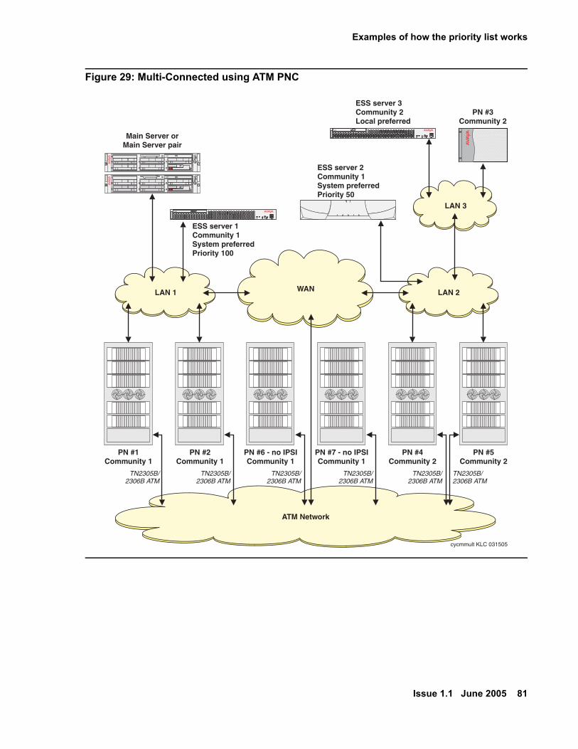
Examples of how the priority list works
Issue 1.1 June 2005 81
Figure 29: Multi-Connected using ATM PNC
UID
2
1
01
10
32
32
discCOMPACT
54
54
Sim
ple
xD
up
lex
ch
ch
21
UID
2
1
01
10
32
32
discCOMPACT
54
54
Sim
ple
xD
up
lex
ch
ch
21
Main Server orMain Server pair
cycmmult KLC 031505
disc
ESS server 1Community 1System preferredPriority 100
disc
ESS server 3Community 2Local preferred
PN #3Community 2
WAN
ATM Network
LAN 1 LAN 2
LAN 3
ESS server 2Community 1System preferredPriority 50
PN #1Community 1
TN2305B/2306B ATM
TN2305B/2306B ATM
TN2305B/2306B ATM
TN2305B/2306B ATM
TN2305B/2306B ATM
TN2305B/2306B ATM
PN #6 - no IPSICommunity 1
PN #4Community 2
PN #2Community 1
PN #7 - no IPSICommunity 1
PN #5Community 2

ESS Design and Planning
82 Avaya Enterprise Survivable Servers (ESS) Users Guide
See Table 5 for an example data collection worksheet for Figure 29.
In this example all IPSIs have the same priority lists. There are no IPSIs in PN6 and PN7 and therefore no priority list associated with those Port Networks.In the case of an IP Network failure, if PN6 and PN7 cannot communicate with the Main server(s), they will fall under control of one of the other ESS servers. In order for an ESS server to control a Port Network without an IPSI, such as PN6 or PN7, the ESS server must first control a Port Network with an IPSI. Once the ESS server controls an Port Network with an IPSI the ESS server may then attempt to communicate with, and possibly control, a non-IPSI Port Network through the ATM network. An ESS server is always more likely to take control of a non-IPSI Port Network if it is providing service to an IPSI in that community.
Table 5: Multi-Connected using ATM PNC data collection sheet
Server Preference C
lust
er ID
Plat
form
Typ
e
SVID
IP A
ddre
ss
Prio
rity
Scor
e
Com
mun
ity
IPSI
Lis
t in
Com
1
IPSI
Lis
t in
Com
2
System Preferred
2 S8700 12
192.9.13.10192.9.13.11
100 1 1 23
123
3 S8500 3 192.9.44.11 50 1
Local Preferred
4 S8500 4 192.9.33.22 2
No Preference
Local Only
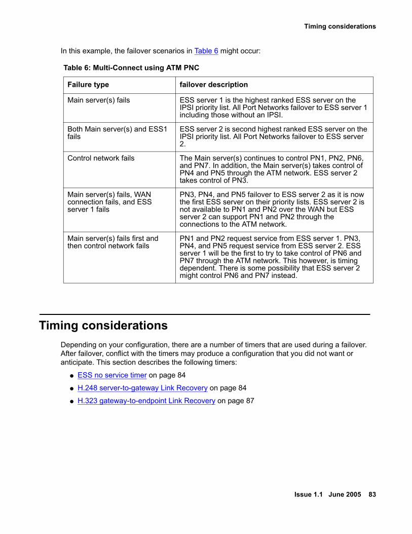
Timing considerations
Issue 1.1 June 2005 83
In this example, the failover scenarios in Table 6 might occur:
Timing considerationsDepending on your configuration, there are a number of timers that are used during a failover. After failover, conflict with the timers may produce a configuration that you did not want or anticipate. This section describes the following timers:
● ESS no service timer on page 84
● H.248 server-to-gateway Link Recovery on page 84
● H.323 gateway-to-endpoint Link Recovery on page 87
Table 6: Multi-Connect using ATM PNC
Failure type failover description
Main server(s) fails ESS server 1 is the highest ranked ESS server on the IPSI priority list. All Port Networks failover to ESS server 1 including those without an IPSI.
Both Main server(s) and ESS1 fails
ESS server 2 is second highest ranked ESS server on the IPSI priority list. All Port Networks failover to ESS server 2.
Control network fails The Main server(s) continues to control PN1, PN2, PN6, and PN7. In addition, the Main server(s) takes control of PN4 and PN5 through the ATM network. ESS server 2 takes control of PN3.
Main server(s) fails, WAN connection fails, and ESS server 1 fails
PN3, PN4, and PN5 failover to ESS server 2 as it is now the first ESS server on their priority lists. ESS server 2 is not available to PN1 and PN2 over the WAN but ESS server 2 can support PN1 and PN2 through the connections to the ATM network.
Main server(s) fails first and then control network fails
PN1 and PN2 request service from ESS server 1. PN3, PN4, and PN5 request service from ESS server 2. ESS server 1 will be the first to try to take control of PN6 and PN7 through the ATM network. This however, is timing dependent. There is some possibility that ESS server 2 might control PN6 and PN7 instead.

ESS Design and Planning
84 Avaya Enterprise Survivable Servers (ESS) Users Guide
ESS no service timerDuring ESS administration, a value is entered for the no service timer. The value of the no service timer determines the amount of time the IPSI waits, after losing communication with the Main server or controlling ESS server, before requesting service from the highest ranked ESS server on its priority list. All stable calls remain in a stable condition when the no service timer activates. The time from when the no service timer actives, to the time the IPSI requests service of an ESS server, is called the no service time out interval. If the communication to the Main server is restored before the no service time out interval expires, normal system recovery occurs.The value for the no service timer is administrable from three to 15 minutes, with a default of five minutes. For more information on the no service timer see, System-parameters ess form - page seven on page 126.
Link Recovery
! Important:Important: This section provides a high-level overview of Link Recovery. For more detailed
information see, Maintenance Procedures for Avaya Communication Manager 3.0, Media Gateways and Servers (03-300192).
Communication Manager offers two levels of Link Recovery:
● H.248 server-to-gateway Link Recovery on page 84
● H.323 gateway-to-endpoint Link Recovery on page 87
H.248 server-to-gateway Link Recovery
The H.248 link between an Avaya server running Avaya Communication Manager Software and the Avaya Media Gateway provides the signaling protocol for:
● Call setup
● Call control (user actions such as Hold, Conference, or Transfer) while the call is in progress
● Call tear-down
If the link goes down, Link Recovery preserves any existing calls and attempts to re-establish the original link. If the gateway cannot reconnect to the original server, then Link Recovery automatically attempts to connect with another server or Local Survivable Processor (LSP).
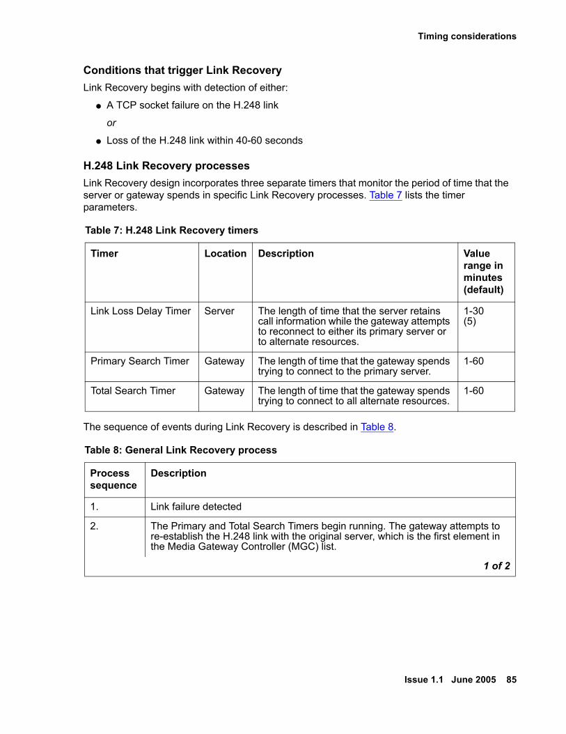
Timing considerations
Issue 1.1 June 2005 85
Conditions that trigger Link RecoveryLink Recovery begins with detection of either:
● A TCP socket failure on the H.248 link
or
● Loss of the H.248 link within 40-60 seconds
H.248 Link Recovery processesLink Recovery design incorporates three separate timers that monitor the period of time that the server or gateway spends in specific Link Recovery processes. Table 7 lists the timer parameters.
The sequence of events during Link Recovery is described in Table 8.
Table 7: H.248 Link Recovery timers
Timer Location Description Value range in minutes(default)
Link Loss Delay Timer Server The length of time that the server retains call information while the gateway attempts to reconnect to either its primary server or to alternate resources.
1-30(5)
Primary Search Timer Gateway The length of time that the gateway spends trying to connect to the primary server.
1-60
Total Search Timer Gateway The length of time that the gateway spends trying to connect to all alternate resources.
1-60
Table 8: General Link Recovery process
Processsequence
Description
1. Link failure detected
2. The Primary and Total Search Timers begin running. The gateway attempts to re-establish the H.248 link with the original server, which is the first element in the Media Gateway Controller (MGC) list.
1 of 2
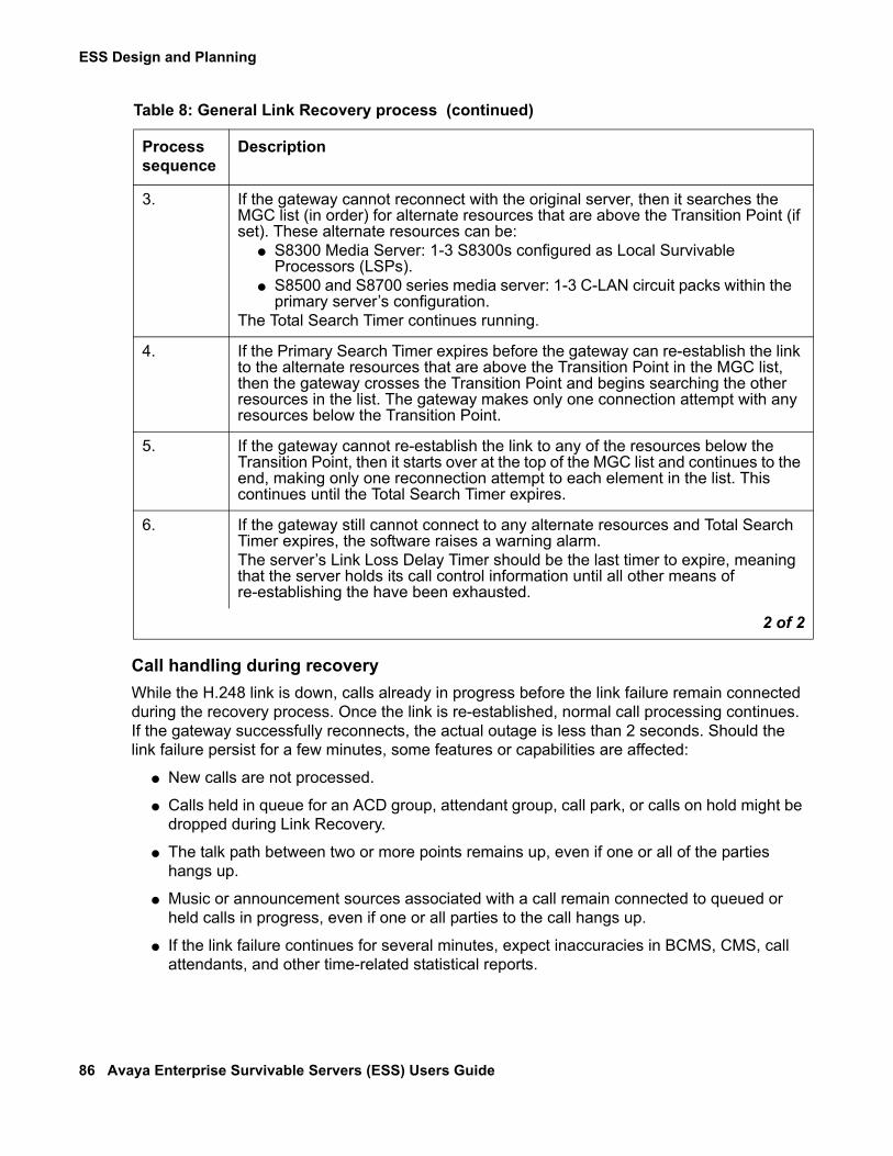
ESS Design and Planning
86 Avaya Enterprise Survivable Servers (ESS) Users Guide
Call handling during recoveryWhile the H.248 link is down, calls already in progress before the link failure remain connected during the recovery process. Once the link is re-established, normal call processing continues. If the gateway successfully reconnects, the actual outage is less than 2 seconds. Should the link failure persist for a few minutes, some features or capabilities are affected:
● New calls are not processed.
● Calls held in queue for an ACD group, attendant group, call park, or calls on hold might be dropped during Link Recovery.
● The talk path between two or more points remains up, even if one or all of the parties hangs up.
● Music or announcement sources associated with a call remain connected to queued or held calls in progress, even if one or all parties to the call hangs up.
● If the link failure continues for several minutes, expect inaccuracies in BCMS, CMS, call attendants, and other time-related statistical reports.
3. If the gateway cannot reconnect with the original server, then it searches the MGC list (in order) for alternate resources that are above the Transition Point (if set). These alternate resources can be:
● S8300 Media Server: 1-3 S8300s configured as Local Survivable Processors (LSPs).
● S8500 and S8700 series media server: 1-3 C-LAN circuit packs within the primary server’s configuration.
The Total Search Timer continues running.
4. If the Primary Search Timer expires before the gateway can re-establish the link to the alternate resources that are above the Transition Point in the MGC list, then the gateway crosses the Transition Point and begins searching the other resources in the list. The gateway makes only one connection attempt with any resources below the Transition Point.
5. If the gateway cannot re-establish the link to any of the resources below the Transition Point, then it starts over at the top of the MGC list and continues to the end, making only one reconnection attempt to each element in the list. This continues until the Total Search Timer expires.
6. If the gateway still cannot connect to any alternate resources and Total Search Timer expires, the software raises a warning alarm. The server’s Link Loss Delay Timer should be the last timer to expire, meaning that the server holds its call control information until all other means of re-establishing the have been exhausted.
Table 8: General Link Recovery process (continued)
Processsequence
Description
2 of 2

Timing considerations
Issue 1.1 June 2005 87
● If the calling party hangs up during Link Recovery, expect inaccuracies in the CDR records for the recovery time period.
● Phone buttons (including feature access buttons) do not work.
H.323 gateway-to-endpoint Link Recovery
The H.323 link between an Avaya Media Gateway and an H.323-compliant IP endpoint provides the signaling protocol for
● Call setup
● Call control (user actions such as Hold, Conference, or Transfer) while the call is in progress
● Call tear-down
If the link goes down, Link Recovery preserves any existing calls and attempts to re-establish the original link. If the endpoint cannot reconnect to the original Gateway, then H.323 Link Recovery automatically attempts to connect with alternate TN799DP (CLAN) circuit pack within the original server’s configuration, or to a LSP.H.323 Link Recovery does not diagnose or repair the network failure that caused the link outage, however it:
● Attempts to overcome any network or hardware failure by re-registering the IP Endpoint with its original Gateway.
● Maintains calls in progress during the re-registration attempt.
● Continues trying to reconnect if the call ends and the IP Endpoint has not yet reconnected to its original Gateway.
● Attempts connecting to and registering with an alternate Gateway if so configured.
See Table 9 for a synopsis of the recovery outcomes.
Table 9: Synopsis of recovery outcomes
If Then
No Gateway is found The endpoint is out-of-service until it can find a Gateway.
The IP endpoint registers with a new Gateway
The call ends and the endpoint is available (full features and buttons) through the new Gateway.
Original Gateway accepts re-registration The endpoint is available (full features and buttons) through the new Gateway.
Call in progress but endpoint cannot re-register
A call in progress remains so. No new calls are accepted. Features and buttons are inoperable.
ESS Design and Planning
88 Avaya Enterprise Survivable Servers (ESS) Users Guide
Feature limitationsSince there is no communication possible between the Gateway and the IP endpoint during a link outage, button depressions are not recognized, feature access codes do not work, and any other types of call handling ceases. In essence, the server cannot react to any stimuli until the H.323 signaling link is restored.
Feature considerationsNote:
Note: Features may act differently depending on the release of Communication Manager.
Depending on the reason for the failure, some Communication Manager features may not work as administered. If the failure is on the Main server(s) but the network is still intact, you may not see any changes to features such as call forwarding, hunt groups, call coverage, etc. If the network fragments, the same features may or may not work as intended.This section highlights how a failover would affect the following Communication Manager features:
● Announcements on page 89
● Attendant Console on page 89
● Best Service Routing (BSR) on page 89
● Call Classification on page 89
● Call Coverage on page 89
● Call Vectoring on page 89
● Centralized Attendant Service (CAS) on page 90
● Crisis Alert on page 90
● CVLAN links on page 90
● Facility Busy Indication on page 90
● Hunt Groups on page 90
● Leave Word Calling on page 90
● Music on Hold on page 91

Feature considerations
Issue 1.1 June 2005 89
AnnouncementsAnnouncements are available to callers when the announcement is under the control of the ESS server.
Attendant ConsoleWhen a Port Network fails-over to an ESS server any attendant console in that Port Network will come into service in the Night Service mode. Calls can be taken from the attendant console after the console is taken out of Night Service. Only the trunks under the control of the servicing ESS server will be affected by the deactivation of the Night Service mode. The ESS server assumes that any console that it cannot control is out of service.
Best Service Routing (BSR)BSR polling works if the facility used for routing the polling call is under the control of that ESS server.
Call ClassificationCall Classification will work only if there are one or more Call Classification resources under the control of the ESS server.
Call CoverageCalls may follow a call coverage path only if the route is under the control of the same ESS server. If the covered party is not under the control of the ESS server, the covering call will go immediately to coverage.
Call VectoringRouting a call using Call Vectoring is successful only if the route-to-endpoints are under the control of the ESS server. This is true whether the endpoint is another station, adjunct, or route in a routing pattern.

ESS Design and Planning
90 Avaya Enterprise Survivable Servers (ESS) Users Guide
Centralized Attendant Service (CAS)For a CAS Main system calls from a Branch will be processed if the Port Networks under the control of the ESS server contain the incoming trunks and attendant consoles.For a CAS Branch, calls are routed as if Night Service mode was activated. Calls are routed only if the trunks to the CAS Main are under control of the ESS server controlling the Port Network where attendant seeking calls arrive for service.
Crisis AlertCrisis alerting calls can only be routed to endpoints under the control of the ESS server that controls the originator.
CVLAN linksThe ESS server will only have access to CVLAN links in Port Networks under its control.
Facility Busy IndicationFacility Busy Indicators can only track the endpoints that are under the control of the same ESS server as the endpoint with the facility busy indicator button or display.
Hunt GroupsHunt Group calls can be directed to hunt group members in Port Networks under the control of that ESS server.
Leave Word CallingWhen an ESS server takes control of a Port Network, all previous Leave Word Calling messages are lost. The same is true when control is returned to the Main server(s).

Adjunct considerations
Issue 1.1 June 2005 91
Music on HoldThe ESS server can provide Music on Hold only if the music source is in control of the ESS server. Calls to an ESS server without a music source hears silence.
Adjunct considerationsWhen a failover occurs, an ESS server may or may not have connectivity to various adjuncts. This section highlights how a failover would affect the following adjuncts:
● Call Detail Recording (CDR) on page 91
● Call Management System (CMS) on page 92
● EC500 on page 92
● Property Management System (PMS) on page 92
● Voice Mail (Audix, Intuity, Octel, Modular Messaging) on page 92
● Voice Response Systems (Conversant) on page 92
Call Detail Recording (CDR)CDR is connected to the server through a CLAN and IP network. The CLAN for each CDR is specified in translations. In the event a failure and fragmentation occurs, call details for completed calls will be collected. The server controlling one or both of the CLANs through which the CDR data is sent, will attempt to deliver the records to the CDR output device. If the network is intact to the device, the call records will be delivered. If the server knows that the CDR device is not connected, it will store the records in a buffer. If the server does not control the Port Network(s) with the CLAN(s), it will buffer the records. When the system restores and all Port Networks return to the control of the Main server(s), any records buffered by the Main server(s) will download to the CDR output link. The buffer size of the output link is the same as the S8700 Server buffer. Other records that were not delivered to the CDR adjuncts and buffered in an ESS server will be unrecoverable, as the ESS server will perform a restart.

ESS Design and Planning
92 Avaya Enterprise Survivable Servers (ESS) Users Guide
Call Management System (CMS)CMS connects to the server through a CLAN. In the event of a failover, an ESS server may control the Port Network that contains the CLAN. In this case only the events that are under control of that ESS server will be sent to the CMS. All other related system data will be lost. This occurs in the event of a fragmented system resulting from a control network failure.
EC500EC500 users will have access to the EC500 service only if their endpoint is also under the control of the same ESS server that controls the EC500.
Property Management System (PMS)PMS interfaces to the server through a CLAN. If the network is fragmented, only the Port Network with that CLAN, under control of an ESS server, will be able to pass entered or event data to the PMS.
Voice Mail (Audix, Intuity, Octel, Modular Messaging)In the event of a failover, the ESS server will only be able to deliver covered and diverted called parties to voice messaging systems that are connected to the same controlled system segment as the calling party.A user of a voice mail system will only get a message waiting indication if their messaging server is in the same controlled segment as their station. The only way a voice mail user will be able to retrieve messages is through a dial connection or tool, such as Message Manager, to connect to the voice mail system.
Voice Response Systems (Conversant)The voice response system is connected by ports to a Port Network. The Port Network is under the control of the Main server(s). In the event of a failure resulting in a fragmented system, the voice response system will be able to execute any instructions that can be handled by call processing in the Port Network under the control of the same server. Other requests will be denied.

Issue 1.1 June 2005 93
Chapter 3: ESS Installation
The ESS installation chapter contains the following:
● ESS Installation Checklist on page 93
● ESS Server License Files on page 110
● Configuring the Servers on page 116
● Administering ESS on page 122
● Saving translations on page 130
ESS Installation Checklist
About this sectionThe section provides a checklist of two types of ESS installations:
● Installing ESS With Existing Servers on page 94
● Installing ESS With New Servers on page 104
OverviewIn general, performing an ESS installation requires the following high-level steps:
1. Design the system and determine the ESS administration factors. For information on how to design and plan the system see, ESS Design and Planning on page 63.
2. Install/upgrade Communication Manager 3.0 or later on each ESS server.
● Install the license and authentication file (ESS Server License Files on page 110)
● Restart the server
● Configure the server ( Configuring the Servers on page 116)
3. Install/upgrade Communication Manager 3.0 or later on the Main server.
● Install the license and authentication file (ESS Server License Files on page 110)
● Restart the server
● Configure the server ( Configuring the Servers on page 116)
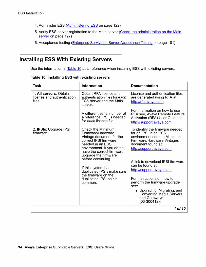
ESS Installation
94 Avaya Enterprise Survivable Servers (ESS) Users Guide
4. Administer ESS (Administering ESS on page 122)
5. Verify ESS server registration to the Main server (Check the administration on the Main server on page 127)
6. Acceptance testing (Enterprise Survivable Server Acceptance Testing on page 181)
Installing ESS With Existing ServersUse the information in Table 10 as a reference when installing ESS with existing servers.
Table 10: Installing ESS with existing servers
Task Information Documentation
1. All servers: Obtain license and authentication files
Obtain RFA license and authentication files for each ESS server and the Main server.
A different serial number of a reference IPSI is needed for each license file.
License and authentication files are generated using RFA at: http://rfa.avaya.com
For information on how to use RFA see, Avaya Remote Feature Activation (RFA) User Guide at: http://support.avaya.com
2. IPSIs: Upgrade IPSI firmware
Check the Minimum Firmware/Hardware Vintage document for the correct IPSI firmware needed in an ESS environment. If you do not have the correct firmware, upgrade the firmware before continuing.
If this system has duplicated IPSIs make sure the firmware on the duplicated IPSI pair is common.
To identify the firmware needed for an IPSI in an ESS environment see the Minimum Firmware/Hardware Vintages document found at:http://support.avaya.com
A link to download IPSI firmware can be found at: http://support.avaya.com
For instructions on how to perform the firmware upgrade see:
● Upgrading, Migrating, and Converting Media Servers and Gateways (03-300412).
1 of 10

ESS Installation Checklist
Issue 1.1 June 2005 95
3a. ESS with CSS-Port Network Connectivity (PNC)
Install an IP Media Processor and an IPSI board in every survivable Port Network.
In all IPSI controlled Port Networks, verify that the TN570D board is used.
For instructions on how to install an IP Media Processor, an IPSI board, or a TN570D board see:Adding New Hardware - Avaya S8500 and S8700 Media Servers (555-245-112).
3b. ESS with Direct-PNC ESS is not supported in a Direct Connect environment. The Direct Connect environment must be converted to an IP Connect environment.
To convert a Direct Connect system to an IP Connect system see:Upgrading, Migrating, and Converting Media Servers and Gateways (03-300412).
3c. ESS with ATM-PNC All ATM PNC and CES boards must be TN2306B boards.
If the ATM is local to the Port Networks, a five to one IPSI port ratio is allowed for each survivable Port Network.
If the ATM is remote to the Port Networks, an IPSI is required in each survivable Port Network.
To change a TN board see:Adding New Hardware - Avaya S8500 and S8700 Media Servers (555-245-112).
3d. ESS with IP-PNC No changes are needed for an IP Connect environment.
4. ESS with mixed Port Network Connectivity (PNC)
Install an IP Media Processor and an IPSI board in every survivable Port Network.
For instructions on how to convert to a mixed PNC environment see:Upgrading, Migrating, and Converting Media Servers and Gateways (03-300412).
Table 10: Installing ESS with existing servers (continued)
Task Information Documentation
2 of 10
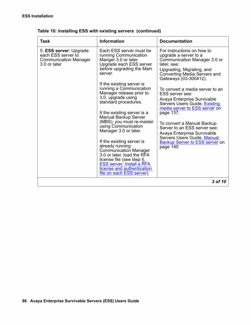
ESS Installation
96 Avaya Enterprise Survivable Servers (ESS) Users Guide
5. ESS server: Upgrade each ESS server to Communication Manager 3.0 or later
Each ESS server must be running Communication Manger 3.0 or later. Upgrade each ESS server before upgrading the Main server.
If the existing server is running a Communication Manager release prior to 3.0, upgrade using standard procedures.
It the existing server is a Manual Backup Server (MBS), you must re-master using Communication Manager 3.0 or later.
If the existing server is already running Communication Manager 3.0 or later, load the RFA license file (see step 6. ESS server: Install a RFA license and authentication file on each ESS server).
For instructions on how to upgrade a server to a Communication Manager 3.0 or later, see:Upgrading, Migrating, and Converting Media Servers and Gateways (03-300412).
To convert a media server to an ESS server see:Avaya Enterprise Survivable Servers Users Guide, Existing media server to ESS server on page 137.
To convert a Manual Backup Server to an ESS server see:Avaya Enterprise Survivable Servers Users Guide, Manual Backup Server to ESS server on page 140.
Table 10: Installing ESS with existing servers (continued)
Task Information Documentation
3 of 10

ESS Installation Checklist
Issue 1.1 June 2005 97
6. ESS server: Install a RFA license and authentication file on each ESS server
If the license file contains a new module ID or if the module ID has changed, you must:
● Use the Bash command, server -z
● Use the SAT command reset system 4
If the license file contains the same module ID as the previous license file, with the ESS functionality turned on, you must:
● Use the SAT command, reset system 4
After loading the license file, verify that the ESS Administration and Enterprise Survivable Server feature is turned on.
To install the license and authentication file see:
● Installing and Configuring the S8500 Media Server (03-300143), or
● Installing and Configuring the S8700 Series Media Server (03-300145).
To verify that the ESS Administration and Enterprise Survivable Server feature is turned on see:Avaya Enterprise Survivable Servers (ESS) Users Guide, ESS Server License Files on page 110.
7. ESS server: Configure the ESS server
The server’s web interface is used to configure the ESS server.
If the server was re-mastered, use the Avaya wizard to configure the server.
If the server is already configured, use the Avaya Enterprise Survivable Servers Users Guide to configure the Enterprise Survivable Server window.
To configure the server using the Avaya wizard see:
● Installing and Configuring the S8500 Media Server (03-300143), or
● Installing and Configuring the S8700 Series Media Server (03-300145).
To configure a server with existing configuration information see:Avaya Enterprise Survivable Servers Users Guide, Existing media server to ESS server on page 137.
Table 10: Installing ESS with existing servers (continued)
Task Information Documentation
4 of 10

ESS Installation
98 Avaya Enterprise Survivable Servers (ESS) Users Guide
8. ESS server: Verify communication with the customer’s LAN interface
You entered an IP address of a CLAN when you configured the ESS server. This CLAN is used when the ESS server registers with the Main server for the first time and may be used for subsequent registrations.
To verify that the ESS server can communicate with the customer’s LAN interface:On the ESS server, use the ping command followed by the IP address of the CLAN.
For information on how to use the ping command, see:
● Installing and Configuring the S8700 Series Media Server (03-300145), or
● Installing and Configuring the S8500 Media Server (03-300143).
9. ESS server: Verify communication to the Main server over the IP network
To verify that the ESS server can communicate to the Main server:On the ESS server, use the ping command followed by the IP address of the Main server.
For information on how to use the ping command, see:
● Installing and Configuring the S8700 Series Media Server (03-300145), or
● Installing and Configuring the S8500 Media Server (03-300143).
Table 10: Installing ESS with existing servers (continued)
Task Information Documentation
5 of 10
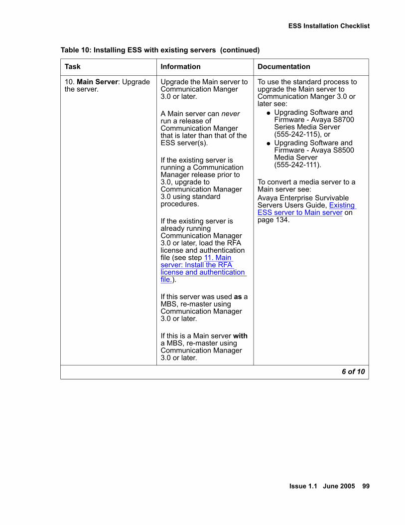
ESS Installation Checklist
Issue 1.1 June 2005 99
10. Main Server: Upgrade the server.
Upgrade the Main server to Communication Manger 3.0 or later.
A Main server can never run a release of Communication Manger that is later than that of the ESS server(s).
If the existing server is running a Communication Manager release prior to 3.0, upgrade to Communication Manager 3.0 using standard procedures.
If the existing server is already running Communication Manager 3.0 or later, load the RFA license and authentication file (see step 11. Main server: Install the RFA license and authentication file.).
If this server was used as a MBS, re-master using Communication Manager 3.0 or later.
If this is a Main server with a MBS, re-master using Communication Manager 3.0 or later.
To use the standard process to upgrade the Main server to Communication Manger 3.0 or later see:
● Upgrading Software and Firmware - Avaya S8700 Series Media Server (555-242-115), or
● Upgrading Software and Firmware - Avaya S8500 Media Server (555-242-111).
To convert a media server to a Main server see:Avaya Enterprise Survivable Servers Users Guide, Existing ESS server to Main server on page 134.
Table 10: Installing ESS with existing servers (continued)
Task Information Documentation
6 of 10

ESS Installation
100 Avaya Enterprise Survivable Servers (ESS) Users Guide
11. Main server: Install the RFA license and authentication file.
If the license file contains a new module ID or if the module ID has changed, you must:
● Use the Bash command, server -z
● Use the SAT command reset system 4
After loading the license file, verify that the ESS Administration feature is turned on.
To install the license and authentication file see:
● Installing and Configuring the S8500 Media Server (03-300143), or
● Installing and Configuring the S8700 Series Media Server (03-300145).
To verify that the ESS Administration feature is turned on see:Avaya Enterprise Survivable Servers (ESS) Users Guide, ESS Server License Files on page 110.
12. IPSIs: Change the dynamic IP address to a static IP address
In an ESS environment, all IPSI’s must have a static IP address.
To change the IPSI from a dynamic IP address to a static IP address see:
● Installing and Configuring the S8500 Media Server (03-300143), or
● Installing and Configuring the S8700 Series Media Server (03-300145).
Table 10: Installing ESS with existing servers (continued)
Task Information Documentation
7 of 10

ESS Installation Checklist
Issue 1.1 June 2005 101
13. Main server: Configure the Main server
The server’s web interface is used to configure the Main server.
If the server was re-mastered using Communication 3.0 or later, use the Avaya wizard to configure the server.
If the server was updated to Communication Manger 3.0 or later, or was already running Communication Manager 3.0 or later, use the Avaya Enterprise Survivable Servers Users Guide to configure the Enterprise Survivable Server window.
In an ESS environment, you must use static IP addresses for the IPSIs in the configuration.
To configure a server for ESS that is already running Communication Manager 3.0 or later use:Avaya Enterprise Survivable Servers Users Guide, Existing ESS server to Main server on page 134.
To configure the server using the Avaya wizard see:
● Installing and Configuring the S8500 Media Server (03-300143), or
● Installing and Configuring the S8700 Series Media Server (03-300145).
14. Main server: Verify open ports in the customer’s network
This step may be necessary if the customer has firewalls. If the customer does not have firewalls, you can skip this step.
Certain ports must be open for ESS to work properly.
To obtain a list of ports that must be open for ESS, see:Avaya Enterprise Survivable Servers (ESS) Users Guide, Network port considerations on page 66.
Table 10: Installing ESS with existing servers (continued)
Task Information Documentation
8 of 10

ESS Installation
102 Avaya Enterprise Survivable Servers (ESS) Users Guide
15. Main server: Verify LAN/WAN connectivity
Verify communication between each ESS server and the Main server over the LAN/WAN.
To verify that the Main server can communicate with all servers on the LAN/WAN:On the Main server, use the ping command followed by the IP address of the ESS server.
For information on how to use the ping command, see:
● Installing and Configuring the S8700 Series Media Server (03-300145), or
● Installing and Configuring the S8500 Media Server (03-300143).
16. Main server: Administer ESS
On the Main server, administer each ESS server, Port Network Communities, and no service timer.
To administer the Main server see:Avaya Enterprise Survivable Servers Users Guide, Administering ESS on page 122.
17. Main server: Verify that each ESS server registers with the Main server
Use the status ess clusters command to verify ESS server registration.
A configured ESS server automatically registers with the Main server when the ESS administration completes. After registration, the ESS server receives a translation download from the Main server. The ESS server resets to load the translations and then re-registers with the Main server.
For information on the status ess clusters command see:Avaya Enterprise Servers Users Guide, status ess clusters on page 153.
Table 10: Installing ESS with existing servers (continued)
Task Information Documentation
9 of 10

ESS Installation Checklist
Issue 1.1 June 2005 103
18. Main server: Distribute the translations to the ESS servers
If changes are made to translations, they must be distributed to the ESS server by executing the save translations all or save translations ess command.
For more information on the save translations command see:Avaya Enterprise Survivable Servers Users Guide, Saving translations on page 130.
19. Acceptance testing Avaya recommends testing the ESS configuration.
For information on testing an ESS configuration see:Avaya Enterprise Survivable Servers Users Guide, Enterprise Survivable Server Acceptance Testing on page 181.
Table 10: Installing ESS with existing servers (continued)
Task Information Documentation
10 of 10

ESS Installation
104 Avaya Enterprise Survivable Servers (ESS) Users Guide
Installing ESS With New ServersUse the information in Table 11 as a reference when installing ESS with new servers.
Table 11: Installing ESS with new servers
Task Information Documentation
1. All servers: Obtain RFA license and authentication files
Obtain RFA license files and authentication files for each ESS server and the Main server.
A serial number of a different reference IPSI is needed for each license file.
License and authentication files are generated using RFA at, http://rfa.avaya.com
For information on how to use RFA see, Remote Feature Activation (RFA) Users Guide at, http://support.avaya.com
2. IPSI: Upgrade IPSI firmware
Check the Minimum Firmware/Hardware Vintage document for the correct IPSI firmware needed in an ESS environment. If you do not have the correct firmware, upgrade the IPSI firmware before continuing.
If this system has duplicated IPSIs make sure the firmware on the duplicated IPSI pair is common.
To identify the firmware needed for an IPSI in an ESS environment see the Minimum Firmware/Hardware Vintages document found at:http://support.avaya.com
A link to download IPSI firmware can be found on the support.avaya.com web site.
For instructions on how to perform the firmware upgrade see:
● Upgrading Software and Firmware - Avaya S8700 Series Media Server (555-242-115), or
● Upgrading Software and Firmware - Avaya S8500 Media Server (555-242-111).
1 of 7
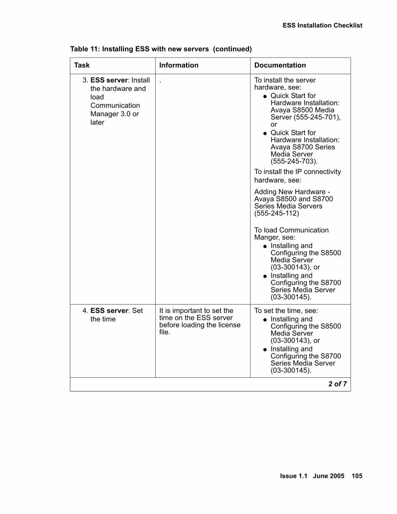
ESS Installation Checklist
Issue 1.1 June 2005 105
3. ESS server: Install the hardware and load Communication Manager 3.0 or later
. To install the server hardware, see:
● Quick Start for Hardware Installation: Avaya S8500 Media Server (555-245-701), or
● Quick Start for Hardware Installation: Avaya S8700 Series Media Server (555-245-703).
To install the IP connectivity hardware, see:Adding New Hardware - Avaya S8500 and S8700 Series Media Servers (555-245-112)
To load Communication Manger, see:
● Installing and Configuring the S8500 Media Server (03-300143), or
● Installing and Configuring the S8700 Series Media Server (03-300145).
4. ESS server: Set the time
It is important to set the time on the ESS server before loading the license file.
To set the time, see: ● Installing and
Configuring the S8500 Media Server (03-300143), or
● Installing and Configuring the S8700 Series Media Server (03-300145).
Table 11: Installing ESS with new servers (continued)
Task Information Documentation
2 of 7

ESS Installation
106 Avaya Enterprise Survivable Servers (ESS) Users Guide
5. ESS server: Install the license and authentication files
Install a RFA license file and an authentication file on each ESS server.
After loading the license file:
● Perform a reset system 4 on the server’s SAT.
● Verify that the ESS Administration and Enterprise Survivable Server feature is turned on.
To install the license and authentication file see:
● Installing and Configuring the S8500 Media Server (03-300143), or
● Installing and Configuring the S8700 Series Media Server (03-300145).
To verify that the ESS Administration and Enterprise Survivable Server feature is turned on see:Avaya Enterprise Survivable Servers (ESS) Users Guide, ESS Server License Files on page 110.
6. ESS server: Configure the ESS server
On a new installation, the Avaya wizard is used. Configuration for ESS is included in the Avaya wizard.
For information on how to use the Avaya wizard see:
● Installing and Configuring the S8700 Series Media Server (03-300145), or
● Installing and Configuring the S8500 Media Server (03-300143).
For information on the Configure ESS window see:Avaya Enterprise Survivable Servers Users Guide, Configuring the Servers on page 116.
Table 11: Installing ESS with new servers (continued)
Task Information Documentation
3 of 7
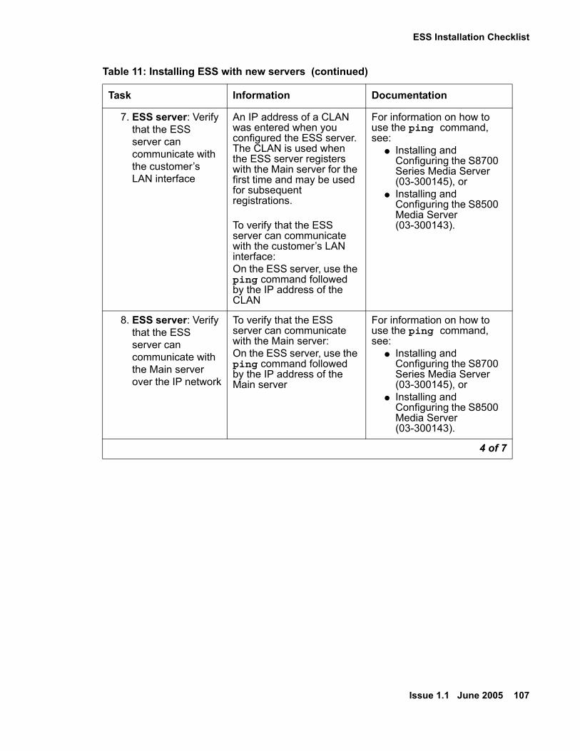
ESS Installation Checklist
Issue 1.1 June 2005 107
7. ESS server: Verify that the ESS server can communicate with the customer’s LAN interface
An IP address of a CLAN was entered when you configured the ESS server. The CLAN is used when the ESS server registers with the Main server for the first time and may be used for subsequent registrations.
To verify that the ESS server can communicate with the customer’s LAN interface:On the ESS server, use the ping command followed by the IP address of the CLAN
For information on how to use the ping command, see:
● Installing and Configuring the S8700 Series Media Server (03-300145), or
● Installing and Configuring the S8500 Media Server (03-300143).
8. ESS server: Verify that the ESS server can communicate with the Main server over the IP network
To verify that the ESS server can communicate with the Main server:On the ESS server, use the ping command followed by the IP address of the Main server
For information on how to use the ping command, see:
● Installing and Configuring the S8700 Series Media Server (03-300145), or
● Installing and Configuring the S8500 Media Server (03-300143).
Table 11: Installing ESS with new servers (continued)
Task Information Documentation
4 of 7
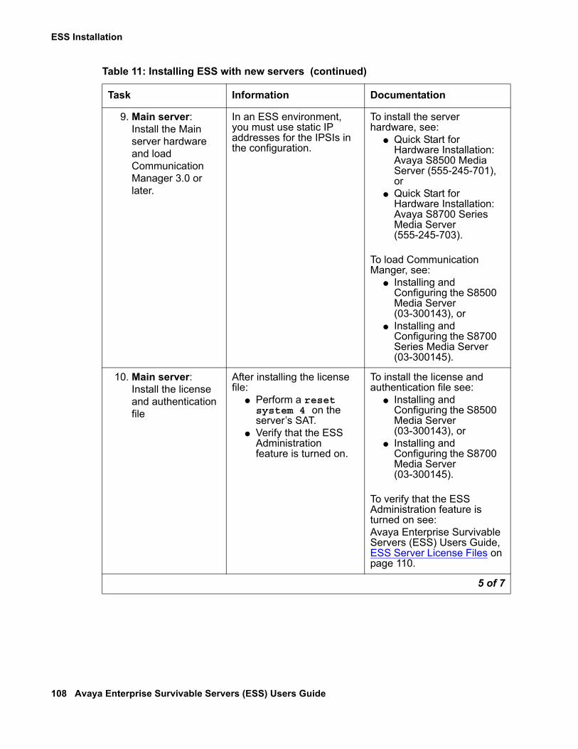
ESS Installation
108 Avaya Enterprise Survivable Servers (ESS) Users Guide
9. Main server: Install the Main server hardware and load Communication Manager 3.0 or later.
In an ESS environment, you must use static IP addresses for the IPSIs in the configuration.
To install the server hardware, see:
● Quick Start for Hardware Installation: Avaya S8500 Media Server (555-245-701), or
● Quick Start for Hardware Installation: Avaya S8700 Series Media Server (555-245-703).
To load Communication Manger, see:
● Installing and Configuring the S8500 Media Server (03-300143), or
● Installing and Configuring the S8700 Series Media Server (03-300145).
10. Main server: Install the license and authentication file
After installing the license file:
● Perform a reset system 4 on the server’s SAT.
● Verify that the ESS Administration feature is turned on.
To install the license and authentication file see:
● Installing and Configuring the S8500 Media Server (03-300143), or
● Installing and Configuring the S8700 Media Server (03-300145).
To verify that the ESS Administration feature is turned on see:Avaya Enterprise Survivable Servers (ESS) Users Guide, ESS Server License Files on page 110.
Table 11: Installing ESS with new servers (continued)
Task Information Documentation
5 of 7

ESS Installation Checklist
Issue 1.1 June 2005 109
11. Main server: Verify LAN/WAN connectivity
Verify communication between each ESS server and the Main server over the LAN/WAN.
To verify that the Main server can communicate with all servers on the LAN/WAN:On the Main server, use the ping command followed by the IP address of the ESS server.
For information on how to use the ping command, see:
● Installing and Configuring the S8700 Series Media Server (03-300145), or
● Installing and Configuring the S8500 Media Server (03-300143).
12. Main server: Verify open ports in customer’s network
This step may be necessary if the customer has firewalls. If the customer does not have firewalls, you can skip this step.
Certain ports must be open for ESS to work properly.
To obtain a list of ports that must be open for ESS, see:Avaya Enterprise Survivable Servers (ESS) Users Guide, Network port considerations on page 66.
13. Main server: Administer ESS
To administer ESS on the Main server see:Avaya Enterprise Survivable Servers Users Guide, Administering ESS on page 122.
14. Main server: Verify ESS server registration
Use the status ess clusters command to verify ESS server registration with the Main server.
For information on the status ess clusters command see:Avaya Enterprise Servers Users Guide, status ess clusters on page 153.
Table 11: Installing ESS with new servers (continued)
Task Information Documentation
6 of 7

ESS Installation
110 Avaya Enterprise Survivable Servers (ESS) Users Guide
ESS Server License Files! Important:
Important: This chapter provides information on RFA license files for an ESS environment. It does not contain information on how to load a license file on an Avaya server. For license file installation, refer to the installation documentation of the product you are installing.
For the S8700 series media servers refer to: Installing and Configuring the S8700 Series Media Server (03-300145) at, http://support.avaya.com.
For the S8500 Media Servers refer to: Installing and Configuring the S8500 Media Server (03-300143) at, http://support.avaya.com.
License filesAvaya requires a separate license file for every Avaya simplex server and every Avaya duplex pair of servers. License files are created using the Remote Feature Activation (RFA) application found at the RFA web site, http://rfa.avaya.com.
15. Acceptance testing Avaya recommends testing the ESS configuration.
For information on how to test a configuration see:Avaya Enterprise Survivable Servers Users Guide, Enterprise Survivable Server Acceptance Testing on page 181.
16. Main server: Distribute the translations to the ESS server(s)
If changes are made to translations, they must be distributed to the ESS server by executing the save translations all or save translations ess command.
For more information on the save translations command see:Avaya Enterprise Survivable Servers Users Guide, Saving translations on page 130.
Table 11: Installing ESS with new servers (continued)
Task Information Documentation
7 of 7
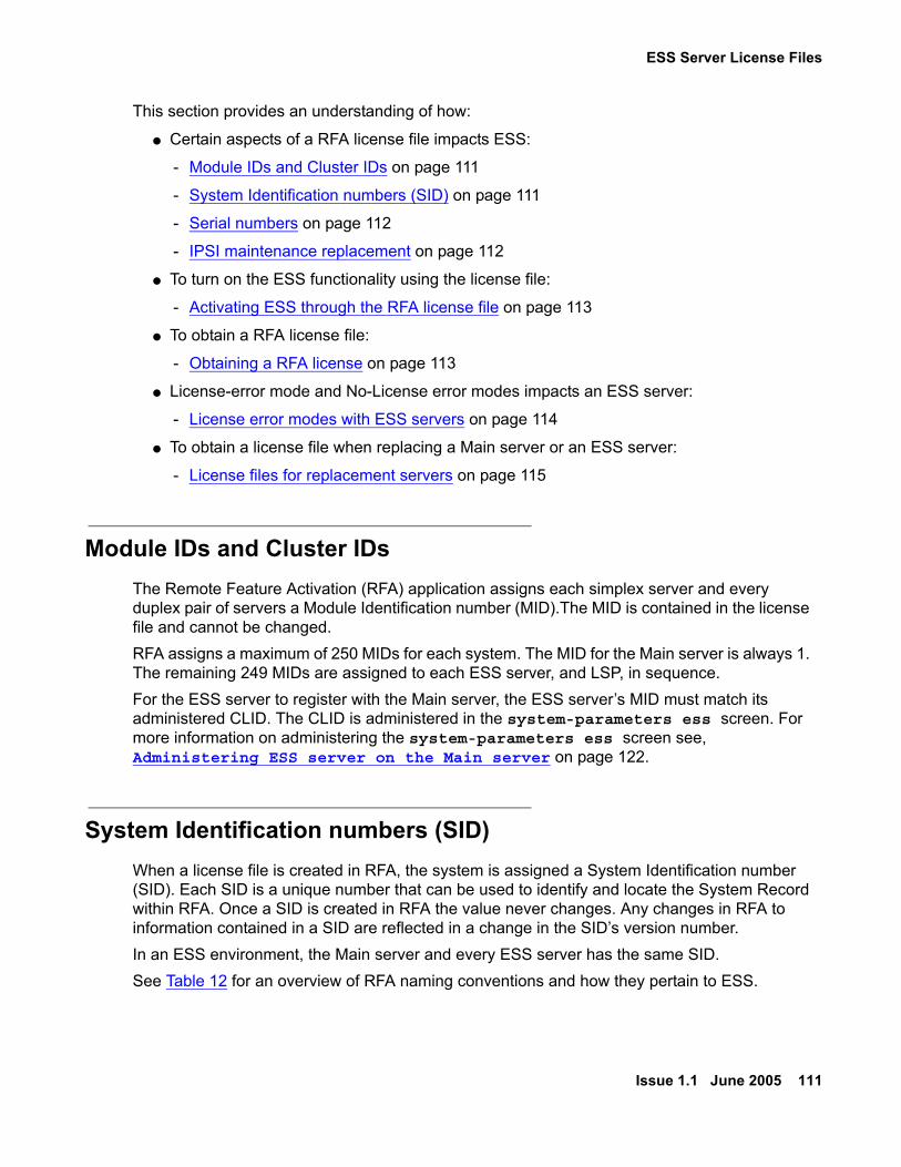
ESS Server License Files
Issue 1.1 June 2005 111
This section provides an understanding of how:
● Certain aspects of a RFA license file impacts ESS:
- Module IDs and Cluster IDs on page 111
- System Identification numbers (SID) on page 111
- Serial numbers on page 112
- IPSI maintenance replacement on page 112
● To turn on the ESS functionality using the license file:
- Activating ESS through the RFA license file on page 113
● To obtain a RFA license file:
- Obtaining a RFA license on page 113
● License-error mode and No-License error modes impacts an ESS server:
- License error modes with ESS servers on page 114
● To obtain a license file when replacing a Main server or an ESS server:
- License files for replacement servers on page 115
Module IDs and Cluster IDsThe Remote Feature Activation (RFA) application assigns each simplex server and every duplex pair of servers a Module Identification number (MID).The MID is contained in the license file and cannot be changed. RFA assigns a maximum of 250 MIDs for each system. The MID for the Main server is always 1. The remaining 249 MIDs are assigned to each ESS server, and LSP, in sequence.For the ESS server to register with the Main server, the ESS server’s MID must match its administered CLID. The CLID is administered in the system-parameters ess screen. For more information on administering the system-parameters ess screen see, Administering ESS server on the Main server on page 122.
System Identification numbers (SID)When a license file is created in RFA, the system is assigned a System Identification number (SID). Each SID is a unique number that can be used to identify and locate the System Record within RFA. Once a SID is created in RFA the value never changes. Any changes in RFA to information contained in a SID are reflected in a change in the SID’s version number.In an ESS environment, the Main server and every ESS server has the same SID. See Table 12 for an overview of RFA naming conventions and how they pertain to ESS.
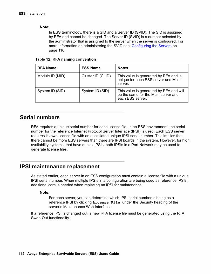
ESS Installation
112 Avaya Enterprise Survivable Servers (ESS) Users Guide
Note:Note: In ESS terminology, there is a SID and a Server ID (SVID). The SID is assigned
by RFA and cannot be changed. The Server ID (SVID) is a number selected by the administrator that is assigned to the server when the server is configured. For more information on administering the SVID see, Configuring the Servers on page 116.
Serial numbersRFA requires a unique serial number for each license file. In an ESS environment, the serial number for the reference Internet Protocol Server Interface (IPSI) is used. Each ESS server requires its own license file with an associated unique IPSI serial number. This implies that there cannot be more ESS servers than there are IPSI boards in the system. However, for high availability systems, that have duplex IPSIs, both IPSIs in a Port Network may be used to generate license files.
IPSI maintenance replacementAs stated earlier, each server in an ESS configuration must contain a license file with a unique IPSI serial number. When multiple IPSIs in a configuration are being used as reference IPSIs, additional care is needed when replacing an IPSI for maintenance.
Note:Note: For each server, you can determine which IPSI serial number is being as a
reference IPSI by clicking License File under the Security heading of the server’s Maintenance Web Interface.
If a reference IPSI is changed out, a new RFA license file must be generated using the RFA Swap-Out functionality.
Table 12: RFA naming convention
RFA Name ESS Name Notes
Module ID (MID) Cluster ID (CLID) This value is generated by RFA and is unique for each ESS server and Main server.
System ID (SID) System ID (SID) This value is generated by RFA and will be the same for the Main server and each ESS server.

ESS Server License Files
Issue 1.1 June 2005 113
Activating ESS through the RFA license file
Feature Keywords
The SAP order for an ESS system contains material codes for feature settings that appear in the license file. The material codes in a license file are identified as Keywords. RFA uses the following Keywords for ESS:
● FEAT_ESS (ESS feature administration): This feature is turned on for both the Main server and the ESS server.
● FEAT_ESS_SRV (Enterprise Survivable Server): This feature is turned off for the Main server and on for the ESS server.
The FEAT_ESS and FEAT_ESS_SRV Keywords are both type I. Type I features have an on/off or yes/no value. In Communication Manager 3.0 and later releases, both ESS Feature Keywords are turned off by default.
! Important:Important: When loading a license file on an ESS server for the first time, or when loading a
license file where changes have been made to the status of an ESS Feature Keyword, a reset system 4 is required.
Obtaining a RFA license
What you need
You will need the following information to create license files for the Main server and each ESS server in RFA:
● Single Sign On (SSO) login
● Serial numbers for each reference IPSI
Note:Note: Each ESS server must be licensed to a unique reference IPSI.
● SAP order numbers
● Serial number of the G250, G350, or G700, if a LSP is being used
● Customer information
● Delivery method: Email address if this file will be delivered using email
- RFA provides two methods of delivery, e-mail and computer download.

ESS Installation
114 Avaya Enterprise Survivable Servers (ESS) Users Guide
Creating the license file
Detailed instructions on how to create a license file can be found in the Avaya Remote Feature Activation (RFA) User Guide at, http://support.avaya.com.
! Important:Important: You must be registered and authenticated for the Communication Manager
product family to create a license file in RFA:
- Registered: You have been given an SSO login and are identified in the RFA database.
- Authenticated: Your coach or your BusinessPartner manager has approved your access to RFA.
License error modes with ESS serversAn ESS server runs in License-Normal mode when it does not control IPSIs. Once the ESS server controls an IPSI, the ESS server runs in License-Error mode. The ESS server continues to run in License-Error mode until it no longer controls an IPSI, or until the 30 day timer expires and it enters into a No-License mode.A Main server runs in License-Normal mode when it has a valid license file and can communicate with its configured reference IPSI. During a failover, the license mode on the Main server can change when:
● It has been in-service for more than 35 minutes and can no longer communicate with its configured reference IPSI: The Main server enters into License-Error mode if it can no longer communicate with its reference IPSI. This condition is possible during a failover if, due to network fragmentation, the reference IPSI resides in a Port Network that is now being controlled by an ESS server.
The lack of communication between the Main server and the reference IPSI is detected by the License File audit or by the test license command. Once the server has determined that the reference IPSI is missing, it takes approximately two to three hours for the Main server to enter into License-Error mode. Once in License-Error mode administration commands are blocked. The License-Error condition remains on the Main server even after communication with the reference IPSI is established until:
- The license audit runs (this may take up to one hour).
- A test license command is executed on the Main server’s SAT and is completed successfully.

ESS Server License Files
Issue 1.1 June 2005 115
● The Main server was out-of-service and upon reboot, cannot communicate with its reference ISPI: Thirty minutes after any system restart, Communication Manager starts the first License File audit by attempting to retrieve the previous license file state. If the previous state cannot be retrieved because of errors, such as, ’Reference IPSI Not Responding’, then the system enters into No-License mode. In No-License mode administration is denied. Once communication with the reference IPSI is re-established, the Main server enters into License-Normal mode when:
- The license audit runs (this may take up to one hour).
- A test license command is executed on the Main server’s SAT and is completed successfully.
License files for replacement serversA new RFA license file is required in the following scenarios:
● The Main server has a non-recoverable error and is replaced by an ESS server:
- The license files for a Main server and an ESS server are different. The license file for an ESS server has both the FEAT_ESS and FEAT_ESS_SRV keywords turned on. The FEAT_ESS keyword identifies this server as an ESS server. To change the ESS server to a Main server, you must obtain a new RFA license file with the FEAT_ESS_SRV keyword turned off and the FEAT_ESS keyword turned on.
An existing RFA license must be installed in the following scenario:
● The ESS server or Main server has a non-recoverable error and must be replaced with another server of the same type.
- If the same reference IPSI is used for the new server, you do not have to generate a new RFA license file.The existing RFA license file can be used.

ESS Installation
116 Avaya Enterprise Survivable Servers (ESS) Users Guide
Configuring the Servers
What you needCollect the following information before configuring the Main server and each ESS server:
● The unique Server ID (SVID) for each server: One SVID for an S8500 Media Server and two unique SVIDs for S8700 series media server. The SVID is selected by the administrator.
● IP address(es):- CLAN
- Main server or server pair
- Each ESS server
- Default gateways
- Subnet mask
- Control network
- NIC cards (if applicable)
Note:Note: DHCP is not supported in an ESS environment.
● Priority and preference settings of each ESS server: See IPSI Priority List on page 71 for more information on setting the priority for each ESS server.
Before you startComplete the following steps before configuring the Main server and each ESS server:
1. Communication Manager release 3.0 or later must be installed on each server.
● An ESS server: An ESS server can run a release of Communication Manager that is later than that of the Main server.
- To ensure that translation downloads occur properly, upgrade an ESS server and any LSPs before upgrading the Main server.
! Important:Important: Do not connect the ESS server to the LAN until you have configured it.
2. Install patches for release 3.0 or later

Configuring the Servers
Issue 1.1 June 2005 117
3. Upgrade the firmware on the IPSIs: To identify the firmware needed for an IPSI in an ESS environment see the Minimum Firmware/Hardware Vintages document found at: http://support.avaya.com
4. A new license file with ESS enabled installed on each server: The license file enables the ESS feature and sets the platform type. A license file with ESS enabled must be loaded on each server in the enterprise. After loading the license file execute the display system-parameters customer-options command.
Check the following:
a. The Main server and each ESS server: Each server is assigned a platform number in the license file. The platform number appears on the first page of the system-parameters customer-options screen. See Figure 30 for an example of page one of the system-parameters customer-options screen.
Figure 30: System-parameters customer-options platform type
Use Table 13 to verify that the platform type is correct for your server type.
Table 13: Platform numbers and server types
Platform number Server type
6 S8700 series media servers
8 S8700 series media serves
12 S8500 Main server
14 S8700 series ESS server
15 S8500 ESS server

ESS Installation
118 Avaya Enterprise Survivable Servers (ESS) Users Guide
b. There are two features for ESS, Enterprise Survivable Server and ESS Administration. The ESS features can be found on page 4 of the system-parameters customer-options screen.
- Main server: Verify the ESS Administration field is set to yes while the Enterprise Survivable Server field is set to no.
- Each ESS server: Verify that both the Enterprise Survivable Server and ESS Administration fields are set to yes.
See Figure 31 for an example of page 4 of the system-parameters customer-options screen for an ESS server.
Figure 31: System-parameters customer-options - page 4 - ESS server
! Important:Important: If this license file contains a new MID, you must:
- Use the Bash command, server -z
- Use the SAT command, reset system 4
If the license file contains the same MID as the previous license file, with changes to the status of either ESS feature, you must:
- Use the SAT command, reset system 4
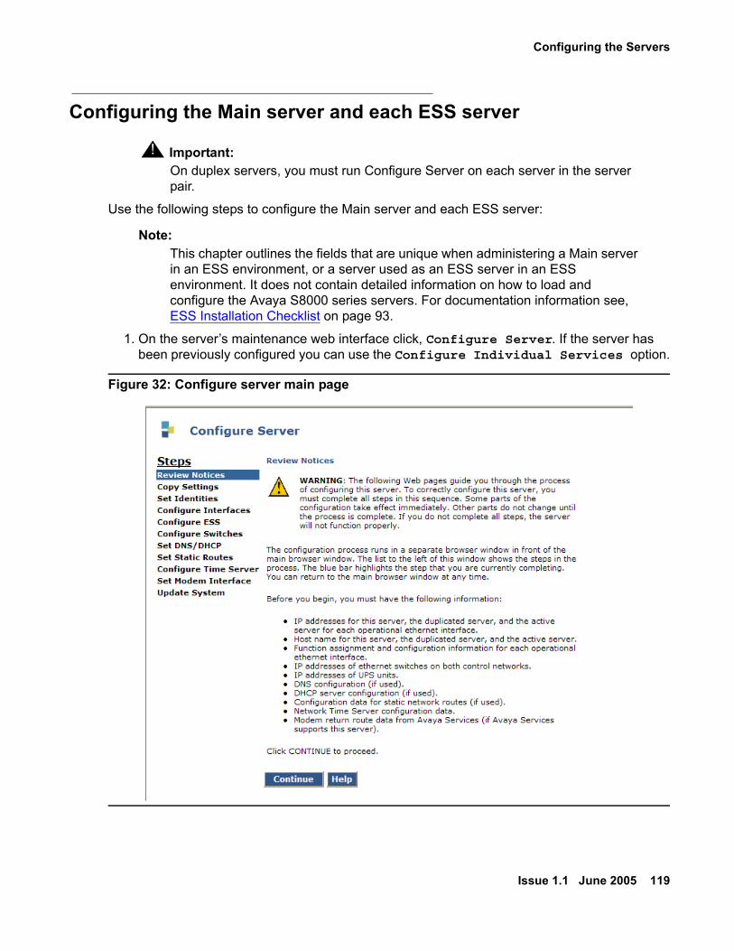
Configuring the Servers
Issue 1.1 June 2005 119
Configuring the Main server and each ESS server
! Important:Important: On duplex servers, you must run Configure Server on each server in the server
pair.
Use the following steps to configure the Main server and each ESS server:
Note:Note: This chapter outlines the fields that are unique when administering a Main server
in an ESS environment, or a server used as an ESS server in an ESS environment. It does not contain detailed information on how to load and configure the Avaya S8000 series servers. For documentation information see, ESS Installation Checklist on page 93.
1. On the server’s maintenance web interface click, Configure Server. If the server has been previously configured you can use the Configure Individual Services option.
Figure 32: Configure server main page

ESS Installation
120 Avaya Enterprise Survivable Servers (ESS) Users Guide
2. On the Set Server Identities web page: Enter the unique Server ID in the ID field (1-99). The ID field can be found to the right of the Host Name field.
You assign a unique Server Identification number (SVID) to each server. The SVID must be in the range of 1 to 99. Each server in a server pair (S8700 series media servers) requires a different SVID. You can assign the SVID sequentially or allow gaps in the numbering such as 10, 20, 30, etc.
Note:Note: Each Server ID in an enterprise must be unique. You will enter the Server ID in
the system-parameters ess form when you administer ESS. You cannot enter duplicate server IDs in this form.
3. On the Configure Enterprise Survivable Server web page:
a. Select the server type:
● For an ESS server select:
- This is an enterprise survivable server with an S8700 series media server as the main server, or
- This is an enterprise survivable server with an S8500 media server as the main server.
● For a Main server select:
- This is NOT an enterprise survivable server, and select Change.
b. For the ESS server, complete the following fields under the section you selected in the previous step (step a):
● Enter the CLAN IP address that will be used when the ESS server registers with the Main server. See CLAN access for ESS registration on page 65 for more information.
● Enter the IP address(es) for the Main server. This IP address(es) will be used for synchronizing the translation file between the Main server and the ESS server.
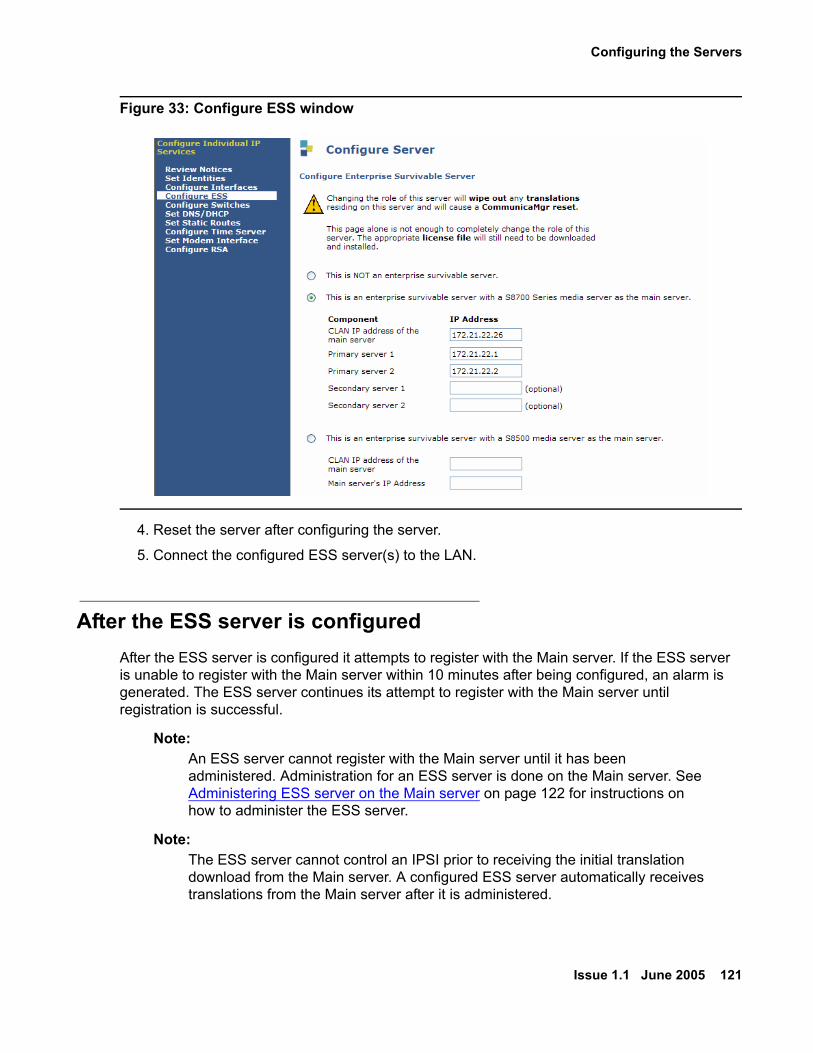
Configuring the Servers
Issue 1.1 June 2005 121
Figure 33: Configure ESS window
4. Reset the server after configuring the server.
5. Connect the configured ESS server(s) to the LAN.
After the ESS server is configuredAfter the ESS server is configured it attempts to register with the Main server. If the ESS server is unable to register with the Main server within 10 minutes after being configured, an alarm is generated. The ESS server continues its attempt to register with the Main server until registration is successful.
Note:Note: An ESS server cannot register with the Main server until it has been
administered. Administration for an ESS server is done on the Main server. See Administering ESS server on the Main server on page 122 for instructions on how to administer the ESS server.
Note:Note: The ESS server cannot control an IPSI prior to receiving the initial translation
download from the Main server. A configured ESS server automatically receives translations from the Main server after it is administered.
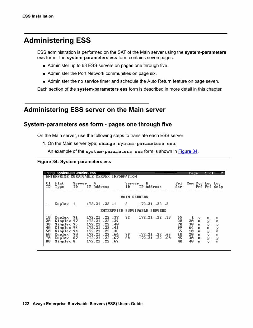
ESS Installation
122 Avaya Enterprise Survivable Servers (ESS) Users Guide
Administering ESSESS administration is performed on the SAT of the Main server using the system-parameters ess form. The system-parameters ess form contains seven pages:
● Administer up to 63 ESS servers on pages one through five.
● Administer the Port Network communities on page six.
● Administer the no service timer and schedule the Auto Return feature on page seven.
Each section of the system-parameters ess form is described in more detail in this chapter.
Administering ESS server on the Main server
System-parameters ess form - pages one through five
On the Main server, use the following steps to translate each ESS server:
1. On the Main server type, change system-parameters ess.
An example of the system-parameters ess form is shown in Figure 34.
Figure 34: System-parameters ess

Administering ESS
Issue 1.1 June 2005 123
2. For each ESS server enter data into the following fields:
a. CLID: Enter the Cluster ID (the MID from the RFA license file) for the ESS server. The MID was assigned by RFA and appears in the license file. Use the following Bash command if you do not know the MID for the ESS server:
statuslicense -v
The MID displays in the RFA Module ID field. An example of the output of the statuslicense -v command is shown in Figure 35.
Figure 35: Statuslicense -v command
b. Platform Type: Possible entries for Platform Type are simplex and duplex. Enter simplex if this server is an S8500 Media Server. Enter duplex if this is an S8700 series media server. If Simplex is entered, you cannot enter data for the B-side server.
c. Server ID: Enter the Server ID (SVID) of the S8500 Media Server, or the SVID of the A-side of the S8700 series media server. This is the SVID that you entered in the Set Server Identities web page when you configured this server (see, Configuring the Servers on page 116).
d. A IP Address: Enter the IP address for the S8500 Media Server or the IP address for the A-side of the S8700 series media server.
e. Server ID (S8700 series media servers only): Enter the SVID for the B-side S8700 series media server. This is the SVID that you entered in the Set Server Identities web page when you configured this server (see, Configuring the Servers on page 116).
f. B IP Address (S8700 series media server only): Enter the IP address for the B-side S8700 series media server.
g. Pri Scr: Enter the Priority Score for this ESS server. A priority value is used to distinguish between ESS servers with the same preference settings, ESS servers with no preference setting, or ESS servers that are not in the same community as the IPSI. For details on how priority values work see, IPSI Priority List on page 71.
The Priority Score can be set from one to 100 points. The default value is one. The value of the priority score and the selected preference, combine to determine the position of the ESS server on the IPSI’s priority list.
ESS Installation
124 Avaya Enterprise Survivable Servers (ESS) Users Guide
h. Community: Enter the Network community number in this field.
A community is a virtual group consisting of an ESS server and one or more Port Networks. Assigning an ESS server to a community associates the ESS server with the IPSI(s) in the Port Network(s) for that community. The Port Networks are assigned to communities on page 6 of the system-parameters ess form (see System-parameters ess form - page six: Assigning Port Networks to Communities on page 125).
If the ESS server is administered with a Local Preferred preference, the ESS server has a higher value within its community than outside its community.
A Local Only server only advertises to the IPSIs within its community and will never appear on any IPSI’s priority list outside its community.
For more information on preferences for ESS servers see, IPSI Priority List on page 71.
Note:Note: It is possible to administer an ESS server as having no preferences and just a
priority score. If all ESS servers where administered in this fashion, the IPSI would prioritize each ESS server based on its priority score only.
i. System Preferred: Use this option when the goal is to keep as much of the system network intact as possible, allowing one ESS server to replace the Main server.
Enter a ’y’ or a ’n’ in this field. If the field is set to ’y’ then the Local Preferred and Local Only column will be ’n’ and cannot be changed. If this field is set to ’n’ then both the Local Preferred and Local Only column can be either a ’n’ or a ’y’. The default for this field is set to ’y’.
A System Preferred server will have a higher value than any other Local Preferred server, independent of community or administered priority value. If multiple System Preferred servers are administered, the server with the highest administered priority value will have the top priority on an IPSI’s list.
For more information on preferences see, IPSI Priority List on page 71.
j. Local Preferred: Use this option when you want the ESS server to accept the request for service from IPSIs co-located in the same geographical region, WAN/LAN segment, district, business unit, etc.
Enter a ’y’ or a ’n’ in this field. The default for this field is set to ’n’.
After the System Preferred preference, the Local Preferred preference has the second highest value within an IPSI community. When multiple Local Preferred servers are administered within the same community, the priority value is used to determine which server will have the higher priority in the IPSI’s list.
For more information on preferences see, IPSI Priority List on page 71.

Administering ESS
Issue 1.1 June 2005 125
k. Local Only: Use this option when you want the ESS server to accept the request for service from an IPSI, only if the IPSI is located in the ESS server’s same community.
Enter a ’y’ or a ’n’ in this field. The default for this field is ’n’.
A Local Only server only advertises to the IPSI within its community. The value of a Local Only server is based solely on its priority value. If a Local Preferred server (outside its administered community), or an ESS server with no preference, advertised to an IPSI in the same community as a Local Only server, the priority score of each server would determine its ranking on the IPSI’s priority list.
Servers set to Local Only can also have the Local Preferred preference set to ’y’. Having both Local Only and the Local Preferred preference set will increase the ESS server’s priority on a local IPSI’s list.
For more information on Local Only ESS servers see, IPSI Priority List on page 71.
Note:Note: You cannot have an ESS server that is administered as both Local Only and
System Preferred.
System-parameters ess form - page six: Assigning Port Networks to Communities
Page six of the system-parameter ess form is used to enter the community assignments for each Port Network. Assigning Port Networks to a community associates the Port Network with an ESS server administered with the Local Preferred or as a Local Only server. An ESS server is assigned a community on pages one through six of the system-parameters ess form. To have the ESS server and the Port Networks in the same community, the community number of the ESS server and the community number for each Port Network must match. See Figure 36 for an example of page six of the system-parameters ess form.
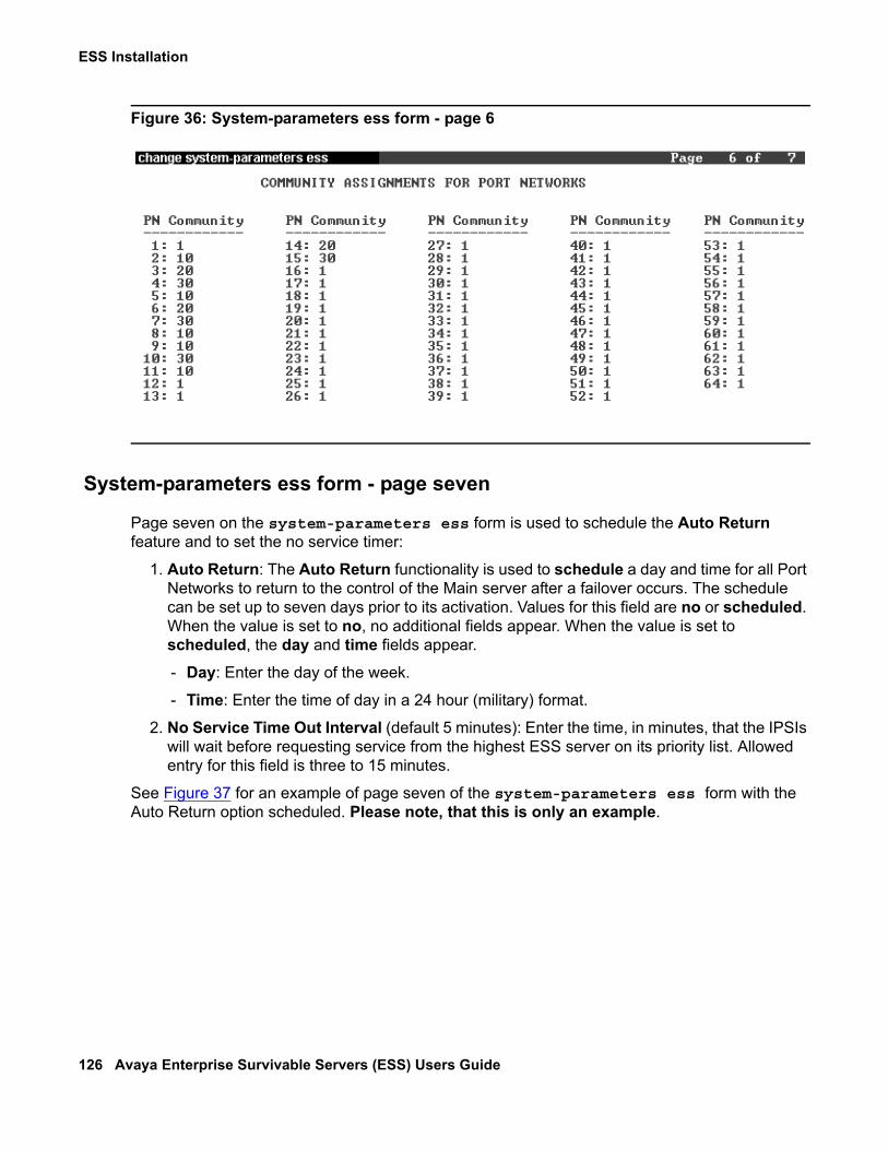
ESS Installation
126 Avaya Enterprise Survivable Servers (ESS) Users Guide
Figure 36: System-parameters ess form - page 6
System-parameters ess form - page seven
Page seven on the system-parameters ess form is used to schedule the Auto Return feature and to set the no service timer:
1. Auto Return: The Auto Return functionality is used to schedule a day and time for all Port Networks to return to the control of the Main server after a failover occurs. The schedule can be set up to seven days prior to its activation. Values for this field are no or scheduled. When the value is set to no, no additional fields appear. When the value is set to scheduled, the day and time fields appear.
- Day: Enter the day of the week.
- Time: Enter the time of day in a 24 hour (military) format.
2. No Service Time Out Interval (default 5 minutes): Enter the time, in minutes, that the IPSIs will wait before requesting service from the highest ESS server on its priority list. Allowed entry for this field is three to 15 minutes.
See Figure 37 for an example of page seven of the system-parameters ess form with the Auto Return option scheduled. Please note, that this is only an example.
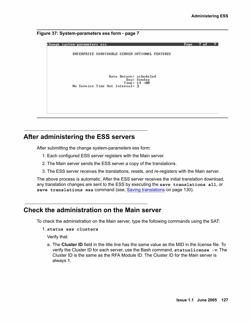
Administering ESS
Issue 1.1 June 2005 127
Figure 37: System-parameters ess form - page 7
After administering the ESS serversAfter submitting the change system-parameters ess form:
1. Each configured ESS server registers with the Main server.
2. The Main server sends the ESS server a copy of the translations.
3. The ESS server receives the translations, resets, and re-registers with the Main server.
The above process is automatic. After the ESS server receives the initial translation download, any translation changes are sent to the ESS by executing the save translations all, or save translations ess command (see, Saving translations on page 130).
Check the administration on the Main serverTo check the administration on the Main server, type the following commands using the SAT:
1. status ess clusters
Verify that:
a. The Cluster ID field in the title line has the same value as the MID in the license file. To verify the Cluster ID for each server, use the Bash command, statuslicense -v. The Cluster ID is the same as the RFA Module ID. The Cluster ID for the Main server is always 1.

ESS Installation
128 Avaya Enterprise Survivable Servers (ESS) Users Guide
b. The Active Server ID field is the Server ID that was entered for this server in the Set Server Identities web page during configuration. For duplex servers, the Active Server ID is active for the pair of servers.
c. The Registered? field is ’y’. If there is a ’n’ in this column, the ESS server is not registered and no data will appear in the Translation Updated or Software Version columns. It may take several minutes for the ESS server to register to the Main server. To troubleshoot the ESS registration see Enterprise Survivable Server - Troubleshooting on page 164.
● The Translations Updated column:
a. For Cluster ID 1 (the Main server): The Translations Updated column correlates with the time of the last successful save translation command.
b. For all other Cluster IDs: The Translations Updated column correlates with the date and time of the last successful translation download from the Main server.
● The Software Version field indicates Communication Manager 3.0 or later.
See Figure 38 for an example of the output of the status ess clusters command.
Figure 38: Status ess clusters
Note:Note: The ESS software version will not appear until the ESS server registers with the
Main server for the first time.
2. display system-parameters ess
Verify that:
● CL ID: This number matches the same value as the MID in the license file.
● Platform Type: This column reads simplex if it is an S8500 Media Server, or duplex if it is an S8700 series media server.
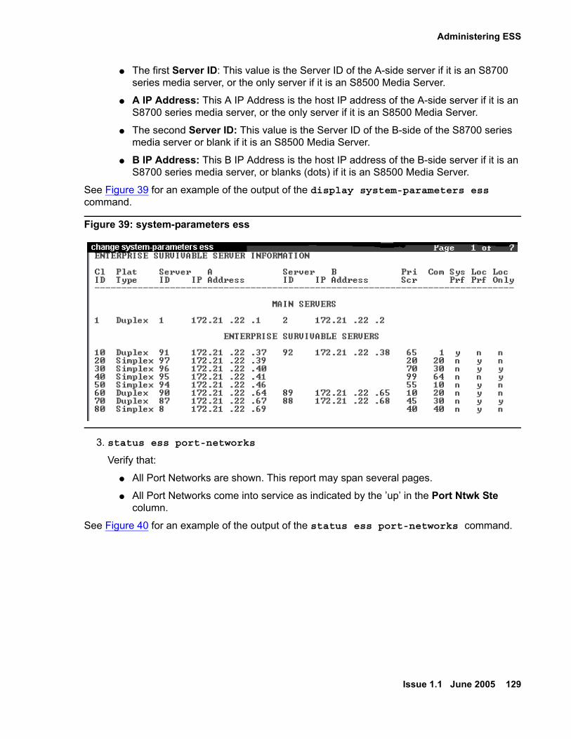
Administering ESS
Issue 1.1 June 2005 129
● The first Server ID: This value is the Server ID of the A-side server if it is an S8700 series media server, or the only server if it is an S8500 Media Server.
● A IP Address: This A IP Address is the host IP address of the A-side server if it is an S8700 series media server, or the only server if it is an S8500 Media Server.
● The second Server ID: This value is the Server ID of the B-side of the S8700 series media server or blank if it is an S8500 Media Server.
● B IP Address: This B IP Address is the host IP address of the B-side server if it is an S8700 series media server, or blanks (dots) if it is an S8500 Media Server.
See Figure 39 for an example of the output of the display system-parameters ess command.
Figure 39: system-parameters ess
3. status ess port-networks
Verify that:
● All Port Networks are shown. This report may span several pages.
● All Port Networks come into service as indicated by the ’up’ in the Port Ntwk Ste column.
See Figure 40 for an example of the output of the status ess port-networks command.

ESS Installation
130 Avaya Enterprise Survivable Servers (ESS) Users Guide
Figure 40: status ess port-networks
Saving translationsTranslations are saved on the Main server by executing the save translations command. You cannot save translations on an ESS server. When logging into an ESS server you receive a message stating that this server is an ESS server and translations cannot be saved.The Main server keeps one complete copy of translations plus the differences between that copy and one previous copy. Each copy has an associated day and time (timestamp). If the ESS server’s translation timestamp matches the timestamp of the Main server’s current translations, no translation download occurs. If the ESS server’s timestamp matches the timestamp of the Main server’s previous copy, the Main server sends only the differences to the ESS server. If the ESS server’s timestamp does not match either of the Main server’s copies, then the Main server sends the entire translation download to the ESS server.Translations are distributed from the Main server to the ESS server by executing the save translations ess or save translations all command. Executing the save translations ess or save translations all command requires network resources and should be performed when impact to the network is minimal. After the ESS server receives the translation download, it resets. The ESS server’s registration to the Main server drops until the reset completes.Saving translations, including sending the translations to the ESS servers, can be performed during routine Communication Manager maintenance. Communication Manager scheduled maintenance is administered on the system-parameters maintenance form. See Figure 41 for an example of the system-parameters maintenance form.

Saving translations
Issue 1.1 June 2005 131
Figure 41: system-parameters maintenance
On the Main server verify that the ESS has received the translations by executing the status ess cluster command. The Translations Updated column contains the day and time (timestamp) of the last successful translation download to each ESS server. After the save translations command executes, the Translations Updated column may take several minutes to update, depending on the size of the translations and network congestion. See Figure 38 for an example of the status ess cluster command.

ESS Installation
132 Avaya Enterprise Survivable Servers (ESS) Users Guide
Basic guidelines for conversions
Issue 1.1 June 2005 133
Chapter 4: Enterprise Survivable Server Conversions
During the evolution of enterprise communication networks, it may be necessary to convert a standard server to an Enterprise Survivable Server (ESS server) or Main server, a Main server to an ESS server, or an ESS server to a Main server.These conversion procedures detail only the specific steps required for the ESS feature. Other steps (such as upgrading, re-mastering, or completely configuring a media server) are found in standard documents that are referenced in this document.These conversion procedures are covered here:
● Existing ESS server to Main server on page 134
● Existing media server to ESS server on page 137
● Manual Backup Server to ESS server on page 140
● ESS server to Manual Backup Server on page 142 (Not Supported)
Basic guidelines for conversions These points may apply to any of the conversion procedures presented here.
1. For any conversion involving both the Main server and the ESS servers, the ESS servers should be addressed first. When they are not controlling Port Networks they may be converted without disrupting service.
2. For any conversion, if possible, disconnect ESS servers from the LAN/WAN until the Main server is operational. Then connect the ESS servers to the LAN/WAN and allow them to register with the Main server.
3. Two Main servers should never be active on the LAN/WAN at the same time. When converting a media server to a Main server, care should be taken to disconnect or power down an existing Main server before the new Main server comes online.
4. When converting media servers, ESS server to Main server, or Main server to ESS server, a new license file is required. There are no exceptions and no way to turn on the required features without a new license file.
5. Each Main server and ESS server requires a unique IPSI serial number in order to generate a license file in RFA. This means that you cannot have more servers requiring licenses (i.e. Main server plus all ESS servers) than there are physical IPSI circuit packs in the system. With high availability (duplex IPSI) systems both active and standby IPSI serial numbers may be used to generate individual license files.
Enterprise Survivable Server Conversions
134 Avaya Enterprise Survivable Servers (ESS) Users Guide
6. All conversion options including the Main server(s) (non ESS server to Main server, ESS server to Main server, and Main server to ESS server) will be service affecting. When Port Networks are controlled by a new media server (Main server or ESS server), they preform a restart which resets every board in the Port Network.
7. IP server interface (IPSI) circuit packs may require a firmware upgrade to be compatible with the ESS feature. See the Minimum Firmware/Hardware Vintages document found at: http://support.avaya.com .
Existing ESS server to Main server Note:
Note: Manual Backup Servers and the Enterprise Survivable Server functionality can not be implemented on the same system.
Note:Note: Do not use this procedure to convert a Manual Backup Server to a Main server.
See Manual Backup Server to ESS server on page 140.
! CAUTION:CAUTION: This procedure is service affecting. Because a new Main server is coming on line,
Port Networks that are being controlled by other servers will eventually get switched to the new Main server. This requires that the Port Networks perform a reset. It may be advantageous to switch all Port Networks to another ESS server, if one exists, during the conversion.
One example of when this procedure might be used is when two or more systems are being combined into one system. An existing Avaya media server could be converted to a Main server while other media servers could be converted to ESS servers.
! Important:Important: If a media server is being converted to replace a previously existing Main server it
must be of the same model as the original.
To convert an existing media server to a Main server:
1. Backup the translations on the media server to be converted. If the existing Main server is still in operation, perform a complete backup. If the existing Main server is not in operation, determine the location of the last known good backup.
2. Verify that the media server to be converted is disconnected from the LAN/WAN.

Existing ESS server to Main server
Issue 1.1 June 2005 135
! CAUTION:CAUTION: Be careful to never have two Main servers connected to the LAN/WAN at the
same time.
3. Confirm that the media server to be converted is running Communication Manager 3.0 or later software.
● On the Maintenance Web Interface click Software Version under the Server heading.
If the media server is not running Communication Manager 3.0 or later software, upgrade the media server(s). See, Upgrading, Migrating, and Converting Media Servers and Gateways, 03-300412 for the procedure to upgrade the media server.
4. If the media server is a duplex pair (S8700 | 8710) busy out the standby server.
5. Install a new license file with the appropriate settings for the Main server. See License files on page 110 for more information. This license file should probably use the same IPSI serial number that the previous license file used unless the media server is physically moved and another IPSI is now logically closer.
The new license file should have the following attributes:
● Enterprise Survivable Server set to n.
● ESS Administration set to Y.
● A Module ID (MID) of 1: The MID is referred to as the Cluster ID (CLID) by the ESS feature. This value is set by the license file and cannot be administered in Communication Manager. Each server in a duplex pair (S8700/S8710) will have the same CLID. A Main server always has the MID of 1.
● A System ID (SID): The SID is unique to the system configuration. The Main server and all ESS servers will have the same SID.
6. Execute this step for S8500 and S8700 | 8710 active media servers.Run the Configure Server command from the Maintenance Web Interface. Select the Configure Individual Services method.
a. Choose - Set Server Identities: - Enter a unique Server ID (SVID) in the ID field. A single SVID is required for a S8500
media server and two unique SVIDs are required for a S8700 | 8710 server pair. This ID must be between 1 and 99. Usually the Main servers are set to SVID 1 and 2.Gaps in the numbering are allowed (10, 20, 30, . . .) but servers may also be consecutively numbered.
- Click Continue and verify the IP Addresses.
b. Choose - Configure ESS from the left margin.
- Select: This is NOT an enterprise survivable server.7. For S8700 | 8710 media server perform the same configuration activities as step 6 for the
standby media server.

Enterprise Survivable Server Conversions
136 Avaya Enterprise Survivable Servers (ESS) Users Guide
8. Configuring the media server via the Maintenance Web Interface causes a reset to be executed. While this is normal, it is not sufficient to notify all of the non Avaya Communication Manager processes of the new Cluster ID. From the active media server command line interface use the following command to notify all processes of the new parameters:
server -z
Then, from the SAT interface on the active media server, execute:
reset system 4.
9. For S8700 | 8710 media servers release the busy out of the standby server using the Release Server command on the Maintenance Web Interface.Wait for the license file to be file synced from the active media server to the standby. This can be verified by using the bash command statuslicense -v repeatedly until the Module ID is updated. Once the Module ID is updated execute:server -z
to inform all processes of the new Module ID.
10. Verify that the new Main server has the latest translations available. If not, restore the translations from the latest backup.
11. Remove the translations for the old Main server. If this is not done the new Main server will alarm when the old Main server does not register. See Administering ESS server on the Main server on page 122 for greater detail.
12. Verify that the correct translations are present for all ESS servers with the change system-parameters ess command.
13. Disconnect, if connected, the old Main server from the LAN/WAN.
14. Connect the new Main server(s) to the LAN/WAN.
15. At any existing ESS server(s), verify that they are connected to the LAN/WAN.
16. At each ESS server specify:
a. The IP address of a CLAN controlled by the new Main server.
b. The IP address(es) of the new Main server.
Changing the address of the Main server on the ESS server does not require a reset system 4, nor does it do one automatically.
For more information see Configuring the Main server and each ESS server on page 119
17. Verify that each ESS server registers with the Main server and translations are updated.
a. status ess clusters Verify that the Main server (this server) is shown and that all ESS servers register and translations are updated. Periodically repeat this command until all ESS servers are registered and updated.
Existing media server to ESS server
Issue 1.1 June 2005 137
Note:Note: An active Main server knows its own state and that of any ESS servers that have
registered with it. For some period of time (minutes), after all servers are installed and configured, there may be a discrepancy between the state displayed by the Main server and the ESS servers.
18. At the Main server execute a save translation ess command to synchronize translations between the new Main server and the ESS servers.
Existing media server to ESS server Note:
Note: Manual Backup Servers and the Enterprise Survivable Server functionality can not be implemented on the same system.
Note:Note: Do not use this procedure to convert a Manual Backup Server to an ESS server.
See Manual Backup Server to ESS server on page 140.
One example of when this procedure might be used is when an existing S8700 Media Server pair is being replaced by an S8710 Media Server pair. The S8700 Media Servers could then be converted to an ESS server.
To convert an existing media server to an ESS server:
1. Backup the translations on the media server to be converted. If the existing media server is still in operation, perform a complete backup. If the existing Main server is not in operation, determine the location of the last known good backup.
2. Verify that the media server to be converted is disconnected from the LAN/WAN.
! CAUTION:CAUTION: Be careful to never have two Main servers connected to the LAN/WAN at the
same time.
3. Confirm that the media server to be converted is running Communication Manager 3.0 or later software.
a. On the Maintenance Web Interface click on Software Version under the Server heading.
If the server is not running Communication Manager 3.0 or later software, upgrade the media server(s). See Upgrading, Migrating, and Converting Media Servers and Gateways, 03-300412 for the procedure to upgrade the media server.
4. If the media server is a duplex pair (S8700 | 8710) busy out the standby server.

Enterprise Survivable Server Conversions
138 Avaya Enterprise Survivable Servers (ESS) Users Guide
5. Install a new license file with the appropriate settings for an ESS server. See License files on page 110 for more information. This license file should probably use the same IPSI serial number that the previous license file used unless the media server is physically moved and another IPSI is now logically closer.
The new license file should have the following attributes:
● Enterprise Survivable Server set to y.
● ESS Administration set to Y.
● A Module ID (MID) greater than 1: A MID is also referred to as the Cluster ID (CLID) by the ESS feature. This value is set by the license file and cannot be administered in Communication Manager. Each server in a duplex pair (S8700/S8710) will have the same CLID.
● A System ID (SID): The SID is unique to the system configuration. The Main server and all ESS servers will have the same SID.
6. Execute this step for S8500 and S8700 | 8710 active media servers.Run the Configure Server command from the Maintenance Web Interface. Select the Configure Individual Services method.
a. Choose - Set Server Identities: ● Enter a unique Server ID (SVID) in the ID field. A single SVID is required for a S8500
media server and two unique SVIDs are required for a S8700 | 8710 server pair. This ID must be between 1 and 99. Usually the Main servers are set to SVID 1 and 2.Gaps in the numbering are allowed (10, 20, 30, . . .) but servers may also be consecutively numbered.
● Click Continue and verify the IP Addresses.
b. Choose - Configure ESS from the left margin.
Select either:
● This is an enterprise survivable server with an S8700/S8710 media server as the main server - When this option is selected enter the IP address of a CLAN that is controlled by
the Main server and the IP address for each of the Main servers.
or
● This is an enterprise survivable server with an S8500 series server as a main server. - When this option is selected enter the IP address of a CLAN that is controlled by
the Main server and the IP address for the Main server.
7. For the S8700 | 8710 media servers perform the same configuration activities as step 6 for the standby media server.

Existing media server to ESS server
Issue 1.1 June 2005 139
8. Configuring the media server via the Maintenance Web Interface will cause a reset to be executed. While this is normal, it is not sufficient to notify all of the non Avaya Communication Manager processes of the new Cluster ID. From the active media server command line interface use the following command to notify all processes of the new parameters:
server -z
Then, from the SAT interface on the active media server, execute:
reset system 4
9. For the S8700 | 8710 media servers, release the busy out of the standby server using the Release Server command on the Maintenance Web Interface.Wait for the license file to be file synced from the active media server to the standby. This can be verified by using the bash command statuslicense -v repeatedly until the Module ID is updated. Once the Module ID is updated execute:server -zto inform all processes of the new Module ID.
10. Verify that the Main server has the latest translations available.
11. Translate the new ESS server on the Main server: From the Main server execute the change system-parameters ess command. See Administering ESS server on the Main server on page 122 for greater detail.
12. Connect the new ESS server(s) to the LAN/WAN.
13. Verify that each ESS server registers with the Main server and translations are updated on the ESS server.
a. Use the status ess clusters command to verify that the Main (this server) is shown and that all ESS servers register and translations are updated. Periodically repeat this command until all ESS servers are registered and updated
Note:Note: A active Main server knows its own state and that of any ESS server that
registers with it. For some period of time (minutes), after all servers are installed and configured, there may be a discrepancy between the state displayed by the Main server and the ESS servers.
14. At the Main server execute the save translation ess command to synchronize translations between the new Main server and the ESS server(s).

Enterprise Survivable Server Conversions
140 Avaya Enterprise Survivable Servers (ESS) Users Guide
Manual Backup Server to ESS server If Manual Backup Servers (MBS) are installed at some locations, they will need to be converted to ESS servers. You cannot use MBS and ESS together in the same configuration. There is only one manual backup server pair installed for each installation.
! CAUTION:CAUTION: Some MBS installations perform manual file transfers (ftp) between the Main
server and MBS servers and a manual restore to keep the MBS up-to-date. This practice must be stopped once the conversion to ESS server is completed. The synchronization of translation data for an ESS server is automatic. Manual file transfers to the ESS server will cause errors.
The following procedure steps may be used to make the conversion. These steps are general in nature. Refer to the specific referenced documents for more detail.
1. Upgrade the existing Main S8700/S8710 servers to Communication Manager 3.0 or later. See Upgrading Software and Firmware - Avaya S8500 Media Server, 555-245-111, or Upgrading Software and Firmware - Avaya S8700 Media Server, 555-245-115.
2. On the Main server install a new license file with the appropriate settings for a Main server. See License files on page 110 for more information.
The new license file should have the following attributes:
● Enterprise Survivable Server set to n.
● ESS Administration set to y.
● A unique Module ID (MID): The MID is referred to as the Cluster ID (CLID) by the ESS feature. The MID of a Main server is always 1 (CLID 1). This value is set by the license file and cannot be administered in Communication Manager. Each server in a duplex pair (S8700/S8710) will have the same MID (CLID).
● A System ID (SID): The SID is unique to the system configuration. The Main server and each ESS server will have the same SID.
3. On the Main server, administer the ESS server in translations. See Administering ESS server on the Main server on page 122.
● change system-parameters ess
4. Disconnect the Manual Backup Server(s) from the WAN/LAN.
5. Re-master the Manual Backup Server(s) with Communication Manager 3.0 or later.
! CAUTION:CAUTION: This is very important, DO NOT upgrade a Manual Backup Server, re-master it.
DO NOT reinstall the Manual Backup Server scripts or the Manual Backup Server cron tasks on the Main server or ESS server.

Manual Backup Server to ESS server
Issue 1.1 June 2005 141
To re-master a MBS server running a 1.x load, use the steps outlined in Upgrading, Migrating, and Converting Media Servers and Gateways located at http:\\support.avaya.com.
To re-master a MBS server running a 2.x load, re-master using the Communication Manager CD. Refer to Installing and Configuring the S8700 Media Server (03-300145), located at http:\\support.avaya.com.
After re-mastering, use steps 6 through 11 to complete the conversion of the MBS to the ESS server.
6. Install a new license file with the appropriate settings for an ESS server. See License files on page 110 for more information.
The license file should have the following attributes:
● Enterprise Survivable Server set to y.
● ESS Administration set to y.
● A unique Module ID (MID): The MID is referred to as the Cluster ID (CLID) by the ESS feature. The MID is set by the license file and cannot be administered in Communication Manager. Each server in a duplex pair (S8700/S8710) will have the same MID (CLID).
● A System ID (SID): The SID is unique to the system configuration. The Main server and each ESS server will have the same SID.
7. Install a new authentication file.
8. Configure the ESS server using the Maintenance Web Interface pages per standard procedures. See Installing and Configuring the S8500 Media Server (03-300143) or Installing and Configuring the S8700 Media Server (03-300145). The specific web pages and fields that are unique to ESS are:● Maintenance Web Interface - Set Server Identities page:
Enter a unique Server ID (SVID) in the ID field. A single SVID is required for a S8500 media server and two unique SVID are required for a S8700 | 8710 server pair. This ID must be between 1 and 99. Gaps in the numbering are allowed (10, 20, 30, . . .) but servers may also be consecutively numbered.
● Maintenance Web Interface - Enterprise Survivable Server page: Select either:● This is an enterprise survivable server with an S8700/S8710 media server as the
main server - When this option is selected enter the IP address of a CLAN that is controlled by
the Main server and the IP address for each of the Main server(s),or● This is an enterprise survivable server with an S8500 series server as a main
server. - When this option is selected enter the IP address of a CLAN that is controlled by
the Main server and the IP address for the Main media server.

Enterprise Survivable Server Conversions
142 Avaya Enterprise Survivable Servers (ESS) Users Guide
9. Configuring the media server using the Maintenance Web Interface causes a reset to be executed. While this is normal, it is not sufficient to notify all of the non Avaya Communication Manager processes of the new Cluster ID. From the active media server command line interface use the following command to notify all processes of the new parameters:
server -z
Then, from the SAT interface on the active media server, execute:
reset system 4
10. Re-connect the new ESS server(s) to the LAN/WAN.
11. On the Main server, verify that the new ESS server(s) register and that translations are updated. Periodically repeat this command until each server registers.
● status ess clusters
Note:Note: An ESS server only knows its own state. For some period of time (minutes) after
an ESS server boots up and connects to the network there may be a discrepancy between the state displayed by the Main server and the ESS server(s).
ESS server to Manual Backup Server This conversion path is not supported.
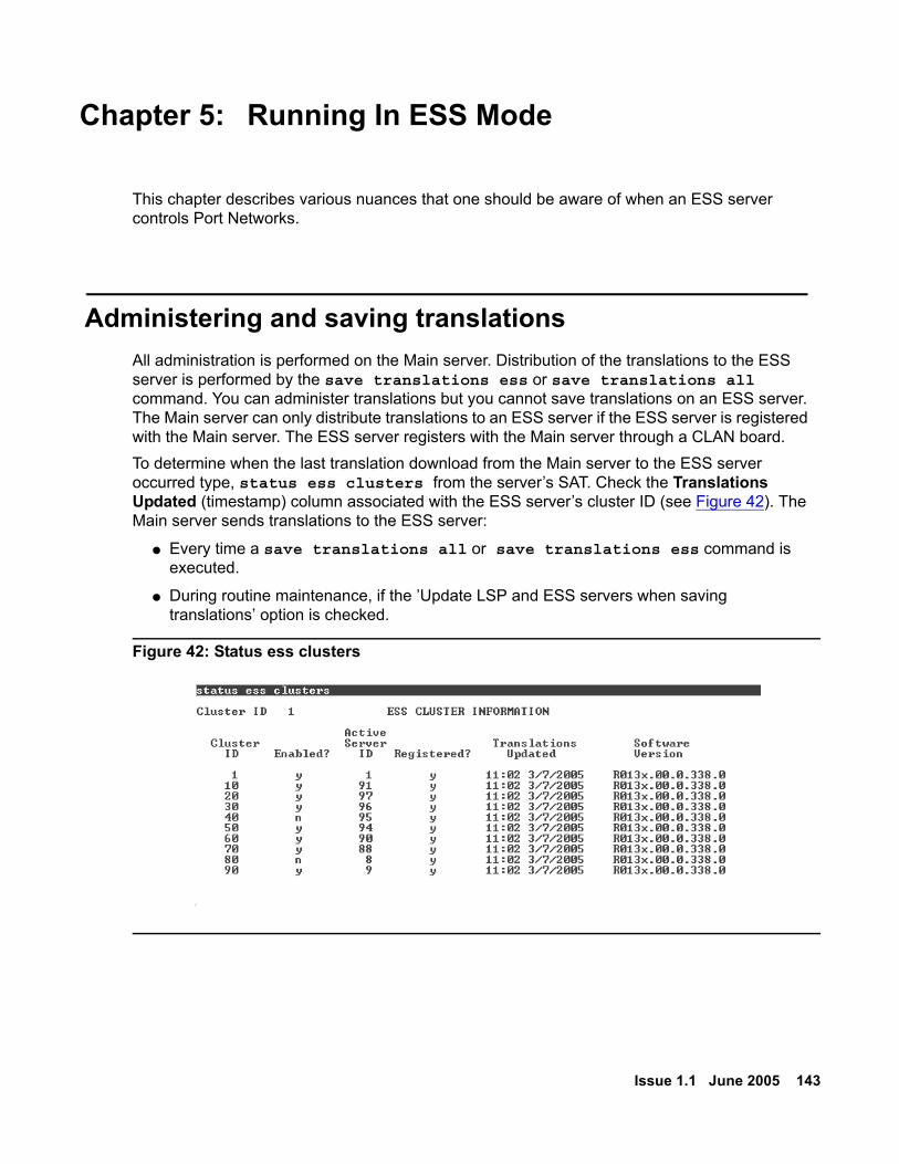
Issue 1.1 June 2005 143
Chapter 5: Running In ESS Mode
This chapter describes various nuances that one should be aware of when an ESS server controls Port Networks.
Administering and saving translationsAll administration is performed on the Main server. Distribution of the translations to the ESS server is performed by the save translations ess or save translations all command. You can administer translations but you cannot save translations on an ESS server. The Main server can only distribute translations to an ESS server if the ESS server is registered with the Main server. The ESS server registers with the Main server through a CLAN board.To determine when the last translation download from the Main server to the ESS server occurred type, status ess clusters from the server’s SAT. Check the Translations Updated (timestamp) column associated with the ESS server’s cluster ID (see Figure 42). The Main server sends translations to the ESS server:
● Every time a save translations all or save translations ess command is executed.
● During routine maintenance, if the ’Update LSP and ESS servers when saving translations’ option is checked.
Figure 42: Status ess clusters

Running In ESS Mode
144 Avaya Enterprise Survivable Servers (ESS) Users Guide
User Enabled telephone featuresUser enabled telephone features, such as call forwarding and send all calls, will be preserved when a failover occurred to an ESS server, if the administered features where captured when translations where saved, and the translations were distributed to the ESS server prior to the failover.When an ESS server controls a Port Network, user enabled telephone features will not be preserved when the system falls back to the Main server. The user enabled feature cannot be saved to translations on an ESS server and the Main server will have no knowledge of the settings.
AlarmingThe Main server generates alarms when it fails over to an ESS server. The following is a partial list of the types of alarms the Main server may generate:
● Port Network alarms: A major alarm is generated for every Port Network that is no longer under the Main server’s control.
● Media Gateway: A major alarm is generated for every media gateway no longer under Main server’s control.
● ATM-EI: A minor alarm is generated for every ATM Expansion Interface board no longer communicating with the Main server.
● CSS-EI: A minor alarm is generated for every CSS Expansion Interface board no longer communicating with the Main server.
● Platform: If the Main server failed over because of a hardware issue.
Until the ESS server controls a Port Network it only produces platform alarms. Once in control of a Port Network, Communication Manager alarms on the ESS server as it would on the Main server. An ESS server alarms when it looses communication with an IPSI unless the ESS server was rejected by the IPSI. The following is a partial list of the types of alarms generated by the ESS server when it obtains control of a Port Network:
● ESS server alarm: A major alarm is generated when the ESS server controls a Port Network. For more information see, ESS (Enterprise Survivable Server) on page 173.
● License-Error: An alarm is generated when the ESS server enters into License-Error mode. An ESS server runs in License-Error mode until it no longer controls a Port Network or until the 30 day timer expires and it enters into a No-License mode.
● No-License: An alarm is generated when the ESS server enters into No-License mode. If the ESS server runs in License-Error mode for 30 days, it enters into a No-License mode.

Unplanned fall-back or failover
Issue 1.1 June 2005 145
Unplanned fall-back or failoverIn some cases an unplanned fall-back to the Main server or an unplanned failover to another ESS server is possible. It is important to understand the circumstances surrounding these situations to prevent unwanted configurations and fragmentation.
Unplanned fall-back to the Main serverThe no service timer activates when an IPSI cannot communicate with the Main server or the controlling ESS server. The no service timer is administered on page seven of the system-parameters ess form. If the fall-back to the Main server was premature, the get forced-takeover ipserver-interface command can be used to pull the Port Networks back to the control of the previous ESS server. For more information on the get forced-takeover ipserver-interface command see, get forced-takeover ipserver-interface on page 152.
! CAUTION:CAUTION: The get forced-takeover ipserver-interface command is service
effecting.
In an environment where there are multiple ESS servers, you can ensure that the Port Networks, controlled by the ESS server, do not fall-back to the Main server by:
● Executing the disable ess command: This command allows an ESS server or Main server to be disabled (taken out of service). An ESS server or Main server may be disabled only if it is not controlling any Port Networks. A disabled ESS server or Main server will not connect to any IPSIs.
This command may be executed from either a Main server or an ESS server. An ESS server may only disable its own cluster ID. When the command is run from the Main server, any and all cluster IDs may be disabled, including the Main server itself.
For more information on the disable ess command see, disable ess on page 147.
● Disconnecting the control network from the Main server: By disconnecting the control network the Main server cannot access the IPSIs.
! CAUTION:CAUTION: Disabling or isolating the Main server is not recommended when only there is
only one ESS server in the configuration. In this case, disabling the Main server would cause a system outage if the ESS server were to fail or if communication between the ESS server and the Port Network(s) was lost.
Running In ESS Mode
146 Avaya Enterprise Survivable Servers (ESS) Users Guide
Unplanned failover to another ESS server A system that failed over to a single ESS server could experience unwanted fragmentation if the IPSI(s) can no longer communicate with the Main server, but can communicate with multiple ESS servers. Due to a temporary network outage, one or more IPSI’s can no longer communicate with the controlling ESS server. In this situation the no service timer activates. If the no service timer expires before the temporary network outage is restored, the IPSI will request service from the next highest ESS server on its priority list. In the resulting configuration, the Port Network(s), experiencing the temporary network outage, is controlled by a different ESS server than the rest of the Port Networks.If the failover to another ESS server causes unwanted fragmentation, the get forced-takeover ipserver-interface command can be used to pull the Port Networks back to the previous ESS server. For more information on the get forcd-takeover ipserver-interface command see, get forced-takeover ipserver-interface on page 152.
! CAUTION:CAUTION: The get forced-takeover ipserver-interface command is service
effecting.
Updating the Main serverBefore bringing a Main server back on-line, check the Main server’s software to make sure it matches the software version running on the ESS server(s). Verify the software version on the ESS server’s web interface. Verify the software version on the Main server. Update the software on the Main server (if necessary).
After a fall-back to the Main serverAfter the Port Networks fall-back to the control of the Main server, and the ESS server no longer controls any Port Networks, the ESS server resets. The reset system 4 is used to clear alarms and busyouts and allow any pending translations to be loaded.
Note:Note: It is possible to download translations to the ESS server while it is controlling a
Port Network. The translations are received by the ESS server but are not loaded as long as the ESS server controls a Port Network. Once the ESS server no longer controls a Port Network, the ESS server resets and loads the new translations.

Enterprise Survivable Servers - Maintenance Commands
Issue 1.1 June 2005 147
Chapter 6: Maintenance
Enterprise Survivable Servers - Maintenance Commands
disable ess S8700 | 8710 / S8500
disable ess [ all | cluster n <1-999> ]
Use disable ess to disable an ESS server or Main server from connecting to IPSIs in Port Networks.
Note:Note: A server cluster is a either a S8500 or S8700 | 8710.
The enabled / disabled status of the ESS server and the Main server(s) is preserved across server power down, restarts, and reboots. If an ESS server or a Main server is controlling any Port Networks (IPSI circuit packs), it may not be disabled. A disabled ESS server or Main server will not connect to any IPSIs. A disabled ESS server remains registered and receives file sync translation updates.Use disable ess from either a Main server or an ESS server. An ESS server may disable only its own cluster ID. When disable ess is run from the Main server, any and all cluster IDs may be disabled including the Main server itself.
! CAUTION:CAUTION: Use caution when using disable ess all. If the Main server is not controlling
any IPSIs it will be disabled disable ess all is used at the Main server. However, because the Main server typically controls IPSIs it is generally safe to use disable ess cluster n to disable only the ESS cluster IDs.
When a Main server or ESS server is disabled it performs a reset system 4 operation. Because a server may not be disabled when it is controlling any Port Networks, this should not cause a service interruption. When the server comes back up it will not attempt to connect to any IPSIs and will not be available for requests for service from any IPSI.When disable ess is run from an ESS server:
● The server resets and no SAT screen results appear.
● Wait for the ESS server to reset and use status ess cluster to confirm that the disable operation succeeded.
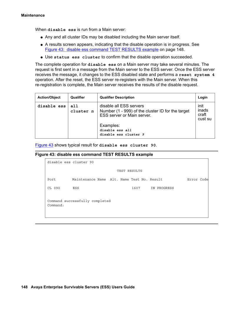
Maintenance
148 Avaya Enterprise Survivable Servers (ESS) Users Guide
When disable ess is run from a Main server:
● Any and all cluster IDs may be disabled including the Main server itself.
● A results screen appears, indicating that the disable operation is in progress. See Figure 43: disable ess command TEST RESULTS example on page 148.
● Use status ess cluster to confirm that the disable operation succeeded.
The complete operation for disable ess on a Main server may take several minutes. The request is first sent in a message from the Main server to the ESS server. Once the ESS server receives the message, it changes to the ESS disabled state and performs a reset system 4 operation. After the reset, the ESS server re-registers with the Main server. When this re-registration is complete, the Main server receives the results of the disable request.
Figure 43 shows typical result for disable ess cluster 90.
Figure 43: disable ess command TEST RESULTS example
Action/Object Qualifier Qualifier Description Login
disable ess allcluster n
disable all ESS serversNumber (1 - 999) of the cluster ID for the target ESS server or Main server.
Examples:disable ess alldisable ess cluster 9
init inads craft cust su
disable ess cluster 90
TEST RESULTS
Port Maintenance Name Alt. Name Test No. Result Error Code
CL 090 ESS 1607 IN PROGRESS
Command successfully completedCommand:
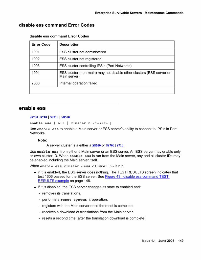
Enterprise Survivable Servers - Maintenance Commands
Issue 1.1 June 2005 149
disable ess command Error Codes
enable ess S8700 | 8710 | S8710 | S8500
enable ess [ all | cluster n <1-999> ]
Use enable ess to enable a Main server or ESS server’s ability to connect to IPSIs in Port Networks.
Note:Note: A server cluster is a either a S8500 or S8700 | 8710.
Use enable ess from either a Main server or an ESS server. An ESS server may enable only its own cluster ID. When enable ess is run from the Main server, any and all cluster IDs may be enabled including the Main server itself.When enable ess cluster <ess cluster n> is run:
● if it is enabled, the ESS server does nothing. The TEST RESULTS screen indicates that test 1606 passed for the ESS server. See Figure 43: disable ess command TEST RESULTS example on page 148.
● if it is disabled, the ESS server changes its state to enabled and:
- removes its translations.
- performs a reset system 4 operation.
- registers with the Main server once the reset is complete.
- receives a download of translations from the Main server.
- resets a second time (after the translation download is complete).
disable ess command Error Codes
Error Code Description
1991 ESS cluster not administered
1992 ESS cluster not registered
1993 ESS cluster controlling IPSIs (Port Networks)
1994 ESS cluster (non-main) may not disable other clusters (ESS server or Main server)
2500 Internal operation failed

Maintenance
150 Avaya Enterprise Survivable Servers (ESS) Users Guide
- re-registers with the Main server once the second reset is complete.
- establishes socket connections to the IPSIs in the configuration.
- advertises its administered values to all IPSIs in the configuration.
At this point the Main server receives the enabled/disabled status of the ESS server.
Tip:Tip: Use status ess cluster n to check if the enable operation succeeded. The
complete enable operation may take several minutes to complete.
When enable ess cluster <main cluster n> is run, the Main server:
● Does nothing, if it is the ESS cluster is already enabled. The TEST RESULTS screen indicates that Test 1606 passed for the Main server. See Figure 44: enable ess command TEST RESULTS example on page 151.
● Changes its state to enabled (if the ESS cluster is disabled) and:
- Performs a reset system 4 operation.
- Establishes socket connections to the IPSIs in the configuration.
- Advertises its administered values to all IPSIs in the configuration.
The following display shows typical result for enable ess all.
Action/Object Qualifier Qualifier Description Login
enable ess allcluster n
enable all ESS serversNumber (1 - 999) of the cluster ID for the target ESS server or Main server.
Examples:enable ess allenable ess cluster 9
init inads craft cust su

Enterprise Survivable Servers - Maintenance Commands
Issue 1.1 June 2005 151
Figure 44: enable ess command TEST RESULTS example
enable ess command Error Codes
enable ess all TEST RESULTS
Port Maintenance Name Alt. Name Test No. Result Error Code
CL 001 ESS 1606 PASS CL 009 ESS 1606 IN PROGRESS CL 013 ESS 1606 IN PROGRESS CL 044 ESS 1606 PASSCL 064 ESS 1606 IN PROGRESS CL 100 ESS 1606 IN PROGRESS CL 200 ESS 1606 IN PROGRESS CL 306 ESS 1606 IN PROGRESS CL 500 ESS 1606 IN PROGRESS CL 850 ESS 1606 IN PROGRESS
Command successfully completed
enable ess command Error Codes
Error Code Description
1991 ESS cluster not administered
1992 ESS cluster not registered
1993 ESS cluster controlling IPSIs (Port Networks)
1994 ESS cluster (non-main) may not disable other clusters (ESS server or Main server)
2500 Internal operation failed

Maintenance
152 Avaya Enterprise Survivable Servers (ESS) Users Guide
get forced-takeover ipserver-interface S8700 | 8710 | S8710 | S8500 get forced-takeover ipserver-interface [ all | port-network n <1 - 64>]
! CAUTION:CAUTION: Moving a Port Network from one server to another causes a level two reset of the
Port Network. This resets every board in the Port Network and drops any established calls carried by the Port Network. Shuffled IP calls are not dropped but during the reset they will not have access to any features such as Hold, Transfer, Conference, etc.
Use get forced-takeover ipserver-interface to give an ESS server or Main server the capability to manually take control of IPSI Port Networks. Run get forced-takeover ipserver-interface from the Main server or ESS server that intends to take control of a Port Network.
● If the Port Network targeted by get forced-takeover ipserver-interface is already controlled by the Main server or ESS server where the command is issued, Test #1605 will immediately PASS.
● If the Port Network is not controlled by the Main server or ESS server where get forced-takeover ipserver-interface is issued the ESS server shows the test result as IN PROGRESS.
Use status ess port-networks or list ipserver-interface to verify that the get forced-takeover ipserver-interface command was successful.
The following example shows a typical result for get forced-takeover ipserver-interface all.
Action/Object Qualifier Qualifier Description Login
get forced-takeover ipserver-interface
all
port-network n
Force a manual takeover of all IPSI PNs
Force a manual takeover of the Port Network number
Examples:get forced-takeover ipserver-interface all
get forced-takeover ipserver-interface port-network 9
init inads craft cust su

Enterprise Survivable Servers - Maintenance Commands
Issue 1.1 June 2005 153
Figure 45: get forced-takeover ipserver-interface all command example
get forced-takeover ipserver-interface command Error Codes
status ess clusters S8700 | 8710 / S8500 status ess clusters
Note:Note: A server cluster is a either a S8500 or S8700 | 8710.
get forced-takeover ipserver-interface all
TEST RESULTS
Port Maintenance Name Alt. Name Test No. Result Error Code
PN 01 IPSV-CTL 1605 PASS PN 02 IPSV-CTL 1605 IN PROGRESS PN 03 IPSV-CTL 1605 IN PROGRESS PN 04 IPSV-CTL 1605 IN PROGRESS
Command successfully completed
get forced-takeover ipserver-interface command Error Codes
Error Code Description
1995 ESS cluster is disabled
1996 Port network does not exist
1997 Not an IPSI port network
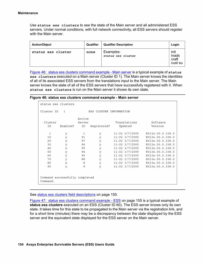
Maintenance
154 Avaya Enterprise Survivable Servers (ESS) Users Guide
Use status ess clusters to see the state of the Main server and all administered ESS servers. Under normal conditions, with full network connectivity, all ESS servers should register with the Main server.
Figure 46: status ess clusters command example - Main server is a typical example of status ess clusters executed on a Main server (Cluster ID 1). The Main server knows the identities of all of its associated ESS servers from the translations input to the Main server. The Main server knows the state of all of the ESS servers that have successfully registered with it. When status ess clusters is run on the Main server it shows its own state.
Figure 46: status ess clusters command example - Main server
See status ess clusters field descriptions on page 155.Figure 47: status ess clusters command example - ESS on page 155 is a typical example of status ess clusters executed on an ESS (Cluster ID 60). The ESS server knows only its own state. It takes time for this state to be propagated to the Main server via the registration link, and for a short time (minutes) there may be a discrepancy between the state displayed by the ESS server and the equivalent state displayed for the ESS server on the Main server.
Action/Object Qualifier Qualifier Description Login
status ess cluster none Examples:status ess cluster
init inads craft cust su
status ess clusters
Cluster ID 1 ESS CLUSTER INFORMATION
Active Cluster Server Translations Software ID Enabled? ID Registered? Updated Version
1 y 1 y 11:02 3/7/2005 R013x.00.0.338.0 10 y 91 y 11:02 3/7/2005 R013x.00.0.338.0 20 y 97 y 11:02 3/7/2005 R013x.00.0.338.0 30 y 96 y 11:02 3/7/2005 R013x.00.0.338.0 40 n 95 y 11:02 3/7/2005 R013x.00.0.338.0 50 y 94 y 11:02 3/7/2005 R013x.00.0.338.0 60 y 90 y 11:02 3/7/2005 R013x.00.0.338.0 70 y 88 y 11:02 3/7/2005 R013x.00.0.338.0 80 n 8 y 11:02 3/7/2005 R013x.00.0.338.0 90 y 9 y 11:02 3/7/2005 R013x.00.0.338.0
Command successfully completedCommand:
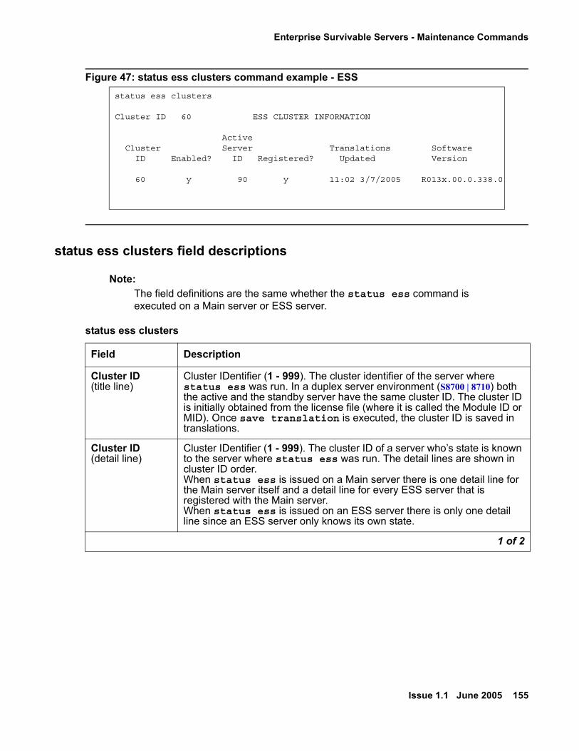
Enterprise Survivable Servers - Maintenance Commands
Issue 1.1 June 2005 155
Figure 47: status ess clusters command example - ESS
status ess clusters field descriptions
Note:Note: The field definitions are the same whether the status ess command is
executed on a Main server or ESS server.
status ess clusters
Cluster ID 60 ESS CLUSTER INFORMATION
Active Cluster Server Translations Software ID Enabled? ID Registered? Updated Version
60 y 90 y 11:02 3/7/2005 R013x.00.0.338.0
status ess clusters
Field Description
Cluster ID (title line)
Cluster IDentifier (1 - 999). The cluster identifier of the server where status ess was run. In a duplex server environment (S8700 | 8710) both the active and the standby server have the same cluster ID. The cluster ID is initially obtained from the license file (where it is called the Module ID or MID). Once save translation is executed, the cluster ID is saved in translations.
Cluster ID (detail line)
Cluster IDentifier (1 - 999). The cluster ID of a server who’s state is known to the server where status ess was run. The detail lines are shown in cluster ID order.When status ess is issued on a Main server there is one detail line for the Main server itself and a detail line for every ESS server that is registered with the Main server. When status ess is issued on an ESS server there is only one detail line since an ESS server only knows its own state.
1 of 2

Maintenance
156 Avaya Enterprise Survivable Servers (ESS) Users Guide
Enabled The ESS server enabled / disabled state of the server. ● y = enabled. This server will connect to administered IPSIs● n = disabled. This server will not connect to administered IPSIs● unknown = the Main server does not yet know the maintenance
state of the ESS server. This may be because:- The ESS server is not registered with the Main server- The ESS server has not yet acknowledged a maintenance state
change request from the Main server via an enable ess or disable ess command
Active Server ID The server identifier of the active server for each cluster, ESS server or Main server:(1 - 99).
● If the server is a simplex configuration (S8500) there is only one Server IDentifier.
● If the server is a duplex configurations (S8700 | 8710) the A and B servers each have unique server identifiers. Because in a duplex configuration only the active server registers with the Main server, only its server identifier is displayed. Only server IDs for registered ESS servers are displayed.
Registered The registration state of the server.● y = registered● n = not registered
The Main server does not register with itself, but always displays its own registration as y.
Translations Updated
For an ESS server:● The time and date stamp of the latest translation update reported by
the ESS server to the Main server over the registration link. For a Main server:
● This is the time and date stamp of the latest successful save translation command of any kind.
Note:Note: For a Main server this time stamp may be later than those
shown for ESS servers. A save translation on the Main server updates its time stamp. A save translation [ess | all] updates the ESS server translations and time stamp.
Software Version
The software version of Avaya Communication Manager running on the server. For an ESS server, this is reported to the Main server over the registration link.
status ess clusters (continued)
Field Description
2 of 2

Enterprise Survivable Servers - Maintenance Commands
Issue 1.1 June 2005 157
status ess port-networks S8700 | 8710 / S8500
status ess port-networks
Use status ess port-networks to see the status of all administered Port Networks on ESS and non-ESS systems.
● For ESS servers and Main servers, on IP Port Network Connectivity (PNC) and Asynchronous Transfer Mode (ATM) PNC systems, status ess port-networks shows the status of all of the administered Port Networks.
● For Center Stage Switch (CSS) PNC systems, only the IPSI equipped Port Networks are known to the ESS server, because only the Main server has access to the CSS. The information displayed is very dynamic and may, for brief periods, appear inconsistent.
Figure 48: status ess port-networks on page 158 is an example of status ess port-networks executed on a server that is controlling five Port Networks in a system. This server is a Main server, but other than the cluster identifier, the display looks exactly the same for an ESS server controlling all five Port Networks. In addition to the Main server, seven other ESS servers are connected to each IPSI in every Port Network. Each IPSI may be connected to the same, some of the same, or completely different servers.
Action/Object Qualifier Qualifier Description Login
status ess port-networks Example:status ess port-networks
init inads craft cust su
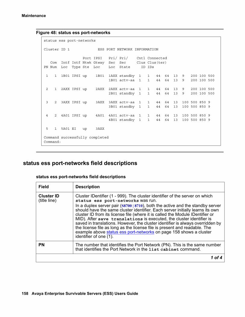
Maintenance
158 Avaya Enterprise Survivable Servers (ESS) Users Guide
Figure 48: status ess port-networks
status ess port-networks field descriptions
status ess port-networks
Cluster ID 1 ESS PORT NETWORK INFORMATION
Port IPSI Pri/ Pri/ Cntl Connected Com Intf Intf Ntwk Gtway Sec Sec Clus Clus(ter)PN Num Loc Type Ste Loc Loc State ID IDs
1 1 1B01 IPSI up 1B01 1AXX standby 1 1 44 64 13 9 200 100 500 1B01 actv-aa 1 1 44 64 13 9 200 100 500 2 1 2AXX IPSI up 2AXX 2AXX actv-aa 1 1 44 64 13 9 200 100 500 2B01 standby 1 1 44 64 13 9 200 100 500 3 2 3AXX IPSI up 3AXX 3AXX actv-aa 1 1 44 64 13 100 500 850 9 3B01 standby 1 1 44 64 13 100 500 850 9 4 2 4A01 IPSI up 4A01 4A01 actv-aa 1 1 44 64 13 100 500 850 9 4B01 standby 1 1 44 64 13 100 500 850 9 5 1 5A01 EI up 3AXX
Command successfully completed Command:
status ess port-networks field descriptions
Field Description
Cluster ID (title line)
Cluster IDentifier (1 - 999). The cluster identifier of the server on which status ess port-networks was run.In a duplex server pair (S8700 | 8710), both the active and the standby server should have the same cluster identifier. Each server initially learns its own cluster ID from its license file (where it is called the Module IDentifier or MID). After save translations is executed, the cluster identifier is saved in translations. However, the cluster identifier is always overridden by the license file as long as the license file is present and readable. The example above status ess port-networks on page 158 shows a cluster identifier of one (1).
PN The number that identifies the Port Network (PN). This is the same number that identifies the Port Network in the list cabinet command.
1 of 4

Enterprise Survivable Servers - Maintenance Commands
Issue 1.1 June 2005 159
Com Num The community number of the Port Network (1 - 64) assigned to the Port Network on display system-paramters. Port networks have a natural attraction for local preferred media servers in the same community. In the event of loss of connectivity with their server, they prefer to be controlled by a server in their community if possible.
Intf Loc Interface Location. Board location of the most recent interface in the Port Network with which the system tried to control the Port Network. The interface may be any circuit pack through which the Port Network may be controlled, such as a TN2312 IP Server Interface (IPSI), a TN2305B or TN2306B ATM Expansion Interface (ATM EI), or a TN570D Expansion Interface (CSS EI):
● blank = there is no interface
Intf Type The type of interface whose location is shown in the Intf Loc field:● IPSI = IP Server Interface ● EI = either type of Expansion Interface (TN570 or TN2305/2306)● UNKN = the interface type cannot be determined● blank = there is no interface
Port Ntwk Ste The Port Network state from the point of view of the server on which status ess port-networks is run:
● up = the Port Network is up● down = the Port Network is down● unkn = the state is unknown ● blank = there is no Port Network state
The Port Network is up from the perspective of the media server that is controlling the Port Network. The Port Network is down from the perspective of all other media servers.
IPSI Gtway Loc IPSI Gateway Location. The location of the IPSI whose Packet Interface (PKTINT) is being used to deliver packet traffic to the packet bus in this Port Network. The IPSI may be in this Port Network (this location is the same as Intf Loc), or it may be in a different Port Network.
Pri / Sec Loc The location of the Primary and Secondary IP Server Interface (if any) in this Port Network.
● If the Port Network has a single IPSI, only one line is displayed.● If the Port Network has duplicated IPSIs equipped, each is displayed
on successive lines. ● blank = the Port Network has only an Expansion Interface from which
it is controlled
status ess port-networks field descriptions (continued)
Field Description
2 of 4
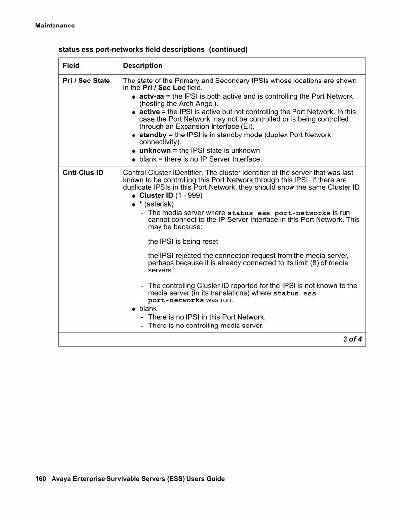
Maintenance
160 Avaya Enterprise Survivable Servers (ESS) Users Guide
Pri / Sec State The state of the Primary and Secondary IPSIs whose locations are shown in the Pri / Sec Loc field.
● actv-aa = the IPSI is both active and is controlling the Port Network (hosting the Arch Angel).
● active = the IPSI is active but not controlling the Port Network. In this case the Port Network may not be controlled or is being controlled through an Expansion Interface (EI).
● standby = the IPSI is in standby mode (duplex Port Network connectivity).
● unknown = the IPSI state is unknown● blank = there is no IP Server Interface.
Cntl Clus ID Control Cluster IDentifier. The cluster identifier of the server that was last known to be controlling this Port Network through this IPSI. If there are duplicate IPSIs in this Port Network, they should show the same Cluster ID
● Cluster ID (1 - 999)● * (asterisk)
- The media server where status ess port-networks is run cannot connect to the IP Server Interface in this Port Network. This may be because:
the IPSI is being reset
the IPSI rejected the connection request from the media server, perhaps because it is already connected to its limit (8) of media servers.
- The controlling Cluster ID reported for the IPSI is not known to the media server (in its translations) where status ess port-networks was run.
● blank - There is no IPSI in this Port Network.- There is no controlling media server.
status ess port-networks field descriptions (continued)
Field Description
3 of 4

Enterprise Survivable Servers - Maintenance Commands
Issue 1.1 June 2005 161
cnc [on | off | status] Use the Linux bash command cnc to enable, disable, or status Control Network C on S8700 | 8710 series media servers.
! CAUTION:CAUTION: If Control Network C is enabled, executing configure server from the
Maintenance Web Interface disables Control Network C. Execute the bash command cnc on again to enable Control Network C.
Control Network C uses the customer LAN for control signaling to TN2312 IPSI circuit packs on IP-Connected Port Networks. Control Network C is used when Control Networks A and B are administered as duplicated control networks to a Direct, CSS, or ATM connected Port Network configuration.
Connected Clus(ter) IDs
Connected Cluster IDentifiers. The list of cluster identifiers that were last known to be connected to this IP Server Interface.These media servers are candidates to control the Port Network through the IPSI should connectivity to the current controlling media server be lost. If a media server was rejected by an IPSI, the information displayed here may be stale. This information will be updated periodically as each media server attempts to connect, or reconnect, to the IPSI. The Cluster ID of the controlling media server should always be displayed in the list of Cluster IDs.
● Cluster ID (1 - 999)● * (asterisk)
- The Cluster ID reported by the IPSI is not known to the media server (in its translations) where status ess port-network was executed.
● blank
- There is no IPSI in this Port Network.
- There is no controlling media server.
status ess port-networks field descriptions (continued)
Field Description
4 of 4
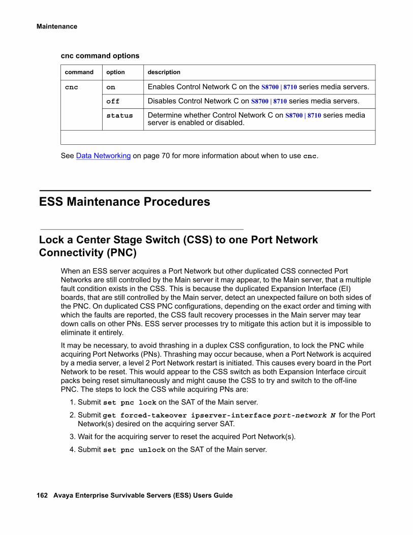
Maintenance
162 Avaya Enterprise Survivable Servers (ESS) Users Guide
See Data Networking on page 70 for more information about when to use cnc.
ESS Maintenance Procedures
Lock a Center Stage Switch (CSS) to one Port Network Connectivity (PNC)
When an ESS server acquires a Port Network but other duplicated CSS connected Port Networks are still controlled by the Main server it may appear, to the Main server, that a multiple fault condition exists in the CSS. This is because the duplicated Expansion Interface (EI) boards, that are still controlled by the Main server, detect an unexpected failure on both sides of the PNC. On duplicated CSS PNC configurations, depending on the exact order and timing with which the faults are reported, the CSS fault recovery processes in the Main server may tear down calls on other PNs. ESS server processes try to mitigate this action but it is impossible to eliminate it entirely.
It may be necessary, to avoid thrashing in a duplex CSS configuration, to lock the PNC while acquiring Port Networks (PNs). Thrashing may occur because, when a Port Network is acquired by a media server, a level 2 Port Network restart is initiated. This causes every board in the Port Network to be reset. This would appear to the CSS switch as both Expansion Interface circuit packs being reset simultaneously and might cause the CSS to try and switch to the off-line PNC. The steps to lock the CSS while acquiring PNs are:
1. Submit set pnc lock on the SAT of the Main server.
2. Submit get forced-takeover ipserver-interface port-network N for the Port Network(s) desired on the acquiring server SAT.
3. Wait for the acquiring server to reset the acquired Port Network(s).
4. Submit set pnc unlock on the SAT of the Main server.
cnc command options
command option description
cnc on Enables Control Network C on the S8700 | 8710 series media servers.
off Disables Control Network C on S8700 | 8710 series media servers.
status Determine whether Control Network C on S8700 | 8710 series media server is enabled or disabled.

ESS Maintenance Procedures
Issue 1.1 June 2005 163
Removing an ESS It may be necessary to remove an ESS server from service. The following steps can be used to do this.
1. At the Main server issue the status ess port-networks command to verify that the ESS server is not controlling any Port Networks. If the ESS server to be removed is controlling Port Networks they must be moved to another media server before removing the ESS server.
2. At the ESS server issue the disable ESS cluster N command where N is the Cluster ID of the ESS server to be removed.
3. At the Main server issue the status ess clusters command to verify that the ESS server to be removed is disabled.
4. At the Main server issue the change system-paramters ess command and remove (blank) the information for the ESS server.
5. At the ESS server, on the standby media server if duplicated, use the Maintenance Web Interface to issue a Shutdown Server command to gracefully shut down.
6. At the ESS server, on the active media server use the Maintenance Web Interface to issue a Shutdown Server command to gracefully shut down.
Checking ESS status It may be advantageous to periodically check the status of the ESS server installation. The following steps can be used to do this.
1. At the Main server issue the status ess cluster command. Verify that:
● The Main server and each ESS server is enabled
● The Main server and each ESS server is registered
● Each ESS server has current translations.
It is possible, even likely, that the Main server will have a Translations Updated timestamp that is more recent than that of the ESS servers. This is because the Main server timestamp is updated every time any save translation [ess, lsp, or all] command is issued at the Main server. Translations are only updated on the ESS servers when a save translation ess, or save translation all command is issued at the Main server.
Use the display system-parameters maintenance SAT command to verify that translations are updated for ESS servers on a routine basis.
Maintenance
164 Avaya Enterprise Survivable Servers (ESS) Users Guide
2. At the Main server issue the status ess port-networks SAT command. Verify that:
● The Port Network State for all Port Networks is up.
● All Port Networks are controlled by the Main server (Cluster ID 1).
● The Connected Cluster IDs are as expected considering the ESS design.
If the Interface Type is EI or UNKN all fields to the right of IPSI Gateway Location will be blank.
The Connected Cluster IDs are displayed in priority order with the highest priority cluster, usually the Main server, on the left.
Enterprise Survivable Server - Troubleshooting
GeneralAt times it may be necessary to troubleshoot aspects of the Enterprise Survivable Server implementation. In order to determine what might be causing a fault it is important to understand the layout and topology of the network, where ESS servers are logically located on the network, and the intent of the design in case of a failure. This information is best obtained from the implementation team or the final customer. It is possible to determine how a particular ESS installation is translated and from this make reasonable predictions as to how the installation will react to server and/or network failures. However, keep in mind that the way the various components are configured and translated may not reflect the original intention of the network design. Commands that can be used to verify ESS server translations are:
● disp system-parameters ess on the Main server to determine all translated ESS servers.
● status ess clusters to determine which clusters are enabled, when translations were last updated, what software release that the Main server and ESS servers are are running. The ESS servers can be on a later release than the Main server but the Main server should never be on a later release than the ESS servers. The software release should only be different when upgrades are being performed, ESS servers first and then the Main server.
● status ess port-networks to display which Cluster ID is controling each Port Network and which ESS server(s) the Port Networks (IPSIs) have on their priority lists.

Enterprise Survivable Server - Troubleshooting
Issue 1.1 June 2005 165
Maintenance Web Interface commands that can be used to verify ESS server configuration are:
● Configure Server > configure ess: Used to specify whether the server is a Main server or an ESS server. If it is an ESS server specify an address for a CLAN and the Main server(s).
● Configure Server > Set Identities: Used to set the Server IDs of the individual servers.
Registration
ESS server is not registered with the Main server
During normal operation an ESS server registers with the Main server. Under normal conditions an ESS server may not register with the Main server if the ESS server is resetting. The ESS server resets when it receives a new translation file or when it is first enabled. This should be a temporary condition.
See the Maintenance Object ESS (Enterprise Survivable Server) on page 173 for errors related to ESS server registration. Error 257 should be logged when an ESS server is administered on the Main server but is not registered. On the Main server, use the following list of commands to troubleshoot an ESS server that is not registering with the Main server:
1. Use the display system-parameters ess to verify that the ESS server is properly administered. An ESS server must be administered on the Main server before it can register with the Main server. Record these values for use when troubleshooting.
2. Use the SAT ping ip-address board <location> nnn.nnn.nnn.nnn command to verify connectivity between the Main server and the ESS server. Where, <location> is the location of the CLAN board the ESS server is trying to register with and nnn.nnn.nnn.nnn is the IP address of the ESS server.
3. Use the display events command with a category of denial to display denial events related to ESS. The ESS registration denial events are in the 36xx range. See Maintenance Alarms for Avaya Communication Manager 3.0, Media Gateways and Servers. 03-300430 for descriptions of individual ESS denial events.
4. Use the list trace ras ip-address command to monitor registration requests from the ESS server. This command will display registration requests from the ESS server and the associated response from the Main server. Note that under normal operation a Keep Alive (KA) message is periodically sent from the ESS server to the Main server. This should not be confused with a registration failure.
Maintenance
166 Avaya Enterprise Survivable Servers (ESS) Users Guide
At the ESS server that is not registering with the Main server, use the following commands to troubleshoot:
! CAUTION:CAUTION: In the next steps be careful to use the Close Window button to cancel out of the
Configure Server page to avoid a reboot of the ESS server. Do not Update the system.
1. Use the bash ping nnn.nnn.nnn.nnn command to verify connectivity between the ESS server and Main servers. Where nnn.nnn.nnn.nnn is IP address of the CLAN in the Main server that the ESS server is trying to register with. To determine which IP address the ESS server is attempting to register with use the Configure Server command from the Maintenance Web Interface on the ESS server to display the Configure ESS screen.
2. Firewalls or other security measures may preclude the Main server and ESS server from communicating. Verify that these ports are open through the network between the Main server and the ESS server:
● 1719 Registration between the ESS server and the Main server.
● 21874 Filesync (rsync) between the Main server and ESS server.
3. On the Maintenance WEB Interface Configure Server pages:
● Verify on the Set Identities page that the correct Server ID (SVID) is entered. This should be a unique value for each server. The SVID must be between 1 and 99. Gaps in the SVIDs for a configuration are allowed but the servers may be consecutively numbered if desired. Each server in the system, duplex or simplex, Main server or ESS server, requires a unique SVID.
● Verify on the Configure ESS page that the correct platform type (8700/8710 or 8500) is selected and the correct CLAN and Main server’s IP addresses are entered. The ESS server will use these addresses to establish a connection with the Main server and register. See step 1 above.
● On the Status Summary page verify that the Cluster ID is correct. Verify that the individual server IDs are correct.
Note:Note: Note: The individual server IDs should be the same as entered on the Set
Identities page of the Configure Server procedure.
4. On the SAT execute the display system-parameters customer-options command.
● Verify that the ESS Administration field is set to y.
● Verify that the Enterprise Survivable Server field is set to y.
Tip:Tip: Customer options may only be set with the Avaya license file. If the fields above
are incorrect obtain a new license file with corrected data.
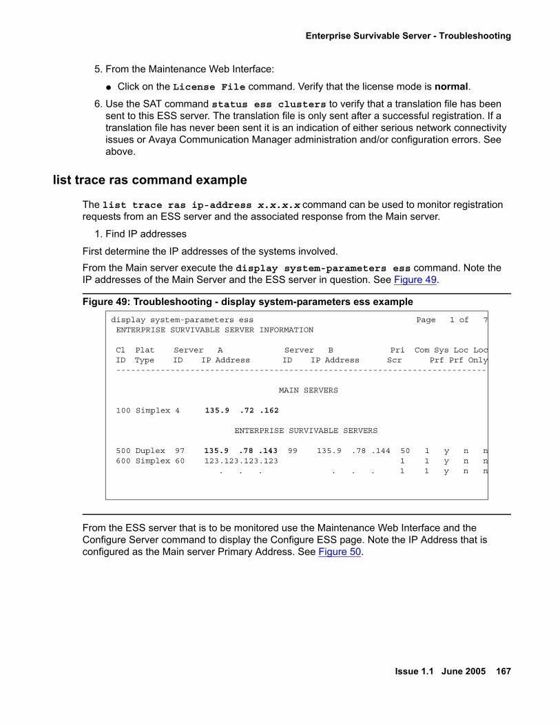
Enterprise Survivable Server - Troubleshooting
Issue 1.1 June 2005 167
5. From the Maintenance Web Interface:
● Click on the License File command. Verify that the license mode is normal.6. Use the SAT command status ess clusters to verify that a translation file has been
sent to this ESS server. The translation file is only sent after a successful registration. If a translation file has never been sent it is an indication of either serious network connectivity issues or Avaya Communication Manager administration and/or configuration errors. See above.
list trace ras command example
The list trace ras ip-address x.x.x.x command can be used to monitor registration requests from an ESS server and the associated response from the Main server.
1. Find IP addresses
First determine the IP addresses of the systems involved.From the Main server execute the display system-parameters ess command. Note the IP addresses of the Main Server and the ESS server in question. See Figure 49.
Figure 49: Troubleshooting - display system-parameters ess example
From the ESS server that is to be monitored use the Maintenance Web Interface and the Configure Server command to display the Configure ESS page. Note the IP Address that is configured as the Main server Primary Address. See Figure 50.
display system-parameters ess Page 1 of 7 ENTERPRISE SURVIVABLE SERVER INFORMATION
Cl Plat Server A Server B Pri Com Sys Loc Loc ID Type ID IP Address ID IP Address Scr Prf Prf Only ---------------------------------------------------------------------------
MAIN SERVERS
100 Simplex 4 135.9 .72 .162
ENTERPRISE SURVIVABLE SERVERS
500 Duplex 97 135.9 .78 .143 99 135.9 .78 .144 50 1 y n n 600 Simplex 60 123.123.123.123 1 1 y n n . . . . . . 1 1 y n n

Maintenance
168 Avaya Enterprise Survivable Servers (ESS) Users Guide
Figure 50: Troubleshooting - Configure ESS example
2. Execute the trace command from the Main server.
From the Main server, enter a list trace ras ip-address x.x.x.x command for the IP address that is to be monitored. In this example it is the IP address of the ESS server (135.9.78.143)The first message exchange is the ESS server sending a Registration Request (RRQ) to the Main server. The Main server responds with a Registration Confirmation (RCF). The ESS server and Main server continue a conversation where the ESS server sends a Keep-Alive message (KARRQ) and the Main server confirms it (RCF). See Figure 51 for an example of the list trace ras command.

Enterprise Survivable Server - Troubleshooting
Issue 1.1 June 2005 169
Figure 51: Troubleshooting - list trace ras command example - Main server
3. Execute the trace command from the ESS server.
Use the IP Address obtained from the Configure ESS screen with the list trace ras command. The same ESS / Main message exchange takes place. From this perspective the ESS server sends a Registration Request (these appear as KARRQ messages at the Main server) and the Main server responds with Registration Confirmation (RCF) messages.
Figure 52: Troubleshooting - list trace ras command example - ESS server
list trace ras ip-address 135.9.78.143 Page 1
LIST TRACE
time data
11:01:02 rcv RRQ endpt 135.9.78.143:1719 switch 135.9.72.168:1719 ext 11:01:02 snd RCF endpt 135.9.78.143:1719 switch 135.9.72.168:1719 ext
11:03:02 rcv KARRQ endpt 135.9.78.143:1719 switch 135.9.72.168:1719 ext 11:03:02 snd RCF endpt 135.9.78.143:1719 switch 135.9.72.168:1719 ext
11:04:02 rcv KARRQ endpt 135.9.78.143:1719 switch 135.9.72.168:1719 ext 11:04:02 snd RCF endpt 135.9.78.143:1719 switch 135.9.72.168:1719 ext
11:05:02 rcv KARRQ endpt 135.9.78.143:1719 switch 135.9.72.168:1719 ext 11:05:02 snd RCF endpt 135.9.78.143:1719 switch 135.9.72.168:1719 ext 11:06:02 rcv KARRQ endpt 135.9.78.143:1719 switch 135.9.72.168:1719 ext 11:06:02 snd RCF endpt 135.9.78.143:1719 switch 135.9.72.168:1719 ext 11:07:02 rcv KARRQ endpt 135.9.78.143:1719 switch 135.9.72.168:1719 ext
list trace ras ip-address 135.9.72.168 Page 1
LIST TRACE
time data
11:01:02 snd RRQ endpt 135.9.72.168:1719 switch 135.9.78.143:1719 ext 11:01:02 rcv RCF endpt 135.9.72.168:1719 switch 135.9.78.143:1719 ext
11:03:02 snd RRQ endpt 135.9.72.168:1719 switch 135.9.78.143:1719 ext 11:03:02 rcv RCF endpt 135.9.72.168:1719 switch 135.9.78.143:1719 ext
11:04:02 snd RRQ endpt 135.9.72.168:1719 switch 135.9.78.143:1719 ext 11:04:02 rcv RCF endpt 135.9.72.168:1719 switch 135.9.78.143:1719 ext
11:05:02 snd RRQ endpt 135.9.72.168:1719 switch 135.9.78.143:1719 ext 11:05:02 rcv RCF endpt 135.9.72.168:1719 switch 135.9.78.143:1719 ext 11:06:02 snd RRQ endpt 135.9.72.168:1719 switch 135.9.78.143:1719 ext 11:06:02 rcv RCF endpt 135.9.72.168:1719 switch 135.9.78.143:1719 ext

Maintenance
170 Avaya Enterprise Survivable Servers (ESS) Users Guide
4. Now, suppose the ESS server is incorrectly administered on the Main server. In this example, the ESS server is configured (via the Configure Identities page of Configure Server) to have Server ID 98, but it is administered (via the SAT command change system-parameters ess) to have Server ID 97 on the Main server.
From the Main server:
Figure 53: Troubleshooting - mis-administration - Main server perspective
Notice that on the Main server a denial event occurs when the ESS server attempts to register. Denial events can be displayed using the display events command. Briefly, the denial events associated with ESS server are:
● 3600: IP RRJ-ESS not admin - The ESS server attempting to register does not match any of the administered ESS servers in translations.
● 3601: IP RRJ-ESS obj not init - The FEAT_ESS feature bit is not turned on in the license file.
● 3602: IP RRJ-ESS bad SID sent - The ESS server sent a SID that does not match that of the Main server. The SID is set by the license file.
From the ESS server:
Figure 54: Troubleshooting - mis-administration - ESS server perspective
Notice that the ESS server sends a Registration Request (RRQ) but only receives a Registration Rejection (RRJ) from the Main server.
list trace ras ip-address 135.9.78.143 Page 1
LIST TRACE
time data
12:47:42 rcv RRQ endpt 135.9.78.143:1719 switch 135.9.72.168:1719 ext 12:47:42 denial event 3600: IP RRJ-ESS not admin endpt 135.9.78.143 data0:0x012:47:42 snd RRJ endpt 135.9.78.143:1719 switch 135.9.72.168:1719 ext
list trace ras ip-address 135.9.72.168 Page 1
LIST TRACE
time data
12:47:42 snd RRQ endpt 135.9.72.168:1719 switch 135.9.78.143:1719 ext 12:47:42 rcv RRJ endpt 135.9.72.168:1719 switch 135.9.78.143:1719 ext
Enterprise Survivable Server - Troubleshooting
Issue 1.1 June 2005 171
IPSI is not connected to a server On the Main server, use the status ess port-networks command to verify which servers a particular IPSI has established a connection with. Under normal operation (no network or server failures) a IPSI will establish connections to all ESS servers but only the eight servers that have the highest priority will be shown by the status ess port-networks command. The servers are listed under the Connect Clus(ter) IDs field. The servers are listed in the order that the IPSI will request service from them. The Main server, if there is a connection to it, always has the highest priority. See the Maintenance Object ESS (Enterprise Survivable Server) on page 173 for errors related to ESS server socket connections to IPSIs. Error 513 should be logged if a socket connection can not be established between an enabled ESS server and an IPSI.
If the IPSI is not connected to the server that it should be, use the following steps to try and determine why:
1. On the Main server’s Maintenance Web Interface, use the ipsiversion command to verify that all IPSIs have the current hardware and firmware. See the Minimum Firmware/Hardware Vintages document found at: http://support.avaya.com .
2. From the Maintenance Web Interface pages of the ESS server that is not connecting, initiate a PING to the administered IPSIs to verify connectivity between the ESS server and IPSIs.
3. Firewalls or other security measures may preclude the server and IPSI from communicating. Verify that these ports are open through the network between the server and the IPSI:
● 5010 IPSI / Server control channel
● 5011 IPSI / Server IPSI version channel
● 5012 IPSI / Server serial number channel
4. Use the SAT command status ess port-network to identify which ESS server’s Cluster IDs a Port Network (IPSI) is connected to. This command may be executed at either a Main server or ESS server. With a fragmented network it may be necessary to execute this command at each media server in the system configuration to acquire a complete view of IPSI connectivity. Figure 55 shows an example of an IPSI (the standby IPSI in PN 2) that does not have a connection established with the media server.

Maintenance
172 Avaya Enterprise Survivable Servers (ESS) Users Guide
Figure 55: status ess port-networks example
5. Resolve network fragmentation and outage issues per local practice.
6. Use the SAT command status ess port-network to verify that all Port Networks (IPSIs) are communicating with media servers.
status ess port-networks
Cluster ID 1 ESS PORT NETWORK INFORMATION
Port IPSI Pri/ Pri/ Cntl Connected Com Intf Intf Ntwk Gtway Sec Sec Clus Clus(ter)PN Num Loc Type Ste Loc Loc State ID IDs
1 1 1B01 IPSI up 1B01 1AXX standby 1 1 44 64 13 9 200 100 500 1B01 actv-aa 1 1 44 64 13 9 200 100 500 2 1 2AXX IPSI up 2AXX 2AXX actv-aa 1 1 44 64 13 9 200 100 500 2B01 standby * * 44 64 13 9 200 100 500 3 2 3AXX IPSI up 3AXX 3AXX actv-aa 1 1 44 64 13 100 500 850 9 3B01 standby 1 1 44 64 13 100 500 850 9 4 2 4A01 IPSI up 4A01 4A01 actv-aa 1 1 44 64 13 100 500 850 9 4B01 standby 1 1 44 64 13 100 500 850 9 5 1 5A01 EI up 3AXX
Command successfully completed Command:

Issue 1.1 June 2005 173
Chapter 7: ESS Maintenance Object
ESS (Enterprise Survivable Server) S8700 | 8710 / S8500
The Enterprise Survivable Server (ESS) maintenance object (MO) monitors the status of the ESS feature. On the Main server the MO will:
● Monitor the registration status for all administered ESS servers. See display system-parameters ess for a list of administered ESS servers. The registration status of all ESS servers is initially checked approximately ten minutes after the Main server boots up. Subsequent to this, the registration status for all ESS servers is monitored each time an ESS server registration status change is received at the Main server.
On an ESS server the MO will:
● Monitor the registration status of the active server within an ESS server. Only the active server of an ESS server pair (S8700 | 8710), registers with the active Main server. The ESS MO at an ESS server does not track the registration status of other ESS servers.
● Monitor the IP Server Interface (IPSI) socket connections for all administered IPSI circuit packs. Each ESS server establishes a socket connection to all administered IPSI circuit packs. These connections are used to advertise the ESS server administered values to all IPSIs. If needed, the IPSI will use this socket connection to request service from the ESS.server
MO Name Alarm Level Initial SAT Command to Run Full Name of MO
ESS MAJ None Enterprise Survivable Server
ESS MIN None Enterprise Survivable Server

ESS Maintenance Object
174 Avaya Enterprise Survivable Servers (ESS) Users Guide
Error Log Entries and Test to Clear Values
Notes:
a. Error Type 1: This error only applies to an ESS server. When an ESS server assumes control of an IPSI Port Network, this error is generated and logged.
The following steps may be followed to investigate and attempt to retire the alarm:
1. Avaya Fault and Performance Management can be used to obtain a network view of the Enterprise Survivable Server configuration. Note any network fragmentation or media server outages (Main server or ESS server).
2. Use the SAT command status ess port-network to identify which ESS Cluster IDs each Port Network (IPSI) is connected to. This command may be executed at either a Main server or ESS server. With a fragmented network it may be necessary to execute this command at each media server in the system configuration to acquire a complete view of IPSI connectivity.
3. Using either Avaya Fault and Performance Management or SAT sessions to each media server determine the extent of any server or network outages.
Table 14: ESS Error Log Entries
ErrorType
AuxData
Associated Test AlarmLevel
On/OffBoard
Test to Clear Value
1 (a) None MAJ OFF ESS server controlling Port Network(s).
Resolve any server and/or network problems. Schedule or initiate an on-demand switch back of Port Networks to the Main server.
257 (b) None MIN OFF ESS server is not registered.
Resolve any server and/or network problems.
513 (c) None MIN OFF Connection not established between ESS server and IPSI.
Resolve any ESS server and/or network problems. Use the PING command to verify connectivity to IPSI circuit packs.
Issue 1.1 June 2005 175
4. Resolve media server outages. If possible bring the Main server(s) back online first.
Note:Note: Bringing a Main server back online will not cause the automatic return of the ESS
controlled Port Networks. Restoring Port Network control to a Main server in a stable network requires proactive interaction. See step 7 below.
5. Resolve network fragmentation and outage issues per local practice.
6. Use either Avaya Fault and Performance Management or the System Access Terminal (SAT) commands status ess port-network and status ess clusters to verify that all media servers and network resources are operational.
! CAUTION:CAUTION: Issuing the commands below causes a service interruption. When Port Networks
switch to either a Main server or ESS server, a level 2 restart is initiated on the Port Network. Service will be interrupted to the entire Port Network. Note that shuffled IP to IP calls will not be dropped but during the restart they will not have any access to features (Hold, Transfer, Conference, etc.).
7. When the Main server(s) and network are operational and stable, schedule or initiate an on demand switch back of Port Networks to the Main server. At the Main server use these commands:
Note:Note: ATM PNC
When a Port Network, that is providing control for other sub-tending Port Networks (via an ATM Expansion Interface) switches to a media server, the other sub-tending Port Networks may or may not end up being controlled by the same server. All IPSI controlled Port Network(s) in the configuration will vie for control of the sub-tending Port Networks. The only way to guarantee that ATM Expansion Interface controlled Port Networks will be controlled by the same server, is if all IPSI controlled Port Networks are controlled by that same server.
● Schedule a switchback to the Main server with the change system-parmeters ess command. See Administering ESS on page 122 for more information. The Auto Return field may be set to scheduled or no. If no is used, the only way to initiate a switch back is by using a demand command (See below).
The system-parameters ess administration screen can be displayed at all ESS servers but can only be changed at the Main server.
● Initiate an on demand switch back by using the get forced-takeover ipserver-interface port-network N command. Note that this command may be issued with a qualifier for all Port Networks or a single individual port-network N.

ESS Maintenance Object
176 Avaya Enterprise Survivable Servers (ESS) Users Guide
b. Error Type 257: This error applies to a Main server or ESS server. This error is generated when an ESS server is translated on the Main server but is NOT registered with the Main server.
For detailed information on maintenance commands see Maintenance Commands for Avaya Communication Manager 3.0, Media Gateways and Servers. 03-300431.
For detailed information on administration commands see Administering ESS server on the Main server on page 122.
Follow these steps to investigate and attempt to retire the alarm:
At the Main server:
1. Use display system-parameters ess to verify that the ESS server is properly administered. An ESS server must be administered on the Main server before it can register with the Main server. Record these values for use when troubleshooting the ESS server.
2. Use the SAT ping ip-address board <location> nnn.nnn.nnn.nnn command to verify connectivity between the Main server and the ESS server. Where board is the location of the CLAN board the ESS server is trying to register with and nnn.nnn.nnn.nnn is the IP address of the ESS server.
3. Use the display events command with a category of denial to display denial events related to ESS. The ESS registration denial events are in the 36xx range. See Maintenance Alarms for Avaya Communication Manager 3.0, Media Gateways and Servers. 03-300430 for descriptions of individual ESS denial events.
4. Use the list trace ras ip-address command to monitor registration requests from the ESS server. This command displays registration requests from the ESS server and the associated response from the Main server. Note that under normal operation a Keep-Alive (KA) message is periodically sent from the ESS server to the Main server. This should not be confused with a registration failure.
5. Firewalls or other security measures may preclude the Main server and ESS server from communicating. Verify that these ports are open through the network between the Main server and the ESS server:
● 1719 Registration between the ESS server and the Main server.
● 21874 Filesync (rsync) between the Main server and ESS server.
At the ESS server that is not registered:
! CAUTION:CAUTION: In the next steps be careful to use the Close Window button to cancel out of the
Configure Server page to avoid a reboot of the ESS server. Do not Update the system.

Issue 1.1 June 2005 177
6. Use the bash ping nnn.nnn.nnn.nnn command to verify connectivity between the ESS server and Main servers. Where nnn.nnn.nnn.nnn is IP address of the CLAN in the Main server that the ESS server is trying to register with. To determine which IP address the ESS server is attempting to register with, use the Configure Server command from the Maintenance Web Interface on the ESS server to display the configure ESS screen.
7. Firewalls or other security measures may preclude the Main server and ESS server from communicating. Verify that these ports are open through the network between the Main server and the ESS server:
● 1719 Registration between the ESS server and the Main server.
● 21874 Filesync (rsync) between the Main server and ESS server.
8. On the Maintenance WEB Interface Configure Server pages:
● Verify on the Set Identities page that the correct Server ID (SVID) is entered. This should be a unique value for each server. The SVID must be between 1 and 99. Gaps in the SVIDs for a configuration are allowed (10, 20, 30, etc.) but the servers may be consecutively numbered if desired. Each server in the system, duplex or simplex, Main server or ESS server, requires a unique SVID.
● Verify on the Configure ESS page that the correct platform type (8700/8710 or 8500) is selected and the correct CLAN and Main server IP addresses are entered. The ESS server will use these addresses to establish a connection with the Main server and register. See step 1 above.
● On the Status Summary page verify that the Cluster ID is correct. Verify that the individual server IDs are correct.
Note:Note: Note: The individual server IDs should be the same as entered on the Set
Identities page of the Configure Server procedure.
9. On the SAT execute the display system-parameters customer-options command.
● Verify that the ESS Administration field is set to y.
● Verify that the Enterprise Survivable Server field is set to y.
Tip:Tip: Customer options may only be set with the Avaya license file. If the fields above
are incorrect obtain a new license file with corrected data.
10. From the Maintenance Web Interface:
● Click on the License File command. Verify that the license mode is normal.
ESS Maintenance Object
178 Avaya Enterprise Survivable Servers (ESS) Users Guide
11. Use the SAT command status ess clusters to verify that a translation file has been sent to this ESS server. The translation file is only sent after a successful registration. If a translation file has never been sent it is an indication of either serious network connectivity issues or Avaya Communication Manager administration and/or configuration errors. See above.
Note:Note: It may take several minutes for the ESS server to register with the Main server.
c. Error Type 513: This error only applies to an ESS server. When a socket connection can not be established between the ESS server and an IPSI, this error is generated and logged.
Follow these steps to investigate and attempt to retire the alarm:
1. On the Maintenance Web Interface use the ipsiversion command to verify that all IPSIs have the current hardware and firmware. See the Minimum Firmware/Hardware Vintages document found at: http://support.avaya.com .
2. From the Maintenance Web Interface pages of the ESS server that is not connecting, initiate a PING to the administered IPSIs to verify connectivity between the ESS server and IPSIs.
3. Firewalls or other security measures may preclude the server and IPSI from communicating. Verify that these ports are open through the network between the server and the IPSI:
● 5010 IPSI / Server control channel
● 5011 IPSI / Server IPSI version channel
● 5012 IPSI / Server serial number channel
4. Use the SAT command status ess port-network to identify which ESS Cluster IDs a Port Network (IPSI) is connected to. This command may be executed at either a Main server or ESS server. With a fragmented network it may be necessary to execute this command at each server in the system configuration to acquire a complete view of IPSI connectivity. Figure 56 shows an example of an IPSI (the standby IPSI in PN 2) that does not have a connection established with the server.
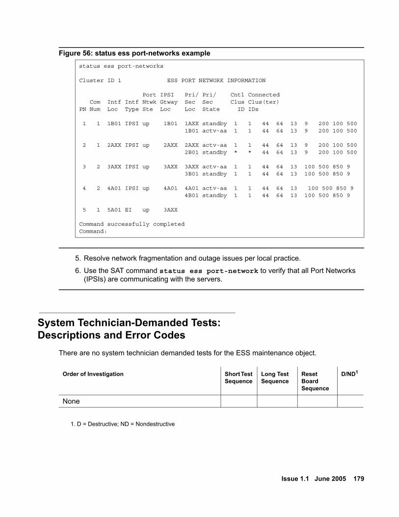
Issue 1.1 June 2005 179
Figure 56: status ess port-networks example
5. Resolve network fragmentation and outage issues per local practice.
6. Use the SAT command status ess port-network to verify that all Port Networks (IPSIs) are communicating with the servers.
System Technician-Demanded Tests:Descriptions and Error Codes
There are no system technician demanded tests for the ESS maintenance object.
status ess port-networks
Cluster ID 1 ESS PORT NETWORK INFORMATION
Port IPSI Pri/ Pri/ Cntl Connected Com Intf Intf Ntwk Gtway Sec Sec Clus Clus(ter)PN Num Loc Type Ste Loc Loc State ID IDs
1 1 1B01 IPSI up 1B01 1AXX standby 1 1 44 64 13 9 200 100 500 1B01 actv-aa 1 1 44 64 13 9 200 100 500 2 1 2AXX IPSI up 2AXX 2AXX actv-aa 1 1 44 64 13 9 200 100 500 2B01 standby * * 44 64 13 9 200 100 500 3 2 3AXX IPSI up 3AXX 3AXX actv-aa 1 1 44 64 13 100 500 850 9 3B01 standby 1 1 44 64 13 100 500 850 9 4 2 4A01 IPSI up 4A01 4A01 actv-aa 1 1 44 64 13 100 500 850 9 4B01 standby 1 1 44 64 13 100 500 850 9 5 1 5A01 EI up 3AXX
Command successfully completed Command:
Order of Investigation Short Test Sequence
Long Test Sequence
Reset Board Sequence
D/ND1
1. D = Destructive; ND = Nondestructive
None

ESS Maintenance Object
180 Avaya Enterprise Survivable Servers (ESS) Users Guide
Testing transfer of control from Main server to ESS server
Issue 1.1 June 2005 181
Chapter 8: Enterprise Survivable Server Acceptance Testing
Acceptance testing is used to test the design and administration of the ESS configuration. To check the ESS configuration, it is recommended that the status ess port-networks and status ess clusters command be preformed on a regular bases.
Testing transfer of control from Main server to ESS server
What to expectAll Port Networks under test perform a restart when coming into service on the ESS server. This may take several minutes.
What this test is used for
! CAUTION:CAUTION: This test is service affecting. When an ESS server or Main media server
assumes control of a Port Network, the Port Network restarts. All established calls on the Port Network will be torn down except shuffled calls between IP endpoints. Shuffled IP calls do not have access to features during Port Network resets.
Use this procedure to test the ability of an ESS server to take control of one or more Port Networks.
1. Identify the Port Network(s) that will be used for the test.
2. Identify the ESS server you wish to test. The ESS server must be currently connected to the Port Networks identified in step 1. To verify that the ESS server is currently connected to the Port Network(s), execute a status ess port-network command from either the Main server or the ESS server under test. The CLID of the ESS server must appear in the list of connected ’Clusters IDs’ for the Port Network(s).
3. On the ESS server, execute the get forced-takeover ipserver-interface N command (where N is the number of the first Port Network.

Enterprise Survivable Server Acceptance Testing
182 Avaya Enterprise Survivable Servers (ESS) Users Guide
4. On the ESS server, repeat the get forced-takeover ipserver-inerface N command for every Port Network identified in step 1 that you desire to test.
Acceptance criteriaCheck that the selected Port Network(s) is under control of the ESS server under test:
1. On the Main server:
a. Execute status ess port-networks command from the SAT. Verify the following:
- All Port Networks are displayed on the list
- The status of the selected Port Network(s) under test is shown as down. The status of all other Port Networks are shown as up.
2. On the ESS server:
a. Execute a status ess port-networks command from the SAT. Verify the following:
- All Port Networks are displayed on the list.
- The status of the selected Port Network(s) under test is shown as up. The status of all other Port Networks are shown as down.
3. Place a phone call between the Port Networks under test. If there was only one selected Port Network selected, place a phone call within the Port Network.
4. Place a phone call between the Port Networks that were not selected for this test.
5. Place a phone call between the Port Network(s) under test and the Port Networks not selected for this test. Verify that you receive a fast busy. Note that calls to EC500 endpoints may go to coverage instead of returning a fast busy.
Testing transfer of control from ESS server to Main server
What to expectThe ESS server loses control of all Port Networks currently under its control as the Port Networks restart. Communication Manager on the Main server reboots.This test takes several minutes.

Testing transfer of control from ESS server to Main server
Issue 1.1 June 2005 183
What this test is used for
! CAUTION:CAUTION: This test is service affecting.
Use this test to verify that the Main server can assume control of the Port Networks under control of the ESS server.
1. Verify that the ESS server is currently in control of the Port Network(s) under test by executing the status ess port-network command from the Main server. The status of the Port Network(s) under test is shown as down.
2. On the Main server, execute the get forced-takeover ipserver-interface all command from the SAT.
Acceptance criteriaCheck that the selected Port Network(s) is now under control of the Main server:
1. On the Main server:
a. Execute the status ess port-networks command. Verify the following:
- All Port Networks are listed
- The status of all Port Networks is shown as up
2. On the ESS server:
a. Execute the status ess port-networks command. Verify the following:
- All Port Networks are listed
- The status of all Port Networks is shown as down
3. Place a phone call between two Port Networks under test. If only one Port Network was tested, skip to step 4. Verify a two way talk path.
4. Place a phone call between two Port Networks that were not under test. Verify a two way talk path.
5. Place a phone call between a Port Network under test and one that was not under test. Verify a two way talk path.

Enterprise Survivable Server Acceptance Testing
184 Avaya Enterprise Survivable Servers (ESS) Users Guide
Disable an ESS server from the Main server
What to expectCommunication Manager on the selected ESS server resets. Once the ESS server resets it will re-register with the Main server. The status of the ESS server from unregistered to registered takes several minutes and will not happen immediately.
What this test is used forUse this test to verify the ability to disable an ESS server from the Main server
1. On the Main server, execute the disable ess cluster <cluster ID> command.
Note:Note: You cannot disable an ESS server that is controlling an IPSI. For more
information on the disable ess cluster command see disable ess on page 147
Acceptance criteriaVerify that the selected ESS server is now disabled:
1. On the Main server:
a. After the ESS server comes back up from the reset and re-registers with the Main server, execute the status ess clusters command from the Main server SAT. Verify that:
- The enabled state under the Enabled? column, shows n.
- The registration state under the Registered? column shows y.
2. On the ESS server:
a. Execute the status ess clusters command. Verify that:
- The enabled state under the Enabled? column, shows n.
- The registration state under the Registered? column shows yb. Execute the status ess port-networks:
- The Port Network connection under the Port Ntwk Ste column shows down
Enable an ESS server from the Main server
Issue 1.1 June 2005 185
Enable an ESS server from the Main server
What to expectCommunication Manager on the selected ESS server resets. Once the ESS server resets it will re-register with the Main server. Once registered, the ESS server receives a translation download from the Main server and resets. After the reset, the ESS server re-registers with the Main server.
What this test is used forUse this test to verify the ability to enable an ESS server from the Main server
1. On the Main server, execute the enable ess cluster <cluster ID> command.
Acceptance criteriaVerify that the selected ESS server is now enabled:
1. On the Main server:
a. After the ESS server comes back up from the reset and re-registers with the Main server, execute the status ess clusters command from the Main server SAT. Verify that:
- The enabled state under the Enabled? column, shows y.
2. On the ESS server:
a. Execute the status ess clusters command. Verify that:
- The enabled state under the Enabled? column, shows y.

Enterprise Survivable Server Acceptance Testing
186 Avaya Enterprise Survivable Servers (ESS) Users Guide

Issue 1.1 June 2005 187
Glossary
AATM Asynchronous Transfer Mode. An industry standard for moving data. In an ESS
environment, ATM refers to the scheme used to connect Port Networks together.
CCLID Cluster Identification number. In an ESS environment, the Module Identification
number (MID) found in the license file is referred to as the CLID. The CLID identifies a unique cluster. Each server in a duplex pair has the same CLID. The MID/CLID is set by the RFA license file and cannot be changed.
Cluster A cluster is a server or set of servers which share call state. The cluster can be the singular case (S8500 series servers) or the duplex case (S8700 series servers). This definition implies that servers within a cluster can be interchanged if duplicated.
Community A virtual group consisting of one ESS server and one or more Port Networks.
EESS Enterprise Survivable Servers: The Avaya option that provides survivability by
allowing backup servers to be placed in various locations in the customer’s network.
ESS server The server(s) that are ready to respond to an IPSI’s request for service if all other recovery mechanisms fail. The ESS may be simplex (S8500 series servers), or duplex (S8700 series servers).
LLSP Local Survivable Processor: A media server (usually an S8300) that may
accept media gateway and/or endpoint registrations incase of a server or network failure.
MMain server The primary server(s) that usually control the system. The Main server may be
simplex (S8500 series media servers), or duplex (S8700 series media servers).

MID
188 Avaya Enterprise Survivable Servers (ESS) Users Guide
MID Module Identification number: RFA refers to a simplex server and a duplex pair of servers, within the same Avaya system, as a module. Each module is assigned a unique Module Identification number (MID). In the case where there is a duplex pair of servers, each processor within the pair has the same license file.The MID is assigned by RFA and cannot be changed. In an ESS environment, the MID and the CLID are the same value.
MO Maintenance objectPPreference An ESS server can be administered with one of three preference settings. The
preference settings are System Preferred, Local Preferred, and Local Only.Priority value An administered value entered in the system-parameters ess from. The priority
value is used to distinguish between ESS servers with the same preference settings and ESS servers with no preference settings. For this document, the term priority value and priority score is interchangeable.
Priority score See Priority value.RRFA Remote Feature Activation: The web-based application used to generate
license and authentication files.SSAP Avaya’s ordering system for products and services.Serial numbers A serial number of the Avaya hardware is used to create a valid license file. The
hardware serial number and the serial number within the license file must match.
SSO Single Sign-On: An Avaya corporate mechanism requiring a single login to allow users access to certain web sites.
SVID Server Identification number: A unique identification number assigned by the customer to the server when the server is configured.
SVOR Server Ordinal: This value identifies a server within its server pair. This value is set automatically when the server is configured. The A-side server in a duplex pair always has the ordinal of one. The B-side server in a duplex pair always has the ordinal of two. Simplex servers always have the ordinal of one.
System Record A number used by RFA to identify the system within the RFA database.

Issue 1.1 June 2005 189
Index
Index
AAdjunct considerations . . . . . . . . . . . . . . . 91Administer IP address A-side . . . . . . . . . . . . 123Administer IP address B-side . . . . . . . . . . . . 123Administering and saving translations . . . . . . . . 143Administering ESS . . . . . . . . . . . . . . . . . 122Administration . . . . . . . . . . . . . . . . . . . 143Administrative value . . . . . . . . . . . . . . . . 68Announcements . . . . . . . . . . . . . . . . . . 89Attendant Console . . . . . . . . . . . . . . . . . 89Auto Return . . . . . . . . . . . . . . . . . . . . 126Avaya survivability . . . . . . . . . . . . . . . . . 17Avoiding overload of network resources . . . . . . . 63Avoiding system fragmentation . . . . . . . . . . . 63
BBest Service Routing (BSR) . . . . . . . . . . . . 89
CCall Classification . . . . . . . . . . . . . . . . . 89Call Coverage . . . . . . . . . . . . . . . . . . . 89Call Detail Recording (CDR) . . . . . . . . . . . . 91Call Management System (CMS) . . . . . . . . . . 92Call Vectoring . . . . . . . . . . . . . . . . . . . 89Centralized Attendant Service (CAS) . . . . . . . . 90Check the administration . . . . . . . . . . . . . . 127CLAN access for ESS registration. . . . . . . . . . 65CLID . . . . . . . . . . . . . . . . . . . . . . . 123Cluster ID . . . . . . . . . . . . . . . . . . . . . 111Commands
cnc . . . . . . . . . . . . . . . . . . . . . . 161Community . . . . . . . . . . . . . . . . . . . . 124conventions . . . . . . . . . . . . . . . . . . . . 12Conversions . . . . . . . . . . . . . . . . . . . . 133Creating a license file . . . . . . . . . . . . . . . 114Crisis Alert . . . . . . . . . . . . . . . . . . . . 90CSS . . . . . . . . . . . . . . . . . . . . . . . 67CSS considerations . . . . . . . . . . . . . . . . 71CVLAN links . . . . . . . . . . . . . . . . . . . . 90
DD-channel . . . . . . . . . . . . . . . . . . . . . 68Design . . . . . . . . . . . . . . . . . . . . . . 63Design strategy . . . . . . . . . . . . . . . . . . 63
Detailed ESS Overview . . . . . . . . . . . . . . . 18downloading this book . . . . . . . . . . . . . . . 12downloading updates from the Web . . . . . . . . . 11
EE911 . . . . . . . . . . . . . . . . . . . . . . . 69EC500 . . . . . . . . . . . . . . . . . . . . . . . 92Enterprise Survivable Server (ESS)
Conversions . . . . . . . . . . . . . . . . . 133ESS to Manual Backup Server . . . . . . . 142Existing ESS media server to Main server . . 134Existing media server to ESS server. . . . . 137Manual Backup Server to ESS server . . . . 140
Conversions, basic guidelines . . . . . . . . . 133Lock CSS PNC . . . . . . . . . . . . . . . . 162Maintenance Commands . . . . . . . . . . . 147
cnc . . . . . . . . . . . . . . . . . . . . 161disable ess . . . . . . . . . . . . . . . . 147enable ess cluster . . . . . . . . . . . . . 149get forced-takeover ipserver-interface . . . . 152status ess clusters . . . . . . . . . . . . . 153status ess port-networks . . . . . . . . . . 157
Maintenance Procedures . . . . . . . . . . . 162Check ESS status . . . . . . . . . . . . . 163Checking ESS status . . . . . . . . . . . . 163Remove an ESS . . . . . . . . . . . . . . 163
MO . . . . . . . . . . . . . . . . . . . . . . 173Troubleshooting . . . . . . . . . . . . . . . . 164
ESS not registered . . . . . . . . . . . . . 165IPSI not connected . . . . . . . . . . . . . 171
ESSCapacity . . . . . . . . . . . . . . . . . . . . 68Conversions . . . . . . . . . . . . . . . . . 133
ESS to Manual Backup Server . . . . . . . 142Existing ESS media server to Main server . . 134Existing media server to ESS server. . . . . 137Manual Backup Server to ESS server . . . . 140
Conversions, basic guidelines . . . . . . . . . 133ESS Design and Planning . . . . . . . . . . . . 63ESS design strategy . . . . . . . . . . . . . . . 63ESS Maintenance Object . . . . . . . . . . . 173Failover to an ESS server . . . . . . . . . . . . 19Maintenance Commands . . . . . . . . . . . 147
cnc . . . . . . . . . . . . . . . . . . . . 161disable ess . . . . . . . . . . . . . . . . 147enable ess cluster . . . . . . . . . . . . . 149get forced-takeover ipserver-interface . . . . 152status ess clusters . . . . . . . . . . . . . 153status ess port-networks . . . . . . . . . . 157
190 Avaya Enterprise Survivable Servers (ESS) Users Guide
Index
ESS, (continued)Maintenance Procedures . . . . . . . . . . . . 162
Check ESS status . . . . . . . . . . . . . . 163Checking ESS status . . . . . . . . . . . . 163Lock CSS PNC . . . . . . . . . . . . . . . 162Remove an ESS. . . . . . . . . . . . . . . 163
No-service timer . . . . . . . . . . . . . . . . 84Prerequisites . . . . . . . . . . . . . . . . . . 64Registration . . . . . . . . . . . . . . . . . . 65Requirements . . . . . . . . . . . . . . . . . 22Sequence of events for a failover . . . . . . . . 19Troubleshooting . . . . . . . . . . . . . . . . 164
ESS not registered . . . . . . . . . . . . . 165troubleshooting
IPSI not connected . . . . . . . . . . . . . 171ESS failover examples . . . . . . . . . . . . . . . 23
Mixed Port Networks. . . . . . . . . . . . . 35CSS with DS1C . . . . . . . . . . . . . . . . 41CSS with multiple nodes . . . . . . . . . . . . 44Distributed ATM Switches . . . . . . . . . . . . 52ESS with ATM . . . . . . . . . . . . . . . . . 47ESS with CSS . . . . . . . . . . . . . . . . . 38Main server fails . . . . . . . . . . . . . . . . 23Network failure . . . . . . . . . . . . . . . . . 27
ESS license file . . . . . . . . . . . . . . . . . . 110ESS MO . . . . . . . . . . . . . . . . . . . . . 173ESS Overview
Detailed . . . . . . . . . . . . . . . . . . . . 18ESS re-registers with Main server . . . . . . . . . . 65Examples
CSS with DS1C . . . . . . . . . . . . . . . . 41CSS with multiple nodes . . . . . . . . . . . . 44Distributed ATM Switches . . . . . . . . . . . . 52ESS with ATM . . . . . . . . . . . . . . . . . 47ESS with CSS . . . . . . . . . . . . . . . . . 38Mixed Port Networks . . . . . . . . . . . . . . 35Network failure . . . . . . . . . . . . . . . . . 27
Examples of how the priority list works . . . . . . . 76
FFacility Busy Indication . . . . . . . . . . . . . . . 90Failover to an ESS server . . . . . . . . . . . . . 19Feature considerations . . . . . . . . . . . . . . . 88Feature Keywords . . . . . . . . . . . . . . . . . 113Figures
ATM with a single ESS server in a takeover scenario . . . . . . . . . . . . . . . . . . . 50
ATM with a single ESS server in normal operation . . . . . . . . . . . . . . . . . . . 48
ATM, single ESS server, multiple nodes in a takeover scenario . . . . . . . . . . . . . . . 54
ATM, single ESS server, multiple nodes in normal operation . . . . . . . . . . . . . . . . . . . 53
Catastrophic Main server failure . . . . . . . . . 25
Figures, (continued)Configure ESS window . . . . . . . . . . . . 121Configure server main page . . . . . . . . . . .119CSS after failover with single ESS server . . . . . 40CSS with DS1C - normal operation . . . . . . . . 41CSS with DS1C - remote takeover . . . . . . . . 43CSS with multiple nodes - failover . . . . . . . . 46CSS with multiple nodes in normal operation . . . 44Fall-back to the Main server . . . . . . . . . . . 34Main server recovery . . . . . . . . . . . . . . 32Main servers fail. . . . . . . . . . . . . . . . . 23Main servers fail - ESS recovery of failure. . . . . 26Mixed Port Network after failover . . . . . . . . . 37Mixed Port Network in normal operation . . . . . 36Network failure - ESS recovery . . . . . . . . . . 29Network fragmentation failure . . . . . . . . . . 28Network fragmentation recovery . . . . . . . . . 31Normal operation CSS with single ESS server. . . 39S8710 Media Server with ESS servers in normal
operation . . . . . . . . . . . . . . . . . . . 24Status ess clusters . . . . . . . . . . . . . . 128Statuslicense -v command . . . . . . . . . . . 123System-parameters customer-options - page 4
ESS features . . . . . . . . . . . . . . . . .118System-parameters customer-options platform
type . . . . . . . . . . . . . . . . . . . . . .117System-parameters ess . . . . . . . . . . . . 122System-parameters ess form - page 6 . . . . . 126System-parameters ess form - page 7 . . . . . 127system-parameters maintenance . . . . . . . . 131
GG250 . . . . . . . . . . . . . . . . . . . . . . . 84
HH.248 link recovery . . . . . . . . . . . . . . . . . 84High-level ESS overview . . . . . . . . . . . . . . 17Hunt Groups . . . . . . . . . . . . . . . . . . . . 90
IImportant considerations . . . . . . . . . . . . . . 63IP connected Port Networks . . . . . . . . . . . . . 76IP Endpoints . . . . . . . . . . . . . . . . . . . . 84IPSI maintenance replacement . . . . . . . . . . .112IPSI version . . . . . . . . . . . . . . . . . . . . 22ISDN PRI guidelines . . . . . . . . . . . . . . . . 68ISDN PRI Non Facility associated signaling . . . . . 68
LLeave Word Calling. . . . . . . . . . . . . . . . . 90License file . . . . . . . . . . . . . . . . . . . 67, 110

Issue 1.1 June 2005 191
Index
License files . . . . . . . . . . . . . . . . . . . . 110Licenses files . . . . . . . . . . . . . . . . . . . 64link recovery . . . . . . . . . . . . . . . . . . . . 84Local Only. . . . . . . . . . . . . . . . . . . . . 125Local Preferred . . . . . . . . . . . . . . . . . . 124LSP and ESS . . . . . . . . . . . . . . . . . . . 21
MMain server and ESS differences . . . . . . . . . . 67Maintenance Object
ESS . . . . . . . . . . . . . . . . . . . . . . 173Manual Backup Server
Conversion to ESS server . . . . . . . . . . . . 140MID . . . . . . . . . . . . . . . . . . . . . . . . 64Module ID . . . . . . . . . . . . . . . . . . . . . 111Module Identification Number . . . . . . . . . . . . 64MOs (maintenance objects)
ESS . . . . . . . . . . . . . . . . . . . . . . 173Multi-connected configuration. . . . . . . . . . . . 80Music on Hold . . . . . . . . . . . . . . . . . . . 91
NNetwork addressing considerations . . . . . . . . . 70Network port considerations . . . . . . . . . . . . 66No service time out interval . . . . . . . . . . . . . 126No service timer . . . . . . . . . . . . . . . . . . 18
OObtaining a RFA license file . . . . . . . . . . . . 113Overview
High-level . . . . . . . . . . . . . . . . . . . 17
PPCOL . . . . . . . . . . . . . . . . . . . . . . . 70Planning . . . . . . . . . . . . . . . . . . . . . 63Platform Type . . . . . . . . . . . . . . . . . . . 123Port Network Communities . . . . . . . . . . . . . 125Port Network fall-back . . . . . . . . . . . . . . . 20Ports . . . . . . . . . . . . . . . . . . . . . . . 66Prerequisites . . . . . . . . . . . . . . . . . . . 64priority list . . . . . . . . . . . . . . . . . . . . . 76Priority Score . . . . . . . . . . . . . . . . . . . 123Property Management System (PMS) . . . . . . . . 92
RRegistration . . . . . . . . . . . . . . . . . . . . 65Running in ESS mode . . . . . . . . . . . . . . 143
Administering and saving translations. . . . . . 143Alarming . . . . . . . . . . . . . . . . . . . 144save translations ess . . . . . . . . . . . . . 143Unplanned fall-back or failover . . . . . . . . . 145Updating the Main server . . . . . . . . . . . 146User enabled telephone features . . . . . . . . 144
SSave translations . . . . . . . . . . . . . . . . . 130Saving translations . . . . . . . . . . . . . . . . 143SBS . . . . . . . . . . . . . . . . . . . . . . . . 70Serial numbers . . . . . . . . . . . . . . . . . . .112Server ID . . . . . . . . . . . . . . . . . . .64, 123SID . . . . . . . . . . . . . . . . . . . . . . . .111SVID . . . . . . . . . . . . . . . . . . . . . . . 64Synchronization . . . . . . . . . . . . . . . . . . 69System Identification numbers. . . . . . . . . . . . 111System Preferred. . . . . . . . . . . . . . . . . 124System-parameters ess form . . . . . . . . . . . 122
TTables
Installing ESS with existing servers . . . . . . . . 94Installing ESS with new servers . . . . . . . . 104Platform numbers and server types . . . . . . . .117RFA naming convention . . . . . . . . . . . . .112
technical assistance . . . . . . . . . . . . . . . . 15Timing considerations. . . . . . . . . . . . . . . . 83trademarks and service marks. . . . . . . . . . . . 13Translations . . . . . . . . . . . . . . . . . .67, 130Trunking considerations. . . . . . . . . . . . . . . 68
UUnplanned failover to another ESS . . . . . . . . 146
get forced-takeover ipserver-inferface. . . . . . 146Unplanned fall-back to the Main server. . . . . . . 145Unplanned fallback to the Main server
get forced-takeover ipserver-interface. . . . . . 145system-parameters ess . . . . . . . . . . . . 145
Updating the Main server . . . . . . . . . . . . . 146
VVoice Mail (Audix, Intuity, Octel) . . . . . . . . . . . 92Voice Response Systems (Conversant) . . . . . . . 92

192 Avaya Enterprise Survivable Servers (ESS) Users Guide
Index