esbjornson gymnasium men’s locker room upgrades project … … · esbjornson gymnasium –...
TRANSCRIPT

ESBJORNSON GYMNASIUM
MEN’S LOCKER ROOM UPGRADES
PROJECT MANUAL
PROJECT NO. 77031
July 20, 2018
Issued for Bid / Construction
Esbjornson Gymnasium
Men’s Locker Room Upgrades
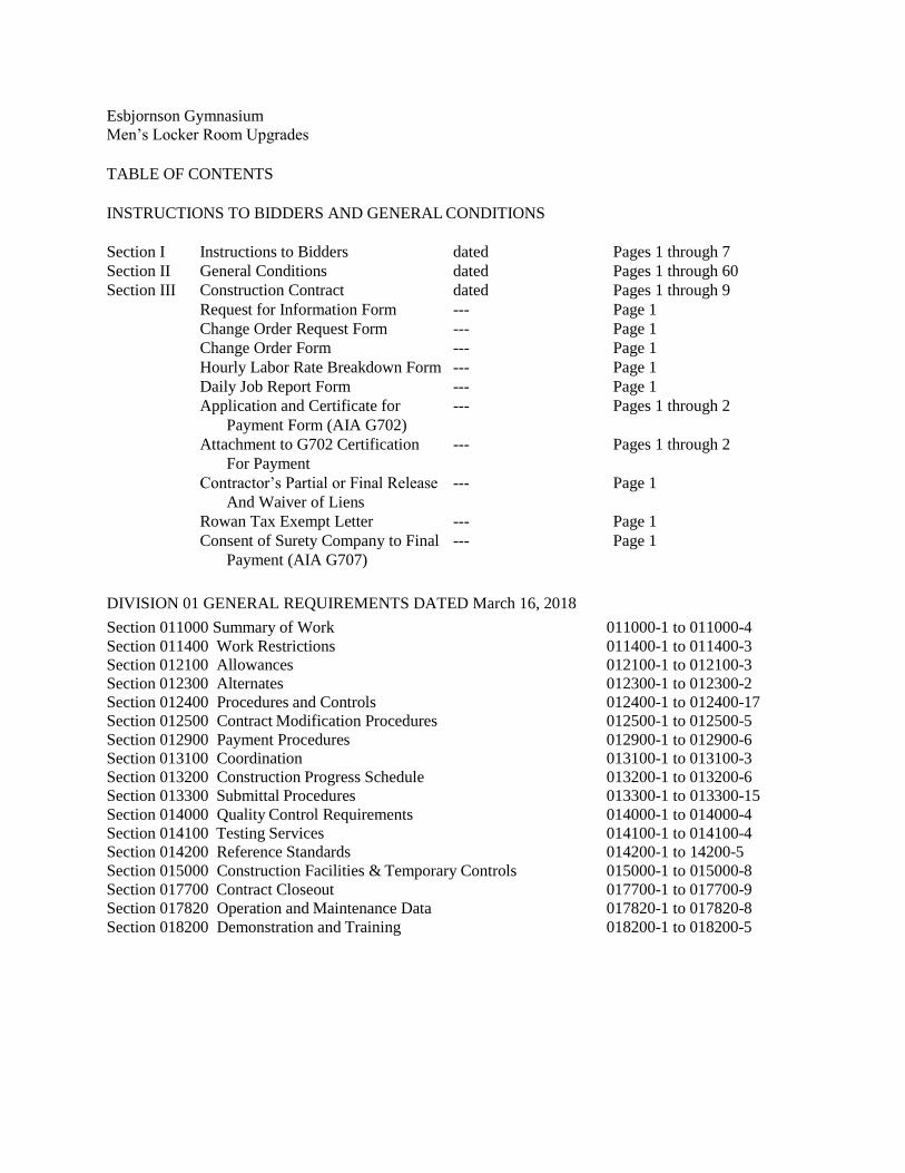
TABLE OF CONTENTS
INSTRUCTIONS TO BIDDERS AND GENERAL CONDITIONS
Section I Instructions to Bidders dated Pages 1 through 7
Section II General Conditions dated Pages 1 through 60
Section III Construction Contract dated Pages 1 through 9
Request for Information Form --- Page 1
Change Order Request Form --- Page 1
Change Order Form --- Page 1
Hourly Labor Rate Breakdown Form --- Page 1
Daily Job Report Form --- Page 1
Application and Certificate for --- Pages 1 through 2
Payment Form (AIA G702)
Attachment to G702 Certification --- Pages 1 through 2
For Payment
Contractor’s Partial or Final Release --- Page 1
And Waiver of Liens
Rowan Tax Exempt Letter --- Page 1
Consent of Surety Company to Final --- Page 1
Payment (AIA G707)
DIVISION 01 GENERAL REQUIREMENTS DATED March 16, 2018
Section 011000 Summary of Work 011000-1 to 011000-4
Section 011400 Work Restrictions 011400-1 to 011400-3
Section 012100 Allowances 012100-1 to 012100-3
Section 012300 Alternates 012300-1 to 012300-2
Section 012400 Procedures and Controls 012400-1 to 012400-17
Section 012500 Contract Modification Procedures 012500-1 to 012500-5
Section 012900 Payment Procedures 012900-1 to 012900-6
Section 013100 Coordination 013100-1 to 013100-3
Section 013200 Construction Progress Schedule 013200-1 to 013200-6
Section 013300 Submittal Procedures 013300-1 to 013300-15
Section 014000 Quality Control Requirements 014000-1 to 014000-4
Section 014100 Testing Services 014100-1 to 014100-4
Section 014200 Reference Standards 014200-1 to 14200-5
Section 015000 Construction Facilities & Temporary Controls 015000-1 to 015000-8
Section 017700 Contract Closeout 017700-1 to 017700-9
Section 017820 Operation and Maintenance Data 017820-1 to 017820-8
Section 018200 Demonstration and Training 018200-1 to 018200-5

TECHNICAL SPECIFICATIONS
DIVISION 02 EXISTING CONDITIONS
Section 024119 Selective Demolition 024119-1 to 024119-4
DIVISION 03 CONCRETE
Section 033000 Cast-In-Place Concrete 033000-1 to 033000-6
DIVISION 07 THERMAL AND MOISTURE PROTECTION
Section 071326 Self-Adhering Membrane Waterproofing 071326-1 to 071326-6
Section 072100 Thermal Insulation 072100-1 to 072100-2
Section 079200 Joint Sealants 079200-1 to 079200-6
DIVISION 08 OPENINGS
Section 081113 Hollow Metal Frames 081113-1 to 081113-5
Section 081743 Frp Doors 081743-1 to 081743-7
Section 087100 Door Hardware 087100-1 to 087100-20
DIVISION 09 FINISHES
Section 092216 Non-Structural Metal Framing 092216-1 to 092216-3
Section 092900 Gypsum Board 092900-1 to 092900-4
Section 095113 Acoustical Panel Ceilings 095113-1 to 095113-3
Section 096513 Resilient Base and Accessories 096513-1 to 096513-4
Section 096566 Resilient Athletic Flooring 096566-1 to 096566-5
Section 099123 Interior Painting 099123-1 to 099123-6
DIVISION 20 – COMMON WORK RESULTS FOR PLUMBING AND MECHANICAL SYSTEMS Section 20 00 01 - General Requirements Section 20 00 02 - Definitions Section 20 05 13 - Motor Requirements Section 20 05 29 - Hangers and Supports Section 20 05 30 - Vibration Isolation Section 20 05 53 - Identification for Piping and Equipment Section 20 07 00 - Piping Insulation DIVISION 21 - FIRE SUPPRESSION Section 21 05 00 - Common Work Results for Fire Suppression Section 21 13 13 - Wet-Pipe Sprinkler Systems

DIVISION 23 - MECHANICAL Section 23 05 93 - Testing, Adjusting, and Balancing Section 23 07 10 - Duct Insulation Section 23 07 20 - Equipment Insulation Section 23 09 00 - Instrumentation Section 23 09 23 - Direct-Digital Control System Section 23 09 93 - Sequence of Operation Section 23 09 95 - Variable Frequency Controllers Section 23 23 00 - Refrigerant Piping Section 23 31 00 - HVAC Ducts and Casings Section 23 33 00 - Air Duct Accessories Section 23 34 00 - HVAC Fans Section 23 37 00 - Air Outlets and Inlets Section 23 81 26 - Variable Refrigerant Flow System DIVISION 26 – ELECTRICAL Section 26 00 00 - General Electrical Section 26 20 00 - Electrical Work Practices Section 26 30 00 - Electrical Materials Section 26 40 00 - Lighting System
Section 26 51 00 - Fire Alarm System Modifications

ROWAN UNIVERSITY SECTION I
INSTRUCTIONS TO BIDDERS
Rowan University Esbjornson Gymnasium – Men’s Locker Room Upgrades July 20, 2018 Rowan Project No. 77031 INSTRUCTIONS TO BIDDERS Section I - 1
1B1. BID PROPOSALS
1B1.1. Sealed proposals for the work described herein must be received and time-stamped at the University. The closing date and time for bids will be stated in the Advertisement and Invitation to Bid. Bidders are cautioned that reliance of the U. S. Mail for timely delivery of proposals is at the bidder's risk. Failure by the contractor to have sealed proposals reach the University by the prescribed time will result in a return of the submission unopened and unread.
1B1.2. This contract will be bid as a single prime contract only. Bids for less than all of the project as described herein will be deemed nonconforming.
1B1.3. The Instructions to Bidders, Bid forms, Contract forms, plans and specifications, forms of Bid Bond, Agreement of Surety, Performance Bonds, Payment Bonds and other contract documents may be examined at the University. Contractors may obtain contract documents at the University’s Purchasing Website. The University reserves the right to deny award to any bidder who is not clearly responsible based upon experience, past performance and financial capability to perform the work required hereunder or other material factors.
1B1.4. Set(s) of contract documents will be available for inspection by interested parties free of change in Rowan University’s Purchasing Department.
1B1.5. Bid proposals based upon the plans, specifications, general, special and supplementary conditions, clarifications and/or addenda shall be deemed as having been made by the contractor will full knowledge of all project conditions. Bidders are required to visit the site prior to submitting proposals for the work herein described and to have thoroughly examined the conditions under which the contract is to be executed including those reasonably observable conditions of the premises which would hinder, delay or otherwise affect the performance of the contractor required under the terms of the contract. The University will not allow claims for additional costs as a result of the contractor's failure to become aware of the reasonably observable conditions affecting his/her required performance. The bidder is required to make appropriate allowances in the preparation of his/her bid for the accommodation of such conditions. Bidders must warrant in the bid documents that the bidder is familiar with conditions existing at the site at the time the bid is submitted.
1B1.6. Bid proposals shall be submitted on the standard form provided by the University, enclosed in a sealed envelope issued by Rowan University. The name and address of the bidder must be indicated on the envelope as well as indication of the project, project location and other appropriate identification.
1B1.7. All amounts in the bid documents shall be stated in numerical figures only.
1B1.8. The bidder must include the following items in the bid envelope. Other documents may be required by the University Purchasing Department. Check the University’s website for further information on required documents.

ROWAN UNIVERSITY SECTION I
INSTRUCTIONS TO BIDDERS
Rowan University Esbjornson Gymnasium – Men’s Locker Room Upgrades July 20, 2018 Rowan Project No. 77031 INSTRUCTIONS TO BIDDERS Section I - 2
a. The proposal signed by the bidder; b. The executed Affidavit of Non-collusion; c. Bid security as further described in Paragraph 1B6; d. The completed set of bid forms found after the Table of Contents; e. The names and license numbers of and evidence of performance security form of
all sub-contractors to who the bidder will sub-contract any of the work on the project for the following: 1) The plumbing and gas fitting work; 2) The heating and ventilating systems and equipment; 3) The electrical work including any electrical power plants; 4) The structural and ornamental iron work.
1B1.9. Proposals shall remain open for acceptance and may not be withdrawn for a period of sixty (60) days after the bid opening date.
1B1.10. Proposals not submitted and filed in accordance with instructions contained herein and in the Advertisement will be considered informal and rejected as non-responsive.
1B2. BID MODIFICATION
1B2.1. A bidder may modify his/her bid proposal by telegram or letter at any time prior to the scheduled closing time for receipt of bids provided such communication is received by the University prior to such closing time. A written confirmation of any telegraphic modification signed by the bidder must have been mailed and time-stamped by the post office prior to specified closing time. Such confirmation shall be accompanied by a newly executed Affidavit of Non-Collusion.
1B2.2. Telegraphic communications shall not reveal the basic bid price but only shall provide the amount to be added, subtracted or modified so that the final price(s) or term(s) will not be revealed until the sealed proposal is opened. If written confirmation of the telegraphic modification is not received within two (2) working days after the scheduled closing time, no consideration will be given to the telegraphic modification.
1B2.3. Bids may be withdrawn upon written request received from the bidder prior to the time fixed for the bid opening. Right for withdrawal of a bid is lost after a bid has been opened. If any error has been made in the bid amount, request for relief from the bid may be made in writing to the University. The written request shall be signed by an authorized corporate officer. A determination of whether the bidder will be released shall be at the sole discretion of the University who shall issue his/her finding(s) within five (5) days of his/her receipt of all pertinent information relating to such request for relief.
1B3. CONSIDERATION OF BIDS
1B3.1. Award of Projects (s) or Rejection of Bid(s):
a. The project will be awarded to the lowest responsible bidder whose bid, conforming to the Bidding Documents, will be most advantageous to the University. The award will be made or the bid(s) rejected within sixty (60) days from the date of the opening of the bids.
ROWAN UNIVERSITY SECTION I
INSTRUCTIONS TO BIDDERS
Rowan University Esbjornson Gymnasium – Men’s Locker Room Upgrades July 20, 2018 Rowan Project No. 77031 INSTRUCTIONS TO BIDDERS Section I - 3
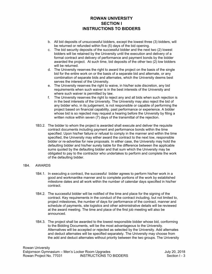
b. All bid deposits of unsuccessful bidders, except the lowest three (3) bidders, will be returned or refunded within five (5) days of the bid opening.
c. The bid security deposits of the successful bidder and the next two (2) lowest bidders will be retained by the University until the execution and delivery of a formal contract and delivery of performance and payment bonds by the bidder awarded the project. At such time, bid deposits of the other two (2) low bidders will be returned.
d. The University reserves the right to award the project on the basis of the single bid for the entire work on or the basis of a separate bid and alternate, or any combination of separate bids and alternates, which the University deems best serves the interest of the University.
e. The University reserves the right to waive, in his/her sole discretion, any bid requirements when such waiver is in the best interests of the University and where such waiver is permitted by law.
f. The University reserves the right to reject any and all bids when such rejection is in the best interests of the University. The University may also reject the bid of any bidder who, in its judgement, is not responsible or capable of performing the project based on financial capability, past performance or experience. A bidder whose bid is so rejected may request a hearing before the University by filing a written notice within seven (7) days of the transmittal of the rejection.
1B3.2. The bidder to whom the project is awarded shall execute and deliver the requisite contract documents including payment and performance bonds within the time specified. Upon his/her failure or refusal to comply in the manner and within the time specified, the University may either award the contract to the next low, responsible bidder or re-advertise for new proposals. In either case, the University may hold the defaulting bidder and his/her surety liable for the difference between the applicable sums quoted by the defaulting bidder and that sum which the University may be obligated to pay to the contractor who undertakes to perform and complete the work of the defaulting bidder.
1B4. AWARDS
1B4.1. In executing a contract, the successful bidder agrees to perform his/her work in a good and workmanlike manner and to complete portions of the work by established milestone dates and all work within the number of calendar days specified in his/her contract.
1B4.2. The successful bidder will be notified of the time and place for the signing of the contract. Key requirements in the conduct of the contract including, but not limited to, project milestones, the number of days for performance of the contract, manner and schedule of payments, site logistics and other administrative details will be reviewed at the award meeting. The time and place of the first job meeting will also be announced.
1B4.3. The project shall be awarded to the lowest responsible bidder whose bid, conforming to the Bidding Documents, will be the most advantageous to the University. Alternatives will be accepted or rejected as selected by the University. Add alternates and deduct alternates will be specified separately. The University may choose from the add and deduct alternates without priority between the two groups. The University

ROWAN UNIVERSITY SECTION I
INSTRUCTIONS TO BIDDERS
Rowan University Esbjornson Gymnasium – Men’s Locker Room Upgrades July 20, 2018 Rowan Project No. 77031 INSTRUCTIONS TO BIDDERS Section I - 4
may accept alternates out of sequence provided it states its reasons for so doing.
1B4.4. Should submission of unit prices be required for specific items of work in bid proposals, they will be considered in the evaluation of bids.
1B4.5. LIQUIDATED DAMAGES ARE PART OF THIS PROJECT. Please refer to Section 017700 Contract Closeout in the Project Manual.
1B5. QUALIFICATIONS OF BIDDERS
1B5.1. If the successful bidder is a corporation not organized under the laws of the State of New Jersey, or is not authorized to do business in this state, the award of the project shall be conditioned upon the prompt filing by the said corporation of a certificate to do business in this state and shall comply with the laws of this state in that regard. This filing must be made within the Department of State. No award of project will be made until the Department of State confirms this authorization.
1B5.2. The University requires that each contractor shall perform a minimum of thirty-five percent (35%) of the contract work by his/her own forces. The University, however, may, in its sole discretion, reduce this percentage depending upon the nature and circumstances in any particular case if he/she determines that to do so would be in the best interests of the University provided that a written request is submitted to him/her with the original bid proposal.
1B5.3. The University reserves the right to reject a bidder at any time prior to the signing of a contract if information or data is obtain which, in the opinion of the University, adversely affects the responsibility and/or the capability of the bidder to undertake and to complete the work regardless of the bidder's previous qualification or classification. The University may conduct any investigation as it deems necessary to determine the bidder's responsibility and capacity and the bidder shall furnish all information and data for this purpose as the University may request.
1B5.4. The bidder shall include a list of the sub-contractors to whom the bidder will sub- contract work with his/her bid for:
a. the plumbing and gas fitting work; b. the heating and ventilating systems and equipment; c. the electrical work including any electrical power plants; d. the structural and ornamental iron work; and e. special categories as may be required.
1B6. DEPOSIT AND BID BOND
1B6.1. Each proposal shall be accompanied by a bid bond or by a certified or cashier's check made payable to the University equal to ten percent (10%) of the amount of the proposal as evidence of good faith which guarantees that, if the proposal submitted by the bidder is accepted, the bidder will enter into the contract and furnish the required contract documents and surety bonds. If a bid bond is submitted, it shall also provide that the surety issuing the bid bond be bound to issue the required payment and performance bonds if the bidder is awarded the project. If the bidder

ROWAN UNIVERSITY SECTION I
INSTRUCTIONS TO BIDDERS
Rowan University Esbjornson Gymnasium – Men’s Locker Room Upgrades July 20, 2018 Rowan Project No. 77031 INSTRUCTIONS TO BIDDERS Section I - 5
whose proposal is accepted is unable to provide the performance and payment bonds or fails to execute a contract, then such bidder and the bid bond surety shall be obligated to pay to the University the difference between the amount of the bid and the amount which the University contracts to pay another party to perform the work. The University reserves the right to retain any certified or cashier's check deposited hereunder as reimbursement for the difference as aforesaid and shall return any non-required balance to the bidder. Should there be a deficiency in the excess of the bid deposit, the bidder and the surety shall pay the entire amount of the University's difference in cost upon demand. Nothing contained herein shall be construed as reason of a default or breach by the contractor. Certified or cashier's checks or bonds submitted by the unsuccessful bidders will be returned after the contract has been executed. Contractors electing to furnish a bid bond must include consent of surety, both in form acceptable to the University.
1B6.2. Attorneys-in-fact who sign bid bonds or contract bonds must file a certified power of attorney with the University indicating the effective date of that power.
1B7. PERFORMANCE AND PAYMENT BONDS
1B7.1. Within five (5) calendar days, the successful bidder shall furnish a performance bond in statutory form in an amount equal to one hundred percent (100%) of the total contract price as security for the faithful performance of this contract and also a payment bond in statutory form in an amount equal to one hundred percent (100%) of the contract price as security for the payment of all persons and firms performing labor and furnishing materials in connection with this contract. The performance and payment bond may be in one or in separate instruments in accordance with the law. No contract shall be executed unless and until each bond is submitted to and approved by the University and the surety must be presently authorized to do business in the State of New Jersey. The surety's obligation shall continue beyond final acceptance to the extent that the contractor would have such an obligation.
1B7.2. The cost of bonds shall be paid for by the contractor.
1B7.3. At any time, if the University is dissatisfied with any surety or sureties, who have issued or proposed to issue, the performance or payment bonds for justifiable cause, the contractor shall substitute an acceptable bond or bonds in such form and sum and executed by such other surety or sureties as may be satisfactory to the University within ten (10) days after notice from the University to do so. The premiums of such bonds shall be paid by the contractor. No contract shall be executed and/or no payment made under a contract until the new surety or sureties shall have furnished such an acceptance bond to the University.
1B7.4. Bonds must be legally effective as of the date the contract is signed. Bonds must indicate contractor’s names exactly as they appear on the contract. Current attorney-in-fact instruments and financial statement of the surety must be included with the bond. Bonds must be executed by an authorized officer of the surety. Bonds furnished under this article shall conform in all respects to the requirements and language of N.J.S.A. 2A:44-143 to 147.
1B8. BULLETINS AND INTERPRETATIONS

ROWAN UNIVERSITY SECTION I
INSTRUCTIONS TO BIDDERS
Rowan University Esbjornson Gymnasium – Men’s Locker Room Upgrades July 20, 2018 Rowan Project No. 77031 INSTRUCTIONS TO BIDDERS Section I - 6
1B8.1. No interpretation of the meaning of the plans, specifications or other pre- bid documents will be provided to any bidder unless such interpretation is made in writing to all prospective bidders prior to the bid opening. Any such interpretations must be identified in bid proposals submitted. Any interpretations which are not entered in accordance with this provision shall be unauthorized and not binding upon the University.
1B8.2. Every request for an interpretation relating to, clarification or correction of the plans, specifications or other bid documents shall be made in writing addressed to the University and must be received at least five (5) working days prior to the date fixed for the bid opening. Any and all interpretations, clarifications or corrections and any supplemental instructions must be issued by the University in writing in the form of bulletins and mailed by certified mail, return receipt requested or by telegraphic notice to all prospective bidders no later than three (3) working days prior to the date of the bid opening. All bulletins issued shall become part of the contract documents and shall be acknowledged in all the bid proposals. Failure of a contractor to acknowledge receipt of all such bulletins and interpretations by the time of the bid opening shall result in his/her proposal being considered non-responsive at the option of the University.
1B8.3. Each bidder shall be responsible for thoroughly reviewing the contract documents prior to submission of bids. Bidders are advised that no claim for expenses incurred or damage sustained on account of any error, discrepancy, omission or conflict in their bid submission will be entertained. Documents shall be recognized by the University unless, and only to the extent that, a written request for interpretation, clarification or correction has been submitted in compliance with section 1B8.2 and the matter has not been addressed by the University through the issuance of a bulletin interpreting, clarifying and/or correcting such error, discrepancy, omission or conflict.
1B9. ASSIGNMENTS
1B9.1. The contractor shall not assign the whole or any part of this contractor without prior written consent of the University. Money due or to become due to the contractor hereunder shall not be assigned for any purposes whatsoever
1B10. FEDERAL EXCISE TAXES AND STATE SALES TAX
1B10.1. In general, bidders must take into consideration applicable Federal and state tax laws when preparing their bids.
1B10.2. Under Chapter 32 of the Internal Revenue Code, an exemption certificate must be on file with the University of the Division of purchase and Property. (example, Number 22-75-005)
1B10.3. Materials, supplies or services for exclusive use in erecting structures or buildings or otherwise improving, altering or requiring all University-owned property are exempt from the State sales tax.
1B10.4. Bidders must make their own determinations as to the current status and applicability

ROWAN UNIVERSITY SECTION I
INSTRUCTIONS TO BIDDERS
Rowan University Esbjornson Gymnasium – Men’s Locker Room Upgrades July 20, 2018 Rowan Project No. 77031 INSTRUCTIONS TO BIDDERS Section I - 7
of any tax laws and the contractor may make no claim based upon any error or misunderstanding as to the applicability of any tax laws.
1B10.5. Purchases or rentals of equipment are not exempt from any tax under the State Sales Tax Act.
1B11. RESTRICTIVE SPECIFICATIONS
1B11.1. Should any bidder determine before the bid due date that any portion of the specifications or drawings specify a particular product which can be provided by one (1) supplier or manufacturer with the result that competitive prices are not available, he/she shall immediately notify the University and Construction Manager of the fact in writing.
1B11.2. If such notice is not given in a timely manner, it shall be assumed that the bidder has included the estimate of such sole source in his/her bid. In the alternative, if the University or Construction Manager are notified in a timely manner of the requirement in the specification of a sole source of supply or manufacture, the University may order the project rebid or may take any other lawful action.
1B12. OFFER OF GRATUITIES
1B12.1. Chapter 48 of the laws of 1954 make it a misdemeanor to offer, pay or give any fee, commission, compensation, gift or gratuity to any person employed by the State. It is the policy of the University to treat the offer of any gift or gratuity by any company, its officers or employees to any person employed by Rowan University as grounds for debarment or suspension of such company from bidding on and providing work or materials on University contracts.
END OF SECTION I

ROWAN UNIVERSITY SECTION II
GENERAL CONDITIONS
Rowan University Esbjornson Gymnasium – Men’s Locker Room Upgrades July 20, 2018 Rowan Project No. 77031 GENERAL CONDITIONS Section II - 1
ARTICLE 1 - CONTRACT DOCUMENTS
1.1 DEFINITIONS
1.1.1 "Architect" or "Engineer" means the Architect, Engineer or other design professional engaged by the University to work under the direction of the University’s project manager or contracting officer.
1.1.2 Where "as shown", "as indicated", "as detailed" or words of similar import are used, it shall be understood that the reference is made to the drawings accompanying this contract unless otherwise stated. The word "provided", as used herein, shall be understood to mean "provided complete in place", that is, "furnished and installed".
1.1.3 Bulletin or Addendum: The bulletin or addendum is a document issued by the University prior to opening of bids which supplements, revises or modifies the solicitation documents furnished for bidding purposes.
1.1.4 Change Order Request Form: A request for equitable adjustment made by the Contractor in response to written direction by the contracting officer pursuant to Article 14 entitled "Changes to Contract". Unless otherwise specified by the University, the Contractor shall use Form AIG 701
1.1.5 Claims: Differences between the University and a contractor concerning extra work, alleged errors or omissions in the specifications or drawings, unreasonable delays, damages to work, informal suspensions or interferences by University personnel and like matters.
1.1.6 University: The word "University" or "owner" as used herein refers to Rowan University.
1.1.7 University’s project manager: An employee of the University (the University’s project manager) to provide general administration and project management services as required by the contract documents.
1.1.8 Contract Documents: This contract, together with any plans, drawings, specifications or other documents which are attached hereto or incorporated herein by reference, together with any such plans, drawings, specifications, schedules or other documents which may be produced pursuant to this contract or derived there from and which are intended to bind the contractor hereunder.
1.1.9 Contract Limit Lines: Those lines shown on the drawings which limit the boundaries of the project and beyond which no construction work or activities shall be performed by the contractor unless otherwise noted on the drawings or specifications.
1.1.10 Contract Line Item Number (CLIN): A specifically described unit of work for which a

ROWAN UNIVERSITY SECTION II
GENERAL CONDITIONS
Rowan University Esbjornson Gymnasium – Men’s Locker Room Upgrades July 20, 2018 Rowan Project No. 77031 GENERAL CONDITIONS Section II - 2
price is provided in the contract.
1.1.11 Contractor means the person or persons, partnership or corporation named as contractor in this contract operating as an independent contractor and not as an agent of the State in the performance of its functions. Whether referred to as "contractor", "prime contractor", "prime", "separate contractor" or "single contractor", it shall be understood to mean contractor. It does not include suppliers or material men.
1.1.12 Contracting Officer means the individual authorized, as an officer of the University, to administer the design, engineering and construction of all University buildings and facilities. He/she is the procuring contracting officer representing the University personally or through University’s project managers in all relationships with contractors, consultants and architects/engineers. This includes a duly appointed successor or an authorized administrative contracting officer (ACO) acting within the limits of his/her authority.
The contracting officer is the interpreter of the conditions of the contract and the judge of its performance. He/she shall not take arbitrary positions benefiting either the University or the contractor but shall use his/her powers under the contract to enforce its faithful performance by both.
1.1.13 Wherever in the specifications or upon the drawings the words "directed", "required", "ordered", "designated", "prescribed" "shall" or words of like import are used, it shall be understood that the "direction", "requirement", "order", "designation" or "prescription" of the contracting officer is intended and similarly the words "approved", "acceptable", "satisfactory" or words of like import shall mean "approved by", "acceptable to" or "satisfactory to" the contracting officer unless otherwise expressly stated.
1.1.14 "Final Acceptance" shall mean the acceptance of the Project upon Final Completion.
1.1.15 "Final Completion" shall mean the date the project, including all punch list items properly performed by the contractor, all warranties have been transferred to the University and the Contractor has demobilized from the site.
1.1.16 General Construction Contractor: The general construction contractor means either the contractor for general construction whenever separate prime contractors are involved in a project or the sole contractor if there are no other prime contractors involved.
1.1.17 Notice is a written directive or communication served on the contractor to act or perform work or carry out some other contractual obligation. It shall be deemed to have been duly served if delivered to an individual or member of the firm or entity or to an officer of the corporation for whom it was intended. This includes delivery by courier, registered or certified mail, telegram, facsimile, E-mail or other electronic means to the business address cited in the contract documents.

ROWAN UNIVERSITY SECTION II
GENERAL CONDITIONS
Rowan University Esbjornson Gymnasium – Men’s Locker Room Upgrades July 20, 2018 Rowan Project No. 77031 GENERAL CONDITIONS Section II - 3
1.1.18 Plans means any drawings or reproductions thereof pertaining to the details of the work contemplated by this contract.
1.1.19 Project is the general term for identification of the total contract. It includes the work and all administrative aspects required to fully satisfy the contract requirements.
1.1.20 Public Contract: Any contract or agreement entered into by the State of New Jersey or any instrumentality of the State, including Rowan University, to purchase goods, services or both.
1.1.21 The term site, construction site or project site refers to the geographical area of the entire University campus at which the work under the contract is to be performed bounded by the Contract Limits and other areas designated by the University.
1.1.22 Specifications means all written agreements, instructions or other documents in or pursuant to this contract pertaining to the method of performing the work and the results to be obtained.
1.1.23 The words State or Agency of the State, as are used herein, mean the State of New Jersey or any department or agency of the State.
1.1.24 Sub-contractor means the person or persons, partnerships or corporations who enter into a contract with the contractor for the performance of work under this contract or the sub-contractors of any tier of such individual or corporation.
1.1.25 Substantial Completion: The date the building or facility is operational or capable of serving its intended use even though all permanent installations are not in place. The determination as to the date of substantial completion shall be made pursuant to Article 8.3 of the General Conditions and other applicable Sections in the Project Manual.
1.1.26 Schedule of Values shall mean a detailed list of the work activities required for project construction; including costs allocated thereto to be utilized by the Architect/Engineer in progress payments. The schedule of values shall include all elements associated with fulfilling the requirements of the contract; bonds, insurance, etc.; major items of material or equipment.
1.1.27 The term work, as used herein, comprises all construction efforts required by the contract documents and all supervision, labor, material, management and equipment necessary to complete such construction.
1.2 INTENT OF THE CONTRACT
1.2.1 The drawings and specifications of the contract are intended to require the contractor to provide for everything necessary to accomplish the proper and complete finishing of the work. All work and materials included in the specifications and not shown on the drawings or shown on the drawings and not in the specifications shall be performed or furnished by the contractor as if described in

ROWAN UNIVERSITY SECTION II
GENERAL CONDITIONS
Rowan University Esbjornson Gymnasium – Men’s Locker Room Upgrades July 20, 2018 Rowan Project No. 77031 GENERAL CONDITIONS Section II - 4
both. Any incidental material and/or work not specified in the drawings and/or specifications which is, nevertheless, necessary for the true development thereof and reasonably inferable there from, the contractor shall understand the same to be implied and required and he/she shall perform all such work and furnish all such materials as if particularly delineated or described therein. Should there be an obvious error or omission in the drawings or specifications, it shall be the contractor's responsibility to complete the work as reasonably required consistent with the intent of such drawings and specifications.
1.2.2 The contractor shall abide by and comply with the true intent and meaning of the drawings, the specifications and other contract documents taken as a whole and shall not avail himself/herself of any unintentional error or omission should any exist. Should any error, omission or discrepancy appear or should any doubt exist or any dispute arise as to the true intent and meaning of the drawings, the specifications or other contract documents, or should any portion thereof be obscure or capable of more than one interpretation, the contractor shall immediately notify the contracting officer or the University’s project manager and seek correction or interpretation thereof prior to commencement of affected work. The contracting officer shall issue his/her interpretation with reasonable promptness. However, the contractor shall make no claim against the University for expenses incurred or damages sustained on account of any error, discrepancy, omission or conflict in the contract documents unless, and only to the extent that, the contractor has submitted a written request for interpretation, clarification or correction to the Architect/Engineer and the contracting officer through the University’s project manager and such written request has been received by the Architect/Engineer and the contracting officer at least five (5) working days prior to the date fixed for the opening of bids provided further that such claim shall only be recognized by the University if the matter raised by the written request has not been addressed by the University through the issuance of an addendum interpreting, clarifying and/or correcting such error, discrepancy, omission or conflict. In case of dispute, the matter shall be referred to the contracting officer for decision.
1.2.3 Each and every provision required by law to be inserted in the contract documents shall be deemed to have been inserted therein. If any such provision has been omitted or has not been correctly inserted, then, upon application of either party, the contract shall be physically amended to provide for such insertion or correction.
1.2.4 The organization of the specifications into divisions, sections and articles and the arrangement of drawings shall not be construed by the contractor as being intended to divide or allocate the work among sub-contractors in any manner or to establish the extent of the work to be performed by any trade.
1.2.5 N/A
1.2.6 The contractor shall do no work without proper drawings and instructions unless authorization to proceed from the contracting officer or someone designate by the contracting officer is received in writing by the contractor. In giving such additional instructions, the contracting officer may make minor changes in the work not
ROWAN UNIVERSITY SECTION II
GENERAL CONDITIONS
Rowan University Esbjornson Gymnasium – Men’s Locker Room Upgrades July 20, 2018 Rowan Project No. 77031 GENERAL CONDITIONS Section II - 5
involving extra cost.
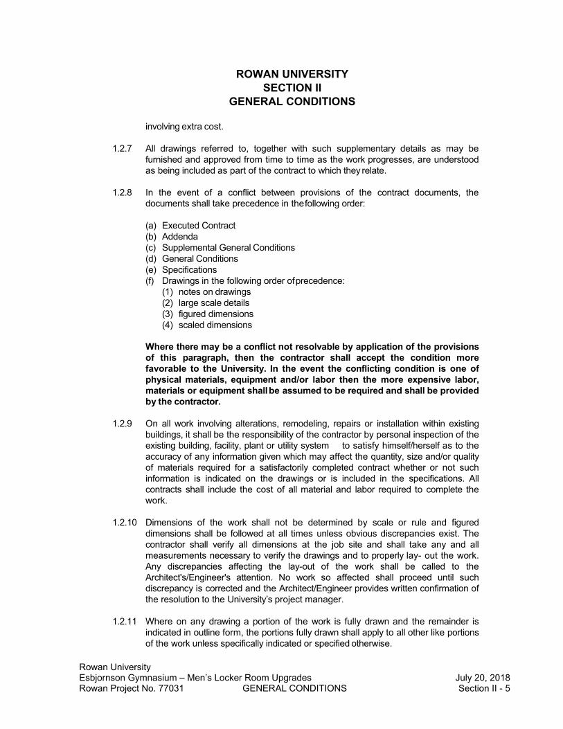
1.2.7 All drawings referred to, together with such supplementary details as may be furnished and approved from time to time as the work progresses, are understood as being included as part of the contract to which they relate.
1.2.8 In the event of a conflict between provisions of the contract documents, the documents shall take precedence in the following order:
(a) Executed Contract (b) Addenda (c) Supplemental General Conditions (d) General Conditions (e) Specifications (f) Drawings in the following order of precedence:
(1) notes on drawings (2) large scale details (3) figured dimensions (4) scaled dimensions
Where there may be a conflict not resolvable by application of the provisions of this paragraph, then the contractor shall accept the condition more favorable to the University. In the event the conflicting condition is one of physical materials, equipment and/or labor then the more expensive labor, materials or equipment shall be assumed to be required and shall be provided by the contractor.
1.2.9 On all work involving alterations, remodeling, repairs or installation within existing buildings, it shall be the responsibility of the contractor by personal inspection of the existing building, facility, plant or utility system to satisfy himself/herself as to the accuracy of any information given which may affect the quantity, size and/or quality of materials required for a satisfactorily completed contract whether or not such information is indicated on the drawings or is included in the specifications. All contracts shall include the cost of all material and labor required to complete the work.
1.2.10 Dimensions of the work shall not be determined by scale or rule and figured dimensions shall be followed at all times unless obvious discrepancies exist. The contractor shall verify all dimensions at the job site and shall take any and all measurements necessary to verify the drawings and to properly lay- out the work. Any discrepancies affecting the lay-out of the work shall be called to the Architect's/Engineer's attention. No work so affected shall proceed until such discrepancy is corrected and the Architect/Engineer provides written confirmation of the resolution to the University’s project manager.
1.2.11 Where on any drawing a portion of the work is fully drawn and the remainder is indicated in outline form, the portions fully drawn shall apply to all other like portions of the work unless specifically indicated or specified otherwise.
ROWAN UNIVERSITY SECTION II
GENERAL CONDITIONS
Rowan University Esbjornson Gymnasium – Men’s Locker Room Upgrades July 20, 2018 Rowan Project No. 77031 GENERAL CONDITIONS Section II - 6
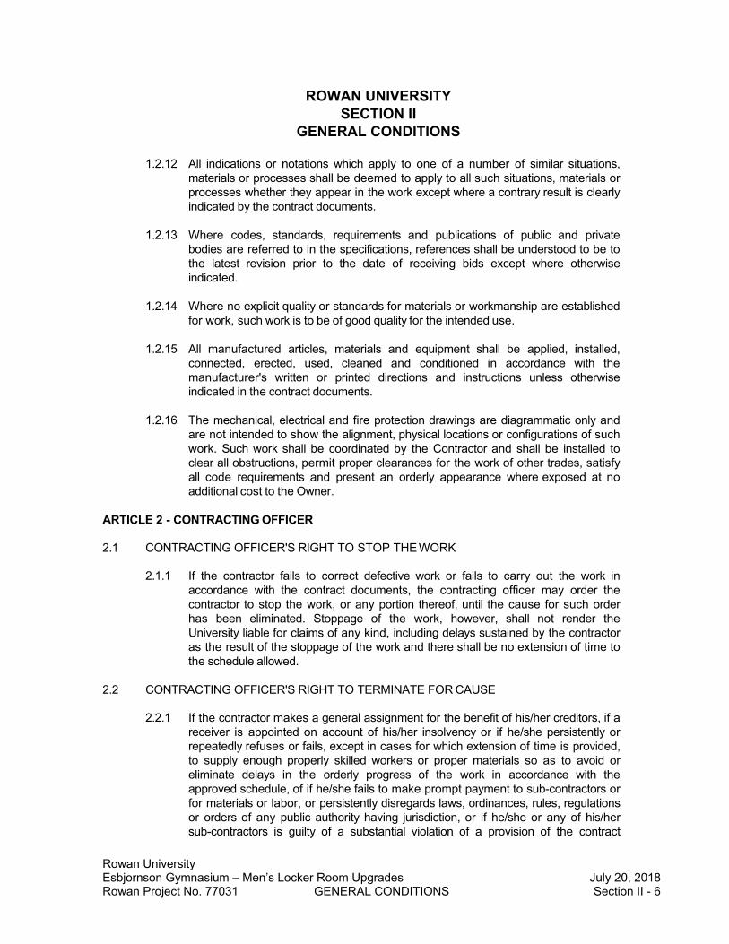
1.2.12 All indications or notations which apply to one of a number of similar situations, materials or processes shall be deemed to apply to all such situations, materials or processes whether they appear in the work except where a contrary result is clearly indicated by the contract documents.
1.2.13 Where codes, standards, requirements and publications of public and private bodies are referred to in the specifications, references shall be understood to be to the latest revision prior to the date of receiving bids except where otherwise indicated.
1.2.14 Where no explicit quality or standards for materials or workmanship are established for work, such work is to be of good quality for the intended use.
1.2.15 All manufactured articles, materials and equipment shall be applied, installed, connected, erected, used, cleaned and conditioned in accordance with the manufacturer's written or printed directions and instructions unless otherwise indicated in the contract documents.
1.2.16 The mechanical, electrical and fire protection drawings are diagrammatic only and are not intended to show the alignment, physical locations or configurations of such work. Such work shall be coordinated by the Contractor and shall be installed to clear all obstructions, permit proper clearances for the work of other trades, satisfy all code requirements and present an orderly appearance where exposed at no additional cost to the Owner.
ARTICLE 2 - CONTRACTING OFFICER
2.1 CONTRACTING OFFICER'S RIGHT TO STOP THE WORK
2.1.1 If the contractor fails to correct defective work or fails to carry out the work in accordance with the contract documents, the contracting officer may order the contractor to stop the work, or any portion thereof, until the cause for such order has been eliminated. Stoppage of the work, however, shall not render the University liable for claims of any kind, including delays sustained by the contractor as the result of the stoppage of the work and there shall be no extension of time to the schedule allowed.
2.2 CONTRACTING OFFICER'S RIGHT TO TERMINATE FOR CAUSE
2.2.1 If the contractor makes a general assignment for the benefit of his/her creditors, if a receiver is appointed on account of his/her insolvency or if he/she persistently or repeatedly refuses or fails, except in cases for which extension of time is provided, to supply enough properly skilled workers or proper materials so as to avoid or eliminate delays in the orderly progress of the work in accordance with the approved schedule, of if he/she fails to make prompt payment to sub-contractors or for materials or labor, or persistently disregards laws, ordinances, rules, regulations or orders of any public authority having jurisdiction, or if he/she or any of his/her sub-contractors is guilty of a substantial violation of a provision of the contract

ROWAN UNIVERSITY SECTION II
GENERAL CONDITIONS
Rowan University Esbjornson Gymnasium – Men’s Locker Room Upgrades July 20, 2018 Rowan Project No. 77031 GENERAL CONDITIONS Section II - 7
documents or otherwise defaults or neglects to carry out the work in accordance with the contract documents, then the contracting officer may, without prejudice to any right or remedy and, after giving the contractor and his/her surety three (3) working days written notice to forthwith commence and continue correction of such default or neglect with diligence and promptness, terminate the employment of the contractor by the issuance of a written notice to that effect to the contractor and his/her surety at any time subsequent to three (3) working days thereafter should they, or either of them, fail to comply with the demands of the original three (3) day notice as mentioned above.
2.2.2 Upon such termination, the contracting officer may take possession of the site and of all the materials, equipment and tools on the site and may finish the work by whatever method he/she may deem expedient. In such case, the contractor shall not be entitled to receive any further payment until the work is finished. The person or firm designated to carry out such work will be paid as authorized by the contracting officer without entailing any personal liability upon the officers of the University issuing certificates or making such payment(s).
2.2.3 If the unpaid balance of the contract sum exceeds the cost of finishing the work, including liquidated damages for delays and all consequential damages sustained by the University flowing from such breach of contract, such excess shall be paid to the contractor. If such costs exceed the unpaid balance, the contractor and/or his/her surety shall pay the difference to the University promptly upon demand and this obligation shall survive the termination of the contract.
2.2.4 If, within three (3) working days following receipt of notice of termination by the contractor's surety, the issuer of the performance and payment bonds, the said surety exercises its right to take over the work and expeditiously commences to prosecute the same to completion, the contracting officer shall permit him/her to do so under the following terms and conditions:
(a) evidence of the surety's intention to take over and complete the contract shall be in writing over the signature of a University project manager and served upon the contracting officer within three (3) days after receipt by the surety of notice of termination
(b) the execution of a written agreement between the University, by the contracting officer, and the surety whereby the latter undertakes and assumes the obligation to complete the balance of the work of its defaulting contractor in accordance with the terms and conditions of the University contractor agreement, to be performed by a substituted contractor satisfactory to the contracting officer, at the surety's sole cost and expense, and providing for payments to the surety or to the substituted contractor of unpaid contract balances, if any, then in the hands of the University
(c) the said agreement shall also expressly provide that the surety shall not be relieved thereby from any of its obligations under the performance and payment bonds and that it furnishes the University with an additional performance and payment bond to secure the faithful performance of the

ROWAN UNIVERSITY SECTION II
GENERAL CONDITIONS
Rowan University Esbjornson Gymnasium – Men’s Locker Room Upgrades July 20, 2018 Rowan Project No. 77031 GENERAL CONDITIONS Section II - 8
substituted contractor (d) that all current obligations for labor and materials incurred and outstanding by
the defaulting contractor on this project be paid without delay, subject to allowance of a reasonable time within which to verify such claims by the surety
(e) that the parties expressly understand and agree that this agreement is without prejudice and is subject to such rights and remedies as either party, including the contractor, may elect to assert after final completion and acceptance of the work
2.2.5 Right to Terminate for Convenience: The contracting officer reserves the right to terminate for the convenience of the University in which case the contractor shall be entitled to a proportion of the fee for which the services actually and satisfactorily performed by the contractor shall bear to the total services contemplated under this agreement, less payments previously made, together with appropriate reimbursable costs and a reasonable termination fee to be negotiated between the contractor and the contracting officer.
2.3 REVIEW OF CONTRACTOR CLAIMS AND DISPUTES
2.3.1. In the event of a dispute other than a Change Order dispute between the Contractor and the University, the Contractor may request, in writing, a hearing of any claim, dispute or matter in question relating to this contract. The University shall then designate a Hearing Officer, who may be the University's designee under this contract. The Hearing Officer shall not side with the University or the Contractor but shall use his/her powers to enforce faithful performance by all.
2.3.1.1 The Hearing Officer shall permit both the Contractor and the University to provide such relevant information to the Hearing Officer and each other, as the Hearing Officer needs to render a decision. Upon rendering a decision, the Hearing Officer will memorialize that decision in writing.
2.3.1.2 In the event that both the Contractor and the University agree with the Hearing Officer's decision, each will acknowledge its acceptance in writing.
2.3.1.3 In the event that the dispute is not resolved as set forth in Paragraph 2.3.1.2 hereof, then the University shall review all information provided to the Hearing Officer pursuant to Paragraph 2.3.1.1 hereof and the finding of the Hearing Officer and shall issue a final decision which shall be reduced to writing and a copy provided to the University's designee and the Contractor.
2.3.1.4 Pending such final decision, the Contractor shall have no recourse to court actions, assuming that the aforesaid administrative procedures take place within a reasonable amount of time. Upon receipt of the final decision, either party may then commence appropriate legal proceedings.
2.3.1.5 Unless and until it is determined as a result of any legal proceedings that the University is in material breach of this contract the Contractor shall proceed diligently with the performance of its contract responsibilities.
2.4 UNIVERSITY REPRESENTATION

ROWAN UNIVERSITY SECTION II
GENERAL CONDITIONS
Rowan University Esbjornson Gymnasium – Men’s Locker Room Upgrades July 20, 2018 Rowan Project No. 77031 GENERAL CONDITIONS Section II - 9
2.4.1. The University shall be represented on the site by a University’s project manager. The University’s project manager will conduct or contract out on-site inspections, maintenance of logs for construction progress and problems encountered, approval of contractor's requisition for payments subject to final approval by the Architect and contracting officer, attendance at job meetings, the act of liaison with the Architect/Engineer and contractor, preparation and submission of reports on special problems associated with the job, evaluation and processing change orders and generally remain fully cognizant and be kept informed by the contractor of every aspect of ongoing construction. The University's project manager will have only those duties, which are required of an owner. Responsibility for completion of this project, pursuant to the contract documents, remains with the contractor. No right of the University exercised hereunder shall be considered a waiver of the contractor's obligation or any obligations created by this agreement, which may be modified or excused only in accordance with the terms of the contract.
ARTICLE 3 - ARCHITECT/ENGINEER AND CONSTUCTION MANAGER
3.1 ARCHITECT/ENGINEER
3.1.1 The Architect's/Engineer's has no power or authority to approve changes to the work under this contract and its role is that of consultant to the University.
3.2 ADMINISTRATION OF THE CONTRACT
3.2.1 The Architect/Engineer and the University’s project manager will provide a certain portion of the administration of the contract as hereinafter described.
3.2.2 The Architect/Engineer and the University’s project manager will monitor the execution and progress of the work and will immediately notify the University of any related problems. The Architect/Engineer and the University’s project manager will be provided access to the work at all times. The general contractor shall provide facilities for such access so as to enable the Architect/Engineer and the University’s project manager to perform their functions under the contract documents.
3.2.3 The Architect/Engineer and/or the University’s project manager will not be responsible for, nor will they have control or charge of, construction means, methods, techniques, sequences of procedures or safety precautions and programs in connection with the work. The Architect/Engineer and/or the University’s project manager will not be responsible for, nor have control or charge over, the acts or omissions of the contractor, sub-contractors or any of their agents or employees or any other person performing any of the work but shall have the obligation to immediately inform the contractor, and the contracting officer of any inadequate performance on the project.
In the event that the University’s project manager notices any safety violations, the University’s project manager shall have the right, but not the obligation, to inform the Contractor and to immediately stop work for any imminent or life threatening danger.

ROWAN UNIVERSITY SECTION II
GENERAL CONDITIONS
Rowan University Esbjornson Gymnasium – Men’s Locker Room Upgrades July 20, 2018 Rowan Project No. 77031 GENERAL CONDITIONS Section II - 10
3.2.4 The University’s project manager, after consultation with the Architect/Engineer, will recommend the rejection of work, which he/she believes does not conform to the contract documents. In his/her opinion, whenever he/she considers it necessary or advisable, he/she may request the contracting officer to provide special inspection or testing of the work whether or not such work has been fabricated, installed or completed. The Contractor shall pay for all such testing whether the work is deemed to conform to the contract document or not.
3.2.5 Both the Architect/Engineer and the University’s project manager will periodically review the contractor's as-built drawings to determine whether these are up-to-date.
3.3 INSPECTIONS - SUBSTANTIAL AND FINAL COMPLETION
3.3.1 The Architect/Engineer and the University’s project manager will conduct inspections, accompanied by the contractor to determine the dates of substantial and final completion. The Architect/Engineer and the University’s project manager will receive and forward written warranties and related documents required by the contract documents and assembled by the contractor to the contracting officer for his/her review. The Architect/Engineer and the University’s project manager will approve the issuance of a certificate of final completion.
3.4 OWNERSHIP AND USE OF DOCUMENTS
3.4.1 All drawings, specifications and copies thereof furnished to the Contractor by the Architect/Engineer are and shall remain the property of the University. They are reserved to this project only and are not be to be used on any other project. Submission or distribution of documents to meet official regulatory requirements or for any other purposes in connection with the project shall not be construed as derogation of the Architect's/Engineer's copyright or other reserved rights.
3.5 UNIVERSITY’S PROJECT MANAGER
3.5.1 In addition to the duties specified elsewhere in the contract documents, the University’s project manager and the contractor shall perform as follows in relation to one another:
a) the contractor will permit the University’s project manager to inspect delivery of any off-site materials that are being requisitioned by the contractor;
b) upon request by the University’s project manager, the contractor will schedule visits to fabrication plants to inspect the status of various fabricated materials with regard to quality and scheduled delivery; the contractor will allow the University’s project manager access to such facilities;
c) the contractor will attend a Preconstruction conference and bi-weekly project meetings, or more often if necessary, at times and locations specified by the University’s project manager;
d) the contractor shall submit to the contracting officer, through the University’s project manager, all information or requests concerning scheduling, contract or change order/claims;

ROWAN UNIVERSITY SECTION II
GENERAL CONDITIONS
Rowan University Esbjornson Gymnasium – Men’s Locker Room Upgrades July 20, 2018 Rowan Project No. 77031 GENERAL CONDITIONS Section II - 11
e) the University’s project manager will receive, log, transmit and evaluate any requests from the contractor for interpretations of the meaning and intent of the contract documents to the contracting officer and Architect/Engineer;
f) the University’s project manager will monitor all training by the contractor of owner's representatives for equipment and maintenance procedures.
ARTICLE 4 - THE CONTRACTOR
4.1 REVIEW OF CONTRACT
4.1.1 The contractor has the duty and warrants and represents that he/she has thoroughly examined and is familiar with all the contract documents including, but not limited, the complete set of drawings and specifications of the entire project; all other documents referred to in the advertisement for bids, the specifications, or otherwise; that he/she has noted cases where it is specified that certain work or materials, or both, are to be omitted from the contract and to be furnished or installed by another; that he/she has carefully examined the site and the contract; that from his/her own investigations, he/she has satisfied himself/herself as to the nature and location of the work, the current local equipment labor and material conditions and all matters which may, in any way, affect the work or its performance. The contractor is responsible to check and verify all conditions inside and outside the contract limit lines to determine whether any conflict exists with the work he/she is required to perform under the contract. The submission of a bid is conclusive evidence that the bidder has made such examination and is fully aware of the conditions to be encountered in performing the work including any subsurface condition which could be ascertained by due diligence and as to the requirements of the contract documents. This includes a verification of all elevations, utility locations and other site data. Within the site of the project, there may be public utility structures and, notwithstanding any other clause or clauses of this contract, the contractor shall not proceed with the work until he/she has made diligent inquiry at the utility companies and municipal authorities or other owners to determine their exact location. The contractor shall notify the utility companies and municipalities or other owners involved in writing of the nature and scope of the project and of his/her operation that may affect their facilities or property. The contractor is directed to the fact that the approximate locations of known utility structures and facilities that may be encountered within and adjacent to the limits of the work may be shown on the plans. The accuracy and completeness of this information is not guaranteed by the State and the contractor is advised to ascertain for himself/herself all the facts concerning the location of these utilities. The contractor shall carry out his/her work carefully and skillfully and shall support and secure utility structures so as to avoid damage to them. It is understood and agreed that the contractor has considered all of the permanent and temporary utility facilities in their present and/or relocated positions as shown on the plans and as revealed by his/her site investigation in his/her bid, is cognizant of the limited ability of the State to control the actions of the utilities and has made allowance for the fact that additional compensation will not be allowed for any delays, inconvenience or damage sustained by him/her due to any interference from the said utility facilities or the operation of moving them in his/her bid. As a result of such examination and

ROWAN UNIVERSITY SECTION II
GENERAL CONDITIONS
Rowan University Esbjornson Gymnasium – Men’s Locker Room Upgrades July 20, 2018 Rowan Project No. 77031 GENERAL CONDITIONS Section II - 12
investigation, the contractor warrants and represents that he/she fully understands the intent and purposes of the contract documents and his/her obligations there under and that he/she accepts responsibility for and is prepared to execute and fulfill completely by his/her construction work the intent of the contract without exception and without reservation at the price specified in the contract.
4.1.2 The contractor shall carefully study and compare the contract documents during the progress of the work and shall immediately report any error, inconsistency or omission to the University’s project manager upon discovery. The contractor shall immediately report any error, inconsistency or ambiguity detected during the course of the project to the University’s project manager and shall do no work thereafter which may be affected by such error until the contracting officer, through the University’s project manager, has had the opportunity to respond and clarify the work it wants performed in view of this information. Wherever any error, inconsistency or omission appears, it shall be disposed of pursuant to appropriate procedures set forth elsewhere herein.
4.1.3 Unless otherwise ordered in writing by the contracting officer through the University’s project manager, the contractor shall perform no portion of the work without approved change orders, approved shop drawings or samples for such portions of the work or other approvals as may be applicable and required by the contract documents.
4.1.4 Unless otherwise provided in the contract documents, the contractor shall provide and pay for all labor, equipment, materials, tools, construction equipment and machinery, water, heat, utilities, transportation and other facilities and services necessary for the proper execution and completion of the work whether or not incorporated or to be incorporated in the work.
4.1.5 At all times, the contractor shall enforce strict discipline and good order among his/her employees and shall not employ any individual who violates these provisions or is unfit or anyone not skilled in the task assigned to him/her on the work.
4.1.6 The contractor shall be obligated to pay the prevailing wage rates set forth in the specifications. He/she shall abide by the requirements of the State's Affirmative Action Program. He/she shall also be responsible to insure that all principles of safety are carried out as further described in Article 12 herein. The contractor shall prepare certified payrolls and shall submit such records to the University as required by New Jersey statute and corresponding regulations.
4.2 NEW JERSEY PREVAILING WAGE ACT
4.2.1 Each contractor or any sub-contractor shall comply with the New Jersey Prevailing Wage Act Laws of 1963, Chapter 150, and all amendments thereto as this Act is hereby made a part of every contract entered into on behalf of the University except those contracts which are not within the contemplation of the Act. Provisions of the Act include:

ROWAN UNIVERSITY SECTION II
GENERAL CONDITIONS
Rowan University Esbjornson Gymnasium – Men’s Locker Room Upgrades July 20, 2018 Rowan Project No. 77031 GENERAL CONDITIONS Section II - 13
a) All workmen employed in the performances of every contract in which the contract sum is in excess of $2,000 and work to which the University is a party shall be paid not less than the prevailing wage rate as designed by the Commissioner of Labor and Industry or his/her duly University’s project manager. 1. The contractor and all sub-contractor(s) performing public work for the
University who are subject to the provisions of the Prevailing Wage Act shall post the prevailing wage rates for each craft and classification involved as determined by the Commissioner, including the effective date of any changes thereof, in prominent and easily accessible places at the site of the work or at such place or places as are used by them to pay workmen/workwomen their wages.
2. The contractor's signature on the proposal is his/her guarantee that neither he/she nor any sub-contractor is currently listed or is on record by the Commissioner as one who has failed to pay the prevailing wages according to the Prevailing Wage Act.
b) In the event it is found any workman/workwoman employed by the contractor or any sub-contractor covered by the contract in excess of $2,000 for any public work to which the University is a party has been paid a rate of wages less than the prevailing wage required to be paid by such contract, the contracting officer may terminate the contractor's or sub-contractor's right to proceed with the work or such part of the work as to which there has been a failure to pay required wages and may otherwise prosecute the work to completion.
c) Nothing contained in the Prevailing Wage Act shall prohibit the payment of more than the prevailing wage rate to any workman/workwoman employed on a public work.
4.3 SUPERVISION AND CONSTRUCTION PROCEDURES
4.3.1 The contractor shall supervise and direct the work using his/her best skill and attention and coordinate his/her work with his/her sub-contractors. He/she shall be solely responsible for all construction means, methods, techniques, sequences and procedures and for coordinating all portions or the work under the contract.
4.3.2 The contractor shall employ a full-time, competent superintendent and necessary foreperson and assistants who shall be in attendance on the project site at all times during the progress of the work. The superintendent shall represent the contractor and all communications given to the superintendent shall be as binding as if given to the contractor. Important communications shall be confirmed in writing. The University reserves the right to require a change in a superintendent if his/her performance, as judged by the contracting officer, is deemed to be inadequate. Upon application in writing to the contracting officer, this requirement for a full-time superintendent may be waived by the contracting officer should he/she determine that such staffing is not required by the University.
4.3.3 The contractor shall hire qualified, able crafts persons in their respective lines of work.

ROWAN UNIVERSITY SECTION II
GENERAL CONDITIONS
Rowan University Esbjornson Gymnasium – Men’s Locker Room Upgrades July 20, 2018 Rowan Project No. 77031 GENERAL CONDITIONS Section II - 14
4.3.4 The various sub-contractors shall have competent superintendents and/or forepersons in charge of their respective portions of the work at all times. They shall not employ a person unfit or unskilled in the work assigned to him/her. If it should become apparent to the University or its consultant that a sub-contractor does not have his/her portion of the work under control of a competent foreperson, the contractor shall take appropriate steps to immediately provide proper supervision.
4.3.5 If due to a trade agreement or otherwise stand-by personnel are required to supervise equipment installation or for any other purpose during normal working hours of other trades, the contractor shall valuate and include the costs thereof in his/her bid price and shall provide said services without additional charge.
4.3.6 The contractor shall give the Architect/Engineer timely notice of any additional drawings, specifications or instructions required to define the work in greater detail or to permit the proper progress of the work.
4.3.7 The contractor shall correct all work incorrectly done at the contractor’s own expense.
4.4. RESPONSIBILITY FOR THE WORK
4.4.1 The contractor shall be responsible to the University, the contracting officer, the University’s project manager, the Architect/Engineer and to separate contractors having a contract with the University on this project for the acts and omissions of his/her employees, sub-contractors and their agents and employees which injure, damage or delay such other contractors in the performance of their work. This responsibility is not limited by the applicable provisions stated elsewhere herein but is in conjunction with and related thereto.
4.4.2 The contractor shall be responsible for all damage or destruction caused directly or indirectly by his/her operations to all parts of the work, both temporary and permanent, to all affected property including adjoining property.
4.4.3 At his/her own expense, the contractor shall protect all finished work and any stored materials whether on site or off and keep the same protected until the project is completed and accepted. In the case of substantial completion accompanied by beneficial occupancy by the University, the contractor's obligation to protect his/her finished work shall cease simultaneously with the occupancy of the portion or portions of the structure.
4.4.4 The contractor shall defend, protect, indemnify and save harmless the State and the University from all claims, suits, actions, damages and costs of every name and description arising out of, or resulting from, the performance of or failure to perform work under this contract. This responsibility is not limited by the provisions of other indemnification provisions included elsewhere herein or compliance with any other insurance provision.
4.4.5 In order to protect the lives and health of his/her employees, the contractor shall comply with all applicable statutes, laws, rules, and regulations and shall maintain

ROWAN UNIVERSITY SECTION II
GENERAL CONDITIONS
Rowan University Esbjornson Gymnasium – Men’s Locker Room Upgrades July 20, 2018 Rowan Project No. 77031 GENERAL CONDITIONS Section II - 15
an accurate record of all cases of death, occupational disease and injury requiring medical attention or causing loss of time from work arising out of and in the course of employment on work under this contract. The contractor alone shall be responsible for the safety, efficiency and adequacy of his/her plant, appliances and methods and, for any damage or injury, which may result from his/her failure or his/her improper construction, maintenance or operation.
4.5 PERMITS - LAW - REGULATIONS
4.5.1 Unless otherwise provided in the contract documents, the contractor shall secure but the University shall pay for all permits and governmental fees and inspections necessary for the proper execution and completion of the work.
4.5.2 All construction work shall be done in accordance with the New Jersey Uniform Construction Code. No work requiring inspections and approvals of construction code officials is to be covered or enclosed prior to inspection and approval by appropriate code enforcement officials.
4.5.3 The work under this contract is exempt from local ordinances, codes and regulations as related to the building and the site on which it is located, except where construction could adversely affect adjacent property, public sidewalks and/or streets. The contractor shall coordinate his/her activities with municipal and/or highway authorities having appropriate jurisdiction.
4.5.4 Soil conservation measures are to be in accordance with the County Soil Conservation District requirements and all pertinent codes and regulations.
4.5.6 The contractor shall comply with all applicable Federal, State and local laws and regulations and all conditions of permits controlling pollution of the environment. Necessary precautions shall be taken to prevent pollution of streams, lakes, ponds, wetlands, ground water and reservoirs with fuels, oils, bitumens, chemicals or harmful materials and to prevent pollution of the atmosphere from particulate and gaseous matter. All sewage disposal work shall conform with the regulations of the State Department of Environmental Protection.
4.5.7 The University will pay for all code inspections; however, it is the contractor's responsibility to request and set up inspections with the appropriate agency for all work requiring inspection, in a timely manner.
4.5.8 Consistent with sub-paragraph 4.4.4, the contractor shall be responsible for and save harmless the University from all fines, penalties or loss incurred for, or by reason of, the violation of any Federal, State of municipal law, rule, regulation or ordinance while the said work is in the process of construction.
4.5.9 Without limiting the foregoing, the contractor shall comply with the Federal Occupational Safety and Health Act of 1970 and all of the rules and regulations promulgated there under and the New Jersey Worker and Community Right-to-Know Act, PL1983 c. 315 N.J.S.A. 34:5A-1, et.seq.

ROWAN UNIVERSITY SECTION II
GENERAL CONDITIONS
Rowan University Esbjornson Gymnasium – Men’s Locker Room Upgrades July 20, 2018 Rowan Project No. 77031 GENERAL CONDITIONS Section II - 16
4.5.10 As a result of a finding, by an appropriate finder of fact, that the contractor caused a substantial violation of a Federal, State or local statute or regulation on said project, the University may declare the contractor to be in default.
4.5.11 Prior to the start of any crane equipment operations, the contractor shall make all necessary applications and obtain all required permits from the Federal Aviation Administration (FAA). The sequence of operations, timing and methods of conducting the work shall be approved by the FAA to the extent it relates to their jurisdiction.
4.6 STORAGE, CLEANING AND FINAL CLEAN-UP
4.6.1 The contractor shall confine his/her apparatus, the storage of his/her equipment, tools and materials and his/her operations and workmen/workwomen to areas permitted by law, ordinances, permits, contract limit lines as established in the contract documents, the rules and regulations of the University or as ordered by the contracting officer and/or University’s project manager and shall not unreasonably encumber the site or the premises with his/her materials, tools and equipment.
4.6.2 At all times during the progress of the work, the contractor shall keep the premises and the job site free from the accumulation of all refuse, rubbish, scrap materials and debris caused by his/her operations to the end that the premises and site shall present a neat, orderly and workmanlike appearance at all times. This is to be accomplished as frequently as is necessary by the removal of such material, debris, etc. from the site and the owner's premises.
4.6.3 Upon completion of the construction, the contractor will remove all his/her tools, construction equipment, machinery, temporary staging, false work, formwork, shoring, bracing, protective enclosures, scaffolding, stairs, chutes, ramps, runways, hoisting equipment, elevators, derricks, cranes, etc. from the project site.
4.6.4 Should the contractor not promptly and properly discharge his/her obligation relating to cleaning and final clean-up, the University shall have the right to employ others and to charge the cost thereof to the contractor after first having given the contractor a three (3) working day written notice of such intent.
4.6.5 In each instance, the clean-up work shall be performed by the contractor.
4.6.6 All construction equipment, materials or supplies of any kind, character or description of value belonging to the contractor which remains on the job site for more than thirty (30) days from the date of the certificate of final acceptance and completion issued by the University to the contractor shall become the absolute property of the University. It shall be disposed of in any manner the University deems reasonable and proper. Disposal costs will be the responsibility of the contractor.
4.7 CUT-OVERS, TIE-INS, INTERRUPTIONS TO EXISTING BUILDINGS
ROWAN UNIVERSITY SECTION II
GENERAL CONDITIONS
Rowan University Esbjornson Gymnasium – Men’s Locker Room Upgrades July 20, 2018 Rowan Project No. 77031 GENERAL CONDITIONS Section II - 17
4.7.1 All cut-overs of inter and tie-ins to existing building shall be scheduled and coordinated in advance with the contracting officer's representative and shall be done at a time convenient to the University so as not to unreasonably interfere with its operations.
4.8 WORKDAYS
4.8.1 Regular working hours shall be 8:00 a.m. to 4:30 p.m. Monday through Friday or as agreed to by the Contractor and University after consultation with the University’s project manager. Changes thereto may be granted with written approval of the contracting officer. Any work required to be performed after regular working hours or on Saturdays, Sundays or legal holidays as may be reasonably required consistent with contractual obligations shall be performed without additional expense to the University. The contractor shall obtain approval of the contracting officer through the University’s project manager for performance of work after regular working hours or on non-regular workdays at least forty-eight (48) hours prior to the commencement of overtime, unless such overtime work is caused by an emergency.
4.9 DRAWINGS, SPECIFICATIONS, SHOP DRAWINGS, AS-BUILT DRAWINGS
4.9.1 The contracting officer, through the Architect/Engineer or University’s project manager, will furnish additional instructions for the proper execution of the work after he/she becomes aware of its need. All drawings and instructions issued by the contracting officer shall be consistent with the contract documents and reasonably inferable there from. The work shall be executed in conformity therewith. The contractor shall do no work without proper drawings and instructions. In giving such additional instructions, the contracting officer will have the authority to make minor changes in the work not involving extra cost. Drawings and instructions with such supplementary details as may be furnished or approved are understood to be included and a part of the contract.
4.9.2 Where certain of the work is shown in complete detail but not repeated in similar detail in other areas of the drawings or there is an indication of continuation, the remainder being only shown in outline, the work shown in detail shall be understood to be required in other like portions of the project.
4.9.3 At any time after the execution of his/her contract, the contractor shall not make any claims whatsoever based upon insufficient data or his/her incorrectly assumed conditions nor shall he/she claim any misunderstandings with regard to the nature, conditions or character of the work to be done under the contract and he/she shall assume all risks resulting from any changes in conditions not caused by the University, the contracting officer or the University’s project manager which may occur during the progress of the work. In the event that the Contractor alleges that there was insufficient data or that he/she incorrectly assumed any condition or that he/she claims any misunderstanding with regard to the nature, conditions or character of the work, the Contractor shall disclose to the University the method by which he/she intended to perform the work in question as set forth in his/her bid.
ROWAN UNIVERSITY SECTION II
GENERAL CONDITIONS
Rowan University Esbjornson Gymnasium – Men’s Locker Room Upgrades July 20, 2018 Rowan Project No. 77031 GENERAL CONDITIONS Section II - 18
This information must be provided with the initial notice from the Contractor to the University. The Contractor shall not be entitled to any additional compensation based upon clarifications issued pursuant to this section.
4.9.4 If the contractor desires to make any deviations or changes from the requirements of the contract documents, he/she shall obtain the consent of the contracting officer through the University’s project manager or Architect/Engineer to such changes in writing before submitting drawings showing such proposed changes. All drawings submitted by the contractor shall have been checked and approved by him/her before submission. The drawings and specification references shall be noted on all submissions. Failure to comply with these instructions will be sufficient reason to return such drawings to the contractor without any action being taken.
4.9.5 LEFT BLANK
4.9.6 LEFT BLANK
4.9.7 LEFT BLANK
4.9.8 LEFT BLANK
4.9.9 Wherever any material is specified in accordance with federal specifications, ASTM specifications, American National Standards Institute, Inc. specifications, manufacturer's association’s specification standards or other standards, the contractor shall present an affidavit to the Architect/Engineer upon request from the manufacturer certifying that the material complies with the particular standard specification. Where necessary and requested or specified, supporting test data shall be submitted to substantiate compliance. All tests required in support of the affidavit shall be at the cost of the contractor.
4.10 SAMPLES
4.10.1 The contractor shall furnish all samples as directed to the University’s project manager who shall forward them to the Architect/Engineer and University for approval. The work shall be in accordance with approved samples. Such samples shall be representative of the actual and the University’s project manager shall submit conditions promptly to the contracting officer after approval by the Architect/Engineer at the beginning of the work as so as give the contracting officer time to examine them. Contractor shall provide all disclaimers, limitations and conditions to contracting officer in order to fully inform contracting officer of potential deviations from the sample, including but not limited to color, texture, type, finish, etc. Any list of samples prepared by the Architect/Engineer is for the contracting officer's convenience only and shall not be construed as limiting the number of samples, which the contractor shall furnish upon request of the Architect/Engineer or University’s project manager.
4.11 LEFT BLANK

ROWAN UNIVERSITY SECTION II
GENERAL CONDITIONS
Rowan University Esbjornson Gymnasium – Men’s Locker Room Upgrades July 20, 2018 Rowan Project No. 77031 GENERAL CONDITIONS Section II - 19
4.12 OPENINGS, CHANNELS, CUTTING AND PATCHING
4.12.1 The contractor shall be responsible for furnishing and setting of sleeves, built-in items, anchors, inserts, etc. for his/her work and for all cutting, fitting, closing-in, patching, finishing or adjusting of his/her work in a new and/or existing construction as required for the completed installation. Where applicable, the contractor shall build these items into the construction.
4.12.2 The contractor shall built recesses, channels, chases, opening and flues and shall leave or create holes where on drawings or where directed for steam, water or other piping, electrical conduits, switch boxes, panel boards, hues and ducts or any other feature of the heating and ventilating work.
4.12.3 The contractor shall close, build-in and finish around or over all openings, chases, channels, pockets, etc. after installation has been completed.
4.13 TESTS
4.13.1 The contractor shall notify the contracting office in writing through the University’s project manager of all work required to be inspected, tested or approved. The notice shall be provided no later than five (5) working days prior to the scheduled inspection, test or request for approval. The contractor shall bear all costs of such inspections, tests or approvals except for code inspections as stated in 4.5.6. All tests must be recorded by the contractor and records made available to the University and/or University’s project manager upon request.
4.13.2 LEFT BLANK
4.13.3 LEFT BLANK
4.13.4 LEFT BLANK
4.13.5 The contractor shall acquire inspection or testing services using only those firms/entities preapproved by the University. Failure to use a firm/entity preapproved by the University shall be grounds for rejection of the inspection or test as non-conformance.
4.13.6 In addition to the above, the contractor agrees to insert in all contracts/purchase orders for inspection and testing the requirement for the inspection or testing firm/entity to submit, in conjunction with the report to the contractor, a copy of the report directly to the University’s project manager or contracting officer. The copy shall be held pending receipt of the contractor's certification of the report. Further, the contractor agrees to require all reports be submitted within fourteen (14) calendar days of the test or inspection. Failure to provide reports within the required time shall be addressed pursuant to Article 10.3.9 of the general conditions.
4.13.7 LEFT BLANK
ROWAN UNIVERSITY SECTION II
GENERAL CONDITIONS
Rowan University Esbjornson Gymnasium – Men’s Locker Room Upgrades July 20, 2018 Rowan Project No. 77031 GENERAL CONDITIONS Section II - 20
4.14 EQUIPMENT - MATERIAL
4.14.1 The contractor warrants to the University, the contracting officer, University’s project manager and Architect/Engineer that all materials and equipment furnished under the contract will be new, unless otherwise specified, and that all work will be of good quality, free from defects, faults and in conformance with the contract documents. All work not conforming to these requirements, including substitutions not properly approved and authorized, may be considered defective and rejected by the contracting officer, the University’s project manager or the Architect/Engineer. If required by the University’s project manager, Architect/Engineer or the contracting officer, the contractor shall furnish satisfactory evidence as to the kind and quality of materials and equipment. This warranty is not limited by the provisions of the other paragraphs contained herein.
4.14.2 The contractor shall furnish and deliver the necessary equipment and materials in ample quantities and as frequently as required to avoid delay in progress of the work and shall store same so as not to cause interference with the orderly progress of the project.
4.14.3 The contractor shall furnish and pay for all necessary transportation, storage, scaffolding, centering, forms, water, labor, tools, light and power mechanical appliances and all other means, materials and supplies for properly prosecuting the work under this contract unless expressly specified otherwise. The contractor shall make arrangements to have representatives of his/her firm at the site to accept delivered materials. The University will not be held responsible for damage, theft or disappearance of the contractor's property. In receiving and storing equipment and material, the contractor shall be responsible for OSHA requirements for the entire project including OSHA requirements for temporary access to all floors.
4.14.4 Whenever available, manufactured products of the United States shall be used in this work. Wherever practicable, preference shall be given at all times to material and equipment manufactured or produced in the State of New Jersey where such preference is reasonable and will best serve the interest of the University.
4.14.5 No materials, equipment or supplies for the work shall be purchased by the contractor or any sub-contractor subject to any lien or encumbrance or other agreement by which an interest is retained by the seller. By signing his/her requisition for payment, the contractor warrants that he/she has good and sufficient title to all such material, equipment and supplies used by him/her in the work, free from all liens, claims and encumbrances.
4.15 SUBSTITUTIONS
4.15.1 The contract documents are intended to produce a building of consistent character and quality of design. All components of the building, including visible items of mechanical and electrical equipment, have been selected to have a coordinated design in relation to the overall appearance of the building. The Architect/Engineer shall judge the design and appearance of proposed substitutes on the basis of their

ROWAN UNIVERSITY SECTION II
GENERAL CONDITIONS
Rowan University Esbjornson Gymnasium – Men’s Locker Room Upgrades July 20, 2018 Rowan Project No. 77031 GENERAL CONDITIONS Section II - 21
suitability in relation to the overall design of the project as well as for their intrinsic merits. The Architect/Engineer will not approve as equal to materials specified proposed substitutes which, in the Architect's/Engineer's sole opinion, would be out of character, obtrusive or otherwise inconsistent with the character or quality of design of the project. In order to permit coordinated design of color and finishes, the contractor shall, if required by the Architect/Engineer, furnish the substituted material in any color, finish, texture or pattern which would have been available from the manufacturer originally specified at no additional cost to the owner.
4.15.2 In the event the contractor should propose a substitution for the specified equipment or materials, it shall be his/her responsibility to submit proof of equality and to provide and pay for any tests which may be required by the contracting officer, the University’s project manager or Architect/Engineer in order to evaluate such proposed substitution.
4.15.3 Where any particular brand or manufactured article is specified, it shall be regarded as a standard. Similar products of other manufacturers, capable of equal performance and quality in the opinion of the contracting officer, will be accepted, if approved.
4.15.4 There shall be no extension of time to the project schedule granted to accommodate the requirements of this Article 4.15. Substitutions and/or any testing, etc. required to be done by the contractor to have the substitution approved will be done within the approved project schedule timeframe.
4.15.5 The application for approval of a substitution by the contractor shall include the following information:
a) identifying information shall be fully and completely furnished b) note whether the item is included in the specifications in which case,
identify the specification paragraph and section c) attach data indicating, in detail, whether and how the substitution differs, if
at all, from the article specified d) if a credit is to be offered for the substitution, a detailed itemization of the
amount of credit must be shown e) if the proposed substitution involves a change in the scope of the work of
this or any other contractor or trade under the contract documents, then and, in that event, the contractor undertakes and agrees to be responsible for any and all added costs and thereby involved by reason of the change in the work, including redesign if any
f) when requesting approval of an out-of-state sub-contractor or material manufacturer or supplier, a statement indicating that reasonable effort was first made to find and employ New Jersey firms and/or materials at comparable costs, term and performance capabilities
g) an agreement by the contractor to submit proof of equality and to have such tests performed at his/her own expense as may be required by the contracting officer or the Architect/Engineer

ROWAN UNIVERSITY SECTION II
GENERAL CONDITIONS
Rowan University Esbjornson Gymnasium – Men’s Locker Room Upgrades July 20, 2018 Rowan Project No. 77031 GENERAL CONDITIONS Section II - 22
h) the contractor shall not base his/her bid on substitutions, which may have been approved on previous projects; bids shall be based solely on plans and specifications of the subject project
Since substitutions are primarily for the financial benefit of the contractor, a credit change order shall accompany each request for substitution.
4.16 SUB-CONTRACTOR APPROVALS
4.16.1 Approval by the contracting officer, University’s project manager or Architect/Engineer of a sub-contractor or material supplier shall not relieve the contractor of the responsibility for complying with all provisions of the contract documents. The approval of a sub-contractor does not imply approval of any material, equipment or supplies.
4.16.2 The contractor shall coordinate and supervise the work performed by sub-contractors to the end that the work is carried out without conflict between trades and so that no delay to the general progress of the work occurs. The contractor and all sub-contractors shall afford each trade, any separate contractor or the owner every reasonable opportunity for the installation of work and the storage of materials at all times.
4.17 PAY LIMITS FOR ADDITIONS OR DEDUCTIONS FOR EXCAVATION
4.17.1 The method of measurement and establishment of pay limits for additions or deductions for excavation shall be as follows:
a) Basement Excavations: Pay limit for excavation shall be determined by horizontal and sloped lines as defined on the foundation plan and "typical subsoils preparation details": In the case where the contract limit line is in close proximity to the building and sheeting/shoring are required, the vertical line of sheeting will be the pay limit line
b) All Pipelines and Encased Utilities: pay limit for trench excavations shall be limited to width of thirty-six inches (36") or the largest diameter of pipe barrel plus twenty-four inches (24"), whichever is greatest, and depth at bottom of pipe barrel; when rock is encountered, the contractor shall excavate to six inches (6") below bottom of pipe barrel; a compacted granular fill for the pipe shall be provided by the contractor; no additional payment will be made for this additional six inches (6") of granular fill
c) Encased Electrical Conduit, Steam Transmission Lines and Unformed Foundation Footing: width and depth of trench shall be limited to same width and elevations of the structure shown on the contract drawings
d) Unsuitable Foundation Material: where unsuitable foundation material is encountered, the contractor shall excavate to elevations as directed by the contracting officer through the University’s project manager; unit prices for additional excavation and replacement with approved compacted granular fill, stated in the proposal form, shall be used as a basis for additional payment by the University; in the event that no unit price is included in the

ROWAN UNIVERSITY SECTION II
GENERAL CONDITIONS
Rowan University Esbjornson Gymnasium – Men’s Locker Room Upgrades July 20, 2018 Rowan Project No. 77031 GENERAL CONDITIONS Section II - 23
proposal form, the unit prices shall be negotiated with the contracting officer through the University’s project manager prior to performance of the work or, at the option of the contracting officer, shall be done on a time and material basis plus ten percent (10%) profit; the decision setting unit prices shall be made by the contracting officer
4.18 SOIL BORINGS (IF APPLICABLE)
4.18.1 The University may possess geotechnical reports. Any geotechnical report/reports is/are included in the project manual for informational purposes only. The University is in no way responsible for, nor does it warrant, the data contained in the report(s) or the methods utilized in their preparation. Bidders will be granted access to the site to conduct their own tests upon request. The contractor assumes full responsibility for interpretation of any borings and the University shall have no responsibility or liability should the data provided prove to be incorrect or unrepresentative. All the provisions of paragraph 4.1.1 shall also apply hereto.
4.19 COORDINATION OF WORK
4.19.1 The contractor shall be responsible for coordinating all work performed upon the project as follows:
a) the contractor shall be responsible for all arrangements for the storage of materials
b) the contractor shall keep informed of the progress and the details of work of his/her sub-contractors and shall notify the University’s project manager immediately of lack of progress or defective workmanship on the part of sub-contractors; the contractor shall provide scheduling updates at the bi-weekly project meetings
c) failure of the contractor to keep informed of the work progressing at the site and failure to give notice of lack of progress or defective workmanship by others shall be construed as acceptance by him/her of the status of the work as being satisfactory for proper coordination and completion of the project
d) the contractor shall be responsible to supervise, direct and manage the conduct of the construction and the efforts of all sub-contractors so as to deliver the project as required under the contract
4.19.2 The contractor shall refer to all of the drawings including those showing primarily the work of the mechanical, electrical or other specialized trades and to all of the sections of the specifications and shall perform all work reasonably inferable therefrom as being necessary to produce the indicated results. The contractor shall insure that all of his/her sub-contractors are fully familiar with their obligations to the contractor in his/her performance of the contract.
4.19.3 This project as described by these specifications and accompanying drawings is bid under a single prime contract as mandated by 1B1.2 of the instructions to bidders. However, this section will apply to work relating to this project and not described herein as part of this project.

ROWAN UNIVERSITY SECTION II
GENERAL CONDITIONS
Rowan University Esbjornson Gymnasium – Men’s Locker Room Upgrades July 20, 2018 Rowan Project No. 77031 GENERAL CONDITIONS Section II - 24
4.20 PROTECTION OF CONTRACTOR'S PROPERTY
4.20.1 The contractor shall adequately secure and protect his/her own tools, equipment, materials and supplies. The University assumes no liability for any damage, theft or negligent injury to the contractor's property or to the property of his/her employees, agents or sub-contractors.
4.21 PATENTS
4.21.1 The contractor shall hold and save the University and its officers, agents, servants and employees harmless from liability of any nature or kind, including costs and expenses for or on account of any patented or unpatented invention, process, article or appliance manufactured or used in the performance of the contract, including its use by the University, unless otherwise specifically stipulated in the contract documents.
4.21.2 License and/or royalty fees for the use of a process, which is authorized by the University, must be reasonable and paid to the holder of the patent or his/her authorized licensee directly by the University and not by or through the contractor. .If the contractor uses any design, device or materials covered by letters, patent or copyright, he/she shall provide for such use by suitable agreement with the University of such patented or copyrighted design, device or material. It is mutually agreed and understood that, without exception, the contract prices shall include all royalties or costs arising from the use of such design, device or materials in any way involved in the work. The contractor and/or his/her sureties shall indemnify and save harmless the University from any and all claims for infringement by reason of the use of such patented or copyrighted design, device or materials or any trademark or copyright in connection with work agreed to be performed under this contract and shall indemnify the University for any cost, expense or damage which it may be obliged to pay by reason of such infringement at any time during the prosecution of the work or after completion of the work.
4.22 RIGHT TO AUDIT
4.22.1 The University reserves the right to audit the records of the contractor in connection with all matters related to this contract. The contractor agrees to maintain his/her records in accordance with generally accepted accounting principles for a period of not less than three (3) years after receipt of final payment.
Accounting records must identify all labor and material, costs and expenses whether they be direct or indirect. The identification must include at least the project number for direct expenses and/or account number for indirect expenses. All charges must be supported by appropriate documentation including, but not limited to, canceled checks.
4.22.2 The contractor shall develop, maintain and make available to the contracting officer upon request such schedule of quantities and costs, progress schedules, payrolls, reports, estimates, change orders, all original estimates, take-offs and other bidding

ROWAN UNIVERSITY SECTION II
GENERAL CONDITIONS
Rowan University Esbjornson Gymnasium – Men’s Locker Room Upgrades July 20, 2018 Rowan Project No. 77031 GENERAL CONDITIONS Section II - 25
documents, all sub-contractors and supplier contracts and changes, all records showing all costs and liabilities incurred or to be incurred in connection with the project including all sub-contractor and supplier costs, all payment records and all records incurred in labor and personnel of any kind, records and other data as the University may request concerning work to be performed under this contract.
4.22.3 The contractor acknowledges and agrees that no claim for payment, which is premised, to any degree upon actual costs of the contractor shall be recognized by the University except and to the extent that such actual costs are substantiated by records required to be maintained under these provisions.
4.22.4 The contractor acknowledges and agrees that the contractor's obligation to establish, maintain and make available records and the University's right to audit as delineated herein shall extend to actual costs incurred by sub-contractors in performing work required under the contract or any supplemental agreement thereto.
4.23 CONTROL WIRING
4.23.1 The contractor shall include in his/her proposal the cost of all control wiring and its installation for all mechanical equipment including, but not limited to, heating, ventilating and air conditioning systems, ATC systems, boilers, remote monitoring systems, etc. which systems require electrical control wiring. The contractor shall employ a sub-contractor approved by the University for all such control wiring. The sub-contractor shall provide a final certificate of electrical inspection of the control wiring.
Installed or control wiring must connect to a point of electrical power supply as shown on the contract documents.
4.24 STAND-BY PERSONNEL
4.24.1 The contractor, when obligated to employ stand-by personnel by trade agreement to which he/she is a party, shall determine and include all such costs thereof in his/her bid proposal. The contractor shall not, at any time, make a claim to the University for costs relating to stand-by maintenance or stand-by supervision for electric motor driven or other equipment. The University, under no condition, will entertain or consider a claim in this regard unless such claim is made as a result of the University's unreasonable refusal to accept beneficial occupancy of the completed project.
ARTICLE 5 - CONTRACTOR FOR GENERAL CONSTRUCTION; SPECIAL RESPONSIBILITIES
Whenever the term "general construction contractor" is used herein, it is intended to mean either the contractor for general construction whenever separate prime contracts are involved or the sole contractor if there are no other prime contracts engaged on the project.
5.1 UNIQUE ROLE OF RESPONSIBILITY-STAFFING

ROWAN UNIVERSITY SECTION II
GENERAL CONDITIONS
Rowan University Esbjornson Gymnasium – Men’s Locker Room Upgrades July 20, 2018 Rowan Project No. 77031 GENERAL CONDITIONS Section II - 26
5.1.1 Wherever separate contracts are awarded to separate prime contractors for different branches of the work or where there is a single prime contractor, the contractor for general construction, hereinafter referred to as the general construction contractor, has the responsibility for being the supervisor, manager, overseer, coordinator and expediter of all the contractors and/or sub-contractors and/or of the total construction process and of its parts in accordance with the contract documents.
5.2 CONTRACTING OFFICER'S RELIANCE UPON CONTRACTOR FOR GENERAL CONSTRUCTION
5.2.1 The contracting officer relies upon the organization, management, skills, cooperation and efficiency of the general construction contractor to supervise, direct, control and manage the work so as to deliver the completed project in conformance with the contract documents and within the scheduled time.
5.2.2 The contractor for general construction shall include in his/her bid an amount sufficient to cover his/her cost of furnishing necessary administrative and supervisory forces to coordinate his/her own work and that of his/her sub-contractors and other primary contractors.
5.3 LAYOUT, DIMENSIONAL CONTROL AND VERIFICATION, SURVEYOR'S CERTIFICATION
5.3.1 The general construction contractor shall be responsible for locating and laying out the building of all of its parts of the site in strict accordance with the drawings and shall accurately establish and maintain dimensional control. He/she shall employ and pay for the services of a competent and licensed New Jersey engineer or land surveyor hereinafter Contractor's Engineer or Surveyor who shall be approved by the University to perform all layout work and to test the levels of excavations, footing base plates, columns, walls and floors and roof lines and furnish to the University’s project manager as the work progresses certificates that each of such levels as is required by the drawings is met. The plumb lines of walls, etc. shall be tested and certified by the surveyor as the work progresses.
5.3.2 The Contractor's engineer or surveyor, in his/her layout work both on the site and within the building shall establish all points, lines, elevations, grades and bench marks for proper control and execution of the work. He/she shall establish a single permanent benchmark as directed to which all three (3) coordinates of dimensional control shall be referred. He/she shall verify all University furnished topographical and utility survey data and all points, lines, elevations, grades and benchmarks. Should any discrepancies be found between information given on the drawings and the actual site or field conditions, the general contractor shall notify the University’s project manager of such discrepancy and shall not proceed with any work affected until receipt of written instructions from the University’s project manager.
5.3.3 Maintenance of Construction Access Routes: The general construction contractor shall be responsible for providing and maintaining unobstructed traffic lanes on the designed construction access routes either shown on the contract drawings or

ROWAN UNIVERSITY SECTION II
GENERAL CONDITIONS
Rowan University Esbjornson Gymnasium – Men’s Locker Room Upgrades July 20, 2018 Rowan Project No. 77031 GENERAL CONDITIONS Section II - 27
reasonably required so as to perform the work and shall provide and maintain all reasonably required safety devices. He/she shall provide the addition of materials, their grading and compaction, the removal of snow and debris so as to provide and maintain the general, serviceable condition of the access roadbed as well as pedestrian walk ways.
5.3.4 Project Sign: The general construction contractor shall erect and maintain one (1) sign at the project site as shown on the drawings and located as directed by the University’s project manager. Painting shall be done by a professional sign painter with two (2) coats of exterior paint, colors, letter face and layout as shown. No other signs will be permitted at the site. Upon completion of the project and when directed by the University’s project manager or the University, the general construction contractor shall remove the sign. Should there be a change in the listed officials, the contractor shall make appropriate changes to the sign at his/her expense. Sign is to be six feet by ten feet (6' x 10') to include, at a minimum, the information shown on the drawing title sheet. Additional information will be as directed by the owner.
5.3.5 The general construction contractor, at his/her expenses, shall provide and maintain necessary temporary dustproof partitions or other necessary protection around areas of work in any existing building or in new building areas as directed by the University’s project manager or the contracting officer.
5.3.6 The contractor shall supply dumpster for trash, trash chutes, all debris, clean-up and all temporary fire protection per OSHA requirements.
5.3.7 Repair of Cracks: The general contractor accepts sole responsibility for repair of uncontrolled dislodgement, cracking, delaminating and peeling of finished surfaces, such as, concrete, precast concrete, case and natural stone; until masonry, millwork, plaster, glass and applied finishes; such as, paint and special coatings; within the contract scope and the limits of specified guarantee periods regardless of the cause.
5.3.8 The general construction contractor shall be responsible for replacement of all broken glass installed by him/her or his/her sub-contractors after same has been installed no matter by whom or what caused same and shall replace all broken, scratched or otherwise damaged glass before the completion and acceptance of the work or as required pursuant to any applicable warranty. He/she shall wash all glass on both sides when directed by University’s project manager and at completion of the Project, removing all paint spots, stains, plaster, etc.
5.3.9 Nothing herein is intended to limit the right of the contractor to seek payment from the party who is responsible for the damages.
5.4 PHOTOGRAPHS
5.4.1 With each monthly application for payment the general contractor shall submit progress photographs of the building in duplicate to the University’s project manager, giving four (4) views of each area photographed as selected by the

ROWAN UNIVERSITY SECTION II
GENERAL CONDITIONS
Rowan University Esbjornson Gymnasium – Men’s Locker Room Upgrades July 20, 2018 Rowan Project No. 77031 GENERAL CONDITIONS Section II - 28
University’s project manager, taken from the same points each month.
5.4.2 The photographs shall be eight inches by ten inches (8" x 10"). Two (2) copies and color photos shall bear a caption stating the date of the exposure and the name of the project, the contractor, the Architect/Engineer and the University’s project manager.
5.5 GUARANTEE
5.5.1 Neither the final certification of payment nor any provision in the contract documents nor partial or entire occupancy of the premises by the University shall constitute an acceptance of work not done in accordance with the contract documents nor shall it relieve the contractor of liability with respect to any expressed or implied warranties or responsibility for faulty materials or workmanship. The University will give notice of observed defects with reasonable promptness. The surety's obligation shall continue beyond final acceptance to the extent that the contractor would have had such obligation.
5.5.2 In addition to guarantees otherwise specified in other sections of the specifications, the contractor and each individual sub-contractor shall guarantee and warrant, in writing, the work to be performed and all materials to be furnished under this contract against the defects in materials or workmanship and to pay for the value of repair of any damage to other work resulting there from for a period of one (1) year from the date of Final Acceptance. All guarantees, bonds, etc. required by the specifications shall be in writing in requisite legal form and delivered to the contracting officer at the time of submission of the requisition for final payment. All sub-contractor's guarantees, bonds, etc. shall be underwritten by the contractor who shall obtain and deliver same to the contracting officer before the work shall be deemed finished and accepted.
5.5.3 The contractor shall, at his/her own expense and without cost to the University within a reasonable time after receipt of written notice thereof, make good any defects in material or workmanship which may develop during stipulated guarantee periods as well as any damage to other work caused by such defects or by their repairs. Any other defects in material or workmanship not reasonably observable or discovered during the guarantee period shall be repaired and/or replaced at the contractor's expense and such shall be completed within a reasonable time after written notice is given to the contractor.
5.5.4 It is anticipated that certain permanent equipment will have to be activated during construction of the project to support construction operations. This would particularly be the case with respect to service elevators and those portions of the permanent heating system, which might be required to provide temporary heat for interior, finish operations. Regardless of when equipment is activated for use during construction, all equipment warranties must extend for the time periods required in these specifications starting as of the date of Final Acceptance, of the project by the University. The contractor shall include in his/her base bid all costs necessary to provide extended warranties as necessary for any equipment, which may be

ROWAN UNIVERSITY SECTION II
GENERAL CONDITIONS
Rowan University Esbjornson Gymnasium – Men’s Locker Room Upgrades July 20, 2018 Rowan Project No. 77031 GENERAL CONDITIONS Section II - 29
activated prior to final building acceptance by the University.
5.6 INSPECTION OF ROADWAY SUB-GRADES
5.6.1 Where applicable, the general construction contractor shall notify the University’s project manager forty-eight (48) hours prior to anticipated completion of all roadway sub-grade work. The University’s project manager may request an inspection by an appropriate agency to insure that the sub- grade meets the compaction standards. All sub-grades shall be proof-rolled for such inspection. If compaction soil tests are required, these tests will be done by soils testing laboratories through the contractor unless contrary provisions are made elsewhere in the specifications. The contractor shall not proceed with base course until the results of the compaction tests are determined and upgrade approved by the University’s project manager.
5.7 WATCHMAN SERVICES
5.7.1 The general construction contractor shall provide watchman services to adequately protect the work, stored materials and temporary structures located on the premises and to prevent unauthorized persons from entering upon the construction site. The University or the University’s project manager may require the general construction contractor to increase the watchman services in terms of hours or number of watchman, at no cost to the University, in the event that the University and/or University’s project manager determine that the watchman services are not sufficient.
ARTICLE 6 - TEMPORARY FACILITIES, UTILITIES AND SERVICES
Whenever the term "general construction contractor" is used herein, it is intended to mean either the contractor for general construction whenever separate prime contracts are involved or the sole contractor if there are no other prime contracts engaged on the project.
6.1 FIELD OFFICES
6.1.1 The contractor will provide on-site and maintain during the project construction a suitable weather-tight insulated field office conveniently located for reception and continuous use and shall maintain therein a complete set of contract documents including plans, specifications, CPM schedules, change orders, logs and other details and correspondence. The field office shall contain approved and safe heating facilities and lighting, convenience outlets, fire extinguisher, a minimum of two (2) operating windows CIF 15 S.F. each, outside door, handle, hasp and padlock.
6.1.2 Deleted
6.1.3 Deleted
6.1.4 The contractor shall provide his/her own telephones. The general construction

ROWAN UNIVERSITY SECTION II
GENERAL CONDITIONS
Rowan University Esbjornson Gymnasium – Men’s Locker Room Upgrades July 20, 2018 Rowan Project No. 77031 GENERAL CONDITIONS Section II - 30
contractor shall provide a coin operated pay telephone for use by all workers on the construction site.
6.2 STORAGE SHEDS, TOOL SHEDS, SHOPS AND EMPLOYEE SHEDS
6.2.1 LEFT BLANK
6.3 STORAGE AREAS, EMPLOYEE VEHICULAR PARKING, EQUIPMENT MARSHALLING AREAS, EXCAVATION BORROW/SPOILS DESIGNATED AREAS, COMMERCIAL CANTEEN AREA, ETC.
6.3.1 The contractor shall be responsible for providing his/her own requirements. He/she shall locate these areas to suit project requirements as indicated in the contract documents with the University’s project manager's concurrence.
6.4 TEMPORARY TOILET FACILITIES
6.4.1 The contractor shall provide and pay for suitable temporary toilets at an approved location approved by the University’s project manager on the site prior to the start of any fieldwork. They shall comply with all Federal, State and local laws. The contractor will be responsible for maintenance, removal and relocation as described hereinafter.
6.4.2 LEFT BLANK
6.4.3 LEFT BLANK
6.4.4 LEFT BLANK
6.4.5 LEFT BLANK
6.4.6 LEFT BLANK
6.4.7 LEFT BLANK
6.4.8 LEFT BLANK
6.4.9 LEFT BLANK
6.4.10 Workman are not to use the finish bathroom and toilet facilities in the project buildings. Reasonable steps must be taken by the general construction contractor to enforce this rule.
6.5 TEMPORARY DRIVES AND WALKS
6.5.1 The general construction contractor shall be responsible for keeping all roadways, drives and parking areas within or proximate to the site free and clear of debris, gravel, mud or any other site materials by insuring that all measures reasonably

ROWAN UNIVERSITY SECTION II
GENERAL CONDITIONS
Rowan University Esbjornson Gymnasium – Men’s Locker Room Upgrades July 20, 2018 Rowan Project No. 77031 GENERAL CONDITIONS Section II - 31
necessary are taken to prevent such materials from being deposited on such surfaces including, as may be appropriate, the cleaning of vehicle wheels, etc. prior to their leaving the construction site. Should such surface require cleaning, the general construction contractor will clean these surfaces without additional cost to the University. The general construction contractor will be held accountable for any citations, fines or penalties imposed on the University for failing to comply with local rules and regulations.
6.5.2 LEFT BLANK
6.5.3 The general construction contractor shall obtain permission, in writing, from the University’s project manager before using any existing driveways or parking areas not specifically designated for such use in the contract documents for construction purposes. He/she shall maintain such driveways and areas in good condition during the construction period and, at completion of the project, shall repair or replace said driveway or areas in a manner acceptable to the University. Conditions before use should be carefully photographed or documented by the contractor and a copy provided to the University prior to the commencement of work.
6.6 TEMPORARY WATER
6.6.1 LEFT BLANK
6.6.2 It is the obligation of the contractor requiring temporary facilities to investigate and make specific arrangements with the University through the University’s project manager for such facilities and to include in his/her proposal the cost of any facilities he/she may require for proper conduct of his/her work.
6.6.3 The contractor shall install his/her temporary and/or permanent water lines to the boiler room and heating equipment in sufficient time to be available for supplying water for testing and operation on the heating system when needed to supply heat on the project.
6.6.4 The contractor is responsible to protect all water lines from damage or freezing be they permanent or temporary. Should water connections be made to an existing line, the contractor shall provide a positive shut-off valve at his/her cost and expense.
6.6.5 If the contractor fails to carry out his/her responsibility in supplying the water as set forth herein, he/she shall be held responsible for such failure and the University’s project manager shall have the right to take such action as he/she deems proper for the protection and conduct of the work and may deduct the cost involved in so doing from any sums due to the contractor.
6.7 TEMPORARY LIGHT AND POWER
6.7.1 LEFT BLANK

ROWAN UNIVERSITY SECTION II
GENERAL CONDITIONS
Rowan University Esbjornson Gymnasium – Men’s Locker Room Upgrades July 20, 2018 Rowan Project No. 77031 GENERAL CONDITIONS Section II - 32
6.7.2 LEFT BLANK
6.7.3 LEFT BLANK
6.7.4 If applicable and necessary, the contractor shall provide all electrical service for operation of elevator equipment during construction as well as for permanent installation.
6.7.5 The contractor shall pay for the cost of all electric energy used on distribution lines installed until the project is accepted by the University.
6.7.6 The contractor shall provide and pay for all maintenance, servicing, operating and supervision of the service and distribution facilities. He/she shall also connect, maintain and service any electrical equipment which may be necessary for maintaining heat whenever heat is required in the building whether from the temporary or permanent system.
6.7.7 The contractor failing to carry out his/her responsibility in supplying uninterrupted light and power or other utility as set forth in the construction documents shall be held responsible for such failure and the University’s project manager shall have the right to take such action as he/she deems proper for the protection and conduct of the work and shall deduct the costs involved from the amount due the contractor at fault.
6.7.8 There shall be no additional cost to the University because of stand-by requirements due to conflict in the normal working hours of trades. Where overtime work by the contractor necessitates stand- by electricians or other trades, the contractor shall be responsible for making appropriate arrangements, financial and otherwise, for such service at no cost to the University.
6.7.9 LEFT BLANK
6.8 Deleted
6.8.1 Deleted
6.9 TEMPORARY HEAT
6.9.1 Maintenance and safe operation of the temporary heating system and equipment shall be the responsibility of the Contractor. Any liability arising out of damage or injury resulting from the use or operation of heating equipment by the Contractor, sub-contractors, equipment and material suppliers, consultants, agents of any of them and anyone employed either directly or indirectly by any of them or anyone for whose acts they may be liable shall be the sole responsibility of the Contractor.
6.9.2 LEFT BLANK
6.9.3 LEFT BLANK

ROWAN UNIVERSITY SECTION II
GENERAL CONDITIONS
Rowan University Esbjornson Gymnasium – Men’s Locker Room Upgrades July 20, 2018 Rowan Project No. 77031 GENERAL CONDITIONS Section II - 33
6.9.4 LEFT BLANK
6.9.5 LEFT BLANK
6.9.6 LEFT BLANK
6.9.7 LEFT BLANK
6.9.8 LEFT BLANK
6.9.9 On the (60th) calendar day after the building, buildings or major unit thereof is/are permanently enclosed & the contracting officer has determined that heat is required for the proper execution of the construction work, the contractor shall continue to provide heat. A building or major unit thereof shall be considered "permanently enclosed" when (a) the exterior & enclosure work including walls, windows, glazing, louvers and doors have been permanently installed; (b) a permanent building roof has been completed & satisfactorily tested; (c) the permanent building roof drain system has been completed and made operational;(d) all building openings have been closed such that the building is weather tight. Regardless of whether the boiler room is within the confines of the major unit or not, it must be enclosed & the floor installed at least sixty (60) calendar days prior to the time when the contractor becomes responsible to supply heat.
6.9.10 Deleted
6.9.11 Deleted
6.9.12 The University reserves the right to permit the substitution of limited, temporary enclosures in lieu of permanent construction for the attainment of a permanently tight building if such action is deemed to be in the best interest of the project by the University’s project manager. This action will not be such as to create a future jeopardy to the environmental integrity of the building as construction proceeds.
6.9.13 When the permanent heating system is the source of the heat, the contractor shall be responsible for paying all water, electricity and fuel required for the operation of the permanent heating system until beneficial occupancy acceptance of the project by the University except for the cost of fuel during the test period as previously provided. The contractor shall install adequate controls and shall arrange, at his/her own cost, for making such temporary connection as required for the operation of the heating system. Should the heating system be designed for the tie-in to existing steam lines for source of heat, the University will provide steam for temporary heat through the project permanent heating system at no cost to the contractor after tie-in is completed.
6.9.14 LEFT BLANK
6.9.15 Valves, traps and other parts of the heating system, except air filters, which are permanently installed by the contractor and used for supplying heat during the

ROWAN UNIVERSITY SECTION II
GENERAL CONDITIONS
Rowan University Esbjornson Gymnasium – Men’s Locker Room Upgrades July 20, 2018 Rowan Project No. 77031 GENERAL CONDITIONS Section II - 34
construction period, need not be replaced, provided that the system was in acceptable condition prior to its use and was properly maintained. The system shall be properly cleaned and adjusted to operate after the permanent system is in use. Seven (7) days prior to acceptance by the University of the heating system as substantially complete, the contractor shall replace disposable filters with clean filters of the type specified or turn over spare sets of filters to the University as directed by the Construction Manager.
6.9.16 If plastering, parging or finishing of any surface is necessary to enable the contractor to install the heating system in a manner as to permit its use for supplying heat during the construction period, the plastering, parging and finishing of such surfaces shall be done by the contractor so as not to delay the installation of the permanent system. In the event this plastering, parging or other finishing work is not completed in ample time to make possible the installation of permanent piping and heating units, the contractor shall install temporary/primary heating units. The cost of such temporary installation and its removal shall be paid by the contractor.
6.9.17 LEFT BLANK
6.9.18 If additional heat is required beyond that specified in the contract documents, the contractor should arrange and pay the additional costs thereof at no expense to the University.
6.9.19 The Contractor shall provide a cost to supply heat in accordance with all requirements of this Section and Division 1; General Requirements, Section 01500 of the Specifications.
6.10 TEMPORARY ENCLOSURES
6.10.1 Whenever necessary in order to maintain proper temperatures for the prosecution of the work or for the protection thereof, the contractor shall furnish and maintain temporary enclosures for all openings in exterior walls which are not enclosed with finishing materials. Temporary wood doors shall be provided at door openings.
6.11 TEMPORARY CONSTRUCTION FENCE AND SIGNAGE
6.11.1 As required by the University’s project manager, the contractor shall provide and maintain an eight foot (8') high temporary chain link fence with necessary posts and top rails to enclose the area at the job site and to guard and close effectively the designated area. The contractor shall be responsible for posting appropriate signage restricting access and shall further be responsible for controlling access to the job site. The contractor shall provide gates at locations where required for access to the enclosed area. Gates shall be of chain link material, cross-braced, hung on heavy strap hinges and shall have suitable hasps and padlocks.
6.11.2 The contractor shall remove the fence upon completion of the work or at such time before final completion as directed by the University.
ROWAN UNIVERSITY SECTION II
GENERAL CONDITIONS
Rowan University Esbjornson Gymnasium – Men’s Locker Room Upgrades July 20, 2018 Rowan Project No. 77031 GENERAL CONDITIONS Section II - 35
6.12 EDGE PROTECTION
6.12.1 The contractor shall be responsible for proper protection for all floor, roof and stair penetrations.
ARTICLE 7 - SUB-CONTRACTORS
7.1 CONTRACTOR/SUB-CONTRACTOR RELATIONSHIP
7.1.1 As provided in other sections of the Contract Documents after award of the contract, the contractor shall notify the contracting officer through the University’s project manager in writing of the names of sub-contractors, other than those required to be listed in the bid, proposed to perform the principal parts of the work and of such others as the contracting officer may direct and shall not employ any sub-contractor without prior, written approval of the contracting officer or any that the contracting officer may, within a reasonable time, reject. Failure of the contracting officer to reply within fifteen (15) days upon receipt of such names shall constitute notice of approval.
7.1.2 If the contracting officer has a reasonable objection to any such proposed person or firm, the contractor shall substitute another sub-contractor to which the contracting officer has no reasonable objection. Under no circumstances shall the University be obligated for additional cost due to such substitution.
7.1.3 The contractor shall make no substitution for any sub-contractor, person or firm previously selected and approved without written notification to the contracting officer and receipt of his/her written approval for such substitution.
7.1.4 The contractor acknowledges his/her full responsibility to the University for all acts and omissions of his/her sub-contractors and of persons and firms either directly or indirectly employed by them equally to the extent that he/she is responsible for the acts and omissions of persons and firms directly or indirectly employed by him/her and the contractor acknowledges he/she remains fully responsible for the proper performance of his/her contract irrespective of whether work is performed by his/her own forces or sub-contractors engaged by him/her.
7.1.5 Nothing contained in the contract documents shall create any contractual relationship between any sub-contractor and the University.
7.1.6 By an appropriate written agreement the contractor shall require each sub-contractor, to the extent of the work performed by the sub-contractor, be bound to the contractor by the terms of the contract documents and to assume toward the contractor all the obligations and responsibilities which the contractor, by these documents, assumes toward the University, the contracting officer, the University’s project manager and the Architect/Engineer. The contractor shall require each sub-contractor to enter into similar agreement with his/her sub-sub-contractors.
7.1.7 The contractor and all sub-contractors agree that, in the employment of both skilled

ROWAN UNIVERSITY SECTION II
GENERAL CONDITIONS
Rowan University Esbjornson Gymnasium – Men’s Locker Room Upgrades July 20, 2018 Rowan Project No. 77031 GENERAL CONDITIONS Section II - 36
and unskilled labor, preference shall be given to residents of the State of New Jersey if such labor force is available.
7.1.8 Approval by the contracting officer, the University’s project manager or Architect/Engineer of a sub-contractor or material supplier shall not relieve the contractor, the sub-contractor or material supplier of the responsibility of complying with all provisions of the contract documents. The approval of a sub- contractor does not imply approval of any material, equipment or supplies.
7.1.9 The contractor shall coordinate and supervise the work performed by sub-contractors to the end that the work is carried out without conflict between trades and so that no delay to the general progress of the work occurs. The contractor and all sub-contractors shall afford each trade, any separate contractor or the owner every reasonable opportunity for the installation of work and the storage of materials at all times.
7.1.10 The contractor shall require each sub-contractor to the extent of the work to be performed by the sub-contractor to be bound to the contractor to the terms of the University contract documents and to assume toward the contractor all the obligations and responsibilities which the contractor assumes by the documents to the University and its contractual parties.
7.1.11 The contractor shall not grant to any sub-contractor terms more favorable than those extended to the contractor by the University.
7.1.12 The contractor shall not permit his/her sub-contractor to perform sub-contract work without the express written approval of the contracting officer through the University’s project manager.
7.1.13 The contractor shall be required in all sub-contracts that the sub-contractor establish, maintain and make available to the University all records as defined and delineated herein related to all work performed under the subcontractors including work performed by a sub-contractor.
ARTICLE 8 - RELATIONSHIP BETWEEN UNIVERSITY/CONTRACTOR
8.1 UNIVERSITY'S RIGHT TO PERFORM WORK
8.1.1 The University may and reserves the right to enter upon the premises at any and all times during the progress of the work or cause others to do so for the purpose of installing any apparatus or carrying on any construction not included in these specifications or for any other reasonable purpose.
8.1.2 The contractor shall examine all work or materials installed by other contractors and/or sub- contractors, the installation of which may affect the work in his/her contract, and should the same be imperfect, incorrect or insecure, he/she shall notify the contracting officer immediately in order that same be rectified. The

ROWAN UNIVERSITY SECTION II
GENERAL CONDITIONS
Rowan University Esbjornson Gymnasium – Men’s Locker Room Upgrades July 20, 2018 Rowan Project No. 77031 GENERAL CONDITIONS Section II - 37
contracting officer shall be responsible for instructing the contractor as to what corrective action is required of the contractor.
8.2 MUTUAL RESPONSIBILITY
8.2.1 The contractor shall afford the University, the University’s project manager and all sub-contractors reasonable opportunity for the introduction and storage of their materials and equipment and the execution of their work. The contractor shall coordinate all work with adjacent work with all trades so that no portion of the work is delayed or not properly undertaken due to lack or failure of cooperation.
8.2.2 The contractor shall lay out and install his/her work at such time or times and in such manner as to be in compliance with the project schedule and so as to facilitate the general progress of the project.
8.2.3 Before completion of the work contemplated herein, should it be deemed necessary by the University to do any work whatsoever in or about the building or structure other than as provided for in the contract documents, the contractor shall fully cooperate with such other individual or firm as the University may employ to do such work so that such additional work may be performed without unreasonable interference. The contractor shall afford said other individual or firm all reasonable facilities for doing such work. The Contractor may not seek an extension of the Contract time as a result of such work. However, Contractor is not entitled to any additional compensation nor shall be entitled to maintain a claim for additional costs or damages as a result of such work.
8.2.4 The contracting officer or his/her University’s project manager, and Architect/Engineer shall have access to the work at all times whether it is in preparation or in progress and the contractor shall provide proper facilities for such access and for inspection. The contracting officer reserves the right at his/her option to employ the services of a professional consultant to evaluate any phase of the work he/she may deem to be in the best interest of the University but no evaluation performed shall in any way relieve the contractor of his/her responsibilities under the contract. The consultant's work product shall be confidential and shall not be disclosed to the contractor. The contractor shall cooperate with the consultant(s) and provide access to the work and facilities for inspection. Should any portion of the work or material be found deficient or defective, the contractor will pay the applicable fees of such consultant and be responsible for replacing the deficient or defective work as required by the provisions stated elsewhere herein. In the event that contractor is required to pay the applicable consultant fees, the contractor shall be entitled to a copy of the result of the consultant's investigation.
8.2.5 Any costs caused by defective or ill-timed work shall be borne by the party responsible therefore.
8.2.6 If the contractor should destroy, damage or disturb the work of any other contractor in or about the building or premises, the contractor shall immediately either replace

ROWAN UNIVERSITY SECTION II
GENERAL CONDITIONS
Rowan University Esbjornson Gymnasium – Men’s Locker Room Upgrades July 20, 2018 Rowan Project No. 77031 GENERAL CONDITIONS Section II - 38
the destroyed work and make good the damaged or disturbed work to the satisfaction of the University’s project manager and the contracting officer or shall reimburse the contractor whose work he/she has destroyed, damaged or disturbed for the expense of replacing such work.
8.2.7 Should a contractor sustain any damage through any act or omission of any other contractor having a contract with the University or through any act or omission of the Architect/Engineer, the contractor shall have no claims against the University for such damage but shall have a right of action to recover such damages from the causing party or parties in accordance with 8.4.2 which is included in the contract with all other such contractors and the Architect/Engineer.
8.3 SUBSTANTIAL COMPLETION/FINAL COMPLETION
8.3.1 At the request of the University, the University’s project manager and/or the Architect/Engineer, the contractor and the University representative shall make a joint inspection of the work and, if all determine that the work is substantially completed, the University shall give notice of Substantial Completion for beneficial use. Such certification shall in no way relieve the contractor of any contractual obligation or in any way relieve the contractor from responsibility to promptly complete punch list work.
8.3.2 Use and Possession Prior to Completion: The University shall have the right to take possession of or use any complete or partially completed part of the work. Prior to such possession or use, the contracting officer shall furnish the contractor with an itemized list of work remaining to be performed or corrected on such portions of the project as are to be possessed or used by the University provided that failure to list any item of work shall not be deemed an acceptance of any work under the contract. While the University has such possession or use, the contractor, not withstanding the provisions of the article of this contract entitled "Permits - Laws Regulations" shall be relieved of the responsibility for the loss or damage to the work resulting from University possession or use. If such prior possession or use by the University delays the progress of the work or causes additional expense to the contractor, an equitable adjustment in the contract amount will be made and the contract shall be modified in writing accordingly. Such an equitable adjustment of cost shall be the sole relief available to the contractor.
8.4 CONTRACTOR'S CLAIMS FOR DAMAGES
8.4.1 Any claims made by the contractor against the University for damages or extra costs are governed by and subject to the New Jersey Contractual Liability Act, N.J.S.A. 59:13-1 et.seq. as well as all the provisions in this contract.
8.4.2 Should any contractor, or Architect/Engineer having or who shall hereafter have a contract with the University, by his/her own acts, errors or omissions, damage or unnecessarily delay the work of the owner or other contractors by not properly cooperating with them or by not affording them reasonably sufficient opportunity or facility to perform work as may be specified by reason of which act, error or

ROWAN UNIVERSITY SECTION II
GENERAL CONDITIONS
Rowan University Esbjornson Gymnasium – Men’s Locker Room Upgrades July 20, 2018 Rowan Project No. 77031 GENERAL CONDITIONS Section II - 39
omission of said contractor, the University’s project manager, the Architect/Engineer or any other contractor shall sustain damages including delay damages during the progress of work hereunder, then and in that event, the culpable party agrees to pay all costs and expenses incurred by the damaged contractor(s), the Architect/Engineer due to any such delays and/or damages whether by settlement, compromise mediation or arbitration and the injured contractor, Architect/Engineer shall have a right to redress enforcement in court directly against the culpable party. In addition, the culpable party further agrees to defend, indemnify and save harmless the University from all such claims and damages. Nothing contained in this paragraph shall be construed to relieve the culpable contractor, Architect/Engineer from any liability or damage sustained on account of such acts, errors or omissions.
8.4.3 The University shall not be liable to any contractor for any damages or extra costs caused by any acts or omissions of any person or entity except the University (as specified in this paragraph) and the contractor's exclusive remedy shall be against the culpable party and not the University.
8.5 CONTRACTING OFFICER'S RIGHT TO ACCELERATE
8.5.1 The contracting officer may order and direct the contractor responsible for delay as described in 8.2.2 or, as may be apparent as a result of his/her observation of the work, to accelerate that contractor's work at any particular place or places by increasing his/her forces, working overtime and/or on Saturdays, Sundays and holidays as may be required to enable others to carry on with their work in accordance with the project progress schedule. The cost of such acceleration efforts shall be borne entirely by the contractor and shall not be billed to the University.
8.6 TIME OF COMPLETION - DELAY - LIQUIDATED DAMAGES
8.6.1 In the event of the failure of the contractor to complete the said work within the time stated in the Bid Documents the contractor shall be liable to the University in the sum amount specified in Advertisement for Bids AND/OR the project manual front end per day for each and every calendar day that the said work shall be and remains uncompleted which sum shall be treated as liquidated damages, and not a penalty, for the loss to the University of the use of premises in a completed state of construction, alteration or repair, as the case may be, and for added administrative and inspection costs to the University on account of the delay provided, however, that the liquidated damages provided for herein shall be in addition to other consequential losses or damages that the University may incur by reason of such delay such as, but not limited to, added costs of the project and the cost of furnishing temporary services, if any. The University, from any monies due or to become due to the contractor, may deduct any such items for which the contractor is liable.
8.6.2 The contractor agrees that said work should be prosecuted regularly, diligently and uninterruptedly at such rate of progress as will insure full completion thereof within

ROWAN UNIVERSITY SECTION II
GENERAL CONDITIONS
Rowan University Esbjornson Gymnasium – Men’s Locker Room Upgrades July 20, 2018 Rowan Project No. 77031 GENERAL CONDITIONS Section II - 40
the time specified. It is expressly understood and agreed by and between the contractor and the University that the time for the completion of the work herein is a reasonable time for the completion of same, taking into consideration the average climatic range and usual industrial conditions prevailing in this locality. If the contractor shall neglect, fail or refuse to complete the work within the time herein specified then the contractor does hereby agree, as a part consideration for the awarding this contract, to pay the University the amount referred to in paragraph 8.6.1. Liquidated damages but not as a penalty.
8.6.3 The said amount is fixed and agreed upon by and between the contractor and the University because of the impracticality and the extreme difficulty of fixing and ascertaining of the actual damages the University would sustain in such event and said amount is agreed to be the amount of damages which the University would sustain.
8.6.4 It is further agreed that time is of the essence of each and every portion of this contract and of the specifications wherein a definite and certain length of time is fixed for the performance of any act whatsoever.
8.6.5 The contractor's reasons for the time extension are listed below. Also the contractor shall not be charged with liquidated damages when the delay in the completion of the work is due to the following:
a) to any preference, priority or allocation order duly issued by the government b) to unforeseeable cause beyond the control and without the fault or negligence
of the contractor restricted to, acts of God except inclement weather or of the public enemy, fires, floods, epidemics, quarantine restrictions, freight embargoes; and
c) to any delays of sub-contractors or suppliers occasioned by any of the causes specified in sub-sections (a) and (b) of this paragraph.
8.6.6 Delete
8.6.7 Payment of liquidated damages will not release Contractor from liability for damages sustained by other contractors as set forth in Section 8.4 hereto.
8.6.8 The University shall have the right to defer the beginning or to suspend the whole or any part of the work herein contracted to be done whenever, in the opinion of the contracting officer, it may be necessary or expedient for the University to do so.
8.6.9 The contractor shall not be entitled to any damages or extra compensation from the University on account of any work performed by the University, any other contractor, the Architect/Engineer, any other party or by reason of any delays whatsoever whether caused by the University or any other party including, but not limited to, the delays mentioned in this contract.
8.7 TIME OF COMPLETION – DELAY – OTHER COSTS

ROWAN UNIVERSITY SECTION II
GENERAL CONDITIONS
Rowan University Esbjornson Gymnasium – Men’s Locker Room Upgrades July 20, 2018 Rowan Project No. 77031 GENERAL CONDITIONS Section II - 41
8.7.1 In the event of the failure of the contractor to complete the said work within the time stated in the Bid Documents the contractor shall be liable to the University for all professional fees (i.e. Architect and any other consultants) and associated costs incurred by Rowan during the delay/extended construction duration. All additional professional fees will be deducted from the contractor’s contract value via a credit change order. Professional fees and associated expenses are non-negotiable.
8.7.2 Other costs incurred by Rowan as a result of the contractor’s failure to complete the said work within the time stated in the Bid Documents are not independent of any liquidated damages outlined within section 8.6 herein.
8.8 INDEMNIFICATION
8.8.1 The contractor shall assume all risk of and responsibility for and agrees to indemnify, defend and save harmless the University, the University’s project manager and the Architect/Engineer, their employees, servants and agents, from and against any and all claims, demands, suits, actions, recoveries, judgments and costs and expenses in connection therewith on account of the loss of life, property, injury or damage to the person, body or property of any person or persons whatsoever resulting from the performance of the project or through the negligence of the contractor or any of his/her sub- contractors or through any improper or defective machinery, implements or appliances used by the contractor or his/her sub-contractors in the project or through any act or omission on the part of the contractor of his/her sub-contracts or his/her agents, employees or servants which shall arise from or result directly or indirectly from the work and/or materials supplied under this contract. This indemnification obligation is not limited by but is in addition to the insurance obligations contained in this agreement.
8.8.2 In any and all claims against the University, the Architect/Engineer or any of their agents or employees by any employees of the contractor, any sub-contractor, anyone directly or indirectly employed by any of them or anyone for whose acts any of them may be liable, the indemnification obligation under this Article shall not be limited in any way as to the amount or type of damages, compensation or benefits payable by or for the contractor or any sub-contractor under worker's or workman's compensation acts, disability benefit acts or other employee benefit acts.
8.9 COMMENCEMENT OF WORK
8.9.1 The contract time shall commence on the date of receipt by the contractor of a written notice to proceed and/or University purchase order and/or fully executed University contract issued by the contracting officer. The above document(s) shall be promptly issued by the University. The contractor agrees that contract work shall commence no later than ten (10) calendar days after receipt of at least one of the documents listed above in this Section 8.9.1.
8.9.2 Provided the contract is not terminated pursuant to the paragraph contained within the Instructions to Bidders entitled "Contracts and Bonds", if, in the opinion of the contracting officer, the contractor's delay in furnishing financial responsibility and

ROWAN UNIVERSITY SECTION II
GENERAL CONDITIONS
Rowan University Esbjornson Gymnasium – Men’s Locker Room Upgrades July 20, 2018 Rowan Project No. 77031 GENERAL CONDITIONS Section II - 42
performance or payment bonds causes a delay in the issuance of any of the documents listed in Section 8.9.1 above, the time to complete the work as specified in the contract may be reduced to reflect such delay.
8.9.3 The contractor shall perform no work under this contract until the required evidence of financial responsibility, insurance and bonds has been furnished. Thereafter, work at other than the contract site may be undertaken. The contractor shall perform no work at the contract site except pursuant to a fully executed contract and/or purchase order.
8.9.4 The notice to proceed, contract and/or purchase order may be issued by the University at its convenience. The Contractor shall not be entitled to any additional compensation caused by any delay in issuing the issuance of the above mentioned documents. The Contractor's sole remedy shall be an extension of the scheduled final completion date in an amount equal to the length of the delay in issuing the contract, purchase order and/or Notice to Proceed.
ARTICLE 9 - CONSTRUCTION PROGRESS
9.1 Deleted
9.1.1 Deleted
9.2 CONSTRUCTION PROGRESS SCHEDULE
9.2.1 This Project shall be completed within the specified number of calendar days from the earlier of the date of the Notice to Proceed, the Purchase Order and/or the Contract.
9.2.2 The project shall be monitored by detailed scheduling system. This system shall be the basis for the evaluation of all contractors’ performance.
a) The contractor, upon its completion of a project schedule as defined in this section, agrees that the project network schedule is the designated plan for completion of all work in the allotted time and the contractor will assume full responsibility for the prosecution of the work shown. The University shall indicate formal acceptance of the contractors schedule by signing the finalized schedule.
b) The contractor shall furnish sufficient labor, materials and equipment to insure the prosecution of the work in accordance with the approved schedule. If, in the opinion of the contracting officer and/or the University project manager, the contractor falls behind the approved schedule, the contractor shall take such steps as may be necessary to improve his/her progress and the contracting officer may require him/her to increase the number of shifts, days of work and/or the amount of materials and equipment, all without additional cost to the University and as provided in section 8.5.1.
9.2.3 Initial Submittal: The initial schedule, which is submitted to the University by the

ROWAN UNIVERSITY SECTION II
GENERAL CONDITIONS
Rowan University Esbjornson Gymnasium – Men’s Locker Room Upgrades July 20, 2018 Rowan Project No. 77031 GENERAL CONDITIONS Section II - 43
contractor, shall show a coordinated plan for work for the contractor thereby providing a common basis of acceptance, understanding and communication.
9.2.4 LEFT BLANK
9.2.5 The schedule shall accurately reflect the manner in which the contractor intends to proceed with the project and shall incorporate the impact of all delays and change orders as soon as these factors can be defined. All changes made to the schedule shall be subject to approval by the University. If the contractor desires to revise the logic of the approved schedule so as to reflect a sequence of construction, which differed from that, originally agreed to, he/she must first obtain the approval of the University. If this change extends the completion date of the project or delays the work of other trades, the contractor agrees that these impacts and all associated costs will be considered a claim to be assessed against the contractor and will not be the basis for a project time extension.
9.2.6 Payments to the Contractor:
a) The submission of the computer produced calendar dated schedule shall be an integral part and basic element of the estimate upon which progress payments shall be made pursuant to the provisions of Article 10. The contractor shall be entitled to progress payments only upon receipt by the University of an updated computer produced calendar dated scheduled as outlined in the contract documents.
b) Wherever required by the University’s project manager, the contractor shall provide sufficient documentation to confirm reported progress for any costed items appearing in the scheduling and requisition system; i.e., bills of lading for delivered materials and equipment, etc.
c) Payment to the contractor shall be dependent upon the contractor furnishing all of the information and data which, in the judgment of the University, is necessary to ascertain actual progress and all the information and data necessary to prepare any necessary revision to the computer produced calendar dated schedule and the network arrow diagram. The University's determination that the contractor has failed or refused to furnish the required information and data shall constitute a basis for withholding payment until the required information and data is furnished and the schedule and/or diagram is prepared or revised on the basis of such information and data.
9.2.7 Deleted
9.2.8 LEFT BLANK
9.2.9 The contractor acknowledges and agrees that the evaluation of project delay will be based upon the project schedule and the following criteria:
a) float time shown on the schedule is not for the exclusive use of either the contractor or the University. It is agreed that float time is available for use by all parties to facilitate the effective use of available resources and to minimize the

ROWAN UNIVERSITY SECTION II
GENERAL CONDITIONS
Rowan University Esbjornson Gymnasium – Men’s Locker Room Upgrades July 20, 2018 Rowan Project No. 77031 GENERAL CONDITIONS Section II - 44
impact of problems or change orders which may arise during construction. The contractor specifically agrees that the University or its representatives or consultants in conjunction with their review activities or to resolve project problems may use float time. The contractor agrees that there will be no basis for a project time extension as a result of any project problem, change order or delay which only results in the loss of available positive float on the project schedule. The contractor further agrees that there will be no basis for a claim for cost escalation for any activity which is completed on or before its initially required late end date as shown on the initially approved schedule regardless of the justification or any delaying factors which might have results in elimination of float which was originally available for the activity. If the contractor refuses to perform work which is available to them, the University’s project manager or contracting officer may, regardless of the float shown to be available for the work, consider the contractor to be in violation of the contract documents. In such instances, the contracting officer may, without prejudice to any right or remedy and after giving the contractor and his/her surety three (3) working days written notice to forthwith commence and continue with the work with diligence and promptness, terminate the employment of the contractor by the issuance of a written notice to that effect to the contractor and his/her surety at any time subsequent to three (3) working days thereafter should they or either of them fail to comply with the directive of the original three (3) day notice mentioned above.
9.2.10 The final coordinated schedule shall be signed and dated by all Contractors and shall become part of the Contract Documents.
9.3 Each Contractor agrees that they will make no claim for, and have no right to, additional payment or extension of time for completion of the Work, or any other concession because of any misinterpretation or misunderstanding on its part of the Project Schedule, its failure to attend the pre- bid conference, or because of any failure on its part to fully acquaint itself with all conditions relating to the Project Schedule and the manner in which it will be used on the project or because of any other Contractor's failure to participate properly in the development of a schedule or to perform its contract in accordance with the schedule.
ARTICLE 10 - PAYMENTS
10.1 THE UNIVERSITY SHALL PAY THE CONTRACTOR THE CONTRACT PRICE AS HEREINAFTER PROVIDED
10.1.1 The University will make progress payments monthly as the work proceeds or at more frequent intervals as determined by the contracting officer on estimates approved by the contracting officer. Unless otherwise directed, the contractor shall furnish to the University’s project manager within two (2) weeks after a notice to proceed is issued to the contractor, a schedule of values for contract payments regarding labor and material breakdown of the total contract price showing the amount included therein for each principal category of the work in such detail as requested by the University. This schedule of values shall provide the basis for
ROWAN UNIVERSITY SECTION II
GENERAL CONDITIONS
Rowan University Esbjornson Gymnasium – Men’s Locker Room Upgrades July 20, 2018 Rowan Project No. 77031 GENERAL CONDITIONS Section II - 45
determining progress payments. The schedule, as approved, shall be used only as a basis for the contractor's estimates for progress payments and approval by the contracting officer does not constitute acceptance of the allocability of costs to a specific element of work. The contractor is cautioned that no payment requests shall be approved until the contracting officer or his/her University’s project manager has approved the schedule of values in writing. The contractor shall use the attachment to the G702 application for payment form.
10.1.2 LEFT BLANK
10.1.3 All material and work covered by progress payments made shall thereupon become the sole property of the University but this provision shall not be construed as relieving the contractor from the sole responsibility for the care and protection of all materials and work upon which payments have been made or the restoration of any damaged work or as waiving the right of the University to require the fulfillment of all of the terms and conditions of the contract.
10.1.4 If performance or payment bonds are required under this contract, the University shall pay the total premiums paid by the contractor to obtain the bonds to the contractor. This payment shall be paid at one time to the contractor together with the first progress payment unless otherwise due after the contractor has (1) furnish the bonds, including co-insurance and reinsurance agreements when applicable, (2) furnished evidence satisfactory to the University (such evidence being in the form of a receipt from the bonding company) of full payment to the surety company and (3) submitted a request for such payment. The payment by the University of the bond premiums to the contractor shall not be made as increments of the individual progress payments and shall be in addition to the contract price.
10.1.5 In addition to other warranties required by provisions of the contract and specifications, the contractor warrants that title to all work, materials and equipment covered by an application for payment will pass to the University, either upon incorporation into the construction or upon receipt of payment by the contractor, whichever occurs first, free and clear of all liens, claims, security interests and encumbrances. This provision shall not be construed as relieving the contractor from sole responsibility for the care and protection of materials and work upon which payments have been made or the restoration of any damaged work or as a waiver by the University of its rights to require fulfillment of all terms of the contract.
10.1.6 Recommendation for approval of a requisition for payment will constitute a representation by the University’s project manager and/or the Architect/Engineer to the contracting officer based on his/her inspections at the site and data contained in the requisition for payment that the work has progressed to the point indicated, that, to the best of his/her knowledge, information and belief, the quality of the work is in accordance with the contract documents and that the contractor is entitled to payment in the amount certified. By recommending approval of a requisition for payment, however, the University’s project manager and/or Architect/Engineer shall not thereby be deemed to represent that he/she has made exhaustive or continuous on-site inspections to check the quality or quantity of the work or that

ROWAN UNIVERSITY SECTION II
GENERAL CONDITIONS
Rowan University Esbjornson Gymnasium – Men’s Locker Room Upgrades July 20, 2018 Rowan Project No. 77031 GENERAL CONDITIONS Section II - 46
he/she has reviewed the construction means, methods, techniques, sequences or procedures or that he/she has made any examination to ascertain how and for what purpose the contractor has used the monies previously paid on account of the contract sum.
10.1.7 If any corporation licensed to do business in New Jersey shall be or become delinquent in the payment of taxes due the State, unless under an active appeal process, the contracting officer may withhold monies due to the said corporation for the purpose of assuring the payment to the State of such taxes.
10.2 INVOICES
10.2.1 LEFT BLANK
10.2.2 LEFT BLANK
10.2.3 LEFT BLANK
10.2.4 For the purpose of determining if interest begins to accrues under the State's Prompt Payment Act:
a) a proper invoice will be deemed to have been received when it is received in the proper form and with all required attachments by the office designated for receipt of invoices and acceptance of the supplies delivered or services rendered has occurred
b) payment shall be considered made on the date on which a check for such payment is dated
c) payment terms; i.e., "net 20"; offered by the contractor will not be deemed a "required payment date"
d) the following period of time will not be included: 1) after receipt of an improper invoice and prior to notice of any defect or
impropriety but not to exceed sixty (60) calendar days 2) between the date of a notice of any defect or impropriety and the date a
proper invoice is received; when the notice is in writing, it shall be considered made on the date shown on the notice
10.3 INTEREST
10.3.1 Interest shall be paid on the amount due to the contractor pursuant to a properly executed State invoice in reference to general condition 10.2 if the required payment is not made on or before the required payment date.
10.3.2 The required payment date shall be sixty (60) calendar days from the receipt of a properly completed and executed invoice.
10.3.3 Interest on amounts due shall be paid to the contractor for the period beginning on the day after the required payment date and ending on the date on which the check for payment is drawn. The interest shall be paid at a rate, which is specified by

ROWAN UNIVERSITY SECTION II
GENERAL CONDITIONS
Rowan University Esbjornson Gymnasium – Men’s Locker Room Upgrades July 20, 2018 Rowan Project No. 77031 GENERAL CONDITIONS Section II - 47
State Treasurer pursuant to "New Jersey Prompt Payment Act".
10.3.4 No interest charge as required by this provision shall become a debt of the State until it exceeds five dollars ($5.00).
10.3.5 Interest may be paid by separate payment to the contractor but shall be paid within thirty (30) calendar days of payment of the original invoice.
10.3.6 The State Treasurer shall have the right to waive the interest payment for delinquencies due to circumstances beyond the control of the contracting officer or other State or University representatives involved in the processing of contractor invoices including, but not limited to, strikes and natural disasters.
10.3.7 Nothing in this provision nor the New Jersey Prompt Payment Act shall be construed as permitting the accrual of prejudgment interest in the case of a disputed contract for which a notice of claim has been filed pursuant to N.J.S.A. 59:13-3 et.seq. as provided in N.J.S.A. 59:13-8.
10.4 WITHHOLDING PAYMENT FOR NON-DELIVERY OF DATA:
(a) If technical data, such as "as built" drawings, reports, spare parts lists, repair parts lists or the like or instruction books including operational and maintenance manuals or any part thereof are not delivered within the time specified by this contract or are deficient upon delivery, the contracting officer shall withhold from each invoice a percentage in addition to any other retainage required by the contract or the contract price in accordance with the following table
When Total Contract Price Is: Percentage to be Withheld Is: Less than $250,000 10% $250,000 to $1,000,000 5% Over $1,000,000 2%
(b) The withholding of any sums pursuant to this section shall not be construed as or constitute in any manner a waiver by the University of the contractor's obligation to furnish the data required under this contract. In the event the contractor fails to furnish these items, the University shall have those rights and remedies provided by law and pursuant to this contract in addition to and not in lieu of the sums withheld in accordance with this section.
10.5 FINAL PAYMENT
10.5.1 LEFT BLANK.
10.5.2 LEFT BLANK
10.5.3 LEFT BLANK
ARTICLE 11 - UNCOVERING AND INSPECTION OF WORK

ROWAN UNIVERSITY SECTION II
GENERAL CONDITIONS
Rowan University Esbjornson Gymnasium – Men’s Locker Room Upgrades July 20, 2018 Rowan Project No. 77031 GENERAL CONDITIONS Section II - 48
11.1 UNCOVERING AND INSPECTION OF WORK
11.1.1 If any portion of the work is covered prior to inspection conducted by the contracting officer or the University’s project manager or Architect/Engineer or any other person, it shall be uncovered for observation. Uncovering and replacement of covering shall be at the installation contractor's expense. The contractor is obligated to advise the contracting officer and the University’s project manager of all work scheduled to be covered which is reasonably subject to prior inspection before actual covering.
11.2 CORRECTION OF WORK
11.2.1 The contractor shall promptly correct all work rejected by the contracting officer the University’s project manager or the Architect/Engineer as defective or as failing to conform to the contract documents whether observed before or after final acceptance and whether or not fabricated, installed or completed. The contractor shall bear all costs of correcting such rejected work including the University’s project manager's or Architect's/Engineer's additional services, if any.
11.2.2 The contractor shall remove from the site all portions of the work, which are defective, or non- conforming and which have not been corrected unless the contracting officer waives removal.
11.2.3 If the contractor does not proceed with the correction of such defective or non-conforming work within a reasonably time, fixed by written notice from the contracting officer, University’s project manager or the Architect/Engineer. The contracting officer may make arrangements for such correction by others and charge the cost of doing so to the contractor and/or his/her sureties. The contracting officer may also remove the defective or non-conforming work and may store the materials or equipment at the expense of the contractor. If the contractor does not pay for the cost of such removal and storage within ten (10) additional days written notice, the contracting officer shall sell such material and equipment at auction or at private sale and shall account for the net proceeds thereof after deducting all of the costs which are the responsibility of the contractor including compensation for the University’s project manager or Architect's/Engineer's additional services, if any. If such proceeds of sale do not cover all costs, which the contractor should have borne, the difference shall be charged to the contractor and an appropriate credit change order shall be issued. If the payments then or thereafter due the contractor are not sufficient to cover such amount, the contractor and/or his/her surety shall pay the difference to the University.
11.2.4 The contractor shall also be responsible for the cost of making good all work destroyed or damaged by such correction or removal.
11.2.5 Nothing contained herein shall be construed to establish a period of limitation with respect to any other obligation, which the contractor might have under the contract documents.

ROWAN UNIVERSITY SECTION II
GENERAL CONDITIONS
Rowan University Esbjornson Gymnasium – Men’s Locker Room Upgrades July 20, 2018 Rowan Project No. 77031 GENERAL CONDITIONS Section II - 49
11.3 ACCEPTANCE OF DEFECTIVE OR NON-CONFORMING WORK
11.3.1 If the contracting officer determines that the best interests of the University will be served by accepting defective or non-conforming work, he/she may do so instead of requiring its removal and correction. In such instance, a change order will be issued to reflect an appropriate and equitable reduction in the contract sum. Such adjustment shall be effected regardless of final payment having been previously made and the contractor and/or his/her surety shall be responsible for promptly providing any funds due the University as a result thereof.
ARTICLE 12 - PROTECTION OF PERSONS AND PROPERTY
12.1 SAFETY PRECAUTIONS AND PROGRAMS
12.1.1 The contractor shall be responsible for initiating, maintaining and supervising all safety precautions and programs in connection with the work. He/she shall designate a responsible member of his/her organization at the site whose duty shall be the prevention of accidents. This person shall be the contractor's superintendent unless otherwise designated by the contractor in writing to the University and the University’s project manager.
12.2 SAFETY OF PERSONS AND PROPERTY
12.2.1 The contractor shall give all notices and comply with all applicable laws, ordinance, rules, regulations and lawful orders of any public authority bearing on the safety of persons or property or their protection from damage, injury or loss, including but not limited to OSHA.
12.2.2 The contractor shall take all necessary precautions for the safety of and shall provide all necessary protection to prevent damage, injury and loss to:
(a) every employee on the work and all other persons who may be affected thereby (b) all the work and all materials and equipment to be incorporated therein
whether in storage on or off the site, under the care, custody or control of the contractor or any of his/her sub-contractors or sub-sub-contractors.
(c) other property at the site or adjacent thereto, including trees, shrubs, lawns, walks, pavements, roadways, structures and utilities not designed for removal, relocation or replacement in the course of construction
12.2.3 As required by existing conditions and progress of work, the contractor shall erect and maintain all necessary safeguards for safety and protection, including but not limited to rails, night lights, the posting of danger signs and other warnings against hazards, promulgating safety regulations, notifying owners and users of adjacent utilities and other means of protection against accidental injury or damage to persons and property.
12.2.4 When the use or storage of explosives or other hazardous materials or equipment is necessary for the execution of the work, the contractor shall exercise the utmost
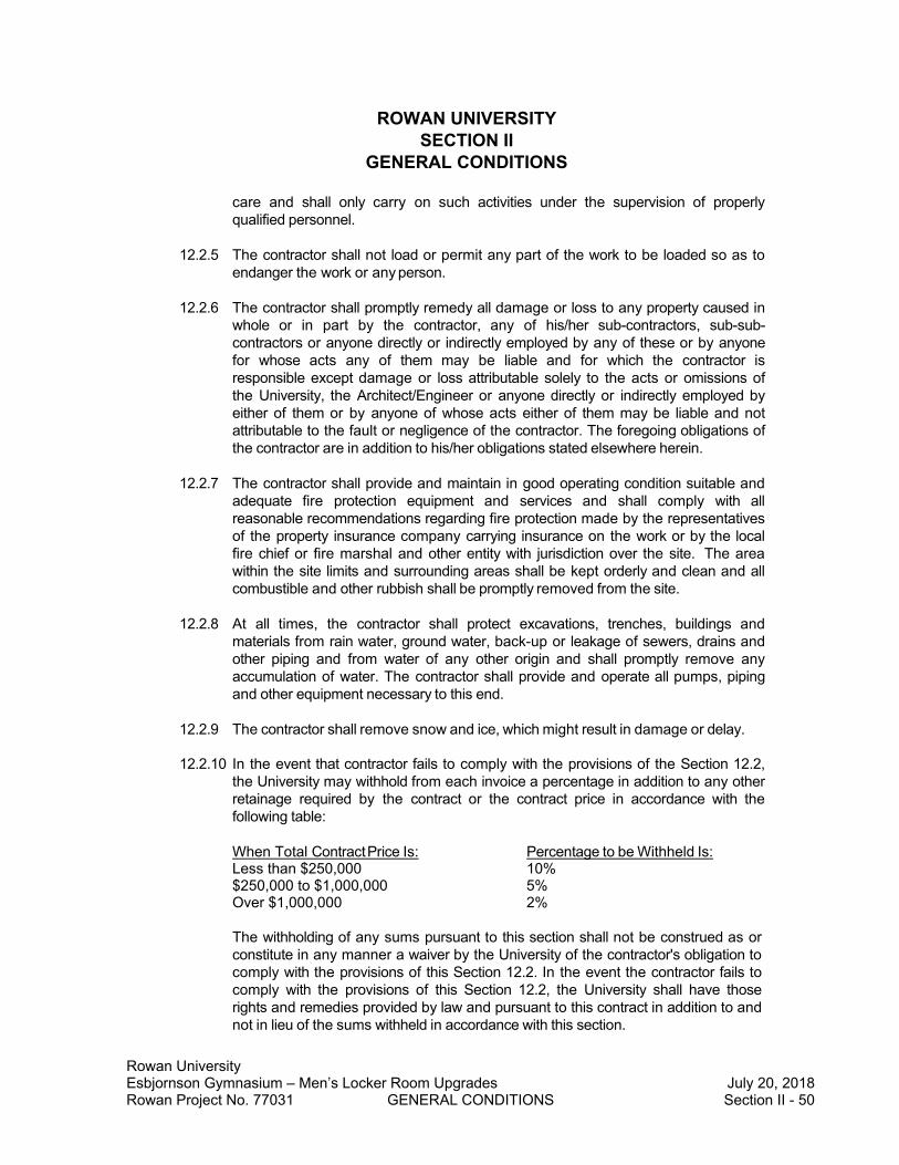
ROWAN UNIVERSITY SECTION II
GENERAL CONDITIONS
Rowan University Esbjornson Gymnasium – Men’s Locker Room Upgrades July 20, 2018 Rowan Project No. 77031 GENERAL CONDITIONS Section II - 50
care and shall only carry on such activities under the supervision of properly qualified personnel.
12.2.5 The contractor shall not load or permit any part of the work to be loaded so as to endanger the work or any person.
12.2.6 The contractor shall promptly remedy all damage or loss to any property caused in whole or in part by the contractor, any of his/her sub-contractors, sub-sub-contractors or anyone directly or indirectly employed by any of these or by anyone for whose acts any of them may be liable and for which the contractor is responsible except damage or loss attributable solely to the acts or omissions of the University, the Architect/Engineer or anyone directly or indirectly employed by either of them or by anyone of whose acts either of them may be liable and not attributable to the fault or negligence of the contractor. The foregoing obligations of the contractor are in addition to his/her obligations stated elsewhere herein.
12.2.7 The contractor shall provide and maintain in good operating condition suitable and adequate fire protection equipment and services and shall comply with all reasonable recommendations regarding fire protection made by the representatives of the property insurance company carrying insurance on the work or by the local fire chief or fire marshal and other entity with jurisdiction over the site. The area within the site limits and surrounding areas shall be kept orderly and clean and all combustible and other rubbish shall be promptly removed from the site.
12.2.8 At all times, the contractor shall protect excavations, trenches, buildings and materials from rain water, ground water, back-up or leakage of sewers, drains and other piping and from water of any other origin and shall promptly remove any accumulation of water. The contractor shall provide and operate all pumps, piping and other equipment necessary to this end.
12.2.9 The contractor shall remove snow and ice, which might result in damage or delay.
12.2.10 In the event that contractor fails to comply with the provisions of the Section 12.2, the University may withhold from each invoice a percentage in addition to any other retainage required by the contract or the contract price in accordance with the following table:
When Total Contract Price Is: Percentage to be Withheld Is: Less than $250,000 10% $250,000 to $1,000,000 5% Over $1,000,000 2%
The withholding of any sums pursuant to this section shall not be construed as or constitute in any manner a waiver by the University of the contractor's obligation to comply with the provisions of this Section 12.2. In the event the contractor fails to comply with the provisions of this Section 12.2, the University shall have those rights and remedies provided by law and pursuant to this contract in addition to and not in lieu of the sums withheld in accordance with this section.

ROWAN UNIVERSITY SECTION II
GENERAL CONDITIONS
Rowan University Esbjornson Gymnasium – Men’s Locker Room Upgrades July 20, 2018 Rowan Project No. 77031 GENERAL CONDITIONS Section II - 51
12.3 EMERGENCIES
12.3.1 In any emergency affecting the safety of persons or property, the contractor shall act with diligence at his/her discretion to prevent threatening injury, damage or loss. In such case, he/she shall immediately notify those individuals or entities designated at the pre-construction meeting. The Contractor shall immediately thereafter notify the contracting officer through the University’s project manager of the action taken and shall forthwith prepare and submit a detailed and documented report of the occurrence and all actions taken in response thereto.
ARTICLE 13 - INSURANCE AND INDEMNITY
13.1 CONTRACTOR INSURANCE REQUIREMENTS
13.1.1 The Contractor shall secure and maintain in force for the term of the Contract, insurance coverage provided herein. All insurance coverage is subject to the approval of the University and shall be issued by an insurance company authorized to do business in the State of New Jersey and which maintains an A.M. Best rating of A- (VII) or better.
13.1.2 The Contractor shall provide the University with current Certificates of Insurance for all coverage and renewals thereof which must contain the provision that the insurance provided in the certificate shall not be canceled for any reason except after thirty (30) days written notice to the University. All insurance required herein shall contain a waiver of subrogation in favor of the University. All insurance required herein, except Workers' Compensation and Owners and Contractors Protective, shall name ROWAN University, the State of New Jersey, the architect/engineer and University’s Project Manager as additional insureds.
13.1.2 Commercial General Liability insurance written on an occurrence form including independent contractor liability, products/completed operations liability, contractual liability, covering but not limited to the liability assumed under the indemnification provisions of this contract. Coverage for bodily injury and property damage claims arising out of the professional acts of the general contractor and subcontractors shall also be included. The policy shall not include any endorsement that restricts or reduces coverage as provided by the ISO CG0001 form without the approval of the University. The minimum limits of liability shall not be less than a combined single limit of one million dollars ($1,000,000) per occurrence, two million dollars ($2,000,000) general aggregate, three million dollars ($3,000,000) product/completed operations aggregate. The Products and Completed Operations insurance shall be maintained for two (2) years after final payment. A “per project endorsement” shall be included, so that the general aggregate limit applies solely to the project that is the subject of this contract.
13.1.3 Comprehensive Automobile Liability covering owned, non-owned, and hired vehicles. The limits of liability shall not be less than a combined single limit of one million dollars ($1,000,000) per occurrence.

ROWAN UNIVERSITY SECTION II
GENERAL CONDITIONS
Rowan University Esbjornson Gymnasium – Men’s Locker Room Upgrades July 20, 2018 Rowan Project No. 77031 GENERAL CONDITIONS Section II - 52
13.1.4 Worker's Compensation Insurance applicable to the laws of the State of New Jersey and other State or Federal jurisdiction required to protect the employees of the Contractor and any Subcontractor who will be engaged in the performance of this Contract. The certificate must so indicate that no proprietor, partner, executive officer or member is excluded. This insurance shall include Employers' Liability Protection with a limit of liability not less than one million dollars ($1,000,000) bodily injury, each occurrence, one million dollars ($1,000,000) disease, each employer, and two million dollars ($2,000,000) disease, aggregate limit. Including the employer’s liability insurance under the umbrella insurance can satisfy the limit requirements.
13.1.5 The Contractor shall obtain and maintain a separate Owners and Contractor's Protective Liability Insurance Policy for the same limits of liability as specified for the Commercial General Liability Insurance in the name of the University, the State of New Jersey. The Architect/Engineer, and the University’s Project Manager are to be the named as additional insured. The policy shall be maintained in force for the term of the Project or one year, whichever is longer.
13.1.6 Excess Liability, umbrella insurance form, applying excess of primary to the commercial general liability, commercial automobile liability and employer’s liability insurance shall be provided with minimum limits of three million dollars ($3,000,000) per occurrence, three million dollars ($3,000,000) general aggregate, and three million dollars ($3,000,000) products/completed operations.
13.1.6.1 The General Liability insurance General Aggregate and Umbrella Excess Liability limits shall apply and be written exclusively, in total, to this Project only. A per project endorsement for all coverage’s and limits must be included in each policy.
a) Bodily injury and property damage insurance policies shall be so written as to provide coverage for special hazards where such hazards will be incidental to subcontractors’ work.
13.1.7 The contractor shall require all its subcontractors and sub-subcontractors and any other company employed by the contractor working on this project to maintain during the life of the contract agreement(s) between itself and its sub-contractors, along with agreements between its subcontractors and their subcontractors, until final acceptance of the work by the University the insurance limits and requirements as defined above. It is a contractor option to determine the amount of excess liability it will require its subcontractors to carry however all insurance shall be written on a “per project” basis. The contractor shall be responsible for obtaining certificates of insurance from all of its subcontractors, sub-subcontractors, etc. for all coverage and renewals thereof for each company either hired directly by the contractor or hired by the contractors subcontractors working on this project prior to each company beginning work on the project. The contractor shall provide copies of all subcontractor certificates of insurance to the University.
a) ALL SUBCONTRACTOR CERTIFICATES MUST BE SUBMITTED PRIOR TO

ROWAN UNIVERSITY SECTION II
GENERAL CONDITIONS
Rowan University Esbjornson Gymnasium – Men’s Locker Room Upgrades July 20, 2018 Rowan Project No. 77031 GENERAL CONDITIONS Section II - 53
THE START OF WORK ON THE SITE.
13.1.8 Prior to commencement of construction, the contractor shall provide four (4) certified copies of such insurance policy or certificate of such insurance to be delivered to the University’s project manager and the University.
13.1.9 Should the contractor fail to comply with all insurance requirements indicated in the contract documents and provide satisfactory evidence of such compliance to the University within seven (7) calendar days of the issuance of a Notice to Proceed, contract and/or receipt by the contractor of a University purchase order on this project from the University, the contracting officer will consider the contractor to be in violation of the contract documents. Upon such declaration of a breach of contract, the contracting officer through the University’s project manager without prejudice to any other right or remedy available to the University and after giving the contractor and/or its surety three (3) working days written notice can either terminate the employment of the contractor for this project or purchase the required insurance. If the University chooses to purchase the required insurance it will deduct the cost of said insurance from the contact amount agreed upon with the contractor. Under either option selected by the University the contractor will have no recourse against the University.
13.2 INSURANCE TO BE CARRIED BY THEUNIVERSITY
13.2.1 The University shall provide insurance protection in the form of a Builders Risk Insurance or similar Policy upon the structure for which the Work on this Contract is to be done. The structure will be insured for 100% of the insurable replacement value thereof including materials, owned by the University, in place or to be used as part of the permanent construction including surplus materials. Should the structure be damaged or destroyed as a result of the contractors’ negligence the University will subrogate against the contractor for the cost to repair or replace the damage to bring the structure back to the condition intended under this contract.
13.2.2 This insurance shall not protect against damage or loss to any of the Contractor's or Subcontractor's property including but not limited to tools, equipment, scaffolding, staging towers or forms, Contractor's materials and sheds or other temporary structures erected for used by the Contractor or Subcontractors. It is understood that the Contractor will at their own expense, carry all insurance which may be required to provide the necessary protection against such loss or damage herein described which insurance shall contain a waiver of any right of subrogation against the University.
13.2.3 The insurance procured by the University under this paragraph may provide for a deductible. The Contractor shall assume the responsibility for any deductible for any builder’s risk loss it may make claim for under this policy.
13.2.4 The Contractor shall immediately notify the University, in writing and take any other appropriate steps as may be required under the standard Builder's Risk
ROWAN UNIVERSITY SECTION II
GENERAL CONDITIONS
Rowan University Esbjornson Gymnasium – Men’s Locker Room Upgrades July 20, 2018 Rowan Project No. 77031 GENERAL CONDITIONS Section II - 54
Insurance Policy in effect in the event of any loss. Prior to the acceptance of the building by the University, the Contractor shall, at the University's option, replace and repair the damaged Work as originally provided in the drawings and specifications at no additional compensation to that provided in the original contract.
13.2.5 All losses will be adjusted with, and payable to, the University.
13.2.6 The Contractor shall not include any cost for Builders Risk insurance premiums as described herein. However, this provision shall not relieve the Contractor from their obligation to complete, according to plans and specifications, the project covered by the contract, and the Contractor and their Surety shall be obligated to full performance of the Contractor's undertaking.
ARTICLE 14 - CHANGES IN THE WORK
14.1 CHANGES IN THE WORK
14.1.1 Changes to this Contract may only be accomplished by a Change Order issued in accordance with the procedures set forth in this Article 14 and Division #1 of the Specifications. The Change Order may result in an increase, decrease or have no effect upon the Contract Price only. The contract time cannot and will not be adjusted for any reason.
14.1.2 LEFT BLANK
14.1.3 Change Orders shall include all impacts that the change to the work may have upon the performance of the job and shall resolve all issues between the parties related, either directly or indirectly, to the change. By executing the Change Order, the Contractor waives the right to assert any future claims of any kind caused in whole or in part by the change.
14.2 OWNER DIRECTED CHANGES
14.2.1 At any time after execution of this contract by all parties the contracting officer may make any change in the work within the general scope of the contract including, but limited to, changes as follows:
a) in the specifications, including drawings and designs; b) in the method or manner of performance of the work; c) in the University furnished facilities, equipment, materials, services or site; d) directing acceleration in the performance of the work.
14.2.2 LEFT BLANK
14.3 LEFT BLANK
14.3.1 LEFT BLANK
ROWAN UNIVERSITY SECTION II
GENERAL CONDITIONS
Rowan University Esbjornson Gymnasium – Men’s Locker Room Upgrades July 20, 2018 Rowan Project No. 77031 GENERAL CONDITIONS Section II - 55
14.4 FAILURE TO PROVIDE NOTIFICATION
14.4.1 In the event that the Contractor fails to provide the immediate notification to the University’s project manager and/or to complete the "Change Order Request" pursuant to and as specified elsewhere in the contract documents with the supporting documentation as set forth in the Specifications, the Contractor shall have waived any and all claims for additional compensation related to said changes or conditions encountered.
14.5 LEFT BLANK
14.5.1 LEFT BLANK
14.5.2 LEFT BLANK
14.5.3 In the event that the parties cannot agree to a lump sum amount for a Change Order, the University’s contracting officer shall be permitted to order the Contractor to completed the work covered by the Change Order on a time and material basis, under procedures established by the University’s project manager to ensure the proper accounting of direct labor and direct material costs. The Contractor shall be allowed the same allowance for overhead and profit as set forth in the contract documents.
14.6 LEFT BLANK
14.6.1 LEFT BLANK
14.6.2 LEFT BLANK
14.7 CONTINUATION OF THE WORK
14.7.1 In order to avoid delays in the progress of work or when, in the best interest of the University, the contracting officer may, at his/her discretion, direct the contractor in writing to proceed with a change without a prior or final agreement on costs and/or scope of work. Such direction shall be in the form of an unpriced Change Order or written direction. If the contractor has or intends to assert a request for additional compensation under this article, he/she shall turn over to the University’s project manager in sufficient detail and in accordance with all contract document requirements hereof all necessary information and costs as required by the contacting officer after receipt of an unpriced change order or written direction.
14.7.2 Where the cost of property made obsolete or excess as a result of a change is included in the contractor's request for adjustment, the contracting officer shall have the right to prescribe the manner of deposition of such property.
ARTICLE 15 - ASSIGNMENT OF ANTITRUST CLAIM(S)
15.1 ASSIGNMENT OF ANTITRUST CLAIM(S)

ROWAN UNIVERSITY SECTION II
GENERAL CONDITIONS
Rowan University Esbjornson Gymnasium – Men’s Locker Room Upgrades July 20, 2018 Rowan Project No. 77031 GENERAL CONDITIONS Section II - 56
15.1.1 The contractor recognizes that in actual economic practice, overcharges resulting from antitrust violations are, in fact, usually borne by the ultimate purchaser. Therefore, and as a consideration for executing this contract, the contractor, acting herein by and through its duly authorized agent, hereby conveys, sells, assigns and transfers to the University all right, title and interest to all claims and causes of action it may now of hereafter acquire under the antitrust laws of the United States or the State of New Jersey relating to the particular goods or services purchased or acquired by the University pursuant to this contract.
In connection with this agreement, the following are the express obligations of the contractor:
a) it will take no action, which will in any way diminish the value of the rights conveyed or assigned hereunder
b) it will advise the University: (1) in advance of its intention to commence any action on its own behalf
regarding such claim or cause(s) of action (2) immediately upon becoming aware of the fact that action has been
commenced on its behalf by some other person(s) of the pendency of such action
c) it will notify the defendants in any antitrust suit of the fact of the within assignment at the earliest practicable opportunity after the contractor has initiated an action on its behalf or becomes aware that such an action has been filed on his/her behalf by any other person; a copy of such notice will be sent to the University.
Furthermore, it is understood and agreed that in the event any payment under any such claim or cause of action is made to the contractor, it shall promptly pay over to the University the aliquot share thereof, if any, assigned to the University herein.
ARTICLE 16 - AFFIRMATIVE ACTION REQUIREMENTS
16.1 POLICY STATEMENT
It has long been the policy of the University to promote equal employment opportunity by prohibiting discrimination in employment and requiring affirmative action in the performance of contracts funded by the University. This policy has been reinforced and expended by an act of the legislature. The new statute, New Jersey Public Law 1975, Chapter IR, provides that no public works contractor can be awarded nor any monies paid until the prospective contractor has agreed to contract performance, which complies with the approved affirmative action plan. The law applies to each political subdivision and agency of the State and includes procurement and service contracts as well as construction contracts. This section was prepared to explain the affirmative action requirements and procedures for public agencies awarding contracts and for contractors bidding on contracts. To assure effective implementation of the affirmative action law while allowing the business operations of a government to proceed efficiently, these regulations are designed to minimize administrative paperwork and delays.

ROWAN UNIVERSITY SECTION II
GENERAL CONDITIONS
Rowan University Esbjornson Gymnasium – Men’s Locker Room Upgrades July 20, 2018 Rowan Project No. 77031 GENERAL CONDITIONS Section II - 57
16.2 MANDATORY LANGUAGE
During the performance of this contract, the contractor agrees as follows:
a) Where applicable, the contractor or sub-contractor will not discriminate against any employee or applicant for employment because of age, race, creed, color, national origin, ancestry, marital status, sex, affectional or sexual orientation. The contractor will take affirmative action to insure that such applicants are recruited and employed and that employees are treated during employment without regard to their age, race, creed, color, national origin, ancestry, marital status, sex, affectional or sexual orientation. Such action shall include, but not be limited to, the following: employment, upgrading, demotion, transfer, recruitment or recruitment advertising, lay-off or termination, rates of pay or other forms of compensation and the selection for training, including apprenticeship. The contractor agrees to post in conspicuous places available to employees and applicants for employment notices to be provided by the public agency compliance officer setting forth provisions of this non-discrimination clause.
b) Where applicable, the contractor or sub-contractor will, in all solicitations or advertisements for employees placed by or on behalf of the contractor, state that all qualified applicants will receive consideration for employment without regard to age, race, creed, color, national origin, ancestry, marital status, sex, affectional or sexual orientation.
c) Where applicable, the contractor or sub-contractor will send to each labor union or representative of workers with which it has a collective bargaining agreement or other contract or understanding a notice to be provided by the agency contracting officer advising the labor union or worker's representative of the contractor's commitments under this act and shall post copies of the notice in conspicuous places available to employees and applicants for employment.
d) Where applicable, the contractor or sub-contractor agrees to comply with any regulations promulgated by the Treasurer pursuant to P.L. 1975, c.127, as amended and supplemented from time to time.
e) When hiring workers in each construction trade, the contractor or sub-contractor agrees to attempt in good faith to employ minority and female workers in each construction trade consistent with the applicable employment goal prescribed by
N.J.A.C. 17:27-7.3 provided, however, that the affirmative action officer may, in its discretion, exempt a contractor or sub-contractor from compliance with the good faith procedures prescribed by the following provisions (a), (b) and (c) as long as the affirmative action office is satisfied that the contractor is employing workers provided by a union which provides evidence in accordance with standards prescribed by the affirmative action office that its percentage of active, "card carrying" members who are minority and female workers is equal to or greater than the applicable employment goal prescribed by N.J.A.C. 17:27-7.3 promulgated by the Treasurer pursuant to P.L. 1975, c.127, as amended and supplemented from time to time. The contractor or sub-contractor agrees that a good faith effort shall include compliance with the

ROWAN UNIVERSITY SECTION II
GENERAL CONDITIONS
Rowan University Esbjornson Gymnasium – Men’s Locker Room Upgrades July 20, 2018 Rowan Project No. 77031 GENERAL CONDITIONS Section II - 58
following procedures:
1) If the contractor or sub-contractor has a referral agreement or arrangement with a union for a construction trade, the contractor or sub-contractor shall, within three (3) days of the contract award, seek assurances from the union that it will cooperate with the contractor or sub-contractor as it fulfills its affirmative action obligations under this contract and in accordance with the rules promulgated by the Treasurer pursuant to P.L. 1975, c.127, as it is amended and supplemented from time to time. If the contractor or sub-contractor is unable to obtain said assurances from the construction trade union at least five (5) days prior to the commencement of construction work, the contractor or sub- contractor agrees to directly attempt to hire minority and female workers consistent with the applicable employment goal. If the contractor's or sub-contractor's prior experience with a construction trade union, regardless of whether the union has provided said assurances, indicates a significant possibility that the trade union will not refer sufficient minority and female workers consistent with the applicable employment goal, the contractor or sub-contractor agrees to be prepared to hire minority and female workers directly consistent with the applicable employment goal by complying with the hiring procedures prescribed under (2) below and the contractor or sub- contractor further agrees to take immediate said action if it determines or is so notified by the affirmative action office that the union is not referring minority and female workers consistent with the applicable employment goal.
2) If the hiring of a workforce consistent with the employment goal has not or cannot be achieved for each construction trade by adhering to the procedures of (1) above or if the contractor or sub-contractor dos not have a referral agreement or arrangement with a union for a construction trade, the contractor or sub-contractor agrees to take the following actions consistent with the applicable county employment goals. (a) to notify the public agency compliance officer, affirmative action office
and at least one (1) approved minority referral organization of its manpower needs and request the referral of minority and female workers;
(b) to notify any minority and female workers who have been listed with it as awaiting available vacancies;
(c) prior to commencement of work to request the local construction trade union, if the contractor or sub-contractor has a referral agreement or arrangement with a union for the construction trade, to refer minority and female workers to fill job openings;
(d) to leave standing requests for additional referral to minority and female workers with the local construction trade union if the contractor or sub-contractor has a referral agreement or arrangement with a union for the construction trade, the State training and employment service and the other approved referral sources in the area until such time as the workforce is consistent with the employment goal;
(e) if it is necessary to lay-off some of the workers in a given trade on the
ROWAN UNIVERSITY SECTION II
GENERAL CONDITIONS
Rowan University Esbjornson Gymnasium – Men’s Locker Room Upgrades July 20, 2018 Rowan Project No. 77031 GENERAL CONDITIONS Section II - 59
construction site to assure, consistent with the applicable State and Federal statutes and court decisions, that sufficient minority and female employees remain on the site consistent with the employment goal and to employ any minority and female workers laid-off by the contractor or on any other construction site in the area on which its workforce composition is not consistent with an employment goal established pursuant to rules implementing P.L. 1975, c.127;
(f) to adhere to the following procedure when minority and female workers apply or are referred to the contractor or sub-contractor: (i) If said individuals have never previously received any document or
certification signifying a level of qualification lower than that required, the contractor or sub-contractor shall determine the qualifications of such individuals and, if the contractor's or sub-contractor's workforce in each construction trade is not consistent with the applicable employment goal, it shall employ such persons which satisfy appropriate qualification standards provided, however, that a contractor or sub-contractor shall determine that the individual at least possess the skills and experience recognized by any workers' skill and experience classification determination which may have been made by a public agency compliance officer, union, apprentice program or referral agency provided the referral agency is acceptable to the affirmative action office and provided further that, if necessary, the contractor or sub-contractor shall hire minority and female workers who qualify as trainees pursuant to these regulations. All of the requirements of this paragraph, however, are limited by the provisions of paragraph (3) below.
(ii) If the contractor's or sub-contractor's workforce is consistent with the applicable employment goal, the name of said minority or female group individual shall be maintained on a waiting list for the first consideration in the event the contractor's or sub-contractor's workforce is no longer consistent with the applicable employment goal.
(iii) If, for any reason, said contractor or sub- contractor determines that a minority individual or a female is not qualified or if the individual qualifies as an advanced trainee or apprentice, the contractor or sub-contractor shall inform the individual in writing with the reasons for the determination and maintain a copy in its files and send a copy to the public agency compliance officer and to the affirmative action office.
(g) to keep a complete and accurate record of all requests made for the referral of workers in any trade covered by the contract on forms made available by the affirmative action office and shall be submitted promptly to that office upon request.
3) The contractor or sub-contractor agrees that nothing contained in (2) preceding provision shall preclude the contractor or sub-contractor from complying with the hiring hall or apprenticeship provisions in any applicable bargaining agreement or hiring hall arrangement and, where required by

ROWAN UNIVERSITY SECTION II
GENERAL CONDITIONS
Rowan University Esbjornson Gymnasium – Men’s Locker Room Upgrades July 20, 2018 Rowan Project No. 77031 GENERAL CONDITIONS Section II - 60
custom or agreement, it shall send journeymen and trainees to the union for referral or to the apprenticeship program for admission pursuant to such agreement or arrangement provided, however, that where the practices of a union or apprenticeship program will result in the exclusion of minorities and females or the failure to refer minorities and females consistent with the county employment goal, the contractor or sub-contractor shall consider for employment persons referred pursuant to said provisions (2) without regarding to such agreement or arrangement; provided further, however, that the contractor or sub-contractor shall not be required to employ minority and female advanced trainees and trainees in numbers which result in the employment of advanced trainees and trainees as a percentage of the total workforce for the construction trade which percentage significantly exceeds the apprentice to journey worker ratio specified in the applicable collective bargaining agreement or, in the absence of a collective bargaining agreement, exceeds the ratio established by practice in the area for said construction trade. Also, the contractor or sub-contractor agrees that in implementing the procedures of the preceding provisions (2) it shall, where applicable, employ minority and female workers residing within the geographical jurisdiction of the union.
4) The contractor agrees to complete an initial manning report on forms provided by the affirmative action office on in the form prescribed by the affirmative action office and submit a copy of said form no later than three (3) days after signing a construction contract provided, however, that the public agency may extend in a particular case the allowable time for submitting the form to no more than fourteen (14) days and to submit a copy of the monthly project manning report once a month by the seventh (7th) work day of each month thereafter for the duration of this contract to the affirmative action office and to the public agency compliance officer. The contractor agrees to cooperate with the public agency in the payment of budgeted funds as is necessary for on-the-job and off-the-job programs for outreach and training of minority and female trainees employed on the construction site.
5) The contractor and its sub-contractors shall furnish such reports or other documents to the affirmative action office as may be requested by the office from time to time in order to carry out the purposes of these regulations and public agencies shall furnish such information as may be requested by the affirmative action office for conducting a compliance investigation pursuant to Sub-Chapter 10 of the Administrative Code, N.J.A.C. 17:27.
END OF SECTION II

Rowan University Esbjornson Gymnasium – Men’s Locker Room Upgrades July 20, 2018 Rowan Project No. 77031 CONSTRUCTION CONTRACT Section III - 1
THIS AGREEMENT, made this day of , 2017, by and between ROWAN UNIVERSITY, herein called “Owner”, acting herein through its VP of Finance and CFO, and
CONTRACTOR NAME
CONTRACTOR ADDRESS CONTRACTOR CITY, STATE & ZIP CODE
A Corporation, State of New Jersey, hereinafter called CONTRACTOR. The
Contractor hereby agrees with the Owner to commence and complete the construction described as follows:
<ENTER PROJECT NAME> PROJECT NO. 77XXX
The Contractor agrees to furnish all labor, material, equipment and services
necessary to construct and complete the project as detailed in Rowan University’s Bid No. , dated , hereinafter called the Project, for the sum of , to include the base bid items and to include all work in connection therewith, under the terms as stated in the Bid Documents, and at his (its or their) own proper cost and expense to furnish all the materials, supplies, machinery, equipment tools, superintendence, labor, insurance, and services necessary to complete the said project in accordance with the conditions and prices stated in the Contract Documents, as detailed on Exhibit “A” attached hereto and made a part hereof.
Unless the Notice to Proceed specifies a different date, the contractor hereby
agrees to commence work under this contract as soon as possible but no later than , and to fully complete the project within consecutive calendar days thereafter. Time is the essence for the completion of this contract. The Contractor further agrees to pay, as liquidates damages, the sum of for each consecutive calendar day thereafter as hereinafter provided in Article 8 of the General Conditions.
The OWNER agrees to pay the CONTRACTOR for the performance of the contract,
subject to additions and deductions, as provided in the General Conditions of the Contract Specifications, and to make payments on account thereof as provided in Article 10 of the General Conditions and Section 012500 – Contract Modification Procedures.

Rowan University Esbjornson Gymnasium – Men’s Locker Room Upgrades July 20, 2018 Rowan Project No. 77031 CONSTRUCTION CONTRACT Section III - 2
“The Contractor shall comply with the provisions of Chapter 33, of Title 52 of the Revised Statues (R.S. 52:33-1 et seq) requiring that preference be given to the use of domestic materials or as same may be governed by Federal Law or Regulation.
Mandatory Equal Employer Opportunity Language N.J.S.A. 10:5-31 et seq., N.J.A.C. 17:27
During the performance of this contract, the contractor agrees as follows:
The contractor or subcontractor, where applicable, will not discriminate against any
employee or applicant for employment because of age, race, creed, color, national origin, ancestry, marital status, affectional or sexual orientation, gender identity or expression, disability, nationality or sex. Except with respect to affectional or sexual orientation and gender identity or expression, the contractor will ensure that equal employment opportunity is afforded to such applicants in recruitment and employment, and that employees are treated during employment, without regard to their age, race, creed, color, national origin, ancestry, marital status, affectional or sexual orientation, gender identity or expression, disability, nationality or sex. Such equal employment opportunity shall include, but not be limited to the following: employment, upgrading, demotion, or transfer; recruitment or recruitment advertising; layoff or termination; rates of pay or other forms of compensation; and selection for training, including apprenticeship. The contractor agrees to post in conspicuous places, available to employees and applicants for employment, notices to be provided by the Public Agency Compliance Officer setting forth provisions of this nondiscrimination clause.
The contractor or subcontractor, where applicable will, in all solicitations or
advertisements for employees placed by or on behalf of the contractor, state that all qualified applicants will receive consideration for employment without regard to age, race, creed, color, national origin, ancestry, marital status, affectional or sexual orientation, gender identity or expression, disability, nationality or sex.
The contractor or subcontractor, where applicable, will send to each labor union or
representative of workers with which it has a collective bargaining agreement or other contract or understanding, a notice, to be provided by the agency contracting officer advising the labor union or workers' representative of the contractor's commitments under this act and shall post copies of the notice in conspicuous places available to employees and applicants for employment.
The contractor or subcontractor where applicable, agrees to comply with any
regulations promulgated by the Treasurer pursuant to N.J.S.A. 10:5-31 et seq., as amended and supplemented from time to time and the Americans with Disabilities Act.
When hiring or scheduling workers in each construction trade, the contractor or
subcontractor agrees to make good faith efforts to employ minority and women workers in each construction trade consistent with the targeted employment goal prescribed by N.J.A.C. 17:27-7.2; provided, however, that the Division may, in its discretion, exempt a contractor or subcontractor from compliance with the good faith procedures prescribed by the following provisions, A, B and C, as long as the Division is satisfied that the contractor or subcontractor is employing workers provided by a union which provides evidence, in accordance with standards prescribed by the Division , that its percentage of active "card carrying" members who are minority and women workers is equal to or greater than the targeted employment goal established in accordance with N.J.A.C. 17:27-7.2.
Rowan University Esbjornson Gymnasium – Men’s Locker Room Upgrades July 20, 2018 Rowan Project No. 77031 CONSTRUCTION CONTRACT Section III - 3
The contractor or subcontractor agrees that a good faith effort shall include compliance with the following procedures:
(A) If the contractor or subcontractor has a referral agreement or arrangement
with a union for a construction trade, the contractor or subcontractor shall, within three business days of the contract award, seek assurances from the union that it will cooperate with the contractor or subcontractor as it fulfills its affirmative action obligations under this contract and in accordance with the rules promulgated by the Treasurer pursuant to N.J.S.A. 10:5-31 et. seq., as supplemented and amended from time to time and the Americans with Disabilities Act. If the contractor or subcontractor is unable to obtain said assurances from the construction trade union at least five business days prior to the commencement of construction work, the contractor or subcontractor agrees to afford equal employment opportunities to minority and women workers directly, consistent with this chapter. If the contractor's or subcontractor's prior experience with a construction trade union, regardless of whether the union has provided said assurances, indicates a significant possibility that the trade union will not refer sufficient minority and women workers consistent with affording equal employment opportunities as specified in this chapter, the contractor or subcontractor agrees to be prepared to provide such opportunities to minority and women workers directly, consistent with this chapter, by complying with the procedures prescribed under (B) below; and the contractor or subcontractor further agrees to take said action immediately if it determines or is so notified by the Division that the union is not referring minority and women workers consistent with the equal employment opportunity goals set forth in this chapter.
(B) If good faith efforts to meet targeted employment goals have not or cannot
be met for each construction trade by adhering to the procedures of (A) above, or if the contractor does not have a referral agreement or arrangement with a union for a construction trade, the contractor or subcontractor agrees to take the following actions:
(1) To notify the public agency compliance officer, the Division, and
minority and women referral organizations listed by the Division pursuant to N.J.A.C. 17:27- 5.3, of its workforce needs, and request referral of minority and women workers;
(2) To notify any minority and women workers who have been
listed with it as awaiting available vacancies;
(3) Prior to commencement of work, to request that the local construction trade union refer minority and women workers to fill job openings, provided the contractor or subcontractor has a referral agreement or arrangement with a union for the construction trade;

Rowan University Esbjornson Gymnasium – Men’s Locker Room Upgrades July 20, 2018 Rowan Project No. 77031 CONSTRUCTION CONTRACT Section III - 4
(4) To leave standing requests for additional referral to minority and
women workers with the local construction trade union, provided the contractor or subcontractor has a referral agreement or arrangement with a union for the construction trade, the State Training and Employment Service and other approved referral sources in the area;
(5) If it is necessary to lay off some of the workers in a given trade on the
construction site, layoffs shall be conducted in compliance with the equal employment opportunity and non-discrimination standards set forth in this regulation, as well as with applicable Federal and State court decisions;
(6) To adhere to the following procedure when minority and women
workers apply or are referred to the contractor or subcontractor:
(i) If said individuals have never previously received any document or certification signifying a level of qualification lower than that required in order to perform the work of the construction trade, the contractor or subcontractor shall in good faith determine the qualifications of such individuals. The contractor or subcontractor shall hire or schedule those individuals who satisfy appropriate qualification standards in conformity with the equal employment opportunity and non- discrimination principles set forth in this chapter. However, a contractor or subcontractor shall determine that the individual at least possesses the requisite skills, and experience recognized by a union, apprentice program or a referral agency, provided the referral agency is acceptable to the Division. If necessary, the contractor or subcontractor shall hire or schedule minority and women workers who qualify as trainees pursuant to these rules. All of the requirements, however, are limited by the provisions of (C) below.
(ii). The name of any interested women or minority individual shall be
maintained on a waiting list, and shall be considered for employment as described in paragraph (i) above, whenever vacancies occur. At the request of the Division, the contractor or subcontractor shall provide evidence of its good faith efforts to employ women and minorities from the list to fill vacancies.
(iii). If, for any reason, said contractor or subcontractor determines that a
minority individual or a woman is not qualified or if the individual qualifies as an advanced trainee or apprentice, the contractor or subcontractor shall inform the individual in writing of the reasons for the determination, maintain a copy of the determination in its files, and send a copy to the public agency compliance officer and to the Division.

Rowan University Esbjornson Gymnasium – Men’s Locker Room Upgrades July 20, 2018 Rowan Project No. 77031 CONSTRUCTION CONTRACT Section III - 5
(7). To keep a complete and accurate record of all requests made for the
referral of workers in any trade covered by the contract, on forms made available by the Division and submitted promptly to the Division upon request.
( C ) The contractor or subcontractor agrees that nothing contained in (B) above
shall preclude the contractor or subcontractor from complying with the union hiring hall or apprenticeship policies in any applicable collective bargaining agreement or union hiring hall arrangement, and, where required by custom or agreement, it shall send journeymen and trainees to the union for referral, or to the apprenticeship program for admission, pursuant to such agreement or arrangement. However, where the practices of a union or apprenticeship program will result in the exclusion of minorities and women or the failure to refer minorities and women consistent with the targeted county employment goal, the contractor or subcontractor shall consider for employment persons referred pursuant to (B) above without regard to such agreement or arrangement; provided further, however, that the contractor or subcontractor shall not be required to employ women and minority advanced trainees and trainees in numbers which result in the employment of advanced trainees and trainees as a percentage of the total workforce for the construction trade, which percentage significantly exceeds the apprentice to journey worker ratio specified in the applicable collective bargaining agreement, or in the absence of a collective bargaining agreement, exceeds the ratio established by practice in the area for said construction trade. Also, the contractor or subcontractor agrees that, in implementing the procedures of (B) above it shall, where applicable, employ minority and women workers residing within the geographical jurisdiction of the union.
After notification of award, but prior to signing a construction contract, the contractor shall submit to the public agency compliance officer and the Division an initial project workforce report (Form AA 201) provided to the public agency by the Division for distribution to and completion by the contractor, in accordance with N.J.A.C. 17:27-7. The contractor also agrees to submit a copy of the Monthly Project Workforce Report once a month thereafter for the duration of this contract to the Division and to the public agency compliance officer.
The contractor agrees to cooperate with the public agency in the payment of budgeted funds, as is necessary, for on-the-job and/or off-the-job programs for outreach and training of minorities and women.
(D) The contractor and its subcontractors shall furnish such reports or other
documents to the Division of Public Contracts Equal Employment Opportunity Compliance as may be requested by the Division from time to time in order to carry out the purposes of these regulations, and public agencies shall furnish such information as may be requested by the

Rowan University Esbjornson Gymnasium – Men’s Locker Room Upgrades July 20, 2018 Rowan Project No. 77031 CONSTRUCTION CONTRACT Section III - 6
Division of Public Contracts Equal Employment Opportunity Compliance for conducting a compliance investigation pursuant to Subchapter 10 of the Administrative Code at N.J.A.C. 17:27.

Rowan University Esbjornson Gymnasium – Men’s Locker Room Upgrades July 20, 2018 Rowan Project No. 77031 CONSTRUCTION CONTRACT Section III - 7
IN WITNESS WHEREOF, the parties to these presents have executed this contract electronically, which shall be deemed an original, in the year and day first above mentioned. ATTEST: for Rowan University ________________________ _______________________________ Witness Joseph F. Scully Jr.
Sr. VP of Finance, Chief Financial Officer
(SEAL) _______________________________ Contractor Date
_______________________________ Title
WARRANTY: It is hereby certified and warranted by the undersigned contractor and by the undersigned principals or officers thereof, for said Contractor and for themselves, personally and individually, that no person has been employed to solicit or secure this Contract in violation of the provisions of Section 10, Chapter 48 of the Laws of 1954, N.J.S.A 52:34-15, or in violation of any other laws of the State of New Jersey; and it is further warranted that all applicable laws and regulations shall be complied with in the performance of this contract.
(SEAL) _______________________________ Contractor Date
_______________________________ By
_______________________________ Title
_______________________________ Address _______________________________ City State Zip Code

Rowan University Esbjornson Gymnasium – Men’s Locker Room Upgrades July 20, 2018 Rowan Project No. 77031 CONSTRUCTION CONTRACT Section III - 8
Exhibit A
Rowan University Invitation for Bid
PROJECT MANUAL
INSTRUCTIONS TO BIDDERS AND GENERAL CONDITIONS Section I Instructions to Bidders dated July 25, 2017 Pages 1 through 7 Section II General Conditions dated July 25, 2107 Pages 1 through 60 Section III Construction Contract dated July 25, 2107 Pages 1 through 9 Allowance Authorization Form dated October 2010 Page 1 Allowance Charge Request Form dated September 2010 Page 1 Request for Information Form --- Page 1 Change Order Request Form --- Page 1 Change Order Form --- Page 1 Hourly Labor Rate Breakdown Form --- Page 1 Daily Job Report Form --- Page 1 Application and Certificate for --- Pages 1 through 2 Payment Form (AIA G702) Attachment to G702 Certification --- Pages 1 through 2 For Payment Contractor’s Partial or Final Release --- Page 1
And Waiver of Liens Rowan Tax Exempt Letter --- Page 1 Consent of Surety Company to Final --- Page 1 Payment (AIA G707)
DIVISION 01 GENERAL REQUIREMENTS DATED July 25, 2017
Section 011000 Summary of Work 011000-1 to 011000-4 Section 011400 Work Restrictions 011400-1 to 011400-3 Section 012200 Unit Prices 012200-1 Section 012300 Alternates 012300-1 to 012300-2 Section 012400 Procedures and Controls 012400-1 to 012400-17 Section 012500 Contract Modification Procedures 012500-1 to 012500-5 Section 012900 Payment Procedures 012900-1 to 012900-6 Section 013100 Coordination 013100-1 to 013100-3 Section 013200 Construction Progress Schedule 013200-1 to 013200-6 Section 013300 Submittal Procedures 013300-1 to 013300-15 Section 014000 Quality Control Requirements 014000-1 to 014000-4 Section 014100 Testing Services 014100-1 to 014100-4 Section 014200 Reference Standards 014200-1 to 14200-5 Section 015000 Construction Facilities & Temporary Controls 015000-1 to 015000-8 Section 017700 Contract Closeout 017700-1 to 017700-9 Section 017820 Operation and Maintenance Data 017820-1 to 017820-8 Section 018200 Demonstration and Training 018200-1 to 018200-5
TECHNICAL SPECIFICATIONS

Rowan University Esbjornson Gymnasium – Men’s Locker Room Upgrades July 20, 2018 Rowan Project No. 77031 CONSTRUCTION CONTRACT Section III - 9
DIVISION XX
Section XXXXXX
DRAWINGS DATED
ARCHITECTURAL
MECHANICAL
ELECTRICAL
PLUMBING
END OF SECTION

Facilities Planning & Construction
RFI No:
Rowan Project No./Description: Date Submitted:
Requested Response Date:
Actual Response Date:
Rowan Project Manager:
Submitted to:
Company:
Contract Document Reference:
RFI DISCUSSION Individually number each separate topic or question
Submitted by (Name & Company): Title: Date:
RFI RESPONSE
Answered by (Name & Company): Title: Date:
REQUEST FOR INFORMATION

CHANGE OWNER
ORDER ARCHITECT
REQUEST CONTRACTOR
FIELD
OTHER
PROJECT: (name, address) CHANGE ORDER REQUEST NUMBER:
DATE OF ISSUANCE:
ARCHITECT’S PROJECT NO:
CONTRACT FOR:
OWNER: (name, address) CONTRACT DATE:
ARCHITECT: (name, address) FROM CONTRACTOR: (name, address)
The contractor must submit this proposal with all appropriate documentation and/or notify the Architect or Owner, in writing, of the date on which proposal submission is anticipated.
THIS IS NOT A CHANGE ORDER, A CONSTRUCTION DIRECTIVE OR A DIRECTION TO
PROCEED WITH THE WORK DESCRIBED IN THE PROPOSED MODIFICTIONS.
DESCRIPTION: (Insert a written description of the Work)
ATTACHMENTS: (List attached documents that support description)
REQUESTED BY THE CONTRACTOR:
(Signature) (Printed Name and title)

CHANGE OWNER
ORDER ARCHITECT
CONTRACTOR
FIELD
OTHER
PROJECT: CHANGE ORDER NUMBER: (name, address) DATE: TO CONTRACTOR: ARCHITECT’S PROJECT NO: (name, address) CONTRACT DATE: CONTRACT FOR: PURCHASE ORDER NO: The Contract is changed as follows:
Not valid until signed by the Owner, Architect and Contractor.
The original (Contract Sum) (Guaranteed Maximum Price) was New change by previously authorized Change Orders The (Contract Sum) (Guaranteed Maximum Price) prior to this Change Order was The (Contract Sum) (Guaranteed Maximum Price) will be (increased) (decreased) (unchanged) by this Change Order in the amount of
The new (Contract Sum) (Guaranteed Maximum Price) including this Change Order will be The Contract Time will be (increased) (decreased) (unchanged) by ( ) days. The date of Substantial Completion as of the date of this Change Order therefore is NOTE: This summary does not reflect changes in the Contract Sum, Contract Time or Guaranteed Maximum Price which have
been authorized by Construction Change Directive. _ _ Rowan University ARCHITECT CONTRACTOR OWNER _ ________ 201 Mullica Hill Road Address Address Address _ Glassboro, NJ 08028-1701 BY______________________________ BY_____________________ BY_____________________________________ DATE____________________________ DATE___________________ DATE__________________________________
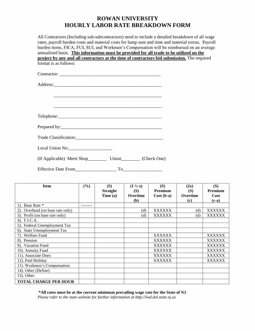
ROWAN UNIVERSITY
HOURLY LABOR RATE BREAKDOWN FORM All Contractors (Including sub-subcontractors) need to include a detailed breakdown of all wage
rates, payroll burden costs and material costs for lump sum and time and material extras. Payroll
burden items, FICA, FUI, SUI, and Workmen’s Compensation will be reimbursed on an average
annualized basis. This information must be provided for all trade to be utilized on the
project by any and all contractors at the time of contractors bid submission. The required
format is as follows:
Contractor: ____________________________________________
Address:_______________________________________________
_______________________________________________
_______________________________________________
Telephone:_____________________________________________
Prepared by:____________________________________________
Trade Classification:______________________________________
Local Union No:___________________
(If Applicable) Merit Shop________ Union________ (Check One)
Effective Date From__________________ To_________________
Item (%) (S)
Straight
Time (a)
(1 ½ x)
(S)
Overtime
(b)
(S)
Premium
Cost (b-a)
(2x)
(S)
Overtime
(c)
(S)
Premium
Cost
(c-a)
1). Base Rate * --------
2). Overhead (on base rate only) (d) XXXXXX (d) XXXXXX
3). Profit (on base rate only) (d) XXXXXX (d) XXXXXX
4). F.I.C.A.
5). Federal Unemployment Tax
6). State Unemployment Tax
7). Welfare Fund XXXXXX XXXXXX
8). Pension XXXXXX XXXXXX
9). Vacation Fund XXXXXX XXXXXX
10). Annuity Fund XXXXXX XXXXXX
11). Associate Dues XXXXXX XXXXXX
12). Paid Holiday XXXXXX XXXXXX
13). Workmen’s Compensation
14). Other (Define)
15). Other TOTAL CHARGE PER HOUR
*All rates must be at the current minimum prevailing wage rate for the State of NJ.
Please refer to the state website for further information at http://lwd.dol.state.nj.us

DAILY JOB REPORT
Project #
CONTRACTORS ON SITE:
SUPER
ON SITE
(Y/N):
NO. OF
WORKE
RS
MATERIALS DELIVERED: EQUIPMENT ONSITE:
NOTEWORTHY PHONE CALLS:
PROBLEMS/STATUS/CAUSES FOR DELAY:
WORKFORCE ON SITE:
(Foreman, Tradesmen,
Laborers, etc.)
VISITORS:
WORK BEING DONE:
DATE:
WEATHER CONDITIONS:
4/4/2016 8:55 AM


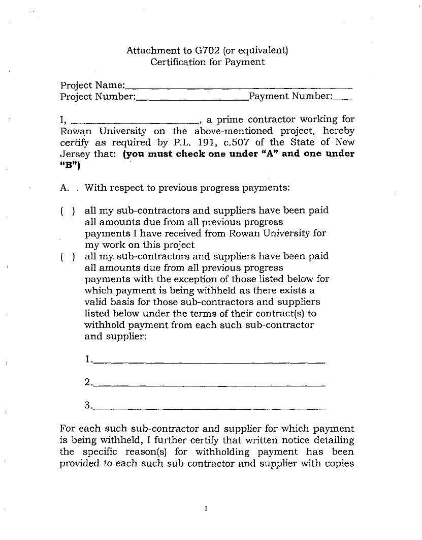
Attachment to G702 (or equivalent) Certification for Payment
Project Name: Project Number: Payment Number:-
1, , a prime contractor working for Rowan University on the above-mentioned project, hereby certify as required by P.L. 191, c.507 of the State of . New Jersey that: (you must check one under "A" and one under ","I
A. . With respect to previous progress payments:
( ) all my sub-contractors and suppliers have been paid all amounts due from all previous progress payments I have received from Rowan University for my work on this project
( ) all my sub-contractors and suppliers have been paid all amounts due from all previous progress payments with the exception of those listed below for which payment is being withheld as there exists a valid basis for those sub-contractors and suppliers listed below under the terms of their contract(s) to withhold payment from each such sub-contractor and supplier:
For each such sub-contractor and supplier for which payment is being withheld, I further c e m that written notice detailing the specific reason(s) for withholding payment has been provided to each such sub-contractor and supplier with copies

thereof provided to my performance bond company and Rowan University.
B. With respect to this payment number
( ) all my sub-contractors and suppliers shall be paid all amounts due from this progress payment
( ) all my sub-contractors and suppliers shall be paid all amounts due from this progress payment with the exception of those listed below for which payment will be withheld as there exists a valid basis for those sub-contractors and suppliers listed below under the terms of their contract(s) to withhold payment from each such sub-contractor and supplier:
For each sub-contractor and supplier for which payment is being withheld, I further ce& that written notice detailing the specific' reason@) for withholding payment has been provided to each sub-contractor and supplier with copies thereof provided to my performance bond company and Rowan University.
I certify that the above statements are true. I am aware that if any of the above statements are willfully false, I am subject to punishment.
Dated: Signature
Please Print Name

CONTRACTOR’S PARTIAL OR FINAL RELEASE AND WAIVER OF LIENS
OWNER: CONTRACT FOR:
OWNER’S AGENT:
PROJECT: CONTRACT DATE:
Upon receipt by the undersigned Contractor of a check from Owner in the sum of $ ,
which check will consume payment of all sums due the Contractor for labor, equipment and/or materials supplied
in connection with the Project, and when said check has been paid by the bank upon which it is drawn, this
document shall become effective to fully and finally waive and release any and all liens, claims, liabilities,
actions, and demands that this Contractor and all its subcontractors have or might have against Owner, Lender,
the Project, the real property upon which the Project is located and any and all other property owned by Owner
on account of or in connection with labor, equipment and/or materials supplied by the undersigned to the Project.
The undersigned Contractor does hereby further acknowledge and represent that through the date hereof
the undersigned has received payments totaling $ for labor, equipment and/or materials
supplied to the Project.
This instrument has been executed as of the ________ day of _______________________, 20__.
CONTRACTOR:
By:
Name:
Title:
STATE OF ____________
COUNTY OF ___________________
Sworn to and subscribed before me the undersigned authority on this ________ day of
__________________, 20__.
[ S E A L ]
Notary Public, State of _________________
My Commission Expires:
________________________
Printed Name of Notary Public


CONSENT OF O\Z~NCE AF,CHITCCT
D
SURETY COMPANY 0
CONTRACTOR D
TO FINAL PAYMENT sufim 0 1 1 i c f i
nrA DOCUMCNT C707
PROJECT: (name, address)
L CONTRACTOR:
1 ARCIHITECT'S PROJECT NO:
CONTRACT FOR:
C O N T R A 0 DATE:
In accordance with the provisions of tlic Contract between the Owner and the Contractor as indicated above, the
(here anscrl name and address ol Surely Comprnyl
, SUREN COMPANY,
on bond 01 there insrtr name m d addrrs ol Con! r~ to t l
CONTRACTOR,
hereby approves of the final payment to the Contractor, and agrees that final payment to the Contractor shall not relieve the Surely Company o f any o f its obligations to lltrrc in%rrl name m d addresr oi Owncrl
, OWNER,
as set fortfi in the said Surety Company's bond
IN WITNESS WIiIRCOF, the Surety Company l i a s liereunto set its hand this
Attest: (Scall:
Surety Company
-. - - - . - . . . -. . . . Signature 01 Autliorized Represenlalive
- - -. - - - . .- - . - . . - - - . - - - - Title
NOT[: l l n i s (o,m i r to bc u,rd 2 % 1 comnrnion datvmrnt l o AIA DOCUMINT C7L%. CONTRACIOR'S A l 1 l l ~ A V l l 01 PAYMCNT 0 1 f)[DTS A N 0 CLAIMS, Curten[ Cdilion
AIA OOCUM[NT C707. C O N S l N I 0 1 SURITY COMPANY TO r i N A l PAYMlNI ' AI'RII 1970 CDITION ' AIAQ O N [ PAC[ 6 3 1970. Ill[ AMCRICAN INSTITUT[ Or ARCIIITICTS. 1715 NtW YOHI: AVI.. NW. WASIIINCTON, O.C >OM(,

Rowan University Esbjornson Gymnasium – Men’s Locker Room Upgrades July 20, 2018 Rowan Project No. 77031 SUMMARY 011000 - 1
SECTION 011000 - SUMMARY
PART 1 - GENERAL
1.1 RELATED DOCUMENTS
A. Drawings and general provisions of the Contract, including General and Supplementary Conditions and other Division 1 Specification Sections, apply to this Section. In the event of any conflicts between the requirements of these Sections, the more stringent requirement shall apply.
1.2 SUMMARY
A. This Section includes the following:
1. Work covered by the Contract Documents 2. Use of premises.
B. Related Sections include the following:
1. Division 1 Section “Construction Facilities and Temporary Controls” for limitations and procedures governing temporary use of Owner’s premises.
1.3 WORK COVERED BY CONTRACT DOCUMENTS
A. Project Identification:
1. Project Location: Rowan University, Glassboro, New Jersey
a. Esbjornson Gymnasium
2. Owner: Rowan University
B. Architect Identification: The Contract Documents were prepared for Project by: Clarke Caton Hintz, 100 Barrack Street, Trenton, NJ 08608.
C. The Work consists of the following: 1. BASE SCOPE: Provide construction services for demolition, furnish and install of new
finishes, and mechanical systems in the Men’s Locker Room of Esbjornson Gym. The work needs to be complete before the start of the Men’s Basketball season. Not included in this contract is the furnish and install of new lockers. This Contract is responsible to coordinate with the Locker Contractor that will be installing the lockers.
1.4 CONTRACT
A. Project will be constructed under two, separate Construction Contracts.

Rowan University Esbjornson Gymnasium – Men’s Locker Room Upgrades July 20, 2018 Rowan Project No. 77031 SUMMARY 011000 - 2
1.5 USE OF PREMISES
A. General Construction Operations: Contractor shall have limited use of premises for construction operations, including a limited use of the project site (outside the facilities exterior walls) during the period of construction activity. Contractor’s use of the premises is limited by Rowans right to perform work or to retain other contractor’s on portions of the Project or to limit access for events or other functions as the University might require. The Contractor will be given notice of any such events well in advance so that arrangements can be made to insure the prosecution of the work continues as scheduled.
B. Arrange use of site and premises to allow:
1. Owner occupancy. 2. Work by others. 3. Work by Owner.
C. Use of Site: Limit use of premises to work in areas indicated. Do not disturb portions of Project site beyond the building perimeter unless prior approval of the University is received prior to conduction such work or operations.
1. Limit site disturbance, as approved by Rowan University. 2. REFER TO SECTION 011400 FOR WORK HOURS. 3. Storage of construction materials and equipment is not permitted inside the existing
building. 4. Driveways and Entrances: Keep driveways and entrances serving premises clear and
available to Rowan University, Rowans employees, and emergency vehicles at all times. Do not use these areas for parking or storage of materials.
a. Staging areas will not be allotted for usage by the Contractor.
b. Limited parking will be made available in General Parking Lots found on campus.
c. Schedule deliveries to minimize use of the driveways and entrances. d. Contractor may NOT have a trash dumpster, storage shed, nor container boxes
near the building.
D. Use of Existing Building: Maintain existing building in a weather tight condition throughout construction period. Repair damage caused by construction operations. Protect building and its occupants during construction period.
E. The Contractor will be responsible for photographing the entire area of work, adjacent spaces where incidental work may occur, corridors and elevators accessing the area of work, the loading area, and contractor parking area. The Contractor will provide the Owner with digital copies of all the photographs prior to mobilization as a record of the existing conditions PRIOR to the start of the work. Digital format will be in PDF format.
1.6 SPECIFICATION FORMATS AND CONVENTIONS
A. Specification Format: The Specifications are organized into Divisions and Sections using the 16-division format and CSI/CSC's "MasterFormat" numbering system.
1. Section Identification: The Specifications use section numbers and titles to help cross-referencing in the Contract Documents. Sections in the Project Manual are in numeric

Rowan University Esbjornson Gymnasium – Men’s Locker Room Upgrades July 20, 2018 Rowan Project No. 77031 SUMMARY 011000 - 3
sequence; however, the sequence is incomplete. Consult the table of contents at the beginning of the Project Manual to determine numbers and names of sections in the Contract Documents.
1.7 MISCELLANEOUS PROVISIONS
A. WORK REQUIRED TO BE PERFORMED UNDER THIS CONTRACT SHALL BE COMPLETED IN ACCORDANCE WITH THE FOLLOWING MILESTONES AND COMPLETION DATES. CONTRACTORS MUST INCLUDE IN THEIR BIDS ALL COSTS INCLUDING OVERTIME ASSOCIATED WITH INSURING THAT THE PROJECT IS COMPLETED BY THE MILESTONE DEADLINES LISTED HEREIN.
B. Summary of Milestones:
1. Notice to Proceed/Authorization by: The University intends to issue Notice to Proceed, Construction Contract, and/or University purchase order as evidence of contract award on or before August 31, 2018. 2. ALL submittals to Architect: one (1) week after Notice to Proceed. 3. Architect return of reviewed submittals by: two (2) weeks after receipt. 4. Construction Start Date: September 4, 2018. 5. Substantial Completion: no later than October 26, 2018. 6. Final Completion of work on site by FIVE (5) BUSINESS DAYS FROM SUBSTANTIAL
COMPLETION. All construction including punch list work will be completed by this date. 7. Final Closeout Documents by TEN (10) BUSINESS DAYS FROM SUBSTANTIAL
COMPLETION DATE. All closeout documentation, final payment application, etc.
C. Weather Conditions:
1. Unfavorable weather conditions shall not be justification for delays in completion or final completion dates as specified. No change orders will be issued or approved for extensions of time due to weather conditions. Seasonal weather conditions shall be considered in the planning and scheduling of all work influenced by high or low ambient temperatures for the completion of all contract work within the allotted contract time. In addition, appropriate allowances shall be made for anticipated time losses due to normal rain and snow conditions by statistically expanding the estimated time durations for weather sensitive activities with the constraint that the substantial completion deadline cannot change.
2. The University may at its sole discretion entertain extensions of time from the contractor for weather related delays. However no extensions of time shall be considered by the University until at least twenty-five (25) lost project schedule days have accrued. Lost time will accrue on a proportionate basis – ¼ lost day will be charged as ¼ lost day, 1/2 lost day will be charged as ½ lost day, and so forth. A lost project schedule day is considered a day or any portion of a day when all members of the construction workforce on the project cannot work due to inclement weather conditions. Whether or not the contractors’ workforce fails to begin work or leaves the project site on any given day due to a claim of inclement weather a lost project schedule day will not be recognized by the University until it is approved in writing by the University’s project manager.
3. Should the University approve an extension of time the contractor may only submit reimbursement for the cost of the extension of rental equipment agreements; bond premium and insurance adjustments at actual cost with no mark up; and general conditions directly impacted by the approved extension. Appropriate back up documentation as requested by the University project manager must accompany any submission for

Rowan University Esbjornson Gymnasium – Men’s Locker Room Upgrades July 20, 2018 Rowan Project No. 77031 SUMMARY 011000 - 4
reimbursement. Appropriate back up can be anything from copies of contractor’s rental agreements showing rental durations, unit costs, rental rates, etc. to copies of superintendents pay stubs.
D. Intent of Contract: The drawings and specifications of the contract are intended to require the contractor to provide for everything reasonably necessary to accomplish the proper and complete finishing of the work. All work and materials included in the specifications and not shown on the drawings, or shown on the drawings and not in the specifications, shall be performed and/or furnished by the contractor as if described in both. Any incidental materials and/or work not specified in the drawings and/or the specifications which are, nevertheless, necessary for the true development thereof and reasonably inferable therefrom, the contractor shall understand the same to be implied and required, and shall perform all such work and furnish all such materials as if particularly delineated or described therein. Should there be an obvious error between the drawings and specifications, the most stringent constraints of the conflicting information shall be assumed by the contractor and it shall be the contractor’s responsibility to complete the work as reasonably required, consistent with the intent of such drawings and specifications as may be interpreted by the University.
PART 2 - PRODUCTS (Not Used)
PART 3 - EXECUTION (Not Used)
END OF SECTION 011000

Rowan University Esbjornson Gymnasium – Men’s Locker Room Upgrades July 20, 2018 Rowan Project No. 77031 WORK RESTRICTIONS 011400 - 1
SECTION 011400 – WORK RESTRICTIONS
PART 1 - GENERAL
1.1 RELATED DOCUMENTS
A. Drawings and general provisions of the Contract, including General and Supplementary Conditions and other Division 1 Specification Sections, apply to this Section. In the event of any conflicts between the requirements of these Sections, the more stringent requirement shall apply.
1.2 USE OF PREMISES
A. Use of Site: Limit use of premises to work in areas indicated. Do not disturb portions of site beyond areas in which the Work is indicated.
1. Limits: Confine construction operations to weekdays (Monday through Friday) from 7:00 AM to 5:00 PM. Weekend and Holiday work may be permitted if approved by the Owner.
2. Owner Occupancy: Allow for Owner occupancy of building, site and use by the public. Classes will be in session and the Contractor must account for allowing free usage by the Owner and it’s individuals.
3. Driveways and Entrances: Keep streets, driveways and entrances serving premises clear and available to owner, Owner’s employees, and emergency vehicles at all times. Do not use these areas for parking or storage of materials. a. Schedule deliveries to minimize use of driveways and entrances.
B. Use of Existing Building: Repair damage caused by construction operations. Protect building and its occupants during construction period.
1.3 OCCUPANCY REQUIREMENTS
A. Full Owner Occupancy: Owner will occupy site and existing building during entire construction period. Cooperate with owner during construction operations to minimize conflicts and facilitate Owner usage. Perform the Work so as not to interfere with Owner’s operations.
1.4 WORK SEQUENCE
A. Work shall be completed within the schedule as outlined in Section 011000 – Summary. University intends to issue Notice to Proceed, Construction Contract, and/or University Purchase Order as evidence of contract award on or before Project start date listed. The General Contractor must work in unison with the Locker Contractor that is awarded the furnish and install of the new lockers.

Rowan University Esbjornson Gymnasium – Men’s Locker Room Upgrades July 20, 2018 Rowan Project No. 77031 WORK RESTRICTIONS 011400 - 2
1.5 CONTRACTOR WORK AREAS, WORKING CONDITIONS AND EQUIPMENT STORAGE REGULATIONS
A. The Contractor shall not unreasonably encumber the facilities with its equipment or work to be performed. Work conducted by the Contractor, Subcontractor, or any other person and/or firm affiliated with the Contractor shall be contained within pre-designated working areas established by the documents.
B. The Contractor shall, at all times during the progress of the work, keep the site free from the accumulation of all rubbish and debris caused by its performance. The Contractor shall remove all debris and rubbish related to its work at the end of each workday to the satisfaction of the Project Manager. Tool storage boxes shall not be permitted inside the building on the first floor or outside the building.
C. The Contractor shall adequately secure and protect its equipment, materials and vehicles. The University assumes no liability for any damage to, or theft of, the Contractor’s property. The Contractor shall have the use of a designated area for storage and staging of construction materials and equipment. The Contractor shall be responsible for adhering to security procedures outlined by the Project Manager.
D. The Contractor is responsible for all safety precautions for all of its employees and property while performing its services.
E. The Contractor shall strictly limit its employees’ use of the facilities for lunch, smoking or rest time usage to only those areas designated by the Project Manager. Use of facility telephones will not be allowed. Use of building toilet facilities shall not be permitted. Smoking is not allowed inside the building.
1.6 WORK STOPPAGES, EXISTING UTILITY INTERRUPTIONS, NOISE AND ODOR RESTRICTIONS, AND MATERIAL APPROVALS
A. Work Stoppages – DOES NOT APPLY.
B. Existing Utility Interruptions: Do not interrupt utilities serving facilities occupied by Owner or others unless permitted under the following conditions and then only after arranging to provide temporary utility services according to requirements indicated:
1. Notify Owner not less than three (3) days in advance of proposed utility interruptions. 2. Do not proceed with utility interruptions without Project Manager’s written permission.
C. Consideration shall be given by the Contractor regarding odors emanating from adhesives and sealants, etc and excessive noise. If the odors or noise are such that they may disturb the employees and guests then such work shall be performed while the building is not occupied. This determination shall be at the sole discretion of the Project Manager. The playing of radios and other unnecessary noise will not be permitted at any time.
D. All material safety data sheets shall be submitted and approved by the Project Manager prior to use of the material.

Rowan University Esbjornson Gymnasium – Men’s Locker Room Upgrades July 20, 2018 Rowan Project No. 77031 WORK RESTRICTIONS 011400 - 3
1.7 PROTECTION OF INTERIOR FINISHES
A. The Contractor shall take extra care to avoid damage or soiling to any part of the facility. The Contractor is responsible for all damages or destruction caused directly or indirectly by its performance to any part of the building or adjoining property. Any damage or destruction caused by the Contractor or its employees will be repaired or replaced as the Project Manager directs and to their satisfaction with all costs charged to the Contractor. The costs may be deducted from any and all amounts due to the Contractor.
B. Any of the Contractor’s employees found defacing, damaging or marring the building or its finishes or contents shall be immediately removed by the Contractor. The Contractor shall be charged for all remedial work to restore the damaged area or contents to their original condition to the satisfaction of the State.
C. The Contractor shall take all necessary steps to ensure adequate protection of all building furniture, equipment and building finishes, including but not limited to: floors, walls, ceilings, windows, draperies, blinds, carpeting, doors, doorways and contents. In this endeavor, all workers are to take precautions to protect rugs and floors. The Contractor shall be charged for all remedial work to clean, repair and/or replace items damaged by the Contractor to the satisfaction of the State.
D. The Contractor is responsible for the cost of cleanup of dust, dirt and stains caused by the work to the satisfaction of the Project Manager. The Contractor shall take all necessary precautions to keep dust, dirt and debris to a minimum both within the construction area and throughout the buildings.
PART 2 - PRODUCTS (Not Used)
PART 3 - EXECUTION (Not Used)
END OF SECTION 011400

Rowan University Esbjornson Gymnasium – Men’s Locker Room Upgrades July 20, 2018 Rowan Project No. 77031 ALLOWANCES 012100 - 1
SECTION 012100 - ALLOWANCES
PART 1 - GENERAL
1.1 RELATED DOCUMENTS
A. Drawings and general provisions of the Contract, including General and Supplementary Conditions and other Division 1 Specification Sections, apply to this Section. In the event of any conflicts between the requirements of these Sections, the more stringent requirement shall apply.
1.2 SUMMARY
A. This Section includes administrative and procedural requirements governing allowances.
1. Certain items are specified in the Contract Documents by allowances. Allowances have been established in lieu of additional requirements and to defer selection of actual materials and equipment to a later date when additional information is available for evaluation. If necessary, additional requirements will be issued by Change Order Directive THE ALLOWANCE SHALL BE INCLUDED IN THE BASE BID.
B. Types of allowances include the following:
1. Lump-sum allowances.
C. Related Sections include the following: 1. Division 1 Section "Quality Control Services" for procedures governing the use of allowances
for testing and inspecting. 2. Divisions 2 through 16 Sections for items of Work covered by allowances.
1.3 SELECTION AND PURCHASE
A. If applicable, at the earliest practical date after award of the Contract, advise Architect of the date when final selection and purchase of each product or system described by an allowance must be completed to avoid delaying the Work.
B. At Architects request and Owners approval, obtain proposals for each allowance for use in making final selections. Include recommendations that are relevant to performing the Work.
C. Purchase products and systems selected by Architect from the designated supplier.
1.4 SUBMITTALS
A. Submit proposals for purchase of products or systems included in allowances, in the form specified for Change Orders.
B. Submit invoices or delivery slips to show actual quantities of materials delivered to the site for use in fulfillment of each allowance.

Rowan University Esbjornson Gymnasium – Men’s Locker Room Upgrades July 20, 2018 Rowan Project No. 77031 ALLOWANCES 012100 - 2
C. Coordinate and process submittals for allowance items in same manner as for other portions of the Work.
D. All Allowances will be recorded as separate line items on the initial Schedule of Values to be approved by the Owner and/or Architect. Once the initial Schedule of Values is approved all subsequent Schedule’s will continue to include these Allowances as separate line items. Allowances will be tracked as separate line items.
1.5 COORDINATION
A. Coordinate allowance items with other portions of the Work. Furnish templates as required to coordinate installation.
1.6 LUMP-SUM ALLOWANCES
A. Allowance shall include cost to Contractor of specific products and materials and shall include taxes, freight, and delivery to Project site.
B. Contractor's costs for receiving and handling at Project site, labor, installation, overhead and profit, and similar costs related to products and materials accepted by Owner under this Section shall be included as part of the allowance.
1.7 UNUSED MATERIALS
A. Return unused materials purchased under an allowance to manufacturer or supplier for credit to Owner, after installation has been completed and accepted.
1. If requested by Architect, prepare unused material for storage by Owner when it is not economically practical to return the material for credit. If directed by Architect, deliver unused material to Owner's storage space. Otherwise, disposal of unused material is Contractor's responsibility.
1.8 UNUSED ALLOWANCES
A. All unused Allowances are and will remain the Owner’s property. The Contractor shall return any remaining Allowance balances to the Owner upon completion of all punch list items and Final Acceptance of the Building. 1. Allowance balances will be returned to the Owner by Change Order. 2. Change Orders for returning Allowance balances to the Owner will be initiated and approved
prior to the Contractor submitting for Final Payment. Allowance balances will not be included in the Final Application for Payment.

Rowan University Esbjornson Gymnasium – Men’s Locker Room Upgrades July 20, 2018 Rowan Project No. 77031 ALLOWANCES 012100 - 3
PART 2 - PRODUCTS (Not Used)
PART 3 - EXECUTION
3.1 EXAMINATION
A. Examine products covered by an allowance promptly on delivery for damage or defects. Return damaged or defective products to manufacturer for replacement.
3.2 PREPARATION
A. Coordinate materials and their installation for each allowance with related materials and installations to ensure that each allowance item is completely integrated and interfaced with related work.
3.3 SCHEDULE OF ALLOWANCES
Lump Sum Allowance No. 1, Owner Directed Work: During the demolition phase of this project, this shall allow for any unforeseen conditions. $15,000.
END OF SECTION 012100

Rowan University Esbjornson Gymnasium – Men’s Locker Room Upgrades July 20, 2018 Rowan Project No. 77031 ALTERNATES Section 012300 - 1
SECTION 012300 - ALTERNATES
PART 1 - GENERAL
1.1 RELATED DOCUMENTS
A. Drawings and general provisions of the Contract, including General and Supplementary Conditions and other Division 1 Specification Sections, apply to this Section. In the event of any conflicts between the requirements of these Sections, the more stringent requirement shall apply.
1.2 SUMMARY
A. This Section includes administrative and procedural requirements for alternates.
1.3 DEFINITIONS
A. Alternate: An amount proposed by bidders and stated on the Bid Form for certain work defined in the Bidding Requirements that may be added to or deducted from the Base Bid amount if Owner decides to accept a corresponding change either in the amount of construction to be completed or in the products, materials, equipment, systems, or installation methods described in the Contract Documents.
1. The cost or credit for each alternate is the net addition to or deduction from the Contract Sum to incorporate alternate into the Work. No other adjustments are made to the Contract Sum.
1.4 PROCEDURES
A. Coordination: Modify or adjust affected adjacent work as necessary to completely integrate work of the alternate into Project.
1. Include as part of each alternate, miscellaneous devices, accessory objects, and similar items incidental to or required for a complete installation whether or not indicated as part of alternate.
B. Notification: Immediately following award of the Contract, notify each party involved, in writing, of the status of each alternate. Indicate if alternates have been accepted, rejected, or deferred for later consideration. Include a complete description of negotiated modifications to alternates.
C. Execute accepted alternates under the same conditions as other work of the Contract.
D. Schedule: A Schedule of Alternates is included at the end of this Section. If specification Sections are referenced in alternate schedule, the specification section contains the requirements for materials necessary to achieve the work described under each alternate. If specifications are not listed in the schedule below, base the alternate price on the description below.

Rowan University Esbjornson Gymnasium – Men’s Locker Room Upgrades July 20, 2018 Rowan Project No. 77031 ALTERNATES Section 012300 - 2
PART 2 - PRODUCTS (Not Used)
PART 3 - EXECUTION
3.1 SCHEDULE OF ALTERNATES
A. Deduct Alternate No. 1: Instead of the Resilient Athletic Flooring, furnish and install epoxy flooring in the locations shown.
END OF SECTION 012300
Rowan University Esbjornson Gymnasium – Men’s Locker Room Upgrades July 20, 2018 Rowan Project No. 77031 PROCEDURES AND CONTROLS Section 012400 - 1
SECTION 012400 – PROCEDURES AND CONTROLS
PART 1 - GENERAL
1.1 RELATED DOCUMENTS
A. Drawings and general provisions of the Contract, including General Conditions, General Conduct of the Work and Special Requirements, Supplementary Conditions, and other Division 1 Specification Sections, apply to this Section. In the event of any conflicts between the requirements of these Sections, the more stringent requirement shall apply.
1.2 DESCRIPTION OF WORK
A. The types of minimum requirements for procedures and performance or control work of a general nature, to be fulfilled collectively by contractors, include but are not necessarily limited to the following categories:
1. Coordination and meetings. 2. Administration/supervisory personnel. 3. Examination and checking of contract drawings. 4. Surveys and records or reports. 5. Limitations for use of site. 6. Protection of Persons and Property. 7. Special reports. 8. Subcontractor, material approval. 9. Tradesmen and workmanship standards. 10. Inspections, tests and reports. 11. Progress photographs. 12. General installation provisions. 13. Control Wiring. 14. Chases, recesses and openings. 15. Sleeves, built-in items. 16. Cutting and patching. 17. Uncovering and correction of work. 18. Cleaning and protection. 19. Conservation and salvage.
1.3 COORDINATION AND MEETINGS
A. General: Contractor shall prepare a written memorandum of general instructions on required coordination activities including notices/reports/meetings, and distribute memorandum to each engaged entity performing work at project site, with copies to Architect and Owner.
B. Coordination Drawings: Where work by separate entities requires off-site fabrication of products and materials which must be accurately interfaced and closely intermeshed to produce required results, prepare coordination drawings to indicate how work shown by separate shop drawings will be interfaced, intermeshed, and sequenced for installation.
1. Comply with submittal requirements of "Submittals" section, and other requirements outlined in the other Divisions.
C. Biweekly Job Meeting: The Contractor’s Project Manager and Superintendent, the Owner's Project Manager and the Architect shall attend biweekly job meetings convened by the Owner

Rowan University Esbjornson Gymnasium – Men’s Locker Room Upgrades July 20, 2018 Rowan Project No. 77031 PROCEDURES AND CONTROLS Section 012400 - 2
for the purpose of affording the opportunity to review Contractor's coordination efforts, to expedite the performance of administrative tasks, and to generally assess the work progress. Contractor shall require representation (at each meeting) by every entity currently involved in coordination or planning for the work (of the entire project). Contractor shall participate in meetings in a manner, which will resolve coordination problems.
1. Time and location of job meetings shall be designated by the mutual agreement of the Contractor, Architect and Owner.
2. Job meetings shall be chaired by the Architect, who shall record the proceedings in the form of minutes and shall be responsible for proper distribution thereof to all parties. Initial minutes will be distributed within three (3) business days after the meeting.
3. Any and all corrections or clarifications to these minutes shall be received by the Architect in writing within three (3) days of their issuance. After the interval allowed for corrections and clarifications, Job Meeting Minutes will stand as part of the project record.
4. All decisions, instructions and interpretations given by Owner, with concurrence of the Architect, at these meetings shall be binding and conclusive on Contractor.
5. Architect and Owner shall have the right to schedule Special Job Meetings or increase the frequency of job meetings if, in his opinion, the progress and condition of the work warrant it. Attendance at such meetings is mandatory.
6. Subcontractors and suppliers shall attend at the request of the Architect or Owner as appropriate to the agenda topics at each meeting.
7. Agenda:
a. Review of Work progress. b. Field observations, problems, and decisions. c. Identification of problems, which impede planned progress. d. Maintenance of Progress Schedule- updated by Contractor and discussed at every
meeting. e. Corrective measures to regain projected schedule milestones and deadlines. f. Planned progress during succeeding work period and two (2) week look ahead. g. Effect of proposed changes on progress schedule and coordination. h. Review and update Submittal Log for every meeting. i. Other business relating to the Work.
D. Pre-Construction Meeting: Owner will schedule a meeting after Notice of Award.
1. Attendance Required:
a. Owner. b. Architect. c. Contractor.
2. Agenda:
a. Execution of Owner/Contractor Agreement. b. Submission of executed bonds and insurance certificates. c. Distribution of Contract Documents. d. Submission of list of Subcontractors, list of Products, schedule of values, etc. e. Procedures and processing of field decisions, submittals, substitutions,
applications for payment, proposal requests, Change Orders, and Contract closeout procedures.
f. Scheduling (Preliminary Progress Schedule by Contractor).

Rowan University Esbjornson Gymnasium – Men’s Locker Room Upgrades July 20, 2018 Rowan Project No. 77031 PROCEDURES AND CONTROLS Section 012400 - 3
The above Agenda is a comprehensive list of items that could be discussed at the Pre- Construction Meeting. Some items will be included while the Owner may choose to handle other items by other means.
3. Architect will record minutes and distribute copies within two (2) days after meeting to participants, with two copies to Contractor, Owner, and those affected by any decisions made.
E. Pre-Installation Conferences:
1. When required by individual specification sections, contractor shall convene a pre- installation conference prior to the start of installation for the portion of work in question.
2. Require attendance of all Subcontractors, suppliers, manufacturers (if necessary), Owner Architect (at the Owners request), Engineers (at the Owners request) directly affecting of affected by the Work in question.
F. Application for Payment “PENCIL COPY” review meeting:
1. Contractor to schedule a Pencil Copy Review Meeting five (5) working days prior to payment period deadline stipulated in the Agreement.
2. Contractor will be responsible to incorporate all agreed upon changes to the Pencil Copy version of the Application and submit the revised Application in accordance with all Contract requirements.
1.4 ADMINISTRATIVE/SUPERVISORY PERSONNEL
A. General: In addition to a Home Office Project Manager and a Field Construction Superintendent and other administrative and supervisory personnel required for performance of the work, the Contractor shall provide specific coordinating personnel as may be required for proper interface between the trades and other work of the total project.
B. Project Superintendent: The Contractor shall provide a full-time Project Superintendent, who is experienced in administration and supervision of building construction of a type similar in nature and scope to this Project, including mechanical and electrical work, and who is hereby authorized to act as the general coordinator of interfaces between the work of all the trades. For purpose of this provision, "interface" is defined to include the scheduling and sequencing of work, sharing of access to work spaces, installations, each trade's protection of work by other trades, cutting and patching, tolerances, preparation of coordination drawings, inspections, tests, and temporary facilities and services.
C. Submittal of Staff Names, Duties: Within 15 days of contract date, the Contractor shall submit to the Owner and Architect a listing of Contractor's principal staff assignments and consultants, naming persons and listing their addresses, telephone numbers and past construction experience.
1.5 EXAMINATION AND CHECKING OF CONTRACT DOCUMENTS
A. Contractor shall be responsible for reviewing the contract documents in accordance with the requirements specified herein.
1. Contractor shall examine and check all quantities and dimensions given on contract drawings, and shall be responsible for noting any errors which can be discovered by

Rowan University Esbjornson Gymnasium – Men’s Locker Room Upgrades July 20, 2018 Rowan Project No. 77031 PROCEDURES AND CONTROLS Section 012400 - 4
such examination and check, and shall be responsible for satisfactory joining and fitting of all parts of the work; any check or observation by Architect/Engineer shall not relieve the Contractor of any responsibility as to correctness of the work.
2. Field verification of dimensions on drawings is specifically directed and required of the Contractor as a matter of course, because locations, distances and elevations will be governed by actual field conditions. Contractor shall review plans, site plans and details of construction on the drawings, and adjust his work to conform to all conditions indicated thereon or reasonably inferable therefrom.
3. Discrepancies shown on different plans and details, or between drawings, and actual field conditions, or between drawings and specifications, shall promptly be brought to the attention of the Architect for interpretation and resolution.
4. If, in Contractor's opinion, any work is indicated on drawings or specified in such a manner as will make it impossible to produce such in conformance with the contact, he shall refer same to Architect for interpretation. If additional and supplementary instructions are necessary, Architect/Engineer will prepare and issue same in an appropriate form to the Contractor, with a copy being forwarded to the Owner.
5. Contractor is directed never to scale dimensions or locations from contract drawings. Consult Architect/Engineer for dimensions and locations of all items.
1.6 SURVEYS AND RECORDS/REPORTS
A. General: Working from lines and levels established by property survey, and as shown in relation to the work, the Contractor shall establish and maintain bench marks and other dependable markers to set lines and levels for the work at each story of construction and elsewhere on site as needed to properly locate each element of entire project. Contractor shall calculate and measure required dimensions as shown (within recognized tolerances if not otherwise indicated); and shall not scale drawings to determine dimensions. Advise tradesmen performing the work, of marked lines and levels provided for their use in layout of work.
1.7 LIMITATIONS FOR USE OF SITE
A. General: It is the intent of the Owner to preserve the present character of the campus to the greatest extent possible, both during and after the period of construction. To this end the Contractor will be subject to certain operational controls in the movement of personnel and equipment on and off the construction site. The Contractor's cooperation with the general goal of protecting and preserving the Institute campus, and with the specific controls specified hereinafter, shall be mandatory. The following general controls shall be observed:
1. Construction activities, including location of temporary support facilities, stockpiling of materials, loading and unloading, parking for construction personnel and other related activities shall be restricted to areas as specified by the Owner.
2. The accumulation or stockpiling of debris, rubbish or other material resulting from demolition or construction operations will not be permitted. Removal and off-site disposal must proceed concurrent with demolition and construction activities, to the end that the site shall at all times present a neat, orderly and workmanship appearance. No liquid or solid material of any kind is to be disposed of on campus property. No burning of trash or debris will be permitted on the site.
3. The Contractor shall be responsible for the prevention, abatement and control of any environmental pollution arising from demolition or construction activities in the performance of the work, in full compliance with all applicable Federal and State laws and regulations.
a. Existing trees and other vegetation on and adjacent to the project site shall be

Rowan University Esbjornson Gymnasium – Men’s Locker Room Upgrades July 20, 2018 Rowan Project No. 77031 PROCEDURES AND CONTROLS Section 012400 - 5
protected. Refer to Section 015000 - "Temporary Facilities" - for specific requirements concerning fencing. Under no circumstances shall materials be stored or heavy equipment operated beneath the drip lines of existing trees.
4. Contractor shall be responsible for the control of dust arising from demolition or construction operations within the project site or along the Access Routes.
B. Allocation of Space: In addition to site utilization limitations and requirements shown on drawings, and indicated by other contract documents, Contractor shall administer allocation of available space equitably among separate subcontractors and other entities needing access and space, so as to produce overall efficiency in performance of total work of project.
C. Deliveries: Contractor shall schedule deliveries so as to minimize space and time requirements for storage of materials and equipment on site.
D. Construction Access:
1. Contractor shall plan, coordinate and execute all construction activities in such manner as to avoid traffic disruption over local streets.
a. Prior to the start of work, Contractor shall contact the Police Department and determine approved travel routes for delivery vehicles on local streets.
b. Contractor shall obtain and pay for all necessary permits in connection with the operation of overweight and over length vehicles on City streets.
2. Contractor shall be responsible for controlling all traffic entering and leaving the Owner's property including provision of flagmen as necessary. Contractor shall be responsible to require mud removal from rubber-tired vehicles departing the immediate project site. Operation of tracked vehicles shall be restricted to the project site as defined by the contract limit lines, and is not permitted on paved areas.
3. Whenever and wherever the project work must be performed outside the contract limit lines, and after the necessary permits have been secured from local authorities, Contractor shall erect and maintain barricades, danger signals and warning signs at working sites, closed roads, intersections and other places of danger to traffic, the work, or the public. Barricades and obstructions of any kind shall be marked with lights or flares at not more than five (5) foot intervals visible for a distance of not less than 500 feet. Contractor shall provide sufficient watchmen and traffic directors and shall take all necessary precautions for the proper protection of the work and the safety of the public.
4. Contractor shall be responsible for identification, control and maintenance of construction traffic within the contract limit lines. Identification and control shall include the provision of temporary traffic signs and the installation of barricades and warning lights to protect the work and to identify excavations or other hazards, all as may be required. Maintenance shall include the provision and placing of ballast materials as may be required, grading and compaction, removal of debris, removal of snow, and general care to insure a serviceable roadbed at all times.
a. The Owner shall be responsible for snow removal from paved roadways and parking lots in the vicinity of the project area, but not within the work areas or areas immediate to the Contractor's temporary facilities.
5. Prior to final completion, perform all cleaning and repairs as necessary to restore all existing areas within the limits of any and all work required as a part of the scope of these contract documents, to their original condition.

Rowan University Esbjornson Gymnasium – Men’s Locker Room Upgrades July 20, 2018 Rowan Project No. 77031 PROCEDURES AND CONTROLS Section 012400 - 6
E. Temporary Parking for Construction Personnel: The Owner shall designate available areas for parking.
1. Offsite parking will be available for employee parking, in an area to be designated by the Owner on RUI property. Construction personnel will not be permitted to park in campus parking lots, except as specifically designated and authorized by the Owner. The designated parking area may change due to seasonal demands of the Owner.
F. Staging and Storage Area: The Contractor shall have the authority and responsibility to plan and locate storage areas, equipment marshaling areas, and temporary field facilities. Staging and storage areas shall be so located and utilized as to afford unrestricted access to all of the work at all times. Such areas shall not encroach upon access routes to the work, nor shall they be so located or utilized as to impede free access of emergency vehicles. Such areas must be approved by the Owner prior to use by the contractor.
1. Staging and storage areas shall be located wholly within the contract limit lines and site enclosure fence.
2. All loading and unloading operations shall occur inside the contract limit lines and behind the site enclosure fence.
3. Storage of materials and equipment outside the site enclosure fence or on City streets is absolutely prohibited.
4. Prior to final completion, perform all cleanup, disposal, grading, topsoiling, seeding and other work as necessary to restore the entire staging/storage area to its original condition.
G. Verification of Underground Utilities: Contractor shall have the responsibility to verify the actual locations of existing underground utility lines. Should verified underground utility locations conflict with excavation required in connection with the work, Contractor shall notify the Owner's project manager immediately. Hand excavation shall be required at locations in close proximity to verified existing utilities.
1. The Owner does not guarantee the accuracy and completeness of information shown on any contract drawings for underground utilities; Contractor must be responsible for ascertaining all facts concerning utility locations.
2. Damage to existing underground utilities, caused as a result of Contractor's negligence or failure to comply with the requirements listed herein, shall be repaired and/or replaced at Contractor's expense, to the complete satisfaction of the Owner and utility company by close of business of the day of damage.
H. Cleaning and Trash Disposal: Comply with requirements specified in Section 01500, "Temporary Facilities".
1.8 PROTECTION OF PERSONS AND PROPERTY
A. Safety Precautions and Programs: Contractor shall be responsible for initiating, maintaining and supervising all safety precautions and programs in connection with the work. He shall designate a responsible member of his organization at the site whose duty shall be the prevention of accidents. This person shall be the Contractor's superintendent, unless otherwise designated by the Contractor, in writing, to the Owner.
B. Protection of Persons: Contractor shall take all necessary precautions for the safety of employees on the work, and shall comply with all applicable provisions of Federal and State safety laws, union safety regulations, and building codes to prevent accidents or injury to
Rowan University Esbjornson Gymnasium – Men’s Locker Room Upgrades July 20, 2018 Rowan Project No. 77031 PROCEDURES AND CONTROLS Section 012400 - 7
persons on, about or adjacent to the premises where the work is being performed. Particular attention is called to the requirements of the Federal Occupational Safety and Health Act (OSHA). In connection with the work of its own forces, Contractor shall direct and properly maintain, at all times, as required by the conditions and progress of the work, all necessary safeguards for the protection of workers and the public and shall post danger signs warning against the hazards created by such features of construction as protruding nails, hoists, well holes, elevator hatchways, scaffolding, window openings, stairways and falling materials.
1. Security/protection provisions are specified in "Temporary Facilities" section.
C. Protection of Work and Property: Contractor shall take all precautions for the safety of, and shall provide all reasonable protection to prevent damage, injury or loss to:
1. All the work and all materials and equipment to be incorporated therein, whether in storage on or off the site, under the care, custody or control of the Contractor or any of his Subcontractors, or Sub-subcontractors; and
2. Other property at the site or adjacent thereto, including trees, shrubs, lawns, walks, pavements, roadways, structures and utilities not designated for removal, relocation or replacement in the course of construction.
a. Refer to "Temporary Facilities" section for specific requirements concerning fencing around existing trees.
D. Emergencies: In any emergency affecting the safety of persons or property, Contractor shall act with diligence, at his discretion, to prevent threatening injury, damage or loss. In such case, he shall immediately notify the Owner, of the action taken and shall forthwith prepare and submit a detailed and documented report to the Owner and the Architect.
E. Insurance and Indemnification: Comply with requirements of the Contract Agreement.
1.9 SPECIAL REPORTS
A. General: Except as otherwise indicated, submit special reports directly to Owner within one day of occurrence requiring special report, with copy to Architect/Engineer and others affected by occurrence.
B. Reporting Unusual Events: When an event of unusual and significant nature occurs at site, the Contractor shall prepare and submit a special report listing chain of events, persons participating, response by Contractor's personnel, evaluations of results or effects, and similar pertinent information. When such events are known or predictable in advance, it is the responsibility of the Contractor to advise the Owner in advance at earliest possible date.
C. Reporting Accidents: Contractor shall prepare and submit reports of significant accidents, at site and anywhere else work is in progress. Record and document data and actions; comply with industry standards. For this purpose, a significant accident is defined to include events where bodily injury is sustained, or property loss of substance is sustained, or where the event posed a significant threat of loss or personal injury.
1.10 SUBCONTRACTOR, MATERIAL APPROVAL
A. Material Approval: Contractor shall submit to the Owner and Architect, for approval, a list of all vendors and manufacturers for the supply of materials and equipment, whether specified or not, starting within fifteen (15) calendar days after award of contract; said list shall be complete

Rowan University Esbjornson Gymnasium – Men’s Locker Room Upgrades July 20, 2018 Rowan Project No. 77031 PROCEDURES AND CONTROLS Section 012400 - 8
within forty-five (45) days thereafter. In instances where specified materials and equipment are subject to the Owner’s and Architect's approval by way of the submittal process, no contract shall be entered into with any vendor, supplier or manufacturer before the Owner and Architect have approved his name in writing.
B. Subcontractor Approval: Contractor shall, beginning within fifteen (15) calendar days after award of contract and ending within forty-five (45) days thereafter, notify the Architect and Owner in writing of the names of all subcontractors proposed for the work, and shall not employ any without prior written approval of the Owner, or any that Owner may within a reasonable time reject.
1.11 TRADESMEN AND WORKMANSHIP STANDARDS
A. General: Contractor shall instigate and maintain procedures to ensure that tradesmen performing work at site are skilled and knowledgeable in methods and craftsmanship needed to produce required quality-levels for workmanship in completed work. Remove and replace work, which does not comply with workmanship standards as specified and as recognized in the construction industry for applications indicated. Remove and replace other work damaged or deteriorated by faulty workmanship or its replacement.
B. Availability of Tradesmen: At each progress or job meeting, Contractor shall review availability of tradesmen and projected needs to accomplish work as scheduled. Require each entity employing tradesmen to report on current and pending trade actions and jurisdictional matters, which might affect progress of work. Where possible dispute or delay is identified, consider alternatives and take actions to avoid disputes and delays.
C. Labor Peace Clause:
1. The Contractor agrees that in the performance of the work called for under these Contract Documents, it will employ only such labor as will not delay or interfere with the speedy and diligent progress of the project and as will be acceptable to and work in harmony with all other workmen employed by the Owner.
2. In the event of labor difficulties (including, but not limited to, strikes, walkouts, picketing, boycotts, shutdowns, or inability to obtain a sufficient number of competent laborers or mechanics), which interfere with the work, or any part thereof, it shall be the responsibility of the contractor to take all measures necessary and possible to insure the projects progress and completion as prescribed by the time schedule including, but not limited to, seeking injunctive relief in an appropriate Court of Common Pleas, filing an unfair labor practices charge(s) with the National Labor Relations Board, discharging employees who engage in an unprotected strike or work stoppage, or any other applicable legal or equitable action related to the aforesaid labor difficulty which occurs in connection with the performance of this contract.
3. In the event of a strike or stoppage of work resulting from a dispute involving or affecting the labor employed by the contractor (including subcontractors and suppliers), the Owner may, at its option, terminate this contract. However, where practicable the contractor will give subcontractors 24 hours to resolve the strike or stoppage of work before terminating its contract. In the event there is a conflict between this clause and any other agreement between contractor and the Owner, including but not limited to other provisions of this contract, other written agreements and verbal agreements, this clause will take precedent. In the event of such termination, the Owner shall have the right to take possession, for the purpose of completing such work, of all materials, tools, and appliances on its premises and employ any person or persons to finish the work and provide the materials and labor for such work. The Contractor shall not be entitled to

Rowan University Esbjornson Gymnasium – Men’s Locker Room Upgrades July 20, 2018 Rowan Project No. 77031 PROCEDURES AND CONTROLS Section 012400 - 9
receive any further payments under this agreement until the work shall be finished completely, at which time the contractor shall be paid whatever balance is found to be due to contractor for amounts expended by it either for labor, materials, or otherwise, plus contractors percentage of profit as provided in this agreement, less, however such expenses or damages as the Owner may suffer by so completing the work. The Contractor shall not be entitled to prospective profits on portions of the project not performed by it or with respect to the materials not furnished by it. Further, it is understood and agreed that should the expenses to the Owner in completing the contract be increased by reason of such discontinuance of the services of this contractor, then this contractor shall be responsible to the Owner for such entire increase in addition to the other expenses or damages referred to above.
1.12 INSPECTIONS, TESTS AND REPORTS
A. General: Required inspection and testing services are intended to assist in determination of probable compliances of the work with requirements, but do not relieve Contractor of responsibility for those compliances, or for general fulfillment of requirements of contract documents. Specified inspections and tests are not intended to limit Contractor's quality control program. Afford reasonable access to agencies performing tests and inspections.
B. Inspection and Testing by Independent Agencies: General requirements are specified in "Quality Control Services" section of these specifications (Section 01400). Particular requirements are specified in the technical sections (Divisions 2 through 16).
C. Inspection and Testing by Authorities with Jurisdiction: If the Contract Documents, laws, ordinances, rules, regulations or order of any public authority having jurisdiction require any portion of the Work to be inspected, tested or approved, the Contractor shall give the Owner not less than five (5) working days notice in writing of its readiness for inspections or testing. The Contractor shall bear all costs of such inspections, tests or approvals conducted by public authorities.
D. Inspection and Testing by Contractors: When inspections and tests are required by the technical sections of these specifications to be performed by Contractors on installed materials and equipment, all such inspections and tests shall be conducted in the presence of, and upon timely notice to, the Owner, and the results thereof approved prior to acceptance of the installation. Fuel, power and any other items or services required for the proper inspecting and testing of equipment and for the period of instructing the Owner's operating personnel shall be at the cost and expense of the Contractor furnishing such equipment.
E. Special Inspection and Testing: If the Owner or Architect/Engineer determines that any Work requires special inspection, testing or approval, not otherwise required herein, he will instruct the Contractor to order such special inspection, testing or approval, and the Contractor shall give notice as provided in subparagraph C. If such special testing or inspection reveals a failure of the Work to comply with the requirements of the Contract Documents, the Contractor shall bear all costs thereof, including compensation for the Architect/Engineer's additional services made necessary by such failure; otherwise the Owner shall bear all costs and an appropriate Change Order will be issued.
1.13 PROGRESS PHOTOGRAPHS
A. Refer to Specification Section 01300, “Submittals” for requirements pertaining to Progress Photographs.
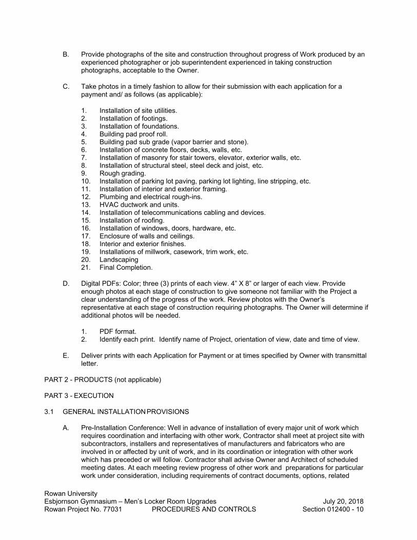
Rowan University Esbjornson Gymnasium – Men’s Locker Room Upgrades July 20, 2018 Rowan Project No. 77031 PROCEDURES AND CONTROLS Section 012400 - 10
B. Provide photographs of the site and construction throughout progress of Work produced by an experienced photographer or job superintendent experienced in taking construction photographs, acceptable to the Owner.
C. Take photos in a timely fashion to allow for their submission with each application for a payment and/ as follows (as applicable):
1. Installation of site utilities. 2. Installation of footings. 3. Installation of foundations. 4. Building pad proof roll. 5. Building pad sub grade (vapor barrier and stone). 6. Installation of concrete floors, decks, walls, etc. 7. Installation of masonry for stair towers, elevator, exterior walls, etc. 8. Installation of structural steel, steel deck and joist, etc. 9. Rough grading. 10. Installation of parking lot paving, parking lot lighting, line stripping, etc. 11. Installation of interior and exterior framing. 12. Plumbing and electrical rough-ins. 13. HVAC ductwork and units. 14. Installation of telecommunications cabling and devices. 15. Installation of roofing. 16. Installation of windows, doors, hardware, etc. 17. Enclosure of walls and ceilings. 18. Interior and exterior finishes. 19. Installations of millwork, casework, trim work, etc. 20. Landscaping 21. Final Completion.
D. Digital PDFs: Color; three (3) prints of each view. 4” X 8” or larger of each view. Provide enough photos at each stage of construction to give someone not familiar with the Project a clear understanding of the progress of the work. Review photos with the Owner’s representative at each stage of construction requiring photographs. The Owner will determine if additional photos will be needed.
1. PDF format. 2. Identify each print. Identify name of Project, orientation of view, date and time of view.
E. Deliver prints with each Application for Payment or at times specified by Owner with transmittal letter.
PART 2 - PRODUCTS (not applicable)
PART 3 - EXECUTION
3.1 GENERAL INSTALLATION PROVISIONS
A. Pre-Installation Conference: Well in advance of installation of every major unit of work which requires coordination and interfacing with other work, Contractor shall meet at project site with subcontractors, installers and representatives of manufacturers and fabricators who are involved in or affected by unit of work, and in its coordination or integration with other work which has preceded or will follow. Contractor shall advise Owner and Architect of scheduled meeting dates. At each meeting review progress of other work and preparations for particular work under consideration, including requirements of contract documents, options, related

Rowan University Esbjornson Gymnasium – Men’s Locker Room Upgrades July 20, 2018 Rowan Project No. 77031 PROCEDURES AND CONTROLS Section 012400 - 11
change orders, purchases, deliveries, shop drawings, product data, quality control samples, possible conflicts, compatibility problems, time schedules, weather limitations, temporary facilities, space and access limitations, structural limitations, governing regulations, safety, inspection and testing requirements, required performance results, recording requirements, and protection. Contractor shall record significant discussions of each conference, and agreements and disagreements, along with final plan of action. Distribute record of meeting promptly to everyone concerned, including Architect/Engineer and Owner.
1. Do not proceed with the work if associated pre-installation conference cannot be concluded successfully. Instigate actions to resolve impediments to performance of the work, and reconvene conference at earliest date feasible.
B. Installer's Inspection of Conditions: Require Installer of each major unit of work to inspect substrate to receive the work, and conditions under which the work will be performed, and to report (in writing to Contractor) unsatisfactory conditions. Do not proceed with the work until unsatisfactory conditions have been corrected in a manner acceptable to Installer.
C. Manufacturer's Instructions: Where installations include manufactured products, comply with manufacturer's applicable instructions and recommendations for installation, to whatever extent these are more explicit or more stringent than applicable requirements indicated in contract documents.
D. Inspect each item of materials or equipment immediately prior to installation, and reject damaged and defective items.
E. Provide attachment and connection devices and methods for securing work properly as it is installed; true to line and level, and within recognized industry tolerances if not otherwise indicated. Allow for expansions and building movements. Provide uniform joint widths in exposed work, organized for best possible visual effect. Refer questionable visual-effect choices to Architect for final decision.
F. Recheck measurements and dimensions of the work, as an integral step of starting each installation.
G. Install work during conditions of temperature, humidity, exposure, forecasted weather, and status of project completion, which will ensure best possible results for each unit of work, in coordination with entire work. Isolate each unit of work from non-compatible work, as required to prevent deterioration.
H. Coordinate enclosure (closing-in) of work with inspections and tests, so as to minimize necessity of uncovering work for that purpose.
I. Mounting Heights: Except as otherwise indicated, mount individual units of work at industry- recognized standard mounting heights, for applications indicated. Refer questionable mounting height choices to Architect/Engineer for final decision.
3.2. The contractor shall include in his/her proposal the cost of all control wiring and its installation for all mechanical equipment including, but not limited to, heating, ventilating and air conditioning systems, ATC systems, boilers, remote monitoring systems, etc. which systems require electrical control wiring. The contractor shall employ a sub-contractor approved by the University for all such control wiring. The sub-contractor shall provide a final certificate of electrical inspection of the control wiring. Installed or control wiring must connect to a point of electrical power supply as shown on the contract documents.
Rowan University Esbjornson Gymnasium – Men’s Locker Room Upgrades July 20, 2018 Rowan Project No. 77031 PROCEDURES AND CONTROLS Section 012400 - 12
3.3 CHASES, RECESSES AND OPENINGS
A. Contractor shall build chases, recesses, openings, channels and flues, and shall leave or create holes where shown on drawings, or where directed for piping, electrical conduits, switchboxes, panelboards, flues and ducts, or any other feature of the mechanical and electrical work. All trades requiring chases, recesses, openings, etc. shall furnish to the Contractor, complete detailed drawings for all chases, recesses and openings required in connection with such work in ample time to allow the construction to proceed without interruption or delay. Comply with requirements of "Submittals" section of these specifications.
1. Contractor shall close, build in and finish around or over all chases, recesses, openings, etc. after installation of mechanical and electrical work has been completed. Should any fail to furnish the above required information in time, he shall, at his own expense, arrange for all cutting, rebuilding, patching and finishing, but shall employ the Contractor whose work must be cut to do so.
2. Contractor shall obtain prior written approval from the Architect/Engineer and the Owner before cutting or boring through beams, floor construction or supporting members.
3.4 SLEEVES, BUILT-IN ITEMS
A. Each trade shall be responsible for furnishing and setting of sleeves, built-in items, anchors, inserts, etc. for his work. Contractor shall build these items into the construction.
1. Comply with requirements of "Submittals" section in the preparation of sleeve drawings.
3.5 CUTTING AND PATCHING
A. General: Do not cut-and-patch structural work in a manner resulting in reduction of load- carrying capacity or load/deflection ratio; submit proposed cutting and patching to Architect/Engineer for structural approval before proceeding. Do not cut-and-patch operational elements and safety-related components in a manner resulting in reduction of capacities to perform in manner intended or resulting in decreased operational-life, increased maintenance, or decreased safety. Do not cut-and-patch work which is exposed on exterior or exposed in occupied spaces of building, in a manner resulting in reduction of visual qualities or resulting in substantial evidence of cut-and-patch work, both as judged solely by Architect. Remove and replace work judged by Architect to be cut-and-patched in a visually unsatisfactory manner.
1. Contractor shall do all cutting, fitting, adjusting and patching as may be required to permit the several parts to properly come together as intended and indicated.
2. Engage original Fabricator/Installer to perform cutting-and-patching of structural work, operational/ safety-related components, and visually exposed work; or, if not available, engage only recognized experts; employ only proven methods.
3. Do not cut or alter work performed under separate contracts without the Architect’s written permission.
4. Use adequate numbers of skilled workmen who are thoroughly trained and experienced in the necessary crafts and who are completely familiar with the specific requirements and methods needed for proper performance of the work of this Section.
5. Verify that existing site conditions and substrate surfaces are acceptable for subsequent work. Beginning new work means acceptance of existing conditions.
6. Verify that existing substrate is capable of structural support or attachment of new work being applied or attached.
7. Examine and verify specific conditions described in individual specification sections. 8. Verify that utility services are available, of the correct characteristics, and in the correct

Rowan University Esbjornson Gymnasium – Men’s Locker Room Upgrades July 20, 2018 Rowan Project No. 77031 PROCEDURES AND CONTROLS Section 012400 - 13
locations. 9. Prior to Cutting: Examine existing conditions prior to commencing work, including
elements subject to damage or movement during cutting and patching. After uncovering existing work, assess conditions affecting performance of work. Beginning of cutting or patching means acceptance of existing conditions.
B. Materials: Except as otherwise indicated or approved by Architect/Engineer, provide materials for cutting-and-patching which will result in equal-or-better work than work being cut-and- patched, in terms of performance characteristics and including visual effect where applicable. Use materials identical with original materials where feasible and where recognized that satisfactory results can be produced thereby.
C. Temporary Support and Protection: Provide adequate temporary support for work to be cut, to prevent failure. Do not endanger other work. Provide adequate protection of other work during cutting-and-patching, to prevent damage; and provide protection of the work from adverse weather exposure.
D. Cut work using methods least likely to damage work to be retained and work adjoining.
1. Where physical cutting action is required, cut work with sawing and grinding tools, not with hammering and chopping tools. Core drill openings through concrete work. Comply with the requirements of applicable sections of Division 2 where cutting-and-patching requires excavating and backfilling.
2. Fit work air tight to pipes, sleeves, ducts, conduit, and other penetrations through surfaces.
3. At penetrations of fire rated walls, partitions, ceilings, or floor construction, completely seal voids with fire rated materials in accordance with Section 07841 to full thickness of the penetrated elements.
4. Refinish surfaces to match adjacent finish. For continuous surfaces, refinish to nearest intersection or natural break. For an assembly, refinish entire unit.
E. Patch with seams, which are durable and as invisible as possible. Comply with specified tolerances for the work.
1. Where feasible, inspect and test patched areas to demonstrate integrity of work.
F. Restore exposed finishes of patched areas; and, where necessary extend finish restoration onto retained work adjoining, in a manner, which will eliminate evidence of patching.
1. Where patch occurs in a smooth painted surface, extend final paint coat over entire unbroken surface containing patch, after patched area has received prime and base coats.
G. Execute cutting and patching including excavation and fill to complete the work, to uncover work to install improperly sequenced work, to remove and replace defective or non-conforming work, to remove samples of installed work for testing when requested, to provide opening in the work for penetrations of mechanical and electrical work, to execute patching to complement adjacent work, and to fit Products together to integrate with other work.
H. Execute work by methods to avoid damage to other work, and which will provide appropriate surfaces to receive patching and finishing. In existing work, minimize damage and restore to original conditions.

Rowan University Esbjornson Gymnasium – Men’s Locker Room Upgrades July 20, 2018 Rowan Project No. 77031 PROCEDURES AND CONTROLS Section 012400 - 14
I. ALL CUTTING AND PATCHING SHALL BE CONSIDERED PART OF THE BASE BID PRICE WHEN THE WORK IS REQUIRED AS PART OF THE OVERALL PROJECT. NO ADDITIONAL PAYMENT WILL BE CONSIDERED FOR WORK OF THIS SECTION UNLESS ALL APPLICABLE PARTIES OBTAIN PRIOR AUTHORIZATION OR WRITTEN APPROVAL.
3.6 UNCOVERING AND CORRECTION OF WORK
A. Comply with requirements of the General Conditions of the Contract, and with additional requirements specified herein.
1. Subsequent Disclosure of Faulty Work: Failure of Owner or Architect/Engineer to exercise powers of rejection or condemnation against the work of the Contractor during construction shall not be construed as an acceptance on Owner's part or Architect/ Engineer's part that Contractor's work has been faithfully performed, if the fact be otherwise.
3.7 PROJECT CONDITIONS
A. Protect site from puddling or running water. Provide water barriers as required to protect site from soil erosion.
B. Ventilate enclosed areas to assist cure of materials, to dissipate humidity, and to prevent accumulation of dust, fumes, vapors, or gases.
C. Pollution Control: Provide methods, means, and facilities to prevent contamination of soil, water, and air from discharge of noxious, toxic substances, and pollutants produced by construction activities. Comply with all governmental and code requirements.
3.8 PREPERATION FOR CUTTING AND PATCHING AND/OR NEW WORK.
A. Prepare surfaces and remove surface finishes to provide for proper installation of work and finishes.
B. Clean substrate surfaces prior to applying next material or substance.
C. Seal cracks or openings of substrate prior to applying next material or substance.
D. Apply manufacturers required or recommended substrate primer, sealer, or conditioner prior to applying any new material or substance in contact or bond.
3.9 LAYING OUT THE WORK
A. Verify locations of survey control points prior to starting work.
B. Promptly notify Owner’s Representative and Architect of any discrepancies discovered.
C. Protect survey control points prior to starting site work; preserve permanent reference points during construction.
D. Promptly report to Architect/Engineer and Owner’s Representative the loss or destruction of any reference point or relocation required because of changes in grades or other reasons.
E. Utilize recognized engineering survey practices.

Rowan University Esbjornson Gymnasium – Men’s Locker Room Upgrades July 20, 2018 Rowan Project No. 77031 PROCEDURES AND CONTROLS Section 012400 - 15
F. Establish elevations, lines and levels. Locate and lay out by instrumentation and similar appropriate means:
1. Site improvements including but not limited to pavements; stakes for grading, fill and topsoil placement; utility locations, slopes, and invert elevations, etc.
2. Building foundation, column locations, all floor elevations, stairwells, elevator shafts, machine and mechanical rooms, etc.
3. All other work as necessary to complete all the requirements of the contract documents.
G. Periodically verify layouts by same means.
H. Maintain a complete and accurate log of control and survey work as it progresses.
3.10 GENERAL INSTALLATION REQUIREMENTS
A. Install Products as specified in individual sections and in accordance with manufacturer’s recommendations.
B. Make neat transitions. Patch work to match adjacent work in texture and appearance. Where new Work abuts or aligns with existing, perform a smooth and even transition.
C. When existing finished surfaces are cut so that a smooth transition with new Work is not possible, terminate existing surface along a straight line at a natural line of division and make recommendations to the Architect and Owner.
3.11 CLEANING AND PROTECTION
A. General: During handling and installation of work at project site, Contractor shall clean and protect work in progress and adjoining work on a basis of perpetual maintenance. Apply suitable protective covering on newly installed work where reasonably required to ensure freedom from damage or deterioration at time of substantial completion; otherwise, clean and perform maintenance on newly installed work as frequently as necessary through remainder of construction period. Adjust and lubricate operable components to ensure operability without damaging effects.
B. Removal of all debris and rubbish resulting from or relating to the construction work; rubbish shall not be thrown from building openings above the ground floor unless confined within chutes.
1. Progress Cleaning:
a. Maintain areas free of waste material, debris, and rubbish (on a daily basis). Maintain site in a clean and orderly condition, as determined by the Owner.
b. Remove debris and rubbish from pipe chases, plenums, attics, crawl spaces, and other closed or remote spaces, prior to enclosing the space.
c. Broom and vacuum clean interior areas prior to start of surface finishing, and continue cleaning to eliminate dust.
d. Collect and remove waste materials, debris, and rubbish from site periodically and dispose of off-site.
e. Protect installed work and provide special protection where specified in individual specification sections.
f. Provide temporary and removable protection for installed Products. Control activity during and after installation in the immediate work area to prevent damage.

Rowan University Esbjornson Gymnasium – Men’s Locker Room Upgrades July 20, 2018 Rowan Project No. 77031 PROCEDURES AND CONTROLS Section 012400 - 16
g. Protect finished floors and other surfaces from traffic, dirt, wear, damage, or movement of heavy objects, by protecting with durable sheet materials appropriate for the task involved.
C. Limiting Exposures of Work: To extent possible through reasonable control and protection methods, Contractor shall supervise performance of work in a manner and by means which will ensure that none of the work, whether completed or in progress, will be subjected to harmful, dangerous, damaging, or otherwise deleterious exposures during construction period. Such exposures include (where applicable, but not by way of limitation) static loading, dynamic loading, internal pressures, external pressures, high or low temperatures, thermal shock, high or low humidity, air contamination or pollution, water, ice, solvents, chemicals, light, radiation, puncture, abrasion, heavy traffic, soiling, bacteria, insect infestation, combustion, electrical current, high speed operation, improper lubrication, unusual wear, misuse, incompatible interface, destructive testing, misalignment, excessive weathering, unprotected storage, improper shipping/handling, theft and vandalism.
D. Construction Debris: The Contractor shall intermittently remove waste and rubble so that at no time shall there be undue accumulations. Upon completion, the Contractor shall dress up all areas affected by this work whether inside or outside the boundary of the Project. Loading, crating, hauling and dumping will be at the contractor's expense.
E. Rubbish: The Contractor shall provide covered metal trash cans in sufficient quantity to accept the accumulation of rubbish and garbage from lunch and the like of employees of all Contractors working on site.
1. The Contractor shall instruct his and his subcontractors’ employees to deposit their trash and garbage in these containers and not elsewhere about the site; and also not to use the containers for construction scraps, rubbish, trash and surplus materials.
2. The Contractor shall empty these containers daily and haul the rubbish to a legal disposal site off the property.
F. Roads and Pathways:
1. The Contractor is responsible for the removal of construction dirt and debris in public areas on the site and in the surrounding areas serving the site.
2. Dirt and mud tracked onto streets by the Contractor or its subcontractors is to be immediately cleaned up by the Contractor to the satisfaction of the Owner and the local municipal authorities.
G. Trucks: All trucks leaving the construction area are to be covered in accordance with NJDOT over the road requirements. Trucks leaving the site are to be clean and free of mud or other materials.
H. Quality Assurance: University streets and pathways are to be maintained in a clean safe condition at all times. Under no circumstances shall the Contractor leave the site each day without inspecting and verifying that streets and paths to the construction site, access areas, lay down areas, and gates in the area of the site are clean of all construction related materials and are clean and sage for use by the Rowan University population. The Contractor will immediately correct any violation of this provision upon notification by the Owner.
3.12 CONSERVATION AND SALVAGE
A. General: It is a general procedural requirement for Contractor's supervision and administration
Rowan University Esbjornson Gymnasium – Men’s Locker Room Upgrades July 20, 2018 Rowan Project No. 77031 PROCEDURES AND CONTROLS Section 012400 - 17
of the work that construction operations be carried out with maximum practical consideration for conservation of energy, water and materials; and with maximum practical consideration for salvaging materials and equipment involved in performance of the work but not incorporated therein.
END OF SECTION 012400

Rowan University Esbjornson Gymnasium – Men’s Locker Room Upgrades July 20, 2018 Rowan Project No. 77031 CONTRACT MODIFICATION PROCEDURES Section 012500 - 1
SECTION 012500 - CONTRACT MODIFICATION PROCEDURES
PART 1 - GENERAL
1.1 RELATED DOCUMENTS
A. Drawings and general provisions of the Contract, including General and Supplementary Conditions and other Division 1 Specification Sections, apply to this Section. In the event of any conflicts between the requirements of these Sections, the more stringent requirement shall apply.
1.2 SUMMARY
A. This Section specifies administrative and procedural requirements for handling and processing Contract modifications.
B. Related Sections include the following:
1. Division 1 Section "Allowances" for procedural requirements for handling and processing allowances.
2. Division 1 Section "Unit Prices" for administrative requirements for using unit prices. 3. Division 1 Section "Product Requirements" for administrative procedures for handling
requests for substitutions made after Contract award.
1.3 MINOR CHANGES IN THE WORK
A. Architect may issue through Owners project manager supplemental instructions authorizing Changes in the Work, not involving adjustment to the Contract Time, as “Architects Supplemental Instructions” (ASI). Architects Supplemental Instructions may or may not involve adjustments to the contract sum. THERE WILL BE NO ADJUSTMENTS TO THE CONTRACT TIME ALLOWED FOR THIS PROJECT.
1. For ASI’s involving no adjustment to the contract sum or time, the contractor is authorized to execute the change or clarification immediately.
2. For ASI’s resulting in an adjustment to the contract sum, do not consider them instructions either to stop work in progress or to execute the proposed change without obtaining written authorization from the Owner. Written authorization can include the provisions of the general conditions, Article 14, paragraphs 14.5.3 and 14.7.1, an approved change order or a Construction Change Directive.
1.4 PROPOSAL REQUESTS
A. In the event the Contractor believes that any change directed by the Owner or Architect would entitle it to additional compensation to complete its work under this contract, the Contractor shall immediately notify the Owners project manager of this fact WITHIN 48 HOURS OF RECEIPT OF THE CHANGE REQUESTED. The contractor shall then prepare and submit an original of the Change Order Request (COR) with all supporting documentation to the Owners project manager and submit two (2) copies of the Change Order Request (COR) with all supporting documentation to the Architect and University within five (5) calendar days of its receipt of the directive by the Owner and/or Architect.
B. Owner-Initiated Proposal Requests: Owner may issue proposal requests or may have the

Rowan University Esbjornson Gymnasium – Men’s Locker Room Upgrades July 20, 2018 Rowan Project No. 77031 CONTRACT MODIFICATION PROCEDURES Section 012500 - 2
Architect issue such requests. In any event a detailed description of proposed changes in the Work will be submitted to the contractor that may require adjustment to the Contract Sum. THERE WILL BE NO ADJUSTMENTS TO TIME FOR ANY GIVEN CHANGE ORDER REQUESTED. If necessary, the description will include supplemental or revised Drawings and Specifications.
1. Proposal Requests issued by Architect are for information only. For ASI’s resulting in adjustments to the contract sum, do not consider them instructions either to stop work in progress or to execute the proposed change without first obtaining written authorization from the Owner.
2. If the contractor feels the ASI or proposal request requires a change to the contract sum then the contractor shall notify the Owners project manager of this fact within 48 hours of receipt of the ASI or OIPR directive.
3. Within five (5) business days after receipt of directive, ASI or proposal request from the Owner, submit a Change Order Request estimating cost adjustments to the Contract Sum necessary to execute the change. The contractor shall then prepare and submit an original of the Change Order Request (COR) with all supporting documentation to the Owners project manager and submit two (2) copies of the COR with all supporting documentation to the architect.
a. Include a list of quantities of products required or eliminated and unit costs, with total amount of purchases and credits to be made. If requested, furnish survey data to substantiate quantities.
b. Indicate applicable delivery charges, equipment rental, and amounts of trade discounts.
c. Include costs of labor directly attributable to the change. 1) Labor shall be broken down by man-hours, hourly wages, fringe benefits per
hour and any other benefits payable. d. Include an updated Contractor's Construction Schedule that indicates the effect of
the change, including, but not limited to, changes in activity duration, start and finish times, and activity relationship. Use available total float however the date of Substantial and Final Completion cannot be extended.
C. In the event that the Contractor encounters a condition that it considers a change, the Contractor shall immediately notify the Owners Project Manager prior to disturbing the condition and shall then prepare and submit an original of the COR with all supporting documentation to the Owners project manager and two (2) copies of a Change Order Request with all required supporting documentation to the architect within five (5) calendar days of encountering the condition. The condition shall not be disturbed until the Project Manager has inspected the condition.
D. Contractor-Initiated Proposals: If latent or unforeseen conditions require modifications to the Contract, Contractor may propose changes by submitting a Change Order Request (COR) to Owners project manager. The contractor shall prepare and submit one (1) original of the COR with all supporting documentation to the Owners project manager and submit two (2) copies of the COR with all supporting documentation to the architect.
1. Include a statement outlining reasons for the change and the effect of the change on the Work. Provide a complete description of the proposed change. Indicate the effect of the proposed change on the Contract Sum.
2. Include a list of quantities of products required or eliminated and unit costs, with total amount of purchases and credits to be made. If requested, furnish survey data to substantiate quantities.
3. Indicate applicable delivery charges, equipment rental, and amounts of trade discounts. 4. Include costs of labor and supervision directly attributable to the change. 5. Include an updated Contractor's Construction Schedule that indicates the effect of the

Rowan University Esbjornson Gymnasium – Men’s Locker Room Upgrades July 20, 2018 Rowan Project No. 77031 CONTRACT MODIFICATION PROCEDURES Section 012500 - 3
change, including, but not limited to, changes in activity duration, start and finish times, and activity relationship. Use available total float however the date of Substantial and Final Completion cannot be extended.
6. Comply with requirements in General Conditions Article 4.15 if the proposed change requires substitution of one product or system for product or system specified.
E. Proposal Request Form: Use AIA Document G709 for Proposal Requests.
1.5 ALLOWANCES (IF APPLICABLE ON A GIVEN PROJECT)
A. Allowance Adjustment: To adjust allowance amounts, base each Allowance Request Proposal on the difference between purchase amount and the allowance, multiplied by final measurement of work-in-place. If applicable, include reasonable allowances for cutting losses, tolerances, mixing wastes, normal product imperfections, and similar margins. Only allowances included as part of the Bid Price will be considered for an Allowance Authorization. All other Proposals must be hard costed.
1. Include installation costs in purchase amount only where indicated as part of the allowance.
2. If requested, prepare explanation and documentation to substantiate distribution of overhead costs and other margins claimed.
3. Submit substantiation of a change in scope of work, if any, claimed in Change Orders related to allowances.
4. Owner reserves the right to establish the quantity of work-in-place by independent quantity survey, measure, or count.
B. Submit claims for increased costs because of a change in scope or nature of the allowance described in the Contract Documents, whether for the Purchase Order amount or Contractor's handling, labor, installation, overhead, and profit. Submit claims within ten (10) business days of receipt of the Change Order or Construction Change Directive authorizing work to proceed. Owner will reject claims submitted later than ten (10) business days after such authorization.
1. Do not include Contractor's or subcontractor's indirect expense in the Change Order cost amount unless it is clearly shown that the nature or extent of work has changed from what could have been foreseen from information in the Contract Documents.
2. No change to Contractor's indirect expense is permitted for selection of higher- or lower- priced materials or systems of the same scope and nature as originally indicated.
C. Use the same procedure(s) followed for handling Change Order Requests (COR’s) and Change Orders with Allowances (except use Allowance Forms rather than Change Order Forms).
1.6 CHANGE ORDER PROCEDURES
A. Upon the Owner’s approval of a Change Order Request (COR), the Owner will direct the Architect to issue a Change Order for signatures of the Contractor and Owner on AIA Document G701.
1. The Change Order breakdown shall be in sufficient detail to permit an analysis of all material, labor, equipment, sub-contract and overhead costs as well as profit. Any amount proposed for sub-contracts shall be supported by a similar price breakdown.
B. Each Change Order must contain a detailed description of the change and the amount by which the Contract Price will be increased or decreased.
C. COMPUTATION OF ADDITIONAL COMPENSATION

Rowan University Esbjornson Gymnasium – Men’s Locker Room Upgrades July 20, 2018 Rowan Project No. 77031 CONTRACT MODIFICATION PROCEDURES Section 012500 - 4
1. In connection with any request for additional compensation the Contractor shall furnish a price breakdown, as follows:
a. Labor shall be broken down by the man-hour, hourly wages, fringe benefits per hour and any other benefits payable by the Contractor;
b. Materials shall be broken down by quantity and unit prices.
2. Unless otherwise directed, the breakdown shall cover all work involved in the change whether such work was deleted, added or changed.
3. The breakdown shall be in sufficient detail to permit an analysis of all material, labor, equipment, sub-contract and overhead costs as well as profit. Any amount proposed for sub-contracts shall be supported by a similar price breakdown.
4. The following rates shall apply in computing indirect costs and profit for the negotiation of additional compensation under all provisions of this contract, which provide for such adjustments that do not exceed twenty-five thousand dollars ($25,000.00). The resulting change in the contract amount will include the indirect impact cost of extended performance computed in accordance with the terms of this article and no further consideration of such costs arising from the specific modification will be given. The percentages for overhead and profit shall be negotiated and may vary according to the nature, extent and complexity of the work involved. If not negotiated prior to the start of construction then the rates herein designated shall apply. The percentages shall be applicable for deleted work as well as additional work. When a change consists of both added and deleted work, the applicable percentages shall be applied to the net cost or credit. In any event, the percentages shall not exceed the sum of the following:
a. Overhead will be the sum of ten percent (10%) of direct labor costs. 1) For the purpose of the article, the term direct labor shall include all labor by
contractor’s employees necessary to perform the actual work on site. Foremen, equipment operators and skilled, semi-skilled and common laborers directly assigned to the specific operation are direct labor; project managers, superintendents, office personnel, and subcontractors are not direct labor.
2) The term direct labor costs shall consist of the contract or actual payroll rate of wage per hour and fringe benefits paid for each and every hour that such employees are actually engaged in the performance of the work. Overhead will be the sum of ten percent (10) % of direct material costs.
b. Overhead will be the sum of ten percent (10%) of direct material costs. 1) For the purpose of the article, the term direct material costs shall consist of the
actual costs of the materials, including applicable tax and transportation charges c. For rented equipment, an hourly rental rate will be used which will be determined by
using the monthly rental rates taken from the current edition of the rental rate blue book for construction equipment and dividing it by one hundred seventy-six (176). An allowance will be made for operating costs for each and every hour the equipment is actually operating in accordance with the rate listed in the aforesaid rental book. The contractor will be allowed only sixty-five percent (65%) of the rental rate on contractor owned equipment.
d. Bond premiums, insurance, payroll taxes and travel subsistence, if applicable, will be allowed at actual cost (only) for the equitable adjustment allowed. No mark-up will be allowed for overhead on these indirect cost items.
e. The contractor's profit on the sub-contractor's work will be five percent (5%) of the sub-contractor's costs. Sub-contractor indirect costs will be computed in the same manner as for the contractor. The contractor agrees to incorporate this article in each of it sub-contracts.
f. A profit of six percent (6%) where profit is allowable by the terms of the applicable contract provision shall be added to the contractor's total cost for the equitable adjustment allowed for the work conducted by the contractors own workforce. Indirect costs will not be duplicated in direct costs.
g. When more than one (1) tier of sub-contractors exists, they shall be treated as one

Rowan University Esbjornson Gymnasium – Men’s Locker Room Upgrades July 20, 2018 Rowan Project No. 77031 CONTRACT MODIFICATION PROCEDURES Section 012500 - 5
(1) sub-contractor for the purpose of mark-ups.
D. ANY CONTRACTOR PERFORMING CHANGE ORDER WORK WITHOUT WRITTEN APPROVAL FROM THE OWNER DOES SO AT ITS OWN RISK.
1. Only the signature of an Assistant Vice President or above is authorized to give approval of a Change Order Request (COR) or Change Order (CO). The Owners project manager is not authorized to approve change orders. The project manager is only authorized to verify the work in question is in addition to or outside the scope of work delineated on the original contract documents.
1.7 CONSTRUCTION CHANGE DIRECTIVE
A. Construction Change Directive: Architect at the direction of the Owners project manager may issue a Construction Change Directive on AIA Document G714. Construction Change Directive instructs Contractor to proceed with a change in the Work, for subsequent inclusion in a Change Order.
1. Construction Change Directive contains a complete description of change in the Work. It also designates method to be followed to determine change in the Contract Sum.
B. Documentation: Maintain detailed records on a time and material basis of work required by the Construction Change Directive.
1. After completion of change, submit an itemized account and supporting data necessary to substantiate cost adjustments to the Contract.
PART 2 - PRODUCTS (Not Used)
PART 3 - EXECUTION
3.1 PERFORMANCE OF CHANGE ORDER WORK
A. A contractor who performs any scope of work associated with a change order or allowance (if allowances are applicable on a given project) without receiving proper approval in accordance with all contract document requirements hereof does so at its own risk. The Contractor shall have waived any and all claims for additional compensation related to said changes or conditions encountered.
END OF SECTION 012500

Rowan University Esbjornson Gymnasium – Men’s Locker Room Upgrades July 20, 2018 Rowan Project No. 77031 PAYMENT PROCEDURES 012900 - 1
SECTION 012900 - PAYMENT PROCEDURES
PART 1 - GENERAL
1.1 RELATED DOCUMENTS
A. Drawings and general provisions of the Contract, including General and Supplementary Conditions and other Division 1 Specification Sections, apply to this Section. In the event of any conflicts between the requirements of these Sections, the more stringent requirement shall apply.
1.2 SUMMARY
A. This Section specifies administrative and procedural requirements necessary to prepare and process Applications for Payment.
B. Related Sections include the following:
1. Division 1 Section "Allowances" for procedural requirements governing handling and processing of allowances.
2. Division 1 Section "Unit Prices" for administrative requirements governing use of unit prices.
3. Division 1 Section "Contract Modification Procedures" for administrative procedures for handling changes to the Contract.
4. Division 1 Section "Construction Progress Documentation" for administrative requirements governing preparation and submittal of Contractor's Construction Schedule and Submittals Schedule.
1.3 DEFINITIONS
A. Schedule of Values: A statement furnished by Contractor allocating portions of the Contract Sum to various portions of the Work and used as the basis for reviewing Contractor's Applications for Payment.
1.4 SCHEDULE OF VALUES
A. Coordination: Coordinate preparation of the Schedule of Values with preparation of Contractor's Construction Schedule.
1. Correlate line items in the Schedule of Values with other required administrative forms and schedules, including the following: a. Application for Payment forms with Continuation Sheets. b. Submittals Schedule.
2. Submit the Schedule of Values submission to Architect and Owners Construction Manager in accordance with the general conditions and general conduct of work.
3. Sub schedules: Where the Work is separated into phases requiring separately phased payments, provide sub schedules showing values correlated with each phase of payment.
B. Format and Content: Use the Project Manual table of contents as a guide to establish line

Rowan University Esbjornson Gymnasium – Men’s Locker Room Upgrades July 20, 2018 Rowan Project No. 77031 PAYMENT PROCEDURES 012900 - 2
items for the Schedule of Values. Provide at least one line item for each Specification Section.
1. Identification: Include the following Project identification on the Schedule of Values: a. Project name and location. b. Name of Architect. c. Architect's project number. d. Contractor's name and address. e. Date of submittal.
2. Arrange the Schedule of Values in tabular form with separate columns to indicate the following for each item listed: a. Related Specification Section or Division. b. Description of the Work. c. Name of subcontractor. d. Name of manufacturer or fabricator. e. Name of supplier. f. Change Orders (numbers) that affect value. g. Dollar values h. Cost totals.
1) Percentage of the Contract Sum to nearest one-hundredth percent, adjusted to total 100 percent.
3. Provide a breakdown of the Contract Sum in enough detail to facilitate continued evaluation of Applications for Payment and progress reports. Coordinate with the Project Manual table of contents. Provide several line items for principal subcontract amounts, where appropriate. a. Use data from approved Schedule of Values. Provide dollar value in each column
for each line item for portion of work performed. 4. Round amounts to nearest whole dollar; total shall equal the Contract Sum. 5. Provide a separate line item in the Schedule of Values for each part of the Work where
Applications for Payment may include materials or equipment purchased or fabricated and stored, but not yet installed. a. Differentiate between items stored on-site and items stored off-site.
b. The University may, in its sole discretion, pay the Contractor for material delivered on the site and preparatory work done to be taken into consideration. Material delivered to the contractor at locations other than the site may also be taken into consideration if (1) such consideration is specifically authorized by the contract and (2) the contractor furnishes a form entitled "Contractor's Summary of Stored Materials" and agreement and bill of sale certification, respectively, for stored materials and (3) the contractor furnishes evidence of insurance for said materials or a bonded warehousing agreement.
6. Provide separate line items in the Schedule of Values for initial cost of materials, for each subsequent stage of completion, and for total installed value of that part of the Work.
7. Allowances: Provide a separate line item in the Schedule of Values for each allowance. Show line-item value of unit-cost allowances, as a product of the unit cost, multiplied by measured quantity. Use information indicated in the Contract Documents to determine quantities. Allowances will only be accepted for items listed in the Bid Documents.
8. Each item in the Schedule of Values and Applications for Payment shall be complete. Include total cost and proportionate share of general overhead and profit for each item. a. Temporary facilities and other major cost items that are not direct cost of actual
work-in-place must be shown as separate line items in the Schedule of Values. 9. Schedule Updating: Update and resubmit the Schedule of Values before the next
Applications for Payment when Change Orders or Construction Change Directives result in a change in the Contract Sum. a. List each authorized Change Order as a separate line item, listing Change Order
number and dollar amount as for an original item of work.

Rowan University Esbjornson Gymnasium – Men’s Locker Room Upgrades July 20, 2018 Rowan Project No. 77031 PAYMENT PROCEDURES 012900 - 3
1.5 APPLICATIONS FOR PAYMENT
A. Each Application for Payment shall be consistent with previous applications and payments as certified by Architect and paid for by Owner.
1. Initial Application for Payment, Application for Payment at time of Substantial Completion, and final Application for Payment involve additional requirements.
2. Submit three (3) copies of each Application for Payment, at least five (5) business days prior to the actual submission date as specified. This Application will be reviewed and adjusted by all parties (Architect, Owner and Contractor) at a “PENCIL COPY REVIEW” meeting prior to final approval.
B. Payment Application Times: The date for each progress payment is indicated in the Agreement between Owner and Contractor. The period of construction Work covered by each Application for Payment is the period indicated in the Agreement.
C. Payment Application Times: The date for each progress payment is per the General Conditions. The period covered by each Application for Payment starts on the day following the end of the preceding period and ends 15 days before the date for each progress payment.
D. Payment Application Forms: Use AIA Document G702 and AIA Document G703 Continuation Sheets
E. Application Preparation: Complete every entry on form. Notarize and execute by a person authorized to sign legal documents on behalf of Contractor. Project Manager will return incomplete applications without action.
1. Entries shall match data on the Schedule of Values and Contractor's Construction Schedule. Use updated schedules if revisions were made.
2. Include amounts of Change Orders and Construction Change Directives issued before last day of construction period covered by application.
F. Transmittal: Submit 3 (three) signed and notarized original copies of each Application for Payment to Project Manager by a method ensuring receipt within 24 hours. All copy’s shall include ‘Attachment to G702- Certification for Payment”, Release of Liens Forms (included in the Contract Documents) entirely completed for the contractor, all subcontractors and anyone else whose payment is listed in the Schedule of Values for the application being requested, AIA G706 A-Contractors Affidavit…, Certified Payrolls and Monthly Work Force Reports, updated and current Construction Schedule, updated and current Submittal Log, and current Project Photograph’s.
1. Transmit each copy with a transmittal form listing attachments and recording appropriate information about application.
G. Release of Mechanic's Lien: With each Application for Payment, submit partial or final releases of mechanic's lien (as may apply) from every entity that is lawfully entitled to file a mechanic's lien arising out of the Contract and related to the Work covered by the payment.
1. Submit partial waivers on each item for amount requested, before deduction for retainage, on each item.
2. When an application shows completion of an item, submit final or full waivers. 3. Owner reserves the right to designate which entities involved in the Work must submit
waivers. 4. Submit final Application for Payment with or proceeded by final waivers from every entity
involved with performance of the Work covered by the application that is lawfully entitled to a lien.

Rowan University Esbjornson Gymnasium – Men’s Locker Room Upgrades July 20, 2018 Rowan Project No. 77031 PAYMENT PROCEDURES 012900 - 4
5. Release Forms: Submit release of lien on forms, executed in a manner acceptable to Owner. (Use Form listed in Division 0 of the Specifications).
H. Initial Application for Payment: Administrative actions and submittals that must precede or coincide with submittal of first Application for Payment include the following:
1. List of subcontractors. 2. Schedule of Values. 3. Contractor's Construction Schedule (preliminary if not final). a) A final schedule must be submitted prior to Owners payment of the second (2nd) progress
payment. 4. Products list. 5. Schedule of unit prices. 6. Submittals Schedule (preliminary if not final). 7. List of Contractor's staff assignments. 8. List of Contractor's principal consultants. 9. Copies of building permits. 10. Copies of authorizations and licenses from authorities having jurisdiction for performance
of the Work. 11. Initial progress report.
12. Report of preconstruction conference.
13. Certificates of insurance and insurance policies. 14. Performance and payment bonds. 15. Data needed to acquire Owner's insurance. 16. Initial settlement survey and damage report if required. 17. Current construction photographs as specified herein.
I. Application for Payment at Substantial Completion: After issuing the Certificate of Substantial Completion, submit an Application for Payment showing 100 percent completion for portion of the Work claimed as substantially complete.
1. Include documentation supporting claim that the Work is substantially complete and a statement showing an accounting of changes to the Contract Sum.
2. This application shall reflect Certificates of Partial Substantial Completion issued previously for Owner occupancy of designated portions of the Work.
J. Final Payment Application: Submit final Application for Payment with releases and supporting documentation not previously submitted and accepted, including, but not limited, to the following:
1. Evidence of completion of Project closeout requirements. 2. Insurance certificates for products and completed operations where required and proof
that taxes, fees, and similar obligations were paid. 3. Updated final statement, accounting for final changes to the Contract Sum. 4. AIA Document G706, "Contractor's Affidavit of Payment of Debts and Claims." 5. AIA Document G706A, "Contractor's Affidavit of Release of Liens." 6. AIA Document G707, "Consent of Surety to Final Payment." 7. Evidence that claims have been settled. 8. Final meter readings for utilities, a measured record of stored fuel, and similar data as of
date of Substantial Completion or when Owner took possession of and assumed responsibility for corresponding elements of the Work.
9. Final, liquidated damages settlement statement.
K. When Owner or Architect/Engineer requires substantiating information, submit data justifying

Rowan University Esbjornson Gymnasium – Men’s Locker Room Upgrades July 20, 2018 Rowan Project No. 77031 PAYMENT PROCEDURES 012900 - 5
dollar amounts in question. Provide one (1) copy of data with cover letter for each copy of submittal. Show application number and date, and line item by number and description.
1. Any other information or documentation required by other provisions of the contract documents shall be supplied.
L. In order to be proper an Application for Payment must include the following as applicable:
1. Total amount, payee name and address, department/agency, payee declaration, payee reference number and identification number.
2. contract number, contractor’s name, period of the Application, completion date, number of sheets, amount due this period, amount to date, retainage, certification by payee, certification signed by the Project Manager and Architect and approval of payment signed by the contracting officer or his/her designee, previous payment requests, total deductions and additions.
3. In making progress payments for work, the University will retain two percent (2%) of the approved invoice of payment until final acceptance and completion of all work covered by the contract.
4. After fifty percent (50%) of the work has been completed, upon written request by the contractor and provided the contracting officer determines that the contractor's performance and progress have been satisfactory, the University will make partial payments thereafter in full of the approved payment amount. If, however, progress is not maintained in accordance with the approved schedule, the contracting officer may elect to reinstitute retainage of two percent (2%) of amounts due to the contractor. The contracting officer shall have the sole authority to determine whether contractor’s performance and progress warrant waiver of two percent (2%) retainage.
M. Upon acceptance and completion of each building or other clearly definable severable portion of the contract work for which the price is stated separately within the contract, payment may be made in full at the discretion of the contracting officer including retained percentages thereon less authorized deductions.
N. All authorized Applications are to be sent to the Owners authorized representative at the address provided at the pre-construction conference. Receipt shall start the prompt payment clock unless returned to the contractor for correction within thirty (30) calendar days after receipt. Reference section 10.2.4 (d) of the General Conditions.
1.6 FINAL PAYMENT
A. Upon final acceptance, the amount due the contractor under this contract shall be paid upon satisfactory completion by the contractor of all contract close-out requirements as required by the University, completion of a University audit on all contract values and payments and after the contractor shall have furnished the University with a final release of liens from the contractor and all subcontractors, sub-subcontractors, vendors, suppliers and any other entity affiliated with the contractor for completion of this project of any and all claims against the University arising by virtue of this contract other than claims in stated amounts as may be specifically excepted by the contractor from the release.
B. Upon satisfying the above conditions, the contractor shall submit a properly executed Application for Final Payment to the University through the Project Manager. The University Controller shall date stamp the Application. This action by the University Controller shall constitute receipt of a properly executed State invoice application.
C. If, for any reason, the contractor refuses final payment, the project shall be closed-out by the University unilaterally processing a final acceptance certificate. The University will hold all residual funds in escrow until all claims of the University and all contractors are satisfied.

Rowan University Esbjornson Gymnasium – Men’s Locker Room Upgrades July 20, 2018 Rowan Project No. 77031 PAYMENT PROCEDURES 012900 - 6
END OF SECTION 012900

Rowan University Esbjornson Gymnasium – Men’s Locker Room Upgrades July 20, 2018 Rowan Project No. 77031 COORDINATION 013100 - 1
SECTION 013100 - COORDINATION
PART 1 - GENERAL
1.1 RELATED DOCUMENTS
A. Drawings and general provisions of the Contract, including General Conditions, general conduct of the Work and Special Requirements, Supplementary Conditions, and other Division 1 Specification Sections, apply to this Section. In the event of any conflicts between the requirements of these Sections, the more stringent requirement shall apply.
1.2 SUMMARY
A. This Section includes administrative and supervisory requirements necessary for coordinating construction operations including, but not necessarily limited to, the following:
1. General project coordination procedures. 2. Conservation. 3. Coordination Drawings. 4. Administrative and supervisory personnel. 5. Cleaning and protection.
B. Related Sections: The following Sections contain requirements that relate to this Section:
1. Division 1 Section "Field Engineering" specifies procedures for field engineering services, including establishment of benchmarks and control points.
2. Division 1 Section "Submittals" for preparing and submitting the Contractor's Construction Schedule.
3. Division 1 Section "Contract Closeout" for coordinating contract closeout.
1.3 COORDINATION
A. Coordinate construction operations included in various Sections of these Specifications to assure efficient and orderly installation of each part of the Work. Coordinate construction operations included under different Sections that depend on each other for proper installation, connection, and operation.
1. Schedule construction operations in the sequence required to obtain the best results where installation of one part of the Work depends on installation of other components, before or after its own installation.
2. Coordinate installation of different components to assure maximum accessibility for required maintenance, service, and repair.
3. Make provisions to accommodate items scheduled for later installation.
B. The mechanical. electrical and fire protection drawings are diagrammatic only and are not intended to show the alignment, physical locations or configurations of such work. Such work shall be coordinated by the Contractor and shall be installed to clear all obstructions, permit proper clearances for the work of other trades, satisfv all code requirements and present an orderlv appearance where exposed a t no additional cost to the Owner.
C. Where necessary, prepare memoranda for distribution to each party involved, outlining special procedures required for coordination. Include such items as required notices, reports, and
Rowan University Esbjornson Gymnasium – Men’s Locker Room Upgrades July 20, 2018 Rowan Project No. 77031 COORDINATION 013100 - 2
attendance at meetings.
1. Prepare similar memoranda for the Owner and separate contractors where coordination of their work is required.
D. Administrative Procedures: Coordinate scheduling and timing of required administrative procedures with other construction activities to avoid conflicts and assure orderly progress of the Work. Such administrative activities include, but are not limited to, the following:
1. Prepare and coordinate scheduling, delivery and processing of submittals, and work of the various sections of the Project Manual to ensure efficient and orderly sequence of installation of interdependent construction elements, with provisions for accommodating items installed later.
2. Verify that utility requirements and characteristics of operating equipment are compatible with building utilities. Coordinate work of various sections having interdependent responsibilities for installing, connecting to, and placing in service, such equipment.
3. Coordinate space requirements, supports, and installation of mechanical and electrical work, which are indicated diagrammatically on the Drawings. Follow routing shown for pipes, ducts and conduit, as closely as practicable; place runs parallel with lines of building. Utilize spaces efficiently to maximize accessibility for other installations, for maintenance and for repairs.
4. Installation and removal of temporary facilities. 5. Progress meetings. 6. In finished areas except as otherwise indicated, conceal pipes, ducts, and wiring within
the construction. Coordinate locations of fixtures and outlets with finish elements. 7. Coordinate completion and clean-up of work of separate sections. 8. After Owner occupancy of premises, coordinate access to site for correction of
defective work and work not in accordance with Contract Documents, to minimize disruption of Owner's activities.
9. Project closeout activities.
E. Conservation: Coordinate construction operations to assure that operations are carried out with consideration given to conservation of energy, water, and materials.
1. Salvage materials and equipment involved in performance of, but not actually incorporated in, the Work.
1.4 SUBMITTALS
A. Coordination Drawings: Prepare coordination drawings where careful coordination is needed for installation of products and materials fabricated by separate entities. Prepare coordination drawings where limited space availability necessitates maximum utilization of space for efficient installation of different components.
1. Show the relationship of components shown on separate Shop Drawings. 2. Indicate required installation sequences. 3. Comply with requirements contained in Section "Submittals."
a. Note the coordination drawing submittal requirements under Section 013300 "Submittals", paragraph 2.3.9
B. Staff Names: Within fifteen (15) days of commencement of construction operations, submit a list of the Contractor's principal staff assignments, including the superintendent and other personnel in attendance at the Project Site. Identify individuals and their duties and responsibilities. List their addresses and telephone numbers.
1. Post copies of the list in the Project meeting room, and the temporary field office.

Rowan University Esbjornson Gymnasium – Men’s Locker Room Upgrades July 20, 2018 Rowan Project No. 77031 COORDINATION 013100 - 3
PART 2 - EXECUTION
2.1 GENERAL COORDINATION PROVISIONS
A. Inspection of Conditions: Require the Installer of each major component to inspect both the substrate and conditions under which Work is to be performed. Do not proceed until unsatisfactory conditions have been corrected in an acceptable manner.
B. Coordinate temporary enclosures with required inspections and tests to minimize the necessity of uncovering completed construction for that purpose.
2.2 CLEANING AND PROTECTION
A. Clean and protect construction in progress and adjoining materials in place, during handling and installation. Apply protective covering where required to assure protection from damage or deterioration at Substantial Completion.
B. Clean and provide maintenance on completed construction as frequently as necessary through the remainder of the construction period. Adjust and lubricate operable components to assure operability without damaging effects.
C. Limiting Exposures: Supervise construction operations to assure that no part of the construction, completed or in progress is subject to harmful, dangerous, damaging, or otherwise deleterious exposure during the construction period.
END OF SECTION 013100

Rowan University Esbjornson Gymnasium – Men’s Locker Room Upgrades July 20, 2018 Rowan Project No. 77031 CONSTRUCTION PROGRESS DOCUMENTATION 013200 - 1
SECTION 013200 – CONSTRUCTION PROGRESS SCHEDULE
PART 1 - GENERAL
1.1 RELATED DOCUMENTS
A. Drawings and general provisions of the Contract, including General Conditions (Contract Administration Division Section D), General Conduct of the Work and Special Requirements, and other Division 1 Specification Sections, apply to this Section. In the event of any conflicts between the requirements of these Sections, the more stringent requirement shall apply.
1.2 SUBMITTALS
A. Within three (3) days after the date established in the Notice to Proceed, University Contract and/or purchase order submit preliminary schedule indicating the scope of work for the duration of the project. A Gantt chart format will be acceptable however the final approved schedule must be in both a Gantt chart and CPM schedule format. If another method other than CPM is used the critical path and float time must be established and programmed into the schedule.
B. Initial Working CPM Schedule Submittal: To the extent necessary for the Contractor to reflect in the arrow diagram the plan for completion of this contract, the contractor shall meet with and furnish all necessary information for the preparation of the scheduling system within ten (10) calendar days after award of this contract. This information shall include, but not necessarily be limited to, logical sequencing of work operations; activity time estimated, intended crew flow, activity costs and estimated manpower requirements of each activity.
1. The contractor shall be responsible to reflect all sub-contractor work as well as his/her own work in proper coordinated sequence on the network diagram. The contractor shall be prepared to meet as many times as necessary with the Project Manager for the timely development of the project schedule.
1.3 SCHEDULE FORMAT
A. Listings: In chronological order according to the start date for each activity. Identify each activity with the applicable specification section number. At a minimum provide the following.
1. Include a separate bar for each portion of work or operation. 2. Identify the first workday of each week. 3. Identify each critical path task or portion of work. 4. Identify task durations, predecessors and dependent tasks. 5. Identify milestone dates for completion/start of each critical path element.
B. The contractor shall utilize the earliest scheduled start and finish dates in planning, coordinating and performing the work under this contract including all activities of sub-contractors, equipment vendors and suppliers.
PART 2 - PRODUCTS – NOT USED
Rowan University Esbjornson Gymnasium – Men’s Locker Room Upgrades July 20, 2018 Rowan Project No. 77031 CONSTRUCTION PROGRESS DOCUMENTATION 013200 - 2
PART 3 - EXECUTION
3.1 CONTENT
A. Construction logic and activity time durations shall be established by the contractor subject to approval by the Owner’s Project Manager consistent with contract requirements and reflective of proper coordination between trades.
B. The Owner’s Project Manager shall establish the specific level of detail to be reflected in the scheduling system.
C. Seasonal weather conditions shall be considered in the planning and scheduling of all work influenced by high or low ambient temperatures for the completion of all contract work within the allotted contract time. In addition, appropriate allowances shall be made for anticipated time losses due to normal rain and snow conditions by statistically expanding the estimated time durations for weather sensitive activities with the constraint that the substantial completion deadline cannot change.
D. The coordinated combined Progress Schedule the Contractor will develop shall incorporate the schedules of all Prime Contractors engaged on the project. The Schedule shall be in a form as specified herein and elsewhere in the contract documents and in sufficient detail to satisfy the Architect/Engineer and the University.
E. If applicable, the Contractor shall submit copies of his initial draft of this Schedule to all Prime Contractors. Each Prime Contractor shall then prepare a Progress Schedule for his own work, properly coordinated with the General Construction Contractor's initial draft and then submit it to the General Construction Contractor for his preparation of the final draft of a Single Coordinated Progress Schedule. Contract Requisitions will not be processed by the University until and unless such a single coordinated Progress Schedule shall have been submitted to and approved by the University Project Manager and/or Contracting Officer. This submission shall be no later than thirty (30) colander days after the award of the Contract. If any Prime Contractor delays his submission, the Project Schedule will be submitted without his input and any payments otherwise due him will be withheld until he complies.
F. The Progress Schedule based upon the Contractor's logic and time estimates shall indicate, in suitable detail for display, all significant features of the Work of each Contractor, including the placing of orders and anticipated delivery dates for critical items and all other critical path activities, submissions and approvals of Shop Drawings, all work activities to be performed by each Contractor and the beginning and time durations thereof, float time and the dates of substantial and final completion of the various branches of the Work.
1. Show complete sequence of construction activity, with dates for beginning and completion of each element of construction.
2. Identify each item by specification section number or per bid form breakdown.
3. Show accumulated percentage of completion of each item, and total percentage of Work completed, as of the first day of each month.
4. Indicate delivery dates as milestones for Owner-furnished items and any critical path items.
5. Provide legend for symbols and abbreviations used. 6. Show critical path tasks; differentiate them from other construction tasks. 7. Schedule will be based upon a five-day workweek.

Rowan University Esbjornson Gymnasium – Men’s Locker Room Upgrades July 20, 2018 Rowan Project No. 77031 CONSTRUCTION PROGRESS DOCUMENTATION 013200 - 3
3.2 REVIEW AND EVALUATION OF SCHEDULE
A. Review and Approval of Initial Working Schedule: Within ten (10) calendar days after receipt of the initial arrow diagram and computer produced schedule, the University's representative shall meet with the contractor and for joint review, correction or adjustment of the proposed plan and schedule to evaluate the cost values assigned to each activity. Within ten (10) calendar days after the joint review, the Contractor will revise the arrow diagram and the computer- produced schedule in accordance with agreement reached during the joint review and shall submit two (2) copies each of the revised arrow diagram, computer produced schedule and cost requisition to the University. The resubmission will be reviewed by the University and, if found to be as previously agreed upon, will be approved. An approved copy of each will be returned to the Contractor. The contractor shall review the schedule to insure that it reflects all changes agreed to and, if all changes have been made, the contractor shall approve and sign the network diagrams, computer produced schedule and cost requisition listing at that time. Approval will be without reservation and the contractor will be deemed to have accepted the schedule as adequate, proper and binding in all respects and shall not raise objections to the schedule. After the network diagrams, computer-produced schedule and cost requisition listing have been signed, the Contractor shall forward one (1) set of signed copies of all scheduling documents to the University Project Manager. The arrow diagram and the computer-produced schedule with approved signatures shall constitute the project work schedule until subsequently revised in accordance with the requirements of this section.
B. Evaluate project status to determine work behind schedule and work ahead of schedule. Submit revised recovery schedule with action plan to bring “behind schedule” tasks and milestones back into original timeline.
3.3 UPDATING SCHEDULES
A. Maintain schedules to record actual start and finish dates of completed activities.
1. Updated schedules must be submitted at each progress meeting and with each application for payment or as required by Architect or Owner. These schedules must include the following: a. approved changes in activity sequencing; b. changes in activity durations for unstarted or partially completed activities where
agreed upon; c. the effect to the network of any delays in any activities in progress and/or the impact
of known delays, which are expected to affect future work; d. the effect of contractor modifications; i.e., activity durations, logic and cost estimates;
to the network; e. changes to activity logic where agreed upon to reflect revision in the contractor's
work plan; i.e., changes in activity duration, cost estimates and activity sequences for the purpose of regaining lost time or improving progress;
f. changes to milestones, and due dates (except substantial completion) which have been agreed upon by the University since the last revision of the schedule.
B. At the same time the network is updated, the contractor and the University's representative shall jointly make entries on the preceding network diagram schedule to show actual progress, to identify those activities started by date and those completed by date during the previous period to show the estimated time required to complete each activity started but not yet completed, to show activity percent completed and to reflect any changes in the arrow diagram approved in accordance with the preceding paragraph. After completion of the joint review and the University's approval of all entries, the Contractor will submit updated network diagrams and an updated computer produced calendar dated schedule to the University and the

Rowan University Esbjornson Gymnasium – Men’s Locker Room Upgrades July 20, 2018 Rowan Project No. 77031 CONSTRUCTION PROGRESS DOCUMENTATION 013200 - 4
contractor.
1. The resultant computer print-out and network diagrams shall be recognized by the contractor as solely his/her updated construction schedule to complete all remaining contractor work except that portion affected by interim University decisions.
3.4 DISTRIBUTION OF SCHEDULES
A. Upon approval at each level of schedule development (preliminary, final for Contractors work and Single Coordinated including all Prime Contractors work) the Contractor shall prepare and distribute (10) copies of the schedule at each level to the University. The Contractor shall also prepare and distribute two (2) copies of the final schedule showing Prime Contractors work to each Prime Contractor. In the event a new Prime Contractor is added to the job the General Construction Contractor shall furnish a revised schedule immediately with copies as indicated. The final coordinated schedule shall be signed and dated by all Prime Contractors involved and shall become part of the contract documents.
B. Distribute copies of updated (current) schedules to Contractors project site file, subcontractors, suppliers, Architect and Owner at each bi-weekly progress meeting. Also submit an updated (current) schedule with each Application for Payment or more often as required by the Architect and/or Owner.
3.5 SCHEDULE ADJUSTMENTS
A. Upon Owner and/or Architects request, if Contractor falls behind the approved schedule, the Contractor must submit a revised schedule to show how the Contractor intends to accomplish the completion of the work within the original contract time.
1. Within seven (7) days after receipt of notice from the Owner, the contractor shall submit to the University in writing an explanation of corrective action taken or proposed. The contracting officer shall make a decision binding on all parties after reviewing the written submissions.
B. Responsibility for Completion: The contractor agrees that whenever it becomes apparent from the current monthly computer produced calendar dated schedule that any contract completion date will not be met, he/she will take some or all of the following actions at no additional cost to the University.
1. increase construction manpower in such trades and numbers as will substantially eliminate the backlog of work in the opinion of the Construction Manager and contracting officer
2. increase the number of working hours per shift, shifts per working days, working days per week or the amount of construction equipment of any combination of the foregoing sufficiently to substantially eliminate the backlog of work in the judgment of the Construction Manager and contracting officer
3. reschedule activities to achieve maximum practical concurrence of accomplishment of activities
C. Lost time due to weather conditions will not accrue nor be credited to Contractor for weather delays with time added to the Substantial Completion milestone deadline. No weather delays will be granted once the building is under roof.
3.6 BI-WEEKLY REPORTING

Rowan University Esbjornson Gymnasium – Men’s Locker Room Upgrades July 20, 2018 Rowan Project No. 77031 CONSTRUCTION PROGRESS DOCUMENTATION 013200 - 5
A. Upon request from the Owner, the Contractor shall furnish for approval, his proposed operating schedule for the next immediate two-week period of time. This schedule will be submitted at each bi-weekly progress meeting along with the overall updated schedule.
1. Every two (2) weeks, the Architect will conduct a coordination and scheduling meeting on the job site. At this meeting, the contractor shall provide detailed information in the form of a bar chart schedule regarding the work schedule to be performed during the upcoming two (2) weeks. Bi-weekly scheduling by the contractor shall be in accordance with the priorities and degree of concurrent work required by the official schedule for the project. The contractor shall be prepared to explain a difference between the contractor's bi-weekly schedules and the priorities required by the latest updating of the official schedule.
2. At the bi-weekly scheduling meeting, the Owner and Architect shall review the bar charts for the preceding two (2) weeks and the contractor shall report the progress actually achieved for each activity, which was scheduled to be performed during the two (2) weeks, including the actual dates on which the work was performed. The contractor agrees that this information shall constitute the official historical record of project progress. At each bi-weekly scheduling meeting, the contractor shall document any current delays to work operations. In addition, the contractor shall provide any available information regarding any potential delays, which they anticipate; i.e., procurement delays, expected strikes, etc.
3. Following the bi-weekly scheduling meeting, the Contractor shall issue to the Owner and Architect a new set of bi-weekly bar charts as developed at the meeting, which shall constitute the construction schedule for the upcoming two (2) weeks. The Contractor shall also issue a narrative bi-weekly progress analysis documenting progress achieved during the preceding two (2) weeks and analyze delays reported to constitute current or anticipated impacts to timely construction. The revised bar chart schedule and progress narrative shall agree with the meeting minutes and items discussed and agreed to at the bi-weekly meeting.
4. The contractor shall be represented at the bi-weekly scheduling meeting by their Construction Manager who shall have complete authority to provide the information required for the development of the next two (2) weeks bar chart schedule, documentation of past progress and documentation of delays. The contractor representatives shall also be authorized to discuss correction action planned to overcome delaying conditions at these meetings.
3.7 DAILY REPORTS
A. Daily Construction Reports: Prepare a daily construction report recording the following
information concerning events at the Project site:
1. List of subcontractors at Project site. 2. List of separate contractors at Project site. 3. Approximate count of personnel at Project site. 4. Equipment at Project site. 5. Material deliveries. 6. High and low temperatures and general weather conditions. 7. Accidents. 8. Meetings and significant decisions. 9. Unusual events (refer to special reports). 10. Stoppages, delays, shortages, and losses. 11. Meter readings and similar recordings. 12. Emergency procedures. 13. Orders and requests of authorities having jurisdiction.

Rowan University Esbjornson Gymnasium – Men’s Locker Room Upgrades July 20, 2018 Rowan Project No. 77031 CONSTRUCTION PROGRESS DOCUMENTATION 013200 - 6
14. Change Orders received and implemented. 15. Construction Change Directives received and implemented. 16. Services connected and disconnected. 17. Equipment or system tests and startups. 18. Partial Completions and occupancies. 19. Substantial Completions authorized.
B. Field Condition Reports: Immediately on discovery of a difference between field conditions
and the Contract Documents prepare and submit a detailed report. Submit with requests for
interpretation. Include a detailed description of the differing conditions, together with
recommendations for changing the Contract Documents.
END OF SECTION 013200

Rowan University Esbjornson Gymnasium – Men’s Locker Room Upgrades July 20, 2018 Rowan Project No. 77031 SUBMITTAL PROCEDURES 013300 - 1
SECTION 013300 SUBMITTAL PROCEDURES
PART 1 - GENERAL
1.1 RELATED DOCUMENTS
A. Drawings and general provisions of the Contract, including General Conditions, General Conduct of the Work, Supplementary Conditions, and other Division 1 Specification Sections, apply to this Section. In the event of any conflicts between the requirements of these Sections, the more stringent requirement shall apply.
B. EVERY EFFORT MUST BE MADE TO ACCELERATE LONG LEAD SUBMITTALS ON ALL LONG LEAD MATERIALS TO ASSURE MEETING THE PROJECT SCHEDULE.
1.2 SUMMARY
A. This Section augments requirements set forth in the General Conditions and specifies administrative and procedural requirements for submittals required for performance of the Work, including:
1. Contractor’s Use of Architect’s CAD Files. 2. Shop Drawings. 3. Product Data. 4. Samples. 5. Informational Submittals. 6. Delegated Design.
B. Administrative Submittals: Refer to General Conditions, other Division 1 Sections and other Contract Documents for requirements for administrative submittals. Such submittals include, but are not limited to:
1. Permits. 2. Contractor’s Construction Schedule. 3. Submittal Schedule. 4. Schedule of Values. 5. Applications for payment. 6. List of Subcontractors.
C. Related Sections include the following:
1. Division 1 Section "Project Management and Coordination" for submitting and distributing meeting and conference minutes and for submitting Coordination Drawings.
2. Division 1 Section "Quality Requirements" for submitting test and inspection reports and for mockup requirements.
3. Division 1 Section "Closeout Procedures" for submitting warranties. 4. Division 1 Section "Operation and Maintenance Data" for submitting operation and
maintenance manuals. 5. Division 1 Section "Demonstration and Training" for submitting videotapes of
demonstration of equipment and training of Owner's personnel. 6. Divisions 2 through 16 Sections for specific requirements for submittals in those
Rowan University Esbjornson Gymnasium – Men’s Locker Room Upgrades July 20, 2018 Rowan Project No. 77031 SUBMITTAL PROCEDURES 013300 - 2
Sections.
1.3 DEFINITIONS
A. Action Submittals: Written and graphic information that requires Architect and Construction Manager's responsive action.
B. Informational Submittals: Written information that does not require Architect and Construction Manager's responsive action. Submittals may be rejected for not complying with requirements.
C. Concurrent Review: Simultaneous review by Architect and other discipline(s).
D. Shop Drawings: Original fabrication drawings.
E. Product Data: Manufacturer’s standard product literature and samples.
1.4 SUBMITTAL PROCEDURES
A. Coordination: Coordinate preparation and processing of submittals with performance of construction activities.
1. Coordinate each submittal with fabrication, purchasing, testing, delivery, other submittals, and related activities that require sequential activity.
2. Coordinate transmittal of different types of submittals for related parts of the Work so processing will not be delayed because of need to review submittals concurrently for coordination. a. Architect reserves the right to withhold action on a submittal requiring coordination
with other submittals until related submittals are received.
B. Submittals Schedule: Comply with General Conditions and other requirements of the Contract Administration Division. A submittal schedule will be developed by the Contractor within 5 working days of Notice to Proceed and approved by the Architect within 10 working days after receipt for review.
1. Follow the submittal requirements listed in this Section and elsewhere throughout the Contract Documents however and in addition to submittals required in other specification sections, one (1) copy of all HVAC, sprinkler, plumbing, electrical, and control system submittal must be forwarded to the Owners Project Manager. At minimum, for submittals other than those listed under this item a transmittal must be forwarded to the Project Manager.
C. Contractor shall record all submittal information on the required “Submittal Log”. Distribute Log at each progress meeting.
D. Processing Time: Allow enough time for submittal review, including time for resubmittals, as follows. Time for review shall commence on Architect's receipt of submittal. No extension of the Contract Time will be authorized because of failure to transmit submittals enough in advance of the Work to permit processing, including resubmittals.
1. Initial Review: Allow 10 working days for initial review of each submittal. Allow additional time if coordination with subsequent submittals is required. Architect will advise Contractor when a submittal being processed must be delayed for coordination.
2. Intermediate Review: If intermediate submittal is necessary, process it in same manner as initial submittal.

Rowan University Esbjornson Gymnasium – Men’s Locker Room Upgrades July 20, 2018 Rowan Project No. 77031 SUBMITTAL PROCEDURES 013300 - 3
3. Resubmittal Review: Allow 5 working days for review of each resubmittal. 4. Concurrent Consultant Review: Where the Contract Documents indicate that submittals
may be transmitted simultaneously to Architect and to Architect's consultants, allow 10 working days for initial review of each submittal. Submittal will be returned to Contractor, through Architect. Submittals in the following sections require concurrent consultant review: a. Division 3: All Sections. b. Division 5: Sections 05120 “Structural Steel”, 05310 “Steel Deck”, 05300 “Steel
Joists. c. Division 9: Acoustic Sections d. Division 13: All Sections. e. Division 15: All Sections. f. Division 16: All Sections.
5. Concurrent Transmittal to Consultant: Where indicated above and acceptable to Architect, Contractor may transmit submittals directly to Architect’s consultants in the required number of copies, while at the same time transmitting two additional copies of the entire submittal including the transmittal to the Architect.
6. Concurrent Transmittal to Owner: a. Transmit two (2) additional copies of all shop drawings, product data and
coordination drawings and coordination drawings and one (1) set of each sample submittal to Owner’s Project Manager.
E. Identification: Place a permanent label or title block on each submittal for identification.
1. Indicate name of firm or entity that prepared each submittal on label or title block. 2. Provide a space approximately 4 by 5 inches on label or beside title block to record
Contractor's review and approval markings and action taken by Architect. 3. Include the following information on label for processing and recording action taken:
a. Project name. b. Date. c. Name and address of Architect. d. Name and address of Contractor. e. Name and address of subcontractor. f. Name and address of supplier. g. Name of manufacturer. h. Submittal number or other unique identifier, including revision identifier.
1) Architect will assign own numbers to each submittal, which may be different than those assigned by the Contractor.
i. Number and title of appropriate Specification Section, and Keynote reference where applicable.
j. Drawing number and detail references, as appropriate. k. Other necessary identification.
F. Deviations: Encircle or otherwise specifically identify deviations from the Contract Documents on submittals.
G. Additional Copies: Unless additional copies are required for final submittal, and unless Architect observes noncompliance with provisions in the Contract Documents, initial submittal may serve as final submittal.
1. Submit specified number of copies of submittal to concurrent reviewer in addition to one complete copy and transmittal to Architect.
2. Additional copies submitted for maintenance manuals will not be marked with action taken and will be returned.

Rowan University Esbjornson Gymnasium – Men’s Locker Room Upgrades July 20, 2018 Rowan Project No. 77031 SUBMITTAL PROCEDURES 013300 - 4
H. Transmittal: Package each submittal individually and appropriately for transmittal and handling. Transmit each submittal using a transmittal form. Architect will return submittals, without review, received from sources other than Contractor.
1. Transmittal Form: Provide locations on form for the following information: a. Project name. b. Date. c. Destination (To:). d. Source (From:). e. Names of subcontractor, manufacturer, and supplier. f. Category and type of submittal. g. Submittal purpose and description. h. Specification Section number and title. i. Drawing number and detail references, as appropriate. j. Submittal and transmittal distribution record. k. Remarks. l. Signature of transmitter.
2. On the transmittal record relevant information and requests for data. On the form, or separate sheet, record deviations from Contract Document requirements, including minor variations and limitations. Include Contractor’s Certification that information complies with Contract Document requirements.
I. Contractor’s Certification: All scale and full-size shop, erection or setting drawings, roughing drawings, sleeve and opening drawings, product data, and samples shall be examined and checked by qualified technical employees of Contractor as to accuracy, completeness and compliance with all contract documents prior to submission to the Architect for his review. These drawings, data and samples shall be stamped and signed by Contractor certifying to such examination and compliance. Any drawings, data and samples not checked, stamped, and signed by Contractor will be returned unchecked, to Contractor. Contractor will be held responsible for any delay in the progress of the work due to his failure to observe these requirements, and the time for the completion of his contract will not be extended on account of his failure to submit drawings, data and samples promptly in accordance herewith.
J. Resubmittals: Make resubmittals in same form and number of copies as initial submittal.
1. Note date and content of previous submittal. 2. Note date and content of revision in label or title block and clearly indicate extent of
revision. 3. Resubmit submittals until they are marked “No Exceptions Taken", or “Make Corrections
Noted”.
K. Distribution: Furnish copies of final submittals to manufacturers, subcontractors, suppliers, fabricators, installers, and authorities having jurisdiction, and others as necessary for performance of construction activities. Furnish one (1) copy of final submittals to Owner. Show distribution on transmittal forms.
L. Use for Construction: Use only final submittals with mark indicating "No Exceptions Taken” or “Make Corrections Noted” by Architect.
M. In instances where sepias, shop drawings and/or erection of drawings of a scale larger than the contract drawings are prepared by a contract, such drawings and sepias will be accepted in lieu of marked-up contract drawings provided they are updated according to the contract documents. A master sheet of the same dimensions as the contract drawings shall be prepared by the contractor on a tracing which shall indicate, sheet by sheet, a cross-reference

Rowan University Esbjornson Gymnasium – Men’s Locker Room Upgrades July 20, 2018 Rowan Project No. 77031 SUBMITTAL PROCEDURES 013300 - 5
to all shop drawings pertaining to that drawing. All drawings and sepias as required by Section 2.8 F below, shall be labeled "as-built" and dated above the tile block.
1.5 CONTRACTOR'S USE OF ARCHITECT'S CAD FILES
A. General: Architect may provide electronic copies of CAD files of the Contract Drawings for Contractor’s use in preparing submittals subject to execution by the Contractor of a waiver and payment to the Architect for this service in the amount of $250. In accordance with the language of the waiver, the agreement is non-transferable by the Contractor to any Subcontractor, from any Subcontractor to the Contractor or from any Subcontractor to another Subcontractor. A separate waiver and payment is required for each individual contractor or subcontractor requesting electronic copies of CAD Drawings.
1. A sample copy of the waiver is included at the end of this Section. Upon request, Architect will provide an original.
2. This service is not available prior to the award of the contract. 3. Architect’s consultants may or may not provide CAD files under the above agreement.
Such consultants reserve the right to refuse to provide CAD files, regardless of whether or not the aforementioned waiver and fee agreement is executed. Consultants may, if they agree to provide CAD files, attach additional conditions to those listed above and below. Architect’s consultants include the following disciplines: civil, landscape, structural, mechanical, electrical, plumbing, and fire protection. Architect will advise Contractor if any consultants will not provide CAD files prior to executing above agreement.
4. CAD files will be provided in AutoCad 2002 format or newer version only. 5. CAD files will be provided in Architect’s office standard conventions for file structure, file
names, layering standards, drafting standards, etc. Architect will not make revisions to these standards for the convenience of the Contractor.
6. CAD files may or may not contain differences from the Contract Documents, including work and information related, but not limited to, alternate designs, obsolete designs, addenda, bulletins, construction sketches, and informational sketches. Such differences may or may not be clearly indicated. Where such differences are found, they do not supersede the Contract Documents.
PART 2 - PRODUCTS
2.1 ACTION SUBMITTALS
A. General: Prepare and submit Action Submittals required by individual Specification Sections.
B. When the following are specified in individual sections, submit them for review:
1. Shop drawings. 2. Samples for selection. 3. Samples for verification. 4. HVAC Test and Balance Reports.
C. Submit to Architect for review for the limited purpose of checking for conformance with information given and the design concept expressed in the contract documents.
D. Architect will consult with the Owner prior to rendering a decision or approval.
2.2 PRODUCT DATA

Rowan University Esbjornson Gymnasium – Men’s Locker Room Upgrades July 20, 2018 Rowan Project No. 77031 SUBMITTAL PROCEDURES 013300 - 6
A. Collect information into a single submittal for each element of construction and type of product or equipment.
1. If information must be specially prepared for submittal because standard printed data are not suitable for use, submit as Shop Drawings, not as Product Data.
2. Mark each copy of each submittal to show which products and options are applicable. 3. Include the following information, as applicable:
a. Manufacturer's written recommendations. b. Manufacturer's product specifications. c. Manufacturer's installation instructions. d. Standard color charts. e. Manufacturer's catalog cuts. f. Wiring diagrams showing factory-installed wiring. g. Printed performance curves. h. Operational range diagrams. i. Mill reports. j. Standard product operation and maintenance manuals. k. Compliance with specified referenced standards. l. Testing by recognized testing agency. m. Application of testing agency labels and seals. n. Notation of coordination requirements.
4. Submit Product Data before or concurrent with Samples. Each item of materials listed shall be marked “as specified” or “unspecified” as the case may be.
5. Number of Copies: Submit one original and three copies. For color charts submit four original color charts. One original and one copy will be returned. Reproduction for distribution to subcontractors, manufacturers, fabricators and suppliers is the responsibility of the Contractor. a. Concurrent Submittals to Consultants: Submit one original and three copies to
concurrent reviewer and two copies to Architect. In the case of color charts and other non-reproducible information, submit four originals to concurrent reviewer and two original to Architect.
b. Concurrent Submittals to Owner: Submit one (1) copy. c. Copy Owner with any transmittals for Product data sent to Architect or Consultants.
2.3 SHOP DRAWINGS:
A. Shop Drawings:
1. Prepare Project-specific information, drawn accurately to scale. Do not base Shop Drawings on reproductions of the Contract Documents or standard printed data.
2. Preparation: Fully illustrate requirements in the Contract Documents. Include the following information, as applicable: a. Dimensions. b. Identification of products. c. Fabrication and installation drawings. d. Roughing-in and setting diagrams. e. Wiring diagrams showing field-installed wiring, including power, signal, and control
wiring. f. Shopwork manufacturing instructions. g. Templates and patterns. h. Schedules. i. Design calculations. j. Compliance with specified standards. k. Notation of coordination requirements.

Rowan University Esbjornson Gymnasium – Men’s Locker Room Upgrades July 20, 2018 Rowan Project No. 77031 SUBMITTAL PROCEDURES 013300 - 7
l. Notation of dimensions established by field measurement. m. Relationship to adjoining construction clearly indicated. n. Seal and signature of professional engineer if specified. o. Wiring Diagrams: Differentiate between manufacturer-installed and field-installed
wiring. 3. Sheet Size: Except for templates, patterns, and similar full-size drawings, submit Shop
Drawings on sheets at least 8-1/2 by 11 inches but no larger than 36 by 48 inches. 4. Number of Copies: Submit one original (Contractor’s option of bond print or correctable
translucent reproducible print) and three additional copies. One original and one copy will be returned. Reproduction for distribution to subcontractors, manufacturers, fabricators and suppliers is the responsibility of the Contractor. a. Concurrent Submittals: Submit one original and three copies to concurrent reviewer
and two copies to Architect. b. Concurrent Submittals to Owner: Submit one (1) copy to Owner c. Copy Owner with any transmittals for Product data sent to Architect or Consultants.
5. Special Types of Shop Drawings: a. Sleeve and Opening Drawings: Comply with requirements set forth in the General
Conditions. 1) Comply with shop drawing requirements for submittal and review as specified in
this Section. b. Roughing Drawings: Furnish manufacturers certified roughing drawings, indicating
accurate locations and sizes of all service utility connections, for machinery and equipment requiring such connections. Submit roughing drawings together with shop drawings for respective machinery and equipment.
6. Mechanical/Electrical Shop Drawing Minimum Requirements: Shop Drawings prepared by mechanical specialty trades shall comply with the following minimum requirements: a. The accurate dimensions locate all horizontal ducts from column centerline.
Locate all offsets, transitions, elbows, fire dampers, registers, grilles and diffusers. b. All components shall be located to avoid recessed lighting, piping, conduits, cable
trays and other in-plenum assemblies and where required shall be located so as to provide access to the component through removable ceiling material panels or access doors.
c. Vertical riser ducts shall be located and dimensioned from column centerlines in two (2) directions. Each vertical duct riser shall be shown in its total length when concealed inside of a shaft.
d. Each horizontal duct run shall be drawn to scale and size (width and depth noted) and an ELEVATION (bottom of duct) be clearly noted. This elevation shall clear all beams in the floor above and the ceiling construction below.
e. Sheet metal shop drawings shall be made using not less than ¼" scale per foot; increase scale as required in congested areas or as directed by the Contractor.
7. All piping, including fire protection, storm, sanitary, domestic, heating and cooling systems. a. Give location of lines from column centerlines, indicate size, indicate centerline
ELEVATION of piping and indicate drainage pitch as required. b. Where a piping line is indicated locate centerline ELEVATION and pitch at intervals
not to exceed twenty (20) feet. c. Priority status shall be accorded preparation of dimensioned piping drawings for all
piping below slabs-on-grade. Show all line pitches, critical inverts, in-slab fixtures as drains, floor sinks, troughs, cleanouts, etc. and outfall tie-in to site plumbing. Coordinate under slab piping with arrangement(s) of equipment furnished by others where applicable.
8. Electrical Trade: a. Plan layouts, not less than ¼" scale, of transformer vaults, main electrical rooms,
satellite electrical and/or communications closets, emergency generator spaces showing equipment to scale and locations thereof.

Rowan University Esbjornson Gymnasium – Men’s Locker Room Upgrades July 20, 2018 Rowan Project No. 77031 SUBMITTAL PROCEDURES 013300 - 8
b. Main feeder distribution routing, horizontal and vertical sweep transitions to scale, of conduit over 1" showing ceiling plenum to scale.
9. Coordination: a. Coordination of the work of the several trades and the fitting and routing of the
systems within concealed areas to avoid conflicts is the responsibility of the contractor(s). The Architect reserves the right to request coordinated drawings of congested areas showing all systems in plan and section to appropriate scale to insure the proper fitting of the work. The Contractor shall comply if so requested by the Architect.
b. Provide coordinated drawings of all main mechanical, electrical, communications, and other rooms listed below showing equipment required by all trades including structure, piping, hanger assemblies, HVAC ductwork, conduit, electrical devices, fire alarm devices, control centers, pipe grids, acoustic enclosures, other devices. Drawings dimensioned in both plan and section(s); not less than 3/8"=1’-0” scale.
2.4 COORDINATION DRAWINGS
A. Prepare and submit Coordination Drawings where close and careful coordination is required for installation of products and materials fabricated off-site by separate entities, and where limited space availability necessitates maximum utilization of space for efficient installation of different components. See paragraph 2.3.9 above.
1. Show the interrelationship of components shown on separate Shop Drawings. 2. Indicate required installation sequences. 3. Refer to Division-15 and Division-16 "General Provisions" Sections for specific
Composite Drawing requirements for mechanical and electrical installations.
B. Role of Expediter: Contractor shall be responsible for expediting the preparation of the Coordination Drawings. Actual preparation of the drawings is described below. Contractor shall meet with subcontractors to develop a format for the Coordination Drawings (e.g. CAD, pin-register drafting, conventional drafting on Mylar using multiple pencil colors, etc.) such that reproductions obtained from the final Coordination Drawings can distinguish between the work of the various trades. Contractor shall resolve all conflicts arising in the coordination process.
C. Preparation Responsibility: Preparation of Coordination Drawings is the responsibility of the Contractor and all subcontractors principally involved. Production of the drawings shall proceed as follows:
1. HVAC subcontractor shall initiate the drawings by indicating his work, drawn at a scale of 3/8" per foot, showing dimensions, layouts, elevations and sections, all in relation to building construction (all steel structure, floor / roof slabs, ceilings, beams and columns).
2. Where applicable, the GWB subcontractor shall indicate the layout of all acoustic ceiling construction extent including all hanger devices and locations. AC ceiling construction indicated as well.
3. Fire Protection subcontractor shall then indicate the layout, sizes, dimensions and elevations of his work, using the HVAC subcontractor's drawings as a base, with dimensions in reference to fixed building construction.
4. Electrical subcontractor shall add his work to the base drawings begun by HVAC and Fire Protection subcontractors. Indicate locations and dimensions of light fixtures and electrical equipment conduit/cable-tray infrastructure, fire alarm equipment with reference to fixed building construction.
5. Plumbing subcontractor shall then add layouts, sizes and elevations of his work to the drawings of the above-mentioned trades, also dimensioned with reference to building structure.
Rowan University Esbjornson Gymnasium – Men’s Locker Room Upgrades July 20, 2018 Rowan Project No. 77031 SUBMITTAL PROCEDURES 013300 - 9
D. Conflicts arising between the work of several trades shall be resolved between the respective trades, with the assistance of the General Contractor as expediter; and the drawings revised. Final Coordination Drawings shall be submitted by the Contractor to the Architect as required for submittals.
2.5 SAMPLES:
A. Submit Samples for review of kind, color, pattern, and texture for a check of these characteristics with other elements and for a comparison of these characteristics between submittal and actual component as delivered and installed.
1. Transmit Samples that contain multiple, related components such as accessories together in one submittal package.
2. Identification: Attach label on unexposed side of Samples that includes the following: a. Generic description of Sample. b. Product name and name of manufacturer. c. Sample source. d. Number and title of appropriate Specification Section.
3. Disposition: Maintain sets of approved Samples at Project site, available for quality- control comparisons throughout the course of construction activity. Sample sets may be used to determine final acceptance of construction associated with each set. a. Samples not incorporated into the Work, or otherwise designated as Owner's
property, are the property of Contractor. 4. Samples for Initial Selection: Submit manufacturer's color charts consisting of units or
sections of units showing the full range of colors, textures, and patterns available. a. Number of Samples: Submit three full set(s) of available choices where color,
pattern, texture, or similar characteristics are required to be selected from manufacturer's product line. Architect will return submittal with options selected.
5. Samples for Verification: Submit full-size units or Samples of size indicated, prepared from same material to be used for the Work, cured and finished in manner specified, and physically identical with material or product proposed for use, and that show full range of color and texture variations expected. Samples include, but are not limited to, the following: partial sections of manufactured or fabricated components; small cuts or containers of materials; complete units of repetitively used materials; swatches showing color, texture, and pattern; color range sets; and components used for independent testing and inspection. a. Number of Samples: Submit four sets of Samples. Architect will retain one Sample
sets; remainder will be returned. Mark up and retain one returned Sample set as a Project Record Sample. 1) Submit a single Sample where assembly details, workmanship, fabrication
techniques, connections, operation, and other similar characteristics are to be demonstrated.
2) If variation in color, pattern, texture, or other characteristic is inherent in material or product represented by a Sample, submit at least three sets of paired units that show approximate limits of variations.
2.6 INFORMATIONAL SUBMITTALS
A. General: Prepare and submit Informational Submittals required by other Specification Sections.
1. Number of Copies: Submit two copies of each submittal, unless otherwise indicated. Architect will not return copies.
2. Certificates and Certifications: Provide a notarized statement that includes signature of entity responsible for preparing certification. An officer shall sign certificates and

Rowan University Esbjornson Gymnasium – Men’s Locker Room Upgrades July 20, 2018 Rowan Project No. 77031 SUBMITTAL PROCEDURES 013300 - 10
certifications or other individual authorized to sign documents on behalf of that entity. 3. Test and Inspection Reports: Comply with requirements specified in Division 1 Section
"Quality Requirements."
B. Coordination Drawings: Comply with requirements specified in Division 1 Section "Coordination."
C. Qualification Data: Prepare written information that demonstrates capabilities and experience of firm or person. Include lists of completed projects with project names and addresses, names.
D. Welding Certificates: Prepare written certification that welding procedures and personnel comply with requirements in the Contract Documents. Submit record of Welding Procedure Specification (WPS) and Procedure Qualification Record (PQR) on AWS forms. Include names of firms and personnel certified.
E. Installer Certificates: Prepare written statements on manufacturer's letterhead certifying that Installer complies with requirements in the Contract Documents and, where required, is authorized by manufacturer for this specific Project.
F. Manufacturer Certificates: Prepare written statements on manufacturer's letterhead certifying that manufacturer complies with requirements in the Contract Documents. Include evidence of manufacturing experience where required.
G. Product Certificates: Prepare written statements on manufacturer's letterhead certifying that product complies with requirements in the Contract Documents.
H. Material Certificates: Prepare written statements on manufacturer's letterhead certifying that material complies with requirements in the Contract Documents.
I. Material Test Reports: Prepare reports written by a qualified testing agency, on testing agency's standard form, indicating and interpreting test results of material for compliance with requirements in the Contract Documents.
J. Product Test Reports: Prepare written reports indicating current product produced by manufacturer complies with requirements in the Contract Documents. Base reports on evaluation of tests performed by manufacturer and witnessed by a qualified testing agency, or on comprehensive tests performed by a qualified testing agency.
K. Research/Evaluation Reports: Prepare written evidence, from a model code organization acceptable to authorities having jurisdiction, that product complies with building code in effect for Project. Include the following information:
1. Name of evaluation organization. 2. Date of evaluation. 3. Time period when report is in effect. 4. Product and manufacturers' names. 5. Description of product. 6. Test procedures and results. 7. Limitations of use.
L. Schedule of Tests and Inspections: Comply with requirements specified in Division 1 Section "Quality Requirements."

Rowan University Esbjornson Gymnasium – Men’s Locker Room Upgrades July 20, 2018 Rowan Project No. 77031 SUBMITTAL PROCEDURES 013300 - 11
M. Preconstruction Test Reports: Prepare reports written by a qualified testing agency, on testing agency's standard form, indicating and interpreting results of tests performed before installation of product, for compliance with performance requirements in the Contract Documents.
N. Compatibility Test Reports: Prepare reports written by a qualified testing agency, on testing agency's standard form, indicating and interpreting results of compatibility tests performed before installation of product. Include written recommendations for primers and substrate preparation needed for adhesion.
O. Field Test Reports: Prepare reports written by a qualified testing agency, on testing agency's standard form, indicating and interpreting results of field tests performed either during installation of product or after product is installed in its final location, for compliance with requirements in the Contract Documents.
P. Maintenance Data: Prepare written and graphic instructions and procedures for operation and normal maintenance of products and equipment. Comply with requirements specified in Division 1 Section "Operation and Maintenance Data."
Q. Design Data: Prepare written and graphic information, including, but not limited to, performance and design criteria, list of applicable codes and regulations, and calculations. Include list of assumptions and other performance and design criteria and a summary of loads. Include load diagrams if applicable. Provide name and version of software, if any, used for calculations. Include page numbers.
R. Manufacturer's Instructions: Prepare written or published information that documents manufacturer's recommendations, guidelines, and procedures for installing or operating a product or equipment. Include name of product and name, address, and telephone number of manufacturer. Include the following, as applicable:
1. Preparation of substrates. 2. Required substrate tolerances. 3. Sequence of installation or erection. 4. Required installation tolerances. 5. Required adjustments. 6. Recommendations for cleaning and protection.
S. Manufacturer's Field Reports: Prepare written information documenting factory-authorized service representative's tests and inspections. Include the following, as applicable:
1. Name, address, and telephone number of factory-authorized service representative making report.
2. Statement on condition of substrates and their acceptability for installation of product. 3. Statement that products at Project site comply with requirements. 4. Summary of installation procedures being followed, whether they comply with
requirements and, if not, what corrective action was taken. 5. Results of operational and other tests and a statement of whether observed performance
complies with requirements. 6. Statement whether conditions, products, and installation will affect warranty. 7. Other required items indicated in individual Specification Sections.
T. Insurance Certificates and Bonds: Prepare written information indicating current status of insurance or bonding coverage. Include name of entity covered by insurance or bond, limits of coverage, amounts of deductibles, if any, and term of the coverage.

Rowan University Esbjornson Gymnasium – Men’s Locker Room Upgrades July 20, 2018 Rowan Project No. 77031 SUBMITTAL PROCEDURES 013300 - 12
2.7 DELEGATED DESIGN
A. Performance and Design Criteria: Where professional design services or certifications by a design professional are specifically required of Contractor by the Contract Documents, provide products and systems complying with specific performance and design criteria indicated.
1. If criteria indicated are not sufficient to perform services or certification required, submit a written request for additional information to Architect.
B. Delegated-Design Submittal: In addition to Shop Drawings, Product Data, and other required submittals, submit three copies of a statement, signed and sealed by the responsible design professional, for each product and system specifically assigned to Contractor to be designed or certified by a design professional.
1. Indicate that products and systems comply with performance and design criteria in the Contract Documents. Include list of codes, loads, and other factors used in performing these services.
2.8 ADMINISTRATIVE SUBMITTALS
A. Contractor’s Construction Schedule: Comply with the General Conditions and other requirements of the Contract Administration Division.
1. If preliminary schedule requires revision after review, submit revised schedule within 5 business days.
2. Submit updated schedule with each Application for Payment.
B. Submittals Schedule: Comply with the General Conditions and other requirements of the Contract Administration Division.
1. Submit updated Submittal Log with each Application for Payment.
C. Application for Payment: Comply with the General Conditions and other requirements of the Contract Administration Division.
D. Schedule of Values: Comply with the General Conditions and other requirements of the Contract Administration Division.
E. Subcontract List: Comply with the General Conditions and other requirements of the Contract Administration Division. Prepare a written summary identifying individuals or firms proposed for each portion of the Work, including those who are to furnish products or equipment fabricated to a special design. Include the following information in tabular form:
1. Name, address, and telephone number of entity performing subcontract or supplying products.
2. Number and title of related Specification Section(s) covered by subcontract. 3. Drawing number and detail references, as appropriate, covered by subcontract. 4. Number of Copies: Submit three copies of subcontractor list, unless otherwise indicated.
Architect will return two copies. a. Mark up and retain one returned copy as a Project Record Document.
5. Submit one (1) copy of initial subcontractor list to Owner within (10) business days after Owner’s Notice to Proceed. No portion of the work shall be started until the Contractor has furnished the Owner with a list showing the sub-contractor and/or material supplier responsible for the portion of the actual work needing to be started. The list will be

Rowan University Esbjornson Gymnasium – Men’s Locker Room Upgrades July 20, 2018 Rowan Project No. 77031 SUBMITTAL PROCEDURES 013300 - 13
updated until the list reflects the complete group of all subcontractors, suppliers, vendors, etc. employed to carry out the work.
F. The contractor shall keep one (1) set of drawings on the project at all times which are to be marked "as-built". During the course of the project, they shall mark these drawings with colored pencils to reflect any changes as well as dimension, the location of all pipe runs, conduits, traps, footing depths or any other information not already shown on the drawings or differing there from. All buried utilities outside the building shall be located by a meter and bounds survey performed by a licensed surveyor who shall certify as to its accuracy. These marked-up drawings and surveys shall be made available to the contracting officer, the Construction Manager and the Architect/Engineer at any time during the progress of the work upon their request. These shall include the drawings of principal sub-contractors as well. The Owner’s Project Manager as well as the Architect on a monthly basis as a prerequisite to the review of the contractor’s payment applications will review as-built drawings.
2.9 SUBMITTALS FOR PROJECT CLOSE OUT
A. When the following are specified in individual sections, submit them at project closeout:
1. Project record documents. 2. Operation and maintenance data 3. Warranties. 4. Bonds (if and when required by the Owner). 5. Other types as indicated.
B. Manufacturers’ Instructions, Product Literature, Certificates, and Reports.
1. All instructions, literature, certificates, test reports, other technical data and correspondence shall be submitted in four (4) copies. The Owner shall retain Two (2) copies, and the other two (2) returned to the Contractor.
C. Written Certifications
1. Provide written certifications where required, in the following formats: a. Manufacturer’s Written Certifications: Shall be submitted in letter form on the
manufacturer’s letterhead, signed by an authorized representative, indicating that all required components and elements of their manufacture are in conformity with the requirements so stated under the individual sections of these Specifications. Technical data, additional support material, or other information may be submitted with the certification letter.
b. Installer’s Written Certifications: Shall be submitted in letter form on the installer’s company letterhead, signed by a legal authorized company officer, indicating that their respective installation and/or Work are in conformity with the requirements so stated under the individual sections of these Specifications.
D. Submit all of the above items in this Section for the Owner’s benefit during and after project completion.
PART 3 - EXECUTION
3.1 CONTRACTOR'S REVIEW
A. Review each submittal and check for coordination with other Work of the Contract and for compliance with the Contract Documents. Note corrections and field dimensions. Mark with

Rowan University Esbjornson Gymnasium – Men’s Locker Room Upgrades July 20, 2018 Rowan Project No. 77031 SUBMITTAL PROCEDURES 013300 - 14
approval stamp before submitting to Architect. The Architect / Consultants will not review submittals that do not bear Contractor's approval stamp and will return them without action.
B. Approval Stamp: Stamp each submittal with a uniform, approval stamp. Include Project name and location, submittal number, Specification Section title and number, name of reviewer, date of Contractor's approval, and statement certifying that submittal has been reviewed, checked, and approved for compliance with the Contract Documents.
3.2 ARCHITECT'S ACTION
A. General: Architect will not review submittals that do not bear Contractor's approval stamp and will return them without action.
B. Action Submittals: Architect will review each submittal, make marks to indicate corrections or modifications required, and return it. Architect will stamp each submittal with an action stamp and will mark stamp appropriately to indicate action taken, as follows:
1. Final Unrestricted Release: When submittals are marked “No Exceptions Taken” (NET), that part of the Work covered by the submittal may precede provided it complies with requirements of the Contract Documents; final acceptance will depend upon compliance.
2. Final-But-Restricted Release: When submittals are marked “Make Corrections Noted” (MCN), that part of the Work covered by the submittal may precede provided it complies with notations or corrections on the submittal and requirements of the Contract Documents; final acceptance will depend on that compliance.
3. Returned for Resubmittal: When submittal is marked “Amend and Resubmit” (AR), do not proceed with that part of the Work covered by the submittal, including purchasing, fabrication, delivery, or other activity. Revise or prepare a new submittal in accordance with the notations; resubmit without delay. Repeat if necessary to obtain a different action mark. a. Do not permit submittals marked “Amend and Resubmit” to be used at the Project
site, or elsewhere where Work is in progress. 4. Disapproved for Non-Compliance: When submittal is marked “Rejected - See Remarks”
(R), Architect’s explanation for rejection will be included. Do not proceed with the work. Prepare a completely new submission.
5. Other Action: Where a submittal is primarily for information or record purposes, special processing or other activity, the submittal will be returned, marked “Action Not Required”.
C. Informational Submittals: Architect will review each submittal and will not return it, or will return it if it does not comply with requirements. Architect will forward each submittal to appropriate party.
D. Partial submittals are not acceptable, will be considered nonresponsive, and will be returned without review.
E. Submittals not required by the Contract Documents may not be reviewed and may be discarded.
F. Architect's Review: Review of shop and setting drawings, roughing drawings, sleeve and opening drawings, product data and samples by Architect will be a general review for conformance with design concept and compliance with information given in contact documents only, and shall not relieve Contractor of responsibility for accuracy of such submissions, nor for proper fitting, construction of work, or for furnishings of materials or work required by the contract and not indicated on submissions. Field dimensions, fabrication details, and job fitting are entirely Contractor's responsibility. Review shall not be construed as approving departures from contract requirements. Any proposed deviations from contract requirements, together with

Rowan University Esbjornson Gymnasium – Men’s Locker Room Upgrades July 20, 2018 Rowan Project No. 77031 SUBMITTAL PROCEDURES 013300 - 15
Contractor's explanations thereof, shall be stated in the letter of transmittal. Approval of a specific item shall not indicate approval of an entire assembly of which the item is a component. Should contractor check and certify submissions which indicate changes or deviations from the contract documents, and such changes are found acceptable to Architect, any and all additional costs resulting therefrom, including any cost for changes required to adjacent work or the work of other trades shall be the sole responsibility of Contractor.
RELEASE AGREEMENT – DIGITAL INFORMATION – SAMPLE
Architects and sub-consultants have prepared design documents for the project identified as:
These design documents are instruments of the Architect’s and sub-consultants’ service and they retain all rights to such work. The design documents requested have been issued in hard copy form, which is the basis of a contract with the project Owner.
The undersigned has requested copies of these design documents in digital format.
Architect provides the digital files under the following understandings and conditions:
1. The digital files provided are not the contract documents. The digital files provided may differ from the contract documents and have not been verified against the actual (hard-copy) contract documents.
2. The digital files can deteriorate undetected or be altered without the knowledge of Architect. The use of the digital information is wholly at the risk of the undersigned.
3. Architect is under no obligation to provide any software, hardware, any supplemental files, linked data or operational support required to read and/or manipulate the digital files.
4. Architect is under no obligation to correct, modify, update or to notify the undersigned of the need to correct, modify or update the digital files.
5. The undersigned agrees to indemnify, release and hold Architect and their consultants and the Owner harmless from any responsibility or obligation as to the accuracy or completeness of the digital information and further waives any claim it may have for compensation for additional work, delay costs, losses, consequential damages, and expenses including but not limited to attorney fees resulting from the undersigned relying upon or utilizing the digital information.
6. The digital files are provided for the exclusive use of the undersigned personnel only. The information will not be transferable or transmitted by the undersigned for use by others.
7. The above shall constitute an agreement between Architect and the undersigned for providing a service.
8. This agreement does not constitute a waiver of copyright or transfer of ownership of the said in- formation and documents.
This agreement accepted by: By:
Witness: Title:
Date:
Company:
Address:
END OF SECTION 013300

Rowan University Esbjornson Gymnasium – Men’s Locker Room Upgrades July 20, 2018 Rowan Project No. 77031 QUALITY CONTROL REQUIREMENTS 014000 - 1
SECTION 014000 - QUALITY CONTROL REQUIREMENTS
PART 1 - GENERAL
1.1 RELATED DOCUMENTS
A. Drawings and general provisions of the Contract, including General Conditions, general conduct of the Work and Special Requirements, Supplementary Conditions, and other Division 1 Specification Sections, apply to this Section. In the event of any conflicts between the requirements of these Sections, the more stringent requirement shall apply.
1. In Divisions 1 through 16 Sections: a. The term "Architect" shall be synonymous with the term “Professional”. b. The terms “Subcontractor”, “Sub-subcontractor”, “Installer”, “Applicator”, “Erector”
and similar terms are synonymous with the term “Trade Contractor”.
1.2 SUMMARY
A. This Section includes administrative and procedural requirements for quality-control services.
B. Quality-control services include inspections, tests, and related actions, including reports performed by Contractor, by independent agencies, and by governing authorities. They do not include contract enforcement activities performed by Architect.
C. Inspection and testing services are required to verify compliance with requirements specified or indicated. These services do not relieve Contractor of responsibility for compliance with Contract Document requirements.
D. Requirements of this Section relate to fabrication and installation procedures.
1. Specific quality-control requirements for individual construction activities are specified in the Sections that specify those activities. Requirements in those Sections may also cover production of standard products.
2. Specified inspections, tests, and related actions do not limit Contractor's quality-control procedures that facilitate compliance with Contract Document requirements.
3. Requirements for Contractor to provide quality-control services required by Architect, Owner, or authorities having jurisdiction are not limited by provisions of this Section.
E. Related Sections: The following Sections contain requirements that relate to this Section:
1. Testing by the Contractor of installed materials and equipment is specified in the Technical Sections (Divisions 2 through 17) of these Specifications.
F. Testing requirements for real property installed equipment (RPIE) to be furnished by the contractor when such testing is required by code, contract or the manufacturer shall be performed in a pre-approved testing laboratory or in the absence of such by the manufacturer or its authorized representative at its place of business. The contractor shall provide a five (5) days’ notice to the University and Architect/Engineer through the Project Manager. The University and the Architect/Engineer shall have the right to witness all tests.
G. The contractor will hire and pay for a qualified testing agency.

Rowan University Esbjornson Gymnasium – Men’s Locker Room Upgrades July 20, 2018 Rowan Project No. 77031 QUALITY CONTROL REQUIREMENTS 014000 - 2
1.3 RESPONSIBILITIES
A. Contractor Responsibilities: Unless otherwise indicated as the responsibility of another identified entity, Contractor shall provide inspections, tests, and other quality-control services specified elsewhere in the Contract Documents and/or required by authorities having jurisdiction. Costs for these services are included in the Contract Sum.
1. Where individual Sections specifically indicate that certain inspections, tests, and other quality-control services are to be done these services will be the Contractor's responsibility. The Contractor shall employ and pay a qualified independent testing agency to perform quality-control services. Costs for these services are included in the Contract Sum.
B. Retesting: The Contractor is responsible for retesting where results of inspections, tests, or other quality-control services prove unsatisfactory and indicate noncompliance with Contract Document requirements, regardless of whether the original test was Contractor's responsibility.
1. The cost of retesting construction, revised or replaced by the Contractor, is the Contractor's responsibility where required tests performed on original construction indicated noncompliance with Contract Document requirements. The contractor shall pay for all costs including administrative cost incurred by the University.
2. When the University and/or Architect/Engineer require special or additional inspections, testing or approvals due to Contractor's failure to comply with contract specifications, industry standards, good building practices, any applicable code procedures including but not limited to ASIC, ASTM, etc., whether or not testing is required by the contract documents for any individual component, entire system or process, the Contractor will secure the service of such special or additional inspections, testing or approvals. In the event such special or additional inspections and testing reveal a failure of the work to comply with the terms and conditions of the contract, the contractor shall also bear all costs necessary to repair or replace the work as required by the Architect/Engineer.
C. Associated Services: Cooperate with agencies performing required inspections, tests, and similar services, and provide reasonable auxiliary services as requested. Notify the agency sufficiently in advance of operations to permit assignment of personnel. Auxiliary services required include, but are not limited to, the following:
1. Provide access to the Work. 2. Furnish incidental labor and facilities necessary to facilitate inspections and tests. 3. Take adequate quantities of representative samples of materials that require testing or
assist the agency in taking samples. 4. Provide facilities for storage and curing of test samples. 5. Deliver samples to testing laboratories. 6. Provide the agency with a preliminary design mix proposed for use for materials mixes
that require control by the testing agency. 7. Provide security and protection of samples and test equipment at the Project Site.
D. Duties of the Testing Agency: The independent agency engaged to perform inspections, sampling, and testing of materials and construction specified in individual Sections shall cooperate with the Architect, the Contractor and the Owner in performance of the agency's duties. The testing agency shall provide qualified personnel to perform required inspections and tests.
1. The agency shall notify the Architect, the Contractor, and the Owner promptly of

Rowan University Esbjornson Gymnasium – Men’s Locker Room Upgrades July 20, 2018 Rowan Project No. 77031 QUALITY CONTROL REQUIREMENTS 014000 - 3
irregularities or deficiencies observed in the Work during performance of its services. 2. The agency is not authorized to release, revoke, alter, or enlarge requirements of the
Contract Documents or approve or accept any portion of the Work. 3. The agency shall not perform any duties of the Contractor.
E. Coordination: Coordinate the sequence of activities to accommodate required services with a minimum of delay. Coordinate activities to avoid the necessity of removing and replacing construction to accommodate inspections and tests.
1. The Contractor is responsible for scheduling times for inspections, tests, taking samples, and similar activities.
1.4 SUBMITTALS
A. Submit a certified written report of each inspection, test, or similar service.
1. Distribute copies of each report to Owner, Architect and Engineer. Distribution of reports shall be made promptly, upon the completion of each test or inspection. A field report will be distributed to the Owner’s Project Manager prior to the Inspector leaving the jobsite on any day during which a test or inspection has been done. A final inspection report will be required from the inspection agency to all parties within five (5) business days following the inspection. Test reports will be required within (5) business days following the actual test date.
2. Submit additional copies of each written report directly to the governing authority, when the authority so directs.
3. Report Data: Refer to specification sections of Divisions 2 through 17 for submittal requirements applicable to inspection and test reports. In general, each report shall include: a. Date of issue. b. Project title and number. c. Name, address, and telephone number of testing agency. d. Dates and locations of samples and tests or inspections. e. Names of individuals making the inspection or test. f. Designation of the Work and test method. g. Identification of product and Specification Section. h. Complete inspection or test data. i. Test results and an interpretation of test results. j. Ambient conditions at the time of sample taking and testing. k. Comments or professional opinion on whether inspected or tested Work complies
with Contract Document requirements. l. Name and signature of laboratory inspector. m. Recommendations on retesting.
4. All submittals of inspections and test reports or requests for approval shall be accompanied by a certification signed by the contractor attesting to his/her knowledge of the submittal, acceptance of its findings and acknowledgement that material tested meets the required standards and certify the report's representation of the facts. Failure to provide the written certification shall be grounds for rejection of the submittal.
1.5 QUALITY ASSURANCE
A. Qualifications for Service Agencies: Engage inspection and testing service agencies, including independent testing laboratories, that are prequalified as complying with the American Council of Independent Laboratories' "Recommended Requirements for Independent Laboratory Qualification" and that specialize in the types of inspections and tests to be performed.

Rowan University Esbjornson Gymnasium – Men’s Locker Room Upgrades July 20, 2018 Rowan Project No. 77031 QUALITY CONTROL REQUIREMENTS 014000 - 4
1. Each independent inspection and testing agency engaged on the Project shall be authorized by authorities having jurisdiction to operate in the state where the Project is located.
2. Each independent inspection and testing agency engaged on the Project shall be pre- qualified by the Division of Building and Construction of the State of New Jersey to perform the types of tests and inspections required.
PART 2 - PRODUCTS (NOT USED)
PART 3 - EXECUTION
3.1 REPAIRS AND PROTECTION
A. General: Upon completion of inspection, testing, sample taking and similar services, repair damaged construction and restore substrates and finishes. Comply with Contract Document requirements for Division 1 Section "Cutting and Patching."
B. Protect construction exposed by or for quality control service activities, and protect repaired construction.
C. Repair and protection is Contractor's responsibility, regardless of the assignment of responsibility for inspection, testing, or similar services.
END OF SECTION 014000

Rowan University Esbjornson Gymnasium – Men’s Locker Room Upgrades July 20, 2018 Rowan Project No. 77031 TESTING SERVICES 014100 - 1
SECTION 014100 - TESTING LABORATORY SERVICES
PART 1 - GENERAL
1.1 RELEATED DOCUMENTS
A. Drawings and general provisions of the contract, including general conditions, general conduct of the work and special requirements, supplementary conditions, and other Division 1 specification sections, apply to this section. In the event of any conflicts between the requirements of these sections, the more stringent requirement shall apply.
1.2 SECTION INCLUDES
A. Selection and payment.
B. Contractor submittals.
C. Laboratory responsibilities.
D. Laboratory reports.
E. Limits on testing laboratory authority.
F. Contractor responsibilities.
1.3 RELATED SECTIONS
A. General Conditions: Inspections, testing, and approvals required by public authorities.
B. Individual Specification Sections: Inspections and tests required, and standards for testing.
C. Drawings and general provisions of the Contract, including General Conditions, General Conduct of the Work and Special Requirements, Supplementary Conditions, and other Division 1 Specification Sections, apply to this Section. In the event of any conflicts between the requirements of these sections, the more stringent requirement shall apply.
1.4 REFERENCE STANDARDS
A. American Society for Testing and Materials (ASTM):ASTM C802 - Practice for Conducting an Interlaboratory Test Program to Determine the Precision of Test Methods for Construction.
B. ASTM C1077 - Practice for Laboratories Testing Concrete and Concrete Aggregates for Use in Construction and Criteria for Laboratory Evaluation.
C. ASTM D290 - Recommended Practice for Bituminous Mixing Plant Inspection.
D. ASTM D3740 - Practice for Evaluation of Agencies Engaged in Testing and/or Inspection of Soil and Rock as Used in Engineering Design and Construction.
E. ASTM D4561 - Practice for Quality Control Systems or an Inspection and Testing Agency for Bituminous Paving Materials.

Rowan University Esbjornson Gymnasium – Men’s Locker Room Upgrades July 20, 2018 Rowan Project No. 77031 TESTING SERVICES 014100 - 2
F. ASTM E329 - Practice for Use in the Evaluation of Inspection and Testing Agencies as Used in Construction.
G. ASTM E548 - Practice for Preparation of Criteria for Use in the Evaluation of Testing Laboratories and Inspection Bodies.
H. Testing, Quality Assurance, and Evaluating Building Components in Accordance with Test Methods Promulgated by ASTM Committee E6.
1.5 SELECTION AND PAYMENT
A. Contractor shall employ and pay for services of an independent Testing Laboratory, and Balancing Laboratory/Organization, approved by Owner and Architect/Engineer, to perform all specified inspecting and testing.
B. Employment of testing laboratory in NO WAY relieves Contractor of obligation to perform Work in accordance with requirements of Contract Documents.
1.6 QUALITY ASSURANCE
A. Comply with requirements of ASTM C802, ASTM C1077, ASTM D290, ASTM D3740, ASTM D4561, ASTM E329, ASTM E548, and ASTM E699.
B. Testing Laboratory Qualifications: Shall have been inspected by a nationally recognized inspection agency, acceptable to Owner and Architect/Engineer. Evidence of such inspection and current status shall be provided to Owner and Architect/Engineer. In addition, the approved lab shall document participation in a nationally recognized soils and concrete reference testing program during the twelve (12) months preceding the start of work on this project. Results of reference testing shall indicate an acceptable rating for the laboratory to be considered by the Owner and Architect/Engineer.
C. Laboratory: Authorized to operate in the State in which Project is located.
D. Laboratory Staff: Maintain a full time registered Professional Engineer on staff to review services.
E. Testing Equipment: Shall be calibrated at reasonable intervals with devices of accuracy traceable to either National Bureau of Standards or accepted values of natural physical constants.
1.7 CONTRACTOR SUBMITTALS
A. PRIOR TO START OF WORK, submit testing laboratory name, address, and telephone number, and names of full time registered Engineer and responsible officer.
B. Submit copy of report of laboratory facilities inspection made by Materials Reference Laboratory of National Bureau of Standards during most recent inspection, with memorandum of remedies of any deficiencies reported by the inspection.
1.8 LABORATORY RESPONSIBILITIES
A. Test samples of required items submitted by Contractor.

Rowan University Esbjornson Gymnasium – Men’s Locker Room Upgrades July 20, 2018 Rowan Project No. 77031 TESTING SERVICES 014100 - 3
B. Provide qualified personnel at site. Cooperate with Architect/Engineer and Contractor in performance of services.
C. Perform specified inspecting, sampling, and testing of Products in accordance with specified standards.
D. Ascertain compliance of materials and mixes with requirements of Contract Documents.
E. Promptly notify Architect/Engineer and Contractor of observed irregularities or non-conformance of Work or Products.
F. Perform additional inspection and tests required by Architect/Engineer.
1.9 LABORATORY REPORTS
A. After each inspection and test within five (5) business days, promptly submit three (3) copies of laboratory report to Owner, Architect/ Engineer, and to Contractor. Include:
1. Date issued 2. Project title and number 3. Name of inspector 4. Date and time of sampling or inspection 5. Identification of product and specifications section 6. Location in the Project 7. Type of inspection or test 8. Date of test 9. Results of tests 10. Conformance with Contract Documents.
B. When requested by Architect/Engineer, provide interpretation of test results.
1.10 LIMITS ON TESTING LABORATORY AUTHORITY
A. Laboratory MAY NOT release, revoke, alter, or enlarge on requirements of Contract Documents.
B. Laboratory MAY NOT approve or accept any portion of the Work.
C. Laboratory MAY NOT assume any duties of Contractor.
D. Laboratory HAS NO authority to stop the Work.
1.11 CONTRACTOR RESPONSIBILITIES
A. Deliver to laboratory at designated location, adequate samples of materials proposed to be used, which require testing.
B. Cooperate with laboratory personnel, and provide access to the Work and to manufacturers' facilities.
C. Provide incidental labor and facilities:
1. to provide access to Work to be tested, 2. to obtain and handle samples at the site or at source of Products to be tested,

Rowan University Esbjornson Gymnasium – Men’s Locker Room Upgrades July 20, 2018 Rowan Project No. 77031 TESTING SERVICES 014100 - 4
3. to facilitate tests and inspections, 4. to provide storage and curing of test samples.
D. Notify Architect/Engineer, Owner and laboratory 24 hours prior to expected time for operations requiring inspecting and testing services.
PART 2– PRODUCTS (NOT USED)
PART 3 – EXECUTION (NOT USED)
END OF SECTION 014100
Rowan University Esbjornson Gymnasium – Men’s Locker Room Upgrades July 20, 2018 Rowan Project No. 77031 REFERENCE STANDARDS 014200 - 1
SECTION 014200- REFERENCE STANDARDS
PART 1 – GENERAL
1.1 RELATED DOCUMENTS
A. Drawings and general provisions of the Contract, including General Conditions, General Conduct of the Work and Special Requirements, Supplementary Conditions, and other Division 1 Specification Sections, apply to this Section. In the event of any conflicts between the requirements of these Sections, the more stringent requirement shall apply. In the event of any conflicts between the requirements of these Sections, the more stringent requirement shall apply.
1.2 DEFINITIONS
A. General: Basic contract definitions are included in the Conditions of the Contract.
B. "Indicated": The term "indicated" refers to graphic representations, notes, or schedules on the Drawings; or to other paragraphs or schedules in the Specifications and similar requirements in the Contract Documents. Terms such as "shown," "noted," "scheduled," and "specified" are used to help the user locate the reference. Location is not limited.
C. “Directed": Terms such as "directed," "requested," "authorized," "selected," "approved," "required," and "permitted" mean directed by the Architect, requested by the Architect, and similar phrases, unless any item associated with these terms will result in a monetary change order to the project. If the items associated with these terms require a change order the Owner must be notified prior to any action being taken.
D. "Approved": The term "approved," when used in conjunction with the Architect's action on the Contractor's submittals, applications, and requests, and the Architect's and Owners duties and responsibilities are limited as specified by the Conditions of the Contract.
E. "Regulations": The term "regulations" includes laws, ordinances, statutes, and lawful orders issued by authorities having jurisdiction, as well as rules, conversations and agreements within the construction industry that control performance of the Work.
F. "Furnish": The term "furnish" means to supply and deliver to the Project site, ready for unloading, unpacking, assembly, installation, and similar operations.
G. "Install": The term "install" describes operations at the Project site including the actual unloading, temporary storage, unpacking, assembling, erecting, placing, anchoring, applying, working to dimension, finishing, curing, protecting, cleaning, and similar operations.
H. "Provide": The term "provide" means to furnish and install, complete and ready for the intended use.
I. "Installer": An installer is the Contractor or another entity engaged by the Contractor, either as an employee, subcontractor, or contractor of lower tier, to perform a particular construction activity, including installation, erection, application, or similar operations. Installers are
Rowan University Esbjornson Gymnasium – Men’s Locker Room Upgrades July 20, 2018 Rowan Project No. 77031 REFERENCE STANDARDS 014200 - 2
required to be experienced in the operations they are engaged to perform.
1. The term "experienced," when used with the term "installer," means having successfully completed a minimum of five previous projects similar in size and scope to this Project; being familiar with the special requirements indicated; and having complied with requirements of authorities having jurisdiction.
2. Trades: Using a term such as "carpentry" does not imply that certain construction activities must be performed by accredited or unionized individuals of a corresponding generic name, such as "carpenter." It also does not imply that requirements specified apply exclusively to tradespersons of the corresponding generic name. However, work resulting from any construction activity performed by a "Trade" must meet all quality standards acceptable to the Architect and Owner
J. "Project site" is the space available to the Contractor for performing construction activities, either exclusively or in conjunction with others performing other work as past of the Project. The extent of the Project site is shown on the Drawings and may or may not be identical with the description of the land on which the Project is to be built.
K. "Testing Agencies": A testing agency is an independent entity engaged to perform specific inspections or tests, either at the Project site or elsewhere, and to report on and, if required, to interpret results of those inspections or tests.
L. If Requested: If requested by the Owner.
M. Where: Where or when practicable in the judgment of the Owner.
N. Satisfactory: Acceptable in the judgment of the Owner.
O. As Required: As required by the Architect, or as field conditions dictate.
P. Replace: To remove an existing product or service, and furnish and install an indicated product in its place.
Q. Specifications: The total and complete specifications of this Project as identified by the Architect, and the Architects consultants through the Architect, including referenced standard specifications, the General Specifications and the Technical Specifications as indexed.
R. System/ Assembly: In the context of this Project, where a 'system' or an 'assembly' as indicated in the Specifications and/or Drawings, it shall consist of the sum of all the relevant parts and/or materials specific to the use of the system or assembly indicated; installed complete, in place, and in working order. All said parts and/or materials required for a complete system indicated, shall be supplied and installed as part of the Base Bid Price for a complete, proper, and fully functional installation, whether specifically detailed or not. All materials for the system or assembly shall be installed completely, all necessary connections to other construction shall be provided. Upon completion of this system or assembly, the sum of all the parts that constitute the make-up of this unit, shall function and/or operate properly according to its intended design.
S. Mandatory: Means as required by code, any Building Authority, and any and all governing laws. All mandatory requirements for construction shall be included in the Base Bid Price for the Project.
T. Functional: Items(s) installed that are to operate properly or as intended.

Rowan University Esbjornson Gymnasium – Men’s Locker Room Upgrades July 20, 2018 Rowan Project No. 77031 REFERENCE STANDARDS 014200 - 3
U. Typical: A condition, detail, or other item that is common to an identified system, assembly, or any other construction condition where the essential characteristics are the same.
1.3 SPECIFICATION FORMAT AND CONTENT EXPLANATION
A. Specification Format: These Specifications are organized into Divisions and Sections based on the 16-division format and CSI/ICSC's "MasterFormat" numbering system.
B. Specification Content: These Specifications use certain conventions for the style of language and the intended meaning of certain terms, words, and phrases when used in particular situations. These conventions are as follows.
1. Abbreviated Language: Language used in the Specifications and other Contract Documents is abbreviated. Words and meanings shall be interpreted as appropriate. Words implied, but not stated, shall be interpolated, as the sense requires. Singular words shall be interpreted as plural and plural words interpreted as singular where applicable as the context of the Contract Documents indicates. a. The Technical Specifications are of the abbreviated type and include incomplete
sentences. Omissions of words or phrases such as "the Contractor shall"; "in conformance with"; "shall be"; "as noted on the Drawings"; "according to the Plans"; "a" "an"; "the"; and "all" are intentional. Omitted words and phrases shall be supplied by inference in the same manner, as they are when a "note" occurs on the Drawings. Works "shall be" "shall have", and "shall" will be supplied by inference where a colon (:) is used within sentences or phrases.
2. Imperative mood and streamlined language are generally used in the Specifications. Requirements expressed in the imperative mood are to be performed by the Contractor. At certain locations in the Section Text, subjective language is used for clarity to describe responsibilities that must be fulfilled indirectly by the Contractor or by others when so noted. a. The words "shall," "shall be," or "shall comply with," depending on the context, are
implied where a colon (:) is used within a sentence or phrase. b. Abbreviated references to trade associations, technical societies, recognized
authorities and other institutions are included in the contract documents. Any abbreviation or organization not recognized by the Contractors shall be requested from the Architect for interpretation. Failure to request and receive an interpretation shall not relieve the Contractor from performing and/or supplying materials or workmanship in compliance with specified references to the satisfaction of the Architect or Owner
C. References: References to known standard specifications shall mean and intend the latest edition of such specifications adopted and published as of the date of the invitation to bid.
D. Divisions: Divisions of the specifications into sections is done for the convenience of reference and is not intended to control the Contractor in dividing the Work among subcontractors or to limit the scope of work performed by any trade under any section
1.4 INDUSTRY STANDARDS
A. Applicability of Standards: Unless the Contract Documents include more stringent requirements, applicable construction industry standards have the same force and effect as if bound or copied directly into the Contract Documents to the extent referenced. Such standards are made a past of the Contract Documents by reference.

Rowan University Esbjornson Gymnasium – Men’s Locker Room Upgrades July 20, 2018 Rowan Project No. 77031 REFERENCE STANDARDS 014200 - 4
B. Publication Dates: Comply with standards in effect as of the date of the Contract Documents.
C. Conflicting Requirements: Where compliance with two or more standards is specified and the standards establish different or conflicting requirements for minimum quantities or quality levels, comply with the most stringent requirement. Refer uncertainties and requirements that are different, but apparently equal, to the Architect for a decision before proceeding.
1. Minimum Quantity or Quality Levels: The quantity or quality level shown or specified shall be the minimum provided or performed. The actual installation may comply exactly with the minimum quantity or quality specified, or it may exceed the minimum within reasonable limits. To comply with these requirements, indicated numeric values are minimum or maximum, as appropriate, for the context of the requirements. Refer uncertainties to the Architect for a decision before proceeding
D. Copies of Standards: Each entity engaged in construction on the Project must be familiar with industry standards applicable to its construction activity. Copies of applicable standards are not bound with the Contract Documents.
1. Where copies of standards are needed to perform a required construction activity, the Contractor shall obtain copies directly from the publication source and make them available on request.
E. Abbreviations and Names: Trade association names and titles of general standards are frequently abbreviated. Where abbreviations and acronyms are used in the Specifications or other Contract Documents, they mean the recognized name of the trade association, standards-producing organization, authorities having jurisdiction, or other entity applicable to the context of the text provision. Refer to Gale Research's "Encyclopedia of Associations" or Columbia Books' "National Trade & Professional Associations of the U.S.," which are available in most libraries.
1.5 GOVERNING REGULATIONS AND AUTHORITIES
A. Copies of Regulations: Obtain copies of the following regulations and retain at the Project site to be available for reference by parties who have a reasonable need:
1. Any and all Federal, State or Local regulations required by the Agency having jurisdiction to be retained or posted at the project site
1.6 SUBMITTALS
A. Permits, Licenses, and Certificates: For the Owner's records, submit copies of permits, licenses, certifications, inspection reports, releases, jurisdictional settlements, notices, receipts for fee payments, judgments, correspondence, records, and similar documents, established for compliance with standards and regulations bearing on performance of the Work.
1.7 DRAWINGS
A. The Contractor shall provide all quantities, items, articles, materials, operations, or methods listed, mentioned, implied, scheduled, or specified, on the Drawings, including all labor, materials, equipment, and incidentals required for their completion.
B. Intent of the Drawings:

Rowan University Esbjornson Gymnasium – Men’s Locker Room Upgrades July 20, 2018 Rowan Project No. 77031 REFERENCE STANDARDS 014200 - 5
1. As with any plan, the Contractor shall be responsible for verifying all field conditions, whether or not noted in the plans prior to construction. Any discrepancies shall be resolved with the Owner prior to construction. The start of construction will not be delayed due to the Contractors need to verify all field conditions. Verification of items must be scheduled by the Contractor so as not to impede the progress of the work. The Contractor shall be responsible for correcting damage resulting from Contractor's failure to verify field conditions. Architect/Engineer and Owner liability for accuracy of survey information.
2. The implied intent of the Drawings, includes the overall layout of the Project, inclusive of site structures, site improvements, location of all items required during construction, the extent of construction and the extent of the materials.
3. All such Drawings and Specifications constitute the Project as a whole, and are as a result, directly related to one another. The Drawings and Specifications are not divided into, or are intended to be divided into separate entities according to building trades or local practice. It is the responsibility of the Contractor to disseminate all information represented on the Drawings and Specifications so that all trades and sub-trades will have complete and thorough knowledge of the Project intent. No requests for Change Orders, time extensions, or other considerations will be accepted if the Contractor fails to properly coordinate information to the various trades/sub-trades.
PART 2 - PRODUCTS (NOT USED)
PART 3 – EXECUTION (NOT USED)
END OF SECTION 014200

Rowan University Esbjornson Gymnasium – Men’s Locker Room Upgrades July 20, 2018 Rowan Project No. 77031 CONSTRUCTION FACILITIES & TEMPORARY CONTROLS 015000 - 1
SECTION 015000 – CONSTRUCTION FACILITIES AND TEMPORARY CONTROLS
PART 1 - GENERAL
1.1 RELATED DOCUMENTS
A. Drawings and general provisions of the Contract, including General Conditions, Supplementary Conditions, and other Division 1 Specification Sections, apply to this Section. In the event of any conflicts between the requirements of these Sections, the more stringent requirement shall apply.
1.2 SUMMARY
A. This Section includes requirements for construction facilities and temporary controls, including temporary utilities, support facilities, and security and protection. Temporary utilities include, but are not limited to, the following:
1. Temporary water service and distribution. 2. Temporary electric power and light. 3. Temporary heat. 4. Telephone service. 5. Sanitary facilities, including drinking water. 6. Storm and sanitary sewer.
B. Support facilities include, but are not limited to, the following:
1. Field offices and storage sheds. 2. Temporary roads, paving and truck wash-down station. 3. Dewatering facilities and drains. 4. Temporary enclosures. 5. Hoists. 6. Temporary project identification signs and bulletin boards. 7. Waste disposal services. 8. Rodent and pest control. 9. Construction aids and miscellaneous services and facilities. 10. Security and protection facilities include, but are not limited to, the following:
C. Security and protection facilities include, but are not limited to, the following:
1. Temporary fire protection. 2. Barricades, warning signs, and lights. 3. Sidewalk bridge or enclosure fence for the site. 4. Environmental protection.
D. The Contractor is responsible for all costs associated with the supply, maintenance or usage of temporary utilities and construction related facilities unless indicated otherwise in this Section.
1.3 QUALITY ASSURANCE
A. Regulations: Comply with industry standards and applicable laws and regulations of

Rowan University Esbjornson Gymnasium – Men’s Locker Room Upgrades July 20, 2018 Rowan Project No. 77031 CONSTRUCTION FACILITIES & TEMPORARY CONTROLS 015000 - 2
authorities having jurisdiction including, but not limited to, the following:
1. Building code requirements. 2. Health and safety regulations. 3. Utility company regulations. 4. Police, fire department, and rescue squad rules. 5. Environmental protection regulations.
B. Standards: Comply with NFPA 241 "Standard for Safeguarding Construction, Alterations, and Demolition Operations," ANSI A10 Series standards for "Safety Requirements for Construction and Demolition," and NECA Electrical Design Library "Temporary Electrical Facilities."
1. Electrical Service: Comply with NEMA, NECA, and UL standards and regulations for temporary electric service. Install service in compliance with NFPA 70 "National Electric Code."
C. Inspections: Arrange for authorities having jurisdiction to inspect and test each temporary utility before use. Obtain required certifications and permits.
1.4 PROJECT CONDITIONS
A. Temporary Utilities: Prepare a schedule indicating dates for implementation and termination of each temporary utility.
B. Conditions of Use: Keep temporary services and facilities clean and neat in appearance. Operate in a safe and efficient manner. Relocate temporary services and facilities as the Work progresses. Do not overload facilities or permit them to interfere with progress. Take necessary fire-prevention measures. Do not allow hazardous, dangerous, or unsanitary conditions, or public nuisances to develop or persist on-site.
C. Provide waste removal services as required to maintain the site in a clean and orderly condition.
PART 2 - PRODUCTS
2.1 MATERIALS
A. General: Provide new materials. If acceptable to the Owner, the Contractor may use undam- aged, previously used materials in serviceable condition. Provide materials suitable for use in- tended.
B. Paint: Comply with requirements.
1. For job-built temporary offices, shops, sheds, fences, and other exposed lumber and ply- wood, provide exterior-grade acrylic-latex emulsion over exterior primer.
2. For sign panels and applying graphics, provide exterior-grade alkyd gloss enamel over exterior primer.
C. Tarpaulins: Provide waterproof, fire-resistant, UL-labeled tarpaulins with flame-spread rating of 15 or less. For temporary enclosures, provide translucent, nylon-reinforced, laminated polyethylene or polyvinyl chloride, fire-retardant tarpaulins.
D. Water: Provide potable water approved by local health authorities.

Rowan University Esbjornson Gymnasium – Men’s Locker Room Upgrades July 20, 2018 Rowan Project No. 77031 CONSTRUCTION FACILITIES & TEMPORARY CONTROLS 015000 - 3
2.2 EQUIPMENT
A. General: Provide new equipment. If acceptable to the Owner, the Contractor may use undam- aged, previously used equipment in serviceable condition. Provide equipment suitable for use intended.
B. Water Hoses: Provide 3/4-inch, heavy-duty, abrasion-resistant, flexible rubber hoses 100 feet long, with pressure rating greater than the maximum pressure of the water distribution system. Provide adjustable shutoff nozzles at hose discharge.
C. Electrical Outlets: Provide properly configured, NEMA-polarized outlets to prevent insertion of 110- to 120-Volt plugs into higher voltage outlets. Provide receptacle outlets equipped with ground-fault circuit interrupters, reset button, and pilot light for connection of power tools and equipment.
D. Electrical Power Cords: Provide grounded extension cords. Use hard-service cords where ex- posed to abrasion and traffic. Provide waterproof connectors to connect separate lengths of electric cords if single lengths will not reach areas where construction activities are in progress. Do not exceed safe length-voltage ratio.
E. Lamps and Light Fixtures: Provide general service incandescent lamps of wattage required for adequate illumination. Provide guard cages or tempered-glass enclosures where exposed to breakage.
F. Fire Extinguishers: Provide hand-carried, portable, UL-rated; Class A fire extinguishers for temporary offices and similar spaces. In other locations, provide hand-carried, portable, UL- rated, Class ABC, dry-chemical extinguishers or a combination of extinguishers of NFPA- recommended classes for the exposures.
1. Comply with NFPA 10 and NFPA 241 for classification, extinguishing agent, and size required by location and class of fire exposure.
PART 3 - EXECUTION
3.1 INSTALLATION
A. Use qualified personnel for installation of temporary facilities. Locate facilities where they will serve the Project adequately and result in minimum interference with performance of the Work and the areas adjacent to the Work area. Relocate and modify facilities as required.
B. Provide each facility ready for use when needed to avoid delay. Maintain and modify as required. Do not remove until facilities are no longer needed.
3.2 TEMPORARY UTILITY INSTALLATION
A. General: Engage the appropriate local utility company to install temporary service or connect to existing service. Where company provides only part of the service, provide the remainder with matching, compatible materials and equipment. Comply with company recommendations.
1. Arrange with company and existing users for a time when service can be interrupted, if necessary, to make connections for temporary services.
2. Provide adequate capacity at each stage of construction. Prior to temporary utility avail- ability, provide trucked-in services.
3. Obtain easements to bring temporary utilities to the site where the Owner's

Rowan University Esbjornson Gymnasium – Men’s Locker Room Upgrades July 20, 2018 Rowan Project No. 77031 CONSTRUCTION FACILITIES & TEMPORARY CONTROLS 015000 - 4
easements cannot be used for that purpose. 4. Use Charges: Cost or use charges for temporary facilities are not chargeable to the
Owner. Neither the Owner will accept cost or use charges as a basis of claims for Change Orders.
5. Install services to cause minimum disruption to area’s adjacent to the work area. 6. Add provisions for work not in Contract but served by temporary facilities, if required.
B. Water Service: Contractor may use existing water service in the area of work.
C. Temporary Electric Power Service: Provide weatherproof, grounded electric power service and distribution system of sufficient size, capacity, and power characteristics during construction period. Include meters, transformers, overload-protected disconnects, automatic ground-fault interrupters, and main distribution switchgear. Cost of temporary electric power usage is the Contractors responsibility. Cost shall be included in the bid.
D. Initial temporary service shall be three (3) phase, or single phase. Temporary light and power installations, wiring and miscellaneous electrical hardware must meet the electric code. Electrical characteristics shall be provided to meet all temporary light and power reasonably required as herein and hereinafter specified or as included under the general conditions. The contractor shall pay the cost of running temporary services. All costs shall be included in the bid.
1. Power Distribution System: Install wiring overhead and rise vertically where least ex- posed to damage. Where permitted, wiring circuits not exceeding 125 Volts, ac 20 Ampere rating, and lighting circuits may be nonmetallic-sheathed cable where overhead and exposed for surveillance.
E. Power outlets shall be fed independently of the temporary lighting system. The extension of service shall include the necessary wiring of sufficient capacity to the location of the well for the operation of the well pump in the event a water well is the source of water supply for the project. Where service of a type other than herein mentioned is required, the contractor requiring it shall pay all costs of such special service.
F. Temporary Lighting: Provide temporary lighting with local switching. Cost of temporary lighting usage is the contractors’ responsibility. Cost shall be included in the bid.
1. The contractor shall provide double sockets at a maximum of thirty feet (30') on centers in large areas. One (1) socket shall contain a 150-watt lamp and the other socket shall be a grounding type to accept a receptacle plug for small, single-phase loads to be used for short periods of time.
2. Install and operate temporary lighting that will fulfill security and protection requirements without operating the entire system. Provide temporary lighting that will provide adequate illumination for construction operations and traffic conditions.
G. The contractor shall observe the requirements of the Federal Occupational Safety and Health Act (OSHA) of 1970 with regard to temporary light and power.
H. Temporary Heat: Provide temporary heat required by construction activities. Select safe equipment that will not have a harmful effect. Any cost associated with the supply, maintenance and usage of temporary heat will be the responsibility of the contractor. Cost of temporary heat shall be included in the bid.
I. Use of gasoline-burning space heaters, open flame, or salamander heating units is prohibited.
Rowan University Esbjornson Gymnasium – Men’s Locker Room Upgrades July 20, 2018 Rowan Project No. 77031 CONSTRUCTION FACILITIES & TEMPORARY CONTROLS 015000 - 5
J. Should electricians be required to supervise and maintain equipment required for the provision of heat, the payment for the services of the supervisors and/or maintenance personnel shall be the responsibility of the Contractor. The contractor shall pay the cost of all fuel consumed in the operation of the generating unit for supplying temporary heat.
K. All heating equipment shall be NFPA approved. Heaters shall be approved by a recognized testing laboratory and must be equipped with a positive shut-off safety valve. Notwithstanding the above, all temporary heating equipment will comply with all Federal and State laws and regulations.
L. Temporary Telephones: Contractor shall utilize their own cell phones for service.
M. The contractor may utilize the Owner’s sanitary/wash facilities, drinking water, etc. if these amenities are available. The contractor shall only use these facilities with Owner’s permission. The contractor will be responsible to reimburse the Owner for all Owner provided utilities use by the Contractor. Further, should the contractor elect to utilize Owner provided utilities the contractor will be responsible to repair all damage and replace all damaged items before the project will be considered substantially completed. The Owner will not be required to make final payment to the contractor until such damage is repair or replaced to its original or better than original condition.
3.3 SUPPORT FACILITIES INSTALLATION
A. Temporary storage sheds are not permitted on the Owner’s property.
B. Temporary Enclosures: Provide temporary enclosures for protection of construction, in progress and completed, from exposure, foul weather, other construction operations, and similar activities.
1. Where temporary wood or plywood enclosure exceeds 100 sq. ft. in area, use UL-labeled, fire-retardant-treated material for framing and main sheathing.
C. Temporary Lifts and Hoists: Contractor may utilize the existing elevator for bringing materials to the area of work and disposing materials to the area of work provided that:
1. The Contractor provides temporary protection materials, padding, etc. for the elevator cab.
2. The Contractor observes the weight capacity of the existing elevator cab. 3. The Contractor is only permitted to use the existing elevator from the hours of 9:00 p.m.
to 6:00 a.m. Monday through Friday. 4. The Contractor notify the Owner of the elevator use three (3) business days prior to
use.
D. Project Identification and Temporary Signs: Prepare project identification and other signs of size indicated. Install signs where indicated to inform the public and persons seeking entrance to the Project. Support on posts or framing of preservative-treated wood or steel. Do not permit installation of unauthorized signs.
1. Temporary Signs: Prepare signs to provide directional information to construction personnel and visitors.
E. Collection and Disposal of Waste: Collect waste from construction areas and elsewhere daily. Comply with requirements of NFPA 241 for removal of combustible waste material and debris. Enforce requirements strictly. Do not hold materials more than 7 days during normal weather

Rowan University Esbjornson Gymnasium – Men’s Locker Room Upgrades July 20, 2018 Rowan Project No. 77031 CONSTRUCTION FACILITIES & TEMPORARY CONTROLS 015000 - 6
or 3 days when the temperature is expected to rise above 80 deg F. Handle hazardous, dangerous, or unsanitary waste materials separately from other waste by containerizing properly. Dispose of material lawfully.
1. Provide containers with lids. Dispose of waste off-site periodically.
F. Individual Project circumstances may require use of other construction aids and miscellaneous facilities, such as walkways, scaffoldings, platforms, swing stages, ramps and bridges, incidental sheeting and shoring, demolition waste chutes, and similar construction aids. Add requirements as necessary to suit Project.
3.4 SECURITY AND PROTECTION FACILITIES INSTALLATION
A. Temporary Fire Protection: Install and maintain temporary fire-protection facilities of the types needed to protect against reasonably predictable and controllable fire losses. Comply with NFPA 10 "Standard for Portable Fire Extinguishers" and NFPA 241 "Standard for Safeguarding Construction, Alterations, and Demolition Operations."
1. Locate fire extinguishers where convenient and effective for their intended purpose, but not less than one extinguisher on each floor at or near each usable stair- well.
2. Store combustible materials in containers in fire-safe locations. 3. Maintain unobstructed access to fire extinguishers, fire hydrants, temporary fire-
protection facilities, stairways, and other access routes for fighting fires. Prohibit smoking in hazardous fire-exposure areas.
4. Provide supervision of welding operations, combustion-type temporary heating units, and similar sources of fire ignition.
B. Barricades, Warning Signs, and Lights: Comply with standards and code requirements for erection of structurally adequate barricades. Paint with appropriate colors, graphics, and warning signs to inform personnel and the public of the hazard being protected against. Where appropriate and needed, provide lighting, including flashing red or amber lights.
C. Security Enclosure and Lockup: Install substantial temporary enclosure of partially completed areas of construction. Provide locking entrances to prevent unauthorized entrance, vandalism, theft, and similar violations of security.
1. Storage: Where materials and equipment must be stored, and are of value or attractive for theft, provide a secure lockup. Enforce discipline in connection with the installation and release of material to minimize the opportunity for theft and vandalism.
D. Environmental Protection: Provide protection, operate temporary facilities, and conduct construction in ways and by methods that comply with environmental regulations, and minimize the possibility that air, waterways, and subsoil might be contaminated or polluted or that other undesirable effects might result. Avoid use of tools and equipment that produce harmful noise. Re- strict use of noise-making tools and equipment to hours that will minimize complaints from per- sons or firms near the site.
1. No burning will be permitted on the site. 2. It will be the Contractor’s responsibility to control dust by a means acceptable to the
Owner. The Contractor shall make due allowance in his bid to cover these non-productive costs.
E. Protection of Utilities:

Rowan University Esbjornson Gymnasium – Men’s Locker Room Upgrades July 20, 2018 Rowan Project No. 77031 CONSTRUCTION FACILITIES & TEMPORARY CONTROLS 015000 - 7
1. The Contractor shall exercise special care when working near existing utility installations such as lights, ducts, structures, underground trench laid cables, cable markers, pads, water lines, underground oil lines, railroads and other installations, to ensure that no damage is done to them and that the underground wiring to such utilities is not damaged or rooted out, or pipelines broken or punctured.
2. If the Contractor damages any installation, the Contractor shall repair at no cost to the Owner the damaged item to the Owner’s satisfaction. At the Owners discretion, repairs will be done continuously on a 24-hour per day basis until completed. The Contractor shall submit for approval the name of an electrical contractor and a plumbing contractor who shall be available on a 24 hour a day basis to affect any repairs as may be necessary due to Contractor error.
3. The Contractor shall obtain (if available) as-built site underground information prior to beginning excavation to minimize the possibility of interruption or damage to existing facilities. The lack of this information shall not excuse damage to the utilities by the con- tractor or the requirement to make necessary repairs immediately, the Contractor shall pay for Cost of the repair work.
F. Protection and Restoration of Property and Landscape: The Contractor shall be responsible for the preservation of all public and private property. All land monuments and property markers shall be preserved until the Owner has witnessed and recorded their location.
G. Protection of Existing Trees, Shrubs, and Vegetation to Remain: Contractor shall take all means necessary to protect existing trees, shrubs, and vegetation. Contractor and its forces shall abide by the boundaries set by the Drawings for the protection of root systems of all designated trees, shrubs and vegetation. Protection shall be completely in place prior to the start of construction work in any area. Contractor shall clearly mark all restricted areas as indicated on the Drawings and prevent the use of the area by all personnel and equipment until final cleanup.
H. Project Security:
1. The Contractor shall be responsible for monitoring all personnel requiring access to the work site including his personnel, subcontractor’s personnel, other contractors working in the same construction area, material delivery trucks, authorized visitors to the site, etc.
2. The Contractor shall be held responsible for the security and protection of its own, sub- contractors and sub-subcontractors equipment, vehicles, trailers, tools, materials, and all other items necessary for the work under this Contract.
3. The Contractor shall be held responsible for the admission of any unauthorized personnel into his work area.
4. In general, provide security and facilities to protect Work, existing facilities, and the Owner’s operations from unauthorized entry, vandalism or theft.
3.5 OPERATION, TERMINATION, AND REMOVAL
A. Supervision: Enforce strict discipline in use of temporary facilities. Limit availability of temporary facilities to essential and intended uses to minimize waste and abuse.
B. Maintenance: Maintain facilities in good operating condition until removal. Protect from dam- age by freezing temperatures and similar elements.
1. Protection: Prevent water-filled piping from freezing. Maintain markers for underground lines. Protect from damage during excavation operations.
C. Termination and Removal: Unless the Owner requests that it be maintained longer, remove
Rowan University Esbjornson Gymnasium – Men’s Locker Room Upgrades July 20, 2018 Rowan Project No. 77031 CONSTRUCTION FACILITIES & TEMPORARY CONTROLS 015000 - 8
each temporary facility when the need has ended or no later than Substantial Completion. Complete or, if necessary, restore existing permanent construction that may have been damaged as a result of the use, maintenance or operation of temporary facility for this project. Repair damaged new work, repair or replace, as directed by the Owner, existing work and or conditions, clean ex- posed surfaces, and replace construction that cannot be satisfactorily repaired as a result of the use, maintenance or operation of temporary facilities for the project.
1. Where the area is intended for future landscape development, remove any material, equipment, debris, trash, soil and aggregate fill used as part or in conjunction with the project that do not comply with requirements for fill or subsoil in the area. Remove materials contaminated with road oil, asphalt and other petrochemical compounds, and other substances that might impair growth of plant materials or lawns. Repair or replace street paving, curbs, and sidewalks damaged during and as a result of work conducted as part of this project. Replace and/or repair as required and direct by the governing authority and the Owner.
END OF SECTION 015000

Rowan University Esbjornson Gymnasium – Men’s Locker Room Upgrades July 20, 2018 Rowan Project No. 77031 CONTRACT CLOSEOUT 017700-1
SECTION 017700– CONTRACT CLOSEOUT
PART 1 - GENERAL
1.1 RELATED DOCUMENTS
A. Drawings and general provisions of the Contract, including General and Supplementary Conditions and other Division 01 Specification Sections, apply to this Section. In the event of any conflicts between the requirements of these Sections, the more stringent requirement shall apply.
1.2 SUMMARY
A. This Section includes administrative and procedural requirements for contract closeout, including, but not limited to, the following:
1. Inspection procedures. 2. Project record document submittal. 3. Operation and maintenance manual submittal. 4. Submittal of warranties. 5. Final cleaning.
B. Closeout requirements for specific construction activities are included in the appropriate Drawings.
1.3 SUBSTANTIAL COMPLETION
A. Substantial Completion: The date of Substantial Completion for the Work, or designated portion thereof, is the date certified by the Architect when the construction is sufficiently complete, in accordance with the Contract Documents, so that the Owner may occupy the project, or the designated portions thereof, for the use for which it was intended PRIOR to the Mandatory Completion Date. Substantial Completion shall be accomplished and the full project and all designated portions thereof, read for use and occupancy by the Owner by the completion milestone deadline listed below. It shall be the responsibility of the Contractor to notify the Architect and Owner in not less than seven (7) calendar days prior to the Substantial Completion Milestone deadline for a “substantial completion” inspection. The University shall issue a Certificate of Substantial Completion (AIA Document G704) at the point in time when the inspection has been fully completed and the appropriate approvals and certificates have been granted by governing authorities and obtained by the Contractor.
IT IS THE INTENT OF THESE SPECIFICAITONS THAT SUBSTANTIAL COMPLETION IS ACHIEVED NO LATER THAN THE DATES AS OUTLINED IN SECTION 011000 “SUMMARY”. THE CONTRACTOR MUST INCLUDE ANY AND ALL COSTS INCLUDING ANY OVERTIME NECESSARY TO ATTAIN SUBSTANTIAL COMPLETION BY THE DEADLINE LISTED IN SECTION 011000 BASED UPON BEING AWARDED THE PROJECT BY THE DATE LISTED IN SECTION 011000.
B. LIQUIDATED DAMAGES ARE PART OF THIS PROJECT. These will be assessed at the following rates:
1. $1,000.00 per calendar day for each day beyond substantial completion.

Rowan University Esbjornson Gymnasium – Men’s Locker Room Upgrades July 20, 2018 Rowan Project No. 77031 CONTRACT CLOSEOUT 017700-2
C. Preliminary Procedures: Before requesting inspection for certification of Substantial Completion, complete the following. List items below that are incomplete in request.
1. In the Application for Payment that coincides with, or first follows, the date Substantial Completion is claimed, show 100 percent completion for the portion of the Work claimed as substantially complete. a. Include supporting documentation for completion as indicated in these Contract
Documents and a statement showing an accounting of changes to the Contract Sum.
b. If 100 percent completion cannot be shown, include a list of incomplete items (a project punch list), the value of incomplete construction, reasons the Work is not complete, and a timeline during which the work must be completed.
2. Advise Owner of pending insurance changeover requirements. 3. Submit specific warranties, workmanship bonds, maintenance agreements, final
certifications, and similar documents. 4. Obtain and submit releases enabling the Owner unrestricted use of the Work and
access to services and utilities. Include occupancy permits, operating certificates, and similar releases.
5. Prepare and submit Project Record Documents, operation and maintenance manuals, Final Completion construction photographs, damage or settlement surveys, property surveys, and similar final record information.
6. Deliver tools, spare parts, extra materials, and similar items to location designated by Owner. Label with manufacturer's name and model number where applicable.
7. Make final changeover of permanent locks and deliver keys to Owner. Advise Owner's personnel of changeover in security provisions.
8. Complete startup testing of systems and instruction of the Owner’s operation and maintenance personnel.
9. Disconnect and remove temporary facilities from Project site, along with mockups, construction tools, and similar elements.
10. When mechanical, electrical or other equipment is installed, it shall be the responsibility of the contractor to maintain, warrant and operate it for such period of time as required by the contract documents or as necessary for the proper inspecting and testing of the equipment for adequately instructing the University's operating personnel. All costs associated with the maintenance, warranty, operations, inspection and testing of equipment in addition to instructing University personnel shall be borne by the contractor. All tests shall be conducted in the presence of and upon timely notice to the contracting officer, Project Manager and Architect/Engineer prior to acceptance of the equipment.
11. Owner’s warranties will start at Final Acceptance of the Project.
D. Pre-final Inspection:
1. When the Contractor has completed all work and is satisfied the Project is in compliance with the Contract Documents, it will notify the Owner and Architect, in writing, that the Project is complete and ready for inspection. The Owner and Architect will arrange for and conduct an inspection of the Project by the Owner, Architect, Engineers and the Contractor. The Owner will be provided with a reasonable time to arrange for and conduct an inspection.
2. The Owner and Architect will document any deficiencies on a written punch list and will arrange a meeting with the Contractor to review the punch list, explain deficient items and designate a time frame in which the punch list must be completed. The Contractor will correct all the deficiencies within the designated time frame and notify the Owner in writing, when the Project is ready for re-inspection. The Owner will arrange and conduct the re-inspection of the Project to review the corrected items.

Rowan University Esbjornson Gymnasium – Men’s Locker Room Upgrades July 20, 2018 Rowan Project No. 77031 CONTRACT CLOSEOUT 017700-3
3. The formal list of deficiencies found shall not be considered a final list of all deficient items. Any deficiencies found during instructions to the Owner, inspection for Substantial Completion, beneficial occupancy, or inspection for final acceptance, the Contractor will correct all deficient items per the contract documents prior to final acceptance.
E. Substantial Completion:
1. Upon completion of deficient items and instruction to the Owner, the Contractor will arrange for an inspection of the Project with the Owner and the Architect. This inspection may result in a list of additional items to complete after occupancy, but before final payment and/or may require additional correction prior to occupancy by the Owner.
2. Upon formal notice from the Owner, the Contractor shall then arrange for the submission of all outstanding record documents, including: maintenance manuals, guarantees, warranties, maintenance contracts, and any additional instructions necessary for the operation of the project. The Contractor shall acquaint the Owner with acceptance tests, guarantees, warranties, and maintenance manuals. The Contractor shall also obtain a ‘Certificate of Occupancy’ or similar releases required to permit the Owner’s occupancy of the Project.
3. Should the instruction period find deficiencies, the Owner will notify the Contractor in writing of deficient items.
4. If the inspection confirms that the Project is ‘substantially complete’ and is ‘ready for occupancy’, the Owner through the Architect/Engineer will issue a “Certificate of Substantial Completion’. The Certificate will confirm that the Project can be occupied for its intended use. Attached to the Certificate will be any final punch list to be completed. Prior to issuance of the Certificate, the Contractor shall submit a schedule for completion of remaining deficiencies, approved or amended by the Owner.
5. Inspection Procedures: On receipt of a request for inspection, the Architect will either proceed with inspection or advise the Contractor of unfilled requirements. The Architect will prepare the Certificate of Substantial Completion following inspection or advise the Contractor of construction that must be completed or corrected before the certificate will be issued. a. The Architect will repeat inspection when requested and assured that the Work is
substantially complete. b. Results of the completed inspection will form the basis of requirements for final
acceptance.
1.4 BENEFICIAL OCCUPANCY
A. Upon issuance of the ‘Certificate of Substantial Completion’, the Owner may then occupy the Project (or the designated area of the Project).
1.5 FINAL ACCEPTANCE
A. Final Inspection: Upon completion of any remaining deficiencies the Contractor shall notify the Owner in writing, that the Project is complete and ready for final inspection. The Contractor shall arrange for and conduct the final inspection of the Project with the Owner.
B. Final Acceptance: If the final inspection indicates satisfactory completion of the Work, the Owner through the Architect/Engineer will issue a Change Order adjusting to the final quantities. Following acceptance of the final Change Order, receipt of required affidavits, final release of liens, consent of surety for final payment along with all other documentation required by the contractor documents, the Owner through the Architect will authorize a final Certificate for Payment.

Rowan University Esbjornson Gymnasium – Men’s Locker Room Upgrades July 20, 2018 Rowan Project No. 77031 CONTRACT CLOSEOUT 017700-4
1. Mandatory or Final Completion: Final Completion shall be accomplished and the full project, and all designated portions thereof, completed and ready for use without any further work required within the time frame identified for each phase of work from the date of issuance and as listed on the Certificate of Substantial Completion by the Architect.
2. The guarantee period for all materials, equipment and workmanship shall start on the date of ‘Final Acceptance’ unless otherwise noted on the Certificate.
C. Preliminary Procedures: Before requesting final inspection for certification of final acceptance and final payment, complete the following. List exceptions in the request.
1. Submit the final payment request with releases and supporting documentation not previously submitted and accepted. Include insurance certificates for products and completed operations where required.
2. Submit an updated final statement, accounting for final additional changes to the Contract Sum.
3. Submit a certified copy of the Architect's final inspection list of items to be completed or corrected, endorsed and dated by the Architect. The certified copy of the list shall state that each item has been completed or otherwise resolved for acceptance and shall be endorsed and dated by the Architect.
4. Submit final meter readings for utilities, a measured record of stored fuel, and similar data as of the date of Substantial Completion or when the Owner took possession of and assumed responsibility for corresponding elements of the Work.
5. Submit consent of surety to final payment. 6. Submit a final liquidated damages settlement statement. 7. Submit evidence of final, continuing insurance coverage complying with insurance
requirements.
D. Re-inspection Procedure: The Architect will re-inspect the Work upon receipt of notice that the Work, including inspection list items from earlier inspections, has been completed, except for items whose completion is delayed under circumstances acceptable to the Owner.
1. Upon completion of re-inspection, the Architect will prepare a certificate of final acceptance. If the Work is incomplete, the Architect will advise the Contractor of Work that is incomplete or of obligations that have not been fulfilled but are required for final acceptance.
2. If necessary, re-inspection will be repeated. 3. Should the Project require inspections beyond the inspections noted above, i.e. a pre-
final and a final inspection only the Owner will reduce from the Contractor’s final payment those monies necessary to provide for the cost of the additional inspections. The reduction shall not be considered as a part of any “Liquidated Damages’ for failure to complete within the specified Contract Time. The reduction shall not be considered as a penalty to the Contractor; but shall be for the actual cost of monies required for the reimbursement of fees for the Architect, Engineers, Owner and any other specialists necessary for obtaining final approval of the Work.
1.6 EXCESSIVE DEFICIENCIES
A. During any inspection for Project completion, if it is determined by the Owner, that the Contractor has not sufficiently completed the Work in compliance with the Contract Documents, the Owner may declare that the Project is not sufficiently complete to continue the inspection of the Work. Within three (3) working days of this declaration, the Owner will issue in writing, a list of excessive deficiencies found. Upon receipt of the Owners notice of excessive deficiencies the Contractor will have ten (10) working days to remove such deficiencies. If such deficiencies have not been corrected in the time frame herein specified
Rowan University Esbjornson Gymnasium – Men’s Locker Room Upgrades July 20, 2018 Rowan Project No. 77031 CONTRACT CLOSEOUT 017700-5
the Owner can at its’ option complete the Work. Any costs incurred by the Owner as a result of its’ assuming the responsibilities of the Contractor in this regard will be deducted from any monies remaining to be paid to the Contractor. Should the costs associated with the Owner having to assume responsibility for the work to correct excessive deficiencies exceed the amount of funds remaining to be paid the Contractor shall be liable to the Owner for the difference.
1.7 RECORD DOCUMENT SUBMITTALS
A. General: Do not use record documents for construction purposes. Protect record documents from deterioration and loss in a secure, fire-resistant location. Provide access to record documents for the Architect's reference during normal working hours.
1. All of the record documentation listed herein shall be provided by the Contractor in hard copy and digitally. Digital copies shall be provided by the Contractor in PDF format, and issued to the Owner via CD. Hard copy shall be provided by the Contractor in an 8-1/2” x 11” binder.
B. Record Drawings: Maintain a clean, undamaged set of blue or black line white-prints of Contract Drawings and Shop Drawings. Mark the set to show the actual installation where the installation varies from the Work as originally shown. Mark which drawing is most capable of showing conditions fully and accurately. Where Shop Drawings are used, record a cross-reference at the corresponding location on the Contract Drawings. Give particular attention to concealed elements that would be difficult to measure and record at a later date.
1. Mark record sets with red erasable pencil. Use other colors to distinguish between variations in separate categories of the Work.
2. Mark new information that is important to the Owner but was not shown on Contract Drawings or Shop Drawings.
3. Note related change-order numbers where applicable. 4. Organize record drawing sheets into manageable sets. Bind sets with durable-paper
cover sheets; print suitable titles, dates, and other identification on the cover of each set.
C. Record Specifications: Maintain one complete copy of the Project Manual, including addenda. Include with the Project Manual one copy of other written construction documents, such as Change Orders and modifications issued in printed form during construction.
1. Mark these documents to show substantial variations in actual Work performed in comparison with the text of the Specifications and modifications.
2. Give particular attention to substitutions and selection of options and information on concealed construction that cannot otherwise be readily discerned later by direct observation.
3. Note related record drawing information and Product Data. 4. Upon completion of the Work, submit record Specifications to the Architect for the
Owner's records.
D. Record Product Data: Maintain one copy of each Product Data submittal. Note related Change Orders and markup of record drawings and Specifications.
1. Mark these documents to show significant variations in actual Work performed in comparison with information submitted. Include variations in products delivered to the site and from the manufacturer's installation instructions and recommendations.
2. Give particular attention to concealed products and portions of the Work that cannot otherwise be readily discerned later by direct observation.
Rowan University Esbjornson Gymnasium – Men’s Locker Room Upgrades July 20, 2018 Rowan Project No. 77031 CONTRACT CLOSEOUT 017700-6
3. Upon completion of markup, submit complete set of record Product Data to the Architect for the Owner's records.
E. Record Sample Submitted: Immediately prior to Substantial Completion, the Contractor shall meet with the Architect and the Owner's personnel at the Project Site to determine which Samples are to be transmitted to the Owner for record purposes. Comply with the Owner's instructions regarding delivery to the Owner's Sample storage area.
F. Miscellaneous Record Submittals: Refer to other Specification Sections for requirements of miscellaneous record keeping and submittals in connection with actual performance of the Work. Immediately prior to the date or dates of Substantial Completion, complete miscellaneous records and place in good order. Identify miscellaneous records properly and bind or file, ready for continued use and reference. Submit to the Architect for the Owner's records.
G. Maintenance Manuals: Organize operation and maintenance data into suitable sets of manageable size. Bind properly indexed data in individual, heavy-duty, 2-inch (51-mm), 3-ring, vinyl-covered binders, with pocket folders for folded sheet information. Mark appropriate identification on front and spine of each binder. Include the following types of information:
1. Emergency instructions. 2. Spare parts list. 3. Copies of warranties. 4. Wiring diagrams. 5. Recommended "turn-around" cycles. 6. Inspection procedures. 7. Shop Drawings and Product Data. 8. Fixture lamping schedule.
H. Roughing Drawings and Operating Manuals: Plumbing, HVAC, electrical and other machinery and mechanical equipment items requiring utility service connections shall have their respective shop drawings accompanied by manufacturer's certified roughing drawings indicating accurate locations and sizes of all service utility connections.
I. Sleeve and Opening Drawings: Prior to installing service utilities or other piping, etc. through structural elements of the building, the contractor shall prepare and submit accurate dimensioned drawings to the Construction Manager for approval of the Architect and/or Structural Engineer for approval indicating the positions and sizes of all sleeves and openings required to accommodate his/her work and installation of his/her piping, equipment, etc. and all with reference to the established dimensional grid of the building. Such drawings must be submitted in sufficient time to allow proper coordination with reinforcing steel shop drawings and proper placing in the field.
J. Control Valve and Circuit Location Charts and Diagrams: The contractor shall prepare a complete set of inked or typewritten control valve and circuit location diagrams, charts, diagrams and lists under frame glass in appropriate designed equipment rooms as directed. The contractor shall also furnish one-line diagrams as well as such color-coding of piping and wiring and identifying charges as specified or required. This information is to be framed under glass and installed where directed. The Contractor shall also provide the University a second complete set of the control valve and circuit location diagrams, charts, diagrams and lists not under glass.
K. Warranties:

Rowan University Esbjornson Gymnasium – Men’s Locker Room Upgrades July 20, 2018 Rowan Project No. 77031 CONTRACT CLOSEOUT 017700-7
1. For equipment or component parts of equipment put into service during construction with Owner’s permission, submit documents within the (10) days after completion of the applicable item of work. Leave the date of beginning of time of warranty until the Date of Final Acceptance of the building and prior to receipt of final payment.
2. Make other submittals within ten (10) days after Date of Substantial Completion, prior to final Application for Payment.
3. For items of Work for which acceptance is delayed beyond the Date of Substantial Completion, submit within (10) days after written acceptance, listing the date of acceptance as the beginning of the warranty period. Final payment will not be approved until the Owner has received all warranties.
4. Warranty periods for all items installed as part of the Work under this Contract will start at ‘Final Acceptance’ of the entire scope of Work on the Project.
5. Co-execute submittals when required. 6. Warranty Manual: Bind all warranties and bonds in a commercial type 81/2” X 11” three
D side ring binder with durable plastic covers. a. Cover: Identify each binder with typed or printed title WARRANTIES AND
BONDS, with title of Project; name, address and telephone number of General Contractor and equipment suppliers; and name of responsible company principal.
b. Table of Contents: Neatly typed, in the sequence of the Table of Contents of the Project Manual, with each item identified with the number and title of the specification section in which specified, and the name of the product or work item.
c. Transmit two (2) copies of the “Warranties Manual” to the University prior to submission of Final Application for Payment.
7. A certificate of Asbestos shall certify that no asbestos or asbestos-containing products are or have been installed as part of this project.
1.8 CLOSEOUT PROCEDURES
A. Operation and Maintenance Instructions: Arrange for each Installer of equipment that requires regular maintenance to meet with the Owner's personnel to provide instruction in proper operation and maintenance. Provide instruction by manufacturer's representatives if installers are not experienced in operation and maintenance procedures. Include a detailed review of the following items:
1. Maintenance manuals. 2. Record documents. 3. Spare parts and materials. 4. Tools. 5. Lubricants. 6. Fuels. 7. Identification systems. 8. Control sequences. 9. Hazards. 10. Cleaning. 11. Warranties and bonds. 12. Maintenance agreements and similar continuing commitments.
B. As part of instruction for operating equipment, demonstrate the following procedures:
1. Startup. 2. Shutdown. 3. Emergency operations. 4. Noise and vibration adjustments. 5. Safety procedures. 6. Economy and efficiency adjustments.

Rowan University Esbjornson Gymnasium – Men’s Locker Room Upgrades July 20, 2018 Rowan Project No. 77031 CONTRACT CLOSEOUT 017700-8
7. Effective energy utilization.
C. Allow a minimum of three (3) hours training for all of the Owners personnel who will be involved with the maintenance or operation for each piece of equipment or system that requires any type of maintenance or operation.
D. For equipment, or component parts of equipment put into service during construction and operated by the Owner, submit completed documents within ten (10) days after written acceptance and prior to receipt of final payment.
E. The contractor shall submit the as-built documents to the Owner’s Project Manager for review by the Architect/Engineer whether altered or not with a certification as to the accuracy of the information thereon at the time of contract completion and before final payment will be made to the contractor. After acceptance by the Architect/Engineer, the contractor will furnish two (2) sets of all shop and/or erection drawings used for as-built documentation.
1. All as-built drawings as submitted by the contractor shall be labeled "as-built" and dated above the title block. This information shall be checked, edited and certified by the Architect/Engineer who shall then transpose such information from the contractor's as-built drawings to the original tracings and certify that such tracing reflect "as-built" status and deliver said tracings to the University. Where shop drawings have been used by the contractor for as-built documentation the tracing provided shall include cross-reference information, which shall be included in the set of as-built drawings furnished to the University. The Contractor shall be responsible for and shall pay for the cost of erasable transparencies for its as-built drawings.
PART 2 - PRODUCTS
2.1 MATERIALS
A. Cleaning Agents: Use cleaning materials and agents recommended by manufacturer or fabricator of the surface to be cleaned. Do not use cleaning agents that are potentially hazardous to health or property or that might damage finished surfaces.
PART 3 - EXECUTION
3.1 FINAL CLEANING
A. General: The General Conditions require general cleaning during construction. Regular site cleaning is included in Division 1 Section "Construction Facilities and Temporary Controls."
B. Cleaning: Employ experienced workers or professional cleaners for final cleaning. Clean each surface or unit to the condition expected in a normal, commercial building cleaning and maintenance program. Comply with manufacturer's instructions.
1. Complete the following cleaning operations before requesting inspection for certification of Substantial Completion. a. Remove labels that are not permanent labels. b. Clean transparent materials, including mirrors and glass in doors and windows.
Remove glazing compounds and other substances that are vision-detracting materials. Replace chipped or broken glass and other damaged transparent materials.

Rowan University Esbjornson Gymnasium – Men’s Locker Room Upgrades July 20, 2018 Rowan Project No. 77031 CONTRACT CLOSEOUT 017700-9
1) removal of putty stains from glass and mirrors; wash and polish inside and outside;
c. Clean exposed exterior and interior hard-surfaced finishes to a dust-free condition, free of stains, films, and similar foreign substances. Restore reflective surfaces to their original condition. Leave concrete floors broom clean and dust free. Vacuum carpeted surfaces. 1) removal of spots, paint and soil from resilient, glaze and unglazed masonry and
ceramic flooring and wall work; d. Vacuum as required and advisable and wipe surfaces of mechanical and electrical
equipment. Remove excess lubrication and other substances. Clean plumbing fixtures to a sanitary condition. Clean light fixtures and lamps to a mark free condition.
e. Clean the site, including landscape development areas, of rubbish, litter, and other foreign substances. Sweep paved areas broom clean; remove stains, spills, mud, stones and other foreign deposits. Rake grounds that are neither paved nor planted to a smooth, even-textured surface. 1) restoration of all landscaping, roadway and walkways to pre-existing condition;
damage to trees and plantings shall be repaired in the next planting season and such shall be guaranteed for one (1) year from date of repair and/or replanting;
f. removal of marks, undesirable stains, fingerprints, other soil, dust or dirt from painted, decorated or stained woodwork, plaster or plasterboard, metal acoustic tile and equipment surfaces;
g. removal of temporary floor protections; clean, wash or otherwise treat and/or polish all finished floors as directed;
h. clean exterior and interior metal surfaces, including doors and window frames and hardware, of oil stains, dust, dirt, paint and the like; polish where applicable and leave without fingerprints or blemishes;
i. removal of all pollutants of any kind or nature deposited or remaining upon the site or upon the University's property as a result of the construction work on this project;
C. Pest Control: Engage an experienced, licensed exterminator to make a final inspection and rid the Project of rodents, insects, and other pests.
D. Removal of Protection: Remove temporary protection and facilities installed for protection of the Work during construction.
E. Compliance: Comply with regulations of authorities having jurisdiction and safety standards for cleaning. Do not burn waste materials. Do not bury debris or excess materials on the Owner's property. Do not discharge volatile, harmful, or dangerous materials into drainage systems. Remove waste materials from the site and dispose of lawfully.
1. Where extra materials of value remain after completion of associated Work, they become the Owner's property. Dispose of these materials as directed by the Owner.
END OF SECTION 017700
Rowan University Esbjornson Gymnasium – Men’s Locker Room Upgrades July 20, 2018 Rowan Project No. 77031 OPERATION AND MAINTENANCE DATA 017820 - 1
SECTION 017820 - OPERATION AND MAINTENANCE DATA
PART 1 - GENERAL
1.1 RELATED DOCUMENTS
A. Drawings and general provisions of the Contract, including General and Supplementary Conditions and other Division 1 Specification Sections, apply to this Section. In the event of any conflicts between the requirements of these Sections, the more stringent requirement shall apply.
1.2 SUMMARY
A. This Section includes administrative and procedural requirements for preparing operation and maintenance manuals, including the following:
1. Operation and maintenance documentation directory. 2. Emergency manuals. 3. Operation manuals for systems, subsystems, and equipment. 4. Maintenance manuals for the care and maintenance of products, materials, and finishes
systems and equipment.
B. Related Sections include the following:
1. Division 1 Section "Summary” for coordinating operation and maintenance manuals covering the Work of multiple contracts.
2. Division 1 Section "Submittal Procedures" for submitting copies of submittals for operation and maintenance manuals.
3. Division 1 Section "Closeout Procedures" for submitting operation and maintenance manuals.
4. Division 1 Section "Project Record Documents" for preparing Record Drawings for operation and maintenance manuals.
5. Divisions 2 through 16 Sections for specific operation and maintenance manual requirements for the Work in those Sections.
1.3 DEFINITIONS
A. System: An organized collection of parts, equipment, or subsystems united by regular interaction.
B. Subsystem: A portion of a system with characteristics similar to a system.
1.4 SUBMITTALS
A. Initial Submittal: Submit two (2) draft copies of each manual at least fifteen (15) calendar days before requesting inspection for Substantial Completion. Include a complete operation and maintenance directory. Owner will return one copy of draft and mark whether general scope and content of manual are acceptable.
1. In lieu of hard copies, Contractor may submit digital copies in PDF format.

Rowan University Esbjornson Gymnasium – Men’s Locker Room Upgrades July 20, 2018 Rowan Project No. 77031 OPERATION AND MAINTENANCE DATA 017820 - 2
B. Final Submittal: Submit two copies of each manual in final form at least fifteen (15) calendar days before final inspection. Architect will return copy with comments within 15days after final inspection.
1. Submit four (4) sets prior to final inspection, bound in 8-1/2” X 11” binders with durable plastic covers, table of contents, tabbed sections, and acceptable to the Owner.
2. In addition, Contractor shall submit digital copy in PDF format. 3. Submit final volumes revised, to the authorized representative of the Owner as required
in these Contract Documents.
1.5 COORDINATION
A. Where operation and maintenance documentation includes information on installations by more than one factory-authorized service representative, assemble and coordinate information furnished by representatives and prepare manuals.
PART 2 - PRODUCTS
2.1 OPERATION AND MAINTENANCE DOCUMENTATION DIRECTORY
A. Organization: Include a section in the directory for each of the following:
1. List of documents. 2. List of systems. 3. List of equipment. 4. Table of contents.
B. List of Systems and Subsystems: List systems alphabetically. Include references to operation and maintenance manuals that contain information about each system.
C. List of Equipment: List equipment for each system, organized alphabetically by system. For pieces of equipment not part of system, list alphabetically in separate list.
D. Tables of Contents: Include a table of contents for each emergency, operation, and maintenance manual.
E. Identification: In the documentation directory and in each operation and maintenance manual, identify each system, subsystem, and piece of equipment with same designation used in the Contract Documents. If no designation exists, assign a designation according to ASHRAE Guideline 4, "Preparation of Operating and Maintenance Documentation for Building Systems."
2.2 MANUALS, GENERAL
A. Organization: Unless otherwise indicated, organize each manual into a separate section for each system and subsystem, and a separate section for each piece of equipment not part of a system. Each manual shall contain the following materials, in the order listed:
1. Title page. 2. Table of contents. 3. Manual contents.
B. Title Page: Enclose title page in transparent plastic sleeve. Include the following information:

Rowan University Esbjornson Gymnasium – Men’s Locker Room Upgrades July 20, 2018 Rowan Project No. 77031 OPERATION AND MAINTENANCE DATA 017820 - 3
1. Subject matter included in manual. 2. Name and address of Project. 3. Name and address of Owner. 4. Date of submittal. 5. Name, address, and telephone number of Contractor. 6. Name and address of Architect. 7. Cross-reference to related systems in other operation and maintenance manuals.
C. Table of Contents: List each product included in manual, identified by product name, indexed to the content of the volume, and cross-referenced to Specification Section number in Project Manual.
1. If operation or maintenance documentation requires more than one volume to accommodate data, include comprehensive table of contents for all volumes in each volume of the set.
D. Manual Contents: Organize into sets of manageable size. Arrange contents alphabetically by system, subsystem, and equipment. If possible, assemble instructions for subsystems, equipment, and components of one system into a single binder.
1. Binders: Heavy-duty, 3-ring, vinyl-covered, loose-leaf binders, in thickness necessary to accommodate contents, sized to hold 8-1/2-by-11-inch paper; with clear plastic sleeve on spine to hold label describing contents and with pockets inside covers to hold folded oversize sheets. a. If two or more binders are necessary to accommodate data of a system, organize
data in each binder into groupings by subsystem and related components. Cross- reference other binders if necessary to provide essential information for proper operation or maintenance of equipment or system.
2. Identify each binder on front and spine, with printed title "OPERATION AND MAINTENANCE MANUAL," Project title or name, and subject matter of contents. Indicate volume number for multiple-volume sets. These manuals shall include a complete description of all systems and equipment, diagrams indicating connectors, oiling requirements, types of lubricants to be used and method of operating equipment. Included within the manuals shall be a list of names, addresses and telephone numbers of sub- contractors involved in the installation and firms capable of performing services for each mechanical item.
3. Dividers: Heavy-paper dividers with plastic-covered tabs for each section. Mark each tab to indicate contents. Include typed list of products and major components of equipment included in the section on each divider, cross-referenced to Specification Section number and title of Project Manual. Internally subdivide the binders contents with permanent page dividers, logically organized as described below and with tab titling clearly printed under reinforced laminated plastic tabs. a. PART 1: Directory, listing names, addresses, contact persons and telephone
numbers of Architects, Engineers, Contractors, Subcontractors and suppliers. b. PART 2: Maintenance instructions subdivided by MasterSpec Format Sections as
listed within these Contract Documents. For each Section identify names, addresses, contact persons and telephone numbers of Subcontractors and suppliers. Identify the following (in addition to the items listed in “G” above): 1) Significant design criteria 2) List of equipment. 3) Parts list for each component. 4) Maintenance instructions for equipment and systems. 5) Maintenance instructions for special finishes, including recommended cleaning

Rowan University Esbjornson Gymnasium – Men’s Locker Room Upgrades July 20, 2018 Rowan Project No. 77031 OPERATION AND MAINTENANCE DATA 017820 - 4
methods and materials and special precautions identifying detrimental agents. 4. Protective Plastic Sleeves: Transparent plastic sleeves designed to enclose diagnostic
software diskettes for computerized electronic equipment. 5. Supplementary Text: Prepared on 8-1/2-by-11-inch white bond paper. 6. Drawings: Attach reinforced, punched binder tabs on drawings and bind with text.
a. If oversize drawings are necessary, fold drawings to same size as text pages and use as foldouts.
b. If drawings are too large to be used as foldouts, fold and place drawings in labeled envelopes and bind envelopes in rear of manual. At appropriate locations in manual, insert typewritten pages indicating drawing titles, descriptions of contents, and drawing locations.
2.3 EMERGENCY MANUALS
A. Content: Organize manual into a separate section for each of the following:
1. Type of emergency. 2. Emergency instructions. 3. Emergency procedures.
B. Type of Emergency: Where applicable for each type of emergency indicated below, include instructions and procedures for each system, subsystem, piece of equipment, and component:
1. Fire. 2. Flood. 3. Gas leak. 4. Water leak. 5. Power failure. 6. Water outage. 7. System, subsystem, or equipment failure. 8. Chemical release or spill.
C. Emergency Instructions: Describe and explain warnings, trouble indications, error messages, and similar codes and signals. Include responsibilities of Owner's operating personnel for notification of Installer, supplier, and manufacturer to maintain warranties.
D. Emergency Procedures: Include the following, as applicable:
1. Instructions on stopping. 2. Shutdown instructions for each type of emergency. 3. Operating instructions for conditions outside normal operating limits. 4. Required sequences for electric or electronic systems. 5. Special operating instructions and procedures.
2.4 OPERATION MANUALS
A. Content: In addition to requirements in this Section, include operation data required in individual Specification Sections and the following information:
1. System, subsystem, and equipment descriptions. 2. Performance and design criteria if Contractor is delegated design responsibility. 3. Operating standards.

Rowan University Esbjornson Gymnasium – Men’s Locker Room Upgrades July 20, 2018 Rowan Project No. 77031 OPERATION AND MAINTENANCE DATA 017820 - 5
4. Operating procedures. 5. Operating logs. 6. Wiring diagrams. 7. Control diagrams. 8. Piped system diagrams. 9. Precautions against improper use. 10. License requirements including inspection and renewal dates.
B. Descriptions: Include the following:
1. Product name and model number. 2. Manufacturer's name. 3. Equipment identification with serial number of each component. 4. Equipment function. 5. Operating characteristics. 6. Limiting conditions. 7. Performance curves. 8. Engineering data and tests. 9. Complete nomenclature and number of replacement parts.
C. Operating Procedures: Include the following, as applicable:
1. Startup procedures. 2. Equipment or system break-in procedures. 3. Routine and normal operating instructions. 4. Regulation and control procedures. 5. Instructions on stopping. 6. Normal shutdown instructions. 7. Seasonal and weekend operating instructions. 8. Required sequences for electric or electronic systems. 9. Special operating instructions and procedures.
D. Systems and Equipment Controls: Describe the sequence of operation, and diagram controls as installed.
E. Piped Systems: Diagram piping as installed, and identify color-coding where required for identification.
2.5 PRODUCT MAINTENANCE MANUAL
A. Content: Organize manual into a separate section for each product, material, and finish. Include source information, product information, maintenance procedures, repair materials and sources, and warranties and bonds, as described below.
B. Source Information: List each product included in manual identified by product name and arranged to match manual's table of contents. For each product, list name, address, and telephone number of Installer or supplier and maintenance service agent, and cross-reference Specification Section number and title in Project Manual.
C. Product Information: Include the following, as applicable:
1. Product name and model number.

Rowan University Esbjornson Gymnasium – Men’s Locker Room Upgrades July 20, 2018 Rowan Project No. 77031 OPERATION AND MAINTENANCE DATA 017820 - 6
2. Manufacturer's name. 3. Color, pattern, and texture. 4. Material and chemical composition. 5. Reordering information for specially manufactured products.
D. Maintenance Procedures: Include manufacturer's written recommendations and the following:
1. Inspection procedures. 2. Types of cleaning agents to be used and methods of cleaning. 3. List of cleaning agents and methods of cleaning detrimental to product. 4. Schedule for routine cleaning and maintenance. 5. Repair instructions.
E. Repair Materials and Sources: Include lists of materials and local sources of materials and related services.
F. Warranties and Bonds: Include copies of warranties and bonds and lists of circumstances and conditions that would affect validity of warranties or bonds.
1. Include procedures to follow and required notifications for warranty claims.
2.6 SYSTEMS AND EQUIPMENT MAINTENANCE MANUAL
A. Content: For each system, subsystem, and piece of equipment not part of a system, include source information, manufacturers' maintenance documentation, maintenance procedures, maintenance and service schedules, spare parts list and source information, maintenance service contracts, and warranty and bond information, as described below.
B. Source Information: List each system, subsystem, and piece of equipment included in manual identified by product name and arranged to match manual's table of contents. For each product, list name, address, and telephone number of Installer or supplier and maintenance service agent, and cross-reference Specification Section number and title in Project Manual.
C. Manufacturers' Maintenance Documentation: Manufacturers' maintenance documentation including the following information for each component part or piece of equipment:
1. Standard printed maintenance instructions and bulletins. 2. Drawings, diagrams, and instructions required for maintenance, including disassembly
and component removal, replacement, and assembly. 3. Identification and nomenclature of parts and components. 4. List of items recommended to be stocked as spare parts.
D. Maintenance Procedures: Include the following information and items that detail essential maintenance procedures:
1. Test and inspection instructions. 2. Troubleshooting guide. 3. Precautions against improper maintenance. 4. Disassembly; component removal, repair, and replacement; and reassembly instructions. 5. Aligning, adjusting, and checking instructions. 6. Demonstration and training videotape, if available.
E. Maintenance and Service Schedules: Include service and lubrication requirements, list of

Rowan University Esbjornson Gymnasium – Men’s Locker Room Upgrades July 20, 2018 Rowan Project No. 77031 OPERATION AND MAINTENANCE DATA 017820 - 7
required lubricants for equipment, and separate schedules for preventive and routine maintenance and service with standard time allotment.
1. Scheduled Maintenance and Service: Tabulate actions for daily, weekly, monthly, quarterly, semiannual, and annual frequencies.
2. Maintenance and Service Record: Include manufacturers' forms for recording maintenance.
F. Spare Parts, Extra Materials and Maintenance Materials
1. Provide products, spare parts, maintenance and extra materials in quantities specified in individual specification sections. If there are no quantities specified then provide a minimum of five percent (5%) of: a. all interior finish materials (attic stock). b. the number of lamps and ballast needed for every light fixture. c. the total number of automatic light sensors d. the total number of each filter type required for each Mechanical Unit requiring
filters. 2. Provide 100% of all spare parts necessary to operate and maintain all equipment and
building systems within the design parameters and/or as recommended by the manufacturer or supplier.
3. Deliver to Project Manager and obtain receipt prior to final payment. 4. Spare Parts List and Source Information: Include lists of replacement and repair parts,
with parts identified and cross-referenced to manufacturers' maintenance documentation and local sources of maintenance materials and related services.
G. Special Tools
1. Provide any “special tools” (one of each type) if required as part of the operation and maintenance of any of the systems herein specified. “Special tools” are devices that are considered unique to a specified system and necessary for maintenance and operation of that system, and not normally part of the maintenance department inventory.
H. Maintenance Service Contracts: Include copies of maintenance agreements with name and telephone number of service agent.
I. Warranties and Bonds: Include copies of warranties and bonds and lists of circumstances and conditions that would affect validity of warranties or bonds.
1. Include procedures to follow and required notifications for warranty claims.
PART 3 - EXECUTION
3.1 MANUAL PREPARATION
A. Operation and Maintenance Documentation Directory: Prepare a separate manual that provides an organized reference to emergency, operation, and maintenance manuals.
B. Emergency Manual: Assemble a complete set of emergency information indicating procedures for use by emergency personnel and by Owner's operating personnel for types of emergencies indicated.
C. Product Maintenance Manual: Assemble a complete set of maintenance data indicating care and maintenance of each product, material, and finish incorporated into the Work.

Rowan University Esbjornson Gymnasium – Men’s Locker Room Upgrades July 20, 2018 Rowan Project No. 77031 OPERATION AND MAINTENANCE DATA 017820 - 8
D. Operation and Maintenance Manuals: Assemble a complete set of operation and maintenance data indicating operation and maintenance of each system, subsystem, and piece of equipment not part of a system.
1. Engage a factory-authorized service representative to assemble and prepare information for each system, subsystem, and piece of equipment not part of a system.
2. Prepare a separate manual for each system and subsystem, in the form of an instructional manual for use by Owner's operating personnel.
E. Manufacturers' Data: Where manuals contain manufacturers' standard printed data, include only sheets pertinent to product or component installed. Mark each sheet to identify each product or component incorporated into the Work. If data include more than one item in a tabular format, identify each item using appropriate references from the Contract Documents. Identify data applicable to the Work and delete references to information not applicable.
1. Prepare supplementary text if manufacturers' standard printed data are not available and where the information is necessary for proper operation and maintenance of equipment or systems.
F. Drawings: Prepare drawings supplementing manufacturers' printed data to illustrate the relationship of component parts of equipment and systems and to illustrate control sequence and flow diagrams. Coordinate these drawings with information contained in Record Drawings to ensure correct illustration of completed installation.
1. Do not use original Project Record Documents as part of operation and maintenance manuals.
2. Comply with requirements of newly prepared Record Drawings in Division 1 Section "Project Record Documents."
G. Comply with Division 1 Section "Closeout Procedures" for schedule for submitting operation and maintenance documentation.
END OF SECTION 017820

Rowan University Esbjornson Gymnasium – Men’s Locker Room Upgrades July 20, 2018 Rowan Project No. 77031 DEMONSTRATION AND TRAINING 018200 - 1
SECTION 018200 - DEMONSTRATION AND TRAINING
PART 1 - GENERAL
1.1 RELATED DOCUMENTS
A. Drawings and general provisions of the Contract, including General and Supplementary Conditions and other Division 1 Specification Sections, apply to this Section. In the event of any conflicts between the requirements of these Sections, the more stringent requirement shall apply.
1.2 SUMMARY
A. This Section includes administrative and procedural requirements for instructing Owner's personnel, including the following:
1. Demonstration of operation of systems, subsystems, and equipment. 2. Training in operation and maintenance of systems, subsystems, and equipment. 3. Demonstration and training videotapes.
B. Related Sections include the following, as applicable to this project:
1. Division 1 Section "Allowances" for administrative and procedural requirements for demonstration and training allowances.
2. Division 1 Section "Project Management and Coordination" for requirements for pre-instruction conferences.
3. Divisions 2 through 16 Sections for specific requirements for demonstration and training for products in those Sections.
C. Allowances: Furnish demonstration and training instruction time under the Demonstration and Training Allowance as specified in Division 1 Section "Allowances."
D. Unit Price for Instruction Time: Length of instruction time will be measured by actual time spent performing demonstration and training in required location. No payment will be made for time spent assembling educational materials, setting up, or cleaning up.
1.3 SUBMITTALS
A. Instruction Program: Submit two (2) copies of outline of instructional program for demonstration and training, including a schedule of proposed dates, times, length of instruction time, and instructors' names for each training module. Include learning objective and outline for each training module.
1. At completion of training, submit two (2) complete training manual(s) for Owner's use.
B. Qualification Data: For instructors.
C. Attendance Record: For each training module, submit list of participants and length of instruction time.
D. Evaluations: For each participant and for each training module, submit results and

Rowan University Esbjornson Gymnasium – Men’s Locker Room Upgrades July 20, 2018 Rowan Project No. 77031 DEMONSTRATION AND TRAINING 018200 - 2
documentation of performance-based test.
E. Demonstration and Training Videotapes: Submit two (2) copies within seven (7) days of end of each training module.
1. Identification: On each copy, provide an applied label with the following information: a. Name of Project. b. Name and address of photographer. c. Name of Architect. d. Name of Contractor. e. Date videotape was recorded. f. Description of vantage point, indicating location, direction (by compass point), and
elevation or story of construction. 2. Transcript: Prepared on 8-1/2-by-11-inch paper, punched and bound in heavy-duty, 3-
ring, vinyl-covered binders. Mark appropriate identification on front and spine of each binder. Include a cover sheet with same label information as the corresponding videotape. Include name of Project and date of videotape on each page.
1.4 QUALITY ASSURANCE
A. Facilitator Qualifications: A firm or individual experienced in training or educating maintenance personnel in a training program similar in content and extent to that indicated for this Project, and whose work has resulted in training or education with a record of successful learning performance.
B. Instructor Qualifications: A factory-authorized service representative, complying with requirements in Division 1 Section "Quality Control Requirements," experienced in operation and maintenance procedures and training.
C. Photographer Qualifications: A professional photographer who is experienced photographing construction projects.
D. Pre-instruction Conference: Conduct conference at Project site to comply with requirements in Division 1 Section "Project Management and Coordination." Review methods and procedures related to demonstration and training including, but not limited to, the following:
1. Inspect and discuss locations and other facilities required for instruction. 2. Review and finalize instruction schedule and verify availability of educational materials,
instructors' personnel, audiovisual equipment, and facilities needed to avoid delays. 3. Review required content of instruction. 4. For instruction that must occur outside, review weather and forecasted weather
conditions and procedures to follow if conditions are unfavorable.
1.5 COORDINATION
A. Coordinate instruction schedule with Owner's operations. Adjust schedule as required to minimize disrupting Owner's operations.
B. Coordinate instructors, including providing notification of dates, times, length of instruction time, and course content.
C. Coordinate content of training modules with content of approved emergency, operation, and maintenance manuals. Do not submit instruction program until operation and maintenance data has been reviewed and approved by Architect.
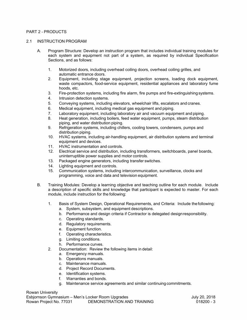
Rowan University Esbjornson Gymnasium – Men’s Locker Room Upgrades July 20, 2018 Rowan Project No. 77031 DEMONSTRATION AND TRAINING 018200 - 3
PART 2 - PRODUCTS
2.1 INSTRUCTION PROGRAM
A. Program Structure: Develop an instruction program that includes individual training modules for each system and equipment not part of a system, as required by individual Specification Sections, and as follows:
1. Motorized doors, including overhead coiling doors, overhead coiling grilles, and automatic entrance doors.
2. Equipment, including stage equipment, projection screens, loading dock equipment, waste compactors, food-service equipment, residential appliances and laboratory fume hoods, etc.
3. Fire-protection systems, including fire alarm, fire pumps and fire-extinguishing systems. 4. Intrusion detection systems. 5. Conveying systems, including elevators, wheelchair lifts, escalators and cranes. 6. Medical equipment, including medical gas equipment and piping. 7. Laboratory equipment, including laboratory air and vacuum equipment and piping. 8. Heat generation, including boilers, feed water equipment, pumps, steam distribution
piping, and water distribution piping. 9. Refrigeration systems, including chillers, cooling towers, condensers, pumps and
distribution piping. 10. HVAC systems, including air-handling equipment, air distribution systems and terminal
equipment and devices. 11. HVAC instrumentation and controls. 12. Electrical service and distribution, including transformers, switchboards, panel boards,
uninterruptible power supplies and motor controls. 13. Packaged engine generators, including transfer switches. 14. Lighting equipment and controls. 15. Communication systems, including intercommunication, surveillance, clocks and
programming, voice and data and television equipment.
B. Training Modules: Develop a learning objective and teaching outline for each module. Include a description of specific skills and knowledge that participant is expected to master. For each module, include instruction for the following:
1. Basis of System Design, Operational Requirements, and Criteria: Include the following: a. System, subsystem, and equipment descriptions. b. Performance and design criteria if Contractor is delegated design responsibility. c. Operating standards. d. Regulatory requirements. e. Equipment function. f. Operating characteristics. g. Limiting conditions. h. Performance curves.
2. Documentation: Review the following items in detail: a. Emergency manuals. b. Operations manuals. c. Maintenance manuals. d. Project Record Documents. e. Identification systems. f. Warranties and bonds. g. Maintenance service agreements and similar continuing commitments.

Rowan University Esbjornson Gymnasium – Men’s Locker Room Upgrades July 20, 2018 Rowan Project No. 77031 DEMONSTRATION AND TRAINING 018200 - 4
3. Emergencies: Include the following, as applicable: a. Instructions on meaning of warnings, trouble indications, and error messages. b. Instructions on stopping. c. Shutdown instructions for each type of emergency. d. Operating instructions for conditions outside of normal operating limits. e. Sequences for electric or electronic systems. f. Special operating instructions and procedures.
4. Operations: Include the following, as applicable: a. Startup procedures. b. Equipment or system break-in procedures. c. Routine and normal operating instructions. d. Regulation and control procedures. e. Control sequences. f. Safety procedures. g. Instructions on stopping. h. Normal shutdown instructions. i. Operating procedures for emergencies. j. Operating procedures for system, subsystem, or equipment failure. k. Seasonal and weekend operating instructions. l. Required sequences for electric or electronic systems. m. Special operating instructions and procedures.
5. Adjustments: Include the following: a. Alignments. b. Checking adjustments. c. Noise and vibration adjustments. d. Economy and efficiency adjustments.
6. Troubleshooting: Include the following: a. Diagnostic instructions. b. Test and inspection procedures.
7. Maintenance: Include the following: a. Inspection procedures. b. Types of cleaning agents to be used and methods of cleaning. c. List of cleaning agents and methods of cleaning detrimental to product. d. Procedures for routine cleaning e. Procedures for preventive maintenance. f. Procedures for routine maintenance. g. Instruction on use of special tools.
8. Repairs: Include the following: a. Diagnosis instructions. b. Repair instructions. c. Disassembly; component removal, repair, and replacement; and reassembly
instructions. d. Instructions for identifying parts and components. e. Review of spare parts needed for operation and maintenance.
PART 3 - EXECUTION
3.1 PREPARATION
A. Assemble educational materials necessary for instruction, including documentation and training module. Assemble training modules into a combined training manual.
B. Set up instructional equipment at instruction location.

Rowan University Esbjornson Gymnasium – Men’s Locker Room Upgrades July 20, 2018 Rowan Project No. 77031 DEMONSTRATION AND TRAINING 018200 - 5
3.2 INSTRUCTION
A. Facilitator: Engage a qualified facilitator to prepare instruction program and training modules, to coordinate instructors, and to coordinate between Contractor and Owner for number of participants, instruction times, and location.
B. Engage qualified instructors to instruct Owner's personnel to adjust, operate, and maintain systems, subsystems, and equipment not part of a system.
1. Architect will furnish an instructor to describe basis of system design, operational requirements, criteria, and regulatory requirements.
2. Owner will furnish an instructor to describe Owner's operational philosophy. 3. Owner will furnish Contractor with names and positions of participants.
C. Scheduling: Provide instruction at mutually agreed on times. For equipment that requires seasonal operation, provide similar instruction at start of each season.
1. Schedule training with Owner with at least seven (7) calendar days' advance notice.
D. Evaluation: At conclusion of each training module, assess and document each participant's mastery of module by use of an oral and a demonstration performance-based test.
E. Cleanup: Collect used and leftover educational materials and give to Owner. Remove instructional equipment. Restore systems and equipment to condition existing before initial training use.
3.3 DEMONSTRATION AND TRAINING VIDEOTAPES
A. General: Engage a qualified commercial photographer to record demonstration and training videotapes. Record each training module separately. Include classroom instructions and demonstrations, board diagrams, and other visual aids, but not student practice.
1. At beginning of each training module, record each chart containing learning objective and lesson outline.
B. Videotape Format: Provide high-quality VHS color videotape in full-size cassettes.
C. Recording: Mount camera on tripod before starting recording, unless otherwise necessary to show area of demonstration and training. Display continuous running time.
D. Narration: Describe scenes on videotape by dubbing audio narration off-site after videotape is recorded. Include description of items being viewed. Describe vantage point, indicating location, direction (by compass point), and elevation or story of construction.
E. Transcript: Provide a typewritten transcript of the narration. Display images and running time captured from videotape opposite the corresponding narration segment.
END OF SECTION 018200

Esbjornson Gymnasium Men’s Locker Room Upgrades
SELECTIVE DEMOLITION 024119 - 1
SECTION 024119 - SELECTIVE DEMOLITION
PART 1 - GENERAL
1.1 SUMMARY
A. This Section includes the following:
1. Demolition and removal of selected portions of building.
1.2 DEFINITIONS
A. Remove: Detach items from existing construction and legally dispose of them off-site, unless indicated to be removed and salvaged or removed and reinstalled.
B. Remove and Reinstall: Detach items from existing construction, prepare them for reuse, and reinstall them where indicated.
C. Existing to Remain: Existing items of construction that are not to be removed and that are not otherwise indicated to be removed, removed and salvaged, or removed and reinstalled.
1.3 SUBMITTALS
A. Schedule of Selective Demolition Activities: Indicate detailed sequence of selective demolition and removal work, with starting and ending dates for each activity, interruption of utility services, use of elevator and stairs, and locations of temporary partitions and means of egress.
B. Predemolition Photographs: Show existing conditions of adjoining construction and site improvements, including finish surfaces that might be misconstrued as damage caused by selective demolition operations. Comply with Division 01 Section "Photographic Documentation." Submit before Work begins.
C. Landfill Records: Indicate receipt and acceptance of hazardous wastes by a landfill facility licensed to accept hazardous wastes.
1. Comply with submittal requirements in Division 01 Section "Construction Waste Management and Disposal."
1.4 QUALITY ASSURANCE
A. Demolition Firm Qualifications: An experienced firm that has specialized in demolition work similar in material and extent to that indicated for this Project.
B. Regulatory Requirements: Comply with governing EPA notification regulations before beginning selective demolition. Comply with hauling and disposal regulations of authorities having jurisdiction.

Esbjornson Gymnasium Men’s Locker Room Upgrades
SELECTIVE DEMOLITION 024119 - 2
C. Standards: Comply with ANSI A10.6 and NFPA 241.
D. Predemolition Conference: Conduct conference at Project site.
1.5 PROJECT CONDITIONS
A. Owner will occupy portions of building immediately adjacent to selective demolition area. Conduct selective demolition so Owner's operations will not be disrupted.
B. Notify Architect of discrepancies between existing conditions and Drawings before proceeding with selective demolition.
C. Hazardous Materials: It is not expected that hazardous materials will be encountered in the Work. 1. If materials suspected of containing hazardous materials are encountered, do not disturb;
immediately notify Architect and Owner. Owner will remove hazardous materials under a separate contract.
D. Storage or sale of removed items or materials on-site is not permitted.
E. Utility Service: Maintain existing utilities indicated to remain in service and protect them against damage during selective demolition operations.
1. Maintain fire-protection facilities in service during selective demolition operations.
1.6 WARRANTY
A. Existing Warranties: Remove, replace, patch, and repair materials and surfaces cut or damaged during selective demolition, by methods and with materials so as not to void existing warranties.
PART 2 - PRODUCTS (Not Used)
PART 3 - EXECUTION
3.1 EXAMINATION
A. Verify that utilities have been disconnected and capped.
B. Survey existing conditions and correlate with requirements indicated to determine extent of selective demolition required.
C. When unanticipated mechanical, electrical, or structural elements that conflict with intended function or design are encountered, investigate and measure the nature and extent of conflict. Promptly submit a written report to Architect.
D. Survey of Existing Conditions: Record existing conditions by use of preconstruction photographs.
Esbjornson Gymnasium Men’s Locker Room Upgrades
SELECTIVE DEMOLITION 024119 - 3
1. Comply with requirements specified in Division 01 Section "Photographic Documentation."
E. Perform surveys as the Work progresses to detect hazards resulting from selective demolition activities.
3.2 UTILITY SERVICES AND MECHANICAL/ELECTRICAL SYSTEMS
A. Existing Services/Systems: Maintain services/systems indicated to remain and protect them against damage during selective demolition operations.
B. Service/System Requirements: Locate, identify, disconnect, and seal or cap off indicated utility services and mechanical/electrical systems serving areas to be selectively demolished. 1. If services/systems are required to be removed, relocated, or abandoned, before
proceeding with selective demolition provide temporary services/systems that bypass area of selective demolition and that maintain continuity of services/systems to other parts of building.
2. Cut off pipe or conduit in walls or partitions to be removed. Cap, valve, or plug and seal remaining portion of pipe or conduit after bypassing.
3.3 PREPARATION
A. Temporary Facilities: Provide temporary barricades and other protection required to prevent injury to people and damage to adjacent buildings and facilities to remain.
B. Temporary Shoring: Provide and maintain shoring, bracing, and structural supports as required to preserve stability and prevent movement, settlement, or collapse of construction and finishes to remain, and to prevent unexpected or uncontrolled movement or collapse of construction being demolished.
3.4 SELECTIVE DEMOLITION
A. General: Demolish and remove existing construction only to the extent required by new construction and as indicated. Use methods required to complete the Work within limitations of governing regulations and as follows:
1. Neatly cut openings and holes plumb, square, and true to dimensions required. Use cutting methods least likely to damage construction to remain or adjoining construction. Use hand tools or small power tools designed for sawing or grinding, not hammering and chopping, to minimize disturbance of adjacent surfaces. Temporarily cover openings to remain.
2. Cut or drill from the exposed or finished side into concealed surfaces to avoid marring existing finished surfaces.
3. Do not use cutting torches until work area is cleared of flammable materials. At concealed spaces, such as duct and pipe interiors, verify condition and contents of hidden space before starting flame-cutting operations. Maintain fire watch and portable fire-suppression devices during flame-cutting operations.
Esbjornson Gymnasium Men’s Locker Room Upgrades
SELECTIVE DEMOLITION 024119 - 4
4. Locate selective demolition equipment and remove debris and materials so as not to impose excessive loads on supporting walls, floors, or framing.
5. Dispose of demolished items and materials promptly.
B. Existing Items to Remain: Protect construction indicated to remain against damage and soiling during selective demolition. When permitted by Architect, items may be removed to a suitable, protected storage location during selective demolition and cleaned and reinstalled in their original locations after selective demolition operations are complete.
3.5 DISPOSAL OF DEMOLISHED MATERIALS
A. General: Except for items or materials indicated to be reused, salvaged, reinstalled, or otherwise indicated to remain Owner's property, remove demolished materials from Project site and legally dispose of them in an EPA-approved landfill.
1. Comply with requirements specified in Division 01 Section "Construction Waste Management and Disposal."
B. Burning: Do not burn demolished materials.
C. Disposal: Transport demolished materials off Owner's property and legally dispose of them.
3.6 CLEANING
A. Clean adjacent structures and improvements of dust, dirt, and debris caused by selective demolition operations. Return adjacent areas to condition existing before selective demolition operations began.
END OF SECTION 024119

Esbjornson Gymnasium Men’s Locker Room Upgrades
CAST-IN-PLACE CONCRETE 033000 - 1
SECTION 033000 - CAST-IN-PLACE CONCRETE
PART 1 - GENERAL
1.1 SUMMARY
A. This Section specifies cast-in place concrete, including formwork, reinforcement, concrete materials, mixture design, placement procedures, and finishes.
1.2 SUBMITTALS
A. Product Data: For each type of product indicated.
B. Design Mixtures: For each concrete mixture.
C. Shop Drawings: For steel reinforcement. Material test reports.
1.3 QUALITY ASSURANCE
A. Manufacturer Qualifications: A firm experienced in manufacturing ready-mixed concrete products and that complies with ASTM C 94/C 94M requirements for production facilities and equipment.
1. Manufacturer certified according to NRMCA's "Certification of Ready Mixed Concrete Production Facilities."
B. ACI Publications: Comply with the following unless modified by requirements in the Contract Documents:
1. ACI 301, "Specification for Structural Concrete," Sections 1 through 5. 2. ACI 117, "Specifications for Tolerances for Concrete Construction and Materials."
C. Preinstallation Conference: Conduct conference at Project site.
PART 2 - PRODUCTS
2.1 STEEL REINFORCEMENT
A. Reinforcing Bars: ASTM A 615/A 615M, Grade 60 (Grade 420), deformed.
B. Steel Welded Wire Reinforcement: ASTM A 185, plain, fabricated from steel wire into flat sheets.

Esbjornson Gymnasium Men’s Locker Room Upgrades
CAST-IN-PLACE CONCRETE 033000 - 2
C. Bar Supports: Bolsters, chairs, spacers, and other devices for spacing, supporting, and fastening reinforcing bars and welded wire reinforcement in place. Manufacture bar supports from steel wire, plastic, or precast concrete according to CRSI's "Manual of Standard Practice."
2.2 CONCRETE MATERIALS
A. Cementitious Material: Use the following cementitious materials, of the same type, brand, and source, throughout Project:
1. Portland Cement: ASTM C 150, Type I or Type
B. Normal-Weight Aggregates: ASTM C 33, graded, 3/4-inch (19-mm) nominal maximum coarse-aggregate size.
C. Water: ASTM C 94/C 94M and potable.
D. Chemical Admixtures: Provide admixtures certified by manufacturer to be compatible with other admixtures and that will not contribute water-soluble chloride ions exceeding those permitted in hardened concrete. Do not use calcium chloride or admixtures containing calcium chloride.
1. Water-Reducing Admixture: ASTM C 494/C 494M, Type A. 2. Retarding Admixture: ASTM C 494/C 494M, Type B. 3. Water-Reducing and Retarding Admixture: ASTM C 494/C 494M, Type D. 4. High-Range, Water-Reducing Admixture: ASTM C 494/C 494M, Type F. 5. High-Range, Water-Reducing and Retarding Admixture: ASTM C 494/C 494M,
Type G. 6. Plasticizing and Retarding Admixture: ASTM C 1017/C 1017M, Type II.
E. Prohibited admixtures: Calcium chloride thyocyanates or admixtures containing more than 0.05 percent chloride ions are not permitted.
2.3 CURING MATERIALS
A. Absorptive Cover: AASHTO M 182, Class 2, burlap cloth made from jute or kenaf, weighing approximately 9 oz./sq. yd. (305 g/sq. m) when dry.
B. Moisture-Retaining Cover: ASTM C 171, polyethylene film or white burlap-polyethylene sheet.
C. Clear, Waterborne, Membrane-Forming Curing and Sealing Compound: ASTM C 1315, Type 1, Class A.
2.4 PROPORTIONING AND DESIGN OF MIXES
A. Prepare design mixtures for each type and strength of concrete, proportioned on the basis of laboratory trial mixture or field test data, or both, according to ACI 301.

Esbjornson Gymnasium Men’s Locker Room Upgrades
CAST-IN-PLACE CONCRETE 033000 - 3
B. Submit written reports to Architect of each proposed mix for each class of concrete at least 15 days prior to start of work. Do not begin concrete production until mixes have been reviewed by Architect.
C. Design mixes to provide normal weight concrete with the following properties, 3000 psi 28-day compressive strength; W/C ratio, 0.51 maximum, 3500 psi 28-day compressive strength W/C ratio, 0.47 maximum.
D. Adjustment to Concrete Mixes: Mix design adjustments may be requested by Contractor when characteristics of materials, job conditions, weather, test results or other circumstances warrant; at no additional cost to Owner and as accepted by Architect. Laboratory test data for revised mix design and strength results must be admitted to and accepted by Architect before using in work.
E. Admixtures: 1. Use water-reducing admixture or high range water-reducing admixture (super plasticizer)
in concrete as required for placement and workability. 2. Use high-range water-reducing admixture in pumped concrete, concrete for industrial
slabs, architectural concrete, parking structure slabs, concrete required to be watertight and concrete with water/cement ratios below 0.50.
3. Use admixtures for water-reducing and set-control in strict compliance with manufacturer's directions.
F. Slump Limits: Proportion and design mixes to result in concrete slump at point of placement as follows: 1. Ramps, slabs and sloping surfaces: Not more than 3". 2. Concrete containing HRWR admixture (super-plasticizer): Not more than 8" after
addition of HRWR to site-verified 2"-3" slump concrete. 3. Other concrete: Not less than 1" nor more than 4".
2.5 FABRICATING REINFORCEMENT
A. Fabricate steel reinforcement according to CRSI's "Manual of Standard Practice."
2.6 CONCRETE MIXING
A. Ready-Mixed Concrete: Measure, batch, mix, and deliver concrete according to ASTM C 94/C 94M, and furnish batch ticket information.
1. When air temperature is between 85 and 90 deg F (30 and 32 deg C), reduce mixing and delivery time from 1-1/2 hours to 75 minutes; when air temperature is above 90 deg F (32 deg C), reduce mixing and delivery time to 60 minutes.

Esbjornson Gymnasium Men’s Locker Room Upgrades
CAST-IN-PLACE CONCRETE 033000 - 4
PART 3 - EXECUTION
3.1 STEEL REINFORCEMENT
A. omply with Concrete Reinforcing Steel Institute's recommended practice for "Placing Reinforcing Bars", for details and methods of reinforcement placement and supports, and as herein specified. 1. Avoid cutting or puncturing water proofing during reinforcement placement and
concreting operations.
B. Clean reinforcement of loose rust and mill scale, earth, ice and other materials which reduce or destroy bond with concrete.
C. Accurately position, support and secure reinforcement against displacement by formwork, construction, or concrete placement operations. Locate and support reinforcing by metal chairs, runners, bolsters, spacers and hangers, as required.
D. Place reinforcement to obtain at least minimum coverages for concrete protection. Arrange, space and securely tie bars and bar supports to hold reinforcement in position during concrete placement operations. Set wire ties so ends are directed into concrete, not toward exposed concrete surfaces.
E. Install welded wire fabric in as long lengths as practicable. Lap adjoining pieces at least one full mesh and lace splices with wire. Offset end laps in adjacent widths to prevent continuous laps in either direction.
3.2 CONCRETE PLACEMENT
A. Preplacement inspection: Before placing concrete, inspect and complete formwork installation, reinforcing steel and items to be embedded or cast-in. Notify other crafts to permit installation of their work; cooperate with other trades in setting such work. Moisten wood forms immediately before placing concrete where form coatings are not used. 1. Apply temporary protective covering to lower 2' of finished walls adjacent to poured
floor slabs and similar conditions, and guard against spattering during placement.
B. General: Comply with ACI 304R "Guide for Measuring, Mixing, Transporting and Placing Concrete", and as herein specified.
C. Deposit concrete continuously or in layers of such thickness that no concrete will be placed on concrete which has hardened sufficiently to cause the formation of seams or planes of weakness. Deposit concrete as nearly as practicable to its final location to avoid segregation.
D. Placing Concrete Slabs: Deposit and consolidate concrete slabs in a continuous operation until the placing of a panel or section is completed.
E. Consolidate concrete during placing operations so that concrete is thoroughly worked around reinforcement and other embedded items and into corners.

Esbjornson Gymnasium Men’s Locker Room Upgrades
CAST-IN-PLACE CONCRETE 033000 - 5
F. Bring slab surfaces to correct level with straightedge and strikeoff. Use bull floats or darbies to smooth surface, free of humps or hollows. Do not disturb slab surfaces prior to beginning finishing operations.
G. Maintain reinforcing in proper position during concrete placement operations.
H. Hot Weather Placing: When hot weather conditions exist that would seriously impair quality and strength of concrete, place concrete in compliance with ACI 305R.
3.3 FINISHING FLOORS AND SLABS
A. Float Finish: Apply float finish to monolithic slab surfaces to receive trowel finish and other finishes as hereinafter specified, and slab surfaces which are to be covered with membrane or elastic waterproofing, membrane or elastic roofing, or sand-bed terrazzo, and as otherwise indicated.
B. After screeding, consolidating and leveling concrete slabs, do not work surface until ready for floating. Begin floating when surface water has disappeared or when concrete has stiffened sufficiently to permit operation of power-driven floats, or both. Consolidate surface with power-driven floats, or by hand-floating if area is small or inaccessible to power units. Check and level surface plane to tolerances of Ff18 - Fl15. Cut down high spots and fill low spots. Uniformly slope surfaces to drains. Immediately after leveling, refloat surface to a uniform, smooth, granular texture.
C. Trowel Finish: Apply trowel finish to monolithic slab surfaces to be exposed-to-view, and slab surfaces to be covered with resilient flooring, carpet, ceramic or quarry tile, paint, or other thin film finish coating system.
D. After floating, begin first trowel finish operation using a power driven trowel. Begin final troweling when surface produces a ringing sound as trowel is moved over surface. Consolidate concrete surface by final hand-troweling operation, free of trowel marks, uniform in texture and appearance, and with surface leveled to tolerances of Ff20 - Fl17. Grind smooth surface defects which would telegraph through supplied floor covering system.
3.4 CONCRETE PROTECTING AND CURING
A. General: Protect freshly placed concrete from premature drying and excessive cold or hot temperatures.
B. B. Start initial curing as soon as free water has disappeared from concrete surface after placing and finishing. Keep continuously moist for not less than 7 days.
C. Begin final curing procedures immediately following initial curing and before concrete has dried. Continue final curing for at least 7 days in accordance with ACI 301 procedures. Avoid rapid drying at end of final curing period.
D. Curing Unformed Surfaces: Cure unformed surfaces, such as slabs, floor topping, and other flat surfaces by application of appropriate curing method.
Esbjornson Gymnasium Men’s Locker Room Upgrades
CAST-IN-PLACE CONCRETE 033000 - 6
3.5 CONCRETE SURFACE REPAIRS
A. Defective Concrete: Repair and patch defective areas when approved by Architect. Remove and replace concrete that cannot be repaired and patched to Architect's approval.
END OF SECTION 033000

Esbjornson Gymnasium Men’s Locker Room Upgrades
SELF-ADHERING MEMBRANE WATERPROOFING 071326 - 1
SECTION 071326 - SELF-ADHERING MEMBRANE WATERPROOFING
PART 1 - GENERAL
1.1 SUMMARY
A. The Work of this Section includes, but is not limited to, sheet membrane waterproofing that forms an integral bond to poured concrete for the following applications: 1. Pre-Applied sheet membrane waterproofing for horizontal applications prior to placement
of poured concrete on top of the membrane, which forms and integral bond to poured concrete.
1.2 REFERENCE STANDARDS
A. The following standards and publications are applicable to the extent referenced in the text.
B. American Society for Testing and Materials (ASTM): 1. C 836 Standard Specification for High Solids, Cold Liquid-Applied Elastomeric
Waterproofing Membrane for Use with Separate Wearing Course 2. D 412 Standard Test Methods for Rubber Properties in Tension 3. D 570 Standard Test Method for Water Absorption of Plastics 4. D 903 Standard Test Method for Peel or Stripping Strength of Adhesive Bonds 5. D 1876 Standard Test Method for Peel Release of Adhesives (T-Peel) 6. D 1970 Standard Specification for Self-Adhering Polymer Modified Bituminous Sheet
Materials Used as Steep Roofing Underlayment for Ice Dam Protection 7. D 3767 Standard Practice for Rubber - Measurements of Dimensions 8. D 5385 Standard Test Method for Hydrostatic Pressure Resistance of Waterproofing
Membranes 9. E 96 Standard Test Methods for Water Vapor Transmission of Materials 10. E 154 Standard Test Methods for Water Vapor Retarders Used in Contact with Earth
Under Concrete Slabs, on Walls, or as Ground Cover
1.3 SUBMITTALS
A. Product Data: Include manufacturer's written instructions for evaluating, preparing, and treating substrate, technical data, and tested physical and performance properties of waterproofing.
B. Shop Drawings: Show locations and extent of waterproofing. Include details for substrate joints and cracks, sheet flashings, penetrations, inside and outside corners, tie-ins with adjoining existing waterproofing, and other termination conditions.
C. Product Test Reports: Based on evaluation of comprehensive tests performed by a qualified testing agency, for waterproofing.
D. Special warranties.

Esbjornson Gymnasium Men’s Locker Room Upgrades
SELF-ADHERING MEMBRANE WATERPROOFING 071326 - 2
E. Samples: Submit representative samples of the following for approval: 1. Sheet membrane waterproofing system.
1.4 QUALITY ASSURANCE
A. Manufacturer: Sheet membrane waterproofing system shall be manufactured and marketed by a firm with a minimum of 20 years experience in the production and sales of sheet membrane waterproofing for below grade applications. Manufacturers proposed for use but not named in these specifications shall submit evidence of ability to meet all requirements specified, and include a list of projects of similar design and complexity completed within the past 5 years.
B. System Installer: 1. Installers must have a minimum of 5 years successful track record in the waterproofing,
roofing or another closely related industry or must employ qualified personnel with a minimum of 5 years experience in these industries. They must have a sound and solid reputation for quality workmanship and reliability.
2. Installers must be fully familiar with the water proofing system application instructions and detailing techniques and have previously completed a minimum of five (5) projects greater than 5000 square feet.
3. Installer shall successfully complete any manufacturer required training before the receipt of bids.
4. Installer shall secure and grant the right for manufacturer or its representatives to inspect the job site during installation and at any reasonable time after the completion of installation and prior to final concealment of the System membrane.
5. Installer shall request in writing within sixty (60) days of the date of completion and final inspection of the installation, that manufacturer issue the Warranty. Installer’s request shall bear the Installer’s signature certifying proper installation.
C. Materials: For each type of material required for the work of this section, provide primary materials which are the products of one manufacturer.
D. Preinstallation Conference: Conduct conference at Project site. 1. Review waterproofing requirements including surface preparation, substrate condition
and pretreatment, minimum curing period, special details and sheet flashings, installation procedures, coordinate this work with related and adjacent work, testing and inspection procedures, and protection and repairs.
E. Contractor is responsible for all inspections, procedures, and conditions as required by the manufacture to obtain water tightness guarantee.
1.5 PROJECT CONDITIONS
A. Environmental Limitations: Apply waterproofing within the range of ambient and substrate temperatures recommended by waterproofing manufacturer. Do not apply waterproofing to a damp or wet substrate.
Esbjornson Gymnasium Men’s Locker Room Upgrades
SELF-ADHERING MEMBRANE WATERPROOFING 071326 - 3
1.6 DELIVERY, STORAGE AND HANDLING
A. Deliver materials in labeled packages. Store and handle in strict compliance with manufacturer’s instructions. Protect from damage from weather, excessive temperature and construction operations. Remove and dispose of damaged material in accordance with applicable regulations.
B. Do not double-stack pallets of membrane on the job site. Provide cover on top and all sides, allowing for adequate ventilation.
C. Protect mastic and adhesive from moisture and potential sources of ignition.
D. Protect surface conditioner from freezing.
E. Sequence deliveries to avoid delays, but minimize on-site storage.
1.7 PROJECT CONDITIONS
A. Proceed with installation only when the substrate construction and preparation work is complete and in condition to receive Pre-Applied or Self-Adhered Sheet Membrane waterproofing.
1.8 WARRANTY
A. Special Manufacturer's Warranty: Manufacturer's standard form in which manufacturer agrees to replace waterproofing material that does not comply with requirements or that fails to remain watertight within specified warranty period.
1. Warranty Period: 10 years from date of Substantial Completion.
B. Installer’s Warranty 1. Special Installer's Warranty in addition to Water Tightness Warranty. 2. Provide Installer Warranty, signed by Installer, covering Work of this Section. 3. Warranty Period: 2 years from date of System installation completion.
PART 2 - PRODUCTS
2.1 MODIFIED BITUMINOUS SHEET WATERPROOFING
A. Pre-Applied Integrally Bonded HDPE Sheet Waterproofing Membrane: a 1.2mm (0.046 in) nominal thickness composite sheet membrane consisting of 0.8 mm (0.030 in.) of high density polyethylene film, a pressure-sensitive adhesive and a trafficable weather resistant coating. The membrane shall be supplied in a kick-out roll orientation and shall have no release liner to reduce waste onsite. The membrane shall form an integral, adhesive and permanent bond to poured concrete to prevent water migration at the interface of the membrane and structural concrete and shall include dual adhesive ZipLap technology to complete sidelaps and secure adjacent sheets.

Esbjornson Gymnasium Men’s Locker Room Upgrades
SELF-ADHERING MEMBRANE WATERPROOFING 071326 - 4
1. Available Products: Subject to compliance with requirements, products that may be incorporated into the Work include: a. Preprufe® 300R Plus Membrane by GCP Applied Technologies. b. Or approved eqaul.
2. Physical Properties:
Property Test Method Typical Value Color White Thickness ASTM D 3767 Method
A 1.2 mm (0.046 in.) nominal
Lateral Water Migration Re-sistance
ASTM D 5385 Modi-fied1
Pass at 71 m (231 ft) of hydro-static head pressure
Low Temperature Flexibility ASTM D 1970 Unaffected at -29°C (-20°F) Elongation ASTM D 412 Modified2 500% Crack Cycling at -23°C (-9.4°F), 100 Cycles
ASTM C 836 Unaffected, Pass
Tensile Strength, film ASTM D 412 27.6 MPa (4,000 lbs/in.2) Peel Adhesion to Concrete ASTM D 903 Modified3 880 N/m (5.0 lbs/in.) Lap Adhesion ASTM D 1876 Modi-
fied4 1408 N/m (8.0 lbs/in.)
Resistance to Hydrostatic Head
ASTM D 5385 Modi-fied5
71 m (231 ft)
Puncture Resistance ASTM E 154 990 N (221 lbs) Permeance ASTM E 96 Method B 0.6 ng/Pa x s x m2 (0.01 perms) Water Absorption ASTM D 570 0.5%
Footnotes: 1. Lateral water migration resistance is tested by casting concrete against membrane with a hole and subjecting the membrane to
hydrostatic head pressure with water. The test measures the resistance of lateral water migration between the concrete and the blind side waterproofing membrane. A hydrostatic head pressure of 71 m (231 ft) of water is the limit of the apparatus.
2. Elongation of membrane is run at a rate of 50 mm (2 in.) per minute. 3. Concrete is cast against the protective coating surface of the membrane and allowed to cure (7 days minimum). Peel adhesion
of membrane to concrete is measured at a rate of 50 mm (2 in.) per minute at room temperature. 4. The test is conducted 15 minutes after the lap is formed as per manufacturer’s instructions and run at a rate of 50 mm (2 in.)
per minute. 5. Hydrostatic head tests are performed by casting concrete against the membrane with a lap. Before the concrete sets a 3 mm
(0.125 in.) spacer is inserted perpendicular to the membrane to create a gap. The cured block is placed in a chamber where water is introduced to the membrane surface up to a head of 71 m (231 ft) of water which is the limit of the apparatus.
2.2 AUXILIARY MATERIALS
A. Preformed Inside and Outside Corners: Preprufe Preformed Corners by GCP Applied Technologies as prefabricated inside and outside corners.
B. Preformed covers for soil retention heads: Preprufe Tieback Covers by GCP Applied Technologies as prefabricated tieback head and soil anchor covers.
C. Tape for covering cut edges, roll ends, penetrations and detailing: Preprufe Tape LT (for temperatures between 25°F (-4°C) and 86°F (+30°C)) and Preprufe Tape HC (for use in Hot Climates, minimum 50°F (10°C)).

Esbjornson Gymnasium Men’s Locker Room Upgrades
SELF-ADHERING MEMBRANE WATERPROOFING 071326 - 5
D. Tape to be located at all construction joints in the concrete on top of the pre-applied sheet waterproofing membrane: Preprufe CJ Tape LT (for temperatures between 25°F (-4°C) and 86°F (30°C)) and Preprufe CJ Tape HC (for use in Hot Climates, minimum 50°F (10°C)).
E. Waterstops: 1. De Neef SWELLSEAL 2010 vulcanized rubber hydrophilic waterstop by GCP Applied
Technologies for non-moving concrete construction joints and penetrations. 2. De Neef SWELLSEAL WA hydrophilic gun-grade by GCP Applied Technologies for
non-moving concrete construction joints and penetrations. 3. De Neef INJECTO Tube groutable waterstop by GCP Applied Technologies for non-
moving concrete construction joints and penetrations. 4. De Neef TRIOject groutable waterstop with multiple grout hose by GCP Applied
Technologies for non-moving concrete construction joints and penetrations.
F. Miscellaneous Materials: Surface conditioner, mastic, liquid membrane, tape and accessories specified or acceptable to manufacturer of Pre-Applied and Self-Adhered Sheet Membrane Waterproofing.
PART 3 - EXECUTION
3.1 EXECUTION
A. The installer shall examine conditions of substrates and other conditions under which this work is to be performed and notify the Contractor, in writing, of circumstances detrimental to the proper completion of the work. Do not proceed with work until unsatisfactory conditions are corrected.
3.2 SURFACE PREPARATION
A. Substrates to receive Pre-Applied Sheet Membrane Waterproofing: 1. It is essential to create a sound and solid substrate to eliminate movement during the
concrete pour. Substrates must be regular and smooth with no gaps or voids greater than 0.5 in. (12 mm).
2. Grout around all penetrations such as mechanical, electrical, plumbing, etc. to create a sound and solid substrate, and eliminate movement during the concrete pour.
3. The substrate must be free of loose aggregate and sharp protrusions. Avoid curved or rounded substrates.
4. When installing over earth or crushed stone, ensure substrate is well compacted to avoid displacement of substrate due to traffic or concrete pour. The surface does not need to be dry, but standing water must be removed.
3.3 APPLICATION
A. Strictly comply with installation instructions in manufacturer’s published literature.
B. If required, install prefabricated drainage and protection composite for horizontal applications per manufacturer’s requirements.

Esbjornson Gymnasium Men’s Locker Room Upgrades
SELF-ADHERING MEMBRANE WATERPROOFING 071326 - 6
C. Application of Pre-Applied Sheet Membrane waterproofing for concrete slab: 1. Place the membrane HDPE film side to the substrate with the green zip strip facing
towards the concrete pour. End laps should be staggered to avoid a build-up of layers. 2. Leave the green and blue (backside) zip strips in position until the overlap procedure is
completed and the lap is to be made. 3. Accurately position succeeding sheets to overlap the previous sheet 3 in. (75 mm) along
the marked selvedge with a blue guideline. The blue zip strip on the underside of the succeeding membrane shall be positioned on top of the green zip strip on the top of the previous sheet. Ensure the underside of the succeeding sheet is clean, dry and free from contamination before attempting to overlap.
4. Peel back and remove both the green and blue zip strips in the overlap area to achieve an adhesive to adhesive bond, lining up leading edge of the top sheet with the blue guideline.
5. Ensure a continuous bond is achieved without creases and roll firmly with a heavy roller. 6. Overlap all roll ends and cut edges by a minimum 3 in. (75 mm) and ensure the area is
clean and free from contamination, wiping with a damp cloth if necessary. 7. Allow to dry and apply Preprufe Tape LT (or HC in hot climates) centered over the lap
edges and roll firmly. Apply additional Preprufe Tape LT (or HC in hot climates) a minimum of 2 in. beyond all edges of membrane that are not sealed by the selvedge.
8. Immediately remove tinted plastic release liner from the Preprufe Tape. 9. Center Preprufe CJ Tape LT (or HC in hot climates) at all concrete construction joints
and adhere the Preprufe CJ Tape to the top of pre-applied waterproofing membrane. 10. Immediately remove tinted plastic release liner from the Preprufe CJ Tape. 11. Protect membrane, tape and ancillaries in accordance with manufacturer’s
recommendations until placement of concrete. Inspect for damage just prior to placement of concrete and make repairs in accordance with manufacturer’s recommendations.
3.4 PROTECTION AND CLEANING
A. Do not permit foot traffic on unprotected membrane.
B. Protect waterproofing from damage and wear during remainder of construction period.
C. Clean spillage and soiling from adjacent construction using cleaning agents and procedures recommended by manufacturer of affected construction.
END OF SECTION 071326

Esbjornson Gymnasium Men’s Locker Room Upgrades
THERMAL INSULATION 072100 - 1
SECTION 072100 - THERMAL INSULATION
PART 1 - GENERAL
1.1 SUMMARY
A. Section Includes: 1. Glass-fiber blanket insulation.
1.2 SUBMITTALS
A. Product Data: For each type of product indicated.
B. Product test reports.
C. Research/evaluation reports.
PART 2 - PRODUCTS
2.1 GLASS-FIBER BLANKET INSULATION
A. Manufacturers: Subject to compliance with requirements, provide products by one of the following:
1. CertainTeed Corporation. 2. Johns Manville. 3. Owens Corning. 4. Or approved equal.
B. Unfaced, Glass-Fiber Blanket Insulation: ASTM C 665, Type I; with maximum flame-spread and smoke-developed indexes of 25 and 50, respectively, per ASTM E 84; passing ASTM E 136 for combustion characteristics.
C. Polypropylene-Scrim-Kraft-Faced, Glass-Fiber Blanket Insulation: ASTM C 665, Type II (non-reflective faced), Class A (faced surface with a flame-spread index of 25 or less); Category 1 (membrane is a vapor barrier).
PART 3 - EXECUTION
3.1 INSTALLATION, GENERAL
A. Comply with insulation manufacturer's written instructions applicable to products and applications indicated.

Esbjornson Gymnasium Men’s Locker Room Upgrades
THERMAL INSULATION 072100 - 2
B. Install insulation that is undamaged, dry, and unsoiled and that has not been left exposed to ice, rain, or snow at any time.
C. Extend insulation to envelop entire area to be insulated. Cut and fit tightly around obstructions and fill voids with insulation. Remove projections that interfere with placement.
D. Provide sizes to fit applications indicated and selected from manufacturer's standard thicknesses, widths, and lengths. Apply single layer of insulation units to produce thickness indicated unless multiple layers are otherwise shown or required to make up total thickness.
3.2 INSTALLATION OF INSULATION FOR FRAMED CONSTRUCTION
A. Apply insulation units to substrates by method indicated, complying with manufacturer's written instructions. If no specific method is indicated, bond units to substrate with adhesive or use mechanical anchorage to provide permanent placement and support of units.
B. Glass-Fiber or Mineral-Wool Blanket Insulation: Install in cavities formed by framing members according to the following requirements:
1. Use insulation widths and lengths that fill the cavities formed by framing members. If more than one length is required to fill the cavities, provide lengths that will produce a snug fit between ends.
2. Place insulation in cavities formed by framing members to produce a friction fit between edges of insulation and adjoining framing members.
3. Maintain 3-inch (76-mm) clearance of insulation around recessed lighting fixtures not rated for or protected from contact with insulation.
4. For metal-framed wall cavities where cavity heights exceed 96 inches (2438 mm), support unfaced blankets mechanically and support faced blankets by taping flanges of insulation to flanges of metal studs.
5. Vapor-Retarder-Faced Blankets: Tape joints and ruptures in vapor-retarder facings, and seal each continuous area of insulation to ensure airtight installation. a. Interior Walls: Set units with facing placed toward areas of high humidity.
C. Miscellaneous Voids: Install insulation in miscellaneous voids and cavity spaces where required to prevent gaps in insulation using the following materials:
1. Loose-Fill Insulation: Compact to approximately 40 percent of normal maximum volume equaling a density of approximately 2.5 lb/cu. ft. (40 kg/cu. m).
2. Spray Polyurethane Insulation: Apply according to manufacturer's written instructions.
END OF SECTION 072100

Esbjornson Gymnasium Men’s Locker Room Upgrades
JOINT SEALANTS 079200 - 1
SECTION 079200 - JOINT SEALANTS
PART 1 - GENERAL
1.1 SUMMARY
A. Section Includes:
1. Silicone joint sealants. 2. Urethane joint sealants. 3. Latex joint sealants. 4. Acoustical Sealants.
1.2 SUBMITTALS
A. Product Data: For each joint-sealant product indicated.
B. LEED Submittal:
1. Product Data for Credit EQ 4.1: For sealants and sealant primers used inside the weatherproofing system, including printed statement of VOC content.
C. Samples: For each kind and color of joint sealant required.
D. Joint-Sealant Schedule: Include the following information:
1. Joint-sealant application, joint location, and designation. 2. Joint-sealant manufacturer and product name. 3. Joint-sealant formulation. 4. Joint-sealant color.
E. Product test reports.
F. Preconstruction compatibility and adhesion test reports.
G. Preconstruction field-adhesion test reports.
H. Field-adhesion test reports.
I. Warranties.
1.3 QUALITY ASSURANCE
A. Testing Agency Qualifications: Qualified according to ASTM C 1021 to conduct the testing indicated.
B. Preinstallation Conference: Conduct conference at Project site.

Esbjornson Gymnasium Men’s Locker Room Upgrades
JOINT SEALANTS 079200 - 2
1.4 WARRANTY
A. Special Installer's Warranty: Manufacturer's standard form in which Installer agrees to repair or replace joint sealants that do not comply with performance and other requirements specified in this Section within specified warranty period.
1. Warranty Period: Two years from date of Substantial Completion.
B. Special Manufacturer's Warranty: Manufacturer's standard form in which joint-sealant manufacturer agrees to furnish joint sealants to repair or replace those that do not comply with performance and other requirements specified in this Section within specified warranty period.
1. Warranty Period: 5 years from date of Substantial Completion.
PART 2 - PRODUCTS
2.1 MATERIALS, GENERAL
A. VOC Content of Interior Sealants: Provide sealants and sealant primers for use inside the weatherproofing system that comply with the following limits for VOC content when calculated according to 40 CFR 59, Part 59, Subpart D (EPA Method 24):
1. Architectural Sealants: 250 g/L. 2. Sealant Primers for Nonporous Substrates: 250 g/L. 3. Sealant Primers for Porous Substrates: 775 g/L.
2.2 URETHANE JOINT SEALANTS
A. Urethane Joint Sealant: ASTM C 920.
1. Manufacturers: Subject to compliance with requirements, provide products by one of the following:
a. BASF Building Systems. b. Pecora Corporation. c. Sika Corporation; Construction Products Division. d. Tremco Incorporated. e. Or approved equal.
2. Type: Single component (S). 3. Grade: Pourable (P). 4. Class: 50. 5. Uses Related to Exposure: Traffic (T).
2.3 LATEX JOINT SEALANTS
A. Latex Joint Sealant: Acrylic latex or siliconized acrylic latex, ASTM C 834, Type OP, Grade NF.

Esbjornson Gymnasium Men’s Locker Room Upgrades
JOINT SEALANTS 079200 - 3
1. Manufacturers: Subject to compliance with requirements, provide products by one of the following:
a. BASF Building Systems. b. Pecora Corporation. c. Tremco Incorporated. d. Or approved equal.
2.4 ACOUSTICAL JOINT SEALANTS
A. Acoustical Joint Sealant: Manufacturer's standard nonsag, paintable, nonstaining latex sealant complying with ASTM C 834. Product effectively reduces airborne sound transmission through perimeter joints and openings in building construction as demonstrated by testing representative assemblies according to ASTM E 90.
1. Manufacturers: Subject to compliance with requirements, provide products by one of the following:
a. Pecora Corporation. b. USG Corporation. c. Or approved equal.
2.5 JOINT SEALANT BACKING
A. Cylindrical Sealant Backings: ASTM C 1330, Type C (closed-cell material with a surface skin), and of size and density to control sealant depth and otherwise contribute to producing optimum sealant performance.
B. Bond-Breaker Tape: Polyethylene tape or other plastic tape recommended by sealant manufacturer.
2.6 MISCELLANEOUS MATERIALS
A. Primer: Material recommended by joint-sealant manufacturer where required for adhesion of sealant to joint substrates indicated, as determined from preconstruction joint-sealant-substrate tests and field tests.
B. Cleaners for Nonporous Surfaces: Chemical cleaners acceptable to manufacturers of sealants and sealant backing materials.
C. Masking Tape: Nonstaining, nonabsorbent material compatible with joint sealants and surfaces adjacent to joints.
Esbjornson Gymnasium Men’s Locker Room Upgrades
JOINT SEALANTS 079200 - 4
PART 3 - EXECUTION
3.1 PREPARATION
A. Surface Cleaning of Joints: Clean out joints immediately before installing joint sealants to comply with joint-sealant manufacturer's written instructions.
1. Remove laitance and form-release agents from concrete. 2. Clean nonporous joint substrate surfaces with chemical cleaners or other means that do
not stain, harm substrates, or leave residues capable of interfering with adhesion of joint sealants.
B. Joint Priming: Prime joint substrates where recommended by joint-sealant manufacturer or as indicated by preconstruction joint-sealant-substrate tests or prior experience. Apply primer to comply with joint-sealant manufacturer's written instructions. Confine primers to areas of joint-sealant bond; do not allow spillage or migration onto adjoining surfaces.
C. Masking Tape: Use masking tape where required to prevent contact of sealant or primer with adjoining surfaces that otherwise would be permanently stained or damaged by such contact or by cleaning methods required to remove sealant smears. Remove tape immediately after tooling without disturbing joint seal.
3.2 INSTALLATION
A. Sealant Installation Standard: Comply with recommendations in ASTM C 1193 for use of joint sealants as applicable to materials, applications, and conditions indicated.
B. Install sealant backings of kind indicated to support sealants during application and at position required to produce cross-sectional shapes and depths of installed sealants relative to joint widths that allow optimum sealant movement capability.
1. Do not leave gaps between ends of sealant backings. 2. Do not stretch, twist, puncture, or tear sealant backings. 3. Remove absorbent sealant backings that have become wet before sealant application and
replace them with dry materials.
C. Install bond-breaker tape behind sealants where sealant backings are not used between sealants and backs of joints.
D. Install sealants using proven techniques that comply with the following and at the same time backings are installed:
1. Place sealants so they directly contact and fully wet joint substrates. 2. Completely fill recesses in each joint configuration. 3. Produce uniform, cross-sectional shapes and depths relative to joint widths that allow
optimum sealant movement capability.
E. Tooling of Nonsag Sealants: Immediately after sealant application and before skinning or curing begins, tool sealants according to requirements specified in subparagraphs below to form

Esbjornson Gymnasium Men’s Locker Room Upgrades
JOINT SEALANTS 079200 - 5
smooth, uniform beads of configuration indicated; to eliminate air pockets; and to ensure contact and adhesion of sealant with sides of joint.
1. Remove excess sealant from surfaces adjacent to joints. 2. Use tooling agents that are approved in writing by sealant manufacturer and that do not
discolor sealants or adjacent surfaces. 3. Provide concave joint profile per Figure 8A in ASTM C 1193, unless otherwise
indicated.
F. Acoustical Sealant Installation: Comply with ASTM C 919 and with manufacturer's written recommendations.
G. Clean off excess sealant or sealant smears adjacent to joints as the Work progresses by methods and with cleaning materials approved in writing by manufacturers of joint sealants and of products in which joints occur.
3.3 FIELD QUALITY CONTROL
A. Field-Adhesion Testing: Field test joint-sealant adhesion to joint substrates as follows:
1. Extent of Testing: Test completed and cured sealant joints as follows:
a. Perform 10 tests for the first 1000 feet (300 m) of joint length for each kind of sealant and joint substrate.
b. Perform 1 test for each 1000 feet (300 m) of joint length thereafter or 1 test per each floor per elevation.
2. Test Method: Test joint sealants according to Method A, Field-Applied Sealant Joint Hand Pull Tab, in Appendix X1 in ASTM C 1193 or Method A, Tail Procedure, in ASTM C 1521.
B. Evaluation of Field-Adhesion Test Results: Sealants not evidencing adhesive failure from testing or noncompliance with other indicated requirements will be considered satisfactory. Remove sealants that fail to adhere to joint substrates during testing or to comply with other requirements. Retest failed applications until test results prove sealants comply with indicated requirements.
3.4 JOINT-SEALANT
A. Joint-Sealant Application: Interior joints in horizontal traffic surfaces.
1. Joint Locations:
a. Isolation joints in cast-in-place concrete slabs. b. Other joints as indicated.
2. Joint Sealant: Urethane. 3. Joint-Sealant Color: As selected by Architect from manufacturer's full range of colors.
B. Joint-Sealant Application: Interior joints in vertical surfaces and horizontal nontraffic surfaces.

Esbjornson Gymnasium Men’s Locker Room Upgrades
JOINT SEALANTS 079200 - 6
1. Joint Locations: a. Perimeter joints between interior wall surfaces and frames of interior doors. b. Other joints as indicated.
2. Joint Sealant: Latex. 3. Joint-Sealant Color: As selected by Architect from manufacturer's full range of colors.
C. Joint-Sealant Application: Interior acoustical joints in vertical surfaces and horizontal nontraffic surfaces.
1. Joint Location:
a. Joints on underside of plant-precast structural concrete beams and planks. b. Joints at base of gypsum board in metal stud framed paritions.
2. Joint Sealant: Acoustical. 3. Joint-Sealant Color: As selected by Architect from manufacturer's full range.
END OF SECTION 079200

Esbjornson Gymnasium Men’s Locker Room Upgrades
HOLLOW METAL FRAMES 081113 - 1
SECTION 081113 - HOLLOW FRAMES
PART 1 - GENERAL
1.1 SUMMARY
A. Section Includes:
1. Standard hollow metal frames.
1.2 SUBMITTALS
A. Product Data: For each type of product indicated.
B. Shop Drawings: Include elevations, door edge details, frame profiles, metal thicknesses, preparations for hardware, and other details.
C. Samples for Initial Selection: For units with factory-applied color finishes.
D. Samples for Verification: For each type of exposed finish required.
E. Schedule: Prepared by or under the supervision of supplier, using same reference numbers for details and openings as those on Drawings.
PART 2 - PRODUCTS
2.1 MANUFACTURERS
A. Manufacturers: Provide products by one of the following: 1. Ceco Door Products; an Assa Abloy Group company. 2. Curries Company; an Assa Abloy Group company. 3. Steelcraft; an Ingersoll-Rand company. 4. Or approved equal.
2.2 MATERIALS
A. Cold-Rolled Steel Sheet: ASTM A 1008/A 1008M, CS, Type B; suitable for exposed applications.
B. Hot-Rolled Steel Sheet: ASTM A 1011/A 1011M, CS, Type B.
C. Metallic-Coated Steel Sheet: ASTM A 653/A 653M, Commercial Steel (CS), Type B; with minimum A40 (ZF120) metallic coating.

Esbjornson Gymnasium Men’s Locker Room Upgrades
HOLLOW METAL FRAMES 081113 - 2
D. Frame Anchors: ASTM A 591/A 591M, Commercial Steel (CS), 40Z (12G) coating designation; mill phosphatized.
1. For anchors built into exterior walls, steel sheet complying with ASTM A 1008/A 1008M or ASTM A 1011/A 1011M, hot-dip galvanized according to ASTM A 153/A 153M, Class B.
E. Inserts, Bolts, and Fasteners: Hot-dip galvanized according to ASTM A 153/A 153M.
F. Grout: ASTM C 476, except with a maximum slump of 4 inches (102 mm), as measured according to ASTM C 143/C 143M.
G. Mineral-Fiber Insulation: ASTM C 665, Type I.
H. Glazing: Division 08 Section "Glazing."
I. Bituminous Coating: Cold-applied asphalt mastic, SSPC-Paint 12, compounded for 15-mil (0.4-mm) dry film thickness per coat.
2.3 STANDARD HOLLOW METAL FRAMES
A. General: Comply with ANSI/SDI A250.8.
B. Interior Frames: Fabricated from metallic-coated steel sheet. 1. Fabricate frames as full profile welded unless otherwise indicated.
C. Hardware Reinforcement: ANSI/SDI A250.6.
2.4 FRAME ANCHORS
A. Jamb Anchors: 1. Stud-Wall Type: Designed to engage stud, welded to back of frames; not less than 0.042
inch (1.0 mm) thick.
B. Floor Anchors: Formed from same material as frames, not less than 0.042 inch (1.0 mm) thick, and as follows:
1. Monolithic Concrete Slabs: Clip-type anchors, with two holes to receive fasteners.
2.5 FABRICATION
A. Tolerances: Fabricate hollow metal work to tolerances indicated in SDI 117.
B. Hollow Metal Frames: Where frames are fabricated in sections, provide alignment plates or angles at each joint, fabricated of same thickness metal as frames.
1. Welded Frames: Weld flush face joints continuously; grind, fill, dress, and make smooth, flush, and invisible.
Esbjornson Gymnasium Men’s Locker Room Upgrades
HOLLOW METAL FRAMES 081113 - 3
2. Provide countersunk, flat- or oval-head exposed screws and bolts for exposed fasteners unless otherwise indicated.
3. Floor Anchors: Weld anchors to bottom of jambs and mullions with at least four spot welds per anchor.
4. Jamb Anchors: Provide number and spacing of anchors as follows:
a. Stud-Wall Type: Locate anchors not more than 18 inches (457 mm) from top and bottom of frame. Space anchors not more than 32 inches (813 mm) o.c. and as follows:
1) Three anchors per jamb up to 60 inches (1524 mm) high. 2) Four anchors per jamb from 60 to 90 inches (1524 to 2286 mm) high. 3) Five anchors per jamb from 90 to 96 inches (2286 to 2438 mm) high. 4) Five anchors per jamb plus 1 additional anchor per jamb for each 24 inches
(610 mm) or fraction thereof above 96 inches (2438 mm) high. 5) Two anchors per head for frames more than 42 inches (1066 mm) wide and
mounted in metal-stud partitions.
5. Door Silencers: Except on weather-stripped doors, drill stops to receive door silencers.
a. Single-Door Frames: Three door silencers. b. Double-Door Frames: Two door silencers.
C. Hardware Preparation: Factory prepare hollow metal work to receive templated mortised hardware according to the Door Hardware Schedule and templates furnished as specified in Division 08 Section "Door Hardware."
1. Locate hardware as indicated, or if not indicated, according to ANSI/SDI A250.8. 2. Reinforce doors and frames to receive nontemplated, mortised and surface-mounted door
hardware. 3. Comply with applicable requirements in ANSI/SDI A250.6 and ANSI/DHI A115 Series
specifications for preparation of hollow metal work for hardware. 4. Coordinate locations of conduit and wiring boxes for electrical connections with
Division 26 electrical Sections.
D. Stops and Moldings: Provide stops and moldings around glazed lites where indicated. Form corners of stops and moldings with butted or mitered hairline joints.
1. Single Glazed Lites: Provide fixed stops and moldings welded on secure side of hollow metal work.
2. Multiple Glazed Lites: Provide fixed and removable stops and moldings so that each glazed lite is capable of being removed independently.
3. Provide fixed frame moldings on outside of exterior and on secure side of interior doors and frames.
4. Provide loose stops and moldings on inside of hollow metal work. 5. Coordinate rabbet width between fixed and removable stops with type of glazing and
type of installation indicated.

Esbjornson Gymnasium Men’s Locker Room Upgrades
HOLLOW METAL FRAMES 081113 - 4
2.6 STEEL FINISHES
A. Prime Finish: Apply manufacturer's standard primer immediately after cleaning and pretreating.
1. Shop Primer: ANSI/SDI A250.10.
PART 3 - EXECUTION
3.1 INSTALLATION
A. Hollow Metal Frames: Comply with ANSI/SDI A250.11.
1. Set frames accurately in position, plumbed, aligned, and braced securely until permanent anchors are set. After wall construction is complete, remove temporary braces, leaving surfaces smooth and undamaged.
a. At fire-protection-rated openings, install frames according to NFPA 80. b. Where frames are fabricated in sections because of shipping or handling
limitations, field splice at approved locations by welding face joint continuously; grind, fill, dress, and make splice smooth, flush, and invisible on exposed faces.
c. Install frames with removable glazing stops located on secure side of opening. d. Install door silencers in frames before grouting. e. Remove temporary braces necessary for installation only after frames have been
properly set and secured. f. Check plumbness, squareness, and twist of frames as walls are constructed. Shim
as necessary to comply with installation tolerances. g. Field apply bituminous coating to backs of frames that are filled with grout
containing antifreezing agents.
2. Floor Anchors: Provide floor anchors for each jamb and mullion that extends to floor, and secure with postinstalled expansion anchors.
a. Floor anchors may be set with powder-actuated fasteners instead of postinstalled expansion anchors if so indicated and approved on Shop Drawings.
3. Metal-Stud Partitions: Solidly pack mineral-fiber insulation behind frames. 4. Masonry Walls: Coordinate installation of frames to allow for solidly filling space
between frames and masonry with grout. 5. Concrete Walls: Solidly fill space between frames and concrete with grout. Take
precautions, including bracing frames, to ensure that frames are not deformed or damaged by grout forces.
6. In-Place Concrete or Masonry Construction: Secure frames in place with postinstalled expansion anchors. Countersink anchors, and fill and make smooth, flush, and invisible on exposed faces.
7. In-Place Gypsum Board Partitions: Secure frames in place with postinstalled expansion anchors through floor anchors at each jamb. Countersink anchors, and fill and make smooth, flush, and invisible on exposed faces.
8. Ceiling Struts: Extend struts vertically from top of frame at each jamb to overhead structural supports or substrates above frame unless frame is anchored to masonry or to

Esbjornson Gymnasium Men’s Locker Room Upgrades
HOLLOW METAL FRAMES 081113 - 5
other structural support at each jamb. Bend top of struts to provide flush contact for securing to supporting construction. Provide adjustable wedged or bolted anchorage to frame jamb members.
9. Installation Tolerances: Adjust hollow metal door frames for squareness, alignment, twist, and plumb to the following tolerances:
a. Squareness: Plus or minus 1/16 inch (1.6 mm), measured at door rabbet on a line 90 degrees from jamb perpendicular to frame head.
b. Alignment: Plus or minus 1/16 inch (1.6 mm), measured at jambs on a horizontal line parallel to plane of wall.
c. Twist: Plus or minus 1/16 inch (1.6 mm), measured at opposite face corners of jambs on parallel lines, and perpendicular to plane of wall.
d. Plumbness: Plus or minus 1/16 inch (1.6 mm), measured at jambs at floor.
3.2 ADJUSTING AND CLEANING
A. Final Adjustments: Check and readjust operating hardware items immediately before final inspection. Leave work in complete and proper operating condition. Remove and replace defective work, including hollow metal work that is warped, bowed, or otherwise unacceptable.
B. Prime-Coat Touchup: Immediately after erection, sand smooth rusted or damaged areas of prime coat and apply touchup of compatible air-drying, rust-inhibitive primer.
C. Metallic-Coated Surfaces: Clean abraded areas and repair with galvanizing repair paint according to manufacturer's written instructions.
END OF SECTION 081113

Esbjornson Gymnasium Men’s Locker Room Upgrades
FRP DOORS 081743 - 1
SECTION 081743 FRP DOORS PART 1 GENERAL 1.1 SECTION INCLUDES
A. AF Composite flush doors with FRP frames. 1.2 RELATED SECTIONS
A. Section 08710 (08 71 00) - Door Hardware. 1.3 REFERENCES
A. AAMA 920-11 – Specification for Operating Cycle Performance of Side-Hinged Exterior Door Systems.
B. AAMA 1304-02 - Voluntary Specification for Forced Entry Resistance of Side-Hinged Door Sys-tems.
C. ASTM C 1363 – Standard Test Method for Thermal Performance of Building Materials and En-velope Assemblies by Means of Hot Box Apparatus.
D. ASTM D 256 – Standard Test Methods for Determining the Izod Pendulum Impact Resistance of Plastics.
E. ASTM D 638 – Standard Test Method for Tensile Properties of Plastics.
F. ASTM D 570 – Standard Test Method for Water Absorption of Plastics.
G. ASTM D 790 – Standard Test Methods for Flexural Properties of Unreinforced and Reinforced Plastics and Electrical Insulating Materials.
H. ASTM D 1761-06 – Standard Test Methods for Mechanical Fasteners in Wood.
I. ASTM D 2583 – Standard Test Method for Indentation Hardness of Rigid Plastics by Means of a
Barcol Impressor.
J. ASTM D 3029 – Test Methods for Impact Resistance of Flat Rigid Plastic Specimens by Means of a Falling Weight.
K. ASTM D 6670-01 - Standard Practice for Full-Scale Chamber Determination of Volatile Organic Emissions from Indoor Materials/Products.
L. ASTM E 84-11 – Standard Method of Test for Surface Burning Characteristics of Building Mate-
rials.
M. ASTM E 283-04 – Test Method for Determining Rate of Airflow Through Exterior Windows,

Esbjornson Gymnasium Men’s Locker Room Upgrades
FRP DOORS 081743 - 2
Curtain Walls and Doors Under Specified Pressure Differences Across the Specimen.
N. ASTM E 330-02 – Test Method for Structural Performance of Exterior Windows, Curtain Walls, Doors by Uniform Static Air Pressure Difference.
O. ASTM E 331-00 – Test Method for Water Penetration of Exterior Windows, Curtain Walls and
Doors, and Curtain Walls by Uniform Static Air Pressure Difference.
P. ASTM E 1886 – Standard Test Method for Performance of Exterior Windows, Curtain Walls, Doors and Storm Shutters Impacted by Missile and Exposed to Cyclic Pressure Differentials.
Q. ASTM E 1996 – Standard Specification for Performance of Exterior Windows, Curtain Walls, Doors, and Impact Protective Systems Impacted by Windborne Debris in Hurricanes.
1.4 PERFORMANCE REQUIREMENTS
A. General: Provide door assemblies that have been designed and fabricated to comply with specified performance requirements, as demonstrated by testing manufacturer's corresponding standard systems.
B. Air Infiltration: For a single door 3’-0” x 7’-0”, test specimen shall be tested in accordance with
ASTM E 283 at pressure differential of 6.24 psf. Door shall not exceed 0.45 cfm/ft2.
C. Water Penetration: For a single door 3’-0” x 7’-0”, test specimen shall be tested in accordance with ASTM E 331. Door shall not have water leakage.
D. Uniform Load Structural: For a single door 3’-0” x 7’-0”, test specimen shall be tested in
accordance with ASTM E 330: Plus or minus 80 psf.
E. Forced Entry Resistance per AAMA 1304-02: Pass
F. Air Pressure Cycle Test per ASTM E 1886: Plus or Minus 75psf.
G. Indoor air quality testing per ASTM D 6670-01: GREENGUARD Environmental Institute Certi-fied including GREENGUARD for Children and Schools Certification
H. Thermal Transmission, Exterior Doors, U-Value, ASTM C 1363: Maximum of 0.18
BTU/hr x sf x degrees F.
I. Screw Pullout, ASTM D 1761-06, Minimum 924 pounds.
J. Cycle Test, AAMA 920-11, 2,000,000 Cycles.
K. Surface Burning Characteristics, FRP Doors and Panels, ASTM E 84: 1. Flame Spread: Maximum of 200, Class C. 2. Smoke Developed: Maximum of 450, Class C.
Surface Burning Characteristics, Class A Option On Interior Faces of FRP Exterior Panels and Both Faces o 1. Flame Spread: Maximum of 25. 2. Smoke Developed: Maximum of 450.
M. FRP Pebbled Face Sheet Properties:

Esbjornson Gymnasium Men’s Locker Room Upgrades
FRP DOORS 081743 - 3
a. Izod Impact Strength, ASTM D 256, Minimum 7 ft-lb/in notched. b. Tensile Strength, ASTM D 638, Minimum 18 x 103 psi. c. Tensile Modulus, ASTM D 638, Minimum 18 x 106 psi. d. Water Absorption, ASTM D 570, Maximum 0.16% / 24 hours @ 77°F. e. Flexural Strength, ASTM D 790, Minimum 27 x 103 psi. f. Flexural Modulus, ASTM D 790, Minimum .7 x 106 psi. g. Barcol Hardness, ASTM D 2583, Minimum 40. h. Gardner Impact Strength, ASTM D 3029, Minimum 30 in-lb.
1.5 SUBMITTALS
A. Comply with Section 013300 - Submittal Procedures.
B. Product Data: Submit manufacturer's product data, including description of materials, compo-nents, fabrication, finishes, and installation.
C. Shop Drawings: Submit manufacturer's shop drawings, including elevations, sections, and de-
tails, indicating dimensions, tolerances, materials, fabrication, doors, panels, framing, and finish. D. Samples:
1. Door: Submit manufacturer's sample of door showing face sheets, core, framing, and fin-ish.
2. Color: Submit manufacturer's samples of standard colors of doors and frames.
E. Test Reports: Submit test reports from qualified independent testing agency indicating doors comply with specified performance requirements.
F. Manufacturer's Project References: Submit list of successfully completed projects including pro-
ject name and location, name of architect, and type and quantity of doors manufactured.
G. Maintenance Manual: Submit manufacturer's maintenance and cleaning instructions for doors, including maintenance and operating instructions for hardware.
H. Warranty: Submit manufacturer's standard warranty.
1.6 QUALITY ASSURANCE
A. Manufacturer's Qualifications: 1. Continuously engaged in manufacturing of doors of similar type to that specified, with a
minimum of 25 years successful experience. 2. Door and frame components from same manufacturer. 3. Evidence of a compliant documented quality management system.
1.7 DELIVERY, STORAGE, AND HANDLING
A. Delivery: Deliver materials to site in manufacturer's original, unopened containers and packag-ing, with labels clearly identifying opening door mark and manufacturer.
B. Storage: Store materials in clean, dry area indoors in accordance with manufacturer's instruc-
tions.

Esbjornson Gymnasium Men’s Locker Room Upgrades
FRP DOORS 081743 - 4
C. Handling: Protect materials and finish from damage during handling and installation.
1.8 WARRANTY
A. Warrant doors, frames, and factory hardware against failure in materials and workmanship, in-cluding excessive deflection, faulty operation, defects in hardware installation, and deterioration of finish or construction in excess of normal weathering.
B. Warranty Period: Ten years starting on date of shipment. In addition, a limited lifetime (while
the door is in its specified application in its original installation) warranty covering: failure due to corrosion.
PART 2 PRODUCTS 2.1.0 MANUFACTURER
A. Manufacturer: Subject to compliance with requirements, provide products by one of the follow-
ing: a. Special-Lite, Inc. b. Corrim Company. c. Tiger Door. d. Or approved equal.
2.2 FRP FLUSH DOORS
A. Basis-of-Design Product: Special-Lite AF-217 Pebbled Skin.
B. Door Opening Size: As indicated on the Drawings.
C. Construction:
1. Door Thickness: 1-3/4 inches. 2. Construction: Doors shall be fabricated using insulated pultruded stiles and rails with .120”
FRP face sheets. Stiles and rails to be secured at corners with pultruded corner clip. 3. Reinforcement: Solid high-density urethane shapes to be chemically welded at factory. 5. Top Rail: Pultruded FRP insulated stile material. 6. Bottom Rail: Pultruded FRP insulated stile material.
B. Face Sheet:
a. AF-217
1. Material: Exterior Grade UV resistant FRP, 0.120-inch thickness, finish color throughout.
2. Texture: Pebbled 3. Color: To be selected from manufacturer’s full range of colors.
F. Core: 1. Material: Expanded Polystyrene foam (EPS).
Esbjornson Gymnasium Men’s Locker Room Upgrades
FRP DOORS 081743 - 5
F. Hardware:
1. Pre-machine doors in accordance with templates from specified hardware manufacturers and hardware schedule.
2.3 MATERIALS
A. Components: Door and frame components from same manufacturer.
B. Fasteners: 1. Material: Aluminum, 18-8 stainless steel, or other noncorrosive metal. 2. Compatibility: Compatible with items to be fastened.
2.4 FABRICATION
A. Sizes and Profiles: Required sizes for door and frame units, and profile requirements shall be as indicated on the Drawings.
B. Coordination of Fabrication: Field measure before fabrication and show recorded measurements
on shop drawings.
C. Assembly: 1. Complete cutting, fitting, forming, drilling, and chemically welding of FRP before assem-
bly.
D. Fit: 1. Maintain continuity of line and accurate relation of planes and angles. 2. Secure attachments and support at mechanical joints with hairline fit at contacting mem-
bers. 2.5 HARDWARE
A. Premachine doors in accordance with templates from specified hardware manufacturers and hardware schedule. Reinforce for specific hardware locations.
B. Hardware Schedule: As specified in Section 08710 (08 71 00).
2.6 FINISH
A. Finish For Door Edges and Frames: Primer with a finished color coat. 1. Painted Finish: Two-part aliphatic polyurethane, low VOC, Industrial Coating. 2. Thickness: 5 mils 3. Sheen: Gloss 4. Impact Resistance per ASTM D 2794: 140 in lbs.
B. Finish for Face Sheet: Finish color throughout.
PART 3 EXECUTION 3.1 EXAMINATION

Esbjornson Gymnasium Men’s Locker Room Upgrades
FRP DOORS 081743 - 6
A. Examine areas to receive doors. Notify Architect of conditions that would adversely affect instal-
lation or subsequent use. Do not proceed with installation until unsatisfactory conditions are cor-rected.
3.2 PREPARATION
A. Ensure openings to receive frames are plumb, level, square, and in tolerance. 3.3 INSTALLATION
A. Install doors in accordance with manufacturer's instructions.
1. Install doors plumb, level, square, true to line, and without warp or rack.
2. Anchor frames securely in place.
3. Set thresholds in bed of mastic and backseal.
E. Install exterior doors to be weathertight in closed position.
F. Repair minor damages to finish in accordance with manufacturer's instructions and as approved by Architect.
H. Remove and replace damaged components that cannot be successfully repaired as determined by
Architect. 3.4 FIELD QUALITY CONTROL
A. Manufacturer's Field Services: Manufacturer's representative shall provide technical assistance and guidance for installation of doors.
3.5 ADJUSTING
A. Adjust doors, hinges, and locksets for smooth operation without binding. 3.6 CLEANING
A. Clean doors promptly after installation in accordance with manufacturer's instructions.
B. Do not use harsh cleaning materials or methods that would damage finish. 3.7 PROTECTION
A. Protect installed doors to ensure that, except for normal weathering, doors will be without damage or deterioration at time of substantial completion.
END OF SECTION

Esbjornson Gymnasium Men’s Locker Room Upgrades
DOOR HARDWARE 087100-1
PART 1 - GENERAL
1.1 RELATED DOCUMENTS
A. Drawings and general provisions of the Contract, including General and Supplementary Conditions and Division 01 Specification Sections, apply to this Section.
1.2 SUMMARY
A. Section includes:
1. Mechanical and electrified door hardware for:
a. Swinging doors.
B. Exclusions: Unless specifically listed in hardware sets, hardware is not specified in this section for:
1. Windows 2. Cabinets (casework), including locks in cabinets 3. Signage 4. Toilet accessories 5. Overhead doors
C. Related Sections:
1. Division 01 Section “Alternates” for alternates affecting this section. 2. Division 07 Section “Joint Sealants” for sealant requirements applicable to threshold
installation specified in this section. 3. Division 09 sections for touchup finishing or refinishing of existing openings modified by
this section. 4. Division 26 sections for connections to electrical power system and for low-voltage
wiring. 5. Division 28 sections for coordination with other components of electronic access control
system.
1.3 REFERENCES
A. Fire/Life Safety
1. NFPA - National Fire Protection Association
a. NFPA 70 – National Electric Code b. NFPA 80 - Standard for Fire Doors and Fire Windows c. NFPA 101 - Life Safety Code d. NFPA 105 - Smoke and Draft Control Door Assemblies
2. State Fire Safety Code.

Esbjornson Gymnasium Men’s Locker Room Upgrades
DOOR HARDWARE 087100-2
B. UL - Underwriters Laboratories
1. UL 10B - Fire Test of Door Assemblies 2. UL 10C - Positive Pressure Test of Fire Door Assemblies 3. UL 1784 - Air Leakage Tests of Door Assemblies 4. UL 305 - Panic Hardware
C. Accessibility
1. ADA - Americans with Disabilities Act. 2. ANSI A117.1 - Accessible and Usable Buildings and Facilities.
D. DHI - Door and Hardware Institute
1. Sequence and Format for the Hardware Schedule 2. Recommended Locations for Builders Hardware 3. Key Systems and Nomenclature
E. ANSI - American National Standards Institute
1. ANSI/BHMA A156.1 - A156.29, and ANSI A156.31 - Standards for Hardware and Specialties
1.4 SUBMITTALS
A. General:
1. Submit in accordance with Conditions of Contract and Division 01 requirements. 2. Highlight, encircle, or otherwise specifically identify on submittals deviations from
Contract Documents, issues of incompatibility or other issues which may detrimentally affect the Work.
3. Prior to forwarding submittal, comply with procedures for verifying existing door and frame compatibility for new hardware, as specified in PART 3, “EXAMINATION” article, herein.
B. Action Submittals:
1. Product Data: Product data including manufacturers’ technical product data for each item of door hardware, installation instructions, maintenance of operating parts and finish, and other information necessary to show compliance with requirements.
2. Riser and Wiring Diagrams: After final approval of hardware schedule, submit details of electrified door hardware, indicating:
a. Wiring Diagrams: For power, signal, and control wiring and including: 1) Details of interface of electrified door hardware and building safety and security
systems. 2) Schematic diagram of systems that interface with electrified door hardware. 3) Point-to-point wiring. 4) Risers.

Esbjornson Gymnasium Men’s Locker Room Upgrades
DOOR HARDWARE 087100-3
3. Samples for Verification: If requested by Architect, submit production sample or sample installations of each type of exposed hardware unit in finish indicated, and tagged with full description for coordination with schedule.
a. Samples will be returned to supplier in like-new condition. Units that are acceptable to Architect may, after final check of operations, be incorporated into Work, within limitations of key coordination requirements.
4. Door Hardware Schedule: Submit schedule with hardware sets in vertical format as illustrated by Sequence of Format for the Hardware Schedule as published by the Door and Hardware Institute. Indicate complete designations of each item required for each door or opening, include:
a. Door Index; include door number, heading number, and Architects hardware set number.
b. Opening Lock Function Spreadsheet: List locking device and function for each opening.
c. Type, style, function, size, and finish of each hardware item. d. Name and manufacturer of each item. e. Fastenings and other pertinent information. f. Location of each hardware set cross-referenced to indications on Drawings. g. Explanation of all abbreviations, symbols, and codes contained in schedule. h. Mounting locations for hardware. i. Door and frame sizes and materials. j. Name and phone number for local manufacturer's representative for each product. k. Operational Description of openings with any electrified hardware (locks, exits,
electromagnetic locks, electric strikes, automatic operators, door position switches, magnetic holders or closer/holder units, and access control components). Operational description should include how door will operate on egress, ingress, and fire and smoke alarm connection. 1) Submittal Sequence: Submit door hardware schedule concurrent with
submissions of Product Data, Samples, and Shop Drawings. Coordinate submission of door hardware schedule with scheduling requirements of other work to facilitate fabrication of other work that is critical in Project construction schedule.
5. Key Schedule:
a. After Keying Conference, provide keying schedule listing levels of keying as well as explanation of key system's function, key symbols used and door numbers controlled.
b. Use ANSI A156.28 “Recommended Practices for Keying Systems” as guideline for nomenclature, definitions, and approach for selecting optimal keying system.
c. Provide 3 copies of keying schedule for review prepared and detailed in accordance with referenced DHI publication. Include schematic keying diagram and index each key to unique door designations.
d. Index keying schedule by door number, keyset, hardware heading number, cross keying instructions, and special key stamping instructions.
e. Provide one complete bitting list of key cuts and one key system schematic illustrating system usage and expansion. 1) Forward bitting list, key cuts and key system schematic directly to Owner, by
means as directed by Owner.

Esbjornson Gymnasium Men’s Locker Room Upgrades
DOOR HARDWARE 087100-4
f. Prepare key schedule by or under supervision of supplier, detailing Owner’s final keying instructions for locks.
6. Templates: After final approval of hardware schedule, provide templates for doors, frames and other work specified to be factory prepared for door hardware installation.
C. Informational Submittals:
1. Qualification Data: For Supplier, Installer and Architectural Hardware Consultant. 2. Product Certificates for electrified door hardware, signed by manufacturer:
a. Certify that door hardware approved for use on types and sizes of labeled fire-rated doors complies with listed fire-rated door assemblies.
3. Certificates of Compliance:
a. Certificates of compliance for fire-rated hardware and installation instructions if requested by Architect or Authority Having Jurisdiction.
b. Installer Training Meeting Certification: Letter of compliance, signed by Contractor, attesting to completion of installer training meeting specified in “QUALITY ASSURANCE” article, herein.
c. Electrified Hardware Coordination Conference Certification: Letter of compliance, signed by Contractor, attesting to completion of electrified hardware coordination conference, specified in “QUALITY ASSURANCE” article, herein.
4. Product Test Reports: For compliance with accessibility requirements, based on evaluation of comprehensive tests performed by manufacturer and witnessed by qualified testing agency, for door hardware on doors located in accessible routes.
5. Warranty: Special warranty specified in this Section.
D. Closeout Submittals:
1. Operations and Maintenance Data : Provide in accordance with Division 01 and include:
a. Complete information on care, maintenance, and adjustment; data on repair and replacement parts, and information on preservation of finishes.
b. Catalog pages for each product. c. Name, address, and phone number of local representative for each manufacturer. d. Parts list for each product. e. Final approved hardware schedule, edited to reflect conditions as-installed. f. Final keying schedule g. Copies of floor plans with keying nomenclature h. As-installed wiring diagrams for each opening connected to power, both low voltage
and 110 volts. i. Copy of warranties including appropriate reference numbers for manufacturers to
identify project.
1.5 QUALITY ASSURANCE
A. Product Substitutions: Comply with product requirements stated in Division 01 and as specified herein.

Esbjornson Gymnasium Men’s Locker Room Upgrades
DOOR HARDWARE 087100-5
B. Supplier Qualifications and Responsibilities: Recognized architectural hardware supplier with record of successful in-service performance for supplying door hardware similar in quantity, type, and quality to that indicated for this Project and that provides certified Architectural Hardware Consultant (AHC) available to Owner, Architect, and Contractor, at reasonable times during the Work for consultation.
1. Warehousing Facilities: In Project's vicinity. 2. Scheduling Responsibility: Preparation of door hardware and keying schedules. 3. Engineering Responsibility: Preparation of data for electrified door hardware, including
Shop Drawings, based on testing and engineering analysis of manufacturer's standard units in assemblies similar to those indicated for this Project.
4. Coordination Responsibility: Coordinate installation of electronic security hardware with Architect and electrical engineers and provide installation and technical data to Architect and other related subcontractors.
a. Upon completion of electronic security hardware installation, inspect and verify that all components are working properly.
C. Installer Qualifications: Qualified tradesmen, skilled in application of commercial grade hardware with record of successful in-service performance for installing door hardware similar in quantity, type, and quality to that indicated for this Project.
D. Architectural Hardware Consultant Qualifications: Person who is experienced in providing consulting services for door hardware installations that are comparable in material, design, and extent to that indicated for this Project and meets these requirements:
1. For door hardware, DHI-certified, Architectural Hardware Consultant (AHC). 2. Can provide installation and technical data to Architect and other related subcontractors. 3. Can inspect and verify components are in working order upon completion of installation. 4. Capable of producing wiring diagrams. 5. Capable of coordinating installation of electrified hardware with Architect and electrical
engineers.
E. Single Source Responsibility: Obtain each type of door hardware from single manufacturer.
1. Provide electrified door hardware from same manufacturer as mechanical door hardware, unless otherwise indicated.
2. Manufacturers that perform electrical modifications and that are listed by testing and inspecting agency acceptable to authorities having jurisdiction are acceptable.
F. Fire-Rated Door Openings: Provide door hardware for fire-rated openings that complies with NFPA 80 and requirements of authorities having jurisdiction. Provide only items of door hardware that are listed and are identical to products tested by Underwriters Laboratories, Intertek Testing Services, or other testing and inspecting organizations acceptable to authorities having jurisdiction for use on types and sizes of doors indicated, based on testing at positive pressure and according to NFPA 252 or UL 10C and in compliance with requirements of fire-rated door and door frame labels.
G. Smoke- and Draft-Control Door Assemblies: Where smoke- and draft-control door assemblies are required, provide door hardware that meets requirements of assemblies tested according to UL 1784 and installed in compliance with NFPA 105.

Esbjornson Gymnasium Men’s Locker Room Upgrades
DOOR HARDWARE 087100-6
1. Air Leakage Rate: Maximum air leakage of 0.3 cfm/sq. ft. (3 cu. m per minute/sq. m) at tested pressure differential of 0.3-inch wg (75 Pa) of water.
H. Electrified Door Hardware: Listed and labeled as defined in NFPA 70, Article 100, by testing agency acceptable to authorities having jurisdiction.
I. Means of Egress Doors: Latches do not require more than 15 lbf (67 N) to release latch. Locks do not require use of key, tool, or special knowledge for operation.
J. Accessibility Requirements: For door hardware on doors in an accessible route, comply with governing accessibility regulations cited in “REFERENCES” article, herein.
1. Provide operating devices that do not require tight grasping, pinching, or twisting of wrist and that operate with force of not more than 5 lbf (22.2 N).
2. Maximum opening-force requirements:
a. Interior, Non-Fire-Rated Hinged Doors: 5 lbf (22.2 N) applied perpendicular to door. b. Sliding or Folding Doors: 5 lbf (22.2 N) applied parallel to door at latch. c. Fire Doors: Minimum opening force allowable by authorities having jurisdiction.
3. Bevel raised thresholds with slope of not more than 1:2. Provide thresholds not more than 1/2 inch (13 mm) high.
4. Adjust door closer sweep periods so that, from open position of 70 degrees, door will take at least 3 seconds to move to 3 inches (75 mm) from latch, measured to leading edge of door.
K. Keying Conference: Conduct conference at Project site to comply with requirements in Division 01.
1. Attendees: Owner, Contractor, Architect, Installer, and Supplier’s Architectural Hardware Consultant.
2. Incorporate keying conference decisions into final keying schedule after reviewing door hardware keying system including:
a. Function of building, flow of traffic, purpose of each area, degree of security required, and plans for future expansion.
b. Preliminary key system schematic diagram. c. Requirements for key control system. d. Requirements for access control. e. Address for delivery of keys.
L. Pre-installation Conference: Conduct conference at Project site.
1. Review and finalize construction schedule and verify availability of materials, Installer's personnel, equipment, and facilities needed to make progress and avoid delays.
2. Inspect and discuss preparatory work performed by other trades. 3. Inspect and discuss electrical roughing-in for electrified door hardware. 4. Review sequence of operation for each type of electrified door hardware. 5. Review required testing, inspecting, and certifying procedures.
M. Coordination Conferences:

Esbjornson Gymnasium Men’s Locker Room Upgrades
DOOR HARDWARE 087100-7
1. Installation Coordination Conference: Prior to hardware installation, schedule and hold meeting to review questions or concerns related to proper installation and adjustment of door hardware.
a. Attendees: Door hardware supplier, door hardware installer, Contractor. b. After meeting, provide letter of compliance to Architect, indicating when meeting
was held and who was in attendance.
2. Electrified Hardware Coordination Conference: Prior to ordering electrified hardware, schedule and hold meeting to coordinate door hardware with security, electrical, doors and frames, and other related suppliers.
a. Attendees: electrified door hardware supplier, doors and frames supplier, electrified door hardware installer, electrical subcontractor, Owner, Architect and Contractor.
b. After meeting, provide letter of compliance to Architect, indicating when coordination conference was held and who was in attendance.
1.6 DELIVERY, STORAGE, AND HANDLING
A. Inventory door hardware on receipt and provide secure lock-up for hardware delivered to Project site.
B. Tag each item or package separately with identification coordinated with final door hardware schedule, and include installation instructions, templates, and necessary fasteners with each item or package.
1. Deliver each article of hardware in manufacturer’s original packaging.
C. Project Conditions:
1. Maintain manufacturer-recommended environmental conditions throughout storage and installation periods.
2. Provide secure lock-up for door hardware delivered to Project, but not yet installed. Control handling and installation of hardware items so that completion of Work will not be delayed by hardware losses both before and after installation.
D. Protection and Damage:
1. Promptly replace products damaged during shipping. 2. Handle hardware in manner to avoid damage, marring, or scratching. Correct, replace or
repair products damaged during Work. 3. Protect products against malfunction due to paint, solvent, cleanser, or any chemical
agent.
E. Deliver keys to manufacturer of key control system for subsequent delivery to Owner.
F. Deliver keys to Owner by registered mail or overnight package service.

Esbjornson Gymnasium Men’s Locker Room Upgrades
DOOR HARDWARE 087100-8
1.7 COORDINATION
A. Coordinate layout and installation of floor-recessed door hardware with floor construction. Cast anchoring inserts into concrete. Concrete, reinforcement, and formwork requirements are specified in Division 03.
B. Installation Templates: Distribute for doors, frames, and other work specified to be factory prepared. Check Shop Drawings of other work to confirm that adequate provisions are made for locating and installing door hardware to comply with indicated requirements.
C. Security: Coordinate installation of door hardware, keying, and access control with Owner's security consultant.
D. Electrical System Roughing-In: Coordinate layout and installation of electrified door hardware with connections to power supplies and building safety and security systems.
E. Existing Openings: Where hardware components are scheduled for application to existing construction or where modifications to existing door hardware are required, field verify existing conditions and coordinate installation of door hardware to suit opening conditions and to provide proper door operation.
F. Direct shipments not permitted, unless approved by Contractor.
1.8 WARRANTY
A. Special Warranty: Manufacturer's standard form in which manufacturer agrees to repair or replace components of door hardware that fail in materials or workmanship within specified warranty period.
1. Warranty Period: Years from date of Substantial Completion, for durations indicated.
a. Closers: 1) Mechanical: 30 years. 2) Electrified: 2 years.
b. Automatic Operators: 2 year. c. Exit Devices:
1) Mechanical: 3 years. 2) Electrified: 1 year.
d. Locksets: 1) Mechanical: 3 years. 2) Electrified: 1 year.
e. Continuous Hinges: Lifetime warranty. f. Key Blanks: Lifetime
2. Warranty does not cover damage or faulty operation due to improper installation, improper use or abuse.

Esbjornson Gymnasium Men’s Locker Room Upgrades
DOOR HARDWARE 087100-9
1.9 MAINTENANCE
A. Maintenance Tools:
1. Furnish complete set of special tools required for maintenance and adjustment of hardware, including changing of cylinders.
PART 2 - PRODUCTS
2.1 MANUFACTURERS
A. Approval of products from manufacturers indicated as “Acceptable Manufacturer” is contingent upon those products providing all functions and features and meeting all requirements of scheduled manufacturer’s product.
B. Hand of Door: Drawings show direction of slide, swing, or hand of each door leaf. Furnish each item of hardware for proper installation and operation of door movement as shown.
C. Where specified hardware is not adaptable to finished shape or size of members requiring hardware, furnish suitable types having same operation and quality as type specified, subject to Architect's approval.
2.2 MATERIALS
A. Fasteners
1. Provide hardware manufactured to conform to published templates, generally prepared for machine screw installation.
2. Furnish screws for installation with each hardware item. Finish exposed (exposed under any condition) screws to match hardware finish, or, if exposed in surfaces of other work, to match finish of this other work including prepared for paint surfaces to receive painted finish.
3. Provide concealed fasteners for hardware units exposed when door is closed except when no standard units of type specified are available with concealed fasteners. Do not use thru-bolts for installation where bolt head or nut on opposite face is exposed in other work unless thru-bolts are required to fasten hardware securely. Review door specification and advise Architect if thru-bolts are required.
4. Install hardware with fasteners provided by hardware manufacturer.
B. Provide screws, bolts, expansion shields, drop plates and other devices necessary for hardware installation.
1. Where fasteners are exposed to view: Finish to match adjacent door hardware material.
2.3 HINGES
A. Provide five-knuckle, ball bearing hinges.

Esbjornson Gymnasium Men’s Locker Room Upgrades
DOOR HARDWARE 087100-10
1. Manufacturers and Products:
a. Scheduled Manufacturer and Product: Ives 5BB series. b. Acceptable Manufacturers and Products: Hager BB series, McKinney TA/T4A series,
Stanley FBB Series.
B. Requirements:
1. 1-3/4 inch (44 mm) thick doors, up to and including 36 inches (914 mm) wide:
a. Exterior: Standard weight, bronze or stainless steel, 4-1/2 inches (114 mm) high b. Interior: Standard weight, steel, 4-1/2 inches (114 mm) high
2. 1-3/4 inch (44 mm) thick doors over 36 inches (914 mm) wide:
a. Exterior: Heavy weight, bronze/stainless steel, 5 inches (127 mm) high b. Interior: Heavy weight, steel, 5 inches (127 mm) high
3. 2 inches or thicker doors:
a. Exterior: Heavy weight, bronze or stainless steel, 5 inches (127 mm) high b. Interior: Heavy weight, steel, 5 inches (127 mm) high
4. Provide three hinges per door leaf for doors 90 inches (2286 mm) or less in height, and one additional hinge for each 30 inches (762 mm) of additional door height.
5. Where new hinges are specified for existing doors or existing frames, provide new hinges of identical size to hinge preparation present in existing door or existing frame.
6. Hinge Pins: Except as otherwise indicated, provide hinge pins as follows:
a. Steel Hinges: Steel pins b. Non-Ferrous Hinges: Stainless steel pins c. Out-Swinging Exterior Doors: Non-removable pins d. Out-Swinging Interior Lockable Doors: Non-removable pins e. Interior Non-lockable Doors: Non-rising pins
7. Width of hinges: 4-1/2 inches (114 mm) at 1-3/4 inch (44 mm) thick doors, and 5 inches (127 mm) at 2 inches (51 mm) or thicker doors. Adjust hinge width as required for door, frame, and wall conditions to allow proper degree of opening.
8. Doors 36 inches (914 mm) wide or less furnish hinges 4-1/2 inches (114 mm) high; doors greater than 36 inches (914 mm) wide furnish hinges 5 inches (127 mm) high, heavy weight or standard weight as specified.
9. Provide hinges with electrified options as scheduled in the hardware sets. Provide with sufficient number and wire gage to accommodate electric function of specified hardware. Locate electric hinge at second hinge from bottom or nearest to electrified locking component.
10. Provide mortar guard for each electrified hinge specified, unless specified in hollow metal frame specification.
11. Provide spring hinges where specified. Provide two spring hinges and one bearing hinge per door leaf for doors 90 inches (2286 mm) or less in height. Provide one additional bearing hinge for each 30 inches (762 mm) of additional door height.

Esbjornson Gymnasium Men’s Locker Room Upgrades
DOOR HARDWARE 087100-11
2.4 CONTINUOUS HINGES
A. Aluminum Geared
1. Manufacturers:
a. Scheduled Manufacturer: Ives. b. Acceptable Manufacturers: Pemko, Stanley.
2. Requirements:
a. Provide aluminum geared continuous hinges conforming to ANSI A156.25, Grade 2. b. Provide aluminum geared continuous hinges, where specified in the hardware sets,
fabricated from 6063-T6 aluminum. c. Provide nylon bearings at each hinge knuckle for quiet, smooth, self-lubricating
operation. d. Provide hinges capable of supporting door weights up to 450 pounds, and
successfully tested for 1,500,000 cycles. e. On fire-rated doors, provide aluminum geared continuous hinges that are classified
for use on rated doors by testing agency acceptable to authority having jurisdiction. f. Provide aluminum geared continuous hinges with electrified option scheduled in the
hardware sets. Provide with sufficient number and wire gage to accommodate electric function of specified hardware.
g. Install hinges with fasteners supplied by manufacturer. h. Provide hinges with symmetrical hole pattern.
2.5 CYLINDRICAL LOCKS – GRADE 1
A. Manufacturers and Products:
1. Scheduled Manufacturer and Product: Best 9K Series 2. Acceptable Manufacturers and Products: Schlage ND Series, Sargent 10-Line.
B. Requirements:
1. Provide cylindrical locks conforming to ANSI A156.2 Series 4000, Grade 1. Cylinders: Refer to “KEYING” article, herein.
2. Provide locks with standard 2-3/4 inches (70 mm) backset, unless noted otherwise, with 1/2 inch latch throw. Provide proper latch throw for UL listing at pairs.
3. Provide locksets with thru-bolts, and no exposed screws. 4. Provide independently operating levers with two external return spring cassettes mounted
under roses to prevent lever sag. 5. Provide standard ASA strikes unless extended lip strikes are necessary to protect trim. 6. Provide electrified options as scheduled in the hardware sets. 7. Lever Trim: Solid cast levers without plastic inserts, and wrought roses on both sides.
a. Lever Design: Best 15D. b. Tactile Warning (Knurling): Where required by authority having jurisdiction. Provide
on levers on exterior (secure side) of doors serving rooms considered to be hazardous.

Esbjornson Gymnasium Men’s Locker Room Upgrades
DOOR HARDWARE 087100-12
2.6 CYLINDERS
A. Manufacturer:
1. Scheduled Manufacturer: Best Key System, No Substitute
B. Requirements: Provide cylinders/cores complying with the following requirements.
1. Furnished by same manufacturer as locks. 2. Cylinders/cores compliant with ANSI/BHMA A156.5; latest revision, Section 12,
Grade 1; permanent cylinders; cylinder face finished to match lockset, manufacturer’s series as indicated.
C. Full-sized cylinders in the below-listed configuration(s), distributed throughout the Project as indicated.
1. Conventional cylinder with interchangeable core (SFIC) core with keyway compatible with existing system.
2. Keying:
D. Manufacturer-keyed permanent cylinders/cores, configured into existing keying system per “KEYING” article herein.
E. Nickel silver bottom pins.
1. Identification:
F. Mark permanent cylinders/cores and keys with applicable blind code per DHI publication “Keying Systems and Nomenclature” for identification. Blind code marks shall not include actual key cuts.
G. Identification stamping provisions must be approved by the Architect and Owner.
H. Construction Keying System.
I. 3 construction control keys and extractor tool, if required.
J. 12 construction change (day) keys.
1. Owner or Owner’s Representative will void operation of temporary construction keys.
K. Replaceable Construction Cores.
1. Provide temporary construction cores replaceable by permanent cores, furnished in accordance with the following requirements.
L. 12 construction change (day) keys.
1. Owner or Owner’s Representative will replace temporary construction cores with permanent cores.

Esbjornson Gymnasium Men’s Locker Room Upgrades
DOOR HARDWARE 087100-13
2.7 KEYING
A. Keying System: Factory registered, complying with guidelines in ANSI/BHMA A156.28, incorporating decisions made at keying conference.
B. Keying System: Existing system maintained by Owner or Owners representative, incorporating decisions made at keying conference.
C. Keying Requirements – General
1. Permanent cylinders/cores keyed by the manufacturer according to the following key system.
D. Keying system tied into existing system as directed by the Owner.
1. Forward bitting list and keys separately from cylinders, by means as directed by Owner. Failure to comply with forwarding requirements shall be cause for replacement of cylinders/cores involved at no additional cost to Owner.
E. Keys
1. Material: Nickel silver; minimum thickness of .092-inch (2.3mm) 2. Identification:
F. Coordinate with cylinder/core and key identification requirements above.
G. Stamp keys with Owner’s unique key system facility code as established by the manufacturer; key symbol and embossed or stamped with “DO NOT DUPLICATE” along with the “PATENTED” or patent number to enforce the patent protection.
H. Failure to comply with stamping requirements shall be cause for replacement of keys involved at no additional cost to Owner.
1. Quantity: Furnish in the following quantities.
a. Change (Day) Keys: 3 per cylinder/core. b. Permanent Control Keys: 3. c. Master Keys: 6.
2.8 DOOR CLOSERS
A. Manufacturers and Products:
1. Scheduled Manufacturer and Product: LCN 4010/4110/4020 series 2. Acceptable Manufacturers and Products: Sargent 281/281P10/281TJ series factory
assembled (without PRV).
B. Requirements:
1. Provide door closers conforming to ANSI/BHMA A156.4 Grade 1 requirements by BHMA certified independent testing laboratory. Stamp units with date of manufacture code.

Esbjornson Gymnasium Men’s Locker Room Upgrades
DOOR HARDWARE 087100-14
2. Provide door closers with fully hydraulic, full rack and pinion action with high strength cast iron cylinder.
3. Cylinder Body: 1-1/2 inch (38 mm) diameter. 4. Hydraulic Fluid: Fireproof, passing requirements of UL10C, and requiring no seasonal
closer adjustment for temperatures ranging from 120 degrees F to -30 degrees F. 5. Spring Power: Continuously adjustable over full range of closer sizes, and providing
reduced opening force as required by accessibility codes and standards. 6. Hydraulic Regulation: By tamper-proof, non-critical valves with separate adjustment for
latch speed, general speed, and backcheck. 7. Provide closers with a solid forged steel main arms and factory assembled heavy-duty
forged forearms for parallel arm closers. 8. Pressure Relief Valve (PRV) Technology: Not permitted. 9. Finish for Closer Cylinders, Arms, Adapter Plates, and Metal Covers: Powder coating
finish which has been certified to exceed 100 hours salt spray testing as described in ANSI Standard A156.4 and ASTM B117, or has special rust inhibitor (SRI).
10. Provide special templates, drop plates, mounting brackets, or adapters for arms as required for details, overhead stops, and other door hardware items interfering with closer mounting.
2.9 OVERHEAD STOPS AND OVERHEAD STOP/HOLDERS
A. Manufacturers:
1. Scheduled Manufacturers: Glynn-Johnson 2. Acceptable Manufacturers: Rixson, Sargent
B. Requirements:
1. Provide heavy duty concealed mounted overhead stop or holder as specified for exterior and interior vestibule single acting doors.
2. Provide heavy duty concealed mounted overhead stop or holder as specified for double acting doors.
3. Provide heavy or medium duty and concealed or surface mounted overhead stop or holder for interior doors as specified. Provide medium duty surface mounted overhead stop for interior doors and at any door that swings more than 140 degrees before striking wall, open against equipment, casework, sidelights, and where conditions do not allow wall stop or floor stop presents tripping hazard.
4. Where overhead holders are specified provide friction type at doors without closer and positive type at doors with closer.
2.10 DOOR STOPS AND HOLDERS
A. Manufacturers:
1. Scheduled Manufacturer: Ives. 2. Acceptable Manufacturers: Burns, Rockwood.
B. Provide door stops at each door leaf:

Esbjornson Gymnasium Men’s Locker Room Upgrades
DOOR HARDWARE 087100-15
1. Provide wall stops wherever possible. Provide convex type where mortise type locks are used and concave type where cylindrical type locks are used.
2. Where a wall stop cannot be used, provide universal floor stops for low or high rise options.
3. Where wall or floor stop cannot be used, provide medium duty surface mounted overhead stop.
2.11 THRESHOLDS, SEALS, DOOR SWEEPS, AUTOMATIC DOOR BOTTOMS, AND GASKETING
A. Manufacturers:
1. Scheduled Manufacturer: Zero. 2. Acceptable Manufacturers: Pemko, Reese.
B. Requirements:
1. Provide thresholds, weatherstripping (including door sweeps, seals, astragals) and gasketing systems (including smoke, sound, and light) as specified and per architectural details. Match finish of other items.
2. Size of thresholds::
a. Saddle Thresholds: 1/2 inch (13 mm) high by jamb width by door width b. Bumper Seal Thresholds: 1/2 inch (13 mm) high by 5 inches (127 mm) wide by door
width
3. Provide door sweeps, seals, astragals, and auto door bottoms only of type where resilient or flexible seal strip is easily replaceable and readily available.
2.12 SILENCERS
A. Manufacturers:
1. Scheduled Manufacturer: Ives. 2. Acceptable Manufacturers: Burns, Rockwood.
B. Requirements:
1. Provide "push-in" type silencers for hollow metal or wood frames. 2. Provide one silencer per 30 inches (762 mm) of height on each single frame, and two for
each pair frame. 3. Omit where gasketing is specified.
2.13 COAT HOOKS
A. Acceptable manufacturers and products: Ives, Burns, Rockwood.
B. Provide coat hooks as specified.

Esbjornson Gymnasium Men’s Locker Room Upgrades
DOOR HARDWARE 087100-16
2.14 FINSHES
A. Finish: BHMA 626/652 (US26D); except:
1. Hinges at Exterior Doors: BHMA 630 (US32D) 2. Continuous Hinges: BHMA 628 (US28) 3. Push Plates, Pulls, and Push Bars: BHMA 630 (US32D) 4. Protection Plates: BHMA 630 (US32D) 5. Overhead Stops and Holders: BHMA 630 (US32D) 6. Door Closers: Powder Coat to Match 7. Wall Stops: BHMA 630 (US32D) 8. Latch Protectors: BHMA 630 (US32D) 9. Weatherstripping: Clear Anodized Aluminum 10. Thresholds: Mill Finish Aluminum
PART 3 - EXECUTION
3.1 EXAMINATION
A. Prior to installation of hardware, examine doors and frames, with Installer present, for compliance with requirements for installation tolerances, labeled fire-rated door assembly construction, wall and floor construction, and other conditions affecting performance.
B. Examine roughing-in for electrical power systems to verify actual locations of wiring connections before electrified door hardware installation.
C. Proceed with installation only after unsatisfactory conditions have been corrected.
3.2 PREPARATION
A. Where on-site modification of doors and frames is required:
1. Remove existing hardware being replaced, tag, and store according to contract documents.
2. Field modify and prepare existing door and frame for new hardware being installed. 3. When modifications are exposed to view, use concealed fasteners, when possible. 4. Prepare hardware locations in accordance with:
a. Steel Doors and Frames: For surface applied door hardware, drill and tap doors and frames according to ANSI/SDI A250.6.
b. Wood Doors: DHI WDHS.5 "Recommended Hardware Reinforcement Locations for Mineral Core Wood Flush Doors."
c. Doors in rated assemblies: NFPA 80 for restrictions on on-site door hardware preparation.

Esbjornson Gymnasium Men’s Locker Room Upgrades
DOOR HARDWARE 087100-17
3.3 INSTALLATION
A. Mounting Heights: Mount door hardware units at heights to comply with the following, unless otherwise indicated or required to comply with governing regulations.
1. Standard Steel Doors and Frames: ANSI/SDI A250.8. 2. Custom Steel Doors and Frames: HMMA 831. 3. Wood Doors: DHI WDHS.3, "Recommended Locations for Architectural Hardware for
Wood Flush Doors."
B. Install each hardware item in compliance with manufacturer’s instructions and recommendations, using only fasteners provided by manufacturer.
C. Do not install surface mounted items until finishes have been completed on substrate. Protect all installed hardware during painting.
D. Set units level, plumb and true to line and location. Adjust and reinforce attachment substrate as necessary for proper installation and operation.
E. Drill and countersink units that are not factory prepared for anchorage fasteners. Space fasteners and anchors according to industry standards.
F. Install operating parts so they move freely and smoothly without binding, sticking, or excessive clearance.
G. Hinges: Install types and in quantities indicated in door hardware schedule but not fewer than quantity recommended by manufacturer for application indicated or one hinge for every 30 inches (750 mm) of door height, whichever is more stringent, unless other equivalent means of support for door, such as spring hinges or pivots, are provided.
H. Intermediate Offset Pivots: Where offset pivots are indicated, provide intermediate offset pivots in quantities indicated in door hardware schedule but not fewer than one intermediate offset pivot per door and one additional intermediate offset pivot for every 30 inches (750 mm) of door height greater than 90 inches (2286 mm).
I. Lock Cylinders: Install construction cores to secure building and areas during construction period.
1. Replace construction cores with permanent cores as indicated in keying section.
J. Wiring: Coordinate with Division 26, ELECTRICAL sections for:
1. Conduit, junction boxes and wire pulls. 2. Connections to and from power supplies to electrified hardware. 3. Connections to fire/smoke alarm system and smoke evacuation system. 4. Connection of wire to door position switches and wire runs to central room or area, as
directed by Architect. 5. Testing and labeling wires with Architect’s opening number.
K. Key Control System: Tag keys and place them on markers and hooks in key control system cabinet, as determined by final keying schedule.

Esbjornson Gymnasium Men’s Locker Room Upgrades
DOOR HARDWARE 087100-18
L. Door Closers: Mount closers on room side of corridor doors, inside of exterior doors, and stair side of stairway doors from corridors. Closers shall not be visible in corridors, lobbies and other public spaces unless approved by Architect.
M. Closer/Holders: Mount closer/holders on room side of corridor doors, inside of exterior doors, and stair side of stairway doors.
N. Thresholds: Set thresholds in full bed of sealant complying with requirements specified in Division 07 Section "Joint Sealants."
O. Stops: Provide floor stops for doors unless wall or other type stops are indicated in door hardware schedule. Do not mount floor stops where they may impede traffic or present tripping hazard.
P. Perimeter Gasketing: Apply to head and jamb, forming seal between door and frame.
Q. Meeting Stile Gasketing: Fasten to meeting stiles, forming seal when doors are closed.
R. Door Bottoms: Apply to bottom of door, forming seal with threshold when door is closed.
3.4 FIELD QUALITY CONTROL
A. Architectural Hardware Consultant: Engage qualified independent Architectural Hardware Consultant to perform inspections and to prepare inspection reports.
1. Architectural Hardware Consultant will inspect door hardware and state in each report whether installed work complies with or deviates from requirements, including whether door hardware is properly installed and adjusted.
3.5 ADJUSTING
A. Initial Adjustment: Adjust and check each operating item of door hardware and each door to ensure proper operation or function of every unit. Replace units that cannot be adjusted to operate as intended. Adjust door control devices to compensate for final operation of heating and ventilating equipment and to comply with referenced accessibility requirements.
1. Door Closers: Adjust sweep period to comply with accessibility requirements and requirements of authorities having jurisdiction.
3.6 CLEANING AND PROTECTION
A. Clean adjacent surfaces soiled by door hardware installation.
B. Clean operating items as necessary to restore proper function and finish.
C. Provide final protection and maintain conditions that ensure door hardware is without damage or deterioration at time of Substantial Completion.
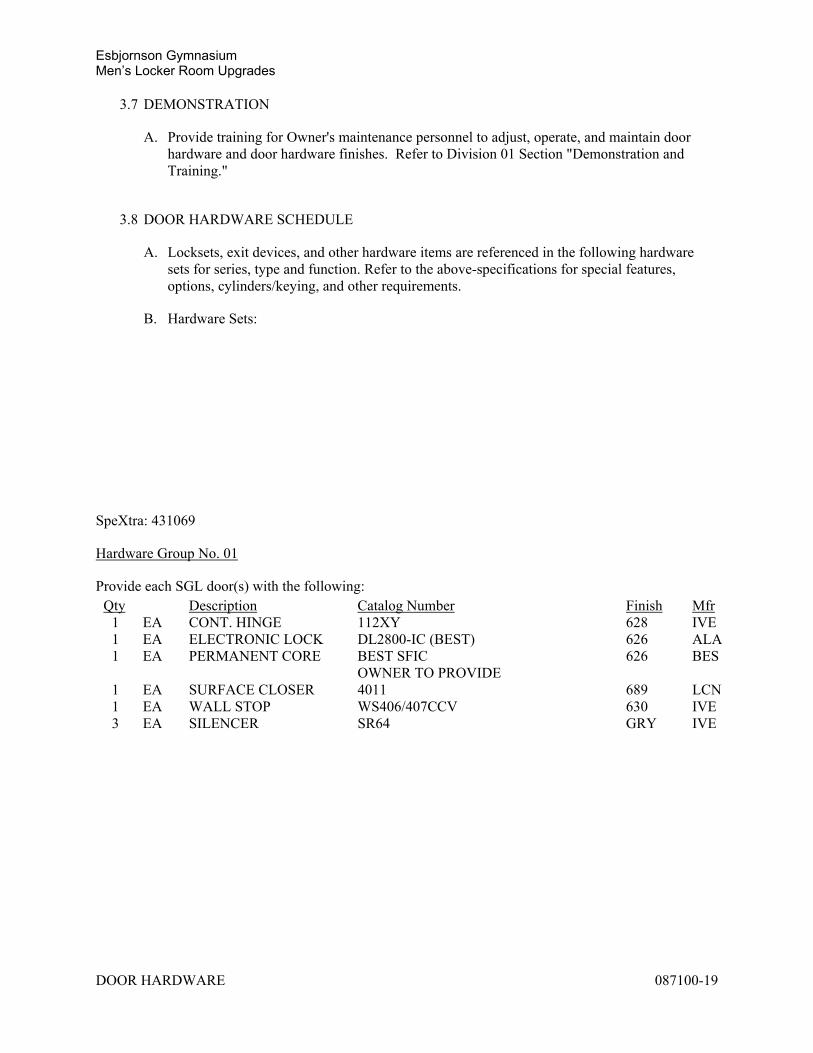
Esbjornson Gymnasium Men’s Locker Room Upgrades
DOOR HARDWARE 087100-19
3.7 DEMONSTRATION
A. Provide training for Owner's maintenance personnel to adjust, operate, and maintain door hardware and door hardware finishes. Refer to Division 01 Section "Demonstration and Training."
3.8 DOOR HARDWARE SCHEDULE
A. Locksets, exit devices, and other hardware items are referenced in the following hardware sets for series, type and function. Refer to the above-specifications for special features, options, cylinders/keying, and other requirements.
B. Hardware Sets: SpeXtra: 431069
Hardware Group No. 01
Provide each SGL door(s) with the following: Qty Description Catalog Number Finish Mfr
1 EA CONT. HINGE 112XY 628 IVE 1 EA ELECTRONIC LOCK DL2800-IC (BEST) 626 ALA 1 EA PERMANENT CORE BEST SFIC
OWNER TO PROVIDE 626 BES
1 EA SURFACE CLOSER 4011 689 LCN 1 EA WALL STOP WS406/407CCV 630 IVE 3 EA SILENCER SR64 GRY IVE

Esbjornson Gymnasium Men’s Locker Room Upgrades
DOOR HARDWARE 087100-20
Hardware Group No. 02
Provide each SGL door(s) with the following: Qty Description Catalog Number Finish Mfr
1 EA CONT. HINGE 112XY 628 IVE 1 EA ELECTRONIC LOCK DL2800-IC (BEST) 626 ALA 1 EA PERMANENT CORE BEST SFIC
OWNER TO PROVIDE 626 BES
1 EA OH STOP 100S 630 GLY 1 EA SURFACE CLOSER 4011 ST-1544 689 LCN 1 EA MOUNTING PLATE 4020-18 689 LCN 3 EA SILENCER SR64 GRY IVE
Hardware Group No. 03
Provide each SGL door(s) with the following: Qty Description Catalog Number Finish Mfr
1 EA CLASSROOM 9K37R 15D 626 BES 1 EA PERMANENT CORE BEST SFIC
OWNER TO PROVIDE 626 BES
1 EA NOTE RE-USE BALANCE OF EXISTING HARDWARE
MIS
GC TO RE-WORK EXISTING DOOR & FRAME AS REQUIRED FOR NEW HARDWARE END OF SECTION

Esbjornson Gymnasium Men’s Locker Room Upgrades
NON-STRUCTURAL METAL FRAMING 092216 - 1
SECTION 092216 - NON-STRUCTURAL METAL FRAMING
PART 1 - GENERAL
1.1 SUMMARY
A. This Section includes non-load-bearing steel framing members for the following applications:
1. Interior framing systems (e.g., supports for partition walls, framed soffits, furring, etc.).
1.2 SUBMITTALS
A. Product Data: For each type of product indicated.
1.3 QUALITY ASSURANCE
A. Fire-Test-Response Characteristics: For fire-resistance-rated assemblies that incorporate non-load-bearing steel framing, provide materials and construction identical to those tested in assembly indicated according to ASTM E 119 by an independent testing agency.
B. Sound Transmission Characteristics: For STC-rated assemblies that incorporate non-load-bearing steel framing, provide materials and construction identical to those tested in assembly indicated according to ASTM E 90 and classified according to ASTM E 413 by an independent testing agency.
PART 2 - PRODUCTS
2.1 NON-LOAD-BEARING STEEL FRAMING, GENERAL
A. Framing Members, General: Comply with ASTM C 754 for conditions indicated.
1. Steel Sheet Components: Comply with ASTM C 645 requirements for metal, unless otherwise indicated.
2. Protective Coating: ASTM A 653/A 653M, G60 (Z180), hot-dip galvanized zinc coating, unless otherwise indicated.
2.2 STEEL FRAMING FOR FRAMED ASSEMBLIES
A. Steel Studs and Runners: ASTM C 645.
1. Minimum Base-Metal Thickness: 20 ga.
B. Slip-Type Head Joints: Where indicated, provide the following:

Esbjornson Gymnasium Men’s Locker Room Upgrades
NON-STRUCTURAL METAL FRAMING 092216 - 2
1. Deflection Track: Steel sheet top runner manufactured to prevent cracking of finishes applied to interior partition framing resulting from deflection of structure above; in thickness not less than indicated for studs and in width to accommodate depth of studs.
C. Flat Strap and Backing Plate: Steel sheet for blocking and bracing.
1. Minimum Base-Metal Thickness: 0.0179 inch (0.45 mm).
D. Cold-Rolled Channel Bridging: 0.0538-inch (1.37-mm) bare-steel thickness, with minimum 1/2-inch- (12.7-mm-) wide flanges.
1. Depth: 1-1/2 inches (38.1 mm). 2. Clip Angle: Not less than 1-1/2 by 1-1/2 inches (38.1 by 38.1 mm), 0.068-inch- (1.73-
mm-) thick, galvanized steel.
2.3 AUXILIARY MATERIALS
A. Fasteners for Metal Framing: Of type, material, size, corrosion resistance, holding power, and other properties required to fasten steel members to substrates.
B. Isolation Strip at Exterior Walls: Provide one of the following:
1. Asphalt-Saturated Organic Felt: ASTM D 226, Type I (No. 15 asphalt felt), nonperforated.
2. Foam Gasket: Adhesive-backed, closed-cell vinyl foam strips that allow fastener penetration without foam displacement, 1/8 inch (3.2 mm) thick, in width to suit steel stud size.
PART 3 - EXECUTION
3.1 INSTALLATION, GENERAL
A. Installation Standard: ASTM C 754. 1. Gypsum Board Assemblies: Also comply with requirements in ASTM C 840 that apply
to framing installation.
3.2 INSTALLING FRAMED ASSEMBLIES
A. Where studs are installed directly against exterior masonry walls or dissimilar metals at exterior walls, install isolation strip between studs and exterior wall.
B. Install tracks (runners) at floors and overhead supports. Extend framing full height to structural supports or substrates above suspended ceilings, except where partitions are indicated to terminate at suspended ceilings. Continue framing around ducts penetrating partitions above ceiling.

Esbjornson Gymnasium Men’s Locker Room Upgrades
NON-STRUCTURAL METAL FRAMING 092216 - 3
1. Slip-Type Head Joints: Where framing extends to overhead structural supports, install to produce joints at tops of framing systems that prevent axial loading of finished assemblies.
2. Door Openings: Screw vertical studs at jambs to jamb anchor clips on door frames; install runner track section (for cripple studs) at head and secure to jamb studs.
a. Install two studs at each jamb, unless otherwise indicated. b. Install cripple studs at head adjacent to each jamb stud, with a minimum 1/2-inch
(12.7-mm) clearance from jamb stud to allow for installation of control joint in finished assembly.
c. Extend jamb studs through suspended ceilings and attach to underside of overhead structure.
3. Other Framed Openings: Frame openings other than door openings the same as required for door openings, unless otherwise indicated. Install framing below sills of openings to match framing required above door heads.
C. Installation Tolerance: Install each framing member so fastening surfaces vary not more than 1/8 inch (3 mm) from the plane formed by faces of adjacent framing.
END OF SECTION 092216

THIS PAGE INTENTIONALLY LEFT BLANK

Esbjornson Gymnasium Men’s Locker Room Upgrades
GYPSUM BOARD 092900 - 1
SECTION 092900 - GYPSUM BOARD
PART 1 - GENERAL
1.1 SUMMARY
A. This Section includes the following:
1. Interior gypsum board.
1.2 SUBMITTALS
A. Product Data: For each type of product indicated.
B. Samples: For the following products:
1. Trim Accessories: Full-size Sample in 12-inch- (300-mm-) long length for each trim accessory indicated.
PART 2 - PRODUCTS
2.1 INTERIOR GYPSUM BOARD
A. General: Complying with ASTM C 36/C 36M or ASTM C 1396/C 1396M, as applicable to type of gypsum board indicated and whichever is more stringent.
1. Available Manufacturers: Subject to compliance with requirements, manufacturers offering products that may be incorporated into the Work include, but are not limited to, the following:
2. Manufacturers: Subject to compliance with requirements, provide products by one of the following:
a. Certainteed. b. National Gypsum Company. c. Georgia Pacific.
B. Abuse and Moisture-Resistant Type: Manufactured to produce greater resistance to surface indentation and through-penetration (impact resistance) than standard and with moisture- and mold-resistant core, regular-type and Type X gypsum board.
1. Moisture-Resistant Core: Thickness As indicated on Drawings. 2. Long Edges: Tapered.

Esbjornson Gymnasium Men’s Locker Room Upgrades
GYPSUM BOARD 092900 - 2
2.2 TRIM ACCESSORIES
A. Interior Trim: ASTM C 1047.
1. Material: Galvanized or aluminum-coated steel sheet or rolled zinc. 2. Shapes:
a. Cornerbead. b. LC-Bead: J-shaped; exposed long flange receives joint compound. c. Expansion (control) joint.
2.3 JOINT TREATMENT MATERIALS
A. General: Comply with ASTM C 475/C 475M.
B. Joint Tape:
1. Interior Gypsum Wallboard: Paper. 2. Exterior Gypsum Soffit Board: Paper. 3. Glass-Mat Gypsum Sheathing Board: 10-by-10 glass mesh. 4. Tile Backing Panels: As recommended by panel manufacturer.
C. Joint Compound for Interior Gypsum Wallboard: For each coat use formulation that is compatible with other compounds applied on previous or for successive coats.
1. Prefilling: At open joints and damaged surface areas, use setting-type taping compound. 2. Embedding and First Coat: For embedding tape and first coat on joints, fasteners, and
trim flanges, use setting-type taping compound.
a. Use setting-type compound for installing paper-faced metal trim accessories.
3. Fill Coat: For second coat, use setting-type, sandable topping compound. 4. Finish Coat: For third coat, use setting-type, sandable topping compound. 5. Skim Coat: For final coat of Level 5 finish, use setting-type, sandable topping
compound.
2.4 AUXILIARY MATERIALS
A. General: Provide auxiliary materials that comply with referenced installation standards and manufacturer's written recommendations.
B. Laminating Adhesive: Adhesive or joint compound recommended for directly adhering gypsum panels to continuous substrate.
1. Use adhesives that have a VOC content of 50 g/L or less when calculated according to 40 CFR 59, Subpart D (EPA Method 24).
C. Steel Drill Screws: ASTM C 1002, unless otherwise indicated.

Esbjornson Gymnasium Men’s Locker Room Upgrades
GYPSUM BOARD 092900 - 3
1. Use screws complying with ASTM C 954 for fastening panels to steel members from 0.033 to 0.112 inch (0.84 to 2.84 mm) thick.
2. For fastening cementitious backer units, use screws of type and size recommended by panel manufacturer.
D. Sound Attenuation Blankets: ASTM C 665, Type I (blankets without membrane facing) produced by combining thermosetting resins with mineral fibers manufactured from glass, slag wool, or rock wool.
E. Acoustical Sealant: As specified in Division 07 Section "Joint Sealants."
F. Thermal Insulation: As specified in Division 07 Section "Thermal Insulation."
G. Vapor Retarder: As specified in Division 07 Section "Thermal Insulation."
PART 3 - EXECUTION
3.1 APPLYING AND FINISHING PANELS, GENERAL
A. Comply with ASTM C 840.
B. Examine panels before installation. Reject panels that are wet, moisture damaged, and mold damaged.
C. Isolate perimeter of gypsum board applied to non-load-bearing partitions at structural abutments, except floors. Provide 1/4- to 1/2-inch- (6.4- to 12.7-mm-) wide spaces at these locations, and trim edges with edge trim where edges of panels are exposed. Seal joints between edges and abutting structural surfaces with acoustical sealant.
D. Wood Framing: Install gypsum panels over wood framing, with floating internal corner construction. Do not attach gypsum panels across the flat grain of wide-dimension lumber, including floor joists and headers. Float gypsum panels over these members, or provide control joints to counteract wood shrinkage.
3.2 APPLYING INTERIOR GYPSUM BOARD
A. Install interior gypsum board in the following locations: 1. Abuse Moisture -Resistant Type: All areas unless otherwise noted.
3.3 INSTALLING TRIM ACCESSORIES
A. General: For trim with back flanges intended for fasteners, attach to framing with same fasteners used for panels. Otherwise, attach trim according to manufacturer's written instructions.
B. Control Joints: Install control joints according to ASTM C 840 and in specific locations approved by Architect for visual effect.

Esbjornson Gymnasium Men’s Locker Room Upgrades
GYPSUM BOARD 092900 - 4
C. Interior Trim: Install in the following locations:
1. Cornerbead: Use at outside corners. 2. LC-Bead: Use at exposed panel edges.
D. Exterior Trim: Install in the following locations:
1. Cornerbead: Use at outside corners. 2. LC-Bead: Use at exposed panel edges.
3.4 FINISHING GYPSUM BOARD
A. General: Treat gypsum board joints, interior angles, edge trim, control joints, penetrations, fastener heads, surface defects, and elsewhere as required to prepare gypsum board surfaces for decoration. Promptly remove residual joint compound from adjacent surfaces.
B. Prefill open joints and damaged surface areas.
C. Apply joint tape over gypsum board joints, except those with trim having flanges not intended for tape.
D. Gypsum Board Finish Levels: Finish panels to levels indicated below:
1. Level 1: Ceiling plenum areas, concealed areas, and where indicated. 2. Level 5: At panel surfaces that will be exposed to view, unless otherwise indicated.
a. Primer and its application to surfaces are specified in other Division 09 Sections.
3.5 PROTECTION
A. Protect installed products from damage from weather, condensation, direct sunlight, construction, and other causes during remainder of the construction period.
B. Remove and replace panels that are wet, moisture damaged, and mold damaged.
1. Indications that panels are wet or moisture damaged include, but are not limited to, discoloration, sagging, or irregular shape.
2. Indications that panels are mold damaged include, but are not limited to, fuzzy or splotchy surface contamination and discoloration.
END OF SECTION 092900

Esbjornson Gymnasium Men’s Locker Room Upgrades
ACOUSTICAL PANEL CEILINGS 095113 - 1
SECTION 095113 - ACOUSTICAL PANEL CEILINGS
PART 1 - GENERAL
1.1 SUMMARY
A. This Section includes acoustical panels and exposed suspension systems for ceilings.
1.2 SUBMITTALS
A. Product Data: For each type of product indicated.
B. Coordination Drawings: Drawn to scale and coordinating acoustical panel ceiling installation with hanger attachment to building structure and ceiling mounted items:
C. Samples: For each exposed finish.
D. Product test reports.
E. Research/evaluation reports.
F. Maintenance data.
1.3 QUALITY ASSURANCE
A. Acoustical Testing Agency Qualifications: An independent testing laboratory or an NVLAP-accredited laboratory.
B. Fire-Test-Response Characteristics:
1. Fire-Resistance Characteristics: Where indicated, provide acoustical panel ceilings identical to those of assemblies tested for fire resistance per ASTM E 119 by UL or another testing and inspecting agency acceptable to authorities having jurisdiction.
a. Identify materials with appropriate markings of applicable testing and inspecting agency.
2. Surface-Burning Characteristics: Acoustical panels complying with ASTM E 1264 for Class A materials, when tested per ASTM E 84.
a. Smoke-Developed Index: 450 or less.
C. Seismic Standard: Comply with the following:
1. Standard for Ceiling Suspension Systems Requiring Seismic Restraint: Comply with ASTM E 580.

Esbjornson Gymnasium Men’s Locker Room Upgrades
ACOUSTICAL PANEL CEILINGS 095113 - 2
2. CISCA's Recommendations for Acoustical Ceilings: Comply with CISCA's "Recommendations for Direct-Hung Acoustical Tile and Lay-in Panel Ceilings--Seismic Zones 0-2."
3. CISCA's Guidelines for Systems Requiring Seismic Restraint: Comply with CISCA's "Guidelines for Seismic Restraint of Direct-Hung Suspended Ceiling Assemblies--Seismic Zones 3 & 4."
4. UBC Standard 25-2, "Metal Suspension Systems for Acoustical Tile and for Lay-in Panel Ceilings."
5. ASCE 7, "Minimum Design Loads for Buildings and Other Structures": Section 9, "Earthquake Loads."
D. Mockups: Build mockups to verify selections made under sample submittals and to demonstrate aesthetic effects and set quality standards for materials and execution.
1. Approved mockups may become part of the completed Work if undisturbed at time of Substantial Completion.
E. Preinstallation Conference: Conduct conference at Project site.
1.4 EXTRA MATERIALS
A. Furnish extra materials described below that match products installed and that are packaged with protective covering for storage and identified with labels describing contents.
1. Acoustical Ceiling Panels: Full-size panels equal to 5.0 percent of quantity installed.
PART 2 - PRODUCTS
2.1 ACOUSTICAL PANEL CEILINGS, GENERAL
A. Acoustical Panel Standard: Comply with ASTM E 1264.
B. Metal Suspension System Standard: Comply with ASTM C 635.
C. Attachment Devices: Size for five times the design load indicated in ASTM C 635, Table 1, "Direct Hung," unless otherwise indicated. Comply with seismic design requirements. 1. Power-Actuated Fasteners in Concrete: Fastener system of type suitable for application
indicated, fabricated from corrosion-resistant materials, with clips or other accessory devices for attaching hangers of type indicated, and with capability to sustain, without failure, a load equal to 10 times that imposed by ceiling construction, as determined by testing per ASTM E 1190, conducted by a qualified testing and inspecting agency.
D. Wire Hangers, Braces, and Ties: Zinc-coated carbon-steel wire; ASTM A 641/A 641M, Class 1 zinc coating, soft temper.
1. Size: Select wire diameter so its stress at 3 times hanger design load (ASTM C 635, Table 1, "Direct Hung") will be less than yield stress of wire, but provide not less than 0.106-inch- (2.69-mm-) diameter wire.

Esbjornson Gymnasium Men’s Locker Room Upgrades
ACOUSTICAL PANEL CEILINGS 095113 - 3
E. Seismic perimeter stabilizer bars, seismic struts, and seismic clips.
F. Metal Edge Moldings and Trim: Type and profile indicated or, if not indicated, manufacturer's standard moldings for edges and penetrations that comply with seismic design requirements; formed from sheet metal of same material, finish, and color as that used for exposed flanges of suspension system runners.
2.2 ACOUSTICAL PANELS FOR ACOUSTICAL PANEL CEILING
A. Available Products: Subject to compliance with requirements, products that may be incorporated into the Work include, but are not limited to, the following:
B. Manufacturers: Subject to compliance with requirements, provide one of the following:
1. Armstrong World Industries, Inc. 2. USG Interiors, Inc. 3. Certainteed. 4. Or approved equal.
C. Basis-of-Design Product:
1. Armstrong World Industries, Inc.: Ultima High NRC 1941.
D. Color: White.
E. Edge/Joint Detail: Beveled, tegular.
F. Thickness: 7/8 inch (22 mm).
G. Modular Size: 24 by 24 inches (610 by 610 mm).
2.3 METAL SUSPENSION SYSTEM FOR ACOUSTICAL PANEL CEILING
A. Available Products: Subject to compliance with requirements, products that may be incorporated into the Work include, but are not limited to, the following:
B. Manufacturers: Subject to compliance with requirements, provide one of the following:
1. Armstrong World Industries, Inc. 2. USG Interiors, Inc. 3. Certainteed. 4. Or approved equal.
C. Basis-of-Design Product:
1. Armstrong World Industries, Inc.: Suprafine XL.
D. Double-Web Steel Suspension System: Main and cross runners roll formed from cold-rolled steel sheet, prepainted, electrolytically zinc coated, or hot-dip galvanized according to

Esbjornson Gymnasium Men’s Locker Room Upgrades
ACOUSTICAL PANEL CEILINGS 095113 - 4
ASTM A 653/A 653M, not less than G30 (Z90) coating designation, with prefinished 9/16-inch- (15-mm-) wide metal caps on flanges.
1. Structural Classification: Intermediate-duty system. 2. Cap Finish: white.
PART 3 - EXECUTION
3.1 INSTALLATION
A. Comply with ASTM C 636 and seismic design requirements indicated, per manufacturer's written instructions and CISCA's "Ceiling Systems Handbook."
B. Measure each ceiling area and establish layout of acoustical panels to balance border widths at opposite edges of each ceiling. Avoid using less-than-half-width panels at borders.
C. Suspend ceiling hangers from building's structural members, plumb and free from contact with insulation or other objects within ceiling plenum. Splay hangers only where required to miss obstructions; offset resulting horizontal forces by bracing, countersplaying, or other equally effective means. Where width of ducts and other construction within ceiling plenum produces hanger spacings that interfere with location of hangers, use trapezes or equivalent devices. When steel framing does not permit installation of hanger wires at spacing required, install carrying channels or other supplemental support for attachment of hanger wires.
D. Install edge moldings and trim of type indicated at perimeter of acoustical ceiling area and where necessary to conceal edges of acoustical panels. Screw attach moldings to substrate at intervals not more than 16 inches (400 mm) o.c. and not more than 3 inches (75 mm) from ends, leveling with ceiling suspension system to a tolerance of 1/8 inch in 12 feet (3.2 mm in 3.6 m). Miter corners accurately and connect securely.
E. Install suspension system runners so they are square and securely interlocked with one another. Remove and replace dented, bent, or kinked members.
F. Install acoustical panels with undamaged edges and fit accurately into suspension system runners and edge moldings. Scribe and cut panels at borders and penetrations to provide a neat, precise fit.
END OF SECTION 095113

Esbjornson Gymnasium Men’s Locker Room Upgrades
RESILIENT BASE AND ACCESSORIES 096513 - 1
SECTION 096513 - RESILIENT BASE AND ACCESSORIES
PART 1 - GENERAL
1.1 SUMMARY
A. Section Includes:
1. Resilient base. 2. Resilient molding accessories.
1.2 SUBMITTALS
A. Product Data: For each type of product indicated.
B. Samples: For each type of product indicated, in manufacturer's standard-size Samples but not less than 12 inches (300 mm) long, of each resilient product color, texture, and pattern required.
1.3 QUALITY ASSURANCE
A. Fire-Test-Response Characteristics: As determined by testing identical products according to ASTM E 648 or NFPA 253 by a qualified testing agency.
1. Critical Radiant Flux Classification: Class I, not less than 0.45 W/sq. cm.
1.4 PROJECT CONDITIONS
A. Maintain ambient temperatures within range recommended by manufacturer in spaces to receive resilient products.
B. Until Substantial Completion, maintain ambient temperatures within range recommended by manufacturer.
C. Install resilient products after other finishing operations, including painting, have been completed.
PART 2 - PRODUCTS
2.1 RESILIENT BASE
A. Resilient Base:
1. Manufacturers: Subject to compliance with requirements, provide products by one of the following:

Esbjornson Gymnasium Men’s Locker Room Upgrades
RESILIENT BASE AND ACCESSORIES 096513 - 2
a. Armstrong World Industries, Inc. b. Johnsonite. c. Roppe Corporation, USA. d. Or approved equal.
B. Resilient Base Standard: ASTM F 1861.
1. Material Requirement: Type TV (vinyl, thermoplastic). 2. Manufacturing Method: Group I (solid, homogeneous. 3. Style: Straight (flat or toeless).
C. Minimum Thickness: 0.125 inch (3.2 mm).
D. Height: 4 inches (102 mm).
E. Outside Corners: Job formed.
F. Inside Corners: Job formed.
G. Finish: Matte.
H. Colors and Patterns: As selected by Architect from full range of industry colors.
2.2 RESILIENT MOLDING ACCESSORY <Insert drawing designation>
A. Resilient Molding Accessory:
1. Manufacturers: Subject to compliance with requirements, provide products by one of the following: a. Armstrong World Industries, Inc. b. Johnsonite. c. Roppe Corporation, USA. d. Or approved equal.
B. Description: Nosing for resilient floor covering, Reducer strip for resilient floor covering, Transition strips.
C. Material: Vinyl.
D. Colors and Patterns: As selected by Architect from full range of industry colors.
2.3 INSTALLATION MATERIALS
A. Trowelable Leveling and Patching Compounds: Latex-modified, portland cement based or blended hydraulic-cement-based formulation provided or approved by manufacturer for applications indicated.
B. Adhesives: Water-resistant type recommended by manufacturer to suit resilient products and substrate conditions indicated.

Esbjornson Gymnasium Men’s Locker Room Upgrades
RESILIENT BASE AND ACCESSORIES 096513 - 3
1. Use adhesives that comply with the following limits for VOC content when calculated according to 40 CFR 59, Subpart D (EPA Method 24):
a. Cove Base Adhesives: Not more than 50 g/L. b. Rubber Floor Adhesives: Not more than 60 g/L.
PART 3 - EXECUTION
3.1 PREPARATION
A. Prepare substrates according to manufacturer's written instructions to ensure adhesion of resilient products.
B. Fill cracks, holes, and depressions in substrates with trowelable leveling and patching compound and remove bumps and ridges to produce a uniform and smooth substrate.
C. Do not install resilient products until they are same temperature as the space where they are to be installed.
1. Move resilient products and installation materials into spaces where they will be installed at least 48 hours in advance of installation.
D. Sweep and vacuum clean substrates to be covered by resilient products immediately before installation.
3.2 RESILIENT BASE INSTALLATION
A. Comply with manufacturer's written instructions for installing resilient base.
B. Apply resilient base to walls, columns, pilasters, casework and cabinets in toe spaces, and other permanent fixtures in rooms and areas where base is required.
C. Install resilient base in lengths as long as practicable without gaps at seams and with tops of adjacent pieces aligned.
D. Tightly adhere resilient base to substrate throughout length of each piece, with base in continuous contact with horizontal and vertical substrates.
E. Do not stretch resilient base during installation.
3.3 RESILIENT ACCESSORY INSTALLATION
A. Comply with manufacturer's written instructions for installing resilient accessories.
B. Resilient Molding Accessories: Butt to adjacent materials and tightly adhere to substrates throughout length of each piece. Install reducer strips at edges of resilient floor covering that would otherwise be exposed.

Esbjornson Gymnasium Men’s Locker Room Upgrades
RESILIENT BASE AND ACCESSORIES 096513 - 4
3.4 CLEANING AND PROTECTION
A. Comply with manufacturer's written instructions for cleaning and protection of resilient products.
B. Cover resilient products until Substantial Completion.
END OF SECTION 096513

Esbjornson Gymnasium Men’s Locker Room Upgrades
RESILIENT ATHLETIC FLOORING 096566 - 1
SECTION 096566 - RESILIENT ATHLETIC FLOORING
PART 1 - GENERAL
1.1 SUMMARY
A. This Section includes the following: 1. Recycled rubber resilient roll/sheet flooring.
1.2 SUBMITTALS
A. Product Data: For each type of product indicated.
B. Shop Drawings: Show installation details and locations of the following: 1. Layout, colors, and widths. 2. Seam locations.
C. Samples: For each exposed finish.
D. Maintenance data.
E. Quality Assurance Submittals: Submit the following: 1. Test Reports: Certified test reports showing compliance with specified performance
characteristics and physical properties. 2. Certificates: Product certificates signed by manufacturer certifying materials comply with
specified performance characteristics and criteria and physical requirements. 3. Manufacturer’s Instructions: Manufacturer’s installation instructions.
1.3 REFERENCES
A. Standards listed by reference, including revisions by issuing authority, form a part of this specification section to extent indicated. Standards listed are identified by issuing authority, authority abbreviation, designation number, title or other designation established by issuing authority. Standards subsequently referenced herein are referred to by issuing authority abbreviation and standard designation.
B. American Society for Testing and Materials (ASTM): 1. ASTM D3676 Standard Specification for Rubber Cellular Cushion Used for Carpet or
Rug Underlay. 2. ASTM D2240 Standard Test Method for Rubber Property-Durometer Hardness. 3. ASTM D412 Standard Test Methods for Vulcanized Rubber and Thermoplastic Rubbers
and Thermoplastic Elastomers – Tension. 4. ASTM D624 Standard Test Method for Tear Strength of Conventional Vulcanized
Rubber and Thermoplastic Elastomers. 5. ASTM F137 Test Method for Flexibility of Resilient Flooring Materials.

Esbjornson Gymnasium Men’s Locker Room Upgrades
RESILIENT ATHLETIC FLOORING 096566 - 2
6. ASTM F710 Practice for Preparing Concrete Floors and Other Monolithic Floors to Receive Resilient Flooring.
7. ASTM F925 Test Method for Resistance to Chemicals of Resilient Flooring.
1.4 SYSTEM DESCRIPTION
A. Performance Requirements: Provide recycled rubber resilient flooring, which has been manufactured and installed to maintain performance criteria stated by manufacturer without defects, damage or failure.
1.5 QUALITY ASSURANCE
A. Qualifications: 1. Installer Qualifications: Installer with at least 5 years’ experience in performing work of
this section who has specialized in installation of work similar to that required for this project.
2. 2. Manufacturer’s Qualifications: Manufacturer capable of providing field service representation during construction and approving application method.
B. Mock-Ups: Install at project site a job mock-up using acceptable products and manufacturer-approved installation methods. Obtain Owner’s and Architect’s acceptance of finish color, texture and pattern, and workmanship standard. 1. Mock-Up Size: 12’-0”x12’-0”. 2. Incorporation: Mock-up may be incorporated into final construction upon Owner’s
approval.
C. Pre-installation Conference: Conduct pre-installation meeting to verify project requirements, substrate conditions, manufacturer’s instructions and manufacturer’s warranty requirements.
D. Pre-installation Testing: Conduct pre-installation substrate testing as required by manufacturer.
1.6 DELIVERY, STORAGE & HANDLING
A. Delivery: Deliver materials in manufacturer’s original, unopened, undamaged containers with identification labels intact.
B. Storage and Protection: Store materials at temperature and humidity conditions recommended by manufacturer and protect from exposure to harmful weather conditions.
1.7 PROJECT CONDITIONS
A. Temperature Requirements: Maintain air temperature in spaces where products will be installed for time period before, during and after installation as recommended by manufacturer.
B. Field Measurements: Verify actual measurements/openings by field measurements before fabrication; show recorded measurements on shop drawings. Coordinate field measurements and fabrication schedule with construction progress to avoid construction delays.
Esbjornson Gymnasium Men’s Locker Room Upgrades
RESILIENT ATHLETIC FLOORING 096566 - 3
1.8 WARRANTY
A. Manufacturer’s Warranty: Submit, for Owner’s acceptance, manufacturer’s standard warranty document executed by authorized company official. 1. Warranty Period: 15 years commencing from Date of Substantial Completion.
1.9 MAINTENANCE
A. Extra Materials: Deliver to Owner extra materials from same production run as products installed. Package products with protective covering and identify with descriptive labels. 1. Quantity: Furnish quantity of recycled rubber flooring units equal to 10 % of amount
installed.
PART 2 - PRODUCTS
2.1 RECYCLED RUBBER RESILIENT ROLL/SHEET FLOORING
A. Products: Subject to compliance with requirements, provide one of the following: 1. Regupol, America – Aktiv Flooring. 2. Or approved equal.
B. Material: Recycled-rubber resilient sheet flooring.
C. Installation Method: Adhered.
D. Traffic-Surface Texture: Smooth>
E. Roll Size: Not less than 48 inches (1219 mm) wide by longest length that is practical to minimize splicing during installation.
F. Thickness: 3/8 inch (9.5 mm).
G. Color and Pattern: Custom color to match owners sample.
H. Accessories:
1. Trowelable Leveling and Patching Compound: Latex-modified, hydraulic-cement-based formulation approved by floor covering manufacturer.
2. Installation Adhesive: Water-resistant type recommended in writing by manufacturer for substrate and conditions indicated.
a. Use adhesive that has a VOC content of 60 g/L or less when calculated according to 40 CFR 59, Subpart D (EPA Method 24).

Esbjornson Gymnasium Men’s Locker Room Upgrades
RESILIENT ATHLETIC FLOORING 096566 - 4
PART 3 - EXECUTION
3.1 PREPARATION
A. Concrete Substrates: Prepare according to ASTM F 710.
1. Verify that substrates are dry and free of curing compounds, sealers, and hardeners. 2. Alkalinity and Adhesion Testing: Perform tests recommended in writing by
manufacturer. Proceed with installation only after substrates pass testing. 3. Moisture Testing:
a. Perform anhydrous calcium chloride test, ASTM F 1869. Proceed with installation only after substrates have maximum moisture-vapor-emission rate of 3 lb of water/1000 sq. ft. (1.36 kg of water/92.9 sq. m) in 24 hours.
b. Perform tests recommended in writing by manufacturer. Proceed with installation only after substrates pass testing.
B. Remove substrate coatings and other substances that are incompatible with adhesives and that contain soap, wax, oil, or silicone, using mechanical methods recommended in writing by manufacturer. Do not use solvents.
C. Use trowelable leveling and patching compound to fill cracks, holes, and depressions in substrates.
D. Move floor coverings and installation materials into spaces where they will be installed at least 48 hours in advance of installation, unless manufacturer recommends a longer period in writing.
1. Do not install floor coverings until they are same temperature as space where they are to be installed.
E. Sweep and vacuum clean substrates to be covered by floor coverings immediately before installation. After cleaning, examine substrates for moisture, alkaline salts, carbonation, and dust. Proceed with installation only after unsatisfactory conditions have been corrected.
3.2 FLOOR COVERING INSTALLATION, GENERAL
A. Scribe, cut, and fit floor coverings to butt neatly and tightly to vertical surfaces, equipment anchors, floor outlets, and other interruptions of floor surface.
B. Extend floor coverings into toe spaces, door reveals, closets, and similar openings, unless otherwise indicated.
C. Adhere products to substrates using a full spread of adhesive applied to substrate to comply with adhesive and floor covering manufacturers' written instructions, including those for trowel notching, adhesive mixing, and adhesive open and working times.
1. Provide completed installation without open cracks, voids, raising and puckering at joints, telegraphing of adhesive spreader marks, and other surface imperfections.

Esbjornson Gymnasium Men’s Locker Room Upgrades
RESILIENT ATHLETIC FLOORING 096566 - 5
3.3 SHEET FLOOR COVERING INSTALLATION
A. Lay out sheet floor coverings as follows:
1. Maintain uniformity of floor covering direction. 2. Minimize number of seams; place seams in inconspicuous and low-traffic areas, at least 6
inches (152 mm) away from parallel joints in floor covering substrates. 3. Match edges of floor coverings for color shading at seams. 4. Avoid cross seams.
B. Seams: Prepare and finish seams to produce surfaces flush with adjoining floor covering surfaces.
1. Heat-Welded Seams: Comply with ASTM F 1516. Rout joints and use welding bead to permanently fuse sections into a seamless floor covering.
2. Chemically Bonded Seams: Comply with ASTM F 693. Seal seams to prevent openings from forming between cut edges and to prevent penetration of dirt, liquids, and other substances into seams.
3.4 CLEANING AND PROTECTING
A. Perform the following operations immediately after completing floor covering installation:
1. Remove adhesive and other blemishes from floor covering surfaces. 2. Sweep and vacuum floor coverings thoroughly. 3. Damp-mop floor coverings to remove marks and soil.
a. Do not wash floor coverings until after time period recommended in writing by manufacturer.
B. Protect floor coverings from mars, marks, indentations, and other damage from construction operations and placement of equipment and fixtures during remainder of construction period. Use protection methods recommended in writing by manufacturer.
END OF SECTION 096566

THIS PAGE INTENTIONALLY LEFT BLANK

Esbjornson Gymnasium Men’s Locker Room Upgrades
INTERIOR PAINTING 099123 - 1
SECTION 099123 - INTERIOR PAINTING
PART 1 - GENERAL
1.1 SUMMARY
A. This Section includes surface preparation and the application of paint systems on the following interior substrates:
1. Concrete. 2. Metal. 3. Gypsum board.
1.2 SUBMITTALS
A. Product Data: For each type of product indicated.
B. Samples: For each finish and for each color and texture required.
C. Product List: Printout of current "MPI Approved Products List" for each product category specified in Part 2, with the proposed product highlighted.
1.3 QUALITY ASSURANCE
A. MPI Standards:
1. Products: Complying with MPI standards indicated and listed in "MPI Approved Products List."
2. Preparation and Workmanship: Comply with requirements in "MPI Architectural Painting Specification Manual" for products and paint systems indicated.
B. Mockups: Apply benchmark samples of each paint system indicated and each color and finish selected to verify preliminary selections made under sample submittals and to demonstrate aesthetic effects and set quality standards for materials and execution.
1. Architect will select one surface to represent surfaces and conditions for application of each paint system specified in Part 3.
a. Wall and Ceiling Surfaces: Provide samples of at least 100 sq. ft. (9 sq. m). b. Other Items: Architect will designate items or areas required.
2. Apply benchmark samples after permanent lighting and other environmental services have been activated.
3. Final approval of color selections will be based on benchmark samples.
a. If preliminary color selections are not approved, apply additional benchmark samples of additional colors selected by Architect at no added cost to Owner.

Esbjornson Gymnasium Men’s Locker Room Upgrades
INTERIOR PAINTING 099123 - 2
1.4 EXTRA MATERIALS
A. Furnish extra materials described below that are from same production run (batch mix) as materials applied and that are packaged for storage and identified with labels describing contents.
1. Quantity: Furnish an additional 5 percent, but not less than 1 gal. (3.8 L) of each material and color applied.
PART 2 - PRODUCTS
2.1 PAINT, GENERAL
A. Material Compatibility:
1. Provide materials for use within each paint system that are compatible with one another and substrates indicated, under conditions of service and application as demonstrated by manufacturer, based on testing and field experience.
2. For each coat in a paint system, provide products recommended in writing by manufacturers of topcoat for use in paint system and on substrate indicated.
B. VOC Content of Field-Applied Interior Paints and Coatings: Provide products that comply with the following limits for VOC content, exclusive of colorants added to a tint base, when calculated according to 40 CFR 59, Subpart D (EPA Method 24); these requirements do not apply to paints and coatings that are applied in a fabrication or finishing shop:
1. Flat Paints, Coatings, and Primers: VOC content of not more than 50 g/L. 2. Nonflat Paints, Coatings, and Primers: VOC content of not more than 150 g/L. 3. Anti-Corrosive and Anti-Rust Paints Applied to Ferrous Metals: VOC not more than 250
g/L. 4. Floor Coatings: VOC not more than 100 g/L. 5. Shellacs, Clear: VOC not more than 730 g/L. 6. Shellacs, Pigmented: VOC not more than 550 g/L. 7. Flat Topcoat Paints: VOC content of not more than 50 g/L. 8. Nonflat Topcoat Paints: VOC content of not more than 150 g/L. 9. Anti-Corrosive and Anti-Rust Paints Applied to Ferrous Metals: VOC not more than 250
g/L. 10. Floor Coatings: VOC not more than 100 g/L. 11. Shellacs, Clear: VOC not more than 730 g/L. 12. Shellacs, Pigmented: VOC not more than 550 g/L. 13. Primers, Sealers, and Undercoaters: VOC content of not more than 200 g/L. 14. Dry-Fog Coatings: VOC content of not more than 400 g/L. 15. Zinc-Rich Industrial Maintenance Primers: VOC content of not more than 340 g/L. 16. Pre-Treatment Wash Primers: VOC content of not more than 420 g/L.
C. Chemical Components of Field-Applied Interior Paints and Coatings: Provide topcoat paints and anti-corrosive and anti-rust paints applied to ferrous metals that comply with the following chemical restrictions; these requirements do not apply to paints and coatings that are applied in a fabrication or finishing shop:
Esbjornson Gymnasium Men’s Locker Room Upgrades
INTERIOR PAINTING 099123 - 3
1. Aromatic Compounds: Paints and coatings shall not contain more than 1.0 percent by weight of total aromatic compounds (hydrocarbon compounds containing one or more benzene rings).
2. Restricted Components: Paints and coatings shall not contain any of the following:
a. Acrolein. b. Acrylonitrile. c. Antimony. d. Benzene. e. Butyl benzyl phthalate. f. Cadmium. g. Di (2-ethylhexyl) phthalate. h. Di-n-butyl phthalate. i. Di-n-octyl phthalate. j. 1,2-dichlorobenzene. k. Diethyl phthalate. l. Dimethyl phthalate. m. Ethylbenzene. n. Formaldehyde. o. Hexavalent chromium. p. Isophorone. q. Lead. r. Mercury. s. Methyl ethyl ketone. t. Methyl isobutyl ketone. u. Methylene chloride. v. Naphthalene. w. Toluene (methylbenzene). x. 1,1,1-trichloroethane. y. Vinyl chloride.
D. Colors: As selected by Architect from manufacturer's full range.
2.2 BLOCK FILLERS
A. Interior/Exterior Latex Block Filler: MPI #4.
1. VOC Content: E Range of E3.
2.3 PRIMERS/SEALERS
A. Interior Latex Primer/Sealer: MPI #50.
1. VOC Content: E Range of E3.
2.4 METAL PRIMERS
A. Rust-Inhibitive Primer (Water Based): MPI #107.

Esbjornson Gymnasium Men’s Locker Room Upgrades
INTERIOR PAINTING 099123 - 4
1. VOC Content: E Range of E3.
2.5 LATEX PAINTS
A. Interior Latex (Eggshell): MPI #52 (Gloss Level 3).
1. VOC Content: E Range of E3.
B. Interior Latex (Semigloss): MPI #54 (Gloss Level 5).
1. VOC Content: E Range of E3.
PART 3 - EXECUTION
3.1 EXAMINATION
A. Examine substrates and conditions, with Applicator present, for compliance with requirements for maximum moisture content and other conditions affecting performance of work.
B. Maximum Moisture Content of Substrates: When measured with an electronic moisture meter as follows:
1. Concrete: 12 percent. 2. Masonry (Clay and CMU): 12 percent. 3. Wood: 15 percent. 4. Gypsum Board: 12 percent. 5. Plaster: 12 percent.
C. Verify suitability of substrates, including surface conditions and compatibility with existing finishes and primers.
D. Begin coating application only after unsatisfactory conditions have been corrected and surfaces are dry.
1. Beginning coating application constitutes Contractor's acceptance of substrates and conditions.
3.2 PREPARATION AND APPLICATION
A. Comply with manufacturer's written instructions and recommendations in "MPI Architectural Painting Specification Manual" applicable to substrates indicated.
B. Clean substrates of substances that could impair bond of paints, including dirt, oil, grease, and incompatible paints and encapsulants.
1. Remove incompatible primers and reprime substrate with compatible primers as required to produce paint systems indicated.

Esbjornson Gymnasium Men’s Locker Room Upgrades
INTERIOR PAINTING 099123 - 5
C. Apply paints to produce surface films without cloudiness, spotting, holidays, laps, brush marks, roller tracking, runs, sags, ropiness, or other surface imperfections. Cut in sharp lines and color breaks.
D. Painting Mechanical and Electrical Work: Paint items exposed in equipment rooms and occupied spaces including, but not limited to, the following:
1. Mechanical Work:
a. Uninsulated metal piping. b. Uninsulated plastic piping. c. Pipe hangers and supports. d. Tanks that do not have factory-applied final finishes. e. Visible portions of internal surfaces of metal ducts, without liner, behind air inlets
and outlets. f. Duct, equipment, and pipe insulation having cotton or canvas insulation covering
or other paintable jacket material. g. Mechanical equipment that is indicated to have a factory-primed finish for field
painting.
2. Electrical Work:
a. Switchgear. b. Panelboards. c. Electrical equipment that is indicated to have a factory-primed finish for field
painting.
E. Protect work of other trades against damage from paint application. Correct damage to work of other trades by cleaning, repairing, replacing, and refinishing, as approved by Architect, and leave in an undamaged condition.
F. At completion of construction activities of other trades, touch up and restore damaged or defaced painted surfaces.
3.3 INTERIOR PAINTING SCHEDULE
A. CMU Substrates:
1. Latex System: MPI INT 4.2A.
a. Prime Coat: Interior/exterior latex block filler. b. Intermediate Coat: Interior latex matching topcoat. c. Topcoat: Interior latex eggshell.
B. Steel Substrates:
1. Water-Based Dry-Fall System: MPI INT 5.1C.
a. Prime Coat: Alkyd anticorrosive metal primer. b. Topcoat: Latex dry fog/fall.

Esbjornson Gymnasium Men’s Locker Room Upgrades
INTERIOR PAINTING 099123 - 6
C. Galvanized-Metal Substrates:
1. Latex Over Waterborne Primer System: MPI INT 5.3J.
a. Prime Coat: Waterborne galvanized-metal primer. b. Intermediate Coat: Interior latex matching topcoat. c. Topcoat: Interior latex eggshell.
D. Aluminum (Not Anodized or Otherwise Coated) Substrates:
1. Latex System: MPI INT 5.4H.
a. Prime Coat: Quick-drying primer for aluminum. b. Intermediate Coat: Interior latex matching topcoat. c. Topcoat: Interior latex eggshell.
E. Gypsum Board Substrates:
1. Latex System: MPI INT 9.2A.
a. Prime Coat: Interior latex primer/sealer. b. Intermediate Coat: Interior latex matching topcoat. c. Topcoat: Interior latex eggshell.
END OF SECTION 099123

Esbjornson Gymnasium Men’s Locker Room Upgrades
GENERAL REQUIREMENTS 20 00 01 - 1
SECTION 20 00 01 - GENERAL REQUIREMENTS PART 1 - GENERAL 1.1 APPLICATION
A. The provisions of this Section applies to all heating, ventilation, air conditioning, plumbing, fire protection, and electrical work of this Contract to the extent that they do not conflict with the provisions of the General Conditions, Supplementary Conditions, Division 00, Division 01, and/or other General Contract Documents. When such conflict occurs the provisions of this Section are thereby superseded but only to the extent of the conflict.
1.2 SCOPE OF WORK
A. The work under this Section of the Specification shall include all labor, materials, appliances, and services necessary for and incidental to the proper completion of the heating, ventilating, air conditioning, plumbing, fire protection, electrical and related work shown, implied or required by the drawings and described in these specifications.
B. Each Contractor shall perform all necessary rigging required for completion of work
under his contract. C. Each Contractor shall perform all necessary earthwork required for completion of work
under his contract. 1.3 OWNER OCCUPANCY
A. The Owner will partially occupy the building during work under this contract. B. The Contractor shall be responsible for the shut-down and start-up of smoke detection
systems on a daily basis, and for providing fire watches during periods when the system OFF.
C. All hot work shall cease one (1) hour prior to the end of the work day. A fire watch
inspection of all areas shall be completed at the end of each day. 1.4 QUALITY CONTROL
A. Monitor suppliers' products and services, site conditions, and workmanship to conform to specified quality.
B. Comply with manufacturer's instructions and with specified standards. C. Work shall be performed by qualified personnel. D. References E. Conform to current referenced standards in effect on date of contract documents.
Esbjornson Gymnasium Men’s Locker Room Upgrades
GENERAL REQUIREMENTS 20 00 01 - 2
F. Inspection and Testing Laboratory Services
1. Testing laboratory will be subject to acceptance by the Owner. 2. Submit notice in writing, 72 hours prior to testing, that Owner or his
Representative can make arrangements to be on site. 3. Covered, concealed, or insulated work shall remain exposed until tested and
accepted. 4. Pressure, operating and specified performance testing of components or systems
shall be conducted in the presence of the Owner or his Representative. 5. Certificates of approval and/or acceptance as specified or required by regulations
of agencies having jurisdiction shall be submitted prior to acceptance of work. 6. Retesting required because of non-conformance to specified requirements shall
be performed by the same independent firm on instructions by the Architect/Engineer. Payment for retesting will be by the Contractor with no additional cost to the Owner.
G. Manufacturers Field Services and Reports
1. Require material or product suppliers or manufacturers to provide qualified staff personnel to observe site conditions, conditions of surfaces and installation, quality of workmanship, and start-up of equipment as applicable, and to initiate instructions when necessary.
2. Report observations, and decisions, and/or instructions given to applicators or installers that are supplemental or contrary to manufacturers' written instructions.
3. Submit report in duplicate within 15 days of observation to Architect/Engineer for review.
1.5 PERMITS, LAWS, ORDINANCES AND REGULATIONS
A. The heating, ventilation, air conditioning, plumbing, fire protection, and electrical systems shall conform to all pertinent laws, ordinances and regulations of agencies and government bodies.
B. Contractor shall obtain all permits and inspection by each authority having jurisdiction.
Contractor shall pay permit, inspection and certification fees. 1.6 DRAWINGS AND SPECIFICATIONS
A. It is intended that these specifications and drawings shall include all materials, equipment, and labor required to correctly install and put in proper operation all systems of all work specified and/or indicated.
B. Small items of equipment, material, apparatus or machinery not specified or indicated in
detail which may be necessary to complete any part of the work as required, implied or intended shall be provided at no additional cost to the Owner.
1.7 OPERATION AND MAINTENANCE DATA
A. Prepare two sets prior to final inspection, bound in 8 ½ x 11 inch text pages, three D side ring capacity expansion binders with durable plastic covers.

Esbjornson Gymnasium Men’s Locker Room Upgrades
GENERAL REQUIREMENTS 20 00 01 - 3
1. Submit one copy of completed volumes in final form 15 days prior to final
inspection. This copy will be returned, with Architect/Engineer comments. Revise content of documents as required prior to final submittal.
B. Prepare binder covers with printed title, "OPERATION AND MAINTENANCE
INSTRUCTIONS", title of project, and subject matter of binder when multiple binders are required.
C. Internally subdivide the binder contents with permanent page dividers, logically
organized as described below; with tab titling clearly printed under reinforced laminated plastic tabs.
D. Contents: Prepare a Table of Contents for each volume, with each product or system
description identified type written on 24 pound white paper. E. Part 1: Directory listing names, addresses, and telephone numbers of Architect/Engineer,
Contractor, Subcontractors, and major equipment suppliers. F. Part 2: Operation and maintenance instructions arranged by system and subdivided by
specification section. For each category, identify names, addresses, and telephone numbers of Subcontractors and suppliers. Identify the following:
1. Significant design criteria. 2. List of equipment. 3. Parts list for each component. 4. Operating instructions. 5. Maintenance instructions for equipment and systems. 6. Maintenance instructions for finishes, including recommended cleaning methods
and materials and special precautions identifying detrimental agents. G. Part 3: Project documents and certificates, including the following:
1. Shop drawings and product data. 2. Air and water balance reports. 3. Certificates. 4. Photocopies of warranties.
H. Submit four (4) final revised volumes within ten days after final inspection to the
Architect/Engineer.
1.8 GUARANTEE
A. All materials, equipment and workmanship shall be unconditionally guaranteed in writing for a period of one year from the date of acceptance. The Contractor shall replace or repair, at no cost to the Owner, any material, equipment or workmanship which becomes defective during the guarantee period. The Contractor shall service all equipment and systems included in this contract during guarantee period.
1.9 SITE VISIT

Esbjornson Gymnasium Men’s Locker Room Upgrades
GENERAL REQUIREMENTS 20 00 01 - 4
A. All Bidders are required to thoroughly examine the site. B. Contractor shall notify the Engineer, prior to bidding, of any discrepancies between
existing site conditions and requirements of contract documents. The Engineer will issue clarification prior to submission of bids. Lack of this notification to Engineer will result in binding interpretation by the Engineer.
1.10 PROJECT RECORD DOCUMENTS
A. Maintain on site, one set of the following record documents.
1. Contract Drawings. 2. Specifications. 3. Addenda. 4. Change Orders and other modifications to the contract. 5. Reviewed shop drawings, product data, and samples.
B. Store Record Documents separate from documents used for construction. C. Record information concurrent with construction progress. D. Specifications: Legibly mark and record at each product section a description of actual
products installed, including the following:
1. Manufacturer's name and product model and number. 2. Product substitutions or alternates utilized. 3. Changes made by Addenda and Modifications.
E. Record Drawings and Shop Drawings: Legibly mark each item to record actual
construction including:
1. Measured horizontal and vertical locations of underground utilities and appurtenances referenced to permanent surface improvements.
2. Measured locations of internal utilities to include pipes, valves, equipment, conduit, access doors, controls, ducts, sprinklers, fixtures, etc.
3. Field changes of dimension and detail. 4. Details not on original contract drawings.
F. Delete Architect/Engineer's title block and seal from all documents. G. Submit documents to Architect/Engineer with claim for final Application for Payment
1.11 TEMPORARY UTILITIES, HEATING AND FACILITIES
A. Temporary Power
1. Provide power outlets for construction operations with branch wiring and distribution boxes, as required.
B. Temporary Lighting

Esbjornson Gymnasium Men’s Locker Room Upgrades
GENERAL REQUIREMENTS 20 00 01 - 5
1. Provide branch wiring from power source with lighting, conductors, pigtails and lamps, as required.
2. Maintain lighting and provide routine repairs. D. Temporary Water
1. Contractor shall provide connections to existing water service. E. Temporary Sanitary Facilities
1. The Owner will designate facilities for use by Contractor personnel. F. Removal of Temporary Utilities, Heating and Facilities
1. Remove temporary above grade or buried utilities, equipment, facilities and /or materials prior to substantial completion inspection.
2. Restore existing facilities used during construction to original condition. 1.12 COORDINATION:
A. Coordinate scheduling, submittals, and work of the various specification sections and work of other contractors, to assure efficient and orderly sequence of installation of interdependent construction elements.
B. Verify that utility requirement characteristics of operating equipment are compatible with
building utilities. Coordinate work of various specification sections having interdependent responsibilities for installing, connecting to, and placing in service such equipment.
C. Coordinate space requirements and installation of mechanical and electrical work.
Follow routing shown for pipes, ducts, and conduit as closely as practicable; place runs parallel with line of building. Utilize space efficiently to maximize accessibility for other installations, for maintenance, and for repairs.
D. In finished areas, except as otherwise indicated, conceal pipes, ducts, and wiring within the construction. Coordinate locations of fixtures and outlets with finish elements.
E. Coordinate completion and clean-up of work of separate trades in preparation for
substantial completion. F. After Owner's occupancy of premises, coordinate access to site for correction of defective
work and work not in accordance with Contract Documents, to minimize disruption of Owner's activities.
G. Prior to installing any equipment, material, device, etc. the contractors (General, Steel,
Mechanical, Plumbing, Electrical, and Fire Protection) and all sub-contractors shall, in a coordinated effort, prepare detailed coordination drawings in AutoCAD at a minimum scale of 3/8’ to 1’-0”. Provide enlarged sections and plan views in congested areas to coordinate all materials and equipment. The Mechanical Contractor shall be the responsible party for preparing the base plans and coordinating with the project managers, superintendents, and foreman of the various trades.

Esbjornson Gymnasium Men’s Locker Room Upgrades
GENERAL REQUIREMENTS 20 00 01 - 6
1.13 INTERRUPTION OF UTILITIES:
A. The Contractor shall not take any action that will interrupt any of the existing building services for this building or any other buildings without prior arrangement with the Engineer, Owner, or Owner's Representative.
B. Contractor shall notify Engineer/Owner 14 days in advance of any interruption to
building services HVAC, Plumbing, Fire Protection, Electrical, Fire Alarm, Communications, etc.
C. The Contractor causing any unplanned utility interruption shall immediately provide all
continuous labor, material and equipment necessary until such utility service is restored. 1.14 SUBSTITUTIONS
A. Bids shall be submitted only on the basis of materials, products or equipment specified in the specifications, on the drawings, or as named by Addendum issued prior to bid date and pursuant to requests for approval.
B. Materials, products or equipment specified in these specifications or on the drawings are
specified for the purpose of establishing a standard of quality, cost, design and function. It is not the intent to limit the acceptance of materials, products or equipment specified, but rather to name or describe a material, product or piece of equipment as the absolute minimum standard that is desired and acceptable. Where proprietary names are used, whether or not followed by the words "or approved equal", they shall be subject to equals only as approved by the Engineer prior to the date for receipt of bids.
C. No substitutions shall be considered unless written requests are submitted to the Engineer
for approval ten (10) days prior to the date for receipt of bids. Such requests shall be from a Prime Contractor and shall include a complete description of the proposed substitute, documentary proof of equal or superior quality, drawings or catalog cuts clearly marking the models or lines, sample of materials, performance and test data, jobs completed locally within the past five years and any other data or information necessary for a complete evaluation.
D. Approved substitutions will be set forth by Addenda to alert all bidders. E. The contract documents have been prepared to provide for the incorporation of the
standard of design and construction of the specified items or assemblies of every category of materials, products or pieces of equipment. In the event that incorporation of a substituted, acceptable equivalent, or approved equal item or assembly into the work will require revisions or additions to the contractual requirements of the Prime Contractor or any Sub-contractors, the Prime Contractor or Sub-contractor electing to use such item or assembly shall bear the cost of such revisions or additions to the work of all trades without change to the Contract sum.
F. If no prospective bidder has elected to obtain approval by the means described above, the
Owner has no authority, after award of contract, to consider any brand other than those named in the Contract Documents.

Esbjornson Gymnasium Men’s Locker Room Upgrades
GENERAL REQUIREMENTS 20 00 01 - 7
G. A substitution submitted by a Contractor or Sub-contractor after the award of contract, for reason that a product is not available, will not be permitted unless proof is submitted that a firm order was placed within 15 days after Notice of Award to the Prime Contractor. If an order was placed as stated, and the product is not available, the Contractor may submit a substitute product for review by the Owner and Architect/Engineer.
1.15 CLEANING
A. Each Contractor and/or Sub-Contractor who is responsible for execution of individual sections of work shall be responsible for the following:
1. Removal of all lumber, refuse, metal, piping and debris from site resulting from
their work. 2. Cleaning droppings resulting from their work, etc., from finished work of other
trades. 3. Cleaning, polishing, waxing of their work as required.
B. After testing and acceptance of all work by the Architect/Engineer and the Owner, each
Contractor shall thoroughly clean all equipment and material involved in his Contract to the satisfaction of the Architect/Engineer.
1.16 INSTRUCTING OWNER'S PERSONNEL
A. After all tests and adjustments have been made, each Contractor shall fully instruct the representatives of the Owner in all details of operation of the equipment installed under his Contract.
B. Each Contractor shall operate his equipment for sufficient length of time to satisfy the
Engineer that the requirements of the Contract Documents have been fulfilled. 1.17 PIPE/DUCT TESTING
A. All new hydronic piping and ductwork shall be tested.
1. All piping shall be hydraulically tested in accordance with ASME B31.9 or as specified in individual sections.
a. Provide necessary components to isolate existing systems.
2. All ductwork shall be leak tested in accordance with SMACNA HVAC air duct, Duct Leakage Test Manual, latest edition or as specified in individual sections.
a. Provide necessary components to isolate existing systems. PART 2 - PRODUCTS 2.1 SUPPORTS AND ANCHORS
A. Anchors of approved design shall be provided in locations shown on drawings to control movement in piping. Where types are not indicated or specified, contractor shall submit shop drawings detailing the entire anchor installation. Weld anchors to ferrous piping and braze anchors to nonferrous piping. Anchors must be made of heavy cross-sectional

Esbjornson Gymnasium Men’s Locker Room Upgrades
GENERAL REQUIREMENTS 20 00 01 - 8
material and fastened securely to the building construction by anchor bolts set in the concrete or attached to the structural framing of the building as approved. Strengthen the structure at anchor points to take the additional loads.
B. All materials, designs and types of inserts, hanger supports and clamps shall meet the
requirements of the Manufacturers Standardization Society Document MSS-SP-58, latest edition and also Underwriters Laboratories, Inc., National Electrical Code and Factory Mutual Engineering Division Standards where applicable.
C. Each Contractor shall be responsible for and provide all necessary inserts, hanger
supports, fastenings, clamps and attachments necessary for support of his work. The types of all inserts, hanger supports, fastenings, clamps and attachments to be used shall be selected to suit both new and existing building construction conditions and applied specifically for the purposes intended.
2.2 ELECTROLYSIS CONTROL
A. All copper to ferrous piping connections shall be made with the use of dielectric unions or flanges.
B. Connection between bronze valves and ferrous piping do not require electrolysis control.
2.3 MOTOR AND MOTOR STARTERS
A. All motors shall be furnished by the Mechanical Contractor unless specified to the contrary in Section 20 05 13 (Motor Requirements) or Division 26, and shall conform to the following requirements:
1. Characteristics, dimensions, tolerances, temperature rise, insulation, rating, noise,
vibration, and all other characteristics in accordance with the latest standards of IEEE or NEMA.
2. Unless required by the driven unit, motors shall have normal starting torque, NEMA Design B characteristics. Horsepower rating of motor shall be equal to or greater than that required by driven equipment. Current density design of motor rating shall be limited so that overload protection provided by standard motor starters will be adequate to prevent damaging overheating during stall, single phasing or slightly prolonged acceleration.
3. Use NEMA Class F insulation with motor frames amply sized to provide 1.15
service factor and an ambient of 40C maximum. Insulation systems shall be designed for an average life of 60,000 hours.
4. Each motor shall be mounted on the same bedplate as the equipment driven and be complete with pulleys, slide rails or flexible couplings as required.
5. Each Contractor is responsible in each instance for the proper selection of motors of suitable characteristics with details submitted for approval to the Architect/Engineer prior to installation
B. All motor starters, capacitors and variable frequency drives shall be provided by the
electrical contractor. 2.4 SUBMITTALS

Esbjornson Gymnasium Men’s Locker Room Upgrades
GENERAL REQUIREMENTS 20 00 01 - 9
A. Submit shop drawings and product data for all material and equipment required under this
contract. Submit the number of copies that the Contractor requires, plus three copies which will be retained by the Architect/Engineer.
B. Present shop drawings in a clear and thorough manner. Title each drawing with Project
name and number; identify each element of drawings by reference to A/E's Drawing number and detail, specification section, schedule, or room number. For product data submit only pages which are pertinent; mark each copy of standard printed data to identify pertinent products, referenced to Specification Section and Article number. Show reference standards, performance characteristics and capacities, wiring and piping diagrams and controls, component parts, finishes, dimensions, and required clearances.
C. Allow two (2) weeks for Engineer's processing of each submittal, exclusive of Owner,
Architect, or others in the processing chain. Allow a longer time period where processing must be delayed for coordination with subsequent submittals.
D. Each Contractor shall examine all submittals before submission for review. Each
Contractor shall then forward all submittals with his initialed approval stamp, and by so doing the Contractor thereby represents that he has determined and verified all field measurements, field construction criteria, materials, dimensions, catalog numbers, and similar data, has notified the Architect/Engineer of site conditions varying from those indicated or specified, and that he has checked and coordinated each item with other applicable approved shop drawings and the contract requirements. Shop drawings and product data submitted without the contractor's stamp of approval will be returned to the Contractor without review.
E. The Mechanical Contractor shall prepare 3/8" minimum scale, AutoCad Release 12 or
later, sheet metal shop drawings at the earliest practicable time and coordinate these drawings with the other contractors, prior to submission for review and prior to erection of the sheet metal work, in order to effect timely resolution of all conflicts with the work of other contractors.
F. Corrections or comments made on submittals during review by the Architect/Engineer does
not relieve the contractor from compliance with requirements of the drawings and specifications. Such review shall be only for general conformance with the design concept and general compliance with the information given in the Contract Documents. It shall not include review of quantities, dimensions, weights or gauges, fabrication processes, construction methods, coordination with the work of other trades, or construction safety precautions, all of which are the sole responsibility of the Contractor. Review of a specific item shall not indicate acceptance of an assembly of which the item is a component. The Engineer shall not be responsible for any deviations from the Contract Documents not clearly noted by the Contractor, nor shall the Engineer review partial submissions or those for which submissions for correlated items have not been received. The Contractor is responsible for: confirming and correlating all quantities, clearance and dimensions, selecting fabrication processes and techniques of construction, coordinating work with that of all other trades, and performing his work in a safe and satisfactory manner.
2.5 ACCESS DOORS

Esbjornson Gymnasium Men’s Locker Room Upgrades
GENERAL REQUIREMENTS 20 00 01 - 10
A. Each Mechanical and Electrical Contractor shall furnish and locate, for installation by the Prime Contractor, all access doors and panels for concealed portions of Mechanical and Electrical work requiring accessibility for operation and maintenance of his installed work.
B. Steel Access Doors: Fabricate units of continuous welded steel construction with flush
panel doors having concealed hinges and screwdriver operated cam locks. Provide attachment devices and fasteners of type required to secure access panels.
C. Fabricate frame from 16 - gage steel with exposed flange nominal 1-inch wide around
perimeter of frame.
1. For gypsum drywall or gypsum veneer plaster, furnish perforated frames with drywall bead.
2. For installation in masonry construction, furnish frames with adjustable metal masonry anchors.
D. Finish: Manufacturer's factory-applied primer coat ready for field painting. E. Underwriters "B" label access doors where required for access to shafts, corridors, and
where located in fire walls and partitions. F. No access panels shall be installed without specific approval of the Architect/Engineer as
to location. The proposed location of each sub-contractor panel shall be reviewed with the Architect/Engineer by the Prime Contractor's Job Superintendent before installation of equipment or panels. Controversies must be resolved at no cost to the Owner.
2.6 SLEEVES
A. Each Contractor shall furnish all sleeves required for his work to the Prime Contractor for positioning into formwork.
B. Sleeves shall be Schedule 40 steel pipe for piping or conduit penetrations and 18 gage
galvanized steel for ductwork penetrations. Seal voids between duct/pipe and sleeve with fire retardant insulation meeting ASTM Standards.
C. Sleeves shall extend through construction. Finish flush with wall surfaces and extend two
(2) inches above floors. Each sleeve shall provide for a minimum ½” clearance around pipe or its covering in the instance of pipe covered with insulation.
D. All sleeves in waterproof walls shall be fitted and sealed with positive hydrostatic "Link
Seals" as manufactured by Thunderline Corporation. Sleeves shall be sized accordingly. Link Seals shall be placed around piping and/or conduit and inserted into void between inner wall of sleeve and piping and/or conduit. Tighten link seals as required for watertight seal. Where opening has not bee cored cleanly, or in new construction, provide a properly sized sleeve set and weather proofed to prevent leakage.
E. Voids between sleeves and piping, ductwork or conduit, where located in fire rated
partitions or masonry walls shall be sealed with firestopping insulation and sealant as required to maintain the fire resistance rating of the partition.
2.7 VIBRATION CONTROL

Esbjornson Gymnasium Men’s Locker Room Upgrades
GENERAL REQUIREMENTS 20 00 01 - 11
A. The Mechanical and Electrical Contractors shall provide vibration isolation support
provisions for all moving or rotating equipment, machinery and transformers when such provisions are not furnished and/or integrally mounted by the equipment manufacturer. All vibration isolators shall be manufactured by the Mason Industries, Inc. company or approved equal and, installed in accordance with the manufacturer's recommendations.
PART 3 - EXECUTION 3.1 CONSTRUCTION
A. The Contract Drawings cover the approximate relative positioning of the heating, ventilating, air conditioning, plumbing, fire protection, and electrical equipment. Final positioning and placement shall be determined by the contractor during coordination.
B. The equipment shall be installed and interconnected to form complete systems in
accordance with the manufacturer's instructions and current trade practices. C. Prior to purchasing materials or performing work, the Contractor shall confirm all
dimensions and site conditions at no additional payment to the Contractor. 3.2 DUST CONTROL
A. Provide temporary partitions and ceilings as required to separate work areas from Owner occupied areas to prevent penetration of dust and moisture into Owner occupied areas, and to prevent damage to existing materials and equipment.
3.3 LUBRICATION
A. The Contractor providing and/or furnishing operating equipment shall be responsible for lubrication of that equipment in accordance with the equipment manufacturer's instructions.
1. Complete lubrication shall be accomplished prior to start-up for any reason. 2. After acceptance and prior to in-service use the Contractor shall assure that
equipment is completely lubricated. 3. Lubricants shall be of the type, grade and quality as specified by the equipment
manufacturer. B. Lubrication of operating equipment furnished by the Owner, to be installed under this
contract, shall be the responsibility of the installing contractor.
1. Lubrication shall be as specified above. 2. The installing contractor shall obtain the equipment manufacturer's lubricating
instructions. 3.4 MECHANICAL - ELECTRICAL COORDINATION
A. Electrical equipment characteristics shall be as indicated.

Esbjornson Gymnasium Men’s Locker Room Upgrades
GENERAL REQUIREMENTS 20 00 01 - 12
1. Mechanical contractors shall provide all motors, automatic switches, HVAC controls, automatic temperature controls, and all other controls specified, for all equipment provided under this contract except as otherwise specified or indicated. a. Electrical equipment furnished shall conform to the recommendations of
the mechanical equipment manufacturer, and comply with automatic temperature control requirements specified.
b. Mechanical contractor shall supply complete electrical wiring diagrams for use by the Electrical Contractor.
c. All electrical work by the mechanical contractor or his sub-contractors shall conform to the ELECTRICAL section of these specifications and all local codes and requirements.
d. Refer to Article 2.3 – Motors and Motor Starters. 2. Starters and electrical components that are integral to any mechanical equipment
shall be complete with wiring necessary for intended operation. B. Piping Over Electrical Equipment
1. Do not install any piping or fittings over the top of, or within a distance of six feet (6') measured horizontally from the top of all switchboards, panelboards, motor starters, metering assemblies, bus ducts and associated equipment. Where piping or fittings are installed above the required six (6') feet, provide watertight sheet metal trough around and under piping to completely contain water leakage. Provide drain provisions in troughs and pipe to nearest floor drain.
3.5 WELDING
A. All welding shall be performed in accordance with the standards and recommendations of the American Welding Society by experienced welders whose qualifications are satisfactory to the Engineer.
B. Before assigning any welder to work covered by this specification, each Contractor shall
provide the Engineer with the names of pipe welders to be employed in the work, together with the certification that each of these welders has passed qualification tests as prescribed by the National Certified Pipe Welding Bureau, or other reputable testing laboratory or agency, using procedures approved by the American Society of Mechanical Engineers or the American Welding Society. If requested by the Engineer, each contractor shall submit identifying stenciled test coupons made by an operator in question. Each Contractor shall require any welder to retake a test when, in the opinion of the Engineer, the work of the welder creates a reasonable doubt as to his proficiency. Tests, when required, shall be conducted at no expense to the Owner. Re-certification of the welder shall be made to the Engineer only after the welder has taken and passed the required test.
C. Each Contractor must adequately protect all adjacent surfaces, systems, material and
building occupant during welding processes. Any damaged items must be repaired or replaced to the satisfaction of the Engineer at no additional cost to the Owner.

Esbjornson Gymnasium Men’s Locker Room Upgrades
GENERAL REQUIREMENTS 20 00 01 - 13
D. In confined and enclosed spaces, each Contractor must provide temporary forced ventilation systems, to prevent the accumulation of smoke and odors within the building. All such temporary ventilation systems shall be discharged to building exterior.
E. Forced ventilation and exhaust provisions shall be provided in strict accordance with the
requirements of OSHA and ANSI Z49.1. 3.6 DEMOLITIONS
A. The Contract Documents do not indicate all the existing piping and equipment that may have to be relocated or removed. Therefore, prior to submitting a bid, the Contractor shall thoroughly examine the site to familiarize himself with the existing conditions.
B. Removals shall be performed without damage to adjacent retained work. However, where
such work is damaged, the Contractor shall patch, repair or otherwise restore same to its original condition. Removals shall be as indicated or as specified herein, and shall be performed in a neat and workman like manner to the limits indicated or specified, or to the minimum extent necessary or required for the proper installation of new work. Existing surfaces remaining after removals to which new work is to be applied, shall be left in a condition suitable for application of the new work.
C. Debris shall be placed in approved, Contractor furnished containers to prevent the spread
and accumulation of dust and dirt. Debris shall be removed from the area of work as often as necessary, but not less than once at the end of each day.
D. The Contractor shall take all necessary precautions to adequately protect personnel and
public and private property in the areas of the work. Contractor will be held responsible for any damage to same.
E. The dust resulting from removals shall be controlled so as to prevent its spread to
occupied portions of the building and to avoid creation of a nuisance in the surrounding areas. On start-up, Contractor shall use temporary down stream filters over diffusers to protect the occupants from construction debris.
F. Where new installations interfere with existing piping, equipment, etc., the Contractor
shall remove the interfering material if it is not to be reused. If the interfering material is part of an existing active system, it shall be relocated to clear the obstruction using additional material if necessary of same design and type.
G. The Contractor shall not remove or disturb any substance which is suspected of being
asbestos. He shall notify the Owner for further inspection and possible removal. H. The Owner has salvage right to all equipment before disposal; however, disposal of all
unwanted equipment shall be the responsibility of the Contractor. 3.7 CUTTING AND PATCHING
A. Execute cutting, fitting, and patching including excavation and fill, to complete Work, and to:
1. Fit the several parts together, to integrate with other Work.

Esbjornson Gymnasium Men’s Locker Room Upgrades
GENERAL REQUIREMENTS 20 00 01 - 14
2. Uncover Work to install or correct ill-timed Work. 3. Remove and replace defective and non-conforming Work. 4. Remove samples of installed Work for testing. 5. Provide openings in elements of Work for penetrations of mechanical and
electrical Work. B. Cut masonry and concrete materials using masonry saw or core drill. Maintain integrity
of wall, ceiling, or floor construction; completely seal voids. C. Employ skilled installer to perform patching work. Refinish surfaces to match adjacent
finishes in texture and color. For continuous surfaces, refinish to nearest intersection; for an assembly, refinish entire unit.
3.8 CLOSEOUT
A. Submit written certification that Contract Documents have been reviewed, Work has been inspected, and that Work is complete in accordance with Contract Documents, revised shop drawings, approved change orders and punch list items have been resolved to Architect/Engineer/Owner's satisfaction.
B. Provide submittals to Architect/Engineer/Owner that are required by governing or other
authorities. END OF SECTION

Esbjornson Gymnasium Men’s Locker Room Upgrades
DEFINITIONS 20 00 02 - 1
SECTION 20 00 02 – DEFINITIONS PART 1 - GENERAL 1.1 DEFINITIONS General: Except as specifically defined otherwise, the following definitions, compiled in random order, supplement definitions of the Contract, General Conditions, Supplementary Conditions Division 00, and Division 01 and other general contract documents, and apply to the work. Definitions of the General Conditions, Supplementary Conditions, Division 00, Division 01, and other general contract conditions supersede those in this Section when in conflict and only to the extent of such conflict.
A. The Contract Documents: The Contract Documents consist of the Agreement, the Waiver of Liens, and Exhibits thereto, the Conditions of the Contract (General, Supplementary and other Conditions), Contract Bond (Performance and payment), the Drawings, the Specifications, all Addenda issued prior to execution of the Contract, and all Modifications thereto. A Modification is (1) a written amendment to the Contract signed by both parties, (2) a Change Order, (3) a written interpretation issued by the Architect/Engineer, (4) a written order for a minor change in the Work issued by the Architect/Engineer. A Modification may be made only after execution of the Contract.
B. The Contract: The Contract Documents form the Contract. The Contract represents the
entire and integrated agreement between the parties hereto and supersedes all prior negotiations, representations, or agreements, either written or oral, including the bidding documents. The Contract may be amended or modified only by a Modification as defined above.
C. The Work: The term "Work" includes all labor necessary to produce the construction
required by the Contract Documents, and all materials and equipment incorporated or to be incorporated in such construction.
D. The Project: The "Project" is the total construction designed by the Architect/Engineer of
which the Work performed under the Contract Documents may be the whole or a part. E. The Prime Contractor: The Prime Contractor is the person or entity with whom the
Owner executes the Contract for the Project and is referred to throughout the Contract Documents as if singular in number and masculine in gender. The term "Contractor" means the Prime Contractor or his authorized representative.
F. Contractor: A person or entity who has a direct contract with the Prime Contractor to
perform any of the work at the site. The term "Contractor" is referred to throughout the Contract Documents as if singular in number and masculine in gender and means a Contractor, his authorized representative, or any of his Subcontractors or Sub-subcontractors.
G. Subcontractor: A person or entity who has a direct contract with the Contractor to
perform any of the work at the site. The term "Subcontractor" is referred to throughout the Contract Documents as if singular in number and masculine in gender and means a Subcontractor, his authorized representative, or any of his Sub-subcontractor.

Esbjornson Gymnasium Men’s Locker Room Upgrades
DEFINITIONS 20 00 02 - 2
H. Sub-subcontractor: A person or entity who has a direct or indirect contract with a
Contractor to perform a portion of the Work at the site. The term "Sub-subcontractor" is referred to throughout the Contract Documents as if singular in number and means a Sub-subcontractor or an authorized representative of the Sub-subcontractor.
I. Shop Drawings: Drawings, diagrams, submittals, schedules and other data specially
prepared for the Work by the Contractor or a Subcontractor, Sub-subcontractor, manufacturer, supplier or distributor to illustrate some portion of the Work.
1. Product Data: Illustrations, standard schedules, performance charts, instructions,
brochures, diagrams and other information furnished by the Contractor to illustrate materials or equipment for some portion of the Work.
2. Samples: Physical examples which illustrate materials, equipment or workmanship and establish standards by which the Work will be judged.
3. Shop Drawings, Product Data, Samples and similar submittals are not Contract Documents. The purpose of their submittal is to demonstrate for those portions of the Work for which submittals are required the way the Contractor proposes to conform to the information given and the design concept expressed in the Contract Documents.
J. Substantial Completion: The stage in the progress of the Work when the Work or
designated portion thereof is sufficiently complete in accordance with the Contract Documents so the Owner can occupy or utilize the Work for its intended use.
K. "Specified": Described, noted or scheduled in the project documents. L. Indicated: Shown on drawings by notes, graphics or scales. Terms such as "shown" or
"scheduled" have same meaning as "indicated". M. Directed, requested, approved, accepted, etc.: These terms imply "by the
Architect's/Engineer", unless otherwise indicated. No implied meaning shall be interpreted to extend the Architect's/Engineer's responsibility into the Contractor's supervision of construction.
N. Reviewed by Architect/Engineer: In no case releases Contractor from responsibility to
fulfill requirements of contract documents. O. Project Site: Space available to Contractor at location of project, either exclusively or to
be shared with separate contractors for performance of the work. P. Furnish: Supply and deliver to project site, for installation by other than entity
furnishing. Q. Install: Operations at project site, including unloading, unpacking, assembly, erection,
placing, anchoring, applying, working to dimension, finishing, curing, protecting, cleaning of items furnished to Contractor
R. Provide: Furnish and install, complete and ready for intended use.

Esbjornson Gymnasium Men’s Locker Room Upgrades
DEFINITIONS 20 00 02 - 3
S. Installer: Entity (firm or person) engaged to install work, by Contractor, sub-contractor or sub-subcontractor. Installers are required to be skilled in work they are engaged to install.
T. Specification Text Format: Underscoring facilitates scan reading, it has no other
meaning. Imperative language is directed at Contractor, unless otherwise noted. U. Overlapping/Conflicting Requirements: Most stringent (generally) language written
directly into contract documents applies, unless document clearly indicates that a less stringent requirement is acceptable. Refer uncertainties to Architect/Engineer for decision before proceeding. Where optional requirements are specified in a parallel manner, option is intended to be Contractor's unless otherwise indicated.
V. Minimum Requirements: Indicated requirements are for a specific minimum acceptable
level of quality/quantity, as recognized in the industry. Refer uncertainties to Architect/Engineer before proceeding.
W. Contract Time: Unless otherwise provided, Contract Time is the period of time,
including authorized adjustments, allotted in the Contract Documents for Substantial Completion of the Work.
1. The date of commencement of the Work is the date established in the Agreement.
The date shall not be postponed by the failure to act of the Contractor or of persons or entities for which the Contractor is responsible.
2. The term "day" as used in the Contract Documents shall mean calendar day unless otherwise specifically defined.
X. Abbreviations, Plural Words: Abbreviations, where not defined in contract documents,
will be interpreted to mean the normal construction industry terminology, determined by recognized grammatical rules, by the Architect/ Engineer. Plural words will be interpreted as plural where applicable in the context of contract documents.
Y. Testing Laboratory: An independent entity engaged for the project to provide
inspections, tests interpretations, reports and similar services. Z. Industry Standards: Applicable standards of construction industry have same force and
effect on performance of the work as if copied directly into contract documents or bound and published therewith. Standards references in contract documents or in governing regulations have precedence over non-referenced standard, insofar as different standards may contain overlapping or conflicting requirements. Comply with standards in effect as of date of contract documents, unless otherwise indicated.
PART 2 - NOT APPLICABLE PART 3 - NOT APPLICABLE
END OF SECTION

Esbjornson Gymnasium Men’s Locker Room Upgrades
DEFINITIONS 20 00 02 - 4

Esbjornson Gymnasium Men’s Locker Room Upgrades
MOTOR REQUIREMENTS 20 05 13 - 1
SECTION 20 05 13 - MOTOR REQUIREMENTS
PART 1 GENERAL
1.1 SUMMARY
A. Section includes single- and three-phase motors for application on equipment provided under other sections and for motors furnished loose to Project.
B. Related Sections: 1. Section 20 00 01 – General MEP Requirements. 2. Section 20 00 02 – MEP Definitions. 3. Section 26 05 26 - Grounding and Bonding for Electrical Systems. 4. Section 26 05 53 - Identification for Electrical Systems.
1.2 REFERENCES
A. American Bearing Manufacturers Association: 1. ABMA 9 - Load Ratings and Fatigue Life for Ball Bearings.
B. National Electrical Manufacturers Association: 1. NEMA MG 1 - Motors and Generators.
C. International Electrical Testing Association: 1. NETA ATS - Acceptance Testing Specifications for Electrical Power Distribution
Equipment and Systems.
1.3 SUBMITTALS
A. Section 01 33 00 - Submittal Procedures: Submittal procedures.
B. Product Data: Submit catalog data for each motor furnished loose. Indicate nameplate data, standard compliance, electrical ratings and characteristics, and physical dimensions, weights, mechanical performance data, and support points.
C. Test Reports: Indicate procedures and results for specified factory and field testing and inspection.
1.4 QUALIFICATIONS
A. Manufacturer: Company specializing in manufacturing products specified in this section with minimum three years documented experience.
B. Testing Agency: Company member of International Electrical Testing Association and specializing in testing products specified in this section with minimum three years documented experience.
1.5 DELIVERY, STORAGE, AND HANDLING
A. Section 01 60 00 - Product Requirements: Product storage and handling requirements.

Esbjornson Gymnasium Men’s Locker Room Upgrades
MOTOR REQUIREMENTS 20 05 13 - 2
B. Lift only with lugs provided. Handle carefully to avoid damage to components, enclosure, and finish.
C. Protect products from weather and moisture by covering with plastic or canvas and by maintaining heating within enclosure.
D. For extended outdoor storage, remove motors from equipment and store separately.
PART 2 PRODUCTS
2.1 PRODUCT REQUIREMENTS FOR MOTORS FURNISHED WITH EQUIPMENT
A. Manufacturers: 1. Baldor Premium Efficiency Motors 2. Emerson U.S. Premium Efficiency Motors 3. TECO-Westinghouse Premium Efficiency Motors 4. Substitutions Not Permitted.
B. Motors 3/4 hp and Larger: Three-phase motor as specified below.
C. Motors Smaller Than 3/4 hp: Single-phase motor as specified below, except motors less than 250 watts or 1/4 hp may be equipment manufacturer’s standard.
D. Three-Phase Motors: NEMA MG 1, Design B, energy-efficient squirrel-cage induction motor, with windings to accomplish starting methods and number of speeds as indicated on Drawings. 1. Voltage: 208 230 230/460 460 volts, three phase, 60 Hz as indicated on Drawing
Schedules. 2. Service Factor: 1.15. 3. Enclosure: Open Drip Proof (ODP) unless otherwise indicated on Drawing Schedules. 4. Design for continuous operation in 40 degrees C environment, with temperature rise in
accordance with NEMA MG 1 limits for insulation class, service factor, and motor enclosure type.
5. Insulation System: NEMA Class F or better. 6. Motor Frames: NEMA Standard T-Frames of steel, aluminum, or cast iron with end
brackets of cast iron or aluminum with steel inserts. 7. Inverter duty rated in variable frequency drive applications. 8. Bearings: Grease lubricated anti-friction ball bearings with housings equipped with
plugged provision for re-lubrication, rated for minimum ABMA 9, L-10 life of 200,000 hours. Calculate bearing load with NEMA minimum V-belt pulley with belt center line at end of NEMA standard shaft extension. Stamp bearing sizes on nameplate.
9. Provide power factor correction capacitors on all constant speed motors 20.0 HP and larger.
10. Sound Power Levels: Conform to NEMA MG 1.
E. Single Phase Motors: 1. Permanent split-capacitor type where available, otherwise use split-phase start/capacitor
run or capacitor start/capacitor run motor. 2. Voltage: 115 115/230 230 volts, single phase, 60 Hz.

Esbjornson Gymnasium Men’s Locker Room Upgrades
MOTOR REQUIREMENTS 20 05 13 - 3
F. Inverter Duty Applications: Provide maintenance free, circumferential, conductive micro fiber, split ring, shaft grounding rings to discharge shaft currents to ground. Shaft rings shall be AEGIS SGR. Apply AEGIS CSO5 colloidal silver shaft coating prior to installing the shaft ring. Shaft rings shall be sized by the motor manufacturer and AEGIS.
G. Wiring Terminations: Furnish terminal lugs to match branch circuit conductor quantities, sizes, and materials indicated.
2.2 THREE-PHASE MOTORS FURNISHED LOOSE
A. Manufacturers: 1. Baldor Premium Efficiency Motors 2. Emerson U.S. Premium Efficiency Motors 3. TECO-Westinghouse Premium Efficiency Motors 4. Substitutions Not Permitted.
B. Product Description: NEMA MG 1, Design B, energy-efficient squirrel-cage induction motor, with windings to accomplish starting methods and number of speeds indicated.
C. Voltage: 208 230 230/460 460 volts, three phase, 60 Hz.
D. Service Factor: 1.15.
E. Enclosure: Totally Enclosed Fan Cooled (TEFC) unless otherwise indicated on Drawing Schedules.
F. Design for continuous operation in 40 degrees C environment, with temperature rise in accordance with NEMA MG 1 limits for insulation class, service factor, and motor enclosure type.
G. Insulation System: NEMA Class For better.
H. Motor Frames: NEMA Standard T-Frames of steel, aluminum, or cast iron with end brackets of cast iron or aluminum with steel inserts.
I. Inverter duty rated in variable frequency drive applications.
J. Bearings: Grease lubricated anti-friction ball bearings with housings equipped with plugged provision for re-lubrication, rated for minimum ABMA 9, L-10 life of 200,000 hours. Calculate bearing load with NEMA minimum V-belt pulley with belt center line at end of NEMA standard shaft extension. Stamp bearing sizes on nameplate.
K. Inverter Duty Applications: Provide maintenance free, circumferential, conductive micro fiber, split ring, shaft grounding rings to discharge shaft currents to ground. Shaft rings shall be AEGIS SGR. Apply AEGIS CSO5 colloidal silver shaft coating prior to installing the shaft ring. Shaft rings shall be sized by the motor manufacturer and AEGIS.
L. Sound Power Levels: Conform to NEMA MG 1.
M. Wiring Terminations: Furnish terminal lugs to match branch circuit conductor quantities, sizes, and materials indicated.

Esbjornson Gymnasium Men’s Locker Room Upgrades
MOTOR REQUIREMENTS 20 05 13 - 4
N. Provide power factor correction capacitors on all constant speed motors 20.0 HP and larger.
2.3 SOURCE QUALITY CONTROL
A. Test motors in accordance with NEMA MG 1, including winding resistance, no-load speed and current, locked rotor current, insulation high-potential test, and mechanical alignment tests.
PART 3 EXECUTION
3.1 EXISTING WORK
A. Disconnect and remove abandoned motors
B. Maintain access to existing motors and other installations remaining active and requiring access. Modify installation or provide access panel.
3.2 INSTALLATION
A. Install securely on firm foundation. Mount ball bearing motors with shaft in any position.
B. Install engraved metal nameplates in accordance with Section 26 05 53.
C. Ground and bond motors in accordance with Section 26 05 26.
3.3 FIELD QUALITY CONTROL
A. Inspect and test in accordance with NETA ATS, except Section 4.
B. Perform inspections and tests listed in NETA ATS, Section 7.15.
END OF SECTION

Esbjornson Gymnasium Men’s Locker Room Upgrades
HANGERS AND SUPPORTS FOR HVAC PIPING AND EQUIPMENT 20 05 29 - 1
SECTION 20 05 29 - HANGERS AND SUPPORTS FOR HVAC PIPING AND EQUIPMENT
PART 1 GENERAL
1.1 SUMMARY
A. Section Includes: 1. Pipe hangers and supports. 2. Hanger rods. 3. Inserts. 4. Sleeves. 5. Mechanical sleeve seals. 6. Insulated Piping Saddles 7. Firestopping. 8. Firestopping accessories. 9. Equipment bases and supports.
B. Related Sections: 1. Section 23 07 00 - HVAC Insulation: Product and execution requirements for piping
insulation. 2. Section 23 21 13 - Hydronic Piping: Execution requirements for placement of hangers and
supports specified by this section.
1.2 REFERENCES
A. American Society of Mechanical Engineers: 1. ASME B31.1 - Power Piping. 2. ASME B31.5 - Refrigeration Piping. 3. ASME B31.9 - Building Services Piping.
B. ASTM International: 1. ASTM C209 – Standard Test Methods for Cellulosic Fiber Insulating Board. 2. ASTM C518 – Standard Test Method for Steady-State Thermal Transmission Properties by
Means of the Heat Flow Meter Apparatus. 3. ASTM C1136 – Standard Specifications for Flexible, Low Permeance Vapor Retarders for
Thermal Insulation. 4. ASTM D 1621 – Standard Test Method for Compressive Properties of Rigid Cellular
Plastics. 5. ASTM E84 – Standard Test Method for Surface Burning Characteristics of Building
Materials. 6. ASTM E96 – Standard Test Methods for Water Vapor Transmission of Materials. 7. ASTM E119 - Standard Test Methods for Fire Tests of Building Construction and Materials. 8. ASTM E814 - Standard Test Method for Fire Tests of Through Penetration Fire Stops. 9. ASTM F708 - Standard Practice for Design and Installation of Rigid Pipe Hangers. 10. ASTM E1966 - Standard Test Method for Fire-Resistive Joint Systems.

Esbjornson Gymnasium Men’s Locker Room Upgrades
HANGERS AND SUPPORTS FOR HVAC PIPING AND EQUIPMENT 20 05 29 - 2
C. American Welding Society: 1. AWS D1.1 - Structural Welding Code - Steel.
D. FM Global: 1. FM - Approval Guide, A Guide to Equipment, Materials & Services Approved By Factory
Mutual Research For Property Conservation.
E. Manufacturers Standardization Society of the Valve and Fittings Industry: 1. MSS SP 58 - Pipe Hangers and Supports - Materials, Design and Manufacturer. 2. MSS SP 69 - Pipe Hangers and Supports - Selection and Application. 3. MSS SP 89 - Pipe Hangers and Supports - Fabrication and Installation Practices.
F. Underwriters Laboratories Inc.: 1. UL 263 - Fire Tests of Building Construction and Materials. 2. UL 723 - Tests for Surface Burning Characteristics of Building Materials. 3. UL 1479 - Fire Tests of Through-Penetration Firestops. 4. UL 2079 - Tests for Fire Resistance of Building Joint Systems. 5. UL - Fire Resistance Directory.
1.3 DEFINITIONS
A. Firestopping (Through-Penetration Protection System): Sealing or stuffing material or assembly placed in spaces between and penetrations through building materials to arrest movement of fire, smoke, heat, and hot gases through fire rated construction.
1.4 SYSTEM DESCRIPTION
A. Firestopping Materials: ASTM E119 ASTM E814 UL 263 UL 1479 to achieve fire ratings for adjacent construction, but not less than 1 hour fire rating. 1. Ratings may be 3-hours for firestopping in through-penetrations of 4-hour fire rated
assemblies unless otherwise required by applicable codes.
1.5 PERFORMANCE REQUIREMENTS
A. Firestopping: Conform to applicable code FM and UL WH for fire resistance ratings and surface burning characteristics.
B. Firestopping: Provide certificate of compliance from authority having jurisdiction indicating approval of materials used.
1.6 SUBMITTALS
A. Shop Drawings: Indicate system layout with location including critical dimensions, sizes, and pipe hanger and support locations and detail of trapeze hangers.
B. Product Data: 1. Hangers and Supports: Submit manufacturers catalog data including load capacity. 2. Firestopping: Submit data on product characteristics, performance and limitation criteria.

Esbjornson Gymnasium Men’s Locker Room Upgrades
HANGERS AND SUPPORTS FOR HVAC PIPING AND EQUIPMENT 20 05 29 - 3
C. Firestopping Schedule: Submit schedule of opening locations and sizes, penetrating items, and required listed design numbers to seal openings to maintain fire resistance rating of adjacent assembly.
D. Design Data: Indicate load carrying capacity of trapeze, multiple pipe, and riser support hangers. Indicate calculations used to determine load carrying capacity of trapeze, multiple pipe, and riser support hangers.
E. Manufacturer's Installation Instructions: 1. Firestopping: Submit preparation and installation instructions.
F. Manufacturer's Certificate: Certify products meet or exceed specified requirements.
G. Engineering Judgments: For conditions not covered by UL listed designs, submit judgments by licensed professional engineer suitable for presentation to authority having jurisdiction for acceptance as meeting code fire protection requirements.
1.7 QUALITY ASSURANCE
A. Through Penetration Firestopping of Fire Rated Assemblies: UL 1479 or ASTM E814 with 0.10 inch water gage minimum positive pressure differential to achieve fire F-Ratings and temperature T-Ratings of adjacent construction, but not less than 1-hour. 1. Wall Penetrations: Fire F-Ratings equal to adjacent construction, but not less than 1-hour. 2. Floor and Roof Penetrations: Fire F-Ratings and temperature T-Ratings equal to adjacent
construction, but not less than 1-hour. a. Floor Penetrations Within Wall Cavities: T-Rating is not required.
B. Through Penetration Firestopping of Non-Fire Rated Floor and Roof Assemblies: Materials to resist free passage of flame and products of combustion. 1. Noncombustible Penetrating Items: Noncombustible materials for penetrating items
connecting maximum of three stories. 2. Penetrating Items: Materials approved by authorities having jurisdiction for penetrating
items connecting maximum of two stories.
C. Fire Resistant Joints in Fire Rated Floor, Roof, and Wall Assemblies: ASTM E1966 or UL 2079 to achieve fire resistant rating for assembly in which joint is installed.
D. Fire Resistant Joints Between Floor Slabs and Exterior Walls: ASTM E119 with 0.10 inch water gage minimum positive pressure differential to achieve fire resistant rating as indicated on Drawings for floor assembly.
E. Surface Burning Characteristics: Maximum 25/450 flame spread/smoke developed index when tested in accordance with ASTM E84.
F. Perform Work in accordance with applicable authority AWS D1.1 for welding hanger and support attachments to building structure.
G. Perform Work in accordance with State Municipality of Highways Public Work's standard.

Esbjornson Gymnasium Men’s Locker Room Upgrades
HANGERS AND SUPPORTS FOR HVAC PIPING AND EQUIPMENT 20 05 29 - 4
H. Maintain one copy of each document on site.
1.8 DELIVERY, STORAGE, AND HANDLING
A. Accept materials on site in original factory packaging, labeled with manufacturer's identification.
B. Protect from weather and construction traffic, dirt, water, chemical, and damage, by storing in original packaging.
1.9 ENVIRONMENTAL REQUIREMENTS
A. Do not apply firestopping materials when temperature of substrate material and ambient air is below 60ºF.
B. Maintain this minimum temperature before, during, and for minimum 3 days after installation of firestopping materials.
C. Provide ventilation in areas to receive solvent cured materials.
1.10 FIELD MEASUREMENTS
A. Verify field measurements prior to fabrication.
PART 2 PRODUCTS
2.1 PIPE HANGERS AND SUPPORTS
A. Manufacturers: 1. Cooper B-Line 2. National Pipe Hanger. 3. Anvil international.
B. Hydronic and Domestic Water Piping: 1. Conform to ASME B31.9 ASTM F708 MSS SP58 MSS SP69 MSS SP89. 2. Hangers for Pipe Sizes 1/2 to 1-1/2 inch: Malleable iron Carbon steel, adjustable swivel,
split ring. 3. Hangers for Cold Pipe Sizes 2 inches and Larger: Carbon steel, adjustable, clevis. 4. Hangers for Hot Pipe Sizes 2 to 4 inches: Carbon steel, adjustable, clevis. 5. Hangers for Hot Pipe Sizes 6 inches and Larger: Adjustable steel yoke, cast iron roll, double
hanger. 6. Multiple or Trapeze Hangers: Steel channels with welded spacers and hanger rods. 7. Vertical Support: Steel riser clamp. 8. Floor Support for Cold Pipe: Cast iron adjustable pipe saddle, lock nut, nipple, floor flange,
and concrete pier or steel support. 9. Floor Support for Hot Pipe Sizes 4 Inches and Smaller: Cast iron adjustable pipe saddle, lock
nut, nipple, floor flange, and concrete pier or steel support. 10. Copper Pipe Support: Copper-plated, carbon steel ring.

Esbjornson Gymnasium Men’s Locker Room Upgrades
HANGERS AND SUPPORTS FOR HVAC PIPING AND EQUIPMENT 20 05 29 - 5
2.2 ACCESSORIES
A. Hanger Rods: Mild steel threaded both ends, threaded on one end, or continuous threaded.
2.3 INSULATED PIPING SADDLES
A. Manufacturers: 1. Buckaroos, Inc. Tru-Balance Sliding Saddles 2. Substitutions: None Permitted.
B. Insulated Piping Saddles 1. Pre-assembled and pre-insulated 2. Water Resistant 3. Insulation:
a. Material: Rigid phenolic foam with vapor retarder jacket and self-seal, acrylic. Pressure-sensitive, adhesive tape.
b. Free of nutrients to contribute to mold or fungus. c. Free of CFC and HCFC compounds. d. Length: Based on manufacturers recommendations for pipe type and size.
4. Vapor Retarder Jacket: a. Compliance: ASTM C 1136, Type III and IV. b. Non-Yellowing. c. Free of nutrients to contribute to mold or fungus. d. Puncture resistant e. Surface Burning Characteristics, ASTM E 84
1) Flame Rating: Less than 25. 2) Smoke Rating: Less than 50.
5. Saddles (top and Bottom): a. Material: Galvanized steel, G-90 b. Gauge and Length: Based on manufacturers recommendations for pipe type and size. c. Arc: 180 degrees. d. Flared edge to protect vapor retarder jacket and insulation. e. Bottom Saddle fitted with PTFE layer and centered partial ribs on bottom of saddle to
properly secure saddle inside clevis hanger or strut system and to prevent saddle sliding.
C. Insulation (1/2 inch to 8 inch pipe size): 1. Density 2.5 pounds per cubic foot. 2. Thermal Conductivity, ASTM C 518: 0.13 Btu-in/hr-ft sq-degrees F at 75 degrees F. 3. Service Temperature: minus 290 degrees F to plus 250 degrees F. 4. Compressive Strength, ASTM D 1621:
a. Parallel to Rise: 29 PSIG. b. Perpendicular to Rise: 17.5 PSIG.
5. Water Absorption, by volume, ASTM C 209: 0.5 percent. 6. Water Vapor Permeability, ASTM E 96: 0.117 perm-inch. 7. Specific Heat: 0.45 Btu/lb-degrees F. 8. Closed Cell Content: Minimum 92 percent. 9. Surface Burning Characteristics, ASTM E 84
a. Flame Rating: Less than 25. b. Smoke Rating: Less than 50.

Esbjornson Gymnasium Men’s Locker Room Upgrades
HANGERS AND SUPPORTS FOR HVAC PIPING AND EQUIPMENT 20 05 29 - 6
2.4 INSERTS
A. Inserts: Malleable iron case of galvanized steel shell and expander plug for threaded connection with lateral adjustment, top slot for reinforcing rods, lugs for attaching to forms; size inserts to suit threaded hanger rods.
2.5 FLASHING
A. Metal Flashing: 26 gage thick galvanized steel.
B. Metal Counterflashing: 22 gage thick galvanized steel.
C. Flexible Flashing: 47 mil thick sheet butyl; compatible with roofing.
D. Caps: Steel, 22 gage minimum; 16 gage at fire resistant elements.
2.6 SLEEVES
A. Sleeves for Pipes Through Non-fire Rated Floors: Schedule 40 galvanized steel pipe.
B. Sleeves for Pipes Through Non-fire Rated Beams, Walls, Footings, and Potentially Wet Floors: Schedule 40 galvanized steel pipe.
C. Sleeves for Round Ductwork: Galvanized steel.
D. Sleeves for Rectangular Ductwork: Galvanized steel or wood.
E. Sealant: Acrylic; refer to Section 07 90 00.
2.7 MECHANICAL SLEEVE SEALS
A. Manufacturers: 1. Thunderline Link-Seal, Inc. Model. 2. Substitutions: Not Permitted.
B. Product Description: Modular mechanical type, consisting of interlocking synthetic rubber links shaped to continuously fill annular space between object and sleeve, connected with bolts and pressure plates causing rubber sealing elements to expand when tightened, providing watertight seal and electrical insulation.
C. Coordinate sleeve and penetration sizes with manufacturers’ representative to assure proper selection of sleeve.
2.8 FORMED STEEL CHANNEL
A. Manufacturers: 1. Allied Tube & Conduit Corp. 2. B-Line Systems 3. Midland Ross Corporation, Electrical Products Division

Esbjornson Gymnasium Men’s Locker Room Upgrades
HANGERS AND SUPPORTS FOR HVAC PIPING AND EQUIPMENT 20 05 29 - 7
4. Unistrut Corp. 5. Substitutions: Not Permitted.
B. Product Description: Galvanized steel. Sized to provide a Load Safety Factor of 5.0 above maximum static and dynamic loads.
C. Submit calculations prepared by a Licensed Professional Engineer in the Commonwealth of Pennsylvania.
2.9 FIRESTOPPING
A. Manufacturers: 1. Dow Corning Corp. 2. Fire Trak Corp. 3. Hilti Corp. 4. International Protective Coating Corp. 5. 3M fire Protection Products 6. Specified Technology, Inc. 7. Substitutions: Not Permitted.
B. Product Description: Different types of products by multiple manufacturers are acceptable as required to meet specified system description and performance requirements; provide only one type for each similar application. 1. Silicone Firestopping Elastomeric Firestopping: Single multiple component silicone
elastomeric compound and compatible silicone sealant. 2. Foam Firestopping Compounds: Single multiple component foam compound. 3. Formulated Firestopping Compound of Incombustible Fibers: Formulated compound mixed
with incombustible non-asbestos fibers. 4. Fiber Stuffing and Sealant Firestopping: Composite of mineral ceramic fiber stuffing
insulation with silicone elastomer for smoke stopping. 5. Mechanical Firestopping Device with Fillers: Mechanical device with incombustible fillers
and silicone elastomer, covered with sheet stainless steel jacket, joined with collars, penetration sealed with flanged stops.
C. Color: As selected from manufacturer’s full range of colors.
2.10 FIRESTOPPING ACCESSORIES
A. Primer: Type recommended by firestopping manufacturer for specific substrate surfaces and suitable for required fire ratings.
B. Dam Material: Permanent: 1. Mineral fiberboard. 2. Mineral fiber matting. 3. Sheet metal. 4. Alumina silicate fire board.

Esbjornson Gymnasium Men’s Locker Room Upgrades
HANGERS AND SUPPORTS FOR HVAC PIPING AND EQUIPMENT 20 05 29 - 8
C. Installation Accessories: Provide clips, collars, fasteners, temporary stops or dams, and other devices required to position and retain materials in place.
D. General: 1. Furnish UL listed products or products tested by independent testing laboratory. 2. Select products with rating not less than rating of wall or floor being penetrated.
E. Non-Rated Surfaces: 1. Stamped steel, chrome plated, hinged, split ring escutcheons or floor plates or ceiling plates
for covering openings in occupied areas where piping is exposed. 2. For exterior wall openings below grade, furnish mechanical sealing device to continuously
fill annular space between piping and cored opening or water-stop type wall sleeve.
PART 3 EXECUTION
3.1 EXAMINATION
A. Section 01 30 00 - Administrative Requirements: Verification of existing conditions before starting work.
B. Verify openings are ready to receive sleeves.
C. Verify openings are ready to receive firestopping.
D. Examine piping to receive insulated piping saddles
E. Notify Engineer of conditions that would adversely affect installation.
F. Do not begin installation until all unacceptable conditions are corrected.
3.2 PREPARATION
A. Clean substrate surfaces of dirt, dust, grease, oil, loose material, or other matter affecting bond of firestopping material.
B. Remove incompatible materials affecting bond.
C. Install backing damming materials to arrest liquid material leakage.
D. Obtain permission from Architect/Engineer before using powder-actuated anchors.
E. Do not drill or cut structural members.
3.3 INSTALLATION - INSERTS
A. Install inserts for placement in concrete forms.

Esbjornson Gymnasium Men’s Locker Room Upgrades
HANGERS AND SUPPORTS FOR HVAC PIPING AND EQUIPMENT 20 05 29 - 9
B. Install inserts for suspending hangers from reinforced concrete slabs and sides of reinforced concrete beams.
C. Provide hooked rod to concrete reinforcement section for inserts carrying pipe 4 inches and larger.
D. Where concrete slabs form finished ceiling, locate inserts flush with slab surface.
E. Where inserts are omitted, drill through concrete slab from below and provide through-bolt with recessed square steel plate and nut above flush with top of recessed into and grouted flush with slab.
3.4 INSTALLATION - PIPE HANGERS AND SUPPORTS
A. Install in accordance with ASME B31.1 ASME B31.5 ASME 31.9 ASTM F708 MSS SP 58 MSS SP 69 MSS SP 89.
B. Support horizontal piping as scheduled.
C. Install hangers with minimum 1/2 inch space between finished covering and adjacent work.
D. Place hangers within 12 inches of each horizontal elbow, flange, valve, or fittings.
E. Use hangers with 1-1/2 inch minimum vertical adjustment.
F. Support vertical piping at every other floor.
G. Where piping is installed in parallel and at same elevation, provide multiple pipe or trapeze hangers.
H. Support riser piping independently of connected horizontal piping.
I. Provide copper plated hangers and supports for copper piping sheet lead packing between hanger or support and piping.
J. Design hangers for pipe movement without disengagement of supported pipe.
K. Prime coat exposed steel hangers and supports. Refer to Section 09 90 00. Hangers and supports located in crawl spaces, pipe shafts, and suspended ceiling spaces are not considered exposed.
L. Provide clearance in hangers and from structure and other equipment for installation of insulation. Refer to Section 22 07 00.
M. Install insulated piping saddles at all hanger locations serving insulated piping in accordance with manufacturer’s instructions.
N. Secure and seal vapor retarder jacket in place and to adjoining insulation with self-seal adhesive tape.

Esbjornson Gymnasium Men’s Locker Room Upgrades
HANGERS AND SUPPORTS FOR HVAC PIPING AND EQUIPMENT 20 05 29 - 10
O. Center insulated piping saddle inside clevis or strut hanger.
3.5 INSTALLATION - EQUIPMENT BASES AND SUPPORTS
A. Provide housekeeping pads of concrete, minimum 4 inches thick and extending 6 inches beyond supported equipment. Refer to Section 03 30 00.
B. Using templates furnished with equipment, install anchor bolts, and accessories for mounting and anchoring equipment.
C. Construct supports of steel members formed steel channel steel pipe and fittings. Brace and fasten with flanges bolted to structure.
D. Provide rigid anchors for pipes after vibration isolation components are installed. Refer to Section 21 05 48.
3.6 INSTALLATION - FLASHING
A. Provide flexible flashing and metal Counterflashing where piping and ductwork penetrate weather or waterproofed walls, floors, and roofs.
B. Provide acoustical flashing around ducts and pipes penetrating equipment rooms for sound control.
C. Provide curbs for roof installations 14 inches minimum high above roofing surface. Flash and counter-flash with sheet metal; seal watertight. Attach Counterflashing to equipment and lap base flashing on roof curbs. Flatten and solder joints.
D. Adjust storm collars tight to pipe with bolts; caulk around top edge. Use storm collars above roof jacks. Screw vertical flange section to face of curb.
3.7 INSTALLATION - SLEEVES
A. Exterior watertight entries: Seal with mechanical sleeve seals.
B. Set sleeves in position in forms. Provide reinforcing around sleeves.
C. Size sleeves large enough to allow for movement due to expansion and contraction. Provide for continuous insulation wrapping.
D. Extend sleeves through floors 1 inch above finished floor level. Caulk sleeves.
E. Where piping or ductwork penetrates floor, ceiling, or wall, close off space between pipe or duct and adjacent work with stuffing firestopping insulation and caulk airtight. Provide close fitting metal collar or escutcheon covers at both sides of penetration.
F. Install chrome plated steel plastic stainless steel escutcheons at finished surfaces.

Esbjornson Gymnasium Men’s Locker Room Upgrades
HANGERS AND SUPPORTS FOR HVAC PIPING AND EQUIPMENT 20 05 29 - 11
3.8 INSTALLATION - FIRESTOPPING
A. Install material at fire rated construction perimeters and openings containing penetrating sleeves, piping, ductwork, and other items, requiring firestopping.
B. Apply primer where recommended by manufacturer for type of firestopping material and substrate involved, and as required for compliance with required fire ratings.
C. Apply firestopping material in sufficient thickness to achieve required fire and smoke rating, to uniform density and texture.
D. Place foamed material in layers to ensure homogenous density, filling cavities and spaces. Place sealant to completely seal junctions with adjacent dissimilar materials.
E. Remove dam material after firestopping material has cured. Dam material to remain.
F. Fire Rated Surface: 1. Seal opening at floor, wall, partition, ceiling, and roof as follows:
a. Install sleeve through opening and extending beyond minimum of 1 inch on both sides of building element.
b. Size sleeve allowing minimum of 1 inch void between sleeve and building element. c. Pack void with backing material. d. Seal ends of sleeve with UL listed fire resistive silicone compound to meet fire rating of
structure penetrated. 2. Where cable tray, bus, cable bus, conduit, wireway, trough, and penetrates fire rated surface,
install firestopping product in accordance with manufacturer's instructions.
G. Non-Rated Surfaces: 1. Seal opening through non-fire rated wall, partition floor, ceiling, and roof opening as
follows: a. Install sleeve through opening and extending beyond minimum of 1 inch on both sides
of building element. b. Size sleeve allowing minimum of 1 inch void between sleeve and building element. c. Install type of firestopping material recommended by manufacturer.
2. Install escutcheons floor plates or ceiling plates where conduit, penetrates non-fire rated surfaces in occupied spaces. Occupied spaces include rooms with finished ceilings and where penetration occurs below finished ceiling.
3. Exterior wall openings below grade: Assemble rubber links of mechanical sealing device to size of piping and tighten in place, in accordance with manufacturer's instructions.
4. Interior partitions: Seal pipe penetrations at clean rooms, laboratories, hospital spaces, computer rooms, telecommunication rooms, data rooms and apply sealant to both sides of penetration to completely fill annular space between sleeve and conduit.
3.9 FIELD QUALITY CONTROL
A. Section 01 40 00 - Quality Requirements 01 70 00 - Execution and Closeout Requirements: Field inspecting, testing, adjusting, and balancing.
B. Inspect installed firestopping for compliance with specifications and submitted schedule.

Esbjornson Gymnasium Men’s Locker Room Upgrades
HANGERS AND SUPPORTS FOR HVAC PIPING AND EQUIPMENT 20 05 29 - 12
3.10 CLEANING
A. Section 01 70 00 - Execution and Closeout Requirements: Requirements for cleaning.
B. Clean adjacent surfaces of firestopping materials.
3.11 PROTECTION OF FINISHED WORK
A. Section 01 70 00 - Execution and Closeout Requirements: Requirements for protecting finished Work.
B. Protect adjacent surfaces from damage by material installation.
3.12 SCHEDULES
A. Heating and Cooling Hanger Spacing:
PIPE SIZE
Inches
COPPER TUBING
MAXIMUM
HANGER SPACING
Feet
STEEL PIPE
MAXIMUM
HANGER SPACING
Feet
COPPER TUBING
HANGER ROD
DIAMETER
Inches
STEEL PIPE
HANGER ROD
DIAMETER
Inches
1/2 5 7 3/8 3/8
3/4 5 7 3/8 3/8
1 6 7 3/8 3/8
1-1/4 7 7 3/8 3/8
1-1/2 8 9 3/8 3/8
2 8 10 3/8 3/8
2-1/2 (Note 2) 9 11 1/2 1/2
3 10 12 1/2 1/2
4 12 14 1/2 5/8
END OF SECTION
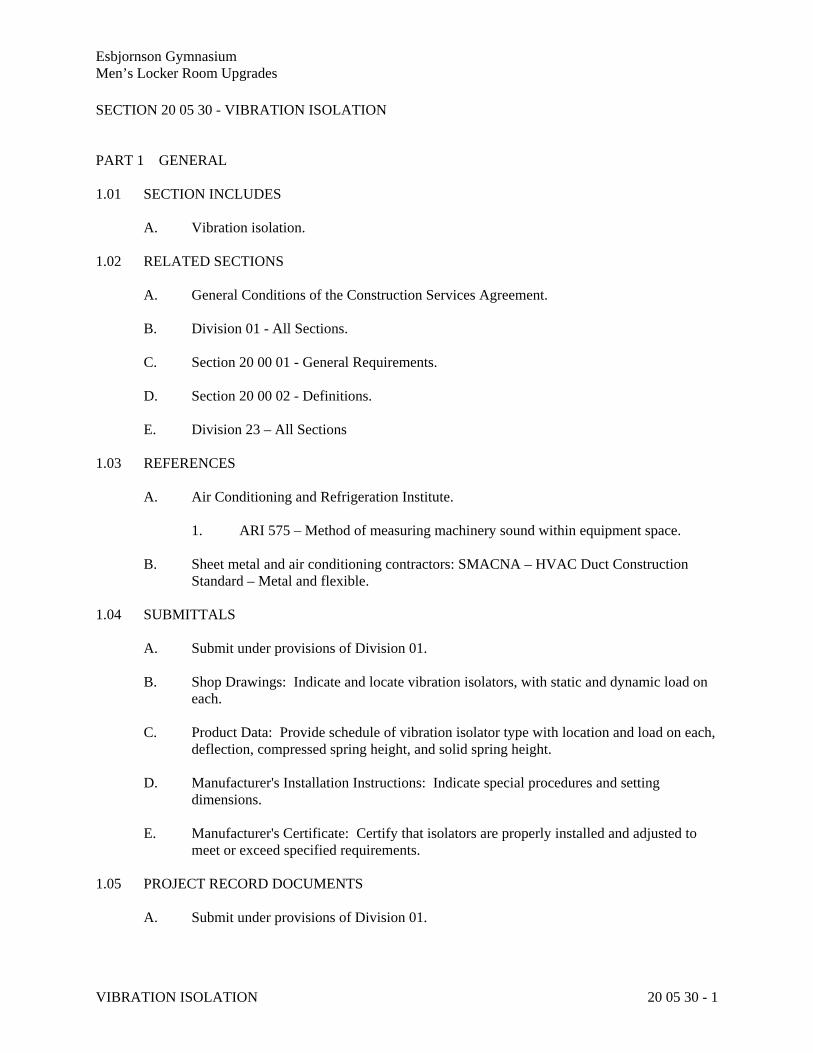
Esbjornson Gymnasium Men’s Locker Room Upgrades
VIBRATION ISOLATION 20 05 30 - 1
SECTION 20 05 30 - VIBRATION ISOLATION PART 1 GENERAL 1.01 SECTION INCLUDES
A. Vibration isolation. 1.02 RELATED SECTIONS
A. General Conditions of the Construction Services Agreement.
B. Division 01 - All Sections. C. Section 20 00 01 - General Requirements. D. Section 20 00 02 - Definitions. E. Division 23 – All Sections
1.03 REFERENCES
A. Air Conditioning and Refrigeration Institute.
1. ARI 575 – Method of measuring machinery sound within equipment space.
B. Sheet metal and air conditioning contractors: SMACNA – HVAC Duct Construction Standard – Metal and flexible.
1.04 SUBMITTALS
A. Submit under provisions of Division 01.
B. Shop Drawings: Indicate and locate vibration isolators, with static and dynamic load on each.
C. Product Data: Provide schedule of vibration isolator type with location and load on each,
deflection, compressed spring height, and solid spring height. D. Manufacturer's Installation Instructions: Indicate special procedures and setting
dimensions. E. Manufacturer's Certificate: Certify that isolators are properly installed and adjusted to
meet or exceed specified requirements. 1.05 PROJECT RECORD DOCUMENTS
A. Submit under provisions of Division 01.
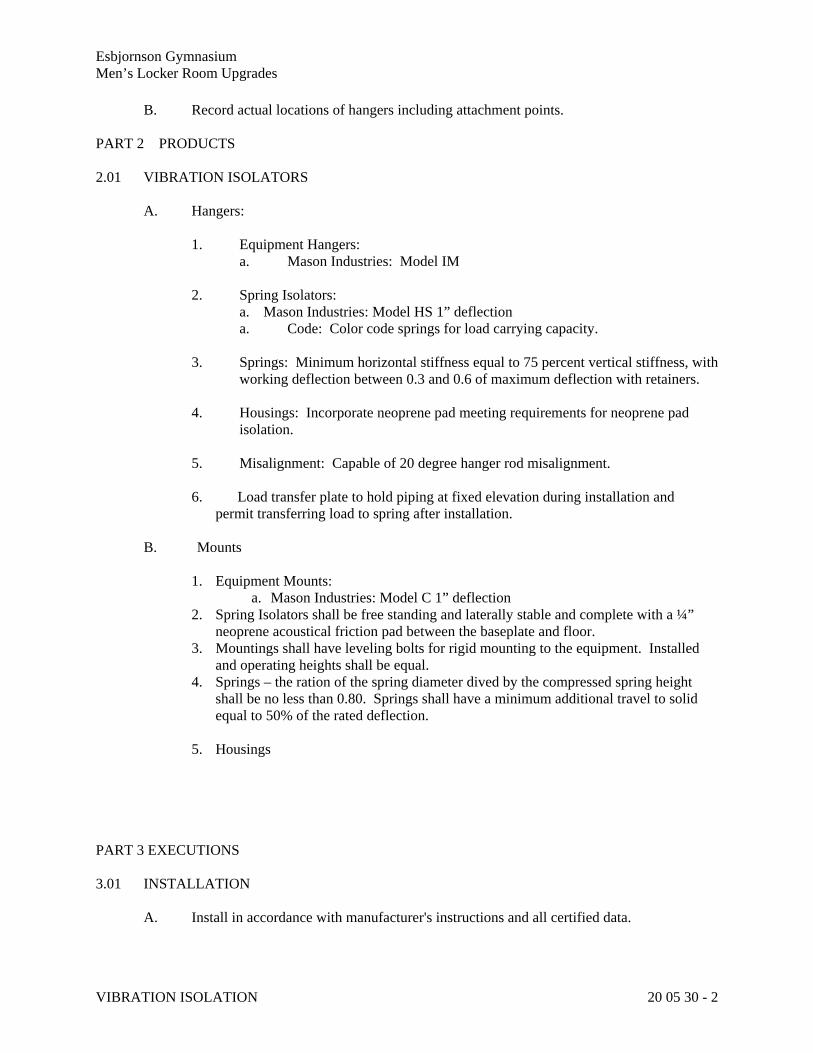
Esbjornson Gymnasium Men’s Locker Room Upgrades
VIBRATION ISOLATION 20 05 30 - 2
B. Record actual locations of hangers including attachment points. PART 2 PRODUCTS 2.01 VIBRATION ISOLATORS
A. Hangers:
1. Equipment Hangers: a. Mason Industries: Model IM
2. Spring Isolators:
a. Mason Industries: Model HS 1” deflection a. Code: Color code springs for load carrying capacity.
3. Springs: Minimum horizontal stiffness equal to 75 percent vertical stiffness, with working deflection between 0.3 and 0.6 of maximum deflection with retainers.
4. Housings: Incorporate neoprene pad meeting requirements for neoprene pad
isolation.
5. Misalignment: Capable of 20 degree hanger rod misalignment.
6. Load transfer plate to hold piping at fixed elevation during installation and permit transferring load to spring after installation.
B. Mounts
1. Equipment Mounts:
a. Mason Industries: Model C 1” deflection 2. Spring Isolators shall be free standing and laterally stable and complete with a ¼”
neoprene acoustical friction pad between the baseplate and floor. 3. Mountings shall have leveling bolts for rigid mounting to the equipment. Installed
and operating heights shall be equal. 4. Springs – the ration of the spring diameter dived by the compressed spring height
shall be no less than 0.80. Springs shall have a minimum additional travel to solid equal to 50% of the rated deflection.
5. Housings
PART 3 EXECUTIONS 3.01 INSTALLATION
A. Install in accordance with manufacturer's instructions and all certified data.

Esbjornson Gymnasium Men’s Locker Room Upgrades
VIBRATION ISOLATION 20 05 30 - 3
B. Install spring hangers without binding. Installation shall not cause the change of position of equipment, piping, or duct work resulting in misalignment.
C. No rigid connections between equipment and the building structure shall be made that
degrades the noise and vibration control system D. Prior to making piping connections to equipment with operating weights substantially
different from installed weights, block up equipment with temporary shims to final height. When full load is applied, adjust isolators to load to allow shim removal.
E. Install spring type hangers on all piping systems at connections to rotating equipment.
Continue spring type hanger supports for a minimum of 5 supports upstream and downstream of the equipment or 40 pipe diameters of run, whichever is greater.
3.02 MANUFACTURER'S FIELD SERVICES
A. Provide field supervision to assure correct installation and alignment. B. Inspect isolated equipment after installation and submit report. Include static deflections.
END OF SECTION

Esbjornson Gymnasium Men’s Locker Room Upgrades
IDENTIFICATION FOR PIPING AND EQUIPMENT 20 05 53 - 1
SECTION 20 05 53 - IDENTIFICATION FOR PIPING AND EQUIPMENT
PART 1 GENERAL
1.1 SUMMARY
A. Section Includes: 1. Nameplates. 2. Tags. 3. Stencils. 4. Pipe markers. 5. Ceiling tacks. 6. Labels. 7. Lockout devices.
1.2 REFERENCES
A. American Society of Mechanical Engineers: 1. ASME A13.1 - Scheme for the Identification of Piping Systems.
1.3 SUBMITTALS
A. Section 01 33 00 - Submittal Procedures: Submittal procedures.
B. Product Data: Submit manufacturers catalog literature for each product required.
C. Shop Drawings: Submit list of wording, symbols, letter size, and color coding for mechanical identification and valve chart and schedule, including valve tag number, location, function, and valve manufacturer's name and model number.
D. Samples: None required.
E. Manufacturer's Installation Instructions: Indicate installation instructions, special procedures, and installation.
F. Manufacturer's Certificate: Certify products meet or exceed specified requirements.
1.4 CLOSEOUT SUBMITTALS
A. Section 01 70 00 - Execution and Closeout Requirements: Closeout procedures.
B. Project Record Documents: Record actual locations of tagged valves; include valve tag numbers.
1.5 QUALITY ASSURANCE
A. Conform to ASME A13.1 for color scheme for identification of piping systems and accessories.
B. Maintain one copy of each document on site.
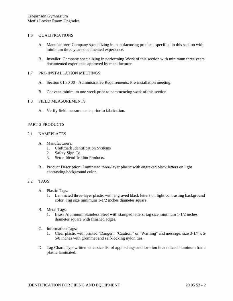
Esbjornson Gymnasium Men’s Locker Room Upgrades
IDENTIFICATION FOR PIPING AND EQUIPMENT 20 05 53 - 2
1.6 QUALIFICATIONS
A. Manufacturer: Company specializing in manufacturing products specified in this section with minimum three years documented experience.
B. Installer: Company specializing in performing Work of this section with minimum three years documented experience approved by manufacturer.
1.7 PRE-INSTALLATION MEETINGS
A. Section 01 30 00 - Administrative Requirements: Pre-installation meeting.
B. Convene minimum one week prior to commencing work of this section.
1.8 FIELD MEASUREMENTS
A. Verify field measurements prior to fabrication.
PART 2 PRODUCTS
2.1 NAMEPLATES
A. Manufacturers: 1. Craftmark Identification Systems 2. Safety Sign Co. 3. Seton Identification Products.
B. Product Description: Laminated three-layer plastic with engraved black letters on light contrasting background color.
2.2 TAGS
A. Plastic Tags: 1. Laminated three-layer plastic with engraved black letters on light contrasting background
color. Tag size minimum 1-1/2 inches diameter square.
B. Metal Tags: 1. Brass Aluminum Stainless Steel with stamped letters; tag size minimum 1-1/2 inches
diameter square with finished edges.
C. Information Tags: 1. Clear plastic with printed "Danger," "Caution," or "Warning" and message; size 3-1/4 x 5-
5/8 inches with grommet and self-locking nylon ties.
D. Tag Chart: Typewritten letter size list of applied tags and location in anodized aluminum frame plastic laminated.

Esbjornson Gymnasium Men’s Locker Room Upgrades
IDENTIFICATION FOR PIPING AND EQUIPMENT 20 05 53 - 3
2.3 STENCILS
A. Stencils: With clean cut symbols and letters of following size: 1. Up to 2 inches Outside Diameter of Insulation or Pipe: 1/2 inch high letters. 2. 2-1/2 to 6 inches Outside Diameter of Insulation or Pipe: 1-inch high letters. 3. Over 6 inches Outside Diameter of Insulation or Pipe: 1-3/4 inches high letters. 4. Ductwork and Equipment: 1-3/4 inches high letters.
B. Stencil Paint: As specified in Section 09 90 00, semi-gloss enamel, colors and lettering size conforming to ASME A13.1.
2.4 PIPE MARKERS
A. Color and Lettering: Conform to ASME A13.1. 1. Factory fabricated, flexible, semi-rigid plastic, preformed to fit around pipe or pipe covering.
Larger sizes may have maximum sheet size with spring fastener.
B. Plastic Tape Pipe Markers: 1. Flexible, vinyl film tape with pressure sensitive adhesive backing and printed markings.
2.5 CEILING TACKS
A. Description: Steel with 3/4 inch diameter color-coded head.
B. Color code as follows: 1. HVAC equipment: Yellow. 2. Fire dampers/smoke dampers: Red. 3. Plumbing valves: Green. 4. Heating/cooling valves: Blue.
2.6 LABELS
A. Description: Aluminum Polyester Laminated Mylar, size 1.9 x 0.75 inches, adhesive backed with printed identification and bar code.
2.7 LOCKOUT DEVICES 1. Anodized aluminum Reinforced nylon hasp with erasable label surface; size minimum 7-1/4
x 3 inches.
B. Valve Lockout Devices: 1. Nylon Steel Plastic device preventing access to valve operator, accepting lock shackle.
PART 3 EXECUTION
3.1 PREPARATION
A. Degrease and clean surfaces to receive adhesive for identification materials.

Esbjornson Gymnasium Men’s Locker Room Upgrades
IDENTIFICATION FOR PIPING AND EQUIPMENT 20 05 53 - 4
B. Prepare surfaces in accordance with Section 09 90 00 for stencil painting.
3.2 INSTALLATION
B.A. Install identifying devices after completion of coverings and painting.
C.B. Install plastic nameplates with corrosive-resistant mechanical fasteners, or adhesive.
D.C. Install labels with sufficient adhesive for permanent adhesion and seal with clear lacquer. For unfinished canvas covering, apply paint primer before applying labels.
D. Install tags using corrosion resistant chain. Number tags consecutively by location.
E. Identify air handling units, pumps, heat transfer equipment, tanks, and water treatment devices with plastic nameplates. Identify in-line pumps and other small devices with tags.
F. Identify control panels and major control components outside panels with plastic nameplates.
G. Identify valves with tags.
H. Tag automatic controls, instruments, and relays. Key to control schematic.
I. Identify piping, concealed or exposed, with plastic pipe markers plastic tape pipe markers. Use tags on piping 3/4 inch diameter and smaller. Identify service, flow direction, and pressure. Install in clear view and align with axis of piping. Locate identification not to exceed 20 feet on straight runs including risers and drops, adjacent to each valve and tee, at each side of penetration of structure or enclosure, and at each obstruction.
J. Identify ductwork with plastic nameplates. Identify with air handling unit identification number and area served. Locate identification at air handling unit, at each side of penetration of structure or enclosure, and at each obstruction.
K. Provide ceiling tacks to locate valves or dampers above T-bar type panel ceilings. Locate in corner of panel closest to equipment. Coordinate with Architect PRIOR to installing tacks.
END OF SECTION

Esbjornson Gymnasium Men’s Locker Room Upgrades
PIPING INSULATION 20 07 00 - 1
SECTION 20 07 00 - PIPING INSULATION PART 1 - GENERAL 1.01 SECTION INCLUDES
A. Piping insulation.
B. Jackets and accessories.
C. Insulation accessories. 1.02 RELATED SECTIONS
A. General Conditions of the Construction Service Agreement.
B. Division 00 and 01 - All Sections.
C. Section 20 00 01 - General Requirements.
D. Section 20 00 02 - Definitions.
E. Section 20 05 29 Hangers and Supports
F. Section 20 05 53 Identification for Piping and Equipment
G. Section 23 21 13 - Hydronic Piping. 1.03 REFERENCES
A. ASTM B209 - Aluminum and Aluminum-Alloy Sheet and Plate.
B. ASTM C177 - Steady-State Heat Flux Measurements and Thermal Transmission Properties by Means of the Guarded-Hot- Plate Apparatus.
C. ASTM C195 - Mineral Fiber Thermal Insulation Cement.
D. ASTM C335 - Steady-State Heat Transfer Properties of Horizontal Pipe Insulation.
E. ASTM C449 - Mineral Fiber Hydraulic-setting Thermal Insulating and Finishing
Cement.
F. ASTM C518 - Steady-State Heat Flux Measurements and Thermal Transmission Properties by Means of the Heat Flow Meter Apparatus.
G. ASTM C533 - Calcium Silicate Block and Pipe Thermal Insulation.

Esbjornson Gymnasium Men’s Locker Room Upgrades
PIPING INSULATION 20 07 00 - 2
H. ASTM C534 - Performed Flexible Elastomeric Cellular Thermal Insulation in Sheet and Tubular Form.
I. ASTM C547 - Mineral Fiber Performed Pipe Insulation.
J. ASTM C552 – Standard Specification for Cellular Glass Thermal Insulation.
K. ASTM C553 – Standard Specification for Mineral Fiber Blanket Thermal.
L. ASTM C585 - Inner and Outer Diameters of Rigid Thermal Insulation for Nominal Sizes
of Pipe and Tubing (NPS Sys tem).
M. ASTM C921 - Properties of Jacketing Materials for Thermal Insulation.
N. ASTM D1056 - Flexible Cellular Materials - Sponge or Expanded Rubber.
O. ASTM D1667 - Flexible Cellular Materials - Vinyl Chloride Polymers and Copolymers (Closed Cell Foam).
P. ASTM E84 - Surface Burning Characteristics of Building Materials.
Q. ASTM E96 - Water Vapor Transmission of Materials.
R. NFPA 255 - Surface Burning Characteristics of Building Materials.
S. UL 723 - Surface Burning Characteristics of Building Materials.
1.04 SUBMITTALS
A. Submit under provisions of Division 1.
B. Product Data: Provide product description, list of materials and thickness for each service, and locations.
C. Samples: Submit one sample illustrating each insulation type including mastic coatings
and adhesives.
D. Manufacturer's Installation Instructions: Indicate procedures which ensure acceptable workmanship and installation standards will be achieved.
1.05 QUALITY ASSURANCE
A. Materials: Flame spread/smoke developed rating of 25/50 or less in accordance with NFPA 255.
1.06 QUALIFICATIONS
A. Applicator: Company specializing in performing the work of this section with minimum three years experience.

Esbjornson Gymnasium Men’s Locker Room Upgrades
PIPING INSULATION 20 07 00 - 3
1.07 DELIVERY, STORAGE, AND HANDLING
A. Deliver, store, protect, and handle products to site under provisions of Division 00 and 01.
B. Deliver materials to site in original factory packaging, labeled with manufacturer's
identification including product density and thickness.
C. Store insulation in original wrapping and protect from weather and construction traffic.
D. Protect insulation against dirt, water, chemical, and mechanical damage. 1.08 ENVIRONMENTAL REQUIREMENTS
A. Maintain ambient temperatures and conditions required by manufacturers of adhesives, mastics, and insulation cements.
B. Maintain temperature during and after installation for minimum period of 24 hours.
1.09 WARRANTY
A. Division 1 – Execution Requirements: Product warranties and product bonds. B. Furnish five (5) year manufacturer warranty for man-made fiber.
PART 2 - PRODUCTS 2.1 GLASS FIBER
A. Manufacturers:
1. Standard of Design and Construction: a. Schuller - Micro-Lok.
2. Acceptable Manufacturers: Refer to Section 20 00 01, Article 1.13 Substitutions.
a. Knauf. b. Owens-Corning.
B. Insulation: ASTM C547; rigid molded, noncombustible.
1. "K" Value: ASTM C335, 0.24 at 75ºF. 2. Minimum Service Temperature: -20ºF. 3. Maximum Service Temperature: 850ºF. 4. Maximum Moisture Absorption: 0.2 percent by volume. 5. Density: 4 pounds per cubic foot.
C. Insulation: ASTM C165; Flexible Board Type Insulation

Esbjornson Gymnasium Men’s Locker Room Upgrades
PIPING INSULATION 20 07 00 - 4
A. “K” Valve ASTM C335, 0.27 at 75ºF. B. Minimum Service Temperature – 20ºF.
C. Maximum Service Temperature – 650ºF.
D. Maximum Moisture Absorption – 0.2 percent by volume.
E. Density: Three (3) pounds per cubic feet.
D. Factory Applied Vapor Barrier Jacket:
1. ASTM C921, White Kraft paper reinforced with glass fiber yarn and bonded to aluminized film, suitable for field painting.
2. Moisture Vapor Transmission: ASTM E96; 0.02 perm inches. 3. Secure with self-sealing longitudinal laps and butt strips.
E. Vapor Barrier Lap Adhesive:
1. Foster Spark-FAS 85-20 adhesive. 2. Compatible with insulation.
F. Vapor Barrier/Lagging Adhesive:
1. Foster Monolar 60 Series Mastic with custom color selection. 2. ASTM C195; hydraulic setting on mineral wool.
G. Field Applied Jacket Fabric:
1. Foster Mast-A-Fab Membrane. 2. Cloth: NFPA 90A and 90B, minimum 9 oz./sq. yd.
2.02 CELLULAR FOAM
A. Manufacturers:
1. Standard of Design and Construction: a. Armstrong AP Armaflex.
B. Insulation: ASTM C534; flexible, cellular elastomeric, molded or sheet.
1. ‘K’ (‘ksi’) Value: ASTM C177 or C518; 0.27 at 75ºF. 2. Minimum Service Temperature: -40ºF. 3. Maximum Service Temperature: 220ºF. 4. Maximum Moisture Absorption: ASTM D1056; 5.0 percent (pipe) weight. 5. Moisture Vapor Transmission: ASTM E96; 0.20 perm inches.
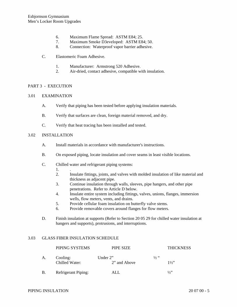
Esbjornson Gymnasium Men’s Locker Room Upgrades
PIPING INSULATION 20 07 00 - 5
6. Maximum Flame Spread: ASTM E84; 25. 7. Maximum Smoke D3eveloped: ASTM E84; 50. 8. Connection: Waterproof vapor barrier adhesive.
C. Elastomeric Foam Adhesive.
1. Manufacturer: Armstrong 520 Adhesive. 2. Air-dried, contact adhesive, compatible with insulation.
PART 3 - EXECUTION 3.01 EXAMINATION
A. Verify that piping has been tested before applying insulation materials.
B. Verify that surfaces are clean, foreign material removed, and dry.
C. Verify that heat tracing has been installed and tested. 3.02 INSTALLATION
A. Install materials in accordance with manufacturer's instructions.
B. On exposed piping, locate insulation and cover seams in least visible locations.
C. Chilled water and refrigerant piping systems: 1. . 2. Insulate fittings, joints, and valves with molded insulation of like material and
thickness as adjacent pipe. 3. Continue insulation through walls, sleeves, pipe hangers, and other pipe
penetrations. Refer to Article D below. 4. Insulate entire system including fittings, valves, unions, flanges, immersion
wells, flow meters, vents, and drains. 5. Provide cellular foam insulation on butterfly valve stems. 6. Provide removable covers around flanges for flow meters.
D. Finish insulation at supports (Refer to Section 20 05 29 for chilled water insulation at
hangers and supports), protrusions, and interruptions. 3.03 GLASS FIBER INSULATION SCHEDULE
PIPING SYSTEMS PIPE SIZE THICKNESS
A. Cooling: Under 2” ½ “ Chilled Water: 2” and Above 1½”
B. Refrigerant Piping: ALL ½”

Esbjornson Gymnasium Men’s Locker Room Upgrades
PIPING INSULATION 20 07 00 - 6
END OF SECTION

Esbjornson Gymnasium Men’s Locker Room Upgrades
COMMON WORK RESULTS FOR FIRE SUPPRESSION 21 05 00 - 1
SECTION 21 05 00 - COMMON WORK RESULTS FOR FIRE SUPPRESSION
PART 1 GENERAL
1.1 SUMMARY
A. Section includes pipe, fittings, valves, and connections for sprinkler systems.
B. Related Sections: 1. Division 20 – All Sections
1.2 REFERENCES
A. American Society of Mechanical Engineers: 1. ASME B16.1 - Cast Iron Pipe Flanges and Flanged Fittings. 2. ASME B16.11 - Forged Steel Fittings - Socket-Welding and Threaded. 3. ASME B16.25 - Buttwelding Ends. 4. ASME B16.3 - Malleable Iron Threaded Fittings. 5. ASME B16.4 - Gray Iron Threaded Fittings. 6. ASME B16.5 - Pipe Flanges and Flanged Fittings. 7. ASME B16.9 - Factory-Made Wrought Steel Buttwelding Fittings. 8. ASME B36.10M - Welded and Seamless Wrought Steel Pipe.
B. ASTM International: 1. ASTM A53/A53M - Standard Specification for Pipe, Steel, Black and Hot-Dipped, Zinc-
Coated, Welded and Seamless. 2. ASTM A135 - Standard Specification for Electric-Resistance-Welded Steel Pipe. 3. ASTM A234/A234M - Standard Specification for Piping Fittings of Wrought Carbon Steel
and Alloy Steel for Moderate and High Temperature Service. 4. ASTM A795/A795M - Standard Specification for Black and Hot-Dipped Zinc-Coated
(Galvanized) Welded and Seamless Steel Pipe for Fire Protection Use.
C. American Welding Society: 1. AWS A5.8 - Specification for Filler Metals for Brazing and Braze Welding. 2. AWS D1.1 - Structural Welding Code - Steel.
D. National Fire Protection Association: 1. NFPA 13 - Installation of Sprinkler Systems.
E. Underwriter Laboratories, Inc.: 1. UL 1887 - Fire Tests of Plastic Sprinkler Pipe for Visible Flame and Smoke Characteristics.
1.3 SUBMITTALS
A. Section 01 33 00 - Submittal Procedures: Submittal procedures.
Esbjornson Gymnasium Men’s Locker Room Upgrades
COMMON WORK RESULTS FOR FIRE SUPPRESSION 21 05 00 - 2
B. Shop Drawings: Indicate pipe materials used, jointing methods, supports, and floor and wall penetration seals. Indicate installation, layout, weights, mounting and support details, and piping connections.
C. Product Data: Submit manufacturers’ catalogue information. Indicate valve data and ratings.
D. Manufacturer's Certificate: Certify products meet or exceed specified requirements.
1.4 CLOSEOUT SUBMITTALS
A. Section 01 70 00 - Execution and Closeout Requirements: Closeout procedures.
B. Project Record Documents: Record actual locations of components and tag numbering.
C. Operation and Maintenance Data: Submit spare parts lists.
1.5 QUALITY ASSURANCE
A. Provide fire sprinkler piping located in plenums with peak optical density not greater than 0.5, average optical density not greater than 0.15, and flame spread not greater than 5 feet (1.5 m) when tested in accordance with UL 1887.
B. Perform Work in accordance with NFPA 13, City of Philadelphia codes and University of Pennsylvania standards.
1.6 QUALIFICATIONS
A. Manufacturer: Company specializing in manufacturing products specified in this section with minimum three years documented experience.
B. Installer: Company specializing in performing Work of this section with minimum three years documented] experience.
1.7 DELIVERY, STORAGE, AND HANDLING
A. Section 01 60 00 - Product Requirements: Product storage and handling requirements.
B. Deliver and store valves in shipping containers, with labeling in place.
C. Furnish cast iron and steel valves with temporary protective coating.
D. Furnish temporary end caps and closures on piping and fittings. Maintain in place until installation.
1.8 WARRANTY
A. Section 01 70 00 - Execution and Closeout Requirements: Product warranties and product bonds.

Esbjornson Gymnasium Men’s Locker Room Upgrades
COMMON WORK RESULTS FOR FIRE SUPPRESSION 21 05 00 - 3
PART 2 PRODUCTS
2.1 ABOVE GROUND PIPING
A. Steel Pipe: ASTM A53, threaded, Schedule 40 black, seamless. 1. Steel Fittings: ASME B16.9, wrought steel, butt welded; ASME B16.5, steel flanges and
fittings; ASME B16.11, forged steel socket welded and threaded. 2. Malleable Iron Fittings: ASME B16.3, threaded fittings, ASTM B47. 3. Mechanical Grooved Couplings: Malleable iron housing clamps to engage and lock, "C"
shaped elastomeric sealing gasket, steel bolts, nuts, and washers; galvanized for galvanized pipe.
4. Mechanical Formed Fittings: Carbon-steel housing with integral pipe stop and O-ring pocked and O-ring uniformly compressed into permanent mechanical engagement onto pipe.
2.2 PIPE HANGERS AND SUPPORTS
A. Conform to NFPA 13.
B. Hangers for Pipe Sizes 1/2 to 1-1/2 inch: Carbon steel, adjustable swivel, split ring.
C. Hangers for Pipe Sizes 2 inch and Over: Carbon steel, adjustable, clevis.
D. Multiple or Trapeze Hangers: Steel channels with welded spacers and hanger rods.
E. Wall Support for Pipe Sizes to 3 inches: Cast iron hook.
F. Wall Support for Pipe Sizes 4 inches and Over: Welded steel bracket and wrought steel clamp.
G. Vertical Support: Steel riser clamp.
H. Floor Support: Cast iron adjustable pipe saddle, lock nut, nipple, floor flange, and concrete pier or steel support.
PART 3 EXECUTION
3.1 PREPARATION
A. Ream pipe and tube ends. Remove burrs. Bevel plain end ferrous pipe.
B. Remove scale and foreign material, from inside and outside, before assembly.
C. Prepare piping connections to equipment with flanges or unions.
3.2 INSTALLATION
A. Install piping in accordance with NFPA 13 for sprinkler systems.

Esbjornson Gymnasium Men’s Locker Room Upgrades
COMMON WORK RESULTS FOR FIRE SUPPRESSION 21 05 00 - 4
B. Route piping in orderly manner, plumb and parallel to building structure. Maintain gradient.
C. Install piping to conserve building space, to not interfere with use of space and other work.
D. Group piping whenever practical at common elevations.
E. Install pipe sleeve at piping penetrations through partitions, walls, and floors. Seal pipe and sleeve penetrations to maintain fire resistance equivalent to fire separation.
F. Install piping to allow for expansion and contraction without stressing pipe, joints, or connected equipment.
G. Pipe Hangers and Supports: 1. Install in accordance with NFPA 13. 2. Install hangers to with minimum 1/2 inch space between finished covering and adjacent
work. 3. Place hangers within 12 inches of each horizontal elbow. 4. Use hangers with 1-1/2 inch minimum vertical adjustment. Design hangers for pipe
movement without disengagement of supported pipe. 5. Support vertical piping at every floor. Support riser piping independently of connected
horizontal piping. 6. Where installing several pipes in parallel and at same elevation, provide multiple or trapeze
hangers. 7. Prime coat exposed steel hangers and supports. [Refer to Section 09 90 00.] Hangers and
supports located in crawl spaces, pipe shafts, and suspended ceiling spaces are not considered exposed.
H. Slope piping and arrange systems to drain at low points. Install eccentric reducers to maintain top of pipe level.
I. Prepare pipe, fittings, supports, and accessories for finish painting. Where pipe support members are welded to structural building framing, scrape, brush clean, and apply one coat of zinc rich primer to welding. Refer to Section 09 90 00.
J. Do not penetrate building structural members unless indicated.
K. Where more than one piping system material is specified, install compatible system components and joints. Install flanges, union, and couplings at locations requiring servicing.
L. Die cut threaded joints with full cut standard taper pipe threads with red lead and linseed oil or other non-toxic joint compound applied to male threads only.
M. Install drain valves at main shut-off valves, low points of piping and apparatus.
3.3 INTERFACE WITH OTHER PRODUCTS
A. Inserts: 1. Install inserts for placement in concrete forms.

Esbjornson Gymnasium Men’s Locker Room Upgrades
COMMON WORK RESULTS FOR FIRE SUPPRESSION 21 05 00 - 5
2. Install inserts for suspending hangers from reinforced concrete slabs and sides of reinforced concrete beams.
3. Install hooked rod to concrete reinforcement section for inserts carrying pipe over 4 inches. 4. Where concrete slabs form finished ceiling, locate inserts flush with slab surface.
3.4 CLEANING
A. Section 01 70 00 - Execution and Closeout Requirements: Final cleaning.
B. Clean entire system after other construction is complete.
END OF SECTION

Esbjornson Gymnasium Men’s Locker Room Upgrades
WET-PIPE SPRINKLER SYSTEMS 21 13 13 - 1
SECTION 21 13 13 - WET-PIPE SPRINKLER SYSTEMS
PART 1 GENERAL
1.1 SUMMARY
A. Section includes wet-pipe sprinkler system, system design, installation, and certification.
1.2 REFERENCES
A. National Fire Protection Association: 1. NFPA 13 - Installation of Sprinkler Systems.
1.3 SYSTEM DESCRIPTION
A. System to provide coverage for building areas indicated on the drawings.
B. Provide hydraulically designed system to NFPA 13 light hazard, occupancy requirements.
C. Determine volume and pressure of incoming water supply from water flow test data.
D. Interface system with building fire alarm system.
1.4 SUBMITTALS
A. Shop Drawings: Indicate layout of finished ceiling areas indicating sprinkler locations coordinated with ceiling installation. Indicate detailed pipe layout, hangers and supports, sprinklers, components and accessories. Indicate system controls.
B. Product Data: Submit data on sprinklers, valves, and specialties, including manufacturers catalog information. Submit performance ratings, rough-in details, weights, support requirements, and piping connections.
C. Design Data: Submit design calculations signed and sealed by professional engineer and NICET Level 3 technician.
D. Manufacturer's Certificate: Certify products meet or exceed specified requirements.
1.5 CLOSEOUT SUBMITTALS
A. Section 01 70 00 - Execution and Closeout Requirements: Closeout procedures.
B. Project Record Documents: Record actual locations of sprinklers and deviations of piping from drawings. Indicate drain and test locations.
C. Operation and Maintenance Data: Submit components of system, servicing requirements, record drawings, inspection data, replacement part numbers and availability, and location and numbers of service depot.

Esbjornson Gymnasium Men’s Locker Room Upgrades
WET-PIPE SPRINKLER SYSTEMS 21 13 13 - 2
1.6 QUALITY ASSURANCE
A. Perform Work in accordance with NFPA 13, City of Philadelphia Codes, Factory Mutual, and University of Pennsylvania standards.
1.7 QUALIFICATIONS
A. Manufacturer: Company specializing in manufacturing products specified in this section with minimum three years documented experience.
B. Installer: Company specializing in performing Work of this section with minimum three years documented experience approved by manufacturer.
1.8 DELIVERY, STORAGE, AND HANDLING
A. Store products in shipping containers until installation.
B. Furnish piping with temporary inlet and outlet caps until installation.
PART 2 PRODUCTS
2.1 SPRINKLERS
A. Manufacturers: 1. Standard of Design and Construction – VK462 and VK300 2. Grinnell Corp. 3. Substitutions: Not Permitted.
B. Suspended Ceiling Type: 1. Type: Quick response concealed pendant type with matching screw on escutcheon plate. 2. Finish: Chrome plated. 3. Escutcheon Plate Finish: Enamel, color as selected by Architect. 4. Fusible Link: Fusible solder link type temperature rated for specific area hazard.
C. Exposed Area Type: 1. Type: Quick response upright type (with guard in Mechanical Areas). 2. Finish: Brass 3. Fusible Link: Fusible-solder link type temperature rated for specific area hazard.
D. Guards: Finish to match sprinkler finish.
PART 3 EXECUTION
3.1 INSTALLATION
A. Install in accordance with NFPA 13, Factory Mutual, State of New Jersey Codes, and Rowan University standards.
Esbjornson Gymnasium Men’s Locker Room Upgrades
WET-PIPE SPRINKLER SYSTEMS 21 13 13 - 3
B. Place pipe runs to minimize obstruction to other work.
C. Install piping in concealed spaces above finished ceilings.
D. Center sprinklers in two directions in ceiling tile and install piping offsets.
E. Install guards on sprinklers.
F. Hydrostatically test entire system.
G. Require test be witnessed by Owner and Fire Marshall.
3.2 INTERFACE WITH OTHER PRODUCTS
A. Verify signal devices are installed and connected to fire alarm system.
3.3 CLEANING
A. Section 01 70 00 - Execution and Closeout Requirements: Final cleaning.
B. Flush entire piping system of foreign matter.
3.4 PROTECTION OF INSTALLED CONSTRUCTION
A. Section 01 70 00 - Execution and Closeout Requirements: Protecting installed construction.
B. Apply masking tape or paper cover to protect concealed sprinklers, cover plates, and sprinkler escutcheons not receiving field paint finish. Remove after painting. Replace painted sprinklers with new.
END OF SECTION

Esbjornson Gymnasium Men’s Locker Room Upgrades
TESTING, ADJUSTING, AND BALANCING 23 05 93 - 1
SECTION 23 05 93 - TESTING, ADJUSTING, AND BALANCING
PART 1 GENERAL
1.1 SUMMARY
A. Section Includes: 1. Testing, adjusting, and balancing of air systems. 2. Testing, adjusting, and balancing of hydronic systems. 3. Measurement of final operating condition of HVAC systems. 4. Sound measurement of equipment operating conditions. 5. Vibration measurement of equipment operating conditions. 6. Written documentation and reports of above testing, adjusting, balancing, and
measurements.
B. Related Sections: 1. Section 23 09 23 - Direct-Digital Control System for HVAC: Requirements for
coordination between DDC system and testing, adjusting, and balancing work. 2. Section 23 09 93 - Sequence of Operations for HVAC Controls: Sequences of
operation for HVAC equipment.
1.2 REFERENCES
A. Associated Air Balance Council: 1. AABC MN-1 - National Standards for Testing and Balancing Heating, Ventilating,
and Air Conditioning Systems.
B. American Society of Heating, Refrigerating and Air-Conditioning Engineers: 1. ASHRAE 111 - Practices for Measurement, Testing, Adjusting and Balancing of
Building Heating, Ventilation, Air-Conditioning and Refrigeration Systems.
C. Natural Environmental Balancing Bureau: 1. NEBB - Procedural Standards for Testing, Adjusting, and Balancing of
Environmental Systems.
1.3 SUBMITTALS
A. Section 01 33 00 - Submittal Procedures: Submittal procedures.
B. Prior to commencing Work, submit proof of latest calibration date of each instrument and proof AABC or NEBB technician certification for all field balancing technicians who will be performing the work and completing reports.
C. Test Reports: Indicate data on AABC MN-1 National Standards for Total System Balance forms or NEBB Report forms.
D. Field Reports: Indicate deficiencies preventing proper testing, adjusting, and balancing of systems and equipment to achieve specified performance.

Esbjornson Gymnasium Men’s Locker Room Upgrades
TESTING, ADJUSTING, AND BALANCING 23 05 93 - 2
E. Prior to commencing Work, submit report forms or outlines indicating adjusting, balancing, and equipment data required. Include detailed procedures, agenda, sample report forms, and copy of AABC National Project Performance Guaranty or copy of NEBB Certificate of Conformance Certification
F. Submit draft copies of report for review prior to final acceptance of Project.
G. Furnish Four (4) original reports in 3-ring binder manuals, complete with table of contents page and indexing tabs, with cover identification at front and side. Include set of reduced drawings with air outlets and equipment identified to correspond with data sheets, and indicating thermostat locations.
1.4 CLOSEOUT SUBMITTALS
A. Project Record Documents: Record actual locations of dampers, and balancing valves including rough and final settings.
B. Operation and Maintenance Data: Furnish final copy of testing, adjusting, and balancing report inclusion in operating and maintenance manuals.
1.5 QUALITY ASSURANCE
A. Perform Work in accordance with AABC MN-1 National Standards for Field Measurement and Instrumentation, Total System Balance or NEBB Procedural Standards for Testing, Balancing and Adjusting of Environmental Systems.
B. Maintain one copy of each document on site.
C. Prior to commencing Work, calibrate each instrument to be used. Upon completing Work, recalibrate each instrument to assure reliability. Submit calibration certificates.
1.6 QUALIFICATIONS
A. Agency: Company specializing in testing, adjusting, and balancing of systems specified in this section with minimum five (5) years documented experience certified by AABC or NEBB.
B. Perform Work under supervision of AABC Certified Test and Balance Engineer or NEBB Certified Testing, Balancing and Adjusting Supervisor.
1.7 PRE-INSTALLATION MEETINGS
A. Convene minimum one week prior to commencing work of this section.
1.8 SEQUENCING
A. Sequence balancing between completion of systems tested and Date of Substantial Completion.
Esbjornson Gymnasium Men’s Locker Room Upgrades
TESTING, ADJUSTING, AND BALANCING 23 05 93 - 3
PART 2 PRODUCTS
Not Used.
PART 3 EXECUTION
3.1 EXAMINATION
A. Verify systems are complete and operable before commencing work. Verify the following: 1. Systems are started and operating in safe and normal condition. 2. Control instrumentation and control devices are wired and powered. 3. Temperature control systems are installed complete and operable. 4. Proper thermal overload protection is in place for electrical equipment. 5. Final filters are clean and in place. If required, install temporary media in addition to
final filters. 6. Duct systems are clean of debris. 7. Fans are rotating correctly. 8. Volume and automatic dampers are in place and open. 9. Air coil fins are cleaned and combed. 10. Access doors are closed and duct end caps are in place. 11. Air outlets are installed and connected. 12. Duct system leakage is minimized. 13. Hydronic systems are flushed, filled, and vented. 14. Pumps are rotating correctly. 15. Proper strainer baskets are clean and in place or in normal position. 16. Service and balancing valves are open.
3.2 PREPARATION
A. Furnish instruments required for testing, adjusting, and balancing operations.
B. Make instruments available to Architect/Engineer to facilitate spot checks during testing.
3.3 INSTALLATION TOLERANCES
A. Air Handling/Fan Coil Unit Systems: Adjust to within plus or minus 7 percent of design.
B. Air Outlets and Inlets: Adjust total to within plus and minus 5percent of design to space.
C. Hydronic Systems: Adjust to within plus or minus 10 percent of design.
3.4 ADJUSTING
A. Section 01 70 00 - Execution and Closeout Requirements: Testing, adjusting, and balancing.
B. Verify recorded data represents actual measured or observed conditions.

Esbjornson Gymnasium Men’s Locker Room Upgrades
TESTING, ADJUSTING, AND BALANCING 23 05 93 - 4
C. Permanently mark settings of valves, dampers, and other adjustment devices allowing settings to be restored. Set and lock memory stops.
D. After adjustment, take measurements to verify balance has not been disrupted. If disrupted, verify correcting adjustments have been made.
E. Report defects and deficiencies noted during performance of services, preventing system balance.
F. Leave systems in proper working order, replacing belt guards, closing access doors, closing doors to electrical switch boxes, and restoring thermostats to specified settings.
G. At final inspection, recheck random selections of data recorded in report. Recheck points or areas as selected and witnessed by Owner.
H. Check and adjust systems approximately six months after final acceptance and submit report.
3.5 AIR SYSTEM PROCEDURE
A. Adjust air handling and distribution systems to obtain required or design supply, return, and exhaust air quantities.
B. Make air quantity measurements and pressures in main ducts by Pitot tube traverse of entire cross sectional area of duct and both upstream and downstream of branch take-offs.
C. Measure air quantities and pressures at air inlets and outlets and in each branch take-off.
D. Adjust distribution system to obtain uniform space temperatures free from objectionable drafts.
E. Use volume control at terminal devices to regulate air quantities only to extent needed to offset small differences in air volume (less than 5%) and to the extent that such adjustments do not create objectionable noise. Effect volume control by using volume dampers located in ducts.
F. Vary total system air quantities by adjustment of fan speeds. Provide sheave drive changes to vary fan speed and to obtain full modulation range of VFD controlled fans. Vary branch air quantities by damper regulation.
G. Measure static air pressure conditions at each unit, including filter and coil pressure drops, and total pressure across fan. Make allowances for 50 percent loading of filters.
H. Measure air pressure conditions at each location measured and monitored by packaged equipment and indicate accuracy of readings compared to field readings.
I. Adjust outside air automatic dampers, outside air, return air, and exhaust dampers for design conditions.

Esbjornson Gymnasium Men’s Locker Room Upgrades
TESTING, ADJUSTING, AND BALANCING 23 05 93 - 5
J. Measure temperature conditions across outside air, return air, and exhaust dampers to check leakage.
K. At modulating damper locations, take measurements and balance at extreme conditions. Balance variable volume systems at maximum airflow rate, full cooling, and at minimum airflow rate, full heating.
L. Provide building and system schematics that document both required and actual quantities recorded from each field measurement mentioned above. Schematics shall identify building room names and numbers, HVAC devices in each space, and schematic layout of system that was balanced. The schematic shall be tagged to correlate with the field measurements documented in tables provided within the testing, adjusting, and balancing report.
3.6 WATER (HYDRONIC) SYSTEM PROCEDURE
A. Adjust water systems, after air balancing, to obtain design quantities.
B. Use calibrated Venturi tubes, orifices, or other metered fittings and pressure gauges to determine flow rates for system balance. Where flow-metering devices are not installed, the contractor shall utilize ultra-sonic transient meters to measure flow conditions in the pipe.
C. Adjust systems to obtain specified pressure drops and flows through heat transfer elements prior to thermal testing. Perform balancing by measurement of temperature differential in conjunction with air balancing.
D. Effect system balance with automatic control valves fully open or in normal position to heat transfer elements.
E. Effect adjustment of water distribution systems by means of balancing cocks, valves, and fittings. Do not use service or shut-off valves for balancing unless indexed for balance point.
F. Measure total dynamic head across pumps at both design flow and zero flow conditions. Measure both suction and discharge pressures.
G. Measure system pressure at expansion tanks when hydronic systems are off.
H. Measure both differential and supply/return pressures at differential pressure sensors and transmitters.
I. Where available pump capacity is less than total flow requirements or individual system parts, simulate full flow in one part by temporary restriction of flow to other parts and proportionally balance the common distribution systems.
J. Provide building and system schematics that document both required and actual quantities recorded from each field measurement mentioned above. Schematics shall identify building room names and numbers, HVAC devices in each space, and schematic layout of system that was balanced. The schematic shall be tagged to correlate with the field measurements documented in tables provided within the testing, adjusting, and balancing report.

Esbjornson Gymnasium Men’s Locker Room Upgrades
TESTING, ADJUSTING, AND BALANCING 23 05 93 - 6
3.7 SCHEDULES
A. Equipment Requiring Testing, Adjusting, and Balancing: 1. Pumps 2. Water Cooled Condensing Units 3. Terminal Units 4. Fans 5. Air Filters 6. Air Inlets and Outlets
B. Report Forms 1. Title Page:
a. Name of Testing, Adjusting, and Balancing Agency b. Address of Testing, Adjusting, and Balancing Agency c. Telephone and facsimile numbers of Testing, Adjusting, and Balancing
Agency d. Project name e. Project location f. Project Architect g. Project Engineer h. Project Contractor i. Project altitude j. Report date
2. Summary Comments:
a. Design versus final performance b. Notable characteristics of system c. Description of systems operation sequence d. Summary of outdoor and exhaust flows to indicate building pressurization e. Nomenclature used throughout report f. Test conditions
3. Instrument List:
a. Instrument b. Manufacturer c. Model number d. Serial number e. Range f. Calibration date
4. Electric Motors:
a. Manufacturer b. Model/Frame c. HP/BHP and kW d. Phase, voltage, amperage; nameplate, actual, no load e. RPM f. Service factor g. Starter size, rating, heater elements

Esbjornson Gymnasium Men’s Locker Room Upgrades
TESTING, ADJUSTING, AND BALANCING 23 05 93 - 7
h. Sheave Make/Size/Bore i. On VFD controlled fans, operating frequency at final balance under peak
airflow. 5. V-Belt Drive:
a. Identification/location b. Required driven RPM c. Driven sheave, diameter and RPM d. Belt, size and quantity e. Motor sheave diameter and RPM f. Center to center distance, maximum, minimum, and actual
6. Pump Data:
a. Identification/number b. Manufacturer c. Size/model d. Impeller e. Service f. Design flow rate, pressure differential, BHP and kW g. Actual flow rate, pressure differential, BHP and kW h. Discharge pressure at actual flow rate i. Suction pressure at actual flow rate j. Zero flow pressure differential, discharge pressure, suction pressure, BHP,
and kW k. Total operating head pressure l. Shut off, discharge and suction pressures m. Shut off, total head pressure n. On VFD controlled pumps, operating frequency at final balance under peak
water flow 7. Condensing Units:
a. Identification/number b. Manufacturer c. Capacity d. Model number e. Serial number f. Cooling water entering water temperature, design and actual g. Cooling water leaving water temperature, design and actual h. Cooling water design flow i. Cooling water actual flow j. Cooling water pressure drop across unit at design flow
8. Heat Exchanger:
a. Identification/number b. Location c. Service d. Manufacturer e. Model number

Esbjornson Gymnasium Men’s Locker Room Upgrades
TESTING, ADJUSTING, AND BALANCING 23 05 93 - 8
f. Serial number g. Steam pressure and temperature, design and actual h. Primary water entering temperature, design and actual i. Primary water leaving temperature, design and actual j. Primary water flow, design and actual k. Primary water pressure drop, design and actual l. Secondary water leaving temperature, design and actual m. Secondary water leaving temperature, design and actual n. Secondary water flow, design and actual o. Secondary water pressure drop, design and actual
9. Air Coil Data (all coils and coils in air handling/fan coil units):
a. Identification/number b. Location c. Service d. Manufacturer e. Water flow, design and actual f. Water pressure drop, design and actual g. Entering water temperature, design and actual h. Leaving water temperature, design and actual
10. Fan Coil Data:
a. Manufacturer b. Identification/number c. Location d. Model number e. Size f. Air Coils as indicated above. g. Electric Motors as indicated above.
11. Terminal Units and Other Air Moving Equipment:
a. Location b. Identification/number c. Manufacturer d. Model number e. Serial number f. Size g. Airflow, specified and actual h. Total static pressure (total external), specified and actual i. Minimum design air flow j. Maximum design air flow k. Maximum actual air flow l. Inlet static pressure m. Outlet static pressure n. Sheave Make/Size/Bore o. Number of Belts/Make/Size p. Air pressure drop, actual q. Entering air DB temperature, design and actual

Esbjornson Gymnasium Men’s Locker Room Upgrades
TESTING, ADJUSTING, AND BALANCING 23 05 93 - 9
r. Entering air WB temperature, design and actual s. Entering air pressure t. Leaving air DB temperature, design and actual u. Leaving air WB temperature, design and actual v. Leaving air pressure
12. Return Air/Outside Air Data:
a. Identification/location b. Design air flow c. Actual air flow d. Design return air flow e. Actual return air flow f. Design outside air flow g. Actual outside air flow h. Return air temperature i. Outside air temperature j. Required mixed air temperature k. Actual mixed air temperature l. Design outside/return air ratio m. Actual outside/return air ratio
13. Exhaust Fan Data:
a. Location b. Identification/number c. Manufacturer d. Model number e. Serial number f. Arrangement/Class/Discharge g. Air flow, specified and actual h. Total static pressure (total external), specified and actual i. Inlet pressure j. Discharge pressure k. Sheave Make/Size/Bore l. Number of Belts/Make/Size m. Fan RPM
14. Duct Traverse:
a. System zone/branch b. Duct size c. Area d. Design velocity e. Design air flow f. Actual velocity g. Actual air flow h. Duct static pressure i. Air temperature j. Air correction factor

Esbjornson Gymnasium Men’s Locker Room Upgrades
TESTING, ADJUSTING, AND BALANCING 23 05 93 - 10
15. Sound Level Report (Indoor Units and Exhaust Fan): a. Location b. Octave bands - equipment off c. Octave bands - equipment on d. RC level - equipment on
16. Vibration Test (Exhaust Fan):
a. Location of points: 1) Fan bearing, drive end 2) Fan bearing, opposite end 3) Motor bearing, center (when applicable) 4) Motor bearing, drive end 5) Motor bearing, opposite end 6) Casing/housing (bottom or top) 7) Casing/housing (side) 8) Duct/pipe after flexible connection or downstream of isolation
devices (discharge) 9) Duct/pipe after flexible connection or upstream of isolation devices
(suction) b. Test readings:
1) Horizontal, velocity and displacement 2) Vertical, velocity and displacement 3) Axial, velocity and displacement
c. Normally acceptable readings, velocity and acceleration d. Unusual conditions at time of test e. Vibration source (when non-complying)
END OF SECTION

Esbjornson Gymnasium Men’s Locker Room Upgrades
DUCT INSULATION 23 07 10 - 1
SECTION 23 07 10 - DUCT INSULATION PART 1 GENERAL 1.1 SECTION INCLUDES
A. Ductwork insulation. 1.2 RELATED SECTIONS
A. Section 20 05 00 - General Requirements. B. Section 20 00 02 - Definitions.
1.3 REFERENCES
A. ASTM C518 -Steady-State Heat Flux Measurements and Thermal Transmission Properties by Means of the Heat Flow Meter Apparatus.
B. ASTM C553 - Mineral Fiber Blanket and Felt Insulation. C. ASTM C612 - Mineral Fiber Block and Board Thermal Insulation. D. ASTM E84 - Surface Burning Characteristics of Building Materials. E. ASTM E96 - Water Vapor Transmission of Materials. F. NFPA 255 - Surface Burning Characteristics of Building Materials. G. SMACNA - HVAC Duct Construction Standards - Metal and Flexible. H. UL 723 - Surface Burning Characteristics of Building Materials.
1.4 SUBMITTALS
A. Submit under provisions of Division 01. B. Product Data: Provide product description, list of materials and thickness for each
service, and locations. C. Manufacturer's Installation Instructions: Indicate procedures which ensure acceptable
workmanship and installation standards will be achieved. 1.5 QUALITY ASSURANCE
A. Materials: Flame spread/smoke developed rating of 25/50 in accordance with ASTM E84, NFPA 255, and UL 723.

Esbjornson Gymnasium Men’s Locker Room Upgrades
DUCT INSULATION 23 07 10 - 2
1.6 QUALIFICATIONS
A. Applicator: Company specializing in performing the work of this section with minimum three years documented experience.
1.7 DELIVERY, STORAGE, AND HANDLING
A. Deliver, store, protect and handle products to site under provisions of Division 01. B. Deliver materials to site in original factory packaging, labeled with manufacturer's
density and thickness. C. Store insulation in original wrapping and protect from weather and construction traffic. D. Protect insulation against dirt, water, chemical, and mechanical damage.
1.8 ENVIRONMENTAL REQUIREMENTS
A. Maintain ambient temperatures and conditions required by manufacturers of adhesives, mastics, and insulation cements.
B. Maintain temperature during and after installation for minimum period of 24 hours.
1.9 SCOPE
A. The entire existing supply air ventilation and exhaust air systems will be insulated.
B. All Indoor Unit supply ducts and diffusers will be insulated. PART 2 PRODUCTS 2.1 GLASS FIBER, RIGID
A. Manufacturers:
1. Manville 800 Series Spin-Glass, Type 814. 2. Other acceptable manufacturers offering equivalent products.
a. Owens-Corning. b. Knauf.
B. Insulation: ASTM C612; rigid, noncombustible.
1. 'K' value: ASTM C335, 0.23 at 75°F. 2. Maximum service temperature: 450°F. 3. Maximum moisture absorption: less than 1.0 percent by volume. 4. Density: 3.0 lb./cu ft density.
Esbjornson Gymnasium Men’s Locker Room Upgrades
DUCT INSULATION 23 07 10 - 3
C. Vapor Barrier Jacket
1. Foil-Serim-Kraft (FSK) or All-Purpose (ASJ) as indicated. 2. Moisture vapor transmission: ASTM E96; 0.02 perm. 3. Secure with self sealing longitudinal laps and butt strips.
2.2 GLASS FIBER, FLEXIBLE
A. Manufacturers:
1. Manville Microlite, Type 150. 2. Other acceptable manufacturers offering equivalent products.
a. Owens-Corning. b. Knauf.
B. Insulation: ASTM C553; flexible, noncombustible.
1. 'K' value: ASTM C518, 0.295 at 75°F. 2. Maximum service temperature: 250°F. 3. Maximum moisture absorption: 0.2 percent by volume. 4. Density: 1.5 lb./cu ft.
C. Vapor Barrier Jacket
1. Aluminum foil facing reinforced with glass fiber yarn mesh and bonded to Kraft
paper (FSK). 2. Moisture vapor transmission: ASTM E96; 0.02 perm. 3. Secure with longitudinal laps and butt joints with outward clinching staples and
self sealing pressure sensitive tape with matching facing. PART 3 EXECUTIONS 3.1 EXAMINATION
A. Verify that ductwork has been tested before applying insulation materials. B. Verify that surfaces are clean, foreign material removed, and dry.
3.2 INSTALLATION
A. Install materials in accordance with manufacturer's instructions. B. Insulated ductwork conveying air above and/or below ambient temperature:
1. Provide insulation with vapor barrier jackets. 2. Finish with tape and vapor barrier jacket. 3. Continue insulation through walls, sleeves, hangers, and other duct penetrations.

Esbjornson Gymnasium Men’s Locker Room Upgrades
DUCT INSULATION 23 07 10 - 4
4. Insulate entire system including fittings, joints, flanges, fire dampers, flexible connections, expansion joints. Where service access is required, bevel and seal ends of insulation.
3.3 TOLERANCE
A. Substituted insulation materials shall provide thermal resistance within 10 percent at normal conditions, as materials indicated.
3.4 GLASS FIBER DUCTWORK INSULATION SCHEDULE DUCTWORK THICKNESS TYPE FINISH
Exposed Supply and Exhaust (Ventilation Unit and EF) Ducts 1-1/2" Rigid ASJ Concealed Supply (Ventilation Unit and Indoor Unit) Ducts 1-1/2" Flexible Foil Faced Supply and Exhaust Ducts in Mechanical Rooms 1-1/2" Rigid Foil-Faced
END OF SECTION

Esbjornson Gymnasium Men’s Locker Room Upgrades
EQUIPMENT INSULATION 23 07 20 - 1
SECTION 23 07 20 - EQUIPMENT INSULATION PART 1 GENERAL 1.1 SECTION INCLUDES
A. Pump Insulation. 1.2 RELATED SECTIONS
A. Section 20 05 00 – General Requirements
B. Section 20 00 02 – Definitions C. Section 20 05 53 - Identification for Piping and Equipment
D. Section 23 21 23 – HVAC Pumps
1.3 REFERENCES
A. ASTM B209 - Aluminum and Aluminum-Alloy Sheet and Plate. B. ASTM C177 - Steady-State Heat Flux Measurements and Thermal Transmission
Properties by Means of the Guarded-Hot-Plate Apparatus. C. ASTM C335 - Steady-State Heat Transfer Properties of Horizontal Pipe Insulation. D. ASTM C533 - Calcium Silicate Block and Pipe Thermal Insulation. E. ASTM C534 - Preformed Flexible Elastomeric Cellular Thermal Insulation in Sheet and
Tubular Form. F. ASTM C921 - Properties of Jacketing Materials for Thermal Insulation. G. ASTM D1056 - Flexible Cellular Materials - Sponge or Expanded Rubber. H. ASTM E84 - Surface Burning Characteristics of Building Materials. I. ASTM E96 - Water Vapor Transmission of Materials. J. NFPA 255 - Surface Burning Characteristics of Building Materials. K. UL 723 - Surface Burning Characteristics of Building Materials.
1.4 SUBMITTALS
A. Product Data: Provide product description, list of materials and thickness for equipment
scheduled.
Esbjornson Gymnasium Men’s Locker Room Upgrades
EQUIPMENT INSULATION 23 07 20 - 2
B. Shop Drawings: Detail fabrication of removable heat exchangers end plate, and pump insulation cover.
C. Manufacturer's Installation Instructions: Indicate procedures which ensure acceptable
workmanship and installation standards will be achieved. 1.5 QUALITY ASSURANCE
A. Materials: Flame spread/smoke developed rating of 25/50 in accordance with ASTM E84, NFPA 255, UL 723.
1.6 QUALIFICATIONS
A. Applicator: Company specializing in performing the work of this section with minimum three (3) years experience.
1.7 DELIVERY, STORAGE, AND HANDLING
A. Deliver materials to site in original factory packaging, labeled with manufacturer's density and thickness.
B. Store insulation in original wrapping and protect from weather and construction traffic. C. Protect insulation against dirt, water, chemical, and mechanical damage.
1.8 ENVIRONMENTAL REQUIREMENTS
A. Maintain ambient temperatures and conditions required by manufacturers of adhesives, mastics, and insulation cements.
B. Maintain temperature during and after installation for minimum period of 24 hours.
PART 2 PRODUCTS 2.1 CELLULAR FOAM
A. Manufacturers:
1. Armstrong AP Armaflex B. Insulation: ASTM C534; flexible, cellular elastomeric, molded or sheet.
1. 'K' value: ASTM C177 or C518; 0.27 at 75 degrees F. 2. Minimum service temperature: -40 degrees F. 3. Maximum service temperature: 220 degrees F. 4. Maximum moisture absorption: ASTM D1056; 5 percent by weight. 5. Moisture vapor transmission: ASTM E96; 0.20 perm inches. 6. Maximum flame spread: ASTM E84; 25. 7. Maximum smoke developed: ASTM E84; 50.
Esbjornson Gymnasium Men’s Locker Room Upgrades
EQUIPMENT INSULATION 23 07 20 - 3
8. Secure longitudinal seams and but joints with self-sealing pressure sensitive insulation tape or adhesive.
C. Elastomeric Foam Adhesive
1. Air dried, contact adhesive, compatible with insulation. PART 3 EXECUTION 3.1 EXAMINATION
A. Verify that equipment has been tested before applying insulation materials. B. Verify that surfaces are clean, foreign material removed, and dry.
3.2 INSTALLATION
A. Install materials in accordance with manufacturer's instructions. B. Do not insulate factory insulated equipment. C. On exposed equipment, locate insulation and cover seams in least visible locations. D. Apply insulation close to equipment by grooving, scoring, and beveling insulation.
Secure insulation to equipment with studs, pins, clips, adhesive, wires, or bands.
E. Insulated cold equipment containing fluids below ambient temperature:
1. Insulate entire equipment less motors.
F. Finish insulation at supports, protrusions, and interruptions. Extend insulation vertically down supports on chilled piping stanchions.
G. Do not insulate over nameplate or ASME stamps. Bevel and seal insulation around such. H. Install insulation for equipment requiring access for maintenance, repair, or cleaning, in
such a manner that it can be easily removed and replaced without damage. 3.3 TOLERANCE
A. Substituted insulation materials shall provide thermal resistance within 10 percent at normal conditions, as materials indicated.
3.4 PUMP INSULATION
A. Provide two-piece, 1” thick cellular foam insulation adhered to interior surface.. Enclosure shall completely enclose pump. Provide hole for air vents and drains to outside of enclosure.

Esbjornson Gymnasium Men’s Locker Room Upgrades
EQUIPMENT INSULATION 23 07 20 - 4
END OF SECTION

Esbjornson Gymnasium Men’s Locker Room Upgrades
INSTRUMENTATION 23 09 00 - 1
SECTION 23 09 00 - INSTRUMENTATION PART 1 - GENERAL 1.1 SECTION INCLUDES
A. Pressure gages and pressure gage taps.
B. Thermometer and Thermometer Wells. 1.2 PRODUCTS FURNISHED BUT NOT INSTALLED UNDER THIS SECTION A. Section 23 21 13 - Hydronic Piping: Installation of thermometer wells and pressure gage
tapings. 1.3 RELATED SECTIONS A. Section 20 00 01 - General Requirements. B. Section 20 00 02 - Definitions. C. Section 23 21 13 - Hydronic Piping. D. Section 23 09 23 - Direct Digital Control Systems. E. Section 23 09 93 - Sequence of Operation. 1.4 REFERENCES A. ASME B40.1 - Gages - Pressure Indicating Dial Type - Elastic Element. B. FS-GG-G-76 - Gages, Pressure and Vacuum, Dial Indicating (for Air, Steam, Oil, Water,
Ammonia, Chlorofluorohydrocarbon Gases, and Compressed Gases). 1.5 SUBMITTALS A. Submit under provisions of Division 00 and 01. B. Product Data: Include list which indicates use, operating range, total range and location
for manufactured components. 1.6 PROJECT RECORD DOCUMENTS A. Submit documents under provisions of Division 00 and 01. (Contract Closeout) B. Accurately record actual locations of instrumentation.

Esbjornson Gymnasium Men’s Locker Room Upgrades
INSTRUMENTATION 23 09 00 - 2
1.7 ENVIRONMENTAL REQUIREMENTS A. Do not install instrumentation when areas are under construction, except for required
rough-in, taps, supports and test plugs. PART 2 - PRODUCTS 2.1 PRESSURE GAGES A. ASME B40.1, , 3½ inch diameter stainless steel case, phosphor bronze bourbon tube,
rotary brass movement, brass socket, black scale on white background, one percent mid-scale accuracy, scale calibrated in psi, Model 1009 SWL manufactured by Ashcroft.
2.2 PRESSURE GAGE TAPS A. Water Systems:
1. Gage Cock: Three-piece ball valve, Model 595-Y-66 manufactured by Nibco. 2. Pulsation Damper: Pressure snubber, brass with ¼ inch connections.
2.3 STEM TYPE THERMOMETERS
A. 5 inch diameter scale, 304 stainless case with electric polished 304 stainless steel bezel, black aluminum pointer, 304 stainless steel stems, adjustable angle connection, series 320 manufactured by Noshok, Inc. Accuracy shall be ± 1% of full scale. Scale shall be 0-100ºF. Stem size shall be nearest to ½ diameter of pipe.
2.4 THERMOMETER WELLS
A. Socket: 316 stainless steel separable sockets for thermometer stems with extensions for insulation as required. Provide with cap and chain for spare wells. All thermo wells shall be bottom third filled with heat conductive grease as manufactured by DOW Chemical.
2.5 PART 3 - EXECUTION 3.1 INSTALLATION
A. Install in accordance with manufacturer's instructions. B. Install one pressure gage per pump, installing taps on suction and discharge of pump,
pump strainer, and pump check valve. Pipe to gage as indicated. C. Install pressure gages with pulsation dampers. Provide ball valve to isolate each gage as
indicated.

Esbjornson Gymnasium Men’s Locker Room Upgrades
INSTRUMENTATION 23 09 00 - 3
D. Install thermometers in piping systems in sockets. Enlarge pipes smaller than 2 ½ inch for installation of thermometer sockets.
E. Install thermometer sockets for temperature transmitters. F. Install pipe taps with ball valves for all control system switches and transmitters. G. Install gages and thermometers in locations where they are easily read from normal
operating level. H. Install spare wells as indicated. I. Fill wells 1/3 full with heat conducting grease.
3.02 EXAMINATION
A. Verify that systems are ready to receive work.
B. Beginning of installation means installer accepts existing conditions.
C. Coordinate all work.
END OF SECTION

Esbjornson Gymnasium Men’s Locker Room Upgrades
DIRECT-DIGITAL CONTROL SYSTEMS 23 09 23 - 1
SECTION 23 09 23 - DIRECT-DIGITAL CONTROL SYSTEMS
PART 1: GENERAL
1.1 SUMMMARY A. Section Includes: 1. Related Sections. 2. Description. 3. Approved Control Systems. 4. Quality Assurance. 5. Codes and Standards. 6. System Performance. 7. Submittals. 8. Warranty. 9. Ownership of Proprietary Material. 1.2 RELATED SECTIONS
A. The General Conditions of the Contract, Supplementary Conditions, and General Requirements are part of this specification and shall be used in conjunction with this section as part of the contract documents.
B. The following sections constitute related work: 1. Division 20 – All Sections 2. Division 23 – All Sections
1.3 DESCRIPTION
A. General: The control system shall consist of a high-speed, peer-to-peer network of DDC controllers and a web-based operator interface. Depict each mechanical system and building floor plan by a point-and-click graphic.
B. The system shall directly control HVAC equipment as specified in Section 23 09 93 – Sequence of Operations for HVAC Controls. Each zone controller shall provide occupied and unoccupied modes of operation by individual zone. Furnish energy conservation features such as optimal start and stop, night setback, request-based logic, and demand level adjustment of setpoints as specified in the sequence.
C. Provide for future system expansion to include monitoring of occupant card access, fire alarm, and lighting control systems.
1.4.1 APPROVED CONTORL SYSTEMS
A. Suppliers and Installers:
1. Honeywell Building Solutions, Marlton, NJ Branch Office 2. Automated Logic Inc/Radius Systems LLC, Chadds Ford, PA
Or Approved Equal
Esbjornson Gymnasium Men’s Locker Room Upgrades
DIRECT-DIGITAL CONTROL SYSTEMS 23 09 23 - 2
1.4.2 SYSTEMS INTEGRATION
A. The controls provided under this contract must be fully integrated into the University’s existing SCADA system and Operations Control Center. The work under this contract must include the services of a qualified systems integrator to perform the SCADA system interface. SCADA system services shall include database development, graphic, trend, and alarm development, and any required software and hardware driver development needed to fully integrate the systems.
B. Contractor shall provide all necessary communication wiring and interface hardware and software necessary to interface with the nearest controls system communications node as determined by the University.
1.6 QUALITY ASSURANCE
A. Installer and Manufacturer Qualifications 1. Installer shall have an established working relationship with Control System Manufacturer. 2. Installer shall have successfully completed Control System Manufacturer's control system
training. Upon request, Installer shall present record of completed training including course outlines.
1.7 CODES AND STANDARDS
A. Work, materials, and equipment shall comply with the most restrictive of local, state, and federal authorities' codes and ordinances or these plans and specifications. As a minimum, the installation shall comply with current editions in effect 30 days prior to receipt of bids of the following codes:
1. National Electric Code (NEC) 2. International Building Code (IBC) 3. International Mechanical Code (IMC) 4. University of Pennsylvania Design Standards
1.8 SYSTEM PERFORMANCE
A. Performance Standards. System shall conform to the following minimum standards over network connections. Systems shall be tested using manufacturer's recommended hardware and software for operator workstation (server and browser for web-based systems).
1. Graphic Display. A graphic with 20 dynamic points shall display with current data within 10 sec.
2. Graphic Refresh. A graphic with 20 dynamic points shall update with current data within 8 sec. and shall automatically refresh every 15 sec.
3. Configuration and Tuning Screens. Screens used for configuring, calibrating, or tuning points, PID loops, and similar control logic shall automatically refresh within 6 sec.
4. Object Command. Devices shall react to command of a binary object within 2 sec. Devices shall begin reacting to command of an analog object within 2 sec.
5. Alarm Response Time. An object that goes into alarm shall be annunciated at the workstation within 15 sec.
6. Program Execution Frequency. Custom and standard applications shall be capable of running as often as once every 5 sec. Select execution times consistent with the mechanical process under control.

Esbjornson Gymnasium Men’s Locker Room Upgrades
DIRECT-DIGITAL CONTROL SYSTEMS 23 09 23 - 3
7. Performance. Programmable controllers shall be able to completely execute DDC PID control loops at a frequency adjustable down to once per sec. Select execution times consistent with the mechanical process under control.
8. Multiple Alarm Annunciation. Each workstation on the network shall receive alarms within 5 sec of other workstations.
9. Reporting Accuracy. System shall report values with minimum end-to-end accuracy listed in Table 1.
10. Control Stability and Accuracy. Control loops shall maintain measured variable at setpoint within tolerances listed in Table 2.
Table 1 Reporting Accuracy
Measured Variable Reported Accuracy Space Temperature ±0.5ºC (±1ºF) Ducted Air ±0.5ºC (±1ºF) Outside Air ±1.0ºC (±2ºF) Dew Point ±1.5ºC (±3ºF) Water Temperature ±0.5ºC (±1ºF) Delta-T ±0.15ºC (±0.25ºF) Relative Humidity ±5% RH Water Flow ±2% of full scale Airflow (terminal) ±10% of full scale (see Note 1) Airflow (measuring stations) ±5% of full scale Airflow (pressurized spaces) ±3% of full scale Air Pressure (ducts) ±25 Pa (±0.1 in. w.g.) Air Pressure (space) ±3 Pa (±0.01 in. w.g.) Water Pressure ±2% of full scale (see Note 2) Electrical (A, V, W, Power Factor) ±1% of reading (see Note 3) Carbon Monoxide (CO) ±5% of reading Carbon Dioxide (CO2) ±50 ppm
Note 1: Accuracy applies to 10% - 100% of scale Note 2: For both absolute and differential pressure Note 3: Not including utility-supplied meters
Table 2 Control Stability and Accuracy
Controlled Variable Control Accuracy Range of Medium
Air Pressure ±50 Pa (±0.2 in. w.g.) ±3 Pa (±0.01 in. w.g.)
0-1.5 kPa (0-6 in. w.g.) -25 to 25 Pa (-0.1 to 0.1 in. w.g.)
Airflow ±10% of full scale
Space Temperature ±1.0ºC (±2.0ºF)

Esbjornson Gymnasium Men’s Locker Room Upgrades
DIRECT-DIGITAL CONTROL SYSTEMS 23 09 23 - 4
Duct Temperature ±1.5ºC (±3ºF) Humidity ±5% RH
Fluid Pressure ±10 kPa (±1.5 psi) ±250 Pa (±1.0 in. w.g.)
MPa (1-150 psi) 0-12.5 kPa (0-50 in. w.g.) differential
1.9 SUBMITTALS
A. Product Submittal Requirements: Meet requirements of Section 01 30 00 on Shop Drawings, Product Data, and Samples. Provide six copies of shop drawings and other submittals on hardware, software, and equipment to be installed or furnished. Begin no work until submittals have been approved for conformity with design intent. Provide drawings as AutoCAD 2006 (or newer) compatible files on magnetic or optical disk (file format: .DWG, .DXF, .VSD, or comparable) and 3 prints of each drawing on 11" x 17" paper. When manufacturer's cutsheets apply to a product series rather than a specific product, clearly indicate applicable data by highlighting or by other means. Clearly reference covered specification and drawing on each submittal. General catalogs shall not be accepted as cutsheets to fulfill submittal requirements. Select and show submittal quantities appropriate to scope of work. Submittal approval does not relieve Contractor of responsibility to supply sufficient quantities to complete work. Provide submittals within 12 weeks of contract award on the following:
1. Direct Digital Control System Hardware a. Complete bill of materials indicating quantity, manufacturer, model number, and
relevant technical data of equipment to be used. b. Manufacturer's description and technical data such as performance curves, product
specifications, and installation and maintenance instructions for items listed below and for relevant items not listed below:
i. Direct digital controllers (controller panels) ii. Transducers and transmitters
iii. Sensors (include accuracy data) iv. Actuators v. Valves
vi. Relays and switches vii. Control panels
viii. Power supplies ix. Batteries x. Operator interface equipment
xi. Wiring c. Wiring diagrams and layouts for each control panel. Show termination numbers. d. Floor plan schematic diagrams indicating field sensor and controller locations. e. Riser diagrams showing control network layout, communication protocol, and wire
types. 2. Central System Hardware and Software
a. Complete bill of material indicating quantity, manufacturer, model number, and relevant technical data of equipment used.
b. Manufacturer's description and technical data such as product specifications and installation and maintenance instructions for items listed below and for relevant items furnished under this contract not listed below:
i. Central Processing Unit (CPU) or web server ii. Monitors
iii. Keyboards

Esbjornson Gymnasium Men’s Locker Room Upgrades
DIRECT-DIGITAL CONTROL SYSTEMS 23 09 23 - 5
iv. Power supplies v. Battery backups
vi. Interface equipment between CPU or server and control panels vii. Operating System software
viii. Operator interface software ix. Color graphic software x. Third-party software
c. Schematic diagrams of control, communication, and power wiring for central system installation. Show interface wiring to control system.
d. Network riser diagrams of wiring between central control unit and control panels. 3. Controlled Systems
a. Riser diagrams showing control network layout, communication protocol, and wire types.
b. Schematic diagram of each controlled system. Label control points with point names. Graphically show locations of control elements.
c. Schematic wiring diagram of each controlled system. Label control elements and terminals. Where a control element is also shown on control system schematic, use the same name.
d. Instrumentation list (Bill of Materials) for each controlled system. List each control system element in a table. Show element name, type of device, manufacturer, model number, and product data sheet number.
e. Complete description of control system operation including sequences of operation. Include and reference schematic diagram of controlled system. List I/O points and software points specified in Section 23 09 93. Indicate alarmed and trended points.
4. Description of process, report formats, and checklists to be used in Section 23 09 23 (Control System Demonstration and Acceptance).
5. BACnet Protocol Implementation Conformance Statement (PICS) for each submitted type of controller and operator interface.
B. Schedules 1. Schedule of work provided within one month of contract award, indicating:
a. Intended sequence of work items b. Start date of each work item c. Duration of each work item d. Planned delivery dates for ordered material and equipment and expected lead times e. Milestones indicating possible restraints on work by other trades or situations
2. Monthly written status reports indicating work completed and revisions to expected delivery dates. Include updated schedule of work.
C. Project Record Documents. Submit three copies of record (as-built) documents upon completion of installation for approval prior to final completion. Submittal shall consist of:
1. Project Record Drawings. As-built versions of submittal shop drawings provided as AutoCAD 2006 (or newer) compatible files on magnetic or optical disk (file format: .DWG, .DXF, .VSD, or comparable) and 6 prints of each drawing on 11" x 17" paper.
2. Testing and Commissioning Reports and Checklists. Completed versions of reports, checklists, and trend logs used to meet requirements of Section 23 09 23 Article 3.17 (Control System Demonstration and Acceptance).
3. Operation and Maintenance (O&M) Manual. Printed, electronic, or online help documentation of the following:
a. As-built versions of submittal product data.
Esbjornson Gymnasium Men’s Locker Room Upgrades
DIRECT-DIGITAL CONTROL SYSTEMS 23 09 23 - 6
b. Names, addresses, and telephone numbers of installing contractors and service representatives for equipment and control systems.
c. Operator's manual with procedures for operating control systems: logging on and off, handling alarms, producing point reports, trending data, overriding computer control, and changing setpoints and variables.
d. Programming manual or set of manuals with description of programming language and syntax, of statements for algorithms and calculations used, of point database creation and modification, of program creation and modification, and of editor use.
e. Engineering, installation, and maintenance manual or set of manuals that explains how to design and install new points, panels, and other hardware; how to perform preventive maintenance and calibration; how to debug hardware problems; and how to repair or replace hardware.
f. Documentation of programs created using custom programming language including setpoints, tuning parameters, and object database. Electronic copies of programs shall meet this requirement if control logic, setpoints, tuning parameters, and objects can be viewed using furnished programming tools.
g. Graphic files, programs, and database on magnetic or optical media. h. List of recommended spare parts with part numbers and suppliers. i. Complete original-issue documentation, installation, and maintenance information for
furnished third-party hardware including computer equipment and sensors. j. Complete original-issue copies of furnished software, including operating systems,
custom programming language, operator workstation or web server software, and graphics software.
k. Licenses, guarantees, and warranty documents for equipment and systems. l. Recommended preventive maintenance procedures for system components, including
schedule of tasks such as inspection, cleaning, and calibration; time between tasks; and task descriptions.
D. Training Materials: Provide course outline and materials for each class at least six weeks before first class. Training shall be furnished via instructor-led sessions, computer-based training, or web-based training. Engineer will modify course outlines and materials if necessary to meet Owner's needs. Engineer will review and approve course outlines and materials at least three weeks before first class.
E. Submittal requirements for software and hardware per the University of Pennsylvania’s Design Standards
1.10 WARRANTY
A. Warrant work as follows: 1. Warrant labor and materials for specified control system free from defects for a period of 12
months after final acceptance. Control system failures during warranty period shall be adjusted, repaired, or replaced at no additional cost or reduction in service to Owner. Respond during normal business hours within 24 hours of Owner's warranty service request.
2. Work shall have a single warranty date, even if Owner receives beneficial use due to early system start-up. If specified work is split into multiple contracts or a multi-phase contract, each contract or phase shall have a separate warranty start date and period.
3. If Engineer determines that equipment and systems operate satisfactorily at the end of final start-up, testing, and commissioning phase, Engineer will certify in writing that control system operation has been tested and accepted in accordance with the terms of this specification. Date of acceptance shall begin warranty period.

Esbjornson Gymnasium Men’s Locker Room Upgrades
DIRECT-DIGITAL CONTROL SYSTEMS 23 09 23 - 7
4. Provide updates to operator workstation or web server software, project-specific software, graphic software, database software, and firmware that resolve Contractor-identified software deficiencies at no charge during warranty period. If available, Owner can purchase in-warranty service agreement to receive upgrades for functional enhancements associated with above-mentioned items. Do not install updates or upgrades without Owner's written authorization.
5. Exception: Contractor shall not be required to warrant reused devices except those that have been rebuilt or repaired. Installation labor and materials shall be warranted. Demonstrate operable condition of reused devices at time of Engineer's acceptance.
1.11 OWNERSHIP OF PROPRIETARY MATERIAL
A. Project-specific software and documentation shall become Owner's property. This includes, but is not limited to:
1. Graphics 2. Record drawings 3. Database 4. Application programming code 5. Documentation 6. Software Licenses.
PART 2: PRODUCTS
2.01 SECTION INCLUDES A. Materials. B. Communication. C. Operator Interface. D. Controller Software. E. Controllers. F. Input and Output Interface. G. Power Supplies and Line Filtering. H. Auxiliary Control Devices. I. Wiring and Raceways. J. Fiber Optic Cable System.
2.02 MATERIALS
A. Use new products the manufacturer is currently manufacturing and selling for use in new installations. Do not use this installation as a product test site unless explicitly approved in writing by Owner. Spare parts shall be available for at least five years after completion of this contract.
2.03 COMMUNICATION
A. Control products, communication media, connectors, repeaters, hubs, and routers shall comprise a internetwork.
B. Install new wiring and network devices as required to provide a complete and workable control network. Use existing Ethernet backbone for communications to the University’s SCADA System.

Esbjornson Gymnasium Men’s Locker Room Upgrades
DIRECT-DIGITAL CONTROL SYSTEMS 23 09 23 - 8
C. Each controller shall have a communication port for temporary connection to a laptop computer or other operator interface. Connection shall support memory downloads and other commissioning and troubleshooting operations.
D. Internetwork operator interface and value passing shall be transparent to internetwork architecture. 1. An operator interface connected to a controller shall allow the operator to interface with each
internetwork controller as if directly connected. Controller information such as data, status, and control algorithms shall be viewable and editable from each internetwork controller.
2. Inputs, outputs, and control variables used to integrate control strategies across multiple controllers shall be readable by each controller on the internetwork. Program and test all cross-controller links required to execute control strategies specified in Section 23 09 93. An authorized operator shall be able to edit cross-controller links by typing a standard object address or by using a point-and-click interface.
E. System shall automatically synchronize system clocks daily from an operator-designated controller via the internetwork. If applicable, system shall automatically adjust for daylight saving and standard time.
F. System shall be expandable to at least twice the required input and output objects with additional controllers, associated devices, and wiring.
2.04 OPERATOR INTERFACE
A. Operator Interface. Each standard browser connected to server shall be able to access all system information.
B. Communication. Web server or workstation and control network backbone shall communicate using ISO 8802-3 (Ethernet) Data Link/Physical layer protocol.
C. Operator Functions. Operator interface shall allow each authorized operator to execute the following functions as a minimum:
1. Log In and Log Out. System shall require user name and password to log in to operator interface.
2. Point-and-click Navigation. Operator interface shall be graphically based and shall allow operators to access graphics for equipment and geographic areas using point-and-click navigation.
3. View and Adjust Equipment Properties. Operators shall be able to view controlled equipment status and to adjust operating parameters such as setpoints, PID gains, on and off controls, and sensor calibration.
4. View and Adjust Operating Schedules. Operators shall be able to view scheduled operating hours of each schedulable piece of equipment on a weekly or monthly calendar-based graphical schedule display, to select and adjust each schedule and time period, and to simultaneously schedule related equipment. System shall clearly show exception schedules and holidays on the schedule display.
5. View and Respond to Alarms. Operators shall be able to view a list of currently active system alarms, to acknowledge each alarm, and to clear (delete) unneeded alarms.
6. View and Configure Trends. Operators shall be able to view a trend graph of each trended point and to edit graph configuration to display a specific time period or data range. Operator shall be able to create custom trend graphs to display on the same page data from multiple trended points.
7. View and Configure Reports. Operators shall be able to run preconfigured reports, to view report results, and to customize report configuration to show data of interest.
8. Manage Control System Hardware. Operators shall be able to view controller status, to restart (reboot) each controller, and to download new control software to each controller.
Esbjornson Gymnasium Men’s Locker Room Upgrades
DIRECT-DIGITAL CONTROL SYSTEMS 23 09 23 - 9
9. Manage Operator Access. Typically, only a few operators are authorized to manage operator access. Authorized operators shall be able to view a list of operators with system access and of functions they can perform while logged in. Operators shall be able to add operators, to delete operators, and to edit operator function authorization. Operator shall be able to authorize each operator function separately.
D. System Software. 1. System shall comply with the University’s Design Standards 2. System Graphics. Operator interface shall be graphically based and shall include at least one
graphic per piece of equipment or occupied zone, graphics for each chilled water and hot water system, and graphics that summarize conditions on each floor of each building included in this contract. Indicate thermal comfort on floor plan summary graphics using dynamic colors to represent zone temperature relative to zone setpoint.
a. Functionality. Graphics shall allow operator to monitor system status, to view a summary of the most important data for each controlled zone or piece of equipment, to use point-and-click navigation between zones or equipment, and to edit setpoints and other specified parameters.
b. Animation. Graphics shall be able to animate by displaying different image files for changed object status.
c. Alarm Indication. Indicate areas or equipment in an alarm condition using color or other visual indicator.
d. Format. Graphics shall be saved in an industry-standard format such as BMP, JPEG, PNG, or GIF.
E. System Tools. System shall provide the following functionality to authorized operators as an integral part of the operator interface or as stand-alone software programs. If furnished as part of the interface, the tool shall be available from each workstation or web browser interface. If furnished as a stand-alone program, software shall be installable on standard IBM-compatible PCs with no limit on the number of copies that can be installed under the system license.
1. Automatic System Database Configuration. Each workstation or web server shall store on its hard disk a copy of the current system database, including controller firmware and software. Stored database shall be automatically updated with each system configuration or controller firmware or software change.
2. Controller Memory Download. Operators shall be able to download memory from the system database to each controller.
3. System Configuration. Operators shall be able to configure the system. 4. Online Help. Context-sensitive online help for each tool shall assist operators in operating and
editing the system. 5. Security. System shall require a user name and password to view, edit, add, or delete data.
a. Operator Access. Each user name and password combination shall define accessible viewing, editing, adding, and deleting functions in each system application, editor, and object. Authorized operators shall be able to vary and deny each operator's accessible functions based on equipment or geographic location.
b. Automatic Log Out. Automatically log out each operator if no keyboard or mouse activity is detected. Operators shall be able to adjust automatic log out delay.
c. Encrypted Security Data. Store system security data including operator passwords in an encrypted format. System shall not display operator passwords.
6. System Diagnostics. System shall automatically monitor controller and I/O point operation. System shall annunciate controller failure and I/O point locking (manual overriding to a fixed value).

Esbjornson Gymnasium Men’s Locker Room Upgrades
DIRECT-DIGITAL CONTROL SYSTEMS 23 09 23 - 10
7. Alarm Processing. System input and status objects shall be configurable to alarm on departing from and on returning to normal state. Operator shall be able to enable or disable each alarm and to configure alarm limits, alarm limit differentials, alarm states, and alarm reactions for each system object. Configure and enable alarm points as specified in Section 23 09 93 – Sequence of Operations for HVAC Controls. Alarms shall be BACnet alarm objects and shall use BACnet alarm services.
8. Alarm Messages. Alarm messages shall use an English language descriptor without acronyms or mnemonics to describe alarm source, location, and nature.
9. Alarm Reactions. Operator shall be able to configure (by object) actions workstation or web server shall initiate on receipt of each alarm. As a minimum, workstation or web server shall be able to log, print, start programs, display messages, send e-mail, send page, and audibly annunciate.
10. Alarm Maintenance. Operators shall be able to view system alarms and changes of state chronologically, to acknowledge and delete alarms, and to archive closed alarms to the workstation or web server hard disk from each workstation or web browser interface.
11. Trend Configuration. Operator shall be able to configure trend sample or change of value (COV) interval, start time, and stop time for each system data object and shall be able to retrieve data for use in spreadsheets and standard database programs. Controller shall sample and store trend data and shall be able to archive data to the hard disk. Configure trends as specified in Section 23 09 93 – Sequence of Operations for HVAC Controls. Trends shall be BACnet trend objects.
12. Object and Property Status and Control. Operator shall be able to view, and to edit if applicable, the status of each system object and property by menu, on graphics, or through custom programs.
13. Reports and Logs. Operator shall be able to select, to modify, to create, and to print reports and logs. Operator shall be able to store report data in a format accessible by standard spreadsheet and word processing programs.
14. Standard Reports. Furnish the following standard system reports: a. Objects. System objects and current values filtered by object type, by status (in alarm,
locked, normal), by equipment, by geographic location, or by combination of filter criteria.
b. Alarm Summary. Current alarms and closed alarms. System shall retain closed alarms for an adjustable period.
c. Logs. System shall log the following to a database or text file and shall retain data for an adjustable period:
i. Alarm History. ii. Trend Data. Operator shall be able to select trends to be logged.
iii. Operator Activity. At a minimum, system shall log operator log in and log out, control parameter changes, schedule changes, and alarm acknowledgment and deletion. System shall date and time stamp logged activity.
15. Energy Reports. System shall include an easily configured energy reporting tool that provides the capabilities described in this section.
a. The energy reporting tool shall be accessible through the same user interface as is used to manage the BAS.
b. The energy reporting tool shall be preconfigured by the Contractor to gather and store energy demand and consumption data from each energy source that provides metered data to the BAS. Meter data shall be stored at 5 minute intervals unless otherwise specified in the Sequence of Operation provided in section 23 09 93. This data shall be maintained in an industry standard SQL database for a period of not less than five years.

Esbjornson Gymnasium Men’s Locker Room Upgrades
DIRECT-DIGITAL CONTROL SYSTEMS 23 09 23 - 11
c. The energy reporting tool shall allow the operator to select an energy source and a time period of interest (day, week, month, year, or date range) and shall provide options to view the data in a table, line graph, bar graph, or pie chart. The tool shall also allow the operator to select two or more data sources and display a comparison of the energy used over this period in any of the listed graph formats, or to total the energy used by the selected sources and display that data in the supported formats.
d. The energy reporting tool shall allow the operator to select an energy source and two time periods of interest (day, week, month, year, or date range) and display a graph that compares the energy use over the two time periods in any of the graph formats listed in the previous paragraph. The tool shall also allow the operator to select multiple energy sources and display a graph that compares the total energy used by these sources over the two time periods.
e. The energy reporting tool shall allow the operator to easily generate the previously described graphs "on the fly," and shall provide an option to store the report format so the operator can select that format to regenerate the graph at a future date. The tool shall also allow the user to schedule these reports to run on a recurring basis using relative time periods, such as automatically generating a consumption report on the first Monday of each month showing consumption over the previous month. Automatically generated reports shall be archived on the server in a common industry format such as Adobe PDF or Microsoft Excel with copies e-mailed to a user editable list of recipients.
f. The energy reporting tool shall be capable of collecting and displaying data from the following types of meters:
i. Electricity ii. Steam
iii. Chilled Water iv. Heating and cooling degree days. (May be calculated from sensor data rather
than metered.) g. The user shall have the option of using Kw (Kwh) or Btu/hr (Btu) as the units for
demand and consumption reports. Multiples of these units (MWH, kBtu, etc.) shall be used as appropriate. All selected sources shall be automatically converted to the selected units. The user shall similarly have the option of entering facility area and occupancy hours and creating reports that are normalized on an area basis, an annual use basis, or an occupied hour basis.
h. The user shall have the option of entering benchmark data for an individual facility or a group of facilities.
i. The user shall have the option of displaying any or all of the following data on any chart, line, or bar graph generated by the energy reporting tool:
i. Low/High/Average value of the metered value being displayed. ii. Heating and/or Cooling Degree Days for the time period(s) being displayed.
iii. The Environmental Index for the facilities and time periods being displayed. 16. Environmental Index. System shall monitor all occupied zones and compile an index that
provides a numerical indication of the environmental comfort within the zone. As a minimum, this indication shall be based upon the deviation of the zone temperature from the heating or cooling setpoint. If humidity is being measured within the zone then the environmental index shall be adjusted to reflect a lower comfort level for high or low humidity levels. Similarly, if carbon dioxide levels are being measured as an indication of ventilation effectiveness then the environmental index shall be adjusted to indicate degraded comfort at high carbon dioxide levels. Other adjustments may be made to the environmental index based upon additional measurements. The system shall maintain a trend of the environmental index for each zone in

Esbjornson Gymnasium Men’s Locker Room Upgrades
DIRECT-DIGITAL CONTROL SYSTEMS 23 09 23 - 12
the trend log. The system shall also compute an average comfort index for every building included in this contract and maintain trend logs of these building environmental indices. Similarly, the system shall compute the percentage of occupied time that comfortable conditions were maintained within the zones. Through the UI the user shall be able to add a weighting factor to adjust the contribution of each zone to the average index based upon the floor area of the zone, importance of the zone, or other static criteria.
17. Custom Reports. Operator shall be able to create custom reports that retrieve data, including archived trend data, from the system, that analyze data using common algebraic calculations, and that present results in tabular or graphical format. Reports shall be launched from the operator interface.
18. Custom Application Programming. Operator shall be able to create, edit, debug, and download custom programs. System shall be fully operable while custom programs are edited, compiled, and downloaded. Programming language shall have the following features:
a. Language. Language shall be graphically based and shall use function blocks arranged in a logic diagram that clearly shows control logic flow. Function blocks shall directly provide functions listed below, and operators shall be able to create custom or compound function blocks.
b. Programming Environment. Tool shall provide a full-screen, cursor-and-mouse-driven programming environment that incorporates word processing features such as cut and paste. Operators shall be able to insert, add, modify, and delete custom programming code, and to copy blocks of code to a file library for reuse in other control programs.
c. Independent Program Modules. Operator shall be able to develop independently executing program modules that can disable, enable and exchange data with other program modules.
d. Debugging and Simulation. Operator shall be able to step through the program observing intermediate values and results. Operator shall be able to adjust input variables to simulate actual operating conditions. Operator shall be able to adjust each step's time increment to observe operation of delays, integrators, and other time-sensitive control logic. Debugger shall provide error messages for syntax and for execution errors.
e. Conditional Statements. Operator shall be able to program conditional logic using compound Boolean (AND, OR, and NOT) and relational (EQUAL, LESS THAN, GREATER THAN, NOT EQUAL) comparisons.
f. Mathematical Functions. Language shall support floating-point addition, subtraction, multiplication, division, and square root operations, as well as absolute value calculation and programmatic selection of minimum and maximum values from a list of values.
g. Variables: Operator shall be able to use variable values in program conditional statements and mathematical functions.
i. Time Variables. Operator shall be able to use predefined variables to represent time of day, day of the week, month of the year, and date. Other predefined variables or simple control logic shall provide elapsed time in seconds, minutes, hours, and days. Operator shall be able to start, stop, and reset elapsed time variables using the program language.
ii. System Variables. Operator shall be able to use predefined variables to represent status and results of Controller Software and shall be able to enable, disable, and change setpoints of Controller Software as described in Controller Software section.

Esbjornson Gymnasium Men’s Locker Room Upgrades
DIRECT-DIGITAL CONTROL SYSTEMS 23 09 23 - 13
F. Portable Operator's Terminal. Provide all necessary software to configure an IBM-compatible laptop computer for use as a Portable Operator's Terminal. Operator shall be able to connect configured Terminal to the system network or directly to each controller for programming, setting up, and troubleshooting.
2.05 CONTROLLER SOFTWARE
A. Building and energy management application software shall reside and operate in system controllers. Applications shall be editable through operator workstation, or engineering workstation.
B. System Security. See Paragraph 2.3.F.5 (Security) and Paragraph 2.3.F.15.c (Operator Activity). C. Scheduling. See Paragraph 2.3.D.4 (View and Adjust Operating Schedules). System shall provide the
following schedule options as a minimum: 1. Weekly. Provide separate schedules for each day of the week. Each schedule shall be able to
include up to 5 occupied periods (5 start-stop pairs or 10 events). 2. Exception. Operator shall be able to designate an exception schedule for each of the next 365
days. After an exception schedule has executed, system shall discard and replace exception schedule with standard schedule for that day of the week.
3. Holiday. Operator shall be able to define 24 special or holiday schedules of varying length on a scheduling calendar that repeats each year.
D. System Coordination. Operator shall be able to group related equipment based on function and location and to use these groups for scheduling and other applications.
E. Binary and Analog Alarms. See Paragraph 2.3.F.7 (Alarm Processing). F. Alarm Reporting. See Paragraph 2.3.F.9 (Alarm Reactions). G. Remote Communication. System shall automatically contact operator workstation or server on receipt of
critical alarms. If no network connection is available, system shall use a modem connection. H. Maintenance Management. System shall generate maintenance alarms when equipment exceeds
adjustable runtime, equipment starts, or performance limits. Configure and enable maintenance alarms as specified in Section 23 09 93 – Sequence of Operations for HVAC Controls.
I. Sequencing. Application software shall sequence equipment as specified in Section 23 09 93 – Sequence of Operations for HVAC Controls.
J. PID Control. System shall provide direct- and reverse-acting PID (proportional-integral-derivative) algorithms. Each algorithm shall have anti-windup and selectable controlled variable, setpoint, and PID gains. Each algorithm shall calculate a time-varying analog value that can be used to position an output or to stage a series of outputs.
K. Staggered Start. System shall stagger controlled equipment restart after power outage. Operator shall be able to adjust equipment restart order and time delay between equipment restarts.
L. Energy Calculations. 1. System shall accumulate and convert instantaneous power (kW) or flow rates (L/s [gpm]) to
energy usage data. 2. System shall calculate a sliding-window average (rolling average). Operator shall be able to
adjust window interval to 15 minutes, 30 minutes, or 60 minutes. M. Anti-Short Cycling. Binary output objects shall be protected from short cycling by means of adjustable
minimum on-time and off-time settings. N. On and Off Control with Differential. System shall provide direct- and reverse-acting on and off
algorithms with adjustable differential to cycle a binary output based on a controlled variable and setpoint.
O. Runtime Totalization. System shall provide an algorithm that can totalize runtime for each binary input and output. Operator shall be able to enable runtime alarm based on exceeded adjustable runtime limit.
Esbjornson Gymnasium Men’s Locker Room Upgrades
DIRECT-DIGITAL CONTROL SYSTEMS 23 09 23 - 14
Configure and enable runtime totalization and alarms as specified in Section 23 09 93 – Sequence of Operations for HVAC Controls.
2.06 CONTROLLERS
A. General. Provide Building Controllers (BC), Advanced Application Controllers (AAC), Application Specific Controllers (ASC), Smart Actuators (SA), and Smart Sensors (SS) as required to achieve performance specified in Section 23 09 23 Article 1.9 (System Performance).
B. Communication. 1. Service Port. Each controller shall provide a service communication port for connection to a
Portable Operator's Terminal. Connection shall be extended to space temperature sensor ports where shown on drawings.
2. Signal Management. BC and ASC operating systems shall manage input and output communication signals to allow distributed controllers to share real and virtual object information and to allow for central monitoring and alarms.
3. Data Sharing. Each BC and AAC shall share data as required with each networked BC and AAC.
4. Stand-Alone Operation. Each piece of equipment specified in Section 23 09 93 shall be controlled by a single controller to provide stand-alone control in the event of communication failure. All I/O points specified for a piece of equipment shall be integral to its controller. Provide stable and reliable stand-alone control using default values or other method for values normally read over the network.
C. Environment. Controller hardware shall be suitable for anticipated ambient conditions. 1. Controllers used outdoors or in wet ambient conditions shall be mounted in waterproof
enclosures and shall be rated for operation at -29°C to 60°C (-20°F to 140°F). 2. Controllers used in conditioned space shall be mounted in dust-protective enclosures and shall
be rated for operation at 0°C to 50°C (32°F to 120°F). D. Keypad. Provide a local keypad and display for each BC and AAC. Operator shall be able to use keypad
to view and edit data. Keypad and display shall require password to prevent unauthorized use. If the manufacturer does not normally provide a keypad and display for each BC and AAC, provide the software and any interface cabling needed to use a laptop computer as a Portable Operator's Terminal for the system.
E. Real-Time Clock. Controllers that perform scheduling shall have a real-time clock. F. Serviceability.
1. Controllers shall have diagnostic LEDs for power, communication, and processor. 2. Wires shall be connected to a field-removable modular terminal strip or to a termination card
connected by a ribbon cable. 3. Each BC and AAC shall continually check its processor and memory circuit status and shall
generate an alarm on abnormal operation. System shall continuously check controller network and generate alarm for each controller that fails to respond.
G. Memory. 1. Controller memory shall support operating system, database, and programming requirements. 2. Each BC and AAC shall retain BIOS and application programming for at least 72 hours in the
event of power loss. 3. Each ASC and SA shall use nonvolatile memory and shall retain BIOS and application
programming in the event of power loss. System shall automatically download dynamic control parameters following power loss.

Esbjornson Gymnasium Men’s Locker Room Upgrades
DIRECT-DIGITAL CONTROL SYSTEMS 23 09 23 - 15
H. Immunity to Power and Noise. Controllers shall be able to operate at 90% to 110% of nominal voltage rating and shall perform an orderly shutdown below 80% nominal voltage. Operation shall be protected against electrical noise of 5 to 120 Hz and from keyed radios up to 5 W at 1 m (3 ft).
I. Transformer. ASC power supply shall be fused or current limiting and shall be rated at a minimum of 125% of ASC power consumption.
2.07 INPUT AND OUTPUT INTERFACE
A. General. Hard-wire input and output points to BCs, AACs, ASCs, or SAs. B. Protection. Shorting an input or output point to itself, to another point, or to ground shall cause no
controller damage. Input or output point contact with up to 24 V for any duration shall cause no controller damage.
C. Binary Inputs. Binary inputs shall monitor the on and off signal from a remote device. Binary inputs shall provide a wetting current of at least 12 mA and shall be protected against contact bounce and noise. Binary inputs shall sense dry contact closure without application of power external to the controller.
D. Pulse Accumulation Inputs. Pulse accumulation inputs shall conform to binary input requirements and shall accumulate up to 10 pulses per second.
E. Analog Inputs. Analog inputs shall monitor low-voltage (0-10 Vdc), current (4-20 mA), or resistance (thermistor or RTD) signals. Analog inputs shall be compatible with and field configurable to commonly available sensing devices.
F. Binary Outputs. Binary outputs shall send an on-or-off signal for on and off control. Building Controller binary outputs shall have three-position (on-off-auto) override switches and status lights. Outputs shall be selectable for normally open or normally closed operation.
G. Analog Outputs. Analog outputs shall send a modulating 0-10 Vdc or 4-20 mA signal as required to properly control output devices. Each Building Controller analog output shall have a two-position (auto-manual) switch, a manually adjustable potentiometer, and status lights. Analog outputs shall not drift more than 0.4% of range annually.
H. Tri-State Outputs. Control three-point floating electronic actuators without feedback with tri-state outputs (two coordinated binary outputs). Tri-State outputs may be used to provide analog output control in zone control and terminal unit control applications such as VAV terminal units, duct-mounted heating coils, and zone dampers.
I. Universal Inputs and Outputs. Inputs and outputs that can be designated as either binary or analog in software shall conform to the provisions of this section that are appropriate for their designated use.
2.08 POWER SUPPLIES AND LINE FILTERING
A. Power Supplies. Control transformers shall be UL listed. Furnish Class 2 current-limiting type or furnish over-current protection in primary and secondary circuits for Class 2 service in accordance with NEC requirements. Limit connected loads to 80% of rated capacity.
1. DC power supply output shall match output current and voltage requirements. Unit shall be full-wave rectifier type with output ripple of 5.0 mV maximum peak-to-peak. Regulation shall be 1.0% line and load combined, with 100-microsecond response time for 50% load changes. Unit shall have built-in over-voltage and over-current protection and shall be able to withstand 150% current overload for at least three seconds without trip-out or failure.
a. Unit shall operate between 0°C and 50°C (32°F and 120°F). EM/RF shall meet FCC Class B and VDE 0871 for Class B and MILSTD 810C for shock and vibration.
b. Line voltage units shall be UL recognized and CSA listed. B. Power Line Filtering.

Esbjornson Gymnasium Men’s Locker Room Upgrades
DIRECT-DIGITAL CONTROL SYSTEMS 23 09 23 - 16
1. Provide internal or external transient voltage and surge suppression for workstations and controllers. Surge protection shall have:
b. Dielectric strength of 1000 V minimum c. Response time of 10 nanoseconds or less d. Transverse mode noise attenuation of 65 dB or greater e. Common mode noise attenuation of 150 dB or greater at 40-100 Hz
2.09 AUXILLIARY CONTROL DEVICES
A. Motorized Control Dampers. 1. Type. Control dampers shall have linear flow characteristics and shall be parallel-blade type as
specified in section 23 33 00 – Air Duct Accessories. B. Electric Damper and Valve Actuators.
1. Stall Protection. Mechanical or electronic stall protection shall prevent actuator damage throughout the actuator's rotation.
2. Spring-return Mechanism. Actuators used for power-failure and safety applications shall have an internal mechanical spring-return mechanism or an uninterruptible power supply (UPS).
3. Signal and Range. Proportional actuators shall accept a 0-10 Vdc or a 0-20 mA control signal and shall have a 2-10 Vdc or 4-20 mA operating range.
4. Wiring. 24 Vac and 24 Vdc actuators shall operate on Class 2 wiring. 5. Manual Positioning. Operators shall be able to manually position each actuator when the
actuator is not powered. Non-spring-return actuators shall have an external manual gear release. Spring-return actuators with more than 7 N·m (60 in.-lb) torque capacity shall have a manual crank.
6. Approved manufacturers: a. Belimo, GMX24-SR Series Valve Actuator (for chilled and hot water/glycol service
only) b. Belimo, LVKB24-SR Series Valve Actuator (for steam service only) c. Belimo, EF Series Damper Actuators (for air service only)
C. Control Valves. 1. General. Select body and trim materials in accordance with manufacturer's recommendations for
design conditions and service shown. 2. Type. Provide two-way control valves for two-position or modulating service 3. Water Valves.
a. Valves providing two-position service shall be quick opening. Two-way valves shall have replaceable disc or ball.
b. Close-off (Differential) Pressure Rating. Valve actuator and trim shall provide the following minimum close-off pressure ratings.
i. Two-way: 150% of total system (pump) head. c. Ports. Valves providing modulating service shall have equal percentage ports. d. Sizing.
i. Two-position service: line size. ii. Two-way modulating service: select pressure drop equal to the greatest of twice
the pressure drop through heat exchanger (load), 50% of the pressure difference between supply and return mains, or 35 kPa (5 psi).
e. Fail Position. Water valves shall fail normally open or closed as follows unless otherwise specified.
i. Water zone valves: normally open. ii. Heating coils in air handlers: normally open.

Esbjornson Gymnasium Men’s Locker Room Upgrades
DIRECT-DIGITAL CONTROL SYSTEMS 23 09 23 - 17
iii. Chilled water control valves: normally closed. iv. Other applications: as scheduled or as required by sequences of operation.
4. Steam Valves. – Refer to Sections 23 22 13 and 23 22 16. D. Binary Temperature Devices.
1. Low-Voltage Space Thermostats. Low-voltage space thermostats shall be 24 V, bimetal-operated, mercury-switch type, with adjustable or fixed anticipation heater, concealed setpoint adjustment, 13°C-30°C (55°F-85°F) setpoint range, 1°C (2°F) maximum differential, and vented ABS plastic cover.
2. Low-Limit Thermostats. Low-limit airstream thermostats shall be UL listed, vapor pressure type. Element shall be at least 6 m (20 ft) long. Element shall sense temperature in each 30 cm (1 ft) section and shall respond to lowest sensed temperature. Low-limit thermostat shall be manual reset only.
E. Temperature Transmitters (TT) (Sensors): 1. Chilled Water
a. MINCO – Spring loaded Holder – Part # FG911 b. MINCO – RTD – Part # S460PD120Y6 (100 Ohm Platinum – TCR 0.00385) c. MINCO – Temperature Transmitter – Part # TT211PD1U(30-80 Deg F.)
2. All temperature transmitters shall be resistance temperature detectors (RTD) with 2-wire circuitry. RTD’s shall be 100 ohm at 70 Deg. F., platinum type as manufactured by Minco.
3. Duct mounted insertion type RTD’s (“RTD Duct Probe”) shall be rigid area averaging type, and shall include the sending probe, holder, utility box and gasket to prevent air leakage and vibration noise. Minimum insertion depth shall be 12 inches.
4. Bendable area averaging type RTD’s (“RTD Duct Avg”) shall include the averaging sensor, utility box and gasket to prevent air leakage and vibration noise, and shall be used, as a minimum, in all mixed air, supply air and preheat air temperature applications. Standard length for averaging RTD’s shall be minimum 12 feet or two times the duct width, whichever is greater.
5. Fluid immersion-type RTD’s (“RTD Pipe Well”) shall be used for all water sensing points, and shall include RTD probe, thermowell, and connection head. Probe and connection head shall be removable without breaking fluid seal. Fluid immersion RTD’s shall be installed on the top of the pipe in horizontal runs and at a positive slope on vertical runs to prevent condensation from flowing to connection head. All thermowells shall be bottom third filled with heat conductive grease as manufactured by Dow Chemical. Thermowell shall be constructed of stainless steel.
6. End-to-end (i.e., measured temperature at field devices versus displayed valued in engineering units at DPU operator terminals and as displayed at CCU operator terminals) minimum accuracy of all TT’s shall be +/-1.0 degree F over 100 degree F span, +/-0.5 degree F over any selected 20 degree F span and +/-0.25 degree F over any selected 10 degree F span.
7. Space temperature transmitters shall be provided in recessed wall boxes with room mount perforated metal covers having temperature indication, setpoint adjustment, and local override. Color selection of room mount shall be as selected by the Architect from the Manufacturer’s standard color/finish schedule.
8. Immersion Sensors. Provide immersion sensors with a separable stainless steel well. Well pressure rating shall be consistent with system pressure it will be immersed in. Well shall withstand pipe design flow velocities.
9. Space Sensors. Space sensors shall have setpoint adjustment, override switch, display, and communication port as shown.
10. Differential Sensors. Provide matched sensors for differential temperature measurement. F. Humidity Sensors.
1. Duct and room sensors shall have a sensing range of 20%-80%.

Esbjornson Gymnasium Men’s Locker Room Upgrades
DIRECT-DIGITAL CONTROL SYSTEMS 23 09 23 - 18
2. Duct sensors shall have a sampling chamber. 3. Outdoor air humidity sensors shall have a sensing range of 20%-95% RH and shall be suitable
for ambient conditions of 40°C-75°C (40°F-170°F). 4. Humidity sensors shall not drift more than 1% of full scale annually.
G. Flow Switches. Flow-proving switches shall be paddle (water service only) or differential pressure type (air or water service) as shown. Switches shall be UL listed, SPDT snap-acting, and pilot duty rated (125 VA minimum).
1. Paddle switches shall have adjustable sensitivity and NEMA 1 enclosure unless otherwise specified.
2. Differential pressure switches shall have scale range and differential suitable for intended application and NEMA 1 enclosure unless otherwise specified.
H. Electrical Interface Devices: 1. Control Relays:
a. All control relays shall be UL listed with contacts rated for the application and mounted in minimum NEMA I enclosure.
b. Control relays for use on electrical systems of 120 Volts or less shall be Pottor Brumfield Model KRPA or approved equivalent product of other manufacturer.
c. Relays used for the across-the-line control (start/stop) of 120V motors, ¼ HP and 1/3 HP shall be rated to break a minimum 10 amp inductive load. Relays shall be Honeywell Model R4222D or approved equivalent product of other manufacturers.
d. Control relays for use on electrical systems greater than 120 volts shall be rated for 600 volts and shall be Allen Bradley Bulletin 70, Type N or approved equivalent product of other manufacturers.
I. Override Timers. 1. Unless implemented in control software, override timers shall be spring-wound line voltage, UL
Listed, with contact rating and configuration required by application. Provide 0-6 hour calibrated dial unless otherwise specified. Flush mount timer on local control panel face or where shown.
J. Current Transmitters. 1. AC current transmitters shall be self-powered, combination split-core current transformer type
with built-in rectifier and high-gain servo amplifier with 4-20 mA two-wire output. Full-scale unit ranges shall be 10 A, 20 A, 50 A, 100 A, 150 A, and 200 A, with internal zero and span adjustment. Unit accuracy shall be ±1% full-scale at 500 ohm maximum burden.
2. Transmitter shall meet or exceed ANSI/ISA S50.1 requirements and shall be UL/CSA recognized.
3. Unit shall be split-core type for clamp-on installation on existing wiring. K. Voltage Transmitters.
1. AC voltage transmitters shall be self-powered single-loop (two-wire) type, 4-20 mA output with zero and span adjustment.
2. Adjustable full-scale unit ranges shall be 100-130 Vac, 200-250 Vac, 250-330 Vac, and 400-600 Vac. Unit accuracy shall be ±1% full-scale at 500 ohm maximum burden.
3. Transmitters shall meet or exceed ANSI/ISA S50.1 requirements and shall be UL/CSA recognized at 600 Vac rating.
L. Voltage Transformers. 1. AC voltage transformers shall be UL/CSA recognized, 600 Vac rated, and shall have built-in
fuse protection. 2. Transformers shall be suitable for ambient temperatures of 4°C-55°C (40°F-130°F) and shall
provide ±0.5% accuracy at 24 Vac and 5 VA load. 3. Windings (except for terminals) shall be completely enclosed with metal or plastic.

Esbjornson Gymnasium Men’s Locker Room Upgrades
DIRECT-DIGITAL CONTROL SYSTEMS 23 09 23 - 19
M. Power Monitors. 1. Power monitors shall be three-phase type and shall have three-phase disconnect and shorting
switch assembly, UL listed voltage transformers, and UL listed split-core current transformers. 2. Power monitors shall provide selectable output: rate pulse for kWh reading or 4-20 mA for kW
reading. Power monitors shall operate with 5 A current inputs and maximum error of ±2% at 1.0 power factor or ±2.5% at 0.5 power factor.
N. Current Switches. 1. Current-operated switches shall be self-powered, solid-state with adjustable trip current. Select
switches to match application current and DDC system output requirements. O. Pressure Transducers.
1. Transducers shall have linear output signal and field-adjustable zero and span. 2. Continuous operating conditions of positive or negative pressure 50% greater than calibrated
span shall not damage transducer sensing elements. 3. Water pressure transducer diaphragm shall be stainless steel with minimum proof pressure of
150 psi. Transducer shall have 4-20 mA output, suitable mounting provisions, and block and bleed valves.
4. Water differential pressure transducer diaphragm shall be stainless steel with minimum proof pressure of 150 psi. Over-range limit (differential pressure) and maximum static pressure shall be 2000 kPa (300 psi.) Transducer shall have 4-20 mA output, suitable mounting provisions, and 5-valve manifold.
P. Differential Pressure Switches. Differential pressure switches (air service) shall be UL listed, SPDT snap-acting, pilot duty rated (125 VA minimum) and shall have scale range and differential suitable for intended application and NEMA 1 enclosure unless otherwise specified.
Q. Differential Pressure Transmitters (water service): 1. All differential pressure transmitters shall be direct electronic sensing type as
manufactured by Rosemount Inc., Model 2051, Alphaline. 2. Transmitter shall have a range as follows:
a. Flow meters: To be coordinated with V-cone flow elements during submittal phase.
b. Chilled water system: 0-100 psi; use high differential pressure model. 3. Provide with Zero and Span hardware for field adjustments. 4. Provide isolation valves on both input lines (high and low), and with equalizing valve;
valve equal to Precision General, Inc., M-500; 316 stainless steel construction. R. Pressure Transmitters (water service):
1. All differential pressure transmitters shall be direct electronic sensing type as manufactured by Rosemount Inc., Model 2051, Alphaline.
2. Transmitter shall have a range as follows: a. Chilled water system: 0-150 psi; use high differential pressure model.
3. Provide with Zero and Span hardware for field adjustments. 4. Provide isolation valves on both input lines (high and low), and with equalizing valve;
valve equal to Precision General, Inc., M-500; 316 stainless steel construction. S. Pressure-Electric (PE) Switches. PE switches shall be UL listed, pilot duty rated (125 VA minimum) or
motor control rated, metal or neoprene diaphragm actuated, operating pressure rated for 0-175 kPa (0-25 psig), with calibrated scale minimum setpoint range of 14-125 kPa (2-18 psig).
1. Provide one- or two-stage switch action (SPDT, DPST, or DPDT) as required by application. 2. Switches shall be open type (panel-mounted). Exception: Switches shall be enclosed type for
remote installation. Enclosed type shall be NEMA 1 unless otherwise specified. 3. Each pneumatic signal line to PE switches shall have permanent indicating gauge.
T. Local Control Panels.
Esbjornson Gymnasium Men’s Locker Room Upgrades
DIRECT-DIGITAL CONTROL SYSTEMS 23 09 23 - 20
1. Indoor control panels shall be fully enclosed NEMA 1 construction with hinged door key-lock latch and removable sub-panels. A common key shall open each control panel and sub-panel.
2. Prewire internal and face-mounted device connections with color-coded stranded conductors tie-wrapped or neatly installed in plastic troughs. Field connection terminals shall be UL listed for 600 V service, individually identified per control and interlock drawings, with adequate clearance for field wiring.
3. Each local panel shall have a control power source power switch (on-off) with overcurrent protection.
2.10 RACEWAYS
A. General. Provide copper wiring, plenum cable, and raceways as specified in applicable sections of Division 26.
B. Insulated wire shall use copper conductors and shall be UL listed for 90°C (200°F) minimum service.
2.11 ELECTRICAL WORK REQUIREMENTS:
A. General: 1. Wiring of all field devices, and electrical devices to Control Panels. 2. All communication wiring and cabling from existing Campus Automation System to new
DPU’s. 3. All wiring of LCP’s including but not limited to EP’s, I/P’s, VPT’s, DPT’s, pilot lights, relays,
transformers and other miscellaneous devices as shown, specified, or required. 4. All power wiring (120 VAC) of field devices as required. 5. All miscellaneous control wiring. 6. All wiring shall be run in rigid conduit unless otherwise noted.
B. All field devices except Room Temperature Transmitters shall have conduit connections made to them
from junction boxes, with a maximum of 18 inches of flexible metallic conduit (“Greenfield”) (liquid tight for devices outdoors or otherwise exposed to moisture) with sufficient slack to allow for removal and/or servicing.
C. Signal Wiring: 1. Signal wiring to all analog field devices, including but not limited to temperature transmitters
(TT) (other than resistance temperature detectors (RTD), shall be twisted, 100% shielded pair, minimum 18 gauge wire with PVC cover Belden #8760 or approved equivalent product, run in conduit with no splices, separate from any wiring above 30 volts.
2. Signal wiring to RTD’s shall be as listed above, except shall be three (3) conductor Belden #8770.
3. Signal wiring to digital field devices (for circuits of 30 VAC or less) shall be as specified herein below for Low Voltage Control Wiring.
4. Signal wiring shield shall be grounded at DPU end only or as recommended by the DPU manufacturer.
D. Communication Wiring: 1. Communication wiring between field DPU’s shall be minimum three individually 100% fielded
pairs (i.e., six conductors), minimum 18 gauge cable with overall PVC cover Belden #9773 or approved equivalent product of other manufacturers, run in conduit with no splices, separate from any wiring over 30 volts. Shield shall be terminated as recommended by DPU or DCC system manufacturer. Contractor shall notify Owner/Engineer in writing within 60 days after

Esbjornson Gymnasium Men’s Locker Room Upgrades
DIRECT-DIGITAL CONTROL SYSTEMS 23 09 23 - 21
aware of contract if this is in conflict with shield termination recommended by the manufacturer.
2. In addition to the requirements specified above, all communication wiring cables shall include a minimum of one individually 100% shielded pair (two conductors) as unused spare conductors. Where the number of conductors and specific cable specified above for each type of communication wiring will not meet this requirement for spare conductors, Contractor shall provide approved equivalent product of Belden or other manufacturer with the necessary number of conductors and which meets the requirements specified above.
3. All wiring shall be provided in rigid conduit. All devices and equipment shall be mounted in minimum NEMA 12 enclosures.
4. Low Voltage Control Wiring (30 VAC or Less): a. Low voltage control wiring shall be minimum 16 gauge, twisted pair, 100% shielded
with PVC cover Belden #9316 or approved equivalent product of other manufacturers run in conduit with no splices, separate from any wiring above 30 volts.
PART 3: EXECUTION
3.01 SECTION INLCUDES: A. Examination. B. Protection. C. Coordination. D. General Workmanship. E. Field Quality Control. F. Existing Equipment. G. Wiring. H. Communication Wiring. I. Fiber Optic Cable. J. Installation of Sensors. K. Flow Switch Installation. L. Actuators. M. Warning Labels. N. Identification of Hardware and Wiring. P. Programming. Q. Control System Checkout and Testing. R. Control System Demonstration and Acceptance. S. Cleaning. T. Training.
3.02 EXAMINATION
A. Thoroughly examine project plans for control device and equipment locations. Report discrepancies, conflicts, or omissions to Architect or Engineer for resolution before starting rough-in work.
B. Inspect site to verify that equipment can be installed as shown. Report discrepancies, conflicts, or omissions to Engineer for resolution before starting rough-in work.
C. Examine drawings and specifications for work of others. Report inadequate headroom or space conditions or other discrepancies to Engineer and obtain written instructions for changes necessary to accommodate Section 23 09 23 work with work of others. Controls Contractor shall perform at his expense necessary changes in specified work caused by failure or neglect to report discrepancies.

Esbjornson Gymnasium Men’s Locker Room Upgrades
DIRECT-DIGITAL CONTROL SYSTEMS 23 09 23 - 22
3.03 PROTECTION
A. Controls Contractor shall protect against and be liable for damage to work and to material caused by Contractor's work or employees.
B. Controls Contractor shall be responsible for work and equipment until inspected, tested, and accepted. Protect material not immediately installed. Close open ends of work with temporary covers or plugs during storage and construction to prevent entry of foreign objects.
3.04 COORDINATION
A. Site. 1. Assist in coordinating space conditions to accommodate the work of each trade where work will
be installed near or will interfere with work of other trades. If installation without coordination causes interference with work of other trades, Contractor shall correct conditions without extra charge.
2. Coordinate and schedule work with other work in the same area and with work dependent upon other work to facilitate mutual progress.
B. Submittals. See Section 23 09 23 Article 1.10 (Submittals). C. Test and Balance.
1. Provide Test and Balance Contractor a single set of necessary tools to interface to control system for testing and balancing.
2. Train Test and Balance Contractor to use control system interface tools. 3. Provide a qualified technician to assist with testing and balancing the first 20 terminal units. 4. Test and Balance Contractor shall return tools undamaged and in working condition at
completion of testing and balancing. D. Life Safety.
1. Duct smoke detectors required for air handler shutdown. Interlock smoke detectors to air handlers for shutdown as specified in Section 23 09 93 – Sequence of Operations for HVAC Controls.
2. Smoke dampers and actuators required for duct smoke isolation are provided under Division 23. Interlock smoke dampers to air handlers as specified in Section 23 09 93 – Sequence of Operations for HVAC Controls.
3. Fire and smoke dampers and actuators required for fire-rated walls are provided under Division 23. Fire and smoke damper control is provided under Division 28.
E. Coordination with Other Controls. Integrate with and coordinate controls and control devices furnished or installed by others as follows.
1. Communication media and equipment shall be provided as specified in Section 23 09 23 Article 2.2 (Communication).
2. Each supplier of a controls product shall configure, program, start up, and test that product to meet the sequences of operation described in Section 23 09 93 Appendix A regardless of where within the contract documents those products are described.
3. Coordinate and resolve incompatibility issues that arise between control products provided under this section and those provided under other sections or divisions of this specification.
4. Controls Contractor shall be responsible for integration of control products provided by multiple suppliers regardless of where integration is described within the contract documents.
3.05 GENERAL WORKMANSHIP

Esbjornson Gymnasium Men’s Locker Room Upgrades
DIRECT-DIGITAL CONTROL SYSTEMS 23 09 23 - 23
A. Install equipment, piping, and wiring or raceway horizontally, vertically, and parallel to walls wherever possible.
B. Provide sufficient slack and flexible connections to allow for piping and equipment vibration isolation. C. Install equipment in readily accessible locations as defined by National Electrical Code (NEC) Chapter
1 Article 100 Part A. D. Verify wiring integrity to ensure continuity and freedom from shorts and ground faults. E. Equipment, installation, and wiring shall comply with industry specifications and standards and local
codes for performance, reliability, and compatibility.
3.06 FIELD QUALITY CONTROL
A. Work, materials, and equipment shall comply with rules and regulations of applicable local, state, and federal codes and ordinances as identified in Section 23 09 23 Article 1.8 (Codes and Standards).
B. Continually monitor field installation for code compliance and workmanship quality. C. Contractor shall arrange for work inspection by local or state authorities having jurisdiction over the
work.
3.07 EXISITING EQUIPMENT
A. Wiring and Pneumatic Tubing: Existing interconnecting control wiring and pneumatic tubing shall be removed and shall become Contractor's property unless needed for the continued operation of existing systems to remain.
1. Contractor shall review existing pneumatic system and identify the extent to which the existing devices, tubing, air supplies, controllers, etc. are required for continued operation of the existing HVAC systems.
2. Identify and label all existing to remain pneumatic systems. Labeling shall be performed in accordance with Section 20 05 53.
3. New pneumatic tubing installed to bridge removed systems to existing –to-remain systems shall be Type L soft copper tubing with no-lead soldered joints.
4. Any pneumatic systems not needed for the continued proper operation of the existing systems shall be removed and disposed of from the site.
B. Local Control Panels. Remove and dispose of from site. C. Repair. Unless otherwise directed, Contractor is not responsible for repair or replacement of existing
energy equipment and systems, valves, dampers, or actuators. Notify Owner in writing immediately of existing equipment that requires maintenance.
D. Indicator Gauges. Ensure operation of and recalibrate for reasonable accuracy or replace existing gauges.
E. Room Thermostats. Remove and dispose of from site. F. Patch and finish holes and marks left by removal to match existing walls. G. Electronic Sensors and Transmitters. Remove and deliver existing sensors and transmitters to Owner. H. Controllers and Auxiliary Electronic Devices. Remove and deliver existing controllers and auxiliary
electronic devices to Owner. I. Damper Actuators, Linkages, and Appurtenances: Remove and deliver existing damper actuators,
linkages and appurtenances to Owner. J. Existing System Operating Schedule. Existing mechanical system cannot be disabled during this work.
Esbjornson Gymnasium Men’s Locker Room Upgrades
DIRECT-DIGITAL CONTROL SYSTEMS 23 09 23 - 24
K. Maintain fan scheduling using existing or temporary time clocks or control systems throughout the control system installation.
L. Modify existing starter control circuits if necessary to provide hand-off-auto control of each controlled starter. Furnish new starters or starter control packages as required.
M. Patch holes and finish to match existing walls. N. At Owner's request, items to be delivered to Owner shall instead be properly disposed of. Hazardous
materials shall be disposed of under Division 02.
3.08 WIRING
A. Control and interlock wiring and installation shall comply with national and local electrical codes, Division 26, and manufacturer's recommendations. Where the requirements of Section 23 09 23 differ from Division 26, Section 23 09 23 shall take precedence.
B. NEC Class 1 (line voltage) wiring shall be UL listed in approved raceway as specified by NEC and Division 26.
C. Low-voltage wiring shall meet NEC Class 2 requirements. Subfuse low-voltage power circuits as required to meet Class 2 current limit.
D. NEC Class 2 (current-limited) wires not in raceway but in concealed and accessible locations such as return air plenums shall be UL listed for the intended application.
E. Install wiring in raceway where subject to mechanical damage and at levels below 3 m (10ft) in mechanical, electrical, or service rooms.
F. Install Class 1 and Class 2 wiring in separate raceways. Boxes and panels containing high-voltage wiring and equipment shall not be used for low-voltage wiring except for the purpose of interfacing the two through relays and transformers.
G. Do not install wiring in raceway containing tubing. H. Run exposed Class 2 wiring parallel to a surface or perpendicular to it and tie neatly at 3 m (10 ft)
intervals. I. Use structural members to support or anchor plenum cables without raceway. Do not use ductwork,
electrical raceways, piping, or ceiling suspension systems to support or anchor cables. J. Secure raceways with raceway clamps fastened to structure and spaced according to code requirements.
Raceways and pull boxes shall not be hung on or attached to ductwork, electrical raceways, piping, or ceiling suspension systems.
K. Size raceway and select wire size and type in accordance with manufacturer's recommendations and NEC requirements.
L. Include one pull string in each raceway 2.5 cm (1 in.) or larger. M. Use color-coded conductors throughout. N. Locate control and status relays in designated enclosures only. Do not install control and status relays in
packaged equipment control panel enclosures containing Class 1 starters. O. Conceal raceways except within mechanical, electrical, or service rooms. Maintain minimum clearance
of 15 cm (6 in.) between raceway and high-temperature equipment such as steam pipes or flues. P. Adhere to requirements in Division 26 where raceway crosses building expansion joints. Q. Install insulated bushings on raceway ends and enclosure openings. Seal top ends of vertical raceways. R. Terminate control and interlock wiring related to the work of this section. Maintain at the job site
updated (as-built) wiring diagrams that identify terminations. S. Flexible metal raceways and liquid-tight flexible metal raceways shall not exceed 1 m (3 ft) in length
and shall be supported at each end. Do not use flexible metal raceway less than ½ in. electrical trade size. Use liquid-tight flexible metal raceways in areas exposed to moisture including chiller and boiler rooms.

Esbjornson Gymnasium Men’s Locker Room Upgrades
DIRECT-DIGITAL CONTROL SYSTEMS 23 09 23 - 25
T. Install raceway rigidly, support adequately, ream at both ends, and leave clean and free of obstructions. Join raceway sections with couplings and according to code. Make terminations in boxes with fittings. Make terminations not in boxes with bushings.
3.09 COMMUNICATION WIRING
A. Communication wiring shall be low-voltage Class 2 wiring and shall comply with Article 3.7 (Wiring). B. Install communication wiring in separate raceways and enclosures from other Class 2 wiring. C. During installation do not exceed maximum cable pulling, tension, or bend radius specified by the cable
manufacturer. D. Verify entire network's integrity following cable installation using appropriate tests for each cable. E. Install lightning arrestor according to manufacturer's recommendations between cable and ground where
a cable enters or exits a building. F. Each run of communication wiring shall be a continuous length without splices when that length is
commercially available. Runs longer than commercially available lengths shall have as few splices as possible using commercially available lengths.
G. Label communication wiring to indicate origination and destination. H. Ground coaxial cable according to NEC regulations article on "Communications Circuits, Cable, and
Protector Grounding." I. BACnet MS/TP communications wiring shall be installed in accordance with ASHRAE/ANSI Standard
135. This includes but is not limited to: 1. The network shall use shielded, twisted-pair cable with characteristic impedance between 100
and 120 ohms. Distributed capacitance between conductors shall be less than 100 pF per meter (30 pF per foot.)
2. The maximum length of an MS/TP segment is 1200 meters (4000 ft) with AWG 18 cable. The use of greater distances and/or different wire gauges shall comply with the electrical specifications of EIA-485.
3. The maximum number of nodes per segment shall be 32, as specified in the EIA 485 standard. Additional nodes may be accommodated by the use of repeaters.
3.11 INSTALLATION OF SENSORS
A. Install sensors according to manufacturer's recommendations. B. Mount sensors rigidly and adequately for operating environment. C. Install room temperature sensors on concealed junction boxes properly supported by wall framing. D. Air seal wires attached to sensors in their raceways or in the wall to prevent sensor readings from being
affected by air transmitted from other areas. E. Use averaging sensors in mixing plenums and hot and cold decks. Install averaging sensors in a
serpentine manner vertically across duct. Support each bend with a capillary clip. F. Install mixing plenum low-limit sensors in a serpentine manner horizontally across duct. Support each
bend with a capillary clip. Provide 3 m (1 ft) of sensing element for each 1 m 2 (1 ft2) of coil area. G. Install pipe-mounted temperature sensors in wells. Install liquid temperature sensors with heat-
conducting fluid in thermal wells. H. Install outdoor air temperature sensors on north wall at designated location with sun shield. I. Differential Air Static Pressure.
1. Supply Duct Static Pressure. Pipe high-pressure tap to duct using a pitot tube. Make pressure tap connections according to manufacturer's recommendations.
2. Return Duct Static Pressure. Pipe high-pressure tap to duct using a pitot tube. Make pressure tap connections according to manufacturer's recommendations.

Esbjornson Gymnasium Men’s Locker Room Upgrades
DIRECT-DIGITAL CONTROL SYSTEMS 23 09 23 - 26
3. Building Static Pressure. Pipe pressure sensor's low-pressure port to the static pressure port located on the outside of the building through a high-volume accumulator. Pipe high-pressure port to a location behind a thermostat cover.
4. Piping to pressure transducer pressure ports shall contain a capped test port adjacent to transducer.
5. Pressure transducers, except those controlling VAV boxes, shall be located in control panels, not on monitored equipment or on ductwork. Mount transducers in a vibration-free location accessible for service without use of ladders or special equipment.
6. Mount gauge tees adjacent to air and water differential pressure taps. Install shut-off valves before tee for water gauges.
J. Smoke detectors, freezestats, high-pressure cut-offs, and other safety switches shall be hard-wired to de-energize equipment as described in the sequence of operation. Switches shall require manual reset. Provide contacts that allow DDC software to monitor safety switch status.
3.12 FLOW SWITCH INSTALLATION
A. Use correct paddle for pipe diameter. B. Adjust flow switch according to manufacturer's instructions.
3.13 ACTUATORS
A. General. Mount actuators and adapters according to manufacturer's recommendations. B. Electric and Electronic Damper Actuators. Mount actuators directly on damper shaft or jackshaft unless
shown as a linkage installation. Link actuators according to manufacturer's recommendations. 1. For low-leakage dampers with seals, mount actuator with a minimum 5° travel available for
damper seal tightening. 2. To compress seals when spring-return actuators are used on normally closed dampers, power
actuator to approximately 5° open position, manually close the damper, then tighten linkage. 3. Check operation of damper-actuator combination to confirm that actuator modulates damper
smoothly throughout stroke to both open and closed positions. 4. Provide necessary mounting hardware and linkages for actuator installation.
C. Valve Actuators. Connect actuators to valves with adapters approved by actuator manufacturer.
3.14 WARNING LABELS
A. Affix permanent warning labels to equipment that can be automatically started by the control system. 1. Labels shall use white lettering (12-point type or larger) on a red background. 2. Warning labels shall read as follows.
C A U T I O N This equipment is operating under automatic control and may start or stop at
any time without warning. Switch disconnect to "Off" position before servicing.
B. Affix permanent warning labels to motor starters and control panels that are connected to multiple power sources utilizing separate disconnects.
1. Labels shall use white lettering (12-point type or larger) on a red background.

Esbjornson Gymnasium Men’s Locker Room Upgrades
DIRECT-DIGITAL CONTROL SYSTEMS 23 09 23 - 27
2. Warning labels shall read as follows.
C A U T I O N This equipment is fed from more than one power source with separate
disconnects. Disconnect all power sources before servicing.
3.15 IDNETIFICATION OF HARDWARE AND WIRING
A. Label wiring and cabling, including that within factory-fabricated panels, with control system address or termination number at each end within 5 cm (2 in.) of termination.
B. Label pneumatic tubing at each end within 5 cm (2 in.) of termination with a descriptive identifier. C. Permanently label or code each point of field terminal strips to show instrument or item served. D. Label control panels with minimum 1 cm (½ in.) letters on laminated plastic nameplates. E. Label each control component with a permanent label. Label plug-in components such that label
remains stationary during component replacement. F. Label room sensors related to terminal boxes or valves with nameplates. G. Manufacturers' nameplates and UL or CSA labels shall be visible and legible after equipment is
installed. H. Label identifiers shall match record documents.
3.16 PROGRAMMING
A. Point Naming. Name points as shown on the equipment points list provided with each sequence of operation. See Section 23 09 93 (Sequences of Operation). If character limitations or space restrictions make it advisable to shorten the name, the abbreviations given in Appendix B to Section 23 09 93 may be used. Where multiple points with the same name reside in the same controller, each point name may be customized with its associated Program Object number. For example, "Zone Temp 1" for Zone 1, "Zone Temp 2" for Zone 2.
B. Software Programming. Programming shall provide actions for each possible situation. Graphic- or parameter-based programs shall be documented. Text-based programs shall be modular, structured, and commented to clearly describe each section of the program.
1. Application Programming. Provide application programming that adheres to sequences of operation specified in Section 23 09 93. Program documentation or comment statements shall reflect language used in sequences of operation.
2. System Programming. Provide system programming necessary for system operation. C. Operator Interface.
1. Standard Graphics. Provide graphics as specified in Section 23 09 23 Article 2.3 Paragraph E.2 (System Graphics). Show on each equipment graphic input and output points and relevant calculated points such as indicated on the applicable Points List in Section 23 09 93. Point information on graphics shall dynamically update.
2. Install, initialize, start up, and troubleshoot operator interface software and functions (including operating system software, operator interface database, and third-party software installation and integration required for successful operator interface operation) as described in Section 23 09 23.
3.17 CONTROL SYSTEM CHECKOUT AND TESTING Control

Esbjornson Gymnasium Men’s Locker Room Upgrades
DIRECT-DIGITAL CONTROL SYSTEMS 23 09 23 - 28
A. Startup Testing. Complete startup testing in conjunction with the Commissioning Plan and Agent to verify operational control system before notifying Owner of system demonstration. Provide Owner with schedule for startup testing. Owner may have representative present during any or all startup testing.
1. Calibrate and prepare for service each instrument, control, and accessory equipment furnished under Section 23 09 23.
2. Verify that control wiring is properly connected and free of shorts and ground faults. Verify that terminations are tight.
3. Enable control systems and verify each input device's calibration. Calibrate each device according to manufacturer's recommendations.
4. Verify that binary output devices such as relays, solenoid valves, two-position actuators and control valves, and magnetic starters, operate properly and that normal positions are correct.
5. Verify that analog output devices such as I/Ps and actuators are functional, that start and span are correct, and that direction and normal positions are correct. Check control valves and automatic dampers to ensure proper action and closure. Make necessary adjustments to valve stem and damper blade travel.
6. Prepare a log documenting startup testing of each input and output device, with technician's initials certifying each device has been tested and calibrated.
7. Verify that system operates according to sequences of operation. Simulate and observe each operational mode by overriding and varying inputs and schedules. Tune PID loops and each control routine that requires tuning.
8. Alarms and Interlocks. a. Check each alarm with an appropriate signal at a value that will trip the alarm. b. Trip interlocks using field contacts to check logic and to ensure that actuators fail in the
proper direction. c. Test interlock actions by simulating alarm conditions to check initiating value of
variable and interlock action.
3.18 CONTORL SYSTEM DEMONSTRATION AND ACCEPTANCE
A. Demonstration. Prior to acceptance, perform the following performance tests to demonstrate system operation and compliance with specification after and in addition to tests specified in Article 3.17 (Control System Checkout and Testing). Provide Engineer with log documenting completion of startup tests.
1. Engineer will be present to observe and review system demonstration. Notify Engineer at least 10 days before system demonstration begins.
2. Demonstration shall follow process submitted and approved under Section 23 09 23 Article 1.10 (Submittals). Complete approved checklists and forms for each system as part of system demonstration.
3. Demonstrate actual field operation of each sequence of operation as specified in Section 23 09 93. Provide at least two persons equipped with two-way communication. Demonstrate calibration and response of any input and output points requested by Engineer. Provide and operate test equipment required to prove proper system operation.
4. Demonstrate compliance with Section 23 09 23 Part 1 (System Performance). 5. Demonstrate compliance with sequences of operation through each operational mode. 6. Demonstrate complete operation of operator interface. 7. Demonstrate each of the following.
a. DDC loop response. Supply graphical trend data output showing each DDC loop's response to a setpoint change representing an actuator position change of at least 25% of full range. Trend sampling rate shall be from 10 seconds to 3 minutes, depending on

Esbjornson Gymnasium Men’s Locker Room Upgrades
DIRECT-DIGITAL CONTROL SYSTEMS 23 09 23 - 29
loop speed. Each sample's trend data shall show setpoint, actuator position, and controlled variable values. Engineer will require further tuning of each loop that displays unreasonably under- or over-damped control.
b. Demand limiting. Supply trend data output showing demand-limiting algorithm action. Trend data shall document action sampled each minute over at least a 30-minute period and shall show building kW, demand-limiting setpoint, and status of setpoints and other affected equipment parameters.
c. Building fire alarm system interface. d. Trend logs for each system. Trend data shall indicate setpoints, operating points, valve
positions, and other data as specified in the points list provided with each sequence of operation in Section 23 09 93. Each log shall cover three 48-hour periods and shall have a sample frequency not less than 10 minutes or as specified on its points list. Logs shall be accessible through system's operator interface and shall be retrievable for use in other software programs as specified in Section 23 09 23 Article 2.3 Paragraph E.11 (Trend Configuration).
8. Tests that fail to demonstrate proper system operation shall be repeated after Contractor makes necessary repairs or revisions to hardware or software to successfully complete each test.
B. Acceptance. 1. After tests described in this specification are performed to the satisfaction of both Engineer and
Owner, Engineer will accept control system as meeting completion requirements. Engineer may exempt tests from completion requirements that cannot be performed due to circumstances beyond Contractor's control. Engineer will provide written statement of each exempted test. Exempted tests shall be performed as part of warranty.
2. System shall not be accepted until completed demonstration forms and checklists are submitted and approved as required in Section 23 09 23 Article 1.10 (Submittals).
3.19 CLEANING
A. Each day clean up debris resulting from work. Remove packaging material as soon as its contents have been removed. Collect waste and place in designated location.
B. On completion of work in each area, clean work debris and equipment. Keep areas free from dust, dirt, and debris.
C. On completion of work, check equipment furnished under this section for paint damage. Repair damaged factory-finished paint to match adjacent areas. Replace deformed cabinets and enclosures with new material and repaint to match adjacent areas.
3.20 TRAINING
A. Provide training for a designated staff of Owner's representatives. Training shall be provided via self-paced training, web-based or computer-based training, classroom training, or a combination of training methods.
B. Training shall enable students to accomplish the following objectives. 1. Proficiently operate system 2. Understand control system architecture and configuration 3. Understand DDC system components 4. Understand system operation, including DDC system control and optimizing routines
(algorithms) 5. Operate workstation and peripherals 6. Log on and off system

Esbjornson Gymnasium Men’s Locker Room Upgrades
DIRECT-DIGITAL CONTROL SYSTEMS 23 09 23 - 30
7. Access graphics, point reports, and logs 8. Adjust and change system setpoints, time schedules, and holiday schedules 9. Recognize common HVAC system malfunctions by observing system graphics, trend graphs,
and other system tools 10. Understand system drawings and Operation and Maintenance manual 11. Understand job layout and location of control components 12. Access data from DDC controllers 13. Operate portable operator's terminals 14. Create and change system graphics 15. Create, delete, and modify alarms, including configuring alarm reactions 16. Create, delete, and modify point trend logs (graphs) and multi-point trend graphs 17. Configure and run reports 18. Add, remove, and modify system's physical points 19. Create, modify, and delete application programming 20. Add operator interface stations 21. Add a new controller to system 22. Download firmware and advanced applications programming to a controller 23. Configure and calibrate I/O points 24. Maintain software and prepare backups 25. Interface with job-specific, third-party operator software 26. Add new users and understand password security procedures
C. Divide presentation of objectives into three sessions (1-13, 14-23, and 24-26). Participants will attend one or more of sessions, depending on knowledge level required.
1. Day-to-day Operators (objectives 1-13) 2. Advanced Operators (objectives 1-13 and 14-23) 3. System Managers and Administrators (objectives 1-13 and 24-26)
D. Provide course outline and materials according to Section 23 09 23 Article 1.10 (Submittals). Provide one copy of training material per student.
E. Instructors shall be factory-trained and experienced in presenting this material. F. Perform classroom training using a network of working controllers representative of installed hardware.
END OF SECTION

Esbjornson Gymnasium Men’s Locker Room Upgrades
SEQUENCE OF OPERATIONS 23 09 93 - 1
SECTION 23 09 93 - SEQUENCE OF OPERATIONS
PART 1: GENERAL
1.01 Section Includes
A. Exhaust Fan B. Variable Refrigerant Flow Terminal Units C. Variable Refrigerant Flow (VRF) Air-Cooled Condensing Units D. VRF Water Cooled Condensing Units’ Chilled Water Loop System
1.02 Exhaust Fan
A. Run Conditions – Interlocked. The fan(s) shall be interlocked to run whenever the existing Heating and Ventilating Unit No. 5 runs unless shutdown on safeties.
B. Fan speed shall be controlled via the variable frequency drive to maintain the static pressure setpoint (determined during balancing) as sensed by a remote static pressure sensor.
C. Fan Status: The controller shall monitor the fan status via current transducers.
1. Alarms shall be provided as follows:
a. Fan Failure: Status conflicts with command. b. Fan in Hand.
1.04 Variable Refrigerant Flow Terminal Units
A. Run Conditions – Continuous. The unit shall run according to a user definable time schedule in the following modes:
1. Occupied Mode: The unit shall maintain
a. A 75°F (adj.) cooling setpoint b. A 70°F (adj.) heating setpoint
2. Unoccupied Mode (night setback): The unit shall maintain a. A 80°F (adj.) cooling setpoint. b. A 65°F (adj.) heating setpoint.
3. Alarms shall be provided as follows: a. High Zone Temp: If the zone temperature is greater than the cooling setpoint by a
user definable amount (adj.). b. Low Zone Temp: If the zone temperature is less than the heating setpoint by a user
definable amount (adj.).
B. Zone Setpoint Adjust: The occupant shall be able to adjust the zone temperature heating and cooling setpoints at the zone sensor.

Esbjornson Gymnasium Men’s Locker Room Upgrades
SEQUENCE OF OPERATIONS 23 09 93 - 2
C. Zone Unoccupied Override:
1. A timed local override control shall allow an occupant to override the schedule and place the unit into an occupied mode for an adjustable period of time. At the expiration of this time, control of the unit shall automatically return to the schedule.
D. Fan: The fan shall run anytime the unit is commanded to run, unless shutdown on safeties. E. Heating and Cooling: The controller shall measure the zone temperature and modulate the
thermal expansion valve to maintain its setpoint. The compressor shall run subject to its own internal safeties and controls.
F. Fan Status: The controller shall monitor the fan status. G. Alarms shall be provided as follows:
1. Fan Failure: Status conflicts with command.
1.05 Variable Refrigerant Flow (VRF) Air-Cooled Condensing Units
A. Factory installed microprocessor controls in the unit, and terminal unit(s) shall perform functions to efficiently operate the VRF system and communicate in a daisy chain configuration between the condensing unit, and indoor unit(s) via RS485.
B. Condensing Units - Run Conditions: a. The condensing unit shall be enabled to run whenever terminal units command units to run. b. To prevent short cycling, the condensing units shall run for and be off for minimum
adjustable times (both user definable), unless shutdown on safeties or outside air conditions. c. The condensing unit shall run subject to their own internal safeties and controls. d. The condensing unit shall be enabled a user adjustable time after statuses are proven.
The condensing units shall therefore have a user adjustable delay on start. The delay time shall be set appropriately to allow for orderly chilled water system
e. Alarms shall be provided as follows: i. Condensing units Failure: Status conflicts with command
C. Emergency Shutdown: The condensing units shall shut down and an alarm generated upon
receiving an emergency shutdown signal status.
D. The following points shall be controlled through the Direct Digital Control System:
a. Terminal Units
i. Start/Stop Status ii. Lock Status
iii. Filter Sign Reset iv. Operating Mode Status v. Swing Status

Esbjornson Gymnasium Men’s Locker Room Upgrades
SEQUENCE OF OPERATIONS 23 09 93 - 3
vi. Fan Speed vii. Room Temperature
viii. Upper Temperature Status ix. Lower Temperature Status x. Mode Lock Status
xi. Fan Lock Status
b. Condensing Unit i. Start/Stop Status
ii. Lock Status iii. Operation Mode Status.
1.07 The following points shall be transmitted to and monitored by the Direct Digital Control System.
Provide BACNet to ethernet Gateway for communications.
A. Terminal Units i. Start/Stop Status
ii. Lock Status iii. Filter Sign Reset iv. Operating Mode Status v. Swing Status
vi. Fan Speed vii. Room Temperature
viii. Upper Temperature Status ix. Lower Temperature Status x. Mode Lock Status
xi. Fan Lock Status B. Condensing Unit
i. Start/Stop Status ii. Lock Status
iii. Operation Mode Status
END OF SECTION

Esbjornson Gymnasium Men’s Locker Room Upgrades
VARIABLE FREQUENCY CONTROLLERS 23 09 95 - 1
SECTION 23 09 95 - VARIABLE FREQUENCY CONTROLLERS
PART 1 GENERAL 1.1 SECTION INCLUDES
A. Variable Frequency Drive (VFD). 1.2 COORDINATION
A. Manufacturer shall coordinate drive and motor compatibility prior to VFD submittal. 1.3 REFERENCES
A. NEMA ICS 7 - Industrial Control and Systems: Adjustable Speed Drives. B. NEMA ICS 7.1 - Safety Standards for Construction and Guide for Selection, Installation
and Operation of Adjustable Speed Drive Systems. C. NEMA - Enclosures for Electrical Equipment (1000 Volts Maximum).
D. CSA Approved.
E. NEMA 250 - Enclosures for Electrical Equipment (1000 Volts Maximum).
F. UL, and cUL Approved
G. IEEE Standard 444 (ANSI-C343)
H. IEEE Standard 519
I. IEC: 146A.
1.4 SUBMITTALS
A. Shop drawings shall include, wiring diagrams, front and side views of enclosures, overall dimensions, conduit entrance locations and requirements, nameplate legends, and enclosure details.
B. Product Data: Provide data sheets showing; voltage, ratings and size of switching and
overcurrent protective devices, short circuit ratings, and weights.
C. Manufacturer's Installation Instructions: Indicate application conditions and limitations of use stipulated by product testing agency specified under regulatory requirements. Include instructions for storage, handling, protection, examination, preparation, installation, and starting of adjustable speed drive. Document the sequence of operation, cautions and warnings, trouble shooting procedures, spare parts lists and programming guidance.

Esbjornson Gymnasium Men’s Locker Room Upgrades
VARIABLE FREQUENCY CONTROLLERS 23 09 95 - 2
D. Manufacturer shall submit correspondence showing motor drive compatibility.
E. Test Reports: Indicate field test and inspection procedures and test results.
F. Manufacturer's Field Reports: Indicate start-up inspection findings.
1.5 QUALITY ASSURANCE
A. VFD shall have a minimum MTBF (mean time between failure) rating of 28 years (245,280 Hours).
1.6 OPERATION AND MAINTENANCE DATA
A. Submit under provisions of Section 15000, General Requirements.
B. Include instructions for starting and operating VFD, and describe operating limits, that may result in hazardous or unsafe conditions.
1.7 QUALIFICATIONS
A. Manufacturer must have a minimum of 25 years documented experience, specializing in
adjustable speed drives. 1.8 DELIVERY, STORAGE, AND HANDLING
A. Accept VFD on site in original packing. Inspect for damage.
B. Store in a clean, dry space. Maintain factory wrapping or provide an additional heavy canvas or heavy plastic cover, to protect units from dirt, water, construction debris, and traffic.
C. Handle carefully, in accordance with manufacturer's written instructions, to avoid damage
to components, enclosure, and finish. 1.9 WARRANTY
A. Provide VFD warranty, for 5 years from date of startup, not to exceed 18 months from date of shipment. Warranty shall include parts, and labor allowance for repair hours.
PART 2 PRODUCTS 2.1 MANUFACTURERS
A. Yaskawa B. ABB Industrial Systems C. Cutler Hammer

Esbjornson Gymnasium Men’s Locker Room Upgrades
VARIABLE FREQUENCY CONTROLLERS 23 09 95 - 3
2.2 DESCRIPTION
A. Provide enclosed adjustable speed drives suitable for operating at the current, voltage, and horsepower indicated on the schedule. Conform to requirements of NEMA ICS 3.1.
2.3 RATINGS
A. VFD must operate, without fault or failure, when voltage varies plus 10% or minus 15% from rating, and frequency varies plus or minus 5% from rating.
B. VFD shall be 480V, 60 HZ, 3 phase, 35kAIC. All components in the VFD shall be rated
35kAIC or greater.
C. Displacement Power Factor: 0.98 over entire range of operating speed and load.
D. Operating Ambient Temperature: 14 degrees F, to 104 degrees F.
E. Humidity: 0% to 95% non-condensing.
F. Altitude: to 3300 feet, higher by derating.
G. Minimum Efficiency: 96% at half speed; 98% at full speed.
H. Starting Torque: 100% starting torque shall be available from 0.5 Hz to 60 Hz.
I. Overload capability: 110% of rated F.L.A. (full load amps) for 60 seconds; 180 % of rated F.L.A., instantaneous.
J. The VFD must meet the requirements for Radio Frequency Interference (RFI) above 7
Mhz as specified by FCC regulations, part 15, subpart J, Class A devices.
K. VFDs must have a minimum short circuit rating of 65K amps RMS (100K amps RMS with a DC bus reactor) without additional input fusing.
L. Total Harmonic Distortion (THD) compliance.
1. Given the information provided by the customer’s electric power single line diagram and
distribution transformer data, the VFD manufacturer shall carry out an analysis of the system. The analysis reviews the potential for the proposed equipment, and any existing equipment, to meet IEEE 519 (tables 10.2 and 10.3) recommendations at the Point of Common Coupling (PCC). The result of the analysis shall determine if additional power quality improvement measures should be included in the proposal to meet the THD recommendations of IEEE 519. The PCC shall be at the primary side of the main distribution transformer.
2.4 DESIGN
A. VFD shall employ microprocessor based inverter logic, isolated from all power circuits.

Esbjornson Gymnasium Men’s Locker Room Upgrades
VARIABLE FREQUENCY CONTROLLERS 23 09 95 - 4
B. VFD shall include surface mount technology, with protective coating.
C. VFD shall employ a PWM (pulse width modulated) inverter system, consisting of:
1. Input Section: a. VFD input power stage shall convert three-phase AC line power into a
fixed DC voltage via a solid state full wave diode rectifier, with MOV (metal oxide varistor) protection.
2. Intermediate Section: a. DC bus as a supply to the VFD Output Section shall maintain a fixed
voltage with filtering and short circuit protection. b. DC Buss shall be interfaced with the VFD diagnostic logic circuit, for
continuous monitoring and protection of the power components. 3. Output Section
a. Insulated gate bipolar transistors (IGBT’s) shall convert DC bus voltage to variable frequency and voltage.
b. The VFD shall employ PWM sine coded output technology to power the motor.
D. Design for ability to operate controller with motor disconnected from output. E. The VFD must be selected for operation at carrier frequencies at or above 5 kHz to
satisfy the conditions for current, voltage, and horsepower as indicated on the equipment schedule. Exception to this requirement is allowed only for VFDs providing 506 amps or more.
F. VFD shall have an adjustable carrier frequency: The carrier frequency shall have a
minimum of six settings to allow adjustment in the field.
G. VFD shall have embedded Building Automation System (BAS) protocols for network communications; BACNet, Automated Logic, and Honeywell. These protocols shall be accessible via a RS-422/485 communication port.
H. VFD shall have a quick disconnect, removable control I/O terminal block to simplify
control wiring procedures.
I. VFD shall include two independent analog inputs. One shall be 0-10 VDC. The other shall be programmable for either 0-10 VDC or 4-20 mA. Either input shall respond to a programmable bias and gain.
J. VFD shall include a minimum of five multi-function input terminals, capable of being
programmed, to determine their function when their state is changed. These terminals shall provide up to 30 functions, including, but not limited to:
1. Remote/Local operation selection. 2. Detection of external overheat condition. 3. Remote reset. 4. Multistep speed control. 5. Run permissive

Esbjornson Gymnasium Men’s Locker Room Upgrades
VARIABLE FREQUENCY CONTROLLERS 23 09 95 - 5
6. Floating control
K. VFD shall include two 0-10 VDC or 4-20 mA analog output for monitoring, or "speed tracking" the VFD. The analog output signal will be proportional to output frequency, output current, output power, PI (Proportional & Integral control) feedback or DC bus voltage.
L. VFD shall provide terminals for remote contacts, to allow starting in the automatic mode. M. VFD shall include at least one external fault input, which shall be programmable, for
either a normally open or a normally closed contact, for connection to firestats, freezestats, etc.
N. VFD shall include a minimum of three multi-function output terminals, one of which
shall be fully rated form “C” contact, capable of being programmed, to determine what conditions must be met, in order for them to change their state. These terminals shall provide up to 15 functions, including, but not to:
1. Zero speed detection. 2. Low and high frequency detection. 3. Missing frequency reference detection. 4. Overtorque detection.
O. VFD shall include a power loss ride thru of 2000 milliseconds (2 seconds). P. VFD shall have DC injection braking capability, to prevent fan “wind milling” at start or
stop, adjustable, current limited. Q. VFD shall have a motor preheat function to prevent moisture accumulation in an idle
motor.
R. VFD shall include diagnostic fault indication in selected language, last 10 faults storage and heatsink cooling fan operating hours.
S. VFD shall have a digital operator with program copy and storage functions to simplify set up
of multiple drives. The digital operator shall be interchangeable for all drive ratings.
T. VFD shall include a front mounted, sealed keypad operator, with an English language (or one of 6 additional international languages) illuminated LCD display. The operator will provide complete programming, program copying, operating, monitoring, and diagnostic capability. Keys provided shall include industry standard commands for Hand, Off, and Auto functions.
U. VFD plain language display shall provide readouts of; output frequency in hertz, PI feedback in percent, output voltage in volts, output current in amps, output power in kilowatts, D.C. bus voltage in volts, interface terminal status, heatsink temperature and fault conditions. All displays shall be viewed in an easy-to-read illuminated LCD with International language selectability.

Esbjornson Gymnasium Men’s Locker Room Upgrades
VARIABLE FREQUENCY CONTROLLERS 23 09 95 - 6
V. VFD unit shall include the following meters to estimate use and energy costs: 1. Elapsed Time Meter 2. Kilowatt/Hour Meter 3. Operating Cost Meter
W. VFD shall include PI control logic, to provide closed loop setpoint control capability, from a
feedback signal, eliminating the need for closed loop output signals from a building automation system. The PI controller shall have a differential feedback capability for closed loop control of fans and pumps for pressure, flow or temperature regulation in response to dual feedback signals.
X. An energy saving sleep function shall be available in both open loop (follower mode) and
closed loop (PI) control, providing significant energy savings while minimizing operating hours on driven equipment. When the sleep function senses a minimal deviation of a feedback signal from setpoint, or low demand in open loop control, the system reacts by stopping the driven equipment. Upon receiving an increase in speed command signal deviation, the drive and equipment resume normal operation.
Y. VFD shall include loss of input signal protection, with a selectable response strategy
including speed default to a percent of the most recent speed.
Z. VFD shall include electronic thermal overload protection for both the drive and motor. The electronic thermal motor overload shall be approved by UL. If the electronic thermal motor overload is not approved by UL, a separate UL approved thermal overload relay shall be provided in the VFD enclosure.
AA. Product Description: IEEE C62.41, factory-mounted transient voltage surge suppressor,
selected to meet requirements for medium exposure and to coordinate with system circuit voltage.
BB. VFD shall include the following program functions:
1. Critical frequency rejection capability: 3 selectable, adjustable deadbands. 2. Auto restart capability: 0 to 10 attempts with adjustable delay between attempts. 3. Ability to close fault contact after the completion of all fault restart attempts. 4. Stall prevention capability. 5. "S" curve soft start capability. 6. Bi-directional "Speed search" capability, in order to start a rotating load. 7. 14 preset and 1 custom volts per hertz pattern. 8. Heatsink over temperature speed fold back capability 9. Terminal status indication. 10. Program copy and storage in a removable digital operator. 11. Current limit adjustment capability, from 30% to 200% of rated full load current of
the VFD. 12. Motor pre-heat capability 13. Input signal or serial communication loss detection and response strategy. 14. Anti "wind-milling" function capability. 15. Automatic energy saving function. 16. Undertorque/Overtorque Detection. 17. Preset speeds
Esbjornson Gymnasium Men’s Locker Room Upgrades
VARIABLE FREQUENCY CONTROLLERS 23 09 95 - 7
CC. VFD shall include factory settings for all parameters, and the capability to be reset back to those settings.
DD. VFD shall include user parameter initialization capability to re-establish project specific
parameters.
EE. VFD shall include the capability to adjust the following functions, while the VFD is running: 1. Speed command input. 2. Acceleration adjustment from 0 to 6000 seconds. 3. Deceleration adjustment from 0 to 6000 seconds. 4. Select from 5 preset speeds. 5. Analog monitor display. 6. Removal of digital operator.
2.5 PRODUCT OPTIONS TO BE PROVIDED
A. RFI (Radio Frequency Interference) filters to further attenuate possible VFD generated noise
shall be provided. B. Current limiting input fusing for short circuit protection of VFD semiconductor devices shall
be provided. C. Line reactors shall be provided on the input side of the drive for harmonic suppression. D. Serial communication gateway to communicate with building automation system.
Coordinate with ATC contractor. E. Engraved cabinet nameplates shall be provided.
2.6 FABRICATION
A. Enclosure: NEMA Type 12. 2.7 SOURCE QUALITY CONTROL
A. In-circuit testing of all printed circuit boards shall be conducted, to insure the proper mounting and correct value of all components.
B. All printed circuit boards shall be burned in for 96 hours, at 85 degrees C.
C. Final printed circuit board assemblies shall be functionally tested, via computerized test
equipment. All tests and acceptance criteria shall be preprogrammed. All test results shall be stored as detailed quality assurance data.
D. All fully assembled controls shall be functionally tested, with fully loaded induction
motors. The combined test data shall then be analyzed, to insure adherence to quality assurance specifications.
E. Inspect and production test, under load, each completed VFD assembly.

Esbjornson Gymnasium Men’s Locker Room Upgrades
VARIABLE FREQUENCY CONTROLLERS 23 09 95 - 8
PART 3 EXECUTION 3.1 EXAMINATION
A. Verify that surface is suitable for VFD installation.
B. Do not install VFD until the building environment can be maintained, within the service conditions required by the manufacturer.
3.2 INSTALLATION
A. Install VFD where indicated, in accordance with manufacturer's written instructions and NEMA ICS 7.1.
B. Tighten accessible connections and mechanical fasteners after placing VFD.
C. Select and install overload heater elements in motor controllers to match installed motor
characteristics.
D. Provide neatly typed label on each VFD, identifying nameplate horsepower, full load amperes, model number, service factor and voltage/phase rating.
3.3 FIELD QUALITY CONTROL
A. Field inspection and testing to be performed under provisions of Section 01700, Contract Closeout.
B. Inspect completed installation for physical damage, proper alignment, anchorage, and
grounding. 3.4 MANUFACTURER'S FIELD SERVICES
A. Prepare and start systems under provisions of Section 01700, Contract Closeout. 3.5 ADJUSTING
A. Adjust work under provisions of Section 01700. Make final adjustments to installed VFD, to assure proper operation of the pumps.
END OF SECTION

Esbjornson Gymnasium Men’s Locker Room Upgrades
REFRIGERANT PIPING 23 23 00 - 1
SECTION 23 23 00 - REFRIGERANT PIPING
GENERAL 1.1 SUMMARY
A. Section Includes:
1. Refrigerant piping. 2. Unions, flanges, and couplings. 3. Pipe hangers and supports. 4. Refrigerant moisture and liquid indicators. 5. Valves. 6. Refrigerant filter-driers.
B. Related Sections: 1. Section 20 05 29 - Hangers and Supports: Product requirements for pipe hangers and
supports, sleeves, for placement by this section. 2. Section 20 05 53 - Identification for Piping and Equipment: Product requirements for pipe
identification for placement by this section. 3. Section 20 07 00 - HVAC Insulation: Product requirements for Piping Insulation for
placement by this section.
1.2 REFERENCES
A. Air-Conditioning and Refrigeration Institute: 1. ARI 495 - Refrigerant Liquid Receivers. 2. ARI 710 - Liquid-Line Driers. 3. ARI 730 - Flow-Capacity Rating and Application of Suction-Line Filters and Filter Dryers. 4. ARI 750 - Thermostatic Refrigerant Expansion Valves. 5. ARI 760 - Solenoid Valves for Use with Volatile Refrigerants.
B. American Society of Heating, Refrigerating and Air-Conditioning Engineers: 1. ASHRAE 15 - Safety Code for Mechanical Refrigeration.
C. American Society of Mechanical Engineers: 1. ASME B16.22 - Wrought Copper and Copper Alloy Solder Joint Pressure Fittings. 2. ASME B16.26 - Cast Copper Alloy Fittings for Flared Copper Tubes. 3. ASME B31.5 - Refrigeration Piping. 4. ASME Section VIII - Boiler and Pressure Vessel Code - Pressure Vessels.
D. ASTM International: 1. ASTM A53/A53M - Standard Specification for Pipe, Steel, Black and Hot-Dipped, Zinc-
Coated, Welded and Seamless. 2. ASTM A234/A234M - Standard Specification for Piping Fittings of Wrought Carbon Steel
and Alloy Steel for Moderate and High Temperature Service. 3. ASTM B88 - Standard Specification for Seamless Copper Water Tube. 4. ASTM B280 - Standard Specification for Seamless Copper Tube for Air Conditioning and
Refrigeration Field Service.
Esbjornson Gymnasium Men’s Locker Room Upgrades
REFRIGERANT PIPING 23 23 00 - 2
5. ASTM F708 - Standard Practice for Design and Installation of Rigid Pipe Hangers. 6. ASTM B749 - Standard Specification for Lead and Lead Alloy Strip, Sheet, and Plate
Products.
E. American Welding Society: 1. AWS A5.8 - Specification for Filler Metals for Brazing and Braze Welding. 2. AWS D1.1 - Structural Welding Code - Steel.
F. Manufacturers Standardization Society of the Valve and Fittings Industry: 1. MSS SP 58 - Pipe Hangers and Supports - Materials, Design and Manufacturer. 2. MSS SP 69 - Pipe Hangers and Supports - Selection and Application. 3. MSS SP 89 - Pipe Hangers and Supports - Fabrication and Installation Practices.
G. Underwriters Laboratories Inc.: 1. UL 429 - Electrically Operated Valves.
1.3 SYSTEM DESCRIPTION
A. Where more than one piping system material is specified, provide compatible system components and joints. Use non-conducting dielectric connections when joining dissimilar metals in systems.
B. Provide flanges, unions, or couplings at locations requiring servicing. Use unions, flanges, or couplings downstream of valves and at equipment connections. Do not use direct welded or threaded connections to valves or equipment.
C. Provide pipe hangers and supports in accordance with ASME B31.5, MSS SP 58, MSS SP 69, and MSS SP 89.
1.4 SUBMITTALS
A. Shop Drawings: Indicate layout of refrigeration piping system, including equipment, critical dimensions, and sizes as determined by the manufacturer.
B. Product Data: 1. Piping: Submit data on pipe materials, fittings, and accessories. 2. Valves: Submit manufacturers catalog information with valve data and ratings for each
service. 3. Hangers and Supports: Submit manufacturers catalog information including load capacity. 4. Refrigerant Specialties: Submit manufacturers catalog information including capacity,
component sizes, rough-in requirements, and service sizes for the following: a. Refrigerant moisture and liquid indicators. b. Refrigerant filter-driers.
C. Design Data: Indicate pipe size. Indicate load carrying capacity of trapeze, multiple pipe, and
riser support hangers.
D. Test Reports: Indicate results of refrigerant leak test per EPA standards.

Esbjornson Gymnasium Men’s Locker Room Upgrades
REFRIGERANT PIPING 23 23 00 - 3
E. Welders Certificates: Certify welders employed on the Work, verifying AWS qualification within previous 12 months.
1.5 CLOSEOUT SUBMITTALS
A. Section 01 70 00 - Execution Requirements: Closeout procedures.
B. Project Record Documents: Record actual locations of valves, equipment and refrigerant
accessories.
C. Operation and Maintenance Data: Submit instructions for installation and changing components, spare parts lists, exploded assembly views.
1.6 QUALITY ASSURANCE
A. Perform Work in accordance with ASME B31.5 code for installation of refrigerant piping
systems.
B. Perform Work in accordance with applicable code and University Standards.
C. Perform Work in accordance with City op Philadelphia, Commonwealth of Pennsylvania, and Federal standards.
1.7 QUALIFICATIONS
A. Manufacturer: Company specializing in manufacturing products specified in this section with
minimum three years documented experience.
B. Fabricator or Installer: Company specializing in performing Work of this section with minimum three years documented experience and approved by manufacturer.
C. Design piping system, hangers and supports as directed by the manufacturer.
1.8 DELIVERY, STORAGE, AND HANDLING
A. Dehydrate and charge refrigeration components including piping and receivers, seal prior to shipment. Maintain seal until connected into system.
B. Accept valves on site in shipping containers with labeling in place. Inspect for damage.
C. Provide temporary end caps and closures on piping and fittings. Maintain in place until installation.
D. Protect piping systems from entry of foreign materials by temporary covers, completing sections of the Work, and isolating parts of completed system.
Esbjornson Gymnasium Men’s Locker Room Upgrades
REFRIGERANT PIPING 23 23 00 - 4
1.9 FIELD MEASUREMENTS
A. Verify field measurements prior to fabrication.
1.10 WARRANTY
A. Furnish five-year manufacturer warranty for valves excluding packing. PART 2 PRODUCTS
2.1 REFRIGERANT PIPING
A. Copper Tubing: ASTM B280, ACR, seamless copper tube. 1. Fittings: ASME B16.22 wrought copper. 2. Joints: Braze, AWS A5.8 BCuP silver/phosphorus/copper alloy with melting range 1190 to
1480 degrees F
2.2 UNIONS, FLANGES, AND COUPLINGS
A. 2 inches and Smaller: 1. Copper Pipe: Bronze, Braze, AWS A5.8 BCuP silver/phosphorus/copper alloy with melting
range 1190 to 1480 degrees F
2.3 PIPE HANGERS AND SUPPORTS
A. Conform to ASME B31.5, MSS SP 58, MSS SP 69, and MSS SP 89.
B. Hangers: copper, adjustable swivel, split ring.
C. Vertical Support: copper riser clamp.
D. Copper Pipe Support: Carbon steel rings, adjustable, copper plated.
E. Hanger Rods: Mild steel threaded both ends, threaded one end, or continuous threaded.
2.4 REFRIGERANT MOISTURE AND LIQUID INDICATORS
A. Indicators: 1. Port: Single, UL listed. 2. Body: Copper solder ends. 3. Sight glass: Color-coded paper moisture indicator and plastic cap. 4. Maximum working pressure: 500 psig 5. Maximum working temperature: 200 degrees F.
2.5 VALVES
A. Service Valves:

Esbjornson Gymnasium Men’s Locker Room Upgrades
REFRIGERANT PIPING 23 23 00 - 5
1. Forged brass body with copper stubs, brass caps, removable valve core, flared or solder ends.
2. Maximum working pressure: 500 psig.
2.6 REFRIGERANT FILTER-DRIERS
A. Replaceable Cartridge Angle Type: 1. Shell: ARI 710, UL listed, brass, removable cap, for maximum working pressure of 500
psig. 2. Filter/Dryer Cartridge: Pleated media with solid core sieve with activated alumina, ARI 730
rating for 150% of unit tons. PART 3 EXECUTION
3.1 PREPARATION
A. Ream pipe and tube ends. Remove burrs.
B. Remove scale and dirt on inside and outside before assembly.
C. Prepare piping connections to equipment with flanges or unions.
D. Keep open ends of pipe free from scale and dirt. Protect open ends with temporary plugs or caps.
3.2 INSTALLATION - PIPE HANGERS AND SUPPORTS
A. Install hangers and supports in accordance with ASME B31.5, and MSS SP 89.
B. Install hangers to provide minimum 1/2 inch space between finished covering and adjacent work.
C. Place hangers within 12 inches of each horizontal elbow.
D. Install hangers to allow 1-1/2 inch minimum vertical adjustment. Design hangers for pipe movement without disengagement of supported pipe.
E. Support vertical piping at every floor. Support riser piping independently of connected horizontal piping.
F. Where installing several pipes in parallel and at same elevation, provide multiple pipe hangers or trapeze hangers.
G. Provide copper plated hangers and supports for copper piping.
H. Prime coat and paint exposed steel hangers and supports.
I. Provide clearance in hangers and from structure and other equipment for installation of insulation and access to valves and fittings.
Esbjornson Gymnasium Men’s Locker Room Upgrades
REFRIGERANT PIPING 23 23 00 - 6
3.3 INSTALLATION
A. Route piping parallel to building structure and maintain gradient.
B. Install piping to conserve building space, and not interfere with use of space.
C. Group piping whenever practical at common elevations.
D. Sleeve pipe passing through partitions, walls and floors.
E. Install pipe identification.
F. Install piping to allow for expansion and contraction without stressing pipe, joints, or connected equipment.
G. Provide access where valves and fittings are not exposed.
H. Arrange refrigerant piping to return oil to compressor. Provide traps and loops in piping, and provide double risers as required. Slope horizontal piping 0.40 percent in direction of flow.
I. Flood refrigerant piping system with nitrogen when brazing.
J. Where pipe support members are welded to structural building framing, scrape, brush clean, and apply one coat of zinc rich primer to welds.
K. Prepare unfinished pipe, fittings, supports, and accessories, ready for finish painting.
L. Install valves with stems upright or horizontal, not inverted.
M. Insulate piping.
N. Provide replaceable cartridge filter-dryers, with isolation valves and bypass with valve.
O. Locate expansion valve sensing bulb immediately downstream of evaporator on suction line.
P. Fully charge completed system with refrigerant after testing.
Q. Follow ASHRAE 15 procedures for charging and purging of systems and for disposal of refrigerant.
R. Install refrigerant piping in accordance with ASME B31.5.
Esbjornson Gymnasium Men’s Locker Room Upgrades
REFRIGERANT PIPING 23 23 00 - 7
3.4 INSTALLATION - REFRIGERANT SPECIALTIES
A. Refrigerant Liquid Indicators:
1. Install line size liquid indicators in main liquid line downstream of condenser. 2. When receiver is provided, install line size liquid indicators in liquid line downstream of
receiver. 3. Install line size liquid indicators downstream of liquid solenoid valves.
B. Refrigerant Valves: 1. Install service valves on indoor and outdoor suction and discharge. 2. Install gage taps at compressor inlet and outlet. 3. Install refrigerant charging valve in liquid line between receiver shut-off valve and
expansion valve.
C. Filter-Dryers: 1. Install replaceable cartridge filter-dryer vertically in liquid line.
3.5 FIELD QUALITY CONTROL
A. Test refrigeration system in accordance with ASME B31.5.
B. Pressure test refrigeration system with dry nitrogen to 200 psig. Perform final tests at 27 inches
vacuum and 200 psig using electronic leak detector.
C. Repair leaks.
D. Retest until no leaks are detected.
END OF SECTION

Esbjornson Gymnasium Men’s Locker Room Upgrades
HVAC DUCTS AND CASINGS 23 31 00 - 1
SECTION 23 31 00 - HVAC DUCTS AND CASINGS PART 1 GENERAL 1.1 SECTION INCLUDES
A. Metal ductwork. B. Duct cleaning.
1.2 RELATED SECTIONS
A. Section 09 90 00 - Painting: Weld priming, weather resistant, paint or coating. B. Section 20 05 00 - General Requirements. C. Section 20 00 02 - Definitions.
D. Section 20 05 29 - Hangers and Supports E. Section 23 07 10 - Duct insulation F. Section 23 33 00 – Air Duct Accessories. G. Section 23 05 93 - Testing, Adjusting, and Balancing.
1.3 REFERENCES
A. ASTM A 36 - Structural Steel. B. ASTM A 90 - Weight of Coating on Zinc-Coated (Galvanized) Iron or Steel Articles. C. ASTM A 525 - General Requirements for Steel Sheet, Zinc Coated (Galvanized) by the
Hot-Dip Process. D. ASTM A 527 - Steel Sheet, Zinc-Coated (Galvanized) by Hot Dip Process, Lock
Forming Quality. E. NFPA 90A - Installation of Air Conditioning and Ventilating Systems. F. NFPA 90B - Installation of Warm Air Heating and Air Conditioning Systems. G. SMACNA - HVAC Air Duct Leakage Test Manual. H. SMACNA - HVAC Duct Construction Standards - Metal and Flexible. I. UL 181 - Factory-Made Air Ducts and Connectors.

Esbjornson Gymnasium Men’s Locker Room Upgrades
HVAC DUCTS AND CASINGS 23 31 00 - 2
1.4 PERFORMANCE REQUIREMENTS
A. No variation of duct configuration or sizes permitted except by written permission. Size round ducts installed in place of rectangular ducts in accordance with ASHRAE table of equivalent rectangular and round ducts.
1.5 SUBMITTALS
A. Submit under provisions of Division 01. Submittals B. Shop Drawings: Indicate duct fittings, particulars such as gages, sizes, welds, and
configuration prior to start of work. Sheetmetal shop drawings shall be prepared at a minimum scale of 3/8"=1'-0" and shall be in AutoCAD V12 or later.
C. Product Data: Provide data for duct materials. D. Test Reports: Indicate pressure tests performed. Include date, section tested, test
pressure, and leakage rate, following SMACNA HVAC Air Duct Leakage Test Manual. 1.6 PROJECT RECORD DOCUMENTS
A. Submit under provisions of Section 20 00 01. B. Record actual locations of ducts and duct fittings. Record changes in fitting location and
type. Show additional fittings used. 1.7 QUALITY ASSURANCE
A. Perform Work in accordance with SMACNA - HVAC Duct Construction Standards - Metal and Flexible.
B. Maintain one copy of document on site.

Esbjornson Gymnasium Men’s Locker Room Upgrades
HVAC DUCTS AND CASINGS 23 31 00 - 3
1.8 QUALIFICATIONS
A. Manufacturer: Company specializing in manufacturing the Products specified in this section with minimum three years documented experience.
B. Installer: Company specializing in performing the work of this section with minimum
three years documented experience. 1.9 REGULATORY REQUIREMENTS
A. Construct ductwork to NFPA 90A and NFPA 90B standards. 1.10 ENVIRONMENTAL REQUIREMENTS
A. Do not install duct sealants when temperatures are less than those recommended by sealant manufacturers.
B. Maintain temperatures during and after installation of duct sealants.
PART 2 PRODUCTS 2.1 MATERIALS
A. Interior Ductwork: Galvanized Steel Ducts, ASTM A924 and ASTM A653 galvanized steel sheet, lock-forming quality, having G60 zinc coating of in conformance with ASTM A90.
B. Exterior Ductwork: Stainless Steel Ducts, ASTM A924 and ASTM A653, lock-forming quality.
2.2 DUCTWORK FABRICATION
A. Fabricate and support in accordance with SMACNA HVAC Duct Construction Standards - Metal and Flexible, and as indicated. Provide duct material, gages, reinforcing, and sealing for operating pressures indicated.
B. Construct T's, bends, and elbows with radius of not less than 1-1/2 times width of duct on
centerline. Where not possible and where rectangular elbows are used, provide air foil turning vanes.
C. Increase duct sizes gradually, not exceeding 15 degrees divergence wherever possible;
maximum 30 degrees divergence upstream of equipment and 45 degrees convergence downstream.
D. Fabricate continuously welded round and oval duct fittings two gages heavier than duct
gages indicated in SMACNA Standard. Joints shall be minimum 4 inch cemented slip joint, brazed or electric welded. Prime coat welded joints.
Esbjornson Gymnasium Men’s Locker Room Upgrades
HVAC DUCTS AND CASINGS 23 31 00 - 4
E. Provide standard 45 degree lateral wye takeoffs unless otherwise indicated where 90 degree conical tee connections may be used.
F. All elbows shall have single thickness turning vanes. G. Seal Class: Class A for all ductwork. H. Pressure Class:
1. Supply Ductwork: +0.5 inches of water 2. Return Air Ductwork: - 0.5 inches of water gauge 3. Exhaust Ductwork: - 2.0 inches of water gauge
I. Internal tie-rod supports are not acceptable.
PART 3 EXECUTIONS 3.1 INSTALLATION
A. Install in accordance with manufacturer's instructions. B. Install and seal ducts in accordance with SMACNA HVAC Duct Construction Standards
- Metal and Flexible. All rectangular ducts shall have joints constructed with ductmate. C. Duct Sizes are inside clear dimensions. D. Provide openings in ductwork where required to accommodate thermometers and
controllers. Provide pitot tube openings where required for testing of systems, complete with metal can with spring device or screw to ensure against air leakage. Where openings are provided in insulated ductwork, install insulation material inside a metal ring.
E. Locate ducts with sufficient space around equipment to allow normal operating and
maintenance activities. F. Use crimp joints with or without bead for joining round duct sizes 8 inch and smaller
with crimp in direction of air flow. G. Use double nuts and lock washers on threaded rod supports. H. Connect diffuser or register boots to pressure ducts directly unless otherwise indicated. I. During construction provide temporary closures of metal or taped polyethylene on open
ductwork to prevent construction dust from entering ductwork system.
J. All ductmate joints shall utilize ductmate gasket tape. Duct sealant in place of gasket tape is not acceptable.

Esbjornson Gymnasium Men’s Locker Room Upgrades
HVAC DUCTS AND CASINGS 23 31 00 - 5
3.2 CLEANING
A. Clean work under provisions of 01 70 00, Execution and Closeout Requirements. B. Clean duct system and force air at high velocity through duct to remove accumulated
dust. To obtain sufficient air, clean half the system at a time. Protect equipment which may be harmed by excessive dirt with temporary filters, or bypass during cleaning.
3.3 SCHEDULES
A. DUCTWORK MATERIAL SCHEDULE
AIR SYSTEM MATERIAL Interior Ductwork Galvanized Steel Exterior Ductwork Stainless Steel
END OF SECTION

Esbjornson Gymnasium Men’s Locker Room Upgrades
AIR DUCT ACCESSORIES 23 33 00 - 1
SECTION 23 33 00 - AIR DUCT ACCESSORIES PART 1 GENERAL 1.1 SECTION INCLUDES
A. Duct test holes B. Flexible duct connections C. Manual volume dampers D. Control dampers
1.2 RELATED SECTIONS
A. Section 20 00 01 - General Requirements. B. Section 20 00 02 - Definitions. C. Section 23 31 00 - HVAC Ducts and Casings D. Section 23 37 00 - Air Outlets and Inlets.
1.3 REFERENCES
A. NFPA 90A - Installation of Air Conditioning and Ventilating Systems. B. SMACNA - HVAC Duct Construction Standards - Metal and Flexible.
1.4 SUBMITTALS
A. Submit under provisions of Division 01. B. Shop Drawings: Indicate for shop fabricated assemblies including volume control
dampers, duct access doors and duct test holes.
1.5 PROJECT RECORD DOCUMENTS
A. Submit under provisions of Section 20 00 01. B. Record actual locations of access doors and test holes.
1.6 QUALIFICATIONS
A. Manufacturer: Company specializing in manufacturing the Products specified in this section with minimum three years documented experience.

Esbjornson Gymnasium Men’s Locker Room Upgrades
AIR DUCT ACCESSORIES 23 33 00 - 2
1.7 DELIVERY, STORAGE, AND HANDLING
A. Deliver, store, protect and handle products to site under provisions of Division 01. B. Protect dampers from damage to operating linkages and blades.
PART 2 PRODUCTS 2.1 DUCT TEST HOLES
A. Temporary Test Holes: Cut or drill in ducts as required. Cap with neat patches, neoprene plugs, threaded plugs, or threaded or twist-on metal caps.
B. Permanent Test Holes: Factory fabricated, air tight flanged fittings with screw cap.
Provide extended neck fittings to clear insulation. 2.2 FLEXIBLE DUCT CONNECTIONS
A. Fabricate in accordance with SMACNA HVAC Duct Construction Standards - Metal and Flexible, and as indicated.
B. Connector: Fabric crimped into metal edging strip.
1. Fabric: UL listed fire-retardant neoprene coated woven glass fiber fabric to NFPA 90A, minimum density 30 oz. per sq. yd.
2. Net Fabric Width: Approximately 6 inches wide. 3. Metal: 3 inch wide, 24 gauge galvanized steel.
2.4 MANUAL DAMPERS.
A. Manufacturer and Model 1. Ruskin Model CD50L opposed blade – Class 1.
B. Fabricate in accordance with SMACNA HVAC Duct Construction Standards - Metal and
Flexible, and as indicated. Seal and Pressures classes for all dampers shall be rated for static pressure ratings listed in the ductwork fabrication section, specification Section 23 31 00.
C. Single Blade Dampers: Fabricate for duct sizes up to 6 X 30 inch. D. Multi-Blade Damper: Fabricate of opposed blade pattern with maximum blade sizes 8 X
72 inch. Assemble center and edge crimped blades in prime coated or galvanized channel frame with suitable hardware.
E. End Bearings: provide end bearings. On multiple blade dampers, provide oil-impregnated
nylon or sintered bronze bearings. F. Quadrants:

Esbjornson Gymnasium Men’s Locker Room Upgrades
AIR DUCT ACCESSORIES 23 33 00 - 3
1. Provide locking, indicating quadrant regulators on single and multi-blade
dampers. 2. On insulated ducts mount quadrant regulators on stand-off mounting brackets,
bases, or adapters. 3. Where rod lengths exceed 30 inches provide regulator at both ends.
2.5 CONTROL DAMPERS
A. Model: CD40 as manufactured by Ruskin Company.
B. Rating: 1. Temperature Rating: Withstand -72 to 275 degrees F (-58 to 135 degrees C). 2. Size: Damper widths from 6 inches (152 mm) to 60 inches (1524 mm). 3. Capacity: Damper shall withstand HVAC system operating conditions:
a. Closed Position: Maximum pressure of 13 inches w.g. (3.2 kPa) @ a 12 inches (305 mm) blade length.
b. Open Position: Maximum air velocity of 6,000 feet per minute (1,829 m/min). 4. Leakage: Maximum 5 cfm/sq.ft. (0.6 m3/min/m2) at 4 inches w.g. (1 kPa) for size 48
x 48 inches (1219 x 1219 mm). 5. Pressure Drop: Maximum 0.03 inch w.g. (0.01 kPa) at 1,000 feet per minute (305
m/min) across 24 inch x 24 inch (610 x 610 mm) damper.
C. Construction: 1. Frame: 4 inches x 1 inch x minimum 0.081 inch (101 x 25 x minimum 2.1 mm) 6063-
T5 extruded aluminum hat-shaped channel, mounting flanges on both sides of frame, reinforced at corners.
2. Blades: a. Style: Airfoil-shaped, single-piece. b. Action: Parallel. c. Action: Opposed. d. Orientation: Horizontal. e. Orientation: Vertical with thrust washers and without side seals f. Material: Heavy duty 6063-T5 extruded aluminum. g. Width: Maximum 4 inches (101 mm).
3. Bearings: Molded synthetic sleeve, turning in hole in frame. 4. Seals:
a. Blade: Extruded Ruskiprene type for low leakage from -72 to 275 degrees F (-58 to 135 degrees C). Mechanically attached to blade edge.
b. Jamb: Flexible metal compression type. 5. Linkage: Concealed in frame. 6. Axles: Minimum 1/2 inch (13 mm) diameter plated steel, hex-shaped, mechanically
attached to blade. 7. Mounting: Horizontal. 8. Finish: Mill aluminum
D. Actuator: 1. Electric: 120 V, two-position.

Esbjornson Gymnasium Men’s Locker Room Upgrades
AIR DUCT ACCESSORIES 23 33 00 - 4
2. Fail Position: Open 3. Mounting: In airstream.
PART 3 EXECUTIONS 3.1 INSTALLATION
A. Install accessories in accordance with manufacturer's instructions, NFPA 90A, and follow SMACNA HVAC Duct Construction Standards - Metal and Flexible. Refer to Section 23 31 00 for duct construction.
B. Provide duct test holes where indicated and required for testing and balancing purposes. C. Provide flexible connections immediately adjacent to equipment in ducts associated with
fans and motorized equipment supported by vibration isolators. D. Provide balancing dampers at points on supply and return systems where branches are
taken from larger ducts as required for air balancing. Install minimum 2 duct widths from duct take-off.
E. Provide balancing dampers on duct take-off to diffusers, registers, and grilles regardless
of whether dampers are specified as part of the diffuser or register assembly.
F. Demonstrate re-setting of fire dampers to authorities having jurisdiction and Owner's representative.
END OF SECTION
Esbjornson Gymnasium Men’s Locker Room Upgrades
HVAC FANS 23 34 00 - 1
SECTION 23 34 00 - HVAC FANS PART 1 - GENERAL 1.01 SECTION INCLUDES
A. Centrifugal Fan Set 1.02 RELATED WORK A. General Conditions of the Construction Contract
B. Division 01 - All Sections C. Section 20 00 01 - General Requirements D. Section 20 00 02 - Definitions. E. Section 20 00 01 - General Requirements Mechanical F. Section 20 05 29 - Hangers and Supports G. Section 20 05 13 – Motor Requirements H. Section 20 05 53 - Identification for Piping and Equipment I. Section 20 05 30 - Vibration Isolation J. Section 23 31 00 – HVAC Ducts and Casings K. Section 23 31 00 – Air duct Accessories
L. Section 23 37 00 – Air Outlets and Inlets
M. Section 23 09 23 - Direct Digital Control System N. Section 23 09 93 - Sequence of Operation
O. Section 23 09 00 – Instrumentation
P. Section 23 05 93 - Testing, Adjusting, and Balancing
1.03 REFERENCES
A. AFBMA 9 - Load Ratings and Fatigue Life for Ball Bearings. B. AFBMA 11 - Load Ratings and Fatigue Life for Roller Bearings.

Esbjornson Gymnasium Men’s Locker Room Upgrades
HVAC FANS 23 34 00 - 2
C. AMCA 99 - Standards Handbook. D. AMCA 210 - Laboratory Methods of Testing Fans for Rating Purposes E. AMCA 300 - Test Code for Sound Rating Air Moving Devices. F. AMCA 301 - Method of Calculating Fan Sound Ratings from Laboratory Test Data. G. NEMA MG1 - Motors and Generators. H. NFPA 70 - National Electrical Code. I. SMACNA - HVAC Duct Construction Standards - Metal and Flexible.
1.04 SUBMITTALS
A. Shop Drawings: Indicate assembly of centrifugal fans and accessories including fan curves with specified operating point clearly plotted, sound power levels for both fan inlet and outlet at rated capacity, and electrical characteristics and connection requirements.
B. Product Data: Provide data on centrifugal fans and accessories including fan curves with
specified operating point clearly plotted, sound power levels for both fan inlet and outlet at rated capacity, and electrical characteristics and connection requirements.
C. Manufacturer's Installation Instructions.
1.05 OPERATION AND MAINTENANCE DATA
A. Submit under provisions of Division 01. B. Maintenance Data: Include instructions for lubrication, motor and drive replacement,
spare parts list, and wiring diagrams. 1.06 DELIVERY, STORAGE, AND HANDLING
A. Deliver, store, protect and handle products to site under provisions of Division 01. B. Protect motors, shafts, and bearings from weather and construction dust.
1.07 ENVIRONMENTAL REQUIREMENTS
A. Do not operate fans for any purpose until ductwork is clean, bearings lubricated, and fan has been test run under observation.
1.08 WARRANTY
A. Manufacturer's Warranty: Submit, for Owner's acceptance, manufacturer's standard warranty document executed by authorized company official. Manufacturer's warranty is

Esbjornson Gymnasium Men’s Locker Room Upgrades
HVAC FANS 23 34 00 - 3
in addition to, and not a limitation of, other rights Owner may have under Contract Documents
1. The warranty of this equipment is to be free from defects in material and workmanship for a period of one year from the purchase date.
2. Motor Warranty is warranted by the motor manufacturer for a period of one year.
PART 2 - PRODUCTS 2.01 Inline Fan – Tubular Centrifugal
A. Standard of Design and Constrution: Loren Cook Company, Model CA SWSI.
B. Fan shall be a single width, single inlet backward inclined airfoil, belt driven centrifugal blower.
C. Certifications: Fan shall be manufactured at an ISO 9001 certified facility. Fan shall be listed by Underwriters Laboratories (UL/cUL 705) for US. Fan shall bear the AMCA certified ratings seal for sound and air performance.
D. Construction: The fan shall be of bolted and welded construction utilizing corrosion resistant fasteners. The scroll wrapper and scroll side panels shall be a minimum 12 gauge steel. The entire fan housing shall have continuously welded seams for leakproof operation and shall have a minimum 1 ½” outlet discharge flange. A performance cut-off shall be furnished to prevent the recirculation of air in the fan housing. Bearing support shall be minimum 10 gauge welded steel. Lifting eyes shall be provided for ease of installation. Unit shall bear an engraved aluminum nameplate. Nameplate shall indicate design CFM, static pressure, and maximum fan RPM. Unit shall be shipped in ISTA certified transit tested packaging.
E. Coating: Steel fan components shall be costed with an electrostatically applied, baked polyester powder coating. Each component shall be subject to a five stage environmentally friendly wash system, followed by a minimum 2 mil thick baked powder finish. Paint must exceed 1,000 hour salt spray under ASTM B117 test method.
F. Wheel: Wheel shall be steel, non-overloading, centrifugal backward inclined, airfoil type. Blades shall be continuously welded to the backplate and deep spun inlet shroud. All sizes shall be keyed and securely attached to the fan shaft. Wheel shall overlap an aerodynamic aluminum inlet cone to provide maximum performance and efficiency. Wheel shall be balanced in accordance with AMCA Standard 204-05, Balance Quality and Vibration Levels for Fans.
G. Motor: Motor shall be NEMA design B with class F insulation rated for inverter duty and furnished at the specified voltage, phase and enclosure. Refer to Section 20 05 13.

Esbjornson Gymnasium Men’s Locker Room Upgrades
HVAC FANS 23 34 00 - 4
H. Blower Shaft: Blower shaft shall be AISI C-1045 hot rolled and accurately turned, ground and polished. Shafting shall be sized for a critical speed of at least 125% of maximum RPM.
I. Bearings: Bearings shall be designed and tested specifically for use in air handling applications. Construction shall be heavy duty regreasable ball or roller type in a cast iron pillow block housing and selected for a minimum L50 life in excess of 200,000 hours at maximum cataloged operating speed.
J. Belts and Drives: Belts shall be oil and heat resistant, static conducting. Drives shall be precision machined cast iron type, keyed and securely attached to the wheel and motor shafts. Drives shall be sized for 150% of the installed motor horsepower. The variable pitch motor drive must be factory set to the specified fan RPM.
PART 3 - EXECUTION 3.01 INSTALLATION
A. Install in accordance with manufacturer's instructions.
B. Install fans as specified, with resilient mountings and flexible electrical leads. Refer to Section 20 05 30
C. Install flexible connections specified in Section 23 33 00 Ductwork Accessories between
fan and ductwork. Ensure metal bands of connectors are parallel with minimum one-inch flex between ductwork and fan while running.
D. Install fan restraining snubbers as required. Adjust snubbers to prevent tension in
flexible connectors when fan is operating. E. Provide fixed sheaves required for final air balance.
END OF SECTION
Esbjornson Gymnasium Men’s Locker Room Upgrades
AIR OUTLETS AND INLETS 23 37 00 - 1
SECTION 23 37 00 - AIR OUTLETS AND INLETS
PART 1 GENERAL
1.1 SUMMARY
A. Section Includes: 1. Diffusers. 2. Registers 3. Grilles.
1.2 REFERENCES
A. Air Movement and Control Association International, Inc.: 1. AMCA 500 - Test Methods for Louvers, Dampers, and Shutters.
B. American Society of Heating, Refrigerating and Air-Conditioning Engineers: 1. ASHRAE 70 - Method of Testing for Rating the Performance of Air Outlets and Inlets.
C. Sheet Metal and Air Conditioning Contractors: 1. SMACNA - HVAC Duct Construction Standard - Metal and Flexible.
1.3 SUBMITTALS
A. Product Data: Submit sizes, finish, and type of mounting. Submit schedule of outlets and inlets showing type, size, location, application, and noise level.
B. Test Reports: Rating of air outlet and inlet performance.
C. Manufacturer's Certificate: Certify products meet or exceed specified requirements.
1.4 CLOSEOUT SUBMITTALS
A. Project Record Documents: Record actual locations of air outlets and inlets.
1.5 QUALITY ASSURANCE
A. Test and rate diffuser, register, and grille performance in accordance with ASHRAE 70.
B. Test and rate louver performance in accordance with AMCA 500.
1.6 WARRANTY
A. Furnish five year manufacturer warranty for air outlets and inlets.

Esbjornson Gymnasium Men’s Locker Room Upgrades
AIR OUTLETS AND INLETS 23 37 00 - 2
PART 2 PRODUCTS
2.1 RECTANGULAR CEILING DIFFUSERS
A. Manufacturers: 1. Titus Model TMS
B. Type: Square and rectangular of the sizes and mounting types show on the plans and schedule.
C. Frame: Lay-in type to match ceiling grid. Three-cone having uniform appearance regardless of neck size. Cones shall be precision die- stamped in one piece.
D. Round inlet with damper and optional factory installed R-6 foil backed insulation blanket.
E. Fabrication: 24- gauge steel with baked enamel white #26 finish.
F. Accessories: Butterfly damper and multi-louvered equalizing grid with damper adjustable from diffuser face.
2.2 WALL EXHAUST AND VENTILATION REGISTERS
A. Manufacturers: 1. Titus Model 300FS
B. Type: Aluminum supply grilles shall be of the sizes and mounting types shown on the plans and schedule. The deflection blades shall be available parallel to the short dimension of the grille or register. Screw holes shall be countersunk for a neat appearance. Streamlined blades, 3/4 inch maximum spacing, with spring or other device to set blades, horizontal
C. Frame: 1-1/4 inch margin with countersunk screw mounting.
D. Fabrication: Aluminum with 20 gage minimum frame, with #26 white finish, anodic acrrylic paint baked at 325 degrees F for 30 minutes.
E. Damper: Integral, gang-operated, opposed-blade type with removable key operator, operable from face.
2.3 WALL TRANSFER GRILLES
A. Manufacturers: 1. Titus Model 350FL
B. Type: Fixed grilles of 3/4 inch spacing parallel to the long dimension, 35o fixed deflection.
C. Frame: 1-1/4 inch margin with countersunk screw mounting.
D. Fabrication: Aluminum with factory #26 white finish.

Esbjornson Gymnasium Men’s Locker Room Upgrades
AIR OUTLETS AND INLETS 23 37 00 - 3
2.4 CEILING RETURN GRILLES
A. Manufacturers: 1. Titus Model PAR
B. Return models shall have the same face and border construction as the supply diffusers specified above for harmonious appearance in the room.
C. Diffusers shall have a perforated face with 3/16-inch diameter holes on ¼-inch staggered centers and no less than 51 percent free area. Perforated face shall be steel.
D. The backpan shall be one piece stamped heavy gauge steel of the sizes and mounting types shown on the plans and outlet schedule. The diffuser neck shall have 1 1/8-inch depth for easy duct connection.
E. The perforated face must be easily unlatchable from the backpan.
F. The finish shall be #26 white. The finish shall be an anodic acrylic paint, baked at 315°F for 30 minutes. The pencil hardness must be HB to H. The paint must pass a 100-hour ASTM B117 Corrosive Environments Salt Spray Test without creepage, blistering or deterioration of film. The paint must pass a 250-hour ASTM D870 Water Immersion Test. The paint must also pass the ASTM D2794 Reverse Impact Cracking Test with a 50-inch pound force applied.
PART 3 EXECUTION
3.1 EXAMINATION
A. Verify inlet and outlet locations.
B. Verify ceiling and wall systems are ready for installation.
3.2 INSTALLATION
A. Install diffusers to ductwork with airtight connection.
B. Install balancing dampers on duct take-off to diffusers, grilles, and registers, whether or not dampers are furnished as part of diffuser, grille, and register assembly.
C. Paint visible portion of ductwork behind air outlets and inlets matte black.
3.3 INTERFACE WITH OTHER PRODUCTS
A. Check location of outlets and inlets and make necessary adjustments in position to conform to architectural features, symmetry, and lighting arrangement.
END OF SECTION

Esbjornson Gymnasium Men’s Locker Room Upgrades
VARIABLE REFRIGERANT FLOW SYSTEM 23 81 26 - 1
SECTION 23 81 26 - VARIABLE REFRIGERANT FLOW SYSTEM
PART 1 GENERAL
1.1 SUMMARY
A. Section Includes: 1. Variable Refrigerant Flow System 2. Indoor/Terminal Units 3. Air-Cooled Condensing units
B. Related Sections: 1. Section 23 05 48 - Vibration and Seismic Controls for HVAC Piping and
Equipment: Vibration isolators. 2. Section 23 09 23 - Direct-Digital Control System for HVAC: Controls remote from
unit. 3. Section 23 09 93 - Sequence of Operations for HVAC Controls: Sequences of
operation applying to units in this section. 4. Section 23 21 13 - Hydronic Piping: Execution requirements for connection to hot
water and drain piping specified by this section. 5. Section 23 23 00 - Refrigerant Piping: Execution requirements for connection to
refrigerant piping specified by this section. 6. Section 23 33 00 - Air Duct Accessories: Flexible connections.
1.2 REFERENCES
A. Air-Conditioning and Refrigeration Institute: 1. ARI 210/240 - Unitary Air-Conditioning and Air-Source Heat Pump Equipment. 2. ARI 270 - Sound Rating of Outdoor Unitary Equipment. 3. ARI 340/360 - Commercial and Industrial Unitary Air-Conditioning and Heat Pump
Equipment. 4. ARI 365 - Commercial and Industrial Unitary Air-Conditioning Condensing Units.
B. American Society of Heating, Refrigerating and Air-Conditioning Engineers: 1. ASHRAE 52.1 - Gravimetric and Dust-Spot Procedures for Testing Air-Cleaning
Devices Used in General Ventilation for Removing Particulate Matter. 2. ASHRAE 90.1 - Energy Standard for Buildings Except Low-Rise Residential
Buildings.
C. ASTM International: 1. ASTM B117 - Standard Practice for Operating Salt Spray (Fog) Apparatus.
D. National Electrical Manufacturers Association: 1. NEMA MG 1 - Motors and Generators.
E. National Fire Protection Association: 1. NFPA 90A - Standard for the Installation of Air Conditioning and Ventilating
Systems.

Esbjornson Gymnasium Men’s Locker Room Upgrades
VARIABLE REFRIGERANT FLOW SYSTEM 23 81 26 - 2
1.3 SUBMITTALS
A. Product Data: Submit data indicating: 1. Cooling and heating capacities. 2. Dimensions. 3. Weights. 4. Rough-in connections and connection requirements. 5. Piping connections. 6. Electrical requirements with electrical characteristics and connection requirements. 7. Controls system and controls diagrams. 8. Accessories.
B. Manufacturer's Installation Instructions: Submit assembly, support details, connection requirements, and include start-up instructions.
C. Manufacturer's Certificate: Certify Products meet or exceed specified requirements.
D. Manufacturer’s Field Reports: Submit start-up report for each unit.
1.4 CLOSEOUT SUBMITTALS
A. Project Record Documents: Record actual locations of controls installed remotely from units.
B. Operation and Maintenance Data: Submit manufacturer's descriptive literature, operating instructions, installation instructions, and maintenance and repair data.
1.5 QUALITY ASSURANCE
A. Performance Requirements: Energy Efficiency Rating (EER) not less than prescribed by ASHRAE 90..
B. Cooling Capacity: Rate in accordance with [ARI 210/240] [ARI 340/360] [ARI 365].
C. Sound Rating: Measure in accordance with ARI 270.
D. Insulation and adhesives: Meet requirements of NFPA 90A.
1.6 QUALIFICATIONS
A. Manufacturer: Company specializing in manufacturing products specified in this section with minimum five years documented experience.
B. Installer: Company specializing in performing Work of this section with minimum three years documented experience.

Esbjornson Gymnasium Men’s Locker Room Upgrades
VARIABLE REFRIGERANT FLOW SYSTEM 23 81 26 - 3
1.7 PRE-INSTALLATION MEETINGS
A. Convene minimum one week prior to commencing work of this section.
1.8 DELIVERY, STORAGE, AND HANDLING
A. Accept units and components on site in factory protective containers, with factory shipping skids and lifting lugs. Inspect for damage.
B. Comply with manufacturer's installation instruction for rigging, unloading and transporting units.
C. Protect units from weather and construction traffic by storing in dry, roofed location.
1.9 COORDINATION
A. Coordinate installation of condensing units with concrete pad.
B. Coordinate installation of terminal units with building structure and existing ceiling devices.
1.10 WARRANTY
A. Furnish five-year manufacturer’s parts and labor warranty for compressors.
PART 2 PRODUCTS
2.1 VARIABLE REFRIGERANT FLOW SYSTEM
A. Standard of Design and Construction: 1. LG Model MultiV, Indoor Ducted Terminal Units, and MultiV Water IV air-cooled
heat pump condensing unit. 2. Acceptable equivalents:
a. Johnson Controls, Inc. b. Mitsubishi Electric
3. Product Description: Variable Refrigerant Flow (VRF) HVAC system shall be a variable capacity, direct expansion (DX) heat pump engineered system. The condnesing unit shall consist of one or more cabinet(s) connected through common refrigerant piping. Each system shall have (1) inverter compressor. Each system shall be connected to multiple indoor/ducted terminal units, refrigerant piping, and integrated system controls. Each indoor unit shall be capable of providing individual zone control.
2.2 TERMINAL UNITS
A. Configuration: Ducted Low Static

Esbjornson Gymnasium Men’s Locker Room Upgrades
VARIABLE REFRIGERANT FLOW SYSTEM 23 81 26 - 4
1. General: a. Unit shall be factory assembled, wired, piped and run tested. b. . The unit shall not require any access from the top of the unit for service or
maintenance. c. Unit shall be capable to be installed with heat pump or cooling VRF system.
2. Casing/Panel
a. Unit case shall be manufactured using galvanized steel plate and be a maximum of eight (8) inches high.
b. Unit shall be provided with metal ears designed to support the unit weight on four corners.
c. Ears shall have pre-punched holes designed to accept field supplied all thread rod hangers and vibration isolators.
3. Cabinet Assembly
a. Unit shall have connection for supply and return ducts b. Unit shall have a factory assembled, piped and wired electronic expansion
valve (EEV) for refrigerant control. c. Unit shall have a built-in control panel to communicate with other indoor units
and to the outdoor unit. d. Unit shall have the following functions as standard
1) Self-diagnostic function 2) Auto restart function 3) Auto changeover function (Heat Recovery system only) 4) Auto operation function 5) Child lock function 6) Forced operation 7) Dual thermistor control 8) Sleep mode
4. Fan Assembly
a. The unit fans shall be made of high strength ABS HT-700 polymeric resin.
b. The fan impeller shall be statically and dynamically balanced. c. The fan speed shall be controlled using a microprocessor based direct
digital control algorithm that provides a high fan speed in cooling thermal ON and low fan speed in cooling thermal OFF, high fan speed in heating thermal ON and fan off in heating thermal OFF. The fan speeds can be field adjusted between low, medium, and high speeds and DIP switch settings will allow the fan to run constantly during defrost or oil return modes. Each setting can be field adjusted from the factory setting (RPM / ESP) to compensate for resistance to airflow caused by field connected ductwork or other airflow restricting devices.
d. The unit shall have a direct driven cross flow tangential Sirocco fan. e. The fan shall be made of high strength ABS GP-2305 polymeric resin. f. The fan motor is Brushless Digitally controlled (BLDC) with permanently
lubricated and sealed ball bearings.

Esbjornson Gymnasium Men’s Locker Room Upgrades
VARIABLE REFRIGERANT FLOW SYSTEM 23 81 26 - 5
g. The fan/motor assembly shall be mounted on vibration attenuating rubber grommets.
h. The fan speed shall be controlled using microprocessor based direct digitally controlled algorithm.
i. In cooling mode, the indoor fan shall have the following settings: Low, Med, High, Super high, Power Cool and Auto.
j. In heating mode, the indoor fan shall have the following settings: Low, Med, High, Super High and Auto.
k. The Auto fan setting shall adjust the fan speed to most effectively achieve the set-point.
5. Filter Assembly
a. The return air inlet shall have a factory supplied removable, washable filter. b. The filter access shall be from both sides of the cabinet.
6. Coil Assembly
a. Unit shall have a factory-built coil comprised of aluminum fins mechanically bonded on copper tubing.
b. The copper tubing shall have inner grooves for high efficiency heat exchanger. c. Unit shall have minimum of 2 rows of coils. d. Unit shall have a factory supplied condensate drain pan below the coil. e. Unit shall be provided with a wired condensate drain pump capable of
providing minimum 27.5 inch lift from bottom surface of the unit. f. The drain pump shall have a safety switch to shut off the unit if condensate
rises too high in the drain pan. g. Unit shall have provision of 45° flare refrigerant pipe connections h. The coil shall be factory pressure tested at a minimum of 551 psig. i. All refrigerant piping from outdoor unit or Heat Recovery (HR) unit to indoor
unit shall be field insulated.
7. Microprocessor Control a. The unit shall have a factory installed microprocessor controller capable of
performing functions necessary to operate the system. b. All unit parameters shall be stored in non0volatile memory resident on the unit
microprocessor. Operating schedules shall be stored in the central controller. c. The unit shall be able to communicate with other indoor units and the outdoor
unit using a field supplied minimum of 18 AWG, 2 core, stranded and shielded communication cable (RS485).
d. The microprocessor shall provide the following functions: 1) Auto addressing 2) Self-diagnostics 3) Auto restart following power restoration 4) Test run
e. The unit controls shall operate the indoor unit using one of the four operating modes: 1) Heating 2) Cooling 3) Dry

Esbjornson Gymnasium Men’s Locker Room Upgrades
VARIABLE REFRIGERANT FLOW SYSTEM 23 81 26 - 6
4) Fan only
8. Condensate Pump a. Unit shall be provided with a factory installed and wired condensate pump
capable of providing a 27.5 inch lift from the bottom exterior surface of the cabinet.
b. Provide a safety switch to shut off indoor unit if condensate rises high in the drain pan.
9. Electrical
a. The unit electrical power shall be 208-230/1/60 (V/Ph/Hz) b. The unit shall be capable of operating within voltage limits of +/- 10% of the
rated voltage.
10. Controls/Features a. Unit shall use controls provided by the manufacturer to perform all functions
necessary to operate the system effectively and efficiently and communicate with the outdoor unit over an RS485 daisy chain.
b. Auto operation c. Auto restart d. External on/off control e. Filter life and power consumption display f. Group control g. External static pressure control h. Hot start i. Self-diagnostics j. Timer (on/off) k. Weekly schedule l. Fan speed control m. Ventilation
2.3 WATER COOLED CONDENSING UNITS
A. Air-Cooled Unit shall be capable of the following operating ambient range.
1. Cooling mode a. Normal operating temperature range: 14°F to 122°F b. Provide with low ambient cooling baffle to extended operating temperature
range to: -9.9°F to 122°F 23°F 2. Heating mode
a. Normal entering water range temperature: -13°F to 61°F
B. General
1. The air-conditioning system shall use R410A refrigerant. 2. Each system shall have one air-cooled unit.

Esbjornson Gymnasium Men’s Locker Room Upgrades
VARIABLE REFRIGERANT FLOW SYSTEM 23 81 26 - 7
3. Dual and triple frame configurations shall be field piped together using manufacturer’s designed and supplied Y-branch kit and field provided interconnecting pipe to form a common refrigerant circuit.
4. Factory installed microprocessor controls in the water source unit and indoor units shall perform functions to efficiently operate the VRF system and communicate in a daisy chain configuration between the water source unit, the and indoor unit(s) via RS485.
5. The system shall have the ability to accept connection up to 64 indoor units. 6. The maximum allowable system combination ratio shall be 130%. Systems designed
with combination ratio above 130% are not acceptable. 7. The total nominal capacity of all indoor units shall be no less than 50% and no more
than 130% of outdoor unit’s nominal capacity to ensure the VRF system will have sufficient capacity to meet the building’s cooling and heating load at design day weather conditions.
8. The unit shall be shipped from the factory fully assembled including internal refrigerant piping, compressor, contacts, relay(s), power and communications wiring necessary.
9. Each water source unit refrigeration circuit shall have the following components: a. Refrigerant strainer b. Check valves c. Oil separator d. Accumulator e. Hot gas bypass valve f. 4-way reversing valve g. Electronic expansion valve(s) h. Sub-cooler i. High and low side Schrader valves j. Service valves
10. Variable Water Flow Control Kit accessory shall be installed when entering water temperature is below 59ºF or when water loop pump output flow is variable. Variable Water Flow Control Kit allows connection to a field supplied modulating water valve that will vary the flow to the water source used based on compressor speed.
C. Piping Capabilities
1. The system shall be capable of operating at an elevation difference of up to 164 feet
above or below the lowest or highest indoor unit respectively. 2. The system shall be capable of operating with up to 1640 equivalent length feet of
interconnecting liquid line refrigerant pipe in the network. 3. The system shall be capable of operating with up to 656 actual feet or 738 equivalent
length feet of liquid line refrigerant pipe spanning between the outdoor unit and farthest indoor unit.
4. The elevation difference between two indoor units shall not exceed 131 feet for heat pump.
D. Oil Management
1. The system shall have High Pressure Oil Return (HiPOR) to ensure a consistent film of
oil on all moving compressor parts at low speed. Oil is returned to compressor through a separate oil injection pipe.

Esbjornson Gymnasium Men’s Locker Room Upgrades
VARIABLE REFRIGERANT FLOW SYSTEM 23 81 26 - 8
2. The system shall be provided with a centrifugal oil separator designed to extract oil from the oil/refrigerant gas stream leaving the compressor and return the extracted oil to the compressor oil sump.
3. The system shall have an oil level sensor in the compressor to provide direct oil level sensing.
4. The system shall only initiate an oil return cycle when the oil level is below minimum, but revert to time interval based recovery if oil sensing system fails.
5. Use of time interval based oil recovery cycles as primary means is not permitted.
E. Cabinet
1. Water source unit cabinet shall be made of 20 gauge galvanized steel with a powder coated baked enamel finish.
2. Water source unit cabinet shall be tested in accordance with ASTM B-117 salt spray test procedure for a minimum of 1000 hours.
3. All pipe connections, maintenance, and service access shall be from front side of the unit only. Unit designs that require service access or pipe connections through either side, top or back panels will not be acceptable.
4. A smaller service access panel, not larger than 4”x 8” shall be provided in the front panel to access the following with removing the front service panel: a. Service tool connection b. DIP switches c. Error code
5. Water connections shall be from the front of the water source unit.
F. Condenser
1. Constructed of non-ferrous materials, louvered aluminum fins on copper tubing. 2. Coils shall be protected with an integral metal guard. 3. Provide with factory applied corrosion resistant hydrophilic coating. 4. Fans and motors shall include at least one (1) direct drive, variable speed, propeller type
fans. Motors shall have inherent protection, permanently lubricated ball bearings. 5. Provide raised fan guards.
G. Compressor(s)
1. 208-230V Air-Cooled Unit
a. Each cabinet shall be equipped with one hermetically sealed, High Side Shell (HSS), inverter driven, scroll compressor.
b. Low Side Shell compressor(s) are not acceptable. 2. Each inverter driven, digitally scroll compressor shall be capable of operating in a
frequency range from 20 Hz to 140 Hz with control in 1 Hz increments. 3. The compressor shall be provided with a full charge of Polyvinyl Ether (PVE) oil from
the factory. 4. The compressor bearing(s) shall be Teflon coated. 5. The compressor(s) shall be mounted on rubber isolation grommets. 6. The compressor(s) shall be wrapped with heat resistant, sound attenuating blanket. 7. Inverter compressor(s) safeties shall include a minimum of:
Esbjornson Gymnasium Men’s Locker Room Upgrades
VARIABLE REFRIGERANT FLOW SYSTEM 23 81 26 - 9
a. High Pressure switch b. Over-current /under current protection c. Phase failure d. Phase reversal
H. Sound Levels
1. Each cabinet shall be rated with a sound level not to exceed 62 dB(A) when tested in an anechoic chamber under ISO3745 standard.
I. Sensors
1. Each unit cabinet shall be equipped with: a. Suction temperature thermistor b. Discharge temperature thermistor c. High Pressure switch d. High Pressure sensor e. Low Pressure sensor
2.4 CONTROLS
A. General: 1. Provide 18 gauge 2 conductor, stranded copper, shielded control wire throughout the
system 2. Indoor Unit Controllers (Thermostats):
a. Simple Wired Controller 1) Provided with 40’ of 22 gauge 3 conductor, stranded, shield control
wiring with controller (thermostat) b. Available Functions
1) On/Off Control 2) Temperature Setting 3) Fan Speed 4) Air Flow Direction 5) Child Lock 6) Mode Selection
c. Ability to allow up to 2 controllers per indoor unit d. Ability to control a group of 16 indoor units with 1 controller e. Auto addressable f. Provide with Display, Fan Speed Selection switch, and Temp Setting Adjust
B. System Controller:
1. BACnet Gateway capabilities:
a. Control and monitor up to 256 indoor units b. Power Failure Compensation c. Web Accessible d. LCD Screen e. Password protection f. History – Save Operation and Error

Esbjornson Gymnasium Men’s Locker Room Upgrades
VARIABLE REFRIGERANT FLOW SYSTEM 23 81 26 - 10
g. Communicate all points from the Systems Controller provided by the controls contractor.
h. Available Control Functions: 1) Indoor Unit on/off – Read/Write 2) Operating Mode – Read/Write 3) Fan Speed – Read/Write 4) Temperature Setpoint – Read/Write 5) Locking Function – Read/Write 6) Auto Swing – Read/Write 7) Indoor Temperature – Read Only 8) Error Monitoring and Code – Read Only 9) Peak Power Control – Read/Write
2. The following points shall be controlled, monitored, and transmitted to the DDC
system:
a. Terminal Units 1) Start/Stop Status 2) Lock Status 3) Filter Sign Reset 4) Operating Mode Status 5) Swing Status 6) Fan Speed 7) Room Temperature 8) Upper Temperature Status 9) Lower Temperature Status 10) Mode Lock Status 11) Fan Lock Status
b. Condensing Unit
1) Start/Stop Status 2) Lock Status 3) Operation Mode Status
PART 3 EXECUTION
3.1 EXAMINATION
A. Verify concrete pad for condensing unit is ready for unit installation.
3.2 INSTALLATION
A. Install terminal units on vibration isolators. Refer to Section 23 05 48 and drawing details.
B. Connect terminal units to supply and return ductwork with flexible connections. Refer to Section 23 33 00.
Esbjornson Gymnasium Men’s Locker Room Upgrades
VARIABLE REFRIGERANT FLOW SYSTEM 23 81 26 - 11
C. Install condensate piping with trap and route from drain pan as indicated.
D. Install components furnished loose for field mounting.
E. Install connection to electrical power wiring.
3.3 INSTALLATION - CONDENSING UNIT
A. Install units on concrete foundations.
B. Install refrigerant piping from unit to condensing unit. Install refrigerant specialties furnished with unit.
C. Evacuate refrigerant piping and install initial charge of refrigerant.
D. Install electrical devices furnished loose for field mounting.
E. Install control wiring between terminal unit, heat recovery unit, condensing unit, and field installed accessories.
F. Install connection to electrical power wiring.
3.4 MANUFACTURER'S FIELD SERVICES
A. Furnish initial start-up and shutdown during first year of operation, including routine servicing and checkout.
3.5 CLEANING
A. Vacuum clean coils and inside of unit cabinet.
B. Clean filters in units at Substantial Completion.
3.6 DEMONSTRATION
A. Demonstrate system operation and maintenance.
B. Demonstrate starting, maintenance, and operation of condensing unit .
C. Furnish services of manufacturer's technical representative for 8 hour day to instruct Owner's personnel in operation and maintenance of units. Schedule training with Owner, provide at least 14 days notice to owner and engineer of training date.
3.7 PROTECTION OF FINISHED WORK
A. Do not operate air handling units until ductwork is clean, filters are in place, bearings lubricated, and fan has been test run under observation.
END OF SECTION

Esbjornson Gymnasium Men’s Locker Room Upgrades
GENERAL ELECTRICAL 26 00 00 - 1
SECTION 26 00 00 - GENERAL ELECTRICAL 1. GENERAL PROVISIONS 1.1 The applicable provisions of the Division 1 General Conditions, Supplemental Conditions,
Special Contract Requirements, Amendments and Additions to the General Conditions, and all project addenda are hereby made an integral part of this section.
1.2 These specifications apply to all electrical work performed. 1.3 When apparent conflict exists between these specifications and the contract drawings, within
the specifications, or within the drawings, the engineer will determine the intent. 1.4 The term "provide" means "furnish and install". The terms "contractor", "E.C.", and "EC"
mean "electrical contractor", unless otherwise noted. All work indicated in specifications division 26 00 00 and on the electrical drawings is by the electrical contractor, unless otherwise noted.
1.5 The terms "unless otherwise noted" or "unless otherwise indicated" in any form of wording
mean "unless specifically indicated otherwise on the electrical drawings, in the electrical specifications, or in the General Conditions and Requirements to the specifications and/or contract". These terms do not mean "unless indicated otherwise on the general construction, mechanical construction, or other disciplines' drawings or specifications", except where specifically so worded on the electrical drawings or electrical specifications.
1.6 Materials and equipment manufacturers and catalog numbers specified constitute the type and
quality of design, material, workmanship, ruggedness of construction, resistance to vandalism, exact operating and performance characteristics, features, configuration, dimensions, etc.. Where multiple manufacturers are shown in the drawings and/or specifications, not all manufacturers shown may be capable of providing materials and equipment meeting the specifications, field conditions, etc. Manufacturers not specifically shown on the drawings or specifications shall be considered, provided the products are equivalent or superior to the requirements of the drawings and specifications (including equivalent or superior to products and/or manufacturers specifically shown on drawings and specifications). Manufacturers, whether shown on the drawings or specifications or not, are acceptable only if they can meet the specifications, conditions, and requirements specific to this project. Provide materials and equipment as required (include all costs in bid). The terms "equivalent", "equal", "equaling", and "approved equal" mean "equivalent or superior to the item/process specified when approved by the engineer", unless otherwise noted.
2. SCOPE OF WORK 2.1 The work governed by these specifications consists of providing all labor, materials,
equipment, services, and related items/work necessary to complete all the electrical work as indicated and described in the drawings and specifications.
2.2 Electrical work includes but is not limited to:
A. Power distribution and wiring B. Interior lighting

Esbjornson Gymnasium Men’s Locker Room Upgrades
GENERAL ELECTRICAL 26 00 00 - 2
C. Emergency lighting D. Utilization equipment connections E. Fire alarm system modifications F. Telephone raceway/pathway system G. Temporary power and lighting
3. CONTRACT DRAWINGS AND SPECIFICATIONS 3.1 Drawings are diagrammatic and indicate the general arrangement of the various systems and
approximate and relative locations of the materials and equipment defined by the specifications. Coordinate with and obtain the approval of the owner, architect, and engineer for the exact locations of all materials and equipment. Check the drawings, specifications, and all fabrication and shop drawings (including fabrication and shop drawings of other trades) to verify space conditions, headroom requirements, characteristics, and for coordination. Where space conditions and headroom requirements appear inadequate, notify the engineer before submitting a bid. No extra consideration, claims, charges, or compensation will be granted under any circumstance for failure to notify the engineer, or for any alleged misunderstanding of the requirements above. Completely furnish, install, connect, and interconnect all components of all systems in accordance with contract requirements, manufacturer's instructions, applicable codes and standards, and best practices of the trade.
3.2 Minor deviations, variations, changes, and corrections from layouts shown on the drawings
(based on coordination, conditions, manufacturer's instructions, codes and standards, shop drawings, and verification of measurements and conditions) are permitted to facilitate construction provided the changes do not represent potential changes in scope of work (see the section of these specifications "Changes to the Scope of Work") and provided the changes are acceptable to the owner, architect, and engineer.
3.3 Before submitting bid, examine and check all drawings and specifications relating to all work,
including electrical, mechanical, plumbing, general construction, fire protection, and any other trades' drawings and specifications (as well as Division 1 General Conditions) and become fully informed as to the extent and character of work required and its relation to the work of other trades. No extra consideration, claims, charges, or compensation will be granted under any circumstance for any alleged misunderstanding of the work to be performed, or the force and intent of these specifications.
4. VISIT TO SITE 4.1 Before estimating work, visit the project site and verify all measurements and field conditions
affecting the work. The contractor is fully responsible for the correctness of all measurements and for any connections to existing work. Submission of bid is considered evidence that this contractor has visited and examined the site. No extra consideration, claims, charges, or compensation will be granted under any circumstance for extra work as a result of the contractor's failure to visit the site or verify conditions and measurements.
5. VERIFICATION OF MEASUREMENTS AND CONDITIONS 5.1 The electrical contractor is solely responsible for verifying field measurements, conditions, and
drawing and specifications information (for all trades) before ordering materials and equipment and before commencing work. The electrical contractor is solely responsible for verifying shop drawings (including shop drawings of other trades) before releasing related materials and

Esbjornson Gymnasium Men’s Locker Room Upgrades
GENERAL ELECTRICAL 26 00 00 - 3
equipment and before rough in. No extra consideration, claims, charges, or compensation will be granted under any circumstance due to any differences between the actual dimensions and any dimensions indicated on the drawings.
5.2 Report any apparent discrepancies or conflicts found at once to the engineer for consideration
and wait for a decision before proceeding with any work in the affected area. 5.3 The engineer's decisions in cases of discrepancies, conflicts, and related to verification of
measurements and conditions are final and binding upon the contractor, make all installation accordingly.
6. EXISTING CONDITIONS AND UTILITIES 6.1 Information and data indicated on the drawings regarding existing conditions (including
underground utilities) is from the best available sources. However, no assurance is made as to completeness and/or accuracy.
7. ITEMS NOT SHOWN OR SPECIFIED 7.1 Provide any items of material not indicated on the drawings and/or not specified, but which are
required for the complete and proper installation and/or operation of any part of the work, as if indicated and specified.
7.2 Provide any work not indicated on the drawings and/or not specified, but which is required for
compliance with applicable codes and regulations, as if indicated and specified. 7.3 No extra consideration, claims, charges, or compensation will be granted under any
circumstance for performing work required for complete and proper installation/operation or required for compliance with applicable codes and regulations.
8. REGULATIONS AND CODES 8.1 Perform work in accordance with all respective requirements of the latest adopted editions (as
of the date of electrical construction permit approval) of all applicable federal, state, and local codes, standards, regulations, ordinances, laws, etc. and industry standards. This includes applicable requirements of the National Electrical Code (NEC), National Fire Protection Association (NFPA), American National Standards Institute (ANSI), Americans with Disabilities Act (ADA) (as well as all related state disabled access and/or barrier free codes and standards and ANSI A117.1), International Building Code (IBC), International Energy Conservation Code (IECC), International Residential Code (IRC), Factory Mutual (FM), Illuminating Engineering Society of North America (IES, IESNA), Institute of Electrical and Electronic Engineers (IEEE), Insulated Power Cable Engineer's Association, National Electrical Contractors' Association (NECA) "Standard of Installation", National Electrical Manufacturer's Association (NEMA), National Electrical Safety Code (N.E.S.C.), Underwriter's Laboratories (UL), United States Department of Labor Occupational Safety and Health Administration (OSHA), utility companies requirements, etc..
8.2 Where NEC article numbers are referenced in the drawings and specifications, they apply to the
latest edition. Where the authority having jurisdiction has not adopted the latest edition, refer to the corresponding applicable code requirement article.

Esbjornson Gymnasium Men’s Locker Room Upgrades
GENERAL ELECTRICAL 26 00 00 - 4
9. PERMITS, CERTIFICATES, AND FEES 9.1 Apply for, obtain, pick-up, and pay for (pay all costs associate with) all permits, licenses,
certificates, etc., required for execution of the project. Procure all permits immediately upon notice to proceed with the contract. The contractor is fully responsible for verifying all permits, licenses, certificates, etc. which are required. Submit (see the section of these specifications "Summary of Submissions") copies of all permits, licenses, certificates, etc. in conjunction with this project for record. Prepare all information and data for submittal to any authority as required to obtain permits and certification of compliance for the permits. This specifically includes this contractor reproducing contract drawings for permit submission, which shall be sealed by the electrical engineer upon request.
9.2 Obtain and submit (see the section of these specifications "Summary of Submissions") six (6)
copies of inspection certificate(s) from authorities having jurisdiction indicating approval of the electrical installation. Arrange and pay for all electrical inspections (performed by an approved Underwriters Inspection Agency) associated with inspection certificate(s).
9.3 If and when requested by the owner or owner's representative, the electrical contractor shall
submit to the owner any information necessary as part of the owner's application or submission for applicable grants, rebate programs, reimbursement programs (including, but not limited to, energy rebate programs such as "smart start" or "clean energy"), or other similar/related programs. Submit all required documentation, including, but not limited to, detailed pricing information on materials and/or labor, bills of materials, invoices, receipts, counts, take-offs, other related cost information, submittals, shop drawings, etc.. Compile information in format as required for submission as directed by the owner or owner's representative including tables and other formats as requested.
10. GUARANTEE AND WARRANTIES 10.1 The electrical contractor is fully responsible to guarantee all electrical equipment and work
(applies to all materials and equipment, including lamps for luminaires) and is fully responsible for all manufacturers' warranties from material purchase (by the contractor), through the date of final acceptance by the owner, to the expiration date(s) of the guarantee and warranties. Guarantee and provide warranties for a period after the date of final acceptance by the owner as per Division 1 General Conditions, unless longer periods are specifically indicated otherwise on the electrical drawings or specifications. Guarantee/warranty periods of less than one (1) year after date of final acceptance are not permitted under any circumstance.
10.2 Wherever "warranties" are indicated elsewhere in the specifications, provide and submit (see
the section of these specifications "Summary of Submissions") written manufacturers' warranties for equipment. Include all costs in bid associated with providing specified warranties periods (including purchasing any required extended or special warranties to meet the specified periods). Submission of written warranties showing periods, conditions, or coverage of less than the periods, conditions, and coverage specified does not relieve the contractor or manufacturers' of the responsibility to provide warranties with periods, conditions, or coverage as specified. Manufacturers' warranties do not relieve the contractor of any responsibility associated with the electrical contractor's guarantee.
10.3 The electrical contractor shall guarantee and respective manufacturers shall warranty equipment
and materials from defects in workmanship, materials, and operation. Provide guarantee/warranties including all service, maintenance (excluding routine maintenance),

Esbjornson Gymnasium Men’s Locker Room Upgrades
GENERAL ELECTRICAL 26 00 00 - 5
materials, labor, travel, all other work, and all expenses required as part of guarantee/warranties. Provide all guarantee/warranties service at no extra cost to the owner under any circumstance. Provide all guarantee/warranties service in timely manner.
10.4 Completely replace or repair, to the satisfaction of the owner, any equipment (as part of this
project) improperly installed or damaged before or after installation until expiration of the guarantee period. Completely replace or repair, to the satisfaction of the owner, any equipment (including existing equipment and equipment installed by any other contractor or party) damaged by the electrical contractor (or any subcontractor thereof).
11. SEQUENCE OF WORK 11.1 Perform work in areas or general sequences (including applicable project phasing) as
determined and directed by the owner and architect. Submit (see the section of these specifications "Summary of Submissions") a complete schedule of construction for approval, showing delivery of equipment, erection of equipment, pertinent work related to installation, and when equipment will be placed in operation. Fully coordinate exact sequencing, phasing, and scheduling with all contractors, the architect, and the owner in detail and obtain approval of sequencing, phasing, and scheduling before starting work.
11.2 Perform all work in such a manner and associated with sequencing, phasing, and scheduling as
required and include all costs and manpower allocations in bid. For example, to complete a particular sequence or phase of the work, it may be necessary to perform work in physical areas of the project areas which are covered by and/or part of prior phases or subsequent phases of work (i.e. work in initial phases of the project may involve installing the electrical service and electrical distribution equipment in areas which are proposed for renovation as part of a later phase; this would require installing the electrical service and electrical distribution equipment as part of the initial phase). Verify all such conditions, implications, requirements and include costs in bid. No extra consideration, claims, charges, or compensation will be granted under any circumstance for sequencing, phasing, and scheduling.
11.3 Maintain service at all times (except as provided elsewhere in the drawings and specifications
for shutdowns) and minimize disruptions to all active areas, activities, and operations in and around the scope of work. This specifically includes activities and operations of the owner, third parties in the vicinity of the project, roads and highways surrounding the project, and utility companies serving the project. Coordinate specific requirements with the owner before submitting bids.
11.4 Maintain service of life safety systems (specifically emergency lighting and fire alarm) at all
times.
A. As a minimum, maintain the following during construction (except brief periods, not exceeding one (1) working day, while making connections to or transitions between existing, proposed, and temporary systems [where applicable]):
1) Maintain code compliant emergency lighting in all occupied areas of the building.
Emergency lighting is not required in unoccupied areas and other areas closed to use by building occupants.
2) Maintain manual fire alarm operation throughout the entire building (including
areas under construction). This includes manual pull stations (existing, proposed,

Esbjornson Gymnasium Men’s Locker Room Upgrades
GENERAL ELECTRICAL 26 00 00 - 6
and/or temporary) at all active building means of egress exits (i.e. exits from each floor to stairwells or the exterior). This includes audible signaling devices to adequately warn building occupants and construction personnel (visual signaling is not required and signaling is not required to comply with the ADA during construction).
3) Maintain supervision of all active sprinklers in the building. This includes
monitoring flow, tamper, and pressure switches. 4) Maintain service to automatic fire detection as much as practical. Automatic fire
detection is not required to operate in areas of construction at times when construction personnel are present (who can activate manual fire alarms). Other shutdowns of automatic fire detection may be considered, if approved in writing by the owner.
4) Whenever ADA approved signaling is not operational during construction, the
electrical contractor's construction personnel shall be instructed with and shall carry out procedures to manually notify any disabled building occupants of fire emergencies (this provision does not apply if the existing fire alarm system is not ADA compliant or is not present).
5) Whenever HVAC duct smoke detection systems are not operational during
construction, the electrical contractor is responsible for maintaining clear and unobstructed access to HVAC controls and/or disconnecting means (to facilitate manual operation in the event of a fire).
B. To satisfy requirements above, any existing and proposed life safety systems may be used
as much as practical. Where requirements cannot be satisfied using existing/proposed systems, provide suitable temporary life safety systems (including all associated temporary wiring) as required.
C. Whenever unable to meet the above requirements, the electrical contractor (at the
electrical contractor's expense) shall provide continuous fire watch. 12. CHANGES TO THE SCOPE OF WORK 12.1 Changes to the scope of work include any change effecting the overall nature or cost of the
project. Examples of changes to the scope of work include, but are not limited to, additions or deletions of equipment or items of work, substitutions not equivalent or superior to equipment specified, substitutions with characteristics or operation varying from equipment specified, changes which effect the ultimate use or functioning of equipment or areas of the building, changes considered to be "substantial", any change which any party (contractors, sub-contractors, owner, architect, engineers, etc.) believes may involve a possible change in contract price, etc..
12.2 Make all changes to the scope of work in complete accordance with the general conditions of
the specifications. Submit (see the section of these specifications "Summary of Submissions") changes to the scope of work immediately upon proposal of changes. Do not proceed with any work associated with or affected by changes to the scope of work unless the owner approves changes in writing or authorizes proceeding in writing.

Esbjornson Gymnasium Men’s Locker Room Upgrades
GENERAL ELECTRICAL 26 00 00 - 7
12.3 All applicable provisions of the contract drawings and specifications, including addenda and prior changes, apply to all changes to the scope of work, unless specifically indicated otherwise.
12.4 In addition to all requirements of the general conditions, submit all pricing related to changes to
the scope of work as indicated below. Pricing will not be reviewed until the required breakdowns (summarized below) are submitted.
12.5 Submit pricing for a proposed change to the scope of work with detailed breakdown as follows.
A. Submit a complete detailed breakdown of all material associated with the proposed change in scope of work. Itemize each unit of material and the respective cost.
B. Submit a complete detailed breakdown of all labor associated with each respective item
of the above material breakdown. Itemize labor hours and classification for each item of material. Summarize total labor costs, broken down by worker classification and/or billing rate.
12.6 Where instructed to proceed with a change to the scope of work on a time-and-material (T&M)
basis, submit pricing with detailed breakdown as follows.
A. Submit a complete detailed breakdown of all material. Submit copies of all receipts, invoices, and stock material lists.
B. Submit a complete detailed breakdown of all actual labor hours. Submit copies of time
sheets. Summarize total labor costs, broken down by worker classification and/or billing rate.
13. TEMPORARY POWER AND LIGHTING 13.1 For this specification section only, the term "responsible" (in any form) means "responsible to
pay all costs (pay to the electrical contractor) to erect the described work". For this specification section only, the term "erect" (in any form) means "furnish, install, maintain, and remove".
13.2 The electrical contractor is responsible for temporary power and lighting service/source and
distribution during construction. Provide service capacity as required for construction. Provide service including any required utility or private metering.
13.3 The electrical contractor is responsible for all temporary lighting, all 120 V power for small
construction tools, and all other temporary power not exceeding 120 V or 20 A. Power for large tools and equipment exceeding 120 V or 20 A (including arc welders, etc.) is the responsibility of the contractor requesting such power. Temporary power during construction (exceeding 120 V or 20 A) to permanent equipment installed as part of this project (for installing, testing, operating, etc., including mechanical equipment, elevators, etc.) is the responsibility of the contractor requesting such power.
13.4 Where a general contractor's construction trailer is present, the electrical contractor is
responsible for a minimum 60 A, maximum 200 A single phase service to the trailer. Provide service including any required utility or private metering. Temporary service to any other contractor or subcontractor trailer is the responsibility of the contractor requesting such service.

Esbjornson Gymnasium Men’s Locker Room Upgrades
GENERAL ELECTRICAL 26 00 00 - 8
13.5 Where utility power is not available and during shutdowns of utility power, the contractor
requesting power under these conditions is responsible for providing portable generator(s), associated temporary wiring, and fuel (as required to meet power requirements during these conditions). Generator power to owner loads during construction is not required (unless specifically indicated on the drawings).
13.6 The electrical contractor is responsible for temporary power to existing and/or other owner
loads, equipment, and wiring as indicated on the drawings. 13.7 The electrical contractor shall erect all temporary power equipment and wiring as required for
complete temporary power installation, regardless of the contractor who is responsible for the temporary power.
13.8 Erect all temporary power and lighting during construction in accordance with OSHA and the
NEC. This includes required ground fault circuit interrupter (GFCI) protection for personnel and "assured grounding program".
14. TESTING 14.1 After completing installation of equipment and wiring and prior to energizing or placing in
service, test all electrical equipment, conductors, systems, and each and every part thereof to insure continuity, proper splicing, freedom from unwanted grounds, acceptable insulation values, proper operation and functioning, and a complete workmanlike installation to the satisfaction of the engineer and owner.
14.2 Completely test all equipment installed. This includes all equipment furnished and installed by
the electrical contractor as well as equipment furnished by others and installed by the electrical contractor and equipment furnished and installed by others and wired by the electrical contractor.
A. Visual and mechanical checks are required for all equipment (including all panels,
switches, circuit breakers, motors, motor starters, and all other equipment) without exception.
14.3 Where any abnormal, questionable, "failing", or "borderline" test results are encountered or
where discrepancies are noted during testing, submit results immediately to the engineer before energizing equipment. Do not energize until authorized in writing by the engineer. Test results submitted under these circumstances are not required to be bound or complete.
14.4 Where connecting to or otherwise modifying existing wiring, test wiring as follows.
A. Test existing wiring before performing work to confirm integrity (where testing is performed, the electrical contractor is not responsible for the prior existing condition of wiring).
B. Test new wiring before connecting to existing wiring. C. Test connections of new to existing wiring (test new wiring and existing wiring together)
and modified existing wiring after performing work.
Esbjornson Gymnasium Men’s Locker Room Upgrades
GENERAL ELECTRICAL 26 00 00 - 9
Where this testing is not performed, the condition of existing wiring will be assumed to be a direct and sole result of work preformed and the electrical contractor will be held fully responsible for the condition of existing wiring. Where this testing is not performed and where existing wiring is not in acceptable condition for maintained use or service, the electrical contractor shall repair or replace wiring to the satisfaction of the owner at no cost to the owner.
15. SUBSTITUTIONS 15.1 Materials and equipment manufacturers and catalog numbers specified constitute the type and
quality of design, material, workmanship, ruggedness of construction, resistance to vandalism, exact operating and performance characteristics, features, configuration, dimensions, etc.. The engineer will consider substitutions of similar equipment superior to specified equipment (meeting or exceeding all characteristics of the specified equipment).
15.2 Submit shop drawings associated with substitutions complete with documentation necessary to
establish compliance with the specifications (see the sections of these specifications "Shop Drawings" and "Summary of Submissions"). Submit samples of substitutions where requested (see the sections of these specifications "Samples" and "Summary of Submissions"). If documentation and/or samples are not submitted when required, the request for substitution will be denied.
15.3 Determination of compliance with specifications rests with the engineer. When a request for
substitution is denied, furnish the equipment specified. The engineer's decisions in cases of substitutions are final and binding upon the contractor, provide equipment accordingly.
15.4 Pay all costs associated with a substitution where granted. For the provisions of this section,
"substitutions" includes equipment where characteristics or operation vary significantly from equipment specified (including equipment of the specified manufacturer). This includes costs incurred by any party (electrical contractor, other contractors, sub-contractors, owner, architect, engineers, etc.), costs resulting from differences of details, configuration, ratings, operation, characteristics, and dimensions between the specified and substituted equipment, costs to provide features of the specified equipment which may be manufacturer's options of the substituted equipment, and costs to remove and replace work already installed and any other remedial work as a result of substitutions. Approval of substitutions is conditional that there is no cost change to the contract, unless specifically indicated on the shop drawings submittal and corresponding approval. The electrical contractor is fully responsible for coordinating with the owner, architect, and other trades to identify all possible cost impacts associated with any substitution before releasing equipment and before any party proceeds with work effected by the substitution.
15.5 Submit bid based on the items as specified. Substitutions will be considered only after a
contract has been awarded. 16. SHOP DRAWINGS 16.1 Submit (see the section of these specifications "Summary of Submissions") shop drawings of
all equipment and materials proposed to be furnished for review and approval by the engineer. Submit quantity of sets as directed in the general construction specifications, but in no case less than ten (10) sets.
16.2 Submit shop drawings for all equipment and materials including, but not limited to luminaires,
Esbjornson Gymnasium Men’s Locker Room Upgrades
GENERAL ELECTRICAL 26 00 00 - 10
solid state energy saving ballasts, raceways, conductors, cable, termination methods, grounding, wiring devices, safety switches, enclosed circuit breakers, branch and distribution panels, transformers, contactors, time clocks, photocells, fire alarm system, emergency power and lighting system equipment, engraved plastic nameplates, and any other items requested by the owner, architect, any code official, or engineer.
16.3 Stamp or mark shop drawings with the contractor's approval, as evidence that they were
checked for accuracy and that all dimensions, characteristics, ratings, operation, features, data, relation to existing conditions, and coordination with work and shop drawings of other trades were completely verified before submission. Approval of shop drawings by the engineer does not relieve the contractor of responsibilities to review shop drawings in detail, to comply with drawings and specifications, for errors contained in shop drawings, for coordination, and to provide equipment as listed.
16.4 Where any characteristics, ratings, operations, or features differ from the specified equipment
(where not equivalent or superior to the characteristics, ratings, operations, and features of the specifications and specified equipment), circle, highlight, or otherwise clearly designate and identify the specific differences.
16.5 In the event that shop drawings are not acceptable to the engineer (including as provided below
for conditional approval), submit acceptable shop drawings within seven (7) days of notification.
16.6 Approval of shop drawings, including approval of substitutions, is conditional that there is no
cost change to the contract, unless specifically indicated on the shop drawings submittal and corresponding approval.
16.7 Approval of shop drawings is conditional upon the contractor fully and completely complying
with all review comments by the owner, architect, and engineer. Where the contractor fails to or is unable to fully and completely comply with every review comment, then the shop drawings are disapproved (whether or not they are stamped or noted as "approved" in any manner in any review comment) and must be resubmitted as within seven (7) days (as indicated above). Immediately upon receipt of shop drawing review comments, the contractor is responsible for carefully reviewing all comments in detail and for complying with comments. Where unable to fully satisfy any comment or where the contractor takes exception to any comment, revise and resubmit acceptable shop drawings (or, where taking exception, notify the engineer in writing) within seven (7) days. Where the contractor fails to comply with these requirements (including resubmitting/notifying within the seven (7) day period specified), the contractor shall provide acceptable equipment meeting all specified requirements and all review comments (including removing unacceptable equipment [if installed] and replacing with acceptable equipment) at no cost to the owner.
16.8 Do not release equipment until shop drawings are approved. The electrical contractor is
responsible for all changes where equipment is released before approval and/or where equipment does not comply with all approval conditions.
16.9 In addition to the quantity of shop drawings submitted for approval (see above), submit one (1)
copy of approved shop drawings to the general contractor, the mechanical contractor, and each other contractor and trade for review and coordination. The electrical contractor is not required to submit copies direct to subcontractors or vendors to other contractors (this is the other contractors' responsibility). The electrical contractor is responsible for all changes and other

Esbjornson Gymnasium Men’s Locker Room Upgrades
GENERAL ELECTRICAL 26 00 00 - 11
costs where the electrical contractor fails to submit shop drawings to other parties for coordination.
16.10 Obtain copies of all shop drawings relating in any way to electrical work from all other
contractors, subcontractors, and trades. Review shop drawings and coordinate with electrical work. Notify the architect and engineer immediately where discrepancies are found. The electrical contractor is responsible for all changes and other costs where the electrical contractor fails to obtain shop drawings or fails to coordinate shop drawing information. Approval of other trades submittals by the architect or engineers (or lack of review by the architect or engineers) does not relieve the electrical contractor of the responsibility to review other trades shop drawings in detail and for coordination.
16.11 No extra consideration, claims, charges, or compensation will be granted under any
circumstance associated with any party's failure or delay in properly submitting, transmitting, obtaining, reviewing, and/or coordinating shop drawings.
17. SUMMARY OF SUBMISSIONS 17.1 Submit items as indicated elsewhere in the specifications (applicable sections are shown for
convenience) and as summarized as follows. Information below indicates relative schedule of submission.
17.2 Submit within ten (10) days of receiving notice to proceed; resubmit within seven (7) days of
notification:
A. Permits, licenses, certificates (see 26 00 00) B. Schedule of work (see 26 00 00) C. Shop drawings (see 26 00 00)
18. SAFETY 18.1 Perform all work and work practices in strict accordance with all applicable local, state, and
federal codes, standards, regulations, and requirements including OSHA (including the proper use and maintenance of personal protective equipment (PPE) and clothing), state labor and industry, the NEC, ASTM, the National Electrical Safety Code, NFPA, etc..
18.2 The term "live" means "energized or capable of being energized at any time for any reason,
either intentionally or accidentally". 18.3 Suitably protect all live equipment against accidental contact at all times. Install and maintain
covers on all live equipment. Where covers are not installed, provide suitable insulating barriers at all live parts. Suitable barriers include arc-resistant NEMA GPO-2 or GPO-3 and UL 94 V-0 electrical grade fiberglass reinforced epoxy compound sheets, rubber insulating blankets, suitable thermoplastic insulating materials, etc. as per OSHA, ASTM, and the NEC. Cardboard and similar materials are not acceptable. Provide listed OSHA approved signs reading "Danger: High Voltage" at locations of live parts and on doors/gates leading to rooms/fences/areas containing the equipment and keep doors/gates locked at all times.
18.5 When working on equipment or wiring, properly identify and use lockout devices and tags (in
accordance with OSHA requirements) to prevent unauthorized or accidental energizing of equipment and wiring.

Esbjornson Gymnasium Men’s Locker Room Upgrades
GENERAL ELECTRICAL 26 00 00 - 12
18.6 Perform all work in or associated with confined spaces (including manholes, hand holes, vaults,
crawl spaces, etc.) in accordance with all safety codes referenced above. Obtain appropriate permits where required by the above codes and/or the owner.
19. HAZARDOUS MATERIALS 19.1 The electrical contractor is not responsible for and is not required to remove equipment
contaminated by hazardous materials, except as indicated below. For this specification section, the term "hazardous material(s)" applies to any materials classified by federal, state, or l local authorities having jurisdiction as environmental or health hazards (including, but not limited to, polychlorinated biphenyls (PCB's), asbestos, mercury, radioactive materials, lead, etc.). For this specification section, the term "contaminated" (in any form) means "contains or is contaminated by hazardous material(s)".
19.2 The electrical contractor (and all applicable subcontractors) shall be fully insured for
performing all work related to, on, and around contaminated equipment and for all work specifically shown in this specifications section as by the electrical contractor. Submit proof of insurance to the owner as part of or along with other applicable insurance submittals (as per Division 1 General Conditions, Supplemental Conditions, and Special Contract Requirements).
19.3 Immediately notify the owner if any electrical equipment or wiring to be removed or modified
as part of this project is contaminated or suspected as contaminated. Identify all areas where disruptive work is proposed (including, but not limited to, excavation, cutting, penetration, drilling, etc.) in advance of performing work so the owner can arrange to have any necessary abatement completed, include all costs and schedule time accordingly. No extra consideration, claims, charges, or compensation will be granted under any circumstance under any circumstance for any delays resulting from abatement of hazardous materials.
19.4 When performing work with, on, and around equipment contaminated or suspected as
contaminated, assume that the equipment is contaminated until/unless proven otherwise by testing. Exercise care and suitably guard and protect equipment at all times from the start of work until the equipment is either proven by testing as not contaminated or is removed from the project site.
19.5 When removing existing luminaires containing ballasts (fluorescent, H.I.D., etc.), consider all
ballasts as being contaminated by PCB's, unless ballast factory nameplate specifically indicates that the ballast does not contain PCB's. The electrical contractor shall completely disconnect, remove, and dispose of all ballasts not contaminated by PCB's. For ballasts considered as contaminated by PCB's, remove ballasts from luminaires, cut all ballast wiring leads within 51 mm (2") of the ballasts, and neatly place ballasts in owner furnished drum containers (i.e. 55-gallon). The owner shall dispose of PCB contaminated ballasts in drum containers. For luminaires (with ballasts considered as contaminated by PCB's) where there are signs of ballast rupture or leakage, carefully remove the entire luminaire and turn over to the owner (owner shall dispose of luminaires where PCB leakage is suspected).
END OF SECTION

Esbjornson Gymnasium Men’s Locker Room Upgrades
ELECTRICAL WORK PRACTICES 26 20 00 - 1
SECTION 26 20 00 - ELECTRICAL WORK PRACTICES 1. GENERAL PROVISIONS 1.1 The applicable requirements and conditions of specifications section "General Provisions" of
specifications division 26 00 00, General Electrical, are hereby made an integral part of this section.
1.2 The work governed by these specifications includes but is not limited to that as defined in
specifications section "Scope of Work" of specifications division 26 00 00, General Electrical. 2. INSTALLATION 2.1 Provide all equipment and materials in accordance with the recommendations and instructions
of the respective manufacturers. This includes recommendations and instructions for equipment furnished by other trades or the owner and installed or connected by the electrical contractor.
2.2 Perform all work in an approved first class and workmanlike manner and conform to the best
practices of the trade and to all requirements of the NEC. 2.3 Protect and preserve all existing, new and proposed raceways, wiring, materials, devices,
luminaires, and equipment from corrosion, dirt, paint, building materials, acid, solvents, chemicals, water, tools, overload, heat, theft, damage, abrasion, inadvertent removal, improper installation (including where installation has not been completely or properly coordinated), conflicts, interference, vandalism, etc. at all times. Repair or replace all equipment and materials lost or damaged as the result of inadequate protection. Cap and plug open ends of raceways and equipment during construction until wiring is ready to be installed.
2.4 Coordinate with and obtain approval of the owner and architect for all exact locations of all
outlets, raceways, materials, and equipment. Prior to purchasing conduit or prior to any installation, submit sketches/drawings of proposed raceway routing, equipment locations, and any other details of installation. Any conduits routed in a location not formerly approved shall be removed and reinstalled by the Contractor at the Contractor’s own expense.
2.5 Completely coordinate installation and routing of all wiring, materials, and equipment in the
field and with shop drawing information of all trades prior to rough in of wiring or releasing equipment. Completely inspect equipment and materials upon receiving in the field (including equipment received by other trades where installed or connected to by the electrical contractor) and verify exact installation requirements and details (compare to installation and routing as coordinated above) prior to installing, preparing installation, modifying, or handling in any manner which would restrict the ability to return material or equipment in the event of potential installation complications.
2.6 Cooperate and fully coordinate all work with the work of all other trades, contractors,
subcontractors, and the owner, including work as part of other contracts and projects related to and/or in the vicinity of the specified work. Coordinate the locations of pipes, ducts, structure, reinforcement, foundation components, floor/wall/ceiling construction, raceways, branch and

Esbjornson Gymnasium Men’s Locker Room Upgrades
ELECTRICAL WORK PRACTICES 26 20 00 - 2
distribution panels, luminaires, devices, electrical outlets, air outlets, motor controls, and all other equipment in order to avoid conflicts, interference, or placing services at the wrong locations. Coordinate all demolition, disconnection, removals, relocations, extension, and re-feeding associated with existing equipment and wiring. Coordinate with shop drawings of all trades. Install all wiring and equipment in such a way to maintain clearance and clear access to all equipment requiring access by code or for operating, servicing, maintaining, replacing, examining, etc.. This includes access to electrical equipment and devices as well as mechanical, architectural, and other equipment including, but not limited to, valves, dampers, sensors, meters, gauges, clean-outs, access doors and panels, operating mechanisms, motors, pumps, fans, air handling and other mechanical equipment, etc.. This specifically includes coordinating wall mounted electrical devices and outlets with wall mounted HVAC equipment (including baseboard, radiation, cabinets, etc.).
2.7 Provide all work indicated on the electrical drawings and electrical specifications but involving
disciplines of other trades performed by the electrical contractor (or applicable sub-contractors to the electrical contractor), unless specifically indicated otherwise. Perform work in complete accordance with all general construction specifications applicable to the work. This applies to all work including, but not limited to, cutting and patching, excavation, backfill, surface restoration (including paving), concrete, metal fabrication, fire stopping and sealing, painting, etc..
2.8 Properly isolate all materials and equipment against the transmission of vibration or noise to,
from, or between any parts of the building. 2.9 The electrical contractor is fully responsible for determining and verifying all exact details of
installation. Where installation details or similar information is shown on the drawings or is otherwise forwarded to the contractor (including during construction), the information represents the minimum criteria required and serves as a guide to the contractor but does not relieve the contractor of the responsibility for determining and verifying installation details.
3. GROUNDING 3.1 Completely ground and bond all equipment in strict and complete accordance with all
applicable requirements of the NEC. 3.2 Provide insulated grounding conductors run with all wiring. 3.3 Install all metallic raceways in such a way to provide a continuous grounding path without the
use of the insulated grounding conductor required above. Include all bonding jumpers and conductors (in addition to the insulated conductor required above) as required for flexible conduit, loosely jointed raceways, etc.. Provide suitable raceway/conduit fittings for a completely grounded raceway system as required, including the use of fittings approved and/or listed for grounding, grounding bushings, grounding lock nuts, etc..
3.4 Wherever new wiring or equipment is installed at or near roofs of buildings with lightning
protection system(s), bond wiring/equipment to the lightning protection system(s) as required by lightning protection codes and standards.

Esbjornson Gymnasium Men’s Locker Room Upgrades
ELECTRICAL WORK PRACTICES 26 20 00 - 3
4. WIRING METHODS 4.1 The wiring methods in this section apply to all systems (including power, lighting, emergency,
fire alarm, and any other system), unless specifically indicated otherwise. 4.2 In finished areas, run all wiring hidden or concealed in/behind ceilings, walls, and floors,
include all cutting and patching as required. In unfinished areas, wiring may run exposed. Run exposed wiring following building lines.
4.3 Utilize steel rigid metal conduit (RMC) for all wiring unless indicated otherwise. Utilize only
steel RMC for all exposed visible exterior raceways, for raceways in wet locations above ground, for exposed visible raceways in damp locations.
4.4 Steel intermediate metal conduit (IMC) may be utilized for all wiring except conditions
indicated above as requiring only steel RMC. 4.5 Where permitted by code, electrical metallic tubing (EMT) may be used for interior feeder and
branch wiring in locations not subject to abuse or injury. Utilize steel RMC for conditions indicated above as requiring only steel RMC.
4.6 Utilize flexible conduit for flexible connections to motors, equipment requiring flexibility,
equipment subject to vibration (including transformers), and where required for adjustment, in lengths not to exceed 1.8 m (6'0"). Flexible conduit may be utilized for flexible connections to luminaires only where wiring is concealed or located above accessible ceilings (in lengths not to exceed 1.8 m (6'0")). Exposed visible flexible conduit is not permitted for luminaires, except adjustable luminaires. Flexible conduit may be used where existing walls are fished in lengths not to exceed the portion in the wall plus 0.9 m (3'0"). Utilize liquidtight flexible metal conduit (LFMC, "Sealtite"), unless indicated otherwise. Utilize only LFMC in damp, wet, and outdoor locations, mechanical rooms. Utilize flexible metal conduit (FMC, "Greenfield") in dry locations only (except conditions indicated above as requiring only LFMC).
4.7 Where permitted by Code and approved by local authorities having jurisdiction and the owner,
metal clad cable (type "MC") may be used for interior branch wiring concealed in walls/ceilings and hidden above accessible ceilings in dry locations only. Where applicable, comply with NEC Article 518 "Assembly Occupancies". Utilize raceway for all feeder wiring (#4 AWG and larger). Type "MC" cables is not permitted in wet, damp, or exterior locations. Type "MC" cable is not permitted in exposed visible locations.
4.8 Surface raceway without integral wiring devices is permitted only where all of the following
conditions are met or where specifically indicated on the drawings. Surface raceway without integral wiring devices is permitted where physically impossible to run wiring hidden or concealed, where impossible to hide or conceal wiring by cutting, patching, and painting, where approved by code, in dry locations only, and where specifically approved by the owner and architect in writing. Permission to use surface raceway without integral wiring devices is conditional upon there being no cost change to the contract, unless specifically indicated on the written approval.
4.9 Nonmetallic-sheathed cable (types "NM", "NMC", and "NMS", i.e. "Romex") is not permitted
under any circumstance. Electrical nonmetallic tubing (ENT), liquidtight flexible nonmetallic conduit (types LFNC-A and LFNC-B), high-density polyethylene (HDPE) conduit, type "A"

Esbjornson Gymnasium Men’s Locker Room Upgrades
ELECTRICAL WORK PRACTICES 26 20 00 - 4
nonmetallic conduit, and type "EB" nonmetallic conduit are not permitted under any circumstance.
4.10 Provide all wiring within air handling plenum spaces in complete accordance with the NEC.
Provide wiring methods utilizing metal conduit raceways (as permitted by the specifications) only. Type "MC" cable, where otherwise permitted, may be utilized in plenum ceilings (but not other plenum spaces). Type "AC" cable is not acceptable in plenum ceilings or other plenum spaces.
4.11 Provide all systems wiring (including only fire alarm) in complete accordance with all
requirements of other sections of the electrical specifications, except as modified below. Where permitted by Code and approved by local authorities having jurisdiction and the owner, suitable code approved systems type cables (without conduit) may be used for interior branch wiring concealed in walls/ceilings and hidden above accessible ceilings in dry locations only. Contact local authorities for approval before submitting bid and include all costs in bid (no extra consideration, claims, charges, or compensation will be granted under any circumstance associated with wiring methods not approved by local authorities). Systems type cables without conduit are not permitted in wet, damp, or exterior locations. Systems type cables without conduit are not permitted in exposed visible locations. Run wiring in pathways as indicated on the drawings and specifications.
A. Provide wiring as directed, recommended, and approved by the respective system
manufacturer/utility company and meeting all minimum requirements of the system manufacturer/utility (including where manufacturer/ utility requirements exceed the requirements of the specifications and the NEC).
B. Provide all cables as multi-conductor style having an overall jacket (of a color other than
red; red is reserved for fire alarm) and utilize only cables approved by the NEC for use with the system.
C. Provide all wiring in plenum spaces in complete accordance with the NEC. In dry
location plenum ceilings, utilize only plenum rated cables. For damp and wet location plenum ceilings and in all other duct and plenum spaces, run wiring (utilize a non-plenum type suitable for the damp/wet location) in metal conduit. Plenum rated cables may be utilized for other (i.e. non-plenum) applications, but only in dry locations. Plenum cables, even when installed in conduit, are prohibited in damp and wet locations.
D. In damp locations, utilize only cables specifically listed and identified for use in damp or
wet locations. Provide all cables in wet locations (including underground and embedded in concrete slabs at or below grade, whether in conduit or direct buried) specifically designed for outdoor and submerged use and specifically listed and identified for use in wet locations.
4.12 Except as indicated otherwise on the drawings, 21 mm (3/4") raceways are the minimum
permitted. No raceway smaller than 21 mm (3/4") is permitted under any circumstance (except where specifically approved in writing by the owner and engineer for the individual condition encountered). Where luminaires, devices, or equipment have factory knockouts or hubs smaller than 21 mm (3/4") size (or smaller than conduit sizes specified on the drawings), provide suitable reducing conduit fittings or provide field knockouts at equipment to match conduit size.

Esbjornson Gymnasium Men’s Locker Room Upgrades
ELECTRICAL WORK PRACTICES 26 20 00 - 5
4.13 Except as indicated otherwise on the drawings, #12 AWG conductors are the minimum
permitted for power and lighting and #14 AWG conductors are the minimum permitted for control and signal systems. #10 AWG conductors are the minimum permitted for outdoor wiring, night lighting circuit wiring, and emergency power and lighting wiring. #10 AWG conductors are the minimum permitted where circuits exceed 23 m (75'0") for 120/208/240 V circuits or exceed 46 m (150'0") for 277/480 V circuits, measured to the center of the load.
4.14 Provide a separate neutral conductor with each branch circuit where a neutral is required or
indicated on the drawings. Multi-wire branch circuits with a shared common neutral are not permitted, unless specifically indicated otherwise on the drawings. Utilize multi-wire branch circuits with a shared common neutral conductor for lighting controlled by "dual switching" where the lighting is connected to two (2) circuits.
4.15 Multiple branch circuits may be installed in the same raceway (including surface raceways)
where permitted by code and provided all of the following conditions (A through D below) are met.
A. Apply appropriate NEC de-rating factors and adjust conductor sizes accordingly. Wiring
sizes indicated on the drawings are based on each circuit run in an individual raceway (and are not adjusted for de-rating factors), except where multiple branch circuits in a common raceway are specifically indicated on the drawings (wiring is adjusted for applicable de-rating factors in this case, but only for the specific wiring combination shown on the drawings).
B. Provide no conductor (after de-rating adjustment) exceeding #10 AWG, except
grounding conductors as provided below (or as otherwise specifically approved in writing by the engineer).
C. Common equipment grounding conductors are permitted in lieu of individual equipment
grounding conductors for each individual circuit. Provide minimum single equipment grounding conductor size two (2) standard wire sizes larger than the size as determined in accordance with the NEC. Provide isolated grounding conductors (where required) individually for each circuit and in addition to common equipment grounding conductors.
D. Provide raceway fill (after derating adjustment) not exceeding 30% (provide maximum
number of conductors permitted not exceeding 75% of the maximum number permitted by Code [i.e. refer to NEC Chapter 9 and Annex C] to allow for future wiring). Adjust minimum raceway size to maintain 30% maximum fill.
4.16 Minimum raceway sizes indicated in the specifications and on the drawings are applicable to all
conduit types specified, except schedule 80 PVC RNC (unless the drawings specifically indicate schedule 80 PVC RNC). Where schedule 80 PVC RNC is utilized and the specified conduit size is 63 mm (2.5") and smaller, increase conduit to the next higher trade size. Where schedule 80 PVC RNC is proposed and the specified conduit size is 78 mm (3") and larger, submit raceway fill calculations; where raceway fill with the specified conduit size exceeds 40%, increase conduit to the next higher trade size.
5. WIRING INSTALLATION

Esbjornson Gymnasium Men’s Locker Room Upgrades
ELECTRICAL WORK PRACTICES 26 20 00 - 6
5.1 Securely support and fasten all raceways, cables, outlets, boxes, equipment, etc. in place as required by the NEC. Support at intervals as required by the NEC, but in no case exceeding 3.0 m (10'0"). Refer to the section of this specification "Fastenings, Supports, and Hangers" for information.
5.2 Make all changes in direction of 27 mm (1") and larger conduits with standard elbows or case
metal fittings. Fabricate field-made bends and offsets in conduit with suitable hickey/conduit-bending machine. Make conduit bends of the long radius type without kinks, flattening or crushing. Do not install crushed or deformed raceways. Avoid trapped raceways in damp and wet locations. Exercise care to prevent the accumulation of plaster, dirt, or trash in raceways, boxes, fittings and equipment during the course of construction. Entirely free clogged or obstructed raceways or replace raceways.
5.3 Provide raceway ends cut squarely and reamed. Provide raceway installation (including pull
boxes as required) so there is no more than a total of 360 degrees of bends in any run of raceway. Provide pull boxes at intervals not greater than every 30 m (100'0"), unless otherwise indicated on drawings.
5.4 Maintain a separation of not less than 155 mm (6") between all raceways and hot water lines,
steam lines, and any other surface with temperature exceeding 104 degrees F (40 degrees C), whenever possible. When not possible to maintain the 155 mm (6") separation, provide insulation pipe covering on the electrical raceways.
5.5 Provide a suitable insulating or grounding type (as required) bushing on each conduit
terminating in a pressed steel box and for each conduit stub. Bushing is not required where conduit terminates in a suitable conduit connector/termination fitting which includes an integral bushing or which provides smoothly rounded surface suitable and approved for use without a bushing.
5.6 Running threads are not permitted. 5.7 Do not run wiring horizontally across floors or the ground, to avoid tripping hazards and
facilitate cleaning floors. 5.8 Horizontal runs of raceway at rooftops are not permitted (to facilitate future roofing
repairs/replacement) except where specifically approved in writing by the architect and owner. Horizontal runs may not exceed 2.4 m (8'0") length. Do not install any wiring or electrical equipment of any type (specifically including disconnecting means and receptacles) within 4.5 m (15'0") of any edge of any roof under any circumstance, to avoid tripping and fall hazards. Equipment and wiring is only permitted within 4.5 m (15'0") of any edge of any roof where necessary to serve utilization equipment within the space and only where specifically approved in writing by the engineer and architect (where approved suitable protective means are included to prevent fall hazards). Support raceways at roofs in a manner to avoid harming, impacting, or compromising the roofing weatherproof integrity (fully coordinate requirement with roofing contractor/supplier [where present], architect, and owner). Where wiring is installed atop roofing material, utilize only pre-cast concrete paving units measuring not less than 12" x 12" x 2" (300 mm x 300 mm x 51 mm) laid on the roof and bonded to the roof using suitable roofing adhesive. Running rooftop wiring on wood blocks or bricks is not permitted under any circumstance.

Esbjornson Gymnasium Men’s Locker Room Upgrades
ELECTRICAL WORK PRACTICES 26 20 00 - 7
5.9 Install wiring in such a manner to avoid infiltrating water into the wiring system (during or after construction). Install wiring in such a manner so any water which does infiltrate cannot become trapped or accumulate and cannot drain into electrical or other equipment.
5.10 Install exposed wiring (including visible wiring and wiring in accessible ceiling spaces or other
accessible locations) parallel or perpendicular to walls, structural members, or intersections of vertical planes and floors or ceilings.
5.11 Install concealed wiring (except as provided above for wiring in accessible spaces) as straight
and direct as possible. Detail routing of all concealed wiring on record (as-built) documents. 5.12 Provide all splices only in suitable code-sized junction or outlet boxes. Splices are not
permitted in any type of conduit body under any circumstance. 5.13 Do not install any conductors in raceways until all raceway work is completed and closed in
such a manner as to prevent the possibility of water or other foreign matter entering raceways. 5.14 Wherever empty or spare raceways are installed, provide suitable pull wires with identification
tags securely attached to each end. Where empty or spare raceways do not terminate in boxes or enclosures, provide suitable conduit caps. Utilize only conduit fitting type caps appropriate for the conduit involved. Rubber and plastic conduit plugs, duct sealing compounds, and tape are not acceptable.
6. FASTENERS, SUPPORTS, AND HANGERS 6.1 Provide all fastenings, supports, hangers, clamps, and anchors of the type made for the specific
purpose for which they are used.
A. Utilize wood screws for fastening to wood. B. Utilize toggle bolts or bolt fastenings for fastening to hollow tile, terra cotta, hollow
masonry units, lath, and similar construction. C. Utilize machine screws/bolts with nuts for fastening to structural steel. D. Utilize metallic expansion shield anchors and machine screws/bolts for fastening to
concrete, brick, and solid masonry. Wooden plugs with screws and plastic expansion shield anchors are not acceptable.
E. Threaded studs driven in by a powder charge and provided with washers and nuts may be used in lieu of expansion anchors, machine screws, and wood screws under the applications indicated above.
F. Utilize engineer approved adhesive fastening on roofing areas (mechanical fasteners are not be permitted to be driven into roofing surfaces).
G. Threaded C-clamps are not permitted. H. Additional acceptable supports for a single 21 mm (3/4") EMT only include common
nails for wood, spring-tension clamps for steel and nail-type nylon anchors for masonry. I. Additional acceptable supports for not more than two (2) cables (where cable wiring
methods are permitted elsewhere in this specification) only include nails for wood, spring-tension clamps for steel, and nail-type nylon anchors for masonry. A single cable only may be secured directly to wood with N.E.C approved cable staples.
6.2 To prevent swaying, vibrating and/or sagging, rigidly and firmly install raceway and cable

Esbjornson Gymnasium Men’s Locker Room Upgrades
ELECTRICAL WORK PRACTICES 26 20 00 - 8
(where cable wiring methods are permitted elsewhere in this specification).
A. Support with malleable or wrought steel clamps, hangers, or with fabricated strut type supports (steel only, aluminum is not acceptable unless specifically indicated on the drawings). Provide strut type supports as B-Line, Kindorf, Power-Strut, or Unistrut (or approved equal).
B. Stamped metal one-hole and two-hole straps are permitted to secure EMT and cable wiring methods permitted by the specifications in exposed and concealed dry indoor locations not subject to abuse or injury only.
C. Stamped metal wrap around "Mineralax" type hangers are permitted to secure EMT and cable wiring methods permitted by the specifications in hidden and concealed dry indoor locations not subject to abuse or injury only. Stamped metal wrap around type hangers are not permitted for visible exposed wiring.
D. Additional manufactured fastening systems specifically designed for the purpose shall be considered to secure cable wiring methods permitted by the specifications, but only where submitted for review and approval before commencing work.
E. Do not weld raceways, clamps, hangers, or straps to steel structure. F. Wire (including ceiling support wires), perforated pipe straps, plastic ties, "J" hooks, and
bridle rings are not acceptable. 6.3 Provide all supports and fasteners of the following materials, unless indicated otherwise.
A. Utilize stainless steel for all applications, unless indicated otherwise. Utilize stainless steel only when underground or in contact with earth or floors in outdoor areas, mechanical rooms, kitchens, and other areas subject to the possible presence of water on the floor/ground.
B. Steel protected by hot-dip or mechanical galvanizing after fabrication may be utilized for all conditions except conditions indicated above as requiring only stainless steel. Clean areas where galvanizing is cut or damaged and touch-up with suitable zinc dust/zinc oxide paint.
C. Steel protected by pre-galvanizing before fabrication, epoxy coating, zinc electrolytic plating, or other engineer approved corrosion resistant coating may be utilized for interior locations not subject to abuse or injury.
D. Other materials providing equivalent or superior strength and corrosion resistance to the above shall be considered.
E. Supports and fasteners without corrosion protection, protected only by painting, or protected only by oil coating are not acceptable under any circumstances.
F. For electrical fasteners (at conductors and all current-carrying parts), utilize only materials and types approved by the NEC and listed for the application.
6.4 Provide all fastening, supports, wall brackets, ceiling trapeze, and hangers as required for the
installation of all equipment and wiring. Install all fastenings, supports and hangers in such a way and at such intervals as required by Code or otherwise required to support the equipment. The electrical contractor is responsible for verifying that supports are adequate for the load supported, based upon weight, stresses which may be applied to the support (including when installing equipment, pulling wiring, physical impacts to equipment, and seismic/earthquake loads as per IBC Section 1613), vibration, etc. Submit calculations for any supports where requested by the engineer.
6.5 Where the contractor installs fasteners or supports not meeting specified requirements (without

Esbjornson Gymnasium Men’s Locker Room Upgrades
ELECTRICAL WORK PRACTICES 26 20 00 - 9
prior written approval) the contractor shall remove the fasteners and supports and install new fasteners and supports as specified at no cost to the owner.
7. CUTTING, PATCHING, FIRE STOPPING, AND PAINTING 7.1 Perform all required cutting, patching, fire stopping, sealing, surface restoration, and painting
associated with the electrical installation. Perform in accordance with general construction specifications and as indicated elsewhere in this specification. Coordinate all requirements with the general contractor. This includes cutting and patching associated with suspended ceiling tiles and grid.
7.2 Completely restore (including painting where applicable) all surfaces to match existing
condition as directed and approved by the owner, architect, and engineer. 7.3 Completely seal and fire stop all penetrations of all fire and/or smoke rated walls,floors,
ceilings and any other construction (including all construction required to be rated by any code) to a rating matching or exceeding the fire rating of the construction. Refer to architectural drawings and specifications for information on fire ratings of building construction and include all costs in bid. Provide the complete installation (including fire stopping methods and materials) complying with all applicable fire rating codes and standards (including the NEC, NFPA, IBC/BOCA, and UL (including the UL "Fire Resistance Directory").
7.4 Completely seal and weatherproof all penetrations of exterior, at or below grade, and wet
location walls and floors and roof penetrations. 7.5 Paint all exposed raceways, boxes, enclosures, etc. as directed by the owner and architect. 7.6 Provide baked enamel painted finish for all equipment and materials as directed by the owner
and architect. Wherever finish colors are indicated on the drawings (including symbol list and luminaire schedule) as being selected by the architect ("as per architect", etc.), include costs in bid to utilize any of the available standard and/or optional colors listed in manufacturers' catalogs (excluding any colors identified in manufacturers' catalogs as "custom" or "premium").
7.7 Touch up damages to prime and/or finished paint coats on equipment. This includes touching-
up stainless steel surfaces to avoid superficial surface rust (i.e. at cut surfaces and welds). 8. LOCATIONS AND MOUNTING HEIGHTS 8.1 The approximate locations of luminaires, pipes, switches, radiation, receptacles, outlets and
other equipment and materials are indicated on the drawings. Provide actual locations and mounting heights as determined by, confirmed with, and approved by the owner and architect during field construction (prior to rough-in). Where equipment or devices are installed without prior approval/confirmation or without prior written notification (see below) and the location or mounting height is not acceptable to the owner and architect, relocate the equipment and all associated wiring as directed by the owner and architect at no cost to the owner.
8.2 Provide mounting heights complying with all applicable federal, state, and local disabled
("handicapped") access codes, standards, and requirements, including the Americans with Disabilities Act (ADA).

Esbjornson Gymnasium Men’s Locker Room Upgrades
ELECTRICAL WORK PRACTICES 26 20 00 - 10
8.3 Provide mounting heights for all equipment as follows. Utilize standard mounting heights indicated below for all equipment, unless indicated otherwise on the drawings or otherwise directed by the owner and architect. Where installation conditions and/or obstructions make it impossible to install equipment at the standard height, the mounting height may be adjusted as required by conditions, provided the mounting height falls within the listed maximum and minimum heights. Notify the architect and engineer in writing of all conditions where deviating from standard mounting heights. Provide mounting heights not greater than the maximum mounting height and not less than the minimum mounting height under any circumstance, unless specifically approved in writing by the owner, architect, and engineer.
8.4 All mounting heights listed below are above finished floor (AFF), unless indicated otherwise.
Mounting heights listed as "to bottom" are measured to the lowest operable part of the equipment or the lowest visual indicating device on the equipment. Mounting heights listed as "to top" are measured to the highest operable part of the equipment or the highest visual indicating device on the equipment.
Mounting Heights Standard Minimum Maximum Control Devices Wall Switches & lighting controls 46" (1.17m) to ctr. 15" (0.38m) to bot. 48" (1.22m) to top Thermostats & other controls 46" (1.17m) to ctr. 15" (0.38m) to bot. 48" (1.22m) to top Receptacles and Outlets Receptacles, tele/data, & similar * 18" (0.46m) to ctr. 15" (0.38m) to bot. 48" (1.22m) to top Wall mounted telephones 46" (1.17m) to top 27" (0.69m) to bot. 48" (1.22m) to top Electrical Equipment Safety switches ** See max./min. 15" (0.38m) to bot. 48" (1.22m) to top Devices with fuses/breakers ** See max./min. 15" (0.38m) to bot. 48" (1.22m) to top Fire Alarm Equipment Fire alarm controls 15" (0.38m) to 48" (1.22m) None 78" (1.98m) to top Pull stations 48" (1.22m) to top 42" (1.07m) to bot. 48" (1.22m) to top Horns/speakers/strobes/bells **** 80" (2.03m) to bot. 80" (2.03m) to bot. 96" (2.43m) to bot. All equipment mounted above counters ***** 15" (0.38m) to bot. 44" (1.17m) to top Other Equipment Other equipment mounted on standard46" (1.17m) to ctr. 15" (0.38m) to bot. 48" (1.22m) to top electrical outlet boxes Contact the engineer for any equipment not listed or similar to equipment above. * Specifically coordinate with any wall-mounted radiation, if present ** Applies where equipment is mounted individually, see below for group mounted
equipment. *** Provide metering equipment mounting heights conforming to utility company
requirements, where applicable, regardless of mounting heights indicated above. **** For ceilings lower than 90" (2.29m), mount fire alarm signaling devices 6" (0.15m)
Esbjornson Gymnasium Men’s Locker Room Upgrades
ELECTRICAL WORK PRACTICES 26 20 00 - 11
below the ceiling. Fire alarm signaling devices may be ceiling mounted if mounted on the lowest portion of the ceiling, if mounted not higher than 9.14 m (30'0") above the lowest floor level in the room and if located and spaced in accordance with NFPA requirements.
9. UTILIZATION EQUIPMENT CONNECTIONS 9.1 Provide complete power wiring and final connections for utilization equipment as indicated on
the drawings. This includes, but is not limited to, all mechanical, kitchen, elevator, manufacturing, computer, medical, office, copier, fixed, and portable equipment and apparatus. Coordinate all requirements with the contractor supplying the equipment (the supplying contractor).
9.2 Provide connections complete and including power wiring from the electrical contractor
provided local disconnecting means to each piece of equipment. If required, pass power wiring through supplying contractor furnished control equipment (including thermostats, relays, timers, integrated controllers, starters, contactors, VFD's, etc.). Provide a single point connection or multiple-point connections (by separating one larger circuit into smaller circuits at controller and/or equipment) as required (include all costs in bid). The electrical contractor is responsible for taking deliveries of all control equipment (which power wiring passes through) from the supplying contractor and for mounting and passing power wiring through this control equipment. Locate control equipment as indicated on mechanical or other trades documents or as otherwise coordinated with and approved by the owner, architect, mechanical engineer, and the supplying contractor.
9.3 All control wiring and associated raceway is by the supplying contractor, unless specifically
indicated on the drawings. All central/common control panels are by the supplying contractor (power wiring is by the electrical contractor), unless specifically indicated on the drawings.
9.4 Provide safety switches as local disconnecting means at all equipment. Provide switches
regardless of whether shown on the drawings or not. Provide switches regardless of whether or not the equipment includes integral unit switches or circuit breakers. Provide outdoor switches as NEMA-3R and indoor switches as NEMA-1.
9.5 For all equipment rated 120 V or 277 V and 20 A or less, provide either direct connection,
including thermal overload switch where disconnecting means is required, or suitable receptacle where equipment is supplied with cord and plug (combination of plug and receptacle serves as disconnecting means), include all costs in bid.
9.6 Prior to rough in of raceway or purchasing any associated electrical equipment, obtain shop
drawings from the supplying contractor and verify all requirements. The electrical contractor is fully responsible for contacting and obtaining copies of approved shop drawings from the supplying contractor. This includes fully coordinating the locations of all equipment and wiring in/serving elevator shafts, pits, and machine rooms.
9.7 Where equipment is served by variable frequency drives (VFD's), other solid-state controllers,
or other special starters or controllers, wiring indicated on the drawings is as a guide to pricing only. Prior to rough in of raceway or purchasing associated electrical equipment, verify all requirements in writing with the supplying contractor. Provide exact circuit breaker trip amperes (or fuse amperes, where applicable) for circuits feeding this equipment as coordinated
Esbjornson Gymnasium Men’s Locker Room Upgrades
ELECTRICAL WORK PRACTICES 26 20 00 - 12
with and directed and approved by the manufacturer, include all costs in bid. Where the required circuit breaker/fuse amperes exceed the ampacity of the specified wiring, notify the engineer in writing. Provide all safety switches connected on the load side of VFD's with auxiliary contacts and interconnect (including providing all required wiring in separate 21 mm (3/4") raceway from power wiring) with VFD controls (to prevent and stop operating VFD with load disconnected). Provide all power wiring on the load side of any VFD as a dedicated circuit (from individual VFD to motor served) with no other circuit or wiring (of any kind) in the same raceway.
9.8 Where control power transformers and control power supplies (rated 500 VA and less), plug-in
condensate pumps, electrically operated security devices, door hardware, dampers (including smoke and fire dampers), and valves (including sinks/toilets/urinals), etc. are specified on mechanical, plumbing, fire protection, electrical, or architectural drawings or specifications, provide appropriate wiring and power connections (whether shown on electrical drawings or not). Verify and coordinate voltage and wattage/amperes in field and provide wiring accordingly. Obtain power from a suitable nearby branch circuit. Include all disconnecting means switches, junction boxes, receptacles, and other equipment as required by code or manufacturer recommendations. Provide ground fault protection (utilizing protective devices complying with the NEC) for all heat tracing.
10. DEMOLITION, REMOVAL, RELOCATION, AND RE-FEEDING 10.1 Disconnect, remove, relocate, and/or re-feed existing wiring and electrical equipment as
indicated on the drawings (including, but not limited to, as indicated in electrical notes on the drawings) and otherwise provided in contract documents. Assume that all demolition and new construction requires disconnecting, removing, relocating, and re-feeding unless verified otherwise in the field. No extra consideration, claims, charges, or compensation will be granted for any alleged misunderstanding of the scope of disconnecting, removing, relocating, and re-feeding or as a result of failure to verify existing conditions.
10.2 Fully verify all requirements associated in any way with demolition, removals, relocations, and
re-feeding and include all costs in bid. Visit site prior to submitting bid and investigate and verify all existing conditions (including verifying conditions above all accessible "drop" ceilings and in accessible chases). Completely remove from the site and properly dispose of all equipment and materials removed.
10.3 Prior to commencing any removals, completely verify all conditions and exact requirements
related to re-feeding, maintaining, or affecting service to existing electrical equipment, devices, and wiring and mechanical, architectural, and other equipment and system in the field during construction. Where equipment or wiring is removed which is required to re-feed equipment, maintain service, or effects systems to remain, replace or reinstall the equipment and wiring as required. No extra consideration, claims, charges, or compensation will be granted to re-feed, reinstall, replace, reconfigure, etc. wiring and equipment where removed without first verifying all conditions.
10.4 Wherever electrical equipment and wiring is removed from visible finished surfaces, patch and
restore the surface to the original condition matching existing adjacent surfaces. This includes all required painting, filling all openings (including channels and filling holes left from supports), etc.

Esbjornson Gymnasium Men’s Locker Room Upgrades
ELECTRICAL WORK PRACTICES 26 20 00 - 13
10.5 Where electrical work involves removal and reinstallation of existing ceilings, removal and relocation is the responsibility of the electrical contractor. As an alternative (at the electrical contractor's option) to reinstalling ceilings removed to facilitate electrical work, the electrical contractor may install a new ceiling of a type matching the existing ceiling provided there is no cost change to the contract (wherever new ceiling involves additional cost to the contract, new ceiling is not acceptable).
END OF SECTION

Esbjornson Gymnasium Men’s Locker Room Upgrades
ELECTRICAL MATERIALS 26 30 00 - 1
SECTION 26 30 00 - ELECTRICAL MATERIALS 1. GENERAL PROVISIONS 1.1 The applicable requirements and conditions of specifications section "General Provisions" of
specifications division 26 00 00, General Electrical, are hereby made an integral part of this section.
1.2 The work governed by these specifications includes but is not limited to that as defined in
specifications section "Scope of Work" of specifications division 26 00 00, General Electrical. 1.3 Provide all materials and equipment (products) as new, the best in grade and quality, and
manufactured in the United States of America with standards and ratings as specified herein. No substitution or deviation from the materials and equipment specified is permitted except by written permission from the engineer. Provide all materials and equipment listed and/or labeled where applicable.
1.4 Replace or repair, to the satisfaction of the owner, any materials and equipment damaged before
or after installation. 1.5 Materials and equipment manufacturers and catalog numbers specified constitute the type and
quality of design, material, workmanship, ruggedness of construction, resistance to vandalism, exact operating and performance characteristics, features, configuration, dimensions, etc. Where multiple manufacturers are shown in the drawings and/or specifications, not all manufacturers shown may be capable of providing materials and equipment meeting the specifications, field conditions, etc. Manufacturers not specifically shown on the drawings or specifications shall be considered, provided the products are equivalent or superior to the requirements of the drawings and specifications (including equivalent or superior to products and/or manufacturers specifically shown on drawings and specifications). Manufacturers, whether shown on the drawings or specifications or not, are acceptable only if they can meet the specifications, conditions, and requirements specific to this project. Provide materials and equipment as required (include all costs in bid). The terms "equivalent", "equal", "equaling", and "approved equal" mean "equivalent or superior to the item/process specified when approved by the engineer", unless otherwise noted.
2. RACEWAYS 2.1 Steel Rigid Metal Conduit (RMC) and Steel Intermediate Metal Conduit (IMC)
A. Provide steel RMC as full weight, heavy wall, mild steel pipe, galvanized inside and outside.
B. Provide steel IMC as standard wall steel pipe; otherwise the same as steel RMC. C. Provide fittings for steel RMC and steel IMC of high grade steel, having rust resistant
finish, providing ample wiring space, having smooth round edges, and having full threaded hubs.
Esbjornson Gymnasium Men’s Locker Room Upgrades
ELECTRICAL MATERIALS 26 30 00 - 2
D. Utilize only fully threaded screw-on fittings with steel RMC and steel IMC (coat field-cut threads as per NEC Article 300.6(A)). Compression, set screw, bolt on, or other thread-less fittings are not permitted.
2.2 Electrical Metallic Tubing (EMT)
A. Provide EMT of high grade steel and galvanized inside and outside. Enamel coating only is not acceptable.
B. Provide fittings for EMT of high-grade steel, having rust-resistant finish, providing ample
wiring space, having smooth round edges, and of the thread-less compression type without set screws. Die cast, set screw, and indenter fittings are not permitted.
2.3 Flexible Metal Conduit (FMC) and Liquidtight Flexible Metal Conduit (LFMC)
A. Provide FMC ("Greenfield") of high-grade steel, galvanized inside and outside, having a smooth interior, and providing a continuously effective ground. Provide fittings for FMC of high grade steel, having rust resistant finish, providing ample wiring space, having smooth round edges, of the two (2) screw type, listed and NEC approved for grounding.
B. Provide LFMC ("Sealtite") with an overall PVC sheath; otherwise the same as FMC.
Provide fittings for LFMC of high grade steel, having rust resistant finish, providing ample wiring space, having smooth round edges, listed and NEC approved for grounding, and of the sealing compression gland type.
C. Where applicable, provide FMC and LFMC manufactured to comply with NEC Article
"Places of Public Assembly". 2.4 Surface Raceway
A. Surface raceway without integral wiring devices: Provide steel type. Utilize Wiremold types #V700, #V2000, #V2100, or #V2400 (or approved equal) as required by the number of conductors to be run in the raceway. Utilize the smallest size raceway facilitating conductors. Raceway smaller than #V700 type is not acceptable.
B. Provide all steel surface raceways in factory ivory finish. Provide final painting (over the
ivory factory finish) as directed by the owner and architect in the field. Provide all aluminum surface raceways in natural brushed aluminum finish.
C. Nonmetallic surface raceways are not permitted, unless specifically indicated otherwise
on the drawings. D. Provide all installations of surface raceways complete including all required fittings,
accessories, details of installation, etc.. Include costs in bid for installing surface raceways around all obstructions encountered.
E. Provide fittings for surface raceways manufactured by the surface raceway manufacturer
and specifically designed to be used with and compatible with the surface raceway and the actual installation conditions encountered. Provide fittings for surface raceways having rust resistant finish, providing ample wiring space, and having smooth round

Esbjornson Gymnasium Men’s Locker Room Upgrades
ELECTRICAL MATERIALS 26 30 00 - 3
edges. Provide device box type fittings as per the section of this specification "Outlet, Switch, and Junction Boxes".
F. Perform all cutting, bending, and offsetting of surface raceways and components utilizing
tools specifically designed and manufactured for the purpose by the surface raceway manufacturer. Cutting with hacksaws and bending/offsetting with standard conduit benders is not acceptable. Where the manufacturer does not manufacture or supply tools to perform work required (as indicated in manufacturer's standard catalogs), use only tools specifically recommended and approved for the purpose by the manufacturer.
G. Fasten and secure all surface raceways utilizing hardware concealed by the surface
raceway. Visible securing and fastening hardware is not acceptable except that Wiremold #V5703 (or approved equal) supporting "back clip" type fasteners are permitted with #V700 style surface raceway without integral wiring devices only. One (1) or two (2) hole straps over the raceway are not acceptable.
H. Specifications are based on equipment as manufactured by Wiremold. Equipment as
manufactured by Hubbell and Mono-Systems (or approved equal) shall be considered.
3. OUTLET, SWITCH, PULL, AND JUNCTION BOXES 3.1 Provide boxes of proper types and sizes as required at all outlets and junctions indicated on the
drawings and as otherwise required. 3.2 In unfinished areas, mount boxes flush or exposed. In finished areas, mount boxes flush in
ceilings, walls, and floors, include all cutting and patching as required. Where impossible to mount flush in finished areas or where surface wiring is required to serve equipment in finished areas, finished style (Wiremold #V5730 to #V5760, equipment as manufactured by Hubbell or Thomas & Betts (or approved equal) shall be considered) surface boxes are permitted. Standard style pressed steel boxes are not permitted in finished areas. Where the contractor installs improper boxes in finished locations (without prior written approval), the contractor shall remove the boxes and install new boxes flush mounted (including cutting and patching to flush mount boxes and wiring and including replacing or reinstalling wiring) at no cost to the owner.
3.3 Utilize boxes of either unit or ganged construction and sized as required for devices and wiring
installed and not smaller than the minimum sizes as per the drawings and specifications (and in no case smaller than the minimum size permitted by the NEC). Provide boxes as galvanized pressed steel (unless indicated otherwise), not less than 4" square, and with the proper size knockouts to facilitate wiring.
3.4 For flush mounted boxes, provide box shape permitting surfacing materials to be on straight
lines and to fit closely around the box. Provide boxes in plastered, drywall (GWB), and similar walls, partitions, and ceilings with suitable plastering rings.
3.5 Utilize cast and/or malleable rust-resisting steel boxes for wiring in exterior, wet, or damp
locations and for exposed visible steel RMC and IMC runs. Utilize aluminum or alloy boxes only where aluminum conduit is permitted by the specifications and used.

Esbjornson Gymnasium Men’s Locker Room Upgrades
ELECTRICAL MATERIALS 26 30 00 - 4
3.6 Secure boxes firmly in place and set true, square, and flat or flush (as applicable) with finished surfaces. Keep all unused knockouts closed or close with suitable threaded plugs (for threaded knockouts or hubs) or knockout seals (for unthreaded knockouts). Install flush mounted boxes so the covers are flush with the finished surface.
3.7 Provide all boxes with cover plates as specified below. 4. COVER PLATES 4.1 Provide cover plates for switches, receptacles, outlet and junction boxes, and other devices of
1.0 mm (0.04") thick metal with paint finish or of stainless steel (as directed by the owner and architect, include costs in bid for painted or non-magnetic stainless steel), unless indicated otherwise.
4.2 Utilize suitable pressed galvanized steel code gauge raised covers for exposed wiring methods
in unfinished areas and accessible hidden locations. Flat pressed galvanized steel code gauge covers may be utilized on junction boxes (where devices are not installed) or for ganged devices (three (3) gang or greater only). Tile and/or plastering rings style covers are not permitted for exposed wiring methods under any circumstance.
4.3 Utilize cast rust-resisting steel or #302 stainless steel covers with gaskets for boxes in wet,
damp, or exterior locations or other locations where cast steel boxes are utilized. 4.4 Provide suitable blank covers on all unused boxes and boxes for future use (including boxes
where devices are not installed at the time that electrical work is completed; specifically including telephone/data outlets where jacks and covers are not installed).
5. CONDUCTORS AND CABLE (600 V) 5.1 Provide all wiring (for all systems) utilizing multiple single conductors in raceway, unless
indicated otherwise. Conductor sizes indicated in the specifications and on the drawings are the minimum that will be accepted (conductor sizes are identified based on the NEC, as either American Wire Gauge [AWG] or thousands of circular mils [MCM or kcmil]). Where the contractor installs conductors smaller than the minimum size, the contractor shall remove conductors and install new conductors of the specified size at no cost to the owner.
5.2 Provide all conductors (including conductors in cables, where permitted) as 600 V, having
flame retardant, heat resistant, and moisture resistant insulation, and listed and marked in accordance with industry standards and the NEC. Unless indicated otherwise, provide all conductors identified both as type "THHN" and as type "THWN" ("THHN/THWN"), rated 90 degrees C for dry and damp locations and rated 75 degrees C for wet locations. Conductors identified as type "XHHW" (in lieu of type "THHN/THWN") are permitted only where conductors are of the compact stranded type (type "XHHW" is not permitted for solid conductors or for standard concentric or compressed stranded conductors). Provide all conductors for all systems of a type suitable for installing in dry, damp and wet locations. Conductors suitable for dry locations only and conductors suitable for dry and damp locations only are not acceptable (except as specifically otherwise provided for plenum rated systems cables).

Esbjornson Gymnasium Men’s Locker Room Upgrades
ELECTRICAL MATERIALS 26 30 00 - 5
5.3 Provide all conductors of soft drawn copper (Cu, CU) wire of 98% conductivity. Aluminum
(Al, AL) conductors are not acceptable. 5.4 Where permitted elsewhere in this specification, provide metal clad cable (type "MC") having
interlocked steel or aluminum cladding and having conductors as specified above, including an insulated grounding conductor. Provide conductors #10 AWG and smaller as solid and conductors #6 A.W.G and larger as stranded. Conductors #8 AWG may be solid or stranded. Provide type "MC" cable listed and NEC approved to provide an acceptable grounding path. Provide fittings for type "MC" cable of suitable pressure pad/clamp type, high grade steel, having rust resistant finish, providing ample wiring space, having smooth round edges, and having full threaded hubs. Fittings utilizing set screws are not acceptable. "Snap-in" fittings of any kind (including, but not limited to, fittings designed to fasten in knockouts or hold cable with spring tension, fittings without treaded hubs, and fittings designed to be installed without the use of tools) are not acceptable. Provide type "MC" cable as listed and install in complete accordance with NEC Article 330. Where permitted by the NEC (including Article 604), listed manufactured wiring systems consisting of cables identified as type "MC" may be utilized wherever specifications allow the use of type "MC" cables. Where permitted by the NEC (including Articles 725 and 770), listed type "MC" cables containing Class 2 and Class 3 cable and/or optical fiber members in addition to power conductors may be utilized wherever specifications allow the use of type "MC" cables.
6. SPLICES, TAPS, AND CONNECTIONS 6.1 Make all splices, taps, and connections at locations indoor and above ground only. Splices,
taps, and connections are not permitted below grade (including below any floor level where the floor is in direct contact with earth, i.e. basement slabs, slabs on grade, etc.), or where subject to being submerged (except as specifically provided as follows). Route raceways and wiring as required and include all costs in bid. Where physically impossible to install wiring to make splices/taps above grade, splices/taps below grade shall be considered where specifically requested in writing in advance (prior to installing conductors) by the contractor and where approved in writing by the engineer. Specifically and individually identify each and every case involved for below grade splices/taps in the request(s) and submit shop drawings for splices/taps (as indicated below). Where below grade splices/taps are installed by the contractor (without prior written approval) the contractor shall remove the raceways, wiring, splices, and taps and install new raceways and wiring in such a manner to completely avoid below grade splices/taps at no cost to the owner.
6.2 Perform all splices/taps in suitable code sized outlet and junction boxes only, not in raceways,
conduit bodies, or equipment cabinets. Clean each strand of conductors carefully before connecting.
6.3 Where aluminum wiring is permitted elsewhere in this specification or where connecting to
existing aluminum wiring, utilize only suitable crimp-on compression connectors/lugs. Bolted pressure type connectors/lugs are not acceptable under any circumstance. Where aluminum wiring terminates in factory installed bolted pressure lugs at equipment, utilize suitable crimp-on compression adapters (Ilsco #CPM, #ACM, and #ACO types or approved equal).
6.4 Insulation piercing type splices, taps, and connections of any kind are not permitted under any

Esbjornson Gymnasium Men’s Locker Room Upgrades
ELECTRICAL MATERIALS 26 30 00 - 6
circumstance (including where applied after removing insulation). 7. RECEPTACLES AND SWITCHES 7.1 Provide all receptacles and switches as industrial and specification grade, totally enclosed in
non-flammable and heat resistant heavy-duty thermoset or thermoplastic case, with terminal screws on the side of the case. Pigtail conductor connections are not permitted (except for specialty devices where side terminal screws are not available options in the manufacturer's catalog). Provide color as selected and approved by the owner and architect.
7.2 Provide receptacles as duplex, parallel blade, side wired, three (3) wire, grounding type, 20 A,
120 V, and listed as "tamper-resistant", unless specifically indicated otherwise on the drawings. Listed combination receptacle and separable snap-in wiring terminal assemblies (Hubbell "SNAPConnect" style, Pass & Seymour "PlugTail" style, or approved equal) may be used and may utilize pigtail connections on the wiring terminal assemblies.
7.3 Provide weatherproof receptacles listed as weather-resistant type and mounted in a
weatherproof box with gasket and single spring-hinged weatherproof-while-in-use cover over both receptacle positions.
7.4 Provide receptacles at bathrooms, janitor closets, kitchen/kitchenette counters, outdoors, wet
locations, and as indicated on the drawings or required by the NEC with integral ground fault circuit interrupter (GFCI) protection for personnel with trip characteristics as per the NEC and UL standards.
7.5 Provide wall switches as single pole, three-way, or four-way as required, heavy duty flux
tumbler type, UL "T" rated, specification grade, and rated 20 A, 277 V and 120 V. 7.6 Provide horsepower rated single-pole thermal overload switches (manual motor starters, O/L
switches, etc.) with thermal overload heater element coordinated with equipment served. Where overload protection is not required (where the switch acts only as disconnecting means) provide overload heater element rated in excess of the branch circuit breaker amperes.
7.7 For all switches where locking provisions are required by Code or indicated on the drawings
and for all thermal overload switches, provide a suitable handle locking guard capable of visibly padlocking in the open or closed position (with switch handle position visible when locked).
8. SAFETY SWITCHES 8.1 Provide all safety switches (disconnect switches) of the quick-make and quick-break type, with
contacts not marked or shielded, designed to function if the operating spring fails or is removed, with mechanical interlock so operation is impossible when the cover is open (provide means to manually bypass/defeat the interlock), with provisions for padlocking in both the open and closed positions, and of the heavy duty type. Provide switches with voltage ratings equaling or exceeding the operating voltage. Provide indoor switches with NEMA-1 enclosures. Provide outdoor switches with NEMA-3R enclosures. Where NEMA-4X enclosures are specifically indicated on the drawings only, provide of the stainless steel type

Esbjornson Gymnasium Men’s Locker Room Upgrades
ELECTRICAL MATERIALS 26 30 00 - 7
only. 8.2 Provide fuse clips in fusible switches to facilitate fuses as per the section of this specification
"Fuses". Provide suitable "rejection" type clips to prevent replacing fuses with short circuit ratings lower than specified.
8.3 Provide safety switches with ground busses. Where neutral conductor is present, provide safety
switches with separate neutral busses (with provisions for bonding; bond where required by the NEC).
8.4 For all safety switches on the load side of variable frequency drive (VFD) units, provide safety
switches with integral "electrical interlock" auxiliary contacts (one (1) N.O. and one (1) N.C., minimum) which "break" before safety switch opens. Provide two (2) #14 AWG interlock conductors run (in raceway with line side power conductors) from auxiliary contact to VFD unit. The VFD supplying contractor shall connect interlock wiring at VFD unit to shut down VFD unit if safety switch is opened to prevent operating VFD without load connected.
8.5 Equipment as manufactured by Eaton, General Electric, Siemens, and Square-D (or approved
equal) shall be considered.
END OF SECTION

Esbjornson Gymnasium Men’s Locker Room Upgrades
LIGHTING SYSTEM 26 40 00 - 1
SECTION 26 40 00 - LIGHTING SYSTEM 1. GENERAL PROVISIONS 1.1 The applicable requirements and conditions of specifications section "General Provisions" of
specifications divisions 26 00 00, General Electrical, and 26 30 00, Electrical Materials, are hereby made an integral part of this section.
1.2 Provide lighting systems consisting of all components necessary for a complete installation.
Refer to the lighting fixture schedule on the drawings for additional information. 2. DRIVERS, AND WIRING 2.1 Completely coordinate exact lamp types (including configuration, dimensions), drivers,,
lighting fixture construction and arrangement (as related to facilitating lamps and related equipment), and all applicable ancillary equipment as required and provide a complete and compatible installation.
2.2 Submit shop drawings of all drivers proposed for use (multiple manufacturers and series are
permitted, provided all drivers conform to the specifications). Where lighting fixtures are installed by the contractor which include drivers that do not meet the specifications (without prior written approval) the contractor shall remove drivers and provide new drivers meeting the specified criteria at no cost to the owner.
3. LAMPS 3.1 Completely coordinate exact lamp types (including configuration, dimensions), drivers, lighting
fixture construction and arrangement (as related to facilitating lamps and related equipment), and all applicable ancillary equipment as required and provide a complete and compatible installation.
4. LIGHTING FIXTURES 4.1 Provide lighting fixture types and manufacturers as indicated on the drawings. Where a
lighting fixture type designation (i.e. letter) is not shown at a lighting fixture symbol, include costs in bid to provide any applicable type of lighting fixture used for the same symbol anywhere else on the drawings.
4.2 Support all lighting fixtures (including outlet boxes and/or conduits used to support lighting
fixtures, where permitted) in complete accordance with all applicable requirements of the NEC (including, but not limited to, code requirements for mounting and support of lighting fixtures, outlet and other boxes, conduits, raceways, and devices). Provide all required mounting hardware, including pendant kits, fasteners, hangers, wall mounted brackets, concrete foundations, conduits, supplementary supports, grounding, etc., as required for a complete installation. Support all lighting fixtures completely independent of suspended ceilings and direct from the structure (suspended ceilings are permitted to provide supplemental lateral support to lighting fixtures which are vertically supported direct from the structure). Supporting lighting fixtures with or from conduits or raceways is not permitted, except that lighting fixtures specifically designed for conduit support may be supported utilizing only rigid
Esbjornson Gymnasium Men’s Locker Room Upgrades
LIGHTING SYSTEM 26 40 00 - 2
steel conduit (supporting with any other type conduit or raceway, including IMC, EMT, PVC, surface raceway, and flexible conduit, is not permitted under any circumstance). Supporting lighting fixtures from screw shells of lamp holders is not permitted under any circumstance. Supporting lighting fixtures or wiring from trees or vegetation is not permitted under any circumstance.
4.3 Refer to architectural drawings, reflected ceiling plans, and details for exact locations of all
lighting fixtures. Verify final location of all lighting fixtures with the owner, architect, and lighting designer (where applicable) prior to rough-in.
4.4 Perform field measurements, verify proper clearances, and verify all exact mounting and
installation conditions and requirements prior to ordering lighting fixtures. 5. EMERGENCY AND EXIT LIGHTING 5.1 Provide all emergency and exit lighting as indicated on the drawings. 5.2 Verify exact mounting, quantity of faces, and directional arrows of all exit signs prior to
ordering. 5.3 Install all exit signs at general locations as shown on the drawings. Coordinate and obtain
approval for exact locations with the architect and local authorities having jurisdiction before installation. Install exit signs as required to ensure they are completely and clearly visible from the entire covered areas and egress paths.
5.5 Wherever any battery units or battery packs are installed (including batteries integral to lighting
fixtures), connect power to the battery units/packs on the line side of all lighting and other control switches so it is impossible to de-energize by turning any switch off.
END OF SECTION

Esbjornson Gymnasium Men’s Locker Room Upgrades
FIRE ALARM SYSTEM MODIFICATIONS 26 51 00 - 1
SECTION 26 51 00 - FIRE ALARM SYSTEM MODIFICATIONS 1. GENERAL PROVISIONS 1.1 The applicable requirements and conditions of specifications section "General Provisions" of
specifications divisions 26 00 00, General Electrical, and 26 30 00, Electrical Materials, are hereby made an integral part of this section.
1.2 Extent of fire alarm and detection system work is indicated on the drawings and schedules. Fire
alarm work includes modifying the existing fire alarm system to facilitate new fire alarm devices as indicated on the drawings. Types of fire alarm and detection equipment includes the following:
A. Control panel modifications B. Audio/visual horn/strobes and visual strobes C. Smoke, heat, and other automatic fire detectors
1.3 Provide the fire alarm system (including operation, equipment, devices, wiring, installation, and
manufacturer's representative services [programming, testing, adjustment, equipment start-up, as-built documentation, and operation and maintenance documentation and instructions]) in complete accordance with all applicable federal, state, and local codes and standards (including National Electrical Code (NEC), Institute of Electrical and Electronic Engineers (IEEE), National Fire Protection Association (NFPA), Underwriter's Laboratories (UL), Factory Mutual (FM), American National Standards Institute (ANSI), National Electrical Contractors' Association (NECA) "Standard of Installation", Americans with Disabilities Act (ADA), United States Department of Labor Occupational Safety and Health Administration (OSHA), all local authorities having jurisdiction, etc.). Provide fire alarm system controls and all new and existing system components (including devices, equipment, modules, interfaces, etc.) listed to operate together. Provide all signaling devices of an ADA approved type and as required for ADA approved audible and visual coverage throughout all areas of the project.
1.4 Specifications are based on equipment indicated on the Electrical Symbol List on the drawings.
Only equipment matching and fully compatible with (including maintaining NFPA, UL, FM, and other applicable listings and approvals) the existing fire alarm controls will be considered. The electrical contractor is fully responsible for verifying all compatibility requirements and all exact existing devices in the field before submitting shop drawings and shall provide the system accordingly. Include all costs in bid. Manufacturer and catalog numbers of equipment indicate the type and quality of the equipment required.
1.5 Submit a list of local approved service vendors with shop drawings. Perform manufacturer's
representative services (specifically including programming, testing, adjustment, equipment start-up, as-built documentation, and operation and maintenance documentation and instructions) throughout the entire duration of the project, up through final testing and acceptance of the system by the owner and local authorities having jurisdiction, include all costs in bid. No extra consideration, claims, charges, or compensation will be granted under any circumstance for manufacturer's representative services (including programming, testing, adjustment, equipment start-up, as-built documentation, and operation and maintenance documentation and instructions) during the project (specifically including where associated with changes to the scope of work, alternates, unit prices, allowances, etc.) performed before

Esbjornson Gymnasium Men’s Locker Room Upgrades
FIRE ALARM SYSTEM MODIFICATIONS 26 51 00 - 2
final testing and acceptance of the system. Extra claims and/or compensation shall only be considered for changes which are initiated after final testing and acceptance of the system.
2. SUBMITTALS 2.1 Submit shop drawings including, but not limited to, shop drawings on equipment and devices
(specifically showing manufacturers, model numbers, and listing information), rough in diagrams, detailed project-specific riser and wiring diagrams (specifically showing conductor/cable types and sizes), installation layout drawings (specifically showing locations of all equipment and devices on floor plans [drawn to scale], equipment, and wiring and information on ceiling height and construction [on architectural background plans which shall be made available to the contractor for this purpose], information showing ADA compliant signaling device audible and visual coverage (specifically show all audible device decibel (dB) and visual device candela (cd) settings), installation instructions, written warranty, detailed zone or addressable device lists (showing each system point identifiable from the control panel and the associated numbered address and detailed description), sequence of operation, power supply wiring information, and power consumption/supply/battery sizing and voltage drop calculations. Submit quantity as indicated elsewhere in the specifications to the engineer for review and approval. In addition to submitting to the engineer, submit additional sets (quantity as per local authorities) to the local authorities having jurisdiction for review, approval, and permits.
2.2 Include all costs in bid associated with preparing and submitting shop drawing information.
This includes sealing (by a registered professional engineer) diagrams if required by the local authorities having jurisdiction.
2.3 Upon project completion, submit operation and maintenance (O&M) manuals (include with
other project O&M manuals). Submit at least three (3) original copies of all fire alarm system software.
2.4 Upon project completion, submit certification of the entire system to the owner and local
authorities having jurisdiction. 3. FIRE ALARM AND DETECTION SYSTEMS 3.1 Provide all components of the alarm and detection system products matching and maintaining
current operation, functioning, and system arrangement. Construct as required for a complete installation.
3.2 Perform all modifications as required to maintain current fire alarm system operation and
operation as required by code. 3.3 The fire alarm riser diagram on the drawings is approximate as a general guide to system
architecture and functioning. Provide exact quantities as required (based on floor plan drawings, etc.).
3.4 Provide the following sequence of operation and functions for new initiating and signaling
devices.

Esbjornson Gymnasium Men’s Locker Room Upgrades
FIRE ALARM SYSTEM MODIFICATIONS 26 51 00 - 3
A. Fire Alarm Activation: Actuation of any initiating device (including manual pull stations, automatic smoke, heat, and other fire detectors initiates a "fire alarm" and activates all fire alarm signaling, output, and notification devices (including, but not limited to, horns and strobes, elevator interfaces, HVAC equipment shut-downs, door releases, and central station and fire department alarm notification).
B. Trouble Alarm Activation: Any trouble conditions in the fire alarm system initiates a
"trouble alarm" and activates central station (and fire department where required) trouble notification and an audio and visual signal at the control panel and remote annunciator (where applicable). "Trouble alarms" do not activate alarm signaling devices or output devices (do not activate elevator interfaces or door releases [or HVAC equipment shut-downs, except as specifically provided as follows]). Only where code officials specifically require in writing that duct smoke detectors NOT initiating a general "fire alarm", duct detectors shall initiate a "duct smoke supervisory alarm" audio and visual signal at the control panel and remote annunciator and activate appropriate central station (and fire department where required) trouble notification.
4. MATERIALS, EQUIPMENT, AND DEVICES 4.1 CONTROL PANEL MODIFICATIONS: Modify the existing fire alarm control panel as
required to facilitate all new devices specified. Visit the site and verify exact existing control system conditions and requirements in field before submitting bid and include all costs for modifications in bid. No extra consideration, claims, charges, or compensation will be granted under any circumstance associated with fire alarm control panel modifications or resulting from the failure to fully verify all control system conditions and requirements before submitting bid.
A. Existing system components may be reused as much as practical where they support new
devices B. Where necessary to facilitate new signaling devices, provide supervised signal circuit
modules (complete and including modules to synchronize all new visual indicating devices) as required
C. Where necessary to facilitate new output functions (elevator interfaces, HVAC equipment shut-downs, door releases, etc.) provide relaying as required
D. Modify, upgrade, and/or replace the power supply and control panel main circuitry where necessary to facilitate new devices
E. Modify, upgrade, and/or replace batteries and related components as required to provide battery backup to operate the system under "normal", "trouble", and "alarm" conditions as required by code, but not less than a minimum of 24 hours and then operate the system in "alarm" condition for a minimum of 15 minutes at the end of the 24 hour period.
F. Where necessary to facilitate new initiating devices, provide suitable device termination, zone, and/or loop modules as applicable
G. Where necessary (i.e. due to limitations of existing controls for expansion), provide a slave sub-panel interconnected with the existing control panel.
H. As an alternative to modifying the existing fire alarm control panel, a new fire alarm control panel may be installed to replace the existing control panel (and may re-feed existing peripheral devices), provided there is no additional cost to the project. No extra consideration, claims, charges, or compensation will be granted under any circumstance associated with the contractor's election to utilize this alternative (include all costs in bid, where this alternative is desired). For this alternative, equipment as manufactured by GE Infrastructure (Edwards/EST), Honeywell (Fire Control Instruments (FCI) and Notifier
Esbjornson Gymnasium Men’s Locker Room Upgrades
FIRE ALARM SYSTEM MODIFICATIONS 26 51 00 - 4
product lines only), Siemens, and Simplex/Grinnell/Tyco (or approved equal) shall be considered.
I. Where not existing, provide smoke detector(s) located to provide protection/ coverage (in accordance with NFPA-72 requirements) for the main fire alarm control panel, all sub- or slave- control panels, all power supplies, all remote indicating controllers, and related equipment, whether shown on the drawings or not.
J. Provide power to (obtain from power circuit for main control panel) and smoke detector(s) located to provide protection/coverage (in accordance with NFPA-72 requirements) for the main fire alarm control panel, all sub- or slave- control panels, all power supplies, all remote indicating controllers, and related equipment, whether shown on the drawings or not.
4.2 REMOTE ANNUNCIATOR: Modify annunciator to match applicable control panel
modifications for annunciation as required by code. 4.3 COMBINATION HORN AND STROBE ASSEMBLIES: Provide combination horn and
flashing strobe audible and visual notification appliances with code approved wording "FIRE" as required. Provide listed, flush mounted (mount on flush outlet box), ADA approved type wired using Class "B" supervised circuits. Provide listed for wall or ceiling mounting as applicable. Only appliance types featuring both listed wall mounting models and listed ceiling mounting models or models listed for both wall and ceiling mounting shall be considered. Provide audibly and visually synchronized (utilizing synchronized type appliances in conjunction with suitable synchronizing control modules in signaling circuits) to prevent photosensitive reactions and ensure distinct audible patterns. Provide with adjustable output settings (90, 95, and 99 dBA audible and 15, 30, 75, and 95 or 110 cd visual). Base pricing and wiring and power supply sizing on maximum settings. Lower output settings shall be considered only where they provide audible and visual coverage meeting or exceeding ADA and code requirements (throughout all areas of the project where coverage is required or otherwise shown on the drawings) and where the manufacturer submits calculations/criteria showing compliant coverage. Include costs in bid to provide additional signaling appliances where necessary to provide compliant coverage.
4.4 STROBE ONLY ASSEMBLIES: Provide flashing strobe visual notification appliances with
code approved wording "FIRE" as required. Provide listed, flush mounted (mount on flush outlet box), ADA approved type wired using Class "B" supervised circuits. Provide visually synchronized (utilizing synchronized type appliances in conjunction with suitable synchronizing control modules in signaling circuits) to prevent photosensitive reactions. Provide with adjustable output settings (15, 30, 75, and 95 or 110 cd). Base pricing and wiring and power supply sizing on maximum settings. Lower output settings shall be considered only where they provide audible and visual coverage meeting or exceeding ADA and code requirements (throughout all areas of the project where coverage is required or otherwise shown on the drawings) and where the manufacturer submits calculations/criteria showing compliant coverage. Include costs in bid to provide additional signaling appliances where necessary to provide compliant coverage.
4.5 SMOKE DETECTORS: Provide detector of the dual chamber, solid-state photoelectric type
arranged for two-wire, non-polarized installation. Provide detector of low profile design, white in color, and with twist-lock base for mounting on standard flush outlet box. For addressable and addressable/analog systems, provide detectors of the addressable and addressable/analog types, respectively.

Esbjornson Gymnasium Men’s Locker Room Upgrades
FIRE ALARM SYSTEM MODIFICATIONS 26 51 00 - 5
4.6 HEAT DETECTORS: Provide detector functioning on the fixed temperature (rating as indicated on the drawing, unless otherwise required as noted below) and rate-of-rise principals of operation. Provide detector arranged for two-wire, non-polarized installation. Provide detector of low profile design, white in color, and with twist-lock base for mounting on standard flush outlet box. For any area where ambient temperatures may normally exceed 38 degrees C (100 degrees F), such as unconditioned attic spaces or spaces which are not insulated, utilize detectors with temperature ratings as recommended by the detector manufacturer (detectors rated 80 degrees C (175 degrees F) or greater may utilize fixed temperature sensing only (rate-of-rise sensing is not required for these detectors). Verify all requirements associated with temperature ratings with detector manufacturer in detail before purchasing detectors or rough-in (no extra consideration, claims, charges, or compensation will be granted under any circumstance associated with temperature ratings of heat detectors).
4.7 SUPERVISORY AND CONTROL DEVICES: Interconnect each supervisory and control
device specifically indicated on the drawings to the fire alarm system. For addressable systems, provide including suitable addressable monitor module as required.
4.8 RELAY INTERFACES: Provide a suitable output relays as required for control relay
interconnection to the fire alarm system. Provide all wiring as required for complete connections to the respective controlled device.
4.9 Wherever non-addressable ("conventional") style devices remain, are specified, or are
otherwise required for the project (i.e. to satisfy code requirements or where addressable devices are not approved by NFPA, UL, or FM for the application) in conjunction with an addressable system, provide each device individually addressed utilizing a suitable addressable monitor module. Verify all requirements before submitting bid and include all costs in bid.
5. INSTALLATION 5.1 Provide fire alarm wiring in complete accordance with all requirements of other sections of the
electrical specifications, except as modified below. Utilize wiring methods in accordance with specifications section 26 20 00 "Electrical Work Practices".
5.2 Provide all fire alarm system wiring as directed, recommended, and approved by the system
manufacturer and meeting all system manufacturer minimum requirements (including where manufacturer's requirements exceed the requirements of the specifications and the NEC). #14 AWG conductors are the minimum permitted. Provide all wiring utilizing solid conductors. Stranded conductors are permitted only where in accordance with NEC Article 760. The fire alarm system may utilize individual conductors wiring in conduit and/or multi-conductor cables (in conduit where otherwise required by the specifications).
5.3 Provide multi-conductor cables (where utilized) as follows. Provide insulation rated not less
than 300 V. Utilize only cables having an overall red jacket and approved by the NEC and NFPA for use with fire alarm systems. Plenum rated cables may be utilized, but only in dry locations (plenum cables, even when installed in conduit, are prohibited in damp and wet locations). In damp locations, utilize only cables specifically listed and identified for use in damp or wet locations. Provide all cables in wet locations (including underground and embedded in concrete slabs at or below grade) specifically designed for outdoor and submerged use and specifically listed and identified for use in wet locations.

Esbjornson Gymnasium Men’s Locker Room Upgrades
FIRE ALARM SYSTEM MODIFICATIONS 26 51 00 - 6
5.4 Provide raceways for the fire alarm system dedicated to fire alarm wiring. Fire alarm raceways
may not contain wiring of any other system (including power, lighting, controls, telecommunications, etc.). Where fire alarm wiring is recommended or required by the manufacturer to be separated from other fire alarm wiring due to noise, interference, or other concerns, install wiring in separate raceways as required (or physically separate wiring as per manufacturer recommendations where wiring is permitted elsewhere to run without raceway). Paint outlet, junction, device, and other boxes, conduit bodies, and covers associated with the fire alarm system red. Paint exposed fire alarm raceways red.
5.5 Identify all new (and existing equipment as specifically indicated below of as specifically
indicated on the drawings) fire alarm equipment, devices (as listed below), and wiring as indicated in specifications section "Identification, Nameplates, and Tags" of specifications division 26 30 00, Electrical Materials.
A. For addressable systems, suitably label (in an engineer and owner approved method) all
new addressable fire alarm devices (manual pull stations, smoke detectors, heat detectors, duct type smoke detector housings, duct smoke detector test/reset/indicating stations, supervised output relay modules, identification modules, etc.) with the respective system address. Labeling annunciator(s) is not required. Labeling signaling devices and magnetic door holders is not required, except that labeling is required for any associated addressable relays.
5.6 Where replacing existing fire alarm devices with new devices, existing locations may be used
where practical, provided NFPA required coverage is maintained and provided it does not represent a change in scope of work. Where replacing devices in existing drop ceilings which remain, reuse existing ceiling tiles and install new devices in existing holes in tiles (reuse existing holes). Relocate tiles within ceiling as required for proper device locations. Removing existing devices in such a manner which leaves exposed openings (holes) in tiles is not acceptable. Patching holes in tiles and using blank cover plates to close holes in tiles are not acceptable. Where required to avoid leaving holes, patching, and blank covers, provide (at the electrical contractor's expense) new ceiling tiles to match existing (submit shop drawings [and samples, if requested] of ceiling tiles to the architect and owner for review and approval).
6. QUALITY ASSURANCE 6.1 Completely test the entire system as per "Testing" in specifications section 26 00 00 "General
Electrical". Perform the following additional testing. 6.2 Completely test the entire system to demonstrate proper operation, functioning, capability, and
compliance with all code and specification requirements. Inspect equipment, devices, relays, signals, etc. for malfunctioning. Correct malfunctions and retest to demonstrate satisfying the above requirements. Perform all testing in complete accordance with all applicable NFPA-72 standards and testing procedures.
6.3 The electrical contractor and manufacturer's representative shall fully certify (in writing) the
entire system and system operation, including documenting successful testing of the system. Submit copies of certification to the owner and local authorities having jurisdiction.
6.4 Provide manufacturer's representative services performed by specially trained personnel

Esbjornson Gymnasium Men’s Locker Room Upgrades
FIRE ALARM SYSTEM MODIFICATIONS 26 51 00 - 7
employed by the fire alarm system manufacturer's representative. Perform manufacturer's representative services (specifically including programming, testing, adjustment, equipment start-up, as-built documentation, and operation and maintenance documentation and instructions) throughout the entire duration of the project, up through final testing and acceptance of the system by the owner and local authorities having jurisdiction, include all costs in bid. No extra consideration, claims, charges, or compensation will be granted under any circumstance for manufacturer's representative services (including programming, testing, adjustment, equipment start-up, as-built documentation, and operation and maintenance documentation and instructions) during the project (specifically including where associated with changes to the scope of work, alternates, unit prices, allowances, etc.) performed before final testing and acceptance of the system. Extra claims and/or compensation shall only be considered for changes which are initiated after final testing and acceptance of the system.
END OF SECTION