erwin di suite user guideerwin.com/bookshelf/disbookshelf/content/pdfs/erwin dis user gui… · sql...
TRANSCRIPT

erwin Data Intelligence Suite
User Guide
Release v10.0

2
Legal Notices
This Documentation, which includes embedded help systems and electronically distributed materials (hereinafter referred to as the “Documentation”), is for your informational pur-poses only and is subject to change or withdrawal by erwin Inc. at any time. This Docu-mentation is proprietary information of erwin Inc. and may not be copied, transferred, reproduced, disclosed, modified or duplicated, in whole or in part, without the prior written consent of erwin Inc.
If you are a licensed user of the software product(s) addressed in the Documentation, you may print or otherwise make available a reasonable number of copies of the Docu-mentation for internal use by you and your employees in connection with that software, provided that all erwin Inc. copyright notices and legends are affixed to each reproduced copy.
The right to print or otherwise make available copies of the Documentation is limited to the period during which the applicable license for such software remains in full force and effect. Should the license terminate for any reason, it is your responsibility to certify in writing to erwin Inc. that all copies and partial copies of the Documentation have been returned to erwin Inc. or destroyed.
TO THE EXTENT PERMITTED BY APPLICABLE LAW, ERWIN INC. PROVIDES THIS DOCUMENTATION “AS IS” WITHOUT WARRANTY OF ANY KIND, INCLUDING WITHOUT LIMITATION, ANY IMPLIED WARRANTIES OF MERCHANTABILITY, FITNESS FOR A PARTICULAR PURPOSE, OR NONINFRINGEMENT. IN NO EVENT WILL ERWIN INC. BE LIABLE TO YOU OR ANY THIRD PARTY FOR ANY LOSS OR DAMAGE, DIRECT OR INDIRECT, FROM THE USE OF THIS DOCUMENTATION, INCLUDING WITHOUT LIMITATION, LOST PROFITS, LOST INVESTMENT, BUSINESS INTERRUPTION, GOODWILL, OR LOST DATA, EVEN IF ERWIN INC. IS EXPRESSLY ADVISED IN ADVANCE OF THE POSSIBILITY OF SUCH LOSS OR DAMAGE.
The use of any software product referenced in the Documentation is governed by the applic-able license agreement and such license agreement is not modified in any way by the terms of this notice.
The manufacturer of this Documentation is erwin Inc.

3
Provided with “Restricted Rights.” Use, duplication or disclosure by the United States Govern-ment is subject to the restrictions set forth in FAR Sections 12.212, 52.227-14, and 52.227-19(c)(1) - (2) and DFARS Section 252.227-7014(b)(3), as applicable, or their successors.
Copyright © 2020 erwin Inc. All rights reserved. All trademarks, trade names, service marks, and logos referenced herein belong to their respective companies.

4
Contact erwinUnderstanding your Support
Review support maintenance programs and offerings.
Registering for Support
Access the erwin support site and click Sign in to register for product support.
Accessing Technical Support
For your convenience, erwin provides easy access to "One Stop" support for erwin Data Intel-ligence Suite (DI Suite), and includes the following:
Online and telephone contact information for technical assistance and customer ser-vices
Information about user communities and forums
Product and documentation downloads
erwin Support policies and guidelines
Other helpful resources appropriate for your product
For information about other erwin products, visit http://erwin.com/.
Provide Feedback
If you have comments or questions, or feedback about erwin product documentation, you can send a message to [email protected].
erwin Data Modeler News and Events
Visit www.erwin.com to get up-to-date news, announcements, and events. View video demos and read up on customer success stories and articles by industry experts.

5
Contents
Legal Notices 2
Contents 5
Introduction 7
Architecture 8
User Interface 11
Application Menu 13
Quick Start 15
Resource Management 15
Metadata Management 15
Data Literacy 15
Reference Data Management 15
Life Cycle Management 16
Mapping Management 16
Creating Roles 17
Creating Users and Assigning Roles 20
Creating Systems 24
Creating Environments 29
Scanning Metadata 33
Defining Transformations 36
Creating Maps 39
Mapping Source and Target 44
Categorizing Codesets and Defining Code Values 48

6
Publishing Codesets 55
Creating Code Crosswalks (Mappings) 59
Associating Code Mappings with Data Item Mappings 68
Creating Business Terms 73
Defining Associations for Business Terms 77
Creating Test Cases 80
Documenting Requirements 83
Linking Requirements to Mappings 88
Performing Lineage Analysis 91
Performing Impact Analysis 93
Exporting Mapping Specifications to ETL Tools 95

7
Introduction
erwin Data Intelligence Suite (DI Suite) is a single unified platform for data integration pro-fessionals that enables you to perform pre-ETL source to target data mappings. It enables you to govern data, manage its life cycle, create mapping designs using scanned metadata, and automate tasks by categorizing and auto-generating ETL jobs.
This section introduces you to erwin DI Suite, its user interface (UI), and the tasks that you can accomplish using it.

8
Architecture
To get you started with erwin Data Intelligence Suite (DI Suite), this topic gives you an over-view of erwin DI Suite architecture and modules.
The Following diagram shows a high level modular architecture of the application.
The following sequence gives a high level understanding about how the modules interact in a typical data integration project:
1. Scan metadata (source/ target) from a data source using Metadata Manager.
2. Create business terms and associate it with technical metadata in Business Glossary Manager.
3. Perform source to target mappings in Mapping Manager
4. Capture functional requirements in Requirements Manager.
5. Associate the requirements with mappings in Mapping Manager.
6. Define codesets and perform code crosswalks (mappings) in Codeset Manager.
7. Associate code crosswalks with mappings in Mapping Manager.
8. Validate and manage reference data in Reference Data Manager.

9
9. Associate reference data with Mappings in Mapping Manager.
10. Code generation for the following:
ETL Jobs
SQL Scripts
Python Code
Spark Code
DDL Scripts
Stored Procedures
erwin DI Suite consists of 11 modules that are categorized as core and add-on modules. These modules are available via Application Menu.
The core modules perform the major functions of erwin DI Suite offering.
The add-on modules offer additional functions on top of the core functions. The avail-ability of add-on modules is subject to licensing.
The following table gives an overview of all the modules and their functions.
ModuleTyp-e
Function
Resource Manager
Core
It allows you to manage your resources by creating users and roles. You can assign roles to users to give them access-level permissions.
Metadata Manager
CoreIt allows you to harvest source or target metadata from a data source and makes it available for mappings. You can run impact & lineage ana-lysis to have better control on a data integration project.
Mapping Manager
Core
It acts as the core of erwin DI Suite by providing a platform to perform source to target mappings. Further, it allows linking code mapping object, reference data objects and requirements to the mappings.
Codeset Man-ager
Add-On
It enables you to manage your enterprise and legacy codesets. You can perform code mappings (crosswalks) and manage them.
Reference Data Man-ager
Add-On
It enables you to manage all your reference data. You can run val-idation rules on the reference data and perform data quality checks. Further, you can associate codesets with the reference data.

10
ModuleTyp-e
Function
Business Glossary Man-ager
Add-On
It helps in having better data governance with enriched data dic-tionaries. It helps in understanding how semantic definitions are related to physical data dictionaries, data mappings, and data lineages.
Requirements Manager
Add-On
It enables you to standardize the documentation of functional require-ments. Further, you can link requirements with data mappings.
Test ManagerAdd-On
It enables you to manage test specifications created under Metadata Manager and Mapping Manager.
Release Man-ager
Add-On
It enables you to release data mappings, database objects, and release notes to standardize the release process.
Reports Man-ager
Add-On
It enables you to create and publish reports. It involves report and dash-board configuration.
Workflow Manager
Add-On
It enables you to manage workflows in Business Glossary Manager, Metadata Manager, and Mapping Manager. This involves creating cus-tom workflows and monitoring their execution.

11
User Interface
To get you started with using erwin Data Intelligence Suite (DI Suite), this topic walks you through the erwin DI Suite UI, its components, and their functions.
Once you have installed erwin DI Suite, follow these steps to access and use it:
1. Start erwin DI Suite.
The Login page appears. It displays your license information at the top-right corner of the page.
2. Enter your credentials to log on to erwin DI Suite.
3. Select the I accept & agree to the terms of the EULA check box.
4. Click Sign In.
After a successful log in, the following page appears.
Note: By default the landing module is set to the Mapping Manager. The landing module can be changed by editing user details.

12
UI Section Icon Function
Navigation Pane
Application Menu: Click this icon to access mod-ules of erwin DI Suite. For more information, refer to the Application Menu section.
Messaging Center: Click this icon to view noti-fications and messages.Search: Use this feature to search for a keyword based on the module that you are working in.Search Options: Click this icon to set the search criteria.
Help: Click this icon to access the context sensitive help.Bookshelf: Click this icon to access the erwin DI Suite bookshelf.Options: Click this icon to manage your profile options.
Suggestions: Send an enhancement request to our team through an email.
Change Password: Change your password.
My Dashboard: View your activity report and mapping assignments.
My Profiles: View your profiles.
My Workflow: View and update your work-flow queues.
Logout: Log out of the application.Workspace Mappings
Use this pane to browse and work on different pro-jects and mappings.
Published Mappings
Expand this pane and browse through it to view and export published mapping details.
Central PaneBased on your selection in the browser pane, use this pane to view or work on the data.

13
UI Section Icon FunctionMapping Manager Dashboard
Expand this page to view statistics related to map-pings and projects in the Mapping Manager.
Application Menu
Click to access the Application Menu.
The Application Menu has two sections, left and right panes. The left pane displays cat-egories of modules. Hovering over a category displays the modules under it in the right pane.
Category Modules
Data CatalogAccess Resource Manager, Metadata Manager, Mapping Manager, Codeset Manager, Reference Data Manager, Requirements Manager, Release Man-ager, and Test Manager.
Data Literacy Access Business Glossary Manager.Automation Access Automation Framework.
Miscellaneous Access Reporting Manager, Workflow Manager, Download Template, Plu-

14
Category Modulesgins, and Settings.

15
Quick Start
This section gives a quick hands-on experience of erwin Data Intelligence Suite (DI Suite). It walks you through the operations that you would perform regularly and helps you under-stand Metadata Management, Mapping Management, Data Literacy, Data Governance, and Life Cycle Management.
The following are the tasks that you would be performing regularly in a data integration pro-ject.
Resource Management
Creating Roles
Creating Users and Assigning Roles
Metadata Management
Creating Systems
Creating Environments
Scanning Metadata
Performing Lineage Analysis
Performing Impact Analysis
Data Literacy
Creating Business Terms
Defining Associations for Business Terms
Reference Data Management
Categorizing Codesets and Defining Code Values
Publishing Codesets
Creating Code Crosswalks (Mappings)

16
Life Cycle Management
Documenting Requirements
Creating Test Cases
Mapping Management
Creating Projects and Maps
Defining Transformations
Mapping Source and Target
Associating Code Crosswalks with Data Item Mappings
Linking Requirements to Mappings
Exporting Mapping Specifications to ETL Tools

17
Creating Roles
Roles are used to assign access-level permissions to users. While a few roles are available by default in erwin DI Suite, you can create your own roles using the Resource Manager.
To create roles, follow these steps:
1. Go to Application Menu > Data Catalog > Resource Manager.
2. Click Roles.
3. Right-click the Roles node.
4. Click New Role.
The New Role page appears.

18
5. Enter Role Name and Role Description.
For example:
Role Name - Mapping Admin
Role Description - The role has access to Resource Manager, Metadata Man-ager, and Mapping Manager.
6. Under the Permissions Tree, select the check box against the modules or the per-mission object to which you want to grant access to the role.
7. Click .
A role is created and added to the Roles tree.

19
Once roles are created, you can create users and assign roles to them. For more inform-ation on managing resources, refer to the Managing Resources section.

20
Creating Users and Assigning Roles
Users are used to grant members of your team access to erwin DI Suite and your projects. While a few users are available by default, you can create as many users as you need using the Resource Manager. While you create users, you also assign them roles to define their access-level permissions.
Note: The Administrator user is system-generated and cannot be edited or deleted.
To create a user, follow these steps:
1. Go to Application Menu > Data Catalog > Resource Manager.
2. Right-click the Users node.
3. Click New User.
The New User page appears.

21
4. Enter appropriate values in the fields. Fields marked with a red asterisk are man-datory. Refer to the following table for field descriptions.
Field Name
Description
User TypeSpecifies whether the user type is Database, LDAP, or SAML.
For example, Database.
User IDSpecifies the user name of the user to log on to erwin DI Suite.
For example, janedoe.
User Full Name
Specifies the user's full name.
For example, Jane Doe.
Password
Specifies the password to log on to erwin DI Suite.
For example, Janedoe@1.
The Administrator provides a default password, which can be changed later.
MobileSpecifies the user's valid mobile number.
For example, +658374414288.Company Specifies the user's company title or designation.

22
Field Name
Description
Title For example, Data Administrator.
Default Role
Specifies the default role of the user.
For example, Mapping Admin.
Landing Module
Specifies the landing module for the user.
For example, Mapping Manager.
The Landing Module is the first page displayed on logging on.
User Roles
Select roles under Available Roles and move them to Assigned Roles using
the arrows ( ). Similarly, to change existing role assignment, select roles under Assigned Roles and move them back to Available Roles using
the arrows ( ).
For more information on adding a new role under the Available Roles list-box, refer to the Creating Roles topic.
Telephone Number
Specifies the valid telephone number of the user.
For example, 1-800-783-7946.
Email IDSpecifies the user's email address.
For example, [email protected] Telephone Number
Specifies the user's valid alternate telephone number.
For example, 1-802-456-7946.
Manager Name
Specifies the name of the user's reporting manager.
For example, John Doe.
CompanySpecifies the name of the user's company.
For example, ABC Consulting Services.
Send Email
Specifies whether to send email to the user's email ID.
Select the Send Email check box to send an email notification to the user's email ID. For more information on configuring notifications, refer to the Configuring Notifications topic.

23
Field Name
Description
ThemeSpecifies the theme for the user to set the appearance of erwin DI Suite.
By default, it is set to erwin (Web Blue).
Language Preference
Specifies the language preferred by the user.
For example, English.
For more information on language settings, refer to the Configuring Lan-guage Settings topic.
User Image
Specifies the physical image file being attached to the user.
Drag and drop a user's image or click to browse and upload a picture.
5. Click .
A new user is created and added to the Users tree.
For more information on managing resources, refer to the Managing Resources section.

24
Creating Systems
You can harvest (scan) metadata from data sources in the Metadata Manager. The scanned
metadata is stored in a hierarchical manner (System > Environment > Table > Column) inthe System Catalogue. To store the scanned metadata, you need to create a system.
A System is the highest node in the System Catalogue and it can contain multiple envir-onments.In a typical data integration project a system can be a source or target type.
You can create a system and specify data steward, system owner, and its business purpose etc.
To create systems, follow these steps:
1. Go to Application Menu > Data Catalog > Metadata Manager.
2. Under the System Catalogue pane, right-click the Metadata node.
3. Click New System.
The New System page appears.

25
4. Enter appropriate values in the fields. Fields marked with a red asterisk are man-datory. Refer to the following table for field descriptions.
Field Name Description
System Name
Specifies the physical name of the system.
For example, Enterprise Data Warehouse.
For more information on naming conventions, refer to the Best Practices section.
Data Steward
Specifies the name of the data steward responsible for the sys-tem.
For example, Jane Doe.
For more information on configuring list of data stewards, refer to the Configuring Data Stewards topic.
Business PurposeSpecifies the business objective of the system.
For example: This is a source system to store Sales metadata of the organization for a data integration project.
Server PlatformSpecifies the server platform of the system.
For example, Windows.

26
Field Name Description
DBMS PlatformSpecifies the DBMS platform of the system (if the system is an RDBMS source).
For example, SQL Server.
File Management Type
Specifies the file management system (if the system is a file-based source).
For example, MS Excel.
Owner NameSpecifies the full name of the system owner.
For example, Talon Smith.
Telephone NumberSpecifies the telephone number of the system owner.
For example, 1-800-783-7946.
Primary Move Type (Source/Target)
Specifies whether the system is source, target, or both.
Valid values are:
Source
Target
Both
DQ Score
Specifies the overall data quality score of the system.
For example, High (7-8).
For more information on configuring DQ scores, refer to the Configuring Data Profiling and DQ Scores topic.
Server OS versionSpecifies the OS version of the system's server.
For example, Windows Server 2012 R2.
DBMS VersionSpecifies the DBMS version of the system (if the system is an RDBMS source).
For example, SQL Server 2017.
File LocationSpecifies a file path (if the system is a file-based source).
For example, C:\Users\Talon Smith\erwin\Mike - Target System
ReleaseSpecifies the system release including the point release num-ber.
For example, Oracle 18c.

27
Field Name Description
Email AddressSpecifies the system owner's email address.
For example, [email protected]
5. Click Miscellaneous and enter appropriate values in the fields. Fields marked with a red asterisk are mandatory. Refer to the following table for field descriptions.
Field Name Description
ESB Platform TypeSpecifies the enterprise platform bus type (if the system is an ESB source).
For example, Mule.
ESB Q Manager Name
Specifies the ESB queue manager's name of the system (if the source is an ESB).
For example, John Doe.
Total DBSizeSpecifies the total physical size of the database.
For example, 198 GB.
Total Number of Tables
Specifies the total number of tables associated with the system.
For example, 300.
Definition of the day
Specifies the definition of the system at the end of the day.
For example: Extraction of details from the source system is com-plete.
Batch Extract Win-dow
Specifies the daily batch extract window of the system.
For example: Batch extract from the source system is scheduled at 3:30 P.M. everyday.
Average UserSpecifies the average number of system users.
For example, 30.
Average Con-current Users
Specifies the average number of concurrent system users.
For example, 15.
Special Instructions Specifies any special instructions or comments about the system.
For example: The system acts as a source for creating the map-ping specification.
6. Click Save and Exit.

28
A new system is created and added under the system tree.
Once a system is created, you can create environments under it and scan metadata from dif-ferent database types. For more information on managing metadata, refer to the Managing Metadata section.

29
Creating Environments
After creating a system in the Metadata Manager, you can create environments under the system. An environment can be created for different database types and flat files by ful-filling prerequisites and providing the connection parameters.
1. Go to Application Menu > Data Catalog > Metadata Manager.
2. Under the System Catalogue pane, right-click the system created by you.
3. Click New Environment.
The New Environment page appears.
30
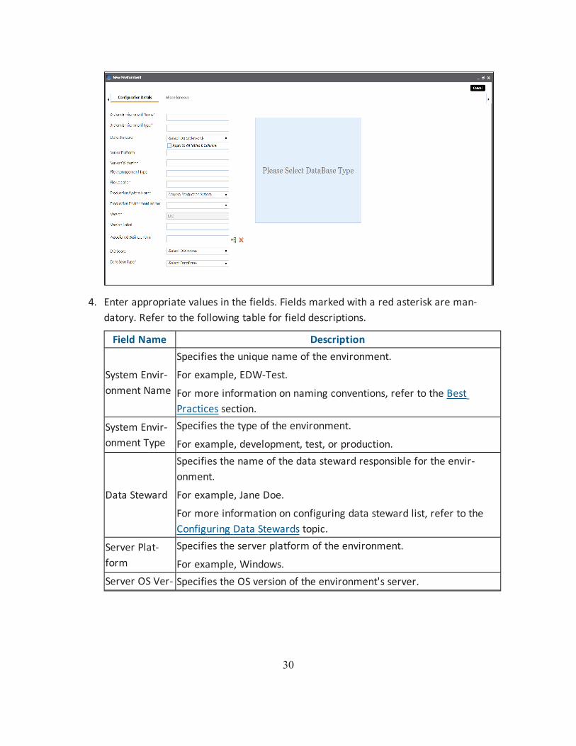
4. Enter appropriate values in the fields. Fields marked with a red asterisk are man-datory. Refer to the following table for field descriptions.
Field Name Description
System Envir-onment Name
Specifies the unique name of the environment.
For example, EDW-Test.
For more information on naming conventions, refer to the Best Practices section.
System Envir-onment Type
Specifies the type of the environment.
For example, development, test, or production.
Data Steward
Specifies the name of the data steward responsible for the envir-onment.
For example, Jane Doe.
For more information on configuring data steward list, refer to the Configuring Data Stewards topic.
Server Plat-form
Specifies the server platform of the environment.
For example, Windows.Server OS Ver- Specifies the OS version of the environment's server.

31
Field Name Descriptionsion For example, Windows Server 2012 R2.
File Man-agement Type
Specifies the file management system (if the environment is a file-based source).
For example, MS Excel.
File LocationSpecifies a file path (if the environment is a file-based source).
For example, C:\Users\Jane Doe\erwin\Mike - Target System
Production Sys-tem Name
Specifies the system name being associated with the environment as the production system.
For example, Enterprise Data Warehouse.
Production Environment Name
Specifies the environment name being associated with the envir-onment as the production environment.
For example, EDW-PRD.
Version Label
Specifies the version label of the environment to track change history.
For example, Alpha.
For more information on configuring version display, refer to the Con-figuring Version Display of the Environments topic.
DQ Score
Specifies the overall data quality score of the environment.
For example, High (7-8).
For more information on configuring DQ scores, refer to the Con-figuring Data Profiling and DQ Scores topic.
Database Type
Specifies the database type.
For example, Sql Server.
Select the type of database from where you wish to scan metadata.
Depending upon your choice of database type you need to provide additional fields (connection parameters) appearing on the right hand side.
Note: There are no additional fields for MS Excel File, and XSD.
5. Click to test the connection.

32
If the connection with database is established successfully then a success message pops up.
6. Click Save and Exit.
A new environment is created and stored in the environment tree.
Once an environment is created, you can scan source or target metadata from the database type.
Different database types have different prerequisites and connection parameters:
SQL Server - via SQL or Window authentication mode
Oracle and Oracle RAC
MySQL
Snowflake
Salesforce
MS Dynamics CRM
SAP ECC R/3 and IS-U Metadata via JCO Driver

33
Scanning Metadata
After creating system and environment, the next logical step is to scan source/target metadata. You can also import metadata from MS Excel file, JSON, CSV (Flat File), XMI, MS Access File, and XSD.
To scan source or target metadata, follow these steps:
1. Go to Application Menu > Data Catalog > Metadata Manager.
2. Under the System Catalogue pane, expand the system created by you.
3. Right-click the Environment node created by you.
4. Click Scan Metadata.
Metadata Scan-Step 1 wizard appears.
34
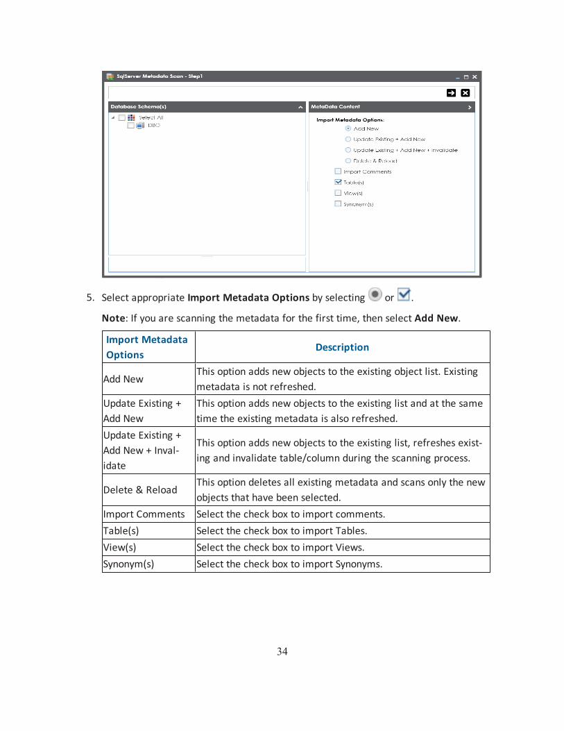
5. Select appropriate Import Metadata Options by selecting or .
Note: If you are scanning the metadata for the first time, then select Add New.
Import Metadata Options
Description
Add NewThis option adds new objects to the existing object list. Existing metadata is not refreshed.
Update Existing + Add New
This option adds new objects to the existing list and at the same time the existing metadata is also refreshed.
Update Existing + Add New + Inval-idate
This option adds new objects to the existing list, refreshes exist-ing and invalidate table/column during the scanning process.
Delete & ReloadThis option deletes all existing metadata and scans only the new objects that have been selected.
Import Comments Select the check box to import comments.Table(s) Select the check box to import Tables.View(s) Select the check box to import Views.Synonym(s) Select the check box to import Synonyms.

35
6. Select the appropriate Database Schema check box.
7. Click to move to next step.
Metadata Scan Step-2 Wizard appears. It pulls up the objects selected in Metadata Scan Step-1 like Tables, Views and Synonyms.
8. Select the objects to be imported by selecting the appropriate check box.
9. Click .
The metadata is scanned successfully and saved under the environment node.
For more information on managing metadata, refer to the Managing Metadata section.
You can also import metadata from:
MS Excel File
JSON
CSV (Flat File)
XMI
MS Access File
XSD

36
Defining Transformations
You can define transformations which can be used as business rules and extended business rule transformations in a mapping specification.
To define transformations, follow these steps:
1. Go to Application Menu > Data Catalog > Mapping Manager.
2. Under the Workspace Mappings pane, click the Transformations node.
The Transformation Details page appears.
3. Click .
The Transformation Rule Editor page appears.

37
4. Switch Published to ON to publish the transformation.
5. Enter appropriate values in the fields. Fields marked with a red asterisk are man-datory. Refer to the following table for field descriptions.
Field Name Description
Transformation Name
Specifies the unique name of the transformation.
For example, ASCII.
Scope Specifies the scope of the transformation.
For example, All Projects.
ETL Option
Specifies the ETL option.
Valid values are:
BODS Pseudocode
SSIS Pseudocode

38
Field Name DescriptionInformatica Pseudocode
ODI Pseudocode
Talend Pseudocode
You can configure ETL option list and add or remove an ETL option from the list.
6. Switch Replace Transformation Name with Pseudocode to ON to replace the trans-formation name with pseudocode.
7. Place the cursor in the Pseudocode box and type a pseudocode or use Ctrl + Space to select a pseuducode.
Note: You can use multiple pseudocode for a transformation.
8. Click .
A new transformation is added under the Transformations node.
For more information on transformations, refer to the Defining and Managing Trans-formation section.

39
Creating Maps
Maps are categorized under projects and a project can have multiple maps. The maps are stored in a hierarchical manner, Projects > Mappings. Source to target mappings are per-formed in maps. You can create maps under a new or existing projects.
To create maps under a new project, follow these steps:
1. Go to Application Menu > Data Catalog > Mapping Manager.
2. Under the Workspace Mappings pane, right-click the Projects node.
3. Click Create Project.
The Create Project page appears.

40
4. Enter appropriate values in the fields. Fields marked with a red asterisk are man-datory. Refer to the following table for field descriptions.
Field Name Description
Project Name
Specifies the name of the project.
For example, Data Lake Migration.
For more information on naming conventions, refer to the Best Practices section.
DescriptionSpecifies the description of the project.
For example: The project contains the mapping spe-cifications for the sales data migration.
Project Manager NameSpecifies the project manager's name.
For example, John Doe.
Business Sponsor NameSpecifies the business sponsor of the project.
For example, ABC Consulting Services.
Project ETLSpecifies the ETL tool assigned to the project.
For example, Informatica Pseudocode.Cost Center Specifies the cost center of the project.

41
Field Name DescriptionFor example, Finance and Accounting.
IT Sponsor NameSpecifies the IT sponsor of the project.
For example, XYZ IT Services.
Enable display of Trans-formation without pseudo-code
Specifies whether the transformation is displayed without pseudocode.
Switch Enable display of Transformation without pseudocode to Yes to display transformation without pseudocode.
5. Click Save and Exit.
A new project is created and stored in the project tree.
6. Right-click the project.
7. Click New Map.
The New Mapping Wizard appears.

42
8. Enter appropriate values in the fields. Fields marked with a red asterisk are man-datory. Refer to the following table for field descriptions.
Field Name Description
Mapping Name
Specifies the mapping specification name.
For example, EDW_PROD_IDS_Benefits_Detail.
For more information on naming conventions, refer to the Best Practices section.
Mapping Ver-sion
Specifies the version of the mapping specification.
For example, 1.00.
It is autopopulated.
For more information on configuring version display of maps, refer to the Configuring Version Display topic.
Sync Source Metadata
Switch Sync Source Metadata to ON to sync source metadata with the mapping.
Sync Target Metadata
Switch Sync Target Metadata to ON to sync target metadata with the mapping.
Mapping Description
Specifies the description about the mapping.

43
Field Name DescriptionFor example: This is a map between EDW source and IDS target sys-tems.
Mail Com-ments
Specifies the mail comments, which can be sent to the project users through an email notification.
For example: Source and target have identical columns, hence they can be mapped using auto-map technique.
For more information on configuring notifications, refer to the Con-figuring Notifications topic.
9. Click Finish.
A new map is created and saved under the map tree.
For more information on performing source to target mappings, refer to the Creating and Managing Mapping Specifications section.

44
Mapping Source and Target
You can create mapping specifications using drag and drop method, even when source column names are different from target column names. After mapping source to target, you can set the target update strategy and enter a description about the strategy.
To create mapping specifications using drag and drop method, follow these steps:
1. Under the Workspace Mappings pane, click the required map.
By default, it opens the Mapping Specification tab.
2. Click .
You can now, edit the Mapping Specification tab.
3. Drag source table or column from Metadata Catalogue and drop in Mapping Spe-cification.
You cannot drop source system or source environment in Mapping Specification. Ensure that you drop source table or column under the respective column.

45
4. Drag target table or column from Metadata Catalogue and drop in Mapping Spe-cification.
You cannot drop target system or target environment in Mapping Specification. Ensure that you drop target table or column under the respective column.
5. Click .
The mapping specification is saved.
To set the target update strategy, follow these steps:
1. Expand the Additional Mapping Information pane.
The pane is available at bottom of the central pane when you click the map in Work-space Mappings.
2. Click the Target Update Strategy tab.

46
3. In the Target Update Strategy tab, click .
4. Click the required strategy, enter Update Strategy Description, and click .
The target update strategy is set.
You can enrich a mapping specification by:
Adding transformation and lookup details
Associating code cross walks (code mappings)
Associating reference tables
Linking requirements
After creating a mapping specification, you can analyze a mapping specification. Analyzing mapping specification involves:
Generating virtual preview of target
Previewing Data
Performing table gap analysis
Performing column gap analysis
Running impact analysis
Running lineage analysis
Running end to end lineage

47
Opening business view
Viewing mapping statistics

48
Categorizing Codesets and Defining Code Values
You can create and manage codesets in Codesets Manager. Its workspace has two sections, Enterprise Codesets and Codeset Mappings. You can categorize and define codesets in the Enterprise Codesets section, while you can create codeset crosswalks (mappings) in the Codeset Mappings section.
Before defining codesets, you need to create categories to hold the codesets.
To create categories, follow these steps:
1. Go to Application Menu > Data Catalog > Codeset Manager.
2. In Codesets Workspace, right-click the Codesets node.
3. Click New Category.
The New Category page appears.

49
4. Enter Category Name and Category Description.
For example:
Category Name - EDW
Category Description - This category contains three codesets, Country Codes, Gender, and Marital Status.
5. Click .
A new category is created and added to the category tree.
After creating a category, you can define codesets, which are stored inside the category.
To define codesets, follow these steps:

50
1. Right-click the category node created by you in the above step.
2. Click New Codeset.
The New Codeset page appears.
3. Enter Codeset Name and Codeset Description.

51
For example:
Codeset Name - Country Codes
Codeset Description - This codeset has code names and code values for four countries.
4. Click .
A codeset is created and stored in the codesets tree.
We can populate code values in codesets by scanning the database.
To populate code values in codesets via DB scan, follow these steps:
1. Click the codeset created by you.
2. In Code Value Grid, click .
3. Click and expand the Quick Connection pane.

52
4. Enter appropriate values in the fields (connecting parameters). Fields marked with a red asterisk are mandatory. Refer to the following table for field description.
Field Name Description
DBType
Specifies the database type.
For example, Sql Server.
Select the database type from which you wish to scan codes.
Driver Name
Specifies the JDBC driver name for connecting to the database.
For example, com.microsoft.sqlserver.jdbc.SQLServerDriver
It is autopopulated depending on the DB type. You can also update the driver name.
IP Address/Host Name
Specifies the IP address or server host name of the database.
For example, localhost.
Port
Specifies the port to connect with the database.
For example: 1433 is the default port for a Sql Server database type.
Database NameSpecifies the database name being used to connect to the code-set.

53
Field Name DescriptionFor example, ErwinDIS931.
System Name
Specifies the name of the system related with the codeset.
For example, EDW.
The name of the system should be same as provided in Metadata Manager.
System Envir-onment Name
Specifies the name of the environment related with the codeset.
For example, EDW-DEV.
The name of the environment should be same as provided in Metadata Manager.
User NameSpecifies the user name to connect with database.
For example, sa.
PasswordSpecifies the password to connect with database.
For example, goerwin@1.
URL
Specifies the full JDBC URL that is used to establish a connection with the database.
For example, jdbc:sqlserver://SERVER_ NAME:PORT#;data-baseName=DatabaseName
It is autopopulated based on the other parameters.
5. Click to test the connection.
If connection is established then a success message pops up.
6. Write a query in the Query Panel and click to validate the query.
7. Click to preview the query result.
8. Double-click the Select CSMHeader Template cell of the required column.
The columns of the Code Value Grid appears as an option list.

54
9. Select the required Code Value Grid column.
Note: You can select multiple columns from the data base.
10. Click to import the selected columns in the Code Value Grid.
The selected columns are imported in the Code Value Grid.
You can also enter codes in the Code Value Grid:
Manually
Using MS Excel files
For more information on maintaining codesets, refer to the Maintaining Enterprise Codesets section.

55
Publishing Codesets
You can publish your codesets to an environment, hence it is important that you create the required publishing environments such as test, development, or production.
To create publish environments, follow these steps:
1. Go to Application Menu > Data Catalog > Codeset Manager.
2. Under the Codesets Workspace pane, right-click the Environments node.
3. Click New Environment.
The New Environment page appears.
4. Enter Environment Name.

56
5. Click .
A new publish environment is created and saved in the Publish Environments pane.
To publish codesets, follow these steps:
1. Go to Application Menu > Data Catalog > Codeset Manager>.
2. Under the Codesets Workspace pane, right-click the required codeset.
3. Click Publish.
The Publish Codesets page appears.
57
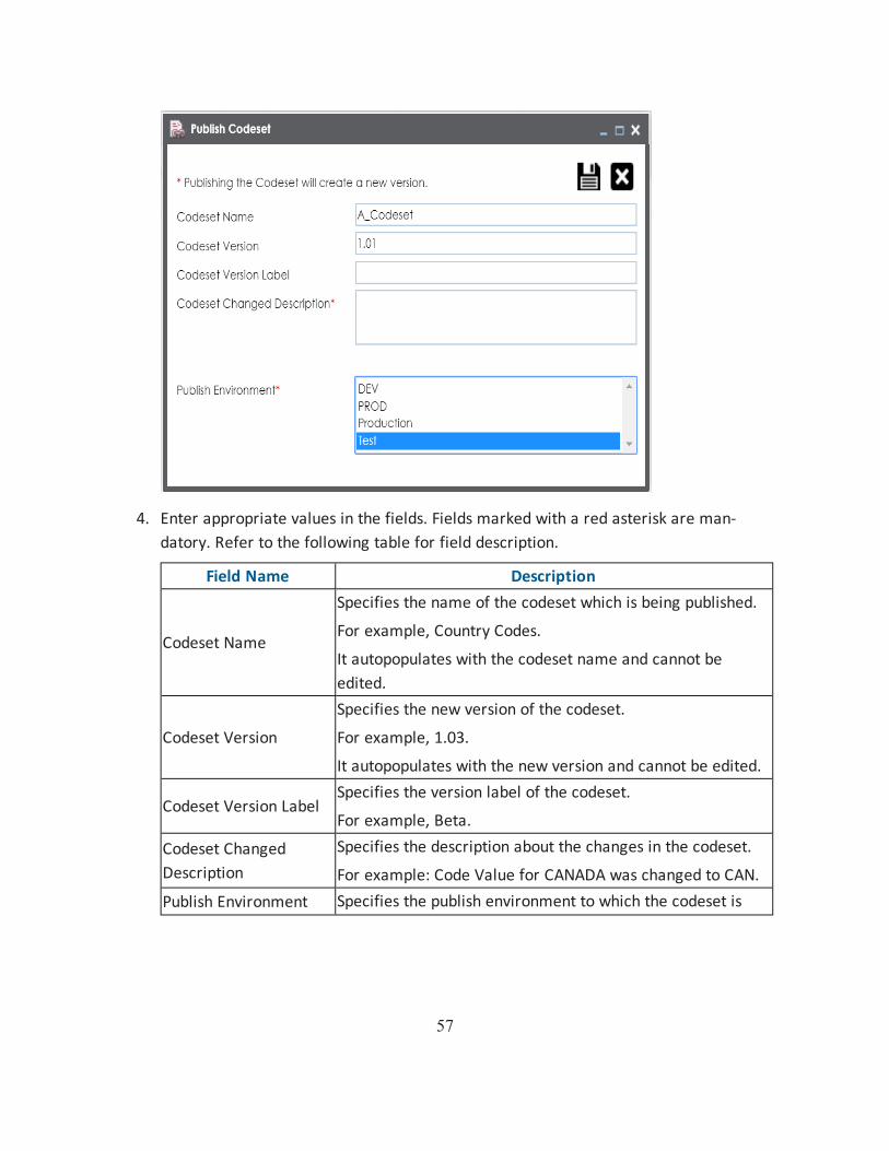
4. Enter appropriate values in the fields. Fields marked with a red asterisk are man-datory. Refer to the following table for field description.
Field Name Description
Codeset Name
Specifies the name of the codeset which is being published.
For example, Country Codes.
It autopopulates with the codeset name and cannot be edited.
Codeset Version
Specifies the new version of the codeset.
For example, 1.03.
It autopopulates with the new version and cannot be edited.
Codeset Version LabelSpecifies the version label of the codeset.
For example, Beta.
Codeset Changed Description
Specifies the description about the changes in the codeset.
For example: Code Value for CANADA was changed to CAN.Publish Environment Specifies the publish environment to which the codeset is

58
Field Name Descriptionbeing published.
For example, Production.
5. Click .
The codeset is published successfully and the published codesets move under Pub-lished Codesets pane.

59
Creating Code Crosswalks (Mappings)
You can create code crosswalks (mappings) of the source and target codesets in Codeset Manager. The codesets can have same or different code values. Auto-Map functionality enables you to map codesets having same code values. Codesets having different code val-ues can be mapped using drag and drop method.
A category can hold multiple code maps. Code maps are stored in a hierarchical manner, Category > Mappings. You can also create sub-categories under a category to provide one more level of categorization to mappings.
To create a category, follow these steps:
1. Go to Application Menu > Data Catalog > Codeset Manager > Codeset Mappings.
2. Under the Code Mappings Workspace pane, right-click the Code Mappings node.
3. Click New Category.
The New Category page appears.

60
4. Enter Category Name and Category Description.
For example:
Category Name - EDW
Category Description - This category contains two code mappings, Gender Cross-walk and Marital Status Crosswalk.
5. Click .
A new category is created and saved under the category tree.
To create sub-categories under a category, follow these steps:

61
1. Under the Code Mappings Workspace pane, right-click the required category.
2. Click New Sub Category.
The New Category page appears.
3. Enter Category Name and Category Description.
For example:
Category Name - EDW-Finance
Category Description - This sub-category contains two code mappings, Gender Crosswalk and Marital Status Crosswalk.

62
4. Click .
A new sub-category is created and saved under the sub-category tree.
You can use Auto-Map functionality to map source and target codesets having same code values.
To create code mappings when source and target codesets have same code values, follow these steps:
1. Right-click the desired category.
2. Click New Map.
The New Codeset Map page appears.

63
3. Enter Codeset Map Name and Codeset Map Description.
For example:
Codeset Map Name - Gender Crosswalk
Codeset Map Description - The codeset map is the code mappings between the two codesets, Misc Gender Codes and Gender.
4. Select the Source Codeset/System and Target Codeset/System.
5. Select the Auto Map check box and click .
A new code mapping is created and source and target codesets are mapped in the Codeset Mapping Grid.

64
6. Click to validate the code mapping.
You need to use drag and drop method to map codesets having different code values.
To create code mappings when source codesets and target codesets have different code val-ues, follow these steps:
1. Right-click the category.

65
2. Click New Map.
The New Codeset Map page appears.
3. Enter Codeset Map Name and Codeset Map Description.
For example:
Codeset Map Name - Gender Crosswalk
Codeset Map Description - The codeset map is the code mappings between the two codesets, Misc Gender Codes and Gender.
4. Select the Source Codeset/System.
5. Click .
The source codesets details are updated in the Codeset Mapping Grid.

66
6. Click .
7. Scroll to right of the Codeset Mapping Grid to see the Target Code Value column.
8. In the Codeset Tree, expand the target category and the Codesets node.
9. Drag and drop the target codeset into the Code Set Mapping Grid under the Target Code Value column.

67
10. Click .
The code mappings are successfully saved.
11. Click to validate the code mapping.
The code map is validated. Ensure that all the desired codes are mapped.
Use the following options:
Export
To download the code map details in .xlsx format, click .
Extend Mapping Grid
To extend the Codeset Mapping Grid, click .

68
Associating Code Mappings with Data Item Mappings
Before associating a code mapping with a data item mapping, you need to publish the code map.
Associating code mappings with data item mappings involves:
Publishing code maps in the Codeset Manager
Associating code maps with data item mappings in the Mapping Manager
To publish code maps, follow these steps:
1. Go to Application Menu > Data Catalog > Codeset Manager > Codeset Mappings.
2. Under the Code Mappings Workspace pane, right-click the required map.
The Publish Codeset Map page appears.

69
3. Enter appropriate values in the fields. Fields marked with a red asterisk are man-datory. Refer to the following table for field descriptions.
Field Name Description
Codeset Map Name
Specifies the name of the code map.
For example, Gender Crosswalk.
Codeset Map Version
Specifies the new version of the code map.
For example, 1.02.
Codeset Map Descrip-tion
Specifies the description about the code map.
For example: The codeset map is the code mappings between the two codesets, Misc Gender Codes and Gender.
Map Version Label
Specifies the version label of the code map.
For example, Beta.Map Changed Description
Specifies the description about the changes made in the code map.
For example: Code values were updated.
Publish Envir-onment
Specifies the environment where the code map is being published.
For example, test.

70
Field Name DescriptionYou can create publish environments in Enterprise Codesets. For more information on creating publish environments, refer to the Publishing Codesets topic.
4. Click .
The codeset map is published and it can be found in the Published Code Mappings pane under the selected Publish Environment.
A new version of the codeset map is created under the Mappings tree.
A published code map can be associated with a mapping in the Mapping Manager. The pub-lished code map is available under the Code Mappings Catalogue.
To associate published code maps with data item mappings, follow these steps:
1. Go to Application Menu > Data Catalog > Mapping Manager.
2. Under the Workspace Mappings pane, click the required map.
The center pane shows the mapping specification.

71
3. In Mapping Specification, click .
4. Right-click Header Menu and select the CSM Mapping check box.
The CSM Mapping Column appears in the Mapping Specification.
5. On right pane, expand Code Mapping Catalogue.

72
6. Expand the required category, which contains the code crosswalks to be associated with the data item mapping.
7. Drag the code map into Mapping Specification and drop it under the CSM Mapping column in the required row.
8. In Mapping Specification, Click .
The code map is associated with the data item mappings.

73
Creating Business Terms
Business Glossary Manager enables you to create business terms. They enable you to main-tain a common vocabulary across your organization. Catalogs are the containers for busi-ness terms and you need to create a catalog before creating business terms.
To create catalogs, follow these steps:
1. Go to Application Menu > Data Literacy > Business Glossary Manager.
2. In the Workspace pane, right-click the Business Terms node.
3. Click New Catalog.
The New Catalog page appears.
4. Enter Catalog Name and Catalog Description.
For example:
Catalog Name - Customers Business
Catalog Description - The catalog contains business terms of the organization.
5. Click .

74
A catalog is created and added to the catalog tree.
Once a catalog has been created, you can create business terms under it.
To create business terms, follow these steps:
1. In Workspace, under the Business Terms node, right-click the catalog node.

75
2. Click New Business Term.The New Business Term Definition page appears.
3. Enter appropriate values to the fields. Fields marked with a red asterisk are man-datory.Refer to the following table for field descriptions.
Field Name Description
Business Term
Specifies the name of the business term.
For example, Account.
DefinitionSpecifies the definition of the business term.
For example: An Account contains data for a party.
DescriptionSpecifies the description about the business term.
For example: Account contains data for posting, payments, debt recov-ery, and taxes.
NotesSpecifies the reference notes, if any.
For example: The data for posting, payments, debt recovery, and taxes was imported from the Account.xlsx file.

76
Field Name Description
Business Term Image
Drag and drop a picture of business term or click to browse and upload a picture.
Acronym Specifies whether the business term is an acronym.
Data Steward
Specifies the name of the data steward responsible for the business term.
For example, Jane Doe.
For more information on configuring list of data stewards, refer to the Configuring Data Stewards topic.
4. Click . A business term is created and added to the catalog.
Once, a business term is created you can define associations for business terms.
You can also create Business Policies, Business Rules, and other business assets in the Busi-ness Glossary Manager. For more information on creating business assets, refer to the Managing Business Glossary section.

77
Defining Associations for Business Terms
Business Glossary Manager allows you to manage a common business vocabulary across the organization.
By default, you can associate business terms with business policies, other business terms, columns, environments, and tables. You can control the glossary object types available for association using the Business Glossary Manager settings page. For more information, refer to the configuration topic.
To define associations for business terms, follow these steps:
1. Go to Application Menu > Data Literacy > Business Glossary Manager.
2. In Workspace, click the desired catalog and click the Grid View tab.
3. In the list of business terms, under the options column, click to edit a business term.

78
The business term opens in edit mode.
4. Go to the Associations tab.
5. In the object type (business policies, business terms, columns, environments, and tables) list, select the object type that you want to associate with the business term.

79
6. Click .
The Relationship Associations page appears. Based on the object type that you select, it displays a list of available business policies, business terms, columns, environments, or tables.
7. From the list, select the objects that you want to associate to your business term.
If you know the object name, use the Search (partial matches) field to look up for it.
8. Click Save.The selected objects are associated to the business term and added to the list of asso-ciations for an object type.You can define as many associations as required.

80
Creating Test Cases
You can create multiple test cases at project level in Mapping Manager and record expec-ted and actual results. These test cases can test data mappings and ETL process. You can also manage test cases as per your requirements.
To create test cases at project level, follow these steps:
1. Go to Application Menu > Data Catalog > Mapping Manager > Workspace Map-pings.
2. Under the Workspace Mappings pane, expand the required project node.
3. Click the Test Cases node.
The Test Case Summary pane appears.
4. Click .
The Add New Test Case page appears.

81
5. Enter appropriate values in the fields. Fields marked with a red asterisk are man-datory. Refer to the following table for field descriptions.
Field Name Description
Test Case Name
Specifies the name of the test case.
For example, Verifying the Completeness of Source Metadata.
Test Case Label
Specifies the unique label for the test case.
For example, Source Metadata.
Type of Test-ing
Specifies the type of testing.
For example, Metadata Testing.
Test SQL Script
Specifies the SQL script required in the test execution.
For example, select * from dbo.ADS_ASSOCIATIONS.
DescriptionSpecifies the test objective in brief.
For example: The objective of the test case is to verify the com-pleteness of source metadata.
Expected Res-ult
Specifies the expected result of the test case in detail.
For example: The source table should have 50 columns.Actual Result Specifies the actual test result after the execution of the test.

82
Field Name DescriptionFor example: The source table has 39 columns.
Testing Com-ments
Specifies the testing comments about the test case.
For example: The source metadata was scanned from a Sql Server data-base.
6. Click Save and Exit.
The test case is created and saved under the Test Cases node.
Once the test case is created, you can enrich it by:
Adding validation steps
Adding documents
Managing test cases involves:
Updating test cases
Exporting test cases
Deleting test cases
You can also create test cases at :
Map level in the Mapping Manager
Metadata level in the Metadata Manager
All the test cases created in Mapping Manager and Metadata Manager can be viewed and analyzed in the Test Manager.

83
Documenting Requirements
You can document functional requirements in a standardized manner in Requirements Man-ager. It is an agile and collaborative platform to create customized requirements templates.
To document your requirements in standard templates, follow these steps:
1. Go to Application Menu > Data Catalog > Requirements Manager > Requirements Workspace.
2. Right-click the Specification Templates Catalogue node.
3. Click Create Project.
Create Project page appears.

84
4. Enter Project Name and Project Description.
For example:
Project Name - Nasdaq PDLC
Project Description - This project captures functional and business requirements of the data migration project.
5. Click .
A new project is created and stored in the project tree.
6. Right-click the project node.

85
7. Click Create Specifications.
Create Specifications page appears.
8. Enter appropriate values in the fields. Fields marked with a red asterisk are man-datory. Refer to the following table for field descriptions.
Field Name Description
Specification Template Type
Specifies the template of the specification.
For example, Health Migration Template.
You can create templates and add artifacts to templates in the Requirements Manager Settings.
Specification Template Description
Specifies the description about the specification template.
For example: The Health Migration Template is to capture functional and business requirements of the data migration project.
Specification Name
Specifies the name of the specification.
For example, OrganMatch.
Specification Version
Specifies the version of the specification.
For example, 1.01.
The specification version is autopopulated. For more information on configuring version display of specifications, refer to the Configuring Version Display topic.

86
Field Name Description
Version Label
Specifies the version label of the specification.
For example, Beta.
For more information on configuring version display of specifications, refer to the Configuring Version Display topic.
Specification Description
Specifies the description about the specification.
For example: The specification uses the Health Migration Template to capture functional and business requirements of the data migration project.
Specification Owner
Specifies the specification owner's name.
For example, Jane Doe.
StatusSpecifies the status of the specification.
For example, Pending Review.
Mail Com-ments
Specifies the mail comments, which are sent to the project users.
For example: The specification uses the Health Migration Template.
For more information on configuring email notifications, refer to the Configuring Email Settings topic.
9. Click .
A new specification is created and stored in the specifications tree. The specifications tree is nested under the project node.
10. Document your requirements in the Specification Overview page.

87
Note: Specification Overview page depends on the Specification Template Type selected while creating the specification.
11. Click .
The artifact is saved.
For more information on creating specifications and documenting requirements, refer to the Using Requirements Manager section.

88
Linking Requirements to Mappings
You can link your functional requirements to data mappings. This helps in enterprise level traceability between requirements and mappings.
To link your functional requirements to mappings, follow these steps:
1. Go to Application Menu > Data Catalog > Mapping Manager.
2. Click the required map.
The Mapping specification page appears.
3. In Mapping Specification, right click the Header Menu.
A list of header columns appears.
89
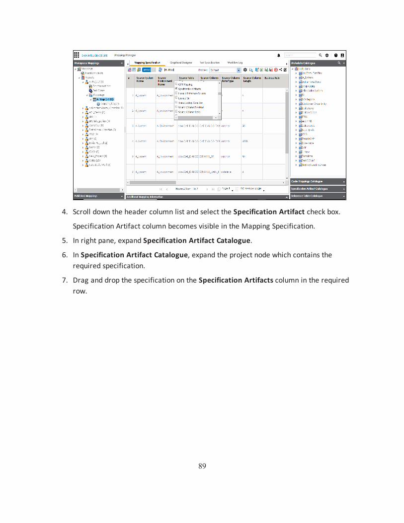
4. Scroll down the header column list and select the Specification Artifact check box.
Specification Artifact column becomes visible in the Mapping Specification.
5. In right pane, expand Specification Artifact Catalogue.
6. In Specification Artifact Catalogue, expand the project node which contains the required specification.
7. Drag and drop the specification on the Specification Artifacts column in the required row.

90
8. Click .
Requirements are linked to the mappings.

91
Performing Lineage Analysis
Once you are done with source to target mappings in the Mapping Manager, you can per-form lineage analysis on a particular table/column. The Metadata Manager allows you to perform end to end forward and backward lineage analysis to determine the upstream and downstream dependencies.
To perform lineage analysis at table level in the Metadata Manager, follow these steps:
1. Go to Application Menu > Data Catalog > Metadata Manager.
2. Under the System Catalogue pane, click a table.
3. Click Forward Lineage to perform forward lineage analysis.
End to end forward lineage is displayed.
4. Click Reverse Lineage to perform reverse lineage analysis.
End to end reverse lineage is displayed.

92
For more information on performing lineage and impact analysis in Metadata Manager, refer to the Performing Impact and Lineage Analysis section.
You can also perform lineage analysis in the Mapping Manager at:
Table level
Column level

93
Performing Impact Analysis
Once you are done with mappings in Mapping Manager, you can perform impact analysis on the metadata (table level). The Metadata Manager enables you to perform end to end impact analysis.
To perform impact analysis in the Metadata Manager, follow these steps:
1. Go to Application Menu > Data Catalog > Metadata Manager.
2. Under the System Catalogue pane, click a table.
3. Click Impact Analysis.
Impact analysis report is displayed where Direct Impact as source and as target are shown.
4. Click Indirect Impact to view Indirect Impact, .
The Indirect Impact page appears. You can analyze upstream impact and downstream impact.

94
For more information on performing lineage and impact analysis in the Metadata Manager, refer to the Performing Impact and Lineage Analysis section.
You can also run impact analysis in the Mapping Manager on:
Any source / target table
Any source / target column

95
Exporting Mapping Specifications to ETL Tools
Once the mappings are considered 'approved for coding', you can export the mappings as coding requirements to automatically generate ETL/ELT jobs for industry leading ETL tools like Informatica PowerCenter, IBM DataStage, Microsoft SQL Server SSIS, and Talend.
1. Go to Application Menu > Data Catalog > Mapping Manager > Workspace Map-pings.
2. Expand the desired project node and click the desired mapping.
The Mapping Specification tab appears on the center pane.
3. Click .
The Export Window appears.

96
4. Click ETL Engineering tab.
5. Select the desired ETL tool and click .
Multi Mapping page appears.

97
6. Select the mapping to be exported from the tree and click .
7. Download the XML / DTSX file by clicking the Download File hyperlink.
The mapping specification is exported.