error code troubleshooting guide - gympart.com code... · troubleshooting steps verify electrical...
TRANSCRIPT
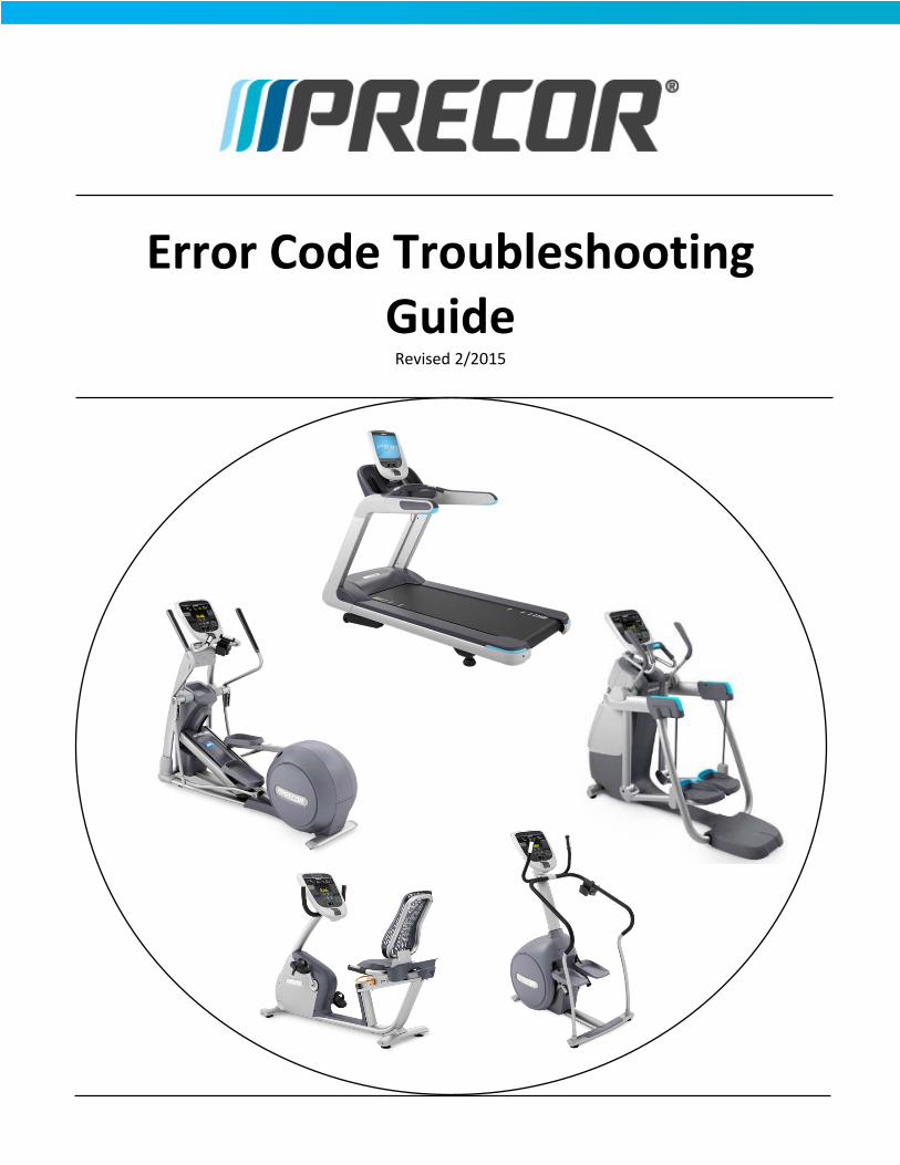
Error Code Troubleshooting Guide
Revised 2/2015

Table of Contents - Click the code to go directly to the page Error Page ABOUT THIS DOCUMENT ......................................................................................... 2 01, 02, 03, 04 ........................................................................................................... 3 STUCK KEY (05) ........................................................................................................ 4 09 ............................................................................................................................. 5 10 ............................................................................................................................. 6 11 ............................................................................................................................. 7 12 ............................................................................................................................. 8 14 ............................................................................................................................. 9 15 ........................................................................................................................... 10 16 ........................................................................................................................... 11 17 ........................................................................................................................... 12 18 ........................................................................................................................... 13 19 ........................................................................................................................... 14 20 ........................................................................................................................... 15 21 ........................................................................................................................... 16 22, 23, 26 ............................................................................................................... 17 25 ........................................................................................................................... 18 27, 28, 29 OVERVIEW ............................................................................................. 19 27 ........................................................................................................................... 19 28 ........................................................................................................................... 20 29 ........................................................................................................................... 20 30, 31, 32, 33 ......................................................................................................... 23 35, 36 ..................................................................................................................... 24 37 ........................................................................................................................... 25 40 ........................................................................................................................... 26 42 ........................................................................................................................... 27 44 ........................................................................................................................... 28 45 ........................................................................................................................... 29 46 ........................................................................................................................... 30 50 ........................................................................................................................... 31 60, 61 ..................................................................................................................... 32 62 ........................................................................................................................... 34 70-79 OVERVIEW ................................................................................................... 35 70, 71, 72, 73 ......................................................................................................... 36 74, 75, 76, 77 ......................................................................................................... 37 78, 79 ..................................................................................................................... 38 80, 81, 82, 83 ......................................................................................................... 39 85 ........................................................................................................................... 40 86-87 ...................................................................................................................... 41 88 ........................................................................................................................... 42 LS ............................................................................................................................ 43 ERR ......................................................................................................................... 44 E2 ........................................................................................................................... 44 E4 ........................................................................................................................... 46
Contact Precor Customer Support at [email protected] or 800.786.8404 with any questions. Page 1 of 46 ©2015 Precor Incorporated, Unauthorized reproduction and distribution prohibited by law. Back to Top

About this Document This document covers the error codes that exist within the Precor software hierarchy for products currently supported by Precor. Each section will include a description of the error code being displayed and the systems associated with the error code. Each code has a symptoms discussion where the error and common causes are discussed. It must be understood this document cannot anticipate every possible cause for a particular error code. However, it should list the causes encountered in the majority of cases. The document then has the troubleshooting steps associated with each of the possible causes. These steps are listed in order of likelihood of occurrence. It is worth noting there may be instances of multiple errors occurring, but with only one error listed in the Error Log. Multiple errors in a row that occur with the same hour or odometer reading will not be recorded, only the first occurrence. For a repeat error (with identical readings) to be listed, a different error must be recorded between them. A good practice is to check the error logs of adjoining machines to verify the problem is with the machine and not the location.
Contact Precor Customer Support at [email protected] or 800.786.8404 with any questions. Page 2 of 46 ©2015 Precor Incorporated, Unauthorized reproduction and distribution prohibited by law. Back to Top

01, 02, 03, 04 Memory, Ram & EEPROM Test Errors Applies to All cardio equipment Issue Symptoms Errors 00 through 04 check upper PCA memory locations, RAM memory locations, and the EEPROM checksum during the power up test sequence. If a fault is found during the power up test sequence, the appropriate error code will be displayed. While rare, these messages may display intermittently due to external causes. If the unit's AC input significantly dips during the power up test sequence the test could fail resulting in triggering one of these errors. In addition, treadmills operating on non-dedicated branch AC circuits may see these errors on an intermittent basis. Troubleshooting steps
1 Reproduce the error and evaluate a. Turn off unit. b. Turn on unit. Repeat. c. If the error message is consistently displayed when the unit is powered up, replace the upper PCA.
Contact Precor Customer Support at [email protected] or 800.786.8404 with any questions. Page 3 of 46 ©2015 Precor Incorporated, Unauthorized reproduction and distribution prohibited by law. Back to Top

Stuck Key (05) Key In The Operated Position At Power Up Applies to All consoles NOTE: Error 05 has not been displayed on Precor equipment since 2003. It was replaced by the simpler “Stuck Key” message, and is not recorded in the error log. Issue Symptoms The power up test sequence has detected a key in the operated condition. A permanently stuck key inhibits the correct operation of the unit. Likely causes are liquids present on a touch sensitive display, or a key in the display housing is stuck in the operated condition. Less likely but possible is a failure on the upper PCA. Troubleshooting steps
1. Check for visible liquid 2. Wipe off any visible liquid from the surface of the touch sensitive display. 3. Restart the unit. If error 5 is no longer present, the liquid was the cause. 4. Test the keypad 5. Turn off the unit. 6. Remove the keypad connector cable from the upper PCA. 7. Restart the unit, if error 5 is no longer present, the keypad is the cause. Note that the keypad is typically
part of the display housing. 8. Replace the display housing to correct the problem. 9. Test the upper PCA 10. Turn off the unit. 11. Remove the keypad connector cable from the upper PCA. 12. Restart the power up sequence, if error 5 is still present, the upper PCA is the cause.
Contact Precor Customer Support at [email protected] or 800.786.8404 with any questions. Page 4 of 46 ©2015 Precor Incorporated, Unauthorized reproduction and distribution prohibited by law. Back to Top

09 Lower PCA Memory Test Errors Applies to All cardio equipment Description During the power up test sequence the lower PCA memory locations are checked. Error 09 indicates that a fault was found. This error message almost always indicates a lower PCA problem when it is consistently displayed. Failures causing this error message to be displayed are rare. These messages may display intermittently due to external causes. If the unit's AC input significantly dips during the power up test sequence the test could fail resulting in triggering one of these errors. In addition, treadmills operating on non-dedicated AC circuits may see these errors on an intermittent basis. Troubleshooting steps
1. Reproduce the error and evaluate a. Turn off unit. b. Turn on unit. Repeat. c. If the error message is consistently displayed when the unit is powered up, replace the lower PCA.
Contact Precor Customer Support at [email protected] or 800.786.8404 with any questions. Page 5 of 46 ©2015 Precor Incorporated, Unauthorized reproduction and distribution prohibited by law. Back to Top

10 Line Frequency Out Of Acceptable Range Applies to Treadmills built since 2006 Issue Symptoms The AC line frequency must be either 50Hz or 60Hz for Experience treadmills built 2006-2013, and between 45Hz and 65Hz for TRM800 v2 (2014 onward). Error 10 is triggered if the line frequency moves beyond these acceptable ranges, or if electrical noise is generated causing a perceived change in frequency. Error 10 can also be caused by electrical wiring and supply issues, such as shared neutrals or AC hot and AC neutral wires being reversed. If facility power is lost, and a backup generator turns on the frequency can be off for a short time, causing Error 10. Troubleshooting steps Verify electrical supply
1. Treadmills must be installed on an AC 20 amp dedicated branch circuit. Both the hot and neutral leads must be dedicated to the treadmill. If another piece of equipment is sharing a circuit with the treadmill it can create enough electrical noise to make AC line frequency identification impossible. The treadmill’s AC circuit must be reconfigured as a completely dedicated 20 amp circuit.
2. Most line frequency detection systems monitor the AC line frequency on the hot AC line. In the case of a reversed 120 V.A.C circuit, the monitoring is taking place on the neutral (ground) side of the AC line. Many of the monitoring systems are incapable of detecting line frequency on the neutral wire. It must first be determined if the reversal is in the AC wiring feeding the treadmill or in the treadmill internal wiring. The hot and neutral wires can be verified by measuring each in reference to AC (green wire) ground.
3. Even though unlikely, the AC line frequency could actually be out of acceptable limits. This is more likely to occur in countries where AC power systems may not be well developed and controlled. There may be little that can be done about this condition. If a generator is used during a power outage, during the time the generator is coming up to speed the line frequency may be detected as incorrect.
4. Sometimes AC being fed into the distribution system is too electrically noisy to allow correct line frequency identification. This can be caused by other equipment within the AC distribution system creating the electrical noise. Identifying the source of the electrical noise can be difficult. There may be little that can be done about this condition.
Contact Precor Customer Support at [email protected] or 800.786.8404 with any questions. Page 6 of 46 ©2015 Precor Incorporated, Unauthorized reproduction and distribution prohibited by law. Back to Top

11 Low Voltage Watchdog (Upper PCA) Applies to Treadmills and powered Ellipticals Issue Symptoms This watchdog program monitors the voltage of the upper PCA and displays error 11 if it drops below the acceptable value. This can be present if the communications cable between the lower PCA and the upper PCA is faulty, or if a failure in the upper PCA causes an overload in the low voltage power supply, causing it to drop below the limit. It is also possible to see this message displayed intermittently due to external causes. If the unit's AC input significantly dips during the power up test sequence the test could fail resulting in this message being displayed. Treadmills operating on non-dedicated AC circuits may see this message displayed on an intermittent basis. Troubleshooting steps
1. Test the interconnect cable a. Clear the error log and turn off unit. b. Substitute a known good interconnect cable in place of the existing cable directly between the
upper PCA and lower PCA. c. Turn on unit and check the error log.
2. Check the upper PCA a. Cycle power of the unit and check the error log. b. If the error is consistently displayed when the unit is powered up, replace the console.
Contact Precor Customer Support at [email protected] or 800.786.8404 with any questions. Page 7 of 46 ©2015 Precor Incorporated, Unauthorized reproduction and distribution prohibited by law. Back to Top

12 Low Voltage Watchdog (Lower PCA) Applies to Treadmills and powered Ellipticals Issue Symptoms This watchdog program monitors the voltage of the lower PCA and displays error 12 if it drops below the acceptable value. This can be present if the communications cable between the lower PCA and the upper PCA is faulty, or if a failure in the upper PCA causes an overload in the low voltage power supply, causing it to drop below the limit. It is also possible to see this message displayed intermittently due to external causes. If the unit's AC input significantly dips during the power up test sequence the test could fail resulting in this message being displayed. Treadmills operating on non-dedicated branch AC circuits may see this message displayed on an intermittent basis. Troubleshooting steps
1 Test the interconnect cable 2 Clear the error log and turn off unit. 3 Substitute a known good interconnect cable in place of the existing cable directly between the upper PCA
and lower PCA. 4 Turn on unit and check the error log. 5 Check the upper PCA 6 Cycle power of the unit and check the error log. 7 If the error is consistently displayed when the unit is powered up, replace the console.
Contact Precor Customer Support at [email protected] or 800.786.8404 with any questions. Page 8 of 46 ©2015 Precor Incorporated, Unauthorized reproduction and distribution prohibited by law. Back to Top

14 Fan Fail (Lower PCA) Applies to Treadmills Issue Symptoms The rotation of the cooling fan used to cool the lower PCA is monitored. If the fan is not rotating or rotating too slowly an error 14 will be logged. Typical symptoms include the heatsink by the fan can getting clogged with dust and/or dirt, the fan connector/cable becoming disconnected or damaged, the drive motor cable routed such that it is preventing the fan from turning, or the fan itself is failed. Troubleshooting steps
1 Visually inspect the fan 2 Clear the error log. 3 Turn off unit. 4 Remove any debris from the fan. 5 Reset the motor cable as required. 6 Turn on unit, test when running the belt. 7 Inspect the fan connector 8 Turn off unit. 9 Inspect and reconnect the fan connector. 10 Visually inspect the drive motor cable for clearance away from the fan 11 Visually inspect the fan for movement during operation 12 If the fan does not move, replace the lower PCA.
Contact Precor Customer Support at [email protected] or 800.786.8404 with any questions. Page 9 of 46 ©2015 Precor Incorporated, Unauthorized reproduction and distribution prohibited by law. Back to Top

15 DC Bus Over Voltage Applies to Treadmills Issue Symptoms The AC input voltage is monitored. If the AC input momentarily reaches the upper limit, error 15 is logged. The upper acceptable input voltage limit is 132 VAC on 120 VAC systems and 264 VAC on 240 VAC systems. This issue is most often caused by a faulty DB resistor, in conjunction with a user pushing hard on the hand grips while the MC is driving the belt. Troubleshooting steps
1. Check DB resistor connection a. Clear the error log. b. Turn off unit. c. Verify all DB resistor connections are connected and are seated properly.
2. Check DB resistance a. Check DB resistance. It should be 100ohms. If greater than 150ohms, replace DB resistor. b. Check resistance between either terminals of the switch connector (smaller black) to either
terminal of the resistor element connector (larger white/natural). The resistance should be greater than 1Meg of resistance. If less than 1Meg, replace DB resistor.
3. Verify input AC voltage is within the acceptable range. 4. If none of the above, replace the motor controller.
Contact Precor Customer Support at [email protected] or 800.786.8404 with any questions. Page 10 of 46 ©2015 Precor Incorporated, Unauthorized reproduction and distribution prohibited by law. Back to Top
16 AC Input Voltage Too Low Applies to All AC powered cardio equipment Issue Symptoms The condition that causes error 16 has to persist for 15 seconds before it is logged. The most common cause of this problem is external power fluctuations due to brownouts, blackouts or other poor power conditions. This can also be caused by wiring that is too small of a gauge to handle the current, or if the neutrals are shared between multiple outlets. Less likely but possible is a worn deck and belt causing high current. Troubleshooting steps
1 Find out if blackouts/brownouts have occurred recently in that area 2 Check if treadmill was running off of a backup generator or backup power source 3 Ask that an electrician verify wiring 4 Monitor minimum rms line voltage with: 5 Treadmill at banner 6 Treadmill at 6MPH with runner 7 Treadmill at banner, run at 6MPH on a neighboring tread
Contact Precor Customer Support at [email protected] or 800.786.8404 with any questions. Page 11 of 46 ©2015 Precor Incorporated, Unauthorized reproduction and distribution prohibited by law. Back to Top

17 DB Resistor Thermal Trip Applies to TRM 800.v2 Issue Symptoms This error monitors generated current being sent to the Dynamic Brake (DB) resistor. When the drive motor is energized, and external forces cause it to turn faster than it is being driven, current is created. This current is sent through the MC to the DB resistor. When the MC perceives that enough current is being delivered to the DB resistor to make it hot, this error is displayed and the treadmill comes to a stop. The most likely causes for this are a runner at incline with a new deck and belt, a large runner at incline, or a user pushing against the handgrips while forcing the belt with their feet. Troubleshooting steps
1 If deck and belt are new, this failure mode will likely go away after a few months of use. 2 Allow DB resistor to cool down- reset MC status- monitor for repeat error.
Contact Precor Customer Support at [email protected] or 800.786.8404 with any questions. Page 12 of 46 ©2015 Precor Incorporated, Unauthorized reproduction and distribution prohibited by law. Back to Top

18 DB Resistor Thermal Switch Open Applies to TRM 800 v2 (2014) Issue Symptoms As with Error 17, current generated by the drive motor is sent to the DB resistor. If sufficient current is sent to the DB resistor such that it becomes excessively warm, an internal thermal switch will open, which will stop the treadmill and display Error 18. This error will be displayed if the DB resistor thermal switch connector is not plugged in, or if the DB resistor has reached its thermal upper limit. Troubleshooting steps
1 Check to see if the DB resistor thermal switch is properly seated into the connector (it can be wedged into the connector opening without being properly seated)
2 Check DB resistor temperature. If it is stuck on it may be hot. If stuck ON and it is not hot, replace both drive and DB resistor.
3 Unplug all connections from the DB resistor and check resistance of the DB thermal switch (smaller black connector). If 10Ω or greater, replace the DB resistor.
Contact Precor Customer Support at [email protected] or 800.786.8404 with any questions. Page 13 of 46 ©2015 Precor Incorporated, Unauthorized reproduction and distribution prohibited by law. Back to Top

19 PFC Malfunction Applies to TRM 800 v2 (2014) Issue Symptoms The treadmill uses Power Factor Correction (PFC) to maximize the input power for greatest efficiency. This allows for fluctuations in the input voltage without affecting the performance of the treadmill. When the MC detects that the PFC circuitry is not able to correctly compensate for fluctuating input voltage, the treadmill will stop and Error 19 will be displayed. Troubleshooting steps
1 Check for an error 16. If the Error 16 is present, troubleshoot that first. The PFC will not be able to compensate for input voltage that is below the lowest threshold. As such, an Error 19 will be displayed along with an Error 16.
2 Absent an accompanying Error 16, replace the MC.
Contact Precor Customer Support at [email protected] or 800.786.8404 with any questions. Page 14 of 46 ©2015 Precor Incorporated, Unauthorized reproduction and distribution prohibited by law. Back to Top

20 Motor Will Not Start / No Motor Movement Detected Applies to All AC drive motor treadmills Issue Symptoms The treadmill is monitoring the motor movement, through current monitoring. If the lower PCA does not detect that the motor is moving an error 20 will be displayed. This can be caused by a disconnected drive motor, or a very heavy user standing on the belt while starting. Troubleshooting steps
1 Verify motor connector is connected to drive 2 Check machine for stalling during operation 1MPH through 6MPH 3 Check error log for motor current during fault - If it is very low, check the connector and contacts, if it is
over 7amps, it is likely a true stall condition 4 Check belt rating and current draw of treadmill - replace belt and deck if necessary.
Contact Precor Customer Support at [email protected] or 800.786.8404 with any questions. Page 15 of 46 ©2015 Precor Incorporated, Unauthorized reproduction and distribution prohibited by law. Back to Top

21 Too Many Maximum Consecutive Power Requests Applies to Consumer Treadmills, Commercial treadmills pre 2006 Issue Symptoms This error monitors the treadmill's power bit reading when the treadmill was operating at speeds above 1 mph. Power bits indicate the relative time that the motor controller drive circuit is turned on. Therefore power bits is an indication of the amount of power the load is demanding from the motor controller. Error 21 indicates that at a speed of greater than 1 mile per hour an excessive amount of power is being demanded from the motor controller. The main cause of this error being displayed while the treadmill is being used is a badly worn running belt/deck. This error can also be caused by badly worn motor brushes, or brushes that are not making contact with the commutator. Least likely but possible is a shorted drive motor. Troubleshooting steps
1 A clamp-on AC ammeter must be used to determine the amount of A.C input current being drawn by the treadmill under no load and loaded conditions. Remember, many running beds are double sided and the bed can be flipped over rather than being replaced. If the current is excessively high at slow speed replace the belt and deck surface with new.
2 Turn off the treadmill, and disconnect power from the wall receptacle. Remove and inspect the motor brushes for arcing and pitting. If present replace both drive motor brushes. Also check that the brush can move smoothly in the grooves, and that the spring is able to press the brushes against the commutator. Adjust or replace the brushes as necessary.
3 Test the drive motor resistance, it should not be near 0Ω. If 0Ω, a known good drive motor must be substituted for the existing drive motor.
Contact Precor Customer Support at [email protected] or 800.786.8404 with any questions. Page 16 of 46 ©2015 Precor Incorporated, Unauthorized reproduction and distribution prohibited by law. Back to Top
22, 23, 26 Motor Pulses Incorrect Applies to Consumer Treadmills, Commercial Treadmills prior to 2006 Issue Symptoms Dust on the speed sensor, an inoperative sensor, and a failed lower PCA will cause these errors to be displayed.
• Error 22 indicates that the drive motor has been instructed to start, by either manual or program control, and the monitoring system has not received any response from the speed sensing system indicating that the drive motor has started.
• Error 23 indicates that the speed sensor signal was lost while the treadmill was in operation. • Error 26 monitors the speed sensor signal and verifies the speed sensor signal is appropriate for the
requested speed. If the speed sensor signal is incorrect or erratic an Error 26 will be displayed. Troubleshooting steps
1 Carefully, vacuum out the drive motor compartment with a static safe vacuum cleaner. 2 Test the speed sensor at the board for a 0-5Vdc transition when the sensor is activated by the appropriate
device or actuator. The 400 Series treadmills utilize an optical (infrared) through speed sensor. The through sensor beam is broken by a chopper wheel attached to the motor. Dust can accumulate in the sensor. The 200 Series treadmills use a reed switch attached to the frame, actuated by a magnet installed in the drive roller pulley. Check to make sure the magnet is still installed in the pulley.
3 Turn off the treadmill, and disconnect power from the wall receptacle. Remove and inspect the motor brushes for arcing and pitting. If present replace both drive motor brushes. Also check that the brush can move smoothly in the grooves, and that the spring is able to press the brushes against the commutator. Adjust or replace the brushes as necessary.
4 Substitute a known good lower PCA to determine if the lower PCA is bad.
Contact Precor Customer Support at [email protected] or 800.786.8404 with any questions. Page 17 of 46 ©2015 Precor Incorporated, Unauthorized reproduction and distribution prohibited by law. Back to Top

25 Motor Controller Hardware Error Applies to TRM 800.v2 Issue Symptoms This error monitors the functionality of the MC. If the software detects a defect in the MC the treadmill will stop working and Error 25 will be displayed. Troubleshooting steps
1 Attempt to clear the error. It is does not clear, cycle power to the cycle three times. If the error persists, replace the MC.
Contact Precor Customer Support at [email protected] or 800.786.8404 with any questions. Page 18 of 46 ©2015 Precor Incorporated, Unauthorized reproduction and distribution prohibited by law. Back to Top

27, 28, 29 Overview Drive Motor Current Overloading Applies to Treadmills Overview Characteristics of treadmill overloading are:
• Most frequent cause of treadmill shutting down. • Overloading is most often caused by excess deck/belt friction, but can be made worse by line voltage
conditions. • Happens more often with heavier runners, but never walkers. • In high user clubs (10 hours or more of use per day), the decks/belts will wear out much faster than at
other locations, sometimes in months rather than years. • Often accompanied by an error code:
o Error 27 (motor current too high) o Error 28 (average input current too high, or motor controller overheated) o Error 29 (instantaneous input current too high)
27 Issue Symptoms for Error 27 The motor controller monitors the amount of current being delivered to the drive motor. The software sets a maximum amount of allowable drive motor current. This error indicates that maximum drive motor current has been reached. The most likely cause of this is a badly worn running belt/deck. Less likely but possible is a faulty drive motor causing high current demand. Troubleshooting steps
1 Check the belt rating for TRM800.v2 treads. If below 2 replace the bed and belt.
2 For older treadmills, a clamp-on AC ammeter must be used to determine the amount of A.C input current being drawn by the treadmill under no load and loaded conditions. The current readings can be used to determine the condition of the running belt and/or running bed. Replace the running belt and/or running bed as required. Remember, many running beds are double sided and the bed can be flipped over rather than being replaced.
3 A known good drive motor must be substituted for the existing drive motor.
Contact Precor Customer Support at [email protected] or 800.786.8404 with any questions. Page 19 of 46 ©2015 Precor Incorporated, Unauthorized reproduction and distribution prohibited by law. Back to Top

28 Electronics Temperature Too High Issue Symptoms for Error 28 Treadmill motor controllers monitor the temperature of the motor controller output switching device. Typically, these motor controllers use a fan to force cool the output device’s heat sink. This error indicates that the heat sink temperature has exceeded maximum. The most common cause of this is a clogged cooling fan or heat-sink. Lesser causes include an inoperative cooling fan, a defective lower PCA or a faulty drive motor. Troubleshooting steps
1 Check the cooling fan mounted on the lower PCA to ensure that the fan is not clogged with dust. 2 Thoroughly clean the fan and ensure that it spins freely. 3 As with Error 27, check the belt rating or current, and replace bed and belt as needed. 4 Replace the lower board. 5 Replace the motor.
29 Excessive AC Input Current Applies to Commercial treadmills built after 2006 and prior to 2014. Issue Symptoms for Error 29 This error code is used on three phase AC drive motor systems. If the AC input current reaches a value slightly over 20 amps R.M.S. or there is an instantaneous AC input current spike of 65 amps, the drive motor system will shut down and an error 29 will be logged.
Contact Precor Customer Support at [email protected] or 800.786.8404 with any questions. Page 20 of 46 ©2015 Precor Incorporated, Unauthorized reproduction and distribution prohibited by law. Back to Top

29 cont. Possible Causes
Intermittent AC input power: Facilities using supplemental AC generator power may cause error events due to excess AC-grid to generator power switchover time.
Shared AC power circuit (wall outlets):
Each treadmill must be connected to separate 20 amp AC individual branch circuits including the Hot, Neutral, and Ground wires. Shared outlet power is not allowed.
Faulty AC Neutral wiring: Each treadmill power outlet circuit must use a separate neutral wire. Neutral wires cannot be shared by multiple outlets (Exception: one PVS allowed per treadmill).
Low AC wire voltage: Low AC input voltage drops (< 108 Vrms for 120 VAC and 200 VAC for 240 VAC systems) can cause an error event.
Heavy exerciser loading: A heavy user under certain conditions (high speed running on a used belt) can overload the motor drive system causing an error event.
Excessive Deck/Belt friction loading:
Worn deck and running belt friction can overload the motor drive system causing an error event.
Treadmill faulty component issues:
A shorted lower control module (IFT module). A shorted drive motor is causing the high power demand
Troubleshooting steps Check for a one time nonrecurring error event.
Check the error log for multiple occurrences of error 29. Clear the error code from the lower PCA memory by cycling the input power (OFF/ON). 1 Check the error log for multiple occurrences.
• If there are multiple error events continue to the next step. • If there is only one error event recorded clear the error log and put back in service.
Check for a multiple time recurring error event.
1 Check the error code log for multiple occurrences of the error, and check the error logs of adjoining treadmills for occurrences of the error. If the adjoining treadmills have error 29 occurrences it is likely that the problem is within the house electrical wiring. If not, the problem is most likely with the one individual treadmill.
Check for correct input AC power and circuit wiring:
1 Verify the wall outlets do not share a common neutral wire and that each wall outlet is on an individual branch circuit. Each branch circuit should have its own separate hot wire (120/240 VAC), neutral wire, and ground wire. • If SHARED, advise customer to have their facility wiring upgraded per Precor specifications. See the
Owner’s Manual for specifications. • If NOT SHARED, continue with the next step.
Contact Precor Customer Support at [email protected] or 800.786.8404 with any questions. Page 21 of 46 ©2015 Precor Incorporated, Unauthorized reproduction and distribution prohibited by law. Back to Top

29 cont. Check for intermittent, inconsistent, and/or low AC input line voltage.
1 Measure and note the average AC input line voltage at the Input Module between the brown and blue wire contacts with the treadmill circuit breaker "ON" and the speed set to 0 (idle). Then measure the instantaneous voltage drop while someone is running on the treadmill at 7.0 MPH or higher for several minutes. You can use an analog volt meter or a digital volt meter with a min/max function. • If any measurement is below 108 VAC for 120 VAC units (or 200 VAC for 240 VAC units), advise the
customer to have the facility wiring inspected by an electrician. For example, a 250 lb person running at 7mph on a good deck and belt can cause the voltage to drop to near 108 VAC.
• If the measurements are within specification continue with the next step. Note: Facilities that use generator power can cause an error 29 event due to intermittent and/or inconsistent
AC input voltage levels and frequency stability. Make sure to verify that the AC Input power is within Precor specification for proper operation.
Check for excessive current draw due to worn running belt and/or deck. This procedure will require a Clamp Ammeter to measure pulsed AC input load current.
1 Remove the treadmill cover and place the Clamp ammeter onto the Brown wire between the AC input module (AC power cord input) to the circuit breaker (ON/OFF switch).
2 Set the treadmill speed at 7 mph and the incline at 0%. Run on the treadmill and observe the average AC current reading. Typical average AC current readings for a new running belt and deck are between 8 to 12 amperes. • If the average current reading approaches 20 amperes or greater, the running belt should be replaced.
The running deck should be flipped (or replaced if previously flipped). Note:
Repeat the amp measurement test after replacing a running belt and deck. Compare these new numbers to the worn deck/belt numbers. This will help you to establish a baseline for you and your meter, which you can use to help troubleshoot future high current service calls.
Check for a faulty Motor Drive Module (IFT module): A shorted Motor Drive Module (IFT module) can be the cause of the error 29 event.
1. Replace the treadmill Motor Drive Module with a known “in good condition” module and verify proper treadmill operation and that the error event has been fixed. • If the error event was not fixed, continue with the next step.
Check for a faulty Drive Motor: A shorted drive motor creating a high power demand can be the cause of the error 29 event.
1 Replace the treadmill Drive Motor with a known “in good condition” Drive Motor and verify proper treadmill operation and that the error event has been fixed. • If the error event was not fixed, contact Precor Customer Support for further assistance.
Contact Precor Customer Support at [email protected] or 800.786.8404 with any questions. Page 22 of 46 ©2015 Precor Incorporated, Unauthorized reproduction and distribution prohibited by law. Back to Top

30, 31, 32, 33 Communication Errors Applies to All products Issue Symptoms Errors 30 through 33 all indicate the loss of communications or erratic communications between the microprocessors in the upper PCA and the lower PCA. The troubleshooting procedures for all of them are essentially the same.
• Error 30 is defined as upper PCA is active, the lower PCA is not communicating • Error 31 is defined as faulty data received from lower PCA (extremely rare) • Error 32 is defined as lower PCA is active, the upper PCA is not communicating • Error 33 is defined as faulty data received from upper PCA (extremely rare)
The main reason for a general communication error is a faulty interconnect cable, either it is not connected securely, or it has become damaged. Error 30 can be caused by an overloaded or shorted +3.3VDC or +5VDC on the lower PCA, which can be caused by an external component plugged into the lower PCA. Error 32 is often caused right after service or installation, when the interconnect cable is unplugged from the upper PCA while the lower PCA is powered. It is also caused when the cable is plugged into the CSAFE port on the upper PCA. Less likely but possible is a defective upper or lower PCA. Troubleshooting steps
1 Substitute a known good interconnect cable between the upper and lower PCAs to determine if the interconnect cable is defective.
2 Verify the interconnect cable is securely connected into the proper connectors on both PCA’s. The cable should lock, if the locking tab on the connector is broken replace the cable.
3 Unplug all the components from the upper and lower PCA's except the data cable and the AC power going to the lower PCA. If the unit does not show an error, plug in components one at a time, cycling power on after each new component is plugged in. If a communication error is newly displayed, the last component plugged in is the cause of the error.
4 Substitute a known good lower PCA to determine if the lower PCA is defective. 5 Substitute a known good upper PCA to determine if the upper PCA is defective.
Contact Precor Customer Support at [email protected] or 800.786.8404 with any questions. Page 23 of 46 ©2015 Precor Incorporated, Unauthorized reproduction and distribution prohibited by law. Back to Top

35, 36 Excessive AC Input Current Applies to TRM 800.v2 Issue Symptoms Error 35: This error monitors the instantaneous input current to the treadmill. If the input current should spike above 65 amps, an Error 35 will be displayed. The most likely cause of this error will be a catastrophic failure internally to the MC. Error 36: This error monitors the average input current to the treadmill. If the MC detects current in excess of 20 amps for a sustained period an error 36 is displayed and the treadmill shuts down. The most likely cause of this is a worn deck and belt. It is possible that this error could be caused by a combination of a worn deck/belt and the DB Resistor being stuck ON. Low line voltage can cause error 36; however this usually causes an error 16, so check for that error in the log. If the error 36 occurs when the treadmill is fairly new, and the facility has not had other treadmills plugged in previously, it is possible that the wiring to the outlet is not of sufficient gauge to handle the current required. Troubleshooting steps Error 35
1 If error 35 is persistent, replace the MC. Troubleshooting steps Error 36
1 Check the belt rating (120VAC only) and current draw of the treadmill, replace the belt and deck as necessary
2 Monitor the minimum line voltage as follows: a. With the TRM at the Welcome banner b. With a runner at 6MPH c. With the TRM at the Welcome banner, and a runner at 6MPH on an adjoining tread
3 If fluctuations of greater than 15% are observed between the banner case (a.) and the runner @6MPH case (b.), or if fluctuations of 5V or more are seen when running on the adjoining TRM, request an evaluation of the distribution wiring.
4 Check the error log for errors 17 or 18. If not present, check the DB Resistor temperature. If the control circuitry is stuck on the resistor will be hot. If it is stuck on, replace both the MC and the DB Resistor.
Contact Precor Customer Support at [email protected] or 800.786.8404 with any questions. Page 24 of 46 ©2015 Precor Incorporated, Unauthorized reproduction and distribution prohibited by law. Back to Top
37 E-STOP Upper PCA/Lower PCA Mismatch Applies to TRM800.v2, TRM2XX Issue Symptoms The error 37 may occur after an E-STOP event. If the E-STOP event is not successfully cleared in the lower PCA and the upper display believes the E-STOP has been cleared, a error 37 will occur. Possible causes include pulling and resetting the E-STOP twice within the 10 second time-out period, pulling the E-STOP, turning off the treadmill, turning the treadmill back on, and then starting a course, or pulling the E-STOP, turning off the treadmill, reset the E-STOP, turning the treadmill back on, and then starting a course. Also possible is a break in the E-STOP line, or a loose cable connection. Troubleshooting steps:
1 Verify the connectors are seated properly. 2 Verify Dielectric grease has been applied to both connectors. 3 Run the treadmill and move the communications cable attempting to duplicate the error. If it reproduces,
change out the cable. 4 If this error is persistent and none of the above corrects the problem, install a new console. 5 If the console does not correct the problem, change the MC.
Recommended Additional Action: Add Dielectric grease, NYOGEL 760G 0.1ml, to both connectors, recommended for all products regardless of age. Precor part number PPP000000013012010.
Contact Precor Customer Support at [email protected] or 800.786.8404 with any questions. Page 25 of 46 ©2015 Precor Incorporated, Unauthorized reproduction and distribution prohibited by law. Back to Top

40 No Lift Motion Detected Applies to All Treadmills and EFX, AMT12 Issue Symptoms Error indicates that the incline (lift) system on either a treadmill, EFX or AMT12 has been instructed to start moving and no lift motion has been detected by the lift position monitoring system. Most likely causes are a blown lift fuse on the lower PCA or the lift motor is physically jammed and unable to move. On the EFX and the AMT12 a fully dead battery can also cause this error. While unlikely but possible, a faulty lift motor capacitor or winding will prevent movement. Troubleshooting steps
1 Remove power from the unit and remove the lift fuse from the lower PCA. Measure the fuse with an ohmmeter, if the reading is higher than very near zero, replace the fuse.
2 Disconnect the lift motor from the lift platform (treadmill, AMT12) or ramp (EFX). If the lift tube or lift nut is jammed against the motor housing, rotate the lift nut or lift tube away from the motor housing. Calibrate and install the lift motor per the appropriate service manual procedure.
3 With a voltmeter reading AC volts, measure between the black wire of the lift motor connector and the hot lead of the line filter. You should read line voltage. Enter Diagnostics, Machine Test, Incline Test, and operate the lift in the up direction. You should read approximately 200VAC (120V Units) or 300V (240V Units). If this value is significantly low the capacitor is failing, requiring lift motor replacement.
4 If a lift motor winding is bad the lift will not operate in one or both directions depending on the exact fault in the motor. The lift motor winding may be checked with an ohmmeter. A.C lift motors will have a split winding (3 wires). D.C lift motors will have a single winding (2 wires). On A.C motors both windings must be checked. Depending on the lift motor being tested, normal winding readings could vary anywhere between 1 and 60 ohms. Refer to the appropriate service manual for the motor being tested.
Contact Precor Customer Support at [email protected] or 800.786.8404 with any questions. Page 26 of 46 ©2015 Precor Incorporated, Unauthorized reproduction and distribution prohibited by law. Back to Top

42 Lift Position Out Of Range Applies to All Treadmills and EFX, AMT12 Issue Symptoms The software on the lower PCA is expecting that the A/D value from the lift potentiometer is within a certain range, low to high. If the A/D value goes outside this range, an Error 42 will be displayed. The most likely cause of this error is the motor moving further than it should, or jamming against the housing. A loose connector or a damaged potentiometer inside the motor assembly will also cause this error. Troubleshooting steps
1 If the lift motor has drifted too low, disconnect the motor from the lift assembly and adjust the jack screw until the motor is in range. Perform the appropriate lift motor calibration procedure. If the motor continues to drift low, replace the motor.
2 Inspect the lift motor connector, verifying the pins are secure in the connector. Attach the connector to the lower PCA and ensure that it is locked into the header.
3 Enter Diagnostics, Machine Test, Incline or Crossramp test. Run the lift all the way extended and back to minimum. The A/D number should climb and decrease smoothly during the test. If not, replace the lift motor.
4 While in the Incline or Crossramp test scroll to see Glitches, and run the lift to both extremes. Glitches are anomalies recorded by the lower board during lift movement, indicating a possible or existing problem with the internal potentiometer or the gearing that turns it. Very few if any glitches should be recorded. If greater than 50 glitches are recorded during a full movement to either extreme, replacement of the lift motor is necessary.
Contact Precor Customer Support at [email protected] or 800.786.8404 with any questions. Page 27 of 46 ©2015 Precor Incorporated, Unauthorized reproduction and distribution prohibited by law. Back to Top
44 Un-commanded Lift Motion Applies to All machines with a lift actuator Issue Symptoms The lift control system has detected that the lift is in motion without a lift command having been issued. This can happen in one of two ways: either the lift drive circuit has failed in a turned on condition or the lift position sensor (lift position potentiometer or revolution sensor) is sending an erroneous signal to the lift control circuit. This is most often caused by a poor or intermittent connection of the lift motor potentiometer, or the potentiometer itself is defective. Less likely but possible is a defective lower PCA. Troubleshooting steps
1 Verify all wiring and connections associated with the lift motor assembly. Repair or replace wiring or connections as appropriate.
2 Operate the lift in the diagnostics while monitoring the lift position A/D number being displayed. If the reading is erratic and makes large changes in readings the lift position potentiometer is probably bad. Replace the lift motor assembly.
3 If there is actual lift motion without a manual or program control lift command having been issued, replace the lower PCA.
Contact Precor Customer Support at [email protected] or 800.786.8404 with any questions. Page 28 of 46 ©2015 Precor Incorporated, Unauthorized reproduction and distribution prohibited by law. Back to Top

45 Lift Moving In The Wrong Direction Applies to All machines with a lift actuator Issue Symptoms The lift control system has detected that the lift is moving in the opposite direction of the issued lift command. This error would typically happen when the lift was already in motion (typically downward) when a lift command in the opposite direction (lift up) was issued. Some motors exhibited a very long turnaround time and the lift motor would still be moving in the original direction (downward) while the control system was attempting to move the lift in the opposite direction. Less likely but also possible would be a defective motor controller. Troubleshooting steps
1 Check that the MC is properly controlling the lift motor. Measure between the line filter hot output and the red wire of the lift motor connector while pressing the up button in Diagnostics. You should see line voltage when the motor is not being driven, and 0Vac when it is being driven. Repeat the test with the black wire of the connector and the downward drive. If the MC is not switching properly, replace the MC.
2 If the error 45 condition is persistent and the voltages from the controller are correct, replace the lift motor.
Contact Precor Customer Support at [email protected] or 800.786.8404 with any questions. Page 29 of 46 ©2015 Precor Incorporated, Unauthorized reproduction and distribution prohibited by law. Back to Top
46 Low Battery Voltage Applies to All self-powered units Issue Symptoms The operating system has a battery monitoring system. If the battery voltage falls below 11 Vdc when stride height movement is initiated (AMT12) or the battery voltage falls below 10 Vdc after the ramp movement has been initiated (EFX), ramp movement will be stopped and the message ERROR 46 will be displayed. Stride Height motion will not be enabled until such time as the battery voltage exceeds the above limits. The battery voltage must be raised to correct this condition either by battery charging or battery replacement. This is strictly a battery problem and not an incline system or incline motor problem. Possible causes include an open 10A slow blow fuse (AMT12 only) on the battery terminal, faulty or poor connection on the battery or lower PCA, or a depleted battery. Note: While an occurrence of the error is possible, this error is rarely reported on self-powered bikes and climbers. Troubleshooting steps:
1 (AMT12) Remove the lift fuse from the in-line fuse holder on the positive battery cable. Measure the fuse with an ohmmeter, the fuse should read approximately 1 ohm or less. If the ohmmeter reading is significantly high, replace the fuse.
2 Check battery cable connector for shorts or poor connections. 3 Enter the diagnostic program per procedure, P80 Settings or Accessing the P30 Diagnostic Software. Using
the diagnostic program allows you to test the incline system without continuously pedaling the unit if you have an external power supply. Otherwise, you will need to continue to pedal the unit. Connect a DC volt meter to the J3 connector on the lower PCA as follows: voltmeter common lead to terminal 3 (black wire) and voltmeter "hot" lead to terminal 2 (red wire). Using the STRIDE HEIGHT , keys ope The voltmeter should read +12 Vdc approximately when the incline is instructed to move upward and -12 Vdc approximately when the incline is instructed to move downward. If the either voltage measurement is significantly low, replace the battery.
Contact Precor Customer Support at [email protected] or 800.786.8404 with any questions. Page 30 of 46 ©2015 Precor Incorporated, Unauthorized reproduction and distribution prohibited by law. Back to Top

50 Too Much Brake (Magnet) Current Applies to Consumer EFX, AMT, U/RBK Issue Symptoms This error is associated with eddy current EFX’s, AMT's, Climbers and Bikes. The resistance (brake) control system constantly monitors the amount of current being demanded by the eddy current magnet. Error 50 indicates that the amount of current being demanded by the eddy current magnet is excessive. The most common cause of this error is shorted or damaged wiring between the lower PCA and the eddy current magnet. While possible but lease likely, this can be caused when the eddy current magnet is bad or the lower PCA is bad. Troubleshooting steps
1 Carefully check the eddy current wiring and connections, ensuring that the wires are not shorted together or shorted to the frame. Repair or replace the damaged wiring as appropriate.
2 Unplug the eddy current cable connection from the lower PCA. Pedal the unit and increase the resistance level, if the error is still displayed, replace the lower PCA. If the error is not displayed, replace the eddy current magnet.
Contact Precor Customer Support at [email protected] or 800.786.8404 with any questions. Page 31 of 46 ©2015 Precor Incorporated, Unauthorized reproduction and distribution prohibited by law. Back to Top
60, 61 Auto Stop Not Working/Present Applies to These errors are associated with the TRMv1 Treadmill, built starting March 2010 through May 2014. The Auto Stop feature was not on the TRM as a standard feature until 12/28/2010 but may have shipped with a P80 console prior to 12/28/2010. These errors will only be present when the Auto Stop function is Enabled in the Club Settings/Workout Limits. When the Auto Stop function is Disabled the input to the console is ignored in the software, and any failures or broken cables/connection will be made moot. NOTE: These errors will not be present if the magnet on the deck is missing or misaligned. These errors will only indicate an electrical problem with the sensor. Failing to move or correctly align/gap the magnet when the deck is flipped, or moved to a new deck when a previously flipped deck is replaced, will cause the Auto Stop function to engage after 90 seconds of use, with a 10 second countdown following. Issue Symptoms Error 60 indicates the Auto Stop feature has stopped functioning during a workout. If the error is detected while a workout is in progress, the treadmill will operate normally until the workout has ended. At the end of the workout, the error will lock out the next user, displaying "Temporarily Out of Order, Please Use another treadmill" on the P80 console and "PLEASE USE ANOTHER TREADMILL" on the P30 and P10 consoles. When this error occurs error 60 will be recorded in the error log of the console. The most likely cause of error 60 is a poor or missing connection between the Auto Stop sensor and the cable connecting the sensor to the console. A damaged or faulty Auto Stop sensor may also cause this problem. Least likely but possible is a failure in the upper PCA/Console. Error 61 indicates the Auto Stop sensor is not detected. If the error is detected the user will be locked out, displaying "Temporarily Out of Order, Please Use another treadmill" on the P80 console and "PLEASE USE ANOTHER TREADMILL" on the P30 and P20 consoles. When this error occurs error 61 will be recorded in the error log of the console. The most likely cause of error 61 is a broken or disconnected cable between the sensor and the console. Less likely but possible is a missing or faulty sensor. Troubleshooting steps
1 Check that the Auto Stop cable connectors are secure at the sensor and console. Visually verify the Auto Stop hardware components are installed onto the treadmill frame. If the Auto Stop hardware is not present contact Precor Customer Support. Check that the Auto Stop cable connectors are secure at the sensor and console. Visually inspect the Auto Stop sensor for physical damage and correct installation. Replace if appropriate.
2 Access the diagnostic system tests, and select the Auto Stop test. If the feature is enabled the P80 Auto Stop sensor test will count the number of times the magnet crosses the sensor. The P30 and P20 consoles will display "USER DETECTED" if motion is detected from the running deck or "NO USER DETECTED" if no motion is detected from the running deck. If the Auto Stop test in the P80 did not count steps or if the P30 and P20 consoles displayed "NO USER DETECTED", disconnect the Auto Stop cable from the Auto Stop sensor and check for 5 vdc between the red and black wire. If 5 vdc is present replace the Auto Stop sensor. If not present, continue with the next test.
Contact Precor Customer Support at [email protected] or 800.786.8404 with any questions. Page 32 of 46 ©2015 Precor Incorporated, Unauthorized reproduction and distribution prohibited by law. Back to Top
3 Check for 5 vdc at the upper PCA or console. Disconnect the Auto Stop cable connector from the upper
PCA or console and measure the voltage from the console. If 5 vdc is not present replace the upper PCA or console. If 5 vdc is present then replace the Auto Stop cable.
Contact Precor Customer Support at [email protected] or 800.786.8404 with any questions. Page 33 of 46 ©2015 Precor Incorporated, Unauthorized reproduction and distribution prohibited by law. Back to Top

62 Vertical Sensor Failure Applies to AMT 12 Issue Symptoms Error 62 will occur when the vertical stride is not detected. The most likely cause of this will be a faulty, broken or poor cable connection at the lower PCA. A missing or reversed magnet on the crank arm is also a possibility, as is a defective sensor. Least likely but possible is a fault on the lower PCA. Troubleshooting steps:
1 Check to ensure vertical sensor cable connector is secure on lower PCA, and that the cable is intact, that it has not been compromised.
2 Verify the magnet is present in the crank arm, and is correctly installed. The sensor is polarity sensitive, and an incorrectly installed magnet will cause this error. To test it, remove the magnet from the crank arm, and while in the Stride Sensor test move the magnet back and forth past the sensor, if the polarity is correct you will see counts recorded.
3 If the previous test does not show a count (regardless of polarity) eplace the vertical sensor with a known good vertical sensor. Retest.
4 Substitute the lower PCA with a known good lower PCA.
Contact Precor Customer Support at [email protected] or 800.786.8404 with any questions. Page 34 of 46 ©2015 Precor Incorporated, Unauthorized reproduction and distribution prohibited by law. Back to Top

70-79 overview Flat Belt Count Error Overview Applies to AMT12, all models Issue Symptoms These errors have to do with the flat belt count of the AMT12. The AMT12 utilizes a flat belt system to provide fluid movement and support to the stairarms. It is critical that the flat belts are replaced at a defined stride count. To ensure the stride count is maintained throughout the life of the AMT12, the stride count is stored on both the lower PCA and the upper PCA. If either PCA is replaced, the stride count will be written to the new board, depending on certain criteria. Different conditions will cause an error to be logged. In most cases errors 70 to 77 will be for informational purposes, and will not affect the operation of the AMT. Errors 78 and 79 will indicate that belt replacement is imminent or necessary. The PCA’s will compare software versions and stride counts, and an appropriate error will be generated as an indicator of the condition. These error scan be used to determine if used or new PCA’s were installed.
Contact Precor Customer Support at [email protected] or 800.786.8404 with any questions. Page 35 of 46 ©2015 Precor Incorporated, Unauthorized reproduction and distribution prohibited by law. Back to Top

70, 71, 72, 73 Flat Belt Count/Software Mismatches Applies to AMT12, all models Issues Symptoms When power is applied to the upper PCA and lower PCA, the stride count written on each of the EEPOMs will be compared to each other and to a set of preset stride conditions. If the stride count written on the EEPOM's do not match or meet a preset stride count condition, a error will be written to the error log or displayed to the user at the end of the workout summary.
• Error 70: Lower PCA not read. The upper PCA EEPOM cannot detect the stride count written on the lower PCA. This error is only reported to the error log. This is usually caused by a lower PCA with no software installed.
• Error 71: Virgin lower PCA. The upper PCA has detected a lower PCA that does not have a stride count written to the lower PCA EEPROM. This is not an error and is used for tracking only. For reference it will be reported to the error log.
• Error 72: Lower PCA version not known. A version mismatch is detected between the EEPROMs of the upper PCA and the lower PCA. When the upper PCA reads the data from the lower PCA’s EEPROM, and the internal version isn’t correct, the upper PCA logs error 72. The upper PCA will then attempt to write the correct version number to the lower PCA. If the correct version can be successfully written to the lower PCA’s EEPROM, then this error probably won’t be seen again. If the upper PCA version number cannot be successfully written to the lower PCA, then numerous errors will be logged with different odometer values. The occurrence of this error would be rare and if it did occur, the normal operation of the AMT12 would not be effected.
• Error 73: Lower PCA record bad. A byte size error is detected between the EEPROMs of the upper PCA and the lower PCA. When the upper PCA reads the data from the lower PCA’s EEPROM, and the byte size isn’t correct, the upper PCA logs error 73. The upper PCA will then attempt to write the correct byte size to the lower PCA. If the correct byte size can be written to the lower PCA’s EEPROM, then this error probably won’t be seen again. If the upper PCA byte size cannot be successfully written to the lower PCA, then numerous errors will be logged with different odometer values. The occurrence of this error would be rare and if it did occur, the normal operation of the AMT12 would not be effected.
Troubleshooting steps
1 Error 70: Replace lower PCA with a known good lower PCA. 2 Error 71: None, this is for informational purposes only. 3 Errors 72 and 73: These errors will not affect the operation of the AMT12 and the error would only be
recorded in the error log. Replacing the lower PCA would only resolve the repeated recordings of the error in the error log.
Contact Precor Customer Support at [email protected] or 800.786.8404 with any questions. Page 36 of 46 ©2015 Precor Incorporated, Unauthorized reproduction and distribution prohibited by law. Back to Top

74, 75, 76, 77 Flat Belt Count, Mismatched console Applies to AMT12, all models Issues Symptoms The upper PCA and lower PCA compare the stride count record written on each EEPROM.
• Error 74: The lower PCA stride count is less than that of the upper PCA, and the upper PCA is less than 30,000 strides.
• Error 75: The lower PCA stride count is less than that of the upper PCA, and the lower PCA is less than 30,000 strides.
• Error 76: The lower PCA stride count is greater than that of the upper PCA, and the upper PCA is greater than 30,000 strides.
• Error 77: The upper PCA stride count is greater than that of the lower PCA, and the lower PCA is greater than 30,000 strides.
The events will be recorded to the error log during the workout summary and the lower PCA stride count record is written to the upper PCA EEPROM. The most likely cause of these errors is that upper PCA or lower PCA was replaced during troubleshooting, utilizing the related board from an adjoining unit. See Note below. Troubleshooting steps
In general, no action is needed. This is an event that has been recorded to the error log. Troubleshooting Note: If you are swapping a PCA to perform troubleshooting, note the process below to prevent the stride count odometer from being prematurely overwritten.
• When you stop pedaling the AMT, the AMT will pause for 20 seconds, and then give a 10 second workout summary (which is when the records are written between the PCA’s). After the PCA is replaced and testing the AMT is complete you will need to unplug the data cable from either PCA within the 20 second pause period to prevent the summary from happening. If the AMT is prevented from going into the summary, the stride count will not be overwritten.
• When testing is complete make sure that each PCA board is replaced in the original unit from which it was removed. The only exception to this would be if you find a bad board that needs to be replaced.
• All of these functions will place a code in the error log, and they should be cleared before returning the unit to use.
Contact Precor Customer Support at [email protected] or 800.786.8404 with any questions. Page 37 of 46 ©2015 Precor Incorporated, Unauthorized reproduction and distribution prohibited by law. Back to Top

78, 79 Flat Belt Replacement Applies to AMT 12 Issue Symptom The AMT12 flat belt system has a predetermined life span of 100,000,000 (100M) strides. The AMT12 maintains a stride count independent from the overall machine stride count. When this stride count reaches 90,000,000 (90M) strides, error 78 is recorded in the error log and displays a message, alerting that the flat belts need to be replaced soon. Normal workout operation is still available. When the stride count reaches 100M strides error 79 is recorded in the error log and displays a message, indicating that the flat belts must be replaced. If this occurs during a workout the user will be able to continue the workout until ended. No further workouts will be allowed until the stride count is reset in the console after the belts have been replaced. Troubleshooting steps
1 Replace all four flat belts. 2 Reset the flat belt stride odometer.
Contact Precor Customer Support at [email protected] or 800.786.8404 with any questions. Page 38 of 46 ©2015 Precor Incorporated, Unauthorized reproduction and distribution prohibited by law. Back to Top
80, 81, 82, 83 Phase A or B Missing / Incline Control Applies to P30 Console, all products Issue Symptoms The main symptoms for these errors are lack of control for incline and speed (TRM) or resistance and crossramp (EFX, AMT). These errors will occur upon “lack of” or broken hardware communication. The sensors communicate through an 8-pin connection. Pins 1-3 are incline controls; pins 6-8 are drive (speed or resistance) controls.
• Error 80 - Incline (or crossramp) will stop at current incline. Error 80 is displayed when there is a missing incline signal on pins 1 or 2.
• Error 81 - Incline (or crossramp) will stop at current incline. Error 81 is displayed when there is a missing incline signal on pin 3
• Error 82 - Speed will decrease at 0.1mph per key press until belt stops. Error 82 is displayed when there is a missing drive signal on pins 6 or 7
• Error 83 - Speed will remain at current speed. Error 83 is displayed when there is a missing drive signal on pin 8.
The most likely causes for these errors are a loose or disconnected connector to the upper PCA, damaged cables, or a faulty machine control. Troubleshooting steps
1 Check the Error log for multiple occurrences of the error with the same odometer reading. Clear the error log, and cycle power to the machine.
2 Open the console and check the connectors. Ensure that they are securely connected to both the upper PCA and to the machine control.
3 Check the cable for visual damage; use an ohmmeter to verify continuity on each line. Replace both the cable and machine control if a fault is found.
4 Inspect the machine control for corrosion or damage, and replace both the machine control and cable if any damage is found.
5 Review the software version of the P30. If the user states the issue is related to the machine controls not working as designed, the P30 software may need to be updated in addition to the replacement of the machine control and cable assemblies. Current software versions are available on the Precor Connection website.
Contact Precor Customer Support at [email protected] or 800.786.8404 with any questions. Page 39 of 46 ©2015 Precor Incorporated, Unauthorized reproduction and distribution prohibited by law. Back to Top

85 No Dynamic Brake Resistor Detected Applies to TRM800.v2 Issue Symptoms The dynamic brake resistor (DBR) is designed to absorb the excessive current produced by the drive motor turning faster than it is being driven. When the Machine Controller boots up, it checks for the resistor to be plugged in. If it detects an open an error 85 will be displayed. It will only be displayed briefly when power is applied. The most probable cause for this is the DBR not being plugged in, or it is open due to overheating or a broken cable. Troubleshooting steps
1 Visually determine if the DBR is connected to the MC. 2 Use a multimeter and measure the DBR. It should read 100 ohms. If this is significantly higher than 100
ohms replace the resistor.
Contact Precor Customer Support at [email protected] or 800.786.8404 with any questions. Page 40 of 46 ©2015 Precor Incorporated, Unauthorized reproduction and distribution prohibited by law. Back to Top

86-87 Console Mismatch Applies to TRM800.v2 P10, P30 Issue Symptoms The P10 and P30 for the TRM800.v2 require different software versions than the TRM800.v1 for communicating with the Machine Controller. Installing a console with mismatched software between the console and MC will cause an error to be displayed.
• Error 86 occurs when TRM800.v1 console software is connected to TRM800.v2 MC software. • Error 87 occurs when TRM800.v2 console software is connected to TRM800.v1 MC software.
Troubleshooting steps
1 Update the software in the console to the correct version.
Contact Precor Customer Support at [email protected] or 800.786.8404 with any questions. Page 41 of 46 ©2015 Precor Incorporated, Unauthorized reproduction and distribution prohibited by law. Back to Top

88 Drive Motor Temperature Too High Applies to TRM800.v2 Issue Symptoms The MC monitors both the current delivered to the drive motor and a thermal switch connected from the motor to the MC. When the software perceives that excessive current has been required, an error 88 will be displayed. Cycling power will allow the treadmill to restart. Additionally, a thermal switch is imbedded into the drive motor housing. When the motor exceeds a certain temperature, an Error 88 is displayed, and the treadmill stops until the switch closes when the temperature drops. Troubleshooting steps
1 Disconnect the thermal switch from the MC and using an ohmmeter measure across the switch. If the motor is hot and the switch is open, allow the motor to cool and repeat the test. If the motor is not hot and the switch is open, replace the motor.
Contact Precor Customer Support at [email protected] or 800.786.8404 with any questions. Page 42 of 46 ©2015 Precor Incorporated, Unauthorized reproduction and distribution prohibited by law. Back to Top
LS Speed Sensor Signal Missing Applies to 9.23, 9.27 Issue Symptoms This error is displayed in the display’s TIME window when the drive motor speed signal is not received from the speed sensor for eight consecutive seconds. When the LS error occurs, all drive motor and lift motor motion is halted and the display is blanked except for the error display. The treadmill utilizes a reed switch and two magnets in the drive roller pulley as a speed sensing system. The most likely causes for this are the speed sensor wiring having an intermittent or open connection, an intermittent or defective reed switch, or bad drive motor brushes. Least likely but possible is a bad upper PCA. Troubleshooting steps
1 Check the reed switch wiring and connection to the lower PCA. 2 Check the reed switch using an ohmmeter while rotating the drive pulley. The reed switch will close when
a magnet passes in front of it. 3 Replace both drive motor brushes. 4 Substitute a known good upper PCA to determine if the upper PCA is bad.
Contact Precor Customer Support at [email protected] or 800.786.8404 with any questions. Page 43 of 46 ©2015 Precor Incorporated, Unauthorized reproduction and distribution prohibited by law. Back to Top

ERR EEPROM Problem Applies to 9.23, 9.27 Issue Symptoms This error is displayed in the display’s TIME window when the EEPROM is damaged or unable to retrieve or store data. When the Err error occurs, all drive motor and lift motor motion is halted and the display is blanked except for the error display. This error indicates an upper PCA problem when they are consistently displayed. Failures causing these error messages to be displayed are rare. Troubleshooting steps
1 If the error message is consistently displayed when the unit is powered up, the upper PCA should be replaced. It is possible to see one of these messages displayed intermittently due to external causes. If the input AC significantly dips during the power up test sequence, the test could fail resulting in one of these messages being displayed. Treadmills operating on non-independent AC circuits may see these messages displayed on an intermittent basis.
Contact Precor Customer Support at [email protected] or 800.786.8404 with any questions. Page 44 of 46 ©2015 Precor Incorporated, Unauthorized reproduction and distribution prohibited by law. Back to Top

E2 Lift Error Applies to 9.23, 9.27 Issue Symptoms This error is displayed in the display’s TIME window indicating an incline problem. This error will occur if the incline is unable to move or if the incline position potentiometer is not functioning. When the E2 error occurs, all drive motor and lift motor motion is halted and the display is blanked except for the error display. Troubleshooting steps
1 Refer to the sections for error 40 and error 42 above.
Contact Precor Customer Support at [email protected] or 800.786.8404 with any questions. Page 45 of 46 ©2015 Precor Incorporated, Unauthorized reproduction and distribution prohibited by law. Back to Top

E4 Incomplete Initialization Applies to 9.23, 9.27 Description This error is displayed in the display's TIME window indicating an incomplete upper PCA to lower PCA initialization has occurred. When the E4 error occurs, all drive motor and lift motor motion is halted and the dispaly is blanked except for the error display. Remedy:
Run the initialization program per procedures of the 9.23, 9.27 service manual.
Contact Precor Customer Support at [email protected] or 800.786.8404 with any questions. Page 46 of 46 ©2015 Precor Incorporated, Unauthorized reproduction and distribution prohibited by law. Back to Top