erosion and sediment control plan - ntepa · erosion and sediment control plan ... (results noted...
TRANSCRIPT

~ Commercial-in-Confidence ~
Erosion and Sediment Control Plan
Wellard Integrated Live Export Facility (ILEF)
Report Number 23919.80376
Prepared for
Wellard Rural Exports Pty Ltd
Prepared by BRISBANE
1A Pakenham Street
Fremantle WA 6160
Telephone: (08) 9432 2800
ABN: 31 109 866 328
PO Box 1197
MILTON QLD 4064
Telephone: (07) 3367 0001
ABN: 56 135 005 999

______________________________________________________________________________ Report No 23919.80376
EnviroAg Australia Pty Limited © 2015 _____________________________________________________________ Page i
Document Status Record
Report Type: Erosion and Sediment Control Plan
Project Title: Wellard Integrated Live Export Facility (ILEF)
Client: Wellard Rural Exports Pty Ltd
Project Document Number: 23919.80376
File Name: 23919.80376_150914_Wellards Darwin_ESCP_Rev B.docx
Revision Date of
Issue
Author Reviewed Quality Assurance Approved
B 14/09/2015 Hamish Cato Lindi Olivier Jenni Lott Michael Lane
Signatures
Notes: Distribution:
Rev B: Draft report (clients comments) Recipient No. Copies
Client Wellard Rural Exports
Pty Ltd
1
Company EnviroAg Australia 1
This document provides information to address the intent of Project Number 23919 as agreed to by Wellard
Rural Exports Pty Ltd.
Disclaimer: In preparing this document EnviroAg Australia Pty Limited may have relied upon certain information and data generated and
provided by the client as set out in the terms of engagement agreed for the purposes of this document. Under the terms of engagement, EnviroAg Australia is not required to verify or test the accuracy and/or completeness of such client information and data. Accordingly, EnviroAg Australia does not and cannot warrant that the client information and data relied upon for the purpose of this report is accurate and complete. EnviroAg Australia therefore does not and cannot accept any responsibility and disclaims any liability for errors, omissions or misstatements contained in this report, which have resulted from EnviroAg Australia placing reasonable reliance on such client information and data.
Copyright: The contents of this document are copyright and subject to the Copyright Act 1968. Extracts or the entire document may not be
reproduced by any process without the written permission of the Directors of EnviroAg Australia Pty Limited.

______________________________________________________________________________ Report No 23919.80376
EnviroAg Australia Pty Limited © 2015 ____________________________________________________________ Page ii
Executive Summary
EnviroAg Australia Pty Ltd has been engaged to provide an Erosion and Sediment Control Plan for the
construction activities associated with Wellard’s Livingstone Integrated Live Export Facility (ILEF).
The development is located on the property known as “Livingstone Valley” (Lot 5544, Hundred of
Strangways) on the Stuart Highway at Livingstone, Northern Territory. It is situated 50 km south-south east
(SSE) of Darwin; 40 km south east of the Darwin harbour, and about 8 km west of Berry Springs.
This Erosion and Sediment Control Plan (ESCP) outlines management conditions for best practice soil and
water management. These include construction sequence, erosion and sediment control measures, waste
management, stabilisation and rehabilitation, as well as monitoring and maintenance requirements.

______________________________________________________________________________ Report No 23919.80376
EnviroAg Australia Pty Limited © 2015 ____________________________________________________________ Page iii
Table of Contents
1. Introduction 1
1.1 Objectives 1
1.2 Scope 1
2. Project Area and Site Characteristics 6
2.1 Geography 6
2.2 Geology 6
2.3 Hydrology 6
2.4 Vegetation and Current Land Use 7
2.5 Soil Erosion Assessment 7
2.6 Estimated Soil Loss 8
3. ESCP Control Conditions 9
3.1 General Instructions 9
3.2 Construction Sequence 9
3.3 Site Specific Conditions 10
3.4 Erosion Control Conditions 12
3.5 Pollution Control Conditions 13
4. Waste Management 14
5. Stabilisation and Rehabilitation 15
6. Monitoring and Maintenance 16
7. References 17
8. Appendices 18

______________________________________________________________________________ Report No 23919.80376
EnviroAg Australia Pty Limited © 2015 ____________________________________________________________ Page iv
List of Tables
Table 1 Typical soil profile (results noted from Test Pit 2) 6
Table 2 Summary of site characteristics and constraints 7
Table 3 Site specific values for calculation of RUSLE 8
Table 4 Construction Sequence staging 9
Table 5 Road Construction Sequence staging 10
Table 6 Contour bank specifications for lands with a slope of 1-5% (DERM 2004) 11
Table 7 Water Storage Area Construction Sequence staging 12
Table 8 Hardstand Area Construction Sequence staging 12
List of Figures
Figure 1 The undeveloped site as it currently is 3
Figure 2 Early works erosion and sediment control drainage system 4
Figure 3 Site plan for Wellard’s Integrated Live Export Facility 5
List of Appendices
Appendix A. Soil Erosion Assessment Calculations A-1
______________________________________________________________________________ Report No 23919.80376
EnviroAg Australia Pty Limited © 2015 ____________________________________________________________ Page 1
1. Introduction
Wellard Rural Exports Pty Ltd is constructing an Integrated Live Export Facility (ILEF) at Livingstone,
Northern Territory (NT). To mitigate environmental impacts during the construction phase of the project an
Erosion and Sediment Control Plan will be enacted.
This ESCP plan has been prepared in consideration of the following guidelines and standards:
Erosion and Sediment Control Plans for Rural Development (NT Government, 2014).
Best Practice Erosion and Sediment Control Manual (International Erosion Control
Association, Australasia, 2008).
Erosion and Sediment Control Manual Version 1.2 “Maroon Manual” (Matthews, 2008).
1.1 Objectives
The objectives of this ESCP are to:
Implement best practice soil and water management;
Provide management conditions for managers and construction personnel in relation to best
practice erosion and sediment control;
Reduce pollution and minimise impacts from construction works on soils, landforms and
receiving waters; and
Reduce land degradation and improve rehabilitation outcomes.
1.2 Scope
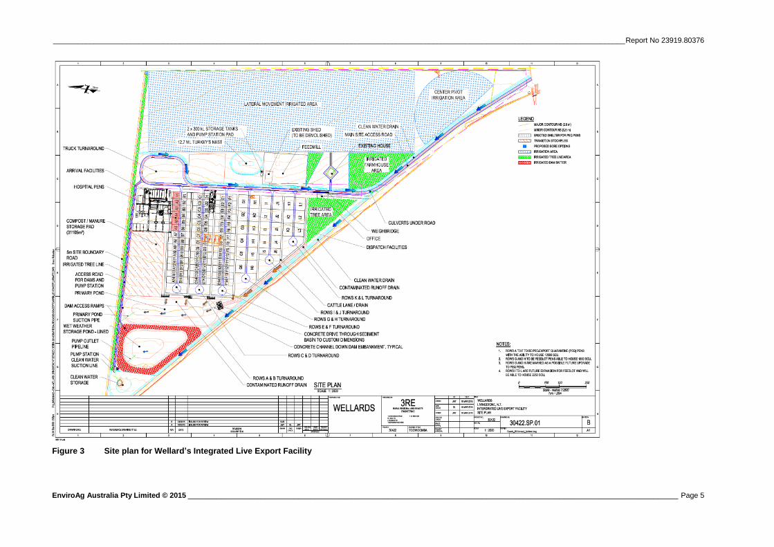
This ESCP is limited to the following construction activities within the project site, including construction of:
Care takers house;
Commodity and fodder storage sheds;
Feed mill;
Freshwater storage (ring tank and clean water tanks), for capture and storage of roof runoff and
storage of ground waters for stock water supply;
Pre-Export Quarantine (PEQ) holding yard (Normalised holding capacity 3,000 SCU, with a
12,000 head ‘peak’ short term (~4 day average) holding capacity over a 16 day shipment cycle
time (25% occupancy);
Livestock Truck washing facility;
1,000 SCU (Short term) feedlot; for holding stock for up to 30 days;
Installation of water pipes for pivot irrigators;
Fresh water supply turkeys nest;
Primary waste water pond;
Wet weather storage pond;
Fresh water runoff dam;
Sedimentation basins;
Hard Stand Area;
Contour banks; and
Clearing of native vegetation.
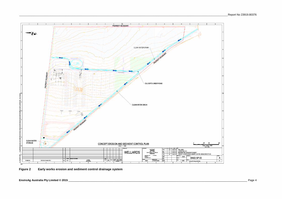
The proposed ILEF will be constructed in two stages, with an early works package preceding the works to
provide access, erosion and sediment control measures, temporary site facilities and water infrastructure for
construction works to commence (Figure 2). The early works is expected to commence in late 2015 followed
by Stages 1 and 2, to have all the works completed by September 2016.

______________________________________________________________________________ Report No 23919.80376
EnviroAg Australia Pty Limited © 2015 ____________________________________________________________ Page 2
Stage 1 includes the construction of most of the ILEF facilities (induction yards, bore, feedmill, office,
commodity storage sheds, wastewater treatment ponds, clean water storage, diversion drains and the
irrigation area). It also includes 80% of the short term holding pre export quarantine (PEQ) yards. The yard
would then be ready to receive and process cattle.
Stage 2 would see the construction of the final rows of the short term feedlot, additional storage sheds and
feed mill facilities. This stage is planned for construction in 2017.

____________________________________________________________________________________________________________________________________________ Report No 23919.80376
EnviroAg Australia Pty Limited © 2015 ________________________________________________________________________________________________________________________ Page 3
Figure 1 The undeveloped site as it currently is
____________________________________________________________________________________________________________________________________________ Report No 23919.80376
EnviroAg Australia Pty Limited © 2015 ________________________________________________________________________________________________________________________ Page 4
Figure 2 Early works erosion and sediment control drainage system
____________________________________________________________________________________________________________________________________________ Report No 23919.80376
EnviroAg Australia Pty Limited © 2015 ________________________________________________________________________________________________________________________ Page 5
Figure 3 Site plan for Wellard’s Integrated Live Export Facility

______________________________________________________________________________ Report No 23919.80376
EnviroAg Australia Pty Limited © 2015 ____________________________________________________________ Page 6
2. Project Area and Site Characteristics
2.1 Geography
“Livingstone Valley” drains from east to west, with elevation varying from approximately 60 AHD
(Australian Height Datum) to 40 AHD across the site. The gradient is approximately 1.5% to 3%.
The site is located in the NT Van Diemen soils group. Within this zone the landscape is undulating to rolling
hills and rises with mostly poorly developed, shallow and gravelly Kandosols, though Tenosols dominate the
southern half of the zone.
2.2 Geology
The Kandosol soils overlie a sedimentary geology. The Kandosols contain varying amounts of clay. Clays
are generally shallow on the upper slopes or exposed hill crests; these are the likely recharge areas.
Haig and Townsend (date) describe the geology:-
The bedrock geology consists of dolomite, carbonate rocks, sandstone, shale, siltstone, schist, granite
and metamorphic rocks. The highest yielding bedrock aquifers are the dolomites and carbonate rocks.
Lesser yielding aquifers are found in the fractured sandstones and siltstone. Schist, granite and
metamorphic rocks are low yielding aquifers.
Most of the region is covered with 20 to 50 metres of more recent sandstone, siltstone and claystone.
There is a 5 to 10 metre thick layer of laterite ie. a residual clayey layer mainly consisting of
hydroxides of iron and aluminium formed under tropical climatic conditions by the weathering of
igneous rocks, that forms a capping layer over most of the area.
Recharge to the regional aquifers is a result of direct infiltration of rain through the surface deposits.
The average annual rainfall in the region is 1,700 mm, as much as 200 mm is recharged to some of
the more transmissive areas in the catchment.
Table 1 Typical soil profile (results noted from Test Pit 2)
Depth (m) Horizon Description
0.0 - 0.10 A1 Dark brown sandy silt trace of clay. Massive structure with humic layer at a A0 with
minor gravel
0.10 - 0.20 A2 Light yellow brown sandy silt. Massive structure, saturated, weak and partially leached
0.20 - 0.30 B1 Orangey yellow clayey, sandy silt. Massive structure.
0.30 - 0.65 B2 Red silty (20-30%) clay (20-30%) with gravel. Massive structure.
0.65 - 0.90 B3 Red/Yellow gravelly clay. Massive structure with decomposed ferricrete and red yellow
mottles.
0.90 - 1.20 C1 Ferricrete rock with red yellow mottles.
2.3 Hydrology
The site has no creeks and is situated at the top of a watershed. Water runs off to the west. The site does not
flood.
Low lying areas in the north-west corner of the property, where it is lowest, and proximate to the railway line
are flat and become inundated with runoff from upslope.

______________________________________________________________________________ Report No 23919.80376
EnviroAg Australia Pty Limited © 2015 ____________________________________________________________ Page 7
Areas to the east of Stuart Highway are considered to be recharge areas. There is some connectivity between
these recharge areas, ground waters and downslope surface waters. Berri Creek gains water from the shallow
groundwater systems and it is groundwater that delivers water to this system during the dry season.
The chosen site is underlain by a considerable depth of clay and, as such, transmission of surface waters from
the property to the ground waters is at best slow, if not unlikely.
2.4 Vegetation and Current Land Use
The site has predominantly been cleared and developed. 2.6 ha of degraded remnant vegetation remains
onsite (Figure 1). Some exotic trees have been planted proximate to the existing residence. The vast majority
of the property has been cultivated and sown to improved pasture species; Jarra and Tully grasses. The
remnant vegetation will need to be cleared for development (Figure 3).
2.5 Soil Erosion Assessment
An erosion risk assessment has been completed for the ILEF Darwin site in accordance with the principles
outlined in Matthews (2008). The assessment concluded that during the land disturbance activities (12
months) the total soil loss would equal approximately 101.71 tonnes (Table 2). An area of approximately
51.63 ha would be disturbed during this period. (Calculation presented in Appendix A)
Further to this, IECA (2008) states that developments disturbing more than 4 ha require 5 soil samples per
every 2 ha of disturbance. As such it could be argued that the amount of soil samples supporting this erosion
risk assessment is insufficient in order to be representative for the whole site. However, the samples taken are
representative of the areas which will be disturbed and increase the erodibility of the site, hence; the erosion
risk assessment has covered the worst case scenario.
Table 2 Summary of site characteristics and constraints
Characteristic/Constraint Value/Rating
Rainfall erosivity (R) 13,738
General slope gradient 1.2 %
Potential erosion hazard Low, slopes < 10% (from figure 4.4 in Matthews (2008))
Calculated soil loss 1.97 tonnes/ha/year
Total soil loss 101.71 tonnes
Soil loss class Class 1 Very Low (from table 4.2 in Matthews (2008))
Soil texture group Type C and D (Australian Soil Classification)
Runoff coefficient for ARI of 10 years 1.54
Volumetric runoff coefficient 0.81
Soil hydrological group Group D Clay (Dept. LRM)
Total site area 90.5 ha
Disturbed site area 51.63 ha
Annual mean rainfall 1698 mm (Bureau of Meteorology 2014, Berry Springs)
75th
percentile, 5-day rainfall event 36 mm
Duration of project (Construction) 12 months
1 Pilgrim, 2001

______________________________________________________________________________ Report No 23919.80376
EnviroAg Australia Pty Limited © 2015 ____________________________________________________________ Page 8
2.6 Estimated Soil Loss
The estimated soil loss (tonnes/ha/year) is derived from the Revised Universal Soil Loss equation (RUSLE),
Equation 2 below.
A = R x K x LS x P x C (Equation 2)
Where;
A = computed soil loss (tonnes/ha/year);
R = rainfall erosivity factor;
K = soil erodibilty;
LS = slope length/ gradient factor;
P = erosion control practice factor;
C = ground cover factor.
The site specific values used to calculate the soil loss for the Darwin ILEF are shown in Table 3. Applying
the site specific values, calculation of RUSLE results in a soil loss of approximately 1.97 tonnes/ha/year.
Table 3 Site specific values for calculation of RUSLE
Factor Site Specific Value
Rainfall erosivity (R) 13,738
Soil erodibility (K) 0.012
Length-Slope (LS) 0.12
Erosion control practice (P) 12
Ground cover (C) 0.13
2 Due to a lack of spatial data and tillage practices, it is assumed that the value of the P factor is 1. The estimated soil loss
ratio reflects the erosion potential under conditions with no soil conservation support practices (Lu. et. al., 2001).
3 Grazing modified pastures, Table 6.5 (DHACERG, 2006)

______________________________________________________________________________ Report No 23919.80376
EnviroAg Australia Pty Limited © 2015 ____________________________________________________________ Page 9
3. ESCP Control Conditions
A revised ESCP including a diagram with the mapped control measures throughout the construction phases
of the project will be provided on finalisation of the detailed design.
3.1 General Instructions
This ESCP shall be read in conjunction with engineering plans and any other plans or written
instructions issued in relation to the development;
All personnel, including contractors and subcontractors, must understand their responsibility to
minimise the potential for soil and water pollution and undertake all measures described in this
ESCP;
Land disturbance is to be kept to a minimum at all times and where possible be limited to a
maximum of 5 meters from the edge of any essential construction activity. Land clearing must
be delayed as long as practicable and disturbed areas rehabilitated as soon as practical;
Temporary end-of-day control measures must be put in place in the event that significant
rainfall is expected. These may include the application of flow diversion banks, straw bales and
geo-textile; and,
Diversion banks shall be constructed along the top side of paddocks where required to intercept
run-on from adjacent land away from the project site. All banks shall be seeded and/or lined
with suitable material to prevent erosion. Run-on shall be directed to stable, well grassed
waterways or drainage lines.
3.2 Construction Sequence
All work must be undertaken in the following sequence. Each subsequent stage is not to commence until the
previous one is completed.
Table 4 Construction Sequence staging
Sequence
Number
Construction Stage
1 Construct stabilised site access
2 Mark access tracks, sensitive areas and no-go zones as required. Temporary fencing may be
used to mark access roads and no-go zones. Access areas should be limited to a maximum
width of 10m
3 Install clean water diversion banks where required, directing overland flow away from
disturbed areas and into stable areas. Stabilise drains with suitable material to prevent
erosion.
4 Install sediment fences or other appropriate sediment controls downslope from disturbed
areas.
5 Clear site, strip and stockpile topsoil/seedbed for later reinstatement or landscaping
purposes.
6 Perform earth works as required and in accordance with engineering plans.
7 Apply erosion control measures to disturbed areas as required.
8 Monitor and improve controls as necessary.
9 Undertake final site stabilisation.
______________________________________________________________________________ Report No 23919.80376
EnviroAg Australia Pty Limited © 2015 ___________________________________________________________ Page 10
3.3 Site Specific Conditions
3.3.1 Clearing of Native Vegetation
Clearing of native vegetation must be kept to a minimum at all times. Where clearing is required temporary
sediment controls such as sediment fences must be installed prior to commencing clearing activities. Cleared
vegetation should be mulched and used for soil stabilisation within the project site or relocated to adjacent
vegetated areas within the project site to provide shelter and refugee habitat for fauna.
3.3.2 Installation of Pivot Irrigation
To manage erosion and sedimentation from pipe installation for pivot irrigators, disturbed areas shall be
seeded with a quick germinating annual and covered with jute matting as soon as practical after installation
of pipe. Temporary sediment controls shall be applied as necessary to ensure pollution of downslope lands
does not occur.
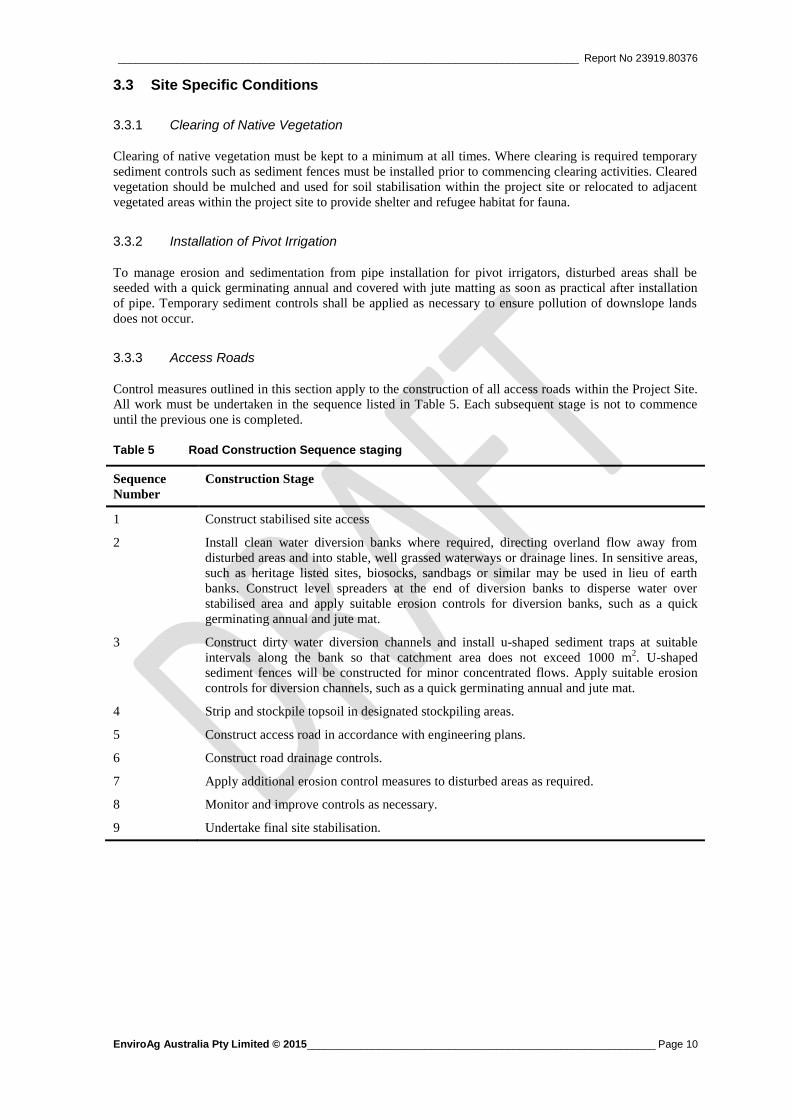
3.3.3 Access Roads
Control measures outlined in this section apply to the construction of all access roads within the Project Site.
All work must be undertaken in the sequence listed in Table 5. Each subsequent stage is not to commence
until the previous one is completed.
Table 5 Road Construction Sequence staging
Sequence
Number
Construction Stage
1 Construct stabilised site access
2 Install clean water diversion banks where required, directing overland flow away from
disturbed areas and into stable, well grassed waterways or drainage lines. In sensitive areas,
such as heritage listed sites, biosocks, sandbags or similar may be used in lieu of earth
banks. Construct level spreaders at the end of diversion banks to disperse water over
stabilised area and apply suitable erosion controls for diversion banks, such as a quick
germinating annual and jute mat.
3 Construct dirty water diversion channels and install u-shaped sediment traps at suitable
intervals along the bank so that catchment area does not exceed 1000 m2. U-shaped
sediment fences will be constructed for minor concentrated flows. Apply suitable erosion
controls for diversion channels, such as a quick germinating annual and jute mat.
4 Strip and stockpile topsoil in designated stockpiling areas.
5 Construct access road in accordance with engineering plans.
6 Construct road drainage controls.
7 Apply additional erosion control measures to disturbed areas as required.
8 Monitor and improve controls as necessary.
9 Undertake final site stabilisation.
______________________________________________________________________________ Report No 23919.80376
EnviroAg Australia Pty Limited © 2015 ___________________________________________________________ Page 11
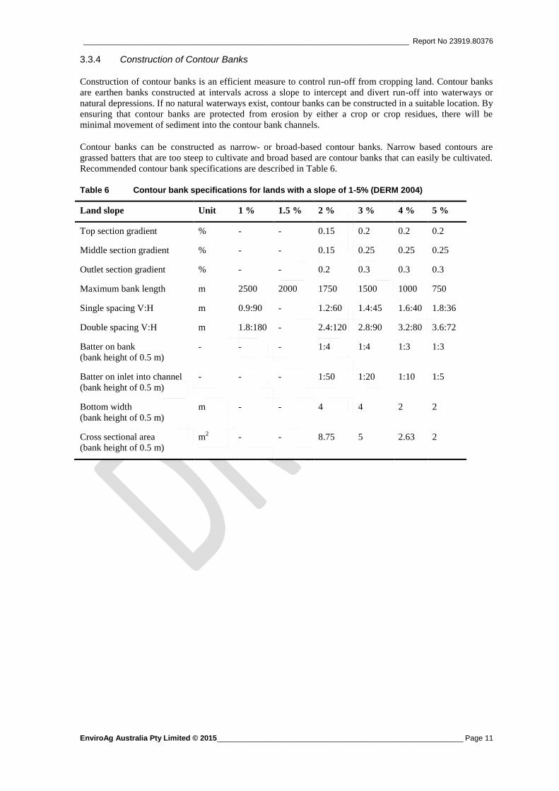
3.3.4 Construction of Contour Banks
Construction of contour banks is an efficient measure to control run-off from cropping land. Contour banks
are earthen banks constructed at intervals across a slope to intercept and divert run-off into waterways or
natural depressions. If no natural waterways exist, contour banks can be constructed in a suitable location. By
ensuring that contour banks are protected from erosion by either a crop or crop residues, there will be
minimal movement of sediment into the contour bank channels.
Contour banks can be constructed as narrow- or broad-based contour banks. Narrow based contours are
grassed batters that are too steep to cultivate and broad based are contour banks that can easily be cultivated.
Recommended contour bank specifications are described in Table 6.
Table 6 Contour bank specifications for lands with a slope of 1-5% (DERM 2004)
Land slope Unit 1 % 1.5 % 2 % 3 % 4 % 5 %
Top section gradient % - - 0.15 0.2 0.2 0.2
Middle section gradient % - - 0.15 0.25 0.25 0.25
Outlet section gradient % - - 0.2 0.3 0.3 0.3
Maximum bank length m 2500 2000 1750 1500 1000 750
Single spacing V:H m 0.9:90 - 1.2:60 1.4:45 1.6:40 1.8:36
Double spacing V:H m 1.8:180 - 2.4:120 2.8:90 3.2:80 3.6:72
Batter on bank
(bank height of 0.5 m)
- - - 1:4 1:4 1:3 1:3
Batter on inlet into channel
(bank height of 0.5 m)
- - - 1:50 1:20 1:10 1:5
Bottom width
(bank height of 0.5 m)
m - - 4 4 2 2
Cross sectional area
(bank height of 0.5 m)
m2 - - 8.75 5 2.63 2

______________________________________________________________________________ Report No 23919.80376
EnviroAg Australia Pty Limited © 2015 ___________________________________________________________ Page 12
3.3.5 Water Storage Area
The water storage area is subject to the following control measures (Table 7). Each subsequent stage is not to
commence until the previous one is completed.
Table 7 Water Storage Area Construction Sequence staging
Sequence
Number
Construction Stage
1 Install clean water diversion banks where required.
2 Install sediment fences downslope of lands to be disturbed for construction of the CAR dam
and storage ponds.
3 Stabilise land surfaces disturbed by construction of CAR basin and storage ponds as soon as
final levels are established.
4 Construct dirty water diversion channels to direct run-off from disturbed areas
5 Strip and stockpile topsoil from areas to be disturbed from construction.
6 Perform earth works as required and in accordance with engineering plans.
7 Apply erosion control measures to disturbed areas as required.
8 Monitor and improve controls as necessary.
9 Undertake final site stabilisation
3.3.6 Hardstand Area
The hardstand area is subject to the following control measures (Table 8). Each subsequent stage is not to
commence until the previous one is completed.
Table 8 Hardstand Area Construction Sequence staging
Sequence
Number
Hardstand Construction Stage
1 Install clean water diversion banks where required.
2 Strip and stockpile topsoil from areas to be disturbed from construction
3 Perform earth works as required and in accordance with engineering plans
4 Construct rock lined chutes and outlet structures for cut and fill.
5 Apply erosion control measures to disturbed areas as required.
6 Monitor and improve controls as necessary.
7 Undertake final site stabilisation
3.4 Erosion Control Conditions
The following erosion control measures are applicable to all construction works associated with the
Livingstone ILEF Development.
Clearly visible barrier fencing shall be installed at the discretion of the site superintendent to
limit unnecessary disturbance.
Soil materials must be replaced in the same order they are removed from the ground.
Topsoil/seedbed shall be stockpiled for later reinstatement or landscaping purposes.

______________________________________________________________________________ Report No 23919.80376
EnviroAg Australia Pty Limited © 2015 ___________________________________________________________ Page 13
Disturbed areas must be seeded with a quick germinating annual as soon as practical after earth
works have been completed. All disturbed areas are to have a maximum C-factor of 0.15
(minimum of 50 percent ground cover) after 20 days of inactivity, even though works might
continue later.
Stockpiles that are to be stored for more than 10 days also have to have a maximum C-factor of
0.15 within 20 days (50 percent ground cover). This can be achieved by using a quick
germinating annual or geo-textile.
Ensure the time from starting land disturbance activities to stabilisation is less than six months.
Mulch cleared vegetation and place on disturbed areas to improve soil stability.
Ideally, handle topsoil when moist (not wet or dry) to avoid deterioration of soil structure.
Apply additional erosion control measures as required and in particular to areas of high erosion
risk. Additional erosion control products include, but are not limited to geo-textile, jute-mesh,
mulch, hydraulic seeding. Erosion blankets should be installed as per standard drawing ECM-
01.
Synthetic reinforced erosion control mats and blankets must not be placed within or adjacent to
riparian zones and watercourses if such materials are likely to cause environmental harm to
wildlife or wildlife habitats.
Disturbed ground is not to exceed a slope length of 40 meters and 2 percent, unless additional
erosion controls are applied. To reduce the slope length mid-slope flow control berms may be
installed.
All earthworks, including waterways, drains, spillways and their outlets, will be constructed to
be stable in at least the 10-year ARI time of concentration storm event.
Ensure effective weed control management is implemented.
Construct earth batter with as low gradient as possible, but not steeper than 2(H):1(V) if the
total slope length is 10 meters, 3(H):1(V) if the total slope length is 15 meters, 4(H):1(V) if the
total slope length is 22 meters and 5(H):1(V) if the total slope length is 30 meters.
Ensure discharged water does not cause an increased erosion hazard to downslope lands and
waterways, which can be achieved by using geo-textile, installing energy dissipaters as per
standard drawing OS-01 or constructing level spreaders as per standard drawing LS-01.
3.5 Pollution Control Conditions
All stockpiled material must be located within designated stockpiling areas and be constructed
as low, elongated mounds, no more than 2 m high. Stockpiles of erodible material must have
sediment filters installed on the downslope side to trap sediment from run-off, as well as an
earth bank constructed on the upslope side to divert run-on water around stockpile.
Stockpiles must not be placed closer than 2 m from hazard areas such as concentrated water
flows, gutters and existing vegetation and at least 40 m away from any riparian lands.
All disturbed areas are to have sediment control measures installed on the down slope side of
the disturbance and be designed to withstand at least a 10-year ARI storm event.
Installed sediment controls are to be maintained and improved until site has been successfully
stabilised.
Minimise dust generation and wind erosion by applying water, gluon or erosion control
blankets where necessary.
Sediment fences will:
o Be installed where shown on the Erosion & Sediment Control Plan Drawing and
elsewhere at the discretion of the site superintendent.
o Have no larger catchment than 1000 m2, or have returns of 1 metre upslope at intervals
along the fence so that the catchment area does not exceed 1000 m2.
o Be placed in a way that keeps the sediment as close to its source as possible.

______________________________________________________________________________ Report No 23919.80376
EnviroAg Australia Pty Limited © 2015 ___________________________________________________________ Page 14
4. Waste Management
The following waste management principles are to be implemented throughout the project:
Separation of reusable and recyclable materials from waste.
Storage of waste receptacles away from watercourses and intertidal areas.
Emptying of waste bins as required and disposal of waste appropriately.
Wash down of materials and equipment to be undertaken away from watercourses and
intertidal areas and sediment filters to be used if required.
Where practical, waste materials should be reused on-site, for example by chipping or
mulching cleared vegetation.
For vegetation that cannot be reused on-site, approval from council should be sought before
disposing of it at landfill or burning it on-site.
Maintain and regularly check plant and equipment for leaks (e.g. fuels, oils, hydraulic fluids).
Bund all fuel and oil storage areas to contain 120 percent of the maximum capacity of the
largest storage container. These storage facilities and bunds must be regularly inspected for
spills and drained of rainwater so there is sufficient storage volume in the event of a spill.
Emergency spill response kits must be available on-site at all times. These kits must contain
spill absorbent and containment materials to ensure materials do not migrate off-site, reach
water bodies or create risk to employees.
In the event of an emergency or spill, work must cease immediately and appropriate action
undertaken. Actions may include, but are not limited to, containment of the spill, clean-up of
contaminated soil and rectification of the problem that resulted in the spill.

______________________________________________________________________________ Report No 23919.80376
EnviroAg Australia Pty Limited © 2015 ___________________________________________________________ Page 15
5. Stabilisation and Rehabilitation
During all stages of the development, all disturbed areas, including stockpiles, are to have a maximum C-
factor of 0.15 (50 percent ground cover or more) after 20 days. Additionally, upon reinstatement and site
close-out the site is to achieve a C-factor of less than 0.05 (70 percent cover or more) within 60 days of
completion.
Guiding principle to achieve successful stabilisation and rehabilitation of disturbed lands, include:
Prepare a good seedbed and loosen compacted soil before sowing any seed;
Avoid cultivation in very wet or very dry conditions;
Apply appropriate ameliorants and/or fertilisers as required;
Use plant species that are consistent within the existing soil conditions and climate;
Undertake effective weed management; and
Implement maintenance regimes.
Temporary erosion and sediment controls are not to be removed before the site has been adequately stabilised
and rehabilitated.

______________________________________________________________________________ Report No 23919.80376
EnviroAg Australia Pty Limited © 2015 ___________________________________________________________ Page 16
6. Monitoring and Maintenance
During all stages of the development, site inspections are to be carried out at least weekly, immediately
before site closure and immediately following/during rain events that cause run-off. These site inspections
may be implemented as part of a broader project specific Construction Environmental Management Plan
(CEMP). Site inspections shall be done in a systematic manner and include recordings of:
The condition and effectiveness of control measures; and
Any maintenance requirements, including removal of sediment trapped in sediment fences,
diversion drains, sediment basins and waterways etc. Ensure that:
o Sediment filters are maintained so that no more than 30 percent of their design capability
is lost to accumulated sediment.
o Any sediment removed is placed in areas where further pollution to down slope lands and
water will not occur.
o Construction materials are replaced as required.
o Installed sediment controls are maintained until site has been appropriately stabilised.
Any improvements required, including additional sediment fences and maintenance of
diversion banks;
Maintenance requirements for grass cover in waterways;
The condition of recently stabilised areas and any required repairs or measures to be initiated;
Vehicle movements and signs of sediment being transported off-site through vehicle
movements;
Condition of waste bins; and
Any modifications required to this plan.
Sediment basins must be kept in good working condition and attention will be given to:
Recent works to ensure drains and basins have been constructed suitably to the local conditions
and that sediment laden water is managed appropriately;
Degradable products to ensure they are replaced as necessary;
Sediment removal to ensure the design capacity or less remains in the settling zone; and
Waters in sediment basins that occupy more than one quarter of the design capacity will be
treated with a flocculating agent and discharged within five days from any storm event large
enough to fill the basin to that level.
Furthermore, should significant erosion occur, demonstrated by visual loss of topsoil, subsoil or stockpiled
material, all efforts must be made to address further loss from the site. This includes, but is not limited to:
Diversion or slowing of water onto and away from the eroded area. Care should be taken not to
unduly disturb other surfaces capable of becoming erosion sources.
Improvements to earthworks to reduce or stabilise erodible slopes.
The installation or improvement of sediment control structures.

______________________________________________________________________________ Report No 23919.80376
EnviroAg Australia Pty Limited © 2015 ___________________________________________________________ Page 17
7. References
Boggs, G., J Fortune, J., Parry, D., Townsend, S., Wasson, R., and Williams, D.(2006). ‘Sediment, nutrients,
organic matter and metals input to Darwin Harbour from its catchment, and the ecological impacts on the
Harbour’ Darwin Harbour Advisory Committee Ecosystem Research Group (DHACERG).
Bureau of Meteorology, (2015). Climate Statistics for Australian Locations – Darwin Airport, (Site Number:
014015). Australian Bureau of Meteorology. Available from:
http://www.bom.gov.au/climate/averages/tables/cw_075041_All.shtml [Accessed 03/08/2015].
Bureau of Meteorology, (2015). Climate Statistics for Australian Locations – Berry Springs, (Site Number:
014215). Australian Bureau of Meteorology. Available from:
http://www.bom.gov.au/climate/averages/tables/cw_075041_All.shtml [Accessed 03/08/2015].
Landcom, 2004. Managing Urban Stormwater: Soils and Construction Volume 1. 4th
edition. © New South
Wales Government.
Loch, R.J., Slater, B.K., and Devoil, C. (1998). ‘Soil erodibility (K) values for some Australian soils’.
Australian Journal of Soil Research Vol. 36, pp. 1045-1056.
Lu, H., Gallent, J., I.P., Moran, C., and Priestley, G. (2001), ‘Prediction of Sheet and Rill Erosion Over the
Australian Continent, Incorporating Monthly Soil Loss Distribution’. Technical Report 13/01, CSIRO Land
and Water, Canberra, Australia.
Matthews, M., (2008). ‘Erosion and Sediment Control Manual Version 1.2 “Maroon Manual”. Sunshine
Coast Regional Council. Available from: http://www.sunshinecoast.qld.gov.au/sitePage.cfm?code=erosion-
sediment-manual [Accessed 7 August].
Mitasova, H., Hofierka, J., Zlocha, M. and Iverson, L.R. (1996).’ Modelling topographic potential for erosion
and deposition using GIS’. International Journal of Geographical Information Systems, 10: 629 - 641.
NT Government (2014). Erosion and Sediment Control Plans for Rural Development. Available from:
http://www.lrm.nt.gov.au/__data/assets/pdf_file/0008/356408/ESCP_Rural_Dev_Dec2014.pdf [Accessed
14/09/2015].
The Clean Water Team Guidance Compendium for Watershed Monitoring and Assessment (2011) State
Water Resources Control Board 5.1.3 FS-(RC)
Western, L. and Pilgrim, A. (2001). ‘Learning as We Go: Catchment Management in the Urban Rural
Fringe.’ Australian Journal of Environmental Education, 17, pp 143-148.
Yu, B., (1998). ‘Rainfall erosivity and its estimation for Australia’s tropics’. Australian Journal of Soil
Research, 36: 143–65.

______________________________________________________________________________ Report No 23919.80376
EnviroAg Australia Pty Limited © 2015 ___________________________________________________________ Page 18
8. Appendices
Appendix A. Soil Erosion Assessment Calculations A-1

______________________________________________________________________________ Report No 23919.80376
EnviroAg Australia Pty Limited © 2015 __________________________________________________________ Page A-1
Appendix A. Soil Erosion Assessment Calculations

______________________________________________________________________________ Report No 23919.80376
EnviroAg Australia Pty Limited © 2015 __________________________________________________________ Page A-2
Erosion Risk Assessment
According to Matthews (2008) the erosion risk for a particular area can be calculated with Equation 1.
R = A x B x T (Equation 1)
Where R = predicted total soil loss in tonnes, A = calculated soil loss in tonnes/hectare/year, B = surface area
of disturbance (hectares), T = predicted duration of the disturbance (months disturbed/12).
The soil loss (tonnes/ha/year) is derived from the Universal Soil Loss Equation, Equation 2 below.
A = R x K x LS x P x C (Equation 2)
Where, A = computed soil loss (tonnes/ha/yr), R = rainfall erosivity factor, K = soil erodibility factor, LS =
slope length/gradient factor, P = erosion control practice factor, C = ground cover factor.
Calculation of Equation 2
To R-factor was calculated from rainfall data from the Darwin Airport (Yu, 1998) to be 13,738.
The LS factor for the ILEF development site was 0.12, which corresponds to a typical slope length of 1.2
percent over 575 meters.
The P factor was set to 1 (default)
The C factor to 1 (Grazing modified pastures).
The K factor was derived from the soil data in Table 1 and the data of the disturbed soil was used, resulting
in a K-factor of 0.012.
The resulting soil loss (tonnes/ha/year) is then calculated as below:
A = 13,738 x 0.012 x 0.12 x 1 x 0.1 = 1.97 tonnes/ha/year

______________________________________________________________________________ Report No 23919.80376
EnviroAg Australia Pty Limited © 2015 __________________________________________________________ Page A-3
Calculation of Equation 1
The total soil loss is calculated by multiplying the estimated soil loss (1.97 tonnes/ha/year) with the total area
of ground disturbance (51.63 ha) and the duration of the project (12 months/12):
R = 1.97 x 51.63 x (12/12) = 101.71 tonnes
Coefficient Calculation
To determine the peak volumetric flow the formula for the Rational Method (Pilgrim, 2001) is applied:
AICQ ty
y 278.0 …. (F.2)
Where Qy = peak volumetric flow (m³/s) having an ARI of y years, C = runoff coefficient (typically 0.8), yIt = rainfall intensity (mm/h) of design storm having duration tc, and A = catchment area (km²).
For the runoff coefficient of a 10 year ARI rainfall event;
The runoff coefficient (C) is 0.08 in accordance with Pilgrim (2001).
The rainfall intensity (yIt) of a 10 year ARI rainfall event is 76.5 mm/h.
The catchment area of the Wellard’s ILEF site is 0.905km2
The resulting peak volumetric flow having a 10 year ARI is below;
Qy = 0.278 x 0.08 x 76.5 x 0.905 = 1.54 (m3/s).