kentucky erosion prevention and sediment control …conservation.ky.gov/publications/kentucky...
TRANSCRIPT
Kentucky Erosion Prevention and Sediment Control Field Guide
Funding for this project was provided in part by a grant from the U.S. Environmental Protection Agency (USEPA) through the Kentucky Division of Water (KDOW), Nonpoint Source Section
and the Kentucky Division of Conservation (KDOC) to Tetra Tech, as authorized by the Clean Water Act Amendments of
1987, Section 319(h) Nonpoint Source Implementation Grant # C9994861-01. Mention of trade names or commercial products, if any, does not constitute endorsement. This
document was printed on recycled paper.
Technical Review Committee
Bruce Scott, KY Division of Water
Tom Gabbard, KY Division of Water
Joe Ferguson, KY Division of Water
Jennifer Thompson, KY Division of Conservation
Carolyn Hestand, KY Division of Conservation
David Waldner, KY Transportation Cabinet
Stephen Bowling, KY Transportation Cabinet
Ray Werkmeister, KY Transportation Center
Kurt Mason, USDA NRCS
Charles Farmer, USDA NRCS
Mary Kathryn Dickerson, Boone, Kenton, Campbell Cons. Dist.
David Uckotter, Lexington-Fayette Urban Co. Govt.
Randy Stambaugh, Metropolitan Sewer District
John Lyons, NKY Sanitation District # 1
James Kipp, KY Water Resources Research Institute
Lindell Ormsbee, Tracy Farmer Center for the Environment
Laura Wagers, KY Association of Counties
Henry Duncan, UK Cooperative Extension Service
Richard Warner, UK Cooperative Extension Service
Judy Petersen, KY Waterways Alliance
Russ Barnett, KY Institute for Sustainable Development
Michael Berthurem, KY League of Cities
Juva Sizemore Barber, Home Builders Association of Kentucky
Richard Walker, Tetra Tech
John Kosco, Tetra Tech
William Marshall, Tetra Tech
Barry Tonning, Tetra Tech
This document has been approved by the Kentucky Transportation Cabinet, and reflects Best Management Practices for erosion and
sediment control for highway construction projects.
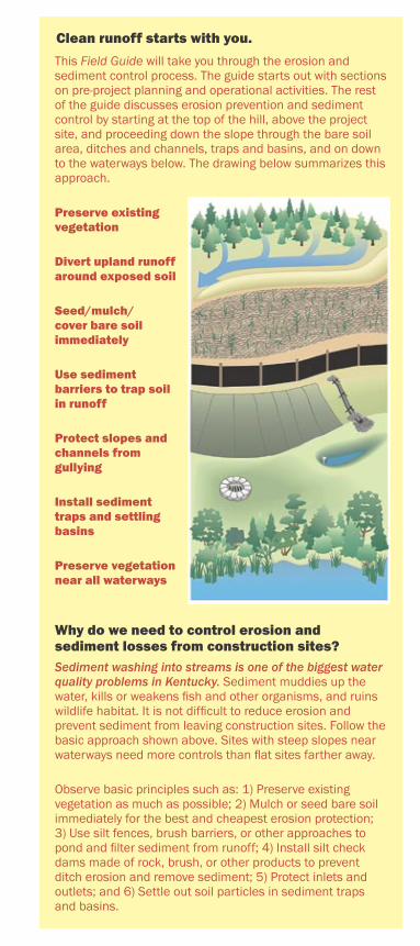
This Field Guide will take you through the erosion and sediment control process. The guide starts out with sections on pre-project planning and operational activities. The rest of the guide discusses erosion prevention and sediment control by starting at the top of the hill, above the project site, and proceeding down the slope through the bare soil area, ditches and channels, traps and basins, and on down to the waterways below. The drawing below summarizes this approach.
Preserve existing vegetation
Divert upland runoff around exposed soil
Seed/mulch/cover bare soil immediately
Use sediment barriers to trap soil in runoff
Protect slopes and channels from gullying
Install sediment traps and settling basins
Preserve vegetation near all waterways
Why do we need to control erosion and sediment losses from construction sites?Sediment washing into streams is one of the biggest water quality problems in Kentucky. Sediment muddies up the water, kills or weakens fish and other organisms, and ruins wildlife habitat. It is not difficult to reduce erosion and prevent sediment from leaving construction sites. Follow the basic approach shown above. Sites with steep slopes near waterways need more controls than flat sites farther away.
Observe basic principles such as: 1) Preserve existing vegetation as much as possible; 2) Mulch or seed bare soil immediately for the best and cheapest erosion protection; 3) Use silt fences, brush barriers, or other approaches to pond and filter sediment from runoff; 4) Install silt check dams made of rock, brush, or other products to prevent ditch erosion and remove sediment; 5) Protect inlets and outlets; and 6) Settle out soil particles in sediment traps and basins.
Clean runoff starts with you.
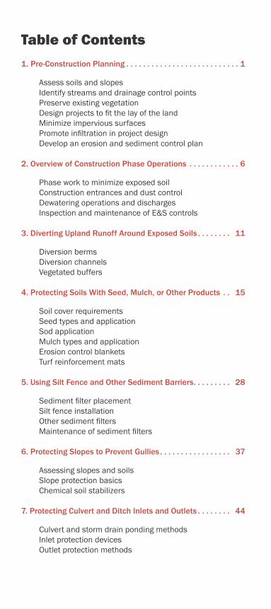
Table of Contents
1. Pre-Construction Planning . . . . . . . . . . . . . . . . . . . . . . . . . . . 1
Assess soils and slopes Identify streams and drainage control points Preserve existing vegetation Design projects to fit the lay of the land Minimize impervious surfaces Promote infiltration in project design Develop an erosion and sediment control plan
2. Overview of Construction Phase Operations . . . . . . . . . . . . 6
Phase work to minimize exposed soil Construction entrances and dust control Dewatering operations and discharges Inspection and maintenance of E&S controls
3. Diverting Upland Runoff Around Exposed Soils . . . . . . . . 11
Diversion berms Diversion channels Vegetated buffers
4. Protecting Soils With Seed, Mulch, or Other Products . . 15
Soil cover requirements Seed types and application Sod application Mulch types and application Erosion control blankets Turf reinforcement mats
5. Using Silt Fence and Other Sediment Barriers. . . . . . . . . 28
Sediment filter placement Silt fence installation Other sediment filters Maintenance of sediment filters
6. Protecting Slopes to Prevent Gullies. . . . . . . . . . . . . . . . . 37
Assessing slopes and soils Slope protection basics Chemical soil stabilizers
7. Protecting Culvert and Ditch Inlets and Outlets . . . . . . . . 44
Culvert and storm drain ponding methods Inlet protection devices Outlet protection methods
8. Stabilizing Drainage Ditches . . . . . . . . . . . . . . . . . . . . . . . 52
Drainage ditch slopes and soils Erosion control blanket and turf mat linings Silt check dams of rock, brush, or other products Lining steep channels
9. Installing Sediment Traps and Basins . . . . . . . . . . . . . . . 57
Locations for traps and basins Sediment traps Sediment basins Sizing considerations Inspection and maintenance
10. Protecting Stream Channels, Wetlands, and Lakes . . . 62
Setback requirements Vegetated buffers Stream bank stabilization Stream crossings
11. Maintaining & Closing Out Your Construction Project . 66
Inspecting storm water flow structures Managing trash, materials, and supplies Vegetated cover considerations for close-out Removing temporary sediment controls Final site stabilization
12. Regulatory Information . . . . . . . . . . . . . . . . . . . . . . . . . . 69
Storm water permits Erosion protection and sediment control plans Utility construction regulations Transportation project regulations Section 404 permits for wetlands and streams
Appendices
Appendix A: KPDES Permit Requirements Appendix B: Local ESC Plan Requirements Appendix C: Section 404 Permits for Work in Waterways Appendix D: 401 Water Quality Certification Appendix E: Floodplain Construction Permits Appendix F: Additional Details for KYTC Projects Appendix G: Erosion/Sediment Control Checklist Appendix H: Kentucky Site Inspection Report
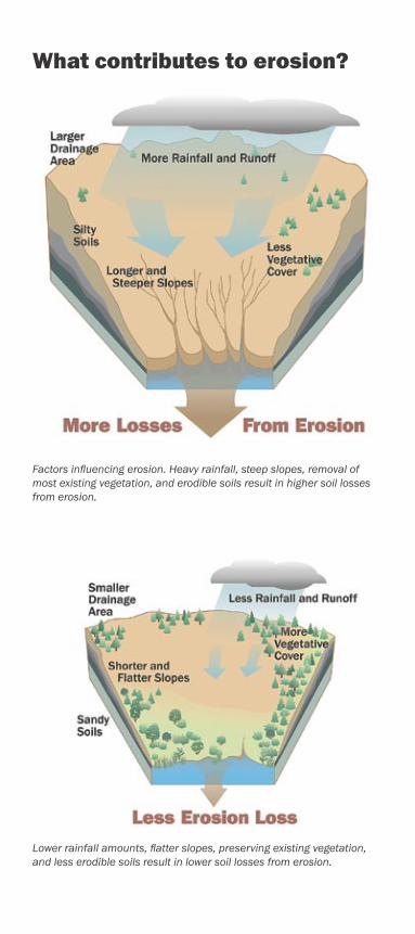
Factors influencing erosion. Heavy rainfall, steep slopes, removal of most existing vegetation, and erodible soils result in higher soil losses from erosion.
Lower rainfall amounts, flatter slopes, preserving existing vegetation, and less erodible soils result in lower soil losses from erosion.
What contributes to erosion?
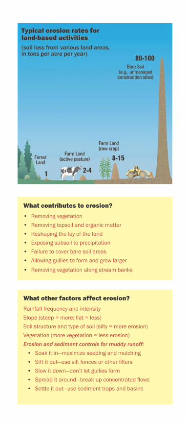
What contributes to erosion?
• Removing vegetation
• Removing topsoil and organic matter
• Reshaping the lay of the land
• Exposing subsoil to precipitation
• Failure to cover bare soil areas
• Allowing gullies to form and grow larger
• Removing vegetation along stream banks
What other factors affect erosion?
Rainfall frequency and intensity
Slope (steep = more; flat = less)
Soil structure and type of soil (silty = more erosion)
Vegetation (more vegetation = less erosion)
Erosion and sediment controls for muddy runoff:
• Soak it in—maximize seeding and mulching
• Sift it out—use silt fences or other filters
• Slow it down—don’t let gullies form
• Spread it around—break up concentrated flows
• Settle it out—use sediment traps and basins
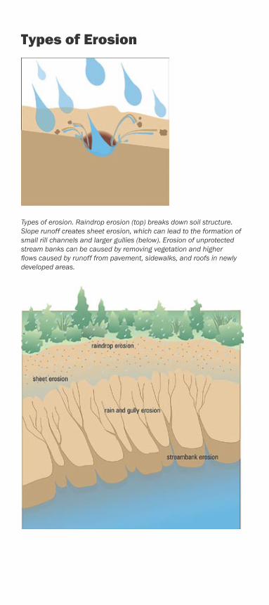
Types of erosion. Raindrop erosion (top) breaks down soil structure. Slope runoff creates sheet erosion, which can lead to the formation of small rill channels and larger gullies (below). Erosion of unprotected stream banks can be caused by removing vegetation and higher flows caused by runoff from pavement, sidewalks, and roofs in newly developed areas.
Types of Erosion
Pre-Construction Planning
Planning your construction project can help you avoid costly mistakes in controlling erosion and sediment loss to nearby waterways. Follow the steps below before you begin clearing, grading, and exca-vation work. If your project is one acre or larger, you will need a storm water permit from the Kentucky Division of Water (502-564-3410, or see http://www.water.ky.gov/permitting/wastewaterpermitting/KPDES/storm/).
Assess soils and slopes on the construction siteIf your construction site has highly erodible soils
and steep slopes, you will need maximum erosion and sediment control protection. See the table below.
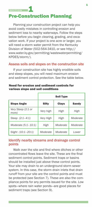
Need for erosion and sediment controls for various slope and soil conditions
Soil Type
Slope Angle Silty Clays Sandy
Very Steep (2:1 or more)
Very high High High
Steep (2:1–4:1) Very High High Moderate
Moderate (5:1–10:1) High Moderate Moderate
Slight (10:1–20:1) Moderate Moderate Lower
Identify nearby streams and drainage control points
Walk over the site and find where ditches or other concentrated flows leave the site. These are the final sediment control points. Sediment traps or basins should be installed just above these control points. Your site may drain to an underground storm sewer system. In this case, the storm drain inlets that drain runoff from your site are the control points and must be protected (see Section 7). These are also the com-pliance points for any permits issued for the site. Low spots—where rain water ponds—are good places for sediment traps (see Section 9).
SECTION
1
2 Pre-Construction Planning
Install clean water diversions, sediment traps/basins, grassed ditches, silt check dams, and sedi-ment barriers such as silt fences before clearing and excavation work begins!
Preserve existing vegetation wherever possibleOnly dig or grade where necessary. Existing trees,
bushes, and grass help keep erosion to a minimum. Protect large trees by marking off a no-dig root protec-tion zone that is twice as large as the outer perimeter of the branches. Plan your project to limit the amount of bare soil area exposed to the weather, and limit the amount of exposure time. Do not clear vegetation or excavate areas near streams, rivers, lakes, or wet-lands without getting the required state and federal permits!
Design projects to fit the lay of the landMinimize clearing and grading to preserve mature
vegetation and save money. Identify natural land-scape features you want to keep, like large trees, wildflower areas, grasslands, streams, and wetlands. Plan ways to fit your project around these features, so they remain in place after construction is completed. Be sure to mark off these areas with colored ribbon or stakes and warn equipment operators of their loca-tion!
Minimize impervious surfacesKeep the amount of roof area, parking lots, drive-
ways, and roads to a minimum. Design these hard surfaces so that rain water they collect is directed onto landscaped or yard areas, not into ditches or streams. For example, design roads slightly higher than adjacent lawn areas, and use rain infiltration ditches (swales) rather than curbs along roadways. Porous pavement can also help soak up runoff.
Promote infiltration in project designMoving storm water runoff from hard surfaces to
landscaped or yard areas helps runoff soak into the soil. This promotes groundwater recharge, filters sedi-ment and other pollutants from runoff, and helps to prevent flooding.
Pre-Construction Planning 3
Develop an erosion and sediment control planDevelop a written site plan for your project that
shows the drainage patterns and slopes, areas of disturbance (cuts/fills, grading), location of erosion and sediment controls, location of surface waters and wetlands, and the location of storm water drain-age control points. Your site plan must be updated as conditions change at the site. If your construction site is one acre or more, erosion protection and sediment control plans must be on file to assure compliance with storm water regulations (see Appendix A). Plans related to state road projects must be filed with the Transportation Cabinet; some counties also require that plans be filed with local agencies (see Section 12 and Appendices).
Design specifications for erosion and sediment controls (i.e., “Best Management Practices” or BMPs) are available from the Kentucky Division of Water, Di-vision of Conservation, the Louisville-Jefferson County Metropolitan Sewer District, and the Lexington-Fayette Urban County Government.
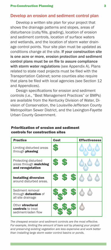
The cheapest erosion and sediment controls are the most effective. For example, limiting the amount of bare soil by phasing your project and preserving existing vegetation are less expensive and work better than installing large storm water control basins or ponds.
4 Pre-Construction Planning
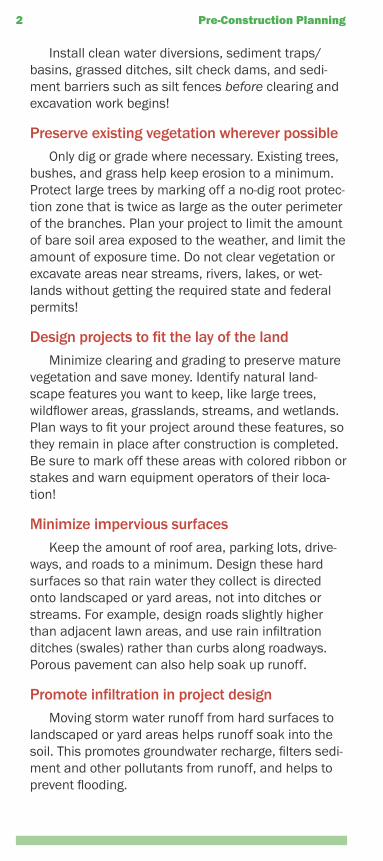
Limiting the amount of bare soil exposed to the weather by working in phases reduces erosion and sediment control expenses.
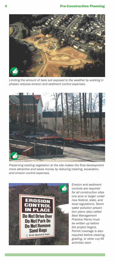
Preserving existing vegetation at the site makes the final development more attractive and saves money by reducing clearing, excavation, and erosion control expenses.
Erosion and sediment controls are required for all construction sites one acre or larger under new federal, state, and local regulations. Storm water pollution preven-tion plans (also called Best Management Practice Plans) must be written up before the project begins. Permit coverage is also required before clearing, grading, or other cut/fill activities start.
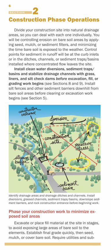
Providing primary and secondary containment for fuel and other haz-ardous materials at the work site helps prevent problems. Controlling non-storm water runoff, trash and other wastes, and post-construction runoff are also required under the new storm water permit program.
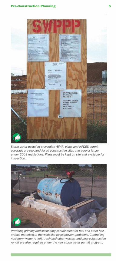
Storm water pollution prevention (BMP) plans and KPDES permit coverage are required for all construction sites one acre or larger under 2003 regulations. Plans must be kept on site and available for inspection.
Pre-Construction Planning 5
Construction Phase Operations
Divide your construction site into natural drainage areas, so you can deal with each one individually. You will be controlling erosion on bare soil areas by apply-ing seed, mulch, or sediment filters, and minimizing the time bare soil is exposed to the weather. Control points for sediment in runoff will be at the curb inlets or in the ditches, channels, or sediment traps/basins installed where concentrated flow leaves the site.
Install clean water diversions, sediment traps/basins and stabilize drainage channels with grass, liners, and silt check dams before excavation, fill, or grading work begins (see Sections 8 and 9). Install silt fences and other sediment barriers downhill from bare soil areas before clearing or excavation work begins (see Section 5).
Phase your construction work to minimize ex-posed soil areas
Excavate or place fill material at the site in stages, to avoid exposing large areas of bare soil to the elements. Establish final grade quickly, then seed, mulch, or cover bare soil. Require utilities and sub-
SECTION
6
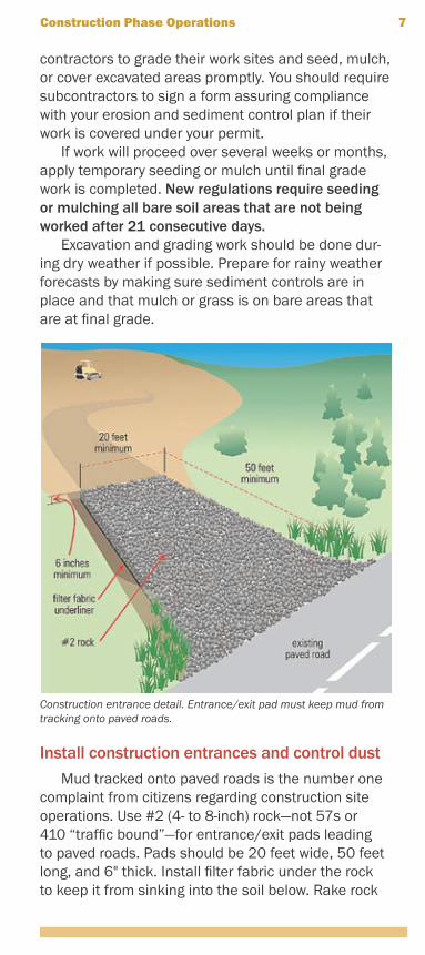
Identify drainage areas and drainage ditches and channels. Install diversions, grassed channels, sediment traps/basins, downslope sedi-ment barriers, and rock construction entrance before beginning work.
contractors to grade their work sites and seed, mulch, or cover excavated areas promptly. You should require subcontractors to sign a form assuring compliance with your erosion and sediment control plan if their work is covered under your permit.
If work will proceed over several weeks or months, apply temporary seeding or mulch until final grade work is completed. New regulations require seeding or mulching all bare soil areas that are not being worked after 21 consecutive days.
Excavation and grading work should be done dur-ing dry weather if possible. Prepare for rainy weather forecasts by making sure sediment controls are in place and that mulch or grass is on bare areas that are at final grade.
Install construction entrances and control dustMud tracked onto paved roads is the number one
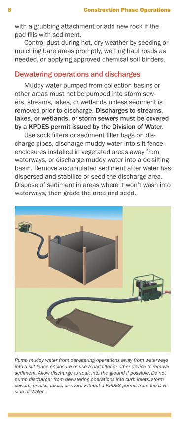
complaint from citizens regarding construction site operations. Use #2 (4- to 8-inch) rock—not 57s or 410 “traffic bound”—for entrance/exit pads leading to paved roads. Pads should be 20 feet wide, 50 feet long, and 6" thick. Install filter fabric under the rock to keep it from sinking into the soil below. Rake rock
Construction Phase Operations 7
Construction entrance detail. Entrance/exit pad must keep mud from tracking onto paved roads.
with a grubbing attachment or add new rock if the pad fills with sediment.
Control dust during hot, dry weather by seeding or mulching bare areas promptly, wetting haul roads as needed, or applying approved chemical soil binders.
Dewatering operations and dischargesMuddy water pumped from collection basins or
other areas must not be pumped into storm sew-ers, streams, lakes, or wetlands unless sediment is removed prior to discharge. Discharges to streams, lakes, or wetlands, or storm sewers must be covered by a KPDES permit issued by the Division of Water.
Use sock filters or sediment filter bags on dis-charge pipes, discharge muddy water into silt fence enclosures installed in vegetated areas away from waterways, or discharge muddy water into a de-silting basin. Remove accumulated sediment after water has dispersed and stabilize or seed the discharge area. Dispose of sediment in areas where it won’t wash into waterways, then grade the area and seed.
8 Construction Phase Operations
Pump muddy water from dewatering operations away from waterways into a silt fence enclosure or use a bag filter or other device to remove sediment. Allow discharge to soak into the ground if possible. Do not pump discharger from dewatering operations into curb inlets, storm sewers, creeks, lakes, or rivers without a KPDES permit from the Divi-sion of Water.
Inspection and maintenance of erosion and sediment controls
For sites one acre or larger, new state and federal regulations require that you inspect and repair/replace silt fences, vegetated buffers, berms, silt check dams, channels, and other erosion and sedi-ment controls every 7 days and after each rainfall of 0.5 inch or more (0.1 inch for KYTC projects). Re-move accumulated sediment from behind silt fences before it reaches 1⁄2 the silt fence height. Remove sediment from pipe or curb inlet ponding dams or filters as it accumulates. Clean mud off paved roads immediately. Your inspection reports must be in writ-ing, and kept on file at the site.
Silt check dams in ditches and sediment traps/basins also require periodic sediment removal. Re-move sediment from traps and basins before they are halfway full. Dispose of removed sediment in areas where it will not wash into waterways. Seed or mulch bare soil areas as soon as possible.
Keep written records of these inspections, includ-ing dates, observations and corrective actions taken, with your erosion and sediment control plan and Storm Water Pollution Prevention Plan, or BMP Plan. See Section 5 for information on installing and maintaining overland sheet flow sediment filters. See Sections 7, 8, and 9 for information on handling concentrated flows in ditches, channels, and other areas.
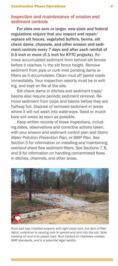
Rock pad was installed properly with right sized rock, but lack of filter fabric underliner is causing rock to spread and sink into the soil. Note tracking of mud onto paved road. Mud tracked on roadways violates BMP standards, and is a potential legal liability.
Construction Phase Operations 9
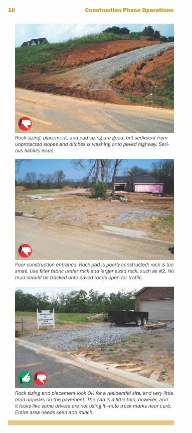
Poor construction entrance. Rock pad is poorly constructed; rock is too small. Use filter fabric under rock and larger sized rock, such as #2. No mud should be tracked onto paved roads open for traffic.
10 Construction Phase Operations
Rock sizing, placement, and pad sizing are good, but sediment from unprotected slopes and ditches is washing onto paved highway. Seri-ous liability issue.
Rock sizing and placement look OK for a residential site, and very little mud appears on the pavement. The pad is a little thin, however, and it looks like some drivers are not using it—note track marks near curb. Entire area needs seed and mulch.
Diverting Upland Runoff Around Exposed Soils
Keep clean upland runoff from flowing through your construction site, or route it through stable ditches so it won’t get muddy. Below are some simple approaches for dealing with uphill sources of runoff.
Diversion bermsA diversion berm is a long, mounded “collar” of
compacted soil located uphill from the excavated area. The berm is designed to intercept overland runoff and direct it around the construction site. This prevents “clean” water from becoming muddied with soil from the construction site. Berms can be temporary or per-manent landscape features of the site.
Berms should be located so that storm water flow-ing along their uphill face follows a gently sloping path (i.e., less than 5 percent channel slope). Turf rein-forcement mats, erosion control blankets, or rock pro-tection might be needed for berms that channel water at a slope of 5 percent or more (see Section 4). Berm side slopes should be 2:1 or flatter, 10 to 14 inches high, and seeded immediately after construction.
11
SECTION
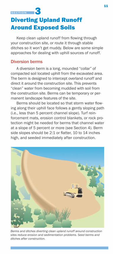
Berms and ditches diverting clean upland runoff around construction sites reduce erosion and sedimentation problems. Seed berms and ditches after construction.
Extend the downhill end of the berm so it directs overland flow to areas of thick vegetation or flat sur-faces to promote dispersal and infiltration. Seed and mulch berms after construction to minimize erosion.
Diversion ditchesDiversion ditches are similar to berms—they are
designed to intercept and divert upland runoff around bare soil areas. Ditches are cut above cleared or fill areas and designed with a gentle slope to carry water away from work areas. Ditches should be 8 to 12 inches deep and seeded. Side slopes should be 2:1 or flatter.
Stabilized, lined ditches can also be used to move upland water through your site without getting muddy. Construct and line “pass-through” ditches before general clearing or grading work begins.
Ditches should discharge to areas with thick vegetation or flat surfaces to promote dispersal and infiltration. Gullies must be repaired as soon as they appear. Ditches with slopes less than 5 percent may be heavily seeded, mulched, and maintained without additional protection if stabilized quickly after con-struction. Ditches with slopes of 5 percent or more need erosion control blankets, turf mats, or rock liner protection.
12 Diverting Upland Runoff
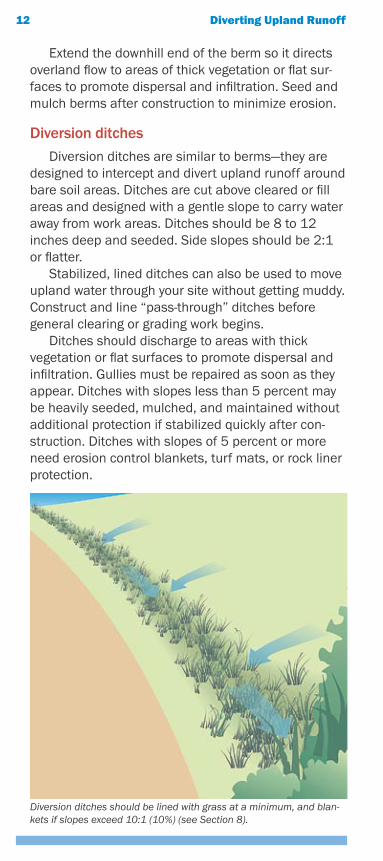
Diversion ditches should be lined with grass at a minimum, and blan-kets if slopes exceed 10:1 (10%) (see Section 8).
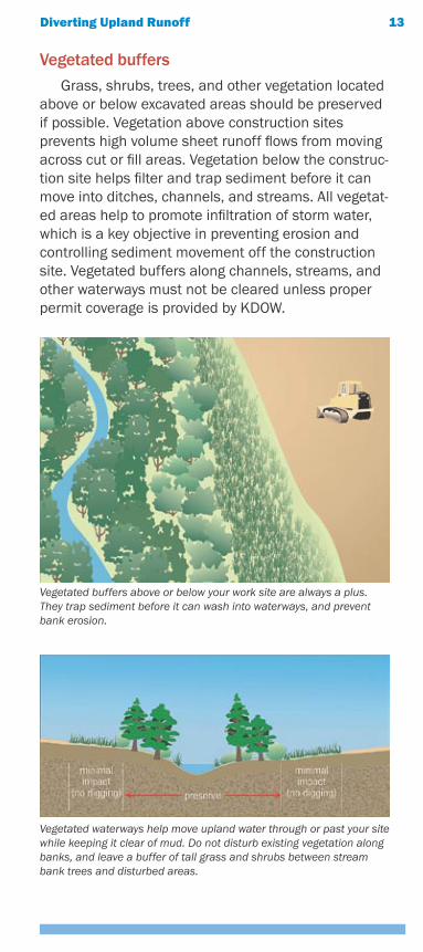
Vegetated buffersGrass, shrubs, trees, and other vegetation located
above or below excavated areas should be preserved if possible. Vegetation above construction sites prevents high volume sheet runoff flows from moving across cut or fill areas. Vegetation below the construc-tion site helps filter and trap sediment before it can move into ditches, channels, and streams. All vegetat-ed areas help to promote infiltration of storm water, which is a key objective in preventing erosion and controlling sediment movement off the construction site. Vegetated buffers along channels, streams, and other waterways must not be cleared unless proper permit coverage is provided by KDOW.
Diverting Upland Runoff 13
Vegetated buffers above or below your work site are always a plus. They trap sediment before it can wash into waterways, and prevent bank erosion.
Vegetated waterways help move upland water through or past your site while keeping it clear of mud. Do not disturb existing vegetation along banks, and leave a buffer of tall grass and shrubs between stream bank trees and disturbed areas.
14 Diverting Upland Runoff
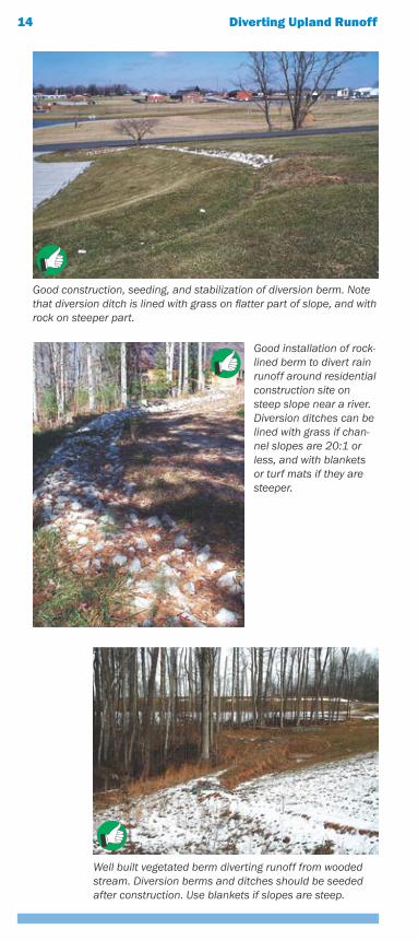
Well built vegetated berm diverting runoff from wooded stream. Diversion berms and ditches should be seeded after construction. Use blankets if slopes are steep.
Good construction, seeding, and stabilization of diversion berm. Note that diversion ditch is lined with grass on flatter part of slope, and with rock on steeper part.
Good installation of rock-lined berm to divert rain runoff around residential construction site on steep slope near a river. Diversion ditches can be lined with grass if chan-nel slopes are 20:1 or less, and with blankets or turf mats if they are steeper.
Protecting Soils With Seed, Mulch, or Other Products
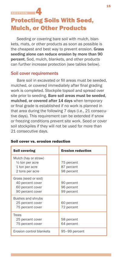
Seeding or covering bare soil with mulch, blan-kets, mats, or other products as soon as possible is the cheapest and best way to prevent erosion. Grass seeding alone can reduce erosion by more than 90 percent. Sod, mulch, blankets, and other products can further increase protection (see tables below).
Soil cover requirementsBare soil in excavated or fill areas must be seeded,
mulched, or covered immediately after final grading work is completed. Stockpile topsoil and spread over site prior to seeding. Bare soil areas must be seeded, mulched, or covered after 14 days when temporary or final grade is established if no work is planned in that area during the following 7 days (i.e., 21 consecu-tive days). This requirement can be extended if snow or freezing conditions prevent site work. Seed or cover soil stockpiles if they will not be used for more than 21 consecutive days.
Soil cover vs. erosion reduction
Soil covering Erosion reduction
Mulch (hay or straw) 1⁄2 ton per acre 1 ton per acre 2 tons per acre
75 percent87 percent98 percent
Grass (seed or sod) 40 percent cover 60 percent cover 90 percent cover
90 percent96 percent99 percent
Bushes and shrubs 25 percent cover 75 percent cover
60 percent72 percent
Trees 25 percent cover 75 percent cover
58 percent64 percent
Erosion control blankets 95–99 percent
SECTION
15
Seed types and applicationPrepare bare soil for planting by disking across
slopes, scarifying, or tilling if soil has been sealed or crusted over by rain. Seedbed must be dry with loose soil to a depth of 3 to 6 inches.
For slopes steeper than 4:1, walk bulldozer or other tracked vehicle up and down slopes before seeding to create tread-track depressions for catching and holding seed. Mulch slopes after seeding if pos-sible. Cover seed with erosion control blankets or turf mats if slopes are 2:1 or greater.
Fertilize poor soils with 400–800 pounds per acre of 10-10-10 fertilizer. Apply lime at 1 to 2 tons per acre if needed. Disk or harrow fertilizer and lime 2 to 4 inches into soil. Follow the contour (level path) with tractors and other equipment on all slopes if possible.
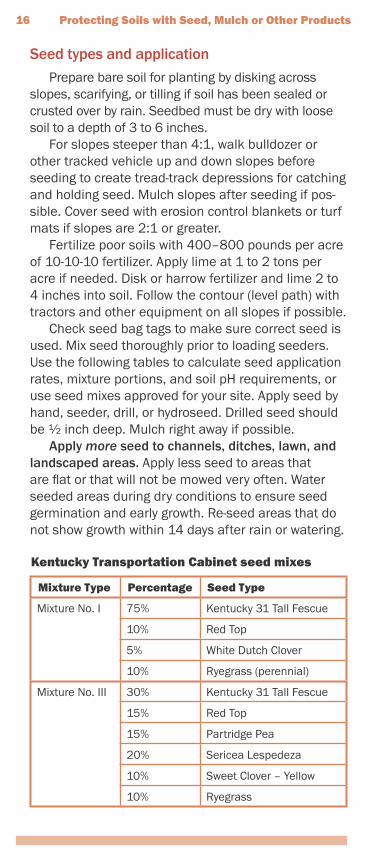
Check seed bag tags to make sure correct seed is used. Mix seed thoroughly prior to loading seeders. Use the following tables to calculate seed application rates, mixture portions, and soil pH requirements, or use seed mixes approved for your site. Apply seed by hand, seeder, drill, or hydroseed. Drilled seed should be 1⁄2 inch deep. Mulch right away if possible.
Apply more seed to channels, ditches, lawn, and landscaped areas. Apply less seed to areas that are flat or that will not be mowed very often. Water seeded areas during dry conditions to ensure seed germination and early growth. Re-seed areas that do not show growth within 14 days after rain or watering.
Kentucky Transportation Cabinet seed mixes
Mixture Type Percentage Seed Type
Mixture No. I 75% Kentucky 31 Tall Fescue
10% Red Top
5% White Dutch Clover
10% Ryegrass (perennial)
Mixture No. III 30% Kentucky 31 Tall Fescue
15% Red Top
15% Partridge Pea
20% Sericea Lespedeza
10% Sweet Clover – Yellow
10% Ryegrass
16 Protecting Soils with Seed, Mulch or Other Products
Protecting Soils with Seed, Mulch or Other Products 17
Protect bare areas during the cold season by sow-ing winter rye, winter wheat, or mulching. Sow perma-nent seed when weather permits.
Do not mow newly seeded bluegrass or red fescue until it is at least 4 inches high. Crownvetch should never be mowed. KY 31 tall fescue can be mowed for appearance or only occasionally, according to site conditions and the owner’s preferences.
Seed mixes for wildflower and native plant plots are also available. They are more expensive, but are very hardy, require little mowing or watering, and add beauty to landscaped and other areas. Most mixes require mowing only once per year, to control tree and brush growth.
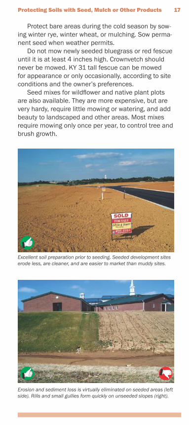
Excellent soil preparation prior to seeding. Seeded development sites erode less, are cleaner, and are easier to market than muddy sites.
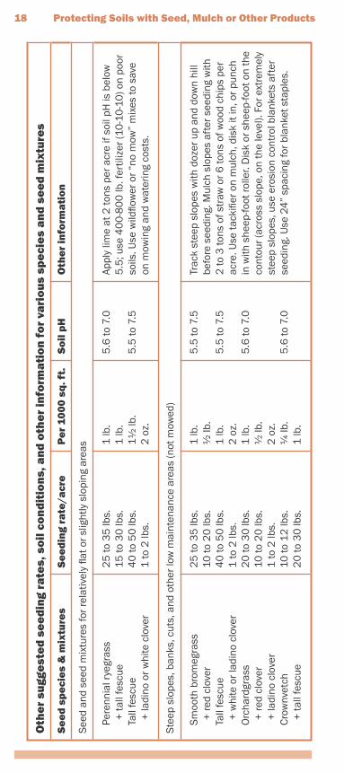
Erosion and sediment loss is virtually eliminated on seeded areas (left side). Rills and small gullies form quickly on unseeded slopes (right).
18 Protecting Soils with Seed, Mulch or Other Products
Oth
er
sugg
est
ed
se
ed
ing
rate
s, s
oil
co
nd
itio
ns,
an
d o
the
r in
form
ati
on
fo
r va
rio
us
spe
cie
s a
nd
se
ed
mix
ture
s
Se
ed
sp
eci
es
& m
ixtu
res
Se
ed
ing
rate
/acr
eP
er
100
0 s
q. f
t.S
oil
pH
Oth
er
info
rma
tio
n
See
d an
d se
ed m
ixtu
res
for
rela
tivel
y fla
t or
slig
htly
slo
ping
are
as
Pe
renn
ial r
yegr
ass
+
tall
fesc
ue
Tall
fesc
ue
+ la
dino
or
whi
te c
love
r
25
to 3
5 lb
s.1
5 to
30
lbs.
40
to 5
0 lb
s.1
to 2
lbs.
1 lb
.1
lb.
11⁄2
lb.
2 o
z.
5.6
to 7
.0
5.5
to 7
.5
Appl
y lim
e at
2 to
ns p
er a
cre
if so
il pH
is b
elow
5
.5; u
se 4
00
-80
0 lb
. fer
tiliz
er (1
0-1
0-1
0) o
n po
or
soils
. Use
wild
flow
er o
r “n
o m
ow”
mix
es to
sav
e on
mow
ing
and
wat
erin
g co
sts.
Ste
ep s
lope
s, b
anks
, cut
s, a
nd o
ther
low
mai
nten
ance
are
as (n
ot m
owed
)
S
moo
th b
rom
egra
ss
+ re
d cl
over
Ta
ll fe
scue
+
whi
te o
r la
dino
clo
ver
O
rcha
rdgr
ass
+
red
clov
er
+ la
dino
clo
ver
C
row
nvet
ch
+ ta
ll fe
scue
25
to 3
5 lb
s.10
to 2
0 lb
s.4
0 to
50
lbs.
1 to
2 lb
s.2
0 to
30
lbs.
10 to
20
lbs.
1 to
2 lb
s.10
to 1
2 lb
s.2
0 to
30
lbs.
1 lb
.1⁄2
lb.
1 lb
.2
oz.
1 lb
.1⁄2
lb.
2 o
z.1⁄4
lb.
1 lb
.
5.5
to 7
.5
5.5
to 7
.5
5.6
to 7
.0
5.6
to 7
.0
Trac
k st
eep
slop
es w
ith d
ozer
up
and
dow
n hi
ll be
fore
see
ding
. Mul
ch s
lope
s af
ter
seed
ing
with
2
to 3
tons
of s
traw
or
6 to
ns o
f woo
d ch
ips
per
acre
. Use
tack
ifier
on
mul
ch, d
isk
it in
, or
punc
h in
with
she
ep-fo
ot ro
ller.
Dis
k or
she
ep-fo
ot o
n th
e co
ntou
r (a
cros
s sl
ope,
on
the
leve
l). F
or e
xtre
mel
y st
eep
slop
es, u
se e
rosi
on c
ontr
ol b
lank
ets
afte
r se
edin
g. U
se 2
4”
spac
ing
for
blan
ket s
tapl
es.
Protecting Soils with Seed, Mulch or Other Products 19
Law
ns a
nd o
ther
hig
h tr
affic
or
high
mai
nten
ance
are
as (m
owed
)
B
lueg
rass
Pe
renn
ial r
yegr
ass
(tur
f)
+ b
lueg
rass
Ta
ll fe
scue
(tur
f typ
e)
+ b
lueg
rass
105
to 1
40
lbs.
45
to 6
0 lb
s.7
0 to
90
lbs.
13
0 to
17
0 lb
s.2
0 to
30
lbs.
3 lb
.2
lb.
21⁄2
lb.
4 lb
.1
lb.
5.5
to 7
.05
.6 to
7.0
5.6
to 7
.5
Use
wild
flow
er m
ixes
to s
ave
on m
owin
g an
d w
ater
ing
cost
s. D
o no
t est
ablis
h gr
asse
d la
wns
nea
r st
ream
s or
wet
land
s –
leav
e a
15
- to
30
-foot
buf
fer
of n
atur
al v
eget
atio
n.
Ditc
hes
and
othe
r ar
eas
of c
once
ntra
ted
wat
er fl
ows
Pe
renn
ial r
yegr
ass
+
whi
te o
r la
dino
clo
ver
K
entu
cky
blue
gras
s
+ s
moo
th b
rom
egra
ss
+ s
witc
hgra
ss
+ ti
mot
hy
+ p
eren
nial
rye
gras
s
+ w
hite
or
ladi
no c
love
r
Tall
fesc
ue
+ la
dino
or
whi
te c
love
r
Tall
fesc
ue
+ p
eren
nial
rye
gras
s
+ K
entu
cky
blue
gras
s
100
to 1
50
lbs.
1 to
2 lb
s.2
0 lb
s.10
lbs.
3 lb
s.4
lbs.
10 lb
s.1
to 2
lbs.
100
to 1
50
lbs.
1 to
2 lb
s.10
0 to
15
0 lb
s.1
5 to
20
lbs.
15
to 2
0 lb
s.
3 lb
.2
oz.
1⁄2 lb
.1⁄4
lb.
2 o
z.1⁄4
lb.
1⁄4 lb
.2
oz.
3 lb
.2
oz.
3 lb
.1⁄2
lb.
1⁄2 lb
.
5.6
to 7
.0
5.5
to 7
.5
5.5
to 7
.5
5.5
to 7
.5
See
d di
tche
s an
d ch
anne
ls th
ickl
y. D
o no
t use
fe
rtili
zer
near
ditc
h or
cha
nnel
bot
tom
. Use
ero
sion
co
ntro
l bla
nket
s or
turf
rein
forc
emen
t mat
s w
hen
chan
nel b
otto
m s
lope
s ex
ceed
3 p
erce
nt.
Silt
che
ck d
ams
are
need
ed w
hen
chan
nel
slop
es e
xcee
d 5
per
cent
or
whe
n ch
anne
ls b
egin
do
wnc
uttin
g (g
ully
ing)
on
the
bott
om. D
o no
t use
silt
fe
ncin
g or
hay
bal
es a
s si
lt ch
eck
dam
s in
cha
nnel
s w
ith s
lope
s gr
eate
r th
an 3
per
cent
; use
rock
, bru
sh,
or c
omm
erci
al s
ilt d
ikes
inst
ead.
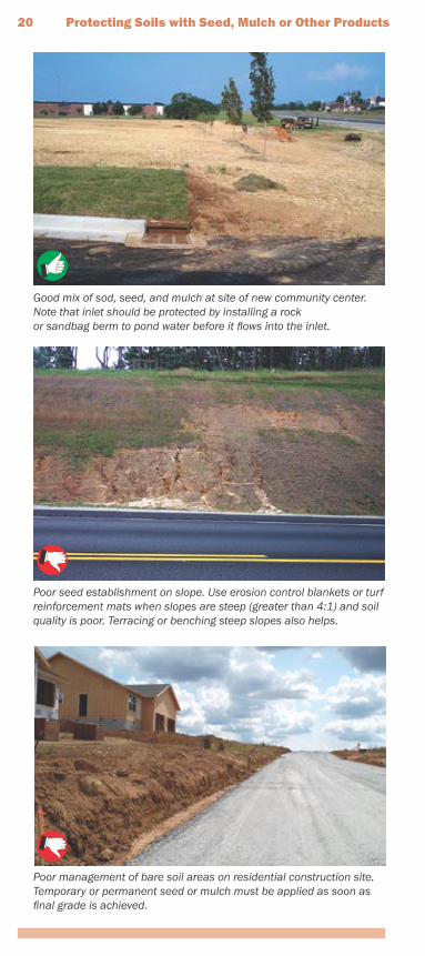
Poor management of bare soil areas on residential construction site. Temporary or permanent seed or mulch must be applied as soon as final grade is achieved.
Good mix of sod, seed, and mulch at site of new community center. Note that inlet should be protected by installing a rockor sandbag berm to pond water before it flows into the inlet.
Poor seed establishment on slope. Use erosion control blankets or turf reinforcement mats when slopes are steep (greater than 4:1) and soil quality is poor. Terracing or benching steep slopes also helps.
20 Protecting Soils with Seed, Mulch or Other Products
Protecting Soils with Seed, Mulch or Other Products 21
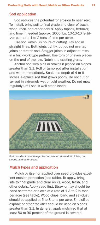
Sod applicationSod reduces the potential for erosion to near zero.
To install, bring soil to final grade and clear of trash, wood, rock, and other debris. Apply topsoil, fertilizer, and lime if needed (approx. 1000 lbs. 10-10-10 fertil-izer per acre; 1 to 2 tons of lime per acre).
Use sod within 36 hours of cutting. Lay sod in straight lines. Butt joints tightly, but do not overlap joints or stretch sod. Stagger joints in adjacent rows in a brickwork type pattern. Use torn or uneven pieces on the end of the row. Notch into existing grass.
Anchor sod with pins or stakes if placed on slopes greater than 3:1. Roll or tamp sod after installation and water immediately. Soak to a depth of 4 to 6 inches. Replace sod that grows poorly. Do not cut or lay sod in extremely wet or cold weather. Do not mow regularly until sod is well established.
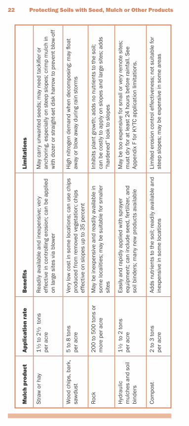
Mulch types and applicationMulch by itself or applied over seed provides excel-
lent erosion protection (see table). To apply, bring site to final grade and clear rocks, wood, trash, and other debris. Apply seed first. Straw or hay should be hand scattered or blown at a rate of 11⁄2 to 21⁄2 tons per acre (see table). Wood chips, bark, and sawdust should be applied at 5 to 8 tons per acre. Emulsified asphalt or other tackifier should be used on slopes greater than 3:1. In general, apply mulch so that at least 80 to 90 percent of the ground is covered.
Sod provides immediate protection around storm drain inlets, on slopes, and other areas.
Mu
lch
pro
du
ctA
pp
lica
tio
n r
ate
Be
ne
fits
Lim
ita
tio
ns
Str
aw o
r ha
y1
1⁄2 to
21⁄2
ton
spe
r ac
reR
eadi
ly a
vaila
ble
and
inex
pens
ive;
ver
y ef
fect
ive
in c
ontr
ollin
g er
osio
n; c
an b
e ap
plie
d on
larg
e si
tes
via
blow
er
May
car
ry u
nwan
ted
seed
s; m
ay n
eed
tack
ifier
or
anch
orin
g, e
spec
ially
on
stee
p sl
opes
; crim
p m
ulch
in
with
doz
er o
r st
raig
ht-s
et d
isk
harr
ow to
pre
vent
blo
w-o
ff
Woo
d ch
ips,
bar
k,
saw
dust
5 to
8 to
nspe
r ac
reVe
ry lo
w c
ost i
n so
me
loca
tions
; can
use
chi
ps
prod
uced
from
rem
oved
veg
etat
ion;
chi
ps
effe
ctiv
e on
slo
pes
up to
35
per
cent
Hig
h ni
trog
en d
eman
d w
hen
deco
mpo
sing
; may
floa
t aw
ay o
r bl
ow a
way
dur
ing
rain
sto
rms
Roc
k2
00
to 5
00
tons
or
mor
e pe
r ac
reM
ay b
e in
expe
nsiv
e an
d re
adily
ava
ilabl
e in
so
me
loca
litie
s; m
ay b
e su
itabl
e fo
r sm
alle
r si
tes
Inhi
bits
pla
nt g
row
th; a
dds
no n
utrie
nts
to th
e so
il;
can
be c
ostly
to a
pply
on
slop
es a
nd la
rge
site
s; a
dds
“har
dene
d” lo
ok to
slo
pes
Hyd
raul
ic
mul
ches
and
soi
l bi
nder
s
11⁄2
to
2 to
nspe
r ac
reEa
sily
and
rap
idly
app
lied
with
spr
ayer
eq
uipm
ent;
can
incl
ude
seed
, fer
tiliz
er, a
nd
soil
bind
ers;
man
y ne
w p
rodu
cts
avai
labl
e
May
be
too
expe
nsiv
e fo
r sm
all o
r ve
ry re
mot
e si
tes;
m
ust d
ry fo
r at
leas
t 24
hou
rs b
efor
e ra
infa
ll. S
ee
Appe
ndix
F fo
r K
YTC
app
licat
ion
limita
tions
.
Com
post
2 to
3 to
nspe
r ac
reAd
ds n
utrie
nts
to th
e so
il; re
adily
ava
ilabl
e an
d in
expe
nsiv
e in
som
e lo
catio
nsLi
mite
d er
osio
n co
ntro
l eff
ectiv
enes
s; n
ot s
uita
ble
for
stee
p sl
opes
; may
be
expe
nsiv
e in
som
e ar
eas
22 Protecting Soils with Seed, Mulch or Other Products
Protecting Soils with Seed, Mulch or Other Products 23
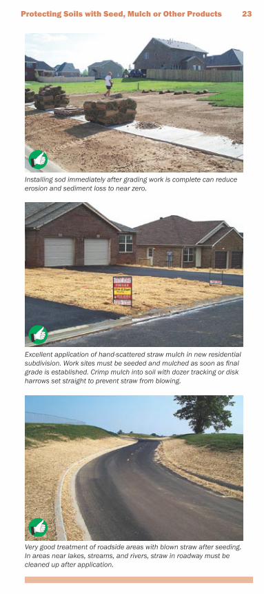
Installing sod immediately after grading work is complete can reduce erosion and sediment loss to near zero.
Excellent application of hand-scattered straw mulch in new residential subdivision. Work sites must be seeded and mulched as soon as final grade is established. Crimp mulch into soil with dozer tracking or disk harrows set straight to prevent straw from blowing.
Very good treatment of roadside areas with blown straw after seeding. In areas near lakes, streams, and rivers, straw in roadway must be cleaned up after application.
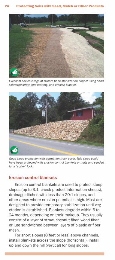
Good slope protection with permanent rock cover. This slope could have been protected with erosion control blankets or mats and seeded for a “softer” look.
Excellent soil coverage at stream bank stabilization project using hand scattered straw, jute matting, and erosion blanket.
Erosion control blanketsErosion control blankets are used to protect steep
slopes (up to 3:1; check product information sheets), drainage ditches with less than 20:1 slopes, and other areas where erosion potential is high. Most are designed to provide temporary stabilization until veg-etation is established. Blankets degrade within 6 to 24 months, depending on their makeup. They usually consist of a layer of straw, coconut fiber, wood fiber, or jute sandwiched between layers of plastic or fiber mesh.
For short slopes (8 feet or less) above channels, install blankets across the slope (horizontal). Install up and down the hill (vertical) for long slopes.
24 Protecting Soils with Seed, Mulch or Other Products
Protecting Soils with Seed, Mulch or Other Products 25
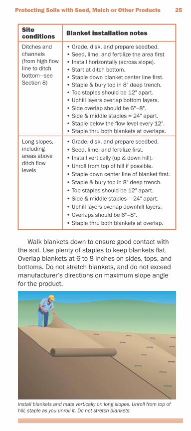
Site conditions Blanket installation notes
Ditches and channels (from high flow line to ditch bottom—see Section 8)
• Grade, disk, and prepare seedbed.• Seed, lime, and fertilize the area first• Install horizontally (across slope).• Start at ditch bottom. • Staple down blanket center line first.• Staple & bury top in 8" deep trench. • Top staples should be 12" apart. • Uphill layers overlap bottom layers. • Side overlap should be 6"–8".• Side & middle staples = 24" apart. • Staple below the flow level every 12".• Staple thru both blankets at overlaps.
Long slopes, including areas above ditch flow levels
• Grade, disk, and prepare seedbed.• Seed, lime, and fertilize first.• Install vertically (up & down hill).• Unroll from top of hill if possible.• Staple down center line of blanket first.• Staple & bury top in 8" deep trench.• Top staples should be 12" apart.• Side & middle staples = 24" apart.• Uphill layers overlap downhill layers.• Overlaps should be 6"–8".• Staple thru both blankets at overlap.
Walk blankets down to ensure good contact with the soil. Use plenty of staples to keep blankets flat. Overlap blankets at 6 to 8 inches on sides, tops, and bottoms. Do not stretch blankets, and do not exceed manufacturer’s directions on maximum slope angle for the product.
Install blankets and mats vertically on long slopes. Unroll from top of hill, staple as you unroll it. Do not stretch blankets.
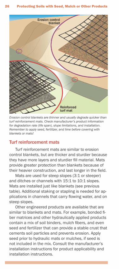
Turf reinforcement matsTurf reinforcement mats are similar to erosion
control blankets, but are thicker and sturdier because they have more layers and sturdier fill material. Mats provide greater protection than blankets because of their heavier construction, and last longer in the field.
Mats are used for steep slopes (3:1 or steeper) and ditches or channels with 15:1 to 10:1 slopes. Mats are installed just like blankets (see previous table). Additional staking or stapling is needed for ap-plications in channels that carry flowing water, and on steep slopes.
Other engineered products are available that are similar to blankets and mats. For example, bonded fi-ber matrices and other hydraulically applied products contain a mix of soil binders, mulch fibers, and even seed and fertilizer that can provide a stable crust that cements soil particles and prevents erosion. Apply seed prior to hydraulic mats or mulches, if seed is not included in the mix. Consult the manufacturer’s installation instructions for product applicability and installation instructions.
Erosion control blankets are thinner and usually degrade quicker than turf reinforcement mats. Check manufacturer’s product information for degradation rate (life span), slope limitations, and installation. Remember to apply seed, fertilizer, and lime before covering with blankets or mats!
26 Protecting Soils with Seed, Mulch or Other Products
Protecting Soils with Seed, Mulch or Other Products 27
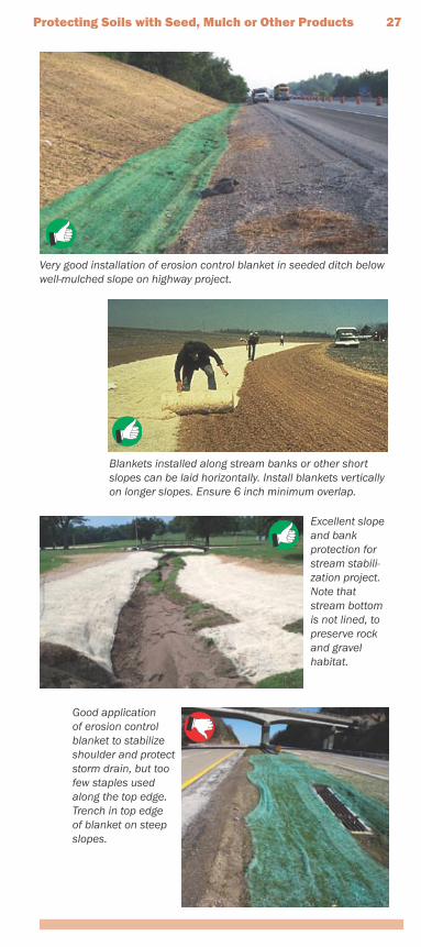
Good application of erosion control blanket to stabilize shoulder and protect storm drain, but too few staples used along the top edge. Trench in top edge of blanket on steep slopes.
Very good installation of erosion control blanket in seeded ditch below well-mulched slope on highway project.
Blankets installed along stream banks or other short slopes can be laid horizontally. Install blankets vertically on longer slopes. Ensure 6 inch minimum overlap.
Excellent slope and bank protection for stream stabili-zation project. Note that stream bottom is not lined, to preserve rock and gravel habitat.
Using Silt Fence and Other Sediment Barriers
The use of silt fences and other sediment barriers involves simple observation and common sense. How-ever, as Will Rogers once noted, “common sense ain’t so common.” The following summary provides details on how to install sediment barriers.
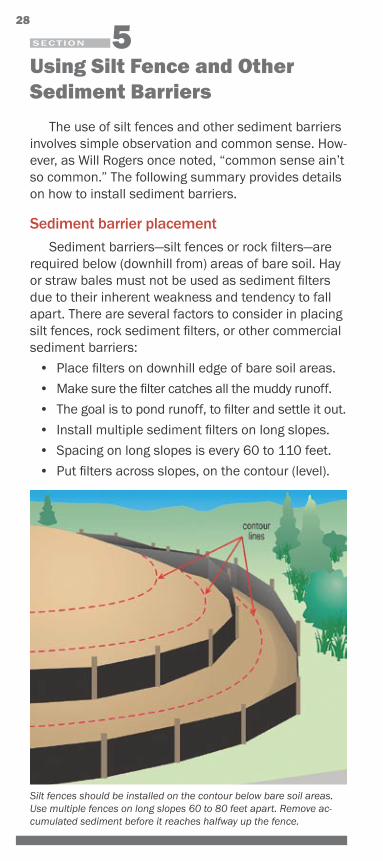
Sediment barrier placementSediment barriers—silt fences or rock filters—are
required below (downhill from) areas of bare soil. Hay or straw bales must not be used as sediment filters due to their inherent weakness and tendency to fall apart. There are several factors to consider in placing silt fences, rock sediment filters, or other commercial sediment barriers:
• Place filters on downhill edge of bare soil areas.
• Make sure the filter catches all the muddy runoff.
• The goal is to pond runoff, to filter and settle it out.
• Install multiple sediment filters on long slopes.
• Spacing on long slopes is every 60 to 110 feet.
• Put filters across slopes, on the contour (level).
SECTION
28
Silt fences should be installed on the contour below bare soil areas. Use multiple fences on long slopes 60 to 80 feet apart. Remove ac-cumulated sediment before it reaches halfway up the fence.
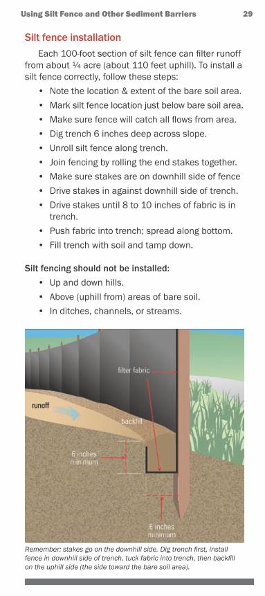
Silt fence installationEach 100-foot section of silt fence can filter runoff
from about 1⁄4 acre (about 110 feet uphill). To install a silt fence correctly, follow these steps:
• Note the location & extent of the bare soil area.
• Mark silt fence location just below bare soil area.
• Make sure fence will catch all flows from area.
• Dig trench 6 inches deep across slope.
• Unroll silt fence along trench.
• Join fencing by rolling the end stakes together.
• Make sure stakes are on downhill side of fence
• Drive stakes in against downhill side of trench.
• Drive stakes until 8 to 10 inches of fabric is in trench.
• Push fabric into trench; spread along bottom.
• Fill trench with soil and tamp down.
Silt fencing should not be installed:
• Up and down hills.
• Above (uphill from) areas of bare soil.
• In ditches, channels, or streams.
Using Silt Fence and Other Sediment Barriers 29
Remember: stakes go on the downhill side. Dig trench first, install fence in downhill side of trench, tuck fabric into trench, then backfill on the uphill side (the side toward the bare soil area).
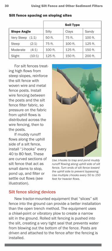
Silt fence spacing on sloping sites
Soil Type
Slope Angle Silty Clays Sandy
Very Steep (1:1) 50 ft. 75 ft. 100 ft.
Steep (2:1) 75 ft. 100 ft. 125 ft.
Moderate (4:1) 100 ft. 125 ft. 150 ft.
Slight (10:1) 125 ft. 150 ft. 200 ft.
For silt fences treat-ing high flows from steep slopes, reinforce the silt fence with woven wire and metal fence posts. Install wire fencing between the posts and the silt fence filter fabric, so pressure on the fabric from uphill flows is distributed across the wire fencing, then to the posts.
If muddy runoff flows along the uphill side of a silt fence, install “J-hooks” every 40 to 80 feet. These are curved sections of silt fence that act as small dams to stop, pond up, and filter or settle out flows (see illustration).
Silt fence slicing devicesNew tractor-mounted equipment that “slices” silt
fence into the ground can provide a better installation than the open trench method. The equipment uses a chisel-point or vibratory plow to create a narrow slit in the ground. Rolled silt fencing is pushed into the slit, creating a very tight seal that prevents water from blowing out the bottom of the fence. Posts are driven and attached to the fence after the fencing is installed.
Use J-hooks to trap and pond muddy runoff flowing along uphill side of silt fence. Turn ends of silt fence toward the uphill side to prevent bypassing. Use multiple J-hooks every 50 to 150 feet for heavier flows.
30 Using Silt Fence and Other Sediment Filters
Using Silt Fence and Other Sediment Filters 31
Besides better performance, the slicing method is also faster. For slicing and all other applications, posts are spaced 6 feet apart or less.
Other sediment barriersBrush cleared from the site can make an excellent
sediment filter if it is properly placed (see previous illustration) and built up well. Brush barriers are in-stalled on the contour and are 2 to 5 feet high and 4 to 10 feet wide at the base. Walk them down slightly with a loader or dozer to compress the material in the brush barrier. Stuff additional brush on the uphill side where bypasses or undercutting are evident.
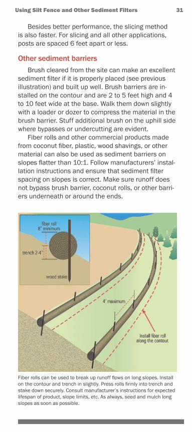
Fiber rolls and other commercial products made from coconut fiber, plastic, wood shavings, or other material can also be used as sediment barriers on slopes flatter than 10:1. Follow manufacturers’ instal-lation instructions and ensure that sediment filter spacing on slopes is correct. Make sure runoff does not bypass brush barrier, coconut rolls, or other barri-ers underneath or around the ends.
Fiber rolls can be used to break up runoff flows on long slopes. Install on the contour and trench in slightly. Press rolls firmly into trench and stake down securely. Consult manufacturer’s instructions for expected lifespan of product, slope limits, etc. As always, seed and mulch long slopes as soon as possible.
32 Using Silt Fence and Other Sediment Filters
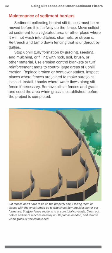
Maintenance of sediment barriersSediment collecting behind silt fences must be re-
moved before it is halfway up the fence. Move collect-ed sediment to a vegetated area or other place where it will not wash into ditches, channels, or streams. Re-trench and tamp down fencing that is undercut by gullies.
Stop uphill gully formation by grading, seeding, and mulching, or filling with rock, soil, brush, or other material. Use erosion control blankets or turf reinforcement mats to control large areas of uphill erosion. Replace broken or bent-over stakes. Inspect places where fences are joined to make sure joint is solid. Install J-hooks where water flows along silt fence if necessary. Remove all silt fences and grade and seed the area when grass is established, before the project is completed.
Silt fences don’t have to be on the property line. Placing them on slopes with the ends turned up to trap sheet flow provides better per-formance. Stagger fence sections to ensure total coverage. Clean out before sediment reaches halfway up. Repair as needed, and remove when grass is well established.
Using Silt Fence and Other Sediment Filters 33
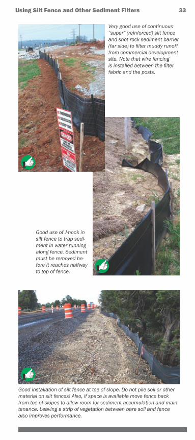
Good installation of silt fence at toe of slope. Do not pile soil or other material on silt fences! Also, if space is available move fence back from toe of slopes to allow room for sediment accumulation and main-tenance. Leaving a strip of vegetation between bare soil and fence also improves performance.
Very good use of continuous “super” (reinforced) silt fence and shot rock sediment barrier (far side) to filter muddy runoff from commercial development site. Note that wire fencing is installed between the filter fabric and the posts.
Good use of J-hook in silt fence to trap sedi-ment in water running along fence. Sediment must be removed be-fore it reaches halfway to top of fence.
34 Using Silt Fence and Other Sediment Filters
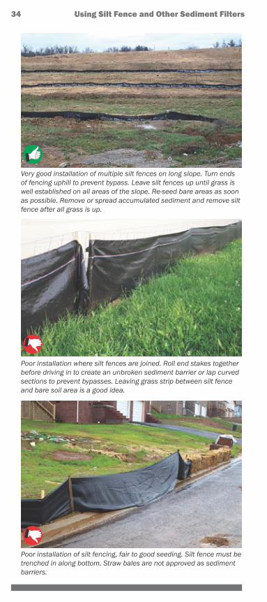
Poor installation of silt fencing, fair to good seeding. Silt fence must be trenched in along bottom. Straw bales are not approved as sediment barriers.
Poor installation where silt fences are joined. Roll end stakes together before driving in to create an unbroken sediment barrier or lap curved sections to prevent bypasses. Leaving grass strip between silt fence and bare soil area is a good idea.
Very good installation of multiple silt fences on long slope. Turn ends of fencing uphill to prevent bypass. Leave silt fences up until grass is well established on all areas of the slope. Re-seed bare areas as soon as possible. Remove or spread accumulated sediment and remove silt fence after all grass is up.
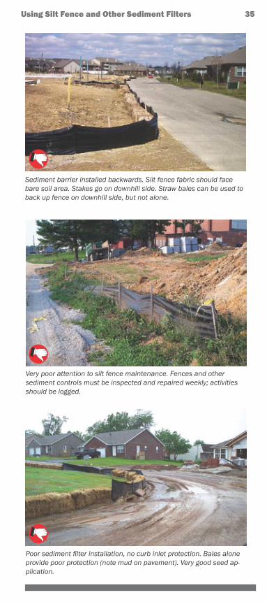
Poor sediment filter installation, no curb inlet protection. Bales alone provide poor protection (note mud on pavement). Very good seed ap-plication.
Very poor attention to silt fence maintenance. Fences and other sediment controls must be inspected and repaired weekly; activities should be logged.
Using Silt Fence and Other Sediment Filters 35
Sediment barrier installed backwards. Silt fence fabric should face bare soil area. Stakes go on downhill side. Straw bales can be used to back up fence on downhill side, but not alone.
36 Using Silt Fence and Other Sediment Filters
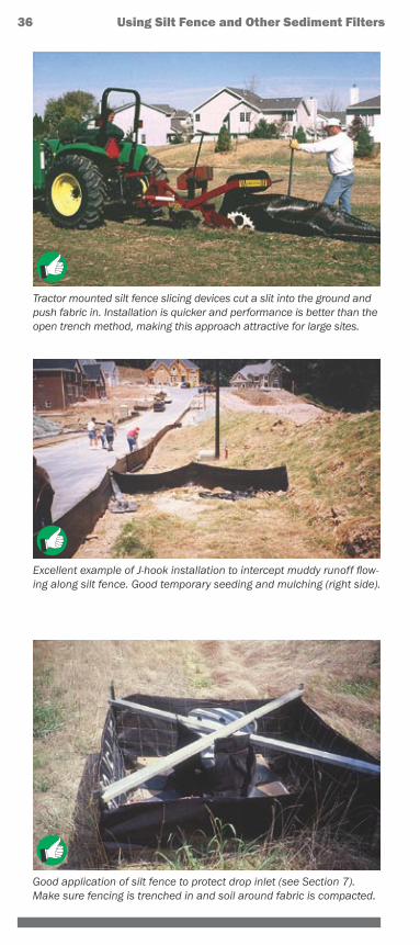
Good application of silt fence to protect drop inlet (see Section 7). Make sure fencing is trenched in and soil around fabric is compacted.
Tractor mounted silt fence slicing devices cut a slit into the ground and push fabric in. Installation is quicker and performance is better than the open trench method, making this approach attractive for large sites.
Excellent example of J-hook installation to intercept muddy runoff flow-ing along silt fence. Good temporary seeding and mulching (right side).
Protecting Slopes to Prevent Gullies
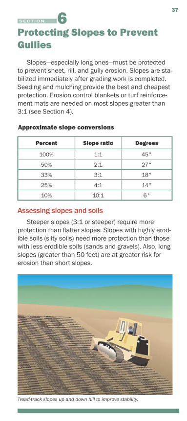
Slopes—especially long ones—must be protected to prevent sheet, rill, and gully erosion. Slopes are sta-bilized immediately after grading work is completed. Seeding and mulching provide the best and cheapest protection. Erosion control blankets or turf reinforce-ment mats are needed on most slopes greater than 3:1 (see Section 4).
Approximate slope conversions
Percent Slope ratio Degrees
100% 1:1 45°
50% 2:1 27°
33% 3:1 18°
25% 4:1 14°
10% 10:1 6°
Assessing slopes and soilsSteeper slopes (3:1 or steeper) require more
protection than flatter slopes. Slopes with highly erod-ible soils (silty soils) need more protection than those with less erodible soils (sands and gravels). Also, long slopes (greater than 50 feet) are at greater risk for erosion than short slopes.
SECTION
37
Tread-track slopes up and down hill to improve stability.
Slope protection basicsProtecting slopes from erosion requires several actions that must be taken together. No single approach will be successful, especially if the slope is long, steep, or has highly erodible soils (see table). Use one or more of the following actions to reduce erosion on slopes:
Divert upland runoffSee Section 3 for information on how to install a berm or channel above the slope to divert upland rain runoff around the bare soil area.
Control slope runoffIf slopes are broken up into benches or steps, runoff can be collected and diverted along berms or in channels to pipe or open channel slope drains with stable outlets.
Till seedbed or condition the soilDozer tracks up and down slopes help hold soil in place and lengthen the runoff flow path down the slope. See the table for information on how the condition of the soil surface (compacted, tracked, etc.) can increase or decrease erosion.
Seed and mulchThe best and cheapest protection by far. See Section 4 for details on seed types, application rates, and mulch, blanket, and mat products.
Silt fence or other barrierThese should be installed at the toe of the slope or slightly away from the toe, and every 75 to 125 feet apart on long slopes. Fiber rolls installed on the contour work very well in breaking up flows on long slopes.
Retaining wallExtremely steep slopes can be leveled out and shortened into two or more steps or benches by installing retaining walls of rock, brick, block, wood, logs, or other material. If rock layers are present along the slope, use these to establish firm benches in a stair-step pattern.
Blankets, mats, or armoringSlopes exceeding 3:1 with highly erodible soils must be protected with erosion control blankets, turf reinforcement mats, or other products such as hydraulic soil binders or bonded fiber matrices. Rock mulch and lined downdrain channels might be needed on steep slopes to control gullying.
38 Protecting Slopes to Prevent Gullies
Protecting Slopes to Prevent Gullies 39
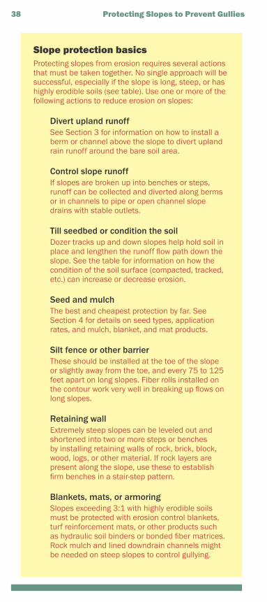
Temporary downdrain using plastic pipe. Stake down securely, and install where heavy flows need to be transported down highly erodible slopes. Note silt check dam in front of inlet.
Temporary or permanent downdrain using geotextile underliner and riprap. All slope drains must have flow dissipaters at the outlet to absorb high energy discharges, and silt checks at the inlet until grass is established.
40 Protecting Slopes to Prevent Gullies
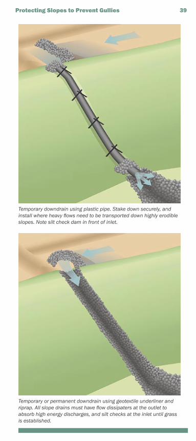
Soil conditions vs. erosion
If soil is: Erosion will be:
Compacted and smoothTracks across slopesTracks up & down slopesRough and irregularRough & loose to 12" deep
30 percent more20 percent more10 percent less10 percent less20 percent less
Chemical soil stabilizers and hydraulic mulchAnionic polyacrylamide (PAM) and other chemical
soil binders and stabilizers have been proven effec-tive in controlling erosion on slopes. Do not use these products within 25 feet of natural waterways. Follow manufacturer recommendations regarding mixing and application. Keep equipment off treated areas.
Note that this protection is only temporary—repeat applications or seeding and mulching or other ac-tion is still needed for permanent slope protection. Bonded fiber matrices and other hydraulic mulch products applied after seeding or with seed in the mix can provide permanent protection if mixed and applied properly. Apply 1 to 2 tons per acre; follow manufacturer’s directions.
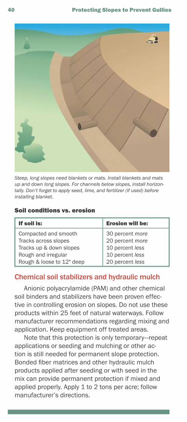
Steep, long slopes need blankets or mats. Install blankets and mats up and down long slopes. For channels below slopes, install horizon-tally. Don’t forget to apply seed, lime, and fertilizer (if used) before installing blanket.
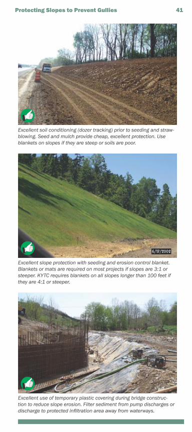
Excellent soil conditioning (dozer tracking) prior to seeding and straw-blowing. Seed and mulch provide cheap, excellent protection. Use blankets on slopes if they are steep or soils are poor.
Excellent slope protection with seeding and erosion control blanket. Blankets or mats are required on most projects if slopes are 3:1 or steeper. KYTC requires blankets on all slopes longer than 100 feet if they are 4:1 or steeper.
Excellent use of temporary plastic covering during bridge construc-tion to reduce slope erosion. Filter sediment from pump discharges or discharge to protected infiltration area away from waterways.
Protecting Slopes to Prevent Gullies 41
42 Protecting Slopes to Prevent Gullies
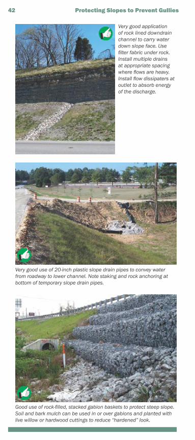
Very good application of rock lined downdrain channel to carry water down slope face. Use filter fabric under rock. Install multiple drains at appropriate spacing where flows are heavy. Install flow dissipaters at outlet to absorb energy of the discharge.
Very good use of 20-inch plastic slope drain pipes to convey water from roadway to lower channel. Note staking and rock anchoring at bottom of temporary slope drain pipes.
Good use of rock-filled, stacked gabion baskets to protect steep slope. Soil and bark mulch can be used in or over gabions and planted with live willow or hardwood cuttings to reduce “hardened” look.
Protecting Slopes to Prevent Gullies 43
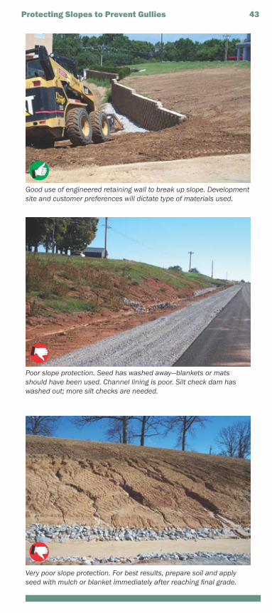
Very poor slope protection. For best results, prepare soil and apply seed with mulch or blanket immediately after reaching final grade.
Good use of engineered retaining wall to break up slope. Development site and customer preferences will dictate type of materials used.
Poor slope protection. Seed has washed away—blankets or mats should have been used. Channel lining is poor. Silt check dam has washed out; more silt checks are needed.
Protecting Culvert and Ditch Inlets and Outlets
Culverts and ditches are designed to carry moder-ate and large flows of storm water. They can transport a lot of sediment to streams, rivers, wetlands, and lakes if they are not properly protected. In addition, culvert and ditch outlets can become severely eroded if high velocity flows are not controlled.
Culvert and storm drain ponding methodsMuddy runoff that flows toward a culvert, ditch, or
storm drain inlet must be slowed down and pooled or filtered to settle out and remove sediment. This can be accomplished by placing rock, reinforced silt fenc-ing, silt dikes, or other barrier in front of the inlet. The goal is to cause ponding of the inflow so sediment can settle out, and allow ponded water to enter the inlet only after sediment has been removed.
Straw bales alone are not approved for inlet pro-tection. The next section describes several inlet pro-tection devices. If the drainage area above the inlet is greater than three acres, a sediment trap or basin is be needed (see Section 9). For all inlet protection approaches, seeding and/or mulching upland areas promptly will greatly reduce incoming runoff volumes and sediment loads
Inlet protection devicesInlets can be protected with structures made of
rock, reinforced silt fence, stone-filled bags, or com-mercial “inlet dam” products. Accumulated sediment must be removed after each rain to ensure effective-ness. Place materials to form a small dam around the inlet. Build larger dams farther away from inlets with heavy incoming flows. When using rock, mix rock of various sizes so flows can seep through the dam slowly (see photos on following pages). If spaces between rocks are too large, runoff will move through the dam without adequate settling time.
Silt fence dams can be used in low flow areas. Install a wire-reinforced silt fence dam or box around the inlet (see Section 5). Use diagonal bracing on
SECTION
44
sides and/or top to protect against incoming flow pressures. Make sure fence is trenched in and securely fastened to posts. Repair bypasses and undercuts promptly.
Place removed sediment in areas where it will not wash into inlets, ditches, channels, or streams. Do not wash sediment or any other material down curb, channel, or drain inlets.
Protecting Culvert and Channel Inlets and Outlets 45
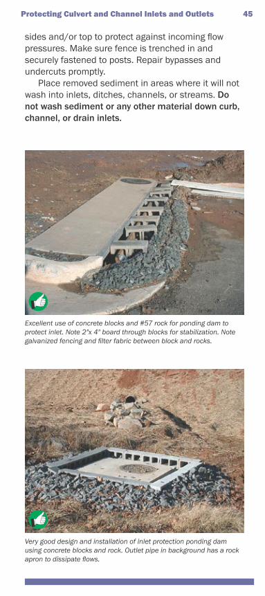
Excellent use of concrete blocks and #57 rock for ponding dam to protect inlet. Note 2"x 4" board through blocks for stabilization. Note galvanized fencing and filter fabric between block and rocks.
Very good design and installation of inlet protection ponding dam using concrete blocks and rock. Outlet pipe in background has a rock apron to dissipate flows.
46 Protecting Culvert and Channel Inlets and Outlets
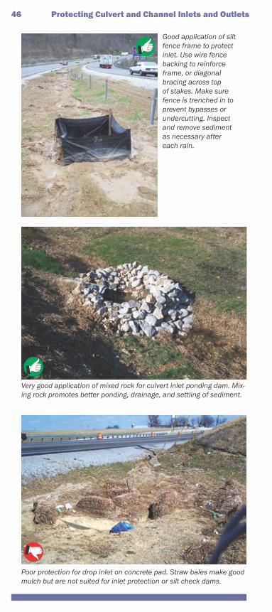
Good application of silt fence frame to protect inlet. Use wire fence backing to reinforce frame, or diagonal bracing across top of stakes. Make sure fence is trenched in to prevent bypasses or undercutting. Inspect and remove sediment as necessary after each rain.
Poor protection for drop inlet on concrete pad. Straw bales make good mulch but are not suited for inlet protection or silt check dams.
Very good application of mixed rock for culvert inlet ponding dam. Mix-ing rock promotes better ponding, drainage, and settling of sediment.
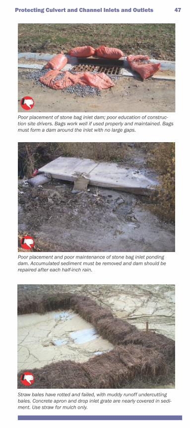
Straw bales have rotted and failed, with muddy runoff undercutting bales. Concrete apron and drop inlet grate are nearly covered in sedi-ment. Use straw for mulch only.
Protecting Culvert and Channel Inlets and Outlets 47
Poor placement of stone bag inlet dam; poor education of construc-tion site drivers. Bags work well if used properly and maintained. Bags must form a dam around the inlet with no large gaps.
Poor placement and poor maintenance of stone bag inlet ponding dam. Accumulated sediment must be removed and dam should be repaired after each half-inch rain.
Outlet protection methodsOutlets for storm drains, culverts, and paved
channels that discharge into natural or constructed channels must be lined with rock or other armoring to prevent downstream bank and channel erosion when flow velocities are high.
The rock-lined “apron” at the outlet must be straight (lined up with the discharging pipe or chan-nel) and laid in flat. Bring the sides up around out-let to prevent erosion, and up the banks a little to prevent scouring. The apron is shaped like a long triangle, with the narrow end located at the outlet and sized about 3 times the diameter of the outlet pipe. The width of the downstream end of the apron will be wider, tied into the channel, and vary according to the shape of the channel it empties into.
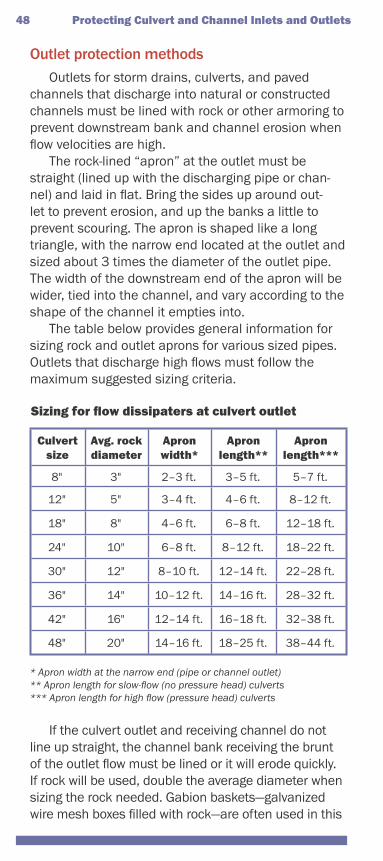
The table below provides general information for sizing rock and outlet aprons for various sized pipes. Outlets that discharge high flows must follow the maximum suggested sizing criteria.
Sizing for flow dissipaters at culvert outlet
Culvert size
Avg. rock diameter
Apron width*
Apron length**
Apron length***
8" 3" 2–3 ft. 3–5 ft. 5–7 ft.
12" 5" 3–4 ft. 4–6 ft. 8–12 ft.
18" 8" 4–6 ft. 6–8 ft. 12–18 ft.
24" 10" 6–8 ft. 8–12 ft. 18–22 ft.
30" 12" 8–10 ft. 12–14 ft. 22–28 ft.
36" 14" 10–12 ft. 14–16 ft. 28–32 ft.
42" 16" 12–14 ft. 16–18 ft. 32–38 ft.
48" 20" 14–16 ft. 18–25 ft. 38–44 ft.
* Apron width at the narrow end (pipe or channel outlet)** Apron length for slow-flow (no pressure head) culverts*** Apron length for high flow (pressure head) culverts
If the culvert outlet and receiving channel do not line up straight, the channel bank receiving the brunt of the outlet flow must be lined or it will erode quickly. If rock will be used, double the average diameter when sizing the rock needed. Gabion baskets—galvanized wire mesh boxes filled with rock—are often used in this
48 Protecting Culvert and Channel Inlets and Outlets
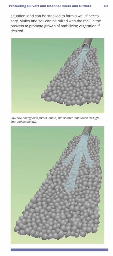
Low-flow energy dissipaters (above) are shorter than those for high-flow outlets (below).
Protecting Culvert and Channel Inlets and Outlets 49
situation, and can be stacked to form a wall if neces-sary. Mulch and soil can be mixed with the rock in the baskets to promote growth of stabilizing vegetation if desired.
50 Protecting Culvert and Channel Inlets and Outlets
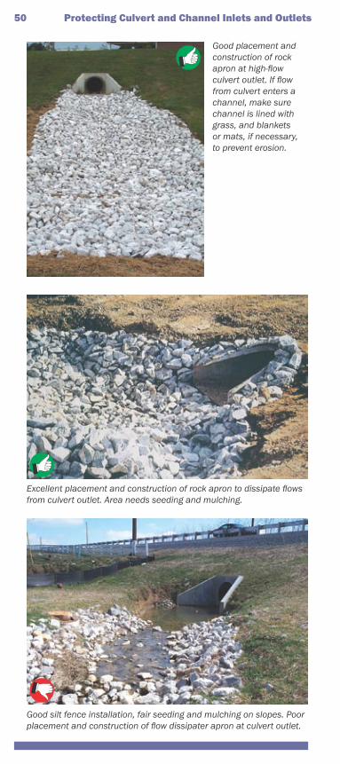
Good placement and construction of rock apron at high-flow culvert outlet. If flow from culvert enters a channel, make sure channel is lined with grass, and blankets or mats, if necessary, to prevent erosion.
Excellent placement and construction of rock apron to dissipate flows from culvert outlet. Area needs seeding and mulching.
Good silt fence installation, fair seeding and mulching on slopes. Poor placement and construction of flow dissipater apron at culvert outlet.
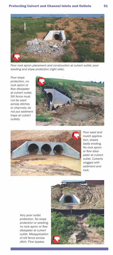
Poor rock apron placement and construction at culvert outlet; poor seeding and slope protection (right side).
Poor slope protection, no rock apron or flow dissipater at culvert outlet. Silt fence must not be used across ditches or channels; do not put sediment traps at culvert outlets.
Poor seed and mulch applica-tion, slopes badly eroding. No rock apron or flow dissi-pater at culvert outlet. Culverts clogged with sediment and rock.
Very poor outlet protection. No slope protection or seeding, no rock apron or flow dissipater at culvert outlet. Misapplication of silt fence across ditch. Flow bypass.
Protecting Culvert and Channel Inlets and Outlets 51
Stabilizing Drainage Ditches
Man-made drainage ditches with gently sloping bottoms (less than 3%) can be stabilized with thick grass seeding and erosion control blankets (see Section 4). Natural (i.e., not “man-made”) drainage channels and creeks or streams cannot be cleared, re-routed, or otherwise altered without one or more permits from the U.S. Army Corps of Engineers and the KY Division of Water (see Section 10). Moderately sloping ditches (3%–6% slopes) will likely require turf reinforcement mats and perhaps some riprap if soils are silty. Steeply sloping ditches (greater than 10%) need heavier armoring with concrete, riprap, gabion baskets, geogrid, retaining walls, or other approved products.
Drainage ditch slopes and soilsAs noted in Section 6, silty soils are the most
erodible and clay is the least erodible. Steeper ditches and those with highly erodible soils need more protection. Drainage ditch bank slopes must not exceed 2:1. If tractor mowers or other equip-ment will cross channels in the future, bank slopes must be 3:1 or flatter. The outlet must be installed, seeded, stabilized, and protected before the ditch receives incoming flows.
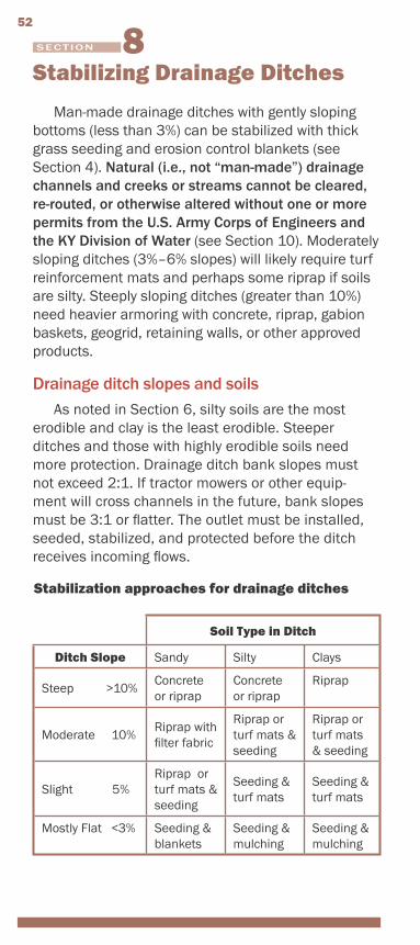
Stabilization approaches for drainage ditches
Soil Type in Ditch
Ditch Slope Sandy Silty Clays
Steep >10%Concrete or riprap
Concrete or riprap
Riprap
Moderate 10%Riprap with filter fabric
Riprap or turf mats & seeding
Riprap or turf mats & seeding
Slight 5%Riprap or turf mats & seeding
Seeding & turf mats
Seeding & turf mats
Mostly Flat <3% Seeding & blankets
Seeding & mulching
Seeding & mulching
52
SECTION
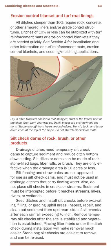
Erosion control blanket and turf mat liningsAll ditches steeper than 10% require rock, concrete,
or other armored liners and/or grade control struc-tures. Ditches of 10% or less can be stabilized with turf reinforcement mats or erosion control blankets if they are seeded quickly. See Section 4 for installation and other information on turf reinforcement mats, erosion control blankets, and seeding/mulching applications.
Silt check dams of rock, brush, or other products
Drainage ditches need temporary silt check dams to capture sediment and reduce ditch bottom downcutting. Silt dikes or dams can be made of rock, stone-filled bags, fiber rolls, or brush. They are only ef-fective when the drainage area is 10 acres or less.
Silt fencing and straw bales are not approved for use as silt check dams, and must not be used in drainage ditches that carry flowing water. Also, do not place silt checks in creeks or streams. Sediment must be intercepted before it reaches streams, lakes, rivers, or wetlands.
Seed ditches and install silt checks before excavat-ing, filling, or grading uphill areas. Inspect, repair, and clean out sediment from upstream side of silt checks after each rainfall exceeding 1⁄2 inch. Remove tempo-rary silt checks after the site is stabilized and vegeta-tion is established. Placing filter fabric under the ditch check during installation will make removal much easier. Stone bag silt checks are easiest to remove, and can be re-used.
Stabilizing Ditches and Channels 53
Lay in ditch blankets similar to roof shingles; start at the lowest part of the ditch, then work your way up. Uphill pieces lap over downhill sec-tions. Staple through both layers around edges. Trench, tuck, and tamp down ends at the top of the slope. Do not stretch blankets or mats.
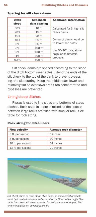
Spacing for silt check dams
Ditch slope
Silt check dam spacing
Additional information
30% 10 ft. Calculated for 3' high silt check dams.
Center of dam should be 6" lower than sides.
Use 5"–10" rock, stone bags, or commercial products.
20% 15 ft.15% 20 ft.10% 35 ft.5% 55 ft.3% 100 ft.2% 150 ft.1% 300 ft.
0.5% 600 ft.
Silt check dams are spaced according to the slope of the ditch bottom (see table). Extend the ends of the silt check to the top of the bank to prevent bypass-ing and sidecutting. Keep the middle part lower and relatively flat so overflows aren’t too concentrated and bypasses are prevented.
Lining steep ditchesRiprap is used to line sides and bottoms of steep
ditches. Rock used in liners is mixed so the spaces between large rocks are filled with smaller rock. See table for rock sizing.
Rock sizing for ditch liners
Flow velocity Average rock diameter
6 ft. per second 5 inches
8 ft. per second 10 inches
10 ft. per second 14 inches
12 ft. per second 20 inches
Silt check dams of rock, stone-filled bags, or commercial products must be installed before uphill excavation or fill activities begin. See table for correct silt check spacing for various channel slopes. Tied end of bag goes on downstream side.
54 Stabilizing Ditches and Channels
Stabilizing Ditches and Channels 55
As ditch depth and steepness increase, rock size must also increase. Line the bare ditch bottom and sides with non-woven filter fabric to prevent undercut-ting and washouts. If flows are 10 feet per second or more, use #2 rock as a bottom liner, below the larger rock. Rock must be placed along ditch bottom first, then up the sides. Rock layer thickness should be 11⁄2 times the average diameter of the largest fourth of the rocks.
Install a protected outlet first by excavating a 11⁄2- to 2-foot trench at the toe of the slope and filling with riprap. See Section 7 for details on outlet apron construction. Replace dislodged rock after storms as needed.
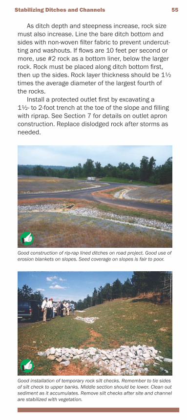
Good construction of rip-rap lined ditches on road project. Good use of erosion blankets on slopes. Seed coverage on slopes is fair to poor.
Good installation of temporary rock silt checks. Remember to tie sides of silt check to upper banks. Middle section should be lower. Clean out sediment as it accumulates. Remove silt checks after site and channel are stabilized with vegetation.
56 Stabilizing Ditches and Channels
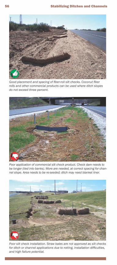
Poor silt check installation. Straw bales are not approved as silt checks for ditch or channel applications due to rotting, installation difficulties, and high failure potential.
Good placement and spacing of fiber-roll silt checks. Coconut fiber rolls and other commercial products can be used where ditch slopes do not exceed three percent.
Poor application of commercial silt check product. Check dam needs to be longer (tied into banks). More are needed, at correct spacing for chan-nel slope. Area needs to be re-seeded; ditch may need blanket liner.
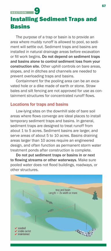
Installing Sediment Traps and Basins
The purpose of a trap or basin is to provide an area where muddy runoff is allowed to pool, so sedi-ment will settle out. Sediment traps and basins are installed in natural drainage areas before excavation or fill work begins. Do not depend on sediment traps and basins alone to control sediment loss from your construction site. Other uphill controls on bare areas, slopes, and in ditches and channels are needed to prevent overloading traps and basins.
Containment for the pooling area can be an exca-vated hole or a dike made of earth or stone. Straw bales and silt fencing are not approved for use as con-tainment structures for concentrated runoff flows.
Locations for traps and basinsLow-lying sites on the downhill side of bare soil
areas where flows converge are ideal places to install temporary sediment traps and basins. In general, sediment traps are designed to treat runoff from about 1 to 5 acres. Sediment basins are larger, and serve areas of about 5 to 10 acres. Basins draining areas larger than 10 acres require an engineered design, and often function as permanent storm water treatment ponds after construction is complete.
Do not put sediment traps or basins in or next to flowing streams or other waterways. Make sure pooled water does not flood buildings, roadways, or other structures.
57
SECTION
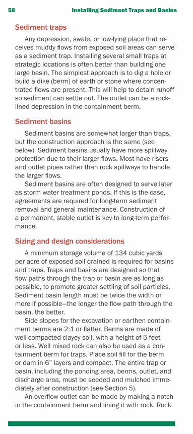
Sediment trapsAny depression, swale, or low-lying place that re-
ceives muddy flows from exposed soil areas can serve as a sediment trap. Installing several small traps at strategic locations is often better than building one large basin. The simplest approach is to dig a hole or build a dike (berm) of earth or stone where concen-trated flows are present. This will help to detain runoff so sediment can settle out. The outlet can be a rock-lined depression in the containment berm.
Sediment basinsSediment basins are somewhat larger than traps,
but the construction approach is the same (see below). Sediment basins usually have more spillway protection due to their larger flows. Most have risers and outlet pipes rather than rock spillways to handle the larger flows.
Sediment basins are often designed to serve later as storm water treatment ponds. If this is the case, agreements are required for long-term sediment removal and general maintenance. Construction of a permanent, stable outlet is key to long-term perfor-mance.
Sizing and design considerationsA minimum storage volume of 134 cubic yards
per acre of exposed soil drained is required for basins and traps. Traps and basins are designed so that flow paths through the trap or basin are as long as possible, to promote greater settling of soil particles. Sediment basin length must be twice the width or more if possible—the longer the flow path through the basin, the better.
Side slopes for the excavation or earthen contain-ment berms are 2:1 or flatter. Berms are made of well-compacted clayey soil, with a height of 5 feet or less. Well mixed rock can also be used as a con-tainment berm for traps. Place soil fill for the berm or dam in 6” layers and compact. The entire trap or basin, including the ponding area, berms, outlet, and discharge area, must be seeded and mulched imme-diately after construction (see Section 5).
An overflow outlet can be made by making a notch in the containment berm and lining it with rock. Rock
58 Installing Sediment Traps and Basins
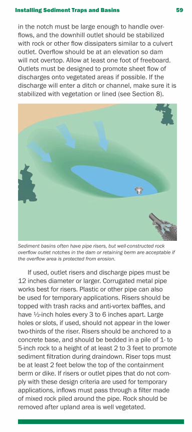
in the notch must be large enough to handle over-flows, and the downhill outlet should be stabilized with rock or other flow dissipaters similar to a culvert outlet. Overflow should be at an elevation so dam will not overtop. Allow at least one foot of freeboard. Outlets must be designed to promote sheet flow of discharges onto vegetated areas if possible. If the discharge will enter a ditch or channel, make sure it is stabilized with vegetation or lined (see Section 8).
If used, outlet risers and discharge pipes must be 12 inches diameter or larger. Corrugated metal pipe works best for risers. Plastic or other pipe can also be used for temporary applications. Risers should be topped with trash racks and anti-vortex baffles, and have 1⁄2-inch holes every 3 to 6 inches apart. Large holes or slots, if used, should not appear in the lower two-thirds of the riser. Risers should be anchored to a concrete base, and should be bedded in a pile of 1- to 5-inch rock to a height of at least 2 to 3 feet to promote sediment filtration during draindown. Riser tops must be at least 2 feet below the top of the containment berm or dike. If risers or outlet pipes that do not com-ply with these design criteria are used for temporary applications, inflows must pass through a filter made of mixed rock piled around the pipe. Rock should be removed after upland area is well vegetated.
Installing Sediment Traps and Basins 59
Sediment basins often have pipe risers, but well-constructed rock overflow outlet notches in the dam or retaining berm are acceptable if the overflow area is protected from erosion.
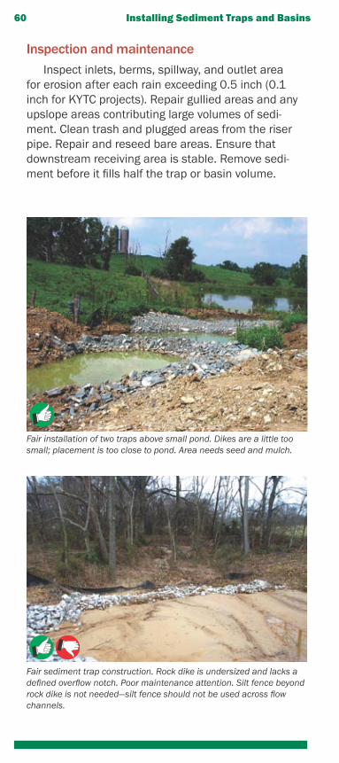
Inspection and maintenanceInspect inlets, berms, spillway, and outlet area
for erosion after each rain exceeding 0.5 inch (0.1 inch for KYTC projects). Repair gullied areas and any upslope areas contributing large volumes of sedi-ment. Clean trash and plugged areas from the riser pipe. Repair and reseed bare areas. Ensure that downstream receiving area is stable. Remove sedi-ment before it fills half the trap or basin volume.
60 Installing Sediment Traps and Basins
Fair installation of two traps above small pond. Dikes are a little too small; placement is too close to pond. Area needs seed and mulch.
Fair sediment trap construction. Rock dike is undersized and lacks a defined overflow notch. Poor maintenance attention. Silt fence beyond rock dike is not needed—silt fence should not be used across flow channels.
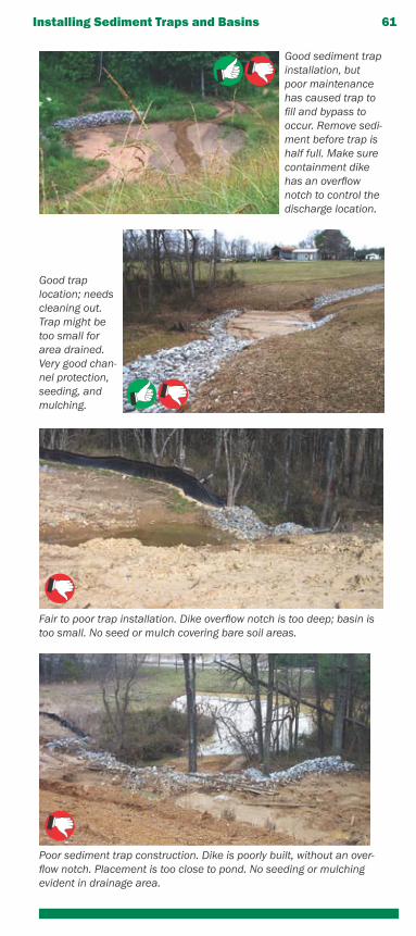
Installing Sediment Traps and Basins 61
Poor sediment trap construction. Dike is poorly built, without an over-flow notch. Placement is too close to pond. No seeding or mulching evident in drainage area.
Good sediment trap installation, but poor maintenance has caused trap to fill and bypass to occur. Remove sedi-ment before trap is half full. Make sure containment dike has an overflow notch to control the discharge location.
Good trap location; needs cleaning out. Trap might be too small for area drained. Very good chan-nel protection, seeding, and mulching.
Fair to poor trap installation. Dike overflow notch is too deep; basin is too small. No seed or mulch covering bare soil areas.
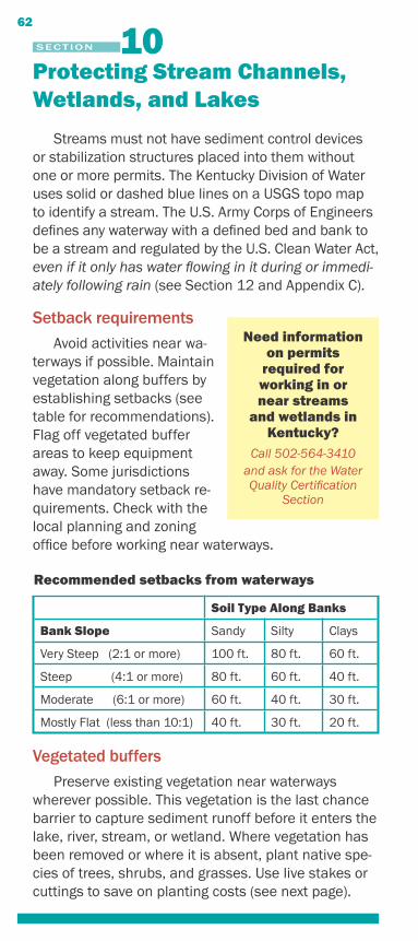
Protecting Stream Channels, Wetlands, and Lakes
Streams must not have sediment control devices or stabilization structures placed into them without one or more permits. The Kentucky Division of Water uses solid or dashed blue lines on a USGS topo map to identify a stream. The U.S. Army Corps of Engineers defines any waterway with a defined bed and bank to be a stream and regulated by the U.S. Clean Water Act, even if it only has water flowing in it during or immedi-ately following rain (see Section 12 and Appendix C).
Setback requirementsAvoid activities near wa-
terways if possible. Maintain vegetation along buffers by establishing setbacks (see table for recommendations). Flag off vegetated buffer areas to keep equipment away. Some jurisdictions have mandatory setback re-quirements. Check with the local planning and zoning office before working near waterways.
Recommended setbacks from waterways
Soil Type Along Banks
Bank Slope Sandy Silty Clays
Very Steep (2:1 or more) 100 ft. 80 ft. 60 ft.
Steep (4:1 or more) 80 ft. 60 ft. 40 ft.
Moderate (6:1 or more) 60 ft. 40 ft. 30 ft.
Mostly Flat (less than 10:1) 40 ft. 30 ft. 20 ft.
Vegetated buffersPreserve existing vegetation near waterways
wherever possible. This vegetation is the last chance barrier to capture sediment runoff before it enters the lake, river, stream, or wetland. Where vegetation has been removed or where it is absent, plant native spe-cies of trees, shrubs, and grasses. Use live stakes or cuttings to save on planting costs (see next page).
Need information on permits
required for working in or near streams
and wetlands in Kentucky?
Call 502-564-3410and ask for the Water Quality Certification
Section
62
SECTION
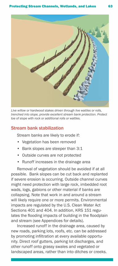
Stream bank stabilizationStream banks are likely to erode if:
• Vegetation has been removed
• Bank slopes are steeper than 3:1
• Outside curves are not protected
• Runoff increases in the drainage area
Removal of vegetation should be avoided if at all possible. Bank slopes can be cut back and replanted if severe erosion is occurring. Outside channel curves might need protection with large rock, imbedded root wads, logs, gabions or other material if banks are collapsing. Note that work in and around a stream will likely require one or more permits. Environmental impacts are regulated by the U.S. Clean Water Act Sections 401 and 404. In addition, KRS 151 regu-lates the flooding impacts of building in the floodplain and stream (see Appendices for details).
Increased runoff in the drainage area, caused by new roads, parking lots, roofs, etc. can be addressed by promoting infiltration at every available opportu-nity. Direct roof gutters, parking lot discharges, and other runoff onto grassy swales and vegetated or landscaped areas, rather than into ditches or creeks.
Protecting Stream Channels, Wetlands, and Lakes 63
Live willow or hardwood stakes driven through live wattles or rolls, trenched into slope, provide excellent stream bank protection. Protect toe of slope with rock or additional rolls or wattles.
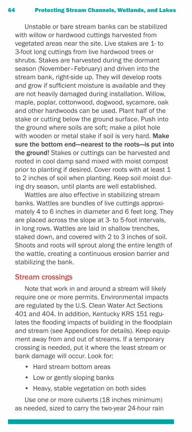
Unstable or bare stream banks can be stabilized with willow or hardwood cuttings harvested from vegetated areas near the site. Live stakes are 1- to 3-foot long cuttings from live hardwood trees or shrubs. Stakes are harvested during the dormant season (November–February) and driven into the stream bank, right-side up. They will develop roots and grow if sufficient moisture is available and they are not heavily damaged during installation. Willow, maple, poplar, cottonwood, dogwood, sycamore, oak and other hardwoods can be used. Plant half of the stake or cutting below the ground surface. Push into the ground where soils are soft; make a pilot hole with wooden or metal stake if soil is very hard. Make sure the bottom end—nearest to the roots—is put into the ground! Stakes or cuttings can be harvested and rooted in cool damp sand mixed with moist compost prior to planting if desired. Cover roots with at least 1 to 2 inches of soil when planting. Keep soil moist dur-ing dry season, until plants are well established.
Wattles are also effective in stabilizing stream banks. Wattles are bundles of live cuttings approxi-mately 4 to 6 inches in diameter and 6 feet long. They are placed across the slope at 3- to 5-foot intervals, in long rows. Wattles are laid in shallow trenches, staked down, and covered with 2 to 3 inches of soil. Shoots and roots will sprout along the entire length of the wattle, creating a continuous erosion barrier and stabilizing the bank.
Stream crossingsNote that work in and around a stream will likely
require one or more permits. Environmental impacts are regulated by the U.S. Clean Water Act Sections 401 and 404. In addition, Kentucky KRS 151 regu-lates the flooding impacts of building in the floodplain and stream (see Appendices for details). Keep equip-ment away from and out of streams. If a temporary crossing is needed, put it where the least stream or bank damage will occur. Look for:
• Hard stream bottom areas
• Low or gently sloping banks
• Heavy, stable vegetation on both sides
Use one or more culverts (18 inches minimum) as needed, sized to carry the two-year 24-hour rain
64 Protecting Stream Channels, Wetlands, and Lakes
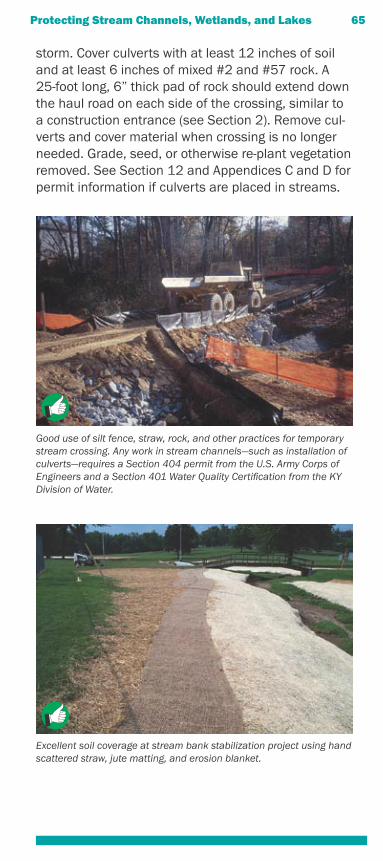
storm. Cover culverts with at least 12 inches of soil and at least 6 inches of mixed #2 and #57 rock. A 25-foot long, 6” thick pad of rock should extend down the haul road on each side of the crossing, similar to a construction entrance (see Section 2). Remove cul-verts and cover material when crossing is no longer needed. Grade, seed, or otherwise re-plant vegetation removed. See Section 12 and Appendices C and D for permit information if culverts are placed in streams.
Protecting Stream Channels, Wetlands, and Lakes 65
Excellent soil coverage at stream bank stabilization project using hand scattered straw, jute matting, and erosion blanket.
Good use of silt fence, straw, rock, and other practices for temporary stream crossing. Any work in stream channels—such as installation of culverts—requires a Section 404 permit from the U.S. Army Corps of Engineers and a Section 401 Water Quality Certification from the KY Division of Water.
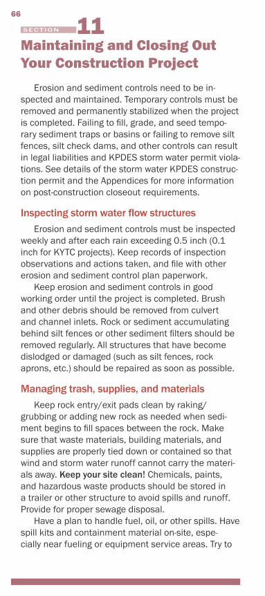
Maintaining and Closing Out Your Construction Project
Erosion and sediment controls need to be in-spected and maintained. Temporary controls must be removed and permanently stabilized when the project is completed. Failing to fill, grade, and seed tempo-rary sediment traps or basins or failing to remove silt fences, silt check dams, and other controls can result in legal liabilities and KPDES storm water permit viola-tions. See details of the storm water KPDES construc-tion permit and the Appendices for more information on post-construction closeout requirements.
Inspecting storm water flow structuresErosion and sediment controls must be inspected
weekly and after each rain exceeding 0.5 inch (0.1 inch for KYTC projects). Keep records of inspection observations and actions taken, and file with other erosion and sediment control plan paperwork.
Keep erosion and sediment controls in good working order until the project is completed. Brush and other debris should be removed from culvert and channel inlets. Rock or sediment accumulating behind silt fences or other sediment filters should be removed regularly. All structures that have become dislodged or damaged (such as silt fences, rock aprons, etc.) should be repaired as soon as possible.
Managing trash, supplies, and materialsKeep rock entry/exit pads clean by raking/
grubbing or adding new rock as needed when sedi-ment begins to fill spaces between the rock. Make sure that waste materials, building materials, and supplies are properly tied down or contained so that wind and storm water runoff cannot carry the materi-als away. Keep your site clean! Chemicals, paints, and hazardous waste products should be stored in a trailer or other structure to avoid spills and runoff. Provide for proper sewage disposal.
Have a plan to handle fuel, oil, or other spills. Have spill kits and containment material on-site, espe-cially near fueling or equipment service areas. Try to
SECTION
66
maintain vehicles and equipment away from the site if possible. If maintenance must occur on-site, ensure that spills are cleaned up quickly.
Vegetated cover considerations for close-outNo site is closed out properly until vegetation is
established on all bare soil areas and ditches are stable. Check seeded areas, and reseed areas where vegetation is thin or absent. This is especially impor-tant for slopes, ditches, and channels.
Removing temporary sediment controlsWhen project is completed:
• Remove all silt fencing and stakes. Grade out and seed or remove accumulated sediment or broadcast over grassed areas or dispose of off-site.
• Culvert inlets should be stabilized, vegetated, and showing no visible gullies. Rock or soil that has been washed away by runoff or upstream flows should be replaced. Brush or other debris that could clog inlets should be removed.
• Check ditches and channels to make sure banks and ditch bottoms are well vegetated. Reseed bare areas and replace rock that has become dislodged.
• Check areas where erosion control blankets or matting was installed. Cut away and remove all loose, exposed material, especially in areas where walking or mowing will occur. Reseed all bare soil areas.
• Replace rock washouts near culvert and channel outlets. Fill, grade, and seed or riprap eroded areas around inlets and outlets. Make sure downstream ditches and channels are fully vegetated. Fill and seed any gullies along the banks or other slopes.
• Fill in, grade, and seed all temporary sediment traps and basins that have been removed. Dou-ble the seeding rate where runoff flows might converge or high velocity flows are expected.
• Remove temporary stream crossings and grade, seed, or re-plant vegetation removed during crossing installation.
Maintaining and Closing Out Your Project 67
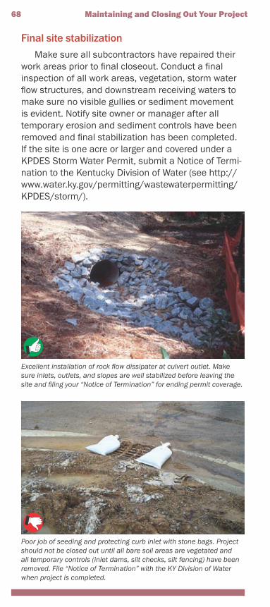
Final site stabilizationMake sure all subcontractors have repaired their
work areas prior to final closeout. Conduct a final inspection of all work areas, vegetation, storm water flow structures, and downstream receiving waters to make sure no visible gullies or sediment movement is evident. Notify site owner or manager after all temporary erosion and sediment controls have been removed and final stabilization has been completed. If the site is one acre or larger and covered under a KPDES Storm Water Permit, submit a Notice of Termi-nation to the Kentucky Division of Water (see http://www.water.ky.gov/permitting/wastewaterpermitting/KPDES/storm/).
68 Maintaining and Closing Out Your Project
Excellent installation of rock flow dissipater at culvert outlet. Make sure inlets, outlets, and slopes are well stabilized before leaving the site and filing your “Notice of Termination” for ending permit coverage.
Poor job of seeding and protecting curb inlet with stone bags. Project should not be closed out until all bare soil areas are vegetated and all temporary controls (inlet dams, silt checks, silt fencing) have been removed. File “Notice of Termination” with the KY Division of Water when project is completed.
Regulatory Information
Storm water permits
Construction projects one acre or larger must be covered by a federal Clean Water Act Storm Water KPDES permit. The permits are issued by the Kentucky Division of Water. If a project smaller than one acre is part of a larger development that exceeds one acre, it also must be covered by a KPDES permit as of March 10, 2003. Following the erosion and sedi-ment control recommendations in this guidebook will help you meet most of the permit requirements. The main goal of the entire permit program is to keep sediment and other pollutants out of lakes, rivers, streams, and wetlands. For more details on permit requirements, see Appendix A of this guide.
Erosion protection and sediment control plansIf you’re working in Jefferson County, Fayette
County, Northern Kentucky, or other designated urban areas, you need to file an erosion and sediment control plan with the local government before you begin work. The plans require you to note which of the erosion and sediment control measures you will use during construction. Plans are also required for Ken-tucky Transportation Cabinet construction projects. See Appendices of this guide for specific plan require-ments and inspection checklists.
If you are working elsewhere in the state and your project is one acre or larger, you have to develop a written erosion and sediment control plan as part of your overall “Storm Water Pollution Prevention (BMP) Plan.” These plans do not have to be filed, but must be available at the construction site for review by con-tractors, subcontractors, and regulatory staff.
Utility construction regulationsIn general, utility construction crews and other
subcontractors are responsible for their own erosion
Need information on Storm Water Permits?Call 502-564-3410; Ask for the KPDES DivisionOr visit this Internet site:http://www.water.ky.gov/permitting/wastewaterpermitting/KPDES/
69
SECTION
and sediment controls. General contractors should make sure that all utilities and subcontractors use rock pad construction entrances. Tracking mud out onto paved roads can lead to legal liabilities. If crews disturb areas that have already been stabilized, they should replace any mulch, sod, seed, blanket, mat-ting, rock, or other material disturbed. Failure to prop-erly grade, seed, and stabilize work sites may violate permit requirements.
If your project is larger than one acre and covered under a KPDES Storm Water Permit, it is recom-mended that subcontractors and others conducting excavation or fill activities sign an agreement that they will follow the Storm Water Pollution Prevention (BMP) Plan. If utility projects are conducted in or near streams, Clean Water Act Section 404 permit cover-age may be required (see next subsection).
Transportation project regulationsThe Kentucky Transportation Cabinet (KYTC)
inspection performance standard for erosion and sediment control is that no sediment should leave the site. KYTC requires that slopes 4:1 or steeper with upland runoff areas exceeding 100 feet and all chan-nels be lined with erosion control blankets. All KYTC projects are subject to KPDES Storm Water Permit requirements. The Cabinet requires that inspection of erosion and sediment controls be conducted at least weekly and after each rain of 0.1 inch or more. If transportation projects are conducted in or near streams, Clean Water Act Section 404 permit cover-age may be required (see below).
KYTC standards also limit the amount of disturbed area to 750,000 square feet (about 17.2 acres). Writ-ten approval from the district engineer is required for exceeding this limit.
Bridge construction/repair and other work near streams require substantial erosion and sediment control efforts. Establish final grade quickly on as much of the site as possible, then stabilize with seed, mulch, blankets, or matting. Bare soil areas at tem-porary grade should also be seeded and mulched if they will not be worked over 21 consecutive days. See Appendix F for more information on transportation project requirements.
70 Regulatory Information
Section 404 permits for wetlands and streamsActivities conducted in or through streams or wet-
lands require a separate permit under Section 404 of the Clean Water Act, which regulates the placement of dredged or fill material into public waters. If equip-ment will be operating in or through a creek, wetland, or river, permit coverage is required. See the box below for a list of the permits issued by the U.S. Army Corps of Engineers under the Section 404 permits:
• Structures in Canals• Maintenance Activities• Survey Activities• Outfall Structure O&M• Temporary Rec. Structures• Utility Line Activities• Bank Stabilization• Linear Transportation Projects• Hydropower Projects• Minor Discharges• Minor Dredging• Surface Coal Mining Activities• Structural Discharges• Stream/Wetland Restoration• Marina Modifications• Single-family Housing• Flood Control Facilities O&M• Construction & Access• Dredging of Existing Basins• Boat Ramps• Waste Cleanup Operations• Development on Waterways• Agricultural Activities• Reshaping Drainage Ditches• Recreational Facilities• Storm Water Management Facilities
• Mining Activities
See Appendix C for contact information regarding Section 404 per-mits.
Regulatory Information 71

72 Regulatory Information
Kentucky Division of WaterRegional Offices and Supervisors:
Bowling Green: Bill Baker (270) 746-7475Columbia: Sara Sproles (270) 384-4734Florence: Todd Giles (859) 525-4923Frankfort: Massoud Shoa (502) 564-3358Hazard: Ferris Sexton (606) 435-6022London: Keith Blair (606) 878-0157Louisville: Mike Mudd (502) 425-4671Madisonville: Ed Carroll (270) 824-7529Morehead: Bob Wells (606) 784-6635Paducah: Vince Priddle (270) 898-8468
For More Information Contact:Tom Gabbard14 Reilly RoadFrankfort, KY 40601Phone: (502) 564-3410Fax: (502) 564-2741E-mail: [email protected]
Federal and State KPDES Storm Water Permit Requirements
EPA regulations at 40 CFR 122.26(b)(14)(x) and 122.26(b)(15) require NPDES storm water discharge permit coverage for discharges from construction activities that disturb one or more acres. These nationwide regulations are implemented by general NPDES permits, which are issued by EPA and autho-rized State agencies such as the Kentucky Division of Water, which issues KPDES permits.
The KDOW KPDES Construction General Permit was developed to satisfy federal storm water per-mitting requirements. KPDES Construction General Permit meets all federal permit requirements and most of the requirements of local governments in Kentucky, though some local governments have ad-ditional requirements that must also be addressed by the applicant. See below for a summary of the KPDES Construction General Permit requirements, and Ap-pendix B for a summary of some local government requirements.
The KPDES Construction General Permit covers all storm water discharges associated with construc-tion activity that disturbs one acre or more. A copy of this permit can be downloaded from http://www.water.ky.gov/permitting/wastewaterpermitting/KPDES/storm/. The permit requires all construction activity in Kentucky disturbing one acre or more to:
• Submit a signed Notice of Intent (NOI) form to Kentucky Division of Water at least 48 hours before construction activity begins.
• Submit a copy of the NOI to the municipal operator of any municipal separate storm sewer system (MS4) the site discharges into.
• Develop and implement a “Storm Water Pollu-tion Prevention (BMP) Plan.”
• Continue to implement the plan during construc-tion activity, including inspections every 7 days and after each rain of one-half inch or more.
• Submit a signed Notice of Termination (NOT) form to Kentucky Division of Water after the site has been finally stabilized.
73
APPENDIX A
The Storm Water Pollution Prevention or “Best Management Practices” (BMP) Plan must be devel-oped in accordance with good engineering practices. The BMP Plan must identify expected sources of pollution and describe how they will be controlled. The BMP Plan must be completed prior to construc-tion, signed, and kept onsite. BMP Plans required by this permit are considered reports that shall be made available to the public, upon written request, in ac-cordance with Section 308(b) of the Clean Water Act (CWA). Deficient plans may require modification upon notification by the KY Division of Water or local regula-tory authority.
Construction site BMP Plan requirementsThe BMP Plan must include, as a minimum, the
following:Site Description: The BMP Plan shall include a
clear description of the nature of the construction activity, the order of major soil disturbing activities, a site map, and other information. The site map shall indicate drainage patterns and show approximate slopes after grading, areas of disturbance, the loca-tion of control measures, surface waters or wetlands, and storm water discharge locations.
Sediment and Erosion Control Measures: The BMP plan must include a clear description of what sediment and erosion control measures will be used and when they will be implemented. The following control measures shall be used as a minimum:
• Soil Stabilization Practices—Existing vegeta-tion shall be preserved where possible. All disturbed areas of the site shall be stabilized. Stabilization shall begin within 14 days on areas of the site where construction activities have permanently or temporarily (for 21 days or more) ceased. When snow cover causes delays, stabilization shall begin as soon as possible. Stabilization practices include seeding, mulch-ing, placing sod, planting trees or shrubs, and using geotextile fabrics and other appropriate measures.
• Perimeter Structural Practices—Silt fences or other equivalent structural practices shall be used on all side and down slope borders of the
74 Appendix A
site. For common drainage locations that serve more than ten (10) disturbed acres at one time, a sediment basin must be used if possible. Structural practices include protecting drain inlets and outlets and using silt fences, earthen dikes, drainage swales, sediment traps, check dams, subsurface drains, pipe slope drains, reinforced soil retaining systems, gabions, sedi-ment basins and other appropriate measures.
• Storm Water Management Devices—Manage-ment devices shall be installed during construc-tion to control the pollutants in storm water discharges that will occur after construction has been completed. Velocity dissipation devices shall be placed at discharge locations and along outfall channels as necessary to provide a non-erosive flow. The goal should be 80% removal of Total Suspended Solids that exceed predevelopment levels. If this goal is not met, the permittee shall provide justification for refusing each device based on site conditions.
Other Control Measures: No solid materials, including building materials, shall be discharged to waters of the Commonwealth, except as authorized by a Section 404 permit. Off-site vehicle sediment tracking and dust generation shall be minimized. Waste disposal methods and sanitary sewer or septic systems shall comply with applicable state or local regulations.
Other State or Local Plans: The BMP Plan shall include any requirements specified in sediment and erosion control plans, storm water management plans or permits that have been approved by other state or local officials.
Maintenance: The BMP Plan shall include a clear description of the maintenance procedures necessary to keep the control measures in good and effective operating condition.
Inspections: Qualified personnel shall inspect all storm water control measures and drainage features at least once every seven days and within 24 hours of the end of a storm that is 0.5 inch or greater (0.1 inch for KYTC projects). Discharge locations shall be inspected to ensure that velocity dissipaters prevent significant impacts to receiving waters. Vehicle exits
Appendix A 75
shall be inspected for evidence of offsite sediment tracking. Disturbed areas and material storage areas that are exposed to precipitation shall be inspected for evidence of pollutants entering the drainage system. A signed report summarizing the scope of the inspection, major observations, and any corrective actions taken shall be made and kept as part of the BMP Plan.
Non-Storm Water Discharges: The BMP Plan shall identify and ensure the implementation of appropri-ate pollution prevention measures for any non-storm water component of a discharge as listed in PART III C, except for flows from fire fighting activities.
Contractors and Subcontractors: The BMP plan shall clearly state the contractor or subcontractors that will implement each control measure identified in the BMP Plan. All contractors and subcontrac-tors identified in the BMP Plan must sign a copy of the certification statement below before conducting any professional service at the site: “I certify under penalty of law that I understand the terms and condi-tions of the general National Pollutant Discharge Elimination System (NPDES) permit that authorizes the storm water discharges associated with industrial activity from the construction site identified as part of this certification.” The certification must include the name and title of the person providing the signa-ture, the name, address, and telephone number of the contracted firm, the address, or other identifying description of the site and the date the certification is made. All certification statements must be included in the BMP Plan.
76 Appendix A
ESC Plan Requirements for Local Governments in Kentucky
Some urban areas in Kentucky have specific requirements for filing earth disturbance plans prior to construction. Check with each local government prior to construction in urban areas to make sure your understanding of the permit requirements is up-to-date. Below is a summary of the requirements of the Metropolitan Sewer District of Louisville and Jefferson County, the Lexington-Fayette Urban County Govern-ment, and Sanitation District #1 in Northern Kentucky.
Louisville – Jefferson County Metropolitan Sewer District
On November 21, 2000 the Jefferson County Fiscal Court adopted an Erosion Prevention and Sediment Control (EPSC) Ordinance applies to all land disturbing activities in Jefferson County, includ-ing single family, commercial, residential and utility construction. Activities disturbing 5,000 square feet or less and not requiring a building permit, limited private development site investigations, and surveying prior to plan application are exempt.
The EPSC Ordinance requires that all EPSC measures be designed and installed to accomplish an 80% design removal efficiency goal for total suspended solids. The MSD Design Manual, Stan-dard Drawings and Standard Specifications contain approved structural and non-structural Best Man-agement Practices (BMPs) for use in achieving this standard. Structural BMPs include sediment trapping devices, inlet protection measures, perimeter controls and construction entrances. Non-structural methods include phasing a project into manageable pieces, scheduling activities within each phase to minimize amount of disturbed area and provisions for tempo-rary and final stabilization. The Permittee, or his or her designee, is required to conduct inspections of all EPSC measures and perform any modifications, main-tenance or repairs as necessary, every 7 calendar days and within 24 hours of each storm event that produces 0.5 inches or more of precipitation. Records of these inspections must be kept on site at all times for review by the appropriate compliance enforcement
77
APPENDIX B
agency. For more information, visit the MSD web site at http://www.msdlouky.org/insidemsd/epsc.htm
Lexington-Fayette Urban County GovernmentAn erosion and sediment control plan must be ap-
proved by the LFUCG before construction commences for any disturbed area other than the construction of a single family, two family, or townhouse residence. The plan shall be developed and signed by a professional engineer or landscape architect licensed in Kentucky. All hydrologic, hydraulic, structural, and geotechnical design work included in the plan must be done and signed by a professional engineer licensed in Ken-tucky. Plans must integrate nonstructural and struc-tural practices and procedures to control erosion and sediment loss. Once the erosion and sediment control practices have been constructed, a grading permit can be obtained. The erosion control permit remains in effect throughout the construction project, including the homebuilding phase of construction for residential subdivisions. Land disturbances for the construction of a structure on a single residential lot are permitted through the building permit process and must comply with LFUCG requirements.
An operation and maintenance plan must be devel-oped which provides a schedule for inspection, mainte-nance and repair of BMPs during construction activi-ties. A maintenance schedule shall also be provided to ensure that permanent measures such as vegetation are properly established after construction is complete. All erosion and sediment controls which are identi-fied in the ESCP shall be inspected and maintained. Any erosion and sediment control devices which are damaged shall be repaired or replaced immediately. For more information, see http://www.lfucg.com/Engineering/ and the storm water manual at http://www.lfucg.com/engineering/engmansw.asp.
Sanitation District # 1 in Northern KentuckySanitation District # 1 (SD1) serves 33 commu-
nities in Boone, Campbell, and Kenton Counties of Northern Kentucky. SD1 has established a “Land Disturbance Permit” to control storm water runoff from construction sites and post-construction storm water management for new developments and re-de-velopments in Boone, Campbell, and Kenton Counties
78 Appendix B
and the municipalities in those counties in the area covered by the KPDES SMS4 Storm Water Permit with the exception of the city of Florence. The regulations require the implementation of proper erosion and sediment control practices; controls for other wastes; and the implementation of post-construction runoff controls in areas undergoing development or re-devel-opment. These regulations require review of improve-ment plans for new developments and re-develop-ments; site inspections and enforcement activities of control measures; long-term operation and mainte-nance of post-construction controls; and sanctions to ensure compliance.
The requirements apply to all land disturbing activities and all development or re-development activities that disturb an area greater than or equal to one acre. Sites that are smaller than one (1) acre may also be covered by these regulations if they are a part of a larger common plan of development or sale. Per-sons responsible for a land disturbing activity, devel-opment activity, or redevelopment activity shall make application to the District. The land disturbing activity, development activity, or re-development activity can-not commence until the District has issued a Land Disturbance Permit. Drawings of the site with informa-tion on drainage, erosion and sediment controls to be used, and other details are also required. For more information, see http://www.sd1.org/StormWater/SWRules&Regs.html.
Other Phase II Storm Water CitiesCities in Kentucky with more than 10,000 popula-
tion (e.g., Bowling Green, Henderson, Madisonville, Elizabethtown, Winchester, Richmond, Georgetown, Somerset, etc.) are subject to KPDES permits under the Kentucky Phase II Storm Water Program. Regu-lations are similar to those of larger cities—all con-struction sites of one acre or more must have written erosion and sediment control plans, controls must be inspected every seven days or after rains of one-half inch or more, controls must be removed after the site is stabilized, etc. For more information on the permit process, see http://www.water.ky.gov/permitting/wastewaterpermitting/KPDES/storm/. For regulatory information, see http://www.lrc.state.ky.us/kar/401/005/002.htm.
Appendix B 79
Section 404 Permits for Work in Regulated Waters
Section 404 of the Clean Water Act regulates the placement of dredged or fill material into the waters of the U.S., including small streams and wetlands adjacent or connected to regulated waters (see Sec-tion 12). The U.S. Army Corps of Engineers (USACE) administers the permit program dealing with these activities, in cooperation with the U.S. Environmental Protection Agency (USEPA). Individual permits are issued for activities with significant impacts, and nationwide or regional general permits are issued for activities with impacts not deemed to be significant.
For minor activities covered under Section 404 general permits (e.g., road culvert installation, utility line activities, bank stabilization, etc.), permit require-ments are typically deemed to be met if activities result in only short-term, limited effects and if all ap-propriate and reasonable measures related to erosion and sediment control, project seeding and stabiliza-tion, and prevention of water quality degradation (e.g., working during low-flow conditions) are applied and maintained. Applicants will be responsible for ensur-ing that erosion and sediment control measures are selected, installed, and maintained properly. For more information, see http://www.water.ky.gov/permitting/wqcert/.
80
APPENDIX C
Contact information for USACE District Offices serving Kentucky:Huntington District502 8th Street, Huntington, WV 25701-2070Tel: 304-529-5487 Fax: 304-529-5085Website: www.lrh.usace.army.milLouisville DistrictPO Box 59, Louisville, KY 40401-0059Tel: 502-315-6675 Fax: 502-315-6677Website: www.lrl.usace.army.milMemphis DistrictClifford Davis Federal Building, Room B-202, Memphis, TN 38103-1894Tel: 901-544-3471 Fax: 901-544-0211Website: www.mvm.usace.army.milNashville District3701 Bell Road, Nashville, TN 37214Tel: 615-369-7515 Fax: 615-369-7501Website: www.orn.usace.army.mil
Kentucky CWA Section 401 Water Quality Certification
Anyone proposing to conduct activities that result in physical disturbances to wetlands or streams will need a Water Quality Certification (WQC) under Section 401 of the Clean Water Act to ensure that Kentucky Water Quality Standards will not be violated (see Section 12). Projects which involve the discharge of dredged or fill materials into waters of the United States, including wetlands, are regulated by the U.S. Army Corps of Engineers under Clean Water Act Sec-tion 404 and require Section 401 WQC.
Examples of activities which may require a Section 404 permit and Section 401 water quality certifica-tion include: stream relocations, road crossings, stream bank protection, construction of boat ramps, placing fill, grading, dredging, ditching, mechanically clearing a wetland, building in a wetland, constructing a dam or dike and stream diversions.
In Kentucky, the Water Quality Certification Section in the Water Quality Branch is responsible for imple-menting the Section 401 program. For wetland-relat-ed impacts involving greater than one acre of wetland loss, the applicant should follow the Wetland Mitiga-tion Requirements when applying for a WQC. Wetland losses involving less than one acre may be regulated by the U.S. Army Corps of Engineers. The U.S. Army Corps of Engineers is responsible for making official, jurisdictional wetland determinations.
For stream-related impacts that involve more than 200 linear feet of stream disturbance, the applicant should submit detailed plan and profile drawings along with the application (see draft Stream Mitiga-tion Guidelines on web site below. Impacts in streams or lakes designated as Special Use Waters require an individual WQC and special attention should be paid to the sediment and erosion control plan. For more information, see http://water.nr.state.ky.us/wq/wqcertification/index.htm.
APPENDIX D 81
Floodplain Construction Permits
The Kentucky Division of Water Floodplain Man-agement Section has the primary responsibility for the approval or denial of proposed construction and other activities in the 100-year floodplain of all streams in the Commonwealth. Typical activities permitted are dams, bridges, culverts, residential and commercial buildings, placement of fill, stream altera-tions or relocations, small impoundments, and water and wastewater treatment plants.
Applicants must submit a completed application with a location map, plans of the proposed construc-tion, and the addressing of public notice. If the pro-posed construction lies in an area where there is no existing floodplain information, hydrologic and hydrau-lic analysis must be performed.
KDOW engineers will perform the required analysis provided the Applicant supplies them with the flood-plain geometry in the form of cross sections, prefer-ably tabulated on an Excel Spreadsheet. This analysis determines the effects the proposed construction has on existing flood conditions and determine the expected 100-year flood heights and the delineation of the floodway (a portion of the natural floodplain that is restricted to little or no construction).
From this analysis, construction limits for fills and buildings and required elevations for finished floors or floodproofing can be provided. For all construction, especially bridges and culverts, a check is made to ensure that the project has only minimal impacts on existing flood levels. Regulations limit the effect to a maximum of one foot. For more information, see http://water.ky.gov/permitting/floodconstr/.
APPENDIX E82
Additional Details for Transportation Projects
The Kentucky Transportation Cabinet (KYTC) requires inspection and documentation of all con-trols weekly or after each rain of 0.1 inch or more. Approved curled wood fiber or straw/coconut fiber erosion control blankets or mats must be used in all ditches (except sodded, paved, and channel-lined ditches) and on all slopes of 4:1 or steeper, if upland drainage area exceeds 100 feet. KYTC will allow the use of hydromulch in lieu of straw during March 1 to May 15 and September 1 to November 1 only. Use sufficient quantities of mulch and tackifier to promote germination and control erosion until vegetation is established.
Projects conducted within the jurisdiction of a “Storm Water Phase II City” (see Appendix B) should coordinate activities with local storm water programs.
KYTC requires an erosion control plan prior to ex-cavation or grading. Erosion control plans require site drawings that show natural and constructed drainage features and the actions that will be taken to control both erosion on bare soil areas and sediment in sheet runoff or concentrated flows. Erosion and sediment control actions must be indicated on the site drawing. Natural streams and other surface waters should also be noted.
Plans must indicate temporary and permanent ero-sion control features. At a minimum, this includes silt checks, silt traps, sediment traps/basins, silt fences, and other methods. Streams, wetlands, and other sur-face waters should be disturbed only when necessary, and as little as possible. Temporary stream crossings should be designated. Erosion and sediment controls must be properly maintained during construction and closed out after construction to ensure continuing compliance with the permit and KYTC requirements. See Section 11 for maintenance information, and Sec-tion 12 for information on closeout.
Specific design and other requirements can be found in the project contract documents.
APPENDIX F 83
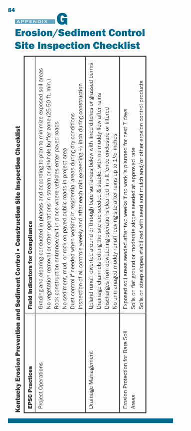
APPENDIX G84
Ke
ntu
cky
Ero
sio
n P
reve
nti
on
an
d S
ed
ime
nt
Co
ntr
ol •
Co
nst
ruct
ion
Sit
e In
spe
ctio
n C
he
ckli
st
EP
SC
Pra
ctic
es
Fie
ld In
dic
ato
rs f
or
Co
mp
lia
nce
Proj
ect O
pera
tions
Gra
ding
and
cle
arin
g co
nduc
ted
in p
hase
s an
d ac
cord
ing
to p
lan
to m
inim
ize
expo
sed
soil
area
sN
o ve
geta
tion
rem
oval
or
othe
r op
erat
ions
in s
trea
m o
r si
nkho
le b
uffe
r zo
ne (2
5-5
0 f
t. m
in.)
Roc
k co
nstr
uctio
n en
tran
ce/e
xit i
n pl
ace
whe
re v
ehic
les
ente
r pa
ved
road
sN
o se
dim
ent,
mud
, or
rock
on
pave
d pu
blic
road
s in
pro
ject
are
aD
ust c
ontr
ol if
nee
ded
whe
n w
orki
ng in
resi
dent
ial a
reas
dur
ing
dry
cond
ition
sIn
spec
tion
of a
ll co
ntro
ls w
eekl
y an
d af
ter
each
rai
n ex
ceed
ing
1⁄2 in
ch d
urin
g co
nstr
uctio
n
Dra
inag
e M
anag
emen
tU
plan
d ru
noff
div
erte
d ar
ound
or
thro
ugh
bare
soi
l are
as b
elow
with
line
d di
tche
s or
gra
ssed
ber
ms
Dra
inag
e ch
anne
ls e
xitin
g th
e si
te a
re s
eede
d &
sta
ble,
with
no
mud
dy fl
ow a
fter
rai
nsD
isch
arge
s fr
om d
ewat
erin
g op
erat
ions
cle
aned
in s
ilt fe
nce
encl
osur
e or
filte
red
No
unm
anag
ed m
uddy
run
off l
eavi
ng s
ite a
fter
rai
ns u
p to
11⁄2
inc
hes
Eros
ion
Prot
ectio
n fo
r B
are
Soi
l Ar
eas
Expo
sed
soil
area
s se
eded
aft
er tw
o w
eeks
if n
o w
ork
is p
lann
ed fo
r ne
xt 7
day
sS
oils
on
flat g
roun
d or
mod
erat
e sl
opes
see
ded
at a
ppro
ved
rate
Soi
ls o
n st
eep
slop
es s
tabi
lized
with
see
d an
d m
ulch
and
/or
othe
r er
osio
n co
ntro
l pro
duct
s
Erosion/Sediment Control Site Inspection Checklist
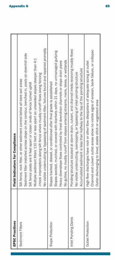
EP
SC
Pra
ctic
es
Fie
ld In
dic
ato
rs f
or
Co
mp
lia
nce
Sed
imen
t Filt
ers
Silt
fenc
e, ro
ck fi
lter,
or o
ther
sed
imen
t con
trol
bel
ow a
ll ba
re s
oil a
reas
Sed
imen
t filte
r in
stal
led
acro
ss s
lope
on
the
cont
our,
tren
ched
in, p
osts
on
dow
nhill
sid
eS
ilt fe
nce
post
s ar
e 6
feet
apa
rt o
r cl
oser
; end
s of
fenc
e tu
rned
uph
illM
ultip
le s
edim
ent fi
lters
110
feet
or
less
apa
rt o
n un
seed
ed s
lope
s st
eepe
r th
an 4
:1
J-ho
ok in
terc
epto
rs a
long
silt
fenc
e w
here
mud
dy r
unof
f flow
s al
ong
fenc
ing
No
visi
ble
unde
rcut
ting
or b
ypas
sing
of s
edim
ent fi
lter,
failu
res
foun
d an
d re
paire
d pr
ompt
ly
Slo
pe P
rote
ctio
nS
lope
s tr
acke
d, d
iske
d, o
r co
nditi
oned
aft
er fi
nal g
rade
is e
stab
lishe
dS
lope
s se
eded
, mul
ched
, or
cove
red
with
bla
nket
s w
ithin
21
day
s, n
o un
man
aged
gul
lyin
gH
eavy
dow
nslo
pe fl
ows
cont
rolle
d by
line
d do
wnd
rain
cha
nnel
s or
slo
pe d
rain
pip
esN
o gu
llies
, no
mud
dy r
unof
f fro
m s
lope
s en
terin
g st
ream
s, r
iver
s, la
kes,
or
wet
land
s
Inle
t Pon
ding
Dam
sPo
ndin
g st
ruct
ure
loca
ted
at s
torm
dra
in, c
ulve
rt, a
nd c
hann
el in
lets
rece
ivin
g m
uddy
flow
sN
o vi
sibl
e un
derc
uttin
g, o
vert
oppi
ng, o
r by
pass
ing
of in
let p
ondi
ng s
truc
ture
Accu
mul
ated
sed
imen
t is
less
than
hal
fway
to th
e to
p of
the
pond
ing
stru
ctur
e
Out
let P
rote
ctio
nH
igh
flow
dis
char
ges
have
rock
or
othe
r flo
w d
issi
pate
rs o
f ade
quat
e si
zing
at o
utle
tC
hann
el a
nd c
ulve
rt o
utle
t are
as s
how
no
visi
ble
sign
s of
ero
sion
, ban
k fa
ilure
, or
colla
pse
Out
let d
isch
argi
ng to
line
d, s
tabl
e di
tch
or v
eget
ated
are
a
Appendix G 85
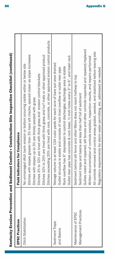
86 Appendix G K
en
tuck
y E
rosi
on
Pre
ven
tio
n a
nd
Se
dim
en
t C
on
tro
l • C
on
stru
ctio
n S
ite
Insp
ect
ion
Ch
eck
list
(co
nti
nu
ed
)
EP
SC
Pra
ctic
es
Fie
ld In
dic
ato
rs f
or
Co
mp
lia
nce
Ditc
h S
tabi
lizat
ion
No
unm
anag
ed d
itch
bank
ero
sion
or
bott
om s
cour
ing
visi
ble
with
in o
r be
low
site
Ditc
hes
with
slo
pes
grea
ter
than
3%
hav
e si
lt ch
ecks
, spa
ced
clos
er a
s sl
ope
incr
ease
sD
itche
s w
ith s
lope
s up
to 3
% a
re th
ickl
y se
eded
with
gra
ssD
itche
s 3
% to
10
% a
re li
ned
with
thic
k gr
ass
and
ero
sion
con
trol
bla
nket
sD
itche
s 10
% to
20
% a
re li
ned
with
thic
k gr
ass
and
turf
mat
s or
oth
er a
ppro
ved
prod
uct
Ditc
hes
exce
edin
g 2
0%
are
line
d w
ith ro
ck, c
oncr
ete,
or
othe
r ap
prov
ed e
rosi
on c
ontr
ol p
rodu
cts
Sed
imen
t Tra
psan
d B
asin
sS
tora
ge v
olum
e is
at l
east
13
4 c
ubic
yar
ds fo
r ea
ch a
cre
of b
are
soil
area
dra
ined
Out
let s
truc
ture
is s
tabl
e an
d co
nsis
ts o
f roc
k lin
ed o
verfl
ow o
r ou
tlet r
iser
pip
eR
ock
over
flow
has
6”
depr
essi
on to
con
trol
dis
char
ges;
dis
char
ge a
rea
is s
tabl
eO
utle
t ris
er p
ipe
has
conc
rete
& ro
ck b
ase,
1⁄2 in
ch h
oles
eve
ry 3
” to
6”,
and
tras
h ra
ck
Mai
nten
ance
of E
PSC
Man
agem
ent P
ract
ices
Sed
imen
t beh
ind
silt
fenc
e an
d ot
her
filte
rs d
oes
not r
each
hal
fway
to to
pS
edim
ent t
raps
and
bas
ins
are
less
than
hal
f ful
l of s
edim
ent
Gul
lies
note
d an
d re
paire
d, s
ilt fe
nces
and
oth
er c
ontr
ols
insp
ecte
d an
d re
paire
d/re
plac
edW
ritte
n do
cum
enta
tion
of c
ontr
ols
inst
alle
d, in
spec
tion
resu
lts, a
nd re
pairs
per
form
edAl
l con
trol
s re
mov
ed a
nd c
ontr
ol a
reas
gra
ded,
see
ded,
and
sta
biliz
ed b
efor
e le
avin
g si
teR
egul
ator
y re
quire
men
ts fo
r st
orm
wat
er p
erm
ittin
g, e
tc. a
ddre
ssed
as
need
ed
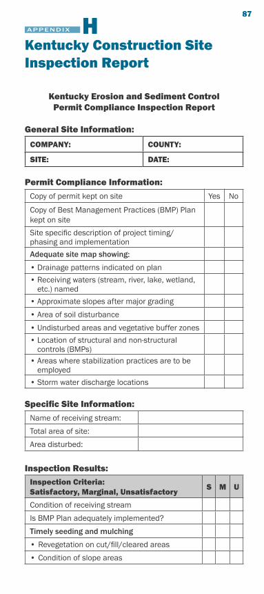
Kentucky Erosion and Sediment ControlPermit Compliance Inspection Report
General Site Information:
COMPANY: COUNTY:
SITE: DATE:
Permit Compliance Information:
Copy of permit kept on site Yes No
Copy of Best Management Practices (BMP) Plan kept on site
Site specific description of project timing/phasing and implementation
Adequate site map showing:
• Drainage patterns indicated on plan
• Receiving waters (stream, river, lake, wetland, etc.) named
• Approximate slopes after major grading
• Area of soil disturbance
• Undisturbed areas and vegetative buffer zones
• Location of structural and non-structural controls (BMPs)
• Areas where stabilization practices are to be employed
• Storm water discharge locations
Specific Site Information:
Name of receiving stream:
Total area of site:
Area disturbed:
Inspection Results:
Inspection Criteria: Satisfactory, Marginal, Unsatisfactory
S M U
Condition of receiving stream
Is BMP Plan adequately implemented?
Timely seeding and mulching
• Revegetation on cut/fill/cleared areas
• Condition of slope areas
APPENDIX H 87
Kentucky Construction Site Inspection Report
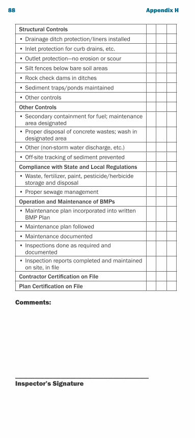
Structural Controls
• Drainage ditch protection/liners installed
• Inlet protection for curb drains, etc.
• Outlet protection—no erosion or scour
• Silt fences below bare soil areas
• Rock check dams in ditches
• Sediment traps/ponds maintained
• Other controls
Other Controls
• Secondary containment for fuel; maintenance area designated
• Proper disposal of concrete wastes; wash in designated area
• Other (non-storm water discharge, etc.)
• Off-site tracking of sediment prevented
Compliance with State and Local Regulations
• Waste, fertilizer, paint, pesticide/herbicide storage and disposal
• Proper sewage management
Operation and Maintenance of BMPs
• Maintenance plan incorporated into written BMP Plan
• Maintenance plan followed
• Maintenance documented
• Inspections done as required and documented
• Inspection reports completed and maintained on site, in file
Contractor Certification on File
Plan Certification on File
Comments:
_________________________________________Inspector’s Signature
88 Appendix H

This publication was produced by Tetra Tech with support from the Kentucky Environmental and Public Protection Cabinet. Illustrations were developed by Emily Faalasli of Tetra Tech; photographs were provided by the Kentucky Transportation Cabinet, the Upper Chattahoochee Riverkeeper, and Tetra Tech. Barry Tonning of Tetra Tech was the principal author and project manager, with technical support from Richard Walker, John Kosco, and William Marshall of Tetra Tech.
The Environmental and Public Protection Cabinet (EPPC) and Tetra Tech do not discriminate on the basis of race, color, national origin, sex, age, religion, or disability. The EPPC and Tetra Tech will provide, on request, reasonable accommodations including auxiliary aids and services necessary to afford an individual with a disability an equal opportunity to participate in all services, programs and activities. To request materials in an alternative format, contact the Kentucky Division of Water, 14 Reilly Road, Frankfort, KY, 40601 or call (502) 564-3410 or contact Tetra Tech, 10306 Eaton Place, Suite 340, Fairfax VA 22030, (703) 385-6000.