erosion and sediment control guide - city of scottsbluff
TRANSCRIPT

Erosion and Sediment Control Guide
Adapted from the WASH Partnership
This guide is provided for minimal guidance on the design of erosion and sediment control Best Management Practices for construction sites.
Increased planning and knowledge on the proper use of BMPs will reduce costs and
delays from unplanned maintenance.

Erosion & Sediment Control Guidebook In order to address sediment and pollutants in stormwater runoff, a system of federal, state, and local regulations exists, which requires that programs be developed to manage sources of stormwater pollution that have the potential to discharge to municipal storm drainage systems and streams. Specific requirements for construction site management are currently in effect through state and local regulations. Local Government Requirements The Nebraska Stormwater Cooperative, consisting of Grand Island, Kearney, Hastings, Lexington, Beatrice, Norfolk, Columbus, Fremont, North Platte and Scottsbluff are required by federal and state regulations to develop local programs which meet the requirements of a state stormwater discharge permit. These communities continue to work together in an attempt to coordinate the local requirements and minimize confusion for individuals working in several different communities. This guidebook was developed by The Watershed Approach to Stream Health (WASH) Partners of Colorado. These WASH communities have adopted from Urban Drainage and Flood Control District (UDFCD) Drainage Criteria Manual Vol. 3, common standards for construction sites, which were to be incorporated into their individual community ordinances in late 2004. The Nebraska Stormwater Cooperative shares a similar goal. P ractices designed to prevent sediment and construction materials pollutants from leaving the construction site are available. When these practices, known as Best Management Practices (BMPs), are properly installed and maintained, sediment and pollutants generated by construction sites are greatly reduced. Guidebook This guidebook is intended to aid inspectors and construction and maintenance personnel in implementing and maintaining water quality BMPs. The collection of figures contained in this guidebook is extracted from Urban Drainage and Flood Control District (UDFCD) Drainage Criteria Manual Vol. 3 Refer to the Drainage Criteria Manual for more information on the application, use limitations, design, construction, and maintenance of BMPs for erosion and sediment control and stormwater quality management. The guidebook illustrates good and bad examples of BMPs. Several other entities have also produced reputable criteria manuals which will provide much more detailed information. BMPs in this guidebook are provided for general guidance. Additional BMPs can be used as appropriate. Be sure to consult local requirements. Specific installations and requirements may apply. The guiding reference document for site-specific BMP installations will be the project's Stormwater Management Plan (SWMP), developed for the Nebraska Department of Environmental Quality (NDEQ) – Water Quality Control Division permit, Stormwater Discharges Associated with Construction Activity and any erosion control plan developed for local compliance.
- 1 -

- 2 -
Checklist The state requires the permit holder to: Develop a Stormwater Management Plan (SWMP). File a permit application (Notice Of Intent) at least 7 days prior to the start of construction
activities (land disturbance/grubbing/grading). Update SWMP to reflect current conditions and keep it on-site. Install Best Management Practices (BMPs) prior to initial land disturbance and according
to specifications outlined in the SWMP. Perform inspections of stormwater and erosion controls following each significant storm event (0.5 inches) and maintain records. Perform inspections of BMPs every 14 days and following each significant storm event. Maintain inspection records. Provide SWMP and records to inspector upon request. Maintain and modify BMPs to reflect current conditions of job site. Achieve stabilization. (All disturbed areas have been either built on, paved, or a uniform vegetative cover has been established with a density of at least 70 percent of native back- ground vegetation levels, or equivalent permanent, physical erosion reduction methods have been employed. (Re-seeding alone does not qualify.) Remove all temporary BMPs. Inactivate permit (Submit Notice Of Termination). Prevent contamination, pollution, or degradation of State waters. RESOURCES NDOR/LTAP Erosion Control Training 402.472.5748 (LTAP) http://www.ne-ltap.unl.edu/ (http://www.ne-ltap.unl.edu/erosion_control.html) Nebraska Department of Environmental Quality (402) 471-2186 http://www.deq.state.ne.us/ Nebraska Stormwater General Permits (pathway) - http://www.deq.state.ne.us/ → NDEQ (home) → Focus on Water → Water Permitting Programs → National Pollutant Discharge Elimination System (NPDES) → NPDES Program - Publications, Forms & Applications Permits not from NDEQ Corps of Engineers 404 Permit – (Omaha Office) 402.896.0896 : (Kearney) 308.234.1403 Urban Drainage and Flood Control District (Colorado) Criteria Manual download: www.udfcd.org/downloads/down_critmanual.htm Environmental Protection Agency www.epa.gov/npdes/stormwater Sample SWMP - www.epa.gov/npdes/pubs/sample_swppp.pdf
- 3 -
Table of Contents
Figures & Tables
Figure 1: Erosion Control Plan Symbols Page 4 Figure 2: Example Site Plan Map Page 4 Figures 3, A & B: Surface Roughening Pages 5 & 6 Figures 4, A, B, C & D: Mulching & Revegetation Pages 7, 8, 9 & 10 Figures 5: Orientation of Blankets, Netting and Matting Page 11 Figures 6, A & B: Installation of Blankets, Netting and Matting Pages 12 & 13 Figures 7, A & B: Temporary Vehicle Tracking Control Pages 14 & 15 Figures 8, A & B: Temporary Diversion Berms Pages 16 & 17 Figures 9, A & B: Rough Cut Street Control Pages 18 & 19 Figures 10, A & B: Temporary Slope Drain Pages 20 & 21 Figures 11, A & B: Straw Bale Barrier Pages 22 & 23 Figures 12, A & B: Silt Fence Erosion Barrier Pages 24 & 25 Figures 13, A & B: Residential Erosion Control Barriers Pages 26 & 27 Figures 14, A & B: Temporary Sediment Basin Pages 28 & 29 Figures 15, A, B & C: Temporary Sediment Basin Outlet Detail Pages 30 & 31 Figures 16, A & B: Temporary Culvert Stream Crossing Pages 32 & 33 Figures 17, A & B: Outlet Protection Pages 34 & 35 Figures 18, A & B: Check Dams Pages 36 & 37 Figures 19, A & B: Inlet Protection – Straw Bales Pages 38 & 39 Figures 20, A & B: Inlet Protection – Filter Fabric Pages 40 & 41 Figures 21, A & B: Curb Inlet Gravel Filter Pages 42 & 43 Figures 22, A & B: Drop Inlet Protection – Block and Gravel Filter Pages 44 & 45 Figures 23, A & B: Curb Inlet Protection – Curb Sock Pages 46 & 47 Figures 24-A & B: Concrete Washout Page 48 Figures 25-A & B: Fuel Storage Page 49 Figures 26-A & B: Portable Toilets Page 50 Figures 27-A & B: Stockpile Management Page 51

EROSION CONTROL PLAN SYMBOLS
CHECK DAM
CONSTRUCTION ROAD
TEMPORARY DIVERSION DIKE
MULCHING
PAVED FLUME
PERMANENT SEEDING
OUTLET PROTECTION
MU
DD
TITLE KEY SYMBOL
CD
CRS
DD
DV
IP
MU
OP
PF
PS
STABILIZATION
DVTEMPORARY CHANNELDIVERSION
INLET PROTECTIONSTORM DRAIN
PF
PS
CRS
ROUGH CUT STREET CONTROL RCS
CURB SOCK INLET CSPROTECTION
Figure 1 – Map Symbols
WR
VTC
TSD
TS
STB
ST
SR
SF
SC
SB
KEY
EROSION CONTROL PLAN SYMBOLS
VEHICLE TRACKING CONTROL
TEMPORARY SLOPE DRAIN
TEMPORARY SEEDING
STRAW BALE BARRIER
VEHICLE TRACKING CONTROL
SEDIMENT TRAP
SILT FENCE
TEMPORARY STREAM CROSSING
SEDIMENT BASIN
TITLE SYMBOL
SURFACE ROUGHENING
WITH WASH RACK
WR
TSD
TS
SR
Figure 2 – Example Site Plan Map
- 4 -

From: Environmental Protection Agency, 1976 FIGURE 3 Surface Roughening
SR
- 5 -
SURFACE ROUGHENING
Definition Provide a rough soil surface with horizontal depressions created by operating a tillage or other suitable implement on the contour, or by leaving slopes in a roughened condi-tion by not fine-grading them.
Purposes 1. To aid in seed bed preparation and establishment of vegetative cover. 2. To reduce runoff velocity and increase infiltration. 3. To reduce runoff and wind erosion and provide for sediment trapping.

- 6 -
Figure 3-A
Figure 3-B

MU
From: Environmental Protection Agency, 1976 FIGURE 4 Mulching
- 7 -
MULCHING
Definition Application of plant residues or other suitable materials to the soil surface.
Purposes 1. To prevent erosion by protecting the soil surface from raindrop impact and re-ducing the velocity of overland flow. 2. To foster the growth of vegetation by increasing available moisture and provid-ing insulation against extreme heat and cold.
2 tons per acre are recommended by NDOR, 4 tons per acre if crimping.

- 8 -
Figure 4-A

- 9 -
Figure 4-B
NOTE: Prior to crimping, the amount of residue on this ground probably looked much more substantial. After crimping, a portion of the residue is anchored in the ground and a large portion of the remainder is standing upward. Both of these reduce the apparent amount of ground cover. Higher amounts of residue should be utilized with crimping. Crimping lines and other grooves should be running along the slope, not up and down the slope.

- 10 -
Figure 4-C
Figure 4-D

- 11 -
From: Virginia Soil and Water Conservation Commission, 1985 FIGURE 5 Orientation of Blankets, Netting and Matting

- 12 -
From: Virginia Soil and Water Conservation Commission, 1985 FIGURE 6 Installation of Blankets, Netting, and Matting

- 13 -
Figure 6-A
Figure 6-B

VEHICLE TRACKING CONTROL
Definition A stone stabilized pad located at points of vehicular ingress and egress on a construction site.
Purpose To reduce the amount of sediment transported onto public roads by motor vehicles or runoff.
Note: Once the VTC pad has become smooth and no longer jars the vehicle, it requires maintenance. Sediment that is racked out must be picked up promptly.
Non-Woven Geotextile Filter Cloth
Coarse Aggregate - 2-3” (larger stones can lodge between dual tires and become projectiles)
50’ minimum
12’ minimum
6” minimum
VTC
- 14 -

- 15 -
Figure 7-A
Figure 7-B

TEMPORARY DIVERSION DIKE
Definition A temporary ridge of compacted soil located at the top, midslope, or base of a disturbed area.
Purposes 1. To divert storm runoff from higher drainage areas away from unprotected slopes to a permanent or temporary channel diversion. 2. To divert sediment laden runoff from the midslope of a disturbed area to a temporary slope drain. 3. To divert sediment laden runoff from the base of a disturbed area to a sediment trapping facility
- 16 -
DD
From: Virginia Soil and Water Conservation Commission, 1985 FIGURE 8 Temporary Diversion Dike

- 17 -
Figure 8-A
Figure 8-B

ROUGH-CUT STREET CONTROL
Definition A temporary sediment barrier placed on alternate sides of a rough cut street.
Purpose To divert sediment laden runoff from rough-cut streets and slow the velocity of storm runoff. Note: 1. Alternate materials such as curb socks or silt fences may be used where large flows are not expected. 2. Requirements for and spacing of velocity reducers for streets with grades of less than 4% shall be as shown on the erosion control plan.
Adopted From: Orange County, California Department of Environmental Quality, 1981 FIGURE 9 Rough-Cut Street Control
- 18 -
RCS

- 19 -
Figure 9-A
Figure 9-B

TSD
TEMPORARY SLOPE DRAIN
Definition A flexible tube or conduit extending from the top to the bottom of a cut or fill slope.
Purpose To temporarily conduct concentrated stormwater runoff safely down the face of a cut or fill slope without causing erosion problems on or below the slope.
- 20 -

- 21 -
Figure 9-A
Figure 9-B

From: Virginia Soil and Water Conservation Commission, 1985
FIGURE 11 Straw Bale Barriers
- 22 -
STB
STRAW BALE BARRIER
Definition A temporary sediment barrier consisting of a row of entrenched and anchored straw bales.
Purposes
1. To intercept and detain small amounts of sediment from disturbed areas of limited extent in order to reduce sediment in runoff from leaving the site.
2. To decrease the velocity of sheet flow from hill slope areas.

- 23 -
Figure 11-A
Figure 11-B
SF
- 24 -
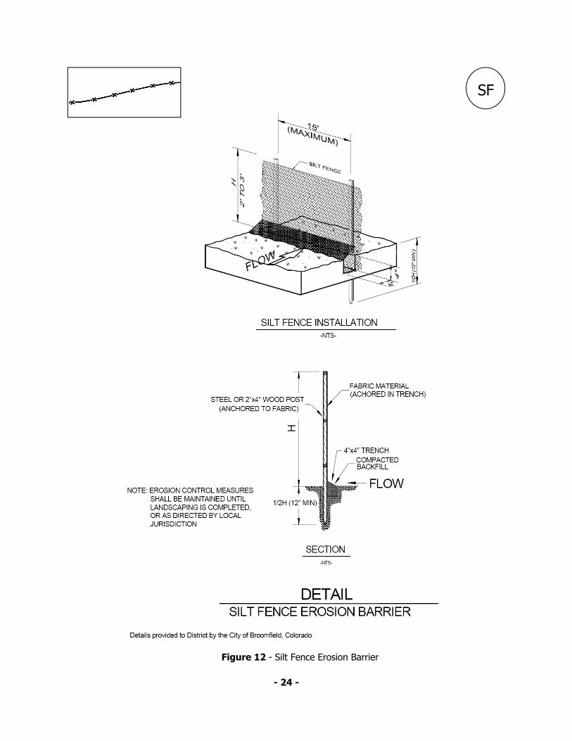
Figure 12 - Silt Fence Erosion Barrier

- 25 -
Figure 12-A
Figure 12-B

- 26 -
Figure 13 – Residential Erosion Control Barrier

- 27 -
Figure 13-A
Figure 13-B

From: Virginia Soil and Water Conservation Commission, 1985 FIGURE 14 Temporary Sediment Basin
- 28 -
SB
TEMPORARY SEDIMENT BASIN
Definition A temporary basin with a controlled stormwater release structure, formed by excava-
tion or construction of an embankment of compacted soil.
Purposes
To detain sediment-laden runoff from disturbed areas to allow the majority of the sedi-ment to settle out.

- 29 -
Figure 14-A
Figure 14-B

- 30 -
From: Environmental Protection Agency, 1976 FIGURE 15 Temporary Sediment Basin Outlet Detail

Temporary Sediment Basin Outlet Detail
Figure 15-C Figure 15-B
- 31 -

TEMPORARY STREAM CROSSING
Definition A temporary structural span installed across a flowing watercourse for use by construc-tion traffic. Structures may include bridges, round pipes or pipe arches.
Purposes
To stabilize stream crossings and reduce erosion created by construction traffic.
From: Virginia Soil and Water Conservation Commission, 1985
FIGURE 16 Temporary Culvert Stream Crossing
- 32 -
SC

- 33 -
Figure 16-A
Figure 16-B

From: Urban Drainage and Flood Control District, 1961
FIGURE 17 Outlet Protection for a Culvert in a Channel
- 34 -
OP
OUTLET PROTECTION
Definition Structurally lined aprons or other acceptable energy dissipating devices placed at the outlets of pipes or paved channel sections.
Purposes
To prevent scour at stormwater outlets and to minimize the potential for downstream erosion by reducing the velocity of concentrated stormwater flows.

- 35 -
Figure 17-A
Figure 17-B

CD
From: Virginia Soil and Water Conservation Commission, 1985
FIGURE 18 Check Dam
- 36 -
CHECK DAM
Definition Small temporary dam constructed across a swale or drainage ditch.
Purposes
To reduce the velocity of stormwater flows and erosion of the swale or ditch.

Figure 18-A
Figure 18-B
- 37 -
IP
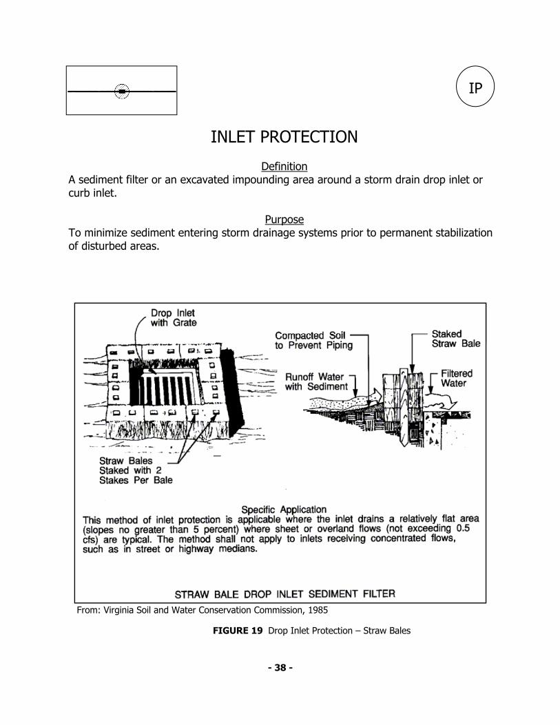
INLET PROTECTION
Definition A sediment filter or an excavated impounding area around a storm drain drop inlet or curb inlet.
Purpose
To minimize sediment entering storm drainage systems prior to permanent stabilization of disturbed areas.
From: Virginia Soil and Water Conservation Commission, 1985
FIGURE 19 Drop Inlet Protection – Straw Bales
- 38 -

- 39 -
Figure 19-A
Figure 19-B

From: Washington State Department of Ecology, 1991
FIGURE 20 Inlet Protection – Filter Fabric
IP
INLET PROTECTION
Definition A sediment filter or an excavated impounding area around a storm drain drop inlet or curb inlet.
Purpose
To minimize sediment entering storm drainage systems prior to permanent stabilization of disturbed areas.
- 40 -

Figure 20-A
Figure 20-B
- 41 -
- 42 -
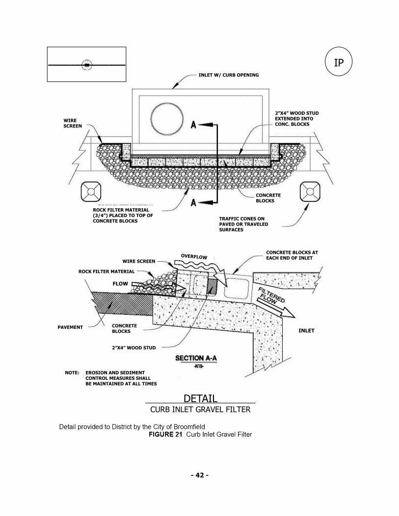
IP
ROCK FILTER MATERIAL (3/4”) PLACED TO TOP OF CONCRETE BLOCKS
WIRE SCREEN
TRAFFIC CONES ON PAVED OR TRAVELED SURFACES
CONCRETE BLOCKS
CONCRETE BLOCKS AT EACH END OF INLET
INLET
2”X4” WOOD STUD EXTENDED INTO CONC. BLOCKS
INLET W/ CURB OPENING
OVERFLOW WIRE SCREEN
FLOW
ROCK FILTER MATERIAL
CONCRETE BLOCKS
PAVEMENT
2”X4” WOOD STUD
NOTE: EROSION AND SEDIMENT CONTROL MEASURES SHALL BE MAINTAINED AT ALL TIMES
DETAIL CURB INLET GRAVEL FILTER

- 43 -
Figure 21-A
Figure 21-B

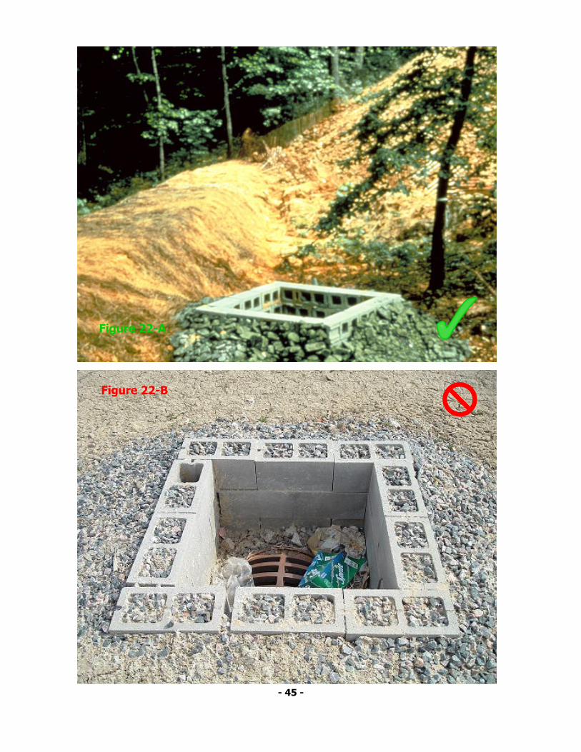
From: Virginia Soil and Water Conservation Commission, 1985 FIGURE 22 Drop Inlet Protection – Block and Gravel Filter
- 44 -
IP
INLET PROTECTION
Definition A sediment filter or an excavated impounding area around a storm drain drop inlet or curb inlet.
Purpose
To minimize sediment entering storm drainage systems prior to permanent stabilization of disturbed areas.
- 45 -
Figure 22-A
Figure 22-B

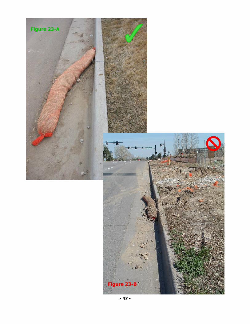
NOTES: 1) Socks should be used up gradient of inlet, perpendicular to and flush with curb 2) No less than two 10-inch diameter socks should be used in sequence, spaced no more than five feet apart, up gradient of inlet. No less than six socks should be used if the 4-inch sock size is chosen. 3) Inline at 30 degrees from perpendicular, opposite the direction of flow (see Detail 2) 4) Sediment control measures shall be maintained at all times.
FIGURE 23 Inlet Protection – Curb Sock
Details based on those provided by City of Lakewood, Colorado
CS
- 46 -
- 47 -
Figure 23-A
Figure 23-B
- 48 -
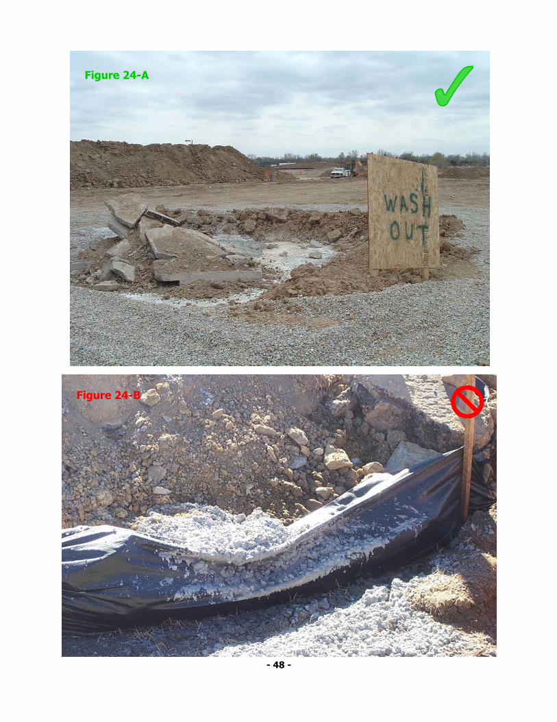
Figure 24-A
Figure 24-B

- 49 -
Figure 25-A
Figure 25-B

- 50 -
Figure 26-A
Figure 26-B

- 51 -
Figure 26-A
Figure 26-B