ergonomic principles in the design of hand … principles in the design of hand tools ... reviewed...
TRANSCRIPT
OCCUPATIONAL SAFETYAND HEALTH SERIESNo. 44
ERGONOMIC PRINCIPLESIN THE DESIGN OF HAND TOOLS
T. M. Fraser
Ir II iI Iff IllI fill47515
I II
INTERNATIONAL LABOUR OFFICE GENEVA

ISBN 92-2-102356-7
First published 1980
The designations employed in ILO publications, which are in conformity with UnitedNations practice, alid the presentation of material therein do not imply the expression ofany opinion whatsoever on the part of the International Labour Office concerning thelegal status of any country or territory or of its authorities, or concerning the delimitationof its frontiers.The responsibility for opinions expressed in signed articles, studies and other contri-butions rests solely with theirauthors, and publication does not constitute an endorsementby the International Labour Office of the opinions expressed in them.
ILO publications can be obtained through major booksellers or ILO local offices in manycountries, ordirectfrom ILO Publications, International Labour Off ice, CH-1211 Geneva 22,Switzerland. A catalogue or list of new publications will be sent free of charge from theabove address.
Printed by the International Labour Office, Geneva, Switzerland
FOREWORD
The present publication is one of a series of the InternationalLabour Office on the subject of occupational safety and health.
It is intended to assist all those who are connected with thedesign, manufacture, purchase and use of basic hand tools in thedeveloping countries as well as in industrially advanced countries.
Much of the anthropometric data used is based on studies inEurope and North America but it can, nevertheless, be of value inthe design of hand tools for use elsewhere in the world.
This publication was originally drafted by Mr. T.M. Fraser,Director and Professor, Centre for Occupational Health and Safety,University of Waterloo, Ontario, Canada, and was subsequentlyreviewed by a number of experts in the field of ergonomics repre-senting a cross section of employer, worker, government and academiccircles drawn from different parts of the world. Their commentsand suggestions have been taken into consideration in the finalversion of this text. The International Labour Office is gratefulto all who have thus contributed to the preparation of this publica-tion.
-
TABLE OF CONTENTS
Page
FOREWORD
PREFACE T11
CHAPTER 1 - TEE NATURE AND EVOLUTION OF TOOLS 1
Basic requirements for tools 1
Generic tools 1
Manually driven tools 1
Power driven tools 4
CHAPTER 2 - THE NATURE OF ERGONOMICS 8
Origin and development of ergonomics 8
The components of ergonomics 9
Man-machine-environmental systems and theirrelationships to tools 11
CHAPTER 3 - HUMAN WORK, SKILL AND FATIGUE 12
Physical work 12
Energy resources 12
Distribution of resources and end products 14
Energy requirements 14
Muscle function 16
Skilled work 17
Fatigue 18
Management of fatigue 19
CHAPTER 4 - ANTHROPOEETRY AND BIONECHANICS IN RELATIONTO TOOL DESIGN 23
Functional anatomy - shoulder, arm, hand 23
Operational aspects of anthropometry in tool usage 26
Human dimensions and physical abilities 31.
Anthropoinetry 32
Joint rotation 35
Hand strength 35
Sex .. 35
Comparative male-female strength 36
- vi
CHAPTER 5 -. A PRACTICAL GUIDE TO HUMAN ENGINEERINGIN TOOL DESIGN
Page
General requirements 38
Size of tools 47
Characteristics of handles for specific tools 48
Human engineering of hand tool controls and displays 61
Displays 66
CHAPTER 6 - DESIGN NETHODOLOGY 70
Environmental defect 72
Needs analysis 72
Definition of the problem 72
Development of design criteria 73
Development of alternative solutions 73
Analysis of feasibility 74
Optimisation 74
Selection of the solution 75
Implementation and communication 75
Significance of ergonomics in the design process 76
Testing of models and prototypes 77
REFERENCES AND BIBLIOGRAPHY '78
APPENDIX A - CHARACTERISTICS OF CONMON HAND TOOLS 83.

One areamanufacturer,is devoted tothere will behand tools in
PREFACE
As the title would imply, it is the intent of this text todiscuss the design and usage of hand tools from the point of viewof ergonomics. For this purpose the material has been organisedin a certain, pattern. It is well to start at the beginning, andconsequently Chapter 1 begins with an outline of the evolution ofhand tools throughout history. However, one cannot discuss toolsfrom the point of view of ergonomics without first defining theterm and expanding on its nature. Chapter 2 is devoted to thispurpose.
Since the use of tools involves work, and since ergonomicsis concerned with man in his working environment, Chapter 3 examinesthe physiological and psychological aspects of human work, skill,and fatigue. This, in turn, leads to a discussion in Chapter 4of. some of the limiting human constraints in anthropometry and. bio-mechanics that determine the optimum design of hand tools and theuses to which they can best be put. With the background establishedin relation to history, human physiology and psychology, anthro-pometry and biomechanics, Chapter 5 goes on to provide a practicalguide to the human engineering of hand tools and small power tools,or in other words, defines wherever possible the optimum designspecifications for a variety of olasses of tool.
remains to be covered from the point of view of thenamely the principles of design itself. Chapter 6a discussion of design methodology. As a supplement,found in the Appendix a description of many of thecommon use.
While this text may serve several purposes, and hopefully,may even provide some assistance to the designers, manufacturersand users of hand tools in the established industrial countries,it is primarily intended for those in developing countries who arein process of entering the field and are seeking information whichis otherwise difficult to come by.

CH1PTER 1
THE NATURE AND EVOLUTION OP TOOLS
Basic requirements for tools
It will be apparent that tools have developed in an evolutionarymanner, perhaps aided every now and then by some gigantic intuitiveleap forward. With the hindsight of today, however, it is possibleto define some basic requirements for efficient tools (developedfrom Drillis, 1963).
The tool must perform effectively the function for which itis intended (e.g. an axe should separate wood fibres cleanly,be easily withdrawn, and should convert the maximum amount ofkinetic energy into useful cutting or splitting work).
The tool should be properly proportioned to the body dimen-sions of the operator (e.g. the ratio of the kinetic energyat the instant of contact with the material to the totalenergy expenditure during the full working cycle characterisesthe efficiency of the movement and should approach maximum).
The tool should be designed to the strength and work capacityof the operator (e.g. allowances should be made for theoperator's build, sex, and training).
The operation of the tool should be such as to produce leastfatigue (e.g. its use should not demand unusual activities orpostures on the part of the operator).
The tool must provide sensory feedback to the operator(e.g. the hand should sense pressure, impact shock, texture,temperature, etc.).
Generic tools
Over the 10,000 years or more of their specialised developmenttools have assumed many forms, but certain clearly discerniblefunctional groups can be identified. The primary difference todayis in the distinction between manually driven and power driventools. In the former, of course, the motive power for operationis derived from the operator alone, while in the latter, althoughthe operator may hold and direct the tool, the motive power is fromsome external source. The development of each of these fundamentalgroups is examined below. A description of contemporary commonhand tools is found in Appendix A.
Nanually driven tools
1. Percussive tools
Percussive tools are defined as those which require a propul-sive force to deliver a blow. The basic representatives are theaxe and hammer, the axe having a cutting edge. Other differencesare determined by the weight, shape and material of the head, andthe length and angular relationships of the handle.

-2-
Thus a hammer consists essentially of a heavy head on a woodenhandle. When it is swung the kinetic energy of the head is impactedto the object struck. The attainable energy depends on the weightof the head, the angle through which it is swung, the radius of theswing, the velocity of the swing and the magnitude of the appliedforce.
There are many varieties of hammers. The contemporary modeloriginated with the Age of Metals and has changed little. A sledge-hammer, weighing for example up to 3.3 kg (7 1/2 ibs) with a handleof approximately 60 cm (24 inches), may be used double-handed forheavy driving or working of wrought iron; a fitter's hammer witha 0.9 kg (2 lb) head and a handle of 25 to 30 cm (10 to 12 inches)is a single-handed tool which combines strength with speed; theballpeen or hemispherical back of the head is used for rivetting.eologist's and boilermaker's hammers have longer narrower headsfor use in a restricted space and for concentrating the blow on asmaller area. The back of a carpenter's hanmer may either have anarrow straight edge for driving nails with small heads or a clawfor extracting nails. The claw hammer, in fact, is known fromRoman times. Heads made of soft metal, rubber, rawhide, or synthe-tic materials may be used to avoid damage to the material beingstruck. Some indeed may be hollow and weighted with lead, whilelead itself is used as the head of a plumber's dresser, and wood asthe head of a carpenter's mallet or a wooden maul.
Axes and adzes are also striking tools, but with a cuttingedge. The essential difference is in the relationship of the headto the handle. In the adze the plane of the head is at right anglesto the handle. The weight and shape of the axe head is adjustedto the operation it has to perform varying from 0.5 to 2.2 kg (1 to5 lbs) or more.
2. Scraping tools
Saws: Primitive stone tools were of course scraping tools aswell as percussive tools, but the saw as an implement did not becomespecialised until the seventh century B.C., with the beginnings ofthe Metal Age. It was originally used with a pull cut. The pushcut utilised by most saws today originated with the Romans. Pruningsaws, fret saws, and coping $aws, with thin narrow blades, may havepull cuts as also do powered reciprocating and sabre saws. Theconcept of the M-shaped teeth, with variable set, was developed inthe Middle Ages, but the modern saw blade originated from rollingmill stock in. the eighteenth century.
Piles: Piles also show their basic origin, in the antiquity ofrough Stone Age tools. Bronze files, characterised by their teethoriented in one direction, appeared as long ago as 1500 B.C., butcould not of course maintain their abrasive cut. They becamepopular in the Iron Age and were common by 1100 A.D. Today thereare many varieties, distinguished by shape, size and by the presenceor absence of a handle, but essentially there has been no changesince the Middle Ages.
Chisels: The chisel originated in the stone hand-held axe.As the Age of Metals began, copper chisels appeared, their edgeshardened by hammering. By the time that bronze replaced copper a

-3
wooden haft had been added to the chisel. With the use of iron,different varieties appeared, distinguished by size and shape, ontilby the eighteenth century some 70 different types could be counted,including curved gouges. While most of these are no longer in use,the basic chisel has remained almost unchanged.
Planes: No definite line of descent has been identified forthe plane, although one might suspect a derivation from the adze.The first clearly identified users were the ancient Romans whoseplane was very similar to that of today. The major difference infact has been the addition of the top iron or double iron ineighteenth century England. This device is an inverted plane ironwedged over the cutting iron, which limits the thickness of theshaving and assists its curl.
Drilling and boring tools
Drilling and boring tools, such as the awl, gimlet, borer,and drill itself, are derived from the primitive use of abrasivesand on the end of a stick. For many thousands of years the motivepower was supplied by rotating the stick between the hands. Thisactivity was eventually replaced by the use of a bow string wrappedaround the stick. The stick was then rotated by a sawing actionof the bow. The pump drill, which operated by the vertical move-ment of a handle on a screw, was developed by the Romans, who evenadded a flywheel to the system to maintain the motion. This methodcontinued to the present day where it is still used (without the fly-wheel) in the operation of some rapid action screwdrivers. Themodern rotary-action spiral drill with handle and ratchet is a pro-duct of nineteenth century mechanical development.
Screwdrivers and wrenches (spanners)
In 300 B.C., Archimedes utilized a screw system for raisingwater; this may be the first recorded use of the screw principle.By the first century B.C., however, very large wood screws turnedby hand spikes were in use in wine and. oil presses. The sane typeare still used today.
Metal screws, hand cut, began to appear in the fifteenthcentury, followed by bolts and threaded nuts in the sixteenthcentury which were fastened by a T-handle socket wrench. Woodscrews, started by an awl or drill, also came into use at that time.
With the increasing use of wood screws cane the need for ascrewdriver, which initially was a slot-bladed bit used with acarpenter's brace, which itself was an early form o± drill. Thehandled screwdriver, however, did not appear until the nineteenthcentury, although it became common after 1850 in a variety of shapesand sizes with the mass produotion of tapered gimlet-pointed woodscrews.
Box and socket wrenches also appeared by the early nineteenthcentury, along with the adjustable sliding-jaw wrench which wasoriginally held (1830) by a wedge tapped appropriately into place.Screw wrench patents appeared in 1835 and the familiar monkey wrenchin 1858.

-4
Holding tools
Spanners, wrenches, and screwdrivers also act as holding tools,but a variety of specialised holding tools has also been developed.
Tongs or pliers date from the first working of metals. Laterforms differ chiefly in the shape of the jaws, which may be narrowand rounded for twisting wire, elongated crosswise and grooved forgripping, or with special hinges to ensure a parallel relationshipof the two faces a-b all times. The most complex devices arefound in the very wide variety of faces, sizes, linkages, andhandles of surgical and dental forceps, each of which is designedfor some special purpose.
Cutting tools
Cutting tools are derived from the primitive stone axe.The most common form is the ]mife in which a hardened steel edgeis pressed with a sliding action against the material to be cut.The variety is very great, from the general purpose pocket knifeto the agricultural scythe and sickle, or from the grossness ofthe sabre to jhe precision of the scalpel. Each is distinguishedby characteristics of size, shape, handle, balance and weight,although in all a sliding cutting action is used, the proportionof sliding to direct forward movement being very high for thecleanest cut.
Scissors, shears, and tinsuips are also cutting tools, eachof which has a shearing, cutting action with very little forwardsliding motion.
Power driven tools
Any kind of tool can be operated by some form of externalpower. The decision to use manual or external power is generallydetermined by the type of work and the productivity demanded. Forcasual light work manual power is common; for heavier work with ahigher productivity requirement power tools should be considered.Electric power tools, for example, will pay for themselves in anindustrial setting if used for eight hours or more per week (1-IMSO,1969). The sources of power for coinmonpower tools are electricity,and the internal combustion engine. Compressed air and explosivechanges are also used for special purpose tools which will not beconsidered here other than to mention them in a broad general out-line.
(a) Electric power tools
Portable electric power tools, of the correct type, properlyused and maiiatained, will relieve a workman of much of the physicaleffort required in operating tools, although he will still have theeffort, which can be considerable, of holding and directing them.
Electric power tools are generally compact with one or twohand grips. Most have a finger-operated trigger switch incorporatedinto the main handle for starting and stopping the motor. Actionis sustained by holding the switch in position, or it may be main-tained by operating a secondary catch which must be released -to stopthe action.
5
The tool may be single purpose, such as a circular saw, ormultipurpose, with a chuck at the drive end to accommodate twistdrills or spindles for other types of function.s. The tool isgenerally driven by a universal electric motor with a wire-woundrotor supplied through a commutator and carbon brushes, and gearedto drive the chuck. Alternative speeds may be available. Themotor and gears are contained in either a metal or insulated casing(Beckingsale, 1971). Typical examples with some comments areshown below:
Power saws: Electric power circular saws are ten times or morefaster than hand saws. The motor, depending on type, may operateon AC or DC current. The motors operate at a high no-load speed,depending on size and design. They are connected to the saw arborthrough gearing to reduce the motor speed of 2,500 to 7,000 rpm toa speed more practical for sawing. Cutting takes place on the up-ward portion of the cycle, by blades of 15 to 30 cm (6 to 12 inches)in diameter, allowing cuts of 45 to 115 mis (1 3/4 to 4 1/2 inches).Most are equipped with an adjustable foot or base which permitstilting of the blade through a controlled angle and also limits thedepth of the cut (National Safety Council, 1967).
Fixed upper guards and movable lower guards are fitted over theblade, the lower guard commonly held in place by a spring which com-presses as the depth of cut increases and allows the lower guard toslide into the upper guard.
Saw blades are available for wood and non-ferrous metal cutting,friction blades for thin sheet steel, and abrasive discs, or diamondgrit blades, or tungsten tips, for concrete, stone, brick, tile.,steel and iron.
Powered jig saws for complex cuts in wood or for dovetailing,as well as reciprocating and sabre saws for straight cuts, curves,and scrolls are similar in general principle.
Power drills: Power drills use electric motors similar tothose of power saws with different gearing and different heads.Whereas the circular saw is commonly at the side of the motor, thedrill is normally in. direct line. The head comprises a chuck,into which various shapes mad sizes of bit can be fitted. Depend-ing on size and. weight the tool is designed for one or two handedaction with one or two handles. In addition, heavy drills may besupported by an external sling and may be covertible to a benchdrill.
The larger drills weigh up to 6 kg (13 lbs), and. have twospeeds, consuming 600 watts of power. They may penetrate up to90 mm (3 1/2 inches) in steel (HMSO, 1969).
Screwdrivers: Screwdrivers are similar to drills. Theoperating rpm are slower and the tool includes a sensitive adjust-able clutch which operates when the driver is pressed into thescrew head and slips when the torque reaches a predetermined tension.
Percussion drills: In a percussion drill, which has the samegeneral form of power source, the rotary motion is converted into apowerful fast percussion, up to 160 strokes per second, for penetra-tion of concrete and stone with appropriate impact bits.
-6-
Electric hammer: An electric hammer is another percussiontool in which the rotary motion is converted into impacts at arate of 25 per second. It is generally heavier than a percussiondrill, weighing up to 4 kg (9 lbs).
Sanders and grinders: In. a disc sander the rotary motion fromthe motor drives an abrasive coated disc of approximately 11.5 to30 cm (4 1/2 to 12 inches) in diameter. It is particularly suit-able for carpentry and wood scraping. In a belt sander the driveis applied -to a rolling continuous abrasive belt mounted below themotor. The weight of the tool, 7 kg (16 lbs) or so, assists inmaintaining the friction. It is valuable for fast sanding of flatsurfaces. An angle grinder is similar in principle to a discsander but is used for weld dressing and cutting off a welded part.
Special tools: A variety of special electric power tools alsoexist, including a brickwork chaser used for cutting grooves up to35 mm (1 3/8 inches) in depth for compacting concrete by deliveringvibrations in the order of 200 per second (IE.ffSO, 1969).
(b) Compressed air tools(Pfeffer, 1971)
Compressed air or pneumatic tools are inherently simple andoffer the advantage over electric tools that they are free ofelectrical hazard. Because of the requirements for a compressedair source and connective tubing they are clumsy, but they offeradvantages of lightness and ease of control. They are also usefulunder potentially explosive or wet conditions where electricalpower should be used either not at all or with great care. Sizefor size they are generally capable of heavier work than electrical.Both percussive and rotary pneumatic tools can be defined.
Percussive tools: In a percussive tool compressed air actuatesa piston which may strike freely agatust the driven toolpiece, e.g.rivetting gun, caulking, chipping or drilling hammer, or which maybe rigidly connected to the toolpiece, e.g. rammers, percussivedrilling and cutting machines. In some cases the piston itself mayact as the toolpiece, e.g. scale chipper. A system of ports orvalves controls the input and output of air.
Rotary tools: In rotary tools the compressed air is appliedto reciprocating pistons actuating crankshafts, or to rotors; theresulting motion is used to drive rotary cutting or abrasivetoolpieces such as drills, reamers, screw cutters, grinding wheels,etc. Various types of low speed rotors are found, while for veryhigh speed precision work requiring little power, such as a dentist'sdrill, a turbine mechanism is employed.
Depending on size and weight, pneumatic tools are designed forone or two handed action with appropriate hand grips. Like electrictools, most have trigger control which can hold a sustained action.
7
Internal combustion
The only portable hand tool to use an internal combustion driveis the chain saw. Although some chain saws may be driven byelectricity, most are used in situations where electricity or othersouroes of power are unavailable. The chain saw commonly operatesfrom a light petrol engine integral to the tool, which also carriesstores of petrol-oil mixture for fuel, and oil for lubricating the
chain. The reciprocating action of the piston is converted to arotary action which drives a toothed chain. The chain, runningalong the rim of a metal blade, projects forward with the bladefrom the side of the motor for a distance of up to two feet or more.
The engine is commonly started, after switching on the magneticignition, by pulling on a rope attached to a flywheel. The move-ment of the saw chain is effected by a clutch mechanism operated bya trigger incorporated into the rear handle of the machine. Therear handle lies in the vertical plane. There is also a fronthandle lying in the horizontal sideways plane. The device is heavyand clumsy and normally operated two-handed. Action of the sawcan be stopped by releasing the trigger, while the motor can be
stopped by switching off the ignition. Various types of teeth areavailable for the chain.
Explosive drive
Explosive charges are used in devices such as bolt guns toforce a nail or stud into brick, concrete or steel. They are alsoused for cutting various sizes and types of cable, splicing orattaching terminal fittings to cable, removing rivets, tighteningrivets, joining pipe, etc. (National Safety Council, 1962). Theprinciple of operation is essentially the sane in all cases. Theexplosive powder in a cartridge is ignited by means of a percussiontype primer and the resulting force is directed to perform thedesired function.
The tools are designed so that the resulting gases are confinedand directed. A slide, for example, starts down the barrel whenthe cartridge is fired but only reaches its final velocity when ithas moved down to the mouth of the barrel. Accurate control isaccomplished in various ways. Some tools use a selection of powdercharges over a varying powder range. Others control penetration bymeans of calibrated powder plugs or a positioning rod to place theslide a predetermined distance from the cartridge to reduce combus-tion volume. All models must be held in close contact with thework and forcibly depressed against the work before they can beoperated. In one model an indicator button informs the operatorwhen the tool is in firing position. In another design it is neces-sary to depress the tool and rotate a firing ring, thereby usingboth hands. Still others recluire the release of safety devicesbefore the tool can be fired (National Safety Council, 1962).
In each case the cartridge is placed in-to the breach betweenthe firing pin and the barrel and the bolt or stud is introducedthrough the muzzle or breach. The cartridge is ultimately detonatedby a firing pin activated either by a lever or twist-type trigger,or by a blow from a hammer (Chavanel, 1971).

-8-
CHAPTER 2
THE NATURE OF ERGONOMICS
The previous chapter has outlined the nature and evolution oftools. A tool is a device used by man to extend the range of hismanipulation activities. To define the factors that constrainthis usage it is necessary to examine the area of expertise thathas come to be 3mown as ergonomics.
Ergonomics has been defined as the study of the anatomical,psychological and physiological aspects of man in his workingenvironment, with the object of optinlising human safety, health,comfort and efficiency. Thus it is concerned with the study of man(and woman) in his or her daily work. The intent is to ensurethat the work, the working equipment and the working environmentare so designed or modified as to fit the job to the man rather thanthe man to the job. Whether the work involves hand tools, officeor home equipment, heavy machinery, vehicles of land, sea and air,or control consoles for electrical complexes, the same principlesapply, although with different emphasis. Man in his workingenvironment has certain assets and liabilities, certain capacitiesand. limitations. The assets and capacities must be utilised totheir best advantage; the liabilities and limitations requirecompensation.
Origin and development of ergonomics
In a few million years of his evolution man has shown remarkableability to adapt to the needs of his environment. He has learnedto live, or at least survive, almost everywhere on earth, from thesea (and even to some extent under it) to the high mountain ranges(and even to outer space),from the rain forests to the deserts,from the equatorial heat to th polar cold. But while no doubtsome of his adaptation has been evolutionary in character, most ofit has resulted from the use of his superior intelligence whichpermitted him to devise procedures, techniques and devices forsurvival under adverse conditions (e.g. water and. food storage,clothes, etc.), and for comfort and efficiency under better condi-tions. That same intelligence allowed him to develop tools toextend his usefulness, as was shown in the last chapter, machinesto reduce his labour and increase his mobility, as well as socialand organisational systems to concentrate his functions, and com-munication systems to co-ordinate his activities. As each newdevelopment appeared he learned to exploit it, seemingly secure inthe belief that he could adjust to whatever situation his intellig-ence and skills could devise and produce. In his social organisa-tion he developed specialists, physical scientists and engineers tocreate the tools and machines that he needed to further his purposes.He also developed social and life scientists (psychologists,biologists, physiologists, doctors of medicine, etc.) to study anddeal with the human problems, as well as a variety of other specia-lists. But all too often the engineer biew little or nothing aboutthe engineering sciences.
Inevitably, because of the complexity, and indeed intangibility,of the social and life sciences, engineering developments began toexceed the capacity of man to adjust to the situations in which they

-9
placed him. In transportation, and. in aviation in particular,where more and more an operator was required to process largequantities of information in shorter periods of time, and wherecontrol of the vehicle became increasingly more complex, -the result-ing situation gradually became untenable, until, near the begixmingof the Second World War, it was recognised that the machines anddevices which man was making had indeed outstripped his capacity tocontrol them, and his ability to tolerate the environment in whichthey placed him. With this realisation came the understanding thata machine or device created for use by man could no more be consideredand developed independently of the needs of the ian for whom it was
developed. Both man and machine had to be considered together asa functioning entity, a man-machine system. A system is definedas an aggregate of interactive components operating together to
perform a function. In a man-machine system man is one of the inter-active components. Thus, for optimal function, the system must beso designed or created as to exploit the relative capacities of eachof the two major components of the system, and compensate for therelative weaknesses, while ensuring that the interface between thetwo is compatible with the needs of human sensory or informationinput, and motor or control output.
Mow it must be recognised also, that a man-machine systemfunctions within a certain operational environment which it definesfrom the totality of the whole environment. Thus the operationalenvironment is an interactive part of the total man-machine-environment system. The man-machine system changes the environmentin. which it operates and in turn is changed by it. Man in parti-cular, whose anatomy and physiology cannot be changed to meet adverseenvironmental circumstances, is unusually susceptible to environmentalcircumstances, is particularly susceptible to environmental extremesand suffers loss of efficiency and eventually permanent damage oreven death from environmental phenomena such as acceleration, vibra-tion, toxic pollution, and noise. Thus for efficiency, safety,health and comfort, it is necessary to ensure compatibility of manand machine, but also compatibility of the resulting environment inwhich he finds himself.
With the realisation of these matters came the need for studyand guidance in the transdisciplinary subject that came to be knownas ergonomics. Thus while ergonomics makes use of the rigorousdisciplines of physics, mathematics and the engineering sciences,as well as descriptive and empirical aspects of anatomy, physiology,biology, psychology and sociology, it is perhaps not so much anacademic discipline as a professional practice. It is concernedmore with purposeful application than with academic study, althoughthe latter is indeed an integral part of the activity.
The components of ergonomics
Because of its transdisoiplinary nature ergonomics covers awide variety of fields and its practitioners derive from an assortedgroup of disciplines. Indeed there are broad regional differencesin practice and in what is recognised as legitimate activity forergonomists. The nature of the practice, however, is to some extentdetermined by the background of the practitioner. Several distincttypes of activity, nevertheless, may be distinguished, which aresignificant in forming the background to ergonomics.
- 10 -
Work and environmental physiology
This area is concerned with the physiological processesinvolved in human working activity; the energy cost of work; the
energy demand of different types of work; the effect of varyingenvironmental conditions on energy cost; the nature of fatigue;and the minimisation of fatigue by appropriate design and/or develop-ment of tools, equipment, machines, tecbniques and procedures, andmanagement o± the environment.
Anthropometry and biomechanics
Anthropometry is the science of human measurement. It includesthe study of human dimensions, both of the parts and of the whole,including lengths, breadths, thicknesses, angles of motion, reach,grasp, etc., as well as the capacity to lift, carry and exert force,under varying postural conditions, in static and dynamic states,according to age, sex and ethnic background. Biomechanics is arelated area concerned with the study of motion in living creatures,with particular respect to the forces acting on joints. Togetherthe subjects provide essential data for the design of the man-machineinterface, for example, handles, seats, control characteristic,exertable forces, etc.
Cc) Human factors and human engineering
human factors and human engineering are two closely relatedterms that are often (and particularly in North America) usedsynonymously f or ergonomics. The distinctions are perhaps more amatter of usage than reality. The subjects derive largely fromthe application of experimental psychology to engineering, and areconcerned with design of hardware at all points of the man-machineinterface, and with the development of suitable operational pro-cedures. In both cases the objective is to ensure compatibilitywith the norms of human behaviour and human performance capability,and to minimise the adverse effects of extreme conditions.
To cite the foregoing as components or ergonomics is not tolimit ergonomics to the practice of these activities alone. Infact numerous other activities may be involved, including elementsof industrial and educational psychology, notably those associatedwith the measurement of skills, and the requirements of selection andtraining, as well as, in Eastern European countries, some subjects,more commonly found elsewhere in the practice of occupational medi-cine and hygiene. A significant activity also is found in consumerergonomics which is concerned in general with design for human useand involves the functions of the industrial designer to perhaps aneven greater extent than the engineer.
Dividing the subject into component parts, however, may giverise to the false impression that these components are independentof each other. This of course is not the case. The division isartificial and is merely a convenient means of classifying relatedactivities in family groups. Ergonomics is concerned with thestudy of man in his working environment, and in that study any orall of the activities described above may be involved, or others asyet undescrfbed, depending on the nature of the work and any asso-ciated problems.
Thus, in coxinection with the use of tools it is necessary toexamine the physiology o± work and fatigue, anthroponietry and bio-mechanics as they pertain to handling and usage, the human factorsof tool design, and work layout, the procedural problems of taskdesign and the environmental hazards of operation.
Man-machine-environmental sy-s tensand their relationship to tools
In considering the ergonomics of the design and usage of handtools it will be evident from the foregoing that one cannot considerthe tool independent of its operator, or of the environment in whichit will be operated. The earlier section of this chapter has shownthe need for, and the development of, what is sometimes ]mown asthe systems approach to man-machine relationships. It has alsoindicated the role of ergonomics in defining and optimising theserelationships. What then in this context is the role of ergonomicswith respect to the design and usage of hand tools? There is nodoubt of course -that in its more complex form a power tool whethersmall and portable or large and fixed, is indeed a machine, and thatwhen used by man it forms a man-machine-environment system. Howeverthe word "machine" as used in t1is context is in fact representativeof any device or artifact that might be purposefully applied andused for a function. Thus when a man interposes a stone betweenhimself and the environment and uses that stone as a tool he hasindeed formed a simple system. He and the stone inter-act andtogether they inter-act with the environment. The simpler thedevice, of course, the simpler is the inter-action, but for optimumefficiency, comfort and sometimes safety and health, the interfacebetween man and device must be made compatible with human characteris-tics; the techniques and procedures for usage and maintenance mustbe effective and within the human capacity to operate as required;and the operational environment during and after usage must be toler-able to the operator and any other involved. Thus, for example,the design of a screwdriver must take into account the anatomy andbiQmechanics of the human grip, the capacity of the human shoulder-aria segment to apply torque, the limi,tations on that capacity imposed,for example, by the need to adopt a certain posture because of apoorly designed handle or an awkward workplace, the variations, ifany, that may occur by reason of sex, ethnicity, or age, etc. Thedesigner of a power chain saw on the other hand will need to takeinto account the requirements for location, shape and angling ofhandles, the weight that can be held by extended arms, the effectsof vibration and noise on the operator, the safety hazards involved,including those of "kickback", and the possible dangers of environ-mental pollution from exhaust and dust.
Thus, in considering the ergonomics of tools we are concernedwith a man-tool system functioning within an operational environment.The system has many variations depending on the tool and of coursethe operator, while the operational environment will also change asit inter-acts with the man-tool system.
Some of the factors involved in this system will be examinedin subsequent chapters, and guidelines will be developed to assistin the design of man-tool systems that are optimal for human use.
- 12 -
CHAPTER 3
IUJT'LkN WORK, SKILl AND FATIGUE
Work can be defined by the physicist or the engineer as theproduct of the intensity of the applied force and the distance ofthe resulting movement, a definition which, although precise, islimited in its application and bears nothing of the connotationsand. nuances of many forms of human working activity. From thepoint of view of tool usage, and by-passing the definition of work,two forms of human work can be distinguished, namely physical workand skilled work. All human function, including that involved inthe basic processes of living, requires the consumption of energy.Over and above the basic, physical work is characterised by theexpenditure of relatively large quantities of energy in the contrac-tion of torso and back muscles against some imposed load, e.g.running, lifting, carrying, pushing, pulling, striking, etc. Inskilled work the expenditure of energy in muscle contraction may bemuch less, since the activity may require relatively minor physicalmovements. These movements, however, have to be made with preci-sion, in. some complex learned pattern, the maintenance of whichinvolves evaluation, judgement, feedback of information and continuedor repeated experience. Under most circumstances the use of toolsrequiresboth physical and skilled work. In addition, each formof work shares the characteristics that if persisted in for a longenough period with inadequate breaks the output of the worker willdiminish and he will undergo the subjective experience of fatigue.
To ensure a better understanding of the need to consider basichuman requirements in the design and operation of tools, some aspectsof the functions and mechanisms utilised in human physical work willbe examined in this next section.
Physical work
The functions and mechanisms employed by the body to liberateand channel available energy into the contraction of body musclesare subsumed under the term work physiology. The body in fact canbe considered as a heat engine which burns fuel in oxygen. Thegeneral efficiency as an engine varies from about 10 per cent to30 per cent depending on what it is required to do, an efficiencywhich compares reasonably with that for example of the steam engine(12-15 per cent). The lower efficiency tends to occur under circum-stances where the body requires a greater amount of energy for itsown. stabilisation, e.g. in awkward postural conditions in the cold,while the higher efficiency occurs under circumstances closer tothe ideal. One of the functions of ergonomics is to ensure that,wherever feasible, the transfer of humthi energy to any intermediaryoccurs at the highest level of efficiency compatible with safety andhealth of the operator.
Energy resources
The body itself is in fact an aggregate of systems and sub-systems, each of which has its components. The smallest componentcapable of independent existence is the cell, a microscopic miniaturefunctioning system in itself. All body tissues are made of cells,

- 13 -
differing in size, form, content and function, although with certainsimilar subcomponents, and all have certain common characteristics.Each uses energy to effect chemical changes within itself and itsenvironment. Some of these changes might be for storage of carbo-hydrate fuel, somemight be for manipulation of electrolyte ionswithin the cell or the body fluids, some might be for transmissionof electrochemical signals along nerve fibres, etc. Functionalchemical changes in body organs and tissues are referred to asmetabolism. Thus energy metabolism, for example, refers to thosechanges associated with the utilisatioxi of energy.
Human energy is derived from the ingestion of materials whichin turn have captured that energy directly or indirectly from thesun; directly in the case of plant life that has converted solarenergy via a photosynthetic process, and indirectly via animal lifethat has ingested the plant life, or even other animal life. Themain source of the ingested energy lies in the starches and sugarscreated in the photosynthetic process, and known as carbohydrates.These carbohydrates exist in the form of complex chains of carbon,oxygen and hydrogen atoms, but in the human digestive tract, and inthe liver, they are broken down to smaller and smaller chain compon-ents by chemical catalysts known as enzymes, eventually forming arelatively simple sugar known as glucose, which is carried in thebody as a ready reserve of energy. Excess glucose is convertedand stored as glycogen.
The glucose in turn can be broken down still further, again byenzyme action, to form two acid materials known as pyruvic and lacticacid, along with the release of some 5 per cent of the availableenergy locked up in the carbohydrate. All this can be done withoutthe aid of oxygen and hence is considered to be an anaerobic- process.The energy so supplied serves immediate purposes without institutinga requirement to increase the oxygen supply. Meanwhile the pyruvicand lactic acid undergo further metabolism, this time with the aidof oxygen in an aerobic process, until ultimately they are convertedinto carbon dioxide and water, with the release of the remaining95 per cent of the available energy. The carbon dioxide is expelledby the lungs, the water is stored or expelled by the kidneys, andthe energy is made available for use. The anaerobic process israpid and provides sufficient energy for sudden requirements likeswinging an axe for a short period or running up a short flight ofstairs. The aerobic process is much slower. Hence an individualwith a requirement for continued high energy output will enter oxygendebt as he consumes in the anaerobic process more carbohydrate thancan be handled by the aerobic process in the time available. Thushe continues to gasp and pant long after the energy expenditure isover.
However, the energy supplied by these processes is not theenergy that is immediately available to the muscles. That energyis held in still another form within a chemical called adenosinetriphosphate (ATp). ATP has the remarkable quality of storing verylarge quantities of energy in what are known as resonating bonds andof releasing this energy almost explosively on demand via enzymeaction. It is this energy that is made available to the musclesand for that matter for other body functions. Through still moremetabolic processes the energy from the carbohydrates is used torestore the depleted energy of ATP.

- 14 -
Distribution of resources andend products
It will be apparent from the foregoing that to provide theresources in the appropriate places and to remove heat and unwantedend products there must be some distribution mechanism or mechanisms.In fact all body organs, tissues arid fluids participate in the func-tion, but the main distribution activity is conducted by the heart,the blood vessels and the lungs, or, in other terms, the cardio-vascular and respiratory systems.
The respUratory system of courde permits gas exchange with theexterior. Air ,containing oxygen, is inhaled into the lungs.The relative pressure of that oxygen in the air mixture is deter-minedby the ambient air pressure and the fraction of the mixturethat comprises oxygen. Within the lungs the air mixture is separatedfrom the circulating blood by microscopically thin membranes. Sincethe pressure of the oxygen in the air is higher than the pressure ofthe oxygen carried in the blood, oxygen is forced into the blood.Meantime by a similar type of process in the peripheral tissues theblood collects the carbon dioxide formed during metabolic processesand carries it to the lungs. The carbon dioxide in the blood isnow at a higher pressure in the lungs than the minute quantity foundin normal breathing air and consequently it is forced into the lungswhen it is exhaled. Consequently a gas exchange takes place. Theoxygen in the blood is now carried to the tissues by the bloodstreamand another gas exchange takes place at the tissues, with oxygengoing to the cells and carbon dioxide to the blood.
The bloodstream thus becomes the major distribution channel.The blood of course is pumped by the heart, which in fact is adouble pump joined in the same organ; one portion is a low pressurepump which pumps the blood around the lungs to effect that gasexchange, the other is a high pressure system which pumps theoxygenated blood round the body to effect the other gas exchange atthe tissues. The pumps work synchronously and are controllable,although unconsciously, in force, rate and volume of output. Thebloodstream carries in one form or another all the constituentsthat are required for metabolic processes, as well as the gasesinvolved in the exchange process; it is also a medium for thedistribution of water and for exchanging heat with the exterior.
Thus, under the demand of work there is an increase in theoutput from the heart, effected by an increase in rate of contrac-tion and in volume per beat, along with an increase in rate anddepth of breathing and of the internal body temperature. Forhealth and survival, however, the latter has to be maintainedfairly critically within one or two degrees of the normal, and acomplex heat exchange system exists to ensure this.
Under tolerable working conditions these systems all functioneffectively and a productive work output can be maintained forprolonged periods.
Energy requirements
The amount of energy required under varying circumstances canbe measured. As noted, mechanically the body is a heat engine.Thus by measuring the generation of heat the energy can be calculated.This in fact can be done in a special chamber called a body calori-meter, but the procedure is complex. Normally, instead, advantage
Walking without load
Climbing
Cycling
Working with axe
Working with hammer
Piling iron
Sawing wood
Driving screws
- 15 -
is taken of the relationship that under controlled dietetic condi-
tions consumption of 1 litre f oxygen is approximately equivalentto production of 5 kilocalories (kcal) of heat. Neasurement ofoxygen consumption is relatively simple with the appropriate skilland equipment. It can therefore be used as a measure of energyutilisation. Using such methods it can be shown that at totalrest under standard conditions (fasting, in a thermoneutral environ-ment) the Basal Metabolic Rate (B?]R) for a healthy standard 70 kgCaucasian man is 1,750 kcal per day (1,450 kcal for a woman). TheBNR represents the energy required for merely living. Any additionalrequirements imposed by work give rise to an increased demand. Thusfor sedentary work an additional 1,000 kcal might be required to atotal of 2,750 kcal. For light industry, a worker will need about1,500 kcal extra, to a total of 3,250 kcal, while for heavy industry,such as coalminiug, there might be a requirement for a total of5,750-4,000 kcal.
Normally the maximum expenditure for continued daily work shouldbe in the range of 3,750 to 4,000 kcal per day. For short periodsof a few weeks to a few months 5,000-6,000 kcal per day can betolerated, and for very short periods of a day or less up to 10,000kcal of expenditure could be achieved. Expenditure beyond theselevels, or expenditure beyond the levels of one's intake, givesrise to depletion of resources and is a contributory cause offatigue which will be considered later. Thus, where for examplediet is inadequate to meet th requirements of BMR plus extra work,the work output will be diminished accordingly.
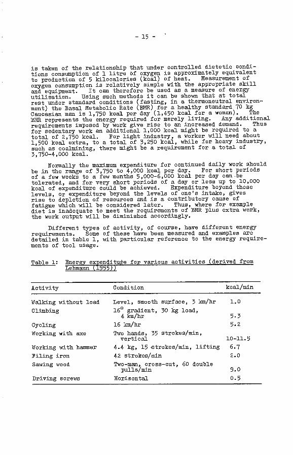
Different types of activity, of course, have different energyrequirements. Some of these have been measured and examples aredetailed in table 1, with particular reference to the energy require-ments of tool usage.
Table 1: Energy expenditure for various activities (derived fromLelimann (1955))
Level, smooth surface, 3 km/hr 1.0
16° gradient, 30 kg load,4km/hr 5.3
16 km/hr 5.2
Two hands, 35 strokes/mm,vertical 10-11.5
4.4 kg, 15 -strokes/mm, lifting 6.7
42 strokes/mm 2.0
Two-man, cross-cut, 60 doublepulls/nun 9.0
Horizontal 0.5
Activity Condition kcal/min

- 16 -
Nuscie function
For physical work, much of the energy that is made available isused to achieve contraction of muscle fibres to move or s-tabilisejoints.
The muscles, which comprise the meaty portion of an animal,are made of bundles of muscle fibres. Each muscle fibre in turnis made of microscopic muscle fibrils bound together, each of whichis an individual muscle cell. It can be shown that each fibrilphysically is made up of a contractile element, that is, an elementwhich is capable of being contracted, and in series with the contrac-tile element, an elastic element, capable of being stretched.Because of this structure a muscle can undergo two types of contrac-tion, namely isotonic, or contraction with shortening, and isometric,or contraction without shortening (figure 1). This differencebecomes inportant when one considers how muscles are used.
Figure 1 - The difference between(&) isometric and (B) isotonic contraction

- 17 -
As will be noted in the next chapter, muscles are placed acrossjoints such that, if there were no opposing force, when a musclecontracted motion would occur at the joint. Thus some muscles maybe used in isotonic contraction to cause movemeni at a joint whileothers may be used in isometric contraction to stabilise that andother joints, or to hold a position against an applied force.Therefore another factor must also be considered, namely whetherthe muscle function. is dynamic or static; in other words, doesit involve movement or does it involve maintaining a posture againsta load. When a set of muscles contract, and particularly when theycontract and relax rhythmically, they act as an auxiliary pump tothe circulation within the area concerned and thereby assist inremoval of waste products and in provision of oxygen and nutrients.For this and. other reasons dynamic muscle function can be maintainedat a higher level and for a longer -Lime than static. For example,it is easier to swing an axe for a long period of time than to holdit at arm's length for that same period of time. Prom the ergonomicpoint of view, tools and operational procedures should be designedto minimise the need for static isometric work. Thus for exampleprocedures should be devised so that it is not necessary to usesmall hand tools at arm's length; the grip on screwdrivers shouldbe designed so that the grasp does not have to be maintained byprolonged isometric action of the small muscles of the fingersand hand; or, if it is necessary to use a heavy drill at arm'slength some supporting sling should be devised to minimise the needto hold it statically against gravity. These and other factorswill be considered in due course.
Skilled work
The operation of all tools requires some skill, some very muchmore than others. G-eneraliy, the greater the physical work requiredthe less is the skill. The presence of skill implies the occurrenceof learning. Skills are acquired either through conscious orunconscious learning, and unless they are practised they will deteri-orate.
Various theories have been advanced to explain the nature ofskill and learning. Nothing is to be gained by recounting theirrelative merits here. Suffice it to say that when conducting acomplex akilled task the skilled individual perceives that task and.its associated environment as a whole, within which changes aretaking place either under his guidance or from some outside stimu-lus. He organises that environment as a dynamically changingpattern within which individual stimuli may change from time totime without degrading the total pattern. He uses whatever humansensing mechanisms are available, conscious and unconscious, toprovide him with information on the state of the pattern, settingup standards and terms of reference for permissible changes withinthe schema that he has formed. He reacts either when the changeswithin the pattern, or changes to the pattern as a whole, exceedthe permissible limits that he has set up.
The unskilled operator initially does not recognise the totalityof the pattern, and tends to perceive only individual and apparentlyunrelated changes for which his permissible limits may be either toogross or too narrow, and to which his response may be excessive orinsufficient. As he gains information through sensory feedback heacquires the capacity -to perceive the task and its immediate environ-ment as a total pattern.

- 18 -
Thus while physical work consumes large quantities of energyin gross isotonic movements of muscles, skilled work may requirerelatively little energy, with much of the work involving muscleaction at a level less intense than that of the gross isotonicmotion. Isometric activity has a greater kinesthetic feedback thanisotonic; the operator receives more information from the feel ofwhat he is doing than from consciously observing it. As a result,isometric activity, with minimal movement, is often more suitablefor precision work than isotonic. Excessive skilled work, however,will also give rise -to fatigue, and subjectively at least thefatigue of skilled work may be even less tolerable than that ofphysical work.
Fatigue
While the concept of fatigue, and the subjective responses toit, are appreciated by all, it has proved difficult if not impossibleto provide a precise scientific definition of the term. Mostcertainly it occurs when one persists at a task for too long.Furthermore, it occurs as a result of both physical and skilled work,and in either case it can be relieved by rest. However it is alsothe case, and particularly so with skilled demanding work, thatapparent fatigue can be relieved by changing the nature of thetask or the environment in which the task is conducted until fatigueagain ensues and progressively increases. While clearly physicalfatigue and skill fatigue are related ii is convenient to examinethe fatigue of physical and skilled work separately.
1. Physical fatigue
Physical fatigue may be acute or chronic. Acute fatigueoccurs as a result of a short-term overload and may be a generalisedwhole-body response, as at the end of a hard day's work, or it maybe localised to a certain region in response to a certain task, asin. arm and shoulder fatigue from intensive use of a screwdriver.Both may occur at the sane time. It is characterised by generalisedbody weariness, perhaps sleepiness, pain, aching, and perhapsswelling of the affected muscle, with immediate inability to continuethe task, followed, where severe, by persistent aching and stiffness.
The causes are inherent in the physiological mechanisms ofmuscle function, including accumulation of waste products in themuscle body which interfere with that function, and other more com-plex factors to do with interference with the circulation of bloodand tissue fluids as well as inhibition of the controlling and co-ordinating activities of nerve cells and fibres in the brain andnervous system. Indeed, perhaps there is also interference withthe capacity of cell mechanisms to transform energy, and in thecapacity to acquire, transport and effect gas exchange with oxygenand carbon dioxide. Acute fatigue, however, responds readily torest, as will be discussed later.
Chronic fatigue is a more intangible condition characterisedby dullness, apathy, loss of drive, perhaps depression, perhapsirritability and loss of productivity. It is associated withprolonged experience, for week or months, of physical and mentaloverload, prolonged hours, inadequate rest periods, inadequatesleep and perhaps poor working conditions. Like acute fatigueit too is relieved by rest and is modified by change, although therest and change need to be of much longer duration.

- 19 -
2. Skill fatigue
In any skilled job utilising tools there is always an elementof physical work which may contribute significantly to the totalpattern of fatigue. Performance of a skill, however, can itselfbe fatiguing even with minimal physical work. Subjectively skillfatigue is experienced as weariness, staleness, loss of motivationand vague intangible discomforts dpendent on the nature of theskilled task. Performance deteriorates measurably. It was notedearlier that the performer of a skilled task sees his operation s
a dynamically varying totality. He sets up subjective standardsor limits of permissible variation of the components of the taskand of the task as a whole in relation to its environment. Asfatigue progresses standards here and there momentarily deteriorateand the operator becomes satisfied with less. The totality ofthe pattern momentarily ceases to be maintained and the operatorbecomes concerned with the behaviour of components, some of whichmay appear to require more correction than others. The timing ofactivities also becomes progressively disorganised with, for example,the right action being performed at the wrong time. The peripheralelements of the task, which are less highly organised than thecentral, tend to be overlooked. The momentary lapses increase induration as the fatigue develops although initially it remainspossible to compensate for them by extra effort. The effect atfirst is specific to particular skills and by changing the activityor changing the environment the fatigue can be relieved, but even-tually it progresses to encompass all areas and general performanceis severely affected.
The capacity to perform prolonged skilled work, and converselythe onset of skill fatigue, are closely related to the presence orabsence of the phenomenon termed arousal. Arousal is the term givento a state of physical and mental alertness which is under the controlof nerve centres deep in the brain. Information from the exteriorenvironment and from the body itself is fed to these centres andevaluated. Significant incoming information, even if perceivedunconsciously, will induce the co-ordinating centre to instruct thehigher brain centres of reasoning, judgement, sensation and motion,etc., and the body itself, to operate at high efficiency; so alsowill information peciIved and evaluated initially by the highercentres. Where incoming information is inadequate, arousal willdiminish and indeed inhibitory centres will predominate, inducingsubjective weariness, sleepiness and lowered efficiency. Thus,where the work and the environment are monotonous, dull, unchalleng-ing and unchanging, arousal is low, motivation is low, fatigue issubjectively perceived and proficiency diminished.
Management of fatigue
Understanding of the physiological and psychological mechanismsinvolved in the occurrence of fatigue provides an insight into themeans of managing it. Several factors can be isolated for con-sideration, each of which has applicability whether or not the workin. question involves the use of tools.
1. Physical workload
The activities of physical work involve standing, sitting,lying, crouching, 1neeling, moving at varying rates on the level oron slopes, lifting, carrying and utilising the limbs and body for
- 20 -
the exertion of various forms of force. With respect, in particular,to the use of tools, recommendations for the working range of loadsinvolving these activities are discussed in subsequent chapters.It is pointed out here as a general observation, that to ensureoptimum efficiency and health the load that a worker might beregularly expected to bear should not exceed, except for shortperiods, the load that permits him to maintain an energy balanceover a prolonged working life.
However, although physiological limitations are the ultimatecriterion, there are other motivational and cultural factors whichmay modify the load tolerance to less than the ultimate. Conse-quently, in addition to variations imposed by physical size and sex,the tolerable load may vary quite widely from one cultural group toanother, and from individual to individual. These possibilitieswill have to be borne in mind in establishing load levels. Trainingmay be required. Unless the individual worker is considered to beexpendable, however, short-sighted attempts to maintain high overloadsfor periods of more than a few weeks are doomed to failure becauseof the inevitable reduction of proficiency that will ensue.
2. Working hours and rest pauses
The question of working hours is closely related to that ofworkload. It has been shown both by accumulated experience and byexperiment that in an industrialised population at least (figuresfor undeveloped countries are not available) the optimum work routineis found with an 8-hour day in a 40-50 hour week.
An eight-hour day cannot be completed without a break. Theoptimum duration and timing of the breaks have not been establishedwith any clear definition, other than cultural living patterns, butit has been clearly shown that where official breaks are not permittedeither the proficiency falls or unofficial breaks are taken.Several types of breaks exist. Spontaneous breaks occur followingsome intensive, perhaps short-term effort where the worker halts hisactivity and rests for a short period to recover. This restre-establishes, at least in part, the physiological steady stateor homeostasis that was disturbed by his work. In some situationsthe break will not be obvious. The worker will in fact stop theactivity that is causing the fatigue but will busy himself for ashort period doing some other activity related to his job that isdifferent and less fatiguing, e.g. sharpening a tool, cleaning thesurrounds, etc. Formal breaks, however, have become an establishedpattern in most industrial work and generally are permitted to occurover and above spontaneous breaks. Studies of output, sickness andabsenteeism have shown that where formal rest periods are permittedthe over-all proficiency is higher, an even greater difference beingobserved in the older worker doing heavy work (Murrell, 1969).
As already mentioned the optimal timing and duration is notcertain but long established practice, frequently hallowed by unioncontract, has shown that for those engaged in. moderately intensework during a continued eight-hour shift, such as the semi-skilledor skilled use of hand tools, a suitable purpose would be served bya break of 10-15 minutes in each half-shift and a 30-minute breakin the middle of the eight-hour period. Many cultures however donot work a continued eight-hour shift but tend to split the dayinto shifts of four or more hours apiece, with a midday break of
Occupation Type of work
- 21 -
perhaps several hours. Here again, however, it is desirable tosplit the part-shifts with a break, although in this case a10-15-minute break will probably suffice.
Sleep
The question of sleep is of course related to that of rest.The physiological need of muscles for the recovery time of sleepis not at all clear. The heart muscle and the chest musclesused in breathing continue to function without a break from lifeto death. Yet for physical well-being sleep is necessary althoughone can in fact go for many days without sleep with minimal decre-ment in performance and little in the way of physiological manifesta-tion. While there is a great range of tolerance, from a minimumrequirement of about four hours daily to a maximum of nine or ten,most individuals would seem to require six-eight hours continuoussleep per day for continued well-being.
Nutrition
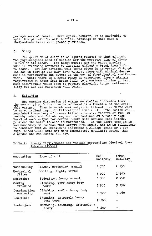
The earlier discussion of energy metabolism indicates thatthe amount of work that can be achieved is a function of the avail-able energy. Thus to match work output in kilocalories there mustbe an equivalent input in kilocalories (table 2). The health well-nourished human body of course has an extensive reserve of fuel incarbohydrates and fat stores, and can continue at a fairly highlevel of work output for several weeks with minimal fuel intake,provided the water balance is maintained. In the short term it isnot necessary to balance fuel output with input, and it is fallaciousto consider that an individual ingesting a glucose drink or a fewsugar cubes would have any more immediately available energy thana person who had fasted all day.
Table 2: Energy requirements for various occupations (derived fromLelunann (1953))
Light, sedentary, manual
Walking, light, manual
Sedentary, heavy manual 3 300
Standing, very heavy bodywork 3 900
Climbing, medium heavy bodywork 3 900
Standing, extremely heavybody work
Standing, climbing, extremelyheavy 4 200
Men Womenkcal/day kcal/day
2700 2250
3000 2500
4 200
2 750
3 250
3 250
Watclmtaking
Mechanicalfitter
Shoemaker
Sawingfirewood
Constructioncarpenter
C oalminer
Lumberjack
- 22 -
In the long run, however, it is necessary to maintain a balancecommensurate with the type of work being done as well as to providethe necessary protein, fat, minerals and vitamins and water thatare naturally available in a proper balanced diet. Syntheticdietary supplements, including additional vitamins, are unnecessaryfor the normal healthy individual eating a balanced, natural diet.The requirements for a balanced diet, the type of which may varyfrom culture to culture, can be found in other references.
Environmental conditions
Unsuitable environmental conditions contribute to the causesof fatigue in any working situation. In oonnection with the use oftools the specific problems associated with noise, vibration, toxiccontamination, etc., are examined in Chapter 6. Of no less import-ance are problems caused by inadequacy of vision, lighting andgeneral ventilation. It is obvious, without enlarging on the point,that while information is provided to the person using the tool bysenses other than vision, in particular touch and the kinestheticsense of "feel", vision is the primary sense used in monitoring theperformance of a task. Accordingly, wherever possible tasks shouldbe so designed as to be under the visual control of the operator.Vision, of course, requires adequate lighting. Lighting is a com-plex study. To establish appropriate illumination levels it isnecessary to take into account such factors as brightness, reflect-ance, glare and contrast, as well as the nature and requirements ofthe activity. Appropriate engineering texts should be consulted.
Work station organisation
The work station or place of work is, Qf course, also part ofthe environment. Often, however, when using hand tools, a workeris not operating out of a formally organised work station and he mayindeed be working under conditions i,n which there is little or nocontrol over the layout of the workplace, as for example on construc-tion sites or in doing repair work away from one's base. Thesuitability or unsuitability of a fixed work situation, however, cancontribute significantly to the onset of fatigue, in relation, forexample, to working heights of benches, type and dimensions of seats,organisation of stowage and other facilities. These factors willbe considered in detail in Chapter 5. As a general observation,however, it may be noted that where the organisation of the workstation is such that additional work is required to maintain undesir-able postures caused by, for example, poorly designed seats,inappropriate work surface heights, or inefficient carrying,operating and viewing angles for tools and equipment then the likeli-hood and severity of fatigue will be increased.

- 23 -
CHLPTER 4
ANTHROPONETRY AND BIONEOHAUCS INSEL1TION TO TOOL DESIGN
Anthropometry was stated earlier to be the science of humanmeasurement. It is concerned with human dimensions and with themeasurement of human physical activities. It is significant inthe design and operation of hand tools, not only becuuse it presentsquantitative specifications, for example, for the size of humanhands, but also because it provides information in functional termsrelated, for example, to grasp and reach.
Biomechanics, in -this context at least, is concerned with theanalysis of human motion, with particular reference to limbs andlimb segments. Human descriptive anatomy is of course basic toboth anthropometry and biomechanics, arid some over-all familiaritywith the basic functional anatomy of the human upper limb is neces-sary to any consideration of the ergonomics of tool design.
Functional anatomy - shoulder, arts, hand
It is, of course, artificially limiting -to consider the anatomyof the shoulder, arm and hand as sri entity separate from that of therest of the body. It is on the other hand convenient, providedthat one recognises that anatomically, physiologically and in everyother way, the body is an integral whole, and that under mostcircumstances movement of an arm may give rise to compensatorymovements throughout the body, perhaps as far away as the toes.Furthermore, the motion of that arm is controlled and co-ordinatedfrom the brain, arid its extension the spinal cord, via a network ofnerve cells, nerves arid nerve fibres, while its logistics are imple-mented by a circulatory system centred on the heart and derivingsupplies from elsewhere in the body.
The shoulder-arm-hand segment of the body comprises threelarge long bones, namely the humerus of the upper arm and the radiusand ulna of the forearm, as well as two bones of the shouldergirdles, and some 26 bones of the hand and wrist. A joint, ofcourse, describes the junction site of two or more bones. At theshoulder joint the bone of the upper arm, the humerus, comes incontact with the bones of the shoulder girdle, namely the scapula,which wraps round the upper chest from the back, and the claviclewhich has a similar role at the front. The head of the humeruslies in a flatly cupped portion of -the scapula, aided by the presenceof the overlapping clavicle. It is held in place by muscles andfirm fibro-elastic bands called ligaments. Because of the flatcup of the joint the shoulder is movable in 5 degrees of freedom.For the same reason the humerus is readily dis'ocated from itssetting.
The lower end of the humerus meets the radius and ulna at theelbow joint. Because of the shape of -the joint, motions arelimited to flexion and extension, and rotation of the forearm onthe upper arm. Rotation towards the body is referred to as prona-tion; rotation away from the body is supination. The radius, whichis heavier and thicker than the ulna, lies on the thumb side of thearm and bears the primary load.
- 24 -
At the lower end, the radius and ulna meet the small bonesof the wrist at the wrist or carpal joint, which functionally islocated at the base of the hand. A complex joint is formed withlimited flexion aid extension at the wrist as well as abduction,or tilt (in the supine position) away from the body, and adduction,or tilt towards the body.
The small carpal bones of the wrist, in turn, meet the fivemetacarpal bones of the palm of the hand and thumb in still anotherjoint (carpometacarpal) which, except for the thumb, permits primarilyflexion and, extension. The inter-action of 'the five metacarpalsamong themselves however allows for a slight abductive splay whichforms a base with the carpals for cupping the hand. The thumb,however, the base segment of which is a metacarpal bone, has a widerange of movement because of the setting of the metacarpal on itscarpal bone. In particular, that relationship allows the thumbto be opposed to each or all of the other four fingers, a fact whichis critical in permitting the unique human grasp.
The metacarpals join with th.e finger bones or phalanges, whilethe three phalanges of each finger in turn form interphalangealjoints. The fingers are capable of being extended and. flexed.When extended they can be spread apart along with the thumb to forma cup or a cylinder for receiving; as they are flexed they cometogether again in a tight grasp.
All joints are maintained in their stable state by ligaments,assisted by muscles. Muscles are so placed across joints that whenthey contract they cause motion at the joint. The siting of themuscles determines the nature of the motion. Thus some produceflexion, some extension, some abduction and, some adduction, while,acting together, some produce rotation. Movements, however, areco-ordinated and as one set of muscles, the agonists, are permitted'to contract, another set, the antagonists l.thich act in opposition,are permitted to relax. At the same time, as noted before, stillothers are used to stabilise the joint or to stabilise other jointsto allow the motion to take place. Purposive motion is thus verycomplex, involving the isometric contraction of many muscles, andthe isotonic contraction of others, in a highly co-ordinated schemaof activity which is implemented and controlled by the nervoussystem.
Muscles are of different sizes and strengths. The flexorsand ex'tensors of the upper arm, such as the biceps and triceps, arebulky and powerful, while the forearm muscles that are responsiblefor wrist and. finger movement are less so. Least of all are thesmall muscles of the hand, such as the interossei, which are activein stabilising the hand during precision motion, and hence fatigueeasily, or sometimes develop the uncoordinated spasm known as cramp.
Furthermore, because of their specific position in relation tojoints, the mechanical advantage of muscles may be more effectivein one position than another. Thus for example, the biceps, whichis primarily a flexor muscle, also acts as a powerful supinator ofthe forearm. Because of the elbow joint structure and the site ofinsertion of the biceps tendon the muscle works at its best advantagewhen the forearm is flexed at approximately 9Q0 (Tichauer, 1966).When the limb is extended supina'tion is performed by other lesspowerful muscles working at less of a mechanical advantage. Rhyth-mic supination is a common activity in tool handling, demonstrated

- 25 -
most clearly in driving a screw (although many other examples exist),and consequently procedures or designs should be such as to encour-age the appropriate handling posture. The same phenomenon, ofcourse, causes a limitation for the left-handed operator who isforced to use pronation of his left arm to accomplish the same pur-pose as would be met by supination of the right arm.
Of importance also are the resting position of the limb andthe axial line of force transmission. At rest the unsupportedlimb is allowed to hang from the shoulder, neither abducted noradducted, with a few degrees of flexion at the elbow joint, andwith the forearm half pronated. The half-pronated position isretained when the forearm is supported, for example, on a bench.The wrist itself is neither abducted nor adducted but is held inslight extension with the fingers partially flexed. As will benoted later, in the so-called precision grip that slight extensionis increased, while in the power grip there is some slight ulnardeviation. The limb is normally used flexed at the elbow joint toa greater or lesser extent, or undergoing rhythmic flexion.
Disturbance of any of these positions requires muscle action,and if the disturbance is extreme it may make a task impossible.Thus, for example the hand camnot be operated in positions ofextreme flexion or extension, nor is it possible to flex the elbowagainst strong resistance while pronating the ist, as in simul-taneous pulling and twisting of the same control. However of morecommon importance is the early fatigue that develops when holdingone's arm away from the body against the gravitational pull. Thisrequires an exhausting isometric activity which is aggravated by anyadditional requirement to support, for example, the weight of anelectric drill. It is important, therefore, to so design tools andprocedures that operations can be completed with the limb segmentsclose to a resting position. The same principle, of course, appliesto the wrist joint or at the fingers. A tool handle design thatrequires an excessively pronated or supinated wrist or widely spreadfingers, for example, will of necessity by less efficient and morefatiguing than one which conforms to natural positions.
The axial line of transmission of force is along the middlefinger, through a large central carpal bone and along the radius tothe humerus. Forces through the other fingers and thumb are alsotransmitted to the radius. With the wrist in excessive adductionor abduction not only is-there increased fatigue because of therequirement to maintain the abduction or adduction, but also theline of transmission through the joint is distorted. The hand canstill function but with less efficiency and earlier onset of fatigue.A position of marked adduction is common in the use of currentlyavailable tools and instruments such as scissors, shears, cutters,pliers and forceps.
One of the characteristic responses to acute muscle fatigueis the recruitment of accessory muscles to support the fatiguingmuscles. This is perhaps most evident in driving a screw, fasteninga nut, or cranking a hand-grinding wheel. Initially the actionmay largely involve rhythmic ponation-supination or rotation at thewrist. As the muscles fatigue the action changes. The wrist isnow fixed and the action occurs at the shoulder. Eventually theremay almost be a whole body function. ftile such a phenomenonhardly affects the design of a tool it is significant in tool usageand should be considered in the layout of workspace and workingequipment.

- 26 -
The angles of useful movement at various joints of the shoulder-arm-hand segment of the body willbe outlined in a later sectionalong with other significant human dimensions and capacities.
Operational aspects of anthropometryin tool usage
While the shoulder, arm and hand can be analysed in terms oftheir component tissues, the operational interest lies in the func-tion or purposeful movement of these tissues. Disregarding forthe moment the special aptitudes of the hand, the hand-arm-shoulderunit can operate as a whole in the application of force, with orwithout the mass of the body. The extent and type of force thatcan be applied is of great significance in the use of tools but ofcourse that force cannot be applied in the absence of a capacity tograsp.
1. Grasp
Several approaches have been made towards defining thecharacteristics of grasp. Some of these have been purpose oriented(e.g. Griffiths, 1943) and some have been function oriented (e.g.McB'ide, 1942). A simple and yet embracing viewpoint has, however,been outlined by Napier (1956) who defines the prehensile movementsof the human hand in terms of a power grip and a precision grip.Each grip has different functional characteristics but virtually allmanual activities, excluding the hook grip which will be discussedlater, can be classified in terms of their requirement for a preci-sion or power grip, either separately or in combination.
In a power grip the object is held in a clamp formed by thepartly flexed fingers and the palm, with counter pressure beingapplied by the thumb lying more or less in the plane of the palm(figure 2). Such a grip is found for example in holding a heavyhammer. In a precision grip the object is pinched between theflexor aspects of ihe fingers and the opposing thumb (figure 3).In fact the position of the thumb and forefinger in relation to thehandle of a hammer determines the relative amount of power versusprecision. For precise tapping movements with a light hammer thethumb will be aligned along the handle and the forefinger separatedfrom the others such that the hammer is held in a triangle comprisingthumb, forefinger and middle finger. For heavy force with a largehammer the fingers are curled round the handle with the thumb givingadditional support in a firm power grip. The posture of the thumband fingers in a precision grip ensures that the sensory surfaces ofthese digits are used to the best advantage in providing the greatestopportunity for delicate adjustments of grip in response to sensoryfeedback.
Napier outlines other factors which influence the posture ofthe hand during function. Of these, the shape influences the griponly in so far as the eventual use of the object will determine howit is going to be held. Thus, other things being equal, it may bemore convenient to hold a cylinder in a power grip and a ball shapein a precision grip, but if the cylinder-shaped object is going tobe used for a precision purpose, e.g. a chipping hammer, it will beheld in a precision grip while if the ball-shaped object is going tobe used for forceful activity, e.g. the front handle of a powersander, it will be held in a power grip.

- 27 -
Figure 2 - Power grasp Figure 3 - Precision grasp
From the point of view of design and operation it is difficultto combine a grasp function with a control function. This indeedcan be done, as witness the trigger or lever of many power tools.Greenberg and Chaffin (1976) however, cite one study of a sanderwith a near-dome shaped handle on its top. The handle of courseis used for directing the sander. Downward pressure of the dome,however, also activates the sander. The fingers, therefore, notonly are required for grasping but also have to exert counterpressure upwards to allow the palm to compress the dome downwards.This action, which requires prolonged and intensive activity of thesmall muscles of the hand, is of course inherently much more fatigu-ing than a simple grasping action. Such complex requirements shouldbe avoided.
It must also be recognised that while two varieties of gripmay be defined for the sake of analysis, the two types of prehensileactivity, namely precision and power, are not of course mutuallyexclusive. One or the other may dominate in a given action, butone may yield to the other during the course of an activity, andconsequently the design of a tool may have to meet the needs of both.Thus in driving a screw the initial activity is one of precision butas the screw becomes set the requirement for power becomes dominantand the grip changes.
The relationship of the hand to the forearm shows differencesbetween the two grips. In the precision grip the wrist is dorsi-flexed and stabilised while the tool lies in the axis of what wouldbe the extended forefinger. In the power grip the hand is deviatedtowards the ulnar side and the wrist is held in the neutral positionbetween full extension and full flexion.

- 28 -
As noted earlier, another form of grip, namely the hook grip,is found where there is no requirement for precision but wheresomething heavy, e.g. a power tool, needs to be carried. In. thehook grip the object is suspended from the flexed fingers, with orwithout the support of the thumb. Since this grip can be maintainedfor more prolonged periods -than a power grip heavy tools should bedesigned in such a manner -that they can be carried in. a hook grip.
Handedness
Consideration of the requirements of grasp leads to considera-tion of the problem of handedness. For single-handed activity thevast majority of people have a hand preference, some 92 per centfavouring the right hand. A few are completely ambidextrous andall can learn to function adequately with either hand, although fewwill have the strength and dexterity of their favoured hand. in theless favoured hand, even with training.
While the number of persons who are clearly left-handed isrelatively small, their requirements should be borne in mind whereverpossible. The fitting of handles to tools should make the toolapplicable to both left and right-handed persons, for example, inthe position of controls in a power tool, unless it is clearlyinefficient to do so. It is recognised, as noted before, that thedriving of screws and fasteners utilises the powerful supinatingmovement in a right-handed person and the less powerful pronatingmovement in a left-handed person. This limitation has to be acceptedsince the provision of left-handed threads is not a feasible solutionfor the purpose.
Clothing
It is sometimes overlooked by tool designers that tools are notalways held and operated by bare hands. Gloves and other protectiveequipment will be worn both for safety and comfort. Safety glovesare seldom bulky, but gloves worn in subfreezing climates may bevery heavy, interfering not only with sensory feedback but also withthe ability to grasp and hold a handle, particularly if the handleis in the form of some type of closed loop. The wearing of woollenox- leather gloves adds 5 mm (0.2 inches) to hand thickness and 8 mm(0.3 inches) to hand breadth at the thumb, while heavy mittens addl96. inch) and. 40 mm (1.5 inches) respectively (Damon et al.,
There is thus here a conflict of interest. Good. anthropometricdesign calls for tools tailored to meet a range of physical attributesof the operator that fit a reasonable majority of the population.It is difficult if not impossible to design an interface that satis-fies the basic anthropometric requirements and at the sane time isflexible enough -to meet the requirements of climatic extremes.However, this indeed should be the objective wherever possible, orat least the problem should be borne in mind. It might, in fact,be both desirable and economically rewarding to design special-purpose tools -to meet such additional requirements.
Still another related problem is found in the use of tools inhot countries where sweating may cause slippage, for example, betweenhand and handle. This leads to consideration of handle materialand. texture which will be examined in Chapter 5.

- 29 -
Rhythm of activity
The operation of a tool involves repetition of a particularpattern of motion. One of the attributes of skill lies in establish-ing the pattern of rhythmic activity that is most economical in termsof cost effectiveness. This rhythm may or may not include ballisticmovements of the arm and tool. The skilled operator establishes aschema of motor activity for a particular purpose, e.g. swinging ahammer. For the same type of action, change in the weight of thehammer, for example, will not change the basic schema but it maymodify the path, the velocity and the tempo while unbalance in thetool will hinder establishment of the most effective rhythm. Ithas been shown (Drillis, 1963) that after some tentative startingstrokes the rhythm is established and is maintained with a highconsistency in velocity and acceleration. This consistency isconfirmed through kinesthetic and aural feedback, sometimes indeedemphasised by work songs or other external rhythmic sources. Someof the natural rhythms that have been determined are shown below:
Table 3: O.timum work temso for various activitieserive. roin 'ri is, l.
Folk norms for tool sizes
In a very interesting report summarising some of his activitiesover many years Drillis (1963) described some of the basic means ofmeasurement used by man before the development of quantitativemensuration techniques and showed how these can be applied to commontools. Most of his examples are agricultural but some are pertin-ent to -this context. The natural units of measure are shown infigure 4. They are derived from the body itself and as a resultreflect ethnic differences.
Various combinations of these natural measures can be usedto determine optimum sizes of tools. Before turning to the methodsof contemporary measurement it is perhaps salutary to examine a fewexamples of this more primitive but highly effective system of toolspecification. For instance, the axe handle, and by analogy, theheavy hammer, is the length of one ax'm from finger tip to shoulder,or two feet from toe to heel, or six handbreadths excluding thethumb; in addition it is approximately 35 per cent of the operatortsheight. It might be noted that the Mierican axe handle conforms tosome extent to the curves and shapes of a somewhat flattened arm.The long-handled scythe, however, is higher by a fist than the bodyheight when the shaft is held vertical, although with many variationson the shape, length, curvature and angling of the scythe blade.Where two handle grips are used they are found to be a chestwidthor double thumb-ell apart, with the lower grip fixed at the level of
Activity Rate/Minute
Filing 78 strokesChiseling 60 strokesShoveling 14-17 shovelsCranking 35 revs

- 30 -
Figure 4 - Folk norms in measurement(after Drillis, 1963, with permission)
the anterior superior iliac spine (the outermost point of the hipgirdle). A spade plus its handle, used for digging, reaches to theheight of the elbow of a standing man, while a shovel is higher,reaching to the nipple line. Still other norms have been developed,for example, those for the short-handled scythe, the grass or hayrake, various flax switching tools, the flail, sundry agriculturalforks, yokes, tables, chairs and stairs. Since tools have beendeveloped over the millenia, and since those designs that have been
NAME METERS
INCH 1
/
OFTERMINAL
PHALANX OFLITTLE FINGER
0.025
BREADTHTHE THUMB
3 BARLEYCORN LENGTHS
PPIALANX::
iF,U 0.04*
TERMINALPHALANXOF THUMB
____-'A-4
2 INCHES
SECONDPHALANX OF
MIDDLE FINGER
HAND,PALM,F 1ST
ri4 INCHES
a.0e-O.I0
2 PHALANGESLENGTH OF
INDEX FINGER
SPAN _ ijj.&14PHAL.ANGES
0.18-023a:
2 HANDS8 INCHES
FOOT6 PHALANGES
O.28-O2
12 INCHES 3 HANDS
DOUBLETHUMBELL
1
4 HANDS
ELLI
W -i
ENCE OF HEAD
__________
6 HANDS
0.50-065
3SPANS
STEP'
UUU316 PHALNJGES ii 0.65-0.80
4SPANS
FATHOM.STRETcH,SPREAD
:
,
617FEET1.7-2.1.,r '3STEPS
- 31 -
unsatisfactory have failed and been discarded, much can be learnedfrom folk culture in tool design. In fact in many instances thedesign cannot be improved. Unfortunately the optimum design isnot always handed down from generation to generation. It may belost on the way only to be refound in still another generation.Thus just because a tool is in widespread use it is not necessarilythe best tool for the purpose. To continue the agriculture example,the West African hoe is a very widely used tool. The head is madeby local craftdmen from available scrap metal and is hafted by theoperator from available natural wood. The size and, weight varyfrom area to area but all tend to have a short club-shaped handlewhich compels the operators to work in a stooped position. The hoeis inefficient and very fatiguing to use but tradition demands itsuse.
Thus it is necessary also to define human requirements inrelation to human dimensions and human physical abilities. Thesewill be considered in the next section.
Human dimensions and physical abilities
Accurate, precise human measurement is not the simple matterthat it would be if the body shape conformed to a readily definableset of cylinders, spheres and flat planes of consistent volumes andweight. To achieve valid measurments that can be compared withothers gathered from different samples it is therefore necessaryto specify clearly the actual dimensions that are being measured.This is not always easy. Where does an arm begin? Between whatpoints do you measure the width of a hand? Standardisation.unfortunately is not consistent throughout the anthropometric litera-ture and sometimes indeed the measurements that are taken, whileof academic value, may not be of immediate use to the engineeringdesigner since they may not apply to his particular problem. Thus,the source of any data, as well as the means by which they wereobtained and the endpoints used in the measures, should be notedwherever possible in order to determine to what extent these datacan be applied to the job at hand.
The shapes of the body members of course are not only irregularbut vary from person to person and in some cases from time to timein the same individual. This variation, or biological variability,prohibits the definition of human speQi,Zications from single measuresof a parameter, or even from uteasures derived from several persons.To define the spectrum it becomes necessary to conduct measures onrandom samples of the population and. derive a statistical pictureof the dimension that might be applicable to the total population.For design purposes it would be equally invalid to use the meanor average of a group of measurements so derived. A mean is thehalf-way point between two extremes. Therefore, at best, a designbased on a mean dimension, such as the average grip strength, wouldbe unsuitable for half the population. If the distribution of thepopulation samples were not normally spread across the population,such that for example the majority were at the lower end of thescale and a few were very high indeed, the mean would be appropriateto even less of the population. Fortunately, in a large randompopulation human characteristics tend to be normally distributed,that is, the majority are near the average, with increasingly fewerat the extremes.

- 32 -
It is good and increasingly common practice to ensure that thespecifications for a design for human. use should be appropriate for95 per cent of the population, that is, excluding the top and bottom2.5 per cent of the range. In other words, the design should besuitable for the needs of the group that encompasses the 2.5th tothe 97.5th percentile of the population under consideration. The97.5th percentile includes 97.5 per cent of the population, and only2.5 per cent are larger; the 50th percentile is the mean, and. the2.5th percentile excludes the lowest 2.5 per cent. It is thusdesirable, although unfortunately only sometimes found, that anthro-pometric data for use in engineering design be presented in percentileform. Commonly they are presented as a mean figure with a range,and sometimes a standard deviation, which is an index of the scatterabout, or dispersion of, the mean.
It is also unfortunate that many of the human data that areavailable for use in engineering design are derived from the measure-ment of limited population groups such as healthy young members ofthe military forces of the industrially developed nations, most ofthese being North American and European. Thus there is a limitedamount of data:, and in some cases none at all, on older age groups,females and many of these population groups that are of Asiatic ornative African origin. In addition, although detailed data arenot available, it is clear that there are in many cases consistentdifferences between rural and urban populations, as well as differ-ences attributable to diet and nutrition, and genetic differencesin racial groups even living ii essentially the same culture.
Thus while human specifications will be quoted here it is neces-sary to interpret these with caution. A heavy power drill designedon the basis of specifications obtained from measures of US combatsoldiers might be singularly inappropriate in the hands of aMalaysian construction worker. In tool design, as in any otherdesign for human use, it is clearly best to obtain the design datafrom the population for whom the hardware is intended. Thus, ifdesigning primarily for an Asiatic market it would be desirable touse data derived not only from an Asiatic population but from thespecific population that will use the designed article. This ofcourse is a scientifically demanding, expensive and time-consumingprocedure. A less worthy, but cheaper, alternative is to selectfrom the available data such measures as might seem appropriate onthe basis of knowledge and experience, build a prototype or a model,depending on the nature of the tool, and conduct trials for fib andani±abilityina selecteU user population, modifying the design inaccordance with the findings. In this regard, the concept ofmodular power tools (see Chapter 5) with separate linkable modulesfor head, body and handle, allows for the design of handles, forexample, to meet different circumstances. This approach becomesincreasingly valuable with the development of multinational market-ing.
An-thropometry
Anthropometry, as already noted, is the science of humanmeasurement. The basic criterion required for fitting tools topeople is a knowledge of the body measurements involved. Unfor-tunately while measures have been made of very many body dimensionsin select groups, they have been undertaken as general surveys ofa population sample, or for specific purposes such as sizing of

- 33 -
military and civilian clothing, or in relation to such things asthe design of cabs or cockpits of aircraft and vehicles, or forspecific workplaces, etc. No surveys would appear to have beenundertaken with respect to tool design and indeed a query addressedto major international manufacturers of hand tools elicited theresponse that very little human measurement of any kind had beenundertaken with respect to tools.
From basic measurements of the shoulder-arm-hand segments andother general measures of function it is possible nevertheless toprovide broad data which are of general use in tool design. Inaddition, other data are scattered through the text under variousheadings. It is emphasised that the data given here are notexhaustive, and are applicable primarily to western Caucasions.In fact, although derived from different populations they are lumpedtogether here for illustrative purposes. Very little anthropometricdata are available for Asiatics other than Japanese. In consequence,any data presented here should be used with caution, noting that in.general, western Caucasions tend to be larger, for example, thanAsiatics or Mediterranean peoples. Comprehensive data may beobtained from such sources as 'he Human Body in. Equipment Design"by A Damon, H.W. Stoudt and R.A. McFarland (Harvard UniversityPress, 1966), or "Humanscale" by N. Diffrient, A.R. Tilley,J.O. Bardagjy (Henry Dreyfuss Associates) (Harvard University Press,1974). Those who wish to conduct measurements for the purposes oftool design would do well to consult "Engineering AnthropornetryMethods" by J.A. Roebuck, K.H.E. Kroemer and W.G. Thomson (John Wileyand Sons, 1975).
An. illustration of the differences that occur among differentethnic or national groups, which at the same time provides a veryrough approach towards the extrapolation of data from one group toanother, is given in the table of comparative statures below:
The following data provide some basic information on variouslengths, breadths and thicimesses of the shoulder-arm-hand segment:
Table 4: Standing height of adult males (50th percentile)(data derived from many sources)
Country Centimetres Inches
Australia 174.0 68.5Canada 172.0 68.0France 169.9 66.9Germany 169.2 66.6Great Britain 170.9 67.3Italy 170.7 67.2Japan 166.9 65.7Norway 177.5 69.9Turkey 169.4 66.7United States 172.8 68.8USSR 171.5 67.7

- 34 -
Table 5: Selected measurements of shoulder-arm-hand segment
Lengths (Data from Damon, S±oudt and McFarland, 1966)Shoulder to elbow:
Defined as: uppermost point of lateral edge of shoulder to point ofelbow
5th percentile 50th percentile 95th percentileMale: 35.1 cm (13.8 in) 37.6 cm (14.8 in) 40.4 cm (15.9 inFemale: 30.2cm (11.9 in) 33.2cm (13.1 in) 37.8cm (14.9 in
Mlbow to fingertip:Defined as: point of elbow to tip of longest finger
Male: 43.9 cn (17.3 in) 47.8 cm (18.8 in) 51.3 cm (20.2 in)Female: subtract 5.1 cm (2 inches), as estimate
Hand:Defined as: fron base of thumb to tip of middle finger
Male: 18.0 cm ( 7.1 in) 19.3 cm ( 7.6 in) 20.6 cm (8.1 inFemale: 16.3 cm ( 6.4 in) 17.5 cm ( 6.9 in) 18.8 cm (7.4 in
Widths (Data from Diffrient, Tilley and Bardagy, 1974)Upper arm: Defined as: mid-biceps)Male: 84 mm ( 3.3 in) 99 mm ( 3.9 in) 11.9 cm ( 4.7 inFemale: 71 inn ( 2.8 in) 84 mm ( 3.3 in) 99 mm ( 3.9 inForearm: Defined as: widest part below elbow)Male: 81 mm ( 3.2 in) 94 mm ( 3.7 in) 10.4 cm ( 4.1 inFemale: 69 mm ( 2.7 in) 76 mm ( 3.0 in) 89 mm ( 3.5 in
Wrist: Defined as: proximal to end, of long bones)Male: 61 mm ( 2.4 in) 69 mm ( 2..7 in) 76 mm ( 3.0 inFemale: 51 mm ( 2.0 in) 58 mm ( 2.3 in) 64 mm ( 2.5 in
Hand at thumb: Defined as: including supinated closed thumb)Male: 94 mm ( 3.7 in) 10.4 cm ( 4.1 in) 11.4 cm ( 4.5 inFemales: 86 mm ( 3.4 in) 91 mm ( 3.6 in) 10.4 cm ( 4.1 in
Hand at metacarpals: Defined as: not including thumb)Male: 81mm ( 3.2 in) 89mm ( 3.5 in) 97mm ( 3.8 inFemale: 74 mm ( 2.9 in) 79 mm ( 3.1 in) 89 mm ( 3.5 in
Thicknesses (Data from Diffrient, Tilley and Bardagjy, 1974)Hand and thumb: Defined as: including half-pronated thumb)Male: 53 mm ( 2.1 in) 61 mm ( 2.4 in) 71 mm ( 2.8 inFemale: 43 mm ( 1.7 in) 51 mm ( 2.0 in) 58 mm
( 2.3 in
Hand at fingers: Defined as: at base of fingersMale: 25mm ( 1.0 in) 33mm ( 1.3 in) 38mm ( 1.5 inFemale: 23 mm ( 0.9 in) 28 mm ( 1.1 in) 30 mm
( 1.2 in
GraspsMaximum span: Defined as: distal end of index finger to distal end
of thumbMale: 15.2 cm ( 6.0 in) -Female: - 14.6 cm ( 5.25 in) 13.3 cm ( 5.25 in)
Inside diameter: Defined as: 270 grip, distal end of thumb to distalend of index finger)
Male: - 74 cm C 2.9 in) -Female: - - -

Hand strength
Hand strength has been the subject of several surveys, againvery largely confined to somewhat selected populations. Thestudies quoted by Damon, et al. (1966) refer to US military andcivilian workers and have a mean value for hand strength rangingfrom 41.9-59.8 kg (94-134 lbs) for males and, in another populationgroup including British and US workers, 24.5-33.0 kg (55-74 lbs)for females. Other studies, quoted by Greenberg and Ohaffin (1976),suggest an average grip strength of 43.3 kg (110 lbs) for men.
Sex
From the very limited amount of data available, which confirmpopular observation, it is apparent that women tend to be shorterwith smaller arm dimensions; they tend to weigh less than compar-able men for whom tools are designed, and have smaller hands andless strength in grasp and other functions. Hence it would not besurprising if they found problems in manipulation of hand tools.This speculation is confirmed by an interesting study done byDucharnie (1975) who surveyed the opinions of female US militarypersonnel on tools employed on their trades. These were commonindustrial hand tools normally used in a similar manner by men.While the study is applicable only to the population of which thesample was representative, the principle no doubt applies in otherconditions.
- 35 -
Joint rotation
The following data, again to be used with great caution, aederived from a sample of young North American males and provide anestimate of joint movement in the upper limb segment (Barter, etal., 1957).
Table 6: Extent of joint rotation of shoulder-arm-hand segment(data derived from Barter, et al., 1957)
Extension at shoulder: 188° ± 12
Flexion at shoulder: 610 ± 14
Adduction at shoulder: 48°± 9
Abduction at shoulder: 134° + 17
Lateral rotation at shoulder:340
± 13Medial rotation at shoulder:
970± 22
Flexion at elbow: 142° 10
Supination of forearm: 113° + 22
Pronation of forearm:770
± 24Abduction at wrist: 27°± 9Adduction at wrist:
4707
Extension of wrist:990
+ 13
Flexion of wrist: 90° 12
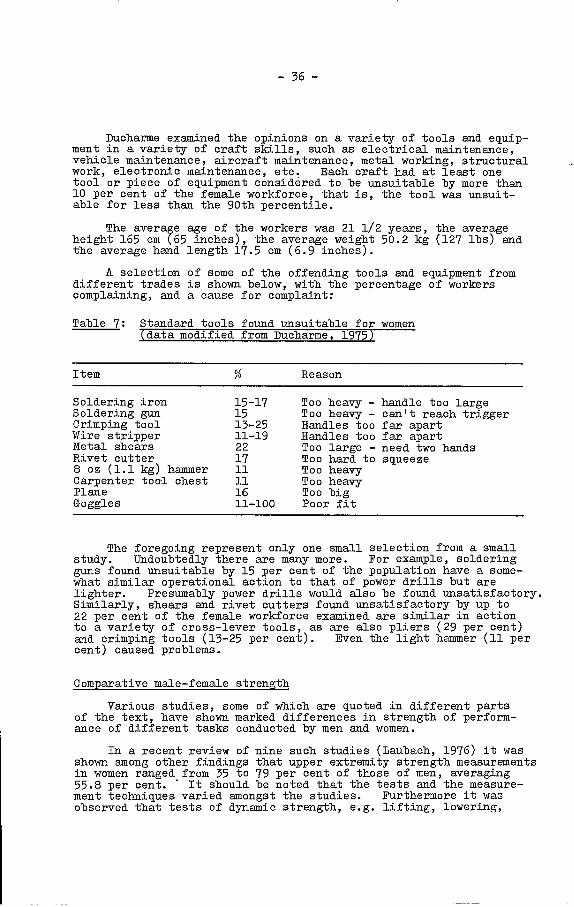
Soldering ironSoldering gunCrimping toolWire stripperMetal shearsRivet cutter8 oz (1.1 kg) hammerCarpenter tool chestPlaneGoggles
15-171513-2511-19221711111611-100
- 36 -
Ducharme examined the opinions on a variety of tools and equip-ment in a variety of craft skills, such as electrical maintenance,vehicle maintenance, aircraft maintenance, metal working, structuralwork, electronic maintenance, etc. Each craft had at least onetool or piece of equipment considered to be unsuitable by more than10 per cent of the female workforce, that is, the tool was unsuit-able for less than the 90th percentile.
The average age of the workers was 21 1/2 years, the averageheight 165 cm (65 inches), the average weight 50.2 kg (127 lbs) andthe average hand length 17.5 cm (6.9 inches).
A selection of some of the offending tools and equipment fromdifferent trades is shown below, with the percentage of workerscomplaining, and. a cause for complaint:
Table 7: Standard tools found unsuitable for women(data modified from Ducharme, 1975)
Too heavy -Too heavy -Handles tooHandles tooToo large -Too hard toToo heavyToo heavyToo bigPoor fit
handle too largecan't reach triggerfar apartfar apartneed two handssqueeze
The foregoing represent only one small selection from a smallstudy. Undoubtedly there are many more. For example, solderingguns found unsuitable by 15 per cent of the population have a some-what similar operational action to that of power drills but arelighter. Presumably power drills would also be found unsatisfactory.Similarly, shears and rivet cutters found unsatisfactory by up to22 per cent of the female workforoe examined are similar in actionto a variety of cross-lever tools, as are also pliers (29 per cent)and crimping tools (13-25 per cent). Even the light hammer (11 percent) caused problems.
Comparative male-female strength
Various studies, some of which are quoted in different partsof the text, have shown marked differences in strength of perform-ance of different tasks conducted by men and women.
In a recent review of nine such studies (Laubach, 1976) it wasshom among other findings that upper extremity strength measurementsin women ranged from 35 to 79 per cent of those of men, averaging55.8 per cent. It should be noted that the tests and the measure-ment techniques varied amongst the studies. Furthermore it wasobserved that tests of dynamic strength, e.g. lifting, lowering,
I tern Reason

- 37 -
pushing, pulling and. carrying showed that women were some 59 to94 per cent as strong as men, with an average of 68.6 per cent orabout two-thirds. However, because of the very broad range it isunwise in establishing design criteria to assume that women havetwo-thirds of the strength of men, except in the most general terms.
Average hand strength of women, however, has been shown to beabout 23.5 kg (60 lbs) (reenberg and Chaffin, 1976) but to beapplicable to a sufficiently large number of women it is necessaryto convert that figure to a 95th percentile, namely, approximately10 kg (25 lbs).
- 38 -
CHAPTER 5
A PRACTICAl GUIDE TO HUMANENGINEERING IN TOOL DESIGN
It was pointed out in Chapter 2 that the primary objective ofhuman engineering in ergonomics is to ensure that the design of theinterface between man and the eqipment that he is using (be itmachine, tool, or protective clothing), is compatible with his humanrequirements and the needs of the function to be performed. Humanengineering is then concerned with design and operation in the lightof various human factors that might affect ultimate function. Itis well to note at this point the relationship between the ergonomist(or in this case human factors engineer) and the industrial designer.Good industrial designers will utilise the knowledge and expertiseof ergonomics. Others may approach the sane end intuitively, some-times with less success. There is a major difference, however, inthe orientation of the industrial designer and the human factorsengineer. 1hile each is ultimately seeking optimal function, theindustrial designer is concerned primarily with the requirementfor marketing and sales appeal of the device or machine in thelight of aesthetics, while the human factors engineer is concernedprimarily with safety, efficiency, health and comfort of the user.Each approach, of course, is constrained by the economics of thesituation, and the two viewpoints should be complementary ratherthan incompatible. There are cases, however, in which the func-tion has been constrained by the form, and where the ergonomicallyideal might seem to be aesthetically unpleasing. The principlesof ergonomics, however, have direct application to any form ofdesign for human use, although sometimes the need can be moreobvious than others.
In any area with so broad a background and so long a historyas that of the design of hand tools it is difficult to make anydramatic changes simply by the application of the expertise of humanengineering. Designs that have stood the test of millennia tendto be good. However, while the broad principles of tool designhave been handed down from generation to generation, not all designshave survived without occasional loss of the subtleties that distin-guish the good from the bad. Nor is it necessarily true that noimprovements can be made in even the simplest of tools; and further-more, with the development of power tool tecbnology much can yet bedone to ensure that the interface between the tool and. the user isoptimal.
General requirements
Essentially a tool comprises a head and a handle, with some-times a shaft, or in the case of the power tool, a body. It maybe difficult to determine where the junctions of head, shaft, andhandle actually occur. In a double-ended wrench or spanner, onehead and a portion of the shaft act as the handle for the other.In the case of a hammer the handle and shaft are continuous, whilein the case of a screwdriver the same applies to the head and shaft.

-. 39 -
A tool requires some motive power which, in the simple handtool, is supplied by the masculatu.re of the user, while ii the caseof the power tool it is provided by a motor mounted in the body orhandle, or from some external source. In every case, however, thereis some form of handle or handles, and it is at the handle that thegreater portion of the human interface of any tool is found. Thusthe handle is of prime significance as the means whereby human inputis applied to the system as a motive force, or guiding and stablisirigforce, or some combination. In a power tool the controls and themeans of mounting the head are also part of the interface. In othermore complex man-machine systems the interface is also the site forthe provision of information on the state of the system. That informa-tion is usually provided in the form of visual displays. In a man-tool system, however, most of the feedback, other than tactile andkinesthetic (which are indeed important sources), occurs by directvisual monitoring of the result. Formal visual displays are almostnon-existent except in such tools as the torque-wrench, devices formeasurement, and a few special purpose displays. Some of therequirements for information display will be considered later.Meantime consideration will be given to the requirements for handles.
Obviously each general class of tool will have a somewhatsimilar handle, but within that class the actual form of the handlewill depend on a number of factors, including to a greater or lessextent the nature of the tool, the size of the head and/or body,whether manually or power operated, the usage to which it is goingto be put, the extent to which its use demands a precision grip, ora power grip, and the primary function of the handle, that is, whetherprimarily for wielding the tool, operating the tool, stabilizing thetool, or carrying the tool.
Incompatibility of handle and hand will not give rise toinefficiency in use, or even inability to use the tool but may alsogive rise to permanent damage to, and destruction of, tissue - theoccupational stigmata that serve to characterise the cobbler, theupholsterer, the tailor, etc.
Roubal and Kouva (1962) point out that the pressures trans-ferred from a handle during work should be applied mainly to theplaces where the tissue of the hand is most resistant, for examplethe thexiar and antithenar eminences, that is, the palm at the baseo± the thumb and the little finger, and that they should be slighton the surfaces of fingers. In general, the main direction of forceshould lead to the larger surface of the hand, with as even adistribution as possible over the joints and ligaments of the hand,forearm, or arm, according to the strength required for the work.
Blisters, callosities, and occupational stigmata, includingdistortion of joints are caused by:
excessive pressure per unit of hand surface during work;
pressure acting on an inadequately protected surface of thehand, e.g. where bones are thinly covered;
pressure during work by a handle of which the line of actionis not perpendicular to the surface of the hand; and
slippage of the tool over the surface of the hand frominadequate area of contact surface or incompatibility ofhandle fit to hand.

- 40 -
Since in many cases the handle is required to serve severalfunctions which require different proportions of power and precision,basic conflicts can arise which have to be met with compromise.It is In the solution of these problems that the expertise of ergo-nom.ics can be found advantageous. Each class of tool, or some-times each individual tool, requires consideration, but certaingeneral requirements for tool handles can be defined.
1. Shape of handle
The shape should conform to the natural holding position ofthe hand. In the resting stage, the right hand of a right-handed person holding a tool In such a manner as to meet therequirements of both precislon and power will be held more thanhaif-supinated, with the wrist abducted about 150 and slightlydorsiflexed, the little finger in almost full flexion, the othersless so, the first finger less than half flexed, and. the thumb adduc-ted and slightly flexed. The combination of adduction and dorsi-flexion at the wrist with varying flexion of the fingers and thumbgenerates an angle of about 780 between the long axis of the armand. a line passing through the centre point of the loop created bythe thumb and first finger, that is, the transverse axis of thefist (figure 5). While the wrist is being used, of course, thatangle will not be continuously maintained. For example, inhammering, the wrist will move from full adduction to full abduc-tion; on the other hand during the operation of a power drill,the angle will very largely- be maintained continuously.
In general, the shape of a handle corresponds basically tothat of a cylinder, or a truncated cone, or occasionally a sectorof a sphere, although the basic shape may undergo flattening, orother curves may be superimposed upon it. Because of its attach-ments to the body of a tool, a handle may also take the form of astirrup, a T-shape or an Is-shape, but the portion that is held bythe hand will commonly be in the form of a cylinder or cone.
Figure 5 - Angle of grasp
- 41 -
While a cylindrical form is the basic shape for moot handles,a true cylinder is indeed not the desirable shape, except where ahandle is intended virtually solely as a hook grip for carrying.Instead, the cylinder should be modified into the form of a curvedand truncated cone, such as is found in hammers, screwdrivers,chisels, files, etc., or in more complex modifications as in thehandles of saws and power tools. The truncated curved cone derivesfrom the varying degree of flexion in the fingers during the restinggrasp. The space enclosed by the grasp is of course not in factcylindrical but is complex and inulticurved.
It would be a relatively simple matter, of course, to make acasting of that shape and build.a handle to match it. This,however, would be a highly undesirable approach since the resultinghandle would be appropriate only to the hand on which it was modelled,and only wider the circumstances of use under which the model wasmade. The shape also varies in its dimensions from hand to handand during use of the hand. Instead of using a contour-matchingshape, it is necessary -to develop a shape which, with minimalobstruction, will meet the requirements of both hand and function.In fact, any form of specific shaping to a hand is undesirable, suchas ridges and valleys for fingers, fluting, indentations, etc.,since with varying shape and size of hands, and varying mode offunction the resulting shapes do not in fact fit the hands of asignificant number of users. Shapes then should be generalised. andbasic, sectors of spheres, flattened cylinders, long contouredcurves, flat planes put together in such a manner as to conformIa. general to the contours of the space of the grasping hand, butnot specifically. Particular examples of this shaping will bediscussed later in connection with examination of individual tools.
Oonsideration must also be given to other shapes. The sphere,or portion of a sphere, is in fact not commonly found except insome forms of stabilising handle. It has the advantage that itcan be readily grasped from many angles. It is desirable, however,to use a sector of a sphere as the dome at the head of tools wheresome of the drive comes via the palm of the hand, such as arew-drivers, chisels, and planes. It provides a good contour fit tothe palm with rio sharp projections. In this regard it should benoted that no edges should be permitted in the handles of tools.All potential edges should be smoothly curved off. Manycontemporary tools, particularly some screwdrivers, still haverelatively sharp edges -to the fluting that has been designed intothe plastic handles with the object of improving the grip.Oontinued pressure from the edges of tool handles gives rise todiscomfort, inefficiency, and eventually damage to the hand of theuser.
Still another shape, which can be regarded as a modificationof the cylinder, is the hexagon. It is of particular value forsmall calibre implements which would otherwise be cylindrical insection. It is easier to maintain a stable grip on a hexagonsection of small calibre than on a cylindrical section. Squareor cuboidal sections can be rotated less freely, and have sharperedges, but are also of value. A hexagonal section for the handleof a small screwdriver can be very effective.
Where the grasp has to undergo dynamic change, such as in theuse of pliers and shears, rather -than remain static, such as with ahammer, there are still other considerations with respect to shape,

- 42 -
but the same principles apply. One is still concerned with acylindrical or conical form, but in this case one is concernedonly with sections of the cone or cylinder which continuouslychange in diameter along the handles. The specific require-ments for the handles of such tools will be examined later.
2. Thickness (width) of handles
With respect to thickness, again it is desirable for the handleto conform to anthropometric requirements. Surprisingly, however,very little work seems to have been done to determine the anthropo-metric limitations on human grasp, although fairly adequate informa-tion exists on the recommended dimensions of knobs, selecto-rswitches, etc. One study on human grasp involving constructionworkers (Bobbert, 1969), indicates an average maximum inside graspbetween thumb and index finger, encompassing at least 2700 of acylinder, to be 7.4 cm (2.9 inches).
Design recommendations for knob controls, which have some ofthe requirements of handles, include the following: (note that alldimensional conversions are approximate).
Table 8: Recommended diameters of knobs for use palmof hand (data derived from YanOott and Kincade, 1972)
Diameter
Minimum 10 inn (0.375 in) 40 mm (1.5 in)
Maximum 100 mm (4 in) 75 mm (3 in)
It is clear that these numbers cannot be used directly todetermine handle sizes but they provide some reference background.Recommended dimensions for levers are perhaps even more applicable.These are shown as follows:
Table 9: Recommended dimensions for levers (dataderived from VanOott and Kincade, 1972)
Grasp Fingertip Palm of hand
Parameter Minimum Maximum
Finger grasp 13 inn (0.5 in) 75 mm (3.0 in)
Hand grasp 40 mm (1.5 in) 75 inn (3.0 in)
Length of grasp area 75 mm (3.0 in) no limit

- 43 -
Prom a review of several studies (particularly Ayoub andLoPresti, 1971; Konz, 1974) it is apparent that a grip diameterof 40 mm (1 1/2 inches) is most appropriate for a power grip.The grip force at 50 mm (2 inches) is 95 per cent of that at40mm (1 1/2 inches), and 70 per cent of that at 65mm (2.1/2inches). For precision grips diameters of less than 6 mm (1/4 inch)tend to cut into the hand and do not give sufficient control.
Although 75 mm (3 inches) is given as the recommended maximum,a handle of that size would be unsatisfactory. In practice, mosthandles should range between 25-40 mm (approximately 1 1/2 inches).Indeed the capacity to apply torque becomes reduced when thediameter of the handle exceeds approximately 50 mm (approximately2 inches) (Pheasant and O'Neill, 1975). This latter figure shouldbe considered the maximum diameter of a handle. For females allthe foregoing recommended limits should be reduced by 10 per cent,and indeed additional as yet unspecified limitations might berequired by reason of ethnic heritage.
For a hook grip a diameter of 20 mm (3/4 inch) is recommended(Woodson and Conover, 1966).
The actual width for the individual tool will of course varywith its function and size. Thus, where the tool is large and apower grip is required, e.g., in a heavy hammer or the handle ofa power drill, the width will be found at the upper limit of therange. Where the tool is small and demands a precision grip,e.g., a jeweller's screwdriver or a dental drill, the width of thehandle will lie at the lower end, or even below, for specialpurposes. Where a power grip is required, however, even wherethe toolhead is small, as in a small driver for wood screws, itis necessary to provide a grip at the high end of the calibrerange. 1'flaere rotation of the tool is unwanted, as in the case ofa hammer, it is desirable to have bilateral flattening, ratherthan to retain a circular section.
In a study concerned with hand muscle activity during thumband forefinger grasp±ng of handles of 1, 5, 10 and 15 mm (1/25,1/5, 2/5 and 3/5 inch) Binkhorst and Carls5 (1965) showed thatwithin the range examined, the thicker the handle the less was theload on the hand muscles. However, because of the shape of thespace enclosed by the grip, the width of calibre of a handle shouldnot be the same throughout its length. It will, of course,normally be wider at the thumb end and narrower at the littlefinger. Representative dimensions for the classic "pistol grip",which is applicable to many forms of tool handle, are shown inthe accompanying sketch (figure 6).
3. Length of handle
While in some cases the handle of a tool merges indistinguishablyinto the shaft, as for example in a hammer, in others the length isdetermined by the working position of the hand. It is thus fixedby the critical anthropometric dimensions and the nature of the gripused. Particulars will be considered later when examiningspecific tools, but ideally the length must meet the maximum expecteddimension at the level of the 97.5th percentile or higher. Thus,for example, a power tool handle must accommodate the maximum widthof the closed grasp at the 97.5th percentile, that is approximately102 mm (4 inches), bearing in mind the possible need for gloves,

- 44 -.
Figure 6 - Representative dimensions for pistol grip handle
while the heavy screwdriver, used partly in a precision grip andpartly in a power grip, must accommodate the length from palm toflexed knuckle of the forefinger, approximately 102 mm (4 inches).Short handles are unsuitable for tools requiring a power grip. Ahandle with a length so short that it cannot be grasped betweenthumb and forefinger, that is, approximately 19 mm (3/4 inch), isunsuitable for any tool. Drillis (1963) notes that the length ofhandle for a tool such as a file, or for that matter a screwdriver,should be one thuxnb-ell, (see figure 4), in folk terminology.
4. Weight of tool
The weight of the handle should be considered in relationshipto the weight and balance of the tool. In the case of percussiontools it is desirable to reduce the weight of the handle to theminimum, and have as much weight as possible in the head. Inother tools the balance should be evenly distributed where possible.In tools with small heads, and bulky handles, such as small screw-drivers, this may not be possible, but the handle ideally shouldthen be made progressively lighter as its bulk increases relativeto the size of the head and shaft.
The weight of the tool as a whole only becomes significant asit approaches the higher levels of recommendation. The handlingof heavy objects is inherently hazardous. In a review of thousandsof industrial accident reports the US National Safety Council report-ed that 28.5 per cent of injuries involved handling an object(National Safety Council, 1972). In addition, of course, thecapacity of individuals -to handle heavy objects is limited both fora single lift and even more so for the repeated lifts that might berequired in tool operation. It has been shown (Snook and Ciriello,1974) that the limit for safe lifting by most men for a single non-repetitive lift is in the region of 55 kg (125 ibs).
- 45 -'
The maximum acceptable weights found by Snook and Ciriello(1974) under varying circumstances are shown in table 10.
Table 10: Maximum weight (ibs) by percentile found acceptable bymales and females in industry lifting a tote box
In their study on hand tools and small presses (Greenberg and.Chaff in (1976:)) note further that the weight of a tool determinesits ability to be moved and. hence that a heavy weight reduces theproficiency of the worker. While dvooating a 11 kg (25 lb) limiton weight they also recommend. that requirements for lifting thetool be limited to five times or less per minute. While 11 kg(25 lb) can be considered an upper limit., it would be well to addthat for ordinary purposes the weight of a tool should notexceed 4.5-5.5 kg (10-12 ibs). Lifting handles or designatedgrasp points should be provided in heavy tools so that twopeople can co-operate in moving the device and that a lifting boltor hole should be provided for the better use of a hoist ortool balancer to assist in lifting and lbwering the device. Thegrasp points or handles should allow the fingers to wrap aroundthe surface for at least 2700.
5. Angulation of handles
It was shown in Chapter 4 that the line of transmitted forcepasses along the fingers, then through a centrally located carpalbone in the w-ris-t to the radius bone, and up the arm. Althoughthe middle finger is the central finger, and also the longestringer, the axis around which the hand operates is not in fact thatOf the middle finger but that of the index finger. Thus theaxis of function of a tool grasped by the hand, whether it is ahammer, a screwdriver or a power drill, is along the line of thepointing index finger, a fact that has been sometimes overlookedin the design of tools with angled handles. Therefore anyangulation of handles that is necessary, e.g. in power tools orsingle-handed shears, should be undertaken with this anatomicalrelationship in mind. Thus the handle should not only reflectthe axis of the grasp (i.e. about 78° from the horizontal), butthe handle or handles should be so oriented that the eventual axisof function of the tool is an extension of the index finger.When two hands are operating in parallel the axis of function isbetween and parallel to the axes of the two index fingers, aswhen using two hands in parallel, one above the other, to operatea saw. When one hand is supplementing the activities of the other,as in supporting a power drill, the rnis of funótion is that of thedominant hand. This fact will be considered when examining theplacement of handles iii power tools.
1 x 13 &.W2 ins.
90% 75% 50% 25% 10%
Shoulder height to Men 29 39 49 59 68axis reach: Women: 24 26 29 32 35
Knuckle height to Men: 34 43 53 62 71shoulder height: Women: 25 29 34 38 42
Floor level to Men: 37 45 54 63 70knuckle height: Women: 28 33 37 42 47

- 46 -
6. Texture and materials
It is not by accident that for millennia wood was the materialof choice for tool handles. In addition to being readily availableand easily worked, it has qualities that make it desirable as thelink between hand and metal. Its inherent elasticity provides thedegree of resistance to pressure and shock absorbency that permitcomfortable application of force; its thermal conductivity permitsa rate of heat exchange between the tools and the skin such thatsubjectively it feels neutral in warmth; its frictional resist-ance allows the application of torque with minimal discomfort atthe skin, and also even when wet with sweat or other liquid;it is light in relation to its bulk, and it is visually and tactuallypleasing. On the other hand, although moderately hard wearing,it can be damaged fairly readily and it will easily become stainedand impregnated with grease and oil. Even more significantly, itwill break and become detached from its mounting. Inevitably thewooden handles of many tools have given way -to handles of poly-styrene or some other form of impact resistant and stain resistantplastic, which has something of the sane qualities as wood but ismore durable, more colourful and more economical. In one quality,however, namely the aesthetic of texture, plastic cannot replacewood. Texture of course is not merely an aesthetic quality, it isalso functional. A tool handle requires a readily identifiabletexture to provide an input to the sensory nervous system to assistin maintaining the grip. It is desirable in. fact to ensure thatsome distinctive surface texture is incorporated into the otherwisesmooth plastic handles for this purpose. As already noted,flutings, ridges, and indentations, which were intended to providetexture and increase frictional resistance, may in fact causepressure injury on the fingers. Some dull roughening, palpableto the skin of the hand, but neither sharp nor injurious, canserve the purpose better.
Deep recesses of greater than 3 mm (1/8 inch) are notrecommended because of the variation in morphology of the fingerthroughout the population. In particular, a person with largefingers may create compression forces on the lateral surfaces ofthe fingers, which are abundant in superficial nerves, arteriesand veins; or a person with small fingers may be forced toattempt compression of two fingers into one recess with similarresults. In general, finger recesses should only be providedwhen the primary force is pulling across the palm, as in a toolused to insert or pull apart objects, and then only when smallforces of no greater than about 6.5 kg (15 lbs) are expected.If larger forces are required a pistol grip tool with a triggeroperated by flexing all the fingers should be provided. Theuse of a flange and thumb s-top on the handle is also recommendedfor tools used to insert or press parts together.
If recesses are found on both handles of, for example, apair of pliers, there is a possibility of damage to the palm ofthe hand as well as to the fingers; it is therefore recommendedthat the force bearing area, where high or repetitive forces areexpected, should be designed to span the breadth of the palm,which for 95 per cent of male workers would require a length of noless than 10 cm (4 inches), and it should have a curvature of nogreater than about 1.3 cm (1/2 inch) over it entire length.
- 47 -
Several other recommendations in this regard can be quotedfrom the work of Greenberg and Chaffin, (1976). Bright highlypolished surfaces should be avoided. Smooth surfaces should onlybe provided when small forces are needed frequently to actuate thetool. Non-reflective ripple coatings should be used in mostcases. Cast or machine surfaces should, if possible, be coatedwith matt paint or other similar material. Should this not bepracticable, such surfaces should be sandblasted or otherwisesurface treated so that the sharp surface peaks are rounded,thereby reducing the abrasive characteristics of the surface.
All exterior edges of a tool which are not part o thefunctions]. operation and which meet at an angle of 135 or lessshould be rounded with a radius of at least 0.8 mm approximately(1/32 inch). Similarly, all corners formed by the interse8tionof three or more surfaces of which two form an angle of 135 orless should be rounded to at least 1.6 mm (1/16 inch). Ifrounding is not feasible, a layer of plastic or rubber may beoverlaid and securely attached. The same principle applies todistinct surface protrusions which should be removed, relocated orcountersunk; failing that, the part should be covered with a round-ed pliable material. In some situations, e.g. a projecting bolt,it might be necessary to cover it with a metal guard.
A related problem may occur with openings. Exterioropenings may be found in large power tools. These openings cancatch clothing, tear skin, or even injui'e joints should, forexample, a finger be caught. Although this is perhaps unlikely,such openings should be eliminated wherever possible, or coveredwhere otherwise necessary. Where the openings are inherent inthe action of the tool, such as in the jaws of pliers or clamps,consideration should be given, where it is compatible with theintended action of the tool, to so design the jaws that even whenfully closed they could not compress a finger. Even if this isnot feasible, at least it should be ensured that the handles orother moving parts of the tool do not come sufficiently closetogether that they could trap the skin of the operating hand,as may happen with improperly designed pliers or handclamps.Furthermore, operational procedures should be designed to minimisethe likelihood of entrapment of body members.
Metal handles may be used in some tools in. place of wood,but to meet the requirements of shock absorbency, thermalconductivity, frictional resistance and texture, they have to becovered with a rubber, leather, or synthetic sheath of thicknessappropriate to the material used.
Size of tools
Various studies have shown that the size of an object, takenin conjunction with its weight, have a multiplicative effect overand above that of either size or weight alone. The size of ahand tool, however, is only o± significance when it is unusuallylarge, a situation that is relatively uncommon. A significantlystressful factor in this regard is the horizontally measureddisplacement of the centre of gravity of the load from the torso(Greenberg and. Chaffin, 1976). The size of the load may be amajor factor in determining this effect. Where the centre ofgravity is displaced from the front of the torso by greater than25.4 cm (10 inches) the ability to lift and lower an object isgreatly decreased for both men and women. Consequently, objects
p
- 48
that have to be manually handled (including heavy tools) shouldbe designed so as to locate the centre of gravity as close to theperson's torso as possible. Instructions or markings shouldindicate either where to grasp the tool to achieve this result, orwhere the centre of gravity is located if not close to the perceivedgeometric centre.
Similarly if an object is too wide to pass easily betweenthe knees when the individual is in a squatting position, excessivestress will be placed on ther person's back when lifting the objectfrom the floor since the object must then be lifted in. front of theknees instead of between them and consequently move out from thetorso. Thus, the greater the breadth of the object the greater thehorizontal forward distance between the object and the spine, andhence the lower the lifting capacity and the greater the back strain.It is therefore recommended that the object breadth be kept as smallas possible (preferably below 35.5 cm C 14 inches)) if it has to bemanually lifted or lowered to the floor.
Still another factor lies in the distribution of the dimensions.\Vhere one dimension is about five times or more greater than any ofthe other major exterior dimensions the object has a potentiallyunstable orientation, and, for example, can fall over or be knockedover more readily if set on the base of a large vertical dimension.In addition the long dimension may be such as to invoke thecircumstances described above during lifting, and cause an increasein the distance between the torso and the mass centre of gravity withthe attendant dangers therefrom.
Oharacteristics of handles forspecific tools
In addition to the general characteristics discussed above,each class of tool, and sometimes individual tools, hascharacteristics that are unique. It is not feasible to discuss thefeatures of every tool, nor to define all the characteristics foreach tool discussed, but certain representative examples will beselected and certain significant features will be emphasised.
1. Hammer
The hammer belongs to the class of percussive tools. Inanalysing a percussive tool one must distinguish between the centreof mass and the centre of percussion (figure 7). The centre of massis found at the balance point of the hammer-handle system, normallyalong the handle from the head, while the centre of percussion isthe ideal point at which striking should occur to deliver an optimumblow. The line of action passes through the centre of percussion,which is normally close to the centre of mass of the head, at rightangles to the plane of the hammer contact face. Using geometricmethods, Drillis and his colleagues (1963) showed that theefficiency of the system () is a function of the distance from themass centre to the line of action Cs) and the radius of gyration withrespect to the centre of action (p), namely:
(1)
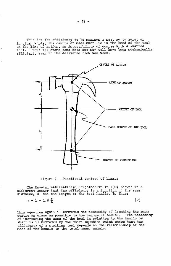
-
- 49 -
Thus for the efficiency to be maximum a must go to zero, orin other words, the centre of mass must lie in the head of the toolon the line of action, an impossibility of course with a shaftedtool. Thus the stone hand-held axe may well have been mechanicallyefficient, even if the delivered blow was weak.
CENTRE OF ACTION
Figure 7 - Functional centres of hammer
The Russian mathematician Gorjatselikizi in. 1924 showed in adifferent maimer that the efficiency is a function of the sanedistance, a, and the length of the tool handle, L, thus:
(2)
This equation again illustrates the necessity of locating the masscentre as close as possible to the centre of action. The necessityof increasing the mass of the head in relation to the handle orshaft is illustrated by -the third equation which shows that theefficiency of a striking tool depends on the relationship of themass of the handle to the total mass, namely:
LINE OF ACTION
WEIGHT OF TOOL
MASS CENTRE OF ThE TOOL
CENTRE OF PERCUSSION

- 50 -
II = 1 - 0.75 m1 + 012
m(3)
where m1 = mass of the tool handle
012 = mass of the tool head.
Drillis and. his colleagues also considered other aspects ofthe efficiency of striking tools, such as the stroke-movementeficiency, or the ratio of the energy output of the tool at theinstant of contact -to the energy input expended in its rising andstriking; the impact efficiency and, recoil, namely the ratiobetween the relative velocity after impact and that before impact,which is defined as the coefficient of restitution, and, in turncan be used to derive the energy of recoil. The details are notpertinent to this discussion although they can be found in theoriginal work. With respect to forging of a red-hot object bystriking it with a hammer on an anvil, however, the significancelies in the fact that the analysis shows that the mass of thehammer must be small in comparison with the combined mass of theobject and the anvil in order to dissipate a large part of thekinetic energy. On the other hand, in driving a nail the intentis to transform the kinetic energy of the tool into kinetic energy ofthe nail. The loss of energy should be kept as low as possible,and consequently the mass of the hammer should be great in relationto the mass of the nail. In thousands of years of evolution ofcourse these matters have already been empirically established butit is rewarding to find empirical knowledge confirmed byengineering analysis.
Bearing these and other factors in mind, the over-allcoefficient of efficiency for the entire man-tool system strokemovement is defined as the product of the efficiency of the tool,the efficiency of the human stroke movement, the coefficient ofimpact and the physiological energy transfer factor, namely theratio between the physiological work achieved and the physiologicalcost of the work as measured from calculation of metabolic rates.Using an average range for the last noted factor the net efficiencyfor hammer strokes used by a skilled operator driving a 6-inchnail is found, -to be 57 per cent (Drillis, et al, 1963).
The hammer, although occurring in many varieties, is one ofthe simplest tools ever developed, comprising a shaped head and ashaft or handle. Normally it is used in a power grip, but theordinary carpenter's hammer is not uncommonly held in a precisiongrip which merges into a power grip as the character of the workchanges. Light-weight carpentry and panel-beating hammers, orchipping hammers, etc., are also commonly held in a precision grip.Thus a hammer handle must meet the needs of a wide variety ofactivities. In fact a straight cylindrical., wooden handle ofcalibre within the range of 25-40 mm (1-1 1/2 inches), appropriateto the weight of the head, is indeed very effective. The lengthof the shaft is also a function of the activity. It has been shownthat the mean weight of the need for a chopping action should be nogreater than 2 per cent of the operator's weight, 6.5-7.5 kg (3-3 1/2 ibs), and the mean length of the handle, 35 per cent of theoperator's height (Drillis, 1963). Appropriate dimensions forseveral types of hammer are shown in the accompanying sketches(figure 8).
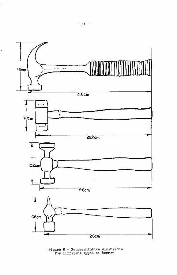
- 51 -
Figure 8 - Representative dimensionsfor different tyl2es of hammer

- 52 -
Although a cylindrical shaft is effective, simple, andeconomical to manufacture it is not ideal for power grip work. Anappropriately contoured shaft provides a more comfortable lessfatiguing grasp that is safer to use, since the enlargement at theend of the shaft, which is integral to the contouring, reduces therisk of slippage. The contours should conform to those describedearlier in consideration of the shape of handles, and are designedto fit the grasping hand. While curving is desirable, angulationof the handle is not acceptable since it alters the axis offunction. The shaft, as an extension of the handle, should be onthe axis of the extended forefinger. Cylindrical handles remaindesirable for the numerous variations of precision grip that arerequired in the use of lightweight hammers and mallets for body andpanel work, chipping, chiselling, and so forth.
Plastic handles are susceptible to fatigue and fracture, andare not suitable in most instances, but general purpose hammers arecommonly made with contoured metal handles. As noted earlier,metal handles must be covered with an appropriate material, e.g.rubber, plastic or leather. These coverings tend to becomeslippery with sweat or grease. Leather is one of the moresuitable materials, but is relatively expensive. It is doubtful ifmetal handles present any ergonomic advantages, although if appro-priately covered they are visually pleasing and have market appeal.
Wooden handles ate commonly made from ash and hickory, ash inEurope and hickory in the United States. Each is hard and densewith high shock resistance, but also is straight and easily workable.The beSt hammer shafts are made from second growth hickory which isdescribed as feeling cold and hard in the hand (Ford, l96l. In agood quality hammer the shaft will form a close fit into the hammerhead before wedging. Wedging is an additional safety measure insecuring the head to the shaft. Three wedges, two iron and onewood, are recommended, and should be fitted by a mechanical pressset at a predetermined pressure to ensure uniformity (Ford, 1961).After wedging, the eye of the head, that is, the slot or hole forthe shaft, should be completely filled with wood.
The same comments and recommendations apply to other forms ofpercussion hand tools, such as axes, adzes, mallets and. mauls.
2. Screwdrivers
The handles of screwdrivers, and tools held in a somewhat similarmanner, such as files, scrapers and hand chisels, have somewhatdifferent requirements. Each, at one time or another, is used witha precision grip or a power grip; each relies on the functions ofthe fingers and the palm of the hand for stabilisation and thetransmission of force. The screwdriver in particular must alsosubmit to torque. In each case the handle must also be capable ofbeing approached equally effectively from different angles.
The most commonly effective shape has been found to be that o±a modified cylinder, dome shaped at the end to receive the palm,and slightly flared where it meets the shaft to provide support tothe ends of the fingers. Theoretically, at least at first sight,this does not seem to be an ideal shape from the viewpoint ofergonomics. Ideally, considering the natural grasp, it would seemthat the handle should flare to a dome at the palm end, be relativelynarrow below the dome to accommodate the flexion o± the little

- 53 -
finger, and then flare to a wider calibre where it joins the shaft,i.e. in the form of a rotated pistol grip. If, however, this were sothen. the transmission of force, and particularly torque, would occurlargely by way of the fingers, which would then have to maintain acontinued tight grasp and. wpuld more readily become fatigued. Withthe handle that has evolved, however, torque is in fact transmittedby the palm, which is relatively passively maintained in contact withthe handle by way of pressure applied from the arm and. frictionalresistance at the skin. The fingers in this case, although alsotransmitting force, occupy more of a stabilising role, which is lessfatiguing since less power is required. Thus the dome of the headbecomes very important in handle design. If uncomfortable, andparticularly if there are sharp edges or ridges where the dome meetsthe rest of the handle, then either the hand becomes injured andcalloused, or the transmission of force is transferred towards thefingers and thumb which is more fatiguing and. less effective.
The body of the handle is perhaps less significant; differenttool makers use a variety of different shapes and designs todistinguish their product. Many of them, unfortunately, use ridgesand flutings which can be undesirable if they produce pressure injuryon the fingers. A tool manufacturing company in Germany, which hasmade good use of ergonomic principles in tool design, has recentlyintroduced a successful version of a screwdriver handle of triangularsection. The planes of the sides allow better use of the fingersin the application of torque, and in fact it has been found thatthe handles can be made smaller than would otherwise be necessary forapplication of the same amount of torque (0. ?Iansfeld, Hazet-Werk,personal communication, 1976).
The precise shape of the body of the handle, however, seemsrelatively unimportant, the effectiveness of the activity being morelimited by the size of the handle and the quality of the hand-handle interface. In fact, Pheasant and O'Neill (1975) conducteda study in which they compared the effectiveness, as handles forthe exertion of torque, of various sizes of smooth and. rough steelcylinders, and a range of commercially available screwdrivers ofvarying size, shape and surface quality. None of the screwdriverswere significantly better for the exertion of torque than roughcylinders of the same mean diameter, nor were any worse than acomparable smooth cylinder.
In those experiments the amount of torque that could beexerted increased as the handle increased in size from 1-5 cm(3/8-2 inches). Muscle strength was found to deteriorate whenusing polished steel handles of greater than 5 cm (2 inches).Knurled cylinders were found to be significantly better than smoothup to as much as 7 cm (2.7 inches) when they became marginallybetter. The simple knurled cylinder had an optimum diameter of5 cm.
3. Pliers
A number of related but different tools use the same principleof function as pliers. These include wire strippers, grip pliers,pincers, nippers, single-handed cutters and shears, and evenscissors. Basically these tools have a head in the form of jawswhich have a wide variety of configurations, a joint which may besimple or complex and forms the body, and two handles. Althoughoccasionally the handles are straight, generally they show bilateral
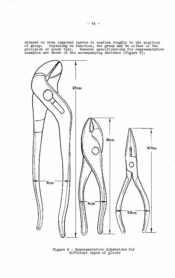
24cm
- 54 -
outward or even conipound curvee to conform roughly to the positionof grasp. Depending on function, the grasp may be either of theprecision or power type. General specifications for representativeexamples are shown in the accompanying sketches (figure 9).
Figure 9 - Representative dimensions fordifferent types of pliers
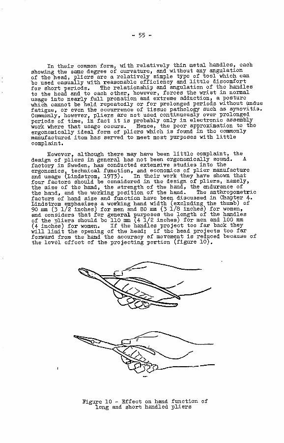
- 55 -
In their common form, with relatively thin metal handles, eachshowing the same degree of curvature, and without any angulationof the head, pliers are a relatively simple type of tool which canbe used casually with reasonable efficiency and little discomfortfor short periods. The relationship and. angulation of the handlesto the head and to each other, however, forces the wrist in normalusage into nearly full pronation and extreme adduction, a posturewhich cannot be held repeatedly or for prolonged periods without unduefatigue, or even the occurrence of tissue pathology such as synovitis.Commonly, however, pliers are not used continuously over prolongedperiods of time, in fact it is probably only in electronic assemblywork where that usage occurs. Hence, the poor approximation to theergonomically ideal form of pliers which is found in the commonlymanufactured item has served to meet most purposes with littlecomplaint.
However, although there may have been little complaint, thedesign of pliers in general has not been ergonomically sound. Afactory in Sweden, has conducted extensive studies into theergonomics, technical function, and. economics of plier manufactureand usage (Lindstrom, 1973). In their work they have shown thatfour factors should be considered in the design of pliers, namely,the size of the hand, the strength of the hand, the endurance ofthe hand, and the working position of the hand. The anthropometricfactors of hand size arid function have been discussed in Chapter 4.Lindstrom emphasises a working hand width (excluding the thumb) of90 mm (3 1/2 inches) for men. and 80 mm (3 1/8 inches) for women,and. considers that for general purposes the length of the handlesof the pliers should be 110 mm (4 1/2 inches) for men and 100 mm(4 inches) for women. If the handles project too far back theywill limit the opening of the head; if the head projects too farforward from the hand the accuracy of movement is reduced because ofthe level effect of the projecting portion (figure 10).
igure 10 - Effect on hand function oflong and short handled pliers

- 56 -
With respect to strength, a 20-35 year old man is consideredto develop 55-60 kp in. his dominant hand, while a woman will havesome 70 per cent of this value. By the age of 60-65 these valueswill have been reduced by 30 per cent. Thus the hand strength ofan older man is about 40 kp and that of a woman about 30 kp. Forrepeated operations, however, at intervals of 10-30 seconds, theuseful capacity is about one-third to one-half of these values.
Approximate working values may then be shown as follows:
Table 11: Strength of dominant hand in plierusage (data derived from Lindstrom, 1973)
Operator Max. strength (kp) Working strength (kp)
For nipper pliers with an approximate working ratio of forcesof 1:8, and with a wire placed next to the joint, the followingare the approximate wire dimensions that can be cut:
Table 12: Cutting thic1ess of wire with flippers(data derived from Lind.strom, 1973)
If the wire is placed at the tip of the head the lever ratio isreduced such that the maximum dimension that can be cut with a forceof 20 kp would be lowered to 1 mm. Two-handed use can. increase thecutting force by 60-70 per cent.
Tormally, the application is not limited so much by lack ofstrength as by pain in the hand. For repeate operations byfemales te pressure should not exceep 1 kp/cm2, and for males2-4 kp/cm , with an occasional maximum 7 kp/cm . To minimise theapplied pressure, it bacomes essential to enlarge and f]atten thehandles, and to avoid pressure-producing ridges.
Man, 20-25 60 20-30
Man, 60 40 15-20
Woman, 20-35 40 15-20
Woman, 60 30 10-15
Hand strength (kp) Piano wire (mci) Copper wire (mm)
20 1 2.5
40 1.25 3
60 1.6 4
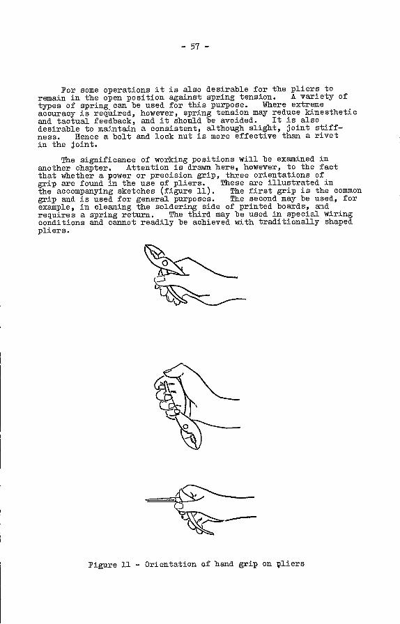
- 57 -
For some operations it is also desirable for -the pliers toremain in -the open position against spring tension. A variety oftypes of spring can be used for this purpose. Where extremeaccuracy is required, however, spring tension may reduce kinestheticand tactual feedback, and it should be avoided. It is alsodesirable to maintain, a consistent, although slight, joint stiff-ness. 1-leuce a bolt and. lock nut is more effective than a rivetin the joint.
The significance of working positions will be examined inanother chapter. Attention is drawn here, however, to the factthat whether a power or precision grip, three orientations ofgrip are found in the use of pliers. These are illustrated in.the accompanying sketches (figure 11). The first grip is the conunon.grip and is used for general purposes. The second may be used, forexample, in cleaning the soldering side of printed boards, andrequires a spring return. The third may be used in special wiringconditions and cannot readily be achieved with traditionally shapedpliers.
Figure 11 - Orientation of hand grip on pliers
-58- I
Studies of hand size, as shown in Chapter 4, have indicatedthat the maximum size of grip making a two-point contact, namelyfrom the distal end of the thumb, averages about 15.3 cm (6 inches),for a man and about 14.6 cm (5 3/4 inches) for a woman (quoted in(reen.berg and Chaffin, 1976). To include all but 5 per cent ofwomen, this span would have to be reduced still further to 13.3 cm(5 1/4 inches). If, however, a substantial grip is necessary, asis generally found in the operation of pliers and related equip-ment, a still greater reduction is required. On this basis it isrecommended that to allow all fingers to exert effective force onthe handles, a grip span of no more than about 11.5-12.5 cmapproximately (4 1/2-5 inches) be considered acceptable. If highgrip forces are required the handle opening should be less than65 to 90 imu approximately (2 1/2-3 1/2 inches).
As already noted in a previous chapter, the large muscleswhich give power to the hand are located in the arm, with tendonscrossing the wrist. The position of the wrist affects the gripcapacity of the hand. When the wrist is flexed or abducted, asis not uncommon in the usage of tools, the grip may then bedecreased by as much as 30 per cent. Thus the average male witha grip of about 50 kg (110 lbs) on an optimal tool with his handin the optimal position could have that grip reduced to about33 kg (75 lbs) when placing his wrist in a fully dorsiflexedposition. This phenomthion serves to emphasise the requirement,already presented, that tools should be designed to ensure thatthe axis of function of a tool is aligned with the longitudinalaxis of the forearm and the extended forefinger.
Ideally pliers and similar tools should be designed to meet therequirements of the position of grasp at rest, whether in precisionform or power form. This requires angulation of the handles to thehead, as well as compound and different curves in the handles withthe lower curve conforming to the inner surface of the flexedfingers, and the upper curve conforming to that of thc innersurface of the thumb and thenar eminence. In addition, the handlesshould be made thicker to provide a more substantial grip, andflatter to increase the area of skin, contact and distribute theforce more widely. A tool of this type has in fact been put inservice in the United States (Tichauer, 1966) with a subsequentreduction in the incidence of pathology previously associated withthe use of a conventional design (figure 12). however, andperhaps because of its departure from the conventional, the tool hasnot been widely accepted elsewhere.
Without going -to radical design changes, which might not beacceptable, but with the object of seeking desirable changethrough a process of quickened evolution, several ergonomicallysound improvements can be made in pliers relatively simply.Perhaps the most important, where power grip is significant, is inthickening and slightly flattening the handles, with a thumb supportat the head-end of the handle and a slight flare at the other end.To minimise the weight and cost, while providing some insulation,and at the same time improving the -tactual quality of the tool andretaining durability, it is best to encase the basic metal handle inan integral or detachable sheath, made of appropriate synthetic, andperhaps bluntly roughened. As the tool becomes accepted, the nextchange would be to add the angulation. of the head and the varyingcurves of the handles. Indentation of handles for fingers isundesirable.

- 59 -
Figure 12 - A. Traditional pliers
B. Pliers designed withapplication ofergonomic principles
The same principles apply to other forms of crossed lever tools,particularly with respect to change in the thickness and flatteningof handles. With scissors and shears, however, another problemarises. Many of these axe made with ouxvatures on the grips, andeven with finger and thumb loops on. the grips, which are suitableonly for right-handed persons, thereby placing the significantnumber of left-handed persons at a disadvantage. There is no doubtthat a right-handed tool will be more efficient when used by aright-handed person. It is doubtful, however, if the increase inefficiency so gained would balance the loss of efficiency that wouldoccur when the same tool is used by a left-hander. Unless it isnecessary that a tool should be ajade to fit one hand only, and itis difficult to forsee such circumstances, all tools should be madesuitable for use by either hand
4. Hand saws
The action of heavy sawing essentially involves a fixed graspin. the power grasp position, with repetitive flexion and extensionat the elbow, while the action of light sawing, such as with a fretsaw, req.uires a precision grip with some manipulation at the wrist.Very heavy crosscut sawing with a two-man saw may indeed requirethe use of two hands, one superimposed upon the other, but thegrasp is the same as for one hand. Thus basically there are twotypes of handles required for saws, one for a power grip and one fora precision grip.

- 60 -
For fret saws, light hacksaws, etc., where precision is thekeynote, a handle comparable to that of a screwdriver meets mostpurposes. Since no rotation of the saw is required, however, thehand can be shaped to conform more easily to the precision grasp,while allowing for a power grasp. Thus a "pistol grip" angledalmost horizontally would indeed meet the requirements even betterthan the oval handle that is commonly found.
5. Electric power drills arid otherpowered hand tools
It is convenient to pass from a hand saw to a power drillsince, although the function of the tools may be very different,the form of the handles is somewhat similar.
In a power drill, and for that matter in all other forms ofpower tools, the major function of the operator is to hold andstabilise the tool against the work while observing the functionand occasionally manipulating the controls. He may also at timeshave to adjust the orientation of the tool in discrete orcontinuous movements. Essentially, however, his function is oneof grasping and holding in a manner that is commonly similar to thatof the power grasp on a saw. Consequently there is, or should be,a fundamental resemblance between the handle of a handsaw and thehandle of a power drill. For the operating hand the grasp is thesame arid the limiting dimensions are the same. All requirementsare indeed met for the operating hand of a power drill by a"pistol grip" type of handle so laced as to provide the appro-priate angle of approximately 78 with the horizontal. Fromthe exgonomic viewpoint the limiting dimensions of the finger spaceare the sane as for the saw, and again it is of no ergonomicsignificance what ultimate shape the space assumes, or whether it isopen or closed. That relationship is conditioned by the linkageto the body of the tool and the dictates of the stylist. Nor isthe pistol grip piandatory, provided the ergonomic constraints aremet and all edges in contact with the hand are rounded.
Placement of the handle, however, is significant. A drillcomprises a handle, a body, and a had. Ideally these should behorizontally in line such that the handle is attached at the rearof the body and the head protrudes from the front. Otherorientations may be required for special circumstances but they areless than ideal. The line of action is again the line of theextended index finger so that in fact in the ideal drill the headwill be eccentric with respect to the central axis of the body.An example of such a drill, which was developed after considerationof the human engineering involved, is described by Paule, 1975.The same company has also pioneered another orientation ofoperating handle which is ergonomically sound for a different typeof function. This handle is designed for lighter devices whereboth power and precision are factors, and provides for a nearlyhorizontally oriented pistol grip which tan readily be used foreither power or precision grips.
- 61 -
reenberg and Cha±'fin (1976) however, point out another factor ofsignificance. In the common power drill the mass centre of gravityof the drill is in the body of the tool in front of the handle,creating a turning movement which the hand must overcome, in addi-tion to holding, positioning and pushing the drill into the work-piece. They advocate placement of the primary handle directlyunder the centre of gravity such that, if necessary, the body jutsout behind the handle as well as in front.
Heavy drills have a requirement for a secondary supportivehandle. Where two handles are required they should be placed inrelation to the centre of gravity of the tool to provide the mostuseful measure of support. The auxiliary handle is sometimesplaced at the left side or on top of the drill, thus forcing aright-handed person to operate it with his left arm raised and.abducted in a very fatiguing position, the more so if the handleis on top. It also forces a left-handed person to operate thedrill with his weaker arm. It is clearly desirable to place theancillary handle below the drill where it can be operated witheither arm, the supporting arm being tucked in against the bodyin a much less fatiguing position.
The general question of weight has already been discussed.The drill is normally operated with the extended forearm and.consequently for prolonged use the weight should be limted. toapproximately 70 per cent of normal human capacity for sustainedholding in that position, or approximately 11 kg (25 lbs), atabsolute maximum for short periods. Where a heavier tool isrequired the supports should be an integral part of the tooldesign and the human requirements should be considered with thetool in the supported position.
Power drills and other powered hand tools require controlsfor their operation. The human engineering of controls for handpower tools will be considered in the nevt section.
What has been outlined above with respect to power drillsalso applies very largely to all powered hand tools, e.g.sanders, circular saws, reciprocating saws, as well as electrichammers, and percussion drills. Indeed adapters for many formsof power tool can be applied to electric power drills. Perhapsa major difference in tools designed for other purposes lies inthe orientation of the handle or handles, and the provisions foroperational safety, particularly in saws and grinders. It isnecessary, for example, to ensure that a saw blade or grinderwheel is not exposed more than is required to perform its function.Integral guards should be provided, operated by spring loading,to ensure that no portion of an operating blade or wheel isexposed in a manner that could cause injury.
Human engirieerin of hand toolcontrols and disp ays
In any man-machine system, and the term includes an operatorusing a power tool, a control is the means by which action istransferred from the man to the machine and a display is the meansby which information is passed from the machine to the man. Thusa control might be a toggle switch or a trigger, and, a display mightbe the scale of a carpenter's square or the static position of anon-off switch.

- 62 -
It is pleasing in this instance to observe that in the designof saw handles ergonomics and evolution are in. agreement. Twotypes of handles tend to be found on commercial saws, a Ilpistol_grip" type on saws designed for heavy work, and a "screwdriver"type on light saws for precision work.
For the heavier work the broad compound curve of the pistolgrip provides a comfortable efficient handle, where the majorlimiting feature is the width of the gloved or ungloved hand.To conform to the flat planes of the saw the sides of the handle canbe flattened without loss of effectiveness, provided that thebilateral width of the handle does not become less than 25 mm(1 inch). Narrower widths increase the pressure loading on thethenar eminence and palm and give rise to limiting discomfort.While the compound curve of the "pistol grip" is desirable it isnot mandatory, providing the angle of the handle between verticaland horizontal coifforms to the approximate 780 which representsthe angle of the resting grasp. All edges however must then berounded. A high quality design which uses an almost rectangularsection with curved edges has recently been marketed.
The loop in which the fingers are placed becomes effectivelya rectangle with rounded ends. Approximate dimensions, allowingfor a gloved hand, are shown in the accompanying sketches(figure 13). A variety of modifications can be made for reasonsof style. Provided these do not impinge upon ergonomic require-ments they can be encouraged. It is of little ergonomicsignificance whether the handle is open or closed, or what formthe front portion of the ioop might take. It is of significancehowever that the plane of action of the saw is in the line of theextended index finger or parallel to it. In most cases, becauseof the. mechanics of the supporting frame, or the necessary width ofthe blade, the cutting edge has to be parallel to the extendedindex finger.
Much work in human engineering has been done to define thetheory of control and display design, and no attempt will be madeto reproduce it in detail here. The interested reader is referredto standard reference texts on the subject. Certain aspects,specific to the design of tools, will be considered, along with avery brief overview of the general range of the subject.
In the general consideration of control design there are twobasic elements that must be borne in mind, namely, the controlmechanics, that is, matching of the control operation to theanatomical function of the operator, and the control dynamics, thatis, matching the control system to the motor and intellectual skillsof the operator. The former is concerned with the physical designof the control itself, that is, the size, shape, mode of operation,force required, etc., while the latter is concerned with the mode ofoperation of the control in relation to the effect it produces, forexample the relationship between, say, the factors involved inturning a steering wheel and the ultimate track of the vehicle con-cerned. In tool operation, however, the control dynamics relate tosimple changes of state. Consequently major interest with respectto tools centres on control mechanics, or functional design.

0
0
- 63 -
A
I .5Cm
12cm
Figure 13 - Representative dimensions for saw handles
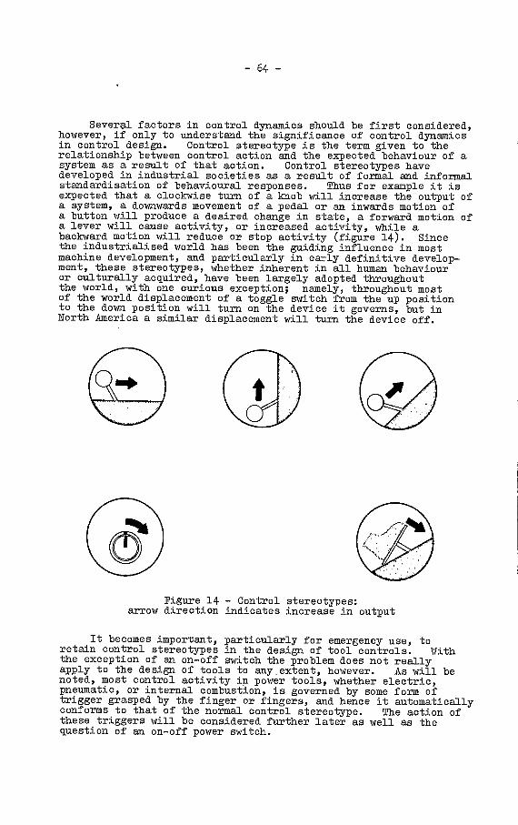
- 64 -
Several factors in control dynamics should be first considered,however, if only to understand the significance of control dynamicsin control design. Control stereotype is the term given to therelationship between control action and the expected behaviour of asystem as a result of that action. Control stereotypes havedeveloped in industrial societies as a result of formal and informalstandardisation of behavioural responses. Thus for example it isexpected that a clockwise turn of a knob will increase the output ofa system, a downwards movement of a pedal or an inwards motion ofa button will produce a desired change in state, a forward motion ofa lever will cause activity, or increased activity, while abackward motion will reduce or stop activity (figure 14). Sincethe industrialised world has been the guiding influence in mostmachine development, and particularly is. early definitive develop-ment, these stereotypes, whether inherent in all human behaviouror culturally acquired, have been largely adopted throughoutthe world, with one curious exception; namely, throughout mostof the world displacement of a toggle switch from the up positionto the down position will turn on the device it governs, but inNorth America a similar displacement will turn the device off.
Figure 14 - Control stereotypes:arrow direction indicates increase in output
It becomes important, particularly for emergency use, toretain control stereotypes in the design of tool controls. Withthe exception of an on-off switch the problem does not reallyapply to the design of tools to anyextent, however. As will benoted, most control activity in power tools, whether electric,pneumatic, or internal combustion, is governed by some form oftrigger grasped by the finger or fingers, and hence it automaticallyconforms to that of the normal control stereotype. The action ofthese triggers will be considered further later as well as thequestion of an on-off power switch.

- 65 -
Another concept of significance in control dynamics is thatof control type. A displacement control is one in which thechange of state of the system governed by the control is alinear function of the displacement of the control, that is, thedistance (or angle) through which the control has been moved. Acontrol, though rarely, may also be a pressure control in whichthe response of the system is a function of the pressure applied tothat control. Power tool controls undergo some form of motion,and consequently are displacement controls. A displacementcontrol is also a zero order control. That is, the functionvaries linearly with the extent of the displacement. It canalso be a first or a second order control, or a mixed control.In a first order control the velocity of the output is a functionof the displacement while in a second order control the accelerationof the ouput is a function of the displacement. The greatmajority of power tool controls are zero order controls, sometimeswith two or more displacement positions. First order, and higherorder controls, are complex to operate and are not found in purestate in tool control, although a mixed zero and first ordercontrol can be employed, that is, the faster the trigger issqueezed the greater is the resulting output.
In power tool design, the functional mechanics of thecontrols are of more practical significance than the controldynamics. It is necessary to determine the form, size, shape,mode of operation, mechanical characteristics (e.g. forcerequirement), and optimum location of the controls.
In this regard the question of on-off power switches meritssome special consideration. Only a few power tools have suchswitches separate from the normal operating control. Fprsafety reasons, however, consideration should be given to theprovision of an independent on-off power switch on a power toolto prevent inadvertent operation during, for example, holding ormoving the inactive tool. The fact that an electric tool has tobe connected to the power supply does not minimise the significanceof this recommendation. Tools are frequently left inactive whilestill connected to the power supply. It is common practice touse a toggle switch as an on-off power switch. Because of theconfusion in control sterotype with toggle switches, however,there is no advantage, and perhaps even disadvantage, in orientingthe switch in the vertical plane. It can be oriented and locatedin which ever way is convenient, although preferably in such aposition that it can be readily operated by the thumb of thecontrolling hand while the handle is being grasped. Regardlessof its orientation, however, because of the control stereotypeit is necessary to indicate in written or pictorial form whichposition is on and which off. Thus the position of the switchitself becomes a display. This requirement, however, raises anew problem, namely that of language or coded symbols. This willbe further examined when considering displays. In addition, theswitch should have a spring loaded resistance to operation, aswill be discussed in the next paragraph. An alternative is to usea push-button switch, which when pushed remains down and on, untilpushed again, when it returns to its resting position in the off-state. It too should operate against resistance. The pushbutton has the advantage of not requiring any form of legend toindicate its state since the state is demonstrated visually aswell as by tactual and kinesthetic feedback during operation.In contrast, however, a push-button switch of this type is lesseasily operated in an emergency.

- 66 -
The other form of control in a power tool is the operationalcontrol. Because of the normal form of handle and also fromlong tradition, which, although evolutionary rather than. imposed,follows sound ergonomic principles, the established control is inthe form of a trigger incorporated into the handle and depressedby the index finger, or rarely, by all the flexed fingers. Theswitch itself assumes many forms, from a simple round push buttonto a rectangular or contoured rocker. The actual shape matterslittle and can be determined by the form of the handle and thepreferred style. It is desirable however that when off it shouldproject from the handle and when on it should be flush with thehandle, such that the fingers assume the normal position of grasp.The dimensions are to some extent determined by the size of thehandle, but the following representation dimensions are derivedfrom US military studies (quoted in Vanoott and Kincade, 1972).
Table 13: Design recommendations. for push buttons (derivedfrom AFSON 80.3 quoted by VanCott and Kincade, 1972)
Diameter Displacement Resistance
Mm. Mm. Max. Mm. Max.
13 mm 3 mm 40 mm 0.3 kg 1.1 kg(0.5 in) (0.25 in) (1.5 in) (10 oz) (40 os)
The most significant dimension from the point of view of toolcontrol is the distance the switch projects from the handle in theoff position. Ideally, for ease of movement with the indexfinger it should not be greater than 13 mm (1/2 inch). It isdesirable practice, and perhaps even a cultural stereotype, thatwhere a rocker trigger is used the trigger should be suspendedfrom its upper pole.
For safety in operation the switch should be spring loadedwith a tension not to exceed 1 kg approximately (40 ounces), i'nsuch a manner that when pressure on the switch is released itreturns automatically to the off position. Where there are twodiscrete positions of the switch, for example for slow and fastoperation, release of pressure in either case should permit theswitch to return to the off position. In. addition, where thereare two positions a clear detent, with a change in resistanceperceptible through the finger, should occur at the first positionwith an angle of 15-40° on each side of the detent. The trippoint should be felt by the fingertip as a distinct increase inpressure. For most applications a brief reduction in resistanceas displacement continues is preferable in order to add to thefeedback information that the trip point has been reached.
Displays
A display is the means by which information on the state ofthe "machine" and its operation is transmitted to the operator.A display can be either dynamic or static, that is, it can offerchanging information or discrete fixed information. It can alsobe qualitative and quantitative, that is, it can indicate asituation., e.g. a flashing warning light or an on-off l?gend, or

- 67 -
it can offer numerical measures. As might be expected the displaysneeded in relation to the use of tools are very simple, involving,for example, scales on rules, or legends on power tools. Althoughthey may be simple, for good design it is still necessary to invokesound ergonomic principles in their implementation.
As with controls, there are also display stereotypes whichhave been accepted across a variety of cultures, as illustratedin. the accompanying sketches (figure 15). For example a scaleincreases from left to right (even in countries where writingtraditionally is presented in another direction), and also fronbottom to top. Unfortunately there is less standardisation in.coded symbols and pictorial displays. For example, a symbolicopen hand held vertically with fingers extended might mean"stop'1 in some cultures but "welcome" or "go" in others. Thislack of standardisation of significance leads to difficulty inthe assignment of legends on switches - a difficulty that has notyet been solved.
EXPECTED
UNEXPECTED
Figure 15 - Display stereotypes: top row,expectect directions; bottom row, unexpected
(undesirable) direction
It must be recognised that the term display, despite itsvisual connotation, pertains not only to the visual sense butalso to the auditory, tactual, and kinesthetic sense. Referencehas already been made to the significance of tactual and kinestheticinformation in the design of controls, particularly with referenceto spring resistance and detents. The auditory sense also offersa valuable channel for the presentation of information, and theoccurrence of an audible and tactually perceptible click when aswitch has been operated provides significant confirmatory evidence

that a desired state has been reached. Vision however is mostcommonly the channel naturally selected for the deliberateacquisition of information.
Only two forms of artificial visual display are used in theoperation of hand. tools, namely scales and legends. The scalesmay be linear measurement scales, as in rules and measuringtapes, or they may be analog scales, as in the meter of a torque-wrench. In either ease there are certain well established prin-ciples of presentation which should be followed to ensure thegreatest facility, accuracy, and efficiency in the acquisition ofinformation from these scales.
Experiment and experience have shown that some scale and dialpatterns are more readily assimilable than others, as shown inthe accompanying sketch (figure 16). In addition, it has beenshown that there is a finite limit on the fineness of the informa-tion that can be derived from a scale of a given length. Thelimit of visual resolution under best light conditions isapproximately 2mm (0.07 inches); markings at that limit, however,unduly crowd the scale and it has been found that scales marked atintervals of 5 aim (0.2 inches) provide information that is moreeasily acquired and with little loss in accuracy (Morgan, et al,1963).
- 68 -
Figure 16 - Desirable patterns for scales and dials:top row: desirable divisions for scale markings;
(note use of thick and thin lines)middle row: desirable orientation of numbers and pointers;
bottom row: desirable scale formats

-69-
Certain general rules can be defined for the graphicrepresentation of scales, namely:
Preferably use decimal or semi-decimal digits, that is, 1,5 and 10; less preferably use 2 and its multiples (2, 4,6, etc.).
Use no more than 10 graduation intervals between scale markswherever feasible, bearing in mind the limitations of visualresolution noted earlier.
Design simple uncluttered scales wherever possible.
Differentiate among major, minor and intermediate graduationmarks by using different lengths (or less preferably) widthsof mark, the major being the most dominant.
Ensure that a moving pointer reaches as far as, but does notobscure, the smallest graduation marks.
Present numbers horizontally and ensure they are not obscuredby the pointer.
Avoid distracting information.
The displays in general should be purged of non-essentials,distractions, obscurities and ambiguities, and, as far as tools areconcerned, should be so printed, protected, or otherwise impressedthat they are not destroyed or obscured by stain, grease or wear,and can be readily maintained in good condition. The simplestdisplay that can present the necessary information should beselected, and the information displayed should be limited to thatnecessary to perform the actions required or make the relevantdecisions; no unnecessary accuracy or specificity should be added.
With respect to static written displays, many of the sameprinciples apply. For optimal presentation of letters and numbersthe following additional comments should be considered:
use simple upright type font;
make height of letters not less than 2.5 mm (0.1 inches);
make a ratio of 1/6-1/8 in the relation of stroke widthto height;
make a ratio of 3/5 in letter (nuniber) width to height; and
use black on white in preference to white on black, and inpreference to other colours.
As ncted, symbols other than alphanumeric have to be selectedwith care. Pictorial or abstract symbols have the advantage ofpermitting an instruction to be passed without language. They arewidely used, for example, in international traffic and transportsigns, and in the description of function of automobile controls.It is not possible at this time to lay down rules for their use inproviding information on. the management of hand tool controls, noris it feasible to suggest here any standardised symbols that wouldbe cross-culturally acceptable. The concept of using pictorialor abstract symbols for this purpose is valuable and should bepursued, but the designer is advised to use great care in thesymbols he selects or devises (Chapanis, 1974).

- 70 -
CHAPTER 6
DESIGN ETH0D0L0GY
Tools have evolved through the trial and error of thousandsof years of human endeavour. Nevertheless, new tools continue toappear and new modifications are developed on old-establishedprinciples, as witness the hand rivet tool, etc. Situations stilloccur where there is a requirement for an as yet undeveloped toolor where existing tools are used inefficiently to perform a taskthat might be better accomplished in another way. For the designer,however, and ultimately the manufacturer, it is not sufficient andindeed may be financially disastrous to approach consideration ofnew designs on a random or haphazard basis. The ultimate resultmight be fortunate but the probability of a desirable outcome isgreatly increased by approaching the design process in a systematicmanner.
Several approaches have been made towards establishing arational design methodology, most following fundamentally the samelines. And indeed in some advanced industries a rational designmethodology may be followed without being formalised. For thoseunfamiliar with the concepts of design methodology, the approachoffered by Roe, Handa and Soulis (1973), which provides the materialfor much of this discussion, offers a practical introduction with awide application. The essence of their approach is outlined infigure 17 (figure 1, p. 132, Roe et al., "Discipline of Design").The circular nature of this diagram emphasizes the continuingrepetitive nature of the design process with all operations groupedaround a central core of knowledge and information. It is alsosignificant that no specific entry or exit point is indicated inthe process. In a design project the sane operations are repeatedon. a more and more detailed level and there is continued feedback ateach stage.
It is wise to emphasise, however, the systems approach todesign. It is unfortunately common to think of a product or adesigned object existing as an entity independent of its user andthe environment in which it is used. A designer approaching hisdesign from the systems viewpoint is concerned with the inter-actionof the object with the user and with the significant parts of theenvironment in which it operates. He views them as a system.
The systems approach to design can be outlined as follows(Love, 1973):
For the purpose of a design, a part of the total environmentis set apart from the rest.
Inside that boundary are components or subsystems which arerelated to each other so that together they form a unifiedwhole which performs some function.
Outside the boundary is the rest of the total environment.Some parts of the environment are significant to the system.Others are put outside the boundary to simplify the analysiso± the system.
All significant transactions across the boundary between thesystem and its environment are defined.
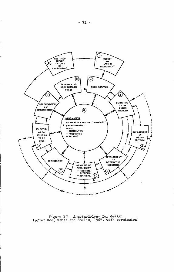
RECTIFIEDDEFECTOR LACK
ENVIRONMENT
IMPLEMENTATION
ANDCOMMLGCATION
TRANSFER TOMORE DETAILED
PHASE
OPTIMIZATION
INFORMATION
0. RELEVANT SCIENCE AND TECHNOLOGY
b. ENVIRONMENTALUSE- DISTRIBUTION- PRODUCTION- SALVAGE
DEFECTOR
LACK INENVIRONMENT
DEFINITIONOF THEDESIGN
PROBLEM
DEVELOPMENTOF
ALTERNATIVESOLUTIONS
SELECTION
OF THE
SOLUTION
1005USED
NEED ANALYSIS
IIDEVELOPMENT!
OFOESI.I
CRITERIA
- 71 -
ANALYSISFEASI OILIlY- PHYSICAL- ECONOMIC
.' f 'V'S
'SI
,755,5_S
-5--
Figure 17 - A methodology for design(after Roe, Handa and Soulis, 1967, with permission)
/
/
/////
/
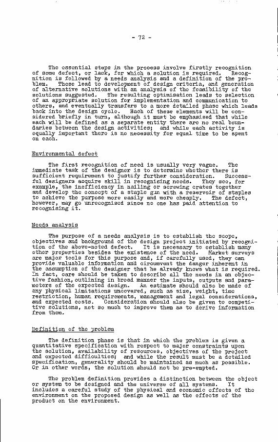
- 72 -
The essential steps in the process involve firstly recognitionof some defect, or lack, for which a solution is required. Recog-nition is followed by a needs analysis and a definition of the pro-blem. These lead to development of design criteria, and generationof alternative solutions with an analysis of the feasibility of thesolutions suggested. The resulting optimisation leads to selectionof an appropriate solution for implementation and cosimunication toothers, and eventually transfers to a more detailed phase which leadsback into the design cycle. Each of these elements will be con-sidered briefly in turn, although it must be emphasised that whileeach will be defined as a separate entity there are no real boun-daries between the design activities; and while each activity isequally important there is no necessity for equal time to be spenton each.
Environmental defect
The first recognition of need is usually very vague. Theimmediate task of the designer is to determine whether there issufficient requirement to justify further consideration. Success-ful designers acquire skill in recognising needs. They see, forexample, the inefficiency in nailing or screwing crates togetherand develop the concept of a staple gun with a reservoir of staplesto achieve the purpose more easily and more cheaply. The defect,however, may go unrecognised since no one has paid attention torecognising it.
Ieeds analysis
The purpose of a needs analysis is to establish the scope,objectives and background of the design project initiated by recogni-tion of the above-noted defect. It is necessary to establish manyother properties besides the existence of the need. Market surveysare major tools for this purpose and, if carefully used, they canprovide valuable information axd circumvent the danger inherent inthe assumption of the designer that he already knows what is required.In fact, care should be taken. to describe all the needs in an objec-tive fashion, outlining iii broad manner the inputs, outputs and para-meters of the expected design. An estimate should also be made ofany physical limitations uncovered, such as size, weight, timerestriction, human requirements, management and legal considerations,and expected costs. Consideration should also be given to competi-tive solutions, not so much to improve them as to derive informationfrom them.
Definition of the problem
The definition phase is that in which the problem is given aquantitative specification with respect to major constraints uponthe solution, availability of resources, objectives of the projectand expected difficulties; and while the result must be a detailedspecification, generality should be maintained as much as possible.Or in other words, the solution should not be pre-empted.
The problem definition provides a distinction between the objector system to be designed and the universe of all systems. Itincludes a careful study of the physical and economic effects of theenvironment on the proposed design as well as the effects of theproduct on the environment.

- 73 -
The specification itself must also include tolerance in thecharacteristics of inputs, outputs, parameters and other designvariables in order that mutual compatibility can be ensured. Theincreased understanding thereby generated may indeed require a re-evaluation of the need, a process which could result in abandonmentof the project or re-emphasis in. a different area.
Development of design criteria
This next step involves development of criteria to be used inevaluating solutions generated. It must be undertaken before thesolutions are presented otherwise there is a danger of setting upbias in favour of a particular approach. The principle is simplealthough the practice is difficult since it involves establishingprocedures for value judgements. Some of the individual criteriaare concerned with easily measurable factors such as cost, profit,performance, efficiency, reliability and compatibility with exist-ing requirements, but others are more difficult to quantify suchas safety, quality, comfort, simplicity, adaptability, etc.
The design criteria that are established provide the basis ofchoice among alternative solutions and establish the rules foroptimisation. Each consequence of the design should have anassociated criterion which may or may not be weighted in accordancewith established need. Weighting, of course, affects the ultimatesolution and it is imperative that the objectives at one level areconsistent with the criteria at another.
Development of alternative solutions
Seldom does a design problem have only one solution. Genera-tion of alternative solutions is the creative heart of the designprocess. The purpose of this phase is to generate as many solu-tions as possible. The information gained in producing them willnot only lead to an ultimate solution, but may also give a clearerunderstanding of the previous steps, even as a last resort leadingto a change in definition of the problem.
There is no stepwise approach to the generation of alternativesolutions. In fact constructive synthesis, which is the humanattribute demanded, comes harder to most people than analysis.With analysis one starts with a Imown system and breaks it downthrough logical steps. In synthesis one starts with a universe ofcomponents and attempts to create a system on the basis, all toooften, of ill-defined criteria.
Alternatives can be developed from various sources, such asthe pertinent literature, patent searches, consultation with peopleconcerned, such as workers, managers, engineers, vendors, etc.Solutions may be found by examining analogous situations from otherfields, and by substitutions combination and. rearrangement of otheralternative solutions. Sometimes it may be of value to break theproposed system into subsystems which can be treated independently,with generation of ideas for each subsystem. By no means the leastand often the most effective technique is by the use of "brain-storming" sessions where a number of concerned individuals sit down.and. in. an uninhibited and initially uncritical manner generate ideas,however wild, which in turn spur each other to produce still moreideas. These ultimately can be exmined in critical fashion at alater time.
- 74 -
Analysis of feasibility
The first of the evaluation processes used to select the mostappropriate solution is the analysis of the physical, economic andfinancial feasibility of the proposed solutions. Each solution isexamined to determine whether it can be physically realised,whether its potential utility to the user is commensurate with thecosts of making it available, whether the return on the investmentnecessary to produce the solution will be satisfactory arid whetherthere will be sufficient financial resources available for itsproduction. As with other steps in the process, feasibilityanalysis may cause a reiteration of previous activities.
Generally, when a solution appears to be workable from anover-all view, it is necessary to examine its components or parts.In fact, analysis may become centred on determining the compatibilityof components and whether there may be vital requirements which mustbe realised to make the concept practicable.
The objective is to ensure that solutions which are toreceive further attention must satisfy the design criteria whilebeing physically realisable, economically worthy and financiallyfeasible. When the analysis is completed many of the suggestedsolutions will have then been rejected; the few that remain willrequire further attention.
Optimisation
Optimisation is the process by which the optimum solution withrespect to the design criteria is selected from among the feasiblealternatives. An optimum solution is available for most if not allproblems. One of the obstructions to its achievement, however, isthe time available. Various approaches can be made to the processof optimisation such as trial and error, experimental comparison,experienced judgement, or in the case of complex systems, mathemati-cal and computer modelling.
Essentially there are two elements to the optimisation process,either or both of which may be required. One may wish to find themaximum or minimum value of some particular criterion, such asmaximum performance, maximum yield, minimum heat production, mini-mum weight, etc.; or one may wish to maximise or minimise somecriterion as much as possible within the time and resources avail-able, such as maximum aesthetic appeal, minimum wear, or some otherideal objective which can never be completely achieved. Not allcriteria are likely to be compatible in optimisation, and trade-offsmay be required where increased value in one criterion is exchangedfor decreased value in another. In fact some principle criterion,for example, reliability, may override all others.
Sometimes the process can be simplified by optimising thecomponents of the solution separately. This can be effective ifcare is taken to ensure that the criteria are compatible with theneeds of the whole system; if not, the design may be suboptimisedin favour of some component to the detriment of the design as awhole.

- 75 -
Selection of the solution.
Selection of the solution arises following the optiinisationprocess by evaluation of each of the surviving alternatives in thelight of the design criteria. Despite the narrowing process, how-ever, it may still be a difficult procedure involving subjection ofeach of the remaining solutions to a deeper and deeper analysis untilone solution becomes paramount. Final selection is in reality acontinuation of the optimisation process until a decision can bemade. Decisions can be rational or intuitive. In the design pro-cess they are preferably rational, although there is indeed a placefor intuitive decision by a skilled and experienced designer who,although making what appears to be an intuitive decision is in factbasing that decision on an informalised logic of kpowledge andunconscious observation.
Most product decisions have to be determined with some elementof uncertainty since it is necessary to combine quantitative criteriasuch as performance, weight and cost, with qualitative criteria suchas appearance, comfort and safety. The latter may involve uncertainvalue judgements which are commonly not linear.
Simple value judgements of criteria can be put on a verbalscale, such as excellent, good, satisfactory and unsatisfactory, andused in a matrix to present the data in systematic form. It isemphasised, however., that such a presentation does not make thedecision: it merely presents the information. Alternatively, aweighted decision matrix, in which a weight is assigned to eachcriterion, based on an estimate of the nature of this criterion tothe over-all criterion function, can be used with per cent valuesfor each quality, thus (the numbers here being inserted as examplesonly):
It is emphasised, however, that even when the information isrationalised to the pseudo-quantitative base the decision still hasto be made as a conscious act with or without all the facts. Ithas been said tlmt one of the greatest attribute$ of a designer isthe capacity to live with uncertainty.
Implementation and communication
Once the decision is made the implementation process starts.At this point, however, only the designer )mows the decision. Theexistence of the solution and instruction for its implementation mustbe communicated to others and acceptance of the design obtained withjustification. of the project.
Table 14: Design selection matrix (based on Love, 1973,table 3, p. 62)
Criterion (x) A B C D E Value
0.2 0.3 0.3 0.1 0.1
Design 1 100% 90% 70% 90% 50% 79
Design 2 75% 80% 60% 80% 100% 75
Design 3 60% 60% 90% 50% 50% 67
- 76 -
The approach to implementation of the design involves plans forthe physical realization of the product, with allowances for workon. critical elements which have not previously been realised, forsimplification of the design, for the construction, test and evalua-tion of engineering prototypes and for modifications to the designwhich may become necessary during its construction. The plansindeed should cover all phases of construction, prototype testing,distribution, installation, initial operation and maintenance,including the preparation of documentation, operation and servicemanuals for both the manufacturer and the operator or consumer.Not the least important should be assigned to the acquisition ofpatent protection and the rights to use already patented processesor devices.
The design project does not end with the selection of thesolution. It continues at least until the project has beenphysically realised. In the realization process several difficul-ties may arise. Previously unrealized elements merit major con-sideration. Undesirable characteristics may arise from differencebetween actual components and their ideal models. These must berecognised and dealt with. The final product should emphasisesimplicity; undue importance attached to secondary objectives maylead to an unnecessarily complex project.
Significance of ergonomicsin the design process
rgonomic pretice and principles, of course, are consideredthroughout the design process, but with respect to product designin particular, consideration should be given at this stage to anumber of questions of ergonomic significance in the followingareas:
Hazards intrinsic in the design: The physical shape and formof the object or device should be such as to minimise hazard fromsharp edges, protrusions, etc. Consideration should also be givento the effect of failure or malfunction of the product on the humanoperator or the environment, and if necessary the design should bemodified accordingly. In. this regard analysis should take intoaccount the parts or components that are critical to the operationor the integrity of the device, with the object of ensuring thatthese components can tolerate all expected conditions.
Hazards intrinsic in the environment: Consideration should begiven to the environment in which the product will be used to deter-mine whether the environment itself will affect the operation in ahazardous manner, e.g. the effect of wet or moist environments onelectrically powered tools.
Hazards inherent in usage: Consideration should be given tothe manner in which the product will be used, e.g. will it requirean awkward and potentially hazardous posture, can it release unwantedand potentially dangerous energy (thermal or electric).

- 77 -
Operational limitations: Consideration should also be givento determining to what extent the physical form (e.g. size, weight,handedness) of the product or the mode of usage (e.g. at armtslength, cramped posture) may condition the selection of the opera-tion or determine the nature of the operational procedures.
Tests should simulate the expected working environment asmuch as is feasible.
Testing of models and prototypes
The prototype and its components should be evaluated instrength, performance, durability, reliability, simplicity in useand ease of maintenance. The design can only proceed towardsproduction when all test results meet their objectives. Everyfacet of the production phase must be anticipated and every attri-bute of the design must be fully specified, usually with detailed,dimensioned engineering drawings, ready for production.
It may indeed be desirable then to enter a preproduction phasewhereby a small quantity of units is placed on the market for userevaluation, in terms o± acceptability, performance, safety andgeneral information. If so, this testing should be undertaken onformal basis, with specific surveys of the users along planned
lines, seeking answers on. performance, type of usage (in particularwhether it is used as expected and for the anticipated purpose),abuse and. its nature, structure of the user population, actualhazards and injuries, etc. This information may be used forfurther modifications.
This evaluation process, of course, should be continued afterthe unit has been marketed. No matter how carefully a product hasbeen designed some unforeseen problem will arise or the item willbe used for some purpose not anticipated, or in some circumstanceswhere it is unsuitable or even potentially hazardous.

- 78 -
R8FERENOES AND BIBLIOGBAPHY
Anon (1955): Tools, Chambers Encyclopedia, Gebrge Nenes Ltd.,London, pp. 677-680.
Anon (1974): Hand Tools and History of Agriculture, EncyclopediaBritannica, Inc., Benton, Chicago.
Astrand, P-0, RodTi1, K. (1970): Textbook of Work Physiology,McGraw-Hill Book Company, New York, New York, USA.
Axelsson, Sven-Ake (1971): Kickbacks, Noise and Vibrations inRower Chain Saws, Symposium on Ergonomics Applied to Forestry,Vol. II, Part I, pp. 55-72, International Labour Office,Geneva.
Ayoub, N., LoPresti, P. (1971): "The Determination of an OptimumSize Cylindrical Handle by Use of Electromyography",Ergonomics 14: 509-518.
Baker, P.T.,..NcKendry, J.N., Grant, G. (1960): "Volumetric Require-ments for Hand Tool Usage", Human Factors 2: 156-162.
Barter, J.T., Emanuel, I., Truett, B. (1957): "A StatisticalEvaluation of Joint Range Data", WADO Tech. Report, TN57-3ll,Wright-Patterson AFB Ohio, USA.
Basmajian, J.V. (1967): Muscles Alive: Their Function Revealedby Electromyography, Williams and Watkins, New York,New York, USA.
Baudys, N. (1969): "Protective Systems", in Electrical Safety:Portable Tools and Mobile Appliances, Occupational Safety andHealthSeries, No. 18, International Labour Office, Geneva.
Beckingeale, A.A. (1971): Electric Power Tools, Portable,Encyclopedia of Occupational Health and. Safety, Vol. 1, A-K,International Labour Office, Geneva, pp. 444-446.
Bell, A. (1968): Noise in Industry, CIS Information Sheet 17,International Labour Office, Geneva.
Bobbert, A.C. (1960): "Optimal Form and Dimensions of Hand Grips onCertain Concrete Building Blocks", Ergonomics 3: 141-147.
Brouha, L. (.1960): Physiology in Industry, Pergamon Press, New York,New York, USA.
Chapanis, A. (1974): "National and Cultural Variables inErgonomics", Ergonomics 17: 153-175.
Chavanel, A. (1971): Bolt Guns, Encyclopedia of Occupational Healthand Safety, Vol. 1, A-K, International Labour Office, Geneva,pp. 201-202.
Ccermann, R.R. (1970): "Mechanical Vibrations", in Ergonomics andPhysical Environmental Factors, Occupational Safety and HealthSeries, No. 21, International Labour Office, Geneva.
Damon, A., Stoudt, H.W., McFarland, R.A. (1966): The Human Bodyin Equipment Design, Harvard University Press, Cambridge,Mass., USA.

- 79 -
Diffrient, N., Tilley, A.R., Bardagjy, J.C. (1974): Humanscale,Harvard University Press, Cambridge, Mass., USA (Henry DreyfussAssociates).
Drake, G.R. (1974): Everyone's Book of Hand and Small Power Tools,Reston Publishing Co. Inc., Reston, Virgina, USA.
Dreyfuss, H. (1966): "People Come in Assorted Sizes", HumanFactors 8: 273-277.
Drillis, R.J. (1963): "Folk Norms and Biomechanics", Human Factors 5:427-441.
Drillis, R.J., Sc:hneck, D., Gage, H. (1963): "The Theory ofStriking Tools", Human Factors 5: 467-478.
Ducharme, R.E. (1975): "Problem Tools for Women", IndustrialEngineering, Sep., pp. 46-50.
Ely, J.H., Thomson, R.M., Orlanaky, J. (1963): "Design of Controls",in Human Engineering Guide to Equipment Design, Morgan, C.T.,Cook, J.S., Chapanis, A., Lund, M.W. (eds.), McGraw-Hill BookCompany, New York, Toronto, London.
Ford, L.J. (1961): "The Safe Design and Use of Hand Hanimer&',The Brit. J. of Indust. Safety 5: 114-116.
Gatley, W.S. (1971): "Industrial Noise Control", Mech. Engineering,pp. 29-37.
W. (1924): "Theory of Striking Hand Tools", HeraldIndustry, No. 4, Moscow (Russian).
(1971): Fitting the Task to the Man, Taylor andLtd., London, England.
Gray, H. (1974): Anatomy: Descriptive and Surgical (Gray'sAnatomy), T. Pickering Pick and R. Howden (eds.), Running Press,Philadelphia, Pa., USA.
Greenberg, L., Chaffin, D.B. (1976): Workers and Their Tools:A Guide to the Ergonomic Design of Hand Tools and Small Presses,Pendal Press Inc., Michigan, USA.
Guyton, A.O. (1971): Basic Human Physiology, W.B. Saunders,Philadelphia, Pa., USA.
Hanris, C.M. (1957): Handbook of Noise Control, McGraw-Hill Inc.,New York, New York, USA.
Her Majesty's Stationery Office (HMSO) (1969): Powered Hand Tools 1.Electric Tools, Ministry of Public Buildings and Works, AdvisoryLeaflet, No. 18, London.
Her Majesty's Stationery Office (HMSO) (1969): Powered Hand Tools 2.Pneumatic Tools, Ministry of Public Buildings and Works, No. 19,London.
Her Majesty's Stationery Office (HMSO) (1972): Report of the Commit-tee on Safety and Health at Work (Lord Robens, Chairman),London.
Gorj atscbkin,of Metal
Grandjean, E.Francis
- 80 -
Hertzberg, H.TE. (1956): Handbook of Instructions for AircraftGround Support Equipment Design, Aeromedical Laboratory,Wright-Patterson APB, Ohio, USA.
Hertzberg, H.T.E. (1956): "Size and Motion", in BioastronauticsData Book (Paul Webb (ed.)), National Aeronautics and SpaceAdministration, Scientific and TechnicaJ. Information Division,Washington, NASA SP3006, Chap. 14-9.
Hertzberg, H.T.E., Daniels, G.S., Churchill, E. (1954):"Anthropometry of Plying Persounel", WADO Tech. Report 52-321,Aeromedical laboratory, Wright-Patterson AFB Ohio, USA.
Hughes, J., Paul, J.P., Kenedi, R.M. (1970): "Control and Movementof the Lower Limb", in Modern Trends in Biomechanics (editor,J. Simpson), Butterworths, London.
Jenkins, L.J., Connor, M.B. (1949): "Some Design Factors in MakingSettings on a Linear Scale, J. Appl. Psychol. 33: 395-409.
Kaminsky, G. (1971): Environmental and Occupational Health Aspects(Climate, Noise, Vibrations, etc. , Symposium on Ergonomics asApplied to Forestry, Vol. 1, pp. 38-53, International LabourOffice, Geneva.
Keighley, G.D. (1974): "Safe Working Limits", in The VibrationSyndrome (w. Taylor (ed.)), Academic Press, London andNew York.
Konz, S. (1974): Design of Handtools, Proceedings of the 18thAnnual Meeting, Human Factors Society, Huntsville, Alabama,USA.
Laubach, L.L. (l976): "Comparative Muscular Strength of Men andWomen: A Review o± the Literature", Aviat. Space and Envir.Med. 47: 534-542.
Leaky, L.S.B. (1960): "Finding the World's Earliest Man",National Geographic 118: 420-435.
Leaky, L.S.B. (1961): "Exploring 1,750,000 Years into Man's Past",National Geographic 120: 564-589.
Leaky, L.S.B. (1963): "Adventures in the Search for Man",National Geographic 123: 132-152.
Lehmann, G. (1953): Praktische Arbeitephysiologie, Thieme-Verlag,Stuttgart, Germany.
Lindstrom, P.E. (1973): Modern Pliers, BAHCO Vertyg, Enköping,Sweden.
Love, S.F. (1970): Design Methodology; Parts 1-12, Designetics Ltd.,Waterloo, Ontario, Canada.
May, J. (1971): Hand Tools, Encyclopedia of Occupational Healthand Safety, Vol. 1, A-K, International Labour Office, Geneva,pp. 637-639.

- 81 -
McCormick, E.J. (1970): Human Factors Enineerixig, McGraw-HillBook Company, New York, New York, USA.
McFarland, R.A., Damon, A., Stoudt, H.W. (1958): "Anthropometryin the Design of the Driver's Workplace", Amer. J. of PhysicalAnthropol. 16: 1-23.
Miller, M., Harschoff, 3., Tichauer, E.R. (1971): "ErgonomicEvaluation of aRedesigned Surgical Instrument", AppliedErgonomics 2: 194-197.
Morgan, C.T., Cook, J.S., Chapanis, A., Lund, M.W. (1963): HumanEngineering Guide to Equipment Design, McGraw-Hill BookCompany, New York, Toronto, London.
Murrell, K.F.H. (1969): Ergonomics, Chapman and Hall, London,England.
Naier, J.R. (1956): "The Prehensile Movements of the Human Hand",J. Bone and Joint Surgery 38B: 902-913.
Näslund, U. (1974): "Reduction of Vibration in Chain Saws", inThe Vibration Syndrome, (w. Taylor,(ed.)), Academic Press,London and New York.
National SafetyData Sheet
National SafetyData Sheet
Council (US) (1961): On Powered Hand Tools,392 (revised), Chicago, Ill., USA.
Council (us) (1962): Power-Actuated Hand Tools,236 (revised), Chicago, Ill., USA.
National safety Council (Us) (1967): Electric Hand Saws, CircularBlade Type, Data She.et 344 (revised), Chicago, IlL., USA.
National Safety Council (us) (1972): Accident Facts, Chicago,Ill., USA.
National Safety Council (us) (1974): Accident Prevention Manualfor Industrial Operations, Chicago, Ill., USA.
Osené, AJVI., Ward, D.M. (1971): Problems of Forest Ergonomics inTropical Countries, Symposium on Ergonomics as Applied toForestry, Vol. 1, International Labour Office, Geneva,pp 90-121.
Paule, K. (1975): Personal Communication, Robert Bosch GmbH,Leinfelden, West Germany.
Petersen, D. (1971): Tecbniques of Safety Management, MeG-raw-HillBook Company, New York, Toronto, London.
Pfeffer, H. (1971): Pneumatic Tools, Encyclopedia of OccupationalHealth and Safety, Vol. 1, L-2, International Labour Office,Geneva, pp. 1083-1085.
Pheasant, S., O'Neill, D. (1975): "Performance in Gripping andTurning. A Study in Hand/Handle Effectiveness", AppliedErgonomics 6: 205-208.

- 82 -
Provins, K.A. (1975): Men, Machines and Controls, Ergonomics forIndustry 7, Information Division DSIR, State Rouse,High Holborn, London, England.
Reynolds, D.D., Jokel, 0. (1974): "Hand-Arm Vibration - AnEngineering Approach", Amer. Industr. Hyg. J'., Oct.,Pp. 613-622.
Roe, P.R., Handa, V.K., Soulis, G.N. (1967): TIe Discipline ofDesign, Allyn and Bacon, Boston, Mass., USA.
Roebuck, J.A.,Jr., Kroemer, K.H.E., Thomson, W.G. (1975):Engineering Antliropometry Methods, John Wiley and Sons,Ne York, New York, USA.
Roubal, J., Kova, S.: "Tool Handles and Control Levers ofMachines", Am. Occup. Hyg. 5: 37-40.
Schwarz, H.K. (1969): "Design and Construction Problems inElectrically Driven Tools", in Electrical Safety: PortableTools and Mobile Appliances, Occupational Safety and HealthSeries, International Labour Office, Geneva.
Sheppard, R.J. (1974): Men at Work, Charles C. Thomas,Springfield, Illinois, USA.
Snook, S.H., Ciriello, V.M. (1974): "Maximum Weights and WorkloadsAcceptable to Female Workers", J. Occup. Med. 16: 527-530.
Stewart, Alice H., Goda, D.P. (1970): "Vibration Syndrome",Brit. J. Indust. Ned. 27: 19-27.
Suggs, C.W. (1974): "Modelling of the Dynamic Characteristics ofthe Hand-Arm System", in The Vibration Syndrome (w. Taylor(ed.)), Academic Press, London, New York.
Taylor, W. (1974): The Vibration Syndrome, Proceedings of aConference on the Medical Engineering and Legal Aspects ofHand-Arm Vibration, University of Dundee, Academic Press,London, New York.
Taylor, W., Pearson, J., Kell, R.L., Keighley, G.D. (1971):"Vibration Syndrome in Forestry Chain Saw Operators",Brit. J. Indust. Med. 28: 83-89.
Tichauer, E.R. (1966): "Some Aspects of Stress on Forearm and.Hand in Industry", J. Oucup. Med. 8: 63-71.
VanCott, H.P., Kincade, R.G. (1972): Human Engineering Guide toEquipment Design, American Ixstitute for Research,Washington, DO, USA.
Vanloon, J.H. (1971): Hearing Losses of Power Saw Operators inForestry, Vol. II, Part 1, pp. 22-26, International LabourOffice, Food and Agricultural Organisation and EconomicCommission for Europe, United Nations, Geneva.
Woodson, W.E., Conover, D.W. (1966): Human Engineering Guide toEquipment for Equipment Designers, University of CaliforniaPress, Berkeley, Calif., USA.

- 83 -
APPENDIX A
CHARACTERISTICS OP COTYIMON HAND TOOLS
1. Hammers
Claw hammer
The claw hammer is used to drive nails, tacks, etc. intomaterial. The head is iron or steel with a striking face anda claw. The striking face is flat with a circular section.The two-pronged claw may be straight or curved and is used forripping or for pulling nails. Head weights vary from 0.7-4.5 kg (5-32 ounces), with handles from 28-36 cm (11-14 inches).
Bailpeen hammer
Bailpeen hammers are used in metal work for striking, forshaping metal, and for rivetting. The had has a flat facefor hammering and a spherical end for expanding or shapingmetal (peening), or for flattening a rivet. The head weighsfrom 0.3-4.0 kg (2-28 ounces) with handles from 25-40 cm(10-16 inches).
Soft-faced hammer
Soft-faced hammers are used in forming or shaping sheetmetal with minimum possible damage. The two faces of thehammer may be of different materials, e.g. rubber, wood, lead,vinyl, rawhide, fibre or copper. Heads may weigh from0.3-4.5 kg (2-32 ounces), with handle lengths from 18-38 cm(7-15 inches).
Soft-faced hammers may also be used is. the adjustmentand setting of machines and machine tools, or in drivingbushings and gears. A mallet is a special form of soft-facedhammer with a solid, but light, head, commonly rubber or wood.
Sledge hammer (sledges)
A sledge is a double-faced heavy metal headed hammer?with commonly a bevelled face of 40-75 mm (1 1/2-3 inches) indiameter, which is used, often two-handed, for heavy hammering.
2. Screwdrivers
Screwdrivers are used for inserting or withdrawing screws, orbolts with slotted heads.
(a) Standard screwdriver
A standard or conventional screwdriver has a blade2.5-30 cm (1-12 inches), or more beyond the handle. The
- 84 -
operating end is parallel to the ground and may be 3-10 mm (1/8-3/8 inches) in width. The handle end. or -the blade may besquare for driving with a wrench.
Phillips head screwdriver
A Phillips head screwdriver has a head to fit Phillipsscrews, and comprises instead of a blade, a blunt point with30 flutings. The head is made in four sizes with shaftlengths from 2.5-46 cm (1-18 inches). The sizes may bedistinguished by colour coding of the handle.
Robertson head screwdriver
The Robertson head screwdriver has a square section headmounted on the end of the shaft which fits into a square-slotted screw. The head comes in four sizes which may becolour coded at the handle.
Offset screwdriver
An offset screwdriver has a double-L shape with a headat each short end of the I. The head may be conventional orPhillips style; if conventional, the heads may be at mutualright angles. It is used in situations where working spaceis very limited.
Spiral ratchet screwdriver
The shaft of the spiral ratchet screwdriver retreats intothe handle, rotating right or left as it does so according toa selecting lever, when the handle is pushed down over theshaft. A spring restores the handle to its resting positionwhen the pressure is removed. A screw can thus be driven orwithdrawn by pumping on the handle.
Jewellerst screwdriver
A jewellers' screwdriver is a miniature, precision, all-metal driver comprising a body with four or more inter-changeable bits with sizes from 0.6-1.3 mm (0.025-0.05 inches)(often with a Phillips head). The body is cylindrical witha knurled surface and is held in a precision grip between thethumb, middle and fourth fingers. The index rests on afreely rotatory concave finger support mounted at the endopposite the head. The driver is held against the screw bythe index fingers and rotatedby the thumb and other twofingers.

- 85
3. Saws
A saw comprises a handle and a blade. The butt or wide endof the blade is in$erted into the handle. The other end is thetip. The number of teeth, or points, determine the coarseness,5 points to the inch (25 am) being coarse, and 10 points fine.
Cross-cut saw
A cross-out saw is the common carpenter's saw and isintended for cutting across the grain of the wood, although itcan. cut with the grain. The saw blade cones in lengths of40-66 cm (16-26 inches) with the width of blade being from16.5 cm (6 1/2 inches) at the butt to 40 mm (1 1/2 inches) atthe tip. The teeth are set alternately left and right, toform a kerf which encourages the removal of sawdust andprevents blocking.
Hacksaw
A hacksaw comprises a frame, a handle, and a blade, andis used to cut metal. The frame maintains sufficient tensionto stabilise the blade and is adjustable to accept 25-30 cm(10 to 12 inch) blades. There is also a free space betweenthe frame and blade of some 75-100 mm (3-4 inches). Bladescan be found with 14, 18, 24 or 32 -teeth to the 25 mm (1 inch).In general, blades with larger numbers of teeth are used forcutting thin tubing and those with smaller numbers for thicktubing. Tungsten-carbide tipped blades are used for cuttingceramics, steel and glass. The workpiece is normally fixed,or held firmly in a vise, with the blade cutting on the forwardstroke only.
Coping saw
A coping saw has a thin, narrow, flexible blade of about16.5 cm (6 1/2 inches) in length, and 3-4mm (1/8-1/6 inches)in width mounted in a spring-steel frame that allows freespace between blade and frame of about 11-18 cm (4 1/2-7 inches).The saw, because of its flexible blade with 10-20 teeth to25 mm(l inch), is used for cutting complex curves and angles.In addition, the blade can be rotated lengthwise to cut at anangle to the plane of the frame. Rotation is achieved byslightly unscrewing the handle, manually rotating the bladeto the desired position, and tightening the handle.
Bow saw
The bow saw is a large tubular metal frame saw (althoughoriginally wooden) with a blade 55-106 cm (21-42 inches) long.It is normally used for cutting trees and. logs. The teeth arecommonly coarse and may present special patterns.
86 -
(e) Miscellaneous saws
Special purpose saws are used in cabinet making and otherwoodcraft industries. These include compass saws for lightcut-out work, backsaws for use with miter boxes in makingangled joints, dovetail saws for a somewhat similar purpose,and keyhole saws for small hole cutting. Each has specialblade characteristics.
4. Wrenches (spanners)
Wrenches, 1ionin English-speaking countries as spanners, areprimarily for tightening or loosening bolts, nuts and headed screws.Some wrenches are intended to hold cylindrical section objects suchas pipes, while locking wrenches may be used as vices.
Open-end (socket) wrench
The open-end wrench is double-ended with openings onesize apart at each end. The opening size is determined by,and fractionally larger than, the fastener it is intended tofit. Openings for standard wrenches ranges from 6-28 aim(1/4-1 3/4 inches). Miniature wrenches can be obtained withmuch smaller0openings. Commonly the ends of the wrench areoffset by 15 to accommodae rotation. Wrenches may have endsoffset at 45, 60, 75 or 50 . The length of the interveningshaft is normally a function of the size of the opening,i.e. the greater the head the longer and stronger the shaft.Shafts range from 11-45 cm (4 1/2-12 inches.
Box wrench
The box wrench serves the same function as the open-endwrench, but the head completely encircles the fastener. Thewrench opening may be in hex or double-hex form with openingsranging from 6-70 mm (1/4-2 3/4 inches). Miniatures are alsoavailable.
A box wrench may be combined with an open-ended wrench ofthe same size to form a combination wrench, in which the box-end is used for continous turning and the open-end for repeatedapplication.
Adjustable wrench
An adjustable wrench has a movable and fixed jaw. Themovable jaw can be opened or closed to a given size by way of aknurled wheel wormscrew, operated by the thumb. Some modelscan be locked in a given position. Standard wrenches havejaws opening to 13-44 mm (1/2-1 3/4 inches) with handles of10-41 cm (4-16 inches). Adjustable wrenches have theadvantage of being usable for different sizes of fasteners butare never so effective as a fixed wrench of the appropriatesize.

- 87 -
Allen wrench (hex key)
The Allen wrench is L-shaped and of hexagonal section.It is used on setscrews and socket-headed screws by insertingit in-to the screw and rotating. They are commonly maintainedin sets and may even be attached to each other in a combinationtool. Sizes range from less than 0.8-50 mm (1/32-2 inches).
Nut driver
A nut driver is similar in design to a screwdriver exceptthat the bevelled head of the screwdriver is replaced by ahexagonal socket. They-come in sizes similar to screwdriversand are most commonly used in electronic assembly.
Pipe wrench (stillson wrench)
A pipe wrench is used to hold and rotate pipe, or tomove fasteners which have lost their corners. It is somewhatsimilar in structure to an adjustable wrench except that themovable jaw extends from the handle on a parallel track.The jaw surfaces are not parallel to each other; the outer, orhook jaw, has a small amount of play such that when thewrench is turned in the direction of the moving jaw the grip onthe part will tighten. Pipe wrenches are found with openingsof 0.6-15 cm (1/4-6 inches) and the handle lengths of 25-35 cm(10-14 inches) for normal usage.
Socket wrench
A socket wrench comprises a drive handle ending in asquare section plug at right angles to the plane of thehandle to which can be attached any of a variety of sockets.The handle may incorporate a ratchet which can be adjusted bya thumb switch to allow right or left rotation, and thence tofasten or unfasten a fastener. Other forms of handles maybe used including a flexible drive handle which may be usedperpendicular to the work like a nut driver or at rightangles to the work or any angle between; a sliding bardriver, or T-bar, can be used as a bar through an appropriatehole in. the socket. Other varieties exist.
Sockets plug onto the square-end of the drive which mayrange in size from 6-25 mm (1/4-1 inch) on a side. Thesocket side may be hex or double-hex, or square or double-square in form. Socket sizes range from 3 mm (1/8 inch)to as much as 80 mm (3 1/8 inches), with different combina-tions of sizes for different sizes of drive. Sockets inaddition may have different lengths, or may be plugged ontoextensions of different lengths. For especially inaccessiblesituations the socket may be connected to the drive by way ofa universal joint which allows rotation where there is other-wise lack of clearance.

- 88 -
(h) Torque-wrench
A torque-wrench is used to tighten fasteners to thelimits of a pre-established pressure. The wrench isoperated. like a socket ratchet wrench with a square drivefitting a variety of sockets. Two systems are availablein addition for determining the torque applied. lxi thetorque limiting type the previously established torque level isset on a micrometer gauge mounted in the handle. Onreaching the torque level an audible and tactual click isheard and felt. In the beam-converging scale type a pointer isdisplaced as the torque is applied. and the level is read on ascale at the pointer. A sound is heard when the pre-determinedvalue is reached.
5. Pliers
Pliers are found in a variety of forms and an even greatervariety of names, of which only a few of the more common will beconsidered here.
Combination slip-joint pliers
The combination slip-joint pliers are one of the mostcommon forms of pliers and comprise a pair of mulled jaws, apivot point or joint, and a pair of handles. They are usedfor holding, bending, cutting and a variety of other tasks.Some combination slip-joint pliers have an additional set orsets of wire cutting jaws near the pivot point. Theserration.s at the ends of the jaws are fine while those in thecentre are coarse. The centre may be hollowed to hold acylindrical object. The jaws range in opening fromapproximately 19-38 mm (3/4-1 1/2 inches) and the handlesfrom 12-25 cm (5-10 inches) for standard usage.
Channel pliers
In channel pliers the lower jaw, attached to one leg,can slide in a channel below the upper jaw and can be lockedeasily in place by engaging a torque on the lower jaw in anappropriate groove in the upper jaw. Angulation of thechannel ensures that the handles remain in usable relation-ship to each other. In this manner the opening of the jaws canbe grossly expanded, with capacities of 25-115 mxn/(l-4 1/2inches) for normal usage and handles of 16.5-40 cm (6 1/2-16 inches).
(o) End-cutting pliers (pincers)
End-cutting pliers have jaws that curve outwards in ahalf-circle to meet again with flattened knife edges. Theyare used for the cutting of wire and nails close to the work.The jaws are generally about 22 mm (7/8 inch) wide, while thetotal length, which includes the jaws, is about 20 cm (7 3/4inches).

- 89 -
(d) Needle-nose pliers
Needle-nose pliers have long tapered jaws which may bebent at an angle up to 90 from the handles. The jaws maybe 38-64 nun (1 1/2-2 1/2 inches) with a total length of thepliers of 15-20 cm (6-8 inches).
Ce) Locking pliers
A locking plier is an adjustable gripping tool which actsas a wrench or a clamp. The upper jaw is fixed; the lowerjaw is adjustable in opening by a knurled screw incorporatedin the handle. When the handles are squeezed to the closedposition the plier locks at the pre-set opening. A lockrelease lever between the two handles provides immediaterelease to the lock. The tool comes in a variety of heads,including straight-jaw and curved jaw pliers, a C-clamp, asheet metal holding tool, and a chain clamp, etc. Thetypical plier jaws are adjustable up to 32-44 mm (1 1/4-1 3/4inches) for wrench lengths of 19-25 cm (7 1/2-10 inches).
6. Chisels and gouges
Wood chisels, which are extremely sharp, are used in woodfinishing; metal chisels are used in metal cutting. Woodchisels are normally driven by hand, either in a pushing motionor by holding with one hand and striking with the other.
Wood chisel and gouge
The wood chisel comprises a flat narrow blade, a shank,and a handle. The handle is commonly made of wood, orpolystyrene, while the blade, which is continuous with theshank, is made of hardened steel. The blades have cuttingedges bevelled on the outside with a width from 3-50 aim (1/8-.2 inches) and are normally found in sets. The normal lengthof the tool is 18-23 cm (7-9 inches) although heavy chiselscan be obtained up to 40 cm (16 inches) long.
A gouge is a hollow-bladed chisel which is bevel groundboth inside and outside. They are made in sets similar tochisels.
Cold chisel
A cold chisel is an all-metal tool with a flat cuttingedge ranging in width from 5-25 mm (3/16-1 inch). The bladegives way to a shank which in turn yields to a flat expandedhead or anvil. The total length varies from 13-30 cm (5-12inches). The tool is used with a club hammer for chippingor cutting metal, stone, or concrete block.

- 90 -
Planes
A variety of planes are used for trimming and shaving wood.These are best represented by the jack plane.
(a) Jack plane
The jack plane comprises a flat smooth metal shoe(originally a wooden block) with a grasping handle at the rearand commonly a supporting knob at the front. Into the shoeis0insrted a flat narrow metal blade tilted back at an angle of15 -30 . The blade is bevelled and protrudes below thesurface of the plane to a pre-selected distance following whichthe blade is clamped in place by a lever mechanism. The depthof cut can be adjusted as required. The blade commonly variesfrom 50-60 mm (2-2 3/8 inches) in width, while the lengthvaries according to the usage. A smoothing plane has alength from 14-25 cm (5 1/2-10 inches), a jack plane, forgeneral use, has a length from 25-38 cm (10-15 inches), whilea jointer may have a length from 56-64 cm (22-25 inches).
Files
A file is a long metal tool with one, two, three or four flatfaces roughened with a pattern of teeth. It is used for shavingor removing material, commonly metal. The file ends in a shorttang or neck which is inserted into a wooden handle. Depending onthe number of faces the file may be flat, triangular, square, half-round, or round in section. The pattern of teeth may0be single cut,i.e. with parallel rows of teeth at an angle of 0°-80 to the longaxis; double-cut, i.e. with oe cut at about 45 and another on theopposite diagonal about 60 -80
; rasp cut, i.e. with repeated single,separate teeth evenly distributed; or curved cut, i.e. with curvingrows of teeth along its length. The grade or spacing of the teeth isclassified as coarse, bastard, second cut, and smooth; the file cutsaccordingly.
For some curious reason files are normally sold separately fromtheir handles which are loosely attached later. The handles arecommonly ovoid unfinished wood with a metal ferrule which fits overthe tang. A 10 cm (4 inch) handle is used for files of 7.5-15 cm(3-6 inches), excluding the tang; 11.5 cm (4 1/2 inches) for files of10-21 cm (4-8 inches); 13 cm (5 inches) for files of 15-25 cm (6-10inches); 14 cm (5 1/2 inches) for files of 20-31 cm (8-12 inches);and 15 cm (6 inches) for files of 31-48 cm (12-18 inches.
Drills
(a) Hand drills
A hand drill comprises a stabilising handle from whichleads a shank. The shank ends in a chuck into which a drillbit can be inserted and tightened in place. The chuck isrotated by a gear wheel fastened in the same plane as theshank. A handle is attached to the wheel and is turned byone hand while the other stabilises the drill. The chuckjaws will accept drill bits from 1.5 mm (1/16 inch) to6 mm (1/4 inch) which may be used for drilling wood, syntheticmaterials or metal.

- 91 -
(ID) Brace and bit
The brace is a form of drill which has an offset handlearound the shank halfway down its length. At one end of theshank is a head in the shape of a flattened dome which may bestabilised by the hand or even by leaning on it with thechest. The other end terminates iii an adjustable chuck whichmay hold bits of 6-25 mm (1/4-1 inch) in lengths of 18-25 cm(7-10 inches). The brace is operated by sweeping the offsethandle around the axis of the shank. The size of the brace isdetermined by the sweep which may be 20, 25, 30 cm (8, 10 or12 inches).
Electric powered hand tools
Drill
The electric drill comprises a handle or handles, a bodywhich contains the drive unit, and an adjustable chuck to which canbe attached a wide variety of heads including drill bits, discsander, buffer, wire brush, grinder, saw blades (circular andreciprocating), screw or nut driver, etc., and even paint sprayersand mixers.
The capacity of the chuck varies from 6 aim (1/4 inch) diameterto 18 ian (3/4 inches), the larger sizes being for industrial use.The greater the size the lower are the revolutions per minute (rpm).A 6 mm (1/4 inch) drill will rotate at up to 2,250 rpm, 10 mm(3/8 inch) up to 1,200 rpm, 12 mm (1/2 inch) up to 600 rpm, arid18 mm (3/4 inch) up to 475 rpm. The required horsepower willvary similarly from a minimum of 1/6 to a maximum of 1 or 1 1/2.Drills may be fixed speed, double speed (slow and fast) orvariable speed. A reversing switch may be incorporated into thecontrols which allows the bit to be backed out of a hole. Largedrills normally require a two-hand operation, one hand at the rearguiding and supporting the operation, a second hand (see Chapter 4)assisting in support and preventing turning of the drill. Veryheavy work may require two persons. Drill press stands and supportsare also available.
Circular saw
The circular saw, which comprises a handle and motor unitdriving a circular blade mounted parallel to the drive unit, isused for cross-cutting or ripping. It may also be used forbevelling and other special woodworking purposes.
The blade diameter normally varies from 16.5 cm (6 1/2 inches)to 20.3 cm (8 inches), requiring motors from 1 to 2 1/2 hp drivingthe saw at 4,700 to 5,200 rpm. The ensuing cuts range from50-75 mm (2-3 inches).
The saws normally incorporate an on-off switch, a retractableguard, a means of lowering or raising the blade t8 control thedepth of cut, and a base that can be tilted to 45 for bevel cuts.

- 92 -
Several different types of blade may be used. The commonblade is the all-purpose which is self-explanatory. Planer bladesproduce very smooth cuts, cutoff blades are specifically forcross-cutting, rip blades for rip sawing. Other special purposeblades are available including for example a carborundum blade forcutting masonry and concrete blocks.
Reciprocating and sabre saws
Reciprocating and sabre saws use the same principle, namelythat the motor is used to drive a long thin blade backwards andforwards rather than to rotate a circular blade.
The reciprocating saw is the larger and operates in thehorizontal direction, whereas the sabre saw operates vertically.The reciprocating saw can be used for heavy work, for examplecutting logs, metal, or masonry. The blades are of many differenttypes according to requirement, ranging in length from 7.5-30 cm(3-12 inches) with strokes from 10-32 mm (3/4-1 1/4 inches), drivenby a 1/4 hp motor. The number of teeth vary from 3 to 32 per25 mm (1 inch), the lower number being used for wood and the higherfor metal. Motor speeds vary from 1,600 to 2,400 strokes perminute.
The sabre saw is lighter and smaller, and may be found as anattachment to a power drill. like the drill, its operation may befixed speed, two speed, or variable speed, ranging from 0 to3,500 strokes per minute and driven by a 1/4 to 1/2 hp motor.
As already noted the saw operates on the vertical 1ane, butby adjusting the base plate it can be tilted through 45 left orright.
A wide variety of different blades are available to meetdifferent requirements. Blades range in length from 7.5-11.5 cm(3-4 1/2 inches) producing cuts of 25-42 mm (1-1/5/8 inches) inwood, depending on the variety, and 6 mm (1/4 inch) in steel. Thesaw can be used to cut curves.
Sander
Three types of sander are found, namely belt sanders, discsanders, and finishing sanders. The belt sander is used forheavy, coarse work, including removing of unwanted material(normally wood), paint, and stain.
It comprises a continuous abrasive-coated belt, sliding overtwo drums mounted on the base of a rectangular frame which housesthe motor. Commonly there is a rear "pistol grip" type of handleabove and. at the back of the motor, and a front knob for the palmof the other hand. The rear handle incorporates a trigger and isused for directing the sander. The front knob is used forstabilising and applying pressure. The belt is normally driven fromthe rear drum, the front drum idling. The belt tracks across asanding plate such that the belt moves between the sanding plateand the workpiece. The plate is approximately 100 x 150 mm(4 x 6 inches) and the belt is driven by a 3/4 to 1 1/2 hp motor atapproximately 400-500 metres (1,200-1,500 feet) per minute.Normally the belt is 75 mm (3 inches) wide. It is replaceable.

- 93 -
The disc sander, as the name would imply, comprises anabrasive disc which rotates around a, central point. It is usedfor general rough purposes and also as a polisher. It has apopular use in vehicle metal body work. The abrasive die, often mademade of heavy paper coated with abrasive material, is mounted bybolting it at the centre point or attaching it with adhesive to arubber or fibre backing pad, which in turn is mounted on a spindleattaching it to the motor drive. The drive may be in-line oroffset. The disc varies with the size of the sander and mayrange from approximately 125-180 aim (5-7 inches) in diameter.The motor ranges in size from 7/8 to 1 1/2 hp, with speeds up to5,000 rpm.
The finishing sander which is used for fine finishing workon wood, metal, or plastic, may be of the orbital, or the straightline type, or a combination of both. Straight line sandersoperate in a forwards and backwards mode at about 14,000 strokesper minute, driven by a 1/6 hp motor. Orbital sanders operate,without rotation, in an orbital path of about 4.5 cm (3/16 inches)at about 4,000 cycles per minute.
The abrasive paper is mounted over a rubber or fibre platen,rectangular in form, above which is the motor and handles, apistol grip at the rear and a Imob at the front. Two commonsizes of abrasive paper are found, one of approximately 9 x 23 cm(3 5/8 x 9 inches), and the other of approximately 11.5 x 28 cal(4 1/2 x 11 inches), fitting over platens of slightly smallerlong dimension to which they are clamped at each end.
There is a variety of abrasive material available forsanders, depending on the purpose for which they will be used,including silicon carbide for cutting metals and plastics,garnet and flint for wood, emery for metal polishing and pumice foruse with linseed oil in special finishes. The papers (whichindeed may be made of cloth, fibre or plastic) come in a varietyof grades of coarseness from extra coarse to extra fine. Thedegree of coarseness is classified in size, or grit number.
The foregoing represents a wide variety of common hand andportable power tools, most if not all of which may already befamiliar to many readers. The selection is not intended to beall-comprehensive although it covers most of the tools used forordinary purposes. Those who might wish access to illustrationsof a much wider list of tools are referred to the IllustratedList of Workshop Tools and Equipment (1975) available from theUNICEF Packing and Assembly Centre (UNIPAC) in Copenhagen andprepared by the International Labour Office, or to variouscommercial catalogues.