epoxy/2d materials aerogel composites with multifunctional
TRANSCRIPT

Epoxy2D materials aerogel composites with
multifunctional properties
A thesis submit to
The University of Manchester
for the degree of
Doctor of Philosophy
in the
Faculty of Science and Engineering
2021
Pei Yang
Department of Materials
School of Natural Sciences
2
Contents
Contents 2
List of Tables 6
List of Figures 8
List of Abbreviations 18
List of Pubilications 19
Abstract 20
Declaration 21
Copyright 22
Acknowledgments 23
1 Chapter 1 Introduction 24
11 Polymer materials 24
12 2D materials 25
121 Graphene 25
122 MXene 27
123 Other 2D material 29
13 Polymer nanocomposites 29
131 Nanocomposites with 2D materials 30
132 Epoxy2D materials based nanocomposites 30
133 Aims and objectives 31
2 Chapter 2 Literature Review 36
21 Preparation of 2D materials-based aerogel 36
211 Hydrothermal reduction method 36
212 Cross-linking method 40
213 Chemical reduction method 42
214 Ice-template method 44
22 Preparation of 2D materials aerogel-based polymer nanocomposites 51
3
221 Dip coating 51
222 Casting approach 52
223 Electrostatic spray deposition 52
224 Vacuum infiltration technique 53
23 Properties of 2D aerogel-based polymer composites 54
231 Electrical properties 54
232 Thermal properties 56
233 Joule heating properties 60
234 Mechanical properties 62
235 Other properties 64
24 Potential application of 2D materials aerogel-based polymer composites 65
25 Conclusion 66
3 Chapter 3 Ice-templated hybrid graphene oxide - graphene nanoplatelet lamellar
architectures with tunable mechanical and electrical properties 67
31 Introduction 67
32 Materials and methods 69
321 Materials 69
322 Synthesis of Graphene Oxide 69
323 Production of the rGO-GNP Aerogels 71
324 Zeta potential characterisation 72
325 Morphylogy and microstructure 72
326 Electrical properties 73
327 Mechanical properties 73
33 Results and Discussion 73
331 Rheology of suspension as a function of chemical reduction time 73
332 Production of areogels 76
34 Conclusion 86
4 Chapter 4 rGOGNP aerogel based epoxy composites for Joule heating applications
88
4
41 Introduction 89
42 Experimental methodology 90
421 Materials 90
422 Synthesis of aerogel composite 90
423 Joule heating characterisation 92
424 Morphology and structure 93
425 Electrical and thermal properties 93
426 Mechanical properties 94
43 Results and discussions 94
431 Morphological and structural analysis 94
432 Electrical properties 96
433 Thermal properties 98
434 Joule heating properties 100
435 Mechanical properties 104
44 Conclusion 107
5 Chapter 5 Hierarchical graphene aerogel interpenetrated-carbon fibre polymer
composites 109
51 Introduction 109
52 Experimental 111
521 Materials 111
522 Preparation of the reduced graphene oxide aerogel reinforced carbon fibre
(rGOA-CF) composites 111
523 Joule heating characterisation 113
524 Morphology and microstructure 113
525 Electrical properties 113
526 Mechanical properties 114
53 Results and discussion 114
531 GO and rGO powders 114
532 GOA-CF and GOA-CFEP composites 115
5
533 Electrical properties 118
534 Joule heating properties 120
535 Fracture toughness enhancement of the composites 121
54 Conclusion 125
6 Chapter 6 Epoxy resinTi3C2Tx MXene Aerogel Composites for Electrothermal
Applications 127
61 Introduction 127
62 Experimental section 128
621 Materials 128
622 Preparation of Ti3C2Tx 128
623 Preparation of 3D Epoxy resinTi3C2Tx MXene Aerogel composites 129
624 Joule heating characterisation 131
625 Morphology and microstructure 132
626 Electrical properties 132
63 Result and Discussion 133
631 Morphological analysis 133
632 X-ray diffraction studies 134
633 Electrical conductivity 135
634 X-ray photoelectron spectroscopic result 137
635 Joule heating characteristion 140
64 Conclusion 149
7 Chapter 7 Conclusions and Future Work 151
71 Conclusions 151
72 Future work 156
References 158
6
List of Tables
Table 2-1 Summary of properties and applications of 2D materials aerogel based polymer
composites 66
Table 3-1 Summary of processing parameters samples density samples volume shrinkage
(before and after freeze dry) and XPS spectroscopy result of C1s spectra and O1s
spectrum for CR0 CRtTR300 and CR60TR800 aerogels 77
Table 4-1 Summarized sample loading and starting graphene suspension concentration
91
Table 4-2 Electrical conductivities of EGAC samples compare with reported graphene-
basedEP composites 98
Table 5-1 Density of CFEP Oven-dried GO-CFEP GOA-CFEP and rGOA-CFEP
composites 117
Table 5-2 Electrical conductivities of rGOA-CFEP compare with reported graphene-
basedCF composites 120
Table 5-3 Mechanical properties of rGOA-CFEP compare with reported graphene-
basedCF composites 124
Table 6-1 Extracted fitting parameters of epoxy resinTi3C2TX aerogel composite before
Joule Heating test 139
Table 6-2 Extracted characteristic parameters (120591 g 120591 d and hr+c) for the Joule heating
performance of epoxy resinTi3C2Tx aerogel composite at different applied voltages
146
Table 6-3 The extracted parameters from XPS analysis of bare Ti3C2TX MXene aerogel
and epoxy resin Ti3C2TX MXene aerogel composite 149
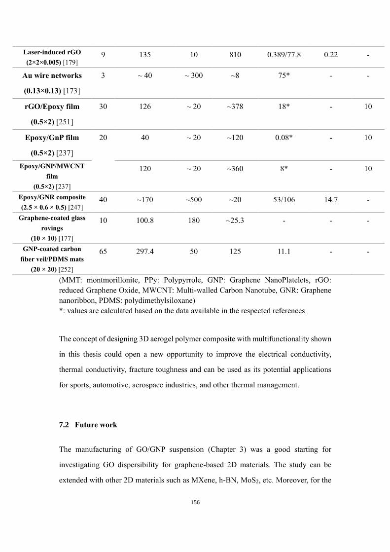
Table 7-1 Joule heating properties comparison between rGOGNP aerogel epoxy
composites and MXene aerogel epoxy composites 153
Table 7-2 Joule heating features of epoxy resingraphene-based aerogel composite with
reported electrothermal materials (l length b breadth and h height) 154
Table 7-3 Joule heating features of Ti3C2TX aerogel and epoxy resin Ti3C2TX MXene-
7
based aerogel composites with reported electrothermal materials (l length b breadth
and h height) 155
8
List of Figures
Figure 11 Molecular structure of epoxide group 24
Figure 12 (a) Different kinds of the studies 2D nanomaterials[8] (b) Research
development of 2D nanomaterials[9] 25
Figure 13 A molecular model of a single layer of graphene[10] 26
Figure 14 (a) General schematic of the explanation of the formation of MXene from the
corresponding MAX phases [25] (b) Schematic of the process of Mo2CTx synthesis
by etching the selected two Ga layers from Mo2Ga2C (purple green brown red and
white represent of Mo Ga C O and H atom respectively) (c) SEM images of
MXene flakes[20] 28
Figure 21 (a) Photographs of 2 mgmL GO dispersion before and after hydrothermal
reduction at 180 degC for 12 h (b) photographs of GO hydrogel allowing easy handling
and supporting weight (c-e) SEM images with low and high magnifications of rGO
hydrogel microstructures (f) room temperature I-V curve of the rGO hydrogel
exhibiting Ohmic characteristic (insert for showing a two-probe method for the
conductivity measurements)[60] 37
Figure 22 XRD patterns of natural graphite (black) GO (blue) and freeze-dried rGO
aerogel[60] 38
Figure 23 (a) Poissonrsquos ratio in the air as a function of applied strain in the axial direction
(b) Poissonrsquos ratio with a function of numbers of compression and release cycles
along the axial direction (Blue and black are Poissonrsquos ratios when the aerogel is in
air and acetone respectively) (c) The Schwartzite model for sp2-carbon phases used
for the Poissonrsquos ratio modelling[76] 39
Figure 24 (a) Fabrication process for the 3D Fe3O4N-GAs catalyst stable suspension of
GO iron ions and PPy dispersed in a vial (b) Fe- and PPy-supporting graphene
hybrid hydrogel prepared by hydrothermal self-assembly and floating on water in a
vial and its ideal assembled model (c) monolithic Fe3O4N-GAs hybrid aerogel
obtained after freeze-drying and thermal treatment (de) typical SEM images of
9
Fe3O4 N-GAs revealing the 3D macroporous structure and uniform distribution of
Fe3O4 NPs in the GAs(f) schematic diagram of the morphological formation of
highly porous Gas[82ndash84] 40
Figure 25 (a) Photographs of the processing for ultralight N-doped rGO aerogels (b) SEM
image for rGO aerogels (c) electrical conductivity of rGO aerogel with the functional
of compressive force[87] 41
Figure 26 Schematic presentation of the synthesis procedure for the glucose strutted
graphene aerogel paper[93] 42
Figure 27 (a) Digital photos of the aqueous suspension of graphene oxide (b) heating the
mixture of graphene oxide and Vitamin C without stirring (c) The final aerogel after
CO2 dried (left) and freeze-dried (right) (d) A 71 mg graphene aerogel pillar with
the diameter of 062 cm and the height of 083 cm supporting 100 g counterpoise
more than 14000 times its own weight[98] 43
Figure 28 SEM images of supercritical CO2 dried (a) and freeze-dried (b) graphene
aerogels and typical nitrogen sorption isotherms (c) BJH (BarretndashJoynerndashHalenda)
desorption pore size distribution (d) of these graphene aerogels[85] 44
Figure 29 (a) Qualitative schematic of the relationship between nucleation and crystal
growth as a function of freezing temperature during ice solidification (b)
Performance of water absorptionresistance on the cross-section of a sponge[103]
45
Figure 210 (a) Parallel to freezing direction and (b) top view (perpendicular to freezing
direction) of a GO-PN fabricated by freeze casting of GO-sus (c) Foam-like porous
networks fabricated by using high concentrated oil-in-water emulsions (75 vol )
and (d) hybrid foam-lamellar structure fabricated through the freeze casting of oil in
water emulsions with low oil content (25 vol ) (e) A lamellar GO-PN produced
from GO-sus of the same density (5thinspmgml) as those used for samples shown in (ab)
but using smaller GO flakes (lt2thinspμm) than (ab) (20ndash60thinspμm) (f) An rGO-PN network
after the heat treatment at 1223K[105] 46
Figure 211 Illustration of a radiating graphene oxide aerogel fabricated by bidirectional
10
freezing (a) Scheme of the fabrication process (b) The freezing set up for making
the radiating structure has a copper rod with its upper surface hollowed out (c) Two
temperature gradients are induced by the upper copper mold (d) Model of the ice
crystals growing along with radial directions because of the two temperature
gradients The orange sheets represent the dispersed graphene oxide sheets[106] 47
Figure 212 Optical and SEM images of GO aerogels made by adding different additives
and comparison of BDF with conventional freezing methods (a) Ultralow density
(69 mg cmminus3 ) rGO aerogel made by adding ethanol during freezing standing on
grass (b) rGO aerogel with a weight of 27 mg can sustain 290 g of iron blocks (c)
rGOcellulose nanofiber (CeNF) nanocomposite aerogel with an obvious radiating
pattern on its surface (d) GOchitosan aerogel without chemical reduction one can
also see the texture on the surface (e) SEM image of the rG-OCeNF nanocomposite
aerogel (fg) SEM images of GOchitosan aerogels even a spiral pattern can be
obtained (hminusj) Illustrations comparing BDF and conventional freezing methods
using three cylindrical molds projected to the plane of the paper[106] 48
Figure 213 Schematics and images of the fabrication strategy to produce Ti3C2Tx
aerogels and supercapacitor electrodes by using three different approaches From the
top left of the image following the arrows optical photographs and SEM images of
Ti3AlC2 particles the image of the mold on top of the freeze caster containing the
Ti3C2Tx suspension (aqueous suspensions is schematically illustrated) and
corresponding SEM image of a few layers sheet unidirectional freeze-cast sample
inside the mold (schematic of the microstructure formation during ice crystal growth)
optical photographs and SEM images of electrode layers in the form of as-prepared
MA (lamellae architecture formed within the aerogel is schematically illustrated)
pressed (P-MA) and rolled Ti3C2Tx aerogel (R-MA) The range of electrode densities
(ρ) achieved by each approach is also indicated The red vectors inserted in the SEM
images indicate the freezing direction[107] 50
Figure 214 (a-d) Processing of dip-coating method for graphene aerogel-polymer
composites[110] 52
11
Figure 215 Schematic of the electrostatic spray coating process[111] 53
Figure 216 The processing of vacuum infiltration technique (UGA Unidirectional
graphene aerogel)[52] 53
Figure 217 (a) Electrical conductivities of GAepoxy composites as a function of GO
concentration (b) DC electrical conductivities of GAepoxy composites in the
alignment direction and transverse to it [112] 54
Figure 218 The electrical conductivity of NOGA-epoxy composites in orthogonal
directions at different NOGF content[113] 56
Figure 220 Scheme of thermal and electron transport in composites reinforced with 1D
2D and 3D graphene foam[110] 56
Figure 221 Thermal conductivity of PI and 035 wt graphene aerogelPI at 150 degC and
PDMS and 07 wt graphene aerogelPDMS at 85 degC[110] 58
Figure 222 Thermal conductivity vs filler content of Polyamidegraphene aerogel
Multigraphene flakesPDMS Multigraphene flakesgraphene aerogelPDMS[110]
59
Figure 223 Thermal conductivity of raw BN epoxy composites raw BN-rGO epoxy
composites and 3D BN-rGO epoxy composites with different filler loading [119]
60
Figure 224 (a) Heating profiles of GrFminusPDMS composite as a function of increasing
currents (at room temperature 25 degC) (b) Heating profile of the 01 vol
GrFminusPDMS composite at room temperature and input current of 04 A (c) Schematic
representation of restricted phonon transport is poorly dispersed conductive filler
composites vs uninterrupted phonon transport in GrF[120] 61
Figure 225 Joule heating test for 3D MXene aerogel-based polymer composites [109]
62
Figure 226 Mechanical properties of GA-epoxy composites (a) Flexural modulus and
strength and (b) fracture toughness of GA-epoxy composites as a function of
graphene content[113] 63
Figure 227 Typical SEM images of fracture surface for (a) neat epoxy and epoxy
12
composites with (b) 004 vol (c) 011 vol and (d) 022 vol UL-UGA aligned
against the crack plane (e) fracture toughness of UL-UGA and S-UGAepoxy
composites SEM image of fracture surface of S-UGA composite with (f) 016 vol
(g) 004 vol (h) 007 vol and (i) 011 vol of UL-UGA[112] 64
Figure 31 Schematic of the processing route towards rGO-GNP lamellar aerogels (First
row schematic of processing route for rGO-GNP lamellar aerogels Second row
Details of processing from frozen structure to rGO-GNP lamellar aerogel) From left
to right GNP is incorporated into GO aqueous suspensions via shear mixing the
GO-GNP suspensions are partially reduced with L-ascorbic acid at 50 degC for different
times t these are subsequently freeze casted and dried to form lamellae structures
templated by the ice crystals after a freeze-drying step the aerogels are subjected to
a final thermal treatment at 300 and 800 degC in Ar 69
Figure 32 SEM images of (a) graphene oxide (GO) flakes and (c) graphene nanoplatelet
(GNP) flakes (both with flakes width distribution) 70
Figure 33 AFM images of (a) graphene oxide (GO) flakes and (b) graphene nanoplatelet
(GNP) flakes 71
Figure 34 Digital images of GO-GNP suspensions as-prepared CR0 (a) after 35 min
CR35 (b) and after 60 minutes CR60 (c) of the chemical reaction Insets show a
magnified digital image of a droplet of the respective suspension on a 45deg inclined
glass slide after 60 minutes 74
Figure 35 (a) Viscosity (Shear rate at 1 S-1) and (b) as-measure pH value of GO-GNP
suspensions for different chemical reduction time (at 50 degC) The pH value of a
suspension upon the addition of with no chemical reduction step is indicated with the
half-filled symbol in (b) The corresponding zeta potential values of GO-GNP
suspensions at 5 35 and 60 min of reaction is indicated in (b) 74
Figure 36 Zeta potential distribution for as made of GO-GNP GNP and GO suspensions
as a function of the buffer solution pH 76
Figure 37 (a) Photograph of different shape CRtTR300 aerogels produced by the
developed route (b) SEM images of the cross-section perpendicular to the freezing
13
direction of CR0TR300 (c) the cross-sections perpendicular to the freezing direction
with higher magnification (d) cross-section parallel to the freezing direction (e)
SEM images of the cross-section perpendicular to the freezing direction of
CR35TR300) (f) the cross-section perpendicular to the freezing direction with
higher magnification (g) cross-section parallel to the freezing direction (Red circles
and arrows in the images indicate the freezing direction) 78
Figure 38 SEM images of (a) cross-section perpendicular to the freezing direction of
rGOTR300 (b) cross-section parallel to the freezing direction of rGOTR300 (c)
cross-section perpendicular to the freezing direction of CR60TR300 (d) cross-
section parallel to the freezing direction of CR60TR300 the cross-section
perpendicular to the freezing direction with higher magnification (g) cross-section
parallel to the freezing direction Red circles and arrows in the images indicate the
freezing direction 79
Figure 39 (a) Raman spectroscopy patterns for CRtTR300 aerogels with rGO region
(CR0TR300 CR35TR300 and CR60TR300 aerogels) and starting GO and GNP (b)
IDIG ratio (Intensity ratio of D band and G band from Raman spectroscopy) for
CRtTR300 aerogels with rGO region as a function of partial chemical reduction time
(c) XPS survey spectra were undertaken on CR0 and CRtTR300 aerogel samples
(CR0TR300 CR35TR300 and CR60TR300 aerogels) starting GO and GNP 81
Figure 310 XPS spectroscopy results for samples (a) CR0 (b) rGOTR300 samples (c)
CR35TR300 samples and (d) CR60TR300 samples 82
Figure 311 Water contact angles for rGO (rGOTR300) and rGO-GNP aerogels
(CR0TR300 CR35TR300 and CR60TR300) 83
Figure 312 (a) Compressive stress-strain curves of CRtTR300 aerogels (b) Compressive
modulus and strength of CRtTR300 aerogels for different chemical reduction times
(c) Electrical conductivities of CRtTR300 aerogels for different chemical reduction
times 84
Figure 313 The electrical conductivity of CRtTR300 (with t minutes chemical reduction
and 300 degC thermal reduction for 40 minutes at Ar atmosphere) CRtTR800 (with t
14
minutes chemical reduction and 800 oC thermal reduction for 40 minutes at Ar
atmosphere) and rGO-EEG CRtTR800 (GO with electrically exfoliated graphene at
t minutes chemical reduction and 800 oC thermal reduction for 40 minutes at Ar
atmosphere) (a) and compressive modulus of CRtTR300 samples (with t minutes
chemical reduction and 300 oC thermal reduction for 40 minutes at Ar atmosphere)
developed in this work in comparison to literature values for other nanocarbon-based
materials Reduced-graphene cellular network[161] CNT foam[162] reduced
graphene-based aerogel[99] CVD graphene foam[163] graphene elastomer[153]
3D printed graphene[164] 3D graphene macroassembly[99] 3D printing
graphene[165] GO aerogel[106] rGO-GNP hydrogel[166] and rGO
aerogel[104153167168] 85
Figure 314 The electrical conductivity of CRtTR300 samples 86
Figure 41 Schematic of aerogel composite preparation Circular images represent the
scanning electron micrograph of original samples 92
Figure 42 Morphology of aerogel composites scanning electron micrographs of (a) GA-
2 (b) GA-10 the fracture surface of (c) EGAC-2 and (d) EGC-2 95
Figure 43 Raman mapping of graphene G peak (2866 cm-1) with respect to the CH-
deformation peak of epoxy of EGAC-2 (1248 cm-1) (b) Raman spectra of epoxy
GNP and as-synthesized GO 96
Figure 44 Electrical properties of aerogel composites (a) Electrical conductivity for neat
epoxy GA-2 EGAC-2 and EGC-2 with the function of frequency (b) Electrical
conductivity of EGAC with functional of graphene loadings 97
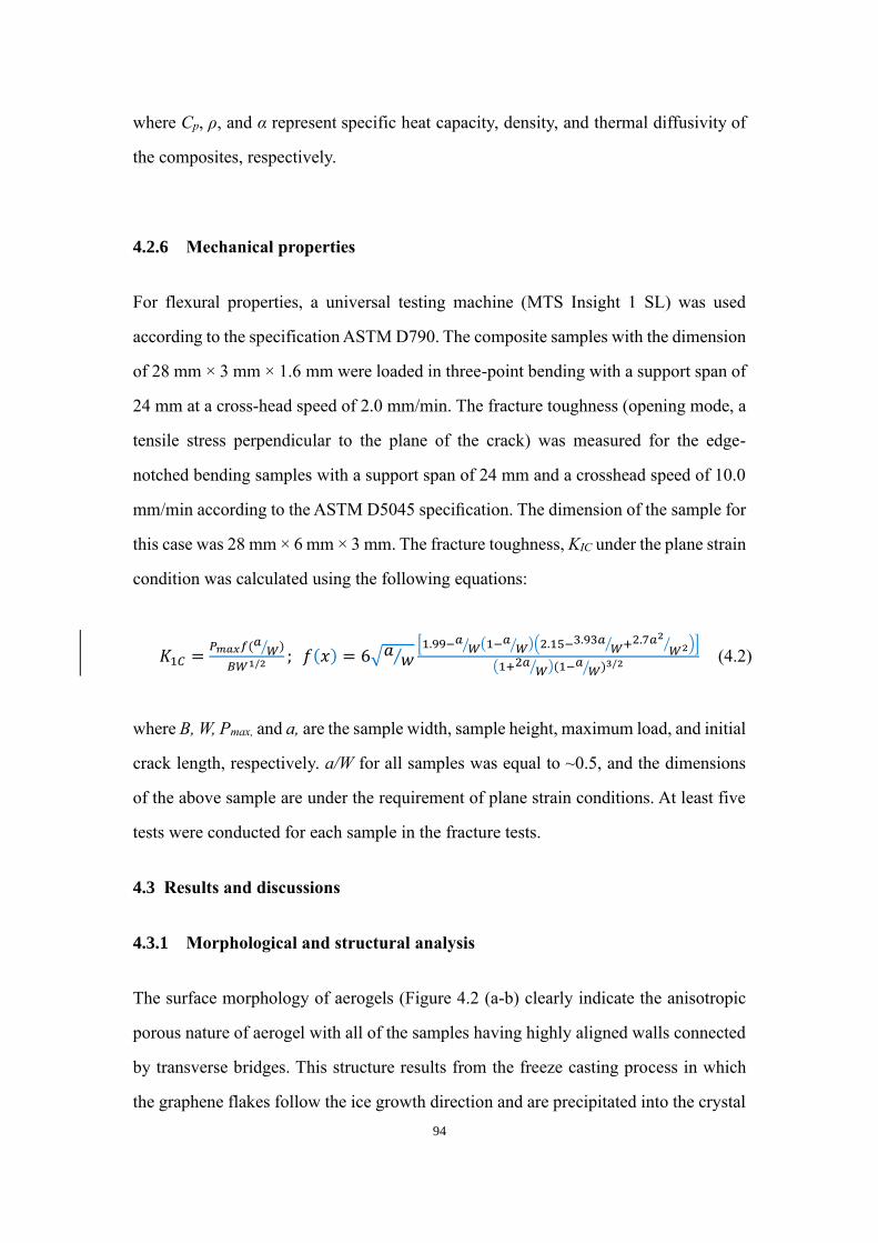
Figure 45 Thermal properties of aerogel composites (a) DSC and (b) TGA of EGAC
with EGC and epoxy 99
Figure 46 Thermal properties of aerogel composites (a) Thermal conductivity and
thermal diffusivity of EGACs with neat epoxy 100
Figure 47 Joule heating properties of aerogel composite (a) Surface temperature versus
time showing the heating zone steady-state zone and cooling zone of aerogel
composites at an applied voltage of 5 V IR images of (b) EGAC-2 (c) EGAC-6 (d)
15
EGAC-8 and (e) EGAC-10 at steady-state zone (f) temperature line profile on spatial
variation of a thermal image of aerogel composites (g) current-voltage-power
relationship for EGAC-10 (h) steady-state temperature vs applied voltage for
EGAC-10 with fitting by quadratic equation and (i) cycle test of EGAC-10 at an
applied voltage of 5V 102
Figure 48 (a) plot of steady-state temperature with electrical conductivity of EGACs (b)
plot of steady-state temperature with thermal conductivity of EGACs (c) Radar plot
of thermal conductivity electrical conductivity and Joule heating performances of
EGAC with respect to the different GNP-content (d) Comparison plot of intrinsic
properties of EGACs with other reported aerogels The data of other aerogel are taken
from the Ref [196] 104
Figure 49 Mechanical properties of aerogel composites Flexural modulus flexural
strength and fracture toughness of neat epoxy and EGACs 105
Figure 410 Scanning electron micrograph of fracture surface for (a) neat epoxy (b-c)
EGAC-4 with different magnification and (d) EGAC-10 107
Figure 51 Schematic illustration of GOA reinforced CFEP composites preparation 113
Figure 52 (a) SEM image of GO flakes from dispersions obtained by drop-casting (b)
GO flakes width distribution (c) AFM image of GO flake from dispersion obtained
by drop-casting (d) Height profiles of the selected section labelled as 1 in Figure (c)
114
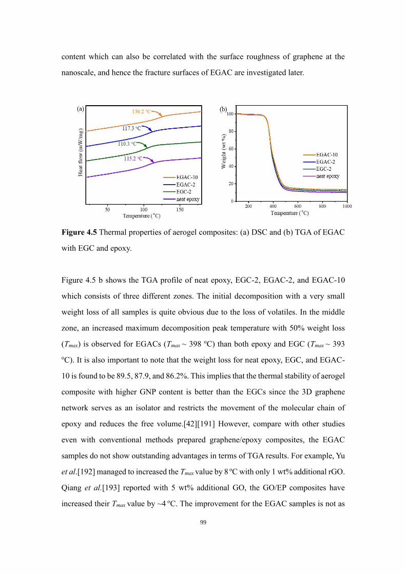
Figure 53 (a) Raman spectroscopy patterns for GO powders and rGO powders (b) XPS
spectroscopy for GO powders and rGO powders 115
Figure 54 SEM images of (a) pure CF (b) High and (c) low magnification of GOA-CF
respectively (d) Oven-dried GO-CF (Yellow arrows indicated the fiber direction and
red arrows indicated freeze direction) 116
Figure 55 Log-log plot of specific conductivity as a function of frequency for CFEP
GOA-CFEP rGOA-CFEP and oven dried GO-CFEP composites (a) in-plane
direction (b) out-of-plane direction and electrical conductivities at the frequency of
1 Hz for CFEP GOA-CFEP rGOA-CFEP and oven dried GO-CFEP composites
16
(c) in-plane direction (d) out-of-plane direction (e) Schematic description of
the x y and z directions in the specimens 118
Figure 56 Mechanical test for CFEP oven-dried GO-CFEP GOA-CFEP and rGOA-
CFEP composites (a) loading vs crack displacement (b) Normalized K1c and G1c
value by volume fraction (c) Schematic diagram of the three-point bending toughness
test 121
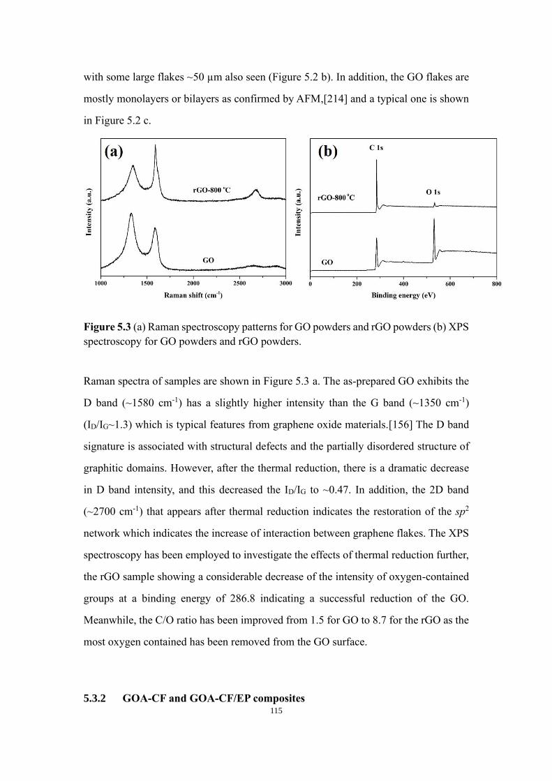
Figure 57 SEM images of fracture surface for (a) neat epoxy (bc) GOA-CFEP
composites (arrow indicate fracture direction) and (d) CFEP composites 123
Figure 58 Schematic diagram of the crack propagation and suppression behaviour of (a)
CFEP laminate (b) GOA-CFEP laminate (c) oven-dried GO-CFEP 124
Figure 61 Schematic of 3D epoxy resinTi3C2TX MXene aerogel composite formation
130
Figure 62 Digital images of (a) epoxy resinTi3C2TX aerogel composite (b) Ti3C2TX
aerogel before Joule heating Digital images of (c) epoxy resinTi3C2TX aerogel
composite and (d) Ti3C2TX aerogel during the Joule heating 131
Figure 63 (a) Scanning electron micrographs of fracture surface of (a) bare Ti3C2TX
aerogel and (b) epoxy resinTi3C2TX MXene aerogel composite 133
Figure 64 X-ray micro-CT of the epoxy resinTi3C2TX MXene aerogel composite
showing a cross-sectional view (left) and a 3D segmented view of a region of interest
(middle and right) showing sheets oriented within a single domain Red vectors
indicate the freezing direction The Yellow dashed box indicates a region of interest
134
Figure 65 (a) XRD patterns of delaminated Ti3C2Tx and Ti3C2Tx aerogel with its MAX
phase Plots of electrical conductivity of epoxy resinTi3C2TX aerogel composite and
Ti3C2Tx aerogel with respect to the (b) frequency and (c) temperature 136
Figure 66 X-ray photoelectron survey spectra of Ti3C2TX aerogel and epoxy resin
Ti3C2TX aerogel composite 138
Figure 67 High-resolution XPS of Ti2p C1s O1s and F1s peaks of epoxy resinTi3C2TX
MXene aerogel before Joule heating test 138
17
Figure 68 Steady-state thermal IR images of epoxy resinTi3C2TX aerogel composite held
at different input voltages of (a) 1 V (b) 125 V (c) 15V (d) 175V (e) 2V and (f) 3
V and Ti3C2TX aerogel at different voltage of (g) 1 V (h) 15 V and (i) 2 V 141
Figure 69 Temperature line profile on spatial variation of thermal image (a) epoxy
resinTi3C2TX MXene aerogel composite and (b) Ti3C2TX Mxene aerogel at an
applied voltage of 2V 143
Figure 610 Plots of (a) Temperature versus time and (b) rate of change of temperature
versus time of the epoxy resin Ti3C2TX MXene aerogel composite at different
applied voltages (c) Heating and cooling rate (solid line is guide to the eye only) and
(d) specific power of composite with respect to the applied voltage 145
Figure 611 (a) Prolonged steady-state phase and (b) Cycle test at the applied voltage of
2 V of bare MXene aerogel and epoxy resin Ti3C2TX MXene aerogel composite (c)
cycle profile of temperature for the epoxy resin Ti3C2TX MXene aerogel composite
at different applied voltages 147
Figure 612 Cycle test at an applied voltage of 2 V of (a) bare MXene aerogel and (b)
epoxy resin Ti3C2TX MXene aerogel composite 148
18
List of Abbreviations
0D Zero dimensional
1D One dimensional
2D Two dimensional
3D Three dimensional
AFM Atomic force microscopy
SEM Scanning electron microscope
CB Carbon black
CNT Carbon nanotube
GO Graphene oxide
rGO Reduced graphene oxide
GA Graphene aerogel
CFs Graphene foams
CVD Chemical vapour deposition
hBN Hexagonal boron nitride
MoS2 Molybdnum disulphide
MWCNT Multi-wall carbon nanotubes
GNP Graphene nanoplatelets
PA Polyamide
TGA Thermogravimetric analysis
XRD X-ray diffraction
XPS X-ray photoelectron spectroscopy
DMTA Dynamic mechanical thermal analysis
DSC Differential scanning calorimetry
PDMS Polydimethylsiloxane
19
List of Publications
1 Pei Yang Tian Xia Subrata Ghosh Jiacheng Wang Shelley D Rawson Philip J Withers
Ian A Kinloch Suelen Barg Realization of 3D epoxy resinTi3C2Tx MXene aerogel
composites for low-voltage electrothermal heater 2D Materials (2021) 8(2)
2 Pei Yang Gustavo Tontini Jiacheng Wang Ian A Kinloch1 and Suelen Barg Ice-
templated hybrid graphene oxide - graphene nanoplatelet lamellar architectures Tunning
mechanical and electrical properties Nanotechnology (2021) 32(20)
3 Vildan Bayram Michael Ghidiu Jae J Byun Shelley D Rawson Pei Yang Samuel A
Mcdonald Matthew Lindley Simon Fairclough Sarah J Haigh Philip J Withers Michel
W Barsoum Ian A Kinloch Suelen Barg MXene tunable lamellae architectures for
supercapacitor electrodes ACS Appl Energy Mater 2020 3 1 411ndash422
4 Pei Yang Tian Xia Zheling Li Eunice Cunha Mark Bissett Suelen Barg Ian A Kinloch
Hierarchical graphene aerogel reinforced carbon fibre composites (to be submitted)
5 Pei Yang Subrata Ghosh Tian Xia Jiacheng Wang Ian A Kinloch Suelen Barg Joule
Heating and Mechanical Properties of EpoxyGraphene-based Aerogel Composite
Influence of Graphene nanoplatelets (to be submitted)
6 Jiacheng Wang Pei Yang Subrata Ghosh Ian A Kinloch Suelen Barg Rheology and 3D
printability of aqueous graphene oxidegraphene nanoplatelets hybrid inks (to be
submitted)
20
Abstract
While polymer composites have drawn significant attention in widespread applications such as
aerospace automotive sports and thermal management Designing a novel composite with
excellent electrical thermal and mechanical properties remains a challenge The main problem
here is to construct a continuously conductive both thermally and electrically the network of
fillers for the polymer matrix which is still a subject of research Since the 2D materials with
admirable properties are anticipated as promising candidates in this context assembling
graphene-based hybrids and MXene into their 3D structure to create 2D materials aerogel-
based aerogel epoxy composites is the major focus of the present thesis
The 3D structures aerogel of 2D materials were prepared by freeze-cast method and the epoxy
was infiltrated into the aerogel followed by curing to obtain the epoxy2D materials-based
aerogel composites In the case of graphene-based composites the non-oxidized graphene
nanoplatelets (GNP) were combined with aqueous graphene oxide (GO) to improve its
electrical and mechanical properties to construct the graphene-based hybrid structure in which
epoxy was infiltrated for its Joule heating applications To explore the concept of 2D materials
aerogel reinforced polymer composites the GO aerogel was then incorporated with traditional
carbon fabrics to give hybrid composites with improved physical properties GO was prepared
by the conventional Hummers method and the reduction was done chemically and thermally to
tune the oxygen functional group and hence structural properties On the other hand other 2D
aerogel materials beyond graphene Ti3C2TX MXene 2D materials of transition metal carbide
were used as preform to create MXene aerogel-based epoxy composites for improving the
electrical conductivity and Joule heating properties
Based on the outstanding electrical thermal and mechanical properties from 2D materials-
based aerogel the epoxy was then incorporated to create multifunctional 2D materials aerogel
epoxy-based nanocomposites for Joule heating applications Moreover the mechanical
property electrical conductivity and thermal conductivity of the aerogel composites have also
been studied extensively The aerogel composites demonstrate better Joule heating
performances than the bare 2D materials aerogel The improved Joule heating performances of
aerogel composites are correlated with their electrical thermal and mechanical properties On
over that epoxy2D materials-based aerogel composites were founded to be superior as
electrothermal materials than the composite prepared by conventional shear mixing method
Finally the Joule heating performances of those epoxy2D materials-based composites are
compared between them and also with the composite reported in the literature
21
Declaration
No portion of the work referred to in the thesis has been submitted in support of an application
for another degree or qualification of this or any other university or other institutes of learning
22
Copyright
The author of this thesis (including any appendices andor schedules to this thesis) owns certain
copyright or related rights in it (the ldquoCopyrightrdquo) and she has given The University of
Manchester certain rights to use such Copyright including for administrative purposes
Copies of this thesis either in full or in extracts and whether in hard or electronic copy may
be made only in accordance with the Copyright Designs and Patents Act 1988 (as amended)
and regulations issued under it or where appropriate in accordance Presentation of Theses
Policy You are required to submit your thesis electronically Page 11 of 25 with licensing
agreements which the University has from time to time This page must form part of any such
copies made
The ownership of certain Copyright patents designs trademarks and other intellectual
property (the ldquoIntellectual Propertyrdquo) and any reproductions of copyright works in the thesis
for example graphs and tables (ldquoReproductionsrdquo) which may be described in this thesis may
not be owned by the author and may be owned by third parties Such Intellectual Property and
Reproductions cannot and must not be made available for use without the prior written
permission of the owner(s) of the relevant Intellectual Property andor Reproductions
Further information on the conditions under which disclosure publication and
commercialisation of this thesis the Copyright and any Intellectual Property andor
Reproductions described in it may take place is available in the University IP Policy (see
httpdocumentsmanchesteracukDocuInfoaspxDocID=24420) in any relevant Thesis
restriction declarations deposited in the University Library The University Libraryrsquos
regulations (see httpwwwlibrarymanchesteracukaboutregulations)and in The
Universityrsquos policy on Presentation of Theses
23
Acknowledgments
First I would like to appreciate my supervisors Dr Suelen Barg and Prof Ian A Kinloch for
their support and guidance during my research and their guidance is my fortune for a lifetime
I would like to thank the members of our groups ldquoAdvanced Nanomaterialsrdquo and ldquoNano 3Drdquo
who provided their support both scientifically and personally Especially I would like to thank
Dr Subrata Ghosh Tian Xia Vildan Bayram Jiacheng Wang Dr Jianyun Cao and Dr Zheling
Li for their contributions to my PhD study with fruitful discussions
I would like to send my gratitude to our collaborators at the University of Manchester Dr
Shelley D Rawson Dr Samuel A Mcdonald from Prof Philip J Witherss group Thank you
for your contributions in conducting Micro-CT characterization
Last but not least I would express my appreciation to my parents my sister and my beloved
families and friends for their love and support
24
1 Chapter 1 Introduction
11 Polymer materials
In the past decades the interest in the use of polymers as replacements for traditional materials
such as metals wood and ceramics has increased significantly[1] Polymeric materials have
many advantages such as ease to process productivity and low cost compare with conventional
materials [2] Polymeric materials are typically either thermosets or thermoplastic depending
on whether there are strong covalent crosslinks formed between the polymer chains
Thermosets are normally needed chemical reactions to form the covalent crosslinks They are
by far the predominant type of polymer in use today due to their excellent mechanical
properties chemical resistance and thermal stability They can be classified as several resin
systems such as epoxies phenolics polyurethanes and polyamides[3] and require additional
curing agents or hardeners and followed by curing steps to finish the materials Epoxy resin is
the most commonly used thermoset in the industry and hence used in this thesis An epoxy is
defined as a molecule containing more than one epoxide groups as shown in Figure 11
Figure 11 Molecular structure of epoxide group
The curing process for epoxy resin is a chemical reaction in which the epoxide groups react
with a hardenercuring agent to form a highly crosslinked three-dimensional network[4]
Depending on the chemical formulation of the curing agent the curing temperature can be
ranged from 5 to 150 degC [5] Epoxy-based materials have some limitations such as intrinsic
brittleness poor fracture toughness and electrical insulation Moreover the inelastic scattering
of polymeric chains motion restricts their effective utilization for thermal management
materials Hence epoxies need reinforcement with other materials such as fibres ceramics and
2D materials to meet the criteria for many applications in aerospace automotive electrical
25
construction medical chemical and electrothermal industries [16]
12 2D materials
The first 2D materials were experimentally observed in 2004[7] Since then the interests in
2D-related materials started blossoming due to their impressive intrinsic properties and it is
not only based on scientific interest but also for its potential technological applications
Figure 12 (a) Different kinds of the studies 2D nanomaterials[8] (b) Research development of
2D nanomaterials[9]
121 Graphene
Graphene a single layer of graphite is considered the first real two-dimensional material (one
atom thick) and was isolated in 2004 at the University of Manchester[7] Graphene can be
visualised as the basic building block of graphite and is an isotope of carbon It consists of sp2
hybridized carbon atoms in single layer formation arranged in a honeycomb structure (Figure
12)
26
Figure 13 A molecular model of a single layer of graphene[10]
The isolation of graphene has started a long time back as for early-stage researchers only
realized that the graphite consists of a host molecule or atoms with a ldquosandwichedrdquo structure
in graphite and it resulted in a weakening of interplanar forces and facilitated separation of the
layers The first single-layer graphene was prepared by the cleaving method and triggered a
tremendous effort for the materials science field in the search of other ways to produce
graphene sheets However despite the microcleavage method being simple but it shows a very
low yield of monolayers without reliability and cost-effectiveness thus this method can only
apply for academics but not for industrial
Therefore a method was needed which was more scalable and economic and could allow mass
production Thus a huge effort has been invested in solution-based techniques It started with
achievements in obtaining the suspensions of organic-molecule-coated graphene sheets using
expandable graphite[11] but the removal of the coating always leads to reaggregation of
graphene sheets to graphite After an intensive and extensive search for appropriate solvent the
colloidal suspension which contains graphene sheets was been obtained from the sonication of
graphite in organic solvents such as NMP[12] (N-methyl pyrrolidone) However this route still
had a low yield of graphene sheets
27
Graphite oxide is an alternative starting material[13] Although the exact chemical structure of
the graphite oxide surface is still resolved it is known that it consists of a layered material
composed of graphene oxide (GO) sheets where the carbon network is disrupted with a
significant amount of carbon atoms with hydroxyl groups or epoxide groups[19][20] The
presence of functional groups makes it possible to exfoliate a single layer of GO with only
stirring or mild sonication in aqueous media This method has greatly improved the yield of
single-layer graphene-like sheet production Although due to the extra-functional groups and
defects from the oxidation process both mechanical and electrical properties for GO is not as
good as graphene Compared with graphene GO is an insulator due to the disruption of its
aromaticity However it still possesses good mechanical and electrical properties from GO are
still desirable for many potential applications of graphene Restoration ordeoxygenation for
GO starts to attract peoplersquos attention to solve the extra defects from GO surfaces Removal of
functional groups from GO surfaces substantially enhances GO electrical properties by
restoring the sp2 network The reduction method for GO has made significant advances in the
past few years for improving the conductivity of GO and now these approaches can be
observed in micro-exfoliated graphene sheets[21][22]
122 MXene
MXene is the new member which joined the 2D materials family in 2011[18] It is based on
2D layered transition metal carbides nitrides or carbonitrides Like graphene MXene also
shows excellent properties due to its 2D materials nature such as large specific surface area
lightweight great mechanical properties thermal conductivity and electrical conductivities
etc However the MXene surface also contains a large number of functional groups of F O or
OH[19] Unlike graphenegraphene oxide MXene shows hydrophilic properties without losing
its excellent electrical conductivity which makes it much easier to process especially in water
for its potential applications
In general MXene is prepared from the MAX phase which consists of ternary carbides in a
layered structure with the formula Mn+1AXn the early transition metal ldquoMrdquo (Sc Ti V Cr Zr
28
Nb Mo Hf or Ta) an element from groups ldquoArdquo (Cd Al Si P S Ga Ge As In Sn Tl Pb or
S) and ldquoXrdquo is carbon andor nitrogen[20ndash24] The synthesize of MXene is always conducted
using strong acid to etching the lsquoArsquo elements between the transition metal sheets and followed
by exfoliation [20ndash22] The weaker hydrogen bonding which contents OH O or F will replace
the relatively strong metallic bonds between M and A in the formula Mn+1AXn As an example
the replacement of the A elements by using an aqueous HF as an etching agent at room
temperature is shown in Figure 13
Figure 14 (a) General schematic of the explanation of the formation of MXene from the
corresponding MAX phases [25] (b) Schematic of the process of Mo2CTx synthesis by etching
the selected two Ga layers from Mo2Ga2C (purple green brown red and white represent of
Mo Ga C O and H atom respectively) (c) SEM images of MXene flakes[20]
Thus the preparation of MXenes normally involves the functionalization of hydroxyl oxygen
and fluorine groups on its surface followed by etching and exfoliation The resulting MXene
shows a significant difference to its parent MAX phase in terms of its electronic structure
MXene has been considered mostly for applications in energy conversion and storage
technologies including water splitting batteries and supercapacitors due to its excellent
physicochemical properties such as hardness high melting point high electrical and thermal
conductivity outstanding oxidation resistance hydrophilic nature and high surface area to host
a wide range of intercalants[920212326ndash31]
29
123 Other 2D material
With the discovery of graphene there is a significant trend in isolating other single-layer
materials from their bulk counterpart Boron nitrides molybdenum disulphide transition metal
dichalcogenides antennae and germanene are promising members of the 2D materials family
Boron nitride is a thermally and chemically resistant refractory compound of boron and
nitrogen with the chemical formula BN The hexagonal formed BN has a similar structure to
graphite and is therefore used as a lubricant and an additive to cosmetic products The cubic
or sphalerite structure formed by boron nitride is more like a ldquodiamondrdquo structure which is
called c-BN The rare wurtzite BN modification is like lonsdaleite but slightly softer than the
cubic form Because of the excellent thermal and chemical stability of BN it is always used in
higher temperature equipment The potential of using BN in nanotechnology has started since
it can be isolated to 2D sheets and the nanotubes of BN can be produced which followed a
similar structure with carbon nanotubes where the 2D sheets can be rolled on themselves
Molybdenum disulfide is an inorganic compound composed of molybdenum and sulfur The
chemical formula is MoS2 and formed with a honeycomb structure like other 2D materials The
monolayer MoS2 can be isolated by micromechanical exfoliation or liquid-phase exfoliation
The final single layer of MoS2 shows an excellent yield strength of 270 GPa with semi-
conductive behaviour which has great potential in a wide of applications
13 Polymer nanocomposites
Compared to traditional polymer composites nanocomposites are predicted to have
extraordinary properties because of the exceptionally high surface-to-volume ratio of the
nanofiller and or its exceptionally high spec ratio[32] Polymer nanocomposites combine the
functionalities of polymeric materials with unique features of the inorganic nanoparticles such
30
as excellent toughness and strength and other properties such as electrical and thermal
conductivities[33]
131 Nanocomposites with 2D materials
Although polymer nanocomposites have shown their advantages over polymeric materials
themselves the 2D materials have boosted the development of polymer nanocomposites further
due to their high aspect ratio (lateral size varies from hundreds of nanometres to few
micrometres and their average thickness is lt5 nm) and relative ease of processing[8] Similarly
2D materials have a large surface area which facilitates good interaction with the matrix at even
very low loadings[34] For example it has been reported that with only small loading (lt1-5
wt) of 2D materials such as the layered silicates or graphene into a polymer matrix the
mechanical properties have been improved up to ~200 compared with the neat polymer[35]
So far a range of different 2D materials has been prepared and used for polymer composites
including graphene[36] graphene oxide (GO)[10] hexagonal boron nitride (h-BN)[37]
132 Epoxy2D materials based nanocomposites
The good distribution of the reinforcement of the 2D material is one of the greatest challenges
in the preparation of epoxy2D nanocomposites A well-dispersed state ensures the maximum
availability of surface area from filler and influences the properties of whole
nanocomposites[38] For epoxy the degree of dispersion of the fillers within the matrix
depends significantly on the processing technique used[39] The most commonly used method
is solution mixing where graphene is normally dispersed with epoxy resin in a suitable solvent
by bath sonication or other dispersion technique The solution mixing of polymer composites
involves the dispersion of nanofiller in the polymer solution controlled evaporation of the
solvent and finally composite casting When the epoxy and nanofiller in solution are mixed
the polymer chains are intercalated and displace the solvent which contains graphene between
the interlayer of polymer chains Once the solvent is removed the intercalated structure
31
remains and resulted in polymer nanocomposites
Solvent processing is another technique for preparing epoxy2D materials nanocomposites
This method takes advantage of the presence of functional groups attached to the graphene
surface which enables the direct dispersion of graphene in water and many organic solvents
This contributes to a strong physical or chemical interaction between the functionalized
graphene and polymeric matrices Several studies explain how the surface modification of
graphene has been done by adding various functional groups such as amine[40] organic
phosphate[41] silane[42] plasma[43] etc Functionalized graphene is normally dispersed in
a suitable solvent by different techniques such as bath sonication then mixed with epoxy resin
and followed by solvent evaporation
133 Aims and objectives
Although adding 2D material filler in epoxy resin enhances its properties and performances in
various fields[44ndash46] several drawbacks restrict the developments of 2D materialsepoxy
composites based science and technologies follow
bull the agglomeration and uneven dispersion of fillers from πndashπ stacking of 2D materials
have been found to reduce the specific surface area and active sites[47]
bull the conventional method to prepare polymer composite sometimes results in a
discontinuous filler network which limits their utilisation in the desired application It
has been reported that additional steps were adopted to make a continuous carbon
nanotube network in the polymer composite
bull Loading of fillers is another important issue Optimum loading of fillers in polymer
matrix might have enhanced electrical and thermal properties of polymer
nanocomposites however the mechanical property was found to be deteriorated
bull
Hence there is an urgent need to construct a 3D network of fillers with optimised loading and
tuneable multifunctional properties which can boost the performance of polymer composite
32
2D materials aerogel is a new class of 3D cellular interconnected material with ultra-low
density and expected to solve the problems such as agglomeration and uneven dispersion from
the fillers Aerogels of materials come with a highly porous structure with high surface area
tunable porosity and large pore volumes Aerogels normally can exhibit low density (3 Kg m-
3) high porosity (90-99 ) low thermal conductivity (0014 Wm-1 K-1 at room temperature)
low dielectric constant and low refractive index[48] So the aerogels can be applied in
electronic devices Cerenkov detectors and other fields[49] The size and shape of the
precursor nanoparticles from aerogels can control its porosity since micropores are connected
to the intra-particle structure and form macropores that connect to the inter-particle
structure[50]
Although the use of 2D materials aerogel as a scaffold to construct aerogel-based epoxy
composites allowed improvements such as mechanical properties and electrical properties for
epoxy-based polymer composites but there are still some problems and challenges to explore
the full potential reinforcement of 2D materials aerogel for epoxy composites Firstly the most
common starting materials for creating 2D materials aerogel is graphene oxide (GO) the extra
defects from GO surfaces will restrict the final properties of 2D materials aerogel epoxy
composites Although few studies have shown the reinforcement from non-oxidized graphene
it always requires special equipmentor involves toxic solvent etc Therefore a scalable and
environmentally friendly method of high-quality graphene 3D network for its polymer
composites is needed for preparing Secondly many studies exhibit great improvement for 2D
materials aerogel-based epoxy composites for their mechanical electrical and thermal
properties But this concept was only applied with neat epoxy materials Other epoxy-based
composites especially carbon fiber epoxy composites have yet been explored and studied
Thirdly among all different materials-based aerogels epoxy composites carbon-based aerogels
have been mostly studied and understood Thus another type of 2D materials such as MXene
aerogel-based epoxy composites has not been studied and explored yet
Given these considerations these has the following aims
33
1 Understand how the electrical thermal and mechanical properties of 2D-polymer
composite change when the 2D materials are connected in a continuous network as opposed to
uniformly dispersed
2 Develop a route to continuous network composites by using 2D material aerogels preforms
which are then impregnated with a polymer matrix
3 Establish if the electrical and thermal performance of GO aerogel-based composites is
improved by incorporating GNP
4 Understand if preforms are used in combination with traditional carbon fabrics to give
hybrid composites with improved physical properties
5 Show that other 2D materials beyond graphene-related materials can be used for aerogel-
based composites
6 Establish whether multifunctionality is achieved and controlled through aerogels
Following these aims the thesis has the following structure
In Chapter 1 a brief introduction of polymer materials 2D materials 2D material-epoxy
nanocomposites and 2D material aerogel-based epoxy nanocomposites are given
In Chapter 2 different techniques for preparing the aerogels with 2D materials and the
aerogels-based epoxy nanocomposites are reviewed The second part of this chapter is on the
literature review on electrical thermal mechanical and Joule heating properties Finally the
potential applications of epoxy2D materials-based aerogel composite are also reviewed
In Chapter 3 the production of GO-based hybrid graphene aerogel has been demonstrated the
additional non-oxidized graphene (GNP) was used aiming to improve the electrical
conductivity of the aerogels The process for prepared hybrid graphene aerogel involves
chemical reduction and unidirectional freeze casting Although several studies showing the
oxygen content in GO will influence the final structure of graphene aerogel the mechanism
and influence in detail are still not been fully understood especially for hybrid graphene-based
34
aerogels In this study the graphene nanoplatelets (GNP) were dispersed with GO without
additional binders or surfactants The mixture of GO and GnP first underwent chemical
reduction to tunes its oxygen content and then studied to ensure sufficient dispersibility to allow
the freeze casting technique Selected dispersions when then used to make aerogels by
unidirectional freeze casting freeze-drying and thermal reduction The final hybrid graphene
aerogels were found to possess high elastic mechanical properties and electrical properties In
addition the final aerogel showing tuneable mechanical and electrical properties with almost
unchangeable bulk densities
In Chapter 4 the hybrid graphene-based aerogel was incorporated with epoxy resin to prepare
3D graphene structure epoxy nanocomposites In this study the 3D graphene epoxy
nanocomposites were compared with graphene epoxy nanocomposites which were prepared
with a conventional shear mixing method to show the advantage of 3D graphene structure The
final 3D graphene epoxy composites showing overall improvements in terms of mechanical
properties electricalthermal conductivities and thermal stabilities compare with conventional
method prepared graphene-based epoxy nanocomposites Finally the microstructure was
investigated with 3D graphene-based epoxy nanocomposites to understand the reason for the
improvements
In chapter 5 a new method for improving carbon fibre epoxy composites is designed By
incorporating a 3D graphene structure with carbon fibre the final composites showing a
significant improvement in their electrical conductivities especially for its out-of-plane
direction as well as its toughness In this study the carbon fibre was infiltrated with GO
suspension followed by unidirectional freeze casting The solid GO aerogel CF structure
(GOA-CF) was then freeze-dried and infiltrated with epoxy resin The 3D GOA-CF structure
was investigated by scanning electron microscope After incorporated with epoxy resin several
tests were employed to investigate its mechanical and electrical properties Finally the fracture
surface was analysed to understand the reason for the overall improvements
35
In Chapter 6 a new facile approach for preparing the MXene aerogel-based epoxy composites
simply is developed The final composites showed excellent electrical conductivity of 21 Scm
Moreover the MXene aerogelepoxy composites exhibit an outstanding electrical resistance
heating profile with rapid heatingcooling performance and great repeatability This MXene
aerogelepoxy composites is anticipated as an excellent alternative to the traditional metal-
based and graphene-based electrothermal materials and could open a new opportunity for a
wide range of applications such as deicing local heater and other thermal management
applications
In Chapter 7 the main conclusions and future work are summarised
36
2 Chapter 2 Literature Review
Compared with 2D materials epoxy nanocomposites prepared with traditional methods more
advanced features can be obtained from 2D materials (mostly graphene and MXene in this
thesis) aerogel based epoxy nanocomposites such as ultra-low electrical percolation[51]
improved toughness at low fillers loading[52] outstanding thermal conductivities[53]
enhanced electrochemical performances[54] Such properties are relevant to energy
applications[55] electromagnetic shielding[56] sensor technology[57] structural
materials[58] and electrothermal heating[59] To optimize the properties of aerogel-based
polymer nanocomposites the preparation and properties of the original 2D materials aerogel
need to be considered initially Different approaches to synthesize the epoxy2D Materials
aerogel composites are then discussed Finally the intrinsic properties and their potentiality in
widespread applications are reviewed
21 Preparation of 2D materials-based aerogel
Functionalised 2D materials are the most common starting points for preparing aerogels due to
their ease of processing Chemically derived GO-based aerogels are typically used for
graphene-like aerogels[60-61] since GO possesses a lot of hydrophilic oxygen groups
including hydroxyls epoxies carbonyls and carboxyl groups and hydrophobic basal plane on
its surface[1362ndash64] Some studies showed that the processing depends on extra chemical
reagents thus it is not possible to be exploited for large-scale 2D materials-based macro-
assembly production[65ndash67] The most common and cited routes for producing the 2D
materials-based aerogels are divided into four categories (1) hydrothermal reduction method
(2) cross-linking method (3) chemical reduction method and (4) ice-templating method
211 Hydrothermal reduction method
Hydrothermal reduction is one of the most common methods for produce hydrogels from which
37
the aerogels are produced by a freeze or supercritical drying process[60][68] The hydrothermal
reduction method involves the self-assembly of GO sheets[60] requires high temperature and
high-pressure conditions and the starting solution is firmly sealed to meets the condition during
the processing[69ndash71] During the GO assembly gelationcross-linking and chemical reduction
can occur simultaneously
Xu et al [60] first reported the simple one-step assembly of rGO aerogel with the hydrothermal
method where the homogeneous GO aqueous dispersion was sealed in a Teflon-lined autoclave
and maintained at 180 degC for 1-12 hours The final hydrogel was then freeze-dried to obtain a
highly porous structure The advantage of this method are (i) it only involves a simple
hydrothermal reduction process with no multiple-step processing [127273] and (ii) it can be
used for other functionalised 2D materials to produce complex 3D structures
Figure 21 (a) Photographs of 2 mgmL GO dispersion before and after hydrothermal reduction
at 180 degC for 12 h (b) photographs of GO hydrogel allowing easy handling and supporting
weight (c-e) SEM images with low and high magnifications of rGO hydrogel microstructures
(f) room temperature I-V curve of the rGO hydrogel exhibiting Ohmic characteristic (insert for
showing a two-probe method for the conductivity measurements)[60]
38
The rGO aerogel showed a well-defined and interconnected 3D porous structure as imaged by
scanning electron microscopy (SEM) after freeze-dried samples (Figure 21 c-e) The pore size
ranged from sub-micron to several micrometers and the walls consisted of thin layers of stacked
graphene sheets The formation of physical cross-linking sites within the GO aerogel resulted
from the partial overlapping and coalescing of the flexible graphene sheets The rGO aerogel
showed an excellent apparent mechanical strength of 24 kPa and electrical conductivity of 5 times
10 -3 Scm due to the recovery of the π-conjugated system of the GO sheets during the
hydrothermal reduction as confirmed from XRD in Figure 22
Figure 22 XRD patterns of natural graphite (black) GO (blue) and freeze-dried rGO
aerogel[60]
The interlayer spacing of rGO aerogel was calculated to be 376 Aring which is much lower than
the GO precursor (694 Aring) and slightly higher than the natural graphite (336 Aring) The residual
hydrophilic oxygenated groups ensure that the rGO sheets can be capsulated in water during
the process of self-assembly and the π stacking results in the successful construction of the rGO
aerogels Although from this method the final graphene aerogel showed great mechanical and
electrical properties it was found that the BET surface aerogel and total pore volume of the
GA were reduced after drying as reported by Nguyen et al[74] and Li et al[75] used tri-
isocyanate for the reinforcements of GA which showed high compressibility and lightweight
and the final structure was used for crude oil absorption
39
Wu et al[76] reported an additive-free hydrothermal method to create graphene aerogels In
this method a modified solvothermal reaction of GO colloidal dispersion in ethanol was used
to create superelastic GA which can fully recover its shape even after 75 strain with near-
zero Poissonrsquos ratio in all directions The final aerogel showed repeatable compress cycles with
complete recovery over a wide temperature in air (~ 900 degC) and liquid (~ -196 degC) without
substantial degradation Moreover the temperature and frequency independent high storage
and loss modulus were obtained from the aerogel structure (Figure 23)
Figure 23 (a) Poissonrsquos ratio in the air as a function of applied strain in the axial direction (b)
Poissonrsquos ratio with a function of numbers of compression and release cycles along the axial
direction (Blue and black are Poissonrsquos ratios when the aerogel is in air and acetone
respectively) (c) The Schwartzite model for sp2-carbon phases used for the Poissonrsquos ratio
modelling[76]
A noble-metal nanocrystal-induced graphene aerogel was prepared by hydrothermal reaction
of GO suspension with noble-metal salt and glucose[77] The final self-assembled graphene
aerogel was then formed by hydrothermal treatment in the presence of divalent metal ions (Ca2+
Co2+ or Ni2+) for in-situ decoration of nanoparticles on 3D-Gs including metallic particles[78]
and alloys[79] The metal ion-induced self-assembly process was also employed for the
formation of graphene based-aerogels Ren et al [80] have developed a cost-effective
technique for the fabrication of 3D freestanding nickel nanoparticleGA using self-assembling
graphene nickel nanoparticles during the hydrothermal process[81] Wu et al reported 3D
nitrogen-doped GA-supported Fe3O4 nanoparticles by hydrothermal self-assembly This was
followed by freeze-drying and thermal treatment using polypyrrole as the nitrogen precursor
as summarized in Figure 24[82ndash84]
40
Figure 24 (a) Fabrication process for the 3D Fe3O4N-GAs catalyst stable suspension of GO
iron ions and PPy dispersed in a vial (b) Fe- and PPy-supporting graphene hybrid hydrogel
prepared by hydrothermal self-assembly and floating on water in a vial and its ideal assembled
model (c) monolithic Fe3O4N-GAs hybrid aerogel obtained after freeze-drying and thermal
treatment (de) typical SEM images of Fe3O4 N-GAs revealing the 3D macroporous structure
and uniform distribution of Fe3O4 NPs in the GAs(f) schematic diagram of the morphological
formation of highly porous Gas[82ndash84]
212 Cross-linking method
By combining the organic amine and GO at a mild temperature the nitrogen-doped graphene
aerogel has been created by the cross-linking method[85] The organic amine was used as a
nitrogen precursor and acted as a cross-linker to tune the microstructure of 3D-Gs to form the
nitrogen-doped graphene hydrogel Ultra-light fire-resistant compressible GA via self-
assembly and simultaneous reduction of GO by using ethylenediamine was reported by Li et
al[86] By following the same strategy Moon et al[87] have developed a highly elastic and
conductive N-doped monolithic GA for multifunctional applications Hexamethylenetetramine
was used as the combined reducing agent nitrogen source and graphene dispersion stabilizer
in a hydrothermal method combined with thermal treatment (Figure 25)
41
Figure 25 (a) Photographs of the processing for ultralight N-doped rGO aerogels (b) SEM
image for rGO aerogels (c) electrical conductivity of rGO aerogel with the functional of
compressive force[87]
Figure 25 (b) shows the interconnected porous network between rGO layers in each cell wall
The N-doped rGO aerogel showed an electrical conductivity of 1174 Sm at zero strain and
after a large compressive strain of 80 the electrical conductivity increased to 70423 Sm
which is the highest among all of the samples in the publication The N-doped graphene aerogel
was prepared by using the hydrothermal reduction of a GO solution with ammonia as the
nitrogen precursor for formation The resulting aerogel showed a high surface area (830 m2 g-
1) high nitrogen content (84 atom ) as well as good electrical conductivity and
wettability[88ndash90]
Besides amine layered double hydroxide (LDH) was also used as cross-linking for the self-
assembly of GO to form GAs The LDHs were found to cross-link the GO nanosheets through
hydrogen bonds and cation-π interactions[91] Lee et al [92] reported a free-standing graphene
aerogel paper with porous structure and flexible properties which was synthesized from acid-
treated glucose-strutted GAs via mechanical compression (Figure 26) Sulfur groups in the
glucose struts strengthen the GA papers owing to hydrogen bonding and thiol-carboxylic acid
esterification The hybrid aerogels exhibited high tensile strength (06 MPa) which is three
42
times higher than the GA paper without the glucose struts
Figure 26 Schematic presentation of the synthesis procedure for the glucose strutted graphene
aerogel paper[93]
213 Chemical reduction method
The chemical reduction method normally involves mild reduction agents like hydrazine
Vitamin C sodium ascorbate etc[94ndash97] to restore the sp2 network[97] as opposed to thermal
reduction via high temperature in an inert or reducing environment[71] The chemical reduction
method is considered to be superior to the hydrothermal method since the hydrothermal method
requires chemical cross-linkers high temperatures and high pressure as discussed in section
212 Chemical reduction method normally accomplished with acid[98] or base[99] as
chemical reducing agents For example Zhang et al[100] have reported the preparation of 3D
graphene aerogel from a GO solution with a reaction system of oxalic acid (OA) and sodium
iodide (NaI) The final aerogel showed low density and high porosity with great mechanical
properties It has also been found that mercapto acetic acid and mercaptoethanol can be used
as reducing agents to form 3D graphene structures since they promote in situ self-assembling
of rGO
Among all the reducing agents Vitamin C has attracted researchersrsquo attention due to its
environmentally friendly and ease of the process Zhang et al[98] has first reported the
graphene aerogel with Vitamin C via chemical reduction method and followed by freeze-dried
and supercritical CO2 dried (Figure 27) The resulting aerogels showed a low density with a
43
range from 12 to 96 mgcm3 and large Brunauer-Emmett-Teller (BET) surface areas of 512
m2g Moreover the bulk electrical conductivity of the graphene aerogel was ~1 times 102m which
is more than 2 orders of magnitude than those reported for macroscopic 3D graphene aerogels
prepared without any chemical cross-linked The morphology and porous structure were
studied by scanning electron microscopy and nitrogen sorption as can be seen in Figure 28
The uniform 3D graphene network even in a large scale of randomly oriented sheet-like
structure with wrinkled texture can be overserved and the aerogel showed a rich hierarchical
pore with a wide size distribution
Figure 27 (a) Digital photos of the aqueous suspension of graphene oxide (b) heating the
mixture of graphene oxide and Vitamin C without stirring (c) The final aerogel after CO2 dried
(left) and freeze-dried (right) (d) A 71 mg graphene aerogel pillar with the diameter of 062
cm and the height of 083 cm supporting 100 g counterpoise more than 14000 times its own
weight[98]
The mechanical properties of aerogel have been investigated by compression test with a loading
speed of 2 mmmin which shows two regions during the compression test an elastic region and
a yield region In the elastic region the solid walls of various pores in the graphene aerogels
have experienced elastic bending while the graphene aerogel pores start to collapse gradually
in the yield region when then stress slowly increased Youngrsquos modulus was 12-62 Mpa in the
elastic region and 03-22 Mpa in the yield region Finally due to the large specific area of the
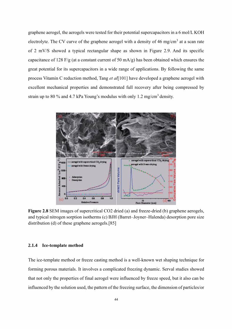
44
graphene aerogel the aerogels were tested for their potential supercapacitors in a 6 molL KOH
electrolyte The CV curve of the graphene aerogel with a density of 46 mgcm3 at a scan rate
of 2 mVS showed a typical rectangular shape as shown in Figure 29 And its specific
capacitance of 128 Fg (at a constant current of 50 mAg) has been obtained which ensures the
great potential for its supercapacitors in a wide range of applications By following the same
process Vitamin C reduction method Tang et al[101] have developed a graphene aerogel with
excellent mechanical properties and demonstrated full recovery after being compressed by
strain up to 80 and 47 kPa Youngrsquos modulus with only 12 mgcm3 density
Figure 28 SEM images of supercritical CO2 dried (a) and freeze-dried (b) graphene aerogels
and typical nitrogen sorption isotherms (c) BJH (BarretndashJoynerndashHalenda) desorption pore size
distribution (d) of these graphene aerogels[85]
214 Ice-template method
The ice-template method or freeze casting method is a well-known wet shaping technique for
forming porous materials It involves a complicated freezing dynamic Serval studies showed
that not only the properties of final aerogel were influenced by freeze speed but it also can be
influenced by the solution used the pattern of the freezing surface the dimension of particlesor
45
flakes the size of freezing moulds etc[102] However solidification and crystallization are
always at the very heart of making porous materials The first fabrication of GAs by freeze
casting was reported by Vickery et al[65] in 2009 Followed by the same concept Xie et al
[103] have reported GAs that can be tailored with large-range porous architecture and its
mechanical properties By changing the freezing speed by adjusting the final freeze-cast
temperature (Figure 29) it has been shown that the pore sizes and wall thickness of aerogel
can be gradually tuned from 105 to 800 microm and 20 nm to 80 microm respectively Also the wetting
property was changed from hydrophilic to hydrophobic and Youngrsquos modulus was varied by
15 times
Figure 29 (a) Qualitative schematic of the relationship between nucleation and crystal growth
as a function of freezing temperature during ice solidification (b) Performance of water
absorptionresistance on the cross-section of a sponge[103]
Na et al [104] reported that the final aerogel with a bigger size of rGO flakes (gt20 μm) was
superelastic exhibited high energy absorption and much enhanced mechanical properties than
those with small flakes (lt 2 μm) Besides this the differences in microstructure such as pore
size and wall distance were also observed (Figure 210)
46
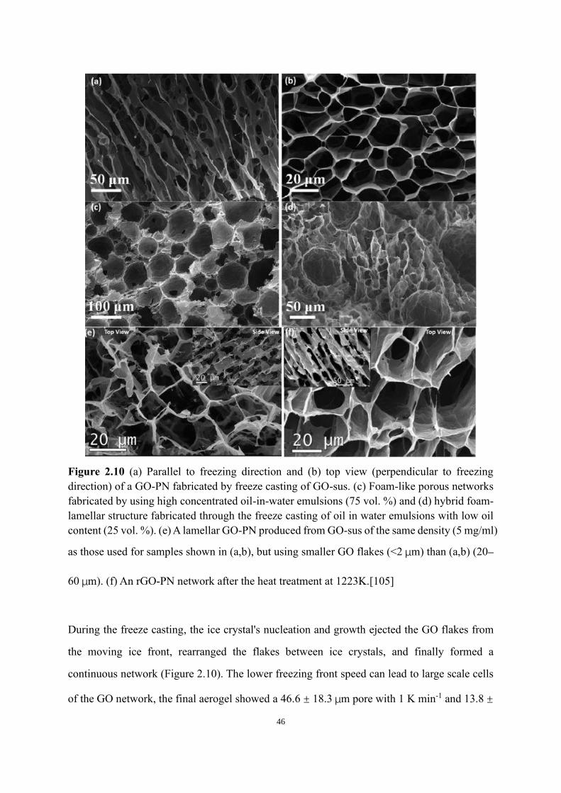
Figure 210 (a) Parallel to freezing direction and (b) top view (perpendicular to freezing
direction) of a GO-PN fabricated by freeze casting of GO-sus (c) Foam-like porous networks
fabricated by using high concentrated oil-in-water emulsions (75 vol ) and (d) hybrid foam-
lamellar structure fabricated through the freeze casting of oil in water emulsions with low oil
content (25 vol ) (e) A lamellar GO-PN produced from GO-sus of the same density (5thinspmgml)
as those used for samples shown in (ab) but using smaller GO flakes (lt2thinspμm) than (ab) (20ndash
60thinspμm) (f) An rGO-PN network after the heat treatment at 1223K[105]
During the freeze casting the ice crystals nucleation and growth ejected the GO flakes from
the moving ice front rearranged the flakes between ice crystals and finally formed a
continuous network (Figure 210) The lower freezing front speed can lead to large scale cells
of the GO network the final aerogel showed a 466thinspplusmnthinsp183thinspμm pore with 1 K min-1 and 138thinspplusmn
47
thinsp34thinspμm once the freeze front speed has increased to 10 K min-1 For mechanical properties the
bigger flakes rGO aerogel showed relatively higher compressive strength and Youngrsquos modulus
Moreover the study has shown that higher thermal reduction temperature can result the
aerogels with better strength recovery due to the fewer defects from the rGO Wang et al[106]
reported a freeze casting technique with a local structure that mimics turbine blades The
centimeter-scale radiating structure with many channels was achieved by controlling the
formation of the ice crystals in the aqueous GO dispersion that grew radially in the shape of
lamellae during freezing (Figure 211)
Figure 211 Illustration of a radiating graphene oxide aerogel fabricated by bidirectional
freezing (a) Scheme of the fabrication process (b) The freezing set up for making the radiating
structure has a copper rod with its upper surface hollowed out (c) Two temperature gradients
are induced by the upper copper mold (d) Model of the ice crystals growing along with radial
directions because of the two temperature gradients The orange sheets represent the dispersed
graphene oxide sheets[106]
As shown in Figure 212 the GO sheets were lamellar and ordered along with radial directions
in a centrosymmetric pattern which indicates a large and lamellar shape of ice crystals During
the freezing lamellar ice crystals have grown preferentially from the edge to the center of the
copper mold As the ice front is curved the spacing between the lamellae becomes narrower
48
the closer to the center of the mould (Figure 212 c) For a typical GO aerogel sample made by
this bidirectional freezing mold the channel width was increased from about 918 μm (Figure
212 d near the center) to about 270 μm and about 4017 μm (Figure 212 f near the edge)
The thickness of these channel walls was increased from about 68 nm to about 101 and 177
nm
Figure 212 Optical and SEM images of GO aerogels made by adding different additives and
comparison of BDF with conventional freezing methods (a) Ultralow density (69 mg cmminus3 )
rGO aerogel made by adding ethanol during freezing standing on grass (b) rGO aerogel with
a weight of 27 mg can sustain 290 g of iron blocks (c) rGOcellulose nanofiber (CeNF)
nanocomposite aerogel with an obvious radiating pattern on its surface (d) GOchitosan
aerogel without chemical reduction one can also see the texture on the surface (e) SEM image
of the rG-OCeNF nanocomposite aerogel (fg) SEM images of GOchitosan aerogels even a
spiral pattern can be obtained (hminusj) Illustrations comparing BDF and conventional freezing
methods using three cylindrical molds projected to the plane of the paper[106]
The final rGO aerogel with bidirectional freeze casting method showed an excellent recovery
even after 1000 compressive cycles with only 8 permanent deformation Moreover the
49
aerogel sample can float on water rapidly with great oil fouling in just a few seconds The
maximum adsorption capacity was 3747 g g-1 which is a much higher value compared with
the normal freeze casting technique The aerogel with changing widths of aligned channels
makes it a potentially superior configuration to perform as an adsorbent such as for treating
contaminated water
The freeze casting technique can be also applied to MXene aerogel preparation Vildan et al
[107] has recently reported a method to prepare MXene aerogel via freeze casting technique
The Ti3AlC2 powder was firstly etched with LiF and HCl to create MXene solution and then
followed by unidirectional freeze-casting After freeze-drying the MXene aerogel (MA) was
prepared with different density ranges from 7-43 mgcm3 The aerogel was then compressed
and rolled for preparing MXene electrodes The final MXene based electrodes could potentially
overcome some limitations such as introducing other 2D materials as spacers between MXene
flakes to avoid their restacking separating MXene layers with surfactants creating porous
structures via additional chemical and thermal processes in parallel with vacuum filtrations
and creating 3D crumpled MXene structures via spray drying and other approaches
50
Figure 213 Schematics and images of the fabrication strategy to produce Ti3C2Tx aerogels
and supercapacitor electrodes by using three different approaches From the top left of the
image following the arrows optical photographs and SEM images of Ti3AlC2 particles the
image of the mold on top of the freeze caster containing the Ti3C2Tx suspension (aqueous
suspensions is schematically illustrated) and corresponding SEM image of a few layers sheet
unidirectional freeze-cast sample inside the mold (schematic of the microstructure formation
during ice crystal growth) optical photographs and SEM images of electrode layers in the form
of as-prepared MA (lamellae architecture formed within the aerogel is schematically
illustrated) pressed (P-MA) and rolled Ti3C2Tx aerogel (R-MA) The range of electrode
densities (ρ) achieved by each approach is also indicated The red vectors inserted in the SEM
images indicate the freezing direction[107]
Bian et al[108] has reported ultralight MXene-based aerogels prepared with freeze-casting
technique with high electromagnetic interference shielding performance The final aerogel
only has a density of less than 10 mgcm3 and gave an excellent EMI shielding performance
(up to 75 dB) with extremely low reflection (lt1 dB) which was equals to 9904 dBcm3g with
its specific shielding effectiveness Moreover MXene aerogel can be used in other applications
Zhang et al[109] have demonstrated the MXene based aerogel has great potential for solar
51
desalination with high efficiency and salt resistance The final aerogel prepared with freeze
casting technique exhibited a high conversion efficiency (87) and stable water yield for 15
days (~146 kgm2h) under 1 sun About 6 Lm2 of freshwater was output daily from seawater
22 Preparation of 2D materials aerogel-based polymer nanocomposites
Keeping 2D materials-based aerogel structure as scaffolds polymer composites were prepared
by various strategies The fabrication methods for 2D materials aerogel-based polymer
nanocomposites were found to be influential to define the structure-behavior of composites
The different types of fabrication techniques include dip coating casting electrostatic spray
deposition and vacuum infiltration method
221 Dip coating
The dip coating method can be applied for producing liquid polymeric matrix materials
composites This method typically involves the immersion of aerogels in the polymer solution
and by varying the parameters one can tune both the quality and formation of the coating and
composites For example the dipping time and 2D materials content are deciding factors for
determining the thickness of the coating After the completion of dip coating the mixture of
2D materials aerogel and polymer solution were cured under specific time and temperature
conditions Figure 214 shows a schematic of the dip coating process for graphene aerogel in
the polymer Figure 214 (a and b) represent the gradual dipping and holding of graphene
aerogel in the liquid polymer using a control apparatus respectively In Figure 214(c) after
the immersion of graphene aerogel-polymer it was removed from the precursor The whole
system was then cured by using UV light or heat source in Figure 214(d)
52
Figure 214 (a-d) Processing of dip-coating method for graphene aerogel-polymer
composites[110]
222 Casting approach
Casting is another processing method for complete infiltration of 2D materials aerogel with the
polymer solution It involves pouring polymer into a mold containing 2D materials aerogel In
this case the polymer solution needs to be low viscous to infiltrates through the pore and coats
of aerogel Once the infiltration complete the whole system will be cured under specific
conditions[111]
223 Electrostatic spray deposition
The electrostatic spray deposition technique can be also adopted to fabricate aerogel-based
composites This method used the spraying technique to deposit polymer matrix in the powder
form on the 2D materials aerogel to create aerogel-based polymer composites Figure 215
explains the electrostatic spray coating deposition process Once 2D materials aerogel connects
to an electrically conductive metal foil the spray gun applies an electrostatic charge to the
polymer powder particles that attract to the aerogel structure The specified thickness of
polymer deposition from the aerogel structure can be controlled by spray time and spray
distance After curing the polymer formed a continuous thin layer on the aerogel structure if it
has good wetting behavior with the aerogel structure At last curing all these components under
53
specific conditions formed the aerogel-based polymer composites
Figure 215 Schematic of the electrostatic spray coating process[111]
224 Vacuum infiltration technique
The vacuum infiltration approach is the most commonly used method to prepare aerogel-based
polymer composites In this method polymeric materials are infiltrated through the macro-
porous architecture of 2D materials aerogel under vacuum to make sure the full infiltration
After the infiltration the whole system is cured at specific conditions and creates aerogel-based
polymer composites
Figure 216 The processing of vacuum infiltration technique (UGA Unidirectional graphene
aerogel)[52]
54
23 Properties of 2D aerogel-based polymer composites
231 Electrical properties
The synergy of polymer and 2D materials aerogel as nano-reinforcement has exhibited
impressive electrical properties of 2D materials aerogel-based polymer composites For 2D
materials reinforced polymer nanocomposites prepared by a conventional method it normally
needs a large amount of 2D materials fillers to form the electrical percolation However due to
the 3D porous structure from aerogel-based polymer composites the percolation can be formed
at ultra-low loading For example Wang et al[51] managed to get the graphene aerogelepoxy
composites conductive with only 0007 vol Furthermore by increasing the loading of
graphene by only 001 vol a remarkable ~8 orders of magnitude increase in electrical
conductivity has been demonstrated The highest electrical conductivity in their study has been
achieved at 12 Sm at a graphene content of 016 vol which could be sufficient for many
practical applications
Figure 217 (a) Electrical conductivities of GAepoxy composites as a function of GO
concentration (b) DC electrical conductivities of GAepoxy composites in the alignment
direction and transverse to it [112]
It has been considered that the size of fillers also influenced the electrical conductivity of
aerogel-based polymer composites Han et al[112] demonstrated that the composites with a
large size of graphene flakes have more well-formed percolation and conductive network
Ultra-large GA (UGA) formed from the ultra-large-GO (UL-GO) sheets exhibited an electrical
55
conductivity of 0178 Scm along the alignment direction whereas the corresponding
UGAepoxy composites have an electrical conductivity of 0135 Scm at 011 vol of UL-
UGA (Figure 219) Compared with each corresponding pair data the conductivities of
UGAepoxy were only slightly lower than those of the respective UGA reinforcements because
of damaged 3D interconnected graphene network causes by the pressure experienced during
the vacuum infiltration method
Apart from flakes size influence the quality of 2D materials also influenced the electrical
properties of aerogel-based polymer composites Kim et al[113] reported the fabrication of
highly crystalline GA using large nonoxidized graphene flakes (NOGFs) and infiltrated with
epoxy resin to create nonoxidized graphene aerogel (NOGA) epoxy composites The electrical
conductivity of NOGA-epoxy composites displayed an increasing trend with rising NOGF
content An excellent electrical conductivity of 1226 Sm was achieved at 027 vol of NOGF
loading in the direction parallel to the alignment at NOFG content which is approximately 12
orders of magnitude higher than that of neat epoxy (Figure 220) They believed such dramatic
enhancement of electrical conductivity is because of the high-quality nonoxidized graphene
flakes and the 3D aerogel structure Not only the graphene quality and the loading of the fillers
will influence the electrical conductivity of graphene aerogel-based epoxy composites but the
test directions The electrical conductivity in parallel direction showing several times higher
than its transverse direction and this phenomenon have been reported by most studies in this
section this is due to the isotropic graphene aerogel network nature Moreover the
disconnections of the graphene network align the transverse direction reduced the density of
electrical paths thus decrease the electrical conductivity of samples
56
Figure 218 The electrical conductivity of NOGA-epoxy composites in orthogonal directions
at different NOGF content[113]
232 Thermal properties
Figure 219 Scheme of thermal and electron transport in composites reinforced with 1D 2D
57
and 3D graphene foam[110]
Pettes et al [114] first observed an increase in thermal conductivity of free-standing graphene
aerogel from 026 to 17 Wm-1K-1 by using different etchants for nickel foam Moreover the
pure graphene aerogel showed an improved thermal conductivity as the temperature increased
above room temperature[115] Graphene aerogel also has a low thermal interfacial resistance
of 004 cm2KW-1 which is ten times lower than the conventional thermal paste and grease used
as thermal interface materials[116] With all these unique thermal properties the combination
of 2D materials aerogel and polymer have great potential in the improvement of thermal
properties for its composites For example graphene aerogel-basedPDMS composites have a
very low thermal resistance of 14 mm2 KW-1[117] owing to the interconnected structure of
graphene aerogel The thermal behavior of polyimide and polyamide matrix aerogel
composites has also been studied The thermal conductivity of neat polyimide (02 W m-1K-1)
has been significantly improved to 185 W m-1K-1 with an additional 01 wt of graphene
aerogels at 150 degC (Figure 221) suggesting that the 3D interconnected structure of graphene
aerogel increased the phonon flow with the PI graphene aerogel composites The comparison
of PDMS graphene aerogel composites and PI graphene aerogel composites indicated that PI-
based composites possessed higher thermal conductivity and stability than PDMS-based
composites which could be due to smaller interface area exposure of PI graphene aerogel to
air unlike PDMS
58
Figure 220 Thermal conductivity of PI and 035 wt graphene aerogelPI at 150 degC and
PDMS and 07 wt graphene aerogelPDMS at 85 degC[110]
Similar to the electrical conductivity behavior of aerogel-based polymer composites the
thermal conductivity of the composites also showed an increasing trend as the loading
increased[110] Figure 222 presents the thermal conductivity behavior of polymer composites
with varying content of the graphene foam and flakes fillers An almost linear increase of
thermal conductivity with the function of filler content was observed Moreover
polyamidegraphene aerogel revealed better thermal conductivity than the multi-graphene
flakes in PDMS[118] portraying that the hierarchical structure of graphene aerogel is
conductive for thermal conduction
59
Figure 221 Thermal conductivity vs filler content of Polyamidegraphene aerogel
Multigraphene flakesPDMS Multigraphene flakesgraphene aerogelPDMS[110]
Yao et al [119] reported an rGO-BN aerogel-based epoxy composite which exhibited an
excellent thermal property In their study the hybrid aerogel was produced by the freeze casting
method followed by epoxy infiltration to create BN-rGO epoxy composites The neat epoxy
has a low thermal conductivity of 018 W m-1K-1 at room temperature The existence of a 3D
BN-rGO structure resulted in a dramatic enhancement of the thermal conductivity of the epoxy
resin The maximum thermal conductivity of 505 W m-1K-1 in BN-rGOepoxy composites was
achieved with 1316 vol BN-rGO at room temperature which is 27 times higher than that of
the neat epoxy resin (Figure 223) As a comparison the same loading of raw BN-rGO epoxy
composites thermal conductivity has been measured but only achieved half value of 3D BN-
rGO epoxy composites indicated the benefit from fillerrsquos 3D structure
60
Figure 222 Thermal conductivity of raw BN epoxy composites raw BN-rGO epoxy
composites and 3D BN-rGO epoxy composites with different filler loading [119]
233 Joule heating properties
The aerogel-based polymer composites are expected to have excellent Joule heating properties
because of their outstanding electrical and thermal properties Bustillos et al [120] first
demonstrated the Joule heating performance of graphene foam-based PDMS composites (GrF-
PDMS) The graphene foam was first formed by the CVD technique and the PDMS then
infiltrated under vacuum The composites showed a rapid heating rate of 087 degCs a steady-
state temperature of ~70 degC with only 1 W power input (Figure 224)
61
Figure 223 (a) Heating profiles of GrFminusPDMS composite as a function of increasing currents
(at room temperature 25 degC) (b) Heating profile of the 01 vol GrFminusPDMS composite at
room temperature and input current of 04 A (c) Schematic representation of restricted phonon
transport is poorly dispersed conductive filler composites vs uninterrupted phonon transport in
GrF[120]
Moreover the composites have been tested with 100 cycles and showed an almost
unchangeable steady-state surface temperature Ju et al[109] reported 3D MXene structure-
based composites with their Joule heating properties (Figure 225) The composites reach
402 degC in 10 mins Compared with the MXene membrane the 3D MXene aerogel-based
composites showed a higher steady-state surface temperature and higher heating rate
The Joule heating properties of 2D materials-aerogel based composites showing the same trend
as its electrical and thermal properties several studies reported with the increasing the fillers
loading in the composites system the samples showing better Joule heating properties such as
higher steady-state temperature quicker response time higher heating rate etc[120]
62
Figure 224 Joule heating test for 3D MXene aerogel-based polymer composites [109]
234 Mechanical properties
Significant mechanical properties enhancement of 2D materials aerogel-based polymer
composites have been reported and reviewed below Examples of polymer here discussed here
including Polydimethylsiloxane (PDMS)[120ndash123] epoxy[111][124][125] and
polyimide[126]
Wang et al [52] prepared graphene aerogel-based epoxy composites by infiltrating epoxy resin
into chemical reduced graphene aerogels They have managed to increase the flexural modulus
in the alignment direction by about 12 with 05 wt graphene as well as flexural strength
However once the loading passes a certain point (05 wt) both flexural modulus and strength
did not show any increase further Along the transverse direction the initial trend was found to
be the same as the alignment direction until loading reaches 05 wt After the loading over
05 wt both flexural modulus and strength start to decrease Kim et al [113] found that the
flexural modulus was enhanced by 254 and the flexural strength by 102 at a low loading
of 034 vol compared with the neat epoxy Moreover the fracture toughness on the other
hand exhibited a sharp enhancement The composites delivered an excellent mechanical
property with a maximum increase of 761 in K1c at 045 vol (Figure 226)
63
Figure 225 Mechanical properties of GA-epoxy composites (a) Flexural modulus and
strength and (b) fracture toughness of GA-epoxy composites as a function of graphene
content[113]
Han et al[112] demonstrated the influence of fillerrsquos dimension for aerogel-based epoxy
composites In their study graphene aerogel has been assembled by using both ultra-large GO
flakes (UL-UGA) and small GO flakes (S-UGA) and infiltrated with epoxy resin The results
showed that the composites based on ultra-large GO flakes have higher flexural strength and
fracture toughness compared to that of small GO flakes Besides this they have discussed the
mechanism for mechanical properties enhancement (Figure 227) It is believed that all
graphene-based aerogel epoxy composites showing remarkable improvements in fracture
resistance at low filler loading were due to the excellent properties from graphene aerogels
originating from the highly preserved crystallinity and graphitic structure Also the fracture
toughens is expected to be enhanced significantly due to effective crack propagation hindrance
by the horizontally aligned graphene walls from graphene aerogel However at the certain
loading point of graphene there is no further improvement in terms of its flexural modulus
flexural strength and fracture toughness This might because of the slight graphene aggeration
that happens at higher loading thus decrease the mechanical properties of the composites
system
64
Figure 226 Typical SEM images of fracture surface for (a) neat epoxy and epoxy composites
with (b) 004 vol (c) 011 vol and (d) 022 vol UL-UGA aligned against the crack
plane (e) fracture toughness of UL-UGA and S-UGAepoxy composites SEM image of
fracture surface of S-UGA composite with (f) 016 vol (g) 004 vol (h) 007 vol and
(i) 011 vol of UL-UGA[112]
235 Other properties
2D materials aerogel-based polymer composites also exhibited other excellent properties
including biological acoustic and chemical For example Nieto et al[127] studied bio-tolerant
and biocompatibility properties of graphene aerogel-based composites in the culturing of
human mesenchymal stem cells (hMSCs) Cellular studies showed that the hMSCs survived
and proliferated on the 3D graphene aerogel reinforced composite In another study
polydopamine PDAgraphene aerogel composites were produced for enzyme
immobilization[128]
A recent study showed that the graphene aerogeltungstenepoxy composites produced an
improved acoustic performance[125] The hierarchical and mesoporous structure was
65
employed in the epoxy matrix and thus provides a confined space that allows a dense packing
of the tungsten spheres within the pores of aerogel The compactness among epoxy tungsten
spheres and graphene aerogel would result in a reduction of air that can propagate acoustic
waves This would thereby lead to high acoustic impedance and increased acoustic attenuation
which is required for excellent backing material
24 Potential application of 2D materials aerogel-based polymer composites
Due to the excellent electrical mechanical thermal and Joule heating properties of 2D
materials aerogel-based polymer composites as discussed above it is expected to open the
avenues where the polymer composites can be used in a wide range of engineering applications
The 2D materials aerogel-based polymer composites can be used in electronic devices flexible
electronics strain sensors electromagnetic interference (EMI) shielding and electrochemical
biosensors in the electronic industry
For EMI shielding materials it requires materials that can prevent the detrimental effects of
EMI interference and microwave on humans and electronics The graphene aerogel-based
PDMS composites can produce a specific EMI shielding that can be up to 500 dB cm3g[129]
Also the graphene aerogel-based polymer composites can provide high-performance
supercapacitors with improved cyclic stability of up to 6000 cycles[130] Besides aerogel-
based polymer composites provide sufficient capacity to be used as thermal interface materials
for chips low thermal resistance and high thermal conductivity[118120131] Combing both
excellent electrical and thermal properties from the 2D aerogel based polymer composites the
rapid heating and high Joule heating efficiency from its nature they can be used as a local
heater deicing devices and other electrothermal devices in the aerospace automotive and
sports industry[132133] Table 2-
1 summarised the 2D aerogel-based polymer composites with different materials properties for
various engineering applications
66
Table 2-1 Summary of properties and applications of 2D materials aerogel based polymer
composites
Material
Property
Composites Applications
Electrical
properties
GrapheneMXene aerogel-
PDMSepoxyPolypyrrole
PANI sponge
Supercapacitors adsorbent strain
sensor electrochemical biosensor
space vehicle protection
Mechanical
properties
GrapheneMXene aerogel-
PDMSepoxy
Dampers packaging strain sensors
Thermal
properties
GrapheneMXeneBoron
nitride aerogel-
PDMSepoxy Polyamide
Thermal interface materials high
power electronics flame-resistant
material
25 Conclusion
Various strategies to synthesize the 2D materials based on aerogel and composites with polymer
are briefed Progress of polymer2D materials aerogel-based composites in terms of intrinsic
properties and their potential applications are also discussed The potential applications of the
polymer2D materials-based aerogel composite are also addressed
67
3 Chapter 3 Ice-templated hybrid graphene oxide -
graphene nanoplatelet lamellar architectures with
tunable mechanical and electrical properties
This Chapter emphasises the design of 3D graphene-based architecture using the stable
suspension of GO and GNP Here a versatile aqueous processing route is presented to produce
lamellar aerogels structure of GO-GNP composites via unidirectional freeze-casting To
optimise the properties of the aerogel GO-GNP dispersions were partially reduced by L-
ascorbic acid prior to freeze-casting for tuning the carbon and oxygen (CO) ratio The aerogels
were heat treated afterward to fully reduce the GO Morphology and structure of reduced
graphene oxide(rGO)GNP aerogel was investigated by scanning electron micrograph Raman
spectroscopy and X-Ray diffraction The properties of the final aerogels were characterized by
electrical conductivity test mechanical test and water contact angle test An optimal partial
reduction time of 35 mins led to an aerogel with the compressive modulus of 051 plusmn 006 Mpa
at a density of 232 plusmn 07 mgcm3 and an electrical conductivity of 423 Sm at a density of
208 plusmn 08 mgcm3 was achieved with partial reduction of 60 mins
31 Introduction
Generally GO is the preferred precursor to produce such aerogels due to the aqueous
preparation routes used as discussed in Chapter 2[60134] And among all producing methods
freeze-casting is one of the most popular for obtaining porous 3D structure because it allows
the formation of an anisotropic microstructure with controllable and uniform macropores[135]
Consequently despite freeze-casting of GO water suspension being a convenient and scalable
method extra defects are generally introduced to the materials surface both during processing
and post-reduction-treatment and severely hinder the properties of interest On the other hand
non-functionalised graphene-based materials such as pristine graphene and graphene
nanoplatelets (GNP) cannot easily be stabilised in suspensions due to their poor dispersibility
68
in both aqueous and organic solvents Several approaches have been studied for the production
of the stable aqueous suspension of graphene[136ndash138] Chemical functionalisation of
graphene with highly concentrated acid is a widely used technique to increase their
dispersibility[139140] However the modification via chemical route can disrupt the
electronic paths in graphene and deteriorate the electrical and other quantum effect properties
of the structures[140] To address this issue some studies have adopted a non-covalent
approach by using surfactant as well as charged and uncharged polymers for dispersing
graphene materials with homogenization and ultrasonication[141142] though the stabilizing
effect is still limited Recently Kazi et al[143] has reported that GNP can be dispersed in GO
water suspension with a wide range of pH values Thus it would be very useful to combine
this approach with freeze casting to create high-quality graphene-based aerogel
In this work a binder-free freeze-cast graphene-based aerogel with tunable CO ratio (Figure
31) has been developed which is based on the use of GO as a multi-purpose colloid that enables
the aqueous dispersion of GNP at concentrations as high as 80 wt (at 41 GNP GO ratios)
aids in the formation of the 3D network and can subsequently restore its π-π conjugated
structure of graphene after partially chemical reduction and contribute to the final aerogel
properties The resulting suspension was later processed by unidirectional freeze-casting
freeze-drying and thermal reduction to obtain a light-weight 3D structure Initially the
dispersions and role of the chemical reduction time on the oxygen contents of the aerogels were
studied and analysed via Raman spectroscopy and X-ray photoelectron spectroscopy The GO-
GNP suspension stability was characterized via zeta potential before and after the partial
chemical reduction process
69
Figure 31 Schematic of the processing route towards rGO-GNP lamellar aerogels (First row
schematic of processing route for rGO-GNP lamellar aerogels Second row Details of
processing from frozen structure to rGO-GNP lamellar aerogel) From left to right GNP is
incorporated into GO aqueous suspensions via shear mixing the GO-GNP suspensions are
partially reduced with L-ascorbic acid at 50 degC for different times t these are subsequently
freeze casted and dried to form lamellae structures templated by the ice crystals after a freeze-
drying step the aerogels are subjected to a final thermal treatment at 300 and 800 degC in Ar
32 Materials and methods
321 Materials
The reagents used were L-ascorbic acid (Sigma-Aldrich L-ascorbic acid 99) graphite flakes
(grade 2369 Graphexel Ltd UK) sodium nitrate (Sigma-Aldrich ACS reagent ge990)
potassium permanganate (KMnO4 Sigma-Aldrich ACS reagent ge990) sulfuric acid
(ACROS Organics 96 solution in water extra pure) and hydrogen peroxide (H2O2 Scientific
Laboratory Supplies 35 solution in water 100 volumes) The graphene nanoplatelets (GNP
M-25 XGscience USA) had a flake size of 107 plusmn 37 microm(Figure 31) and a thickness of ~45
nm (Figure 32)
322 Synthesis of Graphene Oxide
GO flakes were produced using a modified Hummersrsquo method[144] Firstly 38 g of sodium
nitrate was dissolved in 169 mL of sulfuric acid and stirred constantly for 10 minutes in the ice
70
bath 5 g of graphite flakes were then added and stirred for a further 10 minutes Finally 225
g of KMnO4 was gradually added to the mixture over 30 minutes The mixture was allowed to
warm to room temperature and then continuously stirred for 4 days to consume the KMnO4 as
evidenced by the diminished green colour After the first day 152 mL sulfuric was added every
24 hours for the remaining 3 days After 4 days the viscous oxidized mixture was slowly
dispersed in a solution of water (9834 mL) H2O2 (8 mL) and sulfuric acid (9 mL) in an ice
bath The mixture became light-yellow and was continuously stirred for 2 hours after the initial
effervescence stopped The product was centrifuged at 8000 rpm for 30 minutes to separate the
produced GO from the acid solution The GO precipitate was repeatedly washed and
centrifuged with the acidic solution (9834 mL of water 8 mL of H2O2 and 9 mL of sulfuric
acid) 7 times and subsequently washed with deionised water until the pH of the supernatant
was about 5 (after 15 washing cycles) The resulting dark brown-orange viscous GO sol (~10
mg mLminus1) was diluted down to 5 mg mLminus1 using deionised water for further application The
resulting GO had a flake size of 78 plusmn 31 um (Figure 32) and thickness of ~26 nm (Figure
33)
Figure 32 SEM images of (a) graphene oxide (GO) flakes and (c) graphene nanoplatelet (GNP)
flakes (both with flakes width distribution)
71
Figure 33 AFM images of (a) graphene oxide (GO) flakes and (b) graphene nanoplatelet (GNP)
flakes
323 Production of the rGO-GNP Aerogels
GNP powder was added to 10 mL of the GO suspension (5 mg mL-1) at GNP GO weight ratios
of 41 and homogenised in the ice bath (IKA T25 digital Ultra Turrax) at 15000 rpm for 20
minutes A black-coloured aqueous suspension with a solid concentration of 25 mg mL-1 GO-
GNP was formed 50 mg of L-ascorbic acid was then added to the suspension (11 mass ratio
of GO to L-ascorbic acid) homogenised by shear mixing for 10 minutes in the ice bath and
then placed into a water bath at 50 degC for a given time t minutes Samples were prepared with
t from 0 to 60 minutes at 5 minutes steps to investigate the partial reduction treatment Then
the partially chemically reduced GO-GNP (denoted as CRt) suspension was frozen by
unidirectional freeze-casting using a lab-built freeze caster as described in our previous
work[145] and a PTFE cylindrical mould (20 mm diameter and 20 mm height) Freeze-casting
was conducted from 20 degC to -100 degC at a cooling rate of 5 degCmin The frozen samples were
freeze-dried to yields aerogels These have made CRt aerogels did not show any significant
electrical conductivity so they were thermally treated at either 300 or 800 degC in an argon
72
atmosphere for 40 minutes
The resulting samples were labelled as CRtTR300 and CRtTR800 where ldquotrdquo is the partial
chemical reduction (CR) time (minutes) TR300 and TR800 stand for thermal reduction (TR)
at 300 degC and 800 degC respectively
324 Zeta potential characterisation
The zeta potential of the particles in the GO-GNP suspensions was investigated by a Zetasizer
Nano ZS (Malvern Instruments Ltd Malvern UK) using 4 mW He-Ne laser operating at a
wavelength of 633 nm with detection angle of 13deg the pH of the suspension was adjusted by
001 molL NaOH buffer solution for higher pH and 001 molL HCl buffer solution for lower
pH
325 Morphylogy and microstructure
Raman specra were collected from the aerogels using a Renishaw System 1000 Raman
Spectrometer with a 514 nm excitation laser WIRE 32 software was used to deconvolute the
Raman spectra of the as-received GNP as-synthesized GO and rGO-GNP aerogels X-
ray photoelectron spectra (XPS) measurements were performed by a PHI Quantera SXMAES
650 Auger Electron Spectrometer (ULVAC-PHI Inc) equipped with a hemispherical electron
analyzer and a scanning monochromated Al Kα (hυ = 14866 eV) X-ray source
The microstructure of the aerogels was further investigated by using scanning electron
microscopy (FEI Quanta 250) For the morphylogy of GO and GNP powders the sample
preparation for SEM and AFM samples are both the same firstly a very dilute GOwater
solution was made by bath sonicate for 10 mins Then the solution was drop cast on a SiO2Si
wafer and dried overnight under room temperature Finally the sample was mounted to an
aluminium SEM stub by carbon tapeThe density of the samples was determined by measuring
their dimensions using a digital Vernier caliper and their mass using a balance with 0001 mg
accuracy
73
326 Electrical properties
The mechanical properties of the aerogels were measured by Instron 3344L3927 in
compression mode with a load speed of 05 mms and unload speed of 005 mms due to the
slow recovery rate
The electrical was measured by NumetriQ PSM1735 analyzer where the samples were coated
with silver paint on both sides in order to reduce the contact resistance with Impedance Analysis
Interface whose frequency (ω) ranges from 1 to 106 Hz The specific conductivities (σ) of the
samples were calculated by the equation
120590(120596) = |119884lowast(120596)|119905
119860 =
1
119885lowast times 119905
119860 (31)
where Y(ω) is the complex admittance Z is the complex impedance t is the thickness
and A is the cross-sectional area of the sample
327 Mechanical properties
The mechanical properties of the aerogels were measured by Instron 3344L3927 in
compression mode with a load speed of 05 mms and unload speed of 005 mms due to the
slow recovery rate
33 Results and Discussion
331 Rheology of suspension as a function of chemical reduction time
74
Figure 34 Digital images of GO-GNP suspensions as-prepared CR0 (a) after 35 min CR35
(b) and after 60 minutes CR60 (c) of the chemical reaction Insets show a magnified digital
image of a droplet of the respective suspension on a 45deg inclined glass slide after 60 minutes
Figure 35 (a) Viscosity (Shear rate at 1 S-1) and (b) as-measure pH value of GO-GNP
suspensions for different chemical reduction time (at 50 degC) The pH value of a suspension
upon the addition of with no chemical reduction step is indicated with the half-filled symbol in
(b) The corresponding zeta potential values of GO-GNP suspensions at 5 35 and 60 min of
reaction is indicated in (b)
The as-prepared GO-GNP suspensions were found to go from an initial liquid behaviour to gel
behaviour during the 60 minute reduction with an excess of L-ascorbic acid (Figure 34a)
Cone and plate rheology found that the viscosity went from 017 Pa∙s initially to 47 Pa∙s after
35 minutes reduction (CR35) and 102 Pa∙s after 60 minutes (CR60) This gelation was due to
the enhanced π-π interactions between the GO flakes after partial chemical reduction and the
reduced hydrophilic nature to prevent dispersion but left enough for hydrogen bridging which
caused the formation of a weekly cross-linked network within the suspension (Figure 34 and
35)[146147] The pH was monitored as a function of time upon the addition of acid to monitor
the reduction of the GO The initial pH value of the suspension was 39 (Figure 35 b) and it
75
dropped to 28 immediately upon the L-ascorbic acid addition After 40 mins the graphene
oxide appeared to be fully reduced and no further pH was observed De Silva et al suggested
that the functional groups such as carbonyl and carboxylate groups on GO are gradually
removed whilst consuming the H+(aq) leading to the rise of the pH to 35 with reduction
time[148]
The Zeta potential of the suspension was measured to further understand the suspensionrsquos
behaviour It was found that CR5 CR35 and CR60 was constant at -28 2 mV However the
Zeta potential has a complex dependence on both the pH and degree of reduction It is important
though in the formation of the hydrogel hence these factors were explored in more detail The
as-made GO GNP and the GO-GNP dispersions were studied as a function of pH between 2
to 4 using a 001 molL buffer solution As can be seen in Figure 35 b the studied suspensions
after chemical reduction (from 0 to 60 minutes) present pH in the investigated range At all
pHs the GO had a considerably lower value and broader distribution of the Zeta potential than
GNP in accordance to Salim et alrsquos report [149] due to their oxygen functional groups (hydroxyl
carboxyl and carbonyl) which render high density of electrical charge per unit area (Figure
36)
76
Figure 36 Zeta potential distribution for as made of GO-GNP GNP and GO suspensions as a
function of the buffer solution pH
The GO-GNP suspensions show a single peak that goes from around -175 mV for pH 2 to -
353 mV for pH 4 indicating a stable colloidal suspension especially for pH above 2[150] The
lack of a bi-modal distribution is a piece of evidence that the GO and GNP have aggregated
with each other[143] GNP have a relatively defect-free basal plane which is hydrophobic in
nature with a low surface charge measured between -12 mV and -27 mV[150][151] However
in the presence of GO sheets GNP flakes can attach to them via van der Waals and repulsive
electrostatic forces[149ndash151] leading to GO-GNP hybrid flakes with a zeta potential closer to
that of GO making it stable in water
332 Production of areogels
The CRt suspensions were then unidirectionally freeze-cast and freeze-dried to form free-
standing aerogels with both cylindrical (diameter = 2 cm) and rectangular (8cmtimes2cmtimes08cm)
77
shapes as shown in Figure 37 The CR0 samples show a density of ~332 plusmn 21 mgcm3 and
after chemical and thermal treatment the CRtTR300 samples show lower densities between
~21 gcmsup3 and ~28 gcmsup3 (Table 31) The lower density for CRtTR300 samples is due to the
removal of functional groups from GO surfaces and a lower volume shrinkage due to stronger
bonding formed by the partial chemical reduction[152]
Table 3-1 Summary of processing parameters samples density samples volume shrinkage
(before and after freeze dry) and XPS spectroscopy result of C1s spectra and O1s spectrum for
CR0 CRtTR300 and CR60TR800 aerogels
Sample
Chemical
reduction
time
(minutes)
Thermal
reduction
temperature
(oC)
Thermal
reduction
time
(minutes)
Density
(mgcm3)
Oxygen
content
(at)
CO
ratio
Sample
volume
shrinkage
CR0 0 0 0 332 plusmn 21 401 15 97
CR0TR300 0 300 40 313 plusmn 11 85 108 65
CR5TR300 5 300 40 279 plusmn 07 59
CR10TR300 10 300 40 273 plusmn 06 53
CR15TR300 15 300 40 274 plusmn 12 57
CR20TR300 20 300 40 253 plusmn 09 52
CR25TR300 25 300 40 256 plusmn 04 64
CR30TR300 30 300 40 224 plusmn 13 56
CR35TR300 35 300 40 232 plusmn 07 66 142 59
CR40TR300 40 300 40 243 plusmn 13 43
CR45TR300 45 300 40 224 plusmn 05 63
CR50TR300 50 300 40 236 plusmn 07 59
CR55TR300 55 300 40 221 plusmn 09 55
CR60TR300 60 300 40 223 plusmn 06 57 158 57
CR60TR800 60 800 40 208 plusmn 08 32 303 72
78
Figure 37 (a) Photograph of different shape CRtTR300 aerogels produced by the developed
route (b) SEM images of the cross-section perpendicular to the freezing direction of
CR0TR300 (c) the cross-sections perpendicular to the freezing direction with higher
magnification (d) cross-section parallel to the freezing direction (e) SEM images of the cross-
section perpendicular to the freezing direction of CR35TR300) (f) the cross-section
perpendicular to the freezing direction with higher magnification (g) cross-section parallel to
the freezing direction (Red circles and arrows in the images indicate the freezing direction)
The internal structure of the network consisted of long microscopic channels oriented parallel
to the ice growth direction and separated by thin walls that were formed by the rearrangement
of GO and GNP flakes between ice crystals during freezing (Figure 37) Although the weight
ratio of GNP is much higher than GO (41) due to the large specific area from the oxide thin
flakes the aerogels scaffold is mainly formed by GO while thick GNP flakes are found amidst
the network (Figure 37 cf ) The aerogels produced from the suspensions that undergo a partial
reduction step of 35 min (Figure 37 e-g ndash CR35TR300) resulted in the formation of more
defined elongated lamellar pores that extend across larger domain areas as compared to
CR0TR300 samples (Figure 37 b-d) Form the cross-sectional SEM images of the aerogels
79
produced with Figure 37 b and without Figure 37 e partial reduction step it can be seen that
chemical reduction helps in the formation of more defined lamellar channels and extend across
larger areas The freeze-casting process is governed by complex and dynamic liquid-particle
and particle-particle interactions Other studies have previously reported that the oxygen
content is one of the factors that can affect these interactions[153] The degree of reduction of
GO colloids before freezing controls the surface characteristics of the flake[146] which in-turn
can influence the flake-flake interactions promoting the network formation andor their
rejection from the freezing front[153] During freeze-casting as the ice crystals grow
anisotropically both GO and partially reduced GO suspensions can stabilize the GNP in water
allowing the freeze-casting technique to create homogeneous porous networks As partially
reduced GO sheets are less hydrophilic and more rejected than non-reduced GO those are
forced to align along the moving solidification front concentrating and squeezing at the crystal
boundaries and yielding a highly ordered layered assembly[153154] As a result a more
anisotropic structure can be obtained when some partial chemical reduction is employed before
processing However longer chemical reduction periods leads the suspensions to become too
thick (Figure 34 and 35) hindering the mobility of the solid phase within the suspension
during freezing and strongly influencing the final microstructure of the aerogels[153][155]
(Figure 38)
Figure 38 SEM images of (a) cross-section perpendicular to the freezing direction of
80
rGOTR300 (b) cross-section parallel to the freezing direction of rGOTR300 (c) cross-section
perpendicular to the freezing direction of CR60TR300 (d) cross-section parallel to the freezing
direction of CR60TR300 the cross-section perpendicular to the freezing direction with higher
magnification (g) cross-section parallel to the freezing direction Red circles and arrows in the
images indicate the freezing direction
Raman spectra of the rGO region of final aerogels are shown in Figure 39 a The as-prepared
GO exhibits typical features from graphene oxide materials for example the G band (~1580
cm-1) has a similar intensity to the D band (~1350 cm-1) (IDIG~1)[156] The D band signature
is associated with structural defects and the partially disordered structure of graphitic domains
The intensity ratio IDIG decreases from ~089 for CR0TR300 to ~062 for CR35TR300 and
~041 for CR60TR300 Figure 39 b shows how the IDIG ratio varies as a function of partial
chemical reduction time It can be observed that the L-ascorbic acid has a significant effect on
removing functional groups reorganizing the structure of GO-GNP aerogels and leading to a
decrease in the ratio between D and G band intensities However as pointed out previously a
chemical reduction time too long will increases the viscosity even further starting to transform
the suspension into a gel (Figure 34 and 35) and significantly restricts the solid phase mobility
reducing the anisotropy as that can be observed from sample CR60TR300 (Figure 38)
81
Figure 39 (a) Raman spectroscopy patterns for CRtTR300 aerogels with rGO region
(CR0TR300 CR35TR300 and CR60TR300 aerogels) and starting GO and GNP (b) IDIG
ratio (Intensity ratio of D band and G band from Raman spectroscopy) for CRtTR300 aerogels
with rGO region as a function of partial chemical reduction time (c) XPS survey spectra were
undertaken on CR0 and CRtTR300 aerogel samples (CR0TR300 CR35TR300 and
82
CR60TR300 aerogels) starting GO and GNP
Figure 310 XPS spectroscopy results for samples (a) CR0 (b) rGOTR300 samples (c)
CR35TR300 samples and (d) CR60TR300 samples
XPS spectroscopy was also employed to investigate the chemical structure and composition of
the as-prepared GO GNP and aerogel samples For GO CRt and CRtTR300 samples four
distinct peaks associated with sp2 C=C (2845 eV) C-O (2864 eV) C=O (2881 eV) and O-
C=O (2885 eV) were observed (Figure 310) The CO atomic ratios have increased from 15
for GO to 42 for the CR0 mixture (Table 31) due to the additional GNP All treated samples
show a considerable decrease in the intensity of oxygen-contained groups at a binding energy
of 2868 eV indicating the successful reduction of the GO After thermal treatment the sample
CR0TR300 presented a CO atomic ratio of 108 Meanwhile the CO ratio of the samples that
underwent a pre-partial chemical reduction CR35TR300 and CR60TR300 increased to 142
and 158 respectively The XPS results confirm the analysis from Raman spectra that with the
help of chemical reduction oxygen-containing functional groups are better removed from the
83
surface of GO and result in a better reduced final product Figure 310 shows an extract of the
XPS region of C 1s binding energies (280 ndash 298 eV) where it is also possible to see the decrease
of oxygen-containing groups with the increase of chemical reduction time
Figure 311 Water contact angles for rGO (rGOTR300) and rGO-GNP aerogels (CR0TR300
CR35TR300 and CR60TR300)
Another property of interest of aerogels is their wettability For example hydrophobic
graphene-based aerogels have shown promising potential as efficient oil absorbent self-
cleaning and anti-icing materials[157] However due to the hydrophilic nature of GO GO-
based aerogels generally show relatively high hydrophilicity demanding further high-
temperature thermal reduction processes to tune this property Alternatively Figure 311 shows
that the addition of GNP resulted in the increase of WCA value from 506deg for pure rGO to
702deg for rGO-GNP (both treated at only 300 degC) due to the hydrophobic nature of GNP As the
treatment time for partially chemical reduction is increased the WCA increased and reached
1068deg for CR60TR300 being the highest among all the samples The increase in
hydrophobicity of the aerogels is mainly due to the reduction in oxygen-containing functional
groups on GO as the result of the chemical and thermal reduction as indicated by the XPS and
the Raman results
84
Figure 312 (a) Compressive stress-strain curves of CRtTR300 aerogels (b) Compressive
modulus and strength of CRtTR300 aerogels for different chemical reduction times (c)
Electrical conductivities of CRtTR300 aerogels for different chemical reduction times
The compressive stress-strain curves (Figure 312 a) can be divided into three parts linear
elastic yielding and recovery parts SampleCR35TR300 reaches its yielding region at around
7 compressive strain which is much earlier compared to 15 from both samples
CR60TR300 and CR0TR300 Furthermore the samples CR35TR300 and CR60TR300 show
improved recoverability after experiencing large strains compared to non-chemically treated
sample CR0TR300 (Figure 312 a) The compressive modulus of CRtTR300 samples (Figure
312 b) was estimated from the stress-strain curves (Figure 312 a) The results show the
compressive modulus improves as the chemical reduction time of suspensions increases up to
an optimum at 35 mins (CR35TR300 samples) However as the chemical treatment time
increased the compressive modulus decreases down to 006 plusmn 0009 MPa for 60 mins reduction
time (samples CR60TR300) It is mostly accepted that the compressive properties and
behaviour of graphene aerogel are directly related to its density[158159] however as can be
seen a significant difference of compressive modules is found on samples with very similar
density The high compressive strength of CR35TR300 is due to its more organized lamellar
hierarchical structure compared to CR60TR300 which has more disordered structures and
relatively smaller pores (as can be seen in Figure 5e f g and S3) This kind of lamellar
structure usually results in high elasticity and mechanical robustness[104159] In order to
elucidate the effect of the chemical reduction on the properties of the aerogels we compared
sample CR35TR300 with CR0TR300 (no chemical reduction) Although ordered structures
have been obtained within aerogels with no chemical reduction their mechanical and electrical
85
properties (Figure 8 b and c) are lower as compared to the chemically reduced samples The
chemical reduction step can contribute to the formation of a stronger network of partially
reduced flakes before the freeze-casting step[60] It has also been shown to contribute to the
restoring of the sp2 network and reducing the number of defects on GO flake[105]
Consequently besides the ordered lamellar architectures these effects can also contribute to the
properties of the aerogels
The conductivity of rGO-GNP aerogels has increased from 065 Sm with no chemical
reduction for sample CR0TR300 (IDIG ratio of 089) to 423 Sm for CR60TR300 (IDIG ratio
of 041) This behaviour can be attributed to the restoration of the sp2 carbon network
facilitating the electrons transfer within the network[160]
Figure 313 The electrical conductivity of CRtTR300 (with t minutes chemical reduction and
300 degC thermal reduction for 40 minutes at Ar atmosphere) CRtTR800 (with t minutes
chemical reduction and 800 oC thermal reduction for 40 minutes at Ar atmosphere) and rGO-
EEG CRtTR800 (GO with electrically exfoliated graphene at t minutes chemical reduction and
800 oC thermal reduction for 40 minutes at Ar atmosphere) (a) and compressive modulus of
CRtTR300 samples (with t minutes chemical reduction and 300 oC thermal reduction for 40
minutes at Ar atmosphere) developed in this work in comparison to literature values for other
nanocarbon-based materials Reduced-graphene cellular network[161] CNT foam[162]
reduced graphene-based aerogel[99] CVD graphene foam[163] graphene elastomer[153] 3D
printed graphene[164] 3D graphene macroassembly[99] 3D printing graphene[165] GO
aerogel[106] rGO-GNP hydrogel[166] and rGO aerogel[104153167168]
For graphene aerogels several studies show that the electrical conductivity can be related to
the thermal reduction temperature and bulk density[161165169] Figure 313 shows a
86
comparison between the electrical conductivity and compressive modulus obtained for the
aerogels developed in this work and data from the literature One can observe that rGO-GNP
samples show a tunable mechanical and electrical property without changing the density
Furthermore additional tests were made by increasing the thermal reduction temperature to
800 oC increasing GNPGO ratio and using electrochemically exfoliated graphene (EEG)
instead of GNP (Figure 314) It is observed that the electrical conductivity of samples
increased to 774 Sm when the higher thermal reduction was employed Increasing the GNP
content (GNP GO mass ratio of 18) in the samples considerably increases their density (~384
mgcm3) and electrical conductivity (1147 Sm) Finally GO was also shown to be able to
disperse other poor dispersibility graphene-based materials such as EEG Following the same
protocol presented in this work rGO-EEG aerogels were produced showing greater electrical
conductivity (1318 Sm) with ~368 mgcm3 density as can be seen in (Figure 314)
Figure 314 The electrical conductivity of CRtTR300 samples
34 Conclusion
In this work a simple and scalable route to fabricate rGO-GNP hybrid lamellar architectures
by combining partial chemical reduction and unidirectional freeze-casting followed by a final
heat treatment step has been developed GO was shown to effectively stabilise GNP in aqueous
87
dispersions allowing controlled freeze-casting of the hybrid system The partial chemical
reduction was used to control flow properties and flake-flake interactions and the freeze-casting
process creates highly anisotropic structures The partial chemical reduction time is shown to
impact both the electrical and mechanical properties of the obtained aerogels The CR35TR300
samples (chemical reduction for 35 minutes) exhibited the highest compressive modulus (051
plusmn 006 Mpa and strength of 0028 plusmn 00026 Mpa) amongst all the samples with great
recoverability after the large strain of 35 By adjusting the processing and formulation
parameters the aerogels microstructure CO ratio and properties can be fine tuned for a wide
range of applications The protocol reported in this work can also be applied to other graphene-
based materials Electrochemical exfoliated graphene was used here as a proof-of-concept
demonstrating the practical opportunities in the development of lightweight graphene-based
lamellar architectures for functional and structural applications
88
4 Chapter 4 rGOGNP aerogel based epoxy composites
for Joule heating applications
In this Chapter the reduced graphene oxidegraphene nanoplatelets hybrid aerogels were
infiltrated with epoxy resin to create rGOGNP aerogel epoxy nanocomposites The synergistic
effect of GNP on the intrinsic properties of the graphene-based aerogel and hence aerogel
composites such as glass transition temperature electrical conductivity thermal conductivity
and mechanical properties are tuned and investigated Benefiting from the 3D graphene-based
network great dispersion and an improved grapheneepoxy resin interface the composite with
the highest GNP content shows excellent Joule heating performances with a steady-state
temperature of 213 degC at the relatively low applied voltage of 5V and excellent cycle life The
study also show that the Joule heating induced steady-state temperature follows a linear
relationship with both the electrical and thermal conductivities of materials The obtained
results indicate that the epoxygraphene-based aerogel composite can be a promising material
for thermal management applications
89
41 Introduction
Electric heating systems have been used over a century across a wide range of
applications including local heating automotive de-icing drug release and
micropatterning[170] Electrothermal materials are used in this context to convert
electrical energy into heat energy via Joule heating Such materials must possess
resistive behaviour good thermal conductivity high-temperature sensitivity low
energy consumption and good cycle stability[171][172] Traditionally heavy metal
alloys are used for Joule heating applications which are very dense costly prone to
oxidation and incompatible with polymer composites Noble metals are also used for
this purpose[173] but they fail to meet the growing demands in heating performance
due to their high cost Thus carbon-based materials have received significant attention
due to their attractive features such as energy-efficiency and excellent
thermalelectricalmechanical properties[174][175][176][177][178] Unfortunately
these materials have a few shortcomings which lead to unsatisfactory performance
when used for electrothermal applications For instance randomly oriented
nanostructures fail to exhibit good mechanical properties electrical stability and
consume higher energy when used as a heating element[93] Laser-induced reduced
graphene oxide (rGO) can attain a temperature of 135 degC at a relatively high applied
voltage of 9 V with 30 A current[179] It has been seen that the steady-state temperature
can be increased with applied voltage[180] which is unlikely and unsafe
The excellent electrical and thermal properties from rGOGNP hybrid aerogel as
evidenced in Chapter 4 can be a suitable 3D scaffold for polymer composite
preparation and accomplished for Joule heater with uniform heating properties
compared with conventional method such as solvent mixing and sheer
mixing[178][181][110] Hence a scalable and environmentally friendly template
method is proposed in this work to fabricate 3D epoxy resin infiltrated graphene-based
aerogel composites (EGAC) where the 3D hybrid aerogel provides a template
framework and infiltrated with epoxy resin The Joule heating properties of EGAC with
90
GNP-content are explored and correlated with the changes in the morphology electrical
conductivity and thermal conductivity In order to depict the superiority of 3D EGAC
for Joule heating properties and mechanical properties the composite (epoxyGO-GNP
named as EGC) is also prepared by the standard shear mixing method and compared
42 Experimental methodology
421 Materials
The materials were used in this work are graphite flakes (grade 2369 Graphexel Ltd
UK) graphene nanoplatelets (GNP M-25 XGscience USA) with flake size of 106
microm Sodium nitrate (Sigma-Aldrich ACS reagent ge 990) KMnO4 (Sigma-Aldrich
ACS reagent ge 990) H2SO4 (ACROS Organics 96 solution in water extra pure)
L-ascorbic acid (Sigma-Aldrich L-ascorbic acid 99) epoxy resin (Araldite LY5052)
and the hardener (Huntsman Ardur HY5052) The chemicals are used as received and
without any further purification
422 Synthesis of aerogel composite
Preparation of GO solution and rGOGNP hybrid aerogel
GO flakes were produced by a modified Hummersrsquo method which is the same as in
Chapter 3[144] The hybrid rGOGNP aerogel was prepared with the same method as
in Chapter 3 with 60 minutes chemical reduction with 800 degC under argon atmosphere
for 40 minutes The resulting samples were labeled as GA-X where X represents the
weight ratio between GNPs and GO
Epoxy infiltrated graphene-based aerogel composite
Epoxy resin and hardener were mixed at a weight ratio of 10038 and infiltrated in the
GA-X under vacuum for 1 h The mixture was then precured at room temperature for
91
24 h followed by curing at 100 degC for 4 h to obtain the final composite (Scheme 41)
The images presented in Scheme 1 are the scanning electron micrograph of GO GNP
GA and EGAC The resulting samples were labeled as EGAC-X For the sake of
comparison GO and GNP with the same loading in total were added by shear mixing
and cured with epoxy resin named as EGC-X The loading of final composites was
calculated by the weight of graphene aerogel divide by the weight of composites as
125 21 3 375 and 46 wt for EGAC-2 EGAC-4 EGAC-6 EGAC-8 and EGAC-
10 respectively
Table 4-1 Summarized sample loading and starting graphene suspension concentration
Sample Starting graphene
suspension concentration
(GO in mgml3 and GNP
in mg)
rGOGNP
aerogel
density
(mgcm3)
Sample Graphene
loading
(wt)
GA-2 5 (GO) + 10 (GNP) ~132 EGAC-2 125
GA-4 5 (GO) + 20 (GNP) ~233 EGAC-4 21
GA-6 5 (GO) + 30 (GNP) ~334 EGAC-6 3
GA-8 5 (GO) + 40 (GNP) ~426 EGAC-8 375
GA-10 5 (GO) + 50 (GNP) ~534 EGAC-10 46
92
Figure 41 Schematic of aerogel composite preparation Circular images represent the
scanning electron micrograph of original samples
423 Joule heating characterisation
The Joule heating properties of all of the samples were conducted by applying the
voltages across the aerogel The current-induced temperature was recorded by an IR
thermal camera with a recording function Samples were inserted with a custom-made
clip and tightened enough to ensure a reliable and uniform electrical contact area The
electrical current and power applied to samples from two ends were controlled and
monitored by the DC power supply The applied voltage and delivered current were
93
restricted within 20 V and 10 A for safety purposes respectively The digital images of
the custom set-up are shown in Figure 62
424 Morphology and structure
The surface morphological images of all samples were investigated by scanning
electron microscope (SEM Ultra-55) The Raman spectroscopy of the rGO GNPs and
epoxy as well as Raman mapping of the EGAC were performed using a low-power
633 nm He-Ne laser in a Renishaw 2000 Raman spectrometer For the Raman mapping
analysis 121 Raman spectra were obtained over 50times50 microm areas of the composite
WIRE 32 software was used to deconvolute the Raman spectra of the as-received GNP
as-synthesized GO and epoxy
425 Electrical and thermal properties
The electrical conductivity of the studied samples was tested on a rectangular shape
with a dimension of 10 mm times 10 mm times 1 mm The test method is the same as in section
326
Differential Scanning Calorimetry (DSC) was performed using a DSC Q100 analyzer
(TA instruments) heating from room temperature to 200 degC at a rate of 10 degC to
determine the glass transition temperature (Tg) and heat capacity of the studied samples
Thermo-gravimetric analyses (TGA) were performed in the temperature range of room
temperature to 1000 degC at a heating rate of 10 degCmin in an N2 environment The thermal
diffusivity (120572) of samples was tested with the Laser flash technique (Netzsch LFA 467
USA) and the thermal conductivity (120582) of the sample was calculated by the following
equation
120582 = 119862119901 times 120588 times 120572 (41)
94
where Cp ρ and α represent specific heat capacity density and thermal diffusivity of
the composites respectively
426 Mechanical properties
For flexural properties a universal testing machine (MTS Insight 1 SL) was used
according to the specification ASTM D790 The composite samples with the dimension
of 28 mm times 3 mm times 16 mm were loaded in three-point bending with a support span of
24 mm at a cross-head speed of 20 mmmin The fracture toughness (opening mode a
tensile stress perpendicular to the plane of the crack) was measured for the edge-
notched bending samples with a support span of 24 mm and a crosshead speed of 100
mmmin according to the ASTM D5045 specification The dimension of the sample for
this case was 28 mm times 6 mm times 3 mm The fracture toughness KIC under the plane strain
condition was calculated using the following equations
1198701119862 =119875119898119886119909119891(119886
119882frasl )
11986111988212 119891(119909) = 6radic119886119908frasl
[199minus119886119882frasl (1minus119886
119882frasl )(215minus393119886119882frasl +271198862
1198822frasl )]
(1+2119886119882frasl )(1minus119886
119882frasl )32 (42)
where B W Pmax and a are the sample width sample height maximum load and initial
crack length respectively aW for all samples was equal to ~05 and the dimensions
of the above sample are under the requirement of plane strain conditions At least five
tests were conducted for each sample in the fracture tests
43 Results and discussions
431 Morphological and structural analysis
The surface morphology of aerogels (Figure 42 (a-b) clearly indicate the anisotropic
porous nature of aerogel with all of the samples having highly aligned walls connected
by transverse bridges This structure results from the freeze casting process in which
the graphene flakes follow the ice growth direction and are precipitated into the crystal
95
boundaries As the GNP loading increases the walls and bridges are found to be
increased (eg Figure 42 b compared to Figure 42a) The epoxy resin is infiltrated in
the GA without disturbing the network of graphene as shown in Figure 42 c In contrast
graphene flakes in epoxygraphene composite (EGC) are randomly oriented in the
epoxy matrix (Figure 42 d) which may not be enough to provide continuous pathways
electrically and thermally
Figure 42 Morphology of aerogel composites scanning electron micrographs of (a)
GA-2 (b) GA-10 the fracture surface of (c) EGAC-2 and (d) EGC-2
Raman mapping was used to further confirm the uniformity of the graphene within the
composites (Figure 43) Initially the Raman spectra of the different components were
taken The G-peak (1586 cm-1) and Gʹ-peak (~2866 cm-1) are the signature peaks of
the graphitic structure (Figure 43 b)[182] The presence of other characteristics peaks
of defected graphene such as Dʺ (~ 1195 cm-1) D (~1328 cm-1) D (1480 cm-1) Dʹ
(~1610 cm-1) D+Dʺ (~2645 cm-1) D+Dʹ (~2929 cm-1) and 2D (~3064 cm-1) are also
observed in GO and GNP The Dʺ and D are the probe of the oxygen content of
graphene structures[183] Raman spectra of as-synthesized GO confirm the GO
structure and also indicate that GO contains a higher amount of oxygen functional
groups and structural defects than the GNP (Figure 43 b) Moreover the characteristics
96
peaks of epoxy such as CH-wagging (~ 818 and 1178 cm-1) epoxy ring deformation
(~911 cm-1) C-O stretching (~1048 cm-1 ) epoxy ring breathing (~1248 cm-1) CH3
bending (~1335 cm-1) CH2 deformation (~1452 cm-1) aromatic ring stretching (~1590
and 1609 cm-1) CH-aliphatic (~2868 cm-1) C-H aromatic (~3063 cm-1) and some more
prominent peaks are also observed (Figure 43 b)[184] The Raman mapping of EGAC-
2 as shown in Figure 42 a is in good agreement with SEM results
Figure 43 Raman mapping of graphene G peak (2866 cm-1) with respect to the CH-
deformation peak of epoxy of EGAC-2 (1248 cm-1) (b) Raman spectra of epoxy GNP
and as-synthesized GO
432 Electrical properties
The frequency-independent specific electrical conductivity of EGAC-2 and GA-2
confirmed their conducting nature with resistance dominating (Figure 44)[185] On the
contrary the infiltration of the epoxy (EGAC-2) showing a flat polt and around an 8
orders electrical conductivity enhancement compare with EGC-2 samples The
uniformed 3D graphene dispersion ensures the electrical percolation though out the
whole sample thus increased the electrical conductivity significantly Although the
EGAC-2 sample showing a reduced electrical conductivity of the original aerogel (GA-
2) by a factor of 2 due to its wetting separating the flakes (Figure 44a) the dramatic
increase can be observed while comparing with the neat epoxy sample The shear mixed
sample (EGC) though was insulating with the frequency-dependent electrical
97
conductivity showing the role of the aerogel in creating the continuous conducting
network in the other samples The electrical conductivity of the EGAC was found to
increase linearly with increasing GNP loadings (Figure 44b)
Figure 44 Electrical properties of aerogel composites (a) Electrical conductivity for
neat epoxy GA-2 EGAC-2 and EGC-2 with the function of frequency (b) Electrical
conductivity of EGAC with functional of graphene loadings
A comparison of electrical conductivities between EGAC samples with reported
graphene-basedCF composites electrothermal materials has been summarised om
Table 4-2 below The EGAC with 3D graphene network showing orders higher
electrical conductivities compares with conventional methods such as shear mixing
sonication three-roll milling and ball milling This is because the aerogel network
ensures the electrical percolation in the composites which allows the electrics to go
through the whole system thus increased the electrical conductivity dramatically The
EGAC samples with showing a similar electrical conductivity of 112 Sm compare to
the EPRGO aerogels samples of 11 Sm from literature[52] However the non-oxidised
graphene aerogel epoxy composites samples from the literature showing a much higher
electrical conductivity of 1226 Sm than the EGAC samples of 492 Sm from this
thesis This is because the remaining defects of the rGO flakes in the EGAC system
restrict the electrics movement and reduced the electrical conductivity
98
Table 4-2 Electrical conductivities of EGAC samples compare with reported graphene-
basedEP composites
Sample Fillers loading
(wt)
Dispersion method Electrical
conductivity (Sm)
Ref
EGAC-2
EGAC-10
125
46
Aerogel infiltration 112
492
This thesis
EPGNP 4 Three-Roll milling 15х10-3 [186]
EPRGO 01 Sonication and ball milling 7х10-4 [187]
EPGNP 11 Sonication 6х10-3 [188]
EPGO 3 Mechanical stirring 9х10-8 [189]
EPMWCNTs 20 Sonication 5х10-3 [190]
EPRGO
aerogels
14 Aerogel infiltration 11 [52]
054 Aerogel infiltration 1226 [113]
(MWCNT Multi-wall Carbon Nanotubes RGO Reduced Graphene Oxide GO
Graphene Oxide GNP Graphene nanoplatelets)
433 Thermal properties
The differential scanning calorimetric (DSC) study of as-synthesized aerogel
composites along with neat epoxy and EGC was conducted which is shown in Figure
45 a The Tg midpoint of enthalpy change was found to be 1173 degC for EGAC-2 and
112 degC for EGC-2 The relatively lower value of Tg of EGC than the neat epoxy
(~115 degC) may be attributed to the thermally-induced aggregation of the graphene
flakes Importantly it has been seen that the Tg of the EGAC is increasing with the
GNP-content and shifted by a maximum of around 15 degC for EGAC-10 (Tg = 1302 degC)
compared to the neat epoxy The observed result ensures that the polymer chainrsquos
motion is restricted by the 3D interconnected network structure of graphene[42] As a
result thermal stability and higher Tg are observed in EGAC-10 with the highest GNP
99
content which can also be correlated with the surface roughness of graphene at the
nanoscale and hence the fracture surfaces of EGAC are investigated later
Figure 45 Thermal properties of aerogel composites (a) DSC and (b) TGA of EGAC
with EGC and epoxy
Figure 45 b shows the TGA profile of neat epoxy EGC-2 EGAC-2 and EGAC-10
which consists of three different zones The initial decomposition with a very small
weight loss of all samples is quite obvious due to the loss of volatiles In the middle
zone an increased maximum decomposition peak temperature with 50 weight loss
(Tmax) is observed for EGACs (Tmax ~ 398 oC) than both epoxy and EGC (Tmax ~ 393
oC) It is also important to note that the weight loss for neat epoxy EGC and EGAC-
10 is found to be 895 879 and 862 This implies that the thermal stability of aerogel
composite with higher GNP content is better than the EGCs since the 3D graphene
network serves as an isolator and restricts the movement of the molecular chain of
epoxy and reduces the free volume[42][191] However compare with other studies
even with conventional methods prepared grapheneepoxy composites the EGAC
samples do not show outstanding advantages in terms of TGA results For example Yu
et al[192] managed to increased the Tmax value by 8 oC with only 1 wt additional rGO
Qiang et al[193] reported with 5 wt additional GO the GOEP composites have
increased their Tmax value by ~4 oC The improvement for the EGAC samples is not as
100
dramatic as other physical properties such as electrical conductivity thermal
conductivity and fracture toughness The reason for this still needs further investigation
Another influential factor that plays a significant role in the Joule heating properties of
the studied sample is thermal conductivity In order to estimate that the thermal
diffusivity of all EGACs was measured compared with EGC and neat epoxy and
shown in Figure 46 Like the electrical conductivities it has been seen that the
estimated thermal conductivities of EGAC using equation 41 are enhances
proportionally with the GNP content Specifically the improved thermal conductivities
of EGAC (from 032 to 11 WmK as GNP-content increases in the structure) than neat
epoxy (~02 WmK) are evidenced and shown in Figure 46 Eventually the
enhancement is 450 in EGAC-10 compared to the neat epoxy (inset of Figure 46)
Figure 46 Thermal properties of aerogel composites (a) Thermal conductivity and
thermal diffusivity of EGACs with neat epoxy
434 Joule heating properties
As seen from Figure 46 a the temperature-time response of the composites comprised
of an initial heating stage followed by isothermal behavior once a steady state had been
reached The composites then naturally cooled when the voltage was removed The IR
images of the sample surface in a steady-state zone are shown in Figure 46b-e The
steady-state temperature of EGAC was found to increase with the GNP-content with
101
the maximum steady-state temperature of 223 degC being obtained from EGAC-10 with
5V applied voltage at 105 A current (Figure 46) This performance compares to that
of EGAC-2 which had the lowest steady-state temperature of 475 degC with 0074 A
current The spatial variation in the steady-state temperature was found to be quite
uniform for all the samples (Figure 46 f) The composites were found to follow a linear
relationship for both current-voltage and power-voltage (Figure 46)
The performance of EGAC-10 was also evaluated under different applied voltage
Figure 46 h shows the applied voltage (V) dependent steady-state temperature (TJH)
profile of EGAC-10 which is fitted with the quadratic function equation 119879119869119867 = 1198981198812 +
1198790 where 1198790 = 20 degC and the obtained value of m is 892plusmn068 degCV2 Since the cycle
stability is another important factor here we performed repeated heatingcooling cycles
for EGACs Figure 46e confirms excellent cycle stability of EGAC-10 for reference
The Joule heating performances of EGAC-10 compared with other reported
electrothermal materials and summarized in Table 42 In summary the addition of GNP
into the graphene matrix is found to enhance Joule heating The changes in the
morphology structure and improved intrinsic properties of EGAC may be the key
factors for the improved Joule heating performances of EGAC with increased GNP-
content which is discussed in the next sections
In order to demonstrate the advantage of preparing the 3D composite using our method
(Figure 41) the Joule heating performance of the composite prepared by the
conventional shear-mixing method EGC-2 was also tested Unfortunately no
temperature rise was observed even when the maximum input voltage of 20 V This
result can be explained accordingly to Joulersquos Law
119876 = 1198942 times 119877 times 119905 (43)
where Q is the generated heating during the test i the current flow R the electrical
resistance of the specimen and t the time that specimen is subjected to Joule heating
Therefore the electrical properties of these materials play a crucial role in their Joule
heating capabilities The EGC-2 sample which was prepared with conventional
methods showing very low electrical conductivities which around 10-8 Sm (Figure 44)
102
thus no enough current flow going through during the Joule heating test under certain
power input (20V) Several studies showing successfully Joule heating results for
conventional method prepared graphene-based epoxy nanocomposites by increasing
the electrical conductivities by increasing the loading of graphene as well as the power
input For example Saacutenchez-Romate et al [194] managed to heated GNPepoxy
nanocomposites up to 85 degC at 8wt GNP loading with 200 V power input However
such a high power input was considered unsafe based on current lab conditions
Figure 47 Joule heating properties of aerogel composite (a) Surface temperature
103
versus time showing the heating zone steady-state zone and cooling zone of aerogel
composites at an applied voltage of 5 V IR images of (b) EGAC-2 (c) EGAC-6 (d)
EGAC-8 and (e) EGAC-10 at steady-state zone (f) temperature line profile on spatial
variation of a thermal image of aerogel composites (g) current-voltage-power
relationship for EGAC-10 (h) steady-state temperature vs applied voltage for EGAC-
10 with fitting by quadratic equation and (i) cycle test of EGAC-10 at an applied voltage
of 5V
To further understand the reason for Joule heating properties improvement the Joule
heating induced steady-state temperature (119879119869119867) is plotted against electrical conductivity
(120590) as shown in Figure 47a and found that it follows the linear relationship via the
relation[195]
120590 prop ln (119879119869119867) (44)
Like electrical conductivity the Joule heating induced steady-state temperature (119879119869119867) is
also related linearly with thermal conductivity (λ) as shown in Figure 47b Figure 47
c summarizes the relationship of property-performances which reveals that constructing
a 3D network of graphene facilitates isotropic responses and hence excellent thermal-
electron transportation unlike the 1D and 2D nanostructures where the alignment is
crucial Figure 47d indicates the superiority of epoxy infiltration in the graphene
aerogel matrix to improve electrothermal properties compared to the other existing
approaches
Based on the above-obtained results the improved Joule heating performances of
EGACs with the GNP content can be explained as follows (1) The 3D porous structure
of rGOGNP fillers provides a uniform dispersion of fillers in an epoxy matrix and
improved electrical and thermal properties hence improve the Joule heating properties
(2) GNP increased the graphene loading for composites thus increased electrical and
thermal properties and hence the better Joule heating performance has been obtained
The EGAC samples showing great isotropic Joule heating properties due to the GNP
104
aerogels isotropic nature The anisotropic Joule heating properties of EGAC samples
have not been tested and discussed here due to time limits However the Joule heating
properties would be expected to show differences such as heating rate steady-state
surface temperature etc in different directions As the freeze casting method created
high isotropic graphene alignment the current flow going through electrical and
thermal conductivities will not keep consistent in different directions thus influence the
Joule heating properties
Figure 48 (a) plot of steady-state temperature with electrical conductivity of EGACs
(b) plot of steady-state temperature with thermal conductivity of EGACs (c) Radar plot
of thermal conductivity electrical conductivity and Joule heating performances of
EGAC with respect to the different GNP-content (d) Comparison plot of intrinsic
properties of EGACs with other reported aerogels The data of other aerogel are taken
from the Ref [196]
435 Mechanical properties
The flexural modulus flexural strength and fracture toughness of EGAC are measured
105
and shown in Figure 48 An increasing trend in flexural modulus of EGACs with the
GNP-content is observed The EGAC-10 sample exhibits the highest flexural modulus
which has been enhanced by 654 compared to neat epoxy However the flexural
strength drops after initial additional graphene loadings and indicates the brittleness of
grapheneepoxy composites Although the EGAC-8 sample shows the highest flexural
strength with a 287 increment compared to epoxy EGAC-10 shows slightly lower
flexural strength than the EGAC-8 This implies that the loading of GNP beyond a
certain limit may deteriorate the flexural strength of the composite The model I fracture
toughness of these composites has been studied using the single-notch bending
geometry[197] and the stress intensity factor (K1c) is shown in Figure 48 The
calculated K1c of EGAC-2 EGAC-4 EGAC-6 EGAC-8 and EGAC-10 according to
Equation 3 are 695 788 823 899 and 963 MPam) which corresponds to an
improvement of 309 484 549 719 and 814 respectively as compared to
the neat epoxy sample
Figure 49 Mechanical properties of aerogel composites Flexural modulus flexural
strength and fracture toughness of neat epoxy and EGACs
In order to probe insights The SEM images of the fracture surfaces of the neat epoxy
and EGAC samples are shown in Figure 49 One of the most important failure
mechanisms in grapheneepoxy composites is the crack pinning normally proved by
106
crack front bowing while resisted by rigid nanofillers[198199] However there is no
obvious evidence of crack pinning in our EGAC samples (Figure 49 a-c) This scenario
is similar to existing reports on the 3D graphene network epoxy composites
[52112113] Moreover the presence of graphene is evidenced as a curved surface with
folded and blended flakes for our EGAC samples (Figure 42 c and Figure 49 a-c) The
good dispersion of the flakes can be found in the matrix for all our EGAC samples even
for the EGAC-10 sample To propagate cracks need to breakovercome the
interconnected walls where the walls contain multilayer graphene flakes During the
crack propagation the crack front may be blunted and deflected upon encountering the
graphene walls leaving behind significantly increased fracture surface area with a
rough surface and leading to greater energy absorption than in neat epoxy[199200] As
the GNP loading increased the crack needs to break or overcome a much thicker
graphene wall leaves a rougher fracture surface (Figure 49 (a-c)) requires more energy
to dissipate thus improves the fracture toughness The interfacial debonding may also
contribute to fracture energy absorption of the composites and the crack shows a ldquostair-
likerdquo feature in Figure 49 b The debonding may be caused by the interfacial adhesion
arising from the noncovalent bonding mechanisms like hydrogen bonds and π-π
interaction operating at the interface without functionalized rGO and GNPs[201202]
The thickness between ldquostairsrdquo is similar to the distance between the two adjacent
aligned graphene layers in Figure 42 b In comparison the neat epoxy fracture surface
is smooth and featureless which is typical for thermoset polymers after a brittle fracture
(Figure 49 d)
107
Figure 410 Scanning electron micrograph of fracture surface for (a) neat epoxy (b-c)
EGAC-4 with different magnification and (d) EGAC-10
44 Conclusion
Multifunctional properties such as electrical thermal Joule heating and mechanical
properties of the epoxygraphene-based aerogel composites are investigated in this
chapter In order to improve the efficiency of epoxy resin as an electrothermal heater
the graphene-based aerogel was synthesized first by freeze-casting techniques followed
by chemical-cum-thermal reductions and used as a scaffold The interconnected 3D
structures electrical conductivities and thermal conductivities are tuned by graphene
nanoplatelets (GNP) incorporation into the graphene oxide (GO) aqueous dispersion
The main conclusion drawn from our study are as follows
1 Addition of GNP in GO aqueous solution increases the density of graphene walls and
graphene bridges in the aerogel structure leading to a more interconnected porous
network of graphene Both the graphene walls and graphene bridges are served as a
108
nanoheater
2 The 3D graphene-based aerogel network provides efficient thermally and electrically
conductive pathways along with all three directions and accommodates polymers to be
infiltrated effectively
3 Both the graphene bridges and graphene walls serve as an isolator and mass transport
barrier inside the polymer matrix and hence improved glass transition temperature and
better thermal stability are observed from EGAC
4 Due to the GNP incorporation in the graphene structures the thermal diffusivity
thermal conductivity electrical conductivity and mechanical properties of the aerogel
composites are improved significantly As a result the outperformance of EGAC over
the shear-mixed epoxygraphene-based composites is evidenced
5 The above-mentioned factors are attributed to the improved Joule heating
performances of EGAC with higher GNP content
Therefore this work provides a promising methodology to construct 3D polymer2D
materials nanocomposites with improved electrothermal and mechanical properties
which can open an avenue in energy storage electromagnetic interference microwave
shielding biomedical and thermal applications
109
5 Chapter 5 Hierarchical graphene aerogel
interpenetrated-carbon fibre polymer composites
In this Chapter graphene nanoplatelets are replaced by continuous carbon fibre (CF)to
create 3D interconnected graphene oxide (GO)carbon fibre structure to improve the
electrical conductivity and mechanical properties of its final epoxy composites Here
continuous carbon fibres (CF) were infiltrated with graphene oxide (GO) solution
followed by unidirectional freeze casting to create a GO aerogel reinforced hierarchical
CF structure and infiltrated with epoxy resin is infiltrated into the as-prepared 3D
composites The final composite offers superior mechanical (288 improvement in
toughness) and electrical conductivity (624 increase in in-plane and 3300 in out-
of-plane direction) which are among the top of the reported values It is simple scalable
and environmentally friendly hence it is envisaged that it will find wide applications
in the manufacturing of next-generation multifunctional composites
51 Introduction
Carbon fibre reinforced polymer composites (CFRPCs) are used in a wide range of
industries including aerospace automotive and sporting goods due to their high
strength and stiffness [203] However the performance of these CFRPCs is limited by
their relatively poor interlaminar properties which gives rise to low toughness and out-
of-plane conductivity In recent years the nanoscale reinforcement of the matrix has
been investigated as a solution to these challenges with a focus on carbon
nanomaterials In particular graphene-related materials have shown promise due to
their 2D nature allowing more facile processing than nanotubes [204] For example
Bortz et al [205] found that the addition of 01 wt loading of GO in CFRPCs
increased the flexural strength by 25 Watson et al [206] found a 10 increase in
Youngrsquos modulus and flexural modulus of GOCF epoxy composites compared to the
original epoxycarbon fibre composites GO in a reduced state has also been found to
110
improve conductivity with Chen et al obtaining an electrical conductivity of 7 Sm-1 at
the frequency of 8 GHz[207] However one difficulty with graphene-related materials
is obtaining a good dispersion of them within the CFRPCs
Typically the GO is dispersed in the matrix prior to introduction into the CF lay-up
Adak et al [208] managed to increase the critical stress intensity factor (K1c) 33 with
02 wt rGO loading for CFRPCs However this approach means that the GO can
aggregate or can filter during resin infusion processing An alternative approach to pre-
disperse the GO into the required architecture prior to the matrix introduction similar
to that approach taken with the CF plies Such an arrangement can be obtained by using
a graphene aerogel (GA) which is a new class of 3D cellular interconnected material
with ultra-low density (296 mgcm3) and possess both a high surface area (584 m2g)
and electrical conductivity (~ 1 times 102 Sm) [209] The GA can be achieved with
different approaches such as 3D printing [58] chemical reduction [52] and direct
templating [210] Amongst all the methods the freeze-casting technique offers the most
versatility due to the facile control of ice crystal growth [12]ndash[14] Such GA has been
used as sole reinforcement in a polymer composite Wang et al [51] demonstrating that
intrinsic particle connectivity within GA-epoxy composites led to ultralow electrical
percolations of 0007 vol The same group also reported with only 05 wt of
graphene loading GA-epoxy composites had a 113 improvement in fracture
toughness [52] Han et al infiltrated a GA produced by freeze casting to increase 69
of fracture toughness in the epoxy matrix by 011 vol and final composites also
showing 008 Scm electrical conductivity
The improvements observed in GA-epoxy composites in both toughness and
conductivity imply that GAs could bring considerable out-of-plane and interlaminar
benefits if they were used in combination with conventional carbon fiber (CF)
composites Thus in this work carbon fibre fabrics were infiltrated with GO aerogels
to give a uniform dispersion and good alignment of GO flakes perpendicular to the CFs
Some of these infiltrated GA-CF fabrics were then heat-treated to reduce the GO in
order to improve the electrical conductivity of the GO Finally the GA-CF fabrics were
111
infiltrated by epoxy and cured The fracture toughness and electrical properties of the
final composites were evaluated and compared to composites produced by the typical
route of infiltrated GO-filled epoxy into the fabrics
52 Experimental
521 Materials
Graphite flakes (grade 2369 Graphexel Ltd UK) sodium nitrate (Sigma-Aldrich ACS
reagent ge 990) potassium permanganate (KMnO4 Sigma-Aldrich ACS reagent
ge 990) sulphuric acid (ACROS Organics 96 solution in water extra pure)
hydrogen peroxide (H2O2 Scientific Laboratory Supplies 35 solution in water 100
volumes) epoxy resin (Araldite LY5052 Huntsman) and hardener (Aradur HY5052
Huntsman) were used as received The polyacrylonitrile-based (PAN) carbon fibre
[090] woven fabric (T300 Toray Industries) with a filament count of 3 K was used as
the main reinforcement
Preparation of the GO solution
GO flakes were produced by a modified Hummersrsquo method which is the same as in
Chapter 3 [213]
522 Preparation of the reduced graphene oxide aerogel reinforced carbon
fibre (rGOA-CF) composites
Graphene oxide aerogel interpenetrated-carbon fibre (GOA-CF) was prepared by
infiltrating the CF with the GO dispersion and then using unidirectional freeze casting
to create an aerogel in-situ (Figure 51) 12 layers of carbon fabric (40 times 15 mm) were
manually layered up in [090] orientation and then infiltrated with 5 mgml GO
dispersion with the aid of a vacuum for 10 minutes to make ensure full infiltration (10
ml GO dispersion per gram of fabric used) The GO infiltrate fabric was then placed
directly onto the surface of the freeze caster and the GO suspension frozen in-situ by
unidirectional freeze casting The resulting frozen GO-CF materials were then freeze-
dried to remove water crystals and leave GOA-CF The reduced graphene oxide aerogel
112
reinforced carbon fibre (rGOA-CF) was prepared with the same method but was
followed by 800 thermal treatment under Argon inert atmosphere for 40 minutes to
remove functional groups and improve its electrical conductivity It is noted that this
heat treatment would also affect the CFrsquos sizing as well as the functional groups of the
GO Composites were produced by vacuum bag infiltration of the GOA-CF and rGOA-
CF with the epoxy resin and hardener mixed at a weight ratio of 100 38 The epoxy
had fully infiltrated the CF after 2 hrs after which the vacuum was removed and
composites were left to partially cure at room temperature for 24 hrs Curing was then
completed in an oven at 100 deg C for 4 hrs For comparison GO reinforced CF
composites were produced by infiltrating the GO into CF cloth as before but then
drying the samples in an oven rather than freeze casting and freezing drying Thus these
composites are comprised of GO dispersed around the fibres and not arranged as an
aerogel Finally a control CF-epoxy composite with no GO was produced
In this Chapter the samples are denoted as CFEP for pure CFEP composites GOA-
CFEP for GOA reinforced carbon fibre epoxy composites rGOA-CFEP for rGOA
reinforced carbon fibre epoxy composites oven-dried GO-CF for GO reinforced CF
epoxy composites without freeze casting technique and CFEP for the control
The masses of the composites were recorded at each step of production to measure the
relative weight loadings of each component The final GOA-CFEP rGOA-CFEP and
oven-dried GO-CF composites comprised 325 vol CF 1 vol GO and 665 vol
epoxy resin for the samples The CFEP comprised 305 vol CF and 695 vol
epoxy resin (The densities of the GO rGO CF and epoxy were taken as 180 191
176 and 117 gcm3 respectively)
113
Figure 51 Schematic illustration of GOA reinforced CFEP composites preparation
523 Joule heating characterisation
The Joule heating characterisation methods are the same as in section 423 The digital
images of the custom set-up are shown in Figure 62
524 Morphology and microstructure
The morphological and microstructure of the specimens are the same as in section 424
525 Electrical properties
The electrical conductivity of the studied samples was tested on a rectangular shape
with a dimension of 10 mm times 10 mm times 1 mm The test method is the same as in section
326
114
526 Mechanical properties
The mode 1 fracture toughness has been tested with the same method as section 426
according to ASTM D5045 standard
53 Results and discussion
531 GO and rGO powders
Figure 52 (a) SEM image of GO flakes from dispersions obtained by drop-casting (b)
GO flakes width distribution (c) AFM image of GO flake from dispersion obtained by
drop-casting (d) Height profiles of the selected section labelled as 1 in Figure (c)
Figure 52 shows the prepared GO flakes on the silicon substrate It can be seen that the
flakes are quite flat and free of wrinkles which facilitates their flattening during the
preparation of aerogel to ensure a durable network Since the mild condition was used
in the preparation the GO flakes have an average flake size of ~10 microm in diameter
115
with some large flakes ~50 microm also seen (Figure 52 b) In addition the GO flakes are
mostly monolayers or bilayers as confirmed by AFM[214] and a typical one is shown
in Figure 52 c
Figure 53 (a) Raman spectroscopy patterns for GO powders and rGO powders (b) XPS
spectroscopy for GO powders and rGO powders
Raman spectra of samples are shown in Figure 53 a The as-prepared GO exhibits the
D band (~1580 cm-1) has a slightly higher intensity than the G band (~1350 cm-1)
(IDIG~13) which is typical features from graphene oxide materials[156] The D band
signature is associated with structural defects and the partially disordered structure of
graphitic domains However after the thermal reduction there is a dramatic decrease
in D band intensity and this decreased the IDIG to ~047 In addition the 2D band
(~2700 cm-1) that appears after thermal reduction indicates the restoration of the sp2
network which indicates the increase of interaction between graphene flakes The XPS
spectroscopy has been employed to investigate the effects of thermal reduction further
the rGO sample showing a considerable decrease of the intensity of oxygen-contained
groups at a binding energy of 2868 indicating a successful reduction of the GO
Meanwhile the CO ratio has been improved from 15 for GO to 87 for the rGO as the
most oxygen contained has been removed from the GO surface
532 GOA-CF and GOA-CFEP composites
116
Figure 54 SEM images of (a) pure CF (b) High and (c) low magnification of GOA-CF
respectively (d) Oven-dried GO-CF (Yellow arrows indicated the fiber direction and
red arrows indicated freeze direction)
The microstructure of CF GOA-CF and over dried GO-CF was studied by scanning
electron microscopy (SEM) and is shown in Figure 54 The pure carbon fibres
consisted of well aligned fibres ~ 7 microm in diameter The GOA was found to
successfully form within the CF with the GO flakes bridging and separating the CFs
(Figures 54 b and c) The thin GO sheets were oriented vertically along the CF
direction and forming the bridges between CF (Figure 54 b and c) This orientation is
due to the growth of ice crystals parallel to the CF direction The ice growth then
follows highly anisotropic along the moving solid front and it will be concentrated and
then squeezed at the crystal boundaries which yield a highly ordered layered assembly
[102] As a comparison the conventional oven-dried GO-CF (Experimental Section) in
Figure 54 d only shows that the GO sheets have been attached to CF surface due to the
electrostatic force between GO and CF and a significant agglomeration of GO flakes
can be observed
117
Table 5-1 Density of CFEP Oven-dried GO-CFEP GOA-CFEP and rGOA-CFEP
composites
Sample CFEP Oven-dried GO-
CFEP
GOA-
CFEP
rGOA-CFEP
Density
(gcm3)
135 plusmn 006 130 plusmn 009 126 plusmn 004 122 plusmn 008
After the infiltration of the resin the CFEP oven-dried GO-CFEP GOA-CFEP and
rGOA-CFEP composites were cured and their density is shown in Table 51 The
density of the four materials was found to be the same within error suggesting that the
resin infiltration brought the separated fibres back together in the GO-CF samples
118
533 Electrical properties
Figure 55 Log-log plot of specific conductivity as a function of frequency for CFEP
GOA-CFEP rGOA-CFEP and oven dried GO-CFEP composites (a) in-plane
direction (b) out-of-plane direction and electrical conductivities at the frequency of 1
Hz for CFEP GOA-CFEP rGOA-CFEP and oven dried GO-CFEP composites (c)
in-plane direction (d) out-of-plane direction (e) Schematic description of
the x y and z directions in the specimens
The carbon fibre woven employed in this study is 090deg orientation and the electrical
119
conductivities of the composites laminate are different in the two Cartesian directions
Figure 55 a-b shows log-log plots of the specific conductivities with increasing
frequency for all samples of both in-plane and out-of-plane direction It can be obtained
that all samples have exhibited a plateau to a critical frequency which indicated the
formation of the conductive path has formed up in the matrix From Figure 55 c it can
be obtained the electrical conductivities of in-plane (through x-direction and y-direction)
were measured to be two or three orders of magnitude higher than that out-of-plane
(through-thickness z-direction) as displayed in Figure 55 d
The conductivity from in-plane direction depends on the conductivity of carbon fibre
itself in its longitudinal direction which results in a much higher value than out-of-plane
direction This result is from the laminated structure of composites and unidirectional
carbon fabrics nature Moreover wavy carbon fibres are used and these fibres provide
many more contact points between nearby fibres Thus a complex 3D conduction path
is formed from carbon fibres itself through the epoxy matrix contributing to the
electrical conductivities in the in-plane direction
Contrary to the in-plane direction the conduction paths through out-of-plane in the
epoxy-rich area are much less and can only depend on interlayer between carbon fabrics
Compare with control composites laminate the GOA and rGOA reinforced CFEP
systems provides 3D conduction paths between carbon fibres which provide more
conductive paths through fibres especially between carbon fibre interlayers which
increased 702 for GOA and 624 for rGOA in the in-plane direction and an increase
of 715 for GOA and 3300 for rGOA of out-of-plane direction For oven-dried CF-
GOEP composites it does not show too many differences with CFEP composites as
the 3D structure is not been assembled
A comparison of electrical conductivities between rGOA-CFEP with reported
graphene-basedCF composites electrothermal materials has been summarised om
Table 5-2 below It can be obtained with sample graphene loading at ~1 vol the
rGOA-CFEP showing tens higher enhancement in terms of its out-of-plane electrical
conductivities compare with reported values Such a dramatic improvement is due to
120
the uniform fillers dispersion from 3D graphene network in the rGOA-CFEP system
Table 5-2 Electrical conductivities of rGOA-CFEP compare with reported graphene-
basedCF composites
Sample Process Electrical properties enhancement Ref
10 vol rGO
reinforced CFepoxy
composites
3D rGOCF constructed
based on Aerogel forming
mechanism and then
infiltrated with epoxy resin
Conductivity + 3300 This
thesis
10 wt
GNP reinforced
CFepoxy composites
Three-roll milling dispersion Conductivity + 165 [215]
GO coated CFepoxy
composites
Electrophoretic deposition
(EPD) technique for grafting
GOs to the CF followed by
vacuum-assisted resin transfer
moulding
Conductivity + 127 [216]
08 wt hybrid
nanofillers with (25
GNP 50 CNT 25
nanodiamond)
Sonication Conductivity + 172 (145 times
10-5 to 395 times 10-5 Sm)
[217]
GNP reinforced
CFepoxy composites
GNP coated on CF with 3
wt GNP in the coating
solution
Conductivity + 165 [218]
1 vol GNP reinforced
CFepoxy composites Solvent-assisted dispersion Conductivity + 70 [219]
(CNT Carbon Nanotube GO Graphene Oxide PDMS polydimethylsiloxane GNP
Graphene nanoplatelets CF Carbon Fiber)
534 Joule heating properties
The Joule heating experiments have been performed for both GOA-CFEP and rGOA-
CFEP samples however with the maximum power input of 20V applied there is no
temperature rise can be observed from the samplersquos surface As discussed in section
434 The electrical properties play a key role in the samplersquos Joule heating
performance The samples with either too high or too low electrical conductivities may
121
not exhibit any Joule heating properties As can be obtained from section 533 the
GOA-CFEP and rGOA-CFEP samples showing a range from ~3-9 Scm in in-plane
electrical conductivities but its out-of-plane electrical conductivities only showing a
range from ~0005 ndash 0025 Scm Such a great electrical conductivity difference in these
two directions would give a non-uniform current flow thus can not raise up any
temperature for samples with this certain power input (20 V) The GOA-CFEP and
rGOA-CFEP samples could be expected to exhibit any Joule heating performance by
using a much higher power input However this assumption still needs further
investigation
535 Fracture toughness enhancement of the composites
Figure 56 Mechanical test for CFEP oven-dried GO-CFEP GOA-CFEP and rGOA-
CFEP composites (a) loading vs crack displacement (b) Normalized K1c and G1c value
by volume fraction (c) Schematic diagram of the three-point bending toughness test
In the Mode 1 fracture tests the GOA-CFEP composites exhibited the highest load
before failure and the rGOA-CFEP composites showed the longest crack length before
122
failure whilst the oven-dried GO-CFEP and control CFEP showed similar behaviour
(Figure 56 a) The K1C of oven-dried GO-CFEP GOA-CFEP and rGOA-CFEP were
calculated as 283 348 and 326 MPam according to (Eq 52) given a corresponding to
an improvement of 47 288 and 206 respectively as compared to that of the
control CFEP
To further understand the fracture behaviour of the samples (Figure 57) the fracture
surfaces of the samples were studied using SEM The matrix is quite different from that
of a pure epoxy where typical flow patterns are observed (Figure 57 a b) rough surface
is thought to be the structure of GO aerogel in the cured matrix When crack encounters
the GO flakes cracks possibly bifurcate and grow at the vicinity of flakes[198]
However the convergence of cracks when they pass over the GO flakes may not be
easy as it is prohibited by the further network of GO aerogel that connects the GO
flakes[217] Therefore the formation of numerous microcracks occurs and they are
thought to be random as well following the random alignment of GO flakes[220] They
all follow a very tortuous path when propagating in the matrix therefore a much-
increased surface area This along with the oxygen functional groups that improve the
interfacial adhesion remarkably increases the interfacial energy dissipation This
formation of microcracks has also been observed in other epoxy systems when they
were toughened by functionalized graphene[220] However the GO flakes are probably
too thin to deflect the very large crack which may break the network hence a relatively
flat but rough fracture surface can be seen Such large improvement in K1C at this GO
concentration as compared to GNP[221] can be attributed to the less likely of flake
separation as a result of the much higher interlayer bonding and thin thickness This is
beneficial as separation of flakes will further lead to crack sharpening that results in a
decrease of K1C[221]
123
Figure 57 SEM images of fracture surface for (a) neat epoxy (bc) GOA-CFEP
composites (arrow indicate fracture direction) and (d) CFEP composites
In addition the enhanced interface between epoxy and CF also contributes to the
improved toughness as evidenced by the residual epoxy around CF after a fracture As
can be seen in the specimen prepared in the oven method with only CF (Figure 57 d)
CF has smooth surface indicating that the cracks primarily propagate around the CF
that left a smooth CF surface due to the relatively poor interface In contrast GO aerogel
has improved the interfacial adhesion with matrix and effectively anchored the epoxy
resin (Figure 58 a) The cracks are then forced to propagate along a more torturous
path
124
Figure 58 Schematic diagram of the crack propagation and suppression behaviour of
(a) CFEP laminate (b) GOA-CFEP laminate (c) oven-dried GO-CFEP
Thus the proposed mechanism for observed toughening is summarized schematically
in Figure 58 The improvement in oven-dried CFEP composites can be due to the
addition of GO flakes at the fibre-matrix interface that leads to crack deflection or
pinning around the GO flakes as well as the potential improvement in interfacial
adhesion[3][21] However the improvement is not significant due to the heavy
agglomeration of GO flakes (Figure 54 d) [223] In contrast the additional freeze
casting process offers significant enhancement in both K1C and G1C due to the following
reasons
(1) Uniform dispersion leading to significant crack deflectionmicrocracking in the
matrix
(2) Alignment of the GO
(3) Aerogel network ensures a more homogenous toughening of the whole system
A comparison of mechanical properties between GOA-CFEP with reported graphene-
basedCF composites electrothermal materials has been summarised om Table 5-3
below The GOA-CFEP samples showing a 288 K1c improvement which is more
than 3 times higher than the GO reinforcd CFEP with conventional method However
the K1c improvement of GOA-CFEP is not as good as some pristine graphene and
CNT reinforced CFEP composites This is may due to the extra defects from GO
surface which decrease the mechanical properties
Table 5-3 Mechanical properties of rGOA-CFEP compare with reported graphene-
basedCF composites
Sample Process Mechanical properties
enhancement
Ref
10 vol GO
reinforced CFepoxy
3D GOCF constructed based on
Aerogel forming mechanism
K1c + 288
G1c + 676
This thesis
125
composites
06 wt GNP
reinforced CFepoxy
composites
Shear mixing G1c + 56 [224]
2 vol GNP
reinforced CFepoxy
composites
Mechanical stirring G1c + 24 [225]
10 wt GNP
reinforced CFepoxy
composites
Three-roll milling dispersion G1c + 62 (1914 to
2032 Jm2)
[215]
08 wt hybrid
nanofillers with (25
GNP 50 CNT
25 nanodiamond)
Sonication K1c + 53 [217]
02 wt hydrazine
reduced GO
reinforced CFepoxy
composites
Sonication K1c + 33 [208]
025 wt RGO
reinforced CFepoxy
composites
Ultrasonication G1c + 53 [226]
05 wt GNP CF
reinforced epoxy
composites
Mechanical mixing G1c + 481 [227]
025 wt GO
reinforced CFepoxy
composites
Sonication G1c + 81 [228]
(CNT Carbon Nanotube GO Graphene Oxide PDMS polydimethylsiloxane GNP
Graphene nanoplatetes CF Carbon Fiber)
54 Conclusion
Graphene aerogel reinforced carbon fibres epoxy systems by unidirectional freeze
casting was shown to be an efficient technique to develop hierarchical reinforcement in
multi-scale laminated composites which improved the mechanical toughness and
electrical conductivity The whole processing was environmentally friendly with no
toxic solvent or chemicals involved The model I toughness KIC has been improved by
126
288 and the critical strain energy release rate GIC improved by 676 for GOA-
CFEP composites The electrical conductivity has improved for 624 and 3300
along and transverse to the fibre directions respectively This concept for 3D graphene
structure to improve mechanical and electrical properties for CFPRCs could open a new
opportunity for CFPRCs materials and their potential applications for aerospace
automotive and sports industries etc
127
6 Chapter 6 Epoxy resinTi3C2Tx MXene Aerogel
Composites for Electrothermal Applications
This Chapter is focused on using MXene another emerging 2D material as a scaffold
to design epoxy resinMXene aerogel composite Here 3D epoxy resinTi3C2Tx MXene
composites are synthesized using the unidirectional freeze-casting technique to prepare
an anisotropic Ti3C2Tx aerogel and followed by vacuum infiltration of epoxy into the
aerogel Morphology and structure of as-prepared aerogel composite are systematically
investigated by scanning electron micrograph X-ray micro-computed tomography
(microCT) X-Ray diffraction method electrical and thermal conductivity and X-ray
photoelectron spectroscopy Joule heating properties of aerogel composites are
evaluated and compared with bare MXene aerogel and shear-mixed epoxyMXene
composite The epoxyMXene aerogel composites prepared in a simple and cost-
effective manner are anticipated as a potential alternative to the traditional metal-based
and nanocarbon-based electrothermal materials
61 Introduction
As discussed in Chapter 4 there is a need of designing a suitable composite to obtain a
high electrothermal response where aligned nanostructures may provide thermal
transportation pathways and polymer matrix can dissipate the heat effectively at low
driven voltage is the focus of this work With metal-like high conducting features
(electrical conductivity ~106 Sm) and excellent thermal properties MXenes a family
of 2D transition materials of metal carbidenitridecarbonitride[229][230][231][232]
may offer promising electrothermal properties[233][234] 3D porous macrostructures
of MXenes offer outstanding performance mostly in energy applications[235][145] It
is also reported that simultaneous in-plane heat dissipation and cross-plane heat
insulation can be obtained from MXene films[59] Therefore 3D MXene may be a good
128
candidate for elements in an electrothermal heater however unwanted terminal groups
produced during the synthesis are well-known to degrade the stability of MXenes and
can have a negative impact on their Joule heating performance
In this regard Joule heating characteristics of freeze cast Ti3C2Tx MXene aerogels and
their composites with epoxy resin are investigated The morphological structural
electrical and thermal properties of those materials are examined The Joule heating
properties of the aerogels and their composites are measured in a custom-made setup
Steady-state measurement of the surface is performed to study reversibility and power-
temperature characteristics Finally rapid and repeatable temperature cycling of the
composites is demonstrated
62 Experimental section
621 Materials
Ti3AlC2 powders (purchased from Laizhou Kai Kai Ceramic Materials Co Ltd)
lithium fluoride (LiF purchased from Alfa Aesar) hydrochloric acid (HCl purchased
from Sigma Alrdrich) epoxy resin (Araldite LY5052) and the hardener (Aradur
HY5052 purchased from Huntsman) were used as obtained
622 Preparation of Ti3C2Tx
Ti3C2 MXenes were prepared by in-situ HF etching of Ti3AlC2 powders and the
experimental details can be found in our previous report[236] Briefly 3M LiF were
dissolved in 9 M HCl in high-density polyethylene (HDPE) container at room
temperature 2g of Ti3AlC2 powders were slowly added into the etching solution under
vigorous stirring The reaction was kept at 45 ordmC for 24 hours to etch the Ti3AlC2 The
etched MXenes were firstly washed with deionised water using a centrifuge (at 10K
rpm for 5 min per cycle) for multiple cycles to remove the excess acid In between
centrifuge cycles vigorous shaking by hand was applied to delaminate the etched
129
MXenes The delaminated MXenes were collected by collecting the supernatants from
multiple centrifuge cycles (at 35k rpm for 5 min per cycle) The delaminated MXenes
suspension was concentrated via centrifuge (at 10k for 1 hr) to obtain a stock suspension
which can later be used to prepare MXene suspensions for freeze casting
623 Preparation of 3D Epoxy resinTi3C2Tx MXene Aerogel composites
The MXene solution prepared above (120 mgcm3) was poured into a square PTFE
mould (with the dimension of 2 cm times 2 cm times 2 cm) and frozen by unidirectional freeze-
casting over a copper substrate Freeze-casting was conducted from 20 to -100 degC at a
cooling rate of 10 degCmin and the solid structure was then subsequently freeze-dried to
obtain a Ti3C2Tx aerogel To prepare the composite hardener was added to epoxy resin
(38 wt with respect to resin) and mixed by high shear mixing for 5 minutes The
mixture thereafter was kept in a vacuum oven for 10 minutes to remove any air bubbles
The Ti3C2Tx aerogel was immersed into the epoxy which was degassed and infiltrated
by vacuum-assisted infiltration for 1 h (Figure 61) After an initial 24thinsph curing step at
room temperature the samples were then post-cured at 100thinspdegC for 4thinsph in a conventional
oven
130
Figure 61 Schematic of 3D epoxy resinTi3C2TX MXene aerogel composite formation
The cured sample was polished to remove the excess epoxy resin that was not infiltrated
into the aerogel to obtain the final epoxy resinTi3C2Tx MXene Aerogel composite The
mass loading of Ti3C2TX in the epoxy resinTi3C2Tx MXene Aerogel composite was
calculated by dividing the mass of the initial Ti3C2TX aerogel by the mass of the final
epoxy resinTi3C2Tx MXene Aerogel composite after polishing The final epoxy
resinTi3C2Tx MXene Aerogel composite was found to have 10 wt loading of
Ti3C2TX The photographic image of bare Ti3C2Tx MXene and epoxy resinTi3C2Tx
MXene Aerogel composite is shown in Figure 62 a and b respectively For comparison
Ti3C2TX epoxy composite with 10 wt loading of Ti3C2TX was prepared by dispersing
delaminated Ti3C2TX flakes in epoxy resin using a shear mixing method followed by
the same degassing and curing process
131
Figure 62 Digital images of (a) epoxy resinTi3C2TX aerogel composite (b) Ti3C2TX
aerogel before Joule heating Digital images of (c) epoxy resinTi3C2TX aerogel
composite and (d) Ti3C2TX aerogel during the Joule heating
624 Joule heating characterisation
The Joule heating characterisation methods are the same as in section 423 The digital
images of the custom set-up are shown in Figure 62
In the heating zone the temperature-time profile can be expressed by the following
equation [237][238]
(119879119905 minus 1198790
119879119898 minus 1198790) = 1 - exp (-
119905
120591119892) (61)
where T0 Tm and Tt are the initial temperature maximum temperature and arbitrary
temperature at any time (t) respectively
The net heat gain is transferred to the surroundings by radiation and convection (hr+c)
in the heating zone was calculated via the following equation
132
hr+c = 1198681198881198810
119879119898 minus 1198790 (62)
To find out the characteristic decay time constant (120591119889) the cooling profile was fitted
with Equation 63
(119879119905 minus 1198790
119879119898 minus 1198790) = exp (-
119905
120591119889) (63)
625 Morphology and microstructure
The surface morphological images of the as-prepared samples were acquired by
scanning electron microscope (SEM Ultra-55 Germany) X-ray micro-computed
tomography (microCT) imaging was performed using a Zeiss Versa 520 (Zeiss Oberkochen
Germany) with the tube voltage of 60 kV and 5 W power in phase-contrast mode 3001
projections were taken at an exposure time of 12 s per projection Source to sample and
sample to detector distances were 260 and 435 mm respectively 4times magnification was
used and the voxel size was 1264 microm Data were reconstructed using XRM scout-and-
scan control system (Zeiss Oberkochen Germany) and visualised using Avizo (version
20193 Thermo Fisher Scientific Waltham MA US) Powder X-ray diffraction was
undertaken using a Proto AXRD θ-2θ diffractometer (284 mm diameter circle) with a
sample spinner and Dectris Mythen 1K (501deg active length) 1D-detector in Bragg-
Brentano geometry employing a Copper Line Focus X-ray tube with Ni Kβ absorber
(002 mm Kβ = 1392250 Å) Kα radiation (Kα1 = 1540598 Å Kα2 = 1544426 Å Kα
ratio 05 Kαav = 1541874 Å) at 600 W (30 kV 20 mA) X-ray photoelectron spectra
(XPS) measurements were performed by a PHI Quantera SXMAES 650 Auger
Electron Spectrometer (ULVAC-PHI Inc) equipped with a hemispherical electron
analyzer and a scanning monochromated Al Kα (hυ = 14866 eV) X-ray source
626 Electrical properties
133
The electrical properties of epoxy resinTi3C2Tx MXene Aerogel composite have been
tested as the same method in section 326
63 Result and Discussion
631 Morphological analysis
The surface morphologies of Ti3C2Tx and its epoxy composite aerogels are shown in
Figure 63 a-b An anisotropic porous nature of the Ti3C2Tx aerogel with interconnected
MXene flakes is evidenced from Figure 63 b During the freeze-casting process
MXene flakes are excluded from the entrapped regions between the anisotropically
grown ice crystals As a result highly ordered layered assemblies of 3D porous MXene
aerogel are formed with uniform pores with an average size of around 45 microm Such
microstructure where each flake can serve as an nanoheater[185] may facilitate better
electrical and thermal transportation during the Joule heating process compared to their
randomly oriented counterparts[108] A jagged crack pattern and the rough surface of
the epoxyaerogel composite can be seen in Figure 63 c confirming the effective
infiltration of epoxy into the MXene aerogel
Figure 63 (a) Scanning electron micrographs of fracture surface of (a) bare Ti3C2TX
aerogel and (b) epoxy resinTi3C2TX MXene aerogel composite
The microCT image of epoxy resinTi3C2TX MXene aerogel composite is shown in Fig 64
134
The cross-section image (left) shows homogenous Mxene sheets domains across the
scanning area The region of interest has been picked up for creating the 3D image as
shown on the right A 3D lamellae structure of MXene is confirmed which serves as a
scaffold for the epoxy resinTi3C2TX MXene aerogel composite Within the microCT
scanned volume no air filled pores were visible which confirmed the excellent
infiltration of epoxy within the aerogel matrix
Figure 64 X-ray micro-CT of the epoxy resinTi3C2TX MXene aerogel composite
showing a cross-sectional view (left) and a 3D segmented view of a region of interest
(middle and right) showing sheets oriented within a single domain Red vectors indicate
the freezing direction The Yellow dashed box indicates a region of interest
632 X-ray diffraction studies
To validate the successful synthesis of Ti3C2Tx XRD of all samples was recorded and
shown in Figure 65 (a) The (002) peak of Ti3C2Tx is found to have shifted towards a
smaller angle around 7deg and broadened compared to its MAX phase counterpart (~10 deg)
which certainly indicates a successful extraction of Al-atoms from Ti3AlC2 Moreover
the characteristic peaks between 33 and 43o of Ti3AlC2 have vanished for both of the
Ti3C2Tx samples These facts show that Ti3C2Tx was successfully synthesised by the in-
situ etching process It should be noted that the XRD spectra for delaminated Ti3C2Tx
135
and as-prepared Ti3C2Tx aerogel are similar indicating the excellent stability of Ti3C2Tx
flakes even after the freeze-casting method
633 Electrical conductivity
Increasing the resistive features of Ti3C2TX by incorporating epoxy is evidenced in
Figure 65 b The room temperature electrical conductivity for Ti3C2TX aerogelepoxy
is found to be 21 Scm at 1Hz which is lower than the bare Ti3C2TX aerogel (31 Scm)
and much higher than the epoxy resin (~10-11 Scm) The relative reduction in electrical
conductivity in the composite aerogel is due to the epoxy resin incorporation into the
aerogel separating the flakes slightly It is noteworthy that both the Ti3C2TX aerogel and
epoxy resinTi3C2TX MXene aerogel composite are quite independent with the applied
frequency and hence the resistive component dominates in this case The impedance of
the comparison sample where Ti3C2TX flakes were directly mixed into epoxy is also
shown (Figure 65 b) This sample was highly resistive[185] showing the importance
of the percolated connected nature of aerogel on imparting good electrical conductivity
136
Figure 65 (a) XRD patterns of delaminated Ti3C2Tx and Ti3C2Tx aerogel with its MAX
phase Plots of electrical conductivity of epoxy resinTi3C2TX aerogel composite and
Ti3C2Tx aerogel with respect to the (b) frequency and (c) temperature
137
The electrical conductivity of the Ti3C2TX aerogel was almost completely independent
of temperature whereas a drastic drop in conductivity occurred for the epoxy
resinTi3C2TX MXene aerogel composite (Figure 65 c) Note that the measurement of
electrical conductivity of the Ti3C2TX aerogel was restricted to 50 degC since MXenes are
very sensitive to temperature in ambient conditions due to the attached functional
groups In contrast to the Ti3C2TX aerogel the electrical conductivity of epoxy
resinTi3C2TX MXene aerogel is measured at a relatively high temperature to ensure the
stability and integrity of epoxy in the Ti3C2TX aerogel
634 X-ray photoelectron spectroscopic result
The X-ray photoelectron spectroscopic was employed to investigate the chemical
structure of Ti3C2TX aerogel and its epoxy composites The peak observed at 287thinspeV
531thinspeV and 685thinspeV was assigned to O1s C1s and F1s respectively [40] and the peak
at 35thinspeV 60thinspeV 457thinspeV and 563thinspeV was corresponded to the characteristic peaks of
Ti3p Ti 3s Ti 2p and Ti 2s respectively Thus both samples confirmed the presence
of main constituent elements of Ti3C2TX MXene and the terminated groups It is
noteworthy to mention that the epoxyTi3C2TX contains a higher amount of carbon and
oxygen than the bare Ti3C2TX MXene aerogel due to the epoxy resin
138
Figure 66 X-ray photoelectron survey spectra of Ti3C2TX aerogel and epoxy resin
Ti3C2TX aerogel composite
Figure 67 High-resolution XPS of Ti2p C1s O1s and F1s peaks of epoxy
resinTi3C2TX MXene aerogel before Joule heating test
The high-resolution spectra of each element of epoxy resinTi3C2TX MXene aerogel are
139
deconvoluted by CASAXPS software after Shirley background subtraction Extracted
parameters of the fitted data are given in table 61 The Ti2p spectrum is deconvoluted
into six peaks corresponding to Ti atoms (4550 4558 and 4571 eV) TindashO (4587 eV)
TiO2-xFx (4593 eV) and CndashTindashFx (4602 eV) and this is consistent with the
literature[239] Since the peak around 282 eV in C1s spectra is asymmetric (Figure 67
c) and hence it is fitted with two symmetric peaks (C-Ti-Tx and carbide)[240] The O1s
peak is deconvoluted into five symmetrical peaks The fitting peaks around 5299 5316
5320 5325 and 5337 eV are attributed to Ti-O C-OH C-Ti-(OH)x C=O and O=C-
OH [239241] The results show that Ti3C2TX MXene and epoxy resin formed a hybrid
structure composite which is a good agreement with SEM and μCT images
Table 6-1 Extracted fitting parameters of epoxy resinTi3C2TX aerogel composite before
Joule Heating test
Region BE (eV) FWHM
(eV)
Concentration Assigned to
Ti 2p32 (2p12) 4555 (4617) 15 (15) 81 Ti
4559 (4612) 18 (18) 199 Ti2+
4567 (4624) 20 (20) 355 Ti3+
4582 (4637) 20 (20) 208 TiO2
4594 (4652) 12 (12) 83 TiO2-xFx
4601 (4661) 12 (12) 74 C-Ti-Fx
C 1s 2820 10 76 C-Ti-Tx
2840 13 91 Car
285 13 354 Cal
2856 12 190 C-Oar
2862 10 112 C-Oal
287 13 165 Epoxy
2830 06 12 Carbide
O 1s 5302 19 327 TiO2
140
5314 10 55 C-Ti-Ox andor OR
5318 19 55 C-Ti-(OH)x andor OR
533 2 37 Al2O3 andor OR
5341 11 19 H2Oads andor OR
5352 03 10 Al(OF)x
5341 20 147 Epoxy1
5337 13 129 Epoxy2
5327 15 221 Epoxy3
F 1s 6854 13 498 C-Ti-Fx
6852 17 364 TiO2-xFx
6867 13 138 AlFx
0 Al(OF)x
635 Joule heating characteristion
The excellent Joule heating feature of the composite was validated by the IR image
inspection at different applied voltages (Figure 68 a-f) The steady-state temperature
of epoxy resinTi3C2TX aerogel composite was found to increase from 43 to 127 degC as
the applied voltage was increased from 1 to 2 V At 3 V applied voltage with 78 A
current the steady-state temperature of the composite was raised to 166 degC The
obtained result is impressive among the electrothermal materials reported in the
literature (Table 62) Our intention in table 62 is to show the importance of filling the
polymer into the 3D interconnected skeleton over the composite film such that the best
performance from the composite can be obtained Essentially 3D structures are well
known to offer excellent electrical and thermal conducting pathways[120] The steady-
state temperature of Ti3C2TX aerogelepoxy is higher than the bare Ti3C2TX aerogel at
the same input voltage which can be visualized from Figure 68 For instance at the
same input voltage of 2 V the Ti3C2TX aerogel surface can only heat up to 483 degC with
67 A current (Figure 68 i) whereas epoxy resinTi3C2TX aerogel composites with 51
141
A current can provide a much higher steady-state temperature of 123 degC Thermal IR
images of the Ti3C2TX aerogel at different voltages are shown in Figure 68 g-i The
Ti3C2TX MXene aerogel heater also outperforms the Ti3C2TX MXene thin film and
thread heater [233]
Figure 68 Steady-state thermal IR images of epoxy resinTi3C2TX aerogel composite
held at different input voltages of (a) 1 V (b) 125 V (c) 15V (d) 175V (e) 2V and (f)
3 V and Ti3C2TX aerogel at different voltage of (g) 1 V (h) 15 V and (i) 2 V
It should be noted that any rise in temperature is not observed from the epoxy
resinTi3C2TX MXene composite synthesized by simple shear mixing with any
application of external voltage up to 20 V As discussed before the Joule heating
performance of the samples always depends on its own electrical conductivities The
resinTi3C2TX MXene sample here showing very low electrical conductivities which
can not allow current flow going through the sample and generate the heat However a
few studies have reported the resinTi3C2TX MXene composite showing a relatively
high electrical conductivities compare with our samples with conventional method
142
[242] for example Wang et al [243] reported the resinTi3C2TX MXene composite
gives a ~2 Sm electrical conductivity value which is 7 orders higher than our samples
(~10-7 Sm) Such relatively high electrical conductive value may raise the potential for
Joule heating performance for samples This may because the mixing technique
difference between our methods and from others such as low mixing short mixing time
etc gives our sample a bad dispersion of MXene flakes in the epoxy resin system which
results in incomplete electrically conducting pathways However this still needs further
investigation to understand the full mechanism
Both rGOGNP aerogels in chapter 4 and MXene aerogels (chapter 6) are prepared both
with unidirectional freeze casting technique The epoxy resinTi3C2TX MXene aerogel
composites are also expected with different Joule heating properties in different
directions as discussed in section 434
Although Ti3C2TX has been found to be exhibit promising and impressive Joule heating
features[233][234] the combination of epoxy and Ti3C2TX aerogel is demonstrated as
a potential candidate due to better electrothermal behaviour
143
Figure 69 Temperature line profile on spatial variation of thermal image (a) epoxy
resinTi3C2TX MXene aerogel composite and (b) Ti3C2TX Mxene aerogel at an applied
voltage of 2V
Another prominent feature of thermal images of all samples is the spatial variation in
temperature over an approximate 13 times 13 cm2 area (Figure 68 and 69) It is
noteworthy that the central uniform part of the epoxy resinTi3C2TX MXene aerogel
composite is observed to be around 40 higher temperature relatively hotter than its
peripheral region (Figure 68 a-f and Figure 69 a) On the contrary non-uniform
temperature distribution over the surface has been observed from the Ti3C2TX aerogel
(Figure 69 a-b) In addition the central part shows a lower surface temperature than
the two sides of the bare Ti3C2TX aerogel This is due to the porosity of the Ti3C2TX
aerogel which allows heat convection and radiation to the surrounding air and the
thermally isolating nature of the air in the aerogel structure that restricts the heat
transfer[244] However at the sides of the sample lower air density and direct contact
with the clump at the sides of the sample give rise to a locally higher temperature field
144
(Figure 68 g-i) On the other hand epoxy resin is uniformly incorporated throughout
the Ti3C2TX aerogel and hence able to maintain the surface temperature quite uniformly
upon application of the external voltage
As seen from Figure 610 a the Joule heating profile of the sample follows three-stages
the initial increase in surface temperature with time (0 - 160 s) steady-state zone (160
- 800 s) and recovery regime to its original condition (800 - 1000 s) The rise in
temperature is directly proportional to the square of applied voltage and inversely
proportional to the resistance of materials It has also been seen that the electrical
conductivity reduces linearly with the temperature (Figure 65 c) Hence at a higher
applied voltage a better and quicker response in the temperature distribution is
observed for the epoxy resinTi3C2TX aerogel composite (Figure 610 b-c) The response
time which is defined as the time required to attain 90 of the steady-state temperature
from room temperature is another deciding factor for evaluating the Joule heating
performances (see Table 62) The composite shows a heating rate of 35 degCscm3 at
the initial stage under the applied voltage of 3 V (Figure 610 c) It is also important to
see from Figure 610 c that the cooling profile of the aerogel composite follows similar
trends with respect to the applied voltage like heating rate A greater dissipation takes
place at a higher temperature and it can maintain the steady-state temperature for the
desired time indicating its ldquoself-regulatingrdquo behaviour As a higher voltage is applied
the power delivery is increased and hence the surface temperature of epoxy
resinTi3C2TX aerogel composite is increased up to 166 degC at 3 V The drastic
enhancement of specific power (power density) from 17 to 139 Wcm2 (57 to 463
Wcm3 considering a height of 3 mm) is observed as the input voltage increased from
1 to 3V shown in Figure 610 d The energy density of the studied materials is estimated
using the relation specific energy = specific power times heating time (see Table 62) This
result confirms the significant benefits of using our composite as an effective heater
145
Figure 610 Plots of (a) Temperature versus time and (b) rate of change of temperature
versus time of the epoxy resin Ti3C2TX MXene aerogel composite at different applied
voltages (c) Heating and cooling rate (solid line is guide to the eye only) and (d)
specific power of composite with respect to the applied voltage
To gain insight into the electric heating behaviour of the epoxy resin Ti3C2TX aerogel
composite the temperature-time profile (Fig 610 a) was further analysed In the
heating zone The temperature-time profile can be expressed according to equation 61
The characteristic rate constant (120591g) values for the composite could be evaluated by
fitting data in the heating zone of the temperature-time plots as summarized in Table
63 A low 120591g value represents a faster thermal response to the applied voltage It is
clearly seen from Figure 610 a that the surface temperature of the composite is higher
and found to be stable over 10 min without any deterioration at higher input voltage
(V0) and steady-state current (Ic) In this zone the net heat gain is transferred to the
surroundings by radiation and convection (hr+c) via the equation 62
146
As given in Table 63 this value of hr+c highlights the good electric heating efficiency
of the epoxy resinTi3C2TX MXene aerogel composite[237] In the cooling zone the
surface temperature of epoxy resinTi3C2TX MXene aerogel composite drops very
rapidly as the input voltage is turned off To find out the characteristic decay time
constant (120591119889) the cooling profile was fitted with Equation 63 and the extracted value
is tabulated (see Table 62)
Table 6-2 Extracted characteristic parameters (120591g 120591d and hr+c) for the Joule heating
performance of epoxy resinTi3C2Tx aerogel composite at different applied voltages
Sample Voltage (V) 120649g (s) hr+c (W) 120649d (s)
epoxy
resinTi3C2Tx
aerogel
composite
1 387plusmn05 0050 280plusmn13
125 645plusmn10 0035 868plusmn65
15 669plusmn18 0031 724plusmn11
175 723plusmn08 0027 670plusmn32
2 440plusmn26 0027 550plusmn40
Ti3C2Tx aerogel 2 1022plusmn21 0348 244plusmn78
A low 120591119889 value at a higher applied voltage indicates faster recovery of the composite
Overall the composite shows a faster response with excellent heat dissipation along the
in-plane of MXene alignment Impressively the cooling profile of the composite is
found to be a mirror image of heating characteristics and are in good agreement with
Equation 61 and 63
147
Figure 611 (a) Prolonged steady-state phase and (b) Cycle test at the applied voltage
of 2 V of bare MXene aerogel and epoxy resin Ti3C2TX MXene aerogel composite (c)
cycle profile of temperature for the epoxy resin Ti3C2TX MXene aerogel composite at
different applied voltages
148
To examine the stability of the materials the Joule heating test was repeated for a
prolonged steady-state phase and several times at 2 V applied voltage Figure 611 a
shows the prolonged steady-state phase of bare MXene aerogel and epoxy resin
Ti3C2TX MXene aerogel composite for 4 hrs Moreover Figure 611 b shows the Joule
heating cycles of the epoxy resinTi3C2TX MXene aerogel composite and bare MXene
aerogel for several cycles at an applied voltage of 2 V The cycle stability of epoxy resin
Ti3C2TX aerogel composite at different applied voltages is shown in Fig 611 c for each
input voltage The temperature profile of bare MXene aerogel and epoxy resin Ti3C2TX
MXene aerogel composite for repeated cycles is shown in Fig 612
Figure 612 Cycle test at an applied voltage of 2 V of (a) bare MXene aerogel and (b)
epoxy resin Ti3C2TX MXene aerogel composite
The trapped water molecules between MXene layers could be evaporated during the
rapid local heating leading to crack formation and hence it may lead to performance
deterioration Since we cured the composite at the temperature of 100 degC over a long
time of 4 hrs such kinds of possibilities are ignored here Most importantly the
obtained results from Fig 69 are direct proof of the structural stability of the aerogel
composite as an electrothermal heater To strengthen the statement we carried out XPS
study of the studied materials after Joule heating performances (Fig 613) The XPS
result of the aerogel composite before the Joule heating is shown in Fig 66 and Fig
67 The extracted elemental composition is listed in Table 64 As seen from Table 64
149
epoxy resin Ti3C2TX MXene aerogel composite does not show any significant
structural changes However slight changes in the TiC ratio from 129 to 153 have
been observed for the bare Ti3C2TX MXene after the Joule heating (Table 63) This
change can be attributed to the formation of TiO2 on the surface It is important to note
that TiC ratio of epoxy resin Ti3C2TX MXene is relatively lower than the epoxy due
to the carbon content of the epoxy Although the epoxy resin Ti3C2TX MXene aerogel
composite reaches a much higher surface temperature compared to the bare MXene
aerogel the existing epoxy resin can protect the MXene nanofillers in the composites
from oxidation and hence the TiC ratio is remains unchanged even after Joule heating
Thus our result confirms that both MXene aerogel and epoxy resin Ti3C2TX MXene
aerogel composite have excellent structural stability even after several Joule heating
cycles and after prolonged steady-state thermal exposure
Table 6-3 The extracted parameters from XPS analysis of bare Ti3C2TX MXene aerogel
and epoxy resin Ti3C2TX MXene aerogel composite
Sample Ti
(at )
C
(at )
TiC O
(at )
F
(at )
Cl
(at )
Ti3C2Tx aerogel
(before) 4780 3700 129 880 280 360
Ti3C2Tx aerogel
(after) 5090 3310 153 860 290 440
Epoxy
resinTi3C2Tx
aerogel composite
(before)
2560 5560 046 1470 217 197
Epoxy
resinTi3C2Tx
aerogel composite
(after)
2430 5400 045 1640 360 174
64 Conclusion
This chapter demonstrates an efficient strategy for preparing an epoxy resinTi3C2Tx
150
MXene aerogel composite via the infiltration of epoxy into the MXene aerogel A high-
efficiency energy conversion rapid heatingcooling rate and excellent stability for
longer cycles are confirmed from the Joule heating performance of the epoxy
resinTi3C2TX Mxene aerogel composite Importantly the fabricated aerogel composite
has shown a more effective Joule heating feature with three-time higher steady-state
temperature than bare MXene aerogel at the same applied voltage The excellent Joule
heating performance of the composite is attributed to the synergistic effect of MXene
and epoxy resin along with their three-dimensional structure On the other hand
reinforced epoxy resin replacing the air from MXene aerogel serves as an excellent
mediator to dissipate the heat along the direction of MXene sheet alignment and a
protector for MXene from its oxidation This novel approach to prepare 3D composites
paves the way towards the fabrication of electrothermal heaters to be used for energy-
efficient de-icing and other thermal management applications
151
7 Chapter 7 Conclusions and Future Work
71 Conclusions
In this thesis the simple and scalable route to fabricate epoxy2D materials-based
aerogel composite has been demonstrated successfully
Firstly 3D structures of 2D materials were architectured and the intrinsic properties
including electrical thermal mechanical and hence Joule heating was tuned in a
controlled manner and the final structure was utilized as a scaffold to prepare the
epoxyaerogel composites The key outcomes of the thesis chapter-wise are concluded
as below
1 rGO-GNP hybrid lamellar architectures by combining partial chemical reduction
and unidirectional freeze-casting followed by a final heat treatment step have been
demonstrated The effective stabilizability of GNP in aqueous dispersions by both
GO and rGO has been proven by zeta potential characterization The Raman and
XPS techniques results indicate the successful reduction and removal of functional
groups from the GO surface By optimized the chemical reduction time and the
benefit from non-oxidized graphene materials (GNP) the CR35TR300 samples with
optimized chemical reduction time of 35 minutes only exhibited the highest
compressive modulus (051 plusmn 006 Mpa and strength of 0028 plusmn 00026 Mpa)
amongst all the samples with great recoverability after a large strain of 35 On the
other hand CR60TR300 samples (chemical reduction for 60 minutes) exhibited the
highest electrical conductivity of 423 Sm and a water contact angle of 1068 ordm
2 The rGOGNP aerogel with the highest GNP content showed the highest electrical
thermal and mechanical properties Compare with the conventional sheer mixing
technique this aerogel is proven as an efficient filler network for the epoxy
composite and showed a 9 orders higher electrical conductivity It has been shown
that the Joule heating-induced steady-state temperature of the final aerogel
composite is linearly related to their electrical and thermal conductivities The best
aerogel composite showed an excellent Joule heating performance with a steady-
152
state temperature of 213 degC at a relatively low applied voltage of 5V and excellent
cycle life The mechanical properties of composites were tested by flexural and
Model I fracture toughness tests The composites showed around 287 654
and 814 improvement for their flexural strength flexural modulus and stress
intensity factor (K1c) respectively
3 To explore the concept of 3D graphene aerogel reinforced polymer composites for
traditional carbon fabrics GO aerogel (GOA) interpenetrated-carbon fibre epoxy
composites have been successfully developed The SEM results confirmed the
uniform porous 3D graphene-carbon fiber structure The Model I fracture toughness
results exhibit the GOA interpenetrated-carbon fibre epoxy composites showed a
significant enhancement in both K1c and G1c compared with pure carbon fiber epoxy
composites This enhancement is contributed by both uniform graphene dispersion
leading to significant deflectionmicrocracking in the matrix and aligned graphene
structure Moreover the 3D anisotropic graphene structure provides more electrical
path for electric transfers through composites for both in-plane and out-of-plane
direction thus dramatically increased electrical conductivity
4 Later another 2D material Ti3C2Tx MXene has been synthesized successfully by
in-situ etching method and the aerogel was prepared by the freeze-casting method
MXene aerogel was found to be an excellent mechanical backbone for the epoxy
composite and showed excellent Joule heating performances The epoxy resin
Ti3C2Tx MXene aerogel composite showing an electrical conductivity of 21 Sm A
steady-state temperature of 123 degC was obtained by applying a low voltage of 2 V
with 51 A current giving a total power output of 61 Wcm2 with repeated heating-
cooling cycles have been obtained from the Joule heating test Moreover XPS
results indicated both MXene aerogel and MXene aerogel based epoxy composites
showed excellent structural stability even after a long-term and repeated (100 cycles)
Joule heating test
5 A comparison between graphene aerogel-based epoxy composites and MXene
aerogel-based epoxy composites has been summarised in Table 71 below In this
153
thesis the filler loading in MXeneepoxy aerogel composite is more than twice as
graphene-based aerogel composites such a high loading of fillers gives
MXeneepoxy aerogel composite a much higher electrical conductivity when
compared to graphene-based aerogel composites which allow current flow in
MXeneepoxy aerogel composite (51 A) is around 7 times higher than the current
flow in graphene-based aerogel composites (065 A) with the same power input (3
V) Thus the overall Joule heating performance of MXeneepoxy aerogel composite
such as steady-state surface temperature and the heating rate is better than graphene-
based aerogel composites However to further understand the reason some other
tests for example the heat capacity difference between graphene and MXene needs
to be done But due to the time limits such experiments have not been performed
here
Table 7-1 Joule heating properties comparison between rGOGNP aerogel epoxy
composites and MXene aerogel epoxy composites
Sample rGOGNP aerogel
based epoxy
composites
MXene aerogel based
epoxy composites
Fillers loading (wt) 46 10
Electrical conductivities (Scm) 05 21
Voltage input (V) 3 3
Current (A) 065 51
Power density (Wcm3) 102 463
Steady-state surface
temperature (degC)
134 166
Heating rate (degCmin) 574 623
Cooling rate (degCmin) 556 611
6 A comparison between epoxy resingraphene-based aerogel composites with
reported electrothermal materials has been summarised om Table 72 below In this
thesis epoxygraphene-based composites showing overall better Joule heating
154
performance than epoxygraphene-based composites prepared with the
conventional method for example the EpoxyGNR composites needs around 500
seconds to reach their steady-state temperature which is more than 3 times longer
than the EGAC-10 samples Moreover the EGAC-10 showing a higher steady-state
temperature of 213 degC compare with EpoxyGNR samples It can be obtained that
EGAC-10 samples showing slower response time and lower heating rate compare
with aerogels samples such as BNrCNT and BNrGO aerogels However due to
the better thermal conductivity of EGAC-10 samples the steady-state temperature
is almost twice higher as aerogel-based materials
Table 7-2 Joule heating features of epoxy resingraphene-based aerogel composite with
reported electrothermal materials (l length b breadth and h height)
Materials
(l cm times b cm times h cm)
Voltage applied
(Volts)
Steady-state
temperature (degC)
Response
time (sec)
Heating rate
(deg Cmin)
Power density
(Wcm2 and Wcm3)
Epoxygraphene-based
aerogel composite EGAC-
10
(13times13times03)
3 134 140 574 0825
5 213 140 913 31102
3D graphene foamPDMS
(1times04times012 )[245] 25 ~40 ~60 ~40 25208
CfPEEK composites
(1times1times03) [246] ~20 ~7 100 42 ~40~120
EpoxyGNR
composite
(25 times 06 times 05) [247]
40 ~170 ~500 ~20 53
BNrCNT aerogel [196] 55 90 - 580 ~
BNrGO aerogel [196] 35 125 - 580 ~
Grphene-glass fiber
composites
(10times10times03) [248]
~ ~210 ~600 ~21 10733 ˣ 107
Laser-induced
graphenePDMS
composites (~) [249]
6 ~100 840 71 ~
(rGO reduced Graphene Oxide rCNT Reduced Carbon Nanotube PEEK Poly ether
ether ketone PDMS polydimethylsiloxane GNR Graphene nanoribbon)
values are calculated based on the data available in the respected references
155
7 A comparison between epoxy resin Ti3C2TX MXene-based aerogel composites with
reported electrothermal materials has been summarised om Table 73 below The
epoxy resin Ti3C2TX MXene-based aerogel composites showing better Joule
heating performance in terms of heating rate steady-state temperature response
time etc than graphene-based polymer composites with less than 10 V power input
There are some materials from the literature showing similar Joule heating
performance compare with our epoxy resin Ti3C2TX MXene-based aerogel
composites however it requires a much higher power input for example the
rGOEpoxy film needs 30 V power input which is 10 times higher than the power
we used here The traditional metal-based materials showing a 75 Wcm2 power
density which is almost 10 times higher than epoxy resin Ti3C2TX MXene-based
aerogel composites However such high power density does not contribute to its
other Joule heating properties such as heating rate steady-state temperature and
response time and all showing a lower value than our MXene aerogel-based epoxy
composites It should be noted that rGO film showing a greater response time of 10
sec heating rate of 810 degCmin due to its high electrical conductivity
Table 7-3 Joule heating features of Ti3C2TX aerogel and epoxy resin Ti3C2TX MXene-
based aerogel composites with reported electrothermal materials (l length b breadth
and h height)
Materials
(l cm times b cm times h cm)
Voltage
applied
(Volts)
Steady-state
temper-ature
(degC)
Respo-nse
time (sec)
Heatin-g rate
(deg Cmin)
Power density
(Wcm2 and
Wcm3)
Energy
density
(Wcm3h)
Cycles
Ti3C2TX aerogel
(13times13times03)
2 483 35 828 79263 026 100
Epoxy Ti3C2TX aerogel
(13times13times03) 2 123 140 527 61203 079 100
3 166 160 623 139463 206 -
MMTTi3C2TX film
(2times05) [59] 3 60 120 30 06 - 10
PPyTi3C2TX textile
(4times1) [250] 3 57 ~90 ~38 007 - 50
156
Laser-induced rGO
(2times2times0005) [179] 9 135 10 810 0389778 022 -
Au wire networks
(013times013) [173]
3 ~ 40 ~ 300 ~8 75 - -
rGOEpoxy film
(05times2) [251]
30 126 ~ 20 ~378 18 - 10
EpoxyGnP film
(05times2) [237]
20 40 ~ 20 ~120 008 - 10
EpoxyGNPMWCNT
film
(05times2) [237]
120 ~ 20 ~360 8 - 10
EpoxyGNR composite
(25 times 06 times 05) [247] 40 ~170 ~500 ~20 53106 147 -
Graphene-coated glass
rovings
(10 times 10) [177]
10 1008 180 ~253 - - -
GNP-coated carbon
fiber veilPDMS mats
(20 times 20) [252]
65 2974 50 125 111 - -
(MMT montmorillonite PPy Polypyrrole GNP Graphene NanoPlatelets rGO
reduced Graphene Oxide MWCNT Multi-walled Carbon Nanotube GNR Graphene
nanoribbon PDMS polydimethylsiloxane)
values are calculated based on the data available in the respected references
The concept of designing 3D aerogel polymer composite with multifunctionality shown
in this thesis could open a new opportunity to improve the electrical conductivity
thermal conductivity fracture toughness and can be used as its potential applications
for sports automotive aerospace industries and other thermal management
72 Future work
The manufacturing of GOGNP suspension (Chapter 3) was a good starting for
investigating GO dispersibility for graphene-based 2D materials The study can be
extended with other 2D materials such as MXene h-BN MoS2 etc Moreover for the
157
freeze-casting technique more parameters such as freeze rate the final cooling
temperature can be investigated to understand the influence of the final aerogel
structure electrical conductivity and mechanical response In addition to that the
compressive test for rGOGNP aerogel result indicates the outstanding elastic property
However serval studies showed that the electrical conductivity has a significant
correlation with the compressive strain of graphene-based aerogel Hence to explore
the full potential of rGOGNP aerogel for sensing applications the electrical
conductivity measurement with compressive test needs to be carried out in the future
In Chapter 4 the influence of mechanical property electrical conductivity thermal
conductivity and Joule heating property of GNP content for rGOGNP aerogel epoxy
composites has been studied However to explore the rGOGNP aerogel epoxy
composites for deicing applications more parameters need to be considered and studied
for the deicing test such as the thickness of ice atmosphere temperature atmosphere
humidity
In Chapter 5 the GO aerogel reinforced carbon fiber epoxy composites have been
successfully developed The final composites showed a significant improvement for its
Model I fracture toughness and electrical conductivity However the influence of GO
content on the composites has not been studied yet Moreover the freezing conditions
and directions can also be deciding factors and hence further study to understand the
influence of microstructure mechanical property and electrical conductivity will be
well-appreciated
In Chapter 6 high-efficiency MXene aerogelepoxy composites for Joule heating
applications have been demonstrated However more deicing tests need to be
considered to explore the full potential for deicing applications as well as the fluence
of MXene content and freeze casting conditions that need to be studied In terms of
characterization of MXene aerogel-based epoxy composites although it showed great
electrical conductivity and Joule heating performance the mechanical properties need
to be experimentally determined
158
References
[1] Capiati N J and Porter R S 1975 The concept of one polymer composites
modelled with high density polyethylene J Mater Sci 10 1671ndash7
[2] Nabi Saheb D and Jog J P 1999 Natural fiber polymer composites A review
Adv Polym Technol 18 351ndash63
[3] Wang R M Zheng S R and Zheng Y P 2011 Polymer matrix composites and
technology A volume in woodhead publishing series in composites science and
engineering
[4] Wei J Saharudin M S Vo T and Inam F 2017 NN-Dimethylformamide
(DMF) usage in epoxygraphene nanocomposites Problems associated with
reaggregation Polymers (Basel) 9
[5] Hodgkin J H Simon G P and Varley R J 1998 Thermoplastic toughening of
epoxy resins A critical review Polym Adv Technol 9 3ndash10
[6] Alcock B Cabrera N O Barkoula N M Reynolds C T Govaert L E and Peijs
T 2007 The effect of temperature and strain rate on the mechanical properties
of highly oriented polypropylene tapes and all-polypropylene composites
Compos Sci Technol 67 2061ndash70
[7] K S Novoselov A K Geim S V Morozov D Jiang Y Zhang S V
Dubonos I V G and A A F 2016 Electric Field Effect in Atomically Thin
Carbon Films 306 666ndash9
[8] Tan C Cao X Wu X J He Q Yang J Zhang X Chen J Zhao W Han S Nam
G H Sindoro M and Zhang H 2017 Recent Advances in Ultrathin Two-
Dimensional Nanomaterials Chem Rev 117 6225ndash331
[9] Yuan S Pang S Y and Hao J 2020 2D transition metal dichalcogenides
carbides nitrides and their applications in supercapacitors and electrocatalytic
hydrogen evolution reaction Appl Phys Rev 7
[10] Young R J Kinloch I A Gong L and Novoselov K S 2012 The mechanics of
graphene nanocomposites A review Compos Sci Technol 72 1459ndash76
159
[11] Cui X Zhang C Hao R and Hou Y 2011 Liquid-phase exfoliation
functionalization and applications of graphene Nanoscale 3 2118ndash26
[12] Hernandez Y Nicolosi V Lotya M Blighe F M Sun Z De S McGovern I T
Holland B Byrne M Gunrsquoko Y K Boland J J Niraj P Duesberg G
Krishnamurthy S Goodhue R Hutchison J Scardaci V Ferrari A C and
Coleman J N 2008 High-yield production of graphene by liquid-phase
exfoliation of graphite Nat Nanotechnol 3 563ndash8
[13] Stankovich S Dikin D A Dommett G H B Kohlhaas K M Zimney E J Stach
E A Piner R D Nguyen S B T and Ruoff R S 2006 Graphene-based composite
materials Nature 442 282ndash6
[14] Lerf A He H Forster M and Klinowski J 1998 Structure of graphite oxide
revisited J Phys Chem B 102 4477ndash82
[15] Cai W Piner R D Stadermann F J Park S Shaibat M A Ishii Y Yang D
Velamakanni A Sung J A Stoller M An J Chen D and Ruoff R S 2008
Synthesis and solid-state NMR structural characterization of 13C-labeled
graphite oxide Science (80- ) 321 1815ndash7
[16] Loacutepez V Sundaram R S Goacutemez-Navarro C Olea D Burghard M Goacutemez-
Herrero J Zamora F and Kern K 2009 Chemical vapor deposition repair of
graphene oxide A route to highly conductive graphene monolayers Adv
Mater 21 4683ndash6
[17] Li D Muumlller M B Gilje S Kaner R B and Wallace G G 2008 Processable
aqueous dispersions of graphene nanosheets Nat Nanotechnol 3 101ndash5
[18] Naguib M Kurtoglu M Presser V Lu J Niu J Heon M Hultman L Gogotsi
Y and Barsoum M W 2011 Two-dimensional nanocrystals produced by
exfoliation of Ti 3AlC 2 Adv Mater 23 4248ndash53
[19] Hu M Hu T Li Z Yang Y Cheng R Yang J Cui C and Wang X 2018
Surface Functional Groups and Interlayer Water Determine the
Electrochemical Capacitance of Ti3C2 T x MXene ACS Nano 12 3578ndash86
[20] Seh Z W Fredrickson K D Anasori B Kibsgaard J Strickler A L Lukatskaya
160
M R Gogotsi Y Jaramillo T F and Vojvodic A 2016 Two-Dimensional
Molybdenum Carbide (MXene) as an Efficient Electrocatalyst for Hydrogen
Evolution ACS Energy Lett 1 589ndash94
[21] Ma T Y Cao J L Jaroniec M and Qiao S Z 2016 Interacting carbon nitride
and titanium carbide nanosheets for high-performance oxygen evolution
Angew Chemie - Int Ed 55 1138ndash42
[22] Zhao Y Watanabe K and Hashimoto K 2012 Self-supporting oxygen
reduction electrocatalysts made from a nitrogen-rich network polymer J Am
Chem Soc 134 19528ndash31
[23] Ghidiu M Lukatskaya M R Zhao M Q Gogotsi Y and Barsoum M W 2015
Conductive two-dimensional titanium carbide ldquoclayrdquo with high volumetric
capacitance Nature 516 78ndash81
[24] Khazaei M Arai M Sasaki T Estili M and Sakka Y 2014 Two-dimensional
molybdenum carbides Potential thermoelectric materials of the MXene family
Phys Chem Chem Phys 16 7841ndash9
[25] Naguib M Mochalin V N Barsoum M W and Gogotsi Y 2014 25th
anniversary article MXenes A new family of two-dimensional materials Adv
Mater 26 992ndash1005
[26] Abel M Clair S Ourdjini O Mossoyan M and Porte L 2011 Single layer of
polymeric Fe-phthalocyanine An organometallic sheet on metal and thin
insulating film J Am Chem Soc 133 1203ndash5
[27] Chaudhari N K Jin H Kim B San Baek D Joo S H and Lee K 2017 MXene
An emerging two-dimensional material for future energy conversion and
storage applications J Mater Chem A 5 24564ndash79
[28] Tontini G Greaves M Ghosh S Bayram V and Barg S 2020 MXene-based
3D porous macrostructures for electrochemical energy storage J Phys Mater
3 022001
[29] Jorfi M and Foster E J 2015 Recent advances in nanocellulose for biomedical
applications J Appl Polym Sci 132
161
[30] Ling C Shi L Ouyang Y Chen Q and Wang J 2016 Transition Metal-
Promoted V2CO2 (MXenes) A New and Highly Active Catalyst for Hydrogen
Evolution Reaction Adv Sci 3
[31] Ghidiu M Halim J Kota S Bish D Gogotsi Y and Barsoum M W 2016 Ion-
Exchange and Cation Solvation Reactions in Ti3C2 MXene Chem Mater 28
3507ndash14
[32] Potts J R Dreyer D R Bielawski C W and Ruoff R S 2011 Graphene-based
polymer nanocomposites Polymer (Guildf) 52 5ndash25
[33] Wang X Tan D Chu Z Chen L Chen X Zhao J and Chen G 2016
Mechanical properties of polymer composites reinforced by functionalized
graphene prepared via direct exfoliation of graphite flakes in styrene RSC Adv
6 112486ndash92
[34] Huo C Yan Z Song X and Zeng H 2015 2D materials via liquid exfoliation a
review on fabrication and applications Sci Bull 60 1994ndash2008
[35] Markvicka E J Bartlett M D Huang X and Majidi C 2018 An autonomously
electrically self-healing liquid metal-elastomer composite for robust soft-matter
robotics and electronics Nat Mater 17 618ndash24
[36] Geim A K 2009 Graphene Status and prospects Science (80- ) 324 1530ndash4
[37] Zhi C Bando Y Tang C Kuwahara H and Golberg D 2009 Large-scale
fabrication of boron nitride nanosheets and their utilization in polymeric
composites with improved thermal and mechanical properties Adv Mater 21
2889ndash93
[38] Atif R and Inam F 2016 Modeling and Simulation of Graphene Based
Polymer Nanocomposites Advances in the Last Decade Graphene 05 96ndash142
[39] Atif R and Inam F 2016 Fractography Analysis with Topographical Features
of Multi-Layer Graphene Reinforced Epoxy Nanocomposites Graphene 05
166ndash77
[40] Hollertz R Chatterjee S Gutmann H Geiger T Nuumlesch F A and Chu B T T
2011 Improvement of toughness and electrical properties of epoxy composites
162
with carbon nanotubes prepared by industrially relevant processes
Nanotechnology 22
[41] Bao C Guo Y Yuan B Hu Y and Song L 2012 Functionalized graphene
oxide for fire safety applications of polymers A combination of condensed
phase flame retardant strategies J Mater Chem 22 23057ndash63
[42] Ganguli S Roy A K and Anderson D P 2008 Improved thermal conductivity
for chemically functionalized exfoliated graphiteepoxy composites Carbon N
Y 46 806ndash17
[43] Chen Z Dai X J Magniez K Lamb P R Rubin De Celis Leal D Fox B L and
Wang X 2013 Improving the mechanical properties of epoxy using multiwalled
carbon nanotubes functionalized by a novel plasma treatment Compos Part A
Appl Sci Manuf 45 145ndash52
[44] Rafiee M A Rafiee J Wang Z Song H Yu Z Z and Koratkar N 2009
Enhanced mechanical properties of nanocomposites at low graphene content
ACS Nano 3 3884ndash90
[45] Gong L Young R J Kinloch I A Riaz I Jalil R and Novoselov K S 2012
Optimizing the reinforcement of polymer-based nanocomposites by graphene
ACS Nano 6 2086ndash95
[46] Wei J Atif R Vo T and Inam F 2015 Graphene Nanoplatelets in Epoxy
System Dispersion Reaggregation and Mechanical Properties of
Nanocomposites J Nanomater 2015
[47] Tang L C Wan Y J Yan D Pei Y B Zhao L Li Y B Wu L Bin Jiang J X
and Lai G Q 2013 The effect of graphene dispersion on the mechanical
properties of grapheneepoxy composites Carbon N Y 60 16ndash27
[48] Gorgolis G and Karamanis D 2016 Solar energy materials for glazing
technologies Sol Energy Mater Sol Cells 144 559ndash78
[49] Pierre A C and Pajonk G M 2002 Chemistry of aerogels and their applications
Chem Rev 102 4243ndash65
[50] Yoshizawa N Hatori H Soneda Y Hanzawa Y Kaneko K and Dresselhaus
163
M S 2003 Structure and electrochemical properties of carbon aerogels
polymerized in the presence of Cu2+ J Non Cryst Solids 330 99ndash105
[51] Wang Z Shen X Han N M Liu X Wu Y Ye W and Kim J K 2016 Ultralow
Electrical Percolation in Graphene AerogelEpoxy Composites Chem Mater
28 6731ndash41
[52] Wang Z Shen X Akbari Garakani M Lin X Wu Y Liu X Sun X and Kim J
K 2015 Graphene aerogelepoxy composites with exceptional anisotropic
structure and properties ACS Appl Mater Interfaces 7 5538ndash49
[53] Li X H Liu P Li X An F Min P Liao K N and Yu Z Z 2018 Vertically
aligned ultralight and highly compressive all-graphitized graphene aerogels for
highly thermally conductive polymer composites Carbon N Y 140 624ndash33
[54] Zhang D Zhang X Chen Y Yu P Wang C and Ma Y 2011 Enhanced
capacitance and rate capability of graphenepolypyrrole composite as electrode
material for supercapacitors J Power Sources 196 5990ndash6
[55] Wang Y Shi Z Huang Y Ma Y Wang C Chen M and Chen Y 2009
Supercapacitor devices based on graphene materials J Phys Chem C 113
13103ndash7
[56] Yin S Niu Z and Chen X 2012 Assembly of graphene sheets into 3D
macroscopic structures Small 8 2458ndash63
[57] Xu R Lu Y Jiang C Chen J Mao P Gao G Zhang L and Wu S 2014 Facile
fabrication of three-dimensional graphene foam poly(dimethylsiloxane)
composites and their potential application as strain sensor ACS Appl Mater
Interfaces 6 13455ndash60
[58] Zhu C Han T Y J Duoss E B Golobic A M Kuntz J D Spadaccini C M and
Worsley M A 2015 Highly compressible 3D periodic graphene aerogel
microlattices Nat Commun 6
[59] Li L Cao Y Liu X Wang J Yang Y and Wang W 2020 Multifunctional
MXene-Based Fireproof Electromagnetic Shielding Films with Exceptional
Anisotropic Heat Dissipation Capability and Joule Heating Performance ACS
164
Appl Mater Interfaces 12 27350ndash60
[60] Xu Y Sheng K Li C and Shi G 2010 Self-assembled graphene hydrogel via a
one-step hydrothermal process ACS Nano 4 4324ndash30
[61] Bi H Yin K Xie X Zhou Y Wan N Xu F Banhart F Sun L and Ruoff R S
2012 Low temperature casting of graphene with high compressive strength
Adv Mater 24 5124ndash9
[62] Dreyer D R Park S Bielawski C W and Ruoff R S 2010 The chemistry of
graphene oxide Chem Soc Rev 39 228ndash40
[63] Kim F Cote L J and Huang J 2010 Graphene oxide Surface activity and two-
dimensional assembly Adv Mater 22 1954ndash8
[64] Kim J Cote L J Kim F Yuan W Shull K R and Huang J 2010 Graphene
oxide sheets at interfaces J Am Chem Soc 132 8180ndash6
[65] Vickery J L Patil A J and Mann S 2009 Fabrication of graphene-polymer
nanocomposites with higher-order three-dimensional architectures Adv Mater
21 2180ndash4
[66] Bai H Sheng K Zhang P Li C and Shi G 2011 Graphene oxideconducting
polymer composite hydrogels J Mater Chem 21 18653ndash8
[67] Zu S Z and Han B H 2009 Aqueous dispersion of graphene sheets stabilized
by pluronic copolymersFormation of supramolecular hydrogel J Phys Chem
C 113 13651ndash7
[68] Zhang Y Z El-Demellawi J K Jiang Q Ge G Liang H Lee K Dong X and
Alshareef H N 2020 MXene hydrogels Fundamentals and applications Chem
Soc Rev 49 7229ndash51
[69] Wu Z S Yang S Sun Y Parvez K Feng X and Muumlllen K 2012 3D nitrogen-
doped graphene aerogel-supported Fe 3O 4 nanoparticles as efficient
electrocatalysts for the oxygen reduction reaction J Am Chem Soc 134 9082ndash
5
[70] Hou Y Li J Wen Z Cui S Yuan C and Chen J 2014 N-doped
grapheneporous g-C3N4 nanosheets supported layered-MoS2 hybrid as robust
165
anode materials for lithium-ion batteries Nano Energy 8 157ndash64
[71] Worsley M A Pham T T Yan A Shin S J Lee J R I Bagge-Hansen M
Mickelson W and Zettl A 2014 Synthesis and characterization of highly
crystalline graphene aerogels ACS Nano 8 11013ndash22
[72] Eda G Fanchini G and Chhowalla M 2008 Large-area ultrathin films of
reduced graphene oxide as a transparent and flexible electronic material Nat
Nanotechnol 3 270ndash4
[73] Wang X Zhi L and Muumlllen K 2008 Transparent conductive graphene
electrodes for dye-sensitized solar cells Nano Lett 8 323ndash7
[74] Nguyen S T Nguyen H T Rinaldi A Nguyen N P V Fan Z and Duong H M
2012 Morphology control and thermal stability of binderless-graphene aerogels
from graphite for energy storage applications Colloids Surfaces A
Physicochem Eng Asp 414 352ndash8
[75] Li J Wang F and Liu C yan 2012 Tri-isocyanate reinforced graphene aerogel
and its use for crude oil adsorption J Colloid Interface Sci 382 13ndash6
[76] Wu Y Yi N Huang L Zhang T Fang S Chang H Li N Oh J Lee J A
Kozlov M Chipara A C Terrones H Xiao P Long G Huang Y Zhang F
Zhang L Leproacute X Haines C Lima M D Lopez N P Rajukumar L P Elias A
L Feng S Kim S J Narayanan N T Ajayan P M Terrones M Aliev A Chu P
Zhang Z Baughman R H and Chen Y 2015 Three-dimensionally bonded
spongy graphene material with super compressive elasticity and near-zero
Poissonrsquos ratio Nat Commun 6
[77] Tang Z Shen S Zhuang J and Wang X 2010 Noble-metal-promoted three-
dimensional macroassembly of single-layered graphene oxide Angew Chemie -
Int Ed 49 4603ndash7
[78] Jiang X Ma Y Li J Fan Q and Huang W 2010 Self-Assembly of Reduced
Graphene Oxide into Three-Dimensional Architecture by Divalent Ion Linkage
J Phys Chem C 114 22462ndash5
[79] Tang M Wu T Na H Zhang S Li X and Pang X 2015 Fabrication of
166
graphene oxide aerogels loaded with catalytic AuPd nanoparticles Mater Res
Bull 63 248ndash52
[80] Ren L Hui K N Hui K S Liu Y Qi X Zhong J Du Y and Yang J 2015 3D
hierarchical porous graphene aerogel with tunable meso-pores on graphene
nanosheets for high-performance energy storage Sci Rep 5
[81] Ren L Hui K S and Hui K N 2013 Self-assembled free-standing three-
dimensional nickel nanoparticlegraphene aerogel for direct ethanol fuel cells J
Mater Chem A 1 5689ndash94
[82] Wu X Zhou J Xing W Wang G Cui H Zhuo S Xue Q Yan Z and Qiao S Z
2012 High-rate capacitive performance of graphene aerogel with a superhigh
CO molar ratio J Mater Chem 22 23186ndash93
[83] Wu Z S Sun Y Tan Y Z Yang S Feng X and Muumlllen K 2012 Three-
dimensional graphene-based macro- and mesoporous frameworks for high-
performance electrochemical capacitive energy storage J Am Chem Soc 134
19532ndash5
[84] Wu Z S Ren W Xu L Li F and Cheng H M 2011 Doped graphene sheets as
anode materials with superhigh rate and large capacity for lithium ion batteries
ACS Nano vol 5 pp 5463ndash71
[85] Chen M Zhang C Li X Zhang L Ma Y Zhang L Xu X Xia F Wang W and
Gao J 2013 A one-step method for reduction and self-assembling of graphene
oxide into reduced graphene oxide aerogels J Mater Chem A 1 2869ndash77
[86] Li J Meng H Xie S Zhang B Li J Li L Ma H Zhang J and Yu M 2014
Ultra-light compressible and fire-resistant graphene aerogel as a highly
efficient and recyclable absorbent for organic liquids J Mater Chem A 2
2934ndash41
[87] Moon I K Yoon S Chun K Y and Oh J 2015 Highly Elastic and Conductive
N-Doped Monolithic Graphene Aerogels for Multifunctional Applications Adv
Funct Mater 25 6976ndash84
[88] Sui Z Y Meng Y N Xiao P W Zhao Z Q Wei Z X and Han B H 2015
167
Nitrogen-doped graphene aerogels as efficient supercapacitor electrodes and
gas adsorbents ACS Appl Mater Interfaces 7 1431ndash8
[89] Sui Z Y Wang C Shu K Yang Q S Ge Y Wallace G G and Han B H 2015
Manganese dioxide-anchored three-dimensional nitrogen-doped graphene
hybrid aerogels as excellent anode materials for lithium ion batteries J Mater
Chem A 3 10403ndash12
[90] Sui Z Y Wang C Yang Q S Shu K Liu Y W Han B H and Wallace G G
2015 A highly nitrogen-doped porous graphene - An anode material for lithium
ion batteries J Mater Chem A 3 18229ndash37
[91] Fang Q and Chen B 2014 Self-assembly of graphene oxide aerogels by
layered double hydroxides cross-linking and their application in water
purification J Mater Chem A 2 8941ndash51
[92] Lee W S V Peng E Choy D C and Xue J M 2015 Mechanically robust
glucose strutted graphene aerogel paper as a flexible electrode J Mater Chem
A 3 19144ndash7
[93] Lee J Stein I Y Kessler S S and Wardle B L 2015 Aligned carbon nanotube
film enables thermally induced state transformations in layered polymeric
materials ACS Appl Mater Interfaces 7 8900ndash5
[94] Sheng K X Xu Y X Li C and Shi G Q 2011 High-performance self-
assembled graphene hydrogels prepared by chemical reduction of graphene
oxide Xinxing Tan CailiaoNew Carbon Mater 26 9ndash15
[95] Pei S Zhao J Du J Ren W and Cheng H M 2010 Direct reduction of
graphene oxide films into highly conductive and flexible graphene films by
hydrohalic acids Carbon N Y 48 4466ndash74
[96] Moon I K Lee J Ruoff R S and Lee H 2010 Reduced graphene oxide by
chemical graphitization Nat Commun 1
[97] Park S An J Potts J R Velamakanni A Murali S and Ruoff R S 2011
Hydrazine-reduction of graphite- and graphene oxide Carbon N Y 49 3019ndash23
[98] Zhang X Sui Z Xu B Yue S Luo Y Zhan W and Liu B 2011 Mechanically
168
strong and highly conductive graphene aerogel and its use as electrodes for
electrochemical power sources J Mater Chem 21 6494ndash7
[99] Worsley M A Kucheyev S O Mason H E Merrill M D Mayer B P Lewicki
J Valdez C A Suss M E Stadermann M Pauzauskie P J Satcher J H Biener J
and Baumann T F 2012 Mechanically robust 3D graphene macroassembly with
high surface area Chem Commun 48 8428ndash30
[100] Zhang L Chen G Hedhili M N Zhang H and Wang P 2012 Three-
dimensional assemblies of graphene prepared by a novel chemical reduction-
induced self-assembly method Nanoscale 4 7038ndash45
[101] Tang H Gao P Bao Z Zhou B Shen J Mei Y and Wu G 2015 Conductive
resilient graphene aerogel via magnesiothermic reduction of graphene oxide
assemblies Nano Res 8 1710ndash7
[102] Deville S 2013 Ice-templating freeze casting Beyond materials processing J
Mater Res 28 2202ndash19
[103] Xie X Zhou Y Bi H Yin K Wan S and Sun L 2013 Large-range control of
the microstructures and properties of three-dimensional porous graphene Sci
Rep 3
[104] Ni N Barg S Garcia-Tunon E MacUl Perez F Miranda M Lu C Mattevi C
and Saiz E 2015 Understanding Mechanical Response of Elastomeric Graphene
Networks Sci Rep 5 1ndash14
[105] Ni N Barg S Garcia-Tunon E MacUl Perez F Miranda M Lu C Mattevi C
and Saiz E 2015 Understanding Mechanical Response of Elastomeric Graphene
Networks Sci Rep 5
[106] Wang C Chen X Wang B Huang M Wang B Jiang Y and Ruoff R S 2018
Freeze-Casting Produces a Graphene Oxide Aerogel with a Radial and
Centrosymmetric Structure ACS Nano 12 5816ndash25
[107] Bayram V Ghidiu M Byun J J Rawson S D Yang P McDonald S A
Lindley M Fairclough S Haigh S J Withers P J Barsoum M W Kinloch I A
and Barg S 2020 MXene Tunable Lamellae Architectures for Supercapacitor
169
Electrodes ACS Appl Energy Mater 3 411ndash22
[108] Bian R He G Zhi W Xiang S Wang T and Cai D 2019 Ultralight MXene-
based aerogels with high electromagnetic interference shielding performance J
Mater Chem C 7 474ndash8
[109] Ju M Yang Y Zhao J Yin X Wu Y and Que W 2020 Macroporous 3D
MXene architecture for solar-driven interfacial water evaporation J Adv
Dielectr
[110] Idowu A Boesl B and Agarwal A 2018 3D graphene foam-reinforced
polymer composites ndash A review Carbon N Y 135 52ndash71
[111] Embrey L Nautiyal P Loganathan A Idowu A Boesl B and Agarwal A 2017
Three-Dimensional Graphene Foam Induces Multifunctionality in Epoxy
Nanocomposites by Simultaneous Improvement in Mechanical Thermal and
Electrical Properties ACS Appl Mater Interfaces 9 39717ndash27
[112] Han N M Wang Z Shen X Wu Y Liu X Zheng Q Kim T H Yang J and
Kim J K 2018 Graphene Size-Dependent Multifunctional Properties of
Unidirectional Graphene AerogelEpoxy Nanocomposites ACS Appl Mater
Interfaces 10 6580ndash92
[113] Kim J Han N M Kim J Lee J Kim J K and Jeon S 2018 Highly Conductive
and Fracture-Resistant Epoxy Composite Based on Non-oxidized Graphene
Flake Aerogel ACS Appl Mater Interfaces 10 37507ndash16
[114] Pettes M T Ji H Ruoff R S and Shi L 2012 Thermal transport in three-
dimensional foam architectures of few-layer graphene and ultrathin graphite
Nano Lett 12 2959ndash64
[115] Li M Sun Y Xiao H Hu X and Yue Y 2015 High temperature dependence of
thermal transport in graphene foam Nanotechnology 26
[116] Zhang X Yeung K K Gao Z Li J Sun H Xu H Zhang K Zhang M Chen Z
Yuen M M F and Yang S 2014 Exceptional thermal interface properties of a
three-dimensional graphene foam Carbon N Y 66 201ndash9
[117] Zhang K Yuen M M F Wang N Miao J Y Xiao D G W and Fan H B 2006
170
Thermal interface material with aligned CNT and its application in HB-LED
packaging Proceedings - Electronic Components and Technology Conference
vol 2006 pp 177ndash82
[118] Zhao Y H Zhang Y F and Bai S L 2016 High thermal conductivity of flexible
polymer composites due to synergistic effect of multilayer graphene flakes and
graphene foam Compos Part A Appl Sci Manuf 85 148ndash55
[119] Yao Y Sun J Zeng X Sun R Xu J Bin and Wong C P 2018 Construction of
3D Skeleton for Polymer Composites Achieving a High Thermal Conductivity
Small 14
[120] Bustillos J Zhang C Boesl B and Agarwal A 2018 Three-Dimensional
Graphene Foam-Polymer Composite with Superior Deicing Efficiency and
Strength ACS Appl Mater Interfaces 10 5022ndash9
[121] Jia J Du X Chen C Sun X Mai Y W and Kim J K 2015 3D network
graphene interlayer for excellent interlaminar toughness and strength in fiber
reinforced composites Carbon N Y 95 978ndash86
[122] Reddy S K Ferry D B and Misra A 2014 Highly compressible behavior of
polymer mediated three-dimensional network of graphene foam RSC Adv 4
50074ndash80
[123] Zhang Q Xu X Li H Xiong G Hu H and Fisher T S 2015 Mechanically
robust honeycomb graphene aerogel multifunctional polymer composites
Carbon N Y 93 659ndash70
[124] Jia J Sun X Lin X Shen X Mai Y W and Kim J K 2014 Exceptional
electrical conductivity and fracture resistance of 3D interconnected graphene
foamepoxy composites ACS Nano 8 5774ndash83
[125] Qiu Y Liu J Lu Y Zhang R Cao W and Hu P 2016 Hierarchical Assembly
of Tungsten Spheres and Epoxy Composites in Three-Dimensional Graphene
Foam and Its Enhanced Acoustic Performance as a Backing Material ACS
Appl Mater Interfaces 8 18496ndash504
[126] Nautiyal P Boesl B and Agarwal A 2017 Harnessing Three Dimensional
171
Anatomy of Graphene Foam to Induce Superior Damping in Hierarchical
Polyimide Nanostructures Small 13
[127] Nieto A Dua R Zhang C Boesl B Ramaswamy S and Agarwal A 2015
Three Dimensional Graphene FoamPolymer Hybrid as a High Strength
Biocompatible Scaffold Adv Funct Mater 25 3916ndash24
[128] Liu J Wang T Wang J and Wang E 2015 Mussel-inspired biopolymer
modified 3D graphene foam for enzyme immobilization and high performance
biosensor Electrochim Acta 161 17ndash22
[129] Chen Z Xu C Ma C Ren W and Cheng H M 2013 Lightweight and flexible
graphene foam composites for high-performance electromagnetic interference
shielding Adv Mater 25 1296ndash300
[130] Chabi S Peng C Yang Z Xia Y and Zhu Y 2015 Three dimensional (3D)
flexible graphene foampolypyrrole composite Towards highly efficient
supercapacitors RSC Adv 5 3999ndash4008
[131] Zhao Y H Wu Z K and Bai S L 2016 Thermal resistance measurement of 3D
graphene foampolymer composite by laser flash analysis Int J Heat Mass
Transf 101 470ndash5
[132] Tembei S A Hessein A Fath El-Bab A M and El-Moneim A A 2020 A low
voltage flexible graphene-based electrothermal heater for wearable electronics
and localized heating applications Mater Today Proc
[133] Aouraghe M A Xu F Liu X and Qiu Y 2019 Flexible quickly responsive and
highly efficient E-heating carbon nanotube film Compos Sci Technol 183
[134] Qian Y Ismail I M and Stein A 2014 Ultralight high-surface-area
multifunctional graphene-based aerogels from self-assembly of graphene oxide
and resol Carbon N Y 68 221ndash31
[135] Gorgolis G and Galiotis C 2017 Graphene aerogels A review 2D Mater 4
[136] Gurunathan S Han J W Eppakayala V Dayem A A Kwon D N and Kim J H
2013 Biocompatibility effects of biologically synthesized graphene in primary
mouse embryonic fibroblast cells Nanoscale Res Lett 8 1ndash13
172
[137] Wang F Han L Zhang Z Fang X Shi J and Ma W 2012 Surfactant-free ionic
liquid-based nanofluids with remarkable thermal conductivity enhancement at
very low loading of graphene Nanoscale Res Lett 7
[138] Xie H Yu W Li Y and Chen L 2011 Discussion on the thermal conductivity
enhancement of nanofluids Nanoscale Res Lett 6
[139] Baby T T and Ramaprabhu S 2011 Enhanced convective heat transfer using
graphene dispersed nanofluids Nanoscale Res Lett 6
[140] Mu X Wu X Zhang T Go D B and Luo T 2014 Thermal transport in
graphene oxide - From ballistic extreme to amorphous limit Sci Rep 4
[141] Noh Y J Joh H I Yu J Hwang S H Lee S Lee C H Kim S Y and Youn J R
2015 Ultra-high dispersion of graphene in polymer composite via solvent free
fabrication and functionalization Sci Rep 5
[142] Yuan B Sun Y Chen X Shi Y Dai H and He S 2018 Poorly-well-dispersed
graphene Abnormal influence on flammability and fire behavior of
intumescent flame retardant Compos Part A Appl Sci Manuf 109 345ndash54
[143] Kazi S N Badarudin A Zubir M N M Ming H N Misran M Sadeghinezhad
E Mehrali M and Syuhada N I 2015 Investigation on the use of graphene oxide
as novel surfactant to stabilize weakly charged graphene nanoplatelets
Nanoscale Res Lett 10
[144] Hirata M Gotou T Horiuchi S Fujiwara M and Ohba M 2004 Thin-film
particles of graphite oxide 1 High-yield synthesis and flexibility of the
particles Carbon N Y 42 2929ndash37
[145] Bayram V Ghidiu M Byun J J Rawson S D Yang P McDonald S A
Lindley M Fairclough S Haigh S J Withers P J Barsoum M W Kinloch I A
and Barg S 2020 MXene Tunable Lamellae Architectures for Supercapacitor
Electrodes ACS Appl Energy Mater 3 411ndash22
[146] Yang H Zhang T Jiang M Duan Y and Zhang J 2015 Ambient pressure dried
graphene aerogels with superelasticity and multifunctionality J Mater Chem
A 3 19268ndash72
173
[147] Shenoy S L Painter P C and Coleman M M 1999 The swelling and collapse
of hydrogen bonded polymer gels Polymer (Guildf) 40 4853ndash63
[148] De Silva K K H Huang H H Joshi R K and Yoshimura M 2017 Chemical
reduction of graphene oxide using green reductants Carbon N Y 119 190ndash9
[149] Kazi S N Badarudin A Zubir M N M Ming H N Misran M Sadeghinezhad
E Mehrali M and Syuhada N I 2015 Investigation on the use of graphene oxide
as novel surfactant to stabilize weakly charged graphene nanoplatelets
Nanoscale Res Lett 10 212
[150] Lu J Do I Fukushima H Lee I and Drzal L T 2010 Stable aqueous
suspension and self-assembly of graphite nanoplatelets coated with various
polyelectrolytes J Nanomater 2010
[151] Wolf E L 2014 Practical Productions of Graphene Supply and Cost pp 19ndash38
[152] Karamikamkar S Abidli A Behzadfar E Rezaei S Naguib H E and Park C B
2019 The effect of graphene-nanoplatelets on gelation and structural integrity
of a polyvinyltrimethoxysilane-based aerogel RSC Adv 9 11503ndash20
[153] Qiu L Liu J Z Chang S L Y Wu Y and Li D 2012 Biomimetic superelastic
graphene-based cellular monoliths Nat Commun 3 1ndash7
[154] Kotal M Kim J Oh J and Oh I K 2016 Recent progress in multifunctional
graphene aerogels Front Mater 3 1ndash22
[155] Deville S 2013 Ice-templating freeze casting Beyond materials processing J
Mater Res 28 2202ndash19
[156] Valleacutes C Beckert F Burk L Muumllhaupt R Young R J and Kinloch I A 2016
Effect of the CO ratio in graphene oxide materials on the reinforcement of
epoxy-based nanocomposites J Polym Sci Part B Polym Phys 54 281ndash91
[157] Mi H Y Jing X Huang H X Peng X F and Turng L S 2018
Superhydrophobic GrapheneCelluloseSilica Aerogel with Hierarchical
Structure as Superabsorbers for High Efficiency Selective Oil Absorption and
Recovery Ind Eng Chem Res 57 1745ndash55
[158] Patil S P Shendye P and Markert B 2020 Molecular Investigation of
174
Mechanical Properties and Fracture Behavior of Graphene Aerogel J Phys
Chem B 124 6132ndash9
[159] Qin Z Jung G S Kang M J and Buehler M J 2017 The mechanics and design
of a lightweight three-dimensional graphene assembly Sci Adv 3
[160] Barg S Perez F M Ni N Do Vale Pereira P Maher R C Garcia-Tuntildeon E
Eslava S Agnoli S Mattevi C and Saiz E 2014 Mesoscale assembly of
chemically modified graphene into complex cellular networks Nat Commun 5
[161] Barg S Perez F M Ni N Do Vale Pereira P Maher R C Garcia-Tuntildeon E
Eslava S Agnoli S Mattevi C and Saiz E 2014 Mesoscale assembly of
chemically modified graphene into complex cellular networks Nat Commun 5
[162] Worsley M A Kucheyev S O Satcher J H Hamza A V and Baumann T F
2009 Mechanically robust and electrically conductive carbon nanotube foams
Appl Phys Lett 94
[163] Chen Z Ren W Gao L Liu B Pei S and Cheng H M 2011 Three-dimensional
flexible and conductive interconnected graphene networks grown by chemical
vapour deposition Nat Mater 10 424ndash8
[164] Garciacutea-T On E Barg S Franco J Bell R Eslava S DrsquoElia E Maher R C
Guitian F and Saiz E 2015 Printing in three dimensions with Graphene Adv
Mater 27 1688ndash93
[165] Zhang Q Zhang F Medarametla S P Li H Zhou C and Lin D 2016 3D
Printing of Graphene Aerogels Small 12 1702ndash8
[166] Yang J Li X Han S Zhang Y Min P Koratkar N and Yu Z Z 2016 Air-dried
high-density graphene hybrid aerogels for phase change composites with
exceptional thermal conductivity and shape stability J Mater Chem A 4
18067ndash74
[167] Gao W Zhao N Yao W Xu Z Bai H and Gao C 2017 Effect of flake size on
the mechanical properties of graphene aerogels prepared by freeze casting RSC
Adv 7 33600ndash5
[168] Liu X Pang K Yang H and Guo X 2020 Intrinsically microstructured
175
graphene aerogel exhibiting excellent mechanical performance and super-high
adsorption capacity Carbon N Y 161 146ndash52
[169] Cheng Y Zhou S Hu P Zhao G Li Y Zhang X and Han W 2017 Enhanced
mechanical thermal and electric properties of graphene aerogels via
supercritical ethanol drying and high-Temperature thermal reduction Sci Rep
7
[170] Grosse K L Bae M H Lian F Pop E and King W P 2011 Nanoscale Joule
heating Peltier cooling and current crowding at graphene-metal contacts Nat
Nanotechnol 6 287ndash90
[171] Smovzh D V Smovzh D V Kostogrud I A Boyko E V Boyko E V
Matochkin P E and Pilnik A A 2020 Joule heater based on single-layer
graphene Nanotechnology 31 335704
[172] Gupta R Rao K D M Kiruthika S and Kulkarni G U 2016 Visibly
Transparent Heaters ACS Appl Mater Interfaces 8 12559ndash75
[173] Kiruthika S Rao K D M Kumar A Gupta R and Kulkarni G U 2014 Metal
wire network based transparent conducting electrodes fabricated using
interconnected crackled layer as template Mater Res Express 1
[174] Janas D and Koziol K K 2014 A review of production methods of carbon
nanotube and graphene thin films for electrothermal applications Nanoscale 6
3037ndash45
[175] Wang H Lin S Zu D Song J Liu Z Li L Jia C Bai X Liu J Li Z Wang D
Huang Y Fang M Lei M Li B and Wu H 2019 Direct Blow Spinning of
Flexible and Transparent Ag Nanofiber Heater Adv Mater Technol 4 1900045
[176] Ragab T and Basaran C 2009 Joule heating in single-walled carbon nanotubes
J Appl Phys 106
[177] Karim N Zhang M Afroj S Koncherry V Potluri P and Novoselov K S 2018
Graphene-based surface heater for de-icing applications RSC Adv 8 16815ndash23
[178] Menzel R Barg S Miranda M Anthony D B Bawaked S M Mokhtar M Al-
Thabaiti S A Basahel S N Saiz E and Shaffer M S P 2015 Joule heating
176
characteristics of emulsion-templated graphene aerogels Adv Funct Mater 25
28ndash35
[179] Tembei S A Hessein A Fath El-Bab A M and El-Moneim A A 2020 A low
voltage flexible graphene-based electrothermal heater for wearable electronics
and localized heating applications Mater Today Proc
[180] Zhang T Y Zhao H M Wang D Y Wang Q Pang Y Deng N Q Cao H W
Yang Y and Ren T L 2017 A super flexible and custom-shaped graphene heater
Nanoscale 9 14357ndash63
[181] Liang C Qiu H Han Y Gu H Song P Wang L Kong J Cao D and Gu J
2019 Superior electromagnetic interference shielding 3D graphene
nanoplateletsreduced graphene oxide foamepoxy nanocomposites with high
thermal conductivity J Mater Chem C 7 2725ndash33
[182] Ghosh S Polaki S R Ajikumar P K Krishna N G and Kamruddin M 2018
Aging effects on vertical graphene nanosheets and their thermal stability Indian
J Phys 92 337ndash42
[183] Claramunt S Varea A Loacutepez-Diacuteaz D Velaacutezquez M M Cornet A and Cirera
A 2015 The importance of interbands on the interpretation of the raman
spectrum of graphene oxide J Phys Chem C 119 10123ndash9
[184] Vaškovaacute H and Křesaacutelek V 2011 Quasi real-time monitoring of epoxy resin
crosslinking via Raman microscopy Int J Math Model Methods Appl Sci 5
1197ndash204
[185] Xia T Zeng D Li Z Young R J Valleacutes C and Kinloch I A 2018 Electrically
conductive GNPepoxy composites for out-of-autoclave thermoset curing
through Joule heating Compos Sci Technol 164 304ndash12
[186] Imran K A and Shivakumar K N 2018 Enhancement of electrical conductivity
of epoxy using graphene and determination of their thermo-mechanical
properties J Reinf Plast Compos
[187] Wan Y J Yang W H Yu S H Sun R Wong C P and Liao W H 2016 Covalent
polymer functionalization of graphene for improved dielectric properties and
177
thermal stability of epoxy composites Compos Sci Technol
[188] Ghaleb Z A Mariatti M and Ariff Z M 2014 Properties of graphene
nanopowder and multi-walled carbon nanotube-filled epoxy thin-film
nanocomposites for electronic applications The effect of sonication time and
filler loading Compos Part A Appl Sci Manuf
[189] Kim J Im H Kim J M and Kim J 2012 Thermal and electrical conductivity of
Al(OH) 3 covered graphene oxide nanosheetepoxy composites J Mater Sci
[190] Li J Ma P C Chow W S To C K Tang B Z and Kim J K 2007 Correlations
between percolation threshold dispersion state and aspect ratio of carbon
nanotubes Adv Funct Mater
[191] Moosa A A Kubba F Raad M and SA A R 2016 Mechanical and Thermal
Properties of Graphene Nanoplates and Functionalized Carbon-Nanotubes
Hybrid Epoxy Nanocomposites Am J Mater Sci 6 125ndash34
[192] Zeng C Lu S Xiao X Gao J Pan L He Z and Yu J 2015 Enhanced thermal
and mechanical properties of epoxy composites by mixing noncovalently
functionalized graphene sheets Polym Bull
[193] Qiang Y Patel A and Manas-Zloczower I 2020 Enhancing microfibrillated
cellulose reinforcing efficiency in epoxy composites by graphene oxide
crosslinking Cellulose
[194] Saacutenchez-Romate X F Sans A Jimeacutenez-Suaacuterez A Campo M Urentildea A and
Prolongo S G 2020 Highly multifunctional gnpepoxy nanocomposites From
strain-sensing to joule heating applications Nanomaterials
[195] Gong X Zhang H Sun Z Zhang X Xu J Chu F Sun L and Ramakrishna S
2020 A viable method to enhance the electrical conductivity of CNT bundles
Direct in situ TEM evaluation Nanoscale 12 13095ndash102
[196] Xia D Huang P Li H and Rubio Carrero N 2020 Fast and efficient electricalndash
thermal responses of functional nanoparticle decorated nanocarbon aerogels
Chem Commun 56 14393ndash6
[197] Standard a 1996 Standard Test Methods for Plane-Strain Fracture Toughness
178
and Strain Energy Release Rate of Plastic Materials Annu B ASTM Stand 99
1ndash9
[198] Chandrasekaran S Sato N Toumllle F Muumllhaupt R Fiedler B and Schulte K
2014 Fracture toughness and failure mechanism of graphene based epoxy
composites Compos Sci Technol 97 90ndash9
[199] Sun L Gibson R F Gordaninejad F and Suhr J 2009 Energy absorption
capability of nanocomposites A review Compos Sci Technol 69 2392ndash409
[200] Ayatollahi M R Shadlou S and Shokrieh M M 2011 Fracture toughness of
epoxymulti-walled carbon nanotube nano-composites under bending and shear
loading conditions Mater Des 32 2115ndash24
[201] Tang L-C Wan Y-J Yan D Pei Y-B Zhao L Li Y-B Wu L-B Jiang J-X and
Lai G-Q 2013 The effect of graphene dispersion on the mechanical properties
of grapheneepoxy composites Carbon N Y 60 16ndash27
[202] LI J SHAM M KIM J and MAROM G 2007 Morphology and properties of
UVozone treated graphite nanoplateletepoxy nanocomposites Compos Sci
Technol 67 296ndash305
[203] Valorosi F De Meo E Blanco-Varela T Martorana B Veca A Pugno N
Kinloch I A Anagnostopoulos G Galiotis C Bertocchi F Gomez J Treossi E
Young R J and Palermo V 2020 Graphene and related materials in hierarchical
fiber composites Production techniques and key industrial benefits Compos
Sci Technol 185 107848
[204] Kinloch I A Suhr J Lou J Young R J and Ajayan P M 2018 Composites with
carbon nanotubes and graphene An outlook Science (80- ) 362 547ndash53
[205] Bortz D R Heras E G and Martin-Gullon I 2012 Impressive fatigue life and
fracture toughness improvements in graphene oxideepoxy composites
Macromolecules 45 238ndash45
[206] Watson G Starost K Bari P Faisal N Mishra S and Njuguna J 2017 Tensile
and Flexural Properties of Hybrid Graphene Oxide Epoxy Carbon Fibre
Reinforced Composites IOP Conference Series Materials Science and
179
Engineering vol 195
[207] Chen J Wu J Ge H Zhao D Liu C and Hong X 2016 Reduced graphene
oxide deposited carbon fiber reinforced polymer composites for
electromagnetic interference shielding Compos Part A Appl Sci Manuf 82
141ndash50
[208] Adak N C Chhetri S Kuila T Murmu N C Samanta P and Lee J H 2018
Effects of hydrazine reduced graphene oxide on the inter-laminar fracture
toughness of woven carbon fiberepoxy composite Compos Part B Eng 149
22ndash30
[209] Worsley M A Pauzauskie P J Olson T Y Biener J Satcher J H and Baumann
T F 2010 Synthesis of graphene aerogel with high electrical conductivity J Am
Chem Soc 132 14067ndash9
[210] Ye S Feng J and Wu P 2013 Deposition of three-dimensional graphene
aerogel on nickel foam as a binder-free supercapacitor electrode ACS Appl
Mater Interfaces 5 7122ndash9
[211] Yang M Zhao N Cui Y Gao W Zhao Q Gao C Bai H and Xie T 2017
Biomimetic Architectured Graphene Aerogel with Exceptional Strength and
Resilience ACS Nano 11 6817ndash24
[212] Scotti K L and Dunand D C 2018 Freeze casting ndash A review of processing
microstructure and properties via the open data repository FreezeCastingnet
Prog Mater Sci 94 243ndash305
[213] Zaaba N I Foo K L Hashim U Tan S J Liu W W and Voon C H 2017
Synthesis of Graphene Oxide using Modified Hummers Method Solvent
Influence Procedia Engineering vol 184 pp 469ndash77
[214] Rezania B Severin N Talyzin A V and Rabe J P 2014 Hydration of bilayered
graphene oxide Nano Lett 14 3993ndash8
[215] Imran K A and Shivakumar K N 2019 Graphene-modified carbonepoxy
nanocomposites Electrical thermal and mechanical properties J Compos
Mater 53 93ndash106
180
[216] Bhanuprakash L Parasuram S and Varghese S 2019 Experimental
investigation on graphene oxides coated carbon fibreepoxy hybrid composites
Mechanical and electrical properties Compos Sci Technol 179 134ndash44
[217] Bisht A Dasgupta K and Lahiri D 2019 Investigating the role of 3D network
of carbon nanofillers in improving the mechanical properties of carbon fiber
epoxy laminated composite Compos Part A Appl Sci Manuf 126 105601
[218] Qin W Vautard F Drzal L T and Yu J 2015 Mechanical and electrical
properties of carbon fiber composites with incorporation of graphene
nanoplatelets at the fiber-matrix interphase Compos Part B Eng 69 335ndash41
[219] Kandare E Khatibi A A Yoo S Wang R Ma J Olivier P Gleizes N and
Wang C H 2015 Improving the through-thickness thermal and electrical
conductivity of carbon fibreepoxy laminates by exploiting synergy between
graphene and silver nano-inclusions Compos Part A Appl Sci Manuf 69 72ndash
82
[220] Park Y T Qian Y Chan C Suh T Nejhad M G Macosko C W and Stein A
2015 Epoxy toughening with low graphene loading Adv Funct Mater 25 575ndash
85
[221] Kinloch A J and Taylor A C 2006 The mechanical properties and fracture
behaviour of epoxy-inorganic micro- and nano-composites J Mater Sci 41
3271ndash97
[222] Zhang X Fan X Yan C Li H Zhu Y Li X and Yu L 2012 Interfacial
microstructure and properties of carbon fiber composites modified with
graphene oxide ACS Appl Mater Interfaces 4 1543ndash52
[223] Li Z Chu J Yang C Hao S Bissett M A Kinloch I A and Young R J 2018
Effect of functional groups on the agglomeration of graphene in
nanocomposites Compos Sci Technol 163 116ndash22
[224] Elmarakbi A Karagiannidis P Ciappa A Innocente F Galise F Martorana B
Bertocchi F Cristiano F Villaro Aacutebalos E and Goacutemez J 2019 3-Phase
hierarchical graphene-based epoxy nanocomposite laminates for automotive
181
applications J Mater Sci Technol 35 2169ndash77
[225] Basso M Azoti W Elmarakbi H and Elmarakbi A 2019 Multiscale simulation
of the interlaminar failure of graphene nanoplatelets reinforced fibers laminate
composite materials J Appl Polym Sci 136 1ndash11
[226] Alejandro Rodriacuteguez-Gonzaacutelez J Rubio-Gonzaacutelez C de Jesuacutes Ku-Herrera J
Ramos-Galicia L and Velasco-Santos C 2018 Effect of seawater ageing on
interlaminar fracture toughness of carbon fiberepoxy composites containing
carbon nanofillers J Reinf Plast Compos 37 1346ndash59
[227] Kumar A and Roy S 2018 Characterization of mixed mode fracture properties
of nanographene reinforced epoxy and Mode I delamination of its carbon fiber
composite Compos Part B Eng 134 98ndash105
[228] Rodriacuteguez-Gonzaacutelez J A Rubio-Gonzaacutelez C Jimeacutenez-Mora M Ramos-
Galicia L and Velasco-Santos C 2018 Influence of the Hybrid Combination of
Multiwalled Carbon Nanotubes and Graphene Oxide on Interlaminar
Mechanical Properties of Carbon FiberEpoxy Laminates Appl Compos
Mater 25 1115ndash31
[229] Gogotsi Y and Anasori B 2019 The Rise of MXenes ACS Nano 13 8491ndash4
[230] Persson I Naumlslund L Aring Halim J Barsoum M W Darakchieva V Palisaitis J
Rosen J and Persson P O Aring 2018 On the organization and thermal behavior of
functional groups on Ti3C2 MXene surfaces in vacuum 2D Mater 5 015002
[231] Zhang N Hong Y Yazdanparast S and Zaeem M A 2018 Superior structural
elastic and electronic properties of 2D titanium nitride MXenes over carbide
MXenes A comprehensive first principles study 2D Mater 5 045004
[232] Garg R Agarwal A and Agarwal M 2020 A Review on MXene for energy
storage application Effect of interlayer distance Mater Res Express 7 022001
[233] Park T H Yu S Koo M Kim H Kim E H Park J E Ok B Kim B Noh S H
Park C Kim E Koo C M and Park C 2019 Shape-Adaptable 2D Titanium
Carbide (MXene) Heater ACS Nano 13 6835ndash44
[234] Yasaei P Tu Q Xu Y Verger L Wu J Barsoum M W Shekhawat G S and
182
Dravid V P 2019 Mapping Hot Spots at Heterogeneities of Few-Layer Ti 3 C 2
MXene Sheets ACS Nano 13 3301ndash9
[235] Tontini G Greaves M Ghosh S Bayram V and Barg S 2020 MXene-based
3D porous macrostructures for electrochemical energy storage J Phys Mater
3 022001
[236] Yang W Byun J J Yang J Moissinac F P Peng Y Tontini G Dryfe R A W
and Barg S 2020 Freeze‐assisted Tape Casting of Vertically Aligned MXene
Films for High Rate Performance Supercapacitors Energy Environ Mater 3
380ndash8
[237] Jeong Y G and An J E 2014 Effects of mixed carbon filler composition on
electric heating behavior of thermally-cured epoxy-based composite films
Compos Part A Appl Sci Manuf 56 1ndash7
[238] El-Tantawy F 2001 Joule heating treatments of conductive butyl
rubberceramic superconductor composites A new way for improving the
stability and reproducibility Eur Polym J 37 565ndash74
[239] Halim J Cook K M Naguib M Eklund P Gogotsi Y Rosen J and Barsoum
M W 2016 X-ray photoelectron spectroscopy of select multi-layered transition
metal carbides (MXenes) Appl Surf Sci 362 406ndash17
[240] Shah S A Habib T Gao H Gao P Sun W Green M J and Radovic M 2017
Template-free 3D titanium carbide (Ti3C2Tx) MXene particles crumpled by
capillary forces Chem Commun 53 400ndash3
[241] Xue Y Liu J Chen H Wang R Li D Qu J and Dai L 2012 Nitrogen-doped
graphene foams as metal-free counter electrodes in high-performance dye-
sensitized solar cells Angew Chemie - Int Ed 51 12124ndash7
[242] Aghamohammadi H Amousa N and Eslami-Farsani R 2021 Recent advances
in developing the MXenepolymer nanocomposites with multiple properties A
review study Synth Met
[243] Wang L Chen L Song P Liang C Lu Y Qiu H Zhang Y Kong J and Gu J
2019 Fabrication on the annealed Ti3C2Tx MXeneEpoxy nanocomposites for
183
electromagnetic interference shielding application Compos Part B Eng
[244] Kang T J Kim T Seo S M Park Y J and Kim Y H 2011 Thickness-dependent
thermal resistance of a transparent glass heater with a single-walled carbon
nanotube coating Carbon N Y 49 1087ndash93
[245] Bustillos J Zhang C Boesl B and Agarwal A 2018 Three-Dimensional
Graphene FoamndashPolymer Composite with Superior Deicing Efficiency and
Strength ACS Appl Mater Interfaces 10 5022ndash9
[246] Pan L Liu Z kızıltaş O Zhong L Pang X Wang F Zhu Y Ma W and Lv Y
2020 Carbon fiberpoly ether ether ketone composites modified with graphene
for electro-thermal deicing applications Compos Sci Technol
[247] Raji A R O Varadhachary T Nan K Wang T Lin J Ji Y Genorio B Zhu Y
Kittrell C and Tour J M 2016 Composites of graphene nanoribbon stacks and
epoxy for joule heating and deicing of surfaces ACS Appl Mater Interfaces 8
3551ndash6
[248] Zhang Q Yu Y Yang K Zhang B Zhao K Xiong G and Zhang X 2017
Mechanically robust and electrically conductive graphene-paperglass-
fibersepoxy composites for stimuli-responsive sensors and Joule heating
deicers Carbon N Y
[249] Luong D X Yang K Yoon J Singh S P Wang T Arnusch C J and Tour J M
2019 Laser-Induced Graphene Composites as Multifunctional Surfaces ACS
Nano
[250] Wang Q W Zhang H Bin Liu J Zhao S Xie X Liu L Yang R Koratkar N
and Yu Z Z 2019 Multifunctional and Water-Resistant MXene-Decorated
Polyester Textiles with Outstanding Electromagnetic Interference Shielding
and Joule Heating Performances Adv Funct Mater 29
[251] An J E and Jeong Y G 2013 Structure and electric heating performance of
grapheneepoxy composite films Eur Polym J 49 1322ndash30
[252] Zhang X F Li D Liu K Tong J and Yi X S 2019 Flexible graphene-coated
carbon fiber veilpolydimethylsiloxane mats as electrothermal materials with
184
rapid responsiveness Int J Light Mater Manuf 2 241ndash9

2
Contents
Contents 2
List of Tables 6
List of Figures 8
List of Abbreviations 18
List of Pubilications 19
Abstract 20
Declaration 21
Copyright 22
Acknowledgments 23
1 Chapter 1 Introduction 24
11 Polymer materials 24
12 2D materials 25
121 Graphene 25
122 MXene 27
123 Other 2D material 29
13 Polymer nanocomposites 29
131 Nanocomposites with 2D materials 30
132 Epoxy2D materials based nanocomposites 30
133 Aims and objectives 31
2 Chapter 2 Literature Review 36
21 Preparation of 2D materials-based aerogel 36
211 Hydrothermal reduction method 36
212 Cross-linking method 40
213 Chemical reduction method 42
214 Ice-template method 44
22 Preparation of 2D materials aerogel-based polymer nanocomposites 51
3
221 Dip coating 51
222 Casting approach 52
223 Electrostatic spray deposition 52
224 Vacuum infiltration technique 53
23 Properties of 2D aerogel-based polymer composites 54
231 Electrical properties 54
232 Thermal properties 56
233 Joule heating properties 60
234 Mechanical properties 62
235 Other properties 64
24 Potential application of 2D materials aerogel-based polymer composites 65
25 Conclusion 66
3 Chapter 3 Ice-templated hybrid graphene oxide - graphene nanoplatelet lamellar
architectures with tunable mechanical and electrical properties 67
31 Introduction 67
32 Materials and methods 69
321 Materials 69
322 Synthesis of Graphene Oxide 69
323 Production of the rGO-GNP Aerogels 71
324 Zeta potential characterisation 72
325 Morphylogy and microstructure 72
326 Electrical properties 73
327 Mechanical properties 73
33 Results and Discussion 73
331 Rheology of suspension as a function of chemical reduction time 73
332 Production of areogels 76
34 Conclusion 86
4 Chapter 4 rGOGNP aerogel based epoxy composites for Joule heating applications
88
4
41 Introduction 89
42 Experimental methodology 90
421 Materials 90
422 Synthesis of aerogel composite 90
423 Joule heating characterisation 92
424 Morphology and structure 93
425 Electrical and thermal properties 93
426 Mechanical properties 94
43 Results and discussions 94
431 Morphological and structural analysis 94
432 Electrical properties 96
433 Thermal properties 98
434 Joule heating properties 100
435 Mechanical properties 104
44 Conclusion 107
5 Chapter 5 Hierarchical graphene aerogel interpenetrated-carbon fibre polymer
composites 109
51 Introduction 109
52 Experimental 111
521 Materials 111
522 Preparation of the reduced graphene oxide aerogel reinforced carbon fibre
(rGOA-CF) composites 111
523 Joule heating characterisation 113
524 Morphology and microstructure 113
525 Electrical properties 113
526 Mechanical properties 114
53 Results and discussion 114
531 GO and rGO powders 114
532 GOA-CF and GOA-CFEP composites 115
5
533 Electrical properties 118
534 Joule heating properties 120
535 Fracture toughness enhancement of the composites 121
54 Conclusion 125
6 Chapter 6 Epoxy resinTi3C2Tx MXene Aerogel Composites for Electrothermal
Applications 127
61 Introduction 127
62 Experimental section 128
621 Materials 128
622 Preparation of Ti3C2Tx 128
623 Preparation of 3D Epoxy resinTi3C2Tx MXene Aerogel composites 129
624 Joule heating characterisation 131
625 Morphology and microstructure 132
626 Electrical properties 132
63 Result and Discussion 133
631 Morphological analysis 133
632 X-ray diffraction studies 134
633 Electrical conductivity 135
634 X-ray photoelectron spectroscopic result 137
635 Joule heating characteristion 140
64 Conclusion 149
7 Chapter 7 Conclusions and Future Work 151
71 Conclusions 151
72 Future work 156
References 158
6
List of Tables
Table 2-1 Summary of properties and applications of 2D materials aerogel based polymer
composites 66
Table 3-1 Summary of processing parameters samples density samples volume shrinkage
(before and after freeze dry) and XPS spectroscopy result of C1s spectra and O1s
spectrum for CR0 CRtTR300 and CR60TR800 aerogels 77
Table 4-1 Summarized sample loading and starting graphene suspension concentration
91
Table 4-2 Electrical conductivities of EGAC samples compare with reported graphene-
basedEP composites 98
Table 5-1 Density of CFEP Oven-dried GO-CFEP GOA-CFEP and rGOA-CFEP
composites 117
Table 5-2 Electrical conductivities of rGOA-CFEP compare with reported graphene-
basedCF composites 120
Table 5-3 Mechanical properties of rGOA-CFEP compare with reported graphene-
basedCF composites 124
Table 6-1 Extracted fitting parameters of epoxy resinTi3C2TX aerogel composite before
Joule Heating test 139
Table 6-2 Extracted characteristic parameters (120591 g 120591 d and hr+c) for the Joule heating
performance of epoxy resinTi3C2Tx aerogel composite at different applied voltages
146
Table 6-3 The extracted parameters from XPS analysis of bare Ti3C2TX MXene aerogel
and epoxy resin Ti3C2TX MXene aerogel composite 149
Table 7-1 Joule heating properties comparison between rGOGNP aerogel epoxy
composites and MXene aerogel epoxy composites 153
Table 7-2 Joule heating features of epoxy resingraphene-based aerogel composite with
reported electrothermal materials (l length b breadth and h height) 154
Table 7-3 Joule heating features of Ti3C2TX aerogel and epoxy resin Ti3C2TX MXene-
7
based aerogel composites with reported electrothermal materials (l length b breadth
and h height) 155
8
List of Figures
Figure 11 Molecular structure of epoxide group 24
Figure 12 (a) Different kinds of the studies 2D nanomaterials[8] (b) Research
development of 2D nanomaterials[9] 25
Figure 13 A molecular model of a single layer of graphene[10] 26
Figure 14 (a) General schematic of the explanation of the formation of MXene from the
corresponding MAX phases [25] (b) Schematic of the process of Mo2CTx synthesis
by etching the selected two Ga layers from Mo2Ga2C (purple green brown red and
white represent of Mo Ga C O and H atom respectively) (c) SEM images of
MXene flakes[20] 28
Figure 21 (a) Photographs of 2 mgmL GO dispersion before and after hydrothermal
reduction at 180 degC for 12 h (b) photographs of GO hydrogel allowing easy handling
and supporting weight (c-e) SEM images with low and high magnifications of rGO
hydrogel microstructures (f) room temperature I-V curve of the rGO hydrogel
exhibiting Ohmic characteristic (insert for showing a two-probe method for the
conductivity measurements)[60] 37
Figure 22 XRD patterns of natural graphite (black) GO (blue) and freeze-dried rGO
aerogel[60] 38
Figure 23 (a) Poissonrsquos ratio in the air as a function of applied strain in the axial direction
(b) Poissonrsquos ratio with a function of numbers of compression and release cycles
along the axial direction (Blue and black are Poissonrsquos ratios when the aerogel is in
air and acetone respectively) (c) The Schwartzite model for sp2-carbon phases used
for the Poissonrsquos ratio modelling[76] 39
Figure 24 (a) Fabrication process for the 3D Fe3O4N-GAs catalyst stable suspension of
GO iron ions and PPy dispersed in a vial (b) Fe- and PPy-supporting graphene
hybrid hydrogel prepared by hydrothermal self-assembly and floating on water in a
vial and its ideal assembled model (c) monolithic Fe3O4N-GAs hybrid aerogel
obtained after freeze-drying and thermal treatment (de) typical SEM images of
9
Fe3O4 N-GAs revealing the 3D macroporous structure and uniform distribution of
Fe3O4 NPs in the GAs(f) schematic diagram of the morphological formation of
highly porous Gas[82ndash84] 40
Figure 25 (a) Photographs of the processing for ultralight N-doped rGO aerogels (b) SEM
image for rGO aerogels (c) electrical conductivity of rGO aerogel with the functional
of compressive force[87] 41
Figure 26 Schematic presentation of the synthesis procedure for the glucose strutted
graphene aerogel paper[93] 42
Figure 27 (a) Digital photos of the aqueous suspension of graphene oxide (b) heating the
mixture of graphene oxide and Vitamin C without stirring (c) The final aerogel after
CO2 dried (left) and freeze-dried (right) (d) A 71 mg graphene aerogel pillar with
the diameter of 062 cm and the height of 083 cm supporting 100 g counterpoise
more than 14000 times its own weight[98] 43
Figure 28 SEM images of supercritical CO2 dried (a) and freeze-dried (b) graphene
aerogels and typical nitrogen sorption isotherms (c) BJH (BarretndashJoynerndashHalenda)
desorption pore size distribution (d) of these graphene aerogels[85] 44
Figure 29 (a) Qualitative schematic of the relationship between nucleation and crystal
growth as a function of freezing temperature during ice solidification (b)
Performance of water absorptionresistance on the cross-section of a sponge[103]
45
Figure 210 (a) Parallel to freezing direction and (b) top view (perpendicular to freezing
direction) of a GO-PN fabricated by freeze casting of GO-sus (c) Foam-like porous
networks fabricated by using high concentrated oil-in-water emulsions (75 vol )
and (d) hybrid foam-lamellar structure fabricated through the freeze casting of oil in
water emulsions with low oil content (25 vol ) (e) A lamellar GO-PN produced
from GO-sus of the same density (5thinspmgml) as those used for samples shown in (ab)
but using smaller GO flakes (lt2thinspμm) than (ab) (20ndash60thinspμm) (f) An rGO-PN network
after the heat treatment at 1223K[105] 46
Figure 211 Illustration of a radiating graphene oxide aerogel fabricated by bidirectional
10
freezing (a) Scheme of the fabrication process (b) The freezing set up for making
the radiating structure has a copper rod with its upper surface hollowed out (c) Two
temperature gradients are induced by the upper copper mold (d) Model of the ice
crystals growing along with radial directions because of the two temperature
gradients The orange sheets represent the dispersed graphene oxide sheets[106] 47
Figure 212 Optical and SEM images of GO aerogels made by adding different additives
and comparison of BDF with conventional freezing methods (a) Ultralow density
(69 mg cmminus3 ) rGO aerogel made by adding ethanol during freezing standing on
grass (b) rGO aerogel with a weight of 27 mg can sustain 290 g of iron blocks (c)
rGOcellulose nanofiber (CeNF) nanocomposite aerogel with an obvious radiating
pattern on its surface (d) GOchitosan aerogel without chemical reduction one can
also see the texture on the surface (e) SEM image of the rG-OCeNF nanocomposite
aerogel (fg) SEM images of GOchitosan aerogels even a spiral pattern can be
obtained (hminusj) Illustrations comparing BDF and conventional freezing methods
using three cylindrical molds projected to the plane of the paper[106] 48
Figure 213 Schematics and images of the fabrication strategy to produce Ti3C2Tx
aerogels and supercapacitor electrodes by using three different approaches From the
top left of the image following the arrows optical photographs and SEM images of
Ti3AlC2 particles the image of the mold on top of the freeze caster containing the
Ti3C2Tx suspension (aqueous suspensions is schematically illustrated) and
corresponding SEM image of a few layers sheet unidirectional freeze-cast sample
inside the mold (schematic of the microstructure formation during ice crystal growth)
optical photographs and SEM images of electrode layers in the form of as-prepared
MA (lamellae architecture formed within the aerogel is schematically illustrated)
pressed (P-MA) and rolled Ti3C2Tx aerogel (R-MA) The range of electrode densities
(ρ) achieved by each approach is also indicated The red vectors inserted in the SEM
images indicate the freezing direction[107] 50
Figure 214 (a-d) Processing of dip-coating method for graphene aerogel-polymer
composites[110] 52
11
Figure 215 Schematic of the electrostatic spray coating process[111] 53
Figure 216 The processing of vacuum infiltration technique (UGA Unidirectional
graphene aerogel)[52] 53
Figure 217 (a) Electrical conductivities of GAepoxy composites as a function of GO
concentration (b) DC electrical conductivities of GAepoxy composites in the
alignment direction and transverse to it [112] 54
Figure 218 The electrical conductivity of NOGA-epoxy composites in orthogonal
directions at different NOGF content[113] 56
Figure 220 Scheme of thermal and electron transport in composites reinforced with 1D
2D and 3D graphene foam[110] 56
Figure 221 Thermal conductivity of PI and 035 wt graphene aerogelPI at 150 degC and
PDMS and 07 wt graphene aerogelPDMS at 85 degC[110] 58
Figure 222 Thermal conductivity vs filler content of Polyamidegraphene aerogel
Multigraphene flakesPDMS Multigraphene flakesgraphene aerogelPDMS[110]
59
Figure 223 Thermal conductivity of raw BN epoxy composites raw BN-rGO epoxy
composites and 3D BN-rGO epoxy composites with different filler loading [119]
60
Figure 224 (a) Heating profiles of GrFminusPDMS composite as a function of increasing
currents (at room temperature 25 degC) (b) Heating profile of the 01 vol
GrFminusPDMS composite at room temperature and input current of 04 A (c) Schematic
representation of restricted phonon transport is poorly dispersed conductive filler
composites vs uninterrupted phonon transport in GrF[120] 61
Figure 225 Joule heating test for 3D MXene aerogel-based polymer composites [109]
62
Figure 226 Mechanical properties of GA-epoxy composites (a) Flexural modulus and
strength and (b) fracture toughness of GA-epoxy composites as a function of
graphene content[113] 63
Figure 227 Typical SEM images of fracture surface for (a) neat epoxy and epoxy
12
composites with (b) 004 vol (c) 011 vol and (d) 022 vol UL-UGA aligned
against the crack plane (e) fracture toughness of UL-UGA and S-UGAepoxy
composites SEM image of fracture surface of S-UGA composite with (f) 016 vol
(g) 004 vol (h) 007 vol and (i) 011 vol of UL-UGA[112] 64
Figure 31 Schematic of the processing route towards rGO-GNP lamellar aerogels (First
row schematic of processing route for rGO-GNP lamellar aerogels Second row
Details of processing from frozen structure to rGO-GNP lamellar aerogel) From left
to right GNP is incorporated into GO aqueous suspensions via shear mixing the
GO-GNP suspensions are partially reduced with L-ascorbic acid at 50 degC for different
times t these are subsequently freeze casted and dried to form lamellae structures
templated by the ice crystals after a freeze-drying step the aerogels are subjected to
a final thermal treatment at 300 and 800 degC in Ar 69
Figure 32 SEM images of (a) graphene oxide (GO) flakes and (c) graphene nanoplatelet
(GNP) flakes (both with flakes width distribution) 70
Figure 33 AFM images of (a) graphene oxide (GO) flakes and (b) graphene nanoplatelet
(GNP) flakes 71
Figure 34 Digital images of GO-GNP suspensions as-prepared CR0 (a) after 35 min
CR35 (b) and after 60 minutes CR60 (c) of the chemical reaction Insets show a
magnified digital image of a droplet of the respective suspension on a 45deg inclined
glass slide after 60 minutes 74
Figure 35 (a) Viscosity (Shear rate at 1 S-1) and (b) as-measure pH value of GO-GNP
suspensions for different chemical reduction time (at 50 degC) The pH value of a
suspension upon the addition of with no chemical reduction step is indicated with the
half-filled symbol in (b) The corresponding zeta potential values of GO-GNP
suspensions at 5 35 and 60 min of reaction is indicated in (b) 74
Figure 36 Zeta potential distribution for as made of GO-GNP GNP and GO suspensions
as a function of the buffer solution pH 76
Figure 37 (a) Photograph of different shape CRtTR300 aerogels produced by the
developed route (b) SEM images of the cross-section perpendicular to the freezing
13
direction of CR0TR300 (c) the cross-sections perpendicular to the freezing direction
with higher magnification (d) cross-section parallel to the freezing direction (e)
SEM images of the cross-section perpendicular to the freezing direction of
CR35TR300) (f) the cross-section perpendicular to the freezing direction with
higher magnification (g) cross-section parallel to the freezing direction (Red circles
and arrows in the images indicate the freezing direction) 78
Figure 38 SEM images of (a) cross-section perpendicular to the freezing direction of
rGOTR300 (b) cross-section parallel to the freezing direction of rGOTR300 (c)
cross-section perpendicular to the freezing direction of CR60TR300 (d) cross-
section parallel to the freezing direction of CR60TR300 the cross-section
perpendicular to the freezing direction with higher magnification (g) cross-section
parallel to the freezing direction Red circles and arrows in the images indicate the
freezing direction 79
Figure 39 (a) Raman spectroscopy patterns for CRtTR300 aerogels with rGO region
(CR0TR300 CR35TR300 and CR60TR300 aerogels) and starting GO and GNP (b)
IDIG ratio (Intensity ratio of D band and G band from Raman spectroscopy) for
CRtTR300 aerogels with rGO region as a function of partial chemical reduction time
(c) XPS survey spectra were undertaken on CR0 and CRtTR300 aerogel samples
(CR0TR300 CR35TR300 and CR60TR300 aerogels) starting GO and GNP 81
Figure 310 XPS spectroscopy results for samples (a) CR0 (b) rGOTR300 samples (c)
CR35TR300 samples and (d) CR60TR300 samples 82
Figure 311 Water contact angles for rGO (rGOTR300) and rGO-GNP aerogels
(CR0TR300 CR35TR300 and CR60TR300) 83
Figure 312 (a) Compressive stress-strain curves of CRtTR300 aerogels (b) Compressive
modulus and strength of CRtTR300 aerogels for different chemical reduction times
(c) Electrical conductivities of CRtTR300 aerogels for different chemical reduction
times 84
Figure 313 The electrical conductivity of CRtTR300 (with t minutes chemical reduction
and 300 degC thermal reduction for 40 minutes at Ar atmosphere) CRtTR800 (with t
14
minutes chemical reduction and 800 oC thermal reduction for 40 minutes at Ar
atmosphere) and rGO-EEG CRtTR800 (GO with electrically exfoliated graphene at
t minutes chemical reduction and 800 oC thermal reduction for 40 minutes at Ar
atmosphere) (a) and compressive modulus of CRtTR300 samples (with t minutes
chemical reduction and 300 oC thermal reduction for 40 minutes at Ar atmosphere)
developed in this work in comparison to literature values for other nanocarbon-based
materials Reduced-graphene cellular network[161] CNT foam[162] reduced
graphene-based aerogel[99] CVD graphene foam[163] graphene elastomer[153]
3D printed graphene[164] 3D graphene macroassembly[99] 3D printing
graphene[165] GO aerogel[106] rGO-GNP hydrogel[166] and rGO
aerogel[104153167168] 85
Figure 314 The electrical conductivity of CRtTR300 samples 86
Figure 41 Schematic of aerogel composite preparation Circular images represent the
scanning electron micrograph of original samples 92
Figure 42 Morphology of aerogel composites scanning electron micrographs of (a) GA-
2 (b) GA-10 the fracture surface of (c) EGAC-2 and (d) EGC-2 95
Figure 43 Raman mapping of graphene G peak (2866 cm-1) with respect to the CH-
deformation peak of epoxy of EGAC-2 (1248 cm-1) (b) Raman spectra of epoxy
GNP and as-synthesized GO 96
Figure 44 Electrical properties of aerogel composites (a) Electrical conductivity for neat
epoxy GA-2 EGAC-2 and EGC-2 with the function of frequency (b) Electrical
conductivity of EGAC with functional of graphene loadings 97
Figure 45 Thermal properties of aerogel composites (a) DSC and (b) TGA of EGAC
with EGC and epoxy 99
Figure 46 Thermal properties of aerogel composites (a) Thermal conductivity and
thermal diffusivity of EGACs with neat epoxy 100
Figure 47 Joule heating properties of aerogel composite (a) Surface temperature versus
time showing the heating zone steady-state zone and cooling zone of aerogel
composites at an applied voltage of 5 V IR images of (b) EGAC-2 (c) EGAC-6 (d)
15
EGAC-8 and (e) EGAC-10 at steady-state zone (f) temperature line profile on spatial
variation of a thermal image of aerogel composites (g) current-voltage-power
relationship for EGAC-10 (h) steady-state temperature vs applied voltage for
EGAC-10 with fitting by quadratic equation and (i) cycle test of EGAC-10 at an
applied voltage of 5V 102
Figure 48 (a) plot of steady-state temperature with electrical conductivity of EGACs (b)
plot of steady-state temperature with thermal conductivity of EGACs (c) Radar plot
of thermal conductivity electrical conductivity and Joule heating performances of
EGAC with respect to the different GNP-content (d) Comparison plot of intrinsic
properties of EGACs with other reported aerogels The data of other aerogel are taken
from the Ref [196] 104
Figure 49 Mechanical properties of aerogel composites Flexural modulus flexural
strength and fracture toughness of neat epoxy and EGACs 105
Figure 410 Scanning electron micrograph of fracture surface for (a) neat epoxy (b-c)
EGAC-4 with different magnification and (d) EGAC-10 107
Figure 51 Schematic illustration of GOA reinforced CFEP composites preparation 113
Figure 52 (a) SEM image of GO flakes from dispersions obtained by drop-casting (b)
GO flakes width distribution (c) AFM image of GO flake from dispersion obtained
by drop-casting (d) Height profiles of the selected section labelled as 1 in Figure (c)
114
Figure 53 (a) Raman spectroscopy patterns for GO powders and rGO powders (b) XPS
spectroscopy for GO powders and rGO powders 115
Figure 54 SEM images of (a) pure CF (b) High and (c) low magnification of GOA-CF
respectively (d) Oven-dried GO-CF (Yellow arrows indicated the fiber direction and
red arrows indicated freeze direction) 116
Figure 55 Log-log plot of specific conductivity as a function of frequency for CFEP
GOA-CFEP rGOA-CFEP and oven dried GO-CFEP composites (a) in-plane
direction (b) out-of-plane direction and electrical conductivities at the frequency of
1 Hz for CFEP GOA-CFEP rGOA-CFEP and oven dried GO-CFEP composites
16
(c) in-plane direction (d) out-of-plane direction (e) Schematic description of
the x y and z directions in the specimens 118
Figure 56 Mechanical test for CFEP oven-dried GO-CFEP GOA-CFEP and rGOA-
CFEP composites (a) loading vs crack displacement (b) Normalized K1c and G1c
value by volume fraction (c) Schematic diagram of the three-point bending toughness
test 121
Figure 57 SEM images of fracture surface for (a) neat epoxy (bc) GOA-CFEP
composites (arrow indicate fracture direction) and (d) CFEP composites 123
Figure 58 Schematic diagram of the crack propagation and suppression behaviour of (a)
CFEP laminate (b) GOA-CFEP laminate (c) oven-dried GO-CFEP 124
Figure 61 Schematic of 3D epoxy resinTi3C2TX MXene aerogel composite formation
130
Figure 62 Digital images of (a) epoxy resinTi3C2TX aerogel composite (b) Ti3C2TX
aerogel before Joule heating Digital images of (c) epoxy resinTi3C2TX aerogel
composite and (d) Ti3C2TX aerogel during the Joule heating 131
Figure 63 (a) Scanning electron micrographs of fracture surface of (a) bare Ti3C2TX
aerogel and (b) epoxy resinTi3C2TX MXene aerogel composite 133
Figure 64 X-ray micro-CT of the epoxy resinTi3C2TX MXene aerogel composite
showing a cross-sectional view (left) and a 3D segmented view of a region of interest
(middle and right) showing sheets oriented within a single domain Red vectors
indicate the freezing direction The Yellow dashed box indicates a region of interest
134
Figure 65 (a) XRD patterns of delaminated Ti3C2Tx and Ti3C2Tx aerogel with its MAX
phase Plots of electrical conductivity of epoxy resinTi3C2TX aerogel composite and
Ti3C2Tx aerogel with respect to the (b) frequency and (c) temperature 136
Figure 66 X-ray photoelectron survey spectra of Ti3C2TX aerogel and epoxy resin
Ti3C2TX aerogel composite 138
Figure 67 High-resolution XPS of Ti2p C1s O1s and F1s peaks of epoxy resinTi3C2TX
MXene aerogel before Joule heating test 138
17
Figure 68 Steady-state thermal IR images of epoxy resinTi3C2TX aerogel composite held
at different input voltages of (a) 1 V (b) 125 V (c) 15V (d) 175V (e) 2V and (f) 3
V and Ti3C2TX aerogel at different voltage of (g) 1 V (h) 15 V and (i) 2 V 141
Figure 69 Temperature line profile on spatial variation of thermal image (a) epoxy
resinTi3C2TX MXene aerogel composite and (b) Ti3C2TX Mxene aerogel at an
applied voltage of 2V 143
Figure 610 Plots of (a) Temperature versus time and (b) rate of change of temperature
versus time of the epoxy resin Ti3C2TX MXene aerogel composite at different
applied voltages (c) Heating and cooling rate (solid line is guide to the eye only) and
(d) specific power of composite with respect to the applied voltage 145
Figure 611 (a) Prolonged steady-state phase and (b) Cycle test at the applied voltage of
2 V of bare MXene aerogel and epoxy resin Ti3C2TX MXene aerogel composite (c)
cycle profile of temperature for the epoxy resin Ti3C2TX MXene aerogel composite
at different applied voltages 147
Figure 612 Cycle test at an applied voltage of 2 V of (a) bare MXene aerogel and (b)
epoxy resin Ti3C2TX MXene aerogel composite 148
18
List of Abbreviations
0D Zero dimensional
1D One dimensional
2D Two dimensional
3D Three dimensional
AFM Atomic force microscopy
SEM Scanning electron microscope
CB Carbon black
CNT Carbon nanotube
GO Graphene oxide
rGO Reduced graphene oxide
GA Graphene aerogel
CFs Graphene foams
CVD Chemical vapour deposition
hBN Hexagonal boron nitride
MoS2 Molybdnum disulphide
MWCNT Multi-wall carbon nanotubes
GNP Graphene nanoplatelets
PA Polyamide
TGA Thermogravimetric analysis
XRD X-ray diffraction
XPS X-ray photoelectron spectroscopy
DMTA Dynamic mechanical thermal analysis
DSC Differential scanning calorimetry
PDMS Polydimethylsiloxane
19
List of Publications
1 Pei Yang Tian Xia Subrata Ghosh Jiacheng Wang Shelley D Rawson Philip J Withers
Ian A Kinloch Suelen Barg Realization of 3D epoxy resinTi3C2Tx MXene aerogel
composites for low-voltage electrothermal heater 2D Materials (2021) 8(2)
2 Pei Yang Gustavo Tontini Jiacheng Wang Ian A Kinloch1 and Suelen Barg Ice-
templated hybrid graphene oxide - graphene nanoplatelet lamellar architectures Tunning
mechanical and electrical properties Nanotechnology (2021) 32(20)
3 Vildan Bayram Michael Ghidiu Jae J Byun Shelley D Rawson Pei Yang Samuel A
Mcdonald Matthew Lindley Simon Fairclough Sarah J Haigh Philip J Withers Michel
W Barsoum Ian A Kinloch Suelen Barg MXene tunable lamellae architectures for
supercapacitor electrodes ACS Appl Energy Mater 2020 3 1 411ndash422
4 Pei Yang Tian Xia Zheling Li Eunice Cunha Mark Bissett Suelen Barg Ian A Kinloch
Hierarchical graphene aerogel reinforced carbon fibre composites (to be submitted)
5 Pei Yang Subrata Ghosh Tian Xia Jiacheng Wang Ian A Kinloch Suelen Barg Joule
Heating and Mechanical Properties of EpoxyGraphene-based Aerogel Composite
Influence of Graphene nanoplatelets (to be submitted)
6 Jiacheng Wang Pei Yang Subrata Ghosh Ian A Kinloch Suelen Barg Rheology and 3D
printability of aqueous graphene oxidegraphene nanoplatelets hybrid inks (to be
submitted)
20
Abstract
While polymer composites have drawn significant attention in widespread applications such as
aerospace automotive sports and thermal management Designing a novel composite with
excellent electrical thermal and mechanical properties remains a challenge The main problem
here is to construct a continuously conductive both thermally and electrically the network of
fillers for the polymer matrix which is still a subject of research Since the 2D materials with
admirable properties are anticipated as promising candidates in this context assembling
graphene-based hybrids and MXene into their 3D structure to create 2D materials aerogel-
based aerogel epoxy composites is the major focus of the present thesis
The 3D structures aerogel of 2D materials were prepared by freeze-cast method and the epoxy
was infiltrated into the aerogel followed by curing to obtain the epoxy2D materials-based
aerogel composites In the case of graphene-based composites the non-oxidized graphene
nanoplatelets (GNP) were combined with aqueous graphene oxide (GO) to improve its
electrical and mechanical properties to construct the graphene-based hybrid structure in which
epoxy was infiltrated for its Joule heating applications To explore the concept of 2D materials
aerogel reinforced polymer composites the GO aerogel was then incorporated with traditional
carbon fabrics to give hybrid composites with improved physical properties GO was prepared
by the conventional Hummers method and the reduction was done chemically and thermally to
tune the oxygen functional group and hence structural properties On the other hand other 2D
aerogel materials beyond graphene Ti3C2TX MXene 2D materials of transition metal carbide
were used as preform to create MXene aerogel-based epoxy composites for improving the
electrical conductivity and Joule heating properties
Based on the outstanding electrical thermal and mechanical properties from 2D materials-
based aerogel the epoxy was then incorporated to create multifunctional 2D materials aerogel
epoxy-based nanocomposites for Joule heating applications Moreover the mechanical
property electrical conductivity and thermal conductivity of the aerogel composites have also
been studied extensively The aerogel composites demonstrate better Joule heating
performances than the bare 2D materials aerogel The improved Joule heating performances of
aerogel composites are correlated with their electrical thermal and mechanical properties On
over that epoxy2D materials-based aerogel composites were founded to be superior as
electrothermal materials than the composite prepared by conventional shear mixing method
Finally the Joule heating performances of those epoxy2D materials-based composites are
compared between them and also with the composite reported in the literature
21
Declaration
No portion of the work referred to in the thesis has been submitted in support of an application
for another degree or qualification of this or any other university or other institutes of learning
22
Copyright
The author of this thesis (including any appendices andor schedules to this thesis) owns certain
copyright or related rights in it (the ldquoCopyrightrdquo) and she has given The University of
Manchester certain rights to use such Copyright including for administrative purposes
Copies of this thesis either in full or in extracts and whether in hard or electronic copy may
be made only in accordance with the Copyright Designs and Patents Act 1988 (as amended)
and regulations issued under it or where appropriate in accordance Presentation of Theses
Policy You are required to submit your thesis electronically Page 11 of 25 with licensing
agreements which the University has from time to time This page must form part of any such
copies made
The ownership of certain Copyright patents designs trademarks and other intellectual
property (the ldquoIntellectual Propertyrdquo) and any reproductions of copyright works in the thesis
for example graphs and tables (ldquoReproductionsrdquo) which may be described in this thesis may
not be owned by the author and may be owned by third parties Such Intellectual Property and
Reproductions cannot and must not be made available for use without the prior written
permission of the owner(s) of the relevant Intellectual Property andor Reproductions
Further information on the conditions under which disclosure publication and
commercialisation of this thesis the Copyright and any Intellectual Property andor
Reproductions described in it may take place is available in the University IP Policy (see
httpdocumentsmanchesteracukDocuInfoaspxDocID=24420) in any relevant Thesis
restriction declarations deposited in the University Library The University Libraryrsquos
regulations (see httpwwwlibrarymanchesteracukaboutregulations)and in The
Universityrsquos policy on Presentation of Theses
23
Acknowledgments
First I would like to appreciate my supervisors Dr Suelen Barg and Prof Ian A Kinloch for
their support and guidance during my research and their guidance is my fortune for a lifetime
I would like to thank the members of our groups ldquoAdvanced Nanomaterialsrdquo and ldquoNano 3Drdquo
who provided their support both scientifically and personally Especially I would like to thank
Dr Subrata Ghosh Tian Xia Vildan Bayram Jiacheng Wang Dr Jianyun Cao and Dr Zheling
Li for their contributions to my PhD study with fruitful discussions
I would like to send my gratitude to our collaborators at the University of Manchester Dr
Shelley D Rawson Dr Samuel A Mcdonald from Prof Philip J Witherss group Thank you
for your contributions in conducting Micro-CT characterization
Last but not least I would express my appreciation to my parents my sister and my beloved
families and friends for their love and support
24
1 Chapter 1 Introduction
11 Polymer materials
In the past decades the interest in the use of polymers as replacements for traditional materials
such as metals wood and ceramics has increased significantly[1] Polymeric materials have
many advantages such as ease to process productivity and low cost compare with conventional
materials [2] Polymeric materials are typically either thermosets or thermoplastic depending
on whether there are strong covalent crosslinks formed between the polymer chains
Thermosets are normally needed chemical reactions to form the covalent crosslinks They are
by far the predominant type of polymer in use today due to their excellent mechanical
properties chemical resistance and thermal stability They can be classified as several resin
systems such as epoxies phenolics polyurethanes and polyamides[3] and require additional
curing agents or hardeners and followed by curing steps to finish the materials Epoxy resin is
the most commonly used thermoset in the industry and hence used in this thesis An epoxy is
defined as a molecule containing more than one epoxide groups as shown in Figure 11
Figure 11 Molecular structure of epoxide group
The curing process for epoxy resin is a chemical reaction in which the epoxide groups react
with a hardenercuring agent to form a highly crosslinked three-dimensional network[4]
Depending on the chemical formulation of the curing agent the curing temperature can be
ranged from 5 to 150 degC [5] Epoxy-based materials have some limitations such as intrinsic
brittleness poor fracture toughness and electrical insulation Moreover the inelastic scattering
of polymeric chains motion restricts their effective utilization for thermal management
materials Hence epoxies need reinforcement with other materials such as fibres ceramics and
2D materials to meet the criteria for many applications in aerospace automotive electrical
25
construction medical chemical and electrothermal industries [16]
12 2D materials
The first 2D materials were experimentally observed in 2004[7] Since then the interests in
2D-related materials started blossoming due to their impressive intrinsic properties and it is
not only based on scientific interest but also for its potential technological applications
Figure 12 (a) Different kinds of the studies 2D nanomaterials[8] (b) Research development of
2D nanomaterials[9]
121 Graphene
Graphene a single layer of graphite is considered the first real two-dimensional material (one
atom thick) and was isolated in 2004 at the University of Manchester[7] Graphene can be
visualised as the basic building block of graphite and is an isotope of carbon It consists of sp2
hybridized carbon atoms in single layer formation arranged in a honeycomb structure (Figure
12)
26
Figure 13 A molecular model of a single layer of graphene[10]
The isolation of graphene has started a long time back as for early-stage researchers only
realized that the graphite consists of a host molecule or atoms with a ldquosandwichedrdquo structure
in graphite and it resulted in a weakening of interplanar forces and facilitated separation of the
layers The first single-layer graphene was prepared by the cleaving method and triggered a
tremendous effort for the materials science field in the search of other ways to produce
graphene sheets However despite the microcleavage method being simple but it shows a very
low yield of monolayers without reliability and cost-effectiveness thus this method can only
apply for academics but not for industrial
Therefore a method was needed which was more scalable and economic and could allow mass
production Thus a huge effort has been invested in solution-based techniques It started with
achievements in obtaining the suspensions of organic-molecule-coated graphene sheets using
expandable graphite[11] but the removal of the coating always leads to reaggregation of
graphene sheets to graphite After an intensive and extensive search for appropriate solvent the
colloidal suspension which contains graphene sheets was been obtained from the sonication of
graphite in organic solvents such as NMP[12] (N-methyl pyrrolidone) However this route still
had a low yield of graphene sheets
27
Graphite oxide is an alternative starting material[13] Although the exact chemical structure of
the graphite oxide surface is still resolved it is known that it consists of a layered material
composed of graphene oxide (GO) sheets where the carbon network is disrupted with a
significant amount of carbon atoms with hydroxyl groups or epoxide groups[19][20] The
presence of functional groups makes it possible to exfoliate a single layer of GO with only
stirring or mild sonication in aqueous media This method has greatly improved the yield of
single-layer graphene-like sheet production Although due to the extra-functional groups and
defects from the oxidation process both mechanical and electrical properties for GO is not as
good as graphene Compared with graphene GO is an insulator due to the disruption of its
aromaticity However it still possesses good mechanical and electrical properties from GO are
still desirable for many potential applications of graphene Restoration ordeoxygenation for
GO starts to attract peoplersquos attention to solve the extra defects from GO surfaces Removal of
functional groups from GO surfaces substantially enhances GO electrical properties by
restoring the sp2 network The reduction method for GO has made significant advances in the
past few years for improving the conductivity of GO and now these approaches can be
observed in micro-exfoliated graphene sheets[21][22]
122 MXene
MXene is the new member which joined the 2D materials family in 2011[18] It is based on
2D layered transition metal carbides nitrides or carbonitrides Like graphene MXene also
shows excellent properties due to its 2D materials nature such as large specific surface area
lightweight great mechanical properties thermal conductivity and electrical conductivities
etc However the MXene surface also contains a large number of functional groups of F O or
OH[19] Unlike graphenegraphene oxide MXene shows hydrophilic properties without losing
its excellent electrical conductivity which makes it much easier to process especially in water
for its potential applications
In general MXene is prepared from the MAX phase which consists of ternary carbides in a
layered structure with the formula Mn+1AXn the early transition metal ldquoMrdquo (Sc Ti V Cr Zr
28
Nb Mo Hf or Ta) an element from groups ldquoArdquo (Cd Al Si P S Ga Ge As In Sn Tl Pb or
S) and ldquoXrdquo is carbon andor nitrogen[20ndash24] The synthesize of MXene is always conducted
using strong acid to etching the lsquoArsquo elements between the transition metal sheets and followed
by exfoliation [20ndash22] The weaker hydrogen bonding which contents OH O or F will replace
the relatively strong metallic bonds between M and A in the formula Mn+1AXn As an example
the replacement of the A elements by using an aqueous HF as an etching agent at room
temperature is shown in Figure 13
Figure 14 (a) General schematic of the explanation of the formation of MXene from the
corresponding MAX phases [25] (b) Schematic of the process of Mo2CTx synthesis by etching
the selected two Ga layers from Mo2Ga2C (purple green brown red and white represent of
Mo Ga C O and H atom respectively) (c) SEM images of MXene flakes[20]
Thus the preparation of MXenes normally involves the functionalization of hydroxyl oxygen
and fluorine groups on its surface followed by etching and exfoliation The resulting MXene
shows a significant difference to its parent MAX phase in terms of its electronic structure
MXene has been considered mostly for applications in energy conversion and storage
technologies including water splitting batteries and supercapacitors due to its excellent
physicochemical properties such as hardness high melting point high electrical and thermal
conductivity outstanding oxidation resistance hydrophilic nature and high surface area to host
a wide range of intercalants[920212326ndash31]
29
123 Other 2D material
With the discovery of graphene there is a significant trend in isolating other single-layer
materials from their bulk counterpart Boron nitrides molybdenum disulphide transition metal
dichalcogenides antennae and germanene are promising members of the 2D materials family
Boron nitride is a thermally and chemically resistant refractory compound of boron and
nitrogen with the chemical formula BN The hexagonal formed BN has a similar structure to
graphite and is therefore used as a lubricant and an additive to cosmetic products The cubic
or sphalerite structure formed by boron nitride is more like a ldquodiamondrdquo structure which is
called c-BN The rare wurtzite BN modification is like lonsdaleite but slightly softer than the
cubic form Because of the excellent thermal and chemical stability of BN it is always used in
higher temperature equipment The potential of using BN in nanotechnology has started since
it can be isolated to 2D sheets and the nanotubes of BN can be produced which followed a
similar structure with carbon nanotubes where the 2D sheets can be rolled on themselves
Molybdenum disulfide is an inorganic compound composed of molybdenum and sulfur The
chemical formula is MoS2 and formed with a honeycomb structure like other 2D materials The
monolayer MoS2 can be isolated by micromechanical exfoliation or liquid-phase exfoliation
The final single layer of MoS2 shows an excellent yield strength of 270 GPa with semi-
conductive behaviour which has great potential in a wide of applications
13 Polymer nanocomposites
Compared to traditional polymer composites nanocomposites are predicted to have
extraordinary properties because of the exceptionally high surface-to-volume ratio of the
nanofiller and or its exceptionally high spec ratio[32] Polymer nanocomposites combine the
functionalities of polymeric materials with unique features of the inorganic nanoparticles such
30
as excellent toughness and strength and other properties such as electrical and thermal
conductivities[33]
131 Nanocomposites with 2D materials
Although polymer nanocomposites have shown their advantages over polymeric materials
themselves the 2D materials have boosted the development of polymer nanocomposites further
due to their high aspect ratio (lateral size varies from hundreds of nanometres to few
micrometres and their average thickness is lt5 nm) and relative ease of processing[8] Similarly
2D materials have a large surface area which facilitates good interaction with the matrix at even
very low loadings[34] For example it has been reported that with only small loading (lt1-5
wt) of 2D materials such as the layered silicates or graphene into a polymer matrix the
mechanical properties have been improved up to ~200 compared with the neat polymer[35]
So far a range of different 2D materials has been prepared and used for polymer composites
including graphene[36] graphene oxide (GO)[10] hexagonal boron nitride (h-BN)[37]
132 Epoxy2D materials based nanocomposites
The good distribution of the reinforcement of the 2D material is one of the greatest challenges
in the preparation of epoxy2D nanocomposites A well-dispersed state ensures the maximum
availability of surface area from filler and influences the properties of whole
nanocomposites[38] For epoxy the degree of dispersion of the fillers within the matrix
depends significantly on the processing technique used[39] The most commonly used method
is solution mixing where graphene is normally dispersed with epoxy resin in a suitable solvent
by bath sonication or other dispersion technique The solution mixing of polymer composites
involves the dispersion of nanofiller in the polymer solution controlled evaporation of the
solvent and finally composite casting When the epoxy and nanofiller in solution are mixed
the polymer chains are intercalated and displace the solvent which contains graphene between
the interlayer of polymer chains Once the solvent is removed the intercalated structure
31
remains and resulted in polymer nanocomposites
Solvent processing is another technique for preparing epoxy2D materials nanocomposites
This method takes advantage of the presence of functional groups attached to the graphene
surface which enables the direct dispersion of graphene in water and many organic solvents
This contributes to a strong physical or chemical interaction between the functionalized
graphene and polymeric matrices Several studies explain how the surface modification of
graphene has been done by adding various functional groups such as amine[40] organic
phosphate[41] silane[42] plasma[43] etc Functionalized graphene is normally dispersed in
a suitable solvent by different techniques such as bath sonication then mixed with epoxy resin
and followed by solvent evaporation
133 Aims and objectives
Although adding 2D material filler in epoxy resin enhances its properties and performances in
various fields[44ndash46] several drawbacks restrict the developments of 2D materialsepoxy
composites based science and technologies follow
bull the agglomeration and uneven dispersion of fillers from πndashπ stacking of 2D materials
have been found to reduce the specific surface area and active sites[47]
bull the conventional method to prepare polymer composite sometimes results in a
discontinuous filler network which limits their utilisation in the desired application It
has been reported that additional steps were adopted to make a continuous carbon
nanotube network in the polymer composite
bull Loading of fillers is another important issue Optimum loading of fillers in polymer
matrix might have enhanced electrical and thermal properties of polymer
nanocomposites however the mechanical property was found to be deteriorated
bull
Hence there is an urgent need to construct a 3D network of fillers with optimised loading and
tuneable multifunctional properties which can boost the performance of polymer composite
32
2D materials aerogel is a new class of 3D cellular interconnected material with ultra-low
density and expected to solve the problems such as agglomeration and uneven dispersion from
the fillers Aerogels of materials come with a highly porous structure with high surface area
tunable porosity and large pore volumes Aerogels normally can exhibit low density (3 Kg m-
3) high porosity (90-99 ) low thermal conductivity (0014 Wm-1 K-1 at room temperature)
low dielectric constant and low refractive index[48] So the aerogels can be applied in
electronic devices Cerenkov detectors and other fields[49] The size and shape of the
precursor nanoparticles from aerogels can control its porosity since micropores are connected
to the intra-particle structure and form macropores that connect to the inter-particle
structure[50]
Although the use of 2D materials aerogel as a scaffold to construct aerogel-based epoxy
composites allowed improvements such as mechanical properties and electrical properties for
epoxy-based polymer composites but there are still some problems and challenges to explore
the full potential reinforcement of 2D materials aerogel for epoxy composites Firstly the most
common starting materials for creating 2D materials aerogel is graphene oxide (GO) the extra
defects from GO surfaces will restrict the final properties of 2D materials aerogel epoxy
composites Although few studies have shown the reinforcement from non-oxidized graphene
it always requires special equipmentor involves toxic solvent etc Therefore a scalable and
environmentally friendly method of high-quality graphene 3D network for its polymer
composites is needed for preparing Secondly many studies exhibit great improvement for 2D
materials aerogel-based epoxy composites for their mechanical electrical and thermal
properties But this concept was only applied with neat epoxy materials Other epoxy-based
composites especially carbon fiber epoxy composites have yet been explored and studied
Thirdly among all different materials-based aerogels epoxy composites carbon-based aerogels
have been mostly studied and understood Thus another type of 2D materials such as MXene
aerogel-based epoxy composites has not been studied and explored yet
Given these considerations these has the following aims
33
1 Understand how the electrical thermal and mechanical properties of 2D-polymer
composite change when the 2D materials are connected in a continuous network as opposed to
uniformly dispersed
2 Develop a route to continuous network composites by using 2D material aerogels preforms
which are then impregnated with a polymer matrix
3 Establish if the electrical and thermal performance of GO aerogel-based composites is
improved by incorporating GNP
4 Understand if preforms are used in combination with traditional carbon fabrics to give
hybrid composites with improved physical properties
5 Show that other 2D materials beyond graphene-related materials can be used for aerogel-
based composites
6 Establish whether multifunctionality is achieved and controlled through aerogels
Following these aims the thesis has the following structure
In Chapter 1 a brief introduction of polymer materials 2D materials 2D material-epoxy
nanocomposites and 2D material aerogel-based epoxy nanocomposites are given
In Chapter 2 different techniques for preparing the aerogels with 2D materials and the
aerogels-based epoxy nanocomposites are reviewed The second part of this chapter is on the
literature review on electrical thermal mechanical and Joule heating properties Finally the
potential applications of epoxy2D materials-based aerogel composite are also reviewed
In Chapter 3 the production of GO-based hybrid graphene aerogel has been demonstrated the
additional non-oxidized graphene (GNP) was used aiming to improve the electrical
conductivity of the aerogels The process for prepared hybrid graphene aerogel involves
chemical reduction and unidirectional freeze casting Although several studies showing the
oxygen content in GO will influence the final structure of graphene aerogel the mechanism
and influence in detail are still not been fully understood especially for hybrid graphene-based
34
aerogels In this study the graphene nanoplatelets (GNP) were dispersed with GO without
additional binders or surfactants The mixture of GO and GnP first underwent chemical
reduction to tunes its oxygen content and then studied to ensure sufficient dispersibility to allow
the freeze casting technique Selected dispersions when then used to make aerogels by
unidirectional freeze casting freeze-drying and thermal reduction The final hybrid graphene
aerogels were found to possess high elastic mechanical properties and electrical properties In
addition the final aerogel showing tuneable mechanical and electrical properties with almost
unchangeable bulk densities
In Chapter 4 the hybrid graphene-based aerogel was incorporated with epoxy resin to prepare
3D graphene structure epoxy nanocomposites In this study the 3D graphene epoxy
nanocomposites were compared with graphene epoxy nanocomposites which were prepared
with a conventional shear mixing method to show the advantage of 3D graphene structure The
final 3D graphene epoxy composites showing overall improvements in terms of mechanical
properties electricalthermal conductivities and thermal stabilities compare with conventional
method prepared graphene-based epoxy nanocomposites Finally the microstructure was
investigated with 3D graphene-based epoxy nanocomposites to understand the reason for the
improvements
In chapter 5 a new method for improving carbon fibre epoxy composites is designed By
incorporating a 3D graphene structure with carbon fibre the final composites showing a
significant improvement in their electrical conductivities especially for its out-of-plane
direction as well as its toughness In this study the carbon fibre was infiltrated with GO
suspension followed by unidirectional freeze casting The solid GO aerogel CF structure
(GOA-CF) was then freeze-dried and infiltrated with epoxy resin The 3D GOA-CF structure
was investigated by scanning electron microscope After incorporated with epoxy resin several
tests were employed to investigate its mechanical and electrical properties Finally the fracture
surface was analysed to understand the reason for the overall improvements
35
In Chapter 6 a new facile approach for preparing the MXene aerogel-based epoxy composites
simply is developed The final composites showed excellent electrical conductivity of 21 Scm
Moreover the MXene aerogelepoxy composites exhibit an outstanding electrical resistance
heating profile with rapid heatingcooling performance and great repeatability This MXene
aerogelepoxy composites is anticipated as an excellent alternative to the traditional metal-
based and graphene-based electrothermal materials and could open a new opportunity for a
wide range of applications such as deicing local heater and other thermal management
applications
In Chapter 7 the main conclusions and future work are summarised
36
2 Chapter 2 Literature Review
Compared with 2D materials epoxy nanocomposites prepared with traditional methods more
advanced features can be obtained from 2D materials (mostly graphene and MXene in this
thesis) aerogel based epoxy nanocomposites such as ultra-low electrical percolation[51]
improved toughness at low fillers loading[52] outstanding thermal conductivities[53]
enhanced electrochemical performances[54] Such properties are relevant to energy
applications[55] electromagnetic shielding[56] sensor technology[57] structural
materials[58] and electrothermal heating[59] To optimize the properties of aerogel-based
polymer nanocomposites the preparation and properties of the original 2D materials aerogel
need to be considered initially Different approaches to synthesize the epoxy2D Materials
aerogel composites are then discussed Finally the intrinsic properties and their potentiality in
widespread applications are reviewed
21 Preparation of 2D materials-based aerogel
Functionalised 2D materials are the most common starting points for preparing aerogels due to
their ease of processing Chemically derived GO-based aerogels are typically used for
graphene-like aerogels[60-61] since GO possesses a lot of hydrophilic oxygen groups
including hydroxyls epoxies carbonyls and carboxyl groups and hydrophobic basal plane on
its surface[1362ndash64] Some studies showed that the processing depends on extra chemical
reagents thus it is not possible to be exploited for large-scale 2D materials-based macro-
assembly production[65ndash67] The most common and cited routes for producing the 2D
materials-based aerogels are divided into four categories (1) hydrothermal reduction method
(2) cross-linking method (3) chemical reduction method and (4) ice-templating method
211 Hydrothermal reduction method
Hydrothermal reduction is one of the most common methods for produce hydrogels from which
37
the aerogels are produced by a freeze or supercritical drying process[60][68] The hydrothermal
reduction method involves the self-assembly of GO sheets[60] requires high temperature and
high-pressure conditions and the starting solution is firmly sealed to meets the condition during
the processing[69ndash71] During the GO assembly gelationcross-linking and chemical reduction
can occur simultaneously
Xu et al [60] first reported the simple one-step assembly of rGO aerogel with the hydrothermal
method where the homogeneous GO aqueous dispersion was sealed in a Teflon-lined autoclave
and maintained at 180 degC for 1-12 hours The final hydrogel was then freeze-dried to obtain a
highly porous structure The advantage of this method are (i) it only involves a simple
hydrothermal reduction process with no multiple-step processing [127273] and (ii) it can be
used for other functionalised 2D materials to produce complex 3D structures
Figure 21 (a) Photographs of 2 mgmL GO dispersion before and after hydrothermal reduction
at 180 degC for 12 h (b) photographs of GO hydrogel allowing easy handling and supporting
weight (c-e) SEM images with low and high magnifications of rGO hydrogel microstructures
(f) room temperature I-V curve of the rGO hydrogel exhibiting Ohmic characteristic (insert for
showing a two-probe method for the conductivity measurements)[60]
38
The rGO aerogel showed a well-defined and interconnected 3D porous structure as imaged by
scanning electron microscopy (SEM) after freeze-dried samples (Figure 21 c-e) The pore size
ranged from sub-micron to several micrometers and the walls consisted of thin layers of stacked
graphene sheets The formation of physical cross-linking sites within the GO aerogel resulted
from the partial overlapping and coalescing of the flexible graphene sheets The rGO aerogel
showed an excellent apparent mechanical strength of 24 kPa and electrical conductivity of 5 times
10 -3 Scm due to the recovery of the π-conjugated system of the GO sheets during the
hydrothermal reduction as confirmed from XRD in Figure 22
Figure 22 XRD patterns of natural graphite (black) GO (blue) and freeze-dried rGO
aerogel[60]
The interlayer spacing of rGO aerogel was calculated to be 376 Aring which is much lower than
the GO precursor (694 Aring) and slightly higher than the natural graphite (336 Aring) The residual
hydrophilic oxygenated groups ensure that the rGO sheets can be capsulated in water during
the process of self-assembly and the π stacking results in the successful construction of the rGO
aerogels Although from this method the final graphene aerogel showed great mechanical and
electrical properties it was found that the BET surface aerogel and total pore volume of the
GA were reduced after drying as reported by Nguyen et al[74] and Li et al[75] used tri-
isocyanate for the reinforcements of GA which showed high compressibility and lightweight
and the final structure was used for crude oil absorption
39
Wu et al[76] reported an additive-free hydrothermal method to create graphene aerogels In
this method a modified solvothermal reaction of GO colloidal dispersion in ethanol was used
to create superelastic GA which can fully recover its shape even after 75 strain with near-
zero Poissonrsquos ratio in all directions The final aerogel showed repeatable compress cycles with
complete recovery over a wide temperature in air (~ 900 degC) and liquid (~ -196 degC) without
substantial degradation Moreover the temperature and frequency independent high storage
and loss modulus were obtained from the aerogel structure (Figure 23)
Figure 23 (a) Poissonrsquos ratio in the air as a function of applied strain in the axial direction (b)
Poissonrsquos ratio with a function of numbers of compression and release cycles along the axial
direction (Blue and black are Poissonrsquos ratios when the aerogel is in air and acetone
respectively) (c) The Schwartzite model for sp2-carbon phases used for the Poissonrsquos ratio
modelling[76]
A noble-metal nanocrystal-induced graphene aerogel was prepared by hydrothermal reaction
of GO suspension with noble-metal salt and glucose[77] The final self-assembled graphene
aerogel was then formed by hydrothermal treatment in the presence of divalent metal ions (Ca2+
Co2+ or Ni2+) for in-situ decoration of nanoparticles on 3D-Gs including metallic particles[78]
and alloys[79] The metal ion-induced self-assembly process was also employed for the
formation of graphene based-aerogels Ren et al [80] have developed a cost-effective
technique for the fabrication of 3D freestanding nickel nanoparticleGA using self-assembling
graphene nickel nanoparticles during the hydrothermal process[81] Wu et al reported 3D
nitrogen-doped GA-supported Fe3O4 nanoparticles by hydrothermal self-assembly This was
followed by freeze-drying and thermal treatment using polypyrrole as the nitrogen precursor
as summarized in Figure 24[82ndash84]
40
Figure 24 (a) Fabrication process for the 3D Fe3O4N-GAs catalyst stable suspension of GO
iron ions and PPy dispersed in a vial (b) Fe- and PPy-supporting graphene hybrid hydrogel
prepared by hydrothermal self-assembly and floating on water in a vial and its ideal assembled
model (c) monolithic Fe3O4N-GAs hybrid aerogel obtained after freeze-drying and thermal
treatment (de) typical SEM images of Fe3O4 N-GAs revealing the 3D macroporous structure
and uniform distribution of Fe3O4 NPs in the GAs(f) schematic diagram of the morphological
formation of highly porous Gas[82ndash84]
212 Cross-linking method
By combining the organic amine and GO at a mild temperature the nitrogen-doped graphene
aerogel has been created by the cross-linking method[85] The organic amine was used as a
nitrogen precursor and acted as a cross-linker to tune the microstructure of 3D-Gs to form the
nitrogen-doped graphene hydrogel Ultra-light fire-resistant compressible GA via self-
assembly and simultaneous reduction of GO by using ethylenediamine was reported by Li et
al[86] By following the same strategy Moon et al[87] have developed a highly elastic and
conductive N-doped monolithic GA for multifunctional applications Hexamethylenetetramine
was used as the combined reducing agent nitrogen source and graphene dispersion stabilizer
in a hydrothermal method combined with thermal treatment (Figure 25)
41
Figure 25 (a) Photographs of the processing for ultralight N-doped rGO aerogels (b) SEM
image for rGO aerogels (c) electrical conductivity of rGO aerogel with the functional of
compressive force[87]
Figure 25 (b) shows the interconnected porous network between rGO layers in each cell wall
The N-doped rGO aerogel showed an electrical conductivity of 1174 Sm at zero strain and
after a large compressive strain of 80 the electrical conductivity increased to 70423 Sm
which is the highest among all of the samples in the publication The N-doped graphene aerogel
was prepared by using the hydrothermal reduction of a GO solution with ammonia as the
nitrogen precursor for formation The resulting aerogel showed a high surface area (830 m2 g-
1) high nitrogen content (84 atom ) as well as good electrical conductivity and
wettability[88ndash90]
Besides amine layered double hydroxide (LDH) was also used as cross-linking for the self-
assembly of GO to form GAs The LDHs were found to cross-link the GO nanosheets through
hydrogen bonds and cation-π interactions[91] Lee et al [92] reported a free-standing graphene
aerogel paper with porous structure and flexible properties which was synthesized from acid-
treated glucose-strutted GAs via mechanical compression (Figure 26) Sulfur groups in the
glucose struts strengthen the GA papers owing to hydrogen bonding and thiol-carboxylic acid
esterification The hybrid aerogels exhibited high tensile strength (06 MPa) which is three
42
times higher than the GA paper without the glucose struts
Figure 26 Schematic presentation of the synthesis procedure for the glucose strutted graphene
aerogel paper[93]
213 Chemical reduction method
The chemical reduction method normally involves mild reduction agents like hydrazine
Vitamin C sodium ascorbate etc[94ndash97] to restore the sp2 network[97] as opposed to thermal
reduction via high temperature in an inert or reducing environment[71] The chemical reduction
method is considered to be superior to the hydrothermal method since the hydrothermal method
requires chemical cross-linkers high temperatures and high pressure as discussed in section
212 Chemical reduction method normally accomplished with acid[98] or base[99] as
chemical reducing agents For example Zhang et al[100] have reported the preparation of 3D
graphene aerogel from a GO solution with a reaction system of oxalic acid (OA) and sodium
iodide (NaI) The final aerogel showed low density and high porosity with great mechanical
properties It has also been found that mercapto acetic acid and mercaptoethanol can be used
as reducing agents to form 3D graphene structures since they promote in situ self-assembling
of rGO
Among all the reducing agents Vitamin C has attracted researchersrsquo attention due to its
environmentally friendly and ease of the process Zhang et al[98] has first reported the
graphene aerogel with Vitamin C via chemical reduction method and followed by freeze-dried
and supercritical CO2 dried (Figure 27) The resulting aerogels showed a low density with a
43
range from 12 to 96 mgcm3 and large Brunauer-Emmett-Teller (BET) surface areas of 512
m2g Moreover the bulk electrical conductivity of the graphene aerogel was ~1 times 102m which
is more than 2 orders of magnitude than those reported for macroscopic 3D graphene aerogels
prepared without any chemical cross-linked The morphology and porous structure were
studied by scanning electron microscopy and nitrogen sorption as can be seen in Figure 28
The uniform 3D graphene network even in a large scale of randomly oriented sheet-like
structure with wrinkled texture can be overserved and the aerogel showed a rich hierarchical
pore with a wide size distribution
Figure 27 (a) Digital photos of the aqueous suspension of graphene oxide (b) heating the
mixture of graphene oxide and Vitamin C without stirring (c) The final aerogel after CO2 dried
(left) and freeze-dried (right) (d) A 71 mg graphene aerogel pillar with the diameter of 062
cm and the height of 083 cm supporting 100 g counterpoise more than 14000 times its own
weight[98]
The mechanical properties of aerogel have been investigated by compression test with a loading
speed of 2 mmmin which shows two regions during the compression test an elastic region and
a yield region In the elastic region the solid walls of various pores in the graphene aerogels
have experienced elastic bending while the graphene aerogel pores start to collapse gradually
in the yield region when then stress slowly increased Youngrsquos modulus was 12-62 Mpa in the
elastic region and 03-22 Mpa in the yield region Finally due to the large specific area of the
44
graphene aerogel the aerogels were tested for their potential supercapacitors in a 6 molL KOH
electrolyte The CV curve of the graphene aerogel with a density of 46 mgcm3 at a scan rate
of 2 mVS showed a typical rectangular shape as shown in Figure 29 And its specific
capacitance of 128 Fg (at a constant current of 50 mAg) has been obtained which ensures the
great potential for its supercapacitors in a wide range of applications By following the same
process Vitamin C reduction method Tang et al[101] have developed a graphene aerogel with
excellent mechanical properties and demonstrated full recovery after being compressed by
strain up to 80 and 47 kPa Youngrsquos modulus with only 12 mgcm3 density
Figure 28 SEM images of supercritical CO2 dried (a) and freeze-dried (b) graphene aerogels
and typical nitrogen sorption isotherms (c) BJH (BarretndashJoynerndashHalenda) desorption pore size
distribution (d) of these graphene aerogels[85]
214 Ice-template method
The ice-template method or freeze casting method is a well-known wet shaping technique for
forming porous materials It involves a complicated freezing dynamic Serval studies showed
that not only the properties of final aerogel were influenced by freeze speed but it also can be
influenced by the solution used the pattern of the freezing surface the dimension of particlesor
45
flakes the size of freezing moulds etc[102] However solidification and crystallization are
always at the very heart of making porous materials The first fabrication of GAs by freeze
casting was reported by Vickery et al[65] in 2009 Followed by the same concept Xie et al
[103] have reported GAs that can be tailored with large-range porous architecture and its
mechanical properties By changing the freezing speed by adjusting the final freeze-cast
temperature (Figure 29) it has been shown that the pore sizes and wall thickness of aerogel
can be gradually tuned from 105 to 800 microm and 20 nm to 80 microm respectively Also the wetting
property was changed from hydrophilic to hydrophobic and Youngrsquos modulus was varied by
15 times
Figure 29 (a) Qualitative schematic of the relationship between nucleation and crystal growth
as a function of freezing temperature during ice solidification (b) Performance of water
absorptionresistance on the cross-section of a sponge[103]
Na et al [104] reported that the final aerogel with a bigger size of rGO flakes (gt20 μm) was
superelastic exhibited high energy absorption and much enhanced mechanical properties than
those with small flakes (lt 2 μm) Besides this the differences in microstructure such as pore
size and wall distance were also observed (Figure 210)
46
Figure 210 (a) Parallel to freezing direction and (b) top view (perpendicular to freezing
direction) of a GO-PN fabricated by freeze casting of GO-sus (c) Foam-like porous networks
fabricated by using high concentrated oil-in-water emulsions (75 vol ) and (d) hybrid foam-
lamellar structure fabricated through the freeze casting of oil in water emulsions with low oil
content (25 vol ) (e) A lamellar GO-PN produced from GO-sus of the same density (5thinspmgml)
as those used for samples shown in (ab) but using smaller GO flakes (lt2thinspμm) than (ab) (20ndash
60thinspμm) (f) An rGO-PN network after the heat treatment at 1223K[105]
During the freeze casting the ice crystals nucleation and growth ejected the GO flakes from
the moving ice front rearranged the flakes between ice crystals and finally formed a
continuous network (Figure 210) The lower freezing front speed can lead to large scale cells
of the GO network the final aerogel showed a 466thinspplusmnthinsp183thinspμm pore with 1 K min-1 and 138thinspplusmn
47
thinsp34thinspμm once the freeze front speed has increased to 10 K min-1 For mechanical properties the
bigger flakes rGO aerogel showed relatively higher compressive strength and Youngrsquos modulus
Moreover the study has shown that higher thermal reduction temperature can result the
aerogels with better strength recovery due to the fewer defects from the rGO Wang et al[106]
reported a freeze casting technique with a local structure that mimics turbine blades The
centimeter-scale radiating structure with many channels was achieved by controlling the
formation of the ice crystals in the aqueous GO dispersion that grew radially in the shape of
lamellae during freezing (Figure 211)
Figure 211 Illustration of a radiating graphene oxide aerogel fabricated by bidirectional
freezing (a) Scheme of the fabrication process (b) The freezing set up for making the radiating
structure has a copper rod with its upper surface hollowed out (c) Two temperature gradients
are induced by the upper copper mold (d) Model of the ice crystals growing along with radial
directions because of the two temperature gradients The orange sheets represent the dispersed
graphene oxide sheets[106]
As shown in Figure 212 the GO sheets were lamellar and ordered along with radial directions
in a centrosymmetric pattern which indicates a large and lamellar shape of ice crystals During
the freezing lamellar ice crystals have grown preferentially from the edge to the center of the
copper mold As the ice front is curved the spacing between the lamellae becomes narrower
48
the closer to the center of the mould (Figure 212 c) For a typical GO aerogel sample made by
this bidirectional freezing mold the channel width was increased from about 918 μm (Figure
212 d near the center) to about 270 μm and about 4017 μm (Figure 212 f near the edge)
The thickness of these channel walls was increased from about 68 nm to about 101 and 177
nm
Figure 212 Optical and SEM images of GO aerogels made by adding different additives and
comparison of BDF with conventional freezing methods (a) Ultralow density (69 mg cmminus3 )
rGO aerogel made by adding ethanol during freezing standing on grass (b) rGO aerogel with
a weight of 27 mg can sustain 290 g of iron blocks (c) rGOcellulose nanofiber (CeNF)
nanocomposite aerogel with an obvious radiating pattern on its surface (d) GOchitosan
aerogel without chemical reduction one can also see the texture on the surface (e) SEM image
of the rG-OCeNF nanocomposite aerogel (fg) SEM images of GOchitosan aerogels even a
spiral pattern can be obtained (hminusj) Illustrations comparing BDF and conventional freezing
methods using three cylindrical molds projected to the plane of the paper[106]
The final rGO aerogel with bidirectional freeze casting method showed an excellent recovery
even after 1000 compressive cycles with only 8 permanent deformation Moreover the
49
aerogel sample can float on water rapidly with great oil fouling in just a few seconds The
maximum adsorption capacity was 3747 g g-1 which is a much higher value compared with
the normal freeze casting technique The aerogel with changing widths of aligned channels
makes it a potentially superior configuration to perform as an adsorbent such as for treating
contaminated water
The freeze casting technique can be also applied to MXene aerogel preparation Vildan et al
[107] has recently reported a method to prepare MXene aerogel via freeze casting technique
The Ti3AlC2 powder was firstly etched with LiF and HCl to create MXene solution and then
followed by unidirectional freeze-casting After freeze-drying the MXene aerogel (MA) was
prepared with different density ranges from 7-43 mgcm3 The aerogel was then compressed
and rolled for preparing MXene electrodes The final MXene based electrodes could potentially
overcome some limitations such as introducing other 2D materials as spacers between MXene
flakes to avoid their restacking separating MXene layers with surfactants creating porous
structures via additional chemical and thermal processes in parallel with vacuum filtrations
and creating 3D crumpled MXene structures via spray drying and other approaches
50
Figure 213 Schematics and images of the fabrication strategy to produce Ti3C2Tx aerogels
and supercapacitor electrodes by using three different approaches From the top left of the
image following the arrows optical photographs and SEM images of Ti3AlC2 particles the
image of the mold on top of the freeze caster containing the Ti3C2Tx suspension (aqueous
suspensions is schematically illustrated) and corresponding SEM image of a few layers sheet
unidirectional freeze-cast sample inside the mold (schematic of the microstructure formation
during ice crystal growth) optical photographs and SEM images of electrode layers in the form
of as-prepared MA (lamellae architecture formed within the aerogel is schematically
illustrated) pressed (P-MA) and rolled Ti3C2Tx aerogel (R-MA) The range of electrode
densities (ρ) achieved by each approach is also indicated The red vectors inserted in the SEM
images indicate the freezing direction[107]
Bian et al[108] has reported ultralight MXene-based aerogels prepared with freeze-casting
technique with high electromagnetic interference shielding performance The final aerogel
only has a density of less than 10 mgcm3 and gave an excellent EMI shielding performance
(up to 75 dB) with extremely low reflection (lt1 dB) which was equals to 9904 dBcm3g with
its specific shielding effectiveness Moreover MXene aerogel can be used in other applications
Zhang et al[109] have demonstrated the MXene based aerogel has great potential for solar
51
desalination with high efficiency and salt resistance The final aerogel prepared with freeze
casting technique exhibited a high conversion efficiency (87) and stable water yield for 15
days (~146 kgm2h) under 1 sun About 6 Lm2 of freshwater was output daily from seawater
22 Preparation of 2D materials aerogel-based polymer nanocomposites
Keeping 2D materials-based aerogel structure as scaffolds polymer composites were prepared
by various strategies The fabrication methods for 2D materials aerogel-based polymer
nanocomposites were found to be influential to define the structure-behavior of composites
The different types of fabrication techniques include dip coating casting electrostatic spray
deposition and vacuum infiltration method
221 Dip coating
The dip coating method can be applied for producing liquid polymeric matrix materials
composites This method typically involves the immersion of aerogels in the polymer solution
and by varying the parameters one can tune both the quality and formation of the coating and
composites For example the dipping time and 2D materials content are deciding factors for
determining the thickness of the coating After the completion of dip coating the mixture of
2D materials aerogel and polymer solution were cured under specific time and temperature
conditions Figure 214 shows a schematic of the dip coating process for graphene aerogel in
the polymer Figure 214 (a and b) represent the gradual dipping and holding of graphene
aerogel in the liquid polymer using a control apparatus respectively In Figure 214(c) after
the immersion of graphene aerogel-polymer it was removed from the precursor The whole
system was then cured by using UV light or heat source in Figure 214(d)
52
Figure 214 (a-d) Processing of dip-coating method for graphene aerogel-polymer
composites[110]
222 Casting approach
Casting is another processing method for complete infiltration of 2D materials aerogel with the
polymer solution It involves pouring polymer into a mold containing 2D materials aerogel In
this case the polymer solution needs to be low viscous to infiltrates through the pore and coats
of aerogel Once the infiltration complete the whole system will be cured under specific
conditions[111]
223 Electrostatic spray deposition
The electrostatic spray deposition technique can be also adopted to fabricate aerogel-based
composites This method used the spraying technique to deposit polymer matrix in the powder
form on the 2D materials aerogel to create aerogel-based polymer composites Figure 215
explains the electrostatic spray coating deposition process Once 2D materials aerogel connects
to an electrically conductive metal foil the spray gun applies an electrostatic charge to the
polymer powder particles that attract to the aerogel structure The specified thickness of
polymer deposition from the aerogel structure can be controlled by spray time and spray
distance After curing the polymer formed a continuous thin layer on the aerogel structure if it
has good wetting behavior with the aerogel structure At last curing all these components under
53
specific conditions formed the aerogel-based polymer composites
Figure 215 Schematic of the electrostatic spray coating process[111]
224 Vacuum infiltration technique
The vacuum infiltration approach is the most commonly used method to prepare aerogel-based
polymer composites In this method polymeric materials are infiltrated through the macro-
porous architecture of 2D materials aerogel under vacuum to make sure the full infiltration
After the infiltration the whole system is cured at specific conditions and creates aerogel-based
polymer composites
Figure 216 The processing of vacuum infiltration technique (UGA Unidirectional graphene
aerogel)[52]
54
23 Properties of 2D aerogel-based polymer composites
231 Electrical properties
The synergy of polymer and 2D materials aerogel as nano-reinforcement has exhibited
impressive electrical properties of 2D materials aerogel-based polymer composites For 2D
materials reinforced polymer nanocomposites prepared by a conventional method it normally
needs a large amount of 2D materials fillers to form the electrical percolation However due to
the 3D porous structure from aerogel-based polymer composites the percolation can be formed
at ultra-low loading For example Wang et al[51] managed to get the graphene aerogelepoxy
composites conductive with only 0007 vol Furthermore by increasing the loading of
graphene by only 001 vol a remarkable ~8 orders of magnitude increase in electrical
conductivity has been demonstrated The highest electrical conductivity in their study has been
achieved at 12 Sm at a graphene content of 016 vol which could be sufficient for many
practical applications
Figure 217 (a) Electrical conductivities of GAepoxy composites as a function of GO
concentration (b) DC electrical conductivities of GAepoxy composites in the alignment
direction and transverse to it [112]
It has been considered that the size of fillers also influenced the electrical conductivity of
aerogel-based polymer composites Han et al[112] demonstrated that the composites with a
large size of graphene flakes have more well-formed percolation and conductive network
Ultra-large GA (UGA) formed from the ultra-large-GO (UL-GO) sheets exhibited an electrical
55
conductivity of 0178 Scm along the alignment direction whereas the corresponding
UGAepoxy composites have an electrical conductivity of 0135 Scm at 011 vol of UL-
UGA (Figure 219) Compared with each corresponding pair data the conductivities of
UGAepoxy were only slightly lower than those of the respective UGA reinforcements because
of damaged 3D interconnected graphene network causes by the pressure experienced during
the vacuum infiltration method
Apart from flakes size influence the quality of 2D materials also influenced the electrical
properties of aerogel-based polymer composites Kim et al[113] reported the fabrication of
highly crystalline GA using large nonoxidized graphene flakes (NOGFs) and infiltrated with
epoxy resin to create nonoxidized graphene aerogel (NOGA) epoxy composites The electrical
conductivity of NOGA-epoxy composites displayed an increasing trend with rising NOGF
content An excellent electrical conductivity of 1226 Sm was achieved at 027 vol of NOGF
loading in the direction parallel to the alignment at NOFG content which is approximately 12
orders of magnitude higher than that of neat epoxy (Figure 220) They believed such dramatic
enhancement of electrical conductivity is because of the high-quality nonoxidized graphene
flakes and the 3D aerogel structure Not only the graphene quality and the loading of the fillers
will influence the electrical conductivity of graphene aerogel-based epoxy composites but the
test directions The electrical conductivity in parallel direction showing several times higher
than its transverse direction and this phenomenon have been reported by most studies in this
section this is due to the isotropic graphene aerogel network nature Moreover the
disconnections of the graphene network align the transverse direction reduced the density of
electrical paths thus decrease the electrical conductivity of samples
56
Figure 218 The electrical conductivity of NOGA-epoxy composites in orthogonal directions
at different NOGF content[113]
232 Thermal properties
Figure 219 Scheme of thermal and electron transport in composites reinforced with 1D 2D
57
and 3D graphene foam[110]
Pettes et al [114] first observed an increase in thermal conductivity of free-standing graphene
aerogel from 026 to 17 Wm-1K-1 by using different etchants for nickel foam Moreover the
pure graphene aerogel showed an improved thermal conductivity as the temperature increased
above room temperature[115] Graphene aerogel also has a low thermal interfacial resistance
of 004 cm2KW-1 which is ten times lower than the conventional thermal paste and grease used
as thermal interface materials[116] With all these unique thermal properties the combination
of 2D materials aerogel and polymer have great potential in the improvement of thermal
properties for its composites For example graphene aerogel-basedPDMS composites have a
very low thermal resistance of 14 mm2 KW-1[117] owing to the interconnected structure of
graphene aerogel The thermal behavior of polyimide and polyamide matrix aerogel
composites has also been studied The thermal conductivity of neat polyimide (02 W m-1K-1)
has been significantly improved to 185 W m-1K-1 with an additional 01 wt of graphene
aerogels at 150 degC (Figure 221) suggesting that the 3D interconnected structure of graphene
aerogel increased the phonon flow with the PI graphene aerogel composites The comparison
of PDMS graphene aerogel composites and PI graphene aerogel composites indicated that PI-
based composites possessed higher thermal conductivity and stability than PDMS-based
composites which could be due to smaller interface area exposure of PI graphene aerogel to
air unlike PDMS
58
Figure 220 Thermal conductivity of PI and 035 wt graphene aerogelPI at 150 degC and
PDMS and 07 wt graphene aerogelPDMS at 85 degC[110]
Similar to the electrical conductivity behavior of aerogel-based polymer composites the
thermal conductivity of the composites also showed an increasing trend as the loading
increased[110] Figure 222 presents the thermal conductivity behavior of polymer composites
with varying content of the graphene foam and flakes fillers An almost linear increase of
thermal conductivity with the function of filler content was observed Moreover
polyamidegraphene aerogel revealed better thermal conductivity than the multi-graphene
flakes in PDMS[118] portraying that the hierarchical structure of graphene aerogel is
conductive for thermal conduction
59
Figure 221 Thermal conductivity vs filler content of Polyamidegraphene aerogel
Multigraphene flakesPDMS Multigraphene flakesgraphene aerogelPDMS[110]
Yao et al [119] reported an rGO-BN aerogel-based epoxy composite which exhibited an
excellent thermal property In their study the hybrid aerogel was produced by the freeze casting
method followed by epoxy infiltration to create BN-rGO epoxy composites The neat epoxy
has a low thermal conductivity of 018 W m-1K-1 at room temperature The existence of a 3D
BN-rGO structure resulted in a dramatic enhancement of the thermal conductivity of the epoxy
resin The maximum thermal conductivity of 505 W m-1K-1 in BN-rGOepoxy composites was
achieved with 1316 vol BN-rGO at room temperature which is 27 times higher than that of
the neat epoxy resin (Figure 223) As a comparison the same loading of raw BN-rGO epoxy
composites thermal conductivity has been measured but only achieved half value of 3D BN-
rGO epoxy composites indicated the benefit from fillerrsquos 3D structure
60
Figure 222 Thermal conductivity of raw BN epoxy composites raw BN-rGO epoxy
composites and 3D BN-rGO epoxy composites with different filler loading [119]
233 Joule heating properties
The aerogel-based polymer composites are expected to have excellent Joule heating properties
because of their outstanding electrical and thermal properties Bustillos et al [120] first
demonstrated the Joule heating performance of graphene foam-based PDMS composites (GrF-
PDMS) The graphene foam was first formed by the CVD technique and the PDMS then
infiltrated under vacuum The composites showed a rapid heating rate of 087 degCs a steady-
state temperature of ~70 degC with only 1 W power input (Figure 224)
61
Figure 223 (a) Heating profiles of GrFminusPDMS composite as a function of increasing currents
(at room temperature 25 degC) (b) Heating profile of the 01 vol GrFminusPDMS composite at
room temperature and input current of 04 A (c) Schematic representation of restricted phonon
transport is poorly dispersed conductive filler composites vs uninterrupted phonon transport in
GrF[120]
Moreover the composites have been tested with 100 cycles and showed an almost
unchangeable steady-state surface temperature Ju et al[109] reported 3D MXene structure-
based composites with their Joule heating properties (Figure 225) The composites reach
402 degC in 10 mins Compared with the MXene membrane the 3D MXene aerogel-based
composites showed a higher steady-state surface temperature and higher heating rate
The Joule heating properties of 2D materials-aerogel based composites showing the same trend
as its electrical and thermal properties several studies reported with the increasing the fillers
loading in the composites system the samples showing better Joule heating properties such as
higher steady-state temperature quicker response time higher heating rate etc[120]
62
Figure 224 Joule heating test for 3D MXene aerogel-based polymer composites [109]
234 Mechanical properties
Significant mechanical properties enhancement of 2D materials aerogel-based polymer
composites have been reported and reviewed below Examples of polymer here discussed here
including Polydimethylsiloxane (PDMS)[120ndash123] epoxy[111][124][125] and
polyimide[126]
Wang et al [52] prepared graphene aerogel-based epoxy composites by infiltrating epoxy resin
into chemical reduced graphene aerogels They have managed to increase the flexural modulus
in the alignment direction by about 12 with 05 wt graphene as well as flexural strength
However once the loading passes a certain point (05 wt) both flexural modulus and strength
did not show any increase further Along the transverse direction the initial trend was found to
be the same as the alignment direction until loading reaches 05 wt After the loading over
05 wt both flexural modulus and strength start to decrease Kim et al [113] found that the
flexural modulus was enhanced by 254 and the flexural strength by 102 at a low loading
of 034 vol compared with the neat epoxy Moreover the fracture toughness on the other
hand exhibited a sharp enhancement The composites delivered an excellent mechanical
property with a maximum increase of 761 in K1c at 045 vol (Figure 226)
63
Figure 225 Mechanical properties of GA-epoxy composites (a) Flexural modulus and
strength and (b) fracture toughness of GA-epoxy composites as a function of graphene
content[113]
Han et al[112] demonstrated the influence of fillerrsquos dimension for aerogel-based epoxy
composites In their study graphene aerogel has been assembled by using both ultra-large GO
flakes (UL-UGA) and small GO flakes (S-UGA) and infiltrated with epoxy resin The results
showed that the composites based on ultra-large GO flakes have higher flexural strength and
fracture toughness compared to that of small GO flakes Besides this they have discussed the
mechanism for mechanical properties enhancement (Figure 227) It is believed that all
graphene-based aerogel epoxy composites showing remarkable improvements in fracture
resistance at low filler loading were due to the excellent properties from graphene aerogels
originating from the highly preserved crystallinity and graphitic structure Also the fracture
toughens is expected to be enhanced significantly due to effective crack propagation hindrance
by the horizontally aligned graphene walls from graphene aerogel However at the certain
loading point of graphene there is no further improvement in terms of its flexural modulus
flexural strength and fracture toughness This might because of the slight graphene aggeration
that happens at higher loading thus decrease the mechanical properties of the composites
system
64
Figure 226 Typical SEM images of fracture surface for (a) neat epoxy and epoxy composites
with (b) 004 vol (c) 011 vol and (d) 022 vol UL-UGA aligned against the crack
plane (e) fracture toughness of UL-UGA and S-UGAepoxy composites SEM image of
fracture surface of S-UGA composite with (f) 016 vol (g) 004 vol (h) 007 vol and
(i) 011 vol of UL-UGA[112]
235 Other properties
2D materials aerogel-based polymer composites also exhibited other excellent properties
including biological acoustic and chemical For example Nieto et al[127] studied bio-tolerant
and biocompatibility properties of graphene aerogel-based composites in the culturing of
human mesenchymal stem cells (hMSCs) Cellular studies showed that the hMSCs survived
and proliferated on the 3D graphene aerogel reinforced composite In another study
polydopamine PDAgraphene aerogel composites were produced for enzyme
immobilization[128]
A recent study showed that the graphene aerogeltungstenepoxy composites produced an
improved acoustic performance[125] The hierarchical and mesoporous structure was
65
employed in the epoxy matrix and thus provides a confined space that allows a dense packing
of the tungsten spheres within the pores of aerogel The compactness among epoxy tungsten
spheres and graphene aerogel would result in a reduction of air that can propagate acoustic
waves This would thereby lead to high acoustic impedance and increased acoustic attenuation
which is required for excellent backing material
24 Potential application of 2D materials aerogel-based polymer composites
Due to the excellent electrical mechanical thermal and Joule heating properties of 2D
materials aerogel-based polymer composites as discussed above it is expected to open the
avenues where the polymer composites can be used in a wide range of engineering applications
The 2D materials aerogel-based polymer composites can be used in electronic devices flexible
electronics strain sensors electromagnetic interference (EMI) shielding and electrochemical
biosensors in the electronic industry
For EMI shielding materials it requires materials that can prevent the detrimental effects of
EMI interference and microwave on humans and electronics The graphene aerogel-based
PDMS composites can produce a specific EMI shielding that can be up to 500 dB cm3g[129]
Also the graphene aerogel-based polymer composites can provide high-performance
supercapacitors with improved cyclic stability of up to 6000 cycles[130] Besides aerogel-
based polymer composites provide sufficient capacity to be used as thermal interface materials
for chips low thermal resistance and high thermal conductivity[118120131] Combing both
excellent electrical and thermal properties from the 2D aerogel based polymer composites the
rapid heating and high Joule heating efficiency from its nature they can be used as a local
heater deicing devices and other electrothermal devices in the aerospace automotive and
sports industry[132133] Table 2-
1 summarised the 2D aerogel-based polymer composites with different materials properties for
various engineering applications
66
Table 2-1 Summary of properties and applications of 2D materials aerogel based polymer
composites
Material
Property
Composites Applications
Electrical
properties
GrapheneMXene aerogel-
PDMSepoxyPolypyrrole
PANI sponge
Supercapacitors adsorbent strain
sensor electrochemical biosensor
space vehicle protection
Mechanical
properties
GrapheneMXene aerogel-
PDMSepoxy
Dampers packaging strain sensors
Thermal
properties
GrapheneMXeneBoron
nitride aerogel-
PDMSepoxy Polyamide
Thermal interface materials high
power electronics flame-resistant
material
25 Conclusion
Various strategies to synthesize the 2D materials based on aerogel and composites with polymer
are briefed Progress of polymer2D materials aerogel-based composites in terms of intrinsic
properties and their potential applications are also discussed The potential applications of the
polymer2D materials-based aerogel composite are also addressed
67
3 Chapter 3 Ice-templated hybrid graphene oxide -
graphene nanoplatelet lamellar architectures with
tunable mechanical and electrical properties
This Chapter emphasises the design of 3D graphene-based architecture using the stable
suspension of GO and GNP Here a versatile aqueous processing route is presented to produce
lamellar aerogels structure of GO-GNP composites via unidirectional freeze-casting To
optimise the properties of the aerogel GO-GNP dispersions were partially reduced by L-
ascorbic acid prior to freeze-casting for tuning the carbon and oxygen (CO) ratio The aerogels
were heat treated afterward to fully reduce the GO Morphology and structure of reduced
graphene oxide(rGO)GNP aerogel was investigated by scanning electron micrograph Raman
spectroscopy and X-Ray diffraction The properties of the final aerogels were characterized by
electrical conductivity test mechanical test and water contact angle test An optimal partial
reduction time of 35 mins led to an aerogel with the compressive modulus of 051 plusmn 006 Mpa
at a density of 232 plusmn 07 mgcm3 and an electrical conductivity of 423 Sm at a density of
208 plusmn 08 mgcm3 was achieved with partial reduction of 60 mins
31 Introduction
Generally GO is the preferred precursor to produce such aerogels due to the aqueous
preparation routes used as discussed in Chapter 2[60134] And among all producing methods
freeze-casting is one of the most popular for obtaining porous 3D structure because it allows
the formation of an anisotropic microstructure with controllable and uniform macropores[135]
Consequently despite freeze-casting of GO water suspension being a convenient and scalable
method extra defects are generally introduced to the materials surface both during processing
and post-reduction-treatment and severely hinder the properties of interest On the other hand
non-functionalised graphene-based materials such as pristine graphene and graphene
nanoplatelets (GNP) cannot easily be stabilised in suspensions due to their poor dispersibility
68
in both aqueous and organic solvents Several approaches have been studied for the production
of the stable aqueous suspension of graphene[136ndash138] Chemical functionalisation of
graphene with highly concentrated acid is a widely used technique to increase their
dispersibility[139140] However the modification via chemical route can disrupt the
electronic paths in graphene and deteriorate the electrical and other quantum effect properties
of the structures[140] To address this issue some studies have adopted a non-covalent
approach by using surfactant as well as charged and uncharged polymers for dispersing
graphene materials with homogenization and ultrasonication[141142] though the stabilizing
effect is still limited Recently Kazi et al[143] has reported that GNP can be dispersed in GO
water suspension with a wide range of pH values Thus it would be very useful to combine
this approach with freeze casting to create high-quality graphene-based aerogel
In this work a binder-free freeze-cast graphene-based aerogel with tunable CO ratio (Figure
31) has been developed which is based on the use of GO as a multi-purpose colloid that enables
the aqueous dispersion of GNP at concentrations as high as 80 wt (at 41 GNP GO ratios)
aids in the formation of the 3D network and can subsequently restore its π-π conjugated
structure of graphene after partially chemical reduction and contribute to the final aerogel
properties The resulting suspension was later processed by unidirectional freeze-casting
freeze-drying and thermal reduction to obtain a light-weight 3D structure Initially the
dispersions and role of the chemical reduction time on the oxygen contents of the aerogels were
studied and analysed via Raman spectroscopy and X-ray photoelectron spectroscopy The GO-
GNP suspension stability was characterized via zeta potential before and after the partial
chemical reduction process
69
Figure 31 Schematic of the processing route towards rGO-GNP lamellar aerogels (First row
schematic of processing route for rGO-GNP lamellar aerogels Second row Details of
processing from frozen structure to rGO-GNP lamellar aerogel) From left to right GNP is
incorporated into GO aqueous suspensions via shear mixing the GO-GNP suspensions are
partially reduced with L-ascorbic acid at 50 degC for different times t these are subsequently
freeze casted and dried to form lamellae structures templated by the ice crystals after a freeze-
drying step the aerogels are subjected to a final thermal treatment at 300 and 800 degC in Ar
32 Materials and methods
321 Materials
The reagents used were L-ascorbic acid (Sigma-Aldrich L-ascorbic acid 99) graphite flakes
(grade 2369 Graphexel Ltd UK) sodium nitrate (Sigma-Aldrich ACS reagent ge990)
potassium permanganate (KMnO4 Sigma-Aldrich ACS reagent ge990) sulfuric acid
(ACROS Organics 96 solution in water extra pure) and hydrogen peroxide (H2O2 Scientific
Laboratory Supplies 35 solution in water 100 volumes) The graphene nanoplatelets (GNP
M-25 XGscience USA) had a flake size of 107 plusmn 37 microm(Figure 31) and a thickness of ~45
nm (Figure 32)
322 Synthesis of Graphene Oxide
GO flakes were produced using a modified Hummersrsquo method[144] Firstly 38 g of sodium
nitrate was dissolved in 169 mL of sulfuric acid and stirred constantly for 10 minutes in the ice
70
bath 5 g of graphite flakes were then added and stirred for a further 10 minutes Finally 225
g of KMnO4 was gradually added to the mixture over 30 minutes The mixture was allowed to
warm to room temperature and then continuously stirred for 4 days to consume the KMnO4 as
evidenced by the diminished green colour After the first day 152 mL sulfuric was added every
24 hours for the remaining 3 days After 4 days the viscous oxidized mixture was slowly
dispersed in a solution of water (9834 mL) H2O2 (8 mL) and sulfuric acid (9 mL) in an ice
bath The mixture became light-yellow and was continuously stirred for 2 hours after the initial
effervescence stopped The product was centrifuged at 8000 rpm for 30 minutes to separate the
produced GO from the acid solution The GO precipitate was repeatedly washed and
centrifuged with the acidic solution (9834 mL of water 8 mL of H2O2 and 9 mL of sulfuric
acid) 7 times and subsequently washed with deionised water until the pH of the supernatant
was about 5 (after 15 washing cycles) The resulting dark brown-orange viscous GO sol (~10
mg mLminus1) was diluted down to 5 mg mLminus1 using deionised water for further application The
resulting GO had a flake size of 78 plusmn 31 um (Figure 32) and thickness of ~26 nm (Figure
33)
Figure 32 SEM images of (a) graphene oxide (GO) flakes and (c) graphene nanoplatelet (GNP)
flakes (both with flakes width distribution)
71
Figure 33 AFM images of (a) graphene oxide (GO) flakes and (b) graphene nanoplatelet (GNP)
flakes
323 Production of the rGO-GNP Aerogels
GNP powder was added to 10 mL of the GO suspension (5 mg mL-1) at GNP GO weight ratios
of 41 and homogenised in the ice bath (IKA T25 digital Ultra Turrax) at 15000 rpm for 20
minutes A black-coloured aqueous suspension with a solid concentration of 25 mg mL-1 GO-
GNP was formed 50 mg of L-ascorbic acid was then added to the suspension (11 mass ratio
of GO to L-ascorbic acid) homogenised by shear mixing for 10 minutes in the ice bath and
then placed into a water bath at 50 degC for a given time t minutes Samples were prepared with
t from 0 to 60 minutes at 5 minutes steps to investigate the partial reduction treatment Then
the partially chemically reduced GO-GNP (denoted as CRt) suspension was frozen by
unidirectional freeze-casting using a lab-built freeze caster as described in our previous
work[145] and a PTFE cylindrical mould (20 mm diameter and 20 mm height) Freeze-casting
was conducted from 20 degC to -100 degC at a cooling rate of 5 degCmin The frozen samples were
freeze-dried to yields aerogels These have made CRt aerogels did not show any significant
electrical conductivity so they were thermally treated at either 300 or 800 degC in an argon
72
atmosphere for 40 minutes
The resulting samples were labelled as CRtTR300 and CRtTR800 where ldquotrdquo is the partial
chemical reduction (CR) time (minutes) TR300 and TR800 stand for thermal reduction (TR)
at 300 degC and 800 degC respectively
324 Zeta potential characterisation
The zeta potential of the particles in the GO-GNP suspensions was investigated by a Zetasizer
Nano ZS (Malvern Instruments Ltd Malvern UK) using 4 mW He-Ne laser operating at a
wavelength of 633 nm with detection angle of 13deg the pH of the suspension was adjusted by
001 molL NaOH buffer solution for higher pH and 001 molL HCl buffer solution for lower
pH
325 Morphylogy and microstructure
Raman specra were collected from the aerogels using a Renishaw System 1000 Raman
Spectrometer with a 514 nm excitation laser WIRE 32 software was used to deconvolute the
Raman spectra of the as-received GNP as-synthesized GO and rGO-GNP aerogels X-
ray photoelectron spectra (XPS) measurements were performed by a PHI Quantera SXMAES
650 Auger Electron Spectrometer (ULVAC-PHI Inc) equipped with a hemispherical electron
analyzer and a scanning monochromated Al Kα (hυ = 14866 eV) X-ray source
The microstructure of the aerogels was further investigated by using scanning electron
microscopy (FEI Quanta 250) For the morphylogy of GO and GNP powders the sample
preparation for SEM and AFM samples are both the same firstly a very dilute GOwater
solution was made by bath sonicate for 10 mins Then the solution was drop cast on a SiO2Si
wafer and dried overnight under room temperature Finally the sample was mounted to an
aluminium SEM stub by carbon tapeThe density of the samples was determined by measuring
their dimensions using a digital Vernier caliper and their mass using a balance with 0001 mg
accuracy
73
326 Electrical properties
The mechanical properties of the aerogels were measured by Instron 3344L3927 in
compression mode with a load speed of 05 mms and unload speed of 005 mms due to the
slow recovery rate
The electrical was measured by NumetriQ PSM1735 analyzer where the samples were coated
with silver paint on both sides in order to reduce the contact resistance with Impedance Analysis
Interface whose frequency (ω) ranges from 1 to 106 Hz The specific conductivities (σ) of the
samples were calculated by the equation
120590(120596) = |119884lowast(120596)|119905
119860 =
1
119885lowast times 119905
119860 (31)
where Y(ω) is the complex admittance Z is the complex impedance t is the thickness
and A is the cross-sectional area of the sample
327 Mechanical properties
The mechanical properties of the aerogels were measured by Instron 3344L3927 in
compression mode with a load speed of 05 mms and unload speed of 005 mms due to the
slow recovery rate
33 Results and Discussion
331 Rheology of suspension as a function of chemical reduction time
74
Figure 34 Digital images of GO-GNP suspensions as-prepared CR0 (a) after 35 min CR35
(b) and after 60 minutes CR60 (c) of the chemical reaction Insets show a magnified digital
image of a droplet of the respective suspension on a 45deg inclined glass slide after 60 minutes
Figure 35 (a) Viscosity (Shear rate at 1 S-1) and (b) as-measure pH value of GO-GNP
suspensions for different chemical reduction time (at 50 degC) The pH value of a suspension
upon the addition of with no chemical reduction step is indicated with the half-filled symbol in
(b) The corresponding zeta potential values of GO-GNP suspensions at 5 35 and 60 min of
reaction is indicated in (b)
The as-prepared GO-GNP suspensions were found to go from an initial liquid behaviour to gel
behaviour during the 60 minute reduction with an excess of L-ascorbic acid (Figure 34a)
Cone and plate rheology found that the viscosity went from 017 Pa∙s initially to 47 Pa∙s after
35 minutes reduction (CR35) and 102 Pa∙s after 60 minutes (CR60) This gelation was due to
the enhanced π-π interactions between the GO flakes after partial chemical reduction and the
reduced hydrophilic nature to prevent dispersion but left enough for hydrogen bridging which
caused the formation of a weekly cross-linked network within the suspension (Figure 34 and
35)[146147] The pH was monitored as a function of time upon the addition of acid to monitor
the reduction of the GO The initial pH value of the suspension was 39 (Figure 35 b) and it
75
dropped to 28 immediately upon the L-ascorbic acid addition After 40 mins the graphene
oxide appeared to be fully reduced and no further pH was observed De Silva et al suggested
that the functional groups such as carbonyl and carboxylate groups on GO are gradually
removed whilst consuming the H+(aq) leading to the rise of the pH to 35 with reduction
time[148]
The Zeta potential of the suspension was measured to further understand the suspensionrsquos
behaviour It was found that CR5 CR35 and CR60 was constant at -28 2 mV However the
Zeta potential has a complex dependence on both the pH and degree of reduction It is important
though in the formation of the hydrogel hence these factors were explored in more detail The
as-made GO GNP and the GO-GNP dispersions were studied as a function of pH between 2
to 4 using a 001 molL buffer solution As can be seen in Figure 35 b the studied suspensions
after chemical reduction (from 0 to 60 minutes) present pH in the investigated range At all
pHs the GO had a considerably lower value and broader distribution of the Zeta potential than
GNP in accordance to Salim et alrsquos report [149] due to their oxygen functional groups (hydroxyl
carboxyl and carbonyl) which render high density of electrical charge per unit area (Figure
36)
76
Figure 36 Zeta potential distribution for as made of GO-GNP GNP and GO suspensions as a
function of the buffer solution pH
The GO-GNP suspensions show a single peak that goes from around -175 mV for pH 2 to -
353 mV for pH 4 indicating a stable colloidal suspension especially for pH above 2[150] The
lack of a bi-modal distribution is a piece of evidence that the GO and GNP have aggregated
with each other[143] GNP have a relatively defect-free basal plane which is hydrophobic in
nature with a low surface charge measured between -12 mV and -27 mV[150][151] However
in the presence of GO sheets GNP flakes can attach to them via van der Waals and repulsive
electrostatic forces[149ndash151] leading to GO-GNP hybrid flakes with a zeta potential closer to
that of GO making it stable in water
332 Production of areogels
The CRt suspensions were then unidirectionally freeze-cast and freeze-dried to form free-
standing aerogels with both cylindrical (diameter = 2 cm) and rectangular (8cmtimes2cmtimes08cm)
77
shapes as shown in Figure 37 The CR0 samples show a density of ~332 plusmn 21 mgcm3 and
after chemical and thermal treatment the CRtTR300 samples show lower densities between
~21 gcmsup3 and ~28 gcmsup3 (Table 31) The lower density for CRtTR300 samples is due to the
removal of functional groups from GO surfaces and a lower volume shrinkage due to stronger
bonding formed by the partial chemical reduction[152]
Table 3-1 Summary of processing parameters samples density samples volume shrinkage
(before and after freeze dry) and XPS spectroscopy result of C1s spectra and O1s spectrum for
CR0 CRtTR300 and CR60TR800 aerogels
Sample
Chemical
reduction
time
(minutes)
Thermal
reduction
temperature
(oC)
Thermal
reduction
time
(minutes)
Density
(mgcm3)
Oxygen
content
(at)
CO
ratio
Sample
volume
shrinkage
CR0 0 0 0 332 plusmn 21 401 15 97
CR0TR300 0 300 40 313 plusmn 11 85 108 65
CR5TR300 5 300 40 279 plusmn 07 59
CR10TR300 10 300 40 273 plusmn 06 53
CR15TR300 15 300 40 274 plusmn 12 57
CR20TR300 20 300 40 253 plusmn 09 52
CR25TR300 25 300 40 256 plusmn 04 64
CR30TR300 30 300 40 224 plusmn 13 56
CR35TR300 35 300 40 232 plusmn 07 66 142 59
CR40TR300 40 300 40 243 plusmn 13 43
CR45TR300 45 300 40 224 plusmn 05 63
CR50TR300 50 300 40 236 plusmn 07 59
CR55TR300 55 300 40 221 plusmn 09 55
CR60TR300 60 300 40 223 plusmn 06 57 158 57
CR60TR800 60 800 40 208 plusmn 08 32 303 72
78
Figure 37 (a) Photograph of different shape CRtTR300 aerogels produced by the developed
route (b) SEM images of the cross-section perpendicular to the freezing direction of
CR0TR300 (c) the cross-sections perpendicular to the freezing direction with higher
magnification (d) cross-section parallel to the freezing direction (e) SEM images of the cross-
section perpendicular to the freezing direction of CR35TR300) (f) the cross-section
perpendicular to the freezing direction with higher magnification (g) cross-section parallel to
the freezing direction (Red circles and arrows in the images indicate the freezing direction)
The internal structure of the network consisted of long microscopic channels oriented parallel
to the ice growth direction and separated by thin walls that were formed by the rearrangement
of GO and GNP flakes between ice crystals during freezing (Figure 37) Although the weight
ratio of GNP is much higher than GO (41) due to the large specific area from the oxide thin
flakes the aerogels scaffold is mainly formed by GO while thick GNP flakes are found amidst
the network (Figure 37 cf ) The aerogels produced from the suspensions that undergo a partial
reduction step of 35 min (Figure 37 e-g ndash CR35TR300) resulted in the formation of more
defined elongated lamellar pores that extend across larger domain areas as compared to
CR0TR300 samples (Figure 37 b-d) Form the cross-sectional SEM images of the aerogels
79
produced with Figure 37 b and without Figure 37 e partial reduction step it can be seen that
chemical reduction helps in the formation of more defined lamellar channels and extend across
larger areas The freeze-casting process is governed by complex and dynamic liquid-particle
and particle-particle interactions Other studies have previously reported that the oxygen
content is one of the factors that can affect these interactions[153] The degree of reduction of
GO colloids before freezing controls the surface characteristics of the flake[146] which in-turn
can influence the flake-flake interactions promoting the network formation andor their
rejection from the freezing front[153] During freeze-casting as the ice crystals grow
anisotropically both GO and partially reduced GO suspensions can stabilize the GNP in water
allowing the freeze-casting technique to create homogeneous porous networks As partially
reduced GO sheets are less hydrophilic and more rejected than non-reduced GO those are
forced to align along the moving solidification front concentrating and squeezing at the crystal
boundaries and yielding a highly ordered layered assembly[153154] As a result a more
anisotropic structure can be obtained when some partial chemical reduction is employed before
processing However longer chemical reduction periods leads the suspensions to become too
thick (Figure 34 and 35) hindering the mobility of the solid phase within the suspension
during freezing and strongly influencing the final microstructure of the aerogels[153][155]
(Figure 38)
Figure 38 SEM images of (a) cross-section perpendicular to the freezing direction of
80
rGOTR300 (b) cross-section parallel to the freezing direction of rGOTR300 (c) cross-section
perpendicular to the freezing direction of CR60TR300 (d) cross-section parallel to the freezing
direction of CR60TR300 the cross-section perpendicular to the freezing direction with higher
magnification (g) cross-section parallel to the freezing direction Red circles and arrows in the
images indicate the freezing direction
Raman spectra of the rGO region of final aerogels are shown in Figure 39 a The as-prepared
GO exhibits typical features from graphene oxide materials for example the G band (~1580
cm-1) has a similar intensity to the D band (~1350 cm-1) (IDIG~1)[156] The D band signature
is associated with structural defects and the partially disordered structure of graphitic domains
The intensity ratio IDIG decreases from ~089 for CR0TR300 to ~062 for CR35TR300 and
~041 for CR60TR300 Figure 39 b shows how the IDIG ratio varies as a function of partial
chemical reduction time It can be observed that the L-ascorbic acid has a significant effect on
removing functional groups reorganizing the structure of GO-GNP aerogels and leading to a
decrease in the ratio between D and G band intensities However as pointed out previously a
chemical reduction time too long will increases the viscosity even further starting to transform
the suspension into a gel (Figure 34 and 35) and significantly restricts the solid phase mobility
reducing the anisotropy as that can be observed from sample CR60TR300 (Figure 38)
81
Figure 39 (a) Raman spectroscopy patterns for CRtTR300 aerogels with rGO region
(CR0TR300 CR35TR300 and CR60TR300 aerogels) and starting GO and GNP (b) IDIG
ratio (Intensity ratio of D band and G band from Raman spectroscopy) for CRtTR300 aerogels
with rGO region as a function of partial chemical reduction time (c) XPS survey spectra were
undertaken on CR0 and CRtTR300 aerogel samples (CR0TR300 CR35TR300 and
82
CR60TR300 aerogels) starting GO and GNP
Figure 310 XPS spectroscopy results for samples (a) CR0 (b) rGOTR300 samples (c)
CR35TR300 samples and (d) CR60TR300 samples
XPS spectroscopy was also employed to investigate the chemical structure and composition of
the as-prepared GO GNP and aerogel samples For GO CRt and CRtTR300 samples four
distinct peaks associated with sp2 C=C (2845 eV) C-O (2864 eV) C=O (2881 eV) and O-
C=O (2885 eV) were observed (Figure 310) The CO atomic ratios have increased from 15
for GO to 42 for the CR0 mixture (Table 31) due to the additional GNP All treated samples
show a considerable decrease in the intensity of oxygen-contained groups at a binding energy
of 2868 eV indicating the successful reduction of the GO After thermal treatment the sample
CR0TR300 presented a CO atomic ratio of 108 Meanwhile the CO ratio of the samples that
underwent a pre-partial chemical reduction CR35TR300 and CR60TR300 increased to 142
and 158 respectively The XPS results confirm the analysis from Raman spectra that with the
help of chemical reduction oxygen-containing functional groups are better removed from the
83
surface of GO and result in a better reduced final product Figure 310 shows an extract of the
XPS region of C 1s binding energies (280 ndash 298 eV) where it is also possible to see the decrease
of oxygen-containing groups with the increase of chemical reduction time
Figure 311 Water contact angles for rGO (rGOTR300) and rGO-GNP aerogels (CR0TR300
CR35TR300 and CR60TR300)
Another property of interest of aerogels is their wettability For example hydrophobic
graphene-based aerogels have shown promising potential as efficient oil absorbent self-
cleaning and anti-icing materials[157] However due to the hydrophilic nature of GO GO-
based aerogels generally show relatively high hydrophilicity demanding further high-
temperature thermal reduction processes to tune this property Alternatively Figure 311 shows
that the addition of GNP resulted in the increase of WCA value from 506deg for pure rGO to
702deg for rGO-GNP (both treated at only 300 degC) due to the hydrophobic nature of GNP As the
treatment time for partially chemical reduction is increased the WCA increased and reached
1068deg for CR60TR300 being the highest among all the samples The increase in
hydrophobicity of the aerogels is mainly due to the reduction in oxygen-containing functional
groups on GO as the result of the chemical and thermal reduction as indicated by the XPS and
the Raman results
84
Figure 312 (a) Compressive stress-strain curves of CRtTR300 aerogels (b) Compressive
modulus and strength of CRtTR300 aerogels for different chemical reduction times (c)
Electrical conductivities of CRtTR300 aerogels for different chemical reduction times
The compressive stress-strain curves (Figure 312 a) can be divided into three parts linear
elastic yielding and recovery parts SampleCR35TR300 reaches its yielding region at around
7 compressive strain which is much earlier compared to 15 from both samples
CR60TR300 and CR0TR300 Furthermore the samples CR35TR300 and CR60TR300 show
improved recoverability after experiencing large strains compared to non-chemically treated
sample CR0TR300 (Figure 312 a) The compressive modulus of CRtTR300 samples (Figure
312 b) was estimated from the stress-strain curves (Figure 312 a) The results show the
compressive modulus improves as the chemical reduction time of suspensions increases up to
an optimum at 35 mins (CR35TR300 samples) However as the chemical treatment time
increased the compressive modulus decreases down to 006 plusmn 0009 MPa for 60 mins reduction
time (samples CR60TR300) It is mostly accepted that the compressive properties and
behaviour of graphene aerogel are directly related to its density[158159] however as can be
seen a significant difference of compressive modules is found on samples with very similar
density The high compressive strength of CR35TR300 is due to its more organized lamellar
hierarchical structure compared to CR60TR300 which has more disordered structures and
relatively smaller pores (as can be seen in Figure 5e f g and S3) This kind of lamellar
structure usually results in high elasticity and mechanical robustness[104159] In order to
elucidate the effect of the chemical reduction on the properties of the aerogels we compared
sample CR35TR300 with CR0TR300 (no chemical reduction) Although ordered structures
have been obtained within aerogels with no chemical reduction their mechanical and electrical
85
properties (Figure 8 b and c) are lower as compared to the chemically reduced samples The
chemical reduction step can contribute to the formation of a stronger network of partially
reduced flakes before the freeze-casting step[60] It has also been shown to contribute to the
restoring of the sp2 network and reducing the number of defects on GO flake[105]
Consequently besides the ordered lamellar architectures these effects can also contribute to the
properties of the aerogels
The conductivity of rGO-GNP aerogels has increased from 065 Sm with no chemical
reduction for sample CR0TR300 (IDIG ratio of 089) to 423 Sm for CR60TR300 (IDIG ratio
of 041) This behaviour can be attributed to the restoration of the sp2 carbon network
facilitating the electrons transfer within the network[160]
Figure 313 The electrical conductivity of CRtTR300 (with t minutes chemical reduction and
300 degC thermal reduction for 40 minutes at Ar atmosphere) CRtTR800 (with t minutes
chemical reduction and 800 oC thermal reduction for 40 minutes at Ar atmosphere) and rGO-
EEG CRtTR800 (GO with electrically exfoliated graphene at t minutes chemical reduction and
800 oC thermal reduction for 40 minutes at Ar atmosphere) (a) and compressive modulus of
CRtTR300 samples (with t minutes chemical reduction and 300 oC thermal reduction for 40
minutes at Ar atmosphere) developed in this work in comparison to literature values for other
nanocarbon-based materials Reduced-graphene cellular network[161] CNT foam[162]
reduced graphene-based aerogel[99] CVD graphene foam[163] graphene elastomer[153] 3D
printed graphene[164] 3D graphene macroassembly[99] 3D printing graphene[165] GO
aerogel[106] rGO-GNP hydrogel[166] and rGO aerogel[104153167168]
For graphene aerogels several studies show that the electrical conductivity can be related to
the thermal reduction temperature and bulk density[161165169] Figure 313 shows a
86
comparison between the electrical conductivity and compressive modulus obtained for the
aerogels developed in this work and data from the literature One can observe that rGO-GNP
samples show a tunable mechanical and electrical property without changing the density
Furthermore additional tests were made by increasing the thermal reduction temperature to
800 oC increasing GNPGO ratio and using electrochemically exfoliated graphene (EEG)
instead of GNP (Figure 314) It is observed that the electrical conductivity of samples
increased to 774 Sm when the higher thermal reduction was employed Increasing the GNP
content (GNP GO mass ratio of 18) in the samples considerably increases their density (~384
mgcm3) and electrical conductivity (1147 Sm) Finally GO was also shown to be able to
disperse other poor dispersibility graphene-based materials such as EEG Following the same
protocol presented in this work rGO-EEG aerogels were produced showing greater electrical
conductivity (1318 Sm) with ~368 mgcm3 density as can be seen in (Figure 314)
Figure 314 The electrical conductivity of CRtTR300 samples
34 Conclusion
In this work a simple and scalable route to fabricate rGO-GNP hybrid lamellar architectures
by combining partial chemical reduction and unidirectional freeze-casting followed by a final
heat treatment step has been developed GO was shown to effectively stabilise GNP in aqueous
87
dispersions allowing controlled freeze-casting of the hybrid system The partial chemical
reduction was used to control flow properties and flake-flake interactions and the freeze-casting
process creates highly anisotropic structures The partial chemical reduction time is shown to
impact both the electrical and mechanical properties of the obtained aerogels The CR35TR300
samples (chemical reduction for 35 minutes) exhibited the highest compressive modulus (051
plusmn 006 Mpa and strength of 0028 plusmn 00026 Mpa) amongst all the samples with great
recoverability after the large strain of 35 By adjusting the processing and formulation
parameters the aerogels microstructure CO ratio and properties can be fine tuned for a wide
range of applications The protocol reported in this work can also be applied to other graphene-
based materials Electrochemical exfoliated graphene was used here as a proof-of-concept
demonstrating the practical opportunities in the development of lightweight graphene-based
lamellar architectures for functional and structural applications
88
4 Chapter 4 rGOGNP aerogel based epoxy composites
for Joule heating applications
In this Chapter the reduced graphene oxidegraphene nanoplatelets hybrid aerogels were
infiltrated with epoxy resin to create rGOGNP aerogel epoxy nanocomposites The synergistic
effect of GNP on the intrinsic properties of the graphene-based aerogel and hence aerogel
composites such as glass transition temperature electrical conductivity thermal conductivity
and mechanical properties are tuned and investigated Benefiting from the 3D graphene-based
network great dispersion and an improved grapheneepoxy resin interface the composite with
the highest GNP content shows excellent Joule heating performances with a steady-state
temperature of 213 degC at the relatively low applied voltage of 5V and excellent cycle life The
study also show that the Joule heating induced steady-state temperature follows a linear
relationship with both the electrical and thermal conductivities of materials The obtained
results indicate that the epoxygraphene-based aerogel composite can be a promising material
for thermal management applications
89
41 Introduction
Electric heating systems have been used over a century across a wide range of
applications including local heating automotive de-icing drug release and
micropatterning[170] Electrothermal materials are used in this context to convert
electrical energy into heat energy via Joule heating Such materials must possess
resistive behaviour good thermal conductivity high-temperature sensitivity low
energy consumption and good cycle stability[171][172] Traditionally heavy metal
alloys are used for Joule heating applications which are very dense costly prone to
oxidation and incompatible with polymer composites Noble metals are also used for
this purpose[173] but they fail to meet the growing demands in heating performance
due to their high cost Thus carbon-based materials have received significant attention
due to their attractive features such as energy-efficiency and excellent
thermalelectricalmechanical properties[174][175][176][177][178] Unfortunately
these materials have a few shortcomings which lead to unsatisfactory performance
when used for electrothermal applications For instance randomly oriented
nanostructures fail to exhibit good mechanical properties electrical stability and
consume higher energy when used as a heating element[93] Laser-induced reduced
graphene oxide (rGO) can attain a temperature of 135 degC at a relatively high applied
voltage of 9 V with 30 A current[179] It has been seen that the steady-state temperature
can be increased with applied voltage[180] which is unlikely and unsafe
The excellent electrical and thermal properties from rGOGNP hybrid aerogel as
evidenced in Chapter 4 can be a suitable 3D scaffold for polymer composite
preparation and accomplished for Joule heater with uniform heating properties
compared with conventional method such as solvent mixing and sheer
mixing[178][181][110] Hence a scalable and environmentally friendly template
method is proposed in this work to fabricate 3D epoxy resin infiltrated graphene-based
aerogel composites (EGAC) where the 3D hybrid aerogel provides a template
framework and infiltrated with epoxy resin The Joule heating properties of EGAC with
90
GNP-content are explored and correlated with the changes in the morphology electrical
conductivity and thermal conductivity In order to depict the superiority of 3D EGAC
for Joule heating properties and mechanical properties the composite (epoxyGO-GNP
named as EGC) is also prepared by the standard shear mixing method and compared
42 Experimental methodology
421 Materials
The materials were used in this work are graphite flakes (grade 2369 Graphexel Ltd
UK) graphene nanoplatelets (GNP M-25 XGscience USA) with flake size of 106
microm Sodium nitrate (Sigma-Aldrich ACS reagent ge 990) KMnO4 (Sigma-Aldrich
ACS reagent ge 990) H2SO4 (ACROS Organics 96 solution in water extra pure)
L-ascorbic acid (Sigma-Aldrich L-ascorbic acid 99) epoxy resin (Araldite LY5052)
and the hardener (Huntsman Ardur HY5052) The chemicals are used as received and
without any further purification
422 Synthesis of aerogel composite
Preparation of GO solution and rGOGNP hybrid aerogel
GO flakes were produced by a modified Hummersrsquo method which is the same as in
Chapter 3[144] The hybrid rGOGNP aerogel was prepared with the same method as
in Chapter 3 with 60 minutes chemical reduction with 800 degC under argon atmosphere
for 40 minutes The resulting samples were labeled as GA-X where X represents the
weight ratio between GNPs and GO
Epoxy infiltrated graphene-based aerogel composite
Epoxy resin and hardener were mixed at a weight ratio of 10038 and infiltrated in the
GA-X under vacuum for 1 h The mixture was then precured at room temperature for
91
24 h followed by curing at 100 degC for 4 h to obtain the final composite (Scheme 41)
The images presented in Scheme 1 are the scanning electron micrograph of GO GNP
GA and EGAC The resulting samples were labeled as EGAC-X For the sake of
comparison GO and GNP with the same loading in total were added by shear mixing
and cured with epoxy resin named as EGC-X The loading of final composites was
calculated by the weight of graphene aerogel divide by the weight of composites as
125 21 3 375 and 46 wt for EGAC-2 EGAC-4 EGAC-6 EGAC-8 and EGAC-
10 respectively
Table 4-1 Summarized sample loading and starting graphene suspension concentration
Sample Starting graphene
suspension concentration
(GO in mgml3 and GNP
in mg)
rGOGNP
aerogel
density
(mgcm3)
Sample Graphene
loading
(wt)
GA-2 5 (GO) + 10 (GNP) ~132 EGAC-2 125
GA-4 5 (GO) + 20 (GNP) ~233 EGAC-4 21
GA-6 5 (GO) + 30 (GNP) ~334 EGAC-6 3
GA-8 5 (GO) + 40 (GNP) ~426 EGAC-8 375
GA-10 5 (GO) + 50 (GNP) ~534 EGAC-10 46
92
Figure 41 Schematic of aerogel composite preparation Circular images represent the
scanning electron micrograph of original samples
423 Joule heating characterisation
The Joule heating properties of all of the samples were conducted by applying the
voltages across the aerogel The current-induced temperature was recorded by an IR
thermal camera with a recording function Samples were inserted with a custom-made
clip and tightened enough to ensure a reliable and uniform electrical contact area The
electrical current and power applied to samples from two ends were controlled and
monitored by the DC power supply The applied voltage and delivered current were
93
restricted within 20 V and 10 A for safety purposes respectively The digital images of
the custom set-up are shown in Figure 62
424 Morphology and structure
The surface morphological images of all samples were investigated by scanning
electron microscope (SEM Ultra-55) The Raman spectroscopy of the rGO GNPs and
epoxy as well as Raman mapping of the EGAC were performed using a low-power
633 nm He-Ne laser in a Renishaw 2000 Raman spectrometer For the Raman mapping
analysis 121 Raman spectra were obtained over 50times50 microm areas of the composite
WIRE 32 software was used to deconvolute the Raman spectra of the as-received GNP
as-synthesized GO and epoxy
425 Electrical and thermal properties
The electrical conductivity of the studied samples was tested on a rectangular shape
with a dimension of 10 mm times 10 mm times 1 mm The test method is the same as in section
326
Differential Scanning Calorimetry (DSC) was performed using a DSC Q100 analyzer
(TA instruments) heating from room temperature to 200 degC at a rate of 10 degC to
determine the glass transition temperature (Tg) and heat capacity of the studied samples
Thermo-gravimetric analyses (TGA) were performed in the temperature range of room
temperature to 1000 degC at a heating rate of 10 degCmin in an N2 environment The thermal
diffusivity (120572) of samples was tested with the Laser flash technique (Netzsch LFA 467
USA) and the thermal conductivity (120582) of the sample was calculated by the following
equation
120582 = 119862119901 times 120588 times 120572 (41)
94
where Cp ρ and α represent specific heat capacity density and thermal diffusivity of
the composites respectively
426 Mechanical properties
For flexural properties a universal testing machine (MTS Insight 1 SL) was used
according to the specification ASTM D790 The composite samples with the dimension
of 28 mm times 3 mm times 16 mm were loaded in three-point bending with a support span of
24 mm at a cross-head speed of 20 mmmin The fracture toughness (opening mode a
tensile stress perpendicular to the plane of the crack) was measured for the edge-
notched bending samples with a support span of 24 mm and a crosshead speed of 100
mmmin according to the ASTM D5045 specification The dimension of the sample for
this case was 28 mm times 6 mm times 3 mm The fracture toughness KIC under the plane strain
condition was calculated using the following equations
1198701119862 =119875119898119886119909119891(119886
119882frasl )
11986111988212 119891(119909) = 6radic119886119908frasl
[199minus119886119882frasl (1minus119886
119882frasl )(215minus393119886119882frasl +271198862
1198822frasl )]
(1+2119886119882frasl )(1minus119886
119882frasl )32 (42)
where B W Pmax and a are the sample width sample height maximum load and initial
crack length respectively aW for all samples was equal to ~05 and the dimensions
of the above sample are under the requirement of plane strain conditions At least five
tests were conducted for each sample in the fracture tests
43 Results and discussions
431 Morphological and structural analysis
The surface morphology of aerogels (Figure 42 (a-b) clearly indicate the anisotropic
porous nature of aerogel with all of the samples having highly aligned walls connected
by transverse bridges This structure results from the freeze casting process in which
the graphene flakes follow the ice growth direction and are precipitated into the crystal
95
boundaries As the GNP loading increases the walls and bridges are found to be
increased (eg Figure 42 b compared to Figure 42a) The epoxy resin is infiltrated in
the GA without disturbing the network of graphene as shown in Figure 42 c In contrast
graphene flakes in epoxygraphene composite (EGC) are randomly oriented in the
epoxy matrix (Figure 42 d) which may not be enough to provide continuous pathways
electrically and thermally
Figure 42 Morphology of aerogel composites scanning electron micrographs of (a)
GA-2 (b) GA-10 the fracture surface of (c) EGAC-2 and (d) EGC-2
Raman mapping was used to further confirm the uniformity of the graphene within the
composites (Figure 43) Initially the Raman spectra of the different components were
taken The G-peak (1586 cm-1) and Gʹ-peak (~2866 cm-1) are the signature peaks of
the graphitic structure (Figure 43 b)[182] The presence of other characteristics peaks
of defected graphene such as Dʺ (~ 1195 cm-1) D (~1328 cm-1) D (1480 cm-1) Dʹ
(~1610 cm-1) D+Dʺ (~2645 cm-1) D+Dʹ (~2929 cm-1) and 2D (~3064 cm-1) are also
observed in GO and GNP The Dʺ and D are the probe of the oxygen content of
graphene structures[183] Raman spectra of as-synthesized GO confirm the GO
structure and also indicate that GO contains a higher amount of oxygen functional
groups and structural defects than the GNP (Figure 43 b) Moreover the characteristics
96
peaks of epoxy such as CH-wagging (~ 818 and 1178 cm-1) epoxy ring deformation
(~911 cm-1) C-O stretching (~1048 cm-1 ) epoxy ring breathing (~1248 cm-1) CH3
bending (~1335 cm-1) CH2 deformation (~1452 cm-1) aromatic ring stretching (~1590
and 1609 cm-1) CH-aliphatic (~2868 cm-1) C-H aromatic (~3063 cm-1) and some more
prominent peaks are also observed (Figure 43 b)[184] The Raman mapping of EGAC-
2 as shown in Figure 42 a is in good agreement with SEM results
Figure 43 Raman mapping of graphene G peak (2866 cm-1) with respect to the CH-
deformation peak of epoxy of EGAC-2 (1248 cm-1) (b) Raman spectra of epoxy GNP
and as-synthesized GO
432 Electrical properties
The frequency-independent specific electrical conductivity of EGAC-2 and GA-2
confirmed their conducting nature with resistance dominating (Figure 44)[185] On the
contrary the infiltration of the epoxy (EGAC-2) showing a flat polt and around an 8
orders electrical conductivity enhancement compare with EGC-2 samples The
uniformed 3D graphene dispersion ensures the electrical percolation though out the
whole sample thus increased the electrical conductivity significantly Although the
EGAC-2 sample showing a reduced electrical conductivity of the original aerogel (GA-
2) by a factor of 2 due to its wetting separating the flakes (Figure 44a) the dramatic
increase can be observed while comparing with the neat epoxy sample The shear mixed
sample (EGC) though was insulating with the frequency-dependent electrical
97
conductivity showing the role of the aerogel in creating the continuous conducting
network in the other samples The electrical conductivity of the EGAC was found to
increase linearly with increasing GNP loadings (Figure 44b)
Figure 44 Electrical properties of aerogel composites (a) Electrical conductivity for
neat epoxy GA-2 EGAC-2 and EGC-2 with the function of frequency (b) Electrical
conductivity of EGAC with functional of graphene loadings
A comparison of electrical conductivities between EGAC samples with reported
graphene-basedCF composites electrothermal materials has been summarised om
Table 4-2 below The EGAC with 3D graphene network showing orders higher
electrical conductivities compares with conventional methods such as shear mixing
sonication three-roll milling and ball milling This is because the aerogel network
ensures the electrical percolation in the composites which allows the electrics to go
through the whole system thus increased the electrical conductivity dramatically The
EGAC samples with showing a similar electrical conductivity of 112 Sm compare to
the EPRGO aerogels samples of 11 Sm from literature[52] However the non-oxidised
graphene aerogel epoxy composites samples from the literature showing a much higher
electrical conductivity of 1226 Sm than the EGAC samples of 492 Sm from this
thesis This is because the remaining defects of the rGO flakes in the EGAC system
restrict the electrics movement and reduced the electrical conductivity
98
Table 4-2 Electrical conductivities of EGAC samples compare with reported graphene-
basedEP composites
Sample Fillers loading
(wt)
Dispersion method Electrical
conductivity (Sm)
Ref
EGAC-2
EGAC-10
125
46
Aerogel infiltration 112
492
This thesis
EPGNP 4 Three-Roll milling 15х10-3 [186]
EPRGO 01 Sonication and ball milling 7х10-4 [187]
EPGNP 11 Sonication 6х10-3 [188]
EPGO 3 Mechanical stirring 9х10-8 [189]
EPMWCNTs 20 Sonication 5х10-3 [190]
EPRGO
aerogels
14 Aerogel infiltration 11 [52]
054 Aerogel infiltration 1226 [113]
(MWCNT Multi-wall Carbon Nanotubes RGO Reduced Graphene Oxide GO
Graphene Oxide GNP Graphene nanoplatelets)
433 Thermal properties
The differential scanning calorimetric (DSC) study of as-synthesized aerogel
composites along with neat epoxy and EGC was conducted which is shown in Figure
45 a The Tg midpoint of enthalpy change was found to be 1173 degC for EGAC-2 and
112 degC for EGC-2 The relatively lower value of Tg of EGC than the neat epoxy
(~115 degC) may be attributed to the thermally-induced aggregation of the graphene
flakes Importantly it has been seen that the Tg of the EGAC is increasing with the
GNP-content and shifted by a maximum of around 15 degC for EGAC-10 (Tg = 1302 degC)
compared to the neat epoxy The observed result ensures that the polymer chainrsquos
motion is restricted by the 3D interconnected network structure of graphene[42] As a
result thermal stability and higher Tg are observed in EGAC-10 with the highest GNP
99
content which can also be correlated with the surface roughness of graphene at the
nanoscale and hence the fracture surfaces of EGAC are investigated later
Figure 45 Thermal properties of aerogel composites (a) DSC and (b) TGA of EGAC
with EGC and epoxy
Figure 45 b shows the TGA profile of neat epoxy EGC-2 EGAC-2 and EGAC-10
which consists of three different zones The initial decomposition with a very small
weight loss of all samples is quite obvious due to the loss of volatiles In the middle
zone an increased maximum decomposition peak temperature with 50 weight loss
(Tmax) is observed for EGACs (Tmax ~ 398 oC) than both epoxy and EGC (Tmax ~ 393
oC) It is also important to note that the weight loss for neat epoxy EGC and EGAC-
10 is found to be 895 879 and 862 This implies that the thermal stability of aerogel
composite with higher GNP content is better than the EGCs since the 3D graphene
network serves as an isolator and restricts the movement of the molecular chain of
epoxy and reduces the free volume[42][191] However compare with other studies
even with conventional methods prepared grapheneepoxy composites the EGAC
samples do not show outstanding advantages in terms of TGA results For example Yu
et al[192] managed to increased the Tmax value by 8 oC with only 1 wt additional rGO
Qiang et al[193] reported with 5 wt additional GO the GOEP composites have
increased their Tmax value by ~4 oC The improvement for the EGAC samples is not as
100
dramatic as other physical properties such as electrical conductivity thermal
conductivity and fracture toughness The reason for this still needs further investigation
Another influential factor that plays a significant role in the Joule heating properties of
the studied sample is thermal conductivity In order to estimate that the thermal
diffusivity of all EGACs was measured compared with EGC and neat epoxy and
shown in Figure 46 Like the electrical conductivities it has been seen that the
estimated thermal conductivities of EGAC using equation 41 are enhances
proportionally with the GNP content Specifically the improved thermal conductivities
of EGAC (from 032 to 11 WmK as GNP-content increases in the structure) than neat
epoxy (~02 WmK) are evidenced and shown in Figure 46 Eventually the
enhancement is 450 in EGAC-10 compared to the neat epoxy (inset of Figure 46)
Figure 46 Thermal properties of aerogel composites (a) Thermal conductivity and
thermal diffusivity of EGACs with neat epoxy
434 Joule heating properties
As seen from Figure 46 a the temperature-time response of the composites comprised
of an initial heating stage followed by isothermal behavior once a steady state had been
reached The composites then naturally cooled when the voltage was removed The IR
images of the sample surface in a steady-state zone are shown in Figure 46b-e The
steady-state temperature of EGAC was found to increase with the GNP-content with
101
the maximum steady-state temperature of 223 degC being obtained from EGAC-10 with
5V applied voltage at 105 A current (Figure 46) This performance compares to that
of EGAC-2 which had the lowest steady-state temperature of 475 degC with 0074 A
current The spatial variation in the steady-state temperature was found to be quite
uniform for all the samples (Figure 46 f) The composites were found to follow a linear
relationship for both current-voltage and power-voltage (Figure 46)
The performance of EGAC-10 was also evaluated under different applied voltage
Figure 46 h shows the applied voltage (V) dependent steady-state temperature (TJH)
profile of EGAC-10 which is fitted with the quadratic function equation 119879119869119867 = 1198981198812 +
1198790 where 1198790 = 20 degC and the obtained value of m is 892plusmn068 degCV2 Since the cycle
stability is another important factor here we performed repeated heatingcooling cycles
for EGACs Figure 46e confirms excellent cycle stability of EGAC-10 for reference
The Joule heating performances of EGAC-10 compared with other reported
electrothermal materials and summarized in Table 42 In summary the addition of GNP
into the graphene matrix is found to enhance Joule heating The changes in the
morphology structure and improved intrinsic properties of EGAC may be the key
factors for the improved Joule heating performances of EGAC with increased GNP-
content which is discussed in the next sections
In order to demonstrate the advantage of preparing the 3D composite using our method
(Figure 41) the Joule heating performance of the composite prepared by the
conventional shear-mixing method EGC-2 was also tested Unfortunately no
temperature rise was observed even when the maximum input voltage of 20 V This
result can be explained accordingly to Joulersquos Law
119876 = 1198942 times 119877 times 119905 (43)
where Q is the generated heating during the test i the current flow R the electrical
resistance of the specimen and t the time that specimen is subjected to Joule heating
Therefore the electrical properties of these materials play a crucial role in their Joule
heating capabilities The EGC-2 sample which was prepared with conventional
methods showing very low electrical conductivities which around 10-8 Sm (Figure 44)
102
thus no enough current flow going through during the Joule heating test under certain
power input (20V) Several studies showing successfully Joule heating results for
conventional method prepared graphene-based epoxy nanocomposites by increasing
the electrical conductivities by increasing the loading of graphene as well as the power
input For example Saacutenchez-Romate et al [194] managed to heated GNPepoxy
nanocomposites up to 85 degC at 8wt GNP loading with 200 V power input However
such a high power input was considered unsafe based on current lab conditions
Figure 47 Joule heating properties of aerogel composite (a) Surface temperature
103
versus time showing the heating zone steady-state zone and cooling zone of aerogel
composites at an applied voltage of 5 V IR images of (b) EGAC-2 (c) EGAC-6 (d)
EGAC-8 and (e) EGAC-10 at steady-state zone (f) temperature line profile on spatial
variation of a thermal image of aerogel composites (g) current-voltage-power
relationship for EGAC-10 (h) steady-state temperature vs applied voltage for EGAC-
10 with fitting by quadratic equation and (i) cycle test of EGAC-10 at an applied voltage
of 5V
To further understand the reason for Joule heating properties improvement the Joule
heating induced steady-state temperature (119879119869119867) is plotted against electrical conductivity
(120590) as shown in Figure 47a and found that it follows the linear relationship via the
relation[195]
120590 prop ln (119879119869119867) (44)
Like electrical conductivity the Joule heating induced steady-state temperature (119879119869119867) is
also related linearly with thermal conductivity (λ) as shown in Figure 47b Figure 47
c summarizes the relationship of property-performances which reveals that constructing
a 3D network of graphene facilitates isotropic responses and hence excellent thermal-
electron transportation unlike the 1D and 2D nanostructures where the alignment is
crucial Figure 47d indicates the superiority of epoxy infiltration in the graphene
aerogel matrix to improve electrothermal properties compared to the other existing
approaches
Based on the above-obtained results the improved Joule heating performances of
EGACs with the GNP content can be explained as follows (1) The 3D porous structure
of rGOGNP fillers provides a uniform dispersion of fillers in an epoxy matrix and
improved electrical and thermal properties hence improve the Joule heating properties
(2) GNP increased the graphene loading for composites thus increased electrical and
thermal properties and hence the better Joule heating performance has been obtained
The EGAC samples showing great isotropic Joule heating properties due to the GNP
104
aerogels isotropic nature The anisotropic Joule heating properties of EGAC samples
have not been tested and discussed here due to time limits However the Joule heating
properties would be expected to show differences such as heating rate steady-state
surface temperature etc in different directions As the freeze casting method created
high isotropic graphene alignment the current flow going through electrical and
thermal conductivities will not keep consistent in different directions thus influence the
Joule heating properties
Figure 48 (a) plot of steady-state temperature with electrical conductivity of EGACs
(b) plot of steady-state temperature with thermal conductivity of EGACs (c) Radar plot
of thermal conductivity electrical conductivity and Joule heating performances of
EGAC with respect to the different GNP-content (d) Comparison plot of intrinsic
properties of EGACs with other reported aerogels The data of other aerogel are taken
from the Ref [196]
435 Mechanical properties
The flexural modulus flexural strength and fracture toughness of EGAC are measured
105
and shown in Figure 48 An increasing trend in flexural modulus of EGACs with the
GNP-content is observed The EGAC-10 sample exhibits the highest flexural modulus
which has been enhanced by 654 compared to neat epoxy However the flexural
strength drops after initial additional graphene loadings and indicates the brittleness of
grapheneepoxy composites Although the EGAC-8 sample shows the highest flexural
strength with a 287 increment compared to epoxy EGAC-10 shows slightly lower
flexural strength than the EGAC-8 This implies that the loading of GNP beyond a
certain limit may deteriorate the flexural strength of the composite The model I fracture
toughness of these composites has been studied using the single-notch bending
geometry[197] and the stress intensity factor (K1c) is shown in Figure 48 The
calculated K1c of EGAC-2 EGAC-4 EGAC-6 EGAC-8 and EGAC-10 according to
Equation 3 are 695 788 823 899 and 963 MPam) which corresponds to an
improvement of 309 484 549 719 and 814 respectively as compared to
the neat epoxy sample
Figure 49 Mechanical properties of aerogel composites Flexural modulus flexural
strength and fracture toughness of neat epoxy and EGACs
In order to probe insights The SEM images of the fracture surfaces of the neat epoxy
and EGAC samples are shown in Figure 49 One of the most important failure
mechanisms in grapheneepoxy composites is the crack pinning normally proved by
106
crack front bowing while resisted by rigid nanofillers[198199] However there is no
obvious evidence of crack pinning in our EGAC samples (Figure 49 a-c) This scenario
is similar to existing reports on the 3D graphene network epoxy composites
[52112113] Moreover the presence of graphene is evidenced as a curved surface with
folded and blended flakes for our EGAC samples (Figure 42 c and Figure 49 a-c) The
good dispersion of the flakes can be found in the matrix for all our EGAC samples even
for the EGAC-10 sample To propagate cracks need to breakovercome the
interconnected walls where the walls contain multilayer graphene flakes During the
crack propagation the crack front may be blunted and deflected upon encountering the
graphene walls leaving behind significantly increased fracture surface area with a
rough surface and leading to greater energy absorption than in neat epoxy[199200] As
the GNP loading increased the crack needs to break or overcome a much thicker
graphene wall leaves a rougher fracture surface (Figure 49 (a-c)) requires more energy
to dissipate thus improves the fracture toughness The interfacial debonding may also
contribute to fracture energy absorption of the composites and the crack shows a ldquostair-
likerdquo feature in Figure 49 b The debonding may be caused by the interfacial adhesion
arising from the noncovalent bonding mechanisms like hydrogen bonds and π-π
interaction operating at the interface without functionalized rGO and GNPs[201202]
The thickness between ldquostairsrdquo is similar to the distance between the two adjacent
aligned graphene layers in Figure 42 b In comparison the neat epoxy fracture surface
is smooth and featureless which is typical for thermoset polymers after a brittle fracture
(Figure 49 d)
107
Figure 410 Scanning electron micrograph of fracture surface for (a) neat epoxy (b-c)
EGAC-4 with different magnification and (d) EGAC-10
44 Conclusion
Multifunctional properties such as electrical thermal Joule heating and mechanical
properties of the epoxygraphene-based aerogel composites are investigated in this
chapter In order to improve the efficiency of epoxy resin as an electrothermal heater
the graphene-based aerogel was synthesized first by freeze-casting techniques followed
by chemical-cum-thermal reductions and used as a scaffold The interconnected 3D
structures electrical conductivities and thermal conductivities are tuned by graphene
nanoplatelets (GNP) incorporation into the graphene oxide (GO) aqueous dispersion
The main conclusion drawn from our study are as follows
1 Addition of GNP in GO aqueous solution increases the density of graphene walls and
graphene bridges in the aerogel structure leading to a more interconnected porous
network of graphene Both the graphene walls and graphene bridges are served as a
108
nanoheater
2 The 3D graphene-based aerogel network provides efficient thermally and electrically
conductive pathways along with all three directions and accommodates polymers to be
infiltrated effectively
3 Both the graphene bridges and graphene walls serve as an isolator and mass transport
barrier inside the polymer matrix and hence improved glass transition temperature and
better thermal stability are observed from EGAC
4 Due to the GNP incorporation in the graphene structures the thermal diffusivity
thermal conductivity electrical conductivity and mechanical properties of the aerogel
composites are improved significantly As a result the outperformance of EGAC over
the shear-mixed epoxygraphene-based composites is evidenced
5 The above-mentioned factors are attributed to the improved Joule heating
performances of EGAC with higher GNP content
Therefore this work provides a promising methodology to construct 3D polymer2D
materials nanocomposites with improved electrothermal and mechanical properties
which can open an avenue in energy storage electromagnetic interference microwave
shielding biomedical and thermal applications
109
5 Chapter 5 Hierarchical graphene aerogel
interpenetrated-carbon fibre polymer composites
In this Chapter graphene nanoplatelets are replaced by continuous carbon fibre (CF)to
create 3D interconnected graphene oxide (GO)carbon fibre structure to improve the
electrical conductivity and mechanical properties of its final epoxy composites Here
continuous carbon fibres (CF) were infiltrated with graphene oxide (GO) solution
followed by unidirectional freeze casting to create a GO aerogel reinforced hierarchical
CF structure and infiltrated with epoxy resin is infiltrated into the as-prepared 3D
composites The final composite offers superior mechanical (288 improvement in
toughness) and electrical conductivity (624 increase in in-plane and 3300 in out-
of-plane direction) which are among the top of the reported values It is simple scalable
and environmentally friendly hence it is envisaged that it will find wide applications
in the manufacturing of next-generation multifunctional composites
51 Introduction
Carbon fibre reinforced polymer composites (CFRPCs) are used in a wide range of
industries including aerospace automotive and sporting goods due to their high
strength and stiffness [203] However the performance of these CFRPCs is limited by
their relatively poor interlaminar properties which gives rise to low toughness and out-
of-plane conductivity In recent years the nanoscale reinforcement of the matrix has
been investigated as a solution to these challenges with a focus on carbon
nanomaterials In particular graphene-related materials have shown promise due to
their 2D nature allowing more facile processing than nanotubes [204] For example
Bortz et al [205] found that the addition of 01 wt loading of GO in CFRPCs
increased the flexural strength by 25 Watson et al [206] found a 10 increase in
Youngrsquos modulus and flexural modulus of GOCF epoxy composites compared to the
original epoxycarbon fibre composites GO in a reduced state has also been found to
110
improve conductivity with Chen et al obtaining an electrical conductivity of 7 Sm-1 at
the frequency of 8 GHz[207] However one difficulty with graphene-related materials
is obtaining a good dispersion of them within the CFRPCs
Typically the GO is dispersed in the matrix prior to introduction into the CF lay-up
Adak et al [208] managed to increase the critical stress intensity factor (K1c) 33 with
02 wt rGO loading for CFRPCs However this approach means that the GO can
aggregate or can filter during resin infusion processing An alternative approach to pre-
disperse the GO into the required architecture prior to the matrix introduction similar
to that approach taken with the CF plies Such an arrangement can be obtained by using
a graphene aerogel (GA) which is a new class of 3D cellular interconnected material
with ultra-low density (296 mgcm3) and possess both a high surface area (584 m2g)
and electrical conductivity (~ 1 times 102 Sm) [209] The GA can be achieved with
different approaches such as 3D printing [58] chemical reduction [52] and direct
templating [210] Amongst all the methods the freeze-casting technique offers the most
versatility due to the facile control of ice crystal growth [12]ndash[14] Such GA has been
used as sole reinforcement in a polymer composite Wang et al [51] demonstrating that
intrinsic particle connectivity within GA-epoxy composites led to ultralow electrical
percolations of 0007 vol The same group also reported with only 05 wt of
graphene loading GA-epoxy composites had a 113 improvement in fracture
toughness [52] Han et al infiltrated a GA produced by freeze casting to increase 69
of fracture toughness in the epoxy matrix by 011 vol and final composites also
showing 008 Scm electrical conductivity
The improvements observed in GA-epoxy composites in both toughness and
conductivity imply that GAs could bring considerable out-of-plane and interlaminar
benefits if they were used in combination with conventional carbon fiber (CF)
composites Thus in this work carbon fibre fabrics were infiltrated with GO aerogels
to give a uniform dispersion and good alignment of GO flakes perpendicular to the CFs
Some of these infiltrated GA-CF fabrics were then heat-treated to reduce the GO in
order to improve the electrical conductivity of the GO Finally the GA-CF fabrics were
111
infiltrated by epoxy and cured The fracture toughness and electrical properties of the
final composites were evaluated and compared to composites produced by the typical
route of infiltrated GO-filled epoxy into the fabrics
52 Experimental
521 Materials
Graphite flakes (grade 2369 Graphexel Ltd UK) sodium nitrate (Sigma-Aldrich ACS
reagent ge 990) potassium permanganate (KMnO4 Sigma-Aldrich ACS reagent
ge 990) sulphuric acid (ACROS Organics 96 solution in water extra pure)
hydrogen peroxide (H2O2 Scientific Laboratory Supplies 35 solution in water 100
volumes) epoxy resin (Araldite LY5052 Huntsman) and hardener (Aradur HY5052
Huntsman) were used as received The polyacrylonitrile-based (PAN) carbon fibre
[090] woven fabric (T300 Toray Industries) with a filament count of 3 K was used as
the main reinforcement
Preparation of the GO solution
GO flakes were produced by a modified Hummersrsquo method which is the same as in
Chapter 3 [213]
522 Preparation of the reduced graphene oxide aerogel reinforced carbon
fibre (rGOA-CF) composites
Graphene oxide aerogel interpenetrated-carbon fibre (GOA-CF) was prepared by
infiltrating the CF with the GO dispersion and then using unidirectional freeze casting
to create an aerogel in-situ (Figure 51) 12 layers of carbon fabric (40 times 15 mm) were
manually layered up in [090] orientation and then infiltrated with 5 mgml GO
dispersion with the aid of a vacuum for 10 minutes to make ensure full infiltration (10
ml GO dispersion per gram of fabric used) The GO infiltrate fabric was then placed
directly onto the surface of the freeze caster and the GO suspension frozen in-situ by
unidirectional freeze casting The resulting frozen GO-CF materials were then freeze-
dried to remove water crystals and leave GOA-CF The reduced graphene oxide aerogel
112
reinforced carbon fibre (rGOA-CF) was prepared with the same method but was
followed by 800 thermal treatment under Argon inert atmosphere for 40 minutes to
remove functional groups and improve its electrical conductivity It is noted that this
heat treatment would also affect the CFrsquos sizing as well as the functional groups of the
GO Composites were produced by vacuum bag infiltration of the GOA-CF and rGOA-
CF with the epoxy resin and hardener mixed at a weight ratio of 100 38 The epoxy
had fully infiltrated the CF after 2 hrs after which the vacuum was removed and
composites were left to partially cure at room temperature for 24 hrs Curing was then
completed in an oven at 100 deg C for 4 hrs For comparison GO reinforced CF
composites were produced by infiltrating the GO into CF cloth as before but then
drying the samples in an oven rather than freeze casting and freezing drying Thus these
composites are comprised of GO dispersed around the fibres and not arranged as an
aerogel Finally a control CF-epoxy composite with no GO was produced
In this Chapter the samples are denoted as CFEP for pure CFEP composites GOA-
CFEP for GOA reinforced carbon fibre epoxy composites rGOA-CFEP for rGOA
reinforced carbon fibre epoxy composites oven-dried GO-CF for GO reinforced CF
epoxy composites without freeze casting technique and CFEP for the control
The masses of the composites were recorded at each step of production to measure the
relative weight loadings of each component The final GOA-CFEP rGOA-CFEP and
oven-dried GO-CF composites comprised 325 vol CF 1 vol GO and 665 vol
epoxy resin for the samples The CFEP comprised 305 vol CF and 695 vol
epoxy resin (The densities of the GO rGO CF and epoxy were taken as 180 191
176 and 117 gcm3 respectively)
113
Figure 51 Schematic illustration of GOA reinforced CFEP composites preparation
523 Joule heating characterisation
The Joule heating characterisation methods are the same as in section 423 The digital
images of the custom set-up are shown in Figure 62
524 Morphology and microstructure
The morphological and microstructure of the specimens are the same as in section 424
525 Electrical properties
The electrical conductivity of the studied samples was tested on a rectangular shape
with a dimension of 10 mm times 10 mm times 1 mm The test method is the same as in section
326
114
526 Mechanical properties
The mode 1 fracture toughness has been tested with the same method as section 426
according to ASTM D5045 standard
53 Results and discussion
531 GO and rGO powders
Figure 52 (a) SEM image of GO flakes from dispersions obtained by drop-casting (b)
GO flakes width distribution (c) AFM image of GO flake from dispersion obtained by
drop-casting (d) Height profiles of the selected section labelled as 1 in Figure (c)
Figure 52 shows the prepared GO flakes on the silicon substrate It can be seen that the
flakes are quite flat and free of wrinkles which facilitates their flattening during the
preparation of aerogel to ensure a durable network Since the mild condition was used
in the preparation the GO flakes have an average flake size of ~10 microm in diameter
115
with some large flakes ~50 microm also seen (Figure 52 b) In addition the GO flakes are
mostly monolayers or bilayers as confirmed by AFM[214] and a typical one is shown
in Figure 52 c
Figure 53 (a) Raman spectroscopy patterns for GO powders and rGO powders (b) XPS
spectroscopy for GO powders and rGO powders
Raman spectra of samples are shown in Figure 53 a The as-prepared GO exhibits the
D band (~1580 cm-1) has a slightly higher intensity than the G band (~1350 cm-1)
(IDIG~13) which is typical features from graphene oxide materials[156] The D band
signature is associated with structural defects and the partially disordered structure of
graphitic domains However after the thermal reduction there is a dramatic decrease
in D band intensity and this decreased the IDIG to ~047 In addition the 2D band
(~2700 cm-1) that appears after thermal reduction indicates the restoration of the sp2
network which indicates the increase of interaction between graphene flakes The XPS
spectroscopy has been employed to investigate the effects of thermal reduction further
the rGO sample showing a considerable decrease of the intensity of oxygen-contained
groups at a binding energy of 2868 indicating a successful reduction of the GO
Meanwhile the CO ratio has been improved from 15 for GO to 87 for the rGO as the
most oxygen contained has been removed from the GO surface
532 GOA-CF and GOA-CFEP composites
116
Figure 54 SEM images of (a) pure CF (b) High and (c) low magnification of GOA-CF
respectively (d) Oven-dried GO-CF (Yellow arrows indicated the fiber direction and
red arrows indicated freeze direction)
The microstructure of CF GOA-CF and over dried GO-CF was studied by scanning
electron microscopy (SEM) and is shown in Figure 54 The pure carbon fibres
consisted of well aligned fibres ~ 7 microm in diameter The GOA was found to
successfully form within the CF with the GO flakes bridging and separating the CFs
(Figures 54 b and c) The thin GO sheets were oriented vertically along the CF
direction and forming the bridges between CF (Figure 54 b and c) This orientation is
due to the growth of ice crystals parallel to the CF direction The ice growth then
follows highly anisotropic along the moving solid front and it will be concentrated and
then squeezed at the crystal boundaries which yield a highly ordered layered assembly
[102] As a comparison the conventional oven-dried GO-CF (Experimental Section) in
Figure 54 d only shows that the GO sheets have been attached to CF surface due to the
electrostatic force between GO and CF and a significant agglomeration of GO flakes
can be observed
117
Table 5-1 Density of CFEP Oven-dried GO-CFEP GOA-CFEP and rGOA-CFEP
composites
Sample CFEP Oven-dried GO-
CFEP
GOA-
CFEP
rGOA-CFEP
Density
(gcm3)
135 plusmn 006 130 plusmn 009 126 plusmn 004 122 plusmn 008
After the infiltration of the resin the CFEP oven-dried GO-CFEP GOA-CFEP and
rGOA-CFEP composites were cured and their density is shown in Table 51 The
density of the four materials was found to be the same within error suggesting that the
resin infiltration brought the separated fibres back together in the GO-CF samples
118
533 Electrical properties
Figure 55 Log-log plot of specific conductivity as a function of frequency for CFEP
GOA-CFEP rGOA-CFEP and oven dried GO-CFEP composites (a) in-plane
direction (b) out-of-plane direction and electrical conductivities at the frequency of 1
Hz for CFEP GOA-CFEP rGOA-CFEP and oven dried GO-CFEP composites (c)
in-plane direction (d) out-of-plane direction (e) Schematic description of
the x y and z directions in the specimens
The carbon fibre woven employed in this study is 090deg orientation and the electrical
119
conductivities of the composites laminate are different in the two Cartesian directions
Figure 55 a-b shows log-log plots of the specific conductivities with increasing
frequency for all samples of both in-plane and out-of-plane direction It can be obtained
that all samples have exhibited a plateau to a critical frequency which indicated the
formation of the conductive path has formed up in the matrix From Figure 55 c it can
be obtained the electrical conductivities of in-plane (through x-direction and y-direction)
were measured to be two or three orders of magnitude higher than that out-of-plane
(through-thickness z-direction) as displayed in Figure 55 d
The conductivity from in-plane direction depends on the conductivity of carbon fibre
itself in its longitudinal direction which results in a much higher value than out-of-plane
direction This result is from the laminated structure of composites and unidirectional
carbon fabrics nature Moreover wavy carbon fibres are used and these fibres provide
many more contact points between nearby fibres Thus a complex 3D conduction path
is formed from carbon fibres itself through the epoxy matrix contributing to the
electrical conductivities in the in-plane direction
Contrary to the in-plane direction the conduction paths through out-of-plane in the
epoxy-rich area are much less and can only depend on interlayer between carbon fabrics
Compare with control composites laminate the GOA and rGOA reinforced CFEP
systems provides 3D conduction paths between carbon fibres which provide more
conductive paths through fibres especially between carbon fibre interlayers which
increased 702 for GOA and 624 for rGOA in the in-plane direction and an increase
of 715 for GOA and 3300 for rGOA of out-of-plane direction For oven-dried CF-
GOEP composites it does not show too many differences with CFEP composites as
the 3D structure is not been assembled
A comparison of electrical conductivities between rGOA-CFEP with reported
graphene-basedCF composites electrothermal materials has been summarised om
Table 5-2 below It can be obtained with sample graphene loading at ~1 vol the
rGOA-CFEP showing tens higher enhancement in terms of its out-of-plane electrical
conductivities compare with reported values Such a dramatic improvement is due to
120
the uniform fillers dispersion from 3D graphene network in the rGOA-CFEP system
Table 5-2 Electrical conductivities of rGOA-CFEP compare with reported graphene-
basedCF composites
Sample Process Electrical properties enhancement Ref
10 vol rGO
reinforced CFepoxy
composites
3D rGOCF constructed
based on Aerogel forming
mechanism and then
infiltrated with epoxy resin
Conductivity + 3300 This
thesis
10 wt
GNP reinforced
CFepoxy composites
Three-roll milling dispersion Conductivity + 165 [215]
GO coated CFepoxy
composites
Electrophoretic deposition
(EPD) technique for grafting
GOs to the CF followed by
vacuum-assisted resin transfer
moulding
Conductivity + 127 [216]
08 wt hybrid
nanofillers with (25
GNP 50 CNT 25
nanodiamond)
Sonication Conductivity + 172 (145 times
10-5 to 395 times 10-5 Sm)
[217]
GNP reinforced
CFepoxy composites
GNP coated on CF with 3
wt GNP in the coating
solution
Conductivity + 165 [218]
1 vol GNP reinforced
CFepoxy composites Solvent-assisted dispersion Conductivity + 70 [219]
(CNT Carbon Nanotube GO Graphene Oxide PDMS polydimethylsiloxane GNP
Graphene nanoplatelets CF Carbon Fiber)
534 Joule heating properties
The Joule heating experiments have been performed for both GOA-CFEP and rGOA-
CFEP samples however with the maximum power input of 20V applied there is no
temperature rise can be observed from the samplersquos surface As discussed in section
434 The electrical properties play a key role in the samplersquos Joule heating
performance The samples with either too high or too low electrical conductivities may
121
not exhibit any Joule heating properties As can be obtained from section 533 the
GOA-CFEP and rGOA-CFEP samples showing a range from ~3-9 Scm in in-plane
electrical conductivities but its out-of-plane electrical conductivities only showing a
range from ~0005 ndash 0025 Scm Such a great electrical conductivity difference in these
two directions would give a non-uniform current flow thus can not raise up any
temperature for samples with this certain power input (20 V) The GOA-CFEP and
rGOA-CFEP samples could be expected to exhibit any Joule heating performance by
using a much higher power input However this assumption still needs further
investigation
535 Fracture toughness enhancement of the composites
Figure 56 Mechanical test for CFEP oven-dried GO-CFEP GOA-CFEP and rGOA-
CFEP composites (a) loading vs crack displacement (b) Normalized K1c and G1c value
by volume fraction (c) Schematic diagram of the three-point bending toughness test
In the Mode 1 fracture tests the GOA-CFEP composites exhibited the highest load
before failure and the rGOA-CFEP composites showed the longest crack length before
122
failure whilst the oven-dried GO-CFEP and control CFEP showed similar behaviour
(Figure 56 a) The K1C of oven-dried GO-CFEP GOA-CFEP and rGOA-CFEP were
calculated as 283 348 and 326 MPam according to (Eq 52) given a corresponding to
an improvement of 47 288 and 206 respectively as compared to that of the
control CFEP
To further understand the fracture behaviour of the samples (Figure 57) the fracture
surfaces of the samples were studied using SEM The matrix is quite different from that
of a pure epoxy where typical flow patterns are observed (Figure 57 a b) rough surface
is thought to be the structure of GO aerogel in the cured matrix When crack encounters
the GO flakes cracks possibly bifurcate and grow at the vicinity of flakes[198]
However the convergence of cracks when they pass over the GO flakes may not be
easy as it is prohibited by the further network of GO aerogel that connects the GO
flakes[217] Therefore the formation of numerous microcracks occurs and they are
thought to be random as well following the random alignment of GO flakes[220] They
all follow a very tortuous path when propagating in the matrix therefore a much-
increased surface area This along with the oxygen functional groups that improve the
interfacial adhesion remarkably increases the interfacial energy dissipation This
formation of microcracks has also been observed in other epoxy systems when they
were toughened by functionalized graphene[220] However the GO flakes are probably
too thin to deflect the very large crack which may break the network hence a relatively
flat but rough fracture surface can be seen Such large improvement in K1C at this GO
concentration as compared to GNP[221] can be attributed to the less likely of flake
separation as a result of the much higher interlayer bonding and thin thickness This is
beneficial as separation of flakes will further lead to crack sharpening that results in a
decrease of K1C[221]
123
Figure 57 SEM images of fracture surface for (a) neat epoxy (bc) GOA-CFEP
composites (arrow indicate fracture direction) and (d) CFEP composites
In addition the enhanced interface between epoxy and CF also contributes to the
improved toughness as evidenced by the residual epoxy around CF after a fracture As
can be seen in the specimen prepared in the oven method with only CF (Figure 57 d)
CF has smooth surface indicating that the cracks primarily propagate around the CF
that left a smooth CF surface due to the relatively poor interface In contrast GO aerogel
has improved the interfacial adhesion with matrix and effectively anchored the epoxy
resin (Figure 58 a) The cracks are then forced to propagate along a more torturous
path
124
Figure 58 Schematic diagram of the crack propagation and suppression behaviour of
(a) CFEP laminate (b) GOA-CFEP laminate (c) oven-dried GO-CFEP
Thus the proposed mechanism for observed toughening is summarized schematically
in Figure 58 The improvement in oven-dried CFEP composites can be due to the
addition of GO flakes at the fibre-matrix interface that leads to crack deflection or
pinning around the GO flakes as well as the potential improvement in interfacial
adhesion[3][21] However the improvement is not significant due to the heavy
agglomeration of GO flakes (Figure 54 d) [223] In contrast the additional freeze
casting process offers significant enhancement in both K1C and G1C due to the following
reasons
(1) Uniform dispersion leading to significant crack deflectionmicrocracking in the
matrix
(2) Alignment of the GO
(3) Aerogel network ensures a more homogenous toughening of the whole system
A comparison of mechanical properties between GOA-CFEP with reported graphene-
basedCF composites electrothermal materials has been summarised om Table 5-3
below The GOA-CFEP samples showing a 288 K1c improvement which is more
than 3 times higher than the GO reinforcd CFEP with conventional method However
the K1c improvement of GOA-CFEP is not as good as some pristine graphene and
CNT reinforced CFEP composites This is may due to the extra defects from GO
surface which decrease the mechanical properties
Table 5-3 Mechanical properties of rGOA-CFEP compare with reported graphene-
basedCF composites
Sample Process Mechanical properties
enhancement
Ref
10 vol GO
reinforced CFepoxy
3D GOCF constructed based on
Aerogel forming mechanism
K1c + 288
G1c + 676
This thesis
125
composites
06 wt GNP
reinforced CFepoxy
composites
Shear mixing G1c + 56 [224]
2 vol GNP
reinforced CFepoxy
composites
Mechanical stirring G1c + 24 [225]
10 wt GNP
reinforced CFepoxy
composites
Three-roll milling dispersion G1c + 62 (1914 to
2032 Jm2)
[215]
08 wt hybrid
nanofillers with (25
GNP 50 CNT
25 nanodiamond)
Sonication K1c + 53 [217]
02 wt hydrazine
reduced GO
reinforced CFepoxy
composites
Sonication K1c + 33 [208]
025 wt RGO
reinforced CFepoxy
composites
Ultrasonication G1c + 53 [226]
05 wt GNP CF
reinforced epoxy
composites
Mechanical mixing G1c + 481 [227]
025 wt GO
reinforced CFepoxy
composites
Sonication G1c + 81 [228]
(CNT Carbon Nanotube GO Graphene Oxide PDMS polydimethylsiloxane GNP
Graphene nanoplatetes CF Carbon Fiber)
54 Conclusion
Graphene aerogel reinforced carbon fibres epoxy systems by unidirectional freeze
casting was shown to be an efficient technique to develop hierarchical reinforcement in
multi-scale laminated composites which improved the mechanical toughness and
electrical conductivity The whole processing was environmentally friendly with no
toxic solvent or chemicals involved The model I toughness KIC has been improved by
126
288 and the critical strain energy release rate GIC improved by 676 for GOA-
CFEP composites The electrical conductivity has improved for 624 and 3300
along and transverse to the fibre directions respectively This concept for 3D graphene
structure to improve mechanical and electrical properties for CFPRCs could open a new
opportunity for CFPRCs materials and their potential applications for aerospace
automotive and sports industries etc
127
6 Chapter 6 Epoxy resinTi3C2Tx MXene Aerogel
Composites for Electrothermal Applications
This Chapter is focused on using MXene another emerging 2D material as a scaffold
to design epoxy resinMXene aerogel composite Here 3D epoxy resinTi3C2Tx MXene
composites are synthesized using the unidirectional freeze-casting technique to prepare
an anisotropic Ti3C2Tx aerogel and followed by vacuum infiltration of epoxy into the
aerogel Morphology and structure of as-prepared aerogel composite are systematically
investigated by scanning electron micrograph X-ray micro-computed tomography
(microCT) X-Ray diffraction method electrical and thermal conductivity and X-ray
photoelectron spectroscopy Joule heating properties of aerogel composites are
evaluated and compared with bare MXene aerogel and shear-mixed epoxyMXene
composite The epoxyMXene aerogel composites prepared in a simple and cost-
effective manner are anticipated as a potential alternative to the traditional metal-based
and nanocarbon-based electrothermal materials
61 Introduction
As discussed in Chapter 4 there is a need of designing a suitable composite to obtain a
high electrothermal response where aligned nanostructures may provide thermal
transportation pathways and polymer matrix can dissipate the heat effectively at low
driven voltage is the focus of this work With metal-like high conducting features
(electrical conductivity ~106 Sm) and excellent thermal properties MXenes a family
of 2D transition materials of metal carbidenitridecarbonitride[229][230][231][232]
may offer promising electrothermal properties[233][234] 3D porous macrostructures
of MXenes offer outstanding performance mostly in energy applications[235][145] It
is also reported that simultaneous in-plane heat dissipation and cross-plane heat
insulation can be obtained from MXene films[59] Therefore 3D MXene may be a good
128
candidate for elements in an electrothermal heater however unwanted terminal groups
produced during the synthesis are well-known to degrade the stability of MXenes and
can have a negative impact on their Joule heating performance
In this regard Joule heating characteristics of freeze cast Ti3C2Tx MXene aerogels and
their composites with epoxy resin are investigated The morphological structural
electrical and thermal properties of those materials are examined The Joule heating
properties of the aerogels and their composites are measured in a custom-made setup
Steady-state measurement of the surface is performed to study reversibility and power-
temperature characteristics Finally rapid and repeatable temperature cycling of the
composites is demonstrated
62 Experimental section
621 Materials
Ti3AlC2 powders (purchased from Laizhou Kai Kai Ceramic Materials Co Ltd)
lithium fluoride (LiF purchased from Alfa Aesar) hydrochloric acid (HCl purchased
from Sigma Alrdrich) epoxy resin (Araldite LY5052) and the hardener (Aradur
HY5052 purchased from Huntsman) were used as obtained
622 Preparation of Ti3C2Tx
Ti3C2 MXenes were prepared by in-situ HF etching of Ti3AlC2 powders and the
experimental details can be found in our previous report[236] Briefly 3M LiF were
dissolved in 9 M HCl in high-density polyethylene (HDPE) container at room
temperature 2g of Ti3AlC2 powders were slowly added into the etching solution under
vigorous stirring The reaction was kept at 45 ordmC for 24 hours to etch the Ti3AlC2 The
etched MXenes were firstly washed with deionised water using a centrifuge (at 10K
rpm for 5 min per cycle) for multiple cycles to remove the excess acid In between
centrifuge cycles vigorous shaking by hand was applied to delaminate the etched
129
MXenes The delaminated MXenes were collected by collecting the supernatants from
multiple centrifuge cycles (at 35k rpm for 5 min per cycle) The delaminated MXenes
suspension was concentrated via centrifuge (at 10k for 1 hr) to obtain a stock suspension
which can later be used to prepare MXene suspensions for freeze casting
623 Preparation of 3D Epoxy resinTi3C2Tx MXene Aerogel composites
The MXene solution prepared above (120 mgcm3) was poured into a square PTFE
mould (with the dimension of 2 cm times 2 cm times 2 cm) and frozen by unidirectional freeze-
casting over a copper substrate Freeze-casting was conducted from 20 to -100 degC at a
cooling rate of 10 degCmin and the solid structure was then subsequently freeze-dried to
obtain a Ti3C2Tx aerogel To prepare the composite hardener was added to epoxy resin
(38 wt with respect to resin) and mixed by high shear mixing for 5 minutes The
mixture thereafter was kept in a vacuum oven for 10 minutes to remove any air bubbles
The Ti3C2Tx aerogel was immersed into the epoxy which was degassed and infiltrated
by vacuum-assisted infiltration for 1 h (Figure 61) After an initial 24thinsph curing step at
room temperature the samples were then post-cured at 100thinspdegC for 4thinsph in a conventional
oven
130
Figure 61 Schematic of 3D epoxy resinTi3C2TX MXene aerogel composite formation
The cured sample was polished to remove the excess epoxy resin that was not infiltrated
into the aerogel to obtain the final epoxy resinTi3C2Tx MXene Aerogel composite The
mass loading of Ti3C2TX in the epoxy resinTi3C2Tx MXene Aerogel composite was
calculated by dividing the mass of the initial Ti3C2TX aerogel by the mass of the final
epoxy resinTi3C2Tx MXene Aerogel composite after polishing The final epoxy
resinTi3C2Tx MXene Aerogel composite was found to have 10 wt loading of
Ti3C2TX The photographic image of bare Ti3C2Tx MXene and epoxy resinTi3C2Tx
MXene Aerogel composite is shown in Figure 62 a and b respectively For comparison
Ti3C2TX epoxy composite with 10 wt loading of Ti3C2TX was prepared by dispersing
delaminated Ti3C2TX flakes in epoxy resin using a shear mixing method followed by
the same degassing and curing process
131
Figure 62 Digital images of (a) epoxy resinTi3C2TX aerogel composite (b) Ti3C2TX
aerogel before Joule heating Digital images of (c) epoxy resinTi3C2TX aerogel
composite and (d) Ti3C2TX aerogel during the Joule heating
624 Joule heating characterisation
The Joule heating characterisation methods are the same as in section 423 The digital
images of the custom set-up are shown in Figure 62
In the heating zone the temperature-time profile can be expressed by the following
equation [237][238]
(119879119905 minus 1198790
119879119898 minus 1198790) = 1 - exp (-
119905
120591119892) (61)
where T0 Tm and Tt are the initial temperature maximum temperature and arbitrary
temperature at any time (t) respectively
The net heat gain is transferred to the surroundings by radiation and convection (hr+c)
in the heating zone was calculated via the following equation
132
hr+c = 1198681198881198810
119879119898 minus 1198790 (62)
To find out the characteristic decay time constant (120591119889) the cooling profile was fitted
with Equation 63
(119879119905 minus 1198790
119879119898 minus 1198790) = exp (-
119905
120591119889) (63)
625 Morphology and microstructure
The surface morphological images of the as-prepared samples were acquired by
scanning electron microscope (SEM Ultra-55 Germany) X-ray micro-computed
tomography (microCT) imaging was performed using a Zeiss Versa 520 (Zeiss Oberkochen
Germany) with the tube voltage of 60 kV and 5 W power in phase-contrast mode 3001
projections were taken at an exposure time of 12 s per projection Source to sample and
sample to detector distances were 260 and 435 mm respectively 4times magnification was
used and the voxel size was 1264 microm Data were reconstructed using XRM scout-and-
scan control system (Zeiss Oberkochen Germany) and visualised using Avizo (version
20193 Thermo Fisher Scientific Waltham MA US) Powder X-ray diffraction was
undertaken using a Proto AXRD θ-2θ diffractometer (284 mm diameter circle) with a
sample spinner and Dectris Mythen 1K (501deg active length) 1D-detector in Bragg-
Brentano geometry employing a Copper Line Focus X-ray tube with Ni Kβ absorber
(002 mm Kβ = 1392250 Å) Kα radiation (Kα1 = 1540598 Å Kα2 = 1544426 Å Kα
ratio 05 Kαav = 1541874 Å) at 600 W (30 kV 20 mA) X-ray photoelectron spectra
(XPS) measurements were performed by a PHI Quantera SXMAES 650 Auger
Electron Spectrometer (ULVAC-PHI Inc) equipped with a hemispherical electron
analyzer and a scanning monochromated Al Kα (hυ = 14866 eV) X-ray source
626 Electrical properties
133
The electrical properties of epoxy resinTi3C2Tx MXene Aerogel composite have been
tested as the same method in section 326
63 Result and Discussion
631 Morphological analysis
The surface morphologies of Ti3C2Tx and its epoxy composite aerogels are shown in
Figure 63 a-b An anisotropic porous nature of the Ti3C2Tx aerogel with interconnected
MXene flakes is evidenced from Figure 63 b During the freeze-casting process
MXene flakes are excluded from the entrapped regions between the anisotropically
grown ice crystals As a result highly ordered layered assemblies of 3D porous MXene
aerogel are formed with uniform pores with an average size of around 45 microm Such
microstructure where each flake can serve as an nanoheater[185] may facilitate better
electrical and thermal transportation during the Joule heating process compared to their
randomly oriented counterparts[108] A jagged crack pattern and the rough surface of
the epoxyaerogel composite can be seen in Figure 63 c confirming the effective
infiltration of epoxy into the MXene aerogel
Figure 63 (a) Scanning electron micrographs of fracture surface of (a) bare Ti3C2TX
aerogel and (b) epoxy resinTi3C2TX MXene aerogel composite
The microCT image of epoxy resinTi3C2TX MXene aerogel composite is shown in Fig 64
134
The cross-section image (left) shows homogenous Mxene sheets domains across the
scanning area The region of interest has been picked up for creating the 3D image as
shown on the right A 3D lamellae structure of MXene is confirmed which serves as a
scaffold for the epoxy resinTi3C2TX MXene aerogel composite Within the microCT
scanned volume no air filled pores were visible which confirmed the excellent
infiltration of epoxy within the aerogel matrix
Figure 64 X-ray micro-CT of the epoxy resinTi3C2TX MXene aerogel composite
showing a cross-sectional view (left) and a 3D segmented view of a region of interest
(middle and right) showing sheets oriented within a single domain Red vectors indicate
the freezing direction The Yellow dashed box indicates a region of interest
632 X-ray diffraction studies
To validate the successful synthesis of Ti3C2Tx XRD of all samples was recorded and
shown in Figure 65 (a) The (002) peak of Ti3C2Tx is found to have shifted towards a
smaller angle around 7deg and broadened compared to its MAX phase counterpart (~10 deg)
which certainly indicates a successful extraction of Al-atoms from Ti3AlC2 Moreover
the characteristic peaks between 33 and 43o of Ti3AlC2 have vanished for both of the
Ti3C2Tx samples These facts show that Ti3C2Tx was successfully synthesised by the in-
situ etching process It should be noted that the XRD spectra for delaminated Ti3C2Tx
135
and as-prepared Ti3C2Tx aerogel are similar indicating the excellent stability of Ti3C2Tx
flakes even after the freeze-casting method
633 Electrical conductivity
Increasing the resistive features of Ti3C2TX by incorporating epoxy is evidenced in
Figure 65 b The room temperature electrical conductivity for Ti3C2TX aerogelepoxy
is found to be 21 Scm at 1Hz which is lower than the bare Ti3C2TX aerogel (31 Scm)
and much higher than the epoxy resin (~10-11 Scm) The relative reduction in electrical
conductivity in the composite aerogel is due to the epoxy resin incorporation into the
aerogel separating the flakes slightly It is noteworthy that both the Ti3C2TX aerogel and
epoxy resinTi3C2TX MXene aerogel composite are quite independent with the applied
frequency and hence the resistive component dominates in this case The impedance of
the comparison sample where Ti3C2TX flakes were directly mixed into epoxy is also
shown (Figure 65 b) This sample was highly resistive[185] showing the importance
of the percolated connected nature of aerogel on imparting good electrical conductivity
136
Figure 65 (a) XRD patterns of delaminated Ti3C2Tx and Ti3C2Tx aerogel with its MAX
phase Plots of electrical conductivity of epoxy resinTi3C2TX aerogel composite and
Ti3C2Tx aerogel with respect to the (b) frequency and (c) temperature
137
The electrical conductivity of the Ti3C2TX aerogel was almost completely independent
of temperature whereas a drastic drop in conductivity occurred for the epoxy
resinTi3C2TX MXene aerogel composite (Figure 65 c) Note that the measurement of
electrical conductivity of the Ti3C2TX aerogel was restricted to 50 degC since MXenes are
very sensitive to temperature in ambient conditions due to the attached functional
groups In contrast to the Ti3C2TX aerogel the electrical conductivity of epoxy
resinTi3C2TX MXene aerogel is measured at a relatively high temperature to ensure the
stability and integrity of epoxy in the Ti3C2TX aerogel
634 X-ray photoelectron spectroscopic result
The X-ray photoelectron spectroscopic was employed to investigate the chemical
structure of Ti3C2TX aerogel and its epoxy composites The peak observed at 287thinspeV
531thinspeV and 685thinspeV was assigned to O1s C1s and F1s respectively [40] and the peak
at 35thinspeV 60thinspeV 457thinspeV and 563thinspeV was corresponded to the characteristic peaks of
Ti3p Ti 3s Ti 2p and Ti 2s respectively Thus both samples confirmed the presence
of main constituent elements of Ti3C2TX MXene and the terminated groups It is
noteworthy to mention that the epoxyTi3C2TX contains a higher amount of carbon and
oxygen than the bare Ti3C2TX MXene aerogel due to the epoxy resin
138
Figure 66 X-ray photoelectron survey spectra of Ti3C2TX aerogel and epoxy resin
Ti3C2TX aerogel composite
Figure 67 High-resolution XPS of Ti2p C1s O1s and F1s peaks of epoxy
resinTi3C2TX MXene aerogel before Joule heating test
The high-resolution spectra of each element of epoxy resinTi3C2TX MXene aerogel are
139
deconvoluted by CASAXPS software after Shirley background subtraction Extracted
parameters of the fitted data are given in table 61 The Ti2p spectrum is deconvoluted
into six peaks corresponding to Ti atoms (4550 4558 and 4571 eV) TindashO (4587 eV)
TiO2-xFx (4593 eV) and CndashTindashFx (4602 eV) and this is consistent with the
literature[239] Since the peak around 282 eV in C1s spectra is asymmetric (Figure 67
c) and hence it is fitted with two symmetric peaks (C-Ti-Tx and carbide)[240] The O1s
peak is deconvoluted into five symmetrical peaks The fitting peaks around 5299 5316
5320 5325 and 5337 eV are attributed to Ti-O C-OH C-Ti-(OH)x C=O and O=C-
OH [239241] The results show that Ti3C2TX MXene and epoxy resin formed a hybrid
structure composite which is a good agreement with SEM and μCT images
Table 6-1 Extracted fitting parameters of epoxy resinTi3C2TX aerogel composite before
Joule Heating test
Region BE (eV) FWHM
(eV)
Concentration Assigned to
Ti 2p32 (2p12) 4555 (4617) 15 (15) 81 Ti
4559 (4612) 18 (18) 199 Ti2+
4567 (4624) 20 (20) 355 Ti3+
4582 (4637) 20 (20) 208 TiO2
4594 (4652) 12 (12) 83 TiO2-xFx
4601 (4661) 12 (12) 74 C-Ti-Fx
C 1s 2820 10 76 C-Ti-Tx
2840 13 91 Car
285 13 354 Cal
2856 12 190 C-Oar
2862 10 112 C-Oal
287 13 165 Epoxy
2830 06 12 Carbide
O 1s 5302 19 327 TiO2
140
5314 10 55 C-Ti-Ox andor OR
5318 19 55 C-Ti-(OH)x andor OR
533 2 37 Al2O3 andor OR
5341 11 19 H2Oads andor OR
5352 03 10 Al(OF)x
5341 20 147 Epoxy1
5337 13 129 Epoxy2
5327 15 221 Epoxy3
F 1s 6854 13 498 C-Ti-Fx
6852 17 364 TiO2-xFx
6867 13 138 AlFx
0 Al(OF)x
635 Joule heating characteristion
The excellent Joule heating feature of the composite was validated by the IR image
inspection at different applied voltages (Figure 68 a-f) The steady-state temperature
of epoxy resinTi3C2TX aerogel composite was found to increase from 43 to 127 degC as
the applied voltage was increased from 1 to 2 V At 3 V applied voltage with 78 A
current the steady-state temperature of the composite was raised to 166 degC The
obtained result is impressive among the electrothermal materials reported in the
literature (Table 62) Our intention in table 62 is to show the importance of filling the
polymer into the 3D interconnected skeleton over the composite film such that the best
performance from the composite can be obtained Essentially 3D structures are well
known to offer excellent electrical and thermal conducting pathways[120] The steady-
state temperature of Ti3C2TX aerogelepoxy is higher than the bare Ti3C2TX aerogel at
the same input voltage which can be visualized from Figure 68 For instance at the
same input voltage of 2 V the Ti3C2TX aerogel surface can only heat up to 483 degC with
67 A current (Figure 68 i) whereas epoxy resinTi3C2TX aerogel composites with 51
141
A current can provide a much higher steady-state temperature of 123 degC Thermal IR
images of the Ti3C2TX aerogel at different voltages are shown in Figure 68 g-i The
Ti3C2TX MXene aerogel heater also outperforms the Ti3C2TX MXene thin film and
thread heater [233]
Figure 68 Steady-state thermal IR images of epoxy resinTi3C2TX aerogel composite
held at different input voltages of (a) 1 V (b) 125 V (c) 15V (d) 175V (e) 2V and (f)
3 V and Ti3C2TX aerogel at different voltage of (g) 1 V (h) 15 V and (i) 2 V
It should be noted that any rise in temperature is not observed from the epoxy
resinTi3C2TX MXene composite synthesized by simple shear mixing with any
application of external voltage up to 20 V As discussed before the Joule heating
performance of the samples always depends on its own electrical conductivities The
resinTi3C2TX MXene sample here showing very low electrical conductivities which
can not allow current flow going through the sample and generate the heat However a
few studies have reported the resinTi3C2TX MXene composite showing a relatively
high electrical conductivities compare with our samples with conventional method
142
[242] for example Wang et al [243] reported the resinTi3C2TX MXene composite
gives a ~2 Sm electrical conductivity value which is 7 orders higher than our samples
(~10-7 Sm) Such relatively high electrical conductive value may raise the potential for
Joule heating performance for samples This may because the mixing technique
difference between our methods and from others such as low mixing short mixing time
etc gives our sample a bad dispersion of MXene flakes in the epoxy resin system which
results in incomplete electrically conducting pathways However this still needs further
investigation to understand the full mechanism
Both rGOGNP aerogels in chapter 4 and MXene aerogels (chapter 6) are prepared both
with unidirectional freeze casting technique The epoxy resinTi3C2TX MXene aerogel
composites are also expected with different Joule heating properties in different
directions as discussed in section 434
Although Ti3C2TX has been found to be exhibit promising and impressive Joule heating
features[233][234] the combination of epoxy and Ti3C2TX aerogel is demonstrated as
a potential candidate due to better electrothermal behaviour
143
Figure 69 Temperature line profile on spatial variation of thermal image (a) epoxy
resinTi3C2TX MXene aerogel composite and (b) Ti3C2TX Mxene aerogel at an applied
voltage of 2V
Another prominent feature of thermal images of all samples is the spatial variation in
temperature over an approximate 13 times 13 cm2 area (Figure 68 and 69) It is
noteworthy that the central uniform part of the epoxy resinTi3C2TX MXene aerogel
composite is observed to be around 40 higher temperature relatively hotter than its
peripheral region (Figure 68 a-f and Figure 69 a) On the contrary non-uniform
temperature distribution over the surface has been observed from the Ti3C2TX aerogel
(Figure 69 a-b) In addition the central part shows a lower surface temperature than
the two sides of the bare Ti3C2TX aerogel This is due to the porosity of the Ti3C2TX
aerogel which allows heat convection and radiation to the surrounding air and the
thermally isolating nature of the air in the aerogel structure that restricts the heat
transfer[244] However at the sides of the sample lower air density and direct contact
with the clump at the sides of the sample give rise to a locally higher temperature field
144
(Figure 68 g-i) On the other hand epoxy resin is uniformly incorporated throughout
the Ti3C2TX aerogel and hence able to maintain the surface temperature quite uniformly
upon application of the external voltage
As seen from Figure 610 a the Joule heating profile of the sample follows three-stages
the initial increase in surface temperature with time (0 - 160 s) steady-state zone (160
- 800 s) and recovery regime to its original condition (800 - 1000 s) The rise in
temperature is directly proportional to the square of applied voltage and inversely
proportional to the resistance of materials It has also been seen that the electrical
conductivity reduces linearly with the temperature (Figure 65 c) Hence at a higher
applied voltage a better and quicker response in the temperature distribution is
observed for the epoxy resinTi3C2TX aerogel composite (Figure 610 b-c) The response
time which is defined as the time required to attain 90 of the steady-state temperature
from room temperature is another deciding factor for evaluating the Joule heating
performances (see Table 62) The composite shows a heating rate of 35 degCscm3 at
the initial stage under the applied voltage of 3 V (Figure 610 c) It is also important to
see from Figure 610 c that the cooling profile of the aerogel composite follows similar
trends with respect to the applied voltage like heating rate A greater dissipation takes
place at a higher temperature and it can maintain the steady-state temperature for the
desired time indicating its ldquoself-regulatingrdquo behaviour As a higher voltage is applied
the power delivery is increased and hence the surface temperature of epoxy
resinTi3C2TX aerogel composite is increased up to 166 degC at 3 V The drastic
enhancement of specific power (power density) from 17 to 139 Wcm2 (57 to 463
Wcm3 considering a height of 3 mm) is observed as the input voltage increased from
1 to 3V shown in Figure 610 d The energy density of the studied materials is estimated
using the relation specific energy = specific power times heating time (see Table 62) This
result confirms the significant benefits of using our composite as an effective heater
145
Figure 610 Plots of (a) Temperature versus time and (b) rate of change of temperature
versus time of the epoxy resin Ti3C2TX MXene aerogel composite at different applied
voltages (c) Heating and cooling rate (solid line is guide to the eye only) and (d)
specific power of composite with respect to the applied voltage
To gain insight into the electric heating behaviour of the epoxy resin Ti3C2TX aerogel
composite the temperature-time profile (Fig 610 a) was further analysed In the
heating zone The temperature-time profile can be expressed according to equation 61
The characteristic rate constant (120591g) values for the composite could be evaluated by
fitting data in the heating zone of the temperature-time plots as summarized in Table
63 A low 120591g value represents a faster thermal response to the applied voltage It is
clearly seen from Figure 610 a that the surface temperature of the composite is higher
and found to be stable over 10 min without any deterioration at higher input voltage
(V0) and steady-state current (Ic) In this zone the net heat gain is transferred to the
surroundings by radiation and convection (hr+c) via the equation 62
146
As given in Table 63 this value of hr+c highlights the good electric heating efficiency
of the epoxy resinTi3C2TX MXene aerogel composite[237] In the cooling zone the
surface temperature of epoxy resinTi3C2TX MXene aerogel composite drops very
rapidly as the input voltage is turned off To find out the characteristic decay time
constant (120591119889) the cooling profile was fitted with Equation 63 and the extracted value
is tabulated (see Table 62)
Table 6-2 Extracted characteristic parameters (120591g 120591d and hr+c) for the Joule heating
performance of epoxy resinTi3C2Tx aerogel composite at different applied voltages
Sample Voltage (V) 120649g (s) hr+c (W) 120649d (s)
epoxy
resinTi3C2Tx
aerogel
composite
1 387plusmn05 0050 280plusmn13
125 645plusmn10 0035 868plusmn65
15 669plusmn18 0031 724plusmn11
175 723plusmn08 0027 670plusmn32
2 440plusmn26 0027 550plusmn40
Ti3C2Tx aerogel 2 1022plusmn21 0348 244plusmn78
A low 120591119889 value at a higher applied voltage indicates faster recovery of the composite
Overall the composite shows a faster response with excellent heat dissipation along the
in-plane of MXene alignment Impressively the cooling profile of the composite is
found to be a mirror image of heating characteristics and are in good agreement with
Equation 61 and 63
147
Figure 611 (a) Prolonged steady-state phase and (b) Cycle test at the applied voltage
of 2 V of bare MXene aerogel and epoxy resin Ti3C2TX MXene aerogel composite (c)
cycle profile of temperature for the epoxy resin Ti3C2TX MXene aerogel composite at
different applied voltages
148
To examine the stability of the materials the Joule heating test was repeated for a
prolonged steady-state phase and several times at 2 V applied voltage Figure 611 a
shows the prolonged steady-state phase of bare MXene aerogel and epoxy resin
Ti3C2TX MXene aerogel composite for 4 hrs Moreover Figure 611 b shows the Joule
heating cycles of the epoxy resinTi3C2TX MXene aerogel composite and bare MXene
aerogel for several cycles at an applied voltage of 2 V The cycle stability of epoxy resin
Ti3C2TX aerogel composite at different applied voltages is shown in Fig 611 c for each
input voltage The temperature profile of bare MXene aerogel and epoxy resin Ti3C2TX
MXene aerogel composite for repeated cycles is shown in Fig 612
Figure 612 Cycle test at an applied voltage of 2 V of (a) bare MXene aerogel and (b)
epoxy resin Ti3C2TX MXene aerogel composite
The trapped water molecules between MXene layers could be evaporated during the
rapid local heating leading to crack formation and hence it may lead to performance
deterioration Since we cured the composite at the temperature of 100 degC over a long
time of 4 hrs such kinds of possibilities are ignored here Most importantly the
obtained results from Fig 69 are direct proof of the structural stability of the aerogel
composite as an electrothermal heater To strengthen the statement we carried out XPS
study of the studied materials after Joule heating performances (Fig 613) The XPS
result of the aerogel composite before the Joule heating is shown in Fig 66 and Fig
67 The extracted elemental composition is listed in Table 64 As seen from Table 64
149
epoxy resin Ti3C2TX MXene aerogel composite does not show any significant
structural changes However slight changes in the TiC ratio from 129 to 153 have
been observed for the bare Ti3C2TX MXene after the Joule heating (Table 63) This
change can be attributed to the formation of TiO2 on the surface It is important to note
that TiC ratio of epoxy resin Ti3C2TX MXene is relatively lower than the epoxy due
to the carbon content of the epoxy Although the epoxy resin Ti3C2TX MXene aerogel
composite reaches a much higher surface temperature compared to the bare MXene
aerogel the existing epoxy resin can protect the MXene nanofillers in the composites
from oxidation and hence the TiC ratio is remains unchanged even after Joule heating
Thus our result confirms that both MXene aerogel and epoxy resin Ti3C2TX MXene
aerogel composite have excellent structural stability even after several Joule heating
cycles and after prolonged steady-state thermal exposure
Table 6-3 The extracted parameters from XPS analysis of bare Ti3C2TX MXene aerogel
and epoxy resin Ti3C2TX MXene aerogel composite
Sample Ti
(at )
C
(at )
TiC O
(at )
F
(at )
Cl
(at )
Ti3C2Tx aerogel
(before) 4780 3700 129 880 280 360
Ti3C2Tx aerogel
(after) 5090 3310 153 860 290 440
Epoxy
resinTi3C2Tx
aerogel composite
(before)
2560 5560 046 1470 217 197
Epoxy
resinTi3C2Tx
aerogel composite
(after)
2430 5400 045 1640 360 174
64 Conclusion
This chapter demonstrates an efficient strategy for preparing an epoxy resinTi3C2Tx
150
MXene aerogel composite via the infiltration of epoxy into the MXene aerogel A high-
efficiency energy conversion rapid heatingcooling rate and excellent stability for
longer cycles are confirmed from the Joule heating performance of the epoxy
resinTi3C2TX Mxene aerogel composite Importantly the fabricated aerogel composite
has shown a more effective Joule heating feature with three-time higher steady-state
temperature than bare MXene aerogel at the same applied voltage The excellent Joule
heating performance of the composite is attributed to the synergistic effect of MXene
and epoxy resin along with their three-dimensional structure On the other hand
reinforced epoxy resin replacing the air from MXene aerogel serves as an excellent
mediator to dissipate the heat along the direction of MXene sheet alignment and a
protector for MXene from its oxidation This novel approach to prepare 3D composites
paves the way towards the fabrication of electrothermal heaters to be used for energy-
efficient de-icing and other thermal management applications
151
7 Chapter 7 Conclusions and Future Work
71 Conclusions
In this thesis the simple and scalable route to fabricate epoxy2D materials-based
aerogel composite has been demonstrated successfully
Firstly 3D structures of 2D materials were architectured and the intrinsic properties
including electrical thermal mechanical and hence Joule heating was tuned in a
controlled manner and the final structure was utilized as a scaffold to prepare the
epoxyaerogel composites The key outcomes of the thesis chapter-wise are concluded
as below
1 rGO-GNP hybrid lamellar architectures by combining partial chemical reduction
and unidirectional freeze-casting followed by a final heat treatment step have been
demonstrated The effective stabilizability of GNP in aqueous dispersions by both
GO and rGO has been proven by zeta potential characterization The Raman and
XPS techniques results indicate the successful reduction and removal of functional
groups from the GO surface By optimized the chemical reduction time and the
benefit from non-oxidized graphene materials (GNP) the CR35TR300 samples with
optimized chemical reduction time of 35 minutes only exhibited the highest
compressive modulus (051 plusmn 006 Mpa and strength of 0028 plusmn 00026 Mpa)
amongst all the samples with great recoverability after a large strain of 35 On the
other hand CR60TR300 samples (chemical reduction for 60 minutes) exhibited the
highest electrical conductivity of 423 Sm and a water contact angle of 1068 ordm
2 The rGOGNP aerogel with the highest GNP content showed the highest electrical
thermal and mechanical properties Compare with the conventional sheer mixing
technique this aerogel is proven as an efficient filler network for the epoxy
composite and showed a 9 orders higher electrical conductivity It has been shown
that the Joule heating-induced steady-state temperature of the final aerogel
composite is linearly related to their electrical and thermal conductivities The best
aerogel composite showed an excellent Joule heating performance with a steady-
152
state temperature of 213 degC at a relatively low applied voltage of 5V and excellent
cycle life The mechanical properties of composites were tested by flexural and
Model I fracture toughness tests The composites showed around 287 654
and 814 improvement for their flexural strength flexural modulus and stress
intensity factor (K1c) respectively
3 To explore the concept of 3D graphene aerogel reinforced polymer composites for
traditional carbon fabrics GO aerogel (GOA) interpenetrated-carbon fibre epoxy
composites have been successfully developed The SEM results confirmed the
uniform porous 3D graphene-carbon fiber structure The Model I fracture toughness
results exhibit the GOA interpenetrated-carbon fibre epoxy composites showed a
significant enhancement in both K1c and G1c compared with pure carbon fiber epoxy
composites This enhancement is contributed by both uniform graphene dispersion
leading to significant deflectionmicrocracking in the matrix and aligned graphene
structure Moreover the 3D anisotropic graphene structure provides more electrical
path for electric transfers through composites for both in-plane and out-of-plane
direction thus dramatically increased electrical conductivity
4 Later another 2D material Ti3C2Tx MXene has been synthesized successfully by
in-situ etching method and the aerogel was prepared by the freeze-casting method
MXene aerogel was found to be an excellent mechanical backbone for the epoxy
composite and showed excellent Joule heating performances The epoxy resin
Ti3C2Tx MXene aerogel composite showing an electrical conductivity of 21 Sm A
steady-state temperature of 123 degC was obtained by applying a low voltage of 2 V
with 51 A current giving a total power output of 61 Wcm2 with repeated heating-
cooling cycles have been obtained from the Joule heating test Moreover XPS
results indicated both MXene aerogel and MXene aerogel based epoxy composites
showed excellent structural stability even after a long-term and repeated (100 cycles)
Joule heating test
5 A comparison between graphene aerogel-based epoxy composites and MXene
aerogel-based epoxy composites has been summarised in Table 71 below In this
153
thesis the filler loading in MXeneepoxy aerogel composite is more than twice as
graphene-based aerogel composites such a high loading of fillers gives
MXeneepoxy aerogel composite a much higher electrical conductivity when
compared to graphene-based aerogel composites which allow current flow in
MXeneepoxy aerogel composite (51 A) is around 7 times higher than the current
flow in graphene-based aerogel composites (065 A) with the same power input (3
V) Thus the overall Joule heating performance of MXeneepoxy aerogel composite
such as steady-state surface temperature and the heating rate is better than graphene-
based aerogel composites However to further understand the reason some other
tests for example the heat capacity difference between graphene and MXene needs
to be done But due to the time limits such experiments have not been performed
here
Table 7-1 Joule heating properties comparison between rGOGNP aerogel epoxy
composites and MXene aerogel epoxy composites
Sample rGOGNP aerogel
based epoxy
composites
MXene aerogel based
epoxy composites
Fillers loading (wt) 46 10
Electrical conductivities (Scm) 05 21
Voltage input (V) 3 3
Current (A) 065 51
Power density (Wcm3) 102 463
Steady-state surface
temperature (degC)
134 166
Heating rate (degCmin) 574 623
Cooling rate (degCmin) 556 611
6 A comparison between epoxy resingraphene-based aerogel composites with
reported electrothermal materials has been summarised om Table 72 below In this
thesis epoxygraphene-based composites showing overall better Joule heating
154
performance than epoxygraphene-based composites prepared with the
conventional method for example the EpoxyGNR composites needs around 500
seconds to reach their steady-state temperature which is more than 3 times longer
than the EGAC-10 samples Moreover the EGAC-10 showing a higher steady-state
temperature of 213 degC compare with EpoxyGNR samples It can be obtained that
EGAC-10 samples showing slower response time and lower heating rate compare
with aerogels samples such as BNrCNT and BNrGO aerogels However due to
the better thermal conductivity of EGAC-10 samples the steady-state temperature
is almost twice higher as aerogel-based materials
Table 7-2 Joule heating features of epoxy resingraphene-based aerogel composite with
reported electrothermal materials (l length b breadth and h height)
Materials
(l cm times b cm times h cm)
Voltage applied
(Volts)
Steady-state
temperature (degC)
Response
time (sec)
Heating rate
(deg Cmin)
Power density
(Wcm2 and Wcm3)
Epoxygraphene-based
aerogel composite EGAC-
10
(13times13times03)
3 134 140 574 0825
5 213 140 913 31102
3D graphene foamPDMS
(1times04times012 )[245] 25 ~40 ~60 ~40 25208
CfPEEK composites
(1times1times03) [246] ~20 ~7 100 42 ~40~120
EpoxyGNR
composite
(25 times 06 times 05) [247]
40 ~170 ~500 ~20 53
BNrCNT aerogel [196] 55 90 - 580 ~
BNrGO aerogel [196] 35 125 - 580 ~
Grphene-glass fiber
composites
(10times10times03) [248]
~ ~210 ~600 ~21 10733 ˣ 107
Laser-induced
graphenePDMS
composites (~) [249]
6 ~100 840 71 ~
(rGO reduced Graphene Oxide rCNT Reduced Carbon Nanotube PEEK Poly ether
ether ketone PDMS polydimethylsiloxane GNR Graphene nanoribbon)
values are calculated based on the data available in the respected references
155
7 A comparison between epoxy resin Ti3C2TX MXene-based aerogel composites with
reported electrothermal materials has been summarised om Table 73 below The
epoxy resin Ti3C2TX MXene-based aerogel composites showing better Joule
heating performance in terms of heating rate steady-state temperature response
time etc than graphene-based polymer composites with less than 10 V power input
There are some materials from the literature showing similar Joule heating
performance compare with our epoxy resin Ti3C2TX MXene-based aerogel
composites however it requires a much higher power input for example the
rGOEpoxy film needs 30 V power input which is 10 times higher than the power
we used here The traditional metal-based materials showing a 75 Wcm2 power
density which is almost 10 times higher than epoxy resin Ti3C2TX MXene-based
aerogel composites However such high power density does not contribute to its
other Joule heating properties such as heating rate steady-state temperature and
response time and all showing a lower value than our MXene aerogel-based epoxy
composites It should be noted that rGO film showing a greater response time of 10
sec heating rate of 810 degCmin due to its high electrical conductivity
Table 7-3 Joule heating features of Ti3C2TX aerogel and epoxy resin Ti3C2TX MXene-
based aerogel composites with reported electrothermal materials (l length b breadth
and h height)
Materials
(l cm times b cm times h cm)
Voltage
applied
(Volts)
Steady-state
temper-ature
(degC)
Respo-nse
time (sec)
Heatin-g rate
(deg Cmin)
Power density
(Wcm2 and
Wcm3)
Energy
density
(Wcm3h)
Cycles
Ti3C2TX aerogel
(13times13times03)
2 483 35 828 79263 026 100
Epoxy Ti3C2TX aerogel
(13times13times03) 2 123 140 527 61203 079 100
3 166 160 623 139463 206 -
MMTTi3C2TX film
(2times05) [59] 3 60 120 30 06 - 10
PPyTi3C2TX textile
(4times1) [250] 3 57 ~90 ~38 007 - 50
156
Laser-induced rGO
(2times2times0005) [179] 9 135 10 810 0389778 022 -
Au wire networks
(013times013) [173]
3 ~ 40 ~ 300 ~8 75 - -
rGOEpoxy film
(05times2) [251]
30 126 ~ 20 ~378 18 - 10
EpoxyGnP film
(05times2) [237]
20 40 ~ 20 ~120 008 - 10
EpoxyGNPMWCNT
film
(05times2) [237]
120 ~ 20 ~360 8 - 10
EpoxyGNR composite
(25 times 06 times 05) [247] 40 ~170 ~500 ~20 53106 147 -
Graphene-coated glass
rovings
(10 times 10) [177]
10 1008 180 ~253 - - -
GNP-coated carbon
fiber veilPDMS mats
(20 times 20) [252]
65 2974 50 125 111 - -
(MMT montmorillonite PPy Polypyrrole GNP Graphene NanoPlatelets rGO
reduced Graphene Oxide MWCNT Multi-walled Carbon Nanotube GNR Graphene
nanoribbon PDMS polydimethylsiloxane)
values are calculated based on the data available in the respected references
The concept of designing 3D aerogel polymer composite with multifunctionality shown
in this thesis could open a new opportunity to improve the electrical conductivity
thermal conductivity fracture toughness and can be used as its potential applications
for sports automotive aerospace industries and other thermal management
72 Future work
The manufacturing of GOGNP suspension (Chapter 3) was a good starting for
investigating GO dispersibility for graphene-based 2D materials The study can be
extended with other 2D materials such as MXene h-BN MoS2 etc Moreover for the
157
freeze-casting technique more parameters such as freeze rate the final cooling
temperature can be investigated to understand the influence of the final aerogel
structure electrical conductivity and mechanical response In addition to that the
compressive test for rGOGNP aerogel result indicates the outstanding elastic property
However serval studies showed that the electrical conductivity has a significant
correlation with the compressive strain of graphene-based aerogel Hence to explore
the full potential of rGOGNP aerogel for sensing applications the electrical
conductivity measurement with compressive test needs to be carried out in the future
In Chapter 4 the influence of mechanical property electrical conductivity thermal
conductivity and Joule heating property of GNP content for rGOGNP aerogel epoxy
composites has been studied However to explore the rGOGNP aerogel epoxy
composites for deicing applications more parameters need to be considered and studied
for the deicing test such as the thickness of ice atmosphere temperature atmosphere
humidity
In Chapter 5 the GO aerogel reinforced carbon fiber epoxy composites have been
successfully developed The final composites showed a significant improvement for its
Model I fracture toughness and electrical conductivity However the influence of GO
content on the composites has not been studied yet Moreover the freezing conditions
and directions can also be deciding factors and hence further study to understand the
influence of microstructure mechanical property and electrical conductivity will be
well-appreciated
In Chapter 6 high-efficiency MXene aerogelepoxy composites for Joule heating
applications have been demonstrated However more deicing tests need to be
considered to explore the full potential for deicing applications as well as the fluence
of MXene content and freeze casting conditions that need to be studied In terms of
characterization of MXene aerogel-based epoxy composites although it showed great
electrical conductivity and Joule heating performance the mechanical properties need
to be experimentally determined
158
References
[1] Capiati N J and Porter R S 1975 The concept of one polymer composites
modelled with high density polyethylene J Mater Sci 10 1671ndash7
[2] Nabi Saheb D and Jog J P 1999 Natural fiber polymer composites A review
Adv Polym Technol 18 351ndash63
[3] Wang R M Zheng S R and Zheng Y P 2011 Polymer matrix composites and
technology A volume in woodhead publishing series in composites science and
engineering
[4] Wei J Saharudin M S Vo T and Inam F 2017 NN-Dimethylformamide
(DMF) usage in epoxygraphene nanocomposites Problems associated with
reaggregation Polymers (Basel) 9
[5] Hodgkin J H Simon G P and Varley R J 1998 Thermoplastic toughening of
epoxy resins A critical review Polym Adv Technol 9 3ndash10
[6] Alcock B Cabrera N O Barkoula N M Reynolds C T Govaert L E and Peijs
T 2007 The effect of temperature and strain rate on the mechanical properties
of highly oriented polypropylene tapes and all-polypropylene composites
Compos Sci Technol 67 2061ndash70
[7] K S Novoselov A K Geim S V Morozov D Jiang Y Zhang S V
Dubonos I V G and A A F 2016 Electric Field Effect in Atomically Thin
Carbon Films 306 666ndash9
[8] Tan C Cao X Wu X J He Q Yang J Zhang X Chen J Zhao W Han S Nam
G H Sindoro M and Zhang H 2017 Recent Advances in Ultrathin Two-
Dimensional Nanomaterials Chem Rev 117 6225ndash331
[9] Yuan S Pang S Y and Hao J 2020 2D transition metal dichalcogenides
carbides nitrides and their applications in supercapacitors and electrocatalytic
hydrogen evolution reaction Appl Phys Rev 7
[10] Young R J Kinloch I A Gong L and Novoselov K S 2012 The mechanics of
graphene nanocomposites A review Compos Sci Technol 72 1459ndash76
159
[11] Cui X Zhang C Hao R and Hou Y 2011 Liquid-phase exfoliation
functionalization and applications of graphene Nanoscale 3 2118ndash26
[12] Hernandez Y Nicolosi V Lotya M Blighe F M Sun Z De S McGovern I T
Holland B Byrne M Gunrsquoko Y K Boland J J Niraj P Duesberg G
Krishnamurthy S Goodhue R Hutchison J Scardaci V Ferrari A C and
Coleman J N 2008 High-yield production of graphene by liquid-phase
exfoliation of graphite Nat Nanotechnol 3 563ndash8
[13] Stankovich S Dikin D A Dommett G H B Kohlhaas K M Zimney E J Stach
E A Piner R D Nguyen S B T and Ruoff R S 2006 Graphene-based composite
materials Nature 442 282ndash6
[14] Lerf A He H Forster M and Klinowski J 1998 Structure of graphite oxide
revisited J Phys Chem B 102 4477ndash82
[15] Cai W Piner R D Stadermann F J Park S Shaibat M A Ishii Y Yang D
Velamakanni A Sung J A Stoller M An J Chen D and Ruoff R S 2008
Synthesis and solid-state NMR structural characterization of 13C-labeled
graphite oxide Science (80- ) 321 1815ndash7
[16] Loacutepez V Sundaram R S Goacutemez-Navarro C Olea D Burghard M Goacutemez-
Herrero J Zamora F and Kern K 2009 Chemical vapor deposition repair of
graphene oxide A route to highly conductive graphene monolayers Adv
Mater 21 4683ndash6
[17] Li D Muumlller M B Gilje S Kaner R B and Wallace G G 2008 Processable
aqueous dispersions of graphene nanosheets Nat Nanotechnol 3 101ndash5
[18] Naguib M Kurtoglu M Presser V Lu J Niu J Heon M Hultman L Gogotsi
Y and Barsoum M W 2011 Two-dimensional nanocrystals produced by
exfoliation of Ti 3AlC 2 Adv Mater 23 4248ndash53
[19] Hu M Hu T Li Z Yang Y Cheng R Yang J Cui C and Wang X 2018
Surface Functional Groups and Interlayer Water Determine the
Electrochemical Capacitance of Ti3C2 T x MXene ACS Nano 12 3578ndash86
[20] Seh Z W Fredrickson K D Anasori B Kibsgaard J Strickler A L Lukatskaya
160
M R Gogotsi Y Jaramillo T F and Vojvodic A 2016 Two-Dimensional
Molybdenum Carbide (MXene) as an Efficient Electrocatalyst for Hydrogen
Evolution ACS Energy Lett 1 589ndash94
[21] Ma T Y Cao J L Jaroniec M and Qiao S Z 2016 Interacting carbon nitride
and titanium carbide nanosheets for high-performance oxygen evolution
Angew Chemie - Int Ed 55 1138ndash42
[22] Zhao Y Watanabe K and Hashimoto K 2012 Self-supporting oxygen
reduction electrocatalysts made from a nitrogen-rich network polymer J Am
Chem Soc 134 19528ndash31
[23] Ghidiu M Lukatskaya M R Zhao M Q Gogotsi Y and Barsoum M W 2015
Conductive two-dimensional titanium carbide ldquoclayrdquo with high volumetric
capacitance Nature 516 78ndash81
[24] Khazaei M Arai M Sasaki T Estili M and Sakka Y 2014 Two-dimensional
molybdenum carbides Potential thermoelectric materials of the MXene family
Phys Chem Chem Phys 16 7841ndash9
[25] Naguib M Mochalin V N Barsoum M W and Gogotsi Y 2014 25th
anniversary article MXenes A new family of two-dimensional materials Adv
Mater 26 992ndash1005
[26] Abel M Clair S Ourdjini O Mossoyan M and Porte L 2011 Single layer of
polymeric Fe-phthalocyanine An organometallic sheet on metal and thin
insulating film J Am Chem Soc 133 1203ndash5
[27] Chaudhari N K Jin H Kim B San Baek D Joo S H and Lee K 2017 MXene
An emerging two-dimensional material for future energy conversion and
storage applications J Mater Chem A 5 24564ndash79
[28] Tontini G Greaves M Ghosh S Bayram V and Barg S 2020 MXene-based
3D porous macrostructures for electrochemical energy storage J Phys Mater
3 022001
[29] Jorfi M and Foster E J 2015 Recent advances in nanocellulose for biomedical
applications J Appl Polym Sci 132
161
[30] Ling C Shi L Ouyang Y Chen Q and Wang J 2016 Transition Metal-
Promoted V2CO2 (MXenes) A New and Highly Active Catalyst for Hydrogen
Evolution Reaction Adv Sci 3
[31] Ghidiu M Halim J Kota S Bish D Gogotsi Y and Barsoum M W 2016 Ion-
Exchange and Cation Solvation Reactions in Ti3C2 MXene Chem Mater 28
3507ndash14
[32] Potts J R Dreyer D R Bielawski C W and Ruoff R S 2011 Graphene-based
polymer nanocomposites Polymer (Guildf) 52 5ndash25
[33] Wang X Tan D Chu Z Chen L Chen X Zhao J and Chen G 2016
Mechanical properties of polymer composites reinforced by functionalized
graphene prepared via direct exfoliation of graphite flakes in styrene RSC Adv
6 112486ndash92
[34] Huo C Yan Z Song X and Zeng H 2015 2D materials via liquid exfoliation a
review on fabrication and applications Sci Bull 60 1994ndash2008
[35] Markvicka E J Bartlett M D Huang X and Majidi C 2018 An autonomously
electrically self-healing liquid metal-elastomer composite for robust soft-matter
robotics and electronics Nat Mater 17 618ndash24
[36] Geim A K 2009 Graphene Status and prospects Science (80- ) 324 1530ndash4
[37] Zhi C Bando Y Tang C Kuwahara H and Golberg D 2009 Large-scale
fabrication of boron nitride nanosheets and their utilization in polymeric
composites with improved thermal and mechanical properties Adv Mater 21
2889ndash93
[38] Atif R and Inam F 2016 Modeling and Simulation of Graphene Based
Polymer Nanocomposites Advances in the Last Decade Graphene 05 96ndash142
[39] Atif R and Inam F 2016 Fractography Analysis with Topographical Features
of Multi-Layer Graphene Reinforced Epoxy Nanocomposites Graphene 05
166ndash77
[40] Hollertz R Chatterjee S Gutmann H Geiger T Nuumlesch F A and Chu B T T
2011 Improvement of toughness and electrical properties of epoxy composites
162
with carbon nanotubes prepared by industrially relevant processes
Nanotechnology 22
[41] Bao C Guo Y Yuan B Hu Y and Song L 2012 Functionalized graphene
oxide for fire safety applications of polymers A combination of condensed
phase flame retardant strategies J Mater Chem 22 23057ndash63
[42] Ganguli S Roy A K and Anderson D P 2008 Improved thermal conductivity
for chemically functionalized exfoliated graphiteepoxy composites Carbon N
Y 46 806ndash17
[43] Chen Z Dai X J Magniez K Lamb P R Rubin De Celis Leal D Fox B L and
Wang X 2013 Improving the mechanical properties of epoxy using multiwalled
carbon nanotubes functionalized by a novel plasma treatment Compos Part A
Appl Sci Manuf 45 145ndash52
[44] Rafiee M A Rafiee J Wang Z Song H Yu Z Z and Koratkar N 2009
Enhanced mechanical properties of nanocomposites at low graphene content
ACS Nano 3 3884ndash90
[45] Gong L Young R J Kinloch I A Riaz I Jalil R and Novoselov K S 2012
Optimizing the reinforcement of polymer-based nanocomposites by graphene
ACS Nano 6 2086ndash95
[46] Wei J Atif R Vo T and Inam F 2015 Graphene Nanoplatelets in Epoxy
System Dispersion Reaggregation and Mechanical Properties of
Nanocomposites J Nanomater 2015
[47] Tang L C Wan Y J Yan D Pei Y B Zhao L Li Y B Wu L Bin Jiang J X
and Lai G Q 2013 The effect of graphene dispersion on the mechanical
properties of grapheneepoxy composites Carbon N Y 60 16ndash27
[48] Gorgolis G and Karamanis D 2016 Solar energy materials for glazing
technologies Sol Energy Mater Sol Cells 144 559ndash78
[49] Pierre A C and Pajonk G M 2002 Chemistry of aerogels and their applications
Chem Rev 102 4243ndash65
[50] Yoshizawa N Hatori H Soneda Y Hanzawa Y Kaneko K and Dresselhaus
163
M S 2003 Structure and electrochemical properties of carbon aerogels
polymerized in the presence of Cu2+ J Non Cryst Solids 330 99ndash105
[51] Wang Z Shen X Han N M Liu X Wu Y Ye W and Kim J K 2016 Ultralow
Electrical Percolation in Graphene AerogelEpoxy Composites Chem Mater
28 6731ndash41
[52] Wang Z Shen X Akbari Garakani M Lin X Wu Y Liu X Sun X and Kim J
K 2015 Graphene aerogelepoxy composites with exceptional anisotropic
structure and properties ACS Appl Mater Interfaces 7 5538ndash49
[53] Li X H Liu P Li X An F Min P Liao K N and Yu Z Z 2018 Vertically
aligned ultralight and highly compressive all-graphitized graphene aerogels for
highly thermally conductive polymer composites Carbon N Y 140 624ndash33
[54] Zhang D Zhang X Chen Y Yu P Wang C and Ma Y 2011 Enhanced
capacitance and rate capability of graphenepolypyrrole composite as electrode
material for supercapacitors J Power Sources 196 5990ndash6
[55] Wang Y Shi Z Huang Y Ma Y Wang C Chen M and Chen Y 2009
Supercapacitor devices based on graphene materials J Phys Chem C 113
13103ndash7
[56] Yin S Niu Z and Chen X 2012 Assembly of graphene sheets into 3D
macroscopic structures Small 8 2458ndash63
[57] Xu R Lu Y Jiang C Chen J Mao P Gao G Zhang L and Wu S 2014 Facile
fabrication of three-dimensional graphene foam poly(dimethylsiloxane)
composites and their potential application as strain sensor ACS Appl Mater
Interfaces 6 13455ndash60
[58] Zhu C Han T Y J Duoss E B Golobic A M Kuntz J D Spadaccini C M and
Worsley M A 2015 Highly compressible 3D periodic graphene aerogel
microlattices Nat Commun 6
[59] Li L Cao Y Liu X Wang J Yang Y and Wang W 2020 Multifunctional
MXene-Based Fireproof Electromagnetic Shielding Films with Exceptional
Anisotropic Heat Dissipation Capability and Joule Heating Performance ACS
164
Appl Mater Interfaces 12 27350ndash60
[60] Xu Y Sheng K Li C and Shi G 2010 Self-assembled graphene hydrogel via a
one-step hydrothermal process ACS Nano 4 4324ndash30
[61] Bi H Yin K Xie X Zhou Y Wan N Xu F Banhart F Sun L and Ruoff R S
2012 Low temperature casting of graphene with high compressive strength
Adv Mater 24 5124ndash9
[62] Dreyer D R Park S Bielawski C W and Ruoff R S 2010 The chemistry of
graphene oxide Chem Soc Rev 39 228ndash40
[63] Kim F Cote L J and Huang J 2010 Graphene oxide Surface activity and two-
dimensional assembly Adv Mater 22 1954ndash8
[64] Kim J Cote L J Kim F Yuan W Shull K R and Huang J 2010 Graphene
oxide sheets at interfaces J Am Chem Soc 132 8180ndash6
[65] Vickery J L Patil A J and Mann S 2009 Fabrication of graphene-polymer
nanocomposites with higher-order three-dimensional architectures Adv Mater
21 2180ndash4
[66] Bai H Sheng K Zhang P Li C and Shi G 2011 Graphene oxideconducting
polymer composite hydrogels J Mater Chem 21 18653ndash8
[67] Zu S Z and Han B H 2009 Aqueous dispersion of graphene sheets stabilized
by pluronic copolymersFormation of supramolecular hydrogel J Phys Chem
C 113 13651ndash7
[68] Zhang Y Z El-Demellawi J K Jiang Q Ge G Liang H Lee K Dong X and
Alshareef H N 2020 MXene hydrogels Fundamentals and applications Chem
Soc Rev 49 7229ndash51
[69] Wu Z S Yang S Sun Y Parvez K Feng X and Muumlllen K 2012 3D nitrogen-
doped graphene aerogel-supported Fe 3O 4 nanoparticles as efficient
electrocatalysts for the oxygen reduction reaction J Am Chem Soc 134 9082ndash
5
[70] Hou Y Li J Wen Z Cui S Yuan C and Chen J 2014 N-doped
grapheneporous g-C3N4 nanosheets supported layered-MoS2 hybrid as robust
165
anode materials for lithium-ion batteries Nano Energy 8 157ndash64
[71] Worsley M A Pham T T Yan A Shin S J Lee J R I Bagge-Hansen M
Mickelson W and Zettl A 2014 Synthesis and characterization of highly
crystalline graphene aerogels ACS Nano 8 11013ndash22
[72] Eda G Fanchini G and Chhowalla M 2008 Large-area ultrathin films of
reduced graphene oxide as a transparent and flexible electronic material Nat
Nanotechnol 3 270ndash4
[73] Wang X Zhi L and Muumlllen K 2008 Transparent conductive graphene
electrodes for dye-sensitized solar cells Nano Lett 8 323ndash7
[74] Nguyen S T Nguyen H T Rinaldi A Nguyen N P V Fan Z and Duong H M
2012 Morphology control and thermal stability of binderless-graphene aerogels
from graphite for energy storage applications Colloids Surfaces A
Physicochem Eng Asp 414 352ndash8
[75] Li J Wang F and Liu C yan 2012 Tri-isocyanate reinforced graphene aerogel
and its use for crude oil adsorption J Colloid Interface Sci 382 13ndash6
[76] Wu Y Yi N Huang L Zhang T Fang S Chang H Li N Oh J Lee J A
Kozlov M Chipara A C Terrones H Xiao P Long G Huang Y Zhang F
Zhang L Leproacute X Haines C Lima M D Lopez N P Rajukumar L P Elias A
L Feng S Kim S J Narayanan N T Ajayan P M Terrones M Aliev A Chu P
Zhang Z Baughman R H and Chen Y 2015 Three-dimensionally bonded
spongy graphene material with super compressive elasticity and near-zero
Poissonrsquos ratio Nat Commun 6
[77] Tang Z Shen S Zhuang J and Wang X 2010 Noble-metal-promoted three-
dimensional macroassembly of single-layered graphene oxide Angew Chemie -
Int Ed 49 4603ndash7
[78] Jiang X Ma Y Li J Fan Q and Huang W 2010 Self-Assembly of Reduced
Graphene Oxide into Three-Dimensional Architecture by Divalent Ion Linkage
J Phys Chem C 114 22462ndash5
[79] Tang M Wu T Na H Zhang S Li X and Pang X 2015 Fabrication of
166
graphene oxide aerogels loaded with catalytic AuPd nanoparticles Mater Res
Bull 63 248ndash52
[80] Ren L Hui K N Hui K S Liu Y Qi X Zhong J Du Y and Yang J 2015 3D
hierarchical porous graphene aerogel with tunable meso-pores on graphene
nanosheets for high-performance energy storage Sci Rep 5
[81] Ren L Hui K S and Hui K N 2013 Self-assembled free-standing three-
dimensional nickel nanoparticlegraphene aerogel for direct ethanol fuel cells J
Mater Chem A 1 5689ndash94
[82] Wu X Zhou J Xing W Wang G Cui H Zhuo S Xue Q Yan Z and Qiao S Z
2012 High-rate capacitive performance of graphene aerogel with a superhigh
CO molar ratio J Mater Chem 22 23186ndash93
[83] Wu Z S Sun Y Tan Y Z Yang S Feng X and Muumlllen K 2012 Three-
dimensional graphene-based macro- and mesoporous frameworks for high-
performance electrochemical capacitive energy storage J Am Chem Soc 134
19532ndash5
[84] Wu Z S Ren W Xu L Li F and Cheng H M 2011 Doped graphene sheets as
anode materials with superhigh rate and large capacity for lithium ion batteries
ACS Nano vol 5 pp 5463ndash71
[85] Chen M Zhang C Li X Zhang L Ma Y Zhang L Xu X Xia F Wang W and
Gao J 2013 A one-step method for reduction and self-assembling of graphene
oxide into reduced graphene oxide aerogels J Mater Chem A 1 2869ndash77
[86] Li J Meng H Xie S Zhang B Li J Li L Ma H Zhang J and Yu M 2014
Ultra-light compressible and fire-resistant graphene aerogel as a highly
efficient and recyclable absorbent for organic liquids J Mater Chem A 2
2934ndash41
[87] Moon I K Yoon S Chun K Y and Oh J 2015 Highly Elastic and Conductive
N-Doped Monolithic Graphene Aerogels for Multifunctional Applications Adv
Funct Mater 25 6976ndash84
[88] Sui Z Y Meng Y N Xiao P W Zhao Z Q Wei Z X and Han B H 2015
167
Nitrogen-doped graphene aerogels as efficient supercapacitor electrodes and
gas adsorbents ACS Appl Mater Interfaces 7 1431ndash8
[89] Sui Z Y Wang C Shu K Yang Q S Ge Y Wallace G G and Han B H 2015
Manganese dioxide-anchored three-dimensional nitrogen-doped graphene
hybrid aerogels as excellent anode materials for lithium ion batteries J Mater
Chem A 3 10403ndash12
[90] Sui Z Y Wang C Yang Q S Shu K Liu Y W Han B H and Wallace G G
2015 A highly nitrogen-doped porous graphene - An anode material for lithium
ion batteries J Mater Chem A 3 18229ndash37
[91] Fang Q and Chen B 2014 Self-assembly of graphene oxide aerogels by
layered double hydroxides cross-linking and their application in water
purification J Mater Chem A 2 8941ndash51
[92] Lee W S V Peng E Choy D C and Xue J M 2015 Mechanically robust
glucose strutted graphene aerogel paper as a flexible electrode J Mater Chem
A 3 19144ndash7
[93] Lee J Stein I Y Kessler S S and Wardle B L 2015 Aligned carbon nanotube
film enables thermally induced state transformations in layered polymeric
materials ACS Appl Mater Interfaces 7 8900ndash5
[94] Sheng K X Xu Y X Li C and Shi G Q 2011 High-performance self-
assembled graphene hydrogels prepared by chemical reduction of graphene
oxide Xinxing Tan CailiaoNew Carbon Mater 26 9ndash15
[95] Pei S Zhao J Du J Ren W and Cheng H M 2010 Direct reduction of
graphene oxide films into highly conductive and flexible graphene films by
hydrohalic acids Carbon N Y 48 4466ndash74
[96] Moon I K Lee J Ruoff R S and Lee H 2010 Reduced graphene oxide by
chemical graphitization Nat Commun 1
[97] Park S An J Potts J R Velamakanni A Murali S and Ruoff R S 2011
Hydrazine-reduction of graphite- and graphene oxide Carbon N Y 49 3019ndash23
[98] Zhang X Sui Z Xu B Yue S Luo Y Zhan W and Liu B 2011 Mechanically
168
strong and highly conductive graphene aerogel and its use as electrodes for
electrochemical power sources J Mater Chem 21 6494ndash7
[99] Worsley M A Kucheyev S O Mason H E Merrill M D Mayer B P Lewicki
J Valdez C A Suss M E Stadermann M Pauzauskie P J Satcher J H Biener J
and Baumann T F 2012 Mechanically robust 3D graphene macroassembly with
high surface area Chem Commun 48 8428ndash30
[100] Zhang L Chen G Hedhili M N Zhang H and Wang P 2012 Three-
dimensional assemblies of graphene prepared by a novel chemical reduction-
induced self-assembly method Nanoscale 4 7038ndash45
[101] Tang H Gao P Bao Z Zhou B Shen J Mei Y and Wu G 2015 Conductive
resilient graphene aerogel via magnesiothermic reduction of graphene oxide
assemblies Nano Res 8 1710ndash7
[102] Deville S 2013 Ice-templating freeze casting Beyond materials processing J
Mater Res 28 2202ndash19
[103] Xie X Zhou Y Bi H Yin K Wan S and Sun L 2013 Large-range control of
the microstructures and properties of three-dimensional porous graphene Sci
Rep 3
[104] Ni N Barg S Garcia-Tunon E MacUl Perez F Miranda M Lu C Mattevi C
and Saiz E 2015 Understanding Mechanical Response of Elastomeric Graphene
Networks Sci Rep 5 1ndash14
[105] Ni N Barg S Garcia-Tunon E MacUl Perez F Miranda M Lu C Mattevi C
and Saiz E 2015 Understanding Mechanical Response of Elastomeric Graphene
Networks Sci Rep 5
[106] Wang C Chen X Wang B Huang M Wang B Jiang Y and Ruoff R S 2018
Freeze-Casting Produces a Graphene Oxide Aerogel with a Radial and
Centrosymmetric Structure ACS Nano 12 5816ndash25
[107] Bayram V Ghidiu M Byun J J Rawson S D Yang P McDonald S A
Lindley M Fairclough S Haigh S J Withers P J Barsoum M W Kinloch I A
and Barg S 2020 MXene Tunable Lamellae Architectures for Supercapacitor
169
Electrodes ACS Appl Energy Mater 3 411ndash22
[108] Bian R He G Zhi W Xiang S Wang T and Cai D 2019 Ultralight MXene-
based aerogels with high electromagnetic interference shielding performance J
Mater Chem C 7 474ndash8
[109] Ju M Yang Y Zhao J Yin X Wu Y and Que W 2020 Macroporous 3D
MXene architecture for solar-driven interfacial water evaporation J Adv
Dielectr
[110] Idowu A Boesl B and Agarwal A 2018 3D graphene foam-reinforced
polymer composites ndash A review Carbon N Y 135 52ndash71
[111] Embrey L Nautiyal P Loganathan A Idowu A Boesl B and Agarwal A 2017
Three-Dimensional Graphene Foam Induces Multifunctionality in Epoxy
Nanocomposites by Simultaneous Improvement in Mechanical Thermal and
Electrical Properties ACS Appl Mater Interfaces 9 39717ndash27
[112] Han N M Wang Z Shen X Wu Y Liu X Zheng Q Kim T H Yang J and
Kim J K 2018 Graphene Size-Dependent Multifunctional Properties of
Unidirectional Graphene AerogelEpoxy Nanocomposites ACS Appl Mater
Interfaces 10 6580ndash92
[113] Kim J Han N M Kim J Lee J Kim J K and Jeon S 2018 Highly Conductive
and Fracture-Resistant Epoxy Composite Based on Non-oxidized Graphene
Flake Aerogel ACS Appl Mater Interfaces 10 37507ndash16
[114] Pettes M T Ji H Ruoff R S and Shi L 2012 Thermal transport in three-
dimensional foam architectures of few-layer graphene and ultrathin graphite
Nano Lett 12 2959ndash64
[115] Li M Sun Y Xiao H Hu X and Yue Y 2015 High temperature dependence of
thermal transport in graphene foam Nanotechnology 26
[116] Zhang X Yeung K K Gao Z Li J Sun H Xu H Zhang K Zhang M Chen Z
Yuen M M F and Yang S 2014 Exceptional thermal interface properties of a
three-dimensional graphene foam Carbon N Y 66 201ndash9
[117] Zhang K Yuen M M F Wang N Miao J Y Xiao D G W and Fan H B 2006
170
Thermal interface material with aligned CNT and its application in HB-LED
packaging Proceedings - Electronic Components and Technology Conference
vol 2006 pp 177ndash82
[118] Zhao Y H Zhang Y F and Bai S L 2016 High thermal conductivity of flexible
polymer composites due to synergistic effect of multilayer graphene flakes and
graphene foam Compos Part A Appl Sci Manuf 85 148ndash55
[119] Yao Y Sun J Zeng X Sun R Xu J Bin and Wong C P 2018 Construction of
3D Skeleton for Polymer Composites Achieving a High Thermal Conductivity
Small 14
[120] Bustillos J Zhang C Boesl B and Agarwal A 2018 Three-Dimensional
Graphene Foam-Polymer Composite with Superior Deicing Efficiency and
Strength ACS Appl Mater Interfaces 10 5022ndash9
[121] Jia J Du X Chen C Sun X Mai Y W and Kim J K 2015 3D network
graphene interlayer for excellent interlaminar toughness and strength in fiber
reinforced composites Carbon N Y 95 978ndash86
[122] Reddy S K Ferry D B and Misra A 2014 Highly compressible behavior of
polymer mediated three-dimensional network of graphene foam RSC Adv 4
50074ndash80
[123] Zhang Q Xu X Li H Xiong G Hu H and Fisher T S 2015 Mechanically
robust honeycomb graphene aerogel multifunctional polymer composites
Carbon N Y 93 659ndash70
[124] Jia J Sun X Lin X Shen X Mai Y W and Kim J K 2014 Exceptional
electrical conductivity and fracture resistance of 3D interconnected graphene
foamepoxy composites ACS Nano 8 5774ndash83
[125] Qiu Y Liu J Lu Y Zhang R Cao W and Hu P 2016 Hierarchical Assembly
of Tungsten Spheres and Epoxy Composites in Three-Dimensional Graphene
Foam and Its Enhanced Acoustic Performance as a Backing Material ACS
Appl Mater Interfaces 8 18496ndash504
[126] Nautiyal P Boesl B and Agarwal A 2017 Harnessing Three Dimensional
171
Anatomy of Graphene Foam to Induce Superior Damping in Hierarchical
Polyimide Nanostructures Small 13
[127] Nieto A Dua R Zhang C Boesl B Ramaswamy S and Agarwal A 2015
Three Dimensional Graphene FoamPolymer Hybrid as a High Strength
Biocompatible Scaffold Adv Funct Mater 25 3916ndash24
[128] Liu J Wang T Wang J and Wang E 2015 Mussel-inspired biopolymer
modified 3D graphene foam for enzyme immobilization and high performance
biosensor Electrochim Acta 161 17ndash22
[129] Chen Z Xu C Ma C Ren W and Cheng H M 2013 Lightweight and flexible
graphene foam composites for high-performance electromagnetic interference
shielding Adv Mater 25 1296ndash300
[130] Chabi S Peng C Yang Z Xia Y and Zhu Y 2015 Three dimensional (3D)
flexible graphene foampolypyrrole composite Towards highly efficient
supercapacitors RSC Adv 5 3999ndash4008
[131] Zhao Y H Wu Z K and Bai S L 2016 Thermal resistance measurement of 3D
graphene foampolymer composite by laser flash analysis Int J Heat Mass
Transf 101 470ndash5
[132] Tembei S A Hessein A Fath El-Bab A M and El-Moneim A A 2020 A low
voltage flexible graphene-based electrothermal heater for wearable electronics
and localized heating applications Mater Today Proc
[133] Aouraghe M A Xu F Liu X and Qiu Y 2019 Flexible quickly responsive and
highly efficient E-heating carbon nanotube film Compos Sci Technol 183
[134] Qian Y Ismail I M and Stein A 2014 Ultralight high-surface-area
multifunctional graphene-based aerogels from self-assembly of graphene oxide
and resol Carbon N Y 68 221ndash31
[135] Gorgolis G and Galiotis C 2017 Graphene aerogels A review 2D Mater 4
[136] Gurunathan S Han J W Eppakayala V Dayem A A Kwon D N and Kim J H
2013 Biocompatibility effects of biologically synthesized graphene in primary
mouse embryonic fibroblast cells Nanoscale Res Lett 8 1ndash13
172
[137] Wang F Han L Zhang Z Fang X Shi J and Ma W 2012 Surfactant-free ionic
liquid-based nanofluids with remarkable thermal conductivity enhancement at
very low loading of graphene Nanoscale Res Lett 7
[138] Xie H Yu W Li Y and Chen L 2011 Discussion on the thermal conductivity
enhancement of nanofluids Nanoscale Res Lett 6
[139] Baby T T and Ramaprabhu S 2011 Enhanced convective heat transfer using
graphene dispersed nanofluids Nanoscale Res Lett 6
[140] Mu X Wu X Zhang T Go D B and Luo T 2014 Thermal transport in
graphene oxide - From ballistic extreme to amorphous limit Sci Rep 4
[141] Noh Y J Joh H I Yu J Hwang S H Lee S Lee C H Kim S Y and Youn J R
2015 Ultra-high dispersion of graphene in polymer composite via solvent free
fabrication and functionalization Sci Rep 5
[142] Yuan B Sun Y Chen X Shi Y Dai H and He S 2018 Poorly-well-dispersed
graphene Abnormal influence on flammability and fire behavior of
intumescent flame retardant Compos Part A Appl Sci Manuf 109 345ndash54
[143] Kazi S N Badarudin A Zubir M N M Ming H N Misran M Sadeghinezhad
E Mehrali M and Syuhada N I 2015 Investigation on the use of graphene oxide
as novel surfactant to stabilize weakly charged graphene nanoplatelets
Nanoscale Res Lett 10
[144] Hirata M Gotou T Horiuchi S Fujiwara M and Ohba M 2004 Thin-film
particles of graphite oxide 1 High-yield synthesis and flexibility of the
particles Carbon N Y 42 2929ndash37
[145] Bayram V Ghidiu M Byun J J Rawson S D Yang P McDonald S A
Lindley M Fairclough S Haigh S J Withers P J Barsoum M W Kinloch I A
and Barg S 2020 MXene Tunable Lamellae Architectures for Supercapacitor
Electrodes ACS Appl Energy Mater 3 411ndash22
[146] Yang H Zhang T Jiang M Duan Y and Zhang J 2015 Ambient pressure dried
graphene aerogels with superelasticity and multifunctionality J Mater Chem
A 3 19268ndash72
173
[147] Shenoy S L Painter P C and Coleman M M 1999 The swelling and collapse
of hydrogen bonded polymer gels Polymer (Guildf) 40 4853ndash63
[148] De Silva K K H Huang H H Joshi R K and Yoshimura M 2017 Chemical
reduction of graphene oxide using green reductants Carbon N Y 119 190ndash9
[149] Kazi S N Badarudin A Zubir M N M Ming H N Misran M Sadeghinezhad
E Mehrali M and Syuhada N I 2015 Investigation on the use of graphene oxide
as novel surfactant to stabilize weakly charged graphene nanoplatelets
Nanoscale Res Lett 10 212
[150] Lu J Do I Fukushima H Lee I and Drzal L T 2010 Stable aqueous
suspension and self-assembly of graphite nanoplatelets coated with various
polyelectrolytes J Nanomater 2010
[151] Wolf E L 2014 Practical Productions of Graphene Supply and Cost pp 19ndash38
[152] Karamikamkar S Abidli A Behzadfar E Rezaei S Naguib H E and Park C B
2019 The effect of graphene-nanoplatelets on gelation and structural integrity
of a polyvinyltrimethoxysilane-based aerogel RSC Adv 9 11503ndash20
[153] Qiu L Liu J Z Chang S L Y Wu Y and Li D 2012 Biomimetic superelastic
graphene-based cellular monoliths Nat Commun 3 1ndash7
[154] Kotal M Kim J Oh J and Oh I K 2016 Recent progress in multifunctional
graphene aerogels Front Mater 3 1ndash22
[155] Deville S 2013 Ice-templating freeze casting Beyond materials processing J
Mater Res 28 2202ndash19
[156] Valleacutes C Beckert F Burk L Muumllhaupt R Young R J and Kinloch I A 2016
Effect of the CO ratio in graphene oxide materials on the reinforcement of
epoxy-based nanocomposites J Polym Sci Part B Polym Phys 54 281ndash91
[157] Mi H Y Jing X Huang H X Peng X F and Turng L S 2018
Superhydrophobic GrapheneCelluloseSilica Aerogel with Hierarchical
Structure as Superabsorbers for High Efficiency Selective Oil Absorption and
Recovery Ind Eng Chem Res 57 1745ndash55
[158] Patil S P Shendye P and Markert B 2020 Molecular Investigation of
174
Mechanical Properties and Fracture Behavior of Graphene Aerogel J Phys
Chem B 124 6132ndash9
[159] Qin Z Jung G S Kang M J and Buehler M J 2017 The mechanics and design
of a lightweight three-dimensional graphene assembly Sci Adv 3
[160] Barg S Perez F M Ni N Do Vale Pereira P Maher R C Garcia-Tuntildeon E
Eslava S Agnoli S Mattevi C and Saiz E 2014 Mesoscale assembly of
chemically modified graphene into complex cellular networks Nat Commun 5
[161] Barg S Perez F M Ni N Do Vale Pereira P Maher R C Garcia-Tuntildeon E
Eslava S Agnoli S Mattevi C and Saiz E 2014 Mesoscale assembly of
chemically modified graphene into complex cellular networks Nat Commun 5
[162] Worsley M A Kucheyev S O Satcher J H Hamza A V and Baumann T F
2009 Mechanically robust and electrically conductive carbon nanotube foams
Appl Phys Lett 94
[163] Chen Z Ren W Gao L Liu B Pei S and Cheng H M 2011 Three-dimensional
flexible and conductive interconnected graphene networks grown by chemical
vapour deposition Nat Mater 10 424ndash8
[164] Garciacutea-T On E Barg S Franco J Bell R Eslava S DrsquoElia E Maher R C
Guitian F and Saiz E 2015 Printing in three dimensions with Graphene Adv
Mater 27 1688ndash93
[165] Zhang Q Zhang F Medarametla S P Li H Zhou C and Lin D 2016 3D
Printing of Graphene Aerogels Small 12 1702ndash8
[166] Yang J Li X Han S Zhang Y Min P Koratkar N and Yu Z Z 2016 Air-dried
high-density graphene hybrid aerogels for phase change composites with
exceptional thermal conductivity and shape stability J Mater Chem A 4
18067ndash74
[167] Gao W Zhao N Yao W Xu Z Bai H and Gao C 2017 Effect of flake size on
the mechanical properties of graphene aerogels prepared by freeze casting RSC
Adv 7 33600ndash5
[168] Liu X Pang K Yang H and Guo X 2020 Intrinsically microstructured
175
graphene aerogel exhibiting excellent mechanical performance and super-high
adsorption capacity Carbon N Y 161 146ndash52
[169] Cheng Y Zhou S Hu P Zhao G Li Y Zhang X and Han W 2017 Enhanced
mechanical thermal and electric properties of graphene aerogels via
supercritical ethanol drying and high-Temperature thermal reduction Sci Rep
7
[170] Grosse K L Bae M H Lian F Pop E and King W P 2011 Nanoscale Joule
heating Peltier cooling and current crowding at graphene-metal contacts Nat
Nanotechnol 6 287ndash90
[171] Smovzh D V Smovzh D V Kostogrud I A Boyko E V Boyko E V
Matochkin P E and Pilnik A A 2020 Joule heater based on single-layer
graphene Nanotechnology 31 335704
[172] Gupta R Rao K D M Kiruthika S and Kulkarni G U 2016 Visibly
Transparent Heaters ACS Appl Mater Interfaces 8 12559ndash75
[173] Kiruthika S Rao K D M Kumar A Gupta R and Kulkarni G U 2014 Metal
wire network based transparent conducting electrodes fabricated using
interconnected crackled layer as template Mater Res Express 1
[174] Janas D and Koziol K K 2014 A review of production methods of carbon
nanotube and graphene thin films for electrothermal applications Nanoscale 6
3037ndash45
[175] Wang H Lin S Zu D Song J Liu Z Li L Jia C Bai X Liu J Li Z Wang D
Huang Y Fang M Lei M Li B and Wu H 2019 Direct Blow Spinning of
Flexible and Transparent Ag Nanofiber Heater Adv Mater Technol 4 1900045
[176] Ragab T and Basaran C 2009 Joule heating in single-walled carbon nanotubes
J Appl Phys 106
[177] Karim N Zhang M Afroj S Koncherry V Potluri P and Novoselov K S 2018
Graphene-based surface heater for de-icing applications RSC Adv 8 16815ndash23
[178] Menzel R Barg S Miranda M Anthony D B Bawaked S M Mokhtar M Al-
Thabaiti S A Basahel S N Saiz E and Shaffer M S P 2015 Joule heating
176
characteristics of emulsion-templated graphene aerogels Adv Funct Mater 25
28ndash35
[179] Tembei S A Hessein A Fath El-Bab A M and El-Moneim A A 2020 A low
voltage flexible graphene-based electrothermal heater for wearable electronics
and localized heating applications Mater Today Proc
[180] Zhang T Y Zhao H M Wang D Y Wang Q Pang Y Deng N Q Cao H W
Yang Y and Ren T L 2017 A super flexible and custom-shaped graphene heater
Nanoscale 9 14357ndash63
[181] Liang C Qiu H Han Y Gu H Song P Wang L Kong J Cao D and Gu J
2019 Superior electromagnetic interference shielding 3D graphene
nanoplateletsreduced graphene oxide foamepoxy nanocomposites with high
thermal conductivity J Mater Chem C 7 2725ndash33
[182] Ghosh S Polaki S R Ajikumar P K Krishna N G and Kamruddin M 2018
Aging effects on vertical graphene nanosheets and their thermal stability Indian
J Phys 92 337ndash42
[183] Claramunt S Varea A Loacutepez-Diacuteaz D Velaacutezquez M M Cornet A and Cirera
A 2015 The importance of interbands on the interpretation of the raman
spectrum of graphene oxide J Phys Chem C 119 10123ndash9
[184] Vaškovaacute H and Křesaacutelek V 2011 Quasi real-time monitoring of epoxy resin
crosslinking via Raman microscopy Int J Math Model Methods Appl Sci 5
1197ndash204
[185] Xia T Zeng D Li Z Young R J Valleacutes C and Kinloch I A 2018 Electrically
conductive GNPepoxy composites for out-of-autoclave thermoset curing
through Joule heating Compos Sci Technol 164 304ndash12
[186] Imran K A and Shivakumar K N 2018 Enhancement of electrical conductivity
of epoxy using graphene and determination of their thermo-mechanical
properties J Reinf Plast Compos
[187] Wan Y J Yang W H Yu S H Sun R Wong C P and Liao W H 2016 Covalent
polymer functionalization of graphene for improved dielectric properties and
177
thermal stability of epoxy composites Compos Sci Technol
[188] Ghaleb Z A Mariatti M and Ariff Z M 2014 Properties of graphene
nanopowder and multi-walled carbon nanotube-filled epoxy thin-film
nanocomposites for electronic applications The effect of sonication time and
filler loading Compos Part A Appl Sci Manuf
[189] Kim J Im H Kim J M and Kim J 2012 Thermal and electrical conductivity of
Al(OH) 3 covered graphene oxide nanosheetepoxy composites J Mater Sci
[190] Li J Ma P C Chow W S To C K Tang B Z and Kim J K 2007 Correlations
between percolation threshold dispersion state and aspect ratio of carbon
nanotubes Adv Funct Mater
[191] Moosa A A Kubba F Raad M and SA A R 2016 Mechanical and Thermal
Properties of Graphene Nanoplates and Functionalized Carbon-Nanotubes
Hybrid Epoxy Nanocomposites Am J Mater Sci 6 125ndash34
[192] Zeng C Lu S Xiao X Gao J Pan L He Z and Yu J 2015 Enhanced thermal
and mechanical properties of epoxy composites by mixing noncovalently
functionalized graphene sheets Polym Bull
[193] Qiang Y Patel A and Manas-Zloczower I 2020 Enhancing microfibrillated
cellulose reinforcing efficiency in epoxy composites by graphene oxide
crosslinking Cellulose
[194] Saacutenchez-Romate X F Sans A Jimeacutenez-Suaacuterez A Campo M Urentildea A and
Prolongo S G 2020 Highly multifunctional gnpepoxy nanocomposites From
strain-sensing to joule heating applications Nanomaterials
[195] Gong X Zhang H Sun Z Zhang X Xu J Chu F Sun L and Ramakrishna S
2020 A viable method to enhance the electrical conductivity of CNT bundles
Direct in situ TEM evaluation Nanoscale 12 13095ndash102
[196] Xia D Huang P Li H and Rubio Carrero N 2020 Fast and efficient electricalndash
thermal responses of functional nanoparticle decorated nanocarbon aerogels
Chem Commun 56 14393ndash6
[197] Standard a 1996 Standard Test Methods for Plane-Strain Fracture Toughness
178
and Strain Energy Release Rate of Plastic Materials Annu B ASTM Stand 99
1ndash9
[198] Chandrasekaran S Sato N Toumllle F Muumllhaupt R Fiedler B and Schulte K
2014 Fracture toughness and failure mechanism of graphene based epoxy
composites Compos Sci Technol 97 90ndash9
[199] Sun L Gibson R F Gordaninejad F and Suhr J 2009 Energy absorption
capability of nanocomposites A review Compos Sci Technol 69 2392ndash409
[200] Ayatollahi M R Shadlou S and Shokrieh M M 2011 Fracture toughness of
epoxymulti-walled carbon nanotube nano-composites under bending and shear
loading conditions Mater Des 32 2115ndash24
[201] Tang L-C Wan Y-J Yan D Pei Y-B Zhao L Li Y-B Wu L-B Jiang J-X and
Lai G-Q 2013 The effect of graphene dispersion on the mechanical properties
of grapheneepoxy composites Carbon N Y 60 16ndash27
[202] LI J SHAM M KIM J and MAROM G 2007 Morphology and properties of
UVozone treated graphite nanoplateletepoxy nanocomposites Compos Sci
Technol 67 296ndash305
[203] Valorosi F De Meo E Blanco-Varela T Martorana B Veca A Pugno N
Kinloch I A Anagnostopoulos G Galiotis C Bertocchi F Gomez J Treossi E
Young R J and Palermo V 2020 Graphene and related materials in hierarchical
fiber composites Production techniques and key industrial benefits Compos
Sci Technol 185 107848
[204] Kinloch I A Suhr J Lou J Young R J and Ajayan P M 2018 Composites with
carbon nanotubes and graphene An outlook Science (80- ) 362 547ndash53
[205] Bortz D R Heras E G and Martin-Gullon I 2012 Impressive fatigue life and
fracture toughness improvements in graphene oxideepoxy composites
Macromolecules 45 238ndash45
[206] Watson G Starost K Bari P Faisal N Mishra S and Njuguna J 2017 Tensile
and Flexural Properties of Hybrid Graphene Oxide Epoxy Carbon Fibre
Reinforced Composites IOP Conference Series Materials Science and
179
Engineering vol 195
[207] Chen J Wu J Ge H Zhao D Liu C and Hong X 2016 Reduced graphene
oxide deposited carbon fiber reinforced polymer composites for
electromagnetic interference shielding Compos Part A Appl Sci Manuf 82
141ndash50
[208] Adak N C Chhetri S Kuila T Murmu N C Samanta P and Lee J H 2018
Effects of hydrazine reduced graphene oxide on the inter-laminar fracture
toughness of woven carbon fiberepoxy composite Compos Part B Eng 149
22ndash30
[209] Worsley M A Pauzauskie P J Olson T Y Biener J Satcher J H and Baumann
T F 2010 Synthesis of graphene aerogel with high electrical conductivity J Am
Chem Soc 132 14067ndash9
[210] Ye S Feng J and Wu P 2013 Deposition of three-dimensional graphene
aerogel on nickel foam as a binder-free supercapacitor electrode ACS Appl
Mater Interfaces 5 7122ndash9
[211] Yang M Zhao N Cui Y Gao W Zhao Q Gao C Bai H and Xie T 2017
Biomimetic Architectured Graphene Aerogel with Exceptional Strength and
Resilience ACS Nano 11 6817ndash24
[212] Scotti K L and Dunand D C 2018 Freeze casting ndash A review of processing
microstructure and properties via the open data repository FreezeCastingnet
Prog Mater Sci 94 243ndash305
[213] Zaaba N I Foo K L Hashim U Tan S J Liu W W and Voon C H 2017
Synthesis of Graphene Oxide using Modified Hummers Method Solvent
Influence Procedia Engineering vol 184 pp 469ndash77
[214] Rezania B Severin N Talyzin A V and Rabe J P 2014 Hydration of bilayered
graphene oxide Nano Lett 14 3993ndash8
[215] Imran K A and Shivakumar K N 2019 Graphene-modified carbonepoxy
nanocomposites Electrical thermal and mechanical properties J Compos
Mater 53 93ndash106
180
[216] Bhanuprakash L Parasuram S and Varghese S 2019 Experimental
investigation on graphene oxides coated carbon fibreepoxy hybrid composites
Mechanical and electrical properties Compos Sci Technol 179 134ndash44
[217] Bisht A Dasgupta K and Lahiri D 2019 Investigating the role of 3D network
of carbon nanofillers in improving the mechanical properties of carbon fiber
epoxy laminated composite Compos Part A Appl Sci Manuf 126 105601
[218] Qin W Vautard F Drzal L T and Yu J 2015 Mechanical and electrical
properties of carbon fiber composites with incorporation of graphene
nanoplatelets at the fiber-matrix interphase Compos Part B Eng 69 335ndash41
[219] Kandare E Khatibi A A Yoo S Wang R Ma J Olivier P Gleizes N and
Wang C H 2015 Improving the through-thickness thermal and electrical
conductivity of carbon fibreepoxy laminates by exploiting synergy between
graphene and silver nano-inclusions Compos Part A Appl Sci Manuf 69 72ndash
82
[220] Park Y T Qian Y Chan C Suh T Nejhad M G Macosko C W and Stein A
2015 Epoxy toughening with low graphene loading Adv Funct Mater 25 575ndash
85
[221] Kinloch A J and Taylor A C 2006 The mechanical properties and fracture
behaviour of epoxy-inorganic micro- and nano-composites J Mater Sci 41
3271ndash97
[222] Zhang X Fan X Yan C Li H Zhu Y Li X and Yu L 2012 Interfacial
microstructure and properties of carbon fiber composites modified with
graphene oxide ACS Appl Mater Interfaces 4 1543ndash52
[223] Li Z Chu J Yang C Hao S Bissett M A Kinloch I A and Young R J 2018
Effect of functional groups on the agglomeration of graphene in
nanocomposites Compos Sci Technol 163 116ndash22
[224] Elmarakbi A Karagiannidis P Ciappa A Innocente F Galise F Martorana B
Bertocchi F Cristiano F Villaro Aacutebalos E and Goacutemez J 2019 3-Phase
hierarchical graphene-based epoxy nanocomposite laminates for automotive
181
applications J Mater Sci Technol 35 2169ndash77
[225] Basso M Azoti W Elmarakbi H and Elmarakbi A 2019 Multiscale simulation
of the interlaminar failure of graphene nanoplatelets reinforced fibers laminate
composite materials J Appl Polym Sci 136 1ndash11
[226] Alejandro Rodriacuteguez-Gonzaacutelez J Rubio-Gonzaacutelez C de Jesuacutes Ku-Herrera J
Ramos-Galicia L and Velasco-Santos C 2018 Effect of seawater ageing on
interlaminar fracture toughness of carbon fiberepoxy composites containing
carbon nanofillers J Reinf Plast Compos 37 1346ndash59
[227] Kumar A and Roy S 2018 Characterization of mixed mode fracture properties
of nanographene reinforced epoxy and Mode I delamination of its carbon fiber
composite Compos Part B Eng 134 98ndash105
[228] Rodriacuteguez-Gonzaacutelez J A Rubio-Gonzaacutelez C Jimeacutenez-Mora M Ramos-
Galicia L and Velasco-Santos C 2018 Influence of the Hybrid Combination of
Multiwalled Carbon Nanotubes and Graphene Oxide on Interlaminar
Mechanical Properties of Carbon FiberEpoxy Laminates Appl Compos
Mater 25 1115ndash31
[229] Gogotsi Y and Anasori B 2019 The Rise of MXenes ACS Nano 13 8491ndash4
[230] Persson I Naumlslund L Aring Halim J Barsoum M W Darakchieva V Palisaitis J
Rosen J and Persson P O Aring 2018 On the organization and thermal behavior of
functional groups on Ti3C2 MXene surfaces in vacuum 2D Mater 5 015002
[231] Zhang N Hong Y Yazdanparast S and Zaeem M A 2018 Superior structural
elastic and electronic properties of 2D titanium nitride MXenes over carbide
MXenes A comprehensive first principles study 2D Mater 5 045004
[232] Garg R Agarwal A and Agarwal M 2020 A Review on MXene for energy
storage application Effect of interlayer distance Mater Res Express 7 022001
[233] Park T H Yu S Koo M Kim H Kim E H Park J E Ok B Kim B Noh S H
Park C Kim E Koo C M and Park C 2019 Shape-Adaptable 2D Titanium
Carbide (MXene) Heater ACS Nano 13 6835ndash44
[234] Yasaei P Tu Q Xu Y Verger L Wu J Barsoum M W Shekhawat G S and
182
Dravid V P 2019 Mapping Hot Spots at Heterogeneities of Few-Layer Ti 3 C 2
MXene Sheets ACS Nano 13 3301ndash9
[235] Tontini G Greaves M Ghosh S Bayram V and Barg S 2020 MXene-based
3D porous macrostructures for electrochemical energy storage J Phys Mater
3 022001
[236] Yang W Byun J J Yang J Moissinac F P Peng Y Tontini G Dryfe R A W
and Barg S 2020 Freeze‐assisted Tape Casting of Vertically Aligned MXene
Films for High Rate Performance Supercapacitors Energy Environ Mater 3
380ndash8
[237] Jeong Y G and An J E 2014 Effects of mixed carbon filler composition on
electric heating behavior of thermally-cured epoxy-based composite films
Compos Part A Appl Sci Manuf 56 1ndash7
[238] El-Tantawy F 2001 Joule heating treatments of conductive butyl
rubberceramic superconductor composites A new way for improving the
stability and reproducibility Eur Polym J 37 565ndash74
[239] Halim J Cook K M Naguib M Eklund P Gogotsi Y Rosen J and Barsoum
M W 2016 X-ray photoelectron spectroscopy of select multi-layered transition
metal carbides (MXenes) Appl Surf Sci 362 406ndash17
[240] Shah S A Habib T Gao H Gao P Sun W Green M J and Radovic M 2017
Template-free 3D titanium carbide (Ti3C2Tx) MXene particles crumpled by
capillary forces Chem Commun 53 400ndash3
[241] Xue Y Liu J Chen H Wang R Li D Qu J and Dai L 2012 Nitrogen-doped
graphene foams as metal-free counter electrodes in high-performance dye-
sensitized solar cells Angew Chemie - Int Ed 51 12124ndash7
[242] Aghamohammadi H Amousa N and Eslami-Farsani R 2021 Recent advances
in developing the MXenepolymer nanocomposites with multiple properties A
review study Synth Met
[243] Wang L Chen L Song P Liang C Lu Y Qiu H Zhang Y Kong J and Gu J
2019 Fabrication on the annealed Ti3C2Tx MXeneEpoxy nanocomposites for
183
electromagnetic interference shielding application Compos Part B Eng
[244] Kang T J Kim T Seo S M Park Y J and Kim Y H 2011 Thickness-dependent
thermal resistance of a transparent glass heater with a single-walled carbon
nanotube coating Carbon N Y 49 1087ndash93
[245] Bustillos J Zhang C Boesl B and Agarwal A 2018 Three-Dimensional
Graphene FoamndashPolymer Composite with Superior Deicing Efficiency and
Strength ACS Appl Mater Interfaces 10 5022ndash9
[246] Pan L Liu Z kızıltaş O Zhong L Pang X Wang F Zhu Y Ma W and Lv Y
2020 Carbon fiberpoly ether ether ketone composites modified with graphene
for electro-thermal deicing applications Compos Sci Technol
[247] Raji A R O Varadhachary T Nan K Wang T Lin J Ji Y Genorio B Zhu Y
Kittrell C and Tour J M 2016 Composites of graphene nanoribbon stacks and
epoxy for joule heating and deicing of surfaces ACS Appl Mater Interfaces 8
3551ndash6
[248] Zhang Q Yu Y Yang K Zhang B Zhao K Xiong G and Zhang X 2017
Mechanically robust and electrically conductive graphene-paperglass-
fibersepoxy composites for stimuli-responsive sensors and Joule heating
deicers Carbon N Y
[249] Luong D X Yang K Yoon J Singh S P Wang T Arnusch C J and Tour J M
2019 Laser-Induced Graphene Composites as Multifunctional Surfaces ACS
Nano
[250] Wang Q W Zhang H Bin Liu J Zhao S Xie X Liu L Yang R Koratkar N
and Yu Z Z 2019 Multifunctional and Water-Resistant MXene-Decorated
Polyester Textiles with Outstanding Electromagnetic Interference Shielding
and Joule Heating Performances Adv Funct Mater 29
[251] An J E and Jeong Y G 2013 Structure and electric heating performance of
grapheneepoxy composite films Eur Polym J 49 1322ndash30
[252] Zhang X F Li D Liu K Tong J and Yi X S 2019 Flexible graphene-coated
carbon fiber veilpolydimethylsiloxane mats as electrothermal materials with
184
rapid responsiveness Int J Light Mater Manuf 2 241ndash9
5
533 Electrical properties 118
534 Joule heating properties 120
535 Fracture toughness enhancement of the composites 121
54 Conclusion 125
6 Chapter 6 Epoxy resinTi3C2Tx MXene Aerogel Composites for Electrothermal
Applications 127
61 Introduction 127
62 Experimental section 128
621 Materials 128
622 Preparation of Ti3C2Tx 128
623 Preparation of 3D Epoxy resinTi3C2Tx MXene Aerogel composites 129
624 Joule heating characterisation 131
625 Morphology and microstructure 132
626 Electrical properties 132
63 Result and Discussion 133
631 Morphological analysis 133
632 X-ray diffraction studies 134
633 Electrical conductivity 135
634 X-ray photoelectron spectroscopic result 137
635 Joule heating characteristion 140
64 Conclusion 149
7 Chapter 7 Conclusions and Future Work 151
71 Conclusions 151
72 Future work 156
References 158
6
List of Tables
Table 2-1 Summary of properties and applications of 2D materials aerogel based polymer
composites 66
Table 3-1 Summary of processing parameters samples density samples volume shrinkage
(before and after freeze dry) and XPS spectroscopy result of C1s spectra and O1s
spectrum for CR0 CRtTR300 and CR60TR800 aerogels 77
Table 4-1 Summarized sample loading and starting graphene suspension concentration
91
Table 4-2 Electrical conductivities of EGAC samples compare with reported graphene-
basedEP composites 98
Table 5-1 Density of CFEP Oven-dried GO-CFEP GOA-CFEP and rGOA-CFEP
composites 117
Table 5-2 Electrical conductivities of rGOA-CFEP compare with reported graphene-
basedCF composites 120
Table 5-3 Mechanical properties of rGOA-CFEP compare with reported graphene-
basedCF composites 124
Table 6-1 Extracted fitting parameters of epoxy resinTi3C2TX aerogel composite before
Joule Heating test 139
Table 6-2 Extracted characteristic parameters (120591 g 120591 d and hr+c) for the Joule heating
performance of epoxy resinTi3C2Tx aerogel composite at different applied voltages
146
Table 6-3 The extracted parameters from XPS analysis of bare Ti3C2TX MXene aerogel
and epoxy resin Ti3C2TX MXene aerogel composite 149
Table 7-1 Joule heating properties comparison between rGOGNP aerogel epoxy
composites and MXene aerogel epoxy composites 153
Table 7-2 Joule heating features of epoxy resingraphene-based aerogel composite with
reported electrothermal materials (l length b breadth and h height) 154
Table 7-3 Joule heating features of Ti3C2TX aerogel and epoxy resin Ti3C2TX MXene-
7
based aerogel composites with reported electrothermal materials (l length b breadth
and h height) 155
8
List of Figures
Figure 11 Molecular structure of epoxide group 24
Figure 12 (a) Different kinds of the studies 2D nanomaterials[8] (b) Research
development of 2D nanomaterials[9] 25
Figure 13 A molecular model of a single layer of graphene[10] 26
Figure 14 (a) General schematic of the explanation of the formation of MXene from the
corresponding MAX phases [25] (b) Schematic of the process of Mo2CTx synthesis
by etching the selected two Ga layers from Mo2Ga2C (purple green brown red and
white represent of Mo Ga C O and H atom respectively) (c) SEM images of
MXene flakes[20] 28
Figure 21 (a) Photographs of 2 mgmL GO dispersion before and after hydrothermal
reduction at 180 degC for 12 h (b) photographs of GO hydrogel allowing easy handling
and supporting weight (c-e) SEM images with low and high magnifications of rGO
hydrogel microstructures (f) room temperature I-V curve of the rGO hydrogel
exhibiting Ohmic characteristic (insert for showing a two-probe method for the
conductivity measurements)[60] 37
Figure 22 XRD patterns of natural graphite (black) GO (blue) and freeze-dried rGO
aerogel[60] 38
Figure 23 (a) Poissonrsquos ratio in the air as a function of applied strain in the axial direction
(b) Poissonrsquos ratio with a function of numbers of compression and release cycles
along the axial direction (Blue and black are Poissonrsquos ratios when the aerogel is in
air and acetone respectively) (c) The Schwartzite model for sp2-carbon phases used
for the Poissonrsquos ratio modelling[76] 39
Figure 24 (a) Fabrication process for the 3D Fe3O4N-GAs catalyst stable suspension of
GO iron ions and PPy dispersed in a vial (b) Fe- and PPy-supporting graphene
hybrid hydrogel prepared by hydrothermal self-assembly and floating on water in a
vial and its ideal assembled model (c) monolithic Fe3O4N-GAs hybrid aerogel
obtained after freeze-drying and thermal treatment (de) typical SEM images of
9
Fe3O4 N-GAs revealing the 3D macroporous structure and uniform distribution of
Fe3O4 NPs in the GAs(f) schematic diagram of the morphological formation of
highly porous Gas[82ndash84] 40
Figure 25 (a) Photographs of the processing for ultralight N-doped rGO aerogels (b) SEM
image for rGO aerogels (c) electrical conductivity of rGO aerogel with the functional
of compressive force[87] 41
Figure 26 Schematic presentation of the synthesis procedure for the glucose strutted
graphene aerogel paper[93] 42
Figure 27 (a) Digital photos of the aqueous suspension of graphene oxide (b) heating the
mixture of graphene oxide and Vitamin C without stirring (c) The final aerogel after
CO2 dried (left) and freeze-dried (right) (d) A 71 mg graphene aerogel pillar with
the diameter of 062 cm and the height of 083 cm supporting 100 g counterpoise
more than 14000 times its own weight[98] 43
Figure 28 SEM images of supercritical CO2 dried (a) and freeze-dried (b) graphene
aerogels and typical nitrogen sorption isotherms (c) BJH (BarretndashJoynerndashHalenda)
desorption pore size distribution (d) of these graphene aerogels[85] 44
Figure 29 (a) Qualitative schematic of the relationship between nucleation and crystal
growth as a function of freezing temperature during ice solidification (b)
Performance of water absorptionresistance on the cross-section of a sponge[103]
45
Figure 210 (a) Parallel to freezing direction and (b) top view (perpendicular to freezing
direction) of a GO-PN fabricated by freeze casting of GO-sus (c) Foam-like porous
networks fabricated by using high concentrated oil-in-water emulsions (75 vol )
and (d) hybrid foam-lamellar structure fabricated through the freeze casting of oil in
water emulsions with low oil content (25 vol ) (e) A lamellar GO-PN produced
from GO-sus of the same density (5thinspmgml) as those used for samples shown in (ab)
but using smaller GO flakes (lt2thinspμm) than (ab) (20ndash60thinspμm) (f) An rGO-PN network
after the heat treatment at 1223K[105] 46
Figure 211 Illustration of a radiating graphene oxide aerogel fabricated by bidirectional
10
freezing (a) Scheme of the fabrication process (b) The freezing set up for making
the radiating structure has a copper rod with its upper surface hollowed out (c) Two
temperature gradients are induced by the upper copper mold (d) Model of the ice
crystals growing along with radial directions because of the two temperature
gradients The orange sheets represent the dispersed graphene oxide sheets[106] 47
Figure 212 Optical and SEM images of GO aerogels made by adding different additives
and comparison of BDF with conventional freezing methods (a) Ultralow density
(69 mg cmminus3 ) rGO aerogel made by adding ethanol during freezing standing on
grass (b) rGO aerogel with a weight of 27 mg can sustain 290 g of iron blocks (c)
rGOcellulose nanofiber (CeNF) nanocomposite aerogel with an obvious radiating
pattern on its surface (d) GOchitosan aerogel without chemical reduction one can
also see the texture on the surface (e) SEM image of the rG-OCeNF nanocomposite
aerogel (fg) SEM images of GOchitosan aerogels even a spiral pattern can be
obtained (hminusj) Illustrations comparing BDF and conventional freezing methods
using three cylindrical molds projected to the plane of the paper[106] 48
Figure 213 Schematics and images of the fabrication strategy to produce Ti3C2Tx
aerogels and supercapacitor electrodes by using three different approaches From the
top left of the image following the arrows optical photographs and SEM images of
Ti3AlC2 particles the image of the mold on top of the freeze caster containing the
Ti3C2Tx suspension (aqueous suspensions is schematically illustrated) and
corresponding SEM image of a few layers sheet unidirectional freeze-cast sample
inside the mold (schematic of the microstructure formation during ice crystal growth)
optical photographs and SEM images of electrode layers in the form of as-prepared
MA (lamellae architecture formed within the aerogel is schematically illustrated)
pressed (P-MA) and rolled Ti3C2Tx aerogel (R-MA) The range of electrode densities
(ρ) achieved by each approach is also indicated The red vectors inserted in the SEM
images indicate the freezing direction[107] 50
Figure 214 (a-d) Processing of dip-coating method for graphene aerogel-polymer
composites[110] 52
11
Figure 215 Schematic of the electrostatic spray coating process[111] 53
Figure 216 The processing of vacuum infiltration technique (UGA Unidirectional
graphene aerogel)[52] 53
Figure 217 (a) Electrical conductivities of GAepoxy composites as a function of GO
concentration (b) DC electrical conductivities of GAepoxy composites in the
alignment direction and transverse to it [112] 54
Figure 218 The electrical conductivity of NOGA-epoxy composites in orthogonal
directions at different NOGF content[113] 56
Figure 220 Scheme of thermal and electron transport in composites reinforced with 1D
2D and 3D graphene foam[110] 56
Figure 221 Thermal conductivity of PI and 035 wt graphene aerogelPI at 150 degC and
PDMS and 07 wt graphene aerogelPDMS at 85 degC[110] 58
Figure 222 Thermal conductivity vs filler content of Polyamidegraphene aerogel
Multigraphene flakesPDMS Multigraphene flakesgraphene aerogelPDMS[110]
59
Figure 223 Thermal conductivity of raw BN epoxy composites raw BN-rGO epoxy
composites and 3D BN-rGO epoxy composites with different filler loading [119]
60
Figure 224 (a) Heating profiles of GrFminusPDMS composite as a function of increasing
currents (at room temperature 25 degC) (b) Heating profile of the 01 vol
GrFminusPDMS composite at room temperature and input current of 04 A (c) Schematic
representation of restricted phonon transport is poorly dispersed conductive filler
composites vs uninterrupted phonon transport in GrF[120] 61
Figure 225 Joule heating test for 3D MXene aerogel-based polymer composites [109]
62
Figure 226 Mechanical properties of GA-epoxy composites (a) Flexural modulus and
strength and (b) fracture toughness of GA-epoxy composites as a function of
graphene content[113] 63
Figure 227 Typical SEM images of fracture surface for (a) neat epoxy and epoxy
12
composites with (b) 004 vol (c) 011 vol and (d) 022 vol UL-UGA aligned
against the crack plane (e) fracture toughness of UL-UGA and S-UGAepoxy
composites SEM image of fracture surface of S-UGA composite with (f) 016 vol
(g) 004 vol (h) 007 vol and (i) 011 vol of UL-UGA[112] 64
Figure 31 Schematic of the processing route towards rGO-GNP lamellar aerogels (First
row schematic of processing route for rGO-GNP lamellar aerogels Second row
Details of processing from frozen structure to rGO-GNP lamellar aerogel) From left
to right GNP is incorporated into GO aqueous suspensions via shear mixing the
GO-GNP suspensions are partially reduced with L-ascorbic acid at 50 degC for different
times t these are subsequently freeze casted and dried to form lamellae structures
templated by the ice crystals after a freeze-drying step the aerogels are subjected to
a final thermal treatment at 300 and 800 degC in Ar 69
Figure 32 SEM images of (a) graphene oxide (GO) flakes and (c) graphene nanoplatelet
(GNP) flakes (both with flakes width distribution) 70
Figure 33 AFM images of (a) graphene oxide (GO) flakes and (b) graphene nanoplatelet
(GNP) flakes 71
Figure 34 Digital images of GO-GNP suspensions as-prepared CR0 (a) after 35 min
CR35 (b) and after 60 minutes CR60 (c) of the chemical reaction Insets show a
magnified digital image of a droplet of the respective suspension on a 45deg inclined
glass slide after 60 minutes 74
Figure 35 (a) Viscosity (Shear rate at 1 S-1) and (b) as-measure pH value of GO-GNP
suspensions for different chemical reduction time (at 50 degC) The pH value of a
suspension upon the addition of with no chemical reduction step is indicated with the
half-filled symbol in (b) The corresponding zeta potential values of GO-GNP
suspensions at 5 35 and 60 min of reaction is indicated in (b) 74
Figure 36 Zeta potential distribution for as made of GO-GNP GNP and GO suspensions
as a function of the buffer solution pH 76
Figure 37 (a) Photograph of different shape CRtTR300 aerogels produced by the
developed route (b) SEM images of the cross-section perpendicular to the freezing
13
direction of CR0TR300 (c) the cross-sections perpendicular to the freezing direction
with higher magnification (d) cross-section parallel to the freezing direction (e)
SEM images of the cross-section perpendicular to the freezing direction of
CR35TR300) (f) the cross-section perpendicular to the freezing direction with
higher magnification (g) cross-section parallel to the freezing direction (Red circles
and arrows in the images indicate the freezing direction) 78
Figure 38 SEM images of (a) cross-section perpendicular to the freezing direction of
rGOTR300 (b) cross-section parallel to the freezing direction of rGOTR300 (c)
cross-section perpendicular to the freezing direction of CR60TR300 (d) cross-
section parallel to the freezing direction of CR60TR300 the cross-section
perpendicular to the freezing direction with higher magnification (g) cross-section
parallel to the freezing direction Red circles and arrows in the images indicate the
freezing direction 79
Figure 39 (a) Raman spectroscopy patterns for CRtTR300 aerogels with rGO region
(CR0TR300 CR35TR300 and CR60TR300 aerogels) and starting GO and GNP (b)
IDIG ratio (Intensity ratio of D band and G band from Raman spectroscopy) for
CRtTR300 aerogels with rGO region as a function of partial chemical reduction time
(c) XPS survey spectra were undertaken on CR0 and CRtTR300 aerogel samples
(CR0TR300 CR35TR300 and CR60TR300 aerogels) starting GO and GNP 81
Figure 310 XPS spectroscopy results for samples (a) CR0 (b) rGOTR300 samples (c)
CR35TR300 samples and (d) CR60TR300 samples 82
Figure 311 Water contact angles for rGO (rGOTR300) and rGO-GNP aerogels
(CR0TR300 CR35TR300 and CR60TR300) 83
Figure 312 (a) Compressive stress-strain curves of CRtTR300 aerogels (b) Compressive
modulus and strength of CRtTR300 aerogels for different chemical reduction times
(c) Electrical conductivities of CRtTR300 aerogels for different chemical reduction
times 84
Figure 313 The electrical conductivity of CRtTR300 (with t minutes chemical reduction
and 300 degC thermal reduction for 40 minutes at Ar atmosphere) CRtTR800 (with t
14
minutes chemical reduction and 800 oC thermal reduction for 40 minutes at Ar
atmosphere) and rGO-EEG CRtTR800 (GO with electrically exfoliated graphene at
t minutes chemical reduction and 800 oC thermal reduction for 40 minutes at Ar
atmosphere) (a) and compressive modulus of CRtTR300 samples (with t minutes
chemical reduction and 300 oC thermal reduction for 40 minutes at Ar atmosphere)
developed in this work in comparison to literature values for other nanocarbon-based
materials Reduced-graphene cellular network[161] CNT foam[162] reduced
graphene-based aerogel[99] CVD graphene foam[163] graphene elastomer[153]
3D printed graphene[164] 3D graphene macroassembly[99] 3D printing
graphene[165] GO aerogel[106] rGO-GNP hydrogel[166] and rGO
aerogel[104153167168] 85
Figure 314 The electrical conductivity of CRtTR300 samples 86
Figure 41 Schematic of aerogel composite preparation Circular images represent the
scanning electron micrograph of original samples 92
Figure 42 Morphology of aerogel composites scanning electron micrographs of (a) GA-
2 (b) GA-10 the fracture surface of (c) EGAC-2 and (d) EGC-2 95
Figure 43 Raman mapping of graphene G peak (2866 cm-1) with respect to the CH-
deformation peak of epoxy of EGAC-2 (1248 cm-1) (b) Raman spectra of epoxy
GNP and as-synthesized GO 96
Figure 44 Electrical properties of aerogel composites (a) Electrical conductivity for neat
epoxy GA-2 EGAC-2 and EGC-2 with the function of frequency (b) Electrical
conductivity of EGAC with functional of graphene loadings 97
Figure 45 Thermal properties of aerogel composites (a) DSC and (b) TGA of EGAC
with EGC and epoxy 99
Figure 46 Thermal properties of aerogel composites (a) Thermal conductivity and
thermal diffusivity of EGACs with neat epoxy 100
Figure 47 Joule heating properties of aerogel composite (a) Surface temperature versus
time showing the heating zone steady-state zone and cooling zone of aerogel
composites at an applied voltage of 5 V IR images of (b) EGAC-2 (c) EGAC-6 (d)
15
EGAC-8 and (e) EGAC-10 at steady-state zone (f) temperature line profile on spatial
variation of a thermal image of aerogel composites (g) current-voltage-power
relationship for EGAC-10 (h) steady-state temperature vs applied voltage for
EGAC-10 with fitting by quadratic equation and (i) cycle test of EGAC-10 at an
applied voltage of 5V 102
Figure 48 (a) plot of steady-state temperature with electrical conductivity of EGACs (b)
plot of steady-state temperature with thermal conductivity of EGACs (c) Radar plot
of thermal conductivity electrical conductivity and Joule heating performances of
EGAC with respect to the different GNP-content (d) Comparison plot of intrinsic
properties of EGACs with other reported aerogels The data of other aerogel are taken
from the Ref [196] 104
Figure 49 Mechanical properties of aerogel composites Flexural modulus flexural
strength and fracture toughness of neat epoxy and EGACs 105
Figure 410 Scanning electron micrograph of fracture surface for (a) neat epoxy (b-c)
EGAC-4 with different magnification and (d) EGAC-10 107
Figure 51 Schematic illustration of GOA reinforced CFEP composites preparation 113
Figure 52 (a) SEM image of GO flakes from dispersions obtained by drop-casting (b)
GO flakes width distribution (c) AFM image of GO flake from dispersion obtained
by drop-casting (d) Height profiles of the selected section labelled as 1 in Figure (c)
114
Figure 53 (a) Raman spectroscopy patterns for GO powders and rGO powders (b) XPS
spectroscopy for GO powders and rGO powders 115
Figure 54 SEM images of (a) pure CF (b) High and (c) low magnification of GOA-CF
respectively (d) Oven-dried GO-CF (Yellow arrows indicated the fiber direction and
red arrows indicated freeze direction) 116
Figure 55 Log-log plot of specific conductivity as a function of frequency for CFEP
GOA-CFEP rGOA-CFEP and oven dried GO-CFEP composites (a) in-plane
direction (b) out-of-plane direction and electrical conductivities at the frequency of
1 Hz for CFEP GOA-CFEP rGOA-CFEP and oven dried GO-CFEP composites
16
(c) in-plane direction (d) out-of-plane direction (e) Schematic description of
the x y and z directions in the specimens 118
Figure 56 Mechanical test for CFEP oven-dried GO-CFEP GOA-CFEP and rGOA-
CFEP composites (a) loading vs crack displacement (b) Normalized K1c and G1c
value by volume fraction (c) Schematic diagram of the three-point bending toughness
test 121
Figure 57 SEM images of fracture surface for (a) neat epoxy (bc) GOA-CFEP
composites (arrow indicate fracture direction) and (d) CFEP composites 123
Figure 58 Schematic diagram of the crack propagation and suppression behaviour of (a)
CFEP laminate (b) GOA-CFEP laminate (c) oven-dried GO-CFEP 124
Figure 61 Schematic of 3D epoxy resinTi3C2TX MXene aerogel composite formation
130
Figure 62 Digital images of (a) epoxy resinTi3C2TX aerogel composite (b) Ti3C2TX
aerogel before Joule heating Digital images of (c) epoxy resinTi3C2TX aerogel
composite and (d) Ti3C2TX aerogel during the Joule heating 131
Figure 63 (a) Scanning electron micrographs of fracture surface of (a) bare Ti3C2TX
aerogel and (b) epoxy resinTi3C2TX MXene aerogel composite 133
Figure 64 X-ray micro-CT of the epoxy resinTi3C2TX MXene aerogel composite
showing a cross-sectional view (left) and a 3D segmented view of a region of interest
(middle and right) showing sheets oriented within a single domain Red vectors
indicate the freezing direction The Yellow dashed box indicates a region of interest
134
Figure 65 (a) XRD patterns of delaminated Ti3C2Tx and Ti3C2Tx aerogel with its MAX
phase Plots of electrical conductivity of epoxy resinTi3C2TX aerogel composite and
Ti3C2Tx aerogel with respect to the (b) frequency and (c) temperature 136
Figure 66 X-ray photoelectron survey spectra of Ti3C2TX aerogel and epoxy resin
Ti3C2TX aerogel composite 138
Figure 67 High-resolution XPS of Ti2p C1s O1s and F1s peaks of epoxy resinTi3C2TX
MXene aerogel before Joule heating test 138
17
Figure 68 Steady-state thermal IR images of epoxy resinTi3C2TX aerogel composite held
at different input voltages of (a) 1 V (b) 125 V (c) 15V (d) 175V (e) 2V and (f) 3
V and Ti3C2TX aerogel at different voltage of (g) 1 V (h) 15 V and (i) 2 V 141
Figure 69 Temperature line profile on spatial variation of thermal image (a) epoxy
resinTi3C2TX MXene aerogel composite and (b) Ti3C2TX Mxene aerogel at an
applied voltage of 2V 143
Figure 610 Plots of (a) Temperature versus time and (b) rate of change of temperature
versus time of the epoxy resin Ti3C2TX MXene aerogel composite at different
applied voltages (c) Heating and cooling rate (solid line is guide to the eye only) and
(d) specific power of composite with respect to the applied voltage 145
Figure 611 (a) Prolonged steady-state phase and (b) Cycle test at the applied voltage of
2 V of bare MXene aerogel and epoxy resin Ti3C2TX MXene aerogel composite (c)
cycle profile of temperature for the epoxy resin Ti3C2TX MXene aerogel composite
at different applied voltages 147
Figure 612 Cycle test at an applied voltage of 2 V of (a) bare MXene aerogel and (b)
epoxy resin Ti3C2TX MXene aerogel composite 148
18
List of Abbreviations
0D Zero dimensional
1D One dimensional
2D Two dimensional
3D Three dimensional
AFM Atomic force microscopy
SEM Scanning electron microscope
CB Carbon black
CNT Carbon nanotube
GO Graphene oxide
rGO Reduced graphene oxide
GA Graphene aerogel
CFs Graphene foams
CVD Chemical vapour deposition
hBN Hexagonal boron nitride
MoS2 Molybdnum disulphide
MWCNT Multi-wall carbon nanotubes
GNP Graphene nanoplatelets
PA Polyamide
TGA Thermogravimetric analysis
XRD X-ray diffraction
XPS X-ray photoelectron spectroscopy
DMTA Dynamic mechanical thermal analysis
DSC Differential scanning calorimetry
PDMS Polydimethylsiloxane
19
List of Publications
1 Pei Yang Tian Xia Subrata Ghosh Jiacheng Wang Shelley D Rawson Philip J Withers
Ian A Kinloch Suelen Barg Realization of 3D epoxy resinTi3C2Tx MXene aerogel
composites for low-voltage electrothermal heater 2D Materials (2021) 8(2)
2 Pei Yang Gustavo Tontini Jiacheng Wang Ian A Kinloch1 and Suelen Barg Ice-
templated hybrid graphene oxide - graphene nanoplatelet lamellar architectures Tunning
mechanical and electrical properties Nanotechnology (2021) 32(20)
3 Vildan Bayram Michael Ghidiu Jae J Byun Shelley D Rawson Pei Yang Samuel A
Mcdonald Matthew Lindley Simon Fairclough Sarah J Haigh Philip J Withers Michel
W Barsoum Ian A Kinloch Suelen Barg MXene tunable lamellae architectures for
supercapacitor electrodes ACS Appl Energy Mater 2020 3 1 411ndash422
4 Pei Yang Tian Xia Zheling Li Eunice Cunha Mark Bissett Suelen Barg Ian A Kinloch
Hierarchical graphene aerogel reinforced carbon fibre composites (to be submitted)
5 Pei Yang Subrata Ghosh Tian Xia Jiacheng Wang Ian A Kinloch Suelen Barg Joule
Heating and Mechanical Properties of EpoxyGraphene-based Aerogel Composite
Influence of Graphene nanoplatelets (to be submitted)
6 Jiacheng Wang Pei Yang Subrata Ghosh Ian A Kinloch Suelen Barg Rheology and 3D
printability of aqueous graphene oxidegraphene nanoplatelets hybrid inks (to be
submitted)
20
Abstract
While polymer composites have drawn significant attention in widespread applications such as
aerospace automotive sports and thermal management Designing a novel composite with
excellent electrical thermal and mechanical properties remains a challenge The main problem
here is to construct a continuously conductive both thermally and electrically the network of
fillers for the polymer matrix which is still a subject of research Since the 2D materials with
admirable properties are anticipated as promising candidates in this context assembling
graphene-based hybrids and MXene into their 3D structure to create 2D materials aerogel-
based aerogel epoxy composites is the major focus of the present thesis
The 3D structures aerogel of 2D materials were prepared by freeze-cast method and the epoxy
was infiltrated into the aerogel followed by curing to obtain the epoxy2D materials-based
aerogel composites In the case of graphene-based composites the non-oxidized graphene
nanoplatelets (GNP) were combined with aqueous graphene oxide (GO) to improve its
electrical and mechanical properties to construct the graphene-based hybrid structure in which
epoxy was infiltrated for its Joule heating applications To explore the concept of 2D materials
aerogel reinforced polymer composites the GO aerogel was then incorporated with traditional
carbon fabrics to give hybrid composites with improved physical properties GO was prepared
by the conventional Hummers method and the reduction was done chemically and thermally to
tune the oxygen functional group and hence structural properties On the other hand other 2D
aerogel materials beyond graphene Ti3C2TX MXene 2D materials of transition metal carbide
were used as preform to create MXene aerogel-based epoxy composites for improving the
electrical conductivity and Joule heating properties
Based on the outstanding electrical thermal and mechanical properties from 2D materials-
based aerogel the epoxy was then incorporated to create multifunctional 2D materials aerogel
epoxy-based nanocomposites for Joule heating applications Moreover the mechanical
property electrical conductivity and thermal conductivity of the aerogel composites have also
been studied extensively The aerogel composites demonstrate better Joule heating
performances than the bare 2D materials aerogel The improved Joule heating performances of
aerogel composites are correlated with their electrical thermal and mechanical properties On
over that epoxy2D materials-based aerogel composites were founded to be superior as
electrothermal materials than the composite prepared by conventional shear mixing method
Finally the Joule heating performances of those epoxy2D materials-based composites are
compared between them and also with the composite reported in the literature
21
Declaration
No portion of the work referred to in the thesis has been submitted in support of an application
for another degree or qualification of this or any other university or other institutes of learning
22
Copyright
The author of this thesis (including any appendices andor schedules to this thesis) owns certain
copyright or related rights in it (the ldquoCopyrightrdquo) and she has given The University of
Manchester certain rights to use such Copyright including for administrative purposes
Copies of this thesis either in full or in extracts and whether in hard or electronic copy may
be made only in accordance with the Copyright Designs and Patents Act 1988 (as amended)
and regulations issued under it or where appropriate in accordance Presentation of Theses
Policy You are required to submit your thesis electronically Page 11 of 25 with licensing
agreements which the University has from time to time This page must form part of any such
copies made
The ownership of certain Copyright patents designs trademarks and other intellectual
property (the ldquoIntellectual Propertyrdquo) and any reproductions of copyright works in the thesis
for example graphs and tables (ldquoReproductionsrdquo) which may be described in this thesis may
not be owned by the author and may be owned by third parties Such Intellectual Property and
Reproductions cannot and must not be made available for use without the prior written
permission of the owner(s) of the relevant Intellectual Property andor Reproductions
Further information on the conditions under which disclosure publication and
commercialisation of this thesis the Copyright and any Intellectual Property andor
Reproductions described in it may take place is available in the University IP Policy (see
httpdocumentsmanchesteracukDocuInfoaspxDocID=24420) in any relevant Thesis
restriction declarations deposited in the University Library The University Libraryrsquos
regulations (see httpwwwlibrarymanchesteracukaboutregulations)and in The
Universityrsquos policy on Presentation of Theses
23
Acknowledgments
First I would like to appreciate my supervisors Dr Suelen Barg and Prof Ian A Kinloch for
their support and guidance during my research and their guidance is my fortune for a lifetime
I would like to thank the members of our groups ldquoAdvanced Nanomaterialsrdquo and ldquoNano 3Drdquo
who provided their support both scientifically and personally Especially I would like to thank
Dr Subrata Ghosh Tian Xia Vildan Bayram Jiacheng Wang Dr Jianyun Cao and Dr Zheling
Li for their contributions to my PhD study with fruitful discussions
I would like to send my gratitude to our collaborators at the University of Manchester Dr
Shelley D Rawson Dr Samuel A Mcdonald from Prof Philip J Witherss group Thank you
for your contributions in conducting Micro-CT characterization
Last but not least I would express my appreciation to my parents my sister and my beloved
families and friends for their love and support
24
1 Chapter 1 Introduction
11 Polymer materials
In the past decades the interest in the use of polymers as replacements for traditional materials
such as metals wood and ceramics has increased significantly[1] Polymeric materials have
many advantages such as ease to process productivity and low cost compare with conventional
materials [2] Polymeric materials are typically either thermosets or thermoplastic depending
on whether there are strong covalent crosslinks formed between the polymer chains
Thermosets are normally needed chemical reactions to form the covalent crosslinks They are
by far the predominant type of polymer in use today due to their excellent mechanical
properties chemical resistance and thermal stability They can be classified as several resin
systems such as epoxies phenolics polyurethanes and polyamides[3] and require additional
curing agents or hardeners and followed by curing steps to finish the materials Epoxy resin is
the most commonly used thermoset in the industry and hence used in this thesis An epoxy is
defined as a molecule containing more than one epoxide groups as shown in Figure 11
Figure 11 Molecular structure of epoxide group
The curing process for epoxy resin is a chemical reaction in which the epoxide groups react
with a hardenercuring agent to form a highly crosslinked three-dimensional network[4]
Depending on the chemical formulation of the curing agent the curing temperature can be
ranged from 5 to 150 degC [5] Epoxy-based materials have some limitations such as intrinsic
brittleness poor fracture toughness and electrical insulation Moreover the inelastic scattering
of polymeric chains motion restricts their effective utilization for thermal management
materials Hence epoxies need reinforcement with other materials such as fibres ceramics and
2D materials to meet the criteria for many applications in aerospace automotive electrical
25
construction medical chemical and electrothermal industries [16]
12 2D materials
The first 2D materials were experimentally observed in 2004[7] Since then the interests in
2D-related materials started blossoming due to their impressive intrinsic properties and it is
not only based on scientific interest but also for its potential technological applications
Figure 12 (a) Different kinds of the studies 2D nanomaterials[8] (b) Research development of
2D nanomaterials[9]
121 Graphene
Graphene a single layer of graphite is considered the first real two-dimensional material (one
atom thick) and was isolated in 2004 at the University of Manchester[7] Graphene can be
visualised as the basic building block of graphite and is an isotope of carbon It consists of sp2
hybridized carbon atoms in single layer formation arranged in a honeycomb structure (Figure
12)
26
Figure 13 A molecular model of a single layer of graphene[10]
The isolation of graphene has started a long time back as for early-stage researchers only
realized that the graphite consists of a host molecule or atoms with a ldquosandwichedrdquo structure
in graphite and it resulted in a weakening of interplanar forces and facilitated separation of the
layers The first single-layer graphene was prepared by the cleaving method and triggered a
tremendous effort for the materials science field in the search of other ways to produce
graphene sheets However despite the microcleavage method being simple but it shows a very
low yield of monolayers without reliability and cost-effectiveness thus this method can only
apply for academics but not for industrial
Therefore a method was needed which was more scalable and economic and could allow mass
production Thus a huge effort has been invested in solution-based techniques It started with
achievements in obtaining the suspensions of organic-molecule-coated graphene sheets using
expandable graphite[11] but the removal of the coating always leads to reaggregation of
graphene sheets to graphite After an intensive and extensive search for appropriate solvent the
colloidal suspension which contains graphene sheets was been obtained from the sonication of
graphite in organic solvents such as NMP[12] (N-methyl pyrrolidone) However this route still
had a low yield of graphene sheets
27
Graphite oxide is an alternative starting material[13] Although the exact chemical structure of
the graphite oxide surface is still resolved it is known that it consists of a layered material
composed of graphene oxide (GO) sheets where the carbon network is disrupted with a
significant amount of carbon atoms with hydroxyl groups or epoxide groups[19][20] The
presence of functional groups makes it possible to exfoliate a single layer of GO with only
stirring or mild sonication in aqueous media This method has greatly improved the yield of
single-layer graphene-like sheet production Although due to the extra-functional groups and
defects from the oxidation process both mechanical and electrical properties for GO is not as
good as graphene Compared with graphene GO is an insulator due to the disruption of its
aromaticity However it still possesses good mechanical and electrical properties from GO are
still desirable for many potential applications of graphene Restoration ordeoxygenation for
GO starts to attract peoplersquos attention to solve the extra defects from GO surfaces Removal of
functional groups from GO surfaces substantially enhances GO electrical properties by
restoring the sp2 network The reduction method for GO has made significant advances in the
past few years for improving the conductivity of GO and now these approaches can be
observed in micro-exfoliated graphene sheets[21][22]
122 MXene
MXene is the new member which joined the 2D materials family in 2011[18] It is based on
2D layered transition metal carbides nitrides or carbonitrides Like graphene MXene also
shows excellent properties due to its 2D materials nature such as large specific surface area
lightweight great mechanical properties thermal conductivity and electrical conductivities
etc However the MXene surface also contains a large number of functional groups of F O or
OH[19] Unlike graphenegraphene oxide MXene shows hydrophilic properties without losing
its excellent electrical conductivity which makes it much easier to process especially in water
for its potential applications
In general MXene is prepared from the MAX phase which consists of ternary carbides in a
layered structure with the formula Mn+1AXn the early transition metal ldquoMrdquo (Sc Ti V Cr Zr
28
Nb Mo Hf or Ta) an element from groups ldquoArdquo (Cd Al Si P S Ga Ge As In Sn Tl Pb or
S) and ldquoXrdquo is carbon andor nitrogen[20ndash24] The synthesize of MXene is always conducted
using strong acid to etching the lsquoArsquo elements between the transition metal sheets and followed
by exfoliation [20ndash22] The weaker hydrogen bonding which contents OH O or F will replace
the relatively strong metallic bonds between M and A in the formula Mn+1AXn As an example
the replacement of the A elements by using an aqueous HF as an etching agent at room
temperature is shown in Figure 13
Figure 14 (a) General schematic of the explanation of the formation of MXene from the
corresponding MAX phases [25] (b) Schematic of the process of Mo2CTx synthesis by etching
the selected two Ga layers from Mo2Ga2C (purple green brown red and white represent of
Mo Ga C O and H atom respectively) (c) SEM images of MXene flakes[20]
Thus the preparation of MXenes normally involves the functionalization of hydroxyl oxygen
and fluorine groups on its surface followed by etching and exfoliation The resulting MXene
shows a significant difference to its parent MAX phase in terms of its electronic structure
MXene has been considered mostly for applications in energy conversion and storage
technologies including water splitting batteries and supercapacitors due to its excellent
physicochemical properties such as hardness high melting point high electrical and thermal
conductivity outstanding oxidation resistance hydrophilic nature and high surface area to host
a wide range of intercalants[920212326ndash31]
29
123 Other 2D material
With the discovery of graphene there is a significant trend in isolating other single-layer
materials from their bulk counterpart Boron nitrides molybdenum disulphide transition metal
dichalcogenides antennae and germanene are promising members of the 2D materials family
Boron nitride is a thermally and chemically resistant refractory compound of boron and
nitrogen with the chemical formula BN The hexagonal formed BN has a similar structure to
graphite and is therefore used as a lubricant and an additive to cosmetic products The cubic
or sphalerite structure formed by boron nitride is more like a ldquodiamondrdquo structure which is
called c-BN The rare wurtzite BN modification is like lonsdaleite but slightly softer than the
cubic form Because of the excellent thermal and chemical stability of BN it is always used in
higher temperature equipment The potential of using BN in nanotechnology has started since
it can be isolated to 2D sheets and the nanotubes of BN can be produced which followed a
similar structure with carbon nanotubes where the 2D sheets can be rolled on themselves
Molybdenum disulfide is an inorganic compound composed of molybdenum and sulfur The
chemical formula is MoS2 and formed with a honeycomb structure like other 2D materials The
monolayer MoS2 can be isolated by micromechanical exfoliation or liquid-phase exfoliation
The final single layer of MoS2 shows an excellent yield strength of 270 GPa with semi-
conductive behaviour which has great potential in a wide of applications
13 Polymer nanocomposites
Compared to traditional polymer composites nanocomposites are predicted to have
extraordinary properties because of the exceptionally high surface-to-volume ratio of the
nanofiller and or its exceptionally high spec ratio[32] Polymer nanocomposites combine the
functionalities of polymeric materials with unique features of the inorganic nanoparticles such
30
as excellent toughness and strength and other properties such as electrical and thermal
conductivities[33]
131 Nanocomposites with 2D materials
Although polymer nanocomposites have shown their advantages over polymeric materials
themselves the 2D materials have boosted the development of polymer nanocomposites further
due to their high aspect ratio (lateral size varies from hundreds of nanometres to few
micrometres and their average thickness is lt5 nm) and relative ease of processing[8] Similarly
2D materials have a large surface area which facilitates good interaction with the matrix at even
very low loadings[34] For example it has been reported that with only small loading (lt1-5
wt) of 2D materials such as the layered silicates or graphene into a polymer matrix the
mechanical properties have been improved up to ~200 compared with the neat polymer[35]
So far a range of different 2D materials has been prepared and used for polymer composites
including graphene[36] graphene oxide (GO)[10] hexagonal boron nitride (h-BN)[37]
132 Epoxy2D materials based nanocomposites
The good distribution of the reinforcement of the 2D material is one of the greatest challenges
in the preparation of epoxy2D nanocomposites A well-dispersed state ensures the maximum
availability of surface area from filler and influences the properties of whole
nanocomposites[38] For epoxy the degree of dispersion of the fillers within the matrix
depends significantly on the processing technique used[39] The most commonly used method
is solution mixing where graphene is normally dispersed with epoxy resin in a suitable solvent
by bath sonication or other dispersion technique The solution mixing of polymer composites
involves the dispersion of nanofiller in the polymer solution controlled evaporation of the
solvent and finally composite casting When the epoxy and nanofiller in solution are mixed
the polymer chains are intercalated and displace the solvent which contains graphene between
the interlayer of polymer chains Once the solvent is removed the intercalated structure
31
remains and resulted in polymer nanocomposites
Solvent processing is another technique for preparing epoxy2D materials nanocomposites
This method takes advantage of the presence of functional groups attached to the graphene
surface which enables the direct dispersion of graphene in water and many organic solvents
This contributes to a strong physical or chemical interaction between the functionalized
graphene and polymeric matrices Several studies explain how the surface modification of
graphene has been done by adding various functional groups such as amine[40] organic
phosphate[41] silane[42] plasma[43] etc Functionalized graphene is normally dispersed in
a suitable solvent by different techniques such as bath sonication then mixed with epoxy resin
and followed by solvent evaporation
133 Aims and objectives
Although adding 2D material filler in epoxy resin enhances its properties and performances in
various fields[44ndash46] several drawbacks restrict the developments of 2D materialsepoxy
composites based science and technologies follow
bull the agglomeration and uneven dispersion of fillers from πndashπ stacking of 2D materials
have been found to reduce the specific surface area and active sites[47]
bull the conventional method to prepare polymer composite sometimes results in a
discontinuous filler network which limits their utilisation in the desired application It
has been reported that additional steps were adopted to make a continuous carbon
nanotube network in the polymer composite
bull Loading of fillers is another important issue Optimum loading of fillers in polymer
matrix might have enhanced electrical and thermal properties of polymer
nanocomposites however the mechanical property was found to be deteriorated
bull
Hence there is an urgent need to construct a 3D network of fillers with optimised loading and
tuneable multifunctional properties which can boost the performance of polymer composite
32
2D materials aerogel is a new class of 3D cellular interconnected material with ultra-low
density and expected to solve the problems such as agglomeration and uneven dispersion from
the fillers Aerogels of materials come with a highly porous structure with high surface area
tunable porosity and large pore volumes Aerogels normally can exhibit low density (3 Kg m-
3) high porosity (90-99 ) low thermal conductivity (0014 Wm-1 K-1 at room temperature)
low dielectric constant and low refractive index[48] So the aerogels can be applied in
electronic devices Cerenkov detectors and other fields[49] The size and shape of the
precursor nanoparticles from aerogels can control its porosity since micropores are connected
to the intra-particle structure and form macropores that connect to the inter-particle
structure[50]
Although the use of 2D materials aerogel as a scaffold to construct aerogel-based epoxy
composites allowed improvements such as mechanical properties and electrical properties for
epoxy-based polymer composites but there are still some problems and challenges to explore
the full potential reinforcement of 2D materials aerogel for epoxy composites Firstly the most
common starting materials for creating 2D materials aerogel is graphene oxide (GO) the extra
defects from GO surfaces will restrict the final properties of 2D materials aerogel epoxy
composites Although few studies have shown the reinforcement from non-oxidized graphene
it always requires special equipmentor involves toxic solvent etc Therefore a scalable and
environmentally friendly method of high-quality graphene 3D network for its polymer
composites is needed for preparing Secondly many studies exhibit great improvement for 2D
materials aerogel-based epoxy composites for their mechanical electrical and thermal
properties But this concept was only applied with neat epoxy materials Other epoxy-based
composites especially carbon fiber epoxy composites have yet been explored and studied
Thirdly among all different materials-based aerogels epoxy composites carbon-based aerogels
have been mostly studied and understood Thus another type of 2D materials such as MXene
aerogel-based epoxy composites has not been studied and explored yet
Given these considerations these has the following aims
33
1 Understand how the electrical thermal and mechanical properties of 2D-polymer
composite change when the 2D materials are connected in a continuous network as opposed to
uniformly dispersed
2 Develop a route to continuous network composites by using 2D material aerogels preforms
which are then impregnated with a polymer matrix
3 Establish if the electrical and thermal performance of GO aerogel-based composites is
improved by incorporating GNP
4 Understand if preforms are used in combination with traditional carbon fabrics to give
hybrid composites with improved physical properties
5 Show that other 2D materials beyond graphene-related materials can be used for aerogel-
based composites
6 Establish whether multifunctionality is achieved and controlled through aerogels
Following these aims the thesis has the following structure
In Chapter 1 a brief introduction of polymer materials 2D materials 2D material-epoxy
nanocomposites and 2D material aerogel-based epoxy nanocomposites are given
In Chapter 2 different techniques for preparing the aerogels with 2D materials and the
aerogels-based epoxy nanocomposites are reviewed The second part of this chapter is on the
literature review on electrical thermal mechanical and Joule heating properties Finally the
potential applications of epoxy2D materials-based aerogel composite are also reviewed
In Chapter 3 the production of GO-based hybrid graphene aerogel has been demonstrated the
additional non-oxidized graphene (GNP) was used aiming to improve the electrical
conductivity of the aerogels The process for prepared hybrid graphene aerogel involves
chemical reduction and unidirectional freeze casting Although several studies showing the
oxygen content in GO will influence the final structure of graphene aerogel the mechanism
and influence in detail are still not been fully understood especially for hybrid graphene-based
34
aerogels In this study the graphene nanoplatelets (GNP) were dispersed with GO without
additional binders or surfactants The mixture of GO and GnP first underwent chemical
reduction to tunes its oxygen content and then studied to ensure sufficient dispersibility to allow
the freeze casting technique Selected dispersions when then used to make aerogels by
unidirectional freeze casting freeze-drying and thermal reduction The final hybrid graphene
aerogels were found to possess high elastic mechanical properties and electrical properties In
addition the final aerogel showing tuneable mechanical and electrical properties with almost
unchangeable bulk densities
In Chapter 4 the hybrid graphene-based aerogel was incorporated with epoxy resin to prepare
3D graphene structure epoxy nanocomposites In this study the 3D graphene epoxy
nanocomposites were compared with graphene epoxy nanocomposites which were prepared
with a conventional shear mixing method to show the advantage of 3D graphene structure The
final 3D graphene epoxy composites showing overall improvements in terms of mechanical
properties electricalthermal conductivities and thermal stabilities compare with conventional
method prepared graphene-based epoxy nanocomposites Finally the microstructure was
investigated with 3D graphene-based epoxy nanocomposites to understand the reason for the
improvements
In chapter 5 a new method for improving carbon fibre epoxy composites is designed By
incorporating a 3D graphene structure with carbon fibre the final composites showing a
significant improvement in their electrical conductivities especially for its out-of-plane
direction as well as its toughness In this study the carbon fibre was infiltrated with GO
suspension followed by unidirectional freeze casting The solid GO aerogel CF structure
(GOA-CF) was then freeze-dried and infiltrated with epoxy resin The 3D GOA-CF structure
was investigated by scanning electron microscope After incorporated with epoxy resin several
tests were employed to investigate its mechanical and electrical properties Finally the fracture
surface was analysed to understand the reason for the overall improvements
35
In Chapter 6 a new facile approach for preparing the MXene aerogel-based epoxy composites
simply is developed The final composites showed excellent electrical conductivity of 21 Scm
Moreover the MXene aerogelepoxy composites exhibit an outstanding electrical resistance
heating profile with rapid heatingcooling performance and great repeatability This MXene
aerogelepoxy composites is anticipated as an excellent alternative to the traditional metal-
based and graphene-based electrothermal materials and could open a new opportunity for a
wide range of applications such as deicing local heater and other thermal management
applications
In Chapter 7 the main conclusions and future work are summarised
36
2 Chapter 2 Literature Review
Compared with 2D materials epoxy nanocomposites prepared with traditional methods more
advanced features can be obtained from 2D materials (mostly graphene and MXene in this
thesis) aerogel based epoxy nanocomposites such as ultra-low electrical percolation[51]
improved toughness at low fillers loading[52] outstanding thermal conductivities[53]
enhanced electrochemical performances[54] Such properties are relevant to energy
applications[55] electromagnetic shielding[56] sensor technology[57] structural
materials[58] and electrothermal heating[59] To optimize the properties of aerogel-based
polymer nanocomposites the preparation and properties of the original 2D materials aerogel
need to be considered initially Different approaches to synthesize the epoxy2D Materials
aerogel composites are then discussed Finally the intrinsic properties and their potentiality in
widespread applications are reviewed
21 Preparation of 2D materials-based aerogel
Functionalised 2D materials are the most common starting points for preparing aerogels due to
their ease of processing Chemically derived GO-based aerogels are typically used for
graphene-like aerogels[60-61] since GO possesses a lot of hydrophilic oxygen groups
including hydroxyls epoxies carbonyls and carboxyl groups and hydrophobic basal plane on
its surface[1362ndash64] Some studies showed that the processing depends on extra chemical
reagents thus it is not possible to be exploited for large-scale 2D materials-based macro-
assembly production[65ndash67] The most common and cited routes for producing the 2D
materials-based aerogels are divided into four categories (1) hydrothermal reduction method
(2) cross-linking method (3) chemical reduction method and (4) ice-templating method
211 Hydrothermal reduction method
Hydrothermal reduction is one of the most common methods for produce hydrogels from which
37
the aerogels are produced by a freeze or supercritical drying process[60][68] The hydrothermal
reduction method involves the self-assembly of GO sheets[60] requires high temperature and
high-pressure conditions and the starting solution is firmly sealed to meets the condition during
the processing[69ndash71] During the GO assembly gelationcross-linking and chemical reduction
can occur simultaneously
Xu et al [60] first reported the simple one-step assembly of rGO aerogel with the hydrothermal
method where the homogeneous GO aqueous dispersion was sealed in a Teflon-lined autoclave
and maintained at 180 degC for 1-12 hours The final hydrogel was then freeze-dried to obtain a
highly porous structure The advantage of this method are (i) it only involves a simple
hydrothermal reduction process with no multiple-step processing [127273] and (ii) it can be
used for other functionalised 2D materials to produce complex 3D structures
Figure 21 (a) Photographs of 2 mgmL GO dispersion before and after hydrothermal reduction
at 180 degC for 12 h (b) photographs of GO hydrogel allowing easy handling and supporting
weight (c-e) SEM images with low and high magnifications of rGO hydrogel microstructures
(f) room temperature I-V curve of the rGO hydrogel exhibiting Ohmic characteristic (insert for
showing a two-probe method for the conductivity measurements)[60]
38
The rGO aerogel showed a well-defined and interconnected 3D porous structure as imaged by
scanning electron microscopy (SEM) after freeze-dried samples (Figure 21 c-e) The pore size
ranged from sub-micron to several micrometers and the walls consisted of thin layers of stacked
graphene sheets The formation of physical cross-linking sites within the GO aerogel resulted
from the partial overlapping and coalescing of the flexible graphene sheets The rGO aerogel
showed an excellent apparent mechanical strength of 24 kPa and electrical conductivity of 5 times
10 -3 Scm due to the recovery of the π-conjugated system of the GO sheets during the
hydrothermal reduction as confirmed from XRD in Figure 22
Figure 22 XRD patterns of natural graphite (black) GO (blue) and freeze-dried rGO
aerogel[60]
The interlayer spacing of rGO aerogel was calculated to be 376 Aring which is much lower than
the GO precursor (694 Aring) and slightly higher than the natural graphite (336 Aring) The residual
hydrophilic oxygenated groups ensure that the rGO sheets can be capsulated in water during
the process of self-assembly and the π stacking results in the successful construction of the rGO
aerogels Although from this method the final graphene aerogel showed great mechanical and
electrical properties it was found that the BET surface aerogel and total pore volume of the
GA were reduced after drying as reported by Nguyen et al[74] and Li et al[75] used tri-
isocyanate for the reinforcements of GA which showed high compressibility and lightweight
and the final structure was used for crude oil absorption
39
Wu et al[76] reported an additive-free hydrothermal method to create graphene aerogels In
this method a modified solvothermal reaction of GO colloidal dispersion in ethanol was used
to create superelastic GA which can fully recover its shape even after 75 strain with near-
zero Poissonrsquos ratio in all directions The final aerogel showed repeatable compress cycles with
complete recovery over a wide temperature in air (~ 900 degC) and liquid (~ -196 degC) without
substantial degradation Moreover the temperature and frequency independent high storage
and loss modulus were obtained from the aerogel structure (Figure 23)
Figure 23 (a) Poissonrsquos ratio in the air as a function of applied strain in the axial direction (b)
Poissonrsquos ratio with a function of numbers of compression and release cycles along the axial
direction (Blue and black are Poissonrsquos ratios when the aerogel is in air and acetone
respectively) (c) The Schwartzite model for sp2-carbon phases used for the Poissonrsquos ratio
modelling[76]
A noble-metal nanocrystal-induced graphene aerogel was prepared by hydrothermal reaction
of GO suspension with noble-metal salt and glucose[77] The final self-assembled graphene
aerogel was then formed by hydrothermal treatment in the presence of divalent metal ions (Ca2+
Co2+ or Ni2+) for in-situ decoration of nanoparticles on 3D-Gs including metallic particles[78]
and alloys[79] The metal ion-induced self-assembly process was also employed for the
formation of graphene based-aerogels Ren et al [80] have developed a cost-effective
technique for the fabrication of 3D freestanding nickel nanoparticleGA using self-assembling
graphene nickel nanoparticles during the hydrothermal process[81] Wu et al reported 3D
nitrogen-doped GA-supported Fe3O4 nanoparticles by hydrothermal self-assembly This was
followed by freeze-drying and thermal treatment using polypyrrole as the nitrogen precursor
as summarized in Figure 24[82ndash84]
40
Figure 24 (a) Fabrication process for the 3D Fe3O4N-GAs catalyst stable suspension of GO
iron ions and PPy dispersed in a vial (b) Fe- and PPy-supporting graphene hybrid hydrogel
prepared by hydrothermal self-assembly and floating on water in a vial and its ideal assembled
model (c) monolithic Fe3O4N-GAs hybrid aerogel obtained after freeze-drying and thermal
treatment (de) typical SEM images of Fe3O4 N-GAs revealing the 3D macroporous structure
and uniform distribution of Fe3O4 NPs in the GAs(f) schematic diagram of the morphological
formation of highly porous Gas[82ndash84]
212 Cross-linking method
By combining the organic amine and GO at a mild temperature the nitrogen-doped graphene
aerogel has been created by the cross-linking method[85] The organic amine was used as a
nitrogen precursor and acted as a cross-linker to tune the microstructure of 3D-Gs to form the
nitrogen-doped graphene hydrogel Ultra-light fire-resistant compressible GA via self-
assembly and simultaneous reduction of GO by using ethylenediamine was reported by Li et
al[86] By following the same strategy Moon et al[87] have developed a highly elastic and
conductive N-doped monolithic GA for multifunctional applications Hexamethylenetetramine
was used as the combined reducing agent nitrogen source and graphene dispersion stabilizer
in a hydrothermal method combined with thermal treatment (Figure 25)
41
Figure 25 (a) Photographs of the processing for ultralight N-doped rGO aerogels (b) SEM
image for rGO aerogels (c) electrical conductivity of rGO aerogel with the functional of
compressive force[87]
Figure 25 (b) shows the interconnected porous network between rGO layers in each cell wall
The N-doped rGO aerogel showed an electrical conductivity of 1174 Sm at zero strain and
after a large compressive strain of 80 the electrical conductivity increased to 70423 Sm
which is the highest among all of the samples in the publication The N-doped graphene aerogel
was prepared by using the hydrothermal reduction of a GO solution with ammonia as the
nitrogen precursor for formation The resulting aerogel showed a high surface area (830 m2 g-
1) high nitrogen content (84 atom ) as well as good electrical conductivity and
wettability[88ndash90]
Besides amine layered double hydroxide (LDH) was also used as cross-linking for the self-
assembly of GO to form GAs The LDHs were found to cross-link the GO nanosheets through
hydrogen bonds and cation-π interactions[91] Lee et al [92] reported a free-standing graphene
aerogel paper with porous structure and flexible properties which was synthesized from acid-
treated glucose-strutted GAs via mechanical compression (Figure 26) Sulfur groups in the
glucose struts strengthen the GA papers owing to hydrogen bonding and thiol-carboxylic acid
esterification The hybrid aerogels exhibited high tensile strength (06 MPa) which is three
42
times higher than the GA paper without the glucose struts
Figure 26 Schematic presentation of the synthesis procedure for the glucose strutted graphene
aerogel paper[93]
213 Chemical reduction method
The chemical reduction method normally involves mild reduction agents like hydrazine
Vitamin C sodium ascorbate etc[94ndash97] to restore the sp2 network[97] as opposed to thermal
reduction via high temperature in an inert or reducing environment[71] The chemical reduction
method is considered to be superior to the hydrothermal method since the hydrothermal method
requires chemical cross-linkers high temperatures and high pressure as discussed in section
212 Chemical reduction method normally accomplished with acid[98] or base[99] as
chemical reducing agents For example Zhang et al[100] have reported the preparation of 3D
graphene aerogel from a GO solution with a reaction system of oxalic acid (OA) and sodium
iodide (NaI) The final aerogel showed low density and high porosity with great mechanical
properties It has also been found that mercapto acetic acid and mercaptoethanol can be used
as reducing agents to form 3D graphene structures since they promote in situ self-assembling
of rGO
Among all the reducing agents Vitamin C has attracted researchersrsquo attention due to its
environmentally friendly and ease of the process Zhang et al[98] has first reported the
graphene aerogel with Vitamin C via chemical reduction method and followed by freeze-dried
and supercritical CO2 dried (Figure 27) The resulting aerogels showed a low density with a
43
range from 12 to 96 mgcm3 and large Brunauer-Emmett-Teller (BET) surface areas of 512
m2g Moreover the bulk electrical conductivity of the graphene aerogel was ~1 times 102m which
is more than 2 orders of magnitude than those reported for macroscopic 3D graphene aerogels
prepared without any chemical cross-linked The morphology and porous structure were
studied by scanning electron microscopy and nitrogen sorption as can be seen in Figure 28
The uniform 3D graphene network even in a large scale of randomly oriented sheet-like
structure with wrinkled texture can be overserved and the aerogel showed a rich hierarchical
pore with a wide size distribution
Figure 27 (a) Digital photos of the aqueous suspension of graphene oxide (b) heating the
mixture of graphene oxide and Vitamin C without stirring (c) The final aerogel after CO2 dried
(left) and freeze-dried (right) (d) A 71 mg graphene aerogel pillar with the diameter of 062
cm and the height of 083 cm supporting 100 g counterpoise more than 14000 times its own
weight[98]
The mechanical properties of aerogel have been investigated by compression test with a loading
speed of 2 mmmin which shows two regions during the compression test an elastic region and
a yield region In the elastic region the solid walls of various pores in the graphene aerogels
have experienced elastic bending while the graphene aerogel pores start to collapse gradually
in the yield region when then stress slowly increased Youngrsquos modulus was 12-62 Mpa in the
elastic region and 03-22 Mpa in the yield region Finally due to the large specific area of the
44
graphene aerogel the aerogels were tested for their potential supercapacitors in a 6 molL KOH
electrolyte The CV curve of the graphene aerogel with a density of 46 mgcm3 at a scan rate
of 2 mVS showed a typical rectangular shape as shown in Figure 29 And its specific
capacitance of 128 Fg (at a constant current of 50 mAg) has been obtained which ensures the
great potential for its supercapacitors in a wide range of applications By following the same
process Vitamin C reduction method Tang et al[101] have developed a graphene aerogel with
excellent mechanical properties and demonstrated full recovery after being compressed by
strain up to 80 and 47 kPa Youngrsquos modulus with only 12 mgcm3 density
Figure 28 SEM images of supercritical CO2 dried (a) and freeze-dried (b) graphene aerogels
and typical nitrogen sorption isotherms (c) BJH (BarretndashJoynerndashHalenda) desorption pore size
distribution (d) of these graphene aerogels[85]
214 Ice-template method
The ice-template method or freeze casting method is a well-known wet shaping technique for
forming porous materials It involves a complicated freezing dynamic Serval studies showed
that not only the properties of final aerogel were influenced by freeze speed but it also can be
influenced by the solution used the pattern of the freezing surface the dimension of particlesor
45
flakes the size of freezing moulds etc[102] However solidification and crystallization are
always at the very heart of making porous materials The first fabrication of GAs by freeze
casting was reported by Vickery et al[65] in 2009 Followed by the same concept Xie et al
[103] have reported GAs that can be tailored with large-range porous architecture and its
mechanical properties By changing the freezing speed by adjusting the final freeze-cast
temperature (Figure 29) it has been shown that the pore sizes and wall thickness of aerogel
can be gradually tuned from 105 to 800 microm and 20 nm to 80 microm respectively Also the wetting
property was changed from hydrophilic to hydrophobic and Youngrsquos modulus was varied by
15 times
Figure 29 (a) Qualitative schematic of the relationship between nucleation and crystal growth
as a function of freezing temperature during ice solidification (b) Performance of water
absorptionresistance on the cross-section of a sponge[103]
Na et al [104] reported that the final aerogel with a bigger size of rGO flakes (gt20 μm) was
superelastic exhibited high energy absorption and much enhanced mechanical properties than
those with small flakes (lt 2 μm) Besides this the differences in microstructure such as pore
size and wall distance were also observed (Figure 210)
46
Figure 210 (a) Parallel to freezing direction and (b) top view (perpendicular to freezing
direction) of a GO-PN fabricated by freeze casting of GO-sus (c) Foam-like porous networks
fabricated by using high concentrated oil-in-water emulsions (75 vol ) and (d) hybrid foam-
lamellar structure fabricated through the freeze casting of oil in water emulsions with low oil
content (25 vol ) (e) A lamellar GO-PN produced from GO-sus of the same density (5thinspmgml)
as those used for samples shown in (ab) but using smaller GO flakes (lt2thinspμm) than (ab) (20ndash
60thinspμm) (f) An rGO-PN network after the heat treatment at 1223K[105]
During the freeze casting the ice crystals nucleation and growth ejected the GO flakes from
the moving ice front rearranged the flakes between ice crystals and finally formed a
continuous network (Figure 210) The lower freezing front speed can lead to large scale cells
of the GO network the final aerogel showed a 466thinspplusmnthinsp183thinspμm pore with 1 K min-1 and 138thinspplusmn
47
thinsp34thinspμm once the freeze front speed has increased to 10 K min-1 For mechanical properties the
bigger flakes rGO aerogel showed relatively higher compressive strength and Youngrsquos modulus
Moreover the study has shown that higher thermal reduction temperature can result the
aerogels with better strength recovery due to the fewer defects from the rGO Wang et al[106]
reported a freeze casting technique with a local structure that mimics turbine blades The
centimeter-scale radiating structure with many channels was achieved by controlling the
formation of the ice crystals in the aqueous GO dispersion that grew radially in the shape of
lamellae during freezing (Figure 211)
Figure 211 Illustration of a radiating graphene oxide aerogel fabricated by bidirectional
freezing (a) Scheme of the fabrication process (b) The freezing set up for making the radiating
structure has a copper rod with its upper surface hollowed out (c) Two temperature gradients
are induced by the upper copper mold (d) Model of the ice crystals growing along with radial
directions because of the two temperature gradients The orange sheets represent the dispersed
graphene oxide sheets[106]
As shown in Figure 212 the GO sheets were lamellar and ordered along with radial directions
in a centrosymmetric pattern which indicates a large and lamellar shape of ice crystals During
the freezing lamellar ice crystals have grown preferentially from the edge to the center of the
copper mold As the ice front is curved the spacing between the lamellae becomes narrower
48
the closer to the center of the mould (Figure 212 c) For a typical GO aerogel sample made by
this bidirectional freezing mold the channel width was increased from about 918 μm (Figure
212 d near the center) to about 270 μm and about 4017 μm (Figure 212 f near the edge)
The thickness of these channel walls was increased from about 68 nm to about 101 and 177
nm
Figure 212 Optical and SEM images of GO aerogels made by adding different additives and
comparison of BDF with conventional freezing methods (a) Ultralow density (69 mg cmminus3 )
rGO aerogel made by adding ethanol during freezing standing on grass (b) rGO aerogel with
a weight of 27 mg can sustain 290 g of iron blocks (c) rGOcellulose nanofiber (CeNF)
nanocomposite aerogel with an obvious radiating pattern on its surface (d) GOchitosan
aerogel without chemical reduction one can also see the texture on the surface (e) SEM image
of the rG-OCeNF nanocomposite aerogel (fg) SEM images of GOchitosan aerogels even a
spiral pattern can be obtained (hminusj) Illustrations comparing BDF and conventional freezing
methods using three cylindrical molds projected to the plane of the paper[106]
The final rGO aerogel with bidirectional freeze casting method showed an excellent recovery
even after 1000 compressive cycles with only 8 permanent deformation Moreover the
49
aerogel sample can float on water rapidly with great oil fouling in just a few seconds The
maximum adsorption capacity was 3747 g g-1 which is a much higher value compared with
the normal freeze casting technique The aerogel with changing widths of aligned channels
makes it a potentially superior configuration to perform as an adsorbent such as for treating
contaminated water
The freeze casting technique can be also applied to MXene aerogel preparation Vildan et al
[107] has recently reported a method to prepare MXene aerogel via freeze casting technique
The Ti3AlC2 powder was firstly etched with LiF and HCl to create MXene solution and then
followed by unidirectional freeze-casting After freeze-drying the MXene aerogel (MA) was
prepared with different density ranges from 7-43 mgcm3 The aerogel was then compressed
and rolled for preparing MXene electrodes The final MXene based electrodes could potentially
overcome some limitations such as introducing other 2D materials as spacers between MXene
flakes to avoid their restacking separating MXene layers with surfactants creating porous
structures via additional chemical and thermal processes in parallel with vacuum filtrations
and creating 3D crumpled MXene structures via spray drying and other approaches
50
Figure 213 Schematics and images of the fabrication strategy to produce Ti3C2Tx aerogels
and supercapacitor electrodes by using three different approaches From the top left of the
image following the arrows optical photographs and SEM images of Ti3AlC2 particles the
image of the mold on top of the freeze caster containing the Ti3C2Tx suspension (aqueous
suspensions is schematically illustrated) and corresponding SEM image of a few layers sheet
unidirectional freeze-cast sample inside the mold (schematic of the microstructure formation
during ice crystal growth) optical photographs and SEM images of electrode layers in the form
of as-prepared MA (lamellae architecture formed within the aerogel is schematically
illustrated) pressed (P-MA) and rolled Ti3C2Tx aerogel (R-MA) The range of electrode
densities (ρ) achieved by each approach is also indicated The red vectors inserted in the SEM
images indicate the freezing direction[107]
Bian et al[108] has reported ultralight MXene-based aerogels prepared with freeze-casting
technique with high electromagnetic interference shielding performance The final aerogel
only has a density of less than 10 mgcm3 and gave an excellent EMI shielding performance
(up to 75 dB) with extremely low reflection (lt1 dB) which was equals to 9904 dBcm3g with
its specific shielding effectiveness Moreover MXene aerogel can be used in other applications
Zhang et al[109] have demonstrated the MXene based aerogel has great potential for solar
51
desalination with high efficiency and salt resistance The final aerogel prepared with freeze
casting technique exhibited a high conversion efficiency (87) and stable water yield for 15
days (~146 kgm2h) under 1 sun About 6 Lm2 of freshwater was output daily from seawater
22 Preparation of 2D materials aerogel-based polymer nanocomposites
Keeping 2D materials-based aerogel structure as scaffolds polymer composites were prepared
by various strategies The fabrication methods for 2D materials aerogel-based polymer
nanocomposites were found to be influential to define the structure-behavior of composites
The different types of fabrication techniques include dip coating casting electrostatic spray
deposition and vacuum infiltration method
221 Dip coating
The dip coating method can be applied for producing liquid polymeric matrix materials
composites This method typically involves the immersion of aerogels in the polymer solution
and by varying the parameters one can tune both the quality and formation of the coating and
composites For example the dipping time and 2D materials content are deciding factors for
determining the thickness of the coating After the completion of dip coating the mixture of
2D materials aerogel and polymer solution were cured under specific time and temperature
conditions Figure 214 shows a schematic of the dip coating process for graphene aerogel in
the polymer Figure 214 (a and b) represent the gradual dipping and holding of graphene
aerogel in the liquid polymer using a control apparatus respectively In Figure 214(c) after
the immersion of graphene aerogel-polymer it was removed from the precursor The whole
system was then cured by using UV light or heat source in Figure 214(d)
52
Figure 214 (a-d) Processing of dip-coating method for graphene aerogel-polymer
composites[110]
222 Casting approach
Casting is another processing method for complete infiltration of 2D materials aerogel with the
polymer solution It involves pouring polymer into a mold containing 2D materials aerogel In
this case the polymer solution needs to be low viscous to infiltrates through the pore and coats
of aerogel Once the infiltration complete the whole system will be cured under specific
conditions[111]
223 Electrostatic spray deposition
The electrostatic spray deposition technique can be also adopted to fabricate aerogel-based
composites This method used the spraying technique to deposit polymer matrix in the powder
form on the 2D materials aerogel to create aerogel-based polymer composites Figure 215
explains the electrostatic spray coating deposition process Once 2D materials aerogel connects
to an electrically conductive metal foil the spray gun applies an electrostatic charge to the
polymer powder particles that attract to the aerogel structure The specified thickness of
polymer deposition from the aerogel structure can be controlled by spray time and spray
distance After curing the polymer formed a continuous thin layer on the aerogel structure if it
has good wetting behavior with the aerogel structure At last curing all these components under
53
specific conditions formed the aerogel-based polymer composites
Figure 215 Schematic of the electrostatic spray coating process[111]
224 Vacuum infiltration technique
The vacuum infiltration approach is the most commonly used method to prepare aerogel-based
polymer composites In this method polymeric materials are infiltrated through the macro-
porous architecture of 2D materials aerogel under vacuum to make sure the full infiltration
After the infiltration the whole system is cured at specific conditions and creates aerogel-based
polymer composites
Figure 216 The processing of vacuum infiltration technique (UGA Unidirectional graphene
aerogel)[52]
54
23 Properties of 2D aerogel-based polymer composites
231 Electrical properties
The synergy of polymer and 2D materials aerogel as nano-reinforcement has exhibited
impressive electrical properties of 2D materials aerogel-based polymer composites For 2D
materials reinforced polymer nanocomposites prepared by a conventional method it normally
needs a large amount of 2D materials fillers to form the electrical percolation However due to
the 3D porous structure from aerogel-based polymer composites the percolation can be formed
at ultra-low loading For example Wang et al[51] managed to get the graphene aerogelepoxy
composites conductive with only 0007 vol Furthermore by increasing the loading of
graphene by only 001 vol a remarkable ~8 orders of magnitude increase in electrical
conductivity has been demonstrated The highest electrical conductivity in their study has been
achieved at 12 Sm at a graphene content of 016 vol which could be sufficient for many
practical applications
Figure 217 (a) Electrical conductivities of GAepoxy composites as a function of GO
concentration (b) DC electrical conductivities of GAepoxy composites in the alignment
direction and transverse to it [112]
It has been considered that the size of fillers also influenced the electrical conductivity of
aerogel-based polymer composites Han et al[112] demonstrated that the composites with a
large size of graphene flakes have more well-formed percolation and conductive network
Ultra-large GA (UGA) formed from the ultra-large-GO (UL-GO) sheets exhibited an electrical
55
conductivity of 0178 Scm along the alignment direction whereas the corresponding
UGAepoxy composites have an electrical conductivity of 0135 Scm at 011 vol of UL-
UGA (Figure 219) Compared with each corresponding pair data the conductivities of
UGAepoxy were only slightly lower than those of the respective UGA reinforcements because
of damaged 3D interconnected graphene network causes by the pressure experienced during
the vacuum infiltration method
Apart from flakes size influence the quality of 2D materials also influenced the electrical
properties of aerogel-based polymer composites Kim et al[113] reported the fabrication of
highly crystalline GA using large nonoxidized graphene flakes (NOGFs) and infiltrated with
epoxy resin to create nonoxidized graphene aerogel (NOGA) epoxy composites The electrical
conductivity of NOGA-epoxy composites displayed an increasing trend with rising NOGF
content An excellent electrical conductivity of 1226 Sm was achieved at 027 vol of NOGF
loading in the direction parallel to the alignment at NOFG content which is approximately 12
orders of magnitude higher than that of neat epoxy (Figure 220) They believed such dramatic
enhancement of electrical conductivity is because of the high-quality nonoxidized graphene
flakes and the 3D aerogel structure Not only the graphene quality and the loading of the fillers
will influence the electrical conductivity of graphene aerogel-based epoxy composites but the
test directions The electrical conductivity in parallel direction showing several times higher
than its transverse direction and this phenomenon have been reported by most studies in this
section this is due to the isotropic graphene aerogel network nature Moreover the
disconnections of the graphene network align the transverse direction reduced the density of
electrical paths thus decrease the electrical conductivity of samples
56
Figure 218 The electrical conductivity of NOGA-epoxy composites in orthogonal directions
at different NOGF content[113]
232 Thermal properties
Figure 219 Scheme of thermal and electron transport in composites reinforced with 1D 2D
57
and 3D graphene foam[110]
Pettes et al [114] first observed an increase in thermal conductivity of free-standing graphene
aerogel from 026 to 17 Wm-1K-1 by using different etchants for nickel foam Moreover the
pure graphene aerogel showed an improved thermal conductivity as the temperature increased
above room temperature[115] Graphene aerogel also has a low thermal interfacial resistance
of 004 cm2KW-1 which is ten times lower than the conventional thermal paste and grease used
as thermal interface materials[116] With all these unique thermal properties the combination
of 2D materials aerogel and polymer have great potential in the improvement of thermal
properties for its composites For example graphene aerogel-basedPDMS composites have a
very low thermal resistance of 14 mm2 KW-1[117] owing to the interconnected structure of
graphene aerogel The thermal behavior of polyimide and polyamide matrix aerogel
composites has also been studied The thermal conductivity of neat polyimide (02 W m-1K-1)
has been significantly improved to 185 W m-1K-1 with an additional 01 wt of graphene
aerogels at 150 degC (Figure 221) suggesting that the 3D interconnected structure of graphene
aerogel increased the phonon flow with the PI graphene aerogel composites The comparison
of PDMS graphene aerogel composites and PI graphene aerogel composites indicated that PI-
based composites possessed higher thermal conductivity and stability than PDMS-based
composites which could be due to smaller interface area exposure of PI graphene aerogel to
air unlike PDMS
58
Figure 220 Thermal conductivity of PI and 035 wt graphene aerogelPI at 150 degC and
PDMS and 07 wt graphene aerogelPDMS at 85 degC[110]
Similar to the electrical conductivity behavior of aerogel-based polymer composites the
thermal conductivity of the composites also showed an increasing trend as the loading
increased[110] Figure 222 presents the thermal conductivity behavior of polymer composites
with varying content of the graphene foam and flakes fillers An almost linear increase of
thermal conductivity with the function of filler content was observed Moreover
polyamidegraphene aerogel revealed better thermal conductivity than the multi-graphene
flakes in PDMS[118] portraying that the hierarchical structure of graphene aerogel is
conductive for thermal conduction
59
Figure 221 Thermal conductivity vs filler content of Polyamidegraphene aerogel
Multigraphene flakesPDMS Multigraphene flakesgraphene aerogelPDMS[110]
Yao et al [119] reported an rGO-BN aerogel-based epoxy composite which exhibited an
excellent thermal property In their study the hybrid aerogel was produced by the freeze casting
method followed by epoxy infiltration to create BN-rGO epoxy composites The neat epoxy
has a low thermal conductivity of 018 W m-1K-1 at room temperature The existence of a 3D
BN-rGO structure resulted in a dramatic enhancement of the thermal conductivity of the epoxy
resin The maximum thermal conductivity of 505 W m-1K-1 in BN-rGOepoxy composites was
achieved with 1316 vol BN-rGO at room temperature which is 27 times higher than that of
the neat epoxy resin (Figure 223) As a comparison the same loading of raw BN-rGO epoxy
composites thermal conductivity has been measured but only achieved half value of 3D BN-
rGO epoxy composites indicated the benefit from fillerrsquos 3D structure
60
Figure 222 Thermal conductivity of raw BN epoxy composites raw BN-rGO epoxy
composites and 3D BN-rGO epoxy composites with different filler loading [119]
233 Joule heating properties
The aerogel-based polymer composites are expected to have excellent Joule heating properties
because of their outstanding electrical and thermal properties Bustillos et al [120] first
demonstrated the Joule heating performance of graphene foam-based PDMS composites (GrF-
PDMS) The graphene foam was first formed by the CVD technique and the PDMS then
infiltrated under vacuum The composites showed a rapid heating rate of 087 degCs a steady-
state temperature of ~70 degC with only 1 W power input (Figure 224)
61
Figure 223 (a) Heating profiles of GrFminusPDMS composite as a function of increasing currents
(at room temperature 25 degC) (b) Heating profile of the 01 vol GrFminusPDMS composite at
room temperature and input current of 04 A (c) Schematic representation of restricted phonon
transport is poorly dispersed conductive filler composites vs uninterrupted phonon transport in
GrF[120]
Moreover the composites have been tested with 100 cycles and showed an almost
unchangeable steady-state surface temperature Ju et al[109] reported 3D MXene structure-
based composites with their Joule heating properties (Figure 225) The composites reach
402 degC in 10 mins Compared with the MXene membrane the 3D MXene aerogel-based
composites showed a higher steady-state surface temperature and higher heating rate
The Joule heating properties of 2D materials-aerogel based composites showing the same trend
as its electrical and thermal properties several studies reported with the increasing the fillers
loading in the composites system the samples showing better Joule heating properties such as
higher steady-state temperature quicker response time higher heating rate etc[120]
62
Figure 224 Joule heating test for 3D MXene aerogel-based polymer composites [109]
234 Mechanical properties
Significant mechanical properties enhancement of 2D materials aerogel-based polymer
composites have been reported and reviewed below Examples of polymer here discussed here
including Polydimethylsiloxane (PDMS)[120ndash123] epoxy[111][124][125] and
polyimide[126]
Wang et al [52] prepared graphene aerogel-based epoxy composites by infiltrating epoxy resin
into chemical reduced graphene aerogels They have managed to increase the flexural modulus
in the alignment direction by about 12 with 05 wt graphene as well as flexural strength
However once the loading passes a certain point (05 wt) both flexural modulus and strength
did not show any increase further Along the transverse direction the initial trend was found to
be the same as the alignment direction until loading reaches 05 wt After the loading over
05 wt both flexural modulus and strength start to decrease Kim et al [113] found that the
flexural modulus was enhanced by 254 and the flexural strength by 102 at a low loading
of 034 vol compared with the neat epoxy Moreover the fracture toughness on the other
hand exhibited a sharp enhancement The composites delivered an excellent mechanical
property with a maximum increase of 761 in K1c at 045 vol (Figure 226)
63
Figure 225 Mechanical properties of GA-epoxy composites (a) Flexural modulus and
strength and (b) fracture toughness of GA-epoxy composites as a function of graphene
content[113]
Han et al[112] demonstrated the influence of fillerrsquos dimension for aerogel-based epoxy
composites In their study graphene aerogel has been assembled by using both ultra-large GO
flakes (UL-UGA) and small GO flakes (S-UGA) and infiltrated with epoxy resin The results
showed that the composites based on ultra-large GO flakes have higher flexural strength and
fracture toughness compared to that of small GO flakes Besides this they have discussed the
mechanism for mechanical properties enhancement (Figure 227) It is believed that all
graphene-based aerogel epoxy composites showing remarkable improvements in fracture
resistance at low filler loading were due to the excellent properties from graphene aerogels
originating from the highly preserved crystallinity and graphitic structure Also the fracture
toughens is expected to be enhanced significantly due to effective crack propagation hindrance
by the horizontally aligned graphene walls from graphene aerogel However at the certain
loading point of graphene there is no further improvement in terms of its flexural modulus
flexural strength and fracture toughness This might because of the slight graphene aggeration
that happens at higher loading thus decrease the mechanical properties of the composites
system
64
Figure 226 Typical SEM images of fracture surface for (a) neat epoxy and epoxy composites
with (b) 004 vol (c) 011 vol and (d) 022 vol UL-UGA aligned against the crack
plane (e) fracture toughness of UL-UGA and S-UGAepoxy composites SEM image of
fracture surface of S-UGA composite with (f) 016 vol (g) 004 vol (h) 007 vol and
(i) 011 vol of UL-UGA[112]
235 Other properties
2D materials aerogel-based polymer composites also exhibited other excellent properties
including biological acoustic and chemical For example Nieto et al[127] studied bio-tolerant
and biocompatibility properties of graphene aerogel-based composites in the culturing of
human mesenchymal stem cells (hMSCs) Cellular studies showed that the hMSCs survived
and proliferated on the 3D graphene aerogel reinforced composite In another study
polydopamine PDAgraphene aerogel composites were produced for enzyme
immobilization[128]
A recent study showed that the graphene aerogeltungstenepoxy composites produced an
improved acoustic performance[125] The hierarchical and mesoporous structure was
65
employed in the epoxy matrix and thus provides a confined space that allows a dense packing
of the tungsten spheres within the pores of aerogel The compactness among epoxy tungsten
spheres and graphene aerogel would result in a reduction of air that can propagate acoustic
waves This would thereby lead to high acoustic impedance and increased acoustic attenuation
which is required for excellent backing material
24 Potential application of 2D materials aerogel-based polymer composites
Due to the excellent electrical mechanical thermal and Joule heating properties of 2D
materials aerogel-based polymer composites as discussed above it is expected to open the
avenues where the polymer composites can be used in a wide range of engineering applications
The 2D materials aerogel-based polymer composites can be used in electronic devices flexible
electronics strain sensors electromagnetic interference (EMI) shielding and electrochemical
biosensors in the electronic industry
For EMI shielding materials it requires materials that can prevent the detrimental effects of
EMI interference and microwave on humans and electronics The graphene aerogel-based
PDMS composites can produce a specific EMI shielding that can be up to 500 dB cm3g[129]
Also the graphene aerogel-based polymer composites can provide high-performance
supercapacitors with improved cyclic stability of up to 6000 cycles[130] Besides aerogel-
based polymer composites provide sufficient capacity to be used as thermal interface materials
for chips low thermal resistance and high thermal conductivity[118120131] Combing both
excellent electrical and thermal properties from the 2D aerogel based polymer composites the
rapid heating and high Joule heating efficiency from its nature they can be used as a local
heater deicing devices and other electrothermal devices in the aerospace automotive and
sports industry[132133] Table 2-
1 summarised the 2D aerogel-based polymer composites with different materials properties for
various engineering applications
66
Table 2-1 Summary of properties and applications of 2D materials aerogel based polymer
composites
Material
Property
Composites Applications
Electrical
properties
GrapheneMXene aerogel-
PDMSepoxyPolypyrrole
PANI sponge
Supercapacitors adsorbent strain
sensor electrochemical biosensor
space vehicle protection
Mechanical
properties
GrapheneMXene aerogel-
PDMSepoxy
Dampers packaging strain sensors
Thermal
properties
GrapheneMXeneBoron
nitride aerogel-
PDMSepoxy Polyamide
Thermal interface materials high
power electronics flame-resistant
material
25 Conclusion
Various strategies to synthesize the 2D materials based on aerogel and composites with polymer
are briefed Progress of polymer2D materials aerogel-based composites in terms of intrinsic
properties and their potential applications are also discussed The potential applications of the
polymer2D materials-based aerogel composite are also addressed
67
3 Chapter 3 Ice-templated hybrid graphene oxide -
graphene nanoplatelet lamellar architectures with
tunable mechanical and electrical properties
This Chapter emphasises the design of 3D graphene-based architecture using the stable
suspension of GO and GNP Here a versatile aqueous processing route is presented to produce
lamellar aerogels structure of GO-GNP composites via unidirectional freeze-casting To
optimise the properties of the aerogel GO-GNP dispersions were partially reduced by L-
ascorbic acid prior to freeze-casting for tuning the carbon and oxygen (CO) ratio The aerogels
were heat treated afterward to fully reduce the GO Morphology and structure of reduced
graphene oxide(rGO)GNP aerogel was investigated by scanning electron micrograph Raman
spectroscopy and X-Ray diffraction The properties of the final aerogels were characterized by
electrical conductivity test mechanical test and water contact angle test An optimal partial
reduction time of 35 mins led to an aerogel with the compressive modulus of 051 plusmn 006 Mpa
at a density of 232 plusmn 07 mgcm3 and an electrical conductivity of 423 Sm at a density of
208 plusmn 08 mgcm3 was achieved with partial reduction of 60 mins
31 Introduction
Generally GO is the preferred precursor to produce such aerogels due to the aqueous
preparation routes used as discussed in Chapter 2[60134] And among all producing methods
freeze-casting is one of the most popular for obtaining porous 3D structure because it allows
the formation of an anisotropic microstructure with controllable and uniform macropores[135]
Consequently despite freeze-casting of GO water suspension being a convenient and scalable
method extra defects are generally introduced to the materials surface both during processing
and post-reduction-treatment and severely hinder the properties of interest On the other hand
non-functionalised graphene-based materials such as pristine graphene and graphene
nanoplatelets (GNP) cannot easily be stabilised in suspensions due to their poor dispersibility
68
in both aqueous and organic solvents Several approaches have been studied for the production
of the stable aqueous suspension of graphene[136ndash138] Chemical functionalisation of
graphene with highly concentrated acid is a widely used technique to increase their
dispersibility[139140] However the modification via chemical route can disrupt the
electronic paths in graphene and deteriorate the electrical and other quantum effect properties
of the structures[140] To address this issue some studies have adopted a non-covalent
approach by using surfactant as well as charged and uncharged polymers for dispersing
graphene materials with homogenization and ultrasonication[141142] though the stabilizing
effect is still limited Recently Kazi et al[143] has reported that GNP can be dispersed in GO
water suspension with a wide range of pH values Thus it would be very useful to combine
this approach with freeze casting to create high-quality graphene-based aerogel
In this work a binder-free freeze-cast graphene-based aerogel with tunable CO ratio (Figure
31) has been developed which is based on the use of GO as a multi-purpose colloid that enables
the aqueous dispersion of GNP at concentrations as high as 80 wt (at 41 GNP GO ratios)
aids in the formation of the 3D network and can subsequently restore its π-π conjugated
structure of graphene after partially chemical reduction and contribute to the final aerogel
properties The resulting suspension was later processed by unidirectional freeze-casting
freeze-drying and thermal reduction to obtain a light-weight 3D structure Initially the
dispersions and role of the chemical reduction time on the oxygen contents of the aerogels were
studied and analysed via Raman spectroscopy and X-ray photoelectron spectroscopy The GO-
GNP suspension stability was characterized via zeta potential before and after the partial
chemical reduction process
69
Figure 31 Schematic of the processing route towards rGO-GNP lamellar aerogels (First row
schematic of processing route for rGO-GNP lamellar aerogels Second row Details of
processing from frozen structure to rGO-GNP lamellar aerogel) From left to right GNP is
incorporated into GO aqueous suspensions via shear mixing the GO-GNP suspensions are
partially reduced with L-ascorbic acid at 50 degC for different times t these are subsequently
freeze casted and dried to form lamellae structures templated by the ice crystals after a freeze-
drying step the aerogels are subjected to a final thermal treatment at 300 and 800 degC in Ar
32 Materials and methods
321 Materials
The reagents used were L-ascorbic acid (Sigma-Aldrich L-ascorbic acid 99) graphite flakes
(grade 2369 Graphexel Ltd UK) sodium nitrate (Sigma-Aldrich ACS reagent ge990)
potassium permanganate (KMnO4 Sigma-Aldrich ACS reagent ge990) sulfuric acid
(ACROS Organics 96 solution in water extra pure) and hydrogen peroxide (H2O2 Scientific
Laboratory Supplies 35 solution in water 100 volumes) The graphene nanoplatelets (GNP
M-25 XGscience USA) had a flake size of 107 plusmn 37 microm(Figure 31) and a thickness of ~45
nm (Figure 32)
322 Synthesis of Graphene Oxide
GO flakes were produced using a modified Hummersrsquo method[144] Firstly 38 g of sodium
nitrate was dissolved in 169 mL of sulfuric acid and stirred constantly for 10 minutes in the ice
70
bath 5 g of graphite flakes were then added and stirred for a further 10 minutes Finally 225
g of KMnO4 was gradually added to the mixture over 30 minutes The mixture was allowed to
warm to room temperature and then continuously stirred for 4 days to consume the KMnO4 as
evidenced by the diminished green colour After the first day 152 mL sulfuric was added every
24 hours for the remaining 3 days After 4 days the viscous oxidized mixture was slowly
dispersed in a solution of water (9834 mL) H2O2 (8 mL) and sulfuric acid (9 mL) in an ice
bath The mixture became light-yellow and was continuously stirred for 2 hours after the initial
effervescence stopped The product was centrifuged at 8000 rpm for 30 minutes to separate the
produced GO from the acid solution The GO precipitate was repeatedly washed and
centrifuged with the acidic solution (9834 mL of water 8 mL of H2O2 and 9 mL of sulfuric
acid) 7 times and subsequently washed with deionised water until the pH of the supernatant
was about 5 (after 15 washing cycles) The resulting dark brown-orange viscous GO sol (~10
mg mLminus1) was diluted down to 5 mg mLminus1 using deionised water for further application The
resulting GO had a flake size of 78 plusmn 31 um (Figure 32) and thickness of ~26 nm (Figure
33)
Figure 32 SEM images of (a) graphene oxide (GO) flakes and (c) graphene nanoplatelet (GNP)
flakes (both with flakes width distribution)
71
Figure 33 AFM images of (a) graphene oxide (GO) flakes and (b) graphene nanoplatelet (GNP)
flakes
323 Production of the rGO-GNP Aerogels
GNP powder was added to 10 mL of the GO suspension (5 mg mL-1) at GNP GO weight ratios
of 41 and homogenised in the ice bath (IKA T25 digital Ultra Turrax) at 15000 rpm for 20
minutes A black-coloured aqueous suspension with a solid concentration of 25 mg mL-1 GO-
GNP was formed 50 mg of L-ascorbic acid was then added to the suspension (11 mass ratio
of GO to L-ascorbic acid) homogenised by shear mixing for 10 minutes in the ice bath and
then placed into a water bath at 50 degC for a given time t minutes Samples were prepared with
t from 0 to 60 minutes at 5 minutes steps to investigate the partial reduction treatment Then
the partially chemically reduced GO-GNP (denoted as CRt) suspension was frozen by
unidirectional freeze-casting using a lab-built freeze caster as described in our previous
work[145] and a PTFE cylindrical mould (20 mm diameter and 20 mm height) Freeze-casting
was conducted from 20 degC to -100 degC at a cooling rate of 5 degCmin The frozen samples were
freeze-dried to yields aerogels These have made CRt aerogels did not show any significant
electrical conductivity so they were thermally treated at either 300 or 800 degC in an argon
72
atmosphere for 40 minutes
The resulting samples were labelled as CRtTR300 and CRtTR800 where ldquotrdquo is the partial
chemical reduction (CR) time (minutes) TR300 and TR800 stand for thermal reduction (TR)
at 300 degC and 800 degC respectively
324 Zeta potential characterisation
The zeta potential of the particles in the GO-GNP suspensions was investigated by a Zetasizer
Nano ZS (Malvern Instruments Ltd Malvern UK) using 4 mW He-Ne laser operating at a
wavelength of 633 nm with detection angle of 13deg the pH of the suspension was adjusted by
001 molL NaOH buffer solution for higher pH and 001 molL HCl buffer solution for lower
pH
325 Morphylogy and microstructure
Raman specra were collected from the aerogels using a Renishaw System 1000 Raman
Spectrometer with a 514 nm excitation laser WIRE 32 software was used to deconvolute the
Raman spectra of the as-received GNP as-synthesized GO and rGO-GNP aerogels X-
ray photoelectron spectra (XPS) measurements were performed by a PHI Quantera SXMAES
650 Auger Electron Spectrometer (ULVAC-PHI Inc) equipped with a hemispherical electron
analyzer and a scanning monochromated Al Kα (hυ = 14866 eV) X-ray source
The microstructure of the aerogels was further investigated by using scanning electron
microscopy (FEI Quanta 250) For the morphylogy of GO and GNP powders the sample
preparation for SEM and AFM samples are both the same firstly a very dilute GOwater
solution was made by bath sonicate for 10 mins Then the solution was drop cast on a SiO2Si
wafer and dried overnight under room temperature Finally the sample was mounted to an
aluminium SEM stub by carbon tapeThe density of the samples was determined by measuring
their dimensions using a digital Vernier caliper and their mass using a balance with 0001 mg
accuracy
73
326 Electrical properties
The mechanical properties of the aerogels were measured by Instron 3344L3927 in
compression mode with a load speed of 05 mms and unload speed of 005 mms due to the
slow recovery rate
The electrical was measured by NumetriQ PSM1735 analyzer where the samples were coated
with silver paint on both sides in order to reduce the contact resistance with Impedance Analysis
Interface whose frequency (ω) ranges from 1 to 106 Hz The specific conductivities (σ) of the
samples were calculated by the equation
120590(120596) = |119884lowast(120596)|119905
119860 =
1
119885lowast times 119905
119860 (31)
where Y(ω) is the complex admittance Z is the complex impedance t is the thickness
and A is the cross-sectional area of the sample
327 Mechanical properties
The mechanical properties of the aerogels were measured by Instron 3344L3927 in
compression mode with a load speed of 05 mms and unload speed of 005 mms due to the
slow recovery rate
33 Results and Discussion
331 Rheology of suspension as a function of chemical reduction time
74
Figure 34 Digital images of GO-GNP suspensions as-prepared CR0 (a) after 35 min CR35
(b) and after 60 minutes CR60 (c) of the chemical reaction Insets show a magnified digital
image of a droplet of the respective suspension on a 45deg inclined glass slide after 60 minutes
Figure 35 (a) Viscosity (Shear rate at 1 S-1) and (b) as-measure pH value of GO-GNP
suspensions for different chemical reduction time (at 50 degC) The pH value of a suspension
upon the addition of with no chemical reduction step is indicated with the half-filled symbol in
(b) The corresponding zeta potential values of GO-GNP suspensions at 5 35 and 60 min of
reaction is indicated in (b)
The as-prepared GO-GNP suspensions were found to go from an initial liquid behaviour to gel
behaviour during the 60 minute reduction with an excess of L-ascorbic acid (Figure 34a)
Cone and plate rheology found that the viscosity went from 017 Pa∙s initially to 47 Pa∙s after
35 minutes reduction (CR35) and 102 Pa∙s after 60 minutes (CR60) This gelation was due to
the enhanced π-π interactions between the GO flakes after partial chemical reduction and the
reduced hydrophilic nature to prevent dispersion but left enough for hydrogen bridging which
caused the formation of a weekly cross-linked network within the suspension (Figure 34 and
35)[146147] The pH was monitored as a function of time upon the addition of acid to monitor
the reduction of the GO The initial pH value of the suspension was 39 (Figure 35 b) and it
75
dropped to 28 immediately upon the L-ascorbic acid addition After 40 mins the graphene
oxide appeared to be fully reduced and no further pH was observed De Silva et al suggested
that the functional groups such as carbonyl and carboxylate groups on GO are gradually
removed whilst consuming the H+(aq) leading to the rise of the pH to 35 with reduction
time[148]
The Zeta potential of the suspension was measured to further understand the suspensionrsquos
behaviour It was found that CR5 CR35 and CR60 was constant at -28 2 mV However the
Zeta potential has a complex dependence on both the pH and degree of reduction It is important
though in the formation of the hydrogel hence these factors were explored in more detail The
as-made GO GNP and the GO-GNP dispersions were studied as a function of pH between 2
to 4 using a 001 molL buffer solution As can be seen in Figure 35 b the studied suspensions
after chemical reduction (from 0 to 60 minutes) present pH in the investigated range At all
pHs the GO had a considerably lower value and broader distribution of the Zeta potential than
GNP in accordance to Salim et alrsquos report [149] due to their oxygen functional groups (hydroxyl
carboxyl and carbonyl) which render high density of electrical charge per unit area (Figure
36)
76
Figure 36 Zeta potential distribution for as made of GO-GNP GNP and GO suspensions as a
function of the buffer solution pH
The GO-GNP suspensions show a single peak that goes from around -175 mV for pH 2 to -
353 mV for pH 4 indicating a stable colloidal suspension especially for pH above 2[150] The
lack of a bi-modal distribution is a piece of evidence that the GO and GNP have aggregated
with each other[143] GNP have a relatively defect-free basal plane which is hydrophobic in
nature with a low surface charge measured between -12 mV and -27 mV[150][151] However
in the presence of GO sheets GNP flakes can attach to them via van der Waals and repulsive
electrostatic forces[149ndash151] leading to GO-GNP hybrid flakes with a zeta potential closer to
that of GO making it stable in water
332 Production of areogels
The CRt suspensions were then unidirectionally freeze-cast and freeze-dried to form free-
standing aerogels with both cylindrical (diameter = 2 cm) and rectangular (8cmtimes2cmtimes08cm)
77
shapes as shown in Figure 37 The CR0 samples show a density of ~332 plusmn 21 mgcm3 and
after chemical and thermal treatment the CRtTR300 samples show lower densities between
~21 gcmsup3 and ~28 gcmsup3 (Table 31) The lower density for CRtTR300 samples is due to the
removal of functional groups from GO surfaces and a lower volume shrinkage due to stronger
bonding formed by the partial chemical reduction[152]
Table 3-1 Summary of processing parameters samples density samples volume shrinkage
(before and after freeze dry) and XPS spectroscopy result of C1s spectra and O1s spectrum for
CR0 CRtTR300 and CR60TR800 aerogels
Sample
Chemical
reduction
time
(minutes)
Thermal
reduction
temperature
(oC)
Thermal
reduction
time
(minutes)
Density
(mgcm3)
Oxygen
content
(at)
CO
ratio
Sample
volume
shrinkage
CR0 0 0 0 332 plusmn 21 401 15 97
CR0TR300 0 300 40 313 plusmn 11 85 108 65
CR5TR300 5 300 40 279 plusmn 07 59
CR10TR300 10 300 40 273 plusmn 06 53
CR15TR300 15 300 40 274 plusmn 12 57
CR20TR300 20 300 40 253 plusmn 09 52
CR25TR300 25 300 40 256 plusmn 04 64
CR30TR300 30 300 40 224 plusmn 13 56
CR35TR300 35 300 40 232 plusmn 07 66 142 59
CR40TR300 40 300 40 243 plusmn 13 43
CR45TR300 45 300 40 224 plusmn 05 63
CR50TR300 50 300 40 236 plusmn 07 59
CR55TR300 55 300 40 221 plusmn 09 55
CR60TR300 60 300 40 223 plusmn 06 57 158 57
CR60TR800 60 800 40 208 plusmn 08 32 303 72
78
Figure 37 (a) Photograph of different shape CRtTR300 aerogels produced by the developed
route (b) SEM images of the cross-section perpendicular to the freezing direction of
CR0TR300 (c) the cross-sections perpendicular to the freezing direction with higher
magnification (d) cross-section parallel to the freezing direction (e) SEM images of the cross-
section perpendicular to the freezing direction of CR35TR300) (f) the cross-section
perpendicular to the freezing direction with higher magnification (g) cross-section parallel to
the freezing direction (Red circles and arrows in the images indicate the freezing direction)
The internal structure of the network consisted of long microscopic channels oriented parallel
to the ice growth direction and separated by thin walls that were formed by the rearrangement
of GO and GNP flakes between ice crystals during freezing (Figure 37) Although the weight
ratio of GNP is much higher than GO (41) due to the large specific area from the oxide thin
flakes the aerogels scaffold is mainly formed by GO while thick GNP flakes are found amidst
the network (Figure 37 cf ) The aerogels produced from the suspensions that undergo a partial
reduction step of 35 min (Figure 37 e-g ndash CR35TR300) resulted in the formation of more
defined elongated lamellar pores that extend across larger domain areas as compared to
CR0TR300 samples (Figure 37 b-d) Form the cross-sectional SEM images of the aerogels
79
produced with Figure 37 b and without Figure 37 e partial reduction step it can be seen that
chemical reduction helps in the formation of more defined lamellar channels and extend across
larger areas The freeze-casting process is governed by complex and dynamic liquid-particle
and particle-particle interactions Other studies have previously reported that the oxygen
content is one of the factors that can affect these interactions[153] The degree of reduction of
GO colloids before freezing controls the surface characteristics of the flake[146] which in-turn
can influence the flake-flake interactions promoting the network formation andor their
rejection from the freezing front[153] During freeze-casting as the ice crystals grow
anisotropically both GO and partially reduced GO suspensions can stabilize the GNP in water
allowing the freeze-casting technique to create homogeneous porous networks As partially
reduced GO sheets are less hydrophilic and more rejected than non-reduced GO those are
forced to align along the moving solidification front concentrating and squeezing at the crystal
boundaries and yielding a highly ordered layered assembly[153154] As a result a more
anisotropic structure can be obtained when some partial chemical reduction is employed before
processing However longer chemical reduction periods leads the suspensions to become too
thick (Figure 34 and 35) hindering the mobility of the solid phase within the suspension
during freezing and strongly influencing the final microstructure of the aerogels[153][155]
(Figure 38)
Figure 38 SEM images of (a) cross-section perpendicular to the freezing direction of
80
rGOTR300 (b) cross-section parallel to the freezing direction of rGOTR300 (c) cross-section
perpendicular to the freezing direction of CR60TR300 (d) cross-section parallel to the freezing
direction of CR60TR300 the cross-section perpendicular to the freezing direction with higher
magnification (g) cross-section parallel to the freezing direction Red circles and arrows in the
images indicate the freezing direction
Raman spectra of the rGO region of final aerogels are shown in Figure 39 a The as-prepared
GO exhibits typical features from graphene oxide materials for example the G band (~1580
cm-1) has a similar intensity to the D band (~1350 cm-1) (IDIG~1)[156] The D band signature
is associated with structural defects and the partially disordered structure of graphitic domains
The intensity ratio IDIG decreases from ~089 for CR0TR300 to ~062 for CR35TR300 and
~041 for CR60TR300 Figure 39 b shows how the IDIG ratio varies as a function of partial
chemical reduction time It can be observed that the L-ascorbic acid has a significant effect on
removing functional groups reorganizing the structure of GO-GNP aerogels and leading to a
decrease in the ratio between D and G band intensities However as pointed out previously a
chemical reduction time too long will increases the viscosity even further starting to transform
the suspension into a gel (Figure 34 and 35) and significantly restricts the solid phase mobility
reducing the anisotropy as that can be observed from sample CR60TR300 (Figure 38)
81
Figure 39 (a) Raman spectroscopy patterns for CRtTR300 aerogels with rGO region
(CR0TR300 CR35TR300 and CR60TR300 aerogels) and starting GO and GNP (b) IDIG
ratio (Intensity ratio of D band and G band from Raman spectroscopy) for CRtTR300 aerogels
with rGO region as a function of partial chemical reduction time (c) XPS survey spectra were
undertaken on CR0 and CRtTR300 aerogel samples (CR0TR300 CR35TR300 and
82
CR60TR300 aerogels) starting GO and GNP
Figure 310 XPS spectroscopy results for samples (a) CR0 (b) rGOTR300 samples (c)
CR35TR300 samples and (d) CR60TR300 samples
XPS spectroscopy was also employed to investigate the chemical structure and composition of
the as-prepared GO GNP and aerogel samples For GO CRt and CRtTR300 samples four
distinct peaks associated with sp2 C=C (2845 eV) C-O (2864 eV) C=O (2881 eV) and O-
C=O (2885 eV) were observed (Figure 310) The CO atomic ratios have increased from 15
for GO to 42 for the CR0 mixture (Table 31) due to the additional GNP All treated samples
show a considerable decrease in the intensity of oxygen-contained groups at a binding energy
of 2868 eV indicating the successful reduction of the GO After thermal treatment the sample
CR0TR300 presented a CO atomic ratio of 108 Meanwhile the CO ratio of the samples that
underwent a pre-partial chemical reduction CR35TR300 and CR60TR300 increased to 142
and 158 respectively The XPS results confirm the analysis from Raman spectra that with the
help of chemical reduction oxygen-containing functional groups are better removed from the
83
surface of GO and result in a better reduced final product Figure 310 shows an extract of the
XPS region of C 1s binding energies (280 ndash 298 eV) where it is also possible to see the decrease
of oxygen-containing groups with the increase of chemical reduction time
Figure 311 Water contact angles for rGO (rGOTR300) and rGO-GNP aerogels (CR0TR300
CR35TR300 and CR60TR300)
Another property of interest of aerogels is their wettability For example hydrophobic
graphene-based aerogels have shown promising potential as efficient oil absorbent self-
cleaning and anti-icing materials[157] However due to the hydrophilic nature of GO GO-
based aerogels generally show relatively high hydrophilicity demanding further high-
temperature thermal reduction processes to tune this property Alternatively Figure 311 shows
that the addition of GNP resulted in the increase of WCA value from 506deg for pure rGO to
702deg for rGO-GNP (both treated at only 300 degC) due to the hydrophobic nature of GNP As the
treatment time for partially chemical reduction is increased the WCA increased and reached
1068deg for CR60TR300 being the highest among all the samples The increase in
hydrophobicity of the aerogels is mainly due to the reduction in oxygen-containing functional
groups on GO as the result of the chemical and thermal reduction as indicated by the XPS and
the Raman results
84
Figure 312 (a) Compressive stress-strain curves of CRtTR300 aerogels (b) Compressive
modulus and strength of CRtTR300 aerogels for different chemical reduction times (c)
Electrical conductivities of CRtTR300 aerogels for different chemical reduction times
The compressive stress-strain curves (Figure 312 a) can be divided into three parts linear
elastic yielding and recovery parts SampleCR35TR300 reaches its yielding region at around
7 compressive strain which is much earlier compared to 15 from both samples
CR60TR300 and CR0TR300 Furthermore the samples CR35TR300 and CR60TR300 show
improved recoverability after experiencing large strains compared to non-chemically treated
sample CR0TR300 (Figure 312 a) The compressive modulus of CRtTR300 samples (Figure
312 b) was estimated from the stress-strain curves (Figure 312 a) The results show the
compressive modulus improves as the chemical reduction time of suspensions increases up to
an optimum at 35 mins (CR35TR300 samples) However as the chemical treatment time
increased the compressive modulus decreases down to 006 plusmn 0009 MPa for 60 mins reduction
time (samples CR60TR300) It is mostly accepted that the compressive properties and
behaviour of graphene aerogel are directly related to its density[158159] however as can be
seen a significant difference of compressive modules is found on samples with very similar
density The high compressive strength of CR35TR300 is due to its more organized lamellar
hierarchical structure compared to CR60TR300 which has more disordered structures and
relatively smaller pores (as can be seen in Figure 5e f g and S3) This kind of lamellar
structure usually results in high elasticity and mechanical robustness[104159] In order to
elucidate the effect of the chemical reduction on the properties of the aerogels we compared
sample CR35TR300 with CR0TR300 (no chemical reduction) Although ordered structures
have been obtained within aerogels with no chemical reduction their mechanical and electrical
85
properties (Figure 8 b and c) are lower as compared to the chemically reduced samples The
chemical reduction step can contribute to the formation of a stronger network of partially
reduced flakes before the freeze-casting step[60] It has also been shown to contribute to the
restoring of the sp2 network and reducing the number of defects on GO flake[105]
Consequently besides the ordered lamellar architectures these effects can also contribute to the
properties of the aerogels
The conductivity of rGO-GNP aerogels has increased from 065 Sm with no chemical
reduction for sample CR0TR300 (IDIG ratio of 089) to 423 Sm for CR60TR300 (IDIG ratio
of 041) This behaviour can be attributed to the restoration of the sp2 carbon network
facilitating the electrons transfer within the network[160]
Figure 313 The electrical conductivity of CRtTR300 (with t minutes chemical reduction and
300 degC thermal reduction for 40 minutes at Ar atmosphere) CRtTR800 (with t minutes
chemical reduction and 800 oC thermal reduction for 40 minutes at Ar atmosphere) and rGO-
EEG CRtTR800 (GO with electrically exfoliated graphene at t minutes chemical reduction and
800 oC thermal reduction for 40 minutes at Ar atmosphere) (a) and compressive modulus of
CRtTR300 samples (with t minutes chemical reduction and 300 oC thermal reduction for 40
minutes at Ar atmosphere) developed in this work in comparison to literature values for other
nanocarbon-based materials Reduced-graphene cellular network[161] CNT foam[162]
reduced graphene-based aerogel[99] CVD graphene foam[163] graphene elastomer[153] 3D
printed graphene[164] 3D graphene macroassembly[99] 3D printing graphene[165] GO
aerogel[106] rGO-GNP hydrogel[166] and rGO aerogel[104153167168]
For graphene aerogels several studies show that the electrical conductivity can be related to
the thermal reduction temperature and bulk density[161165169] Figure 313 shows a
86
comparison between the electrical conductivity and compressive modulus obtained for the
aerogels developed in this work and data from the literature One can observe that rGO-GNP
samples show a tunable mechanical and electrical property without changing the density
Furthermore additional tests were made by increasing the thermal reduction temperature to
800 oC increasing GNPGO ratio and using electrochemically exfoliated graphene (EEG)
instead of GNP (Figure 314) It is observed that the electrical conductivity of samples
increased to 774 Sm when the higher thermal reduction was employed Increasing the GNP
content (GNP GO mass ratio of 18) in the samples considerably increases their density (~384
mgcm3) and electrical conductivity (1147 Sm) Finally GO was also shown to be able to
disperse other poor dispersibility graphene-based materials such as EEG Following the same
protocol presented in this work rGO-EEG aerogels were produced showing greater electrical
conductivity (1318 Sm) with ~368 mgcm3 density as can be seen in (Figure 314)
Figure 314 The electrical conductivity of CRtTR300 samples
34 Conclusion
In this work a simple and scalable route to fabricate rGO-GNP hybrid lamellar architectures
by combining partial chemical reduction and unidirectional freeze-casting followed by a final
heat treatment step has been developed GO was shown to effectively stabilise GNP in aqueous
87
dispersions allowing controlled freeze-casting of the hybrid system The partial chemical
reduction was used to control flow properties and flake-flake interactions and the freeze-casting
process creates highly anisotropic structures The partial chemical reduction time is shown to
impact both the electrical and mechanical properties of the obtained aerogels The CR35TR300
samples (chemical reduction for 35 minutes) exhibited the highest compressive modulus (051
plusmn 006 Mpa and strength of 0028 plusmn 00026 Mpa) amongst all the samples with great
recoverability after the large strain of 35 By adjusting the processing and formulation
parameters the aerogels microstructure CO ratio and properties can be fine tuned for a wide
range of applications The protocol reported in this work can also be applied to other graphene-
based materials Electrochemical exfoliated graphene was used here as a proof-of-concept
demonstrating the practical opportunities in the development of lightweight graphene-based
lamellar architectures for functional and structural applications
88
4 Chapter 4 rGOGNP aerogel based epoxy composites
for Joule heating applications
In this Chapter the reduced graphene oxidegraphene nanoplatelets hybrid aerogels were
infiltrated with epoxy resin to create rGOGNP aerogel epoxy nanocomposites The synergistic
effect of GNP on the intrinsic properties of the graphene-based aerogel and hence aerogel
composites such as glass transition temperature electrical conductivity thermal conductivity
and mechanical properties are tuned and investigated Benefiting from the 3D graphene-based
network great dispersion and an improved grapheneepoxy resin interface the composite with
the highest GNP content shows excellent Joule heating performances with a steady-state
temperature of 213 degC at the relatively low applied voltage of 5V and excellent cycle life The
study also show that the Joule heating induced steady-state temperature follows a linear
relationship with both the electrical and thermal conductivities of materials The obtained
results indicate that the epoxygraphene-based aerogel composite can be a promising material
for thermal management applications
89
41 Introduction
Electric heating systems have been used over a century across a wide range of
applications including local heating automotive de-icing drug release and
micropatterning[170] Electrothermal materials are used in this context to convert
electrical energy into heat energy via Joule heating Such materials must possess
resistive behaviour good thermal conductivity high-temperature sensitivity low
energy consumption and good cycle stability[171][172] Traditionally heavy metal
alloys are used for Joule heating applications which are very dense costly prone to
oxidation and incompatible with polymer composites Noble metals are also used for
this purpose[173] but they fail to meet the growing demands in heating performance
due to their high cost Thus carbon-based materials have received significant attention
due to their attractive features such as energy-efficiency and excellent
thermalelectricalmechanical properties[174][175][176][177][178] Unfortunately
these materials have a few shortcomings which lead to unsatisfactory performance
when used for electrothermal applications For instance randomly oriented
nanostructures fail to exhibit good mechanical properties electrical stability and
consume higher energy when used as a heating element[93] Laser-induced reduced
graphene oxide (rGO) can attain a temperature of 135 degC at a relatively high applied
voltage of 9 V with 30 A current[179] It has been seen that the steady-state temperature
can be increased with applied voltage[180] which is unlikely and unsafe
The excellent electrical and thermal properties from rGOGNP hybrid aerogel as
evidenced in Chapter 4 can be a suitable 3D scaffold for polymer composite
preparation and accomplished for Joule heater with uniform heating properties
compared with conventional method such as solvent mixing and sheer
mixing[178][181][110] Hence a scalable and environmentally friendly template
method is proposed in this work to fabricate 3D epoxy resin infiltrated graphene-based
aerogel composites (EGAC) where the 3D hybrid aerogel provides a template
framework and infiltrated with epoxy resin The Joule heating properties of EGAC with
90
GNP-content are explored and correlated with the changes in the morphology electrical
conductivity and thermal conductivity In order to depict the superiority of 3D EGAC
for Joule heating properties and mechanical properties the composite (epoxyGO-GNP
named as EGC) is also prepared by the standard shear mixing method and compared
42 Experimental methodology
421 Materials
The materials were used in this work are graphite flakes (grade 2369 Graphexel Ltd
UK) graphene nanoplatelets (GNP M-25 XGscience USA) with flake size of 106
microm Sodium nitrate (Sigma-Aldrich ACS reagent ge 990) KMnO4 (Sigma-Aldrich
ACS reagent ge 990) H2SO4 (ACROS Organics 96 solution in water extra pure)
L-ascorbic acid (Sigma-Aldrich L-ascorbic acid 99) epoxy resin (Araldite LY5052)
and the hardener (Huntsman Ardur HY5052) The chemicals are used as received and
without any further purification
422 Synthesis of aerogel composite
Preparation of GO solution and rGOGNP hybrid aerogel
GO flakes were produced by a modified Hummersrsquo method which is the same as in
Chapter 3[144] The hybrid rGOGNP aerogel was prepared with the same method as
in Chapter 3 with 60 minutes chemical reduction with 800 degC under argon atmosphere
for 40 minutes The resulting samples were labeled as GA-X where X represents the
weight ratio between GNPs and GO
Epoxy infiltrated graphene-based aerogel composite
Epoxy resin and hardener were mixed at a weight ratio of 10038 and infiltrated in the
GA-X under vacuum for 1 h The mixture was then precured at room temperature for
91
24 h followed by curing at 100 degC for 4 h to obtain the final composite (Scheme 41)
The images presented in Scheme 1 are the scanning electron micrograph of GO GNP
GA and EGAC The resulting samples were labeled as EGAC-X For the sake of
comparison GO and GNP with the same loading in total were added by shear mixing
and cured with epoxy resin named as EGC-X The loading of final composites was
calculated by the weight of graphene aerogel divide by the weight of composites as
125 21 3 375 and 46 wt for EGAC-2 EGAC-4 EGAC-6 EGAC-8 and EGAC-
10 respectively
Table 4-1 Summarized sample loading and starting graphene suspension concentration
Sample Starting graphene
suspension concentration
(GO in mgml3 and GNP
in mg)
rGOGNP
aerogel
density
(mgcm3)
Sample Graphene
loading
(wt)
GA-2 5 (GO) + 10 (GNP) ~132 EGAC-2 125
GA-4 5 (GO) + 20 (GNP) ~233 EGAC-4 21
GA-6 5 (GO) + 30 (GNP) ~334 EGAC-6 3
GA-8 5 (GO) + 40 (GNP) ~426 EGAC-8 375
GA-10 5 (GO) + 50 (GNP) ~534 EGAC-10 46
92
Figure 41 Schematic of aerogel composite preparation Circular images represent the
scanning electron micrograph of original samples
423 Joule heating characterisation
The Joule heating properties of all of the samples were conducted by applying the
voltages across the aerogel The current-induced temperature was recorded by an IR
thermal camera with a recording function Samples were inserted with a custom-made
clip and tightened enough to ensure a reliable and uniform electrical contact area The
electrical current and power applied to samples from two ends were controlled and
monitored by the DC power supply The applied voltage and delivered current were
93
restricted within 20 V and 10 A for safety purposes respectively The digital images of
the custom set-up are shown in Figure 62
424 Morphology and structure
The surface morphological images of all samples were investigated by scanning
electron microscope (SEM Ultra-55) The Raman spectroscopy of the rGO GNPs and
epoxy as well as Raman mapping of the EGAC were performed using a low-power
633 nm He-Ne laser in a Renishaw 2000 Raman spectrometer For the Raman mapping
analysis 121 Raman spectra were obtained over 50times50 microm areas of the composite
WIRE 32 software was used to deconvolute the Raman spectra of the as-received GNP
as-synthesized GO and epoxy
425 Electrical and thermal properties
The electrical conductivity of the studied samples was tested on a rectangular shape
with a dimension of 10 mm times 10 mm times 1 mm The test method is the same as in section
326
Differential Scanning Calorimetry (DSC) was performed using a DSC Q100 analyzer
(TA instruments) heating from room temperature to 200 degC at a rate of 10 degC to
determine the glass transition temperature (Tg) and heat capacity of the studied samples
Thermo-gravimetric analyses (TGA) were performed in the temperature range of room
temperature to 1000 degC at a heating rate of 10 degCmin in an N2 environment The thermal
diffusivity (120572) of samples was tested with the Laser flash technique (Netzsch LFA 467
USA) and the thermal conductivity (120582) of the sample was calculated by the following
equation
120582 = 119862119901 times 120588 times 120572 (41)
94
where Cp ρ and α represent specific heat capacity density and thermal diffusivity of
the composites respectively
426 Mechanical properties
For flexural properties a universal testing machine (MTS Insight 1 SL) was used
according to the specification ASTM D790 The composite samples with the dimension
of 28 mm times 3 mm times 16 mm were loaded in three-point bending with a support span of
24 mm at a cross-head speed of 20 mmmin The fracture toughness (opening mode a
tensile stress perpendicular to the plane of the crack) was measured for the edge-
notched bending samples with a support span of 24 mm and a crosshead speed of 100
mmmin according to the ASTM D5045 specification The dimension of the sample for
this case was 28 mm times 6 mm times 3 mm The fracture toughness KIC under the plane strain
condition was calculated using the following equations
1198701119862 =119875119898119886119909119891(119886
119882frasl )
11986111988212 119891(119909) = 6radic119886119908frasl
[199minus119886119882frasl (1minus119886
119882frasl )(215minus393119886119882frasl +271198862
1198822frasl )]
(1+2119886119882frasl )(1minus119886
119882frasl )32 (42)
where B W Pmax and a are the sample width sample height maximum load and initial
crack length respectively aW for all samples was equal to ~05 and the dimensions
of the above sample are under the requirement of plane strain conditions At least five
tests were conducted for each sample in the fracture tests
43 Results and discussions
431 Morphological and structural analysis
The surface morphology of aerogels (Figure 42 (a-b) clearly indicate the anisotropic
porous nature of aerogel with all of the samples having highly aligned walls connected
by transverse bridges This structure results from the freeze casting process in which
the graphene flakes follow the ice growth direction and are precipitated into the crystal
95
boundaries As the GNP loading increases the walls and bridges are found to be
increased (eg Figure 42 b compared to Figure 42a) The epoxy resin is infiltrated in
the GA without disturbing the network of graphene as shown in Figure 42 c In contrast
graphene flakes in epoxygraphene composite (EGC) are randomly oriented in the
epoxy matrix (Figure 42 d) which may not be enough to provide continuous pathways
electrically and thermally
Figure 42 Morphology of aerogel composites scanning electron micrographs of (a)
GA-2 (b) GA-10 the fracture surface of (c) EGAC-2 and (d) EGC-2
Raman mapping was used to further confirm the uniformity of the graphene within the
composites (Figure 43) Initially the Raman spectra of the different components were
taken The G-peak (1586 cm-1) and Gʹ-peak (~2866 cm-1) are the signature peaks of
the graphitic structure (Figure 43 b)[182] The presence of other characteristics peaks
of defected graphene such as Dʺ (~ 1195 cm-1) D (~1328 cm-1) D (1480 cm-1) Dʹ
(~1610 cm-1) D+Dʺ (~2645 cm-1) D+Dʹ (~2929 cm-1) and 2D (~3064 cm-1) are also
observed in GO and GNP The Dʺ and D are the probe of the oxygen content of
graphene structures[183] Raman spectra of as-synthesized GO confirm the GO
structure and also indicate that GO contains a higher amount of oxygen functional
groups and structural defects than the GNP (Figure 43 b) Moreover the characteristics
96
peaks of epoxy such as CH-wagging (~ 818 and 1178 cm-1) epoxy ring deformation
(~911 cm-1) C-O stretching (~1048 cm-1 ) epoxy ring breathing (~1248 cm-1) CH3
bending (~1335 cm-1) CH2 deformation (~1452 cm-1) aromatic ring stretching (~1590
and 1609 cm-1) CH-aliphatic (~2868 cm-1) C-H aromatic (~3063 cm-1) and some more
prominent peaks are also observed (Figure 43 b)[184] The Raman mapping of EGAC-
2 as shown in Figure 42 a is in good agreement with SEM results
Figure 43 Raman mapping of graphene G peak (2866 cm-1) with respect to the CH-
deformation peak of epoxy of EGAC-2 (1248 cm-1) (b) Raman spectra of epoxy GNP
and as-synthesized GO
432 Electrical properties
The frequency-independent specific electrical conductivity of EGAC-2 and GA-2
confirmed their conducting nature with resistance dominating (Figure 44)[185] On the
contrary the infiltration of the epoxy (EGAC-2) showing a flat polt and around an 8
orders electrical conductivity enhancement compare with EGC-2 samples The
uniformed 3D graphene dispersion ensures the electrical percolation though out the
whole sample thus increased the electrical conductivity significantly Although the
EGAC-2 sample showing a reduced electrical conductivity of the original aerogel (GA-
2) by a factor of 2 due to its wetting separating the flakes (Figure 44a) the dramatic
increase can be observed while comparing with the neat epoxy sample The shear mixed
sample (EGC) though was insulating with the frequency-dependent electrical
97
conductivity showing the role of the aerogel in creating the continuous conducting
network in the other samples The electrical conductivity of the EGAC was found to
increase linearly with increasing GNP loadings (Figure 44b)
Figure 44 Electrical properties of aerogel composites (a) Electrical conductivity for
neat epoxy GA-2 EGAC-2 and EGC-2 with the function of frequency (b) Electrical
conductivity of EGAC with functional of graphene loadings
A comparison of electrical conductivities between EGAC samples with reported
graphene-basedCF composites electrothermal materials has been summarised om
Table 4-2 below The EGAC with 3D graphene network showing orders higher
electrical conductivities compares with conventional methods such as shear mixing
sonication three-roll milling and ball milling This is because the aerogel network
ensures the electrical percolation in the composites which allows the electrics to go
through the whole system thus increased the electrical conductivity dramatically The
EGAC samples with showing a similar electrical conductivity of 112 Sm compare to
the EPRGO aerogels samples of 11 Sm from literature[52] However the non-oxidised
graphene aerogel epoxy composites samples from the literature showing a much higher
electrical conductivity of 1226 Sm than the EGAC samples of 492 Sm from this
thesis This is because the remaining defects of the rGO flakes in the EGAC system
restrict the electrics movement and reduced the electrical conductivity
98
Table 4-2 Electrical conductivities of EGAC samples compare with reported graphene-
basedEP composites
Sample Fillers loading
(wt)
Dispersion method Electrical
conductivity (Sm)
Ref
EGAC-2
EGAC-10
125
46
Aerogel infiltration 112
492
This thesis
EPGNP 4 Three-Roll milling 15х10-3 [186]
EPRGO 01 Sonication and ball milling 7х10-4 [187]
EPGNP 11 Sonication 6х10-3 [188]
EPGO 3 Mechanical stirring 9х10-8 [189]
EPMWCNTs 20 Sonication 5х10-3 [190]
EPRGO
aerogels
14 Aerogel infiltration 11 [52]
054 Aerogel infiltration 1226 [113]
(MWCNT Multi-wall Carbon Nanotubes RGO Reduced Graphene Oxide GO
Graphene Oxide GNP Graphene nanoplatelets)
433 Thermal properties
The differential scanning calorimetric (DSC) study of as-synthesized aerogel
composites along with neat epoxy and EGC was conducted which is shown in Figure
45 a The Tg midpoint of enthalpy change was found to be 1173 degC for EGAC-2 and
112 degC for EGC-2 The relatively lower value of Tg of EGC than the neat epoxy
(~115 degC) may be attributed to the thermally-induced aggregation of the graphene
flakes Importantly it has been seen that the Tg of the EGAC is increasing with the
GNP-content and shifted by a maximum of around 15 degC for EGAC-10 (Tg = 1302 degC)
compared to the neat epoxy The observed result ensures that the polymer chainrsquos
motion is restricted by the 3D interconnected network structure of graphene[42] As a
result thermal stability and higher Tg are observed in EGAC-10 with the highest GNP
99
content which can also be correlated with the surface roughness of graphene at the
nanoscale and hence the fracture surfaces of EGAC are investigated later
Figure 45 Thermal properties of aerogel composites (a) DSC and (b) TGA of EGAC
with EGC and epoxy
Figure 45 b shows the TGA profile of neat epoxy EGC-2 EGAC-2 and EGAC-10
which consists of three different zones The initial decomposition with a very small
weight loss of all samples is quite obvious due to the loss of volatiles In the middle
zone an increased maximum decomposition peak temperature with 50 weight loss
(Tmax) is observed for EGACs (Tmax ~ 398 oC) than both epoxy and EGC (Tmax ~ 393
oC) It is also important to note that the weight loss for neat epoxy EGC and EGAC-
10 is found to be 895 879 and 862 This implies that the thermal stability of aerogel
composite with higher GNP content is better than the EGCs since the 3D graphene
network serves as an isolator and restricts the movement of the molecular chain of
epoxy and reduces the free volume[42][191] However compare with other studies
even with conventional methods prepared grapheneepoxy composites the EGAC
samples do not show outstanding advantages in terms of TGA results For example Yu
et al[192] managed to increased the Tmax value by 8 oC with only 1 wt additional rGO
Qiang et al[193] reported with 5 wt additional GO the GOEP composites have
increased their Tmax value by ~4 oC The improvement for the EGAC samples is not as
100
dramatic as other physical properties such as electrical conductivity thermal
conductivity and fracture toughness The reason for this still needs further investigation
Another influential factor that plays a significant role in the Joule heating properties of
the studied sample is thermal conductivity In order to estimate that the thermal
diffusivity of all EGACs was measured compared with EGC and neat epoxy and
shown in Figure 46 Like the electrical conductivities it has been seen that the
estimated thermal conductivities of EGAC using equation 41 are enhances
proportionally with the GNP content Specifically the improved thermal conductivities
of EGAC (from 032 to 11 WmK as GNP-content increases in the structure) than neat
epoxy (~02 WmK) are evidenced and shown in Figure 46 Eventually the
enhancement is 450 in EGAC-10 compared to the neat epoxy (inset of Figure 46)
Figure 46 Thermal properties of aerogel composites (a) Thermal conductivity and
thermal diffusivity of EGACs with neat epoxy
434 Joule heating properties
As seen from Figure 46 a the temperature-time response of the composites comprised
of an initial heating stage followed by isothermal behavior once a steady state had been
reached The composites then naturally cooled when the voltage was removed The IR
images of the sample surface in a steady-state zone are shown in Figure 46b-e The
steady-state temperature of EGAC was found to increase with the GNP-content with
101
the maximum steady-state temperature of 223 degC being obtained from EGAC-10 with
5V applied voltage at 105 A current (Figure 46) This performance compares to that
of EGAC-2 which had the lowest steady-state temperature of 475 degC with 0074 A
current The spatial variation in the steady-state temperature was found to be quite
uniform for all the samples (Figure 46 f) The composites were found to follow a linear
relationship for both current-voltage and power-voltage (Figure 46)
The performance of EGAC-10 was also evaluated under different applied voltage
Figure 46 h shows the applied voltage (V) dependent steady-state temperature (TJH)
profile of EGAC-10 which is fitted with the quadratic function equation 119879119869119867 = 1198981198812 +
1198790 where 1198790 = 20 degC and the obtained value of m is 892plusmn068 degCV2 Since the cycle
stability is another important factor here we performed repeated heatingcooling cycles
for EGACs Figure 46e confirms excellent cycle stability of EGAC-10 for reference
The Joule heating performances of EGAC-10 compared with other reported
electrothermal materials and summarized in Table 42 In summary the addition of GNP
into the graphene matrix is found to enhance Joule heating The changes in the
morphology structure and improved intrinsic properties of EGAC may be the key
factors for the improved Joule heating performances of EGAC with increased GNP-
content which is discussed in the next sections
In order to demonstrate the advantage of preparing the 3D composite using our method
(Figure 41) the Joule heating performance of the composite prepared by the
conventional shear-mixing method EGC-2 was also tested Unfortunately no
temperature rise was observed even when the maximum input voltage of 20 V This
result can be explained accordingly to Joulersquos Law
119876 = 1198942 times 119877 times 119905 (43)
where Q is the generated heating during the test i the current flow R the electrical
resistance of the specimen and t the time that specimen is subjected to Joule heating
Therefore the electrical properties of these materials play a crucial role in their Joule
heating capabilities The EGC-2 sample which was prepared with conventional
methods showing very low electrical conductivities which around 10-8 Sm (Figure 44)
102
thus no enough current flow going through during the Joule heating test under certain
power input (20V) Several studies showing successfully Joule heating results for
conventional method prepared graphene-based epoxy nanocomposites by increasing
the electrical conductivities by increasing the loading of graphene as well as the power
input For example Saacutenchez-Romate et al [194] managed to heated GNPepoxy
nanocomposites up to 85 degC at 8wt GNP loading with 200 V power input However
such a high power input was considered unsafe based on current lab conditions
Figure 47 Joule heating properties of aerogel composite (a) Surface temperature
103
versus time showing the heating zone steady-state zone and cooling zone of aerogel
composites at an applied voltage of 5 V IR images of (b) EGAC-2 (c) EGAC-6 (d)
EGAC-8 and (e) EGAC-10 at steady-state zone (f) temperature line profile on spatial
variation of a thermal image of aerogel composites (g) current-voltage-power
relationship for EGAC-10 (h) steady-state temperature vs applied voltage for EGAC-
10 with fitting by quadratic equation and (i) cycle test of EGAC-10 at an applied voltage
of 5V
To further understand the reason for Joule heating properties improvement the Joule
heating induced steady-state temperature (119879119869119867) is plotted against electrical conductivity
(120590) as shown in Figure 47a and found that it follows the linear relationship via the
relation[195]
120590 prop ln (119879119869119867) (44)
Like electrical conductivity the Joule heating induced steady-state temperature (119879119869119867) is
also related linearly with thermal conductivity (λ) as shown in Figure 47b Figure 47
c summarizes the relationship of property-performances which reveals that constructing
a 3D network of graphene facilitates isotropic responses and hence excellent thermal-
electron transportation unlike the 1D and 2D nanostructures where the alignment is
crucial Figure 47d indicates the superiority of epoxy infiltration in the graphene
aerogel matrix to improve electrothermal properties compared to the other existing
approaches
Based on the above-obtained results the improved Joule heating performances of
EGACs with the GNP content can be explained as follows (1) The 3D porous structure
of rGOGNP fillers provides a uniform dispersion of fillers in an epoxy matrix and
improved electrical and thermal properties hence improve the Joule heating properties
(2) GNP increased the graphene loading for composites thus increased electrical and
thermal properties and hence the better Joule heating performance has been obtained
The EGAC samples showing great isotropic Joule heating properties due to the GNP
104
aerogels isotropic nature The anisotropic Joule heating properties of EGAC samples
have not been tested and discussed here due to time limits However the Joule heating
properties would be expected to show differences such as heating rate steady-state
surface temperature etc in different directions As the freeze casting method created
high isotropic graphene alignment the current flow going through electrical and
thermal conductivities will not keep consistent in different directions thus influence the
Joule heating properties
Figure 48 (a) plot of steady-state temperature with electrical conductivity of EGACs
(b) plot of steady-state temperature with thermal conductivity of EGACs (c) Radar plot
of thermal conductivity electrical conductivity and Joule heating performances of
EGAC with respect to the different GNP-content (d) Comparison plot of intrinsic
properties of EGACs with other reported aerogels The data of other aerogel are taken
from the Ref [196]
435 Mechanical properties
The flexural modulus flexural strength and fracture toughness of EGAC are measured
105
and shown in Figure 48 An increasing trend in flexural modulus of EGACs with the
GNP-content is observed The EGAC-10 sample exhibits the highest flexural modulus
which has been enhanced by 654 compared to neat epoxy However the flexural
strength drops after initial additional graphene loadings and indicates the brittleness of
grapheneepoxy composites Although the EGAC-8 sample shows the highest flexural
strength with a 287 increment compared to epoxy EGAC-10 shows slightly lower
flexural strength than the EGAC-8 This implies that the loading of GNP beyond a
certain limit may deteriorate the flexural strength of the composite The model I fracture
toughness of these composites has been studied using the single-notch bending
geometry[197] and the stress intensity factor (K1c) is shown in Figure 48 The
calculated K1c of EGAC-2 EGAC-4 EGAC-6 EGAC-8 and EGAC-10 according to
Equation 3 are 695 788 823 899 and 963 MPam) which corresponds to an
improvement of 309 484 549 719 and 814 respectively as compared to
the neat epoxy sample
Figure 49 Mechanical properties of aerogel composites Flexural modulus flexural
strength and fracture toughness of neat epoxy and EGACs
In order to probe insights The SEM images of the fracture surfaces of the neat epoxy
and EGAC samples are shown in Figure 49 One of the most important failure
mechanisms in grapheneepoxy composites is the crack pinning normally proved by
106
crack front bowing while resisted by rigid nanofillers[198199] However there is no
obvious evidence of crack pinning in our EGAC samples (Figure 49 a-c) This scenario
is similar to existing reports on the 3D graphene network epoxy composites
[52112113] Moreover the presence of graphene is evidenced as a curved surface with
folded and blended flakes for our EGAC samples (Figure 42 c and Figure 49 a-c) The
good dispersion of the flakes can be found in the matrix for all our EGAC samples even
for the EGAC-10 sample To propagate cracks need to breakovercome the
interconnected walls where the walls contain multilayer graphene flakes During the
crack propagation the crack front may be blunted and deflected upon encountering the
graphene walls leaving behind significantly increased fracture surface area with a
rough surface and leading to greater energy absorption than in neat epoxy[199200] As
the GNP loading increased the crack needs to break or overcome a much thicker
graphene wall leaves a rougher fracture surface (Figure 49 (a-c)) requires more energy
to dissipate thus improves the fracture toughness The interfacial debonding may also
contribute to fracture energy absorption of the composites and the crack shows a ldquostair-
likerdquo feature in Figure 49 b The debonding may be caused by the interfacial adhesion
arising from the noncovalent bonding mechanisms like hydrogen bonds and π-π
interaction operating at the interface without functionalized rGO and GNPs[201202]
The thickness between ldquostairsrdquo is similar to the distance between the two adjacent
aligned graphene layers in Figure 42 b In comparison the neat epoxy fracture surface
is smooth and featureless which is typical for thermoset polymers after a brittle fracture
(Figure 49 d)
107
Figure 410 Scanning electron micrograph of fracture surface for (a) neat epoxy (b-c)
EGAC-4 with different magnification and (d) EGAC-10
44 Conclusion
Multifunctional properties such as electrical thermal Joule heating and mechanical
properties of the epoxygraphene-based aerogel composites are investigated in this
chapter In order to improve the efficiency of epoxy resin as an electrothermal heater
the graphene-based aerogel was synthesized first by freeze-casting techniques followed
by chemical-cum-thermal reductions and used as a scaffold The interconnected 3D
structures electrical conductivities and thermal conductivities are tuned by graphene
nanoplatelets (GNP) incorporation into the graphene oxide (GO) aqueous dispersion
The main conclusion drawn from our study are as follows
1 Addition of GNP in GO aqueous solution increases the density of graphene walls and
graphene bridges in the aerogel structure leading to a more interconnected porous
network of graphene Both the graphene walls and graphene bridges are served as a
108
nanoheater
2 The 3D graphene-based aerogel network provides efficient thermally and electrically
conductive pathways along with all three directions and accommodates polymers to be
infiltrated effectively
3 Both the graphene bridges and graphene walls serve as an isolator and mass transport
barrier inside the polymer matrix and hence improved glass transition temperature and
better thermal stability are observed from EGAC
4 Due to the GNP incorporation in the graphene structures the thermal diffusivity
thermal conductivity electrical conductivity and mechanical properties of the aerogel
composites are improved significantly As a result the outperformance of EGAC over
the shear-mixed epoxygraphene-based composites is evidenced
5 The above-mentioned factors are attributed to the improved Joule heating
performances of EGAC with higher GNP content
Therefore this work provides a promising methodology to construct 3D polymer2D
materials nanocomposites with improved electrothermal and mechanical properties
which can open an avenue in energy storage electromagnetic interference microwave
shielding biomedical and thermal applications
109
5 Chapter 5 Hierarchical graphene aerogel
interpenetrated-carbon fibre polymer composites
In this Chapter graphene nanoplatelets are replaced by continuous carbon fibre (CF)to
create 3D interconnected graphene oxide (GO)carbon fibre structure to improve the
electrical conductivity and mechanical properties of its final epoxy composites Here
continuous carbon fibres (CF) were infiltrated with graphene oxide (GO) solution
followed by unidirectional freeze casting to create a GO aerogel reinforced hierarchical
CF structure and infiltrated with epoxy resin is infiltrated into the as-prepared 3D
composites The final composite offers superior mechanical (288 improvement in
toughness) and electrical conductivity (624 increase in in-plane and 3300 in out-
of-plane direction) which are among the top of the reported values It is simple scalable
and environmentally friendly hence it is envisaged that it will find wide applications
in the manufacturing of next-generation multifunctional composites
51 Introduction
Carbon fibre reinforced polymer composites (CFRPCs) are used in a wide range of
industries including aerospace automotive and sporting goods due to their high
strength and stiffness [203] However the performance of these CFRPCs is limited by
their relatively poor interlaminar properties which gives rise to low toughness and out-
of-plane conductivity In recent years the nanoscale reinforcement of the matrix has
been investigated as a solution to these challenges with a focus on carbon
nanomaterials In particular graphene-related materials have shown promise due to
their 2D nature allowing more facile processing than nanotubes [204] For example
Bortz et al [205] found that the addition of 01 wt loading of GO in CFRPCs
increased the flexural strength by 25 Watson et al [206] found a 10 increase in
Youngrsquos modulus and flexural modulus of GOCF epoxy composites compared to the
original epoxycarbon fibre composites GO in a reduced state has also been found to
110
improve conductivity with Chen et al obtaining an electrical conductivity of 7 Sm-1 at
the frequency of 8 GHz[207] However one difficulty with graphene-related materials
is obtaining a good dispersion of them within the CFRPCs
Typically the GO is dispersed in the matrix prior to introduction into the CF lay-up
Adak et al [208] managed to increase the critical stress intensity factor (K1c) 33 with
02 wt rGO loading for CFRPCs However this approach means that the GO can
aggregate or can filter during resin infusion processing An alternative approach to pre-
disperse the GO into the required architecture prior to the matrix introduction similar
to that approach taken with the CF plies Such an arrangement can be obtained by using
a graphene aerogel (GA) which is a new class of 3D cellular interconnected material
with ultra-low density (296 mgcm3) and possess both a high surface area (584 m2g)
and electrical conductivity (~ 1 times 102 Sm) [209] The GA can be achieved with
different approaches such as 3D printing [58] chemical reduction [52] and direct
templating [210] Amongst all the methods the freeze-casting technique offers the most
versatility due to the facile control of ice crystal growth [12]ndash[14] Such GA has been
used as sole reinforcement in a polymer composite Wang et al [51] demonstrating that
intrinsic particle connectivity within GA-epoxy composites led to ultralow electrical
percolations of 0007 vol The same group also reported with only 05 wt of
graphene loading GA-epoxy composites had a 113 improvement in fracture
toughness [52] Han et al infiltrated a GA produced by freeze casting to increase 69
of fracture toughness in the epoxy matrix by 011 vol and final composites also
showing 008 Scm electrical conductivity
The improvements observed in GA-epoxy composites in both toughness and
conductivity imply that GAs could bring considerable out-of-plane and interlaminar
benefits if they were used in combination with conventional carbon fiber (CF)
composites Thus in this work carbon fibre fabrics were infiltrated with GO aerogels
to give a uniform dispersion and good alignment of GO flakes perpendicular to the CFs
Some of these infiltrated GA-CF fabrics were then heat-treated to reduce the GO in
order to improve the electrical conductivity of the GO Finally the GA-CF fabrics were
111
infiltrated by epoxy and cured The fracture toughness and electrical properties of the
final composites were evaluated and compared to composites produced by the typical
route of infiltrated GO-filled epoxy into the fabrics
52 Experimental
521 Materials
Graphite flakes (grade 2369 Graphexel Ltd UK) sodium nitrate (Sigma-Aldrich ACS
reagent ge 990) potassium permanganate (KMnO4 Sigma-Aldrich ACS reagent
ge 990) sulphuric acid (ACROS Organics 96 solution in water extra pure)
hydrogen peroxide (H2O2 Scientific Laboratory Supplies 35 solution in water 100
volumes) epoxy resin (Araldite LY5052 Huntsman) and hardener (Aradur HY5052
Huntsman) were used as received The polyacrylonitrile-based (PAN) carbon fibre
[090] woven fabric (T300 Toray Industries) with a filament count of 3 K was used as
the main reinforcement
Preparation of the GO solution
GO flakes were produced by a modified Hummersrsquo method which is the same as in
Chapter 3 [213]
522 Preparation of the reduced graphene oxide aerogel reinforced carbon
fibre (rGOA-CF) composites
Graphene oxide aerogel interpenetrated-carbon fibre (GOA-CF) was prepared by
infiltrating the CF with the GO dispersion and then using unidirectional freeze casting
to create an aerogel in-situ (Figure 51) 12 layers of carbon fabric (40 times 15 mm) were
manually layered up in [090] orientation and then infiltrated with 5 mgml GO
dispersion with the aid of a vacuum for 10 minutes to make ensure full infiltration (10
ml GO dispersion per gram of fabric used) The GO infiltrate fabric was then placed
directly onto the surface of the freeze caster and the GO suspension frozen in-situ by
unidirectional freeze casting The resulting frozen GO-CF materials were then freeze-
dried to remove water crystals and leave GOA-CF The reduced graphene oxide aerogel
112
reinforced carbon fibre (rGOA-CF) was prepared with the same method but was
followed by 800 thermal treatment under Argon inert atmosphere for 40 minutes to
remove functional groups and improve its electrical conductivity It is noted that this
heat treatment would also affect the CFrsquos sizing as well as the functional groups of the
GO Composites were produced by vacuum bag infiltration of the GOA-CF and rGOA-
CF with the epoxy resin and hardener mixed at a weight ratio of 100 38 The epoxy
had fully infiltrated the CF after 2 hrs after which the vacuum was removed and
composites were left to partially cure at room temperature for 24 hrs Curing was then
completed in an oven at 100 deg C for 4 hrs For comparison GO reinforced CF
composites were produced by infiltrating the GO into CF cloth as before but then
drying the samples in an oven rather than freeze casting and freezing drying Thus these
composites are comprised of GO dispersed around the fibres and not arranged as an
aerogel Finally a control CF-epoxy composite with no GO was produced
In this Chapter the samples are denoted as CFEP for pure CFEP composites GOA-
CFEP for GOA reinforced carbon fibre epoxy composites rGOA-CFEP for rGOA
reinforced carbon fibre epoxy composites oven-dried GO-CF for GO reinforced CF
epoxy composites without freeze casting technique and CFEP for the control
The masses of the composites were recorded at each step of production to measure the
relative weight loadings of each component The final GOA-CFEP rGOA-CFEP and
oven-dried GO-CF composites comprised 325 vol CF 1 vol GO and 665 vol
epoxy resin for the samples The CFEP comprised 305 vol CF and 695 vol
epoxy resin (The densities of the GO rGO CF and epoxy were taken as 180 191
176 and 117 gcm3 respectively)
113
Figure 51 Schematic illustration of GOA reinforced CFEP composites preparation
523 Joule heating characterisation
The Joule heating characterisation methods are the same as in section 423 The digital
images of the custom set-up are shown in Figure 62
524 Morphology and microstructure
The morphological and microstructure of the specimens are the same as in section 424
525 Electrical properties
The electrical conductivity of the studied samples was tested on a rectangular shape
with a dimension of 10 mm times 10 mm times 1 mm The test method is the same as in section
326
114
526 Mechanical properties
The mode 1 fracture toughness has been tested with the same method as section 426
according to ASTM D5045 standard
53 Results and discussion
531 GO and rGO powders
Figure 52 (a) SEM image of GO flakes from dispersions obtained by drop-casting (b)
GO flakes width distribution (c) AFM image of GO flake from dispersion obtained by
drop-casting (d) Height profiles of the selected section labelled as 1 in Figure (c)
Figure 52 shows the prepared GO flakes on the silicon substrate It can be seen that the
flakes are quite flat and free of wrinkles which facilitates their flattening during the
preparation of aerogel to ensure a durable network Since the mild condition was used
in the preparation the GO flakes have an average flake size of ~10 microm in diameter
115
with some large flakes ~50 microm also seen (Figure 52 b) In addition the GO flakes are
mostly monolayers or bilayers as confirmed by AFM[214] and a typical one is shown
in Figure 52 c
Figure 53 (a) Raman spectroscopy patterns for GO powders and rGO powders (b) XPS
spectroscopy for GO powders and rGO powders
Raman spectra of samples are shown in Figure 53 a The as-prepared GO exhibits the
D band (~1580 cm-1) has a slightly higher intensity than the G band (~1350 cm-1)
(IDIG~13) which is typical features from graphene oxide materials[156] The D band
signature is associated with structural defects and the partially disordered structure of
graphitic domains However after the thermal reduction there is a dramatic decrease
in D band intensity and this decreased the IDIG to ~047 In addition the 2D band
(~2700 cm-1) that appears after thermal reduction indicates the restoration of the sp2
network which indicates the increase of interaction between graphene flakes The XPS
spectroscopy has been employed to investigate the effects of thermal reduction further
the rGO sample showing a considerable decrease of the intensity of oxygen-contained
groups at a binding energy of 2868 indicating a successful reduction of the GO
Meanwhile the CO ratio has been improved from 15 for GO to 87 for the rGO as the
most oxygen contained has been removed from the GO surface
532 GOA-CF and GOA-CFEP composites
116
Figure 54 SEM images of (a) pure CF (b) High and (c) low magnification of GOA-CF
respectively (d) Oven-dried GO-CF (Yellow arrows indicated the fiber direction and
red arrows indicated freeze direction)
The microstructure of CF GOA-CF and over dried GO-CF was studied by scanning
electron microscopy (SEM) and is shown in Figure 54 The pure carbon fibres
consisted of well aligned fibres ~ 7 microm in diameter The GOA was found to
successfully form within the CF with the GO flakes bridging and separating the CFs
(Figures 54 b and c) The thin GO sheets were oriented vertically along the CF
direction and forming the bridges between CF (Figure 54 b and c) This orientation is
due to the growth of ice crystals parallel to the CF direction The ice growth then
follows highly anisotropic along the moving solid front and it will be concentrated and
then squeezed at the crystal boundaries which yield a highly ordered layered assembly
[102] As a comparison the conventional oven-dried GO-CF (Experimental Section) in
Figure 54 d only shows that the GO sheets have been attached to CF surface due to the
electrostatic force between GO and CF and a significant agglomeration of GO flakes
can be observed
117
Table 5-1 Density of CFEP Oven-dried GO-CFEP GOA-CFEP and rGOA-CFEP
composites
Sample CFEP Oven-dried GO-
CFEP
GOA-
CFEP
rGOA-CFEP
Density
(gcm3)
135 plusmn 006 130 plusmn 009 126 plusmn 004 122 plusmn 008
After the infiltration of the resin the CFEP oven-dried GO-CFEP GOA-CFEP and
rGOA-CFEP composites were cured and their density is shown in Table 51 The
density of the four materials was found to be the same within error suggesting that the
resin infiltration brought the separated fibres back together in the GO-CF samples
118
533 Electrical properties
Figure 55 Log-log plot of specific conductivity as a function of frequency for CFEP
GOA-CFEP rGOA-CFEP and oven dried GO-CFEP composites (a) in-plane
direction (b) out-of-plane direction and electrical conductivities at the frequency of 1
Hz for CFEP GOA-CFEP rGOA-CFEP and oven dried GO-CFEP composites (c)
in-plane direction (d) out-of-plane direction (e) Schematic description of
the x y and z directions in the specimens
The carbon fibre woven employed in this study is 090deg orientation and the electrical
119
conductivities of the composites laminate are different in the two Cartesian directions
Figure 55 a-b shows log-log plots of the specific conductivities with increasing
frequency for all samples of both in-plane and out-of-plane direction It can be obtained
that all samples have exhibited a plateau to a critical frequency which indicated the
formation of the conductive path has formed up in the matrix From Figure 55 c it can
be obtained the electrical conductivities of in-plane (through x-direction and y-direction)
were measured to be two or three orders of magnitude higher than that out-of-plane
(through-thickness z-direction) as displayed in Figure 55 d
The conductivity from in-plane direction depends on the conductivity of carbon fibre
itself in its longitudinal direction which results in a much higher value than out-of-plane
direction This result is from the laminated structure of composites and unidirectional
carbon fabrics nature Moreover wavy carbon fibres are used and these fibres provide
many more contact points between nearby fibres Thus a complex 3D conduction path
is formed from carbon fibres itself through the epoxy matrix contributing to the
electrical conductivities in the in-plane direction
Contrary to the in-plane direction the conduction paths through out-of-plane in the
epoxy-rich area are much less and can only depend on interlayer between carbon fabrics
Compare with control composites laminate the GOA and rGOA reinforced CFEP
systems provides 3D conduction paths between carbon fibres which provide more
conductive paths through fibres especially between carbon fibre interlayers which
increased 702 for GOA and 624 for rGOA in the in-plane direction and an increase
of 715 for GOA and 3300 for rGOA of out-of-plane direction For oven-dried CF-
GOEP composites it does not show too many differences with CFEP composites as
the 3D structure is not been assembled
A comparison of electrical conductivities between rGOA-CFEP with reported
graphene-basedCF composites electrothermal materials has been summarised om
Table 5-2 below It can be obtained with sample graphene loading at ~1 vol the
rGOA-CFEP showing tens higher enhancement in terms of its out-of-plane electrical
conductivities compare with reported values Such a dramatic improvement is due to
120
the uniform fillers dispersion from 3D graphene network in the rGOA-CFEP system
Table 5-2 Electrical conductivities of rGOA-CFEP compare with reported graphene-
basedCF composites
Sample Process Electrical properties enhancement Ref
10 vol rGO
reinforced CFepoxy
composites
3D rGOCF constructed
based on Aerogel forming
mechanism and then
infiltrated with epoxy resin
Conductivity + 3300 This
thesis
10 wt
GNP reinforced
CFepoxy composites
Three-roll milling dispersion Conductivity + 165 [215]
GO coated CFepoxy
composites
Electrophoretic deposition
(EPD) technique for grafting
GOs to the CF followed by
vacuum-assisted resin transfer
moulding
Conductivity + 127 [216]
08 wt hybrid
nanofillers with (25
GNP 50 CNT 25
nanodiamond)
Sonication Conductivity + 172 (145 times
10-5 to 395 times 10-5 Sm)
[217]
GNP reinforced
CFepoxy composites
GNP coated on CF with 3
wt GNP in the coating
solution
Conductivity + 165 [218]
1 vol GNP reinforced
CFepoxy composites Solvent-assisted dispersion Conductivity + 70 [219]
(CNT Carbon Nanotube GO Graphene Oxide PDMS polydimethylsiloxane GNP
Graphene nanoplatelets CF Carbon Fiber)
534 Joule heating properties
The Joule heating experiments have been performed for both GOA-CFEP and rGOA-
CFEP samples however with the maximum power input of 20V applied there is no
temperature rise can be observed from the samplersquos surface As discussed in section
434 The electrical properties play a key role in the samplersquos Joule heating
performance The samples with either too high or too low electrical conductivities may
121
not exhibit any Joule heating properties As can be obtained from section 533 the
GOA-CFEP and rGOA-CFEP samples showing a range from ~3-9 Scm in in-plane
electrical conductivities but its out-of-plane electrical conductivities only showing a
range from ~0005 ndash 0025 Scm Such a great electrical conductivity difference in these
two directions would give a non-uniform current flow thus can not raise up any
temperature for samples with this certain power input (20 V) The GOA-CFEP and
rGOA-CFEP samples could be expected to exhibit any Joule heating performance by
using a much higher power input However this assumption still needs further
investigation
535 Fracture toughness enhancement of the composites
Figure 56 Mechanical test for CFEP oven-dried GO-CFEP GOA-CFEP and rGOA-
CFEP composites (a) loading vs crack displacement (b) Normalized K1c and G1c value
by volume fraction (c) Schematic diagram of the three-point bending toughness test
In the Mode 1 fracture tests the GOA-CFEP composites exhibited the highest load
before failure and the rGOA-CFEP composites showed the longest crack length before
122
failure whilst the oven-dried GO-CFEP and control CFEP showed similar behaviour
(Figure 56 a) The K1C of oven-dried GO-CFEP GOA-CFEP and rGOA-CFEP were
calculated as 283 348 and 326 MPam according to (Eq 52) given a corresponding to
an improvement of 47 288 and 206 respectively as compared to that of the
control CFEP
To further understand the fracture behaviour of the samples (Figure 57) the fracture
surfaces of the samples were studied using SEM The matrix is quite different from that
of a pure epoxy where typical flow patterns are observed (Figure 57 a b) rough surface
is thought to be the structure of GO aerogel in the cured matrix When crack encounters
the GO flakes cracks possibly bifurcate and grow at the vicinity of flakes[198]
However the convergence of cracks when they pass over the GO flakes may not be
easy as it is prohibited by the further network of GO aerogel that connects the GO
flakes[217] Therefore the formation of numerous microcracks occurs and they are
thought to be random as well following the random alignment of GO flakes[220] They
all follow a very tortuous path when propagating in the matrix therefore a much-
increased surface area This along with the oxygen functional groups that improve the
interfacial adhesion remarkably increases the interfacial energy dissipation This
formation of microcracks has also been observed in other epoxy systems when they
were toughened by functionalized graphene[220] However the GO flakes are probably
too thin to deflect the very large crack which may break the network hence a relatively
flat but rough fracture surface can be seen Such large improvement in K1C at this GO
concentration as compared to GNP[221] can be attributed to the less likely of flake
separation as a result of the much higher interlayer bonding and thin thickness This is
beneficial as separation of flakes will further lead to crack sharpening that results in a
decrease of K1C[221]
123
Figure 57 SEM images of fracture surface for (a) neat epoxy (bc) GOA-CFEP
composites (arrow indicate fracture direction) and (d) CFEP composites
In addition the enhanced interface between epoxy and CF also contributes to the
improved toughness as evidenced by the residual epoxy around CF after a fracture As
can be seen in the specimen prepared in the oven method with only CF (Figure 57 d)
CF has smooth surface indicating that the cracks primarily propagate around the CF
that left a smooth CF surface due to the relatively poor interface In contrast GO aerogel
has improved the interfacial adhesion with matrix and effectively anchored the epoxy
resin (Figure 58 a) The cracks are then forced to propagate along a more torturous
path
124
Figure 58 Schematic diagram of the crack propagation and suppression behaviour of
(a) CFEP laminate (b) GOA-CFEP laminate (c) oven-dried GO-CFEP
Thus the proposed mechanism for observed toughening is summarized schematically
in Figure 58 The improvement in oven-dried CFEP composites can be due to the
addition of GO flakes at the fibre-matrix interface that leads to crack deflection or
pinning around the GO flakes as well as the potential improvement in interfacial
adhesion[3][21] However the improvement is not significant due to the heavy
agglomeration of GO flakes (Figure 54 d) [223] In contrast the additional freeze
casting process offers significant enhancement in both K1C and G1C due to the following
reasons
(1) Uniform dispersion leading to significant crack deflectionmicrocracking in the
matrix
(2) Alignment of the GO
(3) Aerogel network ensures a more homogenous toughening of the whole system
A comparison of mechanical properties between GOA-CFEP with reported graphene-
basedCF composites electrothermal materials has been summarised om Table 5-3
below The GOA-CFEP samples showing a 288 K1c improvement which is more
than 3 times higher than the GO reinforcd CFEP with conventional method However
the K1c improvement of GOA-CFEP is not as good as some pristine graphene and
CNT reinforced CFEP composites This is may due to the extra defects from GO
surface which decrease the mechanical properties
Table 5-3 Mechanical properties of rGOA-CFEP compare with reported graphene-
basedCF composites
Sample Process Mechanical properties
enhancement
Ref
10 vol GO
reinforced CFepoxy
3D GOCF constructed based on
Aerogel forming mechanism
K1c + 288
G1c + 676
This thesis
125
composites
06 wt GNP
reinforced CFepoxy
composites
Shear mixing G1c + 56 [224]
2 vol GNP
reinforced CFepoxy
composites
Mechanical stirring G1c + 24 [225]
10 wt GNP
reinforced CFepoxy
composites
Three-roll milling dispersion G1c + 62 (1914 to
2032 Jm2)
[215]
08 wt hybrid
nanofillers with (25
GNP 50 CNT
25 nanodiamond)
Sonication K1c + 53 [217]
02 wt hydrazine
reduced GO
reinforced CFepoxy
composites
Sonication K1c + 33 [208]
025 wt RGO
reinforced CFepoxy
composites
Ultrasonication G1c + 53 [226]
05 wt GNP CF
reinforced epoxy
composites
Mechanical mixing G1c + 481 [227]
025 wt GO
reinforced CFepoxy
composites
Sonication G1c + 81 [228]
(CNT Carbon Nanotube GO Graphene Oxide PDMS polydimethylsiloxane GNP
Graphene nanoplatetes CF Carbon Fiber)
54 Conclusion
Graphene aerogel reinforced carbon fibres epoxy systems by unidirectional freeze
casting was shown to be an efficient technique to develop hierarchical reinforcement in
multi-scale laminated composites which improved the mechanical toughness and
electrical conductivity The whole processing was environmentally friendly with no
toxic solvent or chemicals involved The model I toughness KIC has been improved by
126
288 and the critical strain energy release rate GIC improved by 676 for GOA-
CFEP composites The electrical conductivity has improved for 624 and 3300
along and transverse to the fibre directions respectively This concept for 3D graphene
structure to improve mechanical and electrical properties for CFPRCs could open a new
opportunity for CFPRCs materials and their potential applications for aerospace
automotive and sports industries etc
127
6 Chapter 6 Epoxy resinTi3C2Tx MXene Aerogel
Composites for Electrothermal Applications
This Chapter is focused on using MXene another emerging 2D material as a scaffold
to design epoxy resinMXene aerogel composite Here 3D epoxy resinTi3C2Tx MXene
composites are synthesized using the unidirectional freeze-casting technique to prepare
an anisotropic Ti3C2Tx aerogel and followed by vacuum infiltration of epoxy into the
aerogel Morphology and structure of as-prepared aerogel composite are systematically
investigated by scanning electron micrograph X-ray micro-computed tomography
(microCT) X-Ray diffraction method electrical and thermal conductivity and X-ray
photoelectron spectroscopy Joule heating properties of aerogel composites are
evaluated and compared with bare MXene aerogel and shear-mixed epoxyMXene
composite The epoxyMXene aerogel composites prepared in a simple and cost-
effective manner are anticipated as a potential alternative to the traditional metal-based
and nanocarbon-based electrothermal materials
61 Introduction
As discussed in Chapter 4 there is a need of designing a suitable composite to obtain a
high electrothermal response where aligned nanostructures may provide thermal
transportation pathways and polymer matrix can dissipate the heat effectively at low
driven voltage is the focus of this work With metal-like high conducting features
(electrical conductivity ~106 Sm) and excellent thermal properties MXenes a family
of 2D transition materials of metal carbidenitridecarbonitride[229][230][231][232]
may offer promising electrothermal properties[233][234] 3D porous macrostructures
of MXenes offer outstanding performance mostly in energy applications[235][145] It
is also reported that simultaneous in-plane heat dissipation and cross-plane heat
insulation can be obtained from MXene films[59] Therefore 3D MXene may be a good
128
candidate for elements in an electrothermal heater however unwanted terminal groups
produced during the synthesis are well-known to degrade the stability of MXenes and
can have a negative impact on their Joule heating performance
In this regard Joule heating characteristics of freeze cast Ti3C2Tx MXene aerogels and
their composites with epoxy resin are investigated The morphological structural
electrical and thermal properties of those materials are examined The Joule heating
properties of the aerogels and their composites are measured in a custom-made setup
Steady-state measurement of the surface is performed to study reversibility and power-
temperature characteristics Finally rapid and repeatable temperature cycling of the
composites is demonstrated
62 Experimental section
621 Materials
Ti3AlC2 powders (purchased from Laizhou Kai Kai Ceramic Materials Co Ltd)
lithium fluoride (LiF purchased from Alfa Aesar) hydrochloric acid (HCl purchased
from Sigma Alrdrich) epoxy resin (Araldite LY5052) and the hardener (Aradur
HY5052 purchased from Huntsman) were used as obtained
622 Preparation of Ti3C2Tx
Ti3C2 MXenes were prepared by in-situ HF etching of Ti3AlC2 powders and the
experimental details can be found in our previous report[236] Briefly 3M LiF were
dissolved in 9 M HCl in high-density polyethylene (HDPE) container at room
temperature 2g of Ti3AlC2 powders were slowly added into the etching solution under
vigorous stirring The reaction was kept at 45 ordmC for 24 hours to etch the Ti3AlC2 The
etched MXenes were firstly washed with deionised water using a centrifuge (at 10K
rpm for 5 min per cycle) for multiple cycles to remove the excess acid In between
centrifuge cycles vigorous shaking by hand was applied to delaminate the etched
129
MXenes The delaminated MXenes were collected by collecting the supernatants from
multiple centrifuge cycles (at 35k rpm for 5 min per cycle) The delaminated MXenes
suspension was concentrated via centrifuge (at 10k for 1 hr) to obtain a stock suspension
which can later be used to prepare MXene suspensions for freeze casting
623 Preparation of 3D Epoxy resinTi3C2Tx MXene Aerogel composites
The MXene solution prepared above (120 mgcm3) was poured into a square PTFE
mould (with the dimension of 2 cm times 2 cm times 2 cm) and frozen by unidirectional freeze-
casting over a copper substrate Freeze-casting was conducted from 20 to -100 degC at a
cooling rate of 10 degCmin and the solid structure was then subsequently freeze-dried to
obtain a Ti3C2Tx aerogel To prepare the composite hardener was added to epoxy resin
(38 wt with respect to resin) and mixed by high shear mixing for 5 minutes The
mixture thereafter was kept in a vacuum oven for 10 minutes to remove any air bubbles
The Ti3C2Tx aerogel was immersed into the epoxy which was degassed and infiltrated
by vacuum-assisted infiltration for 1 h (Figure 61) After an initial 24thinsph curing step at
room temperature the samples were then post-cured at 100thinspdegC for 4thinsph in a conventional
oven
130
Figure 61 Schematic of 3D epoxy resinTi3C2TX MXene aerogel composite formation
The cured sample was polished to remove the excess epoxy resin that was not infiltrated
into the aerogel to obtain the final epoxy resinTi3C2Tx MXene Aerogel composite The
mass loading of Ti3C2TX in the epoxy resinTi3C2Tx MXene Aerogel composite was
calculated by dividing the mass of the initial Ti3C2TX aerogel by the mass of the final
epoxy resinTi3C2Tx MXene Aerogel composite after polishing The final epoxy
resinTi3C2Tx MXene Aerogel composite was found to have 10 wt loading of
Ti3C2TX The photographic image of bare Ti3C2Tx MXene and epoxy resinTi3C2Tx
MXene Aerogel composite is shown in Figure 62 a and b respectively For comparison
Ti3C2TX epoxy composite with 10 wt loading of Ti3C2TX was prepared by dispersing
delaminated Ti3C2TX flakes in epoxy resin using a shear mixing method followed by
the same degassing and curing process
131
Figure 62 Digital images of (a) epoxy resinTi3C2TX aerogel composite (b) Ti3C2TX
aerogel before Joule heating Digital images of (c) epoxy resinTi3C2TX aerogel
composite and (d) Ti3C2TX aerogel during the Joule heating
624 Joule heating characterisation
The Joule heating characterisation methods are the same as in section 423 The digital
images of the custom set-up are shown in Figure 62
In the heating zone the temperature-time profile can be expressed by the following
equation [237][238]
(119879119905 minus 1198790
119879119898 minus 1198790) = 1 - exp (-
119905
120591119892) (61)
where T0 Tm and Tt are the initial temperature maximum temperature and arbitrary
temperature at any time (t) respectively
The net heat gain is transferred to the surroundings by radiation and convection (hr+c)
in the heating zone was calculated via the following equation
132
hr+c = 1198681198881198810
119879119898 minus 1198790 (62)
To find out the characteristic decay time constant (120591119889) the cooling profile was fitted
with Equation 63
(119879119905 minus 1198790
119879119898 minus 1198790) = exp (-
119905
120591119889) (63)
625 Morphology and microstructure
The surface morphological images of the as-prepared samples were acquired by
scanning electron microscope (SEM Ultra-55 Germany) X-ray micro-computed
tomography (microCT) imaging was performed using a Zeiss Versa 520 (Zeiss Oberkochen
Germany) with the tube voltage of 60 kV and 5 W power in phase-contrast mode 3001
projections were taken at an exposure time of 12 s per projection Source to sample and
sample to detector distances were 260 and 435 mm respectively 4times magnification was
used and the voxel size was 1264 microm Data were reconstructed using XRM scout-and-
scan control system (Zeiss Oberkochen Germany) and visualised using Avizo (version
20193 Thermo Fisher Scientific Waltham MA US) Powder X-ray diffraction was
undertaken using a Proto AXRD θ-2θ diffractometer (284 mm diameter circle) with a
sample spinner and Dectris Mythen 1K (501deg active length) 1D-detector in Bragg-
Brentano geometry employing a Copper Line Focus X-ray tube with Ni Kβ absorber
(002 mm Kβ = 1392250 Å) Kα radiation (Kα1 = 1540598 Å Kα2 = 1544426 Å Kα
ratio 05 Kαav = 1541874 Å) at 600 W (30 kV 20 mA) X-ray photoelectron spectra
(XPS) measurements were performed by a PHI Quantera SXMAES 650 Auger
Electron Spectrometer (ULVAC-PHI Inc) equipped with a hemispherical electron
analyzer and a scanning monochromated Al Kα (hυ = 14866 eV) X-ray source
626 Electrical properties
133
The electrical properties of epoxy resinTi3C2Tx MXene Aerogel composite have been
tested as the same method in section 326
63 Result and Discussion
631 Morphological analysis
The surface morphologies of Ti3C2Tx and its epoxy composite aerogels are shown in
Figure 63 a-b An anisotropic porous nature of the Ti3C2Tx aerogel with interconnected
MXene flakes is evidenced from Figure 63 b During the freeze-casting process
MXene flakes are excluded from the entrapped regions between the anisotropically
grown ice crystals As a result highly ordered layered assemblies of 3D porous MXene
aerogel are formed with uniform pores with an average size of around 45 microm Such
microstructure where each flake can serve as an nanoheater[185] may facilitate better
electrical and thermal transportation during the Joule heating process compared to their
randomly oriented counterparts[108] A jagged crack pattern and the rough surface of
the epoxyaerogel composite can be seen in Figure 63 c confirming the effective
infiltration of epoxy into the MXene aerogel
Figure 63 (a) Scanning electron micrographs of fracture surface of (a) bare Ti3C2TX
aerogel and (b) epoxy resinTi3C2TX MXene aerogel composite
The microCT image of epoxy resinTi3C2TX MXene aerogel composite is shown in Fig 64
134
The cross-section image (left) shows homogenous Mxene sheets domains across the
scanning area The region of interest has been picked up for creating the 3D image as
shown on the right A 3D lamellae structure of MXene is confirmed which serves as a
scaffold for the epoxy resinTi3C2TX MXene aerogel composite Within the microCT
scanned volume no air filled pores were visible which confirmed the excellent
infiltration of epoxy within the aerogel matrix
Figure 64 X-ray micro-CT of the epoxy resinTi3C2TX MXene aerogel composite
showing a cross-sectional view (left) and a 3D segmented view of a region of interest
(middle and right) showing sheets oriented within a single domain Red vectors indicate
the freezing direction The Yellow dashed box indicates a region of interest
632 X-ray diffraction studies
To validate the successful synthesis of Ti3C2Tx XRD of all samples was recorded and
shown in Figure 65 (a) The (002) peak of Ti3C2Tx is found to have shifted towards a
smaller angle around 7deg and broadened compared to its MAX phase counterpart (~10 deg)
which certainly indicates a successful extraction of Al-atoms from Ti3AlC2 Moreover
the characteristic peaks between 33 and 43o of Ti3AlC2 have vanished for both of the
Ti3C2Tx samples These facts show that Ti3C2Tx was successfully synthesised by the in-
situ etching process It should be noted that the XRD spectra for delaminated Ti3C2Tx
135
and as-prepared Ti3C2Tx aerogel are similar indicating the excellent stability of Ti3C2Tx
flakes even after the freeze-casting method
633 Electrical conductivity
Increasing the resistive features of Ti3C2TX by incorporating epoxy is evidenced in
Figure 65 b The room temperature electrical conductivity for Ti3C2TX aerogelepoxy
is found to be 21 Scm at 1Hz which is lower than the bare Ti3C2TX aerogel (31 Scm)
and much higher than the epoxy resin (~10-11 Scm) The relative reduction in electrical
conductivity in the composite aerogel is due to the epoxy resin incorporation into the
aerogel separating the flakes slightly It is noteworthy that both the Ti3C2TX aerogel and
epoxy resinTi3C2TX MXene aerogel composite are quite independent with the applied
frequency and hence the resistive component dominates in this case The impedance of
the comparison sample where Ti3C2TX flakes were directly mixed into epoxy is also
shown (Figure 65 b) This sample was highly resistive[185] showing the importance
of the percolated connected nature of aerogel on imparting good electrical conductivity
136
Figure 65 (a) XRD patterns of delaminated Ti3C2Tx and Ti3C2Tx aerogel with its MAX
phase Plots of electrical conductivity of epoxy resinTi3C2TX aerogel composite and
Ti3C2Tx aerogel with respect to the (b) frequency and (c) temperature
137
The electrical conductivity of the Ti3C2TX aerogel was almost completely independent
of temperature whereas a drastic drop in conductivity occurred for the epoxy
resinTi3C2TX MXene aerogel composite (Figure 65 c) Note that the measurement of
electrical conductivity of the Ti3C2TX aerogel was restricted to 50 degC since MXenes are
very sensitive to temperature in ambient conditions due to the attached functional
groups In contrast to the Ti3C2TX aerogel the electrical conductivity of epoxy
resinTi3C2TX MXene aerogel is measured at a relatively high temperature to ensure the
stability and integrity of epoxy in the Ti3C2TX aerogel
634 X-ray photoelectron spectroscopic result
The X-ray photoelectron spectroscopic was employed to investigate the chemical
structure of Ti3C2TX aerogel and its epoxy composites The peak observed at 287thinspeV
531thinspeV and 685thinspeV was assigned to O1s C1s and F1s respectively [40] and the peak
at 35thinspeV 60thinspeV 457thinspeV and 563thinspeV was corresponded to the characteristic peaks of
Ti3p Ti 3s Ti 2p and Ti 2s respectively Thus both samples confirmed the presence
of main constituent elements of Ti3C2TX MXene and the terminated groups It is
noteworthy to mention that the epoxyTi3C2TX contains a higher amount of carbon and
oxygen than the bare Ti3C2TX MXene aerogel due to the epoxy resin
138
Figure 66 X-ray photoelectron survey spectra of Ti3C2TX aerogel and epoxy resin
Ti3C2TX aerogel composite
Figure 67 High-resolution XPS of Ti2p C1s O1s and F1s peaks of epoxy
resinTi3C2TX MXene aerogel before Joule heating test
The high-resolution spectra of each element of epoxy resinTi3C2TX MXene aerogel are
139
deconvoluted by CASAXPS software after Shirley background subtraction Extracted
parameters of the fitted data are given in table 61 The Ti2p spectrum is deconvoluted
into six peaks corresponding to Ti atoms (4550 4558 and 4571 eV) TindashO (4587 eV)
TiO2-xFx (4593 eV) and CndashTindashFx (4602 eV) and this is consistent with the
literature[239] Since the peak around 282 eV in C1s spectra is asymmetric (Figure 67
c) and hence it is fitted with two symmetric peaks (C-Ti-Tx and carbide)[240] The O1s
peak is deconvoluted into five symmetrical peaks The fitting peaks around 5299 5316
5320 5325 and 5337 eV are attributed to Ti-O C-OH C-Ti-(OH)x C=O and O=C-
OH [239241] The results show that Ti3C2TX MXene and epoxy resin formed a hybrid
structure composite which is a good agreement with SEM and μCT images
Table 6-1 Extracted fitting parameters of epoxy resinTi3C2TX aerogel composite before
Joule Heating test
Region BE (eV) FWHM
(eV)
Concentration Assigned to
Ti 2p32 (2p12) 4555 (4617) 15 (15) 81 Ti
4559 (4612) 18 (18) 199 Ti2+
4567 (4624) 20 (20) 355 Ti3+
4582 (4637) 20 (20) 208 TiO2
4594 (4652) 12 (12) 83 TiO2-xFx
4601 (4661) 12 (12) 74 C-Ti-Fx
C 1s 2820 10 76 C-Ti-Tx
2840 13 91 Car
285 13 354 Cal
2856 12 190 C-Oar
2862 10 112 C-Oal
287 13 165 Epoxy
2830 06 12 Carbide
O 1s 5302 19 327 TiO2
140
5314 10 55 C-Ti-Ox andor OR
5318 19 55 C-Ti-(OH)x andor OR
533 2 37 Al2O3 andor OR
5341 11 19 H2Oads andor OR
5352 03 10 Al(OF)x
5341 20 147 Epoxy1
5337 13 129 Epoxy2
5327 15 221 Epoxy3
F 1s 6854 13 498 C-Ti-Fx
6852 17 364 TiO2-xFx
6867 13 138 AlFx
0 Al(OF)x
635 Joule heating characteristion
The excellent Joule heating feature of the composite was validated by the IR image
inspection at different applied voltages (Figure 68 a-f) The steady-state temperature
of epoxy resinTi3C2TX aerogel composite was found to increase from 43 to 127 degC as
the applied voltage was increased from 1 to 2 V At 3 V applied voltage with 78 A
current the steady-state temperature of the composite was raised to 166 degC The
obtained result is impressive among the electrothermal materials reported in the
literature (Table 62) Our intention in table 62 is to show the importance of filling the
polymer into the 3D interconnected skeleton over the composite film such that the best
performance from the composite can be obtained Essentially 3D structures are well
known to offer excellent electrical and thermal conducting pathways[120] The steady-
state temperature of Ti3C2TX aerogelepoxy is higher than the bare Ti3C2TX aerogel at
the same input voltage which can be visualized from Figure 68 For instance at the
same input voltage of 2 V the Ti3C2TX aerogel surface can only heat up to 483 degC with
67 A current (Figure 68 i) whereas epoxy resinTi3C2TX aerogel composites with 51
141
A current can provide a much higher steady-state temperature of 123 degC Thermal IR
images of the Ti3C2TX aerogel at different voltages are shown in Figure 68 g-i The
Ti3C2TX MXene aerogel heater also outperforms the Ti3C2TX MXene thin film and
thread heater [233]
Figure 68 Steady-state thermal IR images of epoxy resinTi3C2TX aerogel composite
held at different input voltages of (a) 1 V (b) 125 V (c) 15V (d) 175V (e) 2V and (f)
3 V and Ti3C2TX aerogel at different voltage of (g) 1 V (h) 15 V and (i) 2 V
It should be noted that any rise in temperature is not observed from the epoxy
resinTi3C2TX MXene composite synthesized by simple shear mixing with any
application of external voltage up to 20 V As discussed before the Joule heating
performance of the samples always depends on its own electrical conductivities The
resinTi3C2TX MXene sample here showing very low electrical conductivities which
can not allow current flow going through the sample and generate the heat However a
few studies have reported the resinTi3C2TX MXene composite showing a relatively
high electrical conductivities compare with our samples with conventional method
142
[242] for example Wang et al [243] reported the resinTi3C2TX MXene composite
gives a ~2 Sm electrical conductivity value which is 7 orders higher than our samples
(~10-7 Sm) Such relatively high electrical conductive value may raise the potential for
Joule heating performance for samples This may because the mixing technique
difference between our methods and from others such as low mixing short mixing time
etc gives our sample a bad dispersion of MXene flakes in the epoxy resin system which
results in incomplete electrically conducting pathways However this still needs further
investigation to understand the full mechanism
Both rGOGNP aerogels in chapter 4 and MXene aerogels (chapter 6) are prepared both
with unidirectional freeze casting technique The epoxy resinTi3C2TX MXene aerogel
composites are also expected with different Joule heating properties in different
directions as discussed in section 434
Although Ti3C2TX has been found to be exhibit promising and impressive Joule heating
features[233][234] the combination of epoxy and Ti3C2TX aerogel is demonstrated as
a potential candidate due to better electrothermal behaviour
143
Figure 69 Temperature line profile on spatial variation of thermal image (a) epoxy
resinTi3C2TX MXene aerogel composite and (b) Ti3C2TX Mxene aerogel at an applied
voltage of 2V
Another prominent feature of thermal images of all samples is the spatial variation in
temperature over an approximate 13 times 13 cm2 area (Figure 68 and 69) It is
noteworthy that the central uniform part of the epoxy resinTi3C2TX MXene aerogel
composite is observed to be around 40 higher temperature relatively hotter than its
peripheral region (Figure 68 a-f and Figure 69 a) On the contrary non-uniform
temperature distribution over the surface has been observed from the Ti3C2TX aerogel
(Figure 69 a-b) In addition the central part shows a lower surface temperature than
the two sides of the bare Ti3C2TX aerogel This is due to the porosity of the Ti3C2TX
aerogel which allows heat convection and radiation to the surrounding air and the
thermally isolating nature of the air in the aerogel structure that restricts the heat
transfer[244] However at the sides of the sample lower air density and direct contact
with the clump at the sides of the sample give rise to a locally higher temperature field
144
(Figure 68 g-i) On the other hand epoxy resin is uniformly incorporated throughout
the Ti3C2TX aerogel and hence able to maintain the surface temperature quite uniformly
upon application of the external voltage
As seen from Figure 610 a the Joule heating profile of the sample follows three-stages
the initial increase in surface temperature with time (0 - 160 s) steady-state zone (160
- 800 s) and recovery regime to its original condition (800 - 1000 s) The rise in
temperature is directly proportional to the square of applied voltage and inversely
proportional to the resistance of materials It has also been seen that the electrical
conductivity reduces linearly with the temperature (Figure 65 c) Hence at a higher
applied voltage a better and quicker response in the temperature distribution is
observed for the epoxy resinTi3C2TX aerogel composite (Figure 610 b-c) The response
time which is defined as the time required to attain 90 of the steady-state temperature
from room temperature is another deciding factor for evaluating the Joule heating
performances (see Table 62) The composite shows a heating rate of 35 degCscm3 at
the initial stage under the applied voltage of 3 V (Figure 610 c) It is also important to
see from Figure 610 c that the cooling profile of the aerogel composite follows similar
trends with respect to the applied voltage like heating rate A greater dissipation takes
place at a higher temperature and it can maintain the steady-state temperature for the
desired time indicating its ldquoself-regulatingrdquo behaviour As a higher voltage is applied
the power delivery is increased and hence the surface temperature of epoxy
resinTi3C2TX aerogel composite is increased up to 166 degC at 3 V The drastic
enhancement of specific power (power density) from 17 to 139 Wcm2 (57 to 463
Wcm3 considering a height of 3 mm) is observed as the input voltage increased from
1 to 3V shown in Figure 610 d The energy density of the studied materials is estimated
using the relation specific energy = specific power times heating time (see Table 62) This
result confirms the significant benefits of using our composite as an effective heater
145
Figure 610 Plots of (a) Temperature versus time and (b) rate of change of temperature
versus time of the epoxy resin Ti3C2TX MXene aerogel composite at different applied
voltages (c) Heating and cooling rate (solid line is guide to the eye only) and (d)
specific power of composite with respect to the applied voltage
To gain insight into the electric heating behaviour of the epoxy resin Ti3C2TX aerogel
composite the temperature-time profile (Fig 610 a) was further analysed In the
heating zone The temperature-time profile can be expressed according to equation 61
The characteristic rate constant (120591g) values for the composite could be evaluated by
fitting data in the heating zone of the temperature-time plots as summarized in Table
63 A low 120591g value represents a faster thermal response to the applied voltage It is
clearly seen from Figure 610 a that the surface temperature of the composite is higher
and found to be stable over 10 min without any deterioration at higher input voltage
(V0) and steady-state current (Ic) In this zone the net heat gain is transferred to the
surroundings by radiation and convection (hr+c) via the equation 62
146
As given in Table 63 this value of hr+c highlights the good electric heating efficiency
of the epoxy resinTi3C2TX MXene aerogel composite[237] In the cooling zone the
surface temperature of epoxy resinTi3C2TX MXene aerogel composite drops very
rapidly as the input voltage is turned off To find out the characteristic decay time
constant (120591119889) the cooling profile was fitted with Equation 63 and the extracted value
is tabulated (see Table 62)
Table 6-2 Extracted characteristic parameters (120591g 120591d and hr+c) for the Joule heating
performance of epoxy resinTi3C2Tx aerogel composite at different applied voltages
Sample Voltage (V) 120649g (s) hr+c (W) 120649d (s)
epoxy
resinTi3C2Tx
aerogel
composite
1 387plusmn05 0050 280plusmn13
125 645plusmn10 0035 868plusmn65
15 669plusmn18 0031 724plusmn11
175 723plusmn08 0027 670plusmn32
2 440plusmn26 0027 550plusmn40
Ti3C2Tx aerogel 2 1022plusmn21 0348 244plusmn78
A low 120591119889 value at a higher applied voltage indicates faster recovery of the composite
Overall the composite shows a faster response with excellent heat dissipation along the
in-plane of MXene alignment Impressively the cooling profile of the composite is
found to be a mirror image of heating characteristics and are in good agreement with
Equation 61 and 63
147
Figure 611 (a) Prolonged steady-state phase and (b) Cycle test at the applied voltage
of 2 V of bare MXene aerogel and epoxy resin Ti3C2TX MXene aerogel composite (c)
cycle profile of temperature for the epoxy resin Ti3C2TX MXene aerogel composite at
different applied voltages
148
To examine the stability of the materials the Joule heating test was repeated for a
prolonged steady-state phase and several times at 2 V applied voltage Figure 611 a
shows the prolonged steady-state phase of bare MXene aerogel and epoxy resin
Ti3C2TX MXene aerogel composite for 4 hrs Moreover Figure 611 b shows the Joule
heating cycles of the epoxy resinTi3C2TX MXene aerogel composite and bare MXene
aerogel for several cycles at an applied voltage of 2 V The cycle stability of epoxy resin
Ti3C2TX aerogel composite at different applied voltages is shown in Fig 611 c for each
input voltage The temperature profile of bare MXene aerogel and epoxy resin Ti3C2TX
MXene aerogel composite for repeated cycles is shown in Fig 612
Figure 612 Cycle test at an applied voltage of 2 V of (a) bare MXene aerogel and (b)
epoxy resin Ti3C2TX MXene aerogel composite
The trapped water molecules between MXene layers could be evaporated during the
rapid local heating leading to crack formation and hence it may lead to performance
deterioration Since we cured the composite at the temperature of 100 degC over a long
time of 4 hrs such kinds of possibilities are ignored here Most importantly the
obtained results from Fig 69 are direct proof of the structural stability of the aerogel
composite as an electrothermal heater To strengthen the statement we carried out XPS
study of the studied materials after Joule heating performances (Fig 613) The XPS
result of the aerogel composite before the Joule heating is shown in Fig 66 and Fig
67 The extracted elemental composition is listed in Table 64 As seen from Table 64
149
epoxy resin Ti3C2TX MXene aerogel composite does not show any significant
structural changes However slight changes in the TiC ratio from 129 to 153 have
been observed for the bare Ti3C2TX MXene after the Joule heating (Table 63) This
change can be attributed to the formation of TiO2 on the surface It is important to note
that TiC ratio of epoxy resin Ti3C2TX MXene is relatively lower than the epoxy due
to the carbon content of the epoxy Although the epoxy resin Ti3C2TX MXene aerogel
composite reaches a much higher surface temperature compared to the bare MXene
aerogel the existing epoxy resin can protect the MXene nanofillers in the composites
from oxidation and hence the TiC ratio is remains unchanged even after Joule heating
Thus our result confirms that both MXene aerogel and epoxy resin Ti3C2TX MXene
aerogel composite have excellent structural stability even after several Joule heating
cycles and after prolonged steady-state thermal exposure
Table 6-3 The extracted parameters from XPS analysis of bare Ti3C2TX MXene aerogel
and epoxy resin Ti3C2TX MXene aerogel composite
Sample Ti
(at )
C
(at )
TiC O
(at )
F
(at )
Cl
(at )
Ti3C2Tx aerogel
(before) 4780 3700 129 880 280 360
Ti3C2Tx aerogel
(after) 5090 3310 153 860 290 440
Epoxy
resinTi3C2Tx
aerogel composite
(before)
2560 5560 046 1470 217 197
Epoxy
resinTi3C2Tx
aerogel composite
(after)
2430 5400 045 1640 360 174
64 Conclusion
This chapter demonstrates an efficient strategy for preparing an epoxy resinTi3C2Tx
150
MXene aerogel composite via the infiltration of epoxy into the MXene aerogel A high-
efficiency energy conversion rapid heatingcooling rate and excellent stability for
longer cycles are confirmed from the Joule heating performance of the epoxy
resinTi3C2TX Mxene aerogel composite Importantly the fabricated aerogel composite
has shown a more effective Joule heating feature with three-time higher steady-state
temperature than bare MXene aerogel at the same applied voltage The excellent Joule
heating performance of the composite is attributed to the synergistic effect of MXene
and epoxy resin along with their three-dimensional structure On the other hand
reinforced epoxy resin replacing the air from MXene aerogel serves as an excellent
mediator to dissipate the heat along the direction of MXene sheet alignment and a
protector for MXene from its oxidation This novel approach to prepare 3D composites
paves the way towards the fabrication of electrothermal heaters to be used for energy-
efficient de-icing and other thermal management applications
151
7 Chapter 7 Conclusions and Future Work
71 Conclusions
In this thesis the simple and scalable route to fabricate epoxy2D materials-based
aerogel composite has been demonstrated successfully
Firstly 3D structures of 2D materials were architectured and the intrinsic properties
including electrical thermal mechanical and hence Joule heating was tuned in a
controlled manner and the final structure was utilized as a scaffold to prepare the
epoxyaerogel composites The key outcomes of the thesis chapter-wise are concluded
as below
1 rGO-GNP hybrid lamellar architectures by combining partial chemical reduction
and unidirectional freeze-casting followed by a final heat treatment step have been
demonstrated The effective stabilizability of GNP in aqueous dispersions by both
GO and rGO has been proven by zeta potential characterization The Raman and
XPS techniques results indicate the successful reduction and removal of functional
groups from the GO surface By optimized the chemical reduction time and the
benefit from non-oxidized graphene materials (GNP) the CR35TR300 samples with
optimized chemical reduction time of 35 minutes only exhibited the highest
compressive modulus (051 plusmn 006 Mpa and strength of 0028 plusmn 00026 Mpa)
amongst all the samples with great recoverability after a large strain of 35 On the
other hand CR60TR300 samples (chemical reduction for 60 minutes) exhibited the
highest electrical conductivity of 423 Sm and a water contact angle of 1068 ordm
2 The rGOGNP aerogel with the highest GNP content showed the highest electrical
thermal and mechanical properties Compare with the conventional sheer mixing
technique this aerogel is proven as an efficient filler network for the epoxy
composite and showed a 9 orders higher electrical conductivity It has been shown
that the Joule heating-induced steady-state temperature of the final aerogel
composite is linearly related to their electrical and thermal conductivities The best
aerogel composite showed an excellent Joule heating performance with a steady-
152
state temperature of 213 degC at a relatively low applied voltage of 5V and excellent
cycle life The mechanical properties of composites were tested by flexural and
Model I fracture toughness tests The composites showed around 287 654
and 814 improvement for their flexural strength flexural modulus and stress
intensity factor (K1c) respectively
3 To explore the concept of 3D graphene aerogel reinforced polymer composites for
traditional carbon fabrics GO aerogel (GOA) interpenetrated-carbon fibre epoxy
composites have been successfully developed The SEM results confirmed the
uniform porous 3D graphene-carbon fiber structure The Model I fracture toughness
results exhibit the GOA interpenetrated-carbon fibre epoxy composites showed a
significant enhancement in both K1c and G1c compared with pure carbon fiber epoxy
composites This enhancement is contributed by both uniform graphene dispersion
leading to significant deflectionmicrocracking in the matrix and aligned graphene
structure Moreover the 3D anisotropic graphene structure provides more electrical
path for electric transfers through composites for both in-plane and out-of-plane
direction thus dramatically increased electrical conductivity
4 Later another 2D material Ti3C2Tx MXene has been synthesized successfully by
in-situ etching method and the aerogel was prepared by the freeze-casting method
MXene aerogel was found to be an excellent mechanical backbone for the epoxy
composite and showed excellent Joule heating performances The epoxy resin
Ti3C2Tx MXene aerogel composite showing an electrical conductivity of 21 Sm A
steady-state temperature of 123 degC was obtained by applying a low voltage of 2 V
with 51 A current giving a total power output of 61 Wcm2 with repeated heating-
cooling cycles have been obtained from the Joule heating test Moreover XPS
results indicated both MXene aerogel and MXene aerogel based epoxy composites
showed excellent structural stability even after a long-term and repeated (100 cycles)
Joule heating test
5 A comparison between graphene aerogel-based epoxy composites and MXene
aerogel-based epoxy composites has been summarised in Table 71 below In this
153
thesis the filler loading in MXeneepoxy aerogel composite is more than twice as
graphene-based aerogel composites such a high loading of fillers gives
MXeneepoxy aerogel composite a much higher electrical conductivity when
compared to graphene-based aerogel composites which allow current flow in
MXeneepoxy aerogel composite (51 A) is around 7 times higher than the current
flow in graphene-based aerogel composites (065 A) with the same power input (3
V) Thus the overall Joule heating performance of MXeneepoxy aerogel composite
such as steady-state surface temperature and the heating rate is better than graphene-
based aerogel composites However to further understand the reason some other
tests for example the heat capacity difference between graphene and MXene needs
to be done But due to the time limits such experiments have not been performed
here
Table 7-1 Joule heating properties comparison between rGOGNP aerogel epoxy
composites and MXene aerogel epoxy composites
Sample rGOGNP aerogel
based epoxy
composites
MXene aerogel based
epoxy composites
Fillers loading (wt) 46 10
Electrical conductivities (Scm) 05 21
Voltage input (V) 3 3
Current (A) 065 51
Power density (Wcm3) 102 463
Steady-state surface
temperature (degC)
134 166
Heating rate (degCmin) 574 623
Cooling rate (degCmin) 556 611
6 A comparison between epoxy resingraphene-based aerogel composites with
reported electrothermal materials has been summarised om Table 72 below In this
thesis epoxygraphene-based composites showing overall better Joule heating
154
performance than epoxygraphene-based composites prepared with the
conventional method for example the EpoxyGNR composites needs around 500
seconds to reach their steady-state temperature which is more than 3 times longer
than the EGAC-10 samples Moreover the EGAC-10 showing a higher steady-state
temperature of 213 degC compare with EpoxyGNR samples It can be obtained that
EGAC-10 samples showing slower response time and lower heating rate compare
with aerogels samples such as BNrCNT and BNrGO aerogels However due to
the better thermal conductivity of EGAC-10 samples the steady-state temperature
is almost twice higher as aerogel-based materials
Table 7-2 Joule heating features of epoxy resingraphene-based aerogel composite with
reported electrothermal materials (l length b breadth and h height)
Materials
(l cm times b cm times h cm)
Voltage applied
(Volts)
Steady-state
temperature (degC)
Response
time (sec)
Heating rate
(deg Cmin)
Power density
(Wcm2 and Wcm3)
Epoxygraphene-based
aerogel composite EGAC-
10
(13times13times03)
3 134 140 574 0825
5 213 140 913 31102
3D graphene foamPDMS
(1times04times012 )[245] 25 ~40 ~60 ~40 25208
CfPEEK composites
(1times1times03) [246] ~20 ~7 100 42 ~40~120
EpoxyGNR
composite
(25 times 06 times 05) [247]
40 ~170 ~500 ~20 53
BNrCNT aerogel [196] 55 90 - 580 ~
BNrGO aerogel [196] 35 125 - 580 ~
Grphene-glass fiber
composites
(10times10times03) [248]
~ ~210 ~600 ~21 10733 ˣ 107
Laser-induced
graphenePDMS
composites (~) [249]
6 ~100 840 71 ~
(rGO reduced Graphene Oxide rCNT Reduced Carbon Nanotube PEEK Poly ether
ether ketone PDMS polydimethylsiloxane GNR Graphene nanoribbon)
values are calculated based on the data available in the respected references
155
7 A comparison between epoxy resin Ti3C2TX MXene-based aerogel composites with
reported electrothermal materials has been summarised om Table 73 below The
epoxy resin Ti3C2TX MXene-based aerogel composites showing better Joule
heating performance in terms of heating rate steady-state temperature response
time etc than graphene-based polymer composites with less than 10 V power input
There are some materials from the literature showing similar Joule heating
performance compare with our epoxy resin Ti3C2TX MXene-based aerogel
composites however it requires a much higher power input for example the
rGOEpoxy film needs 30 V power input which is 10 times higher than the power
we used here The traditional metal-based materials showing a 75 Wcm2 power
density which is almost 10 times higher than epoxy resin Ti3C2TX MXene-based
aerogel composites However such high power density does not contribute to its
other Joule heating properties such as heating rate steady-state temperature and
response time and all showing a lower value than our MXene aerogel-based epoxy
composites It should be noted that rGO film showing a greater response time of 10
sec heating rate of 810 degCmin due to its high electrical conductivity
Table 7-3 Joule heating features of Ti3C2TX aerogel and epoxy resin Ti3C2TX MXene-
based aerogel composites with reported electrothermal materials (l length b breadth
and h height)
Materials
(l cm times b cm times h cm)
Voltage
applied
(Volts)
Steady-state
temper-ature
(degC)
Respo-nse
time (sec)
Heatin-g rate
(deg Cmin)
Power density
(Wcm2 and
Wcm3)
Energy
density
(Wcm3h)
Cycles
Ti3C2TX aerogel
(13times13times03)
2 483 35 828 79263 026 100
Epoxy Ti3C2TX aerogel
(13times13times03) 2 123 140 527 61203 079 100
3 166 160 623 139463 206 -
MMTTi3C2TX film
(2times05) [59] 3 60 120 30 06 - 10
PPyTi3C2TX textile
(4times1) [250] 3 57 ~90 ~38 007 - 50
156
Laser-induced rGO
(2times2times0005) [179] 9 135 10 810 0389778 022 -
Au wire networks
(013times013) [173]
3 ~ 40 ~ 300 ~8 75 - -
rGOEpoxy film
(05times2) [251]
30 126 ~ 20 ~378 18 - 10
EpoxyGnP film
(05times2) [237]
20 40 ~ 20 ~120 008 - 10
EpoxyGNPMWCNT
film
(05times2) [237]
120 ~ 20 ~360 8 - 10
EpoxyGNR composite
(25 times 06 times 05) [247] 40 ~170 ~500 ~20 53106 147 -
Graphene-coated glass
rovings
(10 times 10) [177]
10 1008 180 ~253 - - -
GNP-coated carbon
fiber veilPDMS mats
(20 times 20) [252]
65 2974 50 125 111 - -
(MMT montmorillonite PPy Polypyrrole GNP Graphene NanoPlatelets rGO
reduced Graphene Oxide MWCNT Multi-walled Carbon Nanotube GNR Graphene
nanoribbon PDMS polydimethylsiloxane)
values are calculated based on the data available in the respected references
The concept of designing 3D aerogel polymer composite with multifunctionality shown
in this thesis could open a new opportunity to improve the electrical conductivity
thermal conductivity fracture toughness and can be used as its potential applications
for sports automotive aerospace industries and other thermal management
72 Future work
The manufacturing of GOGNP suspension (Chapter 3) was a good starting for
investigating GO dispersibility for graphene-based 2D materials The study can be
extended with other 2D materials such as MXene h-BN MoS2 etc Moreover for the
157
freeze-casting technique more parameters such as freeze rate the final cooling
temperature can be investigated to understand the influence of the final aerogel
structure electrical conductivity and mechanical response In addition to that the
compressive test for rGOGNP aerogel result indicates the outstanding elastic property
However serval studies showed that the electrical conductivity has a significant
correlation with the compressive strain of graphene-based aerogel Hence to explore
the full potential of rGOGNP aerogel for sensing applications the electrical
conductivity measurement with compressive test needs to be carried out in the future
In Chapter 4 the influence of mechanical property electrical conductivity thermal
conductivity and Joule heating property of GNP content for rGOGNP aerogel epoxy
composites has been studied However to explore the rGOGNP aerogel epoxy
composites for deicing applications more parameters need to be considered and studied
for the deicing test such as the thickness of ice atmosphere temperature atmosphere
humidity
In Chapter 5 the GO aerogel reinforced carbon fiber epoxy composites have been
successfully developed The final composites showed a significant improvement for its
Model I fracture toughness and electrical conductivity However the influence of GO
content on the composites has not been studied yet Moreover the freezing conditions
and directions can also be deciding factors and hence further study to understand the
influence of microstructure mechanical property and electrical conductivity will be
well-appreciated
In Chapter 6 high-efficiency MXene aerogelepoxy composites for Joule heating
applications have been demonstrated However more deicing tests need to be
considered to explore the full potential for deicing applications as well as the fluence
of MXene content and freeze casting conditions that need to be studied In terms of
characterization of MXene aerogel-based epoxy composites although it showed great
electrical conductivity and Joule heating performance the mechanical properties need
to be experimentally determined
158
References
[1] Capiati N J and Porter R S 1975 The concept of one polymer composites
modelled with high density polyethylene J Mater Sci 10 1671ndash7
[2] Nabi Saheb D and Jog J P 1999 Natural fiber polymer composites A review
Adv Polym Technol 18 351ndash63
[3] Wang R M Zheng S R and Zheng Y P 2011 Polymer matrix composites and
technology A volume in woodhead publishing series in composites science and
engineering
[4] Wei J Saharudin M S Vo T and Inam F 2017 NN-Dimethylformamide
(DMF) usage in epoxygraphene nanocomposites Problems associated with
reaggregation Polymers (Basel) 9
[5] Hodgkin J H Simon G P and Varley R J 1998 Thermoplastic toughening of
epoxy resins A critical review Polym Adv Technol 9 3ndash10
[6] Alcock B Cabrera N O Barkoula N M Reynolds C T Govaert L E and Peijs
T 2007 The effect of temperature and strain rate on the mechanical properties
of highly oriented polypropylene tapes and all-polypropylene composites
Compos Sci Technol 67 2061ndash70
[7] K S Novoselov A K Geim S V Morozov D Jiang Y Zhang S V
Dubonos I V G and A A F 2016 Electric Field Effect in Atomically Thin
Carbon Films 306 666ndash9
[8] Tan C Cao X Wu X J He Q Yang J Zhang X Chen J Zhao W Han S Nam
G H Sindoro M and Zhang H 2017 Recent Advances in Ultrathin Two-
Dimensional Nanomaterials Chem Rev 117 6225ndash331
[9] Yuan S Pang S Y and Hao J 2020 2D transition metal dichalcogenides
carbides nitrides and their applications in supercapacitors and electrocatalytic
hydrogen evolution reaction Appl Phys Rev 7
[10] Young R J Kinloch I A Gong L and Novoselov K S 2012 The mechanics of
graphene nanocomposites A review Compos Sci Technol 72 1459ndash76
159
[11] Cui X Zhang C Hao R and Hou Y 2011 Liquid-phase exfoliation
functionalization and applications of graphene Nanoscale 3 2118ndash26
[12] Hernandez Y Nicolosi V Lotya M Blighe F M Sun Z De S McGovern I T
Holland B Byrne M Gunrsquoko Y K Boland J J Niraj P Duesberg G
Krishnamurthy S Goodhue R Hutchison J Scardaci V Ferrari A C and
Coleman J N 2008 High-yield production of graphene by liquid-phase
exfoliation of graphite Nat Nanotechnol 3 563ndash8
[13] Stankovich S Dikin D A Dommett G H B Kohlhaas K M Zimney E J Stach
E A Piner R D Nguyen S B T and Ruoff R S 2006 Graphene-based composite
materials Nature 442 282ndash6
[14] Lerf A He H Forster M and Klinowski J 1998 Structure of graphite oxide
revisited J Phys Chem B 102 4477ndash82
[15] Cai W Piner R D Stadermann F J Park S Shaibat M A Ishii Y Yang D
Velamakanni A Sung J A Stoller M An J Chen D and Ruoff R S 2008
Synthesis and solid-state NMR structural characterization of 13C-labeled
graphite oxide Science (80- ) 321 1815ndash7
[16] Loacutepez V Sundaram R S Goacutemez-Navarro C Olea D Burghard M Goacutemez-
Herrero J Zamora F and Kern K 2009 Chemical vapor deposition repair of
graphene oxide A route to highly conductive graphene monolayers Adv
Mater 21 4683ndash6
[17] Li D Muumlller M B Gilje S Kaner R B and Wallace G G 2008 Processable
aqueous dispersions of graphene nanosheets Nat Nanotechnol 3 101ndash5
[18] Naguib M Kurtoglu M Presser V Lu J Niu J Heon M Hultman L Gogotsi
Y and Barsoum M W 2011 Two-dimensional nanocrystals produced by
exfoliation of Ti 3AlC 2 Adv Mater 23 4248ndash53
[19] Hu M Hu T Li Z Yang Y Cheng R Yang J Cui C and Wang X 2018
Surface Functional Groups and Interlayer Water Determine the
Electrochemical Capacitance of Ti3C2 T x MXene ACS Nano 12 3578ndash86
[20] Seh Z W Fredrickson K D Anasori B Kibsgaard J Strickler A L Lukatskaya
160
M R Gogotsi Y Jaramillo T F and Vojvodic A 2016 Two-Dimensional
Molybdenum Carbide (MXene) as an Efficient Electrocatalyst for Hydrogen
Evolution ACS Energy Lett 1 589ndash94
[21] Ma T Y Cao J L Jaroniec M and Qiao S Z 2016 Interacting carbon nitride
and titanium carbide nanosheets for high-performance oxygen evolution
Angew Chemie - Int Ed 55 1138ndash42
[22] Zhao Y Watanabe K and Hashimoto K 2012 Self-supporting oxygen
reduction electrocatalysts made from a nitrogen-rich network polymer J Am
Chem Soc 134 19528ndash31
[23] Ghidiu M Lukatskaya M R Zhao M Q Gogotsi Y and Barsoum M W 2015
Conductive two-dimensional titanium carbide ldquoclayrdquo with high volumetric
capacitance Nature 516 78ndash81
[24] Khazaei M Arai M Sasaki T Estili M and Sakka Y 2014 Two-dimensional
molybdenum carbides Potential thermoelectric materials of the MXene family
Phys Chem Chem Phys 16 7841ndash9
[25] Naguib M Mochalin V N Barsoum M W and Gogotsi Y 2014 25th
anniversary article MXenes A new family of two-dimensional materials Adv
Mater 26 992ndash1005
[26] Abel M Clair S Ourdjini O Mossoyan M and Porte L 2011 Single layer of
polymeric Fe-phthalocyanine An organometallic sheet on metal and thin
insulating film J Am Chem Soc 133 1203ndash5
[27] Chaudhari N K Jin H Kim B San Baek D Joo S H and Lee K 2017 MXene
An emerging two-dimensional material for future energy conversion and
storage applications J Mater Chem A 5 24564ndash79
[28] Tontini G Greaves M Ghosh S Bayram V and Barg S 2020 MXene-based
3D porous macrostructures for electrochemical energy storage J Phys Mater
3 022001
[29] Jorfi M and Foster E J 2015 Recent advances in nanocellulose for biomedical
applications J Appl Polym Sci 132
161
[30] Ling C Shi L Ouyang Y Chen Q and Wang J 2016 Transition Metal-
Promoted V2CO2 (MXenes) A New and Highly Active Catalyst for Hydrogen
Evolution Reaction Adv Sci 3
[31] Ghidiu M Halim J Kota S Bish D Gogotsi Y and Barsoum M W 2016 Ion-
Exchange and Cation Solvation Reactions in Ti3C2 MXene Chem Mater 28
3507ndash14
[32] Potts J R Dreyer D R Bielawski C W and Ruoff R S 2011 Graphene-based
polymer nanocomposites Polymer (Guildf) 52 5ndash25
[33] Wang X Tan D Chu Z Chen L Chen X Zhao J and Chen G 2016
Mechanical properties of polymer composites reinforced by functionalized
graphene prepared via direct exfoliation of graphite flakes in styrene RSC Adv
6 112486ndash92
[34] Huo C Yan Z Song X and Zeng H 2015 2D materials via liquid exfoliation a
review on fabrication and applications Sci Bull 60 1994ndash2008
[35] Markvicka E J Bartlett M D Huang X and Majidi C 2018 An autonomously
electrically self-healing liquid metal-elastomer composite for robust soft-matter
robotics and electronics Nat Mater 17 618ndash24
[36] Geim A K 2009 Graphene Status and prospects Science (80- ) 324 1530ndash4
[37] Zhi C Bando Y Tang C Kuwahara H and Golberg D 2009 Large-scale
fabrication of boron nitride nanosheets and their utilization in polymeric
composites with improved thermal and mechanical properties Adv Mater 21
2889ndash93
[38] Atif R and Inam F 2016 Modeling and Simulation of Graphene Based
Polymer Nanocomposites Advances in the Last Decade Graphene 05 96ndash142
[39] Atif R and Inam F 2016 Fractography Analysis with Topographical Features
of Multi-Layer Graphene Reinforced Epoxy Nanocomposites Graphene 05
166ndash77
[40] Hollertz R Chatterjee S Gutmann H Geiger T Nuumlesch F A and Chu B T T
2011 Improvement of toughness and electrical properties of epoxy composites
162
with carbon nanotubes prepared by industrially relevant processes
Nanotechnology 22
[41] Bao C Guo Y Yuan B Hu Y and Song L 2012 Functionalized graphene
oxide for fire safety applications of polymers A combination of condensed
phase flame retardant strategies J Mater Chem 22 23057ndash63
[42] Ganguli S Roy A K and Anderson D P 2008 Improved thermal conductivity
for chemically functionalized exfoliated graphiteepoxy composites Carbon N
Y 46 806ndash17
[43] Chen Z Dai X J Magniez K Lamb P R Rubin De Celis Leal D Fox B L and
Wang X 2013 Improving the mechanical properties of epoxy using multiwalled
carbon nanotubes functionalized by a novel plasma treatment Compos Part A
Appl Sci Manuf 45 145ndash52
[44] Rafiee M A Rafiee J Wang Z Song H Yu Z Z and Koratkar N 2009
Enhanced mechanical properties of nanocomposites at low graphene content
ACS Nano 3 3884ndash90
[45] Gong L Young R J Kinloch I A Riaz I Jalil R and Novoselov K S 2012
Optimizing the reinforcement of polymer-based nanocomposites by graphene
ACS Nano 6 2086ndash95
[46] Wei J Atif R Vo T and Inam F 2015 Graphene Nanoplatelets in Epoxy
System Dispersion Reaggregation and Mechanical Properties of
Nanocomposites J Nanomater 2015
[47] Tang L C Wan Y J Yan D Pei Y B Zhao L Li Y B Wu L Bin Jiang J X
and Lai G Q 2013 The effect of graphene dispersion on the mechanical
properties of grapheneepoxy composites Carbon N Y 60 16ndash27
[48] Gorgolis G and Karamanis D 2016 Solar energy materials for glazing
technologies Sol Energy Mater Sol Cells 144 559ndash78
[49] Pierre A C and Pajonk G M 2002 Chemistry of aerogels and their applications
Chem Rev 102 4243ndash65
[50] Yoshizawa N Hatori H Soneda Y Hanzawa Y Kaneko K and Dresselhaus
163
M S 2003 Structure and electrochemical properties of carbon aerogels
polymerized in the presence of Cu2+ J Non Cryst Solids 330 99ndash105
[51] Wang Z Shen X Han N M Liu X Wu Y Ye W and Kim J K 2016 Ultralow
Electrical Percolation in Graphene AerogelEpoxy Composites Chem Mater
28 6731ndash41
[52] Wang Z Shen X Akbari Garakani M Lin X Wu Y Liu X Sun X and Kim J
K 2015 Graphene aerogelepoxy composites with exceptional anisotropic
structure and properties ACS Appl Mater Interfaces 7 5538ndash49
[53] Li X H Liu P Li X An F Min P Liao K N and Yu Z Z 2018 Vertically
aligned ultralight and highly compressive all-graphitized graphene aerogels for
highly thermally conductive polymer composites Carbon N Y 140 624ndash33
[54] Zhang D Zhang X Chen Y Yu P Wang C and Ma Y 2011 Enhanced
capacitance and rate capability of graphenepolypyrrole composite as electrode
material for supercapacitors J Power Sources 196 5990ndash6
[55] Wang Y Shi Z Huang Y Ma Y Wang C Chen M and Chen Y 2009
Supercapacitor devices based on graphene materials J Phys Chem C 113
13103ndash7
[56] Yin S Niu Z and Chen X 2012 Assembly of graphene sheets into 3D
macroscopic structures Small 8 2458ndash63
[57] Xu R Lu Y Jiang C Chen J Mao P Gao G Zhang L and Wu S 2014 Facile
fabrication of three-dimensional graphene foam poly(dimethylsiloxane)
composites and their potential application as strain sensor ACS Appl Mater
Interfaces 6 13455ndash60
[58] Zhu C Han T Y J Duoss E B Golobic A M Kuntz J D Spadaccini C M and
Worsley M A 2015 Highly compressible 3D periodic graphene aerogel
microlattices Nat Commun 6
[59] Li L Cao Y Liu X Wang J Yang Y and Wang W 2020 Multifunctional
MXene-Based Fireproof Electromagnetic Shielding Films with Exceptional
Anisotropic Heat Dissipation Capability and Joule Heating Performance ACS
164
Appl Mater Interfaces 12 27350ndash60
[60] Xu Y Sheng K Li C and Shi G 2010 Self-assembled graphene hydrogel via a
one-step hydrothermal process ACS Nano 4 4324ndash30
[61] Bi H Yin K Xie X Zhou Y Wan N Xu F Banhart F Sun L and Ruoff R S
2012 Low temperature casting of graphene with high compressive strength
Adv Mater 24 5124ndash9
[62] Dreyer D R Park S Bielawski C W and Ruoff R S 2010 The chemistry of
graphene oxide Chem Soc Rev 39 228ndash40
[63] Kim F Cote L J and Huang J 2010 Graphene oxide Surface activity and two-
dimensional assembly Adv Mater 22 1954ndash8
[64] Kim J Cote L J Kim F Yuan W Shull K R and Huang J 2010 Graphene
oxide sheets at interfaces J Am Chem Soc 132 8180ndash6
[65] Vickery J L Patil A J and Mann S 2009 Fabrication of graphene-polymer
nanocomposites with higher-order three-dimensional architectures Adv Mater
21 2180ndash4
[66] Bai H Sheng K Zhang P Li C and Shi G 2011 Graphene oxideconducting
polymer composite hydrogels J Mater Chem 21 18653ndash8
[67] Zu S Z and Han B H 2009 Aqueous dispersion of graphene sheets stabilized
by pluronic copolymersFormation of supramolecular hydrogel J Phys Chem
C 113 13651ndash7
[68] Zhang Y Z El-Demellawi J K Jiang Q Ge G Liang H Lee K Dong X and
Alshareef H N 2020 MXene hydrogels Fundamentals and applications Chem
Soc Rev 49 7229ndash51
[69] Wu Z S Yang S Sun Y Parvez K Feng X and Muumlllen K 2012 3D nitrogen-
doped graphene aerogel-supported Fe 3O 4 nanoparticles as efficient
electrocatalysts for the oxygen reduction reaction J Am Chem Soc 134 9082ndash
5
[70] Hou Y Li J Wen Z Cui S Yuan C and Chen J 2014 N-doped
grapheneporous g-C3N4 nanosheets supported layered-MoS2 hybrid as robust
165
anode materials for lithium-ion batteries Nano Energy 8 157ndash64
[71] Worsley M A Pham T T Yan A Shin S J Lee J R I Bagge-Hansen M
Mickelson W and Zettl A 2014 Synthesis and characterization of highly
crystalline graphene aerogels ACS Nano 8 11013ndash22
[72] Eda G Fanchini G and Chhowalla M 2008 Large-area ultrathin films of
reduced graphene oxide as a transparent and flexible electronic material Nat
Nanotechnol 3 270ndash4
[73] Wang X Zhi L and Muumlllen K 2008 Transparent conductive graphene
electrodes for dye-sensitized solar cells Nano Lett 8 323ndash7
[74] Nguyen S T Nguyen H T Rinaldi A Nguyen N P V Fan Z and Duong H M
2012 Morphology control and thermal stability of binderless-graphene aerogels
from graphite for energy storage applications Colloids Surfaces A
Physicochem Eng Asp 414 352ndash8
[75] Li J Wang F and Liu C yan 2012 Tri-isocyanate reinforced graphene aerogel
and its use for crude oil adsorption J Colloid Interface Sci 382 13ndash6
[76] Wu Y Yi N Huang L Zhang T Fang S Chang H Li N Oh J Lee J A
Kozlov M Chipara A C Terrones H Xiao P Long G Huang Y Zhang F
Zhang L Leproacute X Haines C Lima M D Lopez N P Rajukumar L P Elias A
L Feng S Kim S J Narayanan N T Ajayan P M Terrones M Aliev A Chu P
Zhang Z Baughman R H and Chen Y 2015 Three-dimensionally bonded
spongy graphene material with super compressive elasticity and near-zero
Poissonrsquos ratio Nat Commun 6
[77] Tang Z Shen S Zhuang J and Wang X 2010 Noble-metal-promoted three-
dimensional macroassembly of single-layered graphene oxide Angew Chemie -
Int Ed 49 4603ndash7
[78] Jiang X Ma Y Li J Fan Q and Huang W 2010 Self-Assembly of Reduced
Graphene Oxide into Three-Dimensional Architecture by Divalent Ion Linkage
J Phys Chem C 114 22462ndash5
[79] Tang M Wu T Na H Zhang S Li X and Pang X 2015 Fabrication of
166
graphene oxide aerogels loaded with catalytic AuPd nanoparticles Mater Res
Bull 63 248ndash52
[80] Ren L Hui K N Hui K S Liu Y Qi X Zhong J Du Y and Yang J 2015 3D
hierarchical porous graphene aerogel with tunable meso-pores on graphene
nanosheets for high-performance energy storage Sci Rep 5
[81] Ren L Hui K S and Hui K N 2013 Self-assembled free-standing three-
dimensional nickel nanoparticlegraphene aerogel for direct ethanol fuel cells J
Mater Chem A 1 5689ndash94
[82] Wu X Zhou J Xing W Wang G Cui H Zhuo S Xue Q Yan Z and Qiao S Z
2012 High-rate capacitive performance of graphene aerogel with a superhigh
CO molar ratio J Mater Chem 22 23186ndash93
[83] Wu Z S Sun Y Tan Y Z Yang S Feng X and Muumlllen K 2012 Three-
dimensional graphene-based macro- and mesoporous frameworks for high-
performance electrochemical capacitive energy storage J Am Chem Soc 134
19532ndash5
[84] Wu Z S Ren W Xu L Li F and Cheng H M 2011 Doped graphene sheets as
anode materials with superhigh rate and large capacity for lithium ion batteries
ACS Nano vol 5 pp 5463ndash71
[85] Chen M Zhang C Li X Zhang L Ma Y Zhang L Xu X Xia F Wang W and
Gao J 2013 A one-step method for reduction and self-assembling of graphene
oxide into reduced graphene oxide aerogels J Mater Chem A 1 2869ndash77
[86] Li J Meng H Xie S Zhang B Li J Li L Ma H Zhang J and Yu M 2014
Ultra-light compressible and fire-resistant graphene aerogel as a highly
efficient and recyclable absorbent for organic liquids J Mater Chem A 2
2934ndash41
[87] Moon I K Yoon S Chun K Y and Oh J 2015 Highly Elastic and Conductive
N-Doped Monolithic Graphene Aerogels for Multifunctional Applications Adv
Funct Mater 25 6976ndash84
[88] Sui Z Y Meng Y N Xiao P W Zhao Z Q Wei Z X and Han B H 2015
167
Nitrogen-doped graphene aerogels as efficient supercapacitor electrodes and
gas adsorbents ACS Appl Mater Interfaces 7 1431ndash8
[89] Sui Z Y Wang C Shu K Yang Q S Ge Y Wallace G G and Han B H 2015
Manganese dioxide-anchored three-dimensional nitrogen-doped graphene
hybrid aerogels as excellent anode materials for lithium ion batteries J Mater
Chem A 3 10403ndash12
[90] Sui Z Y Wang C Yang Q S Shu K Liu Y W Han B H and Wallace G G
2015 A highly nitrogen-doped porous graphene - An anode material for lithium
ion batteries J Mater Chem A 3 18229ndash37
[91] Fang Q and Chen B 2014 Self-assembly of graphene oxide aerogels by
layered double hydroxides cross-linking and their application in water
purification J Mater Chem A 2 8941ndash51
[92] Lee W S V Peng E Choy D C and Xue J M 2015 Mechanically robust
glucose strutted graphene aerogel paper as a flexible electrode J Mater Chem
A 3 19144ndash7
[93] Lee J Stein I Y Kessler S S and Wardle B L 2015 Aligned carbon nanotube
film enables thermally induced state transformations in layered polymeric
materials ACS Appl Mater Interfaces 7 8900ndash5
[94] Sheng K X Xu Y X Li C and Shi G Q 2011 High-performance self-
assembled graphene hydrogels prepared by chemical reduction of graphene
oxide Xinxing Tan CailiaoNew Carbon Mater 26 9ndash15
[95] Pei S Zhao J Du J Ren W and Cheng H M 2010 Direct reduction of
graphene oxide films into highly conductive and flexible graphene films by
hydrohalic acids Carbon N Y 48 4466ndash74
[96] Moon I K Lee J Ruoff R S and Lee H 2010 Reduced graphene oxide by
chemical graphitization Nat Commun 1
[97] Park S An J Potts J R Velamakanni A Murali S and Ruoff R S 2011
Hydrazine-reduction of graphite- and graphene oxide Carbon N Y 49 3019ndash23
[98] Zhang X Sui Z Xu B Yue S Luo Y Zhan W and Liu B 2011 Mechanically
168
strong and highly conductive graphene aerogel and its use as electrodes for
electrochemical power sources J Mater Chem 21 6494ndash7
[99] Worsley M A Kucheyev S O Mason H E Merrill M D Mayer B P Lewicki
J Valdez C A Suss M E Stadermann M Pauzauskie P J Satcher J H Biener J
and Baumann T F 2012 Mechanically robust 3D graphene macroassembly with
high surface area Chem Commun 48 8428ndash30
[100] Zhang L Chen G Hedhili M N Zhang H and Wang P 2012 Three-
dimensional assemblies of graphene prepared by a novel chemical reduction-
induced self-assembly method Nanoscale 4 7038ndash45
[101] Tang H Gao P Bao Z Zhou B Shen J Mei Y and Wu G 2015 Conductive
resilient graphene aerogel via magnesiothermic reduction of graphene oxide
assemblies Nano Res 8 1710ndash7
[102] Deville S 2013 Ice-templating freeze casting Beyond materials processing J
Mater Res 28 2202ndash19
[103] Xie X Zhou Y Bi H Yin K Wan S and Sun L 2013 Large-range control of
the microstructures and properties of three-dimensional porous graphene Sci
Rep 3
[104] Ni N Barg S Garcia-Tunon E MacUl Perez F Miranda M Lu C Mattevi C
and Saiz E 2015 Understanding Mechanical Response of Elastomeric Graphene
Networks Sci Rep 5 1ndash14
[105] Ni N Barg S Garcia-Tunon E MacUl Perez F Miranda M Lu C Mattevi C
and Saiz E 2015 Understanding Mechanical Response of Elastomeric Graphene
Networks Sci Rep 5
[106] Wang C Chen X Wang B Huang M Wang B Jiang Y and Ruoff R S 2018
Freeze-Casting Produces a Graphene Oxide Aerogel with a Radial and
Centrosymmetric Structure ACS Nano 12 5816ndash25
[107] Bayram V Ghidiu M Byun J J Rawson S D Yang P McDonald S A
Lindley M Fairclough S Haigh S J Withers P J Barsoum M W Kinloch I A
and Barg S 2020 MXene Tunable Lamellae Architectures for Supercapacitor
169
Electrodes ACS Appl Energy Mater 3 411ndash22
[108] Bian R He G Zhi W Xiang S Wang T and Cai D 2019 Ultralight MXene-
based aerogels with high electromagnetic interference shielding performance J
Mater Chem C 7 474ndash8
[109] Ju M Yang Y Zhao J Yin X Wu Y and Que W 2020 Macroporous 3D
MXene architecture for solar-driven interfacial water evaporation J Adv
Dielectr
[110] Idowu A Boesl B and Agarwal A 2018 3D graphene foam-reinforced
polymer composites ndash A review Carbon N Y 135 52ndash71
[111] Embrey L Nautiyal P Loganathan A Idowu A Boesl B and Agarwal A 2017
Three-Dimensional Graphene Foam Induces Multifunctionality in Epoxy
Nanocomposites by Simultaneous Improvement in Mechanical Thermal and
Electrical Properties ACS Appl Mater Interfaces 9 39717ndash27
[112] Han N M Wang Z Shen X Wu Y Liu X Zheng Q Kim T H Yang J and
Kim J K 2018 Graphene Size-Dependent Multifunctional Properties of
Unidirectional Graphene AerogelEpoxy Nanocomposites ACS Appl Mater
Interfaces 10 6580ndash92
[113] Kim J Han N M Kim J Lee J Kim J K and Jeon S 2018 Highly Conductive
and Fracture-Resistant Epoxy Composite Based on Non-oxidized Graphene
Flake Aerogel ACS Appl Mater Interfaces 10 37507ndash16
[114] Pettes M T Ji H Ruoff R S and Shi L 2012 Thermal transport in three-
dimensional foam architectures of few-layer graphene and ultrathin graphite
Nano Lett 12 2959ndash64
[115] Li M Sun Y Xiao H Hu X and Yue Y 2015 High temperature dependence of
thermal transport in graphene foam Nanotechnology 26
[116] Zhang X Yeung K K Gao Z Li J Sun H Xu H Zhang K Zhang M Chen Z
Yuen M M F and Yang S 2014 Exceptional thermal interface properties of a
three-dimensional graphene foam Carbon N Y 66 201ndash9
[117] Zhang K Yuen M M F Wang N Miao J Y Xiao D G W and Fan H B 2006
170
Thermal interface material with aligned CNT and its application in HB-LED
packaging Proceedings - Electronic Components and Technology Conference
vol 2006 pp 177ndash82
[118] Zhao Y H Zhang Y F and Bai S L 2016 High thermal conductivity of flexible
polymer composites due to synergistic effect of multilayer graphene flakes and
graphene foam Compos Part A Appl Sci Manuf 85 148ndash55
[119] Yao Y Sun J Zeng X Sun R Xu J Bin and Wong C P 2018 Construction of
3D Skeleton for Polymer Composites Achieving a High Thermal Conductivity
Small 14
[120] Bustillos J Zhang C Boesl B and Agarwal A 2018 Three-Dimensional
Graphene Foam-Polymer Composite with Superior Deicing Efficiency and
Strength ACS Appl Mater Interfaces 10 5022ndash9
[121] Jia J Du X Chen C Sun X Mai Y W and Kim J K 2015 3D network
graphene interlayer for excellent interlaminar toughness and strength in fiber
reinforced composites Carbon N Y 95 978ndash86
[122] Reddy S K Ferry D B and Misra A 2014 Highly compressible behavior of
polymer mediated three-dimensional network of graphene foam RSC Adv 4
50074ndash80
[123] Zhang Q Xu X Li H Xiong G Hu H and Fisher T S 2015 Mechanically
robust honeycomb graphene aerogel multifunctional polymer composites
Carbon N Y 93 659ndash70
[124] Jia J Sun X Lin X Shen X Mai Y W and Kim J K 2014 Exceptional
electrical conductivity and fracture resistance of 3D interconnected graphene
foamepoxy composites ACS Nano 8 5774ndash83
[125] Qiu Y Liu J Lu Y Zhang R Cao W and Hu P 2016 Hierarchical Assembly
of Tungsten Spheres and Epoxy Composites in Three-Dimensional Graphene
Foam and Its Enhanced Acoustic Performance as a Backing Material ACS
Appl Mater Interfaces 8 18496ndash504
[126] Nautiyal P Boesl B and Agarwal A 2017 Harnessing Three Dimensional
171
Anatomy of Graphene Foam to Induce Superior Damping in Hierarchical
Polyimide Nanostructures Small 13
[127] Nieto A Dua R Zhang C Boesl B Ramaswamy S and Agarwal A 2015
Three Dimensional Graphene FoamPolymer Hybrid as a High Strength
Biocompatible Scaffold Adv Funct Mater 25 3916ndash24
[128] Liu J Wang T Wang J and Wang E 2015 Mussel-inspired biopolymer
modified 3D graphene foam for enzyme immobilization and high performance
biosensor Electrochim Acta 161 17ndash22
[129] Chen Z Xu C Ma C Ren W and Cheng H M 2013 Lightweight and flexible
graphene foam composites for high-performance electromagnetic interference
shielding Adv Mater 25 1296ndash300
[130] Chabi S Peng C Yang Z Xia Y and Zhu Y 2015 Three dimensional (3D)
flexible graphene foampolypyrrole composite Towards highly efficient
supercapacitors RSC Adv 5 3999ndash4008
[131] Zhao Y H Wu Z K and Bai S L 2016 Thermal resistance measurement of 3D
graphene foampolymer composite by laser flash analysis Int J Heat Mass
Transf 101 470ndash5
[132] Tembei S A Hessein A Fath El-Bab A M and El-Moneim A A 2020 A low
voltage flexible graphene-based electrothermal heater for wearable electronics
and localized heating applications Mater Today Proc
[133] Aouraghe M A Xu F Liu X and Qiu Y 2019 Flexible quickly responsive and
highly efficient E-heating carbon nanotube film Compos Sci Technol 183
[134] Qian Y Ismail I M and Stein A 2014 Ultralight high-surface-area
multifunctional graphene-based aerogels from self-assembly of graphene oxide
and resol Carbon N Y 68 221ndash31
[135] Gorgolis G and Galiotis C 2017 Graphene aerogels A review 2D Mater 4
[136] Gurunathan S Han J W Eppakayala V Dayem A A Kwon D N and Kim J H
2013 Biocompatibility effects of biologically synthesized graphene in primary
mouse embryonic fibroblast cells Nanoscale Res Lett 8 1ndash13
172
[137] Wang F Han L Zhang Z Fang X Shi J and Ma W 2012 Surfactant-free ionic
liquid-based nanofluids with remarkable thermal conductivity enhancement at
very low loading of graphene Nanoscale Res Lett 7
[138] Xie H Yu W Li Y and Chen L 2011 Discussion on the thermal conductivity
enhancement of nanofluids Nanoscale Res Lett 6
[139] Baby T T and Ramaprabhu S 2011 Enhanced convective heat transfer using
graphene dispersed nanofluids Nanoscale Res Lett 6
[140] Mu X Wu X Zhang T Go D B and Luo T 2014 Thermal transport in
graphene oxide - From ballistic extreme to amorphous limit Sci Rep 4
[141] Noh Y J Joh H I Yu J Hwang S H Lee S Lee C H Kim S Y and Youn J R
2015 Ultra-high dispersion of graphene in polymer composite via solvent free
fabrication and functionalization Sci Rep 5
[142] Yuan B Sun Y Chen X Shi Y Dai H and He S 2018 Poorly-well-dispersed
graphene Abnormal influence on flammability and fire behavior of
intumescent flame retardant Compos Part A Appl Sci Manuf 109 345ndash54
[143] Kazi S N Badarudin A Zubir M N M Ming H N Misran M Sadeghinezhad
E Mehrali M and Syuhada N I 2015 Investigation on the use of graphene oxide
as novel surfactant to stabilize weakly charged graphene nanoplatelets
Nanoscale Res Lett 10
[144] Hirata M Gotou T Horiuchi S Fujiwara M and Ohba M 2004 Thin-film
particles of graphite oxide 1 High-yield synthesis and flexibility of the
particles Carbon N Y 42 2929ndash37
[145] Bayram V Ghidiu M Byun J J Rawson S D Yang P McDonald S A
Lindley M Fairclough S Haigh S J Withers P J Barsoum M W Kinloch I A
and Barg S 2020 MXene Tunable Lamellae Architectures for Supercapacitor
Electrodes ACS Appl Energy Mater 3 411ndash22
[146] Yang H Zhang T Jiang M Duan Y and Zhang J 2015 Ambient pressure dried
graphene aerogels with superelasticity and multifunctionality J Mater Chem
A 3 19268ndash72
173
[147] Shenoy S L Painter P C and Coleman M M 1999 The swelling and collapse
of hydrogen bonded polymer gels Polymer (Guildf) 40 4853ndash63
[148] De Silva K K H Huang H H Joshi R K and Yoshimura M 2017 Chemical
reduction of graphene oxide using green reductants Carbon N Y 119 190ndash9
[149] Kazi S N Badarudin A Zubir M N M Ming H N Misran M Sadeghinezhad
E Mehrali M and Syuhada N I 2015 Investigation on the use of graphene oxide
as novel surfactant to stabilize weakly charged graphene nanoplatelets
Nanoscale Res Lett 10 212
[150] Lu J Do I Fukushima H Lee I and Drzal L T 2010 Stable aqueous
suspension and self-assembly of graphite nanoplatelets coated with various
polyelectrolytes J Nanomater 2010
[151] Wolf E L 2014 Practical Productions of Graphene Supply and Cost pp 19ndash38
[152] Karamikamkar S Abidli A Behzadfar E Rezaei S Naguib H E and Park C B
2019 The effect of graphene-nanoplatelets on gelation and structural integrity
of a polyvinyltrimethoxysilane-based aerogel RSC Adv 9 11503ndash20
[153] Qiu L Liu J Z Chang S L Y Wu Y and Li D 2012 Biomimetic superelastic
graphene-based cellular monoliths Nat Commun 3 1ndash7
[154] Kotal M Kim J Oh J and Oh I K 2016 Recent progress in multifunctional
graphene aerogels Front Mater 3 1ndash22
[155] Deville S 2013 Ice-templating freeze casting Beyond materials processing J
Mater Res 28 2202ndash19
[156] Valleacutes C Beckert F Burk L Muumllhaupt R Young R J and Kinloch I A 2016
Effect of the CO ratio in graphene oxide materials on the reinforcement of
epoxy-based nanocomposites J Polym Sci Part B Polym Phys 54 281ndash91
[157] Mi H Y Jing X Huang H X Peng X F and Turng L S 2018
Superhydrophobic GrapheneCelluloseSilica Aerogel with Hierarchical
Structure as Superabsorbers for High Efficiency Selective Oil Absorption and
Recovery Ind Eng Chem Res 57 1745ndash55
[158] Patil S P Shendye P and Markert B 2020 Molecular Investigation of
174
Mechanical Properties and Fracture Behavior of Graphene Aerogel J Phys
Chem B 124 6132ndash9
[159] Qin Z Jung G S Kang M J and Buehler M J 2017 The mechanics and design
of a lightweight three-dimensional graphene assembly Sci Adv 3
[160] Barg S Perez F M Ni N Do Vale Pereira P Maher R C Garcia-Tuntildeon E
Eslava S Agnoli S Mattevi C and Saiz E 2014 Mesoscale assembly of
chemically modified graphene into complex cellular networks Nat Commun 5
[161] Barg S Perez F M Ni N Do Vale Pereira P Maher R C Garcia-Tuntildeon E
Eslava S Agnoli S Mattevi C and Saiz E 2014 Mesoscale assembly of
chemically modified graphene into complex cellular networks Nat Commun 5
[162] Worsley M A Kucheyev S O Satcher J H Hamza A V and Baumann T F
2009 Mechanically robust and electrically conductive carbon nanotube foams
Appl Phys Lett 94
[163] Chen Z Ren W Gao L Liu B Pei S and Cheng H M 2011 Three-dimensional
flexible and conductive interconnected graphene networks grown by chemical
vapour deposition Nat Mater 10 424ndash8
[164] Garciacutea-T On E Barg S Franco J Bell R Eslava S DrsquoElia E Maher R C
Guitian F and Saiz E 2015 Printing in three dimensions with Graphene Adv
Mater 27 1688ndash93
[165] Zhang Q Zhang F Medarametla S P Li H Zhou C and Lin D 2016 3D
Printing of Graphene Aerogels Small 12 1702ndash8
[166] Yang J Li X Han S Zhang Y Min P Koratkar N and Yu Z Z 2016 Air-dried
high-density graphene hybrid aerogels for phase change composites with
exceptional thermal conductivity and shape stability J Mater Chem A 4
18067ndash74
[167] Gao W Zhao N Yao W Xu Z Bai H and Gao C 2017 Effect of flake size on
the mechanical properties of graphene aerogels prepared by freeze casting RSC
Adv 7 33600ndash5
[168] Liu X Pang K Yang H and Guo X 2020 Intrinsically microstructured
175
graphene aerogel exhibiting excellent mechanical performance and super-high
adsorption capacity Carbon N Y 161 146ndash52
[169] Cheng Y Zhou S Hu P Zhao G Li Y Zhang X and Han W 2017 Enhanced
mechanical thermal and electric properties of graphene aerogels via
supercritical ethanol drying and high-Temperature thermal reduction Sci Rep
7
[170] Grosse K L Bae M H Lian F Pop E and King W P 2011 Nanoscale Joule
heating Peltier cooling and current crowding at graphene-metal contacts Nat
Nanotechnol 6 287ndash90
[171] Smovzh D V Smovzh D V Kostogrud I A Boyko E V Boyko E V
Matochkin P E and Pilnik A A 2020 Joule heater based on single-layer
graphene Nanotechnology 31 335704
[172] Gupta R Rao K D M Kiruthika S and Kulkarni G U 2016 Visibly
Transparent Heaters ACS Appl Mater Interfaces 8 12559ndash75
[173] Kiruthika S Rao K D M Kumar A Gupta R and Kulkarni G U 2014 Metal
wire network based transparent conducting electrodes fabricated using
interconnected crackled layer as template Mater Res Express 1
[174] Janas D and Koziol K K 2014 A review of production methods of carbon
nanotube and graphene thin films for electrothermal applications Nanoscale 6
3037ndash45
[175] Wang H Lin S Zu D Song J Liu Z Li L Jia C Bai X Liu J Li Z Wang D
Huang Y Fang M Lei M Li B and Wu H 2019 Direct Blow Spinning of
Flexible and Transparent Ag Nanofiber Heater Adv Mater Technol 4 1900045
[176] Ragab T and Basaran C 2009 Joule heating in single-walled carbon nanotubes
J Appl Phys 106
[177] Karim N Zhang M Afroj S Koncherry V Potluri P and Novoselov K S 2018
Graphene-based surface heater for de-icing applications RSC Adv 8 16815ndash23
[178] Menzel R Barg S Miranda M Anthony D B Bawaked S M Mokhtar M Al-
Thabaiti S A Basahel S N Saiz E and Shaffer M S P 2015 Joule heating
176
characteristics of emulsion-templated graphene aerogels Adv Funct Mater 25
28ndash35
[179] Tembei S A Hessein A Fath El-Bab A M and El-Moneim A A 2020 A low
voltage flexible graphene-based electrothermal heater for wearable electronics
and localized heating applications Mater Today Proc
[180] Zhang T Y Zhao H M Wang D Y Wang Q Pang Y Deng N Q Cao H W
Yang Y and Ren T L 2017 A super flexible and custom-shaped graphene heater
Nanoscale 9 14357ndash63
[181] Liang C Qiu H Han Y Gu H Song P Wang L Kong J Cao D and Gu J
2019 Superior electromagnetic interference shielding 3D graphene
nanoplateletsreduced graphene oxide foamepoxy nanocomposites with high
thermal conductivity J Mater Chem C 7 2725ndash33
[182] Ghosh S Polaki S R Ajikumar P K Krishna N G and Kamruddin M 2018
Aging effects on vertical graphene nanosheets and their thermal stability Indian
J Phys 92 337ndash42
[183] Claramunt S Varea A Loacutepez-Diacuteaz D Velaacutezquez M M Cornet A and Cirera
A 2015 The importance of interbands on the interpretation of the raman
spectrum of graphene oxide J Phys Chem C 119 10123ndash9
[184] Vaškovaacute H and Křesaacutelek V 2011 Quasi real-time monitoring of epoxy resin
crosslinking via Raman microscopy Int J Math Model Methods Appl Sci 5
1197ndash204
[185] Xia T Zeng D Li Z Young R J Valleacutes C and Kinloch I A 2018 Electrically
conductive GNPepoxy composites for out-of-autoclave thermoset curing
through Joule heating Compos Sci Technol 164 304ndash12
[186] Imran K A and Shivakumar K N 2018 Enhancement of electrical conductivity
of epoxy using graphene and determination of their thermo-mechanical
properties J Reinf Plast Compos
[187] Wan Y J Yang W H Yu S H Sun R Wong C P and Liao W H 2016 Covalent
polymer functionalization of graphene for improved dielectric properties and
177
thermal stability of epoxy composites Compos Sci Technol
[188] Ghaleb Z A Mariatti M and Ariff Z M 2014 Properties of graphene
nanopowder and multi-walled carbon nanotube-filled epoxy thin-film
nanocomposites for electronic applications The effect of sonication time and
filler loading Compos Part A Appl Sci Manuf
[189] Kim J Im H Kim J M and Kim J 2012 Thermal and electrical conductivity of
Al(OH) 3 covered graphene oxide nanosheetepoxy composites J Mater Sci
[190] Li J Ma P C Chow W S To C K Tang B Z and Kim J K 2007 Correlations
between percolation threshold dispersion state and aspect ratio of carbon
nanotubes Adv Funct Mater
[191] Moosa A A Kubba F Raad M and SA A R 2016 Mechanical and Thermal
Properties of Graphene Nanoplates and Functionalized Carbon-Nanotubes
Hybrid Epoxy Nanocomposites Am J Mater Sci 6 125ndash34
[192] Zeng C Lu S Xiao X Gao J Pan L He Z and Yu J 2015 Enhanced thermal
and mechanical properties of epoxy composites by mixing noncovalently
functionalized graphene sheets Polym Bull
[193] Qiang Y Patel A and Manas-Zloczower I 2020 Enhancing microfibrillated
cellulose reinforcing efficiency in epoxy composites by graphene oxide
crosslinking Cellulose
[194] Saacutenchez-Romate X F Sans A Jimeacutenez-Suaacuterez A Campo M Urentildea A and
Prolongo S G 2020 Highly multifunctional gnpepoxy nanocomposites From
strain-sensing to joule heating applications Nanomaterials
[195] Gong X Zhang H Sun Z Zhang X Xu J Chu F Sun L and Ramakrishna S
2020 A viable method to enhance the electrical conductivity of CNT bundles
Direct in situ TEM evaluation Nanoscale 12 13095ndash102
[196] Xia D Huang P Li H and Rubio Carrero N 2020 Fast and efficient electricalndash
thermal responses of functional nanoparticle decorated nanocarbon aerogels
Chem Commun 56 14393ndash6
[197] Standard a 1996 Standard Test Methods for Plane-Strain Fracture Toughness
178
and Strain Energy Release Rate of Plastic Materials Annu B ASTM Stand 99
1ndash9
[198] Chandrasekaran S Sato N Toumllle F Muumllhaupt R Fiedler B and Schulte K
2014 Fracture toughness and failure mechanism of graphene based epoxy
composites Compos Sci Technol 97 90ndash9
[199] Sun L Gibson R F Gordaninejad F and Suhr J 2009 Energy absorption
capability of nanocomposites A review Compos Sci Technol 69 2392ndash409
[200] Ayatollahi M R Shadlou S and Shokrieh M M 2011 Fracture toughness of
epoxymulti-walled carbon nanotube nano-composites under bending and shear
loading conditions Mater Des 32 2115ndash24
[201] Tang L-C Wan Y-J Yan D Pei Y-B Zhao L Li Y-B Wu L-B Jiang J-X and
Lai G-Q 2013 The effect of graphene dispersion on the mechanical properties
of grapheneepoxy composites Carbon N Y 60 16ndash27
[202] LI J SHAM M KIM J and MAROM G 2007 Morphology and properties of
UVozone treated graphite nanoplateletepoxy nanocomposites Compos Sci
Technol 67 296ndash305
[203] Valorosi F De Meo E Blanco-Varela T Martorana B Veca A Pugno N
Kinloch I A Anagnostopoulos G Galiotis C Bertocchi F Gomez J Treossi E
Young R J and Palermo V 2020 Graphene and related materials in hierarchical
fiber composites Production techniques and key industrial benefits Compos
Sci Technol 185 107848
[204] Kinloch I A Suhr J Lou J Young R J and Ajayan P M 2018 Composites with
carbon nanotubes and graphene An outlook Science (80- ) 362 547ndash53
[205] Bortz D R Heras E G and Martin-Gullon I 2012 Impressive fatigue life and
fracture toughness improvements in graphene oxideepoxy composites
Macromolecules 45 238ndash45
[206] Watson G Starost K Bari P Faisal N Mishra S and Njuguna J 2017 Tensile
and Flexural Properties of Hybrid Graphene Oxide Epoxy Carbon Fibre
Reinforced Composites IOP Conference Series Materials Science and
179
Engineering vol 195
[207] Chen J Wu J Ge H Zhao D Liu C and Hong X 2016 Reduced graphene
oxide deposited carbon fiber reinforced polymer composites for
electromagnetic interference shielding Compos Part A Appl Sci Manuf 82
141ndash50
[208] Adak N C Chhetri S Kuila T Murmu N C Samanta P and Lee J H 2018
Effects of hydrazine reduced graphene oxide on the inter-laminar fracture
toughness of woven carbon fiberepoxy composite Compos Part B Eng 149
22ndash30
[209] Worsley M A Pauzauskie P J Olson T Y Biener J Satcher J H and Baumann
T F 2010 Synthesis of graphene aerogel with high electrical conductivity J Am
Chem Soc 132 14067ndash9
[210] Ye S Feng J and Wu P 2013 Deposition of three-dimensional graphene
aerogel on nickel foam as a binder-free supercapacitor electrode ACS Appl
Mater Interfaces 5 7122ndash9
[211] Yang M Zhao N Cui Y Gao W Zhao Q Gao C Bai H and Xie T 2017
Biomimetic Architectured Graphene Aerogel with Exceptional Strength and
Resilience ACS Nano 11 6817ndash24
[212] Scotti K L and Dunand D C 2018 Freeze casting ndash A review of processing
microstructure and properties via the open data repository FreezeCastingnet
Prog Mater Sci 94 243ndash305
[213] Zaaba N I Foo K L Hashim U Tan S J Liu W W and Voon C H 2017
Synthesis of Graphene Oxide using Modified Hummers Method Solvent
Influence Procedia Engineering vol 184 pp 469ndash77
[214] Rezania B Severin N Talyzin A V and Rabe J P 2014 Hydration of bilayered
graphene oxide Nano Lett 14 3993ndash8
[215] Imran K A and Shivakumar K N 2019 Graphene-modified carbonepoxy
nanocomposites Electrical thermal and mechanical properties J Compos
Mater 53 93ndash106
180
[216] Bhanuprakash L Parasuram S and Varghese S 2019 Experimental
investigation on graphene oxides coated carbon fibreepoxy hybrid composites
Mechanical and electrical properties Compos Sci Technol 179 134ndash44
[217] Bisht A Dasgupta K and Lahiri D 2019 Investigating the role of 3D network
of carbon nanofillers in improving the mechanical properties of carbon fiber
epoxy laminated composite Compos Part A Appl Sci Manuf 126 105601
[218] Qin W Vautard F Drzal L T and Yu J 2015 Mechanical and electrical
properties of carbon fiber composites with incorporation of graphene
nanoplatelets at the fiber-matrix interphase Compos Part B Eng 69 335ndash41
[219] Kandare E Khatibi A A Yoo S Wang R Ma J Olivier P Gleizes N and
Wang C H 2015 Improving the through-thickness thermal and electrical
conductivity of carbon fibreepoxy laminates by exploiting synergy between
graphene and silver nano-inclusions Compos Part A Appl Sci Manuf 69 72ndash
82
[220] Park Y T Qian Y Chan C Suh T Nejhad M G Macosko C W and Stein A
2015 Epoxy toughening with low graphene loading Adv Funct Mater 25 575ndash
85
[221] Kinloch A J and Taylor A C 2006 The mechanical properties and fracture
behaviour of epoxy-inorganic micro- and nano-composites J Mater Sci 41
3271ndash97
[222] Zhang X Fan X Yan C Li H Zhu Y Li X and Yu L 2012 Interfacial
microstructure and properties of carbon fiber composites modified with
graphene oxide ACS Appl Mater Interfaces 4 1543ndash52
[223] Li Z Chu J Yang C Hao S Bissett M A Kinloch I A and Young R J 2018
Effect of functional groups on the agglomeration of graphene in
nanocomposites Compos Sci Technol 163 116ndash22
[224] Elmarakbi A Karagiannidis P Ciappa A Innocente F Galise F Martorana B
Bertocchi F Cristiano F Villaro Aacutebalos E and Goacutemez J 2019 3-Phase
hierarchical graphene-based epoxy nanocomposite laminates for automotive
181
applications J Mater Sci Technol 35 2169ndash77
[225] Basso M Azoti W Elmarakbi H and Elmarakbi A 2019 Multiscale simulation
of the interlaminar failure of graphene nanoplatelets reinforced fibers laminate
composite materials J Appl Polym Sci 136 1ndash11
[226] Alejandro Rodriacuteguez-Gonzaacutelez J Rubio-Gonzaacutelez C de Jesuacutes Ku-Herrera J
Ramos-Galicia L and Velasco-Santos C 2018 Effect of seawater ageing on
interlaminar fracture toughness of carbon fiberepoxy composites containing
carbon nanofillers J Reinf Plast Compos 37 1346ndash59
[227] Kumar A and Roy S 2018 Characterization of mixed mode fracture properties
of nanographene reinforced epoxy and Mode I delamination of its carbon fiber
composite Compos Part B Eng 134 98ndash105
[228] Rodriacuteguez-Gonzaacutelez J A Rubio-Gonzaacutelez C Jimeacutenez-Mora M Ramos-
Galicia L and Velasco-Santos C 2018 Influence of the Hybrid Combination of
Multiwalled Carbon Nanotubes and Graphene Oxide on Interlaminar
Mechanical Properties of Carbon FiberEpoxy Laminates Appl Compos
Mater 25 1115ndash31
[229] Gogotsi Y and Anasori B 2019 The Rise of MXenes ACS Nano 13 8491ndash4
[230] Persson I Naumlslund L Aring Halim J Barsoum M W Darakchieva V Palisaitis J
Rosen J and Persson P O Aring 2018 On the organization and thermal behavior of
functional groups on Ti3C2 MXene surfaces in vacuum 2D Mater 5 015002
[231] Zhang N Hong Y Yazdanparast S and Zaeem M A 2018 Superior structural
elastic and electronic properties of 2D titanium nitride MXenes over carbide
MXenes A comprehensive first principles study 2D Mater 5 045004
[232] Garg R Agarwal A and Agarwal M 2020 A Review on MXene for energy
storage application Effect of interlayer distance Mater Res Express 7 022001
[233] Park T H Yu S Koo M Kim H Kim E H Park J E Ok B Kim B Noh S H
Park C Kim E Koo C M and Park C 2019 Shape-Adaptable 2D Titanium
Carbide (MXene) Heater ACS Nano 13 6835ndash44
[234] Yasaei P Tu Q Xu Y Verger L Wu J Barsoum M W Shekhawat G S and
182
Dravid V P 2019 Mapping Hot Spots at Heterogeneities of Few-Layer Ti 3 C 2
MXene Sheets ACS Nano 13 3301ndash9
[235] Tontini G Greaves M Ghosh S Bayram V and Barg S 2020 MXene-based
3D porous macrostructures for electrochemical energy storage J Phys Mater
3 022001
[236] Yang W Byun J J Yang J Moissinac F P Peng Y Tontini G Dryfe R A W
and Barg S 2020 Freeze‐assisted Tape Casting of Vertically Aligned MXene
Films for High Rate Performance Supercapacitors Energy Environ Mater 3
380ndash8
[237] Jeong Y G and An J E 2014 Effects of mixed carbon filler composition on
electric heating behavior of thermally-cured epoxy-based composite films
Compos Part A Appl Sci Manuf 56 1ndash7
[238] El-Tantawy F 2001 Joule heating treatments of conductive butyl
rubberceramic superconductor composites A new way for improving the
stability and reproducibility Eur Polym J 37 565ndash74
[239] Halim J Cook K M Naguib M Eklund P Gogotsi Y Rosen J and Barsoum
M W 2016 X-ray photoelectron spectroscopy of select multi-layered transition
metal carbides (MXenes) Appl Surf Sci 362 406ndash17
[240] Shah S A Habib T Gao H Gao P Sun W Green M J and Radovic M 2017
Template-free 3D titanium carbide (Ti3C2Tx) MXene particles crumpled by
capillary forces Chem Commun 53 400ndash3
[241] Xue Y Liu J Chen H Wang R Li D Qu J and Dai L 2012 Nitrogen-doped
graphene foams as metal-free counter electrodes in high-performance dye-
sensitized solar cells Angew Chemie - Int Ed 51 12124ndash7
[242] Aghamohammadi H Amousa N and Eslami-Farsani R 2021 Recent advances
in developing the MXenepolymer nanocomposites with multiple properties A
review study Synth Met
[243] Wang L Chen L Song P Liang C Lu Y Qiu H Zhang Y Kong J and Gu J
2019 Fabrication on the annealed Ti3C2Tx MXeneEpoxy nanocomposites for
183
electromagnetic interference shielding application Compos Part B Eng
[244] Kang T J Kim T Seo S M Park Y J and Kim Y H 2011 Thickness-dependent
thermal resistance of a transparent glass heater with a single-walled carbon
nanotube coating Carbon N Y 49 1087ndash93
[245] Bustillos J Zhang C Boesl B and Agarwal A 2018 Three-Dimensional
Graphene FoamndashPolymer Composite with Superior Deicing Efficiency and
Strength ACS Appl Mater Interfaces 10 5022ndash9
[246] Pan L Liu Z kızıltaş O Zhong L Pang X Wang F Zhu Y Ma W and Lv Y
2020 Carbon fiberpoly ether ether ketone composites modified with graphene
for electro-thermal deicing applications Compos Sci Technol
[247] Raji A R O Varadhachary T Nan K Wang T Lin J Ji Y Genorio B Zhu Y
Kittrell C and Tour J M 2016 Composites of graphene nanoribbon stacks and
epoxy for joule heating and deicing of surfaces ACS Appl Mater Interfaces 8
3551ndash6
[248] Zhang Q Yu Y Yang K Zhang B Zhao K Xiong G and Zhang X 2017
Mechanically robust and electrically conductive graphene-paperglass-
fibersepoxy composites for stimuli-responsive sensors and Joule heating
deicers Carbon N Y
[249] Luong D X Yang K Yoon J Singh S P Wang T Arnusch C J and Tour J M
2019 Laser-Induced Graphene Composites as Multifunctional Surfaces ACS
Nano
[250] Wang Q W Zhang H Bin Liu J Zhao S Xie X Liu L Yang R Koratkar N
and Yu Z Z 2019 Multifunctional and Water-Resistant MXene-Decorated
Polyester Textiles with Outstanding Electromagnetic Interference Shielding
and Joule Heating Performances Adv Funct Mater 29
[251] An J E and Jeong Y G 2013 Structure and electric heating performance of
grapheneepoxy composite films Eur Polym J 49 1322ndash30
[252] Zhang X F Li D Liu K Tong J and Yi X S 2019 Flexible graphene-coated
carbon fiber veilpolydimethylsiloxane mats as electrothermal materials with
184
rapid responsiveness Int J Light Mater Manuf 2 241ndash9

7
based aerogel composites with reported electrothermal materials (l length b breadth
and h height) 155
8
List of Figures
Figure 11 Molecular structure of epoxide group 24
Figure 12 (a) Different kinds of the studies 2D nanomaterials[8] (b) Research
development of 2D nanomaterials[9] 25
Figure 13 A molecular model of a single layer of graphene[10] 26
Figure 14 (a) General schematic of the explanation of the formation of MXene from the
corresponding MAX phases [25] (b) Schematic of the process of Mo2CTx synthesis
by etching the selected two Ga layers from Mo2Ga2C (purple green brown red and
white represent of Mo Ga C O and H atom respectively) (c) SEM images of
MXene flakes[20] 28
Figure 21 (a) Photographs of 2 mgmL GO dispersion before and after hydrothermal
reduction at 180 degC for 12 h (b) photographs of GO hydrogel allowing easy handling
and supporting weight (c-e) SEM images with low and high magnifications of rGO
hydrogel microstructures (f) room temperature I-V curve of the rGO hydrogel
exhibiting Ohmic characteristic (insert for showing a two-probe method for the
conductivity measurements)[60] 37
Figure 22 XRD patterns of natural graphite (black) GO (blue) and freeze-dried rGO
aerogel[60] 38
Figure 23 (a) Poissonrsquos ratio in the air as a function of applied strain in the axial direction
(b) Poissonrsquos ratio with a function of numbers of compression and release cycles
along the axial direction (Blue and black are Poissonrsquos ratios when the aerogel is in
air and acetone respectively) (c) The Schwartzite model for sp2-carbon phases used
for the Poissonrsquos ratio modelling[76] 39
Figure 24 (a) Fabrication process for the 3D Fe3O4N-GAs catalyst stable suspension of
GO iron ions and PPy dispersed in a vial (b) Fe- and PPy-supporting graphene
hybrid hydrogel prepared by hydrothermal self-assembly and floating on water in a
vial and its ideal assembled model (c) monolithic Fe3O4N-GAs hybrid aerogel
obtained after freeze-drying and thermal treatment (de) typical SEM images of
9
Fe3O4 N-GAs revealing the 3D macroporous structure and uniform distribution of
Fe3O4 NPs in the GAs(f) schematic diagram of the morphological formation of
highly porous Gas[82ndash84] 40
Figure 25 (a) Photographs of the processing for ultralight N-doped rGO aerogels (b) SEM
image for rGO aerogels (c) electrical conductivity of rGO aerogel with the functional
of compressive force[87] 41
Figure 26 Schematic presentation of the synthesis procedure for the glucose strutted
graphene aerogel paper[93] 42
Figure 27 (a) Digital photos of the aqueous suspension of graphene oxide (b) heating the
mixture of graphene oxide and Vitamin C without stirring (c) The final aerogel after
CO2 dried (left) and freeze-dried (right) (d) A 71 mg graphene aerogel pillar with
the diameter of 062 cm and the height of 083 cm supporting 100 g counterpoise
more than 14000 times its own weight[98] 43
Figure 28 SEM images of supercritical CO2 dried (a) and freeze-dried (b) graphene
aerogels and typical nitrogen sorption isotherms (c) BJH (BarretndashJoynerndashHalenda)
desorption pore size distribution (d) of these graphene aerogels[85] 44
Figure 29 (a) Qualitative schematic of the relationship between nucleation and crystal
growth as a function of freezing temperature during ice solidification (b)
Performance of water absorptionresistance on the cross-section of a sponge[103]
45
Figure 210 (a) Parallel to freezing direction and (b) top view (perpendicular to freezing
direction) of a GO-PN fabricated by freeze casting of GO-sus (c) Foam-like porous
networks fabricated by using high concentrated oil-in-water emulsions (75 vol )
and (d) hybrid foam-lamellar structure fabricated through the freeze casting of oil in
water emulsions with low oil content (25 vol ) (e) A lamellar GO-PN produced
from GO-sus of the same density (5thinspmgml) as those used for samples shown in (ab)
but using smaller GO flakes (lt2thinspμm) than (ab) (20ndash60thinspμm) (f) An rGO-PN network
after the heat treatment at 1223K[105] 46
Figure 211 Illustration of a radiating graphene oxide aerogel fabricated by bidirectional
10
freezing (a) Scheme of the fabrication process (b) The freezing set up for making
the radiating structure has a copper rod with its upper surface hollowed out (c) Two
temperature gradients are induced by the upper copper mold (d) Model of the ice
crystals growing along with radial directions because of the two temperature
gradients The orange sheets represent the dispersed graphene oxide sheets[106] 47
Figure 212 Optical and SEM images of GO aerogels made by adding different additives
and comparison of BDF with conventional freezing methods (a) Ultralow density
(69 mg cmminus3 ) rGO aerogel made by adding ethanol during freezing standing on
grass (b) rGO aerogel with a weight of 27 mg can sustain 290 g of iron blocks (c)
rGOcellulose nanofiber (CeNF) nanocomposite aerogel with an obvious radiating
pattern on its surface (d) GOchitosan aerogel without chemical reduction one can
also see the texture on the surface (e) SEM image of the rG-OCeNF nanocomposite
aerogel (fg) SEM images of GOchitosan aerogels even a spiral pattern can be
obtained (hminusj) Illustrations comparing BDF and conventional freezing methods
using three cylindrical molds projected to the plane of the paper[106] 48
Figure 213 Schematics and images of the fabrication strategy to produce Ti3C2Tx
aerogels and supercapacitor electrodes by using three different approaches From the
top left of the image following the arrows optical photographs and SEM images of
Ti3AlC2 particles the image of the mold on top of the freeze caster containing the
Ti3C2Tx suspension (aqueous suspensions is schematically illustrated) and
corresponding SEM image of a few layers sheet unidirectional freeze-cast sample
inside the mold (schematic of the microstructure formation during ice crystal growth)
optical photographs and SEM images of electrode layers in the form of as-prepared
MA (lamellae architecture formed within the aerogel is schematically illustrated)
pressed (P-MA) and rolled Ti3C2Tx aerogel (R-MA) The range of electrode densities
(ρ) achieved by each approach is also indicated The red vectors inserted in the SEM
images indicate the freezing direction[107] 50
Figure 214 (a-d) Processing of dip-coating method for graphene aerogel-polymer
composites[110] 52
11
Figure 215 Schematic of the electrostatic spray coating process[111] 53
Figure 216 The processing of vacuum infiltration technique (UGA Unidirectional
graphene aerogel)[52] 53
Figure 217 (a) Electrical conductivities of GAepoxy composites as a function of GO
concentration (b) DC electrical conductivities of GAepoxy composites in the
alignment direction and transverse to it [112] 54
Figure 218 The electrical conductivity of NOGA-epoxy composites in orthogonal
directions at different NOGF content[113] 56
Figure 220 Scheme of thermal and electron transport in composites reinforced with 1D
2D and 3D graphene foam[110] 56
Figure 221 Thermal conductivity of PI and 035 wt graphene aerogelPI at 150 degC and
PDMS and 07 wt graphene aerogelPDMS at 85 degC[110] 58
Figure 222 Thermal conductivity vs filler content of Polyamidegraphene aerogel
Multigraphene flakesPDMS Multigraphene flakesgraphene aerogelPDMS[110]
59
Figure 223 Thermal conductivity of raw BN epoxy composites raw BN-rGO epoxy
composites and 3D BN-rGO epoxy composites with different filler loading [119]
60
Figure 224 (a) Heating profiles of GrFminusPDMS composite as a function of increasing
currents (at room temperature 25 degC) (b) Heating profile of the 01 vol
GrFminusPDMS composite at room temperature and input current of 04 A (c) Schematic
representation of restricted phonon transport is poorly dispersed conductive filler
composites vs uninterrupted phonon transport in GrF[120] 61
Figure 225 Joule heating test for 3D MXene aerogel-based polymer composites [109]
62
Figure 226 Mechanical properties of GA-epoxy composites (a) Flexural modulus and
strength and (b) fracture toughness of GA-epoxy composites as a function of
graphene content[113] 63
Figure 227 Typical SEM images of fracture surface for (a) neat epoxy and epoxy
12
composites with (b) 004 vol (c) 011 vol and (d) 022 vol UL-UGA aligned
against the crack plane (e) fracture toughness of UL-UGA and S-UGAepoxy
composites SEM image of fracture surface of S-UGA composite with (f) 016 vol
(g) 004 vol (h) 007 vol and (i) 011 vol of UL-UGA[112] 64
Figure 31 Schematic of the processing route towards rGO-GNP lamellar aerogels (First
row schematic of processing route for rGO-GNP lamellar aerogels Second row
Details of processing from frozen structure to rGO-GNP lamellar aerogel) From left
to right GNP is incorporated into GO aqueous suspensions via shear mixing the
GO-GNP suspensions are partially reduced with L-ascorbic acid at 50 degC for different
times t these are subsequently freeze casted and dried to form lamellae structures
templated by the ice crystals after a freeze-drying step the aerogels are subjected to
a final thermal treatment at 300 and 800 degC in Ar 69
Figure 32 SEM images of (a) graphene oxide (GO) flakes and (c) graphene nanoplatelet
(GNP) flakes (both with flakes width distribution) 70
Figure 33 AFM images of (a) graphene oxide (GO) flakes and (b) graphene nanoplatelet
(GNP) flakes 71
Figure 34 Digital images of GO-GNP suspensions as-prepared CR0 (a) after 35 min
CR35 (b) and after 60 minutes CR60 (c) of the chemical reaction Insets show a
magnified digital image of a droplet of the respective suspension on a 45deg inclined
glass slide after 60 minutes 74
Figure 35 (a) Viscosity (Shear rate at 1 S-1) and (b) as-measure pH value of GO-GNP
suspensions for different chemical reduction time (at 50 degC) The pH value of a
suspension upon the addition of with no chemical reduction step is indicated with the
half-filled symbol in (b) The corresponding zeta potential values of GO-GNP
suspensions at 5 35 and 60 min of reaction is indicated in (b) 74
Figure 36 Zeta potential distribution for as made of GO-GNP GNP and GO suspensions
as a function of the buffer solution pH 76
Figure 37 (a) Photograph of different shape CRtTR300 aerogels produced by the
developed route (b) SEM images of the cross-section perpendicular to the freezing
13
direction of CR0TR300 (c) the cross-sections perpendicular to the freezing direction
with higher magnification (d) cross-section parallel to the freezing direction (e)
SEM images of the cross-section perpendicular to the freezing direction of
CR35TR300) (f) the cross-section perpendicular to the freezing direction with
higher magnification (g) cross-section parallel to the freezing direction (Red circles
and arrows in the images indicate the freezing direction) 78
Figure 38 SEM images of (a) cross-section perpendicular to the freezing direction of
rGOTR300 (b) cross-section parallel to the freezing direction of rGOTR300 (c)
cross-section perpendicular to the freezing direction of CR60TR300 (d) cross-
section parallel to the freezing direction of CR60TR300 the cross-section
perpendicular to the freezing direction with higher magnification (g) cross-section
parallel to the freezing direction Red circles and arrows in the images indicate the
freezing direction 79
Figure 39 (a) Raman spectroscopy patterns for CRtTR300 aerogels with rGO region
(CR0TR300 CR35TR300 and CR60TR300 aerogels) and starting GO and GNP (b)
IDIG ratio (Intensity ratio of D band and G band from Raman spectroscopy) for
CRtTR300 aerogels with rGO region as a function of partial chemical reduction time
(c) XPS survey spectra were undertaken on CR0 and CRtTR300 aerogel samples
(CR0TR300 CR35TR300 and CR60TR300 aerogels) starting GO and GNP 81
Figure 310 XPS spectroscopy results for samples (a) CR0 (b) rGOTR300 samples (c)
CR35TR300 samples and (d) CR60TR300 samples 82
Figure 311 Water contact angles for rGO (rGOTR300) and rGO-GNP aerogels
(CR0TR300 CR35TR300 and CR60TR300) 83
Figure 312 (a) Compressive stress-strain curves of CRtTR300 aerogels (b) Compressive
modulus and strength of CRtTR300 aerogels for different chemical reduction times
(c) Electrical conductivities of CRtTR300 aerogels for different chemical reduction
times 84
Figure 313 The electrical conductivity of CRtTR300 (with t minutes chemical reduction
and 300 degC thermal reduction for 40 minutes at Ar atmosphere) CRtTR800 (with t
14
minutes chemical reduction and 800 oC thermal reduction for 40 minutes at Ar
atmosphere) and rGO-EEG CRtTR800 (GO with electrically exfoliated graphene at
t minutes chemical reduction and 800 oC thermal reduction for 40 minutes at Ar
atmosphere) (a) and compressive modulus of CRtTR300 samples (with t minutes
chemical reduction and 300 oC thermal reduction for 40 minutes at Ar atmosphere)
developed in this work in comparison to literature values for other nanocarbon-based
materials Reduced-graphene cellular network[161] CNT foam[162] reduced
graphene-based aerogel[99] CVD graphene foam[163] graphene elastomer[153]
3D printed graphene[164] 3D graphene macroassembly[99] 3D printing
graphene[165] GO aerogel[106] rGO-GNP hydrogel[166] and rGO
aerogel[104153167168] 85
Figure 314 The electrical conductivity of CRtTR300 samples 86
Figure 41 Schematic of aerogel composite preparation Circular images represent the
scanning electron micrograph of original samples 92
Figure 42 Morphology of aerogel composites scanning electron micrographs of (a) GA-
2 (b) GA-10 the fracture surface of (c) EGAC-2 and (d) EGC-2 95
Figure 43 Raman mapping of graphene G peak (2866 cm-1) with respect to the CH-
deformation peak of epoxy of EGAC-2 (1248 cm-1) (b) Raman spectra of epoxy
GNP and as-synthesized GO 96
Figure 44 Electrical properties of aerogel composites (a) Electrical conductivity for neat
epoxy GA-2 EGAC-2 and EGC-2 with the function of frequency (b) Electrical
conductivity of EGAC with functional of graphene loadings 97
Figure 45 Thermal properties of aerogel composites (a) DSC and (b) TGA of EGAC
with EGC and epoxy 99
Figure 46 Thermal properties of aerogel composites (a) Thermal conductivity and
thermal diffusivity of EGACs with neat epoxy 100
Figure 47 Joule heating properties of aerogel composite (a) Surface temperature versus
time showing the heating zone steady-state zone and cooling zone of aerogel
composites at an applied voltage of 5 V IR images of (b) EGAC-2 (c) EGAC-6 (d)
15
EGAC-8 and (e) EGAC-10 at steady-state zone (f) temperature line profile on spatial
variation of a thermal image of aerogel composites (g) current-voltage-power
relationship for EGAC-10 (h) steady-state temperature vs applied voltage for
EGAC-10 with fitting by quadratic equation and (i) cycle test of EGAC-10 at an
applied voltage of 5V 102
Figure 48 (a) plot of steady-state temperature with electrical conductivity of EGACs (b)
plot of steady-state temperature with thermal conductivity of EGACs (c) Radar plot
of thermal conductivity electrical conductivity and Joule heating performances of
EGAC with respect to the different GNP-content (d) Comparison plot of intrinsic
properties of EGACs with other reported aerogels The data of other aerogel are taken
from the Ref [196] 104
Figure 49 Mechanical properties of aerogel composites Flexural modulus flexural
strength and fracture toughness of neat epoxy and EGACs 105
Figure 410 Scanning electron micrograph of fracture surface for (a) neat epoxy (b-c)
EGAC-4 with different magnification and (d) EGAC-10 107
Figure 51 Schematic illustration of GOA reinforced CFEP composites preparation 113
Figure 52 (a) SEM image of GO flakes from dispersions obtained by drop-casting (b)
GO flakes width distribution (c) AFM image of GO flake from dispersion obtained
by drop-casting (d) Height profiles of the selected section labelled as 1 in Figure (c)
114
Figure 53 (a) Raman spectroscopy patterns for GO powders and rGO powders (b) XPS
spectroscopy for GO powders and rGO powders 115
Figure 54 SEM images of (a) pure CF (b) High and (c) low magnification of GOA-CF
respectively (d) Oven-dried GO-CF (Yellow arrows indicated the fiber direction and
red arrows indicated freeze direction) 116
Figure 55 Log-log plot of specific conductivity as a function of frequency for CFEP
GOA-CFEP rGOA-CFEP and oven dried GO-CFEP composites (a) in-plane
direction (b) out-of-plane direction and electrical conductivities at the frequency of
1 Hz for CFEP GOA-CFEP rGOA-CFEP and oven dried GO-CFEP composites
16
(c) in-plane direction (d) out-of-plane direction (e) Schematic description of
the x y and z directions in the specimens 118
Figure 56 Mechanical test for CFEP oven-dried GO-CFEP GOA-CFEP and rGOA-
CFEP composites (a) loading vs crack displacement (b) Normalized K1c and G1c
value by volume fraction (c) Schematic diagram of the three-point bending toughness
test 121
Figure 57 SEM images of fracture surface for (a) neat epoxy (bc) GOA-CFEP
composites (arrow indicate fracture direction) and (d) CFEP composites 123
Figure 58 Schematic diagram of the crack propagation and suppression behaviour of (a)
CFEP laminate (b) GOA-CFEP laminate (c) oven-dried GO-CFEP 124
Figure 61 Schematic of 3D epoxy resinTi3C2TX MXene aerogel composite formation
130
Figure 62 Digital images of (a) epoxy resinTi3C2TX aerogel composite (b) Ti3C2TX
aerogel before Joule heating Digital images of (c) epoxy resinTi3C2TX aerogel
composite and (d) Ti3C2TX aerogel during the Joule heating 131
Figure 63 (a) Scanning electron micrographs of fracture surface of (a) bare Ti3C2TX
aerogel and (b) epoxy resinTi3C2TX MXene aerogel composite 133
Figure 64 X-ray micro-CT of the epoxy resinTi3C2TX MXene aerogel composite
showing a cross-sectional view (left) and a 3D segmented view of a region of interest
(middle and right) showing sheets oriented within a single domain Red vectors
indicate the freezing direction The Yellow dashed box indicates a region of interest
134
Figure 65 (a) XRD patterns of delaminated Ti3C2Tx and Ti3C2Tx aerogel with its MAX
phase Plots of electrical conductivity of epoxy resinTi3C2TX aerogel composite and
Ti3C2Tx aerogel with respect to the (b) frequency and (c) temperature 136
Figure 66 X-ray photoelectron survey spectra of Ti3C2TX aerogel and epoxy resin
Ti3C2TX aerogel composite 138
Figure 67 High-resolution XPS of Ti2p C1s O1s and F1s peaks of epoxy resinTi3C2TX
MXene aerogel before Joule heating test 138
17
Figure 68 Steady-state thermal IR images of epoxy resinTi3C2TX aerogel composite held
at different input voltages of (a) 1 V (b) 125 V (c) 15V (d) 175V (e) 2V and (f) 3
V and Ti3C2TX aerogel at different voltage of (g) 1 V (h) 15 V and (i) 2 V 141
Figure 69 Temperature line profile on spatial variation of thermal image (a) epoxy
resinTi3C2TX MXene aerogel composite and (b) Ti3C2TX Mxene aerogel at an
applied voltage of 2V 143
Figure 610 Plots of (a) Temperature versus time and (b) rate of change of temperature
versus time of the epoxy resin Ti3C2TX MXene aerogel composite at different
applied voltages (c) Heating and cooling rate (solid line is guide to the eye only) and
(d) specific power of composite with respect to the applied voltage 145
Figure 611 (a) Prolonged steady-state phase and (b) Cycle test at the applied voltage of
2 V of bare MXene aerogel and epoxy resin Ti3C2TX MXene aerogel composite (c)
cycle profile of temperature for the epoxy resin Ti3C2TX MXene aerogel composite
at different applied voltages 147
Figure 612 Cycle test at an applied voltage of 2 V of (a) bare MXene aerogel and (b)
epoxy resin Ti3C2TX MXene aerogel composite 148
18
List of Abbreviations
0D Zero dimensional
1D One dimensional
2D Two dimensional
3D Three dimensional
AFM Atomic force microscopy
SEM Scanning electron microscope
CB Carbon black
CNT Carbon nanotube
GO Graphene oxide
rGO Reduced graphene oxide
GA Graphene aerogel
CFs Graphene foams
CVD Chemical vapour deposition
hBN Hexagonal boron nitride
MoS2 Molybdnum disulphide
MWCNT Multi-wall carbon nanotubes
GNP Graphene nanoplatelets
PA Polyamide
TGA Thermogravimetric analysis
XRD X-ray diffraction
XPS X-ray photoelectron spectroscopy
DMTA Dynamic mechanical thermal analysis
DSC Differential scanning calorimetry
PDMS Polydimethylsiloxane
19
List of Publications
1 Pei Yang Tian Xia Subrata Ghosh Jiacheng Wang Shelley D Rawson Philip J Withers
Ian A Kinloch Suelen Barg Realization of 3D epoxy resinTi3C2Tx MXene aerogel
composites for low-voltage electrothermal heater 2D Materials (2021) 8(2)
2 Pei Yang Gustavo Tontini Jiacheng Wang Ian A Kinloch1 and Suelen Barg Ice-
templated hybrid graphene oxide - graphene nanoplatelet lamellar architectures Tunning
mechanical and electrical properties Nanotechnology (2021) 32(20)
3 Vildan Bayram Michael Ghidiu Jae J Byun Shelley D Rawson Pei Yang Samuel A
Mcdonald Matthew Lindley Simon Fairclough Sarah J Haigh Philip J Withers Michel
W Barsoum Ian A Kinloch Suelen Barg MXene tunable lamellae architectures for
supercapacitor electrodes ACS Appl Energy Mater 2020 3 1 411ndash422
4 Pei Yang Tian Xia Zheling Li Eunice Cunha Mark Bissett Suelen Barg Ian A Kinloch
Hierarchical graphene aerogel reinforced carbon fibre composites (to be submitted)
5 Pei Yang Subrata Ghosh Tian Xia Jiacheng Wang Ian A Kinloch Suelen Barg Joule
Heating and Mechanical Properties of EpoxyGraphene-based Aerogel Composite
Influence of Graphene nanoplatelets (to be submitted)
6 Jiacheng Wang Pei Yang Subrata Ghosh Ian A Kinloch Suelen Barg Rheology and 3D
printability of aqueous graphene oxidegraphene nanoplatelets hybrid inks (to be
submitted)
20
Abstract
While polymer composites have drawn significant attention in widespread applications such as
aerospace automotive sports and thermal management Designing a novel composite with
excellent electrical thermal and mechanical properties remains a challenge The main problem
here is to construct a continuously conductive both thermally and electrically the network of
fillers for the polymer matrix which is still a subject of research Since the 2D materials with
admirable properties are anticipated as promising candidates in this context assembling
graphene-based hybrids and MXene into their 3D structure to create 2D materials aerogel-
based aerogel epoxy composites is the major focus of the present thesis
The 3D structures aerogel of 2D materials were prepared by freeze-cast method and the epoxy
was infiltrated into the aerogel followed by curing to obtain the epoxy2D materials-based
aerogel composites In the case of graphene-based composites the non-oxidized graphene
nanoplatelets (GNP) were combined with aqueous graphene oxide (GO) to improve its
electrical and mechanical properties to construct the graphene-based hybrid structure in which
epoxy was infiltrated for its Joule heating applications To explore the concept of 2D materials
aerogel reinforced polymer composites the GO aerogel was then incorporated with traditional
carbon fabrics to give hybrid composites with improved physical properties GO was prepared
by the conventional Hummers method and the reduction was done chemically and thermally to
tune the oxygen functional group and hence structural properties On the other hand other 2D
aerogel materials beyond graphene Ti3C2TX MXene 2D materials of transition metal carbide
were used as preform to create MXene aerogel-based epoxy composites for improving the
electrical conductivity and Joule heating properties
Based on the outstanding electrical thermal and mechanical properties from 2D materials-
based aerogel the epoxy was then incorporated to create multifunctional 2D materials aerogel
epoxy-based nanocomposites for Joule heating applications Moreover the mechanical
property electrical conductivity and thermal conductivity of the aerogel composites have also
been studied extensively The aerogel composites demonstrate better Joule heating
performances than the bare 2D materials aerogel The improved Joule heating performances of
aerogel composites are correlated with their electrical thermal and mechanical properties On
over that epoxy2D materials-based aerogel composites were founded to be superior as
electrothermal materials than the composite prepared by conventional shear mixing method
Finally the Joule heating performances of those epoxy2D materials-based composites are
compared between them and also with the composite reported in the literature
21
Declaration
No portion of the work referred to in the thesis has been submitted in support of an application
for another degree or qualification of this or any other university or other institutes of learning
22
Copyright
The author of this thesis (including any appendices andor schedules to this thesis) owns certain
copyright or related rights in it (the ldquoCopyrightrdquo) and she has given The University of
Manchester certain rights to use such Copyright including for administrative purposes
Copies of this thesis either in full or in extracts and whether in hard or electronic copy may
be made only in accordance with the Copyright Designs and Patents Act 1988 (as amended)
and regulations issued under it or where appropriate in accordance Presentation of Theses
Policy You are required to submit your thesis electronically Page 11 of 25 with licensing
agreements which the University has from time to time This page must form part of any such
copies made
The ownership of certain Copyright patents designs trademarks and other intellectual
property (the ldquoIntellectual Propertyrdquo) and any reproductions of copyright works in the thesis
for example graphs and tables (ldquoReproductionsrdquo) which may be described in this thesis may
not be owned by the author and may be owned by third parties Such Intellectual Property and
Reproductions cannot and must not be made available for use without the prior written
permission of the owner(s) of the relevant Intellectual Property andor Reproductions
Further information on the conditions under which disclosure publication and
commercialisation of this thesis the Copyright and any Intellectual Property andor
Reproductions described in it may take place is available in the University IP Policy (see
httpdocumentsmanchesteracukDocuInfoaspxDocID=24420) in any relevant Thesis
restriction declarations deposited in the University Library The University Libraryrsquos
regulations (see httpwwwlibrarymanchesteracukaboutregulations)and in The
Universityrsquos policy on Presentation of Theses
23
Acknowledgments
First I would like to appreciate my supervisors Dr Suelen Barg and Prof Ian A Kinloch for
their support and guidance during my research and their guidance is my fortune for a lifetime
I would like to thank the members of our groups ldquoAdvanced Nanomaterialsrdquo and ldquoNano 3Drdquo
who provided their support both scientifically and personally Especially I would like to thank
Dr Subrata Ghosh Tian Xia Vildan Bayram Jiacheng Wang Dr Jianyun Cao and Dr Zheling
Li for their contributions to my PhD study with fruitful discussions
I would like to send my gratitude to our collaborators at the University of Manchester Dr
Shelley D Rawson Dr Samuel A Mcdonald from Prof Philip J Witherss group Thank you
for your contributions in conducting Micro-CT characterization
Last but not least I would express my appreciation to my parents my sister and my beloved
families and friends for their love and support
24
1 Chapter 1 Introduction
11 Polymer materials
In the past decades the interest in the use of polymers as replacements for traditional materials
such as metals wood and ceramics has increased significantly[1] Polymeric materials have
many advantages such as ease to process productivity and low cost compare with conventional
materials [2] Polymeric materials are typically either thermosets or thermoplastic depending
on whether there are strong covalent crosslinks formed between the polymer chains
Thermosets are normally needed chemical reactions to form the covalent crosslinks They are
by far the predominant type of polymer in use today due to their excellent mechanical
properties chemical resistance and thermal stability They can be classified as several resin
systems such as epoxies phenolics polyurethanes and polyamides[3] and require additional
curing agents or hardeners and followed by curing steps to finish the materials Epoxy resin is
the most commonly used thermoset in the industry and hence used in this thesis An epoxy is
defined as a molecule containing more than one epoxide groups as shown in Figure 11
Figure 11 Molecular structure of epoxide group
The curing process for epoxy resin is a chemical reaction in which the epoxide groups react
with a hardenercuring agent to form a highly crosslinked three-dimensional network[4]
Depending on the chemical formulation of the curing agent the curing temperature can be
ranged from 5 to 150 degC [5] Epoxy-based materials have some limitations such as intrinsic
brittleness poor fracture toughness and electrical insulation Moreover the inelastic scattering
of polymeric chains motion restricts their effective utilization for thermal management
materials Hence epoxies need reinforcement with other materials such as fibres ceramics and
2D materials to meet the criteria for many applications in aerospace automotive electrical
25
construction medical chemical and electrothermal industries [16]
12 2D materials
The first 2D materials were experimentally observed in 2004[7] Since then the interests in
2D-related materials started blossoming due to their impressive intrinsic properties and it is
not only based on scientific interest but also for its potential technological applications
Figure 12 (a) Different kinds of the studies 2D nanomaterials[8] (b) Research development of
2D nanomaterials[9]
121 Graphene
Graphene a single layer of graphite is considered the first real two-dimensional material (one
atom thick) and was isolated in 2004 at the University of Manchester[7] Graphene can be
visualised as the basic building block of graphite and is an isotope of carbon It consists of sp2
hybridized carbon atoms in single layer formation arranged in a honeycomb structure (Figure
12)
26
Figure 13 A molecular model of a single layer of graphene[10]
The isolation of graphene has started a long time back as for early-stage researchers only
realized that the graphite consists of a host molecule or atoms with a ldquosandwichedrdquo structure
in graphite and it resulted in a weakening of interplanar forces and facilitated separation of the
layers The first single-layer graphene was prepared by the cleaving method and triggered a
tremendous effort for the materials science field in the search of other ways to produce
graphene sheets However despite the microcleavage method being simple but it shows a very
low yield of monolayers without reliability and cost-effectiveness thus this method can only
apply for academics but not for industrial
Therefore a method was needed which was more scalable and economic and could allow mass
production Thus a huge effort has been invested in solution-based techniques It started with
achievements in obtaining the suspensions of organic-molecule-coated graphene sheets using
expandable graphite[11] but the removal of the coating always leads to reaggregation of
graphene sheets to graphite After an intensive and extensive search for appropriate solvent the
colloidal suspension which contains graphene sheets was been obtained from the sonication of
graphite in organic solvents such as NMP[12] (N-methyl pyrrolidone) However this route still
had a low yield of graphene sheets
27
Graphite oxide is an alternative starting material[13] Although the exact chemical structure of
the graphite oxide surface is still resolved it is known that it consists of a layered material
composed of graphene oxide (GO) sheets where the carbon network is disrupted with a
significant amount of carbon atoms with hydroxyl groups or epoxide groups[19][20] The
presence of functional groups makes it possible to exfoliate a single layer of GO with only
stirring or mild sonication in aqueous media This method has greatly improved the yield of
single-layer graphene-like sheet production Although due to the extra-functional groups and
defects from the oxidation process both mechanical and electrical properties for GO is not as
good as graphene Compared with graphene GO is an insulator due to the disruption of its
aromaticity However it still possesses good mechanical and electrical properties from GO are
still desirable for many potential applications of graphene Restoration ordeoxygenation for
GO starts to attract peoplersquos attention to solve the extra defects from GO surfaces Removal of
functional groups from GO surfaces substantially enhances GO electrical properties by
restoring the sp2 network The reduction method for GO has made significant advances in the
past few years for improving the conductivity of GO and now these approaches can be
observed in micro-exfoliated graphene sheets[21][22]
122 MXene
MXene is the new member which joined the 2D materials family in 2011[18] It is based on
2D layered transition metal carbides nitrides or carbonitrides Like graphene MXene also
shows excellent properties due to its 2D materials nature such as large specific surface area
lightweight great mechanical properties thermal conductivity and electrical conductivities
etc However the MXene surface also contains a large number of functional groups of F O or
OH[19] Unlike graphenegraphene oxide MXene shows hydrophilic properties without losing
its excellent electrical conductivity which makes it much easier to process especially in water
for its potential applications
In general MXene is prepared from the MAX phase which consists of ternary carbides in a
layered structure with the formula Mn+1AXn the early transition metal ldquoMrdquo (Sc Ti V Cr Zr
28
Nb Mo Hf or Ta) an element from groups ldquoArdquo (Cd Al Si P S Ga Ge As In Sn Tl Pb or
S) and ldquoXrdquo is carbon andor nitrogen[20ndash24] The synthesize of MXene is always conducted
using strong acid to etching the lsquoArsquo elements between the transition metal sheets and followed
by exfoliation [20ndash22] The weaker hydrogen bonding which contents OH O or F will replace
the relatively strong metallic bonds between M and A in the formula Mn+1AXn As an example
the replacement of the A elements by using an aqueous HF as an etching agent at room
temperature is shown in Figure 13
Figure 14 (a) General schematic of the explanation of the formation of MXene from the
corresponding MAX phases [25] (b) Schematic of the process of Mo2CTx synthesis by etching
the selected two Ga layers from Mo2Ga2C (purple green brown red and white represent of
Mo Ga C O and H atom respectively) (c) SEM images of MXene flakes[20]
Thus the preparation of MXenes normally involves the functionalization of hydroxyl oxygen
and fluorine groups on its surface followed by etching and exfoliation The resulting MXene
shows a significant difference to its parent MAX phase in terms of its electronic structure
MXene has been considered mostly for applications in energy conversion and storage
technologies including water splitting batteries and supercapacitors due to its excellent
physicochemical properties such as hardness high melting point high electrical and thermal
conductivity outstanding oxidation resistance hydrophilic nature and high surface area to host
a wide range of intercalants[920212326ndash31]
29
123 Other 2D material
With the discovery of graphene there is a significant trend in isolating other single-layer
materials from their bulk counterpart Boron nitrides molybdenum disulphide transition metal
dichalcogenides antennae and germanene are promising members of the 2D materials family
Boron nitride is a thermally and chemically resistant refractory compound of boron and
nitrogen with the chemical formula BN The hexagonal formed BN has a similar structure to
graphite and is therefore used as a lubricant and an additive to cosmetic products The cubic
or sphalerite structure formed by boron nitride is more like a ldquodiamondrdquo structure which is
called c-BN The rare wurtzite BN modification is like lonsdaleite but slightly softer than the
cubic form Because of the excellent thermal and chemical stability of BN it is always used in
higher temperature equipment The potential of using BN in nanotechnology has started since
it can be isolated to 2D sheets and the nanotubes of BN can be produced which followed a
similar structure with carbon nanotubes where the 2D sheets can be rolled on themselves
Molybdenum disulfide is an inorganic compound composed of molybdenum and sulfur The
chemical formula is MoS2 and formed with a honeycomb structure like other 2D materials The
monolayer MoS2 can be isolated by micromechanical exfoliation or liquid-phase exfoliation
The final single layer of MoS2 shows an excellent yield strength of 270 GPa with semi-
conductive behaviour which has great potential in a wide of applications
13 Polymer nanocomposites
Compared to traditional polymer composites nanocomposites are predicted to have
extraordinary properties because of the exceptionally high surface-to-volume ratio of the
nanofiller and or its exceptionally high spec ratio[32] Polymer nanocomposites combine the
functionalities of polymeric materials with unique features of the inorganic nanoparticles such
30
as excellent toughness and strength and other properties such as electrical and thermal
conductivities[33]
131 Nanocomposites with 2D materials
Although polymer nanocomposites have shown their advantages over polymeric materials
themselves the 2D materials have boosted the development of polymer nanocomposites further
due to their high aspect ratio (lateral size varies from hundreds of nanometres to few
micrometres and their average thickness is lt5 nm) and relative ease of processing[8] Similarly
2D materials have a large surface area which facilitates good interaction with the matrix at even
very low loadings[34] For example it has been reported that with only small loading (lt1-5
wt) of 2D materials such as the layered silicates or graphene into a polymer matrix the
mechanical properties have been improved up to ~200 compared with the neat polymer[35]
So far a range of different 2D materials has been prepared and used for polymer composites
including graphene[36] graphene oxide (GO)[10] hexagonal boron nitride (h-BN)[37]
132 Epoxy2D materials based nanocomposites
The good distribution of the reinforcement of the 2D material is one of the greatest challenges
in the preparation of epoxy2D nanocomposites A well-dispersed state ensures the maximum
availability of surface area from filler and influences the properties of whole
nanocomposites[38] For epoxy the degree of dispersion of the fillers within the matrix
depends significantly on the processing technique used[39] The most commonly used method
is solution mixing where graphene is normally dispersed with epoxy resin in a suitable solvent
by bath sonication or other dispersion technique The solution mixing of polymer composites
involves the dispersion of nanofiller in the polymer solution controlled evaporation of the
solvent and finally composite casting When the epoxy and nanofiller in solution are mixed
the polymer chains are intercalated and displace the solvent which contains graphene between
the interlayer of polymer chains Once the solvent is removed the intercalated structure
31
remains and resulted in polymer nanocomposites
Solvent processing is another technique for preparing epoxy2D materials nanocomposites
This method takes advantage of the presence of functional groups attached to the graphene
surface which enables the direct dispersion of graphene in water and many organic solvents
This contributes to a strong physical or chemical interaction between the functionalized
graphene and polymeric matrices Several studies explain how the surface modification of
graphene has been done by adding various functional groups such as amine[40] organic
phosphate[41] silane[42] plasma[43] etc Functionalized graphene is normally dispersed in
a suitable solvent by different techniques such as bath sonication then mixed with epoxy resin
and followed by solvent evaporation
133 Aims and objectives
Although adding 2D material filler in epoxy resin enhances its properties and performances in
various fields[44ndash46] several drawbacks restrict the developments of 2D materialsepoxy
composites based science and technologies follow
bull the agglomeration and uneven dispersion of fillers from πndashπ stacking of 2D materials
have been found to reduce the specific surface area and active sites[47]
bull the conventional method to prepare polymer composite sometimes results in a
discontinuous filler network which limits their utilisation in the desired application It
has been reported that additional steps were adopted to make a continuous carbon
nanotube network in the polymer composite
bull Loading of fillers is another important issue Optimum loading of fillers in polymer
matrix might have enhanced electrical and thermal properties of polymer
nanocomposites however the mechanical property was found to be deteriorated
bull
Hence there is an urgent need to construct a 3D network of fillers with optimised loading and
tuneable multifunctional properties which can boost the performance of polymer composite
32
2D materials aerogel is a new class of 3D cellular interconnected material with ultra-low
density and expected to solve the problems such as agglomeration and uneven dispersion from
the fillers Aerogels of materials come with a highly porous structure with high surface area
tunable porosity and large pore volumes Aerogels normally can exhibit low density (3 Kg m-
3) high porosity (90-99 ) low thermal conductivity (0014 Wm-1 K-1 at room temperature)
low dielectric constant and low refractive index[48] So the aerogels can be applied in
electronic devices Cerenkov detectors and other fields[49] The size and shape of the
precursor nanoparticles from aerogels can control its porosity since micropores are connected
to the intra-particle structure and form macropores that connect to the inter-particle
structure[50]
Although the use of 2D materials aerogel as a scaffold to construct aerogel-based epoxy
composites allowed improvements such as mechanical properties and electrical properties for
epoxy-based polymer composites but there are still some problems and challenges to explore
the full potential reinforcement of 2D materials aerogel for epoxy composites Firstly the most
common starting materials for creating 2D materials aerogel is graphene oxide (GO) the extra
defects from GO surfaces will restrict the final properties of 2D materials aerogel epoxy
composites Although few studies have shown the reinforcement from non-oxidized graphene
it always requires special equipmentor involves toxic solvent etc Therefore a scalable and
environmentally friendly method of high-quality graphene 3D network for its polymer
composites is needed for preparing Secondly many studies exhibit great improvement for 2D
materials aerogel-based epoxy composites for their mechanical electrical and thermal
properties But this concept was only applied with neat epoxy materials Other epoxy-based
composites especially carbon fiber epoxy composites have yet been explored and studied
Thirdly among all different materials-based aerogels epoxy composites carbon-based aerogels
have been mostly studied and understood Thus another type of 2D materials such as MXene
aerogel-based epoxy composites has not been studied and explored yet
Given these considerations these has the following aims
33
1 Understand how the electrical thermal and mechanical properties of 2D-polymer
composite change when the 2D materials are connected in a continuous network as opposed to
uniformly dispersed
2 Develop a route to continuous network composites by using 2D material aerogels preforms
which are then impregnated with a polymer matrix
3 Establish if the electrical and thermal performance of GO aerogel-based composites is
improved by incorporating GNP
4 Understand if preforms are used in combination with traditional carbon fabrics to give
hybrid composites with improved physical properties
5 Show that other 2D materials beyond graphene-related materials can be used for aerogel-
based composites
6 Establish whether multifunctionality is achieved and controlled through aerogels
Following these aims the thesis has the following structure
In Chapter 1 a brief introduction of polymer materials 2D materials 2D material-epoxy
nanocomposites and 2D material aerogel-based epoxy nanocomposites are given
In Chapter 2 different techniques for preparing the aerogels with 2D materials and the
aerogels-based epoxy nanocomposites are reviewed The second part of this chapter is on the
literature review on electrical thermal mechanical and Joule heating properties Finally the
potential applications of epoxy2D materials-based aerogel composite are also reviewed
In Chapter 3 the production of GO-based hybrid graphene aerogel has been demonstrated the
additional non-oxidized graphene (GNP) was used aiming to improve the electrical
conductivity of the aerogels The process for prepared hybrid graphene aerogel involves
chemical reduction and unidirectional freeze casting Although several studies showing the
oxygen content in GO will influence the final structure of graphene aerogel the mechanism
and influence in detail are still not been fully understood especially for hybrid graphene-based
34
aerogels In this study the graphene nanoplatelets (GNP) were dispersed with GO without
additional binders or surfactants The mixture of GO and GnP first underwent chemical
reduction to tunes its oxygen content and then studied to ensure sufficient dispersibility to allow
the freeze casting technique Selected dispersions when then used to make aerogels by
unidirectional freeze casting freeze-drying and thermal reduction The final hybrid graphene
aerogels were found to possess high elastic mechanical properties and electrical properties In
addition the final aerogel showing tuneable mechanical and electrical properties with almost
unchangeable bulk densities
In Chapter 4 the hybrid graphene-based aerogel was incorporated with epoxy resin to prepare
3D graphene structure epoxy nanocomposites In this study the 3D graphene epoxy
nanocomposites were compared with graphene epoxy nanocomposites which were prepared
with a conventional shear mixing method to show the advantage of 3D graphene structure The
final 3D graphene epoxy composites showing overall improvements in terms of mechanical
properties electricalthermal conductivities and thermal stabilities compare with conventional
method prepared graphene-based epoxy nanocomposites Finally the microstructure was
investigated with 3D graphene-based epoxy nanocomposites to understand the reason for the
improvements
In chapter 5 a new method for improving carbon fibre epoxy composites is designed By
incorporating a 3D graphene structure with carbon fibre the final composites showing a
significant improvement in their electrical conductivities especially for its out-of-plane
direction as well as its toughness In this study the carbon fibre was infiltrated with GO
suspension followed by unidirectional freeze casting The solid GO aerogel CF structure
(GOA-CF) was then freeze-dried and infiltrated with epoxy resin The 3D GOA-CF structure
was investigated by scanning electron microscope After incorporated with epoxy resin several
tests were employed to investigate its mechanical and electrical properties Finally the fracture
surface was analysed to understand the reason for the overall improvements
35
In Chapter 6 a new facile approach for preparing the MXene aerogel-based epoxy composites
simply is developed The final composites showed excellent electrical conductivity of 21 Scm
Moreover the MXene aerogelepoxy composites exhibit an outstanding electrical resistance
heating profile with rapid heatingcooling performance and great repeatability This MXene
aerogelepoxy composites is anticipated as an excellent alternative to the traditional metal-
based and graphene-based electrothermal materials and could open a new opportunity for a
wide range of applications such as deicing local heater and other thermal management
applications
In Chapter 7 the main conclusions and future work are summarised
36
2 Chapter 2 Literature Review
Compared with 2D materials epoxy nanocomposites prepared with traditional methods more
advanced features can be obtained from 2D materials (mostly graphene and MXene in this
thesis) aerogel based epoxy nanocomposites such as ultra-low electrical percolation[51]
improved toughness at low fillers loading[52] outstanding thermal conductivities[53]
enhanced electrochemical performances[54] Such properties are relevant to energy
applications[55] electromagnetic shielding[56] sensor technology[57] structural
materials[58] and electrothermal heating[59] To optimize the properties of aerogel-based
polymer nanocomposites the preparation and properties of the original 2D materials aerogel
need to be considered initially Different approaches to synthesize the epoxy2D Materials
aerogel composites are then discussed Finally the intrinsic properties and their potentiality in
widespread applications are reviewed
21 Preparation of 2D materials-based aerogel
Functionalised 2D materials are the most common starting points for preparing aerogels due to
their ease of processing Chemically derived GO-based aerogels are typically used for
graphene-like aerogels[60-61] since GO possesses a lot of hydrophilic oxygen groups
including hydroxyls epoxies carbonyls and carboxyl groups and hydrophobic basal plane on
its surface[1362ndash64] Some studies showed that the processing depends on extra chemical
reagents thus it is not possible to be exploited for large-scale 2D materials-based macro-
assembly production[65ndash67] The most common and cited routes for producing the 2D
materials-based aerogels are divided into four categories (1) hydrothermal reduction method
(2) cross-linking method (3) chemical reduction method and (4) ice-templating method
211 Hydrothermal reduction method
Hydrothermal reduction is one of the most common methods for produce hydrogels from which
37
the aerogels are produced by a freeze or supercritical drying process[60][68] The hydrothermal
reduction method involves the self-assembly of GO sheets[60] requires high temperature and
high-pressure conditions and the starting solution is firmly sealed to meets the condition during
the processing[69ndash71] During the GO assembly gelationcross-linking and chemical reduction
can occur simultaneously
Xu et al [60] first reported the simple one-step assembly of rGO aerogel with the hydrothermal
method where the homogeneous GO aqueous dispersion was sealed in a Teflon-lined autoclave
and maintained at 180 degC for 1-12 hours The final hydrogel was then freeze-dried to obtain a
highly porous structure The advantage of this method are (i) it only involves a simple
hydrothermal reduction process with no multiple-step processing [127273] and (ii) it can be
used for other functionalised 2D materials to produce complex 3D structures
Figure 21 (a) Photographs of 2 mgmL GO dispersion before and after hydrothermal reduction
at 180 degC for 12 h (b) photographs of GO hydrogel allowing easy handling and supporting
weight (c-e) SEM images with low and high magnifications of rGO hydrogel microstructures
(f) room temperature I-V curve of the rGO hydrogel exhibiting Ohmic characteristic (insert for
showing a two-probe method for the conductivity measurements)[60]
38
The rGO aerogel showed a well-defined and interconnected 3D porous structure as imaged by
scanning electron microscopy (SEM) after freeze-dried samples (Figure 21 c-e) The pore size
ranged from sub-micron to several micrometers and the walls consisted of thin layers of stacked
graphene sheets The formation of physical cross-linking sites within the GO aerogel resulted
from the partial overlapping and coalescing of the flexible graphene sheets The rGO aerogel
showed an excellent apparent mechanical strength of 24 kPa and electrical conductivity of 5 times
10 -3 Scm due to the recovery of the π-conjugated system of the GO sheets during the
hydrothermal reduction as confirmed from XRD in Figure 22
Figure 22 XRD patterns of natural graphite (black) GO (blue) and freeze-dried rGO
aerogel[60]
The interlayer spacing of rGO aerogel was calculated to be 376 Aring which is much lower than
the GO precursor (694 Aring) and slightly higher than the natural graphite (336 Aring) The residual
hydrophilic oxygenated groups ensure that the rGO sheets can be capsulated in water during
the process of self-assembly and the π stacking results in the successful construction of the rGO
aerogels Although from this method the final graphene aerogel showed great mechanical and
electrical properties it was found that the BET surface aerogel and total pore volume of the
GA were reduced after drying as reported by Nguyen et al[74] and Li et al[75] used tri-
isocyanate for the reinforcements of GA which showed high compressibility and lightweight
and the final structure was used for crude oil absorption
39
Wu et al[76] reported an additive-free hydrothermal method to create graphene aerogels In
this method a modified solvothermal reaction of GO colloidal dispersion in ethanol was used
to create superelastic GA which can fully recover its shape even after 75 strain with near-
zero Poissonrsquos ratio in all directions The final aerogel showed repeatable compress cycles with
complete recovery over a wide temperature in air (~ 900 degC) and liquid (~ -196 degC) without
substantial degradation Moreover the temperature and frequency independent high storage
and loss modulus were obtained from the aerogel structure (Figure 23)
Figure 23 (a) Poissonrsquos ratio in the air as a function of applied strain in the axial direction (b)
Poissonrsquos ratio with a function of numbers of compression and release cycles along the axial
direction (Blue and black are Poissonrsquos ratios when the aerogel is in air and acetone
respectively) (c) The Schwartzite model for sp2-carbon phases used for the Poissonrsquos ratio
modelling[76]
A noble-metal nanocrystal-induced graphene aerogel was prepared by hydrothermal reaction
of GO suspension with noble-metal salt and glucose[77] The final self-assembled graphene
aerogel was then formed by hydrothermal treatment in the presence of divalent metal ions (Ca2+
Co2+ or Ni2+) for in-situ decoration of nanoparticles on 3D-Gs including metallic particles[78]
and alloys[79] The metal ion-induced self-assembly process was also employed for the
formation of graphene based-aerogels Ren et al [80] have developed a cost-effective
technique for the fabrication of 3D freestanding nickel nanoparticleGA using self-assembling
graphene nickel nanoparticles during the hydrothermal process[81] Wu et al reported 3D
nitrogen-doped GA-supported Fe3O4 nanoparticles by hydrothermal self-assembly This was
followed by freeze-drying and thermal treatment using polypyrrole as the nitrogen precursor
as summarized in Figure 24[82ndash84]
40
Figure 24 (a) Fabrication process for the 3D Fe3O4N-GAs catalyst stable suspension of GO
iron ions and PPy dispersed in a vial (b) Fe- and PPy-supporting graphene hybrid hydrogel
prepared by hydrothermal self-assembly and floating on water in a vial and its ideal assembled
model (c) monolithic Fe3O4N-GAs hybrid aerogel obtained after freeze-drying and thermal
treatment (de) typical SEM images of Fe3O4 N-GAs revealing the 3D macroporous structure
and uniform distribution of Fe3O4 NPs in the GAs(f) schematic diagram of the morphological
formation of highly porous Gas[82ndash84]
212 Cross-linking method
By combining the organic amine and GO at a mild temperature the nitrogen-doped graphene
aerogel has been created by the cross-linking method[85] The organic amine was used as a
nitrogen precursor and acted as a cross-linker to tune the microstructure of 3D-Gs to form the
nitrogen-doped graphene hydrogel Ultra-light fire-resistant compressible GA via self-
assembly and simultaneous reduction of GO by using ethylenediamine was reported by Li et
al[86] By following the same strategy Moon et al[87] have developed a highly elastic and
conductive N-doped monolithic GA for multifunctional applications Hexamethylenetetramine
was used as the combined reducing agent nitrogen source and graphene dispersion stabilizer
in a hydrothermal method combined with thermal treatment (Figure 25)
41
Figure 25 (a) Photographs of the processing for ultralight N-doped rGO aerogels (b) SEM
image for rGO aerogels (c) electrical conductivity of rGO aerogel with the functional of
compressive force[87]
Figure 25 (b) shows the interconnected porous network between rGO layers in each cell wall
The N-doped rGO aerogel showed an electrical conductivity of 1174 Sm at zero strain and
after a large compressive strain of 80 the electrical conductivity increased to 70423 Sm
which is the highest among all of the samples in the publication The N-doped graphene aerogel
was prepared by using the hydrothermal reduction of a GO solution with ammonia as the
nitrogen precursor for formation The resulting aerogel showed a high surface area (830 m2 g-
1) high nitrogen content (84 atom ) as well as good electrical conductivity and
wettability[88ndash90]
Besides amine layered double hydroxide (LDH) was also used as cross-linking for the self-
assembly of GO to form GAs The LDHs were found to cross-link the GO nanosheets through
hydrogen bonds and cation-π interactions[91] Lee et al [92] reported a free-standing graphene
aerogel paper with porous structure and flexible properties which was synthesized from acid-
treated glucose-strutted GAs via mechanical compression (Figure 26) Sulfur groups in the
glucose struts strengthen the GA papers owing to hydrogen bonding and thiol-carboxylic acid
esterification The hybrid aerogels exhibited high tensile strength (06 MPa) which is three
42
times higher than the GA paper without the glucose struts
Figure 26 Schematic presentation of the synthesis procedure for the glucose strutted graphene
aerogel paper[93]
213 Chemical reduction method
The chemical reduction method normally involves mild reduction agents like hydrazine
Vitamin C sodium ascorbate etc[94ndash97] to restore the sp2 network[97] as opposed to thermal
reduction via high temperature in an inert or reducing environment[71] The chemical reduction
method is considered to be superior to the hydrothermal method since the hydrothermal method
requires chemical cross-linkers high temperatures and high pressure as discussed in section
212 Chemical reduction method normally accomplished with acid[98] or base[99] as
chemical reducing agents For example Zhang et al[100] have reported the preparation of 3D
graphene aerogel from a GO solution with a reaction system of oxalic acid (OA) and sodium
iodide (NaI) The final aerogel showed low density and high porosity with great mechanical
properties It has also been found that mercapto acetic acid and mercaptoethanol can be used
as reducing agents to form 3D graphene structures since they promote in situ self-assembling
of rGO
Among all the reducing agents Vitamin C has attracted researchersrsquo attention due to its
environmentally friendly and ease of the process Zhang et al[98] has first reported the
graphene aerogel with Vitamin C via chemical reduction method and followed by freeze-dried
and supercritical CO2 dried (Figure 27) The resulting aerogels showed a low density with a
43
range from 12 to 96 mgcm3 and large Brunauer-Emmett-Teller (BET) surface areas of 512
m2g Moreover the bulk electrical conductivity of the graphene aerogel was ~1 times 102m which
is more than 2 orders of magnitude than those reported for macroscopic 3D graphene aerogels
prepared without any chemical cross-linked The morphology and porous structure were
studied by scanning electron microscopy and nitrogen sorption as can be seen in Figure 28
The uniform 3D graphene network even in a large scale of randomly oriented sheet-like
structure with wrinkled texture can be overserved and the aerogel showed a rich hierarchical
pore with a wide size distribution
Figure 27 (a) Digital photos of the aqueous suspension of graphene oxide (b) heating the
mixture of graphene oxide and Vitamin C without stirring (c) The final aerogel after CO2 dried
(left) and freeze-dried (right) (d) A 71 mg graphene aerogel pillar with the diameter of 062
cm and the height of 083 cm supporting 100 g counterpoise more than 14000 times its own
weight[98]
The mechanical properties of aerogel have been investigated by compression test with a loading
speed of 2 mmmin which shows two regions during the compression test an elastic region and
a yield region In the elastic region the solid walls of various pores in the graphene aerogels
have experienced elastic bending while the graphene aerogel pores start to collapse gradually
in the yield region when then stress slowly increased Youngrsquos modulus was 12-62 Mpa in the
elastic region and 03-22 Mpa in the yield region Finally due to the large specific area of the
44
graphene aerogel the aerogels were tested for their potential supercapacitors in a 6 molL KOH
electrolyte The CV curve of the graphene aerogel with a density of 46 mgcm3 at a scan rate
of 2 mVS showed a typical rectangular shape as shown in Figure 29 And its specific
capacitance of 128 Fg (at a constant current of 50 mAg) has been obtained which ensures the
great potential for its supercapacitors in a wide range of applications By following the same
process Vitamin C reduction method Tang et al[101] have developed a graphene aerogel with
excellent mechanical properties and demonstrated full recovery after being compressed by
strain up to 80 and 47 kPa Youngrsquos modulus with only 12 mgcm3 density
Figure 28 SEM images of supercritical CO2 dried (a) and freeze-dried (b) graphene aerogels
and typical nitrogen sorption isotherms (c) BJH (BarretndashJoynerndashHalenda) desorption pore size
distribution (d) of these graphene aerogels[85]
214 Ice-template method
The ice-template method or freeze casting method is a well-known wet shaping technique for
forming porous materials It involves a complicated freezing dynamic Serval studies showed
that not only the properties of final aerogel were influenced by freeze speed but it also can be
influenced by the solution used the pattern of the freezing surface the dimension of particlesor
45
flakes the size of freezing moulds etc[102] However solidification and crystallization are
always at the very heart of making porous materials The first fabrication of GAs by freeze
casting was reported by Vickery et al[65] in 2009 Followed by the same concept Xie et al
[103] have reported GAs that can be tailored with large-range porous architecture and its
mechanical properties By changing the freezing speed by adjusting the final freeze-cast
temperature (Figure 29) it has been shown that the pore sizes and wall thickness of aerogel
can be gradually tuned from 105 to 800 microm and 20 nm to 80 microm respectively Also the wetting
property was changed from hydrophilic to hydrophobic and Youngrsquos modulus was varied by
15 times
Figure 29 (a) Qualitative schematic of the relationship between nucleation and crystal growth
as a function of freezing temperature during ice solidification (b) Performance of water
absorptionresistance on the cross-section of a sponge[103]
Na et al [104] reported that the final aerogel with a bigger size of rGO flakes (gt20 μm) was
superelastic exhibited high energy absorption and much enhanced mechanical properties than
those with small flakes (lt 2 μm) Besides this the differences in microstructure such as pore
size and wall distance were also observed (Figure 210)
46
Figure 210 (a) Parallel to freezing direction and (b) top view (perpendicular to freezing
direction) of a GO-PN fabricated by freeze casting of GO-sus (c) Foam-like porous networks
fabricated by using high concentrated oil-in-water emulsions (75 vol ) and (d) hybrid foam-
lamellar structure fabricated through the freeze casting of oil in water emulsions with low oil
content (25 vol ) (e) A lamellar GO-PN produced from GO-sus of the same density (5thinspmgml)
as those used for samples shown in (ab) but using smaller GO flakes (lt2thinspμm) than (ab) (20ndash
60thinspμm) (f) An rGO-PN network after the heat treatment at 1223K[105]
During the freeze casting the ice crystals nucleation and growth ejected the GO flakes from
the moving ice front rearranged the flakes between ice crystals and finally formed a
continuous network (Figure 210) The lower freezing front speed can lead to large scale cells
of the GO network the final aerogel showed a 466thinspplusmnthinsp183thinspμm pore with 1 K min-1 and 138thinspplusmn
47
thinsp34thinspμm once the freeze front speed has increased to 10 K min-1 For mechanical properties the
bigger flakes rGO aerogel showed relatively higher compressive strength and Youngrsquos modulus
Moreover the study has shown that higher thermal reduction temperature can result the
aerogels with better strength recovery due to the fewer defects from the rGO Wang et al[106]
reported a freeze casting technique with a local structure that mimics turbine blades The
centimeter-scale radiating structure with many channels was achieved by controlling the
formation of the ice crystals in the aqueous GO dispersion that grew radially in the shape of
lamellae during freezing (Figure 211)
Figure 211 Illustration of a radiating graphene oxide aerogel fabricated by bidirectional
freezing (a) Scheme of the fabrication process (b) The freezing set up for making the radiating
structure has a copper rod with its upper surface hollowed out (c) Two temperature gradients
are induced by the upper copper mold (d) Model of the ice crystals growing along with radial
directions because of the two temperature gradients The orange sheets represent the dispersed
graphene oxide sheets[106]
As shown in Figure 212 the GO sheets were lamellar and ordered along with radial directions
in a centrosymmetric pattern which indicates a large and lamellar shape of ice crystals During
the freezing lamellar ice crystals have grown preferentially from the edge to the center of the
copper mold As the ice front is curved the spacing between the lamellae becomes narrower
48
the closer to the center of the mould (Figure 212 c) For a typical GO aerogel sample made by
this bidirectional freezing mold the channel width was increased from about 918 μm (Figure
212 d near the center) to about 270 μm and about 4017 μm (Figure 212 f near the edge)
The thickness of these channel walls was increased from about 68 nm to about 101 and 177
nm
Figure 212 Optical and SEM images of GO aerogels made by adding different additives and
comparison of BDF with conventional freezing methods (a) Ultralow density (69 mg cmminus3 )
rGO aerogel made by adding ethanol during freezing standing on grass (b) rGO aerogel with
a weight of 27 mg can sustain 290 g of iron blocks (c) rGOcellulose nanofiber (CeNF)
nanocomposite aerogel with an obvious radiating pattern on its surface (d) GOchitosan
aerogel without chemical reduction one can also see the texture on the surface (e) SEM image
of the rG-OCeNF nanocomposite aerogel (fg) SEM images of GOchitosan aerogels even a
spiral pattern can be obtained (hminusj) Illustrations comparing BDF and conventional freezing
methods using three cylindrical molds projected to the plane of the paper[106]
The final rGO aerogel with bidirectional freeze casting method showed an excellent recovery
even after 1000 compressive cycles with only 8 permanent deformation Moreover the
49
aerogel sample can float on water rapidly with great oil fouling in just a few seconds The
maximum adsorption capacity was 3747 g g-1 which is a much higher value compared with
the normal freeze casting technique The aerogel with changing widths of aligned channels
makes it a potentially superior configuration to perform as an adsorbent such as for treating
contaminated water
The freeze casting technique can be also applied to MXene aerogel preparation Vildan et al
[107] has recently reported a method to prepare MXene aerogel via freeze casting technique
The Ti3AlC2 powder was firstly etched with LiF and HCl to create MXene solution and then
followed by unidirectional freeze-casting After freeze-drying the MXene aerogel (MA) was
prepared with different density ranges from 7-43 mgcm3 The aerogel was then compressed
and rolled for preparing MXene electrodes The final MXene based electrodes could potentially
overcome some limitations such as introducing other 2D materials as spacers between MXene
flakes to avoid their restacking separating MXene layers with surfactants creating porous
structures via additional chemical and thermal processes in parallel with vacuum filtrations
and creating 3D crumpled MXene structures via spray drying and other approaches
50
Figure 213 Schematics and images of the fabrication strategy to produce Ti3C2Tx aerogels
and supercapacitor electrodes by using three different approaches From the top left of the
image following the arrows optical photographs and SEM images of Ti3AlC2 particles the
image of the mold on top of the freeze caster containing the Ti3C2Tx suspension (aqueous
suspensions is schematically illustrated) and corresponding SEM image of a few layers sheet
unidirectional freeze-cast sample inside the mold (schematic of the microstructure formation
during ice crystal growth) optical photographs and SEM images of electrode layers in the form
of as-prepared MA (lamellae architecture formed within the aerogel is schematically
illustrated) pressed (P-MA) and rolled Ti3C2Tx aerogel (R-MA) The range of electrode
densities (ρ) achieved by each approach is also indicated The red vectors inserted in the SEM
images indicate the freezing direction[107]
Bian et al[108] has reported ultralight MXene-based aerogels prepared with freeze-casting
technique with high electromagnetic interference shielding performance The final aerogel
only has a density of less than 10 mgcm3 and gave an excellent EMI shielding performance
(up to 75 dB) with extremely low reflection (lt1 dB) which was equals to 9904 dBcm3g with
its specific shielding effectiveness Moreover MXene aerogel can be used in other applications
Zhang et al[109] have demonstrated the MXene based aerogel has great potential for solar
51
desalination with high efficiency and salt resistance The final aerogel prepared with freeze
casting technique exhibited a high conversion efficiency (87) and stable water yield for 15
days (~146 kgm2h) under 1 sun About 6 Lm2 of freshwater was output daily from seawater
22 Preparation of 2D materials aerogel-based polymer nanocomposites
Keeping 2D materials-based aerogel structure as scaffolds polymer composites were prepared
by various strategies The fabrication methods for 2D materials aerogel-based polymer
nanocomposites were found to be influential to define the structure-behavior of composites
The different types of fabrication techniques include dip coating casting electrostatic spray
deposition and vacuum infiltration method
221 Dip coating
The dip coating method can be applied for producing liquid polymeric matrix materials
composites This method typically involves the immersion of aerogels in the polymer solution
and by varying the parameters one can tune both the quality and formation of the coating and
composites For example the dipping time and 2D materials content are deciding factors for
determining the thickness of the coating After the completion of dip coating the mixture of
2D materials aerogel and polymer solution were cured under specific time and temperature
conditions Figure 214 shows a schematic of the dip coating process for graphene aerogel in
the polymer Figure 214 (a and b) represent the gradual dipping and holding of graphene
aerogel in the liquid polymer using a control apparatus respectively In Figure 214(c) after
the immersion of graphene aerogel-polymer it was removed from the precursor The whole
system was then cured by using UV light or heat source in Figure 214(d)
52
Figure 214 (a-d) Processing of dip-coating method for graphene aerogel-polymer
composites[110]
222 Casting approach
Casting is another processing method for complete infiltration of 2D materials aerogel with the
polymer solution It involves pouring polymer into a mold containing 2D materials aerogel In
this case the polymer solution needs to be low viscous to infiltrates through the pore and coats
of aerogel Once the infiltration complete the whole system will be cured under specific
conditions[111]
223 Electrostatic spray deposition
The electrostatic spray deposition technique can be also adopted to fabricate aerogel-based
composites This method used the spraying technique to deposit polymer matrix in the powder
form on the 2D materials aerogel to create aerogel-based polymer composites Figure 215
explains the electrostatic spray coating deposition process Once 2D materials aerogel connects
to an electrically conductive metal foil the spray gun applies an electrostatic charge to the
polymer powder particles that attract to the aerogel structure The specified thickness of
polymer deposition from the aerogel structure can be controlled by spray time and spray
distance After curing the polymer formed a continuous thin layer on the aerogel structure if it
has good wetting behavior with the aerogel structure At last curing all these components under
53
specific conditions formed the aerogel-based polymer composites
Figure 215 Schematic of the electrostatic spray coating process[111]
224 Vacuum infiltration technique
The vacuum infiltration approach is the most commonly used method to prepare aerogel-based
polymer composites In this method polymeric materials are infiltrated through the macro-
porous architecture of 2D materials aerogel under vacuum to make sure the full infiltration
After the infiltration the whole system is cured at specific conditions and creates aerogel-based
polymer composites
Figure 216 The processing of vacuum infiltration technique (UGA Unidirectional graphene
aerogel)[52]
54
23 Properties of 2D aerogel-based polymer composites
231 Electrical properties
The synergy of polymer and 2D materials aerogel as nano-reinforcement has exhibited
impressive electrical properties of 2D materials aerogel-based polymer composites For 2D
materials reinforced polymer nanocomposites prepared by a conventional method it normally
needs a large amount of 2D materials fillers to form the electrical percolation However due to
the 3D porous structure from aerogel-based polymer composites the percolation can be formed
at ultra-low loading For example Wang et al[51] managed to get the graphene aerogelepoxy
composites conductive with only 0007 vol Furthermore by increasing the loading of
graphene by only 001 vol a remarkable ~8 orders of magnitude increase in electrical
conductivity has been demonstrated The highest electrical conductivity in their study has been
achieved at 12 Sm at a graphene content of 016 vol which could be sufficient for many
practical applications
Figure 217 (a) Electrical conductivities of GAepoxy composites as a function of GO
concentration (b) DC electrical conductivities of GAepoxy composites in the alignment
direction and transverse to it [112]
It has been considered that the size of fillers also influenced the electrical conductivity of
aerogel-based polymer composites Han et al[112] demonstrated that the composites with a
large size of graphene flakes have more well-formed percolation and conductive network
Ultra-large GA (UGA) formed from the ultra-large-GO (UL-GO) sheets exhibited an electrical
55
conductivity of 0178 Scm along the alignment direction whereas the corresponding
UGAepoxy composites have an electrical conductivity of 0135 Scm at 011 vol of UL-
UGA (Figure 219) Compared with each corresponding pair data the conductivities of
UGAepoxy were only slightly lower than those of the respective UGA reinforcements because
of damaged 3D interconnected graphene network causes by the pressure experienced during
the vacuum infiltration method
Apart from flakes size influence the quality of 2D materials also influenced the electrical
properties of aerogel-based polymer composites Kim et al[113] reported the fabrication of
highly crystalline GA using large nonoxidized graphene flakes (NOGFs) and infiltrated with
epoxy resin to create nonoxidized graphene aerogel (NOGA) epoxy composites The electrical
conductivity of NOGA-epoxy composites displayed an increasing trend with rising NOGF
content An excellent electrical conductivity of 1226 Sm was achieved at 027 vol of NOGF
loading in the direction parallel to the alignment at NOFG content which is approximately 12
orders of magnitude higher than that of neat epoxy (Figure 220) They believed such dramatic
enhancement of electrical conductivity is because of the high-quality nonoxidized graphene
flakes and the 3D aerogel structure Not only the graphene quality and the loading of the fillers
will influence the electrical conductivity of graphene aerogel-based epoxy composites but the
test directions The electrical conductivity in parallel direction showing several times higher
than its transverse direction and this phenomenon have been reported by most studies in this
section this is due to the isotropic graphene aerogel network nature Moreover the
disconnections of the graphene network align the transverse direction reduced the density of
electrical paths thus decrease the electrical conductivity of samples
56
Figure 218 The electrical conductivity of NOGA-epoxy composites in orthogonal directions
at different NOGF content[113]
232 Thermal properties
Figure 219 Scheme of thermal and electron transport in composites reinforced with 1D 2D
57
and 3D graphene foam[110]
Pettes et al [114] first observed an increase in thermal conductivity of free-standing graphene
aerogel from 026 to 17 Wm-1K-1 by using different etchants for nickel foam Moreover the
pure graphene aerogel showed an improved thermal conductivity as the temperature increased
above room temperature[115] Graphene aerogel also has a low thermal interfacial resistance
of 004 cm2KW-1 which is ten times lower than the conventional thermal paste and grease used
as thermal interface materials[116] With all these unique thermal properties the combination
of 2D materials aerogel and polymer have great potential in the improvement of thermal
properties for its composites For example graphene aerogel-basedPDMS composites have a
very low thermal resistance of 14 mm2 KW-1[117] owing to the interconnected structure of
graphene aerogel The thermal behavior of polyimide and polyamide matrix aerogel
composites has also been studied The thermal conductivity of neat polyimide (02 W m-1K-1)
has been significantly improved to 185 W m-1K-1 with an additional 01 wt of graphene
aerogels at 150 degC (Figure 221) suggesting that the 3D interconnected structure of graphene
aerogel increased the phonon flow with the PI graphene aerogel composites The comparison
of PDMS graphene aerogel composites and PI graphene aerogel composites indicated that PI-
based composites possessed higher thermal conductivity and stability than PDMS-based
composites which could be due to smaller interface area exposure of PI graphene aerogel to
air unlike PDMS
58
Figure 220 Thermal conductivity of PI and 035 wt graphene aerogelPI at 150 degC and
PDMS and 07 wt graphene aerogelPDMS at 85 degC[110]
Similar to the electrical conductivity behavior of aerogel-based polymer composites the
thermal conductivity of the composites also showed an increasing trend as the loading
increased[110] Figure 222 presents the thermal conductivity behavior of polymer composites
with varying content of the graphene foam and flakes fillers An almost linear increase of
thermal conductivity with the function of filler content was observed Moreover
polyamidegraphene aerogel revealed better thermal conductivity than the multi-graphene
flakes in PDMS[118] portraying that the hierarchical structure of graphene aerogel is
conductive for thermal conduction
59
Figure 221 Thermal conductivity vs filler content of Polyamidegraphene aerogel
Multigraphene flakesPDMS Multigraphene flakesgraphene aerogelPDMS[110]
Yao et al [119] reported an rGO-BN aerogel-based epoxy composite which exhibited an
excellent thermal property In their study the hybrid aerogel was produced by the freeze casting
method followed by epoxy infiltration to create BN-rGO epoxy composites The neat epoxy
has a low thermal conductivity of 018 W m-1K-1 at room temperature The existence of a 3D
BN-rGO structure resulted in a dramatic enhancement of the thermal conductivity of the epoxy
resin The maximum thermal conductivity of 505 W m-1K-1 in BN-rGOepoxy composites was
achieved with 1316 vol BN-rGO at room temperature which is 27 times higher than that of
the neat epoxy resin (Figure 223) As a comparison the same loading of raw BN-rGO epoxy
composites thermal conductivity has been measured but only achieved half value of 3D BN-
rGO epoxy composites indicated the benefit from fillerrsquos 3D structure
60
Figure 222 Thermal conductivity of raw BN epoxy composites raw BN-rGO epoxy
composites and 3D BN-rGO epoxy composites with different filler loading [119]
233 Joule heating properties
The aerogel-based polymer composites are expected to have excellent Joule heating properties
because of their outstanding electrical and thermal properties Bustillos et al [120] first
demonstrated the Joule heating performance of graphene foam-based PDMS composites (GrF-
PDMS) The graphene foam was first formed by the CVD technique and the PDMS then
infiltrated under vacuum The composites showed a rapid heating rate of 087 degCs a steady-
state temperature of ~70 degC with only 1 W power input (Figure 224)
61
Figure 223 (a) Heating profiles of GrFminusPDMS composite as a function of increasing currents
(at room temperature 25 degC) (b) Heating profile of the 01 vol GrFminusPDMS composite at
room temperature and input current of 04 A (c) Schematic representation of restricted phonon
transport is poorly dispersed conductive filler composites vs uninterrupted phonon transport in
GrF[120]
Moreover the composites have been tested with 100 cycles and showed an almost
unchangeable steady-state surface temperature Ju et al[109] reported 3D MXene structure-
based composites with their Joule heating properties (Figure 225) The composites reach
402 degC in 10 mins Compared with the MXene membrane the 3D MXene aerogel-based
composites showed a higher steady-state surface temperature and higher heating rate
The Joule heating properties of 2D materials-aerogel based composites showing the same trend
as its electrical and thermal properties several studies reported with the increasing the fillers
loading in the composites system the samples showing better Joule heating properties such as
higher steady-state temperature quicker response time higher heating rate etc[120]
62
Figure 224 Joule heating test for 3D MXene aerogel-based polymer composites [109]
234 Mechanical properties
Significant mechanical properties enhancement of 2D materials aerogel-based polymer
composites have been reported and reviewed below Examples of polymer here discussed here
including Polydimethylsiloxane (PDMS)[120ndash123] epoxy[111][124][125] and
polyimide[126]
Wang et al [52] prepared graphene aerogel-based epoxy composites by infiltrating epoxy resin
into chemical reduced graphene aerogels They have managed to increase the flexural modulus
in the alignment direction by about 12 with 05 wt graphene as well as flexural strength
However once the loading passes a certain point (05 wt) both flexural modulus and strength
did not show any increase further Along the transverse direction the initial trend was found to
be the same as the alignment direction until loading reaches 05 wt After the loading over
05 wt both flexural modulus and strength start to decrease Kim et al [113] found that the
flexural modulus was enhanced by 254 and the flexural strength by 102 at a low loading
of 034 vol compared with the neat epoxy Moreover the fracture toughness on the other
hand exhibited a sharp enhancement The composites delivered an excellent mechanical
property with a maximum increase of 761 in K1c at 045 vol (Figure 226)
63
Figure 225 Mechanical properties of GA-epoxy composites (a) Flexural modulus and
strength and (b) fracture toughness of GA-epoxy composites as a function of graphene
content[113]
Han et al[112] demonstrated the influence of fillerrsquos dimension for aerogel-based epoxy
composites In their study graphene aerogel has been assembled by using both ultra-large GO
flakes (UL-UGA) and small GO flakes (S-UGA) and infiltrated with epoxy resin The results
showed that the composites based on ultra-large GO flakes have higher flexural strength and
fracture toughness compared to that of small GO flakes Besides this they have discussed the
mechanism for mechanical properties enhancement (Figure 227) It is believed that all
graphene-based aerogel epoxy composites showing remarkable improvements in fracture
resistance at low filler loading were due to the excellent properties from graphene aerogels
originating from the highly preserved crystallinity and graphitic structure Also the fracture
toughens is expected to be enhanced significantly due to effective crack propagation hindrance
by the horizontally aligned graphene walls from graphene aerogel However at the certain
loading point of graphene there is no further improvement in terms of its flexural modulus
flexural strength and fracture toughness This might because of the slight graphene aggeration
that happens at higher loading thus decrease the mechanical properties of the composites
system
64
Figure 226 Typical SEM images of fracture surface for (a) neat epoxy and epoxy composites
with (b) 004 vol (c) 011 vol and (d) 022 vol UL-UGA aligned against the crack
plane (e) fracture toughness of UL-UGA and S-UGAepoxy composites SEM image of
fracture surface of S-UGA composite with (f) 016 vol (g) 004 vol (h) 007 vol and
(i) 011 vol of UL-UGA[112]
235 Other properties
2D materials aerogel-based polymer composites also exhibited other excellent properties
including biological acoustic and chemical For example Nieto et al[127] studied bio-tolerant
and biocompatibility properties of graphene aerogel-based composites in the culturing of
human mesenchymal stem cells (hMSCs) Cellular studies showed that the hMSCs survived
and proliferated on the 3D graphene aerogel reinforced composite In another study
polydopamine PDAgraphene aerogel composites were produced for enzyme
immobilization[128]
A recent study showed that the graphene aerogeltungstenepoxy composites produced an
improved acoustic performance[125] The hierarchical and mesoporous structure was
65
employed in the epoxy matrix and thus provides a confined space that allows a dense packing
of the tungsten spheres within the pores of aerogel The compactness among epoxy tungsten
spheres and graphene aerogel would result in a reduction of air that can propagate acoustic
waves This would thereby lead to high acoustic impedance and increased acoustic attenuation
which is required for excellent backing material
24 Potential application of 2D materials aerogel-based polymer composites
Due to the excellent electrical mechanical thermal and Joule heating properties of 2D
materials aerogel-based polymer composites as discussed above it is expected to open the
avenues where the polymer composites can be used in a wide range of engineering applications
The 2D materials aerogel-based polymer composites can be used in electronic devices flexible
electronics strain sensors electromagnetic interference (EMI) shielding and electrochemical
biosensors in the electronic industry
For EMI shielding materials it requires materials that can prevent the detrimental effects of
EMI interference and microwave on humans and electronics The graphene aerogel-based
PDMS composites can produce a specific EMI shielding that can be up to 500 dB cm3g[129]
Also the graphene aerogel-based polymer composites can provide high-performance
supercapacitors with improved cyclic stability of up to 6000 cycles[130] Besides aerogel-
based polymer composites provide sufficient capacity to be used as thermal interface materials
for chips low thermal resistance and high thermal conductivity[118120131] Combing both
excellent electrical and thermal properties from the 2D aerogel based polymer composites the
rapid heating and high Joule heating efficiency from its nature they can be used as a local
heater deicing devices and other electrothermal devices in the aerospace automotive and
sports industry[132133] Table 2-
1 summarised the 2D aerogel-based polymer composites with different materials properties for
various engineering applications
66
Table 2-1 Summary of properties and applications of 2D materials aerogel based polymer
composites
Material
Property
Composites Applications
Electrical
properties
GrapheneMXene aerogel-
PDMSepoxyPolypyrrole
PANI sponge
Supercapacitors adsorbent strain
sensor electrochemical biosensor
space vehicle protection
Mechanical
properties
GrapheneMXene aerogel-
PDMSepoxy
Dampers packaging strain sensors
Thermal
properties
GrapheneMXeneBoron
nitride aerogel-
PDMSepoxy Polyamide
Thermal interface materials high
power electronics flame-resistant
material
25 Conclusion
Various strategies to synthesize the 2D materials based on aerogel and composites with polymer
are briefed Progress of polymer2D materials aerogel-based composites in terms of intrinsic
properties and their potential applications are also discussed The potential applications of the
polymer2D materials-based aerogel composite are also addressed
67
3 Chapter 3 Ice-templated hybrid graphene oxide -
graphene nanoplatelet lamellar architectures with
tunable mechanical and electrical properties
This Chapter emphasises the design of 3D graphene-based architecture using the stable
suspension of GO and GNP Here a versatile aqueous processing route is presented to produce
lamellar aerogels structure of GO-GNP composites via unidirectional freeze-casting To
optimise the properties of the aerogel GO-GNP dispersions were partially reduced by L-
ascorbic acid prior to freeze-casting for tuning the carbon and oxygen (CO) ratio The aerogels
were heat treated afterward to fully reduce the GO Morphology and structure of reduced
graphene oxide(rGO)GNP aerogel was investigated by scanning electron micrograph Raman
spectroscopy and X-Ray diffraction The properties of the final aerogels were characterized by
electrical conductivity test mechanical test and water contact angle test An optimal partial
reduction time of 35 mins led to an aerogel with the compressive modulus of 051 plusmn 006 Mpa
at a density of 232 plusmn 07 mgcm3 and an electrical conductivity of 423 Sm at a density of
208 plusmn 08 mgcm3 was achieved with partial reduction of 60 mins
31 Introduction
Generally GO is the preferred precursor to produce such aerogels due to the aqueous
preparation routes used as discussed in Chapter 2[60134] And among all producing methods
freeze-casting is one of the most popular for obtaining porous 3D structure because it allows
the formation of an anisotropic microstructure with controllable and uniform macropores[135]
Consequently despite freeze-casting of GO water suspension being a convenient and scalable
method extra defects are generally introduced to the materials surface both during processing
and post-reduction-treatment and severely hinder the properties of interest On the other hand
non-functionalised graphene-based materials such as pristine graphene and graphene
nanoplatelets (GNP) cannot easily be stabilised in suspensions due to their poor dispersibility
68
in both aqueous and organic solvents Several approaches have been studied for the production
of the stable aqueous suspension of graphene[136ndash138] Chemical functionalisation of
graphene with highly concentrated acid is a widely used technique to increase their
dispersibility[139140] However the modification via chemical route can disrupt the
electronic paths in graphene and deteriorate the electrical and other quantum effect properties
of the structures[140] To address this issue some studies have adopted a non-covalent
approach by using surfactant as well as charged and uncharged polymers for dispersing
graphene materials with homogenization and ultrasonication[141142] though the stabilizing
effect is still limited Recently Kazi et al[143] has reported that GNP can be dispersed in GO
water suspension with a wide range of pH values Thus it would be very useful to combine
this approach with freeze casting to create high-quality graphene-based aerogel
In this work a binder-free freeze-cast graphene-based aerogel with tunable CO ratio (Figure
31) has been developed which is based on the use of GO as a multi-purpose colloid that enables
the aqueous dispersion of GNP at concentrations as high as 80 wt (at 41 GNP GO ratios)
aids in the formation of the 3D network and can subsequently restore its π-π conjugated
structure of graphene after partially chemical reduction and contribute to the final aerogel
properties The resulting suspension was later processed by unidirectional freeze-casting
freeze-drying and thermal reduction to obtain a light-weight 3D structure Initially the
dispersions and role of the chemical reduction time on the oxygen contents of the aerogels were
studied and analysed via Raman spectroscopy and X-ray photoelectron spectroscopy The GO-
GNP suspension stability was characterized via zeta potential before and after the partial
chemical reduction process
69
Figure 31 Schematic of the processing route towards rGO-GNP lamellar aerogels (First row
schematic of processing route for rGO-GNP lamellar aerogels Second row Details of
processing from frozen structure to rGO-GNP lamellar aerogel) From left to right GNP is
incorporated into GO aqueous suspensions via shear mixing the GO-GNP suspensions are
partially reduced with L-ascorbic acid at 50 degC for different times t these are subsequently
freeze casted and dried to form lamellae structures templated by the ice crystals after a freeze-
drying step the aerogels are subjected to a final thermal treatment at 300 and 800 degC in Ar
32 Materials and methods
321 Materials
The reagents used were L-ascorbic acid (Sigma-Aldrich L-ascorbic acid 99) graphite flakes
(grade 2369 Graphexel Ltd UK) sodium nitrate (Sigma-Aldrich ACS reagent ge990)
potassium permanganate (KMnO4 Sigma-Aldrich ACS reagent ge990) sulfuric acid
(ACROS Organics 96 solution in water extra pure) and hydrogen peroxide (H2O2 Scientific
Laboratory Supplies 35 solution in water 100 volumes) The graphene nanoplatelets (GNP
M-25 XGscience USA) had a flake size of 107 plusmn 37 microm(Figure 31) and a thickness of ~45
nm (Figure 32)
322 Synthesis of Graphene Oxide
GO flakes were produced using a modified Hummersrsquo method[144] Firstly 38 g of sodium
nitrate was dissolved in 169 mL of sulfuric acid and stirred constantly for 10 minutes in the ice
70
bath 5 g of graphite flakes were then added and stirred for a further 10 minutes Finally 225
g of KMnO4 was gradually added to the mixture over 30 minutes The mixture was allowed to
warm to room temperature and then continuously stirred for 4 days to consume the KMnO4 as
evidenced by the diminished green colour After the first day 152 mL sulfuric was added every
24 hours for the remaining 3 days After 4 days the viscous oxidized mixture was slowly
dispersed in a solution of water (9834 mL) H2O2 (8 mL) and sulfuric acid (9 mL) in an ice
bath The mixture became light-yellow and was continuously stirred for 2 hours after the initial
effervescence stopped The product was centrifuged at 8000 rpm for 30 minutes to separate the
produced GO from the acid solution The GO precipitate was repeatedly washed and
centrifuged with the acidic solution (9834 mL of water 8 mL of H2O2 and 9 mL of sulfuric
acid) 7 times and subsequently washed with deionised water until the pH of the supernatant
was about 5 (after 15 washing cycles) The resulting dark brown-orange viscous GO sol (~10
mg mLminus1) was diluted down to 5 mg mLminus1 using deionised water for further application The
resulting GO had a flake size of 78 plusmn 31 um (Figure 32) and thickness of ~26 nm (Figure
33)
Figure 32 SEM images of (a) graphene oxide (GO) flakes and (c) graphene nanoplatelet (GNP)
flakes (both with flakes width distribution)
71
Figure 33 AFM images of (a) graphene oxide (GO) flakes and (b) graphene nanoplatelet (GNP)
flakes
323 Production of the rGO-GNP Aerogels
GNP powder was added to 10 mL of the GO suspension (5 mg mL-1) at GNP GO weight ratios
of 41 and homogenised in the ice bath (IKA T25 digital Ultra Turrax) at 15000 rpm for 20
minutes A black-coloured aqueous suspension with a solid concentration of 25 mg mL-1 GO-
GNP was formed 50 mg of L-ascorbic acid was then added to the suspension (11 mass ratio
of GO to L-ascorbic acid) homogenised by shear mixing for 10 minutes in the ice bath and
then placed into a water bath at 50 degC for a given time t minutes Samples were prepared with
t from 0 to 60 minutes at 5 minutes steps to investigate the partial reduction treatment Then
the partially chemically reduced GO-GNP (denoted as CRt) suspension was frozen by
unidirectional freeze-casting using a lab-built freeze caster as described in our previous
work[145] and a PTFE cylindrical mould (20 mm diameter and 20 mm height) Freeze-casting
was conducted from 20 degC to -100 degC at a cooling rate of 5 degCmin The frozen samples were
freeze-dried to yields aerogels These have made CRt aerogels did not show any significant
electrical conductivity so they were thermally treated at either 300 or 800 degC in an argon
72
atmosphere for 40 minutes
The resulting samples were labelled as CRtTR300 and CRtTR800 where ldquotrdquo is the partial
chemical reduction (CR) time (minutes) TR300 and TR800 stand for thermal reduction (TR)
at 300 degC and 800 degC respectively
324 Zeta potential characterisation
The zeta potential of the particles in the GO-GNP suspensions was investigated by a Zetasizer
Nano ZS (Malvern Instruments Ltd Malvern UK) using 4 mW He-Ne laser operating at a
wavelength of 633 nm with detection angle of 13deg the pH of the suspension was adjusted by
001 molL NaOH buffer solution for higher pH and 001 molL HCl buffer solution for lower
pH
325 Morphylogy and microstructure
Raman specra were collected from the aerogels using a Renishaw System 1000 Raman
Spectrometer with a 514 nm excitation laser WIRE 32 software was used to deconvolute the
Raman spectra of the as-received GNP as-synthesized GO and rGO-GNP aerogels X-
ray photoelectron spectra (XPS) measurements were performed by a PHI Quantera SXMAES
650 Auger Electron Spectrometer (ULVAC-PHI Inc) equipped with a hemispherical electron
analyzer and a scanning monochromated Al Kα (hυ = 14866 eV) X-ray source
The microstructure of the aerogels was further investigated by using scanning electron
microscopy (FEI Quanta 250) For the morphylogy of GO and GNP powders the sample
preparation for SEM and AFM samples are both the same firstly a very dilute GOwater
solution was made by bath sonicate for 10 mins Then the solution was drop cast on a SiO2Si
wafer and dried overnight under room temperature Finally the sample was mounted to an
aluminium SEM stub by carbon tapeThe density of the samples was determined by measuring
their dimensions using a digital Vernier caliper and their mass using a balance with 0001 mg
accuracy
73
326 Electrical properties
The mechanical properties of the aerogels were measured by Instron 3344L3927 in
compression mode with a load speed of 05 mms and unload speed of 005 mms due to the
slow recovery rate
The electrical was measured by NumetriQ PSM1735 analyzer where the samples were coated
with silver paint on both sides in order to reduce the contact resistance with Impedance Analysis
Interface whose frequency (ω) ranges from 1 to 106 Hz The specific conductivities (σ) of the
samples were calculated by the equation
120590(120596) = |119884lowast(120596)|119905
119860 =
1
119885lowast times 119905
119860 (31)
where Y(ω) is the complex admittance Z is the complex impedance t is the thickness
and A is the cross-sectional area of the sample
327 Mechanical properties
The mechanical properties of the aerogels were measured by Instron 3344L3927 in
compression mode with a load speed of 05 mms and unload speed of 005 mms due to the
slow recovery rate
33 Results and Discussion
331 Rheology of suspension as a function of chemical reduction time
74
Figure 34 Digital images of GO-GNP suspensions as-prepared CR0 (a) after 35 min CR35
(b) and after 60 minutes CR60 (c) of the chemical reaction Insets show a magnified digital
image of a droplet of the respective suspension on a 45deg inclined glass slide after 60 minutes
Figure 35 (a) Viscosity (Shear rate at 1 S-1) and (b) as-measure pH value of GO-GNP
suspensions for different chemical reduction time (at 50 degC) The pH value of a suspension
upon the addition of with no chemical reduction step is indicated with the half-filled symbol in
(b) The corresponding zeta potential values of GO-GNP suspensions at 5 35 and 60 min of
reaction is indicated in (b)
The as-prepared GO-GNP suspensions were found to go from an initial liquid behaviour to gel
behaviour during the 60 minute reduction with an excess of L-ascorbic acid (Figure 34a)
Cone and plate rheology found that the viscosity went from 017 Pa∙s initially to 47 Pa∙s after
35 minutes reduction (CR35) and 102 Pa∙s after 60 minutes (CR60) This gelation was due to
the enhanced π-π interactions between the GO flakes after partial chemical reduction and the
reduced hydrophilic nature to prevent dispersion but left enough for hydrogen bridging which
caused the formation of a weekly cross-linked network within the suspension (Figure 34 and
35)[146147] The pH was monitored as a function of time upon the addition of acid to monitor
the reduction of the GO The initial pH value of the suspension was 39 (Figure 35 b) and it
75
dropped to 28 immediately upon the L-ascorbic acid addition After 40 mins the graphene
oxide appeared to be fully reduced and no further pH was observed De Silva et al suggested
that the functional groups such as carbonyl and carboxylate groups on GO are gradually
removed whilst consuming the H+(aq) leading to the rise of the pH to 35 with reduction
time[148]
The Zeta potential of the suspension was measured to further understand the suspensionrsquos
behaviour It was found that CR5 CR35 and CR60 was constant at -28 2 mV However the
Zeta potential has a complex dependence on both the pH and degree of reduction It is important
though in the formation of the hydrogel hence these factors were explored in more detail The
as-made GO GNP and the GO-GNP dispersions were studied as a function of pH between 2
to 4 using a 001 molL buffer solution As can be seen in Figure 35 b the studied suspensions
after chemical reduction (from 0 to 60 minutes) present pH in the investigated range At all
pHs the GO had a considerably lower value and broader distribution of the Zeta potential than
GNP in accordance to Salim et alrsquos report [149] due to their oxygen functional groups (hydroxyl
carboxyl and carbonyl) which render high density of electrical charge per unit area (Figure
36)
76
Figure 36 Zeta potential distribution for as made of GO-GNP GNP and GO suspensions as a
function of the buffer solution pH
The GO-GNP suspensions show a single peak that goes from around -175 mV for pH 2 to -
353 mV for pH 4 indicating a stable colloidal suspension especially for pH above 2[150] The
lack of a bi-modal distribution is a piece of evidence that the GO and GNP have aggregated
with each other[143] GNP have a relatively defect-free basal plane which is hydrophobic in
nature with a low surface charge measured between -12 mV and -27 mV[150][151] However
in the presence of GO sheets GNP flakes can attach to them via van der Waals and repulsive
electrostatic forces[149ndash151] leading to GO-GNP hybrid flakes with a zeta potential closer to
that of GO making it stable in water
332 Production of areogels
The CRt suspensions were then unidirectionally freeze-cast and freeze-dried to form free-
standing aerogels with both cylindrical (diameter = 2 cm) and rectangular (8cmtimes2cmtimes08cm)
77
shapes as shown in Figure 37 The CR0 samples show a density of ~332 plusmn 21 mgcm3 and
after chemical and thermal treatment the CRtTR300 samples show lower densities between
~21 gcmsup3 and ~28 gcmsup3 (Table 31) The lower density for CRtTR300 samples is due to the
removal of functional groups from GO surfaces and a lower volume shrinkage due to stronger
bonding formed by the partial chemical reduction[152]
Table 3-1 Summary of processing parameters samples density samples volume shrinkage
(before and after freeze dry) and XPS spectroscopy result of C1s spectra and O1s spectrum for
CR0 CRtTR300 and CR60TR800 aerogels
Sample
Chemical
reduction
time
(minutes)
Thermal
reduction
temperature
(oC)
Thermal
reduction
time
(minutes)
Density
(mgcm3)
Oxygen
content
(at)
CO
ratio
Sample
volume
shrinkage
CR0 0 0 0 332 plusmn 21 401 15 97
CR0TR300 0 300 40 313 plusmn 11 85 108 65
CR5TR300 5 300 40 279 plusmn 07 59
CR10TR300 10 300 40 273 plusmn 06 53
CR15TR300 15 300 40 274 plusmn 12 57
CR20TR300 20 300 40 253 plusmn 09 52
CR25TR300 25 300 40 256 plusmn 04 64
CR30TR300 30 300 40 224 plusmn 13 56
CR35TR300 35 300 40 232 plusmn 07 66 142 59
CR40TR300 40 300 40 243 plusmn 13 43
CR45TR300 45 300 40 224 plusmn 05 63
CR50TR300 50 300 40 236 plusmn 07 59
CR55TR300 55 300 40 221 plusmn 09 55
CR60TR300 60 300 40 223 plusmn 06 57 158 57
CR60TR800 60 800 40 208 plusmn 08 32 303 72
78
Figure 37 (a) Photograph of different shape CRtTR300 aerogels produced by the developed
route (b) SEM images of the cross-section perpendicular to the freezing direction of
CR0TR300 (c) the cross-sections perpendicular to the freezing direction with higher
magnification (d) cross-section parallel to the freezing direction (e) SEM images of the cross-
section perpendicular to the freezing direction of CR35TR300) (f) the cross-section
perpendicular to the freezing direction with higher magnification (g) cross-section parallel to
the freezing direction (Red circles and arrows in the images indicate the freezing direction)
The internal structure of the network consisted of long microscopic channels oriented parallel
to the ice growth direction and separated by thin walls that were formed by the rearrangement
of GO and GNP flakes between ice crystals during freezing (Figure 37) Although the weight
ratio of GNP is much higher than GO (41) due to the large specific area from the oxide thin
flakes the aerogels scaffold is mainly formed by GO while thick GNP flakes are found amidst
the network (Figure 37 cf ) The aerogels produced from the suspensions that undergo a partial
reduction step of 35 min (Figure 37 e-g ndash CR35TR300) resulted in the formation of more
defined elongated lamellar pores that extend across larger domain areas as compared to
CR0TR300 samples (Figure 37 b-d) Form the cross-sectional SEM images of the aerogels
79
produced with Figure 37 b and without Figure 37 e partial reduction step it can be seen that
chemical reduction helps in the formation of more defined lamellar channels and extend across
larger areas The freeze-casting process is governed by complex and dynamic liquid-particle
and particle-particle interactions Other studies have previously reported that the oxygen
content is one of the factors that can affect these interactions[153] The degree of reduction of
GO colloids before freezing controls the surface characteristics of the flake[146] which in-turn
can influence the flake-flake interactions promoting the network formation andor their
rejection from the freezing front[153] During freeze-casting as the ice crystals grow
anisotropically both GO and partially reduced GO suspensions can stabilize the GNP in water
allowing the freeze-casting technique to create homogeneous porous networks As partially
reduced GO sheets are less hydrophilic and more rejected than non-reduced GO those are
forced to align along the moving solidification front concentrating and squeezing at the crystal
boundaries and yielding a highly ordered layered assembly[153154] As a result a more
anisotropic structure can be obtained when some partial chemical reduction is employed before
processing However longer chemical reduction periods leads the suspensions to become too
thick (Figure 34 and 35) hindering the mobility of the solid phase within the suspension
during freezing and strongly influencing the final microstructure of the aerogels[153][155]
(Figure 38)
Figure 38 SEM images of (a) cross-section perpendicular to the freezing direction of
80
rGOTR300 (b) cross-section parallel to the freezing direction of rGOTR300 (c) cross-section
perpendicular to the freezing direction of CR60TR300 (d) cross-section parallel to the freezing
direction of CR60TR300 the cross-section perpendicular to the freezing direction with higher
magnification (g) cross-section parallel to the freezing direction Red circles and arrows in the
images indicate the freezing direction
Raman spectra of the rGO region of final aerogels are shown in Figure 39 a The as-prepared
GO exhibits typical features from graphene oxide materials for example the G band (~1580
cm-1) has a similar intensity to the D band (~1350 cm-1) (IDIG~1)[156] The D band signature
is associated with structural defects and the partially disordered structure of graphitic domains
The intensity ratio IDIG decreases from ~089 for CR0TR300 to ~062 for CR35TR300 and
~041 for CR60TR300 Figure 39 b shows how the IDIG ratio varies as a function of partial
chemical reduction time It can be observed that the L-ascorbic acid has a significant effect on
removing functional groups reorganizing the structure of GO-GNP aerogels and leading to a
decrease in the ratio between D and G band intensities However as pointed out previously a
chemical reduction time too long will increases the viscosity even further starting to transform
the suspension into a gel (Figure 34 and 35) and significantly restricts the solid phase mobility
reducing the anisotropy as that can be observed from sample CR60TR300 (Figure 38)
81
Figure 39 (a) Raman spectroscopy patterns for CRtTR300 aerogels with rGO region
(CR0TR300 CR35TR300 and CR60TR300 aerogels) and starting GO and GNP (b) IDIG
ratio (Intensity ratio of D band and G band from Raman spectroscopy) for CRtTR300 aerogels
with rGO region as a function of partial chemical reduction time (c) XPS survey spectra were
undertaken on CR0 and CRtTR300 aerogel samples (CR0TR300 CR35TR300 and
82
CR60TR300 aerogels) starting GO and GNP
Figure 310 XPS spectroscopy results for samples (a) CR0 (b) rGOTR300 samples (c)
CR35TR300 samples and (d) CR60TR300 samples
XPS spectroscopy was also employed to investigate the chemical structure and composition of
the as-prepared GO GNP and aerogel samples For GO CRt and CRtTR300 samples four
distinct peaks associated with sp2 C=C (2845 eV) C-O (2864 eV) C=O (2881 eV) and O-
C=O (2885 eV) were observed (Figure 310) The CO atomic ratios have increased from 15
for GO to 42 for the CR0 mixture (Table 31) due to the additional GNP All treated samples
show a considerable decrease in the intensity of oxygen-contained groups at a binding energy
of 2868 eV indicating the successful reduction of the GO After thermal treatment the sample
CR0TR300 presented a CO atomic ratio of 108 Meanwhile the CO ratio of the samples that
underwent a pre-partial chemical reduction CR35TR300 and CR60TR300 increased to 142
and 158 respectively The XPS results confirm the analysis from Raman spectra that with the
help of chemical reduction oxygen-containing functional groups are better removed from the
83
surface of GO and result in a better reduced final product Figure 310 shows an extract of the
XPS region of C 1s binding energies (280 ndash 298 eV) where it is also possible to see the decrease
of oxygen-containing groups with the increase of chemical reduction time
Figure 311 Water contact angles for rGO (rGOTR300) and rGO-GNP aerogels (CR0TR300
CR35TR300 and CR60TR300)
Another property of interest of aerogels is their wettability For example hydrophobic
graphene-based aerogels have shown promising potential as efficient oil absorbent self-
cleaning and anti-icing materials[157] However due to the hydrophilic nature of GO GO-
based aerogels generally show relatively high hydrophilicity demanding further high-
temperature thermal reduction processes to tune this property Alternatively Figure 311 shows
that the addition of GNP resulted in the increase of WCA value from 506deg for pure rGO to
702deg for rGO-GNP (both treated at only 300 degC) due to the hydrophobic nature of GNP As the
treatment time for partially chemical reduction is increased the WCA increased and reached
1068deg for CR60TR300 being the highest among all the samples The increase in
hydrophobicity of the aerogels is mainly due to the reduction in oxygen-containing functional
groups on GO as the result of the chemical and thermal reduction as indicated by the XPS and
the Raman results
84
Figure 312 (a) Compressive stress-strain curves of CRtTR300 aerogels (b) Compressive
modulus and strength of CRtTR300 aerogels for different chemical reduction times (c)
Electrical conductivities of CRtTR300 aerogels for different chemical reduction times
The compressive stress-strain curves (Figure 312 a) can be divided into three parts linear
elastic yielding and recovery parts SampleCR35TR300 reaches its yielding region at around
7 compressive strain which is much earlier compared to 15 from both samples
CR60TR300 and CR0TR300 Furthermore the samples CR35TR300 and CR60TR300 show
improved recoverability after experiencing large strains compared to non-chemically treated
sample CR0TR300 (Figure 312 a) The compressive modulus of CRtTR300 samples (Figure
312 b) was estimated from the stress-strain curves (Figure 312 a) The results show the
compressive modulus improves as the chemical reduction time of suspensions increases up to
an optimum at 35 mins (CR35TR300 samples) However as the chemical treatment time
increased the compressive modulus decreases down to 006 plusmn 0009 MPa for 60 mins reduction
time (samples CR60TR300) It is mostly accepted that the compressive properties and
behaviour of graphene aerogel are directly related to its density[158159] however as can be
seen a significant difference of compressive modules is found on samples with very similar
density The high compressive strength of CR35TR300 is due to its more organized lamellar
hierarchical structure compared to CR60TR300 which has more disordered structures and
relatively smaller pores (as can be seen in Figure 5e f g and S3) This kind of lamellar
structure usually results in high elasticity and mechanical robustness[104159] In order to
elucidate the effect of the chemical reduction on the properties of the aerogels we compared
sample CR35TR300 with CR0TR300 (no chemical reduction) Although ordered structures
have been obtained within aerogels with no chemical reduction their mechanical and electrical
85
properties (Figure 8 b and c) are lower as compared to the chemically reduced samples The
chemical reduction step can contribute to the formation of a stronger network of partially
reduced flakes before the freeze-casting step[60] It has also been shown to contribute to the
restoring of the sp2 network and reducing the number of defects on GO flake[105]
Consequently besides the ordered lamellar architectures these effects can also contribute to the
properties of the aerogels
The conductivity of rGO-GNP aerogels has increased from 065 Sm with no chemical
reduction for sample CR0TR300 (IDIG ratio of 089) to 423 Sm for CR60TR300 (IDIG ratio
of 041) This behaviour can be attributed to the restoration of the sp2 carbon network
facilitating the electrons transfer within the network[160]
Figure 313 The electrical conductivity of CRtTR300 (with t minutes chemical reduction and
300 degC thermal reduction for 40 minutes at Ar atmosphere) CRtTR800 (with t minutes
chemical reduction and 800 oC thermal reduction for 40 minutes at Ar atmosphere) and rGO-
EEG CRtTR800 (GO with electrically exfoliated graphene at t minutes chemical reduction and
800 oC thermal reduction for 40 minutes at Ar atmosphere) (a) and compressive modulus of
CRtTR300 samples (with t minutes chemical reduction and 300 oC thermal reduction for 40
minutes at Ar atmosphere) developed in this work in comparison to literature values for other
nanocarbon-based materials Reduced-graphene cellular network[161] CNT foam[162]
reduced graphene-based aerogel[99] CVD graphene foam[163] graphene elastomer[153] 3D
printed graphene[164] 3D graphene macroassembly[99] 3D printing graphene[165] GO
aerogel[106] rGO-GNP hydrogel[166] and rGO aerogel[104153167168]
For graphene aerogels several studies show that the electrical conductivity can be related to
the thermal reduction temperature and bulk density[161165169] Figure 313 shows a
86
comparison between the electrical conductivity and compressive modulus obtained for the
aerogels developed in this work and data from the literature One can observe that rGO-GNP
samples show a tunable mechanical and electrical property without changing the density
Furthermore additional tests were made by increasing the thermal reduction temperature to
800 oC increasing GNPGO ratio and using electrochemically exfoliated graphene (EEG)
instead of GNP (Figure 314) It is observed that the electrical conductivity of samples
increased to 774 Sm when the higher thermal reduction was employed Increasing the GNP
content (GNP GO mass ratio of 18) in the samples considerably increases their density (~384
mgcm3) and electrical conductivity (1147 Sm) Finally GO was also shown to be able to
disperse other poor dispersibility graphene-based materials such as EEG Following the same
protocol presented in this work rGO-EEG aerogels were produced showing greater electrical
conductivity (1318 Sm) with ~368 mgcm3 density as can be seen in (Figure 314)
Figure 314 The electrical conductivity of CRtTR300 samples
34 Conclusion
In this work a simple and scalable route to fabricate rGO-GNP hybrid lamellar architectures
by combining partial chemical reduction and unidirectional freeze-casting followed by a final
heat treatment step has been developed GO was shown to effectively stabilise GNP in aqueous
87
dispersions allowing controlled freeze-casting of the hybrid system The partial chemical
reduction was used to control flow properties and flake-flake interactions and the freeze-casting
process creates highly anisotropic structures The partial chemical reduction time is shown to
impact both the electrical and mechanical properties of the obtained aerogels The CR35TR300
samples (chemical reduction for 35 minutes) exhibited the highest compressive modulus (051
plusmn 006 Mpa and strength of 0028 plusmn 00026 Mpa) amongst all the samples with great
recoverability after the large strain of 35 By adjusting the processing and formulation
parameters the aerogels microstructure CO ratio and properties can be fine tuned for a wide
range of applications The protocol reported in this work can also be applied to other graphene-
based materials Electrochemical exfoliated graphene was used here as a proof-of-concept
demonstrating the practical opportunities in the development of lightweight graphene-based
lamellar architectures for functional and structural applications
88
4 Chapter 4 rGOGNP aerogel based epoxy composites
for Joule heating applications
In this Chapter the reduced graphene oxidegraphene nanoplatelets hybrid aerogels were
infiltrated with epoxy resin to create rGOGNP aerogel epoxy nanocomposites The synergistic
effect of GNP on the intrinsic properties of the graphene-based aerogel and hence aerogel
composites such as glass transition temperature electrical conductivity thermal conductivity
and mechanical properties are tuned and investigated Benefiting from the 3D graphene-based
network great dispersion and an improved grapheneepoxy resin interface the composite with
the highest GNP content shows excellent Joule heating performances with a steady-state
temperature of 213 degC at the relatively low applied voltage of 5V and excellent cycle life The
study also show that the Joule heating induced steady-state temperature follows a linear
relationship with both the electrical and thermal conductivities of materials The obtained
results indicate that the epoxygraphene-based aerogel composite can be a promising material
for thermal management applications
89
41 Introduction
Electric heating systems have been used over a century across a wide range of
applications including local heating automotive de-icing drug release and
micropatterning[170] Electrothermal materials are used in this context to convert
electrical energy into heat energy via Joule heating Such materials must possess
resistive behaviour good thermal conductivity high-temperature sensitivity low
energy consumption and good cycle stability[171][172] Traditionally heavy metal
alloys are used for Joule heating applications which are very dense costly prone to
oxidation and incompatible with polymer composites Noble metals are also used for
this purpose[173] but they fail to meet the growing demands in heating performance
due to their high cost Thus carbon-based materials have received significant attention
due to their attractive features such as energy-efficiency and excellent
thermalelectricalmechanical properties[174][175][176][177][178] Unfortunately
these materials have a few shortcomings which lead to unsatisfactory performance
when used for electrothermal applications For instance randomly oriented
nanostructures fail to exhibit good mechanical properties electrical stability and
consume higher energy when used as a heating element[93] Laser-induced reduced
graphene oxide (rGO) can attain a temperature of 135 degC at a relatively high applied
voltage of 9 V with 30 A current[179] It has been seen that the steady-state temperature
can be increased with applied voltage[180] which is unlikely and unsafe
The excellent electrical and thermal properties from rGOGNP hybrid aerogel as
evidenced in Chapter 4 can be a suitable 3D scaffold for polymer composite
preparation and accomplished for Joule heater with uniform heating properties
compared with conventional method such as solvent mixing and sheer
mixing[178][181][110] Hence a scalable and environmentally friendly template
method is proposed in this work to fabricate 3D epoxy resin infiltrated graphene-based
aerogel composites (EGAC) where the 3D hybrid aerogel provides a template
framework and infiltrated with epoxy resin The Joule heating properties of EGAC with
90
GNP-content are explored and correlated with the changes in the morphology electrical
conductivity and thermal conductivity In order to depict the superiority of 3D EGAC
for Joule heating properties and mechanical properties the composite (epoxyGO-GNP
named as EGC) is also prepared by the standard shear mixing method and compared
42 Experimental methodology
421 Materials
The materials were used in this work are graphite flakes (grade 2369 Graphexel Ltd
UK) graphene nanoplatelets (GNP M-25 XGscience USA) with flake size of 106
microm Sodium nitrate (Sigma-Aldrich ACS reagent ge 990) KMnO4 (Sigma-Aldrich
ACS reagent ge 990) H2SO4 (ACROS Organics 96 solution in water extra pure)
L-ascorbic acid (Sigma-Aldrich L-ascorbic acid 99) epoxy resin (Araldite LY5052)
and the hardener (Huntsman Ardur HY5052) The chemicals are used as received and
without any further purification
422 Synthesis of aerogel composite
Preparation of GO solution and rGOGNP hybrid aerogel
GO flakes were produced by a modified Hummersrsquo method which is the same as in
Chapter 3[144] The hybrid rGOGNP aerogel was prepared with the same method as
in Chapter 3 with 60 minutes chemical reduction with 800 degC under argon atmosphere
for 40 minutes The resulting samples were labeled as GA-X where X represents the
weight ratio between GNPs and GO
Epoxy infiltrated graphene-based aerogel composite
Epoxy resin and hardener were mixed at a weight ratio of 10038 and infiltrated in the
GA-X under vacuum for 1 h The mixture was then precured at room temperature for
91
24 h followed by curing at 100 degC for 4 h to obtain the final composite (Scheme 41)
The images presented in Scheme 1 are the scanning electron micrograph of GO GNP
GA and EGAC The resulting samples were labeled as EGAC-X For the sake of
comparison GO and GNP with the same loading in total were added by shear mixing
and cured with epoxy resin named as EGC-X The loading of final composites was
calculated by the weight of graphene aerogel divide by the weight of composites as
125 21 3 375 and 46 wt for EGAC-2 EGAC-4 EGAC-6 EGAC-8 and EGAC-
10 respectively
Table 4-1 Summarized sample loading and starting graphene suspension concentration
Sample Starting graphene
suspension concentration
(GO in mgml3 and GNP
in mg)
rGOGNP
aerogel
density
(mgcm3)
Sample Graphene
loading
(wt)
GA-2 5 (GO) + 10 (GNP) ~132 EGAC-2 125
GA-4 5 (GO) + 20 (GNP) ~233 EGAC-4 21
GA-6 5 (GO) + 30 (GNP) ~334 EGAC-6 3
GA-8 5 (GO) + 40 (GNP) ~426 EGAC-8 375
GA-10 5 (GO) + 50 (GNP) ~534 EGAC-10 46
92
Figure 41 Schematic of aerogel composite preparation Circular images represent the
scanning electron micrograph of original samples
423 Joule heating characterisation
The Joule heating properties of all of the samples were conducted by applying the
voltages across the aerogel The current-induced temperature was recorded by an IR
thermal camera with a recording function Samples were inserted with a custom-made
clip and tightened enough to ensure a reliable and uniform electrical contact area The
electrical current and power applied to samples from two ends were controlled and
monitored by the DC power supply The applied voltage and delivered current were
93
restricted within 20 V and 10 A for safety purposes respectively The digital images of
the custom set-up are shown in Figure 62
424 Morphology and structure
The surface morphological images of all samples were investigated by scanning
electron microscope (SEM Ultra-55) The Raman spectroscopy of the rGO GNPs and
epoxy as well as Raman mapping of the EGAC were performed using a low-power
633 nm He-Ne laser in a Renishaw 2000 Raman spectrometer For the Raman mapping
analysis 121 Raman spectra were obtained over 50times50 microm areas of the composite
WIRE 32 software was used to deconvolute the Raman spectra of the as-received GNP
as-synthesized GO and epoxy
425 Electrical and thermal properties
The electrical conductivity of the studied samples was tested on a rectangular shape
with a dimension of 10 mm times 10 mm times 1 mm The test method is the same as in section
326
Differential Scanning Calorimetry (DSC) was performed using a DSC Q100 analyzer
(TA instruments) heating from room temperature to 200 degC at a rate of 10 degC to
determine the glass transition temperature (Tg) and heat capacity of the studied samples
Thermo-gravimetric analyses (TGA) were performed in the temperature range of room
temperature to 1000 degC at a heating rate of 10 degCmin in an N2 environment The thermal
diffusivity (120572) of samples was tested with the Laser flash technique (Netzsch LFA 467
USA) and the thermal conductivity (120582) of the sample was calculated by the following
equation
120582 = 119862119901 times 120588 times 120572 (41)
94
where Cp ρ and α represent specific heat capacity density and thermal diffusivity of
the composites respectively
426 Mechanical properties
For flexural properties a universal testing machine (MTS Insight 1 SL) was used
according to the specification ASTM D790 The composite samples with the dimension
of 28 mm times 3 mm times 16 mm were loaded in three-point bending with a support span of
24 mm at a cross-head speed of 20 mmmin The fracture toughness (opening mode a
tensile stress perpendicular to the plane of the crack) was measured for the edge-
notched bending samples with a support span of 24 mm and a crosshead speed of 100
mmmin according to the ASTM D5045 specification The dimension of the sample for
this case was 28 mm times 6 mm times 3 mm The fracture toughness KIC under the plane strain
condition was calculated using the following equations
1198701119862 =119875119898119886119909119891(119886
119882frasl )
11986111988212 119891(119909) = 6radic119886119908frasl
[199minus119886119882frasl (1minus119886
119882frasl )(215minus393119886119882frasl +271198862
1198822frasl )]
(1+2119886119882frasl )(1minus119886
119882frasl )32 (42)
where B W Pmax and a are the sample width sample height maximum load and initial
crack length respectively aW for all samples was equal to ~05 and the dimensions
of the above sample are under the requirement of plane strain conditions At least five
tests were conducted for each sample in the fracture tests
43 Results and discussions
431 Morphological and structural analysis
The surface morphology of aerogels (Figure 42 (a-b) clearly indicate the anisotropic
porous nature of aerogel with all of the samples having highly aligned walls connected
by transverse bridges This structure results from the freeze casting process in which
the graphene flakes follow the ice growth direction and are precipitated into the crystal
95
boundaries As the GNP loading increases the walls and bridges are found to be
increased (eg Figure 42 b compared to Figure 42a) The epoxy resin is infiltrated in
the GA without disturbing the network of graphene as shown in Figure 42 c In contrast
graphene flakes in epoxygraphene composite (EGC) are randomly oriented in the
epoxy matrix (Figure 42 d) which may not be enough to provide continuous pathways
electrically and thermally
Figure 42 Morphology of aerogel composites scanning electron micrographs of (a)
GA-2 (b) GA-10 the fracture surface of (c) EGAC-2 and (d) EGC-2
Raman mapping was used to further confirm the uniformity of the graphene within the
composites (Figure 43) Initially the Raman spectra of the different components were
taken The G-peak (1586 cm-1) and Gʹ-peak (~2866 cm-1) are the signature peaks of
the graphitic structure (Figure 43 b)[182] The presence of other characteristics peaks
of defected graphene such as Dʺ (~ 1195 cm-1) D (~1328 cm-1) D (1480 cm-1) Dʹ
(~1610 cm-1) D+Dʺ (~2645 cm-1) D+Dʹ (~2929 cm-1) and 2D (~3064 cm-1) are also
observed in GO and GNP The Dʺ and D are the probe of the oxygen content of
graphene structures[183] Raman spectra of as-synthesized GO confirm the GO
structure and also indicate that GO contains a higher amount of oxygen functional
groups and structural defects than the GNP (Figure 43 b) Moreover the characteristics
96
peaks of epoxy such as CH-wagging (~ 818 and 1178 cm-1) epoxy ring deformation
(~911 cm-1) C-O stretching (~1048 cm-1 ) epoxy ring breathing (~1248 cm-1) CH3
bending (~1335 cm-1) CH2 deformation (~1452 cm-1) aromatic ring stretching (~1590
and 1609 cm-1) CH-aliphatic (~2868 cm-1) C-H aromatic (~3063 cm-1) and some more
prominent peaks are also observed (Figure 43 b)[184] The Raman mapping of EGAC-
2 as shown in Figure 42 a is in good agreement with SEM results
Figure 43 Raman mapping of graphene G peak (2866 cm-1) with respect to the CH-
deformation peak of epoxy of EGAC-2 (1248 cm-1) (b) Raman spectra of epoxy GNP
and as-synthesized GO
432 Electrical properties
The frequency-independent specific electrical conductivity of EGAC-2 and GA-2
confirmed their conducting nature with resistance dominating (Figure 44)[185] On the
contrary the infiltration of the epoxy (EGAC-2) showing a flat polt and around an 8
orders electrical conductivity enhancement compare with EGC-2 samples The
uniformed 3D graphene dispersion ensures the electrical percolation though out the
whole sample thus increased the electrical conductivity significantly Although the
EGAC-2 sample showing a reduced electrical conductivity of the original aerogel (GA-
2) by a factor of 2 due to its wetting separating the flakes (Figure 44a) the dramatic
increase can be observed while comparing with the neat epoxy sample The shear mixed
sample (EGC) though was insulating with the frequency-dependent electrical
97
conductivity showing the role of the aerogel in creating the continuous conducting
network in the other samples The electrical conductivity of the EGAC was found to
increase linearly with increasing GNP loadings (Figure 44b)
Figure 44 Electrical properties of aerogel composites (a) Electrical conductivity for
neat epoxy GA-2 EGAC-2 and EGC-2 with the function of frequency (b) Electrical
conductivity of EGAC with functional of graphene loadings
A comparison of electrical conductivities between EGAC samples with reported
graphene-basedCF composites electrothermal materials has been summarised om
Table 4-2 below The EGAC with 3D graphene network showing orders higher
electrical conductivities compares with conventional methods such as shear mixing
sonication three-roll milling and ball milling This is because the aerogel network
ensures the electrical percolation in the composites which allows the electrics to go
through the whole system thus increased the electrical conductivity dramatically The
EGAC samples with showing a similar electrical conductivity of 112 Sm compare to
the EPRGO aerogels samples of 11 Sm from literature[52] However the non-oxidised
graphene aerogel epoxy composites samples from the literature showing a much higher
electrical conductivity of 1226 Sm than the EGAC samples of 492 Sm from this
thesis This is because the remaining defects of the rGO flakes in the EGAC system
restrict the electrics movement and reduced the electrical conductivity
98
Table 4-2 Electrical conductivities of EGAC samples compare with reported graphene-
basedEP composites
Sample Fillers loading
(wt)
Dispersion method Electrical
conductivity (Sm)
Ref
EGAC-2
EGAC-10
125
46
Aerogel infiltration 112
492
This thesis
EPGNP 4 Three-Roll milling 15х10-3 [186]
EPRGO 01 Sonication and ball milling 7х10-4 [187]
EPGNP 11 Sonication 6х10-3 [188]
EPGO 3 Mechanical stirring 9х10-8 [189]
EPMWCNTs 20 Sonication 5х10-3 [190]
EPRGO
aerogels
14 Aerogel infiltration 11 [52]
054 Aerogel infiltration 1226 [113]
(MWCNT Multi-wall Carbon Nanotubes RGO Reduced Graphene Oxide GO
Graphene Oxide GNP Graphene nanoplatelets)
433 Thermal properties
The differential scanning calorimetric (DSC) study of as-synthesized aerogel
composites along with neat epoxy and EGC was conducted which is shown in Figure
45 a The Tg midpoint of enthalpy change was found to be 1173 degC for EGAC-2 and
112 degC for EGC-2 The relatively lower value of Tg of EGC than the neat epoxy
(~115 degC) may be attributed to the thermally-induced aggregation of the graphene
flakes Importantly it has been seen that the Tg of the EGAC is increasing with the
GNP-content and shifted by a maximum of around 15 degC for EGAC-10 (Tg = 1302 degC)
compared to the neat epoxy The observed result ensures that the polymer chainrsquos
motion is restricted by the 3D interconnected network structure of graphene[42] As a
result thermal stability and higher Tg are observed in EGAC-10 with the highest GNP
99
content which can also be correlated with the surface roughness of graphene at the
nanoscale and hence the fracture surfaces of EGAC are investigated later
Figure 45 Thermal properties of aerogel composites (a) DSC and (b) TGA of EGAC
with EGC and epoxy
Figure 45 b shows the TGA profile of neat epoxy EGC-2 EGAC-2 and EGAC-10
which consists of three different zones The initial decomposition with a very small
weight loss of all samples is quite obvious due to the loss of volatiles In the middle
zone an increased maximum decomposition peak temperature with 50 weight loss
(Tmax) is observed for EGACs (Tmax ~ 398 oC) than both epoxy and EGC (Tmax ~ 393
oC) It is also important to note that the weight loss for neat epoxy EGC and EGAC-
10 is found to be 895 879 and 862 This implies that the thermal stability of aerogel
composite with higher GNP content is better than the EGCs since the 3D graphene
network serves as an isolator and restricts the movement of the molecular chain of
epoxy and reduces the free volume[42][191] However compare with other studies
even with conventional methods prepared grapheneepoxy composites the EGAC
samples do not show outstanding advantages in terms of TGA results For example Yu
et al[192] managed to increased the Tmax value by 8 oC with only 1 wt additional rGO
Qiang et al[193] reported with 5 wt additional GO the GOEP composites have
increased their Tmax value by ~4 oC The improvement for the EGAC samples is not as
100
dramatic as other physical properties such as electrical conductivity thermal
conductivity and fracture toughness The reason for this still needs further investigation
Another influential factor that plays a significant role in the Joule heating properties of
the studied sample is thermal conductivity In order to estimate that the thermal
diffusivity of all EGACs was measured compared with EGC and neat epoxy and
shown in Figure 46 Like the electrical conductivities it has been seen that the
estimated thermal conductivities of EGAC using equation 41 are enhances
proportionally with the GNP content Specifically the improved thermal conductivities
of EGAC (from 032 to 11 WmK as GNP-content increases in the structure) than neat
epoxy (~02 WmK) are evidenced and shown in Figure 46 Eventually the
enhancement is 450 in EGAC-10 compared to the neat epoxy (inset of Figure 46)
Figure 46 Thermal properties of aerogel composites (a) Thermal conductivity and
thermal diffusivity of EGACs with neat epoxy
434 Joule heating properties
As seen from Figure 46 a the temperature-time response of the composites comprised
of an initial heating stage followed by isothermal behavior once a steady state had been
reached The composites then naturally cooled when the voltage was removed The IR
images of the sample surface in a steady-state zone are shown in Figure 46b-e The
steady-state temperature of EGAC was found to increase with the GNP-content with
101
the maximum steady-state temperature of 223 degC being obtained from EGAC-10 with
5V applied voltage at 105 A current (Figure 46) This performance compares to that
of EGAC-2 which had the lowest steady-state temperature of 475 degC with 0074 A
current The spatial variation in the steady-state temperature was found to be quite
uniform for all the samples (Figure 46 f) The composites were found to follow a linear
relationship for both current-voltage and power-voltage (Figure 46)
The performance of EGAC-10 was also evaluated under different applied voltage
Figure 46 h shows the applied voltage (V) dependent steady-state temperature (TJH)
profile of EGAC-10 which is fitted with the quadratic function equation 119879119869119867 = 1198981198812 +
1198790 where 1198790 = 20 degC and the obtained value of m is 892plusmn068 degCV2 Since the cycle
stability is another important factor here we performed repeated heatingcooling cycles
for EGACs Figure 46e confirms excellent cycle stability of EGAC-10 for reference
The Joule heating performances of EGAC-10 compared with other reported
electrothermal materials and summarized in Table 42 In summary the addition of GNP
into the graphene matrix is found to enhance Joule heating The changes in the
morphology structure and improved intrinsic properties of EGAC may be the key
factors for the improved Joule heating performances of EGAC with increased GNP-
content which is discussed in the next sections
In order to demonstrate the advantage of preparing the 3D composite using our method
(Figure 41) the Joule heating performance of the composite prepared by the
conventional shear-mixing method EGC-2 was also tested Unfortunately no
temperature rise was observed even when the maximum input voltage of 20 V This
result can be explained accordingly to Joulersquos Law
119876 = 1198942 times 119877 times 119905 (43)
where Q is the generated heating during the test i the current flow R the electrical
resistance of the specimen and t the time that specimen is subjected to Joule heating
Therefore the electrical properties of these materials play a crucial role in their Joule
heating capabilities The EGC-2 sample which was prepared with conventional
methods showing very low electrical conductivities which around 10-8 Sm (Figure 44)
102
thus no enough current flow going through during the Joule heating test under certain
power input (20V) Several studies showing successfully Joule heating results for
conventional method prepared graphene-based epoxy nanocomposites by increasing
the electrical conductivities by increasing the loading of graphene as well as the power
input For example Saacutenchez-Romate et al [194] managed to heated GNPepoxy
nanocomposites up to 85 degC at 8wt GNP loading with 200 V power input However
such a high power input was considered unsafe based on current lab conditions
Figure 47 Joule heating properties of aerogel composite (a) Surface temperature
103
versus time showing the heating zone steady-state zone and cooling zone of aerogel
composites at an applied voltage of 5 V IR images of (b) EGAC-2 (c) EGAC-6 (d)
EGAC-8 and (e) EGAC-10 at steady-state zone (f) temperature line profile on spatial
variation of a thermal image of aerogel composites (g) current-voltage-power
relationship for EGAC-10 (h) steady-state temperature vs applied voltage for EGAC-
10 with fitting by quadratic equation and (i) cycle test of EGAC-10 at an applied voltage
of 5V
To further understand the reason for Joule heating properties improvement the Joule
heating induced steady-state temperature (119879119869119867) is plotted against electrical conductivity
(120590) as shown in Figure 47a and found that it follows the linear relationship via the
relation[195]
120590 prop ln (119879119869119867) (44)
Like electrical conductivity the Joule heating induced steady-state temperature (119879119869119867) is
also related linearly with thermal conductivity (λ) as shown in Figure 47b Figure 47
c summarizes the relationship of property-performances which reveals that constructing
a 3D network of graphene facilitates isotropic responses and hence excellent thermal-
electron transportation unlike the 1D and 2D nanostructures where the alignment is
crucial Figure 47d indicates the superiority of epoxy infiltration in the graphene
aerogel matrix to improve electrothermal properties compared to the other existing
approaches
Based on the above-obtained results the improved Joule heating performances of
EGACs with the GNP content can be explained as follows (1) The 3D porous structure
of rGOGNP fillers provides a uniform dispersion of fillers in an epoxy matrix and
improved electrical and thermal properties hence improve the Joule heating properties
(2) GNP increased the graphene loading for composites thus increased electrical and
thermal properties and hence the better Joule heating performance has been obtained
The EGAC samples showing great isotropic Joule heating properties due to the GNP
104
aerogels isotropic nature The anisotropic Joule heating properties of EGAC samples
have not been tested and discussed here due to time limits However the Joule heating
properties would be expected to show differences such as heating rate steady-state
surface temperature etc in different directions As the freeze casting method created
high isotropic graphene alignment the current flow going through electrical and
thermal conductivities will not keep consistent in different directions thus influence the
Joule heating properties
Figure 48 (a) plot of steady-state temperature with electrical conductivity of EGACs
(b) plot of steady-state temperature with thermal conductivity of EGACs (c) Radar plot
of thermal conductivity electrical conductivity and Joule heating performances of
EGAC with respect to the different GNP-content (d) Comparison plot of intrinsic
properties of EGACs with other reported aerogels The data of other aerogel are taken
from the Ref [196]
435 Mechanical properties
The flexural modulus flexural strength and fracture toughness of EGAC are measured
105
and shown in Figure 48 An increasing trend in flexural modulus of EGACs with the
GNP-content is observed The EGAC-10 sample exhibits the highest flexural modulus
which has been enhanced by 654 compared to neat epoxy However the flexural
strength drops after initial additional graphene loadings and indicates the brittleness of
grapheneepoxy composites Although the EGAC-8 sample shows the highest flexural
strength with a 287 increment compared to epoxy EGAC-10 shows slightly lower
flexural strength than the EGAC-8 This implies that the loading of GNP beyond a
certain limit may deteriorate the flexural strength of the composite The model I fracture
toughness of these composites has been studied using the single-notch bending
geometry[197] and the stress intensity factor (K1c) is shown in Figure 48 The
calculated K1c of EGAC-2 EGAC-4 EGAC-6 EGAC-8 and EGAC-10 according to
Equation 3 are 695 788 823 899 and 963 MPam) which corresponds to an
improvement of 309 484 549 719 and 814 respectively as compared to
the neat epoxy sample
Figure 49 Mechanical properties of aerogel composites Flexural modulus flexural
strength and fracture toughness of neat epoxy and EGACs
In order to probe insights The SEM images of the fracture surfaces of the neat epoxy
and EGAC samples are shown in Figure 49 One of the most important failure
mechanisms in grapheneepoxy composites is the crack pinning normally proved by
106
crack front bowing while resisted by rigid nanofillers[198199] However there is no
obvious evidence of crack pinning in our EGAC samples (Figure 49 a-c) This scenario
is similar to existing reports on the 3D graphene network epoxy composites
[52112113] Moreover the presence of graphene is evidenced as a curved surface with
folded and blended flakes for our EGAC samples (Figure 42 c and Figure 49 a-c) The
good dispersion of the flakes can be found in the matrix for all our EGAC samples even
for the EGAC-10 sample To propagate cracks need to breakovercome the
interconnected walls where the walls contain multilayer graphene flakes During the
crack propagation the crack front may be blunted and deflected upon encountering the
graphene walls leaving behind significantly increased fracture surface area with a
rough surface and leading to greater energy absorption than in neat epoxy[199200] As
the GNP loading increased the crack needs to break or overcome a much thicker
graphene wall leaves a rougher fracture surface (Figure 49 (a-c)) requires more energy
to dissipate thus improves the fracture toughness The interfacial debonding may also
contribute to fracture energy absorption of the composites and the crack shows a ldquostair-
likerdquo feature in Figure 49 b The debonding may be caused by the interfacial adhesion
arising from the noncovalent bonding mechanisms like hydrogen bonds and π-π
interaction operating at the interface without functionalized rGO and GNPs[201202]
The thickness between ldquostairsrdquo is similar to the distance between the two adjacent
aligned graphene layers in Figure 42 b In comparison the neat epoxy fracture surface
is smooth and featureless which is typical for thermoset polymers after a brittle fracture
(Figure 49 d)
107
Figure 410 Scanning electron micrograph of fracture surface for (a) neat epoxy (b-c)
EGAC-4 with different magnification and (d) EGAC-10
44 Conclusion
Multifunctional properties such as electrical thermal Joule heating and mechanical
properties of the epoxygraphene-based aerogel composites are investigated in this
chapter In order to improve the efficiency of epoxy resin as an electrothermal heater
the graphene-based aerogel was synthesized first by freeze-casting techniques followed
by chemical-cum-thermal reductions and used as a scaffold The interconnected 3D
structures electrical conductivities and thermal conductivities are tuned by graphene
nanoplatelets (GNP) incorporation into the graphene oxide (GO) aqueous dispersion
The main conclusion drawn from our study are as follows
1 Addition of GNP in GO aqueous solution increases the density of graphene walls and
graphene bridges in the aerogel structure leading to a more interconnected porous
network of graphene Both the graphene walls and graphene bridges are served as a
108
nanoheater
2 The 3D graphene-based aerogel network provides efficient thermally and electrically
conductive pathways along with all three directions and accommodates polymers to be
infiltrated effectively
3 Both the graphene bridges and graphene walls serve as an isolator and mass transport
barrier inside the polymer matrix and hence improved glass transition temperature and
better thermal stability are observed from EGAC
4 Due to the GNP incorporation in the graphene structures the thermal diffusivity
thermal conductivity electrical conductivity and mechanical properties of the aerogel
composites are improved significantly As a result the outperformance of EGAC over
the shear-mixed epoxygraphene-based composites is evidenced
5 The above-mentioned factors are attributed to the improved Joule heating
performances of EGAC with higher GNP content
Therefore this work provides a promising methodology to construct 3D polymer2D
materials nanocomposites with improved electrothermal and mechanical properties
which can open an avenue in energy storage electromagnetic interference microwave
shielding biomedical and thermal applications
109
5 Chapter 5 Hierarchical graphene aerogel
interpenetrated-carbon fibre polymer composites
In this Chapter graphene nanoplatelets are replaced by continuous carbon fibre (CF)to
create 3D interconnected graphene oxide (GO)carbon fibre structure to improve the
electrical conductivity and mechanical properties of its final epoxy composites Here
continuous carbon fibres (CF) were infiltrated with graphene oxide (GO) solution
followed by unidirectional freeze casting to create a GO aerogel reinforced hierarchical
CF structure and infiltrated with epoxy resin is infiltrated into the as-prepared 3D
composites The final composite offers superior mechanical (288 improvement in
toughness) and electrical conductivity (624 increase in in-plane and 3300 in out-
of-plane direction) which are among the top of the reported values It is simple scalable
and environmentally friendly hence it is envisaged that it will find wide applications
in the manufacturing of next-generation multifunctional composites
51 Introduction
Carbon fibre reinforced polymer composites (CFRPCs) are used in a wide range of
industries including aerospace automotive and sporting goods due to their high
strength and stiffness [203] However the performance of these CFRPCs is limited by
their relatively poor interlaminar properties which gives rise to low toughness and out-
of-plane conductivity In recent years the nanoscale reinforcement of the matrix has
been investigated as a solution to these challenges with a focus on carbon
nanomaterials In particular graphene-related materials have shown promise due to
their 2D nature allowing more facile processing than nanotubes [204] For example
Bortz et al [205] found that the addition of 01 wt loading of GO in CFRPCs
increased the flexural strength by 25 Watson et al [206] found a 10 increase in
Youngrsquos modulus and flexural modulus of GOCF epoxy composites compared to the
original epoxycarbon fibre composites GO in a reduced state has also been found to
110
improve conductivity with Chen et al obtaining an electrical conductivity of 7 Sm-1 at
the frequency of 8 GHz[207] However one difficulty with graphene-related materials
is obtaining a good dispersion of them within the CFRPCs
Typically the GO is dispersed in the matrix prior to introduction into the CF lay-up
Adak et al [208] managed to increase the critical stress intensity factor (K1c) 33 with
02 wt rGO loading for CFRPCs However this approach means that the GO can
aggregate or can filter during resin infusion processing An alternative approach to pre-
disperse the GO into the required architecture prior to the matrix introduction similar
to that approach taken with the CF plies Such an arrangement can be obtained by using
a graphene aerogel (GA) which is a new class of 3D cellular interconnected material
with ultra-low density (296 mgcm3) and possess both a high surface area (584 m2g)
and electrical conductivity (~ 1 times 102 Sm) [209] The GA can be achieved with
different approaches such as 3D printing [58] chemical reduction [52] and direct
templating [210] Amongst all the methods the freeze-casting technique offers the most
versatility due to the facile control of ice crystal growth [12]ndash[14] Such GA has been
used as sole reinforcement in a polymer composite Wang et al [51] demonstrating that
intrinsic particle connectivity within GA-epoxy composites led to ultralow electrical
percolations of 0007 vol The same group also reported with only 05 wt of
graphene loading GA-epoxy composites had a 113 improvement in fracture
toughness [52] Han et al infiltrated a GA produced by freeze casting to increase 69
of fracture toughness in the epoxy matrix by 011 vol and final composites also
showing 008 Scm electrical conductivity
The improvements observed in GA-epoxy composites in both toughness and
conductivity imply that GAs could bring considerable out-of-plane and interlaminar
benefits if they were used in combination with conventional carbon fiber (CF)
composites Thus in this work carbon fibre fabrics were infiltrated with GO aerogels
to give a uniform dispersion and good alignment of GO flakes perpendicular to the CFs
Some of these infiltrated GA-CF fabrics were then heat-treated to reduce the GO in
order to improve the electrical conductivity of the GO Finally the GA-CF fabrics were
111
infiltrated by epoxy and cured The fracture toughness and electrical properties of the
final composites were evaluated and compared to composites produced by the typical
route of infiltrated GO-filled epoxy into the fabrics
52 Experimental
521 Materials
Graphite flakes (grade 2369 Graphexel Ltd UK) sodium nitrate (Sigma-Aldrich ACS
reagent ge 990) potassium permanganate (KMnO4 Sigma-Aldrich ACS reagent
ge 990) sulphuric acid (ACROS Organics 96 solution in water extra pure)
hydrogen peroxide (H2O2 Scientific Laboratory Supplies 35 solution in water 100
volumes) epoxy resin (Araldite LY5052 Huntsman) and hardener (Aradur HY5052
Huntsman) were used as received The polyacrylonitrile-based (PAN) carbon fibre
[090] woven fabric (T300 Toray Industries) with a filament count of 3 K was used as
the main reinforcement
Preparation of the GO solution
GO flakes were produced by a modified Hummersrsquo method which is the same as in
Chapter 3 [213]
522 Preparation of the reduced graphene oxide aerogel reinforced carbon
fibre (rGOA-CF) composites
Graphene oxide aerogel interpenetrated-carbon fibre (GOA-CF) was prepared by
infiltrating the CF with the GO dispersion and then using unidirectional freeze casting
to create an aerogel in-situ (Figure 51) 12 layers of carbon fabric (40 times 15 mm) were
manually layered up in [090] orientation and then infiltrated with 5 mgml GO
dispersion with the aid of a vacuum for 10 minutes to make ensure full infiltration (10
ml GO dispersion per gram of fabric used) The GO infiltrate fabric was then placed
directly onto the surface of the freeze caster and the GO suspension frozen in-situ by
unidirectional freeze casting The resulting frozen GO-CF materials were then freeze-
dried to remove water crystals and leave GOA-CF The reduced graphene oxide aerogel
112
reinforced carbon fibre (rGOA-CF) was prepared with the same method but was
followed by 800 thermal treatment under Argon inert atmosphere for 40 minutes to
remove functional groups and improve its electrical conductivity It is noted that this
heat treatment would also affect the CFrsquos sizing as well as the functional groups of the
GO Composites were produced by vacuum bag infiltration of the GOA-CF and rGOA-
CF with the epoxy resin and hardener mixed at a weight ratio of 100 38 The epoxy
had fully infiltrated the CF after 2 hrs after which the vacuum was removed and
composites were left to partially cure at room temperature for 24 hrs Curing was then
completed in an oven at 100 deg C for 4 hrs For comparison GO reinforced CF
composites were produced by infiltrating the GO into CF cloth as before but then
drying the samples in an oven rather than freeze casting and freezing drying Thus these
composites are comprised of GO dispersed around the fibres and not arranged as an
aerogel Finally a control CF-epoxy composite with no GO was produced
In this Chapter the samples are denoted as CFEP for pure CFEP composites GOA-
CFEP for GOA reinforced carbon fibre epoxy composites rGOA-CFEP for rGOA
reinforced carbon fibre epoxy composites oven-dried GO-CF for GO reinforced CF
epoxy composites without freeze casting technique and CFEP for the control
The masses of the composites were recorded at each step of production to measure the
relative weight loadings of each component The final GOA-CFEP rGOA-CFEP and
oven-dried GO-CF composites comprised 325 vol CF 1 vol GO and 665 vol
epoxy resin for the samples The CFEP comprised 305 vol CF and 695 vol
epoxy resin (The densities of the GO rGO CF and epoxy were taken as 180 191
176 and 117 gcm3 respectively)
113
Figure 51 Schematic illustration of GOA reinforced CFEP composites preparation
523 Joule heating characterisation
The Joule heating characterisation methods are the same as in section 423 The digital
images of the custom set-up are shown in Figure 62
524 Morphology and microstructure
The morphological and microstructure of the specimens are the same as in section 424
525 Electrical properties
The electrical conductivity of the studied samples was tested on a rectangular shape
with a dimension of 10 mm times 10 mm times 1 mm The test method is the same as in section
326
114
526 Mechanical properties
The mode 1 fracture toughness has been tested with the same method as section 426
according to ASTM D5045 standard
53 Results and discussion
531 GO and rGO powders
Figure 52 (a) SEM image of GO flakes from dispersions obtained by drop-casting (b)
GO flakes width distribution (c) AFM image of GO flake from dispersion obtained by
drop-casting (d) Height profiles of the selected section labelled as 1 in Figure (c)
Figure 52 shows the prepared GO flakes on the silicon substrate It can be seen that the
flakes are quite flat and free of wrinkles which facilitates their flattening during the
preparation of aerogel to ensure a durable network Since the mild condition was used
in the preparation the GO flakes have an average flake size of ~10 microm in diameter
115
with some large flakes ~50 microm also seen (Figure 52 b) In addition the GO flakes are
mostly monolayers or bilayers as confirmed by AFM[214] and a typical one is shown
in Figure 52 c
Figure 53 (a) Raman spectroscopy patterns for GO powders and rGO powders (b) XPS
spectroscopy for GO powders and rGO powders
Raman spectra of samples are shown in Figure 53 a The as-prepared GO exhibits the
D band (~1580 cm-1) has a slightly higher intensity than the G band (~1350 cm-1)
(IDIG~13) which is typical features from graphene oxide materials[156] The D band
signature is associated with structural defects and the partially disordered structure of
graphitic domains However after the thermal reduction there is a dramatic decrease
in D band intensity and this decreased the IDIG to ~047 In addition the 2D band
(~2700 cm-1) that appears after thermal reduction indicates the restoration of the sp2
network which indicates the increase of interaction between graphene flakes The XPS
spectroscopy has been employed to investigate the effects of thermal reduction further
the rGO sample showing a considerable decrease of the intensity of oxygen-contained
groups at a binding energy of 2868 indicating a successful reduction of the GO
Meanwhile the CO ratio has been improved from 15 for GO to 87 for the rGO as the
most oxygen contained has been removed from the GO surface
532 GOA-CF and GOA-CFEP composites
116
Figure 54 SEM images of (a) pure CF (b) High and (c) low magnification of GOA-CF
respectively (d) Oven-dried GO-CF (Yellow arrows indicated the fiber direction and
red arrows indicated freeze direction)
The microstructure of CF GOA-CF and over dried GO-CF was studied by scanning
electron microscopy (SEM) and is shown in Figure 54 The pure carbon fibres
consisted of well aligned fibres ~ 7 microm in diameter The GOA was found to
successfully form within the CF with the GO flakes bridging and separating the CFs
(Figures 54 b and c) The thin GO sheets were oriented vertically along the CF
direction and forming the bridges between CF (Figure 54 b and c) This orientation is
due to the growth of ice crystals parallel to the CF direction The ice growth then
follows highly anisotropic along the moving solid front and it will be concentrated and
then squeezed at the crystal boundaries which yield a highly ordered layered assembly
[102] As a comparison the conventional oven-dried GO-CF (Experimental Section) in
Figure 54 d only shows that the GO sheets have been attached to CF surface due to the
electrostatic force between GO and CF and a significant agglomeration of GO flakes
can be observed
117
Table 5-1 Density of CFEP Oven-dried GO-CFEP GOA-CFEP and rGOA-CFEP
composites
Sample CFEP Oven-dried GO-
CFEP
GOA-
CFEP
rGOA-CFEP
Density
(gcm3)
135 plusmn 006 130 plusmn 009 126 plusmn 004 122 plusmn 008
After the infiltration of the resin the CFEP oven-dried GO-CFEP GOA-CFEP and
rGOA-CFEP composites were cured and their density is shown in Table 51 The
density of the four materials was found to be the same within error suggesting that the
resin infiltration brought the separated fibres back together in the GO-CF samples
118
533 Electrical properties
Figure 55 Log-log plot of specific conductivity as a function of frequency for CFEP
GOA-CFEP rGOA-CFEP and oven dried GO-CFEP composites (a) in-plane
direction (b) out-of-plane direction and electrical conductivities at the frequency of 1
Hz for CFEP GOA-CFEP rGOA-CFEP and oven dried GO-CFEP composites (c)
in-plane direction (d) out-of-plane direction (e) Schematic description of
the x y and z directions in the specimens
The carbon fibre woven employed in this study is 090deg orientation and the electrical
119
conductivities of the composites laminate are different in the two Cartesian directions
Figure 55 a-b shows log-log plots of the specific conductivities with increasing
frequency for all samples of both in-plane and out-of-plane direction It can be obtained
that all samples have exhibited a plateau to a critical frequency which indicated the
formation of the conductive path has formed up in the matrix From Figure 55 c it can
be obtained the electrical conductivities of in-plane (through x-direction and y-direction)
were measured to be two or three orders of magnitude higher than that out-of-plane
(through-thickness z-direction) as displayed in Figure 55 d
The conductivity from in-plane direction depends on the conductivity of carbon fibre
itself in its longitudinal direction which results in a much higher value than out-of-plane
direction This result is from the laminated structure of composites and unidirectional
carbon fabrics nature Moreover wavy carbon fibres are used and these fibres provide
many more contact points between nearby fibres Thus a complex 3D conduction path
is formed from carbon fibres itself through the epoxy matrix contributing to the
electrical conductivities in the in-plane direction
Contrary to the in-plane direction the conduction paths through out-of-plane in the
epoxy-rich area are much less and can only depend on interlayer between carbon fabrics
Compare with control composites laminate the GOA and rGOA reinforced CFEP
systems provides 3D conduction paths between carbon fibres which provide more
conductive paths through fibres especially between carbon fibre interlayers which
increased 702 for GOA and 624 for rGOA in the in-plane direction and an increase
of 715 for GOA and 3300 for rGOA of out-of-plane direction For oven-dried CF-
GOEP composites it does not show too many differences with CFEP composites as
the 3D structure is not been assembled
A comparison of electrical conductivities between rGOA-CFEP with reported
graphene-basedCF composites electrothermal materials has been summarised om
Table 5-2 below It can be obtained with sample graphene loading at ~1 vol the
rGOA-CFEP showing tens higher enhancement in terms of its out-of-plane electrical
conductivities compare with reported values Such a dramatic improvement is due to
120
the uniform fillers dispersion from 3D graphene network in the rGOA-CFEP system
Table 5-2 Electrical conductivities of rGOA-CFEP compare with reported graphene-
basedCF composites
Sample Process Electrical properties enhancement Ref
10 vol rGO
reinforced CFepoxy
composites
3D rGOCF constructed
based on Aerogel forming
mechanism and then
infiltrated with epoxy resin
Conductivity + 3300 This
thesis
10 wt
GNP reinforced
CFepoxy composites
Three-roll milling dispersion Conductivity + 165 [215]
GO coated CFepoxy
composites
Electrophoretic deposition
(EPD) technique for grafting
GOs to the CF followed by
vacuum-assisted resin transfer
moulding
Conductivity + 127 [216]
08 wt hybrid
nanofillers with (25
GNP 50 CNT 25
nanodiamond)
Sonication Conductivity + 172 (145 times
10-5 to 395 times 10-5 Sm)
[217]
GNP reinforced
CFepoxy composites
GNP coated on CF with 3
wt GNP in the coating
solution
Conductivity + 165 [218]
1 vol GNP reinforced
CFepoxy composites Solvent-assisted dispersion Conductivity + 70 [219]
(CNT Carbon Nanotube GO Graphene Oxide PDMS polydimethylsiloxane GNP
Graphene nanoplatelets CF Carbon Fiber)
534 Joule heating properties
The Joule heating experiments have been performed for both GOA-CFEP and rGOA-
CFEP samples however with the maximum power input of 20V applied there is no
temperature rise can be observed from the samplersquos surface As discussed in section
434 The electrical properties play a key role in the samplersquos Joule heating
performance The samples with either too high or too low electrical conductivities may
121
not exhibit any Joule heating properties As can be obtained from section 533 the
GOA-CFEP and rGOA-CFEP samples showing a range from ~3-9 Scm in in-plane
electrical conductivities but its out-of-plane electrical conductivities only showing a
range from ~0005 ndash 0025 Scm Such a great electrical conductivity difference in these
two directions would give a non-uniform current flow thus can not raise up any
temperature for samples with this certain power input (20 V) The GOA-CFEP and
rGOA-CFEP samples could be expected to exhibit any Joule heating performance by
using a much higher power input However this assumption still needs further
investigation
535 Fracture toughness enhancement of the composites
Figure 56 Mechanical test for CFEP oven-dried GO-CFEP GOA-CFEP and rGOA-
CFEP composites (a) loading vs crack displacement (b) Normalized K1c and G1c value
by volume fraction (c) Schematic diagram of the three-point bending toughness test
In the Mode 1 fracture tests the GOA-CFEP composites exhibited the highest load
before failure and the rGOA-CFEP composites showed the longest crack length before
122
failure whilst the oven-dried GO-CFEP and control CFEP showed similar behaviour
(Figure 56 a) The K1C of oven-dried GO-CFEP GOA-CFEP and rGOA-CFEP were
calculated as 283 348 and 326 MPam according to (Eq 52) given a corresponding to
an improvement of 47 288 and 206 respectively as compared to that of the
control CFEP
To further understand the fracture behaviour of the samples (Figure 57) the fracture
surfaces of the samples were studied using SEM The matrix is quite different from that
of a pure epoxy where typical flow patterns are observed (Figure 57 a b) rough surface
is thought to be the structure of GO aerogel in the cured matrix When crack encounters
the GO flakes cracks possibly bifurcate and grow at the vicinity of flakes[198]
However the convergence of cracks when they pass over the GO flakes may not be
easy as it is prohibited by the further network of GO aerogel that connects the GO
flakes[217] Therefore the formation of numerous microcracks occurs and they are
thought to be random as well following the random alignment of GO flakes[220] They
all follow a very tortuous path when propagating in the matrix therefore a much-
increased surface area This along with the oxygen functional groups that improve the
interfacial adhesion remarkably increases the interfacial energy dissipation This
formation of microcracks has also been observed in other epoxy systems when they
were toughened by functionalized graphene[220] However the GO flakes are probably
too thin to deflect the very large crack which may break the network hence a relatively
flat but rough fracture surface can be seen Such large improvement in K1C at this GO
concentration as compared to GNP[221] can be attributed to the less likely of flake
separation as a result of the much higher interlayer bonding and thin thickness This is
beneficial as separation of flakes will further lead to crack sharpening that results in a
decrease of K1C[221]
123
Figure 57 SEM images of fracture surface for (a) neat epoxy (bc) GOA-CFEP
composites (arrow indicate fracture direction) and (d) CFEP composites
In addition the enhanced interface between epoxy and CF also contributes to the
improved toughness as evidenced by the residual epoxy around CF after a fracture As
can be seen in the specimen prepared in the oven method with only CF (Figure 57 d)
CF has smooth surface indicating that the cracks primarily propagate around the CF
that left a smooth CF surface due to the relatively poor interface In contrast GO aerogel
has improved the interfacial adhesion with matrix and effectively anchored the epoxy
resin (Figure 58 a) The cracks are then forced to propagate along a more torturous
path
124
Figure 58 Schematic diagram of the crack propagation and suppression behaviour of
(a) CFEP laminate (b) GOA-CFEP laminate (c) oven-dried GO-CFEP
Thus the proposed mechanism for observed toughening is summarized schematically
in Figure 58 The improvement in oven-dried CFEP composites can be due to the
addition of GO flakes at the fibre-matrix interface that leads to crack deflection or
pinning around the GO flakes as well as the potential improvement in interfacial
adhesion[3][21] However the improvement is not significant due to the heavy
agglomeration of GO flakes (Figure 54 d) [223] In contrast the additional freeze
casting process offers significant enhancement in both K1C and G1C due to the following
reasons
(1) Uniform dispersion leading to significant crack deflectionmicrocracking in the
matrix
(2) Alignment of the GO
(3) Aerogel network ensures a more homogenous toughening of the whole system
A comparison of mechanical properties between GOA-CFEP with reported graphene-
basedCF composites electrothermal materials has been summarised om Table 5-3
below The GOA-CFEP samples showing a 288 K1c improvement which is more
than 3 times higher than the GO reinforcd CFEP with conventional method However
the K1c improvement of GOA-CFEP is not as good as some pristine graphene and
CNT reinforced CFEP composites This is may due to the extra defects from GO
surface which decrease the mechanical properties
Table 5-3 Mechanical properties of rGOA-CFEP compare with reported graphene-
basedCF composites
Sample Process Mechanical properties
enhancement
Ref
10 vol GO
reinforced CFepoxy
3D GOCF constructed based on
Aerogel forming mechanism
K1c + 288
G1c + 676
This thesis
125
composites
06 wt GNP
reinforced CFepoxy
composites
Shear mixing G1c + 56 [224]
2 vol GNP
reinforced CFepoxy
composites
Mechanical stirring G1c + 24 [225]
10 wt GNP
reinforced CFepoxy
composites
Three-roll milling dispersion G1c + 62 (1914 to
2032 Jm2)
[215]
08 wt hybrid
nanofillers with (25
GNP 50 CNT
25 nanodiamond)
Sonication K1c + 53 [217]
02 wt hydrazine
reduced GO
reinforced CFepoxy
composites
Sonication K1c + 33 [208]
025 wt RGO
reinforced CFepoxy
composites
Ultrasonication G1c + 53 [226]
05 wt GNP CF
reinforced epoxy
composites
Mechanical mixing G1c + 481 [227]
025 wt GO
reinforced CFepoxy
composites
Sonication G1c + 81 [228]
(CNT Carbon Nanotube GO Graphene Oxide PDMS polydimethylsiloxane GNP
Graphene nanoplatetes CF Carbon Fiber)
54 Conclusion
Graphene aerogel reinforced carbon fibres epoxy systems by unidirectional freeze
casting was shown to be an efficient technique to develop hierarchical reinforcement in
multi-scale laminated composites which improved the mechanical toughness and
electrical conductivity The whole processing was environmentally friendly with no
toxic solvent or chemicals involved The model I toughness KIC has been improved by
126
288 and the critical strain energy release rate GIC improved by 676 for GOA-
CFEP composites The electrical conductivity has improved for 624 and 3300
along and transverse to the fibre directions respectively This concept for 3D graphene
structure to improve mechanical and electrical properties for CFPRCs could open a new
opportunity for CFPRCs materials and their potential applications for aerospace
automotive and sports industries etc
127
6 Chapter 6 Epoxy resinTi3C2Tx MXene Aerogel
Composites for Electrothermal Applications
This Chapter is focused on using MXene another emerging 2D material as a scaffold
to design epoxy resinMXene aerogel composite Here 3D epoxy resinTi3C2Tx MXene
composites are synthesized using the unidirectional freeze-casting technique to prepare
an anisotropic Ti3C2Tx aerogel and followed by vacuum infiltration of epoxy into the
aerogel Morphology and structure of as-prepared aerogel composite are systematically
investigated by scanning electron micrograph X-ray micro-computed tomography
(microCT) X-Ray diffraction method electrical and thermal conductivity and X-ray
photoelectron spectroscopy Joule heating properties of aerogel composites are
evaluated and compared with bare MXene aerogel and shear-mixed epoxyMXene
composite The epoxyMXene aerogel composites prepared in a simple and cost-
effective manner are anticipated as a potential alternative to the traditional metal-based
and nanocarbon-based electrothermal materials
61 Introduction
As discussed in Chapter 4 there is a need of designing a suitable composite to obtain a
high electrothermal response where aligned nanostructures may provide thermal
transportation pathways and polymer matrix can dissipate the heat effectively at low
driven voltage is the focus of this work With metal-like high conducting features
(electrical conductivity ~106 Sm) and excellent thermal properties MXenes a family
of 2D transition materials of metal carbidenitridecarbonitride[229][230][231][232]
may offer promising electrothermal properties[233][234] 3D porous macrostructures
of MXenes offer outstanding performance mostly in energy applications[235][145] It
is also reported that simultaneous in-plane heat dissipation and cross-plane heat
insulation can be obtained from MXene films[59] Therefore 3D MXene may be a good
128
candidate for elements in an electrothermal heater however unwanted terminal groups
produced during the synthesis are well-known to degrade the stability of MXenes and
can have a negative impact on their Joule heating performance
In this regard Joule heating characteristics of freeze cast Ti3C2Tx MXene aerogels and
their composites with epoxy resin are investigated The morphological structural
electrical and thermal properties of those materials are examined The Joule heating
properties of the aerogels and their composites are measured in a custom-made setup
Steady-state measurement of the surface is performed to study reversibility and power-
temperature characteristics Finally rapid and repeatable temperature cycling of the
composites is demonstrated
62 Experimental section
621 Materials
Ti3AlC2 powders (purchased from Laizhou Kai Kai Ceramic Materials Co Ltd)
lithium fluoride (LiF purchased from Alfa Aesar) hydrochloric acid (HCl purchased
from Sigma Alrdrich) epoxy resin (Araldite LY5052) and the hardener (Aradur
HY5052 purchased from Huntsman) were used as obtained
622 Preparation of Ti3C2Tx
Ti3C2 MXenes were prepared by in-situ HF etching of Ti3AlC2 powders and the
experimental details can be found in our previous report[236] Briefly 3M LiF were
dissolved in 9 M HCl in high-density polyethylene (HDPE) container at room
temperature 2g of Ti3AlC2 powders were slowly added into the etching solution under
vigorous stirring The reaction was kept at 45 ordmC for 24 hours to etch the Ti3AlC2 The
etched MXenes were firstly washed with deionised water using a centrifuge (at 10K
rpm for 5 min per cycle) for multiple cycles to remove the excess acid In between
centrifuge cycles vigorous shaking by hand was applied to delaminate the etched
129
MXenes The delaminated MXenes were collected by collecting the supernatants from
multiple centrifuge cycles (at 35k rpm for 5 min per cycle) The delaminated MXenes
suspension was concentrated via centrifuge (at 10k for 1 hr) to obtain a stock suspension
which can later be used to prepare MXene suspensions for freeze casting
623 Preparation of 3D Epoxy resinTi3C2Tx MXene Aerogel composites
The MXene solution prepared above (120 mgcm3) was poured into a square PTFE
mould (with the dimension of 2 cm times 2 cm times 2 cm) and frozen by unidirectional freeze-
casting over a copper substrate Freeze-casting was conducted from 20 to -100 degC at a
cooling rate of 10 degCmin and the solid structure was then subsequently freeze-dried to
obtain a Ti3C2Tx aerogel To prepare the composite hardener was added to epoxy resin
(38 wt with respect to resin) and mixed by high shear mixing for 5 minutes The
mixture thereafter was kept in a vacuum oven for 10 minutes to remove any air bubbles
The Ti3C2Tx aerogel was immersed into the epoxy which was degassed and infiltrated
by vacuum-assisted infiltration for 1 h (Figure 61) After an initial 24thinsph curing step at
room temperature the samples were then post-cured at 100thinspdegC for 4thinsph in a conventional
oven
130
Figure 61 Schematic of 3D epoxy resinTi3C2TX MXene aerogel composite formation
The cured sample was polished to remove the excess epoxy resin that was not infiltrated
into the aerogel to obtain the final epoxy resinTi3C2Tx MXene Aerogel composite The
mass loading of Ti3C2TX in the epoxy resinTi3C2Tx MXene Aerogel composite was
calculated by dividing the mass of the initial Ti3C2TX aerogel by the mass of the final
epoxy resinTi3C2Tx MXene Aerogel composite after polishing The final epoxy
resinTi3C2Tx MXene Aerogel composite was found to have 10 wt loading of
Ti3C2TX The photographic image of bare Ti3C2Tx MXene and epoxy resinTi3C2Tx
MXene Aerogel composite is shown in Figure 62 a and b respectively For comparison
Ti3C2TX epoxy composite with 10 wt loading of Ti3C2TX was prepared by dispersing
delaminated Ti3C2TX flakes in epoxy resin using a shear mixing method followed by
the same degassing and curing process
131
Figure 62 Digital images of (a) epoxy resinTi3C2TX aerogel composite (b) Ti3C2TX
aerogel before Joule heating Digital images of (c) epoxy resinTi3C2TX aerogel
composite and (d) Ti3C2TX aerogel during the Joule heating
624 Joule heating characterisation
The Joule heating characterisation methods are the same as in section 423 The digital
images of the custom set-up are shown in Figure 62
In the heating zone the temperature-time profile can be expressed by the following
equation [237][238]
(119879119905 minus 1198790
119879119898 minus 1198790) = 1 - exp (-
119905
120591119892) (61)
where T0 Tm and Tt are the initial temperature maximum temperature and arbitrary
temperature at any time (t) respectively
The net heat gain is transferred to the surroundings by radiation and convection (hr+c)
in the heating zone was calculated via the following equation
132
hr+c = 1198681198881198810
119879119898 minus 1198790 (62)
To find out the characteristic decay time constant (120591119889) the cooling profile was fitted
with Equation 63
(119879119905 minus 1198790
119879119898 minus 1198790) = exp (-
119905
120591119889) (63)
625 Morphology and microstructure
The surface morphological images of the as-prepared samples were acquired by
scanning electron microscope (SEM Ultra-55 Germany) X-ray micro-computed
tomography (microCT) imaging was performed using a Zeiss Versa 520 (Zeiss Oberkochen
Germany) with the tube voltage of 60 kV and 5 W power in phase-contrast mode 3001
projections were taken at an exposure time of 12 s per projection Source to sample and
sample to detector distances were 260 and 435 mm respectively 4times magnification was
used and the voxel size was 1264 microm Data were reconstructed using XRM scout-and-
scan control system (Zeiss Oberkochen Germany) and visualised using Avizo (version
20193 Thermo Fisher Scientific Waltham MA US) Powder X-ray diffraction was
undertaken using a Proto AXRD θ-2θ diffractometer (284 mm diameter circle) with a
sample spinner and Dectris Mythen 1K (501deg active length) 1D-detector in Bragg-
Brentano geometry employing a Copper Line Focus X-ray tube with Ni Kβ absorber
(002 mm Kβ = 1392250 Å) Kα radiation (Kα1 = 1540598 Å Kα2 = 1544426 Å Kα
ratio 05 Kαav = 1541874 Å) at 600 W (30 kV 20 mA) X-ray photoelectron spectra
(XPS) measurements were performed by a PHI Quantera SXMAES 650 Auger
Electron Spectrometer (ULVAC-PHI Inc) equipped with a hemispherical electron
analyzer and a scanning monochromated Al Kα (hυ = 14866 eV) X-ray source
626 Electrical properties
133
The electrical properties of epoxy resinTi3C2Tx MXene Aerogel composite have been
tested as the same method in section 326
63 Result and Discussion
631 Morphological analysis
The surface morphologies of Ti3C2Tx and its epoxy composite aerogels are shown in
Figure 63 a-b An anisotropic porous nature of the Ti3C2Tx aerogel with interconnected
MXene flakes is evidenced from Figure 63 b During the freeze-casting process
MXene flakes are excluded from the entrapped regions between the anisotropically
grown ice crystals As a result highly ordered layered assemblies of 3D porous MXene
aerogel are formed with uniform pores with an average size of around 45 microm Such
microstructure where each flake can serve as an nanoheater[185] may facilitate better
electrical and thermal transportation during the Joule heating process compared to their
randomly oriented counterparts[108] A jagged crack pattern and the rough surface of
the epoxyaerogel composite can be seen in Figure 63 c confirming the effective
infiltration of epoxy into the MXene aerogel
Figure 63 (a) Scanning electron micrographs of fracture surface of (a) bare Ti3C2TX
aerogel and (b) epoxy resinTi3C2TX MXene aerogel composite
The microCT image of epoxy resinTi3C2TX MXene aerogel composite is shown in Fig 64
134
The cross-section image (left) shows homogenous Mxene sheets domains across the
scanning area The region of interest has been picked up for creating the 3D image as
shown on the right A 3D lamellae structure of MXene is confirmed which serves as a
scaffold for the epoxy resinTi3C2TX MXene aerogel composite Within the microCT
scanned volume no air filled pores were visible which confirmed the excellent
infiltration of epoxy within the aerogel matrix
Figure 64 X-ray micro-CT of the epoxy resinTi3C2TX MXene aerogel composite
showing a cross-sectional view (left) and a 3D segmented view of a region of interest
(middle and right) showing sheets oriented within a single domain Red vectors indicate
the freezing direction The Yellow dashed box indicates a region of interest
632 X-ray diffraction studies
To validate the successful synthesis of Ti3C2Tx XRD of all samples was recorded and
shown in Figure 65 (a) The (002) peak of Ti3C2Tx is found to have shifted towards a
smaller angle around 7deg and broadened compared to its MAX phase counterpart (~10 deg)
which certainly indicates a successful extraction of Al-atoms from Ti3AlC2 Moreover
the characteristic peaks between 33 and 43o of Ti3AlC2 have vanished for both of the
Ti3C2Tx samples These facts show that Ti3C2Tx was successfully synthesised by the in-
situ etching process It should be noted that the XRD spectra for delaminated Ti3C2Tx
135
and as-prepared Ti3C2Tx aerogel are similar indicating the excellent stability of Ti3C2Tx
flakes even after the freeze-casting method
633 Electrical conductivity
Increasing the resistive features of Ti3C2TX by incorporating epoxy is evidenced in
Figure 65 b The room temperature electrical conductivity for Ti3C2TX aerogelepoxy
is found to be 21 Scm at 1Hz which is lower than the bare Ti3C2TX aerogel (31 Scm)
and much higher than the epoxy resin (~10-11 Scm) The relative reduction in electrical
conductivity in the composite aerogel is due to the epoxy resin incorporation into the
aerogel separating the flakes slightly It is noteworthy that both the Ti3C2TX aerogel and
epoxy resinTi3C2TX MXene aerogel composite are quite independent with the applied
frequency and hence the resistive component dominates in this case The impedance of
the comparison sample where Ti3C2TX flakes were directly mixed into epoxy is also
shown (Figure 65 b) This sample was highly resistive[185] showing the importance
of the percolated connected nature of aerogel on imparting good electrical conductivity
136
Figure 65 (a) XRD patterns of delaminated Ti3C2Tx and Ti3C2Tx aerogel with its MAX
phase Plots of electrical conductivity of epoxy resinTi3C2TX aerogel composite and
Ti3C2Tx aerogel with respect to the (b) frequency and (c) temperature
137
The electrical conductivity of the Ti3C2TX aerogel was almost completely independent
of temperature whereas a drastic drop in conductivity occurred for the epoxy
resinTi3C2TX MXene aerogel composite (Figure 65 c) Note that the measurement of
electrical conductivity of the Ti3C2TX aerogel was restricted to 50 degC since MXenes are
very sensitive to temperature in ambient conditions due to the attached functional
groups In contrast to the Ti3C2TX aerogel the electrical conductivity of epoxy
resinTi3C2TX MXene aerogel is measured at a relatively high temperature to ensure the
stability and integrity of epoxy in the Ti3C2TX aerogel
634 X-ray photoelectron spectroscopic result
The X-ray photoelectron spectroscopic was employed to investigate the chemical
structure of Ti3C2TX aerogel and its epoxy composites The peak observed at 287thinspeV
531thinspeV and 685thinspeV was assigned to O1s C1s and F1s respectively [40] and the peak
at 35thinspeV 60thinspeV 457thinspeV and 563thinspeV was corresponded to the characteristic peaks of
Ti3p Ti 3s Ti 2p and Ti 2s respectively Thus both samples confirmed the presence
of main constituent elements of Ti3C2TX MXene and the terminated groups It is
noteworthy to mention that the epoxyTi3C2TX contains a higher amount of carbon and
oxygen than the bare Ti3C2TX MXene aerogel due to the epoxy resin
138
Figure 66 X-ray photoelectron survey spectra of Ti3C2TX aerogel and epoxy resin
Ti3C2TX aerogel composite
Figure 67 High-resolution XPS of Ti2p C1s O1s and F1s peaks of epoxy
resinTi3C2TX MXene aerogel before Joule heating test
The high-resolution spectra of each element of epoxy resinTi3C2TX MXene aerogel are
139
deconvoluted by CASAXPS software after Shirley background subtraction Extracted
parameters of the fitted data are given in table 61 The Ti2p spectrum is deconvoluted
into six peaks corresponding to Ti atoms (4550 4558 and 4571 eV) TindashO (4587 eV)
TiO2-xFx (4593 eV) and CndashTindashFx (4602 eV) and this is consistent with the
literature[239] Since the peak around 282 eV in C1s spectra is asymmetric (Figure 67
c) and hence it is fitted with two symmetric peaks (C-Ti-Tx and carbide)[240] The O1s
peak is deconvoluted into five symmetrical peaks The fitting peaks around 5299 5316
5320 5325 and 5337 eV are attributed to Ti-O C-OH C-Ti-(OH)x C=O and O=C-
OH [239241] The results show that Ti3C2TX MXene and epoxy resin formed a hybrid
structure composite which is a good agreement with SEM and μCT images
Table 6-1 Extracted fitting parameters of epoxy resinTi3C2TX aerogel composite before
Joule Heating test
Region BE (eV) FWHM
(eV)
Concentration Assigned to
Ti 2p32 (2p12) 4555 (4617) 15 (15) 81 Ti
4559 (4612) 18 (18) 199 Ti2+
4567 (4624) 20 (20) 355 Ti3+
4582 (4637) 20 (20) 208 TiO2
4594 (4652) 12 (12) 83 TiO2-xFx
4601 (4661) 12 (12) 74 C-Ti-Fx
C 1s 2820 10 76 C-Ti-Tx
2840 13 91 Car
285 13 354 Cal
2856 12 190 C-Oar
2862 10 112 C-Oal
287 13 165 Epoxy
2830 06 12 Carbide
O 1s 5302 19 327 TiO2
140
5314 10 55 C-Ti-Ox andor OR
5318 19 55 C-Ti-(OH)x andor OR
533 2 37 Al2O3 andor OR
5341 11 19 H2Oads andor OR
5352 03 10 Al(OF)x
5341 20 147 Epoxy1
5337 13 129 Epoxy2
5327 15 221 Epoxy3
F 1s 6854 13 498 C-Ti-Fx
6852 17 364 TiO2-xFx
6867 13 138 AlFx
0 Al(OF)x
635 Joule heating characteristion
The excellent Joule heating feature of the composite was validated by the IR image
inspection at different applied voltages (Figure 68 a-f) The steady-state temperature
of epoxy resinTi3C2TX aerogel composite was found to increase from 43 to 127 degC as
the applied voltage was increased from 1 to 2 V At 3 V applied voltage with 78 A
current the steady-state temperature of the composite was raised to 166 degC The
obtained result is impressive among the electrothermal materials reported in the
literature (Table 62) Our intention in table 62 is to show the importance of filling the
polymer into the 3D interconnected skeleton over the composite film such that the best
performance from the composite can be obtained Essentially 3D structures are well
known to offer excellent electrical and thermal conducting pathways[120] The steady-
state temperature of Ti3C2TX aerogelepoxy is higher than the bare Ti3C2TX aerogel at
the same input voltage which can be visualized from Figure 68 For instance at the
same input voltage of 2 V the Ti3C2TX aerogel surface can only heat up to 483 degC with
67 A current (Figure 68 i) whereas epoxy resinTi3C2TX aerogel composites with 51
141
A current can provide a much higher steady-state temperature of 123 degC Thermal IR
images of the Ti3C2TX aerogel at different voltages are shown in Figure 68 g-i The
Ti3C2TX MXene aerogel heater also outperforms the Ti3C2TX MXene thin film and
thread heater [233]
Figure 68 Steady-state thermal IR images of epoxy resinTi3C2TX aerogel composite
held at different input voltages of (a) 1 V (b) 125 V (c) 15V (d) 175V (e) 2V and (f)
3 V and Ti3C2TX aerogel at different voltage of (g) 1 V (h) 15 V and (i) 2 V
It should be noted that any rise in temperature is not observed from the epoxy
resinTi3C2TX MXene composite synthesized by simple shear mixing with any
application of external voltage up to 20 V As discussed before the Joule heating
performance of the samples always depends on its own electrical conductivities The
resinTi3C2TX MXene sample here showing very low electrical conductivities which
can not allow current flow going through the sample and generate the heat However a
few studies have reported the resinTi3C2TX MXene composite showing a relatively
high electrical conductivities compare with our samples with conventional method
142
[242] for example Wang et al [243] reported the resinTi3C2TX MXene composite
gives a ~2 Sm electrical conductivity value which is 7 orders higher than our samples
(~10-7 Sm) Such relatively high electrical conductive value may raise the potential for
Joule heating performance for samples This may because the mixing technique
difference between our methods and from others such as low mixing short mixing time
etc gives our sample a bad dispersion of MXene flakes in the epoxy resin system which
results in incomplete electrically conducting pathways However this still needs further
investigation to understand the full mechanism
Both rGOGNP aerogels in chapter 4 and MXene aerogels (chapter 6) are prepared both
with unidirectional freeze casting technique The epoxy resinTi3C2TX MXene aerogel
composites are also expected with different Joule heating properties in different
directions as discussed in section 434
Although Ti3C2TX has been found to be exhibit promising and impressive Joule heating
features[233][234] the combination of epoxy and Ti3C2TX aerogel is demonstrated as
a potential candidate due to better electrothermal behaviour
143
Figure 69 Temperature line profile on spatial variation of thermal image (a) epoxy
resinTi3C2TX MXene aerogel composite and (b) Ti3C2TX Mxene aerogel at an applied
voltage of 2V
Another prominent feature of thermal images of all samples is the spatial variation in
temperature over an approximate 13 times 13 cm2 area (Figure 68 and 69) It is
noteworthy that the central uniform part of the epoxy resinTi3C2TX MXene aerogel
composite is observed to be around 40 higher temperature relatively hotter than its
peripheral region (Figure 68 a-f and Figure 69 a) On the contrary non-uniform
temperature distribution over the surface has been observed from the Ti3C2TX aerogel
(Figure 69 a-b) In addition the central part shows a lower surface temperature than
the two sides of the bare Ti3C2TX aerogel This is due to the porosity of the Ti3C2TX
aerogel which allows heat convection and radiation to the surrounding air and the
thermally isolating nature of the air in the aerogel structure that restricts the heat
transfer[244] However at the sides of the sample lower air density and direct contact
with the clump at the sides of the sample give rise to a locally higher temperature field
144
(Figure 68 g-i) On the other hand epoxy resin is uniformly incorporated throughout
the Ti3C2TX aerogel and hence able to maintain the surface temperature quite uniformly
upon application of the external voltage
As seen from Figure 610 a the Joule heating profile of the sample follows three-stages
the initial increase in surface temperature with time (0 - 160 s) steady-state zone (160
- 800 s) and recovery regime to its original condition (800 - 1000 s) The rise in
temperature is directly proportional to the square of applied voltage and inversely
proportional to the resistance of materials It has also been seen that the electrical
conductivity reduces linearly with the temperature (Figure 65 c) Hence at a higher
applied voltage a better and quicker response in the temperature distribution is
observed for the epoxy resinTi3C2TX aerogel composite (Figure 610 b-c) The response
time which is defined as the time required to attain 90 of the steady-state temperature
from room temperature is another deciding factor for evaluating the Joule heating
performances (see Table 62) The composite shows a heating rate of 35 degCscm3 at
the initial stage under the applied voltage of 3 V (Figure 610 c) It is also important to
see from Figure 610 c that the cooling profile of the aerogel composite follows similar
trends with respect to the applied voltage like heating rate A greater dissipation takes
place at a higher temperature and it can maintain the steady-state temperature for the
desired time indicating its ldquoself-regulatingrdquo behaviour As a higher voltage is applied
the power delivery is increased and hence the surface temperature of epoxy
resinTi3C2TX aerogel composite is increased up to 166 degC at 3 V The drastic
enhancement of specific power (power density) from 17 to 139 Wcm2 (57 to 463
Wcm3 considering a height of 3 mm) is observed as the input voltage increased from
1 to 3V shown in Figure 610 d The energy density of the studied materials is estimated
using the relation specific energy = specific power times heating time (see Table 62) This
result confirms the significant benefits of using our composite as an effective heater
145
Figure 610 Plots of (a) Temperature versus time and (b) rate of change of temperature
versus time of the epoxy resin Ti3C2TX MXene aerogel composite at different applied
voltages (c) Heating and cooling rate (solid line is guide to the eye only) and (d)
specific power of composite with respect to the applied voltage
To gain insight into the electric heating behaviour of the epoxy resin Ti3C2TX aerogel
composite the temperature-time profile (Fig 610 a) was further analysed In the
heating zone The temperature-time profile can be expressed according to equation 61
The characteristic rate constant (120591g) values for the composite could be evaluated by
fitting data in the heating zone of the temperature-time plots as summarized in Table
63 A low 120591g value represents a faster thermal response to the applied voltage It is
clearly seen from Figure 610 a that the surface temperature of the composite is higher
and found to be stable over 10 min without any deterioration at higher input voltage
(V0) and steady-state current (Ic) In this zone the net heat gain is transferred to the
surroundings by radiation and convection (hr+c) via the equation 62
146
As given in Table 63 this value of hr+c highlights the good electric heating efficiency
of the epoxy resinTi3C2TX MXene aerogel composite[237] In the cooling zone the
surface temperature of epoxy resinTi3C2TX MXene aerogel composite drops very
rapidly as the input voltage is turned off To find out the characteristic decay time
constant (120591119889) the cooling profile was fitted with Equation 63 and the extracted value
is tabulated (see Table 62)
Table 6-2 Extracted characteristic parameters (120591g 120591d and hr+c) for the Joule heating
performance of epoxy resinTi3C2Tx aerogel composite at different applied voltages
Sample Voltage (V) 120649g (s) hr+c (W) 120649d (s)
epoxy
resinTi3C2Tx
aerogel
composite
1 387plusmn05 0050 280plusmn13
125 645plusmn10 0035 868plusmn65
15 669plusmn18 0031 724plusmn11
175 723plusmn08 0027 670plusmn32
2 440plusmn26 0027 550plusmn40
Ti3C2Tx aerogel 2 1022plusmn21 0348 244plusmn78
A low 120591119889 value at a higher applied voltage indicates faster recovery of the composite
Overall the composite shows a faster response with excellent heat dissipation along the
in-plane of MXene alignment Impressively the cooling profile of the composite is
found to be a mirror image of heating characteristics and are in good agreement with
Equation 61 and 63
147
Figure 611 (a) Prolonged steady-state phase and (b) Cycle test at the applied voltage
of 2 V of bare MXene aerogel and epoxy resin Ti3C2TX MXene aerogel composite (c)
cycle profile of temperature for the epoxy resin Ti3C2TX MXene aerogel composite at
different applied voltages
148
To examine the stability of the materials the Joule heating test was repeated for a
prolonged steady-state phase and several times at 2 V applied voltage Figure 611 a
shows the prolonged steady-state phase of bare MXene aerogel and epoxy resin
Ti3C2TX MXene aerogel composite for 4 hrs Moreover Figure 611 b shows the Joule
heating cycles of the epoxy resinTi3C2TX MXene aerogel composite and bare MXene
aerogel for several cycles at an applied voltage of 2 V The cycle stability of epoxy resin
Ti3C2TX aerogel composite at different applied voltages is shown in Fig 611 c for each
input voltage The temperature profile of bare MXene aerogel and epoxy resin Ti3C2TX
MXene aerogel composite for repeated cycles is shown in Fig 612
Figure 612 Cycle test at an applied voltage of 2 V of (a) bare MXene aerogel and (b)
epoxy resin Ti3C2TX MXene aerogel composite
The trapped water molecules between MXene layers could be evaporated during the
rapid local heating leading to crack formation and hence it may lead to performance
deterioration Since we cured the composite at the temperature of 100 degC over a long
time of 4 hrs such kinds of possibilities are ignored here Most importantly the
obtained results from Fig 69 are direct proof of the structural stability of the aerogel
composite as an electrothermal heater To strengthen the statement we carried out XPS
study of the studied materials after Joule heating performances (Fig 613) The XPS
result of the aerogel composite before the Joule heating is shown in Fig 66 and Fig
67 The extracted elemental composition is listed in Table 64 As seen from Table 64
149
epoxy resin Ti3C2TX MXene aerogel composite does not show any significant
structural changes However slight changes in the TiC ratio from 129 to 153 have
been observed for the bare Ti3C2TX MXene after the Joule heating (Table 63) This
change can be attributed to the formation of TiO2 on the surface It is important to note
that TiC ratio of epoxy resin Ti3C2TX MXene is relatively lower than the epoxy due
to the carbon content of the epoxy Although the epoxy resin Ti3C2TX MXene aerogel
composite reaches a much higher surface temperature compared to the bare MXene
aerogel the existing epoxy resin can protect the MXene nanofillers in the composites
from oxidation and hence the TiC ratio is remains unchanged even after Joule heating
Thus our result confirms that both MXene aerogel and epoxy resin Ti3C2TX MXene
aerogel composite have excellent structural stability even after several Joule heating
cycles and after prolonged steady-state thermal exposure
Table 6-3 The extracted parameters from XPS analysis of bare Ti3C2TX MXene aerogel
and epoxy resin Ti3C2TX MXene aerogel composite
Sample Ti
(at )
C
(at )
TiC O
(at )
F
(at )
Cl
(at )
Ti3C2Tx aerogel
(before) 4780 3700 129 880 280 360
Ti3C2Tx aerogel
(after) 5090 3310 153 860 290 440
Epoxy
resinTi3C2Tx
aerogel composite
(before)
2560 5560 046 1470 217 197
Epoxy
resinTi3C2Tx
aerogel composite
(after)
2430 5400 045 1640 360 174
64 Conclusion
This chapter demonstrates an efficient strategy for preparing an epoxy resinTi3C2Tx
150
MXene aerogel composite via the infiltration of epoxy into the MXene aerogel A high-
efficiency energy conversion rapid heatingcooling rate and excellent stability for
longer cycles are confirmed from the Joule heating performance of the epoxy
resinTi3C2TX Mxene aerogel composite Importantly the fabricated aerogel composite
has shown a more effective Joule heating feature with three-time higher steady-state
temperature than bare MXene aerogel at the same applied voltage The excellent Joule
heating performance of the composite is attributed to the synergistic effect of MXene
and epoxy resin along with their three-dimensional structure On the other hand
reinforced epoxy resin replacing the air from MXene aerogel serves as an excellent
mediator to dissipate the heat along the direction of MXene sheet alignment and a
protector for MXene from its oxidation This novel approach to prepare 3D composites
paves the way towards the fabrication of electrothermal heaters to be used for energy-
efficient de-icing and other thermal management applications
151
7 Chapter 7 Conclusions and Future Work
71 Conclusions
In this thesis the simple and scalable route to fabricate epoxy2D materials-based
aerogel composite has been demonstrated successfully
Firstly 3D structures of 2D materials were architectured and the intrinsic properties
including electrical thermal mechanical and hence Joule heating was tuned in a
controlled manner and the final structure was utilized as a scaffold to prepare the
epoxyaerogel composites The key outcomes of the thesis chapter-wise are concluded
as below
1 rGO-GNP hybrid lamellar architectures by combining partial chemical reduction
and unidirectional freeze-casting followed by a final heat treatment step have been
demonstrated The effective stabilizability of GNP in aqueous dispersions by both
GO and rGO has been proven by zeta potential characterization The Raman and
XPS techniques results indicate the successful reduction and removal of functional
groups from the GO surface By optimized the chemical reduction time and the
benefit from non-oxidized graphene materials (GNP) the CR35TR300 samples with
optimized chemical reduction time of 35 minutes only exhibited the highest
compressive modulus (051 plusmn 006 Mpa and strength of 0028 plusmn 00026 Mpa)
amongst all the samples with great recoverability after a large strain of 35 On the
other hand CR60TR300 samples (chemical reduction for 60 minutes) exhibited the
highest electrical conductivity of 423 Sm and a water contact angle of 1068 ordm
2 The rGOGNP aerogel with the highest GNP content showed the highest electrical
thermal and mechanical properties Compare with the conventional sheer mixing
technique this aerogel is proven as an efficient filler network for the epoxy
composite and showed a 9 orders higher electrical conductivity It has been shown
that the Joule heating-induced steady-state temperature of the final aerogel
composite is linearly related to their electrical and thermal conductivities The best
aerogel composite showed an excellent Joule heating performance with a steady-
152
state temperature of 213 degC at a relatively low applied voltage of 5V and excellent
cycle life The mechanical properties of composites were tested by flexural and
Model I fracture toughness tests The composites showed around 287 654
and 814 improvement for their flexural strength flexural modulus and stress
intensity factor (K1c) respectively
3 To explore the concept of 3D graphene aerogel reinforced polymer composites for
traditional carbon fabrics GO aerogel (GOA) interpenetrated-carbon fibre epoxy
composites have been successfully developed The SEM results confirmed the
uniform porous 3D graphene-carbon fiber structure The Model I fracture toughness
results exhibit the GOA interpenetrated-carbon fibre epoxy composites showed a
significant enhancement in both K1c and G1c compared with pure carbon fiber epoxy
composites This enhancement is contributed by both uniform graphene dispersion
leading to significant deflectionmicrocracking in the matrix and aligned graphene
structure Moreover the 3D anisotropic graphene structure provides more electrical
path for electric transfers through composites for both in-plane and out-of-plane
direction thus dramatically increased electrical conductivity
4 Later another 2D material Ti3C2Tx MXene has been synthesized successfully by
in-situ etching method and the aerogel was prepared by the freeze-casting method
MXene aerogel was found to be an excellent mechanical backbone for the epoxy
composite and showed excellent Joule heating performances The epoxy resin
Ti3C2Tx MXene aerogel composite showing an electrical conductivity of 21 Sm A
steady-state temperature of 123 degC was obtained by applying a low voltage of 2 V
with 51 A current giving a total power output of 61 Wcm2 with repeated heating-
cooling cycles have been obtained from the Joule heating test Moreover XPS
results indicated both MXene aerogel and MXene aerogel based epoxy composites
showed excellent structural stability even after a long-term and repeated (100 cycles)
Joule heating test
5 A comparison between graphene aerogel-based epoxy composites and MXene
aerogel-based epoxy composites has been summarised in Table 71 below In this
153
thesis the filler loading in MXeneepoxy aerogel composite is more than twice as
graphene-based aerogel composites such a high loading of fillers gives
MXeneepoxy aerogel composite a much higher electrical conductivity when
compared to graphene-based aerogel composites which allow current flow in
MXeneepoxy aerogel composite (51 A) is around 7 times higher than the current
flow in graphene-based aerogel composites (065 A) with the same power input (3
V) Thus the overall Joule heating performance of MXeneepoxy aerogel composite
such as steady-state surface temperature and the heating rate is better than graphene-
based aerogel composites However to further understand the reason some other
tests for example the heat capacity difference between graphene and MXene needs
to be done But due to the time limits such experiments have not been performed
here
Table 7-1 Joule heating properties comparison between rGOGNP aerogel epoxy
composites and MXene aerogel epoxy composites
Sample rGOGNP aerogel
based epoxy
composites
MXene aerogel based
epoxy composites
Fillers loading (wt) 46 10
Electrical conductivities (Scm) 05 21
Voltage input (V) 3 3
Current (A) 065 51
Power density (Wcm3) 102 463
Steady-state surface
temperature (degC)
134 166
Heating rate (degCmin) 574 623
Cooling rate (degCmin) 556 611
6 A comparison between epoxy resingraphene-based aerogel composites with
reported electrothermal materials has been summarised om Table 72 below In this
thesis epoxygraphene-based composites showing overall better Joule heating
154
performance than epoxygraphene-based composites prepared with the
conventional method for example the EpoxyGNR composites needs around 500
seconds to reach their steady-state temperature which is more than 3 times longer
than the EGAC-10 samples Moreover the EGAC-10 showing a higher steady-state
temperature of 213 degC compare with EpoxyGNR samples It can be obtained that
EGAC-10 samples showing slower response time and lower heating rate compare
with aerogels samples such as BNrCNT and BNrGO aerogels However due to
the better thermal conductivity of EGAC-10 samples the steady-state temperature
is almost twice higher as aerogel-based materials
Table 7-2 Joule heating features of epoxy resingraphene-based aerogel composite with
reported electrothermal materials (l length b breadth and h height)
Materials
(l cm times b cm times h cm)
Voltage applied
(Volts)
Steady-state
temperature (degC)
Response
time (sec)
Heating rate
(deg Cmin)
Power density
(Wcm2 and Wcm3)
Epoxygraphene-based
aerogel composite EGAC-
10
(13times13times03)
3 134 140 574 0825
5 213 140 913 31102
3D graphene foamPDMS
(1times04times012 )[245] 25 ~40 ~60 ~40 25208
CfPEEK composites
(1times1times03) [246] ~20 ~7 100 42 ~40~120
EpoxyGNR
composite
(25 times 06 times 05) [247]
40 ~170 ~500 ~20 53
BNrCNT aerogel [196] 55 90 - 580 ~
BNrGO aerogel [196] 35 125 - 580 ~
Grphene-glass fiber
composites
(10times10times03) [248]
~ ~210 ~600 ~21 10733 ˣ 107
Laser-induced
graphenePDMS
composites (~) [249]
6 ~100 840 71 ~
(rGO reduced Graphene Oxide rCNT Reduced Carbon Nanotube PEEK Poly ether
ether ketone PDMS polydimethylsiloxane GNR Graphene nanoribbon)
values are calculated based on the data available in the respected references
155
7 A comparison between epoxy resin Ti3C2TX MXene-based aerogel composites with
reported electrothermal materials has been summarised om Table 73 below The
epoxy resin Ti3C2TX MXene-based aerogel composites showing better Joule
heating performance in terms of heating rate steady-state temperature response
time etc than graphene-based polymer composites with less than 10 V power input
There are some materials from the literature showing similar Joule heating
performance compare with our epoxy resin Ti3C2TX MXene-based aerogel
composites however it requires a much higher power input for example the
rGOEpoxy film needs 30 V power input which is 10 times higher than the power
we used here The traditional metal-based materials showing a 75 Wcm2 power
density which is almost 10 times higher than epoxy resin Ti3C2TX MXene-based
aerogel composites However such high power density does not contribute to its
other Joule heating properties such as heating rate steady-state temperature and
response time and all showing a lower value than our MXene aerogel-based epoxy
composites It should be noted that rGO film showing a greater response time of 10
sec heating rate of 810 degCmin due to its high electrical conductivity
Table 7-3 Joule heating features of Ti3C2TX aerogel and epoxy resin Ti3C2TX MXene-
based aerogel composites with reported electrothermal materials (l length b breadth
and h height)
Materials
(l cm times b cm times h cm)
Voltage
applied
(Volts)
Steady-state
temper-ature
(degC)
Respo-nse
time (sec)
Heatin-g rate
(deg Cmin)
Power density
(Wcm2 and
Wcm3)
Energy
density
(Wcm3h)
Cycles
Ti3C2TX aerogel
(13times13times03)
2 483 35 828 79263 026 100
Epoxy Ti3C2TX aerogel
(13times13times03) 2 123 140 527 61203 079 100
3 166 160 623 139463 206 -
MMTTi3C2TX film
(2times05) [59] 3 60 120 30 06 - 10
PPyTi3C2TX textile
(4times1) [250] 3 57 ~90 ~38 007 - 50
156
Laser-induced rGO
(2times2times0005) [179] 9 135 10 810 0389778 022 -
Au wire networks
(013times013) [173]
3 ~ 40 ~ 300 ~8 75 - -
rGOEpoxy film
(05times2) [251]
30 126 ~ 20 ~378 18 - 10
EpoxyGnP film
(05times2) [237]
20 40 ~ 20 ~120 008 - 10
EpoxyGNPMWCNT
film
(05times2) [237]
120 ~ 20 ~360 8 - 10
EpoxyGNR composite
(25 times 06 times 05) [247] 40 ~170 ~500 ~20 53106 147 -
Graphene-coated glass
rovings
(10 times 10) [177]
10 1008 180 ~253 - - -
GNP-coated carbon
fiber veilPDMS mats
(20 times 20) [252]
65 2974 50 125 111 - -
(MMT montmorillonite PPy Polypyrrole GNP Graphene NanoPlatelets rGO
reduced Graphene Oxide MWCNT Multi-walled Carbon Nanotube GNR Graphene
nanoribbon PDMS polydimethylsiloxane)
values are calculated based on the data available in the respected references
The concept of designing 3D aerogel polymer composite with multifunctionality shown
in this thesis could open a new opportunity to improve the electrical conductivity
thermal conductivity fracture toughness and can be used as its potential applications
for sports automotive aerospace industries and other thermal management
72 Future work
The manufacturing of GOGNP suspension (Chapter 3) was a good starting for
investigating GO dispersibility for graphene-based 2D materials The study can be
extended with other 2D materials such as MXene h-BN MoS2 etc Moreover for the
157
freeze-casting technique more parameters such as freeze rate the final cooling
temperature can be investigated to understand the influence of the final aerogel
structure electrical conductivity and mechanical response In addition to that the
compressive test for rGOGNP aerogel result indicates the outstanding elastic property
However serval studies showed that the electrical conductivity has a significant
correlation with the compressive strain of graphene-based aerogel Hence to explore
the full potential of rGOGNP aerogel for sensing applications the electrical
conductivity measurement with compressive test needs to be carried out in the future
In Chapter 4 the influence of mechanical property electrical conductivity thermal
conductivity and Joule heating property of GNP content for rGOGNP aerogel epoxy
composites has been studied However to explore the rGOGNP aerogel epoxy
composites for deicing applications more parameters need to be considered and studied
for the deicing test such as the thickness of ice atmosphere temperature atmosphere
humidity
In Chapter 5 the GO aerogel reinforced carbon fiber epoxy composites have been
successfully developed The final composites showed a significant improvement for its
Model I fracture toughness and electrical conductivity However the influence of GO
content on the composites has not been studied yet Moreover the freezing conditions
and directions can also be deciding factors and hence further study to understand the
influence of microstructure mechanical property and electrical conductivity will be
well-appreciated
In Chapter 6 high-efficiency MXene aerogelepoxy composites for Joule heating
applications have been demonstrated However more deicing tests need to be
considered to explore the full potential for deicing applications as well as the fluence
of MXene content and freeze casting conditions that need to be studied In terms of
characterization of MXene aerogel-based epoxy composites although it showed great
electrical conductivity and Joule heating performance the mechanical properties need
to be experimentally determined
158
References
[1] Capiati N J and Porter R S 1975 The concept of one polymer composites
modelled with high density polyethylene J Mater Sci 10 1671ndash7
[2] Nabi Saheb D and Jog J P 1999 Natural fiber polymer composites A review
Adv Polym Technol 18 351ndash63
[3] Wang R M Zheng S R and Zheng Y P 2011 Polymer matrix composites and
technology A volume in woodhead publishing series in composites science and
engineering
[4] Wei J Saharudin M S Vo T and Inam F 2017 NN-Dimethylformamide
(DMF) usage in epoxygraphene nanocomposites Problems associated with
reaggregation Polymers (Basel) 9
[5] Hodgkin J H Simon G P and Varley R J 1998 Thermoplastic toughening of
epoxy resins A critical review Polym Adv Technol 9 3ndash10
[6] Alcock B Cabrera N O Barkoula N M Reynolds C T Govaert L E and Peijs
T 2007 The effect of temperature and strain rate on the mechanical properties
of highly oriented polypropylene tapes and all-polypropylene composites
Compos Sci Technol 67 2061ndash70
[7] K S Novoselov A K Geim S V Morozov D Jiang Y Zhang S V
Dubonos I V G and A A F 2016 Electric Field Effect in Atomically Thin
Carbon Films 306 666ndash9
[8] Tan C Cao X Wu X J He Q Yang J Zhang X Chen J Zhao W Han S Nam
G H Sindoro M and Zhang H 2017 Recent Advances in Ultrathin Two-
Dimensional Nanomaterials Chem Rev 117 6225ndash331
[9] Yuan S Pang S Y and Hao J 2020 2D transition metal dichalcogenides
carbides nitrides and their applications in supercapacitors and electrocatalytic
hydrogen evolution reaction Appl Phys Rev 7
[10] Young R J Kinloch I A Gong L and Novoselov K S 2012 The mechanics of
graphene nanocomposites A review Compos Sci Technol 72 1459ndash76
159
[11] Cui X Zhang C Hao R and Hou Y 2011 Liquid-phase exfoliation
functionalization and applications of graphene Nanoscale 3 2118ndash26
[12] Hernandez Y Nicolosi V Lotya M Blighe F M Sun Z De S McGovern I T
Holland B Byrne M Gunrsquoko Y K Boland J J Niraj P Duesberg G
Krishnamurthy S Goodhue R Hutchison J Scardaci V Ferrari A C and
Coleman J N 2008 High-yield production of graphene by liquid-phase
exfoliation of graphite Nat Nanotechnol 3 563ndash8
[13] Stankovich S Dikin D A Dommett G H B Kohlhaas K M Zimney E J Stach
E A Piner R D Nguyen S B T and Ruoff R S 2006 Graphene-based composite
materials Nature 442 282ndash6
[14] Lerf A He H Forster M and Klinowski J 1998 Structure of graphite oxide
revisited J Phys Chem B 102 4477ndash82
[15] Cai W Piner R D Stadermann F J Park S Shaibat M A Ishii Y Yang D
Velamakanni A Sung J A Stoller M An J Chen D and Ruoff R S 2008
Synthesis and solid-state NMR structural characterization of 13C-labeled
graphite oxide Science (80- ) 321 1815ndash7
[16] Loacutepez V Sundaram R S Goacutemez-Navarro C Olea D Burghard M Goacutemez-
Herrero J Zamora F and Kern K 2009 Chemical vapor deposition repair of
graphene oxide A route to highly conductive graphene monolayers Adv
Mater 21 4683ndash6
[17] Li D Muumlller M B Gilje S Kaner R B and Wallace G G 2008 Processable
aqueous dispersions of graphene nanosheets Nat Nanotechnol 3 101ndash5
[18] Naguib M Kurtoglu M Presser V Lu J Niu J Heon M Hultman L Gogotsi
Y and Barsoum M W 2011 Two-dimensional nanocrystals produced by
exfoliation of Ti 3AlC 2 Adv Mater 23 4248ndash53
[19] Hu M Hu T Li Z Yang Y Cheng R Yang J Cui C and Wang X 2018
Surface Functional Groups and Interlayer Water Determine the
Electrochemical Capacitance of Ti3C2 T x MXene ACS Nano 12 3578ndash86
[20] Seh Z W Fredrickson K D Anasori B Kibsgaard J Strickler A L Lukatskaya
160
M R Gogotsi Y Jaramillo T F and Vojvodic A 2016 Two-Dimensional
Molybdenum Carbide (MXene) as an Efficient Electrocatalyst for Hydrogen
Evolution ACS Energy Lett 1 589ndash94
[21] Ma T Y Cao J L Jaroniec M and Qiao S Z 2016 Interacting carbon nitride
and titanium carbide nanosheets for high-performance oxygen evolution
Angew Chemie - Int Ed 55 1138ndash42
[22] Zhao Y Watanabe K and Hashimoto K 2012 Self-supporting oxygen
reduction electrocatalysts made from a nitrogen-rich network polymer J Am
Chem Soc 134 19528ndash31
[23] Ghidiu M Lukatskaya M R Zhao M Q Gogotsi Y and Barsoum M W 2015
Conductive two-dimensional titanium carbide ldquoclayrdquo with high volumetric
capacitance Nature 516 78ndash81
[24] Khazaei M Arai M Sasaki T Estili M and Sakka Y 2014 Two-dimensional
molybdenum carbides Potential thermoelectric materials of the MXene family
Phys Chem Chem Phys 16 7841ndash9
[25] Naguib M Mochalin V N Barsoum M W and Gogotsi Y 2014 25th
anniversary article MXenes A new family of two-dimensional materials Adv
Mater 26 992ndash1005
[26] Abel M Clair S Ourdjini O Mossoyan M and Porte L 2011 Single layer of
polymeric Fe-phthalocyanine An organometallic sheet on metal and thin
insulating film J Am Chem Soc 133 1203ndash5
[27] Chaudhari N K Jin H Kim B San Baek D Joo S H and Lee K 2017 MXene
An emerging two-dimensional material for future energy conversion and
storage applications J Mater Chem A 5 24564ndash79
[28] Tontini G Greaves M Ghosh S Bayram V and Barg S 2020 MXene-based
3D porous macrostructures for electrochemical energy storage J Phys Mater
3 022001
[29] Jorfi M and Foster E J 2015 Recent advances in nanocellulose for biomedical
applications J Appl Polym Sci 132
161
[30] Ling C Shi L Ouyang Y Chen Q and Wang J 2016 Transition Metal-
Promoted V2CO2 (MXenes) A New and Highly Active Catalyst for Hydrogen
Evolution Reaction Adv Sci 3
[31] Ghidiu M Halim J Kota S Bish D Gogotsi Y and Barsoum M W 2016 Ion-
Exchange and Cation Solvation Reactions in Ti3C2 MXene Chem Mater 28
3507ndash14
[32] Potts J R Dreyer D R Bielawski C W and Ruoff R S 2011 Graphene-based
polymer nanocomposites Polymer (Guildf) 52 5ndash25
[33] Wang X Tan D Chu Z Chen L Chen X Zhao J and Chen G 2016
Mechanical properties of polymer composites reinforced by functionalized
graphene prepared via direct exfoliation of graphite flakes in styrene RSC Adv
6 112486ndash92
[34] Huo C Yan Z Song X and Zeng H 2015 2D materials via liquid exfoliation a
review on fabrication and applications Sci Bull 60 1994ndash2008
[35] Markvicka E J Bartlett M D Huang X and Majidi C 2018 An autonomously
electrically self-healing liquid metal-elastomer composite for robust soft-matter
robotics and electronics Nat Mater 17 618ndash24
[36] Geim A K 2009 Graphene Status and prospects Science (80- ) 324 1530ndash4
[37] Zhi C Bando Y Tang C Kuwahara H and Golberg D 2009 Large-scale
fabrication of boron nitride nanosheets and their utilization in polymeric
composites with improved thermal and mechanical properties Adv Mater 21
2889ndash93
[38] Atif R and Inam F 2016 Modeling and Simulation of Graphene Based
Polymer Nanocomposites Advances in the Last Decade Graphene 05 96ndash142
[39] Atif R and Inam F 2016 Fractography Analysis with Topographical Features
of Multi-Layer Graphene Reinforced Epoxy Nanocomposites Graphene 05
166ndash77
[40] Hollertz R Chatterjee S Gutmann H Geiger T Nuumlesch F A and Chu B T T
2011 Improvement of toughness and electrical properties of epoxy composites
162
with carbon nanotubes prepared by industrially relevant processes
Nanotechnology 22
[41] Bao C Guo Y Yuan B Hu Y and Song L 2012 Functionalized graphene
oxide for fire safety applications of polymers A combination of condensed
phase flame retardant strategies J Mater Chem 22 23057ndash63
[42] Ganguli S Roy A K and Anderson D P 2008 Improved thermal conductivity
for chemically functionalized exfoliated graphiteepoxy composites Carbon N
Y 46 806ndash17
[43] Chen Z Dai X J Magniez K Lamb P R Rubin De Celis Leal D Fox B L and
Wang X 2013 Improving the mechanical properties of epoxy using multiwalled
carbon nanotubes functionalized by a novel plasma treatment Compos Part A
Appl Sci Manuf 45 145ndash52
[44] Rafiee M A Rafiee J Wang Z Song H Yu Z Z and Koratkar N 2009
Enhanced mechanical properties of nanocomposites at low graphene content
ACS Nano 3 3884ndash90
[45] Gong L Young R J Kinloch I A Riaz I Jalil R and Novoselov K S 2012
Optimizing the reinforcement of polymer-based nanocomposites by graphene
ACS Nano 6 2086ndash95
[46] Wei J Atif R Vo T and Inam F 2015 Graphene Nanoplatelets in Epoxy
System Dispersion Reaggregation and Mechanical Properties of
Nanocomposites J Nanomater 2015
[47] Tang L C Wan Y J Yan D Pei Y B Zhao L Li Y B Wu L Bin Jiang J X
and Lai G Q 2013 The effect of graphene dispersion on the mechanical
properties of grapheneepoxy composites Carbon N Y 60 16ndash27
[48] Gorgolis G and Karamanis D 2016 Solar energy materials for glazing
technologies Sol Energy Mater Sol Cells 144 559ndash78
[49] Pierre A C and Pajonk G M 2002 Chemistry of aerogels and their applications
Chem Rev 102 4243ndash65
[50] Yoshizawa N Hatori H Soneda Y Hanzawa Y Kaneko K and Dresselhaus
163
M S 2003 Structure and electrochemical properties of carbon aerogels
polymerized in the presence of Cu2+ J Non Cryst Solids 330 99ndash105
[51] Wang Z Shen X Han N M Liu X Wu Y Ye W and Kim J K 2016 Ultralow
Electrical Percolation in Graphene AerogelEpoxy Composites Chem Mater
28 6731ndash41
[52] Wang Z Shen X Akbari Garakani M Lin X Wu Y Liu X Sun X and Kim J
K 2015 Graphene aerogelepoxy composites with exceptional anisotropic
structure and properties ACS Appl Mater Interfaces 7 5538ndash49
[53] Li X H Liu P Li X An F Min P Liao K N and Yu Z Z 2018 Vertically
aligned ultralight and highly compressive all-graphitized graphene aerogels for
highly thermally conductive polymer composites Carbon N Y 140 624ndash33
[54] Zhang D Zhang X Chen Y Yu P Wang C and Ma Y 2011 Enhanced
capacitance and rate capability of graphenepolypyrrole composite as electrode
material for supercapacitors J Power Sources 196 5990ndash6
[55] Wang Y Shi Z Huang Y Ma Y Wang C Chen M and Chen Y 2009
Supercapacitor devices based on graphene materials J Phys Chem C 113
13103ndash7
[56] Yin S Niu Z and Chen X 2012 Assembly of graphene sheets into 3D
macroscopic structures Small 8 2458ndash63
[57] Xu R Lu Y Jiang C Chen J Mao P Gao G Zhang L and Wu S 2014 Facile
fabrication of three-dimensional graphene foam poly(dimethylsiloxane)
composites and their potential application as strain sensor ACS Appl Mater
Interfaces 6 13455ndash60
[58] Zhu C Han T Y J Duoss E B Golobic A M Kuntz J D Spadaccini C M and
Worsley M A 2015 Highly compressible 3D periodic graphene aerogel
microlattices Nat Commun 6
[59] Li L Cao Y Liu X Wang J Yang Y and Wang W 2020 Multifunctional
MXene-Based Fireproof Electromagnetic Shielding Films with Exceptional
Anisotropic Heat Dissipation Capability and Joule Heating Performance ACS
164
Appl Mater Interfaces 12 27350ndash60
[60] Xu Y Sheng K Li C and Shi G 2010 Self-assembled graphene hydrogel via a
one-step hydrothermal process ACS Nano 4 4324ndash30
[61] Bi H Yin K Xie X Zhou Y Wan N Xu F Banhart F Sun L and Ruoff R S
2012 Low temperature casting of graphene with high compressive strength
Adv Mater 24 5124ndash9
[62] Dreyer D R Park S Bielawski C W and Ruoff R S 2010 The chemistry of
graphene oxide Chem Soc Rev 39 228ndash40
[63] Kim F Cote L J and Huang J 2010 Graphene oxide Surface activity and two-
dimensional assembly Adv Mater 22 1954ndash8
[64] Kim J Cote L J Kim F Yuan W Shull K R and Huang J 2010 Graphene
oxide sheets at interfaces J Am Chem Soc 132 8180ndash6
[65] Vickery J L Patil A J and Mann S 2009 Fabrication of graphene-polymer
nanocomposites with higher-order three-dimensional architectures Adv Mater
21 2180ndash4
[66] Bai H Sheng K Zhang P Li C and Shi G 2011 Graphene oxideconducting
polymer composite hydrogels J Mater Chem 21 18653ndash8
[67] Zu S Z and Han B H 2009 Aqueous dispersion of graphene sheets stabilized
by pluronic copolymersFormation of supramolecular hydrogel J Phys Chem
C 113 13651ndash7
[68] Zhang Y Z El-Demellawi J K Jiang Q Ge G Liang H Lee K Dong X and
Alshareef H N 2020 MXene hydrogels Fundamentals and applications Chem
Soc Rev 49 7229ndash51
[69] Wu Z S Yang S Sun Y Parvez K Feng X and Muumlllen K 2012 3D nitrogen-
doped graphene aerogel-supported Fe 3O 4 nanoparticles as efficient
electrocatalysts for the oxygen reduction reaction J Am Chem Soc 134 9082ndash
5
[70] Hou Y Li J Wen Z Cui S Yuan C and Chen J 2014 N-doped
grapheneporous g-C3N4 nanosheets supported layered-MoS2 hybrid as robust
165
anode materials for lithium-ion batteries Nano Energy 8 157ndash64
[71] Worsley M A Pham T T Yan A Shin S J Lee J R I Bagge-Hansen M
Mickelson W and Zettl A 2014 Synthesis and characterization of highly
crystalline graphene aerogels ACS Nano 8 11013ndash22
[72] Eda G Fanchini G and Chhowalla M 2008 Large-area ultrathin films of
reduced graphene oxide as a transparent and flexible electronic material Nat
Nanotechnol 3 270ndash4
[73] Wang X Zhi L and Muumlllen K 2008 Transparent conductive graphene
electrodes for dye-sensitized solar cells Nano Lett 8 323ndash7
[74] Nguyen S T Nguyen H T Rinaldi A Nguyen N P V Fan Z and Duong H M
2012 Morphology control and thermal stability of binderless-graphene aerogels
from graphite for energy storage applications Colloids Surfaces A
Physicochem Eng Asp 414 352ndash8
[75] Li J Wang F and Liu C yan 2012 Tri-isocyanate reinforced graphene aerogel
and its use for crude oil adsorption J Colloid Interface Sci 382 13ndash6
[76] Wu Y Yi N Huang L Zhang T Fang S Chang H Li N Oh J Lee J A
Kozlov M Chipara A C Terrones H Xiao P Long G Huang Y Zhang F
Zhang L Leproacute X Haines C Lima M D Lopez N P Rajukumar L P Elias A
L Feng S Kim S J Narayanan N T Ajayan P M Terrones M Aliev A Chu P
Zhang Z Baughman R H and Chen Y 2015 Three-dimensionally bonded
spongy graphene material with super compressive elasticity and near-zero
Poissonrsquos ratio Nat Commun 6
[77] Tang Z Shen S Zhuang J and Wang X 2010 Noble-metal-promoted three-
dimensional macroassembly of single-layered graphene oxide Angew Chemie -
Int Ed 49 4603ndash7
[78] Jiang X Ma Y Li J Fan Q and Huang W 2010 Self-Assembly of Reduced
Graphene Oxide into Three-Dimensional Architecture by Divalent Ion Linkage
J Phys Chem C 114 22462ndash5
[79] Tang M Wu T Na H Zhang S Li X and Pang X 2015 Fabrication of
166
graphene oxide aerogels loaded with catalytic AuPd nanoparticles Mater Res
Bull 63 248ndash52
[80] Ren L Hui K N Hui K S Liu Y Qi X Zhong J Du Y and Yang J 2015 3D
hierarchical porous graphene aerogel with tunable meso-pores on graphene
nanosheets for high-performance energy storage Sci Rep 5
[81] Ren L Hui K S and Hui K N 2013 Self-assembled free-standing three-
dimensional nickel nanoparticlegraphene aerogel for direct ethanol fuel cells J
Mater Chem A 1 5689ndash94
[82] Wu X Zhou J Xing W Wang G Cui H Zhuo S Xue Q Yan Z and Qiao S Z
2012 High-rate capacitive performance of graphene aerogel with a superhigh
CO molar ratio J Mater Chem 22 23186ndash93
[83] Wu Z S Sun Y Tan Y Z Yang S Feng X and Muumlllen K 2012 Three-
dimensional graphene-based macro- and mesoporous frameworks for high-
performance electrochemical capacitive energy storage J Am Chem Soc 134
19532ndash5
[84] Wu Z S Ren W Xu L Li F and Cheng H M 2011 Doped graphene sheets as
anode materials with superhigh rate and large capacity for lithium ion batteries
ACS Nano vol 5 pp 5463ndash71
[85] Chen M Zhang C Li X Zhang L Ma Y Zhang L Xu X Xia F Wang W and
Gao J 2013 A one-step method for reduction and self-assembling of graphene
oxide into reduced graphene oxide aerogels J Mater Chem A 1 2869ndash77
[86] Li J Meng H Xie S Zhang B Li J Li L Ma H Zhang J and Yu M 2014
Ultra-light compressible and fire-resistant graphene aerogel as a highly
efficient and recyclable absorbent for organic liquids J Mater Chem A 2
2934ndash41
[87] Moon I K Yoon S Chun K Y and Oh J 2015 Highly Elastic and Conductive
N-Doped Monolithic Graphene Aerogels for Multifunctional Applications Adv
Funct Mater 25 6976ndash84
[88] Sui Z Y Meng Y N Xiao P W Zhao Z Q Wei Z X and Han B H 2015
167
Nitrogen-doped graphene aerogels as efficient supercapacitor electrodes and
gas adsorbents ACS Appl Mater Interfaces 7 1431ndash8
[89] Sui Z Y Wang C Shu K Yang Q S Ge Y Wallace G G and Han B H 2015
Manganese dioxide-anchored three-dimensional nitrogen-doped graphene
hybrid aerogels as excellent anode materials for lithium ion batteries J Mater
Chem A 3 10403ndash12
[90] Sui Z Y Wang C Yang Q S Shu K Liu Y W Han B H and Wallace G G
2015 A highly nitrogen-doped porous graphene - An anode material for lithium
ion batteries J Mater Chem A 3 18229ndash37
[91] Fang Q and Chen B 2014 Self-assembly of graphene oxide aerogels by
layered double hydroxides cross-linking and their application in water
purification J Mater Chem A 2 8941ndash51
[92] Lee W S V Peng E Choy D C and Xue J M 2015 Mechanically robust
glucose strutted graphene aerogel paper as a flexible electrode J Mater Chem
A 3 19144ndash7
[93] Lee J Stein I Y Kessler S S and Wardle B L 2015 Aligned carbon nanotube
film enables thermally induced state transformations in layered polymeric
materials ACS Appl Mater Interfaces 7 8900ndash5
[94] Sheng K X Xu Y X Li C and Shi G Q 2011 High-performance self-
assembled graphene hydrogels prepared by chemical reduction of graphene
oxide Xinxing Tan CailiaoNew Carbon Mater 26 9ndash15
[95] Pei S Zhao J Du J Ren W and Cheng H M 2010 Direct reduction of
graphene oxide films into highly conductive and flexible graphene films by
hydrohalic acids Carbon N Y 48 4466ndash74
[96] Moon I K Lee J Ruoff R S and Lee H 2010 Reduced graphene oxide by
chemical graphitization Nat Commun 1
[97] Park S An J Potts J R Velamakanni A Murali S and Ruoff R S 2011
Hydrazine-reduction of graphite- and graphene oxide Carbon N Y 49 3019ndash23
[98] Zhang X Sui Z Xu B Yue S Luo Y Zhan W and Liu B 2011 Mechanically
168
strong and highly conductive graphene aerogel and its use as electrodes for
electrochemical power sources J Mater Chem 21 6494ndash7
[99] Worsley M A Kucheyev S O Mason H E Merrill M D Mayer B P Lewicki
J Valdez C A Suss M E Stadermann M Pauzauskie P J Satcher J H Biener J
and Baumann T F 2012 Mechanically robust 3D graphene macroassembly with
high surface area Chem Commun 48 8428ndash30
[100] Zhang L Chen G Hedhili M N Zhang H and Wang P 2012 Three-
dimensional assemblies of graphene prepared by a novel chemical reduction-
induced self-assembly method Nanoscale 4 7038ndash45
[101] Tang H Gao P Bao Z Zhou B Shen J Mei Y and Wu G 2015 Conductive
resilient graphene aerogel via magnesiothermic reduction of graphene oxide
assemblies Nano Res 8 1710ndash7
[102] Deville S 2013 Ice-templating freeze casting Beyond materials processing J
Mater Res 28 2202ndash19
[103] Xie X Zhou Y Bi H Yin K Wan S and Sun L 2013 Large-range control of
the microstructures and properties of three-dimensional porous graphene Sci
Rep 3
[104] Ni N Barg S Garcia-Tunon E MacUl Perez F Miranda M Lu C Mattevi C
and Saiz E 2015 Understanding Mechanical Response of Elastomeric Graphene
Networks Sci Rep 5 1ndash14
[105] Ni N Barg S Garcia-Tunon E MacUl Perez F Miranda M Lu C Mattevi C
and Saiz E 2015 Understanding Mechanical Response of Elastomeric Graphene
Networks Sci Rep 5
[106] Wang C Chen X Wang B Huang M Wang B Jiang Y and Ruoff R S 2018
Freeze-Casting Produces a Graphene Oxide Aerogel with a Radial and
Centrosymmetric Structure ACS Nano 12 5816ndash25
[107] Bayram V Ghidiu M Byun J J Rawson S D Yang P McDonald S A
Lindley M Fairclough S Haigh S J Withers P J Barsoum M W Kinloch I A
and Barg S 2020 MXene Tunable Lamellae Architectures for Supercapacitor
169
Electrodes ACS Appl Energy Mater 3 411ndash22
[108] Bian R He G Zhi W Xiang S Wang T and Cai D 2019 Ultralight MXene-
based aerogels with high electromagnetic interference shielding performance J
Mater Chem C 7 474ndash8
[109] Ju M Yang Y Zhao J Yin X Wu Y and Que W 2020 Macroporous 3D
MXene architecture for solar-driven interfacial water evaporation J Adv
Dielectr
[110] Idowu A Boesl B and Agarwal A 2018 3D graphene foam-reinforced
polymer composites ndash A review Carbon N Y 135 52ndash71
[111] Embrey L Nautiyal P Loganathan A Idowu A Boesl B and Agarwal A 2017
Three-Dimensional Graphene Foam Induces Multifunctionality in Epoxy
Nanocomposites by Simultaneous Improvement in Mechanical Thermal and
Electrical Properties ACS Appl Mater Interfaces 9 39717ndash27
[112] Han N M Wang Z Shen X Wu Y Liu X Zheng Q Kim T H Yang J and
Kim J K 2018 Graphene Size-Dependent Multifunctional Properties of
Unidirectional Graphene AerogelEpoxy Nanocomposites ACS Appl Mater
Interfaces 10 6580ndash92
[113] Kim J Han N M Kim J Lee J Kim J K and Jeon S 2018 Highly Conductive
and Fracture-Resistant Epoxy Composite Based on Non-oxidized Graphene
Flake Aerogel ACS Appl Mater Interfaces 10 37507ndash16
[114] Pettes M T Ji H Ruoff R S and Shi L 2012 Thermal transport in three-
dimensional foam architectures of few-layer graphene and ultrathin graphite
Nano Lett 12 2959ndash64
[115] Li M Sun Y Xiao H Hu X and Yue Y 2015 High temperature dependence of
thermal transport in graphene foam Nanotechnology 26
[116] Zhang X Yeung K K Gao Z Li J Sun H Xu H Zhang K Zhang M Chen Z
Yuen M M F and Yang S 2014 Exceptional thermal interface properties of a
three-dimensional graphene foam Carbon N Y 66 201ndash9
[117] Zhang K Yuen M M F Wang N Miao J Y Xiao D G W and Fan H B 2006
170
Thermal interface material with aligned CNT and its application in HB-LED
packaging Proceedings - Electronic Components and Technology Conference
vol 2006 pp 177ndash82
[118] Zhao Y H Zhang Y F and Bai S L 2016 High thermal conductivity of flexible
polymer composites due to synergistic effect of multilayer graphene flakes and
graphene foam Compos Part A Appl Sci Manuf 85 148ndash55
[119] Yao Y Sun J Zeng X Sun R Xu J Bin and Wong C P 2018 Construction of
3D Skeleton for Polymer Composites Achieving a High Thermal Conductivity
Small 14
[120] Bustillos J Zhang C Boesl B and Agarwal A 2018 Three-Dimensional
Graphene Foam-Polymer Composite with Superior Deicing Efficiency and
Strength ACS Appl Mater Interfaces 10 5022ndash9
[121] Jia J Du X Chen C Sun X Mai Y W and Kim J K 2015 3D network
graphene interlayer for excellent interlaminar toughness and strength in fiber
reinforced composites Carbon N Y 95 978ndash86
[122] Reddy S K Ferry D B and Misra A 2014 Highly compressible behavior of
polymer mediated three-dimensional network of graphene foam RSC Adv 4
50074ndash80
[123] Zhang Q Xu X Li H Xiong G Hu H and Fisher T S 2015 Mechanically
robust honeycomb graphene aerogel multifunctional polymer composites
Carbon N Y 93 659ndash70
[124] Jia J Sun X Lin X Shen X Mai Y W and Kim J K 2014 Exceptional
electrical conductivity and fracture resistance of 3D interconnected graphene
foamepoxy composites ACS Nano 8 5774ndash83
[125] Qiu Y Liu J Lu Y Zhang R Cao W and Hu P 2016 Hierarchical Assembly
of Tungsten Spheres and Epoxy Composites in Three-Dimensional Graphene
Foam and Its Enhanced Acoustic Performance as a Backing Material ACS
Appl Mater Interfaces 8 18496ndash504
[126] Nautiyal P Boesl B and Agarwal A 2017 Harnessing Three Dimensional
171
Anatomy of Graphene Foam to Induce Superior Damping in Hierarchical
Polyimide Nanostructures Small 13
[127] Nieto A Dua R Zhang C Boesl B Ramaswamy S and Agarwal A 2015
Three Dimensional Graphene FoamPolymer Hybrid as a High Strength
Biocompatible Scaffold Adv Funct Mater 25 3916ndash24
[128] Liu J Wang T Wang J and Wang E 2015 Mussel-inspired biopolymer
modified 3D graphene foam for enzyme immobilization and high performance
biosensor Electrochim Acta 161 17ndash22
[129] Chen Z Xu C Ma C Ren W and Cheng H M 2013 Lightweight and flexible
graphene foam composites for high-performance electromagnetic interference
shielding Adv Mater 25 1296ndash300
[130] Chabi S Peng C Yang Z Xia Y and Zhu Y 2015 Three dimensional (3D)
flexible graphene foampolypyrrole composite Towards highly efficient
supercapacitors RSC Adv 5 3999ndash4008
[131] Zhao Y H Wu Z K and Bai S L 2016 Thermal resistance measurement of 3D
graphene foampolymer composite by laser flash analysis Int J Heat Mass
Transf 101 470ndash5
[132] Tembei S A Hessein A Fath El-Bab A M and El-Moneim A A 2020 A low
voltage flexible graphene-based electrothermal heater for wearable electronics
and localized heating applications Mater Today Proc
[133] Aouraghe M A Xu F Liu X and Qiu Y 2019 Flexible quickly responsive and
highly efficient E-heating carbon nanotube film Compos Sci Technol 183
[134] Qian Y Ismail I M and Stein A 2014 Ultralight high-surface-area
multifunctional graphene-based aerogels from self-assembly of graphene oxide
and resol Carbon N Y 68 221ndash31
[135] Gorgolis G and Galiotis C 2017 Graphene aerogels A review 2D Mater 4
[136] Gurunathan S Han J W Eppakayala V Dayem A A Kwon D N and Kim J H
2013 Biocompatibility effects of biologically synthesized graphene in primary
mouse embryonic fibroblast cells Nanoscale Res Lett 8 1ndash13
172
[137] Wang F Han L Zhang Z Fang X Shi J and Ma W 2012 Surfactant-free ionic
liquid-based nanofluids with remarkable thermal conductivity enhancement at
very low loading of graphene Nanoscale Res Lett 7
[138] Xie H Yu W Li Y and Chen L 2011 Discussion on the thermal conductivity
enhancement of nanofluids Nanoscale Res Lett 6
[139] Baby T T and Ramaprabhu S 2011 Enhanced convective heat transfer using
graphene dispersed nanofluids Nanoscale Res Lett 6
[140] Mu X Wu X Zhang T Go D B and Luo T 2014 Thermal transport in
graphene oxide - From ballistic extreme to amorphous limit Sci Rep 4
[141] Noh Y J Joh H I Yu J Hwang S H Lee S Lee C H Kim S Y and Youn J R
2015 Ultra-high dispersion of graphene in polymer composite via solvent free
fabrication and functionalization Sci Rep 5
[142] Yuan B Sun Y Chen X Shi Y Dai H and He S 2018 Poorly-well-dispersed
graphene Abnormal influence on flammability and fire behavior of
intumescent flame retardant Compos Part A Appl Sci Manuf 109 345ndash54
[143] Kazi S N Badarudin A Zubir M N M Ming H N Misran M Sadeghinezhad
E Mehrali M and Syuhada N I 2015 Investigation on the use of graphene oxide
as novel surfactant to stabilize weakly charged graphene nanoplatelets
Nanoscale Res Lett 10
[144] Hirata M Gotou T Horiuchi S Fujiwara M and Ohba M 2004 Thin-film
particles of graphite oxide 1 High-yield synthesis and flexibility of the
particles Carbon N Y 42 2929ndash37
[145] Bayram V Ghidiu M Byun J J Rawson S D Yang P McDonald S A
Lindley M Fairclough S Haigh S J Withers P J Barsoum M W Kinloch I A
and Barg S 2020 MXene Tunable Lamellae Architectures for Supercapacitor
Electrodes ACS Appl Energy Mater 3 411ndash22
[146] Yang H Zhang T Jiang M Duan Y and Zhang J 2015 Ambient pressure dried
graphene aerogels with superelasticity and multifunctionality J Mater Chem
A 3 19268ndash72
173
[147] Shenoy S L Painter P C and Coleman M M 1999 The swelling and collapse
of hydrogen bonded polymer gels Polymer (Guildf) 40 4853ndash63
[148] De Silva K K H Huang H H Joshi R K and Yoshimura M 2017 Chemical
reduction of graphene oxide using green reductants Carbon N Y 119 190ndash9
[149] Kazi S N Badarudin A Zubir M N M Ming H N Misran M Sadeghinezhad
E Mehrali M and Syuhada N I 2015 Investigation on the use of graphene oxide
as novel surfactant to stabilize weakly charged graphene nanoplatelets
Nanoscale Res Lett 10 212
[150] Lu J Do I Fukushima H Lee I and Drzal L T 2010 Stable aqueous
suspension and self-assembly of graphite nanoplatelets coated with various
polyelectrolytes J Nanomater 2010
[151] Wolf E L 2014 Practical Productions of Graphene Supply and Cost pp 19ndash38
[152] Karamikamkar S Abidli A Behzadfar E Rezaei S Naguib H E and Park C B
2019 The effect of graphene-nanoplatelets on gelation and structural integrity
of a polyvinyltrimethoxysilane-based aerogel RSC Adv 9 11503ndash20
[153] Qiu L Liu J Z Chang S L Y Wu Y and Li D 2012 Biomimetic superelastic
graphene-based cellular monoliths Nat Commun 3 1ndash7
[154] Kotal M Kim J Oh J and Oh I K 2016 Recent progress in multifunctional
graphene aerogels Front Mater 3 1ndash22
[155] Deville S 2013 Ice-templating freeze casting Beyond materials processing J
Mater Res 28 2202ndash19
[156] Valleacutes C Beckert F Burk L Muumllhaupt R Young R J and Kinloch I A 2016
Effect of the CO ratio in graphene oxide materials on the reinforcement of
epoxy-based nanocomposites J Polym Sci Part B Polym Phys 54 281ndash91
[157] Mi H Y Jing X Huang H X Peng X F and Turng L S 2018
Superhydrophobic GrapheneCelluloseSilica Aerogel with Hierarchical
Structure as Superabsorbers for High Efficiency Selective Oil Absorption and
Recovery Ind Eng Chem Res 57 1745ndash55
[158] Patil S P Shendye P and Markert B 2020 Molecular Investigation of
174
Mechanical Properties and Fracture Behavior of Graphene Aerogel J Phys
Chem B 124 6132ndash9
[159] Qin Z Jung G S Kang M J and Buehler M J 2017 The mechanics and design
of a lightweight three-dimensional graphene assembly Sci Adv 3
[160] Barg S Perez F M Ni N Do Vale Pereira P Maher R C Garcia-Tuntildeon E
Eslava S Agnoli S Mattevi C and Saiz E 2014 Mesoscale assembly of
chemically modified graphene into complex cellular networks Nat Commun 5
[161] Barg S Perez F M Ni N Do Vale Pereira P Maher R C Garcia-Tuntildeon E
Eslava S Agnoli S Mattevi C and Saiz E 2014 Mesoscale assembly of
chemically modified graphene into complex cellular networks Nat Commun 5
[162] Worsley M A Kucheyev S O Satcher J H Hamza A V and Baumann T F
2009 Mechanically robust and electrically conductive carbon nanotube foams
Appl Phys Lett 94
[163] Chen Z Ren W Gao L Liu B Pei S and Cheng H M 2011 Three-dimensional
flexible and conductive interconnected graphene networks grown by chemical
vapour deposition Nat Mater 10 424ndash8
[164] Garciacutea-T On E Barg S Franco J Bell R Eslava S DrsquoElia E Maher R C
Guitian F and Saiz E 2015 Printing in three dimensions with Graphene Adv
Mater 27 1688ndash93
[165] Zhang Q Zhang F Medarametla S P Li H Zhou C and Lin D 2016 3D
Printing of Graphene Aerogels Small 12 1702ndash8
[166] Yang J Li X Han S Zhang Y Min P Koratkar N and Yu Z Z 2016 Air-dried
high-density graphene hybrid aerogels for phase change composites with
exceptional thermal conductivity and shape stability J Mater Chem A 4
18067ndash74
[167] Gao W Zhao N Yao W Xu Z Bai H and Gao C 2017 Effect of flake size on
the mechanical properties of graphene aerogels prepared by freeze casting RSC
Adv 7 33600ndash5
[168] Liu X Pang K Yang H and Guo X 2020 Intrinsically microstructured
175
graphene aerogel exhibiting excellent mechanical performance and super-high
adsorption capacity Carbon N Y 161 146ndash52
[169] Cheng Y Zhou S Hu P Zhao G Li Y Zhang X and Han W 2017 Enhanced
mechanical thermal and electric properties of graphene aerogels via
supercritical ethanol drying and high-Temperature thermal reduction Sci Rep
7
[170] Grosse K L Bae M H Lian F Pop E and King W P 2011 Nanoscale Joule
heating Peltier cooling and current crowding at graphene-metal contacts Nat
Nanotechnol 6 287ndash90
[171] Smovzh D V Smovzh D V Kostogrud I A Boyko E V Boyko E V
Matochkin P E and Pilnik A A 2020 Joule heater based on single-layer
graphene Nanotechnology 31 335704
[172] Gupta R Rao K D M Kiruthika S and Kulkarni G U 2016 Visibly
Transparent Heaters ACS Appl Mater Interfaces 8 12559ndash75
[173] Kiruthika S Rao K D M Kumar A Gupta R and Kulkarni G U 2014 Metal
wire network based transparent conducting electrodes fabricated using
interconnected crackled layer as template Mater Res Express 1
[174] Janas D and Koziol K K 2014 A review of production methods of carbon
nanotube and graphene thin films for electrothermal applications Nanoscale 6
3037ndash45
[175] Wang H Lin S Zu D Song J Liu Z Li L Jia C Bai X Liu J Li Z Wang D
Huang Y Fang M Lei M Li B and Wu H 2019 Direct Blow Spinning of
Flexible and Transparent Ag Nanofiber Heater Adv Mater Technol 4 1900045
[176] Ragab T and Basaran C 2009 Joule heating in single-walled carbon nanotubes
J Appl Phys 106
[177] Karim N Zhang M Afroj S Koncherry V Potluri P and Novoselov K S 2018
Graphene-based surface heater for de-icing applications RSC Adv 8 16815ndash23
[178] Menzel R Barg S Miranda M Anthony D B Bawaked S M Mokhtar M Al-
Thabaiti S A Basahel S N Saiz E and Shaffer M S P 2015 Joule heating
176
characteristics of emulsion-templated graphene aerogels Adv Funct Mater 25
28ndash35
[179] Tembei S A Hessein A Fath El-Bab A M and El-Moneim A A 2020 A low
voltage flexible graphene-based electrothermal heater for wearable electronics
and localized heating applications Mater Today Proc
[180] Zhang T Y Zhao H M Wang D Y Wang Q Pang Y Deng N Q Cao H W
Yang Y and Ren T L 2017 A super flexible and custom-shaped graphene heater
Nanoscale 9 14357ndash63
[181] Liang C Qiu H Han Y Gu H Song P Wang L Kong J Cao D and Gu J
2019 Superior electromagnetic interference shielding 3D graphene
nanoplateletsreduced graphene oxide foamepoxy nanocomposites with high
thermal conductivity J Mater Chem C 7 2725ndash33
[182] Ghosh S Polaki S R Ajikumar P K Krishna N G and Kamruddin M 2018
Aging effects on vertical graphene nanosheets and their thermal stability Indian
J Phys 92 337ndash42
[183] Claramunt S Varea A Loacutepez-Diacuteaz D Velaacutezquez M M Cornet A and Cirera
A 2015 The importance of interbands on the interpretation of the raman
spectrum of graphene oxide J Phys Chem C 119 10123ndash9
[184] Vaškovaacute H and Křesaacutelek V 2011 Quasi real-time monitoring of epoxy resin
crosslinking via Raman microscopy Int J Math Model Methods Appl Sci 5
1197ndash204
[185] Xia T Zeng D Li Z Young R J Valleacutes C and Kinloch I A 2018 Electrically
conductive GNPepoxy composites for out-of-autoclave thermoset curing
through Joule heating Compos Sci Technol 164 304ndash12
[186] Imran K A and Shivakumar K N 2018 Enhancement of electrical conductivity
of epoxy using graphene and determination of their thermo-mechanical
properties J Reinf Plast Compos
[187] Wan Y J Yang W H Yu S H Sun R Wong C P and Liao W H 2016 Covalent
polymer functionalization of graphene for improved dielectric properties and
177
thermal stability of epoxy composites Compos Sci Technol
[188] Ghaleb Z A Mariatti M and Ariff Z M 2014 Properties of graphene
nanopowder and multi-walled carbon nanotube-filled epoxy thin-film
nanocomposites for electronic applications The effect of sonication time and
filler loading Compos Part A Appl Sci Manuf
[189] Kim J Im H Kim J M and Kim J 2012 Thermal and electrical conductivity of
Al(OH) 3 covered graphene oxide nanosheetepoxy composites J Mater Sci
[190] Li J Ma P C Chow W S To C K Tang B Z and Kim J K 2007 Correlations
between percolation threshold dispersion state and aspect ratio of carbon
nanotubes Adv Funct Mater
[191] Moosa A A Kubba F Raad M and SA A R 2016 Mechanical and Thermal
Properties of Graphene Nanoplates and Functionalized Carbon-Nanotubes
Hybrid Epoxy Nanocomposites Am J Mater Sci 6 125ndash34
[192] Zeng C Lu S Xiao X Gao J Pan L He Z and Yu J 2015 Enhanced thermal
and mechanical properties of epoxy composites by mixing noncovalently
functionalized graphene sheets Polym Bull
[193] Qiang Y Patel A and Manas-Zloczower I 2020 Enhancing microfibrillated
cellulose reinforcing efficiency in epoxy composites by graphene oxide
crosslinking Cellulose
[194] Saacutenchez-Romate X F Sans A Jimeacutenez-Suaacuterez A Campo M Urentildea A and
Prolongo S G 2020 Highly multifunctional gnpepoxy nanocomposites From
strain-sensing to joule heating applications Nanomaterials
[195] Gong X Zhang H Sun Z Zhang X Xu J Chu F Sun L and Ramakrishna S
2020 A viable method to enhance the electrical conductivity of CNT bundles
Direct in situ TEM evaluation Nanoscale 12 13095ndash102
[196] Xia D Huang P Li H and Rubio Carrero N 2020 Fast and efficient electricalndash
thermal responses of functional nanoparticle decorated nanocarbon aerogels
Chem Commun 56 14393ndash6
[197] Standard a 1996 Standard Test Methods for Plane-Strain Fracture Toughness
178
and Strain Energy Release Rate of Plastic Materials Annu B ASTM Stand 99
1ndash9
[198] Chandrasekaran S Sato N Toumllle F Muumllhaupt R Fiedler B and Schulte K
2014 Fracture toughness and failure mechanism of graphene based epoxy
composites Compos Sci Technol 97 90ndash9
[199] Sun L Gibson R F Gordaninejad F and Suhr J 2009 Energy absorption
capability of nanocomposites A review Compos Sci Technol 69 2392ndash409
[200] Ayatollahi M R Shadlou S and Shokrieh M M 2011 Fracture toughness of
epoxymulti-walled carbon nanotube nano-composites under bending and shear
loading conditions Mater Des 32 2115ndash24
[201] Tang L-C Wan Y-J Yan D Pei Y-B Zhao L Li Y-B Wu L-B Jiang J-X and
Lai G-Q 2013 The effect of graphene dispersion on the mechanical properties
of grapheneepoxy composites Carbon N Y 60 16ndash27
[202] LI J SHAM M KIM J and MAROM G 2007 Morphology and properties of
UVozone treated graphite nanoplateletepoxy nanocomposites Compos Sci
Technol 67 296ndash305
[203] Valorosi F De Meo E Blanco-Varela T Martorana B Veca A Pugno N
Kinloch I A Anagnostopoulos G Galiotis C Bertocchi F Gomez J Treossi E
Young R J and Palermo V 2020 Graphene and related materials in hierarchical
fiber composites Production techniques and key industrial benefits Compos
Sci Technol 185 107848
[204] Kinloch I A Suhr J Lou J Young R J and Ajayan P M 2018 Composites with
carbon nanotubes and graphene An outlook Science (80- ) 362 547ndash53
[205] Bortz D R Heras E G and Martin-Gullon I 2012 Impressive fatigue life and
fracture toughness improvements in graphene oxideepoxy composites
Macromolecules 45 238ndash45
[206] Watson G Starost K Bari P Faisal N Mishra S and Njuguna J 2017 Tensile
and Flexural Properties of Hybrid Graphene Oxide Epoxy Carbon Fibre
Reinforced Composites IOP Conference Series Materials Science and
179
Engineering vol 195
[207] Chen J Wu J Ge H Zhao D Liu C and Hong X 2016 Reduced graphene
oxide deposited carbon fiber reinforced polymer composites for
electromagnetic interference shielding Compos Part A Appl Sci Manuf 82
141ndash50
[208] Adak N C Chhetri S Kuila T Murmu N C Samanta P and Lee J H 2018
Effects of hydrazine reduced graphene oxide on the inter-laminar fracture
toughness of woven carbon fiberepoxy composite Compos Part B Eng 149
22ndash30
[209] Worsley M A Pauzauskie P J Olson T Y Biener J Satcher J H and Baumann
T F 2010 Synthesis of graphene aerogel with high electrical conductivity J Am
Chem Soc 132 14067ndash9
[210] Ye S Feng J and Wu P 2013 Deposition of three-dimensional graphene
aerogel on nickel foam as a binder-free supercapacitor electrode ACS Appl
Mater Interfaces 5 7122ndash9
[211] Yang M Zhao N Cui Y Gao W Zhao Q Gao C Bai H and Xie T 2017
Biomimetic Architectured Graphene Aerogel with Exceptional Strength and
Resilience ACS Nano 11 6817ndash24
[212] Scotti K L and Dunand D C 2018 Freeze casting ndash A review of processing
microstructure and properties via the open data repository FreezeCastingnet
Prog Mater Sci 94 243ndash305
[213] Zaaba N I Foo K L Hashim U Tan S J Liu W W and Voon C H 2017
Synthesis of Graphene Oxide using Modified Hummers Method Solvent
Influence Procedia Engineering vol 184 pp 469ndash77
[214] Rezania B Severin N Talyzin A V and Rabe J P 2014 Hydration of bilayered
graphene oxide Nano Lett 14 3993ndash8
[215] Imran K A and Shivakumar K N 2019 Graphene-modified carbonepoxy
nanocomposites Electrical thermal and mechanical properties J Compos
Mater 53 93ndash106
180
[216] Bhanuprakash L Parasuram S and Varghese S 2019 Experimental
investigation on graphene oxides coated carbon fibreepoxy hybrid composites
Mechanical and electrical properties Compos Sci Technol 179 134ndash44
[217] Bisht A Dasgupta K and Lahiri D 2019 Investigating the role of 3D network
of carbon nanofillers in improving the mechanical properties of carbon fiber
epoxy laminated composite Compos Part A Appl Sci Manuf 126 105601
[218] Qin W Vautard F Drzal L T and Yu J 2015 Mechanical and electrical
properties of carbon fiber composites with incorporation of graphene
nanoplatelets at the fiber-matrix interphase Compos Part B Eng 69 335ndash41
[219] Kandare E Khatibi A A Yoo S Wang R Ma J Olivier P Gleizes N and
Wang C H 2015 Improving the through-thickness thermal and electrical
conductivity of carbon fibreepoxy laminates by exploiting synergy between
graphene and silver nano-inclusions Compos Part A Appl Sci Manuf 69 72ndash
82
[220] Park Y T Qian Y Chan C Suh T Nejhad M G Macosko C W and Stein A
2015 Epoxy toughening with low graphene loading Adv Funct Mater 25 575ndash
85
[221] Kinloch A J and Taylor A C 2006 The mechanical properties and fracture
behaviour of epoxy-inorganic micro- and nano-composites J Mater Sci 41
3271ndash97
[222] Zhang X Fan X Yan C Li H Zhu Y Li X and Yu L 2012 Interfacial
microstructure and properties of carbon fiber composites modified with
graphene oxide ACS Appl Mater Interfaces 4 1543ndash52
[223] Li Z Chu J Yang C Hao S Bissett M A Kinloch I A and Young R J 2018
Effect of functional groups on the agglomeration of graphene in
nanocomposites Compos Sci Technol 163 116ndash22
[224] Elmarakbi A Karagiannidis P Ciappa A Innocente F Galise F Martorana B
Bertocchi F Cristiano F Villaro Aacutebalos E and Goacutemez J 2019 3-Phase
hierarchical graphene-based epoxy nanocomposite laminates for automotive
181
applications J Mater Sci Technol 35 2169ndash77
[225] Basso M Azoti W Elmarakbi H and Elmarakbi A 2019 Multiscale simulation
of the interlaminar failure of graphene nanoplatelets reinforced fibers laminate
composite materials J Appl Polym Sci 136 1ndash11
[226] Alejandro Rodriacuteguez-Gonzaacutelez J Rubio-Gonzaacutelez C de Jesuacutes Ku-Herrera J
Ramos-Galicia L and Velasco-Santos C 2018 Effect of seawater ageing on
interlaminar fracture toughness of carbon fiberepoxy composites containing
carbon nanofillers J Reinf Plast Compos 37 1346ndash59
[227] Kumar A and Roy S 2018 Characterization of mixed mode fracture properties
of nanographene reinforced epoxy and Mode I delamination of its carbon fiber
composite Compos Part B Eng 134 98ndash105
[228] Rodriacuteguez-Gonzaacutelez J A Rubio-Gonzaacutelez C Jimeacutenez-Mora M Ramos-
Galicia L and Velasco-Santos C 2018 Influence of the Hybrid Combination of
Multiwalled Carbon Nanotubes and Graphene Oxide on Interlaminar
Mechanical Properties of Carbon FiberEpoxy Laminates Appl Compos
Mater 25 1115ndash31
[229] Gogotsi Y and Anasori B 2019 The Rise of MXenes ACS Nano 13 8491ndash4
[230] Persson I Naumlslund L Aring Halim J Barsoum M W Darakchieva V Palisaitis J
Rosen J and Persson P O Aring 2018 On the organization and thermal behavior of
functional groups on Ti3C2 MXene surfaces in vacuum 2D Mater 5 015002
[231] Zhang N Hong Y Yazdanparast S and Zaeem M A 2018 Superior structural
elastic and electronic properties of 2D titanium nitride MXenes over carbide
MXenes A comprehensive first principles study 2D Mater 5 045004
[232] Garg R Agarwal A and Agarwal M 2020 A Review on MXene for energy
storage application Effect of interlayer distance Mater Res Express 7 022001
[233] Park T H Yu S Koo M Kim H Kim E H Park J E Ok B Kim B Noh S H
Park C Kim E Koo C M and Park C 2019 Shape-Adaptable 2D Titanium
Carbide (MXene) Heater ACS Nano 13 6835ndash44
[234] Yasaei P Tu Q Xu Y Verger L Wu J Barsoum M W Shekhawat G S and
182
Dravid V P 2019 Mapping Hot Spots at Heterogeneities of Few-Layer Ti 3 C 2
MXene Sheets ACS Nano 13 3301ndash9
[235] Tontini G Greaves M Ghosh S Bayram V and Barg S 2020 MXene-based
3D porous macrostructures for electrochemical energy storage J Phys Mater
3 022001
[236] Yang W Byun J J Yang J Moissinac F P Peng Y Tontini G Dryfe R A W
and Barg S 2020 Freeze‐assisted Tape Casting of Vertically Aligned MXene
Films for High Rate Performance Supercapacitors Energy Environ Mater 3
380ndash8
[237] Jeong Y G and An J E 2014 Effects of mixed carbon filler composition on
electric heating behavior of thermally-cured epoxy-based composite films
Compos Part A Appl Sci Manuf 56 1ndash7
[238] El-Tantawy F 2001 Joule heating treatments of conductive butyl
rubberceramic superconductor composites A new way for improving the
stability and reproducibility Eur Polym J 37 565ndash74
[239] Halim J Cook K M Naguib M Eklund P Gogotsi Y Rosen J and Barsoum
M W 2016 X-ray photoelectron spectroscopy of select multi-layered transition
metal carbides (MXenes) Appl Surf Sci 362 406ndash17
[240] Shah S A Habib T Gao H Gao P Sun W Green M J and Radovic M 2017
Template-free 3D titanium carbide (Ti3C2Tx) MXene particles crumpled by
capillary forces Chem Commun 53 400ndash3
[241] Xue Y Liu J Chen H Wang R Li D Qu J and Dai L 2012 Nitrogen-doped
graphene foams as metal-free counter electrodes in high-performance dye-
sensitized solar cells Angew Chemie - Int Ed 51 12124ndash7
[242] Aghamohammadi H Amousa N and Eslami-Farsani R 2021 Recent advances
in developing the MXenepolymer nanocomposites with multiple properties A
review study Synth Met
[243] Wang L Chen L Song P Liang C Lu Y Qiu H Zhang Y Kong J and Gu J
2019 Fabrication on the annealed Ti3C2Tx MXeneEpoxy nanocomposites for
183
electromagnetic interference shielding application Compos Part B Eng
[244] Kang T J Kim T Seo S M Park Y J and Kim Y H 2011 Thickness-dependent
thermal resistance of a transparent glass heater with a single-walled carbon
nanotube coating Carbon N Y 49 1087ndash93
[245] Bustillos J Zhang C Boesl B and Agarwal A 2018 Three-Dimensional
Graphene FoamndashPolymer Composite with Superior Deicing Efficiency and
Strength ACS Appl Mater Interfaces 10 5022ndash9
[246] Pan L Liu Z kızıltaş O Zhong L Pang X Wang F Zhu Y Ma W and Lv Y
2020 Carbon fiberpoly ether ether ketone composites modified with graphene
for electro-thermal deicing applications Compos Sci Technol
[247] Raji A R O Varadhachary T Nan K Wang T Lin J Ji Y Genorio B Zhu Y
Kittrell C and Tour J M 2016 Composites of graphene nanoribbon stacks and
epoxy for joule heating and deicing of surfaces ACS Appl Mater Interfaces 8
3551ndash6
[248] Zhang Q Yu Y Yang K Zhang B Zhao K Xiong G and Zhang X 2017
Mechanically robust and electrically conductive graphene-paperglass-
fibersepoxy composites for stimuli-responsive sensors and Joule heating
deicers Carbon N Y
[249] Luong D X Yang K Yoon J Singh S P Wang T Arnusch C J and Tour J M
2019 Laser-Induced Graphene Composites as Multifunctional Surfaces ACS
Nano
[250] Wang Q W Zhang H Bin Liu J Zhao S Xie X Liu L Yang R Koratkar N
and Yu Z Z 2019 Multifunctional and Water-Resistant MXene-Decorated
Polyester Textiles with Outstanding Electromagnetic Interference Shielding
and Joule Heating Performances Adv Funct Mater 29
[251] An J E and Jeong Y G 2013 Structure and electric heating performance of
grapheneepoxy composite films Eur Polym J 49 1322ndash30
[252] Zhang X F Li D Liu K Tong J and Yi X S 2019 Flexible graphene-coated
carbon fiber veilpolydimethylsiloxane mats as electrothermal materials with
184
rapid responsiveness Int J Light Mater Manuf 2 241ndash9