epnk: a generic pnml tool users’ and developers’...
TRANSCRIPT

ePNK: A generic PNML tool
Users’ and Developers’ Guide
Ekkart KindlerDenmark’s Technical University
DTU InformaticsDK-2800 Kgs. Lyngby
January 5th, 2011version 0.9.0


Abstract
The Petri Net Markup Language (PNML) is an XML based inter-change format for all kinds of Petri nets, which is currently understandardization [5]. Technically, PNML as defined in the the up-coming ISO/IEC 15909-2, is defining an interchange format onlyfor high-level Petri nets and a simple version of Place/Transitionsystems. But, one of the objectives of PNML was to provide ameans for exchanging any kind of Petri net [7, 14, 1]. To thisend, the concept of a Petri Net Type Definition (PNTD) wasintroduced, which is subject of a newly issued standardisationproject ISO/IEC 15909-3.
There are many tools supporting one form of PNML or the otherand, in particular, there is the PNML Framework [6], which helpstool developers to ease the implementation of PNML by provid-ing a framework and an API for loading and saving Petri netdocuments in PNML. This framework is based on the EclipseModeling Framework (EMF ) [2] and has the focus on the under-lying meta-models of Petri nets. The PNML Framework, how-ever, is not generic in the following sense: Whenever a new Petrinet type is created, the code for the complete tool needs to beregenerated. Moreover, the PNML Framework does not comewith a graphical editor.
The ePNK overcomes these limitations: It provides an extension-point, so that new Petri net types can be plugged in to theexisting tool without touching the code of the ePNK. For defininga new Petri net type, the developer, basically, needs to give aclass diagram (actually an ecore-diagram) defining the conceptsof the new Petri net type (and automatically generate some codefrom it), along with a mapping of these concepts to XML syntax.This type can then be plugged into the ePNK, and its graphicaleditor will be able to edit nets of this new type with all itsfeatures.
Actually, this was idea when we started the development of thePetri Net Kernel (PNK ) about 15 years ago [11, 9, 12]. At thattime, however, we had to implement all of the IDE functionalityof such a tool ourselves. Today, we can make use of the eclipseplatform [13], which helps us focusing on the Petri net specificparts; we get all the other functionality of a nice IDE, basically,
iii

for free. This is why we named the tool ePNK : it can be consid-ered to be an eclipse based Petri Net Kernel. But, it is just thespirit and idea that the PNK and the ePNK have in common;technically, there is not a single line of code from the PNK inthe ePNK, and they are not compatible.
What is more, we use the nice features of EMF, GMF, andXtext for developing the ePNK in a model-based way. In thisway, the complete development process of the ePNK, is a casestudy in model-based software engineering using EMF and re-lated technologies. This, actually, was the driving force behindthis project. The evaluation and the lessons learned during thisproject, however, will be reported at an other occasion and toa different audience. This manual will focus on how to use theePNK as an end user, and it will show how a developer can usethe extension mechanisms of the ePNK for providing new Petrinet types along with their XML syntax, and how to implementnew functionality.
iv

Contents
1 Installation 11.1 Prerequisites . . . . . . . . . . . . . . . . . . . . . . . . . . . 11.2 Installing the ePNK in Eclipse . . . . . . . . . . . . . . . . . 2
2 Introduction 42.1 Motivation . . . . . . . . . . . . . . . . . . . . . . . . . . . . 42.2 The Petri Net Markup Language . . . . . . . . . . . . . . . . 5
2.2.1 PNML core model . . . . . . . . . . . . . . . . . . . . 52.2.2 Petri net type definitions . . . . . . . . . . . . . . . . 62.2.3 Mapping to XML . . . . . . . . . . . . . . . . . . . . . 7
2.3 ePNK: Objective . . . . . . . . . . . . . . . . . . . . . . . . . 82.4 How to read this manual . . . . . . . . . . . . . . . . . . . . . 8
3 Users’ guide 113.1 Eclipse as an IDE . . . . . . . . . . . . . . . . . . . . . . . . . 113.2 Creating Petri net files . . . . . . . . . . . . . . . . . . . . . . 143.3 The tree editor . . . . . . . . . . . . . . . . . . . . . . . . . . 15
3.3.1 The tree editor: overview . . . . . . . . . . . . . . . . 163.3.2 Creating elements . . . . . . . . . . . . . . . . . . . . 173.3.3 Saving the document . . . . . . . . . . . . . . . . . . . 173.3.4 Validating and correcting the document . . . . . . . . 183.3.5 Other Petri net information . . . . . . . . . . . . . . . 20
3.4 The graphical editor . . . . . . . . . . . . . . . . . . . . . . . 203.4.1 Overview of the graphical editor . . . . . . . . . . . . 213.4.2 Labels . . . . . . . . . . . . . . . . . . . . . . . . . . . 213.4.3 Sub-pages . . . . . . . . . . . . . . . . . . . . . . . . . 23
3.5 Petri net types . . . . . . . . . . . . . . . . . . . . . . . . . . 243.5.1 PTNet . . . . . . . . . . . . . . . . . . . . . . . . . . . 253.5.2 HLPNG . . . . . . . . . . . . . . . . . . . . . . . . . . 25
v

3.6 Limitations and pitfalls . . . . . . . . . . . . . . . . . . . . . 333.6.1 Dirty-flag and saving . . . . . . . . . . . . . . . . . . . 333.6.2 Graphical features . . . . . . . . . . . . . . . . . . . . 343.6.3 Petri net types . . . . . . . . . . . . . . . . . . . . . . 343.6.4 Wrapping labels . . . . . . . . . . . . . . . . . . . . . 353.6.5 Graceful PNML interpretation . . . . . . . . . . . . . 353.6.6 Deviation from PNML . . . . . . . . . . . . . . . . . . 35
4 Developers’ guide 364.1 Eclipse: a development platform for the ePNK . . . . . . . . 37
4.1.1 Installing the ePNK source projects . . . . . . . . . . 374.1.2 Installing Ecore Tools . . . . . . . . . . . . . . . . . . 37
4.2 Adding functions . . . . . . . . . . . . . . . . . . . . . . . . . 384.2.1 Accessing a PNML file and its contents: A file overview 394.2.2 Writing PNML files: Generating a multi-agent mutex
net . . . . . . . . . . . . . . . . . . . . . . . . . . . . . 444.2.3 Long-running functions: A model checker . . . . . . . 48
4.3 Adding Petri net types . . . . . . . . . . . . . . . . . . . . . . 594.3.1 Simple Petri net type definitions: PTNet . . . . . . . 594.3.2 Petri net type definitions in general: HLPNG . . . . . 67
4.4 Adding tool specific information . . . . . . . . . . . . . . . . 844.5 Overview of the ePNK and its API . . . . . . . . . . . . . . . 874.6 Deploying extensions . . . . . . . . . . . . . . . . . . . . . . . 874.7 Future plans . . . . . . . . . . . . . . . . . . . . . . . . . . . . 87
5 Inside the ePNK 89
6 PNML: Observations and suggestions 90
vi

Chapter 1
Installation
This chapter discusses the installation of the ePNK. Readers who are justinterested in getting an idea of what the ePNK is and who do not want towork with it right away, can skip this chapter.
1.1 Prerequisites
In order to install the ePNK, you need to have Java 1.6 (or higher1) andeclipse 3.5 (Galileo) installed on your computer.
For the installation of Java, please refer to http://www.java.com/.Eclipse Galileo is not the most current version of eclipse. But you can
still find it on the eclipse download pages at http://www.eclipse.org/downloads/packages/release/galileo/r. Eclipse is deployed in differentconfigurations. If you are new to eclipse, it is recommended that you installthe Eclipse Classic version. Download this version2 and extract the file tosome directory; after the extraction, you will find a folder named “eclipse”in this directory and in this folder, there will be an executable file also called“eclipse” (e. g. “eclipse.exe” on the Windows platform). Executing this filewill start eclipse.
If you are new to eclipse, you can get a quick start to the EclipseIntegrated Develpoment Environment (IDE) at http://www.vogella.de/
1Actually, there seems to be a problem with the Oracle/Sun VM 1.6.0 21 on Windowsand eclipse (see http://wiki.eclipse.org/FAQ_How_do_I_run_Eclipse%3F). You shoulduse an older or a newer version. The notes on the bug-report suggest also that the eclipseversions 3.3-3.6 might not work together with Java 1.7 anymore.
2Downloading older versions of eclipse can take quite some time. Therefore, we madeversion of eclipse 3.5 for windows available for download at http://www2.imm.dtu.dk/
~eki/projects/ePNK/.
1

2 CHAPTER 1. INSTALLATION
articles/Eclipse/article.html. Once you have installed and startedeclipse, you can also find much information in the “Workbench User Guide”in the eclipse help: You will get access to it in the “Help” menu in the eclipsetoolbar under “Help Contents”.
1.2 Installing the ePNK in Eclipse
Once you have installed eclipse 3.5, you can install the ePNK from the eclipseworkbench. To this end, the ePNK is made available as an eclipse updatesite at http://www2.imm.dtu.dk/~eki/projects/ePNK/update/.
To install the ePNK from there in your eclipse version, you should pro-ceed as follows (after you have started it and selected a workspace):
1. In the eclipse tool bar, select “Help” → “Install New Software...”,which will open an install dialog.
2. In the install dialog, press the “Add...” button to add a new updatesite. In the “Add Site” dialog, enter some name (e. g. “ePNK UpdateSite”), enter the URL
http://www2.imm.dtu.dk/~eki/projects/ePNK/update/
as location, and then press okay.
3. Now, select the newly created ePNK update site in the still open installdialog. After some time, some ePNK items should pop up in the dialog.Select all of them and press okay.
Note: Make sure that the box “Contact all update sitesduring install to find required software” is checked; this willguarantee that all plugins from eclipse that ePNK needs,will be installed too (EMF, GMF, Xtext, etc.)
4. Follow through the installation process (don’t forget to accept thelicense agreement).
5. Then, the ePNK and all other required plugins will be installed; it is agood idea to restart eclipse after that (eclipse will ask you to do thatanyway).
Note: In version 0.8.0 of the ePNK, a dependency to the “EMFValidation Framework OCL Integration” feature was missing,so that this feature needs to be installed manually (at least if

1.2. INSTALLING THE EPNK IN ECLIPSE 3
you want the full functionality of the ePNK). For version 0.8.0,you need to install the “EMF Validation Framework OCL Inte-gration” separately: Select “Help” → “Install New Software...”another time; in the install dialog, select the standard Galileoupdate site, and de-select the option “Group items by groups”(otherwise, you won’t find this feature). Then select the “EMFValidation Framework OCL Integration” and follow through theinstallation process. From version 0.8.1 of the ePNK on, this de-pendency is made explicit, so that the “EMF Validation Frame-work OCL Integration” will be automatically installed when in-stalling the ePNK from the ePNK update site.
Note: “Galileo” is not the the current release of eclipse! TheePNK, will ported to eclipse 3.6 (Helios) shortly.

Chapter 2
Introduction
This chapter gives a brief overview of the Petri Net Markup Language(PNML)) as well as on the concepts and ideas of the ePNK and its mainfeatures. In the end, of this chapter, there is some information for differentkinds of readers on what to read and on how to read this manual.
2.1 Motivation
The PNML is an XML-based interchange format for all kinds of Petri nets,that allows different tools to exchange Petri net models among each other.One of its main features is that it is generic, which means that it provides amechanism to define own types of Petri nets, which are called Petri net typedefinitions (PNTD). These Petri net type definitions define the additionalconcepts of the new Petri net type, as well as the representation of thesenew concepts in XML syntax. It is also possible that different tools includetheir tool specific information into PNML documents, which is informationthat can be ignored by other tools.
Up to now, there is no tool that fully supports these ideas, so that Petrinet types, and tool specific extensions can be easily defined and plugged into the tool and that comes with a generic editor, supporting all Petri nettypes, once they are plugged in.
The lack of this generic tool support was the starting point of developingthe ePNK.
4

2.2. THE PETRI NET MARKUP LANGUAGE 5
2.2 The Petri Net Markup Language
In order to better understand the ideas behind the ePNK, we discuss themain concepts and ideas of the PNML very briefly here. For more informa-tion on PNML and ISO/IEC 15909-2, we refer to [10, 5].
2.2.1 PNML core model
As stated above, the extensibility and genericity were two of the main objec-tives behind the PNML [8]. This is achieved by identifying the concepts thatare common to all Petri nets in the so-called PNML core model. These com-mon concepts are mainly the places, transitions and arcs, and that these arcscan have some kind of label. The PNML core model also takes into accountthat larger Petri nets can be split up into pages and connections betweenthe nodes on the different pages can be established by reference places orreference transitions. And there are all kinds of graphical information thatcan be attached to the different elements, such as position, size, font-type,and font-size, etc.
In addition, the PNML core model defines the possible relation betweenthese elements. In particular, it defines that places and transitions, whichare generalized as nodes, are contained in pages and that arcs may connectthese nodes. Figure 2.1 shows the PNML core model as an UML diagram.
Note that there is only one concrete type of label in the PNML coremodel, which is name. All the other possible labels need to be defined by aPetri net type definition, which will be discussed in Sec. 2.2.2.
In addition to the concepts and relations between them, the PNML coremodel also states some restrictions. For example, there is an OCL constraintstating that arcs can only be between nodes that are on the same page.But, there is no constraint yet that arcs can only run between a place anda transition or the other way round. The reason for that is that there aresome kinds of Petri nets that would allow arcs between places or betweentransitions. This is why these restrictions would be part of a Petri net typedefinition.
Note also that the PNML core model does not specify concrete toolspecific extensions. It is up to a tool to define what it needs. But, any toolmust be able to read – and later write – any tool specific extension; theircontents however, can be ignored.

6 CHAPTER 2. INTRODUCTION
PetriNetDoc
PlaceNode
Label
Annotation Attribute
PetriNet
typeid
Node
RefPlace RefTrans
1
1Page
TransitionNode1
ref
1
ref
1
ToolInfo
Objectid
*
toolversion
*
source
target
page
object
Place Transition
Arc
* *
*
*
label *
label *
*
**
Figure 2.1: The PNML core model
2.2.2 Petri net type definitions
As stated above, it is the purpose of the Petri net type definitions to definewhich labels are possible in a specific kind of Petri net, and also to definesome additional restrictions on the legal connections. Here we explain thisidea by the help of a simple example: Place/Transition- Systems (P/T-Systems).
The two additional kinds of labels for Place/Transition-Systems are theinitial marking for places, and the inscription for arcs. The initial markingcan be any natural number (including 0) and the inscription for arcs canbe any positive number. Figure 2.2 shows the UML model for these newconcepts and how they are related to the concepts of the PNML core model.
In Fig. 2.2, there is also one additional OCL constraint. Without goinginto the details of OCL, this constraint states that an arc must run from aplace to a transition or from a transition to a place. So, for P/T-Systems,it is no longer possible to connect places with places or transitions with

2.2. THE PETRI NET MARKUP LANGUAGE 7
1text
Annotation
Place{redefines label}
initialMarking
PTMarking0..1
1text
Arc
(self.source.isKindOf(PlaceNode) and self.target.isKindOf(TransitionNode) )
or (self.source.isKindOf(TransitionNode) and self.target.isKindOf(PlaceNode) )
context Arc inv:−− no arcs between nodes of the same kind
{redefines label}0..1
inscription
PTAnnotation
PT−Net
XML_Schema::NonNegativeInteger PositiveInteger
XML_Schema::
PNML Core Model
<<merge>>
Figure 2.2: The PNTD for PT-Nets
transitions.A Petri net type definition, would typically also define how the new
concepts from Fig. 2.2 would be mapped to XML. But, for this simple kindof nets, this is actually done in a standard way.
2.2.3 Mapping to XML
As mentioned above, the PNML core model together with the model for aPetri net type definition, define the concepts of a specific kind of Petri netand how they can be connected. Therefore, these models are the centerpieceof PNML. Still, PNML is a XML transfer format for Petri nets. So, PNMLalso needs to define how these concepts will be saved or represented in XML.This is achieved by mapping every concept or feature in the models to someXML construct.
Here, we do not give these mappings, but rather show an example (for a

8 CHAPTER 2. INTRODUCTION
10 20 30 40 50 60
10
20
y
x
ready 2
Figure 2.3: A simple P/T-System
detailed discussion of the mappings, see [5]). Figure 2.3 shows a simple ex-ample of a P/T-System and Listing 2.1 shows its representation in PNML’sXML-syntax1.
Note that this also shows an example of a tool specific extension: thepositions of the individual tokens in the place.
2.3 ePNK: Objective
The main objective of the ePNK is to fully support the concepts of PNML,so that new Petri net types along with the mapping to XML syntax can beeasily plugged into this tool – and to provide all the Petri net type definitionsfor supporting ISO/IEC 15909-2.
As soon as such a new Petri net type definition is plugged in, it should bepossible to load and save nets of this type (and also documents containingnet of different plugged-in types). And there should be a graphical editorthat allows us to edit Petri nets of any plugged-in net type and is fully awareof all the features and the additional restrictions of the plugged-in net types.
For tool developers, the ePNK should provide an API to easily load andaccess Petri nets from PNML files, to manipulate them, and save them.Moreover, it should be easy to plug in new functionality for analysing andmanipulating Petri nets.
2.4 How to read this manual
In this manual, we will explain the features of the ePNK in more detail.This will cover the parts relevant for the “end user” who just wants to
load, save and edit Petri nets of existing types and use some existing orplugged in functionality of the ePNK. In the rest of this manual, we will call“end users” just users. All the information for these users can be found inChapter 3.
1We deleted some line-breaks to make this listing fit to single page

2.4. HOW TO READ THIS MANUAL 9
Listing 2.1: PNML code of the example net in Fig. 2.3
1 <pnml xmlns="http://www.pnml.org/version-2009/grammar/pnml"><net id="n1" type="http://www.pnml.org/version-2009/grammar/ptnet"><page id="top-level"><name><text>An example P/T-net</text></name><place id="p1">
6 <graphics><position x="20" y="20"/></graphics><name><text>ready</text><graphics>
<offset x="0" y="-10"/>11 </graphics>
</name><initialMarking><text>3</text><toolspecific tool="org.pnml.tool" version="1.0">
16 <tokengraphics><tokenposition x="-2" y="-2" /><tokenposition x="2" y="0" /><tokenposition x="-2" y="2" />
</tokengraphics>21 </toolspecific>
</initialMarking></place><transition id="t1"><graphics>
26 <position x="60" y="20"/></graphics>
</transition><arc id="a1" source="p1" target="t1"><graphics>
31 <position x="30" y="5"/><position x="60" y="5"/>
</graphics><inscription><text>2</text>
36 <graphics><offset x="0" y="5"/>
</graphics></inscription>
</arc>41 </page></net></pnml>
10 CHAPTER 2. INTRODUCTION
This manual will also cover the parts relevant for developers, who areinterested in using the ePNK for their purposes and extending it by definingnew Petri net types, by defining new tool specific extensions, or by newfunctionality2. Chapter 4 will provide the information for developers.
In addition, there will (eventually) be a part of this manual that dis-cusses the architecture, the design, and some of the used technologies (andits problems). These parts might be interesting for developers, but actu-ally addresses people interested in model-based software development tech-nologies that are used (and extended) in this project: EMF, GMF, Xtext,ExtendedMetaData, EMF Validation, and OCL.
2Note that up to now, this needs to be done by the standard eclipse mechanisms. But,it is planned to eventually provide some functionality extension mechanisms for the ePNKthat is tuned to Petri nets and allows to plug in ePNK functionality in a more uniformway.

Chapter 3
Users’ guide
This chapter explains how to use the ePNK for creating, loading, saving,and editing Petri nets, and also how to use some of its functions. Since newPetri net types can be plugged in, we try to point out the general principlesof these editors and how to use them. But for the particular syntax of somelabels, it would be necessary to refer to the documentation of that specificextension. We will discuss these principles by some of the Petri net typesthat come with the basic version of the ePNK; and we use high-level nets (interms of the ISO/IEC 15909-2 High-level Petri Net Graphs, or HLPNGs forshort) to point out for which parts you would need to refer to the specificdocumentation of the specific Petri net type.
3.1 Eclipse as an IDE
For users who are new to eclipse and its IDE (Integrated Development Envi-ronment), we start with a brief overview of eclipse’s workbench. Users whoare familiar to eclipse already can directly read on in Sect. 3.2.
Once you installed and started eclipse (see Chapter 1), you will see theeclipse workbench. Depending on the chosen perspective, the different partscan be arranged in different ways. But, the principle behind is always thesame. Figure 3.1 shows an example of the eclipse workbench, with somenumbers marking some parts, which we will discuss next.
At the top (1), you can see the menu bar and the tool bar. Here, you willfind the menus and tools for all the standard functionality, such as loadingand saving files, and for standard editing operations. The menus that areshown in the menu bar depend on you installation and also on the editorthat is currently active. For many operations, there are also the standard
11

12 CHAPTER 3. USERS’ GUIDE
shortcuts, like CNTRL-S (on the windows platform) for saving the contentsof an editor to a file. For getting more information, on that you could chosethe “Help Contents” in the menu “Help” in the menu bar, and read the“Workbench User Guide”.
Note: In automatically generated editors, such as the graphicaleditor of the ePNK, the copy/paste functionality with CNTRL-C, CNTRL-V, CONTRL-X does not work properly without tak-ing some extra measures, which we did not take yet. Therefore,you should not use the copy/paste shortcuts in these editors fornow.
1
3
5
6
4
2
Figure 3.1: The eclipse workbench
On the left-hands side (2), you can see the package explorer, which givesyou access to all the files in your workbench, and you can use it for browsingthrough the existing files and also to manipulate them, rename, copy, move,and delete them. This is very much like the file explorer of your operatingsystem. Eclipse actually has different kinds of explorers, depending on theperspective and the user’s preferences. The package explorer is made forjava development projects. For our purposes, any of these would do, like forexample the “navigator” or the simple “project explorer”. To find and open

3.1. ECLIPSE AS AN IDE 13
one of these other explorers, you can use the menu “Show View” in the menubar menu “Window”. All these explorers have some important concept incommon, which concerns the organisation of files in the workbench: the top-level “folders” are actually not folders, but they are projects. This is onlyrelevant when creating these projects. You can create a folder or file in theworkbench only after you have created some project; this can be done viathe “File” menu or by a right-click in a resource browser and then selecting“New”→ “Project”. Note that in the dialog, you can create many differentkinds of projects; for us the project “Project” in category “General” will do.Then files can be created within this project.
In the center (3), you can see the editor area of eclipse. This is where allthe editors started in eclipse will be opened. Note that there can be manyeditors open at the same time (in our example, there four editors open).Typically, you can only see one at a time and the others are hidden belowit. But, you can move the editor tab to some border of the editor area, sothat you can see the contents of two or more editors at the same time. Inour example, there is a tree editor of a complete Petri net document open onthe left-hand side, and on the right-hand side you can see one specific pageopen in a graphical editor (the graphical editors for some other pages arehidden beneath). Note that, even though there can be many editors openand even visible at the same time, there will always be only one editor thatis active. This editor and what is selected there determines what you see insome other views. For example you can see the overview (4) of the page oryou can see the property of the currently selected element in the propertiesview (5) at the bottom. In order to open an editor on some resource inthe explorer, you would normally double click on the resource you want toopen. This will open the default editor on the selected resource. You canuse the right mouse button on a resource to open a pop-up menu and thenselect “Open with” to select a specific editor for this purpose. The way ofhow the content of a resource is edited very much depends on the kind ofeditor (mostly, it is straight forward). Saving the file can typically doneby a shortcut (like CNTRL-S) in all editors (or via the “File” menu in themenu bar). An editor can be terminated (closed) either by clicking the closesymbol on the tab of the editor or via the “File” menu in the menu bar.
Most editors support undo and redo of the latest changes, which you canaccess via the “Edit” menu or via the CNTRL-Z and CNTRL-Y shortcuts.
Note that the graphical editor for pages of a Petri net cannot be initiateddirectly from the explorer, since the resource could have many pages. Thegraphical editors for pages of a Petri net can be opened with a pop-up menu(right mouse button) on pages in the tree editor for Petri nets (see Sect. 3.4

14 CHAPTER 3. USERS’ GUIDE
for details).All the other areas of the workbench are views1. In eclipse, views are
used for many different purposes. The views that are most relevant for us,are the outline (4), the properties (5), and the problems view (not visible inFig. 3.1). The outline gives an overview over the content of the currentlyactive editor and in case of a graphical editor allows us to quickly movearound in the visible area of this editor. The properties view shows somedetails of the currently selected element in the editor; in many cases, theproperties view also allows us to edit some properties. Note that, initially,the properties view might not be open. You can, typically, open it fromthe active editor via a context menu on the right mouse button: In thepop-up menu that opens, there will be a menu “Show Properties View”,which opens the properties view. You can also open the properties view via“Window”→“Show View”→“Others ...” and then selecting “Properties” inthe category “General”.
We mentioned already that the eclipse workbench can appear in differentways, which is defined by the chosen perspective (and some user-specificsettings). The perspective can be changed via the tools at the top-rightmarked with (6), in our example. We do not need to change it; but if,for whatever reason, you end up in a wrong perspective, by clicking on theleft symbol, you can open the “Open Perspective” dialog. There, you canselect the perspective “Resource” or, if you like, “Java” (which is the defaultperspective).
If you are interested in more details in the eclipse workbench, you canhave a look into the eclipse help (“Help”→“Help Contents”) or at oneof the many books or online articles; http://www.vogella.de/articles/Eclipse/article.html could be a start.
3.2 Creating Petri net files
This section explains how to create new ePNK files. Note that there aretwo ways ePNK can save Petri nets. The first and recommended way isPNML. The second is the XMI-serialisation of the PNML models, which wecall PNX. Note that PNX, is part of the ePNK since XMI is the standardserialisation mechanism of the technology (EMF and ecore), and came forfree. Whether PNX really should be a part of the ePNK distribution is yetto be seen. Therefore, the focus of this users’ guide will be on PNML.
1Actually, also the resource browsers are views.

3.3. THE TREE EDITOR 15
The easiest way of getting started with the ePNK is obtaining existingPNML files from somewhere else and just copy them to the workbench.For example, you could get some examples from the ePNK home page:http://www2.imm.dtu.dk/~eki/projects/ePNK/. You can also use createa simple text file with file extensions “.pnml” and insert the single line
<pnml xmlns="http://www.pnml.org/version-2009/grammar/pnml"/>
to this file, which is an empty Petri net document without any nets in it.The ePNK also provides you with a wizard for creating a PNML docu-
ment. Like all eclipse creation wizards, this wizard will be started via the“New” menu, which can be either accessed by the “File” menu from themenu bar or via the popup menu that opens on a right-mouse click in theexplorer. Then, select “Other...” (the short-cut to that would be pressingCNTRL-N in the explorer) and in the newly opened “Select a wizard” dialogchose “ePNK (PNML)” from the “ePNK” category and press “Next”. Inthe next dialog, you must chose a name and, if you want, you can chose adifferent folder to which this file should be added. Pressing “Finish” willcreate the file and also open the tree editor on it (see Sect. 3.3); note thatyou also can continue the creation process by pressing “Next”, which willallow you to chose an XML-Encoding. Note that in the dialog with the en-coding, there is also a field asking for the “Model Object”; but you cannotchose anything here since PNML, in contrast to other formats, has a fixedroot object that cannot be changed: “PetriNetDoc”.
Note that in the same wizard category “ePNK” there is another wizardcalled “Pnmlcoremodel Model”. When you use this wizard, a PNX file willbe created. And in this wizard, you can select a root element different fromthe PetriNetDoc – but this would be reasonable only in very special cases(and when you know what you are doing).
3.3 The tree editor
As mentioned earlier already, the ePNK provides two kinds of editors forPetri nets. The tree editor, which allows us to create, modify, and delete allparts of the Petri net in a tree like structure. And there is a graphical editorin which a page of a Petri net with its places, transitions, and arcs can beedited in a graphical way. Clearly, the graphical editor is more convenientfor editing pages than the tree editor. But, other parts like for example thepage structure and the complete Petri net document are more convenient toedit in the tree editor. This is way we have both editors in the ePNK, andthe tree editor provides access to the graphical editors.

16 CHAPTER 3. USERS’ GUIDE
3.3.1 The tree editor: overview
We have a closer look at the tree editors first. Figure 3.2 shows the eclipseworkbench with two PNML documents open in tree editors. The right oneshows the tree editor opened with the PNML file (“test.pnml”) with thesingle line as discussed in Sect. 3.2. Therefore, it contains only the Petri netdocument element without any contents. The other PNML document openon the left-hand side (“hlpng-gmf.pnml”) shows a Petri net document withthree nets that have different types.
Figure 3.2: Two Petri net documents in tree editors
These documents were opened from the explorer by a double click2on therespective file in the workbench explorer. Let us briefly go through whatyou see in the Petri net document “hlpng-gmf.pnml”. The top-line showsthe actual resource or file in which this document is stored; the second line isthe symbol for the Petri net document itself – all documents will follow thisstructure in the tree editor. Then you can see that there are three Petri netscontained in this document (with ids n1, n2, and n3); the last one is actuallynot folded out because its was not fitting to the screen. The first line belowthe Petri net is the type of the Petri net. The first net is a high-level net,
2Remember, that you can use the pop-up menu to make an explicit choice by whicheditor you want to open the file. This way, you can open the file with a text editor, sothat you can see the PNML it produces. On a double click, the file will always be openedwith the editor you had selected last time.

3.3. THE TREE EDITOR 17
which is named HLPNG according to ISO/IEC 15909-2; the second net isa Place/Transition-System, called PTNet according to the standard. Youcan also see that the nets contain places, transitions and arc and also somepages and sub-pages, which are indicated by corresponding icons. Note thatthese icons are different for the two different Petri net types, so that it easierto see what they are visually. In the properties view at the bottom, you cansee the properties of the currently selected element, which is Petri net n1,and the only property is its id. Note that this net also has a name; this,however, is not shown as a property, but as a child element of the net, whichis true for all labels of Petri nets. In this case, the name is “A high-levelnext example”.
3.3.2 Creating elements
You can unfold all the sub nodes (children) of the net and this way inspectthe complete document in all details. More importantly, however, you cancreate the basic elements of the Petri net document. You can create newnets, their type, and their pages. And from there, you would use the graphi-cal editor to draw the rest. This basically works by inserting child elements.This is done by right-clicking the element to which we want to add a child,then selecting “New Child” in the dialog that pops up and then selectingthe appropriate element. Figure 3.3 shows the pop-up dialog when insertinga new Petri net to the Petri net document.
The type of a Petri net, its name, and its pages can be inserted in thesame way. Note that it is important that every Petri net is assigned atype right after it was created; and after its creation, the type should neverbe changed again. Otherwise, it could happen that a Petri net containselements that do not make sense in a specific type. The tree editor doesnot enforce this yet3. There will be some more information on the Petri nettypes that are deployed as part of the ePNK in Sect. 3.5.
3.3.3 Saving the document
As discussed in Sect. 3.1, you can save the net via the “File” menu or withthe CNTRL-S shortcut. Note that saving the net should always be done inthe tree-editor, for now; saving from the graphical editors works, but the
3Note that it would be easy to enforce this, and we might eventually implement this.In the current experimentation phase, we leave that in as a feature to play around anexperiment with this. But, you should really now what you are doing, when changing thetype later.

18 CHAPTER 3. USERS’ GUIDE
Figure 3.3: Pop-up menu when inserting a new Petri net
dirty bit is not reliable. So, in after finishing the editing a net, close all thegraphical editors and explicitly save the net from the tree editor again.
3.3.4 Validating and correcting the document
Before saving the document, it would be a good idea to validate it, whichchecks whether all the constraints that PNML imposes on Petri nets aremet. It is possible to save a document that does not properly validate,and you would be able to load the file again. But, if you save a file thatdoes not properly validate, you cannot be sure that the saved document isISO/IEC 15909-2 conformant PNML.
There are many things that could be wrong and need validation on aPetri net document. Most of them are type specific (such as requiring thatan arc must run from places to transitions or the other way round only);these Petri net type specific constraints will be discussed in Sect. 3.5. But,there are also some general constraints:
• Every Petri net object must have an id and this id must be unique inthe scope of this document.
• Arcs may only connect nodes which are on the same page (as long asyou are using the graphical editor, this constraint cannot be violated;but if you do changes in the tree editor, this could be violated).

3.3. THE TREE EDITOR 19
• There must not be cycles on the references between reference nodes,and all reference nodes must refer to a node.
• A reference node must refer to a node within the same net.
In order to identify which constraints are violated, you can use the val-idation feature. Click the right mouse button on the Petri net documentand, in the pop-up menu, select “Validate”. The result will be shown ina dialog; and the results will be also visible in the problem view later asshown in Fig. 3.4. Most of these errors are actually coming from high-levelnets. But, there is also a general constraint violated in this example: someIDs collide (line 5 and 6 in the problems view). Remember that, if for somereason, the problems view is not open in your workbench, you can open itwith “Windows”→“Show View”→“Problems”.
Figure 3.4: The problems view with many constraint violations
In order to reduce number of errors, you can also do a validation ofsub-elements of the Petri net document, which could be a net or even asingle page. Ultimately, however, you must validate the complete Petri netdocument.
In our example, there are some problems that could be fixed automat-ically. For example, unique ids could be set automatically. The ePNKprovides an action for this. To this end, select the Petri net document, clickthe right mouse-button, and then select “ePNK”→“Add missing IDs” in

20 CHAPTER 3. USERS’ GUIDE
the pop-up menu. This will fix all problems with the ids within a Petri netdocument.
There is another tool, which will fix some of the type specific problems.In high-level nets, many of the labels of the net are related to each other.For example, there are variable, function, and sort declarations on pages.And these variables, functions, and sorts could be used at other places,i. e. in other labels. To establish the connection between the use and thedeclaration of these symbols, the labels need to be linked with each other.Since this is part of the Petri net type definition interface, this can be donein a generic way. To properly link the symbols of any such type, you canselect the Petri net in the tree editor, click the right mouse button, andselect “ePNK”→“Link Labels (globally)”. We will discuss more details inSect. 3.5.
3.3.5 Other Petri net information
In principle, you can inspect and edit all the information of a Petri netdocument in the tree editor. In our example from Fig. 3.3, you can alsosee some labels (declarations of high-level nets in this case, or a markingof a P/T-System) or graphical information. If you have a closer look atthese examples, you will also find some other types of elements such as toolspecific information – and once graphical editors are started some auxiliarydata. But, it is strongly recommended not to change any of this informationin the tree editor4.
3.4 The graphical editor
For editing the contents of pages, the graphical editor should be used. Thisgraphical editor can be opened by right-clicking on the respective page inthe tree-editor and, in the pop-up menu, selecting “ePNK”→“Start GMFEditor on Page”.
Figure 3.4 shows the graphical editor with an opened page from a high-level Petri net (in this case one with several errors in it). Normally, this neweditor shows on top of the tree editor, but it can be moved to the right side(click in the tab at the top of the editor window and move it while keepingthe mouse pressed), so that the tree editor as well as the graphical editorare visible at the same time.
4Once the features of the ePNK that are really needed are fixed, the parts that shouldnot be edited in the tree editor will probably removed or at least made read only.

3.4. THE GRAPHICAL EDITOR 21
3.4.1 Overview of the graphical editor
On the left-hand side of the graphical editor for the page, you see the canvaswith all the Petri net objects on that page represented in a graphical way.This includes also the labels, which are either attached to an object by adashed line or attached to the page itself, in which case it is called a pagelabel.
At the top, you see the tab of this page, which also shows the page name(if the page has a name label assigned) or its id, or the path to this page (ifthe page has neither a name nor an id).
On the right-hand side, you see the palette or tool bar of the graphicaleditor. These tools allow you to create all the Petri net objects. Note thatyou can also create sub pages.
There are two different tools for labels. The tool “Label” is for creatinglabels that are attached to objects, the tool “Page label” is for creatinglabels that are directly attached to the page that is shown in this editor.
For creating objects and labels, you first select the tool by clicking on it,and then clicking somewhere into the canvas. For creating an arc, you selectthe arc tool and then click on the source object, and keeping the mousepressed and move the mouse to the target object. Note that the arc is notadded between two objects, if the Petri net type you are editing does notallow this.
3.4.2 Labels
When creating a new page label on a page, the graphical editor will showyou all the possible options of legal labels for that net via a pop-up menu.Figure 3.5 shows the pop-up menu during the creation of a page label forhigh-level nets, where the only option “Declaration” is shown here. Youcan select an option, after which a label of that kind will be created. Youcan also abort by either pressing the “ESC” button or clicking somewhereoutside the menu.
The process for creating a label is a bit different. First you can createa label, which however will not be attached to any object yet. This willbe indicated by the text “<not connected label>”. Such a label can beconnected to some Petri net object (also to a sub-page) by choosing the tool“Link Label”, clicking on an object, and without releasing the mouse buttonmoving it over the not yet connected label. Then, a pop-up menu will beopened showing you the possible options of labels for the chosen object. Thisis shown in Figure 3.6 for a label that is attached to a place. The possible

22 CHAPTER 3. USERS’ GUIDE
Figure 3.5: Pop-up menu during page label creation
options are “Name” (which is a legal option for any object, but only if thereis no name attached yet) or “PTMarking 0”, which is the initial markingfor P/T-Systems (where “0” is the default value). After the selection, thelabel of the chosen type will be attached to the object. Again, attaching thelabel can be aborted by pressing “ESC” or by clicking somewhere outsidethe pop-up menu.
After a label was attached to an object it can be edited “in place”, byclicking into it and pressing the ENTER key in the end. The legal syntaxof the label depends on the Perti net type and which kind of label it is. Ingeneral, editing of labels as well as of page labels can be distinguished intotwo cases. The first case are simple labels, which typically are numbers orsimple values like “true” or “false”. If such a label is typed in syntacticallyincorrectly, the new value will be rejected, and the value of that label willbe reverted to the value it had before editing. The other case, are structurallabels. These are typically, labels with a complex syntax, as for example thedeclarations of a high-level net (actually all labels of high-level nets exceptthe names are structural). These labels will also be parsed and checked forsyntactical correctness; but the entered text will be stored in all cases. If thetext is incorrect, however, the structure is not set and this will very likelyresult in some validation error later (see Sect. 3.3.4). So this error needs tobe fixed, by editing the label again. In case of such an error, the text of

3.4. THE GRAPHICAL EDITOR 23
Figure 3.6: Pop-up menu during attaching a unconnected label to an object
the label will be shown between “<! ” and “ !>”. If for example, we deletethe comma that separates the two sort declarations in the label “sorts B =(A*INT), C = (B*B);” this will be shown as “<! sorts B = (A*INT) C =(B*B); !>”. And upon validation, a validation error message will be givenand shown in the problems view.
The documentation of the legal syntax of all type specific labels, inparticular the one of the structural labels, is part of the documentationof the Petri net type definition. For the types deployed together with theePNK, this information can be found in Sect. 3.5.
Note that labels, in principle5, can have line-breaks. Since pressing theENTER button will finish the editing of a label, however, a line-break isinserted to a label by pressing CNTRL-ENTER while editing the label.
3.4.3 Sub-pages
The graphical editor allows you also to create other pages on that page,which we call sub-pages in order to avoid confusion. This can be done withthe “Page” tool, in the very same way places or transitions are created.In the graphical editor, sub-pages are graphically represented as roundedrectangles (or squares).
5That is, if the legal syntax of a specific Petri net type does allow it

24 CHAPTER 3. USERS’ GUIDE
It is also possible to open a graphical editor on a sub-page with via apop-up menu on the right mouse button: “ePNK” → “Start GMF Editoron Page” (as we have seen it for the tree-editor). Therefore, the tree-editorcould be used for creating the top-level pages of the net only; all the sub-pages could be created by the graphical editor. But navigation is mucheasier in the tree-editor; this is why you would probably want to use thetree- editor for navigating and opening sub-pages further down in the tree-hierarchy. It is recommended not to create sub-pages in the tree editor, sincethey would not have a position in the graphical editor. Still, it is possibleand the graphical editor would show these pages (as well as other objectscreated in the tree-editor) in the top-left corner, when it is opened withthe graphical editor for the first time. Then, you could move it to a betterposition.
What is more important about pages is how to deal with their labels.All the type-specific labels will be shown as page labels within the page.The name, however, will be shown as a label attached to that page on thesuper-page.
Note: There might be some Petri net types that have some la-bels for pages that, like the name, should rather be shown asa label attached to the page on the super-page than as a pagelabel within that page. The mechanism for defining Petri nettypes could provide a way of identifying which is which. But,right now, we do not have any example for such labels. There-fore, all label of a page except for the name are considered to bepage labels in any Petri net type. Once we learn about a rea-sonable example, it would be easy to extend the type definitionmechanism in such a way. Please, contact us, if you have a goodexample.
3.5 Petri net types
In this section, we give an overview of the Petri net types that are de-ployed together with the ePNK. Currently, these are P/T-Systems (PTNet)and high-level Petri nets (HLPNG). And there is the empty type (Empty),which, however, does not contain any concepts in addition to the PNML coremode; therefore, we do not need to discuss this here. The empty type wasintroduced to explicitly indicate, that there are no Petri net type specificextensions.

3.5. PETRI NET TYPES 25
Actually, HLPNGs come in different levels or kinds: “dot nets”, whichis a representation of P/T-Nets in high-level nets; basically, “dot nets” arerestricted to the sort “DOT” and a minimal version of operators on them;“symmetric nets”, which is a restriction to some special finite sorts and alimited set of operations; and the full version of high-level nets. The kind of aHLPNG can be changed by selecting the HLPNG type in the tree editor andselecting the kind in the properties view (identified by the ISO/IEC 15909-2URI). For a detailed discussion of the legal constructs of the different kindsof HLPNG, we refer to [5]. Note that, in contrast to the Petri net type,the kind of a HLPNG can be changed anytime, since the kind of HLPNGconcerns the validation only. The PNML syntax is the same.
3.5.1 PTNet
We start with explaining PTNets. In Sect. 2.2.2 we have already seen theadditional features of PTNets, which are the initial marking for places andthe inscription for arcs. Both labels are simple labels, which means that itwill be checked right after editing whether the label is syntactically correct(see Sect. 3.4.2); if it is not correct the the value will be reverted to the valueit had before.
The marking of a place must be a non-negative integer in any reasonablerepresentation6. The arc-inscription is similar, just that it must represent apositive integer (i. e. must be greater than 0).
Moreover, PTNets have the restriction that arcs may only run from aplace to a transition or from a transition to a place, which will be enforced inthe graphical editor7. Actually, the constraint is slightly more complicateddue to reference nodes: We can connect place-like nodes (PlaceNodes) withtransition-like nodes (TransitionNodes) and vice versa; but semantically, i. e.when flattening reference nodes, this amounts to the above condition.
3.5.2 HLPNG
HLPNGs are much more involved than P/T-Nets and we cannot explainthem in all details here. For a detailed motivation and full account on whatHLPNGs are, we refer to ISO/IEC 15909-2 or [5].
For HLPNGs, there are the following labels (in addition to names):
6For those who want to bother with the technical details, it is any String that wouldbe accepted by the Java Integer.parseInt() method as a number and evaluates to anumber greater or equal than 0.
7In the tree editor, illegal arcs could be created, but this would not pass validation.

26 CHAPTER 3. USERS’ GUIDE
Declaration A declaration is page label, which are used to define vari-ables, sorts, and operators, which can then be used in the other labels.Every page can have any number of declarations and, within a singledeclaration, different kinds of declarations can be mixed. Note that alldeclarations are global (known in the complete Petri net), even thoughit is attached to a specific page.
Type A type is a label that is associated with a place. Every place musthave exactly one type label which denotes the sort (which can be builtfrom built-in sorts and sort constructs or from user defined sorts) ofthe tokens on that place.
HLMarking A marking is a label that is attached to a place and indicatesthe places initial marking. The marking is represented by a ground-term8, which must be a multiset over the places type. Note that thislabel may be omitted, in which case the initial marking is consideredto be empty. But there can be at most one label of this kind.
Condition A condition is a label that can be attached to a transition. Thecondition is a term of type boolean and can contain variables. Therecan be at most one condition, and if it is missing, it is assumed to betrue.
HLAnnotation An arc annotation is also a term that may contain vari-ables. The term must be a multiset term over the type of the placeto which the arc is attached. Every arc should have exactly one arcannotation9.
Note: ISO/IEC 15909-2 also allows declarations directly at-tached to the net. This is not supported by the ePNK, becausethis breaks one of PNML’s own principles and could not be showngraphically. If there was strong need for this feature, it could beimplemented though. Please, let us know.
All labels of HLPNGs are structural labels (see Sect. 3.4.2), which meansthat the user can edit it and leave it syntactically incorrect. Of course, thiswill not pass validation; it is also possible to save nets with incorrect labelsand load them again, so that the labels can be corrected another time. Since
8A ground-term is a term that does not contain variables.9Actually, the ISO/IEC 15909-2 would allow that this label is missing. This does not
make much sense though, since in most cases there is no reasonable standard interpretationif the label is missing.

3.5. PETRI NET TYPES 27
labels can refer to symbols that are defined other places, it is also importantto link these labels before validation (see Sect. 3.3.4), which can be doneby the pop-up menu on the net in the tree-editor: “ePNK”→“Link Labels(globally)”.
PNML does actually not define a concrete syntax for declarations andterms. This is up to the tool. Therefore, the ePNK comes with its ownconcrete syntax, which resembles the one of CPNTools, but is not identical!Before going into the details of the syntax, we briefly discuss some examples.
The following shows several declarations of variables, sorts and operators.Each of them could be in a separate declaration label, but they could alsobe contained in a single declaration:
varsx:NAT;
sortsA = MS(BOOL);
opsf(x:INT, y:INT) = x * y,g() = 1;
sorts B = (A*INT), C = (B*B);
First, a variable x of built-in sort NAT is defined. Then a user-definedsort A is defined, which is a multiset over the built-in sort BOOL. Then, twonamed operations are defined, f and g. f takes two parameters of type INTand g does not have parameters. Note that named operations, basically,are abbreviations and, therefore, do not allow any recursion (see [5]). Inthe end, two other user-defined sorts are defined: B is a product of A andthe built-in sort INT, and C is a pair over sort B. Note that also for sortdeclarations, recursion is not allowed.
The right-hand side of the sort declarations above give you an idea ofthe syntax for sorts already. There are some built-in sort like BOOL, INT,NAT, POS and DOT. From these, we can built products or multiset sorts.
Here are some examples of terms (using the above declarations):
x‘f(x,x) ++ 1‘x ++ x‘g() ++ 1‘5
1‘(dot,1) ++ 1‘(dot,1*1)

28 CHAPTER 3. USERS’ GUIDE
x > 1 and x < 5
The first is a multiset term over the sort INT, which could be used in arcinscriptions (if the attached place is of type INT). The second is a groundterm over the product of built-in sort DOT with INT, where DOT is a sortthat represents a type with a single element dot. The last term is a term ofsort BOOL, which could be a condition.
The precise syntax is defined by the following grammar (that actuallyis a simplified version of the grammar that was used for generating theparser). The terminals ID, INT, NAT, STRING in this grammar representlegal identifiers and legal representations of integer numbers, non-negativeinteger numbers and string constants.
Listing 3.1 shows the part of the grammar for declarations. Listing 3.2shows the part of the grammar for terms. Note that this part of the gram-mar is ambiguous for making it a bit more readable. The ambiguities isresolved by assigning a binding priority to the different operators – more-over all operators are left-associative. Every line in the declaration of BinOprepresents operators on the same level of priority, where the first line has theleast binding-power and the last the highest. The unary operators (actuallythere is only one) have the highest binding power of all. Note that there arealso some operators like the cardinality, which use circumfix notation: if mis some multiset |m| denotes the cardinality of that multiset. This operatorhas the same binding power as parentheses.
Listings 3.3 and 3.4 show the part of the grammar for built-in sorts andconstants. Note that every number constant will implicitly be assigned thebest fitting sort: INT, NAT, or POS. If a positive integer, say 5 should havethe type INT instead, this can be represented by 5:INT, which is like a typecast in object-oriented programming languages.
In addition to these syntactical constraints, the terms must also be cor-rectly typed, which we do not discuss here in detail.
For HLPNGs, there are many constraints. Like for PTNets, arcs mayonly run from places to transitions or from transitions to places. All of theother additional constraints concern the correctness of the labels of HLP-NGs. The following list gives an overview:
1. Every place must have a (correct) type.
2. Every declaration must be syntactically correct and correctly typed.
3. All declarations must properly resolve (must not be recursive).

3.5. PETRI NET TYPES 29
Listing 3.1: Grammar for declarations
Declarations :( ’sorts’ SortDecl ( ’,’ SortDecl )* ’;’ |’vars’ VariableDecl ( ’,’ VariableDecl )* ’;’ |
4 ’ops’ OperatorDecl ( ’,’ OperatorDecl )* ’;’ |’sortsymbols’ ArbitrarySort ( ’,’ declaration )* ’;’ |’opsymbols’ ArbitraryOperator ( ’,’ ArbitraryOperator )*
)*;
9 SortDecl :NamedSort;
NamedSort :ID ’=’ Sort;
14
VariableDecl :ID ’:’ Sort;
OperatorDecl :19 NamedOperator;
NamedOperator :ID ’(’ ( VariableDecl ( ’,’ VariableDecl )* )? ’)’ ’=’ Term;
24 Sort :BuiltInSort | MultiSetSort | ProductSort | UserSort;
MultiSetSort :’MS’ ’(’ Sort ’)’;
29
ProductSort :’(’ ( Sort ( ’*’ Sort )*)? ’)’;
UserSort :34 ID;
ArbitrarySort :ID;
39 ArbitraryOperator :ID ":" ( Sort ("," Sort )* )? "->" Sort;

30 CHAPTER 3. USERS’ GUIDE
Listing 3.2: Grammar for terms
Term :Term BinOp Term |UnOp Term |BasicTerm;
5
BinOp :// all binary operators are left-associative’or’ | ’implies’ | // lowest priority’and’ |
10 ’>’ | ’>=’ | ’<’ | ’<=’ | ’contains’ | // all comparison ops’<r’ | ’<=r’ | ’>r’ | ’>=r’ | // on same level’<p’ | ’>p’ | //’<s’ | ’<=s’ | ’>s’ | ’>=s’ | //
’==’ | ’!=’ |15 ’++’ | ’--’ |
’‘’ |’+’ | ’-’ |’*’ | ’**’ | ’/’ | ’%’ ; // highest priority
20 UnOp :’not’ ; // higher priority than all binary operators
BasicTerm :Variable |
25 UserOperator |OtherBuiltInOperator |BuiltInConst |’(’ Term ’)’ | // a sub-term in parentheses’(’ Term ( ’,’ Term )+ ’)’; // a tuple
30
Variable :ID;
UserOperator :35 ID ’(’ ( Term (’,’ Term )* )? ’)’ ;
OtherBuiltInOperator :’|’ BasicTerm ’|’ | ’#(’ Term ’,’ Term ’)’ |CyclicEnumsBuiltInOperator | PartitionsBuiltInOperator |
40 StringsBuiltInOperator | ListsBuiltInOperator;

3.5. PETRI NET TYPES 31
Listing 3.3: Grammar for sorts and constants (1)
BuiltInSort :Dot | Boolean | Number FiniteEnumeration | CyclicEnumeration |FiniteIntRange | StringSort | ListSort ;
5 BuiltInConst :DotConstant | BooleanConstant | MultisetConstant | NumberConstant |FiniteIntRangeConstant | StringConstant | ListConstant ;
MultisetConstant :10 ’all’ ’:’ Sort |
’empty’ ’:’ Sort;
Dot :’DOT’;
15
DotConstant :’dot’;
Boolean :20 ’BOOL’;
BooleanConstant :’true’ | ’false’;
25 Number :’INT’ | ’NAT’ | ’POS’ ;
NumberConstant :INT (’:’ Number)?;

32 CHAPTER 3. USERS’ GUIDE
Listing 3.4: Grammar for sorts and constants (2)
1 FiniteEnumeration : ’enum’ ’{’ ID ( ’,’ ID)* ’}’ ;
CyclicEnumeration : ’cyclic’ ’{’ ID (’,’ ID)* ’}’ ;
CyclicEnumsBuiltInOperator :6 ’succ’ ’(’ Term ’)’ | ’pred’ ’(’ Term ’)’ ;
FiniteIntRange : ’[’ INT ’..’ INT ’]’ ;
FiniteIntRangeConstant : INT FiniteIntRange ;11
Partition :’partition’ Sort ’in’ ID’{’ PartitionElement ( ’;’ PartitionElement )* ’}’;
16 PartitionElement : ID ’:’ Term ( ’,’ Term )* ;
PartitionsBuiltInOperator : ’partition’ ’:’ ID ’(’ Term ’)’;
StringSort : "STRING" ;21
StringsBuiltInOperator :"concatstring" "(" Term "," Term ")" |// note that we do not have append (does not make sense)"stringlength" "(" Term ")" |
26 "substring" ":" NAT "," NAT "(" Term ")" ;
StringConstant : STRING ;
ListSort : "LIST" ":" Sort;31
ListsBuiltInOperator :"concatlists" "(" Term "," Term ")" |"appendtolist" "(" Term "," Term ")" |"listlength" "(" Term ")" |
36 "sublist" ":" NAT "," NAT "(" Term ")" |"memberat" ":" NAT "(" Term ")" |"makelist" ":" Sort "(" (Term ( "," Term)* )? ")" ;
ListConstant : "emptylist" ":" Sort ;

3.6. LIMITATIONS AND PITFALLS 33
4. Every term (in markings, arc annotations, and conditions) must besyntactically correct and correctly typed.
5. The marking of a place must be a ground term and must be a multisetover the sort of the place.
6. The arc annotation must be a term that is a multiset over the place’ssort.
7. Every condition must be a term of sort BOOL.
8. All declarations must have a distinct name (actually, this causes awarning only since this is a condition on concrete syntax, which is notpart of PNML).
9. Parameters of an operation declaration should have distinct names (ac-tually, this causes a warning only since this is a condition on concretesyntax, which is not part of PNML).
3.6 Limitations and pitfalls
The current version of the ePNK (0.8.1) has some limitations and someproblems, which will be discussed in this section in order to avoid someunpleasant surprises. If you identify other issues or problems, please, let usknow.
3.6.1 Dirty-flag and saving
Technically, the tree-editor and the graphical editor for pages are differenteditors. Up to now, they are working together, but they are not tightlyintegrated yet. This has the effect that the “dirty-bit’ of the editor (indicatedby a star in the editor tab) is not always up to date and is reliable. It isrecommended that all save operations are done from the tree-editor and thatthe tree-editor is always open and the last to be closed. Before finally closingthe tree-editor, make some minor change (e. g. in a net’s name) and thensave it. Do not close the tree-editor on a net when there are still graphicaleditors open10.
In particular when a PNX-file is saved and closed with a graphical editoropen, you will not be able to load it again. If you experience that problem,
10I will, eventually, implement a control that prevents the tree-editor from being closedas long as there are graphical editors and also make sure that the dirty-bit is properlyupdated. But, this does not have the highest priority on my worklist right now.

34 CHAPTER 3. USERS’ GUIDE
you can work around this by opening the corrupted file in a text-editor anddelete all the diagram information of a graphical editor11.
3.6.2 Graphical features
The graphical editor supports many features, such as different fonts, andcolours for labels, colours and linewidth for nodes, and different versions ofcurved arcs. Up to now, this information is not stored in the PNML files(and some of it is not even supported by PNML at all).
Right now, the only graphical information that is stored in the savedPNML or PNX file is the following:
• Position and size of nodes
• Position (resp. relative position) of labels (the size of labels is notsupported by PNML).
• Intermediate points of arcs (but only as polyline; the different kinds ofcurved lines of GMF are not supported by PNML anyway; the beziercurves that are supported by PNML are not supported by GMF).
Therefore, you should not put too much effort in unsupported features,since they will be gone when you open the page next time. It is planned,to implement a toolspecific feature that would keep the graphics exactly asit was edited in the ePNK, though. But this would not be usable by othertools, since it is tool specific.
The ePNK will read all graphical attributes that are supported by PNML;but, except for the ones discussed above, they are not yet shown graphically.And some of the graphically attributes, like CSS attributes for fonts, colours,etc. are not checked for validity; they will be written exactly the same waythey were, when loading the PNML file (see also Sect. 3.6.5).
3.6.3 Petri net types
As mentioned in Sect. 3.3.2, the type of a Petri net should be added rightafter the creation of a Petri net, and the type of the Petri net should never bechanged later – except if you know exactly what you are doing. Otherwise,it could happen that produced PNML is invalid.
11I plan to implement a toolspecific extension for the ePNK, which can save the diagraminformation of GMF in the PNML model; this will fix this problem.

3.6. LIMITATIONS AND PITFALLS 35
For HLPNGs, it is now problem to change its kind any time, since thiskind has an effect on the validation only, but no effect on the serialisationof the net to a PNML file.
3.6.4 Wrapping labels
All labels in ePNK can have line-breaks. In the graphical editor, the line-breaks can be added by pressing the CNTRL and ENTER at the same time.
3.6.5 Graceful PNML interpretation
The PNML files that are produced by ePNK are PNML conformant as de-fined in ISO/IEC 15909-2. The only exception is, when some illegal graphicalattributes are read from an existing PNML file; these attributes will not betouched by the ePNK, and therefore written again. But, if a PNML file wascreated by using the ePNK only and if it validated correctly, the saved fileis PNML conformant.
The ePNK, however, is not a PNML validator. It reads PNML (andPNML-like) documents and writes them again in a graceful manner. Thisway, it is possible to save documents that do not properly validate and loadthem again. For example, when some element do not have ids, the referencesto these elements are stored as XPath references, which is not conformantto PNML. If the ids are added later, and validation is successful, this willproduce conformant PNML documents again.
3.6.6 Deviation from PNML
There is, however, one feature of HLPNGs that the ePNK is not able toread. These are labels that are directly attached to the net and not to oneof its pages, which we call net labels. Since net labels are against PNML’sown principles and they do not appear to be important anyway, net labelsare not supported by the ePNK for now12.
The only way to read a PNML document with net labels with the ePNKright now is to open it in some text editor and add a pair of <page> and<\page> tags around all net labels. Then, the ePNK would be able to openit (with the original net labels on a separate page – without id and pagename, which should be added then).
12If there is some evidence that this feature is important, the ePNK could be extendedto support it – with some reluctance though.

Chapter 4
Developers’ guide
In this chapter, we discuss on how to extend the ePNK, by defining newfunctionality, by defining new Petri net types, or by defining new tool-specificextensions. For all these extensions, the ePNK provides extension-points sothat the extensions can be made without changing the actual code of theePNK1. Actually, the ePNK does not even provide own extension-points foradding functionality: The existing eclipse extension-points are good enoughfor that for now2.
We start with Sect. 4.2, which shows how to add some functionality tothe ePNK, which could be implementing a model-checker, or some otheranalysis or verification function, it could be a function that reads a net inPNML and produces some net in some other format, or a function thatgenerates a net that is stored in the PNML format.
In Section 4.3, we discuss how to add a new Petri net type to the ePNK.Simple net types can almost completely be generated from a model, formore complex ones, such as high-level Petri nets, a mapping to XML mustbe defined.
At last, we discuss how to add tool-specific information to the ePNK inSect. 4.4.
All of these extensions will be discussed by the help of some examples,which are deployed together with the ePNK. In these examples, we assumethat the reader is familiar to the main principles and ideas of eclipse, itsplug-in architecture, and eclipse plug-in development (see for example, the
1Technically, you would not even need to see the code of the ePNK, but looking at itmight help understand the ideas and principles behind the ePNK.
2Eventually, there might be some ePNK-specific extension-point for adding function-ality for getting a more uniform “user-impression” of the added functionality. Since thisis mostly a GUI-issue, this does not have the highest priority right now.
36

4.1. ECLIPSE: A DEVELOPMENT PLATFORM FOR THE EPNK 37
“Platform Plug-in Developer Guide” which is part of eclipse: “Help” →“Help contents” or one of the many eclipse resources [13, 4]); Sect. 4.1 willgive a brief overview though. We go a bit more into the details of EMFand explain some of the steps that need to be done in EMF more explicitly,but it is also recommended to read up on some details on EMF [2] beforestarting with own development projects.
4.1 Eclipse: a development platform for the ePNK
As briefly discussed in Sect. 3.1 already, eclipse is an Integrated Develop-ment Environment (IDE). Here, we briefly explain how to set up the eclipseenvironment so that you can work on your own extensions and do the tu-torials of this chapter – assuming that you have installed eclipse and theePNK as explained in Chapter 1 already.
4.1.1 Installing the ePNK source projects
As a developer you would probably want the source code for the projects,though you would probably not need to change it, and its recommendednot to do so. You can download a zip-file “ePNK-0.9.0.zip” conatining allprojects with the source code from the ePNK homepage: http://www2.imm.dtu.dk/~eki/projects/ePNK/
In your eclipse development workspace, select “File”→ “Import...” and,in the dialog, select “Existing Projects into Workspace” from category “Gen-eral”. In the opended “Import” dialog select “Select archive file” and press“Browse” to select the “ePNK-0.9.0.zip” you obtained from the ePNK home-page. Then press “Finish”.
In your workspace you have now many plug-in projects, which are the ba-sis for developing new plug-ins and, in particular, extensions of the ePNK.Therefore, this workbench is also called the development workbench. Thereason for introducing an additional attribute to the term workbench hereis that we will have another workbench once we start our tool with the newextensions, which is another instance of eclipse again: This workbench iscalled the runtime workbench since this is when the ePNK with your newextensions is running (and it will very much look like the original ePNK asdiscussed in Chapter 3). This runtime workbench can be started from thedevelopment workbench by “Run” → “Run Configurations...” and then se-lecting “Eclipse Application” and pressing the “New” icon and then “Run”.Later, it would be enough to press the “Run” button in the tool bar. For

38 CHAPTER 4. DEVELOPERS’ GUIDE
now, however, we do not start the runtime workbench since we need toimplement some new functionality first.
4.1.2 Installing Ecore Tools
As mentioned already, a major part of defining new Petri net types is cre-ating ecore models with the new concepts of the Petri net type. There is aextension of eclipse “Ecore Tools SDK”, which helps with creating the mod-els, and installing this extension, will also install all other tools necessaryfor generating code from the models.
To install , start the Install dialog3 select the standard Galileo updatesite and select “Ecore Tools SDK (...)” and follow through the installationprocess.
After restarting eclipse, you can check whether the installation was suc-cessful: Open the project org.pnml.tools.epnk and, within that project,open the folder model. The files with extensions “.ecore”, “.ecorediag”, and“.genmodel” should have special icons now. If you open click on “PNML-CoreModel.ecorediag”, you should see a ecore model in a class diagram likegraphical notation (resembling the PNML core model from Fig. 2.1).
4.2 Adding functions
In this section, we discuss how to add new functionality to the ePNK. Tothis end, the API that is generated from the PNML core model and thePetri net type definitions are discussed – giving you an idea of the generalprinciples, which can be found in [2]. Via this API, you can access and alsomodify nets in a uniform way. Moreover, this section shows how to open,create and write PNML files from another program.
To this end, this section will discuss how to plug in functionality intothe ePNK (or to eclipse in general) in three different ways.
• Section 4.2.1 shows how to implement a new eclipse view (cf. 3.1),which gives an overview of a PNML file that is selected in one of theeclipse resource explorer views.
• Section 4.2.2 shows how to implement a wizard for creating a PNMLfile (actually, we changed a wizard that was automatically created bythe eclipse “new plug-in project wizard”). This wizard will create asimple PNML file with a P/T-System that contains a mutual exclusion
3Reminder: Select “Help” → “Install New Software...”.

4.2. ADDING FUNCTIONS 39
algorithm for a user selected number of agents. Each of these agentswill be shown on a different page.
• Section 4.2.3 shows how to implement a simple pop-up menu on aselected Petri net (in the tree editor), which starts a model checker,asking the user for some formulas to be checked, and then checking theformulas on the net. Since model checking can take quite some time,the model checker will run in the background and can be aborted bythe user. This uses eclipse’s concept of jobs. On the side, this showshow to use some of eclipse’s user dialog functions.
4.2.1 Accessing a PNML file and its contents: A file overview
In this section, we discuss how to implement a new (and very simple) view,that will give an overview of the contents of a file that is selected in theexplorer. Figure 4.1 shows a screenshot of the result. For the selected file“hlpng-gmf.pnml” in the “Project Explorer”, the “ePNK File Overview” inthe bottom left, shows that the selected file is a Petri net document, whichcontains 3 Petri nets, a high-level net, a P/T-net, and an empty net – wherethe overview shows the respective “type tag” of PNML. The name of thefirst net is “A high-level next example”; the other two nets do not have aname.
Figure 4.1: The ePNK with the “File Overview” view

40 CHAPTER 4. DEVELOPERS’ GUIDE
This view and its functionality is implemented in the plug-in projectorg.pnml.tools.epnk.functions.tutorial and we will go through thisproject now4. The implementation of the view is contained in a single class:PNMLFileOverviewView in the package
org.pnml.tools.epnk.functions.tutorial.overviewview.We briefly explain the general structure of this view class, which is is ex-tracted in Listing 4.1, where we deleted imports and comment, which can belooked up in the source code. The class extends the eclipse ViewPart, whichactually makes it a view and it implements the ISelectionListener, whichallows our view to obtain the information on the current selection of the userin the workbench. Note that there is no explicit constructor. The reason isthat the view will be set up via the createPartControl method: In the firstthree lines of that method, a viewer (which represents the content of thatview) is initialized, and so-called providers will enable the view to properlyshow the contents. But, we do not do not discuss the details here. In thelast two lines of the createPartControl method, our viewer registers itselfwith the eclipse selection mechanism as a selection listener and then createsthe information that should be shown for the current user selection. We willdiscuss the respective method selectionChanged below. Note that thereare two other methods. The setFocus just forwards the focus properly tothe content of the view, once the view is focused. More important is thedispose method: the implementation of this method makes sure that ourview removes itself as a selection listener once it is disposed (which typicallywould happen if the user decides to close the view).
Once the view has registered itself as a selection listener with the eclipseworkbench, its selectionChanged method will be called whenever there isa change in the user’s selection. In the implementation, of this method, thekind of the current selection is analysed and it is checked whether the firstselected element is a file (i. e. whether it implements the interface IFile). Ifso, the method getOverviewInfo for computing the actual content of thefile overview is called; this produces an array of Strings, which then will beset as the new content of that view – and, this way, shown to the user.
This getOverviewInfo is probably the most interesting part here, sinceit shows how to open and access a PNML or a PNX file (we do not evenneed to make a difference). The implementation of this method is shownin Listing 4.2 Up to line 7, it is checked whether the file extension is either“pnml” or “pnx” (the two file extensions, the ePNK has registered for theePNK) and the path to that file is extracted and a URI is created. Actually,
4Note that this project also contains the implementation of the wizard in Sect. 4.2.2.

4.2. ADDING FUNCTIONS 41
Listing 4.1: Class PNMLFileOverviewView: Infrastructure
package org.pnml.tools.epnk.functions.tutorials.overviewview;
import ...
5 public class PNMLFileOverviewView extends ViewPartimplements ISelectionListener {
private TableViewer viewer;
10 public void createPartControl(Composite parent) {viewer = new TableViewer(parent);viewer.setContentProvider(new ArrayContentProvider());
viewer.setLabelProvider(new LabelProvider());getSite().getPage().addSelectionListener(this);
15 selectionChanged(null, getSite().getPage().getSelection());}
public void setFocus() {viewer.getControl().setFocus();
20 }
public void dispose() {super.dispose();getSite().getPage().removeSelectionListener(this);
25 }
public void selectionChanged(IWorkbenchPart part,ISelection selection) {
if (selection instanceof IStructuredSelection) {30 IStructuredSelection structured =
(IStructuredSelection) selection;Object first = structured.getFirstElement();if (first instanceof IFile) {viewer.setInput(getOverviewInfo((IFile) first));
35 } } }
public String[] getOverviewInfo(IFile file) {...
}40 }

42 CHAPTER 4. DEVELOPERS’ GUIDE
Listing 4.2: Class PNMLFileOverviewView: Accessing the file
public String[] getOverviewInfo(IFile file) {String[] result = {"No ePNK file selected"};String extension = file.getFileExtension();if (extension != null &&
5 (extension.equals("pnml" ) || extension.equals("pnx"))) {String path = file.getLocationURI().toString();URI uri = URI.createURI(path);
ResourceSet resourceSet = new ResourceSetImpl();10 Resource resource = null;
try {resource = resourceSet.getResource(uri, true);
} catch (Exception e) {result[0] = "File could not be read.";
15 return result;}
List<EObject> contents = resource.getContents();if (contents != null && contents.size() > 0) {
20 EObject object = contents.get(0);if (object instanceof PetriNetDoc) {PetriNetDoc document = (PetriNetDoc) object;List<PetriNet> nets = document.getNet();int no = nets.size();
25 result = new String[no + 1];result[0] = "The Petri Net Document contains "+ no + (no == 1 ? " net" : " nets:");
no = 1;for (PetriNet net : nets) {
30 String name = net.getName() != null ?net.getName().getText() : "unknown";
String type = net.getType() != null ?net.getType().toString() : "unknown";
result[no++] = " " + name + ": " + type;35 }
} elseresult[0] = "The file does not contain a PetriNetDoc.";
} elseresult[0] = "The file does not contain any element.";
40 }return result;
}

4.2. ADDING FUNCTIONS 43
eclipse provides also user dialogs and file dialogs that would allow us to askthe user for a file name that would be returned as a URI; here we ab-usedthe selection mechanism and the file to get hold of some legal URI of a pnmlor pnx file. Therefore, the code that comes now, could be used at any otherpoint when a program wants to read and access some file, once we have aString with the path of the file: This starts with creating a resource set and,within that resource set creating a resource with the given URI, which is thefirst parameter of the getResource method; the second parameter indicateswhether cross-references to other resources should be resolved lazily or not(which is not relevant here). Note that in EMF, a resource or file shouldalways be accessed (and created, see Sect. 4.2.2 for more information) inthis way via a resource set. After we successfully got the resource, we canobtain its content by the getContents method which returns a list of itstop-level objects – in case of PNML, this this list should have length 1.Being defensive, we check whether the contents exists and whether its firstelement is an instance of PetriNetDoc. If so, we go systematically throughall the contained nets, get their names and their PNML types and add aString with that information to the String array with the result. In theother cases, we return some error messages. Note that we do not need toclose the file, or do anything else after we have obtained the information weneed.
Let us have a closer look at how the contents of the Petri net documentis accessed, once we have obtained a PetriNetDoc object. For any referenceand attribute of the PNMLCoreModel there are respective getter and settermethods. For example, if we have a name label, the getName method willreturn the String with that name, and with setName we could set it – but wedo not do that here. For attributes and features with a multiplicity greaterthan one, this is slightly different. For example a PetriNetDocument cancontain many nets; therefore, getNet will return a list of nets, which then isiterated over to get the individual nets. And by adding a net to this list, thisPetri net will be added to the Petri net document (see 4.2.2 for examples).
As stated above, the class PNMLFileOverviewView implements the “ePNKFile Overview” as we have seen it in Fig. 4.1. But, if we just implement thisclass, it would not show up in eclipse, because eclipse would not know thatit exists. In order to make the view known to eclipse we need to define it asan extension: This is done in the project’s “plugin.xml”. Double clicking onthe plugin.xml file, will give you a convenient editor for defining and editingthe extensions you want to define. Explaining the actual extensions are a biteasier with the XML fragment this editor produced. The fragment relevantfor our overview view is shown in Listing 4.3. It says that an extension for

44 CHAPTER 4. DEVELOPERS’ GUIDE
Listing 4.3: Defining the extension in “plugin.xml”
<extension2 point="org.eclipse.ui.views">
<categoryname="ePNK"id="org.pnml.tools.epnk.views.category">
</category>7 <view
allowMultiple="false"category="org.pnml.tools.epnk.views.category"class="org.pnml. ... .overviewview.PNMLFileOverviewView"icon="icons/PetriNetDoc.gif"
12 id="org.pnml.tools.epnk.extensions.tutorials.pnmloverview"name="ePNK File Overview">
</view></extension>
extension point org.eclipse.ui.views is defined, which is a new eclipseview. The category defines, where and under which category the new viewcan be found. We define a category specific for the ePNK and then definethe actual view to use it. The attributes of the views say, that a view of thiskind can at most be open once, that it uses the above category, refers to theclass which actually implements it, PNMLFileOverviewView, and defines anicon (used in the tab of that view) and a name for that view.
Note that in order to access some of the classes like Resource, ResourceSet,and some of the ePNK classes like PetriNetDoc, PetriNet, etc. in the im-plementation of the view, we would also need to define by which plug-inprojects they are provided: If you open the file plugin.xml, you will findthese projects in the tab “Dependencies”. But this is a more technical issue,which we do not go into the details.
Now, you could start the runtime-workbench and then the “ePNK FileOverview” view could be opened by the user by “Window”→ “Show View”→“Other...” and then selecting “ePNK File Overview” in the category “ePNK”.This will show the view in the workspace as shown in Fig. 4.1.

4.2. ADDING FUNCTIONS 45
4.2.2 Writing PNML files: Generating a multi-agent mutexnet
Next, we will discuss how to create new files and fill them with some content.In typical applications, the contents might come from a file in a format ofanother specific tool, which should be converted to PNML. In our example,however, we programmatically generate a Petri net: my favourite semaphoremutex example. To make it slightly more interesting, the number of agentscompeting for the semaphore is a parameter. This function is implementedas an eclipse wizard and it was implemented by creating a new file wizard forpnml files automatically by the eclipse “New Plug Project” wizard choosingthe “custom plug-in wizard” with the choice of the “New File Wizard” inthe “Template Selection” dialog. But, this does not need to bother you toomuch. If you are interested in the manual changes made to the automati-cally generated code, you will find all the manual changes in the two classesin the package org.pnml.tools.epnk.functions.tutorials.wizards en-closed by comments like // eki: ... .
In the rest of this section, we focus on the explanation of the parts of theimplementation that are concerned with the file creation. This function-ality is implemented in the method createPNMLFile(String path, intnumber) of the class MultiAgentMutexNetWizard in package
org.pnml.tools.epnk.functions.tutorials.wizardsin the plug-in project org.pnml.tools.epnk.functions.tutorials. Theparameter path is a String representation of a path to the file that shouldbe created. The parameter number is the number of agents that should becreated in the mutex net that will be generated.
Creating a Petri net programmatically is quite simple, but code inten-sive. Therefore, we have split up the creating process into several parts forthe different elements, which will be discussed top-down from creating thedocument, the net, its pages, and the places, transitions, referenence places,and arcs on them. We discuss these methods one after the other – andomitting some boring ones in the end (you will find all details in the sourcecode). Listing 4.4 shows the method that creates the file. First, it calls themethod createPetriNetDoc that creates the Petri net document, which isdiscussed later. This is the content of the file that we want to write. Then,we convert the path into an URI. Then, we use the resource set again – thistime to actually create the file. Surprisingly, enough this is already all weneed to do. At this point, we can add the content to the resource. Note thatit does not even matter whether the resource is a PNML file or a PNX file –eclipse will, dependent on the file extension, chose the right implementation

46 CHAPTER 4. DEVELOPERS’ GUIDE
Listing 4.4: Method createPNMLFile(String path, int number)’
public void createPNMLFile(String path, int number) {PetriNetDoc doc = createPetriNetDoc(number);
final URI uri = URI.createURI(path);5 ResourceSet resourceSet = new ResourceSetImpl();
final Resource resource = resourceSet.createResource(uri);EList<EObject> contents = resource.getContents();contents.add(doc);try {
10 resource.save(null);} catch (IOException e) {// Do nothing for now if file could not be saved.
}}
of the resource so that either a PNML file or a PNX file is written once wesave the resource in the end. But, the wizard was configured in such a waythat the user can only chose the “pnml” extension.
Adding the contents follows the same principle we have discussed already.With getContents we get a list of EMF objects (which would be empty);then we add the Petri net document to this list. The only thing left is tosave the resource, which is done by calling the save method. Note that thesave method has a parameter, that could be used to configure the way a fileis saved. But, null is fine here – and you should only change this, if youknow exactly what you are doing.
So, let us dive a bit deeper: into the method createPetriNetDoc, whichtakes one parameter only – the number of agents. This method is shown inListing 4.5. In the second line, a new Petri net document is created. Notethat this is not done with the usual new construct. Rather, the factory for thePNML core model which is obtained by PnmlcoremodelFactory.eINSTANCEis used for this purpose. It is part of the EMF philosophy that we actuallyshould not know anything about the actual implementation of classes. AndEMF strongly recommends to create new objects only via these factories.Note that the new net and its type are also created by factories – since thetype is plugged in, a the factory of that plug-in is used for this purposePtnetFactory resp. its instance. After creating the net, its id is set, by thesetId method. Note that this could be any string, but it is our responsibilityto make sure that all id’s are different (if we create them programmatically).

4.2. ADDING FUNCTIONS 47
Listing 4.5: Method createPetriNetDoc(int number)’
1 public PetriNetDoc createPetriNetDoc(int number) {PetriNetDoc doc = PnmlcoremodelFactory.eINSTANCE.createPetriNetDoc();
PetriNet net = PnmlcoremodelFactory.eINSTANCE.createPetriNet();6 net.setId("n1");
doc.getNet().add(net);PetriNetType type = PtnetFactory.eINSTANCE.createPTNet();net.setType(type);
11 Name nameLabel = PnmlcoremodelFactory.eINSTANCE.createName();nameLabel.setText("Mutual exclusion");net.setName(nameLabel);
Page page = createPage(type, "pg0", "semaphor page");16 EList<Page> pages = net.getPage();
pages.add(page);
Place semaphor = this.createPlace(type, "semaphor", "semaphor", 1, 380, 140);
21 page.getObject().add(semaphor);
for (int i=1; i<= number; i++) {page = createAgentPage(type, semaphor, i);pages.add(page);
26 }
return doc;}

48 CHAPTER 4. DEVELOPERS’ GUIDE
Then the net is added to the list of nets of that document: to this end, weget the list of all nets of the document via getNet on which we call the addmethod. There is no way to directly add a net to a document. The type ofthe net can, again, be set with the setType method, since the type does notallow for multiple values.
After that, a name label is created, its text value is set, and the namelabel is added to the net.
Next a new page is created by calling a separate method, which is addedto the list of pages of the net, and the place semaphore is created as thesingle object on this place. To this end, we use the createPlace method.
In the for-loop at the end of the method for each agent, there will becreated one page with the net for the each agent.
All the other methods follow the same principles, and there is not toomuch interesting to see in them. Therefore, we finish with discussing themethod createAgentPage, which creates 3 places, one reference place (re-ferring to the semaphore that was created on the first page above), 3 tran-sitions, and 8 arcs. What makes this method a bit more interesting is thegraphical information that is added to the arcs: some intermediate point,which makes the net look a bit nicer. If you have a closer look at thecreateTransition, createPlace, and createRefPlace you will find simi-lar constructs for defining the position and size of the nodes, and the positionof the labels associated with them. But this should be straight forward, sincethis follows the exact principles of ISO/IEC 15909-2 (see [6]).
In the runtime workbench (or a version of the ePNK in which this plug-in is installed), you could invoke this function as follows: Go to the resourceexplorer – or any other explorer – of the workbench, press the right mousebutton and select “New”→“Other...”, select “Multi-agent Mutex Net Wiz-ard” in the category “ePNK”. Then, a dialog opens in which you can chosea folder5 (“container”) in which this file should be created, a “file name”(which must have extension “pnml”), and the number of agents. Note that,normally, the file creation wizard would overwrite existing files. This “multi-agent” wizard, however, was changed in such a way that existing files won’tbe overwritten accidentally.
4.2.3 Long-running functions: A model checker
In this section, we discuss the implementation of a model checker for P/T-Nets, which are interpreted as Condition/Event-Systems here. To this end
5If you have selected exactly one folder when you invoke the wizard, the fields of thisdialog will be pre-set.

4.2. ADDING FUNCTIONS 49
Listing 4.6: Method createAgentPage()’
1 public Page createAgentPage(PetriNetType type, Place sem, int i) {Page page = createPage(type, "pg"+i, "agent"+i);
Place idle = createPlace(type, "idl"+i, "idl"+i, 1, 100, 220);Place pending = createPlace(type, "pen"+i, "pen"+i, 0, 100, 60);
6 Place critical = createPlace(type, "cri"+i, "cri"+i, 0, 300, 140);RefPlace semRef = createRefPlace("sem"+i, "sem", sem, 380, 140);
Transition t1 = createTransition(type, "t1."+i, "t1."+i, 40, 140);Transition t2 = createTransition(type, "t2."+i, "t2."+i, 220, 60);
11 Transition t3 = createTransition(type, "t3."+i, "t3."+i, 220,220);
Arc a1 = createArc(type, "a1."+i, idle, t1);Arc a2 = createArc(type, "a2."+i, t1, pending);...
16 Arc a6 = createArc(type, "a6."+i, t3, idle);
Arc a7 = createArc(type, "a7."+i, semRef, t2);Coordinate coordinate =PnmlcoremodelFactory.eINSTANCE.createCoordinate();
21 coordinate.setX(300);coordinate.setY(60);ArcGraphics arcGraphics =PnmlcoremodelFactory.eINSTANCE.createArcGraphics();
arcGraphics.getPosition().add(coordinate);26 a7.setGraphics(arcGraphics);
Arc a8 = createArc(type, "a8."+i, t3, semRef);...a8.setGraphics(arcGraphics);
31
EList<Object> contents = page.getObject();contents.add(idle);contents.add(pending);...
36 contents.add(t3);contents.add(a1);...contents.add(a8);
41 return page;}

50 CHAPTER 4. DEVELOPERS’ GUIDE
we use a simple library for symbolic model checking that was developed forteaching purposes: Model Checking in Education (MCiE )6. This library isdeployed as part of the ePNK tutorials.
Within this developers’ guide, we will not go into the details of modelchecking and its theoretical foundation, since this is not the point of thistutorial at all. For more information on model checking, we refer to astandard text book on model checking [3]. The point of this tutorial is toshow how some function can be installed as a pop-up menu and action on aPetri net that is open in the tree editor. The actual action can be a functionthat might take some time and, therefore, should not block the graphicaluser interface of eclipse. To this end, the ePNK provides a way that makesit easy to use the eclipse jobs, which are running in the background – but ofcourse provide the possibility to show a result.
The model checking functionality is implemented in the plug-in projectorg.pnml.epnk.functions.modelchecking. The main function (the ac-tual model checking job) is implemented in the class ModelcheckingJobin package org.pnml.epnk.functions.modelchecking.action. The ac-tion initiating the model checking job is ModelcheckingAction in the samepackage.
Since the class ModelcheckingAction and the way it is integrated tothe ePNK is quite simple, we start with explaining that first. It is shown inListing 4.7. This class extends the AbstractEPNKAction, which is an ePNKconvenience class implemented to make it easy to add a new action. It over-writes two methods, isEnabled and createJob. The method isEnabledchecks whether the action is applicable for a Petri net. In our example, it ischecked whether the Petri net has a type set and whether this type is PTNet.The other method createJob creates the actual job, which is an instanceof ModelcheckingJob, with a Petri net and a defaultInput (for the user di-alog). This class extends the ePNK’s convenience class AbstractEPNKJoband will be discussed later.
In order to make the action ModelcheckingAction know to eclipse andappear in the popup menu in the “ePNK” category, we need to define anextension. Listing 4.8 shows the part of the “plugin.xml” file that definesthis extension.
At last, we have a look at the class ModelcheckingJob, which is imple-menting the user dialogs (asking the user for temporal formulas), convertingthe Petri net into ROBDDs, doing the actual model checking, and showingthe result to the user again. In addition to the constructor, we need to im-
6see http://www2.cs.uni-paderborn.de/cs/kindler/Lehre/MCiE/

4.2. ADDING FUNCTIONS 51
Listing 4.7: The action class ModelcheckingAction’
package org.pnml.tools.epnk.functions.modelchecking.action;
3 importorg.pnml.tools.epnk.actions.framework.jobs.AbstractEPNKAction;
import org.pnml.tools.epnk.actions.framework.jobs.AbstractEPNKJob;
import org.pnml.tools.epnk.pnmlcoremodel.PetriNet;8 import org.pnml.tools.epnk.pnmlcoremodel.PetriNetType;
import org.pnml.tools.epnk.pntypes.ptnet.PTNet;
public class ModelcheckingAction extends AbstractEPNKAction {
13 @Overridepublic boolean isEnabled(PetriNet petrinet) {if (petrinet != null) {PetriNetType type = petrinet.getType();return type != null && type instanceof PTNet;
18 }return false;
}
@Override23 protected AbstractEPNKJob createJob(PetriNet petrinet,
String defaultInput) {return new ModelcheckingJob(petrinet,defaultInput);
}
28 }

52 CHAPTER 4. DEVELOPERS’ GUIDE
Listing 4.8: Defining the popup action for the model checking action
<extension2 point="org.eclipse.ui.popupMenus">
<objectContributionid="org.pnml.tools.epnk.functions.modelchecking.contribution1"objectClass="org.pnml.tools.epnk.pnmlcoremodel.PetriNet">
<menu7 id="org.pnml.tools.epnk.actions.standardmenu"
label="ePNK"path="additions">
<separatorname="group1">
12 </separator></menu><action
class="org.pnml.tools.epnk. ... .action.ModelcheckingAction"enablesFor="1"
17 id="org.pnml.tools.epnk.functions.modelchecking"label="Model checker"menubarPath="org.pnml.tools. ... .standardmenu/group1">
</action></objectContribution>
22 </extension>

4.2. ADDING FUNCTIONS 53
plement (overwrite methods of AbstractEPNKJob) the following methods:prepare(), getInput(), run(), showResult(), and canceling(). Here iswhat these methods do:
Constructor: Sets up all the data structures needed during the job; typi-cally, this will be storing the default input. In our model checker ex-ample, we also set up some mappings, for mapping places of the Petrinet to variables of the MCiE library, and mappings from transitions toformulas defining their behaviour, and some other information. Thecode of the constructor is shown in Listing 4.9.
Listing 4.9: The constructor of ModelcheckingJob’
public ModelcheckingJob(PetriNet petrinet, String defaultInput) {super(petrinet, "ePNK: Model checking job");
3 if (defaultInput != null) {defaultformula = defaultInput;
}
place2variable = new HashMap<Place,Variable>();8 place2primedvariable = new HashMap<Place,Variable>();
transitions = new Vector<Formula>();placeNames = new HashSet<String>();duplicateNames = false;
}
prepare(): This method is handling the user dialogs before the actual jobstarts. In our case, it asks the user for some CTL-formulas and, alsoallows the user to correct the input, if the formulas are syntacticallyincorrect – or to abort the action. The code for this user dialog isshown in Listing 4.10. Since this is the standard way of doing this ineclipse, we do not go into the details of this part though. The onlyrelevant part for the ePNK is that the job will not be continued, if theprepare() method returns false – in the implementation of the modelchecking job, this is done, when the user presses cancel in one of thedialogs (line 24/25 and line 33/34).
In our model checker job, the prepare method will try to convert thePetri net into formulas defining the behaviour of the transitions andthe initial marking. And on the way, it will be checked whether thereare duplicate names of places, so that a warning can be issued. List-ing 4.11 shows the part of the prepare method converting the initial

54 CHAPTER 4. DEVELOPERS’ GUIDE
Listing 4.10: The user dialog of the prepare method
...
3 InputDialog dlg = new InputDialog(null,"ePNK: Model checker","Enter a comma separated list of temporal formulas please:",defaultformula,
8 null);dlg.open();
if(dlg.getReturnCode()!=Window.OK)return false;
13
defaultformula = dlg.getValue();
do {try {
18 Parser parser = new Parser(new StringReader(defaultformula));formulas = parser.parseFormulaList();parser.parseEnd();
} catch (Exception e) {formulas = null;
23 dlg = new InputDialog(null,"ePNK: Model checker","Syntax error in formula: \n\r" +e.toString() + "\n\r" +
28 "Fix the error please or press cancel:",defaultformula,null);
dlg.open();
33 if(dlg.getReturnCode()!=Window.OK) // Didn’t click on OK!return false;
defaultformula = dlg.getValue();}
} while (formulas == null);

4.2. ADDING FUNCTIONS 55
marking into a state formula. The basic idea is that in this formula
Listing 4.11: Building the formula for the initial marking (in prepare())
FlatAccess flat = new FlatAccess(getPetriNet());
3 init = new Constant(1);for (org.pnml.tools.epnk.pnmlcoremodel.Place p : flat.getPlaces()) {if (p instanceof Place) {Place place = (Place) p;registerPlace(place);
8
PTMarking marking = place.getInitialMarking();if (marking != null && marking.getText().getValue() > 0) {init = new BinaryOp(BinaryOp.AND,
init,13 place2variable.get(place));
} else {init = new BinaryOp(BinaryOp.AND,
init,new UnaryOp(UnaryOp.NOT,place2variable.get(place)));
18 }}
}
a variable corresponding to the place occurs exactly once. It occursnegated, if the place is not marked and it occurs without negation,if the place is marked (with at lest one token7). All these negatedvariables will be connected by and-operations and the formulas arerepresented in MCiE’s data structure. What is more interesting hereis that the ePNK provides a way to access a net that consist of pageswith reference nodes in a flattened way. This convenience class of theePNK is called FlatAccess, which can be initialized with a Petri netof any type. Then the instance flat is used to get all places of thenet, independently of the pages they occur on. Likewise, flat pro-vides methods to access all the transitions and to get all the input andoutput arcs of a place or transition (including the ones of the referencenodes referring to them). This way, it is easy to obtain the pre- andpost-sets, without being bothered with the page structure. For somemore examples of the use of these methods, you can have a look into
7Remember that we abuse P/T-Nets for representing Condition/Event-Systems.

56 CHAPTER 4. DEVELOPERS’ GUIDE
the code that converts transitions into formulas, which however is notdiscussed here.
The last part of the prepare method, is converting the formulas intoOBDD-representation and creating a transition system out of theseformulas. This is shown in Listing 4.12. Again, this is specific to MCiE.But, there are two parts that are important for the prepare method ingeneral: With this.setName(), we can give the job a specific name,which is used in eclipse’s jobs view. In our example, we say that it isa model checking job, add the name of the net and the formula whichthe user entered. The last important part is that the prepare methodreturns true in order to indicate that the preparation successfullyterminated, and the actual job can be run (in the background) now.
Listing 4.12: Finishing the prepare method
Name name = getPetriNet().getName();String netref = "";if ( name != null && name.getText()!= null) {netref = " on net " + name.getText();
5 }
this.setName("Model checking job" + netref +": " + defaultformula);
Context context = new Context();10 ROBDD is = init.toROBDD(context);
ROBDD ts[] = new ROBDD[transitions.size()];ChangeSet css[] = new ChangeSet[transitions.size()];
for (int i = 0; i< ts.length; i++) {15 ts[i] = transitions.get(i).toROBDD(context);
css[i] = new ChangeSet(context);transitions.get(i).addChangedVariables(css[i]);
}transitionsystem = new Transitionsystem(context,is,ts,css);
20
return true;
getInput() This method is called by the action, to get and store as defaultfor the next call, the user input. In our case, the formula that was en-tered by the user during the prepare phase (in its String representationas entered by the user) is returned.

4.2. ADDING FUNCTIONS 57
run() This method implements the part of the job that will be run inthe background. In our case, this is the model checking job. Thismethods is actually quite simple (most of the programming work liesin the preparation). It is shown in Listing 4.13. But, it is the most
Listing 4.13: The run method
protected void run() {result = "Model checking results:\n\r";for (int i = 0; i < formulas.length; i++) {
4 ROBDD obdd = formulas[i].toROBDD(transitionsystem);result = result + " " + formulas[i] + ": " +transitionsystem.isValid(obdd) + "\n\r";
}}
computation intensive part, which is why we are using the job to runit in the back ground. Note that, in this method, we also prepare theresult already in a String that will be shown to the user. But, thereshould not be any user dialog in the run method, since this method isrun in a separate thread in the background – and user dialogs wouldrequire to be called from a dedicated GUI thread.
showResult() This is the method that will be called for showing the re-sult to the user. And, the infrastructure from AbstractEPNKJob willmake sure that it will be called from the dedicated GUI thread again.Therefore, we can use all eclipse dialogs for showing the result. List-ing 4.14 shows the implementation of this method. The result String,which was prepared during the run method is shown to the user byinitiating an information dialog.
Listing 4.14: Code for showing the final result
protected void showResult() {2 MessageDialog.openInformation(
null,"ePNK: Model checker",result
);7 }

58 CHAPTER 4. DEVELOPERS’ GUIDE
canceling() This method is a call-back mechanism that allows the user toabort jobs. In the case of computation intensive jobs such as modelchecking, to abort the computation and not to let that thread continuein the background is very important; otherwise this thread would con-sume all the computation power until it finishes on its own – whichcould take extremely long. Therefore, MCiE provides a mechanismfor aborting model checking operations on some model, by invokingabort() – from a different thread of course. Our implementation ofthe canceling() method invokes this abort() method to actually fin-ish the model checking – possibly with some delay. This is shown inListing 4.15, where transitionsystem is the one that was constructedin the prepare method and on which the model checking is done.
Listing 4.15: Code for aborting the model checking job
protected void canceling() {if (transitionsystem != null) {
3 transitionsystem.abort();}
}
Together, the ModelcheckingAction and the ModelcheckingJob, pluggedin via the “plugin.xml” implement the complete model checker. It can beinvoked in the run-time workbench, by right-clicking on a Petri net of typePTNet, and then selecting “ePNK”→ “Model checker”. Then, a user dialogasks for the formulas that should be checked. After that, the model check-ing runs as a background job: eclipse indicates a running (non-system) jobat the bottom of the workspace by a small icon with a running bar in the“progress area”. Once the job is finished, the icon will show up with anexclamation mark. When the user clicks on it, the result dialog is shown. Ifthe eclipse progress area and icon are too small for you, you can also openthe eclipse progress view (“Window”→ “Show View”→ “Other...” and thenselect “Progress” in category “General”). This will show all currently run-ning jobs, and the ones that are finished. When clicking on a finished job,the result is shown. Jobs that are still running, can be aborted by pressingthe red “abort” button.
For the syntax of the temporal formulas, we refer to the documentation ofthe MCiE library http://www2.cs.uni-paderborn.de/cs/kindler/Lehre/MCiE/ and its example formulas or have a look into the documentation of
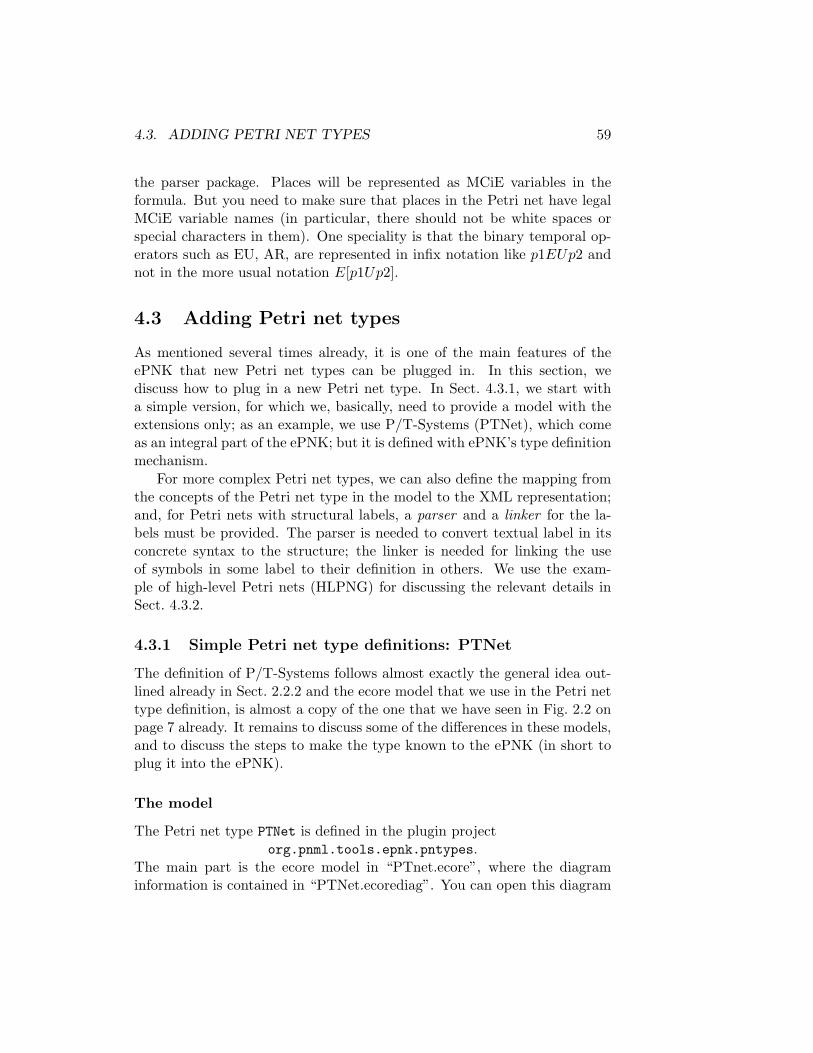
4.3. ADDING PETRI NET TYPES 59
the parser package. Places will be represented as MCiE variables in theformula. But you need to make sure that places in the Petri net have legalMCiE variable names (in particular, there should not be white spaces orspecial characters in them). One speciality is that the binary temporal op-erators such as EU, AR, are represented in infix notation like p1EUp2 andnot in the more usual notation E[p1Up2].
4.3 Adding Petri net types
As mentioned several times already, it is one of the main features of theePNK that new Petri net types can be plugged in. In this section, wediscuss how to plug in a new Petri net type. In Sect. 4.3.1, we start witha simple version, for which we, basically, need to provide a model with theextensions only; as an example, we use P/T-Systems (PTNet), which comeas an integral part of the ePNK; but it is defined with ePNK’s type definitionmechanism.
For more complex Petri net types, we can also define the mapping fromthe concepts of the Petri net type in the model to the XML representation;and, for Petri nets with structural labels, a parser and a linker for the la-bels must be provided. The parser is needed to convert textual label in itsconcrete syntax to the structure; the linker is needed for linking the useof symbols in some label to their definition in others. We use the exam-ple of high-level Petri nets (HLPNG) for discussing the relevant details inSect. 4.3.2.
4.3.1 Simple Petri net type definitions: PTNet
The definition of P/T-Systems follows almost exactly the general idea out-lined already in Sect. 2.2.2 and the ecore model that we use in the Petri nettype definition, is almost a copy of the one that we have seen in Fig. 2.2 onpage 7 already. It remains to discuss some of the differences in these models,and to discuss the steps to make the type known to the ePNK (in short toplug it into the ePNK).
The model
The Petri net type PTNet is defined in the plugin projectorg.pnml.tools.epnk.pntypes.
The main part is the ecore model in “PTnet.ecore”, where the diagraminformation is contained in “PTNet.ecorediag”. You can open this diagram

60 CHAPTER 4. DEVELOPERS’ GUIDE
by double-clicking on it in the resource explorer8 (see Sect. 4.1.2). Thediagram is shown in Fig. 4.2.
Figure 4.2: The ecore model for PTNet
There are only some minor, but important differences, to the model fromFig. 2.2 on page 7. We discuss these differences below:
1. There is a class PTNet in the ecore model, which did not exists in theconceptual model. The reason is that packages are not very tangiblein programming and in the eclipse plugin mechanisms. Therefore,we define a Petri net type as an explicit class, which inherits fromPetriNetType from the PNML core model (pnmlcoremodel). It is theclass PTNet, which will be plugged in as the extension to the ePNKlater. Moreover, this class implements some methods that help theePNK to access the information about its labels; the details, however,do not need to concern us right now.
2. There are two new classes Place and Arc, which inherit from theclasses Place and Arc from the pnmlcoremodel. And it is these newclasses to which the additional labels are attached. The reason for thisis, that ecore does not have the concept of merging packages. Instead,the extended information for the specific Petri net type is attached tothe derived classes in this new package. There could be also a classfor Page and Transition, but we do not need them here, since inP/T-Systems only places and arcs need to have additional labels.
8If for some reason, you have opened this diagram with another editor, you can open itwith the diagram editor again by selecting the file, right-clicking on it and then selecting“Open With” → “Ecore Diagram Editing”.

4.3. ADDING PETRI NET TYPES 61
Note that the name of these two classes are the same as in the PNMLcore package, which is not ambiguous since the new classes are in anew package. For now, we assume that the names of these classes arethe same as in the PNML core model9.
3. The additional classes for labels, PTMarking and PTAnnotation, areattached to the new class Place and Arc as in the conceptual modelvia a composition – only the directive “refines” is missing, due to themissing concept of merging packages in ecore. The features text aredirectly represented as an attribute of type NonNegativeInteger andPositiveInteger, which are predefined data types of the ePNK thatrepresent the respective XML Schema data types. The cardinality forthe text attributes is 1 in both cases – the same as in the conceptualmodel.
4. The new labels PTMarking and PTAnnotation are derived from thePNML core model class Label and not, as in the conceptual model,from Annotation. The reason is that up to now, the ePNK does notdistinguish between attribute and annotation labels.
5. A last difference is that there is no OCL constraint in this model.Constraints will be plugged in in a different way in the ePNK as aEMF constraint (see Sect. ??).
Such a diagram and model can be created by the “Ecore Tools”, whichwill not be discussed here (see the “EMF Ecore Tools Developer Guide” inthe “Eclipse Help” and the web pages for some information).
Generating the code
Also the code generation from that ecore model follows the EMF standardprocedure. But, we will briefly go through the process of generating all therelevant code below.
Before we can generate the code from the model, we need to create theso-called generator model (“genmodel”). This generator model will containsome information on how the code should be generated. For example, the“genmodel” contains the information to which project and which packages,the java code for the model should be generated. The “genmodel” also al-lows us to configure the generation of the EMF tree editor; for example, we
9In principle, the names could be different; but this would require some extra program-ming, which we do not discuss in this manual for now.

62 CHAPTER 4. DEVELOPERS’ GUIDE
can state whether a features can be changed, whether it should be shown asa child element or as a property, etc. See [2] for more details. A new “gen-model” can be created from an ecore model by selecting the ecore model(“PTnet.ecore” in our case), clicking the right mouse button, and select-ing “New”→“Other...” in the pop-up menu and then, in the “New” dialogchoosing “EMF Generator Model” in the category “Eclipse Modeling Frame-work”. In the case of a new Petri net type, we will have references to othermodels like the PNML core model and their “genmodel”; in the wizard forcreating the “genmodel”, make sure that you do not chose these other mod-els as root models, but that you add (and select) the respective generatormodels in the lower part as “Referenced Generator models” instead. You donot need to make any changes in the “genmodel”, but we recommend thatyou change the “Base package” property to some reasonable path.
From the “genmodel”, we can create the code for the model (model code),and the code with the infrastructure for all editors, which is called edit code.But, we do not need to generate the editor code. This is done by opening the“genmodel”, and then selecting (after clicking the right mouse button) “Gen-erate Model Code” and “Generate Edit Code”. After that, you will find10
the code for the model in the “src” folder of the project with the model and“genmodel”. Moreover, the “plugin.xml” will make the model and its codeknown to eclipse by an extension org.eclipse.emf.ecore.generated_package.The edit code will be generated in a project with the same name extendedby a suffix “.edit”. We do not need to change anything in the edit code11.
We need to make a minor change in the model code, though, which isdiscussed in the next section.
Adding the Petri net type to the ePNK
After the above steps, the code for the new model is known to eclipse. But,the ePNK will not know that it is a Petri net type. To this end, we needto define another extension. Before, we can do that, we need to make aminor change in the automatically generated code. We need to make theconstructor of the class that represents the new Petri net type public; in ourexample, this concerns the constructor of the class PTNetImpl, which canbe found in the package org.pnml.tols.epnk.pntypes.ptnet.impl.
Listing 4.16 shows this class. You can see the constructor, which is
10If you do not say otherwise in the “genmodel”.11In the org.pnml.tols.epnk.pntypes.edit project with the “edit code” for PTNets,
some of the automatically generated icons in the folder icons/obj16 have been replacedby some more appropriate images, but this is just a matter of usability.

4.3. ADDING PETRI NET TYPES 63
Listing 4.16: The class PTNetImpl with manual changes
package org.pnml.tools.epnk.pntypes.ptnet.impl;
import org.eclipse.emf.ecore.EClass;import org.pnml.tools.epnk.pnmlcoremodel.impl.PetriNetTypeImpl;
5 import org.pnml.tools.epnk.pntypes.ptnet.PTNet;import org.pnml.tools.epnk.pntypes.ptnet.PtnetPackage;
// @generated10 public class PTNetImpl extends PetriNetTypeImpl implements PTNet {
/*** @generated NOT* @author eki
15 */public PTNetImpl() {super();
}
20 /*** @generated*/
@Overrideprotected EClass eStaticClass() {
25 return PtnetPackage.Literals.PT_NET;}
// @generated NOT// @author eki
30 @Overridepublic String toString() {return "http://www.pnml.org/version-2009/grammar/ptnet";
}
35 }

64 CHAPTER 4. DEVELOPERS’ GUIDE
public now. The manual change is indicated by the @generated NOT tag12.The other manual change is the addition of the toString() method. Thisdefines the value of the PNML type attribute for nets for that particularPetri net. Here, we use the one from ISO/IEC 15909-2 for P/T-Systems.
With this public constructor, we can plugin the PTNetImpl as a newPetri net type to the ePNK now. To this end, we use the extension pointorg.pnml.tools.epnk.pntd in the “plugin.xml”. Listing 4.17 shows therelevant part from the “plugin.xml” file in the project
org.pnml.tools.epnk.pntypes.The attribute point refers to the ePNK type definition extension point, the
Listing 4.17: The extension PTNetImpl
<extensionid="org.pnml.tools.epnk.pntypes.ptnet"name="PTNets"point="org.pnml.tools.epnk.pntd">
5 <typeclass="org.pnml.tools.epnk.pntypes.ptnet.impl.PTNetImpl"description="Place/Transition Nets">
</type></extension>
id is a unique id for the new type, and name is some conclusive name (weuse the one from ISO/IEC 15909-2). The type refers to the class that imple-ments the new type; in our example, this is our PTNetImpl class. In general,this class that is chosen here must extend the class PetriNetTypeImpl fromthe PNML core model code, and have a public constructor (that is why weneeded the manual change). The description can contain a longer descrip-tion of the new net type – for P/T-Systems, we guessed that no furtherexplanation would be needed.
Adding constraints
As mentioned earlier, it is not allowed in P/T-Systems to have arcs that runfrom places to places or from transitions to transitions. In the conceptualmodel of PTNets, this was included as an OCL constraint in the UML modelalready. In the ePNK, this constraint must be added separately, which is
12Actually, we could just delete the tag @generated, but it is easier to search for andkeep track of manual changes, if they are tagged with @generated NOT.

4.3. ADDING PETRI NET TYPES 65
done by the standard mechanisms of EMF Validation in the “plugin.xml”.Listing 4.18 shows the part of the “plugin.xml” that defines this con-
straint. The actual OCL constraint is defined in the bottom in the XMLCDATA part. This OCL expression resembles the one from the conceptualUML model, but is slightly different syntactically – which is due to thespecific technology. Moreover the “headline” that states the context Arc ismissing, since in the EMF Validation technology, the context is explicitlyset by the target element, which you can find immediately above, whichis the Arc of the ptnet package (the URL is defined in the model). Thedeclaration of the events is necessary here, since we made this constrainta live constraint, which means that the editors will make sure not to vio-late it during editing. To this end, the editor needs to know the change ofwhich features might violate the constraint; in our example, this is settingthe source or the target of an arc.
The rest of this constraint definition is a bit more technical. But, wego briefly through it. The extension that we actually define is a constraintprovider, which consists of the package it refers to and the constraints. Inour case, the package is the PNML core model – even though it is for aspecific Petri net types. The reason is that the validation always starts fromthe PNML core model. The constraints are defined in a category; the ePNKdefines its own category, which is used here:
org.pnml.tools.epnk.validationEach constraint must have a unique id, must state the language it is definedin (OCL in our example), have a name, a severity, and a statusCode.The status code can be freely chosen; the ePNK uses codes starting witha 3 for constraints concerning Petri net types. The mode can be live orbatch; in live mode, the graphical editor will watch them and not allowedit operations that would violate them – this is what we chose in ourexample. Other constraints, like correctness of structured labels, might bedefined to be in batch mode; the graphical editor will allow for syntacticallyincorrect labels, but this will be reported when validating the net. The lastinformation in the constraint is a message, which is shown to the end userwhen the constraint is violated. The parameter {0} refers to the object thatviolates the constraint (in its String representation) – for constraints otherthan OCL, there could be more parameters. Moreover, there is a longerdescription of the constraint.
As mentioned above, the constraint can be formulated in different lan-guages. It could, for example, be in Java, which would require to imple-ment a java class. There are some examples of such java constraints in theHLPNG definition. Java is more convenient for implementing more complex

66 CHAPTER 4. DEVELOPERS’ GUIDE
Listing 4.18: Adding a constraint for PTNets
1 <extension point="org.eclipse.emf.validation.constraintProviders"><constraintProvider cache="true"><packagenamespaceUri="http://org.pnml.tools/epnk/pnmlcoremodel">
</package>6
<constraints categories="org.pnml.tools.epnk.validation"><constraint
id="org.pnml.tools.epnk.pntypes.ptnet.validation.PT_TP_ArcsOnly"
11 lang="OCL"mode="Live"name="PT or TP Arcs only"severity="ERROR"statusCode="301">
16 <message>The arc {0} must run from a place to a transition or vice versa.
</message><description>
Arcs between two places or transitions are forbidden in21 P/T-nets (see Clause 5.3.1 of ISO/IEC 15909-2).
</description><target
class="Arc:http://org.pnml.tools/epnk/types/ptnet"><event name="Set">
26 <feature name="source"/><feature name="target"/>
</event></target>
<![CDATA[31 ( self.source.oclIsKindOf(pnmlcoremodel::PlaceNode) and
self.target.oclIsKindOf(pnmlcoremodel::TransitionNode) ) or( self.source.oclIsKindOf(pnmlcoremodel::TransitionNode) andself.target.oclIsKindOf(pnmlcoremodel::PlaceNode) )
]]>36 </constraint>
</constraints></constraintProvider>
</extension>

4.3. ADDING PETRI NET TYPES 67
constraints.
Note that we did not define any mapping from the concepts defined inthe ecore model of P/T-Systems to their representation in XML. The reasonis that, the standard mapping is good enough: the name of the compositionin which the label is contained is the XML element, and the text featureof the label is mapped to the XML element <text> (see Fig. 2.1 on page 9for an example). A mapping to XML needs to be defined only when thestandard mapping is not enough, or when we have structured labels, whichwill be discussed in the next section.
4.3.2 Petri net type definitions in general: HLPNG
In this section, we discuss some more advanced mechanisms that can be usedfor defining new Petri net types. These mechanism will be discussed by thehelp of the Petri net type definition of high-level Petri nets (HLPNGs).Therefore, we start with an overview of the concepts of HLPNGs, from theimplementation point of view (for the conceptual part we refer to Sect. 3.5.2and for a detailed discussion of all models and concepts, we refer to [5]).
Overview of HLPNGs
As discussed in Sect. 3.5.2, HLPNGs have different kinds of complex labels:declarations of variables, sorts, and operators; types defining the sort ofthe tokens of a place, marking which are multiset terms defining the initialmarking, conditions as transition guards, and arc annotations that definewhich tokens are consumed, resp. produced when a transition fires. What ismore, the labels cannot be considered isolated from each other any more –some labels, like markings, arc annotations, or conditions may use symbolsthat are defined in other labels – in particular, in the declarations.
Figure 4.3 shows the ecore model defining these concepts of HLPNGs,which can be found in the folder model in project13
org.pnml.tools.epnk.pntypes.hlpngs.pntdThis model follows the same principles as the model for PTNets, which wasdiscussed in Sect. 4.3.1. The main differences are, that the defined Petri nettype HLPNG extends a more advanced class StructuredPetriNetType, and
13This is the plugin in which HLPNGs are plugged into the ePNK; since HLPNGs arequite complex, and require many models, and also the implementation of a parser, theunderlying definitions are defined in different other projects; all of these projects have aname with prefix org.pnml.tools.epnk.pntypes.hlpngs – some of them are generatedautomatically from models or from a grammar.

68 CHAPTER 4. DEVELOPERS’ GUIDE
Figure 4.3: The ecore model for HLPNGs
all labels extend StructuredLabel, which are part of the PNML core model.These two classes provide the infrastructure needed for parsing the textuallabels and for establishing the links between these labels. This structurewill be discussed in Sect. 4.3.2.
The actual content of all these labels is defined in their containmentstructure; note that we use Term as the contents for HLMarking, Condition,and HLAnnotation, since all of them are terms – just with different addi-tional constraints imposed on them (see Sect. 3.5.2 and Sect. 4.3.2).
The detailed structure and concepts of terms, sorts, and declarations, aredefined in several other models. Since these details are not too relevant forunderstanding the definition of structured Petri net types, we discuss onlythe main part of that model. This part of the model is shown in Fig. 4.4– this as well as the diagrams of all the other models can be found in theplugin org.pnml.tools.epnk.pntypes.hlpngs.datatypes. For a detaileddiscussion of these models and their concepts, we refer to [5]. There is onlyone important difference, which are the classes SymbolDef and SymbolUse,which do not occur in the models of ISO/IEC 15909-2. These two classes,are the ePNKs infrastructure for dealing with the definition of symbols andtheir use in a uniform and generic way. They are part of the PNML coremodel concerning structured Petri net types, which will be discussed in thenext section.

4.3. ADDING PETRI NET TYPES 69
Figure 4.4: The ecore model for the main concepts of HLPNGs
Structured Petri net types and structured labels
As mentioned above, the ePNK provides some general interfaces and infras-tructure for defining structured Petri net types that extracts the generalconcepts of more complex types. This is, again captured in models (and thecode generated from them).
The model for structured Petri net types can be found in the modelfolder of the ePNK core project org.pnml.tools.epnk:
PNMLStructuredPNTypeModelThe diagram is shown in Fig. 4.5. We know the classes PetriNetTypeand Label as well as the interface ID, which is used for all ePNK elementsthat have an id, already from the PNML core model. The abstract classStructuredLabel extends the class Label, it has an attribute text, which

70 CHAPTER 4. DEVELOPERS’ GUIDE
Figure 4.5: The model for structured Petri net types
stores the content of this label as a text String. The actual structural con-tents will be defined by classes that extend it (we have seen some examplesin Fig. 4.3 already). Since, the ePNK cannot not know these concrete imple-mentations, classes extending the structural label must make the referenceto this structural contents known to the ePNK. This is achieved by themethod getStructuralFeature(); as long as the feature for the structureis called ‘structure” in the model, we do not need to do anything in theimplementation (the ePNK will access this feature in a reflective way); onlyif for some reason, the model chooses a different name, this method mustbe implemented manually. Moreover, every class for a structural label mustprovide a method for parsing a String – a representation of this label in con-crete syntax; an implementation of this method may return null, if the textcannot be parsed, or it must return some object (to be precise an EObjectwhich is the EMF version of objects) with all the substructure of that la-bel. In particular, that object must have a type that is compatible with thelabels structural feature. This method must be implemented manually forevery new extension since the ePNK cannot guess the concrete syntax.
The abstract class StructuredPetriNetType has one additional method,

4.3. ADDING PETRI NET TYPES 71
which must provide a Linker for linking the uses of some symbols to theirdefinitions, which are captured by classes SymbolDef and SymbolUse. ASymbolDef is an ID and has a name, which will be used to refer to it (the idis internal to PNML and the ePNK). This name will be used in SymbolUse,again as attribute name, to refer to the definition. The feature that actuallyrefers to the definition, can be accessed via the method getRefFeature().Since the ePNK, does not know anything about how to make these con-nections, the Petri net type needs to provide the linker (via the methodgetLinker()). Linker is an interface: a single method getglobalLinks(),which takes a Petri net and returns a SymbolUseMapping, which is also aninterface. Conceptually, the SymbolUseMapping maps a SymbolUse to itsdefinition SymbolDef. All the symbol uses for which there exists a mapping,can be obtained (as a list) via the method getSymbolUse(); and for eachsymbol use, the method getSymbolDef() will return the definition of thatsymbol.
With this infrastructure, the ePNK can deal with all kinds of structurallabels, provided they implement the required methods. We will have a lookat an implementation examples next: We consider the label Condition inthe Petri net type definition for HLPNGs again (see Fig. 4.3) – the otherlabels are similar. Its structural feature is the containment structure toclass Term. Since this is the standard name for structured labels, we donot need to override the method getStructuralFeature. But, we need toimplement the parse method. The parsers for all labels of HLPNGs wereautomatically generated by Xtext, and made available in a singleton classHLPNGParser in packageorg.pnml.tools.epnk.pntypes.hlpngs.datatypes.concretesyntax
in a project with the same name. For parsing a term, HLPNGParser providesa method parseTerm(String). This singleton and its method parseTermis used in the implementation of ConditionImpl (you will find it in thepackageorg.pnml.tools.epnk.pntypes.hlpng.pntd.hlpngdefinition.impl
in project org.pnml.tools.epnk.pntypes.hlpng.pntd).Since linking is across all the different labels of a net, there is only a
single linker for every net. For HLPNGs, this is implemented in packageorg.pnml.tools.epnk.pntypes.hlpngs.datatypes.concretesyntax.linking
in projectorg.pnml.tools.epnk.pntypes.hlpngs.datatypes.concretesyntax
This class is HLPNGLinker; basically it goes through the complete Petri nettwice; in the first round, it creates a symbol table of all symbol definitions; inthe second round, this symbol table will be used to look up the definitions for

72 CHAPTER 4. DEVELOPERS’ GUIDE
every symbol use, which is stored in the SymbolMapping, which implementsthe SymbolUseMapping that we discussed above.
To make this linker known to the ePNK, the class HLPNGImpl in packageorg.pnml.tools.epnk.pntypes.hlpng.pntd.hlpngdefinition.impl im-plements the method getLinker(): it returns an instance of HLPNGLinker.Note that, in the class HLPNGImpl, we also need to make the constructorpublic and implement the toString() method (as discussed in Sect. 4.3.1).
Constraints
For HLPNGs, we needed to implement quite many constraints. As an ex-ample for a java constraint, we discuss just one example here. The rest ofthem would not provide much insight into the mechanisms of the ePNK –though they might provide some insights to the inner workings of HLPNGsthemselves. There is also one OCL constraint, which forbids connectingplaces with places and transitions with transitions. But, this exactly as forPTNets, which is why we do not discuss it here again.
All constraints for HLPNGs are defined in the projectorg.pnml.tools.epnk.pntypes.hlpng.pntd,
the java constraint implementations can be found in the packageorg.pnml.tools.epnk.pntypes.hlpng.pntd.validation
We discuss the constraint that transition conditions must have type boolean,which is implemented in class ConditionIsBoolType. Listing 4.19 showsthis class. This constraint extends the class AbstractModelConstraintfrom EMF Validation and implements the method validate. From thevalidation context, it obtains the target object, which should be a transition(see later). But, we are defensive and check that explicitly. Then, we obtainthe condition label of that transition, and if it is not null, get the term (itsstructure). Then, we check whether the sort of the term is boolean14. If it is,we return a failure status via the validation context, and add the transitionand the textual label to an array of objects (which is used in the errormessage to be defined later). Otherwise, we return a success status. Notethat the EMF Validation Framework makes sure that this validate methodis called for all transitions of a selected Petri net, Petri net document orpage, once it is properly plugged in, which is discuss below.
Plugging in a java constraint is very similar to plugging in OCL con-straints. The relevant fragment of the “plugin.xml” is shown in Listing 4.20.The main differences are that the attribute lang is “Java” now and the at-
14The implementation of getSort() for terms is actually quite complex, but we do notdiscuss that here.

4.3. ADDING PETRI NET TYPES 73
Listing 4.19: The constraint that conditions have type boolean
1 package org.pnml.tools.epnk.pntypes.hlpng.pntd.validation;
import org.eclipse.core.runtime.IStatus;import org.eclipse.emf.ecore.EObject;import org.eclipse.emf.validation.AbstractModelConstraint;
6 import org.eclipse.emf.validation.IValidationContext;importorg.pnml.tools.epnk.pntypes.hlpng.pntd.hlpngdefinition.Condition;
importorg.pnml.tools.epnk.pntypes.hlpng.pntd.hlpngdefinition.Transition;
11 importorg.pnml.tools.epnk.pntypes.hlpngs.datatypes.booleans.Bool;
import org.pnml.tools.epnk.pntypes.hlpngs.datatypes.terms.Sort;import org.pnml.tools.epnk.pntypes.hlpngs.datatypes.terms.Term;
16 public class ConditionIsBoolType extends AbstractModelConstraint {
public IStatus validate(IValidationContext ctx) {EObject object = ctx.getTarget();
21 if (object instanceof Transition) {Transition transition = (Transition) object;Condition condition = transition.getCondition();if (condition != null) {Term term = condition.getStructure();
26 if (term != null) {Sort sort = term.getSort();if (sort != null) {if (!(sort instanceof Bool)) {return ctx.createFailureStatus(
31 new Object[] {transition,condition.getText()});
}}
}36 }
}return ctx.createSuccessStatus();
}}

74 CHAPTER 4. DEVELOPERS’ GUIDE
Listing 4.20: Adding the constraint for conditions
<extension point="org.eclipse.emf.validation.constraintProviders"><constraintProvider cache="true"><packagenamespaceUri="http://org.pnml.tools/epnk/pnmlcoremodel">
5 </package>
<constraints categories="org.pnml.tools.epnk.validation">...<constraint
10 lang="Java"class="org.pnml. ... .validation.ConditionIsBoolType"severity="ERROR"mode="Batch"name="Condition is of type boolean"
15 id="org.pnml. ... .validation.ConditionIsBoolType"statusCode="314"><target class=
"Transition:http://org.pnml.tools/epnk/pntypes/hlpng/pntd/hlpng"/><description>
20 The condition must be of type BOOL.</description><message>
The condition {1} of transition {0} is not of type BOOL.</message>
25 </constraint>...</constraints>
</constraintProvider></extension>

4.3. ADDING PETRI NET TYPES 75
tribute class refers to the class ConditionIsBoolType, which was discussedabove. As target class, the transitions of HLPNGs are defined (that is whywe could assume that the target object is a transition). Another differenceis that this is no live constraint, but a batch constrain. This means, thatit might be violated during editing, and a violation will only be detectedon explicit validation. Since this is a batch constraint, we do not need todeclare any events in the target.
Another difference to the OCL constraint is, that we can refer to severalparameters in the message now. What the different parameters are, dependson the return value of the validation method. In our case, this was thetransition (or its String representation) and the text of the label.
The ellipses (“...”) indicate that the constraint that we have discussedhere, is just one of many other constraint, which are not discussed here.
XML Mappings
In the sections above, we have discussed how to define a Petri net type andall its concepts and constraints. For saving it in PNML, it is also necessary todefine how these concepts are represented in XML – at least if the “standardmappings” do not work.
In this section, we will discuss how these mappings are defined. Con-ceptually, these mappings are tables (in ISO/IEC 15909-2, these tables aregiven in Clause 7.3.1). In the ePNK, these “tables are programmed” as partof the new Petri net type15.
We explain the concepts of these “programmed tables” by discussingsome of the mappings for HLPNGs. The tables for a new Petri net type areprogrammed, by overwriting the methodregisterExtendedPNMLMetaData(ExtendedPNMLMetaData metadata)
of PetriNetType; the parameter metadata represents the table, to which wecan add entries when this method is called.
Let us have a look at some examples. Listing 4.21 shows an excerptof the registerExtendedPNMLMetaData() method of the class HLPNGImpl.Each of the metadata.add statements defines one table entry, which definesthe mapping of one specific feature of the ecore model to an XML element(we will see later how to map an ecore attribute to an XML attribute). Thethree statements shown in Listing 4.21 define how the structure feature of
15It might be, that a future version will provide a means to plugin these tables directlyin some form; but since “programming the tables” is not too difficult, this does not havea high priority.

76 CHAPTER 4. DEVELOPERS’ GUIDE
Listing 4.21: Mappings for type, marking, and condition extensions
1 public void registerExtendedPNMLMetaData(ExtendedPNMLMetaData metadata) {...
metadata.add(6 HlpngdefinitionPackage.eINSTANCE.getType_Structure(),
HlpngdefinitionPackage.eINSTANCE.getType(),TermsPackage.eINSTANCE.getSort(),"structure",null,
11 HLPNGFactory.getHLPNGFactory());
metadata.add(HlpngdefinitionPackage.eINSTANCE.getHLMarking_Structure(),HlpngdefinitionPackage.eINSTANCE.getHLMarking(),
16 TermsPackage.eINSTANCE.getTerm(),"structure",null,HLPNGFactory.getHLPNGFactory());
21 metadata.add(HlpngdefinitionPackage.eINSTANCE.getCondition_Structure(),HlpngdefinitionPackage.eINSTANCE.getCondition(),TermsPackage.eINSTANCE.getTerm(),"structure",
26 null,HLPNGFactory.getHLPNGFactory());
...}

4.3. ADDING PETRI NET TYPES 77
the labels Type, the HLMarking, and the Condition are mapped to the XMLelement <structure>. We discuss the first one, the Type, in more detail:
• The first parameter, denotes the feature that is mapped, which isthe composition from the class Type to the class Sort (see Fig. 4.3).These source and target classes are mentioned explicitly as second andthird parameter again. We refer to the feature and the two classes viasingleton classes that describes the elements of the packages (HLP-NGdefinition and Terms). These package classes, provide access to allthe classes and features within a package (see [2] for more details).Note that HlpngdefinitionPackage.eINSTANCE refers to the pack-age hlpngdefinition and TermsPackage.eINSTANCE to the packageterms.
• As mentioned above, the second parameter denotes the class to whichthe feature belongs (it could be a sub-class of Type in principle); thisis often called the container class.
• The third parameter denotes the class that the feature refers to (thiscould also be a sub class of Sort); this is often called the object class.
• The forth parameter, defines the XML representation, the string thatwill be used as XML element in the serialisation of this feature (in ourexample “structure”).
• The fifth parameter could refer to a XML attribute, that might benecessary for creating an ecore object from the XML element (we willdiscuss an example later). In most cases, these XML attributes are notneeded, since the XML element (and the context in which it occurs)provide enough information for creating the ecore element from it.
• The last parameter refers to a factory that is capable of creating anecore instance of the respective class from the XML element and – ifprovided – the XML attribute.
You can see that these table entries can be used in two directions. Inthe one direction, it tells how to serialise a Petri net to its XML syntax;in the other direction, it tells how to create the model elements from theXML syntax. In the latter case, the factories play an important role. List-ing 4.22 shows the interface that all these factories must implement. Themethods canCreateObject and createObject have the same parameters,which basically reflect the entries of the table that we discussed above. Only

78 CHAPTER 4. DEVELOPERS’ GUIDE
Listing 4.22: Interface Factory
package org.pnml.tools.epnk.pnmlcoremodel.serialisation;
import org.eclipse.emf.ecore.EObject;import org.eclipse.emf.ecore.EStructuralFeature;
5
public interface IPNMLFactory {
public boolean canCreateObject(EStructuralFeature feature,
10 Object container,String element,String attribute,IAttributeProvider provider);
15 public EObject createObject(EStructuralFeature feature,Object container,String element,String attribute,
20 IAttributeProvider provider);
public Object createAttributeObject(Object object,String attribute,
25 IAttributeProvider provider);
}

4.3. ADDING PETRI NET TYPES 79
the third and six one (the factory itself) are missing. And, there is an ad-ditional parameter (provider), which will provide access to the values ofall attributes of the currently read XML element (in case the factory needsto read them for creating an the object). The method canCreateObjectis used to find out whether the factory is able to create an object from theprovided information, the createObject method is used to actually createit. The createAttributeObject is used to create an object for some XMLattribute. The implementation of these factories is straight-forward and abit boring – we do not discuss the details here. You can have a look intothe class HLPNGFactory in packageorg.pnml.tools.epnk.pntypes.hlpng.pntd.hlpngserialisation.factoryin the project org.pnml.tools.epnk.pntypes.hlpng.pntd to get some in-spiration. What is more, with an extension that came into version 0.9.0 ofthe ePNK, the facory can be set to null. In which case the standard mech-anism for creating an object of the target class will be used; therefore, wewill need factories in very rare and special cases only. Typically, the factorycan be set to null16
Listing 4.23: Mappings of an attribute
metadata.addAttributeMapping(BooleansPackage.eINSTANCE.getBooleanConstant_Value(),
3 BooleansPackage.eINSTANCE.getBooleanConstant(),"value",HLPNGFactory.getHLPNGFactory());
Listing 4.23 shows an example17 of how a feature of the model can bemapped to an XML attribute. In this example, the value of the booleanconstant is mapped to the XML attribute value. This is where the methodcreateAttributeObject of the factory comes into play.
The discussion above, gives a general idea of how these tables and map-pings work. All this, however, could have been achieved with the existingmechanisms of EMF: Extended Metadata. But, the mappings of PNMLhave some specialities that could not be expressed in the Extended Meta-data concepts. Therefore, we introduced yet another extension in the ePNK.
16Note that except for two features, which were sued to test this new mechanism, themappings for HLPNGs have not been updated yet; therefore, you will find factories allover these mappings. But, this has historic reasons only and will eventually be changed(making the mappings more maintainable).
17Actually, this is the only one of HLPNGs.

80 CHAPTER 4. DEVELOPERS’ GUIDE
In the rest of this section, we will discuss some of these special situations.Let us consider the serialisation of the simple term x‘f(x,x), where x is
a variable and f a user defined operator. The PNML representation is shownin Listing 4.24. In addition to being a bit verbose, there is one thing that
Listing 4.24: PNML representation of x‘f(x,x)
<numberof><subterm>
3 <variable refvariable="5"/></subterm><subterm><useroperator declaration="1"><subterm>
8 <variable refvariable="5"/></subterm><subterm><variable refvariable="5"/>
</subterm>13 </useroperator>
</subterm></numberof>
is special about this mapping. There is a XML element <subterm> for theassociation form the top-level term (number of) to its subterm, which arerepresented as two other XML elements, <variable> and <useroperator>.The XML element <subterm> defines to which feature of the term the XMLelement that is contained in it should go. The XML element inside (e. g.<variable>) defines the type that object should have.
The problem here, is that there is an intermediate XML element thathas no object as counter part in the model – it represents an association. Wecall them association elements. The mapping for these association elementsis shown in Listing 4.25. The first entry is actually as we have seen it before.The only difference is that the factory produces an instance of a new classTermAssoc, which has the nature of a term but, actually, represents anassociation to a term. We will discuss that class in more detail later. Thetwo other mappings, define the mapping of variables and user operators toXML, and these are different, since they do not refer to any feature at all.They just refer to a container class and a contained class. The containerclass is the class TermAssoc, which will make sure that the variable resp.user operator will be added to the subterm feature of the operator on the

4.3. ADDING PETRI NET TYPES 81
Listing 4.25: Mappings of associations to XML elements
metadata.add(TermsPackage.eINSTANCE.getOperator_Subterm(),TermsPackage.eINSTANCE.getOperator(),TermsPackage.eINSTANCE.getTerm(),"subterm",
5 null,HLPNGFactory.getHLPNGFactory());
metadata.add(null,HlpngserialisationPackage.eINSTANCE.getTermAssoc(),
10 TermsPackage.eINSTANCE.getVariable(),"variable",null,HLPNGFactory.getHLPNGFactory());
15 metadata.add(null,HlpngserialisationPackage.eINSTANCE.getTermAssoc(),TermsPackage.eINSTANCE.getUserOperator(),"useroperator",null,
20 HLPNGFactory.getHLPNGFactory());

82 CHAPTER 4. DEVELOPERS’ GUIDE
level above18.The class TermAssoc does not need to be programmed. This class, as
well as the other classes for representing associations, could completely begenerated from a model. This model is shown in Fig. 4.6. These classesextend a specific class of our model (the one to which the respective associ-ation should go), and the general class for AssocClass, which is defined bythe ePNK, and implements all the necessary functionality. Note that these
Figure 4.6: The package hlpngserialisation
classes will not occur in the model anymore, once it is completely loaded –they are only used when a PNML file is loaded.
In the case of subterms, every subterm occurs in a separate <subterm>element – even if a term has several subterms, there is one subterm elementfor each of them (see Listing ??). In the case of parameters of an operationdeclaration, this is different: Listing 4.26 shows the PNML representationof the declaration of a named operator f(x:INT, y:INT) = x * y. Here,all variable declarations occur in the same <parameter> element. We calledthese bundled association elements. The table entries for this mapping areshown in Listing 4.27. The first one, is almost the same as for associa-tion elements, and the Factory HLPNGFactory would create an instance ofVariableDeclAssoc for an XML element <parameter>. The new last pa-
18There would actually be another way of doing this, in a slightly more elegant waywhen using “standard features”, which will be discussed later in this section.

4.3. ADDING PETRI NET TYPES 83
Listing 4.26: PNML structure for declaration f(x:INT, y:INT) = x * y
<namedoperator id="1" name="f"><parameter><variabledecl id="2" name="x">
<integer/>5 </variabledecl>
<variabledecl id="3" name="y"><integer/>
</variabledecl></parameter>
10 <def><mult><subterm><variable refvariable="2"/>
</subterm>15 <subterm>
<variable refvariable="3"/></subterm>
</mult></def>
20 </namedoperator>

84 CHAPTER 4. DEVELOPERS’ GUIDE
rameter true says, that this is a bundled association. The second table
Listing 4.27: Mapping bundled association elements
metadata.add(TermsPackage.eINSTANCE.getNamedOperator_Parameters(),TermsPackage.eINSTANCE.getNamedOperator(),TermsPackage.eINSTANCE.getVariableDecl(),
5 "parameter",null,HLPNGFactory.getHLPNGFactory(),true);
10 metadata.add(null,null,TermsPackage.eINSTANCE.getVariableDecl(),"variabledecl",
15 null,HLPNGFactory.getHLPNGFactory());
entry defines the mappings for variable entries, which is independent of thecontext, which is why the first to parameters are null. We call this a contextindependent element mapping.
This context independent element mapping can be applied in any othercontext. In combination with another special case of mappings which wecall standard feature, this is a very powerful mechanism. For example, forDeclarations and sub-element for which context element mapping exists(in the example, there would be variable declarations, sort declarations,and operator declarations), all these elements should be added to this stan-dard feature. The table entry shown in Listing 4.28 defines the compositiondeclaration as the standard feature of Declarations. Note that there
Listing 4.28: Defining a standard feature
metadata.add(TermsPackage.eINSTANCE.getDeclarations_Declaration(),TermsPackage.eINSTANCE.getDeclarations(),TermsPackage.eINSTANCE.getDeclaration(),
4 null,null,null);

4.4. ADDING TOOL SPECIFIC INFORMATION 85
is no mapping to XML here. A standard feature of an element just saysthat, whenever comes from some context independent element, which is notmapped explicitly to a feature, should be added to this standard feature ofthe model. Of course, there should only be one standard feature – otherwisethere would be some ambiguities.
4.4 Adding tool specific information
As discussed in Sect. 2.2.1, the PNML allows tool specific information to beadded to all elements of Petri nets – indicated by a special XML element<toolspecific>. The ePNK will read and write any tool specific infor-mation, and, in principle, its context could be accessed and modified viathe class AnyType, which is defined in the plugin org.eclipse.emf.ecore.But this is tedious and, basically, means navigating in the elements XMLstructure.
Therefore, the ePNK provides an extension point to plugin tool specificextensions, so that they can accessed and modified via an API specific tothe extension which can be defined in terms of a model. We will discuss howto use this extension point by the help of an example: the token positions,which are part of the standard. We have seen an example already in Fig. 2.3and Listing 2.1 on page 9.
This tool specific extension is defined in the projectorg.pnml.tools.epnk.toolspecific.tokenpositions
Most of this code and the “plugin.xml” is automatically generated from themodel “Tokenpositions.ecore” in the folder “model”. This model is shownin Fig. 4.7. The new classes are PNMLToolInfo and Tokengraphics. Theclass PNMLToolInfo represents the actual tool specific information: it mustimplement the PNML core model interface ToolInfo. The actual contentsof this tool specific information is Tokengraphics, which consists of one ormany coordinates; the class Coordinate comes from the PNML core model.
From this model, the code can be generated in the same way as de-scribes in Sect. 4.3.1. First, the “genmodel” must be created, and from the“genmodel”, the model code and the edit code must be generated.
After the code generation, the only thing left to plug in the new toolspecific extension is to manually create a factory for this tool specific ex-tension, and use this factory for plugging it into the ePNK. The factory forour extension is shown in Listing 4.29. The factory implements the ePNKinterface ToolspecificExtensionFactory, which consists of four methods.The two methods createToolInfo create an instance of this tool specific

86 CHAPTER 4. DEVELOPERS’ GUIDE
Figure 4.7: The model for tool specific extension tokenpositions
extension; the method with the two String parameters, tool and version isused, when there is the tool name and a version given, which might returninstances of different classes – in our example, however, the version numberis irrelevant. The two other methods, must return the tool name for thatextension and its version, which, in our example, are encoded in constants.
Listing 4.30 shows the fragment of the “plugin.xml” that is needed toplug in the token position extensions to the ePNK. In addition to the nameand the id, the attribute class defines to the factory for the tool specific ex-tensions; this class must implement the interface ToolspecificExtensionFactory.Moreover, there is a brief description of this extension.
Note that there is no way of explicitly defining the XML syntax of theseextensions. The standard XMI serialisation will be used. Eventually, therewill be a mapping mechanism similar to the one for Petri net types.
4.5 Overview of the ePNK and its API
In this section, we give a brief overview of the different parts of the ePNK,its project structure and the API. As mentioned earlier, developers wouldprobably not need to change anything in these projects, but the overviewhelps to better understand the ideas behind the ePNK, the necessary de-pendencies (that need to be included in new projects via the “plugin.xml”)and the functions that are available in the ePNK API.
...

4.5. OVERVIEW OF THE EPNK AND ITS API 87
Listing 4.29: Factory for the tool specific extension
package org.pnml.tools.epnk.toolspecific.tokenpositions.factory;
import org.pnml.tools.epnk.pnmlcoremodel.ToolInfo;4 import org.pnml.tools.epnk.toolspecific.extension.ToolspecificExtensionFactory;
import org.pnml.tools.epnk.toolspecific.tokenpositions.TokenpositionsFactory;
public class TokenpositionsExtensionFactory9 implements ToolspecificExtensionFactory {
private final static String toolname = "org.pnml.tool";private final static String toolversion = "1.0";
14 public ToolInfo createToolInfo(String tool, String version) {// ToolInfo object does not depend on these values:return createToolInfo();
}
19 public ToolInfo createToolInfo() {return TokenpositionsFactory.eINSTANCE.createPNMLToolInfo();
}
public String getToolName() {24 return toolname;
}
public String getToolVersion() {return toolversion;
29 }
}

88 CHAPTER 4. DEVELOPERS’ GUIDE
Listing 4.30: Plugging in the token position extension
<extensionid="org.pnml.tools.epnk.toolspecific.tokenpositions"name="Token Positions"
4 point="org.pnml.tools.epnk.toolspecific"><typeclass="org.pnml. ... .factory.TokenpositionsExtensionFactory"description="The tool specific extension for token positions">
</type>9 </extension>
4.6 Deploying extensions
In this section, we will briefly discuss how own extensions of the ePNKcould be deployed, so that others can use it. We will briefly touch on theeclipse feature mechanism for combining a bunch of related plugins into adeployable unit, the feature. Moreover, we will briefly discuss how to createan eclipse update site, from which the extensions can be installed.
Since this is standard eclipse, however, this will come at a later stage.For now, looking up the keywords “feature” and “update site” in the eclipsehelp (or googling for them) must be enough.
4.7 Future plans
In this section, we give an overview of some extensions that are plannedfor the ePNK, which will increase its flexibility, make it easier to use, andprovide additional extension mechanisms. The order indicates the priorities,and might be roughly the order in which the features are implemented:
• Full support all graphical features of PNML in the graphical editor(maybe except bezier curves for arcs, which needed to be implementedmanually, since GMF does not support them).
• Add a toolspecific feature that exactly saves the graphics of a Petrinet as it appears in the graphical ePNK editor (even if no PNMLrepresentation exists).
• Smoother integration of EMF-tree editor with the GMF-editor.

4.7. FUTURE PLANS 89
• Add the attributes mechanism of PNML together with a mechanismto define the graphical appearance of net objects.
• Implement the serialisation of the structural labels of HLPNGs toconcrete syntax.
• Define an extension point for defining the concrete syntax of HLPNGs.
• Portation of the code-generation for extended P/T-Nets to the ePNK(and define the extended Petri net type for that).
• Implement an explicit ePNK extension point for functionality, in orderto unify the access to ePNK functions.
• Define an extension point for the XML mapping that directly takes atable instead of “programming the table”.
• Long-term: Support modular PNML.

Chapter 5
Inside the ePNK
In this section, we will have a closer look into the ePNK. We will see howsome of the features of the ePNK are implemented and in which way some ofthe EMF technology needed to be extended to cater for the mappings fromthe ecore models to XML. Note that this chapter is only for very interestedreaders, who eventually might contribute to the development of the ePNKor who want to learn a bit more about EMF and how some of EMF’s moreadvanced features work.
For using the ePNK, and for defining some extensions at the ePNK’spredefined extension points, you would not need to read this chapter.
...
90

Chapter 6
PNML: Observations andsuggestions
During the work on the ePNK, several issues came up concerning PNML.In this chapter, these issues will summarized and some suggestions on howto improve future versions of PNML will be made.
91

Bibliography
[1] J. Billington, S. Christensen, K. van Hee, E. Kindler, O. Kummer,L. Petrucci, R. Post, C. Stehno, and M. Weber. The Petri Net MarkupLanguage: Concepts, technology, and tools. In W. van der Aalst andE. Best, editors, Application and Theory of Petri Nets 2003, 24th Inter-national Conference, volume 2679 of LNCS, pages 483–505. Springer,June 2003.
[2] F. Budinsky, D. Steinberg, E. Merks, R. Ellersick, and T. J. Grose.Eclipse Modeling Framework. The Eclipse Series. Addison-Wesley, 2ndedition edition, Apr. 2006.
[3] E. Clarke, O. Grumberg, and D. Peled. Model checking. MIT Press,1999.
[4] E. Clayberg and D. Rubel. Eclipse Plug-ins. The Eclipse Series.Addison-Wesley, 3rd edition edition, 2008.
[5] L. Hillah, E. Kindler, F. Kordon, L. Petrucci, and N. Treves. A primeron the Petri Net Markup Language and ISO/IEC 15909-2. In K. Jensen,editor, 10th Workshop on Coloured Petri Nets (CPN 09), pages 101–120, Oct. 2009.
[6] L.-M. Hillah, F. Kordon, L. Petrucci, and N. Treves. PNML Frame-work: An extendable reference implementation of the petri net markuplanguage. In J. Lilius and W. Penczek, editors, Petri Nets, volume 6128of Lecture Notes in Computer Science, pages 318–327. Springer, 2010.
[7] M. Jungel, E. Kindler, and M. Weber. The Petri Net Markup Language.Petri Net Newsletter, 59:24–29, Oct. 2000.
[8] M. Jungel, E. Kindler, and M. Weber. Towards a generic interchangeformat for Petri nets – position paper. In R. Bastide, J. Billington,
92

BIBLIOGRAPHY 93
E. Kindler, F. Kordon, and K. H. Mortensen, editors, Meeting on XM-L/SGML based Interchange Formats for Petri Nets, pages 1–5, June2000.
[9] E. Kindler. Der Petrinetz-Kern: Ein Traum wird wahr. In H. Ehrig,W. Reisig, and H. Weber, editors, Move-On-Workshop der DFG-Forschergruppe Petrinetz-Technologie, pages 121–124. Technische Uni-versiat Berlin, 1997.
[10] E. Kindler. The Petri Net Markup Language and ISO/IEC 15909-2:Concepts, status, and future directions. In E. Schnieder, editor, Entwurfkomplexer Automatisierungssysteme, 9. Fachtagung, pages 35–55, May2006. invited paper.
[11] E. Kindler and J. Desel. Der Traum von einem universellen Petrinetz-Werkzeug — Der Petrinetz-Kern. In J. Desel, A. Oberweis, andE. Kindler, editors, 3. Workshop Algorithmen und Werkzeuge furPetrinetze, number 341 in Forschungsberichte. Institut AIFB, Univer-sitat Karlsruhe, Oct. 1996.
[12] E. Kindler and M. Weber. The Petri Net Kernel – an infrastructurefor building Petri net tools. Software Tools for Technology Transfer,3(4):486–497, July 2001.
[13] The Eclipse Foundation. The eclipse platform. http://www.eclipse.org.
[14] M. Weber and E. Kindler. The Petri Net Markup Language. InH. Ehrig, W. Reisig, G. Rozenberg, and H. Weber, editors, Petri NetTechnologies for Modeling Communication Based Systems, volume 2472of LNCS, pages 124–144. Springer, 2003.