ephemeris type a fault analysis and mitigation for laas · ephemeris type a fault analysis and...
TRANSCRIPT

Ephemeris Type A Fault Analysis and Mitigation for LAAS
Haochen Tang, Sam Pullen, and Per Enge, Stanford University
Livio Gratton and Boris Pervan, Illinois Institute of Technology
Mats Brenner, Joe Scheitlin, and Paul Kline, Honeywell Aerospace
ABSTRACT The Local Area Augmentation System (LAAS) has been developed by the FAA to enable precision approach and landing operations using the Global Positioning System (GPS). Each LAAS installation provides services through a LAAS Ground Facility (LGF) which is located at the airport it serves. By monitoring the GPS signals, measurements, and navigation messages, the LGF is able to exclude unhealthy satellites and broadcast real-time range-correction messages for healthy satellites to users via a VHF data link. Airborne users apply these corrections to remove errors that are common between the LGF and the aircraft. The LGF is also responsible for warning the aircraft of any potential integrity threats that cannot easily be resolved by excluding unhealthy satellites. One source of potential errors is the satellite broadcast ephemeris message, which users decode and use to compute GPS satellite positions. In LAAS, potential GPS ephemeris faults are categorized into two types, A and B, based upon whether or not the fault is associated with a satellite maneuver. This work focuses on aviation navigation threats caused by Type A faults. To detect and mitigate these threats, we investigate two LGF monitors based on comparing expected ranges and range rates (based on broadcast ephemeris) with those measured by the LGF. The effectiveness of these monitors is analyzed and verified in this paper. INTRODUCTION Numerous algorithms and supporting systems have been developed to meet the stringent requirements of precision approach and landing operations. One of them is the FAA’s Ground Based Augmentation System (GBAS) implementation, the Local Area Augmentation System (LAAS). Each LAAS installation includes a LAAS Ground Facility (LGF), which is located at the airport it serves and also includes multiple reference receivers, a central processing facility, and a VHF data broadcast
transmitter. By monitoring the received GPS signals and navigation messages, the LGF is able to detect and exclude faulty satellites while broadcasting real-time pseudorange correction messages for healthy satellites to users within its service volume [11]. Airborne users apply these corrections to remove the majority of GPS measurement errors that are completely (or mostly) common between the LGF and the aircraft. These error sources include satellite ephemeris errors, satellite clock errors, ionospheric delays, and tropospheric delays. The LGF is also responsible for detecting and excluding hazardous GPS satellite faults and warning the aircraft of any potential integrity threats that cannot be resolved simply by excluding the affected measurements. This paper focuses on LGF mitigation of ephemeris faults that are related to satellite maneuvers, which is a subject that has not received significant attention in the past. Protection is achieved by monitors that difference the computed and the measured ranges and range rates and compare the resulting “test statistics” to predefined thresholds, which are based on the fault-free behavior of the test statistics. The results in this paper demonstrate that implementation of these monitors is sufficient to meet representative LAAS integrity and continuity requirement allocations for maneuver-based ephemeris faults. EPHEMERIS THREAT MODELS As shown in Figure 1, GPS satellite ephemeris faults are categorized into two types, A and B, based upon whether or not the fault is associated with a satellite maneuver. For a Type B threat, no satellite maneuvers are involved, but the spacecraft broadcasts an anomalous ephemeris that produces large errors in satellite positions when the ephemeris is propagated. To mitigate Type B threats, the LGF stores validated ephemerides from previous days and uses them to project forward an independent predictive estimate of the current ephemeris for comparison. The LGF monitor that performs this function is called the Ephemeris Type B Monitor, and it has been described in detail in [1,2]. In Type A faults, ephemeris data is erroneous following a satellite maneuver. Thus, the Type
654978-1-4244-5037-4/10/$26.00 ©2010 IEEE

Figure 1: LAAS Ephemeris Failure Categories B monitor is not effective against such threats because the predictive capability of the monitor is compromised by the intervening maneuver. Type A faults are further subdivided into two separate classes: A1 and A2. In the A1 case, the satellite maneuver is scheduled and intentional, but the maneuver is followed by the broadcast of erroneous ephemeris data. Thus, the potential hazard to LAAS occurs after the maneuver is completed, where “maneuver” is defined as the initial ΔV impulse (which typically takes less than one minute) followed by the several hours needed for the satellite to drift into the desired new orbit. When a scheduled maneuver is performed by the GPS Operational Control Segment (OCS), an ‘unhealthy’ flag is normally broadcast by the satellite. After the maneuver is completed, the flag is reset to ‘healthy’. If the maneuver is in view of a particular LGF site, a ‘do-not-use’ waiting period for that satellite is initiated after the satellite flag is set back to healthy to collect the necessary data for the Type B monitor to function. The waiting period is nominally two days [1]. The following analysis of the A1 fault will therefore focus on situations in which maneuvers occur out of view of an LGF. If, after an out-of-view maneuver, the newly broadcast ephemeris data is unchanged from the pre-maneuver ephemeris, the new ephemeris will not represent the actual satellite orbit. This is a special case of the Type A1 fault case. The Type A2 fault scenario can be defined as a fault posing a hazard during, instead of after, the maneuver period. There are two possible causes of this. The first (Type A2a) is a planned maneuver within view of the
LGF, during which the SV health bit remains improperly set to ‘healthy’ by the GPS OCS (note that this was previously regarded as part of the A1 fault scenario). An incident matching this description took place on April 10, 2007 [4]. The second possible source (Type A2b), albeit less likely, would be the satellite moving away from its broadcast orbit without being commanded to by the GPS OCS. This could theoretically occur due to a spontaneous (un-commanded) firing of a station-keeping thruster or due to propellant leakage. In either A2 fault case, the user will erroneously assume that the broadcast (pre-maneuver) ephemeris is valid. Also note that, for either the out-of-view A1 or the A2 cases, the two-day wait for the Type B monitor data collection is not initiated, since the LGF is not aware of the maneuver. This is a further reason to provide a layer of detection for these events. Based on the nature of GPS station-keeping maneuvers, in our analysis of the Type A maneuver-related ephemeris faults, we will only consider tangential ΔVs, which means that the maneuvers investigated will instantaneously change the spacecraft along-track velocity only. The upper bound of the maneuver velocity change is set at ± 10.8 m/s, which is equivalent to a ± 2 deg/day maneuver [6]. Note that an un-commanded maneuver may begin with an impulse in any direction, but this case has not been studied in detail because its probability is small enough that it need not be considered for most operations intended for LAAS, including CAT I precision approach. The possibility of an intentional maneuver that erroneously includes a significant non-tangential component has also not been examined, as this event would only become threatening if an additional failure
Hazardous User Error due to Erroneous Satellite Ephemeris
Type A Threat: Satellite maneuver
(orbit change)
Type B Threat: no satellite maneuver
Error in generating or updating ephemeris parameters
Type A1: error aftersatellite maneuver
Type A2: error duringsatellite maneuver
Erroneous (or unchanged)
ephemeris after maneuver completed
Type A2a: intentional OCS maneuver, but
satellite flagged ‘healthy’
Type A2b: unintentional maneuver due to
unplanned thruster firing or propellant leakage
Mitigation not required for CAT I ops.
655

Figure 2: Example Timelines for LAAS Ephemeris Failure Categories of Type A1 or A2 occurs. Scenarios in which two independent worst-case faults are required to threaten LAAS integrity are usually treated as sufficiently improbable to be neglected. The possibility of maneuvers that intentionally (not erroneously) include non-tangential components has not been considered to date. Figure 2 shows the three primary ephemeris failure cases in (example) timeline form. The upper timeline shows the typical pattern for Type B faults, where erroneous data appears at an ephemeris message changeover (“EMC”). These are separated by 2 hours under normal OCS operations. The type of Type B test performed depends on whether the satellite in question is already in view (and previously validated) by the LGF or whether the satellite rises in view after the faulty data appears. In the former case, a straightforward comparison of the newly-received ephemeris to the immediately previous (and healthy) ephemeris is sufficient to detect the fault [12]. In the latter case, the previous valid ephemeris to compare to is from the previous pass(es) of the satellite in question; thus the Type B monitor mentioned above is used [1,2]. The bottom timeline in Figure 2 represents the Type A2a case observed in April 2007, in which a planned satellite maneuver begins in view of an LGF but with the satellite still flagged as ‘healthy.’ Note that the situation does not become ‘faulty’ for LAAS until some time after the initial ΔV, when the satellite has drifted far enough from its original (and broadcast) orbit that the resulting ephemeris error is large enough to be potentially hazardous.
The middle timeline in Figure 2 represents the Type A1 case, in which an intended maneuver was properly conducted, but the new ephemeris uploaded after the maneuver was significantly wrong. The satellite then rises into view of an LGF that does not know that a maneuver occurred when the satellite was out of view. Here, the potential hazard is immediate – the LGF must detect this condition before the satellite is approved for use. In this case, since the new (faulty) ephemeris is usually different from the old (pre-maneuver) ephemeris, the LGF Type B monitor is useful in detecting the change if it is large enough. However, as will be illustrated later in this paper, the change between old and new can be small enough to avoid Type-B detection but still large enough to be hazardous. The Type A monitor identified in this paper is thus needed to insure detection of all potentially hazardous Type A1 errors. One thing to note is that this definition of the Type A1 scenario includes the case where the new ephemeris is unchanged from the old ephemeris. Because the Type B monitor is ineffective, this special case can be analyzed using the simpler Type A2 simulation approach described below, even though the hazard does not occur until the maneuvered satellite in question is set ‘healthy’ again. LGF MONITORS In LAAS, the mitigation of GPS ephemeris faults is the responsibility of the LGF. Since the LGF location is precisely pre-surveyed, the predicted range to the satellite can be computed using the satellite position obtained from
Type A1 Threat: Error After Satellite
Maneuver Completed
Type B Threat: No Satellite Maneuver
EMC: ephemeris message changeover
t (hrs)2 4 6 8 10
Ephem. unhealthy during maneuver Faulty ephem. Nominal ephem.
SV rises into view of LGF
SV rises into view of LGF 1
t (hrs)2 4 6 8 10
EMC
Nominal ephem. Faulty ephem. Nominal ephem.
EMC EMC EMC EMC EMC
EMCEMC EMC EMC EMC EMC
Type A2a Threat: Error During
Satellite Maneuver (after ΔV, during drift
to new orbit)
t (hrs)2 4 6 8 10
EMC
Nominal ephem. Faulty ephem. Ephem. unhealthy
EMC EMC EMC EMC
SV rises into view of LGF
EMC
SV maneuver begins (unflagged)
SV flag updated to ‘unhealthy’
SV rises into view of LGF 2
Type A1 Threat: Error After Satellite
Maneuver Completed
Type B Threat: No Satellite Maneuver
EMC: ephemeris message changeover
t (hrs)2 4 6 8 10
Ephem. unhealthy during maneuver Faulty ephem. Nominal ephem.
SV rises into view of LGF
SV rises into view of LGF 1
t (hrs)2 4 6 8 10
EMCEMC
Nominal ephem. Faulty ephem. Nominal ephem.
EMCEMC EMCEMC EMCEMC EMCEMC EMCEMC
EMCEMCEMCEMC EMCEMC EMCEMC EMCEMC EMCEMC
Type A2a Threat: Error During
Satellite Maneuver (after ΔV, during drift
to new orbit)
t (hrs)2 4 6 8 10
EMCEMC
Nominal ephem. Faulty ephem. Ephem. unhealthy
EMCEMC EMCEMC EMCEMC EMCEMC
SV rises into view of LGF
EMCEMC
SV maneuver begins (unflagged)
SV flag updated to ‘unhealthy’
SV rises into view of LGF 2
656

the broadcast ephemeris. In simple terms, the difference between the computed range and actual measured pseudorange is the LAAS pseudorange correction magnitude. A precise definition for a particular satellite n (of satellites 1, 2, …, N) is given in [11]:
(1) where PRcorr (also called PRC) is the resulting pseudorange correction broadcast to users, m is the reference receiver index, M(n) is the number of reference receivers providing valid measurements for satellite n, and SC and NC define the set of common satellites and the number of satellites in that set, respectively. In most cases, this “common set” includes all satellites tracked by all M approved reference receivers (note that NC ≤ N) [19]. The smoothed pseudorange correction PRsc determined for each individual channel (satellite n, receiver m) is computed as follows [11]:
(2) Where PRs is the 100-second carrier-smoothed pseudorange measurement, R(n,m) is the expected range from receiver antenna to satellite based on the broadcast ephemeris message for that satellite, and tsv_gps is the satellite clock correction computed from the broadcast clock navigation data. PRcorr (or PRC) from equation (1) is the first test statistic used in Type A ephemeris monitoring, and we will call this quantity “range error” for simplicity. The second test statistic, which we will call “range-rate error,” can be generated in two ways. The simpler approach is to use the broadcast range-rate correction RRC, which is simply the difference between the two most recent PRcorr values divided by the time interval between them (typically 0.5 seconds between PRcorr updates). Note that, if the common set of satellites SC changes over this short time interval, both current and previous PRcorr must be recomputed to correspond to the maximum satellite set that is common to both epochs [11]. Because RRC is given by the change in PRcorr over the past epoch, which is dominated by the change in carrier-phase measurements over that epoch, RRC is mostly a carrier-phase rate measurement with errors at the carrier level (~ 1 cm/s). However, a slightly more precise carrier-driven rate measurement can be derived by computing carrier-phase corrections in a manner analogous to equations (1) and (2) and then computing the
rate of change in the same manner as for RRC. Specifically, PRs in equation (2) is replaced by the carrier phase (accumulated delta range) measurement φ(n,m), leading to the per-channel “correction” φc(n,m), which is substituted into equation (1) to derive φca(n,m) and φcorr(n) in a manner analogous to PRcorr in (1). The carrier-based rate-error test statistic (call it φcorr_rate(n)) is then computed in the same manner as RRC by differencing the current and immediately prior φcorr(n) values over a satellite set common to both epochs and then dividing by the intervening time interval. Note that the unknown integer ambiguity in φcorr is constant over time for the same common set (barring cycle slips or loss of lock) and thus disappears when the rate test statistic φcorr_rate is computed. Note that these two test statistics are very similar to the use of the “Message Field Range Test” or “MFRT” for ephemeris monitoring, as described previously in [12]. The original function of MFRT was simply to insure that the smoothed pseudorange and range rate correction values (PRC and RRC, respectively) did not exceed the maximum values allowed in the Message Type (MT) 1 fields defined in the LAAS Interface Control Document, or ICD [18]. The MT 1 maximums for PRC and RRC are very loose: (±) 327.67 m and 32.767 m/s, respectively. However, separate and much tighter thresholds (based on nominal correction magnitudes) can be applied to provide additional monitoring capability that, as explained below, is useful against potential Type A ephemeris faults. The range and range-rate test statistics defined above are generated every 0.5-second measurement update epoch and are compared with corresponding separate, fixed monitor thresholds that are set to ensure fault-free alarm probabilities consistent with the LAAS Signal-in-Space (SIS) continuity risk requirements [11]. The resulting Minimum Detectable Errors (MDEs), consistent with LAAS SIS integrity risk requirements [11], are approximately 200 meters for the range error monitor and 0.04 m/s for the range-rate error monitor. These MDEs are the sum of the “detection threshold” used to trigger monitor alerts in real time and the “missed-detection buffer” used in offline analysis to translate that threshold into the minimum error (or test statistic magnitude) that can be detected with the missed-detection probability derived from the underlying integrity allocation to ephemeris failures [19]. In this case, given an MDE for the range test statistic of 200 meters, the actual detection threshold would be about 100 – 125 meters depending on the precise values chosen for false-alert and missed-detection probabilities. Similarly, for range rate, the MDE of 0.04 m/s implies a threshold of 0.02 – 0.025 m/s. Because the MDE adds a missed-detection buffer to the detection threshold to meet the integrity requirement, the MDE is never less than the threshold by definition [13]. Therefore, satellite position and velocity errors induced
657

by ephemeris faults that yield range and range-rate errors larger than these MDEs can be safely assumed to produce test statistics that exceed the monitor thresholds. In operation, when a satellite rises into view of the LGF, the LGF will compute the range and range-rate test statistics for a certain period to detect potential out-of-view Type A1 failures before sending corrections for that satellite to the users. The need for and duration of this waiting period is discussed in the following sections. After the broadcast of corrections begins, these tests continue to be executed to detect potential Type A2 failures. In the simulations conducted for this paper, receiver measurements and the resulting corrections are not simulated, since extensive random sampling would be needed to reproduce realistic measurement errors. Instead, theoretical error-free versions of the two test statistics are generated based on the known geometry, including the actual and broadcast (potentially erroneous) satellite orbits generated by the simulations. The geometric, error-free versions of the range and range-rate test statistics defined previously are calculated as follows:
r
spredict
rspredicts
predictstrue xx
xxxxr
−
−•−=Δ
)()(
r
spredict
rspredict
s
predict
s
truexx
xxxxr
−
−•−=Δ
••• )()( (3)
where:
rΔ : Perfect LGF range correction struex : Actual satellite position spredictx : Broadcast satellite position
rx : LGF receiver location position •
Δ r : Theoretical LGF range rate correction s
truex•
: Actual satellite velocity s
predictx•
: Broadcast satellite velocity The results of equation (3) give what the real-time test statistics defined in equations (1,2) would be without nominal measurement errors. The MDEs defined for these test statistics express the extent to which nominal errors limit detection of faulty ephemerides. A “box” of dimensions given by the range and range-rate MDEs can be drawn around zero to express these limits, and ephemeris faults that affect the results of equation (3) are “detectable” (with the required missed-detection probability built into the MDEs) if they fall outside this box. This means of comparing simulation results to MDEs will become clearer in the following sections.
The primary objective of this paper is to determine the effectiveness of the two monitors described above in mitigating Type A ephemeris faults by preventing the broadcast of pseudorange corrections for satellites that could generate Hazardously Misleading Information (HMI). For ephemeris threats, an HMI situation is defined as a case in which the 3-D satellite position error is hazardously large. To quantify what “hazardously large” means, we begin with the understanding that no ephemeris monitor can be perfect. For this reason, both the FAA LGF Specification [11] and the RTCA LAAS Minimum Operational Performance Standard (MOPS) [14] specify the use of an ephemeris position bound, which allows safe navigation despite potential undetected ephemeris (satellite position) error magnitudes of up to 3000 meters [1,2]. Both requirements documents permit that the bound be made tighter based on the performance of the ground monitor. For the purposes of this work, we assume a bound of 2700 meters, which is a conservative performance estimate for the Type B monitor described in [1]. Thus, in simple terms, a Type A ephemeris error is considered to produce potential HMI if it results in a 3-D satellite position error greater than 2700 meters, which is the approximate performance bound established by the existing Type B monitor. TYPE A2 ANALYSIS In the Type A2 fault hypothesis, a satellite maneuver which is in view and the LGF is not aware of because the SV flag is healthy occurs, but the spacecraft is still broadcasting the unchanged pre-maneuver ephemeris to GPS users. This in turn results in an incorrect satellite position computation on the part of the user. Note that the special case of an out-of-view Type A1 fault where the post maneuver ephemeris remains unchanged is implicitly included in this discussion and analysis. The pre-maneuver and the post-maneuver orbits share a common tangential intersection where the satellite maneuver occurs (assuming that we regard the initiating event as taking negligible time). It is possible to approximate the simultaneous satellite position and velocity differences between the pre-maneuver and post-maneuver orbits by computing variations from the original orbit with the Euler-Hill method [12,15]. The example in Figure 3 shows the position error simulation response following an increasing along-track (i.e., tangential) ΔV impulse of 10 m/s. From this approximate analysis, it appears that the magnitude of the satellite position difference can be as great as 10 km within 15 minutes of the maneuver onset, which is severe enough to threaten the safety of civil aviation approach and landing procedures if not detected. To investigate the performance of the range and range-rate measurement monitors against Type A2 events, we
658
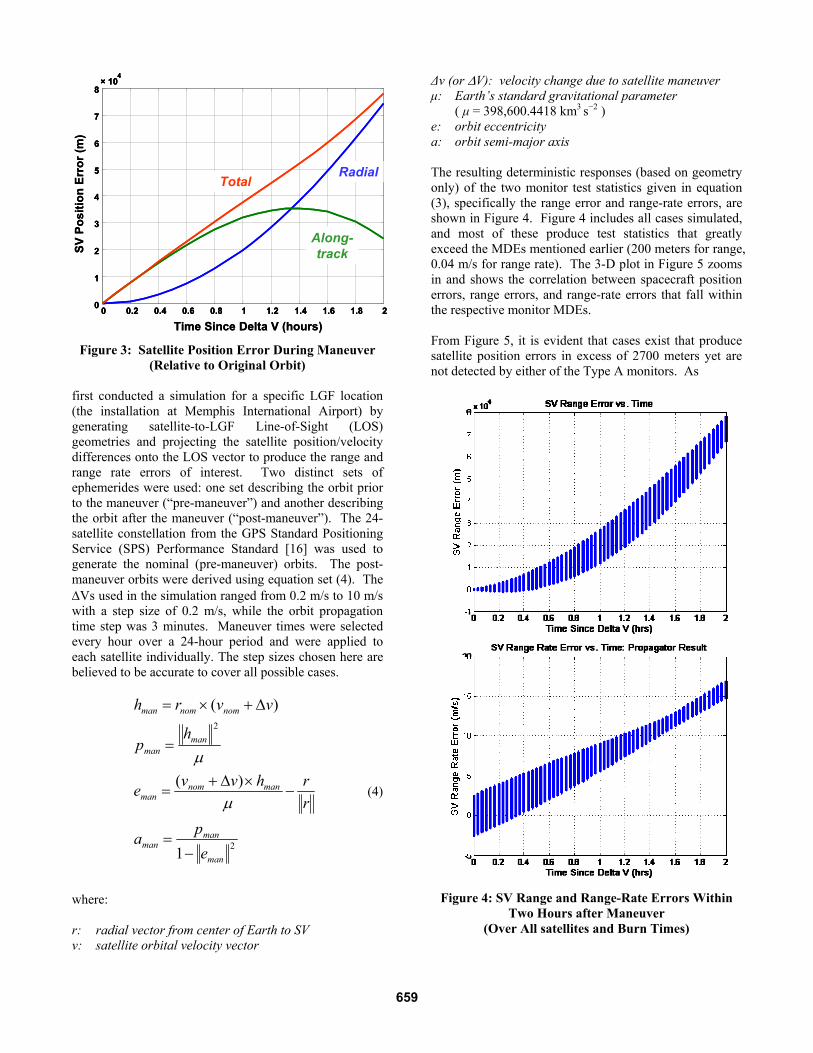
Figure 3: Satellite Position Error During Maneuver (Relative to Original Orbit)
first conducted a simulation for a specific LGF location (the installation at Memphis International Airport) by generating satellite-to-LGF Line-of-Sight (LOS) geometries and projecting the satellite position/velocity differences onto the LOS vector to produce the range and range rate errors of interest. Two distinct sets of ephemerides were used: one set describing the orbit prior to the maneuver (“pre-maneuver”) and another describing the orbit after the maneuver (“post-maneuver”). The 24-satellite constellation from the GPS Standard Positioning Service (SPS) Performance Standard [16] was used to generate the nominal (pre-maneuver) orbits. The post- maneuver orbits were derived using equation set (4). The ΔVs used in the simulation ranged from 0.2 m/s to 10 m/s with a step size of 0.2 m/s, while the orbit propagation time step was 3 minutes. Maneuver times were selected every hour over a 24-hour period and were applied to each satellite individually. The step sizes chosen here are believed to be accurate to cover all possible cases.
2
2
1
)(
)(
man
manman
mannomman
manman
nomnomman
epa
rrhvve
hp
vvrh
−=
−×Δ+
=
=
Δ+×=
μ
μ
(4)
where: r: radial vector from center of Earth to SV v: satellite orbital velocity vector
Δv (or ΔV): velocity change due to satellite maneuver μ: Earth’s standard gravitational parameter ( μ = 398,600.4418 km3 s−2 ) e: orbit eccentricity a: orbit semi-major axis The resulting deterministic responses (based on geometry only) of the two monitor test statistics given in equation (3), specifically the range error and range-rate errors, are shown in Figure 4. Figure 4 includes all cases simulated, and most of these produce test statistics that greatly exceed the MDEs mentioned earlier (200 meters for range, 0.04 m/s for range rate). The 3-D plot in Figure 5 zooms in and shows the correlation between spacecraft position errors, range errors, and range-rate errors that fall within the respective monitor MDEs. From Figure 5, it is evident that cases exist that produce satellite position errors in excess of 2700 meters yet are not detected by either of the Type A monitors. As
Figure 4: SV Range and Range-Rate Errors Within
Two Hours after Maneuver (Over All satellites and Burn Times)
0 0.2 0.4 0.6 0.8 1 1.2 1.4 1.6 1.8 20
1
2
3
4
5
6
7
8× 10
4
Time Since Delta V (hours)
SV P
ositi
on E
rror
(m)
Total
Along-track
Radial
0 0.2 0.4 0.6 0.8 1 1.2 1.4 1.6 1.8 20 0.2 0.4 0.6 0.8 1 1.2 1.4 1.6 1.8 20
1
2
3
4
5
6
7
8
0
1
2
3
4
5
6
7
8× 10
4× 10
4
Time Since Delta V (hours)
SV P
ositi
on E
rror
(m)
Total
Along-track
Radial
659

-200-150
-100-50
050
-0.04
-0.02
0
0.02
0.040
2000
4000
6000
8000
SV Range Error (m)SV Range Rate Error (m/s)
SV
Po
siti
on
Err
or
(m)
Figure 5: SV Range, Range-rate, and Position Errors
explained earlier, since these cases violate the Type B ephemeris bound without being detected, they represent potential HMI. Detailed examination of these cases showed that they were all due to maneuvers that happened just before the satellite came into view of the LGF. To mitigate these HMI cases, we introduced a waiting period between the epoch the satellite rises into view (meaning that it is tracked on more than one reference receiver) and the epoch when the LGF is allowed to start broadcasting corrections for that satellite. During this time, both monitors are active. After some trial and error, it was determined that 200 seconds was a sufficient waiting period, as will be demonstrated shortly. Note that a 200-second delay period after the satellite rise does not constrain the start of correction broadcasts, as the same amount of time is needed for two smoothing time constants to pass, which allows the 100-second carrier-smoothing filter applied to the code-phase measurements to fully converge [11,19]. The upper plot in Figure 6 shows the relationship between satellite position errors and monitor outputs at the epoch when it rises into view. A few potential threats are clearly illustrated in this figure: the LGF monitor alarm is not triggered while the position errors for several cases are already significant enough to cause HMI (above 6000 meters in some cases). The lower plot of Figure 6 shows these corresponding results after the proposed 200-second waiting period. The potential HMI cases are all now outside the monitor MDE window—indicated by the dashed red box in the figure—and therefore would have been detected by the LGF monitors during the 200-second screening interval (more precisely, they would have been detected by the range-rate monitor). Once an alert is issued by either of the LGF monitors, the affected satellite would be excluded from using in the LGF service volume for two days (the reset time of the Type B monitor).
Figure 6: HMI Elimination by Range Rate Monitor
The above analysis was restricted to a single LGF location at Memphis airport. To ensure the global effectiveness of the algorithm, a follow-on simulation was performed over all possible LGF longitudes and latitudes with a 1-degree grid step. In this simulation, a 2-minute maneuver time spacing, a 20-second ephemeris propagation time interval, and a 0.2-m/s step size for maneuver velocity changes were used. Note that the time intervals used here were much shorter than those used in the Memphis-only simulation (2 min vs. 1 hour; 20 sec vs. 3 min). This comprehensive simulation validated that the Memphis results apply globally and with smaller time steps. Using the two monitors together with the 200-second waiting time, no HMI events were observed. The results of this simulation are shown in Figure 7. TYPE A1 ANALYSIS In the A1 threat scenario, as introduced before, a satellite maneuver takes place when the satellite is not visible to a particular LGF site (e.g., Memphis). An example timeline of the satellite maneuver (ΔV) times considered is shown in Figure 8. As with the A2 case, when the maneuver is completed, the nominal ephemeris uploaded in the satellite before the maneuver no longer represents the actual satellite orbit. In the Type A2 simulation, when the
-200-100
0100
200
0
0.1
0.2
0.3
0
2000
4000
6000
8000
10000
SV Range Error (m)
A2 monitor output and SV position error at 200s after rise
SV Range Rate Error (m/s)
SV
Pos
ition
Err
or (
m)
-200-150
-100-50
050
-0.04
-0.02
0
0.02
0.040
2000
4000
6000
8000
SV Range Error (m)
A2 monitor output and SV position error at rise
SV Range Rate Error (m/s)
SV
Pos
ition
Err
or (
m)
660

Figure 7: Global Mitigation of HMI satellite becomes visible to the LGF, the LGF starts receiving the broadcast of the nominal (pre-maneuver) ephemeris from the satellite. In the Type-A1 simulation described here, the post-maneuver ephemeris broadcast errors are modeled as random with error magnitude bounds based on minimum and maximum historical ephemeris parameter values determined by Paul Kline [8], which are shown in Table A1 in Appendix A. The maneuver simulation for the A1 case is executed in a similar method as the A2 case. As shown in Figure 8, the maneuver times are restricted to intervals when the corresponding satellite is out-of-view. The erroneous broadcast ephemeris is simulated from the combination of
Figure 8: Possible Maneuver Time Intervals for a
Single Satellite
Figure 9: FOH Test Statistic (in meters) Before and
After Scaling the nominal pre-maneuver ephemeris (obtained from the RTCA DO-229 almanac [14]) parameters and an ephemeris parameter error set (the details of this procedure are given in Appendix A). Using this error set, the satellite position errors between the pre-maneuver nominal and received post-maneuver erroneous ephemeris are generated, and a Type B First Order Hold (FOH) test is performed. Briefly, this test compares the current ephemeris parameters received by the LGF with those received during the previous visibility period for the satellite in question (details of the Type B FOH test can be found in [1]). Because the FOH test examines the consistency of the previous and current ephemerides, it will also alert Type A1 fault cases whose post-maneuver ephemerides are significantly different from before. With this in mind, a scaling factor (SF) for the ephemeris parameter error set is calculated based on equation set (5), and the randomly generated ephemeris error vector is accordingly scaled so that the FOH test will not be triggered. The intention is to produce the maximum satellite position error caused by a Type A1 fault that will not trigger a Type B FOH alert. An example of the position error estimates produced by the Type B monitor before and after scaling is shown in Figure 9. This scaling process makes the randomly-generated ephemeris errors more significant, as they are all converted to the size that is most likely to lead to HMI. (5)
-0.05
0
0.05
-200
-100
0
100
200
0
1000
2000
3000
4000
Range-rate error (m/s)
A2 monitor output and SV position error at rise
Range error (m)
SV
pos
ition
err
or (
m)
toe
SV visible segment
toe-26 hr
ΔV times considered
Yesterday Today
mMDESFpp
XMDESF
XXX ppp
2700
)max(/
0
0
=⋅=
Δ=
−=Δ +
δδ
δ
00.05
0.1
-200
-100
0
100
200
0
1000
2000
3000
4000
Range-rate error (m/s)
A2 monitor output and SV position error at 200s after rise
Range error (m)
SV
pos
ition
err
or (
m)
661

Figure 10: Type A1 Fault Mitigation Results at Memphis where:
δp0 : the pre-scaled ephemeris error vector δp : the post-scaled ephemeris error vector Xp : the satellite position estimates obtained by
propagating the nominal, non-corrupted ephemeris
Xp+δp0: the satellite position estimates obtained by propagating the pre-scaled erroneous ephemeris
The parameter values in the post-scaled erroneous ephemeris must also be compliant with the ephemeris dynamic ranges listed in Table A1 in Appendix A [9]. If any element exceeds its range, that element will be set to be equal to the maximum value. Moreover, one of the error set parameters, the square root of the semi-major axis, is also bounded by the maneuver detection monitor given in equation (6) [10]. The purpose of this monitor is to detect maneuvers that occurred while out-of-view of the LGF. It is based on the fact that, when no maneuver occurs, the change of the monitor test statistics should be within a certain predictable range. Note that equation (6) has two different thresholds depending on whether the Type B test mentioned above is based on the standard FOH test statistic or a simpler “Zero Order Hold” (ZOH) test statistic. The ZOH test compares the current received ephemeris parameters with those projected from the ephemeris received up to 24 hours ago. The FOH test
makes more-accurate projections based on two days of prior ephemerides; thus it is used when two days of prior ZOH tests, failure of the maneuver detection monitor for a given newly-risen satellite results its exclusion from use.
An example of ephemeris A1 fault mitigation for an LGF at Memphis is shown in Figure 10. From this figure, it is demonstrated that potential HMI events exist when a faulty satellite first becomes visible to the LGF, although the “degree” of HMI is limited to satellite position errors not far above 2700 meters due to the impact of the Type B monitor. Within the 200-second waiting time before corrections can be broadcast, all potential HMI cases are detected by either the range or range-rate test statistics. After the 200-second waiting period ends, any newly-emerging threatening cases will be immediately excluded by the LGF monitors. Plots for potential waiting times of 400 and 600 seconds are also shown, although these longer waiting times are not needed. The results for the A1 fault effect on the LGF monitor outputs are similar to the A2 case that we studied before. However, because of the large simulation parameter space
aaΔ
Should be (6)< 2.027×10⁻⁶ (FOH)
< 0.425×10⁻⁵ (ZOH)
-0.05
0
0.05
-200-100
0100
2000
500
1000
1500
2000
2500
3000
Range-rate error (m/s)
Monitor output and SV position error at rise
Range error (m)
SV
pos
ition
err
or (m
)
-0.04-0.02
00.02
0.040.06
-200
0
200
4000
500
1000
1500
2000
2500
3000
Range-rate error (m/s)
Monitor output and SV position error at 200s after rise
Range error (m)
SV
pos
ition
err
or (m
)
-0.050
0.050.1
0.15
-200
0
200
4000
500
1000
1500
2000
2500
3000
Range-rate error (m/s)
Monitor output and SV position error at 400s after rise
Range error (m)
SV
pos
ition
err
or (m
)
-0.050
0.050.1
0.150.2
-200
0
200
4000
500
1000
1500
2000
2500
3000
Range-rate error (m/s)
Monitor output and SV position error at 600s after rise
Range error (m)
SV
pos
ition
err
or (m
)
662

involved (e.g., 15 ephemeris parameter errors, satellite maneuver time, ΔV magnitude), it is not possible to directly evaluate the result of every possible A1-fault-out-of-view case. Hence, a Monte-Carlo method is applied with the LGF located at Memphis to generate a large volume of error scenarios to ensure that the HMI probability requirement is meet. A total of 14,160,000 ephemeris error vectors were generated, and all potential threatening events were detected by the monitors. This indicates that any GPS navigation integrity risk caused by a Type A1 fault will trigger the LGF monitor alarm either within the 200-second waiting period after satellite rise or before the 3-D satellite position error exceeds the MDE (2700 meters). These simulation results suggest that the actual Missed Detection Probability, Pmd, is less than 1/14,160,000 = 7.06 × 10⁻⁸. Given the likelihood that a satellite maneuver happens out-of-view of a particular LGF is less than 50%, this estimated Pmd can be further reduced to 3.53 × 10⁻⁸. In addition, remember that all failure sizes were arbitrarily manipulated to create the worst-case size for each randomly-selected set of ephemeris parameter errors. Comparing this result to the integrity risk requirement allocated to the A1 failure scenario, which in this case is 1.85 × 10⁻⁷ per approach, significant margin exists.
CONCLUSIONS AND FUTURE WORK In this paper, the GPS satellite ephemeris fault models relevant to LAAS are defined, and the satellite position and velocity error characteristics caused by Type A ephemeris faults (large errors related to GPS satellite maneuvers) are studied. A mitigation strategy for Type A ephemeris faults, in which the LGF monitors the range and range rate measurement corrections, is examined in detail based upon simulations of the 24-satellite RTCA DO-229 GPS constellation. In the Type A1 failure scenario, more than 14 million post-maneuver ephemeris error sets were randomly selected in an attempt to explore all possible post-maneuver fault scenarios. A similar but exhaustive search method was used for the Type A2 failure case. These simulations validated the ability of the proposed monitors to effectively mitigate both Type A1 and A2 ephemeris failures (not counting the extremely rare A2 case where a satellite maneuvers without being commanded to) and meet the CAT I precision approach integrity risk allocations to these threats. The results in this paper suggest several follow-up areas of work, particularly as LAAS evolves to satisfy the more-demanding integrity requirements of CAT II/III precision approaches and landings. First, the effectiveness of the Type A monitor is mostly due to the tight threshold and MDE applied to the range-rate test statistic. This is particularly true in the Type A2 fault case. Recall that nominal errors in range-rate test statistic
are driven by carrier-phase noise differences over the 0.5 seconds between adjacent measurement epochs. If nominal errors from the “snapshot” test statistic derived on a given epoch are too large to meet the threshold and MDE proposed in this paper, a short moving average of the snapshot test statistic can be implemented to reduce the noise. The key questions are the definition of “short” and the variability of carrier-phase errors among LAAS sites. For simplicity, it is preferable to use a single range-rate monitor formulation (with a specific averaging time, if any) at all sites. If averaging is needed to meet the required MDE, its impact on the required waiting time must be considered. The 200-second waiting time derived in this paper assumes no averaging. If averaging over more than a few (~ 5) seconds is implemented, this would “age” the range-rate test statistic enough that a waiting period of slightly more than 200 seconds might be needed. This would not affect LAAS performance, but it might require a software change, since the LGF currently implements precisely 200 seconds of “waiting” for smoothing convergence. Second, the “tangential ΔV only” simulations conducted here should be expanded to better understand the performance of Type-A threat monitoring under a larger set of circumstances. The possibility of intentional OCS maneuvers that include non-tangential components, by design or by mistake, was discussed in the section on Type A2 simulation design. A maneuver that mistakenly includes a significant non-tangential component requires the OCS to also err in setting the satellite healthy again with an ephemeris that does not reflect the unintended resulting orbit before the situation could become hazardous to LAAS. As noted earlier, a scenario that requires two independent failures normally can be neglected for CAT I operations, but in this case, an unexpected non-tangential impulse makes it more likely that the post-maneuver ephemeris will be faulty. Thus, these two faults are not completely independent and deserve further thought. Even if this were not the case, it is worthwhile to understand the effect of non-tangential maneuvers on the Type A monitor in case the GPS OCS begins to execute such maneuvers intentionally in the future. When simulating non-tangential maneuvers, the initial ΔV could theoretically have any direction in 3-D space. For maneuvers deliberately initiated by OCS, we would expect the tangential component to still be dominant, and any non-tangential components would be limited to certain discrete sizes based on the capabilities of GPS satellite thrusters. However, this is not true for un-commanded, unintended maneuvers that fall into the Type A2b case. Here, the resulting ΔV could come from propellant leakage in addition to undesired thruster firings; thus any direction in 3-D and any magnitude (though likely very small) is possible. This suggests that, unlike
663

the Type A2 (A2a) simulations in this paper, simulations of the Type A2b threat would be of the Monte-Carlo type in that they would sample from a much larger space of possible maneuvers, and every possibility could not be covered. With so many possible variations, it is likely that a handful would be found that are not detected (with the required Pmd) by the Type A monitor. However, the very small number of these events as a fraction of the total number of variations, combined with the very improbable nature of the Type A2b failure event in the first place, should be sufficient to meet the CAT II/III LAAS requirements. We plan to carry out Type A2b simulations to verify this hypothesis.
ACKNOWLEDGMENTS The authors appreciate the valuable help and feedback provided by the FAA/Honeywell Ephemeris “Tiger Team” that supported LAAS System Design Approval. This project was funded by the FAA LAAS Program Office through a sub-contract from Stanford University, and sponsorship of this work by the FAA LAAS Program Office is greatly appreciated. However, the opinions provided in this work are solely those of the authors.
REFERENCES [1] B. Pervan and L. Gratton, “Orbit Ephemeris Monitors for Local Area Differential GPS,” IEEE Transactions on Aerospace and Electronic Systems, Vol. 41, No.2, April 2005. [2] L. Gratton, B. Pervan, and S. Pullen, “Orbit Ephemeris Monitors for Category I LAAS”, Proceedings of IEEE PLANS 2004, Monterey, CA, April 26-29, 2004. [3] J. M. Davis and R. J. Kelly, “RNP Tunnel Concept for Precision Approach with GNSS Application”, Proceedings of the ION 49th Annual Meeting, Cambridge, MA, June 21-23, 1993. [4] International Civil Aviation Organization (ICAO), International Standards, Recommended Practices and Procedures for Air Navigation Services – Annex 10, April 1985. [5] Federal Aviation Administration GPS Product Team, “Global Positioning System Standard Positioning Service Performance Analysis Report” Report #58, June 31, 2007. [6] K. Kovach, private communication, May 15, 2007. [7] V. L. Pisacane, Ed., Fundamentals of Space Systems. New York: Oxford University Press, 2nd Edition, 2005, Chapter 3.6.2.
[8] P. Kline, “A1 corner case,” Unpublished Briefing to the FAA, Feb. 20, 2008. [9] “Navstar GPS Space Segment / Navigation User Interfaces.” El Segundo, CA., ARINC Research Corporation, ICD-GPS-200C Rev. 4, April 12, 2000. Page 96, Table 20-III, [10] B. Pervan, L. Gratton, S. Langel, IIT Maneuver Detection Monitor, Unpublished Technical Report, 2008. [11] Specification: Performance Type One Local Area Augmentation System Ground Facility. U.S. Federal Aviation Administration, Washington, D.C., FAA-E-2937A, April 17, 2002. [12] S. Matsumoto, S. Pullen, M. Rotkowitz, and B. Pervan, “GPS Ephemeris Verification for Local Area Augmentation System (LAAS) Ground Stations,” Proceedings of ION GPS-99, Nashville, TN, Sept. 14-17, 1999. [13] R. Braff and C. A. Shively, “Derivation of Ranging Source Integrity Requirements for the Local Area Augmentation System (LAAS),” Navigation: Journal of the Institute of Navigation, Vol. 47, No. 4, Winter 2000-2001. [14] Minimum Operational Performance Standards for GPS Local Area Augmentation System Airborne Equipment. Washington, D.C., RTCA SC-159, WG-4, DO-253C, Dec. 16, 2008. [15] M. H. Kaplan, Modern Spacecraft Dynamics and Control, New York: John Wiley & Sons, 1976, Section 3.6, pp. 108 – 115. [16] Global Positioning System Standard Positioning Service Performance Standard. Washington, D.C., U.S. Department of Defense, 4th Edition, Sept. 2008, Section 3.2, pp. 17-18. [17] “FAA Approves 1st U.S. Ground Based Augmentation System,” FAA Washington Headquarters Press Release, Washington, DC, Sept. 21, 2009. [18] GNSS-Based Precision Approach Local Area Augmentation System (LAAS) Signal-in-Space Interface Control Document (ICD). Washington, D.C., RTCA SC-159, WG-4, DO-246D, Dec. 16, 2008. [19] G. Xie, “Optimal On-Airport Monitoring of the Integrity of GPS-Based Landing Systems,” Ph.D. Dissertation, Stanford University, Dept. of Aeronautics and Astronautics, March 2004. http://waas.stanford.edu/ ~wwu/papers/gps/PDF/Thesis/GangXieThesis04.pdf
664
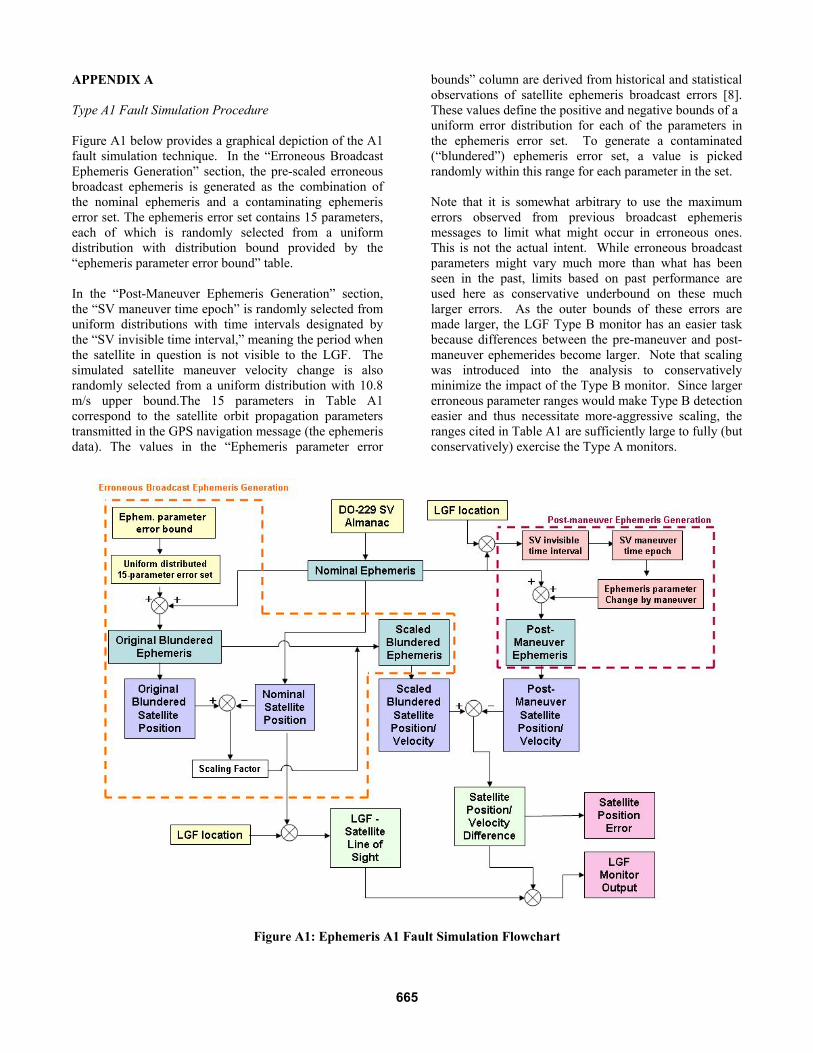
APPENDIX A Type A1 Fault Simulation Procedure Figure A1 below provides a graphical depiction of the A1 fault simulation technique. In the “Erroneous Broadcast Ephemeris Generation” section, the pre-scaled erroneous broadcast ephemeris is generated as the combination of the nominal ephemeris and a contaminating ephemeris error set. The ephemeris error set contains 15 parameters, each of which is randomly selected from a uniform distribution with distribution bound provided by the “ephemeris parameter error bound” table. In the “Post-Maneuver Ephemeris Generation” section, the “SV maneuver time epoch” is randomly selected from uniform distributions with time intervals designated by the “SV invisible time interval,” meaning the period when the satellite in question is not visible to the LGF. The simulated satellite maneuver velocity change is also randomly selected from a uniform distribution with 10.8 m/s upper bound.The 15 parameters in Table A1 correspond to the satellite orbit propagation parameters transmitted in the GPS navigation message (the ephemeris data). The values in the “Ephemeris parameter error
bounds” column are derived from historical and statistical observations of satellite ephemeris broadcast errors [8]. These values define the positive and negative bounds of a uniform error distribution for each of the parameters in the ephemeris error set. To generate a contaminated (“blundered”) ephemeris error set, a value is picked randomly within this range for each parameter in the set. Note that it is somewhat arbitrary to use the maximum errors observed from previous broadcast ephemeris messages to limit what might occur in erroneous ones. This is not the actual intent. While erroneous broadcast parameters might vary much more than what has been seen in the past, limits based on past performance are used here as conservative underbound on these much larger errors. As the outer bounds of these errors are made larger, the LGF Type B monitor has an easier task because differences between the pre-maneuver and post-maneuver ephemerides become larger. Note that scaling was introduced into the analysis to conservatively minimize the impact of the Type B monitor. Since larger erroneous parameter ranges would make Type B detection easier and thus necessitate more-aggressive scaling, the ranges cited in Table A1 are sufficiently large to fully (but conservatively) exercise the Type A monitors.
Figure A1: Ephemeris A1 Fault Simulation Flowchart
665

Table A1: Ephemeris Parameter Error Bounds
666