environmental geotechnology proposal for permeation...
TRANSCRIPT

Environmental Geotechnology
PROPOSAL FOR PERMEATION OF HAZARDOUS WASTE THROUGH LANDFILL LINERS FORMULATED OF CLAY
by
Hsai-Yang Fang
and
Irwin J. Kugelman
September 1, 1983
Fritz Engineering Laboratory Report No. 720.1

TITLE: "Perrr:ea ti on of Hazardous Waste Through Landfi 11 Liners Formulated of Clay"
TABLE OF CONTENTS
Research Personnel
Objectives
Significance of Research
Introduction
Theoretical Considerations
Literature Review
Research Program
a. Preliminary Work b. Description of Equipment c. General Experimental Procedures d. Liner Selection e. Geotechnical and Soil Chemistry Tests f. Test Fluids g. Permeate Analysis h. Data Analysis
Available Facilities and Equipment
Time Schedule
Budget Justification
References
i
17
17
18
21
31
41
41 41 47 49 50 53 56 57
58
58
59
60

L
TITLE: "Permeation of Hazardous Waste Through Landfi 11 Liners Formulated of Clay"
Research Personnel
Dr. H. Y. Fang, Professor of Civil Engineering and Director of Fritz
Laboratory's Geotechnical Division, will direct the major portion of this
study. He will concentrate on the geotechnical aspects of the experimental
effort. He and his students prepared the critical review of the literature
(Evans, et al., 1981) (see section,p.3~. He and his students developed
the design of the special permeameter system to be used here. His resume
is attached. Dr. Fang has no sponsored research at present.
Dr. I. J. Kugelman, Professor of Civil Engineering and Director of the
Center for Marine and Environmental Studies, will direct the waste and soil
·chemistry aspect of this investigation. He has had significant experience
in most areas of water treatment and wastewater disposal and the chemistry
of wastewater. His resume is attached. Dr. Kugelman directs a project
for the City of Allentown titled "Application of Instrumentation and
Autom~tion for Improved Cost Effectiveness of Operation and Maintenance
of the Allentown Sewage Treatment Plant". He devotes about 5% time to the
project which will expire 8/l/83.
Dr. Fortunato J. Micale, Associate Professor of Chemistry, will partici-
pate in the aspects of this project which involve colloid chemistry, his area
of specialty. He is a staff member of the Center for Surface and Coatings
Research. His resume is attached. He devotes 50% time to an ONR project,
"Corrosion Control",and a·NASA project, "Production of Large-Particle-Size
Monodisperse Latexes".
1

Jeffrey Evans is a graduate student studying for his doctorate under
a Woodward-Clyde Fellowship. He will be conducting his doctoral research
on this topic. He has had extensive consulting experience in geotechnical
engineering and was primarily responsible for the design of the special
permeameter. His resume is attached.
In addition to Mr. Evans, two other graduate students (one doctoral
and one master•s level) are called for, as well as a half-time technician,
and some hourly student labor. The extensive level of experimental effort
justifies this level of manpower at the graduate student and technician
level. Approximately 200 runs, each run lasting 6-8 weeks, are planned
for the 2-year effort. Monitoring of several parameters daily is required
as well as sampling and relatively sophisticated analyses. Each run will
require at least 18 distinct geotechnical and chemical tests, in ~ddition
. to daily permeability ana pressure measurement. Additional time is factored
in for startup and shutdown of a run.
2

Dr. Hsai-Yang Fang (Principal Investigator)
Professor and Director Geotechnical Engineering Division fritz Engineering Laboratory Lehigh University Bethlehem, Pennsylvania 18015
Tel: (215) 861-3549 (office) (215) 691-1339 (home)
Education:
B.S. M.S. Ph.D.
Civil Engineering Civil Engineering
Professional Activities:
Hangchow University, China (1947) Purdue University (1957) 1~est Virginia University (1966)
Committee member, Transportation Research Board, Committee on Soils, foundations and Geology (1966-1976)
Chairman, Conference on Design and Installation of Pile Foundations and Cellular Structures, Lehigh University, April (1970)
Co~~ttee member, American Society of Civil Engineers, Committee on Earth Retaining Structures (1972-1977)
Consulting Editor, Envo Publishing Co., Inc. (1972- ) Committee member, American Society of Testing and Haterials, Committee
D-18, Soil and Rock for Engineering Purposes (1974-1980; 1983- ) Course Director, Analysis and Design of Building Foundations, Short
Course and Symposium, Lehigh University, August (1975) Vice Chairman, ASCE Sy~posium on Engineering, Construction, and
Maintenance Problems in Limestone Regions, August (1976) Chairman, International Symposium on New Horizons in Construction
Materials, Lehigh University, November (1976) Co-Chairman, Central American Conference on Earthquake Engineering,
San Salvador, El Salvador, C.A., January (1978) Committee member, Deep Foundations Institute, Geotechnical Research
Committee (1978-1983) Co-Chairman, ASCE Conference on "Disposal of Solid, Liquid and
Hazardous Wastes," Lehigh Valley Section, April (1983) Hember of Editorial Board, The International Journal of Cement
Composites and Lightweight Concrete, England (1983- ) Founder, Council on "Development of Unconventional Construction
Haterials Technology", (1983) Co-Chairman, International Conference on "Development of Low-Cost
and Energy Saving Construction Materials and Applications, Rio de Janeiro, Brazil, July (1984)
Publications and Inventions:
Dr. Fang has published more than one hundred technical papers appearing in ASCE, ASTM, Transportation Research Board publications and other leading international journals and proceedings in the various fields of pavement mechanics, foundation engineering, soil and rock mechanics, ocean engineering, earthquake, soil-structure interaction, and construction materials. He has edited and co-edited to the present six books. He has been awarded U.S. Patents for several inventions with several more under consideration by the Patent Office.
3

(Dr. Hsai-Yang Fang - 2)
Research and Consulting Ehyerience:
Hajor research and consulting experience include:
Pennsylvania Dept. of Transportation and Federal Highway Administration (Pavement Performance, 1967-1972)
U.S. Steel and Bethlehem Steel Corporations (AISI) (Pile and Sheet Piling, 1968-1973)
Buckeye Pipe Line Co. (Slope Stability, 1970-1972) Hong Kong Landslide (1972-1974) Michael Baker Jr. Inc. and Reading, PA Parking Authority
(Deep Foundations, 1973-1974) Glasgow, Inc. and Pennsylvania Dept. of Environmental Resources
(Quarry Blasting Evaluation, 1974-1976) Construction Materials Technology, Inc., International
(Developing Substitute Construction Materials, 1974- ) Colombia, South &~erica (Bucaramanga Landslide, 1975-1976) Government of El Salvador, Central America (Earthquake, 1975-1978) General D;~amics, Electric Boat Division (Harbor Facilities, 1976) Quality Construction Co. (Cofferdam & Deep Foundations, 1976-1978) Moh and Associates, Inc. (Earthquake, Landslide and Materials, 1976-1980) U.S. National Academy of Sciences (Developing Substitute Construction
M?terials, 1979-1980) Shanghai Tongj i University, P.R. C. (Materials and Foundation Problems
in Soft Clays, 1979- ) Envirotronics Corp. (Effect of Air-\,1ater-Land Pollution on Geotechnical
Properties of Soil and Rock, 1980- ) Valley Foundation _Consultants (1980- )
Honor·s and Awards:
Outstanding Service Award, AASHO Road Test, Transportation Research Board, National Academy of Sciences (1962)
Preceptorship Award in Civil Engineering, United Engineers and Constructors, Inc. (1967)
U.S. Delegate to Taiwan, China, Advisory Meeting on Earthquake . Engineering and Landslides, Taipei, National Science Foundation
August (1977) Honorary Citizen, Republic of El Salvador, Central America (1978) Merit Award, Chamber of Commerce and the National Convention and
Visitors Bureau, San Salvador, Republic of El Salvador, C.A. (1979) Visiting Senior Scholar to People's Republic of China, National
Academy of Sciences (1979 and 1980) Keynote Speaker, Symposium on Materials of Construction for Developing
Countries, Australian National Conference on Engineering Materials (1981) Invited Visiting Professorship, The University of New South Wales,
Australia (1981) Keynote Speaker, Seminar on Landslides, The Association of Professional
Engineers of Trinidad and Tobago and Council of Caribbenan Engineering Organizations (1982)
Director, H. H. Liu Education foundation, New York (1982-
4

PRESENT POSITION: Director, Center for Marine and Environ~ental Studies and Professor, Civil Engineering, Lehigh University
RESUME
Irwin Jay Kugelman, Sc.D., Co-Principal Investigator
I. PERSONAL INFORMATION
Name: Irwin Jay Kuge 1 man Birth Date: February 15, 1937 Marital Status: Married Family: 4 children Social Security Number: 109-28-4756 Home Address: 7516 Golf Green Drive
Cincinnati, Ohio 45242 Home Phone: 513/793-9074 Office Phone: 215/861-3651
I I. EDUCATION
SCHOOL DEGREE . MAJOR DATE
The Cooper Union · B. C. E. Civil Engineering 6/58
6/60 Massachusetts Institute of Technology
S.M.S.E. Sanitary Engineering
II Sc.D. II
New York University 20 credits toward S.M.Ch.E.
Special Training
1. Reverse Osmosis Short Course- U.C.L.A. 2. Supervision and Group Performance - U.S.C.S.C. 3. The Effective Middle Manager - U.S.C.S.C. 4. Science Technology and Public Policy - U.S.C.S.C. 5. Integrated Utilities - George Washington University 6. Problem Solving and Decision Making Skills for EPA
Managers and Supervisors - Atlanta, GA
III. PROFESSIONAL EXPERIENCE
A. ACADEMIC
1. Assistant Professor of Civil Engineering New York University, 1962-1965 Department Chairman, Dr. J. Michaelos (present address
Polytechnic Institute of New York) Sanitary Section Head, Dr. W. Dobbins (present address
9/63
1965-68
Aug. 1969 2 weeks July 1970 - 1 week July 1974 - 1 week June 1976 - 2 weeks June 1977 - 2 days
Nov. 1978 - 1 week
515 Johnson Avenue, Bohemia, New York 11716) .
. Responsible for undergraduate Sanitary Engineering instruction, and graduate courses in: Sanitary Microbiology, Sanitary Chemistry, Environmental Radjoactivity, Water and Wastewater Treatment Technology,
Conducted Sponsored Research (U.S.P.H.S. Grant) on toxicity in Anaerobic Digestion.
5

2. Adjunct Assistant Professor of Civil Engineering New York University, 1965-1966 Graduate Instruction in courses listed above.
3. Lecturer, Department of Civil Engineering, The City College of the City University of New York, 1969, Department Chairman, Professor Richard C. Coulter
Undergraduate Course in Water and Wastewater Treatment Technology.
4. Adjunct Professor, Department of Civil Engineering, Manhattan College, Bronx, NY, 1970, Environmental Section Head, Dr. J. Jeris
Graduate Course in Sanitary Microbiology.
5. Instructor, Adult Education Division, Rutgers University, Sewage Treatment Plant Operator Courses, 1965-1967.
6. Instructor, Sewage Treatment Plant Operator Courses at New York University under the auspices of N.Y. State Health Department, 1962-1965.
7. Adjunct Professor, Department of Civil Engineering, University of Cincinnati, 1980-1981, Department Head, Dr. J. McDonough.
Graduate Courses in Advanced Environmental Control Technology.
8. Director, Center for Marine and Environmental Studies, and Professor of Civil Engineering, Lehigh University, Bethlehem, PA 18015, 1982-
B. RESEARCH
1. Research Scientist, American Standard Corporation, Research Division, 1965-70 -Supervisor, Mr. A. Shaines, (1965-68) 40 Moffat Road, Waban, MA 02168; Dr. E.A.G. Hamer, (1968-70) P.O. Box 2003, New Brunswick, NJ 08903
Responsible for research and development on new concepts and processes for wastewater treatment. Major effort was on the development of a single stage counter current liquid solids filtration-adsorption contactor. Development progressed from bench to small pilot to a field installation (50,000 gpd). Two patents were issued. Duties also involved consultation on waste treatment problems with other divisions of the corporation and included aerobic trickling filters, anaerobic contactors, and reverse osmosis systems.
2. Research Sanitary Engineer (Level GS-14), 1970-74 United States Environmental Protection Agency Advanced Waste Treatment Research Laboratory National Environmental Research Center Cincinnati, Ohio 45268 Supervisor: J. M. Cohen, Chief, Physical Chemical Treatment
Primary duties were planning and management of EPA, OR&D research and development activities in areas of (a) wastewater renovation and reuse
6

and (b) removal of organics from wastewater by physical and chemical techniques. This involved long-term budget projections, correlation of research programs with operating division's needs, and direct control, as project officer and grant director, of inhouse and extramural projects. The level of research activity in these areas was in excess of 0.5 million dollars, with a commitment of more than 10 man-years of professional time. Secondary duties were in the technology transfer program. This involved leadership of sections of EPA sponsored technical seminars, and service on committees preparing EPA design manuals. Seminars directed have included phosphorus removal, and physical-chemical treatment. Design manuals have included activated carbon treatment, suspended solids removal, upgrading of municipal treatment plant performance, and nitrogen control.
3. Chief, Pilot Plant and Field Evaluation Section Technology Support Branch (GS-14); 1974- 1982 Wastewater Research Division (WRD) Municipal Environmental Research Laboratory, U. S. EPA Cincinnati, Ohio 45268 Supervisor: Mr. Dolloff F. Bishop, Chief, TDSB
The major activity of the chief, pilot & field evaluations is to coordinate the WRD pilot plant activities with the general research goals of the WRD. Project proposals and scopes are prepared jointly by the WRD program managers and the pilot plant staff. Those which are approved by the Director, WRD are implemented by groups of engineers, scientists and technicians stationed at the WRD pilot plants. The pilot plant staff under the direction and supervision of the Chief, Pilot & Field Evaluation Section carries out the literature review, experimental design, equipment selection and construction, data collection and analyses and interim arid final report execution for each project. Projects cover all aspects of wastewater treatment technology from preliminary treatment through reuse. The major responsibilities of the chief in addition to supervision are preliminary planning and budgeting and execution of final reports.
Pilot plant activities were formerly conducted at permanent multipurpose remote sites in Pomona, California, Washington, D. C., and Lebanon, Ohio by mixtures of federal and contract personnel. Staff totaled 42 with a total of 10 professionals. The budget ranged from 1 to 1.25 million dollars per year. During the past two years the outmoded sites at Lebanon and Blue Plains were gradually phased out, and the Pomona site was turned over to the Los Angeles County Sanitation Districts for operation by their personnel under an EPA contract. A new multipurpose facility was designed and has been constructed on the site of the Mill Creek Sewage Treatment Plant in Cincinnati, Ohio. This facility has a staff of approximately 20 (EPA and contract employees) and will conduct the same type of studies as at the abandoned sites. The budget for FY80 was approximately $750,000.
The nationwide EPA program in instrumentation and automation is also administered by this section. This program develops instrumentation, control strategies and automation to improve the performance, reliability and economy of wastewater treatment plants. Resources have averaged $250,000 to $300,000 per year.
7

C. ENGINEERING
1. Junior Civil Engineer, 1958-59, Assistant Civil Engineer, 1959. The City of New York, Highway Design Section Office of the Borough President of Manhattan, Supervisor - ~1r. Henry Turkeltaub
Duties were the complete structural design of an elevated section of the F.D.R. Drive in New York City. This included steel superstructure, reinforced concrete columns, foundations and retaining walls.
2. Design Engineer, Alexander Potter Associates, l World Trade Center, New York, NY 10048. (Part-time) July 1963-May 1964, Supervisor - Mr. M. Klegerman.
Duties included:
(a) Sewer design for subdivisions in Staten Island, New York (b) Preliminary design of a sewage treatment plant for Florham Park, New Jersey (c) Report on availability of water to augment flow in the New York State
Barge Canal (for U.S. Corps of Engineers) (d) Report on the chemistry of water fluoridation for New York City
3. Consultant to Hydrotechnic Corporation, 641 Lexington Avenue, New York, NY, July 1964 - October 1964. Supervisor - Mr. Ross Nebolsine
Duties were design of a central water, wastes, and soils laboratory for the Public Health Engineering Department of \~est Pakistan. A portion of this assignment included a three-week trip to Lahore, West Pakistan, to conduct a training course in laboratory techniques for Health Department personnel.
IV. PUBLICATIONS
11 Cation Toxicity and Stimulation in Anaerobic Waste Treatment, I: Slug Feed Studies, 11
Journal of the \~ater Pollution Control Federation, 37:97, January 1965, with P. L. McCarty.
11 Cation Toxicity and Stimulation in Anaerobic Waste Treatment, II: Daily Feed Studies, 11
Proceedings of the Purdue Industrial Waste Conference, May 1964, with P. L. McCarty.
"Toxicity Synergism and Antagonism in Anaerobic Waste Treatment Processes," Advances in Chemistry Series, Number 105, American Chemical Society, page 55 (1971), with K. K. Chin.
11 Status of Advanced Waste Treatment," Proceedinqs of the Seminar on Advanced Wastewater Treatment and Disposal, Regior.al Marine Resources Council of Nassau -Suffolk Regional Planning Board, June 1971.
11 Physical-Chemical Treatment of Wastewater, 11 Water Research, §.:487, (1972), with J. M. Cohen.
8

----------- ------------------------------
"Annual Review of the Literature in Physical-Chemical Treatment of Wastewater, 11
Journal of the Water Pollution Control Federation, 44:916_ (1972), and 45:1027 (1973.
';Annual Review of the Literature in Wastewater Renovation and Reuse, 11 Journal of the Water Pollution Control Federation- 46:1195 (1974), 47:1338 (1975 .
"Annual Review of the Literature in Instrumentation and Automation for Wastewater Control Systems,'' Journal of the Water Pollution Control Federation, 48:1206 (1976, 49:1104 (1977), 51:1294 (1979), 54:642 (1982).
""Municipal Wastewater Reuse in the U.S., "Journal of the Water Pollution Control Federation, 47:2229 (1975) with C. J. Schmidt & E. V. Clements.
"Wastewater Disinfection with Ozone," Bull. Calif. WPCF 12:47 (Oct. 1975) with H. B. Gahn, C. L. Chen and R. P. Miele.
11 Advanced Waste Treatment," (chapter in Handbook of Water Resources and Po 11 uti on Control) Van Nostrand-Reinhold, January 1976.
11 Pilot Plant Study of Physicai-Chemical Treatment," Journal of the Hater Pollution Control Federation, 49, 2081 (1977), with C. L. Chen and L. S. Directo.
"Current Status of Research in Automation of Wastewater Treatment in the United States, 11 Progress in Water Technology, _g_, 659 (1977) with J. F. Roesler and D. F. Bishop
"Progress in Instrumentation and Automation,~~ with M. Cummins, W. Schuk, J. Roesler. Proceedin s of the 6th U. S. - Ja an Conference on Sewage Treatment Technolo y, Oct. 1978 .
"Automation of Sludge Processing,~~ Proceedings of the 7th U. S. - Japan Conference on Sewage Treatment Technology, Tokyo (April 1980).
"Procedures for the Development and Evaluation of Sensors to be Used in Monitoring Wastewater, 11 Prog. in Water Sci. & Tech . .Jl., 133 ( 1981) with W. Schuk and W. Rosenkranz
"Anaerobi.c Digestion," (chapter in Sludge Treatment, C. J. Santhanam and ~J. W. Eckenfelder, eds.) Marcel Dekker, New York (1981), with J. S. Jeris.
"Advances in Anaerobic Treatment Technology," Proceedings of the 8th U. S. - Japan Conference on Sewage Treatment Technology, Cincinnati, OH (Oct. 1981).
"Removal of Priority Pollutants by Conventional Treatment," Proceedings of the 8th U. S. -Japan Conference on Sewage Treatment Technology, Cincinnati, OH (Oct. 1981).
"Instrument Testing Center Proposed," APWA Reoorter 49, 3, March 1982, 6-10.
"Evaluation of a Dissolved Oxygen Field Test Protocol," with G. Kulin and W. Schuk, Journal of the Water Pollution Control Federation, 55, 178-186 (Feb 1983).
9

In Press
"Fate of Toxic Organic Compounds in Wastewater Treatment Plants," with A. Petrasek, B. Austern, T. Pressley, L. Winslow and R. Wise (Journal of the Water Pollution Control Federation).
"Fate of Inorganic Priority Pollutants in Wastewater Treatment Plants," with A. Petrasek and W. Schuk (Journal of the Water Pollution Control Federation).
EPA Publications (Co-Author or Project Officer)
Design Manual -Suspended Solids Removal, U.S. EPA, Technology Transfer, 1971.
Design Manual - Upgrading Wastewater Treatment Plants, Technology Transfer, 1971.
Design Manual - Carbon Adsorption, U.S. EPA, Technology Transfer, 1974.
Design Manual - Nitrogen Control, U.S. EPA, Technology Transfer, 1976.
"Demonstrated Technology and Research Needs for Reuse of Municipal Wastewater," U.S. EPA~ OR&D, 670/2-75-038 (1975).
"Experimental Evaluation of Oxygen and Air Activated Sludge Systems,•• U.S. EPA, OR&D, 600/2-76-180 (1976).
11 Pi1ot Plant Evaluation of Alternate Activated Sludge Systems, .. U.S. EPA, OR&D, 600/~-77-108 (1977) .
.. Independent Physical-Chemical Treatment of Raw Sewage,•• U.S. EPA, OR&D, 600/2-77-137. (1977) .
.. Wastewater Demineralization By Two-Stage Fixed Bed Ion Excha.nge, U.S. EPA, OR&D, 600/2-77-146 (1977).
"Demineralization of Sand-Filtered Secondary Effluent by Spiral-Wound ReverseOsmosis, .. U.S. EPA, OR&D, 600/2-77-169 (1977).
"Wastewater Demineralization by a Continuous Counter Current Ion Exchange Process, .. U.S. EPA, OR&D, 600/2-77-152 (1977).
••oownflow Granular Filtration of Activated Sludge Effluents, .. U.S. EPA, OR&D, 600/2-77-144 (1977).
11 Reuse of Municipal Wastewater for Ground \~ater Recharge, .. U.S. EPA, OR&D, 600/2-77-183 (1977).
10

''Wastewater Treatment for Reuse and Its Contribution to Water Supplies, 11
U.S. EPA, OR&D, 600/2-78-027 (March 1978).
~~wastewater Demineralization by Tubular Reverse Osmosis, 11 U.S. EPA, OR&D, 600/2-78-167 (Sept. 1978).
11 Advanced l~aste Treatment for Housing and Community Developments, 11 U.S. EPA, OR&D, 600/2-78-168 (Sept. 1978).
11 Demineralization of Carbon Treated Secondary Effluent by Spiral-Hound Reverse Osmosis, 11 U.S. EPA, OR&D, 600/2-78-169 (Sept. 1978).
11 Two Stage Granular Activated Carbon Treatment, 11 U.S. EPA, OR&D, 600/2-78-170 (Sept. 1978).
11Automatic Sludge Blanket Control in an Operating Gravity Thickener, 11 U.S. EPA, OR&D, 600/2-79-159 (Nov. 1979).
11 Sequential Nitrification-Denitrification in a Plug Flow Activated Sludge System,~~ U.S. EPA, OR&D, 600/2-79-157 (Nov. 1979).
11 Carbon Reactivatiof! by Externally-Fired Rotary Kiln Furnace, 11 U.S. EPA! OR&D, 600/2-80-146 (Aug. 1980).
11 Waste Activated Sludge Processing,~~ U.S. EPA, OR&D, 600/2-80-147 (Aug. 1980).
11 Effect of Pretreatment on the Filtration of Low Turbidity Secondary Effluent, 11
U.S EPA, OR&D, 600/2-80-148 (Aug. 1980).
11 Design Handbook for Automation of Activated Sludge Treatment Plants, 11 U.S. EPA, OR&D, 600/8-80-028 (Aug. 1980).
11 Removal of Metals & Virus in Advanced Waste Treatment Sequences, 11 U.S. EPA, OR&D, 600/2-80-149 (Aug. 1980).
~~Reactivation of Granular Carbon in an Infrared Traveling Belt Furnace,~~ with Ramin Nur and Robert W. Horvath (December 1981).
V. HONORS AND AWARDS
E.I.T. N.Y. State, 1959 U.S.P.H.S. Traineeship, 1959-60 U.S.P.H.S. Pre-Doctoral Research Fellowship, 1961-62 U.S.P.H.S. Research Grant, 1964-65 U.S. Patent 3,512,639, 1970 U.S. Patent 3,512,641, 1970 U.S.E.P.A. Executive Development Program, 1977 Listed in American Men of Science and Who's Who in the Midwest U.S. EPA Bronze Medal 1980 Sigma Xi 1982
11

VI. PROFESSIONAL MEMBERSHIP & ACTIVITIES
1. American Society of Civil Engineers (Member Grade) a. Chairman N.Y. Metropolitan Sanitary Engineering Group ASCE 1963-64,
1965-66. b. Urban Wastewater Engineering Committee ASCE 1974, 1975.
2. Water Pollution Control Federation (PA Local Section) a. Standard Methods Committee - 1967-1970 b. Research Committee- 1972-1977, 1981-c. Student Activities Committee - 1973 d. Program Committee - 1977-
3. American Water ~Jorks Association a. Water Reuse Committee - 1974-1979
4. Association of Environmental Engineering Professors
5. Hazardous Waste Coordination Committee, State of Pennsylvania, 1982-
6. National Academy of Science a. Process Panel, Potomac Estuary Study Committee - 1976-1979
7. U. S. Environmental Protection Agency a. Environmental Engineering & Pollution Control Processes Peer Review Panel
1980-b. Science Advisory Board Advanced Environmental Control Technology Research
Center- U. of Illinois 1980-1981 c. Science Advisory Board Industrial Wastes Elimination Research Center,
Illinois Institute of Technology - Notre Dame University 1981
VII. COMMUNITY ACTIVITIES
Committee member and treasurer, Cub Pack 818, Cincinnati, Ohio 1971-72 Committee member and treasurer, Cub Pack 674, Cincinnati; Ohio 1972-74 Team Manager, Montgomery, Ohio Little League, 1973-74 Team Coach, Sycamore, Soccer for Youth Program, 1975-present Member Board of Directors, Plainfield Hebrew Institute, Plainfield, NJ, 1967-70 Vice President, Plainfield Hebrew Institute, Plainfield, NJ, 1969-70 Member Board of Directors, Northern Hills Synagogue, Cincinnati, Ohio, 1971-present Vice President, Northern Hills Synagogue, Cincinnati, Ohio, 1972-74 Financial Secretary, Northern Hills Synagogue, Cincinnati, Ohio, 1974-77, 1979-1982 Member Board of Directors, Cincinnati Community Hebrew School, Cincinnati, Ohio,
1972-76 Member Board of Directors, Bureau of Jewish Education, Cincinnati, Ohio, 1973-1981 Secretary, Bureau of Jewish Education, Cincinnati, Ohio, 1977-1980 Vice President, Bureau of Jewish Education, Cincinnati, Ohio, 1980-1981
12

FORTUNATO J. MICALE, Faculty Associate
Dr. Micale is Associate Professor of Chemistry and a staff member of the Center for Surface and Coatings Research. He received the B.A. in Philosophy from St. Bonaventure University in 1956, the B.S. in Chemistry from Niagara University in 1959, the t~.S. in Physical Chemistry from Purdue University in 1961, and the Ph.D. in Physical Chemistry from Lehigh University in 1965.
His current research interests include: gas adsorption techniques for characterization of the surface properties of high-surface-area carbon, silica and nickel oxide (this characterization, via adsorption of various polar adsorbates, includes rates of adsorption and multi-temperature adsorption data for determination of concentration and energetics of polar sites); heats of immersion of aqueous and non-aqueous systems for determination of energetics of interaction of adsorbates as a function of their polarity; solution adsorption of cationic and anionic surfactants on previously characterized high surface area samples; microelectrophoresis techniques for determination of electrical double layer properties of colloidal particles as a function of pretreatment conditions; and stability of colloidal systems as a function of surface properties, surfactant adsorption and surface charge.
He is a member of Sigma Xi and the American Chemical Society.
Recent Publications
W. C. Wu, M. s. El-Aasser, F. J. Micale, and J. W. Vanderhoff, "Surface Charge Density and Electrophoretic Mobility of Monodiserse Polystyrene Latexes", in "Emulsions, Latices, and Dispersions", edited by Paul Becher and t~arvi n N. Yudenfreund, Marcel Dekker, Inc., New York, page 71, 1978.
J. W. Vanderhoff and F. J. Micale, Influence of Electroosmosis, "Electrokinetic Separation Methods", p. 81, ED. Righetti, van Oss & Vanderhoff, Elsevier/North-Holland, 1979.
J. W. Vanderhoff, F. J. Micale, and P. H. Krumrine, Continuous Flow Electrophoresis, "Electrokinetic Separation Methods", p. 121, ED. Righetti, van Oss & Vanderhoff, Elsevier/North-Holland, 1979.
C. L. Cronan, F. J. Micale, A. C. Zettlemoyer," M. Topie, and H. Leidheiser, Jr., "Surface Porosity of Ni(OH)2 and NiO, III", J. Colloid & Interface Science, ~. 43, 1980.
J. M. Fetsko and F. J. Micale, "ACZ in Appreciation", J. Colloid & Interface Science, ~. 2, 1980.
F. J. Micale, P. H. Krumrine, T. J. Vital, and J. W. Vanderhoff, "Experimental Parameters Involved in the Separation of Colloidal Particles by Continuous Electrophoresis", Colloi~s & Surfaces, l_, 373-386, 1980.
F. J. Micale, M. S. El-Aasser, J. W. Vanderhoff, A. C. Ying, N. A. Marshall and J. M. Hanna, "Surface Characterization of Polymeric Latexes by Gas Adsorption", Organic Coatings and Plastic Chemistry Reprints, i.£, 38, 1980.
13

E. D. Sudol, M.S. ~1-Aasser, F. J. Micale and J. W. Vanderhoff, "The Photoinitiated Emulsion Polymerization of Styrene- A Feasibility Study", Organic Coatings and Plastic Chemistry Preprints, i£, 162,_ 1980.
S.M. Ahmed, M.S. El-Aasser, F. J. Micale, G. W. Poehlein and J. \L Vanderhoff, "Rapid Measurement of Adsorption Isotherms of Emulsifiers on Latex Particles", · Polymer Colloids ..!...!.• R. M. Fritch, Ed., Plenum, New York, 265-288, 1980.
A. C. Zettlemoyer, M. Siddiq, P. Kovacs and F. J. Micale, Croatica Chemica Acta, .?]_(2), 319, 1980.
C. M. Ma, F. J. Micale, M. S. El-Aasser, and J. W. Vanderhoff, "The Relationship Between the Electrophoretic Mobility and the Adsorption of Ions on Polystyrene Latex", ACS Symposium Series No. 165, 1981.
A. A. Kamel, C. M. Ma, M.S. El-Aas.ser, F. J. Micale, anc J. W. Vanderhoff, "Concerning the Origin of Charge at the Polystyrene Particlef\-Jater Interface", J. Oisp. Sci. & Tech., i(2&3), 315-330, 1981.
F. J. Micale, Book Review: Interfacial Processes - Energy Conversion and Synthesis, Ed. by M. S. Wrighton, J. Colloid & Interface Science, 87, 587, 1982. -
F. J. Micale and C. C. Yu, "Surface Polarity of High Temperature and Silane Treated Iron Oxides by Water Adsorption", Organic Coatings and Plastic Chemistry Preprints, ~. 7-11, 1982.
J. W. Vanderhoff, M. S. El--Aasser, F. J. Micale et al, "Acid-Base Interaction of Polymeric Vehicles with the Corrosion Products of Iron", Organic Coatings and Plastic Chemistry Preprints, i§_, 12-16, 1982.
14

JEFFREY C. EVANS, Graduate Research Assistant
EDUCATION
_Lehigh University: Ph.D. Candidate, Civil Engineering Purdue University: M.S., Civil Engineering Clarkson College of Technology: B.S., Civil Engineering
REGISTRATION
Professional Engineer: Michigan
PROFESSIONAL H1STORY
Woodward-Clyde Consultants
geotechnical engineering waste management quality assurance officer
Woodward-clyde Consultants, Senior Staff to Project Engineer, 1975-date Purdue University, Teaching Assistant, 1973-1974 Mobile Drilling Company, Research Engineer, 197 4 Karteganer Associates, Staff Engineer, 1973
REPRESENTATIVE EXPERIENCE
Mr. Evans has served as Senior Staff to Project Engineer with Woodward-Clyde Consultants since 1975. During this time, his duties have included planning and super-vision of numerous subsurface explorations and engineering analyses relating to the design and construction of a wide variety of projects. These include power plants, earth dams, embankments, hazardous waste containment facilities, offshore pipelines, and commercial and industrial facilities. Brief descriptions of several representative projects follow.
As Project Engineer, Mr. Evans directed final design studies for the James H. Campbell Plant near West Olive, Michigan including appurtenant facilities such as the car dumper building, discharge and intake pumphouses, and ash and coal handling systems. Mr. Evans also ser-ved as Resident Engineer where he was responsible for geotechnical construction monitoring of footings, bearing and sheet piling, tiebacks, excavations, roadways, controlled density fills, a slurry trench cutoff wall, and dewatering. Offshore pipeline studies included those for the Palisades Nuclear Power and the James H. Campbell Plant both in Lake Michigan. Mr. Evans also served as Project Geotechnical Engineer for the construction of the 3500 feet long, 18 foot diameter intake pipeline and the two 2500 feet long discharge pipelines at the Campbell Plant.
Mr. Evans has served as Project Engineer for embankment investigations at the J. R. Whiting and James H. Campbell Plants. As Project Engineer for the test excavation and embankment phase of the Merrill Creek Project, a 235 foot high earth and rockfill dam, Mr. Evans directed the construction and engineering testing and evaluations of four test fills, each of various materials considered for use in the zoned dam. Recently, Mr. Evans was Project Engineer for ash disposal facility expansion studies at both the D. E. Karn and B. C. Cobb Plants in Michigan as well as stability studies for waste storage areas in Tennessee, New Jersey, and Maryland.
15

Woodward-Clyde Consultants
JEFFREY C. EVANS page two
As Project Engineer, Mr. Evans directed studies of disposal considerations for dredge spoil at the James H. Campbell Plant. He has directed construction control and certification of a hazardous waste secure landfill in Deepwater, New Jersey. He has been project engineer for design and construction of slurry trench cutoff walls in Michigan, Ohio, and Maryland. In addition, his expertise regarding geotechnical aspects of waste management has been utilized on numerous projects directed by the Waste Management group.
At Lehigh University, Mr. Evans is currently participating in research relating to the physiochemical effects of hazardous waste pore fluids on the geotechnical properties on finesrained soils. Additional research activity relates to controlling fugitive dust at coal ash disposal facilities. While at Purdue University, he assisted in teaching undergraduate courses in geotechnical engineering and had full responsibility for teaching a dual level geotechnical engineering course.
AFFILIATIONS
American Society of Civil Engineers American Society for Testing and Materials
PUBLICATIONS
Evans, J.C., Kugelman, I.J., Fang, H.Y., (1983), "Influence of Industrial Wastes On the Geotechn~cal Properties of Soils," Proceedings of the 15th Mid-Atlantic Industrial Waste Conference. Bucknell University, Lewisburg, Pennsylvania.
Evans, J.C., Fang, H.Y., and, Kugelman, I.J. (1983) ''Influence of Hazardous and Toxic Wastes on the Engineering Behavior of Soils," Proceedin~ of the Third Ohio Environmental Engineering Conference, American Socie!)1 of Civil Engineers, Columbus, Ohio.
EvanS, J.C., and Fang, H. Y. (1983) "Passive Techniques for Waste Containment," Proceedin~ of the Conference on the Disoosal of Liguid and Solid Wastes, American Society of Civil Engineers, Be~hlehem, Pennsylvania.
Fang, H.Y ., Chaney, R.C., Failmezger, R.A., and Evans, J.C~ (1983) "Mechanics of Soil Cracking" Proceedings of the 20th Meeting of the Societv of Engineerin~ Science, University of Delaware, Newark, Delaware.
Evans, J.C., and Fang, H. Y. (1982) "Geotechnical Aspects of the Design and Construction of Waste Containment Systems" Proceedings of the 3rd National Conference on the Management of Uncontrolled Hazardous Waste Sites, Washington, D. C., pp. 175-182.
Evans, J .C., Dvinoff, A. H., and Marano, P.M. (1982) Discussion of "Construction Vibrations: State-of-the-Art" by J.F. Wiss, Journal of the Geotechnical Engineering Division, ASCE, Vol 108, No. GT3, March, pp 510-512.
Kovacs, W.D., Griffith, A.H., and Evans, J.C. (1978) "An Alternative to the Cathead and Rope for the Standard Penetration Test", Geotechnical Testing Journal, ASTM, Vol 1, No. 2, June, pp. 71-89.
Kovacs, W .D., Evans, J .C., and Griffith, A.H. (1977) ''Towards a More Standardized SPT", Proceedings of the Ninth International Conference on Soil Mechanics and Foundation Engineer.!.!2& ISSMFE, Tokyo, Japan pp. 269-276.

Objective
The purpose of this study is to develop a technique for determining the
rate of permeation of leachate from waste residual landfills through clayey
materials in contact with the leachate. The ideal will be to elucidate a
model which will allow prediction a-priori of the rate of migration as a
function of chemical characteristics of the leachate and liner material and
specific geotechnical properties of the liner material. It may not be possible
to elucidate a complete model within the confines of this experimental program.
However, the research will provide valuable insight into the eventual formu
lation of such a model, i.e.·, the chemical and geotechnic parameters of
importance and their relative effect on permeation. The program detailed
below will at a minimum elucidate and demonstrate techniques for making
accurate and rapid measurements of permeation rate and other significant
geotechnic properties of liner materials when the liner is in contact with
leachates .
. Sianificance of Research
The most cost effective technique for management of waste residuals is
containment in a secure landfill. Clayey liners have been used in the
construction of such landfills because ~f their low permeability to water,
long term stability and low cost. Such liners are also frequently used as
cutoff walls as part of a remedial action system for containment/cleanup of.
existing improperly installed landfills. It has been shown recently, however,
that organic and inorganic constituents in leachate can significantly alter
the permeability of such ·liners (Morrison 1981) as the leachate replaces the

original pore water. This calls into question the long term effectiveness
of clayey liners designed solely on the basis of standard water permeation
data. The significance of this study will be in the elucidation of the
quantitative effect of specific components of leachate over a range of
concentrations on the permeability of a number of clayey liner formulations.
The results can be used to design liners for long term stability when such
liners are used for waste residual containments.
Introduction
Waste management by deposit in a landfill is a technology which has been
used for thousands of years. Recently this type of management option has come
under fire because of the environmental contamination resulting from improper
des1gns of such facilities. Indeed the thrust of the 11 Superfund program 11 is
to provide funding for rapid cleanup of landfill sites which present the
greatest health and environmental risks.
·The basic design concept of landfills is to isolate the waste from contact
with the environment. Faulty designs fail to insure this isolation. In some
instances, the geotechnical properties of the soil surroun-ding the landfill
site are satisfactory with respect to exclusion of groundwater and prevention
of permeation of leachate from the landfill. In most situations this is not so;
thus, a liner must be installed. The use of a liner is not restricted to new
landfills but is frequently installed around existing landfill sites as a
remediation technique. In such remediation situations, the liner is referred
to as a cutoff wall.
18

Various types of liner formulations or types have been used for landfill
isolation including membranes and clayey materials. The advantage of the
latter is their ease of installation compared to membranes and experience
which indicates long term stability against permeation by water. However,
recent evidence has come to light that when clayey liners come in contact
with landfill leachate, the permeability can be adversely affected. Thus,
in its July 26, 1982 RCRA regulations EPA mandated use of a membrane liner
in all new landfill construction unless it could be demonstrated that an
alternate barrier system would be satisfactory. This regulation does not
preclude the use of a clayey.liner as a remediation technique in an existing
landfill nor does it prevent its use in combination with a membrane liner
in a new landfill. It shoulo be noted that at many Superfund sites use of a
clayey cutoff wall is planned as part of the remediation technique.
Membrane liners are not without limitations as containment devices. They
may suffer deterioration over long periods of time. Indeed, based on current
data, membrane lifetimes are not expected to exceed 20-25 years. Furthermore,
installation without damage over large areas is extremely difficult. Even when
extreme precaution in installation has been used, leakage has occurred (Montague
1982).
The use of clayey materials for isolation· of waste containment systems
has significant advantages: low cost, ease of installation, long term stability,
and, if properly formulated, very low permeability to water. The problem which
must be addressed if clayey liners are to be used to their full potential in
waste containment is how to predict or determine permeability rates through
19

these liners when contact occurs with the chemicals (ionic and non-ionic) in·
leachates. A-priori prediction of permeability of uncontaminated water through
geotechnical materials is not possibie with a great degree of accuracy,
although a grain size distribution analysis will provide general guidance.
Precise permeability prediction requires a standard laboratory permeability
test using water and the geotechnical material.
Experience detailed in the literature review which follows indicates
that prediction of permeability of leachate through geotechnical materials
(including clayey liners) is not presently possible either on a theoretical
or empirical basis. More important, the techniques used to measure permeability
with uncontaminated water may not be applicable to situations when
waste leachates are present.
The goals of this research effort are to develop valid techniques to
determine permeability of waste leachates through geotechnical materials,
especially clayey materials usually used in permeation barriers. Techniques
will be developed to properly measure permeation of leachates through
geotechnical materials under controlled conditions. These techniques will be
used to generate valid data which can be used to formulate empirical permeation
models. Eventually the goal is to develop theoretical permeation models which
will allow prediction of permeation rates based on chemical characteristics of
the leachate, chemical characteristics of the clayey barrier material, and
geotechnica1 properties of the clayey barrier material. These models can thus
predict long term stability of present waste containment systems and be used to
properly design future facilities.
20

•.
Theoretical Considerations
An understanding of the interaction between the pore fluids within the
soil pores and the engineering behavior of the soils requires the interweaving
of three normally distinct technical fields. First, experimental geotechnology,
i.e., the measurement of the soil properties of interest. This requires a
thorough knowledge of geotechnical engineering test procedures and the influence
of the test details within these procedures upon the final test result. Of
particular importance is the measurement of the geotechnical engineering parameter
of hydraulic conductivity or soil permeability. The numerous types of available
testing apparatii, the manifold ''standard" procedures for conducting the tests,
the influence of other geotechnical parameters upon the test results, and the
natural variability expected due to sample non-homogeneity and anisotropy must
all be considered in an evaluation of the influence of fluids within the pores
upon the soil properties. Secondly, a knowledge of clay mineralogy is required
to properly interpret the results. Thirdly, to further understand the inter
relationship between the laboratory test results and the fundamental clay
behavior on. the microscopic level, a knowledge of soil and colloid chemistry
is required. This working knowledge of the clay mineralogy and chemistry
involved is essential to the overall understanding of the effect that fluids
within the soil pores will have upon a given soil property. Hence, the study
of pore fluid effects upon the engineering properties of soils requires an
interweaving of the technical skills of these three separate disciplines.
The structure of clay minerals has been extensively studied and is reasonably
well understood (Grim 1968, Mitchell, 1976, Van Olphen 1977). Clay mineral
structure results from combinations of two fundamental units forming the
21

atomic molecular latice. One unit is the octahedral configuration. The other
is a tetrahedral configuration. The tetrahedral configuration (termed a silica
tetrahedron) is formed from one centrally located silica atom between
four oxygen atoms as shown on Figure l. The silica atom is an equal distance
from the four oxygen atoms. This combination can be arranged to form in a
hexagonal network which can be repeated indefinitely to form a tetrahedral
sheet. The second fundamental unit in soil minerals formation is the octahedron
structure. The single octahedron unit is formed by a central atom, such as
aluminum or magnesium, surrounded in an octahedral configuration by oxygen
atoms. In a manner similar ·to tetrahedron these octahedron form continuous
sheet-like structures as shown on Figure 2. When the octahedral sheet cations
are predominantly aluminum, the sheets are termed gibsite. When the octahedral
sheet cations are predominantly magnesium, these octahedral sheets are termed
brucites. The forces holding the atoms and molecules within a clay mineral
can be classified as primary and secondary bonds. Primary bonds are ionic,
covalent and metalic, whereas the secondary bonds, which are much weaker, are
dipole bonds with specific dipole force identified as a hydrogen bond. In
addition, Vanderwal 1 S forces can result in molecular bonding. The basic
tetrahedral and octahedral sheets are then layered in various configurations
resulting in clay minerals with a wide range of behavior. Presented on Table I
is a summary of clay mineral types showing their structure, characteristics,
and typical formulation.
It has been established that the clay layers, made up of tetrahedral and
octahedral sheets, often carry a net negative charge as a result of substitutions
of certain cations within the sheet structure. This net negative charge,
22

1/,)
ann f ~ 0 ~-
,_
FIGURE l - Sili~a tetrahedron and silica tetrahedra arranged in a hexagonal network.
0 tui
~-,
ond ( \ ' I
(""\ 'cJ
II> I
FIGURE 2 - Octahedral unit and oc~ahedral units in sheet structure.
23

TABLE I SUMMARY OF CLAY MINERAL CHARACTERISTICS
rni1.! All b.,., in sam• plan•. G-O~ 2.55 A-Snac• for ~i- 0.55 A-Thickne"'' ~.P3 A. C-C h•ight e 2.1 A. (lH-OH = 2.P~ A. ~pacr for ion ~ 0.61 A. Thickor"' of un1t = 5.05 A. Dioc:.ah•dral. OH-OH = 2.P~ A. Sp.ce for 1on - 0.61 A. Thicknr"' of unit= 5.05 A. Triocunrdral.
Strurt urt--C on tin utd
Crye;tal Strurturt
Tridini<' • - 5.14. b- 8.93. c- i.3i a~ 91.6'.13 • 104.8',-, - 8P.9'
~onoc!!nic • - 5.15. b- 8.95, c- 14.42 13- 9'3'~8'
.IJmoot Orthorhombic a- 5.15. b • S.P6. r- 43 8- 00'20' a- 5.l4HJ O.Pi.a.ne a • 5.06 in OH-Pian• b- S.PJ in 0-Pianr b • 8.62 in OH-P!ant :. layers run-e
• - b.34. b - P.20 c = 28.91,/l - 93" lb'
~1onoclinir t~birdy) • = 5.3, b- 9.3 c - 28.b2. 8 c g;•s·
~lonodinir a • 2 X 11.6. b - 2 X i .86 C a 5.33 &<5inll• 12.9bo- 18 '' - S.2
Basal Sparing
; .2 A
; .2 A
10.1 A.
~. 6A -Co:nplm sepa.rauon
9.6 A-Complm separation
9.6 A-C'omplm sepa.rat100
P.6 .l..-Complm separation
10 ..\.
l"nit C'tl! COD· uiru 2 unit layer!
l'cit cell conuin! 6 unit la,·en
R=domsucki~g or unit rtl!~
~ltt'l' iaytr bf.tWPf'D unit ctlle
Diort.oh<dral
Diort.a.bodul
Dioruh•dral
Trioruh•dral
Trioc:t.ahodral
Triocubednl
Both Dioctra-brd.ral and Triorubtdral
.... h.rrnating ~ica and doubit H:O layrrz
Chain
Doublt Silica Cb.J.iruo
so.,. Jrn,ul&r. •om•·
wb..t rounded
&-sided B..a.k..,
6-oid..d B..a.kto
Rounded Bak.,
Td>e,
Tu~'
Flat:~~ [qui· dimtnsional,
Simil&r t.o ~loot.
Broad Latho
Flakro
Similar ro Illite
Similar t.o lllit•
Fla.i< .. or Fi~n
Laths
Cation Exchangt Sinb Cap.:mrq.'IOO rm'
.Ob-I.,
0.1-4., X). I 05-., ~mg e . . .. 3-15
I o 3000 X 4(\()()· . .tacks l 0.07-300 X 2 . .S... 1-30
1000.,
1., X .O"...s-. 15,.
.07" O.D. .S...JO
.04 "J.D. 1" long.
.S...40
> !0 A X up to 10., 80-1.;()
Breadth= 1/5 length to several " X unit cell
To I" X unit cell bre•dth = 0.02 - 0.1 ..
Simi!ar to Mont.
50 .l.. Thick
.003- .I " X up to 10"
1.,
Mu. 4-5" X .so-100 .l.
Width- 2t
24
110-150
1i .5
i0-00
!0-40
100-150
10-40
20-30
20-30
Specific Gra,·ity
2.60-2.68
2.5.S...2.56
2.0 -2.2
2 .3.S...2. 7
2.2 -2.7
2.24-2.30
2.6 -3.0
2.6 -2.96
2.08
Occu.rrtnee in Soils Sped£c SU!!act of l::r.flintt-rln,
m:,.'p:m. lr.l.t're~t
Common
W-20 Very Co:nrnon
!4 ..
Rare
Occ ... iollal
3.S...70 Occasior.al
b0-120 P,.imar)· \'ery Common 700-&40 Serond&ry
6.s-100
40-80 Prima.ry 870 S.condary
IU.rr
Rare
R.v.
Ytr)' Common
Fairly Comoon
Common
o.e..;onal
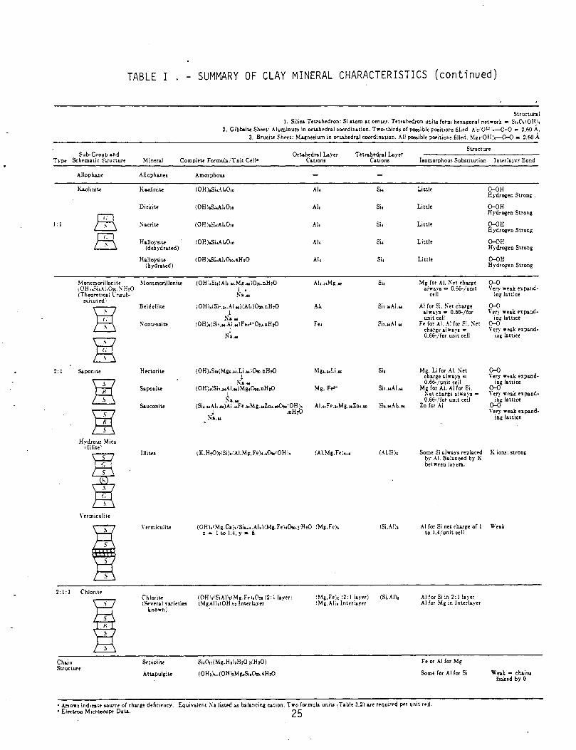
TABLE I SUMMARY OF CLAY MINERAL CHARACTERISTICS (continued)
Structural 1. Silica Tttrahtdron: Si atom at c~nt.er. T~trab~on uni\.6 form htxa~onal network- 5i.Ott0H).
2. Giboo~ Sheet: Alurr.ioum in oc~hedr&l coordination. Tw<>-tbirdo of possible position' filled~. A!:iOJ.I',---0-0 • 2.60 A. 3. Bruci~ Sh .. t: Magn ... ium in ocuhedral coordination .. ~II possible positions fillerl. ~~~··OH)r-0-0- 2.60 A
Structure Sub-Group &nd
Type Scht>matic 5u-urture Mineral Complet< Formula. t:oit Cell• O..~hednd Layer
Catiom; Tet,.hedral Layer
Cations Isomorphous Subsutution lnt.eriayfT Bond
l:l
2: I
Alloph1!1e
K&.olinit<
m L..i:.j,
ffi
Montmorillonit-e tOH • .Si .. ~I.O,. . .S H:O (Theoreti~: l'nsub-
nitutt'd.'·
ffi . .
ffi .
' Sapon11<
H.ydrouo Mica IIIIi~<'
I s . s . I
\"ermiculitt
2:1:1 Chlonte
Cha.i11 Structure
Allopban ...
K..,Jinit<
Dickite
:-;aeriu
Halloysit< (dehydrated)
H&lloysit.e (hydra~.ed)
~lor.tmorilloni~
Beideliite
Sontronite
Htetorite
Saponi~
Sauconite
Illil<'s
\'ermiculiu
C':hlorite {Sf.n·ral Yaritties
onown)
Sepiolit<
Attapulgite
Amorpho\1!
IOH ).Si.AI,O,
(OH\.Si.AI,O,o
(OH\..Si,AI,O,
(OH:,SiaCAb ... Mg.wlO:..nH:O j • s ....
\OH\,\Si: .... AI,.)(AI,)O...oH:O l
.Sa." iOH),(Si: .... AL .. lF.,.•·O,,.nH,O
I
!"'~ ...
(OH),Sio(Mg,.u.Li ... !O...nH:O I
~~ ... (0H),(Sil ... AI.,.)Mg,D,o.nH,O
I
~ .. .. (Sio~ .. Aio .oo)AI ... Fe ... ~ g .>oZo. . ..O..'OH \,
l .nH:O Sa.N
!K.H.OncSi)oi.UMg,Fe),.,o,.roH·,.
AI,
AI,
AI,
AI,
.~I.
Fe.
Mg,.,.Li.w
Mg, F .. •
AI. .. Fe.,.Mg.,.Znuo
(AI.Mg.Fe)._.
(0H\, 1Mg.Ca).ISi .... ,.AI,)CMg.Fe·,,o,..yH,O (Mg,Fe)o 1 - 1 to 1.4, y - 8
(OHI,rSiAI\o1Mg.Fri10,. 12: !layer! (MgAilolOH h: Inter layer
Si,O,I(Mg.H,hH.O ,rH,O)
(0H,)....(0Hl,Mg,$i,0,.,.4H,O
cM~.Fe;, ~2: I layer) rMg,.~l/, lnt.erlaytr
Si,
Si.
Si.
Si,
Si,
Sh.acAl.w
Si, ... Al.w
Sia
Sb.wAI.w
(.USi)a
CSi.AI),
Little
Little
Little
Little
Little
Mg for AI. K •t charge always c::s 0.66-/unit
cell
AI for Si, !' et charge alway, • 0.6~/for unit cell
Fe for AI. AI for 5i. :\et charge alway! = 0.6&-/for unit cell
Mg. Li for AI. ~et cbB.."'ge a.hrays = 0.66-iunit cell
Mg for AI. AI for Si. ~et charge always • 0.6&-/for unit cell
Zn for AI
0-0H Hydrogen Strong .
0-0H Hydrogen Strong
O-OB Hydrogon Strong
O-OH Hydrogen Strong
O-OH Hydrogen Strong
0-0 V•ry weak Oipand
ing lattice
0-0 \' ery wea.k ex paod
ing lattice 0-0 Very weak expand
ing lattice
0-0 Yery wt-ak expand
ing lattice 0-0 Very •eak expand
ing lattice 0-0 \'ery wea.lt: expand
ing lattice
Some Si always replat:'t'd K iol'l!: strong by .~1. Balanced by K bet •ten layers.
AI for Si net charge of I Weak to 1.4/uni\ cell
.~I for Si in 2: lla;-er AI (or Mg in ln~rlayer
Fe or .~I for Mg
Some for AI for Si Weak • ebaino linked by 0
• Arrow! indJca\.f' &OW"f't' of cha.rgt dtficif'ncy. Equi\·a.Jent X a liat.f"d .u balancing cation. Two formul..& uni~ ,_Table 3.2i a.rt reQuirr-d ~r unit rei!. • El«:troo Microorope Da~. 2 5

resulting from the isomorphous substitution of cations by less positive cations,
is often compensated by cations located on the layer surfaces. When the clay
is in the presence of water, these compensating cations have a tendency to
diffuse away from the layer surface. The tendency to diffuse away from the
layer surface in solution and yet be attracted to the layer due to the net
negative charge gives rise to the term diffuse double layer. In a static
environment, this double layer has a constant charge which is largely determined
by the type and degree of isomorphous substitutions and the resulting net
negative charge in the mineral layers. This understanding of the ion distribu
tion relative to the layer structure is based upon work in colloidal chemistry.
When the clay is dry, the adsorbed cations are tightly held to the negatively
charged surfaces. When the clay is in water, the precipitated salt associated
with cations on the particle go into solution. Because the adsorbed cations
are responsible for a much higher cation concentration near the surface of
the particles, there is a tendency for them to diffuse away in order to provide
equal concentrations throughout the liquid. This freedom or tendency to diffuse
away, however, is in contradiction to the attraction force of the clay surface
on the cation. Although several theories on how this distribution of ions
within the double layer can be analyzed; the most widely applied model in
geotechnical engineering is the Gouy-Chapman Model. The Gouy-Chapman Model of
a diffuse double layer has been applied in attempts to explain the behavior of
clay since the 1950's (Lambe, 1958, 1959). Subsequent refinements to the
Gouy-Chapman Model have been developed (Van Olphen, 1977).
These modifications result in a refined definition of the double-layer distribution.
26

It is concluded, however, that most colloidal phenomena can be successfully
interpreted in a general way on the basis of the Gouy-Chapman Model. Deviations
from the general conclusions encountered with certain specific colloidal systems
may necessitate the use of a more sophisticated model in certain instances.
Based upon the interaction of clay minerals and the accompanying diffuse
double layer, definitions of different types of soil fabric have evolved. A
''dispersed 11 soil structure is one in which the net electrical forces between
adjacent particles at the time of deposition produced repulsion. If these
interparticle forces are net attractive during deposition, the soil structure
is said to be flocculated. Therefore, flocculated (or aggregated) structures
are those in which particles tend to join together whereas dispersed structures
are those in which particles tend to move apart. The range of soil structures
is shown in Figure 3.
The Gouy-Chapman model indicates that the tendency toward flocculation is
increased by decreasing the double layer thickness; because, corresponding to
a decrease in the double layer thickness is a decrease in the interparticle
repulsion force. Conversely, the tendency toward dispersion is increased as
the double layer thickness increases. If the double layer thickness is increased,
the electrical repulsion between particles is increased which causes the particles
to form dispersed structure. In order to more fully understand the behavior of
the clay-water system (and therefore the response of clays to hazardous waste
liquids and pore fluids other than water) it is necessary to examine in detail
the variables within the Gouy-Chapman model and how they affect the clay structure
and its associated behavior. The model predicts an increase in the tendency
towards flocculation with an increase in one or more of the following:
27

--=--
(a) (b)
(c) (d)
(e) (g)
Figure 3.. Modes of particle association in clay suspensions and terminology. (a) "Dispersed" and "deflocculated" (b) "Aggregated" but "deflocculated" (face-to-face association, or parallel or oriented aggregation) (c) Edge-to-face flocculated but "dispersed" (d) Edge-toedge flocculated but "dispersed" (e) Edge-to-face flocculated and "aggregated" (f) Edge-to-edge flocculated and "aggregated" (g) Edge-to-face and edge-toedge flocculated and "aggregated".
28

Concentration of electrolyte in the pore fluid
Valence of the ions in the pore liquid
Temperature
or by a decrease in one or more of the following:
Dielectric constant of the pore fluid
Size of the hydrated ions in the pore fluid
pH
Anion adsorption
These relationships are summarized in Table II.
An alternative/supplemental approach to modelling soil-pore fluid interactions
is through the calculation of equilibrium speciation of the chemical elements
in a soil solution. Based upon chemical thermodynamics, a mole balance equation
is set up for each component of a soil solution. Thermodynamic equilibrium
constants, corrected for ionic strength, are incorporated into the various terms
of these equations. The- solution of the set of non-linear algebraic equations
that results from mole balance applied to all components simultaneously ultimately -
provides the concentration of each dissolved, solid, and adsorbed species in the
soil system under consideration. This model will predict the chemical interaction
between.the pore fluid and the clay. For example, if a strong caustic is
brought into contact with clay, it will tend to dissolve silicates. This model
will predict the extent of such dissolution. Loss of silicate will increase
permeability due to the increase in void ratio. Computer programs for solution
of this model include REDE Q22 (Morel, 1972); (Morel, et ~-, 1973) and GEOCHEM
(Sposito and Mattigod, 1980). The latter will be used if this approach is
employed in this study.
. 29

Table II. Effect Of Pore Fluid Parameters On Double Layer Thickness and Soil Structure Tendency
Change in Pore Change in Change in Soil Pore Fluid Fluid Double Layer Structure Parameter Parameter Thickness Tendency
Electrolyte Increase Decrease Flocculated Con centra-tion Decrease Increase Dispersed
Ion Increase Decrease Flocculated Valence Decrease Increase Dispersed
Dielectric Increase Increase Dispersed Constant Decrease Decrease Flocculated
Temperature Increase Increase Dispersed Decrease Decrease Flocculated
Size of Increase Increase Dispersed Hydrated Ion Decrease Decrease Flocculated
pH Increase Increase Dispersed Decrease Decrease Flocculated
Anion Increase Increased Dispersed Adsorption Decrease Decrease Flocculated
30

Literature Review
An extensive literature review covering previous work on the effect of
pore fluid chemical characteristics on the geotechnical properties of soil
was recently completed (Evans,~~· 1981). Highlights of this review
which are relevant to the study proposed here are given below:
(Anderson and Brown 1981) studied organic leachate effects upon the
permeability of clay liners. This study was undertaken using two different
clay minerals permeated with organic fluids utilizing what is considered a
11 Standard permeability test procedure". After approximately one-half of a
pore volume displacement, dramatic increases in permeability were observed
for organic flu1ds. It should be noted, however, that the tests were run
in a compaction mold permeameter. Although a rather high pressure was
·Utilized indicating a signi1icant gradient, no backpressure or consolidation
pressure was utilized. In fact, it is not possible to apply confining
pressure in a lftteral direction in a compaction mold permeameter. It has
been demonstrated that without a backpressure, trapped air can result in an
artificially low permeability. In order to provide adequate precaution
against the trapped air, backpressure is required. Further, any sample
volume change in a fixed ring permeameter,such as the one utilized in the
study, could result in bulk transport of fluids. That is, flow along the
sidewalls of the permeameter can result. An examination of the dielectric
constant for each of the pore fluids used indicates that, with the exception

of ethyiene glycol, all fluids ha'd relatively low dielectric constants. All
of the permeants had a dielectric constant lower than that of water. Consi
deration of the Gouy-Chapman model and the reduction in double layer thickness
due to the low dielectric constant leads to the conclusion that the clays,
in response to these pore fluids, would tend to shrink and, hence, the permeability
would be expected to decrease. This was generally the case in the early stages
of the test. However, if shrinkage is enough to result in bulk transport
between the soil sample and the wall, a permeability increase would result.
This would not be the Darcy permeability that one would normally be interested
in, but some number representative of flow both through and around the sample.
Hence, the effects of piping, shrinkage cracks or other leakage due to the
testing proc~dure can mask the effects of the soils in response to the pore
fluid.
In a similar study (Green, Lee, Jones, 1980), the permeability of three
clays was studied in response to organic solvents. The permeability tests were
conducted on remolded soils in thick-walled glass permeameters. No backpressure
was utilized nor were the samples consolidated. The study found in general that
the permeabil1ty of clays was consistently lower for organic solvents than with
water. The permeability decreased with time and attained equilibrium in several
weeks. The permeability decrease correlated well with the lower dielectric
constant of the pore fluids. It was found that the solvents with extremely
dielectric con3tants could cause clay shrinkage and subsequently result in
cracking and rapid breakthrough of the pore fluids through the clay columns.

•.
This caused the transportation of pore fluids in bulk. The breakthrough, due
to observed cracking, may be the result of the experimental designs, specifically
the testing apparatus. Without the application of a confining stress, similar
to that which would exist in the field, the samples could begin to shrink and
the confining stress would decrease. Eventually, this stress was reduced to
the point where leakage between the permeameter wall and the sample was observed.
Mourn and Rosenquist (1961) found that permeation of illitic and mont
morillonite clays with potassium chloride solutions resulted in increases
of the undisturbed shear strength. This is consistent with the Gouy-Chapman
model because the replacement of sodium with potassium should increase the
flocculation tendency of the clay. Remolded shear strength of the illitic clay
also increased, but not that of the montmorillonite. Matsuo (1957) permeated
several Japanese soils with a variety of chloride salts. No effect on the
plasticity index or liquid limit of soils containing significant amounts of
salt was observed. For-a clay soil, however, both the plasticity index and
liquid limit (a direct function of shear strength) exhibited marked increases
as salt concentration increased. This finding is again predictable from the
Gouy-Chapman model as increases in electrolyte concentration in pore water
should decrease the double layer thickness and increase shear strength.
Similar effects of electrolyte on shear strength of Canadian and Scandinavian
clays was observed by Torrance(l975). The effect was most marked at low
electrolyte concentrations and became essentially independent of concentration
at high electrolyte levels. As the cation of the salt became more polar
the liquid limit shear strength increased at constant concentration. This
33

is again in agreement with the Gouy-Chapman model prediction. The effect of
exchanging the natural cations of four clays with various other cations was
studied by Vees and Winterkorn (1967). The liquid limit and plastic limit
increased with cation valence for ~olinite, knollenmergel, and attapulgite,
but not for bentonite. Again the Gouy-Chapman model yields an accurate
qualitative prediction. However, Leonards and Andersland (1960) obtained
results at varience with those predicted by the Gouy-Chapman model when they
studied the effect of temperature and electrolyte concentration on the
undrained shear strength of a plastic clay.
A series of laboratory leachate tests were conducted by Griffen, et ~·
0976) in order to evaluate the potential of various clay minerals for attenuating
chemical constituents. The test utilized leachate from a sanitary landfill
permeating kaolinitic, illitic and montmorillonitic clays in a matrix of quartz
sand. Prior to permeation, the clay mineral structures were analyzed by X-ray
diffraction in order to evaluate the exchangeable ions. The leachate was
chemically analyzed before and throughout the ten-month testing program. At
the completion of the testing, the soil samples were sectioned and analyzed to
determine the chemical distribution through the samples. The study found that
chloride, sodium and water-soluble orga~ics were relatively unattenuated.
Potassium, ammonium, magnesium, silicon and iron were moderately attenuated.
Finally, the heavy metals - lead, cadmium, mercury and zinc - were strongly
attenuated. Conversely, calcium, boron and manganese were significantly higher
in the effluent concentration than in the original leachate. Montmorillonite
was more effective in attenuating the chemical constituents, followed by illite
and kaolinite. This trend is consistent with that predicted from the
34

physical-chemical standpoint in relation to clay mineralogy. The increase in
effectiveness in attenuating chemical constituents is directly related to the
cation exchange capacity of the clay mineral. The principal attenuation
mechanism was identified to be precipitation for the metals and cation exchange
for the other chemical constituents attenuated. Finally, the hydraulic
conductivity or permeability was found to decrease with increasing time during
the testing period.
In a similar study to the one above leachates were utilized by Fuller
(1978) to permeate ll different naturally occurring clayey soils. The leachate
was generated in a homeowner type septic tank, and at times spiked with various
chemical constituents. Soils were analyzed to evaluate their clay mineralogical
structure prior to permeation .. The results in this study were in contrast to
those found by Griffin. The investigator found that the types of clay minerals
and the cation exchange capacity were among the least important factors in the
attenuation of chemical constituents from the leachate. The amount of clay
in the soil sample, however, was considered to be the most important factor.
Since the hydraulic conductivity will generally decrease with increasing clay
fraction, the results would suggest that a lower hydraulic conductivity with
the accompanying increase in clay content would be more effective in the
attenuation of chemical constituents in the leachate.
These results are somewhat consistent with those that would be predicted
from colloidal theory. It is clear, based on the study conducted by Griffin
et £l. (1976) and our knowledge of clay mineralogy, that the cation exchange
capacity is an important factor in the attenuation of chemical constituents
35

in leachate. However, it is also clear that increasing the clay fraction,
and thus the overall capacity for cation exchange within a given volume of
material, would also significantly affect the attenuation of chemical constituents
in the leachate. The study by Fuller included enough variability in the clay
content of the leached samples to mask that effect of clay mineral structure
and cation exchange capacity.
A study was undertaken by Andrews, ~ ~- ( 1967) to compare the inter
action of three clay minerals with three pore fluids. The pore fluids were
water (H 20), dimethyl sulfoxide (DMSO) and dimethyl formamide (DMF). The clay
minerals used were kaolinite, attapulgite and sodium montmorillonite. Both
DMSO and DMF are aprotic solvents. Their polar nature is shown by the dielectric
constants (DMSO = 48.9, DMF = 26.6) and dipole moments (DMSO = 3.9, DMF = 3.85).
The authors point out that in DMSO and DMF molecules, the positive end of the
dipole is not accessible as is the case with H2o. This shielding makes the
interaction of the dipoles with anions considerably weaker than with cations.
Therefore, the dissolved anions and anionic surfaces are relatively free from
interaction with the liquid while cations can become solvated. Since the solid
surfaces of clay minerals in aqueous solutions are predominantly negatively
charged or anionic in character, this property .of DMSO and DMF molecules is
of particular interest.
In order to study the effect of these various pore fluids on the three
clay minerals, ~n extensive testing program was undertaken. Tests included
specific gravity and specific volume, Atterberg limit tests, the Dietert
compaction tests, sorption tests, sedimentation volumes, and cracking patterns
of thin clay slurry films. The authors note that the specific volume, which
36

is the inverse of the specific gravity of clay in a particular liquid depends
upon the specific volume of the clay substrate, the weights and volume of the
exchangeable ions on the clay, the interaction between the exchangeable ions
and the clay particles in the wetting liquid, the interaction between the clay
substrate and the wetting liquid, and the dried clay crumbs or the sizes of
the pores in the clay crumbs. These factors were utilized in the·evaluation
of the data obtained from their tests. The Atterberg limit test determines
the moisture contents at which changes of state from liquid to plastic to
semisolid to solid occur. The position of these limits on a moisture scale
is based upon the water affinity of the mineral components of the clays, their
tendency to form secondary and higher structural units, and their granular
composition, which controls packing properties and pore space geometry. The
Dietert compaction test is an impact compaction test utilizing smalle~ samples
than the standard Proctor compaction test. Sorption tests are a measure of
the clay 1 s propensity to-take on fluid. The determination of sediment volumes,
frequently used in colloidal chemistry, is little used in soil engineering. In
general, flocculated particles settle rapidly to high equilibrium values while
deflocculated particles settle slowly to low equilibrium values. The test is
usually performed by dispersing a known amount of solids in a large excess of
liquid to determine the relative rate of settling and the final volume of
sediment. Cracking patterns of thin clay slurry films are an indication of
the tensile stresses set up by the clay minerals as they lose their liquids by
evaporation.
It was found that the specific volume of kaolinite and attapulgite was
relatively unaffected by the change in pore fluids between H20 and DMSO.
37

However, the specific volume of the sodium montmorillonite was significantly
greater in water than in DMSO. The results of the Atterberg limit test indicated
that compared to water, the plasticity index for DMSO was higher for the kaolinite
but lower for the attapulgite and sodium montmorillonite. The most profound
effect on plasticity was with the sodium montmorillonite where the plasticity
index was 7.5 lower for DMSO than water.
The results of the Dietert compaction test, consistent with the previous
tests showed only minor effects of alternate pore fluids with kaolinite and
attapulgite. Whereas, with sodium montmorillonite, significant effects were
observed. In all cases, a larger maximum density was obtained with water than
with DMSO. For both the kaolinite and sodium montmorillonite, the optimum liquid
content was higher for DMSO than it was for water. Conversely, for attapulgite,
the optimum liquid content was lower for DMSO than it was for water, indicating
the additional elasticity of the attapulgite mineralogical system.
For all clays except kaoli~ite, the final sorption data were higher for
water than for DMSO. Further, the sorption ratios are higher for sodium
montmorillonite than for attapulgite. The sorption values for kaolinite, being
higher for DMSO than water, indicate a greater affinity of the kaolinite mineral
structure for DMSO than for water.
The sedimentation test yielded the following ratios for H20:DMSO:DMF,
respectively:
Kaolinite 0. 63:: l
Attapulgite 2.6 :
0.64
0.65
Sodium Montmorillonite - Infinity 1.08
38

From these data, one can see that kaolinite interacts more strongly with DMSO
than either water or DMF. Sodium montmorillonite interacts most strongly with
water, but to about the same degree with both DMSO and DMF. Attapulgite
interacts most strongly with water, followed by DMSO and least with DMF. The
stronger interaction of kaolinite with DMSO and DMF than with water is consistent
with the sorption data which showed the kaolinite had a greater affinity for
the organic solvents than for water.
The cracking patterns of thin slurries were observed for all three clay
minerals. The drying of the kaolinite film produced no cracking pattern.
However, the film produced by DMSO has the smoothest appearance, indicating
its great interaction between the DMSO and the kaolinite. The attapulgite water
film showed a few cracks, forming relatively large structural units indicating
a relatively large tensile strength of the clay-water system and good mobility
of the clay particles at relatively low water contents. Finally, the sodium
montmorillonite water films produced no cracks, whereas the sodium montmorillonite
DMSO system produced a cracking pattern of a larger scale than that with DMF.
It was concluded that, since plasticity index values are taken as a measure
of the interaction between the mineral surfaces and the liquids, then this
interaction in the water system was, as expected, greatest with sodium montmorillonite
and least with kaolinite. With DMSO, however, the absolute plasticity index
value was greatest for attapulgite and much less for both bentonite and kaolinite.
Further, the plasticity index value for kaolinite with DMSO was about twice that
with water. The great difference in the interaction of DMSO with kaolinite and
sodium montmorillonite, respectively, with attapulgite lying in between emphasized
the marked differences in the respective surface characteristics and probably
39

the manner in which the water molecules are associated with these surfaces.
The very strong interaction of DMSO with kaolinite showed itself in all of
the tests. Note that in the study by Vees and Winterkorn ( 1967) previously
reviewed bentonite (sodium montmorillonite) exhibited opposite changes from
attapulgite and kaolinite.
The literature reviewed above indicates that pore fluid chemical
characteristics can have a significant effect on the geotechnical properties
of clayey soils.especially the property of permeability. These effects are
undoubtedly rooted in effects on the colloid chemistry and physical structure
of the clay component of the soil. The potential for the use of the Gouy
Chapman model as a basis for understanding and predicting these changes has
been presented.
Much of the research described above was not conducted in the context
of evaluating the effects of hazardous and/or toxic wastes upon the geotechnical
materials. In addition, it must be noted that for the few situations where
this was the specific object of the study, the experimental techniques used,
especially for permeability measurements, were variable and subject to errors.
The purpose of the experimental program described in the next sections is to
a) elucidate and demonstrate a set of experimental procedures which will overcome
the experimental problems alluded to above, and b) yield data which can be used
to develop a quantitative model either empirical, semi-empirical or theoretical
which can be· used to accurately predict the rate of landfill leachate permeation
through clayey liner or barrier materials.
40

Research Program
a. Preliminary Work
Research activity on the effect of pore fluids on the engineering properties
of clay materials is underway at Lehigh University. The initial activity was
the literature review noted above (Evans et ~., 1981). Next, effort was
expended on developing equipment and test procedures to overcome the experimental
difficulties in making accurate laboratory measurement of permeation through
clay. As indicated, the standard tests used for measuring permeation of
uncontaminated water through geotechnical materials are not applicable when
wastes are contaminants of the permeating fluid. Shrinkage and swelling,
especially the former, can result in bulk transport of the fluid which is not
representative of the true situation at a landfill site. Equipment and test
procedures have been devised to resolve these difficulties and are described
below. A formal presentation of this information 1s in press (Evans, et ~·,
1983).
b. Description of Equipment
A diagram of the triaxial cell - permeameter setup for use in these studies
·is given in Figure 4. It consists of a modified triaxial cell assembly connected
to a permeability measurement system. Figure 5 gives details on a typical
triaxial cell. The fundamental purpose of a triaxial cell is to control the
state of stress on the sample either isotropically or anisotropically. As
illustrated, the soil sample is encased in a flexible membrane with top and
bottom end caps or platens. The membrane-encased sample is positioned in a
rigid wall cylindrical cell with a space of several inches between the membrane
and the cell wall. A similar space exists between the platens and the cylinder
41

P'LUID Ri5!D!YOI R
CCICTIIOL PAH!:L
0 0 0
TOP PU. 'ID Barrat I?I!ESSUR! PUn!! : P'IIZI) l?l!li:SSURI
Aift CQIPRIISSOR n:II:D rEED
CELL PRiiSSURE YALYC
Cll.L PRESSURE J'Ei:D
Cll.L llliADC VALVE
kr.: ;:~YClR nLL COCK
RESERVOIR PR&':SUR! VALVE
BACKPR&<:SURE LINE
l!IP'LCN MAN. I'R!:SSURI': YALVI
R!SRRYOIR llliADC VALYC
TOP PU.'!lllf
TRLU IAL C!a.L ( P'LUID riiJ.ED )
SUPPLY LINII: IILUD YALYC
SAil~
EFP'LUDIT TANK PRESSURE YALVR
CLASS W'I'P'LOII IIAHQ\IM'n
Figure 4. Triaxial Cell -.Permeameter Apparatus.
42
YACtrull SIIIJTOrr YA L Y1i:
YACtruM CCICNIX:TIOH
SCHDIATIC Or LD!ICH PEI!I!EAII

Rubber 0 ring
%,"dia stainless steel t1e bars, 3 spacedat
120 ° -----<-l
I~ "dia. sample enclosed in
rubber_
Sta1rlless steel ram, J{dia.
/A 1r release valve J>
____ 11
Seating coned 120"
erspex cy!tnder 4'00 ><3~· !D and
l"in length
membrane --t-H--+------.-1 4 radtal grooves,
1 n/wtde X 11/'
I in depth
Porous dtsc Je" in thickness /
I
·,··, · . .._
Rubber 0 rings I
II i-;6"dta studs,
I ! 3 spaced at I 120" With r ' wtng nvts
:::_,~·~,...,...~:.-~:::::!\.:~::i:, ~~ ~:-~-~~--'~-~'-~· ~~~~~~~~~~,
lon1
Jn.,.,u~;,_,.o.,.,n'"""t"""o,_p__,r,...e,_s,..:"'"'u'":-~'"·--""-~-, "~' '~'-, -~r~~n~~e or pore pressu:e c:nnexi:~ supp(y, f'orce fit or screwed & sweated
Bronze base
Detail of drainage conne.xton to top of sample
Figure 5. Typical triaxial cell.
43

end plates. The space between the membrane-encased sample and the rigid
cylindrical cell is filled with water and connection to a pressure supply is
made to permit application of a cell pressure. Pressurizing the cell subjects
the sample to an isotropic state of stress. If anisotropy is required, the
vertical stress can be increased via the application of an additional load
through the stainless steel ram or piston. A sample in a triaxial cell
encased in a membrane can therefore change shape or volume in response to an
internal physiochemical stress while being maintained in a constant state of
externally applied stresses. This differs from a fixed ring permeameter where
the state of stress cannot be controlled. Samples subjected to hazardous and
toxic wastes are likely to experience changes in volume (i.e., shrinking or
swelling) due to the electrochemical stresses set up in the sample. If these
tests are not run in the triaxial cell, seepage can occur between the side of
the sample and the sidewalls of the permeameter. With a flexible membrane
encapsulating the sample, this cannot occur. The custom designed triaxial cells
to be used here are the same in concept as shown in Figure 5. Several unique
features, however, were incorporated into the modification of the triaxial cell
concept for testing of hazardous and toxic wastes.
First and foremost, all components of the triaxial cell which come into
contact with the waste fluids are of Teflon. This includes Teflon top and
bottom caps, fittings and tubing through the cells. Although the base of these
cells is constructed of stainless steel, the end caps, fittings and tubing are
all of Teflon. Thus, this triaxial cell has all the rigidity and high pressure
capability associated with stainless steel, yet all of the contamination
44

resistance of Teflon. Triaxial cells of pure Teflon are quite yielding and
tend to 11 Creep 11 under the applied stresses.
Another feature of these custom-built Lehigh cells includes double drain
lines through top and bottom pore stones. This permits flushing of all air
within the system prior to the start of the test. Air within the system tends
to artificially lower the true permeability of the soil.
The final major material consideration for the triaxial cells is the
membrane material. At present there are four different membrane types available
for triaxial cell membranes. These are latex, butyl rubber, neoprene, and
Teflon wrap. Continuous elastic membranes can be obtained only of latex,
butyl rubber, and neoprene. For extreme contamination conditions, the sample
can first be wrapped with Teflon and then encapsulated with one of the other
membranes. Prior to the testing here, waste membrane compatibility is checked
to insure no membrane degradation will occur during the testing. This i$ done
via the use of the compatibility chart provided by the material manufacturers,
and by submersion testing in strong concentrations of the subject waste
permeant.
In order to control th~ confining and seepage stresses on the sample in
the triaxial cell, a permeability board is required. The permeability board
and cell are combined to make up the permeability test system (Figure 4).
This board has several unique features. First, the system is designed to be
utilized with the application of back pressure. Back pressure is a technique
used to apply very high pressures to the pore fluid to improve the solubility
of air in the fluid without changing the state of effective stress on the sample.
That is, through the use of a back pressure high pore water pressures can be
utilized without the sample being subjected to artificially high effective pressures.
45

It has been demonstrated (Olson and Daniel, 1979) that without the use of a
back pressure to insure saturation, gas binding can result yielding unrealistically
low permeability determinations. Unless saturation is insured by this back
pressure, the permeability measurements will be quite variable and not reproducible.
Another major unique feature of this system is the ability to measure both
inflow and outflow volumes of the test fluid. As discussed, introduction of a
hazardous or toxic waste pore fluid into the soil could induce changes in the
physio-chemical state of stress which may cause the sample to either shrink or
swell. Measurement of this change in volume is essential to understanding the
overall clay pore fluid behavior. With respect to permeation,shrinkage or
swelling can be either a positive or negative factor. Shrinkage will tighten
a soil and decrease permeability but if excessive shrinkage occurs the soil will
crack resulting in high permeability. Swelling normally opens a clay structure
resulting in higher permeation, but in a soil mix low in clay and high in sand,
the permeation could be decreased if swelling of the clay helps fill the sand
voids. A third feature of this permeability board is that it incorporates the
ability to interchange pore fluids during the test without changing the state
of stress in the sample. For example, in the test protocol, samples are initially
permeated with the same fluid as the original pore fluid of the sample. In
this way a baseline permeability is established without physio-chemical changes
being induced in the sample. After a steady state is achieved, the pore fluid
of interest is placed into the permeability apparatus, and the test continued
to monitor for changes in response to this new pore fluid. Fluids can be
changed without changing the state of stress in the sample, which would otherwise
require a re-establishment of equilibrium.
46

In order to improve the sensitivity of the measurements, small diameter
manometer tubes are used to monitor fluid levels. However, with small diameter
tubing the inflow manometers must be refilled periodically as the inflow
permeant level drops. This design allows for manometer refill without changing
the state of stress in the sample. The system is designed to accommodate a
wide range of stresses up to a maximum of 130 psi. Four permeability boards
have been built to allow multiple tests to be run simultaneously. One of these
four boards is equipped with all Teflon valves, fittings and tubing for the
ultimate contamination resistance.
c. General Experimental Procedures
The basic experimental program consists of measurements of geotechnical
and chemical properties.of clayey soils prior to and after permeation with the
test fluid. In all cases the clayey soil sample will first be permeated with
a 11 Standard 11 uncontaminated water and then with the contaminated test fluid.
Depending on the specific geotechnical or chemical test, the 11 before 11
measurement will be made prior to installation of the clayey soil in the
permeation apparatus, during permeation with uncontaminated water, or just
prior to the switch to the contaminated fluid. All 11 after 11 geotechnical tests
will be performed on the clayey soil after completion of the permeation tests.
All permeability tests will be conducted on clayey soils in the custom
designed triaxial cell permeameters described above. The clayey soils which
will be formulated from sand and various clays can be consolidated in the triaxial
apparatus at effective stresses representative of those in clay liners and
cutoff walls in the field. The effective stress is the difference between the
47

pressure on the sample inside the membrane (back pressure) and the pressure
applied to the water between the membrane and the rigid cell (cell pressure).
After consolidation is complete, permeation can be initiated by changing the
pressure at the top and bottom of the sample by equal and opposite amounts.
Thus, a pressure differential to produce flow is set up but the average pressure
over the sample is maintained at that used during the consolidation. The cell
pressure on the whole sample is also maintained at the same level as during
consolidation.
The allowable permeability in landfill liners must be quite low if these
are to effectively isolate the wastes from the environment. The liner formulations
used in this study will be typical of those used in the field, thus permeation
rates in these experiments at least with the 11 Standard 11 uncontaminated water
will be quite low. In a permeation test at least 2 to 3 pore volumes of fluid
must be exchanged. Taking into account expected permeation rates and the
required pore volume displacement indicates runs of 2 weeks t~ 1 month with
uncontaminated water. On the average a run with first uncontaminated water
and then a contaminated fluid could range from l l/2 to 2 months (this includes
setup time).
48

d. Liner Selection
Liners used in the field are formulated with 5 to 15% by weight clay
material. In this study, the clay level used will be in the low end of the
range to keep the run lengths down. If high levels of clay were used, run
lengths of many months would be required even if very large pressure
differentials were used to permeate the test fluid. The use of a low level
of clay will not invalidate the results because what is sought is the effect
of the contaminated fluid on the liner relative to permeability with an
uncontaminated fluid.
The clay mineralogical structures which will be used to make the test
liners are Kaolinite, Illite and Montmorillonite. These are representative
of the most common clay mineralogies. Use of these 3 (each will be used
sep~rately) will cover the overwhelming majority of geotechnical barrier
materialsused in practice.
49
e. Geotechnical and Soil Chemistry Tests
A total of 9 types of geotechnical and soil chemistry tests will be
utilized in this study. These are permeability, triaxial shear with pore
pressure measurement, Atterberg Limits, grain size distribution, bulk density,
zeta potential, cation exchange capacity, X-ray diffraction, and scanning
electron microscopy. A brief description of each test as well as its function
is given below.
1) Permeability- The coefficient of permeability will be determined
utilizing a 11 Standard 11 uncontaminated water as a base pore fluid to establish
the baseline permeability. This will also allow for establishment of equilibrium
of the soil water system in response to the applied stresses. Then the
contaminated test fluid will be permeated. The inflow and outflow will be
monitored to determine changes in volume of the system during this phase of
the test. The coefficient of permeability will be calculated for each reading
made throughout the test. These data will yield a curve of permeability versus
time (or fraction of pore volume displacement). In addition, volume change
as a function of time and pore volume displacement will be calculated. As
indicated previously, the total time for each permeability run will range from
6 to 8 weeks. Permeability is the prim~ parameter for evaluation of effect of
contaminated fluid on the clayey geotechnic material.
2) Triaxial Shear - The shear strength of the soil will be determined
in terms of both total and effective stresses utilizing an isotropically (axial)
consolidated undrained triaxial shear strength test with pore pressure
measurements (CIU) tests.· Samples after permeation with ••standard 11 water
50

will be tested in triaxial shear. Replicate samples will be tested in shear
after the permeability testing is complete. In this way, the difference in
shear strength due to permeation with the contaminated pore fluid will be
determined. Lehigh University is equipped with two Wykam-Farrence five-ton
loading frames and with transducers to monitor pore pressures during shear.
In this way, both the total and effective strength parameters can be determined
resulting in a more complete evaluation of shear strength changes.
3) Atterberg Limits -The Atterburg Limits (liquid and plastic limits)
are a measure of the plasticity of the soil. The Atterberg Limits have been
found to vary as a function of the primary adsorbed cation as well as the clay
mineral species. The liquid and plastic limits of the soil will be determined
before and after permeation with the contaminated pore fluids. Changes in
these properties can then be used in subsequent model development .
. 4) Grain-size Distribution - The grain-size distribution by a sieve and
hydrometer will be conducted on samples utilized in sample preparati6n. In this
way the grain size distribution prior to any testing is established. Subsequent
to permeation, with a contaminated pore fluid, the grain-size distribution will
again be determined. This parameter will be used to identify certain changes
in soil structure in response to the pore fluid. For example, dissolution of
soil constituents will result in changes in the grain-size distribution. Further,
changes in the shape of the hydrometer curve reflect changes in the nature of
the electrostatic forces between the colloidal particles.
51

5) Material Weights - Determination of the bulk density of samples will
be made at the start of testing and will be correlated with the water chemistry
data. For example, dissolution of silicates with strong caustics will result
in lower bulk densities after testing than before. This should correlate with
increases in the total dissolved solids as determined from chemical analysis
of the permeant.
6) Zeta Potential - The zeta potential is the electric potential in the
double layer at the interface between a particle which moves in an electric
field and the surrounding liquid. That is, the zeta potential is the shearing
plane between the bulk liquid and the envelope of liquid which moves with the
particle. The zeta potential is therefore a fundamental double layer property.
As part of the laboratory testing program the zeta potential for each of the
pore fluid conditions will be determtned. An automated zeta meter is available
for use in this determination.
7) Cation Exchange Capacity - The cation exchange capacity of the clayey
soils will be evaluated before and after permeation. The procedure uses an acid
to replace the soil cations (Jackson, 1958). The literature review and the
short discussion of clay colloid chemistry presented earlier indicates the
potential value of this evaluation.
8) X-ray Diffraction - X-ray diffraction analyses will be conducted on
selected samples to determine structural changes due to the influence of
contaminated pore fluids. Where expulsion of interlayer water occurs, the
basal plane spacing will ·change. This change can be measured by X-ray
diffraction.
52

9) Scanning Electron Micrographs - Scanning electron micrographs will
be obtained on samples before and after permeation. Changes in soil fabric
wi.ll be detected and correlated with the changes observed by the other test
techniques.
f. Test Fluids
The list of chemicals, mixtures of same and the concentrations of same
in leachate is endless. It would be fruitless to attempt a study in which
typical leachates were used as the test fluid. Rather the test program is
set up so that specific chemicals which are known to be in leachates and which
have characteristics expected to be significant in determining permeation
will serve as individual test fluids. With this technique information should
accrue which will make it possible to model permeation as a function of known
chemical propert1es of the leachate and soil.
Six chemicals in addition to the 11 Standard 11 water have been selected for
the ·initial round of tests. These are NaOH (an inorganic base), HCl (an
inorganic a~id), aniline (an aromatic organic base), acetic acid (an aliphatic
organic acid), acetone (a neutral organic) and cc1 4 (a chlorinated alkane).
In addition to being representatives of general classes of chemicals, all of
these have been reported to be present in waste leachates (Shuckrow, et ~·, 1980).
The initial studies will be at two levels of concentration. The high level
will be close to that at which these chemicals can be expected to be present
in leachate, i.e., HCl to a pH of 1-2, NaOH to a pH of 11-12, acetic acid at
a concentration of 10,000- 15,000 mg/1, and aniline, chloroform and acetone
at levels close to their solubility in water. The low level will be set at
53

concentrations which should have a minor, if any, effect on the magnitude of
parameters in the Gouy-Chapman model versus the magnitude set by the solvent
water.
The data from these runs should indicate dominant parameters of importance
in selecting compounds and concentrations for the latter phases. There are
several other classes of organic and inorganic compounds which can be used
such as ethers, phthalates, non-aeromatic amines, phenols, esters, polynuclear
aromatic hydrocarbons, pesticides, oxygenated compounds, heavy metals, etc.
In addition, there are many candidate compounds in each group which could be
used. Selection will depend· on the results obtained from the first set of
tests given above. For example, if dialectric constant rather than chemical
class characteristic appears most important, this will be used as a normalizing
parameter for future studies. Another potential parameter based on the Gouy
Chapman model could be valence of the anion associated with the inorganic acid,
or valence of the cation associated with the inorganic base. Another factor
which could be important is ability to chemically react with or dissolve away
portions of the clay structure. For this situation, concentration may play a
dominant role.
As indicated above, at present it is difficult to project a definitive
experimental plan beyond the original set of experiments with the six fluids
selected, at 2 concentration levels. It is estimated that with the number of
permeation cells presently available, it will be possible to complete the
first round of studies in 6 to 9 months. Over the subsequent 18 months
as many as 162 individual runs can be made provided additional test cells
are obtained. Funding for additional cells is requested in this proposal.
54

These 162 runs will involve 18 other compounds with 3 different clayey soils
at 3 concentration levels each. Compound selection and concentrations cannot
be defined at this time. These will be selected based on the parameters
which seem to have the greatest effect on permeability.
The 11 Standard 11 uncontaminated water will be formulated from distilled
water and specific inorganic chemicals. It will be based on typical ground water
for this area of Pennsylvania given in Todd (1980). The use of a 11 Standard 11
water rather than a natural water is to insure that alterations in water quality
do not affect the results obtained. It is common practice to use tap water
for water permeability tests in geotechnology laboratories. This practice
will not be followed because it has already been demonstrated that standard
geotechnology permeabjlity procedures are not valid for this situation.
It is not anticipated that small changes in dissolved solids in the water
will affect the res~lts because, in effect, the experimental technique used
here yields absolute differences in permeability between the contaminated and
uncontaminated fluids. However, to be ultra safe a water with constant chemical
composition will be used for all tests.
The 11 Standard 11 water will not only be used as the initial test fluid prior
to a sw1tch to contaminated feed but be treated as a test fluid, thus establishing
a complete control. One setup will be permeated throughout the test with the
11 Standard 11 water and all geotechnical and chemical tests will be conducted on
a 11 before 11 and 11 after 11 basis for tnis fluid and all three soils.
If this work proceeds more rapidly than anticipated, i.e., test run time
is shorter than anticipated or a definite model of theoretical justification
is generated earlier than projected, work will commence on studies with mixtures
of the test fluids.
55

g. Permeate Analysis
In general, chemical analysis of the permeate will be routinely conducted
at the conclusion of and during a run. Parameters analyzed for will be the
contaminant and chemical constituents of the clay. The latter will indicate
breakdown of the clay structure due to exposure to the permeate. Chemical
analysis of the feed for contaminant as well as the effluent will indicate
loss during the test. Hold up of contaminant on the clay is not a significant
factor here. Permeability of the fluid is the prime parameter of migration
unless the reactive power of the clay is much larger than can be anticipated.
It is not expected that adsorption precipitation or chemical reaction can be
relied on to prevent migration of pollution through the liner for more than
a short time relative to the required time Of containment. However, data on
holdup of a contaminant will be useful in predicting soil-waste chemical
interactions which could alter the permeability. Thus, the mass balance data
on the containment and soil chemical-constiutents will be useful in model
formulation.
56
h. Data Analysis
The data generated as a result of the laboratory testing program will be
analyzed using the appropriate statistical procedures to establish the
statistically significant main and interaction effects. The determination of
statistically valid effects is required for subsequent evaluation of the
reliability of the selected models.
Once the pore fluid-clay interactions are established, the predictions
resulting from application of the Gouy-Chapman model will be compared with
those determined in the laboratory investigation program. It is expected that
the colloidal model will qualitatively predict the behavior determined in the
Laboratory Investigation Program. The model evaluation will then be extended
to determine the quantitative applicability. Ideally, the colloidal model .
could be used as a tool to quantitatively predict changes in the soil property
of interest, such as permeability, by inputing parameters relating to contaminant
. properties, contaminant concentration, and soil mineralogical species. Such
quantitative predictions could, for example, include the zeta potentials
determined under the pore fluid chemistry conditions. These colloidal model
evaluations will be augmented through the application of the computerized
equilibrium model.
57

'\ I •
Available Facilities and Equipment
The facilities of the Lehigh University's Fritz Engineering Laboratory
and the Center for Marine and Environmental Studies are available as required
for this project. Both of these laboratories are fully equipped with most
equipment required for waste analysis and modern geotechnical testing equipment
to determine the physical and engineering properties of soils. Included is the
equipment required for grain size distribution, moisture content, specific
gravity, compaction, permeability, and static and dynamic shear strength. Of
special interest for the work scope described herein is the unique permeability
testing apparatus which was described earlier. Four of these are available for
use in these studies. Funding is requested for ten more to accelerate the rate
of data generation.
The X-ray diffraction, automated zeta potential, scanning electron
microscope and required computer facilities are available. These
are housed in other academic departments and research centers on campus.
Time Schedule
The program described earlier is scheduled for two years of effort. All
of the equipment required for the initial effort is in place and ready to go.
Indeed, some preliminary studies with only a water feed are scheduled to begin
in the late spring as a final test of the apparatus. During the first 6 months
1) the initial six test fluids at 2 concentrations plus the "standard" water
will be run; 2) the data will be analyzed and selection of the next set of
test fluids and concentrations will occur; 3) the additional test cells and
ancillary apparatus will be ordered and set up. Over the next 18 months, the
selected 18 fluids at 3 concentrations each will be run. Data analysis will
occur concurrently.
58

Budget Justification .
Funds are requested to purchase 10 experimental setups in which to con
duct the permeability and triaxial shear testing. As indicated previously
this equipment is the basic experimental apparatus for this study. A descrip
tion of this equipment was given previously. The number of setups requested
is necessary to complete the work planned within the two-year period of this
grant.
Funding at modest levels for consumable supplies, publications, computer
time and time on the scanning electron microscope, X-ray diffraction, and auto
mated zeta potential device is included. Travel is budgeted to present the
findings at two conferences per year.
An equipment grant request for the type of equipment projected for purchase
under this grant has been made to the Department of Defense. If the DoD grant
is approved, the budget-for this proposal will be reduced to reflect the equip
ment acquisition.
59

•
' •
REFERENCES CITED
Anderson, D. & Brown, K. W., "Organic Leachate Effects on the Permeability of Clay Liners". Proceedings, 7th Annual Research Symposium, Land Disposal: Hazardous Waste. EPA Report No. 600/9-8l-002b, March 1981, pp. 119-130.
Andrews, R. E., J. J. Gawarkiewicz & Winterkorn, H. F., "Comparison of Three Clay Minerals with Water, Dimethyl Sulfoxide, and Dimethyl Formalmide", Highway Research Record No. 209, 1967.
Evans, J. C., Chaney, R. C., and Fang, H.Y., "Influence of Pore Fluid on Clay Behavior," Fritz Engineering Laboratory Report No. 384.14, Lehigh University Dec ember 1 981 .
Evans, J. C., Fang, H.Y., Kugelman, I.J., "Influence of Hazardous and Toxic Wastes on Fine-Grained Soils.: Proceedings of the Third Ohio Environmental Conference, Ohio State University, Columbus, Ohio, March 28-30, 1983.
Fuller, W. H., "Investigation of Landfill Leachate Pollutant Attenuation by Soils." EPA Report No. 600/2-78-158, August 1978, 243 pp.
Green, \,J.J., Lee, G.F. & Jones, R.A., "The Permeability of Clay Soils to Water and Organic Sol vents: Implications for the Storage of Hazardous Hastes." Report submitted to EPA, October 1980.
Griffin, R.A., Cartwright, K. & Shimp, N.F., et al., 11 Attenuation of Pollutants in Municipal Landfill Leachate by Clay Mineral~ Part I. Column Leaching and Field Verification." Ill.State Geol. Surv., Environ. Geol. Notes No. 78, 1976.
Grim, Ralph E., Clay Mineralogy, 2nd ed., McGraw-Hill Book Company, New York, 1968.
Jackson, M. L., "Soil Chemical Analysis, 11 Dept. of Soil Science, University of Wisconsin, Madison, Wisconsin, 1958.
Lambe, T. W., "Physico-Chemical Properties of Soils: Role of Soil Technology," ASCE ~ournal, Soil Mechanics & Foundation Engineering Division, Vol. 85, SM2, April 1959.
Matsuo, S., "A Study of the Effect of Cation Exchange on the Stability of Slopes," Proceedings, 4th International Conference on Soil Mechanics & Foundation Engineering, Vol. 2, pp. 330-333, 1957.
Michaels, A. S., "Discussion: Soil Water Systems.," ASCE Journal, Soil Mechanics & Foundation Engineering Division, April 1959.
Mitchell, J. K., Fundamentals of Soil Behavior, John \~iley & Sons, Inc., New York, 1976, 422 pp.
Montague, P., "Hazardous Waste Landfills: some lessons from New Jersey." Civil Eng., Vol 52, No. 9, p. 53, September 1982 .
Morel, F. & Morgan, J., "A Numerical Method for Computing Equilibria in Aqueous Chemical Systems," Environ. Sci. Technol., Vol. 6, pp. 58-67, 1972. ·
Morel, F., R. E. McDuff, & Morgan, J. J., "Interactions and Chemostasis in Aquatic Chemical Systems: Role of pH, pE, Solubility, and Complexation." .:f..!!. P. C. Singer (ed.), Trace Metals and Metalorganic Interactions in Natural Waters. Ann Arbor Science, Ann Arbor, Michigan, pp. 157-200, 1973.
60

•
' .
Morrison, A., 11 Can clay liners prevent migration of toxic leachate? 11
Civil- Eng., Vol. 51, No. 7, p. 60, July 1981.
Mourn, J. and Rosenquist, I. Th., 11 The Mechanical Properties of Montmorillonitic and Illitic Clays Related to the Electrolytes of the Pore Water, 11
Proceedings, 5th International Conference on Soil Mechanics and Foundation Engineering, Vol. l, 1961, p. 263 .
Olson, R. D. and Daniel, D. E., 11 Field and Laboratory Measurement of the Permeability of Saturated and Partially Saturated Fine-Grained Soils, 11
Geotechnical Engineering Report GR 80-5, University of Texas, June 1979.
Shuckrow, A. J., Pajak, A. P., Touhill, C. J., 11 Management of Hazardous Waste Leachate. 11 U. S. EPA, Office of Water and Waste Management, Washington, D. C. 20460, SW-871, September 1980.
Sposito, G. & Mattigod, S. V., ''Geochem: A Computer Program _for the Calculation of Chemical Equilibria in Soil Solutions and other Natural Water Systems, 11
Univ. of California, Riverside, 1980.
Todd, David Keith, 11 Groundwater Hydrology 11, 2nd edition, John Wiley & Sons, Inc.
1980.
Torrance, J. Kenneth, 11 0n the Role of Chemistry in the Development and Behavior of the Sensitive·Marine Clays of Canada and Scandinavia,~~ Canadian Geotechnical Journal, No. 3, August 1975.
Vari Olphen, H., 11 An Introduction to Clay Colloidal Chemistry for Clay Technologists, Geologists and Soil Scientists, 11 2nd ed., John Wiley & Sons, Inc., 1977.
Vees; E. B. & Winterkorn, H. F., 11 Engineering Properties of Several Pure Clays as Functions of Mineral Type, Exchange Ions, and Phase Composition, 11
Highwa~ Research Record No. 209, 1967.
61