env environmental impact assessment … · 1.4.1 assessment of existing environmental quality ......
TRANSCRIPT

S V SUGAR MILLS LIMITED
ENV
ENVIRONMENTAL IMPACT ASSESSMENT REPORT
For the Proposed 100 KLPD Distillery
IN
S V SUGAR MILLS LIMITEDPalayaseevaram villageKancheepuram Taluk
Kancheepuram District
EXECUTIVE SUMMARY OF THE
ENVIRONMENTAL IMPACT ASSESSMENT STUDY
FOR THE PROPOSED 100 KLPD DISTILLERY
IN
S V SUGAR MILLS LIMITEDPALAYASEEVARAM VILLAGE 631 606.
KANCHEEPURAM TALUK
KANCHEEPURAM DISTRICT.
IN
SURVEY Nos.435, 436 & 439

S V SUGAR MILLS LIMITED
Sl. No.
Description
1.0 INTRODUCTION 1.1 BACKGROUND 1.2 NEED OF EMP1.3 OBJECTIVES OF EMP1.4 METHODOLOGY FOR EMP
1.4.1 ASSESSMENT OF EXISTING ENVIRONMENTAL QUALITY2.0 PLANT, PROCESS & POLLUTANTS2.1 PLANT LOCATION2.2 PRODUCTS AND PRODUCTION CAPACITY2.3 RAW MATERIALS AND PROCESS CHEMICALS2.4 MANUFACTURING PROCESS2.5 WORK FORCE2.6 WATER MANAGEMENT
2.6.1 WATER SOURCE2.6.2 WATER CONSUMPTION2.7 WASTE GENERATION
2.7.1 WASTE WATER2.7.2 SOLID WASTE3.1.1 TEMPERATURE3.1.2 RAINFALL3.1.3 RELATIVE HUMIDITY3.1.4 WIND DIRECTION4.3.1. LAND USE4.3.2. WATER RESOURCES4.3.3. WATER IMPACT4.3.4. AIR ENVIRONMENT4.3.5. SERVICE SYSTEM4.3.6. BIOLOGICAL CONDITIONS4.3.7 NOISE IMPACT4.3.8 AESTHETICS4.3.9 COMMUNITY STRUCTURE
4.3.10 HAZARDOUS4.3.11 RESOURCES
S V SUGAR MILLS LIMITED
5.0 ENVIRONMENTAL MANAGEMENT PLAN5.1 WASTE MINIMISATION
5.1.1. MANAGEMENT COMMITMENT5.1.2. RAW MATERIAL SELECTION5.2 AIR ENVIRONMENT
5.2.1. EFFLUENT TREATMENT PLANT5.2.2. ZERO DISCHARGE5.3 GREENBELT DEVELOPMENT
5.3.1 OBJECTIVES5.3.2 GREENBELT DESIGN6.1 AIR ENVIRONMENT6.2 NOISE ENVIRONMENT6.3 WATER ENVIRONMENT6.4 LAND ENVIRONMENT6.5 SOCIO-ECONOMIC ENVIRONMENT

S V SUGAR MILLS LIMITED
1.0. INTRODUCTION
1.l. BACKGROUND
M/s.S V Sugar Mills Limited with an installed capacity of 2500 Tones Crush per Day established in 1996 is a public limited company promoted by M/s.Mohan Breweries and Distilleries Ltd, situated in Palayaseevaram Village, Kancheepuram District, Tamil Nadu, about 70 kilometers away from CHENNAI. The crushing capacity is being enhanced to 9000 Tonnes Crush per day by adding additional plant and machinery of 6500 TCD. The Co-generation plant capacity also has to be increased from 15MW to 42MW during the year 2008.To utilize the molasses produced by the Sugar Mill for production of Extra Neutral Alcohol and Fuel Ethanol, S.V. Sugar Mills will be putting up a Distillery Unit in the existing Sugar Mill complex at an estimated project cost of Rs.113 Crores and the Schedule for completion and commissioning will be beginning 2009. 1.2. NEED OF EMPRapid urbanization and industrialization particularly in developing countries have resulted in a considerable impact on the environment. During the last few decades there has been a growing realization that development cannot be sustained unless the environment is preserved. Hence the Government is making it mandatory that industrial and other development projects have to follow Environment Management Plan for proper planning of operation. Environmental Management Plan is also mandatory so that the quality of the environment is not only preserved but could also be enhanced.5% Ethanol is being added to fuel Petrol to reduce harmful effect of emissions from Automobiles which will be increased to 10% and will be made mandatory to reduce import of crude to that extent. Anticipating the demand for ethyl alcohol in future S V Sugar Mills proposed to have one distillery to produce Ethyl Alcohol.1.3. OBJECTIVES OF EMP
The basic objective of EMP exercise is to minimize adverse impacts of any development on the environment. Besides fulfilling the legal requirement for getting environmental clearance from concerned authorities, the specific objectives of the EMP are as follows:
To review the current environmental status of the plant site and its surrounding area and to estimate the pollution that would occur after the establishment of the plant and its impact on the surrounding environment.
To suggest EMP including pollution control methods to ensure that the pollution will be well within the limits prescribed by the CPCB and TNPCB, and to minimize the adverse environmental impacts of the plant, so that the quality of environment is not only preserved but also be enhanced.
To propose a post-project environment monitoring plan to ensure that the EMP achieves it’s desired objectives.
1.4. METHODOLOGY FOR EMP
The methodology is based on existing guidelines and has the following distinct features.

S V SUGAR MILLS LIMITED
The existing environmental quality in the project area has to be assessed. Potential sources of pollution have to be identified. Potential environmental impacts have to be identified and assessed qualitatively.
The changes in the quality of environment have to be identified. An EMP has to be drawn up to maintain and enhance the environmental quality
around the proposed project area. A post-project environment monitoring plan has to be suggested to monitor the
changes in environmental quality after the implementation of the project. Potential benefits of EMP have to be discussed.
1.4.1. ASSESSMENT OF EXISTING ENVIRONMENTAL QUALITY
In the case of an industrial project almost all components such as air, water, land, soil, noise etc, get equally affected. Hence, the existing quality of environment viz air, water, land, soil and socio-economics of the people in the area have been assessed and reports enclosed.2. PLANT, PROCESS & POLLUTANTS2.1 PLANT LOCATIONThis unit is located about 70 kms from Chennai and also nearer to the state highway road connecting Kancheepuram and Chengalpet.. This unit is ocated north direction of this road. The nearest major human settlement and railway station is Walajabad.The Government of Tamilnadu has recognized the location of this unit as industrial area. The area has also dominated by some of the engineering industries. The area is suitable for developing Industries.Following are the details regarding the factory site.a) Biological resources
It was found during study period that the location is devoid of any endangered flora and fauna in 10 km radius.b) Cultural Monuments
This proposed unit does not have any cultural monuments within the area of 25 km radius.c) Defence
There is no defence installation within 25 km radius of this unit.
d) Employment Generation
This proposed unit generates employment in the immediate surroundings of the people who are mainly depending on rain fed agriculture.
e) Highway
The nearest National Highway is 20 km away. The setting up of this unit will not harm the traffic and unwanted settlement in the vicinity of highway. There will be a reduction

S V SUGAR MILLS LIMITED
of traffic as the molasses generated in sugar mill is used as raw material in the premises and not transported to other Distilleries. f) Geography
The location is geographically suitable for setting up of industry, as the unit will not be disturbed by climatic and other geographical condition.g) Human settlement
The nearest major human settlement is Kancheepuram whose periphery is 20 km away from this proposed unit.h) Land use classification
Tamilnadu Government has recognized the location of this unit as industrial area. The area has also dominated by medium and small scale Industries, Textiles and other large Industries. The area is suitable for developing Industries.i)Transportation facilities
The Industrial site is well connected by road and rail. The important townships falling within 60 km radius are Chennai, Chengalpet and Kanchipuram. The nearest major railway station is Chengalpet. The site is connected by the Chennai – Kolkota National Highway. The major portion of raw material is available in the existing sugar mill hence need not transported by road.j) Socio- economic
The proposed unit will improve the economy both at national and international level.
k) Land use and availability
The proposed unit is using the area, which is dry land declared as industrial land by Government and favourable climatic conditions for developing Industries.l) Meteorology
Both micro and macro meteorology is found to be suitable for this proposed unit.
m) Natural disaster
The area is devoid of any natural disasters like earthquake, cyclone, landslides etc.
n) On-site and off-site emergency buffering capacity
The unit will not use any hazardous substance. No major problem of handling of hazardous chemicals. Hence the only disaster of small scale can be expected, which will be handled by the work force of the unit without much difficulty.o) Power

S V SUGAR MILLS LIMITED
The power requirement of the plant will be met from their own co-generation plant using the unit’s effluent and surplus bagasse of sugar mill as fuel.
p) Quantum of water and wastewater
The requirement of water for this unit is met from the surplus condensate water from the existing sugar mill evaporators and evaporation of distillery spent wash. There will be no drawal of raw water for process from any source. The trade effluent from process, cooling tower bleed-off and boiler blow down will be concentrated in multiple effect evaporation system, mixed with bagasse, dried and incinerated in bio-mass fuel fired boiler.q) Raw material
Major portion of raw material molasses required will be used from their own sugar mill and any shortfall purchased from neighbouring sugar mills.r) Topography
The topography is plain and will not lead to disaster by accumulation of air pollutants.
2.2 PRODUCTS AND PRODUCTION CAPACITY
The products will be Rectified spirit / Extra Neutral Alcohol / Fuel Ethanol and Technical alcohol. The production capacity will be 100 Kilo Liters Per Day of Extra Neutral Alcohol.
2.3 RAW MATERIALS AND PROCESS CHEMICALS
The monthly requirement of raw materials and process chemicals for the proposed unit is given below in Table 2.1
Table 2.1
S. No MATERIAL QUANTITY IN M. T1. MOLASSES 12600-002. UREA 3-003. DAP 3-004. TRO 6.00
2.4 MANUFACTURING PROCESS
TECHNOLOGY & MANUFACTURING PROCESS:
The Distillery Project proposed will have a multi product designed plant wherein the following products can be produced from the same plant like:
Rectified Spirit (95% v/v)Extra Neutral Alcohol ((96% v/v)

S V SUGAR MILLS LIMITED
Fuel Grade Ethanol (99.8% v/v)
The capacity of the Distillery project will be to produce about 100 KLPD Extra Neutral Alcohol / Fuel Ethanol.
Ethyl alcohol is produced by the process of fermentation of sugars present in the various raw materials like molasses, Sweet Sorghum, Sugar Beet and Cane Juice. The fermentation process is carried out in a series of fermenters where optimum concentration of sugars present in the substrate is mixed with required quantity of active yeast cells. The fermentation reaction takes place forming ethyl alcohol by the enzymes excreted by the live yeast cells.
The average yield of alcohol from molasses is about 240 – 250 litres per MT of molasses.
FERMENTATION
The fermentation process can be either by continuous or batch fermentation.
Fermentation plant consists of four numbers fermenter tanks connected in series with all the accessories like level controller, automatic pH monitoring system, plate heat exchangers for cooling, spargers, broth mixers, agitators and air blowers etc.
Molasses after weighment is diluted to an appropriate sugar concentration while pumping through Molasses Broth Mixer in to the fermenter. This culturing with suitable yeast is carried out only during the start-up of the plant. The culture thus developed maintains itself in fermenters on a continuous basis. The re-cycled yeast is sent after washing to the yeast activation vessel for activation and for further use in the fermenters.
To help the fermentation assailable nitrogen are added in the medium in the form of Urea and DAP as nutrient for yeast growth. The temperature is maintained in the fermenters to an optimum range as required for efficient reaction with the help of Plate Heat Exchanger and recirculation pumping system. This recirculation also helps in proper mixing of fermenting wash. The retention time is about 24 to 36 hours. Air blowers are provided to supply the necessary oxygen required for the yeast. A special type of low RPM agitator is provided for a proper mixing and enhancing the rate of reaction. After completion of reaction the fermented wash is delivered to yeast separator. After the separation, yeast is sent to activation vessel. From that it is taken back for fermentors.
The CO2 which is liberated in fermentation scrubbed contains ethanol which is recovered by collecting CO2 scrubber water into sludge trough where sludge from the hydro cyclones is collected and this sludge is taken for incineration system after the traces of ethanol present in diluted sludge are separated as the supernatant which is collected in to buffer tank.
The fermented wash collected in the Buffer Tank is then pumped to primary column for distillation.

S V SUGAR MILLS LIMITED
DISTILLATION (MULTI PRESSURE)
There are eight distillation columns operating at various pressures to produce Extra Neutral Alcohol from the clarified wash having 7-8% Alcohol concentration.
List of columns are as follows:
- Primary or Mash column- Degasser column- Pre-rectifier column- Hydro Extractive Distillation column.- Final rectifier column- Refining column- Dealdehyde column and- Defusel column
The primary or Mash column is operated under vacuum and it is heated using the vapours from the Rectifier column, which is operated under a slightly higher pressure.The fermented mash is preheated using a beer heater followed by plate heat exchanger and finally delivered to the top of primary column. The pre-heated mash runs down the primary column trays from tray to tray, while vapour goes up in the column contacting the mash at each tray.As a result of this contact and boiling alcohol and other impurities along with some water are stripped in the form of vapours and remaining mash in the form of effluent is disposed off from the bottom of the primary column.When the vapours of alcohol and other volatile compounds reach the top, they are separated out from the top of primary column and taken to pre-rectifier column where they are condensed in beer heating condenser and other primary condensers.The heat is supplied by the Final Rectifier vapours from the Reboilers provided at the bottom of the Primary column.
Two reboilers are provided at the bottom of the Primary column to facilitate the heat transfer from Rectifier column vapour to Primary column. The vapours from Pre Rectifier column top condensed in the above condensers are collected and then sent as reflux liquid. The RS draw is from this column and is fed to RS cooler and sent to RS Storage section Via Safe & Tester Assembly if RS is required as final product.
The RS is fed to the Hydro extractive distillation column for purification. The ethanolstreams from other columns are also diluted with soft water and are fed to Hydro extractive distillation column via a feed preheater (plate heat exchanger). A Reboiler is installed at the bottom of the Hydro extractive distillation column. Impurities such as Aldehydes and Fusel oil are removed from the top of the Hydro extractive distillation column and are fed to Fusel oil concentration column, while dilute ethanol along with fewer impurities, are taken from the bottom of the Hydro extractive distillation column and fed to Rectifier column middle. Steam is fed to Hydro extractive distillation column through Reboiler.

S V SUGAR MILLS LIMITED
A Reboiler is installed at the bottom of the Rectifier column, which heats the process liquid i.e. alcohol and water received from the Hydro extractive distillation column, indirectly with steam. In the Rectifier column, the ethanol is concentrated to 96 % by refluxing the Rectifier reflux liquid. Extra neutral ethanol (ENA) is tapped from the top of Rectifier column, which is directly sent to Refining column for removal of other low boiling impurities. While the bottom product of the Rectifier column called spent lees is drained off/recycled. The higher alcohols also called light and heavy fusel oils are removed from the middle portion of the Rectifier column so that they are not mixed with Extra Neutral Alcohol.Light and Heavy fusel oil from Rectifier column and top cut from Hydro extractive distillation column plus ester cut from Hydro extractive distillation column is fed to Fusel oil concentration column/Defusel column.The steam is delivered from the bottom of the Defusel Column to allow the desired separation. Fusel oil consisting of higher alcohols viz. Amyl alcohol, Iso Amyl alcohol, n-Propanol etc. is concentrated near middle portion of Fusel oil concentration column and can be removed and separated in the Fusel Oil Decanter in sufficient higher concentration While the bottom product called spent lees is drained off. Fusel oil is collected in storage.The top product from the Defusel Column is cooled in the cooler and sent to storage as Technical Alcohol. When the vapours of alcohol and other volatile compounds reach the top, they are separated out from the top of Primary column and taken to PreRectifier column where they are condensed in beer heater and other Primary condensers.The Refining column is fed with the ENA from the Rectifier column, which is boiled off in the Refining column to remove the low boiling impurities like methanol and mercaptans.Extra Neutral Alcohol (ENA) is tapped from the bottom of the Refining column, which is cooled up to 30°C. When the vapours of alcohol and other volatile compounds reach the top, they are separated out from the top of Primary column and taken to Pre Rectifier column where they are condensed in beer heating condenser and other Primary condensers.
The impure ethanol, which contains many impurities, is drawn from the top of the Refining column and cooled in the cooler and sent to storage as Technical Alcohol. Alternatively diluting with soft water in Dealdehyde Column as and when required can further purify some of these Technical Alcohol streams.
Both fermentation and distillation are operated with PLC control systems. This will help in maintaining the parameters consistent without any fluctuations. Most modern distillery plants use computer system for controlling their parameters.

S V SUGAR MILLS LIMITED
BLOCK DIAGRAM
FERMENTATIONSECTION
DISTILLATION SECTION(PRIMARY PLANT-RECTIFIED SPIRIT)
DISTILLATION SECTION(SECONDARY PLANT)
ENA SECTION
FUEL ETHANOL /ABSOLUTE ALCOHOL
(MSDH PLANT)
SPENT WASHTO ETP
MOLASSESHANDLING

S V SUGAR MILLS LIMITED
MOLECULAR SIEVE DEHYDRATION PLANT(FUEL ETHANOL)
PROCESS DESCRIPTIONThe process drives vapours of the rectified spirit feed through a bed of desiccant
beads which adsorbs water from the rectified spirit. To allow for bed regeneration in continuous operation, twin beds are provided of which one is in dehydration mode while the other is regenerating. Depending on feed and product specifications, the dehydration - regeneration exchange takes place approximately every few minutes. As the regeneration process releases the absorbed water together with contained ethanol, it is recycled back to regeneration column for reprocessing.
The feed is pumped to regeneration column after preheating in feed preheater. The vapours of regeneration column is superheated to the required operating temperature and circulated to sieve bed 1 assumed in the description to be in dehydration mode. After passing through the desiccant, the vapor is condensed, cooled and sent to Ethanol storage.A small portion of the product vapour is sent, under high vacuum, through bed 2, in regeneration mode, to prepare the desiccant for cycle changeover when bed 2 goes online.The regeneration operation forces the release of the moisture from the desiccant, making the bed 2 ready for the next cycle. The recovered low strength vapours are condensed and recycled back to the Regeneration column.The stream (lees) from the bottom of regeneration column, containing a maximum of 500 ppm of ethanol, is pumped to battery limits.Benefits of Molecular Sieve Plant- The process ensures high process yield and negligible losses- Highly energy efficient process.- The plant is automated, which virtually eliminates the human error.- The plant can suitably be operated with 60% turndown.
BLOCK DIAGRAM
VacuumAssembly
Superheater
RegenerationFluid
Steam
Spent Lees
Feed Alcohol
Product Cooler Condenser
ToStorage Tank
RegenerationPreheater

S V SUGAR MILLS LIMITED
2.5 WORK FORCEThe total requirement of Manpower for a project of 100 KLPD distillery plant will be 50.2.6 WATER MANAGEMENT2.6.1 WATER SOURCEThe entire requirement of water to the distillery will be met out of the condensate water received from spent wash evaporation and sugar mill cane juice evaporation systems. 2.6.2 WATER CONSUMPTIONThe water input to the proposed unit will be 1950 KL per day including domestic and gardening use. The estimated generation of effluent will be 1170 KL per day.2.7. WASTE GENERATION2.7.1 WASTE WATERS. No. Particulars KL/ Day Method of Treatment1. Trade effluent 960 Effluent Treatment plant2. Spentlees 150 -do-3. Cooling Tower Bleed-off 10 -do-4. Boiler blow down 20 -do-5. Water treatment plant 28 -do-6 Domestic sewage 2
Total 11702.7.2. SOLID WASTEYeast sludge, settled sludge from ETP are dried and incinerated in biomass boiler.Ash from boiler will be used as manure along with filter press mud at sugar cane field.
3.1.1 Temperature May is the hottest month with maximum temperature of 43oC. January is the Coolest month with minimum temperature of 20oC.3.1.2 Rainfall The rainfall data collected for the period from 2005 – 2007. While the predominant rainy season is the north-east monsoon (Oct-Dec) the region is also influenced to some extent by south-west monsoon ( June- Sep). While maximum rainfall of 212 mm is received during the month of October 2007, the minimum of traces is received during April.
3.1.3 Relative HumidityThe monthly mean minimum and monthly mean maximum relative humidity observed in this area during the year June & December 2007 is 52 % and 85% respectively.3.1.4. Wind Direction The predominant wind direction observed was southwest in the month of May and June. 4.3.1 Land UseAs some more industries are expected in the area, the land will be put to appropriate use by converting unutilized land to that of Industrial use.
a) Production of solid waste
The solid waste generated from this unit is only ash from boiler, which will be used as manure.

S V SUGAR MILLS LIMITED
Change in surface permittivity and gradingConstruction of plant and roads will change the natural characteristics of the surface. Addition of impervious surface could add to marginal increase in runoff, which in turn could lead to soil erosion in case that is improperly vegetated.
b) Aesthetics
Developing greenbelt inside and outside the unit will give aesthetics value. The greater lawn in vacant space will also give pleasant aesthetics value.
4.3.2 Water ResourcesAn average of around 1850 m3 water will be needed per day, which will be met from the condensate water received from concentration of effluent and surplus condensate water from sugar mill as detailed in 2.9.2.4.3.3 Water ImpactWater environment is the least affected if at all in the project. For use in the process, mostly condensate water will be used. The waste water will be concentrated and incinerated with baggasse mix in boiler.So, there will be no impact on water environment.The domestic sewage will be treated by the Effluent Treatment Plant.The quantity of sewage generated will be 1m3.4.3.4 Air EnvironmentThe air pollutants resulting from Distillery operations will be SPM, SO2
and Nox emitted from the boiler.The air emission from the boiler will be dispersed through suitable pollution control equipments.4.3.5 Service systemService system including transportation will be unaffected even in peak hours.4.3.6 Biological ConditionsEmission of particulate matter along with oxides will affect vegetation around the unit. The effects may vary from bleaching of leaves, reduction in effective leaf area for photosynthesis to adverse damage like death. This could be overcome by following proper environment management plan.4.3.7 Noise Impact
To meet out the industrial noise level prescribed by the Factory Act [90dB(A) for 8hrs working]. Suitable acoustic measures such as proper engineering design acoustic methods; suitable barriers and enclosures are proposed to reduce the noise level.
The workers are also will be advised to use earplug, ear muff, so as to reduce the impact of noise from the source.In addition adequate greenbelt cover is provided in and around the Industry to maintain the prescribed noise level.4.3.8 Aesthetics

S V SUGAR MILLS LIMITED
Any structure built in the centre of plain area will look aesthetically unpleasant. To overcome this, a green screen of tall trees will be added which will also help in several other ways.4.3.9 Community StructureSocio-economic environment will be benefited by following ways.Due to the proposed project, indirect employment to the extent of 300 will be generated. The Government revenue from the project will increase by way of direct and indirect taxes, duties, etc. It will also increase availability in the local market of investment castings of high quality. The infrastructure development will get an impetus with this industrial growth. Communications, transport, schools, hospitals, trade and commerce will indirectly get an impetus.
a) Generation of employmentThe proposed project on implementation will generate 50 - potential jobs directly, and will also generate many indirect job opportunities.4.3.10 HazardousThe unit will not handle any hazardous material, which is considered as hazardous as it is inflammable. Hence the community shall not have any danger on the proposed unit.4.3.11 ResourcesThe proposed unit will have beneficial impact on Fiscal and human resources and will not have any impact on historic and prehistoric resources.The unit will need electric power of 2000 KW, which will be supplied by power plant itself.5.0 ENVIRONMENT MANAGEMENT PLANA comprehensive Environmental Management Plan is suggested to minimize pollution load on air, water, land and socio-economic environment.5.1 Waste MinimizationThe waste minimization forms a part of the Environmental Management Plan to minimize waste load. The management commitment is one of the important factors deciding waste management plan.5.1.1 Management CommitmentManagement initiative, commitment and involvement are key elements in any waste reduction programme and include activities such as:Employee awareness and participation
• Improved operating procedures• Employee training• Improved scheduling of processes
Employee training, awareness and participation are critically important and can be problematic aspects of waste minimization programmes. Total commitment and support of management and employees are needed for any
S V SUGAR MILLS LIMITED
waste minimization programme to succeed. This includes the evaluation, implementation and maintenance of techniques and technologies to minimize waste. It is advised to use mass balances around the facilities and processes to identify areas where waste is occurring, perhaps unknowingly. The use of good process is also recommended.The technical personnel should continuously educate themselves to keep abreast of improved waste-reducing, pollution preventing technology. Information sources can help industry to know about such technology through trade associations and journals, conferences and industry newsletters. By implementing better technology, the unit can often take advantage of the dual benefits of reduced waste generation and a more cost efficient operation.5.1.2 Raw Material SelectionThe Molasses is the major raw material in the unit. Molasses is a process reject of sugar mills and it is not environmental friendly material. This is being converted to potable alcohol in distillery.5.2 AIR ENVIRONMENT The Environmental Management Plan to be adopted with regard to air environment is detailed out as follows.
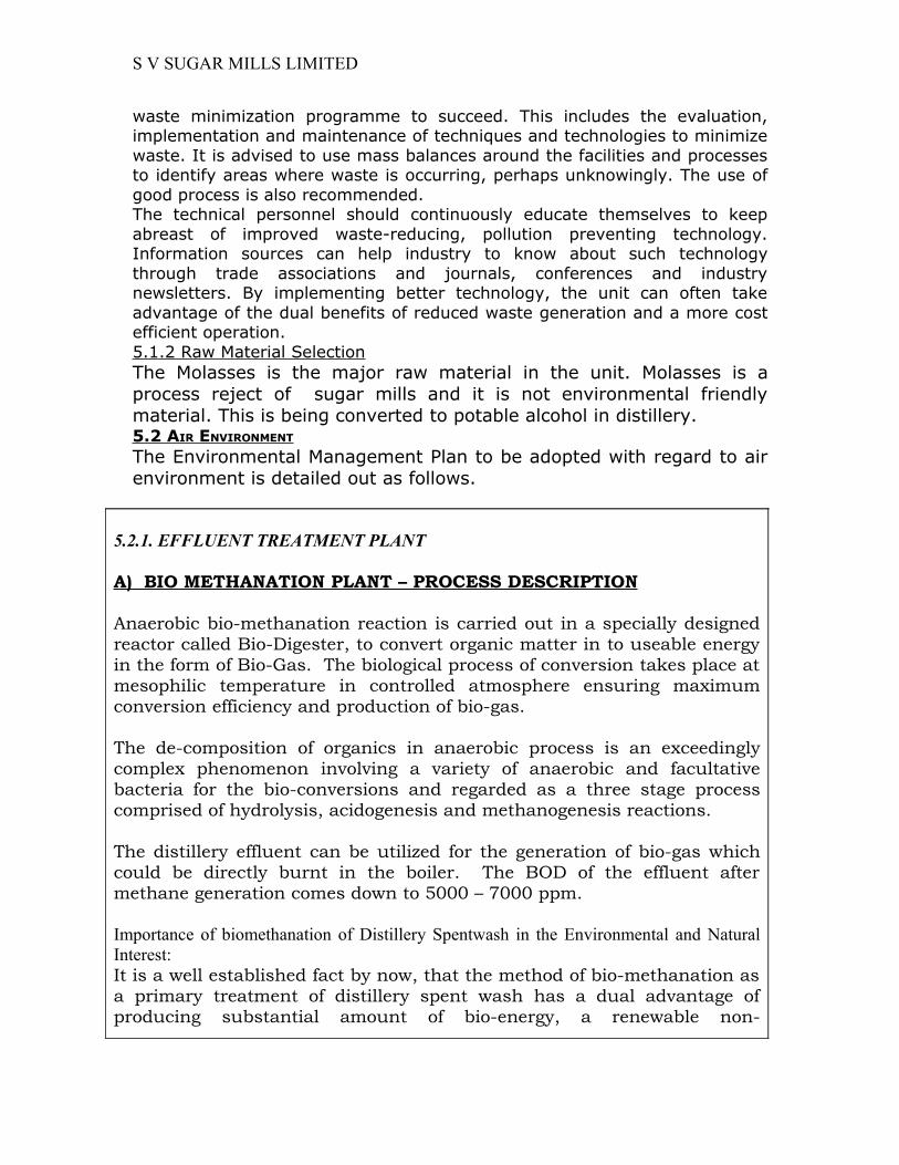
5.2.1. EFFLUENT TREATMENT PLANT
A) BIO METHANATION PLANT – PROCESS DESCRIPTION
Anaerobic bio-methanation reaction is carried out in a specially designed reactor called Bio-Digester, to convert organic matter in to useable energy in the form of Bio-Gas. The biological process of conversion takes place at mesophilic temperature in controlled atmosphere ensuring maximum conversion efficiency and production of bio-gas.
The de-composition of organics in anaerobic process is an exceedingly complex phenomenon involving a variety of anaerobic and facultative bacteria for the bio-conversions and regarded as a three stage process comprised of hydrolysis, acidogenesis and methanogenesis reactions.
The distillery effluent can be utilized for the generation of bio-gas which could be directly burnt in the boiler. The BOD of the effluent after methane generation comes down to 5000 – 7000 ppm.
Importance of biomethanation of Distillery Spentwash in the Environmental and Natural Interest:It is a well established fact by now, that the method of bio-methanation as a primary treatment of distillery spent wash has a dual advantage of producing substantial amount of bio-energy, a renewable non-
S V SUGAR MILLS LIMITED
conventional source of energy while reducing the pollutional strength of the spent wash by nearly 85-90% in terms of BOD reduction and 60-65% in terms of COD reduction. The pH will be improved from 4 to 7.5.Hence the bio-methanation can serve as an effective and economic treatment option. Also this methane gas generated replaces other fuel which is harmful to environment.BASIS OF DESIGNDistillery Capacity : 107 KLPD Total SpiritSpent Wash Quantity : 10 -11 liters / liter of AlcoholWorking days : 300Flow to Digester : 1000 - 1100 m3 / daySpent wash solids : 10-12% w/wDigestive COD in spent wash : 100000 - 120000 mg/litDigestive BOD in spent wash : 55000 - 65000 mg/litTSS in spent wash : 1000 - 1200 mg/lit (Max)Spent wash Temp. : 60 - 65° CSpent wash pH : 4.0 - 4.5EXPECTED PERFORMANCE PARAMETERS:Biogas produced : 0.50-0.55m3/kg of Digestive COD reduced
OR 0.7 to 0.8m3/kg of BOD reduced (Whichever is minimum)
Digestive COD Reduction : 65.00% ± 5%Digestive BOD Reduction : 85.00% ± 5%Expected Biogas composition : Methane - 55 to 60%
: CO2 & Moisture – 40 to 45%
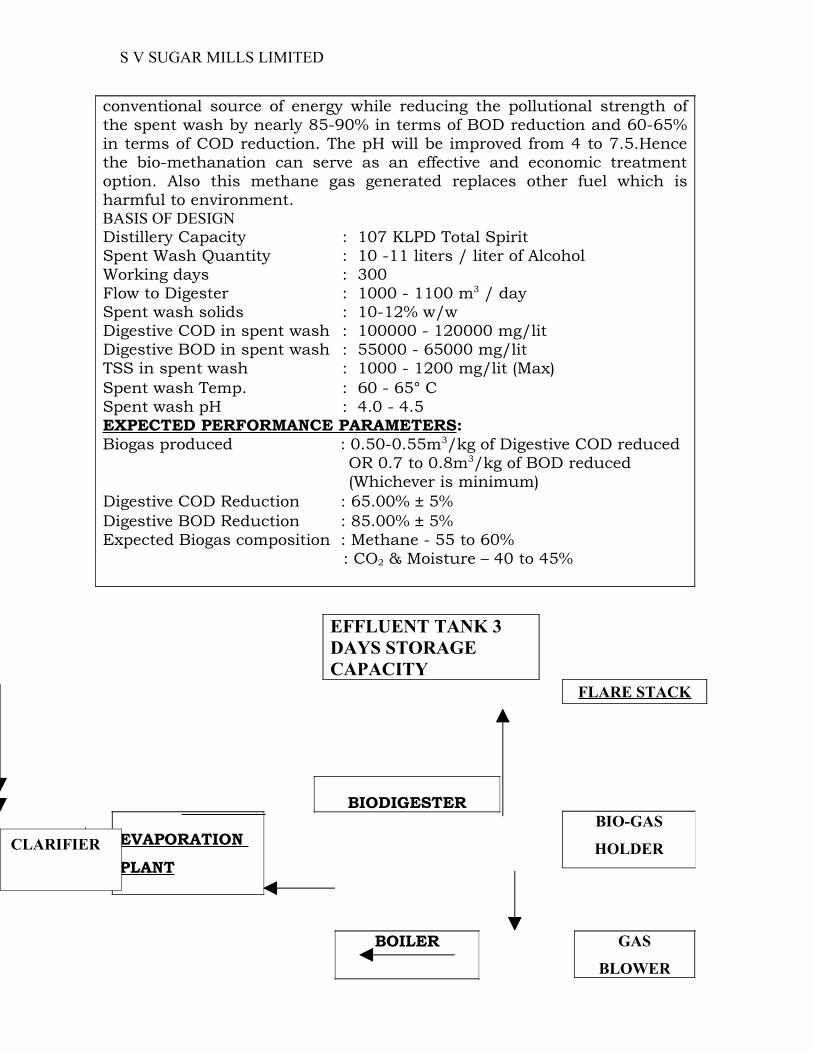
EFFLUENT TANK 3 DAYS STORAGE CAPACITY
FLARE STACK
BIODIGESTERBIO-GAS
HOLDEREVAPORATION PLANT
GAS
BLOWER
BOILER
CLARIFIER

S V SUGAR MILLS LIMITED
5.2.2. ZERO DISCHARGE
B) BIO-METHANATED SPENTWASH EVAPORATION ,BLENDING OF CONCENTRATE WITH BAGGASSE AND DRYING SYSTEM.
GENERAL DESCRIPTION OF THE PLANT:
A) FIVE EFFECT EVAPORATOR SYSTEM
Bio-methanated spent wash is clarified in a holding tank with stirrer system and the sludge is received in sludge thickner and the clear liquid is taken as feed in a level controlled balance tank and passed backward through pre- heaters using vapour from preceding effect as heating medium. Pre-heated feed is then fed to the 1st effect calandria.It is uniformly distributed in the calandria top so that liquid falls inside the tube area in the form of thin film.Dry saturated steam/vapour is supplied as heating medium in the jacket which causes evaporation of water from feed liquid in the calandria. Vapours generated are separated in 1st vapour separator and passed in the jacket of 2nd calandria as heating medium. Concentrated product from 1st effect is fed to calandria of 2nd effect. It then passes through all the effect to meet its final required concentration. Product with desired solid content from last effect is taken out. Vapours from last effect are condensed in surface condenser. All the evaporation effect operate under vacuum maintained by vacuum pump/system. The concentrated product at the desired concentration is continuously taken out from the plant. To lower the steam utility consumption, THERMAL VAPOUR Recompression(TVR) system is used. Part of vapours from intermediate effect is thermally recompressed by motive steam and mix flow is given in the jacket to 1st effect of evaporator.
a) MIXING OF CONCENTRATE WITH BAGGASSE The concentrated slurry from evaporator is mixed with the Bagasse by Twin Blender. The blended baggasse mix at 50% moisture will be fed to the rotary dryer to dry it.
b) ROTARY DRYER Hot air required for drying the mix will be generated through hot air generator using input a portion of mixed baggasse fuel from outlet of rotary dryer. No additional fuel is required once the cycle complete and generate required quantity of mixed fuel. Balance quantity of dried mixed Baggasse will be used as fuel for boiler. 5.3 Greenbelt Development5.3.1 Objectives

S V SUGAR MILLS LIMITED
Greenbelt is a set of rows of trees planted in such a fashion, to create effective barrier between the plant and the surroundings. The greenbelt helps to capture the mist emissions and attenuate the noise levels in the plant and simultaneously improving aesthetics of the plant site. 5.3.2 Greenbelt DesignThe greenbelt development contribute remarkable advantages especially in pollution abatement process like arresting various pollution sources like control of mist, fume, noise etc., an increasing the ecological and aesthetic characteristics of the area. Forests help to intercept incoming and outgoing radiation. Besides, it helps to block the harmful effects of heavy precipitation due to soil washout etc.

S V SUGAR MILLS LIMITED
The filtering capacity of trees for dust is 32 to 80 T/Ha. Noise level abatement to the tune of about 20-30 dB(A) can be achieved by a Greenbelt barrier of 50m wide. The project authorities will plant trees to greenbelt development in peripheral portions and inside vacant plots of the plant for afforestation. The selection of appropriate plant species for this purpose is based upon the following criteria.
• The plant should be fast growing.• The plant should have thick canopy cover.• Preferably perennial and ever green.• Having large leaf area index.• Resistance to specific air pollutant.• Should have maximum height.• Indigenous and should maintain ecological, land and hydrological balance
of the region.The greenbelt development plan for the particular industry depends on the following.• Nature and extent of pollution.• Sink capacity of the eco-system.• Climatic factors.• Soil and water quality.• Specific site background.In any greenbelt development, monoculture is not advisable due to its climatic factor and other environmental constraints. Greenbelt with varieties of species is preferred to maintain species diversity, rational utilization and for maintaining health of the trees.Well developed greenbelt will develop a favourable micro-climatic to support different micro-organisms in the soil as a result of which soil quality will be improved further. In greenbelt bird’s nest may be introduced to encourage more birds in those areas.In the proposed unit greenbelt development will be undertaken in all available areas and also in the earmarked affectation zone, and also along the roads around the plant and plant infrastructure, etc.Tall and leafy trees like Azadirachta Indica, Polyalthia, Longifolia, Pongamia galbrae, etc., will be developed in these areas. Around administrative office, ornamental varieties like Gulmohar, Peltaphorum, Jacarandah will be planted will the backdrops of lawns.As far as possible the following guidelines will be considered in greenbelt development. Shrubs and trees will be planted in encircling rows within the plant site.The short trees (10 m height) will be planted in the first two rows and the tall trees (>10 m) in the outer rows around the purview of the project site.Planting of trees in each row will be in staggered pattern.In the front row, shrubs consisting of Alibizia sp. Peltoforum etc will be grown.

S V SUGAR MILLS LIMITED
Since the trunks of the tall trees are generally devoid of foliage, it will be useful to have shrubs in front of the trees so as to give coverage to this portion.Spacing between the trees will be slightly maintained facilitating effective height of greenbelt.6.1 Air EnvironmentMicrometeorological data confirmed that climatology of the study area is consistent with the regional meteorology. As regards the status of ambient air quality, the change due to the additional stack emissions will be marginal. The comprehensive EMP to control dust emissions at the source will mitigate the impact on air quality.6.2 Noise EnvironmentThe impact of noise generated from the proposed unit on the general population is expected to be insignificant.6.3 Water EnvironmentThe impact of liquid effluent discharge from the unit on the ground water quality will be nil as the only liquid effluent, the domestic sewage is discharged into the land after passing through the septic tank followed by dispersion trench.6.4 Land EnvironmentThere would be a slightly positive impact, as the proposal would involve expansion of the greenbelt thus improving the land use and soil chemistry.6.5 SOCIO-ECONOMIC ENVIRONMENT The impact of the project would be more on the positive side than negative. Positive impacts are felt due to increase in employment opportunities and economic benefits.