entrenador en acondicionamiento de aire para...
TRANSCRIPT
TERMOTRÓNIA
Tomo 2/3
MANUAL DE MANTENIMIENTO MANUAL DE INSTALACiÓN/ENSAMBLAJE
manual PROFESOR/ALUMNO
~ ElettronicaVeneta & l1li111 31045 MOTTA DI LlVENZA (Treviso) ITALY
Via Postumia, 16
© COPYRIGHT BY ELETTRONICA VENETA & INEL SPA
ITALY

ACT212S0.DOC
1. Mantenimiento
2. Reposición de la carga en el circuito del refrigerante
3. Representación gráfica del equipo y de sus principales componentes
4. Instalación
5. Puesta en marcha
6. Control del funcionamiento del ciclo de enfriamiento
7. Control del funcionamiento del ciclo de calentamiento
8. Normas de seguridad
Pág. 1
2
4
7
8
9
10
11


Limpiar a menudo el polvo que se acumula sobre el banco y sus componentes. No utilizar gasolina, disolventes químicos, polvos detergentes ni abrasivos para la limpieza de las superficies. Realizar la limpieza después de haber desconectado la alimentación eléctrica.
Cubrir el equipo después de cada utilización.
Sustituir inmediatamente el cable eléctrico SI éste ha sido pelado o dañado.
Todos los cojinetes se engrasan en fábrica y no precisan ulteriores lubricaciones.
Durante el funcionamiento del ciclo de verano normalmente se condensa una notable cantidad de agua. El agua se envía al tanque, puesto en el armario en la parte inferior, a la derecha, a través de un tubo adecuado.
* Verificar el correcto drenaje del agua de condensación. * Descargar frecuentemente el tanque de recogida del agua. * Con el compresor parado, hacer pasar una gran cantidad de aire a
través del evaporador para eliminar el condensado que se formó con el funcionamiento del Entrenador en el ciclo de verano.
- 1-

Si se necesita añadir gas al circuito, proceder de la siguiente manera: * conectar la bombona del refrigerante HFC-R134a al racor de servicio
puesto en el tubo de admisión del compresor; * abrir levemente el flujo del refrigerante HFC-R134a y descargarlo a
través del tubo de conexión con el compresor, cuya boqueta está todavía aflojada, para evacuar el aire contenido;
* cerrar la boqueta y abrir aún más el flujo del refrigerante HFCR134a; luego, dejarlo fluir hasta obtener, a través del indicador de circulación del líquido, la confirmación del nivel de carga exacto el cual se reconoce por la ausencia total de burbujas de gas incondensado.
Si en una instalación no existe la posibilidad de introducir el refrigerante por el flanco de alta presión, éste se deberá introducir por el flanco de baja presión, prestando atención de que no entre refrigerante líquido en el compresor para evitar que las válvulas se dañen.
Si se descarga todo el gas refrigerante de la instalación, se deberá identificar el punto de pérdida, repararlo, volver a crear el vacío en la instalación y, por último, recargarla.
- 2 -

Las estaciones de vaCÍo y carga portátiles
Constan básicamente de una carretilla sobre la cual está montada la bomba para el vacío, un cilindro de carga graduado en gramos, un grupo manométrico del tipo de cuatro conexiones y tubos flexibles para la conexión con la bomba, por el flanco de alta y baja presión, y el tanque del refrigerante.
El cilindro graduado consta, a su vez, de un tanque metálico que contiene el refrigerante, un indicador de nivel, un cilindro transparente sobre el cual están grabadas diferentes escalas en gramos, cada una de ellas se refiere a una diferente presión del líquido presente en el tanque metálico, y un manómetro que indica la presión del líquido en el tanque.
El procedimiento para obtener un buen vacío es el siguiente: Se lleva a cabo el vacío tres veces consecutivas. La primera vez hasta alcanzar un valor de 1,5 mmHg. La segunda vez se repite el procedimiento anterior y la tercera vez se hace el vacío hasta un valor de 1 mmHg (133 Pa).
Si durante cada fase se extrae el 95% de las sustancias contaminantes, al final del tercer ciclo 6uedará en el circuito 0,05 x 0,05 x 0,05 =
0,000125 = 125 x 10- = 125 partes por millón de residuos, lo que constituye un nivel de contaminación aceptable. Luego, se procede a la carga de la instalación con el procedimiento expuesto anteriormente .
.., - ,j-

3 -.. -R" -. .. ~ • .:. o
2 • • o
~ :1;" nrnl o .
jig. 1 - Entrenador para acondicionamiento de aire del automóvil
Leyenda: 1. Toma eléctrica trifásica con tierra 7. Termómetro digital 2. Panel eléctrico 8. Manómetro de alta y baja presión 3. Mandos de regulación del aire 9. Instrumento eléctrico
acondicionado 10. Condensador de aire 4. Cuadro sinóptico en aluminio serigrafiado 11. Indicador de flujo 5. Centralita de acondicionamiento de aire 12. Grupo motor compresor 6. Receptor de líquido 13. Unidad de agua caliente
- 4 -
.......... ......... == ......... ~-<~_~ WP
'= o 1 •
oto
1 •
00 26
34 O
1 •
00
1 2 J '"
0000
27 F AUlT SIIojULA TOR SIIojULAT[UR DE PANNES
SIIojULATORE GUASTl SIIojULADOR DE AVERIAS S1IojUlADOR DE ... VARIAS 15 81 30 17 87b D 15 .. 50rtTl7b D
00000 o 00000 o
.-.... .....
o COI -
=--~ --_ .. -....... -
N1 .w: nq, n&4
1 lo °1L--_------.1 .:,
...., --..... -
---=~ ........... _.-="~ -.... -.......... .........
-........ --20 O _ ....
"""' ...... l'DDCII'A' WIIaM: --_oo-,=. ":' --. s- . "".
o o o
3
.... "'.:= -~ O
COI -04 "" -
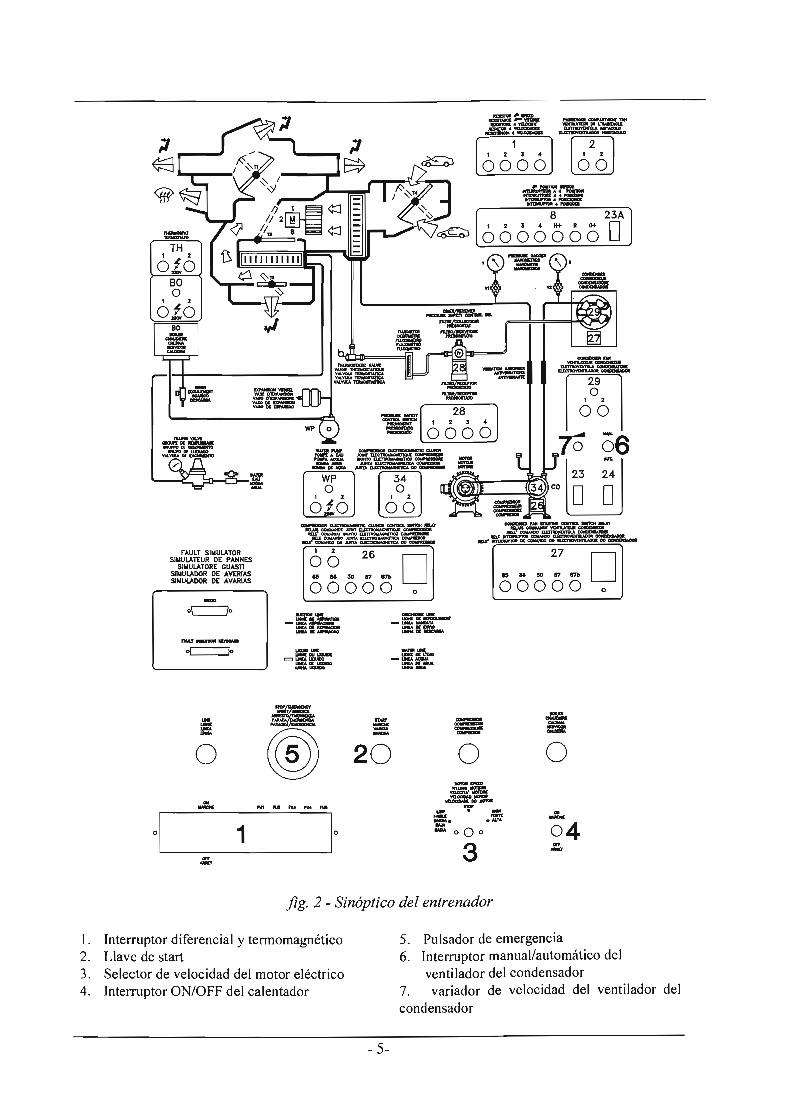
jig. 2 - Sinóptico del entrenador
1. Interruptor diferencial y termomagnético 2. Llave de start 3. Selector de velocidad del motor eléctrico 4. Interruptor ON/OFF del calentador
- 5-
5. Pulsador de emergencia 6. Interruptor manual/automático del
ventilador del condensador 7. variador de velocidad del ventilador del condensador

1111111111111
"'!IIII~-~-....
• ,1
fig. 3 -Mmandos de la centralita de acondicionamiento de aire
l. Tennostato/interruptor giratorio 2. Selector de la velocidad del aire
- 6-
3. Selector de la dirección del flujo de aire 4. Selector de la toma de aire exterior o interior

Antes de poner en marcha el Entrenador, efectuar un control visual para verificar si el mismo padeció daños durante el transporte; en caso afirmativo, tomar las debidas precauciones.
Controlar la presión del agua en el manómetro que se encuentra en el circuito del agua caliente (fig. 1 - posición 7). La presión recomendada en el circuito hidráulico del agua es de 2 bares. Si la presión desciende por debajo de 1 bar, llevarla nuevamente a 2 bares conectando al acueducto la llave del agua situada cerca de la bomba. Una vez descargada del agua, la instalación se deberá conectar a la toma del acueducto.
Controlar la presión del refrigerante (fig. 1 - poslclon 8); los manómetros del refrigerante deberán indicar por lo menos 6 bares. Si la presión es considerablemente inferior a este valor, es probable que exista una pérdida de refrigerante. Localizar la pérdida utilizando un buscador de fugas, eliminarla y reponer la carga de refrigerante.
Por último, conectar el cable de alimentación eléctrica a la red y al entrenador (fig. 1 - posición 1).
- 7-

Verificar que la alimentación eléctrica sea de 380 V trifásica y 50 Hz.
Activar el pulsador del diferencial, activar el interruptor termo magnético situándolo hacia arriba (fig. 2 - posición N° 1).
Verificar que: * los instrumentos eléctricos indiquen tensión 380 V * la luz piloto de la línea esté encendida * los displays de los termómetros estén encendidos y señalicen la
temperatura ambiente * la presión del agua en el depósito sea de 2 bares * los manómetros del refrigerante, con el compresor apagado y antes
del arranque, indiquen por lo menos 6 bares
Activar el interruptor de encendido del calentador y aguardar algunos minutos para que el agua se caliente (fig. 2 - posición 5).
Verificar que: * la luz piloto de la línea del calentador se encienda.
Girar la llave de encendido del motor (fig. 2 - posición 3).
Situar el selector de la velocidad del motor en la posición de velocidad baja (fig. 2 - posición 4). El motor eléctrico arranca y el compresor se mantiene parado.
Mover de su posición de reposo el termostato/interruptor giratorio para la regulación de la temperatura ambiente, situándolo en el punto más bajo de la escala (fig. 3 - posición 1).
Veriricar que: * la luz testigo del compresor se encienda y el compresor funcione.
Girar el selector de la velocidad del ventilador en la posición de velocidad n. 1 (fig. 3 - posición 2).
Verificar que: * el aire salga de las boquillas seleccionadas mediante el selector n. 3 * la temperatura del aire de salida de las boquillas se vuelva cada vez más fría.
Si alguna parte de la instalación no responde a los comandos, controlar los fusibles (fig. 2 -posición 6).
- 8 -

Mover de su posición de reposo el termostato/interruptor giratorio para la regulación de la temperatura ambiente, situándolo en el punto más bajo de la escala (fig. 3 - posición 1, escala de color azul).
Con la instalación en marcha, controlar que: - El manómetro de baja indique 4 bares. - El manómetro de alta indique 10 bares - Durante la circulación del líquido a través del caudalímetro no hayan
burbujas de gas incondensado, si no saltuariamente. - La temperatura del aire de salida del evaporador sea inferior a la de
entrada de por lo menos 10°C.
- 9-
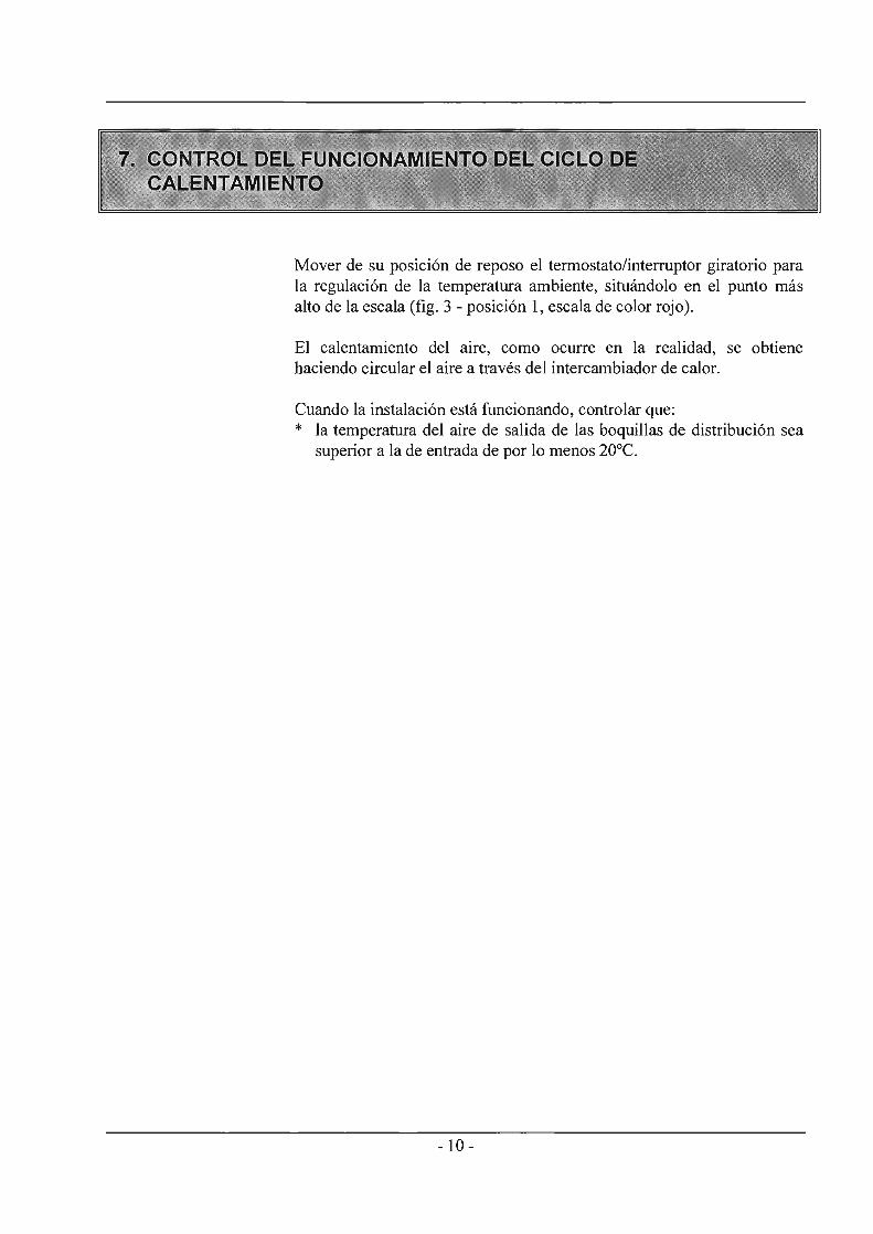
Mover de su posición de reposo el termostato/interruptor giratorio para la regulación de la temperatura ambiente, situándolo en el punto más alto de la escala (fig. 3 - posición 1, escala de color rojo).
El calentamiento del aire, como ocurre en la realidad, se obtiene haciendo circular el aire a través del intercambiador de calor.
Cuando la instalación está funcionando, controlar que: * la temperatura del aire de salida de las boquillas de distribución sea
superior a la de entrada de por lo menos 20DC.
- 10-
DESEMBALAJE
Leer atentamente las advertencias contenidas en el presente manual, ya que proporcionan informaciones importantes referentes a la seguridad durante la instalación, el uso y el mantenimiento del equipo.
Conservar el presente manual para cualquier consulta adicional.
Tras haber quitado el embalaje, poner a un lado todos los accesorios de modo que no se pierdan y cerciorarse de la integridad del equipo; en particular, que el mismo esté íntegro y que no presente daños visibles.
Antes de conectar el equipo a la red eléctrica, verificar que las características nominales del mismo correspondan con las de la red eléctrica.
Los cables de alimentación deberán colocarse de manera tal como para que no puedan ser pisados ni aplastados por objetos; en caso de incompatibilidad entre el tomacorriente y el enchufe del equipo, personal profesionalmente cualificado deberá sustituir el tomacorriente por uno de tipo adecuado y deberá cerciorarse de que la sección de los cables del tomacorriente esté dimensionada en base a la potencia absorbida por el equipo.
Se desaconseja el uso de adaptadores o tomacorrientes múltiples; de precisarse su uso, los mismos deberán ser conformes a las normas de seguridad vigentes.
El condensador y el evaporador presentan hendiduras y aberturas para la ventilación; con el fin de garantizar un funcionamiento fiable de los mismos y proteger el equipo contra el recalentamiento, éstas no deberán obturarse ni cubrirse. Este equipo deberá colocarse en una posición que permita su aireación.
Este entrenador deberá destinarse sólo para el uso para el cual ha sido manifiestamente concebido; es decir, como equipo didáctico, y deberá utilizarse bajo el directo control por parte de personal experto. Cualquier otro uso deberá considerarse impropio y por lo tanto peligroso.
El fabricante no podrá considerarse responsable de eventuales daños debidos a un uso impropio, erróneo o irrazonable del equipo.
- 11-
PRECAUCIONES
Con el fin de amparar la seguridad y la incolumidad del operador, así como el funcionamiento del equipo, el uso de aparatos eléctricos contempla el cumplimiento de algunas reglas fundamentales; en particular, deberán respetarse las normas de uso siguientes: Temperatura ambiente entre 0° C y 45° C Humedad relativa entre 20% y 80% así como deberá evitarse cualquier cambio rápido de temperatura y humedad.
El equipo, incluido el cable de alimentación, deberá utilizarse en un lugar libre de polvo, humedad, calor elevado, objetos que irradien calor, líquidos o sustancias químicas corrosivas.
Alimentación Fusibles
380 Vca trifásica ±10% - 50 Hz y tierra de protección. sólo los indicados en el diagrama eléctrico correspondiente.
Para evitar contactos con las partes eléctricas, no abrir la parte trasera del equipo, eventualmente dirigirse a sólo personal cualificado. Antes de efectuar cualquier operación de mantenimiento, desconectar el equipo de la red de alimentación.
En caso de avería y/o mal funcionamiento, apagar inmediatamente el equipo y no efectuar descomposturas. Para llevar a cabo una eventual reparación, dirigirse al centro de asistencia técnica o pedir exclusivamente piezas de repuesto originales. El incumplimiento de lo anterior podrá perjudicar la seguridad del equipo.
Si se tuvieran que sustituir los fusibles de protección, antes desconectar el cable de alimentación de los tomacorrientes de red. Para desconectarlo agarrarlo sólo por el enchufe. Jamás halar del cable.
Si penetraran objetos o líquidos en el interior del equipo, desconectar el cable de alimentación y pedir el control por parte de personal cualificado antes de utilizarlo nuevamente.
LIMPIEZA DEL SISTEMA Utilizar un paño suave y seco para la limpieza del armazón y del panel sinóptico. Jamás utilizar insecticidas, productos químicos ni disolventes.
VIBRACIONES E IMPACTOS Prestar atención a no causar vibraciones o impactos.
- 12 -

· ": '". 3OO:~SUS Alk)1benzene ':."" : .:. :
~:~:~i,i,{t; , ,;;;:
". '.
:.... <'::~[;.\:~\ . : '~ :- . ~ ><:~ <
INHALATION TOXICITV HFC-134a poses no acute or chronic hazard when it is handled in accordance with DuPont recommendations and when exposures are maintained at or below the DuPont Acceptable Exposure Limit(AEL) of 1 ,000 ppm (8- and 12-hour TIme-WeightedAverage or TWA).
An AEL is an airborne exposure limit established by DuPont scientists that specifies time-weighted average (1W A) airborne concentrations to which nearly all wor1<ers may be repeatedly exposed without adverse effects. The AEL for HFC-134a has the same value as the Threshold Limit Values (TLVs) established for CFC-12 and HCFC-22. TLVs are established by the American Conference of Governmental and Industrial Hygienists (ACGIH).
- 13-
.~:: ., .
However, inhaling high concantrations of HFC-134a vapor may cause temporary central nervous system depression with narcosis, lethargy and anesthetic effects. Other effects that may occur include dizziness, a feeling of intoxication and a loss of coordination. Continued-breathing. of high concentrations of HFC-134a vapors may produce cardiac irregularities (cardiac sensitization), unconsciousness and, with gross over-
; exposure, death.lntentional misuse ordeliberate inhalation of HFC-134a may cause death without waming. This practica is extremely dangerous.
If you experience any of the inltial symptoms, move to fresh air and seek medical attention.
CARDIAC SENSITlZATION If vapors are inhaled at a concentration of 75,000 ppm, which is well aboye the AEL,the heart may become sensitized to adrenaline, leading to cardiac irregularities and, possibly, to cardiac arrest. The Iikelihood of these cardiac problems increases if you are under physical or emotional stress.
Medical attention must be given immediately if exposed to high concentrations of HFC-134a. Do not treat with adrenaline (epinephrine) orsimilar drugs. These drugs may increase the risk of cardiac arrhythmias and cardiac arresto If the person is having difficulty breathing, administer oxygen. If breathing has stopped, give artificial respiration.

SPILLS OR LEAKS If a large release of vapor oecurs, such as from a large spill or leak, the vapors may concentrate near the floor or low spots and displace the oxygen available for breathing, causing suffocation.
Evacuate everyone until the area has been ventilatad. Use blowers or fans to circulate the air at floor level. 00 not reenter the affected area unless you are equipped with a self-contained breathing apparatus or unless an area monitor indicates that the concentration of HFC-134a vapors in the area is below the AEL.
AJways use seH-contained breathing apparatus or an air-líne mask when entering tanks or other areas where vapors might exist. Use the buddy system and a lifeline. Refer to the Material Safety Data Sheet (MSDS) for HFC-134a for more information.
HFC-134a vapors have a slightly sweet odor that can be difficult to detecto Therefore, frequent leak checks and the installation of permanent area monitors may be necessary in enclosed spaces. Refer to ASHRAE Standards 15 and 34 for refrigeration machinery rooms.
To ensure safety when working with HFC-134a in enclosad areas:
1. Raute relief and purge vent piping (if present) outdoors, away from air intakes.
2. Make certain the area is well ventilatad, using auxiliary ventilation, if necessary, to move vapors.
3. Make sure the area is clear of vapors prior to beginning work.
4. Install air monitoring equiprnent to detect leaks. (Monitors are discussed in the next section, Monitors and Leak Detection.)
SKIN ANO EYECONTACT At room temperature, HFC-134a vapors have little or no effect on the skin or eyes. However, in liquid form, HFC-134a can freeze skin or eyes on contact, causing trastbite. Following contact, soak the exposed area in lukewarm water, not cold or hot If medical treatment cannot begin irnmedialely, apply a light coat of a nonmedicated ointment, such as petroleum jelly. If the exposed area is in a location where the presence of the ointment would be awkward, such as on the eye, apply a light bandage. In a/l cases of frostbite, seek medical attention as soon as possible.
A/ways wear protective clothing when there is a risk of exposure to liquid HFC-134a. Where splashing is possible, a/ways wear eye protection and a face shield.
COMBUSTIBILlTY OF HFC-134a HFC-134a is nonf/ammab/e at ambient temperatures and atmospheric pressure. However, tests have shown HFC-134a to be combustible at pressures as lowas 5.5 psig (139.3 kPa absolute) at 177°C {350°F} when mixed with air at concentrations generally greater than 60 volume % airo At lower temperatures, higher pressures are required for combustibility. (HCFC-22 is also combustible at pressures aboye atmospheric in the presence of high air concentrations.) Test results and calculations have shown:
• At ambient temper~ture, all concentrations of HFC-134a in air are nonflammable at pressures below 15 psig (205 kPa absolute).
• Combustible mixtures of air and HFC-134a will not form when liquid HFC-134a is pumped into a closed vessel if the initial air pressure in the vessel is limited to one atmosphere absolute and the final pressure is limitad 10 300 psig (2,170 kPa absolute). If the inmal air pressure is greaterthan one atmosphere, combustible mixtures may form as the tank is filiad.
Based on the aboye information, the following operating practicas are recommended:
• Leak Testing Equipment should never be leak tested with a pressurized mixture of HFC-134a and airo HFC-134a may be safely pressured with dry nitrogen.
• Bulk Delivery and Storage - Tanks should normally be evacuated at the start of
fillíng, and should never be filled while under positive air pressure.
- Tank pressure should never be allowed to exceed 300 psig (2,170 kPa) when fillíng with HFC-134a. Relíef devices on either the tanks or the HFC-134a supply system usually prevent this.
- Tank pressures should be monitored routinely.
- Air línes should never be connected to storage tanks.
• Filling and Charging Operations Before evacuating.cylinders or refrigeration equipment, any remaining refrigerant should be removed by a recovery system.
- Vacuum pump discharge lines should be free of restrictions that could increase discharge pressures aboye 15 psig (205 kPa) and result in the formation of combustible mixtures.
- Cylínders or refligeration equiprnent should normally be evacuated at the start offilling, and should never be filled whíle under positive air pressure.
- Final pressures should not exceed 300 psig (2,170 kPa).
- Filled cylinders should periodically be anaJyzed for air (nonabsorbable gas or NAG).
- 14-

• Refrlgerant Recovery Systerns Efficient recovery of refrigerant from equipment or containers requires evacuation at the end of the recovery cycle. Suction Unes to a recovery compressor should be periodically checked for leaks to prevent compressing air into the recovery cylinder during evacuation. In addition, the recovery cylinder pressure should be monitored, and evacuation stopped in the event of a rapid pressure rise indicating the presence of noncondensable air. The recovery cylinder contents should then be ahalyzed for NAG, and the recovery system leak checked if air is present. Do not continue to evacuate a refrigeration system that has a majorleak.
Service personnel have used leak detection equipment for years when servicing equipment. Leak detectors exist not only for pinpointing specific leaks, but also tor monitoring an entire room on a continual basis. There are several reason& for leak pinpointíng or area monitoring, including: conservation of HFCs, protectíon of valuable equipment, reduction of fugitive emissions and protection of employees.
Leak detectors can be placed into two broad categories: leak pinpointers and area monitors. Before purchasing a monitor or pínpointer, several instrumental criteria should be considered, including sensitivity, detection limits and selectivity.
TYPES OF DETECTORS Using selectivity as a criterion, leak detectors can be placed into one of three categorias: nonselective, halogen-selective or compound-specifíc. In general, as the specifícity of the monitor increases, so does the complexity and costo Another method used to find leaks is to add fluorescent dyes to the system.
A detailed discussion of leak detection, along wíth a list of manufacturers of leak detection equipment, is given in Bulletin ARTD-27 (H-31753-2).
- 15-
NONSELECTlVE OETECTORS Nonselective detectors are those that will detect any type of emission or vapor present, regardless of its chemical composition. These detectors are typically quite simple to use, very rugged, inexpensive and almost always portable. However, their inability to be calibrated, long-term drift, lack of sele~ivity ana lack of sensitivity limit their use for area manitoring.
Sorne nonselective detectors designed for use with CFC-12may have a much lower sensitivity when used with HFC-l34a. However, newly designed detectors with goOO HFC-l34a sensitivity are ROW available. Be sure to consult with the manufacturer befo re selecting or using a nonselective detector with HFC-l34a.
HALOGEN-5ELECnVE OETECTORS Halogen-selective detectors use a specialized sensor that allows the monitor to detect compounds containing fluorine, chlorine, bromine and iodine without interference from other species. The major advantage of such a detector is a reduction in the number of "nuisance alarms"-false alarms caused by the presence of some compound in the area other than the target cornpound.
These detectors are typically easy to use, feature higher sensitivity than the nonselective detectors (detection limits are typically <5 ppm when used as an area monitor and <0.05 oziyr «1.4 gmlyr) when used as a leak pinpointer), and are very durable. In addition, due to the partial specificity of the detector, these instruments can be calibrated easily.
COMPOUND-SPECIAC OETECTORS The mast complex detectors, which are a1so the most expansive, are compound-specific detectors. These units are typically capable of detecting the presence of a single compound without interference from other
,cornpounds.
FLUORESCENT OYES Fluorescent dyes have been usad in refrigeration systems for several years. These dyes, invisible under ordinary lighting, but visible under ultraviolet (UV) light, are used to pinpoint leaks in systems. The dyes are typically placed into the refrigeration lubricant when the system is serviced. Leaks are detected by using a UV light to search tor dye that has escapad from the system.
Recent innovations in dye technology have allowed fluorescent dyes to be used with HFC-l34a. However, before adding dyes to a system, the compatibility of the specific dye with the lubricant and refrigerant should be tested.

DuPont has formed a partnership with Spectronics Corporation to supply refrigerant mixed with fluorescent additives and to assist in developing additives that are compatible with new altemative refrigerants. For additional information, contact DuPont.
SHIPPING CONTAINERS IN THE U.S. HFC-134a-is a liquefied compressed gas. According to the U.S. Department of Transportation (OOT), a nonflammable compressed gas is defined as a nonflammable material having an absolute pressure greater than 40 psi at 21°C (70°F) andlor an absolute pressure greater than 104 psi at 54°C (130°F).
The appropriate OOT designations are as follows:
Proper shipping name: Refrigerant Gas, N.O.S. (T etrafluoroethane)
Hazard cJass: Nonflammable Gas
UN/NA No.: UN 1078
A list of the different types of containers that can be used to ship HFC-134a in the United States, along with their water capacities, dimensions, DOT specifications and the net weights of HFC-l34a, are provided in Table 20. AII pressure relief devices used on the containers must be in compliance with the corresponding Compressed Gas Association (CGA) Standards for compressed gas cylinders, cargo and portable tanks.
The 30-lb and 123-lb cyJinders designed for refrigerant applications are a light blue color with labels that bear the na me of the product in light blue. The color designation is "light Blue (Sky)," PMS 2975.
The30-lbcylinder,knownasaMDisposeACan~ (D.A.C.) fits into a box that measures 10 in. x 10 in. x 17 in. Dispose A Can is DuPonfs registered trade name for this type of single-use container. When used to ship SUVAIII Cold-MP for the stationary refrigeration market, these 3O-Ib cylinders have the same autlet fittings as cylinders of CFC-12. However, when used for SUVA8 Trans AJC for the auto motive industry, these cylinders have a CGA-167 valve outlet. This fitting was specified by the Society of Automotive Engineers (SAE) to avoid mixing CFC-12 and HFC-134a when servicing mobile air conditioning systems. Additional unique fittings used with HFC-134a in automotive service applications are discussed in Bulletin ART-12 (H-45948).
The 123-lb cylinders are equipped with a nonrefillable Iiquid vapor CGA-660 valva. With this two-way valva, HFC-134a can be removed trom the cylinder as either a vapor or as a liquid, withaut inverting the cy\inder. The vapor handwheel is lacated on the topo The liquid wheel is on the side of the valve and attached to a dip t\,Ibe extending to the bottom of the cylinder. EaCh is clearly identified as vapor or Iiquid.
The 4,400-ga1 cyJinder is known as an ISO tank. The dimensions referenced in Table 20 represent the frame in which the container is shipped. The tank itself has the same length of 20 ft and an outside diameter of approximately 86 in. ISO tanks are usad for export shipinents of HFC-134a from the United States.
The general construction of á one-ton returnable container is shown in Figure 9. Notice that one end of the container is fitted with two valves. When the container is tumed so that the valves are lined up vertically, the top valve will discharge vapor and fue bottom valve wiJI discharge liquid. The valves are protected by a dome cover.
TABLE20
., . " ~ ,
0 ,_ 3ó IbDlspoSeA Ctul~ •. - ~Ib' - - 0 .
1;6s21b
5,OOOiJal .
4-.400 QaJISQ 170,0001,
Speclflcations of Shipping Contalners for HFC-134a
; :- '
-_:Dlmel18lOna.. - -
1(rXl0·x:1i"<(box) :.,-55Úi:x 1o-aj ," . 82" Lx 30'-00
-_ IankT\'I.ICk _ . .
8' x 8.5'x;2(Y ~);" - ,
Tank -hail,ear: '
- - ___ DOT _ ,. -_speclficatlon -"" , ,39-
' 4BA300 110As00w
, Mc-330or -331 ,'
51
~ 1t4A340W '
' ·D\SposeA-ean- is a reg~i8ct1rad8martccj(1h8 ~Ponl~y., .:" " - -; -. .
" . - ..... .: .... '-_.
- 16-