ensuring operational privacy of primary users in ... · ensuring operational privacy of primary...
TRANSCRIPT
Ensuring Operational Privacy of Primary Users in GeolocationDatabase-Driven Spectrum Sharing
Summary Report for Task 1: Prior-Art Privacy Preserving Databases andThreat Models
Jung-Min “Jerry” Park and Je↵rey H. Reed
Wireless @ Virginia Tech GroupBradley Department of Electrical and Computer Engineering
Virginia Tech
Technical Point of Contact: Jerry Park540-231-8392, [email protected]
June 30, 2013Blacksburg, Virginia

Contents
1 Introduction 1
2 Spectrum Access System (SAS) 3
2.1 Introduction . . . . . . . . . . . . . . . . . . . . . . . . . . . . . . . . . . . . 3
2.2 Requirements . . . . . . . . . . . . . . . . . . . . . . . . . . . . . . . . . . . 4
2.3 Features . . . . . . . . . . . . . . . . . . . . . . . . . . . . . . . . . . . . . . 5
2.4 Data Model . . . . . . . . . . . . . . . . . . . . . . . . . . . . . . . . . . . . 6
2.5 Functional Components . . . . . . . . . . . . . . . . . . . . . . . . . . . . . 7
2.5.1 Spectrum Manager . . . . . . . . . . . . . . . . . . . . . . . . . . . . 7
2.5.2 Database Management System . . . . . . . . . . . . . . . . . . . . . . 8
2.5.3 Primary Incumbent Update Mechanism . . . . . . . . . . . . . . . . . 10
2.5.4 Access Mechanism to SAS . . . . . . . . . . . . . . . . . . . . . . . . 11
3 Use Case Scenarios 12
3.1 Centralized Infrastructure Based Cellular System . . . . . . . . . . . . . . . 14
3.2 Ad-hoc Networks . . . . . . . . . . . . . . . . . . . . . . . . . . . . . . . . . 18
4 Database Access Protocol 22
4.1 IETF PAWS Attributes . . . . . . . . . . . . . . . . . . . . . . . . . . . . . 22
4.1.1 IETF PAWS Primitives with Geolocation Database . . . . . . . . . . 23
4.2 Database Query and Response Protocol . . . . . . . . . . . . . . . . . . . . . 24
5 Wireless Standardization Activities Using Geolocation Database 27
ii

5.1 FCC 3.5 GHz NPRM and Citizens Broadband Services Database . . . . . . 27
5.2 European Communication Commission (ECC) and Ofcom E↵orts . . . . . . 28
5.3 IEEE Standardization Activities . . . . . . . . . . . . . . . . . . . . . . . . . 29
6 Existing Privacy-Preserving Models and Methods 32
6.1 k-anonymity . . . . . . . . . . . . . . . . . . . . . . . . . . . . . . . . . . . . 32
6.2 l-diversity . . . . . . . . . . . . . . . . . . . . . . . . . . . . . . . . . . . . . 35
6.3 t-closeness . . . . . . . . . . . . . . . . . . . . . . . . . . . . . . . . . . . . . 35
6.4 Confidence Bounding . . . . . . . . . . . . . . . . . . . . . . . . . . . . . . . 36
6.5 Personalized Privacy . . . . . . . . . . . . . . . . . . . . . . . . . . . . . . . 36
6.6 (X, Y )-Privacy . . . . . . . . . . . . . . . . . . . . . . . . . . . . . . . . . . 37
6.7 Perturbation . . . . . . . . . . . . . . . . . . . . . . . . . . . . . . . . . . . . 37
6.7.1 Additive Noise . . . . . . . . . . . . . . . . . . . . . . . . . . . . . . 38
6.7.2 Data Swapping . . . . . . . . . . . . . . . . . . . . . . . . . . . . . . 39
6.7.3 Rounding . . . . . . . . . . . . . . . . . . . . . . . . . . . . . . . . . 39
6.8 Di↵erential Privacy . . . . . . . . . . . . . . . . . . . . . . . . . . . . . . . . 39
7 A General Threat Model 41
7.1 Means . . . . . . . . . . . . . . . . . . . . . . . . . . . . . . . . . . . . . . . 41
7.1.1 Access . . . . . . . . . . . . . . . . . . . . . . . . . . . . . . . . . . . 42
7.1.2 Knowledge . . . . . . . . . . . . . . . . . . . . . . . . . . . . . . . . . 42
7.2 Actions . . . . . . . . . . . . . . . . . . . . . . . . . . . . . . . . . . . . . . 43
7.3 Goals . . . . . . . . . . . . . . . . . . . . . . . . . . . . . . . . . . . . . . . . 43
7.3.1 Presence vs. Absence Disclosure . . . . . . . . . . . . . . . . . . . . . 43
7.3.2 Individual vs. Mass Target . . . . . . . . . . . . . . . . . . . . . . . . 44
7.3.3 Tracking vs. Identification . . . . . . . . . . . . . . . . . . . . . . . . 44
7.4 Using the threat model for evaluating the privacy-preserving techniques . . . 45
8 Applying Existing Privacy-Preserving Models and Methods to Our Prob-lem 46
iii

8.1 k-anonymity . . . . . . . . . . . . . . . . . . . . . . . . . . . . . . . . . . . . 46
8.2 l-diversity . . . . . . . . . . . . . . . . . . . . . . . . . . . . . . . . . . . . . 48
8.3 Confidence Bounding . . . . . . . . . . . . . . . . . . . . . . . . . . . . . . . 48
8.4 (X, Y )-Privacy . . . . . . . . . . . . . . . . . . . . . . . . . . . . . . . . . . 48
8.5 Perturbation . . . . . . . . . . . . . . . . . . . . . . . . . . . . . . . . . . . . 48
8.5.1 Additive Noise . . . . . . . . . . . . . . . . . . . . . . . . . . . . . . 48
8.5.2 Rounding . . . . . . . . . . . . . . . . . . . . . . . . . . . . . . . . . 49
8.5.3 Transfiguration . . . . . . . . . . . . . . . . . . . . . . . . . . . . . . 49
8.6 Di↵erential Privacy . . . . . . . . . . . . . . . . . . . . . . . . . . . . . . . . 49
9 Conclusions 51
iv

List of Figures
2.1 Block diagram of Spectrum Access System (SAS) with functional components. 7
3.1 Centralized Infrastructure Based Spectrum Sharing with geolocation database. 15
3.2 Emergency ad-hoc network with partly connected nodes supported by geolo-cation database. . . . . . . . . . . . . . . . . . . . . . . . . . . . . . . . . . . 19
6.1 k-anonymity for location privacy. . . . . . . . . . . . . . . . . . . . . . . . . 34
8.1 3-anonymity for primary users’ location privacy. . . . . . . . . . . . . . . . . 47
8.2 Perturbation using transfiguration. . . . . . . . . . . . . . . . . . . . . . . . 49
v

List of Tables
2.1 Comparison of Spectrum Access System Capability [1] . . . . . . . . . . . . 4
3.1 measurement plan . . . . . . . . . . . . . . . . . . . . . . . . . . . . . . . . . 15
3.2 A Database Model for a Single Entity Parameters . . . . . . . . . . . . . . . 16
3.3 A Database Model for Ad-hoc Networks . . . . . . . . . . . . . . . . . . . . 20
4.1 Database Query Contents . . . . . . . . . . . . . . . . . . . . . . . . . . . . 25
4.2 Database Response Contents . . . . . . . . . . . . . . . . . . . . . . . . . . . 26
6.1 Impatient Microdata . . . . . . . . . . . . . . . . . . . . . . . . . . . . . . . 33
6.2 4-anonymous Impatient Microdata . . . . . . . . . . . . . . . . . . . . . . . 33
6.3 3-diverse impatient microdata . . . . . . . . . . . . . . . . . . . . . . . . . . 35
6.4 Confidence Bounding . . . . . . . . . . . . . . . . . . . . . . . . . . . . . . . 36
6.5 Students grades relational database . . . . . . . . . . . . . . . . . . . . . . . 38
6.6 Students grades relational database . . . . . . . . . . . . . . . . . . . . . . . 39
6.7 Students grades relational database . . . . . . . . . . . . . . . . . . . . . . . 39
6.8 Students grades relational database . . . . . . . . . . . . . . . . . . . . . . . 40
8.1 Simplified Geolocation Database. . . . . . . . . . . . . . . . . . . . . . . . . 47
8.2 Geolocation Database with 3-anonymity. . . . . . . . . . . . . . . . . . . . . 47
vi

Chapter 1
Introduction
When incumbent users (a.k.a. primary users (PUs)) and secondary users (SUs) share spec-trum, the SUs must adopt technologies that enable them to avoid causing any interference toPUs. The FCC ruling on TV white spaces proposes relying on a database of the incumbents’spectrum usage information as the primary means of determining white space availability atany white space device (WSD) [2]. The database is required to house an up-to-date reposi-tory of incumbents including television stations, and in certain cases, wireless microphones,and use this information to determine white spaces availability at a WSD’s location. It hasbeen shown that sensing-only devices do not generally utilize spectrum as e�ciently as ge-olocation enabled devices, due to the large margins in incumbent detection thresholds thatmust be built into sensing-only devices [3]. geolocation enabled devices have knowledge ofthe specific interference protection requirements of each licensed incumbent, which allowsvarying levels of protection to be applied, and thus maximizing utilization of the spectrum.
Although using geolocation databases for spectrum sharing has many advantages, it poses apotentially serious privacy problem. For instance, SUs, through seemingly innocuous queriesto the database, can determine the types and locations of incumbent systems operating in agiven region of interest—we refer to this as the operational privacy of the incumbents. Whenthe incumbent systems are commercial systems, such as the case in TV spectrum, this is notan issue. However, when the incumbents are federal government systems, including militarysystems, then the information revealed by the databases can result in serious breach ofprivacy.
The primary incumbent contents in the SAS database that must be secured for primary userprotection are the followings:
1. Transmitter Identity (i.e. the Call Sign of the transmitter in FCC CDBS)
2. Its geolocation (i.e. Latitude and Longitude)
3. Antenna Parameters (HAAT, etc)
1

2
4. Power (Max EIRP, Avg operation Power, etc)
5. Protection Contours of Operations (co-channel, Adjacent channel etc)
6. Periods of Operations
The prospects of spectrum sharing between federal government systems and non-governmentsystems has been heightened by a recent notice of proposed rule making (NPRM) publishedby the Federal Communications Commission (FCC). In December 2012, the FCC publishedan NPRM to create a Citizens Broadband Service in the 3.5 GHz band that will promotetwo major technical advances that enable more e�cient use of spectrum: small cells andspectrum sharing [4]. As part of the NPRM, the FCC is looking at whether it will befeasible to open up approximately 100 megahertz of spectrum in the 3550-3650 MHz bandsfor small cell technologies on an unlicensed basis. The 3.5 GHz band is currently used by theU.S. Department of Defense (DoD) for certain radar installations as well as by non-federalusers. It is highly likely that spectrum sharing in the 3.5 GHz band will be enabled bygeolocation databases aided by local spectrum sensing. In the 3.5 GHz band, the criticalityof the incumbents’ operational privacy is obvious. The operational privacy of the incumbentsis one of the major hurdles holding back the federal government from opening up some ofits spectrum to spectrum sharing with commercial systems. Research programs recentlylaunched by federal funding agencies, including the NSF and DARPA, have stressed theimportance of security and privacy in spectrum sharing [5], [6].
The problem of operational privacy of PUs cannot be addressed by tightly controlling accessto the database, since all SUs need access to it to enable spectrum sharing. A more viableapproach is to “obfuscate” the information revealed by the database in an intelligent mannersuch that a certain level of privacy is assured while supporting e�cient use of the spectrum.
The rest of the report is organized as follows. We first discuss the Spectrum Access System(SAS) and some use case scenarios in chapters 2 and 3 respectively. Chapter 4 describesthe database access protocol that is used by the geolocation database. Chapter 5 discussesthe wireless standardization activities that involve geolocation databases. In chapter 6, weintroduce some of the most well known privacy-preserving techniques that are widely used toensure user’s privacy in relational databases. We propose our threat model for operationalprivacy of incumbent users in chapter 7, and finally discuss how we can apply the existingprivacy-preserving techniques to the geolocation databases in chapter 8.
Chapter 2
Spectrum Access System (SAS)
2.1 Introduction
The FCC released its National Broadband Plan [7] citing the exponentially growing demandfor mobile data services and the critical need to utilize the radio spectrum e�ciently. More-over, in the President’s Council of Advisors on Science and Technology (PCAST) report [1]emphasized the role of the spectrum as an important economic growth mechanism. ThePCAST report proposed a shared spectrum access model, wherein a heterogeneous mix ofwireless systems of di↵ering access priorities, QoS requirements, and transmission character-istics need to coexist without causing harmful interference to each other. In this spectrumsharing model, secondary users identify unused spectrum by accessing a geolocation databasethat is constantly updated with the primary user’s spectrum utilization information. ThePCAST report defines a three-tier hierarchy for access to federal spectrum bands. Thefederal primary users have an exclusive right to use the spectrum when they deploy theirnetworks or systems. The secondary users are allocated short term rights for operation ina specific geographical area. They are assured of interference protection with priority overopportunistic users. Any spectrum resources that are left over from the first and secondtier users are made available to the general authorized access users. They opportunisticallyuse these spectrum resources with an obligation to clear the spectrum in case of a federalprimary or secondary user appears in that spectrum band.
For shared access to federal bands, a Spectrum Access System (SAS) with a geolocationdatabase will be used [1] . Access to spectrum is authorized after successful communicationand registration with the database. Unlike the TV whitespace database, the federal SAS[1] has more functional and operational requirements that need to be satisfied. Table 2.1compares the functional requirements of a TV White space database with those of SAS.
3

4
Table 2.1: Comparison of Spectrum Access System Capability [1]Functionality White Space White Space Spectrum Access
in TV Bands Federal Addition System (SAS)Accept specific interference contours for federal Yes Yes Yesprimary access users and specific secondary usesAutomatically determine interference possibilities No No Yesfor any secondary technologyRegister the location of secondary devices No Yes Yesauthorized to operateProvide deconfliction of secondary spectrum users No No YesProvide real time input of primary user operating No Yes Yeslocations and periodsProvide marketplace for leasing of spectrum and No No Yesrevenue to treasuryProvide the Spectrum Management Team (SMT) No No Yesmetrics [1] and advanced featureslike time to live (TTL)
2.2 Requirements
For an e↵ective operational system [8], the SAS must fulfill the requirements of both the pri-mary users and secondary users in the shared spectrum bands. The requirements regardingthe protection of primary users include the following.
1. No interference to existent primary users of the spectrum band.
2. Secondary user must have the ability to reconfigure for accommodating changes inprimary use like waveform types, occupancy, and locations, etc.
3. Secondary users must have backup bands to allow the primary licensed users to reclaimtheir spectrum at any time.
4. Systems must have mechanisms for enforcement of spectrum rules to track down in-terference events quickly and reliably.
5. System must be protected against any unauthorized/accidental use, and security mustbe provided against hackers.
6. E�cient system management for operating complex secondary to secondary system toensure that agreed parameters are not violated.
7. Security of government agencies and protection of their classified information.
5
The requirements regarding secondary users spectrum access in the context of the SASsystem [8] must fulfill are the following.
1. Interference requirements for the secondary systems must be reasonable for practicalsystem deployment.
2. Existing broadband system architecture must be supported with minimal changes toexisting standards and with low software integration costs, etc.
3. Secondary QoS requirements, low power operation must be achievable with no harmfulinterference to the primary systems.
4. A fair use policy with reliability and assured access for all secondary users must beenforced.
5. System must be secured against any unauthorized/accidental use and security must beprovided against hackers.
2.3 Features
To fulfill the above-mentioned requirements, the SAS includes many features that are in-tended for interference protection of incumbent primary and secondary systems [9]. Alongwith the ability to accommodate changes in the federal user’s operational parameters or re-sponse to unforeseen interference scenarios. Central entity of the SAS model is the databasebut sensing, and dynamic frequency selection must be used to enhance the spectrum uti-lization e�ciency of the model. These capabilities are incorporated through the operationalfeatures defined by the PCAST report and summarized below.
1. Channel selection decisions for devices based upon their location, QoS requirements ofthe application and spectrum access rules specified by the database for that geographiclocation.
2. Enforcement of the spectrum reclaims from the primary user by switching o↵ secondarycommunications on certain frequency channels through commands from the databaseor signal beacons.
3. Database must validate the equipment used for secondary access at the time of a spec-trum request. Equipment validation can be done through the use of FCC certificationidentities.
4. The SAS system implemented either as centralized or distributed system must havedefined generic terms of use in all the available bands in the SAS database. In other

6
words, from a user perspective, the database must provide a single consistent interfacefor accessing all geolocation database information and channel allocation methods likethe Internet Domain Naming System (DNS) to facilitate a greater opportunistic useof the spectrum.
5. All the registrations and reservations for use must be time limited and renewed asappropriate. The database must have Time To Live (TTL) mechanisms, that can alsobe used for enforcement by revoking the secondary user spectrum authorizing.
6. Security must be provided by the SAS for both the database request and the responseusing a public key cryptographic system. Experience from the Digital Rights Manage-ment (DRM) systems can be used in securing the whole operational mechanism.
2.4 Data Model
In addition to the above-mentioned requirements, the SAS and the access protocol [1], [8], [10]must have algorithms and data types to support implementation specific details. Some ofthese requirements are mentioned below.
1. Radio and Spectrum Regulatory Concepts. They include channel, co-channel, adja-cent channel, modulation, waveform, data rate, type of filtering, block size, devicecharacteristics and attributes (e.g., FCC ID, serial number, transmitter, receiver, de-tector), Equivalent Isotropically Radiated Power (EIRP), mean EIRP, peak receiver(RX) power, frequency, center frequency, power masks, bandwidth, duty cycle, signaldetector [including detection threshold, frequency range, sample rate, precision, Signalto Noise Ratio (SNR), and Received Signal Strength Indicator (RSSI)], and signal type.
2. Support for signal evidence like detected signal, sensed frequency intervals, peak sensedpower, detected time, scan time/duration, count along with location evidence and timeevidence.
3. Support Scalar constraints like restrictions on frequencies, time and dates.
4. Security considerations like the type of encryption, keys, key exchange, credential,security mechanism (e.g., integrity, confidentiality, authentication, authorization), andsecurity/classification level.
5. Networking concepts like node identities, network membership, and types of networksi.e., peer 2 peer etc.
6. Policy authority for primary and secondary spectrum markets with primary and non-primary users.

7
2.5 Functional Components
The Spectrum Access System (SAS) is a dynamic database system and consists of many log-ical and physical components that will allow a number of unique capabilities like real timechannel availability from dynamic calculations of the protection contour zones of stationaryand mobile primary users. Interference protection and coexistence capability to calculatethe secondary network interference power spectral density (IPSD) at primary incumbentlocation for allowing operations inside the protection zones as well.
The spectrum access system consist of the following components.
1. Spectrum Manager
2. Database Management System
3. Primary Incumbent Update Mechanism
4. Access Mechanism to SAS
Figure 2.1: Block diagram of Spectrum Access System (SAS) with functional components.
2.5.1 Spectrum Manager
Spectrum manager is responsible for ensuring the protection of incumbents and e�cientspectrum utilization while complying with regulatory policies [11]. Following are some of

8
the functions of the spectrum manager.
1. Maintain spectrum availability information
2. Calculations for available channels, spectrum quality ranking and prioritization
3. Association control mechanisms for devices with the SAS
4. Channel set management for prioritized access
5. Scheduling for spectrum sensing
6. Enforcing regulatory domain policies
7. Managing spectrum mobility
8. Facilitating the coexistence of multiple wireless services
Spectrum manager has the database management system that it uses for the spectrum avail-ability information through available white-space channel calculations, ranking the spectrumquality, developing the spectrum prioritization and maintaining a channel set for prioritizedprimary access, secondary licensed access, and general authorized access users.
2.5.2 Database Management System
The DBMS system will reside inside the spectrum manager and include a number of databaseentities having information about primary incumbents in di↵erent spectrum bands like TVstations (54-72 MHz, 76-88 MHz, 174-216 MHz and 470-806 MHz) [2], Satellite systems(1675-1710 MHz) [9], RADAR systems (3500-3650 MHz) [9], Federal communication net-works (1755-1850 MHz) [9], Radio Altimeters(4200-4400 MHz) [9], etc. Each incumbent hastheir own database with primary entity parameters, geographical parameters, regulatoryprotection constraints, and available white-space resources.
Entity Parameters
The entity parameters of each wireless device will depend on application for the device likethe application parameters defined in the FCC CDBS [12] [13]. The entity parameters willinclude transmitter, receiver, antenna, mobility, and network parameters [10], [11], [14].
The transmitter parameters will include but not limited to the device ID, its modulation,bandwidth, transmission power, power spectral density (PSD), spurious emissions, accessmethodology (periodic/continuous) .

9
Receiver/sensing parameters will include but not limited to the type of detector, noise esti-mate, sampling rate, bandwidth, time stamp, location stamp, sensing values, etc.
The antenna parameters will define the maximum gain, antenna pattern, elevation angle,azimuth angle, E↵ective Isotropically Radiated Power (EIRP), height of antenna above ter-rain (HAAT), polarization, beam width, number of sectors, maximum sweep angle, numberof elements, and system type.
Mobility parameters will specify the direction of motion and speed of the device with con-structs like speed, velocity, and acceleration, etc.
The entity parameters will also include the network parameters to which the device is asso-ciated with i-e Network ID, device role, context parameters, etc.
Geographical Parameters
The geographic parameters includes the primary incumbent‘s locations, the terrain featuresof the environment, and the signal propagation conditions. Primary incumbent locations areused to characterize the geographical features around the incumbents. These parameters arein the form of latitude, longitude and height above the terrain.
Terrain features specify the administrative/political boundaries and other features like plainflat areas, hilly terrain, mountains, and bodies of water like lakes, rivers and oceans, etc.These terrain features will be generated from publicly available National Elevation Database[15]
The signal propagation conditions [16] defines all the parameters that a↵ect the propagationof radio frequency electromagnetic waves. These parameters include but not limited to typeof terrain, terrain irregularities, type of built environment, electrical ground constants, radioclimatic conditions, and surface refractivity, etc.
Regulatory Protection Requirements
The SAS system maintains a database of regulatory protection requirements [1], [9], [17]. Theregulatory requirements will specify a framework for sharing the spectrum bands by providingaggregate Interference Power Spectral density (IPSD) limits, along with spectrum masks,underlay masks, co-channel and adjacent channel interference limits, etc. The spectrummanager using the regulatory protection requirements [17] establish the following .
1. Utilize the regulatory-approved interference prediction model, associated input param-eters and aggregate IPSD distributions for authorizing access to commercial within andout of incumbent protection zones.
2. Access the IPSD limits of the secondary network on the primary incumbent user to
10
facilitate coordination among primary and secondary users for authorizing the use ofspectrum bands within the protection areas.
3. Use the spectrum sensing functionality for collecting real time spectrum use data toenforce the IPSD limits in the geographical area of its operation.
The regulatory protection database has constructs for implementing the above-mentionedcapabilities along with the ability for sharing and acquisition with the regulatory updatemechanisms of the FCC CDBS and NTIA databases.
Available White-Spaces
The spectrum manager will use the entity parameters from the databases, the geographicalparameters and calculate the available white-space channels through calculation‘s methods[18], [19], [20], [21], [22] by taking in order to account the regulatory protection requirements.Most of these channel calculation algorithms use the entity parameters, antenna patterns,geographic locations, terrain databases for calculating the protection contours around theprimary incumbents like TV transmitters, CMRS/PLMRS, Wireless Microphones, RadioAstronomy sites, etc. through propagation models [23], [16], [24] defined by these standards.
The protection contours are overlaid in the form of channel power plots [18] to calculate theavailable channels for white space devices (WSD) in a geographical area. The WSD channelavailability is specified through minimum allowed transmit power level for the cognitive radiolink. The transmit power levels for WSD varies across a region, due to high spatial variabilityof the primary incumbent protected service areas. This leads to fewer high powered channelsand more lower powered channels making the spectrum availability highly dynamic across aregion.
2.5.3 Primary Incumbent Update Mechanism
The primary incumbents‘ information is updated in the geolocation database from regulatorydatabases of FCC Consolidated Database Systems (CDBS), and the NTIA database of DoDincumbent systems. This mechanism ensures reliability of information in the geolocationdatabases for proper operations.
The database administrators must ensure the accuracy of their primary incumbent informa-tion by regular updates of their information about the primary incumbents locations, accesspatterns (i.e., periodic or continuous), regulatory interference protection levels, spectrumavailability for open spectrum markets, etc from the FCC Consolidated Database Systems(CDBS) [12], and NTIA Federal Spectrum Management System (FSMS) [25].
These regulatory databases are designed as license databases not as spectrum managementdatabases and cannot be used for new applications of wireless spectrum [26]. The SAS

11
will fulfill this gap and provide all the necessary functionality to promote technologicalinnovations.
The database administrators provide web-based interfaces for registration of primary incum-bent users (DTV stations, Wireless microphones, etc.) and the recent FCC rules requirethese incumbents to update their database registrations daily.
2.5.4 Access Mechanism to SAS
The access mechanism for the SAS includes a generalized database access protocol witha data model that can support the implementation of the objectives mentioned in the Ta-ble 2.1. The white space allocation of channels from the database is analogous to the InternetDomain Naming System (DNS), which maps the symbolic names to the IP addresses andis transparent to the Internet users. The SAS access protocol must map the user spectrumrequirements to a database query and perform all the necessary protocol related operationslike secure database discovery, determining essential query parameters, and exchanging mes-sages with the database for desired frequency channels of operation. This ease of accesswould enable greater opportunistic use of the RF spectrum.
The Internet Engineering Task Force (IETF) is currently working on development of a Proto-col for Access to Whitespace Spectrum (PAWS), that will be used to request resources fromthe geolocation database. The protocol support spectrum queries agnostic of the spectrumbands, and takes in user device description (type, ID, capabilities), location, antenna char-acteristics, etc. These parameters are sent in the query message to the geolocation databaseasking for available spectrum. The database responds back with a set of available channels,time schedule for use of the spectrum, rule set for that area, and maximum allowable locationchange after which the spectrum lease needs to be renewed.
The current implementation of the IETF PAWS does not support enforcement of spectrumrules, coexistence mechanisms, dynamic interference protection. But provides flexible andextensible data structures to implement the SAS functionalities with extended constructsfor enforcement, coexistence and interference assessment.

Chapter 3
Use Case Scenarios
There are a number of scenarios in which the White Space Database (WSD) will be useful inestablishing and maintaining a communication network. In this section, we discuss a few usecase scenarios as case studies in describing our spectrum access system (SAS). In all thesescenarios, the white space database supported networks have the following objectives.
1. Sensing over a wide frequency band and identifying primary users in these bands.
2. Characterizing the available spectrum opportunities and populating them in a localdatabase
3. Accessing the geolocation database for available spectrum and updating the databasewith field measurements and statistics from the local database.
4. Communication between the devices to coordinate the use of identified opportunities,i.e., resource allocation
5. Expressing and applying interference-limiting policies, i.e., regulatory enforcement
6. Enforcing behavior consistent with applicable policies while using identified opportu-nities.
These objectives are helpful in implementing the spectrum access system (SAS) as men-tioned in the section 2.2. For implementation of the above-mentioned objectives, uniquefunctionalities are needed in the wireless networks. These functionalities include spectrumsensing, spectrum decision, spectrum sharing, and spectrum mobility.
Spectrum sensing is an important requirement for white space operations, as radios need tobe aware of their environment and must respond to changes in this environment. Spectrumsensing enables the radios to exploit the unused spectrum portions adaptively. Spectrumsensing involves three main processes of PU detection, cooperation model and sensing control.
12
13
PU detection is necessary to distinguish between used and unused spectrum bands and isachieved by utilizing matched filter detection, energy detection, or cyclostationarity featuredetection of local RF observations. Sensing process is based on hypothesis testing.
R(t) =
⇢n(t) H0(t)h⇥ s(t) + n(t) H1(t)
(3.1)
Where r(t) is the signal received by the radio, s(t) is the transmitted signal of the PU, n(t) isa noise component and h is the amplitude gain of the channel. H0 is a null hypothesis, whichstates that there is no licensed user signal in a certain spectrum band. H1 is the alternativehypothesis, which indicates that there exists some PU signal.
The main objective of spectrum sensing is to find more spectrum access opportunities andreduce the interference to primary networks by reliable PU detection. For this purpose, thesensing operation of each radio is controlled and coordinated by a sensing controller, whichdetermines how long and frequently radios should sense the spectrum for achieving su�cientsensing accuracy for in-band sensing and how quickly radios can find the available spectrumband in out-of-band sensing.
Spectrum sensing requires an e�cient cooperation scheme in order to prevent interferenceto PU outside the observation range of each radio. This cooperation scheme can be throughan infrastructure based cellular system or an ad-hoc network (AHN) architecture.
Spectrum decision requires capabilities to choose on the best spectrum band among theavailable bands according to the QoS requirements of the application. It depends on threefundamental requirements of spectrum characterization, spectrum selection, and reconfigu-ration.
Spectrum characterization is based on the radio environment observation. Radios determinethe characteristics of each available spectrum and the primary user activity model.
In spectrum selection, the radios determine the finest spectrum band to satisfy the end-to-endQoS requirements.
The radios reconfigure communication protocol as well as the PHY and MAC layer protocolsto determine Tx Power, with optimum combination of modulation and FEC codes accordingto the radio environment and the user QoS requirements.
The radio environment for ad-hoc networks contains information about interference, pathloss, wireless link errors and link layer delay. It also contains the metrics for the primaryuser activity parameters.
Spectrum Sharing coordinates the transmission attempts between multiple users. Spectrumsharing provides the capability to maintain the QoS of each user without causing interferenceto the primary user by coordinating the multiple access of CR users as well as allocatingcommunication resources adaptively to the changes in the radio environment. Spectrum

14
sharing has some functional requirements similar to the spectrum sensing.
In Resource Allocations, each user is assigned a channel and transmit power to achieve theQoS requirements as well as resource fairness. Power control is important, so as not toviolate the interference constraints.
Spectrum Access enables multiple users to share the spectrum resource by determining whowill access the channel or when a user may access a channel. Spectrum access depends onthe MAC layer protocols. They are classified into random access the slotted access or hybridmethods, etc.
Spectrum Mobility is the switching of communication from one channel to the next one incase the PU appears in the channel. Users need spectrum hand-o↵ due to the followingreasons.
1. PU is detected in the current operating band
2. Radio loses its connection due to the mobility of users involved in the ongoing com-munications
3. Current spectrum band cannot provide the QoS requirements
Spectrum hand-o↵s are classified as proactive or reactive spectrum hand-o↵s. Spectrummobility is closely related to the routing protocol. It involves the recovery of link failureson the end-to-end route. For uninterrupted communications, a backup list of channels ismaintained for high probability of finding channels for use in the shortest period of time.
3.1 Centralized Infrastructure Based Cellular System
A centralized system consists of a number of radios that are geographically dispersed in aregion served by a base station. The base station manages the allocation of resources for theprocesses of spectrum sensing and communications. In the spectrum sensing process, thebase station selects a band of frequency channels for spectrum sensing, selects a set of radiosfor sensing each frequency channel, and when the radios report sensing results, it combinesthem using a fusion rule to achieve the desired level of spatial and spectral diversity tomitigate fading and shadowing e↵ects in sensing process.
The desired band for spectrum sensing is divided into frequency channels based on theknowledge of existing incumbents in the band. In case of a TV Channel, the subdividing isperformed using the knowledge of signal features, such as pilot signals and other characteristicsignal levels in the channel. In case of radar bands, the existence of primary radar can beconfirmed by measuring the main beam frequency or the side lobe frequency channels toavoid high transmit powers.

15
Figure 3.1: Centralized Infrastructure Based Spectrum Sharing with geolocation database.
Table 3.1: measurement planRadio Channel Measurement Threshold
1 Ch1 FFT based RSSI -90 dBm2 Ch2 Cyclostationary detector -121 dBm3 Ch1 FFT based RSSI -90 dBm...
......
...n Ch10 Correlation based detector -70 dBm
Once the desired band is channelized into frequency channels, su�cient number of subscriberradios are selected based on their geographical locations. The base station formulates aspectrum sensing scheme and allocates frequency channels to di↵erent sets of radios forsensing. For example, in Figure 3.1, radios that are co-located near each other are assigneddi↵erent frequencies for sensing to achieve frequency diversity and radios that are furtherapart are assigned similar frequencies to achieve spatial diversity. Spatial diversity allowsbetter utilization of available radios in the environment for sensing a channel to mitigateshadowing and fading. Frequency diversity is achieved through sensing multiple frequenciesby co-located radios.
One way of formulating the measurement plan for each subscriber radio is formulated as inTable 3.1
The radios may respond with raw measurement data or use the thresholds to report presenceor absence of the incumbent primary users. The base station combines these results usingdata fusion rules to achieve a desired level of diversity in frequency, time, space and subscriberradios. The base station maintains a pool of spectrum in its radio environment map database
16
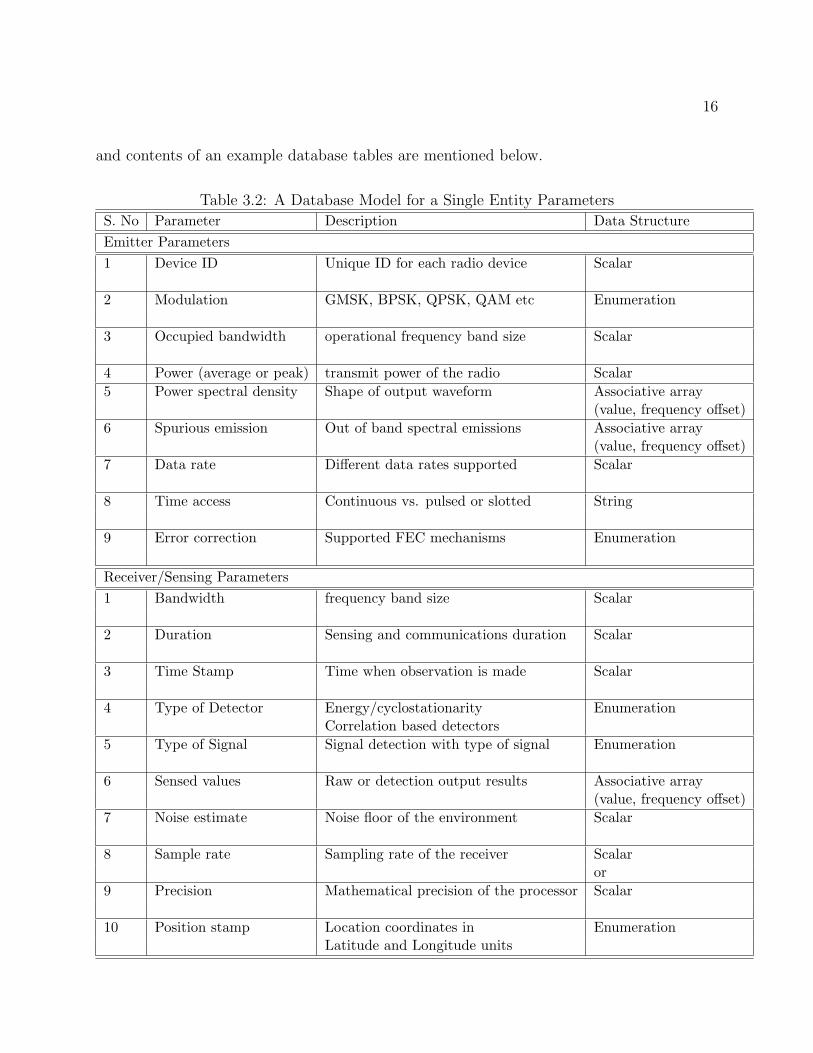
and contents of an example database tables are mentioned below.
Table 3.2: A Database Model for a Single Entity ParametersS. No Parameter Description Data StructureEmitter Parameters1 Device ID Unique ID for each radio device Scalar
2 Modulation GMSK, BPSK, QPSK, QAM etc Enumeration
3 Occupied bandwidth operational frequency band size Scalar
4 Power (average or peak) transmit power of the radio Scalar5 Power spectral density Shape of output waveform Associative array
(value, frequency o↵set)6 Spurious emission Out of band spectral emissions Associative array
(value, frequency o↵set)7 Data rate Di↵erent data rates supported Scalar
8 Time access Continuous vs. pulsed or slotted String
9 Error correction Supported FEC mechanisms Enumeration
Receiver/Sensing Parameters1 Bandwidth frequency band size Scalar
2 Duration Sensing and communications duration Scalar
3 Time Stamp Time when observation is made Scalar
4 Type of Detector Energy/cyclostationarity EnumerationCorrelation based detectors
5 Type of Signal Signal detection with type of signal Enumeration
6 Sensed values Raw or detection output results Associative array(value, frequency o↵set)
7 Noise estimate Noise floor of the environment Scalar
8 Sample rate Sampling rate of the receiver Scalaror
9 Precision Mathematical precision of the processor Scalar
10 Position stamp Location coordinates in EnumerationLatitude and Longitude units

17
S. No Parameter Description Data StructureAntenna Parameters1 Maximum gain Gain of the antenna in dBi units Scalar
2 Antenna pattern Isotropic or Directional Multidimensionalassociative array (value,frequency o↵set, polarization)
3 Occupied bandwidth frequency band size Scalar
4 Elevation angle Vertical height covered by the Scalarantenna beam measured in degrees
5 Azimuth angle Horizontal area covered Scalarby the antenna in degrees
6 EIRP Equivalent Isotropically Radiated Power Scalarat the antenna
7 Height of antenna Depends on the device type Scalarabove ground
8 Polarization Vertical, Horizontal Enumerationleft-hand circular, circular
9 Beam width Width of the antenna beam Scalar
10 Number of sectors Number of sectors in a cell Scalarserved by the antenna
11 Maximum sweep angle angular area covered Scalarby the antenna beams
12 Number of elements total antenna array elements Enumeration
13 Type of system Satellite/radar/cellular Enumerationpublic safety
Mobility Parameters1 Speed Distance covered by radio Single value or range
inm
secor
km
sec2 Velocity Distance covered by radio in Scalar
a particular direction or range of directions3 Acceleration Velocity change of Value and direction
radio or rangeNetwork Parameters1 Device ID Unique ID for each radio device Scalar2 Network ID Unique ID for each network Scalar
3 User role Primary incumbent type Enumerationi-e subscriber radio, base station,satellite transponder, TV base station
4 Context parameters stationary, moving Enumerationindoor, outdoor
18
3.2 Ad-hoc Networks
Operations in the white space spectrum need network support from the infrastructure ofa communication system network. There is no infrastructure support in ad-hoc networks(AHN). So they need to develop their own network support architecture based on inter-node collaboration and sharing of spectrum sensing information. For this purpose, ad-hocnetworks need unique functionalities of spectrum sensing, spectrum decision, spectrum shar-ing and spectrum mobility. These functionalities augmented with access to the geolocationdatabase allow ad-hoc networks to achieve the above-mentioned objectives.
Ad-hoc network architectures are useful in a number of scenarios. Consider a disaster scenarioin which the infrastructure of wireless communication networks is severely a↵ected. To setupa replacement network, spectrum bands are required. In such a scenario, spectrum needsto be quickly cleared and reallocated to the disaster response organizations. White spacedatabases are a preferred option for spectrum allocation in such conditions.
In the ad-hoc networks, there is a group of radios distributed in a geographical area. Thenetwork topologies can be classified into ad-hoc centralized network and ad-hoc distributednetwork. In the ad-hoc centralized network, there is a master node which coordinates thespectrum management and communications among the radios. While in distributed ad-hocnetworks, each radio acts independently in its communications and spectrum selection.
For white space operations, network topologies of ad-hoc networks require wireless links tothe Internet through a public/private network or a satellite link. In both network topologies,handling of RF channel allocation for such radios, a master node with a back-haul link relaysor proxies the database query for the network. So nodes without a back-haul link can querythe geolocation database through a master node with a back-haul link. In such cases, theclient node is a slave node. The ad-hoc network radios utilize the allocated RF channelsfrom the geolocation database for operations with the required access rules mentioned bythe database.
For development of network support for ad-hoc networks a cooperation scheme is neededamong the radios. A common cooperative scheme is forming clusters to share sensing in-formation locally. In this case, the cluster head collects sensing measurements from otherpeers and makes the final sensing decision. For AHN without a central entity, a distributedcooperation method is implemented. In which, when a user detects the PU activity, it shouldnotify its observations promptly to its neighbors to evacuate the busy spectrum. Cooper-ative detection is more accurate since the uncertainty in a single user’s detection can beminimized through collaboration. Moreover, multi-path fading and shadowing e↵ects canbe mitigated so that detection probability is improved in a heavily shadowed environment.However cooperative approaches cause adverse e↵ects due to cooperation overhead.
Consider the ad-hoc network Figure 3.2 with a set of wireless nodes that will sense a numberof channels and exchange their sensing information with each other. The sensing nodes

19
Figure 3.2: Emergency ad-hoc network with partly connected nodes supported by geolocationdatabase.
together will develop a wide-band signal detector, in which nodes will sense a number ofchannels simultaneously and collaboratively detect PU transmitters in the wide-band. Eachnode will maintain an embedded radio environment map (REM) database that will storesensing related statistics and parameters. A database enabled sensing scheduling schemewill ensure reliable transmitter detection and will maximize the scanning speed of the wholespectrum band. The goal for the database enabled spectrum sensing system is to reliablyand quickly detect existing PU in a wide frequency band. The primary user detection willhelp the secondary network to characterize the available white space in the desired spectrumbands.
Tables below provide example REM database tables for AHN.

20
Table 3.3: A Database Model for Ad-hoc NetworksS. No Parameter Description Data StructureDetected Signals1 Signal ID Numeric ID for each signal detected Scalar
2 Sensor ID Numeric ID for each sensor Scalar
3 Emitter ID Numeric ID for each Transmitter Scalar
4 Protocol Name Name of standard like LTE, WiMAX, GSM, etc String
5 Time Stamp Time when measurement Scalarwas taken
6 Frequency operational frequency scalar
7 Bandwidth size of operational band Scalar
8 RSSI Received signal strength of the Stringsignal
Emitters1 Emitter ID Numeric ID for each transmitter Scalar
2 Protocol Name Name of standard like LTE, WiMAX, GSM, etc String3 Time Stamp Time when measurement Scalar
was taken4 Lat latitude of the Transmitter Scalar
location5 Lon Longitude of the Transmitter Scalar
location6 Frequency operational frequency scalar
7 Bandwidth size of operational band Scalar
Protocols1 Protocol ID Numeric ID for each Scalar
signal detected of a protocol4 Protocol Name Name of standard like LTE, WiMAX, GSM, etc String

21
S. No Parameter Description Data StructureScan Results1 Sensor ID Numeric ID for each sensor Scalar
2 Time Stamp Time when measurement was taken Scalar
4 FrequencyLo lower tuning frequency of the Scalarsensor
5 FrequencyHi higher tuning frequency Scalarof the sensor
6 Number Number of signals found during scalarsignals scanning
Spectrum Opportunity Map1 Channel Index Numeric ID for all the channels Scalar
2 State Channel Idle/busy indicator String3 Availability Number of available channels Enumerations
4 Avg PU Average amount of time channel used by PU ScalarUtilization
5 Avg SU Average amount of time channel used by SU ScalarUtilization
6 RSSI Channel power measured in the channel scalar
The REM database will provide network support to the radios by e�ciently representingand storing environmental and operational information. The embedded REM database willinclude provisions for its real time and historical databases. The level of content at the em-bedded REM database will include information accessed from the geolocation database andrealtime sensing statistics derived from spectrum sensing. This information can be used atthe MAC layer for timing requirements of coexistence with other systems. Knowledge neededfor non-real time demands such as channel recommendation or spectrum handover by higherlayers. Historical spectrum information for initiating a new application or information aboutspectrum bands from other sources like dedicated sensor network or regulatory authority.
Chapter 4
Database Access Protocol
Recently, a lot of research and regulatory activities [10], [11], [20], [27] are going on in manycountries around the world in the use of the white-space spectrum. It’s an understandingamong the community that a common interface between white space devices and databasemust be defined for utilizing the unused spectrum. The Internet Engineering Task Force(IETF) is currently working on development of a Protocol for Access to Whitespace Spectrum(PAWS) [28], for accessing the geolocation database. The standard protocol defines thedatabase interface to have the following attributes.
4.1 IETF PAWS Attributes
Global Applicability: This common interface must be conceptually similar to the InternetDomain Naming System (DNS) and would allow users to find the suitable spectrum for theirapplication, either on a secondary or an unlicensed basis. This ease of access would enablegreater opportunistic use of the RF spectrum.
Spectrum Agnostic: The protocol should be spectrum independent and able to be used inany spectrum band where white space sharing is permitted. Devices can operate in anylocation where such spectrum is available, and a common interface ensures uniformity inimplementations and deployment.
Regulatory Support:To allow the global use of white space devices in di↵erent countries(whatever the regulatory domain), the protocol should support the database communicatingapplicable regulatory rule set information to the white space device.
Flexible and extensible data structures: Di↵erent databases are likely to have distinct re-quirements for all kinds of data needed for registration (di↵erent regulatory rule sets thatapply to the registration of devices), and other messages sent by the device to the database.For instance, di↵erent regulators might require distinct device-characteristic information to
22
23
be passed to the database.
4.1.1 IETF PAWS Primitives with Geolocation Database
Database discovery
The master device must obtain the address of a trusted database [29], which it will queryfor available white-space spectrum. If the master device uses a discovery service to locatea trusted database, it may perform the following steps (this description is intended to bedescriptive, not prescriptive):
1. The master device constructs and sends a request (e.g., over the Internet) to a trusteddiscovery service.
2. If no acceptable response is received within a pre-configured time limit, the masterdevice concludes that no trusted database is available. If at least one response isreceived, the master device evaluates the response(s) to determine if a trusted databasecan be identified where the master device is able to receive service from the database.If so, it establishes contact with the trusted database.
Optionally, and in place of steps 1-2 above, the master device can be pre-configured withthe address (e.g., URI) of one or more trusted databases. The master device can establishcontact with one of these trusted databases.
Device Registration
The master device must register with the database before it queries the database for availablespectrum. A registration process may consist of the following steps:
1. The master device sends registration information to the database. This informationmay include the device ID, serial number assigned by the manufacturer, device location,device antenna height above ground, name of the individual or business that owns thedevice, and the name, street and email address, and telephone number of a contactperson responsible for the device’s operation.
2. The database responds to the registration request with an acknowledgement to indi-cate the success of the registration request or with an error if the registration wasunsuccessful. Additional information may be provided by the database in its responseto the master device.

24
Protocol
A protocol that enables a white space device to query a database to obtain informationabout available spectrum is needed. A device may be required to register with the databasewith some credentials prior to being allowed to query. The requirements for such a protocolare specified in this document.
Data Model Definition
A data model is required which enables the white space device to query the database whileincluding all the relevant information such as geolocation, radio technology, power charac-teristics, etc., which may be country and spectrum and regulatory dependent. All databasesare able to interpret the data model and respond to the queries using the same data modelthat is understood by all devices.
4.2 Database Query and Response Protocol
Following are the primitives of the PAWS protocol for accessing the geolocation database.
1. Master device discovers the geolocation database
2. Master device establishes HTTPS connection with database
3. Master device initialization message to database to exchange capabilities
4. Database responds
5. Device registration
6. Device sends available spectrum request to database
7. Master on behalf of a slave. So slave also has to register itself through master device
8. Database responds with available spectrum response
9. Master device spectrum usage info to the database
10. Database responds by spectrum usage acknowledgement response message
Details of the protocol operations and messages exchanged between the white space device(WSD) and the geolocation database are available in the IETF PAWS Documents [28].

25
Content of a database query
In this section, the parameters in the spectrum request are briefly summarized in this table.
Table 4.1: Database Query ContentsParameter Content Data Structuredatabase queryDevice descriptor
Manufacturer serial number stringruleset ID listFCC ID stringDevice type stringRadio Access Technology (RAT) string
geolocation Point, Region, CenterLatitude, Longitude
Antenna characteristics antenna height,antenna type listantenna direction, radiation patternantenna gain, antenna polarization
Device owner vcardDevice capabilities
authority stringMax location change floatMax polling sec intRule set IDs list
Content of a database response
After receiving a spectrum request, the database responds with a spectrum response. Thecontents of the spectrum response are in the table below.

26
Table 4.2: Database Response ContentsParameter Content Data Structuredatabase queryTime stamp
start time stringstop time ID list
Spectrum scheduleBandwidthfrequency rangeBandwidth
Spectrum report antenna height listantenna typeantenna directionradiation patternantenna gainantenna polarization
rule set ID vcardDevice capabilities
authority stringMax location change floatMax polling sec intRule set IDs list
Location geolocation andselected from the spectrum request
maxLocationChange renew the spectrum request
Details of the primitives exchanged between the WSD and the geolocation database areavailable in the IETF PAWS Documents [28].

Chapter 5
Wireless Standardization ActivitiesUsing Geolocation Database
5.1 FCC 3.5 GHz NPRM and Citizens Broadband Ser-vices Database
FCC released a Notice of Proposed Rule Making (FCC NPRM- 12-148) [30] to create anew Citizens Broadband Service in the 3550-3650 MHz band (3.5 GHz Band) currently usedfor military and satellite operations. It will promote two major advances that enable moree�cient use of the radio spectrum: small cells and spectrum sharing.
The 3.5 GHz Band was identified by the National Telecommunications and InformationAdministration (NTIA) for shared federal and non-federal use in the 2010 Fast Track Report[9]. Current FCC’s proposal builds on experience with spectrum sharing in the televisionwhite spaces (TVWS), and prepares ideas for the new notice of Inquiry on Dynamic SpectrumAccess technologies, and broadly reflects recommendations made in a recent report by thePresidents Council of Advisors on Science and Technology (PCAST) [1].
Moreover, these proposed new and flexible rules can be extended to the neighboring 3650-3700 MHz band, which is already used for commercial broadband services. Together, theseproposals would make up to 150 megahertz of a contiguous spectrum available for innovativemobile and fixed wireless broadband services without displacing mission-critical incumbentsystems.
27
28
5.2 European Communication Commission (ECC) andOfcom E↵orts
E�cient use of the radio spectrum is a global regulatory goal from Europe, to Canada orSingapore with a primary focus on what spectrum sharing can add to existing spectrummanagement options. European Commissions recent release [31] on promoting the shareduse of radio spectrum and the interest from regulators such as the UKs Ofcom [32] andSingapore‘s IDA [33] in trials and commercial pilots of the White Spaces technology, ensuresthat a significant portion of spectrum is available for license-exempt sharing on a nationwidebasis, increasing the amount of such spectrum in the urbanized areas within these countries.
The reason is simple: the number of wireless devices is growing exponentially. Accordingto the European Commission statistics [34], by 2015 there will be 7.1 billion phones, tabletsand other mobile devices connected to the Internet globally. Five years further down theline, the number of smart devices connected to the Internet is going to be staggeringly largerparticularly when wireless sensors and other machine-to-machine communication devices arecounted. Unfortunately, the way spectrum is managed today, does not readily allow theflexibility to adapt to meet that projected demand. Gaps in coverage and network overloadin busy areas are already resulting in poor service for end-users.
These problems can be alleviated through spectrum sharing, as proposed in the EuropeanCommissions Communication [31]. Fortunately, the technology is now ready to make thishappen. A Commission funded project called COGEU [35], which brings together researchinstitutes and private companies from Portugal, France, Ireland, Germany, Poland, Slovakia,Greece and Cyprus, has lately set out to quantify the white spaces sharing opportunities inkey central European states. In August, Europe‘s another commercially-authorized TVWhite Space geolocation database established in Finland [36]. Ireland is on the cusp oflaunching its own White Spaces initiative [37], and the French regulator has recently granteda TV white space test license.
With this growing interest and investment in White Spaces technology, it has become increas-ingly clear that its benefits can be much broader than just ensuring good wireless broadbandservices. Trials and pilots have explored a range of solutions from increasing the a↵ordabilityof the Internet and enabling a machine to machine (M2M) communication, to turn a highlypopulated metropolitan area into a leading Smart City with substantial long-term environ-mental benefits. A popular use case is looking at how spectrum resources can help overcomeinadequate Internet access in remote rural areas.

29
5.3 IEEE Standardization Activities
IEEE standards are key drivers for standardization and implementation of novel communica-tions system concepts. A number of IEEE standards have incorporated the use of geolocationdatabase as a source of available white space channels for operation. Some of these standardsare summarized below.
IEEE 802.11 af Standard
IEEE 802.11af working group [38] has been set up to define a standard to implement WiFitechnology within the TV unused spectrum, or TV white space. Research and standardiza-tion groups around the world are taking a more flexible approach to spectrum allocations,the idea of low power systems that are able to work within portions of RF spectrum thatmay need to be kept clear of high-power transmitters to ensure coverage areas do not overlapare being seriously investigated. IEEE 802.11af that use TV white space, the overall systemmust not cause interference to the primary users. There are many benefits from a systemsuch as IEEE 802.11af from using TV white space.
Propagation characteristics: In view of the fact that the 802.11af WiFi system operatingthe TV white spaces would use frequencies below one GHz. This would allow for greaterdistances to be achieved. Current Wi-Fi systems use frequencies in the ISM bands - thelowest band is 2.4 GHz and here signals are easily absorbed.
Additional bandwidth: One of the advantages of using TV white space is that unused fre-quencies can be accessed. However, it will be necessary to aggregate several TV channels toprovide the bandwidths that Wi-Fi uses on 2.4 and 5.6 GHz, to achieve the required datathroughput rates. IEEE 802.11 af uses many new technological concepts of cognitive radioand dynamic spectrum access with sensing and database access technologies.
Cognitive Radio: To utilize the available spectrum as e�ciently as possible, there is a needto utilize radio technology that can sense the environment and configure itself accordingly -Cognitive Radio. The technology is heavily dependent upon Software Defined Radio tech-nology as the radio needs to be configurable according to the prevailing radio environment.
Database Access: The IEEE 802.11af systems have provisions for accessing the geolocationdatabase to get available spectrum for use with the available channel powers mentioned inthe spectrum response.
IEEE P1900 Standard
The IEEE P1900 standard gives a complete overview of a cognitive radio network (CRN).The standard provides basic definitions and interconnection between cognitive radio and

30
cognitive radio network concepts. For example, informative tables and diagrams explain therelationships of CRs, software-controlled radios, intelligent radios, and adaptive radios. TheP1900.1 definitions and terminology are categorized into (1) definitions of advanced radiosystem concepts, (2) definitions of radio system functional capabilities, (3) definitions of net-work technologies that support advanced radio system technology (4) spectrum managementdefinitions, and (5) a glossary of ancillary definitions.
The P1900 committee objective is to develop supporting standards dealing with new tech-nologies and techniques being developed for next-generation radio and advanced spectrummanagement The di↵erent tasks [39] for the working groups are defined below.
1. IEEE P1900.1: Terminology and Concepts for Next-Generation Radio Systems andSpectrum Management,
http://grouper.ieee.org/groups/dyspan/1/index.htm
2. IEEE P1900.2: Recommended Practice for Interference and Coexistence Analysis,
http://grouper.ieee.org/groups/dyspan/2/index.htm
3. IEEE P1900.3: Recommended Practice for Conformance Evaluation of Radio (SDR)Software Modules,
http://grouper.ieee.org/groups/dyspan/3/index.htm
4. IEEE P1900.4: Architectural Building Blocks Enabling Network-Device DistributedDecision Making for Optimized Radio Resource Usage in Heterogeneous Wireless Ac-cess Networks,
http://grouper.ieee.org/groups/dyspan/4/index.htm
5. IEEE P1900.5: Policy Language and Policy Architectures for Managing CognitiveRadio for Dynamic Spectrum Access Applications,
http://grouper.ieee.org/groups/dyspan/5/index.htm
6. IEEE 1900.6 Working Group on Spectrum Sensing Interfaces and Data Structures forDynamic Spectrum Access and other Advanced Radio Communication Systems,
http://grouper.ieee.org/groups/dyspan/6/index.htm
7. IEEE 1900.7 White Space Radio Working Group,
http://grouper.ieee.org/groups/dyspan/7/index.htm

31
IEEE 802.22 Standard
The IEEE 802.22 WG was formed to use the frequencies in the TV-band between 54 MHzand 862 MHz at 6, 7, or 8 MHz bandwidths. The standard defines a cognitive radio basedwide-area regional network (WRAN) that contains cognitive radio devices that can sensethe immediate spectrum. The 802.22 WRAN is the first IEEE standard [40] to define howcognition in radios can be used in the base station and user terminals in a regional areanetwork.
Communications between fixed point-to-multipoint environment with specific use of televi-sion channels and guard bands was considered in the WG specifications. Specifically, theprimary goal was to develop a standard for a CR-based PHY/MAC air interface for use inlicense-exempt wireless communication devices on a non-interfering basis with a TV broad-cast spectrum.
Moreover, deployment in di↵erent geographic areas, including sparsely populated rural areas,while preventing harmful interference to incumbent licensed services in the TV broadcastbands. A secondary objective for the 802.22 standard is to serve dense population areaswhere spectrum is available.
The 802.22 standard have the capability for accessing the geolocation database for availablespecrum in its operational area. The specification defines protocol for accessing the databasefrom the base station perspective as well as the individual CPE device.

Chapter 6
Existing Privacy-Preserving Modelsand Methods
In this chapter we introduce some of the most well known privacy-preserving techniques thatare used widely in di↵erent types of databases.
6.1 k-anonymity
The concept of k-anonymity was originally introduced in the context of relational dataprivacy [41]. It addresses the question of ”How can a data holder release its private datawith guarantees that the individual subjects of the data cannot be identified while the dataremain practically useful” [42]. For instance, a medical institution may want to release atable of medical records with the names of the individuals replaced with dummy identifiers.However, some set of attributes can still lead to identity breaches. These attributes arereferred to as the quasi� identifier. For instance, the combination of zip code, age and thenationality attributes in the disclosed table 6.1 can uniquely determine an individual. Byjoining such a medical record table with some publicly available information source, like avoters list table, the medical information can be easily linked to individuals. k-anonymityprevents such privacy breach by ensuring that each individual record can only be releasedif there are at least k� 1 distinct individuals whose associated records are indistinguishablefrom the former in terms of their quasi-identifier values. Table 6.2 illustrates an exampleof 4-anonymous impatient microdata for the data in table 6.1. It has been shown that theproblem of optimal k-anonymization is NP-hard [89], nevertheless, the problem can be solvedquite e↵ectively by the use of a number of heuristic methods.
In Location-Based Services (LBSs) and mobile clients, location k-anonymity refers to k-anonymous usage of location information. A subject is considered location k-anonymous ifand only if the location information sent from a mobile client to an LBS is indistinguishable
32

33
Table 6.1: Impatient MicrodataID Zip Code Age Nationality Condition1 24060 22 American Heart Disease2 24061 25 Indian Heart Disease3 24061 29 American Viral Infection4 24060 23 American Viral Infection5 28255 42 Chinese Cancer6 28231 51 Ameican Heart Disease7 28255 45 Indian Viral Infection8 28231 47 Chinese Viral Infection9 24054 31 American Cancer10 24054 33 Chinese Cancer11 24021 33 American Cancer12 24021 39 Indian Cancer
Table 6.2: 4-anonymous Impatient MicrodataID Zip Code Age Nationality Condition1 240** < 30 * Heart Disease2 240** < 30 * Heart Disease3 240** < 30 * Viral Infection4 240** < 30 * Viral Infection5 282** � 40 * Cancer6 282** � 40 * Heart Disease7 282** � 40 * Viral Infection8 282** � 40 * Viral Infection9 240** 3⇤ * Cancer10 240** 3⇤ * Cancer11 240** 3⇤ * Cancer12 240** 3⇤ * Cancer
34
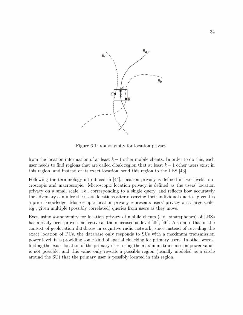
Figure 6.1: k-anonymity for location privacy.
from the location information of at least k� 1 other mobile clients. In order to do this, eachuser needs to find regions that are called cloak region that at least k� 1 other users exist inthis region, and instead of its exact location, send this region to the LBS [43].
Following the terminology introduced in [44], location privacy is defined in two levels: mi-croscopic and macroscopic. Microscopic location privacy is defined as the users’ locationprivacy on a small scale, i.e., corresponding to a single query, and reflects how accuratelythe adversary can infer the users’ locations after observing their individual queries, given hisa priori knowledge. Macroscopic location privacy represents users’ privacy on a large scale,e.g., given multiple (possibly correlated) queries from users as they move.
Even using k-anonymity for location privacy of mobile clients (e.g. smartphones) of LBSshas already been proven ine↵ective at the macroscopic level [45], [46]. Also note that in thecontext of geolocation databases in cognitive radio network, since instead of revealing theexact location of PUs, the database only responds to SUs with a maximum transmissionpower level, it is providing some kind of spatial cloacking for primary users. In other words,finding the exact location of the primary user, using the maximum transmission power value,is not possible, and this value only reveals a possible region (usually modeled as a circlearound the SU) that the primary user is possibly located in this region.

35
Table 6.3: 3-diverse impatient microdataID Zip Code Age Nationality Condition1 240** < 40 * Heart Disease9 240** < 40 * Cancer10 240** < 40 * Cancer4 240** < 40 * Viral Infection5 282** � 40 * Cancer6 282** � 40 * Heart Disease7 282** � 40 * Viral Infection8 282** � 40 * Viral Infection2 240** < 40 * Heart Disease3 240** < 40 * Viral Infection11 240** < 40 * Cancer12 240** < 40 * Cancer
6.2 l-diversity
The l-diversity model was designed to handle some weaknesses in the k-anonymity modelsince protecting identities to the level of k individuals is not the same as protecting thecorresponding sensitive values, especially when there is homogeneity of sensitive values withina group [47]. For example in the 4-anonymous medical database of table 6.2, we can see auser with zipcode 606 ⇤ ⇤⇤ and age 3⇤, has cancer (sensitive data) with probability 1. Inother words although the identity of user is not revealed, but the sensitive data is inferredfrom non-sensitive data. To protect users’ sensitive data against this privacy problem, theconcept of intra-group diversity of sensitive values is promoted within the anonymizationscheme. Table 6.3 shows 3-diversity for the medical database in table 6.1 while preserving4-anonymity.
l-diversity has also been used for preserving privacy in location-based services [48], in orderto mitigate query homogeneity attacks [49].
6.3 t-closeness
The t-closeness model is a further enhancement on the concept of l-diversity. One character-istic of the l-diversity model is that it treats all values of a given attribute in a similar wayirrespective of its distribution in the data. This is rarely the case for real data sets, sincethe attribute values may be very skewed. This may make it more di�cult to create feasiblel-diverse representations. Often, an adversary may use background knowledge of the globaldistribution in order to make inferences about sensitive values in the data. Furthermore, notall values of an attribute are equally sensitive. For example, an attribute corresponding to

36
Table 6.4: Confidence BoundingJob Gender Age Condition
Professional Male [35-40) HepatitisProfessional Male [35-40) HepatitisProfessional Male [35-40) HIV
Artist Female [30-35) FluArtist Female [30-35) HIVArtist Female [30-35) HIVArtist Female [30-35) HIV
a disease may be more sensitive when the value is positive, rather than when it is negative.In [79], a t-closeness model was proposed which uses the property that the distance betweenthe distribution of the sensitive attribute within an anonymized group should not be dif-ferent from the global distribution by more than a threshold t. The Earth Mover distance(a.k.a Wasserstein metric) is used in order to quantify the distance between the two distri-butions [50]. Furthermore, the t-closeness approach tends to be more e↵ective than manyother privacy-preserving data mining methods for the case of numeric attributes.
6.4 Confidence Bounding
Wang et al. [51] considered bounding the confidence of inferring a sensitive value from a quasi-identifier (QID) group by specifying one or more privacy templates of the form, (QID !s, h); s is a sensitive value, QID is a quasi-identifier, and h is a threshold. Let Conf(QID !s) be max{conf(qid ! s)} over all qid groups on QID, where conf(qid ! s) denotes thepercentage of records containing s in the qid group.
A table satisfies (QID ! s, h) if Conf(QID ! s) h. In other words, (QID ! s, h)boundsthe attacker’s confidence of inferring the sensitive value s in any group on QID to themaximum h. For example in the 3-anonymous and 2-diverse table 6.4, with QID = {Job,Sex, Age}, (QID ! HIV, 10%) states that the confidence of inferring HIV from any groupon QID is no more than 10%. But for the data in the table, this privacy template is violatedbecause the confidence of inferring HIV is 75% in the group {Artist, Female, [30-35)}.
6.5 Personalized Privacy
Not all individuals or entities are equally concerned about their privacy. For example, acorporation may have very di↵erent constraints on the privacy of its records as comparedto an individual. This leads to the natural problem that we may wish to treat the recordsin a given data set very di↵erently for anonymization purposes. The notion of personalized

37
privacy is proposed [52] to allow each record owner to specify her own privacy level. Thismodel assumes that each sensitive attribute has a taxonomy tree and that each record ownerspecifies a guarding node in this tree. The record owner’s privacy is violated if an attackeris able to infer any domain sensitive value within the subtree of her guarding node with aprobability, called breach probability, greater than a certain threshold.
Although both confidence bounding and personalized privacy take an approach to boundthe confidence or probability of inferring a sensitive value from a QID group, they havedi↵erences. In the confidence bounding approach, the data publisher imposes a universalprivacy requirement on the entire data set, so the minimum level of privacy protection isthe same for every record owner. In the personalized privacy approach, a guarding node isspecified for each record by its owner. The advantage is that each record owner may specifya guarding node according to her own tolerance on sensitivity. Experiments show that thispersonalized privacy requirement could result in lower information loss than the universalprivacy requirement
6.6 (X, Y )-Privacy
As we described earlier, k-anonymity in states that each group of insensitive attributes X,has at least k distinct values on sensitive values Y (e.g., diseases). However, if some Y valuesoccur more frequently than others, the probability of inferring a particular Y value can behigher than 1
k . To address this issue, Wang and Fung [53] proposed a general privacy model,called (X, Y )-Privacy, which combines both k-anonymity and confidence bounding. Thegeneral idea is to require each group x on X to contain at least k records and conf(x ! y) hfor any y 2 Y , where Y is a set of selected sensitive values and h is a maximum confidencethreshold.
6.7 Perturbation
The perturbative masking method (a.k.a randomization method) is a technique for privacy-preserving databases that uses data distortion in order to mask the attribute values ofrecords. In this method, we add su�ciently large noise to individual record values to preventrecovery of these values by an adversary. One key advantage of the randomization methodis that it is relatively simple, and does not require knowledge of the distribution of otherrecords in the data, and can be implemented at data collection time. This is not true ofother methods such as k-anonymity which require the knowledge of other records in thedata. We describe some of the perturbative methods that can be used for our problemin this section. In [54], it is shown that perturbation-based mechanisms can outperformprivacy-preserving techniques that use cloaking regions for location based services. We need
38
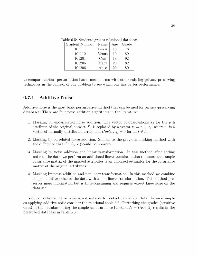
Table 6.5: Students grades relational databaseStudent Number Name Age Grade
101111 Lewis 18 78101112 Venus 19 89101201 Carl 18 92101205 Mary 20 82101206 Alice 20 80
to compare various perturbation-based mechanisms with other existing privacy-preservingtechniques in the context of our problem to see which one has better performance.
6.7.1 Additive Noise
Additive noise is the most basic perturbative method that can be used for privacy-preservingdatabases. There are four noise addition algorithms in the literature:
1. Masking by uncorrelated noise addition: The vector of observations xj for the j-thattribute of the original dataset Xj is replaced by a vector zj = xj + ✏j, where ✏j is avector of normally distributed errors and Cov(✏t, ✏l) = 0 for all t 6= l.
2. Masking by correlated noise addition: Similar to the previous masking method withthe di↵erence that Cov(✏t, ✏l) could be nonzero.
3. Masking by noise addition and linear transformation. In this method after addingnoise to the data, we perform an additional linear transformation to ensure the samplecovariance matrix of the masked attributes is an unbiased estimator for the covariancematrix of the original attributes.
4. Masking by noise addition and nonlinear transformation. In this method we combinesimple additive noise to the data with a non-linear transformation. This method pre-serves more information but is time-consuming and requires expert knowledge on thedata set.
It is obvious that additive noise is not suitable to protect categorical data. As an exampleos applying additive noise consider the relational table 6.5. Perturbing the grades (sensitivedata) in this database using the simple uniform noise function N = (Add, 5) results in theperturbed database in table 6.6.

39
Table 6.6: Students grades relational databaseStudent Number Name Age Grade
101111 Lewis 18 83101112 Venus 19 94101201 Carl 18 97101205 Mary 20 87101206 Alice 20 85
Table 6.7: Students grades relational databaseStudent Number Name Age Grade
101111 Lewis 18 92101112 Venus 19 80101201 Carl 18 82101205 Mary 20 78101206 Alice 20 89
6.7.2 Data Swapping
Data swapping is another type of perturbative method, in which the values across di↵erentrecords are swapped in order to perform the privacy preservation. Note that since thistechnique does not allow the value of a record to be perturbed independently of the otherrecords, it cannot be used for preserving operational privacy of primary users in geolocationdatabase-driven cognitive radio networks.
Table 6.7 illustrates applying this technique to the relational database in table 6.5.
6.7.3 Rounding
Rounding methods replace original values of attributes with rounded values. For a givenattribute Xi, rounded values are chosen among a set of rounding points defining a roundingset (often the multiples of a given base value). Table 6.8 illustrates applying this techniqueto the relational database in table 6.5.
6.8 Di↵erential Privacy
Instead of comparing the prior probability and the posterior probability before and afteraccessing the published data, Dwork [55] proposed di↵erential privacy to compare the riskwith and without the record owner’s data in the published data. In other words di↵erentialprivacy is a condition on the release mechanism and not on the dataset.

40
Table 6.8: Students grades relational databaseStudent Number Name Age Grade
101111 Lewis 18 80101112 Venus 19 90101201 Carl 18 90101205 Mary 20 80101206 Alice 20 80
Assume that the responses of the database are modeled via a randomized algorithm A.The randomized algorithm A is ✏-di↵erentially private if for all datasets D1 and D2 thatdi↵er on a single element (i.e., data of one person), and all S ⇢ Range(A), Pr{A(D1) 2S} e✏ ⇥ Pr{A(D2) 2 S}, where the probability is taken over the coins of the algorithmand Range(A) denotes the output range of the algorithm A. This means that for any twodatasets which are close to one another (that is, which di↵er on a single element) a givendi↵erentially private algorithm A will behave approximately the same on both data sets.
Chapter 7
A General Threat Model
Depending on characteristics of the secondary users’ network, primary users’ network and theservices provided for secondary users by the geolocation database, the operational privacy ofprimary users can be threatened by the adversary in di↵erent ways. The first question thatwe need to answer for creating a threat model is: “who is the adversary?”. The adversarycan be a secondary user (querier) or a group of colluding secondary users that are locatedthroughout the region that the geolocation database covers, or alternatively an entity whoeavesdrops on communications between SUs and the geolocation database (GDB).
In our framework, the adversary is actually the entity who observes the output of privacy-preserving mechanisms and hence has access to a subset of observable events O. The subsetof O that is accessible to a given adversary is called the set of observed event by thatadversary and is denoted by O ✓ O. The properties of this subset and the implicationof this observation on the PUs, operational privacy depend on the characteristic of theadversary. Note that the adversary might have multiple observation points (e.g. sendingqueries from di↵erent locations and observing the GDB’s replies), from each of which she canobserve a di↵erent set of events. At each observation point, the adversary observes di↵erenttransformations of the same actual events, nevertheless the structure of transformations (nottheir settings) is the same. Thus in this section, we focus on the set of adversary’s observedevents at a single observation point, which is shown by O.
In this framework, we model an adversary based on the following three factors: her Means,Actions, and Goals.
7.1 Means
The means of the adversary are the technologies available to er for capturing events, heraccess credentials in the system, and her a priori knowledge about the system.
41

42
7.1.1 Access
The adversary might eavesdrop on the communication channel between SUs and the GDBor she might be a secondary user herself. In both cases, the adversary has access to thecontent of the SU’s queries and the GDB’s corresponding replies to these queries. However,in the former case, based on the level of sophistication of the adversary’s eavesdroppingdevices, the accuracy of observed events changes. We also assume that the adversary hasaccess to spectrum sensing technology and may combine local spectrum sensing results withthe information that she obtains from the GDB’s replies to the SUs’ queries to pose a moreserious privacy threat to PUs.
7.1.2 Knowledge
The a priori knowledge of the adversary is composed of multiple pieces. Here, we categorizethe adversary’s knowledge into multiple classes. The precision and confidence of the adver-sary’s knowledge about each class determines her a priori knowledge. Her knowledge in eachclass can be deterministic or probabilistic and this should be clarified in each threat model.
Users. The adversary might know the (exact or estimated) number of primary users at anytime, or more precisely the set of primary users U , that implies knowing the real identityof active primary users. This knowledge can evolve over time, or she may remain obliviousabout the dynamics of the set of primary users and their joining/leaving. The adversarymight also have some background knowledge about the capabilities of primary users thatoperate on a specific channel. Her knowledge about PUs may include their transmissionpower range, protected contour, antenna characteristics, employed wireless technology (e.g.LTE), required SINR, etc.
Identities. This class specifies to what extent the adversary knows about the primaryusers’ identities and the pseudonyms used by them. The adversary might know the relationbetween pseudonyms of a user, and also the constraints on the set of pseudonyms (e.g., howmany pseudonyms a user can have). The extent to which each pseudonym is linkable to itsholder’s real-identity is also part of the knowledge of the adversary in this class.
Space. The knowledge of the adversary on the space in which primary users move falls intothis class. This knowledge consists of three layers. The first layer models the geographicalspace in which users can move, in a discrete way, using a grid of cells that represents thetwo dimensional space. Each cell is called a location instance and has a unique identity. Thesecond layer models the places or location sites such as roads, houses, etc. Each locationsite consists of a non-empty set of location instances and has a unique name and address.The third layer captures the type of location sites and their similarity. A location typemay represent the usage of the location, e.g., military, residential, or landscape type, e.g.lake, mountain, forest, etc. The connection between users and places must also be specifiedhere. For example, does the adversary know the address of the origin and destination of the

43
moving primary users.
Events. The adversary might have access to some actual events that are performed beforethe observation time. Moreover, in many cases the adversary has some statistics aboutthe typical behavior of primary users. For example, she knows the (im)possibility or theprobability that one specific actual event can be performed by a user, or that two specificevents belong to the same user. Knowledge of the adversary about mobility profile of users(which represents how probable/possible it is for a specific user or a mass of users to movefrom one location to another location in a specific time period) falls into this class.
In addition to these factors, we assume that the adversary knows the application, employedprivacy tools, and also the privacy metric that the geolocation database uses.
7.2 Actions
The action scope of an adversary is determined by the size of the location areas and theduration of time periods in which the adversary observes the system. Considering thesefactors, adversaries can consequently be divided into di↵erent categories. An adversary isglobal if she observes the observable events occurred at any location in the space, i.e. she canquery the geolocation database from any location instance. Whereas, she is called local ifduring the observation period she cannot observe the transformation of some events that aregenerated in specific location areas. Similarly, based on the observation time, an adversaryis referred to as a short-term attacker if the transformation of events performed at some timeperiods are not observable by the adversary. In the case there is no such time restrictions,she is called a long-term attacker. In the case an attack is global and long-term, we haveO = O.
7.3 Goals
7.3.1 Presence vs. Absence Disclosure
An adversary’s goals of observing users’ activities in a mobile network can be divided intotwo main categories: presence disclosure or absence disclosure. In the former category, theadversary’s goal is to find out if a set of primary users are present at some place(s). Whereas,in the latter category, the adversary wants to know whether a specific set of primary users arenot present at some place(s). Usually the adversary is interested in presence disclosure, thusmost of the attacks presented in the literature of location privacy fall into the first category.However, there are some reports about the consequences of absence disclosure attacks onsome primary users such as ordinary people. As an obvious example, by misusing her accessto a geolocation database, the adversary can find out the best time to break into a person’s

44
house. Therefore we need to obfuscate the location of primary users to protect their locationprivacy against both presence and absence disclosure attacks.
7.3.2 Individual vs. Mass Target
The inference attacks against a geolocation database can disclose the private informationof a specific primary user in an individual target attack, or it might be targeting a set ofprimary users, collectively, in a mass target attack where the adversary does not distinguishprimary users in the set, for example when they belong to a community.
7.3.3 Tracking vs. Identification
The two main known attacks on primary users’ location privacy, which are used usuallyto disclose primary users’ presence, are tracking and identification. These two attacks aretightly related to each other, although they have di↵erent ways of obtaining primary users’private location information.
In tracking attacks, the adversary’s goal is to reconstruct the primary users’ actual trajecto-ries (which might have been distorted by privacy preserving mechanisms) and subsequentlyidentify the locations that the primary users have visited. This information can also be usedto predict the future locations of primary users. The tracking can be done in various mannersdepending on the adversary’s goal. The adversary might want to know the trace of locationinstances (i.e., coordinates) visited by the primary users in a given time period along withhis average speed, direction etc., or the location sites (e.g., specific military base) where theyhave been to, or only the type of places that the primary users are used to periodically visitin order to detect the type of primary users.
In identification attacks, the adversary wants to discover the real identity of her targets.This can be done on a small scale where the adversary is interested in de-anonymizing aspecific observed event, or on a large scale where the adversary is interested in finding theidentity of users from whom the adversary has observed some anonymous traces of events.The identification is done using some inference attacks based on the adversary’s knowledgeon the linkability of the primary users to sensitive areas such as their homes or work places.Identification can also leverage on the mobility pattern of users, because primary users tendto visit certain places regularly.
It is clear that the success of each of the two above-mentioned attacks also paves the way forthe other. In the case the adversary manages to discover the actual trajectory of a user, theidentification of the user is not a di�cult task. Especially if the adversary has access to theinformation about location sites such as homes or work places of the users, which containa lot of information about their identities. In the case that the adversary has already de-anonymized some events of a user, the recovery of the user’s actual trajectory (i.e., tracking

45
him) can be done more easily, if the adversary has access to the mobility profile of the users.
7.4 Using the threat model for evaluating the privacy-preserving techniques
We can use the described threat model in this chapter to evaluate di↵erent privacy-preservingtechniques that are designed for the GDB. To evaluate a privacy-preserving technique, weneed to apply di↵erent attacks against it and find the attacker’s cost and its impact.
To find the attacker’s cost in an attack, one needs to know the required means (e.g. amountof knowledge and access level), and type of actions (for instance the cost of a short-termattack should be defined di↵erently from the cost of a long-term attack). This won’t bepossible without applying the threat model to the attack precisely.
On the other hand in order to measure the attacker’s impact or its success rate, we need touse the threat model to learn about the attacker’s goals and proposing a well-defined metricfor the attacker’s impact.
Defining attacker’s cost and impact using the threat model will help us in evaluating privacy-preserving techniques against di↵erent types of attacks which in tern results in designing morerobust techniques.

Chapter 8
Applying Existing Privacy-PreservingModels and Methods to Our Problem
8.1 k-anonymity
In the context of location privacy of PUs in database-driven spectrum sharing, we can achievelocation k-anonymity by combining protected contours of k primary users that are closesttogether and creating a larger protected contour that works like the cloak box for LBSs.The secondary users are not allowed to transmit in the area covered by this larger protectedcontour. This increases the privacy of primary users but will decrease the performance ofthe secondary network. The main problem of this approach is that unlike mobile clients ofLBSs in metropolitan areas, PUs that operate on the channels that may contain spectrumholes, usually are not close enough to create a small cloak box that covers k PUs, such thatk is large enough for preserving privacy and the cloak box is small enough to avoid causingsignificant degradation in spectrum utilization e�ciency. Figure 8.1 illustrates this idea fork = 3. Further research and experimental results on this method is required.
Consider the following simplified scenario. Suppose table 8.1 shows the location and theradius of the protected contour of the 6 primary users in figure 8.1. Also assume that allPUs are operating in the same band. To answer a SU’s query, the database checks if the SUis located inside the protected contour of a PU or not.
To implement 3-anonymity, we replace the following table with table 8.1, where PU1’ andPU2’ are replaces with the set of PUs {PU1,PU2,PI3} and {PU4,PU5,PU6} respectively.The location of the virtual PU that is replaced with 3 actual PUs is the circumcenter of thetriangle that consists of the location of the 3 PUs (the circumcenter is located at the samedistance from all three points). And the radius of the protected contour is the distance ofthis point from one of the PUs plus the largest radius of protected contour of the three PUs.
46

47
Figure 8.1: 3-anonymity for primary users’ location privacy.
Table 8.1: Simplified Geolocation Database.ID 2D Location Radius of Protected Contour (km)
PU1 (1,2) 0.2PU2 (3,-3) 0.25PU3 (5,1) 0.3PU4 (9,2) 0.1PU5 (12,3) 0.15PU6 (12,1) 0.2
Table 8.2: Geolocation Database with 3-anonymity.ID 2D Location Radius of Protected Contour (km)
PU1’ (2.56,-0.28) 3.06PU2 (10.67,2) 1.86

48
Note that although 3-anonymity by spatial cloaking preserves the privacy of PUs, it resultsin poor spectral e�ciency for secondary network, because the SUs cannot transmit in someregions that are not part of the protected contour of real PUs.
8.2 l-diversity
In the context of privacy of PUs in database-driven spectrum sharing, we can achieve l-diversity by providing l di↵erent answers (for example l di↵erent combinations of powervalues and associated availability time) to the same query, i.e. queries that are sent by aspecific SU from a specific location. This seems to degrade the performance of secondaryusers’ network significantly. Further research is required to find out if this method willperform better in preserving the privacy level of primary users.
8.3 Confidence Bounding
In the context of geolocation database, we can implement confidence bounding, by boundingthe number of repetitions of di↵erent answers that database gives to the same query. Forexample if the database replies to the SU at location (x,y) with 3 di↵erent power values40mW, 50mW and 80 mW, and 80mW is the true value for the current deployment of PUs,by replying with 80mW twice for 10 identical queries, the database bounds the confidenceof the attacker to 20% for the correct value.
8.4 (X, Y )-Privacy
In the context of geolocation databases, this technique can be implemented similar to whatwe described for confidence-bounding technique.
8.5 Perturbation
8.5.1 Additive Noise
In the context of PUs location privacy, we can use di↵erent perturbative methods. Forexample we can add noise to the radius of the protected contour of PUs and then computemaximum transmission power and report it to the querier (masking by noise addition andnonlinear transformation) or we can use false positives such as reducing maximum allowedtransmission power (masking by uncorrelated noise addition) in the reply to SUs queries.

49
Figure 8.2: Perturbation using transfiguration.
8.5.2 Rounding
In the context of location privacy of PUs in geolocation databases, the database may roundthe maximum transmission power value which it obtains from the propagation model that ituses. Therefore instead of the exact distance between the querier (SU) and PU, the SU canonly obtain an interval for the possible distances, i.e. less information about the location ofthe PU.
8.5.3 Transfiguration
Another form of perturbation that might be used to preserve the privacy of primary users, ischanging the shape of protected contour of PUs. Replacing the circular protected contourswith random convex shapes that inscribe the actual circular protect contour will increasethe location privacy of PUs. Figure 8.2 illustrates using a pentagon as the protected contourof a PU, that inscribes the real circular shape protected contour of the PU.
8.6 Di↵erential Privacy
In the context of geolocation databases, we can define ✏-di↵erential privacy as follows: As-sume that two queries that are sent by a SU, only di↵er in the location of the SU. Inother words, the identity of the SU, the closest PU to the SU, and all other parametersare fixed and the only change that has happened is the distance between the SU and thePU that is changed from d1 to d2. We can say that the database has di↵erential privacy iffor |d1 � d2| < �: Pr{f(d1) � f(d2) 6= 0} < ✏, where f(d) is the database’s response (e.g.

50
maximum allowed transmission power) for the distance d.

Chapter 9
Conclusions
This report drafts the deficiencies of the existing geolocation database implementations forspectrum sharing to achieve the recommendations made in a number of studies [1], [7], [9],conducted for identifying the 500MHz of spectrum as mentioned in the National BroadbandPlan (NBP) and tiered approach to spectrum access proposed by the President‘s Council ofAdvisors on Science and Technology (PCAST) Report.
To fulfill this gap, the requirements for such a database system along with some new func-tionality are developed. A generalized dynamic database model is proposed in Chapter 2. Itconsists of many components that will allow a number of unique capabilities like real timechannel availability from dynamic calculations of the protection contour zones of stationaryand mobile primary users. Interference protection and coexistence capability to calculate thesecondary network interference power spectral density (IPSD) at primary incumbent’s loca-tion for allowing operations inside the protection zones as well. It can provide deconflictionamong the secondary users for achieving coexistence of multiple wireless standards.
In Chapter 3, some use case scenarios for centralized infrastructure based networks, andAdhoc networks are outlined. Example database implementation tables are provided that canaccommodate locally identified spectrum opportunities along with the resources requestedfrom the geolocation database.
The IETF PAWS protocol for accessing the geolocation database is summarized in chapter 4.The protocol provides a common interface between white space devices and the geolocationdatabase for utilizing the unused spectrum. The attributes of the protocol and primitivesexchanged with the database are outlined.
Wireless standardization activities around the world in di↵erent regulatory bodies are sum-marized in chapter 5. IEEE standards like IEEE 802.11af, IEEE P1900, IEEE802.22, etc.that use the geolocation database for requesting spectrum resources are also summarized inthis chapter.
51

52
This report also provides an overview to existing privacy-preserving techniques for protectingsensitive data in a relational database, and how these techniques can be utilized for preservingoperational privacy of incumbents in a geolocation database.
Privacy-preserving data mining finds numerous applications in surveillance which are nat-urally supposed to be privacy-violating applications. The key is to design methods fordatabases, which continue to be e↵ective, without compromising privacy. Privacy-preservingtechniques have been used for many applications such as bio-surveillance, facial de-identification,identity theft, etc. In chapter 6, we studied an overview of the state-of-the-art in privacy-preserving data mining techniques.
In order to evaluate di↵erent privacy-preserving techniques that are designed for the geolo-cation database, we introduced a threat model in chapter 7. This threat model helps us tofind the attacker’s cost and its impact, for all privacy-preserving techniques.
Finally in chapter 8, we investigated the problem of preserving the operational privacy ofincumbents in a geolocation database-driven cognitive radio network. We showed how we canuse the existing privacy-preserving techniques for this application in a high level discussion.

Bibliography
[1] PCAST, “Realizing the full potential of government-held spectrum to spur economicgrowth,” tech. rep., Report to the President, 2012.
[2] F. C. Commission, “Third order and memorandum opinion and order, in the matterof unlicensed operation in the tv broadcast bands, additional spectrum for unlicenseddevices below 900 mhz and in the 3 ghz band,” April 2012.
[3] D. Gurney, G. Buchwald, L. Ecklund, S. Ku↵ner, and J. Grosspietsch, “Geo-locationdatabase techniques for incumbent protection in the tv white space,” in IEEE Dyspan,2008.
[4] F. C. Commission, “Enabling innovative small cell use in 3.5 ghz band nprm & order(fcc 12-148),” December 2012.
[5] NSF, “Enhancing access to the radio spectrum (ears).” Program Solicitation NSF 13-539.
[6] DARPA, “Baa: Shared spectrum access for radar and communications (ssparc).”DARPA-BAA-13-24, February 2013.
[7] FCC, “Connecting america: The national broadband plan,” tech. rep., White House,2010.
[8] NTIA, “Spectrum sharing working group (sswg) working notes.” csmac_spectrum_
sharing_workinggroup_notes_03feb2012_v3.pdf, 2012. Commerce Spectrum Man-agement Advisory Committee (CSMAC).
[9] “An assessment of the near-term viability of accommodating wireless broadband systemsin the 1675-1710 mhz, 1755-1780 mhz, 3500-3650 mhz, 4200-4220 mhz, and 4380-4400mhz bands,” tech. rep., NTIA:Fast Track Report, 2010.
[10] IEEE, “P1900.6 standard for spectrum sensing interfaces and data structures for dy-namic spectrum access and other advanced radio communication systems,” tech. rep.,2011.
53

54
[11] “Ieee 802.22-2011(tm):standard for cognitive wireless regional area networks (ran) foroperation in tv bands,” tech. rep., 2011.
[12] FCC, “Fcc media bureau databases for am, fm, tv, lptv, and dtv broadcast stations.”http://transition.fcc.gov/mb/databases/cdbs/. Parameters of Devices in Di↵er-ent Applications.
[13] “Fcc tv database query.” http://www.fcc.gov/encyclopedia/
tv-query-broadcast-station-search.
[14] J. Stine, “Model-based spectrum management: Loose coupling spectrum managementand spectrum access,” in New Frontiers in Dynamic Spectrum Access Networks (DyS-PAN), 2011 IEEE Symposium on, pp. 628–631, 2011.
[15] USGS, “National map.” http://nationalmap.gov/viewer.html.
[16] “Ntia-irregular terrain model (itm) (longley-rice).” http://www.ntia.doc.gov/
report/1982/guide-use-its-irregular-terrain-model-area-prediction-mode.
[17] NTIA, “Commerce spectrum management advisory committee final report workinggroup 1 –1695-1710 mhz meteorological-satellite.” www.ntia.doc.gov/files/ntia/
publications/wg-1_report_v2.pdf.
[18] D. Gurney, G. Buchwald, L. Ecklund, S. Ku↵ner, and J. Grosspietsch, “Geo-locationdatabase techniques for incumbent protection in the tv white space,” in New Frontiersin Dynamic Spectrum Access Networks, 2008. DySPAN 2008. 3rd IEEE Symposium on,pp. 1–9, IEEE, 2008.
[19] “Fcc guidelines for channel calculations for white spaces guidelines.” www.ic.gc.ca/
eic/site/smt-gst.../SMSE-012-11-WSDBA-annex1.pdf.
[20] “Further definition of technical and operational requirements for the operation of whitespace devices in the band 470-790 mhz,” tech. rep., Complementary Report to ECCReport 159, 2013.
[21] “Audit of methods for calculating white space spectrum availability.” stakeholders.
ofcom.org.uk/binaries/.../uhf.../Real_Wireless_audit.pdf.
[22] K. Harrison, “Cognitive radios in the tv whitespaces: challenges and opportunities,”Master’s thesis, EECS Department, University of California, Berkeley, Dec 2011.
[23] I. T. U. (ITU), “P.1546 : Method for point-to-area predictions for terrestrial servicesin the frequency range 30 mhz to 3 000 mhz.” http://www.itu.int/rec/R-REC-P.
1546-4-200910-I/en. Online, accessed 06-18-2013.
55
[24] FCC, “Fm and tv propagation curves graphs.” http://transition.fcc.gov/Bureaus/MB/Databases/FM_TV_DTV_Propagation_Curves_Graphs/FM_TV_DTV_propagation_
curves_graphs.html. Online, accessed 25-01-2013.
[25] NTIA, “Ntia planning and processes need strengthening to promote the e�cient use ofspectrum by federal agencies.” http://www.gao.gov/products/GAO-11-352. Online,accessed 25-01-2013.
[26] NTIA, “Report of the spectrum management improvements working group.”http://www.ntia.doc.gov/files/ntia/meetings/spectrum_management_
improvements_report_10nov2011.pdf. Online, accessed 06-25-2013.
[27] FARAMIR, “Faramir a european fp7 project for radio environment mapping.” http:
//www.ict-faramir.eu/. Online, accessed 06-25-2013.
[28] IETF, “Protocol to access ws database (paws).” http://datatracker.ietf.org/wg/
paws/. Online, accessed 06-25-2013.
[29] “Ietf paws database discovery.” http://datatracker.ietf.org/doc/
draft-wei-paws-database-discovery/. Online, accessed 06-25-2013.
[30] “Enabling innovative small cell use in 3.5 ghz band nprm and order.” http://www.fcc.
gov/document/enabling-innovative-small-cell-use-35-ghz-band-nprm-order.Online, accessed 06-25-2013.
[31] “On technical conditions regarding spectrum harmonisation for terrestrial wireless sys-tems in the 3400-3800 mhz frequency band.” www.cept.org/.../ecc/.../ECC(12)
052-Annex15_Draft-CEPT-Report-49. Online, accessed 06-25-2013.
[32] “Ofcom tv whitespace databases.” http://stakeholders.ofcom.org.uk/
spectrum/tv-white-spaces/white-spaces-pilot/TV-White-Space-Database/.Online, accessed 06-25-2013.
[33] “Information development authority of singapore.” http://www.ida.gov.sg/. Online,accessed 06-25-2013.
[34] “Delivering the digital dividend.” http://ec.europa.eu/digital-agenda/en/
delivering-digital-dividend. Online, accessed 06-25-2013.
[35] “Cognitive radio system for e�cient sharing of tv white spaces in european context.”http://www.ict-cogeu.eu/. Online, accessed 06-25-2013.
[36] “Fairspectrum.” http://www.fairspectrum.com/propagating-thoughts. Online, ac-cessed 06-25-2013.
[37] “White spaces ireland.” http://whitespacesireland.wordpress.com/2012/10/22/
first-tv-white-space-database-for-ireland/. Online, accessed 06-25-2013.

56
[38] “Ieee 802.11af standard.” http://grouper.ieee.org/groups/802/11/. Online, ac-cessed 06-25-2013.
[39] B. Fette, Cognitive Radio Technology. Elsevier Science, 2009.
[40] “Ieee std 802.22-2011tm, standard for wireless regional area networks part 22: Cogni-tive wireless ran medium access control (mac) and physical layer (phy) specifications:Policies and procedures for operation in the tv bands.” http://www.ieee802.org/22/.Online, accessed 06-25-2013.
[41] P. Samarati and L. Sweeney, “Protecting privacy when disclosing information: k-anonymity and its enforcement through generalization and suppression,” in IEEE Sym-posium on Research in Security and Privacy, 1998.
[42] L. Sweeney, “k-anonymity: A model for protecting privacy,” International Journal onUncertainty, Fuzziness and Knowledge-based Systems, vol. 10, no. 5, pp. 557–570, 2002.
[43] B. Gedik and L. Liu, “Protecting location privacy with personalized k-anonymity: Ar-chitecture and algorithms,” IEEE transaction on mobile computing, vol. 7, no. 1, 2008.
[44] R. Shokri, J. Freudiger, and J.-P. Hubaux, “A unified framework for location privacy,”Tech. Rep. EPFL-REPORT-148708, EPFL, 2010.
[45] B. Hoh, M. Gruteser, H. Xiong, and A. Alrabady, “Preserving privacy in gps traces viauncertainty-aware path cloaking,” in ACM Symposium on Information, Computer andCommunication Security, 2007.
[46] R. Shokri, J. Freudiger, M. Jadliwala, and J.-P. Hubaux, “A distortion-based metric forlocation privacy,” in Workshop on Privacy in the Electronic Society, 2009.
[47] A. Machanavajjhala, D. Kifer, J. Gehrke, and M. Venkitasubramaniam, “l-diversity:Privacy beyond k-anonymity,” ACM Transactions on Knowledge Discovery from Data(TKDD), vol. 1, no. 1, 2007.
[48] F. Liu, K. Hua, and Y. Cai, “Query l-diversity in location-based services,” in Inter-national Conference on Mobile Data Management: Systems, Services and Middleware,pp. 436–442, 2009.
[49] Z. Xiao, J. Xu, and X. Meng, “p-sensitivity: A semantic privacy-protection model forlocation-based services,” in International Workshop on Privacy-Aware Location-BasedMobile Services, 2008.
[50] Y. Rubner, C. Tomasi, and L. Guibas, “A metric for distributions with applications toimage databases,” in ICCV, pp. 59–66, 1998.

57
[51] K. Wang, B. Fung, and P.Yu, “Handicapping attacker’s confidence: An alternative tok-anonymization,” Knowledge and Information Systems (KAIS), vol. 11, no. 3, pp. 345–368, 2007.
[52] X. Xiao and Y. Tao, “Personalized privacy preservation,” in ACM SIGMOD interna-tional conference on Management of data, pp. 229–240, 2006.
[53] K. Wang and B. Fung, “Anonymizing sequential releases,” in 12th ACM SIGKDD Con-ference, 2006.
[54] R. Dewri, “Local di↵erential perturbations: Location privacy under approximate knowl-edge attacker,” IEEE transaction on mobile computing, 2012.
[55] C. Dwork, “Di↵erential privacy,” Automata, languages and programming, pp. 1–12,2006.