engineering structural calculations · asce 7 - 10 minimum design loads for buildings and other...
TRANSCRIPT

SP-6500, SP-8000, PR-5400, & PR-6500
ANSI/AISC 360-10 - Specification for Structural Steel Buildings
2/24/2020
Matthew T. Baldwin, P.E.Florida License #64608
Location:
ENGINEERING STRUCTURAL CALCULATIONSFor
Gillette Generators - 246" Frame
February 24, 2020
Florida
ASCE 7 - 10 Minimum Design Loads for Buildings and Other Structures2015 Aluminum Association Design Manual
AMPS Project Number: 20190166
Designed in compliance with: 2017 Florida Building Code, 6th Edition

------
----
---
Air Intake
Louvers
Exhaust
-
Fasteners/Hardware
Washer
- Flat Washers- Flat Washers-
Enclosure to Base - Flat Washers- Flat Washers--
Specification Requirements
- 180- D
- III- 5 psf- 0.25 in- 30 mph
BSeismic Site Class
Wind SpeedExposure Category
Florida License #64608Matthew T. Baldwin, P.E.
mph (Greater of Design or Site)
Risk Category 2/24/2020
SP-6500, SP-8000, PR-5400, & PR-6500
5/16"-18 SS Bolts
Steel
Grade 18-8/SSGrade 5/Galv.Hex Nuts
Hex Nuts
8 Ga. Cold Rolled Steel Formed Channel
Enclosure Materials
Project Number
Wall Panels
11 Ga. Cold Rolled Steel Formed Channel
Ground
20190166Sound Attenuated Generator Enclosure Florida
5/16"-18 SS Bolts
Plenum
Base Frame
Gillette
14 Ga. Cold Rolled Steel Panel
Project Information
Supported by -
Project Name/Model #
Roof Bracing
Mounting Location
Project LocationProject Description
Gillette Generators - 246" Frame
5/16"-18 SS Bolts
Base
Roof PanelsWalls Panels
Nut
Hex Nuts
14 Ga. Cold Rolled Steel PanelRoof Panels
Base Frame to Pad
Components
GenSet Size and Model Base FrameGenSet Manufacturer
Bolt Size
Grade 18-8/SSGrade 18-8/SS
Grade/Finish
Hex Nuts
Ice Thickness (t Fig 10-2 to10-6)
1/2" Set Bolt Anchors
and Concurrent Wind Gust (V c )
Ground Snow Load (P g Fig 7.1)
Page 1

Wall
1 x2 x3 x4 x
= 92 in= 246 in= 8 in
= 0.0h = 8.5625
(w1) = 65.7 ft2 = 9,457 in2
(w3) = 175.5 ft2 = 25,277 in2
(R) = 157.2 ft2 = 22,642 in2
(T1) = 736.0 in2(T3) = 1,968.0 in2
= 4,540 lbs= 11,300 lbs== 600 lbs
12/4/2019
Matthew T. Baldwin, P.E.Florida License #64608
Component Weights
GensetEnclosure
Base
Height
Base Side 1/2Base Side 3/4
Degrees
Roof Area -
8.56258.562520.5
Base Dimensions
Width (Wall 1/2 Side)Length (Wall 3/4 Side)
Walls 3/4 Area -Walls 1/2 Area -
Roof Style-
Roof Pitch Angle -
Structure Areas
Roof/Eave Information
8.562520.5
7.67
Flat
Enclosure Dimensions (ft)
Length (ft) Height (ft)
Enclosure Dimensions & Component Weights
Gillette Generators - 246" Frame
Eave/Roof Height -
7.67 8.5625
Page 2

-
- D
(V) 180 mph(I w ) 1.15(K d ) 0.85
(GC pi ) ± 0.18(K z ) 1.03(z) 9.23 ft
(q ) 83.53 psf
Windward Leeward Side 0 to 4.3 4.3 to 8.6 8.6 to 17.1 > 17.1
(Q) 0.97 0.97 0.95(G) 0.91 0.91 0.90
(C p ) 0.80 -0.266 -0.70 -0.18
(Net p+ ) 45.7 -35.2 -67.8 -28.7
(Net p- ) 75.7 -5.2 -37.7 1.4
Windward Leeward Side 0 to 4.3 > 4.3
(Q) 0.95 0.95 0.97(G) 0.90 0.90 0.91
(C p ) 0.80 -0.5 -0.70 -0.18
(Net p+ ) 45.2 -52.7 -68.2 -28.6
(Net p- ) 75.3 -22.6 -38.1 1.5
Plus and minus signs signify pressures acting toward or away from the surfaces, respectively.
MWFRS Net Pressures
Gillette Generators - 246" Frame
Background Response Factor
-93.4 -67.8
Gust Effect Factors
-0.3External Pressure Coefficients
-83.3
Matthew T. Baldwin, P.E.Florida License #64608
3 4
12/4/2019
Enclosure
Net Pressures with - (GC pi ) - psf
External Pressure Coefficients -1.04 -0.70
Net Pressures with + (GC pi ) - psf
(C p )2(C p )1 (Distance From Windward Edge)
Background Response Factor
2 3&4
0.97
Parallel to Ridge1
Enclosed
Importance Factor (Wind)
EnclosureRoof
Roof Mean Height Above Ground Level
Velocity Pressure
Wall #
Wind Direction 1
Velocity Pressure Exposure Coefficient
ASCE 7 are utilized in these calculations.
Enclosure Classification
Basic Wind Speed
Exposure Category
Internal Pressure CoefficientsWind Directionality Factors
-83.3 -53.0Net Pressures with + (GC pi ) - psf
Gust Effect Factors
Wall # Roof - Normal To Ridge
-37.8
Wind Direction 2
-22.9 -7.7Net Pressures with - (GC pi ) - psf
0.91-0.50-0.90 -0.90
0.90
-37.7
(C p )1 (Distance From Windward Edge)
Wind
0.95
-53.3 -53.3
(C p )2
-63.3
1&2
Analytical Procedure method and Load Combinations from
Page 3 - 1

(I s ) 1.1(C e ) 0.8(C t ) 1.2(C s ) 1.0
(p s ) 10.5 psf
Seismic
(I sm ) 1.25(S s ) 0.1 Figures 22-1 Thru 22-14(S 1 ) 0.06 Figures 22-1 Thru 22-14(F a ) 1(F v ) 1
(S MS ) 0.100(S M1 ) 0.06(S DS ) 0.067(S D1 ) 0.04(T a ) 0.100 sec(T L ) 8 sec Figure 22-15 Thru 22-20
- A(W eff ) 19,708 lbs
(R) 2 Table 12.2-1( o ) 2.5 Table 12.2-1(C d ) 2 Table 12.2-1(C s ) 0.042
Resultant Seismic Forces
- (E h )
Base Fram = 0.2 kipsBase Fram = 0.2 kips
Enclosure = 0.113 kips= 0 kips
= 0
Total Effective Seismic WeightResponse Modification Coeficient
System Overstrength FactorDeflection Amplification FactorSeismic Response Coefficient
Horizontal Seismic Load Effect
Mapped Acceleration Parameter
Flat Roof Snow Load
MCE Spectral Resp. Accel. 1-s PeriodDesign Spectral Accel. Short PeriodDesign Spectral Accel. 1-s PeriodFundamental Period of Structure
Mapped Acceleration ParameterSite CoefficientSite Coefficient
MCE Spectral Resp. Accel. Short Per.
Snow
Importance Factor (Snow)Exposure FactorThermal Factor
Slope Factor
Importance Factor (Seismic)
Long Period Transistion PeriodSeismic Design Category
Force at Base ofForce at Top of
(Factor, Used With Deadweight in Load Combinations)Vertical Seismic Load Effect (Ev)
Force on SilencerForce at Top/Bottom of
Florida License #64608
12/4/2019
Matthew T. Baldwin, P.E.
Page 3 - 2

Seismic Load
Downforce 1.477 psf = psi 11 psf = 0.073 psi Horizontal = 113.0 lbsUplift -93.37 psf = psi Vertical Factor = 0
Downforce 20.0 psf = psi or 300 lbs
= 1.88 in2
= 2.80 in4
= N/A in4
= 2.13 in3
= N/A in3
= 1.22 in= N/A in= 4.68 in4
= 0.47 lbs/in= ksi===
(F tu ) = 58 ksi(F ty ) = 36 ksi(F cy ) = 22 ksi(F su ) = 12 ksi
= 91.75 in= 64 in
Snow Pressure
Matthew T. Baldwin, P.E.Florida License #64608
Cross Sectional AreaMoment of Inertia - xMoment of Inertia - y
11 Ga. Cold Rolled Steel Formed Channel
Section Properties
(A)
Concentrated Load
Section Modulus - x
Pressures & loads are the numerical maximums to be analyzed for shear, bending tension, and compression.
(r x )
(S x )(S y )
(I x )(I y )
Radius of Gyration - xSection Modulus - y
1.85
(r y )Radius of Gyration - y
Polar Moment of Inertia (J)Weight of Beam
2.25
Roof Frame Calculations
2.90E+04
Compressive Yield Strength
1.67
Plastic Section Mod. - y (Z y )Tensile Ultimate Strength
(E)()
Modulus of Elasticity
Interior Beam Length
Strong Axis
Shear Ultimate Strength
Member Designed for Forces Acting on the
(L i )
Interior Beam Critical Member Dimensions
(W i )
12/4/2019
Safety Factor(Z x )Plastic Section Mod. - x
Load Spanned Width
Structural Calculations - Roof
Gillette Generators - 246" Frame
Tensile Yield Strength
Critical Loads & Pressures
Wind Pressures
Roof Live Load
0.1389
0.01-0.65
Page 4 - 1

= lbs/in= lbs/in= lbs/in= lbs/in= lbs/in
= lbs
= lbs= lbs= lbs
= lbs= lbs= lbs
= lbs= lbs
= lbs
= lb∙in= lb∙in= lb∙in
= lb∙in== lb∙in
= lb∙in= lb∙in
= lb∙in
= psi
= lbs= lbs
(V bi ) 1,882 lbs < lbsFlorida License #64608
Wind Load Uplift Force (w u )
Matthew T. Baldwin, P.E.
Seismic Load Moment (M E ) 0.0
Snow Load Shear (V S ) 214.1
Snow Load (S)
28,783
13,526
0.0
Interior Beam Calculated Forces
Wind Load Downforce (w d )
Roof Live Load (L r )
9,701
12/4/2019
3273.691 lb∙in
Total Moments UpwardTotal Moments Downward
Design Stress
(L r )
328
(V bi )
Total Shear DownwardTotal Shear Upward
Max. Live Load Shear 407.8
(M b )
Distributed Loads
4.667
Weight of Beam 0.657
8.889
(V wd )
-41.498
300.0
Beam Weight Shear (V b ) 21.45
Snow Load Moment
Conclusion
9,70116,200
(V n )
461
(M T )
( bi )
(M S )
6,564
OK
(V Lr )
Beam Weight Moment(M d )(M u )
Wind Downforce MomentWind Uplift Moment
Max. Live Load Moment
Design Shear Strength
(V n )Allowable Shear Strength
Seismic Load Shear
-28,783
(V E )
Stress Forces (Bending)
Design Shear
(M Lr )
Roof Live Load
Shear Forces (Maximum at End)
Wind DownForce ShearWind Uplift Shear (V wu ) -1903.7
30.1
Design Moment
0.468
429.2
1882.3
6,236
1,882.3
-29,111
Interior Beam Design Calculations
Page 4 - 2

Nominal Flexural Strength
= lb∙in
= lb∙in
= lb∙in
= lb∙in
= psi
( bi ) 13,526 psi < psi
(R) = in2
= lbs= lbs
Total Roof Design Uplift = lbs
= -= -
= -
= psi= in= in2
== in= ksi= ksi== in= lbs= lbs
= lbs
(P ts ) = lbs
(W ru ) < lbs
12/4/2019
-14,681
15 Grade 18-8/SS
Roof Area
Design Flexural Strength
Design Flexural Stress (Fb)
45,873
21,557
0To be conservative, the weight of the roof frame and panels is neglected.
80,573
Roof Uplift Calculated Forces
22,642Area of Roof Subjected to Uplift
Flange Buckling (Mnf)
Web Buckling (Mnw)
Entire Roof Uplift Calculations
76,608
5/16"-18 SS Bolts
a
Mounting Hardware - Roof Frame to Wall Panels
Wind Load Uplift Force
(W ru )
-14,681Weight of Accessories
Screws Along Length - 1 Side
Conclusion
Yielding (Mny)
(w ru )
81,000
Total Mounting Screws
150,000
42
5/16" Bolt Effective Area
Washer Nominal Diameter
0.052
Screws Along Width - 1 Side
Safety Factor 3
Grade 18-8 Ultimate Strength
5/16" Bolt Threads per Inch
Wall Panel Tensile Ult. StrengthWall Panel Tensile Yield Strength
Maximum Shear/Bearing StrengthMaximum Tensile Strength
14,681 lbs
OK(F b ) 21,557
Allowable Stress For Flexure
0.313
Grade 18-8/SS6
Grade 18-8/SS
5/16"-18 SS Bolts
Entire Roof Uplift Design Calculations
5/16"-18 SS Bolts
5/16" Bolt Nominal Diameter
580.500
Conclusion
416.0
36
0.078377.5
OK Matthew T. Baldwin, P.E.
Max. Tensile Load per Screw 377.5
Florida License #64608
Wall Panel Nominal Thickness
15,854Max. Total Screws Tensile Strength
18
15,854(P ts )
Page 4 - 3

= 64 in= 92 in
= lbs
= -= -
= psi= in= in2
== in= ksi= ksi== in
= lbs= lbs
= lbs
(P ts ) = lbs
(w pu ) 3,818 lbs < lbs
= lbs/in= lbs/in= lbs/in= lbs/in
= lbs
= lbs= lbs
= lbs= lbs
Snow Load Force (L S ) 4.67
337.5
(Accounts for screw pull-over and pull-out strengths)
5/16" Bolt Nominal Diameter
5/16"-18 SS BoltsScrews Along Width - 1 Side
OK5,560
Z-Bar
Florida License #64608Matthew T. Baldwin, P.E.
Maximum Load Force From Roof to Single Wall Panel
Maximum Downforce
(Results are used for the Structural Calculations - Walls/Columns)
Maximum Upforce
0.052
0.50058
416.0
Max. Total Screws Tensile Strength
Roof Force Calculations - Applied to Single Critical Wall/Column Section
337.5
377.5
5,560
Max. Tensile Load per Screw
416.0
Roof Frame377.5
30.078
36
1,888.3430.5
Roof Panel Tensile Ult. Strength
18
0.00
(Wu)(W d )
Roof Panel Tensile Yield Strength
21.4
Point Loads
5/16" Bolt Effective Area0.313
(L u ) -41.50Wind Load Uplift Force
(w bi )
0.66
150,000
Roof Panel Uplift Design Calculations
Roof Panel Uplift Calculations
Roof Panel Critical Member Dimensions
Distributed Loads
Maximum Shear/Bearing Strength
Conclusion
(P ts )
Grade 410 Ultimate Strength
Safety Factor
Maximum Tensile Strength
Roof Panel Nominal Thickness
5/16" Bolt Threads per InchWasher Nominal Diameter
Wind Load Downforce (L d )
Screws Along Length - 1 Side
(L p )
(L E )
Critical Interior Beam
Live Load Downforce
Grade 18-8/SS6 5/16"-18 SS Bolts
Mounting Hardware - Roof Panel to Roof Frame
Grade 18-8/SS
3,817.8
(W p )
2
Roof Panel Uplift Calculated Forces
Wind Load Uplift Force
Critical Panel Length
Distributed Loads
Critical Panel Width
(w pu )
12/4/2019
8.89
Max. Roof Live Load (L r ) 300
(L Lr )
Seismic Load
Page 4 - 4

Toward 75.7 psf = psiAway -68.2 psf = psi
Toward 75.3 psf = psiAway -67.8 psf = psi
= lbs= lbs
= in= in
= in2
= in4
= in3
= in= ksi=
= 1.0= 58 ksi= 36 ksi= 12 ksi= 22 ksi
= psi= psi
(F tu )
Maximum - Wind Pressure
Tensile Yield Strength
12/4/2019Maximum + Wind Pressure 0.5260
Shear Ultimate StrengthCompressive Yield Strength
14 Ga. Cold Rolled Steel Panel
Section Modulus - x
Maximum Wind Pressure on Walls
Effective Length Factor (K)
(S x )
1.67Modulus of Elasticity
Critical Wall Panel Calculated Forces
(r x )
(F ty )(F su )
Tensile Ultimate Strength
(F cy )
Radius of Gyration - x2.90E+04
60108.5
Critical Wall Panel Dimensions
Critical/Maximum Panel WidthCritical/Maximum Panel Height
Section Properties
Critical Wind Load Pressures and Roof Forces
Walls 1 & 2
0.5229
431
-0.4706
Maximum Pressures Acting:
Maximum Pressures Acting:
0.5260-0.4733
Walls 3 & 4
Matthew T. Baldwin, P.E.
9.31
(E)
5.08Cross Sectional Area (A)
Factor of Safety
2.34
()
Florida License #64608Plus and minus signs signify pressures acting toward or away from the surfaces, respectively.
Maximum Downforce (W d )
(I x )
0.68
1,888
Pressures and weights are the numerical maximums to be analyzed for shear, tension, and compression.
1" Back Tabs
Maximum Upforce
-0.4733
(Wu)
Structural Calculations - Walls/Columns
Gillette Generators - 246" Frame
Moment of Inertia - x
Roof Forces on Critical Panel (From Roof Frame Calculations)
Page 5 - 1

= lbs/in= lbs/in
= lbs
= lbs
= lb∙in= lb∙in
= psi
==
= psi= psi
= -
= -
= psi= psi= psi= in2
= lbs= lbs
= lbs= lbs
= psi= psi
=
Bolt Shear
(V ww ) 3,424 lbs < lbs
(VR fa ) 0.025 <
(VR fa )
Available Flexural Stress (F cb )
12/4/2019
77,266
Matthew T. Baldwin, P.E.Florida License #64608
150,000
OK
OK
18,720
Stress - Compression
Stress (Flexure with Axial Loading)
(Contributes to both + and - wind stresses)
18,72035,568
5/16"-18 SS Bolts
Wall Panel Design Calculations
1,662.5
0.025Verification Ratio
18,905
Shear Strength per BoltTensile Strength per Bolt
Total Bolts Shear StrengthTotal Bolts Tensile Strength
(F ca )Available Axial Stress
Allowable Stresses For Flexure with Axial Loading
(R vb )(R tb )
(Includes Reduction Factor)
(Includes Reduction Factor)
Grade 18-8 Ultimate Strength
Grade 18-8 Tensile Strength30,00057,000
Grade 18-8 Shear Strength
(wc)
Total Mounting Screws 12
To be conservative, the 'wall to roof' and 'wall to floor' connections are negleted.
5/16"-18 SS Bolts Grade 18-8/SS
Grade 18-8/SS
Bolts Along Length - 1 Side 6
1,747.2
1.0
Conclusions
(R vb )
Mounting Hardware - Shear and Tension
0.05201,5602,964
5/16" Bolt Effective Area
Maximum + Wind Moment
Stress Forces (Flexure)
3,424.4
Axial Roof Load
(V ww )
Maximum + Wind ShearMaximum - Wind Shear
Total Panel Design Shear
31.6
Mounting Hardware - Wall Panel to Wall Panel
Stress - Tension (wt)
(wt)Design Stress - CompressionDesign Stress - Tension
(W wr )
84.7Axial Roof Stress (r)
-13,930.0
Total Wind Shear on Critical Panel
Maximum - Wind Moment15,481.0
Critical Panel Roof Load (Roof to Wall)
1,747.2
psipsi
(wc)
-28.4
1,662.5
430.5
Wind Shear Distributed Loads on Critical Panel
Page 5 - 2

Page 5 - 3

psf = psipsf = psipsf = psi
psf = psipsf = psipsf = psi
psf = psipsf = psipsf = psi
psf = psipsf = psipsf = psi
= lbs
= lbs= in2
= in2
= in2
= lbs= lbs= lbs
(w1) 9457.1(Includes all components)
Seismic
Horizontal Seismic Force (Eh) 113
25276.5
Matthew T. Baldwin, P.E.Florida License #64608
Maximum Wind Load Forces on Walls
Enclosure Critical Dimensions & Weights
11,300(W t )Total Enclosure WeightWalls 1/2 Area -
Structural Calculations - Enclosure to Base/Tank or Pad
Gillette Generators - 246" Frame
12/4/20195,315Walls 1/2 -
Wall 3 or 4 -Roof Uplift -
11,89413,103
0.4396Roof Uplift - 63.3
To determine maximum moment forces, pressures are algebraically combined relative to toward or away forces (+ & -) and each wind direction.
Wall 1 or 2 - 38.1 0.2645
Roof Uplift - 0.578783.3
0.6800
Wall 3 or 4 - 37.7 0.2617
0.648493.4
Roof Uplift - 0.369953.3
Roof Uplift -
Wall 3 or 4 -
Net Pressures with + Internal Pressure (+Gcpi)
Net Pressures with - Internal Pressure (-Gcpi)
67.880.9 0.5620Walls 1 & 2 -
0.4706
97.9 0.6800
Walls 1 & 2 - 0.562080.9
Net Pressures with + Internal Pressure (+Gcpi)
Wind Direction 2
Walls 3 & 4 - 97.9
Critical Pressures & Loads
Wind Direction 1
Wall 1 or 2 - 68.2 0.4733
Net Pressures with - Internal Pressure (-Gcpi)
To be conservative, roof downforce is neglected.
Walls 3 & 4 -
22641.8Walls 3/4 Area - (w3)Roof Area - (R)
Enclosure Calculated Forces
Wind Direction 1
Net Forces with + Internal Pressure (+Gcpi)
Page 7 - 1

= lbs= lbs= lbs
= lbs= lbs= lbs
= lbs= lbs= lbs
= lbs= lbs
= lbs= lbs
= lbs= lbs
= lbs= lbs
= lbs
= 11 -
= psi= psi= in2
= lbs
(R vb ) = lbs
(O E ) 11,284 lbs < lbs
12/4/2019
17,160
Conclusion
(Includes Reduction Factor)
Shear Strength per Bolt 1,560
Wall 3/4No. of Bolt Connections Along
Net Forces with - Internal Pressure (-Gcpi)
To be conservative, bolt connections along the adjacent walls are neglected.
Acting On Wall 3/4
5/16"-18 SS Bolts Grade 18-8/SS
OK Florida License #64608Matthew T. Baldwin, P.E.
(R v )
(Postive forces act upward, negative forces act downward)
Design Overturn Force (O E ) 11,284
Overturn on Walls 3/4 8,920Overturn on Walls 1/2 -151
Wind Direction 2
Overturn on Walls 3/4
17,160
Enclosure Overturn Design Calculations
Grade 18-8 Ultimate Strength 150,000
Total Bolts Shear Strength
Grade 18-8 Shear Strength 30,0005/16" Bolt Effective Area 0.052
Overturn on Walls 3/4-3532,230
Overturn on Walls 1/211,2842,625
Net Forces with + Internal Pressure (+Gcpi)
Overturn on Walls 1/2Overturn on Walls 3/4
2,0127,541
Net Forces with - Internal Pressure (-Gcpi)
Overturn on Walls 1/2
Walls 3/4 -
Walls 1/2 -
Enclosure Overturn Forces (Includes Seismic)
Walls 3/4 -Wall 1 or 2 -Roof Uplift -
Net Forces with + Internal Pressure (+Gcpi)
Wall 3 or 4 -Roof Uplift -
Wall 1 or 2 -Roof Uplift -
Net Forces with - Internal Pressure (-Gcpi)
4,47614,681
5,3156,6168,375
17,188
Wind Direction 2
Mounting Hardware - Enclosure to Base/Tank or Pad
Net Forces with - Internal Pressure (-Gcpi)
2,5019,953
Wind Direction 1
Net Forces with + Internal Pressure (+Gcpi)
17,188
Page 7 - 2

psf = psipsf = psipsf = psi
psf = psipsf = psipsf = psi
psf = psipsf = psipsf = psi
psf = psipsf = psipsf = psi
(EEh) = lbs(EBh) = lbs
= lbs= in2
= in2
= in2
= lbs= lbs Matthew T. Baldwin, P.E.= lbs Florida License #64608
(w3)Roof Area -
(Includes Base/Tank Surface Area)
(Includes Base/Tank Surface Area)
Enclosure With Base/Tank Calculated Forces
10,193Walls 1/2 Area - (w1)Walls 3/4 Area -
12/4/2019
Maximum Wind Shear Forces on Walls Including Base/Tank
Wind Direction 1
Net Forces with + Internal Pressure (+Gcpi)
Roof Uplift -
Walls 1/2 -
27,24522,642(R)
Wall 3 or 4 -
Critical Wind Load Pressures
Wind Direction 1
Wall 1 or 2 - 68.2 0.4733
Net Pressures with - Internal Pressure (-Gcpi)
To be conservative, roof downforce is neglected.
Walls 1 & 2 - 0.562080.9
Net Pressures with + Internal Pressure (+Gcpi)
Wind Direction 2
0.2617
Walls 1 & 2 -0.4706
Walls 3 & 4 - 97.9
0.6800Walls 3 & 4 -
Wall 3 or 4 -
Net Pressures with + Internal Pressure (+Gcpi)
Net Pressures with - Internal Pressure (-Gcpi)
67.880.9 0.5620
0.6800
Wall 3 or 4 - 37.7
0.648493.4
Roof Uplift - 0.369953.3
Roof Uplift -
97.9
Base/Tank Horiz. Seismic Force113197
To determine maximum moment forces, pressures are algebraically combined relative to toward or away forces (+ & -) and each wind direction.
Wall 1 or 2 - 38.1 0.2645
Roof Uplift - 0.578783.3
16,440(W t )Total Enclosure Weight (Includes all components)
Enclosure With Base/Tank Critical Dimensions & Weights
0.4396Roof Uplift - 63.3
Seismic
Enclosure Horiz. Seismic Force
5,72812,82013,103
Structural Calculations - Enclosure With Base/Tank to Pad
Gillette Generators - 246" Frame
Page 8 - 1

= lbs= lbs= lbs
= lbs= lbs= lbs
= lbs= lbs= lbs
= 18,526 lbs
= 0.45Frictional Resisting Force (Total Weight x s) = 7,398
= 11,128
= lbs= lbs
= lbs= lbs
= lbs= lbs
= lbs= lbs
Design Overturn Force = lbs Acting On Wall 3/4
12/4/2019
Matthew T. Baldwin, P.E.Florida License #64608
Coefficient of Friction - Steel to Wet Concrete
Enclosure with Base/Tank Design Shear
10,420
Overturn on Walls 1/2Overturn on Walls 3/4
-322
Net Forces with + Internal Pressure (+Gcpi)
Wind Direction 2
Overturn on Walls 3/4-2,686
Overturn on Walls 1/2
4,825
Acting On Wall 3/4
(V EB )
14,681
Roof Uplift -
Walls 3/4 -
Enclosure with Base/Tank Maximum Wind Force
Enclosure With Base/Tank Overturn Forces (Inlcudes Seismic)
18,526
Net Forces with - Internal Pressure (-Gcpi)
Wind Direction 1
2,6969,953
Net Forces with - Internal Pressure (-Gcpi)
( s )
Wall 1 or 2 -
Walls 1/2 -Wall 3 or 4 -Roof Uplift -
Wall 1 or 2 -Roof Uplift -
5,7287,1318,375
18,526Walls 3/4 -
Net Forces with + Internal Pressure (+Gcpi)
Wind Direction 2
6,198
Net Forces with - Internal Pressure (-Gcpi)
Overturn on Walls 1/2
Net Forces with + Internal Pressure (+Gcpi)
Overturn on Walls 3/4
Overturn on Walls 1/2 -2,579
Net Forces with - Internal Pressure (-Gcpi)
10,420
411
8,056
(O EB )
Postive forces act upward
264
Overturn on Walls 3/4
Page 8 - 2
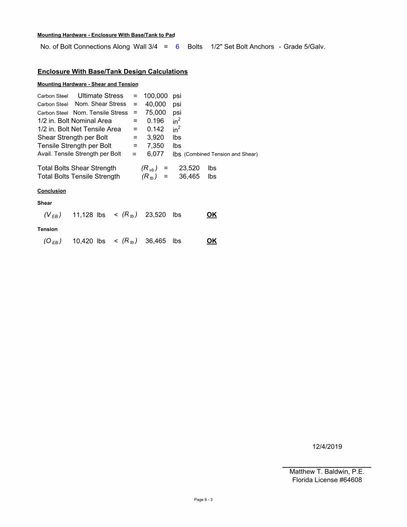
= 6 - Grade 5/Galv.
Carbon Steel = psiCarbon Steel = psiCarbon Steel = psi
= in2
= in2
= lbs= lbs= lbs (Combined Tension and Shear)
(R vb ) = lbs(R tb ) = lbs
(V EB ) 11,128 lbs < lbs
(O EB ) 10,420 lbs < lbs
12/4/2019
Matthew T. Baldwin, P.E.Florida License #64608
Tensile Strength per Bolt
75,000
Shear Strength per Bolt7,350
Enclosure With Base/Tank Design Calculations
Mounting Hardware - Enclosure With Base/Tank to Pad
Bolts
OK
Shear
23,520
No. of Bolt Connections Along 1/2" Set Bolt Anchors
OK
3,920
0.196
Tension
Total Bolts Shear Strength36,465
(R tb ) 23,520
Avail. Tensile Strength per Bolt 6,077
1/2 in. Bolt Nominal Area
Mounting Hardware - Shear and Tension
Wall 3/4
Conclusion
Total Bolts Tensile Strength
Ultimate StressNom. Shear Stress
Nom. Tensile Stress
1/2 in. Bolt Net Tensile Area 0.142
100,000
(R tb ) 36,465
40,000
Page 8 - 3