engineering fracture mechanics - wordpress.com · near-crack tip solution is known and this...
TRANSCRIPT

Engineering Fracture Mechanics 92 (2012) 19–31
Contents lists available at SciVerse ScienceDirect
Engineering Fracture Mechanics
journal homepage: www.elsevier .com/locate /engfracmech
Extended finite element method for dynamic fractureof piezo-electric materials
H. Nguyen-Vinh a,b,c, I. Bakar a,b,c, M.A. Msekh a,b,c, J.-H. Song a,b,c, J. Muthu a,b,c, G. Zi a,b,c, P. Le a,b,c,S.P.A. Bordas a,b,c,d, R. Simpson a,b,c, S. Natarajan a,b,c, T. Lahmer a,b,c, T. Rabczuk a,b,c,⇑a Department of Civil Engineering, Bauhaus University Weimar, Marienstr. 15, 99423 Weimar, Germanyb School of Mechanical, Industrial and Aeronautical Engineering, University of Witwatersrand, Johannesbuerg, South Africac Faculty of Civil Engineering, Universiti Teknologi Mara, 40450 Shah Alam, Selangor, Malaysiad Institute of Mechanics & Advanced Materials (IMAM), School of Engineering, Cardiff University, Queen’s Buildings The Parade, CARDIFF CF243AA, Waless, UK
a r t i c l e i n f o
Article history:Received 4 May 2011Received in revised form 27 December 2011Accepted 16 April 2012
Keywords:XFEMFracturePiezo-electricCracks
0013-7944/$ - see front matter � 2012 Elsevier Ltdhttp://dx.doi.org/10.1016/j.engfracmech.2012.04.025
⇑ Corresponding author at: Department of Civil EE-mail address: [email protected] (
a b s t r a c t
We present an extended finite element formulation for dynamic fracture of piezo-electricmaterials. The method is developed in the context of linear elastic fracture mechanics. It isapplied to mode I and mixed mode-fracture for quasi-steady cracks. An implicit time inte-gration scheme is exploited. The results are compared to results obtained with the bound-ary element method and show excellent agreement.
� 2012 Elsevier Ltd. All rights reserved.
1. Introduction
Piezo-electric materials are used as sensors, actuators or transducers in many engineering applications [7,8,18]. For anexample, piezo-electric materials are used as an accelerator, distance or knock-sensors in automotive industry and as sonartransducers for navigation purposes. Piezo-electric transducers are applied extensively in medical engineering for destroyingkidney stones and for plaque removal. However the limited knowledge about the fracture of these smart materials is essen-tial for their effective use, particularly for applications with high stress concentrations applications, ex: ultrasound cleaningor valve control in common-rail diesel engines [26].
Studies on fracture of piezo-electric materials are limited to static applications using linear elastic fracture mechanics(LEFMs) [29,38,41]. The influence of permeable and impermeable boundary conditions was studied by Fan and Gao [15]and Shindo et al. [37]. Fracture criteria that take the influence of the electric field into account were done by Fulton andGao [14], Gao et al. [16] and Park and Sun [30]. The fracture criterion of Park and Sun [30] agreed well with experimentalresults. Fulton and Gao [14] and Gao et al. [16] extended this criterion to non-linear effects and in [3] to fatigue cracks.
The extended finite element (XFEM) method was originally developed to model arbitrary crack growth without reme-shing [5,25]. XFEM is based on a local partition of unity (PU) enrichment. The basic idea of XFEM is the enrichment of thefinite element (FE)-interpolation with information of the analytical solution. For example, cracks will create discontinuitiesin the displacement field and therefore a discontinuous function such as the Heaviside-function or the step function is usedas an enrichment function. It is also known that in LEFM, there exists a stress singularity at the crack tip. Sometimes, thenear-crack tip solution is known and this information can be also included through the enrichment function in the
. All rights reserved.
ngineering, Bauhaus University Weimar, Marienstr. 15, 99423 Weimar, Germany.T. Rabczuk).

20 H. Nguyen-Vinh et al. / Engineering Fracture Mechanics 92 (2012) 19–31
approximation. In the general case, these functions are not known a priori, and XFEM can be use equally well with numer-ically determined enrichment functions, as, for example in [44,45,46,47,48,49]. XFEM can be considered as an extension ofthe Partition of Unity Finite Element Method (PUFEM) [24] to discontinuous problems. Meanwhile, XFEM has been extendedand applied to a variety of problems such as two-phase-flow [10,11], fluid–structure interaction [1,21,22,50,51] and thermo-mechanical problems [2] as well as moving boundary problems such as biofilm growth [52].
An XFEM-formulation for modeling the fracture of piezo-electric materials under static conditions using LEFM was pre-sented by Béchet et al. [4]. They derived novel enrichment functions around the crack tip for the displacement and for theelectric potential field. They also presented an efficient way to compute the generalized stress intensity factors. Verhooselet al. [42] proposed a multiscale approach for modeling the fracture of piezo-electric materials based on cohesive cracks.An excellent overview article on modeling fracture of piezo-electric materials is given by Kuna [20]. Alternative methodsto model intact piezo-electric materials including the Smoothed Finite Element Method (SFEM) [6,27,28] and meshfreemethods [31] were presented by various authors. Note the recent work on enriched residual free bubble for coupled advec-tion diffusion problems arising in nanoelectronics simulations [53]. Open source extended finite element codes in C++ [54]and enriched meshless method codes in MATLAB [55] are available for download.1
To our best knowledge, there are no studies concerning the dynamic behavior of piezoelectric materials using XFEMwhich are essential for utilizing smart materials for different engineering applications. In this paper, we present an extensionof the work of Béchet et al. [4] to dynamic fracture of piezoelectric materials. We have developed the method using linearelastic fracture mechanics and it is validated by comparing numerical results with boundary element method (BEM) results.
1.1. Governing equations and weak form
The governing equations for the coupled electro-mechanical problem are given in weak form: Find u 2 U 8 du 2 U0 undU 2 V 8 dU 2 V0 such thatZ Z Z Z
1 http
Xrijd�ijdX�
XbiduidX�
Ct
�tiduidC�X.€uiduidC ¼ 0 8 x 2 X ð1ÞZ
XDidEidX�
ZCq
dU�qdC ¼ 0 8 x 2 X ð2Þ
where rij is the Cauchy-stress tensor, ui the displacement field, bi the body forces, ti the traction and U the electric potential;d denotes the ‘variation’ and an overline superimposed quantities, e.g �ti is the von Neumann traction. The domain is denotedby X with boundary C, where the indices u, t,q (U), and c denote ‘displacement’, ‘traction’, ‘electric’ and ‘crack’ boundaries,respectively, see Fig. 1. The approximation of the test and trial functions is given by
U ¼ fuju 2 H1; u ¼ �u on Cu; u discontinuous on CcgU0 ¼ fdujdu 2 H1; du ¼ 0 on Cu; du discontinuous on CcgV ¼ fUjU 2 H1; U ¼ U on Cq; U discontinuous on CcgV ¼ fdUjdU 2 H1; dU ¼ 0 on Cq; dU discontinuous on Ccg ð3Þ
where H1 denotes the first Hilbert space. The compatibility conditions and the constitutive model are imposed in strongform by
�ij ¼ 1=2ðui;j þ uj;iÞEi ¼ �U;i
rij ¼ CEijkl�kl � ekijEk
Di ¼ eikl�kl þ j�ikEk ð4Þ
where �ij is the strain tensor derived from the displacement field ui, Ei is the electric field depending on the electric potentialU;CE
ijkl is the first-order elasticity tensor, j�ik is the dielectric Tensor and ekij is the piezo-electric tensor.
2. XFEM for piezo-electric materials
The approximation of the displacement field in the XFEM [5,25,39,40] is given by
uhðxÞ ¼XI2S
NIðxÞuI þXnc
N¼1
XI2Sc
NIðxÞwðNÞI aðNÞI þXmt
M¼1
XI2St
NIðxÞXNK
K¼1
/ðMÞKI bðMÞKI ð5Þ
and in matrix form:
uhðXÞ ¼ NDþ eN eD þ bN bD ð6Þ
://cmechanicsos.users.sourceforge.net/.
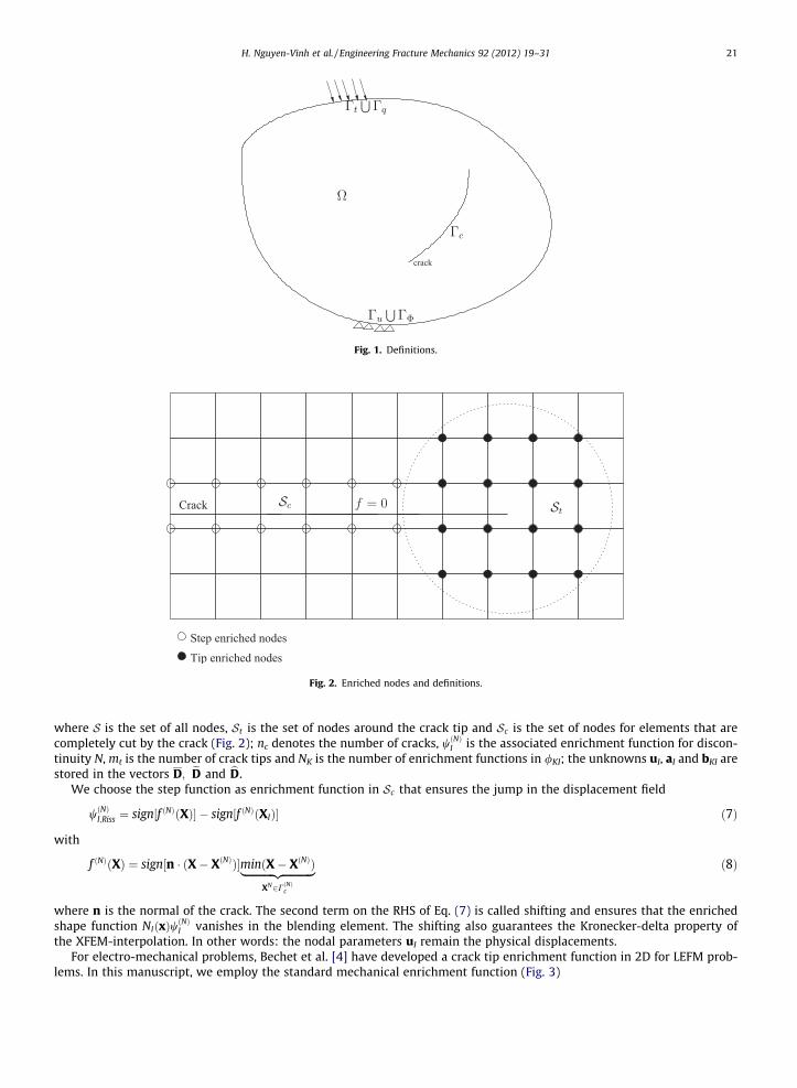
Fig. 2. Enriched nodes and definitions.
Fig. 1. Definitions.
H. Nguyen-Vinh et al. / Engineering Fracture Mechanics 92 (2012) 19–31 21
where S is the set of all nodes, St is the set of nodes around the crack tip and Sc is the set of nodes for elements that arecompletely cut by the crack (Fig. 2); nc denotes the number of cracks, wðNÞI is the associated enrichment function for discon-tinuity N, mt is the number of crack tips and NK is the number of enrichment functions in /KI; the unknowns uI, aI and bKI arestored in the vectors D; eD and bD.
We choose the step function as enrichment function in Sc that ensures the jump in the displacement field
wðNÞI;Riss ¼ sign½f ðNÞðXÞ� � sign½f ðNÞðXIÞ� ð7Þ
with
f ðNÞðXÞ ¼ sign½n � ðX� XðNÞÞ�minðX� XðNÞÞ|fflfflfflfflfflfflfflfflfflfflffl{zfflfflfflfflfflfflfflfflfflfflffl}XN2CðNÞc
ð8Þ
where n is the normal of the crack. The second term on the RHS of Eq. (7) is called shifting and ensures that the enrichedshape function NIðxÞwðNÞI vanishes in the blending element. The shifting also guarantees the Kronecker-delta property ofthe XFEM-interpolation. In other words: the nodal parameters uI remain the physical displacements.
For electro-mechanical problems, Bechet et al. [4] have developed a crack tip enrichment function in 2D for LEFM prob-lems. In this manuscript, we employ the standard mechanical enrichment function (Fig. 3)

Fig. 3. Definitions for the crack tip enrichment.
22 H. Nguyen-Vinh et al. / Engineering Fracture Mechanics 92 (2012) 19–31
/mechKI ¼
ffiffiffirp
sinh2;ffiffiffirp
cosh2;ffiffiffirp
sinh2
sinh;ffiffiffirp
cosh2
sinh
� �ð9Þ
and the electro-mechanical enrichment that has the form
/piezoKI ¼
ffiffiffirp
f1ðhÞ;ffiffiffirp
f2ðhÞ;ffiffiffirp
f3ðhÞ;ffiffiffirp
f4ðhÞ;ffiffiffirp
f5ðhÞ;ffiffiffirp
f6ðhÞ� �
ð10Þ
as proposed by Béchet et al. [4]; more details on the complex enrichment functions fi (i = 1, . . . ,6) are given in [4]. The struc-ture of the test-functions is similar:
duhðXÞ ¼ NdDþ eNdeD þ bNdbD ð11Þ
The approximation of the electric potential is similar to the approximation of the displacement field:
UhðxÞ ¼XI2S
NIðxÞUI þXnc
N¼1
XI2Sc
NIðxÞwðNÞI aðNÞI þXmt
M¼1
XI2St
NIðxÞXNK
K¼1
/ðMÞKI bðMÞKI ð12Þ
or in matrix form
UhðXÞ ¼ NUþ eN eU þ bN bU ð13Þ
where the unknown UI;aðNÞI and bðMÞKI are stored in the vectors U; eU and bU. The approximation of the test function reads:
dUhðXÞ ¼ NdUþ eNd eU þ bNd bU ð14Þ
The spatial derivatives of the trial functions are obtained by formal differentiation
ruhðxÞ¼XI2SrNIðxÞ|fflfflfflffl{zfflfflfflffl}
B
uIþXnc
N¼1
XI2Sc
rNIðxÞwðNÞI þNIðxÞrwðNÞI
� |fflfflfflfflfflfflfflfflfflfflfflfflfflfflfflfflfflfflfflfflfflfflfflfflffl{zfflfflfflfflfflfflfflfflfflfflfflfflfflfflfflfflfflfflfflfflfflfflfflfflffl}eB
aðNÞI þXmt
M¼1
XI2St
rNIðxÞXNK
K¼1/ðMÞKI þNIðxÞ
XNK
K¼1r/ðMÞKI
� |fflfflfflfflfflfflfflfflfflfflfflfflfflfflfflfflfflfflfflfflfflfflfflfflfflfflfflfflfflfflfflfflfflfflfflfflfflfflffl{zfflfflfflfflfflfflfflfflfflfflfflfflfflfflfflfflfflfflfflfflfflfflfflfflfflfflfflfflfflfflfflfflfflfflfflfflfflfflffl}bB
bðMÞKI
E¼rUhðxÞ¼XI2SrNIðxÞ|fflfflfflffl{zfflfflfflffl}
B
UIþXnc
N¼1
XI2Sc
rNIðxÞwðNÞI þNIðxÞrwðNÞI
� |fflfflfflfflfflfflfflfflfflfflfflfflfflfflfflfflfflfflfflfflfflfflfflfflffl{zfflfflfflfflfflfflfflfflfflfflfflfflfflfflfflfflfflfflfflfflfflfflfflfflffl}eB
aðNÞI þXmt
M¼1
XI2St
rNIðxÞXNK
K¼1/ðMÞKI þNIðxÞ
XNK
K¼1r/ðMÞKI
� |fflfflfflfflfflfflfflfflfflfflfflfflfflfflfflfflfflfflfflfflfflfflfflfflfflfflfflfflfflfflfflfflfflfflfflfflfflfflffl{zfflfflfflfflfflfflfflfflfflfflfflfflfflfflfflfflfflfflfflfflfflfflfflfflfflfflfflfflfflfflfflfflfflfflfflfflfflfflffl}bB
bðMÞKI ð15Þ
that can be given in matrix form by
ruhðXÞ ¼ B Dþ eB eD þ bB bDE ¼ BUþ eB eU þ bB bU ð16Þ
Similarly, we obtain the derivatives of the test functions:
rduhðXÞ ¼ BdDþ eBdeD þ bBdbDdE ¼ BdUþ eBd eU þ bBd bU ð17Þ
3. Discrete equations
The discrete equations are obtained by substituting the approximations of the test and trial-functions, Eqs. (6), (11), (13)and (14), and their derivatives, Eqs. (16) and (17), into the weak form, Eqs. (1) and (2). With the compatibility condition andthe constitutive model, Eq. (4), we obtain

H. Nguyen-Vinh et al. / Engineering Fracture Mechanics 92 (2012) 19–31 23
Xnumele
e¼1
ZXðeÞð½BdDþ eBdeD þ bBdbD�symÞT ½CEðB Dþ eB eD þ bB bDÞsym � eðBUþ eB eU þ bB bUÞ�dX
�Xnumele
e¼1
ZXðeÞ½NdDþ eNdeD þ bNdbD�TbdX�
Xnumrandt
e¼1
ZCðeÞt
½NdDþ eNdeD þ bNdbD�T�tdC
�Xnumele
e¼1
ZXðeÞ
.½NdDþ eNdeD þ bNdbD�T½N€Dþ eN e€D þ bN b€D�dX ¼ 0
Xnumele
e¼1
½BdUþ eBd eU þ bBd bU�T½eðB Dþ eB eD þ bB bDÞsym þ jðBUþ eB eU þ bB bUÞ�dX
�Xnumrandq
e¼1
ZCðeÞq
½NdUþ eNd eU þ bNd bU�TqdC ¼ 0 ð18Þ
where numele is the number of elements in the domain X and numrandt and numrandq are the number of boundary elementsin Ct, Cq, respectively; sym denotes the symmetric part of a tensor. Defining
D ¼ ½D; eD; bD;U; eU; bU�TdD ¼ ½dD; deD; dbD; dU; d eU; d bU�T ð19Þ
and factoring out the nodal parameters of the test functions gives after some algebra the final (semi-) discrete system ofequations:
dDðM€Dþ C _Dþ KD� FÞ ¼ 0 ð20Þ
with
M ¼Mmm 0
0 0
� �; C ¼
Cmm Cme
Cem Cee
� �; K ¼
Kmm Kme
Kem Kee
� �ð21Þ
and the following sub-matrices for the mass
Mmm ¼Muu
mm Muamm Mub
mm
Maumm Maa
mm Mabmm
Mbumm Mba
mm Mbbmm
26643775 ð22Þ
the stiffness
Kij ¼Kuu
ij Kuaij Kub
ij
Kauij Kaa
ij Kabij
Kbuij Kba
ij Kbbij
26643775; i; j ¼ m; e ð23Þ
and
Muumm ¼
ZX.NINJdX
Muamm ¼
ZX.NIw
ðNÞJ NJdX ¼Mau
Mubmm ¼
ZX.NIU
ðMÞK NJdX ¼Mbu
mm
Maamm ¼
ZX.NIw
ðNÞI NJw
ðNÞJ dX
Mabmm ¼
ZX.NIU
ðMÞK NJw
ðNÞJ dX ¼Mba
mm
Mbbmm ¼
ZX.NIU
ðMÞK NJU
ðMÞK dX ð24Þ

24 H. Nguyen-Vinh et al. / Engineering Fracture Mechanics 92 (2012) 19–31
Kuumm ¼
ZX
BICBJdX
Kuamm ¼
ZX
BICBJwðNÞJ dX ¼ Kau
mm
Kubmm ¼
ZX
BICBJUðMÞK dX ¼ Kbu
mm
Kaamm ¼
ZX
wðNÞI BICBJwðNÞJ dX
Kabmm ¼
ZX
wðNÞI BICBJUðMÞK dX ¼ Kba
mm
Kbbmm ¼
ZX
UðMÞK BICBJUðMÞK dX ð25Þ
Kuume ¼
ZX
BIeBJdX
Kuame ¼
ZX
BIeBJwðNÞJ dX ¼ Kau
mm
Kubme ¼
ZX
BIeBJUðMÞK dX ¼ Kbu
mm
Kaame ¼
ZX
wðNÞI BIeBJwðNÞJ dX
Kabme ¼
ZX
wðNÞI BIeBJUðMÞK dX ¼ Kba
mm
Kbbme ¼
ZX
UðMÞK BIeBJUðMÞK dX ð26Þ
Kuuem ¼
ZX
BIeBJdX
Kuaem ¼
ZX
BIeBJwðNÞJ dX ¼ Kau
mm
Kubem ¼
ZX
BIeBJUðMÞK dX ¼ Kbu
mm
Kaaem ¼
ZX
wðNÞI BIeBJwðNÞJ dX
Kabem ¼
ZX
wðNÞI BIeBJUðMÞK dX ¼ Kba
mm
Kbbem ¼
ZX
UðMÞK BIeBJUðMÞK dX ð27Þ
Kuuee ¼
ZX
BIjBJdX
Kuaee ¼
ZX
BIjBJwðNÞJ dX ¼ Kau
mm
Kubee ¼
ZX
BIjBJUðMÞK dX ¼ Kbu
mm
Kaaee ¼
ZX
wðNÞI BIjBJwðNÞJ dX
Kabee ¼
ZX
wðNÞI BIjBJUðMÞK dX ¼ Kba
mm
Kbbee ¼
ZX
UðMÞK BIjBJUðMÞK dX ð28Þ
where the superimposed indices e and m indicate electrical and mechanical quantities, superscript u, a and b refer to ‘usual’,‘step-enriched’ and ‘tip-enriched’ nodes and capital indices refer to node numbers. For many applications, it is sufficient toneglect the coupled damping terms and the electrical damping Cme, Cem and Cee, but instead use only the mechanical Ray-leigh-damping [23]:
Cmm ¼ cKmm þ hMmm ð29Þ
H. Nguyen-Vinh et al. / Engineering Fracture Mechanics 92 (2012) 19–31 25
The semi-discrete equations are integrated in time using the implicit b-Newmark scheme. More details regarding time inte-gration in XFEM are given by Cavin et al. [9], Combescure et al. [12], Réthoré et al. [35,36].
4. Computation of the stress intensity factors
The stress intensity factors (SIFs) can be evaluated through the displacement field and the electrical field or the crackopening displacement, for a discussion see De Luycker et al. [13], Garcia-Sanchez et al. [17], Wünsche et al. [43]. Alterna-tively, they can be obtained through the J-integral or the interaction integral. For a piezo-electric material, the domain formof the dynamic J-integral can be written as
J ¼Z
AðCÞrij
@ui
@x1þ Dj
@U@x1� Hd1j
�@q@xj
dAþZ
AðCÞ
q €ui@ui
@x1� q _ui
@ui
@x1
�qdA ð30Þ
where H is the electric enthalpy density for electromechanical loading, q is a smooth function chosen to be unity at the cracktip and nj is the jth component of the outward unit vector normal to an arbitrary contour C enclosing the crack tip. For linearpiezoelectric solids under mixed-mode loading conditions, the relation of the stress intensity factors (SIFs) and the J-integralcan be written as [19]
J ¼ 12
KT YK ð31Þ
where K = (KII KI KIII KIV) is the vector of the four field intensity factors, and Y is the Irwin matrix for piezo-electric materials:
Y ¼
Y11 Y12 Y13 Y14
Y21 Y22 Y23 0Y31 Y32 Y33 0Y41 0 0 Y44
2666437775 ð32Þ
The Irwin matrix is basically derived from the constitute relationship with the boundary conditions �ti ¼ 0 and niDi = 0 on Cc.The left upper 3 � 3 matrix refers to the mechanical behavior of the piezo-electric material, Y44 is related to the permittivityand Y14 = Y41 to the piezo-electricity. More details can be found in the excellent paper by Suo et al. [41].
The stress intensity factors KI, KII and KIII refer to the crack opening mode, crack sliding mode and tearing mode, respec-tively. The SIF KIV, also called the electric displacement intensity factor, characterizes the concentration of the electrical dis-placement fields. Note that in a two-dimensional setting, the SIF KIII vanishes.
The drawback of the J-integral is that it can only be converted into single mode stress intensity factors. However, the crackis generally subjected to a mixed mode loading conditions with an additional electrical mode IV. A possibility in overcomingthe limitation is given by the interaction integral method which is based on two load cases: (1) defines the actual loading ofthe structure and is assumed to be an auxiliary fields on the entire domain and (2) represents the electromechanical loadingalong a vanishingly small contour around the crack tip. The interaction integral for a homogeneous piezoelectric material isdefined as [34]
Ið1;2Þ ¼Z
AðCÞ
rð1Þij
@uð2Þi
@x1þ Dð1Þj
@Uð2Þ
@x1þ rð2Þij
@uð1Þi
@x1þ Dð2Þj
@Uð1Þ
@x1� Hð1;2Þd1j
!@q@xj
dA
þZ
AðCÞ
.€uð1Þi
@uð2Þi
@x1� . _uð1Þi
@uð2Þi
@x1þ .€uð2Þi
@uð1Þi
@x1� . _uð2Þi
@uð1Þi
@x1
!qdA ð33Þ
with
Hð1;2Þ ¼rð1Þij �
ð2Þij þ rð2Þij �
ð1Þij � Dð1Þj Eð2Þj � Dð2Þj Eð1Þj
2ð34Þ
The stress intensity factor can be defined as
Ið1;2Þ ¼ Kð1ÞII Kð2ÞII Y11 þ Kð1ÞI Kð2ÞI Y22 þ Kð1ÞIV Kð2ÞIV Y44 þ Kð1ÞI Kð2ÞII þ Kð1ÞII Kð2ÞI
� Y12 þ Kð1ÞII Kð2ÞIV þ Kð1ÞIV Kð2ÞII
� Y14
þ Kð1ÞI Kð2ÞIV þ Kð1ÞIV Kð2ÞI
� Y24 ð35Þ
The SIFs are then obtained by judiciously choosing the auxiliary state in a way that two SIFs vanish and one is set to 1. Moredetails are found in the excellent paper by Rao and Kuna [34].
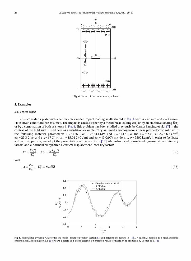
Fig. 4. Set up of the center crack problem.
26 H. Nguyen-Vinh et al. / Engineering Fracture Mechanics 92 (2012) 19–31
5. Examples
5.1. Center crack
Let us consider a plate with a center crack under impact loading as illustrated in Fig. 4 with h = 40 mm and a = 2.4 mm.Plain strain conditions are assumed. The impact is caused either by a mechanical loading �rðtÞ or by an electrical loading DðtÞor by a combination of both as shown in Fig. 4. This problem has been studied previously by Garcia-Sanchez et al. [17] in thecontext of the BEM and is used here as a validation example. They assumed a homogeneous linear piezo-electric solid withthe following material parameters: C11 = 126 GPa; C12 = 84.1 GPa and C22 = 117 GPa and C66 = 23 GPa; e21 = 6.5 C/m2,e22 = 23.3 C/m2 and e16 = 17 C/m2; j11 = 15.04 C/(GV m) and e22 = 13 C/(GV m); density . = 7500 kg/m3. In order to facilitatea direct comparison, we adopt the presentation of the results in [17] who introduced normalized dynamic stress intensityfactors and a normalized dynamic electrical displacement intensity factor:
Fig. 5.enriche
K�I ¼KIðtÞKst
I
; K�IV ¼ KKIV ðtÞ
KstIV
ð36Þ
with
K ¼ e22
j22; Kst
I ¼ r0ffiffiffiffiffiffipap
ð37Þ
Normalized dynamic KI factor for the mode I-fracture problem Section 5.1 compared to the results in [17], k = 1; XFEM-m refers to a mechanical tipd XFEM formulation, Eq. (9); XFEM-p refers to a ‘piezo-electric’ tip enriched XFEM formulation as proposed by Bechet et al. [4].

Fig. 6. Normalized dynamic KIV factor for the mode I-fracture problem Section 5.1 compared to the results in [17], k = 1; XFEM-m refers to a mechanical tipenriched XFEM formulation, Eq. (9); XFEM-p refers to a ‘piezo-electric’ tip enriched XFEM formulation as proposed by Bechet et al. [4].
H. Nguyen-Vinh et al. / Engineering Fracture Mechanics 92 (2012) 19–31 27
Moreover, the ratio between electric impact and mechanical impact is defined as
k ¼ KD22
r22ð38Þ
The plate is discretized with different refinements on Cartesian grids using standard 4-node elements starting from approx-imately 1500 elements up to almost 12,000 (155 � 76) elements. At least 77 � 38 elements were needed in order to obtainconvergent results. Afterwards, the results were very similar. As an analytical solution is not available and therefore a thor-ough convergence study cannot be performed, we present only the results for 77 � 38 elements in this manuscript. We alsoensured that the time step has no critical influence on the numerical results. Though it would reduce computational costs, nosymmetry conditions have been used.
Figs. 5 and 6 compare the results obtained with XFEM to the results of the BEM obtained in [17]. Therefore, we haveadopted the illustration from Garcia-Sanchez et al. [17] and presented the results in normalized form where cL is the longi-tudinal wave speed. The results agree reasonably well. The results of XFEM with pure ‘mechanical’ tip enrichment (XFEM-m),Eq. (9), are also compared with the results of an XFEM-formulation using the enrichment proposed by Bechet et al. [4](XFEM-p). There are only minor differences in the results. We note that the key advantage of XFEM is its ability to modelcrack growth without re-meshing. This capability can also be used in the context of inverse analysis where the detectionof cracks or inclusions in piezo-electric materials is of interest. However, in this manuscript, our main goal is to develop adynamics XFEM-formulation for stationary cracks.
Fig. 7 shows the influence of the electrical impact intensity on the results. For dynamic problems, the dynamic stressintensity factor is larger than the static stress intensity factor. It can also be seen that an electric impact can cause negativevalues of the dynamic stress intensity factor. The maximum values of the normalized dynamic stress intensity factor is re-duced with increasing k-value, i.e. increasing influence of electrical impact. Fig. 8 shows the results for a pure electrical im-pact when the direction of impact is reversed. The magnitudes of the normalized dynamic stress intensity factor remain thesame but the signs change, meaning that change in the direction of the impact does not cause the absolute value of the dy-namic stress intensity factor to change.
Fig. 7. Normalized dynamic KI factor for the mode I-fracture problem Section 5.1 for different k-values.

Fig. 8. Effect of the direction of electrical impact on the normalized dynamic KI-factor for the mode I-fracture problem Section 5.1.
Fig. 9. Set up of the slanter crack problem.
Fig. 10. Normalized dynamic KI factor for the slanted crack problem for different k-values.
28 H. Nguyen-Vinh et al. / Engineering Fracture Mechanics 92 (2012) 19–31
5.2. Slanted crack
The last example was also extracted from Garcia-Sanchez et al. [17]. Therefore, consider a homogeneous and linear piezo-electric specimen that contains a slanted crack as shown in Fig. 9 with h = 22 mm, w = 32 mm, c = 6 mm and a = 22.63 mm.Plain strain conditions are assumed and the material parameters from the previous section are used. We tested again differ-ent refinements as in the previous example and achieved convergence with 4000 elements, which agrees well with the

Fig. 11. Normalized dynamic KI factor for the slanted crack problem for different k-values. Comparison between XFEM with pure ‘mechanical’ tipenrichment, Eq. (9), XFEM-m versus XFEM with ‘piezo-electric’ tip enrichment [4], XFEM-p.
Fig. 12. Normalized dynamic KII factor for the slanted crack problem for different k-values.
Fig. 13. Normalized dynamic KII factor for the slanted crack problem for different k-values. Comparison between XFEM with pure ‘mechanical’ tipenrichment, Eq. (9), XFEM-m versus XFEM with ‘piezo-electric’ tip enrichment [4], XFEM-p.
H. Nguyen-Vinh et al. / Engineering Fracture Mechanics 92 (2012) 19–31 29
previous results. Therefore, we present only results of a discretization with 75 � 54(=4050) elements and compare those tothe BEM results presented in Garcia-Sanchez et al. [17].
Fig. 10 shows the normalized dynamic stress intensity factor KI for different values of k. The results agree well with thoseobtained in Garcia-Sanchez et al. [17]. The same observations are made when comparisons are done with the normalizeddynamic stress intensity factor KII, Fig. 12. Comparisons between different tip-enrichments (XFEM-m versus XFEM-p) are

30 H. Nguyen-Vinh et al. / Engineering Fracture Mechanics 92 (2012) 19–31
illustrated in Figs. 11 and 13. The differences are minor. One can also observe that the electrical impact has in general a ‘po-sitive’ effect on the normalized dynamic stress intensity factor. In other words, both, K�I as well as K�II decrease with increas-ing k.
6. Conclusion
We have presented an extended finite element method for dynamic fracture of piezo-electric materials. The method ex-ploits the partition of unity enrichment and therefore allows crack propagation without remeshing. It can be considered asan extension of the method by Bechet et al. [4] to dynamics. The b-Newmark implicit time integration scheme is adopted.
We have tested different crack tip enrichment functions, i.e. the pure mechanical enrichment function and the more com-plex enrichment function from Bechet et al. [4] for piezo-electric materials. We found that the results differ only slightlywhen the more complex enrichment functions from Bechet et al. [4] are used. However it is not possible to make a generalstatement regarding the accuracy as there are no analytical solutions for dynamic problems of piezo-electric materials.
The method was applied to two examples with mechanical and electrical boundary conditions, that concern with quasi-steady cracks. Since no analytical results are available for dynamic fracture problems of piezo-electric materials, the XFEMresults were compared to results obtained by the BEM [17] and they show excellent agreement.
In the future, we will extend the method to non-linear materials involving cohesive cracks and inverse problems, i.e. todetect inclusions and cracks in piezo-electric materials. XFEM seems to be ideally suited for inverse problems as shown by[32,33].
Acknowledgement
The support of the German Research Foundation (DFG), Project No. RA 1946/10-1 is gratefully acknowledged.
References
[1] Zilian A, Legay A. The enriched space–time finite element method (est) for simultaneous solution of fluid–structure interaction. Int J Numer MethodsEng 2008;75:305–34.
[2] Areias PMA, Belytschko T. Two-scale method for shear bands: thermal effects and variable bandwidth. Int J Numer Methods Eng 2007;72:658–96.[3] Arias I, Serebrinsky S, Ortiz M. A phenomenological cohesive model of ferroelectric fatigue. Acta Mater 2006;54:975–84.[4] Bechet E, Scherzer M, Kuna M. Application of the X-FEM to the fracture of piezoelectric materials. Int J Numer Methods Eng 2009;77:1535–65.[5] Belytschko T, Black T. Elastic crack growth in finite elements with minimal remeshing. Int J Numer Methods Eng 1999;45(5):601–20.[6] Bordas S, Rabczuk T, Nguyen-Xuan H, Nguyen VP, Natarajan S, Bog T, et al. Strain smoothing in FEM and XFEM. Comput Struct 2010;88(23–
24):1419–43.[7] Cady WG. Piezoelectricity – an introduction to the theory and applications of electromechanical phenomena in crystals, vol. 1. Dover Publications, Inc.;
1964.[8] Cady WG. Piezoelectricity – an introduction to the theory and applications of electromechanical phenomena in crystals, vol. 2. Dover Publications, Inc.;
1964.[9] Cavin P, Gravouil A, Lubrecht AA, Combescure A. Automatic energy conserving space–time refinement for linear dynamic structural problems. Int J
Numer Methods Eng 2005.[10] Chessa J, Belytschko T. An enriched finite element method and level sets for axisymmetric two-phase flow with surface tension. Int J Numer Methods
Eng 2003;58(13):2041–64.[11] Chessa J, Belytschko T. An extended finite element method for two-phase fluids. ASME J Appl Mech 2003;70:1017.[12] Combescure A, Gravouil A, Gregoire D, Réthoré J. X-FEM a good candidate for energy conservation in simulation of brittle dynamic crack propagation.
Comput Methods Appl Mech Eng; 2007.[13] De Luycker E, Benson DJ, Belytschko T, Bazilevs Y, Hsu MC. X-FEMIN isogeometric analysis for linear fracture mechanics. Int J Numer Methods Eng; in
press.[14] Fulton CC, Gao HJ. Electrical nonlinearity in fracture of piezoelectric ceramics. Appl Mech Rev 1997;50:5663.[15] Fan WX, Gao CF. Exact solutions for the plane problem in piezoelectric materials with an elliptic or a crack. Int J Solids Struct 1999;36:2527–40.[16] Gao H, Zhang TY, Tong P. Local and global energy release rates for an electrically yielded crack in a piezoelectric ceramic. J Mech Phys Solids
1997;45:491–510.[17] Garcia-Sanchez F, Zhang C, Saez A. 2-d transient dynamic analysis of cracked piezoelectric solids by a time-domain BEM. Comput Methods Appl Mech
Eng 2008;197:3108–21.[18] Ikeda T. Fundamentals of piezoelectricity. Oxford University Press; 1990.[19] Kuna M. Finite element analyses of cracks in piezoelectric structures: a survey. Arch Appl Mech 2006;76:725–45.[20] Kuna M. Fracture mechanics of piezoelectric materials where are we right now? Eng Fract Mech 2010;77:309–26.[21] Legay A, Chessa J, Belytschko T. An Eulerian–Lagrangian method for fluid–structure interaction based on level sets. Comput Methods Appl Mech Eng
2006;95(17–18):2070–87.[22] Legay A, Wang HW, Belytschko T. Strong and weak discontinuities in spectral finite elements. Int J Numer Methods Eng 2005;64:991–1008.[23] Lerch R. Simulation of piezoelectric devices by two- and three-dimensional finite elements. IEEE Trans Ultrason Ferroelectr Freq Control
1990;37(3):233–47. ISSN 0885-3010.[24] Melenk JM, Babuška I. The partition of unity finite element method: basic theory and applications. Comput Methods Appl Mech Eng 1996;139(1–
4):289–314. ISSN 0045-7825.[25] Moes N, Dolbow J, Belytschko T. A finite element method for crack growth without remeshing. Int J Numer Methods Eng 1999;46(1):133–50.[26] Namhoon C, Sunwoo K. Nonlinear modeling and injection rate estimation of common rail injectors for direct injection diesel engines. Trans Soc
Automot Eng Jpn 2006;37(1):49–54.[27] Nguyen-Xuan H, Liu GR, Nguyen-Thoi T, Nguyen Tran C. An edge based smoothed finite element method (ES-FEM) for analysis of twodimensional
piezoelectric structures. J Smart Mater Struct 2009;18:065015.[28] Nguyen-Xuan H, Nguyen-Thoi T, Tran Loc V. Analysis of functionally graded plates using an edge-based smoothed finite element method. Compos
Struct 2011;93:3019–39.[29] Pak YE. Linear electro-elastic fracture mechanics of piezoelectric materials. Int J Fract 1992;54:79100.

H. Nguyen-Vinh et al. / Engineering Fracture Mechanics 92 (2012) 19–31 31
[30] Park SB, Sun CT. Fracture criteria for piezoelectric ceramics. J Am Ceram Soc 1995;78:1475–80.[31] Rabczuk T, Zi G, Bordas S, Nguyen-Xuan H. A simple and robust three dimensional cracking-particle method without enrichment. Comput Methods
Appl Mech Eng 2010;199(37-40):2437–55.[32] Rabinovich D, Givoli D, Vigdergauz S. XFEM-based crack detection scheme using a genetic algorithm. Int J Numer Methods Eng 2007;71:1051–80.[33] Rabinovich D, Givoli D, Vigdergauz S. Crack identification by arrival time using XFEM and a genetic algorithm. Int J Numer Methods Eng
2009;77:337–59.[34] Rao BN, Kuna M. Interaction integrals for fracture analysis of functionally graded piezoelectric materials. Int J Solids Struct 2008;4:5237–57.[35] Réthoré J, Gravouil A, Combescure A. A combined space–time extended finite element method. Int J Numer Methods Eng 2005.[36] Réthoré J, Gravouil A, Combescure A. An energy-conserving scheme for dynamic crack growth using the extended finite element method. Int J Numer
Methods Eng 2005.[37] Shindo Y, Tanaka K, Narita F. Singular stress and electric fields of a piezoelectric ceramic strip with a finite crack under longitudinal shear. Acta Mech
1997;120:3145.[38] Sosa HA. On the fracture mechanics of piezoelectric solids. Int J Solids Struct 1992;29:2613–22.[39] Strouboulis T, Babuška I, Copps K. The design and analysis of the generalized finite element method. Int J Numer Methods Eng 2000;181:43–69.[40] Strouboulis T, Copps K, Babuška I. The generalized finite element method: an example of its implementation and illustration of its performance. Int J
Numer Methods Eng 2000;47(8):1401–17.[41] Suo Z, Kuo CM, Barnett DM, Willis JR. Fracture mechanics for piezoelectric ceramics. J Mech Phys Solids 1992;40:739–65.[42] Verhoosel CV, Remmers JJC, Gutierrez MA. A partition of unity-based multiscale approach for modelling fracture in piezoelectric ceramics. Int J Numer
Methods Eng. http://dx.doi.org/10.1002/nme.2792.[43] Wünsche M, Garcia-Sanchez F, Saez A, Zhang Ch. A 2d time-domain collocation-Galerkin BEM for dynamic crack analysis in piezo electric solids. Eng
Anal Bound Elem 2010;45:377–87.[44] Menk A, Bordas S. Numerically determined enrichment functions for the extended finite element method and their application to polycrystalline
structures. Int J Numer Meth Eng 2010;83(7):805–28.[45] Menk A, Bordas S. Crack growth calculations in solder joints based on microstructural phenomena with X-FEM. Comp Mater Sci 2010;50(3):1145–56.[46] Menk A, Bordas S. Influence of the microstructure on the stress state of solder joints during thermal cycling. In 10th International Conference on
Thermal, Mechanical and Multi-Physics simulation and Experiments in Microelectronics and Microsystems, 2009. EuroSimE 2009, pages 1–5, 2009.[47] Rabczuk T, Bordas S, Zi G. On three-dimensional modelling of crack growth using partition of unity methods. Comput Struct 2010;88(23–
24):1391–411.[48] Natarajan S, Baiz PM, Bordas S, Rabczuk T, Kerfriden P. Natural frequencies of cracked functionally graded material plates by the extended finite
element method. Comp Struct 2011;93(11):3082–92.[49] Bordas S, Natarajan S, Dal Pont S, Rabczuk T, Kerfriden P, Mahapatra DR, et al. On the performance of strain smoothing for enriched finite element
approximations (XFEM/GFEM/PUFEM). Int J Numer Meth Eng 2011;86(4-5):637–66.[50] Rabczuk T, Gracie R, Song JH, Belytschko T. Immersed particle method for fluid structure interaction. Int J Numer Meth Eng 2010;81(1):48–71.[51] Rabczuk T, Areias PMA, Belytschko T. A meshfree thin shell method for nonlinear dynamic fracture. Int J Numer Meth Eng 2007;72(5):524–48.[52] Duddu R, Bordas S, Moran B, Chopp D. A combined extended finite element and level set method for biofilm growth. Int Journal Numer Meth Eng
2008;74:848–70.[53] Simpson RN, Bordas S, Asenov A, Brown AR. Enriched residual free bubbles for semiconductor device simulation. Comput Mech 2012:1–15. http://
www.springerlink.com/content/b7vvq5415w675670/.[54] Bordas S, Nguyen PV, Dunant C, Guidoum A, Nguyen-Dang H. An extended finite element library. Int J Numer Meth Eng 2007;71(6):703–32.[55] Nguyen VP, Rabczuk T, Bordas S, Duflot M. Meshless methods: review and key computer implementation aspects. Math Comput Simulat
2008;79:763–813. http://dx.doi.org/10.1016/j.matcom.2008.01.003.