fracture and frictional mechanics: theorysioviz.ucsd.edu/~fialko/assets/pdf/fialko_treatise15.pdfthe...
TRANSCRIPT
Tre
4.03 Fracture and Frictional Mechanics: TheoryY Fialko, University of California San Diego, La Jolla, CA, USA
ã 2015 Elsevier B.V. All rights reserved.
4.03.1 Introduction 744.03.2 Linear Elastic Fracture Mechanics 744.03.2.1 Singular Crack Models 754.03.2.2 Planar Breakdown Zone Models 754.03.3 The Governing Equations 774.03.4 Exact Solutions for Quasistatic Two-Dimensional Planar Cracks 774.03.5 Shear Cracks Governed by Rate-and-State Friction Laws 804.03.6 Dynamic Effects 814.03.7 Fracture Energy 834.03.8 Coupling between Elastodynamics and Shear Heating 854.03.9 Conclusions 88Acknowledgments 89References 89
Nomenclaturee Small distance
D Average fault slip
fij(q) Azimuthal dependence of a near-tip stress
field
T̂ Temperature scale
w Nondimensional width of the fault
slip zone
sij0 Stress tensor prior to crack propagation
sij1 Stress tensor after crack propagation
A Rupture area
c Specific heat
D(x) Fault slip
Dc Critical weakening displacement
Dm Maximum coseismic displacement
F Half-length of a developed part of a crack
on which friction has dropped to a
residual level sdfi Body force
fs Coefficient of static friction
G Release rate of mechanical energy (per
unit crack length)
Gc Effective fracture energy (per unit crack
length)
ℑ Imaginary part of a complex argument
K Stress intensity factor
Kc Critical stress intensity factor, fracture
toughness
L Crack half-length or full length of a self-
healing pulse
L* Dynamic pulse length
Lc Critical crack length
M0 Scalar seismic moment
p Pore fluid pressure
Q Rate of heat generation
R Length of the process zone at the crack tip
r Distance to the crack tip
atise on Geophysics, Se
cond Edition http://dx.doi.org/10.1016/B978-0-444-538ℜ Real part of a complex argument
R* Dynamic length of the process zone at the
crack tip
r0 Effective radius of the crack tip
S Minor axis of an elliptical cavity
Sf Boundary between elastically and
inelastically deforming materials
T Temperature
t Time
Ue Elastic strain energy
Uf Frictional losses
UG Fracture energy
ui Displacement vector
Ul Potential energy of remotely applied
stresses
Ur Radiated energy
Vl Limiting rupture velocity
Vp P-wave velocity
Vr Rupture velocity
Vs S-wave velocity
w Half-width of the fault slip zone
x, y, z(x1, x2, x3) Spatial coordinates
a Nondimensional factor
g Nondimensional factor
dij Kronecker delta function
DS1 Surface bounding a prospective
increment of the process zone at the crack
tip in the result of crack growth
DS2 Surface bounding a prospective
decrement of the process zone at the
crack tip in the result of crack growth
DUp Change in the potential energy
dW Work done by external forces
Ds Stress drop
eij Strain tensor
u Nondimensional temperature
k Thermal diffusivity
02-4.00071-3
73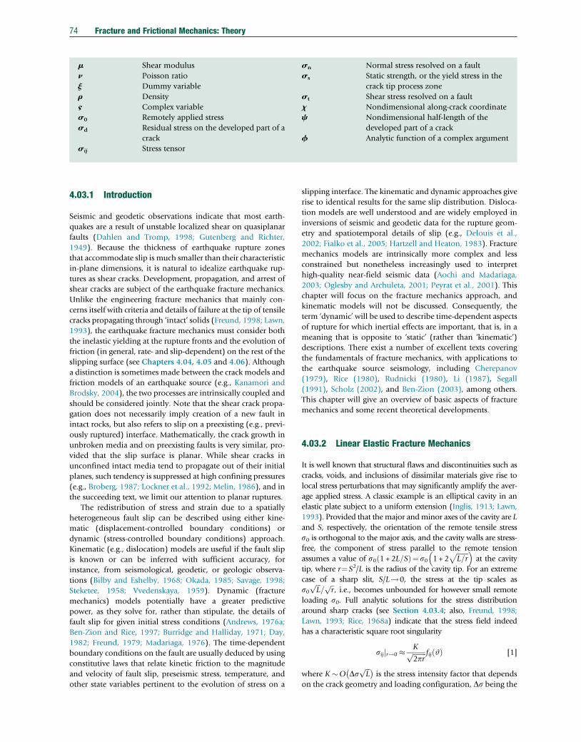
74 Fracture and Frictional Mechanics: Theory
m Shear modulus
n Poisson ratio
j Dummy variable
r Density
§ Complex variable
s0 Remotely applied stress
sd Residual stress on the developed part of a
crack
sij Stress tensor
sn Normal stress resolved on a fault
ss Static strength, or the yield stress in the
crack tip process zone
st Shear stress resolved on a fault
x Nondimensional along-crack coordinate
c Nondimensional half-length of the
developed part of a crack
f Analytic function of a complex argument
4.03.1 Introduction
Seismic and geodetic observations indicate that most earth-
quakes are a result of unstable localized shear on quasiplanar
faults (Dahlen and Tromp, 1998; Gutenberg and Richter,
1949). Because the thickness of earthquake rupture zones
that accommodate slip is much smaller than their characteristic
in-plane dimensions, it is natural to idealize earthquake rup-
tures as shear cracks. Development, propagation, and arrest of
shear cracks are subject of the earthquake fracture mechanics.
Unlike the engineering fracture mechanics that mainly con-
cerns itself with criteria and details of failure at the tip of tensile
cracks propagating through ‘intact’ solids (Freund, 1998; Lawn,
1993), the earthquake fracture mechanics must consider both
the inelastic yielding at the rupture fronts and the evolution of
friction (in general, rate- and slip-dependent) on the rest of the
slipping surface (see Chapters 4.04, 4.05 and 4.06). Although
a distinction is sometimes made between the crack models and
friction models of an earthquake source (e.g., Kanamori and
Brodsky, 2004), the two processes are intrinsically coupled and
should be considered jointly. Note that the shear crack propa-
gation does not necessarily imply creation of a new fault in
intact rocks, but also refers to slip on a preexisting (e.g., previ-
ously ruptured) interface. Mathematically, the crack growth in
unbroken media and on preexisting faults is very similar, pro-
vided that the slip surface is planar. While shear cracks in
unconfined intact media tend to propagate out of their initial
planes, such tendency is suppressed at high confining pressures
(e.g., Broberg, 1987; Lockner et al., 1992; Melin, 1986), and in
the succeeding text, we limit our attention to planar ruptures.
The redistribution of stress and strain due to a spatially
heterogeneous fault slip can be described using either kine-
matic (displacement-controlled boundary conditions) or
dynamic (stress-controlled boundary conditions) approach.
Kinematic (e.g., dislocation) models are useful if the fault slip
is known or can be inferred with sufficient accuracy, for
instance, from seismological, geodetic, or geologic observa-
tions (Bilby and Eshelby, 1968; Okada, 1985; Savage, 1998;
Steketee, 1958; Vvedenskaya, 1959). Dynamic (fracture
mechanics) models potentially have a greater predictive
power, as they solve for, rather than stipulate, the details of
fault slip for given initial stress conditions (Andrews, 1976a;
Ben-Zion and Rice, 1997; Burridge and Halliday, 1971; Day,
1982; Freund, 1979; Madariaga, 1976). The time-dependent
boundary conditions on the fault are usually deduced by using
constitutive laws that relate kinetic friction to the magnitude
and velocity of fault slip, preseismic stress, temperature, and
other state variables pertinent to the evolution of stress on a
slipping interface. The kinematic and dynamic approaches give
rise to identical results for the same slip distribution. Disloca-
tion models are well understood and are widely employed in
inversions of seismic and geodetic data for the rupture geom-
etry and spatiotemporal details of slip (e.g., Delouis et al.,
2002; Fialko et al., 2005; Hartzell and Heaton, 1983). Fracture
mechanics models are intrinsically more complex and less
constrained but nonetheless increasingly used to interpret
high-quality near-field seismic data (Aochi and Madariaga,
2003; Oglesby and Archuleta, 2001; Peyrat et al., 2001). This
chapter will focus on the fracture mechanics approach, and
kinematic models will not be discussed. Consequently, the
term ‘dynamic’ will be used to describe time-dependent aspects
of rupture for which inertial effects are important, that is, in a
meaning that is opposite to ‘static’ (rather than ‘kinematic’)
descriptions. There exist a number of excellent texts covering
the fundamentals of fracture mechanics, with applications to
the earthquake source seismology, including Cherepanov
(1979), Rice (1980), Rudnicki (1980), Li (1987), Segall
(1991), Scholz (2002), and Ben-Zion (2003), among others.
This chapter will give an overview of basic aspects of fracture
mechanics and some recent theoretical developments.
4.03.2 Linear Elastic Fracture Mechanics
It is well known that structural flaws and discontinuities such as
cracks, voids, and inclusions of dissimilar materials give rise to
local stress perturbations that may significantly amplify the aver-
age applied stress. A classic example is an elliptical cavity in an
elastic plate subject to a uniform extension (Inglis, 1913; Lawn,
1993). Provided that the major andminor axes of the cavity are L
and S, respectively, the orientation of the remote tensile stress
s0 is orthogonal to the major axis, and the cavity walls are stress-
free, the component of stress parallel to the remote tension
assumes a value of s0 1 + 2L=Sð Þ¼ s0 1 + 2ffiffiffiffiffiffiffiL=r
p� �at the cavity
tip, where r¼S2/L is the radius of the cavity tip. For an extreme
case of a sharp slit, S/L!0, the stress at the tip scales as
s0ffiffiffiL
p=ffiffir
p, i.e., becomes unbounded for however small remote
loading s0. Full analytic solutions for the stress distribution
around sharp cracks (see Section 4.03.4; also, Freund, 1998;
Lawn, 1993; Rice, 1968a) indicate that the stress field indeed
has a characteristic square root singularity
sijjr!0 � Kffiffiffiffiffiffiffiffi2pr
p fij #ð Þ [1]
where K �O DsffiffiffiL
p� �is the stress intensity factor that depends
on the crack geometry and loading configuration, Ds being the
Fracture and Frictional Mechanics: Theory 75
difference between the far-field stress and stress resolved on the
crack walls (hereafter referred to as the stress drop; for an
empty crack under remote tension, Ds¼s0), r is now the
distance to the crack tip measured from the crack exterior,
and fij(#) is a function characterizing the azimuthal depen-
dence of the near-tip stress field (Lawn, 1993; Rice, 1980).
Because the governing equations and mathematical structure
of solutions are identical for the tensile (mode I), in-plane
shear (mode II), and antiplane shear (mode III) cracks (see
Section 4.03.4), we will use examples of both tensile and shear
cracks to highlight universal features of and important differ-
ences between the shear and tensile rupture modes. Such a
comparison is instructive because many concepts of fracture
mechanics have been developed for tensile failure that is most
common in engineering applications and subsequently bor-
rowed for seismologic applications that mostly deal with shear
failure. Significant differences in the ambient conditions war-
rant a careful evaluation of the range of applicabilities of basic
assumptions behind the fracture mechanics models (e.g.,
Rubin, 1993).
4.03.2.1 Singular Crack Models
The square root singularity in the stress field (eqn [1]) is a
common feature of all crack models assuming a constant stress
drop and elastic deformation of the ambient solid, regardless
of the mode of failure, and rupture velocity (as long as the
latter remains subsonic, see Section 4.03.5). While this stress
singularity is admissible on thermodynamic grounds (in par-
ticular, it is integrable, so that the elastic strain energy is finite
in any closed volume containing the crack tip), it is clearly
unrealistic as no material is able to support infinite stresses.
Theoretical arguments supported by a large number of obser-
vations suggest that the assumption of a perfect brittle behavior
(i.e., elastic deformation of the unbroken host up to the onset
of fracture) is violated in some zone around the crack tip
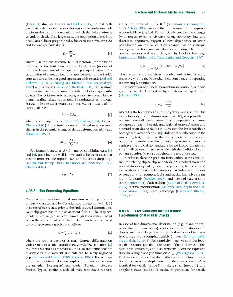
(Atkinson, 1987; Irwin, 1957; Lawn, 1993) (Figure 1).
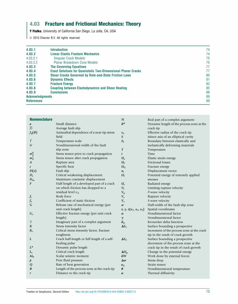
In this zone (commonly referred to as the process or break-
down zone), inelastic yielding prevents stress increases in
excess of a certain peak value ss that presumably represents
the microscopic strength of a material. The size of the process
zone r0 that corresponds to equilibrium (i.e., a crack on a verge
of propagating) may be interpreted as the effective radius of the
crack tip. Outside of the process zone (at distances r> r0),
Mode III
r0
s0
ss
s
r
Mode II
Figure 1 An idealized view of stress variations and yielding at the cracktip. r0 is the characteristic dimension of a inelastic zone in which stressesexceed the yield threshold ss. Solid curve shows the theoreticallypredicted stress increase with a characteristic 1=
ffiffir
psingularity. The
theoretical prediction breaks down at distances r< r0 but may beadequate for r> r0.
stresses are below the failure envelope, and the material
deforms elastically. If the size of the equilibrium process zone
is negligible compared to the crack length, as well as any other
characteristic dimensions (e.g., those of an encompassing
body), a condition termed small-scale yielding (Rice, 1968a)
is achieved, such that the stress and strain fields in the intact
material are not appreciably different from those predicted in
the absence of a process zone. This is the realm of the linear
elastic fracture mechanics (LEFM). According to LEFM, the
near-tip (r0< r�L) stress field is completely specified by the
scalar multiplier on the singular stress field, the stress intensity
factor K (eqn [1]), which can be found by solving an elastic
problem for a prescribed crack geometry and loading condi-
tions. The crack propagation occurs when the stress intensity
factor exceeds a critical value, K>Kc. The critical stress intensity
factor, or the fracture toughness Kc, is believed to be a material
property, independent of the crack length and loading config-
uration (although fracture properties may vary for different
modes of failure, e.g., KIc and KIIc, similar to differences
between macroscopic tensile and shear strengths). To the
extent that the microscopic yield strength ss and the effective
equilibrium curvature of the crack tip, r0, may be deemed
physical properties, the fracture toughness Kc may be inter-
preted as a product ssffiffiffiffir0
p ¼ const.
The critical stress intensity factor is a local fracture criterion,
as it quantifies the magnitude of the near-tip stress field on the
verge of failure. However, it can be readily related to global
parameters characterizing changes in the elastic strain energy
@Ue and potential energy of applied stresses @Ul in the entire
body due to a crack extension @L, such as the energy release rate
Gc¼�(@Ue+@Ul)/@L,
Gc ¼ aK2c
2m[2]
where m is the shear modulus of an intact material and aassumes values of (1�n) and unity for mode II and mode III
loading, respectively (Irwin, 1957). For ideally brittle mate-
rials, the energy release rate may be in turn associated with
the specific surface energy spent on breaking the intermolecu-
lar bonds (Griffith, 1920; Lawn, 1993). Further analysis of the
breakdown process at the crack tip requires explicit consider-
ation of the details of stress concentration in the tip region.
4.03.2.2 Planar Breakdown Zone Models
A simple yet powerful extension of the LEFM formulation is the
displacement-weakening model, which postulates that (i) the
breakdown process is confined to the crack plane, (ii) inelastic
deformation begins when stresses at the crack tip reach some
critical level ss, and (iii) yielding is complete when the crack
wall displacement exceeds some critical value Dc (Barenblatt,
1959; Dugdale, 1960; Leonov and Panasyuk, 1959). In case of
tensile (mode I) cracks, ss represents the local tensile strength
in the breakdown zone, and Dc is the critical opening displace-
ment beyond which there is no cohesion between the crack
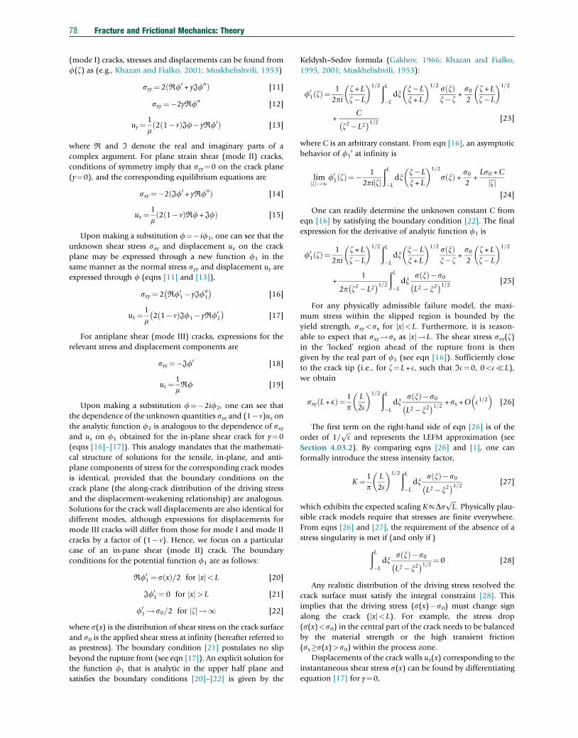
walls. In case of shear (modes II and III) cracks (Figure 2), ssrepresents either the shear strength (for ruptures propagating
through an intact solid) or the peak static friction (for ruptures
propagating along a preexisting fault), and Dc is the
Mode III
Mode IIIx
y
z
V r
Rupture front
Figure 2 Schematic view of a shear rupture expanding at a constantvelocity V. Conditions corresponding to the two-dimensional mode II andmode III loading are approximately satisfied at the rupture frontsorthogonal and parallel to the local slip vector, respectively. For acracklike rupture, slip occurs on the entire area bounded by the rupturefront. For a pulse-like rupture, slip is confined to an area between therupture front (solid line) and a trailing healing front (dashed line).
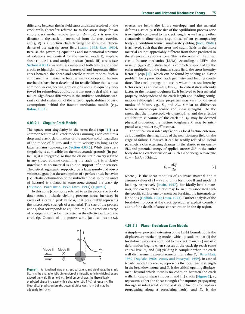
DDC
s (D)
ss
sd
s0
Figure 3 Possible dependence of the breakdown stress s on the crackwall displacement D within the crack tip process zone. Solid line: aschematic representation of the experimentally measured displacement-weakening relations for rocks (Hashida et al., 1993; Li, 1987). Dashedand dotted lines: approximations of the displacement-weakening relationassuming no dependence of the yield stress on D (dotted line) and linearweakening (dashed line). The area beneath all curves is the same andequals to the fracture energy Gc¼assDc, where a is a numerical factorthat depends on the particular form of the displacement-weakeningrelationship. For example, a¼1 for the constant yield stress model, anda¼0.5 for the linear weakening model.
76 Fracture and Frictional Mechanics: Theory
slip-weakening distance at which a transition to the kinetic
friction is complete (Ida, 1972; Palmer and Rice, 1973).
Under these assumptions, the fracture energy may be defined
as work required to evolve stresses acting on the crack plane
from ss to the residual value sd and is of the order of (ss�sd)Dc, depending on the details of the displacement-weakening
relation (Figure 3). For an ideal brittle fracture that involves
severing of intermolecular bonds ahead of the crack tip, ss may
approach theoretical strength, m/10�O(109–1010 Pa), and Dc
may be of the order of the crystal lattice spacing (10�10–
10�9 m), yielding Gc�O(1 J m�2). This is close to the experi-
mentally measured fracture energies of highly brittle crystals
and glasses (Griffith, 1920; Lawn, 1993). At the same time,
laboratory measurements of polycrystalline aggregates (such as
rocks, ceramics, and metals) reveal much higher fracture ener-
gies ranging from 10–102 J m�2 (for tensile failure) to
103 J m�2 (for shear failure), presumably reflecting depen-
dence of the effective Dc on the material microstructure (e.g.,
texture, grain size, and distribution of inhomogeneities) and
the breakdown mechanism (e.g., grain unlocking, ligamentary
bridging, plasticity, off-plane yielding, or some other
deviations from the ideally brittle behavior) (Fialko and
Rubin, 1997; Hashida et al., 1993; Li, 1987). Indirect infer-
ences of fracture energies associated with in situ propagation of
tensile cracks such as man-made hydrofractures and magmatic
dikes (Rubin, 1993) and earthquake ruptures (Abercrombie
and Rice, 2005; Chester et al., 2005; Husseini, 1977; Wilson
et al., 2004) reveal significantly larger fracture energies com-
pared with those measured in the laboratory experiments. This
disagreement may be indicative of some scaling of fracture
energy with the rupture size or rupture history and perhaps
the significance of dynamic effects on cracking and damage
that are not captured in laboratory tests. In the context of an
in-plane breakdown zone model, the inferred scale depen-
dence of fracture energy is usually interpreted in terms of
increases in the effective weakening displacement Dc with the
rupture length L. Possible mechanisms of scale dependence of
Dc include continued degradation of the dynamic fault
strength with slip (e.g., due to thermal or rheological weaken-
ing) (Abercrombie and Rice, 2005; Brodsky and Kanamori,
2001; Di Toro et al., 2004; Lachenbruch, 1980) or fractal
nature of the fault roughness (e.g., Barton, 1971; Power and
Tullis, 1995). It should be pointed out that the common
interpretation of the scale dependence of Gc in terms of the
scale dependence of Dc may be too simplistic, as the assump-
tion of a thin process zone unlikely holds under in situ stress
conditions for either tensile or shear cracks, as suggested by
both theoretical arguments (Fialko and Rubin, 1997; Poliakov
et al., 2002; Rice et al., 2005; Rubin, 1993) and observations
(Chester et al., 2005; Fialko, 2004b; Fialko et al., 2002;
Manighetti et al., 2001; Wilson et al., 2004). A more detailed
quantitative treatment of the energetics of fracture and break-
down processes is presented in Section 4.03.7.
Nonsingular crack models postulating a thin in-plane pro-
cess zone are mathematically appealing because they allow one
to treat the fracture problem as an elastic one by removing
nonlinearities associated with failure from the governing
equations and incorporating them into boundary conditions
on a crack plane. For example, elastic solutions can be readily
used to determine the size of the process zone at the crack tip.
Dimensional arguments indicate that the strain associated with
the material breakdown is of the order of Dc/R, where R is the
characteristic size of the breakdown zone. This strain must be
of the order of the elastic strain associated with the strength
drop, (ss�sd)/m, implying
R¼ gm
ss�sdDc [3]
where g is a nondimensional factor of the order of unity that
depends on the displacement-weakening relation (e.g., as
shown in Figure 3). The small-scale yielding condition
requires R�L. Parallels may be drawn between the size of
the breakdown zone R in the displacement-weakening model
and the critical radius of the crack tip r0 in the LEFM model
Fracture and Frictional Mechanics: Theory 77
(Figure 1; also, see Khazan and Fialko, 1995), in that both
parameters demarcate the near-tip region that undergoes fail-
ure from the rest of the material in which the deformation is
essentially elastic. On a larger scale, the assumption of elasticity
postulates a direct proportionality between the stress drop Dsand the average fault slip D:
D�DsmL [4]
where L is the characteristic fault dimension (for isometric
ruptures) or the least dimension of the slip area (in case of
ruptures having irregular shape or high aspect ratios). The
assumption of a predominantly elastic behavior of the Earth’s
crust appears to be in a good agreement with seismic (Aki and
Richards, 1980; Gutenberg and Richter, 1949; Vvedenskaya,
1959) and geodetic (Fialko, 2004b; Reid, 1910) observations
of the instantaneous response of crustal rocks to major earth-
quakes. The brittle–elastic model gives rise to several funda-
mental scaling relationships used in earthquake seismology.
For example, the scalar seismic momentM0 is a measure of the
earthquake size:
M0 ¼DAm [5]
where A is the rupture area (Aki, 1967; Kostrov, 1974; also, see
Chapter 4.02). The seismic moment is related to a coseismic
change in the potential energy of elastic deformation DUe (e.g.,
Kanamori, 2004),
DUe ¼Ds2m
M0 [6]
For isometric ruptures, A�L2, and by combining eqns [4]
and [5], one obtains a well-known scaling between the scalar
seismic moment, the rupture size, and the stress drop (e.g.,
Dahlen and Tromp, 1998; Kanamori and Anderson, 1975,
Chapter 4.02):
M0 �DsL3 [7]
4.03.3 The Governing Equations
Consider a three-dimensional medium which points are
uniquely characterized by Cartesian coordinates xi (i¼1, 2, 3)
in some reference state prior to the fault-induced deformation.
Fault slip gives rise to a displacement field ui. The displace-
ments ui are in general continuous (differentiable), except
across the slipped part of the fault. The strain tensor is related
to the displacement gradients as follows:
Eij ¼ 1
2ui, j + uj, i� �
[8]
where the comma operator as usual denotes differentiation
with respect to spatial coordinates, a,i¼@a/@xi. Equation [8]
assumes that strains are small (Eij�1), so that terms that are
quadratic in displacement gradients can be safely neglected
(e.g., Landau and Lifshitz, 1986; Malvern, 1969). The assump-
tion of an infinitesimal strain implies no difference between
the material (Lagrangian) and spatial (Eulerian) reference
frames. Typical strains associated with earthquake ruptures
are of the order of 10�4–10�5 (Kanamori and Anderson,
1975; Scholz, 2002) so that the infinitesimal strain approxi-
mation is likely justified. For sufficiently small strain changes
(with respect to some reference state), laboratory data and
theoretical arguments suggest a linear dependence of strain
perturbation on the causal stress change. For an isotropic
homogeneous elastic material, the corresponding relationship
between stresses and strains is given by Hooke’s law (e.g.,
Landau and Lifshitz, 1986; Timoshenko and Goodier, 1970):
Eij ¼ 1
2 1+ nð Þm 1 + nð Þsij� ndijskk� �
[9]
where m and n are the shear modulus and Poisson’s ratio,
respectively, dij is the Kronecker delta function, and repeating
indexes imply summation.
Conservation of a linear momentum in continuous media
gives rise to the Navier–Cauchy equations of equilibrium
(Malvern, 1969):
sij, j + fi ¼ @2ui@t2
[10]
where fi is the body force (e.g., due to gravity) and t is time. Due
to the linearity of equilibrium equations [10], it is possible to
represent the full stress tensor as a superposition of some
background (e.g., lithostatic and regional tectonic) stress and
a perturbation due to fault slip, such that the latter satisfies a
homogeneous case of eqns [10]. Unless noted otherwise, in the
succeeding text, we assume that the stress tensor sij denotesonly stress perturbations due to fault displacements. For con-
venience, the indicial nomenclature for spatial coordinates (x1,
x2, x3) will be used interchangeably with the traditional com-
ponent notation (x, y, z) throughout the rest of the text.
In order to close the problem formulation, some constitu-
tive law relating slip D, slip velocity @D/@t, resolved shear and
normal stresses, st and sn, pore fluid pressure p, temperature T,
etc. needs to be prescribed on surfaces that violate assumptions
of continuity, for example, faults and cracks. Examples are the
Mohr–Coulomb (Byerlee, 1978) and rate-and-state friction
(see Chapter 4.04), flash melting (Molinari et al., 1999; Rice,
2006), thermal pressurization (Andrews, 2002; Segall and Rice,
1995; Sibson, 1973), viscous rheology (Fialko and Khazan,
2005), etc.
4.03.4 Exact Solutions for QuasistaticTwo-Dimensional Planar Cracks
In case of two-dimensional deformation (e.g., plane or anti-
plane strain or plane stress), elastic solutions for stresses and
displacements can be generally expressed in terms of two ana-
lytic functions of a complex variable z¼x+ iy (Kolosoff, 1909;
Muskhelishvili, 1953). For simplicity, here, we consider load-
ing that is symmetric about the center of the crack x¼0. In this
case, both stresses sij and displacements ui can be expressed
through a single analytic function f(z) (Westergaard, 1939).
First, we demonstrate that the mathematical structure of solu-
tions for stresses and displacements in the crack plane (y¼0) is
identical for tensile (mode I), in-plane shear (mode II), and
antiplane shear (mode III) cracks. In particular, for tensile
78 Fracture and Frictional Mechanics: Theory
(mode I) cracks, stresses and displacements can be found from
f(z) as (e.g., Khazan and Fialko, 2001; Muskhelishvili, 1953)
syy ¼ 2 ℜf0 + yJf00ð Þ [11]
sxy ¼�2yℜf00 [12]
uy ¼ 1
m2 1� nð ÞJf� yℜf0ð Þ [13]
where ℜ and ℑ denote the real and imaginary parts of a
complex argument. For plane strain shear (mode II) cracks,
conditions of symmetry imply that syy¼0 on the crack plane
(y¼0), and the corresponding equilibrium equations are
sxy ¼�2 Jf0 + yℜf00ð Þ [14]
ux ¼ 1
m2 1� nð Þℜf + Jfð Þ [15]
Upon making a substitution f¼� if1, one can see that the
unknown shear stress sxy and displacement ux on the crack
plane may be expressed through a new function f1 in the
same manner as the normal stress syy and displacement uy are
expressed through f (eqns [11] and [13]),
sxy ¼ 2 ℜf01� yJf00
1
� �[16]
ux ¼ 1
m2 1� nð ÞJf1� yℜf0
1
� �[17]
For antiplane shear (mode III) cracks, expressions for the
relevant stress and displacement components are
syz ¼�Jf0 [18]
uz ¼ 1
mℜf [19]
Upon making a substitution f¼�2if2, one can see that
the dependence of the unknown quantities syz and (1�n)uz onthe analytic function f2 is analogous to the dependence of sxyand ux on f1 obtained for the in-plane shear crack for y¼0
(eqns [16]–[17]). This analogy mandates that the mathemati-
cal structure of solutions for the tensile, in-plane, and anti-
plane components of stress for the corresponding crack modes
is identical, provided that the boundary conditions on the
crack plane (the along-crack distribution of the driving stress
and the displacement-weakening relationship) are analogous.
Solutions for the crack wall displacements are also identical for
different modes, although expressions for displacements for
mode III cracks will differ from those for mode I and mode II
cracks by a factor of (1�n). Hence, we focus on a particular
case of an in-pane shear (mode II) crack. The boundary
conditions for the potential function f1 are as follows:
ℜf01 ¼ s xð Þ=2 for xj j< L [20]
Jf01 ¼ 0 for xj j> L [21]
f01 !s0=2 for zj j!1 [22]
where s(x) is the distribution of shear stress on the crack surface
and s0 is the applied shear stress at infinity (hereafter referred to
as prestress). The boundary condition [21] postulates no slip
beyond the rupture front (see eqn [17]). An explicit solution for
the function f1 that is analytic in the upper half plane and
satisfies the boundary conditions [20]–[22] is given by the
Keldysh–Sedov formula (Gakhov, 1966; Khazan and Fialko,
1995, 2001; Muskhelishvili, 1953):
f01 zð Þ¼ 1
2piz+ Lz�L
1=2ðL�L
dxx�L
x+ L
1=2 s xð Þx� z
+s02
z+ Lz�L
1=2
+C
z2�L2� �1=2 [23]
where C is an arbitrary constant. From eqn [16], an asymptotic
behavior of f10 at infinity is
limzj j!1
f01 zð Þ¼� 1
2pi zj jðL�L
dxx�L
x + L
1=2
s xð Þ + s02
+Ls0 +C
zj j[24]
One can readily determine the unknown constant C from
eqn [16] by satisfying the boundary condition [22]. The final
expression for the derivative of analytic function f1 is
f01 zð Þ¼ 1
2piz+ Lz�L
1=2ðL�L
dxx�L
x+ L
1=2 s xð Þx� z
+s02
z+ Lz�L
1=2
+1
2p z2�L2� �1=2
ðL�L
dxs xð Þ�s0
L2�x2� �1=2 [25]
For any physically admissible failure model, the maxi-
mum stress within the slipped region is bounded by the
yield strength, sxy<ss for jxj<L. Furthermore, it is reason-
able to expect that sxy!ss as jxj!L. The shear stress sxy(z)in the ‘locked’ region ahead of the rupture front is then
given by the real part of f1 (see eqn [16]). Sufficiently close
to the crack tip (i.e., for z¼L+ E, such that ℑE¼0, 0<E�L),
we obtain
sxy L + Eð Þ¼ 1
pL
2E
1=2ðL�L
dxs xð Þ�s0
L2�x2� �1=2 +ss +O E1=2
� �[26]
The first term on the right-hand side of eqn [26] is of the
order of 1=ffiffiE
pand represents the LEFM approximation (see
Section 4.03.2). By comparing eqns [26] and [1], one can
formally introduce the stress intensity factor,
K ¼ 1
pL
2E
1=2ðL�L
dxs xð Þ�s0
L2�x2� �1=2 [27]
which exhibits the expected scaling K∝DsffiffiffiL
p. Physically plau-
sible crack models require that stresses are finite everywhere.
From eqns [26] and [27], the requirement of the absence of a
stress singularity is met if (and only if )ðL�L
dxs xð Þ�s0
L2�x2� �1=2 ¼ 0 [28]
Any realistic distribution of the driving stress resolved the
crack surface must satisfy the integral constraint [28]. This
implies that the driving stress (s(x)�s0) must change sign
along the crack (jxj<L). For example, the stress drop
(s(x)<s0) in the central part of the crack needs to be balanced
by the material strength or the high transient friction
(ss�s(x)>s0) within the process zone.
Displacements of the crack walls ux(x) corresponding to the
instantaneous shear stress s(x) can be found by differentiating
equation [17] for y¼0,
Fracture and Frictional Mechanics: Theory 79
duxdx
¼ 2 1� nð Þm
Jf01 [29]
and making use of expression [26] to integrate the resulting
differential equation [29] with the initial condition ux(�L)¼0.
The respective solution is
D xð Þ¼ 2 1� nð Þpm
ðLx
L2�x2� �1=2
dxðL�L
s tð ÞdtL2� t2ð Þ1=2 t�xð Þ
[30]
where D(x)¼2ux(x) is slip between the crack walls. The prob-
lem is closed by specifying a constitutive relationship between
slip D and kinetic friction s. In general, such a relationship
may include dependence of friction on slip rate, slip history,
local temperature, and other state variables (Dieterich, 1979;
Blanpied et al., 1995; Ruina, 1983, Chapters 4.04, 4.05 and
4.06). To gain a further analytic insight, here, we consider a
simple slip-weakening relationship
s xð Þ¼ ss forD xð Þ<Dc
s xð Þ¼ sd forD xð Þ>Dc
[31]
where ss is the yield strength or static friction in the process
zone, sd is the residual kinetic friction on the developed part of
the crack, and Dc is the critical slip-weakening displacement
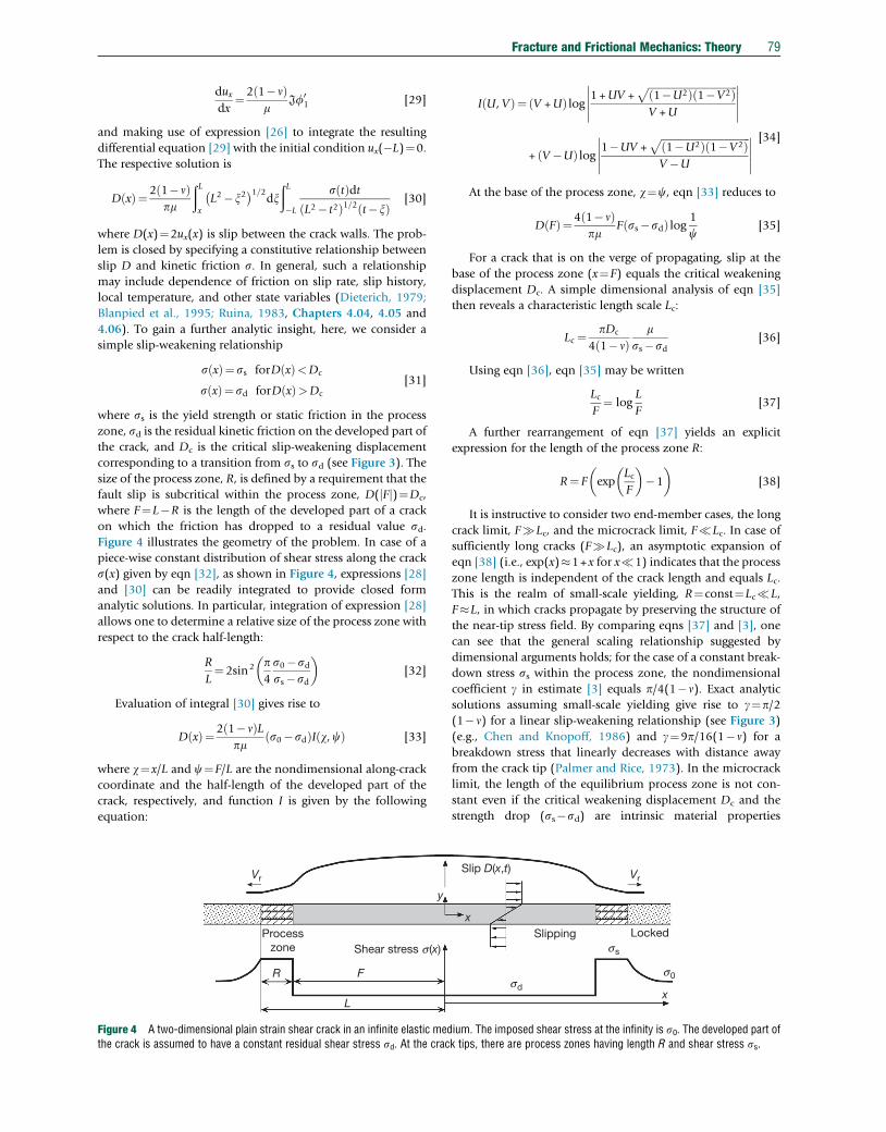
corresponding to a transition from ss to sd (see Figure 3). Thesize of the process zone, R, is defined by a requirement that the
fault slip is subcritical within the process zone, D(jFj)¼Dc,
where F¼L�R is the length of the developed part of a crack
on which the friction has dropped to a residual value sd.Figure 4 illustrates the geometry of the problem. In case of a
piece-wise constant distribution of shear stress along the crack
s(x) given by eqn [32], as shown in Figure 4, expressions [28]
and [30] can be readily integrated to provide closed form
analytic solutions. In particular, integration of expression [28]
allows one to determine a relative size of the process zone with
respect to the crack half-length:
R
L¼ 2sin2 p
4
s0�sdss�sd
[32]
Evaluation of integral [30] gives rise to
D xð Þ¼ 2 1� nð ÞLpm
s0�sdð ÞI w,cð Þ [33]
where w¼x/L and c¼F/L are the nondimensional along-crack
coordinate and the half-length of the developed part of the
crack, respectively, and function I is given by the following
equation:
Shear stress s (x)
Vr
y
Processzone
R F
L
Figure 4 A two-dimensional plain strain shear crack in an infinite elastic medthe crack is assumed to have a constant residual shear stress sd. At the crac
I U, Vð Þ¼ V +Uð Þ log 1 +UV +ffiffiffiffiffiffiffiffiffiffiffiffiffiffiffiffiffiffiffiffiffiffiffiffiffiffiffiffiffiffiffiffiffiffiffi1�U2ð Þ 1�V2ð ÞpV +U
����������
+ V�Uð Þ log 1�UV +ffiffiffiffiffiffiffiffiffiffiffiffiffiffiffiffiffiffiffiffiffiffiffiffiffiffiffiffiffiffiffiffiffiffiffi1�U2ð Þ 1�V2ð Þp
V�U
����������[34]
At the base of the process zone, w¼c, eqn [33] reduces to
D Fð Þ¼4 1� nð Þpm
F ss�sdð Þ log 1
c[35]
For a crack that is on the verge of propagating, slip at the
base of the process zone (x¼F) equals the critical weakening
displacement Dc. A simple dimensional analysis of eqn [35]
then reveals a characteristic length scale Lc:
Lc ¼ pDc
4 1� nð Þm
ss�sd[36]
Using eqn [36], eqn [35] may be written
LcF¼ log
L
F[37]
A further rearrangement of eqn [37] yields an explicit
expression for the length of the process zone R:
R¼ F expLcF
�1
[38]
It is instructive to consider two end-member cases, the long
crack limit, F�Lc, and the microcrack limit, F�Lc. In case of
sufficiently long cracks (F�Lc), an asymptotic expansion of
eqn [38] (i.e., exp(x)�1+x for x�1) indicates that the process
zone length is independent of the crack length and equals Lc.
This is the realm of small-scale yielding, R¼const¼Lc�L,
F�L, in which cracks propagate by preserving the structure of
the near-tip stress field. By comparing eqns [37] and [3], one
can see that the general scaling relationship suggested by
dimensional arguments holds; for the case of a constant break-
down stress ss within the process zone, the nondimensional
coefficient g in estimate [3] equals p/4(1�n). Exact analyticsolutions assuming small-scale yielding give rise to g¼p/2(1�n) for a linear slip-weakening relationship (see Figure 3)
(e.g., Chen and Knopoff, 1986) and g¼9p/16(1�n) for a
breakdown stress that linearly decreases with distance away
from the crack tip (Palmer and Rice, 1973). In the microcrack
limit, the length of the equilibrium process zone is not con-
stant even if the critical weakening displacement Dc and the
strength drop (ss�sd) are intrinsic material properties
sd
ss
s0
Slip D(x,t) Vr
Slipping Locked
x
x
ium. The imposed shear stress at the infinity is s0. The developed part ofk tips, there are process zones having length R and shear stress ss.
80 Fracture and Frictional Mechanics: Theory
independent of the ambient stress and loading conditions. In
particular, R is predicted to exponentially increase as the length
of the stress drop region F decreases. Equations [38] and [32]
suggest that the presence of sufficiently short cracks (such that
F<Lc) has no effect on the macroscopic ‘strength’ of rocks. In
particular, the prestress required for the crack extension must
approach the static yield limit, s0!ss, and the size of the yield
zone increases without bound, L�R!1, for F!0 (see
eqn [38]).
Quantitative estimates of the critical length scale Lc are not
straightforward because it is not clear whether the slip-weakening
distanceDc is indeed a scale-independent material constant (e.g.,
Barton, 1971; Ohnaka, 2003; Rudnicki, 1980). Laboratory mea-
surements of the evolution of friction on smooth slip interfaces
indicate that Dc may be of the order of 10�5 m (Dieterich, 1979;
Li, 1987; Marone, 1998). For m�1010 Pa and (ss�sd)�107–
108 Pa (likely spanning the range of strength drops for both
‘strong’ and ‘weak’ faults), from eqn [36], one obtains
Lc�10�3–10�1 m, negligible compared to the characteristic
dimension of the smallest recorded earthquakes but comparable
to the typical sample size used in the laboratory experiments. An
upper bound on Lc may be obtained from estimates of the
effective fracture energies of earthquake ruptures. For large
(moment magnitude >6) earthquakes, the seismically inferred
fracture energies Gc¼(ss�sd)Dc are of the order of 106–
107 J m�2 (Abercrombie and Rice, 2005; Beroza and Spudich,
1988; Husseini, 1977; Ida, 1972), rendering the effective
Dc�0.01–1 m. Assuming that the seismically inferred values of
Dc are applicable to quasistatic cracks, eqn [36] suggests that a
transition from ‘micro’ to ‘macro’ rupture regimes occurs at
length scales of the order of 1–103 m.
The magnitude of a prestress required to initiate the crack
propagation can be found by combining eqns [37] and [32]:
ss�s0ss�sd
¼ 2
parcsin exp �Lc
F
[39]
In the microcrack or large-scale yielding limit, F�Lc,
eqn [39] predicts s0�ss, that is, the crack propagation requires
ambient stress comparable to the peak static strength of crustal
rocks, as discussed in the preceding text. In the small-scale
yielding limit, F�Lc, eqn [39] gives rise to a well-known
inverse proportionality between the stress drop (s0�sd) and
the square root of the crack length F (e.g., Cowie and Scholz,
1992; Kostrov, 1970; Rice, 1968a):
s0 ¼ sd +2
pss�sdð Þ 2Lc
F
1=2
[40]
It follows from eqn [40] that for sufficiently large ruptures,
the background tectonic stress required for the rupture propa-
gation does not need to appreciably exceed the residual friction
on the slipped surface sd. That is, the stress drop associated
with the rupture propagation, (s0�sd), may be much smaller
than the strength drop, (ss�sd), provided that the rupture size
significantly exceeds the critical nucleation size Lc. This state-
ment forms the basis of the ‘statically strong, but dynamically
weak’ fault theory (Lapusta and Rice, 2004). According to this
theory, major crustal faults may operate at relatively low driv-
ing stresses (e.g., sufficient to explain the so-called heat flow
paradox of the San Andreas fault (Brune et al., 1969;
Lachenbruch, 1980)), even if the peak failure stress required
for the onset of dynamic weakening is consistent with Byerlee’s
law and hydrostatic pore pressures (Byerlee, 1978; Marone,
1998; Scholz, 2002), provided that sd�ss. If so, earthquakeruptures must nucleate in areas where s0 approaches ss (due toeither locally increased ambient stress or decreased static
strength, e.g., due to high pore fluid pressures) and propagate
into areas of relatively low ambient stress. Under this scenario,
the overall fault operation must be such that the average stress
drop Ds remains relatively small (of the order of 0.1–10 MPa)
and essentially independent of the rupture size (Abercrombie,
1995; Kanamori and Anderson, 1975; Scholz, 2002). Because
the overall seismic moment release is dominated by the largest
events, the implication from the Lapusta and Rice (2004)
model is that the Earth crust is not able to support high
deviatoric stresses in the vicinity of large active faults. Phenom-
enologically, this is consistent with the ‘weak fault’ theory
maintaining that the average shear stress s0 resolved on mature
faults is of the order of the earthquake stress drops (i.e., up to a
few tens of megapascals) and is considerably less than pre-
dictions based on Byerlee’s law (a few hundreds of megapas-
cals) (e.g., Kanamori and Heaton, 2000). The ‘statically strong
but dynamically weak’ fault theory seeks to reconcile labora-
tory results from rock friction experiments with seismic obser-
vations. Neither the peak shear stress ss nor the residual
dynamic friction sd can be estimated from seismic data. Both
parameters are likely scale-dependent; for example, the peak
shear stress ss may vary from gigapascals on the scale of micro-
asperities and gouge particles (10�6 m) to the Mohr–Coulomb
stress fs(sn�p), where fs is the static coefficient of friction, sn isthe fault-normal stress, and p is the pore fluid pressure, on the
scale of centimeters to meters (i.e., consistent with laboratory
data), to values that may be lower still on scales of hundreds of
meters to kilometers. Similarly, the residual dynamic friction
may depend on the amount of slip (and the rupture size) (e.g.,
Abercrombie and Rice, 2005; Brown and Fialko, 2012;
Kanamori and Heaton, 2000; Rice, 2006); implications from
such behavior are further discussed in Section 4.03.7.
4.03.5 Shear Cracks Governed by Rate-and-StateFriction Laws
More sophisticated models of earthquake faults combine elas-
ticity with empirical friction laws that relate shear stress to
normal stress and slip velocity and slip history. In particular,
the rate-and-state phenomenology (Dieterich, 1979; Ruina,
1983) provides a system of differential equations that can be
used to define shear stress (e.g., s in eqn [30]) on a fault plane
without oversimplifying assumptions, such as eqns [32]. The
resulting system of equations precludes analytic solutions, and
numerical experiments are required to investigate the evolu-
tion of stress and slip rate on a fault. In the framework of rate-
and-state friction, material properties that govern fault slip are
a (rate parameter), b (state parameter), and the characteristic
evolution distance analogous to the critical weakening dis-
placement Dc discussed in the preceding text (e.g., Figure 3;
also, see Chapter 4.04).
In particular, numerical simulations performed by
Dieterich (1992) revealed that slip instabilities on a
Fracture and Frictional Mechanics: Theory 81
rate-and-state fault require a nucleation zone having a charac-
teristic size greater than Lb¼Dcm/[(1�n)bsn], where sn is the
fault-normal stress (see Figure 4 in Chapter 4.04). The exis-
tence of a minimum nucleation length scale was previously
suggested based on a conditional stability of a spring-box slider
(e.g., Gu et al., 1984; Rice, 1993; Ruina, 1983). However, the
spring-box slider model predicts that the minimum nucleation
length should scale as (b�a)�1, rather than b�1, as reported by
Dieterich (1992). This discrepancy may stem from the fact that
slip on a deformable fault is intrinsically a higher dimensional
(2-D or 3-D) problem compared with a (1-D) problem of
motion of a spring-box slider.
Rubin and Ampuero (2005) showed that Lb is in fact the
minimum nucleation length and that for a weakly weakening
(a/b!1, that is, nearly velocity neutral) friction, larger nucle-
ation areas can exist, with the characteristic length of the order
of b2/(b�a)2Lb. The latter can be reached under quasi-steady-
state conditions (such that the state variable is nearly con-
stant), while Lb is the minimum nucleation length when
the fault is well above steady state (the state variable is
rapidly changing) (Ampuero and Rubin, 2008; Rubin and
Ampuero, 2005).
Some parallels may be drawn between the analytic solu-
tions presented in Section 4.03.4 and numerical results for
rate–state faults (Ampuero and Rubin, 2008; Dieterich, 1992;
Rubin and Ampuero, 2005). If one approximates the velocity
change at the tip of a slipping patch on a rate–state fault by a
step function (e.g., see Figure 8 in Chapter 4.02), then param-
eters asn and bsn of rate-and-state friction are analogous to the
difference between the yield strength and the background
stress (ss�s0) and the strength drop (ss�sd), respectively
(see Figure 4 in this chapter and Figure 1 in Chapter 4.04).
The characteristic length of the process zone Lc (eqn [36]) is
then essentially coincident with the minimum nucleation size
Lb established by Dieterich (1992) based on numerical simu-
lations coupling the rate-and-state friction and elasticity. The
correspondence between the two length scales may be inter-
preted as indicating that no elastodynamic instability is
possible in the microcrack regime (F<Lc). On the other
hand, a condition a/b!1 implies s0�sd, that is, small-scale
yielding (see eqn [40]). Indeed, such conditions were satisfied
prior to the onset of elastodynamic instability in numerical
experiments of Rubin and Ampuero (2005) performed
under the assumption of weak velocity weakening. Using
eqns [32] and [38], one can see that in the limit R/L�1,
b2/(b�a)2Lc�L/R Lc¼L, that is, the ‘velocity neutral’ nucle-
ation length of Rubin and Ampuero (2005) is essentially the
length of a quasistatic crack on the verge of propagation under
a constant remote stress s0. This is the maximum length of a
slip patch satisfying conditions of a quasistatic equilibrium.
The main differences between the rate–state model and that
shown in Figure 4 is that the latter assumes a piece-wise
constant stress distribution on the crack surface and zero slip
velocity ahead of the crack tip, while in the rate–state model,
the shear stress is a continuous function of distance along the
fault, and the fault slip rate is never zero. This analogy between
the analytic solution for a static crack and a deformable rate–
state fault may hold because of large (orders of magnitude)
increases in the slip velocity at the tip of an accelerating slip
patch compared to the nominally locked region ahead of the
tip; variations in slip rate behind the rupture front are much
smaller in comparison, so that a steplike change in slip rate
may be a reasonable approximation.
4.03.6 Dynamic Effects
Quasistatic solutions considered in Section 4.03.4 are valid
only for rupture speeds that are well below the shear wave
velocity Vs. As the rupture velocity increases, the inertial term
in the equilibrium equations [10] eventually becomes non-
negligible, and the near-tip stress field is significantly altered
when Vr becomes a sizeable fraction of Vs (Andrews, 1976a;
Broberg, 1978; Freund, 1979; Rice, 1980). The most pro-
nounced effects of a high rupture speed are the relativistic
shrinking of the in-plane process zone R and simultaneous
increase of stress perturbations off the crack plane (Kame and
Yamashita, 1999; Poliakov et al., 2002; Rice et al., 2005). The
net result is an increased tendency for branching, bifurcation,
and nonsteady propagation, all of which significantly compli-
cate the analytic and numerical treatment of the elastodynamic
rupture problem. In particular, the intermittent propagation of
the rupture front invalidates the equivalence between the
LEFM and slip-weakening formulations (e.g., Freund, 1979),
implying a greater dependence of the model results on a spe-
cific choice of fracture criteria.
Analysis of the full elastodynamic equilibrium equa-
tions [10] reveals that solutions exist for rupture velocities
below a limiting speed Vl, which equals to the Rayleigh wave
velocity VR for mode II cracks and shear wave velocity for mode
III cracks (e.g., Freund, 1979; Kostrov and Das, 1988). Solu-
tions become singular as Vr!Vl; in particular, the dynamic
stress intensity factor and the energy release rate at the crack tip
asymptotically vanish. Main fracture mechanics parameters of
a steady-state elastodynamic rupture (such as the process zone
size and the stress intensity factors) may be readily obtained by
multiplying or dividing the respective results from quasistatic
solutions by dimensionless coefficients that depend on rupture
velocity only. The corresponding coefficients are
fII ¼ 1� nð Þ4
ffiffiffiffiffiffiffiffiffiffiffiffiffiffi1�V2
r
V2p
s ffiffiffiffiffiffiffiffiffiffiffiffiffiffi1�V2
r
V2s
s� 2�V2
r
V2s
2
Vr
Vs
ffiffiffiffiffiffiffiffiffiffiffiffiffiffi1�V2
r
V2s
s [41]
fIII ¼ffiffiffiffiffiffiffiffiffiffiffiffiffiffi1�V2
r
V2s
s[42]
for the mode II and mode III loading, respectively (e.g.,
Freund, 1998; Rice, 1980). In eqn [41], Vp is the P-wave veloc-
ity. Coefficients fII and fIII monotonically decrease from unity
at Vr¼0 to zero at Vr¼Vl. For instance, the length of the
dynamic process zone R* is given by R*(Vr)¼ fII,III(Vr)R, and
the dynamic stress intensity factor for a self-similar expanding
crack is KII,III(Vr)¼ fII,III(Vr)KII,III(0). Note that for a steady-state
self-healing pulse with a fixed stress distribution in the refer-
ence frame of a moving pulse, the process zone shortens at
high rupture velocity, similar to the case of a self-similar crack,
but the dynamic stress intensity factor is independent of Vr.
82 Fracture and Frictional Mechanics: Theory
Rice et al. (2005) confirmed these results with full analytic
solutions for a self-healing pulse with a linearly weakening
process zone, propagating at a constant rupture speed. They
found that the ratio of the dynamic process zone R* to the
pulse length L* is independent of the rupture speed but is
dependent on the ratio of stress drop to strength drop:
s0�sdss�sd
¼ xp� x� sinx2psin2 x=2ð Þ [43]
where x¼ 2arcsinffiffiffiffiffiffiffiffiffiffiffiffiffiR*=L*
p(cf. eqn [32]). The velocity invari-
ance of the relative size of the process zone gives rise to a
somewhat unintuitive result that the pulse length L* vanishes
as the rupture accelerates to a limiting speed. At the same time,
the amount of slip produced by a self-healing pulse is also
invariant with respect to the rupture velocity. Thus, the dynam-
ically shrinking rupture size gives rise to a dramatic increase in
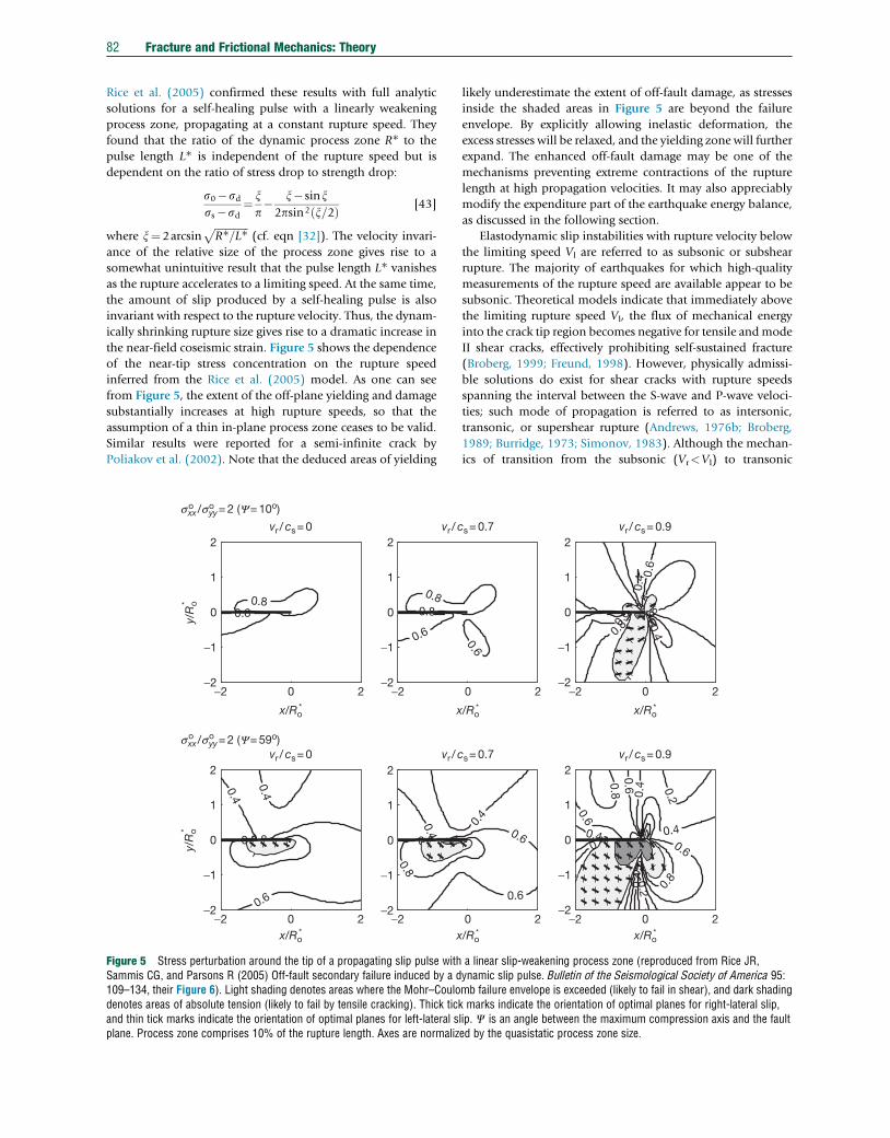
the near-field coseismic strain. Figure 5 shows the dependence
of the near-tip stress concentration on the rupture speed
inferred from the Rice et al. (2005) model. As one can see
from Figure 5, the extent of the off-plane yielding and damage
substantially increases at high rupture speeds, so that the
assumption of a thin in-plane process zone ceases to be valid.
Similar results were reported for a semi-infinite crack by
Poliakov et al. (2002). Note that the deduced areas of yielding
−2 0 2−2
−1
0
1
2
0.40.4
0.6
0.60.81
−2−2
−1
0
1
2
0.4
0.8
0.8
1
−2 0 2−2
−1
0
1
2
y/R
o*y/
Ro*
vr / cs= 0 vr / c
vr / cs= 0 vr / c
0.60.8
−2−2
−1
0
1
2
x
0.6
0.80.8
sxx /syy= 2 (Y= 10o)
sxx /syy= 2 (Y= 59o)
o o
o o
x/Ro*
xx/Ro*
Figure 5 Stress perturbation around the tip of a propagating slip pulse withSammis CG, and Parsons R (2005) Off-fault secondary failure induced by a d109–134, their Figure 6). Light shading denotes areas where the Mohr–Coulodenotes areas of absolute tension (likely to fail by tensile cracking). Thick tickand thin tick marks indicate the orientation of optimal planes for left-lateral splane. Process zone comprises 10% of the rupture length. Axes are normaliz
likely underestimate the extent of off-fault damage, as stresses
inside the shaded areas in Figure 5 are beyond the failure
envelope. By explicitly allowing inelastic deformation, the
excess stresses will be relaxed, and the yielding zone will further
expand. The enhanced off-fault damage may be one of the
mechanisms preventing extreme contractions of the rupture
length at high propagation velocities. It may also appreciably
modify the expenditure part of the earthquake energy balance,
as discussed in the following section.
Elastodynamic slip instabilities with rupture velocity below
the limiting speed Vl are referred to as subsonic or subshear
rupture. The majority of earthquakes for which high-quality
measurements of the rupture speed are available appear to be
subsonic. Theoretical models indicate that immediately above
the limiting rupture speed Vl, the flux of mechanical energy
into the crack tip region becomes negative for tensile andmode
II shear cracks, effectively prohibiting self-sustained fracture
(Broberg, 1999; Freund, 1998). However, physically admissi-
ble solutions do exist for shear cracks with rupture speeds
spanning the interval between the S-wave and P-wave veloci-
ties; such mode of propagation is referred to as intersonic,
transonic, or supershear rupture (Andrews, 1976b; Broberg,
1989; Burridge, 1973; Simonov, 1983). Although the mechan-
ics of transition from the subsonic (Vr<Vl) to transonic
0 2
0.4
0.6
0.6
−2 0 2−2
−1
0
1
2
0.2
0.2
0.4
0.4
0.40.4
0.6
0.6
0.6
0.6
0.8
0.8
0.8
1
1
1
s= 0.7 vr / cs= 0.9
s= 0.7 vr / cs= 0.9
0 2
/Ro*
0.6
−2 0 2−2
−1
0
1
2
x/Ro*
0.4
0.4 0.
60.
6
0.6
0.80.
80.
811
/Ro* x/Ro
*
a linear slip-weakening process zone (reproduced from Rice JR,ynamic slip pulse. Bulletin of the Seismological Society of America 95:mb failure envelope is exceeded (likely to fail in shear), and dark shadingmarks indicate the orientation of optimal planes for right-lateral slip,
lip. C is an angle between the maximum compression axis and the faulted by the quasistatic process zone size.
Fracture and Frictional Mechanics: Theory 83
(Vr>Vs) propagation is not fully understood, there is experi-
mental (Samudrala et al., 2002; Xia et al., 2004) and seismo-
logic (Archuleta, 1984; Bouchon and Vallee, 2003; Dunham
and Archuleta, 2004; Wald and Heaton, 1994) evidence that
transonic rupture speeds may be achieved under certain con-
ditions. The spatial structure of the near-tip stress field and the
radiation pattern in the transonic regime are markedly differ-
ent from those due to subsonic ruptures (see Chapter 4.08).
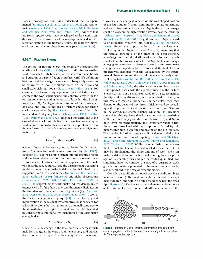
Dc
Sf
S1
S2(a) (b)
R
dL
Figure 6 Schematic view of inelastic deformation associated withcrack propagation. (a) Finite damage zone extending off the fault plane.(b) Thin in-plane damage zone.
4.03.7 Fracture Energy
The concept of fracture energy was originally introduced for
tensile cracks by Griffith (1920) to quantify the irreversible
work associated with breaking of the intermolecular bonds
and creation of a stress-free crack surface. Griffith’s definition
based on a global energy balance was subsequently shown to
be equivalent to local definitions based on the LEFM and
small-scale yielding models (Rice, 1968a; Willis, 1967). For
example, for a Barenblatt-type process zone model, the fracture
energy is the work spent against the cohesive stress ss in the
process zone on separating the crack walls by the critical open-
ing distance Dc. An elegant demonstration of the equivalence
of global and local definitions of fracture energy for tensile
cracks was provided by Rice (1968b) in a form of the path-
independent J-integral (also, see Cherepanov, 1968; Eshelby,
1956). Palmer and Rice (1973) extended this technique to the
case of shear cracks and defined the shear fracture energy as
work required to evolve shear stress on the slip interface from
the yield stress (or static friction) ss to the residual dynamic
friction sd:
Gc ¼ðDc
0
s Dð Þ�sdð ÞdD [44]
where s(D) varies between ss and sd for 0<D<Dc, respec-
tively. A similar formulation was introduced by Ida (1972).
Equation [44] allows a simple insight into the fracture process
and has been widely used for interpretations of seismic data.
However, several factors may limit its application to the anal-
ysis of earthquake ruptures. First, the displacement-weakening
model assumes that all inelastic deformation is limited to the
slip plane. Both theoretical models (Andrews, 2005; Rice et al.,
2005; Rudnicki, 1980) (Figure 5) and field observations
(Chester et al., 2005; Fialko, 2004b; Fialko et al., 2002; Li
et al., 1998) suggest that the earthquake-induced damage likely
extends well off of the fault plane, and the energy dissipated in
the fault damage zone may be quite significant (e.g., Andrews,
2005; Ben-Zion and Shi, 2005; Wilson et al., 2004). Second,
the fracture energy given by eqn [44] has a clear physical
interpretation if the residual dynamic stress sd is constant (or
at least if the along-fault variations in sd are small compared to
the strength drop, ss�sd). The second point can be illustrated
by considering a traditional representation of the earthquake
energy budget:
DUp ¼Ur +Uf +UG [45]
where DUp is the change in the total potential energy (which
includes changes in the elastic strain energy DUe and gravita-
tional potential energy); Ur is the energy radiated in seismic
waves; Uf is the energy dissipated on the well-slipped portion
of the fault due to friction, comminution, phase transitions,
and other irreversible losses; and UG is the fracture energy
spent on overcoming high resisting stresses near the crack tip
(Dahlen, 1977; Kostrov, 1974; Rivera and Kanamori, 2005;
Rudnicki and Freund, 1981). A significant part ofUf is believed
to be ultimately converted into heat (Fialko, 2004a; Sibson,
1980). Under the approximation of the displacement-
weakening model, UG∝ssDc, and Uf∝sdDm. Assuming that
the residual friction is of the order of the peak strength,
sd�O(ss), and the critical slip-weakening distance is much
smaller than the coseismic offset, Dc�Dm, the fracture energy
is negligible compared to frictional losses in the earthquake
energy balance equation [45]. However, if the fault friction
progressively decreases with slip, as suggested by the experi-
mental observations and theoretical inferences of the dynamic
weakening (Abercrombie and Rice, 2005; Di Toro et al., 2004;
Fialko and Khazan, 2005; Goldsby and Tullis, 2002; Tsutsumi
and Shimamoto, 1997), the effective slip-weakening distance
Dc is expected to scale with the slip magnitude, and the fracture
energy UG may not be small compared to Uf. Because neither
the slip-weakening distance Dc nor the residual friction sd in
this case are material properties (in particular, they may
depend on the details of slip history, thickness and permeabil-
ity of the slip zone, etc.), a distinction betweenUG andUf terms
in the earthquake energy balance equation [45] becomes
somewhat arbitrary. Note that for a rupture on a preexisting
fault, there is little physical difference between UG and Uf, as
both terms represent spatially and temporally variable fric-
tional losses associated with fault slip; both UG and Uf ulti-
mately contribute to wearing and heating on the slip interface.
The situation is further complicated if the dynamic friction is a
nonmonotonic function of slip (e.g., Brune and Thatcher,
2002; Hirose and Shimamoto, 2005; Rivera and Kanamori,
2005; Tinti et al., 2005). While a formal distinction between
the frictional and fracture losses associated with shear ruptures
may be problematic, the entire amount of work spent on
inelastic deformation of the host rocks during the crack prop-
agation is unambiguous and can be readily quantified. For
simplicity, here, we consider the case of a quasistatic crack
growth. Formulation presented in the succeeding text can be
also generalized to the case of dynamic cracks.
Consider an equilibriummode II crack in amedium subject
to initial stress sij0. The medium is elastic everywhere except
inside the crack and within a finite process zone near the crack
tips (Figure 6(a)). The inelastic zone is demarcated by a surface
Sf. Let external forces do some work dW on a medium, in the
84 Fracture and Frictional Mechanics: Theory
result of which the crack acquires a new equilibrium configu-
ration. In the new configuration, some area ahead of the crack
front undergoes inelastic yielding and joins the process zone
(see an area bounded by surfaces DS1 and Sf in Figure 6(a)). At
the trailing end of the process zone, slip exceeds Dc, and some
fraction of the process zone (bounded by surface DS2 in
Figure 6(a)) joins the developed part of the crack. The external
work dW is spent on changes in the elastic strain energy dUe
and irreversible inelastic deformation dUG (which includes
friction, breakdown, and comminution):
dW ¼ dUe + dUG [46]
Changes in the elastic strain energy are given by (e.g.,
Landau and Lifshitz, 1986; Timoshenko and Goodier, 1970)
dUe ¼ 1
2s1ijE
1ij�s0ijE
0ij
� �[47]
where sij1 and Eij
1 are stresses and strains, respectively, in the
elastic part of a medium after the crack extension. The assump-
tion of linear elasticity [9] implies that
s0ijE1ij � s1ijE
0ij [48]
for any sijk and Eij
k. The identity eqn [48] allows one to write
eqn [47] as follows:
dUe ¼ 1
2s1ij + s
0ij
� �E1ij�
1
2s1ij +s
0ij
� �E0ij ¼
1
2s1ij +s
0ij
� �dui
h i, j
[49]
where dui¼ui1�ui
0 is the displacement field produced by crack
propagation. Expressions [47] and [49] assume that the strains
are infinitesimal, so that the relationship between strain and
displacement gradients is given by eqn [8]. Also, expres-
sion [49] makes use of the fact that under quasistatic condi-
tions, the divergence of stress is zero, sij, j¼0 (see the
equilibrium equations [10]; note that the body forces may be
excluded from consideration by incorporating the effects of
gravity in prestress). Using the Gauss theorem along with a
condition that the crack-induced deformation must vanish at
infinity, from the energy balance equation [46], one obtains
the following expression for the work done on inelastic
deformation:
dUG ¼ dW�dUe
¼�ðSf
s0ijnjduidS�1
2
ðDS1 +DS2
s0ij + s1ij
� �njduidS [50]
In the limit of an ideally brittle fracture, the area of inelastic
yielding has a negligible volume (i.e., Sf!0), so that the first
integral on the right-hand side of eqn [50] vanishes. In the
second integral, the surface DS2 also vanishes, while the surface
DS1 becomes the crack length increment dL (Figure 6(b)).
Within dL, the stresses are weakly singular, sij∝1=ffiffir
p, where r
is distance to the crack tip, and the crack wall displacements
scale as dui∝ffiffir
p, so that the product of stresses and displace-
ments is of the order of unity, and the corresponding integral
in eqn [50] is of the order of DS1¼dL. This is the well-known
LEFM limit, for which the fracture energy is given by eqn [2].
For more realistic models that explicitly consider failure at
the crack tip, the stresses are finite everywhere, so that the
second integral on the right-hand side of eqn [50] is of the
order of sij0dui(DS1+DS2), that is, negligible compared to the
integral over the finite inelastic zone �O(sij0duiSf). Provided
that the displacement field associated with the crack extension
can be represented as dui¼dL@ui/@L, eqn [50] allows one to
introduce the fracture energy Gc as the total inelastic work per
increment of the crack length or the energy release rate:
Gc ¼ @UG
@L¼�1
2
ðSf
@ui@L
s0ijnjdS [51]
Factor of 1/2 in eqn [51] stems from the assumption of a
bilateral crack propagation. Equation [51] in general cannot be
readily evaluated analytically because the size and geometry of
the inelastic zone Sf are not known in advance and have to be
found as part of a solution. Further insights are possible for
special cases. For example, assuming that all yielding is con-
fined to a crack plane (Figure 6(b)), eqn [51] reduces to
Gc ¼ðL0
s xð Þ@D xð Þ@L
dx [52]
where we took into account that the total offset between the
crack walls is D(x)¼2ux, and the sense of slip is opposite to
that of the resisting shear tractions acting on the crack walls.
The integral equation [52] is still intractable for an arbitrary
loading, as the derivative @D(x)/@L must be calculated along
the equilibrium curve (e.g., see eqn [33]). Closed form analytic
solutions can be obtained for limiting cases of small-scale
(L�R) and large-scale (L�R) yielding. First, consider a crack
that is much longer than the critical size Lc [36] and has a
complete stress drop, s(x)¼0 for D>Dc. As shown in
Section 4.03.2, for such a crack the size of the process zone is
independent of the crack length, R¼Lc, and the crack propa-
gation does not modify the slip distribution within the pro-
cess zone in the reference frame of a propagating crack tip. In
this case,
@D xð Þ=@L¼�@D xð Þ=@x [53]
so that eqn [52] gives rise to
Gc ¼ðLL�R
s xð Þ@D xð Þ@L
dx¼ðDc
0
s Dð ÞdD [54]
Expression [54] is analogous to the result obtained using
the J-integral technique (Rice, 1968b). An expression for the
J-integral contains a derivative of the crack wall displacement
with respect to the integration variable, rather than the crack
length. As noted by Khazan and Fialko (2001), the two deriv-
atives coincide (up to a sign) in a limiting case of a very long
crack (for which the J-integral was derived), but the difference
may be significant if the small-scale yielding approximation
does not hold (also, see Rice, 1979).
For a case of a constant, but nonvanishing, residual friction,
s(x)¼sd for Dc<D<Dm, evaluation of integral equation [52]
gives rise to
Gc ¼ sd Dm�Dcð Þ+ðDc
0
s Dð ÞdD [55]
thanks to self-similarity of the along-crack displacement D(x)
over the interval 0<x<L�R for long cracks, such that the
Fracture and Frictional Mechanics: Theory 85
relationship [53] still holds. For a constant yield stress within
the process zone, s(x)¼const¼ss (e.g., Figure 4), eqn [55]
gives rise to a simple expression Gc¼(ss�sd)Dc+sdDm, in
which the first and second terms may be recognized as the
traditionally defined fracture energy UG and the frictional
work Uf, respectively (cf. eqn [45]).
In case of a large-scale yielding, relationship [53] is gener-
ally not applicable. Assuming ss¼const, expression [52] can
be integrated by parts to yield
Gc ¼ ss@
@L
ðL0
D xð Þdx�ss
ðF0
@D
@Ldx [56]
In the developed part of the crack with the full stress drop
(x<F), slip is essentially constant and equals to Dc, so that the
second integral on the right-hand side of eqn [56] can be
neglected. Taking advantage of expressions [33] and [35] to
evaluate the first term in eqn [56], one obtains (Khazan and
Fialko, 2001)
Gc ¼ pF2Lc
ssDc [57]
Equation [57] indicates that the fracture energy for the case
of small cracks (or large-scale yielding, F�Lc) is substantially
different from the fracture energy for large cracks (or small-
scale yielding, F�Lc). In case of large-scale yielding, the frac-
ture energy is not constant even if both the yield strength ssand the critical slip-weakening displacement Dc are material
constants independent of loading conditions. In particular, Gc
is predicted to linearly increase with the size of the developed
part of the crack F. A linear scaling of fracture energy implies
increases in the apparent fracture toughness Kq proportional to
a square root of the developed crack length, KQ∝ffiffiffiF
p(see
eqn [2]), in the large-scale yielding regime. Increases in the
apparent fracture toughness for small cracks are well known
from laboratory studies of tensile fracture (e.g., Bazant and
Planas, 1998; Ingraffea and Schmidt, 1978).
The apparent scaling of the earthquake fracture energy with
the earthquake size has been inferred from seismic data (e.g.,
Abercrombie and Rice, 2005; Husseini, 1977; Kanamori and
Heaton, 2000). Arguments presented in the preceding text
indicate that several mechanisms may be responsible for the
observed increases in the seismically inferred fracture energies
with the rupture length, in particular, (1) off-fault damage that
scales with the rupture length (larger ruptures are expected to
produce broader zones of high stress near the rupture fronts,
presumably advancing the extent of off-fault damage (see
Figure 5 and eqn [51])); (2) a continuous degradation of
dynamic friction on a fault plane, for example, due to thermal
pressurization or any other slip-weakening mechanism; and
(3) rupture propagation under conditions of large-scale yield-
ing (eqn [57]), although it remains to be seen whether elasto-
dynamic instability can occur when the process zone
comprises a substantial fraction of the crack length (see
Section 4.03.4). These mechanisms are not mutually exclusive
and may jointly contribute to the observed scaling Gc∝F. For
example, the third mechanism might be relevant for small
earthquakes, while the first and second ones perhaps dominate
for large events. Note that the second mechanism is ultimately
limited by a complete stress drop, beyond which no further
increase in fracture energy is possible. The same limit may also
apply to the first mechanism, as the size of the dynamic dam-
age zone scales with the quasistatic one for a given
displacement-weakening relationship (Rice et al., 2005). Estab-
lishing the relative importance of contributions of various
mechanisms to the effective fracture energy is an important
but challenging task. In particular, if contributions from the
off-fault yielding are substantial, interpretations of seismic data
that neglect such yielding may systematically overestimate the
magnitude of the effective slip-weakening distance Dc. Unfor-
tunately, distinguishing between different contributions to the
overall value of Gc can be unlikely accomplished based on the
seismic data alone.
In summary, the fracture energy defined by eqn [51] is
analogous to Griffith’s concept for tensile cracks, provided
that the stress drop is complete (sd¼0) and the small-scale
yielding condition is met. For a nonvanishing friction on the
crack surface, eqn [51] combines inelastic work spent against
residual friction and work spent on evolving the shear stress on
a fault to a residual level (i.e., the traditionally defined fracture
energy). Separation between these two contributions is justi-
fied if small-scale yielding condition applies but may be ill-
defined otherwise. For models with a continuous strength
degradation, there is a continuous repartitioning of the energy
budget, such that the effective fracture energy increases at the
expense of a diminishing frictional dissipation.
4.03.8 Coupling between Elastodynamicsand Shear Heating
One of the factors that can strongly affect the dynamic friction
on the slipping interface and, thereby, the seismic radiation,
efficiency, and stress drop is the coseismic frictional heating.
Rapid slip during seismic instabilities may substantially raise
temperature on a fault surface. The dependence of dynamic
friction on temperature may stem from several mechanisms,
including thermal pressurization by pore fluids (Lachenbruch,
1980; Mase and Smith, 1987; Sibson, 1973), frictional melting
( Jeffreys, 1942; Maddock, 1986; McKenzie and Brune, 1972;
Sibson, 1975), and flash heating of contact asperities (Rice,
2006). Recent experimental measurements confirm apprecia-
ble variations in the dynamic friction at slip velocities
approaching the seismic range of order of a meter per second
(Brown and Fialko, 2012; Di Toro et al., 2004; Goldsby and
Tullis, 2002, 2011; Hirose and Shimamoto, 2003; Reches and
Lockner, 2010; Spray, 2005). The documented variations are
significantly larger than predictions of the rate-and-state fric-
tion (Dieterich, 1979; Ruina, 1983) extrapolated to seismic slip
rates. The likely importance of the thermally induced varia-
tions in friction warrants a quantitative insight into the dynam-
ics of fault heating during seismic slip. Major questions include
the following: What are the dominant mechanisms of fault
friction at high slip rates? How do increases in temperature
affect the dynamic shear stress on a slipping interface? How
robust is the thermally activated weakening? Is dynamic fric-
tion a monotonically decaying function of temperature? If not,
what are the mechanisms, conditions, and significance of the
thermally activated strengthening? When and where is the
onset of the thermally induced weakening or strengthening
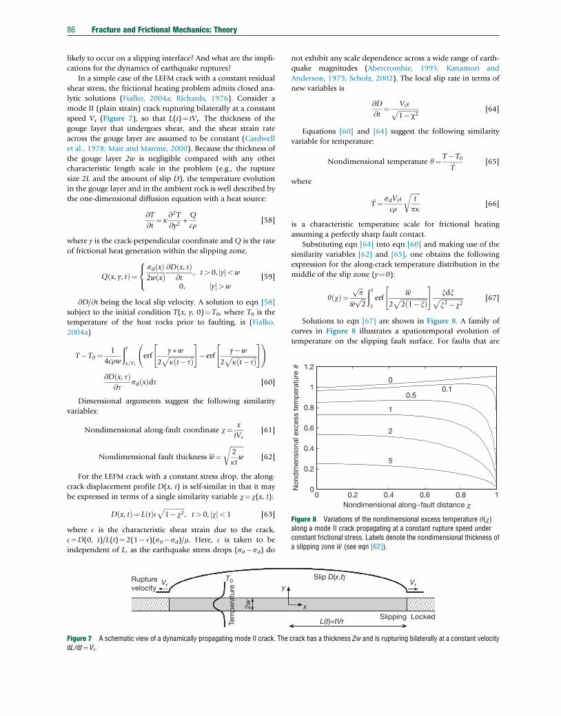
0 0.2 0.4 0.6 0.8 10
0.2
0.4
0.6
0.8
1
1.2
00.1
0.5
1
2
5
Nondimensional along−fault distance c
Non
dim
ensi
onal
exc
ess
tem
per
atur
e q
Figure 8 Variations of the nondimensional excess temperature y(w)along a mode II crack propagating at a constant rupture speed underconstant frictional stress. Labels denote the nondimensional thickness ofa slipping zone w (see eqn [62]).
86 Fracture and Frictional Mechanics: Theory
likely to occur on a slipping interface? And what are the impli-
cations for the dynamics of earthquake ruptures?
In a simple case of the LEFM crack with a constant residual
shear stress, the frictional heating problem admits closed ana-
lytic solutions (Fialko, 2004a; Richards, 1976). Consider a
mode II (plain strain) crack rupturing bilaterally at a constant
speed Vr (Figure 7), so that L(t)¼ tVr. The thickness of the
gouge layer that undergoes shear, and the shear strain rate
across the gouge layer are assumed to be constant (Cardwell
et al., 1978; Mair and Marone, 2000). Because the thickness of
the gouge layer 2w is negligible compared with any other
characteristic length scale in the problem (e.g., the rupture
size 2L and the amount of slip D), the temperature evolution
in the gouge layer and in the ambient rock is well described by
the one-dimensional diffusion equation with a heat source:
@T
@t¼ k
@2T
@y2+Q
cr[58]
where y is the crack-perpendicular coordinate and Q is the rate
of frictional heat generation within the slipping zone,
Q x, y, tð Þ¼sd xð Þ2w xð Þ
@D x, tð Þ@t
, t> 0, yj j<w
0, yj j>w
8<: [59]
@D/@t being the local slip velocity. A solution to eqn [58]
subject to the initial condition T(x, y, 0)¼T0, where T0 is the
temperature of the host rocks prior to faulting, is (Fialko,
2004a)
T�T0 ¼ 1
4crw
ðtx=Vr
erfy +w
2ffiffiffiffiffiffiffiffiffiffiffiffiffiffiffiffik t� tð Þp
" #�erf
y�w
2ffiffiffiffiffiffiffiffiffiffiffiffiffiffiffiffik t� tð Þp
" # !
@D x, tð Þ@t
sd xð Þdt [60]
Dimensional arguments suggest the following similarity
variables:
Nondimensional along-fault coordinate w¼ x
tVr[61]
Nondimensional fault thickness w¼ffiffiffiffiffiffiffiffi2
ktw
r[62]
For the LEFM crack with a constant stress drop, the along-
crack displacement profile D(x, t) is self-similar in that it may
be expressed in terms of a single similarity variable w¼w(x, t):
D x, tð Þ¼ L tð ÞEffiffiffiffiffiffiffiffiffiffiffiffiffi1�w2
p, t> 0, wj j< 1 [63]
where E is the characteristic shear strain due to the crack,
E¼D(0, t)/L(t)¼2(1�n)(s0�sd)/m. Here, E is taken to be
independent of L, as the earthquake stress drops (s0�sd) do
Rupturevelocity
T0
Tem
per
atur
e
2w
yVr
Figure 7 A schematic view of a dynamically propagating mode II crack. ThedL/dt¼Vr.
not exhibit any scale dependence across a wide range of earth-
quake magnitudes (Abercrombie, 1995; Kanamori and
Anderson, 1975; Scholz, 2002). The local slip rate in terms of
new variables is
@D
@t¼ VrEffiffiffiffiffiffiffiffiffiffiffiffiffi
1�w2p [64]
Equations [60] and [64] suggest the following similarity
variable for temperature:
Nondimensional temperature y¼ T�T0
T̂[65]
where
T̂ ¼ sdVrEcr
ffiffiffiffiffiffit
pk
r[66]
is a characteristic temperature scale for frictional heating
assuming a perfectly sharp fault contact.
Substituting eqn [64] into eqn [60] and making use of the
similarity variables [62] and [65], one obtains the following
expression for the along-crack temperature distribution in the
middle of the slip zone (y¼0):
y wð Þ¼ffiffiffip
p
wffiffiffi2
pð1werf
w
2ffiffiffiffiffiffiffiffiffiffiffiffiffiffiffiffiffi2 1�xð Þp
" #xdxffiffiffiffiffiffiffiffiffiffiffiffiffiffiffix2�w2
p [67]
Solutions to eqn [67] are shown in Figure 8. A family of
curves in Figure 8 illustrates a spatiotemporal evolution of
temperature on the slipping fault surface. For faults that are
Slip D(x,t)
x
L(t)=tVrSlipping Locked
Vr
crack has a thickness 2w and is rupturing bilaterally at a constant velocity
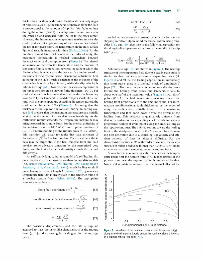
0 0.2 0.4 0.6 0.8 10
0.2
0.4
0.6
0.8
10
0.1
0.5
12
5
Nondimensional along−fault distance c
Non
dim
ensi
onal
exc
ess
tem
per
atur
e q
Figure 9 Variations of the nondimensional excess temperature y(w)along a self-healing pulse. Labels denote the nondimensional thicknessof a slipping zone w (see eqns [71]).
Fracture and Frictional Mechanics: Theory 87
thicker than the thermal diffusion length scale or at early stages
of rupture (i.e., w> 1), the temperature increase along the fault
is proportional to the amount of slip. For thin faults or later
during the rupture w�1ð Þ, the temperature is maximum near
the crack tip and decreases from the tip to the crack center.
However, the instantaneous temperature maximum near the
crack tip does not imply cooling of the crack surface behind
the tip; at any given point, the temperature on the crack surface
T(x, 0, t) steadily increases with time (Fialko, 2004a). For the
nondimensional fault thickness w of the order of unity, the
maximum temperature is reached somewhere between
the crack center and the rupture front (Figure 8). The inferred
anticorrelation between the temperature and the amount of
slip stems from a competition between the rates at which the
frictional heat is generated at the crack surface and removed to
the ambient rocks by conduction. Generation of frictional heat
at the tip of the LEFM crack is singular as the thickness of the
conductive boundary layer is zero, while the slip velocity is
infinite (see eqn [64]). Nonetheless, the excess temperature at
the tip is zero for cracks having finite thickness w> 0ð Þ. Forcracks that are much thinner than the conductive boundary
layer w�1ð Þ, the temperature field develops a shock-like struc-
ture, with the tip temperature exceeding the temperature at the
crack center by about 10% (Figure 8). Assuming that the
thickness of the slip zone is constant during an earthquake,
eqn [67] predicts that the maximum temperatures are initially
attained at the center of a cracklike shear instability. As the
earthquake rupture expands, the temperature maximum may
migrate toward the rupture fronts. For the thermal diffusivity of
the ambient rocks k¼10�6 m2 s�1 and rupture durations of
t¼1–10 s (corresponding to the rupture sizes of �5–50 km),
this transition will occur for faults that have thickness of
the order offfiffiffiffiffiffiffi2kt
p � 2�5mm or less. The critical fault thick-
ness may be larger still if the heat removal from the fault
involves some advective transport by the pressurized pore
fluids, and the in situ hydraulic diffusivity exceeds the thermal
diffusivity k.For sufficiently large ruptures, a model of a self-healing slip
pulse may be a better approximation than the cracklike models
(e.g., Beroza and Mikumo, 1996; Heaton, 1990; Kanamori and
Anderson, 1975; Olsen et al., 1997). A self-healing mode II
pulse having a constant length L (Freund, 1979) generates a
temperature field that is steady state in the reference frame of
a moving rupture front (Fialko, 2004a). The appropriate
similarity variables are
along-fault coordinate w¼ x� tVr
L+1 [68]
nondimensional fault thickness w¼ffiffiffiffiffiffiffiffiffiffiffi2Vr
Lkw
r[69]
nondimensional temparature y¼ T�T0
T̂[70]
T̂ ¼ sdEcr
ffiffiffiffiffiffiffiffiLVr
pk
r[71]
The coseismic displacements and the rate of slip are
assumed to have the LEFM-like characteristics at the rupture
front (w¼1) and a nonsingular healing at the trailing edge
(w¼0):
D wð Þ¼ LEffiffiffiffiffiffiffiffiffiffiffiffiffi1�w2
p[72]
@D
@w¼ VrEwffiffiffiffiffiffiffiffiffiffiffiffiffi
1�w2p [73]
As before, we assume a constant dynamic friction on the
slipping interface. Upon nondimensionalization using vari-
ables [71], eqn [60] gives rise to the following expression for
the along-fault temperature variations in the middle of the slip
zone (y¼0):
y wð Þ¼ffiffiffip
p
wffiffiffi2
pð1werf
w
2ffiffiffiffiffiffiffiffiffiffiffiffiffiffiffiffiffi2 w�xð Þp
" #xdxffiffiffiffiffiffiffiffiffiffiffiffiffi1�x2
p [74]
Solutions to eqn [74] are shown in Figure 9. The near-tip
structure of the temperature field due to a steady-state pulse is
similar to that due to a self-similar expanding crack (cf.
Figures 8 and 9). At the leading edge of an infinitesimally
thin shear pulse, there is a thermal shock of amplitude T̂
(eqn [71]). The fault temperature monotonically decreases
toward the healing front, where the temperature falls to
about one-half of the maximum value (Figure 9). For ‘thick’
pulses w�1ð Þ, the fault temperature increases toward the
healing front proportionally to the amount of slip. For inter-
mediate nondimensional fault thicknesses of the order of
unity, the fault surface initially heats up to a maximum
temperature and then cools down before the arrival of the
healing front. This behavior is qualitatively different from
that on a surface of an expanding crack, which indicates a
progressive heating at every point along the crack as long as
the rupture continues. The inferred cooling toward the healing
front of the steady-state pulse for w> 5 is caused by a decreas-
ing heat generation due to a vanishing slip velocity and effi-
cient removal of heat by thermal diffusion. For the
characteristic rise times L/Vr of the order of seconds, the steady-
state LEFM pulses need to be thinner than 5ffiffiffiffiffiffiffiffiffiffiffiffiffiffiffi2kL=Vr
p � 1cm to
experience maximum temperatures at the rupture front.
Several factors may accentuate the tendency for the temper-
ature peaks near the rupture front. First, higher stresses in the
process zone near the rupture tip imply enhanced heating.
Numerical simulations indicate that the thermal effect of the
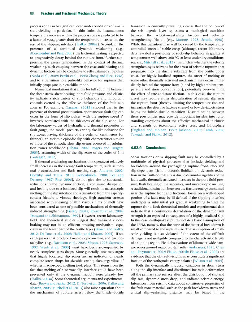
88 Fracture and Frictional Mechanics: Theory
process zone can be significant even under conditions of small-
scale yielding; in particular, for thin faults, the instantaneous
temperature increase within the process zone is predicted to be
a factor of ss/sd greater than the temperature increase on the
rest of the slipping interface (Fialko, 2004a). Second, in the
presence of a continued dynamic weakening (e.g.,
Abercrombie and Rice, 2005), the frictional heating is expected
to progressively decay behind the rupture front, further sup-
pressing the excess temperature. In the context of thermal
weakening, such coupling between the coseismic heating and
dynamic friction may be conducive to self-sustained slip pulses
(Noda et al., 2009; Perrin et al., 1995; Zheng and Rice, 1998)
and to a transition to a pulse-like behavior for ruptures that
initially propagate in a cracklike mode.
Numerical simulations that allow for full coupling between
the shear stress, shear heating, pore fluid pressure, and elastic-
ity indicate a rich variety of slip behaviors and important
controls exerted by the effective thickness of the fault slip
zone w. For example, Garagash (2012) showed that in the
presence of thermal pressurization, spontaneous fault slip can
occur in the form of slip pulses, with the rupture speed Vr
inversely correlated with the thickness of the slip zone. For
the laboratory values of hydraulic and thermal properties of
fault gouge, the model predicts earthquake-like behavior for
slip zones having thickness of the order of centimeters (or
thinner), an aseismic episodic slip with characteristics similar
to those of the episodic slow slip events observed in subduc-
tion zones worldwide (Obara, 2002; Rogers and Dragert,
2003), assuming width of the slip zone of the order of 1 m
(Garagash, 2012).
If thermal weakening mechanisms that operate at relatively
small increases in the average fault temperature, such as ther-
mal pressurization and flash melting (e.g., Andrews, 2002;
Goldsby and Tullis, 2011; Lachenbruch, 1980; Lee and
Delaney, 1987; Rice, 2006), do not give rise to substantial
reductions in the dynamic friction, a continued dissipation
and heating due to a localized slip will result in macroscopic
melting on the slip interface and a transition from the asperity-
contact friction to viscous rheology. High transient stresses
associated with shearing of thin viscous films of melt have
been considered as one of possible mechanisms of thermally
induced strengthening (Fialko, 2004a; Koizumi et al., 2004;
Tsutsumi and Shimamoto, 1997). However, recent laboratory,
field, and theoretical studies suggest that transient viscous
braking may not be an efficient arresting mechanism, espe-
cially in the lower part of the brittle layer (Brown and Fialko,
2012; Di Toro et al., 2006; Fialko and Khazan, 2005). If so,
earthquakes that produced macroscopic melting and pseudo-
tachylites (e.g., Davidson et al., 2003; Sibson, 1975; Swanson,
1992; Wenk et al., 2000) must have been accompanied by
nearly complete stress drops. More generally, one may argue
that highly localized slip zones are an indicator of nearly
complete stress drops for sizeable earthquakes, regardless of
whether macroscopic melting took place. This stems from the
fact that melting of a narrow slip interface could have been
prevented only if the dynamic friction were already low
(Fialko, 2004a). Some theoretical arguments and experimental
data (Brown and Fialko, 2012; Di Toro et al., 2006; Fialko and
Khazan, 2005; Mitchell et al., 2013) also raise a question about
the mechanism of rupture arrest below the brittle–ductile
transition. A currently prevailing view is that the bottom of
the seismogenic layer represents a rheological transition
between the velocity-weakening friction and velocity-
strengthening friction (e.g., Marone, 1998; Scholz, 1998).
While this transition may well be caused by the temperature-
controlled onset of stable creep (although recent laboratory
data revealed a possibility of stick–slip behavior in granite at
temperatures well above 300 C, at least under dry conditions;see, e.g., Mitchell et al., 2013), it is unclear whether the velocity
strengthening is relevant for the arrest of seismic ruptures that
propagate into the ductile substrate from the brittle upper
crust. For highly localized ruptures, the onset of melting or
some other thermally activated mechanism may occur imme-
diately behind the rupture front (aided by high ambient tem-
perature and stress concentration), potentially overwhelming
the effect of rate-and-state friction. In this case, the rupture
arrest may require either delocalization of seismic slip near
the rupture front (thereby limiting the temperature rise and
increasing the effective fracture energy) or low deviatoric stress
below the brittle–ductile transition. Discriminating between
these possibilities may provide important insights into long-
standing questions about the effective mechanical thickness
and strength of tectonically active crust and lithosphere
(England and Molnar, 1997; Jackson, 2002; Lamb, 2002;
Takeuchi and Fialko, 2012).
4.03.9 Conclusions
Shear tractions on a slipping fault may be controlled by a
multitude of physical processes that include yielding and
breakdown around the propagating rupture front, rate- and
slip-dependent friction, acoustic fluidization, dynamic reduc-
tion in the fault-normal stress due to dissimilar rigidities of the
fault walls, thermally activated increases in the pore fluid pres-
sure, flash heating of the asperities, and macroscopic melting.
A traditional distinction between the fracture energy consumed
near the rupture front and frictional losses on a well-slipped
portion of a fault may be ill-defined if the slipping interface
undergoes a substantial yet gradual weakening behind the
rupture front. Both theoretical models and experimental data
indicate that a continuous degradation of the dynamic fault
strength is an expected consequence of a highly localized slip.
In this case, earthquake ruptures violate a basic assumption of
the LEFM, namely, that the zone of the material breakdown is
small compared to the rupture size. The assumption of small-
scale yielding is also violated if the extent of the off-fault
damage is not negligible compared to the characteristic length
of a slipping region. Field observations of kilometer-wide dam-
age zones around major crustal faults (Ambraseys, 1970; Chen
and Freymueller, 2002; Fialko, 2004b; Fialko et al., 2002) are
evidence that the off-fault yielding may constitute a significant
fraction of the earthquake energy balance (Wilson et al., 2004).
Both the dynamically induced variations in shear stress
along the slip interface and distributed inelastic deformation
off the primary slip surface affect the distribution of slip and
slip rate, dynamic stress drop, and radiated seismic energy.
Inferences from seismic data about constitutive properties of
the fault zone material, such as the peak breakdown stress and
critical slip-weakening distance, may be biased if the
Fracture and Frictional Mechanics: Theory 89
aforementioned phenomena are not taken into account. In
particular, simplified rupture models that neglect off-fault
damage likely overestimate the critical slip-weakening distance
Dc. Similarly, models that neglect the physics of high-speed slip
may attribute the dynamic (e.g., thermally induced) weakening
to large in situ values of Dc interpreted as an intrinsic rock
fracture property. Constitutive relationships governing evolu-
tion of the dynamic strength at seismic slip velocities are diffi-
cult to formalize, as temperature, pore fluid pressure, and shear
tractions on the fault interface are sensitive to a number of
parameters such as the effective thickness of the slip zone, fluid
saturation, dynamic damage and changes in the fault wall
permeability, and ambient stress. Many of these parameters
are also poorly constrained by the available data. Nonetheless,
further insights into the dynamics of earthquakes may require
fully coupled elastodynamic–thermodynamic models of seis-
mic rupture. Development of such models is a significant
challenge for future work.
Acknowledgments
I thank Jim Rice, Allan Rubin, and Hiroo Kanamori for their
insightful reviews. Jim Rice kindly provided results of his cal-
culations of off-fault damage (Figure 5). This work was sup-
ported by NSF through grants EAR-0338061, EAR-0450035,
and EAR-0944336.
References
Abercrombie R (1995) Earthquake source scaling relationships from �1 to 5 ML usingseismograms recorded at 2.5-km depth. Journal of Geophysical Research100: 24015–24036.
Abercrombie R and Rice JR (2005) Can observations of earthquake scaling constrainslip weakening? Geophysical Journal International 162: 406–424.
Aki K (1967) Scaling law of seismic spectrum. Journal of Geophysical Research72: 1217–1231.
Aki K and Richards PG (1980) Quantitative Seismology: Theory and Methods, I and II,p. 577. San Francisco, CA: W. H. Freeman,.
Ambraseys N (1970) Some characteristic features of the North Anatolian fault zone.Tectonophysics 9: 143–165.
Ampuero J and Rubin AM (2008) Earthquake nucleation on rate and state faults – Agingand slip laws. Journal of Geophysical Research 113: B01302.
Andrews DJ (1976a) Rupture propagation with finite stress in antiplane strain. Journalof Geophysical Research 81: 3575–3582.
Andrews DJ (1976b) Rupture velocity of plane strain shear cracks. Journal ofGeophysical Research 81: 5679–5687.
Andrews DJ (2002) A fault constitutive relation accounting for thermal pressurizationof pore fluid. Journal of Geophysical Research 107: ESE 15–1–ESE 15–8. http://dx.doi.org/10.1029/2002JB001942.
Andrews DJ (2005) Rupture dynamics with energy loss outside the slip zone. Journal ofGeophysical Research 110: B01307. http://dx.doi.org/10.1029/2004JB003191.
Aochi H and Madariaga R (2003) The 1999 Izmit, Turkey, earthquake: Nonplanar faultstructure, dynamic rupture process, and strong ground motion. Bulletin of theSeismological Society of America 93: 1249–1266.
Archuleta RJ (1984) A faulting model for the 1979 Imperial Valley earthquake. Journalof Geophysical Research 89: 4559–4585.
Atkinson BK (1987) Introduction to fracture mechanics. In: Atkinson BK (ed.) FractureMechanics of Rock, pp. 1–23. London: Academic Press, chapter 1.
Barenblatt GI (1959) The formation of equilibrium cracks during brittle fracture. Generalideas and hypotheses. Axially-symmetric cracks. Journal of Applied Mathematicsand Mechanics 23: 622–636 (in Russian).
Barton N (1971) A relationship between joint roughness and joint shear strength.In: Proceedings of International Symposium on Rock Mechanics, Nancy, Pap. I-8.
Bazant ZP and Planas J (1998) Fracture and Size Effect in Concrete and OtherQuasibrittle Materials. Boca Raton, FL: CRC Press.
Ben-Zion Y (2003) Appendix 2, key formulas in earthquake seismology. In: Lee W,Kanamori H, Jennings P, and Kisslinger C (eds.) International Handbook ofEarthquake and Engineering Seismology, Vol. 81B, pp. 1857–1875. Amsterdam:Academic Press.
Ben-Zion Y and Rice JR (1997) Dynamic simulations of slip on a smooth fault in anelastic solid. Journal of Geophysical Research 102: 17771–17784.
Ben-Zion Y and Shi Z (2005) Dynamic rupture on a material interface with spontaneousgeneration of plastic strain in the bulk. Earth and Planetary Science Letters236: 486–496.
Beroza GC and Mikumo T (1996) Short slip duration in dynamic rupture in the presenceof heterogeneous fault properties. Journal of Geophysical Research101: 22449–22460.
Beroza GC and Spudich P (1988) Linearized inversion for fault rupture. Journal ofGeophysical Research 93: 6275–6296.
Bilby BA and Eshelby JD (1968) Dislocations and the theory of fracture. In: Liebowitz H(ed.). Fracture: An Advanced Treatise, vol. 1, pp. 99–182. New York: AcademicPress.
Blanpied M, Tullis T, and Weeks J (1995) Frictional slip of granite at hydrothermalconditions. Journal of Geophysical Research 100: 13045–13064.
Bouchon M and Vallee M (2003) Observation of long supershear rupture during themagnitude 8.1 Kunlunshan earthquake. Science 301: 824–826.
Broberg K (1978) Transient sliding motion. Geophysical Journal of the RoyalAstronomical Society 52: 397–432.
Broberg K (1987) On crack paths. Engineering Fracture Mechanics 28: 663–679.Broberg K (1989) The near-tip field at high crack velocities. International Journal of
Fracture 39: 1–13.Broberg K (1999) Cracks and Fracture. London: Academic Press.Brodsky EE and Kanamori H (2001) Elastohydrodynamic lubrication of faults. Journal of
Geophysical Research 106: 16357–16374.Brown KM and Fialko Y (2012) “Melt welt” mechanism of extreme weakening of gabbro
at seismic slip rates. Nature 488: 638–641.Brune JN, Henyey T, and Roy R (1969) Heat flow, stress, and rate of slip along San
Andreas fault, California. Journal of Geophysical Research 74: 3821–4009.Brune J and Thatcher W (2002) Strength and energetics of active fault zones. In: Lee W,
Kanamori H, Jennings P, and Kisslinger C (eds.) International Handbookof Earthquake and Engineering Seismology, Vol. 81B, pp. 569–588. Amsterdam:Academic Press.
Burridge R (1973) Admissible speeds for plane-strain self-similar shear cracks withfriction but lacking cohesion. Geophysical Journal of the Royal AstronomicalSociety 35: 439–455.
Burridge R and Halliday G (1971) Dynamic shear cracks with friction as models forshallow focus earthquakes. Geophysical Journal of the Royal Astronomical Society25: 261–283.
Byerlee J (1978) Friction of rock. Pure and Applied Geophysics 116: 615–626.Cardwell R, Chinn D, Moore G, and Turcotte D (1978) Frictional heating on a fault zone
with finite thickness. Geophysical Journal of the Royal Astronomical Society52: 525–530.
Chen Q and Freymueller J (2002) Geodetic evidence for a near-fault compliant zonealong the San Andreas fault in the San Francisco Bay area. Bulletin of theSeismological Society of America 92: 656–671.
Chen YT and Knopoff L (1986) Static shear crack with a zone of slip-weakening.Geophysical Journal of the Royal Astronomical Society 87: 1005–1024.
Cherepanov GP (1968) Cracks in solids. International Journal of Solids and Structures4: 811–831.
Cherepanov GP (1979) Mechanics of Brittle Fracture. Berlin, Heidelberg: SpringerVerlag.
Chester JS, Chester FM, and Kronenberg AK (2005) Fracture surface energy of thePunchbowl fault, San Andreas system. Nature 437: 133–136.
Cowie PA and Scholz CH (1992) Physical explanation for the displacement–lengthrelationship of faults using a post-yield fracture mechanics model. Journal ofStructural Geology 14: 1133–1148.
Dahlen FA (1977) The balance of energy in earthquake faulting. Geophysical Journal ofthe Royal Astronomical Society 48: 239–261.
Dahlen FA and Tromp J (1998) Theoretical Global Seismology, p. 944. Princeton, NJ:Princeton University Press.
Davidson C, Davis K, Bailey C, Tape C, Singleton J, and Singer B (2003) Age, origin,and significance of brittle faulting and pseudotachylyte along the coast shear zone,prince rupert, British Columbia. Geology 31: 43–46.
Day SM (1982) Three-dimensional simulation of spontaneous rupture: The effect ofnonuniform prestress. Bulletin of the Seismological Society of America72: 1881–1902.

90 Fracture and Frictional Mechanics: Theory
Delouis B, Giardini D, Lundgren P, and Salichon J (2002) Joint inversion of InSAR,GPS, teleseismic, and strong-motion data for the spatial and temporal distributionof earthquake slip: Application to the 1999 Izmit mainshock. Bulletin of theSeismological Society of America 92: 278–299.
Di Toro G, Goldsby DL, and Tullis TE (2004) Friction falls towards zero in quartz rock asslip velocity approaches seismic rates. Nature 427: 436–439.
Di Toro G, Hirose T, Nielsen S, Pennacchioni G, and Shimamoto T (2006) Natural andexperimental evidence of melt lubrication of faults during earthquakes. Science311: 647–649.
Dieterich JH (1979) Modeling of rock friction 1. Experimental results and constitutiveequations. Journal of Geophysical Research 84: 2161–2168.
Dieterich JH (1992) Earthquake nucleation on faults with rate- and state-dependentstrength. Tectonophysics 211: 115–134.
Dugdale DS (1960) Yielding of steel sheets containing slits. Journal of the Mechanicsand Physics of Solids 8: 100–115.
Dunham EM and Archuleta RJ (2004) Evidence for a supershear transient during the2002 Denali fault earthquake. Bulletin of the Seismological Society of America94: S256–S268.
England PC and Molnar P (1997) Active deformation of Asia: From kinematics todynamics. Science 278: 647–650.
Eshelby JD (1956) The continuum theory of lattice defects. In: Seitz F and Turnbull D(eds.) Progress in Solid State Physics, pp. 79–144. New York: Academic Press.
Fialko Y (2004a) Temperature fields generated by the elastodynamic propagation ofshear cracks in the Earth. Journal of Geophysical Research 109: B01303. http://dx.doi.org/10.1029/2003JB002497.
Fialko Y (2004b) Probing the mechanical properties of seismically active crust withspace geodesy: Study of the co-seismic deformation due to the 1992 Mw7.3 Landers(southern California) earthquake. Journal of Geophysical Research 109: B03307.http://dx.doi.org/10.1029/2003JB002756.
Fialko Y and Khazan Y (2005) Fusion by earthquake fault friction: Stick or slip? Journalof Geophysical Research 110: B12407. http://dx.doi.org/10.1029/2005JB003869.
Fialko Y, Rivera L, and Kanamori H (2005) Estimate of differential stress in the uppercrust from variations in topography and strike along the San Andreas fault.Geophysical Journal International 160: 527–532.
Fialko YA and Rubin AM (1997) Numerical simulation of high pressure rock tensilefracture experiments: Evidence of an increase in fracture energy with pressure?Journal of Geophysical Research 102: 5231–5242.
Fialko Y, Sandwell D, Agnew D, Simons M, Shearer P, and Minster B (2002)Deformation on nearby faults induced by the 1999 Hector Mine earthquake. Science297: 1858–1862.
Freund LB (1979) The mechanics of dynamic shear-crack propagation. Journal ofGeophysical Research 84: 2199–2209.
Freund LB (1998) Dynamic Fracture Mechanics, p. 563. New York: CambridgeUniversity Press.
Gakhov FD (1966) Boundary Value Problems. London: Pergamon Press.Garagash D (2012) Seismic and aseismic slip pulses driven by thermal pressurization of
pore fluid. Journal of Geophysical Research 117: B04314.Goldsby D and Tullis T (2002) Low frictional strength of quartz rocks at subseismic slip
rates. Geophysical Research Letters 29: 25–1–25–4. http://dx.doi.org/10.1029/2002GL015240.
Goldsby D and Tullis T (2011) Flash heating leads to low frictional strength of crustalrocks at earthquake slip rates. Science 334: 216–218.
Griffith AA (1920) The phenomena of rupture and flow in solids. PhilosophicalTransactions of the Royal Society of London A221: 163–197.
Gu J-C, Rice JR, Ruina AL, and Tse ST (1984) Slip motion and stability of a singledegree of freedom elastic system with rate and state dependent friction. Journal ofthe Mechanics and Physics of Solids 32: 167–196.
Gutenberg B and Richter C (1949) Seismicity of the Earth and Associated Phenomena.Princeton: Princeton University Press.
Hartzell SH and Heaton T (1983) Inversion of strong ground motion and teleseismicwaveform data for the fault rupture history of the 1979 Imperial Valley,California, earthquake. Bulletin of the Seismological Society of America73: 1553–1583.
Hashida T, Oghikubo H, Takahashi H, and Shoji T (1993) Numerical-simulation withexperimental-verification of the fracture-behavior in granite under confiningpressures based on the tension-softening model. International Journal of Fracture59: 227–244.
Heaton T (1990) Evidence for and implications of self-healing pulses of slip inearthquake rupture. Physics of the Earth and Planetary Interiors 64: 1–20.
Hirose T and Shimamoto T (2003) Fractal dimension of molten surfaces as a possibleparameter to infer the slip-weakening distance of faults from naturalpseudotachylytes. Journal of Structural Geology 25: 1569–1574.
Hirose T and Shimamoto T (2005) Growth of molten zone as a mechanism of slipweakening of simulated faults in gabbro during frictional melting. Journal ofGeophysical Research 110: B05202. http://dx.doi.org/10.1029/2004JB003207.
Husseini MI (1977) Energy balance for formation along a fault. Geophysical Journal ofthe Royal Astronomical Society 49: 699–714.
Ida Y (1972) Cohesive force across the tip of a longitudinal-shear crack and Griffith’sspecific surface energy. Journal of Geophysical Research 77: 3796–3805.
Inglis CE (1913) Stresses in a plate due to the presence of cracks and sharp corners.Transactions of the Royal Institution of Naval Architects 55: 219–241.
Ingraffea AR and Schmidt RA (1978) Experimental verification of a fracture mechanicsmodel for tensile strength prediction of Indiana limestone. In: Kim Y-S (ed.)Proceedings of the 19th US Symposium on Rock Mechanics, pp. 247–253. Reno:University of Nevada.
Irwin GR (1957) Relation of stresses near a crack to the crack extension force.In: Proceedings of 9th International Congress on Applied Mechanics, Vol. VIII, pp.245–251.
Jackson J (2002) Strength of the continental lithosphere: Time to abandon the jellysandwich? GSA Today 12: 4–9.
Jeffreys H (1942) On the mechanics of faulting. Geological Magazine 79: 291–295.Kame N and Yamashita T (1999) Simulation of the spontaneous growth of a dynamic
crack without constraints on the crack tip path. Geophysical Journal International139: 345–358.
Kanamori H (2004) The diversity of the physics of earthquakes. Proceedings of theJapan Academy, Series B 80: 297–316.
Kanamori H and Anderson DL (1975) Theoretical basis of some empirical relations inseismology. Bulletin of the Seismological Society of America 65: 1073–1095.
Kanamori H and Brodsky EE (2004) The physics of earthquakes. Reports on Progress inPhysics 67: 1429–1496.
Kanamori H and Heaton TH (2000) Microscopic and macroscopic physics ofearthquakes. In: Rundle J, Turcotte DL, and Klein W (eds.) Physics of Earthquakes.Geophysical Monograph, vol. 106, pp. 117–136. Washington, DC: AGU.
Khazan YM and Fialko YA (1995) Fracture criteria at the tip of fluid driven cracks in theEarth. Geophysical Research Letters 22: 2541–2544.
Khazan YM and Fialko Y (2001) Tensile and shear cracks in the Dugdale–Barenblattmodel. Geofizicheskii Zhurnal 23: 13–30 (in Russian).
Koizumi YK, Otsuki TA, and Nagahama H (2004) Frictional melting can terminateseismic slips: Experimental results of stick-slips. Geophysical Research Letters31. http://dx.doi.org/10.1029/2004GL020, 642, Art. No. L21,605.
Kolosoff GV (1909) On an Application of Complex Function Theory to a Plane Problemof the Mathematical Theory of Elasticity. Yuriev.
Kostrov BV (1970) Tectonic earthquake focal theory. Izvestiya Akademii Nauk SSSR,Earth Physics 4: 84–101.
Kostrov BV (1974) Seismic moment and energy of earthquakes and seismic flow ofrock. Izvestiya, Academy of Sciences, USSR, Physics of the Solid Earth (Engl.Translation) 1: 23–40.
Kostrov BV and Das S (1988) Principles of Earthquake Source Dynamics, p. 286.Cambridge: Cambridge University Press.
Lachenbruch AH (1980) Frictional heating, fluid pressure, and the resistance to faultmotion. Journal of Geophysical Research 85: 6097–6112.
Lamb S (2002) Is it all in the crust? Nature 420: 130–131.Landau LD and Lifshitz EM (1986) Theory of Elasticity, p. 187. Oxford: Pergamon
Press.Lapusta N and Rice JR (2004) Earthquake sequences on rate and state faults with strong
dynamic weakening. EOS, Transactions, American Geophysical Union, Supplement84: S51B02.
Lawn B (1993) Fracture of Brittle Solids, 2nd edn, p. 378. Cambridge: CambridgeUniversity Press.
Lee T-C and Delaney P (1987) Frictional heating and pore pressure rise due to fault slip.Geophysical Journal of the Royal Astronomical Society 88: 569–591.
Leonov MY and Panasyuk VV (1959) The development of very small cracks in a solid.Zhurnal Prikladnoi Mekhaniki i Tekhnicheskoi Fiziki (Applied Mechanics)5: 391–401 (in Ukrainian).
Li VC (1987) Mechanics of shear rupture applied to earthquake zones. In: Atkinson B(ed.) Fracture Mechanics of Rock, pp. 351–428. London: Academic Press.
Li Y, Aki K, Vidale J, and Alvarez M (1998) A delineation of the Nojima fault ruptured inthe M7.2 Kobe, Japan, earthquake of 1995 using fault zone trapped waves. Journalof Geophysical Research 103(B4): 7247–7263.
Lockner DA, Byerlee J, Kuksenko V, Ponomarev A, and Sidorin A (1992) Observationsof quasistatic fault growth from acoustic emissions. In: Evans B and Wong T (eds.)Fault Mechanics and Transport Properties of Rocks, pp. 3–31. San Diego, CA:Academic.
Madariaga R (1976) Dynamics of an expanding circular fault. Bulletin of theSeismological Society of America 66: 636–666.
Maddock R (1986) Frictional melting in landslide-generated frictionites(hyalomylonites) and fault-generated pseudotachylytes – Discussion.Tectonophysics 128: 151–153.
Mair K and Marone C (2000) Shear heating in granular layers. Pure and AppliedGeophysics 157: 1847–1866.

Fracture and Frictional Mechanics: Theory 91
Malvern LE (1969) Introduction to the Mechanics of a Continuum Medium, p. 713.Englewood Cliffs, NJ: Prentice-Hall.
Manighetti I, King G, Gaudemer Y, Scholz C, and Doubre C (2001) Slip accumulationand lateral propagation of active normal faults in Afar. Journal of GeophysicalResearch 106: 13667–13696.
Marone C (1998) Laboratory-derived friction laws and their application to seismicfaulting. Annual Review of Earth and Planetary Sciences 26: 643–696.
Mase CW and Smith L (1987) Effects of frictional heating on the thermal, hydrologic,and mechanical response of a fault. Journal of Geophysical Research92: 6249–6272.
McKenzie D and Brune JN (1972) Melting on fault planes during large earthquakes.Geophysical Journal of the Royal Astronomical Society 29: 65–78.
Melin S (1986) When does a crack grow under mode II conditions. International Journalof Fracture 30: 103–114.
Mitchell E, Fialko Y, and Brown KM (2013) Temperature dependence of frictionalhealing of Westerly granite: Experimental observations and numerical simulations.Geochemistry, Geophysics, Geosystems 14: 567–582.
Molinari A, Estrin Y, and Mercier S (1999) Dependence of the coefficient of friction onthe sliding conditions in the high velocity range. Journal of Tribology 121: 35–41.
Muskhelishvili NI (1953) Some Basic Problems of Mathematical Theory of Elasticity.Groningen, Holland: Noordhoff.
Noda H, Dunham E, and Rice JR (2009) Earthquake ruptures with thermal weakeningand the operation of major faults at low overall stress levels. Journal of GeophysicalResearch 114: B07,302.
Obara K (2002) Nonvolcanic deep tremor associated with subduction in southwestJapan. Science 296: 1679.
Oglesby DD and Archuleta RJ (2001) Fault geometry and the dynamics of the 1999 Chi-Chi (Taiwan) earthquake. Bulletin of the Seismological Society of America91: 1099–1111.
Ohnaka M (2003) A constitutive scaling law and a unified comprehension for frictionalslip failure, shear fracture of intact rock, and earthquake rupture. Journal ofGeophysical Research 108: B2080. http://dx.doi.org/10.1029/2000JB000,123.
Okada Y (1985) Surface deformation due to shear and tensile faults in a half-space.Bulletin of the Seismological Society of America 75: 1135–1154.
Olsen K, Madariaga R, and Archuleta R (1997) Three-dimensional dynamic simulationof the 1992 Landers earthquake. Science 278: 834–838.
Palmer AC and Rice JR (1973) The growth of slip surfaces in the progressive failure ofover-consolidated clay. Proceedings of the Royal Society of London, Series A332: 527–548.
Perrin G, Rice JR, and Zheng G (1995) Self-healing slip pulse on a frictional surface.Journal of the Mechanics and Physics of Solids 43: 1461–1495.
Peyrat S, Olsen K, and Madariaga R (2001) Dynamic modeling of the 1992 Landersearthquake. Journal of Geophysical Research 106: 26467–26482.
Poliakov AB, Dmowska R, and Rice JR (2002) Dynamic shear rupture interactions withfault bends and off-fault secondary faulting. Journal of Geophysical Research107. http://dx.doi.org/10.1029/2001JB000,572.
Power WL and Tullis TE (1995) A review of the fractal character of natural fault surfaceswith implications for friction and the evolution of fault zones. In: Barton CC andLaPointe PR (eds.) Fractals in the Earth Sciences, pp. 89–105. New York: Plenum.
Reches Z and Lockner DA (2010) Fault weakening and earthquake instability by powderlubrication. Nature 467. http://dx.doi.org/10.1038/nature09348 (452-U102).
Reid H (1910) The mechanism of the earthquake. In: Comm RSI (ed.). The CaliforniaEarthquake of April 19, 1906, vol. 2 Washington, DC: Carnegie Institution.
Rice JR (1968a) Mathematical analysis in the mechanics of fracture. In: Liebowitz H (ed.).Fracture: An Advanced Treatise, vol. 2, pp. 191–311. New York: Academic Press.
Rice JR (1968b) A path-independent integral and the approximate analysis of strainconcentration by notches and cracks. Journal of Applied Mechanics 35: 379–386.
Rice JR (1979) The mechanisms of quasistatic crack growth. In: Kelly RE (ed.)Proceedings of 8th US National Congress on Applied Mechanics, UCLA, June1978, pp. 191–216. North Hollywood, CA: Western Periodicals.
Rice JR (1980) The mechanics of earthquake rupture. In: Dziewonski AM and Boschi E(eds.) Physics of the Earth’s Interior, pp. 555–649. Amsterdam: North-Holland.
Rice JR (1993) Spatio-temporal complexity of slip on a fault. Journal of GeophysicalResearch 98: 9885–9907.
Rice JR (2006) Heating and weakening of faults during earthquake slip. Journal ofGeophysical Research 111: B05,311.
Rice JR, Sammis CG, and Parsons R (2005) Off-fault secondary failure induced by adynamic slip pulse. Bulletin of the Seismological Society of America 95: 109–134.
Richards P (1976) Dynamic motions near an earthquake fault – 3-dimensional solution.Bulletin of the Seismological Society of America 66: 1–32.
Rivera LA and Kanamori H (2005) Representations of the radiated energy inearthquakes. Geophysical Journal International 162: 148–155.
Rogers G and Dragert H (2003) Episodic tremor and slip on the Cascadia subductionzone: The chatter of silent slip. Science 300: 1942.
Rubin AM (1993) Tensile fracture of rock at high confining pressure:Implications for dike propagation. Journal of Geophysical Research98: 15919–15935.
Rubin AM and Ampuero J-P (2005) Earthquake nucleation on (aging) rate and statefaults. Journal of Geophysical Research 110: B11,312. http://dx.doi.org/10.1029/2005JB003,686.
Rudnicki JW (1980) Fracture mechanics applied to the Earth’s crust. Annual Review ofEarth and Planetary Sciences 8: 489–525.
Rudnicki JW and Freund LB (1981) On energy radiation from seismic sources. Bulletinof the Seismological Society of America 71: 583–595.
Ruina A (1983) Slip instability and state variable friction laws. Journal of GeophysicalResearch 88: 10359–10370.
Samudrala O, Huang Y, and Rosakis AJ (2002) Subsonic and intersonic shearrupture of weak planes with a velocity weakening cohesive zone. Journalof Geophysical Research 107: B2170. http://dx.doi.org/10.1029/2001JB000,460.
Savage J (1998) Displacement field for an edge dislocation in a layered half-space.Journal of Geophysical Research 103: 2439–2446.
Scholz CH (1998) Earthquakes and friction laws. Nature 391: 37–42.Scholz CH (2002) The Mechanics of Earthquakes and Faulting, 2nd edn, p. 496.
New York, NY: Cambridge University Press.Segall P (1991) Fault mechanics. Reviews of Geophysics 29: 864–876.Segall P and Rice JR (1995) Dilatancy, compaction, and slip instability of a fluid
infiltrated fault. Journal of Geophysical Research 100: 22155–22171.Sibson RH (1973) Interaction between temperature and pore-fluid pressure during
earthquake faulting – A mechanism for partial or total stress relief. Nature243: 66–68.
Sibson RH (1975) Generation of pseudotachylite by ancient seismic faulting.Geophysical Journal of the Royal Astronomical Society 43: 775–794.
Sibson R (1980) Power dissipation and stress levels on faults in the upper crust.Journal of Geophysical Research 85: 6239–6247.
Simonov IV (1983) Behavior of solutions of dynamic problems in the neighborhood ofthe edge of a cut moving at transonic speed in the elastic medium. Mechanics ofSolids (Mekhanika Tverdogo Tela) 18: 100–106.
Spray JG (2005) Evidence for melt lubrication during large earthquakes.Geophysical Research Letters 32. http://dx.doi.org/10.1029/2004GL022,293, Art.No. L07,301.
Steketee JA (1958) Some geophysical applications of the elasticity theory ofdislocations. Canadian Journal of Physics 36: 1168–1198.
Swanson MP (1992) Fault structure, wear mechanisms and rupture processes inpseudotachylyte generation. Tectonophysics 204: 223–242.
Takeuchi C and Fialko Y (2012) Dynamic models of interseismic deformation and stresstransfer from plate motion to continental transform faults. Journal of GeophysicalResearch 117: B05,403. http://dx.doi.org/10.1029/2011JB009,056.
Timoshenko S and Goodier JN (1970) Theory of Elasticity, 3rd edn. New York: McGraw-Hill, 398 pp.
Tinti E, Spudich P, and Cocco M (2005) Earthquake fracture energy inferred fromkinematic rupture models on extended faults. Journal of Geophysical Research110: B12,303. http://dx.doi.org/10.1029/2005JB003,644.
Tsutsumi A and Shimamoto T (1997) High-velocity frictional properties of gabbro.Geophysical Research Letters 24: 699–702.
Vvedenskaya AV (1959) Determination of displacement fields for earthquakes by meansof the dislocation theory. Izvestiya Akademii nauk SSSR; Seriya geofizicheskaya3: 277–284 (in Russian).
Wald DJ and Heaton TH (1994) Spatial and temporal distribution of slip for the 1992Landers, California, earthquake. Bulletin of the Seismological Society of America84: 668–691.
Wenk H-R, Johnson L, and Ratschbacher L (2000) Pseudotachylites in the EasternPeninsular Ranges of California. Tectonophysics 321: 253–277.
Westergaard H (1939) Bearing pressures and cracks. Journal of Applied Mechanics,Transactions of the ASME 6: A49–A53.
Willis JR (1967) A comparison of the fracture criteria of Griffith and Barenblatt. Journalof the Mechanics and Physics of Solids 15: 151–162.
Wilson B, Dewers T, Reches Z, and Brune J (2004) Particle size and energetics of gougefrom earthquake rupture zones. Nature 434: 749–752.
Xia K, Rosakis AJ, and Kanamori H (2004) Laboratory earthquakes: The sub-Rayleigh-to- supershear rupture transition. Science 303: 1859–1861.
Zheng G and Rice J (1998) Conditions under which velocity-weakening friction allows aself-healing versus a cracklike mode of rupture. Bulletin of the SeismologicalSociety of America 88: 1466–1483.