engineering challenges for tailings management … · engineering challenges for tailings...
TRANSCRIPT

T (514) 630-4997 F (514) 630-8937
ENGINEERING CHALLENGES FOR TAILINGS MANAGEMENT FACILITIES AND
ASSOCIATED INFRASTRUCTURE WITH REGARD TO CLIMATE CHANGE IN
NUNAVUT
Report no. L-11-1472 March 21, 2012

S:\1-LAB\2-Projects\1450\1472 - NUNAVUT - Engineering challenges for large scale infrastructure in the north\Rapport\Tailings\22-03-12 Report 1472 - Tailings.doc - i -
TABLE OF CONTENTS
1 INTRODUCTION .................................................................................................................. 1 2 GEOGRAPHY OF THE AREA ............................................................................................. 4
2.1 Territory ........................................................................................................................... 4 2.2 Physiography, Topography and Glaciation ...................................................................... 6
3 CLIMATE CHANGE CONSIDERATIONS REGARDING TAILINGS MANAGEMENT FACILITIES IN NUNAVUT ....................................................................................................... 10
3.1 Climate Change Impacts on Tailings Management Facilities/ Infrastructure ................ 10 3.1.1 Dams ....................................................................................................................... 14
3.2 Permafrost ...................................................................................................................... 15 3.2.1 General Introduction ............................................................................................... 15 3.2.2 Freezing and Thawing Indices ................................................................................ 22 3.2.3 Ice Content in Soils and Settling of Thawing Permafrost ....................................... 23
3.3 Precipitation and Water Balance (Precipitation and Evaporation) ................................. 24 3.4 Designing for Climate Change Impacts on Tailings Management Facilities ................. 27
3.4.1 Predicting Climate Change ..................................................................................... 27 3.4.2 Computer Modeling ................................................................................................ 29 3.4.3 Site Investigation and Monitoring .......................................................................... 31 3.4.4 Laboratory Testing .................................................................................................. 34
3.5 Temperature and Precipitation in Nunavut .................................................................... 36 3.5.1 Temperatures in Nunavut ........................................................................................ 37 3.5.2 Precipitation in Nunavut ......................................................................................... 41
4 TAILINGS MANAGEMENT IN NUNAVUT .................................................................... 43 4.1 Overview of the Mining Industry in Nunavut ................................................................ 43 4.2 Tailings Disposal Methods Chosen by Mines in Permafrost Regions ........................... 46 4.3 Environmental Considerations ....................................................................................... 49
4.3.1 Acid Mine Drainage (AMD) ................................................................................... 52 4.3.2 Cover Design in Permafrost Regions ...................................................................... 53
4.4 Dam Construction in Permafrost Regions ...................................................................... 63 4.4.1 Recommendations for Dam Construction in Nunavut – Frozen Core Dam ........... 65
4.5 General Methods for Tailings Disposal in the North/Nunavut ...................................... 66 4.5.1 Slurry Tailings Disposal Options ............................................................................ 69
4.5.1.1 Sub-aqueous (Underwater/Under Ice) Slurry Tailings Disposal ..................... 69 4.5.1.2 Open Pit Slurry Tailings Disposal ................................................................... 73 4.5.1.3 Natural Terrain Slurry Tailings Disposal ........................................................ 75
4.5.2 Thickened or Paste Tailings Disposal Options ....................................................... 77 4.5.2.1 Sub-aqueous (Underwater/Under Ice) Thickened or Paste Tailings Disposal 77 4.5.2.2 Open Pit/Backfill Thickened or Paste Tailings Disposal ................................ 77 4.5.2.3 Natural Terrain Thickened or Paste Tailings Disposal .................................... 79
4.5.3 Dewatered Tailings Disposal Options .................................................................... 81 4.5.3.1 Open Pit Dewatered Tailings Disposal ............................................................ 81 4.5.3.2 Natural Terrain ‘Dry Stacking’ and Freezing Tailings Disposal ..................... 82

S:\1-LAB\2-Projects\1450\1472 - NUNAVUT - Engineering challenges for large scale infrastructure in the north\Rapport\Tailings\22-03-12 Report 1472 - Tailings.doc - ii -
4.6 Discussion and Recommendations for Tailings Disposal (Dry Stacking, Backfilling or Open Pit Disposal) .................................................................................................................... 83
4.6.1 Design Guidelines – Dry Stacking .......................................................................... 86 4.6.1.1 Transportation, Compaction and Placement of Tailings for Dry Stacking ..... 86 4.6.1.2 Wind Blown Dust ............................................................................................ 90 4.6.1.3 Closure and Reclamation of Tailings Site ....................................................... 91 4.6.1.4 Design Concept for Dry Stacking .................................................................... 92
5 CONCLUSION AND RECOMMENDATIONS ................................................................. 93

S:\1-LAB\2-Projects\1450\1472 - NUNAVUT - Engineering challenges for large scale infrastructure in the north\Rapport\Tailings\22-03-12 Report 1472 - Tailings.doc - iii -
List of Tables Table 3-1 : Potential impact of climate change on hydraulic structures and mine water management in permafrost regions and potential mitigation strategies (modified after Stratos Inc., 2011). .................................................................................................................................... 12 Table 3-2 : Potential impact of climate change on waster covers and disposal sites in permafrost regions and potential mitigation strategies (modified after Stratos Inc., 2011). ........................... 13 Table 3-3 : MAAT and MAP data in Nunavut for the periods 1951 to 1980 and 1971 to 2000 (Holubec, 2004). ........................................................................................................................... 36 Table 4-1 : Sub-aqueous tailings disposal methods in permafrost regions. .................................. 47 Table 4-2 : Sub-aerial tailings disposal methods in permafrost regions. ...................................... 48 Table 4-3 : MEND reports relating to cold regions mining. ......................................................... 49 Table 4-4 : Typical environmental factors for a tailings facility (Golder Associates, 2007). ...... 51 Table 4-5 : Control strategies for acid mine drainage in Arctic (Dawson and Morin, 1996). ...... 53 Table 4-6 : Control strategies for acid mine drainage in Arctic (after Holubec, 2004). ............... 56 Table 4-7 : Cold regions phenomena that may affect cover designs (Rykaart and Hockley, 2010)........................................................................................................................................................ 58 List of Figures Figure 2-1: Nunavut territory and relief details (NRCan, 2002). ................................................... 5 Figure 2-2: Satellite image of Nunavut region, excluding far north (Google, 2012). .................... 8 Figure 2-3: Permafrost zones and thermal monitoring stations within Canada (Courtesy S. Smith – GSC, 2000). ................................................................................................................................. 9 Figure 3-1: Mean annual near-surface ground temperature (Smith and Burgess; 2004). ............. 18 Figure 3-2: Relative thermal response to climate warming (Smith and Burgess; 1998). ............. 19 Figure 3-3: Relative physical response to climate warming (Smith and Burgess; 2004). ............ 20 Figure 3-4: Typical ground temperature profiles (after USARC, 2003). ..................................... 21 Figure 3-5 : Hamlet locations throughout Nunavut (modified after Environment Canada, 2012)........................................................................................................................................................ 37 Figure 3-6 : Comparison of average monthly temperatures and air freezing/thawing indices between 1971 and 2000 – Hamlets in Nunavut. ........................................................................... 38 Figure 3-7: Observed and predicted DDF for Kugluktuk (Coppermine), Nunavut between 1933 and 2100. ....................................................................................................................................... 40 Figure 3-8: Observed and predicted DDT for Kugluktuk (Coppermine), Nunavut between 1933 and 2100. ....................................................................................................................................... 40 Figure 3-9 : Comparison of average monthly temperature conditions between (1971-2000) and (2100) – Rankin Inlet, Nunavut. ................................................................................................... 41 Figure 3-10 : Annual precipitation change (%) from 1961 – 1990 to 2040 – 2050 (Atlas of Canada, 2003). .............................................................................................................................. 43 Figure 4-1: Past mines in Nunavut (after NRCan, 1999). ............................................................. 45 Figure 4-2: Mining exploration and major rock categories in Nunavut (after NRCAN, 1999). .. 45 Figure 4-3: Typical design concepts for cover in permafrost regions (Holubec, 2004). .............. 55 Figure 4-4: Typical dam cross-section with till core and grout curtain. ....................................... 65

S:\1-LAB\2-Projects\1450\1472 - NUNAVUT - Engineering challenges for large scale infrastructure in the north\Rapport\Tailings\22-03-12 Report 1472 - Tailings.doc - iv -
Figure 4-5: Typical cross-section of a frozen core dam. .............................................................. 65 Figure 4-6: Tailings disposal options for cold regions. ................................................................ 68 Figure 4-7: Tailings disposal options – advantages/disadvantages (Davies, 2011). ..................... 68 Figure 4-8: Example of multiple thickened tailings discharge outlets in the summer on level ground in Fort McMurray, Alberta. (Photograph by Rick MacWilliam, Edmonton Journal) ...... 70 Figure 4-9: Schematic cross-section of slurry tailings disposal in a deep lake - From top to bottom: idealized, alternating peripheral spigot and barge deposition. ........................................ 72 Figure 4-10: Schematic cross-section of idealized slurry tailings disposal in an abandoned open pit. ................................................................................................................................................. 74 Figure 4-11: Schematic cross-sections of idealized slurry tailings disposal on natural terrain. ... 76 Figure 4-12: Inert slurry disposal on sloping land in the summer. ............................................... 76 Figure 4-13: Underground mining methods for Diavik mine where backfilling will be used (Rio Tinto, 2009)................................................................................................................................... 79 Figure 4-14: Schematic cross-sections of thickened or paste tailings disposal on natural terrain.80 Figure 4-15: Schematic cross-section of dry stack disposal on relatively flat terrain. ................. 83 Figure 4-16: Hypothetical example of winter and summer disposal over a year. ........................ 87 Figure 4-17: Grain size examples for fine tailings to coarse tailings. .......................................... 88 Figure 4-18: Average number of blizzards across select villages in Canadian Arctic (Environment Canada, 1999). ....................................................................................................... 91 Figure 4-19: Schematic cross-section design for hypothetical dry stacking facility in Nunavut. 93

S:\1-LAB\2-Projects\1450\1472 - NUNAVUT - Engineering challenges for large scale infrastructure in the north\Rapport\Tailings\22-03-12 Report 1472 - Tailings.doc - 1 -
1 INTRODUCTION
“In September 2011 JOURNEAUX ASSOC., a division of LAB JOURNEAUX INC., was awarded
a contract by the Government of Nunavut, with the assistance of National Resources Canada
(NRcan), to outline the engineering challenges for large scale infrastructure/tailings
management facilities over the vast territory of Nunavut in light of the expected climate changes.
Recommendations were to be made for tailings disposal techniques to be used in future mining
projects in Nunavut up to the year 2100. Although the types of mines involved were not defined,
it was considered that hazardous waste producing mines would be the most challenging, as well
as high volume production mines, since the quantities of waste produced can be overwhelming.”
This report presents a study of the engineering challenges for tailings management facilities in
Nunavut, and the associated large scale infrastructure required to build and operate these
facilities. Waste (tailings) containment facilities must be designed to provide the best
environmental solutions for today and for the future. Over the past 50 years, unprecedented rates
of change for both temperature and precipitation have been recorded and future predictions agree
with the current trends (Furgal et al., 2008). Climate change is occurring and it is vital to include
these effects in the design of future waste containment facilities.
In addition to the general concerns relating to climate change, Nunavut’s cold climate poses its
own obstacles for the mining industry. A principle consideration in the construction and
operation of tailings facilities in the Arctic is the extremely low temperatures during winter and
the very short, mild summer. The combination of future climate changes, current harsh climatic

S:\1-LAB\2-Projects\1450\1472 - NUNAVUT - Engineering challenges for large scale infrastructure in the north\Rapport\Tailings\22-03-12 Report 1472 - Tailings.doc - 2 -
conditions, as well as the remoteness of mine locations creates a big challenge for the mining
industry in Nunavut. Safe storage of mine waste must take these factors into consideration.
In Nunavut, the design of tailings storage facilities relies heavily on the integrity of the
permafrost. Permafrost can be used to the advantage of designers to safely store waste material
due to the natural containment provisions the frozen ground provides (e.g. limits seepage). In
addition, the frozen ground provides a solid foundation for dams, dikes and other infrastructure.
However, the integrity of the permafrost over the long-term is of great concern as the region
warms and thawing occurs. Alterations in precipitation and evaporation that are expected to
accompany climate change will also influence waste facility design. Mine water management
design, planning and operation, and the maintenance of adequate water cover over waste zones in
the long-term is influenced by precipitation and evaporation estimates. Hydraulic structures
(dams, ditches, berms, etc.) may not be adequately designed to account for anticipated heavy
rainfall events. Fortunately, future designs of tailings facilities can use the latest climate
predictions and apply conservative safety factors to make the necessary design adjustments.
Therefore, choosing the most stable disposal technique is the first and most important step.
Several waste disposal methods are used in cold regions and a simplified overview of these
methods is provided. The optimum method for disposal from a particular mine will ultimately
require a detailed study of all possible alternatives (see, for example, Rykaart, 2005a, 2006;
Golder Associates, 2007). Past and present lessons learned from other mining projects can give
valuable insight and help to guide future choices. Environmental concerns must be addressed and

S:\1-LAB\2-Projects\1450\1472 - NUNAVUT - Engineering challenges for large scale infrastructure in the north\Rapport\Tailings\22-03-12 Report 1472 - Tailings.doc - 3 -
future disasters must be avoided, especially in the Arctic, where remoteness constrains clean-up
operations and the cold climate results in slow decomposition of pollutants (Pearce et al., 2011).
A review of past and present mining projects, in Nunavut and other cold regions, is presented,
with the recommendation that, because of the significant natural freezing conditions in Nunavut,
the ‘dry stacking’ method of waste disposal should be used for future mining projects, using
disposal in underground cavities (backfilling) or open pits as much as possible. In recent years,
dry stacking has grown rapidly in popularity (Davies et al., 2010). The main arguments for
choosing this method over other tailings disposal methods are the environmental benefits and the
increased water conservation, which is particularly beneficial in Nunavut’s cold and dry climate.
Other advantages are discussed and design considerations are detailed. Again, the
recommendations are general and under specific circumstances (e.g. where ice entrainment or
wind blown dust are big concerns) other disposal techniques could be more desirable.
For completeness, a review of Nunavut’s territory, landscape, and topography is presented. In
addition, current climatic conditions and the expected climate changes in Nunavut are discussed.
Special attention is given to permafrost conditions and topics related to tailings facility
infrastructures over permafrost, such as ground ice and settlement.

S:\1-LAB\2-Projects\1450\1472 - NUNAVUT - Engineering challenges for large scale infrastructure in the north\Rapport\Tailings\22-03-12 Report 1472 - Tailings.doc - 4 -
2 GEOGRAPHY OF THE AREA
2.1 Territory The Nunavut territory (see Figure 2-1) extends westward from Hudson Bay to the boundary
shared with the eastern Northwest Territories. It extends northwards from the southern border,
shared with Manitoba (60o N latitude), to the North Pole. More than half of the territory is
composed of islands; all the eastern Arctic Ocean islands in James Bay, Hudson Bay and Ungava
Bay including Baffin Island, Victoria Island and Ellesmere Island, are within Nunavut. In all,
Nunavut covers two million square kilometres, which corresponds to 1/5th of Canada’s landmass.

S:\1-LAB\2-Projects\1450\1472 - NUNAVUT - Engineering challenges for large scale infrastructure in the north\Rapport\Tailings\22-03-12 Report 1472 - Tailings.doc - 5 -
Figure 2-1: Nunavut territory and relief details (NRCan, 2002).

S:\1-LAB\2-Projects\1450\1472 - NUNAVUT - Engineering challenges for large scale infrastructure in the north\Rapport\Tailings\22-03-12 Report 1472 - Tailings.doc - 6 -
2.2 Physiography, Topography and Glaciation Three physiographic regions cover Nunavut’s vast territory; the Canadian Shield, Arctic
Lowland and Innuitian Region. The Canadian Shield covers the mainland and islands around
Hudson Bay. The area is underlain by ancient rock formations with generally thin overburden
cover. The landscape is often poorly drained and consequently contains numerous rivers, lakes
and peat bogs throughout its rolling landscape. A more detailed background and description of
the Canadian Shield is given in the next paragraph. The Arctic Lowland lies north of the
Canadian Shield and is composed of lowland plains and glacial moraines towards the west and
uplands with plateaus and rocky hills towards the east. Baffin Island has a mountainous terrain
(elev. of 2000 m), which is largely covered by glaciers and ice fields. The terrain changes to
lowlands in the south west where numerous fresh water lakes and rivers exist (thawing only for
brief periods during the summer). The Innuitian Region is found in the most northern and remote
part of the territory. (Furgal et al., 2008)
The land south of Lancaster Sound (see Figure 2-1) was severely glaciated by the continental ice
sheet which expanded outward, approximately 30,000 years ago, from the high land of eastern
Baffin Island. Eighteen thousand years ago, the Laurentian continental ice sheet had reached as
far south as the northern United States. Climate warming caused the ice sheet to retreat to its
present state with some short term fluctuations as climate variations occurred. During this
process, the topography of the land was shaped, leaving the resistant Precambrian bedrock
formation with thousands of lakes and peat bogs crisscrossed by deep fracture and fault zones,
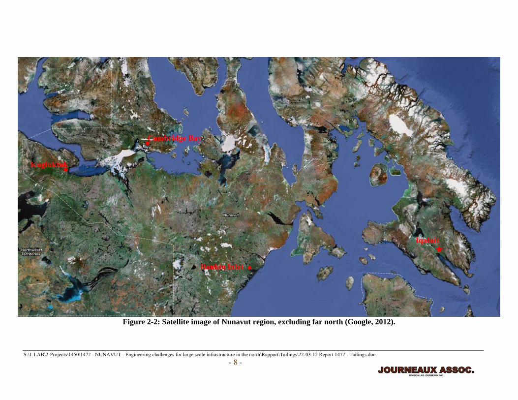
through which the river drainage systems were developed. Figure 2-2 shows a recent satellite
image of Nunavut. Usually, a thin cover of glacial till is found on the bedrock with granular

S:\1-LAB\2-Projects\1450\1472 - NUNAVUT - Engineering challenges for large scale infrastructure in the north\Rapport\Tailings\22-03-12 Report 1472 - Tailings.doc - 7 -
materials deposited in ice scoured fault and fracture zones and in long linear esker ridges usually
located in the bottom of broad synclinal geologic structures. In the lower, deeper, scoured basins,
the topography is much flatter and basal till deposits are more common, although the thickness
varies according to the underlying bedrock geology. In the areas below the highest marine
beaches, ice-rich marine clays and silts have been deposited over the underlying glacial tills. In
broad valleys and in lakes, deep marine clay deposits can be found at elevations of 300 meters
(above present sea level). This is due to isostatic rebound of the earth's crust over the last 10,000
years during which time the western part of Nunavut was mostly free of ice cover. Nunavut is
located in the continuous permafrost zone, see Figure 2-3; this figure also shows the ground
monitoring stations in the area. The depth of permafrost in Nunavut generally extends several
hundred meters below ground.
Nunavut has been the focus of recent geological survey research and mapping. Full details
relating to geoscience mapping are available through the Nunavut Geoscience webpage
(http://nunavutgeoscience.ca), which is a joint initiative of the Canada-Nunavut Geoscience
Office (CNGO), Indian and Northern Affairs Canada (INAC), Government of Nunavut (GN),
Natural Resources Canada (NRCan) and Nunavut Tunngavik Incorporated (NTI). The webpage
provides extensive mapping information including bedrock geology, surficial materials, geologic
faults, elevation data and rock types. (Nunavut Geoscience, 2012)
S:\1-LAB\2-Projects\1450\1472 - NUNAVUT - Engineering challenges for large scale infrastructure in the north\Rapport\Tailings\22-03-12 Report 1472 - Tailings.doc - 8 -
Figure 2-2: Satellite image of Nunavut region, excluding far north (Google, 2012).

S:\1-LAB\2-Projects\1450\1472 - NUNAVUT - Engineering challenges for large scale infrastructure in the north\Rapport\Tailings\22-03-12 Report 1472 - Tailings.doc - 9 -
Figure 2-3: Permafrost zones and thermal monitoring stations within Canada (Courtesy S. Smith – GSC, 2000).

S:\1-LAB\2-Projects\1450\1472 - NUNAVUT - Engineering challenges for large scale infrastructure in the north\Rapport\Tailings\22-03-12 Report 1472 - Tailings.doc
- 10 –
3 CLIMATE CHANGE CONSIDERATIONS REGARDING
TAILINGS MANAGEMENT FACILITIES IN NUNAVUT
3.1 Climate Change Impacts on Tailings Management Facilities/ Infrastructure
The Arctic Council and the International Arctic Science Committee (IASC) have prepared
comprehensive reports relating to climate change in the Arctic and the numerous implications
(see ACIA, 2004, 2005). Chapter 16 of ACIA (2005) is dedicated to climate change impacts on
infrastructure. Stratos Inc. (2009) performed a literature review related to climate change impacts
on mining operations and infrastructure in Canada. The latter provides many references relevant
to northern mine infrastructure, tailings management and mine closure with respect to climate
change. The U.S. Arctic Research Commission also summarizes climate change effects on civil
infrastructure in the permafrost regions (USARC, 2003). Some of the main conclusions relating
to tailings facilities and climate change are summarized here:
• Current and future infrastructure in the Arctic will be affected by climate change.
• All future infrastructure projects will require research relating to climate change.
• Climate data, available over the past century, and expected trends can be used to estimate future climatic conditions and their impact on natural processes.
• Cold regions engineers are able to provide solutions using evolving technologies, but future projects must expect additional costs.
Tables 3-1 and 3-2 summarize climate change items and the associated risks for tailings facilities
in permafrost regions. The tables also provide timeframes during which the impact is likely to be
most significant (e.g. operation or post-closure) and potential mitigation strategies. In general,

S:\1-LAB\2-Projects\1450\1472 - NUNAVUT - Engineering challenges for large scale infrastructure in the north\Rapport\Tailings\22-03-12 Report 1472 - Tailings.doc
- 11 –
the main challenges related to climate change will be associated the post-closure period when
compared to the operational time, which is relatively short for most mines.
The impacts on dams are given in greater detail in the following section (Section 3.1.1).
Precipitation and water balance impacts are discussed in Section 3.3, more information on waste
covers is provided in Section 4.3.2, and disposal sites are discussed in greater detail in the
general disposal alternatives section (Section 4.5).

S:\1-LAB\2-Projects\1450\1472 - NUNAVUT - Engineering challenges for large scale infrastructure in the north\Rapport\Tailings\22-03-12 Report 1472 - Tailings.doc 12 -
Table 3-1 : Potential impact of climate change on hydraulic structures and mine water management in permafrost regions and potential mitigation strategies (modified after Stratos Inc., 2011).
Use frozen core dams and thermosyphons. Be consevative by using flatter slopes and thicker
covers. Constant monitoring of ground temperatures. Reduce ground disturbance and
avoid thaw-sensitive soil locations.
√ Plan water management with future climate change predictions.
√ √Increase capacity of diversion works and
storage structures. Design with future climate change predictions and be conservative.
Mine water mangement
Changes in water balance (see Section 3.3) leading to unforeseen problems in mine water management schemes.
Other hydraulic structures (ditches,
berms, holding and tailings ponds, etc.)
Overflow due to insufficient capacity, resulting in more contaninated runoff or infiltraion, possible need for temporary measures to be taken (e.g. floodings pits) and possible shutdowns.
√
√ √ Provide additional freeboard, design with option to increase spillway capacity.
√ √ Increase erosion resistance of structures (lower slopes, larger diameter rip rap).
Flatter slopes or buttress required. Implement adequate drainage system in dam.
Weakening of structure due to erosion of face or gullying at base.
√
√ √Slope failure due to rising phreatic surface.
√ √ √
√
Increased seepage below dam. √ √ √
Seepage through dam due to formation of cracks (flow paths). √
√ √ Provide additional freeboard.
Increased Wind Action
Changes in Water
B l
OperationPost-
closure
Dam
Settlement
Overtopping √
Mine Component /
Activity
Description of Potential Direct Impact
Most relevant Climate Change Condition(s) Most relevant Potential Mitigation
TemperatureMean Annual Precipitation
Extreme Precipitation
Permafrost Degradation

S:\1-LAB\2-Projects\1450\1472 - NUNAVUT - Engineering challenges for large scale infrastructure in the north\Rapport\Tailings\22-03-12 Report 1472 - Tailings.doc 13 -
Table 3-2 : Potential impact of climate change on waster covers and disposal sites in permafrost regions and potential mitigation strategies (modified after Stratos Inc., 2011).
Potential MitigationTemperature
Mean Annual Precipitation
Extreme Precipitation
Permafrost Degradation
Increased Wind Action
Changes in Water Balance Operation
Post-closure
Waste covers
Mine Component
Description of Potential Direct Impact
Most relevant Climate Change Condition(s) Most relevant
√
Drought conditions may lead to a shortage of water in long-term for 'water covers', resulting in increased oxidization. Increased precipitation may lead to need for emergency discharge.
√ √
Vegetaion unable to adapt to changes leading to increased percolation, erosion or metal uptake.
√ √ √ √ √
Use adaptable vegtation for expected climate change scenarios, increase erosion resistance (flatter slopes, armoured runoff channels) or increase thickness/capacity of storage layer.
√Use alternative cover designs (e.g. insultion
cover) or monitor water cover.
Avoid associated disposal methods; use alternative disposal techniques, such as 'dry'
stacking and underground backfilling.
√
Increased storm magnitude and frequency leading to increased wind and wave action in tailings ponds causing re-suspension of tailings and the formation of ice dams.
√
Sub-component / type
Insulation cover
Water cover
Store and release cover
Drought conditions, during the summer, can impact dust suppression efforts via water spraying over dry stack tailings piles. Increased wind action could result in more difficulty mitigating dust spreading.
Open pits
Design 'insulation covers' conservatively and monitor performance.
Tailings ponds
'Dry' stacked tailings piles
Permafrost degradation of entire insulation cover leading to infiltration into the waste layer and increased oxidization and leaching.
√ √
√ √Conserve water and plan water management with potential for dry periods. Use other dust suppresion methods (see Section 4.4.1.2.).
√
√
√ √
√
Increase erosion resistance of layer.
Diposal sites
Barrier cover
Soil barrier: cover is eroded leading to increased infiltration. Synthetic barrier: protection layer is eroded and risk of damage to synthetics.
√
Install bolts and anchors if feasible to staibilize rock slopes. Avoid runoff into pit by building
diversion works.
Permafrost degradation in walls of open pit mines leading to weakening of structural integrity of wall. More precipitation leads to increased water into pit.
√ √ √ √

S:\1-LAB\2-Projects\1450\1472 - NUNAVUT - Engineering challenges for large scale infrastructure in the north\Rapport\Tailings\22-03-12 Report 1472 - Tailings.doc - 14 -
3.1.1 Dams The thawing of permafrost under dams/dikes is a big concern for tailings management facilities
in the North. Dams are commonly required for several disposal alternatives (see Section 4.5).
Contaminated mine waste is a perpetual issue (e.g. acid rock drainage – see Section 4.3.1) and
dams/dikes, like any structure, will eventually deteriorate. Climate change will increase the rate
of deterioration, especially since the structures rely on the underlying frozen ground for stability
and seepage containment. Thawing of permafrost below dams/dikes can lead to differential
settlements resulting in the opening of cracks (flow paths) within the dam and seepage through
the dam itself. In addition, settlement will reduce the available freeboard to prevent overtopping.
The underlying ground will be subject to the following, which all result in an increased potential
for seepage through the underlying soil:
• Increased pore pressure.
• Increased possibility of piping below foundation.
• Increased flow paths for subsurface flow/increase in overall soil permeability.
The potential for liquefaction of loose saturated material during earthquakes is another concern
for degrading permafrost below dams.
An increase in mean annual precipitation (MAP) and extreme precipitation events will increase
the potential for seepage (due to increases in the hydraulic head) and slope failure (due to the
rising phreatic surface within the dam). The latter depends on the drainage system within the
dam and, therefore, the type of dam used (see Section 4.4). Increased magnitudes and
frequencies of precipitation events could increase erosion of the upstream face or gullying at the
base of a dam, which will result in weakening of the structure. Finally, extreme precipitation

S:\1-LAB\2-Projects\1450\1472 - NUNAVUT - Engineering challenges for large scale infrastructure in the north\Rapport\Tailings\22-03-12 Report 1472 - Tailings.doc - 15 -
events could result in overtopping. All of these climate change impacts will reduce the
capabilities of dams/dikes to contain tailings ponds, holding ponds, etc. Mitigation strategies for
dams/dikes in Nunavut are summarized in the following points:
• Use frozen core dams with thick covers and thermosyphons to maintain the core in a
frozen state (see Section 4.4.1).
• Use flatter slopes and erosion resistant cover material.
• Monitor ground temperatures constantly.
• Reduce ground disturbance and avoid thaw-sensitive soil locations.
• Provide additional freeboard or increase spillway capacity.
3.2 Permafrost
3.2.1 General Introduction In northern Canada, the ability to understand and predict the physical state of permafrost is a
challenge that affects the design, construction, and maintenance of infrastructures. Tailings
facilities in Canada’s North, built on permafrost, rely on the integrity of permafrost to prevent
the movement of toxic mine waste through glacial till and bedrock and into the natural
groundwater drainage systems. Design of above ground structures must therefore preserve frozen
conditions while limiting thaw. Experience has led to a variety of practices and technologies
adapted to cold climates to prevent such hazards. For example, installing a robust and self-
controlling freezing apparatus below foundations to freeze and even supercool permafrost will
prevent thawing for centuries if thick covers are used. Countless papers relating to permafrost
can be found through the International Permafrost Association (IPA) website

S:\1-LAB\2-Projects\1450\1472 - NUNAVUT - Engineering challenges for large scale infrastructure in the north\Rapport\Tailings\22-03-12 Report 1472 - Tailings.doc - 16 -
(http://ipa.arcticportal.org/), where proceedings from the first nine ‘International Conferences on
Permafrost’ are available. A report was also submitted to the Government of Yukon concerning
permafrost considerations for effective mine development (EBA Ltd., 2004).
Smith et al. (2001) provides an extensive report of current knowledge relating to permafrost in
Canada and Holubec (2004) provides a detailed background on permafrost as well. Permafrost is
defined as a soil or rock at or below 0 °C for two or more years. The definition does not consider
the depression of the freezing point due to pore water salinity (e.g. from sea water infiltration or
mill water within tailings), or the oxidation of reactive tailings. Furthermore, the definition does
not include the depth, temperature, location within the stratification or water/ice content, which
are useful in determining the physical and chemical properties of the soil when designing
infrastructure over permafrost. Another factor that increases the complexity of permafrost is the
effect of vegetation. In Nunavut, where permafrost is continuous, (refer back to Figure 2-3)
vegetation can accumulate snow cover during the winter and this insulates the ground from cold
temperatures. Removing vegetation in continuous permafrost zones could result in permafrost
degradation (and possible settlements) during the initial summer construction period, but will
eventually re-establish over the cold winter for the new site conditions. The soil and rock types
and properties (e.g. moisture content and thermal conductivities), cover types (e.g. grass, asphalt,
snow cover, etc.) and respective thicknesses, hydrology and local topography are other
parameters that affect permafrost conditions besides the more obvious temperature conditions.
Figures 3-1 to 3-3 (taken from Smith and Burgess, 1998; 2004) show the mean annual near-
surface ground temperature (MAGST) and the relative thermal and physical responses to climate

S:\1-LAB\2-Projects\1450\1472 - NUNAVUT - Engineering challenges for large scale infrastructure in the north\Rapport\Tailings\22-03-12 Report 1472 - Tailings.doc - 17 -
warming in Canada. From Figure 3-1, it can be seen that Nunavut has mean annual near-surface
ground temperatures below -2 ºC where continuous permafrost is found. The MAGST data is
useful in the design of infrastructure associated with tailings facilities (e.g. cover design to
encapsulate tailings in permafrost – see Section 4.3.2). In Figure 3-2, the thermal ground
response has been separated into three zones. The thermal response generally increases with the
current mean temperatures and is greatest in zones with lower temperatures. However, the
potential for thaw is still greatest in the warmer regions. Nunavut will have a medium to high
relative thermal response to warming. Finally, in Figure 3-3, regions where ice-rich sediments
are present will have the largest physical response (the relative magnitude of the impact of
permafrost thaw and settlement) to climate warming. The ice content of soil is generally larger in
fine-grained soils and organic materials (see Section 3.2.2). Nunavut contains a variety of soil
types; therefore, individual assessments would be required for particular regions where
infrastructure projects are planned.

S:\1-LAB\2-Projects\1450\1472 - NUNAVUT - Engineering challenges for large scale infrastructure in the north\Rapport\Tailings\22-03-12 Report 1472 - Tailings.doc - 18 -
Figure 3-1: Mean annual near-surface ground temperature (Smith and Burgess; 2004).

S:\1-LAB\2-Projects\1450\1472 - NUNAVUT - Engineering challenges for large scale infrastructure in the north\Rapport\Tailings\22-03-12 Report 1472 - Tailings.doc - 19 -
Figure 3-2: Relative thermal response to climate warming (Smith and Burgess; 1998).

S:\1-LAB\2-Projects\1450\1472 - NUNAVUT - Engineering challenges for large scale infrastructure in the north\Rapport\Tailings\22-03-12 Report 1472 - Tailings.doc - 20 -
Figure 3-3: Relative physical response to climate warming (Smith and Burgess; 2004).

S:\1-LAB\2-Projects\1450\1472 - NUNAVUT - Engineering challenges for large scale infrastructure in the north\Rapport\Tailings\22-03-12 Report 1472 - Tailings.doc
- 21 -
Figure 3-4 compares typical temperature profiles through permafrost, from the ground surface to
the base of the permafrost. The figure shows the simplest approximation of the effects of climate
warming; the temperature profile shifts to the right (increased temperature), the active layer
increases in thickness and the permafrost level increases in depth. It should be noted, that the
summer and winter curves intersect at a certain level (the level of zero amplitude) within the
permafrost where temperatures are constant year-round. Above this point the summer and winter
curves veer to the right and left, respectively.
Figure 3-4: Typical ground temperature profiles (after USARC, 2003).

S:\1-LAB\2-Projects\1450\1472 - NUNAVUT - Engineering challenges for large scale infrastructure in the north\Rapport\Tailings\22-03-12 Report 1472 - Tailings.doc
- 22 -
3.2.2 Freezing and Thawing Indices In order to design structures on permafrost, engineers often rely on the air freezing and thawing
indices (given in degree-days) of the proposed site location. [Note: air freezing index = degree-
day freezing (DDF) and air thawing index = degree-day thawing (DDT).] Freezing/thawing
indices are calculated by summing the number of days with temperatures below zero/above zero
multiplied by the average temperature during those days. Boyd (1976) presents a paper
summarizing how the air freezing and thawing indices are calculated based on normal monthly
temperatures. Huschke (1959) used daily average temperatures to calculate the freezing/thawing
indices. These mean freezing/thawing indices can be used to assess temperature trends and, in
turn, their effects on permafrost degradation.
Design air freezing/thawing indices are calculated in different ways depending on the design
codes or other considerations of a given infrastructure project. The design air thawing index is
usually calculated by averaging the seasonal thawing indices for the three warmest summers in
the past 30 years (if 30 years of data is not available, the warmest summer in the past 10 years is
used) and is commonly used to determine the maximum thaw depth. The design air freezing
index has received a lot of attention by researchers, since it is used to estimate frost heave, a key
factor in cold region foundation design. For most civil engineering projects, the maximum air
freezing index that can be expected once in every 25 years is usually sufficient for design
purposes (McCormick, 1991). However, for more conservative design, longer return periods may
be justifiable. The Canadian Foundation Engineering Manual (CFEM, 2007) reviews other
methods for determining the design air freezing index. Once a design index is accepted, it is used
to determine the ground surface index.

S:\1-LAB\2-Projects\1450\1472 - NUNAVUT - Engineering challenges for large scale infrastructure in the north\Rapport\Tailings\22-03-12 Report 1472 - Tailings.doc
- 23 -
Surface freezing indices have to account for the variations in ground cover; the relationship
between the design and surface indices depends on the ground surface material (e.g. snow, grass,
pavement, etc.). An n factor is used to calculate the surface index (see Equation 1) based on the
cover type. Once the surface freezing and thawing indices are determined, the thermal resistance
of the cover and thermal conductivity of the soil is required to perform further analysis on
individual soil layers (Kersten, 1949). Some empirical relationships may exist depending on the
application.
s dI nI= (1)
where Is is the surface freezing index , Id is the design freezing index.
3.2.3 Ice Content in Soils and Settling of Thawing Permafrost
The ice content in soils will depend on the type of soil, the availability of free water during the
freezing period and the salt content in the pore water. In general, in coarse-grained soils that are
more elevated and have good drainage, the ice content is related to the original water content of
the material and occurs usually as ice coatings on soil fragments and in the original saturated
voids of the material. When fine-grained soils are involved, migration of water to the freezing
front can cause significant ice lenses and layers. In the marine silts and clays, thick (up to several
millimetres) and frequent ice layers are common and this can occur to considerable depths (up to
20 meters). In fine-grained glacial till, vertical ice wedges up to 1 metre wide and extending
several meters in depth, are not uncommon. On land, these can be identified by polygonal or
linear topographic expressions. These areas should be avoided when constructing dams/dikes or
other infrastructure.

S:\1-LAB\2-Projects\1450\1472 - NUNAVUT - Engineering challenges for large scale infrastructure in the north\Rapport\Tailings\22-03-12 Report 1472 - Tailings.doc
- 24 -
The ice content within frozen soils is critical for determining possible settlement as it controls
the thaw strain and therefore thaw sensitivity/stability of a soil layer. The Canadian Foundation
Engineering Manual offers little design advice for thaw-settlement predictions and stresses the
importance of an experienced cold regions engineer to perform the analysis. That being said,
Frederick Crory (1973) presented a simple, practical and direct method for predicting settlement
associated with the thawing of permafrost. This method uses the water content and dry unit
weight of undisturbed samples. An accurate measurement and prediction of the ice content/water
content within soil(s) before and after the expected thaw has occurred is essential in performing
the settlement analysis. Thaw consolidation settlement has also been extensively studied by
several researchers in an attempt to develop empirical relationships based on soil types (see for
example Tsytovich et al. 1965; Morgenstern and Nixon, 1971; Hanna et al., 1983). Nevertheless,
laboratory consolidation experiments are irreplaceable in assessing in-situ soil responses for a
specific site. In addition to thaw-settlement, the issue of creep deformations of frozen soils under
applied loads must be addressed. Creep deformation is a function of load, soil type and
temperature; creep deformation will increase dramatically if temperatures approach the thawing
temperatures of soils. More publications and references to cold regions settlement can be found
through the IPA website (http://ipa.arcticportal.org/).
3.3 Precipitation and Water Balance (Precipitation and Evaporation) Precipitation and water balance, in terms of the combination of precipitation and evaporation, are
expected to change in the future and these changes will have major consequences on tailing
management facilities.

S:\1-LAB\2-Projects\1450\1472 - NUNAVUT - Engineering challenges for large scale infrastructure in the north\Rapport\Tailings\22-03-12 Report 1472 - Tailings.doc
- 25 -
Precipitation data is used in the design of hydraulic structures at mine sites (e.g. dams, dikes,
ditches, spillways, tailings ponds, berms). Future mine structures can be designed to withstand
anticipated long-term increases in precipitation. However, current mines, which have not
accounted for these increases, could be at risk. Insufficient capacity of existing hydraulic
structures can lead to runoff of contaminated water and, therefore, detrimental environmental
impacts. The MEND 1.61.7 report suggests that more research is required to determine changes
to the probable maximum precipitation (PMP) and probable maximum flood (PMF), which are
used in the design of dams and collection systems (Stratos Inc, 2011). In general, increased
precipitation would be beneficial to mining operations in Nunavut, where water is scarce;
however, one negative aspect of increased precipitation would be an increase in the runoff from
contaminated areas, which requires costly collection and treatment. Torrential rains have forced
the Minto mine, which is located in the Yukon Territory and began operation in 2007, to release
untreated water into the Yukon River system twice already, with potentially negative impacts on
fish and wildlife. Furthermore, the same torrential rains washed out a four kilometre section of a
haul road (Pearce et al., 2011). Water management plans need to incorporate systems that will
not be overwhelmed by increasing rain storm magnitudes that can force the release untreated
water. Larger collection ponds or diversion works may be suitable solutions.
An evaporation monitoring program, run by the Canadian Water Resources Division (a division
of Aboriginal Affairs and Northern Development Canada), has been operational since 1993.
There are currently eight evaporation monitoring stations across Nunavut and the Northwest
Territories (NWT). The stations are located at the Giant, Salmita, Colomac, Lupin, Silver Bear,
Discovery, Nanisivik and Cullaton Lake mine sites. (AANDC, 2010)

S:\1-LAB\2-Projects\1450\1472 - NUNAVUT - Engineering challenges for large scale infrastructure in the north\Rapport\Tailings\22-03-12 Report 1472 - Tailings.doc
- 26 -
Precipitation and evaporation rates are two main components of water balance management
plans associated with tailing disposal facilities. Changes in water balance may lead to dryer or
wetter conditions in different locations throughout Nunavut. A variety of mine site water
management situations can exist for different mines. All mines require a water source for
operations (e.g. ore processing), which is typically a nearby lake/river or, in extreme conditions,
runoff collection basins. Contaminated water requires treatment before being released back into
the environment; mines often recycle tailings water for ongoing ore processing to avoid
treatment cost. Sometimes a mine will reach a steady-state situation where they no longer require
fresh water from an external source. When too much water (e.g. from precipitation into holding
ponds) accumulates, more frequent releases of water to the environment are required. The design
of polishing ponds, tailings ponds, pumping stations, ditches and so forth all depend on the local
water balance. Changes in the water balance over the lifecycle of a mine should be incorporated
into water management plans.
Water balance is also used in the design of water covers to prevent oxidization of reactive
tailings and in mine site water management. Long-term changes in the water balance may affect
the height of cover; maintaining an adequate water cover is a serious environmental concern for
tailings facilities. Tailings disposal sites are regularly abandoned once the mine operation is
terminated. Therefore, long-term water balance should be accounted for in their design, along
with post-closure monitoring programs, if water cover is the chosen cover method.
S:\1-LAB\2-Projects\1450\1472 - NUNAVUT - Engineering challenges for large scale infrastructure in the north\Rapport\Tailings\22-03-12 Report 1472 - Tailings.doc
- 27 -
3.4 Designing for Climate Change Impacts on Tailings Management Facilities
This section provides an overview of the current state of standard methods used by engineers and
other specialists involved in the design of large scale infrastructure relating to tailings facilities.
This section will provide an introduction to the main methods available for assessing specific
aspects of geotechnical design with climate change.
3.4.1 Predicting Climate Change
Forecasting future climatic trends is an integral part of planning, designing and monitoring future
infrastructure. Both ultimate (failure) and serviceability (deformation) limit states must be
achieved throughout the life of the project. Future trends in soil properties require predictions of
permafrost temperatures, active layer thicknesses, freeze-thaw cycles, frost penetration or
combinations of these.
With the many different climate prediction methods available it can be confusing for design
engineers to choose a scheme for long-term design. Hayley and Horne (2008) rationalize the
design of structures on permafrost (from a Canadian perspective) in their paper by reviewing two
case studies; an apartment building with complex foundation conditions and a reclamation
project that relies on permafrost stability. They conclude that for structures with a service life of
30 years or less, available climate data can be used to predict climate change effects that should
be incorporated into design considerations. For infrastructures with longer lifespans, global
climate models (GCM’s) are recommended. However, GCM’s do not include permafrost
dynamics that can potentially provide critical feedbacks on climate changes. Nicolsky et al.

S:\1-LAB\2-Projects\1450\1472 - NUNAVUT - Engineering challenges for large scale infrastructure in the north\Rapport\Tailings\22-03-12 Report 1472 - Tailings.doc
- 28 -
(2007) and Alexeev (2007) compared Community Land Models (CLM3), which is a land based
scheme, with observed trends. They give recommendations to increase the total soil depth,
incorporate a surface organic layer and modify the numerical scheme to include unfrozen water
dynamics and a more realistic phase change representation in models. Geothermal analysis
coupled with climate trends and failures modes should be used to predict the long-term stability
of structures (see also Section 3.4.2). Past experience should not be overlooked, as lessons
learned from historical performance of past projects can provide valuable insight for new
designs.
In spite of climate change concerns, the economics of the project will propel the construction to
move forward. At this point, experienced engineers must make conservative and realistic
decisions in design. For example, the design of a major structure over ice-rich soil, in a sporadic
permafrost region, is a complex project with the associated difficulties in estimating settlements.
However, appropriate design concepts, such as the use of thermosyphons, adjustable footings,
pile or insulation beneath the foundation, as well as safety factors, will allow these types of
projects to move forward and ultimately perform adequately. Another example would be the
design and construction of a major railway with numerous culverts and bridges that must proceed
on sound engineering design based on reasonable projections of permafrost degradation and
climatic conditions over the next 100 years. When dealing with the disposal of hazardous
tailings, engineers must consider design concepts that promote ease of rehabilitation for future
generations, if eventual loss of containment occurs.

S:\1-LAB\2-Projects\1450\1472 - NUNAVUT - Engineering challenges for large scale infrastructure in the north\Rapport\Tailings\22-03-12 Report 1472 - Tailings.doc
- 29 -
3.4.2 Computer Modeling Recently, finite element computational software programs’, such as ABAQUS®, COMSOL
Multiphysics™ and GEOTHERM®, have been used to analyze a variety of otherwise
mathematically rigorous situations relating to infrastructure design in cold climates. Thermal
predictions can be coupled with the engineering concepts to assess the settlement and strength of
thawing soil over time using finite element programs. Several studies have been carried out to
assess the interaction of oil and gas pipelines in permafrost regions (see for example Xu et al.,
2009). Shuguang (2011) suggests that conducting numerical simulations on the thaw-settlement
of frozen soil can help guide the designs of subgrade and pavement in permafrost zones. With
regard to tailings facilities, many recent projects have used finite element modeling (FEM).
Tchekhovski (2005) provides a study of present and future thermal regimes for a tailings disposal
facility at Kupol Mine, Russia. A detailed geothermal analysis is also presented by EBA Ltd.
(2011) to investigate the long-term impact (with global warming) on the thermal regime
underlying a future dry stack tailings facility in Yukon (Bellekeno Mine). Six more typical
examples of thermal analyses, relating to northern mining projects, are covered by Zhang and
Horne (2010). These include:
1) The thermal design of a frozen core dam with thermosyphons for a tailings management
facility.
2) The thermal design of a ventilated duct system building foundation over ice-rich
permafrost.
3) A feasibility study of artificial ground freezing around an ore body for managing seepage
during underground mining.

S:\1-LAB\2-Projects\1450\1472 - NUNAVUT - Engineering challenges for large scale infrastructure in the north\Rapport\Tailings\22-03-12 Report 1472 - Tailings.doc
- 30 -
4) The thermal evaluation of water filling a mined-out pit within a permafrost zone close to
an active underground operation.
5) The thermal evaluation of dewatered stacked tailings placed over ice-rich permafrost.
6) The evaluation of long-term thermal performance of a tailings dyke with a closure cover.
Springman and Arenson (2008) summarize recent advances in physical and coupled modeling.
Points particularly relevant to tailings management are listed below (for related references see
Springman and Arenson’s paper):
• Physical modeling:
o Physical modeling can be a vital tool in assessing mechanisms of deformation and
failure in frozen soil and interaction with structures.
o Stability models of ice filled jointed rocks have been studied using geotechnical
centrifuge modeling. These studies, along with direct shear tests, confirmed that
the warming of ice sheets inside a joint critical to the stability of a slope could
lead to slope failure. Rock slope instability is often encountered in open pit design
in mines.
• Coupled modeling:
o Constitutive and numerical modeling;
Coupled thermo-hydro-mechanical (THM) modeling is not at a practical
state to fully model all processes together. Often only one or two
dimensional models are used, when in reality problems are three
dimensional. Mostly, only two of the three elements (thermal,
hydrological and mechanical) are modeled at a time.

S:\1-LAB\2-Projects\1450\1472 - NUNAVUT - Engineering challenges for large scale infrastructure in the north\Rapport\Tailings\22-03-12 Report 1472 - Tailings.doc
- 31 -
Thawing and freezing under variable groundwater regimes can be well
modeled.
Risk assessments in permafrost zones would benefit greatly from transient
simulations with varying boundary conditions that continually alter
thermal, hydrological and mechanical effects.
o GIS-based modeling;
Can be a useful tool in assessing spatial distributions of ground
temperature regimes and active layer depth.
They are currently limited by the lack of information on the complex
interaction between the atmosphere and ground.
3.4.3 Site Investigation and Monitoring
Site investigation is the first and therefore, most important step in infrastructure design. Site
investigation in northern regions is complicated by the abundance of cold region phenomena that
occur throughout the region and can create complex problems for design engineers (see, for
example, Washburn, 1973; Rykaart and Hockley, 2009 or Table 4-7, pg. 58). Site investigations,
along with monitoring, are essential in providing geotechnical input on the processes occurring
underground. In order to characterize the underlying ground, a number of methods are available
(for references to the recent advancement listed below, please see Springman and Arenson,
2006):
• Airphoto interpretation and terrain analysis: can be used, along with bedrock geology
maps, to develop a reasonable interpretation of permafrost distribution and the probability
of ice wedges.

S:\1-LAB\2-Projects\1450\1472 - NUNAVUT - Engineering challenges for large scale infrastructure in the north\Rapport\Tailings\22-03-12 Report 1472 - Tailings.doc
- 32 -
• Geophysical methods:
o Ground penetration radar or electromagnetic surveys can help determine relative
ice contents.
o Nunavut Geoscience’s webpage provides several maps both in interactive and
publication-style formats.
o Boreholes and test pits are required to support geophysical methods.
o Tomographic inversion techniques can be used to determine ground structure and
monitor seasonal active layer thaw.
o Seismic approaches can help estimate small strain stiffness.
• Ground temperature measurement: temperature measuring devices can be placed within
boreholes before they are re-filled; certain models can be directly driven into the ground
depending on the depth of penetration and soil conditions. A connection wire, usually
protected by a PVC pipe, is attached to the temperature device and runs upwards to the
ground surface. Ground temperature readings can be taken at any time by re-visiting the
site and connecting the lead wires to a data acquisition system.
• Groundwater pressure measurement: although groundwater measurements are less
applicable in Nunavut where the ground continuously frozen, pressure transducers can be
used to determine water pressures below ground if any groundwater exists. They are
installed in a similar fashion to the temperature measuring devices.
• Monitoring: ground temperature and slope stability (e.g. inclinometer) measurements are
useful in monitoring the stability of infrastructure over its lifecycle. Monitoring can be
used to regulate future maintenance requirements. Inclinometers, installed within tubing,

S:\1-LAB\2-Projects\1450\1472 - NUNAVUT - Engineering challenges for large scale infrastructure in the north\Rapport\Tailings\22-03-12 Report 1472 - Tailings.doc
- 33 -
can be useless if shearing of the tube occurs due to soil movement (e.g. considerable
creep).
• In-situ tests:
o In-situ permeability tests (e.g. packer tests) can be helpful in assessing seepage,
modeling contaminant transport or designing drainage systems.
o Probes can be used to determine thermal properties of the permafrost, although
disturbance due to drilling may make the determination of properties difficult
(Overduin et al., 2006).
o Pressuremeter, cone penetration or dilatometer testing can be used to determine
shear strength and strain stiffness that can be applied to subsequent designs.
• Soil and rock sampling:
o Samples must be extracted with refrigerated fluids (e.g. saline solutions at -4 ºC)
to minimize disturbance, avoiding melting or rearrangement of soil particles.
They can be transported accordingly and kept frozen by packing in dry ice (solid
CO2) for laboratory testing. Sometimes it is impossible to remove intact samples
due to the sensitive blocky nature of soils, particularly when they are released
from the natural confining pressures experienced underground.
o Drilling with auger, air-rotary, wet-rotary or hammer drills is preferred.
o Soil samples are obtained from auger core barrels, split spoon drive samplers or
hammer drill barrels.
o Permafrost that contains large rocks must be drilled using diamond tipped core
barrels. In order to preserve samples, the drilling mud must be saline and

S:\1-LAB\2-Projects\1450\1472 - NUNAVUT - Engineering challenges for large scale infrastructure in the north\Rapport\Tailings\22-03-12 Report 1472 - Tailings.doc
- 34 -
temperature controlled (typically -4° C). Winter operation can be undertaken by a
simple air-to-mud heat exchange system.
Holubec (2010) presents a comprehensive report on geotechnical site investigation guidelines for
building foundations over permafrost. The report provides more detail on drilling and sampling,
as well as other site investigation information for northern regions.
3.4.4 Laboratory Testing
A knowledge of the geomaterial properties is essential in designing waste containment facilities.
For example, the shear strength of a soil is required to assess the stability of slopes and the
permeability is used to estimate fluid transport. Laboratory testing can be used to determine a
wide range of soil properties (e.g. strength properties, permeability properties, water or ice
content, frozen bulk density, grain size distribution, thaw strain and thaw consolidation
properties). Interface tests have also been carried out on ice filled rock joints (Günzel, 2008),
which can be useful in open pit slope design.
Triaxial tests have been performed on artificially frozen soil samples (see for example Arenson
et al., 2004; Arenson and Springman, 2005). Tests can be performed either by applying a
constant strain rate or a constant stress to determine the effect of strain rate, temperature,
volumetric ice-solid-air contents and confining stress on the mobilised shear strength of the
geomaterials. The Young’s modulus (E) can be determined by taking the slope of the linear
portion of the stress-strain curve from a triaxial test. The peak shear strength can are also be
determined; the shear strength values for artificially frozen rock specimens have shown to
increase with lower ice contents and faster strain rates. Many other observations have been

S:\1-LAB\2-Projects\1450\1472 - NUNAVUT - Engineering challenges for large scale infrastructure in the north\Rapport\Tailings\22-03-12 Report 1472 - Tailings.doc
- 35 -
recorded for a variety of geomaterials through triaxial testing. Past research papers on similar or
the same type of geomaterial being considered should be consulted for design and for laboratory
experiment planning. In triaxial experiments, it is important to incorporate the initial in-situ
stress of a sample and the expected changes to the environment. Stress paths and strength
properties at specific confining pressures can be used when performing modeling or design
calculations. Triaxial test are costly and can take an extensive time depending on the
experimental scheme required. Split Hopkinson Pressure Bar (SHBP) tests can also be used to
determine the Young’s modulus of frozen soil. This test can be performed relatively quickly and
provides stress-strain information. The heterogeneity and size effects of frozen soil specimens
can hinder the appropriateness of laboratory experiments used for representing stress paths.
Direct shear, indirect shear (e.g. Brazilian), direct tension and unconfined compression tests can
provide designers with ultimate shear, tensile and unconfined compressive strength estimates. If
samples are properly strain-gauged or displacements are measured accurately by other means
during tests (e.g. tensile, compression or triaxial tests), the Poisson’s ratio can also be
determined. The Poisson’s ratio tends to increase with stress until it reaches its peak value, can
change with temperature or may vary with respect to the loading direction depending on the
heterogeneity of the geomaterial; therefore, a conservative value should be chosen in design.
Many publications relating to frozen geomaterial testing exists; some of these publications can
be downloaded free of charge through the IPA website. See, for example, Lee et al. (2002) for
more details of common frozen soil laboratory tests. Finally, it should be mentioned that new
technological equipment, such as the powerful CT-Scanner at INRS-ETE (Quebec City), could

S:\1-LAB\2-Projects\1450\1472 - NUNAVUT - Engineering challenges for large scale infrastructure in the north\Rapport\Tailings\22-03-12 Report 1472 - Tailings.doc
- 36 -
be extremely useful tools moving towards 3-dimensionally mapping frozen soil specimens and
incorporating the results in modeling applications.
3.5 Temperature and Precipitation in Nunavut Environment Canada’s website provides historical meteorological data for stations across
Nunavut. A detailed overview of air temperatures in Nunavut is given by Holubec (2004).
Table 3-3 presents an overview of the mean annual air temperatures (MAAT) and mean annual
precipitation (MAP) recorded at sixteen stations throughout Nunavut (a total of twenty-three
stations exist). Figure 3-5 shows the location of these stations and other hamlets in Nunavut.
Table 3-3 : MAAT and MAP data in Nunavut for the periods 1951 to 1980 and 1971 to
2000 (Holubec, 2004).

S:\1-LAB\2-Projects\1450\1472 - NUNAVUT - Engineering challenges for large scale infrastructure in the north\Rapport\Tailings\22-03-12 Report 1472 - Tailings.doc
- 37 -
Figure 3-5 : Hamlet locations throughout Nunavut (modified after Environment Canada,
2012).
3.5.1 Temperatures in Nunavut Nunavut has mean annual average temperatures between -9 ºC in the southeast (Iqaluit) and
-20 ºC in the far north (Ellesmere Island). Figure 3-6 summarises the yearly average temperature
variation for the 1971 to 2000 period for the villages of Cambridge Bay, Iqaluit, Eureka, and
Rankin Inlet. These four villages give a representative distribution of the weather over Nunavut
(refer to Figure 3-5 for geographical locations). (Environment Canada, 2012)

S:\1-LAB\2-Projects\1450\1472 - NUNAVUT - Engineering challenges for large scale infrastructure in the north\Rapport\Tailings\22-03-12 Report 1472 - Tailings.doc
- 38 -
Figure 3-6 : Comparison of average monthly temperatures and air freezing/thawing indices
between 1971 and 2000 – Hamlets in Nunavut.
From Figure 3-6, it can be seen that mild temperatures exist between June and September (four
months of the year), except in the far north, where the freezing temperatures return earlier.
Average temperatures reach a high in mid-July for all villages. Freezing conditions arrive rapidly
in autumn to reach very low temperatures (-26 ºC to -34 ºC) by December and last until the end
of February (or into March in the far north). This represents a three month (or four month) period
of intense cold. Figure 3-6 also provides the air freezing and thawing indices given in degree-
days. The values given emphasize the arctic conditions that exist throughout Nunavut where the
ratio of air freezing index (DDF) to air thawing index (DDT) ranges from about 6:1 to 20:1.

S:\1-LAB\2-Projects\1450\1472 - NUNAVUT - Engineering challenges for large scale infrastructure in the north\Rapport\Tailings\22-03-12 Report 1472 - Tailings.doc
- 39 -
Table 3-3 (pg. 35) shows a warming trend between the periods of 1951 to 1980 and 1971 to 2000
for nine stations, a cooling trend for five, and no change for two of the sixteen stations studied in
Nunavut. Four of the five stations showing a decrease in temperature trends are located in the
eastern part of Nunavut. Holubec (2004) showed warming trends in the eastern Arctic between
1950 and 2000, but noted that the warming trend in this region has reversed since 1990.
Regardless, future warming trends are expected in Nunavut and climate warming poses the
greatest engineering challenges for the design of tailings disposal facilities (e.g. permafrost
degradation).
It has been reported that the Arctic Region has experienced three distinct climate changes over
the last 100 years. In the period 1900 to 1945, there was a warming trend of 0.03 °C/year. This
phase was followed by a cooling period from 1946 to 1965 with an overall cooling of
-0.01 °C/year. Another warming trend was reported for the period 1966 to 2003, with an average
warming rate of 0.04 °C/year. Recent events and research indicate that the arctic warming will
continue in the future and should be taken in account in infrastructure design. (ACIA, 2005)
Currently, many research programs have been conducted to evaluate the expected temperature
changes. It has been reported that in the Canadian Arctic there is a possible average increase in
air temperatures of 0.04 °C/year for the next 100 years. Therefore, the overall increase in
temperature could be about 4 °C by 2100. Model projections also show considerable decreases in
the ratios of freezing and thawing index (e.g. decreases in the freezing index and increases in the
thawing index). The charts prepared by Instanes and Mjureke (2002) show similar trends for the
DDF and DDT in Kugluktuk, Nunavut (see Figures 3-7 and 3-8). These figures give projected

S:\1-LAB\2-Projects\1450\1472 - NUNAVUT - Engineering challenges for large scale infrastructure in the north\Rapport\Tailings\22-03-12 Report 1472 - Tailings.doc
- 40 -
freezing/thawing curves for Kugluktuk, based on five different ACIA-designated models. (ACIA
2005)
Figure 3-7: Observed and predicted DDF for Kugluktuk (Coppermine), Nunavut between
1933 and 2100.
Figure 3-8: Observed and predicted DDT for Kugluktuk (Coppermine), Nunavut between
1933 and 2100.

S:\1-LAB\2-Projects\1450\1472 - NUNAVUT - Engineering challenges for large scale infrastructure in the north\Rapport\Tailings\22-03-12 Report 1472 - Tailings.doc
- 41 -
Based on the expected rate of increase in temperatures of 0.04 °C/year, the average temperatures
recorded for Rankin Inlet were modified to estimate the temperatures in 2100 (e.g. the average
monthly temperatures were simply increased by 4 °C). Figure 3-9 shows the difference in the
longer period of above-zero average monthly temperatures (thawing) and the corresponding
shorter freezing period.
Figure 3-9 : Comparison of average monthly temperature conditions between (1971-2000)
and (2100) – Rankin Inlet, Nunavut.
3.5.2 Precipitation in Nunavut The mean annual precipitation for stations in Nunavut is shown in Table 3-3 (pg. 35). The
Nunavut area is part of an arctic desert with an average yearly precipitation of only about 240
mm, the majority of which occurs between June and October with little snowfall occurring

S:\1-LAB\2-Projects\1450\1472 - NUNAVUT - Engineering challenges for large scale infrastructure in the north\Rapport\Tailings\22-03-12 Report 1472 - Tailings.doc
- 42 -
during the winter freezing period. Similar to the temperature distribution, the maximum yearly
precipitation (over 600 mm) is found in the southeast and the minimum precipitation (below 100
mm) in seen in the far north on Ellesmere Island. The snow and ice cover over the land and water
in the far north prevents evapotranspiration and therefore results in arid conditions.
The low precipitation generally produces low snow cover; the insulating effects of snow cover
on the ground are low, and refreezing of the active layer is rapid when a significant lowering of
the temperature occurs, particularly under high wind conditions. This therefore explains why
Nunavut is in the continuous permafrost zone with the thinnest active layer in Canada. Under
these temperature conditions, the active layer in Nunavut should not exceed about 1 metre in ice-
rich soils and perhaps 1.5 meters in relatively dry sands or sand and gravel in late summer
(August-September).
The low precipitation has the advantage of reducing the volume of water entering basins,
providing less flowing water in the tailing storage areas and reducing erosion of drainage
channels. The greatest disadvantage is the lack of processing water for large mines where lakes
are few or small and shallow (< 2 meters) and freeze to the bottom over winter.
Overall global precipitation is expected to increase as the climate warms up. A simple way to
explain this is that more evaporation will occur with warmer weather resulting in increased
precipitation. Figure 3-10 shows the expected percentage increase in precipitation for the year
2050 throughout Canada (no forecast is given up to 2100). For the Nunavut region, the figure
shows considerable variability in the changes of precipitation from (-10 to +30) %. In addition to

S:\1-LAB\2-Projects\1450\1472 - NUNAVUT - Engineering challenges for large scale infrastructure in the north\Rapport\Tailings\22-03-12 Report 1472 - Tailings.doc
- 43 -
expected average annual changes in precipitation, more frequent heavy precipitation events are
projected for Canada (NRTEE, 2010).
Figure 3-10 : Annual precipitation change (%) from 1961 – 1990 to 2040 – 2050 (Atlas of
Canada, 2003).
4 TAILINGS MANAGEMENT IN NUNAVUT
4.1 Overview of the Mining Industry in Nunavut Nunavut has substantial mineral potential. Millions of dollars have already been invested in
exploration and continued interest is inevitable. The volcanic and metamorphic rock formations
across the territory offer numerous possibilities of gold or diamond deposits; the Doris North and
Meliadine projects are prime examples of gold mines already in the planning stage, while the

S:\1-LAB\2-Projects\1450\1472 - NUNAVUT - Engineering challenges for large scale infrastructure in the north\Rapport\Tailings\22-03-12 Report 1472 - Tailings.doc
- 44 -
Cullaton Lake/Shear Lake mine produced 77,783 ounces of gold from 1981 to 1985. The
Meadowbank Gold Project is expected to produce an average of 360,000 ounces of gold per year
over a nine year period (Connell et al., 2008) and is on track to doing so. The Agnico-Eagle
Mines (AEM) high grade Meliadine Gold Project is moving quickly to construction in 2014 –
2015. Base metals, such as copper, iron, nickel, zinc and lead, have been detected across the
territory. The Baffinland Iron Mine Company is currently working to develop a large open pit
iron mine on Baffin Island and Advanced Exploration Inc. is exploring the iron-rich Roche Bay
district. The Nanisivik mine (zinc, lead, silver) and Polaris mine (zinc, lead) have been shown to
be economically viable. Uranium deposits are also quickly gaining interest; the Areva
Kiggaiavik uranium mine project is currently entering a two-year feasibility study and could
begin operation as early as 2015. The Kaminac Gold Corp. is exploring the Kivalliq region,
located about 300 km southwest of Rankin Inlet, which is believed to hold massive amounts of
uranium. (WISE, 2012; NRCan, 1999)
Full details of all active exploration projects in Nunavut are available at
http://nunavutgeoscience.ca. This webpage provides comprehensive exploration maps and
mining overview documents for past years. In 2011, there were 96 mining projects in Nunavut;
38 gold, 14 uranium, 13 base metal, 13 diamond, 7 iron, 5 nickel-copper platinum group element
(PGE), 4 rare earth metal and 2 coal related projects. Figure 4-1 shows the locations of closed
mines in Nunavut; the Polaris and Nanisivik mines (red) closed in 2002. Figure 4-2 shows
mineral exploration sites along with the major rock categories over the territory. Information
related to the mining industry in Nunavut can also be found through the ‘Aboriginal Affairs and
Northern Development Canada’ website (www.aadnc-aandc.gc.ca).

S:\1-LAB\2-Projects\1450\1472 - NUNAVUT - Engineering challenges for large scale infrastructure in the north\Rapport\Tailings\22-03-12 Report 1472 - Tailings.doc
- 45 -
Figure 4-1: Past mines in Nunavut (after NRCan, 1999).
Figure 4-2: Mining exploration and major rock categories in Nunavut (after NRCAN,
1999).

S:\1-LAB\2-Projects\1450\1472 - NUNAVUT - Engineering challenges for large scale infrastructure in the north\Rapport\Tailings\22-03-12 Report 1472 - Tailings.doc
- 46 -
4.2 Tailings Disposal Methods Chosen by Mines in Permafrost Regions Tables 4-1 and 4-2 outline the tailings deposition methods used, or planned to be used, by mines
in permafrost regions. The tables indentify the chosen methods of disposal for mines in
permafrost regions, which can be divided into two main groups; sub-aqueous (underwater) and
sub-aerial (land based). Table 4-1 shows the predominance of sub-aqueous disposal as the
‘method of choice’ for recent mines in Nunavut; the Doris North Project and the Meadowbank
Gold Project. Both projects give detailed reports in determining the optimum solution for tailings
disposal based on numerous environmental, socio-economic, engineering and project economic
factors (please refer to Rykaart, 2005a and 2006; Golder Associates, 2007). As mentioned
previously, the optimum disposal method for tailings is ultimately a case by case decision. Each
disposal method has advantages and disadvantages. The surrounding landscape and climate
conditions are primary components in choosing a disposal technique. Within the ‘Notes’ column
of the tables, the environmental issues/concerns are highlighted in red. Within the ‘Tailings
Disposal Method’ column, cells are highlighted in grey where backfilling disposal methods were
or are to be used. In Table 4-2 the mines are given in order, from top to bottom, of tailings water
content; mines that dispose slurry tailings are given at the top and mines that dispose
dewatered/filtered tailings are shown at the bottom.

S:\1-LAB\2-Projects\1450\1472 - NUNAVUT - Engineering challenges for large scale infrastructure in the north\Rapport\Tailings\22-03-12 Report 1472 - Tailings.doc
- 47 -
Table 4-1 : Sub-aqueous tailings disposal methods in permafrost regions. Mine Name Current Owner Location Tailings Disposal Method Mining Life Notes
Ruttan Mine Hudson Bay Mine and Smelting
Northern Manitoba
Sub-aqueous slurry 1973 - 2002
Thompson Mine Vale - Inco Northern Manitoba
Sub-aqueous slurry 1959 - to date
Red Dog Mine Teck Cominco Alaska Sub-aqueous slurry 1987 - to date - Problems with wind-blown ore dust and wastewater discharge have occurred. (GTT, 2011)
Voisey's Bay Mine Vale - Inco Northern Labrador
Sub-aqueous slurry 2005 - to date
Key Lake Mine Cameco Northern Saskatchewan
Sub-aqueous slurry 1983 - to date
Doris North Project Miramar Hope Bay Ltd.
Nunavut Sub-aqueous slurry planned - Dry stacking was considered too complex. Mine on hold indefinetely.
Rabbit Lake Mine Cameco Northern Saskatchewan
Sub-aqueous slurry 1975 - to date
Polaris Mine Teck Cominco Nunavut Sub-aqueous thickened 1979 - 2002 - Groundwater flow from contaminated lake to Arctic Ocean. (Pollard et al., 1998)
Meliadine Mine Agnico-Eagle Mines
Nunavut Sub-aqueous thickened (tentative plan)
planned - Dust and cost are primary concerns for landbased disposal.
Meadowbank Gold Project
Agnico-Eagle Mines
Nunavut Sub-aqueous and sub-aerial slurry, paste backfill
2010 - to date - Permafrost encapsulated.
Nanisivik Mine Breakwater Resources Ltd.
Nunavut Sub-aqueous and sub-aerial slurry
1976 - 2002 - Initially deposited in lake until filled, permafrost encapsulation.
Jericho Mine Shear Minerals Ltd.
Nunavut Sub-aqueous 2006 - to date - Operation from 2006 to 2008 and planned to re-start shortly.
Ekati Mine BHP NWT Sub-aqueous and sub-aeriel thickened (50%)
1998 - to date - Acid rock drainage problems (Morin, 2003), tailing spill (Mathisen,2008).
Colomac Mine Comaplex Minerals Corp.
NWT Sub-aqueous and sub-aerial slurry
1989 - 1997 - Environmental problems with cyanide contamination of tailings water and seepage. (NCSP, 2006)
Kensington Mine Coueur Alaska Inc.
Alaska Sub-aqueous, paste backfill 2010 - to date - Perpetual risk of acid mine drainage. (GTT, 2011)

S:\1-LAB\2-Projects\1450\1472 - NUNAVUT - Engineering challenges for large scale infrastructure in the north\Rapport\Tailings\22-03-12 Report 1472 - Tailings.doc
- 48 -
Table 4-2 : Sub-aerial tailings disposal methods in permafrost regions. Mine Name Current Owner Location Tailings Disposal Method Mining Life Notes
Copper Cliff Mine Vale - Inco Sudbury, Ontario
Sub-aerial slurry to date
FlinFlon Mine Hudson's Bay Mine and
Northern Manitoba
Sub-aerial slurry to date
Fort Knox and True North Mine
Kincross Gold Corp.
Alaska Sub-aerial slurry 2009 - to date - In dammed valley: closure will be sub-aqueous using eng. wetlands.
Rankin Inlet Mine Asamera Mineral Inc.
Nunavut Sub-aerial slurry 1957 - 1962 - Remidiation (1991); permafrost encapsulation. Before, released acidic and metal rich water to Hudson Bay. Oxidized tailings dust spread as well.
Lupin Mine Echo Bay Mines Ltd.
Nunavut Sub-aerial slurry, paste backfill
1983 - 2005 - Permafrost encapsulation, cyanide contaminated tailings.
Julietta Mine Yanskaya Mining and Geo. Comp.
Russia Sub-aerial: Slurry (present) 2001- to date - Paste tailings in surface facility (previously)
Kupol Mine Kincross Gold Corp.
Russia Sub-aerial slurry 2008 - to data - Permafrost encapsulation, cyanide contaminated tailings.
Mount Polley Imp. Metals Corp.
BC Sub-aerial slurry 1997 - to date
Kumtor Mine Cameco, Kyrgyz Govt
Kyrgyzstan Sub-aerial -
Con Mine Newmount Mining Corp.
NWT Sub-aerial 1938 - 2003
Giant Mine Miramar Mining Corp.
NWT Sub-aerial 1948 - 2004 - Massive amounts of arsenic trioxide dust (NCSP, 2006). Thermosyphons used to freeze and contain contaminated soils.
Snap Lake Mine De Beers NWT Sub-aerial paste, paste backfill
2008 - to date - First fully underground dimaond mine in Canada.
Diavik Mine DDMI, Rio Tinto NWT Sub-aerial, crushed waste rock or paste backfill
2003 - to date
Nunavik Nickel Mine
Canadian Royalties
Northern Quebec
Sub-aerial: Thickened tailings and waste rock
Planned
NICO Project Fortune Mineral Ltd.
NWT Sub-aerial: Thickened tailings and waste rock
Planned
Ryan Lode Mine Bartholome Alaska Sub-aerial: Lined earth dam with reclaimed water system
1987 - 1989
Kubaka Mine Omolon Mining Comp.
Russia Sub-aerial: Two level: Upper dry and lower fluid
- - Permafrost containment.
Kemess Mine Northgate BC Sub-aerial: Dewatered slurry 1998 - to date
Huckleberry Mine Imp. Metals Corp.
BC Sub-aerial: Dewatered slurry 1997 - to date
Illinois Creek Mine Quest Capital Corp.
Alaska - 1997 - 1998 - Company declared bankrupsy leaving State of Alaska to reclaim mine.
Prairie Creek Mine Canadian Zinc. NWT Paste backfill Planned - All tailings will be backfilled.
Greens Creek Mine Hecla Alaska Dry stack, rock fill and cemented paste backfill
1993 - to date - Environmental concern related to ARD and dust. (GTT, 2011). Nearly 80% of cavities will be re-filled at closure.
Raglan Mine Xstrata Nickel Quebec Dry stack, open pit, paste backfill
1997 - to date - Permafrost encapsulation.
Minto Mine Sherwood Copper Corp.
Yukon Dry Stack, then thickened open pit
2007 - to date - Upon completion of mining in open pits, thickened tailings will be disposed by pumping in pits.
Bellenkeno Alexco Resource Corp.
Yukon Dry stack, paste backfill 2011 - to date - Talings disposal plans for 60% surface, 40% underground.
Nixon Fork Mine St. Andrews Goldfields Ltd.
Alaska Dry stack (new disposal plan)
1993- to date - In the past, earth dam was used for tailings disposal.
Pogo Mine Teck Cominco Alaska Dry stack, paste backfill 2006 - to date

S:\1-LAB\2-Projects\1450\1472 - NUNAVUT - Engineering challenges for large scale infrastructure in the north\Rapport\Tailings\22-03-12 Report 1472 - Tailings.doc
- 49 -
4.3 Environmental Considerations
Several reports have been published relating to disposal of contaminated mine waste in the
Arctic and in cold climates. The Mine Environment Neutral Drainage (MEND) program has
published some of the most comprehensive reports relating to disposal of potential acid
generating (PAG) tailings in cold regions (see Table 4-3). These reports provide great detail on
cold regions mining and are available through the MEND website.
Table 4-3 : MEND reports relating to cold regions mining.
MEND Project Year
6.1 1993
1.61.1 1996
1.61.2 1996
1.61.3 1997
1.62.2 1998
W.014 1997
5.4.2d 2001
1.61.4 2004
1.61.5a 2009
1.61.5b 2010
1.61.6 2006
1.61.7 2011
Mine Waste Covers in Cold Regions
Cold Regions Cover Research
Update on Cold Temperature Effects on Geochemical Weathering
Climate Change and Acid Rock Drainage - Risks for Canadian Mining Sector
Acid Mine Drainage Behaviour in Low Temperature Regimes - Thermal Properties of Tailings
Managing Mine Wastes in Permafrost Zones, Summary Notes MEND Workshop
MEND Manual, Volume 4 - Prevention and Control, Chapter 4.8 Permafrost and Freezing
Cover for Reactive Tailings Location in Permafrost Regions Review
Column Leaching Characteristics of Cullaton Lake B and Shear (S) - Zones Tailings Phase 2: Cold Temperature Leaching
Title
Preventing AMD by Disposing of Reactive Tailing in Permafrost
Roles of Ice, in the Water Cover Option, and Permafrost in Controlling Acid Generation from Sulphide Tailings
Acid Mine Drainage in Permafrost Regions: Issues, Control Strategies and Research Requirements

S:\1-LAB\2-Projects\1450\1472 - NUNAVUT - Engineering challenges for large scale infrastructure in the north\Rapport\Tailings\22-03-12 Report 1472 - Tailings.doc
- 50 -
Various reports have been submitted as part of the environmental assessment process for mining
projects. These reports provide some information relating to issues that were raised concerning
climate change and tailings disposal, and the approaches taken to address them; see, for example,
the recent environmental assessment reports for cold regions mining projects in North America:
Voisey’s Bay Mine (Griffiths et al., 1997), Diavik Mine (CEAA, 1999), Snap Lake Mine (Wray
et al., 2003), Pogo Mine (EPA, 2003) and Fort Banks and True North Mines (Golder Associates,
2004). Guidelines of an inclusive framework for an environmental impact assessment are given
by Yap (2003), which is available on the Canadian Environmental Assessment Agency webpage
(www.ceaa-acee.gc.ca). Furthermore, a paper titled “Guidelines for Alternatives Assessments for
Mine Waste Disposal” is available through the Environment Canada website (www.ec.gc.ca)
(Environment Canada, 2011).
Table 4-4, taken from the report on tailings alternatives for the Meadowbank Gold Project, gives
the typical environmental considerations for the construction of a tailings facility. Land or water
use and the loss of wildlife are major concerns for any mine. Potential for geotechnical failures
are primary concerns when building containment structures. Potential for airborne dust
emissions, transported by wind to air, land and water, can be a considerable pollutant (see
Section 4.6.1.2). In Table 4-4, acid rock drainage (see next section; Section 4.3.1) and metal
leaching from tailings are given as potential threats. Other hazardous chemicals can be generated
during mining processes. For example, in order to extract precious metals from the ore,
hazardous chemical solutions such as sodium or potassium cyanide (e.g. used for gold
processing) and hydrochloric acid are used (MPC, 2000). The main concern is preventing the
spread of chemicals to natural water sources. If water is able to enter contaminated tailings piles,

S:\1-LAB\2-Projects\1450\1472 - NUNAVUT - Engineering challenges for large scale infrastructure in the north\Rapport\Tailings\22-03-12 Report 1472 - Tailings.doc
- 51 -
the water can transport the hazardous chemicals to local groundwater sources; therefore, proper
cover or drainage and collection of the surface water is crucial.
Table 4-4 : Typical environmental factors for a tailings facility (Golder Associates, 2007).
S:\1-LAB\2-Projects\1450\1472 - NUNAVUT - Engineering challenges for large scale infrastructure in the north\Rapport\Tailings\22-03-12 Report 1472 - Tailings.doc
- 52 -
4.3.1 Acid Mine Drainage (AMD) Acid mine drainage (AMD) is a widely encountered concern and numerous cases of
environmental hazards due to abandoned tailings waste have been documented. Many rocks
naturally contain sulphide minerals (e.g. pyrite, pyrrhotite, etc.) that, when exposed to air and
water, will oxidize and form sulphuric acid. This natural process is referred to as acid rock
drainage (ARD). Acid mine drainage (AMD) is essentially the same process, but on a much
larger scale. AMD can lead to severe environmental consequences. The more acidic drainage
water, which now contains sulphuric acid, will also increase the potential for metal leaching. In
order to prevent oxidization, the available oxygen surrounding the tailings should be kept to a
minimum. Table 4-5 lists control strategies for AMD (from MEND 1.61.2). In addition,
limestone can also be used to neutralize acid drainage when readily available. Co-disposal
methods (e.g. inclusion of tailings in mine waste rock) can also be used to reduce oxygen flux
and infiltration to control acid mine drainage. Again, refer to the MEND reports (see Table 4-1)
for more information related to AMD. (Mehrotra and Singhal, 1992)

S:\1-LAB\2-Projects\1450\1472 - NUNAVUT - Engineering challenges for large scale infrastructure in the north\Rapport\Tailings\22-03-12 Report 1472 - Tailings.doc
- 53 -
Table 4-5 : Control strategies for acid mine drainage in Arctic (Dawson and Morin, 1996).
4.3.2 Cover Design in Permafrost Regions
Covers are placed over reactive tailings deposits in order to prevent oxidation of the tailings,
which could lead to negative environmental impacts. The design of covers over tailings disposal
sites, in continuous permafrost regions, is usually done by encapsulating the tailings in a frozen
state. These are referred to as insulation covers. The recommended temperature at the depth/level
of zero annual amplitude, see Figure 3-4 (pg.21), [otherwise known as the mean annual ground
design temperature (MAGDT)], is -2 ºC for cover design by encapsulation. The small difference
(~0.3 ºC) between MAGDT and mean annual ground surface temperature (MAGST), due to the

S:\1-LAB\2-Projects\1450\1472 - NUNAVUT - Engineering challenges for large scale infrastructure in the north\Rapport\Tailings\22-03-12 Report 1472 - Tailings.doc
- 54 -
generally small thermal gradient, can allow designers to use the available mean annual near-
surface ground temperature (MAGST) data for preliminary design or feasibility studies. MAGST
data (see Figure 3-1, pg. 18) is also given in more detail by Smith and Burgess in the open file
GSC report (File Rpt 3954, 2000). Holubec (2004) presents a relationship between the mean
annual air temperature (MAAT) and MAGST, which is linear, but shows that a considerable
spread can occur between the two. Ultimately, the report concludes that MAGDT data must be
measured at a representative location for the final cover design. Encapsulation of permafrost is
achieved by covering the frozen tailings, during the winter, with a suitable thickness of material
that will contain the active layer within the cover. This is usually achieved in two main ways:
1) Using a thicker layer of inert waste rock to contain the active layer or
2) Using a thinner inert waste rock cover, underlain by a fine-grained high water content
layer, where an ice-rich permafrost zone develops and retards thawing during the summer
period.
The designs are obviously limited by cost and material availability. Finer materials will provide
more insulation per unit length, since they tend to remain saturated and frozen, thereby providing
more insulation. Esker material (e.g. sand and gravel) is commonly used for cover design;
however, in the Arctic, these deposits should be conserved as they provide preferred habitats for
animals. In addition, they are not always available in close proximity to the site and can only be
obtained after the summer thaw. This does not provide for a long construction period unless the
material is drilled and blasted at the beginning of the thawing period. The use of inert waste rock
or blasted quarry rock provides for a longer construction period.

S:\1-LAB\2-Projects\1450\1472 - NUNAVUT - Engineering challenges for large scale infrastructure in the north\Rapport\Tailings\22-03-12 Report 1472 - Tailings.doc
- 55 -
Another design alternative used in cold regions is to cover the tailings with a saturated zone of
esker material (e.g. sand and gravel). A 0.3 m saturated and frozen zone of esker material can
prevent oxidization of the tailings below by limiting oxidization. The three main design concepts
for covers in permafrost regions are displayed in Figure 4-3. (Holubec, 2004)
* Note: All dimensions are in meters.
Figure 4-3: Typical design concepts for cover in permafrost regions (Holubec, 2004).
Historical field data for cover designs has only recently become available; Holubec (2004)
presents detailed investigations of cover designs for the first field projects. Table 4-6 summarizes
the main conclusions obtained from these studies (e.g. Nanisivik, Raglan, Lupin and Rankin Inlet
mines), which highlight the benefits of constructing tests pads, during operations, to monitor the
performance of cover design alternatives. These benefits include optimizing the final cover
design and providing valuable research for future cover design endeavours.

S:\1-LAB\2-Projects\1450\1472 - NUNAVUT - Engineering challenges for large scale infrastructure in the north\Rapport\Tailings\22-03-12 Report 1472 - Tailings.doc
- 56 -
Table 4-6 : Control strategies for acid mine drainage in Arctic (after Holubec, 2004). Mine and location Cover design Key notes and observations
- Provides an example of difficulties in establishing long-term and extreme climatic conditions in remote Arctic Region.
- Lighter cover material will likely reduce the thaw depth based on observations. - Active layer was observed to be a function of groundwater table. The lower the groundwater table (e.g. saturation level), the deeper the active layer penetrated into the cover (or in some case into the tailings below).
- A 0.3 m thick layer of saturated esker may be even more efficient than 0.3 m of stagnant water cover in preventing oxidation. (Note: 0.3 m of stagnant water was shown to be sufficient in preventing oxidation in southern mines).
- Durability of the cover is not based on permafrost, therefore, temperature warming alone is not an issue for this type of cover design.
- As has been previously shown with gravel pads, thinner esker covers (e.g. 1 m or less) could support and promote vegetation because they contain more mositure or the groundwater table is near ground surface.
Rankin Inlet Mine Nunavut
Sand and gravel esker material of 1 m thickness.
- Shows difficulties encountered when pore water in tailings has a depressed freezing point. The freezing point can be depressed (lowered) as a result of infiltration of sea water, mill water chemistry or sulphide oxidation. Establishing temperatures at which freezing occurs is difficult. A zone of unfrozen water is created as salinity increases.
Lupin Mine Nunavut
Sand and gravel esker material of varying thickness (0.6 m to 1.6 m).
- Provides field data supporting the theory that the active layer thickness decreases as the bottown layer accumulates water, via snow runoff and rain infiltration, which saturates zone directly over the tailings. Crushed esker layer contains a min. of 10 % fines to hold moisture (increases latent heat and retards thawing process). It is assumed a fully saturated/frozen zone will develop at the base of the cover.
- For a given moisture content, the thaw depth is governed by the thawing index (from 8 years of monitoring). The thaw depth was a function of mositure content, as mositure content increased, thaw depth decreased.
Raglan Mine Northern Quebec
Total thickness of 2.4 m; bottom layer 1.2 m (crushed sand and gravel esker) top layer 1.2 m (mine waste rock).
Nanisivik Mine Nunavut
Total thickness of 1.25 m; 1 m of shale overlain by 0.25 m of sand and gravel.

S:\1-LAB\2-Projects\1450\1472 - NUNAVUT - Engineering challenges for large scale infrastructure in the north\Rapport\Tailings\22-03-12 Report 1472 - Tailings.doc
- 57 -
Another variable affecting the active layer thaw depth, besides those mentioned in Table 4-6
(e.g. vegetation cover, moisture content and colour/albedo), is surface orientation. This should be
taken into account in the design; orienting tailing facilities to minimize sun exposure could help
reduce the active layer depth at no additional cost. Since the publication of Holubec’s report
(MEND report 1.61.4), a lot of research has been carried out on cold regions cover design and
MEND reports 1.61.5a and 1.61.5b provide the latest advances. The MEND report 1.61.5a
provides several recommendations, relating to cover design, for practitioners, regulators and
others involved in the mining sector. Designers should be aware of the wide range of
considerations associated with cover design. In addition to a knowledge of special cold regions
phenomena (cold regions features and processes), in-depth site investigations are required to
establish specific site conditions required for design. Cold regions phenomena that could affect
cover design are given in Table 4-7.
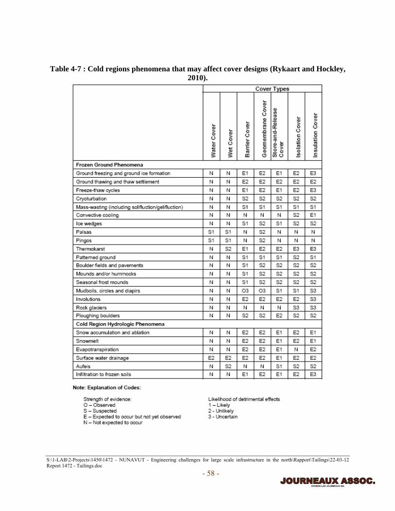
S:\1-LAB\2-Projects\1450\1472 - NUNAVUT - Engineering challenges for large scale infrastructure in the north\Rapport\Tailings\22-03-12 Report 1472 - Tailings.doc
- 58 -
Table 4-7 : Cold regions phenomena that may affect cover designs (Rykaart and Hockley,
2010).

S:\1-LAB\2-Projects\1450\1472 - NUNAVUT - Engineering challenges for large scale infrastructure in the north\Rapport\Tailings\22-03-12 Report 1472 - Tailings.doc
- 59 -
The MEND report 1.61.5a expands on several topics of cold regions phenomena that can affect
covers. These subjects are outlined and expanded briefly below (Rykaart and Hockley, 2009):
• Industry experience:
o A list of cover designs implemented or planned in cold regions, in North America
and Europe, is provided. Few of the covers designed have been reviewed from a
“cold regions” perspective and detailed reports for these sites are not always
available, so few case studies can actually be studied in detail. The industry is still
at the beginner phase in terms of cover design knowledge and understanding.
• Cover selection and design considerations:
o Cover types: isolation covers, barrier covers, store-and-release covers, water
covers and, most notably for cold regions, insulation covers.
o Cold regions effects on mine waste:
Permafrost degradation below mine waste facilities: settlement of
structures, movement of waste and changes to seepage.
Ice entrainment: ice within the mine waste occupies a volume that
otherwise would contain tailings and the ice may be intermediate or long-
term. This results in possible differential settlement concerns. Ice
entrainment in waste rock piles or during construction of covers can affect
the cover design (e.g. ice melting/movement can damage geosynthetics).
Other frozen ground features within mine waste: no records of large scale
features observed, but tailing could be susceptible to growth of ice lenses,

S:\1-LAB\2-Projects\1450\1472 - NUNAVUT - Engineering challenges for large scale infrastructure in the north\Rapport\Tailings\22-03-12 Report 1472 - Tailings.doc
- 60 -
frost heave, formation of pingos and palsas and desiccation cracks leading
to possible formation of ice wedges.
Convective cooling of mine waste: based on grain size distribution of the
waste rock, it should be susceptible to convective cooling leading to the
aggradation of underlying permafrost.
Geochemical weathering: low temperatures tend to slow the oxidation
process.
• Frozen ground effects on cover performance:
o Freeze-thaw effects: usually leads to significant increases in permeability.
o Frost susceptibility: required combination of fine-grained soils, sufficient water
and sufficient cooling to cause soil to freeze.
o Migration of fines through covers: the term ‘boils’ has been adapted to describe
the occurrence of mounds of fines appearing through the covers.
o Other potential ground effects: frost heaving, solifluction (slow down-slope flow
of saturated unfrozen earth), boulder fields (frost action pushing cobbles and
boulders to the surface in loose till, whereas in dense till cobbles and boulders can
move downwards).
• Hydrological effects on cover performance:
o Snow and surface water: difficulties in predicting hydrology.
o Soil water and groundwater: covers that include interflow drains can be subject to
formations of a sheet-like mass of layered ice (aufeis).

S:\1-LAB\2-Projects\1450\1472 - NUNAVUT - Engineering challenges for large scale infrastructure in the north\Rapport\Tailings\22-03-12 Report 1472 - Tailings.doc
- 61 -
o Cold regions hydrological process models: several models designed to represent
snowmelt and frozen ground infiltration processes are discussed in the report.
• Other effects on cover performance:
o Vegetation: concerns that root penetration can lead to preferential flow paths and
metal uptake by vegetation. Shallow rooted species sometimes preferred.
o Animals: caribou migration over or near tailings facilities may result in substantial
erosion or local liquefaction and boils of covered tailings. Also, the presence of
salts in waste areas can attract animals.
• Effects on cover construction:
o Logistics: very remote locations experience great difficulties in transporting
material. As an example, the proposed Doris North Project located near
Kugluktuk in Nunavut, has opted to bring in annual supplies by barges staged out
of Hay River. Their estimated shipping time is eight weeks; therefore, proper
planning of supplies required must be carried out well before the first shipments
arrive in August and must provide a full year’s requirements (Rykaart, 2005b).
The available work force is usually housed in a camp and transportation to and
from the site is costly. The use of geosynthetics or other more complex design
materials requires that specialists be brought on site, making these already
expensive construction alternatives even more costly.
o Productivity: worker productivity is lower in extreme climate conditions and
daylight hours can be limited.
o Soil placement: quick freezing of soils, snow fall and compaction issues.

S:\1-LAB\2-Projects\1450\1472 - NUNAVUT - Engineering challenges for large scale infrastructure in the north\Rapport\Tailings\22-03-12 Report 1472 - Tailings.doc
- 62 -
o Trafficability: construction over soft unconsolidated tailings is a considerable
challenge.
o Use of geosynthetics: generally less economical unless natural material is not
readily available. Geosynthetics have a specified lifespan and strict specifications
on handling, transporting and storing.
o Availability of material: the thawed active layer is only accessible in late summer
or autumn and is often limited in quantity unless acquired from drill and blast
methods. Construction can be accelerated using inert waste rock or blasted rock
and screening.
Phase 2 of the mine waste cover in cold regions report (MEND report 1.61.5b) expands on the
current research; the following items are specifically covered in the report:
• The role of vegetation on cold regions covers is reviewed and literature relating to
evapotranspiration, erosion and rooting is presented.
• Modeling of cold regions soil covers and related hydrologic processes are reviewed and
related literature is provided.
• Convective cooling application in cover design is reviewed and possible applications for
both flat and sloping soil cover designs are examined.
• Insulating layers within low permeability barrier covers are reviewed.
• Tables that summarize recent cover trials or cover research programs are provided.

S:\1-LAB\2-Projects\1450\1472 - NUNAVUT - Engineering challenges for large scale infrastructure in the north\Rapport\Tailings\22-03-12 Report 1472 - Tailings.doc
- 63 -
4.4 Dam Construction in Permafrost Regions In some cases, temporary dams are required for water diversion; however dams are usually
required to be permanent structures for tailings disposal facilities. This section focuses on dam
construction and design alternatives for permanent dam construction. A detailed alternative
evaluation of a water retaining dam construction for the Doris North Project in Nunavut is given
in Rykaart (2005a). Martin et al. (2002) provide a brief review and perspective of tailings dam
failures, outline dam construction techniques to prevent failure and outlines the use of
impermeable lined impoundments for containing highly contaminated tailings. The construction
of tailings dams on permafrost is similar to construction in the more temperate zones except that
the dams are usually built on bedrock or permanently frozen till which, if degraded, will result in
differential settlements of the retaining structures. This could lead to cracking and fracturing of
the dam and may result in leakage or dam failure. Smith (1996) provides a review of earth dams
construction in cold regions. Russian engineers have been constructing dams over permafrost for
many years; one of the first examples dates back to 1792. In continuous permafrost regions, like
Nunavut, the ‘cold construction method’ is the most practical construction method. The cold
construction method entails maintaining the underlying ground and most of the dam in a frozen
state (e.g. frozen core).
Not all dams built in continuous permafrost regions are built on completely frozen ground.
Taliks, which are year-round inclusions of unfrozen ground within the permafrost, exist
throughout Nunavut and are often found beneath lakes or rivers. They are also found in areas
with heavy vegetation (shrubs) and organic matter, which accumulate snow in the winter,
thereby reducing frost penetration to the underlying ground. These unfrozen layers will create

S:\1-LAB\2-Projects\1450\1472 - NUNAVUT - Engineering challenges for large scale infrastructure in the north\Rapport\Tailings\22-03-12 Report 1472 - Tailings.doc
- 64 -
additional problems for seepage and stability. For example, the main tailings dam at the Colomac
Gold mine, in the Northwest Territories (NWT), was built over a talik. Seepage increased from
23 L/minute in 1996 to about 1140 L/minute by 1999, probably due to the growth of the
unfrozen zone. A seepage pump back system (SPS) was installed as a remediation measure. A
new geomembrane-lined rockfill dam was built over an area with no unfrozen zones to control
seepage. Thermosyphons were installed to cool the foundation for 20 years and the zone was
predicted to remain frozen for an additional 150 to 200 years depending on global warming
scenarios. Water retaining dam constructions for the Diavik mine, in the NWT, used rockfill
earth embankments with HDPE liners. A talik (10 m deep by 40 m) wide was encountered and
design provisions were made by excavating to the permafrost and modifying the dam cross-
section in this localized area. (Scott, 2009; Holubec et al., 2003)
Typical tailings storage dams built over bedrock in the Arctic are shown in Figures 4-4 and 4-5.
Figure 4-4 shows a typical dam cross-section that contains a till core, uses drainage filters and a
grout curtain. The grout curtain prevents seepage losses if thawing of the frozen bedrock occurs
and develops pervious pathways. Figure 4-5 shows a typical frozen core dam cross-section,
which includes thermosyphons, aligned vertical and parallel to the ground surface, to prevent the
core and underlying bedrock from thawing. Thermosyphons can be installed in a vertical “picket
fence” alignment from the top of the dam to a considerable depth into the support till and
bedrock (e.g. 5 m). Each thermosyphon can create a localized frozen layer (usually a maximum
of 3 m in diameter in saturated till and even larger in dry bedrock). If several thermosyphons are
installed along the length or width of the dam, they can create a frozen barrier, which will protect
the frozen core and underlying bedrock from thawing.

S:\1-LAB\2-Projects\1450\1472 - NUNAVUT - Engineering challenges for large scale infrastructure in the north\Rapport\Tailings\22-03-12 Report 1472 - Tailings.doc
- 65 -
Figure 4-4: Typical dam cross-section with till core and grout curtain.
Figure 4-5: Typical cross-section of a frozen core dam.
4.4.1 Recommendations for Dam Construction in Nunavut – Frozen Core Dam
Frozen core dams are recommended in Nunavut because no settlement or seepage should occur
provided the underlying ground remains frozen. The cold climate in Nunavut is favourable to
this type of construction. Frozen core dams have been shown to be successful in Arctic regions.
An older example of a frozen core dam was constructed in the 1940’s in Klondike, Yukon
(Beistline, 1963). The Ekati Diamond Mine, in the NWT, was one of the first mines to use frozen
core dams in Canada and the “Leslie Long Lake Frozen Core Dam” has won several design
awards (Nuna, 2010). In Cape Dorset, Nunavut, a frozen core dam has performed satisfactorily

S:\1-LAB\2-Projects\1450\1472 - NUNAVUT - Engineering challenges for large scale infrastructure in the north\Rapport\Tailings\22-03-12 Report 1472 - Tailings.doc
- 66 -
to date (Cavanagh and Tchekhovski, 2010). Construction of frozen core dams should be carried
out during the winter. Scheduling of the excavation and placement is critical in encouraging
freezing of the foundation and core. The lessons learned from past projects must be incorporated
in new designs. Another critical part of any water retaining dam is to ensure that no leakage
occurs at the ends of the dam; proper sealing of natural ground to the end of the dam, particularly
in the active layer, is essential. Detailed design drawings of this section are commonly
disregarded. Leakage around the ends of a dam constructed at Raglan Mine forced the
requirement of the installation of steel piles, which had to flown to the site, leading to large
reparation cost (~ 35 million dollars).
4.5 General Methods for Tailings Disposal in the North/Nunavut Tailings can be disposed in a variety of ways. Choosing the best disposal method will go hand in
hand with the geotechnical and chemical properties of the tailings after final processing. Tailings
will normally be in a slurry state after the valuable material is extracted from the ore. Whether or
not more processing will be done to reduce the water content will depend on the chosen disposal
method. The consistency of tailings (e.g. slurry, paste, thickened or filtered tailings) will
normally govern whether tailings will be pumped through pipelines or trucked to the disposal
facility. Transportation will be affected by the loss of pipeline and road integrity, with the
thawing of permafrost and melting of ice roads. Therefore, considerations should be made in
planning tailings disposal sites to address these concerns, as well as the risks of nearby slope
failures that could cause landslides and block transportation roots. Climate change is also
expected to affect mineral processing operations; most notably, water scarcity can limit

S:\1-LAB\2-Projects\1450\1472 - NUNAVUT - Engineering challenges for large scale infrastructure in the north\Rapport\Tailings\22-03-12 Report 1472 - Tailings.doc
- 67 -
production rates, especially for those processes that are highly water dependent. (Pearce et al.,
2009; 2011)
It should be noted that co-disposal methods (e.g. disposal of tailings and mine rock in one
integrated disposal facility) are used to improve disposal methods in cold regions (e.g. can
reduce acid mine drainage, metal leaching, storage facility footprints, increase compaction and
facilitate progressive closure). Some co-disposal methods are covered in Section 4.5 and 4.6 (e.g.
for dry stack facilities waste rock placed around perimeter increases stability and crushed rock
placed overtop reduces dust generation). Waste rock can be used to construct dams/dikes and
berms, while tailings can be deposited in a way that promotes staged raising of dikes. For more
information on co-disposal techniques in cold regions see, for example, Habte and Bocking
(2012), which provides case studies of co-disposal techniques used at Nunavik Nickel, Green’s
Creek and Snap Lake mines in order to demonstrate that deposition techniques for the proposed
NICO co-disposal facility consisting of thickened tailings and mine waste rock can be successful
in a cold climate.
Figure 4-6 illustrates the typical options for tailings disposal in cold regions based on the
consistency of the tailings, while advantages and disadvantages are outlined in Figure 4-7. Please
note, for the purpose of this section, thickened and paste tailings were grouped together. The
following sections (4.5.1 to 4.5.3) outline the disposal methods by order of presentation, from
top to bottom, in Figure 4-6. Further advantages and disadvantages of the specific disposal
methods used in Nunavut are also provided. Climate change effects for particular methods are
described. Final recommendations are given in Section 4.6.

S:\1-LAB\2-Projects\1450\1472 - NUNAVUT - Engineering challenges for large scale infrastructure in the north\Rapport\Tailings\22-03-12 Report 1472 - Tailings.doc
- 68 -
Figure 4-6: Tailings disposal options for cold regions.
Figure 4-7: Tailings disposal options – advantages/disadvantages (Davies, 2011).

S:\1-LAB\2-Projects\1450\1472 - NUNAVUT - Engineering challenges for large scale infrastructure in the north\Rapport\Tailings\22-03-12 Report 1472 - Tailings.doc
- 69 -
4.5.1 Slurry Tailings Disposal Options 4.5.1.1 Sub-aqueous (Underwater/Under Ice) Slurry Tailings Disposal
Underwater tailings disposal techniques, often referred to as sub-aqueous slurry disposal, involve
direct placement of the tailings slurry in an existing body of water. Typically, this disposal
technique is used for tailings that can produce acid rock drainage or severe dust problems. Due to
the generally large volumes of tailings and/or the necessity of adequate water cover to prevent
oxidation of sulphide minerals in tailings, large and deep bodies of water are required. An
acceptable water body is usually a deep natural lake if available. Artificial ponds contained
behind retaining dikes, dams and spillways, to increase water depth, are another sub-aqueous
option for disposing of smaller volumes of tailings. The authors are against deep sea disposal,
which has effectively been banned in Canada since 1977, due to the lack of scientific evidence to
prove its effects on the marine environment and the lack of remediation strategies in the case of a
disaster (Coumans, 2002).
Conventional slurry, typically with 20 to 40 % solids can be pumped to the desired discharge
location(s). Discharging presents a special problem due to the formation of deltas or cones at the
pipe outlet and backing up of the coarse tailings particularly in cold climate. The presence of
snow has shown to have the opposite effect; the tailings travel a longer distance and settling
could be poor (Habte and Bocking, 2012). The discharge location, within the water body, is often
moved to take full advantage of the disposal area. Single or multiple discharge outlets can be
used. Multiple outlets (see for example Figure 4-8) will reduce the discharge velocity and help
spread tailings over the area. Figure 4-8 illustrates summer discharging from multiple spigot
points supported on a typical sand dike built by pushing or dozing sand from the basin. Single
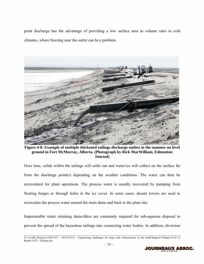
S:\1-LAB\2-Projects\1450\1472 - NUNAVUT - Engineering challenges for large scale infrastructure in the north\Rapport\Tailings\22-03-12 Report 1472 - Tailings.doc
- 70 -
point discharge has the advantage of providing a low surface area to volume ratio in cold
climates, where freezing near the outlet can be a problem.
Figure 4-8: Example of multiple thickened tailings discharge outlets in the summer on level
ground in Fort McMurray, Alberta. (Photograph by Rick MacWilliam, Edmonton Journal)
Over time, solids within the tailings will settle out and water/ice will collect on the surface far
from the discharge point(s) depending on the weather conditions. The water can then be
recirculated for plant operations. The process water is usually recovered by pumping from
floating barges or through holes in the ice cover. In some cases, decant towers are used to
recirculate the process water around the main dams and back to the plant site.
Impermeable water retaining dams/dikes are commonly required for sub-aqueous disposal to
prevent the spread of the hazardous tailings into connecting water bodies. In addition, diversion

S:\1-LAB\2-Projects\1450\1472 - NUNAVUT - Engineering challenges for large scale infrastructure in the north\Rapport\Tailings\22-03-12 Report 1472 - Tailings.doc
- 71 -
structures (berms, ditches, etc.) are normally required to prevent clean, uncontaminated, natural
water from flowing into the storage facility, which would lead to a reduction in available storage
volume and additional water treatment. Figure 4-9 shows typical cross-sections in which slurry
tailings are disposed into a deep lake using three different deposition methods. The idealized
version (top) shows tailings spread evenly around a natural lake. As mentioned above, this is
unrealistic; deltas (or mounds) would be formed at discharge locations with coarser-grained
material gathering nearby and the fines carried further away into deeper water. Alternating
peripheral spigot discharge is a popular disposal technique (middle of Figure 4-9) in arctic
regions and entails discharging the tailings around the perimeter of the water body. A barge can
also be used, during the summer, to transport pumping equipment to discharge tailings in desired
locations within the lake or to pump out water from the lake. (Golder Associates, 2007; Rykaart,
2005a)

S:\1-LAB\2-Projects\1450\1472 - NUNAVUT - Engineering challenges for large scale infrastructure in the north\Rapport\Tailings\22-03-12 Report 1472 - Tailings.doc
- 72 -
Figure 4-9: Schematic cross-section of slurry tailings disposal in a deep lake - From top to
bottom: idealized, alternating peripheral spigot and barge deposition.
The major advantage for this disposal option is the low operational cost of storing large tailings
volumes. With regard to climate change, this disposal method has serious long-term risks
associated with dam stability and containment capabilities (refer back to Table 3-1, pg. 11).
Changes in water balance, leading to dryer conditions, can also compromise water covers. The
more complex water management system required makes it even more challenging to create
water management plans to incorporate the uncertainties associated with climate change. The
risks of clean water entering the contaminated storage site, due to the overflow of diversion
works from natural runoff water, are a concern. The long-term risks are particularly high, with

S:\1-LAB\2-Projects\1450\1472 - NUNAVUT - Engineering challenges for large scale infrastructure in the north\Rapport\Tailings\22-03-12 Report 1472 - Tailings.doc
- 73 -
projected continual increases in storm magnitudes and intensities and the lack of maintenance
after plant shutdown. The following points summarize the general disadvantages:
• Water retaining (impermeable) dams/dikes are commonly required to contain hazardous
tailings from mixing with connected water bodies.
• Diversion structures are required to divert clean water from flowing into the storage
facility.
• Large quantities of material are required for dams; glacial till is only readily available
after thaw and material may not be available in the vicinity of the site.
• Special consideration must be taken to prevent water and/or pipe freezing.
• Losses to aquatic life. Re-compensation plans for no net losses are mandatory, but
temporary loss could have severe impacts on local people and wildlife and re-
compensation can take extended periods of time.
• Possible seepage of contaminated fluid through the lake bottom and into groundwater.
• Complex water management systems.
• Least efficient water conservation (e.g. losses to evaporation and void space within
tailings).
• May require winter and summer discharge points to minimise ice formation in the storage
area.
4.5.1.2 Open Pit Slurry Tailings Disposal
Figure 4-10 shows a typical schematic cross-sectional view of an open pit filled with slurry
tailings (the uniform deposition is an idealized scenario). Slurry tailings can be discharged into

S:\1-LAB\2-Projects\1450\1472 - NUNAVUT - Engineering challenges for large scale infrastructure in the north\Rapport\Tailings\22-03-12 Report 1472 - Tailings.doc
- 74 -
an abandoned and possibly water/ice-filled open pit where the reservoir is contained within the
permafrost. Refilling open pits is desirable to reduce the environmental footprint left by tailings.
However, seepage from contaminated tailings can enter groundwater sources and become an
environmental concern. Few examples of open pit disposal in cold regions were encountered
during research for this report (two examples, however, are given in Section 4.5.2.1). This is due
to the fact that it can be a difficult and dangerous process to place tailings within an abandoned
pit and, more to the point; very few abandoned open pits are available during production. Only
after local deposits have been completely mined out will pits become available for storage.
Slurry tailings can be deposited in similar ways as described in Section 4.5.1.1; as in the deep
lake disposal option, surface water can be removed and recycled for processing. Infiltration
zones from the walls of the pit must be sealed by using a combination of grouting and freezing
using thermosyphons. Climate warming will increase slope stability concerns of the walls for
open pits with thawing permafrost and melting ice within the bedrock interfaces.
Figure 4-10: Schematic cross-section of idealized slurry tailings disposal in an abandoned
open pit.

S:\1-LAB\2-Projects\1450\1472 - NUNAVUT - Engineering challenges for large scale infrastructure in the north\Rapport\Tailings\22-03-12 Report 1472 - Tailings.doc
- 75 -
4.5.1.3 Natural Terrain Slurry Tailings Disposal
Please refer to Section 4.5.2.2. Slurry tailings disposal on land is similar to thickened tailing
disposal on land. The main differences are the greater volumes of tailings and the slower freezing
of tailings due to the higher water content. Figure 4-11 shows examples of slurry tailings
disposal on natural terrain using dike construction. The dams/dikes are usually built in a
progressive manner as the waste pile increases in height. Entrained ice is not displayed in the
figure, but would be present. Normally the tailings water will freeze downstream from the
discharge pipe as it cools and turns to ice, sometimes 1 to 2 km from the discharge point,
depending on the fluidity, temperatures and slope. Referring back to Figure 4-7 (pg. 68), the
likely lower operational cost is the main advantage of this method; however, material availability
in Nunavut may result in very high capital costs for dam/dike construction. Seepage issues, water
management complexity, perpetual risks of dam failure and large footprint areas are the main
disadvantages, particularly when climate change scenarios are taken into consideration.
Inert slurry tailings can be disposed of on steep landscapes (e.g. high slopping valley) without
the need for dam/dike containment (see Figure 4-12). Examples of where inert tailings disposal
sites could be located in Nunavut are the proposed Baffinland Iron Project and the Advanced
Explorations Roche Bay Project. The basic concept of this disposal method is that the tailings
will flow down the slopping terrain, freeze in place and water can be collected in a pond at the
far end. These facilities could be up to several kilometres long. Since these tailings are inert, very
little infrastructure, apart from the collection pond facility, is required and the method does not
pose environmental risks even with climate change.

S:\1-LAB\2-Projects\1450\1472 - NUNAVUT - Engineering challenges for large scale infrastructure in the north\Rapport\Tailings\22-03-12 Report 1472 - Tailings.doc
- 76 -
Figure 4-11: Schematic cross-sections of idealized slurry tailings disposal on natural terrain.
Figure 4-12: Inert slurry disposal on sloping land in the summer.

S:\1-LAB\2-Projects\1450\1472 - NUNAVUT - Engineering challenges for large scale infrastructure in the north\Rapport\Tailings\22-03-12 Report 1472 - Tailings.doc
- 77 -
4.5.2 Thickened or Paste Tailings Disposal Options 4.5.2.1 Sub-aqueous (Underwater/Under Ice) Thickened or Paste Tailings Disposal
Sub-aqueous disposal of slurry tailings is covered in Section 4.5.1.1. Disposal of thickened or
paste tailings in the same manner (e.g. deep lake) requires higher capital investments for tailings
processing and increased operational cost. These costs may be offset by lower water
management cost, minimal particle segregation which increases deposited density and reduces
storage volume, increased water conservation, less ponded water reduces footprint and can
facilitate closure.
4.5.2.2 Open Pit/Backfill Thickened or Paste Tailings Disposal
Open pit tailings disposal involves refilling an excavated pit with tailings (refer back to Section
4.5.1.2). According to a report for Minto Mine in Yukon (Scott et al., 2010), the mine was
expected to have switched disposal methods, in mid 2011, from dry stacking to open pit (in-pit)
sub-aqueous thickened tailings disposal. The disposal method change is expected to bring a
significant cost savings and reduction in disturbed land over the current dry stacking method.
The tailings with elevated copper will be segregated and disposed in a way that limits copper
leaching (e.g. co-disposal) and by installing vertical dewatering wells. In order to maintain
stability of the Main pit, in which tailings will be stored up to the year 2015, a waste rock
buttress was to be constructed. Slurry deposition will be used in select locations to facilitate
uniform distribution of tailings and the winter deposition plan may need to be modified in cases
of extreme cold weather. A floating barge will be used to recycle and remove excess water from
the pit from freshet inflow (flood resulting from heavy rain or spring thaw).

S:\1-LAB\2-Projects\1450\1472 - NUNAVUT - Engineering challenges for large scale infrastructure in the north\Rapport\Tailings\22-03-12 Report 1472 - Tailings.doc
- 78 -
The Doris North Project evaluated the use of an open pit as a disposal alternative (Rykaart,
2006). A rock dike would be constructed to section off a portion of the open pit from the access
portal and a separate water management pond would be constructed on the surface. The use of
open pit disposal with an active portal was described as unprecedented. The tailings would be in
a thickened state and pumped into the pit. Excess water in the pit would be pumped out to the
water management pond. After final placement, the tailings would be covered with a
geosynthetic clay liner (GCL) and waste rock to ensure long-term integrity and prevent
infiltration. The water management pond would be excavated of sludge and underlying soil for
treatment and secure storage. Ultimately, this alternative was disregarded since it was deemed to
be an uneconomical option and the design was not deemed technically unfeasible or flexible in
case of reasonable disturbance conditions. The long-term risks of metal leaching, loss of land and
terrestrial habitat (e.g. from water management pond construction), ice build-up, hydrologic
uncertainties, potential for tailings dust, and very high risks and cost to ensure human safety (e.g.
pit wall stability) were the main concerns. This alternative assessment provides insight into the
common concerns for open pit disposal, but is exaggerated by the fact that the open pit would be
still operational.
Backfilling has become a popular method (e.g. Meadowbank, Kensington, Lupin, Snap Lake,
Diavik, Greens Creek, Raglan, Bellenkeno, Prairie Creek and Pogo mines). Backfilling is a word
used by the mining industry to describe the refilling of underground cavities (e.g. mined out
cells). Backfill material may be hydraulic backfill (alluvial sand, mill tailings and cement),
cemented paste backfill (mine tailings, water and binders) or rock fill (waste rock, tailings, water
and cement). The backfill material must satisfy certain properties, mainly compressive strength

S:\1-LAB\2-Projects\1450\1472 - NUNAVUT - Engineering challenges for large scale infrastructure in the north\Rapport\Tailings\22-03-12 Report 1472 - Tailings.doc
- 79 -
and stiffness, to ensure safe underground working environments. Snap Lake mine expects to
backfill 50% of its waste over the life of the mine, leaving half for above ground storage, thereby
reducing the aboveground footprint. Another benefit of backfilling is that sometimes additional
extraction of the ore can be achieved (e.g. a 5-10% extraction rate increase is expected at Snap
Lake). Figure 4-13 shows two underground mining methods used at the Diavik mine that
incorporate backfilling techniques (DeBeers Canada, 2011, Rio Tinto, 2009). The main
disadvantage of backfilling is usually cost-related, since cement and other admixtures are
expensive, particularly in remote Arctic locations. Climate change should have little to no direct
affect on this disposal technique, since the facilities are located well below ground.
Figure 4-13: Underground mining methods for Diavik mine where backfilling will be used
(Rio Tinto, 2009).
4.5.2.3 Natural Terrain Thickened or Paste Tailings Disposal
Generally, a large valley would be chosen for this disposal technique. Minimizing dam or dike
construction is an important criterion for selecting a land disposal site. Sometimes, a single
earthworks structure will create a storage area, but when peripheral ring dikes are necessary to

S:\1-LAB\2-Projects\1450\1472 - NUNAVUT - Engineering challenges for large scale infrastructure in the north\Rapport\Tailings\22-03-12 Report 1472 - Tailings.doc
- 80 -
complete the basin large capital investment is required. Water within the tailings may eventually
exit by means of drainage, seepage or evaporation. Excess process water is collected and
recycled to the plant. Exterior diversion works may be required to by-pass the storage facility
and to prevent natural runoff water from entering. Furthermore, closure of the site requires an
adequate cover over the reactive tailings and the long-term risks of dam or dike failure is always
present. In Nunavut, the cold weather could increase freezing problems, which would make
water management and tailings placement very difficult. Figure 4-14 shows schematic cross-
sections of facilities on natural terrain (ice-lenses and/or layers are not shown in Figure 4-14, but
would be present). Entrained ice should be accounted for when sizing storage facilities.
Figure 4-14: Schematic cross-sections of thickened or paste tailings disposal on natural terrain.
Thickened or paste tailings will freeze more quickly than slurry tailings and, therefore, mounds,
deltas or sloping ground occurring at the discharge points will be more pronounced. Therefore,

S:\1-LAB\2-Projects\1450\1472 - NUNAVUT - Engineering challenges for large scale infrastructure in the north\Rapport\Tailings\22-03-12 Report 1472 - Tailings.doc
- 81 -
the disposal operation would require even more continual shifting of the discharge locations than
with slurry tailings disposal. Other advantages of thickening tailings for this type of disposal
method are (Habte and Bocking, 2012):
• Smaller tailings pond is required (lower environmental impact).
• Reduced storage volume (smaller footprint).
• Less complicated water management and increased water conservation.
• Typically less risks of dust generation and ingress of oxygen due to reduced particle
segregation.
• Typically less risks of seepage due to lower hydraulic head.
• Can be suitable for co-disposal with mine rock (increased stability).
• Typically has reduced concern of long-term maintenance and dam stability.
Again, climate alterations will increase the concerns for long-term dam stability and diversion
work dependability and create even more difficulties for water management plans, with
permafrost degradation, increases in storm magnitudes/intensities and uncertainties in future
water balance conditions.
4.5.3 Dewatered Tailings Disposal Options
4.5.3.1 Open Pit Dewatered Tailings Disposal
As stated earlier (see Section 4.5.1.1), open pit disposal is essentially refilling a previously
excavated pit with tailings. For open pit disposal, the advantage of disposing of dewatered
tailings (~15 % water content), rather than tailings with higher water contents, is that a greater
volume of solids is disposed in the same volume of tailings (due to the higher density of the
S:\1-LAB\2-Projects\1450\1472 - NUNAVUT - Engineering challenges for large scale infrastructure in the north\Rapport\Tailings\22-03-12 Report 1472 - Tailings.doc
- 82 -
tailings), with a reduction in the seepage water conservation is achieved. Dry material could be
trucked, dumped, spread and compacted in dry open pits. Any problems with slope stability of
open pit walls, precipitation and ice are likely to be magnified by climate change. The main
disadvantages are the additional cost required for dewatering the tailings and transporting the
tailings.
4.5.3.2 Natural Terrain ‘Dry Stacking’ and Freezing Tailings Disposal
Filtered dry stacked tailings are becoming more and more popular in mines even though the costs
are still relatively higher than, for example, underwater deposition. The basic concept involves
dewatering the fine ground tailings to the desired water content through a series of filtering units
(mechanical or vacuum). Recent developments in dewatering techniques and filtering
technologies now allow for greater amounts of tailings to be processed in this manner at reduced
costs. Filtration units of up to 10,000 tons per day are available. For large tonnage mines
additional units can be added. The use of this type of equipment is also ideal for producing dry
material that can be placed and frozen as an upstream blanket on a rock fill dike. The tailings can
be trucked (or conveyed in the summer) to the disposal site (see Figure 4-15). Placement is
performed by spreading evenly and compacting the tailings to the maximum over a given area.
Dry stacks can be built to any height. The frozen stack is ultimately unsaturated, dense with flat
slopes and, in the Nunavut, very stable. The hydraulic and mechanical properties of the
dewatered tailings are critical to design. Recently, several mines in cold regions have opted to
use the dewatering/drying and dry stacking technique: Raglan Mine (Quebec), Pogo Gold Mine
(Alaska), Green Creek Mine (Alaska), Nixon Fork Mine (Alaska), Bellekeno Mine (Yukon) and

S:\1-LAB\2-Projects\1450\1472 - NUNAVUT - Engineering challenges for large scale infrastructure in the north\Rapport\Tailings\22-03-12 Report 1472 - Tailings.doc
- 83 -
Minto Mine (Yukon). The following section covers dry stacking in more detail and outlines the
advantages and disadvantages of the method.
Figure 4-15: Schematic cross-section of dry stack disposal on relatively flat terrain.
4.6 Discussion and Recommendations for Tailings Disposal (Dry Stacking, Backfilling or Open Pit Disposal)
In Nunavut, the optimum disposal method for tailings is ultimately decided on a case by case
basis depending on the surrounding terrain, nature of the tailings and local climate conditions.
However, the general recommendation for tailings disposal in Nunavut is dry stacking, while
refilling open pits and underground cavities (e.g. backfilling) should be done as much as
possible. Ideally, safely depositing all tailings within previously mined out regions would be
preferred, but this is not entirely feasible for a mine, due to operational difficulties and project
economics. Dry stacking has several advantages over other options and the main benefits are
discussed in the following paragraphs. The advantages are also summarized in point form at the
end of this section.
From an environmental standpoint, especially over the long-term, dry stacking offers the best
solution for mine tailings disposal. For potential acid generating tailings and other hazardous
tailings, dry stacking is a stable and safe choice. After closure, maintaining the active layer
within thick covers will provide long-term containment of the waste. Geosynthetic covers are the

S:\1-LAB\2-Projects\1450\1472 - NUNAVUT - Engineering challenges for large scale infrastructure in the north\Rapport\Tailings\22-03-12 Report 1472 - Tailings.doc
- 84 -
least affected by climate change (Stratos Inc., 2011). Holubec (2004) noted that encapsulating
tailings is generally feasible for all of Nunavut for the next 100 to 200 years. Other land-based
methods require impermeable till core dams/dikes that could be problematic due to stability and
seepage issues that might occur in the long-term with climate change. Underwater disposal is
considered to be a safe choice for preventing acid mine drainage at the lowest costs. Rykaart
(2005a) describes sub-aqueous disposal as a pro-active, rather than reactive solution, since mine
waste must oxidize in order to become detrimental and it will be unable to do so if directly
placed underwater. However, groundwater contamination can present a sizeable risk for other
types of hazardous waste (e.g. cyanide contaminated waste). In addition, dams are commonly
required to separate the storage facility from connecting water bodies, which increases the costs.
Land used for disposing tailings via dry stacking, can be covered and re-vegetated. Loss of
wetlands is a central concern for dry stacking; however, when compared to other land-based
disposal methods, dry stacking facilities consume a smaller total area (footprint) than standard
tailings ponds where dams and dikes are required (see for example Condon and Lear, 2006). The
main reason for this is the increased water removal from the tailings. In, addition, to minimize
the footprint, dry stacks can be built high in suitable natural terrain by using features such as
deep crevasses, hill sides and broad valley floors. Sub-aqueous storage on the other hand, if
permitted, can completely fill pristine natural lakes, where aquatic habitat will be permanently
lost. Mandatory compensation plans are in place to mitigate this undesirable loss. However, the
remediation plans may only take affect after extended periods of time, during which negative
impacts on wildlife or local inhabitants can occur. The Kensington mine had planned to actually
increase aquatic life after mine closure for a shallow lake (Lower Slate Lake), by increasing the

S:\1-LAB\2-Projects\1450\1472 - NUNAVUT - Engineering challenges for large scale infrastructure in the north\Rapport\Tailings\22-03-12 Report 1472 - Tailings.doc
- 85 -
water depth using earthworks and introducing fish and other aquatic life (Coeur Alaska, 2006).
Unfortunately, recent developments in the regulations caused deviations from the original plan
and the lake has subsequently been contaminated with waste tailings (Earthjustice, 2011).
Water conservation is another major advantage of dry stacking; water removed from the tailings
and storm runoff collected by drainage channels surrounding the dry stacks can be re-used for
mine processing. Water conservation is particularly beneficial in Nunavut’s dry climate. Water
management in dry stacking is also much simpler in comparison to other tailings disposal
techniques; therefore, planning for future uncertainties related to climate change is more feasible.
The major advantage of dry stacking over other storage techniques, in Nunavut, are summarised
below:
• Involves smaller storage volumes because of low water content (~ 15%).
• Conserves water.
• Easily constructed with standard earth moving equipment (dozers, compactors, haul
trucks).
• Freezes pore-water in place; avoids seepage concerns and leads to stable slopes.
• Avoids construction of costly retaining dikes and dams requiring large borrow pits to provide the materials necessary for dam construction, which are not readily available.
o Avoids developing long roads with culverts and bridges to reach borrow pits for zoned dike construction for tailings ponds.
• Can be built around or over topographic obstacles, including rock outcrops, and in small
localised zones to maximise terrain use, while avoiding streams and lakes.
• Can be designed to use thick inert waste rock covers to conform to changes in active zone depth or unstable permafrost due to climate warming.

S:\1-LAB\2-Projects\1450\1472 - NUNAVUT - Engineering challenges for large scale infrastructure in the north\Rapport\Tailings\22-03-12 Report 1472 - Tailings.doc
- 86 -
• Can be buttressed with inert mine waste rock for added stability on steep slopes.
• Avoids risks involved with complicated storage using dams and spillways, and polishing ponds, which are subject to possible seepage and perpetual monitoring after closure.
• Avoids pipelines and associated mechanical equipment subject to freezing in winter.
• Involves a simple closure plan using adequate cover for projected active layer thickness,
while providing permanent dust free storage.
• Easily accessible in the event of a need for additional mitigation measures.
• Relatively low capital cost for preparation of storage sites at the start of the mining
operation.
• In the end, may prove more cost effective over the life of the mine and permanent closure periods.
4.6.1 Design Guidelines – Dry Stacking 4.6.1.1 Transportation, Compaction and Placement of Tailings for Dry Stacking
The general scheme involves using a fleet of trucks to transport the material to the site where it is
dumped, spread and immediately compacted. In the winter period, the material can be spread and
compacted in thin, 300 mm thick, lifts over a large area and this low water content material will
freeze rapidly under the cold temperatures experienced in Nunavut. The tailings can be deposited
in a secondary ‘summer’ storage facility in the summer period. During this period, an active
layer will develop in the ‘winter’ storage facility. Drainage should be controlled and infiltration
should be prevented by graded surface to shed water to the perimeter, constructing runoff water
diversion berms, finger drains or flow-through drains. Infiltration is usually low due to the
normally low permeability of the tailings; however underdrain systems may be required to
collect seepage. In addition, entrained ice within the active layer of the tailings will melt and can

S:\1-LAB\2-Projects\1450\1472 - NUNAVUT - Engineering challenges for large scale infrastructure in the north\Rapport\Tailings\22-03-12 Report 1472 - Tailings.doc
- 87 -
be drained from the pile. During the summer months, tailings can be placed in the ‘summer’
storage area and compacted to a total depth of about 2.5 meters (or the estimated freezing
penetration into a specific tailings site during the following winter with some safety margin). The
severe cold and high winds, inherent to Nunavut, will quickly freeze the summer layer to the
bottom. While freezing occurs, the disposal operation will be transferred to the original winter
section. This process can be repeated year by year. In this manner, these stacks can be built to
considerable heights and can conform to almost any topography. A hypothetical time distribution
for summer and winter disposal is given in Figure 4-16. The figure illustrates the how winter
disposal period can be started after a month of freezing temperatures to allow the active layer to
refreeze. In reality, the division of summer and winter disposal requires a more in-depth study
based on local climatic conditions, tailings thermal properties, and so forth.
Figure 4-16: Hypothetical example of winter and summer disposal over a year.

S:\1-LAB\2-Projects\1450\1472 - NUNAVUT - Engineering challenges for large scale infrastructure in the north\Rapport\Tailings\22-03-12 Report 1472 - Tailings.doc
- 88 -
The water content of the material should be near the optimum value for compaction purposes
(around 15% depending on the grain size of the tailings). The coarser the tailings, the easier the
material can be placed in the winter. However, in the summer, coarser tailings will absorb more
precipitation. Caution should be taken to avoid saturation of the working platform. The tailing
stack layout should be construction is such a way that drainage from precipitation or storm
runoff would be diverted away from the dry stack. Figure 4-17 shows grain size distribution for
typical fine to coarse tailings.
Figure 4-17: Grain size examples for fine tailings to coarse tailings.
Transportation and storage of tailings in the permafrost regions of Canada must contend with
severe winter cold; transportation in the winter will require insulated and heated truck boxes
(similar to concrete trucks) especially if the storage site is located some distance from the mill.
This will prevent freezing of the material to the truck boxes. Many trucks have exhaust pipes that

S:\1-LAB\2-Projects\1450\1472 - NUNAVUT - Engineering challenges for large scale infrastructure in the north\Rapport\Tailings\22-03-12 Report 1472 - Tailings.doc
- 89 -
lead to the truck box, which helps to prevent freezing. Condon and Lear (2006) provide trucking
and placement details for Green Creeks Mine, Alaska.
Once dumped on site in the winter, the material will freeze very rapidly under low temperatures
and high winds and small particles will become coated with ice, which will lead to poorer
compaction. Each truckload must therefore be spread and compacted immediately. The number
of dozers, graders and compactors equipped with heating equipment must be suited to this rapid
compaction. Naturally, in summer this is not such a problem, but the high summer temperatures
may cause accessibility issues for heavy trucks due to the thawing of the active layer. Dryer
material may be required to support the equipment. Rapid freezing of the compacted tailings, in
cold periods, will increase stability for vehicles and allow for additional layering to be performed
in shorter timeframes. Operation and planning is therefore critical in terms of placement of
tailings. Large working platforms are required to allow the layer to freeze before the equipment
returns to place the next lift. The placing of these waste materials for freezing is similar to
roadway construction and therefore can be built progressively over any type of flat or sloped
terrain. Because of processing challenges, not all tailings will be exactly to specifications;
therefore, when less optimum tailings are encountered, they should be placed in the central
region, where support and strength is less important. Likewise, compaction purely for strength
purposes (e.g. increasing the friction angle) is not necessary in non-structural (central) areas of
the dry stack facility.

S:\1-LAB\2-Projects\1450\1472 - NUNAVUT - Engineering challenges for large scale infrastructure in the north\Rapport\Tailings\22-03-12 Report 1472 - Tailings.doc
- 90 -
4.6.1.2 Wind Blown Dust
Wind blown dust should be kept to a minimum. Some regions in Nunavut experience high winds
and blizzards. Baker Lake (see Figure 4-18) experiences a high number of blizzards each year,
thereby, making dry stacking a less attractive disposal option in this area (see for example Leader
et al., 2009). Prevention measures can be taken to reduce dust emissions. Lower topographic
regions are less susceptible to high winds. Additives (e.g. cement) can be used to bond waste
together, while also providing additional strength to the dry stack. Spraying the waste piles with
water, during the summer periods, or other dust suppressant liquid/solid agents may also be
effective in preventing dust generation. In the design stage, having a holding pond in close
vicinity to the dry stack facility would simplify dust suppression with water during the summer.
Placing a thin layer of waste rock, immediately after the tailings have been spread and
compacted, during windy periods is another option. When possible, trees can be used to form
tree screens (a line of thick evergreen trees) around the site, which can help contain dust. This
may be an option to help contain dust in the Baker Lake region, where it is windy and still within
the tree line.
Lime and cement were used to stabilize tailing at a zinc refinery in Valleyfield, Quebec. The
tailings were previously deposited in ponds in a slurry form. The tailings were thickened and
lime and cement were added to create an inert substance. This process, or a similar one, could be
beneficial in creating a substance less prone to wind issues and could also completely change
hazardous tailings into inert substances (Benoît and Getahun, 2000).

S:\1-LAB\2-Projects\1450\1472 - NUNAVUT - Engineering challenges for large scale infrastructure in the north\Rapport\Tailings\22-03-12 Report 1472 - Tailings.doc
- 91 -
Figure 4-18: Average number of blizzards across select villages in Canadian Arctic
(Environment Canada, 1999). 4.6.1.3 Closure and Reclamation of Tailings Site
Apart from the minimal effects of climate change on frozen tailings in Nunavut, one of the main
advantages of dry stacking is the ease of mine closure and land reclamation. A cover must be
placed over the tailings with an appropriate design in order to prevent negative impacts on the
surrounding environment at closure (see Section 4.2.2 and Section 4.4.1.4). Over the long-term,
the area can be covered with topsoil and re-vegetated to its original vegetative state in a
relatively fast and economic manner when compared to other tailings disposal options. Trial
vegetation plots during operation are recommended to optimize the re-vegetation process. Dry
stack facilities have low slopes, which helps to promote the growth of vegetation. Finally,
continual monitoring is recommended; specifically, temperature monitoring within the dry stack
itself and in the surrounding ground is beneficial for assessing the design performance.

S:\1-LAB\2-Projects\1450\1472 - NUNAVUT - Engineering challenges for large scale infrastructure in the north\Rapport\Tailings\22-03-12 Report 1472 - Tailings.doc
- 92 -
4.6.1.4 Design Concept for Dry Stacking
This section presents a design concept for tailings disposal using dry stacking in Nunavut. A
schematic cross-section of the design concept is shown in Figure 4-19. To eliminate the effects
of climate change on the degrading permafrost in Nunavut, the perimeter tailings slope should
preferably be no steeper than 10H:1V. The flatter slope will result in a larger footprint, which
may not be possible or desirable in many situations. However, the flatter slopes have many
advantages, including increased stability, ease of placement and freezing, more conducive to
vegetation growth after closure and decreased erosion. Flatter slopes will displace the active
thaw zone further from the stack, thus increasing stability. At the end of each season, 200 mm
thick layers of crushed rock can be placed over tailings to control dust.
At closure, a similar cover design concept to those used at the Raglan and Diavik mines, where a
fine layer is placed over the tailings and develops into a fully saturated frozen barrier, is
recommended. Establishing the active layer within the cover is obviously essential. An adequate
cover design consisting of inert waste rock fill underlain by fine crushed rock can suffice. After
closure, precipitation will seep through the cover and collect in the fine layer. Over the following
cold period, the water will freeze in place and saturate this layer. This frozen, high ice content
layer will mitigate the future possibility of thawing due to climate warming by prolonging the
zero-curtain effect (Carey and Woo, 1998). Past experience in Schefferville (Qc.) supports this
method. A frozen snow and ice layer, below the active layer of about 3 m and within the fine-
grained soil (e.g. no convective cooling), has been maintained over the past fifty years, where the
freezing and thawing indices are 3163 °C days/yr and 1270 °C days/yr, respectively. In

S:\1-LAB\2-Projects\1450\1472 - NUNAVUT - Engineering challenges for large scale infrastructure in the north\Rapport\Tailings\22-03-12 Report 1472 - Tailings.doc
- 93 -
Nunavut’s warmest regions, climate warming predictions for the next 100 years will lead to
approximately the same freezing and thawing conditions as were seen in Schefferville over the
last 50 years.
Figure 4-19: Schematic cross-section design for hypothetical dry stacking facility in
Nunavut.
5 CONCLUSION AND RECOMMENDATIONS
This report covers a variety of issues related to tailings management facilities and associated
infrastructure with the growing concerns of climate change in Nunavut. Dry stacking combined
with backfilling and/or open pit disposal are recommended as the tailings disposal techniques for

S:\1-LAB\2-Projects\1450\1472 - NUNAVUT - Engineering challenges for large scale infrastructure in the north\Rapport\Tailings\22-03-12 Report 1472 - Tailings.doc
- 94 -
future mining endeavours. These disposal methods are deemed to be the best practices for
tailings disposal in Nunavut. Dry stacking is recommended for its environmental benefits of
containing hazardous waste through freezing in Nunavut’s cold temperatures, in both the short
and long-term and the reduced footprints that are left behind. In addition, dry stacking avoids the
perpetual risk surrounding other methods that require dams, which have limited lifespans,
particularly with the degradation of the underlying permafrost that would occur as the climate
warms. The main concern of dry stacking is dust generation during operation; therefore, more
research is recommended on ways to reduce dust generation, particularly for mine operations in
windy environments. Backfilling, with paste backfill, is currently being used to dispose of
tailings at several mines in cold regions and has been successful in reducing land consumption.
In addition, backfilling has the advantage of being relatively insensitive to climate change-
related issues, due to the considerable depths at which the disposal facilities are located.
Environmental disasters from contaminated tailings facilities are certainly preventable, barring
unpredictable scenarios. Technologies are available to ensure safe containment of hazardous
material. Cost is the main restraint for designers, but relatively small investments today can
prevent future liabilities and environmental losses. Applying higher factors of safety in the
design of waste covers and hydraulic structures is highly recommended, particularly in view of
the uncertainties of climate change. Research and development of cover designs should be
continued. For dry stacking, more field research should be done and made available to determine
the thickness of a waste layer that can be frozen over a cold period and the corresponding thaw
depth during the warm period, in order to produce empirical relationships for designers to
consult. Further research in tailings processing is crucial in moving foreword to sustainable

S:\1-LAB\2-Projects\1450\1472 - NUNAVUT - Engineering challenges for large scale infrastructure in the north\Rapport\Tailings\22-03-12 Report 1472 - Tailings.doc
- 95 -
tailing disposal sites. Creating inert tailings should ultimately be the goal of any tailings disposal
site. If long-term environmentally safe methods are not applicable (e.g. not economically or
technically feasible) for mining projects, the non-renewable resources should simply not be
mined.

S:\1-LAB\2-Projects\1450\1472 - NUNAVUT - Engineering challenges for large scale infrastructure in the north\Rapport\Tailings\22-03-12 Report 1472 - Tailings.doc - 96 -
Government of Nunavut
ENGINEERING CHALLENGES FOR LARGE SCALE INFRASTRUCTURE IN THE NORTH NUNAVUT
Prepared by :
T (514) 630-4997 F (514) 630-8937

T (514) 630-4997 F (514) 630-8937
References
AANDC – Aboriginal Affairs and Northern Development Canada. 2010. http://www.aadnc-
aandc.gc.ca/eng/1100100022936#evaporation. (Accessed 01/02/12)
Alexeev, V.A., Nicolsky, D.J., Romanovsky, V.E. and Lawrence, D.M. 2007. An evaluation of
deep soil configurations in the CLM3 for improved representation of permafrost. Geophysical
Research Letters, 34: L09502.
Atlas of Canada. 2003.
http://atlas.nrcan.gc.ca/site/english/maps/climatechange/scenarios/nationalannualprecip2050.
(Accessed 07/02/12)
ACIA – Arctic Climate Impact Assessment. 2004. ACIA Overview report. Cambridge
University Press, 1042 p.
ACIA – Arctic Climate Impact Assessment. 2005. ACIA Scientific report. Cambridge University
Press, 908 p.
Arenson, L., Johansen, M.M. and Springman, S.M. 2004. Effects of volumetric ice content and
strain rate on shear strength under triaxial conditions for frozen soil samples. Permafrost and
Periglacial Processes, 15(3): 261-271.
Arenson, L.U. and Springman, S.M. 2005. Triaxial constant stress and constant strain rate tests
on ice-rich permafrost samples. Can. Geotech. J., 42(2): 412-430.
Beistline, E.H. 1963. Placer mining in frozen ground; In Proceedings of the Earthwork and
Foundation Engineering International Conference on Permafrost: Purdue University,
Lafayette, Indiana, 19 pp.
Benoît, D. and Getahun, H. Management of Tailings Stabilized by Lime and Cement at Canadian
Electrolytic Zinc, Valleyfield, Québec. SNC Lavalin. Environment inc. Montreal, QC.
Boyd, D.W. 1976. Normal freezing and thawing degree-days from normal monthly temperatures.
Can. Geotech. J., 13: 176-180.
CEAA – Canadian Environmental Assessment Agency. 1999. Comprehensive Study Report –
Diavik Diamonds Project. Canada.

T (514) 630-4997 F (514) 630-8937
CFEM – Canadian Foundation Engineering Manual. 2006. Fourth Edition Canadian
Geotechnical Society, 488 p.
Carey, S.K. & Woo, M.K. 1998. A case study of active layer thaw and its controlling factors. In
Proceedings of the7th International Permafrost Conference: Yellowknife, N.W.T., Canada:
127-132
Cavanagh, C. and Tchekhovski, A. 2010. Design and performance of a frozen core dam in Cape
Dorset, Nunavut. AMEC Earth and Environmental. In Proceedings of GEO 2010, Calgary,
Alberta, Canada.
Coeur Alaska. 2006. http://www.kensingtongold.com/mining.html#tailings. (Accessed 07/02/12)
Connell, L., Doucet, D., Andy, F., Hettinger, J., Lamontagne, E. and Perron, B. 2008. Technical
Report on the Mineral Resuources and Mineral Reserves – Meadowbank Gold Project
Nunavut, Canada. Agnico-Eagle Mines Limited. Toronto, Ontario.
Condon, P. and Lear, K. 2006. Geochemical and geotechnical characteristics of filter-pressed
tailings at the Green Creek Mine, Admiralty Island, Alaska. In Proceedings of the 7th
International Conference on Acid Rock Drainage (ICARD): St-Louis, MI.
Coumans, C. 2002. Submarine Tailings Disposal - STD Toolkit.
http://www.miningwatch.ca/sites/miningwatch.ca/files/01.STDtoolkit.intr_.pdf. (Accessed
07/02/12).
Crory, F. 1973. Settlement associated with the thawing of permafrost. In Proceedings of the 2nd
International Conference on permafrost, Yakutsk: Washington, D.C. National Academy of
Sciences, p.599-607.
Davies, M. 2011. Filtered dry stacked tailings – The fundamentals. In Proceedings of Tailings
and Mine Waste 2011: Vancouver, BC.
Davies, M., Lupo, J., Martin, T., McRoberts, E., Musse, M. and Ritchie, D. 2010. Dewatered
tailings practice – Trends and observations. In Proceedings of Tailings and Mine Waste ’10:
Balkema.
Dawson, R.F. and Morin, K.A. 1996. Acid Mine Drainage in Permafrost Regions: Issues,
Control Strategies and Research Requirements. MEND Report 1.61.2.

T (514) 630-4997 F (514) 630-8937
DeBeers Canada. 2011. Underground Backfill Implementation. Supporting Document 8: Update
on paste production. (Report prepared for Snap Lake Mine).
Earthjustice. 2011. Kensington Mine Project.
http://earthjustice.org/our_work/cases/2005/kensington-mine-project. (Accessed 07/02/12)
EBA Engineering Consultants Ltd. 2004. Permafrost Considerations Effective Mine Site
Development in the Yukon Territory. MERG Report 2004-1. (Report submitted to Mining
Environment Research Group Government of Yukon.)
EBA Engineering Consultants Ltd. 2011. Detailed Design Dry-Stack Tailings Facility Keno Hill
District Mill Site, Yukon. (Report submitted to Alexco Resource Corp.).
EPA – Environmental Protections Agency. 2003. Pogo Gold Mine Environmental Impact
Statement. National Pollutant Discharge Elimination System (NPDES) Permit Application No.
AK-005334-1.
Environment Canada. 1999. Average number of blizzard events per year for select communities
in Northwest Territories and Nunavut. Found through Google images search. (Accessed
12/02/12)
Environment Canada – Mining and Processing Division. 2011. Guidelines for Alternatives
Assessments for Mine Waste Disposal. Available through environment Canada website
(www.ec.gc.ca). (Accessed 12/02/12)
Environment Canada. Climate Data Online. (Accessed 2011 – 2012)
Furgal, C., Prowse, T.D., Bonsal, B., Chouinard, R., Dickson, C., Edwards, T., Jackson, F.,
Melling, H., Milburn, D., Nickels, S., Nuttall, M., Ogden, A., Peters, D., Reist, J.D., Smith, S.,
Westlake, M., and Wrona, F. 2008. Northern Canada. In Proceedings of From Impacts to
Adaptation: Canada in a Changing Climate 2007. Government of Canada, Ottawa. pp. 57-118.
Golder Associates Ltd. 2004. Five-Year Environmental Audit: Fort Knox Mine, True North
Mine and Twin Creek Road. (Report submitted to Fairbanks Gold Mining, Inc.).
Golder Associates Ltd. 2007. Integrated Report on Evaluation of Tailings Management
Alternatives, Meadowbank Gold Project, Nunavut. (Report submitted to Cumberland
Resources Ltd.).

T (514) 630-4997 F (514) 630-8937
Google Maps. http://maps.google.ca. (Accessed 01/15/12)
Griffiths, L., Usher, P., Pelley, C., Michael, L. and Metcalfe, S. 1997. Voisey's Bay Mine and
Mill Environmental Assessment Panel Report. Canada.
GTT – Groundtruthtrekking. 2011. Greens Creek Mine.
http://www.groundtruthtrekking.org/Issues/MetalsMining/GreensCreekMine.html. (Accessed
09/02/12)
GTT – Groundtruthtrekking. 2011. Kensington Gold Mine.
http://www.groundtruthtrekking.org/Issues/MetalsMining/KensingtonGoldMine.html.
(Accessed 09/02/12)
GTT – Groundtruthtrekking. 2011. Red Dog Mine.
http://www.groundtruthtrekking.org/Issues/MetalsMining/RedDogMine.html. (Accessed
09/02/12)
Günzel, F.K. 2008. Shear strength of ice filled joints. Proceedings, 9th International Conference
on Permafrost, Fairbanks, Alaska.
Habte, K. and Bocking, K. 2012. Co-disposal practices in mine waste management. Golder
Associates. Technical Memorandum. (Prepared for Fortune Minerals Ltd.)
Hanna, A.J., Saunders, R., Lem, G., and Carlson, L. 1983. Alaska highway gas pipeline (Yukon
Section) – thaw settlement design approach. In Proceedings of the 4th International Permafrost
Conference: Fairbanks, Alaska. National Academy Press, Washington, D.C. p. 439–444.
Hayley, D. and Horne, B. 2008. Rationalizing climate change for design of structures on
permafrost : a Canadian perspective. In Proceedings of the 9th International Conference on
Permafrost. Edited by D.L. Kane and K.M. Hinkel: Fairbanks, Alaska. Institute for Northern
Engineering, University of Alaska Fairbanks, Vol.1, pp. 681-686.
Huschke E. 1959. Glossary of meteorology. Am. Meteorol. Soc., Boston, Massachusetts.
Holubec, I., Hu, X., Wonnacott, J., Olive, R. and Delarosbil, D. 2003. Design, construction and
performance of dams in continuous permafrost. In Proceedings of the 8th International
Conference on Permafrost: Zurich, Switzerland. Rotterdam: Balkema.

T (514) 630-4997 F (514) 630-8937
Holubec. I. 2004. Covers for Reactive Tailings Located in Permafrost Regions Review. MEND
Report 1.61.4.
Holubec. I. 2010. Geotechnical Site Investigation Guidelines for Building Foundations in
Permafrost. (Prepared for the Department of Public Works and Services, Government of the
Northwest Territories).
Instanes, A. and Mjureke, D. 2002. Design Criteria for Infrastructure on Permafrost Based on
Future Climate Scenarios. SV4242-2. Instanes Svalbard AS (Report submitted to the
Norwegian ACIA Secretariat, Norwegian Polar Institute,Tromsø).
Kersten, M.S. 1949. Thermal Properties of Soils. Bulletin 28. Mineapolis: Engineering
Experiment Station, University of Minnesota.
Leader. J., Dumka D., Goode J., Jacobs C., López L., Morrison T., Shoemaker S. and Warwick
S. 2009. Independent Technical Report on the Preliminary Assesment of the Meliadine Project
Nunavut, Canada. Comaplex Minerals Corp.. Calgary, Alberta.
Lee , M.Y., Fossum, A.F., Costin, L.S. and Bronowski, D. 2002. Frozen Soil Material Testing
and Constitutive Modeling. Technical report No SAND2002-0524, Sandia National
Laboratories, Albuquerque.
Martin, T., Davies, M., Rice, S., Higgs, T. and Lighthall, P. 2002. Stewardship of Tailings
Facilities. Report no. 20, Mining, Minerals and Sustainable Development (MMSD).
Mathisen, H. 2008. Tailings spill on tundra at Ekati diamond mine. http://nnsl.com/northern-
news-services/stories/papers/jun4_08ek.html. (Accessed 09/02/12)
McCormick G. 1991. Freezing and thawing indices in northern Canada. Can. Geotech. J., 88:
899-903.
Mehrotra, A and Singhal, R. 1992. Environmental Issues and Waste Management in Energy and
Minerals Production. Vol. 2, Balkema, Rotterdam.
MPC – Mineral Policy Center. 2000. Cyanide Leach Mining Packet. Washington, D.C.
Morgenstern, N. and Nixon, J. 197l. One-dimensional settlement of thawing soils. Can. Geotech.
J., 8:558.

T (514) 630-4997 F (514) 630-8937
Morin. K. 2003. Problems with Acid Rock Drainage Predictions at the Ekati Diamond Mine,
Northwest Territories, Canada. Cairns, Queensland, Autralia
NRCan – National Resources Canada. 1999.
http://atlas.NRCan.gc.ca/site/english/maps/peopleandsociety/nunavut/mining/activeclosedmine
s. Last updated 2003. (Accessed 02/02/12)
NRCan – National Resources Canada. 1999.
http://atlas.nrcan.gc.ca/site/english/maps/peopleandsociety/nunavut/mining/mineralexploration
Last updated 2003. (Accessed 02/02/12)
NRCan – National Resources Canada. 2002.
http://atlas.nrcan.gc.ca/auth/english/maps/reference/provincesterritoriesrelief/nunavut_relief/re
ferencemap_image_view. Last updated 2004. (Accessed 02/02/12)
NRTEE – National Round Table on the Environment and the Economy. 2010. Degree of
Change: Climate Warming and the Stakes for Canada. Ottawa, Ontario.
Nicolsky, D.J., Romanovsky, V.E., Alexeev, V.A. and Lawrence, D.M. 2007. Improved
modeling of permafrost dynamics in a GCM land-surface scheme. Geophysical Research
Letters, 34: L08501.
NCSP – Northern Contaminated Sites Program. 2006. Contaminated Sites in the Northwest
Territories. http://explorenorth.com/library/mining/nwt-contaminated_sites.html. (Accessed
09/02/12)
Nuna. 2010. Dams and Frozen Core Dams.
http://www.nunalogistics.com/services/dams_frozen_core_dam.html. (Accessed 13/02/12)
Nunavut Geoscience. 2012. http://nunavutgeoscience.ca. (Accessed 09/02/12)
Overduin, P.P., Kane, D.L. and VanLoon, W.K.P. 2006. Measuring thermal conductivity in
freezing and thawing soil using the soil temperature response to heating. Cold Regions Science
and Technology, 45(1): 8-22.
Pearce, T., Ford, J., Prno, J. and Dueerden, F. 2009. Climate Change and Canadian mining:
Oppurtunities for Adaption. (Report submitted to The David Suzuki Foundation).
T (514) 630-4997 F (514) 630-8937
Pearce, T., Ford, J., Prno, J., Dueerden, F., Pittman, J., Beaumier, M., Berrang-Ford, L. and Smit,
B. 2011. Climate change and mining in Canada. Mitigation and Adaptation Strategies for
Global Change, 16(3): 347-368.
Pollard, W., Omolon, C., Anderson, D. and McKay, C. 1998. Geomorphic and Hydrologic
Characteristics of Perennial Springs on Axel Heiberg Island, Canadian High Arctic. In
Proceedings of the 7th International Conference on Permafrost: Yellowknife, Canada.
Collection Nordicana No. 55.
Rio Tinto. 2009. Diavik Diamond Mine Fact Book.
http://www.diavik.ca/documents/DiavikFactBook.pdf. (Accessed 07/02/12)
Rykaart, M. 2005a. Re-Evaluation of Tailings Alternatives Assessment, Doris North Project,
Hope Bay, Nunavut, Canada. SRK Consulting (Canada) Ltd. Report no. 1CM014.04. (Report
submitted to Miramar Hope Bay Ltd.).
Rykaart, M. 2005b. Preliminary Jetty Design, Doris North Project, Nunavut, Canada. SRK
Consulting (Canada) Ltd. Report no. 1CM014.02. (Report submitted to Miramar Hope Bay
Ltd.).
Rykaart, M. 2006. Integrated Tailings Disposal Alternatives Assessment, Doris North Project,
Hope Bay Nunavut, Canada. SRK Consulting (Canada) Ltd. Report no. 1CM014.006 (Report
submitted to Miramar Hope Bay Ltd.).
Rykaart, M. and Hockley, D. 2009. Mine Waste Covers in Cold Regions. MEND Report 1.61.5a.
Scott, C. 1999. Seepage control at the Colomac tailing containment area. SRK Consulting’s
International Newsletter. No. 44
Rykaart, M. and Hockley, D. 2010. Cold Regions Cover Reseach – Phase 2. MEND Report
1.61.5b.
Scott, C. 1999. Seepage control at the Colomac tailing containment area. SRK Consulting’s
International Newsletter. No. 44
Scott, C., Brimage, D., Pilotto, D., Kirham, G., Doerksen, G., Iakovlev, I., Nowak, M., Levy, M.,
Carliste, S. and Barnett, W. 2010. Minto Phase V – Preliminary Feasibility Study – Technical
Report. SRK Consulting. (Prepared for Minto Explorations Ltd.).

T (514) 630-4997 F (514) 630-8937
Shuguang, H. 2011. The analysis of temperature and displacement coupling in freeze-thaw
process of soil. Applied Mechanics and Materials, 97 – 98: 192-198.
Smith, D.W. 1996. Cold Regions Utilities Monograph, Third Edition. American Society of Civil
Engineers (ASCE).
Smith, S.L. and Burgess, M.M., 1998. Mapping the response of permafrost in Canada to climate
warming; in Current Research 1998-E; Geological Survey of Canada, p. 163-171.
Smith, S.L. and Burgess, M.M., 2000. Ground temperature database for Northern Canada.
Geological Survey of Canada (GSC) Open File 3954.
Smith, S.L. and Burgess, M.M. 2004. Sensitivity of Permafrost to Climate Warming in Canada.
Geological Survey of Canada. Bulletin 548. p. 241-264.
Smith, S.L., Burgess, M.M., and Heginbottom, J.A. 2001. Permafrost in Canada, a Challenge to
Northern Development. In Proceedings of A Synthesis of Geological Hazards in Canada.
Geological Survey of Canada. Bulletin 579. p. 24.
Springman, S.M. and Arenson, L.U. 2008. Recent Advances in Permafrost Geotechnics (Plenary
paper). In Proceedings of the 9th International Conference on Permafrost: Fairbanks, Alaska.
Stratos Inc. 2009. Climate Change Impacts on Mining Operations and Infrastructure Literature
Review. (Report submitted to Centre for Excellence in Mining Innovation).
Stratos Inc. 2011. Risks for the Canadian Mining Sector. MEND Report 1.61.7
Tchekhovski, A. 2005. Kupol Mine Tailings. Submitted to AMEC.
USARC – U.S. Arctic Research Commission. 2003. Climate Change, Permafrost, and Impacts
on Civil Infrastructure. Special report 01-03, U.S. Arctic Research Commission, Arlington,
Virginia.
Tsytovich, N., Yu, A., Zaretsky, K., Grigorycva, V. and Ter-Martirosyan Z. 1965. Consolidation
of thawing soils. In Proceedings of the 6th International Conference on Soil Mechanics and
Foundation Engineering: Montreal, Quebec.
Washburn, A. L. 1973. Periglacial Processes and Environments. London. Edward Arnold. 320 p.

T (514) 630-4997 F (514) 630-8937
WISE – World Information Service on Energy. 2012. New Uranium Mining Projects -
Northwest Territories & Nunavut, Canada. http://www.wise-uranium.org/upcdnnn.html.
(Accessed 02/02/12)
Wray, G., Bahya, D., Pope, F., Snowshoe, C. and Stevenson, J. 2003. Report of Environmental
Assessment and Reasons for Decision on the De Beers Canada Mining Inc. Snap Lake
Diamond Project. Mackenzie Valley Environemental Impact Review Board. Yellowknife,
NWT.
Yap, N.T. 2003. Towards an Inclusive Framework for Environmental Impact Assessment.
(Report prepared for the Research and Development Monograph Series).
Zhang, G. and Horne, W. 2010. Applications of numerical thermal analysis in engineering
designs and evaluations for northern mines. EBA Engineering Consultants Ltd. In Proceedings
of GEO 2010, Edmonton, Alberta, Canada.
Xu, J., Abdalla, B., Eltaher A. and Jukes, P. 2009. Permafrost thawing-pipeline interaction
advance finite element model. In Proceedings of the ASME 28th International Conference on
Ocean, Offshore and Arctic Engineering OMAE: Honolulu, Hawaii.