engineered wood construction guide - pdhonline.com · engineered wood construction guide 2012 ......
TRANSCRIPT

PDHonline Course S147 (8 PDH)
Engineered Wood Construction Guide
2012
Instructor: John C. Huang, Ph.D., PE
PDH Online | PDH Center5272 Meadow Estates Drive
Fairfax, VA 22030-6658Phone & Fax: 703-988-0088
www.PDHonline.orgwww.PDHcenter.com
An Approved Continuing Education Provider

209209
Chapter 12
WOOD STRUCTURE DESIGN REQUIREMENTS
12.1 GENERAL:
12.1.1 Scope: The design and construction of wood structures to resist seismic forces and thematerial used therein shall comply with the requirements of this chapter.
12.1.2 Reference Documents: The quality, testing, design, and construction of members andtheir fastenings in wood systems that resist seismic forces shall conform to the requirements ofthe reference documents listed in this section except as modified by the provisions of this chap-ter.
12.1.2.1 Engineered Wood Construction:
ASCE 16 American Society of Civil Engineers (ASCE), Load and ResistanceFactor Standard for Engineered Wood Construction, includingsupplements, ASCE 16, 1995.
APA Y510T American Plywood Association (APA), Plywood DesignSpecifications 1998
APA N375B American Plywood Association (APA), Design Capacities of APAPerformance-Rated Structural-Use Panels, N375B, 1995
APA E315H American Plywood Association (APA), Diaphragms, Research Report138, 1991
12.1.2.2 Conventional Light-Frame Construction:
CABO Code Council of American Building Officials (CABO), One- and Two-Family Dwelling Code, 1995
NFoPA T903 National Forest and Paper Association (NFoPA), Span Tables forJoists and Rafters, T903, 1992
12.1.2.3 Materials Standards:
PS 20 U.S. Department of Commerce, Natioanal Institute of Standards andTechnology, American Softwood Lumber Standard, PS 20, 1999
ANSI/AITC A190.1 American National Standards Institute/American Institute of TimberConstruction (ANSI/AITC), American National Standard for WoodProducts Structural Glues Laminated Timber, A190.1, 1992
ASTM D5055-95A American Society of Testing and Materials (ASTM), StandardSpecification for Establishing and Monitoring Structural Capacities ofPrefabricated Wood I-Joists, D5055-95A, 1995

2000 Provisions Chapter 12
210210
PS 1 U.S. Department of Commerce, National Institute of Standards andTechnology, Construction and Industrial Plywood American, PS 1,1995
PS 2 U.S. Department of Commerce, Natioanal Institute of Standards andTechnology, Performance Standard for Wood-Based Structural-usePanels, PS 2, 1992
ANSI 05.1 American National Standards Institute (ANSI), Wood Poles, ANSI05.1, 1992
ANSI A208.1 American National Standards Institute (ANSI), Wood Particleboard,ANSI A208.1, 1992
AWPA C1, 2, 3, 9, 28 American Wood Preservers Association (AWPA), PreservativeTreatment by Pressure Process, AWPA C1, 1991; C2 and C3, 1991;C9, 1990; and C28, 1991
12.1.3 Notations:
D = Reference resistance.
D’ = Adjusted resistance.
h = The height of a shear wall measured as:
1. The maximum clear height from top of foundation to bottom of diaphragmframing above or
2. The maximum clear height from top of diaphragm to bottom of diaphragmframing above.
l = The dimension of a diaphragm perpendicular to the direction of application of force. For open-front structures, l is the length from the edge of the diaphragm at the openfront to the vertical resisting elements parallel to the direction of the applied force. For a cantilevered diaphragm, l is the length of the cantilever.
w = The width of a diaphragm or shear wall in the direction of application of forcemeasured as the sheathed dimension of the shear wall or diaphragm.
8 = Time effect factor.
N = Resistance factor.
8ND = Factored resistance.
12.2 DESIGN METHODS: Design of wood structures to resist seismic forces shall be by oneof the methods described in Sec. 12.2.1 and 12.2.2.
12.2.1 Engineered Wood Design: Engineered design of wood structures shall use load andresistance factor design (LRFD) and shall be in accordance with this chapter and the referencedocuments specified in Sec. 12.1.2.1.

Wood Structure Design Requirements
211211
12.2.2 Conventional Light-Frame Construction: Where permitted by Sec.12.7 and 12.8,wood structures shall be permitted to be constructed in accordance with the provisions of Sec.12.5.
12.2.2.1 When a structure of otherwise conventional construction contains structural elementsnot conforming to Sec.12.5, those elements shall be designed in accordance with Sec. 12.2.1 andforce resistance and stiffness shall be maintained.
12.3 GENERAL DESIGN REQUIREMENTS FOR ENGINEERED WOOD CON-STRUCTION:
12.3.1 General: The proportioning, design, and detailing of engineered wood systems,members, and connections shall be in accordance with the reference documents except asmodified by this section.
12.3.2 Shear Resistance Based on Principles of Mechanics: Shear resistance of diaphragmsand shear walls shall be permitted to be calculated by principles of mechanics using values offastener strength and sheathing shear resistance provided consideration is given to the combinedfastener and sheathing performance under cyclic loading.
12.3.3 Deformation Compatibility Requirements: Deformation compatibility of connectionswithin and between structural elements shall be considered in design such that the deformation ofeach element and connection comprising the seismic-force-resisting system is compatible withthe deformations of the other seismic-force-resisting elements and connections and with theoverall system. See Sec. 5.2.8 for story drift limitations.
12.3.4 Framing Requirements: All wood columns and posts shall be framed to provide fullend bearing. Alternatively, column and post end connections shall be designed to resist the fullcompressive loads, neglecting all end bearing capacity. Column and post end connections shallbe fastened to resist lateral and net induced uplift forces.
Shear wall and diaphragm boundary elements shall be provided to transmit the design tensionand compression forces. Diaphragm and shear wall sheathing shall not be used to spliceboundary elements. Diaphragm chords and drag struts shall be placed in, or tangent to, theplane of the diaphragm framing unless it can be demonstrated that the moments, shears, anddeflections and deformations, considering eccentricities resulting from other configurations, canbe tolerated without exceeding the adjusted resistance and drift limits.
12.3.5 Sheathing Requirements: Wood structural panel sheathing shall have nominal sheetsizes of 4 ft by 8 ft (1200 mm by 2400 mm) or larger except where reduced widths are permittedper Sec. 12.4.1.3 and 12.4.2.6. Sheathing fasteners shall be placed at least 3/8 in. (10 mm) fromends and edges of boards and sheets. It is advised that the edge distance be increased wherepossible to reduce the potential for splitting of the framing and nail pull through in the sheathing. Sheathing nails or other approved sheathing connectors shall be driven flush with the surface ofthe sheathing.
Where wood structural panel sheathing is used as the exposed finish on the exterior of outsidewalls, it shall have an exterior exposure durability classification. Where wood structural panelsheathing is used on the exterior of outside walls but not as the exposed finish, it shall be of a

2000 Provisions Chapter 12
212212
type manufactured with exterior glue. Where wood structural panel sheathing is used elsewhere,it shall be of a type manufactured with intermediate or exterior glue.
Panel materials other than wood structural panel sheathing have no recognized capacity forseismic-force resistance and are not permitted as part of the seismic-force-resisting system exceptin conventional light-frame construction, Sec.12.5.
12.3.6 Wood Members Resisting Horizontal Seismic Forces Contributed by Masonry andConcrete: Wood shear walls, diaphragms, horizontal trusses, and other members shall not beused to resist horizontal seismic forces contributed by masonry or concrete construction instructures over one story in height.
Exceptions:
1. Wood floor and roof members shall be permitted to be used in horizontal trusses anddiaphragms to resist horizontal seismic forces (including those due to masonryveneer, fireplaces, and chimneys) provided such forces do not result in torsional forcedistribution through the truss or diaphragm.
2. Vertical wood structural panel sheathed shear walls shall be permitted to be used toprovide resistance to seismic forces in two-story structures of masonry or concreteconstruction provided the following requirements are met:
a. Story-to-story wall heights shall not exceed 12 ft (3660 mm).
b. Diaphragms shall not be considered to transmit lateral forces by torsional forcedistribution or cantilever past the outermost supporting shear wall.
c. Combined deflections of diaphragms and shear walls shall not permit per storydrift of supported masonry or concrete walls to exceed the limits of Table 5.2.8.
d. Wood structural panel sheathing in diaphragms shall have all unsupported edgesblocked. Wood structural panel sheathing for both stories of shear walls shallhave all unsupported edges blocked and, for the lower story, shall have aminimum thickness of 15/32 inch (12 mm).
e. There shall be no out-of-plane horizontal offsets between the first and secondstories of wood structural panel shear walls.
12.4 DIAPHRAGMS AND SHEAR WALLS:
12.4.1 Diaphragms:
12.4.1.1 Horizontal Distribution of Shear: Diaphragms shall be defined as flexible for thepurposes of distribution of story shear and torsional moment when the maximum lateraldeformation of the diaphragm is more than two times the average story drift of the associatedstory determined by comparing the computed maximum in-plane deflection of the diaphragmitself under lateral load with the story drift of adjoining vertical-resisting elements underequivalent tributary lateral load. Other diaphragms shall be defined as rigid. Design ofstructures with rigid diaphragms shall include the structure configuration requirements of Sec.5.2.3.1 and the horizontal shear distribution requirements of Sec. 5.4.4.

Wood Structure Design Requirements
213213
FIGURE 12.4.1.1-1 Diaphragm length and width for plan view of open front building.
Open-front structures with rigid wood diaphragms resulting in torsional force distribution shallbe permitted provided the length, l, of the diaphragm normal to the open side does not exceed 25ft (7620 mm), the diaphragm sheathing conforms to Sec.12.4.1.3 through 12.4.1.5, and the l/wratio (as shown in Figure 12.4.1.1-1) is less than 1/1 for one-story structures or 1/1.5 forstructures over one story in height.
Exception: Where calculations show that diaphragm deflections can be tolerated, thelength, l, normal to the open end shall be permitted to be increased to a l/w ratio notgreater than 1.5/1 when sheathed in conformance with Sec. 12.4.1.3 or 12.4.3.5 or to 1/1when sheathed in conformance with Sec. 12.4.1.4.
Rigid wood diaphragms shall be permitted to cantilever past the outermost supporting shear wall(or other vertical resisting element) a length, l, of not more than 25 ft (7620 mm) or two thirds ofthe diaphragm width, w, whichever is the smaller. Figure 12.4.1.1-2 illustrates the dimensions ofl and w for a cantilevered diaphragm.
Structures with rigid wood diaphragms having a torsional irregularity in accordance with Table5.2.3.2, Item 1, shall meet the following requirements: The l/w ratio shall not exceed 1/1 for one-story structures or 1/1.5 for structures greater than one story in height where l is the dimensionparallel to the load direction for which the irregularity exists.
Exception: Where calculations demonstrate that the diaphragm deflections can be tolerated,the width is permitted to be increased and the l/w ratio may be increased to 1.5/1 whensheathed in conformance with Sec. 12.4.1.3 or to 1/1 when sheathed in conformance with Sec12.4.1.4 or 12.4.1.5.

2000 Provisions Chapter 12
214214
FIGURE 12.4.1.1-2 Diaphragm length and width for plan view of cantilevered diaphragm.
12.4.1.2 Aspect Ratio: The aspect ratio l/w of a diaphragm shall not be more than 4/1 forblocked wood structural panel diaphragms or 3/1 for unblocked wood structural paneldiaphragms, single diagonally sheathed lumber diaphragms, and double diagonally sheathedlumber diaphragms.
12.4.1.3 Wood Structural Panel Sheathing: Diaphragms and shear walls sheathed with woodstructural panel sheathing shall be permitted to be used to resist seismic forces based on the factored shear resistance, 8ND, set forth in Tables 12.4.3-1a and b. Where diaphragms aredesignated as blocked in Tables 12.4.3-1a and b, all joints in sheathing shall occur over framingmembers of the width prescribed in the tables.
The size and spacing of fasteners at wood structure panel sheathing boundaries, wood structuralpanel sheet edges, and intermediate supports shall be as given in Tables 12.4.3-1a and bSheathing shall be arranged so that the width shall not be less than 2 ft (600 mm).
12.4.1.4 Single Diagonally Sheathed Lumber Diaphragms: The factored shear resistance,8ND, of 0.22 Klf (3.2 kN/m) is permitted for single diagonally sheathed lumber diaphragms.Single diagonally sheathed lumber diaphragms shall consist of 1-by (actual ¾ in., 19 mm)sheathing boards laid at an angle of approximately 45 degrees (0.8 rad) to supports. Commonnails at each intermediate support shall be two 8d (0.131 x 2½ in., 3 x 64 mm) for 1 by 6 (actual¾ in by 5½ in., 19 mm by 140 mm) and three 8d (0.131 x 2½ in., 3 x 64 mm) for 1 by 8 (actual ¾in. by 7½ in., 19 mm by 190 mm) boards. One additional nail shall be provided in each board atdiaphragm boundaries. For box nails of the same penny weight, one additional nail shall beprovided in each board at each intermediate support and two additional nails shall be provided ineach board at diaphragm wall boundaries. End joints in adjacent boards shall be separated by atleast one framing space between supports. Single diagonally sheathed lumber diaphragms shallbe permitted to consist of 2-by (actual 1½ in., 38 mm) sheathing boards where 16d (0.131 by 2½in., 3 by 64 mm) nails are substituted for 8d (0.131 by 2½ in., 3 x 64 mm) nails, end joints are

Wood Structure Design Requirements
215215
located as above, and the support is not less than 3 in. (actual 2½ in., 64 mm) width or 4 in.(actual 3½ in., 89 mm) depth.
12.4.1.5 Double Diagonally Sheathed Lumber Diaphragms: Double diagonally sheathedlumber diaphragms conform to the requirements for single diagonally sheathed lumberdiaphragms in Sec. 12.4.1.4 and the requirements of this section, and shall be permitted to beused to resist seismic forces based on the factored shear resistance, 8ND, of 0.66 Klf (9.6 kN/m).
Double diagonally sheathed lumber diaphragms shall be sheathed with two layers of diagonalboards placed perpendicular to each other on the same face of the supports. Each chord shall bedesigned for the axial force induced and for flexure between supports due to a uniform load equalto 50 percent of the shear per foot in the diaphragm
12.4.2 Shear Walls:
12.4.2.1 Summing Shear Capacities: The shear values for shear panels of different capacitiesapplied to the same side of the wall are not cumulative except as allowed in Tables 12.4.3-2a and12.4.3.2b. The shear values for material of the same capacity applied to both faces of the samewall are cumulative. Where the material capacities are not equal, the allowable shear shall beeither two times the smaller shear capacity or the capacity of the stronger side, whichever isgreater. Summing shear capacities of dissimilar materials applied to opposite faces or to thesame wall line is not allowed.
12.4.2.2 Adhesives: Adhesive attachment of shear wall sheathing is not permitted.
Exception: Approved adhesive attachment systems shall be permitted in Seismic DesignCategory B where R = 1.5 and S0 = 2.5 unless other values are approved.
12.4.2.3 Aspect Ratio: The shear wall aspect ratio, h/w, shall not exceed 2/1. See Sec. 12.1.3for definitions of w and h.
Exception: Shear wall aspect ratios greater than 2/1, but not exceeding 3.5/1, shall bepermitted provided the factored shear resistance values in Tables 12.4.3-2a and 12.4.3-2b aremultiplied by 2w/h.
12.4.2.4 Shear Wall Anchorage: Where net uplift is induced, tie-down (hold-down) devicesshall be used. Tie-down (hold-down) devices shall be attached to the end posts with nails,screws, or other fasteners. All tie-down devices shall be used only where the uplift resistancevalues are based on cyclic testing of wall assemblies and the test results indicate that the tie-down device does not reduce the stiffness, ductility, or capacity of the shear wall when comparedto nailed-on devices. Nominal strength of the tie-down assemblies shall be equal to or greaterthan the forces resulting from factored resistance values of Tables 12.4.3-2a and 12.4.3-2b timesSo/1.3. The nominal strength of the tie-down device shall be defined as the average maximumtest load the device can resist under cyclic testing without connection failure by either metal orwood failure. The stiffness of the tie-down assemblies shall be such as to prevent prematurefailure of the sheathing fasteners, and the effect of the tie-down displacement shall be included indrift calculations. End posts shall be selected such that failure across the net section of the postis not a limit state for the connection of the tie-down.

2000 Provisions Chapter 12
216216
Foundation anchor bolts shall have a plate washer under each nut. The minimum plate washersizes are as follows:
Plate washer sizeBolt size for shear walls
2 and 5/8 in. 1/4x3x3 in. (13 and 16 mm) (6x75x75 mm)
3/4, 7/8, and 1 in. 3/8x3x3 in.(19, 22, and 25 mm) (10x75x75 mm)
Hole diameters in the plate washer 3/16 in. (5 mm) larger than the bolt diameter are permittedprovided that a standard cut washer is placed between the plate washer and the nut. Foundationanchor bolt embedment shall conform to the requirements of Chapters 6 and 8.
Bolts shall be placed a maximum of 2 in. (50 mm) from the sheathed side of wall sheathed onone face. Walls sheathed on both faces shall have the bolts staggered with the bolt a maximumof 2 in. (50 mm) from either side of the wall. Alternatively, for wall sheathed on both faces, thebolts shall be placed at the center of the foundation sill with the edge of the plate washer within 2in. (13 mm) of each face of the wall. The plate washer width shall be a minimum of 3 in. (75mm) and the plate thickness shall be determined by analysis using the upward force on the plateequal to the tension capacity of the bolt.
Anchor bolt and tie-down nuts shall be tightened without crushing the wood, and provision forpreventing nuts from loosening shall be made just prior to covering the framing.
12.4.2.5 Framing: All framing used for shear wall construction shall conform to PS 20 for 2-by(1.5 in., 38 mm) or larger members.
12.4.2.6 Wood Structural Panel Sheathing: Shear walls sheathed with wood structural panelsheathing shall be permitted to be used to resist seismic forces based on the factored shearresistance, 8ND, set forth in Tables 12.4.2-6a and 12.4.2-6b.
The size and spacing of fasteners at wood structural panel sheathing boundaries, wood structuralpanel sheet edges, and intermediate supports shall be as given in Tables 12.4.2-6a and b.
All panel sheathing joints shall occur over studs or blocking. Sheathing shall be arranged so thatthe width shall not be less than 2 ft (600mm).
Exception: For sheathing attached with the long direction of the panels perpendicular tothe studs, a single sheathing panel with a minimum vertical dimension of 1 ft (300 mm)and a minimum horizontal dimension of 4 ft (1200 mm) is permitted to be used if it islocated at mid-height of the wall, and is fully blocked and nailed.
12.4.2.7 Single Diagonally Sheathed Lumber Shear Walls: Single diagonally sheathedlumber diaphragms are permitted using the construction and resistance provisions of Sec.12.4.1.4.

Wood Structure Design Requirements
217217
12.4.2.8 Double Diagonally Sheathed Lumber Shear Walls: Double diagonally sheathedlumber diaphragms are permitted using the construction and resistance provisions of Sec.12.4.1.5.
12.4.2.9 Shear Walls With Openings Designed for Force Transfer Around Openings: Where structural-use panel shear walls with openings are designed for force transfer around theopenings, the aspect ratio, h/w, limitations of Sec. 12.4.2.3 shall apply to the overall shear wallincluding openings and to each wall pier at the side of an opening. The height of a wall pier shallbe defined as the clear height of the pier at the side of an opening. The width of a wall pier shallbe defined as the sheathed width of the pier. Design and detailing of boundary elements aroundthe opening shall be provided in accordance with Sec. 12.2.1 or ASCE 16. The width of a wallpier shall not be less than 2 ft (610mm).
12.4.3 Perforated Shear Walls: The provisions of Sec. 12.4.3 shall be permitted to be used forthe design of perforated shear walls.
12.4.3.1 Definitions:
Adjusted shear resistance: The unadjusted factored shear resistance multiplied by the shearresistance adjustment factors of Table 12.4.3-1.
Perforated shear wall: A wood structural panel sheathed wall with openings but notspecifically designed and detailed for force transfer around wall openings.
Perforated shear wall segment: A section of shear wall with full height sheathing that meetsthe aspect ratio limits of Sec. 12.4.2.3.
Unadjusted factored shear resistance: The factored shear resistance set forth in Tables 12.4.2-6a and 12.4.2-6b when the aspect ratio of any perforated shear wall segment used in calculationof perforated shear wall resistance does not exceed 2/1. When the aspect ratio of any perforatedshear wall segment used in calculation of perforated shear wall resistance is greater than 2/1, butnot exceeding 3.5/1, the unadjusted factored shear resistance shall be the factored shearresistance set forth in Tables 12.4.2-6a and 12.4.2-6b multiplied by 2w/h.
12.4.3.2 Limitations: The following limitations shall apply to the use of Sec. 12.4.4:
a. A perforated shear wall segment shall be located at each end of a perforated shear wall.Openings shall be permitted to occur beyond the ends of the perforated shear wall, howeverthe width of such openings shall not be included in the width of the perforated shear wall.
b. The factored shear resistance set fort in Tables 12.4.2-6a and 12.4.2-6b shall not exceed 0.64klf (9.4 kN/m).
c. A perforated shear wall shall not have out of plane (horizontal) offsets. Where out of planeoffsets occur, portions of the wall on each side of the offset shall be considered as separateperforated shear walls.
d. Collectors for shear transfer shall be provided through the full length of the perforated shearwall.

2000 Provisions Chapter 12
218218
e. A perforated shear wall shall have uniform top of wall and bottom of wall elevations. Perforated shear walls not having uniform elevations shall be designed by other methods.
f. Perforated shear wall height, h, shall not exceed 20 ft.
12.4.3.3 Perforated Shear Wall Resistance: The resistance of a perforated shear wall shall becalculated in accordance with the following:
12.4.3.3.1 Percent full height sheathing: The percent of full height sheathing shall becalculated as the sum of widths of perforated shear wall segments divided by the total width ofthe perforated shear wall including openings.
12.4.3.3.2 Maximum opening height ratio: The maximum opening height ratio shall becalculated by dividing the maximum opening clear height by the shear wall height, h.
12.4.3.3.3 Adjusted shear resistance: The adjusted shear resistance shall be calculated bymultiplying the unadjusted factored shear resistance by the shear resistance adjustment factors ofTable 12.4.4-1. For intermediate percentages of full height sheathing the values in Table 12.4.4-1 are permitted to be interpolated.
12.4.3.3.4 Perforated shear wall resistance: The perforated shear wall resistance shall beequal to the adjusted shear resistance times the sum of the widths of the perforated shear wallsegments.
12.4.3.4 Anchorage and Load Path: Design of perforated shear wall anchorage and load pathshall conform to the requirements of this section or shall be calculated using principles ofmechanics. Except as modified by this section, wall framing, sheathing, sheathing attachment,and fastener schedules shall conform to the requirements of 12.4.2.6 and Tables 12.4.3-2a and12.4.3-2b.
12.4.3.4.1 Uplift anchorage at perforated shear wall ends: Anchorage for uplift forces due tooverturning shall be provided at each end of the perforated shear wall. The uplift anchorage shallconform to the requirements of Sec. 12.4.2.4 using the factored resistance values set forth inTables 12.4.2-6a and 12.4.2-6b times S0/1.3.
12.4.3.4.2 Anchorage for in-plane shear: The unit shear force ,v, transmitted into the top of aperforated shear wall, out of the base of the perforated shear wall at full height sheathing, andinto collectors (drag struts) connecting shear wall segments, shall be calculated in accordancewith the following:
vV
C Lo i
=∑
where:
v = unit shear force (klf, kN/m),
V = shear force in perforated shear wall (kips, kN),
h = shear wall height (ft, mm/1000),

Wood Structure Design Requirements
219219
Co = shear resistance adjustment factor from Table 12.4.4-1, and
ELi = sum of widths of perforated shear wall segments (ft, mm/1000).
12.4.3.4.3 Uplift anchorage between perforated shear wall ends: In addition to therequirements of Sec. 12.4.4.4.1, perforated shear wall bottom plates at full height sheathing shallbe anchored for a uniform uplift force, t, equal to the unit shear force, v, determined in Sec.12.4.4.4.2.
12.4.3.4.4. Compression chords: Each end of each perforated shear wall segment shall bedesigned for a compression force, C, from each story calculated in accordance with thefollowing:
C = V h / (Co 3 Li)
where:
C = compression chord force (kips, kN),
V = shear force in perforated shear wall (kips, kN),
h = shear wall height (ft, mm/1000),
Co = shear resistance adjustment factor from Table 12.4.4-1, and
3Li = sum of widths of shear wall segments (ft, mm/1000).
12.4.3.4.5. Load path: A load path to the foundation shall be provided for each uplift force, Tand t, for each shear force, v, and for each compression force, C. Elements resisting shear wallforces contributed by multiple stories shall be designed for the sum of forces contributed by eachstory.

2000 Provisions Chapter 12
220220
TABLE 12.4.3-1 Shear Resistance Adjustment Factor, Co
Maximum Opening Height Ratioa and Height
Wall Height (h) h/3 h/2 2h/3 5h/6 h
8'-0” (2440 mm)
2'-8" (810 mm)
4'-0"(1220 mm)
5'-4"(1630 mm)
6'-8"(2030 mm)
8'-0"(2440 mm)
10'-0” (3050 mm)
3'-4"(1020 mm)
5'-0"(1530 mm)
6'-8"(2030 mm)
8'-4"(2540 mm)
10'-0"(3050 mm)
Percent Full-Height Sheathing b Shear Resistance Adjustment Factor
10%20%30%40%50%60%70%80%90%
100%
1.001.001.001.001.001.001.001.001.001.00
0.690.710.740.770.800.830.870.910.951.00
0.530.560.590.630.670.710.770.830.911.00
0.430.450.490.530.570.630.690.770.871.00
0.360.380.420.450.500.560.630.710.831.00
a See Sec. 12.4.3.3.2.b See Sec. 12.4.3.3.1.
12.5 CONVENTIONAL LIGHT-FRAME CONSTRUCTION:
12.5.1 Scope: Conventional light-frame construction is a system constructed entirely ofrepetitive horizontal and vertical wood light-framing members selected from tables in NFoPAT903 and conforming to the framing and bracing requirements of the CABO Code except asmodified by the provisions in this section. Structures with concrete or masonry walls above thebasement story shall not be considered to be conventional light-frame construction. Constructionwith concrete and masonry basement walls shall be in accordance with the CABO Code orequivalent. Conventional light-frame construction is limited to structures with bearing wallheights not exceeding 10 ft (3 m) and the number of stories prescribed in Table 12.5.1-1. Thegravity dead load of the construction is limited to 15 psf (720 Pa) for roofs and exterior walls and10 psf (480 Pa) for floors and partitions and the gravity live load is limited to 40 psf (1915 Pa).
Exceptions: Masonry veneer is acceptable for:
1. The first story above grade or the first two stories above grade when the lowest storyhas concrete or masonry walls of Seismic Design Category B and C structures.
2. The first two stories above grade or the first three stories above grade when the loweststory has concrete or masonry walls of Seismic Design Category B structures,provided structural use panel wall bracing is used and the length of bracing providedis 1.5 times the length required by Table 12.5.2-1.

Wood Structure Design Requirements
221221
FIGURE 12.5.1.1.1-1 Out-of-plane exterior walls irregularity.
The requirements of this section are based on platform construction. Other framing systems musthave equivalent detailing to ensure force transfer, continuity, and compatible deformation.
When a structure of otherwise conventional light-frame construction contains structural elementsnot conforming to Sec. 12.5, those elements shall have an engineered design to resist the forcesspecified in Chapter 5 in accordance with Sec. 12.2.2.1.
12.5.1.1 Irregular Structures: Irregular structures in Seismic Design Categories C and D ofconventional light-frame construction shall have an engineered lateral-force-resisting systemdesigned to resist the forces specified in Chapter 5 in accordance with Sec. 12.2.1. A structureshall be considered to have an irregularity when one or more of the conditions described in Sec.12.5.1.1.1 to 12.5.1.1.7 are present.
12.5.1.1.1: A structure shall be considered to have an irregularity when exterior braced wallpanels are not in one plane vertically from the foundation to the uppermost story in which theyare required. See Figure 12.5.1.1.1-1.
Exceptions: Floors with cantilevers or setbacks not exceeding four times the nominaldepth of the floor joists (see Figure 12.5.1.1.1-2) are permitted to support braced wallpanels provided:
1. Floor joists are 2 in. by 10 in. (actual 1½ by 9¼ in., 38 by 235 mm) or larger andspaced not more than 16 inches (405 mm) on center.
2. The ratio of the back span to the cantilever is at least 2 to 1.
3. Floor joists at ends of braced wall panels are doubled.
4. A continuous rim joist is connected to the ends of all cantilevered joists. The rimjoist shall be permitted to be spliced using a metal tie not less than 0.058 in. (2 mm)(16 galvanized gage) and 1½ in. (38 mm) wide fastened with six 16d (0.162 by 3½ in,4 by 89 mm) common nails on each side. Steel used shall have a minimum yield of33,000 psi (228 MPa) such as ASTM 653 Grade 330 structural quality or ASTMA446 Grade A galvanized steel.
5. Gravity loads carried by joists at setbacks or the end of cantilevered joists are limitedto single story uniform wall and roof loads and the reactions from headers having aspan of 8 ft (2440 mm) or less.
2000 Provisions Chapter 12
222222
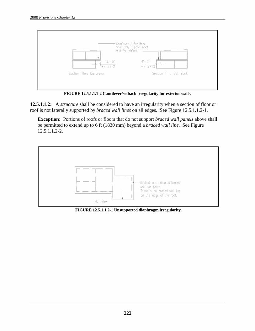
FIGURE 12.5.1.1.1-2 Cantilever/setback irregularity for exterior walls.
FIGURE 12.5.1.1.2-1 Unsupported diaphragm irregularity.
12.5.1.1.2: A structure shall be considered to have an irregularity when a section of floor orroof is not laterally supported by braced wall lines on all edges. See Figure 12.5.1.1.2-1.
Exception: Portions of roofs or floors that do not support braced wall panels above shallbe permitted to extend up to 6 ft (1830 mm) beyond a braced wall line. See Figure12.5.1.1.2-2.

Wood Structure Design Requirements
223223
FIGURE 12.5.1.1.2-2 Allowable cantilevered diaphragm.
FIGURE 12.5.1.1.3 Opening in wall below irregularity.
12.5.1.1.3: A structure shall be considered to have an irregularity when the end of a requiredbraced wall panel extends more than 1 ft (305 mm) over an opening in the wall below. Thisrequirement is applicable to braced wall panels offset in plane and to braced wall panels offsetout of plane as permitted by the exception to Sec. 12.5.1.1.1. See Figure 12.5.1.1.3.
Exception: Braced wall panels shall be permitted to extend over an opening not morethan 8 ft (2440 mm) in width when the header is a 4-in. by 12-in. (actual 3½ by 11¼ in.,89 by 286 mm) or larger member.
12.5.1.1.4: A structure shall be considered to have an irregularity when portions of a floor levelare vertically offset such that the framing members on either side of the offset cannot be lappedor tied together in an approved manner. See Figure 12.5.1.1.4.
Exception: Framing supported directly by foundations.

2000 Provisions Chapter 12
224224
FIGURE 12.5.1.1.4 Vertical offset irregularity.
FIGURE 12.5.1.1.5 Nonperpendicular wall irregularity.
FIGURE 12.5.1.1.6 Diaphragm opening irregularity.
12.5.1.1.5: A structure shall be considered to have an irregularity when braced wall lines are notperpendicular to each other. See Figure 12.5.1.1.5
12.5.1.1.6 Diaphragm Openings: A structure shall be considered to have an irregularity whenopenings in floor and roof diaphragms having a maximum dimension greater than 50 percent ofthe distance between lines of bracing or an area greater than 25 percent of the area betweenorthogonal pairs of braced wall lines are present. See Figure 12.5.1.1.6.

Wood Structure Design Requirements
225225
12.5.1.1.7 Stepped Foundation: A structure shall be considered to have an irregularity whenthe shear walls of a single story vary in height more than 6 ft (1800 mm).
12.5.2 Braced Walls: The following are the minimum braced wall requirements.
12.5.2.1 Spacing Between Braced Wall Lines: Interior and exterior braced wall lines shall belocated at the spacing indicated in Table 12.5.1-1.
12.5.2.2 Braced Wall Line Sheathing Requirements: All braced wall lines shall be braced byone of the types of sheathing prescribed in Table 12.5.2-1. The required sum of lengths of b-raced wall panels at each braced wall line is prescribed in Table 12.5.2-1. Braced wall panelsshall be distributed along the length of the braced wall line with sheathing placed at each end ofthe wall or partition or as near thereto as possible. To be considered effective as bracing, eachbraced wall panel shall conform to Sec. 602.9 of the CABO Code. All panel sheathing jointsshall occur over studs or blocking. Sheathing shall be fastened to all studs and top and bottomplates and at panel edges occurring over blocking. All wall framing to which sheathing used forbracing is applied shall be 2-by (actual 1½ in., 38 mm) or larger members.
Cripple walls shall be braced as required for braced wall lines and shall be considered anadditional story. Where interior post and girder framing is used, the capacity of the braced wallpanels at exterior cripple walls shall be increased to compensate for length of interior bracedwall eliminated by increasing the length of the sheathing or increasing the number of fasteners.
12.5.2.3 Attachment:
12.5.2.3.1: Nailing of braced wall panel sheathing shall be not less than the minimum includedin Tables 12.4.2-6a and 12.4.2-6b or as prescribed in Table 12.5.2-1.
12.5.2.3.2: Nailing for diagonal boards shall be as prescribed in Sec. 12.4.3.3 and 12.4.3.4.
12.5.2.3.3 : Adhesive attachment of wall sheathing is not permitted.
12.5.3 Detailing Requirements: The following requirements for framing and connectiondetails shall apply as a minimum.
12.5.3.1 Wall Anchorage: Anchorage of braced wall line sills to concrete or masonryfoundations shall be provided. Such anchorage shall conform to the requirements in Figure403.1a of Sec. 403 of the CABO code except that such anchors shall be spaced at not more than4 ft (1220 mm) on center for structures over two stories in height. For Seismic DesignCategories C, D and E, plate washers, a minimum of ¼ in. by 3 in. by 3 in. in size, shall beprovided between the foundation sill plate and the nut. Other anchorage devices havingequivalent capacity shall be permitted.
12.5.3.2 Top Plates: Stud walls shall be capped with double-top plates installed to provideoverlapping at corners and intersections. End joints in double-top plates shall be offset at least 4ft (1220 mm). Single top plates shall be permitted to be used when they are spliced by framingdevices providing capacity equivalent to the lapped splice prescribed for double top plates.
12.5.3.3 Bottom Plates: Studs shall have full bearing on a 2-by (actual 1½ in., 38 mm) or largerplate or sill having a width at least equal to the width of the studs.
2000 Provisions Chapter 12
226226
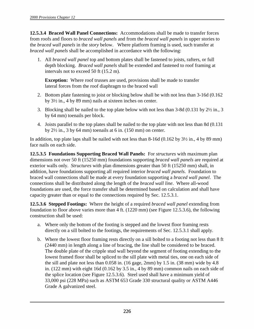
12.5.3.4 Braced Wall Panel Connections: Accommodations shall be made to transfer forcesfrom roofs and floors to braced wall panels and from the braced wall panels in upper stories tothe braced wall panels in the story below. Where platform framing is used, such transfer atbraced wall panels shall be accomplished in accordance with the following:
1. All braced wall panel top and bottom plates shall be fastened to joists, rafters, or fulldepth blocking. Braced wall panels shall be extended and fastened to roof framing atintervals not to exceed 50 ft (15.2 m).
Exception: Where roof trusses are used, provisions shall be made to transferlateral forces from the roof diaphragm to the braced wall
2. Bottom plate fastening to joist or blocking below shall be with not less than 3-16d (0.162by 3½ in., 4 by 89 mm) nails at sixteen inches on center.
3. Blocking shall be nailed to the top plate below with not less than 3-8d (0.131 by 2½ in., 3by 64 mm) toenails per block.
4. Joists parallel to the top plates shall be nailed to the top plate with not less than 8d (0.131by 2½ in., 3 by 64 mm) toenails at 6 in. (150 mm) on center.
In addition, top plate laps shall be nailed with not less than 8-16d (0.162 by 3½ in., 4 by 89 mm)face nails on each side.
12.5.3.5 Foundations Supporting Braced Wall Panels: For structures with maximum plandimensions not over 50 ft (15250 mm) foundations supporting braced wall panels are required atexterior walls only. Structures with plan dimensions greater than 50 ft (15250 mm) shall, inaddition, have foundations supporting all required interior braced wall panels. Foundation tobraced wall connections shall be made at every foundation supporting a braced wall panel. Theconnections shall be distributed along the length of the braced wall line. Where all-woodfoundations are used, the force transfer shall be determined based on calculation and shall havecapacity greater than or equal to the connections required by Sec. 12.5.3.1.
12.5.3.6 Stepped Footings: Where the height of a required braced wall panel extending fromfoundation to floor above varies more than 4 ft. (1220 mm) (see Figure 12.5.3.6), the followingconstruction shall be used:
a. Where only the bottom of the footing is stepped and the lowest floor framing restsdirectly on a sill bolted to the footings, the requirements of Sec. 12.5.3.1 shall apply.
b. Where the lowest floor framing rests directly on a sill bolted to a footing not less than 8 ft(2440 mm) in length along a line of bracing, the line shall be considered to be braced. The double plate of the cripple stud wall beyond the segment of footing extending to thelowest framed floor shall be spliced to the sill plate with metal ties, one on each side ofthe sill and plate not less than 0.058 in. (16 gage, 2mm) by 1.5 in. (38 mm) wide by 4.8in. (122 mm) with eight 16d (0.162 by 3.5 in., 4 by 89 mm) common nails on each side ofthe splice location (see Figure 12.5.3.6). Steel used shall have a minimum yield of33,000 psi (228 MPa) such as ASTM 653 Grade 330 structural quality or ASTM A446Grade A galvanized steel.

Wood Structure Design Requirements
227227
FIGURE 12.5.3.6 Stepped footing detail.
c. Where cripple walls occur between the top of the footing and the lowest floor framing,the bracing requirements for a story shall apply.
12.5.3.7 Detailing for Openings in Diaphragms: For openings with a dimension greater than4 ft (1220 mm) or openings in structures in Seismic Design Categories D and E, the followingminimum detail shall be provided. Blocking shall be provided beyond headers and metal ties notless than 0.058 in. (16 gage, 2 mm) by 1.5 in. (38 mm) wide by 4.8 in. (122 mm) with eight 16d(0.162 by 3.5 in., 4 by 89 mm) common nails on each side of the header-joist intersection (seeFigure 12.5.3.7). Steel used shall have a minimum yield of 33,000 psi (228 MPa) such as ASTM653 Grade 330 structural quality or ASTM A446 Grade A galvanized steel.

2000 Provisions Chapter 12
228228
FIGURE 12.5.3.7 Detail for diaphragm opening.
12.6 SEISMIC DESIGN CATEGORY A: Structures assigned to Seismic Design Category Aare permitted to be designed and constructed using any applicable materials and procedurespermitted in the reference documents and, in addition, shall conform to the requirements of Sec.5.2.6.1.2. Structures constructed in compliance with Sec. 12.5 are deemed to comply withSec. 5.2.6.1.2.
Exceptions:
1. Where Sec. 1.2.1, Exception 1, is applicable, one- and two-family detached dwellingsare exempt from the requirements of the Provisions.
2. Where Sec. 1.2.1, Exception 2, is applicable, one- and two-family dwellings that aredesigned and constructed in accordance with the conventional constructionrequirements of Sec. 12.5 are exempt from other requirements of the Provisions.
12.7 SEISMIC DESIGN CATEGORIES B, C, AND D: Structures assigned to SeismicDesign Categories B, C, and D shall conform to the requirements of this section, and Sec.5.2.6.1.2.
Exceptions:
1. Where Sec. 1.2.1, Exception 1, is applicable, one- and two-family detached dwellingsare exempt from the requirements of the Provisions.
2. Where Sec. 1.2.1, Exception 2, is applicable, one- and two-family dwellings that aredesigned and constructed in accordance with the conventional constructionrequirements of Sec. 12.5 are exempt from other requirements of the Provisions.

Wood Structure Design Requirements
229229
12.7.1 Conventional Light-Frame Construction: Conventional light-frame construction shallmeet the requirements of Sec. 12.5. Alternatively, such structures shall meet the requirements ofSec. 12.7.2. See Sec. 12.2.2.1 for design of nonconventional elements.
12.7.2 Engineered Construction: All engineered wood construction shall meet therequirements of Sec. 12.3 and 12.4.
12.8 SEISMIC DESIGN CATEGORIES E AND F: Structures assigned to Seismic DesignCategories E and F shall conform to all of the requirements for engineered construction inaccordance with Sec. 12.3 and 12.4 and to the additional requirements of this section.
Exception: Structures assigned to Seismic Use Group I that are designed and constructedin accordance with the requirements of Sec. 12.5 are permitted.
12.8.1 Limitations: Structures shall comply with the requirements given below.
12.8.1.1 Unblocked structural-use panel sheathing diaphragms shall not be considered to bepart of the seismic-force-resisting system. Structural-use panel sheathing used for diaphragmsand shear walls that are part of the seismic-force-resisting system shall be applied directly to theframing members.
Exception: Structural-use panel sheathing may be used as a diaphragm when fastenedover solid lumber planking or laminated decking provided the panel joints and lumberplanking or laminated decking joints do not coincide.
12.8.1.2 In addition to the requirements of Sec. 12.3.4.1, the factored shear resistance, 8ND, forstructural-use panel sheathed shear walls used to resist seismic forces in structures with concreteor masonry walls shall be one-half the values set forth in Tables 12.4.3-2a and 12.4.3-2b.
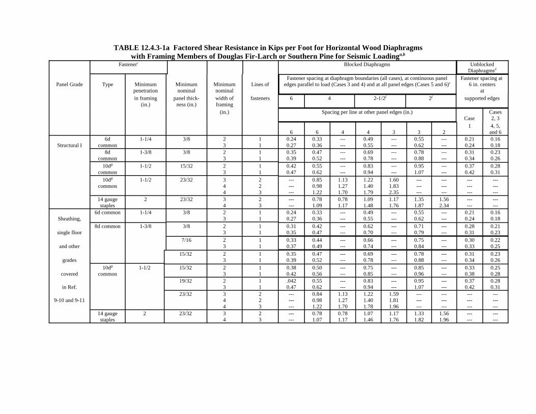
TABLE 12.4.3-1a Factored Shear Resistance in Kips per Foot for Horizontal Wood Diaphragmswith Framing Members of Douglas Fir-Larch or Southern Pine for Seismic Loadinga,b
Fastenerc Blocked Diaphragms UnblockedDiaphragmsd
Panel Grade Type Minimumpenetration
Minimumnominal
Minimumnominal
Lines ofFastener spacing at diaphragm boundaries (all cases), at continuous panel
edges parallel to load (Cases 3 and 4) and at all panel edges (Cases 5 and 6)eFastener spacing at
6 in. centersat
in framing(in.)
panel thick-ness (in.)
width offraming
fasteners 6 4 2-1/2f 2f supported edges
(in.) Spacing per line at other panel edges (in.)Case
Cases2, 3
6 6 4 4 3 3 21 4, 5,
and 6
Structural I6d
common1-1/4 3/8 2
311
0.240.27
0.330.36
------
0.490.55
------
0.550.62
------
0.210.24
0.160.18
8dcommon
1-3/8 3/8 23
11
0.350.39
0.470.52
------
0.690.78
------
0.780.88
------
0.310.34
0.230.26
10dg
common1-1/2 15/32 2
311
0.420.47
0.550.62
------
0.830.94
------
0.951.07
------
0.370.42
0.280.31
10dg
common1-1/2 23/32 3
44
223
---------
0.850.981.22
1.131.271.70
1.221.401.79
1.601.832.35
---------
---------
---------
---------
14 gaugestaples
2 23/32 34
23
------
0.781.09
0.781.17
1.091.48
1.171.76
1.351.87
1.562.34
------
------
Sheathing,6d common 1-1/4 3/8 2
311
0.240.27
0.330.36
------
0.490.55
------
0.550.62
------
0.210.24
0.160.18
single floor8d common 1-3/8 3/8 2
311
0.310.35
0.420.47
------
0.620.70
------
0.710.79
------
0.280.31
0.210.23
and other7/16 2
311
0.330.37
0.440.49
------
0.660.74
------
0.750.84
------
0.300.33
0.220.25
grades15/32 2
311
0.350.39
0.470.52
------
0.690.78
------
0.780.88
------
0.310.34
0.230.26
covered10dg
common1-1/2 15/32 2
311
0.380.42
0.500.56
------
0.750.85
------
0.850.96
------
0.330.38
0.250.28
in Ref.19/32 2
311
.0420.47
0.550.62
------
0.830.94
------
0.951.07
------
0.370.42
0.280.31
9-10 and 9-1123/32 3
44
223
---------
0.840.981.22
1.131.271.70
1.221.401.78
1.591.811.96
---------
---------
---------
---------
14 gaugestaples
2 23/32 34
23
------
0.781.07
0.781.17
1.071.46
1.171.76
1.331.82
1.561.96
------
------

Wood Structure Design Requirements
231231
NOTES for TABLE 12.4.3-1a
a 8 = 1.0 n = 0.65
b l/w shall not be more than 4/1 for blocked diaphragms or more than 3/1 for unblocked diaphragms. For framingmembers of other species set forth in Ref. 12-1, Table 12A, with the range of specific gravity (SG) noted, allowableshear values shall be calculated for all panel grades by multiplying the values from the table above for nail size andactual panel grade by the following factor: Specific Gravity Adjustment Factor = (1-(0.5 - SG)), Where SG =Specific Gravity of the framing lumber. This adjustment factor shall not be greater than 1.
c Space nails along intermediate framing members at 12 in. centers except where spans aregreater than 32 in..; space nails at 6 in. centers.
d Blocked values are permitted to be used for 1-1/8 in. panels with tongue-and-groove edges where 1 in. by 3/8 in..crown by No. 16 gauge staples are driven through the tongue-and-groove edges 3/8 in. from the panel edge so as topenetrate the tongue. Staples shall be spaced at one half the boundary nail spacing for Cases 1 and 2 and at onethird the boundary nail spacing for Cases 3 through 6.
e Maximum shear for Cases 3 through 6 is limited to 1500 pounds per foot.
f For values listed for 2 in. nominal framing member width, the framing members at adjoining panel edges shall be 3in. nominal width. Nails at panel edges shall be placed in two lines at these locations.
g Framing at adjoining panel edges shall be 3 in. nominal or wider and nails shall be staggered where 10d nailshaving penetration into framing of more than 1-5/8 in. are spaced 3 in. or less on center.

TABLE 12.4.3-1b Factored Shear Resistance in kiloNewtons per Meter for Horizontal Wood Diaphragmswith Framing Members of Douglas Fir-Larch or Southern Pine for Seismic Loadinga,b
Fastenerc Blocked Diaphragms UnblockedDiaphragmsd
Panel Grade Type Minimumpenetration
Minimumnominal
Minimumnominal
Lines ofFastener spacing at diaphragm boundaries (all cases), at continuous panel
edges parallel to load (Cases 3 and 4) and at all panel edges (Cases 5 and 6)(mm)e
Fastener spacing at 150 mm centers
at
in framing(mm.)
panel thick-ness (mm.)
width offraming
fasteners 150 100 65f 50f supported edges
(mm.) Spacing per line at other panel edges (mm.)Case
Cases2, 3
150 150 100 100 75 75 501 4, 5,
and 6
Structural I6d
common32 9.5 50
7511
3.54.0
4.75.3
------
7.18.0
------
8.09.0
------
3.13.5
2.42.7
8dcommon
35 9.5 5075
11
5.15.7
6.87.6
------
10.111.4
------
11.412.8
------
4.65.0
3.43.8
10dg
common38 12 50
7511
6.16.8
8.19.1
------
12.113.7
------
13.815.6
------
5.46.1
4.14.6
10dg
common38 18 75
100100
223
---------
12.314.317.8
16.518.624.8
17.820.526.1
23.326.834.1
---------
---------
---------
---------
14 gaugestaples
50 18 75100
23
------
11.415.9
11.417.1
15.921.6
17.125.6
19.727.3
22.834.1
------
------
Sheathing,6d common 32 9.5 50
7511
3.54.0
4.75.3
------
7.18.0
------
8.09.0
------
3.33.5
2.42.7
single floor8d common 35 9.5 50
7511
4.65.1
6.16.8
------
9.110.2
------
10.311.6
------
4.14.6
3.03.4
and other11 50
7511
4.85.4
6.57.2
------
10.912.2
------
10.912.2
------
4.44.8
3.23.6
grades12 50
7511
5.15.7
6.97.6
------
10.111.4
------
11.412.8
------
4.55.0
3.43.8
covered10dg
common38 12 50
7511
5.56.2
7.38.2
------
10.912.3
------
12.413.9
------
4.85.5
3.64.1
in Ref.15 50
7511
6.16.8
8.19.1
------
12.113.7
------
13.815.6
------
5.46.1
4.14.6
9-10 and 9-1118 75
100100
223
---------
12.214.217.7
16.518.624.8
17.720.426.4
23.226.528.6
---------
---------
---------
---------
14 gaugestaples
50 18 75100
23
------
11.415.6
11.417.1
15.621.2
17.125.6
19.426.6
22.828.6
------
------

Wood Structure Design Requirements
233233
NOTES for TABLE 12.4.3-1b
a 8 = 1.0 n = 0.65
b l/w shall not be more than 4/1 for blocked diaphragms or more than 3/1 for unblocked diaphragms. For framingmembers of other species set forth in ASCE 16, Table 12A, with the range of specific gravity (SG) noted, allowableshear values shall be calculated for all panel grades by multiplying the values from the table above for nail size andactual panel grade by the following factor: Specific Gravity Adjustment Factor = (1-(0.5 - SG)), Where SG = Specific Gravity of the framing lumber. Thisadjustment factor shall not be greater than 1.
c Space nails along intermediate framing members at 300 mm centers except where spans are greater than 810 mm;space nails at 150 mm centers.
d Blocked values are permitted to be used for 28.5 mm panels with tongue-and-groove edges where 25 mm by 9 mmcrown by No. 16 gauge staples are driven through the tongue-and-groove edges 9 mm. from the panel edge so as topenetrate the tongue. Staples shall be spaced at one half the boundary nail spacing for Cases 1 and 2 and at onethird the boundary nail spacing for Cases 3 through 6.
e Maximum shear for Cases 3 through 6 is limited to 22.8 kiloNewtons per meter.
f For values listed for 50 mm nominal framing member width, the framing members at adjoining panel edges shallbe 75 mm nominal width. Nails at panel edges shall be placed in two lines at these locations.
g Framing at adjoining panel edges shall be 75 mm nominal or wider and nails shall be staggered where 10d nailshaving penetration into framing of more than 41 mm are spaced 75 mm or less on center.

TABLE 12.4.3-2a Factored Shear Resistance in Kips per Foot (KLF) for Seismic Forces on Structural Use PanelShear Walls with Framing Members of Douglas Fir-Larch or Southern Pinea,b,c
Panel Grade Nail Size(Common orHot-DippedGalvanized
Box)
MinimumPenetrationin Framing
(in.)
PanelThickne
ss(in.)
Panel Applied Direct to Framing Nail Spacingat Panel Edges (in.)
Nail Size(Common orHot-DippedGalvanized
Box)
Panel Applied Over 1/2 in. or 5/8 in. Gypsum SheathingNail Spacing at Panel Edges (in.)
6 4 3 2d 6 4 3 2d
Structural I 6d 1-1/4 3/8 0.26 0.39 0.51 0.66 8d 0.26 0.39 0.51 0.66
8d 1-3/8 3/8 0.30f 0.47f 0.60f 0.79f 10de 0.30f 0.47f 0.60f 0.79f
8d 1-3/8 7/16 0.33f 0.51f 0.66f 0.87f 10de 0.33f 0.51f 0.66f 0.87f
8d 1-3/8 15/32 0.36 0.56 0.72 0.95 10de 0.36f 0.56f 0.72f 0.95f
10de 1-1/2 15/32 0.44 0.66 0.86 1.13 - - - -
14 ga staple 2 3/8 0.19 0.29 0.39 0.58 - - - -
14 ga staple 2 7/16 0.27 0.40 0.53 0.80 - - - -
Sheathing,Panel Siding
andOther
GradesCovered inReferences
9.10and9.11
6d 1-1/4 3/8 0.26 0.39 0.51 0.66 8d 0.26 0.39 0.51 0.66
8d 1-3/8 3/8 0.29f 0.42f 0.53f 0.69f 10de 0.29f 0.42f 0.53f 0.69f
8d 1-3/8 7/16 0.31f 0.46f 0.59f 0.76f 10de 0.31f 0.46f 0.59f 0.76f
8d 1-3/8 15/32 0.34 0.49 0.64 0.83 10de 0.34f 0.49f 0.64f 0.83f
10de 1-1/2 15/32 0.40 0.60 0.78 1.00 - - - -
10de 1-1/2 19/32 0.44 0.66 0.86 1.13 - - - -
14 ga staple 2 3/8 0.17 0.25 0.33 0.50 - - - -
14 ga staple 2 7/16 0.23 0.36 0.47 0.70 - - - -
14 ga staple 2 15/32 0.27 0.40 0.53 0.80 - - - -
(Hot- DippedGalvanized
Casing Nail)
(Hot-DippedGalvanized
Casing Nail)
Panel Sidingas Covered in
Reference 9.10
6d 1-1/4 3/8 0.18 0.27 0.36 0.47 8d 0.18 0.27 0.36 0.47
8d 1-3/8 3/8 0.21 0.31 0.40 0.53 10de 0.21 0.31 0.40 0.53

Wood Structure Design Requirements
235235
NOTES for TABLE 12.4.3-2a
a 8 = 1.0 N = 0.65
b All panel edges backed with 2-inch nominal or wider framing. Panels installed eitherhorizontally or vertically. Space nails at 6 in. on center along intermediate framing members for3/8-in. panels installed with strong axis parallel to studs spaced 24 in. on center and 12 in. oncenter for other conditions and panel thicknesses. Allowable shear values for fasteners inframing members of other species set forth in Table 12A of ASCE 16 shall be calculated for allgrades by multiplying the values by the following factors: 0.82 for species with a specific gravitygreater than or equal to 0.42 but less than 0.49 (0.42 # G < 0.49) and 0.65 for species with aspecific gravity less than 0.42 (G < 0.42). For panel siding using hot-dipped galvanized casingnails, the shear values shall be the values in the table multiplied by the same factors.
c Where panels are applied on both faces of a wall and nail spacing is less than 6 inches on centeron either side, panel joints shall be offset to fall on different framing members or framing shallbe 3-inch nominal or wider and nails on each side of joint shall be staggered.
d Framing at adjoining panel edges shall be 3-in. nominal or wider and nails shall be staggeredwhere nails are spaced 2 in. on center.
e Framing at adjoining panel edges shall be 3-in. nominal or wider and nails shall be staggeredwhere 10d nails having penetration into framing of more than 1-5/8 in. are spaced 3 in. or less oncenter.
f The values for 3/8-in. and 7/16-in. panels applied directly to framing are permitted to beincreased to the values shown for 15/32-in. panels provided studs are spaced a maximum of 16in. on center or panel is applied with strong axis across studs.

TABLE 12.4.3-2b Factored Shear Resistance in kiloNewtons per Meter (kN/m) for Seismic Forces on Structural Use PanelShear Walls with Framing Members of Douglas Fir-Larch or Southern Pinea,b,c
Panel Grade Nail Size(Common orHot-DippedGalvanized
Box)
MinimumPenetrationin Framing
(mm)
PanelThickness
(mm)
Panel Applied Directto Framing
Nail Spacing at Panel Edges (mm)
Nail Size(Hot-DippedCommon or
Galvanized Box)
Panel Applied Over 12.7 mm or 15.9 mm Gypsum Sheathing
Nail Spacing at Panel Edges (mm)
150 100 75 50 150 100 75 50d
Structural I 6d 32 9.5 3.8 5.7 7.4 9.7 8d 3.8 5.7 7.4 9.7
8d 35 9.5 4.4f 6.8f 8.7f 11.6f 10de 4.4 6.8 8.7 11.6
8d 35 11 4.8f 7.5f 9.6f 12.7f 10de 4.8 7.5 9.6 12.7
8d 35 12 5.3 8.2 10.4 13.8 10de 5.3 8.2 10.4 13.8
10de 38 12 6.5 9.7 12.6 16.5 - - - -
14 ga staple 50 9.5 2.8 4.3 5.7 8.4 - - - -
14 ga staple 50 11 3.9 5.8 7.8 11.7 - - - -
Sheathing,Panel Siding
andOther
GradesCovered inReferences
9.10and9.11
6d 32 10 3.8 5.7 7.4 9.7 8d 3.8 5.7 7.4 9.7
8d 35 10 4.2f 6.1f 7.8f 10.1f 10de 4.2 6.1 7.8 10.1
8d 35 11 4.6f 6.6f 8.5f 11.1f 10de 4.6 6.6 8.5 11.1
8d 35 12 4.9 7.2 9.3 12.1 10de 4.9 7.2 9.3 12.1
10de 38 12 5.9 8.7 11.4 14.6 - - - -
10de 38 15 6.5 9.7 12.6 16.5 - - - -
14 ga staple 50 9.5 2.5 3.7 4.8 7.3 - - - -
14 ga staple 50 11 3.4 5.2 6.8 10.2 - - - -
14 ga staple 50 12 3.9 5.8 7.8 11.7 - - - -
Panel Sidingas Covered in
Reference 9.10
(Hot-DippedGalvanized
Casing Nail)
(Hot-DippedGalvanized
Casing Nail)
6d 32 9.5 2.7 4.0 5.2 6.8 8d 2.7 4.0 5.2 6.8
8d 35 9.5 3.0 4.6 5.9 7.8 10de 3.0 4.6 5.9 7.8

Wood Structure Design Requirements
237237
NOTES for TABLE 12.4.3-2b
a 8 = 1.0 n = 0.65
b All panel edges backed with 38 mm nominal or wider framing. Panels installed eitherhorizontally or vertically. Space nails at 150 mm on center along intermediate framing membersfor 9 mm panels installed with strong axis parallel to studs spaced 610 mm on center and 305mm on center for other conditions and panel thicknesses. Allowable shear values for fasteners inframing members of other species set forth in Table 12A of ASCE 16 shall be calculated for allgrades by multiplying the values by the following factors: 0.82 for species with a specific gravitygreater than or equal to 0.42 but less than 0.49 (0.42 # G < 0.49) and 0.65 for species with aspecific gravity less than 0.42 (G < 0.42). For panel siding using hot-dipped galvanized casingnails, the shear values shall be the values in the table multiplied by the same factors.
c Where panels are applied on both faces of a wall and nail spacing is less than 610 mm on centeron either side, panel joints shall be offset to fall on different framing members or framing shallbe 64 mm or wider and nails on each side of joint shall be staggered.
d Framing at adjoining panel edges shall be 64 mm or wider and nails shall be staggered wherenails are spaced 50 mm on center.
e Framing at adjoining panel edges shall be 64 mm or wider and nails shall be staggered where10d nails having penetration into framing of more than 41 mm are spaced 76 mm or less oncenter.
f The values for 9 mm and 11 mm panels applied directly to framing are permitted to beincreased to the values shown for 12 mm panels provided studs are spaced a maximum of 406mm on center or panel is applied with strong axis across studs.

2000 Provisions Chapter 12
238238
TABLE 12.5.1-1 Conventional Light-Frame Construction Braced Wall Requirements
Seismic PerformanceCategory
Maximum DistanceBetween Braced Walls
Maximum Number of StoriesAbove Grade Permitted a
Ab 35 ft (10675 mm) 3
B 35 ft (10675 mm) 3
C 25 ft (7625 mm) 2
D and E (Seismic Use Group I)
25 ft (7625 mm) 1 c
E (Seismic Use GroupII) and F
Conventional construction not permitted; conformancewith Sec. 12.3 required.
a A cripple stud wall is considered to be a story above grade. Maximum bearing wall height shall not exceed
10 ft (3050 mm)
b See exceptions to Sec. 1.2.1.
c Detached one- and two-family dwellings are permitted to be two stories above grade.

Wood Structure Design Requirements
239239
TABLE 12.5.2-1 Conventional Light-Frame Construction Braced Wall Requirementsin Minimum Length of Wall Bracing per Each 25 Lineal Feet (7625 mm) of Braced Wall
Linea
StoryLoca-tion
SheathingTypeb
0.125 ####SDS < 0.25
0.25 #### SDS < 0.375
0.375 #### SDS < 0.50
0.50 #### SDS < 0.75
0.75 #### SDS
< 1.0e
Top oronlystoryabovegrade
G-Pd 8 ft 0 in.(2440 mm)
8 ft 0 in.(2440 mm)
10 ft 8 in.(3250 mm)
14 ft 8 in.(4470 mm)
18 ft 8 in.c
(5690 mm)
S-W 4 ft 0 in.(1220 mm)
4 ft 0 in.(1220 mm)
5 ft 4 in.(1625 mm)
8 ft 0 in.(2440 mm)
9 ft 4 in.c
(2845 mm)
Story be-low topstoryabovegrade
G-Pd 10 ft 8 in(3250 mm)
14 ft 8 in.(4470 mm)
18 ft 8 in.c
(6590 mm)NP NP
S-W 5 ft 4 in.(1625 mm)
6 ft 8 in.(2030 mm)
10 ft 8 in.c
(3250 mm)13 ft 4 in.c
(4065 mm)17 ft 4 in.c
(5280 mm)
Bottomstory of3 storiesabovegrade
G-Pd 14 ft 8 in.(4470 mm)
Conventional construction not permitted;conformance with Sec. 12.3 required.
S-W 8 ft 0 in.(2440 mm)
a Minimum length of panel bracing of one face of wall for S-W sheathing or both faces of wall for G-Psheathing; h/w ratio shall not exceed 2/1, except structures in Seismic Design Category B need only meet therequirements of Sec. 602.9 of the CABO Code. For S-W panel bracing of the same material on two faces of thewall, the minimum length is permitted to be one half the tabulated value but the h/w ratio shall not exceed 2/1 anddesign for uplift is required.
b G-P = gypsumboard, fiberboard, particleboard, lath and plaster, or gypsum sheathing boards; S-W =structural-use panels and diagonal wood sheathing. NP = not permitted.
c Applies to one- and two-family detached dwellings only.
d Nailing shall be as follows:For ½ in. (13 mm) gypsum board, 5d ( 0.086 in., 2.2 mm diameter) coolers at 7 in. (178 mm) centers;For e in. (16mm) gypsum board, 6d ( 0.092 in. ( 2.3 mm) diameter) at 7 in (178 mm) centers;For gypsum sheathing board, 1¾ in. long by 7/16 in. (44 by 11 mm) head, diamond point galvanized at 4 in.(100mm) centers;For gypsum lath, No. 13 gauge (0.092 in., 2.3 mm) by 1c in. long, 19/64 in. (29 by 7.5 mm) head, plasterboardat 5 in. (125 mm) centers;For Portland cement plaster, No. 11 gauge (0.120 in., 3 mm) by 1½ in. long, 7/16 in. head (89 by 11 mm) at 6 in.(150 mm) centers; For fiberboard and particleboard, No. 11 gauge (0.120 in., 3 mm) by 1½ in. (38 mm) long, 7/16 in. ( 11 mm)head, galvanized at 3 in. (76 mm) centers. For structural wood sheathing, the minimum nail size and maximum spacing shall be in accordance with theminimum nails size and maximum spacing allowed for each thickness sheathing in Tables 12.4.3-2a and b. Nailing as specified above shall occur at all panel edges at studs, at top and bottom plates, and, whereoccurring, at blocking. e Where SDS > 1.0, conventional construction is not permitted.
