engineer training machine calibration tj8300 / tj8500 machine calibration
TRANSCRIPT

Engineer Training
Machine Calibration
TJ8300 / TJ8500
Machine Calibration

Confidential 2
Engineer Training
Machine Calibration
TJ8300 / TJ8500General
Machine adjustment includes:
Loading adjustments
Media length adjustments
Bridge – drum distance alignment
Timer adjustments

Confidential 3
Engineer Training
Machine Calibration
TJ8300 / TJ8500Loading Adjustments
Fix drum position P=2 or P=-2
Buffer idler
Buffer belts
Loading tray
Substrate roll
Loading Rollers
Substrate guides
Buffer
Output tray
Guiding Rollers
Spring Tension Bar
Tension Springs

Confidential 4
Engineer Training
Machine Calibration
TJ8300 / TJ8500Loading Adjustments (Cont.)
The quality of loading is based on the following:
Printing unit leveling.
Media feeder leveling.
The parallelism between the media feeder and the printing unit chassis – Depends on 2 adjusting screws between the media feeder and the machine chassis.
Gripper location during load (referred to as Drum Position in the loading macro).
The amount of media that is advanced towards the gripper (referred to as Buffer Position in the loading macro).

Confidential 5
Engineer Training
Machine Calibration
TJ8300 / TJ8500Loading Adjustments (Cont.)
The quality of loading is based on the following (Cont.):
Vacuum level (clogged hoses on the drum surface reduce the vacuum level).
Environmental conditions (Temperature and humidity) – recommended conditions: 15°C-25°C and 35%-60% (respectively).

Confidential 6
Engineer Training
Machine Calibration
TJ8300 / TJ8500Loading Adjustments (Cont.)
The drawings represent three different situations:
A. In this case the media is “caught nicely” under the gripper. There is a good tangency angel between the media and the the drum, which insures good entrance of the media front into the gripper.
B. If “excessive” media enters the gripper, this will cause a front bubble. The drum and buffer positions have to be adjusted (+P or -F or both).
C. If there is a “lack” of media under the gripper. The drum and buffer positions have to be adjusted(+P or -F or both).
A
B
C

Confidential 7
Engineer Training
Machine Calibration
TJ8300 / TJ8500Loading Adjustments (Cont.)
Two screws between the media feeder and the printing unit adjust their parallelism and control X1 and X2.
The difference between X1 and X2 should not exceed 1mm.
Drum
Media Grippers
X1
X2
Y2 Y1

Confidential 8
Engineer Training
Machine Calibration
TJ8300 / TJ8500Loading Adjustments (Cont.)
The parallelism between the printing unit and the media feeder is critical for the accuracy and reliability of the loading.
The parallelism between these units are defined and adjusted only once.
There are two adjusting bolts on each side of the media feeder for fine tuning adjustments.
The immediate effect will be on X1, X2, Y1 & Y2.
Printing unitPrinting unitPrinting unit
Media feederMedia feederMedia feeder
Top viewTop viewTop view

Confidential 9
Engineer Training
Machine Calibration
TJ8300 / TJ8500Media Length Correction
1. Insert 3700 cm of media into the buffer.
2. Remove the media from the buffer and measure its real length (e.g. 3617 cm).
3. From the RT-Run application, select Setup > Machine Parameters; the Machine Parameters dialog box appears.

Confidential 10
Engineer Training
Machine Calibration
TJ8300 / TJ8500Media Length Correction (Cont.)
4. Use the following equation to calculate the "New roller parameters value":
5. Insert the "New roller parameters value" in the Machine Parameters dialog box (under Roller Parameters).
6. Insert 3700 cm of media into the buffer, and measure the real length of the media to verify.
value parameters
rollerNew
202.55) (e.g. field Parameters Roller
in shown Value
cm) 3617 (e.g. media the of length Real
cm) (3700 buffer the into inserted Media

Confidential 11
Engineer Training
Machine Calibration
TJ8300 / TJ8500Drum-Bridge Distance Alignment (DST)
1. From the RT-Run application, select Digital Outputs.
2. From the Digital Outputs dialog box, uncheck DST1 and DST2 checkboxes (to set the DST to 0).
3. From the Bridge Step Motors dialog box, press Go to Plot to send the bridge to Plot position.
Confidential 12
Engineer Training
Machine Calibration
TJ8300 / TJ8500 Drum-Bridge Distance Alignment (DST) – Cont.
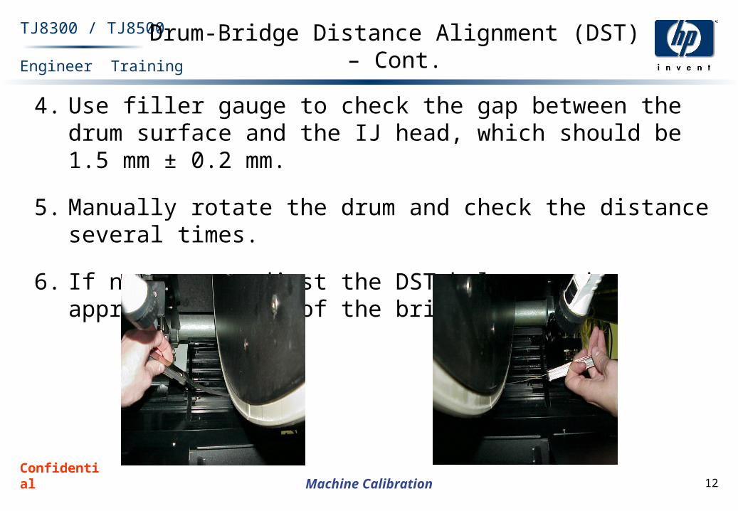
4. Use filler gauge to check the gap between the drum surface and the IJ head, which should be 1.5 mm ± 0.2 mm.
5. Manually rotate the drum and check the distance several times.
6. If necessary adjust the DST bolts on the appropriate side of the bridge.

Confidential 13
Engineer Training
Machine Calibration
TJ8300 / TJ8500 Drum-Bridge Distance Alignment (DST) – Cont.
DST alignment bolts are located on each side of the bridge
Confidential 14
Engineer Training
Machine Calibration
TJ8300 / TJ8500Timer Adjustments
In order to achieve the best possible printing quality, it is necessary to adjust the TPFM boards.
The TPFM boards are normally adjusted in the integration process. However, there may be a need for fine-tuning of the TPFM boards.

Confidential 15
Engineer Training
Machine Calibration
TJ8300 / TJ8500Timer Adjustments (Cont.)
Adjustment Procedure:
1. Print the Line 8 file, which is located under C:\Idanitnt\image\line8.ras or line8.sct. The file should appear as shown.

Confidential 16
Engineer Training
Machine Calibration
TJ8300 / TJ8500Timer Adjustments (Cont.)
2. Check that the horizontal lines (drum rotation axis) in all colors are not doubled as shown in the picture below.If the double lines appear only in the drum rotation axis(see the picture below), the timer boards need to be adjusted.

Confidential 17
Engineer Training
Machine Calibration
TJ8300 / TJ8500Timer Adjustments (Cont.)
Each printing mode has to be adjusted separately.
For example, if the image with double lines was printed in 336, the following setting must be selected from the application software: Preferences > Timer parameters > Printing mode: 336

Confidential 18
Engineer Training
Machine Calibration
TJ8300 / TJ8500Timer Adjustments (Cont.)
It is necessary to adjust the TPFM so that the double lines will appear only as a single line.
To do so, the resolution parameter must be adjusted.
The pictures below illustrate cases where resolution parameters must be increased or decreased.

Confidential 19
Engineer Training
Machine Calibration
TJ8300 / TJ8500Timer Adjustments (Cont.)
The resolution parameter is a Hex number. You can correct the double lines problem by changing this number. For example, if the image had a resolution of 00AA, change this number by +1 to 00AB (AA+1=AB) or -1 to 00A9 (AA-1=A9).
Note: These numbers can also be calculated in the Windows Scientific Calculator by selecting HEX from the upper bar.
After changing the number, print the same file to see if the double line problem is solved. If the double line is not corrected but is only reduced, change the resolution parameter again until the printing is satisfactory.
Repeat the procedures for all printing modes.