energy conservation using new structured-core and
TRANSCRIPT

Instructions for use
Title Energy conservation using new structured-core and transparent vacuum insulation panels: Numerical simulation withexperimental validation
Author(s) Katsura, Takao; Radwan, Ali; Yang, Zhang; Nakamura, Makoto; Nagano, Katsunori
Citation Solar energy, 193, 885-905https://doi.org/10.1016/j.solener.2019.09.083
Issue Date 2019-11-15
Doc URL http://hdl.handle.net/2115/83280
Rights © <2019>. This manuscript version is made available under the CC-BY-NC-ND 4.0 licensehttp://creativecommons.org/licenses/by-nc-nd/4.0/
Rights(URL) http://creativecommons.org/licenses/by-nc-nd/4.0/
Type article (author version)
File Information Revised manuscript2.pdf
Hokkaido University Collection of Scholarly and Academic Papers : HUSCAP

1
Energy Conservation using New Structured-Core and Transparent 1
Vacuum Insulation Panels: Numerical Simulation with Experimental 2
Validation 3 4
Takao Katsura*1, Ali Radwan1, 2, Zhang Yang3, Makoto Nakamura1, Katsunori Nagano1 5 1Division of Human Environmental Systems, Faculty of Engineering, Hokkaido University, 6
N13-W8, Kita-ku, Sapporo 060-8628, Japan 7 2Department of Mechanical Power Engineering, Mansoura University, El-Mansoura 35516, Egypt 8
3Country Garden, Beijiao Town, Shunde District, Foshan, Guangdong 528312, China 9
* Corresponding author: Tel: +81-11-706-6284, e-mail: [email protected] 10
Abstract 11
The rate of heat gain or heat loss from the windows of existing buildings represents a large portion 12
of building energy consumption in harsh hot or cold regions, respectively. Therefore, several thermal 13
insulation technologies have been applied in new buildings. However, these technologies are difficult to 14
implement in existing buildings. Therefore, this study proposes a new, low-cost insulation method using 15
slim, transparent panels with structured cores, for the windows of existing buildings. To do this, five new 16
distinct designs of vacuum insulation panels (VIPs) are proposed to retrofit insulation for the windows of 17
existing buildings. The VIPs comprise a hollow-frame structured-core material encapsulated in a 18
transparent multi-layered polymeric envelope. The effective thermal conductivity of VIPs with different 19
spacers, namely, peek, modified peek, mesh, silica aerogel, and frame, are evaluated at different pressure 20
levels. The spacers are 3D-printed and experimentally-examined. A 3D thermal model is developed and 21
validated using the experimental results of the present work and results from the literature. First, the 22
influences of spacer structure and vacuum pressure on the centre-of-panel thermal conductivity, light 23
transparency, and VIP production costs are evaluated. Second, three different trial manufacturing methods 24
for these VIPs are proposed and compared. Finally, the annual building heat gain and heat loss in two 25
different harsh hot and cold regions, respectively, in Japan are estimated while applying these new proposed 26
VIP designs to the existing windows. The results indicate that VIPs with frame and mesh spacers 27
accomplish better insulation performance, with a centre-of-panel thermal conductivity of 7×10⁻³ W/m.K at 28
a pressure of 1 Pa. Further, the VIP with the peek spacer accomplishes the highest light transparency (0.88). 29
Furthermore, using a frame-type VIP with a total thickness of 3 mm attached to an existing window as a 30
curtain decreases the space heat loss by approximately 69.5%, whereas the light transparency decreases to 31
75 %. In that regard, using a frame-type VIP attached to 3 mm-glass windows decreases window insulation 32
costs by 72 % compared with vacuum glazing thermal insulation. 33
Keywords: Vacuum insulation panel; structured-core and transparent; retrofitting insulation; surface-to-34
surface radiation; 3D modelling 35
Highlights 36
· Five distinct structured-core and transparent vacuum insulation panels are analysed. 37
· A 3D model is used to predict the insulation ability. 38
· VIPs with mesh and frame spacers achieve better insulation performance. 39

2
· The proposed VIPs are cost-effective when compared with silica aerogels and vacuum glazing. 40
· VIPs with pillar spacers provide the highest light transparency. 41 1. Introduction 42
Environmental problems and energy exhaustion have become major global issues. The annual 43
energy consumption is increasing every year, and the amount of environmental pollution is accelerating. In 44
this regard, many energy-saving technologies for building applications have been installed in new buildings. 45
Meanwhile, old buildings are often protected for their aesthetical and historical contributions to society. 46
However, the aforementioned energy-saving technologies are rarely installed in such existing buildings. 47
The insulation ability of the existing buildings is poor; therefore, it is vital to improving their insulation 48
performance. Vacuum insulation panels (VIPs) are panels characterised by very low thermal conductivity 49
as compared to traditional insulating materials (Fricke et al., 2008). For this reason, they represent a 50
promising solution for improving the thermal behaviour of buildings, especially in the case of energy 51
retrofitting (where higher performance and smaller thicknesses are desirable) (Boafo et al., 2019). Further, 52
it is essential to decrease the summer heat gain or winter heat loss in the windows of the existing buildings. 53
At the same time, keeping the transparency of the window as high as possible is essential for decreasing 54
the lighting energy consumption during the daytime (Yang et al., 2017). 55
56
The research on VIPs has been applied in some fields to improve insulation performance. For 57
example, in some buildings, it can attain 5 times higher insulation values than traditional building insulating 58
materials (Fantucci et al., 2019). It has also been widely applied in vacuum cups and refrigerators (Thiessen 59
et al., 2018). A vacuum pipe has been applied in evacuated-tube solar collectors (Farid Arya et al., 2018). 60
The study of vacuum insulation technology, as applied to buildings, began in the 1990s. The VIP apparent 61
thermal conductivity ranges from 10 to 20% of that of conventional insulation materials such as glass wool, 62
expanded polystyrene, and polyurethane foam (Choi et al., 2016). The VIP consists of filler material and a 63
gas barrier envelope. The filler material has a porous structure with an open cell. This filler facilitates the 64
inner air evacuation. Different types of filler materials have been examined and tested in recent years (Choi 65
et al., 2016; Lee and Song, 2019; Liang et al., 2017; Paneri et al., 2019). For instance, (Kim et al., 2012b) 66
used phenolic foam as a filler material for a VIP. They concluded that the effective total thermal 67
conductivity of the VIP was approximately 5×10⁻³ W/m.K at a vacuum of 0.02 Pa, with 5% uncertainty in 68
the measurement. Moreover, the same research group experimentally evaluated the insulation ability of a 69
VIP with glass wool with a minimum centre-of-panel thermal conductivity of 1.2×10⁻³ W/m.K, and that of 70
opacified fumed silica with a minimum centre-of-panel thermal conductivity of 2.5 ×10⁻³ W/m.K, as fillers 71
at different pressing loads and pressure levels in (Kim and Song, 2013). Owing to the permeable open 72
structure of these types of fillers, they concluded that the VIP volume changes by the evacuation. In addition, 73
by applying the pressing load, the filler solid conduction increases, but the radiative thermal conductivity 74
decreases. Glass fibre is also used as the core material in a VIP for high-temperature applications in (Araki 75
et al., 2009). (Choi et al., 2016) proposed a new VIP consisting of two stainless steel plates, with pillar 76
support to sustain the atmospheric pressure. In their work, heat transfer and mechanical stability were 77
analysed together in the design stage. Then, to further decrease the conduction heat transfer through the 78

3
pillar, a multi-pass support (MPS) pillar with a cup-shaped holder was suggested and investigated. They 79
concluded that they attained a VIP with a very low effective thermal conductivity, i.e. approximately 80
1.18×10⁻³ W/m.K. In the recent investigations, the manufactured VIPs are proposed for insulating walls in 81
a building. These structures of VIPs are the most common, and provide an opaque view. Therefore, the light 82
transparency through the VIP was not a main concern. These structures consist of a metallized film barrier, 83
i.e. an "aluminium envelope placed inside the structure of a building wall". 84
85
Silica powder has been applied for the trial manufacture of VIPs. A silica aerogel with a thermal 86
conductivity of 2×10⁻² W/m.K is usually used to make transparent VIPs (Buratti et al., 2017). It has been 87
found that using such material in smart windows decreases the U-values by 63% as compared to 88
conventional glass windows. In addition, a significant reduction in the light transmittance (by 89
approximately 30%) has been measured (Buratti et al., 2017). Moreover, the industrial production cost of a 90
VIP using silica aerogel remains very high. Hence, there is a need to search for another economically 91
competitive material. 92
93
Several trials for different filler materials have recently been investigated. Polyethylene 94
terephthalate (PET) film is applied via aluminium vapour deposition as a core material for analysis, and is 95
considered the core material of the metallic multilayer and overlapping fibre (Kim et al., 2012a). An 96
analysis of a heat transfer model for a nonporous silica vacuum insulation material was reported by 97
(Bouquerel et al., 2012a). Recently, Paneri et al., 2019 published a comprehensive review paper regarding 98
the materials used in transparent insulation panels. Based on this review, the authors concluded that an 99
aerogel quasi-homogeneous geometrical structure is an effective insulation material, achieving a centre-of-100
panel U-value of 0.25 W/(m2.K) with a thickness of 70 mm. However, the insulation cost of using silica 101
aerogels remains a challenging problem. Kwon et al., 2009 proposed powder-type, foam-type, and fibre-102
type fillers, and then described a heat transfer model of the core material with a staggered beam. They 103
concluded that the fibre and staggered-beam thermal conductivities were lower than those of powder and 104
foam, owing to the longer thermal path. Johansson et al., 2012, proposed a short-term in situ performance 105
measurement of VIPs, and its accuracy is being verified. An outgassing problem from the VIP core material 106
and envelope was investigated in (Kwon et al., 2011) and reviewed in (Bouquerel et al., 2012b; Fricke et 107
al., 2008). The polymer fibre was also examined to analyse the reason for outgassing, as proposed by (Kwon 108
et al., 2011). In addition, the gas invasion from the film is described as a mass transfer model inside of the 109
film by (Bouquerel et al., 2012b). 110
111
Many numerical models and experimental methods have been used over the past several years to 112
evaluate the apparent thermal conductivity of VIPs with different core materials. Some of these consider 113
one-dimensional models (Baetens et al., 2010; Choi et al., 2016; Jung et al., 2014; Kwon et al., 2009), some 114
used two-dimensional models (Jang et al., 2011; Kim et al., 2012a; Lorenzati et al., 2016; Spagnol et al., 115
2007), and a few other studies used 3D models (Fang et al., 2007; Johansson et al., 2012). Among these 116
investigations, pillar-supported VIPs are the most commonly investigated (F. Arya et al., 2018; Choi et al., 117

4
2016), and these VIPs were applied for the walls of buildings. Therefore, they were not transparent VIPs. 118
Furthermore, the effects of changing the support structure are rarely addressed in the literature. In addition, 119
in most of the modelling methods, each component of the VIP effective thermal conductivity is determined 120
separately, and then the components are summed together. However, the coupling of the gas conduction, 121
vacuum region radiation, and the support structure conduction is very limited (Spagnol et al., 2007). 122
Therefore, the literature rarely discusses proposing different VIP core structures for transparent VIPs with 123
low thermal conductivity and competitive prices, as compared to silica aerogel panels and traditional 124
vacuum glazing insulations. 125
Based on the previous literature survey, this work aims to propose a new slim structured-core and 126
transparent insulation method for windows of existing buildings, with a lower cost than vacuum glazing 127
technology. Therefore, the originality of the present study is based on four main aspects. First, five distinct 128
designs for VIP spacer structures to retrofit the existing windows are conceived, manufactured, and 129
examined. The proposed VIPs are translucent and slim, and can be closely-fitted to the windows of existing 130
buildings by direct attachment. Second, new experimental methods that simultaneously evacuate and 131
measure the VIP thermal conductivity are used. Third, a 3D heat-transfer model is developed. This model 132
simultaneously solves all mechanisms of heat transfer existing in the VIP, including spacer bridge 133
conduction, vacuum gas conduction, and surface-to-surface radiation. This model allows us to evaluate the 134
contributions of all of the existing heat transfer mechanisms, which is essential for evaluating the conditions 135
at which each part could be the controlling parameter. Finally, annual estimations of building heat gain and 136
loss in two different hot and cold regions in Japan are respectively analysed for the five proposed VIP 137
designs. The types of VIPs investigated in this manuscript are very different from well-known conventional 138
VIPs, which have a solid core material structure and opaque aluminium foil or a metallized film barrier 139
envelope. The VIPs addressed in this manuscript have a hollow-frame structured-core material encapsulated 140
in a transparent multi-layered polymeric envelope; neither material is commonly used. 141
142
2. Physical problem 143
As mentioned above, a metallized film barrier envelope is commonly used in VIPs with solid core 144
materials for building insulations. This film is opaque, meaning that it cannot be applied to existing 145
windows. The appearance of vacuum glazing has generally solved this issue. However, these film barrier 146
envelopes have a relatively high cost and contribute less to retrofitting in buildings, owing to their single 147
purpose and very heavy weight. Therefore, this paper proposes five new designs of VIPs to be attached to 148
existing windows. A concept diagram of the proposed VIPs is shown in Fig. 1. The steps for the 149
manufacturing of the VIP are shown on the left side. The manufacturing steps start with the preparation of 150
the VIP core structure, low-emissivity (L-e) sheet, and transparent envelope. In this work, the heat sealing 151
of the envelope is a four-sided seal type. In addition, the L-e film is coated on one face for a measured 152
emissivity of 0.28, whereas the other face has a larger emissivity of 0.77. This type of L-e film is used 153
because for the same area, the single-face-coated L-e film has a lower price as compared to the two-sided 154
coated film. Therefore, it contributes to lowering the total cost of the VIP. In this work, the L-e side is 155
directed to the vacuum space. This structure decreases the contribution of the radiation heat transfer, which 156

5
is the dominant factor at very low-pressure levels (as will be discussed later). The core structure and the L-157
e film are inserted in a transparent gas barrier envelope. The transparent envelope facilitates the 158
applicability of these VIPs to existing windows where light transparency is indispensable. The full structure 159
is evacuated and sealed in a vacuum sealing machine after reaching the vacuum design pressure. The real 160
photos, schematic representation, and the field applications of the VIPs are depicted in Fig. 1 from the left 161
to the right of the figure. The proposed VIPs could assist in enhancing the insulation ability of existing 162
windows, with light transparency. In addition, the proposed VIPs can be considered as thermal-insulating 163
transparent curtains. 164
165
Fig. 1 Manufacturing steps, real images, schematic description, and the proposed real field application of 166
the structured-core and transparent vacuum insulation panel (VIP) for existing windows. 167
The current VIPs are carefully designed for light transparency requirements. For instance, a transparent 168
gas barrier film is applied as a covering envelope for the structured core. This envelope is favourable for 169
sealing and transparency. The detailed structure and dimensions of the gas barrier envelope are depicted in 170
Fig. 2. 171
172
Fig. 2 Detailed structure of the transparent gas barrier envelope used in the present work with properties 173
essential for VIP life cycle analysis. 174
175
In this study, the insulation performance is implemented for five different designs of structured-core and 176
transparent VIPs, as shown in Fig. 3. These VIP designs include a peek spacer, mesh spacer, frame 177
spacer, modified peek spacer, and silica aerogel spacer. All of these VIPs are designed, 178

6
manufactured, and experimentally-tested, except for the modified peek spacer. The modified peek 179
spacer and another cylindrical pillar are proposed as extensions for the peek spacer. Therefore, the 180
experiment will be conducted for the peek spacer and validated with a numerical model, and the 181
same numerical model and solution methods will be applied for the modified peek spacers and 182
cylindrical pillar. The modified peek spacer, peek spacer, and cylindrical pillar will be compared 183
together to highlight methods for decreasing the conduction heat flux in pillar-supported VIPs. 184
185
Before discussing the design details of the structured-core and transparent VIPs used in this work, it is 186
worth mentioning that at low pressures, the gas conduction is very small, and the effects of gas convection 187
can be neglected (Choi et al., 2016; Fang et al., 2007; Memon et al., 2019a). The dominant parameters that 188
can be controlled to decrease the effective thermal conductivity of a VIP in low-pressure conditions are the 189
radiation heat transfer and the thermal bridges through the outside frame and inner core structure. Therefore, 190
to enhance the VIP insulation performance, this work decreases the radiation by implementing the L-e film. 191
In contrast, the heat conduction through the support structure is decreased by changing the core structure 192
from a common solid core structure to hollow-designed core structures, as depicted in Fig. 3. 193
As shown in Fig. 3, a peek spacer is a modified design of a cylindrical pillar-supported VIP. A 194
conventional pillar-supported VIP uses a continuous cylindrical cross-section pillar with a diameter of (D). 195
This design is the most widespread in the literature, and is used for vacuum glazing technology (Fang et al., 196
2010). However, the peek design differs from the existing structures, as it decreases the diameter of the 197
pillar to (d) while maintaining the pillar diameter head as (D). This decreases the space occupied by the 198
pillar, and slightly enhances the light transparency. In addition, it is possible to attain a decrease in the pillar 199
thermal bridge. To further utilise the same idea, a modified peek pillar-supported VIP is proposed. In this 200
type of pillar-supported VIP, a semi-spherical head is used for the pillar. In such a case, the connection 201
between the hot side and cold side can be reduced, and the thermal bridges through the pillars can be further 202
decreased. In the pillar-supported VIPs in this work, i.e. peek and modified peek, an acrylic plate with δ= 203
1 mm is used to fix the pillars inside it. In addition, other two acrylic plates with δ of 1 mm each are used 204
to keep the vacuum space at one plate, with a thickness of δ at each side. In these two cases, a vacuum 205
space can be obtained, with a thickness of Hv= 1.5 mm. Therefore, the total thickness of the pillar-supported 206
VIPs (with the peek spacer or modified peek spacer) in this study is 4.5 mm. The pillars are fabricated from 207
polycarbonate with a thermal conductivity of 0.2 W/m.K (Choi et al., 2016). The detailed dimensions of 208
the VIPs are provided in Table 1. 209
210
Table 1: Detailed dimensions of the current structured-core and transparent vacuum insulation panels 211
(VIPs). 212
Dimension Value (mm) Dimension Value (mm) δ 1 D 1.8
Wp 150 Lp 150 d 1.2 Hv 1.5 δs 10 Ls 5
213

7
To further decrease the thermal bridges through the spacer structure, a mesh-type spacer is proposed, as 214
shown in Fig. 3. The mesh-type spacer consists of an equal-squares mesh fabricated by the sewing of 215
circular polycarbonate rods, each with diameter δ= 1 mm. This approach decreases the connection area 216
between every two rods to just a point. Thus, the heat transfer by conduction can be lowered, owing to the 217
significant reduction in the connection area. In this case of the VIP, the total thickness of the panel is 2 mm. 218
The main advantages of this design are an easier fabrication process and a slim appearance. As shown in 219
Fig. 3, the frame-type spacer uses two 3D printed frames that have a uniform thickness throughout and are 220
spaced by rectangular pillar supports. In the top layer of the frame, the pillars are 3D-printed and 221
compressed to the lower frame. The total thickness of this panel is approximately 3 mm, and no acrylic 222
plates are used to keep the vacuum space, as in the case of pillar-supported VIPs. Finally, as a reference 223
case, a common transparent VIP uses silica aerogel spacers. Therefore, a silica aerogel spacer with 224
dimensions of Ls= 2.5 mm and a thermal conductivity of 0.02 W/m.K is used between two acrylic plates 225
with 1 mm thickness each. The space between the two consecutive spacers is designed based on a deflection 226
analysis developed by the author in a previous work (Yang et al., 2017). Therefore the δs used in this work 227
is 10 mm, to maintain the deflection between the two consecutive supports less than 0.5 mm (Yang et al., 228
2017). 229

8
230
Fig. 3 Concept diagram of the proposed structured-core and transparent VIPs with different core 231
structures of peek spacer, mesh spacer, frame spacer, modified peek spacer, and silica aerogel spacers. 232
233

9
3. Experimental setup 234
Four experimental setups are established to produce and measure the relevant characteristics of the 235
current structured-core and transparent VIPs. The first setup is used to measure the emissivity of the L-e 236
coated film. The second setup is used for the production process of low-pressure VIPs, with simultaneous 237
measurement of the panel thermal conductivity at different pressure levels. In the third experimental setup, 238
four-trial production methods for the VIPs are compared. In the last setup, a light transparency test is 239
conducted to evaluate the transparency of the proposed VIPs. All of the experimental setups are discussed 240
in detail in the following sections. 241
242
3.1. Measurements of the emissivity of the L-e film 243
The cost of a single-face coated L-e film represents approximately 50% of the total cost of the VIP. This 244
cost increases to approximately 65% in the case of using a double-face coated L-e film. Therefore, to keep 245
the proposed VIPs cost-effective for smart windows, a single-face coated L-e film is used. In this type of 246
L-e film, the emissivity of each face is different. In addition, it is essential to keep the L-e side oriented to 247
the inside of the vacuum space. In view of this, an evaluation of the real emissivity value of the L-e film is 248
essential for developing a thermal model. Consequently, an experiment is conducted to define the coated 249
surface, and to measure the real emissivity of each side. The measurement is performed using an 250
emissometer with a scaling digital voltmeter (Model AE1 RD1). This setup consists of a detector, finned 251
heat sink, scaling digital voltmeter, and device power supply. A real photo of the setup and the schematic 252
layout are depicted in Figs. 4-a and b, respectively. The detector portion is electrically heated. A finned heat 253
sink is provided with the device to keep both a calibration standard and the L-e film at the same temperature. 254
The scaling digital voltmeter is used to monitor the measured sample emissivity. Before conducting each 255
experiment, a calibration is performed by using the standard emissive sample provided with the device. The 256
measurement begins with the calibration step. In this step, a calibration standard sample with a known 257
emissivity of 0.88 is inserted between the detector and the heat sink. Then, a variable resistance is manually 258
changed, until reaching the exact emissivity of the standard sample. After that, the standard calibrated 259
sample is replaced with the L-e film. After reaching a steady state condition, the emissivity of the film side 260
facing the detector can be measured. The same step is repeated for the other face of the film. In the current 261
experiments, the emissivities of the two sides of the film are approximately 0.28 and 0.77, respectively. 262
263 Fig. 4 Experimental setup for the measurement of the film real emissivity; (a) real photograph and (b) 264
schematic representation of the setup. 265

10
3.2. Development of the vacuum insulation panel (VIP) and measurement of the effective thermal 266
conductivity 267
Initially, two vacuum methods are used to produce the VIP. The first system uses a lab-scale vacuum 268
sealing machine. In this machine, the pressure level can be controlled either automatically or manually. 269
After reaching the desired pressure, sealing is automatically performed. Then, the sample can be taken from 270
the vacuum chamber and used for further testing. This sealing machine consists of buster and rotary vacuum 271
pumps connected in series. A sealing width of 9 mm can be achieved using such a machine. This large 272
sealing width prevents the penetration of atmospheric pressure, as compared with conventional sealing 273
methods with a sealing width of 4 mm. However, the controlled pressure is the machine chamber pressure. 274
Moreover, the chamber pressure is slightly different than the real pressure inside the VIP after the sealing. 275
This is because after the sealing is made, the pressure inside the VIP starts to increase, owing to outgassing 276
from the core material, and other factors as explained in (Kwon et al., 2011) and discussed in the results 277
section. 278
279
In contrast, the new measurement method applied herein is used to keep the pressure inside the VIP 280
nearly constant during the thermal conductivity measurement. This method simultaneously accomplishes 281
evacuation and thermal conductivity measurement. In this system, another small-scale vacuum system is 282
connected to the heat flow meter (HFM) apparatus. Three sides of the envelope are thermally sealed after 283
inserting the VIP core structure and the L-e film. The sealing is performed using the vacuum sealing 284
machine, with a sealing width of 9 mm. Then, the last side of the envelope is kept open to be connected to 285
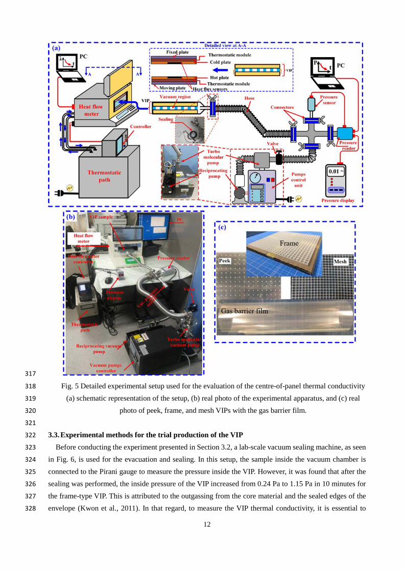
a small-scale vacuum system using a hose/pipe, as shown in Fig. 5. The schematic apparatus and a real 286
photo of the simultaneous evacuation thermal conductivity measurements are depicted in Figs. 5-a and b, 287
respectively. The vacuum system in this experiment consists of a reciprocating vacuum pump and a dry-288
type turbomolecular vacuum pump connected in series. For the measurement of pressure, a Pirani pressure 289
gauge with a pressure display unit is connected at the inlet of the VIP. The VIP with the pressure 290
measurement device can be isolated from the evacuation system using a valve. First, the reciprocating pump 291
is used to lower the pressure inside the VIP to approximately 20 Pa. After that, the turbomolecular pump is 292
used to further decrease the pressure to the desired value. A dry-type or oil-free turbomolecular pump is 293
favourable for such applications, as recommended by (Memon et al., 2019b). The pressure sensor is located 294
as closely as possible to the VIP, to measure the approximate pressure inside the VIP. After reaching the 295
desired vacuum level, the VIP sample is inserted into the HFM apparatus. In this apparatus, the temperature 296
of the hot and cold sides of the VIP can be controlled by using the controlling unit, either from the controller 297
interface, or via system software on a PC. The steady-state hot- and cold-side temperatures of the HFM are 298
kept constant at 35.5 ºC and 10.5 ºC, respectively, during all of the tests. The instrument also has a facility 299
for measuring the total thickness of the sample. The HFM has two heat flux sensors for accurate 300
measurements of the heat fluxes, one on each side of the VIP. After reaching the steady-state criteria with 301
a change in the measured heat fluxes of approximately 2%, the measured sample thermal conductivity, 302
thickness, walls temperature, sample mean temperature, and heat flux values are automatically displayed 303
on the meter interface, and are transmitted to the meter software on the PC and recorded. 304

11
305
The effective thermal conductivity of the VIP is measured based on a Fourier equation of one-306
dimensional heat conduction, as given in the manufacturing datasheet of the HFM apparatus: 307
𝜆𝜆𝑒𝑒𝑒𝑒𝑒𝑒,𝑒𝑒𝑒𝑒𝑒𝑒 = �𝑞𝑞ℎ + 𝑞𝑞𝑐𝑐
2� ×
𝐿𝐿𝑣𝑣∆𝑇𝑇
(1) 308
Here, λeff,exp, qh, qc, lv, and ΔT are the effective measured thermal conductivity of the VIP (in W/m.K), 309
the measured heat flux on the hot and cold sides of the sample using the heat flux sensors ( in W/m2), the 310
measured VIP thickness (in m), and the temperature difference on the sides of the sample (in °C), 311
respectively. In this work, the thermal conductivity is measured for all of the VIPs, except for the modified 312
peek spacers (which are numerically investigated, and are not manufactured). The technical specifications 313
of the measuring tools and their accuracies are depicted in Table 2. 314
Table 2 Technical specifications of the instruments used in the thermal conductivity measurements. 315
Instrument Technical specifications
Heat flow meter (HFM)
apparatus
Model No HC-074 Accuracy ≤ 1% Repeatability 0.2% Hot plate temperature range 5 °C to 75 °C Cold plate temperature range -20 °C to 50 °C Thermal conductivity range 0.005 to 0.8 W/m.K
Pirani gauge
Model No ST2-1 Pressure range 10-5 to 10-3 Pa Accuracy ±10% when 10-5 ≤ P < 3 Pa
±15% when 3 ≤ P ≤ 10 Pa
316
12
317
Fig. 5 Detailed experimental setup used for the evaluation of the centre-of-panel thermal conductivity 318
(a) schematic representation of the setup, (b) real photo of the experimental apparatus, and (c) real 319
photo of peek, frame, and mesh VIPs with the gas barrier film. 320
321
3.3. Experimental methods for the trial production of the VIP 322
Before conducting the experiment presented in Section 3.2, a lab-scale vacuum sealing machine, as seen 323
in Fig. 6, is used for the evacuation and sealing. In this setup, the sample inside the vacuum chamber is 324
connected to the Pirani gauge to measure the pressure inside the VIP. However, it was found that after the 325
sealing was performed, the inside pressure of the VIP increased from 0.24 Pa to 1.15 Pa in 10 minutes for 326
the frame-type VIP. This is attributed to the outgassing from the core material and the sealed edges of the 327
envelope (Kwon et al., 2011). In that regard, to measure the VIP thermal conductivity, it is essential to 328

13
perform the evacuation and the sealing, and then to subsequently transfer the sample to the measuring HFM 329
apparatus. In this case, with the outgassing from the core structure, the estimation of the exact inner pressure 330
of the VIP is very difficult. 331
332 Fig. 6 Photograph and schematic of the vacuum sealing equipment. 333
To avoid this difficulty, four different methods are used and compared for the trial production of the 334
frame-type VIP as examples, using the experimental setup shown in Fig. 6. The main purpose of these steps 335
is to compare the thermal conductivity variations of the VIP with different production methods. 336
337
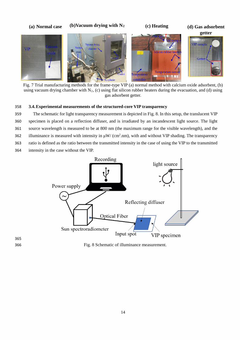
In these methods, outgassing from the core structure is minimised in different ways. In the first setup, 338
Fig. 7-a, named the "normal case", the VIP is manufactured using the vacuum sealing machine in Fig. 6, 339
and a calcium oxide adsorbent pack is used to minimise the outgassing from the core material. In the second 340
setup in Fig. 7-b, named "vacuum drying with N2", the VIP structure is kept inside an environmentally-341
controlled unit. In this unit, the environmental temperature is maintained at 70 °C for 24 h, and the structure 342
is connected to the vacuum machine to maintain the pressure at 0.1 Pa. This method is used to release the 343
outgassing from the core structure. Then, nitrogen is supplied to the inside of the environmentally-344
controlled unit. After that, nitrogen is exhausted from the unit. Then, the VIP structure is evacuated and 345
sealed using the vacuum sealing machine. 346
347
In the third setup, Fig. 7-c, named "heating", a new step is proposed to reduce the time for the VIP 348
production process. In this setup, the two flat silicon rubber heaters are used to heat up the VIP during the 349
evacuation. This also could help the outgassing of the water vapour from the inside of the core structure. 350
The heaters are temperature-controlled using a temperature controller, to maintain the temperature of the 351
VIP at 70 °C during the evacuation. In the second and the third trial methods, calcium oxide adsorbent 352
packs are also used. Finally, in the fourth production method in Fig. 7-d, named "gas adsorbent getter", 353
an absorbent material that contains calcium oxide and alloy getter is inserted into the VIP. The calcium 354
oxide absorbs the water vapour, while the alloy getter absorbs other gases such as nitrogen and carbon 355
dioxide. Consequently, the pressure rise owing to the outgassing can be reduced. The results of these four 356
trial manufacturing methods are compared in detail in Section 5.2. 357
14
(a) Normal case
(b)Vacuum drying with N2
(c) Heating
(d) Gas adsorbent getter
Fig. 7 Trial manufacturing methods for the frame-type VIP (a) normal method with calcium oxide adsorbent, (b) using vacuum drying chamber with N2, (c) using flat silicon rubber heaters during the evacuation, and (d) using
gas adsorbent getter.
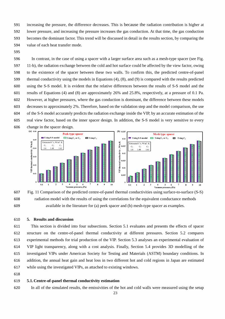
3.4. Experimental measurements of the structured-core VIP transparency 358
The schematic for light transparency measurement is depicted in Fig. 8. In this setup, the translucent VIP 359
specimen is placed on a reflection diffuser, and is irradiated by an incandescent light source. The light 360
source wavelength is measured to be at 800 nm (the maximum range for the visible wavelength), and the 361
illuminance is measured with intensity in μW/ (cm2.nm), with and without VIP shading. The transparency 362
ratio is defined as the ratio between the transmitted intensity in the case of using the VIP to the transmitted 363
intensity in the case without the VIP. 364
365 Fig. 8 Schematic of illuminance measurement. 366

15
4. Theoretical analysis 367
In VIPs, the inner pressure must be reduced to below 10 Pa. Increasing the gas pressure above this value 368
rapidly increases the VIP thermal conductivity (Baetens et al., 2010). In addition, the total heat transfer in 369
VIPs can be divided into four parts: radiation heat transfer through the vacuum space, heat conduction 370
through the skeleton of the core of the core structure, gas conduction, and gas convection (Baetens et al., 371
2010). To enhance the insulation performance of the VIP, all of these parts must be minimised. However, 372
at very low pressures, the convection can be naturally converted to pure gas conduction. Therefore, the 373
convection can be ignored in the calculation (F. Arya et al., 2018; Choi et al., 2016). The basic governing 374
equations used in this study are the 3D heat conduction equation, coupled with the surface-to-surface 375
radiation model. For steady-state 3D heat conduction with a source term, "ANSYS FLUENT" solves the 376
energy equation in the following form (“ANSYS FLUENT Theory Guide,” 2011): 377
∇. (𝑘𝑘 ∇𝑇𝑇) + 𝑆𝑆 = 0 (2) 378
In the above, T is the temperature, k is the element thermal conductivity, and S is a source term added to 379
consider the effect of radiation in the vacuum space (“ANSYS FLUENT Theory Guide,” 2011). This 380
equation is solved to obtain the temperature distribution and heat transfer rate through the solid layers, 381
including the hot and cold plates' conduction and the inner structure, but without a radiation heat source. 382
To include gas conduction in the vacuum layer, the same equation (with the radiation source term )is solved, 383
but with the gas thermal conductivity at the designed pressure. 384
Air thermal conductivity is a function of the pressure and pore size (Baetens et al., 2010). This results 385
from the exact inverse relationship between the gas pressure and the molecule-molecule collisions' mean 386
free path. In more detail, as the gas pressure is decreased, the number of gas molecules available to transport 387
heat is proportionally decreased. Thus, a substantial reduction in heat transfer caused by gaseous conduction 388
occurs at low-pressure levels. To neglect gaseous conduction, the pressure within the vacuum space must 389
be less than 0.1 Pa (Collins and Simko, 1998). The air thermal conductivity, λv, in W/m.K, at different 390
pressures and pore sizes, is calculated as follows (Kim and Song, 2013): 391
𝜆𝜆𝑣𝑣 =𝜆𝜆𝑜𝑜
1 + (1.07 × 10⁻⁷)𝑇𝑇𝑙𝑙𝑣𝑣𝑃𝑃
(3) 392
Here, T, lv, and P are the temperature in K, vacuum thickness in m, and gas pressure in Pa, respectively. 393
In addition, λo is the air thermal conductivity at room temperature and pressure. In this study, it is taken as 394
0.026 W/m.K. However, the vacuum thickness for the proposed structures changes in some locations. To 395
incorporate this into the numerical calculations, a multi-zone approach is used. In this approach, every 396
vacuum space with the same thickness is defined as a specific zone. Using this idea, the thermal 397
conductivity of each zone can be calculated by knowing the thickness of the vacuum space between the hot 398
and cold plates. For example, in frame-type spacers as seen in Fig. 9, the vacuum thicknesses in zone-1 and 399
zone-2 are 3 mm and 1 mm, respectively. Therefore, the thermal conductivities of the respective vacuum 400
spaces in these two zones are considered to be different. The same idea is also applied for all proposed core 401
structures where this issue exists. 402
403

16
Three different techniques exist in the literature for considering the contribution of the radiation heat 404
transfer in the vacuum space. In all of these models, an equivalent thermal conductance is calculated. This 405
thermal conductance is dependent on the emissivity of the hot and cold sides of the VIP, and the view factor. 406
In this case, Equation (2) is solved, without the source term. However, the vacuum space thermal 407
conductivity is modified to include the effect of radiation. In the first technique, the equivalent radiation 408
conductance through the vacuum space is estimated using the following correlation (Fang et al., 2009): 409
𝐶𝐶ℎ−𝑐𝑐,𝑟𝑟𝑟𝑟𝑟𝑟𝑟𝑟𝑟𝑟𝑟𝑟𝑟𝑟𝑜𝑜𝑟𝑟,1 = 4𝜀𝜀𝑒𝑒𝑒𝑒𝑒𝑒𝜎𝜎𝑇𝑇𝑟𝑟𝑣𝑣𝑎𝑎3 (4) 410
In Equation (4), Ch-c, radiation,1, εeff, 𝜎𝜎, and Tavg are the equivalent radiation conductance between the hot and 411
the cold sides of the VIP in units of W/m2.K., the effective emittance of the hot and cold sides of the vacuum 412
space, a Stefan–Boltzmann constant in W/m2.K4, and the average temperature of the vacuum space in 413
Kelvin, respectively. The effective emittance is calculated as follows (Fang et al., 2009): 414
1𝜀𝜀𝑒𝑒𝑒𝑒𝑒𝑒
=1𝜀𝜀ℎ
+1𝜀𝜀𝑐𝑐− 1 (5) 415
Here, εh and εc are the emissivities of the hot and cold sides of the VIP, respectively. 416
In the second technique, the radiation contribution is calculated based on the principle of the heat exchange 417
between two parallel surfaces separated by a very small gap (Incropera et al., 2007): 418
𝑄𝑄𝑟𝑟𝑟𝑟𝑟𝑟 =𝜎𝜎(𝑇𝑇ℎ4 − 𝑇𝑇𝑐𝑐4)
(1 − 𝜀𝜀ℎ𝐴𝐴𝑣𝑣𝜀𝜀ℎ
) + ( 1𝐴𝐴𝑣𝑣𝐹𝐹ℎ−𝑐𝑐
) + (1 − 𝜀𝜀𝑐𝑐𝐴𝐴𝑣𝑣𝜀𝜀𝑐𝑐
)=
𝜎𝜎𝐴𝐴𝑣𝑣(𝑇𝑇ℎ4 − 𝑇𝑇𝑐𝑐4)
(1 − 𝜀𝜀ℎ𝜀𝜀ℎ
) + ( 1𝐹𝐹ℎ−𝑐𝑐
) + (1 − 𝜀𝜀𝑐𝑐𝜀𝜀𝑐𝑐
) (6) 419
In the above, Fh-c is the view factor between the hot and cold surfaces, and Av is the surface area of the 420
panel facing either the hot or the cold side of the vacuum space, in m2. For a unity view factor, the equivalent 421
thermal conductance owing to the radiation is calculated as following (Incropera et al., 2007): 422
𝐴𝐴𝑣𝑣𝐶𝐶ℎ−𝑐𝑐,𝑟𝑟𝑟𝑟𝑟𝑟𝑟𝑟𝑟𝑟𝑟𝑟𝑟𝑟𝑜𝑜𝑟𝑟(𝑇𝑇ℎ − 𝑇𝑇𝑐𝑐) =𝜎𝜎𝐴𝐴𝑣𝑣(𝑇𝑇ℎ4 − 𝑇𝑇𝑐𝑐4)
( 1𝜀𝜀ℎ− 1) + 1 + ( 1
𝜀𝜀𝑐𝑐− 1)
(7) 423
𝐶𝐶ℎ−𝑐𝑐,𝑟𝑟𝑟𝑟𝑟𝑟𝑟𝑟𝑟𝑟𝑟𝑟𝑟𝑟𝑜𝑜𝑟𝑟,2 = �𝜎𝜎�𝑇𝑇ℎ4 − 𝑇𝑇𝑐𝑐4�
� 1𝜀𝜀ℎ�+ �1
𝜀𝜀𝑐𝑐� − 1
� /(𝑇𝑇ℎ − 𝑇𝑇𝑐𝑐) (8) 424
Lastly, in the third technique, the following correlation is used for the prediction of the value of 425
𝐶𝐶ℎ−𝑐𝑐,𝑟𝑟𝑟𝑟𝑟𝑟𝑟𝑟𝑟𝑟𝑟𝑟𝑟𝑟𝑜𝑜𝑟𝑟 as follows (Yang et al., 2018): 426
𝐶𝐶ℎ−𝑐𝑐,𝑟𝑟𝑟𝑟𝑟𝑟𝑟𝑟𝑟𝑟𝑟𝑟𝑟𝑟𝑜𝑜𝑟𝑟,3 = 𝜀𝜀ℎ𝜀𝜀𝑐𝑐𝐶𝐶𝑏𝑏 ��𝑇𝑇ℎ100
�4− � 𝑇𝑇𝑐𝑐
100�4� 1
(𝑇𝑇ℎ−𝑇𝑇𝑐𝑐) (9) 427
In that regard, Cb is a black body radiation constant factor, and it is set to 5.67, as proposed by (Yang et al., 428
2018). After the thermal conductance owing to the radiation is evaluated, the increase in the vacuum space 429
thermal conductivity owing to the radiation effect can be estimated by multiplication of the calculated Ch-430
c, radiation by the vacuum layer thickness. Therefore, the new thermal conductivity of the vacuum space, 431
considering both the radiation effect and gas conduction effect, can be calculated as follows (Choi et al., 432
2016): 433
𝜆𝜆𝑣𝑣, 𝑎𝑎𝑟𝑟𝑔𝑔 𝑐𝑐𝑜𝑜𝑟𝑟𝑟𝑟𝑐𝑐𝑐𝑐𝑟𝑟𝑟𝑟𝑜𝑜𝑟𝑟+𝑟𝑟𝑟𝑟𝑟𝑟𝑟𝑟𝑟𝑟𝑟𝑟𝑟𝑟𝑜𝑜𝑟𝑟 = 𝜆𝜆𝑣𝑣 + 𝐶𝐶ℎ−𝑐𝑐,𝑟𝑟𝑟𝑟𝑟𝑟𝑟𝑟𝑟𝑟𝑟𝑟𝑟𝑟𝑜𝑜𝑟𝑟𝑙𝑙𝑣𝑣 (10) 434

17
Moreover, the contribution of the radiation heat transfer rate, Qrad, in watts between the two sides of the 435
VIP is calculated using the following correlation (Fang et al., 2010): 436
𝑄𝑄𝑟𝑟𝑟𝑟𝑟𝑟 = 𝐴𝐴𝑣𝑣𝐶𝐶ℎ−𝑐𝑐,𝑟𝑟𝑟𝑟𝑟𝑟𝑟𝑟𝑟𝑟𝑟𝑟𝑟𝑟𝑜𝑜𝑟𝑟(𝑇𝑇ℎ − 𝑇𝑇𝑐𝑐) (11) 437
Throughout of all these three models, the view factor between the hot and cold walls is set as unity. This is 438
because of the smaller gap and larger facing area between the hot and cold sides of the VIP. 439
440
In the present study, a new modelling method is used to predict the contribution of the radiation effect 441
between the hot and cold sides of the VIP. This method couples the conduction heat transfer through the 442
vacuum space and support structure with the surface-to-surface (S-S) radiation model in the vacuum space. 443
This model is implemented in the commercial ANSYS software (“ANSYS FLUENT Theory Guide,” 2011). 444
The model solves Equation (2) for the vacuum space, so as to include the conduction and the radiation. This 445
model also calculates the view factor for all contributing surfaces in the computational domain and in 446
contact with the vacuum space. In the S-S model, the energy exchange between two surfaces depends on 447
their size, orientation, and separation distance, which are used to calculate the view factor. These parameters 448
are calculated automatically from the design geometry of the VIP imported by the Fluent module. This 449
model assumes that any emission, absorption, or radiation scattering by the vacuum domain are ignored. 450
Consequently, only the radiation from “surface-to-surface” is considered. In addition, the model assumes 451
that the surfaces' emissivities are independent of the wavelength. This model also can be used for solar 452
collectors’ applications, radiative space heaters, and heat rejection methods in aircraft (“ANSYS FLUENT 453
Theory Guide,” 2011). This model simultaneously solves the radiation exchange equation with the energy 454
equation of the solid regions and the gas conduction in the vacuum space by the use of the source term for 455
radiation, as explained in detail in the ANSYS theory guide (“ANSYS FLUENT Theory Guide,” 2011). 456
The model results are compared with the results of previous methods in the literature in the model 457
verification step. 458
459
In the (S-S) model, the energy flux leaving a certain surface consists of the directly-emitted energy and 460
the reflected energy. The emitted part depends on the surface emittance. However, the reflected part depends 461
on the incident energy flux coming from the surroundings. The last part can be considered in terms of the 462
flux of the energy leaving all other surfaces. Therefore, the energy flux leaving from a certain surface k in 463
the VIP domain, qout,k, can be written as follows: 464
𝑞𝑞𝑜𝑜𝑐𝑐𝑟𝑟,𝑘𝑘 = 𝜀𝜀𝑘𝑘𝜎𝜎𝑇𝑇𝑘𝑘4 + 𝜌𝜌𝑘𝑘𝑞𝑞𝑟𝑟𝑟𝑟,𝑘𝑘 (12) 465
In Equation (12), εk, Tk, ρk, and qin,k are the emissivity, absolute temperature, the reflectivity of the surface 466
k, and the flux of energy incident from all other surfaces and received by the surface k, respectively. 467
According to the grey-body model, the surface absorptivity is assumed to be the same as the surface 468
emissivity. The amount of incident energy flux on the surface k from another surface(s) j is calculated as a 469
direct function of the view factor between the surface k and the surface(s) j. Therefore, the incident flux of 470
energy on the surface k can is calculated as follows: 471

18
𝑞𝑞𝑟𝑟𝑟𝑟,𝑘𝑘 =1𝐴𝐴𝑘𝑘
�𝐴𝐴𝑗𝑗𝑞𝑞𝑜𝑜𝑐𝑐𝑟𝑟,𝑗𝑗𝐹𝐹𝑗𝑗−𝑘𝑘
𝑁𝑁
𝑗𝑗=1
(13) 472
Here, Ak, Aj, and Fj-k are the area of the surfaces k and j, and the view factor between the surface j and 473
surface k, respectively. In addition, N is the total number of surfaces participating in the radiation. This 474
number could also include the surface k if the view factor between the surface k and itself is not zero. The 475
reciprocity relationship for the view factor calculation gives the following: 476
𝐴𝐴𝑘𝑘𝐹𝐹𝑘𝑘−𝑗𝑗 = 𝐴𝐴𝑗𝑗𝐹𝐹𝑗𝑗−𝑘𝑘 𝑓𝑓𝑓𝑓𝑓𝑓 𝑗𝑗 = 1,2,3, … … . .𝑁𝑁 (14) 477
Substituting in Equation (13), then qin,k can be calculated as follows: 478
𝑞𝑞𝑟𝑟𝑟𝑟,𝑘𝑘 = �𝑞𝑞𝑜𝑜𝑐𝑐𝑟𝑟,𝑗𝑗𝐹𝐹𝑘𝑘−𝑗𝑗
𝑁𝑁
𝑗𝑗=1
(15) 479
Therefore, Equation (12) changes to the following: 480
𝑞𝑞𝑜𝑜𝑐𝑐𝑟𝑟,𝑘𝑘 = 𝜀𝜀𝑘𝑘𝜎𝜎𝑇𝑇𝑘𝑘4 + 𝜌𝜌𝑘𝑘�𝑞𝑞𝑜𝑜𝑐𝑐𝑟𝑟,𝑗𝑗𝐹𝐹𝑘𝑘−𝑗𝑗
𝑁𝑁
𝑗𝑗=1
(16) 481
This equation can be written as follows: 482
𝐽𝐽𝑘𝑘 = 𝐸𝐸𝑘𝑘 + 𝜌𝜌𝑘𝑘�𝐽𝐽𝑗𝑗𝐹𝐹𝑘𝑘−𝑗𝑗 (17)𝑁𝑁
𝑗𝑗=1
483
Here, Jk is the radiant energy that is given off surface k, and is known as radiosity, and Ek represents the 484
emissive power of the surface k. This equation can be mathematically represented in matrix form as 485
follows: 486
𝐾𝐾𝐽𝐽 = 𝐸𝐸 (18) 487
In the above, K is a matrix with N × N dimensions; J and E are the radiosity and emissive power vectors 488
with length N each, respectively. The view factors between the participating surfaces must be calculated 489
first to obtain the radiosity matrix. Therefore, after importing the design of the VIP core structure, the 490
surfaces' orientations, areas, and spacing are calculated. Then, the view factors for all of the participating 491
surfaces are calculated using the following relationship (“ANSYS FLUENT Theory Guide,” 2011).: 492
𝐹𝐹𝑘𝑘−𝑗𝑗 =1𝐴𝐴𝑘𝑘
� �𝑐𝑐𝑓𝑓𝑐𝑐 𝜃𝜃𝑘𝑘 𝑐𝑐𝑓𝑓𝑐𝑐 𝜃𝜃𝑗𝑗
𝜋𝜋𝑓𝑓2𝐴𝐴𝑗𝑗𝛿𝛿𝑘𝑘𝑗𝑗 𝑑𝑑𝐴𝐴𝑘𝑘𝑑𝑑𝐴𝐴𝑗𝑗
𝐴𝐴𝑘𝑘 (19) 493
Here, δkj is calculated by the visibility of dAj to dAk, and the value of δkj equals unity if dAj is visible to 494
dAk, and zero otherwise. Small-scale computational domains, boundary conditions, and mesh details are 495
depicted in Fig. 9. This step is used to compare the computationally-estimated centre-of-panel thermal 496
conductivity with the experimental results, and to evaluate the contribution of each heat transfer mode. 497
Finally, after a solution convergence with a residual of less than 1×10⁻¹⁰ in the energy equation is attained, 498
the centre-of-panel thermal conductivity is numerically estimated as follows: 499
𝑘𝑘𝑒𝑒𝑒𝑒𝑒𝑒,𝑟𝑟𝑐𝑐𝑛𝑛. = (𝑞𝑞𝑟𝑟𝑜𝑜𝑟𝑟𝑟𝑟𝑡𝑡) ×𝐿𝐿𝑣𝑣
(𝑇𝑇ℎ − 𝑇𝑇𝑐𝑐) (20) 500

19
In Equation (20), Keff,num and qtotal are the numerical estimated centre-of-panel thermal conductivity and the 501
area weighted average of the total heat flux on the hot side. The latter equals that on the cold side at the 502
converged steady-state condition, and is estimated as follows (“ANSYS FLUENT Theory Guide,” 2011): 503
𝑞𝑞𝑟𝑟𝑜𝑜𝑟𝑟𝑟𝑟𝑡𝑡 =1𝐴𝐴�𝑞𝑞 𝑑𝑑𝐴𝐴 =
1𝐴𝐴�𝑞𝑞𝑟𝑟|𝐴𝐴𝑟𝑟|𝑟𝑟
𝑟𝑟=1
(21) 504
Here, n is the total number of elements in the selected area. 505
506
4.1. Boundary conditions 507
To solve the model-governing equations, one or more boundary conditions must be used. Therefore, Fig. 508
9 depicts a schematic representation of the boundary conditions used for all proposed core-structured VIPs. 509
In more detail, to evaluate the centre-of-panel thermal conductivity, one side of the panel is maintained at 510
a hot temperature of 35.5 °C, while the other side is kept at a cold temperature of 10.5 °C. The wall 511
emissivity and temperature are defined in the vacuum zones. However, in the solid zones of the spacers, 512
only the faces' temperatures are defined, because the radiation effect only appears in the vacuum zones. 513
Further, the peripheral sides of the VIP are assumed to be adiabatic, owing to the symmetry of the 514
computational domain. Finally, thermally-coupled boundary conditions are used at all interfaces. In this 515
case, the temperature on the interfaces and the heat transfer rate are the same. The detailed mathematical 516
expressions of the boundary conditions are presented here for the frame-type spacer as an example. 517
At the hot wall: 518
For the spacer zones 𝑇𝑇 = 𝑇𝑇ℎ; and 519
For the vacuum zones 𝑇𝑇 = 𝑇𝑇ℎ and 𝜀𝜀 = 𝜀𝜀ℎ. 520
At the cold wall: 521
For the spacer zones 𝑇𝑇 = 𝑇𝑇𝑐𝑐; and 522
For the vacuum zones 𝑇𝑇 = 𝑇𝑇𝑐𝑐 and 𝜀𝜀 = 𝜀𝜀𝑐𝑐. 523
A mesh independence test is performed to ensure that the results are independent on the number of elements. 524
After the test, a total of 1370521, 2450133, 1745551, 864000, and 1600000 elements are used for the 525
prediction of the centre-of-panel thermal conductivity of the peek spacer, modified peek spacer, mesh-type, 526
frame-type, and silica aerogel spacers, respectively. 527
528

20
529
Fig. 9 Computational domains, boundary conditions, and mesh details for all investigated cases. 530

21
4.2. Numerical methods 531
In the beginning, the computational domains presented in Fig. 9 are created using the "DesignModular" 532
tool, and using a multizone approach. In the multizone approach, the domain is divided into several zones 533
to enable control of the meshing, properties, and boundary conditions of each zone separately. In addition, 534
the interfaces between each zone and the neighbouring zones were thermally coupled. Then, the 535
computational domain is meshed. The mesh details for each core structure are displayed in Fig. 9 in the 536
right column. The model-governing equations are solved using the Fluent module. In Fluent, the energy 537
equation and fluid flow equations (including continuity and momentum) are standard equations, although 538
in this work, the vacuum zones are fluid. The very low pressure allows us to neglect the convection effect 539
and hence, the fluid flow equations can be eliminated (Fang et al., 2009, 2006; Memon et al., 2019b). 540
However, the S-S radiations model must include a fluid zone. Therefore, the vacuum layer is considered as 541
a fluid zone, but only the energy equation is enabled. The S-S radiation model estimates the orientation, 542
area, and spacing of each face participating in the radiation model. Therefore, the view factors can be 543
calculated. The energy equation for the solid layers and the energy equation for the vacuum space, including 544
the effects of S-S radiation, are simultaneously solved. Moreover, the radiosity evaluation is performed 545
based on the calculated view factors. To include the effects of pressure in the calculation, the vacuum region 546
thermal conductivity with the pressure is evaluated by using Equation (3) for each vacuum zone. Shell zone 547
conduction layers are added in the simulation to include the effects of the existing acrylic support plates. In 548
this case, the real thickness and the thermal conductivity of the acrylic plates must be added in the 549
simulation tool. 550
551
4.3. Model validation 552
The predicted centre-of-panel thermal conductivity is compared with the measured thermal conductivity 553
obtained by the Experiments in Section 3.2 for the peek type spacer, mesh-type spacer, and frame-type 554
spacer in Figs. 10-a, b, and c, respectively. Further, the currently-predicted results are compared with the 555
numerical results of (Katsura et al., 2018), as shown in Fig. 10-d. The model is examined under different 556
pressure values, from 0.1 to 10 Pa. Based on the comparisons depicted in Fig. 10-a, b, and c, it is observed 557
that the model accurately predicts the centre-of-panel thermal conductivity for the peek, mesh and frame-558
type VIPs, with a maximum error of 11%. In addition, the error is higher at lower pressures, especially in 559
the mesh-type spacer. This may be attributed to two causes. First, at low pressure, the connections between 560
the rods become larger, owing to the flexibility of the rods. However, this is difficult to consider in the 561
calculation. This is also the reason that the predicted results are slightly lower than the experimental results, 562
especially in Fig 10-b. The second cause could be gas emissivity from the core structure. 563
In addition, the model is validated for the silica aerogel spacer studied in (Katsura et al., 2018). In this 564
part, the silica aerogel spacer dimensions, boundary conditions, and vacuum zone dimensions are the same 565
as those existing in (Katsura et al., 2018), and are displayed inside Fig. 10-d. The main difference between 566
the present model and the model developed by (Katsura et al., 2018) is that the current model is a 3D model 567
that uses S-S radiation, whereas the model developed in (Katsura et al., 2018) is one-dimensional. Based 568
on Fig. 10-d, an excellent agreement is observed. Although the current model nearly accomplishes the same 569

22
results as the one-dimensional model, the heat flux, and temperature contours can be obtained by the current 570
model, and these parameters cannot be obtained using a one-dimensional model. 571
Fig. 10 Comparison of the predicted centre-of-panel thermal conductivities with (a) the experimental 572
results for peek spacer; (b) the experimental results for mesh spacers; (c) experimental results of frame-573
type spacer; and (d) the numerical results of (Katsura et al., 2018). 574
575
The S-S radiation model is compared with theoretical models using equivalent radiation conductance in 576
the vacuum region, and the comparisons are presented in Figs. 11-a and b for the peek type and mesh-type 577
VIPs as examples, respectively. It is evident that the S-S model accurately predicts the radiation exchange 578
inside the VIP, as compared with the existing traditional methods using different correlations of C’s. From 579
Fig. 11-a, it can be seen that the predicted results using the S-S radiation model are very close to the results 580
of using the models Equations (4), (8)m and (9). The estimated values of the radiation conductance using 581
Equation (4) and Equation (9) are very close. Although the S-S radiation model considers the radiation 582
exchange between all the surfaces in connection with the vacuum regions, the results of this model are very 583
close to the results of using two surfaces' radiation exchanges, as proposed in Equations (4), (8), and (9) for 584
pillar-supported VIPs. This is attributed to the fact that in VIPs, the vacuum space is very small, and the 585
view factor between the spacer side and the radiant surfaces is also very small, owing to the smaller side 586
area of the spacers. Therefore, the assumption of a unity view factor is a reasonable assumption, especially 587
with smaller pillar- or peek-connection areas to the vacuum space. The maximum differences between the 588
results of using the S-S model and other models using Equation (4) and Equation (8) are approximately 589
1.6% and 3.4%, respectively, at the lower pressure level of 0.1 Pa for the peek-type spacer. However, by 590
23
increasing the pressure, the difference decreases. This is because the radiation contribution is higher at 591
lower pressure, and increasing the pressure increases the gas conduction. At that time, the gas conduction 592
becomes the dominant factor. This trend will be discussed in detail in the results section, by comparing the 593
value of each heat transfer mode. 594
595
In contrast, in the case of using a spacer with a larger surface area such as a mesh-type spacer (see Fig. 596
11-b), the radiation exchange between the cold and hot surface could be affected by the view factor, owing 597
to the existence of the spacer between these two walls. To confirm this, the predicted centre-of-panel 598
thermal conductivity using the models in Equations (4), (8), and (9) is compared with the results predicted 599
using the S-S model. It is evident that the relative differences between the results of S-S model and the 600
results of Equations (4) and (8) are approximately 26% and 25.8%, respectively, at a pressure of 0.1 Pa. 601
However, at higher pressures, where the gas conduction is dominant, the difference between these models 602
decreases to approximately 2%. Therefore, based on the validation step and the model comparison, the use 603
of the S-S model accurately predicts the radiation exchange inside the VIP, by an accurate estimation of the 604
real view factor, based on the inner spacer design. In addition, the S-S model is very sensitive to every 605
change in the spacer design. 606
Fig. 11 Comparison of the predicted centre-of-panel thermal conductivities using surface-to-surface (S-S) 607
radiation model with the results of using the correlations for the equivalent conductance methods 608
available in the literature for (a) peek spacer and (b) mesh-type spacer as examples. 609
5. Results and discussion 610
This section is divided into four subsections. Section 5.1 evaluates and presents the effects of spacer 611
structure on the centre-of-panel thermal conductivity at different pressures. Section 5.2 compares 612
experimental methods for trial production of the VIP. Section 5.3 analyses an experimental evaluation of 613
VIP light transparency, along with a cost analysis. Finally, Section 5.4 provides 3D modelling of the 614
investigated VIPs under American Society for Testing and Materials (ASTM) boundary conditions. In 615
addition, the annual heat gain and heat loss in two different hot and cold regions in Japan are estimated 616
while using the investigated VIPs, as attached to existing windows. 617
618
5.1. Centre-of-panel thermal conductivity estimation 619
In all of the simulated results, the emissivities of the hot and cold walls were measured using the setup 620

24
described in Section 3.1, and were found to be 0.28 and 0.9, respectively. The first emissivity is obtained 621
by using the L-e coated film. However, the second emissivity is the emissivity of the acrylic plates and the 622
core structures used in the experiments. In the simulation, all the faces coupled with the vacuum zones and 623
the hot and cold faces are considered to participate in the S-S radiation model. In addition, the steady-state 624
hot- and cold-side temperatures of the heat flow meter are kept constant at 35.5 ºC and 10.5 ºC, respectively. 625
626
The thermal conductivities of the polycarbonate spacers and acrylic plates are 0.2 W/m.K (Choi et al., 627
2016). However, the vacuum zones' thermal conductivity changes according to the pressure levels. At the 628
low pressure of 0.1 Pa and a smaller thickness of the vacuum space of 2 mm, the vacuum region thermal 629
conductivity is estimated to be 2.1×10⁻⁴ W/m.K. This means that the spacer thermal conductivity is 630
approximately 950 times that of the vacuum region thermal conductivity. This ratio decreases to 9.5 times 631
at a pressure of 10 Pa. Therefore, it is expected that the conduction thermal bridge through the core structure 632
is a vital parameter that must be considered, especially at lower pressures. Hence, to decrease the heat 633
transfer rate through the core structure, a smaller connection is examined. This idea focuses on a reduction 634
in the conduction area, and consequently, a reduction in the thermal bridges through the spacer. To clarify 635
this point, a comparison is conducted for three cases of pillar-supported structures, and the results are 636
displayed in Fig. 12. In the first case, a regular cylindrical pillar with a diameter D of 1.8 mm is used to 637
obtain a vacuum gap with a thickness of 1.5 mm. In the second case, a peek-type pillar with a head diameter 638
D of 1.8 mm, thickness δ/2 of 0.5 mm, and nail diameter d of 1.2 mm is used. In the final case, a modified 639
peek shape is theoretically proposed, by including a spherical head for the peek. To fix the pillars in these 640
three structures, two acrylic plates (1 mm each) are used in the simulation. Therefore, the total thickness of 641
the VIP in these three structures is 4.5 mm, as presented inside Fig 12. Fig. 12 presents the variation of the 642
VIP centre-of-panel thermal conductivity for these three cases with the pressure. It is evident that the new 643
modified peek attains a lower centre-of-panel thermal conductivity over the full range of the pressure, i.e. 644
from 0.1 Pa to 10 Pa. This because in the modified peek support, the connection between the hot and cold 645
walls is decreased by using the hemispherical head, in addition to reducing the support diameter from 1.8 646
mm to 1.2 mm. 647
In more detail, the centre-of-panel thermal conductivity is reduced by approximately 37% and 5.9% at 648
pressures of 0.1 Pa and 10 Pa, respectively, with changing the conventional common cylindrical pillar to 649
the modified peek pillar. This reduction is attributed to the reduction in the conduction heat flux, as 650
presented in Fig. 13. In this figure, the variations of the conduction and radiation heat fluxes are displayed 651
for the pillar-supported designs at different pressures in Figs. 13-a and b, respectively. The area-weighted 652
average of the total heat transfer rate from the hot surface is estimated and divided by the total surface area 653
of the hot wall to obtain the total heat flux from the hot wall. After that, the area-weighted average of the 654
net radiation heat transfer rate from the hot wall is also calculated, and the radiation heat flux is estimated 655
by the dividing this value to the surface area of the hot wall. Finally, the conductive heat flux is estimated 656
by the subtraction of the radiation heat flux from the total heat flux. The predicted conduction heat flux 657
considers both the pillar conduction and the gas conduction in the vacuum space. 658
659

25
Based on Fig. 13-a, a significant reduction in the conduction heat flux is predicted while using the 660
modified peek pillar support structure, especially at lower pressures. This may be attributed to two factors. 661
The first is the reduction in the connection area between the hot and the cold walls. The second reason is 662
that a very thin layer of low conductive vacuum exists between the top plate and the pillar circular head in 663
the modified peek support, but does not exist in the cylindrical pillar support. This layer, with a thickness 664
of δ/2, has a very low thermal conductivity as compared with the pillar conductivity of 0.2 W/m.K. 665
Therefore, a smaller conductive heat transfer could be attained. This reduction decreases with the pressure 666
increase, because increasing the pressure increases the conduction through this very thin layer of the 667
vacuum space. Consequently, it increases the VIP thermal conductivity. In more detail, at 0.1 Pa, changing 668
the cylindrical pillar support to the modified peek support decreases the conduction heat flux from 35 W/m2 669
to approximately 5.6 W/m2. 670
671
Meanwhile, the radiative heat flux is presented in Fig. 13-b. It is predicted that the radiative heat flux 672
slightly decreases with an increase in pressure. This is attributed to the observation that at higher pressures, 673
a higher conduction heat flux is obtained. This decreases the temperature differences between the inner 674
surfaces in connection with the vacuum regions. Thus, a reduction in the radiative heat flux could be 675
attained. This reduction is very small compared with the increase in the conduction heat flux. In more detail, 676
with an increase in the pressure from 0.1 to 10 Pa, the conduction heat flux increases from 5.9 to 230 W/m2, 677
whereas the radiation heat flux decreases from 38.6 W/m2 to 33.5 W/m2. In addition, the radiation heat flux 678
in the case of using the modified peek support is higher than that when using the cylindrical support. This 679
because of the increase in the vacuum region with the use of the modified peek support; the radiative heat 680
flux increases from 37.1 to 38.9 W/m2 when replacing the cylindrical pillar with the modified peek pillar 681
at a pressure of 0.1 Pa. 682
683 Fig. 12 Variation of the predicted centre-of-panel thermal conductivity with the internal pressure for three 684
different designs of pillar-supported VIPs. 685
686

26
Fig. 13 Variation of (a) conductive heat flux and (b) radiative heat flux with the pressure levels for the 687
three investigated pillar-supported structures. 688
689
At the beginning of the modelling, the mesh-type spacer is simplified and modelled as a round plus-690
shaped spacer, as seen in Fig. 14 (left side). The predicted centre-of-panel thermal conductivity, in this case, 691
is compared with the experimental results. In this case, the computational fluid dynamic meshing is easier 692
and faster than in an actual case. However, it is found the predicted results are higher than the experimental 693
results. This because the connection between the spacer and the hot wall is larger than in the real case. 694
Therefore, the real case for the mesh spacer is modelled, and the results are compared with the experiments. 695
A good agreement is found, as discussed earlier in the validation step. Therefore, the actual mesh shape as 696
presented in Fig. 14 (right side) is considered through the entirety of this work. 697
698 Fig. 14 Comparison of the predicted centre-of-panel thermal conductivity with the experiments for the 699
simplified and the real case of mesh spacer. 700
701
Figure 15-a compares the variation of the centre-of-panel thermal conductivity for all investigated core 702
structures at different pressure levels. From this figure, three findings can be determined. First, increasing 703
the pressure increases the centre-of-panel thermal conductivity. Second, although the silica aerogel spacer 704
has a lower thermal conductivity of 0.02 W/m.K, the silica aerogel VIP accomplished the highest centre-705
of-panel thermal conductivity among these structures at lower pressure levels. This because in the silica 706

27
aerogel spacer, the ratio of the area occupied by the silica aerogel to the total area of the panel is 707
approximately 25%, and the remaining 75% is occupied by vacuum. Therefore, this increase in silica 708
aerogel area eliminates the benefit of its lower thermal conductivity as compared with other spacers. 709
Therefore, a compromise between the heat transfer area and the spacer thermal conductivity is essential. 710
However, the silica aerogel spacer cannot be easily manufactured in the form of other proposed structures, 711
owing to its brittle structure with a low yield strength, which could lead to the VIP fracturing during the 712
fabrication (Ma et al., 2018; Woignier et al., 2015). Finally, at low pressures below 1 Pa, the mesh-type and 713
frame-type spacers attain the lowest panel thermal conductivity, at approximately 0.007 W/m.K. This is 714
attributed to the reduction in thermal bridge attained in the spacer. In particular, in the mesh-type spacer, 715
the connection area between the hot and cold side of the VIP is very small. For more clarification, Fig 15-716
b shows the variation of the centre-of-panel thermal conductivity with the pressure in a "zoomed in" smaller 717
range, from 0.1 Pa to 3 Pa. 718
719
Fig. 15 Variation of the predicted centre-of-panel thermal conductivity (a) for vacuum pressure from 0.1 720
to 10 Pa and (b) for vacuum pressure from 0.1 to 3 Pa for all the structured-core transparent VIPs. 721
722
Figs. 16-a and b show the variations of conductive heat flux and radiative heat flux attained in the studied 723
VIPs, respectively. Generally, in Fig. 16-a, at pressures above 2 Pa, although the mesh spacer attains the 724
highest conductive heat flux, it accomplishes the lowest VIP thermal conductivity. This because of the small 725
thickness of this panel, at 2 mm. Similarly, at a pressure of 0.1 Pa, although the modified peek spacer has 726
the lowest conductive heat flux, it does not attain the lowest VIP thermal conductivity. This is attributed to 727
the fact that in pillar-supported VIPs, the total VIP thickness is much higher. This larger thickness increases 728
the effective thermal conductivity. In more detail, in pillar-supported spacers, the total VIP thickness is 4.5 729
mm, whereas for the mesh-type spacer, it is approximately 2 mm. This means that for the same total heat 730
flux, the thermal conductivity of the pillar-supported VIP will be 2.25 times that of the mesh-type spacer. 731
This is one of the main drawbacks of the pillar-supported VIPs mentioned in this work. The other drawback 732
is that the manufacturing process is very difficult as compared with the other types of spacers, such as mesh-733
type spacers. From Fig. 16-b, it can be observed that the radiation heat flux decreases slightly for all 734
investigated VIPs with an increase in pressure. Moreover, the frame-type and silica aerogel spacers obtained 735
the lowest radiative heat flux. This is because in these spacers, the vacuum area in connection with the hot 736
wall is at a minimum. This is also why the pillar-supported VIPs attain the maximum radiation heat flux, 737

28
i.e. the vacuum area in connection with the hot wall is at a maximum for pillar-supported VIPs. 738
739
740
Fig. 16 Variations in (a) conductive heat flux and (b) radiative heat flux with pressure for the investigated 741
VIPs. 742
743
5.2. Trial production methods of VIP 744
In Fig. 17-a, the predicted thermal conductivity variation with time is displayed for the four trial 745
production methods explained in Section 3.3. The comparison is implemented for the frame-type VIP as an 746
example. It is evident that using getter material during the manufacturing process of the VIPs accomplishes 747
the lowest thermal conductivity in comparison with the use of other methods. In addition, the direct 748
manufacturing of the VIP without the use of a calcium oxide adsorbent pack is the worst case. As the use 749
of the getter accomplished the best results among these methods, a further trial method is implemented here 750
to compare the predicted thermal conductivity of the frame-type VIP in the case of using two different types 751
of outgassing adsorbent materials. The getter material is compared with the use of a calcium oxide desiccant 752
inside a pack. The results are recorded for 75 h, and are displayed in Fig. 17-b. It is noticeable that the use 753
of getter material accomplished the lowest panel effective thermal conductivity in comparison with the use 754

29
of calcium oxide desiccant packs. The lowest thermal conductivity attained in the case of using getter was 755
approximately 0.011 W/m.K, which is equivalent to 5 Pa. This means that the inside pressure increased 756
after the sealing, owing to the gas emissivity. The effect of this parameter will be investigated in the authors' 757
future work. 758
759 Fig. 17 variation of the centre-of-panel thermal conductivity with the elapsed time for (a) different trial 760
manufacturing methods and (b) different two outgassing adsorbent materials. 761
762
5.3. Light transparency and cost analysis 763
This section presents the transparency measurements of the proposed VIPs, and the cost analysis. Table 764
3 displays the measured transparency of the manufactured VIPs with different core structures. In this 765
experiment, the illuminance is measured with and without VIP shading. The ratio displayed in the table 766
represents the measured light intensity in a case with the VIP to a reference case where no VIP exists. Here, 767
it is worth mentioning that the measured transparency is only for the VIPs without the single-layered glass 768
window of 3 mm. It is evident that the transparency of the manufactured VIPs ranges from 0.65 to 0.9, for 769
the mesh-type spacer to the cylindrical-pillar spacer, respectively. In addition, as the modified peek spacer 770
is only numerically investigated, the expected transparency could be similar to that of the peek type spacer. 771
772
Table 3. Measured transparency for the experimentally-examined VIPs 773
Conditions Without VIP
Silica aerogel spacer
Peek type
spacer
Mesh-type
spacer
Frame-type
spacer Intensity
(𝜇𝜇𝜇𝜇/𝑐𝑐𝑐𝑐2/𝑛𝑛𝑐𝑐) 20000 14000 17500 13000 15000
Transparency Ratio 1 0.70 0.88 0.65 0.75
774
The cost of the proposed VIPs is compared with the most common insulating method, which uses vacuum 775
double-glazing insulation technology. The comparison is made for a 1 m2 window, and is presented in Fig. 776
18. Further, the cost of the VIPs includes the cost of all of the used materials, including the envelope, 777
spacers, and L-e coating films, as presented in detail in Table 4. Based on the available data, it is evident 778
that the insulation cost of using VIPs represents approximately one-third of the cost of an insulation method 779
using double-glazing. In addition, the idea proposed in this work can be effectively applied to the windows 780

30
of existing buildings by attachment or by using it as a curtain, with a very low cost as compared to the use 781
of silica aerogel VIPs. Finally, based on Table 4, it is evident that the L-e film represents approximately 782
half the price of the VIP. 783
Real photos
Design Double-layered
vacuum glazing Frame VIP Mesh VIP Silica aerogel VIP
Pillar supported VIPs
Total Cost
> 270 $ + (90
$ construction fee)
< 99 $ < 90 $ > 4500 $ < 135 $
Fig. 18. Comparison of the calculated production cost of proposed VIPs with the double-layered vacuum 784
glazing insulation. 785
Table 4 Detailed costs of the manufactured VIPs ($ /m2) 786
Item Mesh spacer Frame spacer Peek spacer Silica aerogel
Core material 9 $ 18 $ 36 $ (plates + pillars) 4401 $ L-e film 45 $ 45 $ 45 $ 45 $ Envelope 18 $ 18 $ 18 $ 18 $
Manufacturing fee + adsorbent 18 $ 18 $ 36 $ 36 $
Total cost 90 $ 99 $ 135 $ 4500 787
5.4. Energy analysis 788
This section evaluates the thermal performance when attaching the proposed VIPs to a 3 mm single-789
layered glass window, based on the ASTM standards (Section 5.4.1), and based on real meteorological 790
conditions (Section 5.4.2). 791
792
5.4.1. Thermal performance analysis under American Society for Testing and Materials (ASTM) 793
boundary conditions 794
In this section, the developed 3D model is solved for the proposed VIPs when attached to a conventional 795
glass window with a 3 mm thickness. The aim of this section is to estimate the temperature contours, heat 796
flux transfer, and U-value of the system. The schematic of the modelled system consists of a 3 mm glass 797
layer attached to the VIPs, as shown in Fig. 19. The boundary conditions are used as recommended by the 798
ASTM standards for winter conditions, and as used by (Fang et al., 2009). In these boundary conditions, 799
the indoor and outdoor ambient air temperatures were assumed constant at 21.1 and -17.8 °C, respectively. 800
In addition, the convective heat transfer coefficients on the inside and the outside surfaces of the VIP with 801
the glass window were set to be 8.3 and 30 W/m2.K, respectively. 802
803
The predicted 3D isotherms on the vacuum space at a vacuum pressure of 0.1 Pa are presented in Fig. 804
19. Fig. 19 shows that a substantial temperature difference prevails between the two sides of the vacuum 805

31
layer. The highest temperature difference is accomplished for the mesh-type spacer. In addition, the use of 806
a mesh-type VIP attached to the existing window with 3 mm single-layered glass thickness decreases the 807
U-value from 6.3 to 1.14 W/m2.K. This substantial reduction in the U-value decreases the heat loss from 808
the building. In addition, by using the silica aerogel spacer, a higher U-value is obtained. This because high 809
heat is transferred through the silica aerogel spacer, as previously explained and predicted using the 810
temperature contours. 811
Peek type spacer
q, (W/m2) Uvalue, (W/m2.K)
61.57 1.58
Mesh-type spacer
q, (W/m2) Uvalue, (W/m2.K) 44.4 1.14
Modified peek spacer
q, (W/m2) Uvalue, (W/m2.K) 45.9 1.18
Silica aerogel spacer
q, (W/m2) Uvalue, (W/m2.K) 71.5 1.838
Fig. 19 Predicted 3D temperature contours of the investigated VIPs using American Society for Testing and
Materials (ASTM) boundary conditions.
812
5.4.2. Annual energy analysis 813
This section is used to estimate the hourly and total annual thermal energy transferred through the 814
proposed VIP when attached to the 1 m2 single-layered glass window with 3 mm thickness. Moreover, the 815
total rates of thermal energy transferred with and without the use of VIPs are compared. In this calculation, 816
the inner air temperature is assumed to be at 20 °C, with an inside convective heat transfer coefficient of 817
7.7 W/m2.K (Fang et al., 2010; Memon et al., 2019b). In addition, the calculation uses the actual ambient 818
temperatures and wind speed in Japan, by examining Ishigaki island (24.41° N, 124.17° E) as a hot region, 819

32
and Sapporo, Hokkaido (43.06° N, 141.35° E) as a cold region. The hourly ambient temperature and wind 820
speed are presented in Figs. 20-a and b, respectively. These meteorological conditions are measured by the 821
authors for Ishigaki, and are downloaded from Japan Meteorological Agency website for Sapporo. In-house 822
MATLAB code is developed to estimate the hourly and the annual thermal energy transfer. The model 823
adopted in this section is a one-dimensional quasi-steady model. This model is an efficient for a long-term 824
energy evaluation, as it predicts results with reasonably accepted accuracy in a short period of time. In this 825
model, the contact thermal resistance effect between the VIP and the glass window is not considered in the 826
calculation. In addition, it is also assumed that no solar radiation strikes the exterior surface of the window. 827
Therefore, the sol-air effect is neglected. The steady-state conduction heat flux transfer from the outside to 828
the interior of the building through the VIP-glass window system is calculated as follows: 829
𝑞𝑞 =(𝑇𝑇𝑟𝑟(𝑡𝑡) − 𝑇𝑇𝑟𝑟)
� 1ℎ𝑐𝑐,𝑟𝑟
+𝛿𝛿𝑎𝑎𝑘𝑘𝑎𝑎
+ 𝛿𝛿𝑣𝑣𝑘𝑘𝑣𝑣
+ 1ℎ𝑐𝑐,𝑜𝑜(𝑡𝑡)�
(22) 830
In the above, q, δg, kg, δv, kv, and hc,i are the rate of total thermal heat flux transfer in W/m2, glass thickness 831
in m, glass thermal conductivity in W/m.K, VIP thickness in m, VIP thermal conductivity in W/m.K, and 832
the inside convective heat transfer coefficient in W/m2.K, respectively. A negative value of q denotes a heat 833
loss from the building, which occurs when the outside temperature is less than the inside designed 834
temperature. Instead of using a constant for the outside convective heat transfer coefficient during the 835
simulation, it is taken from the wind speed and ambient temperature-dependent equation derived by 836
Nusselt-Jürges, and described in detail in (Palyvos, 2008). This equation is written for smooth surfaces, 837
such as the exterior surfaces of windows, as follows (Palyvos, 2008): 838
ℎ𝑐𝑐,𝑜𝑜(𝑡𝑡) = 5.678 �0.99 + 0.21 × ��294.26
273.16 + 𝑇𝑇𝑟𝑟(𝑡𝑡)� ×
𝑈𝑈∞(𝑡𝑡)0.3048
�� 𝑎𝑎𝑡𝑡 𝑈𝑈∞(𝑡𝑡) < 4.88 �𝑐𝑐𝑐𝑐�
(23) ℎ𝑐𝑐,𝑜𝑜(𝑡𝑡) = 5.678 �0.5 × ��
294.26273.16 + 𝑇𝑇𝑟𝑟(𝑡𝑡)
� ×𝑈𝑈∞(𝑡𝑡)0.3048
�0.78
� 𝑎𝑎𝑡𝑡 4.88 ≤ 𝑈𝑈∞(𝑡𝑡) < 30.48 �𝑐𝑐𝑐𝑐�
Here, ℎ𝑐𝑐,𝑜𝑜(𝑡𝑡) , 𝑇𝑇a (t), and 𝑈𝑈∞(𝑡𝑡) are the hourly convective heat transfer coefficient from the exterior 839
surfaces of the window in W/m2.K, the ambient temperature variation with the time in °C, and the wind 840
speed in m/s, respectively. The constants in Equation (23) are empirical constants derived from the 841
experiments developed by Nusselt-Jürges. Table 5 shows the thicknesses of the VIPs with the relevant 842
thermal conductivities at a pressure of 1 Pa. 843
844
Table 5 Detailed thickness and centre-of-panel thermal conductivities of the investigated VIPs at 1 Pa 845 Peek
spacer Mesh spacer
Cylindrical pillar
Frame spacer
Modified peek spacer
Silica aerogel
Thickness, (mm) 4.5 2 4.5 3 4.5 4 kv @1 Pa, (mW/m.K) 14.2 6.5 16.7 6.8 12.4 17.7 The hourly variation of the thermal heat flux transfer in W/m2, for both the single-layered glass window 846
and the proposed system of using a glass window with frame-type VIP as an example, is displayed in Figs. 847
21-a and b for Sapporo and Ishigaki, respectively. Based on these two figures, it is evident that attaching 848
the VIP to the single-layer glass windows of existing buildings reduces the heat loss from the building and 849
the heat gains to the buildings in cold and hot weather conditions, respectively. Further, it is highly 850

33
recommended to apply this idea in cold regions such as Sapporo, as the high temperature difference between 851
the outside ambient temperature and the inside designed conditions can be very high some days, e.g. 852
reaching 30 °C. 853
854
855 Fig. 20 Hourly variation of (a) ambient temperature and (b) wind speed for Ishigaki and Sapporo cities in 856
Japan. 857
The total annual thermal energy flux transfer in kW.h/m2 is calculated and compared for all of the studied 858
VIPs in Figs. 22-a and b for Sapporo and Ishigaki, respectively. First, the total annual rate heat flux transfer 859
in W/m2 is divided into loss and gain. The hourly integrations of both rates are displayed in the figure. For 860
the Sapporo region, it is evident that the total annual heat flux loss is much higher than the heat gain in this 861
region, owing to the cold weather. In addition, using a frame VIP attached to 3 mm glass window reduces 862
the heat loss from the buildings by up to 69.5%. In contrast, for Ishigaki region, the heat gain from the 863
window is much higher than the heat loss, and a 65.1% reduction in the annual heat gain is accomplished 864
by attaching the frame-type VIP to the existing 3 mm glass windows. 865
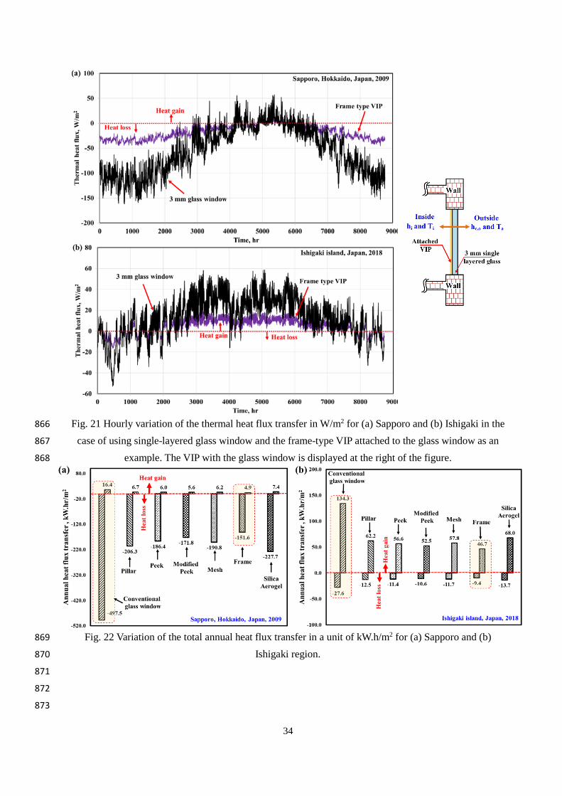
34
Fig. 21 Hourly variation of the thermal heat flux transfer in W/m2 for (a) Sapporo and (b) Ishigaki in the 866
case of using single-layered glass window and the frame-type VIP attached to the glass window as an 867
example. The VIP with the glass window is displayed at the right of the figure. 868
Fig. 22 Variation of the total annual heat flux transfer in a unit of kW.h/m2 for (a) Sapporo and (b) 869
Ishigaki region. 870
871
872
873

35
874
6. Conclusions 875
The present study proposes five new and distinct structured-core transparent VIPs. These VIPs are 876
different from the well-known conventional VIP, which has a solid core material structure and opaque 877
metallized film barrier envelope. The VIPs herein are proposed so as to accomplish high thermal insulation 878
for the windows of existing buildings. The centre-of-panel thermal conductivity, transparency, and cost are 879
experimentally evaluated. In addition, four trial manufacturing methods for these VIPs are proposed and 880
compared. Further, a 3D thermal model is developed and numerically solved, and is validated via 881
experiments. Based on the results, it is determined that the frame and mesh-type spacers accomplished the 882
lowest centre-of-panel thermal conductivities of 6.5×10⁻³ and 6.8 ×10⁻³ W/m.K at a vacuum pressure of 1 883
Pa with thicknesses of 3 mm and 2 mm, respectively. Further, it is concluded that the use of a getter 884
adsorbent material during the manufacturing process of the VIPs keeps the inside pressure stable for a 885
longer period of time. Furthermore, at ASTM boundary conditions, the predicted U-values for the mesh 886
spacers and conventional silica aerogel spacers were 1.14 W/m2.K and 1.84 W/m2.K, respectively. However, 887
the use of mesh spacers is economically competitive with silica aerogels. 888
889
Acknowledgements 890
This work is financially supported by the Grants-in-Aid for Scientific Research of the JSPS (Research 891
representative: Takao Katsura). The authors also thank Mr. Masahiro Aihara, Ms. Ririko Noda in 892
Graduate School of Hokkaido University, Mr Yuji Mori in Faculty of Engineering, Hokkaido University, 893
Hokkaido Electric Power Co. Inc., Mitsubishi Chemical Corporation, Teijin Frontier Co., Ltd., ULVAC Inc., 894
and Miyoshi Vacuum Packing for their assistance in the VIP test production. 895
Nomenclature 896
A vacuum insulation panel front area [m2] 897
C thermal conductance [W/(m2.K)] 898
Cb black body radiation constant factor [W/(m2.K4)] 899
E emissive power density [W/m2] 900
F radiation view factor [unitless] 901
hc,i convective heat transfer coefficient inside the building [W/(m2.K)] 902
hc,o convective heat transfer coefficient on the outer glass surface [W/(m2.K)] 903
J radiosity [W/m2] 904
k thermal conductivity [W/(m.K)] 905
lv VIP thickness [m] 906
P pressure [N/m2] 907
q heat flux either on the hot or the cold side of the VIP [W/m2] 908
T temperature [o C] 909
U∞ wind speed [m/s] 910
Greek symbols 911
Δ difference 912

36
δ thickness [m] 913
ε emissivity [unitless] 914
λo thermal conductivity of the air at the room temperature and pressure [W/(m.K)] 915
λv thermal conductivity of the vacuum space [W/(m.K)] 916
σ Stephan Boltzmann constant 5.67×10⁻⁸ [W/(m2.K4)] 917
Subscripts 918
a ambient 919
avg average 920
c cold side of the VIP 921
eff effective 922
g glass 923
h hot side of the VIP 924
h-c between the hot and the cold side of the VIP 925
i inside the building 926
in entering the surface 927
out exiting from the surface 928
v VIP 929
930
References 931
ANSYS FLUENT Theory Guide, 2011. 932
Araki, K., Kamoto, D., Matsuoka, S. ichi, 2009. Optimization about multilayer laminated film and getter 933
device materials of vacuum insulation panel for using at high temperature. J. Mater. Process. Technol. 934
209, 271–282. https://doi.org/10.1016/j.jmatprotec.2008.01.054 935
Arya, Farid, Moss, R., Hyde, T., Shire, S., Henshall, P., Eames, P., 2018. Vacuum enclosures for solar 936
thermal panels Part 1: Fabrication and hot-box testing. Sol. Energy 174, 1212–1223. 937
https://doi.org/https://doi.org/10.1016/j.solener.2018.10.064 938
Arya, F., Moss, R., Hyde, T., Shire, S., Henshall, P., Eames, P., 2018. Vacuum enclosures for solar thermal 939
panels Part 2: Fabrication and hot-box testing. Sol. Energy 1212–1223. 940
https://doi.org/10.1016/j.solener.2018.10.064 941
Baetens, R., Jelle, B.P., Thue, J.V., Tenpierik, M.J., Grynning, S., Uvsløkk, S., Gustavsen, A., 2010. Vacuum 942
insulation panels for building applications: A review and beyond. Energy Build. 42, 147–172. 943
https://doi.org/10.1016/j.enbuild.2009.09.005 944
Boafo, F.E., Kim, J.-H., Kim, J.-T., 2019. Numerical study of slim curtain wall spandrel with integrated 945
vacuum insulation panel: Concept, performance evaluation and challenges. Energy Build. 183, 139–946
150. https://doi.org/https://doi.org/10.1016/j.enbuild.2018.10.036 947
Bouquerel, M., Duforestel, T., Baillis, D., Rusaouen, G., 2012a. Heat transfer modeling in vacuum 948
insulation panels containing nanoporous silicas - A review. Energy Build. 54, 320–336. 949
https://doi.org/10.1016/j.enbuild.2012.07.034 950
Bouquerel, M., Duforestel, T., Baillis, D., Rusaouen, G., 2012b. Mass transfer modeling in gas barrier 951

37
envelopes for vacuum insulation panels: A review. Energy Build. 55, 903–920. 952
https://doi.org/10.1016/j.enbuild.2012.09.004 953
Buratti, C., Moretti, E., Zinzi, M., 2017. High Energy-Efficient Windows with Silica Aerogel for Building 954
Refurbishment: Experimental Characterization and Preliminary Simulations in Different Climate 955
Conditions. Build. . https://doi.org/10.3390/buildings7010008 956
Choi, B., Yeo, I., Lee, J., Kang, W.K., Song, T.H., 2016. Pillar-supported vacuum insulation panel with 957
multi-layered filler material. Int. J. Heat Mass Transf. 102, 902–910. 958
https://doi.org/10.1016/j.ijheatmasstransfer.2016.06.032 959
Collins, R.E., Simko, T.M., 1998. Current status of the science and technology of vacuum glazing. Sol. 960
Energy 62, 189–213. https://doi.org/10.1016/S0038-092X(98)00007-3 961
Fang, Y., Eames, P.C., Norton, B., Hyde, T.J., 2006. Experimental validation of a numerical model for heat 962
transfer in vacuum glazing. Sol. Energy 80, 564–577. 963
https://doi.org/https://doi.org/10.1016/j.solener.2005.04.002 964
Fang, Y., Eames, P.C., Norton, B., Hyde, T.J., Zhao, J., Wang, J., Huang, Y., 2007. Low emittance coatings 965
and the thermal performance of vacuum glazing. Sol. Energy 81, 8–12. 966
https://doi.org/10.1016/j.solener.2006.06.011 967
Fang, Y., Hyde, T., Hewitt, N., Eames, P.C., Norton, B., 2009. Comparison of vacuum glazing thermal 968
performance predicted using two- and three-dimensional models and their experimental validation. 969
Sol. Energy Mater. Sol. Cells 93, 1492–1498. 970
https://doi.org/https://doi.org/10.1016/j.solmat.2009.03.025 971
Fang, Y., Hyde, T.J., Hewitt, N., 2010. Predicted thermal performance of triple vacuum glazing. Sol. Energy 972
84, 2132–2139. https://doi.org/https://doi.org/10.1016/j.solener.2010.09.002 973
Fantucci, S., Garbaccio, S., Lorenzati, A., Perino, M., 2019. Thermo-economic analysis of building energy 974
retrofits using VIP - Vacuum Insulation Panels. Energy Build. 196, 269–279. 975
https://doi.org/https://doi.org/10.1016/j.enbuild.2019.05.019 976
Fricke, J., Heinemann, U., Ebert, H.P., 2008. Vacuum insulation panels-From research to market. Vacuum 977
82, 680–690. https://doi.org/10.1016/j.vacuum.2007.10.014 978
Incropera, F.P., DeWitt, D.P., Bergman, T.L., Lavine, A.S., 2007. Fundamentals of Heat and Mass Transfer, 979
Water, Dekker Mechanical Engineering. John Wiley & Sons. 980
https://doi.org/10.1016/j.applthermaleng.2011.03.022 981
Jang, C., Kim, J., Song, T.H., 2011. Combined heat transfer of radiation and conduction in stacked radiation 982
shields for vacuum insulation panels. Energy Build. 43, 3343–3352. 983
https://doi.org/10.1016/j.enbuild.2011.08.036 984
Johansson, P., Adl-Zarrabi, B., Hagentoft, C.E., 2012. Using transient plane source sensor for determination 985
of thermal properties of vacuum insulation panels. Front. Archit. Res. 1, 334–340. 986
https://doi.org/10.1016/j.foar.2012.09.004 987
Jung, H., Yeo, I., Song, T.H., 2014. Al-foil-bonded enveloping and double enveloping for application to 988
vacuum insulation panels. Energy Build. 84, 595–606. https://doi.org/10.1016/j.enbuild.2014.08.045 989
Katsura, T., Yang, Z., Aihara, M., Nakamura, M., Nagano, K., 2018. Development of Slim and Translucent 990

38
Vacuum Insulation Panels. J. Japan Sol. Energy Soc. 44, 49–57. https://doi.org/10.24632/jses.44.2_49 991
Kim, J., Jang, C., Song, T.H., 2012a. Combined heat transfer in multi-layered radiation shields for vacuum 992
insulation panels: Theoretical/numerical analyses and experiment. Appl. Energy 94, 295–302. 993
https://doi.org/10.1016/j.apenergy.2012.01.072 994
Kim, J., Lee, J.H., Song, T.H., 2012b. Vacuum insulation properties of phenolic foam. Int. J. Heat Mass 995
Transf. 55, 5343–5349. https://doi.org/10.1016/j.ijheatmasstransfer.2012.05.051 996
Kim, J., Song, T.H., 2013. Vacuum insulation properties of glass wool and opacified fumed silica under 997
variable pressing load and vacuum level. Int. J. Heat Mass Transf. 64, 783–791. 998
https://doi.org/10.1016/j.ijheatmasstransfer.2013.05.012 999
Kwon, J.S., Jang, C.H., Jung, H., Song, T.H., 2010. Vacuum maintenance in vacuum insulation panels 1000
exemplified with a staggered beam VIP. Energy Build. 42, 590–597. 1001
https://doi.org/10.1016/j.enbuild.2009.10.029 1002
Kwon, J.S., Jang, C.H., Jung, H., Song, T.H., 2009. Effective thermal conductivity of various filling 1003
materials for vacuum insulation panels. Int. J. Heat Mass Transf. 52, 5525–5532. 1004
https://doi.org/10.1016/j.ijheatmasstransfer.2009.06.029 1005
Kwon, J.S., Jung, H., Yeo, I.S., Song, T.H., 2011. Outgassing characteristics of a polycarbonate core 1006
material for vacuum insulation panels. Vacuum 85, 839–846. 1007
https://doi.org/10.1016/j.vacuum.2010.12.009 1008
Lee, J., Song, T.-H., 2019. Conduction/radiation combined heat transfer with contact resistance for 1009
application to vacuum insulation. Int. J. Heat Mass Transf. 129, 380–388. 1010
https://doi.org/https://doi.org/10.1016/j.ijheatmasstransfer.2018.09.085 1011
Liang, Y., Wu, H., Huang, G., Yang, J., Wang, H., 2017. Thermal performance and service life of vacuum 1012
insulation panels with aerogel composite cores. Energy Build. 154, 606–617. 1013
https://doi.org/10.1016/j.enbuild.2017.08.085 1014
Lorenzati, A., Fantucci, S., Capozzoli, A., Perino, M., 2016. Experimental and numerical investigation of 1015
thermal bridging effects of jointed Vacuum Insulation Panels. Energy Build. 111, 164–175. 1016
https://doi.org/10.1016/j.enbuild.2015.11.026 1017
Ma, H., Zheng, X., Luo, X., Yi, Y., Yang, F., 2018. Simulation and analysis of mechanical properties of 1018
silica aerogels: From rationalization to prediction. Materials (Basel). 11, 1–12. 1019
https://doi.org/10.3390/ma11020214 1020
Memon, S., Fang, Y., Eames, P.C., 2019a. The influence of low-temperature surface induction on 1021
evacuation, pump-out hole sealing and thermal performance of composite edge-sealed vacuum 1022
insulated glazing. Renew. Energy 135, 450–464. 1023
https://doi.org/https://doi.org/10.1016/j.renene.2018.12.025 1024
Memon, S., Fang, Y., Eames, P.C., 2019b. The influence of low-temperature surface induction on 1025
evacuation, pump-out hole sealing and thermal performance of composite edge-sealed vacuum 1026
insulated glazing. Renew. Energy 135, 450–464. https://doi.org/10.1016/j.renene.2018.12.025 1027
Palyvos, J.A., 2008. A survey of wind convection coefficient correlations for building envelope energy 1028
systems’ modeling. Appl. Therm. Eng. 28, 801–808. 1029

39
https://doi.org/10.1016/j.applthermaleng.2007.12.005 1030
Paneri, A., Wong, I.L., Burek, S., 2019. Transparent insulation materials: An overview on past, present and 1031
future developments. Sol. Energy 184, 59–83. 1032
https://doi.org/https://doi.org/10.1016/j.solener.2019.03.091 1033
Spagnol, S., Lartigue, B., Trombe, A., Gibiat, V., 2007. Thermal modeling of two-dimensional periodic 1034
fractal patterns, an application to nanoporous media. Europhys. Lett. 78, 46005. 1035
https://doi.org/10.1209/0295-5075/78/46005 1036
Thiessen, S., Knabben, F.T., Melo, C., Gonçalves, J.M., 2018. A study on the effectiveness of applying 1037
vacuum insulation panels in domestic refrigerators. Int. J. Refrig. 96, 10–16. 1038
https://doi.org/https://doi.org/10.1016/j.ijrefrig.2018.09.006 1039
Woignier, T., Primera, J., Alaoui, A., Etienne, P., Despestis, F., Calas-Etienne, S., 2015. Mechanical 1040
Properties and Brittle Behavior of Silica Aerogels. Gels . https://doi.org/10.3390/gels1020256 1041
Yang, Z., Katsura, T., Aihara, M., Nakamura, M., Nagano, K., 2018. Investigation into window insulation 1042
retrofitting of existing buildings using thin and translucent frame-structure vacuum insulation panels. 1043
Energies 11. https://doi.org/10.3390/en11020298 1044
Yang, Z., Katsura, T., Aihara, M., Nakamura, M., Nagano, K., 2017. Development of numerical heat transfer 1045
and the structural model to design slim and translucent vacuum layer type insulation panels to 1046
retrofitting insulation in existing buildings. Energies 10. https://doi.org/10.3390/en10122108 1047
1048