energy communication platform - unicornecp.unicornsystems.eu/attachments/ecp_administration... ·...
TRANSCRIPT

> 1 <
CWE
Energy Communication Platform
Administration guide

> 2 <
Unicorn Systems © 2011– Unicorn Systems a.s.
Jankovcova 1037/49, Praha 7, CZ-170 00
Title: CWEEnergy Communication Platform
Author: Petr Sochůrek, Stanislav Mikulecký, Michal Ráček, Vlastimil Unucka, Jiří Neuman, Michal Česák, Jiří Dudek
Version: 2.1.1Date: 18/02/2011
Contact: E-mail: [email protected] Tel.: (+420) 221 400 111

1. CONTENTS
1. Contents.............................................................................................................................. 32. Revisions History...............................................................................................................53. ECP Module Configuration...............................................................................................6
3.1. How to Change the ECP Configuration 63.1.1. Changing Configuration of ECP Node on Linux 63.1.2. Changing Configuration of ECP Node on Windows and ECP Client 73.1.3. Configuration Parameters – Overview 7
3.2. ECP Module Configuration Parameters 83.2.1. Connection to Database 83.2.2. ECP Module Logging Settings 93.2.3. Message Archive Settings 103.2.4. Download Request Signing Settings 103.2.5. Connected Endpoint Register Settings 103.2.6. Notification about Expiring Keys 113.2.7. Message Compression 113.2.8. Message Expiration 123.2.9. Message Priority 123.2.10. SSL Configuration on Client Side 123.2.11. Private Key Encryption 133.2.12. ECP 1.5.6 Compatibility 14
3.3. Endpoint Configuration Parameters 143.3.1. Messaging Component Identification 143.3.2. Connection to Gateway 153.3.3. Message Signing Settings 163.3.4. GUI Configuration 163.3.5. Upload/Download Interval Settings 163.3.6. Event Manager Settings 173.3.7. ECP Public API – Channels Configuration 173.3.8. Public API – Receiving Handlers Registration 193.3.9. Public API – Send Handlers Registration 20
3.4. Gateway Configuration Parameters 213.4.1. Messaging Component Identification 213.4.2. Connection to Node 213.4.3. Listeners for Endpoint Connections 223.4.4. Upload/Download Interval Settings 23
3.5. Node Configuration Parameters 243.5.1. Messaging Component Identification 243.5.2. Listener for Gateway Connections 243.5.3. User Authentication 243.5.4. Notification about Certificates Expiration 25
3.6. Registration Component Configuration 253.6.1. Node Component Identification 253.6.2. Registration Service 25
3.7. ECP Module Logging 274. Application Server Configuration..................................................................................29
4.1. SSL Configuration on Server Side 294.2. Disable HTTP on Server Side 314.3. Limiting Access to ECP Web Pages 31
4.3.1. Configuration on Tomcat 314.3.2. Configuration on JBoss 32
5. HA Administration Tools Configuration........................................................................345.1. ECP Guardian345.2. Geographical Cluster Check 35
6. Administration Tasks.......................................................................................................376.1. Managing Trusted Certificate Authorities 37
> 3 <
CWEEnergy Communication PlatformAdministration guide

6.1.1. Tool Execution and Configuration 376.1.2. Operations Description 39
6.2. Securing Private Keys in Database 406.2.1. Encryption Key Description 406.2.2. Encryption Key Generation 406.2.3. ECP Setup 406.2.4. Encryption Key Management 40
6.3. Update Node List 416.3.1. Description 416.3.2. How to Update Node List File 426.3.3. Upload New Node List File 43
6.4. Update Certificates 446.4.1. Description 446.4.2. How to Update Certificates 48
6.5. Archive Messages into the Long-term Storage 506.5.1. Structure of Long-term Storage 506.5.2. Running MessageArchivation from the Command Line 516.5.3. Running MessageArchivation in the GUI Mode 516.5.4. Running MessageArchivation on Regular Basis 536.5.5. Configuration Parameters 586.5.6. Logging 59
6.6. Bandwidth Throttling 596.6.1. Bandwidth Throttling in General 596.6.2. Bandwidth Throttling on Linux 616.6.3. Bandwidth Throttling on Solaris 63
7. Monitoring.........................................................................................................................687.1. ECP Module – Monitoring Web Page 68
8. References....................................................................................................................... 718.1. Related Documents 718.2. Web References 71
> 4 <
CWEEnergy Communication PlatformAdministration guide

2. REVISIONS HISTORY
Version Date Author Description
0.1 09/02/2009 Petr SochůrekECP module configuration and basic administration tasks.
1.0 09/07/2009 Stanislav Mikulecký Document finalized
1.02 03/11/2009 Michal Ráček Changes for ECP version 1.0.2
1.5 15/02/2010 Jiří Neuman Changes for ECP version 1.5
1.5.1 11/03/2010 Michal Ráček Changes for ECP version 1.5.3
1.5.2 18/03/2010 Michal Ráček Changes according to WS requests.
1.5.3 14/06/2010 Jiří NeumanAdded chapter about container based security.
1.5.4 15/07/2010 Jiří Neuman Changes for ECP version 1.5.6
2.0.0 23/11/2010Vlastimil Unucka, Jiří Neuman
Updates for ECP 2.0.0.
2.0.1 06/12/2010 Michal Česák Node list update
2.0.2 06/12/2010 Michal Česák Update certificates
2.1 21/02/2011 Jiří Dudek Directory service importer
2.1.1 01/03/2011 Jiří Dudek Add bandwidth throttling.
> 5 <
CWEEnergy Communication PlatformAdministration guide

3. ECP MODULE CONFIGURATION
Configurable aspects of ECP module can be modified in a single file - module.properties.
This file is located in the ECP application deployment directory and it is created during ECP installation or upgrade procedure.
The following subchapters contain a list of possible parameters. They are divided with respect to the possible deployment modes.
3.1. How to Change the ECP Configuration
There are two different forms of installation packages provided for ECP.
>Standard installation package. ECP Node for Linux is distributed in this form. This installation package installs the ECP Node on top of pre-installed Tomcat/JBoss and MySQL. To change the configuration, see chapter 3.1.1.
>Simplified installation package. ECP Node for Windows and ECP Client are distributed in this form. This installation package provides simple installation of application without relying on any pre-installed software (package itself contains Tomcat, Java, and Postgres). To change the configuration, see chapter 3.1.2.
3.1.1. Changing Configuration of ECP Node on Linux
To change the configuration, the ECP application must be redeployed using the installation or upgrade package. If you do not have available installation package from previous installation, download a new one and copy module.properties file from the current ECP application into it. Follow these steps to update ECP configuration:
1. Move to the directory with latest ECP installation or upgrade.
2. Make changes to the module.properties file placed in ECP installation directory.
3. Shutdown ECP Node.
4. Make sure that ECP Node is not running.
5. For Tomcat: Delete directory $TOMCAT_HOME/webapps/ECP_MODULE.
6. For Tomcat: Backup file $TOMCAT_HOME/webapps/ECP_MODULE.war.
7. For JBoss: Backup file $JBOSS_HOME/server/all/farm/ECP_MODULE.ear.
8. Make sure that installation.properties and executable scripts are set according to the current system configuration.
9. When using ECP installation package execute script deploy_ecp_app.sh.
10. When using ECP upgrade package execute script upgrade_ecp_app.sh.
> 6 <
CWEEnergy Communication PlatformAdministration guide

11. Startup ECP Node.
3.1.2. Changing Configuration of ECP Node on Windows and ECP Client
For changing configuration of ECP Node deployed on Windows or ECP Client follow these steps:
1. Shutdown running ECP services (use batch located in batches/shutdown).
2. Edit config/module.properties file in any available text editor.
3. Startup ECP services (use batch located in batches/startup).
3.1.3. Configuration Parameters – Overview
Configuration parameters are divided into several major groups and its subgroups. This chapter explains which aspects of ECP can be configured in each group.
3.1.3.1. Basic ECP Module Configuration
This group contains basic configuration parameters that have effect on the whole module. This includes configuration of connection to database, configuration of ECP logger and configuration of message compression and priority. For more details see chapter . Also SSL settings are described in this chapter.
3.1.3.2. Endpoint Component Configuration
Another part is related to the Endpoint messaging component. The Endpoint is responsible mainly for communication with business application and for preparation of the message for the way through ECP network. Configuration of following aspects is supported:
>Basic configuration of Endpoint component (its code and description)
>Message signing by default and special message signer
>Signing of download requests from one module to another
>External communication channels through which ECP communicates with a business application
>Connection to the parent component
These configuration aspects are further described in chapter 3.3 Endpoint ConfigurationParameters.
3.1.3.3. Gateway Component Configuration
Next messaging component in the ECP chain is Gateway. Following aspects of Gateway behavior can be modified in configuration:
>Basic configuration of Gateway component (its code and description)
>Connection to the primary and secondary Node
> Internal communication channels for connection of Endpoints
> 7 <
CWEEnergy Communication PlatformAdministration guide

When configuring Gateway messaging component, please refer to chapter Error: Reference sourcenot found Error: Reference source not found.
3.1.3.4. Node Component Configuration
Node is the third messaging component in the ECP chain.
>Basic configuration of the Node component (its code and description)
> Internal communication channels which allow connection of Gateways
>Credentials for access via web UI
>Notification about expiring or missing certificates for connected messaging components
To see which parameters can be used to configure behavior of Node component, see chapter 3.5 Node Configuration Parameters.
3.1.3.5. Registration Component Configuration
Registration component provides public access to UC Create Registration Request and UC Create Update Request. Registration component is part of ECP Node and it has to share the database with ECP Node. Registration component is designed to be deployed at separate application server.
>Node component identification
>Registration Service
To see which parameters can be used to configure behavior of Registration component, see chapter 3.6 Registration Component Configuration.
3.2. ECP Module Configuration Parameters
This chapter describes configuration parameters which have effect on the whole ECP module. These parameters allow configuration of aspects that don’t belong to any particular messaging component.
3.2.1. Connection to Database
According to the particular deployment needs, the database server can be installed together with the ECP module (on the same machine with application server) or it can be installed separately (the application and database will be on separate machines).
The database part of ECP module can be operated into following databases: PostgreSQL, MySQL, MSSQL and Oracle. The connection to the database is configured using the following parameters.
Parameter Description
Database JDBC connection string
Database.User Database user
> 8 <
CWEEnergy Communication PlatformAdministration guide

Database.Password Database password
Database.Driver Database driver
Database.Dialect Database dialect
The values of the parameters differ depending on the type of database as shown in the following examples.
3.2.1.1. Parameters for Connection to MySQL (example)Database=jdbc:mysql://192.168.80.157:3306/ecp ?autoReconnect=true’ Database.User=ecpDatabase.Password=ecpsqlDatabase.Driver=com.mysql.jdbc.DriverDatabase.Dialect=MYSQL
It is recommended to append parameter autoReconnect=true to the connection string. Adding this parameter will eliminate problems with broken connections to MySQL database which appear mainly when using FSSF channel on Unix-based operating systems.
3.2.1.2. Parameters for Connection to MSSQL (example)Database=jdbc:sqlserver://192.168.81.25;instanceName=SQLExpress;database=ecp;integratedSecurity=false;Database.User=ecpDatabase.Password=ecpsqlDatabase.Driver=com.microsoft.sqlserver.jdbc.SQLServerDriverDatabase.Dialect=SQL_SERVER
3.2.1.3. Parameters for Connection to Oracle (example)Database=jdbc:oracle:thin:@192.168.81.25:1521:xeDatabase.User=ecpDatabase.Password=ecpsqlDatabase.Driver=oracle.jdbc.driver.OracleDriverDatabase.Dialect=ORACLE
3.2.1.4. Parameters for Connection to PostgreSql (example)Database=jdbc:postgresql://localhost:5432/ecpDatabase.User=ecpDatabase.Password=ecpsqlDatabase.Driver=com.postgresql.DriverDatabase.Dialect=POSTGRESQL
3.2.2. ECP Module Logging Settings
It is possible to change the directory, where the ECP module log files are stored.
Parameter Description Default value Example
Module.EcpLogger.DirectoryPath
Path to existing directory, where ECP logs will be stored.
- /tmp/ecp-logs
> 9 <
CWEEnergy Communication PlatformAdministration guide

3.2.3. Message Archive Settings
Configuration parameters for the Message Archive. This component is responsible for archiving messages which reached the end of their lifecycle.
Parameter DescriptionDefault value Example / Other
possible values
Module.Archive.DisabledTypes
List of message types that will be archived without their content. This parameter is voluntary and if is missing, messages of all types are stored into archive including their content. Message types are divided by ‘;’ character.
- MESSAGE_TYPE_1;MESSASSAGE_TYPE_2
3.2.4. Download Request Signing Settings
Each download request from one messaging component to another must be signed. For security reasons, disabling signing on production environment is not recommended. Please note that this parameter has to have the same value at every ECP module in the whole ECP network.
Parameter Description Default value /Other possible values
Module.DownloadRequestSigner.Class
Implementation of download request signer
downloadRequestSigner
/ disabledDownloadRequestSigner
3.2.5. Connected Endpoint Register Settings
These settings allow configuration of Register which maintains information about connected endpoints. The content of the Register is used for monitoring purposes.
Parameter Description Default value Example
Module.EndpointRegister.Retention
Time in seconds through which endpoint is considered active. If no connection is made by given endpoint for specified amount of time, it is deleted from register of connected endpoints.
600
> 10 <
CWEEnergy Communication PlatformAdministration guide

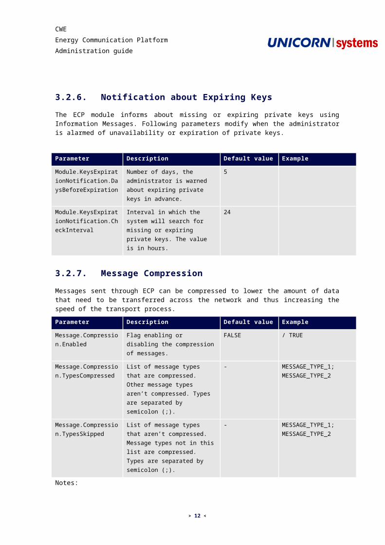
3.2.6. Notification about Expiring Keys
The ECP module informs about missing or expiring private keys using Information Messages. Following parameters modify when the administrator is alarmed of unavailability or expiration of private keys.
Parameter Description Default value Example
Module.KeysExpirationNotification.DaysBeforeExpiration
Number of days, the administrator is warned about expiring private keys in advance.
5
Module.KeysExpirationNotification.CheckInterval
Interval in which the system will search for missing or expiring private keys. The value is in hours.
24
3.2.7. Message Compression
Messages sent through ECP can be compressed to lower the amount of data that need to be transferred across the network and thus increasing the speed of the transport process.
Parameter Description Default value Example
Message.Compression.Enabled
Flag enabling or disabling the compression of messages.
FALSE / TRUE
Message.Compression.TypesCompressed
List of message types that are compressed. Other message types aren’t compressed. Types are separated by semicolon (;).
- MESSAGE_TYPE_1; MESSAGE_TYPE_2
Message.Compression.TypesSkipped
List of message types that aren’t compressed. Message types not in this list are compressed. Types are separated by semicolon (;).
- MESSAGE_TYPE_1; MESSAGE_TYPE_2
Notes:
> If the message compression is enabled without specifying types to compress or types to skip, all messages will be compressed.
>Parameters Message.Compression.TypesCompressed and Message.Compression.Type-sSkipped cannot be used together. Just one of them can be specified at a time.
> 11 <
CWEEnergy Communication PlatformAdministration guide
3.2.8. Message Expiration
ECP can be configured to set expiration time on sent messages. This will cause messages which don’t reach the end of their lifecycle before the expiration time comes to fail, preventing them to hang in ECP forever. It is highly recommended to set this parameter.
Parameter Description Default value Example
Message.Expiration.Time Number of hours after which the message will expire unless it is in its final state. Value 0 means that message will never expire.
0 8
3.2.9. Message Priority
Message priority can be set for message types enabling to prefer transportation of one message type to another. The priority can be configured either on the module level or on the component level. These parameters allow configuration on the module level (i.e. all components within the module will have the same priorities for message transportation).
Parameter Description Default value Example
Message.Priority.<X>.Value
Priority value. Default value is 0, higher value means higher priority. The value must be an integer.
0 / -1 / 2
Message.Priority.<X>.Types
Types to which the priority is assigned. Types are separated by semicolon (;).
- MESSAGE_TYPE_1; MESSAGE_TYPE_2
Notes:
>For each priority replace token <X> with number representing the order in the configuration file: 0, 1, 2, etc.
>To configure priority on component level, add the component type as a prefix to the parameter name (e.g. Node.Message.Priority.1.Value).
>The priority can be configured both at module level and component level at a time. The compo-nent level configuration has higher priority than the module level configuration.
3.2.10. SSL Configuration on Client Side
As mentioned in chapters
>3.3.2 Connection to Gateway and
>3.4.2 Connection to Node,
ECP messaging component can be configured for communication with another messaging component via calling Web service over HTTPS. Establishing HTTPS connection starts with SSL
> 12 <
CWEEnergy Communication PlatformAdministration guide

authentication procedure (SSL handshake) where both sides introduce themselves. This procedure requires proper configuration on both sides of communication (client and server).
This chapter describes settings that should be done on client side. Appropriate settings related to server side are described in the chapter 4.1 SSL Configuration on Server Side.
Parameter DescriptionDefault value
Example / Other possible values
javax.net.ssl.trustStore Keystore file, which contains trusted CA certificate which client uses for authentication of server during SSL authentication procedure.
- /home/ecp/ecp_module _cert.jks
javax.net.ssl.trustStorePassword The password which is used to protect the integrity of the keystore.
- password
javax.net.ssl.keyStore Keystore file, which contains client’s SSL certificate which client uses during SSL authentication procedure
- /home/ecp/ecp_module _cert.jks
javax.net.ssl.keyStorePassword The password which is used to protect the integrity of the keystore.
- password
Note that
> these settings apply to all HTTPS communication that the ECP module initiates,
> javax.net.ssl.keyStore needs to be set only if authentication of client is required by server.
3.2.11. Private Key Encryption
Private keys to all certificates are stored in the database. ECP offers mechanism to secure this important data. The private keys stored in database using AES cipher with 256-bit length key. For more details please see 6.2 Securing Private Keys in Database.
Parameter DescriptionDefault value Example / Other
possible values
> 13 <
CWEEnergy Communication PlatformAdministration guide

Module.Keystore.Encryption.KeyFile
Path to the resource which contains database encryption key. This key is used to encrypt and decrypt all private keys stored into the database. For more details please see 6.2 Securing Private Keys in Database.
The value has to be in following format:
file:[absolute path to the encryption file]
If you want to use default encryption file then the value should be:
classpath:/defaultEncryptionKey
classpath:/defaultEncryptionKey
file:/opt/encryptionKey
3.2.12. ECP 1.5.6 Compatibility
ECP 2.1 uses different signing and encryption mechanism than previous versions of ECP. If the ECP network contains any component with version 1.5.6 then this parameter has to be set to TRUE. Please note that this parameter has to have the same value at every ECP module in the whole ECP network.
Parameter DescriptionDefault value
Example / Other possible values
Module.ECP15.Compatibility If module use ECP 1.5.6 compatible encryption and signing.
FALSE / TRUE
3.3. Endpoint Configuration Parameters
3.3.1. Messaging Component Identification
Each messaging component deployed within a module must have designated code which is unique in the whole ECP platform. Every component has also additional description. This information is used for message routing, logging and tracing purposes.
Parameter Description Default value Example
Endpoint.Enabled Flag telling whether the Endpoint is enabled (TRUE) or not (FALSE)
TRUE / FALSE
Endpoint.Code Code of endpoint.Format: [EIC code of endpoint]
- 10X1001A1001A094
Endpoint.Description Description of Endpoint component. - Endpoint 1
> 14 <
CWEEnergy Communication PlatformAdministration guide

3.3.2. Connection to Gateway
Configuration of internal communication channel for connection from Endpoint to Gateway. This configuration is required and will be used only if the Gateway is not deployed together with the Endpoint in one module. In such a case, communication via Java calls between both components will be forced.
Following configuration sets communication via web service:
Parameter DescriptionDefault value
Example / Other possible values
Endpoint.Parent.Enabled Activation status TRUE / FALSE
Endpoint.Parent.Type Type of channel WS -
Endpoint.Parent.Url URL to web-service of Gateway
- https://139.49.9.13/ECP_MODULE/services
Endpoint.Parent.RequestTimeout Time after which the WS request times out if no response is received(seconds).
30
See also related issues in chapter 3.2.10 SSL Configuration on Client Side.
Following configuration sets communication via SCP:
Parameter DescriptionDefault value Example / Other
possible values
Endpoint.Parent.Enabled Activation status TRUE / FALSE
Endpoint.Parent.Type Type of channel SCP -
Endpoint.Parent.Url IP of SSH server - 199.3.4.99
Endpoint.Parent.User SSH server user - ecp
Endpoint.Parent.DirectoryPath SCP folder - Transfer/
Endpoint.Parent.PollInterval SCP folder polling interval (milliseconds)
1000
Endpoint.Parent.RequestTimeout Interval for which SCP client waits for response (seconds)
30
3.3.3. Message Signing Settings
These settings allow configuration of the way the messages are signed and their signature verified. It also allows disabling signing, although this is not recommended on production environment.
> 15 <
CWEEnergy Communication PlatformAdministration guide

Parameter DescriptionDefault value Example / Other
possible values
Endpoint.Signer.Class Implementation of message signer defaultMessageSigner
/ disabledMessageSigner
Endpoint.Signer.<X>.Class
Implementation of message signer. This form can be used to define multiple signing.
defaultMessageSigner
/ specialMessageSigner
Notes:
>For each priority replace token <X> with number representing the order in the configuration file: 0, 1, 2, etc.
When Special Message Signer is used for signing the messages, additional configuration is required for certificate provider.
Parameter DescriptionDefault value Example / Other
possible values
Endpoint.FileKeystoreProvider.Directory
Path to the directory where the keystores are stored.
- /opt/certificates/specialSigning
Endpoint.FileKeystoreProvider.Password
Password protecting the keystores and private keys in them.
- password
Endpoint.FileKeystoreProvider.Alias
Alias of the signing certificate in the keystores.
- ecp_module_sign
3.3.4. GUI Configuration
Configuration of ECP GUI allows slight modification of its behavior.
Parameter DescriptionDefault value Example / Other
possible values
Endpoint.MessageListInOutbox.Refresh
Automatic refresh interval on Inbox and Outbox web pages. Value is in milliseconds.
120000
3.3.5. Upload/Download Interval Settings
The transportation of messages over ECP network is realized by uploading and downloading between messaging components.
This set of parameters is used to configure time interval of upload/download processes on Endpoint.
> 16 <
CWEEnergy Communication PlatformAdministration guide

Parameter Description Default value Example
Endpoint.TransportTrigger.StartDelay
Delay settings for starting message transport process on Endpoint in milliseconds.
0 0 / 1000
Endpoint.TransportTrigger.RepeatInterval
Message transport repeat interval in milliseconds for Endpoint. When is set to 0 the transport process is stopped.
1000 1000 / 0
3.3.6. Event Manager Settings
Event Manager is internal component responsible for distributing internal events within ECP module. Its settings have influence on the components that listen on these events (sending handlers, receiving handlers and FSSF channel). By default, the preset values do not need to be changed.
Following parameters can be configured regarding Event Manager:
Parameter DescriptionDefault value
Example
Endpoint.EventManager.IterationsDelay
Delay in milliseconds between two distributions of events.
500
Endpoint.EventManager.EventDeliveryFailureDelay
Delay in milliseconds between attempts to deliver event which delivery previously failed.
15000
Endpoint.EventManager.AttemptsLimit
Maximum number of attempts to distribute event to Receiving Handlers.
50
3.3.7. ECP Public API – Channels Configuration
Endpoint messaging component supports three types of APIs which business applications can use for interaction with ECP. Each API can be switched on/off in the configuration. FSSF (File System Shared Folder) API (which is the most complex) provides more advanced settings.
For specification of supported types of API refer to [ECP Public API]. For related examples showing API usage see [ECP Public API – Usage].
Web-Service Public API:
Parameter DescriptionDefault value Example / Other
possible values
Endpoint.ECC.0.Enabled Allows enabling / disabling WS API. TRUE / FALSE
Endpoint.ECC.0.Type API type WS -
> 17 <
CWEEnergy Communication PlatformAdministration guide

Notes
By default, the Endpoint exposes public web services via HTTP. URL has following form http://hostname/ECP_MODULE/services/ECPEndpointService/ .
If you want to use HTTPS, see chapter 4.1 SSL Configuration on Server Side. URL has following form https://hostname/ECP_MODULE/services/ECPEndpointService/.
JAVA Public API:
Parameter DescriptionDefault value Example / Other
possible values
Endpoint.ECC.1.Enabled Allows enabling / disabling Java API.
TRUE / FALSE
Endpoint.ECC.1.Type API type JAVA -
FSSF Public API:
Parameter DescriptionDefault value
Example / Other possible values
Endpoint.ECC.2.Enabled Allows enabling / disabling FSSF API. TRUE / FALSE
Endpoint.ECC.2.Type API type FSSF -
Endpoint.ECC.2.PollInterval Milliseconds between polling out folder 1000
Endpoint.ECC.2.MessageEventPollInterval
Milliseconds between attempts to write events to OUT_LOG
1000
Endpoint.ECC.2.OutgoingDirectory
Folder for messages waiting to be sent
./OUT/
Endpoint.ECC.2.OutgoingErrorDirectory
Folder where messages rejected by ECP will be moved.
./OUT_ERROR/
Endpoint.ECC.2.LogDirectory Folder for messages with logs ./OUT_LOG/
Endpoint.ECC.2.LogType Strategy for OUT LOG files creation (one log file created for each message / one log file for each day which contains records related to all messages).
ONE_PER_MESSAGE
ONE_PER_DAY
Endpoint.ECC.2.IncomingDirectory.<X>.Directory
Folder for received messages ./IN/A/
> 18 <
CWEEnergy Communication PlatformAdministration guide

Endpoint.ECC.2.IncomingDirectory.<X>.MessageTypes
Message types received to incoming folder (separated by semicolon). In case of setting empty string as the message types value, messages of all types will be received by this incoming directory.
MESSAGE_TYPE_1; MESSAGE_TYPE_2
Notes
>One or more incoming folders can be registered by FSSF. Each incoming folder is designated for messages which have defined message types. If such message arrives to the ECP module of recipient (endpoint), it is immediately written into proper incoming folder. Make sure that the same message type is not used more than once.
> In case of setting empty string into ‘MessageTypes’ parameter, messages of all types will be re-ceived into specified folder. It’s highly recommended to not combine this setting with specifying any other message receiver (including all types of message receivers) for explicit message type.
>For each registered incoming folder replace token <X> with number representing the order in the configuration file: 0, 1, 2, etc.
>Make sure that both business application and ECP module have read/write access to the IN, OUT, OUT_ERROR and OUT_LOG folders.
3.3.8. Public API – Receiving Handlers Registration
The concept of custom receiving handlers is described in [ECP Public API].
Following couple of parameters is used for registering the custom receiving handler into ECP module.
Parameter DescriptionDefault value
Example
Endpoint.ReceiveHandler.<X>.ClassName
Name of Java class implementing handler.
TRUE eu.unicorn.tst.SimpleAdapter
Endpoint.ReceiveHandler.<X>.Types
Types of messages the handler listens to (separated by semicolon). If empty value is set, handler will listen to all messages.
- MESSAGE_TYPE_1; MESSAGE_TYPE_2
Notes
>For each registered handler use unique parameter name, e.g. replace token <X> with number representing the order in the configuration file: 0, 1, 2, etc.
> In case of setting empty string into ‘Types’ parameter, messages of all types will be received by this receive handler. It’s highly recommended to not combine this setting with specifying any other message receiver (including all types of message receivers) for explicit message type.
> 19 <
CWEEnergy Communication PlatformAdministration guide

>Each handler is registered for messages of given types. Make sure that the same message type is not used more than once.
>Java archives containing handlers need to be named as ECP_*.jar, where * represents sequence of arbitrary characters. In addition, these archives must be put into the WEB-INF/lib directory lo -cated either:
- Inside the ECP_MODULE directory (ECP Client installations and ECP Node on Windows)
- Inside the ECP Module’s EAR archive and then inside the WAR archive (ECP Node on Linux deployed on Jboss).
- Inside the ECP Module’s WAR archive (ECP Node on Linux deployed on Tomcat).
- This convention is important for preserving the handler after a future upgrade on higher ver-sion of ECP.
3.3.9. Public API – Send Handlers Registration
The concept of custom send handlers is described in [ECP Public API].
Following couple of parameters is used for registering the custom send handler into ECP module.
Parameter DescriptionDefault value
Example
Endpoint.SendHandler.<X>.ClassName
Name of Java class implementing handler.
TRUE eu.unicorn.tst.SimpleAdapter
Endpoint.SendHandler.<X>.Types
Types of messages the handler listens to (separated by semicolon). If empty value is set, handler will listen to all messages.
- MESSAGE_TYPE_1; MESSAGE_TYPE_2
Notes
>For each registered handler use unique parameter name, e.g. replace token <X> with number representing the order in the configuration file: 0, 1, 2, etc.
>Java archives containing handlers need to be named as ECP_*.jar, where * represents sequence of arbitrary characters. In addition, these archives must be put into the WEB-INF/lib directory lo -cated either:
- Inside the ECP_MODULE directory (ECP Client installations and ECP Node on Windows)
- Inside the ECP Module’s EAR archive and then inside the WAR archive (ECP Node on Linux deployed on Jboss).
- Inside the ECP Module’s WAR archive (ECP Node on Linux deployed on Tomcat).
- This convention is important for preserving the handler after a future upgrade on higher ver-sion of ECP.
> 20 <
CWEEnergy Communication PlatformAdministration guide

3.4. Gateway Configuration Parameters
3.4.1. Messaging Component Identification
Each messaging component deployed within a module must have designated code which is unique in the whole ECP platform. Every component has also additional description. This information is used for message routing, logging and tracing purposes.
Parameter Description Default value Example
Gateway.Enabled Flag telling whether the Gateway is enabled (TRUE) or not (FALSE)
TRUE / FALSE
Gateway.Code Code of Gateway.Format: [component code of Endpoint]-MC
- 10X1001A1001A094-MC
Gateway.Description Description of Gateway component. - Gateway 1
3.4.2. Connection to Node
Configuration of internal communication channel for connection from Gateway to Node. This configuration is required and will be used only if the Node is not deployed together with the Gateway in one module. In such a case, communication via Java calls between both components will be forced.
Following configuration sets communication via web service:
Parameter DescriptionDefault value
Example / Other possible values
Gateway.Parent.Enabled Activation status of connection to the primary Node
TRUE / FALSE
Gateway.Parent.Type Type of channel for connection to the primary Node
WS -
Gateway.Parent.Url URL to web-service of the primary Node
https://139.49.9.13/ECP_MODULE/services
Gateway.Parent.RequestTimeout Time after which the WS request times out if no response is received (seconds).
30
Configuration of secondary channel for connection from Gateway to Node via Web service:
> 21 <
CWEEnergy Communication PlatformAdministration guide

Parameter DescriptionDefault value
Example / Other possible values
Gateway.Parent.Secondary.Enabled Activation status of connection to the secondary Node
FALSE / TRUE
Gateway.Parent.Secondary.Type Type of channel for connection to the secondary Node
WS -
Gateway.Parent.Secondary.Url URL to web-service of the secondary Node
https://139.49.9.2/ECP_MODULE/services
Gateway.Parent.Secondary.RequestTimeout
Time after which the WS request times out if no response is received (seconds).
30
See also related issues in chapter 3.2.10 SSL Configuration on Client Side.
3.4.3. Listeners for Endpoint Connections
These parameters allow adjusting the behavior of internal communication between Endpoint and Gateway messaging components.
Configuration of listener allowing to Endpoints to connect via Web service:
Parameter DescriptionDefault value
/ Other possible values
Gateway.ChildConnector.0.Enabled
Activation status TRUE / FALSE
Gateway.ChildConnector.0.Type
API type for child connector. WS -
Notes
>By default, the Gateway exposes internal web services via HTTP (URL has form http://hostname/ECP_MODULE/services).
> If you want to use HTTPS, see chapter 4.1 SSL Configuration on Server Side (URL has form https://hostname/ECP_MODULE/services).
Configuration on listener allowing to Endpoints to connect via SCP:
Parameter DescriptionDefault value
Example / Other possible values
Gateway.ChildConnector.1.Enabled Activation status FALSE / TRUE
> 22 <
CWEEnergy Communication PlatformAdministration guide

Gateway.ChildConnector.1.Type API type for child connector
SCP -
Gateway.ChildConnector.1.Url IP of SSH server 192.168.80.155
Gateway.ChildConnector.1.DirectoryPath
SCP folder transfer/
Gateway.ChildConnector.1.PollInterval
SCP folder polling interval
1000
Gateway.ChildConnector.1.User SSH server user ecp
3.4.4. Upload/Download Interval Settings
The transportation of messages over ECP network is realized by uploading and downloading between messaging components.
This set of parameters is used to configure time interval of upload/download processes on Gateway.
Parameter Description Default value Example
Gateway.TransportTrigger.StartDelay
Delay settings for starting message transport process on Gateway in milliseconds.
0 0 / 1000
Gateway.TransportTrigger.RepeatInterval
Message transport repeat interval in milliseconds for Gateway. When is set to 0 the transport process is stopped.
1000 1000 / 0
> 23 <
CWEEnergy Communication PlatformAdministration guide

3.5. Node Configuration Parameters
3.5.1. Messaging Component Identification
Each messaging component deployed within a module must have designated code which is unique in the whole ECP platform. Every component has also additional description. This information is used for message routing, logging and tracing purposes.
Parameter Description Default value Example
Node.Enabled Flag telling whether the Node is enabled (TRUE) or not (FALSE)
TRUE / FALSE
Node.Code Code of Node.Format: [component code of Endpoint]-MN
- 10X1001A1001A094-MN
Node.Description Description of Node component. - Node 1
3.5.2. Listener for Gateway Connections
These parameters allow adjusting the behavior of internal communication between Gateway and Node messaging components.
Configuration of listener allowing to Gateways to connect via Web service:
Parameter DescriptionDefault value
/ Other possible values
Node.ChildConnector.0.Enabled
Activation status TRUE / FALSE
Node.ChildConnector.0.Type
API type for child connector. WS -
Notes
>By default, the ECP module exposes internal web services via HTTP (URL has form http://host-name/ECP_MODULE/services).
> If you want to use HTTPS, see chapter 4.1 SSL Configuration on Server Side (URL has form https://hostname/ECP_MODULE/services).
3.5.3. User Authentication
ECP Node has limited access to the web pages that only authorized users may access. Web pages that don’t require authentication are Registration form and Update form as these are
> 24 <
CWEEnergy Communication PlatformAdministration guide

supposed to be publicly available. Following configuration parameters define the authentication credentials.
Parameter Description Default value Example
Node.webauthentication.<X>.login
Username used to login. - admin
Node.webauthentication.<X>.password
Password for corresponding login. - password
Notes
>For each authentication login-password pair unique parameter name must be used. This can be achieved by replacing token <X> with number representing the order in the configuration file: 0, 1, 2, etc.
3.5.4. Notification about Certificates Expiration
Directory Service storing all the certificates of known messaging components is part of the Node. As the certificates are issued only for certain time period, it is necessary to update them regularly. When any messaging component registered on the Node has either expired certificates or the certificates are close their expiration date, Node administrator is informed. Following parameters modify when the administrator should be alarmed about expiration of certificates.
Parameter Description Default value Example
Node.CertificateExpirationNotification.DaysBeforeExpiration
Number of days, the Node administrator is warned about expiring certificates in advance.
5
Node.CertificateExpirationNotification.CheckInterval
Interval in which the system will search for expired or expiring certificates. The value is in hours.
24
3.6. Registration Component Configuration
3.6.1. Node Component Identification
Registration Component has to contain basic Node component configuration (Node code and Node description) but the Node.Enabled has to be set to FALSE in case that Registration Component is deployed at dedicated application server. More detail about basic Node component configuration can be found in chapter 3.5.1.
> 25 <
CWEEnergy Communication PlatformAdministration guide

3.6.2. Registration Service
Registration Service allows registration of new Endpoints and Gateways into ECP. This chapter describes configuration parameters that can be changed to modify behavior of Registration Service according to your needs.
Parameter DescriptionDefault value
Example / Other possible values
Node.Registration.Enabled Flag indicating whether the registration service is enabled (TRUE) or not (FALSE).
TRUE / FALSE
Node.Registration.GeneratedCertificate.Length
Length of certificates generated by registration service in bits.
2048 1024
Node.Registration.GeneratedCertificate.Validity
Time for which generated ECP certificates will be valid. Value is in days.
- 365
Node.Registration.Notification.Enabled
Flag indicating whether automatic email notification of request approval (reject) will be sent.
TRUE / FALSE
Node.Registration.Smtp.Host SMTP server through which the email notifications will be sent.
- mail.elia.eu
Node.Registration.Smtp.Port Port on which SMTP server is running.
25
Node.Registration.Smtp.Username Username used to login into SMTP server. If empty, attempt to login anonymously will be made.
- johnSmith
Node.Registration.Smtp.Password Password used to login into SMTP server.
- password
Node.Registration.Notification.Approved.Subject
Subject of email message sent automatically after registration request approval.
- Registration request approved
Node.Registration.Notification.Approved.Text
Text of email message sent automatically after registration request approval.
- Your registration request has been approved by ECP administrator.
Node.Registration.Notification.Rejected.Subject
Subject of email message sent automatically after registration request rejection.
- Registration request rejected
> 26 <
CWEEnergy Communication PlatformAdministration guide

Node.Registration.Notification.Rejected.Text
Text of email message sent automatically after registration request rejection.
- Your registration request has been rejected by ECP administrator.
Node.Registration.Contact.Email Email address used as a sender of automatic email notification (this is put into certificate)
Node.Registration.Contact.Person Name displayed as a sender of automatic email notification (this is put into certificate)
- John Smith
3.7. ECP Module Logging
Logging is configured separately for each key ECP component running within ECP module. Settings are stated in log4j properties files which are included into deployed module archive (EAR/WAR) in following paths:
>WEB-INF\classes\eu\unicorn\ecp\base\logger\log4j.properties
>WEB-INF\classes\eu\unicorn\ecp\edclient\logger\log4j.properties
>WEB-INF\classes\eu\unicorn\ecp\mclient\logger\log4j.properties
>WEB-INF\classes\eu\unicorn\ecp\node\logger\log4j.properties
>WEB-INF\classes\eu\unicorn\ecp\ds\log4j.properties
Example:
#Set application loggerslog4j.logger.eu.unicorn.ecp.node=ERROR, CONSOLE_MN, LOGFILE# CONSOLE is set to be a ConsoleAppender using a PatternLayout.log4j.appender.CONSOLE_MN=org.apache.log4j.ConsoleAppenderlog4j.appender.CONSOLE_MN.layout=org.apache.log4j.PatternLayoutlog4j.appender.CONSOLE_MN.layout.ConversionPattern=MN [%p] [%t] %d %m%n# LOGFILE is set to be a File appender using a PatternLayout.log4j.appender.LOGFILE=org.apache.log4j.RollingFileAppenderlog4j.appender.LOGFILE.Threshold=ERRORlog4j.appender.LOGFILE.File=${Module.EcpLogger.DirectoryPath}/ecp_mn.loglog4j.appender.LOGFILE.Append=truelog4j.appender.LOGFILE.layout=org.apache.log4j.PatternLayoutlog4j.appender.LOGFILE.layout.ConversionPattern=%d [%t] %-5p %c %x - %m%nlog4j.appender.LOGFILE.MaxFileSize=2048KBlog4j.appender.LOGFILE.MaxBackupIndex=30
> 27 <
CWEEnergy Communication PlatformAdministration guide

Notes:
>By default, each component uses its own log file. The files are stored in directory set by ECP configuration parameter Module.EcpLogger.DirectoryPath. This parameter can be modified in module.properties file to suite your needs.
>Only errors are logged into the log file by default. The total size of log files is limited by configura -tion which leads to removing old log records.
>For applying changes the restart of Tomcat application server is required (for JBoss it is not typi -cally necessary however it is recommended).
> 28 <
CWEEnergy Communication PlatformAdministration guide

4. APPLICATION SERVER CONFIGURATION
4.1. SSL Configuration on Server Side
When the ECP module is deployed into application server (JBoss/Tomcat), it can act as HTTP/HTTPS server providing services to
>business applications
>another ECP modules
By default, the support for HTTPS is disabled. To enable HTTPS, the application server descriptor server.xml needs to be properly configured.
The location of the server.xml file differs for particular application servers:
>on JBoss: $JBOSS_HOME/server/all/deploy/jboss-web.deployer/server.xml
>on Tomcat: $TOMCAT_HOME/conf/server.xml
The server.xml must contain configuration of SSL connector which allows handling HTTPS requests from clients. (In the default configuration of the Tomcat and JBoss the Connector element is present but commented out.)
<Connector port="443" protocol="HTTP/1.1" SSLEnabled="true" maxThreads="150" scheme="https" secure="true" sslProtocol="TLS" keystoreFile="/opt/certificates/ecp_module_cert.jks" keystorePass="password" keyAlias="ecp_module_auth" clientAuth="true" truststoreFile="/opt/certificates/ecp_module_cert.jks" truststorePass="password" ciphers="SSL_RSA_WITH_RC4_128_MD5, SSL_RSA_WITH_RC4_128_SHA, TLS_RSA_WITH_AES_128_CBC_SHA, TLS_DHE_RSA_WITH_AES_128_CBC_SHA, TLS_DHE_DSS_WITH_AES_128_CBC_SHA, SSL_RSA_WITH_3DES_EDE_CBC_SHA, SSL_DHE_RSA_WITH_3DES_EDE_CBC_SHA, SSL_DHE_DSS_WITH_3DES_EDE_CBC_SHA"/>
Parameter DescriptionDefault value
Example / Other possible values
port Network port on which connector listens for incoming connections.
443 8443
protocol Mandatory value. HTTP/1.1 -
SSLEnabled Mandatory value. true -
> 29 <
CWEEnergy Communication PlatformAdministration guide

maxThreads Maximum number of simultaneous requests that can be handled.
150 -
scheme Mandatory value. https -
secure Mandatory value true -
sslProtocol The version of the SSL protocol to use. TLS -
keystoreFile The pathname of the keystore file where the server certificate is stored.
- /opt/certificates/ecp_module_cert.jks
keystorePass The password to access the server certificate from the specified keystore.
- password
keyAlias The alias used to for the server certificate in the keystore. If not specified the first key read in the keystore will be used.
ecp_module_auth
-
clientAuth Set to true if you want the SSL stack to require a valid certificate chain from the client before accepting a connection.
false / true
truststoreFile The TrustStore file to use to validate client certificates.
- /opt/certificates/ecp_module_cert.jks
truststorePass The password to access the truststore. - password
ciphers The comma separated list of encryption ciphers that this socket is allowed to use. By default, the default ciphers for the JVM will be used. Note that this usually means that the weak export grade ciphers will be included in the list of available ciphers. The ciphers are specified using the JSSE cipher naming convention. The list of strong ciphers is described in connector exambple above.
-
Notes
>Authentication of client on the server is optional.
>For complete description of connector settings see http://tomcat.apache.org/tomcat-6.0-doc/con-fig/http.html
>After server.xml file is changed, the restart of application server is required.
>Appropriate SSL settings related to client side are described in the chapter 4.1 SSL Configurationon Server Side.
> 30 <
CWEEnergy Communication PlatformAdministration guide

4.2. Disable HTTP on Server Side
By default, the application server provides access to its resources (web services/JPS pages etc.) over non-secured HTTP connection. This behavior can be sufficient for Endpoints where no special security requirements are applied, since they are typically located on the same machine or LAN segment as connecting business applications.
But HTTP being allowed on the Gateways or Nodes represents potential security hole. HTTP can be avoided by filtering network ports on level of infrastructure firewalls. HTTP can be also avoided by on the level of application server – by commenting out the HTTP connector in the application descriptor server.xml file:
<!-- <Connector port="80" protocol="HTTP/1.1"
connectionTimeout="20000" redirectPort="8443" /> -->
4.3. Limiting Access to ECP Web Pages
By default, access to ECP Client’s web pages is allowed to anyone. However it may be desirable to protect web pages from unwanted visitors for security reasons. This can be done using basic authentication mechanism provided by application server.
To limit access to web pages some configuration has to be done. Following subchapters describe separately configuration on Tomcat and configuration on JBoss. Proceed to the chapter which is dedicated to your application server.
4.3.1. Configuration on Tomcat
In order to limit access to web pages on Tomcat follow these steps:
1. Edit tomcat-users.xml located in directory $TOMCAT_HOME/conf in any text editor and add following lines under <tomcat-users> element. You may change any value to suite your needs.
<role rolename="client admin"/><user username="admin" password="password" roles="ECPAdmin"/>
2. Edit web.xml located in ECP_MODULE/WEB-INF directory and add following lines under the root <web-app> element. If you have changed rolename in <role> element in the previous step, you have to substitute “ECPAdmin” for rolename of your choice.
<security-constraint><!-- Protected resource definition --> <web-resource-collection>
<web-resource-name>
> 31 <
CWEEnergy Communication PlatformAdministration guide

Entire Application</web-resource-name><url-pattern>*.seam</url-pattern>
</web-resource-collection><!-- Role required to access protected resources --><auth-constraint>
<role-name>ECPAdmin</role-name></auth-constraint>
</security-constraint><!-- Authentication mechanism definition --><login-config>
<auth-method>BASIC</auth-method><realm-name>Client Admin Area</realm-name>
</login-config>3. Restart Tomcat to apply the changes.
Configuration used in this example limits access to all ECP web pages. To access any page, user will have to enter correct username (admin) and password (password). Access can be limited only to some pages by changing value of <url-pattern> to match your requirements.
4.3.2. Configuration on JBoss
On JBoss application server, configuration is done in following steps:
1. Edit configuration file $JBOSS_HOME/server/all/conf/login-config.xml and add following lines under the root <policy> element.
<application-policy name="ECP"> <authentication> <login-module code="org.jboss.security.auth.spi.UsersRolesLoginModule" flag="required"> <module-option name="usersProperties">props/ecp-users.properties </module-option> <module-option name="rolesProperties">props/ecp-roles.properties </module-option> </login-module> </authentication> </application-policy>
2. In the props subdirectory create two files:
a. ecp-users.properties with line admin=password . This creates user “admin” protected by password “password“. You can set username and password to any value.
b. ecp-roles.properties with line admin=ECPAdmin . This assigns role “ECPAdmin” to user “admin”. If you have used different username in previous step, it has to be used here as well.
3. Unzip ECP_MODULE.ear file located in $JBOSS_HOME/server/all/deploy directory.
> 32 <
CWEEnergy Communication PlatformAdministration guide

4. In the directory where ECP_MODULE.ear was unzipped, unzip ECP_MODULE.war file.
5. In the unzipped content of ECP_MODULE.war file locate file /WEB-INF/web.xml and add following lines under the root <web-app> element:
<security-constraint> <!-- Protected resource definition -->
<web-resource-collection><web-resource-name>Entire Application</web-resource-name><url-pattern>*.seam</url-pattern>
</web-resource-collection> <!-- Role required to access protected resources --> <auth-constraint>
<role-name>ECPAdmin</role-name> </auth-constraint></security-constraint><!-- Authentication mechanism definition --><login-config> <auth-method>BASIC</auth-method> <realm-name>Client Admin Area</realm-name></login-config><!-- Load required roles --><security-role> <role-name>ECPAdmin</role-name></security-role>
6. In the same directory create jboss-web.xml file with following content:
<!-- Set security domain for ECP application --><jboss-web> <security-domain>java:/jaas/ECP</security-domain> </jboss-web>
7. Zip modified ECP_MODULE into new ECP_MODULE.war archive.
8. Zip created ECP_MODULE.war file together with META-INF directory unzipped from original ECP_MODULE.ear file into package ECP_MODULE.ear.
9. Put new ECP_MODULE.ear back to $JBOSS_HOME/server/all/deploy directory.
10. Restart JBoss application server to apply the changes.
Configuration used in this example limits access to all ECP web pages. To access any page, user will have to enter correct username (admin) and password (password). To limit access only to some pages, change value of <url-pattern> to match your requirements.
> 33 <
CWEEnergy Communication PlatformAdministration guide

5. HA ADMINISTRATION TOOLS CONFIGURATION
5.1. ECP Guardian
ECP Guardian is daemon which guards if ECP Module is online and in case of any troubles it restarts the ECP Module. It is simple java-based administration utility provided together with the ECP platform.
5.1.1.1. Tool Execution
The tool is not executed automatically so it is recommended to execute the tool after ECP is started and to shut it down before ECP regular maintanence. The tool is located in the $ECP_HOME/tools/ECPGuardian directory. If you are using the ECP Node on Linux installation or upgrade package for Linux Node you can find the tool inside the $PACKAGE_HOME/install/tools/ECPGuardian directory. Before the execution it is required to change directory to the tool’s directory. The tool can be executed by the following command:
$JAVA_HOME/bin/java -jar ECPGuardian.jar
The tool can be shutdown using common operation system tools.
5.1.1.2. Tool Configuration
ECP Guardian is configurable via ecpguardian.properties file.
Parameter Description
ip IP address to check, whether ECP is running on this IP address.
ssl Defines if web service will be called via SSL. Possible values true/false. If yes, keystore and keystore_pass parameters have to be configured too.
heartbeat_interval Time between trials (seconds).
trials_to_restart Count of not correct results in row to restart the module.
sleep_after_restart Sleep time after executing restart script (seconds).
keystore Path to keystore jks file.
Keystore_pass Keystore password.
> 34 <
CWEEnergy Communication PlatformAdministration guide

5.2. Geographical Cluster Check
ECP supports deployment of the Node as a geographic cluster. It means that Node is deployed at two synchronized sites and Gateways use one of them according to their availability.
5.2.1.1. Tool Execution
The tool is not executed automatically so it is recommended to edit statup scripts of your ECP Node. The tool is located in the $ECP_HOME/tools/GEOChecker directory. If you are using the ECP Node on Linux installation or upgrade package for Linux Node you can find the tool inside the $PACKAGE_HOME/install/tools/GEOChecker directory. Before the execution it is required to change directory to the tool’s directory. The tool can be executed by the following command:
$JAVA_HOME/bin/java -jar GEOChecker.jar
The result code of the execution is 0 when geographical partner is not running and 1 when geographical partner is running.
You can use following patterns for include GEOChacker into your startup scripts :
Usage on Linux platform:
cd <path to GEOChecker>
$JAVA_HOME/java –jar GEOChecker.jar
if [$? = 1 ]; then
return
fi
<<START APPLICATION SERVER>>
Usage on Windows platform:
@cd <path to GEOChecker>
@%JAVA_HOME%/java -jar GEOChecker.jar
@if errorlevel 0 goto :ok
@exit
:ok
<<START APPLICATION SERVER>>
> 35 <
CWEEnergy Communication PlatformAdministration guide

5.2.1.2. Tool Configuration
GEO Checker is configurable via geochecker.properties file.
Parameter Description
ip IP address to check, whether ECP is running on this IP address.
ssl Defines if web service will be called via SSL. Possible values true/false. If yes, keystore and keystore_pass parameters have to be configured too.
keystore Path to keystore jks file.
Keystore_pass Keystore password.
> 36 <
CWEEnergy Communication PlatformAdministration guide

6. ADMINISTRATION TASKS
6.1. Managing Trusted Certificate Authorities
ECP Node’s trusted certificate authoritizes can be managed using Directory service importer tool. Directory service importer is a tool whose main purpose is to manage the Directory Service from the command line. It provides wide range of functions however it is not recommended to use all of them, not documented operations are used during ECP installation and upgrade by scripts. It is recommended to use only following operations which are described in this document:
>Add external certificate authority into the node’s trusted certificate authorities.
>Show list of trusted certificate authorities
>Disable trusted certificate authority.
>Enable trusted certificate authority.
6.1.1. Tool Execution and Configuration
6.1.1.1. Tool Execution
The tool is located in the $ECP_HOME/tools/DSImporter directory. If you are using the ECP Node on Linux installation or upgrade package for Linux Node you can find the tool inside the $PACKAGE_HOME/install/tools/DSImporter directory. Before the execution it is required to change directory to the tool’s directory. The tool can be executed by the following command:
$JAVA_HOME/bin/java -jar DSImporter.jar [operation] [operation parameteres]
Supported operations:
Operation Description
nothingShows list of all possible operations and brief help to each of them.
-help
Without parameter - Shows list of possible operations and brief help to each of them.
With operation name(without leading - ) as parameter – Shows of all operation’s parameters with brief help to each of them.
-importCAImports the new certificate authority to the Node trusted certificate authorities.
-listCA Shows list of trusted certificate authorities of current Node.
-disableCA Disables trusted certificate authority.
> 37 <
CWEEnergy Communication PlatformAdministration guide

Operation Description
-enableCA Enables trusted certificate authority.
If the operation is executed successfully then the last line of the command output will look like this:
[INFO] Operation executed successfully.
In case that the operation failed then the command output will contain the brief error description. The details may be found in DSImporter.log.
6.1.1.2. Tool Configuration
Operation specific parameters are always read from the command line. However there are several parameters which are “static”. These parameters are configured in the general configuration file for the tool (DSImporter.properties). Following parameters have to be configured for operations which are described in this document:
Parameter Description
DatabaseThe configuration of this parameter is described in 3.2.1 Connection to Database.
Database.DriverThe configuration of this parameter is described in 3.2.1 Connection to Database.
Database.DialectThe configuration of this parameter is described in 3.2.1 Connection to Database.
Database.PasswordThe configuration of this parameter is described in 3.2.1 Connection to Database.
Node.Code Code of the node component.
Gateway.CodeCode of the gateway component. Setup only if gateway component is deployed.
Endpoint.CodeCode of the endpoint component. Setup only if endpoint component is deployed.
Module.Keystore.Encryption.KeyFile
Path to the resource which contains database encryption key. This key is used to encrypt and decrypt all private keys stored into the database. For more details please see 6.2 Securing PrivateKeys in Database.
The value has to be in following format :
file:[absolute path to the encryption file]
If you want to use default encryption file then the following value should be used:
file:defaultEncryptionKey
> 38 <
CWEEnergy Communication PlatformAdministration guide

6.1.2. Operations Description
6.1.2.1. Import New Certificate Authority
Import new certificate authority operation adds new external certificate authority into the Node’s trusted certificate authorities. Mandatory parameters are:
Parameter Description
store <path>Path to the JKS keystore which contains external certificate authority certificate.
storePass <password>Password to the JKS keystore which contains external certificate authority certificate.
alias <alias> Alias of the external certificate authority certificate.
Example:
$JAVA_HOME/bin/java -jar DSImporter.jar -importCA -store /opt/eCA.jks -storePass password -alias thawte
This operation performs wide range of checks and it is not possible to import invalid certificate or import same certificate twice.
6.1.2.2. Show List of Trusted Certificate Authorities
Show list of trusted certificate authorities operation shows table with all trusted certificate authorities of the current Node. This operation shows also IDs of all certificate authorities. This ID is required to execute enable or disable certificate authority operation. This operation requires no parameters.
Example:
$JAVA_HOME/bin/java -jar DSImporter.jar -listCA
6.1.2.3. Disable Certificate Authority
Disable certificate authority operation disables external certificate authority. In case that the certificate authority is disabled then the certificates issued by this certificate authority cannot be used in ECP. This operation requires the ID of the certificate authority as a parameter.
Example:
$JAVA_HOME/bin/java -jar DSImporter.jar –disableCA 10
Please note that only external certificate authorities can be disabled.
> 39 <
CWEEnergy Communication PlatformAdministration guide

6.1.2.4. Enable Certificate Authority
Enable certificate authority operation enables disabled external certificate authority. When the disabled certificate authority is enabled then the certificates issued by this certificate authority can be used in ECP again. This operation requires the ID of the disabled certificate authority as a parameter.
Example:
$JAVA_HOME/bin/java -jar DSImporter.jar –enableCA 10
6.2. Securing Private Keys in Database
Private keys to all certificates are stored in database. ECP offers mechanism to secure this important data. The private keys stored in database using AES cipher with 256-bit length key. This chapter describes how to setup ECP to use provided key.
6.2.1. Encryption Key Description
Encryption key is stored in text file encoded using hexadecimal encoding (see web reference [2]). The key has to be exactly 256-bit long so it means that it contains 32 bytes. 32 bytes encoded using hexadecimal encoding are 64 bytes large. So the text file with encryption key has to be exactly 64 bytes long and it can contain only following characters (0,1,2,3,4,5,6,7,8,9,A,B,C,D,E,F).
6.2.2. Encryption Key Generation
ECP does not provide any tool how to generate the encryption key.
6.2.3. ECP Setup
The encryption key has to be used during ECP Installation or ECP Upgrade. Every installation and upgrade guide describes where the encryption key has to be used and contains link to this chapter.
6.2.4. Encryption Key Management
ECP does not contain any process or tool to change the encryption key. The encryption key has to be generated before its first usage. The same encryption key has to be used at all places (for the particular ECP module).
Please note that the encryption key is really important because you cannot use private key stored in database without it. So you should backup the encryption key in the same manner as you backup database.
> 40 <
CWEEnergy Communication PlatformAdministration guide

6.3. Update Node List
6.3.1. Description
The information distribution about added or removed Node to all Node administrators is done by the ECP Network Administrator who has overview about all Nodes and their administrators.
Following step has to be done if the new node needs to be connected to the ECP Network:
1. The Node Administrator requests the Node List file update from the ECP Network Administrator.
2. ECP Network Administrator approves the request for the change of the Node List file.
3. ECP Network Administrator creates the backup of the current Node List file.
4. ECP Network Administrator updates the current Node List file according to the Node Administrator request (see chapter 6.3.2 How to Update Node List File).
5. ECP Network Administrator uploads the updated Node List file into own Node to verify its validity (see chapter 6.3.3 Upload New Node List File).
6. ECP Network Administrator sends Node List file to all known Node Administrators.
7. Changes are successfully distributed to all Nodes.
Single file containing information about all known Nodes is used for the transmission of information about all ECP Nodes. This file is called “Node List file”.
> 41 <
CWEEnergy Communication PlatformAdministration guide

6.3.2. How to Update Node List File
Node Administrator only uploads the node list file received from ECP Network Administrator (see chapter 6.3.3 Upload New Node List File) to the ECP.
Following instructions are for the ECP Network Administrator:
6.3.2.1. Description of Node List File
Name Description
Node component code Code of the Node component
Primary Node URL Primary Node URL in format according to RFC 1738
Secondary Node URL Secondary Node URL in format according to RFC 1738
Format of the Node list file:
>File must be in UTF-8 encoding
>Each Node record is delimited by the new line character (LF U+000A)
>Each attribute in the Node record is delimited by the empty space character (SPACE U+0020) for preceding and following attribute
>Attributes must be stored in Node record in the following order:
- Node component code
- Primary Node URL
- Secondary Node URL
Example of Node list file:Node-1-MN http://192.168.80.176:8080/ECP_MODULE/servicesNode-2-MN http://192.168.80.177:8080/ECP_MODULE/services https://192.168.80.177:8443/ECP_MODULE/services>Node component with name “Node-1-MN“ has only primary URL
>Node component with name “Node-2-MN” has primary URL and secondary URL
6.3.2.2. Add New Node
1. Open file with the current Node list (e.g. current-node-list.conf) in Unicode editor (PSPad etc.)
2. Add new NODE at the end of file according a specification
- Name of Node component
- Primary Node URL
- Secondary Node URL (optional for Node Administrator)
3. Save as new Node list file (e.g. actual-node-list.conf)
Example of new node list file after node with name “Node-3-MN” was added:Node-1-MN http://192.168.80.176:8080/ECP_MODULE/services
> 42 <
CWEEnergy Communication PlatformAdministration guide

Node-2-MN http://192.168.80.177:8080/ECP_MODULE/services https://192.168.80.177:8443/ECP_MODULE/servicesNode-3-MN http://192.168.80.178:8080/ECP_MODULE/services
6.3.2.3. Remove Node
1. Open file with the current Node list (e.g. current-node-list.conf) in Unicode editor (PSPad, ...)
2. Remove required [Node] from the file. Delete following for the node with name [Node] from the node list file
- Name of Node component
- Primary Node URL
- Secondary Node URL (if were )
3. Save as new Node list file (e.g. actual-node-list.conf)
Example of new node list file after node with name “Node-2-MN” was removed:Node-1-MN http://192.168.80.176:8080/ECP_MODULE/servicesNode-3-MN http://192.168.80.178:8080/ECP_MODULE/services
6.3.2.4. Update Node
1. Open file with current Node list (e.g. current-node-list.conf) in Unicode editor (PSPad, ...)
2. Find required [Node] and update file according request. Update following:
- Name of Node component
- Primary Node URL
- Secondary Node URL (if were )
3. Save as new Node list file (e.g. actual-node-list.conf)
Update of the current node list, when secondary URL is requested
Example of new node list file after node with name “Node-1-MN” was updated (secondary URL was added):Node-1-MN http://192.168.80.176:8080/ECP_MODULE/services https://192.168.80.176:8443/ECP_MODULE/servicesNode-3-MN http://192.168.80.178:8080/ECP_MODULE/services
6.3.3. Upload New Node List File
Log in to the ECP Node as the Node administrator and click on the Node list menu item. Click on the button Update list on the Directory Service page - Node List – the following page will be displayed:
> 43 <
CWEEnergy Communication PlatformAdministration guide

Click on the Browse button and find the file with new node list. Click on the Update button. Node list was updated and Directory Service - Node List was displayed. Click on the Synchronize button below header “Other known Nodes” on the bottom of the page. It may happen that Directory Service is locked due to background synchronization. If this situation happened than system shows following error: Directory service objects may be locked by the background synchronization process. Repeat the update later please.
Directory Service was successfully synchronized, if all nodes have green flags in column “Sync successful”.
In any case of error, error message will be displayed on the monitoring page.
6.4. Update Certificates
6.4.1. Description
>ECP Component Administrator creates update request (see chapter 6.4.2.1)
>EPC Node Administrator approves it (see chapter 6.4.2.2)
>ECP Component Administrator installs new certificates and private keys at the messaging com-ponent (see chapter 6.4.2.3)
> 44 <
CWEEnergy Communication PlatformAdministration guide

6.4.1.1. Update Using Integrated Certificate Authority:
1. Component Administrator creates update certificate request using UC Create Certificate Update Request.
> 45 <
CWEEnergy Communication PlatformAdministration guide

2. Component Administrator sends the certificate request to the Node administrator. The transport channel is not provided by ECP.
3. Node Administrator approves request using UC Approve Update Request.
4. Node Administrator sends the update result to the Component Administrator. The transport channel is not provided by ECP.
5. Component Administrator imports the certificate using UC Update Certificates.
> 46 <
CWEEnergy Communication PlatformAdministration guide

6.4.1.2. Update Using External Certificate Authority:
1. Component Administrator gets the new certificate from the External Certificate Authority. If he/she does not want certificates issued by the integrated certificate authority. Please note that authentication certificate has to issued by the Node’s integrated certificate authority.
2. Continue by the step one in update certificate using integrated authority.
> 47 <
CWEEnergy Communication PlatformAdministration guide

6.4.2. How to Update Certificates
6.4.2.1. Create Update Certificate Request
The Component Administrator (hereinafter as “User”) create update request – go to URL of NODE, clicks to menu item “Update certificates” and fill Update form.
1. The User fills in following fields:
- Component code
- Organization
- Contact person
- Contact e-mail
- Contact phone
- Actor role in ENTSOE
- Word verification
- Signing private/public key (optional*)
- Encryption private/public key (optional*)
- SSL private/public key (optional*)
* If user does not enter certificates, system generates new certificates and private keys
2. The User submits the form by clicking on ”Submit update” button
3. The User stores the temporary private keystore file (ecp_module_priv.jks) and update request (ecp_update_request.dat) into a selected local folder
4. User sends file Update request (ecp_update_request.dat) to ECP Node Administrator via external communication channel (email, ...)
6.4.2.2. Approve Update Certificate Request
The ECP Node Administrator approves given update certificate request from the Component Administrator as valid and modifies the data in Directory Service.
1. Node administrator logs in to the ECP and clicks on the “Approve update” menu item
2. Node administrator fills following fields:
> 48 <
CWEEnergy Communication PlatformAdministration guide

- Component code – code of the component to update
- Active since – the date since the updated certificates are active (certificates have to be pub-lished to other Nodes via Directory Service Synchronization)
- The certificate update request – the request sent by the Component Administrator (file ecp_update_request.dat)
3. Node administrator downloads and stores the update result
4. Node administrator sends the Update request file (ecp_update_response.dat) to the ECP Component Administrator via external communication channel (email, ...)
6.4.2.3. Update Certificates
The Component Administrator (hereinafter as “User”) updates certificates which were approved by the Node Administrator.
1. The User logs in to his own ECP and clicks on the Update certificates menu item
2. The User fills following fields:
- Private key set – the private key set (ecp_module_priv.jks) which is output of the Create update request UC
- Certificate update result – the file (ecp_update_response.dat) obtained from the Node Ad-ministrator
3. The User submits the form by clicking on ”Update” button
4. System displays message “Certificates were updated”
New private keys are inserted into the Keystore and the authentication key store is updated according to the update result.
> 49 <
CWEEnergy Communication PlatformAdministration guide

6.5. Archive Messages into the Long-term Storage
MessageArchivation tool provides functionality for moving messages from ECP database archive into long-term storage media. For each standard message from ECP component’s database archive, XML and binary file is created. XML file stores only metadata, binary content of the message is put into binary file. These files are stored in defined directory structure which is described later. Following picture illustrates function of MessageArchivation.
1. MessageArchivation acquires ECP message stored in database archive.
2. It finds all the acknowledgments related to the message in the database archive.
3. It transforms the metadata of the message together with its acknowledgments into a XML file and content of the message into a binary file and puts both files into the long-term storage.
4. When the message is successfully written to the long-term storage, the message and its acknowledgments are deleted from database archive.
6.5.1. Structure of Long-term Storage
6.5.1.1. Directory Naming Convention
Messages are stored in a well-defined structure under the root directory of long-term storage. Under the root directory, two directories are created. These are INCOMING directory where incoming messages are stored and OUTGOING directory where outgoing messages are stored. Messages are put into subdirectories which name corresponds with the date the message was sent.
Each directory is named according to the pattern YYYY-MM-DD where YYYY represents year, MM month and DD day. For example messages sent on 15th of May 2010 will be stored in directory 2010-05-15.
6.5.1.2. File naming convention
Each ECP message is stored into the long-term storage in two files – the first one holds metadata and the second contains binary content of the message. Name of the message file is composed of several parts separated by following this pattern:
>XML file with metadata
- SENDTIME_SENDER_RECEIVER_TYPE_MESSAGEID_COMPONENT.xml
> 50 <
CWEEnergy Communication PlatformAdministration guide

>Binary file with content
- SENDTIME_SENDER_RECEIVER_TYPE_MESSAGEID_COMPONENT.bin
Parameter Description Regular expression
SENDTIME Time the message was sent through ECP. HHmmss
SENDER Component code of sending Endpoint. [A-Za-z0-9-@]+
RECEIVER Component code of receiving Endpoint. [A-Za-z0-9-@]+
TYPE Type of message supplied by sending BA. [A-Za-z0-9-]+
MESSAGEID The unique message identifier assigned by ECP.
[A-Za-z0-9-]+
COMPONENT Code of ECP component to which the message belongs.
One of the following: EDC, MC or MN
6.5.2. Running MessageArchivation from the Command Line
To run MessageArchivation from command line, follow these steps.
1. Edit configuration file MessageArchivation.properties and update the parameters to suite your needs. Configuration parameters are described in details in chapter 6.5.5Error:Reference source not found.
2. Run command MessageArchivation.sh (MessageArchivation.cmd on Windows).
The progress of archiving process is logged into a file (see 6.5.6 Logging).
6.5.3. Running MessageArchivation in the GUI Mode
To run MessageArchivation in GUI (Graphical User Interface) mode, execute command MessageArchivationGUI.sh (MessageArchivationGUI.cmd on Windows). MessageArchivation can be configured either in the GUI or directly in the configuration file (MessageArchivation.properties).
6.5.3.1. Configuration panel
Screenshot below displays configuration panel of the MessageArchivation tool. All the parameters described in chapter 6.5.5 can be set here.
> 51 <
CWEEnergy Communication PlatformAdministration guide

The Browse button at the top enables user to load in configuration file from another location.
Database configuration section allows changing parameters for the database connection. When any change is made in this section, the application must be restarted after saving the configuration.
Parameters modifying the archiving process can be changed in the last section.
The Save button at the bottom of the panel saves the configuration, the Reset button re-loads the configuration parameters from the file so any unsaved changes are thrown away.
Important: When you make any change to the configuration, you must save it to apply the changes. If you change database configuration, you must exit the application after saving the configuration and start it again.
> 52 <
CWEEnergy Communication PlatformAdministration guide

6.5.3.2. Archivation Panel
The Run Archivation button at the top starts the archiving process. When the process is running, this button changes to Terminate Archivation which stops the archiving process (the process is stopped after actually running transaction is finished so the time depends on number of messages in one transaction).
Counter field below shows number of messages that were already archived in current process. The progress bar indicates how far the archiving process is.
The large text area is used by MessageArchivation to inform user about its actions.
6.5.4. Running MessageArchivation on Regular Basis
MessageArchivation can be registered as a periodical job (Cron job) on the operating system. This is the recommended way for running the archiving process. It ensures that the messages will be
> 53 <
CWEEnergy Communication PlatformAdministration guide

moved to long-term storage regularly and thus avoids large amount of messages being archived in one run.
Following subchapters describe how to schedule jobs on supported operating systems. Please note that the steps may differ a little bit for different versions or distributions of operating systems. In that case, please consult the manual to your OS.
All the filenames in this chapter will be relative to the root directory of MessageArchivation (for ECP Client this is $INSTALLATION_HOME/tools/MessageArchivation directory).
6.5.4.1. Registering Periodical Job on Windows
This chapter describes steps, which have to be made to setup automatic execution of MessageArchivation on Windows OS. The screenshots attached to the steps are taken on Windows XP.
1. Update configuration file of MessageArchivation (MessageArchivation.properties).
2. Open Scheduled Tasks in the Control Panel.
3. Double click Add Scheduled Task to run Scheduled Task Wizard. On the first page, click Next.
4. Now you have to choose the application to run. Click on the Browse button and select MessageArchivation.cmd file.
> 54 <
CWEEnergy Communication PlatformAdministration guide

5. Select on what basis the task should be run (e.g. daily).
6. Select time of the day when the task will be executed and the first date when the task will be run.
> 55 <
CWEEnergy Communication PlatformAdministration guide

7. Enter authentication parameters for the user under which the MessageArchivation will be executed. Remember that this user must have
>Read / write permission to the root directory with MessageArchivation tool
>Read / write permission to the root directory (and all subdirectories) of long-term storage.
>Execute permission for the MessageArchivation.cmd file.
8. The summary of the scheduled task is shown. Verify that everything is correct and click Finish.
> 56 <
CWEEnergy Communication PlatformAdministration guide

9. Your task is now scheduled. You can verify here, when the task executed for the last time and see the status of the task.
6.5.4.2. Registering Periodical Job on Linux / Solaris
This chapter is relevant only for Linux / Solaris OS. The steps below describe how to add a Cron job on Linux / Solaris OS. The configuration may be a little different on other distributions. In this case, please consult the manual of your OS.
1. Update configuration file of MessageArchivation (MessageArchivation.properties).
2. Use command crontab –e to edit Cron configuration file. Editor defined by the EDITOR environment variable will be used. If this variable is undefined, the configuration file will be opened in default editor (ed).
3. Append record for MessageArchivation to set the time when the archivation will be run. For example, to run the archivation on daily basis every midnight, append “0 0 * * * cd /opt/ECPPackage/tools/MessageArchivation;./MessageArchivation.sh”.
Remember:
- First part (0 0 * * *) is a cron expression specifying when the job is executed.
- Second part (cd /opt/ECPPackage/tools/MessageArchivation;./MessageArchiva-tion.sh) changes the directory to Message Archivation tool and then it executes the tool.
> 57 <
CWEEnergy Communication PlatformAdministration guide

- The job is run under the user who registered it.
- The user who runs the job must have
- Read / write permission to the root directory with MessageArchivation tool
- Read / write permission to the root directory (and all subdirectories) of long-term stor -age.
- Execute permission for the MessageArchivation.sh file.
- The result of running cron job will be output to the local email account of the user who runs the job.
4. Save the configuration file and close the editor.
6.5.5. Configuration Parameters
Before ECP MessageArchivation can be used, it must be properly configured. Configuration is done by setting following parameters in the configuration file (MessageArchivation.properties).
Parameter Description Default value
Database JDBC connection string jdbc:postgresql://localhost:5432/ecp
Database.User Database user ecp
Database.Password Database password ecpsql
Database.Driver Database driver class com.postgresql.Driver
Database.Dialect Database dialect. This needs to be set to use Hibernate.
POSTGRESQL
Archive.MessagesOlderThan
Minimum age of messages in days which are to be moved from archive tables into long-term storage.
7
Archive.MessagesInTransaction
Number of messages processed in one transaction. Note that each message consumes RAM so avoid setting this parameter to large values.
100
Archive.Storage.RootDirectory
Path to the root directory of long-term storage. Under this directory messages will be stored.
.
> 58 <
CWEEnergy Communication PlatformAdministration guide

Archive.Storage.MaxFilesInDirectory
Maximum number of files in one directory. If lower or equal to zero, number of files in one directory is unlimited.
0
Database connection parameters are the same as in ECP configuration. Refer to chapter 3.2.1 Connection to Database to see example configuration for all the supported databases.
6.5.6. Logging
MessageArchivation creates a log file when it is launched. The log file is created in the directory from which the MessageArchivation is run and is named MessageArchivation.log.
Record for each message successfully archived will be written into the log. The record contains ECP Message ID. If any error occurs during archive process, it will be logged in the file and printed to the console as well.
6.6. Bandwidth Throttling
ECP uses maximum of the allowed network bandwidth when transporting messages. It is reasonable to limit bandwidth when ECP uses network which is used also for another critical services. This chapter describes how the bandwidth for the ECP can be limited.
The bandwidth throttling is not implemented as part of ECP. It relies on the standard system tools and hence it is different for every operation system family which is supported.
Operation system family Bandwidth throttling tool
Windows Please use third-party solution.
Linux Traffic Control - tc
Solaris IP Quality of Service - IPQoS
6.6.1. Bandwidth Throttling in General
The main aim of the bandwidth throttling is to limit bandwidth usage of shared network (such as Electronic Highway) which is used for other critical systems. Typical situation is described on following image. There are:
>ECP Client 1
- It uses its local network to communicate with database and business application.
- Only ECP module can communicate with ECP Node.
- The bandwidth to the Node should be limited.
>ECP Client 2
> 59 <
CWEEnergy Communication PlatformAdministration guide

- It uses its local network to communicate with database and business application.
- Only ECP module can communicate with ECP Node.
- The bandwidth to the Node should be limited.
>ECP Node
- It uses its local network to communicate with database.
- Only ECP module can use the shared network.
- The bandwidth to the Node and from the Node should be limited.
6.6.1.1. Throttle Incoming Data
Due to the design of TCP/IP there is no way how to efficiently throttle incoming data. The component may limit incoming data but the data still has to go through the network and then the component may drop it (if they come in higher rate than it is allowed). Due to this feature the bandwidth throttling has to be performed always at sender side. It means that during uploading of messages from ECP Client 1 to ECP Node, there will be applied output policy of ECP Client 1 and during downloading of messages from ECP Node there will be applied output policy of ECP Node
> 60 <
CWEEnergy Communication PlatformAdministration guide

6.6.2. Bandwidth Throttling on Linux
There exists tool Traffic Control which is used for bandwidth throttling on Linux. This tool is part of standard installation of all supported Linux distributions. The full description of this tool is beyond scope of this document and may found at Traffic Control HOWTO (the web reference [3]).
This chapter describes configuration of Traffic Control to meet the desired bandwidth. Please note that changes made using Traffic Control are not permanent. You should create setup script and launch it automatically after network device initialization or before start of ECP.
Eth0 is used as the network device to throttle in following commands. Please change it according to your network device name. All of following commands has to be run under root user.
6.6.2.1. Throttle Outgoing Data1. Drop root qdisc (If exists). The response of the command will be none (qdisc was dropped)
or “RTNETLINK answers: No such file or directory” when there is no root qdisc.tc qdisc del dev eth0 root
2. Create root qdisc.tc qdisc add dev eth0 root handle 1: htb default 1
3. Create default class (replace 1000Mbit according to your local network max. bandwidth).tc class add dev eth0 parent 1: classid 1:1 htb prio 50 rate 1000Mbit ceil 1bps
4. Create class for bandwidth throttling (replace 8000kbit by max. bandwidth you want to assign to this ECP component for outgoing data).tc class add dev eth0 parent 1: classid 1:2 htb prio 50 rate 8000kbit ceil 1bps
5. Assign limited bandwidth equally.tc qdisc add dev eth0 parent 1:2 handle 20: sfq perturb 10
6. Filter traffic you want to limit. You may add as many filters as you want. At ECP Client you should filter all ECP Nodes in the network and at ECP Node you should filter all ECP Nodes and Clients in the network.
- Filter by IP (replace 192.168.80.177 by the desired target IP).tc filter add dev eth0 protocol ip parent 1:0 prio 1 u32 match ip dst 192.168.80.177 flowid 1:2
- Filter by network (replace 192.168.80.0/24 by the desired target network).tc filter add dev eth0 protocol ip parent 1:0 prio 1 u32 match ip dst 192.168.80.0/24 flowid 1:2
6.6.2.2. Throttle Incoming Data
The throttling of incoming data is optional and does not limit the usage of the network but acceptance rate of the component. It can be set up at the Node to make sure that some component which does not throttle outgoing data does not load the network.
> 61 <
CWEEnergy Communication PlatformAdministration guide

1. Drop incoming qdisc (If exists). The response of the command will be none (qdisc was dropped) or “RTNETLINK answers: No such file or directory” when there is no incoming qdisc.tc qdisc del dev eth0 handle ffff: ingress
2. Create incoming qdisc.tc qdisc add dev eth0 handle ffff: ingress
3. Filter traffic you want to limit. You may add as many filters as you want. At ECP Node you should filter all ECP Nodes and Clients in the network.
- Filter by IP (replace 192.168.80.177 by the desired source IP and replace 8000kbit by the max. bandwidth you want to assign to this ECP component for incoming data).tc filter add dev eth0 parent ffff: protocol ip prio 25 u32 match ip src 192.168.80.177 police index 1 rate 8000kbit burst 500k flowid :1
- Filter by network (replace 192.168.80.0/24 by the desired source network and replace 8000kbit by the max. bandwidth you want to assign to this ECP component for incoming data).tc filter add dev eth0 parent ffff: protocol ip prio 25 u32 match ip src 192.168.80.0/24 police index 1 rate 8000kbit burst 500k flowid :1
6.6.2.3. Monitoring
Monitoring of the Traffic Control can be done using following commands. The description of monitoring commands may found at manual page (man tc) or in Traffic Control HOWTO (the web reference [3]).
>Monitor qdisc statustc -s -d qdisc show dev eth0
>Monitor classes statustc -s -d class show dev eth0
6.6.2.4. Troubleshooting
If you make any mistake during Traffic Control setup you may remove all changes by deleting the appropriate qdisc (outgoing root or incoming).
If you setup Traffic Control according to this guideline and it is not throttling correctly then please check for existence of “giant” packets. “Giant” packets may cause that the bandwidth throttling is not accurate at all. Existence of giant packets may done by following command:
tc -s -d class show dev eth0 | grep giants
If there is some giant packets then you may try to disable TSO (TCP Segmentation Offload). It may be done using following command:
> 62 <
CWEEnergy Communication PlatformAdministration guide

ethtool -K eth0 tso off
Please note that this is workaround of this problem. The root cause is inside the Traffic Control or network card drivers. You may contact support of your Linux distribution to solve the cause of the problem.
6.6.3. Bandwidth Throttling on Solaris
There exists tool IP Quality of Service (hereinafter as “IPQoS”) which is used for bandwidth throttling on Solaris. This tool is part of the standard Solaris installation. The full description of this tool is beyond scope of this document and may found at System Administration Guide: IP Services (the web reference [4]) in the chapter IP Quality of Service.
This chapter describes configuration of IPQoS to meet the desired bandwidth.
6.6.3.1. IPQoS Configuration File
IPQoS uses configuration file. The main template of configuration file is:
fmt_version 1.0action { module ipgpc name ipgpc.classify
<classes>
<filters>}
<actions>
6.6.3.2. Throttle Outgoing Data
To throttle outgoing data you have to :
1. Create outgoing data class.class { name throttle_out next_action throttle_out_action }
2. Filter traffic you want to limit. You may add as many filters as you want but the filter name has to be unique. At ECP Client all ECP Nodes in the network should be filtered and at ECP Node all ECP Nodes and Clients in the network should be filtered.
- Filter by IP (replace 192.168.80.177 by the desired target IP).filter { name 177Out direction LOCAL_OUT daddr 192.168.80.177
> 63 <
CWEEnergy Communication PlatformAdministration guide

class throttle_out }
- Filter by network (replace 192.168.80.0/24 by the desired target network).filter { name network80Out direction LOCAL_OUT daddr 192.168.80.0/24 class throttle_out }
3. Create bandwidth throttle action (replace 8000000 by max. bandwidth (as bits/sec) you want to assign to this ECP component for outgoing data).action { module tokenmt name throttle_out_action
params { committed_rate 8000000 committed_burst 8000000
red_action_name drop green_action_name continue global_stats TRUE }}
6.6.3.3. Throttle Incoming Data
The throttling of incoming data is optional and does not limit the usage of the network but acceptance rate of the component. It can be set up at the Node to make sure that some component which does not throttle outgoing data does not load the network. Use following steps to throttle incoming data:
1. Create incoming data class.class { name throttle_in next_action throttle_in_action }
2. Filter traffic you want to limit. You may add as many filters as you want but the filter name has to be unique. At ECP Node you should filter all ECP Nodes and Clients in the network.
- Filter by IP (replace 192.168.80.177 by the desired target IP).filter { name 177In direction LOCAL_IN saddr 192.168.80.177
> 64 <
CWEEnergy Communication PlatformAdministration guide

class throttle_in }
- Filter by network (replace 192.168.80.0/24 by the desired target network).filter { name network80In direction LOCAL_IN saddr 192.168.80.0/24 class throttle_in }
3. Create bandwidth throttle action (replace 8000000 by max. bandwidth (as bits/sec) you want to assign to this ECP component for incoming data).action { module tokenmt name throttle_in_action
params { committed_rate 8000000 committed_burst 8000000
red_action_name drop green_action_name continue global_stats TRUE }}
6.6.3.4. IPQoS Configuration File Example
Following configuration file will throttle outgoing/incoming data to/from networks 192.168.80.0/24 and 192.168.81.0/24
fmt_version 1.0action { module ipgpc name ipgpc.classify
class { name throttle_in next_action throttle_in_action }
class { name throttle_out next_action throttle_out_action }
> 65 <
CWEEnergy Communication PlatformAdministration guide

filter { name network80In direction LOCAL_IN saddr 192.168.80.0/24 class throttle_in }
filter { name network81In direction LOCAL_IN saddr 192.168.81.0/24 class throttle_in }
filter { name network80Out direction LOCAL_OUT daddr 192.168.80.0/24 class throttle_out }
filter { name network81Out direction LOCAL_OUT daddr 192.168.81.0/24 class throttle_out }
}
action { module tokenmt name throttle_in_action
params { committed_rate 8000000 committed_burst 8000000
red_action_name drop green_action_name continue
global_stats TRUE }}
> 66 <
CWEEnergy Communication PlatformAdministration guide

action { module tokenmt name throttle_out_action
params { committed_rate 8000000 committed_burst 8000000
red_action_name drop green_action_name continue global_stats TRUE }}
6.6.3.5. Managing of IPQoS
To activate IPQoS configuration run following command as root:
ipqosconf -a <configuration file name>
To store current IPQoS configuration as default and activate it during boot run following command as root:
ipqosconf –c
To check current IPQoS configuration run following command as root:
ipqosconf –l
6.6.3.6. Monitoring
Monitoring of the IPQoS can be done using following command. The description of monitoring command may found in System Administration Guide: IP Services (the web reference [4]) in the chapter IP Quality of Service.
>Monitor throtlling actionskstat -m tokenmt
> 67 <
CWEEnergy Communication PlatformAdministration guide

7. MONITORING
7.1. ECP Module – Monitoring Web Page
Each ECP module provides simple web page with basic information about deployed ECP module.
In browser go to URL http://[appserver]:[port]/ECP_MODULE/monitoringPage,seam, where appserver is the IP address of the application server where the ECP client is deployed and the port is http(s) port configured for application (usually 80 or 8080 for HTTP, 443 or 8443 for HTTPS).
The web page similar to this example should be displayed (you may be prompted to log in first):
Notes:
> 68 <
CWEEnergy Communication PlatformAdministration guide

>First part contains brief information about the deployed module Name, Deployment Mode, Version). Page also contains 20 latest information messages ordered by the timestamp. For each message following information is shown:
- Severity – How important the message is.
- Timestamp – Time when the message was created.
- Message – The text description of the message.
>Next section contains information about all active modules’ certificates. For each certificate following information is shown:
- Certificate type – Every ECP module has certificates for encryption, signing and authenti -cation purposes. In addition ECP Node has also certificate of integrated certificate au-thority.
- Certificate authority – Name of certificate issuer.
- Active since – Time since the certificate is active.
- Valid until – Time until the certificate is valid.
- Preferred – determinates whether the certificate is preferred.
>For each deployed messaging components, one section is shown. When all three compo -nents are deployed (Endpoint / Gateway / Node), three sections are displayed.
>For each component is displayed table which contains timestamps of latest operations that component performed:
- Upload-In: accepting message as a reaction to upload of BA or another component
- Upload-Out: uploading message to another component
- Download-In: accepting message downloaded from another component
- Download-Out: returning message to BA or another component which required it
>The table with connected modules – contains parent (not for Node deployment mode) and children (not for Endpoint deployment mode) modules connected to the module:
- Module name: name of the connected module. This is actually the component code of communicating messaging component.
- Module type; type of the communicating component (Endpoint or Gateway).
- Channel: Internal channel type through which the module is connected (WS or SCP)
- Last connection: Time the last successful connection was made
>When Gateway or Node is deployed, also table with connected Endpoints is displayed. This table contains following information:
- Endpoint name: component code of the connected Endpoint
- Connected through: name of the module through which the Endpoint is connected
- Last download message: time the Endpoint downloaded last message
> 69 <
CWEEnergy Communication PlatformAdministration guide

- Last uploaded message: time the Endpoint uploaded last message
>When the Node is deployed, table with trusted certificate authorities is shown. This table con -tains following information:
- Certificate authority name
- Type – Type of the certificate authority. Every ECP Node has 1 GLOBAL and 1 INTE -GRATED certificate authority. Node administrator can add EXTERNAL certificate authori -ties.
- Valid to - Time until the certificate authority is valid.
If the page is not displayed at all, check whether application container is running.
If the page is displayed, but there is no information about any deployed module displayed, check the logs in the [appcontainer_home]/logs/ directory for any errors.
> 70 <
CWEEnergy Communication PlatformAdministration guide

8. REFERENCES
8.1. Related Documents
[ECP Public API] ECP Public API (ECP Public API.doc)
8.2. Web References
[1] Apache Tomcat Configuration Reference – The HTTP Connector
http://tomcat.apache.org/tomcat-6.0-doc/config/http.html
[2] Hexadecimal System
http://en.wikipedia.org/wiki/Hexadecimal
[3] Traffic Control HOWTO
http://www.redhat.com/mirrors/LDP/HOWTO/Traffic-Control-HOWTO/index.html
[4] System Administration Guide: IP Services
http://www.opendocs.net/opensolaris/system-administration-guide-ip-services/html/toc.html
> 71 <
CWEEnergy Communication PlatformAdministration guide