energy and data trasmission -...
TRANSCRIPT
49
TECHNO-LIFT ING EQUIPMENT
Energy and data trasmission30 SeriesFestoon system
CODE MIN. PACK QTY. DIMENSIONSDESCRIPTION
130607001
C-Rail bars
Material: galvanized steel
Lenght: 4 mt
Weight: 5 kg
Load capacity: 100 kg/mt
130607003
Truck support bracket2 Pieces
Material: galvanized steel
Max support spacing: 1mt
130607002
130607005
Truck support bracketTo connect a C-Railsand suitable for supportingthe trackceiling fixing
Material: galvanized steel
2220
62End stop
Material: PA 6
50
Energy and data trasmission30 SeriesFestoon system
30607010
30607009
Towing trolley
Material: galvanized steel
Type of roller: steel rollers with ball
68 mm Plastic saddle
Material: galvanized steel
Type of roller: steel rollers with wheels
68 mm Plastic saddle
30607006
30607011
10
10
1
9625
70
36
M6
90
200 76
45
Ø 25
CODE MIN. PACK QTY. DIMENSIONSDESCRIPTION
30607007
1
1
30607008
30607019
75
55
Towing trolley
Material: galvanized steel
Type of roller: steel rollerswith ball
68 mm Plastic saddle
Trolley with safety plug and socket connectionTo connect the fastoon system to the pendant station
68 mm Plastic saddle
16 Poles
24 Poles
1
End clamp
Material: PA 6 andgalvanized steel
68 mm Plastic saddle
10
Trolley in PA
Material: PA
Type of roller: PA steel rollerswith ball bearings
55 mm Plastic saddle
1
1
30607001/05
30607001/08
Bracket
Material: galvanized steel
Lenght: 50 mm
Lenght: 80 mm
TECHNO-LIFT ING EQUIPMENT
Energy and data trasmission30 SeriesFestoon system
CODE MIN. PACK QTY. DIMENSIONSDESCRIPTION
130607012
Support arm bracket
Material: galvanized steel
Support arm clip
Material: galvanized steel
n.2 Terminals for every bracket
130607004
ASSEMBLY EXAMPLE
C-Rail
End clamp Track couplerbracket
Trolley
TowingtrolleySupport arm with
bracket and clip
51
Energy and data trasmission41 SeriesFestoon system
1
1
56
18
7
1820
39
1.5
CODE MIN. PACK QTY. DIMENSIONSDESCRIPTION
30602054
30602001/4
C-Rail barsMaterial: galvanized steelLenght: 4 mtWeight: 8 kgLoad capacity: 140 kg/mt90° Curve 1,5 mt radius*
1 94
4425
25
m 1
0
105Ø 1260
60
26
30602004
Track support bracketCeiling fixing 2 piecesBolts not included
Material: galvanized steel
Max support spacing:(1 mt recommended)
130602003
Track support bracketWall fixingBolts not included
Material: galvanized steel
Max support spacing:(1 mt recommended)
1
1
30602002
30602034
Track coupler bracketTo join c-rail and suitable for supporting the track
Material: galvanized steel
Double track coupler bracketRecommended for track over 50 mt
Material: galvanized steel
90
61
28
40
4423
23M12
170
63 80
28
3
46
*The use of the curve requires a mechanical adjustment during assembly line.
52
53
TECHNO-LIFT ING EQUIPMENT
Energy and data trasmission41 SeriesFestoon system
74 20
45
CODE MIN. PACK QTY. DIMENSIONSDESCRIPTION
40
10
10
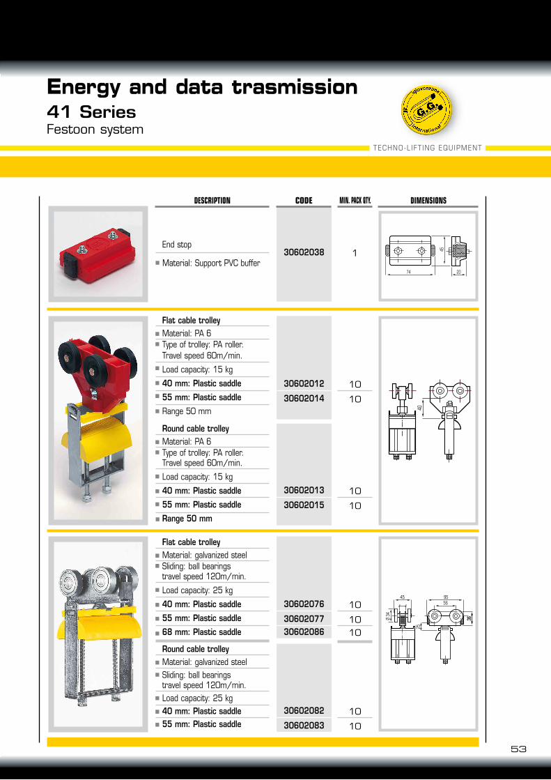
30602012
30602014
End stop
Material: Support PVC buffer
Flat cable trolleyMaterial: PA 6Type of trolley: PA roller.Travel speed 60m/min.
Load capacity: 15 kg
40 mm: Plastic saddle
55 mm: Plastic saddle
Range 50 mm
10
10
30602013
30602015
Round cable trolleyMaterial: PA 6Type of trolley: PA roller.Travel speed 60m/min.
Load capacity: 15 kg
40 mm: Plastic saddle
55 mm: Plastic saddle
Range 50 mm
Ø 34
954556
3636
25
10
1010
30602076
3060207730602086
Flat cable trolleyMaterial: galvanized steelSliding: ball bearingstravel speed 120m/min.
Load capacity: 25 kg
40 mm: Plastic saddle
55 mm: Plastic saddle
68 mm: Plastic saddle
10
10
30602082
30602083
Round cable trolleyMaterial: galvanized steelSliding: ball bearingstravel speed 120m/min.Load capacity: 25 kg40 mm: Plastic saddle55 mm: Plastic saddle
130602038
End clamp
Material: PA 6 andgalvanized steel
Load capacity: 15 kg
40 mm Plastic saddle
55 mm Plastic saddle
68 mm Plastic saddle
Range 50 mm
54
Energy and data trasmission41 SeriesFestoon system
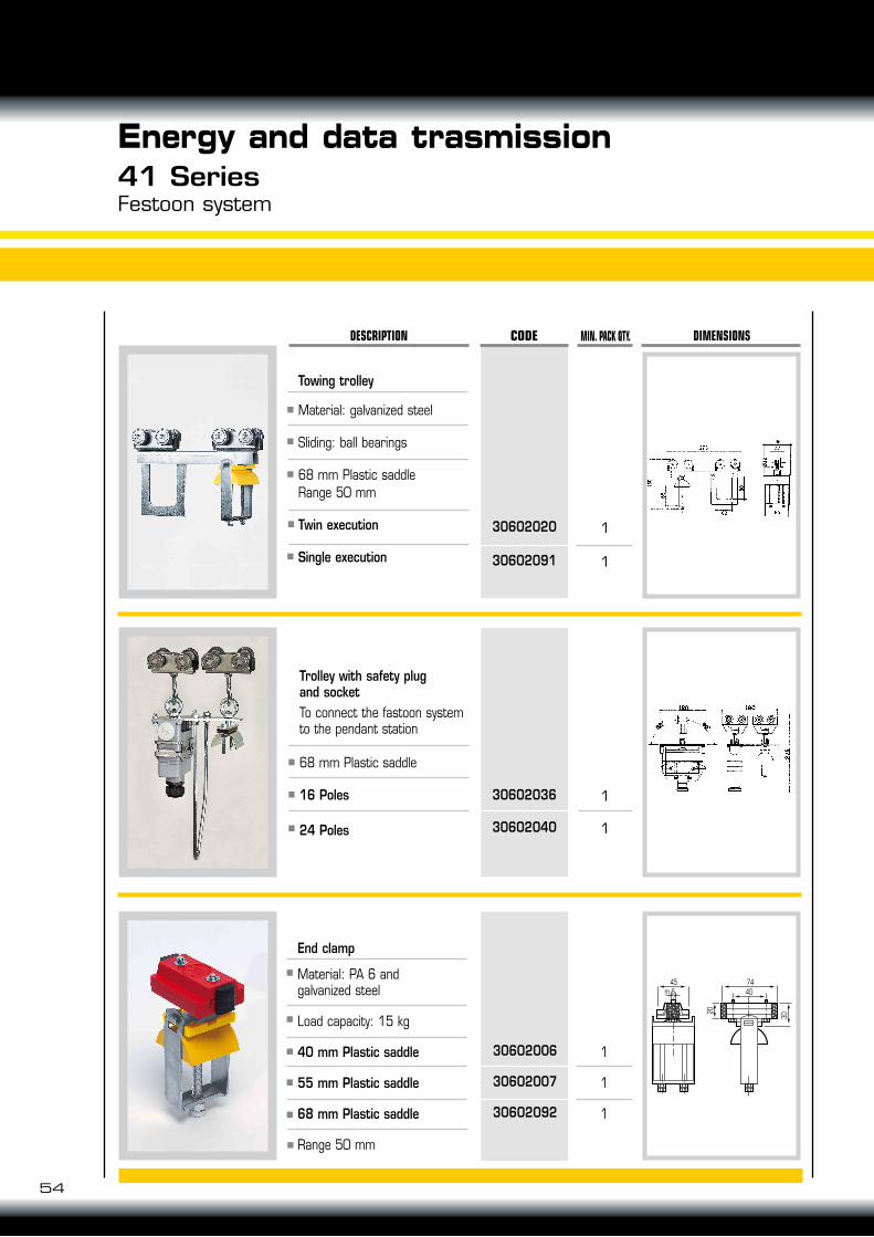
30602006
30602007
30602092
1
1
CODE MIN. PACK QTY. DIMENSIONSDESCRIPTION
30602020
30602091
1
1
30602036
30602040
45m 6
7440
30
20
Towing trolley
Material: galvanized steel
Sliding: ball bearings
68 mm Plastic saddleRange 50 mm
Twin execution
Single execution
Trolley with safety plugand socketTo connect the fastoon system to the pendant station
68 mm Plastic saddle
16 Poles
24 Poles
1
1
1
55
56
18
7
1820
39
1.5
CODE MIN. PACK QTY. DIMENSIONSDESCRIPTION
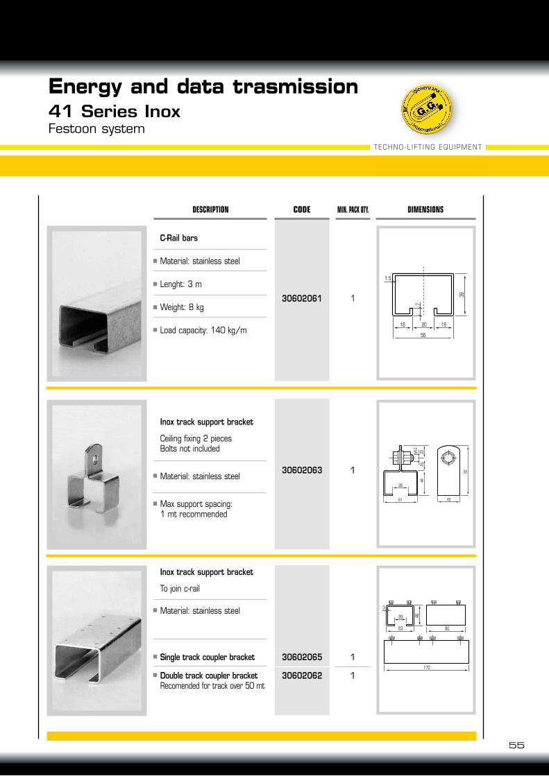
30602061 1
C-Rail bars
Material: stainless steel
Lenght: 3 m
Weight: 8 kg
Load capacity: 140 kg/m
130602063
Inox track support bracket
Ceiling fixing 2 piecesBolts not included
Material: stainless steel
Max support spacing:1 mt recommended
1
1
30602065
30602062
Inox track support bracket
To join c-rail
Material: stainless steel
Single track coupler bracket
Double track coupler bracketRecomended for track over 50 mt
90
61
28
40
4423
23M12
170
63 80
28
3
46
TECHNO-LIFT ING EQUIPMENT
Energy and data trasmission41 Series InoxFestoon system
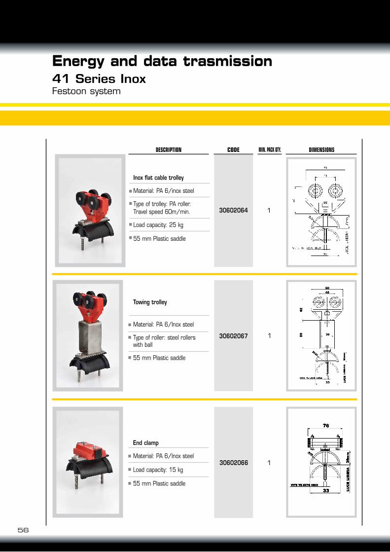
End clamp
Material: PA 6/Inox steel
Load capacity: 15 kg
55 mm Plastic saddle
56
Energy and data trasmission41 Series InoxFestoon system
30602066
1
CODE MIN. PACK QTY. DIMENSIONSDESCRIPTION
30602064
130602067
Inox flat cable trolley
Material: PA 6/inox steel
Type of trolley: PA roller.Travel speed 60m/min.
Load capacity: 25 kg
55 mm Plastic saddle
Towing trolley
Material: PA 6/Inox steel
Type of roller: steel rollerswith ball
55 mm Plastic saddle
1
One roller trolley
Material: PA6 and galvanized steel
Type of roller: PA roller
Rotating 40 mm plastic saddle
Range 50 mm
57
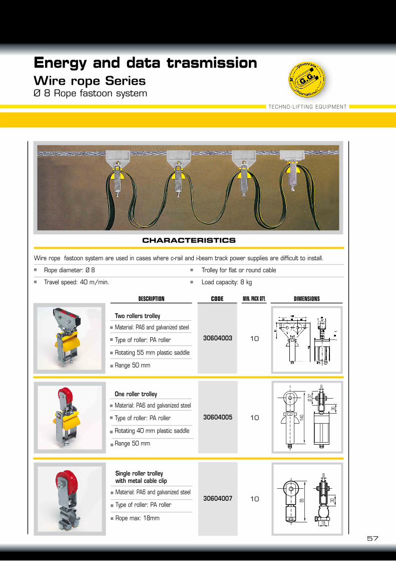
Energy and data trasmissionWire rope SeriesØ 8 Rope fastoon system
10
CODE MIN. PACK QTY. DIMENSIONSDESCRIPTION
30604003
Two rollers trolley
Material: PA6 and galvanized steel
Type of roller: PA roller
Rotating 55 mm plastic saddle
Range 50 mm
10 140
30
Ø 37
8
30604005
1030604007
Single roller trolleywith metal cable clip
Material: PA6 and galvanized steel
Type of roller: PA roller
Rope max: 18mm
3095
8
18
CHARACTERISTICS
Wire rope fastoon system are used in cases where c-rail and i-beam track power supplies are difficult to install.
Rope diameter: Ø 8 Trolley for flat or round cable
Travel speed: 40 m/min. Load capacity: 8 kg
TECHNO-LIFT ING EQUIPMENT
853060600530606105
Seddle mmPA RollersSteel rollers
BEAM IPE 80
150
70
150
102A
100R 80
IPN 80TROLLEY
553060600330606103
853060600630606106
553060600430606104
853060601330606113
Seddle mmPA RollersSteel rollers
BEAM IPE 100 IPN 10055
3060601130606111
853060601430606114
553060601230606112
853060603530606135
Seddle mmPA RollersSteel rollers
BEAM IPE 80 IPN 80TOWING TROLLEY
553060603330606133
853060603630606136
553060603430606134
85
30606063
Saddle mm
Code
BEAM IPE 80 - IPN80 IPE 100 - IPN 100
END CLAMP
55
30606062
85
30606067
55
30606066
853060604330606143
Seddle mmPA RollersSteel rollers
BEAM IPE 100 IPN 10055
3060604130606141
853060604430606144
553060604230606142
IPE 80 A=46+4IPN 80 A=42+4IPE 100 A=55+4IPN 100 A=50+4
IPE 80 A=46+4IPN 80 A=42+4IPE 100 A=55+4IPN 100 A=50+4
Saddle mm
Saddle mm
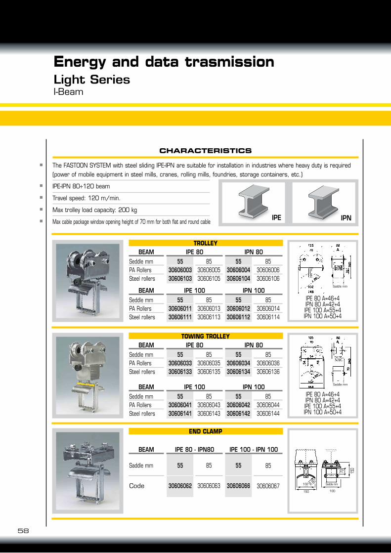
The FASTOON SYSTEM with steel sliding IPE-IPN are suitable for installation in industries where heavy duty is required (power of mobile equipment in steel mills, cranes, rolling mills, foundries, storage containers, etc.)
IPE-IPN 80÷120 beam
Travel speed: 120 m/min.
Max trolley load capacity: 200 kg
Max cable package window opening height of 70 mm for both flat and round cable
Energy and data trasmissionLight SeriesI-Beam
CHARACTERISTICS
IPNIPE
Saddle mm
100150
102
58
59
TECHNO-LIFT ING EQUIPMENT
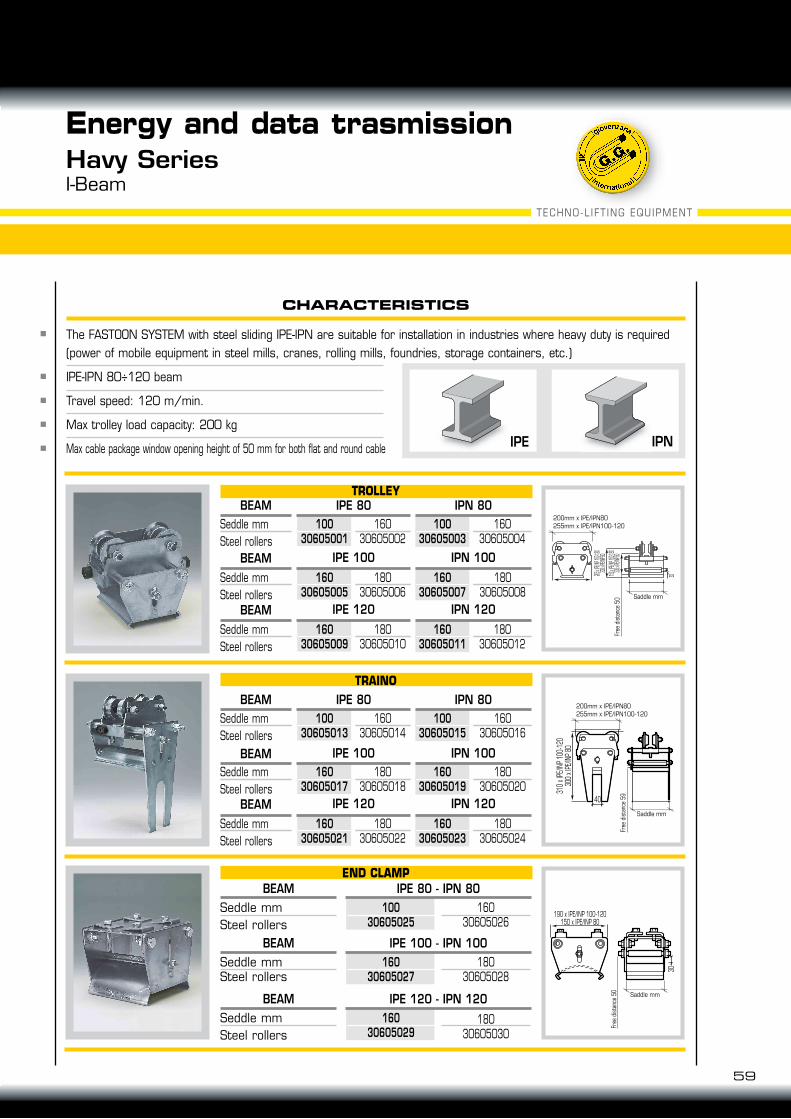
The FASTOON SYSTEM with steel sliding IPE-IPN are suitable for installation in industries where heavy duty is required (power of mobile equipment in steel mills, cranes, rolling mills, foundries, storage containers, etc.)
IPE-IPN 80÷120 beam
Travel speed: 120 m/min.
Max trolley load capacity: 200 kg
Max cable package window opening height of 50 mm for both flat and round cable IPNIPE
Energy and data trasmissionHavy SeriesI-Beam
16030605002
Seddle mmSteel rollers
BEAM IPE 80
190 x IPE/INP 100-120150 x IPE/INP 80
30
CHARACTERISTICS
205 x IP
E/INP 10
0-120
300 x IP
E/INP 80
150 x IP
E/INP 10
0-120
300 x IP
E/INP 80
30
255 x IPE/INP 100-120200 x IPE/INP 80
310
x IPE
/INP 1
00-1
2030
0 x I
PE/IN
P 80
40
30
IPN 80TROLLEY
10030605001
16030605004
10030605003
18030605006
Seddle mmSteel rollers
BEAM IPE 100 IPN 100
16030605005
18030605008
16030605007
18030605010
Seddle mmSteel rollers
BEAM IPE 120 IPN 120
16030605009
18030605012
16030605011
16030605014
Seddle mmSteel rollers
BEAM IPE 80 IPN 80100
30605013160
30605016100
30605015
18030605018
Seddle mmSteel rollers
BEAM IPE 100 IPN 100160
30605017180
30605020160
30605019
18030605022
Seddle mmSteel rollers
BEAM IPE 120 IPN 120
16030605021
18030605024
16030605023
TRAINO
16030605026
Seddle mmSteel rollers
END CLAMPBEAM IPE 80 - IPN 80
10030605025
18030605028
Seddle mmSteel rollers
BEAM IPE 100 - IPN 100160
30605027
18030605030
Seddle mmSteel rollers
BEAM IPE 120 - IPN 120160
30605029
Saddle mm
200mm x IPE/IPN80255mm x IPE/IPN100-120
Free
dist
ance
50
Saddle mm
200mm x IPE/IPN80255mm x IPE/IPN100-120
Free
dist
ance
59
Saddle mm
Free
dist
ance
50
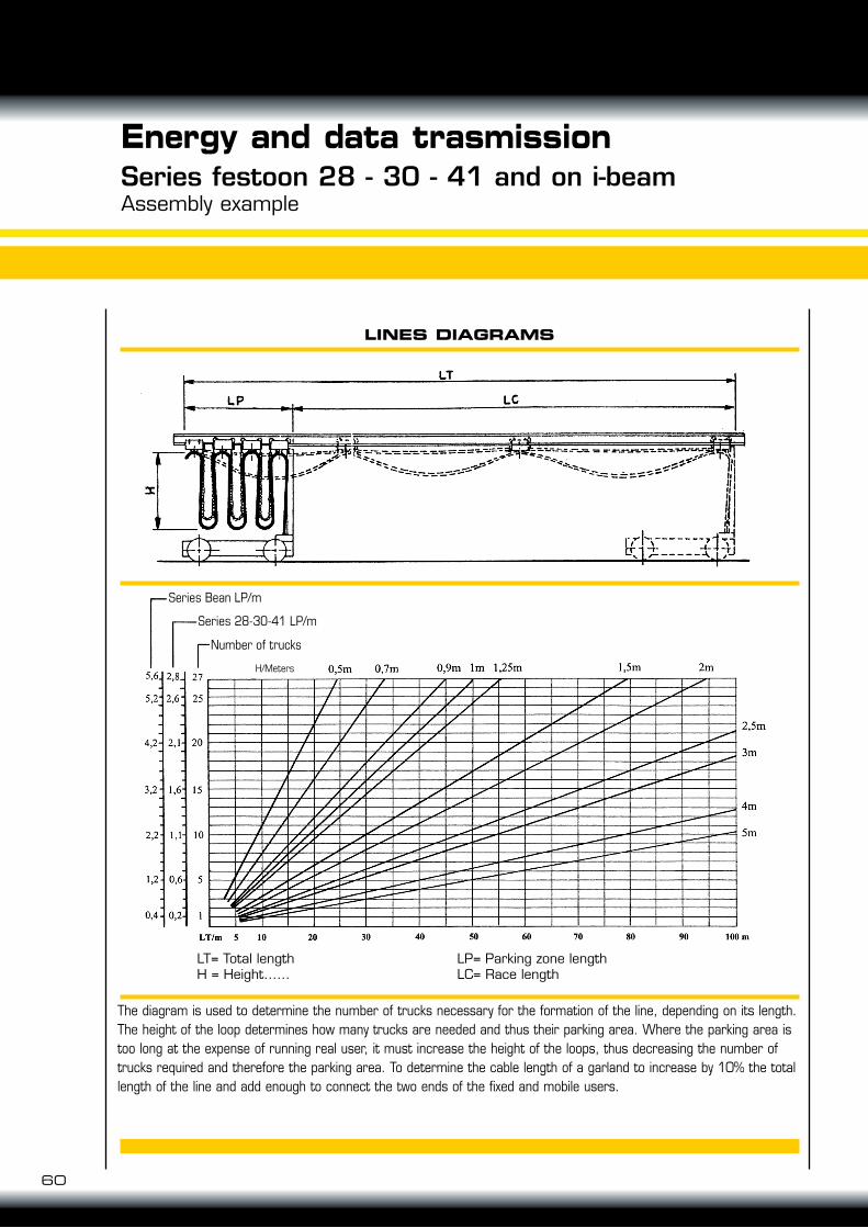
The diagram is used to determine the number of trucks necessary for the formation of the line, depending on its length. The height of the loop determines how many trucks are needed and thus their parking area. Where the parking area is too long at the expense of running real user, it must increase the height of the loops, thus decreasing the number of trucks required and therefore the parking area. To determine the cable length of a garland to increase by 10% the total length of the line and add enough to connect the two ends of the fixed and mobile users.
60
Energy and data trasmissionSeries festoon 28 - 30 - 41 and on i-beamAssembly example
LINES DIAGRAMS
LT= Total lengthH = Height……
LP= Parking zone lengthLC= Race length
Series Bean LP/m
Series 28-30-41 LP/m
Number of trucks
H/Meters
GENERAL CHARACTERISTICS
A
V
H2
kA
A
A
uL 94
CEI EN 60695-2-1. °C
°C
°C
m/min.1
mm2
Ω/m . 10 - 4
Ω/m . 10 - 4
Operating current 23°CComply with rulesRated operating voltage ueFrequencyConditional rated short circuit withstand currentFuse rating gGRated short-time current IcwProtection class CEI EN 60529:Standard executionExecution with rubberFlammabily resistence
Ambient temperature: operating storageAdmissible current collector trolley speedConductor CuResistenceImpedance
40
10
40
600
9.3
18,27
18,36
10
70
900
15,5
10,96
11,01
70
10
100
1400
21,7
7,83
7,87
10
160
1800
31
5,48
5,55
10
200
2500
46,5
3,65
3,67
100 140 200CEI EN 60439-1 e 2, CEI EN 60695-2-1., CEI EN 60570
600V ac
50 Hz
IP13
IP23
VO
960
- 30 + 55
- 30 + 70
200
61
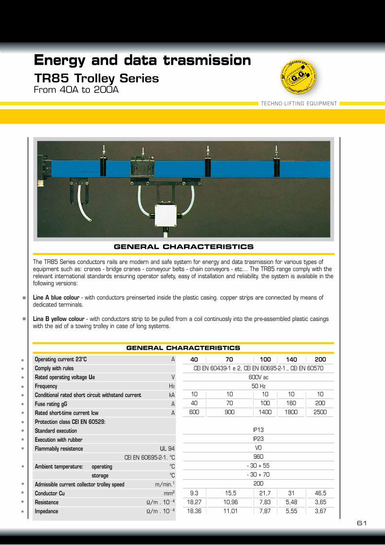
Energy and data trasmissionTR85 Trolley SeriesFrom 40A to 200A
GENERAL CHARACTERISTICS
The TR85 Series conductors rails are modern and safe system for energy and data trasmission for various types of equipment such as: cranes - bridge cranes - conveyour belts - chain conveyors - etc... The TR85 range comply with the relevant international standards ensuring operator safety, easy of installation and reliability. the system is available in the following versions:
Line A blue colour - with conductors preinserted inside the plastic casing. copper strips are connected by means of dedicated terminals.
Lina B yellow colour - with conductors strip to be pulled from a coil continuosly into the pre-assembled plastic casings with the aid of a towing trolley in case of long systems.
TECHNO-LIFT ING EQUIPMENT
L L
L/2
L/6 L/6
LL
L/2L/10 L/10
CALCULATION OF THE VOLTAGE DROP
RAIL TRACK LINES POWER
System with end power feed System with line power feed
Two power feed 1/6 from each end Three power feed at L/2 and L/6 from each end
Lt = L Lt = L/2
MaterialSelf-extinguishing
Ultimate tensile strenghtYield pointModulus of elasticityImpact resistanceDielectric strenghtSoftening temeperature - Vicat
UL 94
DIN 4102
D.M.6/7/83
ISO R527 23°C
ISO R527 23°C
ISO R178 23°C
DIN 53453
ASTM 149
ISO R306 49N
Rigid PVC
Lt = L With end power feed Lt = L/2 With line power feedLt = L/6 With power feed 1/6 at each endLt = L/10 With three power feed at L / 2 and L/10 from each end
V0
B2
CI
430 kg/cm3
460 kg/cm2
30000 kg/cm2
Unbroken25 kV/mm
82°C
4
5
N°CONDUCTORS
WEIGHT PER LINEAR METER/RANGECONDUCTORS BARS WEIGHT TABLE
1,680 kg/m
1,764 kg/m
1,902 kg/m
2,050 kg/m
40A2,122 kg/m
2,305 kg/m
3,010 kg/m
3,423 kg/m
2,454 kg/m
2,730 kg/m
100A 200A70A 140A
3 Phase AC WHEREΔu = Voltage drop (V)Δu % = Voltage drop (%)I = Intensity (A)Lt = Length of section (m) (m)Z = Impedance (Ω/m)U = Voltage (U)
Δu = √3 x I x Lt x Z
Δu % = Δu x 100 U
A proper disposal of power feed points allow voltage drop reduction.If L is the length of the line, Lt is thetrack maximum length to considerthe voltage drop.
Voltage drop should not exceed 5% of rated voltage under normal operating.
PVC RAIL TRACK CHARACTERISTICS
Lt = L/6 Lt = L/10
62
Energy and data trasmissionTR85 Trolley SeriesFrom 40A to 200A
63
TECHNO-LIFT ING EQUIPMENT
CURRENT IN CONTINUOUS SERVICE
Energy and data trasmissionTR85 Trolley SeriesLine construction
LINE CONSTRUCTION
To define the size of trolley line TR85, is necessary to consider:Maximum current in serviceDevices (motors cage, ring, resistors, electronic starters)Devices starting currents Maximum ambient temperatureThe distance between device and nearest power feedAdmissible voltage and voltage dropping in starting and continuous serviceType of currentDevices cycle operations (load factor)
Specify devices number which work simultaneously to calculate the corresponding current:
IN = I1 + I2 + ..In
The current can be determined from the devices power (w) that for a three-phase system is:
In the absence of information on the simultaneous devices operations, consider following table:
(*) To drag n parallel motors rated current In’, consider In = n In’
Current Consumption - AmperPower devices - WattsDevices performancesOperating voltage in voltsPower factor
In =
Ia = K In
In
Pu
Pu
φU
U
cos
φcos
η
η
3
In =
Ia = K In
In
Pu
Pu
φU
U
cos
φcos
η
η
3
LIFTING EQUIPMENTS IN USELifting numbers
devices online
1
2
3
4
5
no.2 lifting equipmentsoperating in contemporary
Engine max.power (*)
1st ENGINE
Power engine dicreasing (*)
4th ENGINE3rd ENGINE2nd ENGINE
xxxxx
x
xxxxx
x
xx
x
xxxx
x
STARTING CURRENT
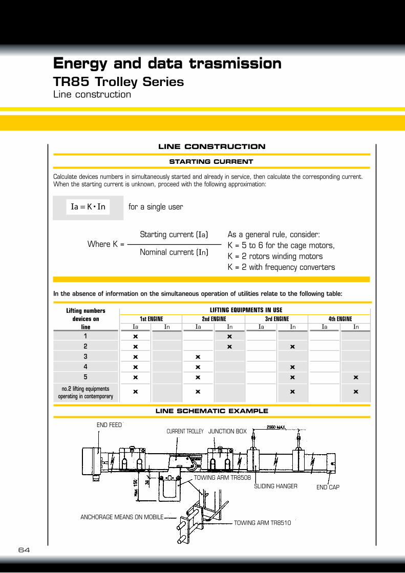
LINE SCHEMATIC EXAMPLE
Line construction
LINE CONSTRUCTION
Calculate devices numbers in simultaneously started and already in service, then calculate the corresponding current. When the starting current is unknown, proceed with the following approximation:
In the absence of information on the simultaneous operation of utilities relate to the following table:
for a single user
Where K =Starting current (Ia)
Nominal current (In)
As a general rule, consider:K = 5 to 6 for the cage motors,K = 2 rotors winding motorsK = 2 with frequency converters
64
Energy and data trasmissionTR85 Trolley Series
In =
Ia = K In
In
Pu
Pu
φU
U
cos
φcos
η
η
3
LIFTING EQUIPMENTS IN USELifting numbersdevices on
line1
2
3
4
5
no.2 lifting equipmentsoperating in contemporary
InIa1st ENGINE
InIa4th ENGINE
InIa3rd ENGINE
InIa2nd ENGINE
xxxxx
x
x
xx
x
x
x
xx
xxx
x
END FEED
TOWING ARM TR8510
END CAPSLIDING HANGERTOWING ARM TR8508
ANCHORAGE MEANS ON MOBILE
CURRENT TROLLEY JUNCTION BOX