encompass® 2 quick start guide (514.13 kb) - transcore
TRANSCRIPT

TransCore January 2012 411950-009
Driving inefficiencies out of surface transportation through innovative solutions
Quick Start Guide

Table of Contents
Start with Site Design .................................................................... 1 Determining Right Reader and Tag Combination .................... 1 Reader Placement .................................................................... 1 Tag Placement .......................................................................... 1 Site Layout, Lane Type, and Traffic Flow ................................. 2 Interfaces to External Loops, Gates or Converters .................. 2 Frequency Plan ......................................................................... 2 Causes of RF Interference or Poor Performance ..................... 3 Electrical and Communications Requirements ......................... 4
Pre-Installation Testing ................................................................. 4 Bench Testing the Reader ........................................................ 5
Installation at the Site .................................................................... 8 Correct Reader Grounding ....................................................... 9
Sense Input/Output Cabling Assignments .................................. 13 Reader Commands ..................................................................... 14 Common Problems – Potential “Gotchas” .................................. 17 More Troubleshooting ................................................................. 17
FCC Site Licensing Because Encompass® 2 Readers radiate more than 3 milliwatts of RF power, their use requires licensing under Federal Communications Commission (FCC) Section 90.239.
An FCC license provides the user with the legal authorization to operate the Encompass 2 Reader on the licensed frequencies at the site specified in the license. The FCC license also provides the user with protection and authorization to maintain the system should any other RFID product be used in the licensed area after the Encompass 2 Reader equipment is installed.
The site owner must complete and file form 601, FCC Application for Wireless Telecommunications Bureau Radio Service Authorization. Forms are available online at the FCC internet site http://www.fcc.gov/formpage.html.
The authorized frequency band for this product in the United States is 912.5 to 919 MHz. Only an authorized installer or service technician should set the RF frequency of the Encompass 2 Reader to the frequency specified in the FCC site license.
1
Only authorized TransCore Encompass® 2 Reader dealers, installers, or service personnel should attempt to install Encompass 2 Readers. Once the system is set up and tested by the authorized installer, Encompass 2 Reader operation requires no end-user intervention.
Start with Site Design You should develop your site plan BEFORE applying for FCC approval, ordering equipment, and installing the Encompass 2 Reader. Factors to be considered include tag type, reader and tag alignment, reader mounting requirements, site layout and traffic flow, and electrical and communications requirements. If your site configuration differs significantly from the recommendations below, contact your TransCore sales representative. Reader/tag choice and site planning is discussed in detail in the Encompass 2 Reader System Guides.
Determining Right Reader and Tag Combination What type of tags are you going to read? If eGo® or both eGo and ATA protocol, then the Encompass 2 Model 2110 is the correct reader to use. How are the tags formatted? Are they ASCII (full or half-frame) or Wiegand tag format? If Wiegand, then is it 26, 37, 54, or other bit configuration? This will determine the tag read mode for your reader. If an external antenna is required for increased signal strength, you should use the Encompass 2 Model 2210 or Model 2201.
Encompass 2 Reader Features Reader Model Protocol Wiegand Antenna
2101 eGo integrated 2110 eGo/ATA integrated 2201 eGo external 2210 eGo/ATA external
Reader Placement Encompass 2 Readers may be mounted on a pole at the side of the lane (side fire) or mounted on a gantry or surface extending over the center of the lane (overhead). You must position the Encompass 2 Reader Model 2110 and 2101, which contain internal antennas, or the antennas for the Model 2210 and 2201, so that the RF signal can travel to and return from the tags within the desired read area or “footprint.” Locate the reader where it is not likely to be bumped out of alignment. Encompass 2 Readers should not directly face each other or be positioned back-to-back.
Tag Placement Reader location determines tag placement in the windshield. Overhead readers require a center-mounted tag; readers on the side of the lane require that tags are placed on the nearest side of the windshield.

2
Site Layout, Lane Type, and Traffic Flow It is important to know the configuration of the site and its proximity to other sites in order to develop a correct site plan as well as a workable frequency plan. Will the lanes be AVI only, or will the lanes also have ticket machines, proximity readers, or other in-lane equipment? The number of lanes at the site, how they are grouped, and number of total entry and exit points determine the number of readers required and the distance between readers. You must determine the lane widths and the distance between adjacent lanes, taking into account any island/barrier width. TransCore recommends that, for the Encompass 2, the lane width with barrier be at least 12 feet.
Interfaces to External Loops, Gates or Converters For the best lane layout and transaction framing, the distance from the entry loop to the reader should normally be no more than about 8 feet with the distance from the reader to the gate arm not exceeding an additional 3 to 4 feet. In most cases, the reader will be positioned before the gate. With this defined read area (frame), it is very difficult for a non-tagged vehicle to sit in front of the gate and be admitted by a following car (the following car won’t be read). As well, if the first vehicle is valid, then subsequent vehicles will not be able to follow. If the read zone is much larger than the distance referenced above, then a following car may be read and allow a non-tagged vehicle to enter the facility. Bigger isn’t always better; in RFID systems, long range can create a problem. The readers are typically configured to be loop activated (on by presence) but may be set to have RF on continuously. The choice depends on traffic volume and possible interaction with the other in-lane components.
Frequency Plan The Encompass 2 Reader FCC-approved frequency band is 912.5 to 919MHz. Because of this relatively narrow frequency band, it requires careful planning to maintain the desired 2MHz frequency separation between adjacent readers. If readers are spread out within a facility (readers ½ mile or so apart), and loops are used, then frequencies may be reused. Special circumstances may necessitate use of multiplexers, especially in installations exceeding 20 readers. The illustration below shows frequency separation for 4 lanes.

3
Reader Frequencies Staggered for 14 Lanes
Lane Number Reader Frequency Lane Number Reader
Frequency 1 912.5 2 915 3 917.5 4 913.5 5 916 6 918.5 7 914.5 8 917 9 913 10 915.5
11 918 12 914 13 916.5 14 919
Causes of RF Interference or Poor Performance When designing your site plan, you must consider permanent structures and transient factors in the vicinity that may affect RF signals. Metal objects, walls, and even wet pavement or ice can reflect RF signals, degrading system performance. Interference from RF and electrical sources also can degrade system performance. Fluorescent lights, neon signs, nearby radio stations, or power lines can interfere with the optimal operation of the system. The magnetic impulse noise from relays that control gate opening and closing can also disrupt the RF signal. Existing interference at the site should be shielded, removed, or positioned further from the Encompass 2 Reader.
METAL GATE

4
Electrical and Communications Requirements Measured voltage at the Encompass 2 Reader MUST be at least 16V for proper operation. It is important to use TransCore approved transformers and cable lengths. TransCore does not endorse or support RF cable lengths greater than 35 feet. See the Encompass 2 Reader System Guides for detailed information. The reader is available as an RS–232 or RS–422 model. The proper configuration depends on the distance between the reader and the computer room. Maximum distance for the RS–232 (3-wire serial) is 50 feet, while RS–422 (4-wire differential signal) maximum distance is up to 4000 feet. You may adjust the baud rate to accommodate noisy environments. If you wish to use Wiegand format tags, you must first:
• Connect the Encompass 2 Reader using the RS–232 or RS–422 interface,
• Set all necessary operating parameters in the reader, • Set the Encompass 2 Reader’s configuration to Wiegand, • Then connect the Encompass 2 Reader to the Wiegand interface.
Pre-Installation Testing Once you have developed the site plan and frequency plan, you are ready to install the reader and perform pre-installation testing of Encompass 2 Reader output power and tag read capability. The Encompass 2 Reader System Guides discuss pre-installation testing in detail.
METAL GRATE
METAL SIGN
Possible Sources of RF Interference or Poor Performance • Metal fences, gates, posts, signs, grates • Wet or icy slopes • Walls, buildings • Curve at entrance • Gate relays • Reader incorrectly located
SLOPE
METAL GATE
SLOPE
CURVE
METAL POLE

5
Bench Testing the Reader To bench test your reader you need an audible circuit tester, a compatible power/communications cable, and a PC. A laptop using a terminal emulation program such as Microsoft HyperTerminal can be used for most diagnostic test and reader command entry. The Encompass 2 reader uses a single 26-pin (13 twisted pair) round Souriau connector to interface to all external components. Power, I/O interface, and communications signals are transmitted through this cable. The reader cable is directly connected to external devices or may be routed to other components via an external junction box.
1. Connect all hardware as directed below.
A. Connect the power wires from the cable to the transformer using the color coding as described below. (Do not apply power to transformer at this time.)
Power Connections
Colored-Wire Pair Use These Colors Connect to
Transformer Terminal Strip
Brown/Red Orange and Brown L1 (16 to 20V AC) Orange/Red Red and Red L2 (16 to 20V AC)
The Encompass 2 Reader system is powered by an 18V AC transformer. Normally, one 10 amp circuit will be sufficient for powering the reader and all associated electronics.
B. For the Encompass 2 Model 2210 or 2201, which require an external antenna, you must next connect the external antenna using an N-type connector. THE EXTERNAL ANTENNA MUST BE CONNECTED before powering up the Model 2210 or 2201.
C. Connect the red and white leads from the audible tester to the red and white pair of wires from the power/communications cable.
D. Connect the appropriate communications wires from the cable to an appropriate connector.
Refer to Correct Reader Grounding on page 9 when connecting power and communications.
RS–232 Interface
Colored Wire Pair User This Color Connect to Host DB9 Pin
Connect to Host DB25 Pin
Red/Black Black Pin 2 Pin 3 Red Pin 3 Pin 2
Yellow/Black Yellow or Black Pin 5 Pin 7

6
RS–422 Interface (Your host must have an RS–422 interface with either an internal or external
converter)
Colored Wire Pair Use This Color Connect to Host Signal
Yellow/Red Yellow Receive (+) Red Receive (-)
Red/Black Black Transmit (+) Red Transmit (-)
2. Start the terminal emulation application Microsoft HyperTerminal by selecting Programs>Accessories>Communications>HyperTerminal and pressing ENTER.
In the dialog boxes choose the com port to which the communications interface is attached and set the properties as follows:
• Bits per second: 9600 baud • Data bits: 8 • Parity: None • Stop bits: 1 • Flow control: None
3. Power up the reader by plugging the transformer into an approved outlet. Verify reader sign-on message appears on laptop/computer display
Once the reader has been wired up and turned on (with the laptop connected), a sign-on message will appear signifying that the reader is talking to the laptop. If startup is successful, the sign-on message appears as follows:
Model [software version] SNYYYYYY
[Copyright notice]
where YYYYYY is the serial number of the Encompass 2 Reader unit being used.
At this point, you can enter commands into the reader for testing, set up, and tuning.
4. Input proper commands in order to test the reader. Commands will include those to set the tag read mode and turn RF ON.

7
Testing Commands
Enter Reader Response What It Does
#01 <CR> #Done <CR/LF> Switches reader to command mode.
#470* #Done <CR/LF> Sets operational mode to Dual (1) - Read eATA data from Intellitag-based tags and read ATA tags
#40 #Done <CR/LF> Transmits all tag IDs without regard for uniqueness
#6401 #Done <CR/LF> Turns RF ON #00 <CR> #Done <CR/LF> Returns reader to data mode.
* Or the command for your tag read mode. See page 14.
5. If not using Wiegand tags, skip to Step 6. If using Wiegand tags, configure the reader for Wiegand operation and connect the Wiegand interface.
Wiegand Testing Commands
Enter Reader Response What It Does #01 <CR> #Done <CR/LF> Switches reader to command mode. #470 #Done <CR/LF> Sets operational mode #451 #Done <CR/LF> Switches reader to Wiegand mode #64011 #Done <CR/LF> Turns RF ON #00 <CR> #Done <CR/LF> Returns reader to data mode.
Wiegand Interface
Colored Wire Pair Use This Color Connect to data wire of Wiegand device
Blue/Red Blue Data0 Red Data1
Yellow/Black Yellow or Black Ground
6. Hold a tag in front of the reader and make sure its data is read out on the computer screen or on the Wiegand interface.
7. If desired, input the following commands to return reader to factory defaults.
Return to Factory Default Commands
Enter Reader Response What It Does #01 <CR> #Done <CR/LF> Switches reader to command mode.
#66F #Done <CR/LF> Loads all factory default operating parameters except operating frequency.
#00 <CR> #Done <CR/LF> Returns reader to data mode.

8
Installation at the Site After pre-installation testing, using the site plan and frequency plan previously developed, you are ready to install the reader on site.
1. Confirm the following:
• All construction is complete and electrical and communications cables of the appropriate length are in place.
• A watertight junction box with terminal strip is present. • A dedicated power supply of the appropriate voltage is present. • The placement of the readers follows the site plan. • The readers are the correct distance apart, side fire or overhead. Normally readers (or antennas) are installed either on the side of the lane, pointing into the lane (side fire) or directly over the lane, pointed downward (center fire or overhead).
Overhead installations normally are used within parking garages and other areas where a mounting surface already exists.
Side-fire installations normally are used where the lanes are out in the open and the installation of a pole is sufficient to mount a reader.
For side-fire reader placement, optimum tag placement is on the side of the windshield nearest the reader; for overhead reader placement, the optimum tag placement is in the upper center of the windshield.
2. Mount the reader on a round pole or flat surface.
Proper reader angle may require both up-down and right-left adjustment. Ensure that the correct wall-mount or pole-mount bracket is used in the reader installation.
For reliable reader operation, ensure that the reader is connected to Earth Ground. Do this by connecting the cable shield of the communications cable to Earth Ground. TransCore strongly recommends that you follow the National Electric Code for lightning protection for the locale where you are installing the Encompass 2 Reader.
3. Connect all wiring as described in Pre-Installation Testing Step 1 on page 5 using the appropriate RS–232 or RS–422 Wiring Diagram on pages 11 and 12 as a guide.
Also connect sense input and sense output circuits using the Sense Input/Output Cabling Assignments table on page 13 as a guide.

9
Correct Reader Grounding Ground the reader following the recommended grounding shown here.
Do not ground the input power supply.
4. Start the terminal emulation application Microsoft HyperTerminal by selecting Programs>Accessories>Communications>HyperTerminal and press ENTER as described in Pre-Installation Testing Step 2 on page 6.
5. Apply power and verify reader sign-on message appears on laptop/computer display as described in Pre-Installation Testing Step 3 on page 6.
6. Use reader commands to query status and set up the system to ensure the following:
• If multiple readers are used, ensure that the frequency separation between readers is sufficient and make sure that each reader is set up to the proper settings
• Adjust reader angle/power to optimize read zone for each reader. • Check for interference by each reader (or by the environment).

10
7. If using Wiegand tags configure the reader for Wiegand operation and connect the Wiegand interface. See Step 5 on page 7.
8. Disconnect the laptop and connect reader to back end devices and recheck read zone and for interference between readers.
9. System test the reader.
Once all in lane testing is complete, perform a system test using tagged vehicles passing through numerous lanes. The tag reads are sent to the back end system and evaluated for validity.

11

12

13
Sense Input/Output Cabling Assignments
Pair Pin Color Signal Description Typical Function Blue/ Red
E Blue WGND0 Wiegand data0 Parking/access control
F Red WGND1 Wiegand data1 Parking/access control
White/Red
L White Lock Tag lock output, active-closed
Testing maintenance
M Red Lock_RTN Tag lock return Testing maintenance Green/Red
N Green Sense Input0 Sense Input0 (loop)
Loop and presence detection
P Red Sense Input0_RTN
Sense Input0 return; not isolated from signal ground
Loop and presence detection
Blue/ Black
R Blue Sense Input1 Sense Input1 General-purpose sense input, not used for detecting presence
S Black Sense Input1_RTN
Sense Input1 return; not isolated from signal ground
General-purpose sense input, not used for detecting presence
Brown/Black
T Black Sense Output0_COM
Sense Output0 (tag detect), common terminal
Switched output to control gate
U Brown Sense Output0_NO
Sense Output0 normally open terminal
Switched output to control gate
Orange/Black
V Black Sense Output0_COM
Sense Output0 (tag detect output), common terminal
Switched sense output for any external control (light, gate, buzzer, etc.)
W Orange Sense Output0_NC
Sense Output0 normally closed terminal
Switched sense output for any external control (light, gate, buzzer, etc.)
Green/Black
X Black Sense Output1_ COM
Sense Output1, common terminal
Switched sense output
Y Green Sense Output1_NO
Sense Output1 normally open terminal
Switched sense output
White/Black
Z Black Sense Output1_ COM
Sense Output1, common terminal
Switched sense output
a White Sense Output1_NC
Sense Output1 normally closed terminal
Switched sense output
Yellow/Black
b Yellow GND Logic ground Signal ground used with RS–232 and Wiegand
c Black GND Logic ground Signal ground used with RS–232 and Wiegand

14
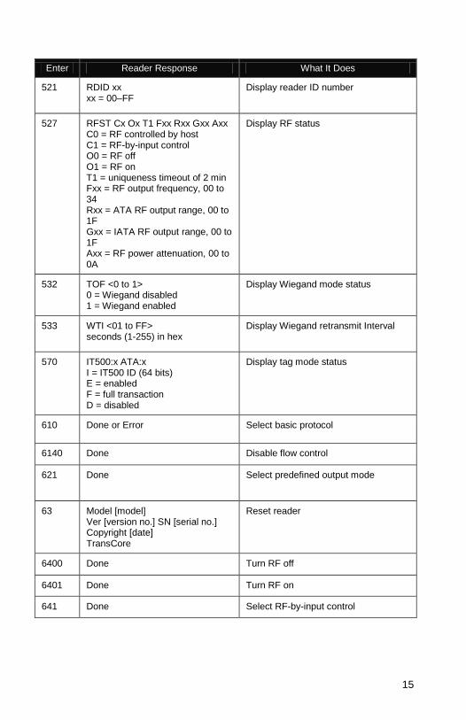
Reader Commands The following table provides the commands frequently used in testing, setting up, and tuning the Encompass 2 Reader. For a complete list of commands see the Encompass 2 Reader System Guides.
Frequently Used Reader Commands
Enter Reader Response What It Does
00 Done Returns reader to data mode.
01 Done Switches to command mode.
1005 Done or Error Set baud rate = 9600
1010 Done or Error Use one stop bit
1020 Done or Error Disable parity
40 Done Transmits all tag IDs without regard for uniqueness
450 Done Disable Wiegand mode
451 Done Enable Wiegand mode
452 Done Disable alternative group select
453 Done or Error Enable alternative group select
454 Done Disable multi-tag sort
455 Done or Error Enable multi-tag sort
46NN Done or Error Set Wiegand retransmit interval NN = 01–FF seconds
47N Done or Error Select tag mode N = 0–4 0 = Dual (1); eATA (128 bits) and ATA tags 1 = ATA tags only 2 = eATA ID only (64 bits) 3 = eATA (128 bits) tags only, default 4 = eATA ID (64 bits) and ATA tags 7 = eATA ID (64 bits) no EAC check
505 Model [model] Ver [version no.] SN [serial no.
Display version
520 PWRB Px R0 P0 = no power fail has occurred P1 = power fail has occurred
Display power fail bit
15
Enter Reader Response What It Does
521 RDID xx xx = 00–FF
Display reader ID number
527 RFST Cx Ox T1 Fxx Rxx Gxx Axx C0 = RF controlled by host C1 = RF-by-input control O0 = RF off O1 = RF on T1 = uniqueness timeout of 2 min Fxx = RF output frequency, 00 to 34 Rxx = ATA RF output range, 00 to 1F Gxx = IATA RF output range, 00 to 1F Axx = RF power attenuation, 00 to 0A
Display RF status
532 TOF <0 to 1> 0 = Wiegand disabled 1 = Wiegand enabled
Display Wiegand mode status
533 WTI <01 to FF> seconds (1-255) in hex
Display Wiegand retransmit Interval
570 IT500:x ATA:x I = IT500 ID (64 bits) E = enabled F = full transaction D = disabled
Display tag mode status
610 Done or Error Select basic protocol
6140 Done Disable flow control
621 Done Select predefined output mode
63 Model [model] Ver [version no.] SN [serial no.] Copyright [date] TransCore
Reset reader
6400 Done Turn RF off
6401 Done Turn RF on
641 Done Select RF-by-input control

16
Enter Reader Response What It Does
642NN (00 – 1F)
Done Set RF operating frequency
643NN (00 – 1F)
Done Set operating range for ATA protocol (distance); 00 = shortest
644NN (00 – 0A)
Done Set attenuation in 1.0 dB increments; 0 to 10 dB
645NN Done Set operating range for eGo protocol
66F Done or Error Load default operating parameters (except RF operating frequency)
693F Done Set RF timeout = infinite
Frequencies Approved for Use in the U.S.
Command Frequency in MHz
64215 912.5
64216 913
64217 913.5
64218 914
64219 914.5
6421A 915 (factory default)
6421B 915.5
6421C 916
6421D 916.5
6421E 917
6421F 917.5
64220 918
64221 918.5
64222 919

17
Common Problems – Potential “Gotchas” Frequency interference between readers Frequency interference may be caused by incorrect spacing and angle of readers, incorrect frequency assignment, objects or changes in the environment, incorrect RF power settings, etc. See pages 2, 3, and 4. Communications problems between the reader and backend host These problems may be caused by incorrectly wiring the communications cable, using the wrong cable, having a too-long cable run, or incorrectly setting communications parameters between host and reader. See pages 5, 6, and 7. Cable run for RS–232 exceeds 50 feet in length Fifty feet exceeds the maximum length for RS–232 interface. The interface should be converted to RS–422, wireless modem, fiber optic, or Wiegand. If in a noisy environment or running long cable lengths, you may need to reduce the baud rate. Long RF cable runs to antennas For the 22XX series Encompass 2 Readers, long RF cable runs between the reader and the antenna may cause signal degradation or loss. This scenario may be site-specific, but TransCore recommends limiting antenna cable runs to 35 feet. RF is not on The technician must verify that RF is on by presence or on continuously. Command # 527 may be used to verify RF status. See page 15.
Improper grounding Cable shielding should be connected to Earth Ground to prevent damage from lightning or power surges.
Mixed tag population In a mixed tag population, multiple tags in the same vehicle must be separated by at least 2 inches, preferably a greater distance. Reader not programmed correctly The technician must verify that all parameters are set appropriately for the reader location. Command # 527 may be used to verify reader parameters. If tags are Wiegand, the technician can use commands #532 and #533 to verify Wiegand status. Readers pointed towards each other Readers must not be “aimed” directly facing each other or be in close proximity back-to-back. See pages 1 through 4. Tag presentation Tags must be properly mounted in a location determined by the reader placement. See page 1. Tag-to-reader polarization Tag polarization must match reader polarization. Factory default is horizontal. For information about vertical operation, contact TransCore.
More Troubleshooting When performing a quick test of the Encompass 2 Reader, the buzz box does not buzz. Check all your wiring connections, and ensure that your buzz box is functioning. You could find more than one red wire, more than one black wire, and so on. You

18
must connect the correct red and white wire pair to the leads from the battery. Verify that RF is on (#6401). Verify that tag uniqueness is NOT on (#40). When testing the Encompass 2 Reader, all the wires are connected correctly but the unit does not respond. Check that the Encompass 2 Reader communication cable is connected to the correct COM port. Verify that the reader is in the correct tag read mode (#47N). Contact Technical Support. Strange signal responses come from the Encompass 2 Reader when tested with the PC. Ensure that the reader is in the correct interface mode for the test tag, i.e., Wiegand mode for a Wiegand tag. Nothing happens when the test tag is passed in front of the Encompass 2 Reader. Ensure that the Encompass 2 Reader is powered on and is in predefined output mode. (#621). Verify that the reader is in the correct tag read mode (#47N). Verify that the reader is set to RF ON (#6401). The Encompass 2 Reader came from another site and does not work the way the factory defaults indicate that it should. Different commands were probably used to support the other site. You can restore the defaults by issuing command #66F. The factory defaults will be restored except for RF operating frequency.

19
Notes

20
Notes

21

TransCore 8600 Jefferson Street NE Albuquerque, NM 87113
Two easy ways to contact us: • Call Dealer Technical Support at 505 856 8007 • Visit us on the Web at www.transcore.com
© 2006 TC License, Ltd. All rights reserved. TRANSCORE, EGO, and ENCOMPASS are registered trademarks of TC License, Ltd. All other trademarks listed are the property of their respective owners. Printed in the U.S.A.