encoder instructions xr685 smartsafetm
TRANSCRIPT
XR685 SMARTSafeTM
XR685 SMARTSafeTM
1
www.avtronencoders.com
Nidec Industrial Solutions 243 Tuxedo Avenue | Cleveland, Ohio 44131
+1 216-642-1230
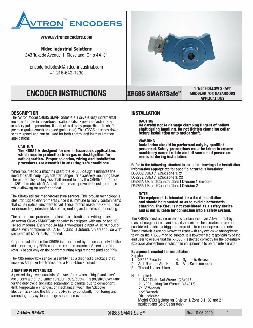
1 1/8” HOLLOW SHAFTMODULAR FOR HAZARDOUS
APPLICATIONSENCODER INSTRUCTIONS
Rev: 10-06-2020
DESCRIPTIONThe Avtron Model XR685 SMARTSafe™ is a severe duty incremental encoder for use in hazardous locations (also known as tachometer or rotary pulse generator). Its output is directly proportional to shaft position (pulse count) or speed (pulse rate). The XR685 operates down to zero speed and can be used for both control and instrumentation applications.
CAUTION The XR685 is designed for use in hazardous applications which require protection from gas or dust ignition for safe operation. Proper selection, wiring and installation procedures are essential to ensuring safe conditions.
When mounted to a machine shaft, the XR685 design eliminates the need for shaft couplings, adapter flanges, or accessory mounting faces. The unit employs a keyless shaft mount to lock the XR685’s rotor to a 1.125” diameter shaft. An anti-rotation arm prevents housing rotation while allowing for shaft end float.
The XR685 utilizes magnetoresistive sensors. This proven technology is ideal for rugged environments since it is immune to many contaminants that cause optical encoders to fail. These factors make the XR685 ideal for demanding industries like paper, metals, and chemical processing.
The outputs are protected against short circuits and wiring errors.An Avtron XR685 SMARTSafe encoder is equipped with one or two XR5 sensor modules. Each module has a two-phase output (A, B) 90° out of phase, with complements (A–, B–), (A Quad B Output). A marker pulse with complement (Z, Z–) is also present.
Output resolution on the XR685 is determined by the sensor only. Unlike older models, any PPRs can be mixed and matched. Selection of the rotor is based only on the shaft mounting requirements (and not PPR).
The XR5 removable sensor assembly has a diagnostic package that includes Adaptive Electronics and a Fault-Check output. ADAPTIVE ELECTRONICSA perfect duty cycle consists of a waveform whose “high” and “low” conditions are of the same duration (50%/50%). It is possible over time for the duty cycle and edge separation to change due to component drift, temperature changes, or mechanical wear. The Adaptive Electronics extend the life of the XR685 by constantly monitoring and correcting duty cycle and edge separation over time.
INSTALLATION
CAUTION Be careful not to damage clamping fingers of hollow shaft during handling. Do not tighten clamping collar before installation onto motor shaft.
WARNING Installation should be performed only by qualified personnel. Safety precautions must be taken to ensure machinery cannot rotate and all sources of power are removed during installation.
Refer to the following attached installation drawings for installation information appropriate for specific hazardous locations:D53008: ATEX / IECEx Zone 1, 21D52353: ATEX / IECEx Zone 2, 22D52354: US and Canada Class I Division 1 EncoderD52355: US and Canada Class I Division 2
NOTE: The equipment is intended for a fixed installation and should be mounted so as to avoid electrostatic charging. The XR45 is not considered as a safety device and is not suitable for connection into a safety system. The XR685 construction materials contain less than 7.5% in total by mass of magnesium, titanium and zirconium. These materials are not considered as able to trigger an explosion in normal operating modes. These materials are not known to react with any explosive atmospheres to which the XR685 may be subject. It is however the responsibility of the end user to ensure that the XR685 is selected correctly for the potentially explosive atmosphere in which the equipment is to be put into service.
Equipment needed for installation Supplied: 1. XR685 Encoder 4. Synthetic Grease 2. Anti-Rotation Arm Kit 5. Anti-Seize (copper) 3. Thread Locker (blue)
Not Supplied: 1-3/4” Clator Nut Wrench (484017) 2-1/2” Locking Nut Wrench (484018) 7/16” Wrench 1/2” Wrench Dial Indicator Model XRB3 Isolator for Division 1, Zone 0,1, 20 and 21 applications (Sold Separately)
XR685 SMARTSafeTM 2Rev: 10-06-2020
The hollow shaft XR685 design eliminates the potential for bearing and coupling failures from misalignment, however, excessive housing movement (wobble) may cause undesirable vibrations. The higher the RPM, the more severe the vibration will be from housing movement. In a typical installation a housing movement of 0.007” TIR or less (as measured at the outside diameter of the main encoder body) will not have an adverse effect.
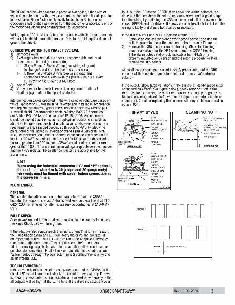
MACHINE SHAFT PREPARATIONPreparing the machine shaft prior to encoder installation is essential in providing an adequate barrier against environmental contamination. In some cases, a separate stub shaft (1.125” D x 4.5” long) will be installed on the motor. To prepare the machine shaft that the XR685 is to be installed on, conduct the following procedures (see figures):1) Remove from the XR685 the four 1/4-20 UNC machine screws which hold the end cap on the cover plate.2) Remove the end cap, O-Ring, and wave spring, noting the location of each to assist in re-assembly. Caution Spanner wrenches must be used during the following procedures. Using a substitute can distort the 1-3/4” nut and damage the unit. Do not try to remove the larger 2-1/2” bearing locknut at any time. This locknut is factory adjusted for optimum XR685 performance. NOTE Two spanner wrenches, which are required for XR685 installation, accommodate the 1-3/4” and 2-1/2” nuts found under the cap.
3) Holding the 2-1/2” bearing locknut, remove the 1-3/4” dia. clamping nut and slide out the internal compression sleeve.4) Verify that the compression sleeve can be installed by hand on the shaft where the unit is to be installed. File any burrs that obstruct sleeve installation and lightly oil the shaft.5) If a keyway or flat exists on the shaft, provide a sealing medium, or true the shaft back to round using metal putty or equal.6) Return the compression sleeve to the XR685 hub.7) Thread the 1-3/4” clamping nut onto the XR685 by hand until resistance is felt. DO NOT TIGHTEN at this time. ENCODER INSTALLATIONInstalling the XR685 and Anti-Rotation Arm:1) The free end of the anti-rotation arm must be secured by the customer to a stationary member such as the floor or machine frame. Refer to “Anti-Rotation Arm Mount ing Guidelines” on the last page for general require ments.2) Based on the location of the stationary point and the guidelines on page 6, attach the 1/4” thick mount ing board to one of two places on the XR685. Use two 1/4-20 UNC by 3/4” long machine screws provided.3) Apply anti-seize (copper), provided, to machine shaft. A packet of silicone grease is provided to lubricate the following shaft seals: First, ALL XR685 types have an O-Ring inside their hollow shafts at the motor end. In addition, in THRU-SHAFT types, the clamping nut has an O-Ring on the inside, plus the outside of the clamping nut requires lubri cation for the radial lip seal per step 8b. Slide the XR685 onto the machine shaft, mounting the board first. Ideally, the XR685 housing will be 1/2” to 1” from the motor or machine housing, but this may vary depend ing on the machine profile and the anti-rotation arm clearance requirements. Consider shaft end float when positioning the XR685.4a) FOR END-of-SHAFT APPLICATIONS, place the XR685 3.38” to 4.13” onto the shaft. The end of the machine shaft must extend completely through the XR685 compression sleeve and be approximately flush with the end of the 1-3/4” clamping nut.4b) FOR THRU SHAFT APPLICATIONS, position the XR685 as required.
5) Attach free end of the anti-rotation arm to the 1/4” mounting board using the shoulder bolt provided.6) Remove 1-3/4” clamping nut and apply liquid thread locker to the threads. (Locktite grade 242, supplied, should be used in most applications.)7) Replace 1-3/4” clamping nut and tighten so the gap is less than or equal to 0.09”, as shown in CLAMPING NUT sketch (approx. 15-20 ft-lbs.), holding the 2-1/2” bearing locknut in place. Spanner wrenches are required for this operation.8a) FOR END-of-SHAFT INSTALLATIONS, replace the end cap with the wave spring (load ing spring) against the bearing and the O-ring located in the cap groove. Secure the end cap with the four 1/4-20 UNC machine screws pre viously re moved. Apply the thread locker to the screws when assembling.8b) FOR THRU SHAFT APPLICATIONS, prior to replacing the end cap per step 8a, apply a small amount of silicone grease (provided) to the seal surface on the 1-3/4” clamping nut. The radial lip seal in the end cap will seal on this surface.
ENVIRONMENTAL CONSIDERATIONSSpecial attention is to be given to conduit runs, interconnection wiring and NEMA type enclosure mounting. In those applications where ambient temperatures are controlled within 20° C and high humidity/washdown are not present, position the flexible conduit with a slight sag to prevent any condensation from entering the encoder via conduit.
In harsh environments, which include temperature extremes, high humidity, equipment washdown or atmosphere contamination, extra care is required. Follow these steps to reduce potential problems:1) Always mount connection points, conduit couplings, junction boxes, etc., lower than actual encoder.2) For washdown areas, shroud or otherwise cover the encoder to prevent direct water spray. Do not attach the shroud directly to the encoder.3) Keep conduit outputs and axis of rotation horizontal.4) Avtron recommends sealed and/or remote connector styles for these applications. These include options (A-J, M-N, R-T, W, Y).
ANTI-ROTATION ARM MOUNTING GUIDELINESThe anti-rotation arm stabilizes the encoder and keeps it from rotating as the machine shaft rotates. To get the best performance, minimize generator movement by following these anti-rotation arm mounting guidelines as closely as possible.1) Mount XR685 with conduit entry ports positioned horizontally. 2) Fasten the 1/4” thick mounting board to the inboard side of the XR685 in one of the two positions shown. Use the two 1/4-20 UNC x 3/4” long fasteners.3) Mount anti-rotation arm perpendicular to motor shaft axis of rotation. Arm mounting bolts and associated rod bearings should be parallel to motor shaft also (top view).4) Mount anti-rotation arm approx. 90° to a line established between the mounting board mounting hole and shaft centerline (viewed from end).5) Mount XR685 as close as possible to the motor with the mounting board closest to the motor.6) Establish a stationary (static) mounting point for the free end of the anti-rotation arm, using the guidelines above. Use the bolt provided to fasten arm to stationary point.7) The anti-rotation arm is fully threaded and can be adjusted in length. The recommended length is 8 to 12”.
WIRING INSTRUCTIONS Refer to the attached installation drawings referenced above for wiring diagrams. Use the drawing appropriate for the encoder’s installation location. Information on specific connector pin-outs and phasing can be found on labels on the encoders and in the tables included in these instructions.
XR685 SMARTSafeTM 3Rev: 10-06-2020
The XR685 can be wired for single phase or two phase, either with or without complements, with or without markers. For bidirectional operation, in most cases Phase A channel typically leads phase B channel for clockwise shaft rotation as viewed from the anti-drive or accessory end of the motor. See pinout and phasing tables for exceptions.
Wiring option “G” provides a pinout compatible with Northstar encoders, with a cable shield connection on pin 10. Note that this option does not ground the shield.
CORRECTIVE ACTION FOR PHASE REVERSAL1) Remove Power. 2) Exchange wires on cable, either at encoder cable end, or at speed controller end (but not both). a) Single Ended 2 Phase Wiring (see wiring diagram) Exchange A and B at the use end of the wires. b) Differential 2 Phase Wiring (see wiring diagram) Exchange either A with A– in the phase A pair OR B with B– in the phase B pair but NOT both. 3) Apply Power. 4) Verify encoder feedback is correct, using hand rotation of shaft, or jog mode of the speed controller.
Interconnection cables specified in the wire selection chart are based on typical applications. Cable must be selected and installed in accordance with regional standards. Typical interconnection cable is 4 twisted pair + overall shield. Recommended cable is Avtron B37178. Alternates are Belden P/N 1064A or Rockbestos 04P-18 I/S-OS. Actual cables should be picked based on specific application requirements such as abrasion, temperature, tensile strength, solvents, etc. General electrical requirements are: stranded copper, 20 through 16 AWG, twisted wire pairs, braid or foil individual shields or over-all shield with drain wire, .03uF of maximum total mutual or direct capacitance and outer sheath insulator. 20 AWG wire should not be used for DC power to the encoder for runs greater than 200 feet and 22AWG should not be used for runs greater than 100 ft. This is to minimize voltage drop between the encoder and the XRB3 isolator. The smaller conductors are acceptable for the signal lines.
NOTE When using the industrial connector (“G” and “P” options), the minimum wire size is 20 gauge, and 20 gauge (only) wire ends must be tinned with solder before connection at the screw terminals.
MAINTENANCE
GENERALThis section describes routine maintenance for the Avtron XR685 Encoder. For support, contact Avtron’s field service department at 216-642-1230. For emergency after hours service contact us at 216-641-8317.
FAULT-CHECKAfter power-up and the internal rotor position is checked by the sensor, the Fault-Check LED will turn green.
If the adaptive electronics reach their adjustment limit for any reason, the Fault-Check alarm and LED will notify the drive and operator of an impending failure. The LED will turn red if the Adaptive Electronics reach their adjustment limit. This output occurs before an actual failure, allowing steps to be taken to replace the unit before it causes unscheduled downtime. Fault-Check annunciation is available as an “alarm” output through the connector (zone 2 configurations only) and as an integral LED.
TROUBLESHOOTING:If the drive indicates a loss of encoder/tach fault and the XR685 fault-check LED is not illuminated, check the encoder power supply. If power is present, check polarity: one indicator of reversed power supply is that all outputs will be high at the same time. If the drive indicates encoder
fault, but the LED shows GREEN, then check the wiring between the drive and the encoder. If the wiring appears correct and in good shape, test the wiring by replacing the XR5 sensor module. If the new module shows GREEN, and the drive still shows encoder loss/tach fault, then the wiring is faulty and should be repaired or replaced.
If the alarm output and/or LED indicate a fault (RED):1. Remove an end sensor plate or the second sensor, and use the built-in gauge to check the location of the rotor (see Figure 1). 2. Remove the XR5 sensor from the housing. Clean the hous ing mounting surface for the XR5 sensor and the XR685 hous ing. If the alarm output and/or LED indicate a fault (RED) on a prop erly mounted XR5 sensor and the rotor is properly located, replace the XR5 sensor.
An oscilloscope can also be used to verify proper output of the XR5 encoder at the encoder connector itself and at the drive/controller cabinet.
If the outputs show large variations in the signals at steady speed (jitter or “accordion effect”, See figure below), check rotor position. If the rotor position is correct, the motor or shaft may be highly magnetized. Replace any magnetized shafts with non-magnetic material (stainless/aluminum). Consider replacing the sensors with super-shielded models, option -004.
THRU SHAFT
STUB SHAFT
COMPRESSIONSLEEVE
COMPRESSIONSLEEVE
WAVE SPRING
O-RING
MACHINETHRU SHAFT
END CAP
RADIAL LIP SEAL
MACHINESTUB SHAFT
O-RING
WAVE SPRING2 1/2" DIABEARING LOCKNUT
1 3/4" DIACLAMPING NUT
END CAP
1/4-20 MACH SCREW
1 3/4" DIA CLAMPING NUT
2 1/2" DIABEARING LOCKNUT
1/4-20 MACH SCREW
WHEN PROPERLY ASSEMBLED, THIS GAP WILL BE LESS THAN 0.09".
MOTOR SHAFT
1 3/4" CLAMPING NUT
2 1/2" BEARING LOCKNUTDO NOT ADJUST
VARIATION > ± 15%
PHASE A
PHASE B
SHAFT STYLE
shaft-style
CLAMPING NUT
clamping-nut

XR685 SMARTSafeTM 4Rev: 10-06-2020
XR685 PART NUMBERS AND AVAILABLE OPTIONS INCLUDING AV5 SENSORS
Model Temp Rating Tether Style Left Module Right Module Connector Options
Modifi-cationsLine Driver PPR Line Driver PPR
XR685 N- -20°C to 80°CC- -40°C to 80°C
X- none1- B21958 threaded rod
E- standard (EOS)T- through shaft
See Line Driver / Connector Options Chart
See Line Driver / Connector Options Chart
See Line Driver / Connector Options Chart
000- none004- Super Magnetic Shielding005- Special 97mm Rotor 400- Special PPR (see table) 018- Includes isolator900- Special Cable Length (xx=ff/0.3m)
X- noneC*- 50F- 60G- 100H- 120A- 128B*- 150L- 240N- 256P- 300E- 360B- 480Q- 500R- 512S- 600V- 900J- 960
Y- 1024Z- 1200A*- 12706- 1800 3- 20004- 20485- 2500D- 40968- 48009- 50000-special
X- noneF- 60G- 100H- 120A- 128L- 240N- 256P- 300E- 360B- 480Q- 500R- 512S- 600V- 900J- 960Y- 1024Z- 1200
6- 18003- 20004- 20485- 2500D- 40968- 48009- 50000- special
Spare sensors and accessories can be ordered separately. See Table 2.
SPECIAL PPR OPTION CODES
OPTION CODE LEFT PPR RIGHT PPR
401 1270 None
402 150 None
403 50 None
404 512 16
405 16 None
406 6000 None
XR5 Sensor Part Numbers
Model Line Driver PPR Connector Options Modifications
XR5- See Line Driver Connection Option Chart
See Line Driver Connection Option Chart
000- none004- Super Magnetic Shielding005- Special 97mm Rotor (see special manual) 4xx- Special PPR (see table)9xx- Special Cable Length (xx=ff/0.3m)
X- noneF- 60G- 100H- 120A- 128L- 240N- 256P- 300E- 360B- 480Q- 500R- 512
S- 600V- 900J- 960Y- 1024Z- 12003- 20004- 20485- 2500D- 40968- 48009- 50000-special
XR685 SMARTSafeTM 5Rev: 10-06-2020
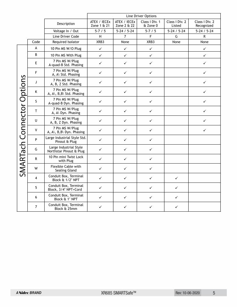
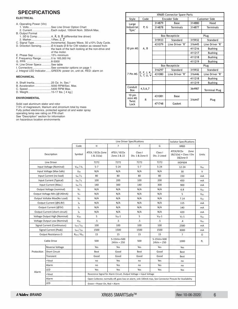
Line Driver Options
Description ATEX / IECEx Zone 1 & 21
ATEX / IECEx Zone 2 & 22
Class I Div. 1 & Zone 0
Class I Div. 2 Listed
Class I Div. 2 Recognized
Voltage In / Out 5-7 / 5 5-24 / 5-24 5-7 / 5 5-24 / 5-24 5-24 / 5-24
Line Driver Code H 7 F G R
Code Required Isolator XRB3 None XRB3 None None
A 10 Pin MS W/O Plug
B 10 Pin MS With Plug
E 7 Pin MS W/Plug A-quad-B Std. Phasing
F 7 Pin MS W/Plug A, A\ Std. Phasing
J 7 Pin MS W/Plug A, B, Z Std. Phasing
K 7 Pin MS W/Plug A, A\, B,B\ Std. Phasing
S 7 Pin MS W/Plug A-quad-B Dyn. Phasing
T 7 Pin MS W/Plug A, A\ Dyn. Phasing
U 7 Pin MS W/Plug A, B, Z Dyn. Phasing
V 7 Pin MS W/Plug A, A\, B,B\ Dyn. Phasing
P Large Industrial Style Std. Pinout & Plug
G Large Industrial Style Northstar Pinout & Plug
R 10 Pin mini Twist Lock with Plug
W Flexible Cable with Sealing Gland
4 Conduit Box, Terminal Block & 1/2" NPT
5 Conduit Box, Terminal Block, 3/4" NPT+Cord
6 Conduit Box, Terminal Block & 1" NPT
7 Conduit Box, Terminal Block & 25mm
SMA
RTac
h Co
nnec
tor O
ptio
ns
XR685 SMARTSafeTM 6Rev: 10-06-2020
SPECIFICATIONSELECTRICAL
A. Operating Power (Vin) 1. Volts .............................See Line Driver Option Chart 2. Current .........................Each output, 100mA Nom. 355mA Max. B. Output Format 1. 2Ø & Comp ..................A, , B, (differential line driver) 2. Marker ..........................1/Rev, Z, C. Signal Type ......................Incremental, Square Wave, 50 ±10% Duty Cycle. D. Direction Sensing.............Ø A leads Ø B for CW rotation as viewed from ................................. the back of the tach looking at the non-drive end ................................. of the motor. E. Phase Sep .......................15% minimum F. Frequency Range .............0 to 165,000 Hz G. PPR ................................8-5000 H. Line Driver Specs ............See table I. Connectors ........................See connector options on page 1 J. Integral LED Indicator .......GREEN: power on, unit ok. RED: alarm on
MECHANICAL
A. Shaft Inertia......................25 Oz. In. Sec.2 B. Acceleration .....................5000 RPM/Sec. Max. C. Speed ..............................5400 RPM Max. D. Weight ..............................15-17 lbs. [ 4 kg.]
ENVIRONMENTAL
Solid cast aluminum stator and rotor 7.5% of magnesium, titanium and zirconium total by mass Fully potted electronics, protected against oil and water spray operating temp see rating on P/N chart See “Description” section for information on hazardous location environments
XR685 Connector Spare Parts
Style Code Encoder Side Customer Side
Large Industrial
"Epic"P, G
314879 Base 314880 Hood
314878 Terminals 314877 Terminals
10 pin MS A, B
Box Recepticle Plug
315933 Standard 315932 Standard
431079 Line Driver "R" 316445 Line Driver "R"
411216 Bushing
411217 Bushing
411218 Bushing
411219 Bushing
7 Pin MS E, F, J, K, S, T, U, V
Box Recepticle Plug
316297 Standard 315932 Standard
431080 Line Driver "R" 316446 Line Driver "R"
411218 Bushing
411219 Bushing
Conduit Box 4,5,6,7 364987 Terminal Plug
10 pin mini MS Twist Lock
R431081 Base
316447 Plug471748 Gasket
XR685 SMARTSafeTM 7Rev: 10-06-2020
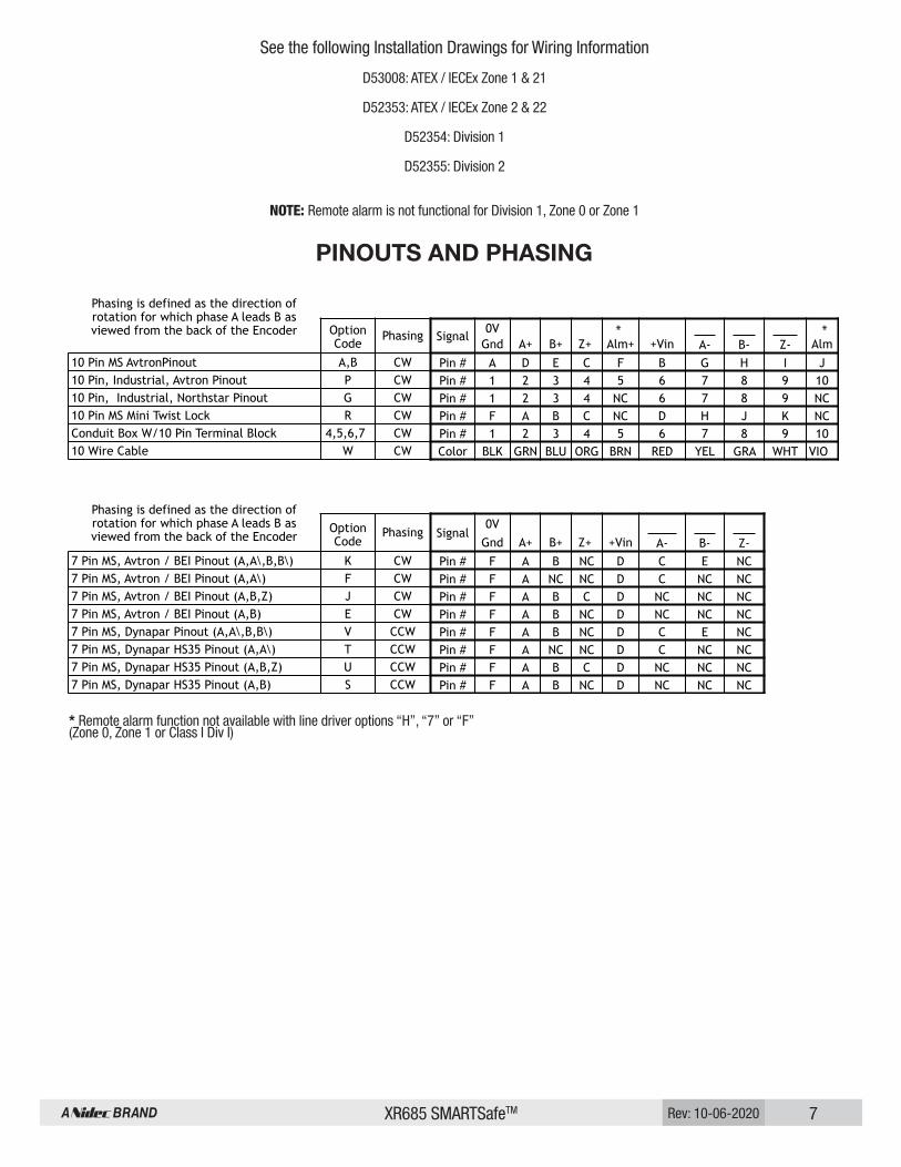
PINOUTS AND PHASING
Phasing is defined as the direction of rotation for which phase A leads B as viewed from the back of the Encoder Option
CodePhasing Signal
0VGnd A+ B+ Z+ Alm+ +Vin A- B- Z- Alm
10 Pin MS AvtronPinout A,B CW Pin # A D E C F B G H I J10 Pin, Industrial, Avtron Pinout P CW Pin # 1 2 3 4 5 6 7 8 9 1010 Pin, Industrial, Northstar Pinout G CW Pin # 1 2 3 4 NC 6 7 8 9 NC10 Pin MS Mini Twist Lock R CW Pin # F A B C NC D H J K NCConduit Box W/10 Pin Terminal Block 4,5,6,7 CW Pin # 1 2 3 4 5 6 7 8 9 1010 Wire Cable W CW Color BLK GRN BLU ORG BRN RED YEL GRA WHT VIO
Phasing is defined as the direction of rotation for which phase A leads B as viewed from the back of the Encoder
Option Code
Phasing Signal0V
Gnd A+ B+ Z+ +Vin A- B- Z-7 Pin MS, Avtron / BEI Pinout (A,A\,B,B\) K CW Pin # F A B NC D C E NC7 Pin MS, Avtron / BEI Pinout (A,A\) F CW Pin # F A NC NC D C NC NC7 Pin MS, Avtron / BEI Pinout (A,B,Z) J CW Pin # F A B C D NC NC NC7 Pin MS, Avtron / BEI Pinout (A,B) E CW Pin # F A B NC D NC NC NC7 Pin MS, Dynapar Pinout (A,A\,B,B\) V CCW Pin # F A B NC D C E NC7 Pin MS, Dynapar HS35 Pinout (A,A\) T CCW Pin # F A NC NC D C NC NC7 Pin MS, Dynapar HS35 Pinout (A,B,Z) U CCW Pin # F A B C D NC NC NC7 Pin MS, Dynapar HS35 Pinout (A,B) S CCW Pin # F A B NC D NC NC NC
* *
See the following Installation Drawings for Wiring Information
D53008: ATEX / IECEx Zone 1 & 21
D52353: ATEX / IECEx Zone 2 & 22
D52354: Division 1
D52355: Division 2
NOTE: Remote alarm is not functional for Division 1, Zone 0 or Zone 1
* Remote alarm function not available with line driver options “H”, “7” or “F” (Zone 0, Zone 1 or Class I Div I)

XR685 SMARTSafeTM 8Rev: 10-06-2020
BLACKRED
GREENYELLOWBLUEGRAYORANGEWHITE
BROWN
VIOLET
OUTPUT OPTIONS
94
510
2
837
61
IC
FJ
D
HEG
BA
IC
F
J
D
HEG
BA
Vcc
OUT
COM
300 OHMMIN.
GND
FUNCTION
ENCODER
ØB
ØAØA
ØB
SOLID STATE RELAY
Q5MMFT6661
LINEDRIVERNOTE 1
CR8 {FUNCTIONAL DIAGRAM
50 mA MAXIMUM
“W” “A”, “B”“P”, “4”, “5”
“6”, “7”
“A”, “B”“P”, “4”, “5”
“6”, “7”
MARKERMARKER COMPLEMENT
COMMON+V (Encoder Power)
{BLACKRED
GREENYELLOWBLUEGRAYORANGEWHITE
BROWN
VIOLET
OUTPUT OPTIONS
94
510
2
837
61
MARKERMARKER COMPLEMENT
GND
FUNCTION
+V (Encoder Power)
COMMON
*VDC+
-
POWERSUPP
*See note belowLY 115 VAC
SINK 100 mA MAXIMUM,Q5MMFT6661
ENCODERFUNCTIONAL DIAGRAM
ØB
ØAØA
ØB
LINEDRIVERNOTE 1
CR8
“W”
*See specifications for Zone 2 power supply limits
Example 2. Alarm Output Using Separate * VDC Power Supply and Relay.
Applies to all XR685 Zone 2 & Division 2models with wiring optons “W”, “P”, “4”, “5”, “6”, “7”, “A” and “B”. Remote alarm not available for Zone 0, Zone 1 or Division 1.
ALARM OUTPUT CONNECTION
Avtron encoders provide an alarm signal if maintenance is required under specific circumstances. An alarm LED indicator is also available. Green indicates power on, red indicates alarm on. Following are application examples provided to help install the alarm output. Example 1. Alarm output using +V(OUT). +V(OUT) is equal to +V, the encoder power supply.
THIN-LINE II™Application Examples
Vcc
OUT
COM
300 OHMMIN.
SOLID STATE RELAY

XR685 SMARTSafeTM 9Rev: 10-06-2020
Nidec Industrial Solutions | 243 Tuxedo Avenue | Cleveland, Ohio 44131 | [email protected]+1 216-642-1230 | www.avtronencoders.com
1.66 [42.2]
3.67 [93.2]ASSEMBLED
1.97 [50.0]
OPTION “B”CONNECTOR W/MATING PLUG
CONNECTOR ONLY10 PIN BULKHEAD
OPTION “A”
0.53 [13.5]
2.87 [72.9]
0.53 [13.5]
OPTION “R”10 PIN MINIATUREMS CONNECTOR
ASSEMBLED
XR685 ENCODER
ANTI-ROTATION ARM/TETHERINCLUDES ALL HARDWARE NECESSARY FOR MOUNTING ENCODER
4.66 [118.4]OPTIONAL 2nd ISOLATED OUTPUT
SINGLE OUTPUT ONLYCOVER PLATE
1/2-14 NPT
INDICATORLED ALARM
3.83 [97.3]OPTIONS “P”, “G”PLUG-IN INDUSTRIAL
CONNECTOR
3/8-16 UNC x 5/8 DEEP4 PLACES
�5.875 [�149.2]41°41°
HOLE FORØ1.122/1.125 [28.499/28.575]SHAFT
16° 16°
8.43 [214.0]
5.56 [
141.2
]
12.00 [304.80] MAX. LENGTH
90°
90°
4.00 [101.58]
OPTIONAL MOUNTINGPOSITION
ADJUSTABLEANTI-ROTATION
ARM
MOUNTING BOARD
5/16-24 X 1.25 (31.75)MOUNTING BOLT
TOP VIEW
INBOARD VIEW SIDE VIEW
0.67 [17.12]
1.51 [38.21]
OPTIONALTHRU SHAFTDESIGN ONLY
MOTOR
1.62 [41.1]3.28 [83.3] ASSEMBLED
1.85 [47.0]
0.53 [13.5]
OPTIONS “E”,“F”,“S”“K”,“S”,“T”,“U”&“V”
7 Pin MS CONNECTOR W/MATING PLUG
36.50 [927.0] MIN
OPTION “W”SEALED FLEXIBLE CABLE
1.94 [49.3]0.53 [13.5]
36.50 [927.0] MIN1.94 [49.3]
0.53 [13.5]
SEALED FLEXIBLE CABLEOPTION “S”
W/10 PIN MINIATURE
2.12 [53.8]ASSEMBLED
Features and specifications subject to change without notice.
Avtron standard warranty applies.All dimensions are in millimeters approx.
OUTLINE DRAWING
These instructions have been reviewed and the product evaluated as suitable for our application.
Company Name
Authorized Company Representative
Title Date

XR685 SMARTSafeTM 10Rev: 10-06-2020

XR685 SMARTSafeTM11 Rev: 10-06-2020

XR685 SMARTSafeTM 12Rev: 10-06-2020

XR685 SMARTSafeTM13 Rev: 10-06-2020
DWG. NO.REV
SCALEMODELSHEET
PSF
IMF
DATE DRAWN
ENG APVD
APVD PROD
NEXT ASSYUSED ON
REVISIONS
REVDESCRIPTIONDATEAPPROVED
UNLESS OTHERWISE SPECIFIEDDIMENSIONS ARE IN INCHES
TOLERANCES:DECIMALS .XX±.XXX±
APPLICATION UNLESS OTHERWISE SPECIFIED THE ABOVE NOTES APPLY
CAGE NO. SIZE
FINISH
CHECKED
D0FMV7
PAINT PER PS
PLATE PER
COAT PER PS
ANODIZED PER
OTHER
ANGLES±1°
ECN NO.
.03.015
8901 E.PLEASANT VALLEY ROADINDEPENDENCE, OH 44131-5529
Nidec Avtron Automation
THIS DOCUMENT CONTAINSPROPRIETARY INFORMATION OFNIDEC AVTRON AUTOMATIONAND MAY NOT BE DISCLOSEDTO OTHERS OR USED FORMANUFACTURING PURPOSESWITHOUT THE WRITTENCONSENT OF NIDEC AVTRONAUTOMATION.
NICKOLI1/8/14
1/1N/A
D52355
DIVISION 2
XXXXXXXXXXXX
.03.015
1 OF 1
INSTALLATION DRAWING
A
XRYYY-X-X---CONNECTOR OPTION CODES
HAZARDOUS LOCATION CODETHE XR --- FAMILY OF ENCODERS HAS BEEN EVALUATED TO BE COMPLIANT WITH:
CSA 22.2 NO. 14-13
LINE DRIVER OPTION G: H, M, N & 8LINE DRIVER OPTION R: A, B, C, D, E, F, J, K, S, T, U, & V
MODEL #
G - CLASS 1 DIV. 2 LISTEDR - CLASS 1 DIV. 2 RECOGNIZEDLINE DRIVER CODE
SEE INSTRUCTION SHEET FOR EACHMODEL FOR EXACT P/N BREAKDOWN
CSA C22.2 NO. 213-M1987 ISA 12.12.01 NONINCENDIVE ELECTRICAL EQUIPMENT FOR USE IN CLASS 1 DIVISION 2 HazLocUL508 STANDARD FOR INDUSTRIAL CONTROL EQUIPMENT
THE XR --- FAMILY OF ENCODERS IS SUITABLE FOR USE IN HAZARDOUS LOCATIONS:CLASS I DIV 2 GROUPS A, B, C OR D, OR NON - HAZARDOUS LOCATIONS ONLY.
WHEN SO MARKED AS ABOVE-40°C<Tamb<+80°C TEMP CODE T4
WARNING: EXPLOSION HAZARD INSTALLATION SHOULD BE PERFORMED ONLY BY QUALIFIED PERSONNEL. SAFETY PRECAUTIONS MUST BETAKEN TO ENSURE MACHINERY CANNOT ROTATE AND ALL SOURCES OF POWER ARE REMOVED DURING INSTALLATION. SUBSTITUTION OF
ENCODERS PARAMETERS ARE:
ENCODER MODEL XR___LINE DRIVER OPTION "G" OR "R"
A+A+B-B+Z-Z+-+
ALM+ALM
TYPICAL CABLE500' (150M) MAX
600V Instrument Tray Cable18AWG, Twisted Pair + Overall Shield
DIFFERENTIAL 2 PHASE WIRING
5-24VOLTS OUT
CUSTOMER EQUIPMENT2 PHASE DIFFERENTIAL
FOR LISTED ENCODERS AND CABLEMUST BE SELECTED AND INSTALLED IN ACCORDANCE WITH THE LATEST EDITION OF ARTICLE 504 OF THE NATIONAL ELECTRICALCODE AS WELL AS THE CANADIAN ELECTRICAL CODE. CABLE CHARACTERISTICS MUST COMPLY WITH THE NATIONAL ELECTRICAL CODE (600V INSTRUMENT TRAY CABLE).
TYPICAL EXAMPLES3 CONDUCTOR1121A
BELDEN01T18I/S-OSROCKBESTOS
TYPICAL EXAMPLES8 PAIR1065A08P18I/S-OS
05P18I/S-OS
HAZARDOUS AREASAFE AREA
INTERCONNECTION CABLES SPECIFIED ABOVE ARE BASED ON TYPICAL APPLICATIONS. CABLE MUST BE SELECTED AND INSTALLED IN ACCORDANCE WITH THENATIONAL ELECTRICAL CODE AND CANADIAN ELECTRICAL CODE. PHYSICAL PROPERTIES OF CABLE SUCH AS ABRASION, TEMPERATURE, TENSILE STRENGTHSOLVENTS, ECT., ARE DICTATED BY SPECIFIC APPLICATION. GENERAL ELECTRICAL REQUIREMENTS ARE: STRANDED COPPER, 18 THROUGH 14 AWG TWISTEDWIRE PAIRS, BRAID OR FOIL SHIELDS WITH DRAIN WIRE, .05uF OF MAXIMUM TOTAL MUTUAL OR DIRECT CAPACITANCE, OUTER SHEATH INSULATOR,MAXIMUM CABLE LENGTH = 500 FT.. 20 AWG WIRE SHOULD NOT BE USED FOR CABLE RUNS GREATER THAN 61 METERS. IF 20 AWG IS USED WITHTHE EPIC TYPE CONNECTOR THE WIRE ENDS SHOULD BE TINNED.
REFER TO THE WIRING DIAGRAMS ON THE ENCODER AND IN SPECIFIC MODEL INSTRUCTION SHEETS FOR SPECIFIC CONNECTOR PIN OUTSAND PHASING TABLES FOR EACH CONNECTOR STYLE OPTION.
CLASS I DIVISION 2 GROUP A, B, C OR D
INSTALLATION IN ACCORDANCE WITH THE NEC AND IN ACCORDANCE WITH THE CEC
ENCODER MODEL XR___LINE DRIVER OPTION "G" OR "R"
A+B+Z+
+VALM
TYPICAL CABLE500' (150M) MAX
600V Instrument Tray Cable18AWG, Twisted Pair + Overall Shield
SINGLE ENDED 2 PHASE WIRING
5-24VOLTS
CUSTOMEREQUIPMENT
-+OUT
ENCODER MODEL XR___LINE DRIVER OPTION "G" OR "R"
A++-
TYPICAL CABLE500' (150M) MAX
600V Instrument Tray Cable18AWG, Triad Pair + Overall Shield
SINGLE ENDED 1 PHASE WIRING
5-24VOLTS OUT
CUSTOMEREQUIPMENT
1064A04P18I/S-OS1063A02P18I/S-OS
ROCKBESTOS BELDEN
5 PAIR4 PAIR2 PAIR
SEE INSTRUCTION SHEETS FOR CONNECTOROPTION PIN OUTS AND PHASING
SHADDUCK1/9/14
SHADDUCK1/9/14
COMPONENTS MAY IMPAIR SUITABILITY FOR CLASS 1 DIVISION 2. DO NOT DISCONNECT EQUIPMENT UNLESS POWER HAS BEEN REMOVED
RECOGNIZED MODELS ARE INTENDED TO BE FACTORY WIRED IN ACCORDANCE WITH ISA 12.12.01 CLAUSE 8.8.1.
THIS EQUIPMENT HAS BEEN EVALUATED FOR USE IN A MAXIMUM AMBIENT TEMPERATURE OF 80°C.CONSIDERATION MUST BE GIVEN TO ENSURE FIELD WIRING IS SUITABLY RATED.
OR THE AREA IS KNOWN TO BE NON-HAZARDOUS.
Cet équipement est adapté à une utilisation en Classe 1, Division 2, Groupes A, B, C et D ou des locations non dangereux.
Cet équipement a été évalué pour une utilisation dans une température ambiante maximum de 80 ° C.Il faut tenir compte pour assurer le câblage est convenablement clasé.
AVERTISSEMENT-RISQUE D'EXPLOSION Ne pas déconnector l'équipement à moins que l'alimentation est coupéeou que la zone est connue pour être non dangereux.
AVERTISSEMENT-RISQUE D'EXPLOSION Le remplacement de composants peut altérer l'aptitude de Classe 1, Division 2.
INPUTOUTPUT5-24VDC5-24VDC
100mA Nom. 355mA Max.100mA Max. ea OutputVOLTAGECURRENT
EA0698AUPDATED ENCODER PARAMETERSNICKOLI5/8/14SHADDUCK