en fr omniview - belkin - iphone, iwatch, ipad, kindle ... kvm switch with micro-cabling technology...
TRANSCRIPT

OmniView™
KVM Switch with Micro-Cabling TechnologyControl up to 16 servers from up to two consoles
Switch KVM avec Micro-Cabling TechnologyContrôlez jusqu’à 16 serveurs à partir d’une ou deux consoles
KVM Switch mit Mikro-KabeltechnologieCSteuern Sie bis zu 16 Server von einer Konsole aus
• Expandable to up to 256 from up to four consoles• Extensible jusqu’à 256 ordinateurs pour contrôle
à partir d’une à quatre consoles• Erweiterbar auf 256 über vier Konsolen
User Manual – ENTERPRISE Quad-Bus SeriesManuel de l’utilisateur – Série ENTERPRISE Quad-Bus Benutzerhandbuch – ENTERPRISE Quad-Bus-Serie
F1DE108CF1DE116CF1DE208CF1DE216C
EnFrDe
P74290ea_F1DExxxC_man.qxd 30-10-2003 11:20 Page 1

OmniView™
KVM Switch with Micro-Cabling Technology
User ManualENTERPRISE Quad-Bus Series
F1DE108CF1DE116CF1DE208CF1DE216C
Control up to 16 servers from up to two consoles
• Expandable to up to 256 from up to four consoles
En
P74290ea_F1DExxxC_man.qxd 30-10-2003 11:20 Page 2
TABLE OF CONTENTS
IntroductionOverview
Feature Overview . . . . . . . . . . . . . . . . . . . . . . . . . . . . . . . . . . . 2Equipment Requirements . . . . . . . . . . . . . . . . . . . . . . . . . . . . . . 4Operating Systems . . . . . . . . . . . . . . . . . . . . . . . . . . . . . . . . . . 4Specifications . . . . . . . . . . . . . . . . . . . . . . . . . . . . . . . . . . . . . 5Unit Display Diagrams . . . . . . . . . . . . . . . . . . . . . . . . . . . . . . . 6
InstallationPre-Configuration . . . . . . . . . . . . . . . . . . . . . . . . . . . . . . . . . . 8Standalone Switch Installation . . . . . . . . . . . . . . . . . . . . . . . . . .9Connecting Multiple Switches (Daisy-Chaining) . . . . . . . . . . . . . . .13DIP Switch Configuration Chart . . . . . . . . . . . . . . . . . . . . . . . . .14Powering Up the Systems . . . . . . . . . . . . . . . . . . . . . . . . . . . . . 17
Using Your SwitchSelecting a Computer Using Direct-Access Port Selectors . . . . . . . . 18Selecting a Computer Using Keyboard Hot Key Commands . . . . . . . . 20AutoScan Mode . . . . . . . . . . . . . . . . . . . . . . . . . . . . . . . . . . . 21IntelliView Graphical On-Screen Display Menu Control . . . . . . . . . . .22The AutoUpdate™ Firmware Update Utility . . . . . . . . . . . . . . . . . .34
Troubleshooting . . . . . . . . . . . . . . . . . . . . . . . . . . . . . . . . . . . . .42
Glossary . . . . . . . . . . . . . . . . . . . . . . . . . . . . . . . . . . . . . . . . . . .44
Information . . . . . . . . . . . . . . . . . . . . . . . . . . . . . . . . . . . . . . . .46
INTRODUCTION
Congratulations on your purchase of this Belkin OmniView ENTERPRISE Quad-BusSeries KVM Switch with Micro-Cabling Technology (the Switch). Our diverse line ofKVM solutions exemplifies the Belkin commitment to delivering high-quality, durableproducts at a competitive price. Designed to give you control over multiplecomputers and servers from up to four consoles, the Switch comes in a variety ofcapacities suitable for all configurations, large or small.
Belkin has designed and developed this Switch with the server administrator inmind. The result is the OmniView ENTERPRISE Quad-Bus Series KVM Switch, whichsurpasses any other switch on the market. The Switch is engineered to work with themost advanced server room and laboratory environments, offering:
• Dual-console* support, expandable to up to 4 consoles• IntelliView Advanced Graphical On-Screen Display• PS/2 and USB mix-and-match keyboard & mouse support• Multilevel security feature• USB flash-upgradeable • Dedicated daisy-chain ports• High video-resolution support (400MHz: up to 2048x1536@85Hz)• Computer naming & group naming• Server connection diagnostics• Intuitive port indicators • Direct-access port selectors• Belkin 5-Year Warranty• Dual-port, micro-construct KVM cables (sold separately)*Available on 2x8 and 2x16 models only
This manual will provide details about your new Switch, from installation andoperation to troubleshooting–in the unlikely event of a problem. From time to time,Belkin may release updates to this product; updated user information will beavailable from our website belkin.com.
For quick and easy installation, please refer to the included Quick Installation Guide.
Thank you for purchasing the Belkin OmniView ENTERPRISE Quad-Bus Series KVMSwitch. We appreciate your business and have confidence that you will soon see foryourself why over 1 million Belkin OmniView products are being used worldwide.
Package Contents:
• One OmniView ENTERPRISE Quad-Bus Series KVM Switch with Micro-CablingTechnology
• Two Rack-Mount Brackets with Screws• User Manual• Quick Installation Guide• IEC Power Supply Cable• Registration Card• One Set of Rubber Feet
1
P74290ea_F1DExxxC_man.qxd 30-10-2003 11:20 Page 4

32
OVERVIEWOVERVIEW
Reprogrammable Hot Key Initiator SequenceThe Switch allows you to select up to six alternate keys to initiate hot keycommands; this creates compatibility with keyboards that either do not featureidentical keys or that may have programmed the identical keys to perform otherfunctions. These settings can be configured through the IntelliView OSD. For moreinformation, please refer to the “IntelliView OSD Features” section of this manual onpages 22 and 23.
AutoScanThe AutoScan feature allows you to set your Switch to scan and monitor theactivities of all connected computers, one by one. The time interval allotted for eachcomputer can be defined or adjusted through the On-Screen Display (OSD) menu.
Direct-Access Port SelectorsThese buttons, conveniently located on the front face of the Switch, allow forsimple, manual port selection.
LED DisplayAn LED display on the front of the Switch serves as a status monitor. An LED aboveeach direct-access port selector lights to indicate which console currently controlsthe corresponding computer. LEDs are colour-coded to simplify the identification ofeach console.
Seven-Segment LED DisplayIn standalone mode, the seven-segment LEDs indicate the port that has beenselected for each console. When daisy-chaining multiple Switches together, theseven-segment LED display indicates the BANK number. During the computerselection process, the seven-segment LEDs will briefly indicate the BANK that isbeing selected; this allows the user to select any computer directly from the frontpanel.
High-Density Computer PortsThe Switch features high-density, 50-pin, SCSI 2 connectors. These connectors allowyour ENTERPRISE Quad-Bus Series KVM Switch to fit into a 1U height rack-mount case.
Micro-Cabling TechnologyWith a 60% reduction in size, this cabling technology offers easy cable management.Supporting high video resolutions of up to 2048x1536@85Hz, these cables areoffered in both PS/2 and USB styles.
Feature Overview
Quad-Bus TechnologyMultiple Switches can be daisy-chained together to allow you to expand up to amaximum of four consoles to simultaneously control up to 256 computers.
Integrated Dual-Console Support*You can connect two consoles to simultaneously control up to 256 computers.
IntelliView Graphical On-Screen Display (OSD) with Mouse SupportThe IntelliView OSD feature simplifies server management by allowing you to assignindividual names to each connected server throughout the system. You can alsocreate groups of computers, which you can use to organise your computers. The OSDprovides a visual means of switching between computers, checking computerconnection status; offers multilevel security; and sets the time interval for theAutoScan function.
PS/2 & USB Mix-and-Match KeyboardThe Switch enables you to use either USB- or PS/2-type keyboards and mice tocontrol computers. Servers can be attached via either the computer’s USB or PS/2interfaces by using the custom ENTERPRISE Quad-Bus Series KVM Dual-Port Cables.
AutoUpdate™The exclusive AutoUpdate system from Belkin and flash-upgradeable firmware allowsyou to obtain the latest firmware upgrades for your Switch. This allows you tomaintain consistent compatibility with the latest devices and computers. Firmwareupdates are free for the life of your Switch. Please visit us at belkin.com forcomplete update information and support.
Video ResolutionThe Switch has 400MHz of video bandwidth, which supports video resolutions of upto 2048x1536@85Hz.
Hot KeysHot key functionality allows you to select a desired port using designated keycommands. By using a simple hot key sequence on your keyboard, selecting onecomputer from as many as 256 computers is instantaneous.
*Available on 2x8 and 2x16 models only
P74290ea_F1DExxxC_man.qxd 30-10-2003 11:20 Page 2

54
OVERVIEWOVERVIEW
Equipment Requirements
Cables
To connect the Switch to a computer requires a specialised Belkin ENTERPRISE Quad-Bus Series KVM Cable. For PS/2 computer connection, please use F1D9400-XX.For USB computer connection, please use F1D9401-XX. To connect multiple BANKstogether, a specialised Belkin ENTERPRISE Quad-Bus Series Daisy-Chain KVM Cable is required.
OmniView ENTERPRISE Quad-Bus Series Dual-Port KVM CableF1D9400-XX (PS/2 Style)
F1D9401-XX (USB Style)
OmniView ENTERPRISE Quad-Bus Series Daisy-Chain CableF1D9402-XX (Daisy-Chain)
(-XX denotes length in feet)
Operating SystemsThe Switch is for use with computers running:
Platforms• Windows® 98, 2000, Me, NT®, XP• Red Hat® Linux® 7.0, 7.1, 7.2, Mandrake, Lindows • Novell® NetWare® 5.x, 6.x• Apple® Macintosh® products (Requires USB support, or the OmniView Mac
Adapter-F1D080)
Keyboards• Supports most PS/2 and USB keyboards up to 101 keys
Mice• Supports most PS/2 and USB mice
Monitor• VGA• SVGA• MultiSync®
Note: DCC is not supported when monitors are connected to the ENTERPRISE Quad-BusSeries KVM Switch.
Specifications
Part No.: F1DE108C, F1DE116C, F1DE208C, F1DE216C
Power: 100-240–264VAC @ 47–63Hz, single phase, 0.25A @ 117VAC, 0.15A @ 240VAC
Daisy-Chain: Maximum of 16 BANKs, including 4 consolesMax. Number of PCs:
8 per BANK = 128 total (F1DE108C and F1DE208C), 16 per BANK = 256 total (F1DE116C and F1DE216C)
Keyboard Emulation: PS/2 & USBMouse Emulation: PS/2 & USBMonitors Supported: VGA, SVGA, MultiSync, LCD monitors that accept analog inputMax. Video Resolution: 2048x1536@85HzVideo Bandwidth: 400MHzMax. Host Connections: 8 (F1DE108C and F1DE208C), 16 (F1DE116C and F1DE216C)Keyboard Input: 6-pin miniDIN (PS/2), and USB Type AMouse Input: 6-pin miniDIN (PS/2), and USB Type AHost Connectors: High-density, 50-pin, SCSI 2-style connector (Requires Belkin
ENTERPRISE Quad-Bus Series Dual-Port KVM Cable-F1D9400-XX or F1D9401-XX)VGA Port: 15-pin HDDB typePort LED Indicators: 8 (F1DE108C), 16 (F1DE116C and F1DE208C), 32 (F1DE216C)Enclosure: Metal enclosure with high-impact plastic faceplateDimensions: 17 x 1.75 x 7.5 inch (431mm x 44.5mm x 190mm)Weight:
(F1DE108C and F1DE208C) 9.2 lbs. (4173g)(F1DE116C and F1DE216C) 9.5 lbs. (4309g)
Operating Temp: 32° to 104° F (0°~40° C)Storage Temp: -4° to 140° F (-20°~60° C)Humidity: 0-80% RH, non-condensingMaximum Altitude: 10,000 ft.Warranty: 5 years
Note: Specifications are subject to change without notice.
P74290ea_F1DExxxC_man.qxd 30-10-2003 11:20 Page 4
76
OVERVIEWOVERVIEW
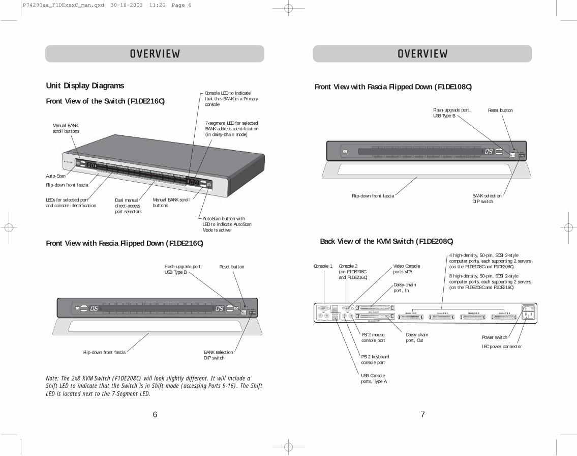
Unit Display Diagrams
Front View of the Switch (F1DE216C)
Dual manualdirect-accessport selectors
PS/2 mouseconsole port
USB Consoleports, Type A
Video Consoleports VGA
4 high-density, 50-pin, SCSI 2-style computer ports, each supporting 2 servers (on the F1DE108C and F1DE208C)
8 high-density, 50-pin, SCSI 2-style computer ports, each supporting 2 servers (on the F1DE208C and F1DE216C)
IEC power connector
Daisy-chainport, In
Daisy-chainport, Out
Power switch
AutoScan button withLED to indicate AutoScanMode is active
Manual BANK scrollbuttons
7-segment LED for selectedBANK address identification(in daisy-chain mode)
Console LED to indicatethat this BANK is a Primaryconsole
LEDs for selected port and console identification
Manual BANKscroll buttons
Flip-down front fascia
Flash-upgrade port,USB Type B
BANK selectionDIP switch
Reset button
Flip-down front fasciaPS/2 keyboardconsole port
Hosts 1 & 2 Hosts 3 & 4 Hosts 5 & 6 Hosts 7 & 8
Back View of the KVM Switch (F1DE208C)
Note: The 2x8 KVM Switch (F1DE208C) will look slightly different. It will include aShift LED to indicate that the Switch is in Shift mode (accessing Ports 9-16). The ShiftLED is located next to the 7-Segment LED.
Auto-Scan
Front View with Fascia Flipped Down (F1DE216C)
Console 1 Console 2(on F1DE208Cand F1DE216C)
Flash-upgrade port,USB Type B
BANK selectionDIP switch
Reset button
Flip-down front fascia
Front View with Fascia Flipped Down (F1DE108C)
P74290ea_F1DExxxC_man.qxd 30-10-2003 11:20 Page 6

9
INSTALLATION
1. Remove the brackets from the box.
2. Align the bracket with the front of the Switch for flush installation in your rack.
3. Attach the bracket to the side of your Switch with the screws provided.
4. Mount the Switch to the rack rail assembly.
*** Cautions and Warnings ***
Before attempting to connect anything to the Switch or your computer(s), pleaseensure that all your computer equipment and devices are powered off. BelkinCorporation is not responsible for damage caused by your failure to do so.
Standalone Switch Installation
This section provides complete instructions for the hardware setup of a single Switch.
Connecting Computers to the Switch (PS/2 Connection)
1. Attach the IEC power cable to the power connector located on the rear of the Switch.
INSTALLATION
Pre-Configuration
The enclosure of the Switch is designed for desktop or rack-mount configuration. TheSwitch is rack-mountable in standard 19-inch server racks. Rack-mount hardware isincluded with these Switches for a sturdy rack installation. Anti-skid feet areincluded for stable desktop configurations.
Consider the following when deciding where to place the Switch:
• Whether or not you intend to use the direct-access port selectors
• The lengths of the cables attached to your keyboard, monitor, and mouse
• The location of your computers in relation to your console
• The lengths of the cables you use to connect your computers to the Switch
• The placement of the daisy-chained BANKs in your server room, and the lengthsof the cables you use to connect the BANKs in your daisy-chain
Cable Length Recommendations
For PS/2 computersWe recommend that PS/2 cable length be limited to 25 feet for best videoperformance. Beyond that length, the probability of video degradation increases.
For USB computersWe recommend that USB cable length be limited to 12 feet for best performance.
Installing the Switch into a Server Rack
The Switch includes mounting brackets ideal for installation in 19-inch racks.
Please consider the following before rack-mounting your Switch.
a) Elevated Operating Ambient Temperature – If installed in a closed ormultiunit rack assembly, the operating ambient temperature of the rackenvironment may be greater than room ambient. Therefore, considerationshould be given to installing the equipment in an environment compatiblewith manufacturer’s maximum rate ambient temperature.
b) Reduce Air Flow – Installation of the equipment in a rack should be suchthat the amount of airflow required for safe operation of the equipment is notcompromised.
c) Mechanical Loading – Mounting of the equipment in the rack should be suchthat hazardous condition is not achieved due to uneven mechanical loading.
d) Reliable Earthing – Reliable earthing of rack-mounted equipment should bemaintained. Particular attention should be given to supply connections otherthan direct connections to the branch circuit.
8
Hosts 1 & 2 Hosts 3 & 4 Hosts 5 & 6 Hosts 7 & 8
P74290ea_F1DExxxC_man.qxd 30-10-2003 11:20 Page 8

1110
INSTALLATIONINSTALLATION
2. Using the OmniView ENTERPRISE Quad-Bus Series Dual-Port PS/2 KVM Cable(F1D9400-XX), connect the high-density, 50-pin, SCSI 2-style connector to a freeSwitch port, starting with the port for the first two computers. (For best results,screw the connectors into the Switch and the computer, when possible.)
3. Connect the VGA and PS/2 connectors to the computer (make sure that you connectthe keyboard and mouse cables to the correct ports on your computer; purpleindicates the keyboard connector and green indicates the mouse connector).
4. Repeat steps 1 through 3 for each additional computer you wish to connect.
Connecting Computers to the Switch (USB Connection)
1. Attach the IEC power cable to the power connector located on the rear of the Switch.
2. Using the OmniView ENTERPRISE Quad-Bus Series Dual-Port USB KVM Cable(F1D9401-XX), connect the high-density, 50-pin, SCSI 2-style connector to a freeSwitch port, starting with the port for the first two computers. (For best results,screw the connectors into the Switch and the computer, when possible.)
3. Connect the USB connector of your KVM Cable to the computer. If your computeris running Windows Me or newer, skip to step 6, otherwise continue with step 4.
Hosts 1 & 2 Hosts 3 & 4 Hosts 5 & 6 Hosts 7 & 8
Hosts 1 & 2 Hosts 3 & 4 Hosts 5 & 6 Hosts 7 & 8
Hosts 1 & 2 Hosts 3 & 4 Hosts 5 & 6 Hosts 7 & 8
Hosts 1 & 2 Hosts 3 & 4 Hosts 5 & 6 Hosts 7 & 8
Hosts 1 & 2 Hosts 3 & 4 Hosts 5 & 6 Hosts 7 & 8
P74290ea_F1DExxxC_man.qxd 30-10-2003 11:20 Page 10

12 13
INSTALLATIONINSTALLATION
3. Connect the PS/2 or USB keyboard to the appropriate port on the back of theSwitch in the “Console” section (the purple PS/2 port).
4. Connect the PS/2 or USB mouse to the appropriate port on the back of the Switchin the “Console” section (the green PS/2 port).
5. Repeat steps 1–4 above if you are connecting a second console.*
6. Power on the Switch.
7. Boot all of your host computers.
Connecting Multiple Switches (Daisy-Chaining)
You can daisy-chain up to 16 Switches and Expanders together; this will give aserver administrator control over a maximum of 256 computers. In addition, when asecond Switch is daisy-chained, two additional consoles can be added*, creating aconfiguration of up to four consoles. Each daisy-chained group of Switches becomesa unit that is referred to as a “BANK” and assigned an address. The Switch that theconsole (keyboard, mouse, and monitor) is connected to is referred to as a “primary”switch. BANKs 00 and 01 can be configured as primary console switches, allowing upto four consoles. BANKs 02 through 15 can only be configured as secondary Switches(without console support). If BANKs 00 through 01 do not have a console attached,they function as secondary Switches. However, the connections on these BANKs arehot swappable. For example, if a console is added to one of the first two BANKs, itwill immediately become a primary console Switch.
Note: A Daisy-Chain Cable (F1D9402-XX) is required to daisy-chain each OmniView KVMSwitch and is available through your Belkin reseller or online at http://www.belkin.com/
All OmniView ENTERPRISE Quad-Bus Series KVM Switches feature a “BANK DIP”switch. The BANK DIP switch is used for proper identification of the Switch.
• For a single-unit configuration, set the BANK DIP switch on the Switch to the“standalone” (BANK address 00) setting. This is the factory default setting.
• For multi-unit configuration, the BANK DIP switch on the primary units must beset to BANK address 00 to (or) 01. Secondary units must be set to a uniqueBANK address (from 02 through 15). Refer to the chart below for DIP switchsettings.
Note: BANK address 00 operates as standalone by default; refer to the section on theOSD Options page for instructions on how to configure BANK 00 to join a daisy-chain.
*2x8 and 2x16 models only
4. Boot the computer you wish to connect via USB, as you would normally, with thekeyboard, mouse, and monitor connected directly to the computer.
5. Your computer will detect the Switch as a generic mouse and keyboard. Olderversions of Windows do not automatically install USB HID devices, so you willhave to manually press “Next” through the Windows Add/Remove Hardware Wizarduntil the HID devices are all installed (the Switch will install four devices: a HIDkeyboard, a HID mouse, a generic keyboard, and a generic mouse). This driverinstallation is only required the first time the Switch enumerates on eachcomputer; the Switch will be detected and enumerate automatically in the future.When driver installation is complete, power down the computer and disconnectthe keyboard, mouse, and monitor.
6. Connect the male VGA HDDB15 connector on the KVM Cable to the VGA port onthe computer.
7. Repeat steps 1 through 5 for each additional computer you wish to connect tothe Switch via USB.
Note: For USB Installation
We recommend you attach the KVM Cable directly to a free USB port on your computer,not through a hub.
Connect the Console
1. Set BANK address (The BANK address is preset to zero at the factory).
2. Connect the monitor to the Switch. Attach your monitor cable to the HDDB15female port on the back of the Switch labelled “Console”.
NOTE: Dual-console support available on 2x8 and 2x16 models only.
Hosts 1 & 2 Hosts 3 & 4 Hosts 5 & 6 Hosts 7 & 8
P74290ea_F1DExxxC_man.qxd 30-10-2003 11:20 Page 12

15
INSTALLATIONINSTALLATION
14
Example:Four OmniView ENTERPRISE Quad-Bus Series KVM Switches (F1DE208C) are daisy-chained together to control 32 computers. The DIP switch on the primary unitsare set to “BANK Address 00” and the secondary units are each set to a unique BANKaddress between 01 and 15 (BANK 00 needs to be configured for daisy-chain operation,as noted above).
InstallationBefore you begin:
1. Make sure that all computers and switches are powered off and that each Switchhas been assigned a unique BANK address.
2. Place primary and secondary Switches in the desired locations.
3. Connect the console monitor, keyboard, and mouse to the console ports of the primarySwitch(es), as previously described for standalone units, skipping steps 5 and 6.*
*Dual-console support available on 2x8 and 2x16 models only.
4. Connect the computers to the Switch as previously described for standalone Switches.
Hosts 1 & 2 Hosts 3 & 4 Hosts 5 & 6 Hosts 7 & 8
Hosts 1 & 2 Hosts 3 & 4 Hosts 5 & 6 Hosts 7 & 8
Hosts 1 & 2 Hosts 3 & 4 Hosts 5 & 6 Hosts 7 & 8
Hosts 1 & 2 Hosts 3 & 4 Hosts 5 & 6 Hosts 7 & 8
DIP Switch Configuration Chart
N° DU COMMUTATEUR DIPADRESSE BANK1 2 3 4
BAS BAS BAS BAS BANK 00 (valeur par défaut)
HAUT BAS BAS BAS BANK 01 PRIMAIRE/SECONDAIRE
BAS HAUT BAS BAS BANK 02 SECONDAIRE
HAUT HAUT BAS BAS BANK 03 SECONDAIRE
BAS BAS HAUT BAS BANK 04 SECONDAIRE
HAUT BAS HAUT BAS BANK 05 SECONDAIRE
BAS HAUT HAUT BAS BANK 06 SECONDAIRE
HAUT HAUT HAUT BAS BANK 07 SECONDAIRE
BAS BAS BAS HAUT BANK 08 SECONDAIRE
HAUT BAS BAS HAUT BANK 09 SECONDAIRE
BAS HAUT BAS HAUT BANK 10 SECONDAIRE
HAUT HAUT BAS HAUT BANK 11 SECONDAIRE
BAS BAS HAUT HAUT BANK 12 SECONDAIRE
HAUT BAS HAUT HAUT BANK 13 SECONDAIRE
BAS HAUT HAUT HAUT BANK 14 SECONDAIRE
HAUT HAUT HAUT HAUT BANK 15 SECONDAIRE
P74290ea_F1DExxxC_man.qxd 30-10-2003 11:20 Page 14

1716
INSTALLATIONINSTALLATION
Connecting the Daisy-Chain Cable:5. Begin with BANK 00. Using the Daisy-Chain Cable (F1D9402-XX), connect one end
to the “Daisy-Chain OUT” port on the first Switch.6. Connect the other end of the Daisy-Chain Cable to the “Daisy-Chain IN” port of
the next Switch.Note: It does not matter which unit is the primary unit, only that they are connected OUT-to-IN or IN-to-OUT.
Adding Additional Units:7. Continuing in the same manner, using the Daisy-Chain Cable (F1D9402-XX),
connect “Daisy-Chain OUT” to “Daisy-Chain IN” on all subsequent units.
CAUTION: Never connect “Daisy-Chain IN” to “Daisy-Chain IN” or “Daisy-Chain OUT”to “Daisy Chain OUT”. This may produce unpredictable results.
Example of Daisy-Chain Configuration
Connecting the Computers:8. Power on the Switches, in any order. You will see the port LEDs flash on and off
and the seven-segment LEDs will light up, displaying a series of diagnostic codes,eventually stopping with the digits “XX”, where XX is its BANK address.
Note: If the Switches still do not enumerate with their corresponding BANK address,check that all Switches have the correct BANK address assigned to them and that alldaisy-chain cables are connected properly.
9. If the primary BANK is set to address 00, the KVM administrator must configurethe Switch for daisy-chain usage. To do this, take the following steps: (Note: Youmay see lines across some of the consoles, which is normal since it is in aninvalid configuration until the “Daisy-Chain this Switch” option is activated).
a) Open the OSD by pressing the CTRL key twice, then the space bar, and enter Setup.b) Go to the Options page, select the “Advanced” button.c) In the Advanced Dialog, check the “daisy-chain this KVM” box.d) A dialog will appear informing you that, “This will reset the KVM to change this
setting.” Click “OK” to clear the dialog and automatically power cycle the Switch.
When the Switch reboots, it will interact with the remainder of the other daisy-chained Switches as expected. You can verify this by opening the OSD and scrollingthrough the list of computers; if any of the other Switch’s computers appear in BANK00’s list, then it is working properly.
Note: If you don’t configure BANK 00 for use on the daisy-chain, then it will not beable to interact with any of the other Switches and they will not be able to interactwith it. In addition, the unit’s front panel will not act the same as the other units’front panels. Finally, there could be some unpredictable interactions caused by connecting an improperly configured BANK 00 to a daisy-chain.
Powering Up the SystemsOnce all cables have been connected, power up the connected computers in anyorder. The Switch emulates both a mouse and keyboard on each port and allows yourcomputer to boot normally; the Switch does not need to be powered on to emulatethe keyboard and mouse.
The computer connected to port 01 of any primary KVM Switch will be displayed onthe monitor. Check to see that the Switch is working normally by use of mouse, keyboard, hot keys, OSD, and/or front-panel push buttons. Proceed to do this withall occupied ports to verify that all computers are connected and responding correctly. If you encounter an error, check your cable connections for that computerand reboot, if necessary. If the problem persists, please call Belkin technical support.
Hosts 1 & 2 Hosts 3 & 4 Hosts 5 & 6 Hosts 7 & 8
Hosts 1 & 2 Hosts 3 & 4 Hosts 5 & 6 Hosts 7 & 8
Hosts 1 & 2 Hosts 3 & 4 Hosts 5 & 6 Hosts 7 & 8
Hosts 1 & 2 Hosts 3 & 4 Hosts 5 & 6 Hosts 7 & 8
P74290ea_F1DExxxC_man.qxd 30-10-2003 11:20 Page 16

19
USING YOUR SWITCH
18
USING YOUR SWITCH
Now that you have connected your consoles and computers to your Switch, it is ready for use.
You can select connected computers by the direct-access port selectors, located onthe front panel of the Switch, hot key commands, or the On-Screen Display.
Note: For hot keys (e.g. up and down arrows) and AutoScan, the order of progression,when switching from one computer to the next, is dictated by the order of the computers in the list box, on the Main page of the OSD.
Selecting a Computer Using Direct-Access Port SelectorsThe Switch has been designed to allow a 1x8 KVM Switch to access all of the ports on a2x16 KVM Switch or KVM Expander (F1DE016C). Front-panel operations take place on therelease of a button. Front-panel operations are also different between daisy-chained configurations and standalone configurations. In standalone configurations, each buttonrelease immediately activates the feature selected. In daisy-chain configurations, the firstbutton release puts the console into Select Mode and subsequent button operations willimmediately activate the feature selected.
Note: It takes a moment for the video signal to refresh (depending on your monitor)after switching computers.
Standalone Configuration• The 7-segment LEDs will display the number of the port in focus for each console.• One Port Selection LED will always be lit, corresponding to the port in focus and
the console.• The Shift LED (labelled with an * on the front panel) indicates that ports 9–16
are selected (not applicable to this Switch in standalone mode).• The Console LED will be lit, indicating that this Switch is a primary console Switch.• BANK selection buttons will have no effect, since there is only one BANK in this
configuration.
1. Press the button corresponding to the port that you would like to select. Whenyou release the button, the Switch will beep, and switch the focus to the selectedport. If you don’t have permission to access the selected port, the Switch willbeep, switch focus away from the selected port, and a banner message will display “Access Denied”.
2. If you press the AutoScan button, when you release the button, the Switch willbeep, and switch into AutoScan Mode.
Note: For a standalone Switch to function as described in this section, the BANKaddress must be set to 00 and the “Daisy-chain this KVM” box must be cleared.Otherwise, the Switch will function, but it will operate like a daisy-chained Switch.
Daisy-Chain Configuration• The 7-segment display of a secondary Switch will always display its BANK
address. All other buttons and LEDs on secondary BANKs will be disabled.
Static Mode (Idle)• The 7-segment LEDs will display the current BANK ID.• The Port Selection and Shift LEDs will be off.• The Console LED will be lit, indicating that this Switch is a console.
The Switch will go into Select Mode when you press and release any button on thefront panel of the console. The Port Selection LEDs will toggle from off to on, andthe 7-segment LEDs will toggle from indicating the BANK ID to indicating the BANKin focus.
Select Mode• Select Mode reverts to Static Mode after 5 seconds of inactivity.• The 7-segment LEDs will display the address of the BANK in focus.• One Port Selection LED will be lit, corresponding with the port in focus on the
BANK in focus.• The Shift LED will light whenever ports 9–16 are selected. To use the 1x8 or 2x8
KVM Switch to select ports 9–16 on a 1x16 or 2x16 KVM Switch, hold down the corresponding button for one second (the Shift LED will light) then release it.For example, to select the computer attached to port 9, from Select Mode, pressthe button for port 1, and hold it for one second before releasing it; the Switchwill beep and both the Port 1 LED and Shift LED will light.
• The Primary Console LED will be lit, indicating that this Switch is a console.
1. Press the BANK selection buttons to cycle through the BANKs available; eachpress increases or decreases the BANK in focus by one, and is immediately indicated by the 7-segment LEDs.
2. Press the button corresponding to the port that you would like to select. Whenyou release the button, the Switch will beep, and change the focus to the selected port. If the user has been restricted from accessing the selected port, abanner message will display “Access Denied”.
3. If you press the AutoScan button, when you release the button, the Switch willbeep, and change into AutoScan Mode.
P74290ea_F1DExxxC_man.qxd 30-10-2003 11:20 Page 18
2120
USING YOUR SWITCHUSING YOUR SWITCH
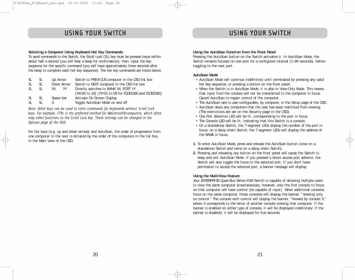
Selecting a Computer Using Keyboard Hot Key CommandsTo send commands to the Switch, the Scroll Lock (SL) key must be pressed twice withinabout half a second (you will hear a beep for confirmation); then, input the keysequence for the specific command (you will have approximately three seconds afterthe beep to complete each hot key sequence). The hot key commands are listed below:
SL SL Up Arrow Switch to PREVIOUS computer in the OSD list boxSL SL Down Arrow Switch to NEXT computer in the OSD list boxSL SL XX YY Directly switches to BANK XX, PORT YY
(XX=00 to 15) (YY=01 to 08 for F1DE108C and F1DE208C)SL SL Space bar Activate On-Screen DisplaySL SL A Toggle AutoScan Mode on and off
Note: Other keys can be used to enter commands for keyboards without Scroll Lockkeys. For example, CTRL is the preferred method for Macintosh® computers, which oftenmap other functions to the Scroll Lock key. These settings can be changed in theOptions page of the OSD.
For hot keys (e.g. up and down arrows) and AutoScan, the order of progression fromone computer to the next is dictated by the order of the computers in the list box,in the Main View of the OSD.
Using the AutoScan Function from the Front PanelPressing the AutoScan button on the Switch activates it. In AutoScan Mode, theSwitch remains focused on one port for a configured interval (1–99 seconds), beforetoggling to the next port.
AutoScan Mode• AutoScan Mode will continue indefinitely until terminated by pressing any valid
hot key sequence, or pressing a button on the front panel.• When the Switch is in AutoScan Mode, it is also in View-Only Mode. This means
that input from the console will not be transmitted to the computer in focus.Cancel AutoScan to regain control of the computer.
• The AutoScan rate is user-configurable, by computer, in the Setup page of the OSD.• AutoScan skips any computers that the user has been restricted from viewing
(The restrictions are set on the Security page in the OSD).• One Port Selection LED will be lit, corresponding to the port in focus.• The Console LED will be lit, indicating that this Switch is a console.• On a standalone Switch, the 7-segment LEDs display the number of the port in
focus; on a daisy-chain Switch, the 7-segment LEDs will display the address ofthe BANK in focus.
1. To enter AutoScan Mode, press and release the AutoScan button (once on a standalone Switch and twice on a daisy-chain Switch).
2. Pressing and releasing any button on the front panel will cause the Switch tobeep and exit AutoScan Mode. If you pressed a direct-access port selector, theSwitch will also toggle the focus to the selected port. If you don’t have permission to access the selected port, a banner message will display.
Using the MultiView FeatureYour ENTERPRISE Quad-Bus Series KVM Switch is capable of allowing multiple usersto view the same computer simultaneously; however, only the first console to focuson that computer will have control (be capable of input). When additional consolesfocus on the same computer, those consoles will display the banner, “Viewing only,no control.” The console with control will display the banner, “Viewed by console X,”where X corresponds to the letter of another console viewing that computer. If thebanner is enabled on either type of console, it will be displayed indefinitely; if thebanner is disabled, it will be displayed for five seconds.
P74290ea_F1DExxxC_man.qxd 30-10-2003 11:20 Page 20

23
USING YOUR SWITCH
22
USING YOUR SWITCH
IntelliView Graphical On-Screen Display Menu ControlThe IntelliView Graphical On-Screen Display (OSD) is intended to have a look andfeel similar to popular Windows-based operating systems for PCs. To activate the On-Screen Display, press on “Scroll Lock + Scroll Lock + space bar” on your keyboard.(There are other keys that can be substituted for the Scroll Lock key. For keyboardsthat do not have Scroll Lock keys, refer to the “IntelliView Options Page” section ofthis User Manual for more information).
IntelliView OSD FeaturesThe Main page is the initial screen that will appear after opening the OSD. TheGraphical OSD screen layout is similar to many Windows-based operating systems.The user will see a window with a title bar with some controls and a main areawhere the user accesses the features of the Switch.
The top right side of the OSD title bar identifies the user’s current console (ConsolesA–D are BANKs 00–03, respectively) and the user that is currently logged-in.Selecting the “?” button displays the Help Screen, which will provide instructions forusing the current OSD page.
Selecting the “X” button will close the page the user is viewing. Selecting theEscape key on your keyboard will also close the OSD.
Note: All changes to the OSD are written and saved to memory as soon as the focuschanges; there is no method of cancelling or undoing actions once they have beenentered. There is one exception, when editing the contents of an edit box (e.g. theComputer Name edit box), ESC will exit the control and revert the contents back totheir original form.
Input and Navigation Features• Clicking on the Group, Computer Name, or ID column headers sorts the list box
entries in ascending order, by the column header selected.• Double-clicking on a computer line will select that computer line and switch the
console’s focus to the selected port. If the user is restricted from accessing theselected computer, an error message will be displayed. When the error dialog iscleared, the console’s focus will remain on the previously selected port.
• Pressing the up or down arrow keys, while the OSD is up, moves the computer cursor (the row highlighted blue) up or down. If the cursor moves outside of thevisible area, the list will scroll by one line. The scroll wheel on the mouse canalso be used to perform this function.
• The up/down double arrows, to the right of the computer list, scroll the list upand down one page at a time. The Page Up and Page Down keys on the keyboardalso perform this function.
• Pressing the space bar will activate the OSD control in focus (same as clicking onthe control). If the list box is in focus, then pressing the space bar gives theconsole control of the highlighted computer.
• Pressing “Enter” activates the control in focus, if the control is on a button, orinside an edit box, but if the focus is on another type of control (e.g. the listbox), the Enter key activates the default control (Close or Exit, depending on thecurrent OSD screen).
• If the administrator presses “Ctrl + TAB” while viewing one of the Setup pages,the OSD goes to the next page.
• Shortcut keys are enabled in the OSD. For example, pressing “ALT + X”, where Xcorresponds to the underlined character in a control’s label, activates that control.
• When the OSD is up, keyboard and mouse input is routed to it; their signals arenot sent directly to the computer.
• Selecting the “Close” button (or pressing “ALT + C”) on any of the Setup pageswill return the user to the Main page.
• The TAB key can be used to cycle through the controls on the current OSD page.Shift+TAB will cycle backwards.
• The OSD window can be repositioned by clicking on the title bar and draggingthe window with the mouse.
• To reposition the banner, press and hold “Ctrl + Alt” while the OSD is up; thecursor jumps from the OSD window to the banner; clicking and dragging themouse will allow the user to reposition the banner.
• The Switch maintains the position settings of the OSD and banner for multiplecomputer video resolutions. The user should set the positions of the OSD andbanner windows during the Switch setup to make the locations identical for allvideo resolutions.
Note: The OSD does not turn off by itself. To reduce the risk of burning the OSD on themonitor, turn off the monitor or set the KVM Switch to AutoScan Mode. All featuresconfigured in the Setup pages are global (affect all consoles) unless otherwise noted.
P74290ea_F1DExxxC_man.qxd 30-10-2003 11:20 Page 22
24 25
USING YOUR SWITCH
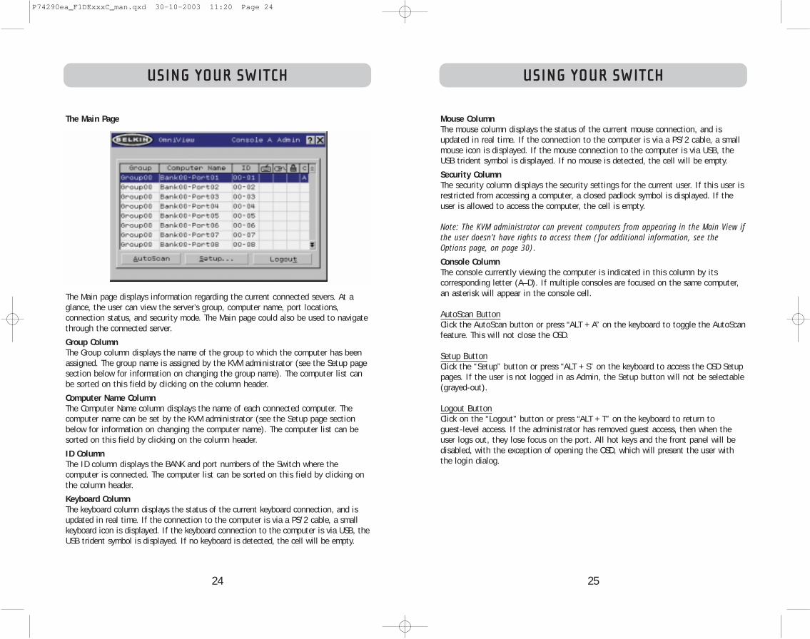
Mouse ColumnThe mouse column displays the status of the current mouse connection, and isupdated in real time. If the connection to the computer is via a PS/2 cable, a smallmouse icon is displayed. If the mouse connection to the computer is via USB, theUSB trident symbol is displayed. If no mouse is detected, the cell will be empty.
Security ColumnThe security column displays the security settings for the current user. If this user isrestricted from accessing a computer, a closed padlock symbol is displayed. If theuser is allowed to access the computer, the cell is empty.
Note: The KVM administrator can prevent computers from appearing in the Main View ifthe user doesn’t have rights to access them (for additional information, see theOptions page, on page 30).
Console ColumnThe console currently viewing the computer is indicated in this column by its corresponding letter (A–D). If multiple consoles are focused on the same computer,an asterisk will appear in the console cell.
AutoScan ButtonClick the AutoScan button or press “ALT + A” on the keyboard to toggle the AutoScanfeature. This will not close the OSD.
Setup ButtonClick the “Setup” button or press “ALT + S” on the keyboard to access the OSD Setuppages. If the user is not logged in as Admin, the Setup button will not be selectable(grayed-out).
Logout ButtonClick on the “Logout” button or press “ALT + T” on the keyboard to return to guest-level access. If the administrator has removed guest access, then when theuser logs out, they lose focus on the port. All hot keys and the front panel will bedisabled, with the exception of opening the OSD, which will present the user withthe login dialog.
USING YOUR SWITCH
The Main Page
The Main page displays information regarding the current connected severs. At aglance, the user can view the server’s group, computer name, port locations, connection status, and security mode. The Main page could also be used to navigatethrough the connected server.
Group ColumnThe Group column displays the name of the group to which the computer has beenassigned. The group name is assigned by the KVM administrator (see the Setup pagesection below for information on changing the group name). The computer list canbe sorted on this field by clicking on the column header.
Computer Name ColumnThe Computer Name column displays the name of each connected computer. Thecomputer name can be set by the KVM administrator (see the Setup page sectionbelow for information on changing the computer name). The computer list can besorted on this field by clicking on the column header.
ID ColumnThe ID column displays the BANK and port numbers of the Switch where the computer is connected. The computer list can be sorted on this field by clicking onthe column header.
Keyboard ColumnThe keyboard column displays the status of the current keyboard connection, and isupdated in real time. If the connection to the computer is via a PS/2 cable, a smallkeyboard icon is displayed. If the keyboard connection to the computer is via USB, theUSB trident symbol is displayed. If no keyboard is detected, the cell will be empty.
P74290ea_F1DExxxC_man.qxd 30-10-2003 11:20 Page 24

26 27
USING YOUR SWITCHUSING YOUR SWITCH
Scan Time and “Change All” ButtonThe user can reset the scan time for all computers by entering a value from 1–99 inthe edit box and clicking on the “Change All” button. The user will be asked to confirmthe action before the new time is applied.
Console ColumnThe console currently viewing the computer is indicated in this column.
Security Page
The Security page allows the administrator to change the computer-access permissionsfor the Switch’s users. There are three levels of user access to the Switch: Admin, User,and Guest. Admin is the only user that can access the Setup pages to configure theSwitch. The administrator can restrict users and guests from accessing specific computers. All users can switch computers and toggle the AutoScan function in theMain page. In addition, the guest is the default user (you never have to login asguest), so all users logoff to guest, when the account is enabled.
If the administrator has removed guest access, then when the user logs out they losefocus on the port. All hot keys and the front panel will be disabled, with the exceptionof opening the OSD, which will present the user with the Login dialog.
The user accounts defined in the Switch can be used by individuals or groups of individuals; the names of the users are fixed.
Note: When the guest user is enabled, it defines the minimum privileges that anyonecan access. It is possible to restrict user accounts more than the guest account; this isa potential mistake to avoid.
The Setup Page
The Setup page is only available to the Admin user and is used to set the group name,computer name, and computer scan times. The scan time is dependent on the portbeing scanned, and is global (i.e. it’s independent of the console or user). While scantimes are independent of the user, AutoScan will skip computers that the user does nothave permission to view.
Group ColumnThe Group column displays the name of the group to which the computer has beenassigned. The group name is arbitrary text, purely for organizational purposes. Thegroup name can be up to eight characters and is assigned by the KVM administrator.The default group name of a computer is “Group X” where X is the BANK number of aSwitch as determined by the BANK address DIP switch. To change the group name,click in the desired cell.
Computer Name ColumnThe Computer Name column displays the name of each connected computer. The computer name can be up to 15 characters and is assigned by the KVM administrator.The computer list can be sorted on this field by clicking on the column header. Bydefault, all computer names will be named BANK XX-Port YY. Where XX is a two-digitBANK address number from 00 to 15 and YY is a two-digit computer number from 01 to16. To input the computer name, click in the desired cell.
ID ColumnThis column displays the BANK and port number of the Switch where the computer isconnected. The computer list can be sorted on this field by left-clicking the mouse onthe column header.
Scan ColumnThe Scan column displays the current setting for how long the console views eachcomputer during AutoScan. To change the viewing duration for a computer, click in thedesired cell.
P74290ea_F1DExxxC_man.qxd 30-10-2003 11:20 Page 26

28 29
USING YOUR SWITCHUSING YOUR SWITCH
Password Entry FieldsThere is a “change password” button associated with each user; clicking the buttondisplays the password entry dialog. The administrator is required to type the passwordand then confirm it; the new password will not be accepted until the entries match(passwords are up to eight characters long, and case-sensitive). cancelling the changepassword dialog will return to the Passwords page without changing the existing password. In a daisy-chain configuration, clicking “OK” automatically synchronizes thispassword with the other consoles.
Enable Check BoxesThe check boxes next to the user names allow the administrator to disable useraccounts with a single mouse click. This removes the need to alter the security settings of each host individually when it is necessary to remove a user’s access.
AutoLogout Enable and TimeThe AutoLogout feature logs-off the user after a specified period (1–99 minutes) of console inactivity. Generally, this will return the Switch to guest-level access, but ifguest access has been disabled, all access rights will be revoked until a valid user logs-on to the console. The edit box sets the length of inactivity required before thelogout occurs. The AutoLogout feature is not global; it has to be set independently foreach console.
Note: Unless AutoLogout is enabled, or the user manually logs out, the session will notend when they close the OSD (the next user will open the OSD at the privilege level ofthe previous user).
Group ColumnThe Group column displays the name of the group to which the computer has beenassigned. The computer list can be sorted on this field by clicking the mouse on thecolumn header.
Computer Name ColumnThe Computer Name column displays the name of each connected computer. The com-puter list can be sorted on this field by clicking on the column header.
User Columns (1, 2, 3, G)These columns allow administrators to set the access rights to each port (computer) for each user (1, 2, 3, and guest). The padlock indicates that the user (col-umn) will be restricted from accessing that port (row). Empty cells indicate that theuser has full access to that computer. To toggle user restrictions for a particular port,click the corresponding cell in the list box, or select the computer row and type thekey corresponding to the user: 1, 2, 3, G (4 also toggles the guest restrictions).
Console ColumnThe console currently viewing the computer is indicated in this column.
Passwords Page
The Passwords page allows the administrator to change user passwords, enable or dis-able user accounts, and set the AutoLogout time.
Note: Only the administrator can change user passwords and settings.
P74290ea_F1DExxxC_man.qxd 30-10-2003 11:20 Page 28

30 31
USING YOUR SWITCHUSING YOUR SWITCH
Display BannerThis check box enables a banner to be displayed for system events: pressing a front-panel button, powering-on the Switch, etc. The banner is either always displayed, or displayed for a configured time (1–99 seconds). If the timed selectionis enabled, the time input determines how long the banner will remain on-screenafter the system event occurs. See the “MultiView” section (on page 21) and the“Banner” section (on page 33) for additional information on the operation and content of the banner. The banner configurations are not global; they have to be setindependently for each console.
Display Inactive PortsEnabling this feature will cause ports that do not have an active computer attachedto appear in the computer list box, on the Main page of the OSD. By default, inactive ports are displayed. The “Display Inactive Ports” feature is not global; it hasto be set independently for each console.
Display Restricted PortsEnabling this feature will cause ports that the current user is restricted from accessing to appear in the computer list box, on the Main page of the OSD. Bydefault, restricted ports are displayed. The “Display Restricted Ports” feature is notglobal; it has to be set independently for each console.
Alternate Attention KeyThis screen allows you to select alternate keys to initiate hot key commands. It provides compatibility with keyboards that do not feature the identical keys or thatmay be using them to perform other functions. You may select any number ofAlternate Attention keys. Note: If all options are deselected, Scroll Lock becomes the default Attention key.
Display Version NumbersThis screen displays product information, including the model number and thefirmware revisions. The “Display Version Numbers” feature is not global; it only displays the version numbers for this BANK.Note: When performing flash upgrades, you will have to upgrade each Switch orExpander unit individually.
Broadcast PasswordsThis check box forces all other consoles to overwrite all of their user passwords withthe passwords contained in the current console. This makes it simple for the administrator to synchronize the passwords of all consoles (e.g. when adding a newconsole to an existing configuration).
Options Page
The controls on this page affect several of the Switch’s features.
P74290ea_F1DExxxC_man.qxd 30-10-2003 11:20 Page 30

32
USING YOUR SWITCHUSING YOUR SWITCH
33
Error Messages and DialogsFrom time to time, it will be necessary to display messages to the user indicatingerrors or requesting simple answers to questions. These pop-up screens use thefamiliar format of title bar and window body, which contains the text of the message. It includes appropriate response controls such as OK and Cancel buttons,based on the nature of the message.
Login DialogThe Login dialog is a simple window with radio buttons to select the user, and anedit box for the user to enter a password. If the user is already logged-in, pressing“Cancel” returns the user to his or her current login (or guest, if the account isenabled). If the user is not logged in, and guest is disabled, pressing cancel willclose the OSD.
Help ScreensOnline help is available within the OSD. Simply press the F1 key, or click on the “?”button on the right side of the title bar.
Banner
The banner, a small window that is displayed to inform the user of the console’sfocus, appears as a line of text surrounded by a gray, 3-D frame. It displays the following information:
• Group name• Host name• BANK and port in focus
If multiple consoles are viewing the same computer (MultiView Mode), the consolewith control displays the following banner information:
• Viewed by console [console letter]• BANK and port in focus
The view-only console displays the following banner information:• Viewing only, no control• BANK and port in focus
The banner also displays important error messages and important changes in theKVM configuration.
Splash Screen When you power-on the Switch, a window appears that displays its product nameand copyright information. This window remains for several seconds then disappears.Opening the OSD will clear the Splash Screen immediately.
Advanced Button
Activating this button will take the user to the advanced option screen.
Disable ViewingWhen “Disable Viewing” is checked, only another administrator may view channelsoccupied by the administrator. This function will be active by default in the OSD bydesign. For security reasons, admin needs to disable this if need be.
Daisy-Chain this KVMChecking this box allows Switches set to BANK 00 to communicate with other BANKsin a daisy-chain configuration. This affects front-panel operations, and other operational parameters. Whenever the state of this check box is changed, the following message will be displayed, “This will reset the KVM to change this setting”.If the user selects “OK”, the Switch will immediately reboot in the new configuration. By default, Switches set to BANK 00 are configured as standalone (thecheck box is cleared).
Steal Control of this HostThis feature allows the KVM administrator to take full control of a host that is currently being used by other users.
Restore Factory DefaultsSelecting this button will reset ALL user-configurable settings (computer names,group names, passwords, etc.) to their default values on all BANKs in the daisy-chain.The user is presented with a confirmation screen before this action is applied.
Note: In a daisy-chain configuration, restoring factory default will cause unpredictablebehavior. To resolve this temporary issue, the administrator will have to go back intothe Options page, select the “Advanced” button, and check the “daisy-chain this KVM”box after “Restoring Factory Defaults” for BANK 00 to function properly.
P74290ea_F1DExxxC_man.qxd 30-10-2003 11:20 Page 32

34 35
USING YOUR SWITCHUSING YOUR SWITCH
To start the update process, you must run the AutoUpdate application by selecting“AutoUpdate.exe” from the start menu, or a desktop shortcut.
The first screen of the AutoUpdate application will prompt the user to select anautomatic or manual update. You should generally select automatic, unless you havea specific reason to do otherwise. An automatic update will check the firmware onthe Switch and compare the versions installed against the latest versions available;if there are newer versions, the application will download the new firmware from theInternet and transfer it into the Switch. Then the user needs to power-cycle the KVMSwitch(es), to complete the firmware installation. The manual update works similarly,but the user needs to acquire the correct update file manually.
Note: Before updating the Switch, make sure that AutoScan is off and the OSD is not displayed on the console. This will reduce the level of extraneous activity in the Switch.
The AutoUpdate Firmware Update Utility
Updating Firmware
The AutoUpdate application is designed to inspect your hardware and guide youthrough the process of updating the firmware (if necessary) on your Switch.AutoUpdate automatically downloads the best firmware for your device from theBelkin website, or you can download the appropriate file manually by going to ourwebsite at belkin.com.
The administrator should perform the updates when the KVM Switch(es) is not inuse. Each Switch will be power-cycled during the process, which may lead to loss ofkeyboard, or mouse functionality on some computers. The administrator should shutdown any computers that he or she is not willing to physically reset, before beginning the update process.
To update the firmware, you will need the following items:
1. A computer running Windows XP, 2000, Me, or 98, with an available USB port.2. A standard USB cable that connects between the Switch and the computer.3. The Belkin AutoUpdate application that can be downloaded from the Internet.4. An Internet connection for automatic installation.
Installing the AutoUpdate application:
1. Download and run the AutoUpdate application from the Belkin website.
2. Click the “Next” buttons, configuring file locations, icon preferences, etc., asdesired, until the install is complete.
Connecting the computer to the Switch:
1. Power on the Switch.
2. Connect one end of the USB cable to the flash port on your Switch(es) (the USB“B” connector) and the other end to the computer’s USB port(s). You may needone or more USB hubs between the computer and the Switch if you intend toupdate multiple Switches simultaneously.
Note: Before you begin the update, the administrator should go into the Options page inthe OSD, press the “Display Version Numbers” button, and record the current version numbers; this will allow the administrator to confirm that the firmware was updated correctly.
P74290ea_F1DExxxC_man.qxd 30-10-2003 11:20 Page 34

3736
USING YOUR SWITCHUSING YOUR SWITCH
Before the AutoUpdate begins, a warning screen will be displayed, informing theuser of the risks involved in proceeding with the update, and actions that should beavoided while the update is in progress.
Note: It is crucial that the PC and the Switch remain powered-on, and the USB cableremains connected to the PC or the Switch during the update. The user should alsoavoid using the PC in ways that might interfere with the operations of the AutoUpdateapplication. If the update process is disturbed, the Switch could become nonfunctional.If the update is interrupted, but the Switch is still on, you should be able to restartthe update (you may have to restart the AutoUpdate application).
Updating Devices via the Web
When you start the AutoUpdate application, it searches your computer for devicesthat support the update process. It also automatically connects to the Web andsearches for available updates for the devices that are found. When the applicationhas gathered the relevant information, it lists all of the devices found. An “OK” tothe left of the device name (filling the check box) indicates that there are no newupdates available on the Web (the device is up to date). If AutoUpdate finds anupdate for a device, it displays a checked box and the AutoUpdate icon to the leftof the device name. If you click on a device in the list box, information about thedevice and the update will be displayed in the details box, to the right of the listbox. Click on the checked boxes in the device list to deselect (uncheck) any devicesthat you don’t want to update. All devices with checked boxes will be updated (oneat a time) when you click “Next”.
P74290ea_F1DExxxC_man.qxd 30-10-2003 11:20 Page 36
3938
USING YOUR SWITCH
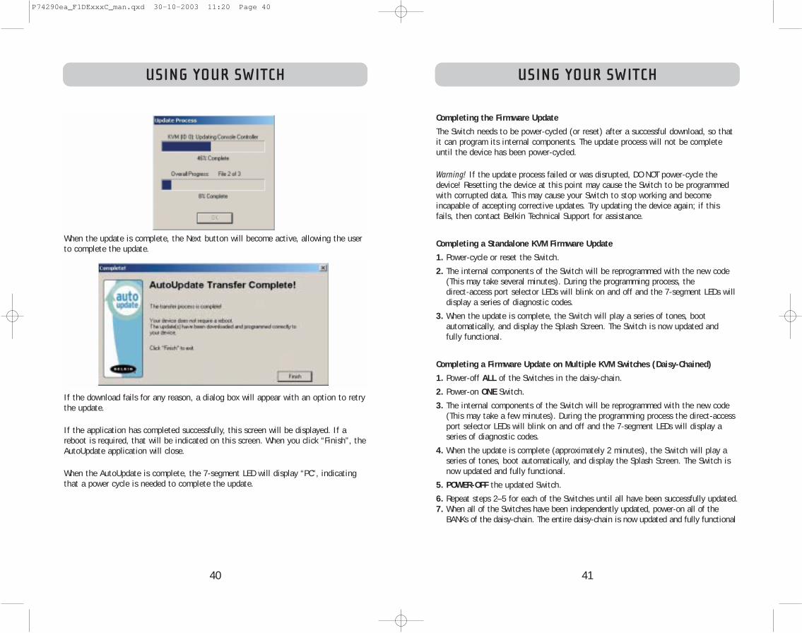
The “Advanced” button allows the user to manually force updates into the targetdevice. AutoUpdate does minimal checking to determine whether the selected file isvalid in this mode. Belkin does not recommend using Advanced Mode unless directedto do so by Belkin Technical Support. The Advanced button will become active at thesame time that the Next button becomes active (when a device is selected and avalid file has been selected).
Warning: Improper use of Advanced Mode could render your Switch nonfunctional andincapable of receiving further updates.
These two paragraphs are repeated (see above).
USING YOUR SWITCH
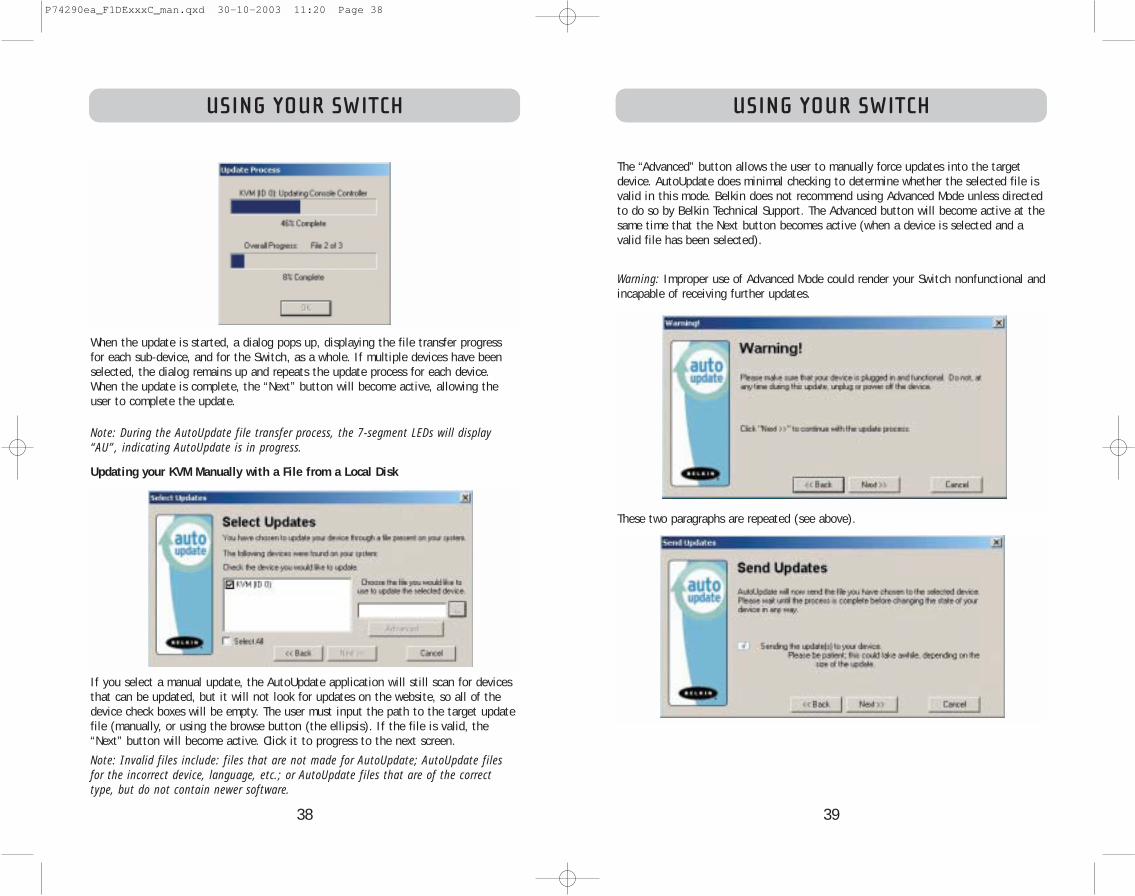
When the update is started, a dialog pops up, displaying the file transfer progressfor each sub-device, and for the Switch, as a whole. If multiple devices have beenselected, the dialog remains up and repeats the update process for each device.When the update is complete, the “Next” button will become active, allowing theuser to complete the update.
Note: During the AutoUpdate file transfer process, the 7-segment LEDs will display“AU”, indicating AutoUpdate is in progress.
Updating your KVM Manually with a File from a Local Disk
If you select a manual update, the AutoUpdate application will still scan for devicesthat can be updated, but it will not look for updates on the website, so all of thedevice check boxes will be empty. The user must input the path to the target updatefile (manually, or using the browse button (the ellipsis). If the file is valid, the“Next” button will become active. Click it to progress to the next screen.
Note: Invalid files include: files that are not made for AutoUpdate; AutoUpdate filesfor the incorrect device, language, etc.; or AutoUpdate files that are of the correcttype, but do not contain newer software.
P74290ea_F1DExxxC_man.qxd 30-10-2003 11:20 Page 38
4140
USING YOUR SWITCH
Completing the Firmware Update
The Switch needs to be power-cycled (or reset) after a successful download, so thatit can program its internal components. The update process will not be completeuntil the device has been power-cycled.
Warning! If the update process failed or was disrupted, DO NOT power-cycle thedevice! Resetting the device at this point may cause the Switch to be programmedwith corrupted data. This may cause your Switch to stop working and become incapable of accepting corrective updates. Try updating the device again; if thisfails, then contact Belkin Technical Support for assistance.
Completing a Standalone KVM Firmware Update
1. Power-cycle or reset the Switch.
2. The internal components of the Switch will be reprogrammed with the new code(This may take several minutes). During the programming process, the direct-access port selector LEDs will blink on and off and the 7-segment LEDs willdisplay a series of diagnostic codes.
3. When the update is complete, the Switch will play a series of tones, boot automatically, and display the Splash Screen. The Switch is now updated and fully functional.
Completing a Firmware Update on Multiple KVM Switches (Daisy-Chained)
1. Power-off ALL of the Switches in the daisy-chain.
2. Power-on ONE Switch.
3. The internal components of the Switch will be reprogrammed with the new code(This may take a few minutes). During the programming process the direct-accessport selector LEDs will blink on and off and the 7-segment LEDs will display aseries of diagnostic codes.
4. When the update is complete (approximately 2 minutes), the Switch will play aseries of tones, boot automatically, and display the Splash Screen. The Switch isnow updated and fully functional.
5. POWER-OFF the updated Switch.
6. Repeat steps 2–5 for each of the Switches until all have been successfully updated.7. When all of the Switches have been independently updated, power-on all of the
BANKs of the daisy-chain. The entire daisy-chain is now updated and fully functional
USING YOUR SWITCH
When the update is complete, the Next button will become active, allowing the userto complete the update.
If the download fails for any reason, a dialog box will appear with an option to retrythe update.
If the application has completed successfully, this screen will be displayed. If areboot is required, that will be indicated on this screen. When you click “Finish”, theAutoUpdate application will close.
When the AutoUpdate is complete, the 7-segment LED will display “PC”, indicatingthat a power cycle is needed to complete the update.
P74290ea_F1DExxxC_man.qxd 30-10-2003 11:20 Page 40

42 43
k) Select “OK” to close the Hot Function Keys dialog box.
l) Close the keyboard application.
Note: By creating a copy of “Eject this disk” application on your desktop, you caneasily map the “Eject this disk” function to the keyboard map. To copy the “Ejectthis disk” application from within Sherlock, hold down the “Option” key on the keyboard (“Alt” key on PC keyboard) and drag the application from the search result box to your desktop.
TROUBLESHOOTINGTROUBLESHOOTING
I’ve daisy-chained multiple Switches; now I want to add another console. Whatdo I need to do to get it running?
• If you want to add your console to a Switch that is already in your daisy-chainwith its DIP switches set from 00 through 01, you simply have to connect yourmonitor, keyboard, and mouse.
• Connect the Switch to the computers following the same procedure that you wouldfor a standalone Switch. Before you power-on the BANK, connect the daisy-chaincable to it and one of the Switches on the end of the chain (be sure to use the INport on one BANK and the OUT port on the other). Turn on the Switch. Bring upthe OSD on one of the other consoles, and enter Setup Mode. Go to the Passwordspage and click the “Broadcast Passwords” button. The new console is ready to useand is synchronized with the remainder of your daisy-chain.
• Connect the Switch to the computers following the same procedure that youwould for a standalone Switch. Before you power-on the BANK, connect thedaisy-chain cable to it and one of the Switches on the end of the chain (be sureto use the IN port on one BANK and the OUT port on the other). Turn on theSwitch. Bring up the OSD, on one of the other consoles, and enter Setup Mode.Go to the Passwords page and click the “Broadcast Passwords” button. The newconsole is synchronized with the remainder of your daisy-chain and ready to use.
I have a Macintosh computer that doesn’t have an eject button on its CD tray,and the Eject key on my keyboard doesn’t work through the Switch. How do Iopen my drive?
• On Mac OS® X (v10.1 and up) press F12 to eject the CD.
• Here’s how to map the eject function on your keyboard for Mac OS 9:
1. The simple method
a) From the Apple menu, select “Sherlock2”.
b) Select the hard drive that contains the Mac OS 9 system information.
c) In the Search field, enter “Eject this disk”.
d) Select the magnifying glass icon to begin search.
e) From the Apple menu, select “Control Panels”.
f) From the Control Panels menu, select “Keyboard”.
g) In the Keyboard dialog box, select the “Function Keys” button.
h) Choose the key that you want to execute the eject function.
i) Select the function key and an “Assign F[X] key” dialog box appears, where Xindicates the number of the function key that you pressed.
j) Choose the application “Eject this disk” (Either from a copy on the desktop,or from the location indicated in Sherlock) and select the “Assign” button.
P74290ea_F1DExxxC_man.qxd 30-10-2003 11:20 Page 42

45
GLOSSARY
Standalone: A single KVM switch that operates independently (not connected to others).
Static Mode: The predominant mode of operation of the KVM switch. The switchenters this state whenever it has not received a button press for at least five seconds.
OSD: On-Screen Display, a Graphical User Interface that can be used to control andconfigure the KVM switch.
View: When discussing switching between ports, viewing means that the console isreceiving video from the computer. Viewing requires that the console also has focuson the port.
GLOSSARY
The following definitions are used throughout the manual.
AutoScan: A mode of operation where the KVM switch scans from one port to another, on an ongoing basis, as configured by the user.
BANK: The address of a daisy-chained KVM (0–15, set by the DIP switch).
Console: The all-in-one term for the keyboard, video monitor, and mouse connectedto a KVM switch.
Console Port: Receptors for the console to connect to the KVM switch.
Control: When discussing switching between ports, control means that the console iscapable of sending input to the computer. Control requires that the console also hasfocus on the port, and is viewing it.
Console Switch: A KVM switch set to BANK address 0–1, with a console attached.
CPU: The markings on the KVM case that indicate the port numbers where each computer cable is connected to the KVM switch.
Daisy-Chain: A configuration of multiple KVM switches that are connected one toanother in a series; a Belkin KVM daisy-chain uses common settings to allow seamless,complex interactions between multiple consoles for control over many computers.
Focus: This term is used in two distinct ways:
1. In the OSD, the focus is represented by a dashed gray line around the control.The focus determines which control will be activated by pressing the spacebar or the Enter key; if the focus is on a button, or inside an edit box, pressing Enter will activate that control, whereas if the focus is on anothercontrol (e.g. the list box), the Enter key will activate the default control(Close or Exit).
2. When discussing switching between ports, focus refers to the act of targetinga particular port.
HID: Human Interface Device, the USB device class that includes keyboards and mice.
KVM: Keyboard Video Mouse switch.
Port: An interface receptor on a computer through which you can attach a device orplug in a device cable.
Primary Switch: A KVM switch set to BANK address 0-1 only with a console attached.
Secondary Switch: Any KVM switch without a console.
Select Mode: The mode of operation a daisy-chained KVM switch, in Static Mode,enters when the first front-panel button is pressed. Select Mode allows the user toselect BANKs, hosts, etc. with the next button press.
44
P74290ea_F1DExxxC_man.qxd 30-10-2003 11:20 Page 44

46
FCC Statement
DECLARATION OF CONFORMITY WITH FCC RULES FOR ELECTROMAGNETIC COMPATIBILITY
We, Belkin Corporation, of 501 West Walnut Street, Compton, CA 90220, declare under our soleresponsibility that the products:
F1DE108CF1DE116CF1DE208CF1DE216C
to which this declaration relates:Comply with Part 15 of the FCC Rules. Operation is subject to the following two conditions:(1) this device may not cause harmful interference, and (2) this device must accept any interferencereceived, including interference that may cause undesired operation.
CE Declaration of ConformityWe, Belkin Corporation, declare under our sole responsibility that the products F1DE108C, F1DE116C,F1DE208C, and F1DE216C to which this declaration relates, are in conformity with Emissions StandardEN55022 and with Immunity Standard EN55024, LVP EN61000-3-2, and EN61000-3-3.
ICESThis Class B digital apparatus complies with Canadian ICES-003. Cet appareil numérique de la classe Best conforme á la norme NMB-003 du Canada.
Belkin Corporation Limited Five-Year Product WarrantyBelkin Corporation warrants this product against defects in materials and workmanship for its warrantyperiod. If a defect is discovered, Belkin will, at its option, repair or replace the product at no chargeprovided it is returned during the warranty period, with transportation charges prepaid, to theauthorized Belkin dealer from whom you purchased the product. Proof of purchase may be required. Thiswarranty does not apply if the product has been damaged by accident, abuse, misuse, ormisapplication; if the product has been modified without the written permission of Belkin; or if anyBelkin serial number has been removed or defaced.
THE WARRANTY AND REMEDIES SET FORTH ABOVE ARE EXCLUSIVE IN LIEU OF ALL OTHERS, WHETHERORAL OR WRITTEN, EXPRESSED OR IMPLIED. BELKIN SPECIFICALLY DISCLAIMS ANY AND ALL IMPLIEDWARRANTIES, INCLUDING, WITHOUT LIMITATION, WARRANTIES OF MERCHANTABILITY AND FITNESS FORA PARTICULAR PURPOSE.
No Belkin dealer, agent, or employee is authorized to make any modification, extension, or addition tothis warranty.
BELKIN IS NOT RESPONSIBLE FOR SPECIAL, INCIDENTAL, OR CONSEQUENTIAL DAMAGES RESULTING FROMANY BREACH OF WARRANTY, OR UNDER ANY OTHER LEGAL THEORY, INCLUDING BUT NOT LIMITED TO,LOST PROFITS, DOWNTIME, GOODWILL, DAMAGE TO OR REPROGRAMMING OR REPRODUCING ANYPROGRAM OR DATA STORED IN OR USED WITH BELKIN PRODUCTS.
Some states do not allow the exclusion or limitation of incidental or consequential damages orexclusions of implied warranties, so the above limitations of exclusions may not apply to you.This warranty gives you specific legal rights, and you may also have other rights that vary fromstate to state.
INFORMATION
P74290ea_F1DExxxC_man.qxd 30-10-2003 11:20 Page 46

OmniView™
Switch KVM avec Micro-Cabling Technology
Manuel de l’utilisateurSérieENTERPRISE Quad-Bus
F1DE108CF1DE116CF1DE208CF1DE216C
Contrôlez jusqu’à 16 serveurs à partir d’une ou deux consoles
• Extensible jusqu’à 256 ordinateurs pour contrôle àpartir d’une à quatre consoles
Fr
© 2003 Belkin Corporation. All rights reserved. All trade names are registered trademarks of respective manufacturers listed. Apple, Macintosh, and Mac OS are
trademarks of Apple Computer, Inc., registered in the U.S. and other countries.
P74290
belkin.com
Belkin Corporation501 West Walnut Street
Compton • CA • 90220 • USATel: 310.898.1100Fax: 310.898.1111
Belkin Components, Ltd.Express Business Park • Shipton Way • Rushden
NN10 6GL • United KingdomTel: +44 (0) 1933 35 2000Fax: +44 (0) 1933 31 2000
Belkin Components B.V.Starparc Building • Boeing Avenue 333
1119 PH Schiphol-Rijk • The NetherlandsTel: +31 (0) 20 654 7300Fax: +31 (0) 20 654 7349
Belkin GmbHHanebergstrasse 2 •
80637 München • GermanyTel: +49 (0) 89 143 4050
Fax: +49 (0) 89 143 405100
Belkin Tech SupportUS: 310.898.1100 ext. 2263
800.223.5546 ext. 2263Europe: 00 800 223 55 460
P74290ea_F1DExxxC_man.qxd 30-10-2003 11:20 Page 48

INTRODUCTION
Merci d’avoir choisi ce switch KVM OmniView série Entreprise Quad-Bus avec Micro-Cabling Technology de Belkin (le switch). Notre gamme variée de solutions KVM vousmontre comment Belkin s’engage à fournir des produits de grande qualité etrésistants, à un prix compétitif. Conçus pour vous donner le contrôle de plusieursordinateurs et serveurs à partir d’une ou plusieurs consoles (jusqu’à quatre), leswitch offre diverses possibilités applicables à toutes les configurations, de petite oude grande taille.
Belkin a conçu et développé ce switch en pensant aux administrateurs de serveurs.Le résultat est le switch KVM OmniView série Entreprise QuadBus, conçu poursurpasser tous les autres switches sur le marché. Il a été étudié pour fonctionnerdans les environnements de laboratoire et de pièce de serveurs les plus évolués etpropose :
• Support pour double console, extensible jusqu’à 4 consoles• Affichage graphique à l’écran IntelliView• Support de choix de combinaisons de claviers et de souris PS/2 et USB• Sécurité multiniveau• Mise à jour par Flash USB• Ports dédiés pour montage en série • Prise en charge vidéo haute-résolution (400MHz: jusqu’à 2048 X 1536 à 85 Hz)• Possibilité de nommer les ordinateurs et les groupes• Diagnostics de connexion serveur• Indicateurs intuitifs au niveau des ports• Sélecteurs de port à accès direct• Garantie de 5 ans de Belkin• Câbles KVM à micro-construction avec double port (vendus séparément)*Disponible sur les modèles 2x8 et 2x16 seulement
Ce manuel vous donnera des détails sur votre nouveau switch, de l’installation et dufonctionnement jusqu’au dépannage, dans le cas peu probable où vous rencontreriezun problème. De temps à autre, il se peut que Belkin lance des mises à jour pour ceproduit; vous pouvez prendre connaissance de ces mises à jour sur notre site Webbelkin.com
Pour une installation rapide et facile, référez-vous au Guide d’Installation Rapidefourni.
Merci d’avoir choisir le switch KVM OmniView Série ENTREPRISE Quad-Bus de Belkin.Merci de votre confiance. Vous allez vite constater pourquoi plus d’un milliond’OmniView de Belkin sont utilisés dans le monde.
Contenu de l’emballage:• Switch OmniView Série ENTERPRISE Quad-Bus avec Micro-Cabling Technology• Deux supports de montage en baie avec vis• Manuel de l’utilisateur• Guide d’Installation Rapide• Câble d’alimentation IEC• Carte d’enregistrement• Un jeu de coussinets en caoutchouc
1
TABLE DES MATIÈRES
IntroductionAperçu
Présentation des fonctions . . . . . . . . . . . . . . . . . . . . . . . . . . . . 2Configuration requise . . . . . . . . . . . . . . . . . . . . . . . . . . . . . . . . 4Systèmes d’exploitation . . . . . . . . . . . . . . . . . . . . . . . . . . . . . . 4Spécifications . . . . . . . . . . . . . . . . . . . . . . . . . . . . . . . . . . . . . 5Illustrations de l’unité . . . . . . . . . . . . . . . . . . . . . . . . . . . . . . . 6
InstallationPréconfiguration . . . . . . . . . . . . . . . . . . . . . . . . . . . . . . . . . . . 8Installation d’un Switch autonome . . . . . . . . . . . . . . . . . . . . . . . .9Connexion de plusieurs switches (montage en serie) . . . . . . . . . . . .13Diagramme de configuration du commutateur DIP . . . . . . . . . . . . .14Mise en route des systèmes . . . . . . . . . . . . . . . . . . . . . . . . . . . 17
Utilisation de votre SwitchSélection d’un ordinateur à l’aide des sélecteurs de port à accès direct 18Sélection d’un ordinateur à l’aide des raccourcis clavier . . . . . . . . . 20Mode AutoScan . . . . . . . . . . . . . . . . . . . . . . . . . . . . . . . . . . . 21Contrôle du menu de l’affichage graphique à l’écran IntelliView . . . . .22Utilitaire de mise à jour du microprogramme AutoUpdate™ . . . . . . .34
Dépannage . . . . . . . . . . . . . . . . . . . . . . . . . . . . . . . . . . . . . . . . .42
Glossaire . . . . . . . . . . . . . . . . . . . . . . . . . . . . . . . . . . . . . . . . . .44
Information . . . . . . . . . . . . . . . . . . . . . . . . . . . . . . . . . . . . . . . .46
P74290ea_F1DExxxC_man.qxd 30-10-2003 11:20 Page 50

3
PRÉSENTATION
Séquence Initiale de Raccourci Clavier ReprogrammableLe switch vous permet de sélectionner jusqu’à six clés alternatives pour initier lescommandes de raccourcis clavier; ceci créée une compatibilité entre le claviers neprésentant pas des touches identiques ou qui ont une séquence identique déjàprogrammée pour exécuter une autre fonction. Ces fonctions peuvent êtreconfigurées à l’aide d’IntelliView. Pour de plus amples informations, consultez lasection “Fonctions de l’Affichage à l’Écran (OSD) IntelliView” de ce manuel, auxpages 22 et 23.
AutoScanLa fonction AutoScan vous permet d’indiquer au switch KVM d’analyser et desurveiller les activités de tous les ordinateurs connectés au KVM, l’un après l’autre.L’intervalle alloué à chaque ordinateur peut être défini ou ajusté par l’intermédiairedu menu OSD (On-Screen Display).
Sélecteurs de port à accès directCes boutons, placés sur la face avant du Switch, vous permettent de choisir un portmanuellement en toute simplicité.
Voyants lumineuxLes voyants lumineux situés sur la face avant du switch servent d’indicateur d’état.Le voyant situé au-dessus de chaque sélecteur de port à accès direct s’allume pourindiquer que la console contrôle actuellement l’ordinateur correspondant. Les voyantsà code de couleur facilitent l’identification de chaque console.
Voyant en sept segmentsEn mode autonome, le voyant en sept segments indique le port sélectionné pourchaque console. Lorsque vous montez en série plusieurs switches, le voyant en septsegments affiche le numéro du banc (BANK). Pendant la sélection de l’ordinateur, cevoyant indique brièvement le banc sélectionné; ceci permet à l’utilisateur desélectionner un ordinateur directement depuis la face avant.
Ports d’ordinateur haute densitéLe switch présente des connecteurs SCSI II à 50 broches haute densité. Cesconnecteurs permettent au Switch KVM Série ENTREPRISE Quad-Bus d’être montésdans une baie de 1U de hauteur.
Micro-Cabling TechnologyAvec une réduction de la taille d’environ 60%, cette technologie de câblage rend lagestion des câbles plus aisée que jamais. Prenant en charge une haute résolution vidéoallant jusqu’à 2048x1536 à 85 Hz, ces câbles sont offerts en version PS/2 et USB.
2
PRÉSENTATION
Présentation des fonctions
Technologie Quad-BusPlusieurs switches peuvent être montés en série, offrant des capacités d’expansion et permettant jusqu’à un maximum de quatre consoles de contrôler simultanémentjusqu’à 256 ordinateurs.
Support pour Double Console intégré*Vous pouvez connecter deux consoles pour contrôler simultanément jusqu’à 256 ordinateurs.
Affichage à l’écran (OSD) IntelliView avec prise en charge de la sourisLa fonction d’Affichage à l’écran IntelliView simplifie la gestion des serveurs enoffrant la possibilité d’attribuer un nom individuel à chaque serveur faisant partie dusystème. Vous pouvez aussi créer des groupes d’ordinateurs, que vous pouvez utiliserpour organiser ceux-ci. L’IntelliView vous offre une interface visuelle pour commuterd’un ordinateur un autre, vérifier l’état des connexions; il vous offre une sécuritémultiniveau; vous permet aussi de déterminer un intervalle de temps pour lafonction de Balayage Automatique (AutoScan).
Choix de combinaisons de claviers PS/2 et USBLe switch vous permet d’utiliser des claviers et des souris USB et PS/2, au choix,pour contrôler les ordinateurs. Les serveurs peuvent être reliés via l’interface USB ou PS/2 de l’ordinateur, en utilisant les câbles KVM avec double port SérieENTREPRISE Quad-Bus personnalisés.
AutoUpdate™Le système de mise à jour automatique exclusif AutoUpdate de Belkin et la mise à jour Flash du microprogramme vous permettent d’obtenir les mises à jour les plus récentes pour votre switch. Ils lui permettent de rester constammentcompatible avec les derniers périphériques et ordinateurs. Les mises à niveau dumicroprogramme sont gratuites pour toute la durée de vie de votre switch KVM.Rendez-vous à belkin.com pour de plus amples informations sur la mise à jour etobtenir de l’assistance.
Résolution vidéoLe Switch possède un largeur de bande vidéo de 400 MHz, prenant en charge des résolutions vidéo jusqu’à 2048x1536 à 85 Hz.
Raccourcis ClavierLa fonction de raccourcis clavier vous permet de sélectionner le port souhaité à l’aide des commandes de clavier appropriées. En utilisant une simple séquence de touches sur votre clavier, vous pouvez choisir instantanément un ordinateur parmi les 256 possibles.
*Disponible sur les modèles 2x8 et 2x16 seulement
P74290ea_F1DExxxC_man.qxd 30-10-2003 11:20 Page 2

5
PRÉSENTATION
Spécifications
Référence : F1DE108C, F1DE116C, F1DE208C, F1DE216C
Alimentation: 100-240–264 VCA @ 47–63 Hz, monophasé, 0.25A à 117 VCA, 0.15A à 240 VCA
Montage en Série: Maximum de 16 bancs, incluant 4 consolesNombre maximum de PC :
8 par banc = 128 au total (F1DE108C et F1DE208C), 16 par banc = 256 au total (F1DE116C et F1DE216C)
Émulation du clavier: PS/2 et USBÉmulation de la souris : PS/2 et USBMoniteurs pris en charge : VGA, SVGA, MultiSync, et moniteurs à cristaux liquides(LCD) prenant en charge l’entrée analogiqueRésolution Vidéo maximum: 2048x1536 à 85 HzLargeur de bande vidéo: 400 MHzConnexions Hôte Maximum: 8 (F1DE108C et F1DE208C), 16 (F1DE116C et F1DE216C)Entrée clavier : miniDIN à 6 broches (PS/2), USB de type AEntrée souris : miniDIN à 6 broches (PS/2), USB de type AConnecteurs Hôte: Connecteur SCSI II à 50 broches haute densité
(Câble KVM Double Port ENTERPRISE Quad-Bus de Belkin - F1D9400-XX ou F1D9401-XX - requis)
Ports VGA: Type HDDB à 15 brochesVoyants lumineux de ports : 8 (F1DE108C), 16 (F1DE116C et F1DE208C), 32 (F1DE216C)Boîtier : Boîtier métal avec face plastique très résistanteDimensions : 17 x 1.75 x 7.5 po (431mm x 44.5mm x 190mm)Poids :
(F1DE108C et F1DE208C) 9.2 lbs (4173g)(F1DE108C et F1DE208C) 9.5 lbs (4309g)
Température de fonctionnement : 32° à 104° F (0°~40° C)Température de stockage : -4° à 140° F (-20°~60° C)Humidité : 0-80% d’humidité relative sans condensationAltitude maximum : 10,000 piGarantie : 5 ans
Remarque: Ces spécifications sont sujettes à modification sans préavis.
4
PRÉSENTATION
Configuration Requise
Câbles
Pour relier le switch à un ordinateur, vous devez posséder un câble KVM Série ENTREPRISE Quad-Bus de Belkin.. Pour une connexion PS/2, veuillez utiliser le câble
F1D9400-XX. Pour une connexion USB, veuillez utiliser le câble F1D9401-XX. Pourrelier ensemble plusieurs bancs, un câble KVM Série ENTREPRISE Quad-Bus pourmontage en série de Belkin est requis.
Câbles KVM Double Port OmniView série ENTREPRISE Quad-BusF1D9402-XX (Type PS/2)
F1D9402-XX (Type USB)
Câble de Montage en Série OmniView Série ENTREPRISE Quad-BusF1D9402-XX (Montage en série)
(-XX indique la longueur en pieds)
Systèmes d’exploitationLe switch peut s’utiliser avec des ordinateurs fonctionnant sous:
Plateformes• Windows® 98, 2000, Me, NT®, XP• Red Hat® Linux® 7.0, 7.1, 7.2, Mandrake, Lindows • Novell® NetWare® 5.x, 6.x• Produits Apple® Macintosh® (support USB requis ou Adaptateur
Mac OmniView™ - F1D080)
Claviers• Prise en charge de la plupart des claviers PS/2 et USB de 101 touches max
Souris• Prise en charge de la plupart des souris PS/2 et USB
Moniteur• VGA• SVGA• MultiSync®
Remarque: Pas de prise en charge DCC lorsque les moniteurs sont connectés au switchKVM Série ENTREPRISE Quad-Bus.
P74290ea_F1DExxxC_man.qxd 30-10-2003 11:20 Page 4

7
PRÉSENTATION
port deconsole poursouris PS/2
ports de consoleUSB, Type A
Ports ConsoleVidéo VGA
4 ports SCSI II haute densité à 50 broches,chacun prenant en charge 2 serveurs (sur F1DE108C et F1DE208C)
8 ports SCSI II haute densité à 50 broches,chacun prenant en charge 2 serveurs (sur F1DE208C et F1DE216C)
Connecteur d’alimentation IEC
Port de montageen série, Entrée
Port de montage en série, Sortie
InterrupteurMarche/Arrêt
port de console pour clavier PS/2
Hosts 1 & 2 Hosts 3 & 4 Hosts 5 & 6 Hosts 7 & 8
Vue arrière du switch KVM (F1DE208C)
Console 1 Console 2(sur F1DE208Cet F1DE216C)
Port de mise à jourFlash, port USB deType B
Sélection du bancCOMMUTATEUR DIP
Bouton deréinitialisation
Panneau avantinclinable
Vue avant avec panneau incliné (F1DE108C)
6
PRÉSENTATION
Illustrations de l’unité
Vue avant du Switch (F1DE216C)
Doublesélecteursmanuels de portsà accès direct Bouton AutoScan avec
voyant indiquant que lemode AutoScan est actif
Boutons dedefilement manuelpour bancs
Voyant lumineux en 7segments pour l’identificationde l’adresse du banc (enmode montage en série)
Voyant de consoleindiquant que ce BANC estune Console Principale
Voyants de ports sélectionnés et identification de la console
Boutons dedéfilementmanuels pourbancs
Panneau avantinclinable
Port de mise à jourFlash, port USB deType B
Sélection dubancCOMMUTATEUR DIP
Bouton deréinitialisation
Panneau avantinclinable
Remarque : Le Switch KVM 2x8 (F1DE208C) a une apparence légèrement différente. Il comprend un voyant de permutation “Shift”, indiquant si le switch est en mode depermutation (accès aux ports 9 à 16). Le voyant “Shift” est situé à côté du voyant en 7 segments.
Auto-Scan
Vue avant avec panneau avant incliné (F1DE216C)
P74290ea_F1DExxxC_man.qxd 30-10-2003 11:20 Page 6

9
INSTALLATION
1. Retirez les supports de la boîte.
2. Alignez les support avec le devant du switch pour une installation au mêmeniveau que votre baie.
3. Fixez le support sur le côté du votre switch à l’aide des vis fournies.
4. Montez l’unité sur le dispositif de rails de la baie.
*** Avertissements ***Avant de brancher quoi que ce soit sur le switch ou sur vos ordinateurs, assurez-vousqu’ils sont tous hors tension. Belkin Components n’est aucunement responsable desdommages liés à la négligence de cet avertissement.
Installation d’un switch autonomeCette section vous donne toutes les instructions nécessaires à l’installation d’un seul switch.
Branchement des ordinateurs sur le switch (connexion PS/2)
1. Branchez le câble d’alimentation IEC sur le connecteur d’alimentation situé à l’arrière du switch.
Hosts 1 & 2 Hosts 3 & 4 Hosts 5 & 6 Hosts 7 & 8
INSTALLATION
Préconfiguration
Le boîtier du switch KVM est conçu pour être installé sur une surface de travail oudans une baie. Le switch peut être monté dans une baie standard de 19 pouces. Lematériel d’installation est fourni avec ces switches pour un montage solide. Descoussinets antidérapants sont fournis, pour assurer une bonne stabilité de l’unité surla surface de travail.
Prenez en considération les éléments suivants avant d’installer votre switch :
• Pensez-vous utiliser les sélecteurs de ports à accès direct ?• La longueur des câbles reliés au clavier, au moniteur et à la souris• L’emplacement des ordinateurs reliés à votre console• La longueur des câbles utilisés pour brancher vos ordinateurs au switch KVM.• L’emplacement des bancs montés en série dans votre environnement de
laboratoire, et la longueur des câbles utilisés pour brancher les bancs à votremontage en série
Recommandations quant à la longueur des câblesOrdinateurs PS/2Nous vous conseillons de limiter la longueur du câble PS/2 à 7,50 mètres pour desperformances vidéo optimales. Au-delà, les probabilités de dégradation vidéoaugmentent.
Ordinateurs USBNous vous conseillons de limiter la longueur du câble USB à 3,60 mètres pour desperformances optimales.
Installation de l’unité dans une baie de serveurLe Switch est livré avec des fixations de montage réglables qui conviennentparfaitement à une installation dans une baie 19 pouces.
Veuillez prendre les éléments suivants en considération avant de monter votreen switch dans une baie.
a) Température ambiante de fonctionnement élevée – Si le switch est installédans une baie à unités multiples, la température ambiante du montage peutêtre plus élevée que la température ambiante de la pièce. Ainsi, il convient des’assurer d’installer l’équipement dans un environnement compatible avec lestempérature ambiantes maximales recommandées par le fabricant.
b) Réduction de la circulation d’air – L’installation de l’équipement dans unebaie ne devrait jamais compromettre la circulation d’air, afin d’assurer unfonctionnement sécuritaire.
c) Chargement mécanique – Le montage de l’équipement en baie ne devraitjamais résulter en une situation dangereuse dûe à un chargement mécaniqueinégal.
d) Mise à la terre sécuritaire – La mise à la terre de l’équipement monté enbaie doit être assurée. Une attention particulière devrait être portée afin defournir des connexions autres que les connexions directes au circuit terminal.
8
P74290ea_F1DExxxC_man.qxd 30-10-2003 11:20 Page 8

11
INSTALLATION
Branchement des ordinateurs sur le switch (connexion USB)
1. Branchez le câble d’alimentation IEC sur le connecteur d’alimentation situé à l’arrière du switch.
2. À l’aide du câble KVM OmniView Série ENTREPRISE Quad-Bus à Double Port USB (F1D9401-XX), branchez le connecteur SCSI II haute densité à 50 broches à un port libre du switch,en commençant par le port pour le premier des deux ordinateurs. (Pour de meilleursrésultats, vissez bien les connecteurs au switch et à l’ordinateur, autant que possible.)
3. Branchez le connecteur USB de votre câble KVM sur l’ordinateur. Si vous utilisez WindowsMe ou supérieur, passez à l’étape 6, sinon continuez à l’étape 4.
Hosts 1 & 2 Hosts 3 & 4 Hosts 5 & 6 Hosts 7 & 8
Hosts 1 & 2 Hosts 3 & 4 Hosts 5 & 6 Hosts 7 & 8
Hosts 1 & 2 Hosts 3 & 4 Hosts 5 & 6 Hosts 7 & 8
10
INSTALLATION
2. À l’aide du câble KVM OmniView Série ENTERPRISE Quad-Bus à Double Port PS/2(F1D9400-XX), branchez le connecteur SCSI II haute densité à 50 broches dans unport libre du switch, en commençant par le port pour le premier des deuxordinateurs. (Pour de meilleurs résultats, vissez bien les connecteurs au switch età l’ordinateur, autant que possible.)
3. Branchez les connecteurs VGA et PS/2 à l’ordinateur (assurez-vous de brancher lescâbles du clavier de la souris dans les ports correspondants sur l’ordinateur; le violetindiquant le port pour le clavier, et le vert indiquant le port pour la souris).
4. Répétez les étapes 1 à 3 pour chaque ordinateur supplémentaire.
Hosts 1 & 2 Hosts 3 & 4 Hosts 5 & 6 Hosts 7 & 8
Hosts 1 & 2 Hosts 3 & 4 Hosts 5 & 6 Hosts 7 & 8
P74290ea_F1DExxxC_man.qxd 30-10-2003 11:20 Page 10
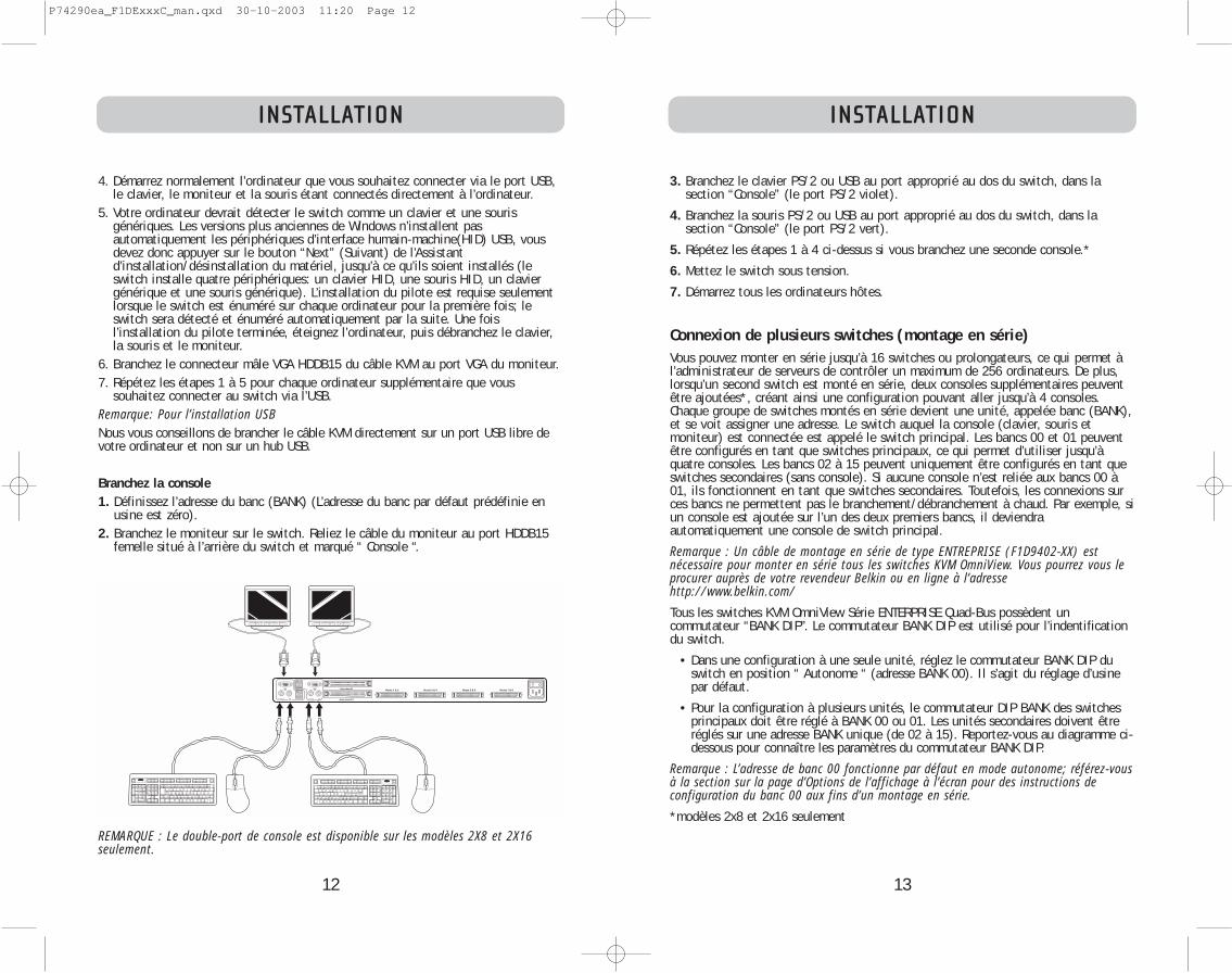
13
INSTALLATION
3. Branchez le clavier PS/2 ou USB au port approprié au dos du switch, dans lasection “Console” (le port PS/2 violet).
4. Branchez la souris PS/2 ou USB au port approprié au dos du switch, dans lasection “Console” (le port PS/2 vert).
5. Répétez les étapes 1 à 4 ci-dessus si vous branchez une seconde console.*
6. Mettez le switch sous tension.
7. Démarrez tous les ordinateurs hôtes.
Connexion de plusieurs switches (montage en série)Vous pouvez monter en série jusqu’à 16 switches ou prolongateurs, ce qui permet àl’administrateur de serveurs de contrôler un maximum de 256 ordinateurs. De plus,lorsqu’un second switch est monté en série, deux consoles supplémentaires peuventêtre ajoutées*, créant ainsi une configuration pouvant aller jusqu’à 4 consoles.Chaque groupe de switches montés en série devient une unité, appelée banc (BANK),et se voit assigner une adresse. Le switch auquel la console (clavier, souris etmoniteur) est connectée est appelé le switch principal. Les bancs 00 et 01 peuventêtre configurés en tant que switches principaux, ce qui permet d’utiliser jusqu’àquatre consoles. Les bancs 02 à 15 peuvent uniquement être configurés en tant queswitches secondaires (sans console). Si aucune console n’est reliée aux bancs 00 à01, ils fonctionnent en tant que switches secondaires. Toutefois, les connexions surces bancs ne permettent pas le branchement/débranchement à chaud. Par exemple, siun console est ajoutée sur l’un des deux premiers bancs, il deviendraautomatiquement une console de switch principal.
Remarque : Un câble de montage en série de type ENTREPRISE (F1D9402-XX) estnécessaire pour monter en série tous les switches KVM OmniView. Vous pourrez vous leprocurer auprès de votre revendeur Belkin ou en ligne à l’adressehttp://www.belkin.com/
Tous les switches KVM OmniView Série ENTERPRISE Quad-Bus possèdent uncommutateur “BANK DIP”. Le commutateur BANK DIP est utilisé pour l’indentificationdu switch.
• Dans une configuration à une seule unité, réglez le commutateur BANK DIP duswitch en position “ Autonome “ (adresse BANK 00). Il s’agit du réglage d’usinepar défaut.
• Pour la configuration à plusieurs unités, le commutateur DIP BANK des switchesprincipaux doit être réglé à BANK 00 ou 01. Les unités secondaires doivent êtreréglés sur une adresse BANK unique (de 02 à 15). Reportez-vous au diagramme ci-dessous pour connaître les paramètres du commutateur BANK DIP.
Remarque : L’adresse de banc 00 fonctionne par défaut en mode autonome; référez-vousà la section sur la page d’Options de l’affichage à l’écran pour des instructions deconfiguration du banc 00 aux fins d’un montage en série.
*modèles 2x8 et 2x16 seulement
12
INSTALLATION
4. Démarrez normalement l’ordinateur que vous souhaitez connecter via le port USB,le clavier, le moniteur et la souris étant connectés directement à l’ordinateur.
5. Votre ordinateur devrait détecter le switch comme un clavier et une sourisgénériques. Les versions plus anciennes de Windows n’installent pasautomatiquement les périphériques d’interface humain-machine(HID) USB, vousdevez donc appuyer sur le bouton “Next” (Suivant) de l’Assistantd’installation/désinstallation du matériel, jusqu’à ce qu’ils soient installés (leswitch installe quatre périphériques: un clavier HID, une souris HID, un claviergénérique et une souris générique). L’installation du pilote est requise seulementlorsque le switch est énuméré sur chaque ordinateur pour la première fois; leswitch sera détecté et énuméré automatiquement par la suite. Une foisl’installation du pilote terminée, éteignez l’ordinateur, puis débranchez le clavier,la souris et le moniteur.
6. Branchez le connecteur mâle VGA HDDB15 du câble KVM au port VGA du moniteur. 7. Répétez les étapes 1 à 5 pour chaque ordinateur supplémentaire que vous
souhaitez connecter au switch via l’USB.Remarque: Pour l’installation USBNous vous conseillons de brancher le câble KVM directement sur un port USB libre devotre ordinateur et non sur un hub USB.
Branchez la console1. Définissez l’adresse du banc (BANK) (L’adresse du banc par défaut prédéfinie en
usine est zéro).2. Branchez le moniteur sur le switch. Reliez le câble du moniteur au port HDDB15
femelle situé à l’arrière du switch et marqué “ Console “.
REMARQUE : Le double-port de console est disponible sur les modèles 2X8 et 2X16seulement.
Hosts 1 & 2 Hosts 3 & 4 Hosts 5 & 6 Hosts 7 & 8
P74290ea_F1DExxxC_man.qxd 30-10-2003 11:20 Page 12

15
INSTALLATION
3. Branchez le moniteur, le clavier et la souris de la console sur les ports Console desswitches principaux, comme décrit précédemment dans la configuration autonome, enignorant les étapes 5 et 6.*
*Le double-port de console est disponible sur les modèles 2X8 et 2X16 seulement.4. Branchez les ordinateurs au switch comme décrit précédemment pour les switches
autonomes.
Hosts 1 & 2 Hosts 3 & 4 Hosts 5 & 6 Hosts 7 & 8
Hosts 1 & 2 Hosts 3 & 4 Hosts 5 & 6 Hosts 7 & 8
Hosts 1 & 2 Hosts 3 & 4 Hosts 5 & 6 Hosts 7 & 8
Hosts 1 & 2 Hosts 3 & 4 Hosts 5 & 6 Hosts 7 & 8
INSTALLATION
14
DIP SWITCH #BANK ADDRESS1 2 3 4
DOWN DOWN DOWN DOWN BANK 00 (Default)
UP DOWN DOWN DOWN BANK 01 PRIMARY/SECONDARY
DOWN UP DOWN DOWN BANK 02 SECONDARY
UP UP DOWN DOWN BANK 03 SECONDARY
DOWN DOWN UP DOWN BANK 04 SECONDARY
UP DOWN UP DOWN BANK 05 SECONDARY
DOWN UP UP DOWN BANK 06 SECONDARY
UP UP UP DOWN BANK 07 SECONDARY
DOWN DOWN DOWN UP BANK 08 SECONDARY
UP DOWN DOWN UP BANK 09 SECONDARY
DOWN UP DOWN UP BANK 10 SECONDARY
UP UP DOWN UP BANK 11 SECONDARY
DOWN DOWN UP UP BANK 12 SECONDARY
UP DOWN UP UP BANK 13 SECONDARY
DOWN UP UP UP BANK 14 SECONDARY
UP UP UP UP BANK 15 SECONDARY
Par exemple :Quatre Switches KVM OmniView Série ENTREPRISE Quad-Bus (F1DE208C) sont montés en série afin de contrôler ensemble 32 ordinateurs. Le commutateur DIP surles unités principales sont définies comment étant “BANK Address 00” et les unitéssecondaires sont définies avec une adresse de banc unique entre 01 et 15 (BANK 00doit être configuré pour un fonctionnement dans un montage en série, comme mention-né ci-dessus).
InstallationAvant de commencer :
1. Assurez-vous que tous les ordinateurs sont éteints et que chaque switch a uneadresse BANK unique.
2. Placez les switches primaire et secondaire à l’endroit qui vous convient.
Diagramme de configuration du commutateur DIP
P74290ea_F1DExxxC_man.qxd 30-10-2003 11:20 Page 14

17
INSTALLATION
9. Si l’adresse de banc principale est 00, l’administrateur du KVM doit configurer le switch pour l’utilisation en montage en série. Pour ce faire, veuillez suivre lesétapes suivantes: (Remarque : Vous verrez peut-être des lignes apparaître surcertaines consoles. Ceci est normal et est dû à une mauvaise configuration, etcesse lorsque l’option “Daisy-Chain this switch” (Monter ce switch en série) est activée).
a) Ouvrez IntelliView (OSD) en appuyant deux fois sur la touche CTRL, appuyezensuite sur la barre d’espacement, et entrez Setup.
b) Allez à la page d’options, sélectionnez le bouton “Advanced” (Avancé).c) Dans “Advanced Dialog”, cochez la case “daisy-chain this KVM” (Monter ce KVM en série).d) Une boîte de dialogue va apparaître pour vous informer que “This will reset the
KVM to change this setting” (Ceci réinitialisera le KVM afin de modifier leparamètre). Cliquez sur “ OK “ pour refermer la boîte de dialogue et lancer laréinitialisation switch.
Lorsque le switch redémarre, il entre en interaction avec les autres boîtiers montésen série comme demandé. Vous pouvez le vérifier en ouvrant IntelliView et en par-courant la liste d’ordinateurs; si l’un ou l’autre des ordinateurs reliés au switch appa-raît dans la liste du banc 00, c’est signe que tout fonctionne correctement.
Remarque: Si vous ne configurez pas le banc 00 pour une utilisation en série, il nepourra pas interagir avec les autres switches KVM et ces derniers ne pourront pas inter-agir avec lui. En outre, la face avant de l’unité ne réagit pas de la même façon quecelle des autres unités. Enfin, il se peut que des interactions imprévisibles soientcausées par la connexion d’un banc 00 mal configuré pour un montage en série.
Mise en route des systèmesUne fois tous les câbles branchés, allumez les ordinateurs connectés. Le switchémule à la fois une souris et un clavier sur chaque port et permet à votre ordinateurde démarrer normalement; nul besoin d’alimenter le switch pour émuler le clavier etla souris.
L’ordinateur connecté au port “ 01 “ de n’importe quel switch principal s’affiche surle moniteur. Vérifiez si le switch fonctionne correctement en utilisant la souris, leclavier, les touches de raccourci, IntelliView et/ou les sélecteurs de ports à accèsdirect. Répétez cette opération pour tous les ports utilisés afin de vérifier que tousles ordinateurs sont connectés et répondent correctement. Si une erreur se produit,vérifiez le branchement des câbles de cet ordinateur et redémarrez-le, le cas échéant.Si le problème persiste, appelez l’assistance technique de Belkin.
16
INSTALLATION
Branchement du câble de montage en série5. Commencez avec BANK 00. Branchez une extrémité du câble de montage en série
(F1D9402-XX) sur le port “ Daisy-Chain OUT “ du premier switch.6. Branchez l’autre extrémité du câble sur le port “ Daisy-Chain IN “ du second
switch.Remarque: Peu importe quelle unité est l’unité principale, ils doivent seulement être branchés OUT-to-IN ou IN-to-OUT.
Ajout d’unités supplémentaires7. De la même façon, continuez à brancher un câble de montage en série (F1D9402-XX)
“ Daisy-Chain IN “ vers “ Daisy-Chain OUT “ sur toutes les autres unités.
ATTENTION : Ne branchez jamais “ Daisy-Chain IN “ sur “ Daisy-Chain IN “ ou “ Daisy-Chain OUT “ sur “ Daisy-Chain OUT “. Ceci peut avoir des conséquences imprévisibles.
Exemple de configuration en série
Branchement des ordinateurs :8. Allumez les switches dans l’ordre qui vous convient. Vous verrez les voyants des
ports clignoter, et les voyants en sept segments s’allumeront, affichant une sériede codes diagnostiques, pour s’arrêter éventuellement sur “XX”, “XX” étantl’adresse du banc.
Remarque: Si les switches ne sont toujours pas énumérés avec leur adresse de bancrespectives, assurez-vous que tous les switches se sont vus assigner l’adresse de banccorrecte, et que tous les câbles de montage en série sont branchés correctement.
Hosts 1 & 2 Hosts 3 & 4 Hosts 5 & 6 Hosts 7 & 8
Hosts 1 & 2 Hosts 3 & 4 Hosts 5 & 6 Hosts 7 & 8
Hosts 1 & 2 Hosts 3 & 4 Hosts 5 & 6 Hosts 7 & 8
Hosts 1 & 2 Hosts 3 & 4 Hosts 5 & 6 Hosts 7 & 8
P74290ea_F1DExxxC_man.qxd 30-10-2003 11:20 Page 16

19
UTILISATION DE VOTRE SWITCH
Configuration de montage en série• Le voyant en 7 segments d’un boîtier secondaire affiche toujours son adresse de
banc. Tous les autres boutons et voyants des bancs secondaires seront désactivés.
Mode Statique (Idle)• Le voyant en 7 segments affiche le numéro de banc actuel.• Les voyants Port Selection et Shift seront éteints.• Le voyant Console s’allume, ce qui indique que ce switch est une console.
Le switch basculera en Mode Sélection lorsque vous appuyez puis relâchez n’importequel bouton se trouvant sur la face avant de la console. Le voyant Port Selectionpassera d’éteint à allumé et le voyant en 7 segments passera de l’adresse du banc àl’affichage du banc activé.
Mode de sélection• Le Mode de Sélection bascule à nouveau
en Mode Statique après 5 secondes d’inactivité.• Le voyant en 7 segments indique toujours l’ID du banc activé.• Un voyant de port est allumé pour indiquer le port actif sur le banc actif.• Le voyant Shift s’allume chaque fois que les ports 9-16 sont sélectionnés. Pour
utiliser le switch 1X8 ou 2X8 afin de sélectionner les ports 9 à 16 sur un switchKVM 1X16 ou 2X16, maintenez le bouton correspondant enfoncé pendant uneseconde (le voyant de permutation s’allume), puis relâchez-le. Par exemple, poursélectionner l’ordinateur relié au port 9: à partir du Mode de Sélection, appuyezsur le bouton pour le port 1, et maintenez-le appuyé pendant 1 seconde avant dele relâcher. Le Switch émettra un son, et les voyants Port 1 et Shift s’allumeront.
• Le voyant Console Principale s’allume, ce qui indique que ce switch est une console.
1. Appuyez sur le boutons de sélection des bancs pour faire défiler les bancsdisponibles. Chaque pression augmente ou diminue le banc d’une unité, et estimmédiatement indiqué par le voyant à 7 segments.
2. Appuyez sur le bouton correspondant au port que vous désirez sélectionner.Lorsque vous relâchez le bouton, le switch émet un son et se centre sur le port sélectionné. Si l’utilisateur se voit refuser l’accès au port sélectionné, un messageapparaît, soit “Access Denied” (Accès refusé).
3. Si vous appuyez sur le bouton AutoScan, lorsque vous relâchez le bouton, leswitch émet un son et passe en Mode AutoScan (Balayage automatique).
18
UTILISATION DE VOTRE SWITCH
Maintenant que votre console et vos ordinateurs sont connectés au switch, vous êtes prêt à l’utiliser.
Vous pouvez sélectionner les ordinateurs connectés grâce aux sélecteurs de ports àaccès direct situés sur la face avant du switch, aux raccourcis clavier ou à IntelliView.
Remarque: Pour les raccourcis clavier (flèches Haut et Bas, par exemple) et AutoScan,l’ordre de progression lors du passage d’un ordinateur au suivant est lié à l’ordre desordinateurs dans la zone de liste (dans la page principale d’IntelliView).
Sélection d’un ordinateur à l’aide des sélecteurs de port à accès directLe switch a été conçu pour permettre à un switch 1X8 d’accéder à tous les ports sur unswitch 2X16 ou un Prolongateur KVM (F1DE016C). Les opérations à partir de la face avantpeuvent s’effectuer grâce à un bouton. Les opérations à partir de la face avant diffèrentselon qu’elles se font en configuration de montage en série ou autonome. Dans une con-figuration autonome, chaque bouton de commande active la fonction sélectionnée. Dansune configuration de montage en série, le premier bouton de commande active le Mode deSélection, et chaque autre bouton active la fonction sélectionnée.
Remarque: Le signal peut prendre un moment pour être rafraîchi (tout dépend de votremoniteur) après avoir commuté entre les ordinateurs.
Configuration autonome• Le voyant en 7 segments affichera le numéro du port activé pour chaque console.• Un voyant Port Selection est constamment allumé. Il correspond au port activé
et la console. • Le voyant Shift (libellé avec une * sur la face avant) indique que les ports 9-16
sont sélectionnés (non applicable si ce switch est en mode autonome).• Le voyant Console s’allume, ce qui indique que ce switch est un switch de con-
sole principale.• Les boutons de sélection du banc n’ont aucun effet, puisque dans cette configu-
ration il n’existe qu’un seul banc.
1. Appuyez sur le bouton correspondant au port que vous désirez sélectionner.Lorsque vous relâchez le bouton, le switch émet un son et se centre sur le portsélectionné. Si vous n’avez pas le droit d’accéder au port sélectionné, le switchémet un son, retire l’activation du port sélectionné, et un message apparaît, soit“Access Denied” (Accès refusé).
2. Si vous appuyez sur le bouton AutoScan, lorsque vous relâchez le bouton, leSwitch émet un son et passe en Mode AutoScan (Balayage automatique).
Remarque : Pour qu’un switch autonome fonctionne comme décrit dans cette section,l’adresse du banc doit être définie à 00 et la case “ Daisy-Chain this KVM “ (Monter ceKVM en série) désélectionnée. Sinon, le switch fonctionnera, mais come un switchmonté en série.
P74290ea_F1DExxxC_man.qxd 30-10-2003 11:20 Page 18
21
UTILISATION DE VOTRE SWITCH
Utilisation de la fonction AutoScan depuis la face avantVous activez la fonction AutoScan en appuyant sur le bouton AutoScan. En modeAutoScan, le switch active un seul port pour une période de temps pré-déterminée(1-99 secondes), pour ensuite passer au port suivant.
Mode AutoScan• Le mode AutoScan continue tant que vous n’y mettez pas fin en utilisant un rac-
courci clavier valide ou en appuyant sur un bouton de la face avant.• Lorsque le switch est en mode AutoScan, il est également en mode d’affichage
seulement (View-Only Mode). Cela signifie que les saisies au niveau de la consolene sont pas transmises au serveur actif. Vous devez annuler l’AutoScan pourreprendre le contrôle de l’ordinateur.
• Le vitesse de l’AutoScan peut être configurée par l’utilisateur via l’ordinateur, sur lapage de Configuration d’IntelliView.
• L’AutoScan omet les ordinateurs dont l’utilisateur s’est vu refuser l’accès (Lesrestrictions d’accès sont configurées sur la page Sécurité d’IntelliView)
• Un voyant correspondant au port actif est allumé.• Le voyant Console s’allume, ce qui indique que ce switch est une console.• Sur un switch autonome, le voyant en 7 segments affiche le numéro du port
actif, mais sur un switch monté en série, ce voyant affiche le numéro du bancactif.
1. Pour passer en mode AutoScan, appuyez sur le bouton AutoScan (une seule foissur un switch autonome et deux fois pour un switch monté en série).
2. Si vous appuyez sur un bouton de la face avant et que vous le relâchez, le boîtierémet un son et quitte le mode AutoScan. Si vous appuyez sur un sélecteur de portà accès direct, le focus du switch passe au port sélectionné. Si vous n’avez pas la permission d’accéder au port sélectionné, un message apparaîtra.
Utilisation de la fonction MultiViewCe switch KVM Série ENTREPRISE Quad-Bus peut autoriser plusieurs utilisateurs àafficher le même serveur simultanément. Toutefois, seule la première console à activ-er ce serveur en a le contrôle (possibilité de saisie). Lorsque des consoles supplé-mentaires accèdent au même ordinateur, ces consoles recevront le message “Viewonly, no control” (Visualisation seulement, sans contrôle). La console ayant le con-trôle reçoit en contre-partie le message “Viewed by console X” (Visualisé par la con-sole X), où “X” correspond à la lettre de l’autre console visualisant l’ordinateur. Si labannière (message) est activée sur n’importe quel type de console, elle sera affichéeindéfiniment. Si la bannière est désactivés, elle sera affichée pendant cinq secondes.
20
UTILISATION DE VOTRE SWITCH
Sélection d’un ordinateur à l’aide des raccourcis clavierPour envoyer vos commandes au switch, vous devez appuyer deux fois sur la touche “Arrêt défil “ dans la seconde qui suit (vous entendrez un son qui le confirmera).Ensuite, entrez la séquence de raccourcis-claviers pour la commande spécifique (vous disposerez d’environ 3 secondes après le son pour compléter la séquence de raccourcis-clavier). Les commandes de raccourcis-clavier sont énumérées ci-dessous:
SL SL Flèche vers le haut Passe à l’ordinateur PRÉCÉDENT dans la zone de liste d’IntelliView.SL SL Flèche vers le bas Passe à l’ordinateur SUIVANT dans la zone de liste d’IntelliView.SL SL XX YY Permet de passer directement au banc XX, port YY
(XX=00 à 15) (YY=01 à 08 pour le F1DE108C et le F1DE208C) SL SL Barre d’espacement Activation d’IntelliViewSL SL A Activer et désactiver le mode AutoScan
Remarque : D’autres touches peuvent être utilisées pour entrer des commandes pourclaviers sans touches Arrêt défil. Par exemple, CTRL est la méthode de choix pour lesordinateurs Macintosh, qui définissent souvent d’autres fonctions pour la touche Arrêtdéfil. Ces paramètres peuvent être modifiés dans la page Options d’IntelliView.
Pour les raccourcis clavier (flèches Haut et Bas, par exemple) et AutoScan, l’ordre deprogression lors du passage d’un ordinateur au suivant est lié à l’ordre des ordina-teurs dans la zone de liste (dans la page principale d’IntelliView).
P74290ea_F1DExxxC_man.qxd 30-10-2003 11:20 Page 20

23
UTILISATION DE VOTRE SWITCH
• En appuyant sur la barre d’espacement, vous activez l’élément sélectionnéd’IntelliView (idem à lorsque vous cliquez sur l’élément). Si la zone de liste estactivée, lorsque vous appuyez sur la barre d’espacement, la console contrôle l’or-dinateur sélectionné.
• Appuyez sur “ Entrée “ pour activer l’élément sélectionné si cet élément est unbouton ou à l’intérieur d’une zone d’édition. Toutefois, si la main est sur unautre type d’élément (une zone de liste, par exemple), la touche Entrée active lacommande par défaut, “ Close “ (Fermer) ou “ Exit “ (Quitter) selon l’écrand’IntelliView dans lequel vous vous trouvez.
• Si l’administrateur appuie sur “ Ctrl+TAB “ dans une page de configuration,IntelliView passe à la page suivante.
• Les raccourcis-clavier sont activés sous IntelliView. Par exemple, en appuyant sur“ALT + X”, où “X” correspond à un caractère souligné dans l’étiquette de la com-mande, vous activez cet élément.
• Lorsque IntelliView est activé, les entrées provenant du clavier et de la souris ysont détournés. Les signaux ne sont pas envoyés directement à l’ordinateur.
• Sélectionnez le bouton “ Close “ (Fermer) ou appuyez sur “ Alt+C “ sur les pagesde configuration pour repasser à la page principale.
• La touche “ Tab “ permet de passer d’un élément à l’autre de la page IntelliViewouverte. Maj + Tab permet de retourner en arrière.
• La fenêtre IntelliView peut être repositionnée. Il vous suffit de cliquer sur labarre de titre et de faire glisser la fenêtre à l’aide de la souris.
• Pour repositionner la bannière, appuyez sur “ Ctrl+Alt “ lorsque la fenêtreIntelliView est ouverte. Le curseur passe de la fenêtre IntelliView à la bannière ;cliquez alors avec la souris et déplacez-la pour repositionner la bannière.
• Le switch conserve les paramètres de positionnement de la bannière etd’IntelliView pour des résolutions vidéo de multiples ordinateurs. L’utilisateurdoit configurer les positions d’IntelliView et de la bannière lors de la configura-tion du switch, afin que ces endroits soient identiques pour toutes les résolu-tions vidéo.
Remarque: L’OSD ne se ferme pas de lui-même. Afin de réduire le risque qu’IntelliView soit imprimé de façon permanente sur l’écran du moniteur, fermez le moniteur ou activez le mode AutoScan du Switch. Toutes les fonctions configuréesdans les pages sont des fonctions globales (pour toutes les consoles), à moins que lecontraire ne soit spécifié.
22
UTILISATION DE VOTRE SWITCH
Commandes du menu de l’affichage à l’écran (OSD) IntelliViewL’affichage à l’écran (OSD) IntelliView permet d’avoir une utilisation comparable aux systèmes sous Windows, trèsrépandus sur les ordinateurs personnels. Pour activer l’affichage à l’écran, appuyezsur les touches “Arrêt Défil + Arrêt Défil + barre d’espacement” de votre clavier.(D’autres touches peuvent remplacer la touche Arrêt Défil. Pour les claviers ne possé-dant pas la touche Arrêt Défil, référez-vous à la section “Page d’Options IntelliView”de ce manuel de l’utilisateur pour de plus amples informations).
Fonction de l’affichage à l’écran IntelliViewLa page principale est l’écran de départ qui apparaît après l’ouverture d’IntelliView.La disposition de la fenêtre est similaire aux nombreux systèmes sous Windows.L’utilisateur voit une fenêtre avec une barre de titre contenant des commandes etune zone principale où il peut accéder aux fonctions du switch.
Le coin supérieur droit de la barre de titre d’IntelliView permet d’identifier la consoleactuelle (les consoles A à D sont les bancs 00 à 03 respectivement), et l’utilisateuractuellement connecté. En cliquant sur le bouton “?”, l’écran d’Aide apparaît. Vous ytrouverez des instructions d’utilisation d’IntelliView.
Sélectionnez le bouton “ X “ pour fermer la page en cours de consultation. Vous pouvez aussi fermer IntelliView à l’aide de la touche Échapp sur votre clavier.
Remarque: Toutes les modifications apportées à IntelliView sont enregistrées dans lamémoire dès que le focus change ; il n’existe pas de méthode pour annuler des actionsun fois qu’elles ont été entrées. Il y a une exception, lorsque vous éditez le contenud’un champ (par ex. le champ Computer Name (Nom de l’Ordinateur)), la toucheÉchapp met fin au contrôle et rétabli le contenu à sa forme originale.
Fonctions d’entrée et de navigation• Cliquez sur l’en-tête de colonne “ Group “ (Groupe), “ Computer Name “ (Nom de
l’ordinateur) ou “ ID “ pour trier les entrées en ordre croissant en fonction del’en-tête sélectionnée.
• Cliquez deux fois sur une ligne d’ordinateur pour sélectionner cette ligne et fairepasser la console sur le port sélectionné. Si l’utilisateur n’a pas le droit d’accéderà l’ordinateur sélectionné, un message d’erreur apparaît. Une fois la boîte de dia-logue fermée, la console reste sur le port précédemment sélectionné.
• Lorsqu’IntelliView est ouvert, appuyez sur les touches de direction Haut ou Baspour déplacer le curseur de l’ordinateur (la rangée en bleu) vers le haut ou lebas. Si le curseur se déplace hors de la zone visible, la liste se déplace d’uneligne. Vous pouvez également utiliser la molette de défilement de la souris poureffectuer cette fonction.
• Les doubles flèches Haut/Bas à droite de la liste des ordinateurs permettent de faire défiler la liste d’une page à la fois vers le haut ou le bas. Les touches “ Pg préc “ et “ Pg suiv “ du clavier ont la même fonction.
P74290ea_F1DExxxC_man.qxd 30-10-2003 11:20 Page 22
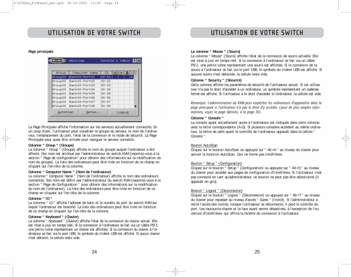
25
UTILISATION DE VOTRE SWITCH
La colonne “ Mouse “ (Souris)La colonne “ Mouse“ (Souris) affiche l’état de la connexion de souris actuelle. Elleest mise à jour en temps réel. Si la connexion à l’ordinateur se fait via un câblePS/2, une petite icône représentant une souris est affichée. Si la connexion de lasouris à l’ordinateur se fait via le port USB, le symbole du trident USB est affiché. Siaucune souris n’est détectée, la cellule reste vide.
Colonne “ Security “ (Sécurité)Cette colonne affiche les paramètres de sécurité de l’utilisateur actuel. Si cet utilisa-teur n’a pas le droit d’accéder à un ordinateur, un symbole représentant un cadenasfermé est affiché. Si l’utilisateur a le droit d’accéder à l’ordinateur, la cellule est vide.
Remarque: L’administrateur du KVM peut empêcher les ordinateurs d’apparaître dans lapage principale si l’utilisateur n’a pas le droit d’y accéder. (pour de plus amples infor-mations, voyez la page Options, à la page 30).
Colonne “ Console “La console ayant actuellement accès à l’ordinateur est indiquée dans cette colonne avec la lettre correspondante (A-D). Si plusieurs consoles accèdent au même ordina-teur, la lettre de celle ayant le contrôle de l’ordinateur apparaît dans la cellule “Console “.
Bouton AutoScanCliquez sur le bouton AutoScan ou appuyez sur “ Alt+A “ au niveau du clavier pouractiver la fonction AutoScan. Ceci ne ferme pas IntelliView.
Bouton “ Setup “ (Configuration)Cliquez sur le bouton “ Setup “ (Configuration) ou appuyez sur “ Alt+S “ au niveaudu clavier pour accéder aux pages de configuration d’IntelliView. Si l’utilisateur n’estpas connecté en tant qu’administrateur, ce bouton ne peut pas être sélectionné (ilapparaît en gris).
Bouton “ Logout “ (Déconnexion)Cliquez sur le bouton “ Logout “ (Déconnexion) ou appuyez sur “ Alt+T “ au niveaudu clavier pour repasser au niveau d’accès “ Guest “ (Invité). Si l’administrateur aretiré l’accès des invités, lorsque l’utilisateur se déconnecte, il perd le contrôle duport. Les raccourcis-clavier et la face avant seront désactivés, à l’exception de l’ou-verture d’IntelliView, qui offrira la fenêtre de connexion à l’utilisateur.
24
UTILISATION DE VOTRE SWITCH
Page principale
La Page Principale affiche l’information sur les serveurs actuellement connectés. Enun coup d’oeil, l’utilisateur peut visualiser le groupe du serveur, le nom de l’ordina-teur, l’emplacement du port, l’état de la connexion et le mode de sécurité. La PagePrincipale peut aussi être utilisée pour naviguer le serveur connecté.
Colonne “ Group “ (Groupe)La colonne “ Group “ (Groupe) affiche le nom du groupe auquel l’ordinateur a étéaffecté. Son nom est attribué par l’administrateur du switch KVM (reportez-vous à lasection “ Page de configuration” pour obtenir des informations sur la modification dunom du groupe). La liste des ordinateurs peut être triée en fonction de ce champ encliquant sur l’en-tête de la colonne.
Colonne “ Computer Name “ (Nom de l’ordinateur)La colonne “ Computer Name “ (Nom de l’ordinateur) affiche le nom des ordinateursconnectés. Son nom est défini par l’administrateur du switch KVM (reportez-vous à lasection “ Page de Configuration “ pour obtenir des informations sur la modificationdu nom de l’ordinateur). La liste des ordinateurs peut être triée en fonction de cechamp en cliquant sur l’en-tête de la colonne.
Colonne “ ID “La colonne “ ID “ affiche l’adresse de banc et le numéro du port du switch KVM surlequel l’ordinateur est branché. La liste des ordinateurs peut être triée en fonctionde ce champ en cliquant sur l’en-tête de la colonne.
Colonne “ Keyboard “ (Clavier)La colonne “ Keyboard “ (Clavier) affiche l’état de la connexion du clavier actuel. Elleest mise à jour en temps réel. Si la connexion à l’ordinateur se fait via un câble PS/2,une petite icône représentant un clavier est affichée. Si la connexion du clavier à l’or-dinateur se fait via le port USB, le symbole du trident USB est affiché. Si aucun claviern’est détecté, la cellule reste vide.
P74290ea_F1DExxxC_man.qxd 30-10-2003 11:20 Page 24

27
UTILISATION DE VOTRE SWITCH
Durée du balayage et bouton “ Change All “ (Modifier tous)L’utilisateur peut réinitialiser la durée du balayage de tous les ordinateurs en entrantune valeur comprise entre 1 et 99 dans la zone d’édition, puis en cliquant sur lebouton “ Change All “ (Modifier tous). Il devra ensuite confirmer l’action avant quela nouvelle durée ne soit appliquée.
Colonne “ Console “La console qui examine actuellement l’ordinateur est indiquée dans cette colonne.
Page “ Security “ (Sécurité)La page “ Security “ (Sécurité) permet à l’administrateur de modifier l’accès aux ordina-teurs à l’utilisateur du switch. Il existe trois niveaux d’accès utilisateur au switch : “Administrator “ (Administrateur), “ User “ (Utilisateur) et “ Guest “ (Invité).L’administrateur est le seul utilisateur qui peut accéder aux pages de configuration afinde régler le switch. Il peut limiter l’accès des utilisateurs et des invités à certains ordinateurs. Tous les utilisateurs peuvent changer d’ordinateur et activer la fonctionAutoScan dans la page principale. En outre, l’invité est l’utilisateur par défaut (vousn’avez jamais à ouvrir de session en “ Invité “). C’est pourquoi tous les utilisateurs sedéconnectent en “ Invité “ lorsque le compte est activé.
Si l’administrateur a retiré l’accès aux invités, lorsque l’utilisateur se déconnecte, ilperd le contrôle du port. Les raccourcis-clavier et la face avant seront désactivés, àl’exception de l’ouverture d’IntelliView, qui offrira la fenêtre de connexion à l’utilisa-teur.
Les comptes “ User “ (Utilisateur) définis dans le switch peuvent être utilisés par des individus ou par des groupes d’individus ; les noms des utilisateurs sont fixes.
Remarque: Lorsque l’utilisateur Invité est activé, les privilèges minimum sont accordéspour l’accès de toutes les personnes. Il est possible de limiter les comptes utilisateur plusencore que le compte d’invité ; c’est une erreur potentielle à éviter.
26
UTILISATION DE VOTRE SWITCH
La Page de Configuration
La page de configuration est uniquement disponible à l’administrateur et permet dedéfinir le nom des groupes, le nom des ordinateurs et l’intervalle d’analyse des ordina-teurs. La durée dépend du port en cours d’analyse. Cette durée est globale, c’est-à-direqu’elle est indépendante de la console ou de l’utilisateur. Bien que la durée d’analyseest indépendante de l’utilisateur, AutoScan ignore les ordinateurs auxquels cet utilisa-teur n’a pas le droit d’accéder.Colonne “ Group “ (Groupe)La colonne “ Group “ (Groupe) affiche le nom du groupe auquel l’ordinateur a étéaffecté. Les nom du groupe est du texte arbitraire, uniquement employé dans un butd’organisation. Le nom du groupe peut être composé de huit caractèresalphanumériques maximum. Il est attribué par l’administrateur du switch KVM. Le nompar défaut est “ Group X “ (Groupe X), où X représente le numéro de banc d’un KVMdéterminé par le commutateur DIP de l’adresse de banc. Pour charger le nom dugroupe, cliquez sur la cellule qui vous convient.Colonne “ Computer Name “ (Nom de l’ordinateur)La colonne “ Computer Name “ (Nom de l’ordinateur) affiche le nom des ordinateursconnectés. Le nom de l’ordinateur peut être composé de 15 caractères alphanumériquesmaximum. Il est attribué par l’administrateur du switch KVM. La liste des ordinateurspeut être triée en fonction de ce champ en cliquant sur l’en-tête de la colonne. Pardéfaut, tous les noms d’ordinateurs sont appelés BANK XX-Port YY, où XX est unnuméro d’adresse de banc à deux chiffres entre 00 et 15, et YY est un numéro d’ordina-teur à deux chiffres compris entre 01 et 16. Pour entrer le nom de l’ordinateur, cliquezsur la cellule qui vous convient. Colonne “ ID “Cette colonne affiche l’adresse de banc et le numéro du port du switch KVM sur lequell’ordinateur est branché. La liste des ordinateurs peut être triée en fonction de cechamp en cliquant sur l’en-tête de la colonne. Colonne “ Scan “ (Balayage)La colonne “ Scan “ (Balayage) affiche la durée pendant laquelle la console va examin-er chaque ordinateur en mode AutoScan. Pour changer cette durée, cliquez sur la cel-lule qui vous convient
P74290ea_F1DExxxC_man.qxd 30-10-2003 11:20 Page 26
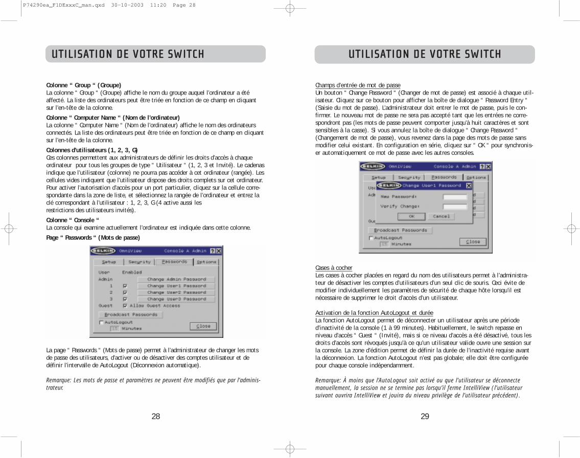
29
UTILISATION DE VOTRE SWITCH
Champs d’entrée de mot de passeUn bouton “ Change Password “ (Changer de mot de passe) est associé à chaque util-isateur. Cliquez sur ce bouton pour afficher la boîte de dialogue “ Password Entry “(Saisie du mot de passe). L’administrateur doit entrer le mot de passe, puis le con-firmer. Le nouveau mot de passe ne sera pas accepté tant que les entrées ne corre-spondront pas (les mots de passe peuvent comporter jusqu’à huit caractères et sontsensibles à la casse). Si vous annulez la boîte de dialogue “ Change Password “(Changement de mot de passe), vous revenez dans la page des mots de passe sansmodifier celui existant. En configuration en série, cliquez sur “ OK “ pour synchronis-er automatiquement ce mot de passe avec les autres consoles.
Cases à cocherLes cases à cocher placées en regard du nom des utilisateurs permet à l’administra-teur de désactiver les comptes d’utilisateurs d’un seul clic de souris. Ceci évite demodifier individuellement les paramètres de sécurité de chaque hôte lorsqu’il estnécessaire de supprimer le droit d’accès d’un utilisateur.
Activation de la fonction AutoLogout et duréeLa fonction AutoLogout permet de déconnecter un utilisateur après une période d’inactivité de la console (1 à 99 minutes). Habituellement, le switch repasse enniveau d’accès “ Guest “ (Invité), mais si ce niveau d’accès a été désactivé, tous lesdroits d’accès sont révoqués jusqu’à ce qu’un utilisateur valide ouvre une session surla console. La zone d’édition permet de définir la durée de l’inactivité requise avantla déconnexion. La fonction AutoLogout n’est pas globale; elle doit être configuréepour chaque console indépendamment.
Remarque: À moins que l’AutoLogout soit activé ou que l’utilisateur se déconnectemanuellement, la session ne se termine pas lorsqu’il ferme IntelliView (l’utilisateursuivant ouvrira IntelliView et jouira du niveau privilège de l’utilisateur précédent).
28
UTILISATION DE VOTRE SWITCH
Colonne “ Group “ (Groupe)La colonne “ Group “ (Groupe) affiche le nom du groupe auquel l’ordinateur a étéaffecté. La liste des ordinateurs peut être triée en fonction de ce champ en cliquantsur l’en-tête de la colonne.
Colonne “ Computer Name “ (Nom de l’ordinateur)La colonne “ Computer Name “ (Nom de l’ordinateur) affiche le nom des ordinateursconnectés. La liste des ordinateurs peut être triée en fonction de ce champ en cliquantsur l’en-tête de la colonne.
Colonnes d’utilisateurs (1, 2, 3, G)Ces colonnes permettent aux administrateurs de définir les droits d’accès à chaqueordinateur pour tous les groupes de type “ Utilisateur “ (1, 2, 3 et Invité). Le cadenasindique que l’utilisateur (colonne) ne pourra pas accéder à cet ordinateur (rangée). Lescellules vides indiquent que l’utilisateur dispose des droits complets sur cet ordinateur.Pour activer l’autorisation d’accès pour un port particulier, cliquez sur la cellule corre-spondante dans la zone de liste, et sélectionnez la rangée de l’ordinateur et entrez laclé correspondant à l’utilisateur : 1, 2, 3, G (4 active aussi les restrictions des utilisateurs invités).
Colonne “ Console “La console qui examine actuellement l’ordinateur est indiquée dans cette colonne.
Page “ Passwords “ (Mots de passe)
La page “ Passwords “ (Mots de passe) permet à l’administrateur de changer les motsde passe des utilisateurs, d’activer ou de désactiver des comptes utilisateur et dedéfinir l’intervalle de AutoLogout (Déconnexion automatique).
Remarque: Les mots de passe et paramètres ne peuvent être modifiés que par l’adminis-trateur.
P74290ea_F1DExxxC_man.qxd 30-10-2003 11:20 Page 28

31
UTILISATION DE VOTRE SWITCH
“ Display Banner “ (Aff. bannière)Cette option permet d’afficher une bannière lors des événements système : l’utilisa-tion d’un sélecteur de port à accès direct, la mise sous tension du switch, etc. Labannière est toujours affichée ou affichée pendant un certain temps (1 à 99 secon-des). Si vous choisissez l’option avec une durée définie, cette durée indique combiende temps la bannière va rester affichée après la réalisation de l’événement système.Référez-vous à la section “MultiView” (page 21) et la section “Banner” (Bannière)(page 33) pour de plus amples informations sur le fonctionnement et le contenu dela bannière. La configuration de la bannière n’est pas globale; elle doit être config-urée pour chaque console indépendamment.
“Display Inactive Ports” (Afficher les ports inactifs)Cette fonction permet aux ports auxquels aucun ordinateur n’est relié d’apparaîtredans la zone de liste des ordinateurs (sur la page principale d’IntelliView). Pardéfaut, les ports inactifs sont affichés. La fonction “Display Inactive Ports” (Afficherles ports inactifs) n’est pas globale; elle doit être configurée pour chaque consoleindépendamment.
“Display Restricted Ports” (Afficher ports sans accès)Cette fonction permet aux ports auxquels l’utilisateur actuel n’a pas le droit d’accéder d’apparaître dans la liste des ordinateurs (sur la page principaled’IntelliView). Par défaut, les ports dont l’accès n’est pas autorisé sont affichés. Lafonction “Display Inactive Ports” (Afficher les ports inactifs) n’est pas globale; elledoit être configurée pour chaque console indépendamment.
“ Alternate Attention Key” (Autre touche d’activation)Cet écran vous permet de sélectionner d’autres touches d’activation pour initier lescommandes par raccourcis-clavier. Il permet aux claviers ne possédant pas les mêmestouches ou qui utilisent ces touches pour d’autres fonctions d’utiliser les raccourcis-clavier. Vous pouvez sélectionner autant de touches d’activation que vous le désirez. Remarque : Si aucune des options n’est sélectionnée, Arrêt Défil devient la touched’activation par défaut.“Display Version Numbers” (Aff. numéros de version)Cette fenêtre affiche les informations sur le produit, notamment le numéro du mod-èle et les révisions du microprogramme. La fonction Display Version Numbers” (Aff.numéros de version) n’est pas globale; elle n’affiche que les numéros de version dece banc en particulier. Remarque : Lorsque vous procédez à une mise à niveau Flash, vous devrez mettre àniveau chaque switch ou prolongateur individuellement.
30
UTILISATION DE VOTRE SWITCH
“ Broadcast Passwords “ (Diffuser les mots de passe)Cette case force toutes les autres consoles à remplacer les mots de passe de leurs util-isateurs par celui contenu dans la console actuelle. Il est alors facile pourl’administrateur de synchroniser les mots de passe de toutes les consoles (lors de l’a-
jout d’une nouvelle console à une configuration existante, par exemple).
Page des options
Les commandes de cette page affectent plusieurs fonctions diverses du switch.
P74290ea_F1DExxxC_man.qxd 30-10-2003 11:20 Page 30

UTILISATION DE VOTRE SWITCH
33
Messages d’erreur et boîtes de dialogueDe temps à autres, il sera nécessaire d’afficher des message à l’utilisateur pour luiindiquer les erreurs ou lui demander de répondre à des questions. Ces fenêtres con-textuelles comprennent une barre de titre ainsi qu’un corps de fenêtre qui contient letexte du message. Les boutons “ OK “ et “ Cancel “ seront également proposés enfonction de la nature du message.Boîte de dialogue d’ouverture de sessionLa boîte de dialogue d’ouverture de session est une fenêtre simple comportant desboutons radio pour sélectionner l’utilisateur et des zones d’édition pour permettre àl’utilisateur d’entrer son mot de passe. Si vous êtes déjà connecté, cliquez sur “Cancel “ (Annuler) pour revenir à votre écran d’ouverture de session (ou au compte “Guest “ (Invité) si ce compte est activé). Si vous n’êtes pas connecté et que lecompte “ Guest “ (Invité) est désactivé, cliquez sur “ Cancel “ (Annuler) pour fermerIntelliView.Fenêtres d’aideVous pouvez accéder à l’aide en ligne via IntelliView. Appuyez simplement sur latouche F1, ou cliquez sur le bouton “?” à la droite de la barre de titre.Bannière
La bannière, une petite fenêtre qui apparaît pour informer l’utilisateur et le portsélectionné par la console, apparaît sous forme d’une ligne de texte entourée d’uncadre 3D gris. Elle affiche les informations suivantes:
• Nom du groupe• Nom de l’hôte• Banc et port activés
Si plusieurs consoles examinent le même ordinateur (mode MultiView), celle ayant le contrôle affiche les informations suivantes :
• Visualisé par la console [lettre de la console]• Banc et port activés
La console en simple consultation affiche les éléments suivants dans sa bannière :• Affichage uniquement, aucun contrôle• Banc et port activés
La bannière affiche aussi les messages d’erreur importants et les changements importants apportés à la configuration du KVM.Ecran d’accueilLorsque vous mettez le switch sous tension, une fenêtre apparaît et affiche le nomdu produit et des informations sur le copyright. La fenêtre est affichée pendantplusieurs secondes, et disparaît ensuite. L’ouverture d’IntelliView effacera l’écrand’accueil immédiatement.
32
UTILISATION DE VOTRE SWITCH
Bouton “Advanced” (Avancé)
En cliquant sur le bouton, l’utilisateur est amené à l’écran de configuration avancée.“Disable Viewing” (Désactiver l’affichage)Lorsque l’option “Disable Viewing” (Désactiver l’affichage) est cochée, les canauxoccupés par l’administrateur ne peuvent être vus que par un autre administrateur.Cette fonction est activée par défaut sur l’IntelliView. Pour des raisons de sécurité,l’administrateur peur la désactiver au besoin.Daisy-Chain this KVM (Monter ce KVM en série)Cette option permet aux switches d’être définis en banc 00 afin de communiqueravec les autres bancs montés en série. Ceci a une influence sur les opérations auniveau de la face avant et sur quelques autres paramètres de fonctionnement divers.Chaque fois que vous cochez ou désélectionnez cette case, un message informe l’util-isateur qu’il doit redémarrer le switch afin que la modification de ce paramètre soitprise en compte. Si l’utilisateur clique sur “OK”, le switch redémarre automatique-ment, avec la nouvelle configuration. Par défaut, les switches définis en banc 00sont configurés en mode autonome (la case n’est pas cochée).“Steal Control of this Host” (Prendre relais de l’hôte)Cette fonction permet à l’administrateur du KVM de prendre le contrôle d’un hôte quiest actuellement utilisé par d’autres utilisateurs. “Restore Factory Defaults” (Rétablir les Paramètres par Défaut)En cliquant sur le bouton, TOUS les paramètres configurables par l’utilisateur (nomsdes ordinateurs, noms des groupes, mots de passe, etc.) de tous les bancs du mon-tage en série seront rétablis vers les paramètres par défaut du fabricant. Un messagede confirmation apparaît avant que cette action soit appliquée.
Remarque: Dans une configuration de montage en série, le rétablissement des paramètresvers les paramètres par défaut entraîne un comportement imprévisible des unités. Afin derésoudre de problème temporaire et rétablir le fonctionnement normal du banc 00, l’ad-ministrateur doit retourner à la page d’Options, cliquer sur le bouton “Advanced”(Avancé) et cocher la case “Daisy-chain this KVM” (Monter en série ce KVM).
P74290ea_F1DExxxC_man.qxd 30-10-2003 11:20 Page 32

35
UTILISATION DE VOTRE SWITCH
Pour amorcer le processus de mise à jour, vous devez exécuter l’applicationAutoUpdate en sélectionnant le fichier “AutoUpdate.ex” à partir du menu Démarrer,ou à partir d’un raccourci sur le bureau.
Le premier écran de l’AutoUpdate invite l’utilisateur à choisir la mise à jour automa-tique ou manuelle. De façon générale, choisissez la mise à jour automatique, à moinsd’une raison spécifique. Lors de la mise à jour automatique, le logiciel compare laversion actuelle du microprogramme et les versions les plus récentes. S’il y a une ver-sion plus récente, le logiciel va télécharger le nouveau microprogramme par Internetet le transférer au switch. L’utilisateur doit ensuite redémarrer le(s) switch(es) KVMpour terminer l’installation du microprogramme. La mise à jour manuelle fonctionnede façon similaire, mais l’utilisateur doit rechercher manuellement le fichier de miseà jour approprié.
Remarque: Avant de mettre le switch à jour, assurez-vous que l’AutoScan est désactivé etqu’IntelliView n’apparaît pas sur la console. Ceci réduit le niveau d’activité du switch.
34
UTILISATION DE VOTRE SWITCH
L’Utilitaire de mise à jour du microprogramme AutoUpdate
Mise à jour du microprogrammeLe programme AutoUpdate est conçu pour analyser votre matériel et vous guider pasà pas dans le processus de mise à jour du microprogramme (si nécessaire) de votreswitch. AutoUpdate télécharge automatiquement le microprogramme adapté à votreappareil à partir du site Web de Belkin, ou vous pouvez télécharger le fichier appro-prié manuellement en visitant notre site Web à belkin.com.L’administrateur doit effectuer les mises à jour lorsque le(s) switch(es) KVM ne sontpas en cours d’utilisation. Chaque switch sera réinitialisé pendant le processus, cequi peut mener au malfonctionnement du clavier ou de la souris de certains ordina-teurs. L’administrateur doit éteindre tout ordinateur qu’il/elle ne désire pas redémar-rer manuellement, avant de débuter le processus de mise à jour.Pour mettre le microprogramme à jour, vous avez besoin des éléments suivants :1. Un ordinateur fonctionnant sous Windows XP, 2000, Me, ou 98, avec un port USB libre.2. Un câble USB régulier pour relier le switch et l’ordinateur.3. L’application AutoUpdate de Belkin peut être téléchargée par Internet.4. Une connexion à Internet pour l’installation automatique.
Installation de l’application AutoUpdate:
1. Téléchargez et lancez l’application AutoUpdate à partir du site Web de Belkin.
2. Cliquez sur le bouton “Next” (Suivant), en configurant l’emplacement du fichier, lechoix de l’icône, etc. tel que désiré, jusqu’à ce que l’installation soit terminée.
Branchement de l’ordinateur au switch :
1. Mettez le switch sous tension.
2. Branchez une extrémité du câble USB au port flash de votre(vos) switch(es) (leconnecteur USB “B”) et l’autre extrémité dans le port USB de l’ordinateur. Vousaurez peut-être besoin d’un ou plusieurs hubs USB entre l’ordinateur et le switchsi vous désirez mettre à jour plusieurs switches simultanément.
Remarque: Avant de débuter la mise à jour, l’administrateur doit se rendre à la paged’Options d’IntelliView, appuyer sur le bouton “Display Version Number” (Aff. numéros deversion)et prendre en note les numéros de la version actuelle. Ceci permettra à l’administra-teur de confirmer la mise à jour du microprogramme.
P74290ea_F1DExxxC_man.qxd 30-10-2003 11:20 Page 34

37
UTILISATION DE VOTRE SWITCH
Avant le début de la mise à jour, un écran d’avertissement apparaît, informant l’util-isateur des risques liés à la mise à jour, et des actions devant être évités lorsque lamise à jour est en cours.
Remarque: Il est primordial que le PC et le switch soient et demeurent sous tension, etque le câble USB demeure connecté au PC ou au switch pendant la mise à jour.L’utilisateur doit aussi éviter d’utiliser le PC, car il risque d’interférer avec le processusde mise à jour d’AutoUpdate. Si le processus est perturbé, le switch peut devenir com-plètement non-opérationnel. Si la mise à jour est interrompue alors que le Switch estsous tension, vous devriez être en mesure de redémarrer la mise à jour (vous devrezprobablement relancer l’application AutoUpdate).
36
UTILISATION DE VOTRE SWITCH
Mise à jour des périphériques via le Web
Au lancement de l’application AutoUpdate, celui-ci parcourt votre ordinateur pour despériphériques qui prennent en charge le processus de mise à jour. Le logiciel se con-necte automatiquement à l’Internet et recherche des mises à jour disponibles pour lespériphériques trouvés. Lorsque l’application a amassé les informations pertinentes, ilaffiche une liste de périphériques trouvés. La présence d’un “OK” à la gauche du nomdu périphérique (emplissant la case d’option) indique qu’il n’existe pas de mises àjour sur le Web (le périphérique est à jour). Si AutoUpdate trouve une mise à jourpour un périphérique, il affiche une case d’option et l’icône AutoUpdate apparaît à lagauche du nom du périphérique. Si vous cliquez sur un périphérique dans la zone deliste, des informations sur ce périphérique et la mise à jour apparaîtront dans lechamp de détails, à la droite de la zone de liste. Cliquez sur les cases marquées d’uncrochet de la liste de périphériques pour désélectionner tout périphérique que vous nedésirez pas mettre à jour pour le moment. Tous les périphériques dont les cases sontcochées seront mis à jour (tous à la fois) lorsque vous cliquez “Next” (Suivant).
P74290ea_F1DExxxC_man.qxd 30-10-2003 11:20 Page 36

39
UTILISATION DE VOTRE SWITCH
Le bouton “Advanced” (Avancé) permet à l’utilisateur de mettre à jour manuellementcertains périphériques choisis. AutoUpdate se contente de vérifier si le fichier estvalide pour ce mode. Belkin ne recommande pas l’utilisation du Mode Avancé, àmoins d’être invité à le faire par le service d’Assistance Technique de Belkin. Le bou-ton Advanced (Avancé) est sélectionné par défaut au même moment que le boutonNext (Suivant) (lorsqu’un périphérique et un fichier valide sont sélectionnés).
Avertissement: Un usage non approprié du Mode Avancé peut rendre votre switch non-opérationnel et incapable d’être mis à jour ultérieurement.
Ces deux paragraphes sont une répétition (voir ci-dessus).
38
UTILISATION DE VOTRE SWITCH
Lorsque la mise à jour est débutée, une boîte de dialogue apparaît, affichant le pro-grès du transfert de fichier pour chaque sous-périphérique et pour le switch, en tantqu’un tout. Si plusieurs périphériques sont été sélectionnés, la boîte de dialoguedemeure et répète le processus pour chaque périphérique. Lorsque la mise à jour estterminée, le bouton “Next” est sélectionné par défaut, ce qui permet à l’utilisateur determiner la mise à jour.
Remarque : Pendant le processus de transfert de fichier d’AutoUpdate, le voyant en 7segments affiche “AU”, ce qui indique que l’AutoUpdate est en cours.
Mise à jour manuelle du KVM à partir d’un fichier sur disque local
Si vous choisissez la mise à jour manuelle, l’application AutoUpdate recherchera lespériphériques qui peuvent être mis à jour, mais ne vérifiera pas du côté de l’Internetpour les mises à jour. Les cases à cocher seront donc toutes vides. L’utilisateur doitindiquer l’emplacement du fichier de mise à jour (de façon manuelle ou en cliquantsur le bouton “parcourir” (l’ellipse). Si le fichier est valide, le bouton “Next” (Suivant)sera sélectionné par défaut. Cliquez sur celui-ci pour passer à l’écran suivant. Remarque: Les fichiers invalides sont: fichiers non conçus pour AutoUpdate; fichiersAutoUpdate pour périphérique erroné, langue erronée, etc.; fichiers AutoUpdate appro-prié mais qui ne contient pas une nouvelle version.
P74290ea_F1DExxxC_man.qxd 30-10-2003 11:20 Page 38

41
UTILISATION DE VOTRE SWITCH
Terminer la mise à jour du microprogramme
Le switch doit être réinitialisé (“power cycled”) après un téléchargement réussi, afinde lui permettre de programmer ses composants internes. Le processus de mise à journ’est pas terminé tant que le périphérique n’a pas été réinitialisé.
Avertissement! Si le processus de mise à jour a échoué ou a été interrompu, NE réini-tialisez PAS le périphérique! La réinitialisation du périphérique dans ces cas entraîn-erait une mauvaise programmation du switch (avec des données corrompues). Cecipeut rendre votre switch non-fonctionnel et le rendre incapable d’être mis à jour cor-rectement par la suite. Tentez à nouveau la mise à jour du périphérique; si elle échoue,contactez le service d’Assistance technique de Belkin pour obtenir de l’aide.
Terminer la mise à jour du microprogramme d’un switch autonome
1. Réinitialisez ou redémarrez le switch.
2. Les composants internes du switch sont reprogrammés avec le nouveau code (cecipeut prendre plusieurs minutes). Pendant le processus de programmation, les voyants de sélection des ports à accès direct clignotent et le voyant en 7 seg-
ments affiche une série de codes diagnostiques.
3. Lorsque la mise à jour est terminée, le switch émettra différents sons, s’amorce automatiquement, et affiche l’Écran d’accueil. Le switch est maintenant mis à jouret entièrement opérationnel.
Terminer la mise à jour du microprogramme sur de multiples switches KVM(montés en série)
1. Mettez hors tension TOUS les switches faisant partie du montage en série.
2. Mettez sous tension UN SEUL switch.
3. Les composants internes du switch sont reprogrammés avec le nouveau code (cecipeut prendre plusieurs minutes). Pendant le processus de programmation, les voy-ants de sélection des ports à accès direct clignotent et le voyant en 7 segmentsaffiche une série de codes diagnostiques.
4. Lorsque la mise à jour est terminée (environ 2 minutes), le switch émettra dif-férents sons, s’amorce automatiquement, et affiche l’Écran d’accueil. Le switch estmaintenant mis à jour et entièrement opérationnel.
5. METTEZ HORS TENSION le switch mis à jour.
6. Répétez les étapes 2 à 5 pour chacun des switches, jusqu’ce qu’ils soient tous mis à jour.7. Lorsque tous les switches sont mis à jour de façon indépendante, mettez sous ten-
sion tous les bancs faisant partie du montage en série. Le montage en série enentier est maintenant mis à jour et entièrement opérationnel.
40
UTILISATION DE VOTRE SWITCH
Lorsque la mise à jour est terminée, le bouton “Next” est sélectionné par défaut, cequi permet à l’utilisateur de terminer la mise à jour.
Si le téléchargement échoue pour une quelconque raison, une boîte de dialogueapparaîtra et vous invitera à recommencer la mise à jour.
Si la mise à jour s’achève avec succès, cet écran devrait apparaître. Si un redémar-rage est nécessaire, il vous sera indiqué à l’écran. Lorsque vous cliquez sur “Finish”(Terminer), l’application AutoUpdate se ferme.
Lorsque la mise à jour est terminée, le voyant en 7 segments indique “PC”, indiquantqu’un redémarrage (“power cycle”) est nécessaire afin de terminer la mise à jour.
P74290ea_F1DExxxC_man.qxd 30-10-2003 11:20 Page 40

43
k) Cliquez sur “OK” pour fermer la boîte de dialogue.
l) Fermez l’application du clavier.
Remarque: En créant une copie de l’application “Eject this disk” (Éjecter ce disque) survotre bureau, vous pouvez facilement définir la fonction d’éjection à la mappe declavier. Pour copier l’application “Eject this disk” à partir de Sherlock, appuyez etmaintenez appuyé la touche “Option” sur le clavier (“Alt” sur un clavier PC), et glissezl’application de la fenêtre de résultat vers votre bureau.
DÉPANNAGE
42
DÉPANNAGE
J’ai monté en série plusieurs switches, je veux maintenant ajouter une autreconsole. De quoi ai-je besoin pour la faire fonctionner?
• Si vous voulez ajouter une console à un switch faisant déjà partie d’un montageen série et dont le commutateur DIP est défini en 00 ou 01, vous n’avez qu’àbrancher votre moniteur, votre clavier et votre souris.
• Reliez le switch aux ordinateurs en suivant la même procédure que pour unswitch autonome. Avant de mettre sous tension le banc, branchez-y le câble demontage en série et branchez sur ce câble un des switch en fin de chaîne(assurez-vous d’utiliser le port N pour un banc et le port OUT pour l’autre).Mettez le switch sous tension. Ouvrez IntelliView sur une des autres consoles, etentrez Setup Mode (Mode de configuration). Allez à la page des mots de passe(Passwords) et cliquez sur le bouton “Broadcast Passwords” (Diffuser les mots depasse). La nouvelle console est prête à être utilisée et est synchronisée avec lereste des périphériques du montage en série.
• Reliez le switch aux ordinateurs en suivant la même procédure que pour unswitch autonome. Avant de mettre sous tension le banc, branchez-y le câble demontage en série et branchez sur ce câble un des switches en fin de chaîne(assurez-vous d’utiliser le port IN pour un banc et le port OUT pour l’autre).Mettez le switch sous tension. Ouvrez IntelliView sur une des autres consoles, etentrez Setup Mode (Mode de configuration). Allez à la page des mots de passe(Passwords) et cliquez sur le bouton “Broadcast Passwords” (Diffuser les mots depasse). La nouvelle console est prête à être utilisée et est synchronisée avec lereste des périphériques du montage en série.
J’ai un ordinateur Macintosh sans bouton d’éjection sur le lecteur de CD. Latouche d’éjection sur mon clavier ne fonctionne pas lorsque je passe par leswitch. Comment puis-je ouvrir mon lecteur?
• Sous Mac OS® X (v10.1 et ultérieure) appuyez sur F12 pour éjecter le CD.• Voici comment programmer la fonction d’éjection sur votre clavier sous Mac OS 9:1. La méthode simple
a) À partir du menu Pomme, choisissez “Sherlock2”.b) Sélectionnez le disque dur contenant les informations système de Mac OS 9.c) Dans le champ Search (Recherche), entrez “Eject this disk” (Éjectez ce disque).d) Cliquez sur la loupe pour commencer la recherche.e) À partir du menu Pomme, sélectionnez “Control Panels” (Panneau de configura-
tion).e) À partir du menu Panneau de Configuration, sélectionnez “Keyboard” (Clavier).g) Dans la boîte de dialogue du Clavier, cliquez sur le bouton “Function Keys”
(Touches de fonctions).h) Choisissez la touche qui servira à exécuter la fonction d’éjection.i) Appuyez sur la touche de fonction désirée. Une boîte de dialogue “Assign F[X]
key” (Attribuer la touche F[X]) apparaît, où X correspond au numéro de la fonc-tion sur laquelle vous avez appuyé.
j) Choisissez l’application “Eject this disk” (Éjecter ce disque), soit à partir d’unecopie sur le bureau, où à partir de l’emplacement indiqué par Sherlock. Cliquezensuite sur le bouton “Assign” (Attribuer).
P74290ea_F1DExxxC_man.qxd 30-10-2003 11:20 Page 42

45
GLOSSAIRE
Autonome : Switch KVM unique, fonctionnant de façon indépendante (non relié aux autres).
Mode statique: Mode de fonctionnement principal d’un switch KVM. Le switch entre en mode statique si vous n’appuyez pas sur un bouton pendant au moins cinq secondes.
OSD:”On-Screen Display”. Interface utilisateur graphique pouvant être employée pour contrôler et configurer le Switch KVM.
Affichage: En terme de permutation de ports, “ afficher “ signifie que la consolereçoit des signaux vidéo de l’ordinateur. L’affichage nécessite que la console soitégalement “ centrée “ sur le port.
GLOSSAIRE
Les définitions suivantes sont utilisées dans le manuel :
AutoScan : Mode de fonctionnement dans lequel le switch analyse les ports un à un, de façon continue, tel que configuré par l’utilisateur.BANK (banc): L’adresse d’un KVM monté en série (0 à 15, tel que déterminé par lecommutateur DIP).Console: Le nom général pour appeler le clavier, le moniteur et la souris reliés à unswitch KVM.Port de la console: Réceptacle permettant à la console de se brancher au switchKVM.Contrôler: En terme de permutation de ports, le contrôle veut dire que la console esten mesure d’envoyer des entrées à l’ordinateur. Le contrôle nécessite que la consoleest également “centrée” sur le port et le visualise.Switch de console: Un switch KVM dont l’adresse de banc est 0-1, avec une consoley étant relié.CPU: Les marques apparaissant sur le boîtier du KVM, qui indiquent les numéros desports où sont branchés chaque câble d’ordinateur relié au switch KVM.Montage en série : Un montage de plusieurs switches KVM, reliés l’un à l’autre ensérie. Un montage de KVM de Belkin utilise des paramètres communs permettant uneharmonie parfaite lors des interactions complexes entre les différentes consoles, pourle contrôle de plusieurs ordinateurs.Focus: Ce terme est utilisé de deux façons distinctes:
1. Dans IntelliView, le “focus” est représenté par une ligne grise hachurée autourdu contrôle.Le “focus” détermine quel contrôle sera activé en appuyant sur labarre d’espacement ou la touche Entrée; si le focus est sur un bouton ou àl’intérieur d’un champ, ce contrôle s’activera lorsque vous appuyez sur latouche Entrée. Si le focus est sur un autre contrôle (par exemple, la zone deliste), la touche Entrée active le contrôle par défaut (Fermer ou Quitter).
2. En terme de permutation de ports, le “focus” réfère à l’action de centrer l’at-tention sur un port en particulier.
HID : Périphérique d’interface humain-machine. Classe de périphériques USB com-prenant les claviers et les souris.KVM: Switch clavier, moniteur, souris (Keyboard Video Mouse). Port: Récepteur d’interface sur un ordinateur, grâce auquel vous pouvez relier unpériphérique ou brancher un câble de périphérique.Switch principal: Un switch KVM dont l’adresse de banc est 0-1, avec seulement uneconsole y étant relié.Switch secondaire: Tout switch KVM sans console.Mode de sélection : Mode de fonctionnement dans lequel un switch KVM en ModeStatique entre lorsque l’on appuie sur le premier bouton de la face avant. Le mode desélection permet à l’utilisateur de choisir les bancs, les hôtes et autres au cours del’utilisation de boutons suivante.
44
P74290ea_F1DExxxC_man.qxd 30-10-2003 11:20 Page 44

46
Déclaration FCCDÉCLARATION DE CONFORMITÉ À LA RÉGLEMENTATION FCC EN MATIÈRE DE
COMPATIBILITÉ ÉLECTROMAGNÉTIQUE.
Nous, Belkin Components, sis au 501 West Walnut Street , Compton CA, 90220, États-Unis, déclaronssous notre seule responsabilité que le produit :
F1DE108CF1DE116CF1DE208CF1DE216C
auxquels se réfère la présente déclaration :Sont conformes aux normes énoncées à l’alinéa 15 de la réglementation FCC. Le fonctionnement estassujetti aux deux conditions suivantes : (1) ces appareils ne peuvent pas provoquer d’interférencenuisible et (2) ces appareils doivent accepter toute interférence reçue, y compris des interférencespouvant entraîner un fonctionnement non désiré.
Déclaration de conformité CENous, Belkin Components, déclarons que les modèles F1DE108C, F1DE116C, F1DE208C, et F1DE216C,auxquels se rapporte la présente déclaration, ont été élaboré dans le respect des normes d’émissionsEN55022 ainsi que des normes d’immunité EN55024, LVP EN61000-3-2 et EN61000-3-3 en vigueur.
ICESThis Class B digital apparatus complies with Canadian ICES-003. Cet appareil numérique de la classe Best conforme á la norme NMB-003 du Canada.
Garantie limitée du produit pendant 5 ans de Belkin CorporationBelkin Corporation garantit ce produit contre tout défaut matériel ou de fabrication pendant toute sapériode de garantie. Si l’appareil s’avère défectueux, Belkin le réparera ou le remplacera gratuitement, àsa convenance, à condition que le produit soit retourné, port payé, pendant la durée de la garantie, audépositaire Belkin agréé auprès duquel le produit a été acheté. Une preuve d’achat peut être exigée. Laprésente garantie est caduque si le produit a été endommagé par accident, abus, usage impropre oumauvaise application, si le produit a été modifié sans autorisation écrite de Belkin, ou si un numéro desérie Belkin a été supprimé ou rendu illisible.
LA GARANTIE ET LES VOIES DE RECOURS SUSMENTIONNÉES FONT FOI EXCLUSIVEMENT ET REMPLACENTTOUTES LES AUTRES, ORALES OU ÉCRITES, EXPLICITES OU IMPLICITES. BELKIN REJETTE EXPRESSÉMENTTOUTES LES GARANTIES IMPLICITES, Y COMPRIS MAIS SANS RESTRICTION, LES GARANTIES AFFÉRENTES ÀLA QUALITÉ LOYALE ET MARCHANDE ET À LA POSSIBILITÉ D’UTILISATION À UNE FIN DONNÉE.
Aucun dépositaire, représentant ou employé de Belkin n’est habilité à apporter des modifications ouadjonctions à la présente garantie, ni à la proroger.
BELKIN N’EST PAS RESPONSABLE DES DOMMAGES SPÉCIAUX, DIRECTS OU INDIRECTS, DÉCOULANT D’UNERUPTURE DE GARANTIE, OU EN VERTU DE TOUTE AUTRE THÉORIE JURIDIQUE, Y COMPRIS MAIS SANSRESTRICTION LES PERTES DE BÉNÉFICES, TEMPS D’ARRÊT, FONDS DE COMMERCE, REPROGRAMMATION OUREPRODUCTION DE PROGRAMMES OU DE DONNÉES MÉMORISÉS OU UTILISÉS AVEC DES PRODUITS BELKINOU DOMMAGES CAUSÉS À CES PROGRAMMES OU À CES DONNÉES.
Certains pays ne permettent pas d’exclure ou de limiter les dommages accidentels ou consécutifsou les exclusions de garanties implicites, de sorte que les limitations d’exclusions ci-dessus nes’appliquent pas dans votre cas. La garantie vous confère des droits légaux spécifiques. Vouspouvez également bénéficier d’autres droits qui varient d’un pays à l’autre.
INFORMATION
P74290ea_F1DExxxC_man.qxd 30-10-2003 11:20 Page 46
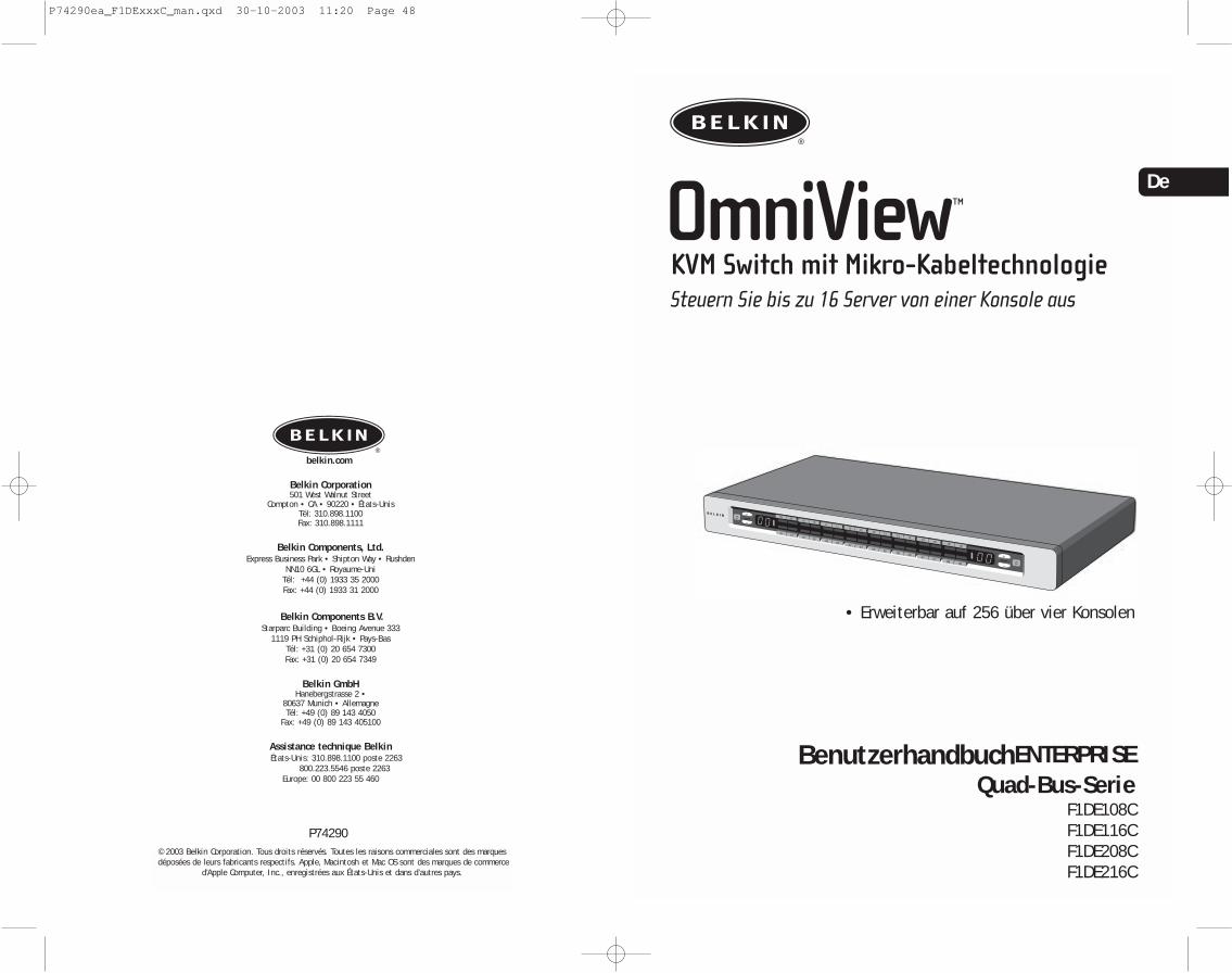
OmniView™
KVM Switch mit Mikro-Kabeltechnologie
BenutzerhandbuchENTERPRISEQuad-Bus-Serie
F1DE108CF1DE116CF1DE208CF1DE216C
Steuern Sie bis zu 16 Server von einer Konsole aus
• Erweiterbar auf 256 über vier Konsolen
De
© 2003 Belkin Corporation. Tous droits réservés. Toutes les raisons commerciales sont des marquesdéposées de leurs fabricants respectifs. Apple, Macintosh et Mac OS sont des marques de commerce
d’Apple Computer, Inc., enregistrées aux États-Unis et dans d’autres pays.
P74290
belkin.com
Belkin Corporation501 West Walnut Street
Compton • CA • 90220 • États-UnisTél: 310.898.1100Fax: 310.898.1111
Belkin Components, Ltd.Express Business Park • Shipton Way • Rushden
NN10 6GL • Royaume-UniTél: +44 (0) 1933 35 2000Fax: +44 (0) 1933 31 2000
Belkin Components B.V.Starparc Building • Boeing Avenue 333
1119 PH Schiphol-Rijk • Pays-BasTél: +31 (0) 20 654 7300Fax: +31 (0) 20 654 7349
Belkin GmbHHanebergstrasse 2 •
80637 Munich • AllemagneTél: +49 (0) 89 143 4050
Fax: +49 (0) 89 143 405100
Assistance technique BelkinÉtats-Unis: 310.898.1100 poste 2263
800.223.5546 poste 2263Europe: 00 800 223 55 460
P74290ea_F1DExxxC_man.qxd 30-10-2003 11:20 Page 48

EINFÜHRUNG
Wir beglückwünschen Sie zum Kauf dieses KVM-Switches aus der OmniViewENTERPRISE Quad-Bus -Serie von Belkin mit Mikro-Kabeltechnologie. Unserevielfältige Reihe an Masterswitch-Lösungen zeigt die hohen Qualitätsansprüche, dieBelkin an sich stellt. Der Name Belkin steht für hochwertige, dauerhafte Produkte zueinem günstigen Preis. Mit Belkin Pro2-Masterswitches kontrollieren Sie mehrereComputer und Server von einer bis vier Konsolen aus. Der Switch ist inunterschiedlichen Ausführungen für alle großen und kleinen Konfigurationenerhältlich.
Bei der Entwicklung des Switches stand der Serveradministrator im Mittelpunkt desKonzepts. Ergebnis ist ein KVM-Switch aus der OmniView ENTERPRISE Quad-Bus-Serie,der den konkurrierenden Systemen konzeptionell und technisch überlegen ist. DerSwitch ist auf die modernsten Serverraum- und Laborumgebungen ausgelegt undbietet folgende Vorteile:
• Unterstützung von Doppel-Konsolen* , erweiterbar auf 4 Konsolen• IntelliView Erweitertes Grafisches Bildchirmmenü• PS/2 und USB mix&match Tastatur- und Mausunterstützung• Mehrstufiges Sicherheitssystem• Geeignet für Flash-Aktualisierung• Spezieller Kaskadierungsanschluss• Unterstützung für hohe Grafikauflösungen (400 MHz: bis zu 2048 x 1536 bei 85 Hz)• Namensgebung für Computer und Gruppen• Server-Verbindungsdiagnose• Klare, einfache Anzeige der aktiven Schnittstelle• Direktwahltasten• 5 Jahre Belkin-Garantie• Doppelschnittstellen-Mikro-KVM-Kabel (separat erhältlich)*Nur für Modelle 2x8 und 2x16
Dieses Handbuch beschreibt Ihren Switch detailliert: von der Installation über dieBedienung bis zur Fehlerbehebung, sollte einmal ein Problem auftreten Von Zeit zuZeit veröffentlicht Belkin Aktualisierungen dieses Produkts; die entsprechendveränderten Informationen sind über die Internetseite www.belkin.de erhältlichEinfache, kurze Installationsanweisungen finden Sie in der Installationanleitung, die in der Verpackung enthalten ist.Wir freuen uns, dass Sie sich für den KVM Switch der OmniView ENTERPRISE Quad-Bus-Serie von Belkin entschieden haben.. Wir hoffen, Sie zu unseren zufriedenenStammkunden zählen zu können. In kurzer Zeit werden Sie selbst sehen, warumweltweit über 1 Million Belkin OmniView Produkte pro Jahr zum Einsatz kommen.Packungsinhalt:
• Ein KVM Switch der OmniView ENTERPRISE Quad-Bus-Serie mit Mikro-Kabeltechnologie
• Zwei Rack-Halterungen mit Befestigungsschrauben• Benutzerhandbuch• Installationsanleitung• Netzkabel nach IEC-Standard• Registrierkarte• Ein Set Gummifüße
1
INHALTSVERZEICHNIS
EinleitungÜbersicht
Merkmale . . . . . . . . . . . . . . . . . . . . . . . . . . . . . . . . . . . . . . . . 2Systemvoraussetzungen . . . . . . . . . . . . . . . . . . . . . . . . . . . . . . . 4Betriebssysteme . . . . . . . . . . . . . . . . . . . . . . . . . . . . . . . . . . . 4Technische Daten . . . . . . . . . . . . . . . . . . . . . . . . . . . . . . . . . . 5Bestandteile . . . . . . . . . . . . . . . . . . . . . . . . . . . . . . . . . . . . . . 6
InstallationVorbereitung des Geräts . . . . . . . . . . . . . . . . . . . . . . . . . . . . . . 8Einfache Installation des Switches . . . . . . . . . . . . . . . . . . . . . . . .9Verbinden mehrerer Switches (Kaskadierung) . . . . . . . . . . . . . . . . .13Konfiguration der DIP-Schalter . . . . . . . . . . . . . . . . . . . . . . . . .14Versorgung der Systeme . . . . . . . . . . . . . . . . . . . . . . . . . . . . . . 17
Verwenden des SwitchesAuswählen eines Computers über die Schnittstellen-Wahltaste . . . . . 18Auswählen eines Computers mit Tastaturbefehlen . . . . . . . . . . . . . 20AutoScan-Betrieb . . . . . . . . . . . . . . . . . . . . . . . . . . . . . . . . . . 21Das IntelliView Bildschirm-Menüsystem . . . . . . . . . . . . . . . . . . . .22Der Firmware-Aktualisierungsdienst AutoUpdate™ . . . . . . . . . . . . .34
Problemlösung . . . . . . . . . . . . . . . . . . . . . . . . . . . . . . . . . . . . . .42
Glossar . . . . . . . . . . . . . . . . . . . . . . . . . . . . . . . . . . . . . . . . . . .44
Information . . . . . . . . . . . . . . . . . . . . . . . . . . . . . . . . . . . . . . . .46
P74290ea_F1DExxxC_man.qxd 30-10-2003 11:20 Page 50
3
ÜBERSICHT
Programmierbare TastaturbefehleMit dem Switch können Sie 6 verschiedene Tasten so programmieren, dass über dieseBefehle ausgeführt werden; dadurch wir die Kompatibilität mit Tastaturengewährleistet, die andere Tasten haben oder dieselben Tasten mit anderenFunktionen belget haben. Diese Einstellungen können über IntelliView OSDvorgenommen werden Weitere Informationen finden Sie im Abschnitt “IntelliViewOSD-Funktionen” auf den Seiten 22 und 23 in diesem Handbuch
AutoScanMit der AutoScan-Funktion kann der Masterswitch die Aktivitäten aller betriebsbereiten Computer einzelnabfragen und überwachen, die am Masterswitch angeschlossen sind. Das Zeitintervall für die Überwachung desjeweiligen Computers kann per Bildschirm-Menü (OSD) eingestellt werden.
DirektwahltastenDiese Schalter, die bequem auf dem Bedienfeld des Switch angebracht sind, könnenSie Schnittstellen einfach und manuell auswählen.
LED-Anzeige:Eine LED-Anzeige an der Vorderseite dient als Statusmonitor. Eine LED befindet sichüber jeder Direktwahltaste. Sie zeigt an, dass die Konsole derzeit den jeweiligenCoomputer kontrolliert. Die LEDs sind verschiedenfarbig, um die Konsolen leichteridentifizieren zu können
Siebenteilige LED-Anzeige:In der Einzeleinstellung zeigt die siebenteilige LED den Port an, der für jede Konsoleausgewählt wurde. Beim Kaskadieren von mehreren Masterswitches gibt diesiebenteilige LED die BANK-Adresse an. Während der Computerauswahl zeigt die LEDkurz die ausgewählte BANK an. Dadurch kann der Benutzer den gewünschtenComputer direkt am Bedienfeld auswählen.
HD-Computer-PortsDer Switch verfügt über 50-Pin SCSI 2-HD-Stecker Die Stecker erlauben den Einbaudes KVM-Switch der ENTERPRISE Quad-Bus-Serie in eine Regal-Einheit
Mikro-KabeltechnologieÜber den Einsatz dieser Technologie wird 60% weniger Platz in Anspruch genommenund die Kabel sind leichter zu verwalten Sowohl ind er USB- als auch in der PS/2-Ausführung unterstützen diese Kabel Bildschirmauflösungen bis 2048x1536@85Hz.
2
ÜBERSICHT
Merkmale
QuadBus-TechnologieMehrere Switches können kaskadiert werden, wodurch Sie mit maximal vier Konsolenbis zu 256 Computer steuern können.
Integrierte Dopelkonsolen-Unterstützung*Sie können zwei Konsolen miteinander verbinden und so gleichzeitig bis zu 256Computer verwalten.
IIntelliView Grafisches Bildchirmmenü (OSD) mit MausunterstützungDas The IntelliView Bildschirm-Menüsystem vereinfacht die Serververwaltung, da Siejeden angeschlossenen Server mit einem Namen versehen können, der für dasGesamtsystem gilt. Sie können zur besseren Übersicht auch Computer zu Gruppenzusammenschließen. Das OSD bietet die visuelle Darstellung der Verbindung mitComputern und des Computer-Status; dabei werde mehrstufige Sicherheitsebenenangeboten und der Zeitinterval für die AutoScan-Funktion eingestellt.
PS/2- und USB-Mischanschluss für TastaturenMit dem Switch können Sie sowohl USB- als auch PS/2-Tastaturen und -Mäuse zurSteuerung verwenden. Server können entweder über den USB-, oder den PS/2-Anschluss des Computers angeschlossen werden, indem die Dual-Port-KVM-Kabel derENTERPRISE Quad-Bus-Serie verwendet werden
AutoUpdate™Mit unserem exklusiven AutoUpdate-System und der Firmware mit Flash-Aktualisiserung können Sie bei Bedarf die jeweils neuen Firmware-Aktualisierungenherunterladen. Dadurch bleibt der Switch mit neuen Geräten und Computernkompatibel, die künftig auf den Markt kommen. Die Firmware-Aktualisierungenkönnen Sie während der gesamten Lebensdauer Ihres Switch kostenlos abrufen. Bittebesuchen Sie unserer Internetseite www.belkin.de. Sie finden dort alleAktualisierungsinformationen und verschiedene Supportmöglichkeiten
BildschirmauflösungDer Switch verfügt über eine Grafik-Bandbreite von 400MHz, dieBildschirmauflössungen bis 2048x1536@85Hz erlaubt.
Hot Keys (Tastaturbefehle)Die gewünschte Schnittstelle können Sie mit Hilfe von Tastaturbefehlen über dieTastatur wählen. Eine einfache Tastenfolge genügt, um aus bis zu 256 Computerneinen bestimmten Rechner festzulegen.
*Nur für Modelle 2x8 und 2x16
P74290ea_F1DExxxC_man.qxd 30-10-2003 11:20 Page 2

5
ÜBERSICHT
Technische Daten
Artikelnr.: F1DE108C, F1DE116C, F1DE208C, F1DE216C
Stromversorgung: 100-240–264 V AC bei 47 – 63 Hz, einphasig, 0.25A @ 117VAC, 0.15A @ 240VAC
Kaskadierung: Maximal 16 BANKs, einschließlich 4 KonsolenMax. PC-Anzahl:
8 pro BANK = 128 gesamt (F1DE108C und F1DE208C), 16 pro BANK = 256 gesamt (F1DE116C und F1DE216C)
Tastaturemulation: PS/2 und USBMausemulation: PS/2 & USBUnterstützte Monitore: VGA, SVGA, MultiSync, LCD-Bildschirme mit analogemEingangMaximale Bildschirmauflösung: 2048x1536@85HzGrafik-Bandbreite: 400MHzMaximal Anzahl der Host-Verbindungen: 8 (F1DE108C und F1DE208C), 16(F1DE116C und F1DE216C)Tastatureingang: MiniDIN 6polig (PS/2) und USB AMauseingang: MiniDIN 6polig (PS/2) und USB AHost-Verbindungen:50-poliger HD SCSI 2-Anschluss (erfordert
Dual-Port KVM-Kabel aus der ENTERPRISE Quad-Bus-Serie von Belkin -F1D9400-XXoder F1D9401-XX)
VGA-Schnittstelle: HDDB 15poligLEDs für die Anschlüsse: 8 (F1DE108C), 16 (F1DE116C und F1DE208C), 32 (F1DE216C)Gehäuse:Metallgehäuse mit stoßfester KunststofffrontplatteMaße: 431mm x 44.5mm x 190mmGewicht:
(F1DE108C und F1DE208C) 4.173g(F1DE108C und F1DE208C) 4.309g
Betriebstemperatur: 0 - 40°C (32 - 104°F)Lagertemperatur:20 - 60°C (-4 - 140°F)Feuchtigkeit:0 bis -80%, nicht-kondensierendMaximale Höhe:3000 mGarantie:5 Jahre
Hinweis: Merkmale können sich ohne vorherige Ankündigung ändern.
4
ÜBERSICHT
Systemvoraussetzungen
KabelUm den Switch mit einem Computer zu verbinden, benötigen Sie ein spezielles KVM-Kabel der ENTERPRISE Quad-Bus-Serie von Belkin. Verwenden Sie für PS/2-Computerden Artikel F1D9400-XX. Verwenden Sie für USB-Computer den Artikel F1D9401-XX.Um mehrere BANKs miteinander zu verbinden, benötigen Sie ein spezielles KVM-Kaskadierungskabel der ENTERPRISE Quad-Bus-Serie
OmniView Enterprise Zweifach-KVM-Kabel der Quad-Bus-SerieF1D9400-XX (PS/2-Ausführung)
F1D9401-XX (USB-Ausführung)
OmniView ENTERPRISE Kaskadierungskabel derQuad-Bus -erieF1D9402-XX (Kaskadierung)
(XX = Länge gemessen in Fuß)
BetriebssystemeDer Switch ist für folgende Compter geeignet:
Plattformen:• Windows® 98, 2000, Me, NT® oder XP• Red Hat® Linux® 7.0, 7.1, 7.2, Mandrake, Lindows• Novell® NetWare® 5.x/6.x• Apple® Macintosh® Produkte (USB-Unterstützung oder
OmniView Mac Adapter™ F1D080 erforderlich)
Tastaturen• Unterstützt die meisten PS/2- und USB-Tastaturen (bis zu 101 Tasten)
Mäuse• Unterstützt die meisten PS/2- und USB-Mäuse
Bildschirm• VGA• SVGA• MultiSync®
Hinweis: DCC wird nicht unterstützt, wenn Monitore mit dem KVM-Switch verbunden sind.
P74290ea_F1DExxxC_man.qxd 30-10-2003 11:20 Page 4

7
ÜBERSICHT
PS/2-MausKonsolen-Port
USB-AKonsolen-Port
GrafikkonsoleVGA-Ports
4 HD 50-polige SCSI 2-Computer-Ports, für jeweils 2 Server (F1DE108C und F1DE208C)
HD 50-polige SCSI 2-Computer-Ports, für jeweils 2 Server (on the F1DE208C and F1DE216C)
IEC-Netzanschluss
Kaskadierungsports,Eingang
Kaskadierungs-Port, Ausgang
Netzschalter
PS/2-TastaturKonsolen-Port
Hosts 1 & 2 Hosts 3 & 4 Hosts 5 & 6 Hosts 7 & 8
Rückansicht des KVM Switch (F1DE208C)
Konsole 1 Konsole 2(F1DE208C undF1DE216C)
Flash-Aktualisierungsport,USB-B
BANK-AuswahlDIP-Schalter
Reset-Schalter
Klappbare Blende
Vorderansicht mit geschlossener Blende (F1DE108C)
6
ÜBERSICHT
Bestandteile
Vorderansicht des Switch (F1DE216C)
DoppelteAuswahlknöpfefür direktenZugriff auf Ports AutoScan-Schalter mit
LED-Anzeige für aktivenAutoScan-Modus
ManuelleBANK-Funktionsschalter
7-teilige LED-Anzeige fürBANK-Adresserkennung (im Kaskadierungsmodus)
Konsolen-LED-Anzeige zurBANK-ERKENNUNG Dies istdie primäre Konsole
LED-Leuchten für Port-und Konsolenerkennung
ManuelleBANK-Funktionsschalter
Klappbare Frontblende
Flash-Aktualisierungsport,USB-B
BANK-AuswahlDIP-Schalter
Reset-Schalter
Klappbare Vorderblende
Hinweis: Der 2x8 KVM Switch (F1DE208C) sieht etwas anders aus. Er verfügt über eine Umschalt-LED-Anzeige für den Umschalt-Modus (Zugriff auf Ports 9-16). Die Umschaltanzeige befindet sich neben der 7-teiligen LED-Leuchte.
Auto-Scan
Vorderansicht mit geschlossener Blende (F1DE216C)
P74290ea_F1DExxxC_man.qxd 30-10-2003 11:20 Page 6

9
INSTALLATION
1. Entnehmen Sie die Halterungen der Verpackung.
2. Befestigen Sie die Halterungen am Switch, um diesem nach leichter in das Rack einbauen zu können.
3. Befestigen Sie die Halterung mit den beigefügten Schrauben seitlich am Switch.
4. Befestigen Sie den Switch am Schienengestell.
*** Warnhinweise ***Vor dem Anschluss von Geräten an dden Switch oder den/den Computer(n) musssichergestellt werden, dass alle Computer und Geräte abgeschaltet sind. BelkinCorporation übernimmt keine Haftung für Schäden, die durch eingeschaltete Geräteentstehen.
Einfache Installation des SwitchIn diesem Abschnitt wird die Hardware-Installation eines Switch-Einzelgerätsbeschrieben.
Anschließen von Computern an den Masterswitch (PS/2-Anschluss)
1. Schließen Sie das IEC-Netzkabel an die Netzbuchse auf der Rückseite des Switch an.
Hosts 1 & 2 Hosts 3 & 4 Hosts 5 & 6 Hosts 7 & 8
INSTALLATION
Vorbereitung des Geräts
Der Switch kann wahlweise als eigenständige Einheit verwendet oder in einem Rackbefestigt werden. Der Switch ist mit Vorrichtungen für die Montage in einemstandardmäßigen 19”-Rack versehen. Die entsprechenden Befestigungen sind imLieferumfang enthalten. Rutschfeste Füße garantieren Stabiliät bei der Auflage.
Bitte beachten Sie bei der Aufstellung des Switch folgendes:
• Sollen die Direktwahltasten verwendet werden?• Wie lang sind die Kabel von Tastatur, Bildchirm und Maus?• Wie groß ist der Abstand zwischen den Computern und der Konsole?• Wie lang sind die Kabel für die Verbindung der Computer mit dem Masterswitch?• Wo im Serverraum stellen Sie die kaskadierten BANKs hin und welche Kaballänge
verwenden Sie, um die BANKs zu verbinden?
Empfohlene KabellängenFür PS/2-Computer:Empfohlen wird eine PS/2-Kabellänge von höchstens 7,5 m, um eine optimaleGrafikleistung zu gewährleisten. Bei größeren Abständen kann sich die Bildqualitätverschlechtern.
Für USB-Computer:Empfohlen wird eine USB-Kabellänge von höchstens 3,5 m, um eine optimaleLeistung zu gewährleisten.
Einbau des Switch in einen Server-Rack:Der Switch verfügt über Halterungen für den Einbau in ein 19”-Rack.
Bitte beachten Sie Folgendes, bevor Sie den Switch montieren.
a) Erhöhte Umgebungstemperatur im Betrieb — Bei der Installation in einemgeschlossenen Rack oder Rack mit mehreren Geräten kann dieUmgebungstemperatur beim Betrieb über der Raumtemperatur liegen. Dahermuss darauf geachtet werden, dass die Geräte in einer Umgebung installiertwerden, in der die vom Hersteller angegebene Höchsttemperatur nichtüberschritten wird.
b) Eingeschränkte Luftzirkulation – Beim Einbau des Geräts in einem Rackmuss darauf geachtet werden, dass die für den sicheren Betrieb des Gerätserforderliche Luftzirkulation nicht beeinträchtigt wird.
c) Mechanische Belastung – Das Gerät muss so im Rack montiert werden, dasskeine ungleichmäßige mechanische Beanspruchung entsteht, die zugefährlichen Situationen führen kann.
d) Zuverlässige Erdung – Das im Rack montierte Gerät muss ordnungsgemäßund zuverlässig geerdet werden. Besonders gründlich müssen Verbindungenzum Stromnetz geprüft werden, wenn kein direkter Anschluss an denNebenstromkreis erfolgt.
8
P74290ea_F1DExxxC_man.qxd 30-10-2003 11:20 Page 8
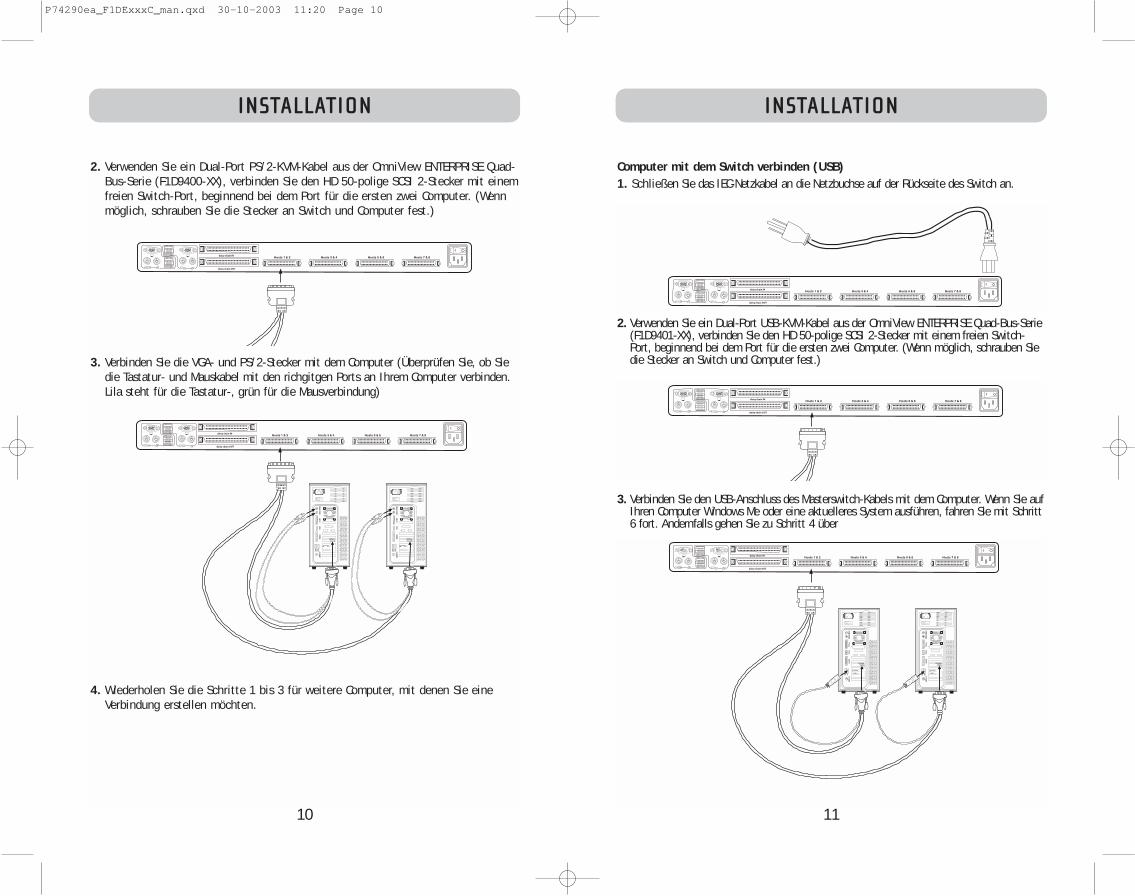
11
INSTALLATION
Computer mit dem Switch verbinden (USB)1. Schließen Sie das IEC-Netzkabel an die Netzbuchse auf der Rückseite des Switch an.
2. Verwenden Sie ein Dual-Port USB-KVM-Kabel aus der OmniView ENTERPRISE Quad-Bus-Serie(F1D9401-XX), verbinden Sie den HD 50-polige SCSI 2-Stecker mit einem freien Switch-Port, beginnend bei dem Port für die ersten zwei Computer. (Wenn möglich, schrauben Siedie Stecker an Switch und Computer fest.)
3. Verbinden Sie den USB-Anschluss des Masterswitch-Kabels mit dem Computer. Wenn Sie aufIhren Computer Windows Me oder eine aktuelleres System ausführen, fahren Sie mit Schritt6 fort. Andernfalls gehen Sie zu Schritt 4 über
Hosts 1 & 2 Hosts 3 & 4 Hosts 5 & 6 Hosts 7 & 8
Hosts 1 & 2 Hosts 3 & 4 Hosts 5 & 6 Hosts 7 & 8
Hosts 1 & 2 Hosts 3 & 4 Hosts 5 & 6 Hosts 7 & 8
10
INSTALLATION
2. Verwenden Sie ein Dual-Port PS/2-KVM-Kabel aus der OmniView ENTERPRISE Quad-Bus-Serie (F1D9400-XX), verbinden Sie den HD 50-polige SCSI 2-Stecker mit einemfreien Switch-Port, beginnend bei dem Port für die ersten zwei Computer. (Wennmöglich, schrauben Sie die Stecker an Switch und Computer fest.)
3. Verbinden Sie die VGA- und PS/2-Stecker mit dem Computer (Überprüfen Sie, ob Siedie Tastatur- und Mauskabel mit den richgitgen Ports an Ihrem Computer verbinden.Lila steht für die Tastatur-, grün für die Mausverbindung)
4. Wiederholen Sie die Schritte 1 bis 3 für weitere Computer, mit denen Sie eineVerbindung erstellen möchten.
Hosts 1 & 2 Hosts 3 & 4 Hosts 5 & 6 Hosts 7 & 8
Hosts 1 & 2 Hosts 3 & 4 Hosts 5 & 6 Hosts 7 & 8
P74290ea_F1DExxxC_man.qxd 30-10-2003 11:20 Page 10

13
INSTALLATION
3. Verbinden Sie die PS/2- bzw. USB-Tastatur mit der entsprechenden Schnittstellean der Rückseite des Switch (Bereich “Console”).
4. Verbinden Sie die PS/2- bzw. USB-Maus mit der entsprechenden Schnittstelle ander Rückseite des Switch (Bereich “Console”, grüner PS/2-Port).
5. Wiederholen Sie die Schritte 1-4, wenn Sie eine zweite Konsole anschließenmöchten.*
6. Schalten Sie den Switch an.
7. Starten Sie alle Host-Computer.
Verbinden mehrerer Switches (Kaskadierung)Sie können bis zu 16 Switches und Expander zusammenschließen. Dadurch kann derServeradministrator bis zu 256 Computer kontrollieren. Wenn ein zweiter Switch inReihe geschaltet wurde, können zusätzliche Konsolen hinzugefügt werden* und biszu vier Konsolen eingestellt werden. Jede kaskadierte Gruppe Switches wird zu einerEinheit, die “BANK” genannt wird und der eine Adresse zukommt. Der Switch, an demdie Konsole (Tastatur, Maus und Bildschirm) angeschlossen ist, wird als “Primär-Umschalter” bezeichnet. Die BANKs 00 bis 03 können als Primär-Umschalterkonfiguriert werden. Dadurch sind bis zu vier Konsolen zulässig. Die BÄNKE 02 bis 15können nur als Sekundär-Umschalter (ohne Konsolenunterstützung) konfiguriertwerden. Wenn an den BÄNKEN 00 bis 01 keine Konsolen angeschlossen sind, werdensie jeweils als Sekundär-Umschalter behandelt. Die Verbindungen mit diesen BANKssind jederzeit austauschbar (hot swappable). For example, if a console is added toone of the first two BANKs, it will immediately become a primary console Switch.
Hinweis: Zur Verkettung ist für jeden Switch ein Kaskadierungskabel erforderlich(F1D9402-XX), das bei Ihrem Belkin-Händler oder online bei belkin.com erhältlich ist.
Alle KVM-Switches aus der OmniView ENTERPRISE Quad-Bus-Serie verfügen über einenBANK DIP-Schalter. Dieser wird für die richtige Installation des Swtich eingesetzt.
• Wird nur ein Switch verwendet, setzen Sie seinen BANK-DIP-Schalter in diePosition “Eigenständig” (BANK-Adresse 00). Dies ist die werksseitigeStandardeinstellung.
• Werden mehrere Switches eingestzt, muss der BANK-DIP-Schalter der primärenEinheiten auf die BANK-Adresse 00 bis/oder 01 eingestellt sein. SekundäreEinheiten müssen eine eigene Adresse haben (02 bis 05). Untenstehende Tabellezeigt die einzelnen DIP-Einstellungen.
Hinweis: Die BANK-Adresse 00 funktioniert standardmäßig als eigenständigeInstallation; Beachten die den entsprechenden Abschnitt auf der Seite der OSD-Optionen über die Einstellung von BANK 00 für Kaskadierte Installationen.
*Nur 2x8- und 2x16-Modelle
12
INSTALLATION
4. Starten Sie den Computer, mit dem Sie über USB eine Verbindung erstellen möchten,wobei Tastatur, Maus und Monitor normal mit dem Computer verbunden sind.
5. Ihr Computer wird den Switch als generische Maus und Tastatur erkennen. ÄltereVersionen von Windows installieren USB-HID-Geräte nicht automatisch. Sie müssendies manuell über die Funktion “Hardware hinzufügen/entfernen” tun, bis alle HID-Geräte installiert sind (Mit dem Switch werden vier Geräte installiert: eine HID-Tastatur, eine HID-Maus, eine generische Tastatur und eine generische Maus. DieTreiberinstallation ist nur bei der ersten Verbindungd es Switch mit jedem Computererforderlich, danach wird der Switch automatisch erkannt und verwendet werden.Nach Abschluss der Treiberinstallation fahren Sie den Computer herunter, und lösenSie die Verbindung von Tastatur, Maus und Bildschirm.
6. Verbinden Sie den VGA HDDB15-Stecker des KVM-Kabels mit dem VGA-AnschlussIhres Computers.
7. Wiederholen Sie Schritt 1 bis 5 für jeden weiteren Computer, den Sie über USB anden Switch anschließen möchten.
Hinweis: Hinweis zur USB-Installation
Sie sollten das KVM-Kabel möglichst direkt an eine freie USB-Schnittstelle desComputers anschließen, also keinen USB-Hub zwischenschalten.
Anschließen der Konsole
1. BANK-Adresse einstellen (Die BANK ist werksseitig auf null gesetzt.)
2. Schließen Sie den Bildschirm an den Switch an. Verbinden Sie hierzu dasMonitorkabel mit der HDDB15-Buchse an der Rückseite des Switch. Die Buchse istmit “Console” gekennzeichnet.
HINWEIS: Unterstützung der Doppel-Konsole nur bei 2x8- und 2x16-Modellen.
Hosts 1 & 2 Hosts 3 & 4 Hosts 5 & 6 Hosts 7 & 8
P74290ea_F1DExxxC_man.qxd 30-10-2003 11:20 Page 12

15
INSTALLATION
3. Verbinden Sie die Tastatur, die Maus und den Monitor der Konsole mit den Konlos-Portsde promären Switch, wie oben für die eigenständige Installationbeschrieben, übergehen Sie dabei die Schritte 5 und 6.*
*Unterstützung der Doppel-Konsole nur bei 2x8- und 2x16-Modellen.
4. Verbinden Sie die Computer mit dem Switch, wie oben für die eigenständige Installationbeschrieben.
Hosts 1 & 2 Hosts 3 & 4 Hosts 5 & 6 Hosts 7 & 8
Hosts 1 & 2 Hosts 3 & 4 Hosts 5 & 6 Hosts 7 & 8
Hosts 1 & 2 Hosts 3 & 4 Hosts 5 & 6 Hosts 7 & 8
Hosts 1 & 2 Hosts 3 & 4 Hosts 5 & 6 Hosts 7 & 8
INSTALLATION
14
DIP-Schalternr.BANKADRESSE1 2 3 4
UNTEN OBEN UNTEN UNTEN BANK 00 (STANDARD)
OBEN UNTEN UNTEN UNTEN BANK 01 PRIMÄR/SEKUNDÄR
UNTEN OBEN UNTEN UNTEN BANK 02 SEKUNDÄR
OBEN OBEN UNTEN UNTEN BANK 03 SEKUNDÄR
UNTEN UNTEN OBEN UNTEN BANK 04 SEKUNDÄR
OBEN UNTEN OBEN UNTEN BANK 05 SEKUNDÄR
UNTEN OBEN OBEN UNTEN BANK 06 SEKUNDÄR
OBEN OBEN OBEN UNTEN BANK 07 SEKUNDÄR
UNTEN UNTEN UNTEN OBEN BANK 08 SEKUNDÄR
OBEN UNTEN UNTEN OBEN BANK 09 SEKUNDÄR
UNTEN OBEN UNTEN OBEN BANK 10 SEKUNDÄR
OBEN OBEN UNTEN OBEN BANK 11 SEKUNDÄR
UNTEN UNTEN OBEN OBEN BANK 12 SEKUNDÄR
OBEN UNTEN OBEN OBEN BANK 13 SEKUNDÄR
UNTEN OBEN OBEN OBEN BANK 14 SEKUNDÄR
OBEN OBEN OBEN OBEN BANK 15 SEKUNDÄR
Beispiel:Vier KVM Switches aus der OmniView ENTERPRISE Quad-Bus-Serie (F1DE208C) sind zur Kontrolle von 32 computers kaskadiert. Der DIP-Schalter der primären Einheit ist auf“BANK-Adresse 00” und der sekundären auf eine eigene BANK-Aadresse zwischen 01 und15 (BANK 00 muss für die kaskadierte Installation eingestellt werden, wie oben erwähnt).
InstallationVorbereitung:
1. Stellen Sie sicher, daß alle Computer abgeschaltet sind, und daß auf jedem Switch eine eindeutige BANK-Adresse eingestellt ist.
2. Stellen Sie den primären und sekundären Switch an ihren Platz.
Konfiguration der DIP-Schalter
P74290ea_F1DExxxC_man.qxd 30-10-2003 11:20 Page 14

17
INSTALLATION
9. Wenn die promäre BANK-Adresse auf 00 eingestellt ist, muss der KVM-Administrator den Switch für die kaskadierte Installation einstellen. UnternehmenSie dazu Folgendes: (Hinweis: Einige Konsolen werden durchgestrichen angezeigt.Dies ist normal, da diese Konfiguration ungültig ist, bis die Option “Daisy-Chainthis Switch” (Diesen Switch kaskadieren) aktiviert ist.
a) Öffnen Sie das Bildschirmmenü, indem Sie doppelt die Taste “Strg” und danach dieLeertaste drücken und öffnen Sie die Installation.
b) Öffnen Sie die Seite der Optionen, wählen Sie die Schaltfläche “Advanced”(Erweitert).
c) Aktivieren Sie im erweiterten Dialogfeld die Option “daisy-chain this KVM” (DiesenKVM kaskadieren).
d) Folgendes Dialogfeld wird angezeigt: “This will reset the KVM to change this set-ting” (Hierdurch wird Ihr KVM zurückgesetzt). Klicken Sie auf “OK”, um dasDialogfeld zu schließen und den Switch hochzufahren.
Beim Starten arbeitet der Switch mit den weiteren Switches auf die erwartete Weisezusammen. Sie können dies überprüfen, in dem Sie das Bildschirmmenü öffnen unddie Liste der Computer durchsuchen; wenn ein Computer des zweiten Switch in derBANK 00-Liste angezeigt wird, ist alles gut.
Hinweis: Wenn Sie BANK 00 nicht für die Kaskadierung konfigurieren, kann derMasterswitch nicht mit den weiteren Switches zusammenarbeiten. Außerdem funktion-iert das Bedienfeld des Geräts nicht mehr auf die gleiche Weise wie bei den anderenGeräten. Zudem können Fehler beim Datenaustausch auftreten, wenn eine fehlerhaft konfigurierte BANK 00 an eine Kaskade angeschlossen wird.
Versorgung der SystemeFahren Sie nach dem Anschließen aller Kabel die angeschlossenen Computer inbeliebiger Reihenfolge hoch. Der Switch emuliert auf jedem Port die Mus und dieTastatur und erlaubt es, den Computer normal zu starten; der Switch benötigt keineexterne Stromversorgung, um Tastatur und Maus zu emulieren.
Der Computer an Schnittstelle 1 des primären KVM Switch wird auf dem Bildschirmangezeigt. Überprüfen Sie, ob der Masterswitch ordnungsgemäß funktioniert, indemSie Maus, Tastatur, Tastaturbefehle, das Bildschirm-Menü und/oder dieDirektwahltasten betätigen. Wiederholen Sie diesen Vorgang an allen belegtenSchnittstellen, um zu überprüfen, ob alle Computer richtig angeschlossen sind undreagieren. Wenn Sie einen Fehler bemerken, überprüfen Sie die Kabelverbindungendes betreffenden Computers, und starten Sie ihn erforderlichenfalls neu. Wenn dasProblem weiterhin besteht, wenden Sie sich bitte an den Technischen Support vonBelkin.
16
INSTALLATION
Schließen Sie das Kaskadierungskabel an.5. Beginnen Sie mit BANK 00. Verbinden Sie das Kaskadierungskabel (F1D9402-XX)
mit der Ausgangsschnittstelle (“Daiy-Chain OUT”) am ersten Masterswitch.6. Schließen Sie das andere Kabelende an die Eingangsschnittstelle des zweiten
Switch an (“Daisy-Chain In”).Hinweis: Unabhängig davon, welcher Masterswitch als Primär-Umschalter dient, wirdimmer ein Eingang mit einem Ausgang (und umgekehrt) verbunden.
Installation weiterer Geräte:7. Gehen Sie jetzt auf die gleiche Weise vor, um die Kaskadierungsein- und ausgänge
der verbleibenden Geräte mit dem Kaskasierungskabel (F1D9402-XX) zu verbinden.
ACHTUNG: Keinesfalls Eingänge mit Eingängen oder Ausgänge mit Ausgängenverbinden, Dies kann zu unvorhergesehenen Ergebnissen führen.
Beispiel für eine Kaskadierung
Anschließen der Computer:8. Schalten Sie die Switches in beliebiger Reihenfolge ein. Die LED-Anzeige des Ports
wird aufblinken, die 7-teilige LED-Anzeige wird aktiviert und eine Reihe Testcodeswird angegeben, die u. U. auf “XX” endet. “XX” steht in diesem Fall für die BANK-Adresse.
Hinweis: Wenn die Switches noch nicht mit der entsprechenden BANK-Adresse korre-spondieren, überprüfen Sie, ob alle BANK-Adresse korrekt zugewiesen sind und ob allKaskadierungskabel korrekt angebracht sind.
Hosts 1 & 2 Hosts 3 & 4 Hosts 5 & 6 Hosts 7 & 8
Hosts 1 & 2 Hosts 3 & 4 Hosts 5 & 6 Hosts 7 & 8
Hosts 1 & 2 Hosts 3 & 4 Hosts 5 & 6 Hosts 7 & 8
Hosts 1 & 2 Hosts 3 & 4 Hosts 5 & 6 Hosts 7 & 8
P74290ea_F1DExxxC_man.qxd 30-10-2003 11:20 Page 16

19
VERWENDEN DES SWITCHES
Kaskadierte Konfiguration• Die siebenteilige Anzeige eines Sekundär-Switch gibt stets die betreffende BANK-
Kennung an. Alle anderen Schalter und LEDs der sekundären BANKs sind deak-tiviert.
Static Mode (Idle) (statischer Modus (Ruhezustand))• Die siebenteiligen LEDs zeigen die jeweilige BANK-Kennung an.• Die Schnittstellen- und die Umschaltanzeige sind ausgeschaltet.• Die Konsolenanzeige leuchtet auf, wenn der Switch an eine Konsoleangeschlossen ist.
Der Switch schaltet in den Select-Modus, wenn Sie einen Schalter an der Vorderseitedrücken und loslassen Die Port-Auswahlanzeigen werden aktiviert und die siebenteili-gen LED-Anzeige wird anstatt der BANK-ID die aktuelle BANK anzeigen.
Select-Mous (Auswahlbetrieb)• Der Select-Mous (Auswahlbetrieb) wird nach fünf Sekunden ohne Aktivität wieder
vom Statikbetrieb abgelöst.• Die siebenteilige LED gibt stets die Kennung der BANK im Fokus an.• Es leuchtet stets die Schnittstellenanzeige derjenigen Schnittstelle auf, auf deren
BANK der Fokus liegt.• Die Umschaltanzeige leuchtet auf, wenn eine der Schnittstellen 9 – 16 aus-
gewählt ist. Um mit einem 1x8- oder 2x8-Switch die Schnittstellen 9 – 16 aneinem 1x16 oder 2x16-Switch anzuwählen, halten Sie die entsprechende Tasteeine Sekunde lang gedrückt. Die Umschaltanzeige leuchtet auf. In beidenBeispielen drücken Sie den Schalter für Port 1, um die angeschlossenen Computerfür Port 9 auszuwählen und halten diesen eine Sekunde gedrückt. Der Switch gibteinen Signalton von sich und die Port 1- und die Shift-Anzeige werden leuchten.
• Die primäre Konsolenanzeige leuchtet auf, wenn der Switch an eine Konsoleangeschlossen ist.
1. Drücken Sie die BANK-Auswahlschalter, um die verfügbaren BANKs auszuwählen;jedesmal wird dabei die BANK über die siebenteilige Anzeige angezeigt.
2. Drücken Sie den Schalter für den Port, den Sie auswählen möchten. Wenn Sie diejeweilige Taste loslassen, gibt der Switch einen Signalton aus und legt den Fokusauf die ausgewählte Schnittstelle. Wenn der Benutzer keine Zugriffsrechte für den aus-gewählten Port hat, wird die Meldung “Access Denied” (Zugriff verweigert).
3. Wenn Sie den AutoScan-Schalter drücken gibt der Switch ein Signalton von sichund schaltet in den AutoScan-Modus.
18
VERWENDEN DES SWITCHES
Der Switch ist jetzt mit Ihren Consolen und Computern verbunden und Sie können nun mitihm arbeiten.
Sie können angeschlossene Computer über die Direktzugangstasten, die sich vorneam Bedienfeld des Switch befinden, über Tastaturbefehle oder mit dem Bildschirm-Menü auswählen.
Hinweis: Beim Umschalten per Tastaturbefehl (Pfeiltaste) oder AutoScan wird dieSchaltreihenfolge der Computer durch die Reihenfolge der Computer im Listenfeld(Hauptseite des Bildschirm-Menüs) bestimmt.
Auswählen eines Computers über die Schnittstellen-WahltasteMit dem Switch können Sie mit einem 1x8 KVM Switch auf alle Ports eines 2x16 KVMSwitch oder KVM Expanders (F1DE016C) zugreifen. Einstellungen über die Knöpfe anderVorderseite werden durch das aktivieren eines Schalters vorgenommen. Die Benienung derGeräteschalter eines Einzelgerätes unterscheidet sich von der in einer kaskadierten Installation. Bei einem Einzelgerät wird jeder Schalter sofort die entsprechende Funktionauslösen. Bei einer kaskadierten Installation wird über den ersten Schalter der Auswahl-Modus aktiviert und werden die Funktionen mit den folgenden Schaltern aktiviert.
Hinweis: Es dauert ein paar Augenblicke, bis das Grafiksignal aktualisiert wird(abhängig von Ihrem Monitor), nachdem Sie von einem Computer auf einen anderengeschaltet haben.
Eigenständige Konfiguration• Über die 7-teilige LED-Anzeige wird die Zahl der Ports für jede Konsole angegeben.• Eine Lampe brennt immer für den ausgewählten Port und die Konsole.• Die Shift-Anzeige (mit einem * an der Vorderseite des Geräts gekennzeichnet)
zeigt an, dass die Ports 9-16 ausgewählt sind (nicht gültig für eigenständigeInstallation.)
• Die Konsolenanzeige leuchtet auf, da dieser Switch der promäre Konsolen-Switch ist.• Die BANK-Auswahltasten haben keine Funktion, weil es in dieser Konfiguration
nur eine BANK gibt.
1. Drücken Sie den Schalter für den Port, den Sied auswählen möchten. Wenn Sie diejeweilige Taste loslassen, gibt der Switch einen Signalton aus und legt den Fokusauf die ausgewählte Schnittstelle. Wenn Sie keine Zugriffsrechte auf die aus-gewählte Schnittstelle haben, gibt der Switch einen Signalton aus und schaltetden Fokus weiter. Auf der siebenteiligen LED erscheint die Meldung “AccessDenied” (Zugriffsfehler).
2. Wenn Sie den AutoScan-Schalter drücken und loslassen, gibt der Switch einenSignalton ab und schaltet ind den AutoScan-Modus.
Hinweis: Damit ein eigenständiger Switch in der beschriebenen Weise betrieben werdenkann, muss die BANK-Adresse auf 00 gesetzt und das Feld “Daisy-Chain this KVM”(Masterswitch kaskadieren) deaktiviert werden. Andernfalls wird der Switch zwar weiter-hin funktionieren, aber wie ein kaskadierter Switch reagieren.
P74290ea_F1DExxxC_man.qxd 30-10-2003 11:20 Page 18

21
VERWENDEN DES SWITCHES
Bedienung der AutoScan-Funktion über das BedienfeldDurch Drücken der AutoScan-Taste am Switch wird er aktiviert. Im AutoScan-Betriebverbleibt der Switch in einem bestimmten Intervall (1 – 99 Sekunden) an jedemAnschluss, bevor er zum nächsten Anschluss weiterschaltet.
AutoScan-Betrieb• Der AutoScan-Betrieb wird so lange fortgesetzt, bis er mit einem Tastaturbefehl
oder durch Drücken einer Taste im Bedienfeld beendet wird.• Wenn sich der Switch im AutoScan-Betrieb befindet, ist der Nur-Anzeige-Modus
aktiviert. Eingaben an der Konsole werden nicht an den Computer im Fokus über-tragen. Um die Kontrolle über den Computer wieder zu übernehmen, müssen Sieden AutoScan-Betrieb beenden.
• Der Benutzer kann die AutoScan-Rate für jeden Computer auf derKonfigurierungsseite des Bildschirmmenüs einstellen.
• AutoScan überspringt alle Computer, die der Benutzer nicht anzeigen darf. DieAnzeigebeschränkungen werden auf der Sicherheitsseite des Bildschirmmenüseingestellt.
• Es leuchtet jeweils die Schnittstellenanzeige der Schnittstelle im Fokus auf.• Die Konsolenanzeige leuchtet auf, wenn der Switch an eine Konsole
angeschlossen ist.• Bei einem eigenständigen Switch zeigt die siebenstellige LED die Kennung der
Schnittstelle im Fokus an. Bei einem kaskadierten Switch zeigt sie die Kennungder BANK im Fokus an.
1. Um in den AutoScan-Betrieb zu wechseln, drücken Sie die AutoScan-Taste (einmalfür einen eigenständigen Switch und zweimal für einen kaskadierten Switch).
2. Der Switch gibt einen Signalton aus und beendet den AutoScan-Betrieb, sobaldeine Taste im Bedienfeld gedrückt wird. Wenn Sie eine Direktwahltaste drücken,verlegt der Switch außerdem den Fokus auf die ausgewählte Schnittstelle. WennSie für den gewählten Anschluss keine Zugriffsberechtigung besitzen, wird eine Fehlermeldung angezeigt.
Verwenden der MultiView-FunktionMit dem ENTERPRISE Quad-Bus KVM Switch können mehrere Benutzer denselbenServer gleichzeitig abfragen; allerdings liegt die Kontrolle über den Computer auss-chließlich bei der Konsole, die den Fokus zuerst angefordert hat (nur die Eingaben andieser Konsole werden angenommen). Legen weitere Konsolen den Fokus auf densel-ben Computer, erscheint an den Konsolen die Meldung “Nur Anzeige, keine Kontrolle”.An der Konsole, die den Computer kontrolliert, erscheint die Meldung “Angezeigt anKonsole X”, wobei X für den Kennbuchstaben der Konsole steht, die den Computeranzeigt. Wenn die Meldungen an einem Konsolentyp aktiviert sind, werden sie unbe-grenzt angezeigt; sind sie deaktiviert, werden sie nach fünf Sekungen ausgeblendet.
20
VERWENDEN DES SWITCHES
Auswahl eines Computer über Tastaturbefehle.Um Befehle an den Switch zu senden, muss die the Rollen-Taste zweimal innerhalbeiner halben Sekunde gedrückt werden (was durch einen Signalton bestätigt wird.Danach drücken Sie die Tastenfolge für den betreffenden Befehle; hierzu haben Sie ca.3 Sekunden Zeit. Folgende Tastenbefehle stehen zur Verfügung:
Rollen Rollen Pfeil-nach-oben Zum vorherigen Computer in der Bildschirmmenü-Liste umschaltenRollen Rollen Pfeil-nach-unten Zum nächsten Computer in der Bildschirmmenü-Liste umschaltenRollen Rollen XX YY Direktes Umschalten zu BANK XX, PORT YY
(X = 00 bis 15) (Y = 01 bis 08 für F1DE108C und F1DE208C) Rollen Rollen Leertaste Bildschirm-Menüs aktivierenRollen Rollen A AutoScan-Betrieb aktivieren/deaktivieren
Hinweis: Für Tastaturen ohne ROLLEN-Taste können andere Tasten zur Befehlseingabeverwendet werden. Zum Beispiel ist die STRG-Taste bei Macintosh® Computern üblich,wobei die Rollen-Taste andere Funktionen übernimmt. Diese Einstellungen können aufder Optionsseite des OSD-Bildschirmmenüs geändert werden.
Beim Umschalten per Tastaturbefehl (Pfeiltaste) oder AutoScan wird dieSchaltreihenfolge der Computer durch die Reihenfolge der Computer im Listenfeld(Hauptansicht des Bildschirmmenüs) bestimmt.
P74290ea_F1DExxxC_man.qxd 30-10-2003 11:20 Page 20

23
VERWENDEN DES SWITCHES
• Mit der Leertaste aktivieren Sie das Bildschirmmenü-Element im Fokus (wie beimKlicken auf das Element). Befindet sich das Listenfeld im Fokus, so übernimmtdie Konsole beim Drücken der Leertaste die Kontrolle über den hervorgehobenenComputer.
• Mit der Eingabetaste aktivieren Sie das Element im Fokus, soweit es sich um eineSchaltfläche oder ein Eingabefeld handelt; befindet sich der Fokus jedoch aufeinem anderen Element (zum Beispiel dem Listenfeld), so aktiviert dieEingabetaste das Standardelement (“Close/Schließen” oder “Exit/Beenden”, jenach dem geöffneten OSD-Bildschirm).
• Wenn der Administrator in einer Konfigurationsseite STRG + TAB drückt, schaltetdas Bildschirmmenü zur nächsten Seite weiter.
• Im Bildschirmmenü können Zugriffstasten verwendet werden. Mit ALT + X zumBeispiel wird das Element aktiviert, in dessen Namen der Buchstabe X unter-strichen ist.
• Wenn das Bildschirmmenü geöffnet ist, werden Tastatur- und Mauseingaben andas Menü weitergeleitet und nicht direkt an den Computer gesendet.
• Mit der Schaltfläche “Close” (Schließen) oder den Tasten ALT+C kehren Sie auseiner Konfigurationsseite zur Hauptseite zurück.
• Mit der Tabulatortaste wechseln Sie durch die Steuerelemente auf der jeweilsaktuellen OSD-Seite. Mit Umschalt + TAB gehen Sie die Steuerelemente in derGegenrichtung durch.
• Sie können das OSD-Fenster verschieben, indem Sie auf die Titelleiste klicken unddas Fenster mit der Maus ziehen.
• Um das Meldungsfenster zu verschieben, drücken Sie bei geöffnetemBildschirmmenü STRG+ALT. Der Cursor wechselt aus dem Menüfenster in dasMeldungsfenster. Der Benutzer kann dann das Meldungsfenster mit der Maus ver-schieben.
• Der Switch merkt sich die Positionseinstellungen von Bildschirmmenü undMeldungsfenster für verschiedene Bildschirmauflösungen. Der Benutzer muss diePosition des Menü- und des Meldungsfensters bei der Einrichtung des Switch ein-stellen, damit die Fensterpositionen für alle Bildschirmauflösungen konstantbleiben.
Hinweis: Das OSD-Bildschirmmenü schaltet sich nicht von selbst ab. Damit es nicht inden Monitor einbrennt, sollten Sie den Monitor abschalten oder den KVM Switch in denAutoScan-Betrieb schalten. Alle Optionen auf den Konfigurierungsseiten gelten für alleKonsolen, soweit nicht anders beschrieben.
22
VERWENDEN DES SWITCHES
IntelliView Bildschirm-Menüsystems Das IntelliView Bildschirm-Menüsystem (OSD) ist Windows-gestützten Systemen für PCsnachempfunden. Um es zu aktivieren, drücken Sie “Rollen”, “Rollen”, “Leertaste”.(Die Rollen-Taste kann durch andere Tasten ersetzt werden. Informationen zuTastaturen ohne Rollen-Taste finden Sie im Abschnitt “IntelliView Optionsseite” indiesem Benutzerhandbuch).
IntelliView-FunktionenDie Hauptseite ist der Eingangsbildschirm, der gleich nach dem Öffnen desBildschirmmenüs erscheint. Das Bildschirm-Layout ähnelt vielen Window-Systemen.Das angezeigte Fenster enthält eine Titelleiste mit Kontrolloptionen und einenHauptbereich mit den Funktionen des Switch.
Oben rechts in der Titelleiste des Bildschirmmenüs werden die aktuelle Konsole desBenutzers und der angemeldete Benutzer angegeben. (Die Konsolen A-D sind jeweilsdie BANKS 00-03.) Mit der Schaltfläche “?” wird das Hilfefenster geöffnet, dasBedienungsanweisungen für die aktuelle Seite des Bildschirmmenüs enthält.
Mit der Schaltfläche “X” wird die angezeigte Seite geschlossen. Mit der ESC-Tastewird das Bildschirmmenü geschlossen.
Hinweis: Alle Änderungen am OSD-Bildschirmmenü werden gespeichert, sobald Sie denFokus wechseln. Es gibt keine Rückgängig-Funktion für eingegebene Änderungen. WennSie allerdings den Inhalt eines Eingabefelds bearbeiten (zum Beispiel das Feld“Computername”), können Sie mit der ESC-Taste das Feld schließen und gleichzeitigauf den ursprünglichen Wert zurücksetzen.
Eingabe- und Navigationsfunktionen• Wenn Sie auf die Spaltenüberschrift “Group” (Gruppe), “Computer Name”
(Computername) oder “ID” (Kennung) klicken, werden die Listenfeldeinträge inder ausgewählten Spaltenüberschrift in absteigender Reihenfolge sortiert.
• Durch Doppelklicken auf eine Computerzeile wird die Zeile ausgewählt und derFokus der Konsole auf die ausgewählte Schnittstelle verlegt. Wenn dem Benutzerder Zugriff auf den ausgewählten Computer verweigert wird, erscheint eineentsprechende Fehlermeldung. Wenn das Meldungsfeld geschlossen wird, wechseltder Fokus der Konsole wieder zur bisher ausgewählten Schnittstelle.
• Durch Drücken der Pfeiltaste nach oben oder unten wird der Computercursor (dieblau hervorgehobene Markierungszeile) nach oben bzw. unten verschoben. Wirdder Cursor aus dem sichtbaren Bereich verlagert, wird die Liste um eine Zeile ver-schoben. Für diese Funktion kann auch das Mausrad verwendet werden.
• Mit der oberen und unteren Pfeilschaltfläche (rechts der Computerliste) wird dieListe jeweils um eine Seite vor- oder zurückgeblättert. Für dieselbe Funktion kannauch die Pfeiltaste nach oben bzw. unten auf der Tastatur verwendet werden.
P74290ea_F1DExxxC_man.qxd 30-10-2003 11:20 Page 22
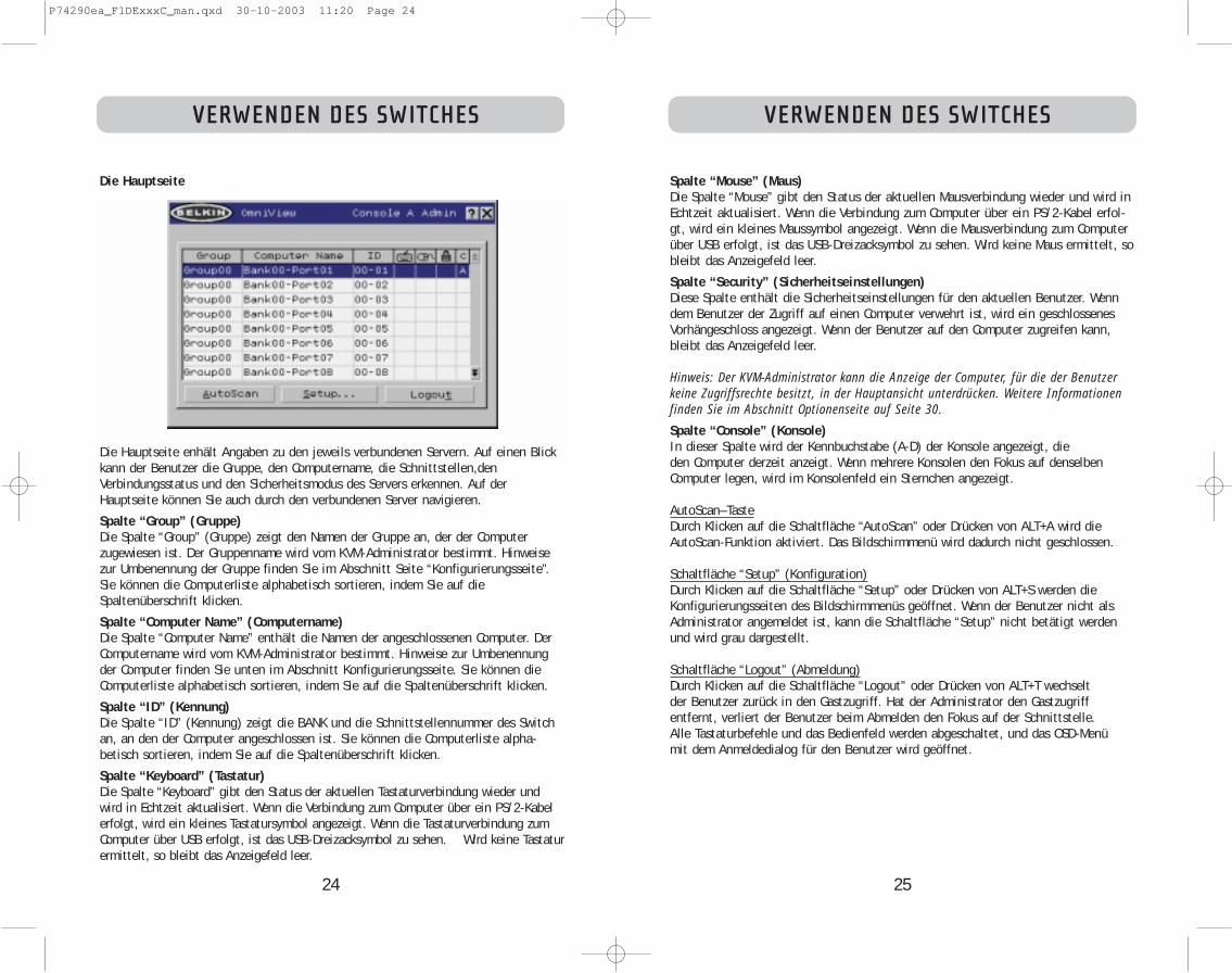
25
VERWENDEN DES SWITCHES
Spalte “Mouse” (Maus)Die Spalte “Mouse” gibt den Status der aktuellen Mausverbindung wieder und wird inEchtzeit aktualisiert. Wenn die Verbindung zum Computer über ein PS/2-Kabel erfol-gt, wird ein kleines Maussymbol angezeigt. Wenn die Mausverbindung zum Computerüber USB erfolgt, ist das USB-Dreizacksymbol zu sehen. Wird keine Maus ermittelt, sobleibt das Anzeigefeld leer.
Spalte “Security” (Sicherheitseinstellungen)Diese Spalte enthält die Sicherheitseinstellungen für den aktuellen Benutzer. Wenndem Benutzer der Zugriff auf einen Computer verwehrt ist, wird ein geschlossenesVorhängeschloss angezeigt. Wenn der Benutzer auf den Computer zugreifen kann,bleibt das Anzeigefeld leer.
Hinweis: Der KVM-Administrator kann die Anzeige der Computer, für die der Benutzerkeine Zugriffsrechte besitzt, in der Hauptansicht unterdrücken. Weitere Informationenfinden Sie im Abschnitt Optionenseite auf Seite 30.
Spalte “Console” (Konsole)In dieser Spalte wird der Kennbuchstabe (A-D) der Konsole angezeigt, die den Computer derzeit anzeigt. Wenn mehrere Konsolen den Fokus auf denselbenComputer legen, wird im Konsolenfeld ein Sternchen angezeigt.
AutoScan–TasteDurch Klicken auf die Schaltfläche “AutoScan” oder Drücken von ALT+A wird dieAutoScan-Funktion aktiviert. Das Bildschirmmenü wird dadurch nicht geschlossen.
Schaltfläche “Setup” (Konfiguration)Durch Klicken auf die Schaltfläche “Setup” oder Drücken von ALT+S werden dieKonfigurierungsseiten des Bildschirmmenüs geöffnet. Wenn der Benutzer nicht alsAdministrator angemeldet ist, kann die Schaltfläche “Setup” nicht betätigt werdenund wird grau dargestellt.
Schaltfläche “Logout” (Abmeldung)Durch Klicken auf die Schaltfläche “Logout” oder Drücken von ALT+T wechselt der Benutzer zurück in den Gastzugriff. Hat der Administrator den Gastzugriff entfernt, verliert der Benutzer beim Abmelden den Fokus auf der Schnittstelle. Alle Tastaturbefehle und das Bedienfeld werden abgeschaltet, und das OSD-Menü mit dem Anmeldedialog für den Benutzer wird geöffnet.
24
VERWENDEN DES SWITCHES
Die Hauptseite
Die Hauptseite enhält Angaben zu den jeweils verbundenen Servern. Auf einen Blickkann der Benutzer die Gruppe, den Computername, die Schnittstellen,denVerbindungsstatus und den Sicherheitsmodus des Servers erkennen. Auf derHauptseite können Sie auch durch den verbundenen Server navigieren.
Spalte “Group” (Gruppe)Die Spalte “Group” (Gruppe) zeigt den Namen der Gruppe an, der der Computerzugewiesen ist. Der Gruppenname wird vom KVM-Administrator bestimmt. Hinweisezur Umbenennung der Gruppe finden Sie im Abschnitt Seite “Konfigurierungsseite”.Sie können die Computerliste alphabetisch sortieren, indem Sie auf dieSpaltenüberschrift klicken.
Spalte “Computer Name” (Computername)Die Spalte “Computer Name” enthält die Namen der angeschlossenen Computer. DerComputername wird vom KVM-Administrator bestimmt. Hinweise zur Umbenennungder Computer finden Sie unten im Abschnitt Konfigurierungsseite. Sie können dieComputerliste alphabetisch sortieren, indem Sie auf die Spaltenüberschrift klicken.
Spalte “ID” (Kennung)Die Spalte “ID” (Kennung) zeigt die BANK und die Schnittstellennummer des Switchan, an den der Computer angeschlossen ist. Sie können die Computerliste alpha-betisch sortieren, indem Sie auf die Spaltenüberschrift klicken.
Spalte “Keyboard” (Tastatur)Die Spalte “Keyboard” gibt den Status der aktuellen Tastaturverbindung wieder undwird in Echtzeit aktualisiert. Wenn die Verbindung zum Computer über ein PS/2-Kabelerfolgt, wird ein kleines Tastatursymbol angezeigt. Wenn die Tastaturverbindung zumComputer über USB erfolgt, ist das USB-Dreizacksymbol zu sehen. Wird keine Tastaturermittelt, so bleibt das Anzeigefeld leer.
P74290ea_F1DExxxC_man.qxd 30-10-2003 11:20 Page 24

27
VERWENDEN DES SWITCHES
Schaltfläche “Scan Time” (Scan-Dauer) und “Change All” (Alles ändern)Der Benutzer kann die Scan-Dauer für alle Computer ändern, indem er einen Wertzwischen 1 und 99 in das Textfeld eingibt und auf die Schaltfläche “Change All”(Alles ändern) klickt. Der Benutzer wird dann aufgefordert, die Aktion zu bestätigen,bevor die neue Dauer wirksam wird.
Spalte “Console” (Konsole)In dieser Spalte wird die Konsole angegeben, auf der der Computer derzeit angezeigt wird.
Seite “Security” (Sicherheitseinstellungen)
Auf der Seite “Security” kann der Administrator die Computer-Zugriffsberechtigungen fürdie Benutzer des Switch einstellen. Für den Switch gibt es drei Zugriffsstufen:“Administrator” (Administrator), “User” (Benutzer) und “Guest” (Gast). Der Administratorist der einzige Benutzer, der auf die Konfigurierungsseiten zugreifen und den Switch kon-figurieren kann. Der Administrator kann Benutzern und Gästen den Zugriff auf bestimmteComputer verwehren. Alle Benutzer können zwischen Computern wechseln und dieAutoScan-Funktion auf der Hauptseite aktivieren oder deaktivieren. “Guest” ist derStandardbenutzer (für den keine Anmeldung erforderlich ist). Daher werden alle Benutzerauf die Stufe “Guest” gesetzt, wenn sie sich von ihrem Benutzerkonto abmelden.
Hat der Administrator den Gastzugriff entfernt, verliert der Benutzer beim Abmelden denFokus auf der Schnittstelle. Alle Tastaturbefehle und das Bedienfeld werden abgeschal-tet, und das OSD-Menü mit dem Anmeldedialog für den Benutzer wird geöffnet.
Die Konten der Stufe “User” (Benutzer), die im KVM Switch definiert sind, können von einzelnen Benutzern oder Benutzergruppen verwendet werden. Die Namen derBenutzer werden festgelegt.
Hinweis: Wenn die Stufe “Guest” aktiviert ist, definiert sie die Mindestrechte, die allenBenutzern zugestanden sind. Der Administrator kann die Konten der Stufe “User” stärkereinschränken als das Konto “Guest”; dieser Fehler sollte vermieden werden.
26
VERWENDEN DES SWITCHES
Die Konfigurierungsseite
Die Konfigurierungsseite steht nur dem Benutzer mit Administratorrechten zurVerfügung und dient zur Einstellung von Gruppenname, Computername und Scan-Dauer. Die Scan-Dauer hängt von der Schnittstelle ab, die gerade geprüft wird undgilt global, also unabhängig von der Konsole oder dem Benutzer. Während die Scan-Dauer nicht vom Benutzer abhängt, überspringt die AutoScan-Funktion Computer, fürdie der Benutzer keine Anzeigerechte besitzt.Spalte “Group” (Gruppe)Die Spalte “Group” (Gruppe) zeigt den Namen der Gruppe an, der der Computerzugewiesen ist. Der Gruppenname kann frei festgelegt werden und dient nur der Über-sichtlichkeit. Der Gruppenname kann aus bis zu acht Zeichen bestehen und wird vomKVM-Administrator festgelegt. Der Standardgruppenname eines Computers ist “GroupX”, wobei X die BANK-Nummer des Switch ist, die mit dem BANK-DIP-Schalter fest-gelegt wird. Um den Gruppennamen zu ändern, klicken Sie in das betreffende Feld.Spalte “Computer Name” (Computername)Die Spalte “Computer Name” enthält die Namen der angeschlossenen Computer. Der Computername kann aus bis zu fünfzehn Buchstaben bestehen und wird vom KVM-Administrator festgelegt. Sie können die Computerliste alphabetisch sortieren, indemSie auf die Spaltenüberschrift klicken. Standardmäßig erhalten alle Computer denNamen BANK XX-Port YY. XX ist eine zweistellige BANK-Adressnummer zwischen 00und 15, und YY ist eine zweistellige Computernummer zwischen 01 und 16. Um denComputernamen einzugeben, klicken Sie in das betreffende Feld. Spalte “ID” (Kennung)Diese Spalte zeigt die BANK und die Schnittstellennummer des KVM Switch an, anden der Computer angeschlossen ist. Sie können die Computerliste alphabetischsortieren, indem Sie auf die Spaltenüberschrift klicken. Spalte “Scan” (Scannen)Die Spalte “Scan” (Scannen) gibt die aktuelle Dauer wieder, die für die Überprüfungdes jeweiligen Computers durch die AutoScan-Funktion eingestellt ist. Um die Dauerfür einen Computer zu ändern, klicken Sie in das betreffende Feld.
P74290ea_F1DExxxC_man.qxd 30-10-2003 11:20 Page 26

29
VERWENDEN DES SWITCHES
Eingabefelder für das KennwortFür jeden Benutzer gibt es eine Schaltfläche namens “Change Password” (Kennwort ändern).Sie ruft den Eingabedialog für das Kennwort auf. Der Administrator muss dasKennwort eingeben und dann bestätigen; das neue Kennwort wird nur dann wirksam,wenn beide Eingaben übereinstimmen. Die Kennwörter bestehen aus bis zu achtZeichen; Groß- und Kleinbuchstaben werden unterschieden. Durch das Abbrechen desKennwortänderungsdialogs kehren Sie auf die Kennwortseite zurück, ohne dasvorhandene Kennwort zu ändern. In einer Kaskadierungskonfiguration wird dasKennwort durch Klicken auf “OK” automatisch mit den anderen Konsolen synchro-nisiert.
AktivierungsfelderMit den Kontrollkästchen neben den Benutzernamen kann der Administrator dieBenutzerkonten mit einem einzigen Mausklick deaktivieren. Dadurch müssen dieSicherheitseinstellungen nicht für jeden Host einzeln geändert werden, wenn derZugriff für einen Benutzer gelöscht werden soll.
Automatische Abmeldung: Aktivierung und IntervallDie automatische Abmeldung meldet den Benutzer nach einer bestimmten Frist (1-99 Minuten) ab, wenn die Konsole nicht mehr betätigt wird. Im Allgemeinen wirdder Switch dadurch auf den “Guest”-Zugriff zurückgesetzt; wenn diese Zugangsstufejedoch deaktiviert worden ist, werden alle Zugriffsrechte gesperrt, bis eine gültigeBenutzeranmeldung an der Konsole erfolgt. Im Eingabefeld wird die Dauer derInaktivität festgelegt, nach der die Abmeldung eingeleitet wird. Die automatischeAbmeldung ist nicht allgemeingültig, sondern muss für jede Konsole einzelneingestellt werden.
Hinweis: Die Sitzung wird beim Schließen des OSD-Bildschirmmenüs nur dann beendet,wenn die automatische Abmeldung aktiviert ist oder wenn sich der Benutzer manuellabmeldet. Ansonsten öffnet der nächste Benutzer das Bildschirmmenü mit derselbenBerechtigungsstufe wie sein Vorgänger.
28
VERWENDEN DES SWITCHES
Spalte “Group” (Gruppe)Die Spalte “Group” (Gruppe) zeigt den Namen der Gruppe an, der der Computerzugewiesen ist. Sie können die Computerliste alphabetisch sortieren, indem Sie auf dieSpaltenüberschrift klicken.
Spalte “Computer Name” (Computername)Die Spalte “Computer Name” enthält die Namen der angeschlossenen Computer. Siekönnen die Computerliste alphabetisch sortieren, indem Sie auf die Spaltenüberschriftklicken.
Benutzerspalten (1, 2, 3, G)In diesen Spalten können Administratoren die Zugriffsrechte auf die einzelnen Computer für jeden “User” (1, 2, 3 und “Guest”) einstellen. Das Vorhängeschloss zeigtan, dass der Benutzer (Spalte) nicht auf die Computerschnittstelle (Zeile) zugreifenkann. Leere Felder zeigen an, dass der Benutzer uneingeschränkt auf den Computerzugreifen darf. Um die Benutzereinschränkungen für eine bestimmte Schnittstelleeinzustellen, klicken Sie auf das entsprechende Feld im Listenfeld, oder wählen Sie dieComputerzeile aus, und drücken Sie die Taste für den jeweiligen Benutzer: 1, 2, 3, G(mit 4 verstellen Sie auch die Gastbeschränkungen für die Benutzergruppe “Guest”).
Spalte “Console” (Konsole)In dieser Spalte wird die Konsole angegeben, auf der der Computer derzeit angezeigt wird.
Seite “Passwords” (Kennwörter)
Auf der Seite “Passwords” kann der Administrator Benutzerkennwörter ändern,Benutzerkonten aktivieren oder deaktivieren und das Intervall für die automatischeAbmeldung einstellen.
Hinweis: Nur der Administrator kann die Benutzerkennwörter und -einstellungen ändern.
P74290ea_F1DExxxC_man.qxd 30-10-2003 11:20 Page 28

31
VERWENDEN DES SWITCHES
Display Banner (M-Fenster anzeigen)Dieses Kontrollkästchen aktiviert ein Meldungsfenster, das beiSystemereignissen angezeigt wird: das Drücken einer Taste auf dem Bedienfeld, dasEinschalten eines Switch usw. Das Meldungsfenster wird entweder ständig angezeigtoder bleibt während einer voreingestellten Dauer (1-99 Sekunden) geöffnet. Wenndie Intervall-Option aktiviert ist, bestimmt die Intervall-Einstellung, wie lange dasMeldungsfenster nach dem Eintritt des Systemereignisses angezeigt bleibt. WeitereInformationen zu Bedienung und Inhalt des Meldungsfensters finden Sie in denAbschnitten “MultiView” (Seite 21) und “Meldungsfenster” (Seite 33). DieMeldungsfenster-Einstellungen sind nicht allgemeingültig, sondern müssen für jedeKonsole einzeln eingestellt werden.
Display Inactive Ports (Inaktive Ports anzeigen)Wenn diese Funktion aktiviert ist, werden die Schnittstellen im Computerlistenfeldangezeigt, an denen kein aktiver Computer angeschlossen ist (Hauptseite des OSD-Menüs). Standardmäßig werden die inaktiven Schnittstellen angezeigt. Die Funktion“Display Inactive Ports” ist nicht allgemeingültig, sondern muss für jede Konsoleeinzeln eingestellt werden.
Display Restricted Ports (Gesperrte Ports anzeigen)Wenn diese Funktion aktiviert ist, werden die Schnittstellen im Computerlistenfeld angezeigt, auf die der aktuelle Benutzer nicht zugreifen darf (Hauptseite desBildschirmmenüs). Standardmäßig werden die gesperrten Schnittstellen angezeigt.Die Funktion “Display Restricted Ports” (Gesperrte Ports anzeigen) ist nicht allgeme-ingültig, sondern muss für jede Konsole einzeln eingestellt werden.
Alternate Attention Key (Alternative Aufruftaste)Auf dieser Bildschirmseite können Sie für die Tasten für die Tastaturbefehle festle-gen. Dadurch sind auch Tastaturen kompatibel, die mit anderen Tasten bestückt sindoder die vorgesehenen Tasten bereits mit anderen Funktionen belegt haben. Sie kön-nen beliebig viele alternative Aufruftasten festlegen. Hinweis: Wenn alle Optionen deaktiviert sind, ist die Rollen-Taste die standardmäßigeAufruftaste.
Display Version Numbers (Versionsnr. anzeigen)In diesem Fenster werden Produktinformationen wie die Modellnummer und dieFirmware-Version angezeigt. Die Funktion “Display Version Numbers” (Versionsnr.anzeigen) wirkt sich nicht allgemeingültig aus und gibt nur die Versionsnummern fürdiese BANK an.Hinweis: Bei einem Flash-Upgrade müssen Sie jeden Switch und jedenAnschlusserweiterung einzeln aktualisieren.
30
VERWENDEN DES SWITCHES
Broadcast Passwords (Kennwörter senden)Dieses Kontrollkästchen erzwingt, dass alleanderen Konsolen alle ihre Benutzerkennwörter durch die Kennwörter der aktuellenKonsole ersetzen. Das vereinfacht die Synchronisierung der Kennwörter aller Konsolendurch den Administrator (zum Beispiel beim Hinzufügen einer neuen Konsole zu einerbestehenden Konfiguration).
Seite “Options” (Optionen)
Die Steuerelemente auf dieser Seite betreffen mehrere der vielschichtigen Switch-Funktionen.
P74290ea_F1DExxxC_man.qxd 30-10-2003 11:20 Page 30

VERWENDEN DES SWITCHES
33
Fehlermeldungen und DialogeManchmal müssen Meldungen angezeigt werden, die den Benutzer auf Fehler hin-weisen oder zur Beantwortung einfacher Fragen auffordern. Das Format derMeldungen entspricht dem gewohnten Standard aus Titelleiste und Fensterbereich,der den Text der Meldung enthält. Es enthält auch die entsprechendenAntwortelemente wie “OK” und “Cancel” (Abbrechen), je nach der Art der Meldung.
Login Dialog (Anmeldedialog)Das Dialogfeld “Login Dialog” enthält Optionsfelder zur Auswahl des Benutzers undein Textfeld zur Eingabe des Benutzerkennworts. Sind die Benutzer bereitsangemeldet, gelangen sie mit der Schaltfläche “Cancel” (Abbrechen) in ihrenaktuellen Anmeldestatus zurück (oder in den Status “Guest”, wenn das entsprechendeKonto aktiviert ist). Wenn kein Benutzer angemeldet und das Konto “Guest” deak-tiviert ist, wird das OSD-Menü mit “Cancel” beendet.
Online-HilfeIm OSD-Menü steht eine Online-Hilfe bereit. Sie kann mit der Taste F1 oder derSchaltfläche “?” oben rechts in der Titelleiste aufgerufen werden.
Banner (Meldungsfenster)
Als “Meldungsfenster” wird ein kleines Fenster bezeichnet, das den Fokus der Konsoleangibt. Es besteht aus einer Textzeile und einem grauen 3D-Rahmen. Es enthält diefolgenden Angaben:
• Gruppenname• Hostname• BANK und Schnittstelle im Fokus
Wenn mehrere Konsolen denselben Computer anzeigen (MultiView-Betrieb), zeigt dasMeldungsfenster an der Konsole, die den Computer kontrolliert, folgende Angaben:
• Viewed by Console (Angezeigt an Konsole) [Konsolenkennung]• BANK und Schnittstelle im Fokus
Auf der Nur-Ansicht-Konsole enthält das Meldungsfenster die folgenden Angaben:• Nur Anzeige, keine Kontrolle• BANK und Schnittstelle im Fokus
Im Meldungsfenster werden zudem wichtige Fehlermeldungen und Änderungen an derKVM-Konfigurierung angezeigt.
EingangsbildschirmBeim Einschalten des Switch erscheint ein Fenster mit dem Produktnamen und demCopyright-Vermerk. Dieses Fenster schließt sich nach einigen Sekunden von selbst.Beim Öffnen des OSD-Menüs wird der Eingangsbildschirm sofort geschlossen.
32
VERWENDEN DES SWITCHES
Schaltfläche “Advanced” (Erweitert)Mit dieser Schaltfläche gelangt der Benutzer zu den erweiterten Optionen.
Disable Viewing (Anzeige deaktivieren)Wenn die Option “Disable Viewing” (Anzeige deaktivieren) aktiviert ist, kann nur einweiterer Administrator die Kanäle anzeigen, die der Administrator belegt hat. DieseFunktion ist im Bildschirmmenü standardmäßig aktiviert. Aus Gründen der Sicherheitkann sie der Administrator bei Bedarf deaktivieren.Daisy-Chain this KVM (Masterswitch kaskadieren)Wird dieses Kontrollkästchen aktiviert, können KVM Switches mit der BANK-Adresse00 mit allen anderen BANKS in der Kaskadierungskonfiguration kommunizieren. Diesbetrifft die Bedienung der Bedienfelder sowie einige weitere Betriebsparameter.Immer wenn sich der Status des Kontrollkästchens ändert, wird die folgende Meldungangezeigt: “This will reset the KVM to change this setting” (Dadurch wird die geän-derte Einstellung bestätigt). Wenn der Benutzer “OK” wählt, wird der Switch mit derneuen Konfiguration sofort neu gestartet. Standardmäßig sind KVM-Switches mit derBANK-Adresse 00 als eigenständige Geräte konfiguriert (das Kontrollkästchen istdeaktiviert).Steal Control of this Host (Host-Kontrolle übernehmen)Mit dieser Funktion kann der KVM-Administrator die Kontrolle über einen Host, dergerade von anderen Benutzern verwendet wird, vollständig übernehmen. Restore Factory Defaults (Werkseinstellungen)Mit dieser Schaltfläche werden sämtliche benutzerkonfigurierbaren Einstellungen (wieComputernamen, Gruppennamen usw.) an allen BANKS in der Kaskadierung auf ihreStandardwerte zurückgesetzt. Der Benutzer muss diese Anweisung in einem Fensterbestätigen, bevor sie umgesetzt wird.
Hinweis: Bei Kaskadierungen führt das Zurücksetzen auf die Werkseinstellungen zufehlerhaftem Verhalten des Switch. Um dieses vorübergehende Problem zu beheben,muss der Administrator auf die Optionenseite wechseln, die Schaltfläche “Advanced”(Erweitert) wählen und die Option “Daisy-chain this KVM” (Diesen KVM Switchkaskadieren) aktivieren, nachdem BANK00 auf die Werksteinstellungen zurückgesetztworden ist.
P74290ea_F1DExxxC_man.qxd 30-10-2003 11:20 Page 32

35
VERWENDEN DES SWITCHES
Zum Start der Aktualisierung wählen Sie im Start-Menü das Programm “AutoUpdate.exe”aus, oder öffnen Sie es mit dem Desktop-Symbol (soweit vorhanden).
Im ersten Fenster der Anwendung wählt der Benutzer zwischen einer automatischenund einer manuellen Aktualisierung. Normalerweise empfiehlt sich eine automatischeAktualisierung, soweit kein bestimmter Grund dagegen spricht. Die automatischeAktualisierung überprüft die Switch-Firmware und vergleicht die installiertenVersionen mit den aktuellen verfügbaren Versionen. Sind neuere Firmware-Versionenverfügbar, werden sie aus dem Internet in den Switch geladen. Zum Abschluss derInstallation muss der Benutzer die KVM Switches herunter- und wieder hochfahren.Die manuelle Aktualisierung funktioniert auf die gleiche Weise; der Benutzer muss diekorrekte Aktualisierungsdatei jedoch manuell auswählen.
Hinweis: Vor dem Aktualisieren des Switch ist sicherzustellen, dass der AutoScan deak-tiviert ist und dass das OSD-Menü an der Konsole nicht angezeigt wird. Dadurch wirdder Switch entlastet.
34
VERWENDEN DES SWITCHES
Der Firmware-Aktualisierungsdienst “AutoUpdate Firmware”
Firmware aktualisierenAutoUpdate überprüft Ihre Hardware und führt Sie bei Bedarf durch dieAktualisierung der Switch-Firmware. AutoUpdate lädt automatisch die beste verfüg-bare Firmware für Ihr Gerät von der Belkin Website herunter. Sie können dieentsprechende Datei auch manuell von unserer Website belkin.com laden.Es wird empfohlen, dass der Administrator die Aktualisierung durchführt, wenn dieKVM Switches gerade nicht verwendet werden. Jeder Switch wird bei derAktualisierung automatisch aus- und wieder eingeschaltet. Das kann an bestimmtenComputern zu Störungen von Tastatur oder Maus führen. Vor der Aktualisierung mussder Administrator alle Computer herunterfahren, die nicht in den Prozess einbezogenwerden sollen.Zur Aktualisierung der Firmware wird folgendes vorausgesetzt:1. Ein Computer mit Windows XP, 2000, ME oder 98 und einem freien USB-Anschluss.2. Ein standardmäßiges USB-Kabel zur Verbindung von Switch und Computer.3. Das Belkin Dienstprogramm AutoUpdate, das aus dem Internet geladen werden
kann.4. Eine Internet-Verbindung für die automatische Installation.
Installieren der Dienstanwendung AutoUpdate:1. Laden Sie die Anwendung AutoUpdate von der Belkin Website herunter, und
führen Sie sie aus.2. Klicken Sie mehrmals auf die Schaltfläche “Next / “Weiter”, und konfigurieren Sie
dabei jeweils den Dateipfad, die Symboleinstellungen usw. wie gewünscht, bis dieInstallation abgeschlossen ist.
Anschließen des Computers an den Switch:1. Schalten Sie den Switch ein.2. Verbinden Sie das USB-Kabel mit der Flash-Schnittstelle am Switch (USB B) und
mit dem USB-Anschluss des jeweiligen Computers. Wenn Sie mehrere Switches gleichzeitig anschließen möchten, benötigen Sie ggf. einen oder mehrere Hubs,die zwischen Computer und Switch zu schalten sind.
Hinweis: Vor der Aktualisierung muss der Administrator die Optionenseite im OSD-Menü öff-nen, die Schaltfläche “Display Version Numbers” (Versionsnr. anzeigen) aktivieren und dieaktuellen Versionsnummern notieren, dadurch kann er später überprüfen, ob die Firmwarekorrekt aktualisiert wurde.
P74290ea_F1DExxxC_man.qxd 30-10-2003 11:20 Page 34

37
VERWENDEN DES SWITCHES
Vor der Aktualisierung wird eine Warnmeldung angezeigt, die den Benutzer auf dieRisiken der Aktualisierung und Aktionen hinweist, die er während der Aktualisierungvermeiden muss.
Hinweis: Während der Aktualisierung müssen PC und Switch unbedingt eingeschaltetund das USB-Kabel mit dem PC bzw. Switch verbunden bleiben. Der Benutzer mussdarauf achten, dass der den PC nicht auf eine Weise nutzt, die die Aktualisierungbeeinträchtigt. Bei einer Störung der Aktualisierung kann es zu Funktionsstörungen amSwitch kommen. Wenn die Aktualisierung unterbrochen wird, aber der Switch weiterhineingeschaltet ist, sollten Sie die Aktualisierung neu starten.
36
VERWENDEN DES SWITCHES
Aktualisieren von Geräten per Internet
Beim Ausführen von AutoUpdate wird der Computer zunächst nach Geräten durch-sucht, die die Aktualisierung unterstützen. Es verbindet sich automatisch mit demInternet und sucht nach verfügbaren Updates für die gefundenen Geräte. Nachdemdie entsprechenen Informationen ermittelt wurden, werden alle gefundenen Geräteaufgelistet. Wenn das Kontrollkästchen eines Gerätenamens mit “OK” markiert ist,sind im Internet keine neuen Updates verfügbar. Das Gerät befindet sich auf demneuesten Stand. Findet AutoUpdate ein Update für ein Gerät, zeigt es einangekreuztes Kästchen und das AutoUpdate-Symbol links neben dem Gerätenamenan. Wenn Sie auf ein Gerät im Listenfeld klicken, werden Angaben zum Gerät und dasUpdate in den Detailfeldern rechts neben dem Listenfeld angezeigt. Deaktivieren Siedie Kontrollkästchen für die Geräte in der Liste, die Sie nicht aktualisieren möchten.Alle aktivierten Geräte werden nacheinander aktualisiert, wenn Sie auf “Next”(Weiter) klicken.
P74290ea_F1DExxxC_man.qxd 30-10-2003 11:20 Page 36
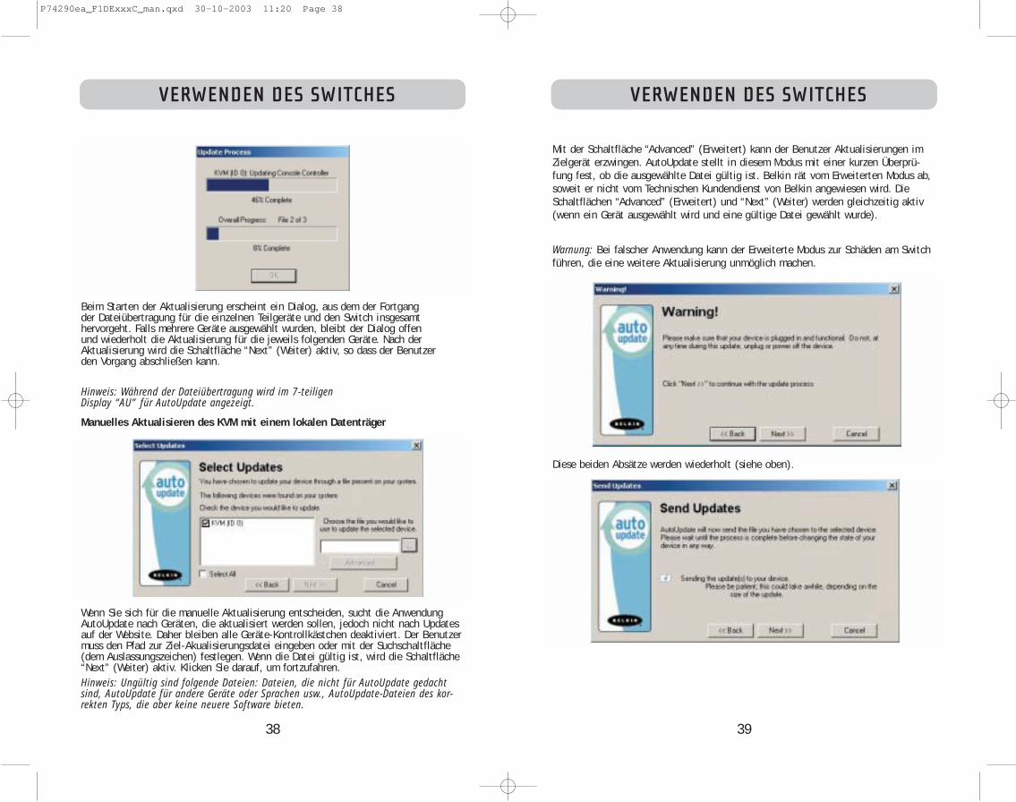
39
VERWENDEN DES SWITCHES
Mit der Schaltfläche “Advanced” (Erweitert) kann der Benutzer Aktualisierungen imZielgerät erzwingen. AutoUpdate stellt in diesem Modus mit einer kurzen Überprü-fung fest, ob die ausgewählte Datei gültig ist. Belkin rät vom Erweiterten Modus ab,soweit er nicht vom Technischen Kundendienst von Belkin angewiesen wird. DieSchaltflächen “Advanced” (Erweitert) und “Next” (Weiter) werden gleichzeitig aktiv(wenn ein Gerät ausgewählt wird und eine gültige Datei gewählt wurde).
Warnung: Bei falscher Anwendung kann der Erweiterte Modus zur Schäden am Switchführen, die eine weitere Aktualisierung unmöglich machen.
Diese beiden Absätze werden wiederholt (siehe oben).
38
VERWENDEN DES SWITCHES
Beim Starten der Aktualisierung erscheint ein Dialog, aus dem der Fortgang der Dateiübertragung für die einzelnen Teilgeräte und den Switch insgesamt hervorgeht. Falls mehrere Geräte ausgewählt wurden, bleibt der Dialog offen und wiederholt die Aktualisierung für die jeweils folgenden Geräte. Nach derAktualisierung wird die Schaltfläche “Next” (Weiter) aktiv, so dass der Benutzer den Vorgang abschließen kann.
Hinweis: Während der Dateiübertragung wird im 7-teiligen Display “AU” für AutoUpdate angezeigt.
Manuelles Aktualisieren des KVM mit einem lokalen Datenträger
Wenn Sie sich für die manuelle Aktualisierung entscheiden, sucht die AnwendungAutoUpdate nach Geräten, die aktualisiert werden sollen, jedoch nicht nach Updatesauf der Website. Daher bleiben alle Geräte-Kontrollkästchen deaktiviert. Der Benutzermuss den Pfad zur Ziel-Akualisierungsdatei eingeben oder mit der Suchschaltfläche(dem Auslassungszeichen) festlegen. Wenn die Datei gültig ist, wird die Schaltfläche“Next” (Weiter) aktiv. Klicken Sie darauf, um fortzufahren. Hinweis: Ungültig sind folgende Dateien: Dateien, die nicht für AutoUpdate gedachtsind, AutoUpdate für andere Geräte oder Sprachen usw., AutoUpdate-Dateien des kor-rekten Typs, die aber keine neuere Software bieten.
P74290ea_F1DExxxC_man.qxd 30-10-2003 11:20 Page 38
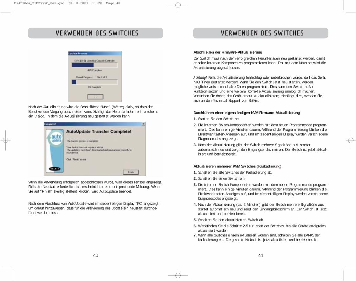
41
VERWENDEN DES SWITCHES
Abschließen der Firmware-Aktualisierung
Der Switch muss nach dem erfolgreichen Herunterladen neu gestartet werden, damiter seine internen Komponenten programmieren kann. Erst mit dem Neustart wird dieAktualisierung abgeschlossen.
Achtung! Falls die Aktualisierung fehlschlug oder unterbrochen wurde, darf das GerätNICHT neu gestartet werden! Wenn Sie den Switch jetzt neu starten, werdenmöglicherweise schadhafte Daten programmiert. Dies kann den Switch außerFunktion setzen und eine weitere, korrekte Aktualisierung unmöglich machen.Versuchen Sie daher, das Gerät erneut zu aktualisieren; misslingt dies, wenden Siesich an den Technical Support von Belkin.
Durchführen einer eigenständigen KVM Firmware-Aktualisierung
1. Starten Sie den Switch neu.
2. Die internen Switch-Komponenten werden mit dem neuen Programmcode program-miert. Dies kann einige Minuten dauern. Während der Programmierung blinken dieDirektwahltasten-Anzeigen auf, und im siebenteiligen Display werden verschiedeneDiagnosecodes angezeigt.
3. Nach der Aktualisierung gibt der Switch mehrere Signaltöne aus, startet automatisch neu und zeigt den Eingangsbildschirm an. Der Switch ist jetzt aktual-isiert und betriebsbereit.
Aktualisieren mehrerer KVM Switches (Kaskadierung)
1. Schalten Sie alle Switches der Kaskadierung ab.
2. Schalten Sie einen Switch ein.
3. Die internen Switch-Komponenten werden mit dem neuen Programmcode program-miert. Dies kann einige Minuten dauern. Während der Programmierung blinken dieDirektwahltasten-Anzeigen auf, und im siebenteiligen Display werden verschiedeneDiagnosecodes angezeigt.
4. Nach der Aktualisierung (ca. 2 Minuten) gibt der Switch mehrere Signaltöne aus,startet automatisch neu und zeigt den Eingangsbildschirm an. Der Switch ist jetztaktualisiert und betriebsbereit.
5. Schalten Sie den aktualisierten Switch ab.
6. Wiederholen Sie die Schritte 2-5 für jeden der Switches, bis alle Geräte erfolgreichaktualisiert wurden.
7. Wenn alle Switches einzeln aktualisiert worden sind, schalten Sie alle BANKS derKaskadierung ein. Die gesamte Kaskade ist jetzt aktualisiert und betriebsbereit.
40
VERWENDEN DES SWITCHES
Nach der Aktualisierung wird die Schaltfläche “Next” (Weiter) aktiv, so dass derBenutzer den Vorgang abschließen kann. Schlägt das Herunterladen fehl, erscheintein Dialog, in dem die Aktualisierung neu gestartet werden kann.
Wenn die Anwendung erfolgreich abgeschlossen wurde, wird dieses Fenster angezeigt.Falls ein Neustart erforderlich ist, erscheint hier eine entsprechende Meldung. WennSie auf “Finish” (Fertig stellen) klicken, wird AutoUpdate beendet.
Nach dem Abschluss von AutoUpdate wird im siebenteiligen Display “PC” angezeigt,um darauf hinzuweisen, dass für die Aktivierung des Update ein Neustart durchge-führt werden muss.
P74290ea_F1DExxxC_man.qxd 30-10-2003 11:20 Page 40

43
k) Wählen Sie “OK”, um den Funktionstastendialog zu schließen.
l) Schließen Sie die Tastaturanwendung.
Hinweis: Wenn Sie eine Kopie der Anwendung “Eject this disk” auf dem Desktop able-gen, können Sie die Auswurffunktion bequemer auf eine Taste setzen. Halten Sie hierzudie Wahltaste gedrückt (entspricht ALT auf der PC-Tastatur), und ziehen Sie dieAnwendung aus dem Suchergebnisfeld auf den Desktop
FEHLERBEHEBUNG
42
FEHLERBEHEBUNG
Ich habe mehrere Switches kaskadiert; jetzt möchte ich eine weitere Konsolehinzufügen. Wie kriege ich die Konsole zum Laufen?
• Wenn Sie Ihre Konsole mit einem Switch Ihrer Kaskadierung verbinden möchten,deren DIP-Schalter von 00 bis 01 gesetzt sind, müssen Sie nur Monitor, Tastaturund Maus anschließen.
• Schließen Sie den Switch an auf die gleiche Weise an die Computer an wie beieinem eigenständigen Switch. Bevor Sie die BANK einschalten, schließen Sie dasKaskadierungskabel an die BANK und an einen Switch am Ende der Kette an. (Ander BANK muss das Kabel mit dem Anschluss IN (Eingang), am anderen Switchmit OUT (Ausgang) verbunden werden.) Schalten Sie den Switch ein. Öffnen Siedas OSD-Menü an einer der Konsolen und aktivieren Sie denKonfigurierungsmodus (Setup). Wechseln Sie zur Kennwortseite, und klicken Sieauf die Schaltfläche “Broadcast Passwords “ (Kennwörter senden). Die neueKonsole ist betriebsbereit und mit der restlichen Kaskadierung synchronisiert.
• Schließen Sie den Switch an auf die gleiche Weise an die Computer an wie beieinem eigenständigen Switch. Bevor Sie die BANK einschalten, schließen Sie dasKaskadierungskabel an die BANK und an einen Switch am Ende der Kette an. (Ander BANK muss das Kabel mit dem Anschluss IN (Eingang), am anderen Switchmit OUT (Ausgang) verbunden werden.) Schalten Sie den Switch ein. Öffnen Siedas OSD-Menü an einer der Konsolen und aktivieren Sie denKonfigurierungsmodus (Setup). Wechseln Sie zur Kennwortseite, und klicken Sieauf die Schaltfläche “Broadcast Passwords “ (Kennwörter senden). Die neueKonsole ist mit der restlichen Kaskadierung synchronisiert und betriebsbereit.
Am CD-Laufwerk meines Macintosh-Computers befindet sich keine Auswurftaste.Die Auswurftaste an der Tastatur funktioniert am Switch nicht. Wie kann ichmein Laufwerk öffnen?
• Unter Mac OS® X (v10.1 und höher) werfen Sie die CD mit der F12-Taste aus.• Unter Mac OS 9 ordnen Sie die Auswurffunktion folgendermaßen zu:1. Einfache Methode
a) Wählen Sie im Apple-Menü die Option “Sherlock2”.b) Wählen Sie die Festplatte mit den Mac OS 9 Systeminformationen.c) Geben Sie im Suchfeld “Eject this disk” ein.d) Wählen Sie das Lupensymbol aus, um die Suche zu starten.e) Wählen Sie im Apple-Menü die Option “Kontrollfelder”.f) Wählen Sie im Kontrollfelder-Menü die Option “Tastatur”.g) Wählen Sie im Dialogfeld “Tastatur” die Schaltfläche “Funktionstasten”.h) Wählen Sie die Taste, die die Auswurffunktion übernehmen soll.i) Wählen Sie die Funktionstaste aus. Ein Zuweisungsdialog erscheint, in dem
die Nummer der gewählten Funktionstaste angegeben wird.j) Wählen Sie die Anwendung “Eject this disk” (Datenträger auswerfen)
(entweder mit dem Desktopsymbol oder aus dem in Sherlock angegebenPfad), und wählen Sie die Schaltfläche “Assign” (Zuordnen).
P74290ea_F1DExxxC_man.qxd 30-10-2003 11:20 Page 42

45
GLOSSAR
Eigenständiger Switch: Einzelner KVM-Switch, der unabhängig betrieben wird (nicht mitanderen Switches verbunden ist).
Statikbetrieb: Der Grund-Betriebsmodus des KVM Switch. Der Switch wechselt indiesen Modus, wenn mindestens fünf Sekunden lang keine Taste gedrückt wurde.
OSD: (auch als Bildschirmmenü bezeichnet): Grafische Benutzeroberfläche, über dieder KVM Switch gesteuert und konfiguriert wird.
Anzeigen:Bezogen auf Schaltvorgänge zwischen verschiedenen Schnittstellenbedeutet “Anzeigen”, dass die Konsole Videodaten aus dem Computer empfängt.Voraussetzung für das Anzeigen ist, dass dass der Konsolenfokus auf der jeweiligenSchnittstelle liegt.
GLOSSAR
Für das Handbuch gelten die folgenden Begriffsdefinitionen:
AutoScan: Betriebsmodus, bei der der KVM Switch die Schnittstellen ständignacheinander abfragt, wie vom Benutzer vorgegeben.
BANK: Die Adresse eines kaskadierten KVM Switch (0-15, einzustellen mit dem DIP-Schalter).
Konsole besteht aus einer Tastatur, einem Monitor und einer Maus, die am KVMSwitch angeschlossen sind.
Konsolenschnittstelle: Anschlüsse zum Verbinden der Konsole mit dem KVM Switch.
Kontrolle: Beim Umschalten zwischen mehreren Schnittstellen bedeutet Kontrolle,dass die Konsole Eingabedaten an den Computer senden kann. Hierzu benötigt dieKonsole Fokus auf die Schnittstelle, und die Schnittstelle muss angezeigt werden.
Konsolen-Switch:KVM-Switch, der auf die BANK-Adresse 0–1 eingestellt und miteiner Konsole verbunden ist.
CPU: Die Kennzeichnungen auf dem KVM-Gehäuse, die die Schnittstellennummern fürden Anschluss der Computerkabel an den KVM Switch angeben.
Kaskadierung: Aus mehreren KVM Switches bestehende Konfiguration, die in Seriegeschaltet sind; eine Belkin KVM Kaskadierung verfügt über gemeinsameEinstellungen, die einen nahtlosen, komplexen Interaktionsverlauf zwischen mehrerenKonsolen zur Kontrolle zahlreicher Computer ermöglichen.
Fokus: Dieser Begrifff wird auf zwei verschiedene Arten verwendet:
1. Im OSD-Menü wird der Fokus durch eine gestrichelte graue Linie amfokusierten Kontrollelement dargestellt. Er bestimmt das Element, das mit derLeer- oder Eingabetaste aktiviert wird. Befindet sich der Fokus auf einerSchaltfläche oder einem Eingabefeld, wird das Element mit der Eingabetaste aktiviert. Befindet er sich auf einemanderen Kontrollelement (zum Beispiel dem Listenfeld), aktiviert dieEingabetaste das Standard-Kontrollelement (Schließen oder Beenden).
2. Beim Umschalten zwischen den verschiedenen Schnittstellen bezeichnet derFokus das Ansteuern einer bestimmten Schnittstelle.
HID: “Human Interface Device”, die USB-Geräteklasse, zu der Tastaturen und Mäusegehören.
KVM Switch: Switches von Belkin für Tastatur, Bildschirm und Maus
Schnittstelle: Anschluss an einem Computer für ein Gerät oder ein Gerätekabel.
Primär-Switch: KVM-Switch, der auf die BANK-Adresse 0-1 eingestellt und mit einerKonsole verbunden ist.
Sekundär-Switch: KVM-Switch ohne Konsole.
Auswahlbetrieb: Betriebsmodus eines kaskadieren KVM Switch, den er imStatikbetrieb aktiviert, sobald die erste Taste auf dem Bedienfeld gedrückt wird. ImAuswahlbetrieb kann der Benutzer die BANK, den Host usw.durch einen weiterenTastendruck auswählen.
44
P74290ea_F1DExxxC_man.qxd 30-10-2003 11:20 Page 44
46
FCC-ErklärungKONFORMITÄTSERKLÄRUNG ZUR EINHALTUNG
DER FCC-BESTIMMUNGEN ÜBER DIE ELEKTROMAGNETISCHE VERTRÄGLICHKEIT
Wir, Belkin Corporation, eine Gesellschaft mit Sitz in 501 West Walnut Street, Compton, CA 90220,USA, erklären hiermit in alleiniger Verantwortung, dass diese Produkte mit der Artikel Nr.
F1DE108CF1DE116CF1DE208CF1DE216C
auf die sich diese Erklärung bezieht,in Einklang mit Teil 15 der FCC- Regelungen stehen. Der Betrieb unterliegt den beiden folgendenBedingungen: (1) Dieses Gerät darf schädigende Störungen nicht verursachen, und (2) dieses Gerätmuss jedwede Störung annehmen, einschließlich der Störungen, die einen unerwünschten Betriebverursachen könnten.
CE-KonformitätserklärungWir, Belkin Corporation, erklären hiermit in alleiniger Verantwortung, dass die Artikel F1DE108C,F1DE116C, F1DE208C und F1DE216C, auf die sich diese Erklärung bezieht, in Einklang mit derFachgrundnorm Störaussendung EN55022 und der Fachgrundnorm Störfestigkeit EN55024 sowie LVPEN61000-3-2 und EN61000-3-3 stehen.
ICES-ErklärungDieses digitale Gerät der Klasse B entspricht der kanadischen Norm ICES-003. Cet appareil numérique dela classe B est conforme à la norme NMB-003 du Canada.
Fünfjährige Garantie von Belkin CorporationBelkin Corporation gewährleistet hiermit, dass dieses Produkt während des Garantiezeitraums keineVerarbeitungs- und Materialfehler aufweist. Bei Feststellung eines Fehlers wird Belkin das Produkt nach eigenem Ermessen entweder kostenlos reparieren oder austauschen, sofern es während desGarantiezeitraums ausreichend frankiert an den autorisierten Belkin-Händler zurückgegeben wurde, bei dem es erworben wurde. Ein Kaufnachweis kann verlangt werden. Diese Garantie erstreckt sich nicht auf die Beschädigung des Produkts durch Unfall, missbräuchliche, unsachgemäße oder fehlerhafteVerwendung oder Anwendung. Ebenso ist die Garantie unwirksam, wenn das Produkt ohne schriftlicheGenehmigung durch Belkin verändert oder wenn eine Belkin-Seriennummer entfernt oder unkenntlichgemacht wurde.
DIE VORSTEHENDEN GARANTIEBEDINGUNGEN UND RECHTSBEHELFE SCHLIEßEN ALLE ANDERENGEWÄHRLEISTUNGEN UND RECHTSBEHELFE - OB MÜNDLICH ODER SCHRIFTLICH, AUSDRÜCKLICH ODERKONKLUDENT - AUS UND TRETEN AN DEREN STELLE. BELKIN ÜBERNIMMT INSBESONDERE KEINERLEIKONKLUDENTE GEWÄHRLEISTUNGEN, U.A. AUCH KEINE GEWÄHRLEISTUNG DER EIGNUNG FÜR EINENBESTIMMTEN ZWECK ODER DER HANDELSÜBLICHEN QUALITÄT.
Kein Händler, Bevollmächtigter bzw. Vertreter oder Mitarbeiter von Belkin ist befugt, dieseGewährleistungsregelung in irgendeiner Weise abzuändern oder zu ergänzen.
BELKIN HAFTET NICHT FÜR KONKRET BESONDERE, DURCH ZUFALL EINGETRETENE ODER FOLGESCHÄDEN AUFGRUND DER VERLETZUNG EINER GEWÄHRLEISTUNG ODER NACH MAßGABE EINERANDEREN RECHTSLEHRE (U.A. FÜR ENTGANGENE GEWINNE, AUSFALLZEITEN, GESCHÄFTS- ODERFIRMENWERTEINBUßEN BZW. DIE BESCHÄDIGUNG, NEUPROGRAMMIERUNG ODER WIEDERHERSTELLUNGVON PROGRAMMEN ODER DATEN NACH SPEICHERUNG IN ODER NUTZUNG IN VERBINDUNG MIT BELKIN-PRODUKTEN).
Da in manchen Ländern der Ausschluss oder die Beschränkung der Haftung für durch Zufalleingetretene oder Folgeschäden bzw. ein Ausschluss konkludenter Gewährleistungen nicht zulässigist, haben die vorstehenden Beschränkungen und Ausschlussregelungen für Sie möglicherweisekeine Gültigkeit. Diese Garantie räumt Ihnen spezifische Rechte ein, die von Land zu Landunterschiedlich ausgestaltet sind.
RECHTLICHE HINWEISE
P74290ea_F1DExxxC_man.qxd 30-10-2003 11:20 Page 46

© 2003 Belkin Corporation. Alle Rechte vorbehalten. Alle Produktnamen sind eingetragene Markender angegebenen Hersteller. Apple, Macintosh und Mac OS sind Warenzeichen der Apple Computer,
Inc., die in den USA und anderen Ländern eingetragen sind.
P74290
belkin.com
Belkin Corporation501 West Walnut Street
Compton • CA • 90220 • USATel: 310.898.1100Fax: 310.898.1111
Belkin Components, Ltd.Express Business Park • Shipton Way • Rushden
NN10 6GL • GroßbritannienTel: +44 (0) 1933 35 2000Fax: +44 (0) 1933 31 2000
Belkin Components B.V.Starparc Building • Boeing Avenue 3331119 PH Schiphol-Rijk • Niederlande
Tel: +31 (0) 20 654 7300Fax: +31 (0) 20 654 7349
Belkin GmbHHanebergstrasse 2 •
80637 München • DeutschlandTel: +49 (0) 89 143 4050
Fax: +49 (0) 89 143 405100
Belkin KundendienstUS: 310.898.1100, Durchwahl: 2263
800.223.5546, Durchwahl: 2263Europa: 00 800 223 55 460
P74290ea_F1DExxxC_man.qxd 30-10-2003 11:20 Page 48

P74290ea
belkin.com
Belkin Corporation501 West Walnut Street
Compton • CA • 90220 • USATel: 310.898.1100Fax: 310.898.1111
Belkin Components, Ltd.Express Business Park • Shipton Way • Rushden
NN10 6GL • United KingdomTel: +44 (0) 1933 35 2000Fax: +44 (0) 1933 31 2000
Belkin Components B.V.Starparc Building • Boeing Avenue 333
1119 PH Schiphol-Rijk • The NetherlandsTel: +31 (0) 20 654 7300Fax: +31 (0) 20 654 7349
Belkin GmbHHanebergstrasse 2 •
80637 München • GermanyTel: +49 (0) 89 143 4050
Fax: +49 (0) 89 143 405100
Belkin Tech SupportUS: 310.898.1100 ext. 2263
800.223.5546 ext. 2263Europe: 00 800 223 55 460
© 2003 Belkin Corporation. All rights reserved. All trade names are registered trademarks of respective manufacturers listed. Apple, Macintosh, and Mac OS are
trademarks of Apple Computer, Inc., registered in the U.S. and other countries.
P74290ea_F1DExxxC_man.qxd 30-10-2003 11:20 Page 50