en / ach580 hvac control program firmware manual · abb drives for hvac ach580 hvac control program...
TRANSCRIPT
—ABB DRIVES FOR HVAC
ACH580 HVAC control programFirmware manual

Related documents are listed on page 17.

Table of contents
1. Introduction to the manual
2. Start-up, control with I/O and ID run
3. Control panel
4. Settings, I/O and diagnostics on the control panel
5. Default I/O configuration
6. Program features
7. Fault tracing
8. Modbus RTU control through the embedded fieldbus interface (EFB)
9. BACnet MS/TP control through the embedded fieldbus interface (EFB)
10. N2 control through the embedded fieldbus interface (EFB)
11. Fieldbus control through a fieldbus adapter
12. Control chain diagrams
13. Parameters
14. Additional parameter data
ACH580HVAC control program
Firmware manual

2019 ABB Oy. All Rights Reserved.3AXD50000027537 Rev EENEFFECTIVE: 2019-01-11

Table of contents 5
1
2
3
4
5
6
7
8
9
10
11
12
13
Table of contents
Part 1
1. Introduction to the manual
Contents of this chapter . . . . . . . . . . . . . . . . . . . . . . . . . . . . . . . . . . . . . . . . . . . . . . . . . . . . . . 15Applicability . . . . . . . . . . . . . . . . . . . . . . . . . . . . . . . . . . . . . . . . . . . . . . . . . . . . . . . . . . . . . . . 15Safety instructions . . . . . . . . . . . . . . . . . . . . . . . . . . . . . . . . . . . . . . . . . . . . . . . . . . . . . . . . . . 15Target audience . . . . . . . . . . . . . . . . . . . . . . . . . . . . . . . . . . . . . . . . . . . . . . . . . . . . . . . . . . . . 16Purpose of the manual . . . . . . . . . . . . . . . . . . . . . . . . . . . . . . . . . . . . . . . . . . . . . . . . . . . . . . 16Contents of this manual . . . . . . . . . . . . . . . . . . . . . . . . . . . . . . . . . . . . . . . . . . . . . . . . . . . . . . 16Related documents . . . . . . . . . . . . . . . . . . . . . . . . . . . . . . . . . . . . . . . . . . . . . . . . . . . . . . . . . 17Categorization by frame (size) . . . . . . . . . . . . . . . . . . . . . . . . . . . . . . . . . . . . . . . . . . . . . . . . . 19Cybersecurity disclaimer . . . . . . . . . . . . . . . . . . . . . . . . . . . . . . . . . . . . . . . . . . . . . . . . . . . . . 22
2. Start-up, control with I/O and ID run
Contents of this chapter . . . . . . . . . . . . . . . . . . . . . . . . . . . . . . . . . . . . . . . . . . . . . . . . . . . . . . 25How to start up the drive . . . . . . . . . . . . . . . . . . . . . . . . . . . . . . . . . . . . . . . . . . . . . . . . . . . . . 26
How to start up the drive using the First start assistant on the Hand-Off-Auto control panel 26
How to control the drive through the I/O interface . . . . . . . . . . . . . . . . . . . . . . . . . . . . . . . . . . 35How to perform the ID run . . . . . . . . . . . . . . . . . . . . . . . . . . . . . . . . . . . . . . . . . . . . . . . . . . . . 36
ID run procedure . . . . . . . . . . . . . . . . . . . . . . . . . . . . . . . . . . . . . . . . . . . . . . . . . . . . . . . . 37
3. Control panel
Contents of this chapter . . . . . . . . . . . . . . . . . . . . . . . . . . . . . . . . . . . . . . . . . . . . . . . . . . . . . . 45Removing and reinstalling the control panel . . . . . . . . . . . . . . . . . . . . . . . . . . . . . . . . . . . . . . 45Layout of the standard Hand-Off-Auto panel control panel . . . . . . . . . . . . . . . . . . . . . . . . . . . 46Layout of the control panel display . . . . . . . . . . . . . . . . . . . . . . . . . . . . . . . . . . . . . . . . . . . . . 47Home view displays . . . . . . . . . . . . . . . . . . . . . . . . . . . . . . . . . . . . . . . . . . . . . . . . . . . . . . . . . 49Keys . . . . . . . . . . . . . . . . . . . . . . . . . . . . . . . . . . . . . . . . . . . . . . . . . . . . . . . . . . . . . . . . . . . . . 51Key shortcuts . . . . . . . . . . . . . . . . . . . . . . . . . . . . . . . . . . . . . . . . . . . . . . . . . . . . . . . . . . . . . . 52
4. Settings, I/O and diagnostics on the control panel
Contents of this chapter . . . . . . . . . . . . . . . . . . . . . . . . . . . . . . . . . . . . . . . . . . . . . . . . . . . . . . 53Primary settings . . . . . . . . . . . . . . . . . . . . . . . . . . . . . . . . . . . . . . . . . . . . . . . . . . . . . . . . . . . . 54
HVAC quick setup . . . . . . . . . . . . . . . . . . . . . . . . . . . . . . . . . . . . . . . . . . . . . . . . . . . . . . . 55Start, stop, reference . . . . . . . . . . . . . . . . . . . . . . . . . . . . . . . . . . . . . . . . . . . . . . . . . . . . . 56Motor . . . . . . . . . . . . . . . . . . . . . . . . . . . . . . . . . . . . . . . . . . . . . . . . . . . . . . . . . . . . . . . . . 58Ramps . . . . . . . . . . . . . . . . . . . . . . . . . . . . . . . . . . . . . . . . . . . . . . . . . . . . . . . . . . . . . . . . 60Limits . . . . . . . . . . . . . . . . . . . . . . . . . . . . . . . . . . . . . . . . . . . . . . . . . . . . . . . . . . . . . . . . . 61Communication . . . . . . . . . . . . . . . . . . . . . . . . . . . . . . . . . . . . . . . . . . . . . . . . . . . . . . . . . 62PID control . . . . . . . . . . . . . . . . . . . . . . . . . . . . . . . . . . . . . . . . . . . . . . . . . . . . . . . . . . . . 67Override . . . . . . . . . . . . . . . . . . . . . . . . . . . . . . . . . . . . . . . . . . . . . . . . . . . . . . . . . . . . . . 69
Safety
14

6 Table of contents
1
2
3
4
5
6
7
8
9
10
11
12
13
14
Fault functions . . . . . . . . . . . . . . . . . . . . . . . . . . . . . . . . . . . . . . . . . . . . . . . . . . . . . . . . . 70Security . . . . . . . . . . . . . . . . . . . . . . . . . . . . . . . . . . . . . . . . . . . . . . . . . . . . . . . . . . . . . . 71Advanced functions . . . . . . . . . . . . . . . . . . . . . . . . . . . . . . . . . . . . . . . . . . . . . . . . . . . . . 72Clock, region, display . . . . . . . . . . . . . . . . . . . . . . . . . . . . . . . . . . . . . . . . . . . . . . . . . . . . 74Reset to defaults . . . . . . . . . . . . . . . . . . . . . . . . . . . . . . . . . . . . . . . . . . . . . . . . . . . . . . . 75
I/O menu . . . . . . . . . . . . . . . . . . . . . . . . . . . . . . . . . . . . . . . . . . . . . . . . . . . . . . . . . . . . . . . . . 77Diagnostics menu . . . . . . . . . . . . . . . . . . . . . . . . . . . . . . . . . . . . . . . . . . . . . . . . . . . . . . . . . . 78System info menu . . . . . . . . . . . . . . . . . . . . . . . . . . . . . . . . . . . . . . . . . . . . . . . . . . . . . . . . . . 79Energy efficiency menu . . . . . . . . . . . . . . . . . . . . . . . . . . . . . . . . . . . . . . . . . . . . . . . . . . . . . 80Backups menu . . . . . . . . . . . . . . . . . . . . . . . . . . . . . . . . . . . . . . . . . . . . . . . . . . . . . . . . . . . . 82
5. Default I/O configuration
Contents of this chapter . . . . . . . . . . . . . . . . . . . . . . . . . . . . . . . . . . . . . . . . . . . . . . . . . . . . . 83HVAC default . . . . . . . . . . . . . . . . . . . . . . . . . . . . . . . . . . . . . . . . . . . . . . . . . . . . . . . . . . . . . 85
Default control connections for the HVAC default . . . . . . . . . . . . . . . . . . . . . . . . . . . . . . 86PID control, single motor . . . . . . . . . . . . . . . . . . . . . . . . . . . . . . . . . . . . . . . . . . . . . . . . . . . . 87
Default control connections for the PID control, single motor . . . . . . . . . . . . . . . . . . . . . 88
6. Program features
What this chapter contains . . . . . . . . . . . . . . . . . . . . . . . . . . . . . . . . . . . . . . . . . . . . . . . . . . . 89Local control vs. external control . . . . . . . . . . . . . . . . . . . . . . . . . . . . . . . . . . . . . . . . . . . . . . 89
Local control . . . . . . . . . . . . . . . . . . . . . . . . . . . . . . . . . . . . . . . . . . . . . . . . . . . . . . . . . . . 90External control . . . . . . . . . . . . . . . . . . . . . . . . . . . . . . . . . . . . . . . . . . . . . . . . . . . . . . . . 91
Operating modes of the drive . . . . . . . . . . . . . . . . . . . . . . . . . . . . . . . . . . . . . . . . . . . . . . . . . 93Drive configuration and programming . . . . . . . . . . . . . . . . . . . . . . . . . . . . . . . . . . . . . . . . . . 94
Configuring via default configurations . . . . . . . . . . . . . . . . . . . . . . . . . . . . . . . . . . . . . . . 94Configuring via menus . . . . . . . . . . . . . . . . . . . . . . . . . . . . . . . . . . . . . . . . . . . . . . . . . . . 94Configuring via parameters . . . . . . . . . . . . . . . . . . . . . . . . . . . . . . . . . . . . . . . . . . . . . . . 94Adaptive programming . . . . . . . . . . . . . . . . . . . . . . . . . . . . . . . . . . . . . . . . . . . . . . . . . . . 95
Control interfaces . . . . . . . . . . . . . . . . . . . . . . . . . . . . . . . . . . . . . . . . . . . . . . . . . . . . . . . . . . 98Programmable analog inputs . . . . . . . . . . . . . . . . . . . . . . . . . . . . . . . . . . . . . . . . . . . . . . 98Programmable analog outputs . . . . . . . . . . . . . . . . . . . . . . . . . . . . . . . . . . . . . . . . . . . . . 98Programmable digital inputs and outputs . . . . . . . . . . . . . . . . . . . . . . . . . . . . . . . . . . . . . 98Programmable frequency input and output . . . . . . . . . . . . . . . . . . . . . . . . . . . . . . . . . . . 98Programmable relay outputs . . . . . . . . . . . . . . . . . . . . . . . . . . . . . . . . . . . . . . . . . . . . . . 99Programmable I/O extensions . . . . . . . . . . . . . . . . . . . . . . . . . . . . . . . . . . . . . . . . . . . . . 99Fieldbus control . . . . . . . . . . . . . . . . . . . . . . . . . . . . . . . . . . . . . . . . . . . . . . . . . . . . . . . 100Control of a supply unit (LSU) . . . . . . . . . . . . . . . . . . . . . . . . . . . . . . . . . . . . . . . . . . . . 100
Override . . . . . . . . . . . . . . . . . . . . . . . . . . . . . . . . . . . . . . . . . . . . . . . . . . . . . . . . . . . . . . . . 102Overview . . . . . . . . . . . . . . . . . . . . . . . . . . . . . . . . . . . . . . . . . . . . . . . . . . . . . . . . . . . . 102Activating the Override mode . . . . . . . . . . . . . . . . . . . . . . . . . . . . . . . . . . . . . . . . . . . . . 102 Reference for override speed/frequency . . . . . . . . . . . . . . . . . . . . . . . . . . . . . . . . . . . . 103Override mode features . . . . . . . . . . . . . . . . . . . . . . . . . . . . . . . . . . . . . . . . . . . . . . . . . 103Application example 1: Override for single override frequency control . . . . . . . . . . . . . 106Application example 2: Override for PID control . . . . . . . . . . . . . . . . . . . . . . . . . . . . . . 110
Interlocks . . . . . . . . . . . . . . . . . . . . . . . . . . . . . . . . . . . . . . . . . . . . . . . . . . . . . . . . . . . . . . . 113Overview . . . . . . . . . . . . . . . . . . . . . . . . . . . . . . . . . . . . . . . . . . . . . . . . . . . . . . . . . . . . 113Application examples of interlocks . . . . . . . . . . . . . . . . . . . . . . . . . . . . . . . . . . . . . . . . . 114
Run permissives . . . . . . . . . . . . . . . . . . . . . . . . . . . . . . . . . . . . . . . . . . . . . . . . . . . . . . . . . . 117

Table of contents 7
1
2
3
4
5
6
7
8
9
10
11
12
13
Overview . . . . . . . . . . . . . . . . . . . . . . . . . . . . . . . . . . . . . . . . . . . . . . . . . . . . . . . . . . . . . 117Configuration . . . . . . . . . . . . . . . . . . . . . . . . . . . . . . . . . . . . . . . . . . . . . . . . . . . . . . . . . . 117Wiring connections . . . . . . . . . . . . . . . . . . . . . . . . . . . . . . . . . . . . . . . . . . . . . . . . . . . . . 117Functionality . . . . . . . . . . . . . . . . . . . . . . . . . . . . . . . . . . . . . . . . . . . . . . . . . . . . . . . . . . 118Application example 1: Damper end switch . . . . . . . . . . . . . . . . . . . . . . . . . . . . . . . . . . 119Application example 2: Valve opening . . . . . . . . . . . . . . . . . . . . . . . . . . . . . . . . . . . . . . 119
Ramps . . . . . . . . . . . . . . . . . . . . . . . . . . . . . . . . . . . . . . . . . . . . . . . . . . . . . . . . . . . . . . . . . . 120Overview . . . . . . . . . . . . . . . . . . . . . . . . . . . . . . . . . . . . . . . . . . . . . . . . . . . . . . . . . . . . . 120Application examples . . . . . . . . . . . . . . . . . . . . . . . . . . . . . . . . . . . . . . . . . . . . . . . . . . . 122
Limits . . . . . . . . . . . . . . . . . . . . . . . . . . . . . . . . . . . . . . . . . . . . . . . . . . . . . . . . . . . . . . . . . . . 123Limits overview . . . . . . . . . . . . . . . . . . . . . . . . . . . . . . . . . . . . . . . . . . . . . . . . . . . . . . . . 123Application examples . . . . . . . . . . . . . . . . . . . . . . . . . . . . . . . . . . . . . . . . . . . . . . . . . . . 123
Application control . . . . . . . . . . . . . . . . . . . . . . . . . . . . . . . . . . . . . . . . . . . . . . . . . . . . . . . . . 124Automatic fault resets . . . . . . . . . . . . . . . . . . . . . . . . . . . . . . . . . . . . . . . . . . . . . . . . . . . 124External events . . . . . . . . . . . . . . . . . . . . . . . . . . . . . . . . . . . . . . . . . . . . . . . . . . . . . . . . 124Constant speeds/frequencies . . . . . . . . . . . . . . . . . . . . . . . . . . . . . . . . . . . . . . . . . . . . . 124Critical speeds/frequencies . . . . . . . . . . . . . . . . . . . . . . . . . . . . . . . . . . . . . . . . . . . . . . . 125Timed functions . . . . . . . . . . . . . . . . . . . . . . . . . . . . . . . . . . . . . . . . . . . . . . . . . . . . . . . . 126
Motor control . . . . . . . . . . . . . . . . . . . . . . . . . . . . . . . . . . . . . . . . . . . . . . . . . . . . . . . . . . . . . 128Speed control mode . . . . . . . . . . . . . . . . . . . . . . . . . . . . . . . . . . . . . . . . . . . . . . . . . . . . 128Frequency control mode . . . . . . . . . . . . . . . . . . . . . . . . . . . . . . . . . . . . . . . . . . . . . . . . . 128Motor types . . . . . . . . . . . . . . . . . . . . . . . . . . . . . . . . . . . . . . . . . . . . . . . . . . . . . . . . . . . 128Motor identification . . . . . . . . . . . . . . . . . . . . . . . . . . . . . . . . . . . . . . . . . . . . . . . . . . . . . 128Scalar motor control . . . . . . . . . . . . . . . . . . . . . . . . . . . . . . . . . . . . . . . . . . . . . . . . . . . . 128U/f ratio . . . . . . . . . . . . . . . . . . . . . . . . . . . . . . . . . . . . . . . . . . . . . . . . . . . . . . . . . . . . . . 129Flux braking . . . . . . . . . . . . . . . . . . . . . . . . . . . . . . . . . . . . . . . . . . . . . . . . . . . . . . . . . . . 130Start methods – DC magnetization . . . . . . . . . . . . . . . . . . . . . . . . . . . . . . . . . . . . . . . . . 131Switching frequency . . . . . . . . . . . . . . . . . . . . . . . . . . . . . . . . . . . . . . . . . . . . . . . . . . . . 133Motor thermal protection . . . . . . . . . . . . . . . . . . . . . . . . . . . . . . . . . . . . . . . . . . . . . . . . . 134Motor overload protection . . . . . . . . . . . . . . . . . . . . . . . . . . . . . . . . . . . . . . . . . . . . . . . . 140Vector control . . . . . . . . . . . . . . . . . . . . . . . . . . . . . . . . . . . . . . . . . . . . . . . . . . . . . . . . . 141Speed control performance figures . . . . . . . . . . . . . . . . . . . . . . . . . . . . . . . . . . . . . . . . . 142Floating point control (Motor potentiometer) . . . . . . . . . . . . . . . . . . . . . . . . . . . . . . . . . . 142
DC voltage control . . . . . . . . . . . . . . . . . . . . . . . . . . . . . . . . . . . . . . . . . . . . . . . . . . . . . . . . . 144Overvoltage control . . . . . . . . . . . . . . . . . . . . . . . . . . . . . . . . . . . . . . . . . . . . . . . . . . . . . 144Undervoltage control (power loss ride-through) . . . . . . . . . . . . . . . . . . . . . . . . . . . . . . . 144Voltage control and trip limits . . . . . . . . . . . . . . . . . . . . . . . . . . . . . . . . . . . . . . . . . . . . . 145Brake chopper . . . . . . . . . . . . . . . . . . . . . . . . . . . . . . . . . . . . . . . . . . . . . . . . . . . . . . . . . 147
Supervisory . . . . . . . . . . . . . . . . . . . . . . . . . . . . . . . . . . . . . . . . . . . . . . . . . . . . . . . . . . . . . . 149Signal supervision . . . . . . . . . . . . . . . . . . . . . . . . . . . . . . . . . . . . . . . . . . . . . . . . . . . . . . 149Application example 1: Dirty filter . . . . . . . . . . . . . . . . . . . . . . . . . . . . . . . . . . . . . . . . . . 149Application example 2: High current . . . . . . . . . . . . . . . . . . . . . . . . . . . . . . . . . . . . . . . . 149User load curve . . . . . . . . . . . . . . . . . . . . . . . . . . . . . . . . . . . . . . . . . . . . . . . . . . . . . . . . 150
Process PID control . . . . . . . . . . . . . . . . . . . . . . . . . . . . . . . . . . . . . . . . . . . . . . . . . . . . . . . . 152Multipump/fan control . . . . . . . . . . . . . . . . . . . . . . . . . . . . . . . . . . . . . . . . . . . . . . . . . . . . . . 155
Single pump and fan control (PFC) . . . . . . . . . . . . . . . . . . . . . . . . . . . . . . . . . . . . . . . . . 155Application example 1: Supply fan, Basic speed follower . . . . . . . . . . . . . . . . . . . . . . . . 164Application example 2: Supply fan, basic speed follower with interlock and status . . . . 166Application example 3: Supply fan, speed follower complete integration . . . . . . . . . . . . 168Application example 4: Supply fan, PID control . . . . . . . . . . . . . . . . . . . . . . . . . . . . . . . 170Application example 5: Cooling tower fan, speed follower . . . . . . . . . . . . . . . . . . . . . . . 172
14
8 Table of contents
1
2
3
4
5
6
7
8
9
10
11
12
13
14
Application example 6: Cooling tower, PID . . . . . . . . . . . . . . . . . . . . . . . . . . . . . . . . . . 174Application example 7: Chilled water pump . . . . . . . . . . . . . . . . . . . . . . . . . . . . . . . . . . 178Application example 8: Condenser water pump . . . . . . . . . . . . . . . . . . . . . . . . . . . . . . . 180
Energy efficiency . . . . . . . . . . . . . . . . . . . . . . . . . . . . . . . . . . . . . . . . . . . . . . . . . . . . . . . . . 182Energy optimization . . . . . . . . . . . . . . . . . . . . . . . . . . . . . . . . . . . . . . . . . . . . . . . . . . . . 182Energy saving calculators . . . . . . . . . . . . . . . . . . . . . . . . . . . . . . . . . . . . . . . . . . . . . . . 182Load analyzer . . . . . . . . . . . . . . . . . . . . . . . . . . . . . . . . . . . . . . . . . . . . . . . . . . . . . . . . . 183
Managing settings . . . . . . . . . . . . . . . . . . . . . . . . . . . . . . . . . . . . . . . . . . . . . . . . . . . . . . . . 185User parameter sets . . . . . . . . . . . . . . . . . . . . . . . . . . . . . . . . . . . . . . . . . . . . . . . . . . . . 185
Safety and protections . . . . . . . . . . . . . . . . . . . . . . . . . . . . . . . . . . . . . . . . . . . . . . . . . . . . . 186Fixed/Standard protections . . . . . . . . . . . . . . . . . . . . . . . . . . . . . . . . . . . . . . . . . . . . . . 186Programmable protection functions . . . . . . . . . . . . . . . . . . . . . . . . . . . . . . . . . . . . . . . . 186Emergency stop . . . . . . . . . . . . . . . . . . . . . . . . . . . . . . . . . . . . . . . . . . . . . . . . . . . . . . . 187
Diagnostics . . . . . . . . . . . . . . . . . . . . . . . . . . . . . . . . . . . . . . . . . . . . . . . . . . . . . . . . . . . . . . 189Diagnostics menu . . . . . . . . . . . . . . . . . . . . . . . . . . . . . . . . . . . . . . . . . . . . . . . . . . . . . . 189
Miscellaneous . . . . . . . . . . . . . . . . . . . . . . . . . . . . . . . . . . . . . . . . . . . . . . . . . . . . . . . . . . . . 190Backup and restore . . . . . . . . . . . . . . . . . . . . . . . . . . . . . . . . . . . . . . . . . . . . . . . . . . . . 190Data storage parameters . . . . . . . . . . . . . . . . . . . . . . . . . . . . . . . . . . . . . . . . . . . . . . . . 191Parameter checksum calculation . . . . . . . . . . . . . . . . . . . . . . . . . . . . . . . . . . . . . . . . . . 191User lock . . . . . . . . . . . . . . . . . . . . . . . . . . . . . . . . . . . . . . . . . . . . . . . . . . . . . . . . . . . . 193Sine filter support . . . . . . . . . . . . . . . . . . . . . . . . . . . . . . . . . . . . . . . . . . . . . . . . . . . . . . 193
7. Fault tracing
What this chapter contains . . . . . . . . . . . . . . . . . . . . . . . . . . . . . . . . . . . . . . . . . . . . . . . . . . 195Safety . . . . . . . . . . . . . . . . . . . . . . . . . . . . . . . . . . . . . . . . . . . . . . . . . . . . . . . . . . . . . . . . . . 195Indications . . . . . . . . . . . . . . . . . . . . . . . . . . . . . . . . . . . . . . . . . . . . . . . . . . . . . . . . . . . . . . 195
Warnings and faults . . . . . . . . . . . . . . . . . . . . . . . . . . . . . . . . . . . . . . . . . . . . . . . . . . . . 195Pure events . . . . . . . . . . . . . . . . . . . . . . . . . . . . . . . . . . . . . . . . . . . . . . . . . . . . . . . . . . 196Editable messages . . . . . . . . . . . . . . . . . . . . . . . . . . . . . . . . . . . . . . . . . . . . . . . . . . . . . 196
Warning/fault history . . . . . . . . . . . . . . . . . . . . . . . . . . . . . . . . . . . . . . . . . . . . . . . . . . . . . . . 196Event log . . . . . . . . . . . . . . . . . . . . . . . . . . . . . . . . . . . . . . . . . . . . . . . . . . . . . . . . . . . . 196Viewing warning/fault information . . . . . . . . . . . . . . . . . . . . . . . . . . . . . . . . . . . . . . . . . 197
QR code generation for mobile service application . . . . . . . . . . . . . . . . . . . . . . . . . . . . . . . 197Warning messages . . . . . . . . . . . . . . . . . . . . . . . . . . . . . . . . . . . . . . . . . . . . . . . . . . . . . . . . 198Fault messages . . . . . . . . . . . . . . . . . . . . . . . . . . . . . . . . . . . . . . . . . . . . . . . . . . . . . . . . . . 209Warnings and faults from the LSU supply unit . . . . . . . . . . . . . . . . . . . . . . . . . . . . . . . . . . . 221
Warning messages . . . . . . . . . . . . . . . . . . . . . . . . . . . . . . . . . . . . . . . . . . . . . . . . . . . . 221Fault messages . . . . . . . . . . . . . . . . . . . . . . . . . . . . . . . . . . . . . . . . . . . . . . . . . . . . . . . 222
8. Modbus RTU control through the embedded fieldbus interface (EFB)
What this chapter contains . . . . . . . . . . . . . . . . . . . . . . . . . . . . . . . . . . . . . . . . . . . . . . . . . . 225System overview . . . . . . . . . . . . . . . . . . . . . . . . . . . . . . . . . . . . . . . . . . . . . . . . . . . . . . . . . 225Connecting the drive to the fieldbus . . . . . . . . . . . . . . . . . . . . . . . . . . . . . . . . . . . . . . . . . . . 226Setting up the embedded fieldbus interface . . . . . . . . . . . . . . . . . . . . . . . . . . . . . . . . . . . . . 228Setting the drive control parameters . . . . . . . . . . . . . . . . . . . . . . . . . . . . . . . . . . . . . . . . . . 229Basics of the embedded fieldbus interface . . . . . . . . . . . . . . . . . . . . . . . . . . . . . . . . . . . . . . 231
Control word and Status word . . . . . . . . . . . . . . . . . . . . . . . . . . . . . . . . . . . . . . . . . . . . 232References . . . . . . . . . . . . . . . . . . . . . . . . . . . . . . . . . . . . . . . . . . . . . . . . . . . . . . . . . . . 232Actual values . . . . . . . . . . . . . . . . . . . . . . . . . . . . . . . . . . . . . . . . . . . . . . . . . . . . . . . . . 232

Table of contents 9
1
2
3
4
5
6
7
8
9
10
11
12
13
Data input/outputs . . . . . . . . . . . . . . . . . . . . . . . . . . . . . . . . . . . . . . . . . . . . . . . . . . . . . . 232Register addressing . . . . . . . . . . . . . . . . . . . . . . . . . . . . . . . . . . . . . . . . . . . . . . . . . . . . 232
About the control profiles . . . . . . . . . . . . . . . . . . . . . . . . . . . . . . . . . . . . . . . . . . . . . . . . . . . . 234Control Word . . . . . . . . . . . . . . . . . . . . . . . . . . . . . . . . . . . . . . . . . . . . . . . . . . . . . . . . . . . . . 235
Control Word for the ABB Drives profile . . . . . . . . . . . . . . . . . . . . . . . . . . . . . . . . . . . . . 235Control Word for the DCU Profile . . . . . . . . . . . . . . . . . . . . . . . . . . . . . . . . . . . . . . . . . . 236
Status Word . . . . . . . . . . . . . . . . . . . . . . . . . . . . . . . . . . . . . . . . . . . . . . . . . . . . . . . . . . . . . . 239Status Word for the ABB Drives profile . . . . . . . . . . . . . . . . . . . . . . . . . . . . . . . . . . . . . . 239Status Word for the DCU Profile . . . . . . . . . . . . . . . . . . . . . . . . . . . . . . . . . . . . . . . . . . . 240
State transition diagrams . . . . . . . . . . . . . . . . . . . . . . . . . . . . . . . . . . . . . . . . . . . . . . . . . . . . 242State transition diagram for the ABB Drives profile . . . . . . . . . . . . . . . . . . . . . . . . . . . . . 242
References . . . . . . . . . . . . . . . . . . . . . . . . . . . . . . . . . . . . . . . . . . . . . . . . . . . . . . . . . . . . . . 245References for the ABB Drives profile and DCU Profile . . . . . . . . . . . . . . . . . . . . . . . . . 245
Actual values . . . . . . . . . . . . . . . . . . . . . . . . . . . . . . . . . . . . . . . . . . . . . . . . . . . . . . . . . . . . . 246Actual values for the ABB Drives profile and DCU Profile . . . . . . . . . . . . . . . . . . . . . . . 246
Modbus holding register addresses . . . . . . . . . . . . . . . . . . . . . . . . . . . . . . . . . . . . . . . . . . . . 247Modbus holding register addresses for the ABB Drives profile and DCU Profile . . . . . . 247
Modbus function codes . . . . . . . . . . . . . . . . . . . . . . . . . . . . . . . . . . . . . . . . . . . . . . . . . . . . . 248Exception codes . . . . . . . . . . . . . . . . . . . . . . . . . . . . . . . . . . . . . . . . . . . . . . . . . . . . . . . . . . 249Coils (0xxxx reference set) . . . . . . . . . . . . . . . . . . . . . . . . . . . . . . . . . . . . . . . . . . . . . . . . . . 250Discrete inputs (1xxxx reference set) . . . . . . . . . . . . . . . . . . . . . . . . . . . . . . . . . . . . . . . . . . 252Error code registers (holding registers 400090…400100) . . . . . . . . . . . . . . . . . . . . . . . . . . . 254
9. BACnet MS/TP control through the embedded fieldbus interface (EFB)
Contents of this chapter . . . . . . . . . . . . . . . . . . . . . . . . . . . . . . . . . . . . . . . . . . . . . . . . . . . . . 255BACnet overview . . . . . . . . . . . . . . . . . . . . . . . . . . . . . . . . . . . . . . . . . . . . . . . . . . . . . . . . . . 255Hardware installation . . . . . . . . . . . . . . . . . . . . . . . . . . . . . . . . . . . . . . . . . . . . . . . . . . . . . . . 256
Connecting devices to a BACnet MS/TP EIA-485 network . . . . . . . . . . . . . . . . . . . . . . . 256Connecting the drive to the building automation controller . . . . . . . . . . . . . . . . . . . . . . . 256
Starting up BACnet communication through the Primary settings menu . . . . . . . . . . . . . . . . 257Starting up fieldbus communication with parameters . . . . . . . . . . . . . . . . . . . . . . . . . . . . . . 261Activating drive control functions . . . . . . . . . . . . . . . . . . . . . . . . . . . . . . . . . . . . . . . . . . . . . . 262
Drive control . . . . . . . . . . . . . . . . . . . . . . . . . . . . . . . . . . . . . . . . . . . . . . . . . . . . . . . . . . 262Miscellaneous drive control . . . . . . . . . . . . . . . . . . . . . . . . . . . . . . . . . . . . . . . . . . . . . . . 264Communication fault . . . . . . . . . . . . . . . . . . . . . . . . . . . . . . . . . . . . . . . . . . . . . . . . . . . . 266Drive feedback . . . . . . . . . . . . . . . . . . . . . . . . . . . . . . . . . . . . . . . . . . . . . . . . . . . . . . . . 266
Parameter setting example . . . . . . . . . . . . . . . . . . . . . . . . . . . . . . . . . . . . . . . . . . . . . . . . . . 269Frequency control . . . . . . . . . . . . . . . . . . . . . . . . . . . . . . . . . . . . . . . . . . . . . . . . . . . . . . 269
BACnet protocol implementation conformance statement . . . . . . . . . . . . . . . . . . . . . . . . . . 270Product description: . . . . . . . . . . . . . . . . . . . . . . . . . . . . . . . . . . . . . . . . . . . . . . . . . . . . 270BACnet standardized device profile (Annex L): . . . . . . . . . . . . . . . . . . . . . . . . . . . . . . . 270List all BACnet interoperability building blocks supported (Annex K): . . . . . . . . . . . . . . . 270Segmentation capability: . . . . . . . . . . . . . . . . . . . . . . . . . . . . . . . . . . . . . . . . . . . . . . . . . 271Standard object types supported: . . . . . . . . . . . . . . . . . . . . . . . . . . . . . . . . . . . . . . . . . . 271Data link layer options: . . . . . . . . . . . . . . . . . . . . . . . . . . . . . . . . . . . . . . . . . . . . . . . . . . 271Device address binding: . . . . . . . . . . . . . . . . . . . . . . . . . . . . . . . . . . . . . . . . . . . . . . . . . 271Networking options: . . . . . . . . . . . . . . . . . . . . . . . . . . . . . . . . . . . . . . . . . . . . . . . . . . . . . 271Network security options: . . . . . . . . . . . . . . . . . . . . . . . . . . . . . . . . . . . . . . . . . . . . . . . . 272Character sets supported: . . . . . . . . . . . . . . . . . . . . . . . . . . . . . . . . . . . . . . . . . . . . . . . . 272
14

10 Table of contents
1
2
3
4
5
6
7
8
9
10
11
12
13
14
Object/Property support matrix . . . . . . . . . . . . . . . . . . . . . . . . . . . . . . . . . . . . . . . . . . . . . . . 273Device object instance summary . . . . . . . . . . . . . . . . . . . . . . . . . . . . . . . . . . . . . . . . . . . . . 273Binary input object instance summary . . . . . . . . . . . . . . . . . . . . . . . . . . . . . . . . . . . . . . . . . 274Binary output object instance summary . . . . . . . . . . . . . . . . . . . . . . . . . . . . . . . . . . . . . . . . 275Binary value object instance summary . . . . . . . . . . . . . . . . . . . . . . . . . . . . . . . . . . . . . . . . . 275Analog input object instance summary . . . . . . . . . . . . . . . . . . . . . . . . . . . . . . . . . . . . . . . . . 277Analog output object instance summary . . . . . . . . . . . . . . . . . . . . . . . . . . . . . . . . . . . . . . . 277Analog value object instance summary . . . . . . . . . . . . . . . . . . . . . . . . . . . . . . . . . . . . . . . . 278Multistate value object instance summary . . . . . . . . . . . . . . . . . . . . . . . . . . . . . . . . . . . . . . 282Loop object instance summary . . . . . . . . . . . . . . . . . . . . . . . . . . . . . . . . . . . . . . . . . . . . . . . 284Mailbox function . . . . . . . . . . . . . . . . . . . . . . . . . . . . . . . . . . . . . . . . . . . . . . . . . . . . . . . . . . 285
10. N2 control through the embedded fieldbus interface (EFB)
Contents of this chapter . . . . . . . . . . . . . . . . . . . . . . . . . . . . . . . . . . . . . . . . . . . . . . . . . . . . 287N2 overview . . . . . . . . . . . . . . . . . . . . . . . . . . . . . . . . . . . . . . . . . . . . . . . . . . . . . . . . . . . . . 287
Supported features . . . . . . . . . . . . . . . . . . . . . . . . . . . . . . . . . . . . . . . . . . . . . . . . . . . . . 288Metasys integration . . . . . . . . . . . . . . . . . . . . . . . . . . . . . . . . . . . . . . . . . . . . . . . . . . . . 289Drive device type . . . . . . . . . . . . . . . . . . . . . . . . . . . . . . . . . . . . . . . . . . . . . . . . . . . . . . 290
Hardware installation . . . . . . . . . . . . . . . . . . . . . . . . . . . . . . . . . . . . . . . . . . . . . . . . . . . . . . 291Connecting devices to a N2 EIA-485 network . . . . . . . . . . . . . . . . . . . . . . . . . . . . . . . . 291Connecting the drive to the building automation controller . . . . . . . . . . . . . . . . . . . . . . 291
N2 analog input objects . . . . . . . . . . . . . . . . . . . . . . . . . . . . . . . . . . . . . . . . . . . . . . . . . . . . 291N2 binary input objects . . . . . . . . . . . . . . . . . . . . . . . . . . . . . . . . . . . . . . . . . . . . . . . . . . . . . 293N2 analog output objects . . . . . . . . . . . . . . . . . . . . . . . . . . . . . . . . . . . . . . . . . . . . . . . . . . . 294N2 binary output objects . . . . . . . . . . . . . . . . . . . . . . . . . . . . . . . . . . . . . . . . . . . . . . . . . . . . 295DDL file for NCU . . . . . . . . . . . . . . . . . . . . . . . . . . . . . . . . . . . . . . . . . . . . . . . . . . . . . . . . . . 297
11. Fieldbus control through a fieldbus adapter
What this chapter contains . . . . . . . . . . . . . . . . . . . . . . . . . . . . . . . . . . . . . . . . . . . . . . . . . . 301System overview . . . . . . . . . . . . . . . . . . . . . . . . . . . . . . . . . . . . . . . . . . . . . . . . . . . . . . . . . 301Basics of the fieldbus control interface . . . . . . . . . . . . . . . . . . . . . . . . . . . . . . . . . . . . . . . . . 303
Control word and Status word . . . . . . . . . . . . . . . . . . . . . . . . . . . . . . . . . . . . . . . . . . . . 304References . . . . . . . . . . . . . . . . . . . . . . . . . . . . . . . . . . . . . . . . . . . . . . . . . . . . . . . . . . . 305Actual values . . . . . . . . . . . . . . . . . . . . . . . . . . . . . . . . . . . . . . . . . . . . . . . . . . . . . . . . . 306Contents of the fieldbus Control word (ABB Drives profile) . . . . . . . . . . . . . . . . . . . . . . 307Contents of the fieldbus Status word (ABB Drives profile) . . . . . . . . . . . . . . . . . . . . . . . 308The state diagram . . . . . . . . . . . . . . . . . . . . . . . . . . . . . . . . . . . . . . . . . . . . . . . . . . . . . 309
Setting up the drive for fieldbus control . . . . . . . . . . . . . . . . . . . . . . . . . . . . . . . . . . . . . . . . 310Parameter setting example: FPBA (PROFIBUS DP) with ABB Drives profile . . . . . . . . 311Parameter setting example: FPBA (PROFIBUS DP) with PROFIdrive profile . . . . . . . . 313
Automatic drive configuration for fieldbus control . . . . . . . . . . . . . . . . . . . . . . . . . . . . . . . . . 315
12. Control chain diagrams
Contents of this chapter . . . . . . . . . . . . . . . . . . . . . . . . . . . . . . . . . . . . . . . . . . . . . . . . . . . . 319Frequency reference selection . . . . . . . . . . . . . . . . . . . . . . . . . . . . . . . . . . . . . . . . . . . . . . . 320Frequency reference modification . . . . . . . . . . . . . . . . . . . . . . . . . . . . . . . . . . . . . . . . . . . . 321Speed reference source selection I . . . . . . . . . . . . . . . . . . . . . . . . . . . . . . . . . . . . . . . . . . . 322Speed reference source selection II . . . . . . . . . . . . . . . . . . . . . . . . . . . . . . . . . . . . . . . . . . . 323

Table of contents 11
1
2
3
4
5
6
7
8
9
10
11
12
13
Speed reference ramping and shaping . . . . . . . . . . . . . . . . . . . . . . . . . . . . . . . . . . . . . . . . . 324Speed error calculation . . . . . . . . . . . . . . . . . . . . . . . . . . . . . . . . . . . . . . . . . . . . . . . . . . . . . 325Speed feedback . . . . . . . . . . . . . . . . . . . . . . . . . . . . . . . . . . . . . . . . . . . . . . . . . . . . . . . . . . . 326Speed controller . . . . . . . . . . . . . . . . . . . . . . . . . . . . . . . . . . . . . . . . . . . . . . . . . . . . . . . . . . 327Torque limitation . . . . . . . . . . . . . . . . . . . . . . . . . . . . . . . . . . . . . . . . . . . . . . . . . . . . . . . . . . 328PID flow calculation . . . . . . . . . . . . . . . . . . . . . . . . . . . . . . . . . . . . . . . . . . . . . . . . . . . . . . . . 329PID setpoint compensation . . . . . . . . . . . . . . . . . . . . . . . . . . . . . . . . . . . . . . . . . . . . . . . . . . 330Process PID setpoint and feedback source selection . . . . . . . . . . . . . . . . . . . . . . . . . . . . . . 331Process PID controller . . . . . . . . . . . . . . . . . . . . . . . . . . . . . . . . . . . . . . . . . . . . . . . . . . . . . . 332External PID setpoint and feedback source selection . . . . . . . . . . . . . . . . . . . . . . . . . . . . . . 333External PID controller . . . . . . . . . . . . . . . . . . . . . . . . . . . . . . . . . . . . . . . . . . . . . . . . . . . . . . 334Direction lock . . . . . . . . . . . . . . . . . . . . . . . . . . . . . . . . . . . . . . . . . . . . . . . . . . . . . . . . . . . . . 335Override . . . . . . . . . . . . . . . . . . . . . . . . . . . . . . . . . . . . . . . . . . . . . . . . . . . . . . . . . . . . . . . . . 336
Part 2 Parameters
13. Parameters
What this chapter contains . . . . . . . . . . . . . . . . . . . . . . . . . . . . . . . . . . . . . . . . . . . . . . . . . . 339Terms and abbreviations . . . . . . . . . . . . . . . . . . . . . . . . . . . . . . . . . . . . . . . . . . . . . . . . . . . . 340Summary of parameter groups . . . . . . . . . . . . . . . . . . . . . . . . . . . . . . . . . . . . . . . . . . . . . . . 341Parameter listing . . . . . . . . . . . . . . . . . . . . . . . . . . . . . . . . . . . . . . . . . . . . . . . . . . . . . . . . . . 343
01 Actual values . . . . . . . . . . . . . . . . . . . . . . . . . . . . . . . . . . . . . . . . . . . . . . . . . . . . . . . 34303 Input references . . . . . . . . . . . . . . . . . . . . . . . . . . . . . . . . . . . . . . . . . . . . . . . . . . . . . 34704 Warnings and faults . . . . . . . . . . . . . . . . . . . . . . . . . . . . . . . . . . . . . . . . . . . . . . . . . . 34805 Diagnostics . . . . . . . . . . . . . . . . . . . . . . . . . . . . . . . . . . . . . . . . . . . . . . . . . . . . . . . . . 34906 Control and status words . . . . . . . . . . . . . . . . . . . . . . . . . . . . . . . . . . . . . . . . . . . . . . 35207 System info . . . . . . . . . . . . . . . . . . . . . . . . . . . . . . . . . . . . . . . . . . . . . . . . . . . . . . . . 36110 Standard DI, RO . . . . . . . . . . . . . . . . . . . . . . . . . . . . . . . . . . . . . . . . . . . . . . . . . . . . . 36311 Standard DIO, FI, FO . . . . . . . . . . . . . . . . . . . . . . . . . . . . . . . . . . . . . . . . . . . . . . . . . 37412 Standard AI . . . . . . . . . . . . . . . . . . . . . . . . . . . . . . . . . . . . . . . . . . . . . . . . . . . . . . . . 37513 Standard AO . . . . . . . . . . . . . . . . . . . . . . . . . . . . . . . . . . . . . . . . . . . . . . . . . . . . . . . 38015 I/O extension module . . . . . . . . . . . . . . . . . . . . . . . . . . . . . . . . . . . . . . . . . . . . . . . . . 38619 Operation mode . . . . . . . . . . . . . . . . . . . . . . . . . . . . . . . . . . . . . . . . . . . . . . . . . . . . . 39520 Start/stop/direction . . . . . . . . . . . . . . . . . . . . . . . . . . . . . . . . . . . . . . . . . . . . . . . . . . . 39621 Start/stop mode . . . . . . . . . . . . . . . . . . . . . . . . . . . . . . . . . . . . . . . . . . . . . . . . . . . . . 40522 Speed reference selection . . . . . . . . . . . . . . . . . . . . . . . . . . . . . . . . . . . . . . . . . . . . . 41323 Speed reference ramp . . . . . . . . . . . . . . . . . . . . . . . . . . . . . . . . . . . . . . . . . . . . . . . . 42324 Speed reference conditioning . . . . . . . . . . . . . . . . . . . . . . . . . . . . . . . . . . . . . . . . . . 42525 Speed control . . . . . . . . . . . . . . . . . . . . . . . . . . . . . . . . . . . . . . . . . . . . . . . . . . . . . . . 42628 Frequency reference chain . . . . . . . . . . . . . . . . . . . . . . . . . . . . . . . . . . . . . . . . . . . . 43130 Limits . . . . . . . . . . . . . . . . . . . . . . . . . . . . . . . . . . . . . . . . . . . . . . . . . . . . . . . . . . . . . 44131 Fault functions . . . . . . . . . . . . . . . . . . . . . . . . . . . . . . . . . . . . . . . . . . . . . . . . . . . . . . 45232 Supervision . . . . . . . . . . . . . . . . . . . . . . . . . . . . . . . . . . . . . . . . . . . . . . . . . . . . . . . . 46234 Timed functions . . . . . . . . . . . . . . . . . . . . . . . . . . . . . . . . . . . . . . . . . . . . . . . . . . . . . 46935 Motor thermal protection . . . . . . . . . . . . . . . . . . . . . . . . . . . . . . . . . . . . . . . . . . . . . . 47736 Load analyzer . . . . . . . . . . . . . . . . . . . . . . . . . . . . . . . . . . . . . . . . . . . . . . . . . . . . . . . 48837 User load curve . . . . . . . . . . . . . . . . . . . . . . . . . . . . . . . . . . . . . . . . . . . . . . . . . . . . . 49140 Process PID set 1 . . . . . . . . . . . . . . . . . . . . . . . . . . . . . . . . . . . . . . . . . . . . . . . . . . . 49441 Process PID set 2 . . . . . . . . . . . . . . . . . . . . . . . . . . . . . . . . . . . . . . . . . . . . . . . . . . . 51143 Brake chopper . . . . . . . . . . . . . . . . . . . . . . . . . . . . . . . . . . . . . . . . . . . . . . . . . . . . . . 513
14

12 Table of contents
1
2
3
4
5
6
7
8
9
10
11
12
13
14
45 Energy efficiency . . . . . . . . . . . . . . . . . . . . . . . . . . . . . . . . . . . . . . . . . . . . . . . . . . . . 51546 Monitoring/scaling settings . . . . . . . . . . . . . . . . . . . . . . . . . . . . . . . . . . . . . . . . . . . . 52047 Data storage . . . . . . . . . . . . . . . . . . . . . . . . . . . . . . . . . . . . . . . . . . . . . . . . . . . . . . . 52349 Panel port communication . . . . . . . . . . . . . . . . . . . . . . . . . . . . . . . . . . . . . . . . . . . . . 52450 Fieldbus adapter (FBA) . . . . . . . . . . . . . . . . . . . . . . . . . . . . . . . . . . . . . . . . . . . . . . . 52551 FBA A settings . . . . . . . . . . . . . . . . . . . . . . . . . . . . . . . . . . . . . . . . . . . . . . . . . . . . . 52952 FBA A data in . . . . . . . . . . . . . . . . . . . . . . . . . . . . . . . . . . . . . . . . . . . . . . . . . . . . . . 53053 FBA A data out . . . . . . . . . . . . . . . . . . . . . . . . . . . . . . . . . . . . . . . . . . . . . . . . . . . . . 53158 Embedded fieldbus . . . . . . . . . . . . . . . . . . . . . . . . . . . . . . . . . . . . . . . . . . . . . . . . . . 53160 DDCS communication . . . . . . . . . . . . . . . . . . . . . . . . . . . . . . . . . . . . . . . . . . . . . . . . 54061 D2D and DDCS transmit data . . . . . . . . . . . . . . . . . . . . . . . . . . . . . . . . . . . . . . . . . . 54062 D2D and DDCS receive data . . . . . . . . . . . . . . . . . . . . . . . . . . . . . . . . . . . . . . . . . . 54170 Override . . . . . . . . . . . . . . . . . . . . . . . . . . . . . . . . . . . . . . . . . . . . . . . . . . . . . . . . . . 54171 External PID1 . . . . . . . . . . . . . . . . . . . . . . . . . . . . . . . . . . . . . . . . . . . . . . . . . . . . . . 54672 External PID2 . . . . . . . . . . . . . . . . . . . . . . . . . . . . . . . . . . . . . . . . . . . . . . . . . . . . . . 54773 External PID3 . . . . . . . . . . . . . . . . . . . . . . . . . . . . . . . . . . . . . . . . . . . . . . . . . . . . . . 54974 External PID4 . . . . . . . . . . . . . . . . . . . . . . . . . . . . . . . . . . . . . . . . . . . . . . . . . . . . . . 55176 PFC configuration . . . . . . . . . . . . . . . . . . . . . . . . . . . . . . . . . . . . . . . . . . . . . . . . . . . 55477 PFC maintenance and monitoring . . . . . . . . . . . . . . . . . . . . . . . . . . . . . . . . . . . . . . . 56180 Flow calculation and protection . . . . . . . . . . . . . . . . . . . . . . . . . . . . . . . . . . . . . . . . . 56294 LSU control . . . . . . . . . . . . . . . . . . . . . . . . . . . . . . . . . . . . . . . . . . . . . . . . . . . . . . . . 56395 HW configuration . . . . . . . . . . . . . . . . . . . . . . . . . . . . . . . . . . . . . . . . . . . . . . . . . . . . 56496 System . . . . . . . . . . . . . . . . . . . . . . . . . . . . . . . . . . . . . . . . . . . . . . . . . . . . . . . . . . . 56797 Motor control . . . . . . . . . . . . . . . . . . . . . . . . . . . . . . . . . . . . . . . . . . . . . . . . . . . . . . . 57798 User motor parameters . . . . . . . . . . . . . . . . . . . . . . . . . . . . . . . . . . . . . . . . . . . . . . . 58199 Motor data . . . . . . . . . . . . . . . . . . . . . . . . . . . . . . . . . . . . . . . . . . . . . . . . . . . . . . . . . 583
Differences in the default values between 50 Hz and 60 Hz supply frequency settings . . . 589
14. Additional parameter data
What this chapter contains . . . . . . . . . . . . . . . . . . . . . . . . . . . . . . . . . . . . . . . . . . . . . . . . . . 591Terms and abbreviations . . . . . . . . . . . . . . . . . . . . . . . . . . . . . . . . . . . . . . . . . . . . . . . . . . . 591Fieldbus addresses . . . . . . . . . . . . . . . . . . . . . . . . . . . . . . . . . . . . . . . . . . . . . . . . . . . . . . . 592Parameter groups 1…9 . . . . . . . . . . . . . . . . . . . . . . . . . . . . . . . . . . . . . . . . . . . . . . . . . . . . 593Parameter groups 10…99 . . . . . . . . . . . . . . . . . . . . . . . . . . . . . . . . . . . . . . . . . . . . . . . . . . 597
Further information
Product and service inquiries . . . . . . . . . . . . . . . . . . . . . . . . . . . . . . . . . . . . . . . . . . . . . . . . 631Product training . . . . . . . . . . . . . . . . . . . . . . . . . . . . . . . . . . . . . . . . . . . . . . . . . . . . . . . . . . 631Providing feedback on ABB Drives manuals . . . . . . . . . . . . . . . . . . . . . . . . . . . . . . . . . . . . 631Document library on the Internet . . . . . . . . . . . . . . . . . . . . . . . . . . . . . . . . . . . . . . . . . . . . . 631

Table of contents
1. Introduction to the manual
2. Start-up, control with I/O and ID run
3. Control panel
4. Settings, I/O and diagnostics on the control panel
5. Default I/O configuration
6. Program features
7. Fault tracing
8. Modbus RTU control through the embedded fieldbus interface (EFB)
9. BACnet MS/TP control through the embedded fieldbus interface (EFB)
10. N2 control through the embedded fieldbus interface (EFB)
11. Fieldbus control through a fieldbus adapter
12. Control chain diagrams
ACH580HVAC control program
Firmware manualPart 1

2019 ABB Oy. All Rights Reserved.Corresponds to3AXD50000209811 Rev BENEFFECTIVE: 2019-01-11

Introduction to the manual 15
1
2
3
4
5
6
7
8
9
10
11
12
13
1Introduction to the manual
Contents of this chapter
The chapter describes applicability, target audience and purpose of this manual. It also describes the contents of this manual and refers to a list of related manuals for more information.
Applicability
The manual applies to the ACH580 HVAC control program (version 2.08).
To check the firmware version of the control program in use, see system information (select Menu > System info > Drive) or parameter 07.05 Firmware version on the control panel.
For ACH580-31, to check the ISU firmware version in use, select Menu > Exit > Options > Select drive > QCON-21 and then select Menu > System info > Drive, or see parameters 07.106 LSU loading package name and 07.107 LSU loading package version on the control panel.
Safety instructions
Follow all safety instructions.
• Read the complete safety instructions in the Hardware manual of the drive before you install, commission, or use the drive.
• Read the firmware function-specific warnings and notes before changing parameter values. These warnings and notes are included in the parameter descriptions presented in chapter Parameters on page 195.
14

16 Introduction to the manual
1
2
3
4
5
6
7
8
9
10
11
12
13
14
Target audience
The reader is expected to know the fundamentals of electricity, wiring, electrical components and electrical schematic symbols.
The manual is written for readers worldwide. Both SI and imperial units are shown. Special US instructions for installations in the United States are given.
Purpose of the manual
This manual provides information needed for designing, commissioning, or operating the drive system.
Contents of this manual
The manual consists of the following chapters:
• Introduction to the manual (this chapter) describes applicability, target audience, purpose and contents of this manual. At the end, it lists terms and abbreviations.
• Start-up, control with I/O and ID run (page 25) describes how to start up the drive as well as how to start, change the direction of the motor rotation and adjust the motor speed through the I/O interface.
• Control panel (page 45) contains instructions for removing and reinstalling the assistant control panel and briefly describes its display, keys and key shortcuts.
• Settings, I/O and diagnostics on the control panel (page 53) describes the simplified settings and diagnostic functions provided on the assistant control panel.
• Default I/O configuration (page 83) contains the connection diagram of the HVAC default configuration together with a connection diagram. The predefined default configuration will save the user time when configuring the drive.
• Program features (page 89) describes program features with lists of related user settings, actual signals, and fault and warning messages.
• Modbus RTU control through the embedded fieldbus interface (EFB) (page 225) describes the communication to and from a fieldbus network using the drive embedded fieldbus interface with the Modbus RTU protocol.
• BACnet MS/TP control through the embedded fieldbus interface (EFB) (page 255) describes the communication to and from a fieldbus network using the drive embedded fieldbus interface with the BACnet MS/TP protocol.
• N2 control through the embedded fieldbus interface (EFB) (page 287) describes the communication to and from a fieldbus network using the drive embedded fieldbus interface with the BACnet MS/TP protocol.
• Fieldbus control through a fieldbus adapter (page 301) describes the communication to and from a fieldbus network using an optional fieldbus adapter module.
Introduction to the manual 17
1
2
3
4
5
6
7
8
9
10
11
12
13
• Fault tracing (page 195) lists the warning and fault messages with possible causes and remedies.
• Control chain diagrams (page 319) describes the parameter structure within the drive.
• Parameters (page 195) describes the parameters used to program the drive.
• Additional parameter data (page 591) contains further information on the parameters.
• Further information (inside of the back cover, page 631) describes how to make product and service inquiries, get information on product training, provide feedback on ABB Drives manuals and find documents on the Internet.
Related documents
You can find manuals and other product documents in PDF format on the Internet. See section Document library on the Internet on the inside of the back cover. For manuals not available in the Document library, contact your local ABB representative
Drive manuals and guides Code (English)ACH580 HVAC control program firmware manual 3AXD50000027537ACH580 HVAC control program firmware manual, Part 1 3AXD50000209811ACH580 HVAC control program firmware manual, Part 2 Parameters
3AXD50000209828
ACH580-01 (0.75 to 250 kW, 1 to 350 hp) hardware manual
3AXD50000044839
ACH580-31 hardware manual 3AXD50000037066ACH580-01 quick installation and start-up guide for frames R1 to R5
3AXD50000044861
ACH580-01 quick installation and start-up guide for frames R6 to R9
3AXD50000036602
ACH580 Installation, Operation, and Maintenance Manual (I, O & M) (US only)
3AXD50000049127
Quick start-up guide for ACH580 HVAC controlprogram
3AXD50000047658
ACH580-31 quick installation guide 3AXD50000048001Adaptive programming application guide 3AXD50000028574ACX-AP-x assistant control panels user’s manual 3AUA0000085685
Option manuals and guidesBACnet Protocol Implementation Conformance Statement (PICS)
3AXD10000387059
CDPI-01 communication adapter module user's manual
3AXD50000009929
FBIP-21 BACnet/IP adapter module user's manual 3AXD50000028468FCAN-01 CANopen adapter module user's manual 3AFE68615500FCNA-01 ControlNet adapter module user's manual 3AUA0000141650FDNA-01 DeviceNet™ adapter module user's manual 3AFE68573360FECA-01 EtherCAT adapter module user's manual 3AUA0000068940
14

18 Introduction to the manual
1
2
3
4
5
6
7
8
9
10
11
12
13
14
FEIP-21 Ethernet/IP adapter module user’s manual 3AXD50000158621FENA-01/-11/-21 Ethernet adapter module user's manual
3AUA0000093568
FEPL-02 Ethernet POWERLINK adapter module user's manual
3AUA0000123527
FLON-01 LONWORKS® adapter module user’s manual 3AUA0000041017FMBA-01 Modbus adapter module user’s manual 3AFE68586704FMBT-21 Modbus/TCP adapter module user’s manual 3AXD50000158607FPBA-01 PROFIBUS DP adapter module user's manual
3AFE68573271
FPNO-21 PROFINET adapter module user’s manual 3AXD50000158614FSCA-01 RS-485 adapter module user's manual 3AUA0000109533Flange mounting kit installation supplement 3AXD50000019100Flange mounting kit quick installation guide for ACX580-01 frames R1 to R3
3AXD50000119172
Flange mounting kit quick installation guide for ACS580-01, ACH580-01 and ACQ580-01 frames R4 to R5
3AXD50000287093
Flange mounting kit quick installation guide for ACS880-01 and ACX580-01 frames R6 to R9
3AXD50000019099
Flange mounting kit quick installation guide forACS880-11, ACS880-31, ACH580-31 and ACQ580-31 frame R3
3AXD50000181506
Flange mounting kit quick installation guide forACS880-11, ACS880-31, ACH580-31 and ACQ580-31 frames R6 and R8
3AXD50000133611
ACS580, ACH580 and ACQ580 drive module framesR3, R5 to R9 for cabinet installation (options +P940and +P944 supplement
3AXD50000210305
Main switch and EMC C1 filter options (+F278, +F316, +E223) installation supplement for ACS580-01, ACH580-01 and ACH580-01 frames R1 to R5
3AXD50000155132
Common mode filter kit for frames R7 and R8 (option+E208) installation guide
3XD50000015179
UK gland plate (+H358) installation guide for ACS880-11, ACS880-31, ACH580-31and ACQ580-31
3AXD50000110711
UL Type 12 hood quick installation guide for ACS580-01, ACH580-01 and ACQ580-01 frames R1 to R9
3AXD50000196067
Tool and maintenance manuals and guidesDrive composer PC tool user's manual 3AUA0000094606Converter module capacitor reforming instructions 3BFE64059629NETA-21 remote monitoring tool user's manual 3AUA0000096939NETA-21 remote monitoring tool installation and start-up guide
3AUA0000096881

Introduction to the manual 19
1
2
3
4
5
6
7
8
9
10
11
12
13
Categorization by frame (size)
The ACH580 is manufactured in several frames (frame sizes), which are denoted as RN, where N is an integer. Some information which only concern certain frames are marked with the symbol of the frame (RN).
The frame is marked on the type designation label attached to the drive, see chapter Operation principle and hardware description, section Type designation label in the Hardware manual of the drive.
ACH580-01 manuals
14
20 Introduction to the manual
1
2
3
4
5
6
7
8
9
10
11
12
13
14
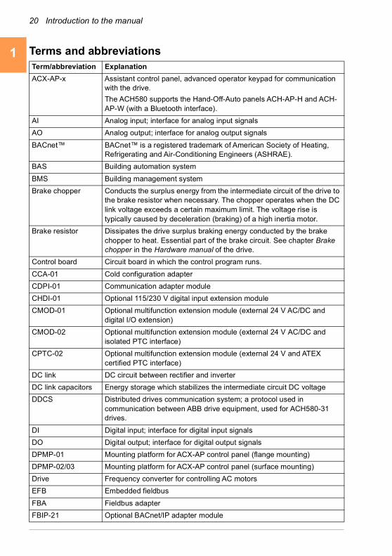
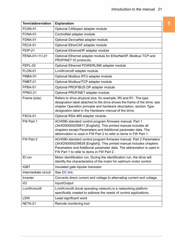
Terms and abbreviationsTerm/abbreviation Explanation
ACX-AP-x Assistant control panel, advanced operator keypad for communication with the drive.
The ACH580 supports the Hand-Off-Auto panels ACH-AP-H and ACH-AP-W (with a Bluetooth interface).
AI Analog input; interface for analog input signals
AO Analog output; interface for analog output signals
BACnet™ BACnet™ is a registered trademark of American Society of Heating, Refrigerating and Air-Conditioning Engineers (ASHRAE).
BAS Building automation system
BMS Building management system
Brake chopper Conducts the surplus energy from the intermediate circuit of the drive to the brake resistor when necessary. The chopper operates when the DC link voltage exceeds a certain maximum limit. The voltage rise is typically caused by deceleration (braking) of a high inertia motor.
Brake resistor Dissipates the drive surplus braking energy conducted by the brake chopper to heat. Essential part of the brake circuit. See chapter Brake chopper in the Hardware manual of the drive.
Control board Circuit board in which the control program runs.
CCA-01 Cold configuration adapter
CDPI-01 Communication adapter module
CHDI-01 Optional 115/230 V digital input extension module
CMOD-01 Optional multifunction extension module (external 24 V AC/DC and digital I/O extension)
CMOD-02 Optional multifunction extension module (external 24 V AC/DC and isolated PTC interface)
CPTC-02 Optional multifunction extension module (external 24 V and ATEX certified PTC interface)
DC link DC circuit between rectifier and inverter
DC link capacitors Energy storage which stabilizes the intermediate circuit DC voltage
DDCS Distributed drives communication system; a protocol used in communication between ABB drive equipment, used for ACH580-31 drives.
DI Digital input; interface for digital input signals
DO Digital output; interface for digital output signals
DPMP-01 Mounting platform for ACX-AP control panel (flange mounting)
DPMP-02/03 Mounting platform for ACX-AP control panel (surface mounting)
Drive Frequency converter for controlling AC motors
EFB Embedded fieldbus
FBA Fieldbus adapter
FBIP-21 Optional BACnet/IP adapter module
Introduction to the manual 21
1
2
3
4
5
6
7
8
9
10
11
12
13
FCAN-01 Optional CANopen adapter module
FCNA-01 ControlNet adapter module
FDNA-01 Optional DeviceNet adapter module
FECA-01 Optional EtherCAT adapter module
FEIP-21 Optional Ethernet/IP adapter module
FENA-01/-11/-21 Optional Ethernet adapter module for EtherNet/IP, Modbus TCP and PROFINET IO protocols
FEPL-02 Optional Ethernet POWERLINK adapter module
FLON-01 LONWORKS® adapter module
FMBA-01 Optional Modbus RTU adapter module
FMBT-21 Optional Modbus/TCP adapter module
FPBA-01 Optional PROFIBUS DP adapter module
FPNO-21 Optional PROFINET adapter module
Frame (size) Refers to drive physical size, for example, R0 and R1. The type designation label attached to the drive shows the frame of the drive, see chapter Operation principle and hardware description, section Type designation label in the Hardware manual of the drive.
FSCA-01 Optional RSA-485 adapter module
FW Part 1 ACH580 standard control program firmware manual, Part 1 (3AXD50000209811 [English]). This printed manual includes all chapters except Parameters and Additional parameter data. The abbreviation is used in FW Part 2 to refer to items in FW Part 1.
FW Part 2 ACH580 standard control program firmware manual, Part 2 Parameters (3AXD50000209828 [English]). This printed manual includes chapters Parameters and Additional parameter data. The abbreviation is used in FW Part 1 to refer to items in FW Part 2.
ID run Motor identification run. During the identification run, the drive will identify the characteristics of the motor for optimum motor control.
IGBT Insulated gate bipolar transistor
Intermediate circuit See DC link.
Inverter Converts direct current and voltage to alternating current and voltage.
I/O Input/Output
LONWORKS® LONWORKS® (local operating network) is a networking platform specifically created to address the needs of control applications.
LSW Least significant word
NETA-21 Remote monitoring tool
Term/abbreviation Explanation
14
22 Introduction to the manual
1
2
3
4
5
6
7
8
9
10
11
12
13
14
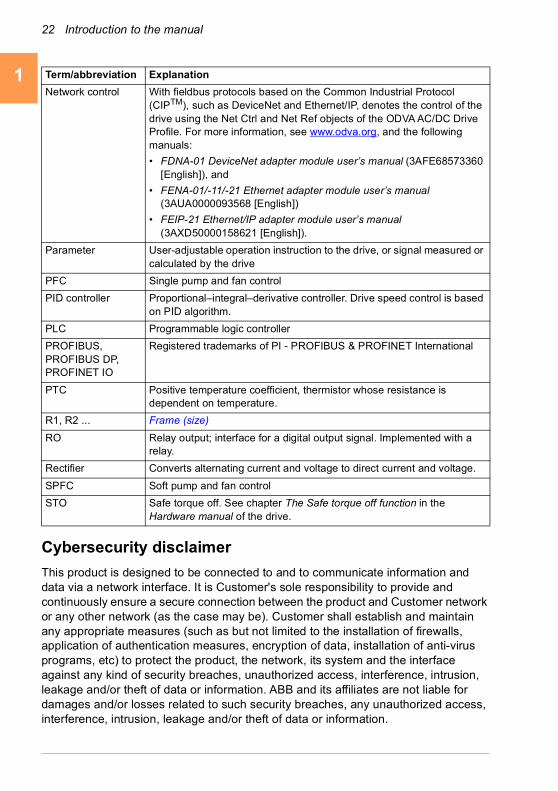
Cybersecurity disclaimer
This product is designed to be connected to and to communicate information and data via a network interface. It is Customer's sole responsibility to provide and continuously ensure a secure connection between the product and Customer network or any other network (as the case may be). Customer shall establish and maintain any appropriate measures (such as but not limited to the installation of firewalls, application of authentication measures, encryption of data, installation of anti-virus programs, etc) to protect the product, the network, its system and the interface against any kind of security breaches, unauthorized access, interference, intrusion, leakage and/or theft of data or information. ABB and its affiliates are not liable for damages and/or losses related to such security breaches, any unauthorized access, interference, intrusion, leakage and/or theft of data or information.
Network control With fieldbus protocols based on the Common Industrial Protocol (CIPTM), such as DeviceNet and Ethernet/IP, denotes the control of the drive using the Net Ctrl and Net Ref objects of the ODVA AC/DC Drive Profile. For more information, see www.odva.org, and the following manuals:
• FDNA-01 DeviceNet adapter module user’s manual (3AFE68573360 [English]), and
• FENA-01/-11/-21 Ethernet adapter module user’s manual (3AUA0000093568 [English])
• FEIP-21 Ethernet/IP adapter module user’s manual (3AXD50000158621 [English]).
Parameter User-adjustable operation instruction to the drive, or signal measured or calculated by the drive
PFC Single pump and fan control
PID controller Proportional–integral–derivative controller. Drive speed control is based on PID algorithm.
PLC Programmable logic controller
PROFIBUS, PROFIBUS DP, PROFINET IO
Registered trademarks of PI - PROFIBUS & PROFINET International
PTC Positive temperature coefficient, thermistor whose resistance is dependent on temperature.
R1, R2 ... Frame (size)
RO Relay output; interface for a digital output signal. Implemented with a relay.
Rectifier Converts alternating current and voltage to direct current and voltage.
SPFC Soft pump and fan control
STO Safe torque off. See chapter The Safe torque off function in the Hardware manual of the drive.
Term/abbreviation Explanation

Introduction to the manual 23
1
2
3
4
5
6
7
8
9
10
11
12
13
See also section Parameter checksum calculation on page 191.
14

24 Introduction to the manual
1
2
3
4
5
6
7
8
9
10
11
12
13
14
Start-up, control with I/O and ID run 25
1
2
3
4
5
6
7
8
9
10
11
12
13
2Start-up, control with I/O and ID run
Contents of this chapter
The chapter describes how to:
• perform the start-up
• start, stop, change the direction of the motor rotation and adjust the speed of the motor through the I/O interface
• perform an Identification run (ID run) for the drive.
14

26 Start-up, control with I/O and ID run
1
2
3
4
5
6
7
8
9
10
11
12
13
14
How to start up the drive
Note: Automatic selection of supply voltage is not supported in ACH580-31. You must select the supply voltage manually using parameter 95.01 Supply voltage. Follow the instructions below.
How to start up the drive using the First start assistant on the Hand-Off-Auto control panel
Safety
Do not start-up the drive unless you are a qualified electrician.
Read and obey the instructions in chapter Safety instructions at the beginning of the Hardware manual of the drive. Ignoring the instructions can cause physical injury or death, or damage to the equipment
Check the installation. See chapter Installation checklist in the Hardware manual of the drive.
Make sure there is no active start on (DI1 in factory settings, that is, HVAC default). The drive will start up automatically at power-up if the external run command is on and the drive is in the external control mode.
Check that the starting of the motor does not cause any danger.
De-couple the driven machine if
• there is a risk of damage in case of an incorrect direction of rotation, or
• a Normal ID run is required during the drive start-up, when the load torque is higher than 20% or the machinery is not able to withstand the nominal torque transient during the ID run.
Hints on using the assistant control panel
The two commands at the bottom of the display (Options and Menu in the figure on the right), show the functions of the two softkeys and
located below the display. The commands assigned to the softkeys vary depending on the context.
Use keys , , and to move the cursor and/or change values depending on the active view.
Key shows a context-sensitive help page.
For more information, see ACX-AP-x assistant control panels user’s manual (3AUA0000085685 [English]).
1 – First start assistant guided settings:Language, motor nominal values, and date and time
Have the motor name plate data at hand.
Power up the drive.
?

Start-up, control with I/O and ID run 27
1
2
3
4
5
6
7
8
9
10
11
12
13
The First start assistant guides you through the first start-up.
The assistant begins automatically. Wait until the control panel enters the view shown on the right.
Select the language you want to use by highlighting it (if not already highlighted) and pressing (OK).
ACH580-31 and ACH580-34 drives: Select the supply voltage with parameter 95.01 Supply voltage: • In the First start assistant menu, select Exit and
press (Next).
• In the Home view, press (Menu) to enter the Main menu.
• In the Main menu, go to Parameters > Complete list > 95 HW configuration by selecting the correct row and pressing (Select) repeatedly.
• Select parameter 95.01 Supply voltage and press (Edit).
• Select supply voltage 380…415 V or 440…480 V and press (Save).
• Go back to the Main menu by pressing (Back) repeatedly.
• In the Main menu, select First start assistant and press (Select) to enter the First start assistant menu.
• Continue with the following steps for commissioning the ACH580.
Select Commission the drive and press (Next).
14

28 Start-up, control with I/O and ID run
1
2
3
4
5
6
7
8
9
10
11
12
13
14
Select the localization you want to use and press (Next).
Change the units shown on the panel if needed.
• Go to the edit view of a selected row by pressing .
• Scroll the view with and .
Go to the next view by pressing (Next).
To select a value in an edit view:
• Use and to select the value.
Press (Save) to accept the new setting, or press (Cancel) to go back to the previous view without making changes.
Set the date and time as well as date and time display formats.
• Go to the edit view of a selected row by pressing .
• Scroll the view with and .
Go to the next view by pressing (Next).
Start-up, control with I/O and ID run 29
1
2
3
4
5
6
7
8
9
10
11
12
13
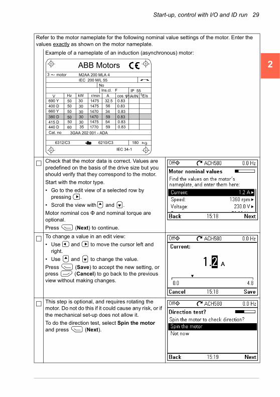
Refer to the motor nameplate for the following nominal value settings of the motor. Enter the values exactly as shown on the motor nameplate.
Example of a nameplate of an induction (asynchronous) motor:
Check that the motor data is correct. Values are predefined on the basis of the drive size but you should verify that they correspond to the motor.
Start with the motor type.
• Go to the edit view of a selected row by pressing .
• Scroll the view with and .
Motor nominal cos Φ and nominal torque are optional.
Press (Next) to continue.
To change a value in an edit view:
• Use and to move the cursor left and right.
• Use and to change the value.
Press (Save) to accept the new setting, or press (Cancel) to go back to the previous view without making changes.
This step is optional, and requires rotating the motor. Do not do this if it could cause any risk, or if the mechanical set-up does not allow it.
To do the direction test, select Spin the motor and press (Next).
M2AA 200 MLA 4
147514751470147014751770
32.556
34595459
0.830.830.830.830.830.83
3GAA 202 001 - ADA
180
IEC 34-1
6210/C36312/C3
Cat. no
35 30 30 30
30 3050
5050
505060
690 Y400 D660 Y
380 D415 D440 D
V Hz kW r/min A cos IA/IN tE/s
Ins.cl. F IP 55No
IEC 200 M/L 55
3 motor
ABB Motors
14
30 Start-up, control with I/O and ID run
1
2
3
4
5
6
7
8
9
10
11
12
13
14
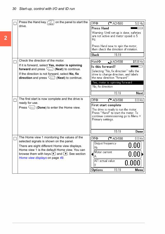
Press the Hand key on the panel to start the drive.
Check the direction of the motor.
If it is forward, select Yes, motor is spinning forward and press (Next) to continue.
If the direction is not forward, select No, fix direction and press (Next) to continue.
The first start is now complete and the drive is ready for use.
Press (Done) to enter the Home view.
The Home view 1 monitoring the values of the selected signals is shown on the panel.
There are eight different Home view displays. Home view 1 is the default Home view. You can browse them with keys and . See section Home view displays on page 49.
Hand

Start-up, control with I/O and ID run 31
1
2
3
4
5
6
7
8
9
10
11
12
13
2 – Completion of commissioning
You can complete the commissioning in five different ways:
HVAC quick setup commissioning
Assistant commissioning
Start/stop, reference and scaling
Ramps, limits, interlock, run permissive
Run & set reference on the panel
2 31
Drive is now ready to be run in the Hand mode.Press the Hand key
on the panel to start the motor.
Set the reference on the panel.
Hand
Complete the followingtwo assistants.
Go through the items on the menu
14

32 Start-up, control with I/O and ID run
1
2
3
4
5
6
7
8
9
10
11
12
13
14
Options 4 and 5:
Set the start/stop and reference
Commissioning with Primary settings
Set the ramps
Commissioning with parameters.
For advanced users only.
5
See chapter Parameters on page 339.
Set the motor data
Set the limits
Continue with further adjustments, see section Primary settings on
page 54.
4
Start-up, control with I/O and ID run 33
1
2
3
4
5
6
7
8
9
10
11
12
13
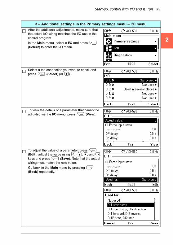
3 – Additional settings in the Primary settings menu – I/O menu
After the additional adjustments, make sure that the actual I/O wiring matches the I/O use in the control program.
In the Main menu, select a I/O and press (Select) to enter the I/O menu.
Select a the connection you want to check and press (Select) (or ).
To view the details of a parameter that cannot be adjusted via the I/O menu, press (View).
To adjust the value of a parameter, press (Edit), adjust the value using , , and keys and press (Save). Note that the actual wiring must match the new value.
Go back to the Main menu by pressing (Back) repeatedly.
14
34 Start-up, control with I/O and ID run
1
2
3
4
5
6
7
8
9
10
11
12
13
14
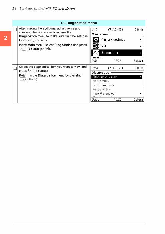
4 – Diagnostics menu
After making the additional adjustments and checking the I/O connections, use the Diagnostics menu to make sure that the setup is functioning correctly.
In the Main menu, select Diagnostics and press (Select) (or ).
Select the diagnostics item you want to view and press (Select).
Return to the Diagnostics menu by pressing (Back).

Start-up, control with I/O and ID run 35
1
2
3
4
5
6
7
8
9
10
11
12
13
How to control the drive through the I/O interface
The table below describes how to operate the drive through the digital and analog inputs when:
• the motor start-up is performed, and
• the default parameter settings of the HVAC default configurations are in use.
Preliminary settings
If you need to change the direction of rotation, check that limits allow reverse direction. Check parameter group 30 Limits and make sure that the minimum limit has a negative value and the maximum limit has a positive value.
Note: Default settings only allow forward direction.
Make sure that the control connections are wired according to the connection diagram given for the HVAC default.
See section HVAC default on page 85.
Make sure that the drive is in external control. To switch to external control, press key .
In external control, the panel display shows text Auto at the top left.
Starting and controlling the speed of the motor
Start by switching digital input DI1 on.
The arrow starts rotating. It is dotted until the setpoint is reached.
Regulate the drive output frequency (motor speed) by adjusting voltage of analog input AI.
Note: If the drive will not start, check that the start interlock 1 (parameter 20.41) is active (1). For the HVAC default, the start interlock 1 is connected to DI4 by default.
Stopping the motor
Switch digital input DI1 off. The arrow stops rotating.
Auto
14

36 Start-up, control with I/O and ID run
1
2
3
4
5
6
7
8
9
10
11
12
13
14
How to perform the ID run
The drive automatically estimates motor characteristics using Standstill ID run when the drive is started for the first time in vector control and after any motor parameter (group 99 Motor data) is changed. This is valid when
• parameter 99.13 ID run requested selection is Standstill and
• parameter 99.04 Motor control mode selection is Vector.
In most applications there is no need to perform a separate ID run. The ID run should be selected manually if:
• vector control mode is used (parameter 99.04 Motor control mode is set to Vector), and
• permanent magnet motor (PM) is used (parameter 99.03 Motor type is set to Permanent magnet motor), or
• synchronous reluctance motor (SynRM) is used (parameter 99.03 Motor type is set to SynRM), or
• drive operates near zero speed references, or
• operation at torque range above the motor nominal torque, over a wide speed range is needed.
Do the ID run with the ID run assistant by selecting Menu > Primary settings > Motor > ID run (see page 37) or with parameter 99.13 ID run requested (see page 41).
Note: If motor parameters (99 Motor data) are changed after the ID run, it must be repeated.
Note: If you have already parameterized your application using the scalar motor control mode (99.04 Motor control mode is set to Scalar) and you need to change motor control mode to Vector,
• change the control mode to vector with the Control mode assistant (go to Menu > Primary settings > Motor > Control mode) and follow the instructions. The ID run assistant then guides you through the ID run.
or
• set parameter 99.04 Motor control mode to Vector, and
• for I/O controlled drive, check parameters in groups 22 Speed reference selection, 23 Speed reference ramp, 12 Standard AI, 30 Limits and 46 Monitoring/scaling settings.
Start-up, control with I/O and ID run 37
1
2
3
4
5
6
7
8
9
10
11
12
13
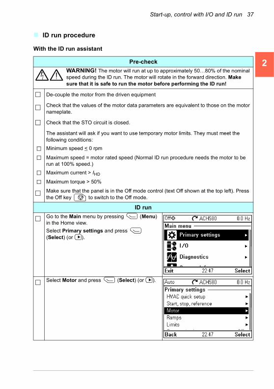
ID run procedure
With the ID run assistant
Pre-check
WARNING! The motor will run at up to approximately 50…80% of the nominal speed during the ID run. The motor will rotate in the forward direction. Make sure that it is safe to run the motor before performing the ID run!
De-couple the motor from the driven equipment
Check that the values of the motor data parameters are equivalent to those on the motor nameplate.
Check that the STO circuit is closed.
The assistant will ask if you want to use temporary motor limits. They must meet the following conditions:
Minimum speed < 0 rpm
Maximum speed = motor rated speed (Normal ID run procedure needs the motor to be run at 100% speed.)
Maximum current > IHD
Maximum torque > 50%
Make sure that the panel is in the Off mode control (text Off shown at the top left). Press the Off key to switch to the Off mode.
ID run
Go to the Main menu by pressing (Menu) in the Home view.
Select Primary settings and press (Select) (or ).
Select Motor and press (Select) (or ).
14
38 Start-up, control with I/O and ID run
1
2
3
4
5
6
7
8
9
10
11
12
13
14
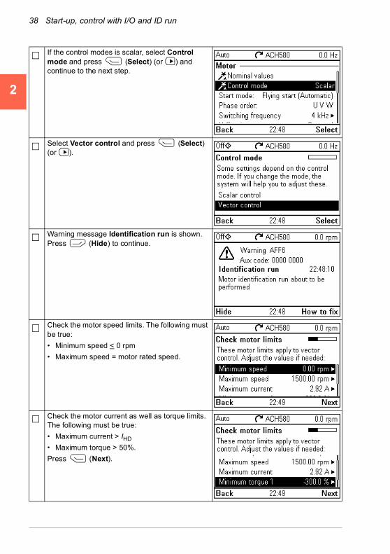
If the control modes is scalar, select Control mode and press (Select) (or ) and continue to the next step.
Select Vector control and press (Select) (or ).
Warning message Identification run is shown. Press (Hide) to continue.
Check the motor speed limits. The following must be true:
• Minimum speed < 0 rpm
• Maximum speed = motor rated speed.
Check the motor current as well as torque limits. The following must be true:
• Maximum current > IHD
• Maximum torque > 50%.
Press (Next).

Start-up, control with I/O and ID run 39
1
2
3
4
5
6
7
8
9
10
11
12
13
Check AI1 scaling, see parameters 12.19 AI1 scaled at AI1 min and 12.20 AI1 scaled at AI1 max.
Press (Next).
Select the type of ID run you want to do and press (Next).
Check the motor limits shown on the panel. If you need other limits during the ID run you can enter them here. The originals limits will be restored after the ID run, unless you select Set values as permanent.
Press (Next).
Press the Hand key ( ) to start the ID run.
In general, it is recommended not to press any control panel keys during the ID run. However, you can stop the ID run at any time by pressing the Off key ( ).During the ID run a progress view is shown.
After the ID run is completed, text ID run done is shown. The LED stops blinking.
If the ID run fails, fault FF61 ID run is shown. See chapter Fault tracing on page 195 for more information.
14

40 Start-up, control with I/O and ID run
1
2
3
4
5
6
7
8
9
10
11
12
13
14
After the ID run is completed, text Done is shown on row ID run.

Start-up, control with I/O and ID run 41
1
2
3
4
5
6
7
8
9
10
11
12
13
With parameter 99.13 ID run requested
Pre-check
WARNING! The motor will run at up to approximately 50…80% of the nominal speed during the ID run. The motor will rotate in the forward direction. Make sure that it is safe to run the motor before performing the ID run!
De-couple the motor from the driven equipment
Check that the values of the motor data parameters are equivalent to those on the motor nameplate.
Check that the STO circuit is closed.
If parameter values (from group 10 Standard DI, RO to group 99 Motor data) are changed before the ID run, check that the new settings meet the following conditions:
30.11 Minimum speed < 0 rpm
30.12 Maximum speed = motor rated speed (Normal ID run procedure needs the motor to be run at 100% speed.)
30.17 Maximum current > IHD
30.20 Maximum torque 1 > 50% or 30.24 Maximum torque 2 > 50%, depending on which torque limit set is in use according to parameter 30.18 Torq lim sel.
Check that signals
run permissive (parameter 20.40 Run permissive) is active
Make sure that the panel is in the Off mode control (text Off shown at the top left). Press the Off key to switch to the Off mode.
ID run
Go to the Main menu by pressing (Menu) in the Home view.
Press .
Select Parameters and press (Select) (or ).
14
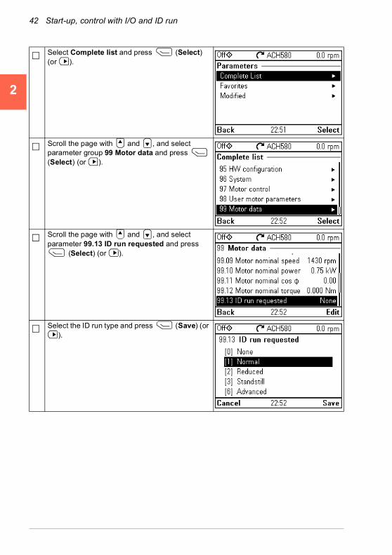
42 Start-up, control with I/O and ID run
1
2
3
4
5
6
7
8
9
10
11
12
13
14
Select Complete list and press (Select) (or ).
Scroll the page with and , and select parameter group 99 Motor data and press (Select) (or ).
Scroll the page with and , and select parameter 99.13 ID run requested and press
(Select) (or ).
Select the ID run type and press (Save) (or ).
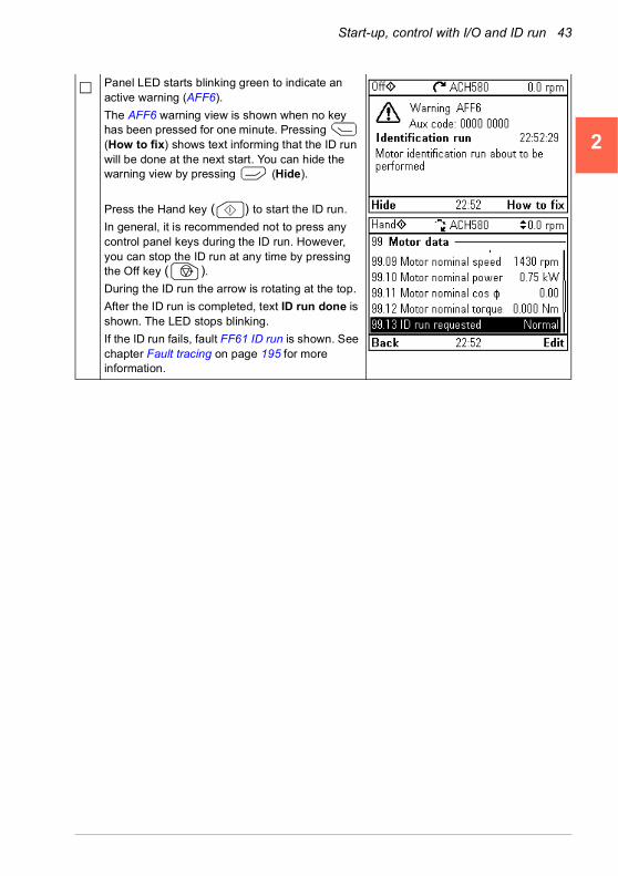
Start-up, control with I/O and ID run 43
1
2
3
4
5
6
7
8
9
10
11
12
13
Panel LED starts blinking green to indicate an active warning (AFF6).
The AFF6 warning view is shown when no key has been pressed for one minute. Pressing (How to fix) shows text informing that the ID run will be done at the next start. You can hide the warning view by pressing (Hide).
Press the Hand key ( ) to start the ID run.
In general, it is recommended not to press any control panel keys during the ID run. However, you can stop the ID run at any time by pressing the Off key ( ).During the ID run the arrow is rotating at the top.
After the ID run is completed, text ID run done is shown. The LED stops blinking.
If the ID run fails, fault FF61 ID run is shown. See chapter Fault tracing on page 195 for more information.
14

44 Start-up, control with I/O and ID run
1
2
3
4
5
6
7
8
9
10
11
12
13
14
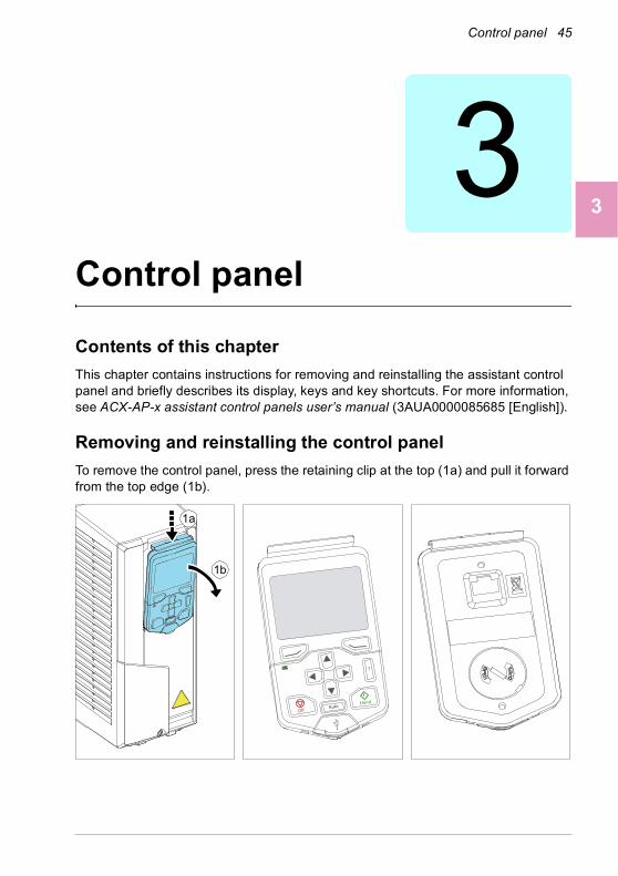
Control panel 45
1
2
3
4
5
6
7
8
9
10
11
12
13
3Control panel
Contents of this chapter
This chapter contains instructions for removing and reinstalling the assistant control panel and briefly describes its display, keys and key shortcuts. For more information, see ACX-AP-x assistant control panels user’s manual (3AUA0000085685 [English]).
Removing and reinstalling the control panel
To remove the control panel, press the retaining clip at the top (1a) and pull it forward from the top edge (1b).
1a
1b
OffAuto
Hand
14

46 Control panel
1
2
3
4
5
6
7
8
9
10
11
12
13
14
To reinstall the control panel, put the bottom of the container in position (1a), press the retaining clip at the top (1b) and push the control panel in at the top edge (1c).
Layout of the standard Hand-Off-Auto panel control panel
1 Layout of the control panel display 6 The arrow keys
2 Left softkey 7 Off (see Hand, Off and Auto)
3 Right softkey 8 Hand (see Hand, Off and Auto)
4 Status LED, see chapter Maintenance and hardware diagnostics, section LEDs in the Hardware manual of the drive.
9 Auto (see Hand, Off and Auto)
5 Help 10 USB connector
1a
1b
1c
43
6
7 8
5
10
2
9
1

Control panel 47
1
2
3
4
5
6
7
8
9
10
11
12
13
Layout of the control panel display
In most views, the following elements are shown on the display:
1. Control location and related icons: Indicates how the drive is controlled:
• No text: The drive is in local control, but controlled from another device. The icons in the top pane indicate which actions are allowed:
• Local: The drive is in local control, and controlled from this control panel. The icons in the top panel indicate which actions are allowed:
Text/Icons Starting from this control panel
Stopping from this control panel
Giving reference from this panel
Not allowed Not allowed Not allowed
Text/Icons Starting from this control panel
Stopping from this control panel
Giving reference from this panel
Off Allowed Drive is stopped Not allowedHand Allowed Allowed Allowed
1
52
6
78
13
7
41
14
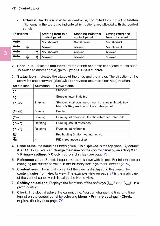
48 Control panel
1
2
3
4
5
6
7
8
9
10
11
12
13
14
• External The drive is in external control, ie, controlled through I/O or fieldbus. The icons in the top pane indicate which actions are allowed with the control panel:
2. Panel bus: Indicates that there are more than one drive connected to this panel. To switch to another drive, go to Options > Select drive.
3. Status icon: Indicates the status of the drive and the motor. The direction of the arrow indicates forward (clockwise) or reverse (counter-clockwise) rotation.
4. Drive name: If a name has been given, it is displayed in the top pane. By default, it is “ACH580”. You can change the name on the control panel by selecting Menu > Primary settings > Clock, region, display (see page 74).
5. Reference value: Speed, frequency, etc. is shown with its unit. For information on changing the reference value in the Primary settings menu (see page 60).
6. Content area: The actual content of the view is displayed in this area. The content varies from view to view. The example view on page 47 is the main view of the control panel which is called the Home view.
7. Softkey selections: Displays the functions of the softkeys ( and ) in a given context.
8. Clock: The clock displays the current time. You can change the time and time format on the control panel by selecting Menu > Primary settings > Clock, region, display (see page 74).
Text/Icons Starting from this control panel
Stopping from this control panel
Giving reference from this panel
Auto Not allowed Not allowed Not allowedAuto Allowed Allowed Not allowedAuto Not allowed Allowed AllowedAuto Allowed Allowed Allowed
Status icon Animation Drive status
- Stopped
- Stopped, start inhibited
Blinking Stopped, start command given but start inhibited. See Menu > Diagnostics on the control panel
Blinking Faulted
Blinking Running, at reference, but the reference value is 0
Rotating Running, not at reference
Rotating Running, at reference
- Pre-heating (motor heating) active
- PID sleep mode active
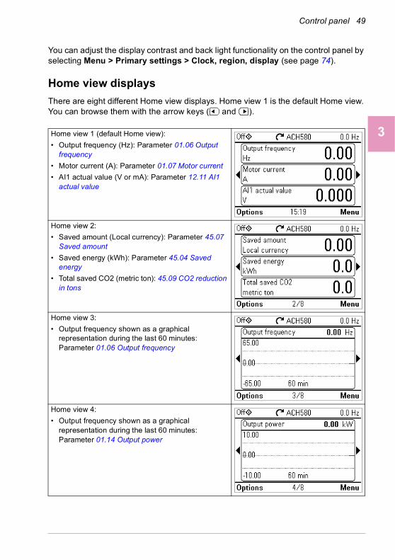
Control panel 49
1
2
3
4
5
6
7
8
9
10
11
12
13
You can adjust the display contrast and back light functionality on the control panel by selecting Menu > Primary settings > Clock, region, display (see page 74).
Home view displays
There are eight different Home view displays. Home view 1 is the default Home view. You can browse them with the arrow keys ( and ).
Home view 1 (default Home view):
• Output frequency (Hz): Parameter 01.06 Output frequency
• Motor current (A): Parameter 01.07 Motor current
• AI1 actual value (V or mA): Parameter 12.11 AI1 actual value
Home view 2:
• Saved amount (Local currency): Parameter 45.07 Saved amount
• Saved energy (kWh): Parameter 45.04 Saved energy
• Total saved CO2 (metric ton): 45.09 CO2 reduction in tons
Home view 3:
• Output frequency shown as a graphical representation during the last 60 minutes: Parameter 01.06 Output frequency
Home view 4:
• Output frequency shown as a graphical representation during the last 60 minutes: Parameter 01.14 Output power
14

50 Control panel
1
2
3
4
5
6
7
8
9
10
11
12
13
14
Home view 5:
• Control board temperature (°C): Parameter 05.10 Control board temperature
• Inverter temperature (%): Parameter 05.11 Inverter temperature
• DC voltage (V): Parameter 01.11 DC voltage
Home view 6:
• On-time counter (days): Parameter 05.01 On-time counter
• Run-time counter (days): Parameter 05.02 Run-time counter
Home view 7:
• DI delayed status, that is, status of DI6…DI1 (DI1 is bit 0, the rightmost bit): Parameter 10.02 DI delayed status
• RO status, that is, status of RO3…RO1 (RO1 is bit 0, the rightmost bit): Parameter 10.21 RO status
• Communication diagnostics: Parameter 58.07 Communication diagnostics
Home view 8:
• Process PID setpoint actual (PID unit 1): Parameter 40.03 Process PID setpoint actual
• Process PID feedback actual (PID unit 1): Parameter 40.02 Process PID feedback actual
• Output frequency (Hz): Parameter 01.06 Output frequency

Control panel 51
1
2
3
4
5
6
7
8
9
0
1
2
3
1
1
1
1
Keys
The keys of the control panel are described below.
Left softkeyThe left softkey ( ) is usually used for exiting and canceling. Its function in a given situation is shown by the softkey selection in the bottom left corner of the display.
Holding down exits each view in turn until you are back in the Home view. This function does not work in special screens.
Right softkeyThe right softkey ( ) is usually used for selecting, accepting and confirming. The function of the right softkey in a given situation is shown by the softkey selection in the bottom right corner of the display.
The arrow keysThe up and down arrow keys ( and ) are used to highlight selections in menus and selection lists, to scroll up and down on text pages, and to adjust values when, for example, setting the time, entering a passcode or changing a parameter value.
The left and right arrow keys ( and ) are used to move the cursor left and right in parameter editing and to move forward and backward in assistants. In menus, and
function the same way as and , respectively.
HelpThe help key ( ) opens a help page. The help page is context-sensitive, in other words, the content of the page is relevant to the menu or view in question.
Hand, Off and AutoThe ACH580 can be in local or external control. The local control has two modes: Hand and Off. See also the diagram in section Local control vs. external control on page 89.
Hand key ( ):
• In local control / Off mode: Starts the drive. The drive will switch to the Hand mode.
• In external control: Switches the drive to local control / Hand mode, keeping it running.
?
14
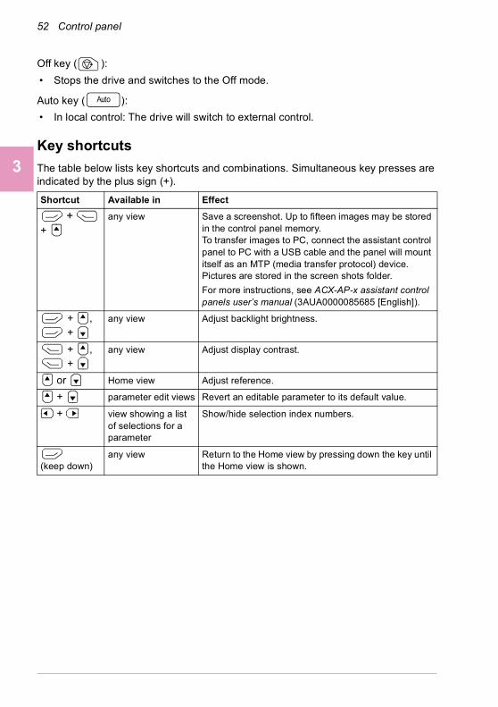
52 Control panel
1
2
3
4
5
6
7
8
9
10
11
12
13
14
Off key ( ):
• Stops the drive and switches to the Off mode.
Auto key ( ):
• In local control: The drive will switch to external control.
Key shortcuts
The table below lists key shortcuts and combinations. Simultaneous key presses are indicated by the plus sign (+).
Shortcut Available in Effect
+ +
any view Save a screenshot. Up to fifteen images may be stored in the control panel memory. To transfer images to PC, connect the assistant control panel to PC with a USB cable and the panel will mount itself as an MTP (media transfer protocol) device. Pictures are stored in the screen shots folder.
For more instructions, see ACX-AP-x assistant control panels user’s manual (3AUA0000085685 [English]).
+ , +
any view Adjust backlight brightness.
+ , +
any view Adjust display contrast.
or Home view Adjust reference.
+ parameter edit views Revert an editable parameter to its default value.
+ view showing a list of selections for a parameter
Show/hide selection index numbers.
(keep down)
any view Return to the Home view by pressing down the key until the Home view is shown.
Auto
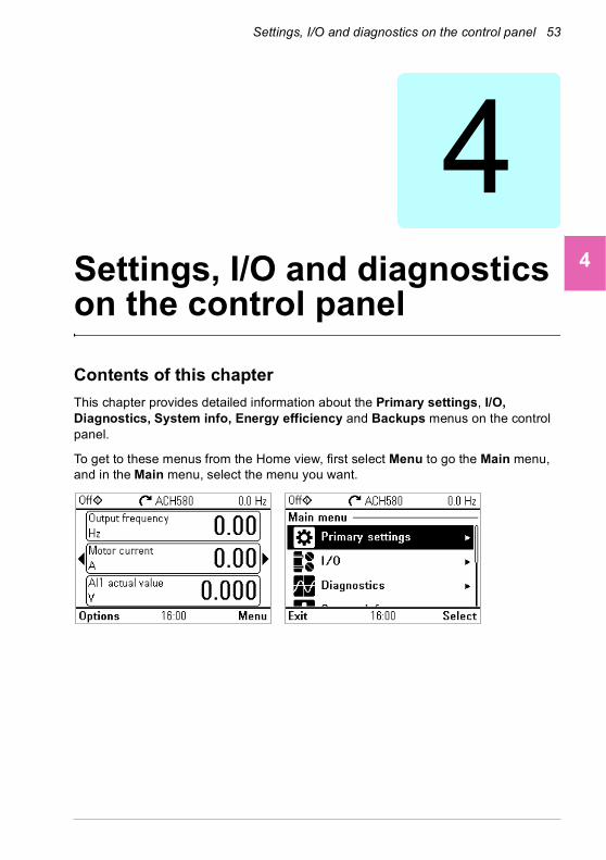
Settings, I/O and diagnostics on the control panel 53
1
2
3
4
5
6
7
8
9
10
11
12
13
4Settings, I/O and diagnostics on the control panel
Contents of this chapter
This chapter provides detailed information about the Primary settings, I/O, Diagnostics, System info, Energy efficiency and Backups menus on the control panel.
To get to these menus from the Home view, first select Menu to go the Main menu, and in the Main menu, select the menu you want.
14

54 Settings, I/O and diagnostics on the control panel
1
2
3
4
5
6
7
8
9
10
11
12
13
14
Primary settings
To go the Primary settings menu from the Home view, select Menu > Primary settings.
After making the guided settings using the first start assistant, you may want to select another default configuration by selecting Start, stop, reference > Basic control set-up > How do you want to control? and then selecting a default configuration.
The Primary settings menu enables you to adjust and define additional settings used in the drive.
We recommend that you make at least these additional settings:
• Set Start, stop, reference values
• Ramps
• Limits
With the Primary settings menu, you can also adjust settings related to the motor, fieldbus communication, PID, override, fault functions, advanced functions and clock, region and display. In addition, you can reset the fault and event logs, panel Home view, parameters not related to hardware, fieldbus settings, motor data and ID run results, all parameters, end user texts as well as reset everything to factory defaults.
Note that the Primary settings menu only enables you to modify some of the settings: more advanced configuration is done via the parameters: Select Menu > Parameters. For more information on the different parameters, see chapter Parameters on page 339.
In the Setting menu, the symbol indicates multiple connected signals/parameters. The symbol indicates that the setting provides an assistant when modifying the parameters.
To get more information on Primary settings menu items, press the key to open the help page.
The sections below provide detailed information about the contents of the different submenus available in the Primary settings menu.
?

Settings, I/O and diagnostics on the control panel 55
1
2
3
4
5
6
7
8
9
10
11
12
13
HVAC quick setup
Use the HVAC quick setup submenu to go through the most important settings (basic setup and basic operation) at start-up if you do not want to do it with the assistants.
The table below provides detailed information about the available setting items in the HVAC quick setup submenu.
Menu item Description Corresponding parameter
Primary start/stop from:
Set where the start and stop comes in the Auto mode.
Primary reference from:
Set where the reference comes in the Auto mode.
AI scaling Set the scaling of AI inputs.Use start interlock 1 Selected/UnselectedStart enabled when: Start enabled when: DIx high 20.41 Start interlock 1
Use run permissive Selected/UnselectedRun enabled when: Run enabled when: DIx high 20.40 Run permissive
Minimum speed:
Minimum frequency:
30.13 Minimum speed30.11 Minimum frequency
Acceleration time: 23.12 Acceleration time 128.72 Freq acceleration time 1
Deceleration time: 23.13 Deceleration time 128.73 Freq deceleration time 1
Stop mode: 21.03 Stop mode
Motor nominal values
Enter the motor's nominal values from the motor's nameplate.
99.03 Motor type … 99.12 Motor nominal torque
Date & time Set the time and date, and their formats.
14

56 Settings, I/O and diagnostics on the control panel
1
2
3
4
5
6
7
8
9
10
11
12
13
14
Start, stop, reference
Use the Start, stop, reference submenu to set up start/stop commands, reference, and related features, such as constant speeds or run permissions.
The table below provides detailed information about the available setting items in the Start, stop, reference submenu.
Menu item Description Corresponding parameter
Basic operation setup
Ramps
Limits
Start interlock signal
Run permissive signal
Naming the driveBasic control setup Direct control via I/O (HVAC default configuration)
• Reference (AI1) scaling
Direct control via fieldbus comm.
• BACnet MS/TP
• Modbus RTU
PID control, single motor
• Feedback (AI2) scaling
• Setpoint source
• Constant setpointPrimary auto control location
Settings for the primary remote control location, Ext1.
12.17 AI1 min12.18 AI1 max
Secondary auto control location
Settings for the secondary remote control location, Ext2. These settings include reference source, start, stop, direction and command sources for Ext2.
By default, Ext2 is set to Off.
19.11 Ext1/Ext2 selection28.15 Ext2 frequency ref1 or22.18 Ext2 speed ref112.17 AI1 min12.18 AI1 max12.27 AI2 min12.28 AI2 max20.06 Ext2 commands20.08 Ext2 in1 source20.09 Ext2 in2 source20.10 Ext2 in3 source
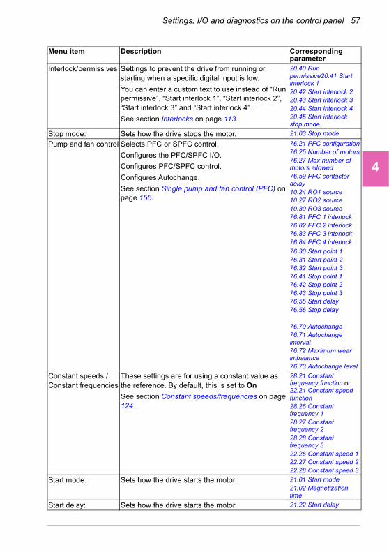
Settings, I/O and diagnostics on the control panel 57
1
2
3
4
5
6
7
8
9
10
11
12
13
Interlock/permissives Settings to prevent the drive from running or starting when a specific digital input is low.
You can enter a custom text to use instead of “Run permissive”, “Start interlock 1”, “Start interlock 2”, “Start interlock 3” and “Start interlock 4”.
See section Interlocks on page 113.
20.40 Run permissive20.41 Start interlock 120.42 Start interlock 220.43 Start interlock 320.44 Start interlock 420.45 Start interlock stop mode
Stop mode: Sets how the drive stops the motor. 21.03 Stop mode
Pump and fan control Selects PFC or SPFC control.
Configures the PFC/SPFC I/O.
Configures PFC/SPFC control.
Configures Autochange.
See section Single pump and fan control (PFC) on page 155.
76.21 PFC configuration76.25 Number of motors76.27 Max number of motors allowed76.59 PFC contactor delay10.24 RO1 source10.27 RO2 source10.30 RO3 source76.81 PFC 1 interlock76.82 PFC 2 interlock76.83 PFC 3 interlock76.84 PFC 4 interlock
76.30 Start point 176.31 Start point 276.32 Start point 376.41 Stop point 176.42 Stop point 276.43 Stop point 376.55 Start delay76.56 Stop delay
76.70 Autochange76.71 Autochange interval76.72 Maximum wear imbalance76.73 Autochange level
Constant speeds / Constant frequencies
These settings are for using a constant value as the reference. By default, this is set to On
See section Constant speeds/frequencies on page 124.
28.21 Constant frequency function or22.21 Constant speed function28.26 Constant frequency 128.27 Constant frequency 228.28 Constant frequency 322.26 Constant speed 122.27 Constant speed 222.28 Constant speed 3
Start mode: Sets how the drive starts the motor. 21.01 Start mode21.02 Magnetization time
Start delay: Sets how the drive starts the motor. 21.22 Start delay
Menu item Description Corresponding parameter
14

58 Settings, I/O and diagnostics on the control panel
1
2
3
4
5
6
7
8
9
10
11
12
13
14
Motor
Use the Motor submenu to adjust motor-related settings, such as nominal values, control mode or thermal protection.
Note that settings that are visible depend on other selections, for example, vector or scalar control mode, used motor type or selected start mode.
Three assistants are available: Control mode, Nominal value and ID run (for vector control mode only).
The table below provides detailed information about the available setting items in the Motor submenu.
Critical speeds/frequencies
Prevents running in critical ranges (speeds or frequencies).
See section Critical speeds/frequencies on page 125.
Vector control:22.51 Critical speed function22.52 Critical speed 1 low22.53 Critical speed 1 high22.54 Critical speed 2 low22.55 Critical speed 2 high22.56 Critical speed 3 low22.57 Critical speed 3 highScalar control:28.51 Critical frequency function…28.57 Critical frequency 3 high
Menu item Description Corresponding parameter
Nominal values Enter the motor's nominal values from the motor's nameplate.
99.03 Motor type … 99.12 Motor nominal torque
Menu item Description Corresponding parameter

Settings, I/O and diagnostics on the control panel 59
1
2
3
4
5
6
7
8
9
10
11
12
13
Control mode Selects whether to use scalar or vector control mode.
For information on scalar control mode, see section Scalar motor control on page 128.
For information on vector control mode, see section Vector control on page 141.
99.04 Motor control mode
Start mode: Sets how the drive starts the motor (for example, pre-magnetize or not). For more information, see section Start methods – DC magnetization on page 131.
21 Start/stop mode
Phase order: If the motor turns in the wrong direction, change this setting to fix the direction instead of changing the phase order on the motor cable.
99.16 Motor phase order
Switching frequency Sets the highest and the lowest allowed switching frequencies. For more information, see section Switching frequency on page 133.
97.01 Switching frequency reference97.02 Minimum switching frequency
U/f ratio: The form of voltage to frequency ratio below field weakening point. For more information, see section U/f ratio on page 129.
97.20 U/F ratio
IR compensation: Sets how much to boost voltage at zero speed. Increase this for higher break-away torque. For more information, see section IR compensation for scalar motor control on page 129.
97.13 IR compensation
Pre-heating Turns pre-heating on or off. The drive can prevent condensation in a stopped motor by feeding it a fixed current (% of motor nominal current). Use in humid or cold conditions to prevent condensation. For more information, see section Start methods – DC magnetization on page 131.
21.14 Pre-heating input source21.16 Pre-heating current
Thermal protection estimated
The settings in this submenu are meant to protect the motor from overheating by automatically triggering a fault or warning above a certain temperature.
By default, motor thermal estimate protection is on. We recommend checking the values for the protection to function properly.
For more information, see section Motor thermal protection on page 134.
35 Motor thermal protection
Thermal protection measured
The settings in this submenu are meant to protect the motor with a thermal measurement from overheating by automatically triggering a fault or warning above a certain temperature.
For more information, see section Motor thermal protection on page 134.
35 Motor thermal protection
Menu item Description Corresponding parameter
14
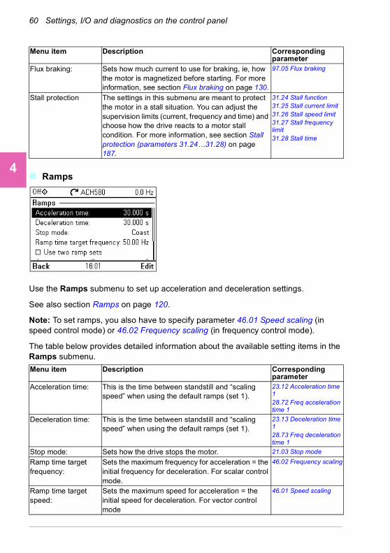
60 Settings, I/O and diagnostics on the control panel
1
2
3
4
5
6
7
8
9
10
11
12
13
14
Ramps
Use the Ramps submenu to set up acceleration and deceleration settings.
See also section Ramps on page 120.
Note: To set ramps, you also have to specify parameter 46.01 Speed scaling (in speed control mode) or 46.02 Frequency scaling (in frequency control mode).
The table below provides detailed information about the available setting items in the Ramps submenu.
Flux braking: Sets how much current to use for braking, ie, how the motor is magnetized before starting. For more information, see section Flux braking on page 130.
97.05 Flux braking
Stall protection The settings in this submenu are meant to protect the motor in a stall situation. You can adjust the supervision limits (current, frequency and time) and choose how the drive reacts to a motor stall condition. For more information, see section Stall protection (parameters 31.24…31.28) on page 187.
31.24 Stall function31.25 Stall current limit31.26 Stall speed limit31.27 Stall frequency limit31.28 Stall time
Menu item Description Corresponding parameter
Acceleration time: This is the time between standstill and “scaling speed” when using the default ramps (set 1).
23.12 Acceleration time 128.72 Freq acceleration time 1
Deceleration time: This is the time between standstill and “scaling speed” when using the default ramps (set 1).
23.13 Deceleration time 128.73 Freq deceleration time 1
Stop mode: Sets how the drive stops the motor. 21.03 Stop mode
Ramp time target frequency:
Sets the maximum frequency for acceleration = the initial frequency for deceleration. For scalar control mode.
46.02 Frequency scaling
Ramp time target speed:
Sets the maximum speed for acceleration = the initial speed for deceleration. For vector control mode
46.01 Speed scaling
Menu item Description Corresponding parameter
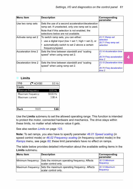
Settings, I/O and diagnostics on the control panel 61
1
2
3
4
5
6
7
8
9
10
11
12
13
Limits
Use the Limits submenu to set the allowed operating range. This function is intended to protect the motor, connected hardware and mechanics. The drive stays within these limits, no matter what reference value it gets.
See also section Limits on page 123.
Note: To set ramps, you also have to specify parameter 46.01 Speed scaling (in speed control mode) or 46.02 Frequency scaling (in frequency control mode) in the Ramps menu, see page 60; these limit parameters have no effect on ramps.
The table below provides detailed information about the available setting items in the Limits submenu.
Use two ramp sets Sets the use of a second acceleration/deceleration ramp set. If unselected, only one ramp set is used.
Note that if this selection is not enabled, the selections below are not available.
Activate ramp set 2 To switch ramp sets, you can either:
• use a digital input (low = set 1; high = set 2), or
• automatically switch to set 2 above a certain frequency/speed.
23.11 Ramp set selection28.71 Freq ramp set selection
Acceleration time 2 Sets the time between standstill and “scaling speed” when using ramp set 2.
23.14 Acceleration time 228.74 Freq acceleration time 2
Deceleration time 2 Sets the time between standstill and “scaling speed” when using ramp set 2.
23.15 Deceleration time 228.75 Freq deceleration time 2
Menu item Description Corresponding parameter
Minimum frequency: Sets the minimum operating frequency. Affects scalar control only.
30.13 Minimum frequency
Maximum frequency: Sets the maximum operating frequency. Affects scalar control only.
30.14 Maximum frequency
Menu item Description Corresponding parameter
14

62 Settings, I/O and diagnostics on the control panel
1
2
3
4
5
6
7
8
9
10
11
12
13
14
Communication
Use the Communication menu to set up and view communication through embedded fieldbus or fieldbus adapter.
Minimum speed: Sets the minimum operating speed. Affects vector control only.
30.11 Minimum speed
Maximum speed: Sets the maximum operating speed. Affects vector control only.
30.12 Maximum speed
Minimum torque: Sets the minimum operating torque. Affects vector control only.
30.19 Minimum torque 1
Maximum torque: Sets the maximum operating torque. Affects vector control only.
30.20 Maximum torque 1
Maximum current: Sets the maximum output current. 30.17 Maximum current
Menu item Description Corresponding parameter
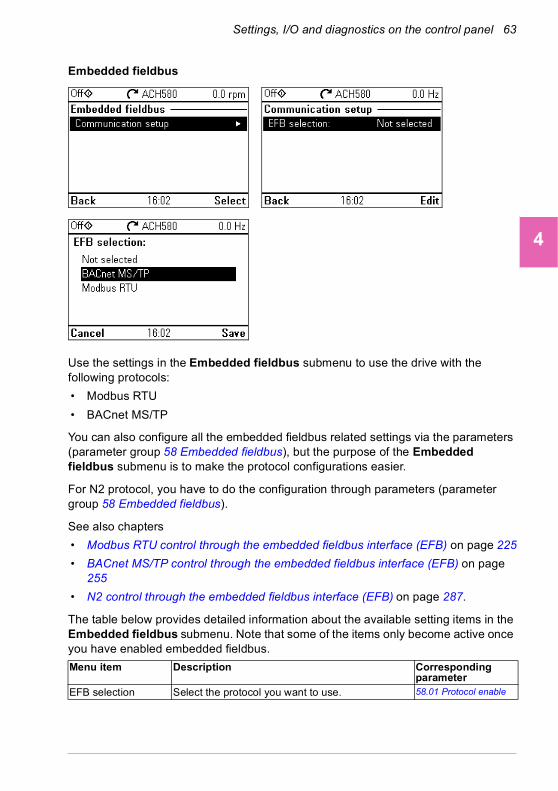
Settings, I/O and diagnostics on the control panel 63
1
2
3
4
5
6
7
8
9
10
11
12
13
Embedded fieldbus
Use the settings in the Embedded fieldbus submenu to use the drive with the following protocols:
• Modbus RTU
• BACnet MS/TP
You can also configure all the embedded fieldbus related settings via the parameters (parameter group 58 Embedded fieldbus), but the purpose of the Embedded fieldbus submenu is to make the protocol configurations easier.
For N2 protocol, you have to do the configuration through parameters (parameter group 58 Embedded fieldbus).
See also chapters
• Modbus RTU control through the embedded fieldbus interface (EFB) on page 225
• BACnet MS/TP control through the embedded fieldbus interface (EFB) on page 255
• N2 control through the embedded fieldbus interface (EFB) on page 287.
The table below provides detailed information about the available setting items in the Embedded fieldbus submenu. Note that some of the items only become active once you have enabled embedded fieldbus.
Menu item Description Corresponding parameter
EFB selection Select the protocol you want to use. 58.01 Protocol enable
14

64 Settings, I/O and diagnostics on the control panel
1
2
3
4
5
6
7
8
9
10
11
12
13
14
Communication setup
To set up communication between the drive and the fieldbus master, define these settings and then select Apply settings to embedded fieldbus module.
58 Embedded fieldbus58.03 Node address (Station ID)58.04 Baud rate58.40 Device object ID58.41 Max master58.42 Max info frames58.43 Max APDU retries58.14 Communication loss action58.15 Communication loss mode58.16 Communication loss time58.06 Communication control
Pass through I/O ->
Drive control setup
After applying the settings, press Back twice to see Pass through I/O on the Communication menu.Select it to go to the Drive control setup menu.
For relay output control, select Relay outputs and set the source of appropriate relays to EFB.
For analog output control, select Analog outputs configure the appropriate analog outputs.
19.11 Ext1/Ext2 selection
20.01 Ext1 commands22.11 Ext1 speed ref128.11 Ext1 frequency ref122.41 Speed ref safe28.41 Frequency ref safe
46.01 Speed scaling46.02 Frequency scaling23.12 Acceleration time 123.13 Deceleration time 128.72 Freq acceleration time 128.73 Freq deceleration time 1
Diagnostics • Actual status:
• Status value:
• EFB data from client
View what the drive EFB receives from the fieldbus master (PLC) / BACnet client (eg BMS).
• EFB data to client
View what the drive EFB sends to the fieldbus master (PLC) / BACnet client (eg BMS).
58.07 Communication diagnostics
58.08 Received packets58.11 UART errors58.12 CRC errors58.13 Token counter58.18 EFB control word03.09 EFB reference 1
58.09 Transmitted packets58.19 EFB status word
Menu item Description Corresponding parameter

Settings, I/O and diagnostics on the control panel 65
1
2
3
4
5
6
7
8
9
10
11
12
13
Fieldbus adapter
Use the settings in the Fieldbus adapter submenu to use the drive with the following fieldbus protocols, shown with the optional fieldbus adapter module required:
• BACnet/IP: FBIP-21 adapter
• CANopen: FCAN-01 adapter
• ControlNet: FCNA-01 adapter
• DeviceNet: FDNA-01 adapter
• EtherCAT: FECA-01 adapter
• Ethernet/IP: FEIP-21, FENA-11/-21 adapter
• ETH Pwrlink (Ethernet Powerlink): FEPL-02 adapter
• ModbusTCP: FMBT-21 adapter, FENA-11/-21 adapter
• PROFIBUS-DB: FBPA-01 adapter
• PROFINET IO: FPNO-21, FENA-11/-21 adapter
• Ethernet/IP: FENA-11/-21 adapter
You can also configure all the fieldbus related settings via the parameters (parameter groups 50 Fieldbus adapter (FBA), 51 FBA A settings, 52 FBA A data in, 53 FBA A data out, 58 Embedded fieldbus, but the purpose of the Fieldbus adapter submenu is to make the protocol configurations easier.
See also chapter Fieldbus control through a fieldbus adapter on page 301.
The table below provides detailed information about the available setting items in the Fieldbus adapter submenu. Note that some of the items only became active once you have enabled fieldbus.
Menu item Description Corresponding parameter
Fieldbus adapter FBA enable: Select this if you want to use the drive with a fieldbus adapter.
50.01 FBA A enable
14

66 Settings, I/O and diagnostics on the control panel
1
2
3
4
5
6
7
8
9
10
11
12
13
14
Communication setup
Select the module (protocol).
To set up communication between the drive and the fieldbus master, define these settings and then select Apply settings to fieldbus module.
51.01 FBA A type58.01 Protocol enable51 FBA A settings51.01 FBA A type51.02 FBA A Par251.27 FBA A par refresh51.31 D2FBA A comm status50.13 FBA A control word50.16 FBA A status word
Drive control setup Sets how a fieldbus master can control this drive, and how the drive reacts if the fieldbus communication fails.
20.01 Ext1 commands19.11 Ext1/Ext2 selection22.11 Ext1 speed ref128.11 Ext1 frequency ref122.41 Speed ref safe28.41 Frequency ref safe50.03 FBA A comm loss t out46.01 Speed scaling46.02 Frequency scaling23.12 Acceleration time 123.13 Deceleration time 128.72 Freq acceleration time 128.73 Freq deceleration time 151.27 FBA A par refresh
Received data from master
Sets what the drive's fieldbus module expects to receive from the fieldbus master (PLC). After changing these settings, select Apply settings to fieldbus module.
50.13 FBA A control word53 FBA A data out51.27 FBA A par refresh
Send data to master Sets what the drive's fieldbus module sends to the fieldbus master (PLC). After changing these settings, select Apply settings to fieldbus module.
50.16 FBA A status word52 FBA A data in51.27 FBA A par refresh
Apply settings to fieldbus module
Applies modified settings to the fieldbus module. 51.27 FBA A par refresh
Menu item Description Corresponding parameter
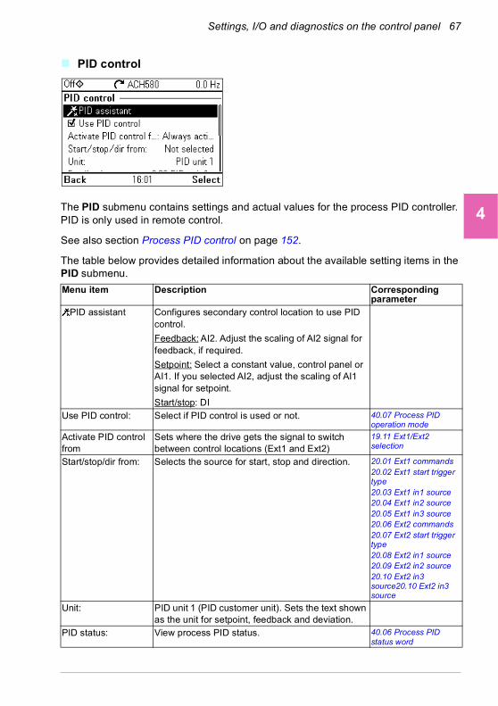
Settings, I/O and diagnostics on the control panel 67
1
2
3
4
5
6
7
8
9
10
11
12
13
PID control
The PID submenu contains settings and actual values for the process PID controller. PID is only used in remote control.
See also section Process PID control on page 152.
The table below provides detailed information about the available setting items in the PID submenu.
Menu item Description Corresponding parameter
PID assistant Configures secondary control location to use PID control.
Feedback: AI2. Adjust the scaling of AI2 signal for feedback, if required.
Setpoint: Select a constant value, control panel or AI1. If you selected AI2, adjust the scaling of AI1 signal for setpoint.
Start/stop: DIUse PID control: Select if PID control is used or not. 40.07 Process PID
operation mode
Activate PID control from
Sets where the drive gets the signal to switch between control locations (Ext1 and Ext2)
19.11 Ext1/Ext2 selection
Start/stop/dir from: Selects the source for start, stop and direction. 20.01 Ext1 commands20.02 Ext1 start trigger type20.03 Ext1 in1 source20.04 Ext1 in2 source20.05 Ext1 in3 source20.06 Ext2 commands20.07 Ext2 start trigger type20.08 Ext2 in1 source20.09 Ext2 in2 source20.10 Ext2 in3 source20.10 Ext2 in3 source
Unit: PID unit 1 (PID customer unit). Sets the text shown as the unit for setpoint, feedback and deviation.
PID status: View process PID status. 40.06 Process PID status word
14

68 Settings, I/O and diagnostics on the control panel
1
2
3
4
5
6
7
8
9
10
11
12
13
14
Feedback: View or configure process PID feedback, ie, the measured value.
40.02 Process PID feedback actual40.08 Set 1 feedback 1 source40.11 Set 1 feedback filter time
Setpoint: View or configure the process PID setpoint, ie, the target process value.
You can also use a constant setpoint value instead of (or in addition to) an external setpoint source. When a constant setpoint is active, it overrides the normal setpoint.
40.03 Process PID setpoint actual40.16 Set 1 setpoint 1 source40.26 Set 1 setpoint min40.27 Set 1 setpoint max
Tuning The Tuning submenu contains settings for gain, integration time and derivation time.
1. Make sure it is safe to start the motor and run the actual process.
2. Start the motor in remote control.
3. Change setpoint by a small amount.
4. Watch how feedback reacts.
5. Adjust gain/integration/derivation.
6. Repeat steps 3-5 until feedback reacts as desired.
40.04 Process PID deviation actual40.32 Set 1 gain40.33 Set 1 integration time40.34 Set 1 derivation time40.35 Set 1 derivation filter time
Increase output: Select whether deviation means “feedback minus setpoint” or “setpoint minus feedback”:
• Feedback < Setpoint: Drive increases motor speed when feedback signal is below setpoint. Examples: Supply fan or pump.
• Feedback > Setpoint: Drive increases motor speed when feedback signal is greater than setpoint. Example: Cooling tower.
40.04 Process PID deviation actual40.31 Set 1 deviation inversion
Output View the process PID output or set its range. 40.01 Process PID output actual40.36 Set 1 output min40.37 Set 1 output max
Sleep function The sleep function can be used to save energy by stopping the motor during low demand. By default, sleep function is disabled. If enabled, the motor automatically stops when demand is low, and starts again when deviation grows too large. This saves energy when rotating the motor at low speeds would be useless.
See section Sleep and boost functions for process PID control on page 152.
40.43 Set 1 sleep level40.44 Set 1 sleep delay40.45 Set 1 sleep boost time40.46 Set 1 sleep boost step40.47 Set 1 wake-up deviation40.48 Set 1 wake-up delay
Menu item Description Corresponding parameter
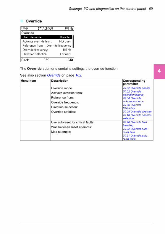
Settings, I/O and diagnostics on the control panel 69
1
2
3
4
5
6
7
8
9
10
11
12
13
Override
The Override submenu contains settings the override function
See also section Override on page 102.
Menu item Description Corresponding parameter
Override mode
Activate override from:
Reference from:
Override frequency:
Direction selection:
Override safeties:
70.02 Override enable70.02 Override activation source70.04 Override reference source70.06 Override frequency70.05 Override direction70.10 Override enables selection
Use autoreset for critical faults
Wait between reset attempts:
Max attempts:
70.20 Override fault handling70.22 Override auto reset time70.21 Override auto reset trials
14

70 Settings, I/O and diagnostics on the control panel
1
2
3
4
5
6
7
8
9
10
11
12
13
14
Fault functions
The Fault functions submenu contains settings for resetting faults automatically or manually.
Menu item Description Corresponding parameter
Autoreset faults Reset faults automatically. For more information, see section Sleep and boost functions for process PID control on page 152.
31.12 Autoreset selection31.14 Number of trials31.15 Total trials time31.16 Delay time
Additional fault reset You can reset an active fault via I/O: a rising pulse in the selected input means reset.
A fault can be reset from the fieldbus even if Reset faults manually is unselected.
31.11 Fault reset selection
Reset from keypad and...
Define from where you want to reset faults manually. Note that this submenu is active only if you have selected to reset faults manually.
31.11 Fault reset selection
Enable AI2 low detection
Enable AI2 minimum limit supervision AI2 < MIN. 12.04 AI supervision selection, bit 2
If any cable failure detected
Define action to be taken when AI2 low detection is enabled and AI2 is less than the minimum limit (AI2 < MIN).
12.03 AI supervision function
If EFB communication fails:
Define action to be taken if EFB communication fails.
58.14 Communication loss action
If EFB communication under monitoring:
Define which message types reset the timeout counter for detecting an EFB communication loss.
58.15 Communication loss mode
Ignore EFB failures shorter than:
Define a timeout for EFB communication. If a communication break lasts longer than the timeout, the action specified in If EFB communication fails: is taken.
58.16 Communication loss time
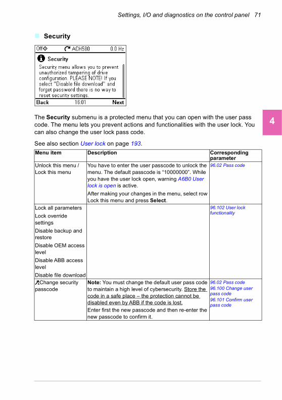
Settings, I/O and diagnostics on the control panel 71
1
2
3
4
5
6
7
8
9
10
11
12
13
Security
The Security submenu is a protected menu that you can open with the user pass code. The menu lets you prevent actions and functionalities with the user lock. You can also change the user lock pass code.
See also section User lock on page 193.
Menu item Description Corresponding parameter
Unlock this menu /Lock this menu
You have to enter the user passcode to unlock the menu. The default passcode is “10000000”. While you have the user lock open, warning A6B0 User lock is open is active.
After making your changes in the menu, select row Lock this menu and press Select.
96.02 Pass code
Lock all parameters
Lock override settings
Disable backup and restore
Disable OEM access level
Disable ABB access level
Disable file download
96.102 User lock functionality
Change security passcode
Note: You must change the default user pass code to maintain a high level of cybersecurity. Store the code in a safe place – the protection cannot be disabled even by ABB if the code is lost.Enter first the new passcode and then re-enter the new passcode to confirm it.
96.02 Pass code96.100 Change user pass code96.101 Confirm user pass code
14

72 Settings, I/O and diagnostics on the control panel
1
2
3
4
5
6
7
8
9
10
11
12
13
14
Advanced functions
The Advanced functions submenu contains settings for advanced functions, such as triggering or resetting custom faults via I/O, signal supervision, using the drive with timed functions, or switching between several entire sets of settings. In addition you can run the First start assistant from this submenu.
The table below provides detailed information about the available setting items in the Advanced functions submenu.
Menu item Description Corresponding parameter
External events Enables you to define custom faults or warnings you can trigger via digital input. The texts of these messages are customizable.
For more information, see section External events on page 124.
31.01 External event 1 source31.02 External event 1 type31.03 External event 2 source31.04 External event 2 type31.05 External event 3 source31.06 External event 3 type
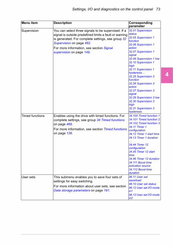
Settings, I/O and diagnostics on the control panel 73
1
2
3
4
5
6
7
8
9
10
11
12
13
Supervision You can select three signals to be supervised. If a signal is outside predefined limits a fault or warning is generated. For complete settings, see group 32 Supervision on page 462.
For more information, see section Signal supervision on page 149.
32.01 Supervision status32.05 Supervision 1 function32.06 Supervision 1 action32.07 Supervision 1 signal32.09 Supervision 1 low32.10 Supervision 1 high32.11 Supervision 1 hysteresis… 32.25 Supervision 3 function32.26 Supervision 3 action32.27 Supervision 3 signal32.29 Supervision 3 low32.30 Supervision 3 high32.31 Supervision 3 hysteresis
Timed functions Enables using the drive with timed functions. For complete settings, see group 34 Timed functions on page 469.
For more information, see section Timed functions on page 126.
34.100 Timed function 134.101 Timed function 234.102 Timed function 334.11 Timer 1 configuration34.12 Timer 1 start time34.13 Timer 1 duration … 34.44 Timer 12 configuration34.45 Timer 12 start time34.46 Timer 12 duration34.111 Boost time activation source34.112 Boost time duration
User sets This submenu enables you to save four sets of settings for easy switching.
For more information about user sets, see section Data storage parameters on page 191.
96.11 User set save/load96.10 User set status96.12 User set I/O mode in196.13 User set I/O mode in2
Menu item Description Corresponding parameter
14

74 Settings, I/O and diagnostics on the control panel
1
2
3
4
5
6
7
8
9
10
11
12
13
14
Clock, region, display
The Clock, region, display submenu contains settings for language, date and time, display (such as brightness) and settings for changing how information is displayed on screen.
The table below provides detailed information about the available setting items in the Clock, region, display submenu.
Confirmation for HAND/OFF
Selects if you have to press Hand and Off buttons twice within five seconds to operate. The panel shows a message about pressing twice after the first press.
This selection can be used to prevent accidental Hand and Off button presses.
If Hand and/or Off buttons are disabled with parameters 19.18 HAND/OFF disable source and 19.19 HAND/OFF disable action, this setting has no effect.
First start assistant Runs the same First start assistant that is used to commission the drive.
Menu item Description Corresponding parameter
Select driveLanguage Change the language used on the control panel
screen. Note that the language is loaded from the drive so this takes some time.
96.01 Language
Date & time Set the time and date, and their formats.Units Select the units used for power, temperature,
torque and currency.96.16 Unit selection
Drive name The drive name defined in this setting is shown in the status bar at the top of the screen while using the drive. If more than one drives are connected to the control panel, the drive names make it easy to identify each drive. It also identifies any backups you create for this drive.
Menu item Description Corresponding parameter

Settings, I/O and diagnostics on the control panel 75
1
2
3
4
5
6
7
8
9
10
11
12
13
Reset to defaults
The Reset to defaults submenu enables you to reset parameters and other settings.
Contact info in fault view
Define a fixed text that is shown during any fault (for example, who to contact in case of a fault).
If a fault occurs, this information appears on the panel screen (in addition to the fault-specific information).
Edit texts Edit drive name, currency unit, PID unit, Start interlocks 1…4, Run permissive, Signal supervisions 1…3, External faults 1…3, Contact info.
Display settings Adjust the brightness, contrast and display power save delay of the panel screen or to invert white and black.
Show in lists Show or hide the numeric IDs of:
• parameters and groups
• option list items
• bits
• devices in Options > Select driveEdit Home view Select the parameters displayed in the Home view,
with display style, decimals, name, unit, minimum and maximum.
Show inhibit pop-up Enables or disables pop-up views showing information on inhibits, for example, when you try to start the drive but it is prevented.
Menu item Description Corresponding parameter
Reset fault and event logs
Clears all events from the drive’s fault and event logs.
96.51 Clear fault and event logger
Reset home view layout
Restores the home view layout back to show the values of the default parameters defined by the control macro in use.
96.06 Parameter restore, selection Reset home view
Menu item Description Corresponding parameter
14

76 Settings, I/O and diagnostics on the control panel
1
2
3
4
5
6
7
8
9
10
11
12
13
14
Reset non-HW parameters
Restores all editable parameter values to default values, except
• motor data and ID run results
• I/O extension module settings
• end user texts, such as customized warnings and faults, and the drive name
• control panel/PC communication settings
• fieldbus adapter settings
• parameter 95.01 Supply voltage
• differentiated defaults implemented by parameters 95.20 HW options word 1 and 95.21 HW options word 2
• user lock configuration parameters 96.100…96.102.
96.06 Parameter restore, selection Restore defaults
Reset all fieldbus settings
Restores all fieldbus and communication related settings to default values.
Note: Fieldbus, control panel and PC tool communication are interrupted during the restore.
96.06 Parameter restore, selection Reset all fieldbus settings
Reset motor data and ID run results
Restores all motor nominal values and motor ID run results to default values.
96.06 Parameter restore, selection Reset motor data
Reset all parameters Restores all editable parameter values to default values, except
• end user texts, such as customized warnings and faults, and the drive name
• control panel/PC communication settings• parameter 95.01 Supply voltage• differentiated defaults implemented by
parameters 95.20 HW options word 1 and 95.21 HW options word 2
• user lock configuration parameters 96.100…96.102
• group 49 Panel port communication parameters.
96.06 Parameter restore, selection Clear all
Reset end user texts Restores all end user texts to default values, including the drive name, contact info, customized fault and warning texts, PID unit and currency unit.
96.06 Parameter restore, selection Reset end user texts
Reset first start assistant
Resets first start assistant to the initial state.
Reset all to factory defaults
Restores all drive parameters and settings back to initial factory values, except
• differentiated defaults implemented by parameters 95.20 HW options word 1 and 95.21 HW options word 2.
96.06 Parameter restore, selection All to factory defaults
Menu item Description Corresponding parameter
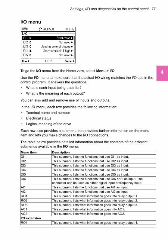
Settings, I/O and diagnostics on the control panel 77
1
2
3
4
5
6
7
8
9
10
11
12
13
I/O menu
To go the I/O menu from the Home view, select Menu > I/O.
Use the I/O menu to make sure that the actual I/O wiring matches the I/O use in the control program. It answers the questions:
• What is each input being used for?
• What is the meaning of each output?
You can also add and remove use of inputs and outputs.
In the I/O menu, each row provides the following information:
• Terminal name and number
• Electrical status
• Logical meaning of the drive
Each row also provides a submenu that provides further information on the menu item and lets you make changes to the I/O connections.
The table below provides detailed information about the contents of the different submenus available in the I/O menu.
Menu item DescriptionDI1 This submenu lists the functions that use DI1 as input.DI2 This submenu lists the functions that use DI2 as input.DI3 This submenu lists the functions that use DI3 as input.DI4 This submenu lists the functions that use DI4 as input.DI5 This submenu lists the functions that use DI5 as input.DI6 This submenu lists the functions that use DI6 or FI as input. The
connector can be used as either digital input or frequency input.AI1 This submenu lists the functions that use AI1 as input.AI2 This submenu lists the functions that use AI2 as input.RO1 This submenu lists what information goes into relay output 1.RO2 This submenu lists what information goes into relay output 2.RO3 This submenu lists what information goes into relay output 3.AO1 This submenu lists what information goes into AO1.AO2 This submenu lists what information goes into AO2.I/O extensionRO4 This submenu lists what information goes into relay output 4.
14

78 Settings, I/O and diagnostics on the control panel
1
2
3
4
5
6
7
8
9
10
11
12
13
14
Diagnostics menu
To go the Diagnostics menu from the Home view, select Menu > Diagnostics.
The Diagnostics menu provides you with diagnostic information, such as faults and warnings, and helps you to resolve potential problems. Use the menu to make sure that the drive setup is functioning correctly.
To clear the fault and event logger, select Menu > Primary settings > Reset to defaults > Reset fault and event logs, or set parameter 96.51 Clear fault and event logger to value Reset.
The table below provides detailed information about the contents of the different views available in the Diagnostics menu.
RO5 This submenu lists what information goes into relay output 5.DO1 This submenu lists what information goes into digital output 1.
Menu item DescriptionDrive actual values
Shows actual values: 01.01 Motor speed used, 01.06 Output frequency, 01.07
Motor current, 01.10 Motor torque, 01.11 DC voltage, 01.13 Output voltage, 01.14
Output power, 06.01 Main control word, 06.11 Main status word, 06.22 HVAC status
word, 19.01 Actual operation mode, 05.01 On-time counter, 05.02 Run-time
counter, 05.04 Fan on-time counter, 05.10 Control board temperature, 05.11
Inverter temperature, 35.01 Motor estimated temperature, 35.02 Measured
temperature 1, 35.03 Measured temperature 2, 40.01 Process PID feedback actual,
40.02 Process PID feedback actual, 40.03 Process PID setpoint actual, 40.04
Process PID deviation actual, 40.07 Process PID operation mode.
Active faults This view shows the currently active faults and provides instructions on how to fix and reset them.
Active warnings This view shows the currently active warnings and provides instructions on how to fix them.
Active inhibits This view shows up to five simultaneous active start inhibits and how to fix them.
Menu item Description
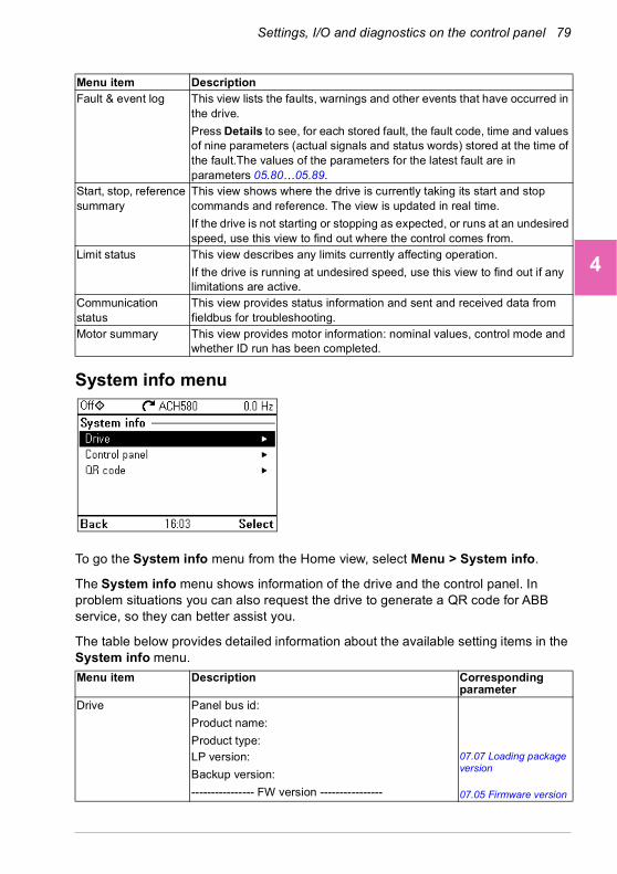
Settings, I/O and diagnostics on the control panel 79
1
2
3
4
5
6
7
8
9
10
11
12
13
System info menu
To go the System info menu from the Home view, select Menu > System info.
The System info menu shows information of the drive and the control panel. In problem situations you can also request the drive to generate a QR code for ABB service, so they can better assist you.
The table below provides detailed information about the available setting items in the System info menu.
Fault & event log This view lists the faults, warnings and other events that have occurred in the drive.
Press Details to see, for each stored fault, the fault code, time and values of nine parameters (actual signals and status words) stored at the time of the fault.The values of the parameters for the latest fault are in parameters 05.80…05.89.
Start, stop, reference summary
This view shows where the drive is currently taking its start and stop commands and reference. The view is updated in real time.
If the drive is not starting or stopping as expected, or runs at an undesired speed, use this view to find out where the control comes from.
Limit status This view describes any limits currently affecting operation.
If the drive is running at undesired speed, use this view to find out if any limitations are active.
Communication status
This view provides status information and sent and received data from fieldbus for troubleshooting.
Motor summary This view provides motor information: nominal values, control mode and whether ID run has been completed.
Menu item Description Corresponding parameter
Drive Panel bus id:
Product name:
Product type:LP version:
Backup version:
---------------- FW version ----------------
07.07 Loading package version
07.05 Firmware version
Menu item Description
14
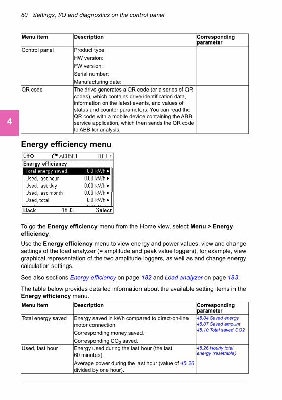
80 Settings, I/O and diagnostics on the control panel
1
2
3
4
5
6
7
8
9
10
11
12
13
14
Energy efficiency menu
To go the Energy efficiency menu from the Home view, select Menu > Energy efficiency.
Use the Energy efficiency menu to view energy and power values, view and change settings of the load analyzer (= amplitude and peak value loggers), for example, view graphical representation of the two amplitude loggers, as well as and change energy calculation settings.
See also sections Energy efficiency on page 182 and Load analyzer on page 183.
The table below provides detailed information about the available setting items in the Energy efficiency menu.
Control panel Product type:
HW version:
FW version:
Serial number:
Manufacturing date:QR code The drive generates a QR code (or a series of QR
codes), which contains drive identification data, information on the latest events, and values of status and counter parameters. You can read the QR code with a mobile device containing the ABB service application, which then sends the QR code to ABB for analysis.
Menu item Description Corresponding parameter
Total energy saved Energy saved in kWh compared to direct-on-line motor connection.
Corresponding money saved.
Corresponding CO2 saved.
45.04 Saved energy45.07 Saved amount45.10 Total saved CO2
Used, last hour Energy used during the last hour (the last 60 minutes).
Average power during the last hour (value of 45.26 divided by one hour).
45.26 Hourly total energy (resettable)
Menu item Description Corresponding parameter
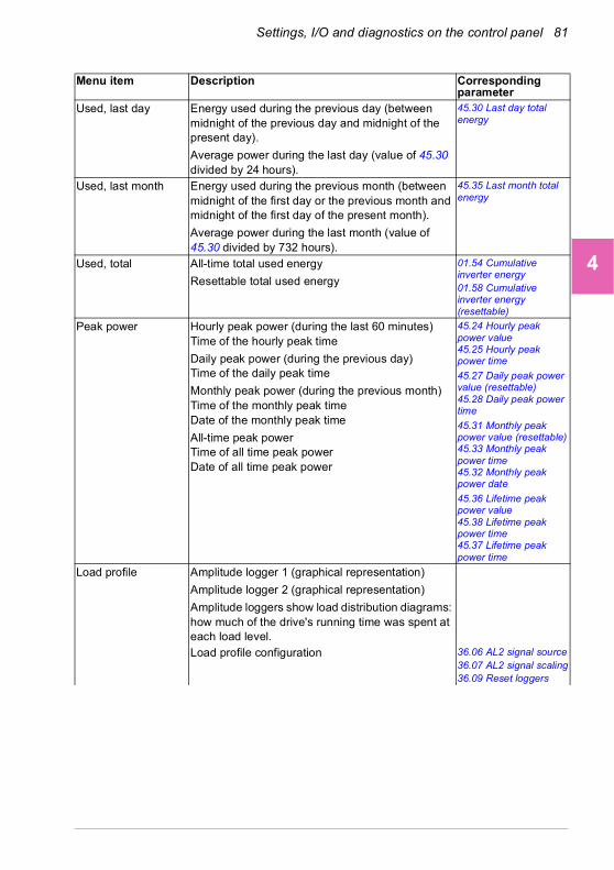
Settings, I/O and diagnostics on the control panel 81
1
2
3
4
5
6
7
8
9
10
11
12
13
Used, last day Energy used during the previous day (between midnight of the previous day and midnight of the present day).
Average power during the last day (value of 45.30 divided by 24 hours).
45.30 Last day total energy
Used, last month Energy used during the previous month (between midnight of the first day or the previous month and midnight of the first day of the present month).
Average power during the last month (value of 45.30 divided by 732 hours).
45.35 Last month total energy
Used, total All-time total used energy
Resettable total used energy
01.54 Cumulative inverter energy01.58 Cumulative inverter energy (resettable)
Peak power Hourly peak power (during the last 60 minutes)Time of the hourly peak time
Daily peak power (during the previous day)Time of the daily peak time
Monthly peak power (during the previous month)Time of the monthly peak timeDate of the monthly peak time
All-time peak powerTime of all time peak powerDate of all time peak power
45.24 Hourly peak power value45.25 Hourly peak power time
45.27 Daily peak power value (resettable)45.28 Daily peak power time
45.31 Monthly peak power value (resettable)45.33 Monthly peak power time45.32 Monthly peak power date
45.36 Lifetime peak power value45.38 Lifetime peak power time45.37 Lifetime peak power time
Load profile Amplitude logger 1 (graphical representation)
Amplitude logger 2 (graphical representation)
Amplitude loggers show load distribution diagrams: how much of the drive's running time was spent at each load level.Load profile configuration 36.06 AL2 signal source
36.07 AL2 signal scaling36.09 Reset loggers
Menu item Description Corresponding parameter
14
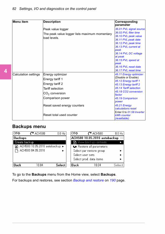
82 Settings, I/O and diagnostics on the control panel
1
2
3
4
5
6
7
8
9
10
11
12
13
14
Backups menu
To go to the Backups menu from the Home view, select Backups.
For backups and restores, see section Backup and restore on 190 page.
Peak value logger
The peak value logger lists maximum momentary load levels.
36.01 PVL signal source36.02 PVL filter time36.10 PVL peak value36.11 PVL peak date36.12 PVL peak time36.13 PVL current at peak36.14 PVL DC voltage at peak36.15 PVL speed at peak36.16 PVL reset date36.17 PVL reset time
Calculation settings Energy optimizer
Energy tariff 1
Energy tariff 2
Tariff selection
CO2 conversion
Comparison power
45.11 Energy optimizer (Disable or Enable)45.12 Energy tariff 145.13 Energy tariff 245.14 Tariff selection45.18 CO2 conversion factor45.19 Comparison power
Reset saved energy counters
Reset total used counter
45.21 Energy calculations resetEnter 0 to 01.58 Inverter kWh counter (resettable)
Menu item Description Corresponding parameter

Default I/O configuration 83
1
2
3
4
5
6
7
8
9
10
11
12
13
5Default I/O configuration
Contents of this chapter
This chapter describes the intended use, operation and default control connections of the application.
You select default configurations in the Primary settings menu.
To get to the Primary settings menu from the Home view, first select Menu to go the Main menu, and then select Primary settings. Select Start, stop, reference, and How do you control? then shows the default configurations (Direct control via I/O means the HVAC default configuration.)
14

84 Default I/O configuration
1
2
3
4
5
6
7
8
9
10
11
12
13
14
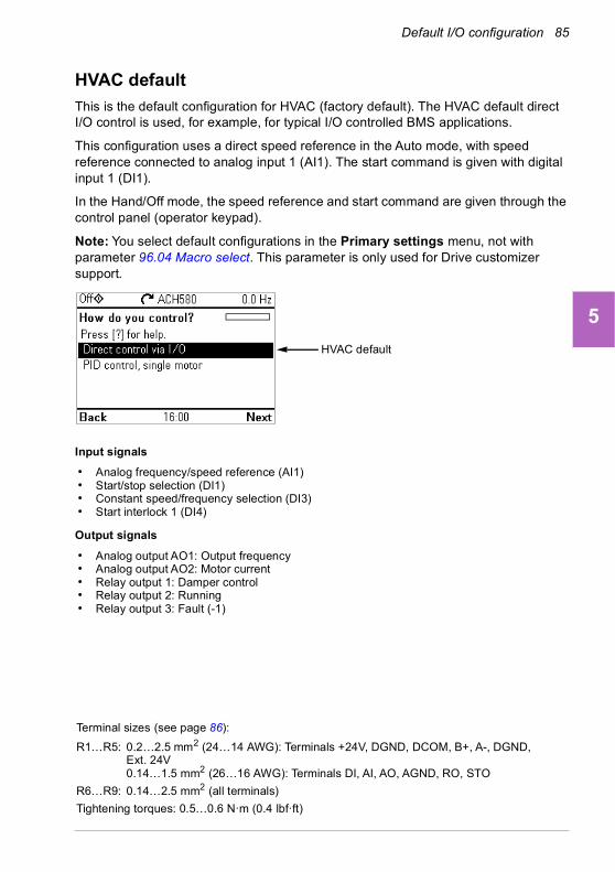
Default I/O configuration 85
1
2
3
4
5
6
7
8
9
10
11
12
13
HVAC default
This is the default configuration for HVAC (factory default). The HVAC default direct I/O control is used, for example, for typical I/O controlled BMS applications.
This configuration uses a direct speed reference in the Auto mode, with speed reference connected to analog input 1 (AI1). The start command is given with digital input 1 (DI1).
In the Hand/Off mode, the speed reference and start command are given through the control panel (operator keypad).
Note: You select default configurations in the Primary settings menu, not with parameter 96.04 Macro select. This parameter is only used for Drive customizer support.
Input signals
• Analog frequency/speed reference (AI1)• Start/stop selection (DI1)• Constant speed/frequency selection (DI3)• Start interlock 1 (DI4)
Output signals
• Analog output AO1: Output frequency• Analog output AO2: Motor current• Relay output 1: Damper control• Relay output 2: Running• Relay output 3: Fault (-1)
HVAC default
Terminal sizes (see page 86):
R1…R5: 0.2…2.5 mm2 (24…14 AWG): Terminals +24V, DGND, DCOM, B+, A-, DGND, Ext. 24V0.14…1.5 mm2 (26…16 AWG): Terminals DI, AI, AO, AGND, RO, STO
R6…R9: 0.14…2.5 mm2 (all terminals)
Tightening torques: 0.5…0.6 N·m (0.4 lbf·ft)
14
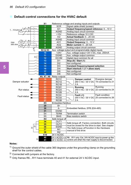
86 Default I/O configuration
1
2
3
4
5
6
7
8
9
10
11
12
13
14
Default control connections for the HVAC default
Run status
Fault status
Damper actuator
max.500 ohm
1…10 kohm
X1 Reference voltage and analog inputs and outputs1 SCR Signal cable shield (screen)2 AI1 Output frequency/speed reference: 0…10 V3 AGND Analog input circuit common4 +10V Reference voltage 10 V DC5 AI2 Actual feedback: 0…20 mA6 AGND Analog input circuit common7 AO1 Output frequency: 0…10 V8 AO2 Motor current: 0…20 mA9 AGND Analog output circuit common
X2 & X3 Aux. voltage output and programmable digital inputs10 +24V Aux. voltage output +24 V DC, max. 250mA11 DGND Aux. voltage output common12 DCOM Digital input common for all13 DI1 Stop (0) / Start (1) 14 DI2 Not configured15 DI3 Constant frequency/speed selection16 DI4 Start interlock 1 (1 = allow start)17 DI5 Not configured18 DI6 Not configured
X6, X7, X8 Relay outputs19 RO1C Damper control
250 V AC / 30 V DC2 A
20 RO1A21 RO1B22 RO2C Running
250 V AC / 30 V DC 2 A
23 RO2A24 RO2B25 RO3C Fault (-1)
250 V AC / 30 V DC2 A
26 RO3A27 RO3BX5 Embedded fieldbus29 B+
Embedded fieldbus, EFB (EIA-485)30 A-31 DGNDS4 TERM Termination switchS5 BIAS Bias resistors switchX4 Safe torque off34 OUT1
Safe torque off. Factory connection. Both circuits must be closed for the drive to start. See chapter The Safe torque off function in the Hardware manual of the drive
35 OUT236 SGND37 IN138 IN2
X10 24 V AC/DC40 24 V AC/DC+ in R6…R11 only: Ext. 24V AC/DC input to power up the
control unit when the main supply is disconnected.41 24 V AC/DC- in
2)
1)
2)2)
3)
Notes:1) Ground the outer shield of the cable 360 degrees under the grounding clamp on the grounding
shelf for the control cables.2) Connected with jumpers at the factory.3) Only frames R6…R11 have terminals 40 and 41 for external 24 V AC/DC input.
Running22 connected to 24
Fault condition25 connected to 26
Energize damper19 connected to 21
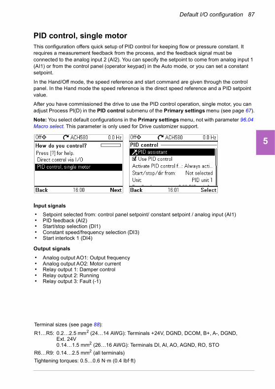
Default I/O configuration 87
1
2
3
4
5
6
7
8
9
10
11
12
13
PID control, single motorThis configuration offers quick setup of PID control for keeping flow or pressure constant. It requires a measurement feedback from the process, and the feedback signal must be connected to the analog input 2 (AI2). You can specify the setpoint to come from analog input 1 (AI1) or from the control panel (operator keypad) in the Auto mode, or you can set a constant setpoint.
In the Hand/Off mode, the speed reference and start command are given through the control panel. In the Hand mode the speed reference is the direct speed reference and a PID setpoint value.
After you have commissioned the drive to use the PID control operation, single motor, you can adjust Process PI(D) in the PID control submenu of the Primary settings menu (see page 67).
Note: You select default configurations in the Primary settings menu, not with parameter 96.04 Macro select. This parameter is only used for Drive customizer support.
Input signals
• Setpoint selected from: control panel setpoint/ constant setpoint / analog input (AI1)• PID feedback (AI2)• Start/stop selection (DI1)• Constant speed/frequency selection (DI3)• Start interlock 1 (DI4)
Output signals
• Analog output AO1: Output frequency• Analog output AO2: Motor current• Relay output 1: Damper control• Relay output 2: Running• Relay output 3: Fault (-1)
Terminal sizes (see page 88):
R1…R5: 0.2…2.5 mm2 (24…14 AWG): Terminals +24V, DGND, DCOM, B+, A-, DGND, Ext. 24V0.14…1.5 mm2 (26…16 AWG): Terminals DI, AI, AO, AGND, RO, STO
R6…R9: 0.14…2.5 mm2 (all terminals)
Tightening torques: 0.5…0.6 N·m (0.4 lbf·ft)
14

88 Default I/O configuration
1
2
3
4
5
6
7
8
9
10
11
12
13
14
Default control connections for the PID control, single motor
Run status
Fault status
Damper actuator
max.500 ohm
1…10 kohm
X1 Reference voltage and analog inputs and outputs1 SCR Signal cable shield (screen)2 AI1 Panel setpoint ref/ Constant setpoint: 0…10 V3 AGND Analog input circuit common4 +10V Reference voltage 10 V DC5 AI2 PID feedback: 0…20 mA6 AGND Analog input circuit common7 AO1 Output frequency: 0…10 V8 AO2 Motor current: 0…20 mA9 AGND Analog output circuit common
X2 & X3 Aux. voltage output and programmable digital inputs10 +24V Aux. voltage output +24 V DC, max. 250 mA11 DGND Aux. voltage output common12 DCOM Digital input common for all13 DI1 Stop (0) / Start (1) 14 DI2 Not configured15 DI3 Constant frequency/speed selection16 DI4 Start interlock 1 (1 = allow start)17 DI5 Not configured18 DI6 Not configured
X6, X7, X8 Relay outputs19 RO1C Damper control
250 V AC / 30 V DC2 A
20 RO1A21 RO1B22 RO2C Running
250 V AC / 30 V DC 2 A
23 RO2A24 RO2B25 RO3C Fault (-1)
250 V AC / 30 V DC2 A
26 RO3A27 RO3BX5 Embedded fieldbus29 B+
Embedded fieldbus, EFB (EIA-485)30 A-31 DGNDS4 TERM Termination switchS5 BIAS Bias resistors switchX4 Safe torque off34 OUT1
Safe torque off. Factory connection. Both circuits must be closed for the drive to start. See chapter The Safe torque off function in the Hardware manual of the drive
35 OUT236 SGND37 IN138 IN2
X10 24 V AC/DC40 24 V AC/DC+ in R6…R11 only: Ext. 24V AC/DC input to power up the
control unit when the main supply is disconnected.41 24 V AC/DC- in
2)
1)
2)2)
3)
Notes:1) Ground the outer shield of the cable 360 degrees under the grounding clamp on the grounding
shelf for the control cables.2) Connected with jumpers at the factory.3) Only frames R6…R11 have terminals 40 and 41 for external 24 V AC/DC input.
Running22 connected to 24
Fault condition25 connected to 26
Energize damper19 connected to 21

Program features 89
1
2
3
4
5
6
7
8
9
10
11
12
13
6Program features
What this chapter contains
This chapter describes some of the more important functions within the control program, how to use them and how to program them to operate. It also explains the control locations and operating modes.
Local control vs. external control
The ACH580 has two main control locations: external and local. In local control there are additionally three different modes: Off, Hand and Auto modes.
In the Off mode, the drive is stopped. In the Hand mode, the drive is running. The initial reference in the Hand mode is copied from the drive reference.
The following diagram shows the state transitions when you press the Hand, Off or Auto button:
The control location can also be selected in the PC tool.
Note: When you restart the drive while fault 7081 Control panel loss is active, the mode changes from Hand or Off to Auto.
Note: Override function overrides the actual running mode.
Auto
Off
Hand
14
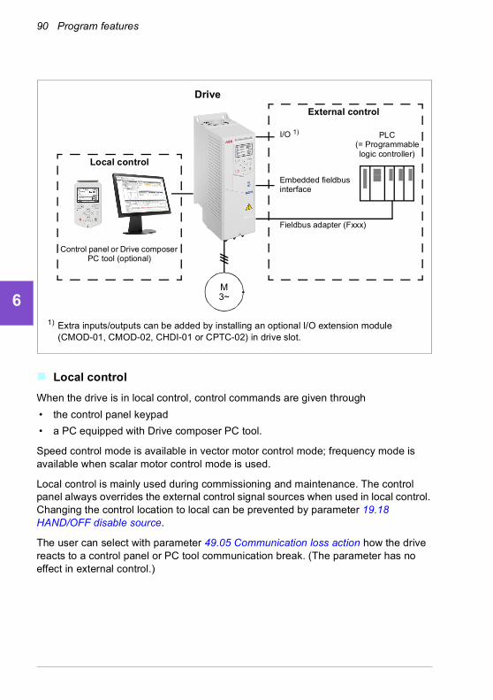
90 Program features
1
2
3
4
5
6
7
8
9
10
11
12
13
14
Local control
When the drive is in local control, control commands are given through
• the control panel keypad
• a PC equipped with Drive composer PC tool.
Speed control mode is available in vector motor control mode; frequency mode is available when scalar motor control mode is used.
Local control is mainly used during commissioning and maintenance. The control panel always overrides the external control signal sources when used in local control. Changing the control location to local can be prevented by parameter 19.18 HAND/OFF disable source.
The user can select with parameter 49.05 Communication loss action how the drive reacts to a control panel or PC tool communication break. (The parameter has no effect in external control.)
Control panel or Drive composer PC tool (optional)
Fieldbus adapter (Fxxx)
1) Extra inputs/outputs can be added by installing an optional I/O extension module (CMOD-01, CMOD-02, CHDI-01 or CPTC-02) in drive slot.
PLC (= Programmable logic controller)
I/O 1)
Embedded fieldbus interface
External control
Local control
Drive
M3~
Program features 91
1
2
3
4
5
6
7
8
9
10
11
12
13
External control
When the drive is in external control, control commands are given through
• the I/O terminals (digital and analog inputs), or optional I/O extension modules
• the fieldbus interface (via the embedded fieldbus interface or an optional fieldbus adapter module).
Two external control locations, EXT1 and EXT2, are available. The user can select the sources of the start and stop commands separately for each location by setting parameters 20.01 Ext1 commands…20.10 Ext2 in3 source. The operating mode can be selected separately for each location, which enables quick switching between different operating modes, for example, speed and process PID control. Selection between EXT1 and EXT2 is done via any binary source such as a digital input or fieldbus control word (parameter 19.11 Ext1/Ext2 selection). The source of reference is selectable for each operating mode separately.
Communication fail functionality
The communication fail functionality ensures continuous process without interruptions. If there is a communication loss, the drive automatically changes the control location from EXT1 to EXT2. This enables process to be controlled, for example, with the drive PID controller. When the original control location recovers, the drive automatically switches control back to the communication network (EXT1).
14
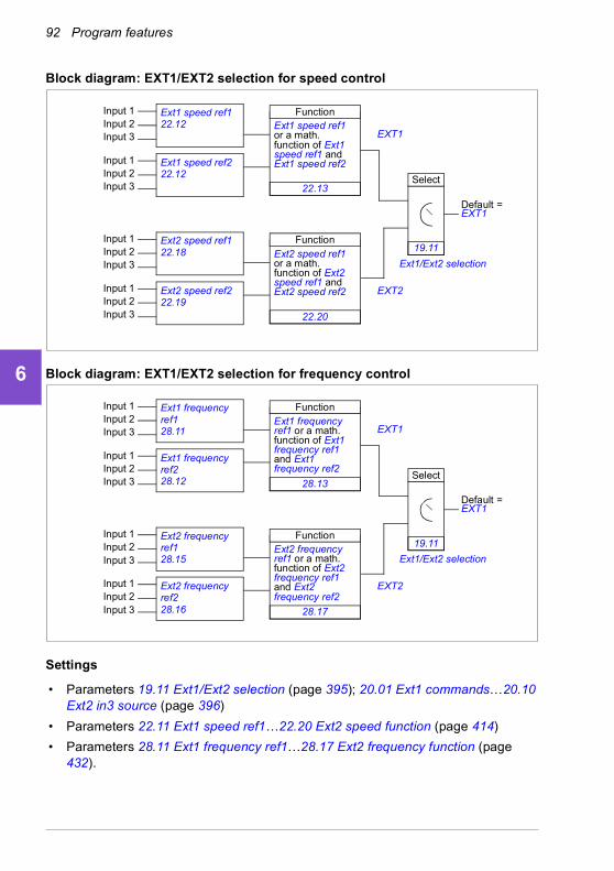
92 Program features
1
2
3
4
5
6
7
8
9
10
11
12
13
14
Block diagram: EXT1/EXT2 selection for speed control
Block diagram: EXT1/EXT2 selection for frequency control
Settings
• Parameters 19.11 Ext1/Ext2 selection (page 395); 20.01 Ext1 commands…20.10 Ext2 in3 source (page 396)
• Parameters 22.11 Ext1 speed ref1…22.20 Ext2 speed function (page 414)
• Parameters 28.11 Ext1 frequency ref1…28.17 Ext2 frequency function (page 432).
Default = EXT1
Input 1 Ext1 speed ref1 22.12
Ext1/Ext2 selection
Input 2Input 3
Input 1Input 2Input 3
Ext1 speed ref2 22.12
Function
22.13
Ext1 speed ref1 or a math. function of Ext1 speed ref1 and Ext1 speed ref2
Input 1 Ext2 speed ref1 22.18Input 2
Input 3
Input 1Input 2Input 3
Ext2 speed ref2 22.19
Function
22.20
Ext2 speed ref1 or a math. function of Ext2 speed ref1 and Ext2 speed ref2
Select
19.11
EXT1
EXT2
Default = EXT1
Input 1 Ext1 frequency ref128.11
Ext1/Ext2 selection
Input 2Input 3
Input 1Input 2Input 3
Ext1 frequency ref228.12
Function
28.13
Ext1 frequency ref1 or a math. function of Ext1 frequency ref1 and Ext1 frequency ref2
Input 1 Ext2 frequency ref128.15
Input 2Input 3
Input 1Input 2Input 3
Ext2 frequency ref228.16
Function
28.17
Ext2 frequency ref1 or a math. function of Ext2 frequency ref1 and Ext2 frequency ref2
Select
19.11
EXT1
EXT2
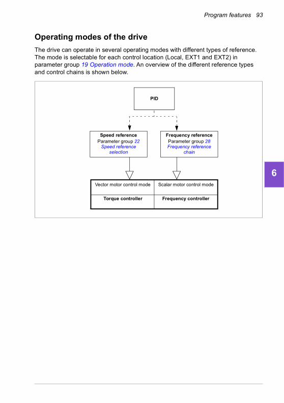
Program features 93
1
2
3
4
5
6
7
8
9
10
11
12
13
Operating modes of the drive
The drive can operate in several operating modes with different types of reference. The mode is selectable for each control location (Local, EXT1 and EXT2) in parameter group 19 Operation mode. An overview of the different reference types and control chains is shown below.
PID
Vector motor control mode Scalar motor control mode
Frequency controllerTorque controller
Speed referenceParameter group 22
Speed reference selection
Frequency referenceParameter group 28 Frequency reference
chain
14
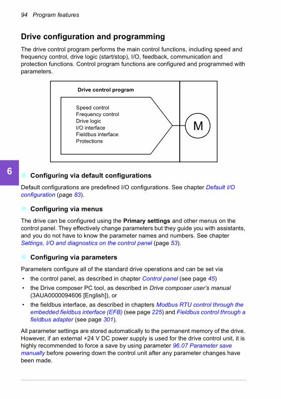
94 Program features
1
2
3
4
5
6
7
8
9
10
11
12
13
14
Drive configuration and programming
The drive control program performs the main control functions, including speed and frequency control, drive logic (start/stop), I/O, feedback, communication and protection functions. Control program functions are configured and programmed with parameters.
Configuring via default configurations
Default configurations are predefined I/O configurations. See chapter Default I/O configuration (page 83).
Configuring via menus
The drive can be configured using the Primary settings and other menus on the control panel. They effectively change parameters but they guide you with assistants, and you do not have to know the parameter names and numbers. See chapter Settings, I/O and diagnostics on the control panel (page 53).
Configuring via parameters
Parameters configure all of the standard drive operations and can be set via
• the control panel, as described in chapter Control panel (see page 45)
• the Drive composer PC tool, as described in Drive composer user’s manual (3AUA0000094606 [English]), or
• the fieldbus interface, as described in chapters Modbus RTU control through the embedded fieldbus interface (EFB) (see page 225) and Fieldbus control through a fieldbus adapter (see page 301).
All parameter settings are stored automatically to the permanent memory of the drive. However, if an external +24 V DC power supply is used for the drive control unit, it is highly recommended to force a save by using parameter 96.07 Parameter save manually before powering down the control unit after any parameter changes have been made.
Drive control program
Speed controlFrequency controlDrive logicI/O interfaceFieldbus interfaceProtections
M

Program features 95
1
2
3
4
5
6
7
8
9
10
11
12
13
If necessary, the default parameter values can be restored by parameter 96.06 Parameter restore.
Adaptive programming
Conventionally, the user can control the operation of the drive by parameters. However, the standard parameters have a fixed set of choices or a setting range. To further customize the operation of the drive, an adaptive program can be constructed out of a set of function blocks.
The Drive composer pro PC tool (version 1.10 or later, available separately) has an Adaptive programming feature with a graphical user interface for building the custom program. The function blocks include the usual arithmetic and logical functions, as well as, for example, selection, comparison and timer blocks.
The physical inputs, drive status information, actual values, constants and parameters can be used as the input for the program. The output of the program can be used, for example, as a start signal, external event or reference, or connected to the drive outputs. See the table below for a listing of the available inputs and outputs.
If you connect the output of the adaptive program to a selection parameter that is a pointer parameter, the selection parameter will be write-protected.
Example:
If parameter 31.01 External event 1 source is connected to an adaptive programming block output, the parameter value is shown as Adaptive program on a control panel or PC tool. The parameter is write-protected (= the selection cannot be changed).
The status of the adaptive program is shown by parameter 07.30 Adaptive program status.The adaptive program can be disabled by 96.70 Disable adaptive program.
For more information, see the Adaptive programming application guide (3AXD50000028574 [English].
Inputs available to the adaptive program
Input Source
I/O
DI1 10.02 DI delayed status, bit 0
DI2 10.02 DI delayed status, bit 1
DI3 10.02 DI delayed status, bit 2
DI4 10.02 DI delayed status, bit 3
DI5 10.02 DI delayed status, bit 4
DI6 10.02 DI delayed status, bit 5
AI1 12.11 AI1 actual value
AI2 12.21 AI2 actual value
Actual signals
Motor speed 01.01 Motor speed used
Output frequency 01.06 Output frequency
Motor current 01.07 Motor current
Motor torque 01.10 Motor torque
Motor shaft power 01.17 Motor shaft power
14

96 Program features
1
2
3
4
5
6
7
8
9
10
11
12
13
14
Status
Enabled 06.16 Drive status word 1, bit 0
Inhibited 06.16 Drive status word 1, bit 1
Ready to start 06.16 Drive status word 1, bit 3
Tripped 06.11 Main status word, bit 3
At setpoint 06.11 Main status word, bit 8
Limiting 06.16 Drive status word 1, bit 7
Ext1 active 06.16 Drive status word 1, bit 10
Ext2 active 06.16 Drive status word 1, bit 11
Data storage
Data storage 1 real32 47.01 Data storage 1 real32
Data storage 2 real32 47.02 Data storage 2 real32
Data storage 3 real32 47.03 Data storage 3 real32
Data storage 4 real32 47.04 Data storage 4 real32
Outputs available to the adaptive program
Output Target
I/O
RO1 10.24 RO1 source
RO2 10.27 RO2 source
RO3 10.30 RO3 source
AO1 13.12 AO1 source
AO2 13.22 AO2 source
Start control
Ext1/Ext2 selection 19.11 Ext1/Ext2 selection
Ext1 in1 cmd 20.03 Ext1 in1 source
Ext1 in2 cmd 20.04 Ext2 in2 source
Ext1 in3 cmd 20.05 Ext1 in3 source
Ext2 in1 cmd 20.08 Ext2 in1 source
Ext2 in2 cmd 20.09 Ext2 in2 source
Ext2 in3 cmd 20.10 Ext2 in3 source
Fault reset 31.11 Fault reset selection
Speed control
Ext1 speed reference 22.11 Ext1 speed ref1
Speed proportional gain 25.02 Speed proportional gain
Speed integration time 25.03 Speed integration time
Acceleration time 1 23.12 Acceleration time 1
Deceleration time 1 23.13 Deceleration time 1
Frequency control
Ext1 frequency reference 28.11 Ext1 frequency ref1
Limit function
Minimum torque 2 30.21 Min torque 2 source
Maximum torque 2 30.22 Max torque 2 source
Events
External event 1 31.01 External event 1 source
External event 2 31.03 External event 2 source
External event 3 31.05 External event 3 source
External event 4 31.07 External event 4 source
Inputs available to the adaptive program
Input Source

Program features 97
1
2
3
4
5
6
7
8
9
10
11
12
13
Adaptive program fault and aux code formats
The format of the aux code:
If the state number is zero but the block number has a value, the fault is related to a function block in the base program. If both state number and block number are zero, the fault is a generic fault that is not related to a specific block.
See fault 64A6 Adaptive program on page 213.
Sequence program
An adaptive program can contain base program and sequence program parts. Base program is run continuously when adaptive program is in running mode. The functionality of the base program is programmed using function blocks and system inputs and outputs.
Sequence program is a state machine. This means that only one state of the sequence program is run at a time. You can create a sequence program by adding states and programming the state programs using the same program elements as in the base program. You can program state transitions by adding state transition outputs to the state programs. The state transition rules are programmed using function blocks.
The number of the active state of the sequence program is shown by parameter 07.31 AP sequence state.
External event 5 31.09 External event 5 source
Data Storage
Data storage 1 real32 47.01 Data storage 1 real32
Data storage 2 real32 47.02 Data storage 2 real32
Data storage 3 real32 47.03 Data storage 3 real32
Data storage 4 real32 47.04 Data storage 4 real32
Process PID
Set 1 setpoint 1 40.16 Set 1 setpoint 1 source
Set 1 setpoint 2 40.17 Set 1 setpoint 2 source
Set 1 feedback 1 40.08 Set 1 feedback 1 source
Set 1 feedback 2 40.09 Set 1 feedback 2 source
Set 1 gain 40.32 Set 1 gain
Set 1 integration time 40.33 Set 1 integration time
Set 1 tracking mode 40.49 Set 1 tracking mode
Set 1 track reference 40.50 Set 1 tracking ref selection
Bits 24-31: State number Bits 16-23: block number Bits 0-15: error code
Outputs available to the adaptive program
Output Target
14
98 Program features
1
2
3
4
5
6
7
8
9
10
11
12
13
14
Control interfaces
Programmable analog inputs
The control unit has two programmable analog inputs. Each of the inputs can be independently set as a voltage (0/2…10 V) or current (0/4…20 mA) input with parameters. Each input can be filtered, inverted and scaled.
Settings
• Parameter group 12 Standard AI (page 375).
Programmable analog outputs
The control unit has two current (0…20 mA) analog outputs. Analog output 1 can be set as a voltage (0/2…10 V) or current (0/4…20 mA) output with a parameter. Analog output 2 always uses current. Each output can be filtered, inverted and scaled.
Settings
• Parameter group 13 Standard AO (page 380).
Programmable digital inputs and outputs
The control unit has six digital inputs.
Digital input DI5 can be used as a frequency input.
Digital input DI6 can used as a thermistor input.
Six digital inputs can be added by using a CHDI-01 115/230 V digital input extension module and one digital output by using a CMOD-01 multifunction extension module.
Settings
• Parameter groups 10 Standard DI, RO (page 363) and 11 Standard DIO, FI, FO (page 374).
Programmable frequency input and output
Digital input DI5 can be configured as a frequency input.
A frequency output can be implemented with a CMOD-01 multifunction extension module.
Settings
• Parameter groups 10 Standard DI, RO (page 363) and 11 Standard DIO, FI, FO (page 374).
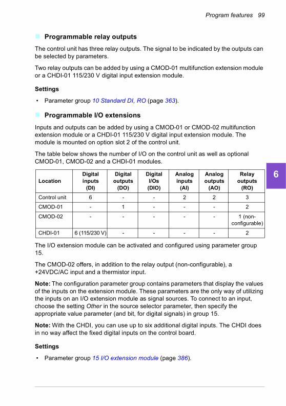
Program features 99
1
2
3
4
5
6
7
8
9
10
11
12
13
Programmable relay outputs
The control unit has three relay outputs. The signal to be indicated by the outputs can be selected by parameters.
Two relay outputs can be added by using a CMOD-01 multifunction extension module or a CHDI-01 115/230 V digital input extension module.
Settings
• Parameter group 10 Standard DI, RO (page 363).
Programmable I/O extensions
Inputs and outputs can be added by using a CMOD-01 or CMOD-02 multifunction extension module or a CHDI-01 115/230 V digital input extension module. The module is mounted on option slot 2 of the control unit.
The table below shows the number of I/O on the control unit as well as optional CMOD-01, CMOD-02 and a CHDI-01 modules.
The I/O extension module can be activated and configured using parameter group 15.
The CMOD-02 offers, in addition to the relay output (non-configurable), a +24VDC/AC input and a thermistor input.
Note: The configuration parameter group contains parameters that display the values of the inputs on the extension module. These parameters are the only way of utilizing the inputs on an I/O extension module as signal sources. To connect to an input, choose the setting Other in the source selector parameter, then specify the appropriate value parameter (and bit, for digital signals) in group 15.
Note: With the CHDI, you can use up to six additional digital inputs. The CHDI does in no way affect the fixed digital inputs on the control board.
Settings
• Parameter group 15 I/O extension module (page 386).
LocationDigital inputs
(DI)
Digital outputs
(DO)
Digital I/Os(DIO)
Analog inputs
(AI)
Analog outputs
(AO)
Relay outputs
(RO)
Control unit 6 - - 2 2 3
CMOD-01 - 1 - - - 2
CMOD-02 - - - - - 1 (non-configurable)
CHDI-01 6 (115/230 V) - - - - 2
14
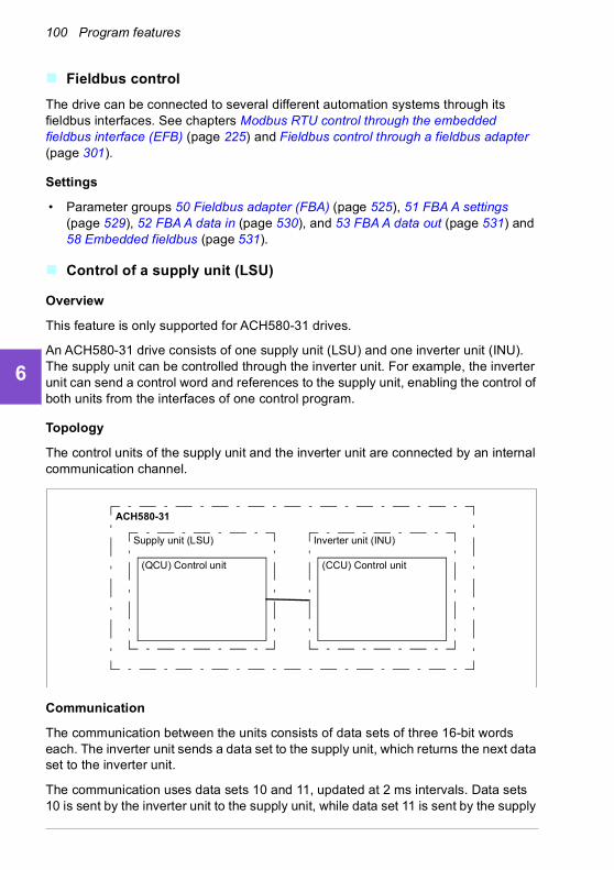
100 Program features
1
2
3
4
5
6
7
8
9
10
11
12
13
14
Fieldbus control
The drive can be connected to several different automation systems through its fieldbus interfaces. See chapters Modbus RTU control through the embedded fieldbus interface (EFB) (page 225) and Fieldbus control through a fieldbus adapter (page 301).
Settings
• Parameter groups 50 Fieldbus adapter (FBA) (page 525), 51 FBA A settings (page 529), 52 FBA A data in (page 530), and 53 FBA A data out (page 531) and 58 Embedded fieldbus (page 531).
Control of a supply unit (LSU)
Overview
This feature is only supported for ACH580-31 drives.
An ACH580-31 drive consists of one supply unit (LSU) and one inverter unit (INU). The supply unit can be controlled through the inverter unit. For example, the inverter unit can send a control word and references to the supply unit, enabling the control of both units from the interfaces of one control program.
Topology
The control units of the supply unit and the inverter unit are connected by an internal communication channel.
Communication
The communication between the units consists of data sets of three 16-bit words each. The inverter unit sends a data set to the supply unit, which returns the next data set to the inverter unit.
The communication uses data sets 10 and 11, updated at 2 ms intervals. Data sets 10 is sent by the inverter unit to the supply unit, while data set 11 is sent by the supply
Inverter unit (INU)
(CCU) Control unit
Supply unit (LSU)
(QCU) Control unit
ACH580-31

Program features 101
1
2
3
4
5
6
7
8
9
10
11
12
13
unit to the inverter unit. The contents of the data sets are freely configurable, but data set 10 typically contains the control word, while data set 11 returns the status word.
If the supply unit supports it, is possible to send a DC voltage and/or reactive power reference to it from the inverter parameter group 94 LSU control. A supply unit will also send actual signals to the inverter unit which are visible in parameter group 01 Actual values.
LSU Override
When override is activated in the inverter, it is also activated in the supply unit and stays active until it is deactivated.
When a fault occurs in the supply unit, it tries to reset it automatically. If the fault cannot be reset within a 30 s delay, the supply unit reboots and continues operation if the fault is not active. If there is a permanent fault, that is, a fault that cannot be reset, occurs in the supply unit, it reboots immediately. If the fault still persists, the supply unit keeps rebooting every 30 seconds until the fault disappears.
Faults occurred in the supply unit during override are stored in the override fault logs (see parameter group 70 Override).
If override is active in the supply unit when the communication between the inverter and the supply units is disconnected, the supply unit reboots and continues operation, if possible, until it gets a deactivate command from the inverter.
Settings
For the parameters, see FW Part 2.
• Parameters 01.102…01.164 (page 346), 05.111…05.121 (page 352), 06.36…06.39 (page 359), 06.116…06.118 (page 360), 07.106…07.107 (page 363), 30.101…30.149 (page 450), 31.120…31.121 (page 461) and 96.108 LSU control board boot (page 576).
• Parameter groups 60 DDCS communication (page 540), 61 D2D and DDCS transmit data (page 540), 62 D2D and DDCS receive data (page 541) and LSU control board boot (page 563).
• Parameter group 70 Override (page 541).
14
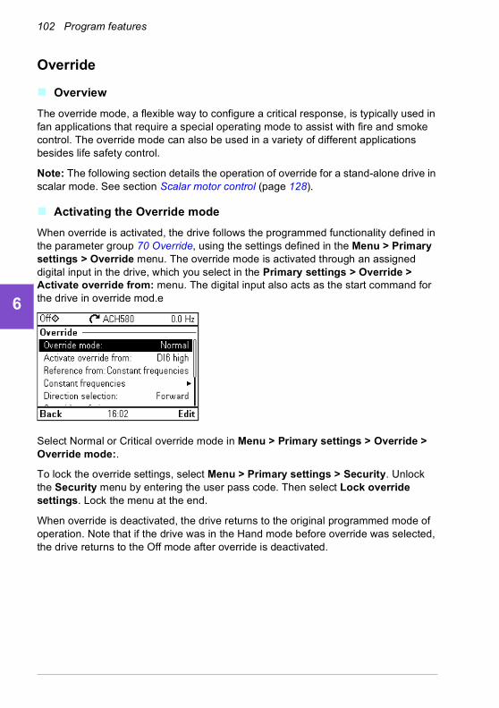
102 Program features
1
2
3
4
5
6
7
8
9
10
11
12
13
14
Override
Overview
The override mode, a flexible way to configure a critical response, is typically used in fan applications that require a special operating mode to assist with fire and smoke control. The override mode can also be used in a variety of different applications besides life safety control.
Note: The following section details the operation of override for a stand-alone drive in scalar mode. See section Scalar motor control (page 128).
Activating the Override mode
When override is activated, the drive follows the programmed functionality defined in the parameter group 70 Override, using the settings defined in the Menu > Primary settings > Override menu. The override mode is activated through an assigned digital input in the drive, which you select in the Primary settings > Override > Activate override from: menu. The digital input also acts as the start command for the drive in override mod.e
Select Normal or Critical override mode in Menu > Primary settings > Override > Override mode:.
To lock the override settings, select Menu > Primary settings > Security. Unlock the Security menu by entering the user pass code. Then select Lock override settings. Lock the menu at the end.
When override is deactivated, the drive returns to the original programmed mode of operation. Note that if the drive was in the Hand mode before override was selected, the drive returns to the Off mode after override is deactivated.

Program features 103
1
2
3
4
5
6
7
8
9
10
11
12
13
Reference for override speed/frequency
You can configure the drive to run in seven different override mode types by selecting the reference for override speed/frequency in the Reference from: menu.
• Constant frequencies allows you to select multiple, constant frequencies based on multiple digital inputs.
• AI1 directly or AI2 directly is the speed reference in the override mode.
• Override frequency commands the drive frequency to a single preprogrammed value.
• Floating point uses two defined digital inputs to increase or decrease the drive frequency. Initial values can be configured, as well as, minimum and maximum values and ramp times.
• Force stop stops the drive following the defined stop mode.
• PID, set1 controls the drive frequency using the output value of the process PID controller for PID parameter set 1.
Override mode features
When placed into the override mode, the drive shows the following features and behavior.
• Once in override, the drive ignores all fieldbus communication commands for start/stop and speed reference.
• In the override mode the drive ignores all commands from the control panel: for example, Hand/Off/Auto requests and any parameters changes that would affect override are ignored. If a DriveWare tool is connected via the USB port, it will be ignored.
• Activating the override mode also initiates a start command. There is no need for a secondary start command while in the override mode.
14
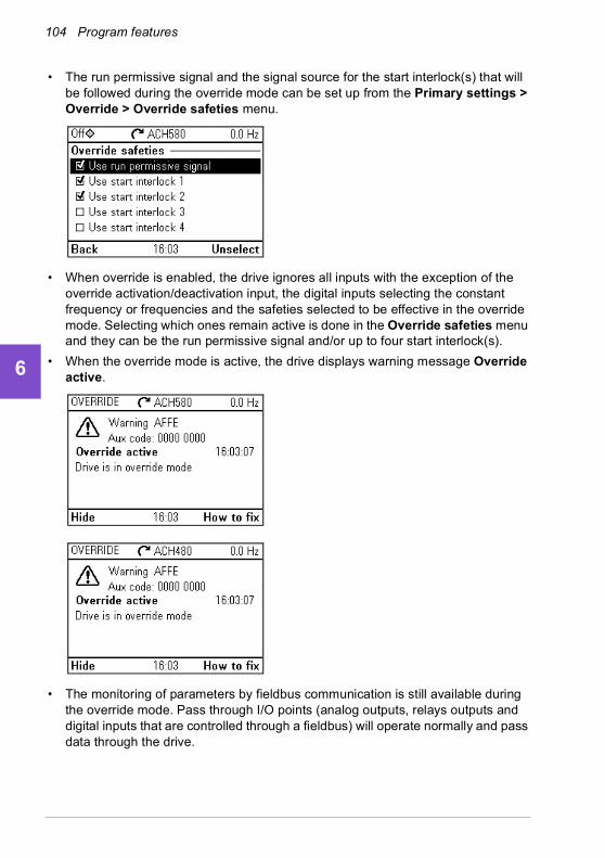
104 Program features
1
2
3
4
5
6
7
8
9
10
11
12
13
14
• The run permissive signal and the signal source for the start interlock(s) that will be followed during the override mode can be set up from the Primary settings > Override > Override safeties menu.
• When override is enabled, the drive ignores all inputs with the exception of the override activation/deactivation input, the digital inputs selecting the constant frequency or frequencies and the safeties selected to be effective in the override mode. Selecting which ones remain active is done in the Override safeties menu and they can be the run permissive signal and/or up to four start interlock(s).
• When the override mode is active, the drive displays warning message Override active.
• The monitoring of parameters by fieldbus communication is still available during the override mode. Pass through I/O points (analog outputs, relays outputs and digital inputs that are controlled through a fieldbus) will operate normally and pass data through the drive.

Program features 105
1
2
3
4
5
6
7
8
9
10
11
12
13
• Faults are grouped into high priority faults and low priority faults. High priority faults are displayed and they will stop the drive. See parameter group 70 Override (page 541) for fault handling. The following is a list of the high priority faults:
• Unless listed above, all other faults are low priority faults. Active low priority faults are reset when the drive enters the override mode. Low priority faults are ignored when the drive is in the override mode.
• You can select whether or not to use autoreset for critical faults (☑ Use autoreset for critical faults) or require a manual reset from the control panel or designated digital input.
• The number of high priority fault reset attempts is affected by the override mode. You can select: Disabled, Normal, or Critical. Disabled indicates that override is not being used. Normal follows the programmed number of fault resets. Critical allows for an infinite number of fault resets.
• The override configuration is able to be locked through the drive’s access level security. See parameter group 96 System (page 567) for pass code and access level settings.
• The AI supervision function still operates for any override modes that utilize an analog input. Thus if an analog input signal is lost, the drive will operate based on parameter group 12 Standard AI (page 375) configuration.
• If Safe Torque Off (STO) is triggered while the drive is in the override mode, the drive exits override and follows the programming for STO alarm and fault configuration. A fault code is displayed to let the operator know the drive is in an STO condition. When STO is disabled, the drive does not go back into override operation.
Settings
• Menu > Primary settings > Override
• Parameter group 70 Override (page 541)
• Parameter group 12 Standard AI (page 375)
• Parameter group 96 System (page 567).
2310 Overcurrent 4982 External temperature 2
2330 Earth leakage 5090 STO hardware failure
2340 Short circuit 5091 Safe torque off
3210 DC link overvoltage FA81 Safe torque off 1
4981 External temperature 1 FA82 Safe torque off 2
14
106 Program features
1
2
3
4
5
6
7
8
9
10
11
12
13
14
Application example 1: Override for single override frequency control
The air handler unit (AHU) that normally provides conditioned air to the occupied zone may be switched into a smoke control mode by the fire alarm system. The AHU dampers are typically configured to full outside air and exhaust air paths, in smoke control mode. The supply fan and the return/exhaust fan are controlled to pre-determined speeds to provide the specified air flow and space pressurization. This example consists of:
• A start/stop command from the building automation system (BAS) for Normal mode operation
• A 0…10 V DC analog speed command signal from the BAS for Normal mode operation
• A Freezestat safety configured as a low priority safety interlock that will be ignored in the override mode
• A duct high static pressure safety (Overpressure) configured as a high priority safety interlock that will operate in normal and override modes
• A supply air smoke detector/alarm safety configured as a high priority safety interlock that will operate in normal and override modes
• In the override mode, the drive will operate at a single, predefined override frequency (air balance preset of 48 Hz)
• In the override mode the high priority safeties will be reset as many times as required to ensure the system stays in operation
• Override mode is enabled by relay output from the fire alarm system to the drive
• A run/stop status feedback from the drive to the BAS
• A fault/not-faulted status feedback from the drive to the BAS.

Program features 107
1
2
3
4
5
6
7
8
9
10
11
12
13
Wiring diagram
Run status
Fault status
X1 Reference voltage and analog inputs and outputs1 SCR Signal cable shield (screen)2 AI1 Output frequency/speed reference: 0…10 V3 AGND Analog input circuit common4 +10V Reference voltage 10 V DC5 AI2 Actual feedback: 0…20 mA6 AGND Analog input circuit common7 AO1 Output frequency: 0…10 V8 AO2 Motor current: 0…20 mA9 AGND Analog output circuit common
X2 & X3 Aux. voltage output and programmable digital inputs10 +24V Aux. voltage output +24 V DC, max. 250 mA11 DGND Aux. voltage output common12 DCOM Digital input common for all13 DI1 Stop (0) / Start (1) 14 DI2 Not configured15 DI3 Start interlock 3 (1 = allow start)16 DI4 Start interlock 1 (1 = allow start)17 DI5 Start interlock 2 (1 = allow start)18 DI6 Override
X6, X7, X8 Relay outputs19 RO1C Damper control
250 V AC / 30 V DC2 A
20 RO1A21 RO1B22 RO2C Running
250 V AC / 30 V DC 2 A
23 RO2A24 RO2B25 RO3C Fault (-1)
250 V AC / 30 V DC2 A
26 RO3A27 RO3B
Start/stop signal
Freezestat safety
High static safety(Overpressure)
Fire alarm override
Supply air smokedetector safety
reference signal0…10 V DC speed +
-
Running22 connected to 24
Fault condition25 connected to 26
Energize damper19 connected to 21
14

108 Program features
1
2
3
4
5
6
7
8
9
10
11
12
13
14
Quick steps – Programming summary
Unless otherwise noted, the settings listed below are changed relative to the drive’s factory defaults to meet the application requirements. The settings identified below are specific to the configuration of override mode and configuration of the Interlock text, and do not review the complete normal mode configuration.
Menu > Primary settings > Override
• Edit Override mode: Critical
• Edit Activate override from: DI6 high
• Edit Reference from: Override frequency
• Edit Override frequency: 48.0 Hz
• Edit Direction selection: Forward (default)
• Select Override safeties
• ☑ Use start interlock 1
• ☑ Use start interlock 2
• Select ☑ Use autoreset for critical faults
• Edit Wait between reset attempts: 5.0 s (default)
• Edit Max attempts: 5 (default)
Menu > Primary settings > Start, stop, reference > Interlocks/permissives
• ☑ Use start interlock 1
• Edit Description text: Overpressure
• Select ☑ Use start interlock 2
• Edit Start enabled when: DI5 high
• Edit Description text: Smoke alarm
• Select ☑ Use start interlock 3
• Edit Start enabled when: DI3 high
• Edit Description text: Freezestat

Program features 109
1
2
3
4
5
6
7
8
9
10
11
12
13
14

110 Program features
1
2
3
4
5
6
7
8
9
10
11
12
13
14
Application example 2: Override for PID control
In the application example 1, the drive ran at a predetermined fixed frequency. In this example, the drive will use its internal PID loop to control based on a fixed pressure. A common application of the control scheme used in application example 2 is for the control of a dedicated stairwell pressurization fan in multi-story buildings during a fire or smoke event. The drive controls the stairwell pressurization fan speed to maintain a specific level of positive pressure in the stairwell. The positive pressure relative to the occupied space helps reduce the amount of smoke that enters the stairwell. This example consists of:
• The drive/fan only operates during a fire or smoke event
• An analog differential pressure sensor measuring the pressure differential between the stairwell and the occupied space
• An override input (Run) from the fire alarm system to start the drive and place it in the override mode
• A dedicated “shutdown” command from the fire alarm system
• An isolation damper end-switch contact closure, wired from the damper to the drive, to indicate the damper open/close status. (The isolation damper has to be proven open for the fan to operate.)
• A High pressure static safety (Overpressure)
• Resetting of high priority faults is Normal with two resets. (This is not “run to destruction”.)
• A run/stop status feedback from the drive to the building automation system (BAS)
• A fault/not-faulted status feedback from the drive to the BAS.
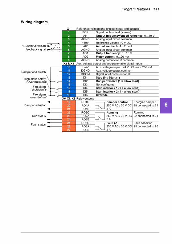
Program features 111
1
2
3
4
5
6
7
8
9
10
11
12
13
Wiring diagram
Run status
Fault status
Damper actuator
X1 Reference voltage and analog inputs and outputs1 SCR Signal cable shield (screen)2 AI1 Output frequency/speed reference: 0…10 V3 AGND Analog input circuit common4 +10V Reference voltage 10 V DC5 AI2 Actual feedback: 4…20 mA6 AGND Analog input circuit common7 AO1 Output frequency: 0…10 V8 AO2 Motor current: 0…20 mA9 AGND Analog output circuit common
X2 & X3 Aux. voltage output and programmable digital inputs10 +24V Aux. voltage output +24 V DC, max. 250 mA11 DGND Aux. voltage output common12 DCOM Digital input common for all13 DI1 Stop (0) / Start (1)14 DI2 Run permissive (1 = allow start)15 DI3 Not configured16 DI4 Start interlock 1 (1 = allow start)17 DI5 Start interlock 2 (1 = allow start)18 DI6 Override
X6, X7, X8 Relay outputs19 RO1C Damper control
250 V AC / 30 V DC2 A
20 RO1A21 RO1B22 RO2C Running
250 V AC / 30 V DC 2 A
23 RO2A24 RO2B25 RO3C Fault (-1)
250 V AC / 30 V DC2 A
26 RO3A27 RO3B
Damper end switch
High static safety(Overpressure)
Fire alarm“shutdown”)
Fire alarmoverride/run
feedback signal4…20 mA pressure +
-
Running22 connected to 24
Fault condition25 connected to 26
Energize damper19 connected to 21
14
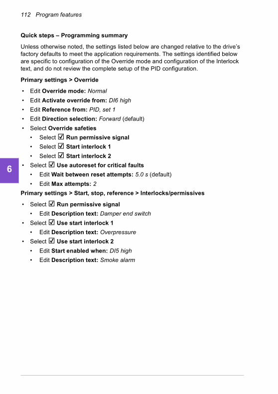
112 Program features
1
2
3
4
5
6
7
8
9
10
11
12
13
14
Quick steps – Programming summary
Unless otherwise noted, the settings listed below are changed relative to the drive’s factory defaults to meet the application requirements. The settings identified below are specific to configuration of the Override mode and configuration of the Interlock text, and do not review the complete setup of the PID configuration.
Primary settings > Override
• Edit Override mode: Normal
• Edit Activate override from: DI6 high
• Edit Reference from: PID, set 1
• Edit Direction selection: Forward (default)
• Select Override safeties
• Select ☑ Run permissive signal
• Select ☑ Start interlock 1
• Select ☑ Start interlock 2
• Select ☑ Use autoreset for critical faults
• Edit Wait between reset attempts: 5.0 s (default)
• Edit Max attempts: 2
Primary settings > Start, stop, reference > Interlocks/permissives
• Select ☑ Run permissive signal
• Edit Description text: Damper end switch
• Select ☑ Use start interlock 1
• Edit Description text: Overpressure
• Select ☑ Use start interlock 2
• Edit Start enabled when: DI5 high
• Edit Description text: Smoke alarm

Program features 113
1
2
3
4
5
6
7
8
9
10
11
12
13
Interlocks
Overview
Interlocks provide a way to prevent the drive from running when an input is not satisfied. The interlock feature of the drive is often used to wire safeties back to the drive. ABB does not recommend wiring interlocks in series with each other, unless there are more than four interlocks. Wiring interlocks separately allows for faster system troubleshooting, as the drive provides quick identification on which individual interlock is no longer satisfied. Monitoring the status of each interlock is available over fieldbus communications.
Interlocks typically are wired to the drive’s digital inputs (DI), DI1 through DI6. Certain fieldbus communications can also be used to control interlocks, although typically not recommended for most applications.
You can configure interlocks either in the Primary settings menu, or via parameter group 20 Start/stop/direction in the Parameters menu. ABB recommends configuration via the Primary settings menu (Menu > Primary settings > Start, stop, reference > Interlocks/permissives).
Interlocks are configurable for normally open or normally closed functionality.
• For example, in the Primary settings, selecting an interlock for DI4 high indicates that digital input 4 must be closed, or logic 1, to allow the drive to run. A setting of DI4 low indicates the digital input must be open, or logic 0, to allow the drive to run. If the interlock is not in a logic state that will allow the drive to run, the interlock is unsatisfied. If the interlock is in a logic state that will allow the drive to run, the interlock is satisfied.
An unsatisfied interlock is indicated on the drive panel display via a flashing green LED light, and a flashing warning on the display. You can set up the drive to indicate an unsatisfied interlock in one of two methods (Menu > Primary settings > Start, stop, reference > Interlocks/permissives > Interlock warning condition). This setting applies to all the interlocks.
• Indicate a warning, whenever an interlock is unsatisfied, regardless of a run command.
• Indicate a warning, whenever an interlock is unsatisfied and a run command is present.
You can configure the drive for either coast or ramp to a stop, when the interlock changes to an unsatisfied state (Menu > Primary settings > Start, stop, reference > Interlocks/permissives > Interlock stop mode).
Interlocks function in both Auto and Hand control modes. ABB recommends that the system interlocks are wired directly to the drive, and not to an external building automation system (BAS) controller.
14
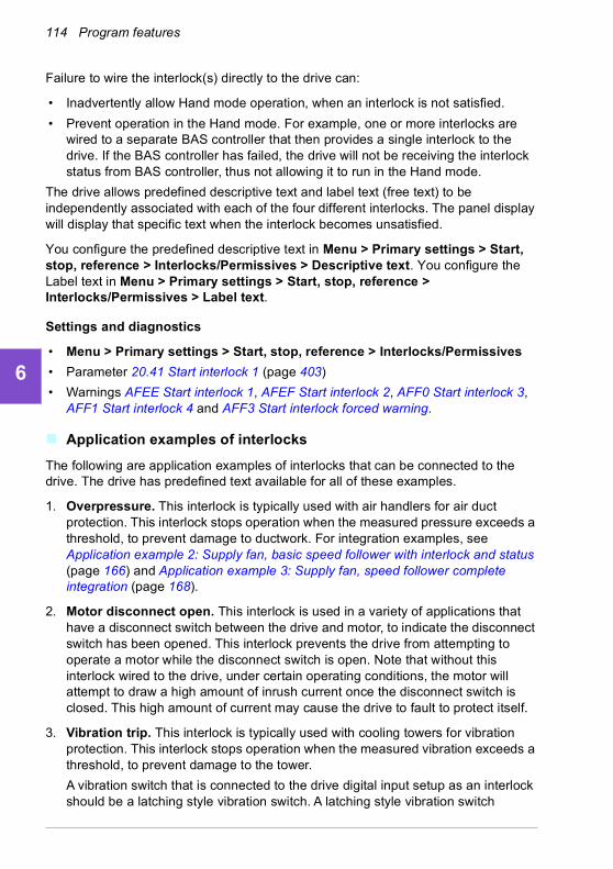
114 Program features
1
2
3
4
5
6
7
8
9
10
11
12
13
14
Failure to wire the interlock(s) directly to the drive can:
• Inadvertently allow Hand mode operation, when an interlock is not satisfied.
• Prevent operation in the Hand mode. For example, one or more interlocks are wired to a separate BAS controller that then provides a single interlock to the drive. If the BAS controller has failed, the drive will not be receiving the interlock status from BAS controller, thus not allowing it to run in the Hand mode.
The drive allows predefined descriptive text and label text (free text) to be independently associated with each of the four different interlocks. The panel display will display that specific text when the interlock becomes unsatisfied.
You configure the predefined descriptive text in Menu > Primary settings > Start, stop, reference > Interlocks/Permissives > Descriptive text. You configure the Label text in Menu > Primary settings > Start, stop, reference > Interlocks/Permissives > Label text.
Settings and diagnostics
• Menu > Primary settings > Start, stop, reference > Interlocks/Permissives
• Parameter 20.41 Start interlock 1 (page 403)
• Warnings AFEE Start interlock 1, AFEF Start interlock 2, AFF0 Start interlock 3, AFF1 Start interlock 4 and AFF3 Start interlock forced warning.
Application examples of interlocks
The following are application examples of interlocks that can be connected to the drive. The drive has predefined text available for all of these examples.
1. Overpressure. This interlock is typically used with air handlers for air duct protection. This interlock stops operation when the measured pressure exceeds a threshold, to prevent damage to ductwork. For integration examples, see Application example 2: Supply fan, basic speed follower with interlock and status (page 166) and Application example 3: Supply fan, speed follower complete integration (page 168).
2. Motor disconnect open. This interlock is used in a variety of applications that have a disconnect switch between the drive and motor, to indicate the disconnect switch has been opened. This interlock prevents the drive from attempting to operate a motor while the disconnect switch is open. Note that without this interlock wired to the drive, under certain operating conditions, the motor will attempt to draw a high amount of inrush current once the disconnect switch is closed. This high amount of current may cause the drive to fault to protect itself.
3. Vibration trip. This interlock is typically used with cooling towers for vibration protection. This interlock stops operation when the measured vibration exceeds a threshold, to prevent damage to the tower.
A vibration switch that is connected to the drive digital input setup as an interlock should be a latching style vibration switch. A latching style vibration switch

Program features 115
1
2
3
4
5
6
7
8
9
10
11
12
13
requires manual reset to allow the drive to run the motor again. If the vibration switch is an auto reset style, the drive digital input should be setup as an external event to fault the drive. This can be done in Menu > Primary Settings > Advanced functions > External events.
For integration examples, see Application example 5: Cooling tower fan, speed follower (page 172) and Application example 6: Cooling tower, PID (page 174).
4. Smoke alarm. This interlock is typically used with air handlers to stop the propagation of smoke through air ducts. This interlock stops operation when the measured smoke exceeds a threshold, to limit the amount of smoke spread through the system. For an integration example, see Application example 3: Supply fan, speed follower complete integration (page 168).
5. Freezestat. This interlock is typically used with air handlers for coil protection. This interlock stops operation when the measured temperature is below a threshold, to prevent freezing and subsequent coil damage. For an integration example, see Application example 4: Supply fan, PID control (page 170).
6. Firestat. This interlock is typically used with air handlers. This interlock stops operation when the measured temperature is above a threshold, possibly indicating a fire in the building.
7. Low suction or Low pressure. This interlock is typically used with pumps for pump protection. This interlock stops operation when the measured pressure on the suction side of the pump is below a threshold, to prevent pump damage from having it run dry.
8. Access door. This interlock is used in a variety of applications that have an access door. This interlock stops operation when the access door is opened. Note that an interlock is not an acceptable alternative to following proper safety procedures.
9. Auxiliary open. This interlock text is a generic term used in a variety of applications that have auxiliary contacts that need to stop drive operation. This interlock stops operation when the auxiliary has been opened.
10. Pressure relief. This interlock is used in applications that have a pressure relief method, such as a pressure relief valve, that also has an interlock tied to this relief method. This interlock stops operation when pressure exceeds a threshold and pressure is being mechanically relieved.
11. Start interlock 1, Start interlock 2, Start interlock 3, and Start interlock 4. This interlock text is a generic term used in a variety of applications that have interlocks. This interlock stops operation when the interlock has been opened or closed depending on the setup. ABB recommends using the predefined Descriptive text and/or custom Label text whenever possible, as this will simplify any future interlock troubleshooting needs.
12. Label text. Provides up to 35 characters of free/custom text describing the interlock. This text will appear on the drive control panel when the interlock is no
14

116 Program features
1
2
3
4
5
6
7
8
9
10
11
12
13
14
longer satisfied. This text can be used to better describe the interlock itself or its physical location. This text can also be used to enter a phone number for the local support of that equipment. Note that the Label text option is separate from the predefined text, thus the two can be used in conjunction with each other. For example, the predefined text can be selected for Overpressure, while the Label text may state “Reset switch located in control panel.”

Program features 117
1
2
3
4
5
6
7
8
9
10
11
12
13
Run permissives
Overview
The run permissive function provides a way to prevent the drive from outputting to a motor when an input is not satisfied. This function is used to support applications that require the drive to first trigger an external event before the drive starts to ramp the motor. Run permissive is often used in conjunction with an end-switch wired back to the drive. This end-switch could be part of a damper or valve control scheme. Monitoring the status of the run permissive is available over fieldbus communications.
Run permissive is different from start interlock:
• A run permissive makes the drive enter a run state but does not provide an output to the motor.
• An unsatisfied run permissive input will only indicate a warning on the panel display if a start command is also provided. No warning will be provided if the start command is not present. Start interlock is configurable to acknowledge, or ignore, the start command status when determining if a warning must be indicated.
The run permissive is typically wired to one of the drive’s digital inputs (DI), DI1 through DI6. DI2 is most commonly used. Certain fieldbus communications can also be used to control run permissive, although typically not recommended for most applications.
Configuration
You can configure run permissive either in the Primary settings menu, or via parameter group 20 Start/stop/direction in the Parameters menu. ABB recommends configuration via the Primary settings menu (Menu > Primary settings > Start, stop, reference > Interlocks/permissives). Run permissive is configurable for normally open or normally closed functionality.
Wiring connections
The run permissive functions in both Auto and Hand control modes. ABB recommends that any system permissive is wired directly to the drive and not to an external building automation system (BAS) controller.
Failure to wire the permissive directly to the drive can:
• Inadvertently allow Hand mode operation when a permissive is not satisfied.
• Prevent operation in the Hand mode. For example, a permissive is wired to a separate BAS controller that then reproduces a permissive to the drive. If the BAS controller were to fail, the drive will not be receiving the permissive status from the BAS controller, thus not allowing it to run in the Hand mode.
14
118 Program features
1
2
3
4
5
6
7
8
9
10
11
12
13
14
Functionality
The drive allows predefined Descriptive text, and Label text (free text), to be associated with the Run permissive. The panel will display that specific text when the permissive becomes unsatisfied.
• You configure (select) the predefined descriptive text in Menu > Primary settings > Start, stop, reference > Interlocks/Permissives > Descriptive text.
• You configure (edit) the label text is configured in Menu > Primary settings > Start, stop, reference > Interlocks/Permissives > Label text.
Run permissive features include the following:
• With no run command issued and run permissive not satisfied, no warning is displayed.
• With a start command issued and run permissive not satisfied, the drive displays a warning that the run permissive is missing, the status LED will flash green, and the panel’s direction arrow is dashed and rotating. The drive remains in running mode, but does not output to the motor until run permissive is satisfied.
• During normal operation of the motor, if run permissive changes state, the drive will coast to stop and display a warning that run permissive is keeping the drive from outputting to the motor.
• Relay settings that are not affected by run permissive input not being satisfied include: Ready run, Enabled, Started, Running, and Damper control. Relay settings that are affected by run permissive include: Warning and Fault/Warning.
Settings and diagnostics
• Menu > Primary settings > Start, stop, reference > Interlocks/permissives
• Parameter 20.40 Run permissive (page 402)
• Warnings AFED Run permissive and AFF2 Run permissive forced warning.

Program features 119
1
2
3
4
5
6
7
8
9
10
11
12
13
Application example 1: Damper end switch
The run permissive function is used in damper control to monitor the damper status through the damper end switch. Sequence of operation:
1. Drive receives start command, either via Hand or Auto source.
2. Drive verifies safeties are satisfied and end switch has not yet been satisfied.
3. Drive activates a relay output that was programmed to Damper control. This relay allows power to the actuator.
4. Once the damper end switch closes, run permissive is satisfied and the drive outputs to the motor.
See the figure on page 371 and Application example 3: Supply fan, speed follower complete integration (page 168).
Application example 2: Valve opening
The Run permissive function is used in valve control to prevent the pump from running until the valve is opened. Sequence of operation:
1. Drive receives start command, either via Hand or Auto source.
2. Drive verifies safeties are satisfied and valve position has not yet been satisfied.
3. Drive activates a relay output that was programmed to Valve opening (could have also been programmed to Started or Running). This relay allows power to the actuator.
4. Once the valve is opened, run permissive is satisfied and the drive outputs to the motor.
14
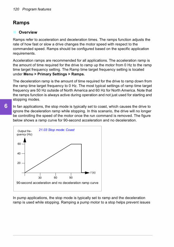
120 Program features
1
2
3
4
5
6
7
8
9
10
11
12
13
14
Ramps
Overview
Ramps refer to acceleration and deceleration times. The ramps function adjusts the rate of how fast or slow a drive changes the motor speed with respect to the commanded speed. Ramps should be configured based on the specific application requirements.
Acceleration ramps are recommended for all applications. The acceleration ramp is the amount of time required for the drive to ramp up the motor from 0 Hz to the ramp time target frequency setting. The Ramp time target frequency setting is located under Menu > Primary Settings > Ramps.
The deceleration ramp is the amount of time required for the drive to ramp down from the ramp time target frequency to 0 Hz. The most typical settings of ramp time target frequency are 50 Hz outside of North America and 60 Hz for North America. Note that the ramps function is always active during operation and not just used for starting and stopping modes.
In fan applications, the stop mode is typically set to coast, which causes the drive to ignore the deceleration ramp while stopping. In this scenario, the drive will no longer be controlling the speed of the motor once the run command is removed. The figure below shows a ramp curve for 90-second acceleration and no deceleration.
In pump applications, the stop mode is typically set to ramp and the deceleration ramp is used while stopping. Ramping a pump motor to a stop helps prevent issues
60
40
20
30 60 90
t (s)
Output fre-quency (Hz)
90-second acceleration and no deceleration ramp curve
21.03 Stop mode: Coast

Program features 121
1
2
3
4
5
6
7
8
9
10
11
12
13
such as water hammer and assist in closing the check valve. The figure below shows a ramp curve for 30-second acceleration and deceleration.
If the acceleration time is too short, the drive may trip out on overcurrent. If the deceleration ramp is set to stop too quickly, the drive may trip out on overvoltage. These scenarios are unlikely in most applications due to the internal current and voltage limiting features built into the drive.
Each application and motor is unique. As a general guideline for HVAC pumps and fans, ramp times are often set between 30 and 90 seconds. Typically a larger drive/motor has a longer ramp time. However, certain applications or pump types require a much faster or slower ramp time.
The drive also supports the ability to have two ramp sets. This feature is most commonly used in situations where a fast acceleration time is needed to a certain speed, and then a slower acceleration time is needed above that speed. This feature is configured with Menu > Primary settings > Ramps > Use two ramp sets.
Settings
• Menu > Primary settings > Ramps
• Speed reference ramping: Parameters 23.11…23.15 and 46.01 (pages 423 and 520)
• Frequency reference ramping: Parameters 28.71…28.75 and 46.02 (pages 438 and 520)
• Floating point control (Motor potentiometer): Parameter 22.75 (page 422)
• Emergency stop (“Off3” mode): Parameter 23.23 Emergency stop time (page 424).
60
40
20
30 60 90
t (s)
30-second acceleration and deceleration ramp curve
21.03 Stop mode: RampOutput fre-quency (Hz)
14
122 Program features
1
2
3
4
5
6
7
8
9
10
11
12
13
14
Application examples
Referring to Application example 7: Chilled water pump (page 178) and Application example 8: Condenser water pump (page 180), the drive is programmed to have the drive ramp the motor to a stop to prevent water hammer. All of the fan application examples are set up to coast to stop.
In the case of the fan application examples, it is not necessary to control the fan while stopping because the resistive forces are not great enough to cause damage to any part in the system. The fan will slowly come to a stop due to the air resistance and friction in the system. If a drive receives a new run command while the fan is still slowing, the drive can catch the spinning motor and ramp the fan to the reference speed.
In the pump application examples, the fluid in the pipes can create enough force on the pump to cause the pump to come to a stop very quickly after the drive stops controlling the motor. This sudden stop will cause a pressure surge in the pipes, often known as water hammer. Water hammer problems include noise and vibration, but can also cause major problems like pipe collapse. By using the drive to control the slowdown of the pump over a longer period of time, the pressure change is not sudden and the water hammer issue is eliminated.
Program features 123
1
2
3
4
5
6
7
8
9
10
11
12
13
Limits
Limits overview
The drive has multiple limits that can be set to prevent the drive from causing damage to the motor or the mechanical system. Limits can be applied to the minimum and maximum frequency, speed, or torque and the maximum current. Frequency limits are used in scalar motor control mode, while speed limits are used in vector motor control mode.
Setting a minimum speed/frequency may be used to prevent a pump or motor from overheating. Running a certain pump or motor type at too slow a speed will decrease its ability to cool itself. Also, certain gearbox style cooling towers require a minimum speed setting to provide proper lubrication of the gearbox. Equipment that runs warmer, or lacks proper lubrication, will likely have a shorter lifespan. Consult the equipment manufacturer for minimum speed/frequency settings.
Setting a maximum speed/frequency may be used to prevent excessive mechanical stress. Mechanical stress at levels above the equipment’s design will likely shorten the lifespan of the equipment. Consult the equipment manufacturer to determine the maximum safe speed/frequency.
The maximum current setting will prevent steady-state operation above a specific current operation. Note that this setting is unrelated to the motor overload protection, which is configured based on actual motor current information entered into the drive.
Settings
• Menu > Primary Settings > Limits
• Parameter group 30 Limits.
Application examples
Referring to Application example 5: Cooling tower fan, speed follower (page 172) and Application example 6: Cooling tower, PID (page 174), the minimum frequency is set based on limitations on the lubrication requirements of the fan’s gearbox. In this case, the limit was is based on information provided by the equipment manufacturer.
While the other examples on pages 164…180 do not use limitations, there may be a benefit. For example, in the pumping application examples, a pump manufacturer may recommend a minimum flow of 25%. Flow is linearly related to motor speed. In this example, assuming a 60 Hz pump system, the drive’s minimum frequency would be set to 15 Hz.
14

124 Program features
1
2
3
4
5
6
7
8
9
10
11
12
13
14
Application control
Automatic fault resets
The drive can automatically reset itself after overcurrent, overvoltage, undervoltage and external faults. The user can also specify a fault that is automatically reset.
By default, automatic resets are off and must be specifically activated by the user.
WARNING! Before you activate the function, make sure that no dangerous situations can occur. The function resets the drive automatically and continues
operation after a fault.
Settings
• Menu > Primary settings > Advanced functions > Autoreset faults
• Parameters 31.12…31.16 (page 454).
External events
Five different event signals from the process can be connected to selectable inputs to generate trips and warnings for the driven equipment. When the signal is lost, an external event (fault, warning, or a mere log entry) is generated. The contents of the messages can be edited on the control panel by selecting Menu > Primary settings > Advanced functions > External events.
Settings
• Menu > Primary settings > Advanced functions > External events
• Parameters 31.01…31.10 (page 452).
Constant speeds/frequencies
Constant speeds and frequencies are predefined references that can be quickly activated, for example, through digital inputs. It is possible to define up to 7 speeds for speed control and 7 constant frequencies for frequency control.
WARNING: Speeds and frequencies override the normal reference irrespective of where the reference is coming from.
Settings
• Menu > Primary settings > Start, stop, reference > Constant speeds
• Menu > Primary settings > Start, stop, reference > Constant frequencies
• Parameter groups 22 Speed reference selection (page 413) and 28 Frequency reference chain (page 431).

Program features 125
1
2
3
4
5
6
7
8
9
10
11
12
13
Critical speeds/frequencies
Critical speeds (sometimes called “skip speeds”) can be predefined for applications where it is necessary to avoid certain motor speeds or speed ranges because of, for example, mechanical resonance problems.
The critical speeds function prevents the reference from dwelling within a critical band for extended times. When a changing reference (22.87 Speed reference act 7) enters a critical range, the output of the function (22.01 Speed ref unlimited) freezes until the reference exits the range. Any instant change in the output is smoothed out by the ramping function further in the reference chain.
When the drive is limiting the allowed output speeds/frequencies, it limits to the absolutely lowest critical speed (critical speed low or critical frequency low) when accelerating from standstill, unless the speed reference is over the upper critical speed/ frequency limit.
The function is also available for scalar motor control with a frequency reference. The input of the function is shown by 28.96 Frequency ref act 7, the output by 28.97 Frequency ref unlimited).
Example for critical speeds:
A fan has vibrations in the range of 540…690 rpm and 1380…1560 rpm. To make the drive avoid these speed ranges,
• enable the critical speeds function by turning on bit 0 of parameter 22.51 Critical speed function, and
• set the critical speed ranges as in the figure below.
540
690
1380
1560
1 Par. 22.52 = 540 rpm
2 Par. 22.52 = 690 rpm
3 Par. 22.54 = 1380 rpm
4 Par. 22.55 = 1560 rpm
1 2 3 4
22.01 Speed ref unlimited (rpm)(output of function)
22.87 Speed reference act 7 (rpm)(input of function)
14

126 Program features
1
2
3
4
5
6
7
8
9
10
11
12
13
14
Example for critical frequencies:
A fan has vibrations in the range of 18…23 Hz and 46…52 Hz. To make the drive avoid these frequency ranges,
• enable the critical frequencies function by turning on bit 0 of parameter 28.51 Critical frequency function, and
• set the critical speed frequencies as in the figure below.
Settings
• Menu > Primary settings > Start, stop, reference > Constant speeds
• Menu > Primary settings > Start, stop, reference > Constant frequencies
• Critical speeds: parameters 22.51…22.57 (page 420)
• Critical frequencies: parameters 28.51…28.57 (page 438).
Timed functions
The base entity of the timed functions is called a timer. A timer can be active based on time of the day, day of the week and season of the year. In addition to these time related parameters, the timer activation can be influenced by so called exceptional days (configurable as holiday or workday). For example, 25.12. (Dec 25th) can be defined as holiday in many countries. A timer can be set to be active or inactive during the exceptional days.
Several timers can be connected to a timed function with the OR function. Thus if any of the timers connected to a timed function is active, the timed function is also active. The timed function is then in turn controlling normal drive functions like starting the drive, choosing the right speed or right setpoint for the PID loop controller.
In many cases where a fan or pump is controlled with a timed function, it is often required that there is a possibility to override the time program for a short while. The overriding functionality is called boost. The boost is directly affecting selected timed
18
23
46
52
1 Par. 28.52 = 18 Hz
2 Par. 28.53 = 23 Hz
3 Par. 28.54 = 46 Hz
4 Par. 28.55 = 52 Hz
1 2 3 4
28.97 Frequency ref unlimited (Hz)(output of function)
28.96 Frequency ref act 7 (Hz)(input of function)
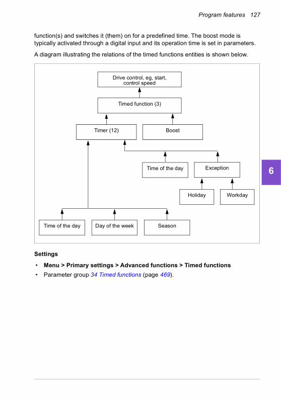
Program features 127
1
2
3
4
5
6
7
8
9
10
11
12
13
function(s) and switches it (them) on for a predefined time. The boost mode is typically activated through a digital input and its operation time is set in parameters.
A diagram illustrating the relations of the timed functions entities is shown below.
Settings
• Menu > Primary settings > Advanced functions > Timed functions
• Parameter group 34 Timed functions (page 469).
Time of the day
Workday
Day of the week Season
Exception
Holiday
Timer (12) Boost
Timed function (3)
Drive control, eg, start, control speed
Time of the day
14
128 Program features
1
2
3
4
5
6
7
8
9
10
11
12
13
14
Motor control
Speed control mode
The motor follows a speed reference given to the drive. This mode can be used with estimated speed used as feedback.
Speed control mode is available in both local and external control. It is supported in vector motor control only.
Speed control uses speed reference chain. Select speed reference with parameters in group 22 Speed reference selection on page 413.
Frequency control mode
The motor follows a frequency reference given to the drive. Frequency control is available in both local and external control. It is supported in scalar motor control only.
Frequency control uses frequency reference chain. Select frequency reference with parameters in group 28 Frequency reference chain on page 431.
Motor types
The drive supports asynchronous AC induction, permanent magnet (PM) and synchronous reluctance motors (SynRM).
Motor identification
The performance of vector control is based on an accurate motor model determined during the motor start-up.
A motor identification magnetization is automatically performed the first time the start command is given. During this first start-up, the motor is magnetized at zero speed for several seconds and the motor and motor cable resistance are measured to allow the motor model to be created. This identification method is suitable for most applications.
In demanding applications a separate Identification run (ID run) can be performed.
Settings
• Menu > Primary settings > Motor > Control mode > Vector control
• Parameter 99.13 ID run requested (page 586).
Scalar motor control
Scalar motor control is the default motor control method. In scalar control mode, the drive is controlled with a frequency reference. However, the excellent performance of vector control is not achieved in scalar control.
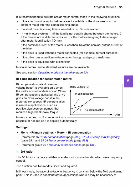
Program features 129
1
2
3
4
5
6
7
8
9
10
11
12
13
It is recommended to activate scalar motor control mode in the following situations:
• If the exact nominal motor values are not available or the drive needs to run different motor after the commissioning phase
• If a short commissioning time is needed or no ID run is wanted
• In multimotor systems: 1) if the load is not equally shared between the motors, 2) if the motors are of different sizes, or 3) if the motors are going to be changed after motor identification (ID run)
• If the nominal current of the motor is less than 1/6 of the nominal output current of the drive
• If the drive is used without a motor connected (for example, for test purposes)
• If the drive runs a medium-voltage motor through a step-up transformer
• If the drive is equipped with a sine filter.
In scalar control, some standard features are not available.
See also section Operating modes of the drive (page 93).
IR compensation for scalar motor control
IR compensation (also known as voltage boost) is available only when the motor control mode is scalar. When IR compensation is activated, the drive gives an extra voltage boost to the motor at low speeds. IR compensation is useful in applications, such as positive displacement pumps, that require a high break-away torque.
In vector control, no IR compensation is possible or needed as it is applied automatically.
Settings
• Menu > Primary settings > Motor > IR compensation
• Parameters 97.13 IR compensation (page 580), 97.94 IR comp max frequency (page 581) and 99.04 Motor control mode (page 583)
• Parameter group 28 Frequency reference chain (page 431).
U/f ratio
The U/f function is only available in scalar motor control mode, which uses frequency control.
The function has two modes: linear and squared.
In linear mode, the ratio of voltage to frequency is constant below the field weakening point. This is used in constant torque applications where it may be necessary to
Motor voltage (V)
f (Hz)
IR compensation
No compensation
14
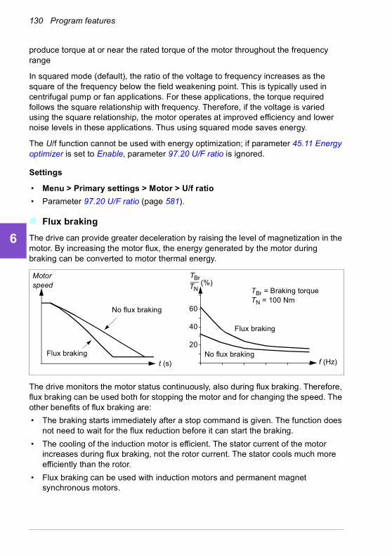
130 Program features
1
2
3
4
5
6
7
8
9
10
11
12
13
14
produce torque at or near the rated torque of the motor throughout the frequency range
In squared mode (default), the ratio of the voltage to frequency increases as the square of the frequency below the field weakening point. This is typically used in centrifugal pump or fan applications. For these applications, the torque required follows the square relationship with frequency. Therefore, if the voltage is varied using the square relationship, the motor operates at improved efficiency and lower noise levels in these applications. Thus using squared mode saves energy.
The U/f function cannot be used with energy optimization; if parameter 45.11 Energy optimizer is set to Enable, parameter 97.20 U/F ratio is ignored.
Settings
• Menu > Primary settings > Motor > U/f ratio
• Parameter 97.20 U/F ratio (page 581).
Flux braking
The drive can provide greater deceleration by raising the level of magnetization in the motor. By increasing the motor flux, the energy generated by the motor during braking can be converted to motor thermal energy.
The drive monitors the motor status continuously, also during flux braking. Therefore, flux braking can be used both for stopping the motor and for changing the speed. The other benefits of flux braking are:
• The braking starts immediately after a stop command is given. The function does not need to wait for the flux reduction before it can start the braking.
• The cooling of the induction motor is efficient. The stator current of the motor increases during flux braking, not the rotor current. The stator cools much more efficiently than the rotor.
• Flux braking can be used with induction motors and permanent magnet synchronous motors.
TBr
TN
20
40
60
(%)Motor speed
No flux braking
Flux braking
TBr = Braking torqueTN = 100 Nm
Flux braking
No flux brakingt (s) f (Hz)
Program features 131
1
2
3
4
5
6
7
8
9
10
11
12
13
Two braking power levels are available:
• Moderate braking provides faster deceleration compared to a situation where flux braking is disabled. The flux level of the motor is limited to prevent excessive heating of the motor.
• Full braking exploits almost all available current to convert the mechanical braking energy to motor thermal energy. Braking time is shorter compared to moderate braking. In cyclic use, motor heating may be significant.
WARNING: The motor needs to be rated to absorb the thermal energy generated by flux braking.
Settings
• Menu > Primary settings > Motor > Flux braking
• Parameter 97.05 Flux braking (page 578).
Start methods – DC magnetization
The drive has different magnetization functions for different phases of motor start/rotation/stop: pre-heating (motor heating), pre-magnetization, DC hold and post-magnetization.
Pre-heating (Motor heating)
The pre-heating function keeps the motor warm and prevents condensation inside the motor by feeding it with DC current when the drive has been stopped. The heating can only be on when the drive is in the stopped state, and starting the drive stops the heating.
When pre-heating is activated and the stop command is given, pre-heating starts immediately if the drive is running below the zero speed limit (see bit 0 in parameter 06.19 Speed control status word)). If the drive is running above the zero speed limit, pre-heating is delayed by the time defined by parameter 21.15 Pre-heating time delay to prevent excessive current.
The function can be defined to be always active when the drive is stopped or it can be activated by a digital input, fieldbus, timed function or supervision function. For example, with the help of signal supervision function, the heating can be activated by a thermal measurement signal from the motor.
The pre-heating current fed to the motor can be defined as 0…30% of the nominal motor current.
14

132 Program features
1
2
3
4
5
6
7
8
9
10
11
12
13
14
Notes:
• In applications where the motor keeps rotating for a long time after the modulation is stopped, it is recommended to use ramp stop with pre-heating to prevent a sudden pull at the rotor when the pre-heating is activated.
• The heating function requires that the STO circuit is closed or not triggered open.
• The heating function requires that the drive is not faulted.
• The heating function is allowed even if Run permissive signal is missing.
• The heating function is allowed even if one or more Start interlock signals are missing.
• Pre-heating uses DC hold to produce current.
Settings
• Menu > Primary settings > Motor > Pre-heating
• Parameters 21.14 Pre-heating input source, 21.15 Pre-heating time delay and 21.16 Pre-heating current (page 409).
Pre-magnetization
Pre-magnetization refers to DC magnetization of the motor before start. Depending on the selected start mode (21.01 Start mode or 21.19 Scalar start mode), pre-magnetization can be applied to guarantee the highest possible breakaway torque, up to 200% of the nominal torque of the motor. By adjusting the pre-magnetization time (21.02 Magnetization time), it is possible to synchronize the motor start and, for example, the release of a mechanical brake.
Settings
• Parameters 21.01 Start mode, 21.19 Scalar start mode, 21.02 Magnetization time.
DC hold
The function makes it possible to lock the rotor at (near) zero speed in the middle of normal operation. DC hold is activated by parameter 21.08 DC current control. When both the reference and motor speed drop below a certain level (parameter 21.09 DC hold speed), the drive will stop generating sinusoidal current and start to inject DC into the motor. The current is set by parameter 21.10 DC current reference. When the
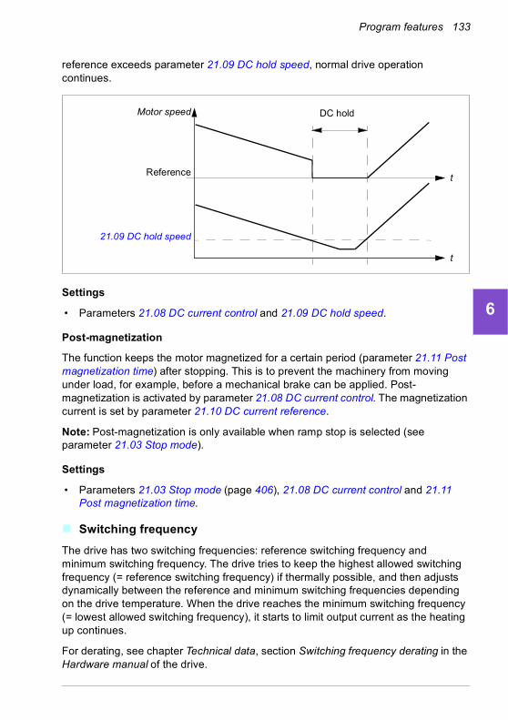
Program features 133
1
2
3
4
5
6
7
8
9
10
11
12
13
reference exceeds parameter 21.09 DC hold speed, normal drive operation continues.
Settings
• Parameters 21.08 DC current control and 21.09 DC hold speed.
Post-magnetization
The function keeps the motor magnetized for a certain period (parameter 21.11 Post magnetization time) after stopping. This is to prevent the machinery from moving under load, for example, before a mechanical brake can be applied. Post-magnetization is activated by parameter 21.08 DC current control. The magnetization current is set by parameter 21.10 DC current reference.
Note: Post-magnetization is only available when ramp stop is selected (see parameter 21.03 Stop mode).
Settings
• Parameters 21.03 Stop mode (page 406), 21.08 DC current control and 21.11 Post magnetization time.
Switching frequency
The drive has two switching frequencies: reference switching frequency and minimum switching frequency. The drive tries to keep the highest allowed switching frequency (= reference switching frequency) if thermally possible, and then adjusts dynamically between the reference and minimum switching frequencies depending on the drive temperature. When the drive reaches the minimum switching frequency (= lowest allowed switching frequency), it starts to limit output current as the heating up continues.
For derating, see chapter Technical data, section Switching frequency derating in the Hardware manual of the drive.
Reference
Motor speed DC hold
21.09 DC hold speed
t
t
14

134 Program features
1
2
3
4
5
6
7
8
9
10
11
12
13
14
Example 1: If you need to fix the switching frequency to a certain value as with some external filters, for example, with EMC C1 filters (see the Hardware manual of the drive), set both the reference and the minimum switching frequency to this value and the drive will retain this switching frequency.
Example 2: If the reference switching frequency is set to 8 kHz and the minimum switching frequency is set to the smallest available value, the drive maintains the highest possible switching frequency to reduce motor noise and only when the drive heats it will decrease the switching frequency. This is useful, for example, in applications where low noise is necessary but higher noise can be tolerated when the full output current is needed.
Settings
• Menu > Primary settings > Motor > Switching frequency
• Parameters 97.01 Switching frequency reference and 97.02 Minimum switching frequency (page 564).
Motor thermal protection
The control program features two separate motor temperature monitoring functions. The temperature data sources and warning/trip limits can be set up independently for each function.
The motor temperature can be monitored using
• the motor thermal protection model (estimated temperature derived internally inside the drive), or
• sensors installed in the windings. This will result in a more accurate motor model.
Motor thermal protection model
The drive calculates the temperature of the motor on the basis of the following assumptions:
1. When power is applied to the drive for the first time, the motor is assumed to be at ambient temperature (defined by parameter 35.50 Motor ambient temperature). After this, when power is applied to the drive, the motor is assumed to be at the estimated temperature.
2. Motor temperature is calculated using the user-adjustable motor thermal time and motor load curve. The load curve should be adjusted in case the ambient temperature exceeds 30 °C.
Note: The motor thermal model can be used when only one motor is connected to the inverter.
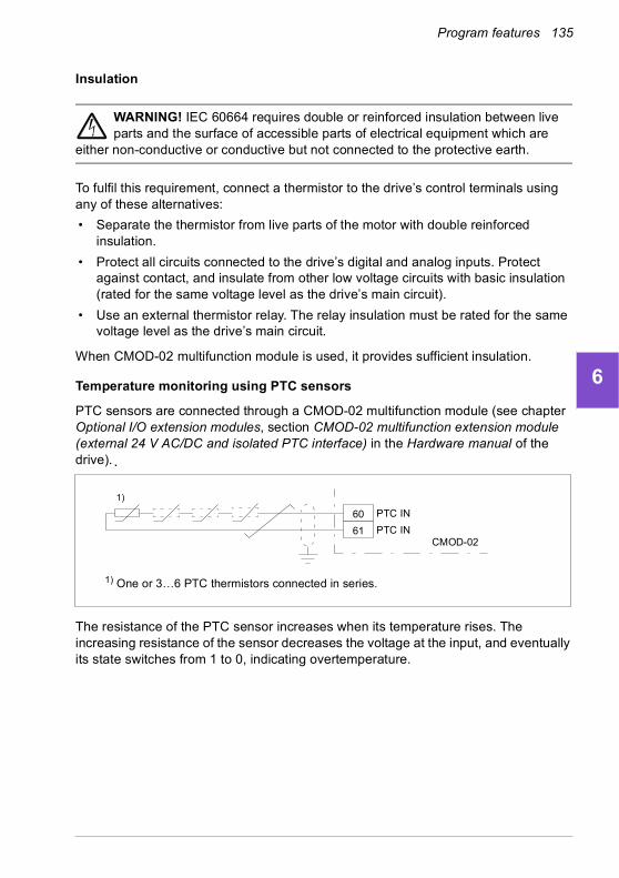
Program features 135
1
2
3
4
5
6
7
8
9
10
11
12
13
Insulation
WARNING! IEC 60664 requires double or reinforced insulation between live parts and the surface of accessible parts of electrical equipment which are
either non-conductive or conductive but not connected to the protective earth.
To fulfil this requirement, connect a thermistor to the drive’s control terminals using any of these alternatives:
• Separate the thermistor from live parts of the motor with double reinforced insulation.
• Protect all circuits connected to the drive’s digital and analog inputs. Protect against contact, and insulate from other low voltage circuits with basic insulation (rated for the same voltage level as the drive’s main circuit).
• Use an external thermistor relay. The relay insulation must be rated for the same voltage level as the drive’s main circuit.
When CMOD-02 multifunction module is used, it provides sufficient insulation.
Temperature monitoring using PTC sensors
PTC sensors are connected through a CMOD-02 multifunction module (see chapter Optional I/O extension modules, section CMOD-02 multifunction extension module (external 24 V AC/DC and isolated PTC interface) in the Hardware manual of the drive).
The resistance of the PTC sensor increases when its temperature rises. The increasing resistance of the sensor decreases the voltage at the input, and eventually its state switches from 1 to 0, indicating overtemperature.
60
61
1) One or 3…6 PTC thermistors connected in series.
1)
CMOD-02
PTC IN
PTC IN
14

136 Program features
1
2
3
4
5
6
7
8
9
10
11
12
13
14
The figure below shows typical PTC sensor resistance values as a function of temperature.
One isolated PTC sensor can also be connected directly to digital input DI6. At the motor end, the cable shield should be earthed through a capacitor. If this is not possible, leave the shield unconnected.
See section Insulation on page 135.
Temperature monitoring using Pt100 sensors
1…3 Pt100 sensors can be connected in series to an analog input and an analog output.
The analog output feeds a constant excitation current of 9.1 mA through the sensor. The sensor resistance increases as the motor temperature rises, as does the voltage over the sensor. The temperature measurement function reads the voltage through the analog input and converts it into degrees Celsius.
It is possible to adjust the motor temperature supervision limits and select how the drive reacts when overtemperature is detected.
See section Insulation on page 135.
100
550
1330
4000
Ohm
T
MT
Control board
DI6
+24 V DC
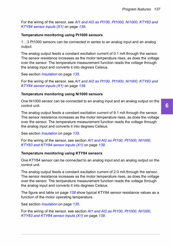
Program features 137
1
2
3
4
5
6
7
8
9
10
11
12
13
For the wiring of the sensor, see AI1 and AI2 as Pt100, Pt1000, Ni1000, KTY83 and KTY84 sensor inputs (X1) on page 139.
Temperature monitoring using Pt1000 sensors
1…3 Pt1000 sensors can be connected in series to an analog input and an analog output.
The analog output feeds a constant excitation current of 0.1 mA through the sensor. The sensor resistance increases as the motor temperature rises, as does the voltage over the sensor. The temperature measurement function reads the voltage through the analog input and converts it into degrees Celsius.
See section Insulation on page 135.
For the wiring of the sensor, see AI1 and AI2 as Pt100, Pt1000, Ni1000, KTY83 and KTY84 sensor inputs (X1) on page 139.
Temperature monitoring using Ni1000 sensors
One Ni1000 sensor can be connected to an analog input and an analog output on the control unit.
The analog output feeds a constant excitation current of 9.1 mA through the sensor. The sensor resistance increases as the motor temperature rises, as does the voltage over the sensor. The temperature measurement function reads the voltage through the analog input and converts it into degrees Celsius.
See section Insulation on page 135.
For the wiring of the sensor, see section AI1 and AI2 as Pt100, Pt1000, Ni1000, KTY83 and KTY84 sensor inputs (X1) on page 139.
Temperature monitoring using KTY84 sensors
One KTY84 sensor can be connected to an analog input and an analog output on the control unit.
The analog output feeds a constant excitation current of 2.0 mA through the sensor. The sensor resistance increases as the motor temperature rises, as does the voltage over the sensor. The temperature measurement function reads the voltage through the analog input and converts it into degrees Celsius.
The figure and table on page 138 show typical KTY84 sensor resistance values as a function of the motor operating temperature.
See section Insulation on page 135.
For the wiring of the sensor, see section AI1 and AI2 as Pt100, Pt1000, Ni1000, KTY83 and KTY84 sensor inputs (X1) on page 139.
14

138 Program features
1
2
3
4
5
6
7
8
9
10
11
12
13
14
Temperature monitoring using KTY83 sensors
One KTY83 sensor can be connected to an analog input and an analog output on the control unit.
The analog output feeds a constant excitation current of 1.0 mA through the sensor. The sensor resistance increases as the motor temperature rises, as does the voltage over the sensor. The temperature measurement function reads the voltage through the analog input and converts it into degrees Celsius.
The figure and table below show typical KTY83 sensor resistance values as a function of the motor operating temperature.
It is possible to adjust the motor temperature supervision limits and select how the drive reacts when overtemperature is detected.
See section Insulation on page 135.
For the wiring of the sensor, see section AI1 and AI2 as Pt100, Pt1000, Ni1000, KTY83 and KTY84 sensor inputs (X1) on page 139.
1000
2000
3000
Ohm
T (oC)-100
0
0 100 200 300
Scaling
KTY84 KTY83
°C ohm ohm
90 936 1569
110 1063 1774
130 1197 1993
150 1340 2225
KTY83KTY84
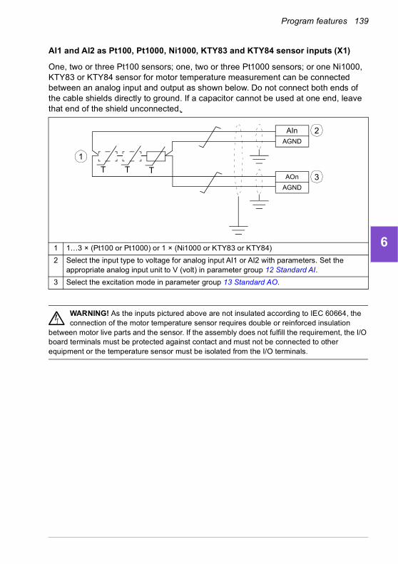
Program features 139
1
2
3
4
5
6
7
8
9
10
11
12
13
AI1 and AI2 as Pt100, Pt1000, Ni1000, KTY83 and KTY84 sensor inputs (X1)
One, two or three Pt100 sensors; one, two or three Pt1000 sensors; or one Ni1000, KTY83 or KTY84 sensor for motor temperature measurement can be connected between an analog input and output as shown below. Do not connect both ends of the cable shields directly to ground. If a capacitor cannot be used at one end, leave that end of the shield unconnected.
WARNING! As the inputs pictured above are not insulated according to IEC 60664, the connection of the motor temperature sensor requires double or reinforced insulation
between motor live parts and the sensor. If the assembly does not fulfill the requirement, the I/O board terminals must be protected against contact and must not be connected to other equipment or the temperature sensor must be isolated from the I/O terminals.
1 1…3 × (Pt100 or Pt1000) or 1 × (Ni1000 or KTY83 or KTY84)
2 Select the input type to voltage for analog input AI1 or AI2 with parameters. Set the appropriate analog input unit to V (volt) in parameter group 12 Standard AI.
3 Select the excitation mode in parameter group 13 Standard AO.
AInAGND
AOn
AGND
TTT
1
2
3
14
140 Program features
1
2
3
4
5
6
7
8
9
10
11
12
13
14
Temperature monitoring using thermistor relays
A normally closed or a normally open thermistor relay can be connected to digital input DI6.
See section Insulation on page 135.
Settings
• Menu > Primary settings > Motor > Thermal protection estimated
• Menu > Primary settings > Motor > Thermal protection measured
• Parameter group 35 Motor thermal protection (page 477).
Motor overload protection
This section describes motor overload protection without using motor thermal protection model, either with estimated or measured temperature. For protection with the motor thermal protection model, see section Motor thermal protection on page 134.
Motor overload protection is required and specified by multiple standards including the US National Electric Code (NEC), UL 508C and the common UL\IEC 61800-5-1 standard in conjunction with IEC 60947-4-1. The standards allow for motor overload protection without external temperature sensors.
The protection feature allows the user to specify the class of operation in the same manner as the overload relays are specified in standards IEC 60947-4-1 and NEMA ICS 2.
Motor overload protection requires that you specify a motor current tripping level. This is defined by a curve using parameters 35.51 Motor load curve, 35.52 Zero speed load and 35.53 Break point. The tripping level is the motor current at which the overload protection will ultimately trip if the motor current remains at this level continuously.
The motor overload class (class of operation), parameter 35.57 Motor overload class, is given as the time required for the overload relay to trip when operating at 7.2 times
MotorT
Thermistorrelay Control board
DI6
+24 V DC

Program features 141
1
2
3
4
5
6
7
8
9
10
11
12
13
the tripping level in the case of IEC 60947-4-1 and 6 times the tripping level in the case of NEMA ICS 2. The standards also specify the time to trip for current levels between the tripping level and the 6 times tripping level. The drive satisfies the IEC standard and NEMA standard trip times.
Using class 20 satisfies the UL 508C requirements.
The motor overload algorithm monitors the squared ratio (motor current / tripping level)2 and accumulates this over time. This is sometimes to as I2t protection. The accumulated value is shown with parameter 35.05 Motor overload level.
You can define with parameter 35.56 Motor overload action that when 35.05 Motor overload level reaches 88%, a motor overload warning will be generated, and when it reaches 100%, the drive will trip on the motor overload fault. The rate at which this internal value is increased depends on the actual current, tripping level current and overload class selected.
Parameters 35.51 Motor load curve, 35.52 Zero speed load and 35.53 Break point serve a dual purpose. They determine the load curve for temperature estimate as well as specify the overload tripping level.
Settings
• Parameters common to motor thermal protection and motor overload protection: 35.51 Motor load curve (page 485), 35.52 Zero speed load (page 485) and 35.53 Break point (page 486).
• Parameters specific to motor overload protection: 35.05 Motor overload level (page 478), 35.56 Motor overload action (page 487) and 35.57 Motor overload class (page 487).
Vector control
Vector control is the motor control mode that is intended for applications where high control accuracy is needed. It offers better control over whole speed range, in particular in applications where slow speed with high torque is needed. It requires an identification run at startup. Vector control cannot be used in all applications, for example, when sine filters are being used or there are multiple motors connected to single drive.
The switching of the output semiconductors is controlled to achieve the required stator flux and motor torque. The reference value for the torque controller comes from the speed controller.
Stator flux is calculated by integrating the motor voltage in vector space. Rotor flux can be calculated from stator flux and the motor model. Motor torque is produced by controlling current 90 degrees from the rotor flux. By utilizing the identified motor model, the rotor flux estimate is improved. Actual motor shaft speed is not needed for the motor control.
14

142 Program features
1
2
3
4
5
6
7
8
9
10
11
12
13
14
Settings
• Menu > Primary settings > Motor > Control mode
• Parameters 99.04 Motor control mode (page 583) and 99.13 ID run requested (page 586).
Speed control performance figures
The table below shows typical performance figures for speed control.
Floating point control (Motor potentiometer)
The Floating point control (parameters are named Motor potentiometer, however) is, in effect, a counter whose value can be adjusted up and down using two digital signals selected by parameters 22.73 Motor potentiometer up source and 22.74 Motor potentiometer down source.
When the Floating point control is enabled by 22.71 Motor potentiometer function, the counter assumes the value set by 22.72 Motor potentiometer initial value. Depending on the mode selected in 22.71, the counter value is either retained or reset over a power cycle.
The change rate is defined in 22.75 Motor potentiometer ramp time as the time it would take for the value to change from the minimum (22.76 Motor potentiometer min value) to the maximum (22.77 Motor potentiometer max value) or vice versa. If the up and down signals are simultaneously on, the counter value does not change.
The output of the Floating point control counter is shown by 22.80 Motor potentiometer ref act, which can directly be set as the reference source in the main selector parameters, or used as an input by other source selector parameters, both in scalar and vector control.
100
t (s)
TTN
(%)
Tload
nact-nrefnN
Area < 10% s
TN = rated motor torquenN = rated motor speednact = actual speednref = speed reference
Speed control Performance
Static accuracy 20% of motor nominal slip
Dynamic accuracy < 10% s with 100% torque step (with default speed controller tuning)
Dynamic accuracy with tuned speed controller
< 2% s with 100% torque step

Program features 143
1
2
3
4
5
6
7
8
9
10
11
12
13
The following example shows the behavior of the Floating point control counter value.
Parameters 22.73 Motor potentiometer up source and 22.74 Motor potentiometer down source control speed or frequency from zero to maximum speed or frequency. The running direction can be changed with parameter 20.04 Ext1 in2 source. See the following example.
Settings
• Parameters 22.71…22.80 (page 421).
0
1
0
1
022.80
22.74
22.73
22.77
22.76
22.75
0
1
1
0
0
1
0
1
22.74
22.73
20.04Ext1 in2
source
20.03Ext1 in1
source
*
* Output speed or frequency has reached the reference value.
14

144 Program features
1
2
3
4
5
6
7
8
9
10
11
12
13
14
DC voltage control
Overvoltage control
Overvoltage control of the intermediate DC link is typically needed when the motor is in generating mode. The motor can generate when it decelerates or when the load overhauls the motor shaft, causing the shaft to turn faster than the applied speed or frequency. To prevent the DC voltage from exceeding the overvoltage control limit, the overvoltage controller automatically decreases the generating torque when the limit is reached. The overvoltage controller also increases any programmed deceleration times if the limit is reached; to achieve shorter deceleration times, a brake chopper and resistor may be required.
Undervoltage control (power loss ride-through)
If the incoming supply voltage is cut off, the drive will continue to operate by utilizing the kinetic energy of the rotating motor. The drive will be fully operational as long as the motor rotates and generates energy to the drive. The drive can continue operation after the break if the main contactor (if present) remained closed.
Note: Units equipped with a main contactor must be equipped with a hold circuit (for example, UPS) to keep the contactor control circuit closed during a short supply break.
130
260
390
520
1.6 5.8 8 11.2 15.4t (s)
UDC
fout
TM
UDC = Intermediate circuit voltage of the drive, fout = Output frequency of the drive, TM = Motor torqueLoss of supply voltage at nominal load (fout = 40 Hz). The intermediate circuit DC voltage drops to the minimum limit. The controller keeps the voltage steady as long as the input power is switched off. The drive runs the motor in generator mode. The motor speed falls but the drive is operational as long as the motor has enough kinetic energy.
Uinput power
20
40
60
80
40
80
120
160
TM
(N·m)fout
(Hz)UDC
(V DC)
Program features 145
1
2
3
4
5
6
7
8
9
10
11
12
13
Implementing the undervoltage control (power loss ride-through)
Implement the undervoltage control function as follows:
• Check that the undervoltage control function of the drive is enabled with parameter 30.31 Undervoltage control.
• Parameter 21.01 Start mode must be set to Automatic (in vector mode) or parameter 21.19 Scalar start mode to Automatic (in scalar mode) to make flying start (starting into a rotating motor) possible.
If the installation is equipped with a main contactor, prevent its tripping at the input power break. For example, use a time delay relay (hold) in the contactor control circuit.
WARNING! Make sure that the flying restart of the motor will not cause any danger. If you are in doubt, do not implement the undervoltage control function.
Automatic restart
It is possible to restart the drive automatically after a short (max. 10 seconds) power supply failure by using the Automatic restart function, provided that the drive is allowed to run for 10 seconds without the cooling fans operating.
When enabled, the function takes the following actions upon a supply failure to a successful restart:
• The undervoltage fault is suppressed (but a warning is generated).
• Modulation and cooling is stopped to conserve any remaining energy.
• DC circuit pre-charging is enabled.
If the DC voltage is restored before the expiration of the period defined by parameter 21.18 Auto restart time and the start signal is still on, normal operation will continue. However, if the DC voltage remains too low at that point, the drive trips on a fault, 3220 DC link undervoltage.
If parameter 21.34 Force auto restart is set to Enable, the drive never trips on the undervoltage fault and the start signal is on forever. When the DC voltage is restored, the normal operation continues.
WARNING! Before you activate the function, make sure that no dangerous situations can occur. The function restarts the drive automatically and
continues operation after a supply break.
Voltage control and trip limits
The control and trip limits of the intermediate DC voltage regulator are relative to the supply voltage as well as drive/inverter type. The DC voltage (UDC) is approximately
14
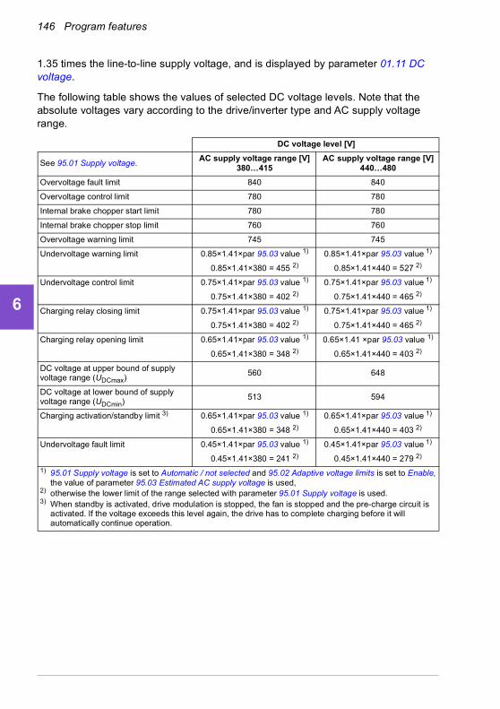
146 Program features
1
2
3
4
5
6
7
8
9
10
11
12
13
14
1.35 times the line-to-line supply voltage, and is displayed by parameter 01.11 DC voltage.
The following table shows the values of selected DC voltage levels. Note that the absolute voltages vary according to the drive/inverter type and AC supply voltage range.
DC voltage level [V]
See 95.01 Supply voltage.AC supply voltage range [V]
380…415AC supply voltage range [V]
440…480
Overvoltage fault limit 840 840
Overvoltage control limit 780 780
Internal brake chopper start limit 780 780
Internal brake chopper stop limit 760 760
Overvoltage warning limit 745 745
Undervoltage warning limit 0.85×1.41×par 95.03 value 1) 0.85×1.41×par 95.03 value 1)
0.85×1.41×380 = 455 2) 0.85×1.41×440 = 527 2)
Undervoltage control limit 0.75×1.41×par 95.03 value 1) 0.75×1.41×par 95.03 value 1)
0.75×1.41×380 = 402 2) 0.75×1.41×440 = 465 2)
Charging relay closing limit 0.75×1.41×par 95.03 value 1) 0.75×1.41×par 95.03 value 1)
0.75×1.41×380 = 402 2) 0.75×1.41×440 = 465 2)
Charging relay opening limit 0.65×1.41×par 95.03 value 1) 0.65×1.41 ×par 95.03 value 1)
0.65×1.41×380 = 348 2) 0.65×1.41×440 = 403 2)
DC voltage at upper bound of supply voltage range (UDCmax)
560 648
DC voltage at lower bound of supply voltage range (UDCmin) 513 594
Charging activation/standby limit 3) 0.65×1.41×par 95.03 value 1) 0.65×1.41×par 95.03 value 1)
0.65×1.41×380 = 348 2) 0.65×1.41×440 = 403 2)
Undervoltage fault limit 0.45×1.41×par 95.03 value 1) 0.45×1.41×par 95.03 value 1)
0.45×1.41×380 = 241 2) 0.45×1.41×440 = 279 2)
1) 95.01 Supply voltage is set to Automatic / not selected and 95.02 Adaptive voltage limits is set to Enable, the value of parameter 95.03 Estimated AC supply voltage is used,
2) otherwise the lower limit of the range selected with parameter 95.01 Supply voltage is used.3) When standby is activated, drive modulation is stopped, the fan is stopped and the pre-charge circuit is
activated. If the voltage exceeds this level again, the drive has to complete charging before it will automatically continue operation.
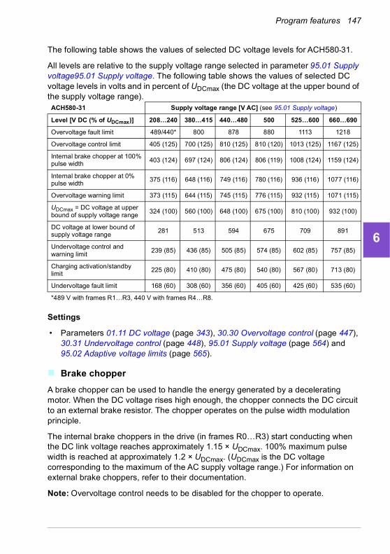
Program features 147
1
2
3
4
5
6
7
8
9
10
11
12
13
The following table shows the values of selected DC voltage levels for ACH580-31.
All levels are relative to the supply voltage range selected in parameter 95.01 Supply voltage95.01 Supply voltage. The following table shows the values of selected DC voltage levels in volts and in percent of UDCmax (the DC voltage at the upper bound of the supply voltage range).
Settings
• Parameters 01.11 DC voltage (page 343), 30.30 Overvoltage control (page 447), 30.31 Undervoltage control (page 448), 95.01 Supply voltage (page 564) and 95.02 Adaptive voltage limits (page 565).
Brake chopper
A brake chopper can be used to handle the energy generated by a decelerating motor. When the DC voltage rises high enough, the chopper connects the DC circuit to an external brake resistor. The chopper operates on the pulse width modulation principle.
The internal brake choppers in the drive (in frames R0…R3) start conducting when the DC link voltage reaches approximately 1.15 × UDCmax. 100% maximum pulse width is reached at approximately 1.2 × UDCmax. (UDCmax is the DC voltage corresponding to the maximum of the AC supply voltage range.) For information on external brake choppers, refer to their documentation.
Note: Overvoltage control needs to be disabled for the chopper to operate.
ACH580-31 Supply voltage range [V AC] (see 95.01 Supply voltage)
Level [V DC (% of UDCmax)] 208…240 380…415 440…480 500 525…600 660…690
Overvoltage fault limit 489/440* 800 878 880 1113 1218
Overvoltage control limit 405 (125) 700 (125) 810 (125) 810 (120) 1013 (125) 1167 (125)
Internal brake chopper at 100% pulse width 403 (124) 697 (124) 806 (124) 806 (119) 1008 (124) 1159 (124)
Internal brake chopper at 0% pulse width
375 (116) 648 (116) 749 (116) 780 (116) 936 (116) 1077 (116)
Overvoltage warning limit 373 (115) 644 (115) 745 (115) 776 (115) 932 (115) 1071 (115)
UDCmax = DC voltage at upper bound of supply voltage range
324 (100) 560 (100) 648 (100) 675 (100) 810 (100) 932 (100)
DC voltage at lower bound of supply voltage range
281 513 594 675 709 891
Undervoltage control and warning limit
239 (85) 436 (85) 505 (85) 574 (85) 602 (85) 757 (85)
Charging activation/standby limit
225 (80) 410 (80) 475 (80) 540 (80) 567 (80) 713 (80)
Undervoltage fault limit 168 (60) 308 (60) 356 (60) 405 (60) 425 (60) 535 (60)
*489 V with frames R1…R3, 440 V with frames R4…R8.
14

148 Program features
1
2
3
4
5
6
7
8
9
10
11
12
13
14
Settings
• Parameter 01.11 DC voltage (page 343); parameter group 43 Brake chopper (page 513).
Program features 149
1
2
3
4
5
6
7
8
9
10
11
12
13
Supervisory
Signal supervision
Six signals can be selected to be supervised by this function. Whenever a supervised signal exceeds or falls below predefined limits, a bit in 32.01 Supervision status is activated, and a warning or fault generated.
The supervised signal is low-pass filtered.
Settings
• Parameter group 32 Supervision (page 462).
Application example 1: Dirty filter
The supervisory function can be used to indicate a dirty filter. Since pressure drop across the air filter increases as the filter becomes dirty, a transducer can be installed that measures the differential pressure across the filter. The transducer output signal is an analog value that is fed back to an analog input on the drive. The supervisory function in the drive is configured to monitor the analog value.
For example, the user wants to be notified when an air handler filter needs to be replaced. Starting with a published value for the drop across a clean filter, a value is established that corresponds to a dirty filter scenario. The drive is then configured to monitor the transducer’s analog output signal. This includes a supervision level to indicate when a threshold for a dirty filter has been exceeded. To use this status, a drive relay output can be used instead of a separate relay to indicate the filter status. This information may also be monitored over fieldbus communications, such as BACnet.
The benefit of using the drive to accomplish this function is to eliminate the need for one analog (transducer) input on the controller, thereby resulting in reduced cost of the building automation controller for the air handler.
Application example 2: High current
The supervisory function can be used to monitor motor current for increasing or excessive loading. This increase in loading may be due to mechanical failure/wear. A single “high current” threshold may be used with the supervisory function. Alternately, parameter group 37 User load curve (page 491) can be used to detect this scenario throughout the entire speed range, as shown under User load curve (page 150).
For example, a fan bearing is beginning to fail due to lack of lubrication. The bearing surfaces are beginning to bind, causing the motor current draw to exceed its normal level. The supervisory function indicates the load is drawing higher current than normal. As a result, service personnel can investigate the problem. The goal is to find the problem before a catastrophic failure occurs.
14

150 Program features
1
2
3
4
5
6
7
8
9
10
11
12
13
14
User load curve
The User load curve provides a supervisory function that monitors an input signal as a function of frequency or speed, and load. It shows the status of the monitored signal and can give a warning or fault based on the violation of a user defined profile.
The user load curve consists of an overload and an underload curve, or just one of them. Each curve is formed by five points that represent the monitored signal as a function of frequency or speed.
In the example below, the user load curve is constructed from the motor nominal torque to which a 10% margin is added and subtracted. The margin curves define a working envelope for the motor so that excursions outside the envelope can be supervised, timed and detected.
An overload warning and/or fault can be set to occur if the monitored signal stays continuously over the overload curve for a defined time. An underload warning and/or fault can be set to occur if the monitored signal stays continuously under the underload for a defined time.
Overload can be, for example, used to monitor for fan load profiles becoming too high.
Underload can be, for example, used to monitor for load dropping and breaking of conveyer belts or fan belts.
Settings
• Parameter group 37 User load curve (page 491).
Motor torque / Nominal torque
1
32
1 = Overload curve (five points)2 = Nominal process load curve3 = Underload curve (five points)
1.2
1.0
0.8
0.6
0.2
0.4
0.0
-0.20 10 20 30 40 50
Output frequency (Hz)

Program features 151
1
2
3
4
5
6
7
8
9
10
11
12
13
Application example: Proof of flow
The user load curve function can be used to indicate proof of flow. Proof of flow is most commonly used for indicating a broken belt on a belt-driven fan. This drive function eliminates the need and cost for an external current-sensing relay and is more reliable. External current-sensing relays depend on the difference in motor current draw between a full-speed, no-load condition (broken belt) and a slow speed with load. This difference is minimal since the motor’s magnetizing current makes up the vast majority of the motor’s current consumption, which is unrelated to load. The drive’s user load curve is adjustable and ideal for variable speed, variable torque, proof-of-flow applications.
For example, during commissioning of the fan, the motor torque is recorded with the belt installed and the fan operating at 50% speed. The drive panel is capable of displaying the motor torque. See parameter 01.10 Motor torque (page 343). Using this value as a reference point, a low torque threshold is determined to indicate a broken belt indication. This technique verifies that not only the drive is running the motor, but that the motor is also loaded by the application. A time delay value is available and configurable to allow for system variables. A relay output can be configured for the user load curve (proof of flow) status.
14

152 Program features
1
2
3
4
5
6
7
8
9
10
11
12
13
14
Process PID control
There are two built-in process PID controllers (PID set 1 and PID set 2) in the drive. The controller can be used to control process variables such as pressure or flow in the pipe or fluid level in the container.
In process PID control, a process reference (setpoint) is connected to the drive instead of a speed reference. An actual value (process feedback) is also brought back to the drive. The process PID control adjusts the drive speed in order to keep the measured process quantity (actual value) at the desired level (setpoint). This means that user does not need to set a frequency/speed/torque reference to the drive but the drive adjust its operation according to the process PID.
The simplified block diagram below illustrates the process PID control. For more detailed block diagrams, see pages 330 and 332.
The drive contains two complete sets of process PID controller settings that can be alternated whenever necessary; see parameter 40.57 PID set1/set2 selection.
Note: Process PID control is only available in external control location EXT2; see section Local control vs. external control (page 89).
Sleep and boost functions for process PID control
The sleep function is suitable for PID control applications where the consumption varies, such as clean water pumping systems. When used, it stops the pump completely during low demand, instead of running the pump slowly below its efficient operating range. The following example visualizes the operation of the function.
Example: The drive controls a pressure boost pump. The water consumption falls at night. As a consequence, the process PID controller decreases the motor speed. However, due to natural losses in the pipes and the low efficiency of the centrifugal pump at low speeds, the motor would never stop rotating. The sleep function detects the slow rotation and stops the unnecessary pumping after the sleep delay has passed. The drive shifts into sleep mode, still monitoring the pressure. The pumping
Process PID
AI1Process actual values
AI2
• • •
FBA
Setpoint
Speed, torque or frequency reference chain
Filter
Limitation
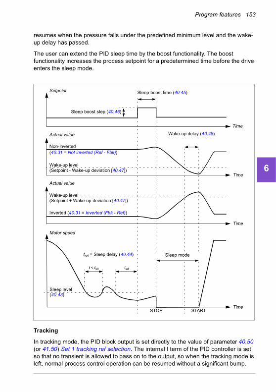
Program features 153
1
2
3
4
5
6
7
8
9
10
11
12
13
resumes when the pressure falls under the predefined minimum level and the wake-up delay has passed.
The user can extend the PID sleep time by the boost functionality. The boost functionality increases the process setpoint for a predetermined time before the drive enters the sleep mode.
Tracking
In tracking mode, the PID block output is set directly to the value of parameter 40.50 (or 41.50) Set 1 tracking ref selection. The internal I term of the PID controller is set so that no transient is allowed to pass on to the output, so when the tracking mode is left, normal process control operation can be resumed without a significant bump.
Wake-up level(Setpoint - Wake-up deviation [40.47])
t < tsd
Motor speed
Actual value
STOP
tsd = Sleep delay (40.44)
Sleep level (40.43)
START
Wake-up delay (40.48)
tsd
Setpoint
Time
Sleep boost step (40.46)
Sleep mode
Sleep boost time (40.45)
Time
Time
Non-inverted(40.31 = Not inverted (Ref - Fbk))
Wake-up level(Setpoint + Wake-up deviation [40.47])
Actual value
Time
Inverted (40.31 = Inverted (Fbk - Ref))
14

154 Program features
1
2
3
4
5
6
7
8
9
10
11
12
13
14
Settings
• Parameter groups 40 Process PID set 1 (page 494) and 41 Process PID set 2 (page 511).

Program features 155
1
2
3
4
5
6
7
8
9
10
11
12
13
Multipump/fan control
Multipump/fan systems consist of several pumps or fans, each connected to a separate drive. This arrangement enables a high flexibility in load sharing, balancing the run time between the pumps or fans and keeping each pump or fan running optimally. If the active pumps or fans cannot meet the demand, the system automatically starts or stops pumps or fans one by one.
The order of the pumps or fans used can be defined to balance the run time better (pumps or fans that have run the least, start first) or can be set by the efficiency class of each pump or fan (for example, pumps or fans with high efficiency are primarily used).
Multipump/fan systems achieve high-level redundancy, if one pump or fan fails or requires maintenance, other pumps or fans can take over the operation. Efficiency, continuous operation and easy maintenance are reasons why multipump/fan systems can be found in a variety of different applications.
Single pump and fan control (PFC)
The Single pump and fan control (PFC) is used in pump or fan systems consisting of one drive and multiple pumps or fans. The drive controls the speed of one of the pumps/fans and in addition connects (and disconnects) the other pumps/fans directly to the supply network through contactors.
The PFC control logic switches auxiliary motors on and off as required by the capacity changes of the process. In a pump application, for example, the drive controls the motor of the first pump, varying the motor speed to control the output of the pump. This pump is the speed regulated pump. When the demand (represented by the process PID reference) exceeds the capacity of the first pump (a user defined speed/frequency limit), the PFC logic automatically starts an auxiliary pump. The logic also reduces the speed of the first pump, controlled by the drive, to account for the addition to the total system output by the auxiliary pump. Then, as before, the PID controller adjusts the speed/frequency of the first pump in such a way that the system output meets the process needs. If the demand continues to increase, the PFC logic adds further auxiliary pumps, in a similar manner as just described.
As the demand drops, making the speed of the first pump fall below a minimum limit (user defined as a speed/frequency limit), the PFC logic automatically stops an auxiliary pump. The PFC logic also increases the speed of the drive controlled pump to account for the missing output of the stopped auxiliary pump.
The Single pump and fan control (PFC) is supported in external control location EXT2 only.
14

156 Program features
1
2
3
4
5
6
7
8
9
10
11
12
13
14
Example: Three-pump constant pressure water supply application
Soft pump and fan control (SPFC)
The Soft pump and fan control (SPFC) logic is a variant of the PFC logic for pump and fan alternation applications where lower pressure peaks are desirable when a new auxiliary motor is to be started. The SPFC logic is an easy way to implement soft starting of direct on line (auxiliary) motors.
The main difference between traditional PFC and SPFC logic is how the SPFC logic connects auxiliary motors on-line. When the criteria for starting a new motor is fulfilled (see above) the SPFC logic connects the drive controlled motor to the supply network in a flying start, that is, while the motor is still coasting. The drive then connects to the
Flow consumption vs. pump status
Consumption Pump 1 Pump 2 Pump 2
Low VSD Off Off
↓ VSD DOL Off
High VSD DOL DOL
↓ VSD DOL Off
Low VSD Off Off
VSD = Controlled by drive, tuning the output speed according to PID control.DOL = Direct On Line. Pump is running at fixed motor nominal speed.Off = Off-line. Pump stops.
Main supply
Aux. motor 2 Aux. motor 3Aux. motor 1VSD motor
Pump 1 is connected to VSD motor (drive controlled motor).Pump 2 is connected to auxiliary motor 1.Pump 3 is connected to auxiliary motor 2.

Program features 157
1
2
3
4
5
6
7
8
9
10
11
12
13
next pump/fan unit to be started and starts controlling the speed of that one, while the previously controlled unit is now connected directly on line through a contactor.
Further (auxiliary) motors are started in a similar manner. The motor stopping routine is the same as for the normal PFC routine.
In some cases SPFC makes it possible to soften the start-up current while connecting auxiliary motors on-line. Lower pressure peaks on the pipelines and pumps may be achieved as a result.
Example: Three-pump constant pressure water supply application
Main supply
Motor 2 Motor 3Motor 1
Pump 1 is connected to Motor 1.Pump 2 is connected to Motor 2.Pump 3 is connected to Motor 3.
14

158 Program features
1
2
3
4
5
6
7
8
9
10
11
12
13
14
Autochange
Automatic rotation of the start order, or Autochange functionality, serves two main purposes in many PFC type setups. One is to keep the run times of the pumps/fans equal over time to even their wear. The other is to prevent any pump/fan from standing still for too long, which would clog up the unit. In some cases it is desirable to rotate the start order only when all units are stopped, for example, to minimize the impact on the process.
The Autochange can also be triggered by the Timed function (see page 126).
There are three modes of autochange according to what kind of PFC and SPFC together with auxiliary circuit are implemented.
Flow consumption and pump status
Consumption Pump 1 Pump 2 Pump 2
Low VSD Off Off
↓ DOL VSD Off
High DOL DOL VSD
↓ DOL Off VSD
Low Off Off VSD
↓ VSD Off DOL
High DOL VSD DOL
↓ DOL VSD Off
Low Off VSD Off
↓ VSD DOL Off
High DOL DOL VSD
VSD = Controlled by drive, tuning the output speed according to PID control.DOL = Direct On Line. Pump is running at fixed motor nominal speed.Off = Off-line. Pump stops.
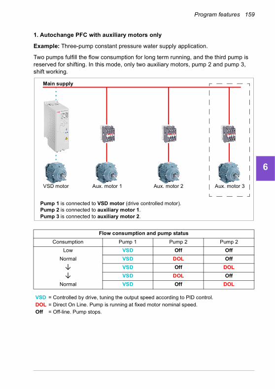
Program features 159
1
2
3
4
5
6
7
8
9
10
11
12
13
1. Autochange PFC with auxiliary motors only
Example: Three-pump constant pressure water supply application.
Two pumps fulfill the flow consumption for long term running, and the third pump is reserved for shifting. In this mode, only two auxiliary motors, pump 2 and pump 3, shift working.
Flow consumption and pump status
Consumption Pump 1 Pump 2 Pump 2
Low VSD Off Off
Normal VSD DOL Off
↓ VSD Off DOL
↓ VSD DOL Off
Normal VSD Off DOL
VSD = Controlled by drive, tuning the output speed according to PID control.DOL = Direct On Line. Pump is running at fixed motor nominal speed.Off = Off-line. Pump stops.
Main supply
Aux. motor 2 Aux. motor 3Aux. motor 1VSD motor
Pump 1 is connected to VSD motor (drive controlled motor).Pump 2 is connected to auxiliary motor 1.Pump 3 is connected to auxiliary motor 2.
14

160 Program features
1
2
3
4
5
6
7
8
9
10
11
12
13
14
2. Autochange PFC with all motors
Example: Three-pump constant pressure water supply application
Two pumps fulfill the flow consumption for long term running, and the third pump is reserved for shifting. Because all motors will be shifted for autochange routine, special auxiliary circuit is needed, which is the same as for the SPFC system.
In this mode, the VSD motor will move to the next pump one by one, but the auxiliary motor will always be put on-line in DOL mode. However, three pumps are shifted overall.
Flow consumption and pump status
Consumption Pump 1 Pump 2 Pump 2
Low VSD Off Off
Normal VSD DOL Off
↓ Off VSD DOL
↓ DOL Off VSD
Normal VSD DOL Off
VSD = Controlled by drive, tuning the output speed according to PID control.DOL = Direct On Line. Pump is running at fixed motor nominal speed.Off = Off-line. Pump stops.
Main supply
Motor 2 Motor 3Motor 1
Pump 1 is connected to Motor 1.Pump 2 is connected to Motor 2.Pump 3 is connected to Motor 3.
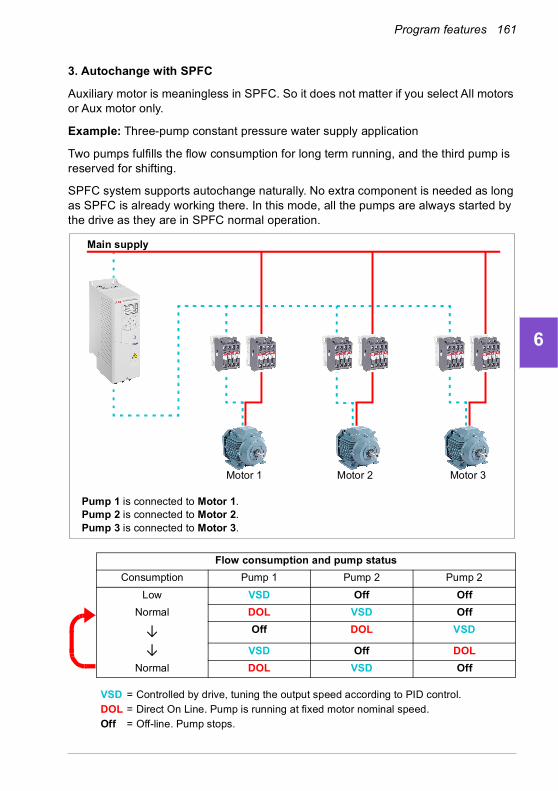
Program features 161
1
2
3
4
5
6
7
8
9
10
11
12
13
3. Autochange with SPFC
Auxiliary motor is meaningless in SPFC. So it does not matter if you select All motors or Aux motor only.
Example: Three-pump constant pressure water supply application
Two pumps fulfills the flow consumption for long term running, and the third pump is reserved for shifting.
SPFC system supports autochange naturally. No extra component is needed as long as SPFC is already working there. In this mode, all the pumps are always started by the drive as they are in SPFC normal operation.
Flow consumption and pump status
Consumption Pump 1 Pump 2 Pump 2
Low VSD Off Off
Normal DOL VSD Off
↓ Off DOL VSD
↓ VSD Off DOL
Normal DOL VSD Off
VSD = Controlled by drive, tuning the output speed according to PID control.DOL = Direct On Line. Pump is running at fixed motor nominal speed.Off = Off-line. Pump stops.
Main supply
Motor 2 Motor 3Motor 1
Pump 1 is connected to Motor 1.Pump 2 is connected to Motor 2.Pump 3 is connected to Motor 3.
14

162 Program features
1
2
3
4
5
6
7
8
9
10
11
12
13
14
Interlock
There is an option to define interlock signals for each motor in the PFC system. When the interlock signal of a motor is Available, the motor participates in the PFC starting sequence. If the signal is Interlocked, the motor is excluded. This feature can be used for informing the PFC logic that a motor is not available (for example, due to maintenance or manual direct-on-line starting).
Settings
• Parameter group 10 Standard DI, RO (page 363)
• Parameter group 40 Process PID set 1 (page 494)
• Parameter groups 76 PFC configuration (page 554) and 77 PFC maintenance and monitoring (page 561).

Program features 163
1
2
3
4
5
6
7
8
9
10
11
12
13
14

164 Program features
1
2
3
4
5
6
7
8
9
10
11
12
13
14
Application example 1: Supply fan, Basic speed follower
There are a variety of different inputs and control schemes that may be applied to a drive being used on a supply fan. The example below consists of one of the more basic configurations. The following pages will build upon this example and provide more advanced examples. The example below consists of:
• Start/stop contact closure from the building automation system (BAS)
• A 0…10 V DC analog speed command signal from the BAS
• No safeties to the drive and no status feedback to the BAS.
Wiring diagram
0…10 V DC speed
X1 Reference voltage and analog inputs and outputs1 SCR Signal cable shield (screen)2 AI1 Output frequency/speed reference: 0…10 V3 AGND Analog input circuit common4 +10V Reference voltage 10 V DC5 AI2 Actual feedback: 0…20 mA6 AGND Analog input circuit common7 AO1 Output frequency: 0…10 V8 AO2 Motor current: 0…20 mA9 AGND Analog output circuit common
X2 & X3 Aux. voltage output and programmable digital inputs10 +24V Aux. voltage output +24 V DC, max. 250 mA11 DGND Aux. voltage output common12 DCOM Digital input common for all13 DI1 Stop (0) / Start (1) 14 DI2 Not configured15 DI3 Constant frequency/speed selection16 DI4 Not configured17 DI5 Not configured18 DI6 Not configured
X6, X7, X8 Relay outputs19 RO1C Damper control
250 V AC / 30 V DC2 A
20 RO1A21 RO1B22 RO2C Running
250 V AC / 30 V DC 2 A
23 RO2A24 RO2B25 RO3C Fault (-1)
250 V AC / 30 V DC2 A
26 RO3A27 RO3B
Start/stop signal
reference signal
+-
Running22 connected to 24
Fault condition25 connected to 26
Energize damper19 connected to 21

Program features 165
1
2
3
4
5
6
7
8
9
10
11
12
13
Quick steps – Programming summary
Settings listed below are changed relative to the drive’s factory defaults to meet the application requirements:
Menu > Primary settings > Start, stop, reference > Interlocks/permissives
• Unselect Use start interlock 1
14
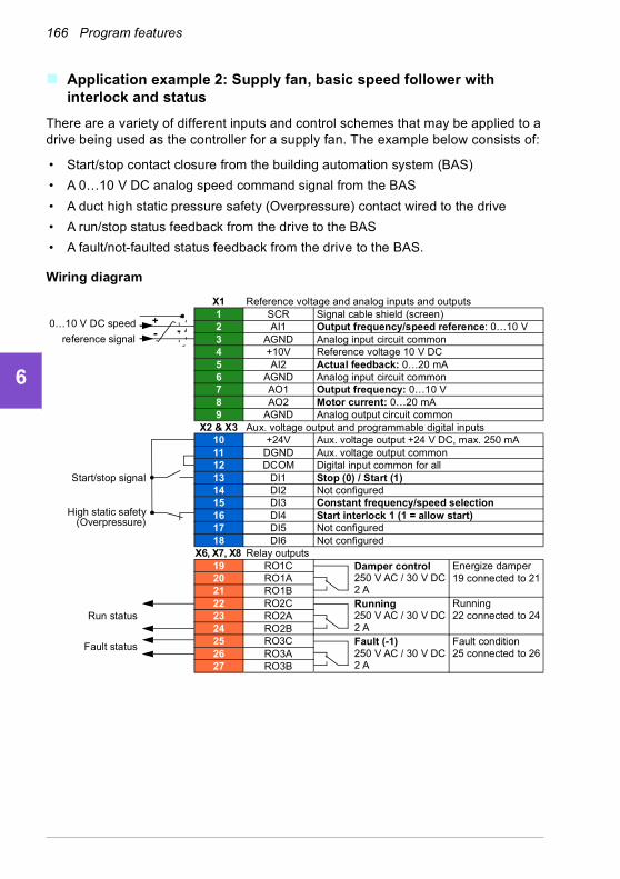
166 Program features
1
2
3
4
5
6
7
8
9
10
11
12
13
14
Application example 2: Supply fan, basic speed follower with interlock and status
There are a variety of different inputs and control schemes that may be applied to a drive being used as the controller for a supply fan. The example below consists of:
• Start/stop contact closure from the building automation system (BAS)
• A 0…10 V DC analog speed command signal from the BAS
• A duct high static pressure safety (Overpressure) contact wired to the drive
• A run/stop status feedback from the drive to the BAS
• A fault/not-faulted status feedback from the drive to the BAS.
Wiring diagram
Run status
Fault status
0…10 V DC speed
X1 Reference voltage and analog inputs and outputs1 SCR Signal cable shield (screen)2 AI1 Output frequency/speed reference: 0…10 V3 AGND Analog input circuit common4 +10V Reference voltage 10 V DC5 AI2 Actual feedback: 0…20 mA6 AGND Analog input circuit common7 AO1 Output frequency: 0…10 V8 AO2 Motor current: 0…20 mA9 AGND Analog output circuit common
X2 & X3 Aux. voltage output and programmable digital inputs10 +24V Aux. voltage output +24 V DC, max. 250 mA11 DGND Aux. voltage output common12 DCOM Digital input common for all13 DI1 Stop (0) / Start (1) 14 DI2 Not configured15 DI3 Constant frequency/speed selection16 DI4 Start interlock 1 (1 = allow start)17 DI5 Not configured18 DI6 Not configured
X6, X7, X8 Relay outputs19 RO1C Damper control
250 V AC / 30 V DC2 A
20 RO1A21 RO1B22 RO2C Running
250 V AC / 30 V DC 2 A
23 RO2A24 RO2B25 RO3C Fault (-1)
250 V AC / 30 V DC2 A
26 RO3A27 RO3B
Start/stop signal
reference signal
+-
High static safety(Overpressure)
Running22 connected to 24
Fault condition25 connected to 26
Energize damper19 connected to 21

Program features 167
1
2
3
4
5
6
7
8
9
10
11
12
13
Quick steps – Programming summary
Settings listed below are changed relative to the drive’s factory defaults to meet the application requirements:
Menu > Primary settings > Start, stop, reference > Interlocks/permissives
• ☑ Use start interlock 1
• Edit Description text: Overpressure
14

168 Program features
1
2
3
4
5
6
7
8
9
10
11
12
13
14
Application example 3: Supply fan, speed follower complete integration
There are a variety of different inputs and control schemes that may be applied to a drive being used as the controller for a supply fan. The example below consists of:
• Start/stop contact closure from the building automation system (BAS)
• A 0…10 V DC analog speed command signal from the BAS
• A damper end-switch contact closure to the drive, to indicate the damper open/closed status
• A duct high static pressure safety (Overpressure) contact wired to the drive
• A supply air Smoke alarm safety contact wired to the drive
• A run/stop status feedback from the drive to the BAS
• A fault/not-faulted status feedback from the drive to the BAS
• A relay output to the external, actuator control circuit to open an isolation damper
• A 0…10 V DC analog output signal from the drive, to indicate drive output frequency, to the BAS.
Wiring diagram
output frequency -0…10 V DC +
X1 Reference voltage and analog inputs and outputs1 SCR Signal cable shield (screen)2 AI1 Output frequency/speed reference: 0…10 V3 AGND Analog input circuit common4 +10V Reference voltage 10 V DC5 AI2 Actual feedback: 0…20 mA6 AGND Analog input circuit common7 AO1 Output frequency: 0…10 V8 AO2 Motor current: 0…20 mA9 AGND Analog output circuit common
X2 & X3 Aux. voltage output and programmable digital inputs10 +24V Aux. voltage output +24 V DC, max. 250 mA11 DGND Aux. voltage output common12 DCOM Digital input common for all13 DI1 Stop (0) / Start (1) 14 DI2 Run permissive (1 = allow start)15 DI3 Constant frequency/speed selection16 DI4 Start interlock 1 (1 = allow start)17 DI5 Start interlock 2 (1 = allow start)18 DI6 Not configured
X6, X7, X8 Relay outputs19 RO1C Damper control
250 V AC / 30 V DC2 A
20 RO1A21 RO1B22 RO2C Running
250 V AC / 30 V DC 2 A
23 RO2A24 RO2B25 RO3C Fault (-1)
250 V AC / 30 V DC2 A
26 RO3A27 RO3B
Start/stop signal
Damper end switch
High static safety(Overpressure)
Smoke alarmsafety
Run status
Fault status
reference signal0…10 V DC speed +
-
Damper actuator
Running22 connected to 24
Fault condition25 connected to 26
Energize damper19 connected to 21

Program features 169
1
2
3
4
5
6
7
8
9
10
11
12
13
Quick steps – Programming summary
Settings listed below are changed relative to the drive’s factory defaults to meet the application requirements:
Primary settings > Start, stop, reference > Interlocks/permissives
• Select ☑ Use run permissive signal
• Edit Run enabled when: DI2 high
• Edit Description text: Damper end switch
• ☑ Use start interlock 1
• Edit Description text: Overpressure
• Select ☑ Use start interlock 2.
• Edit Start enabled when: DI5 high
• Edit Description text: Smoke alarm
14
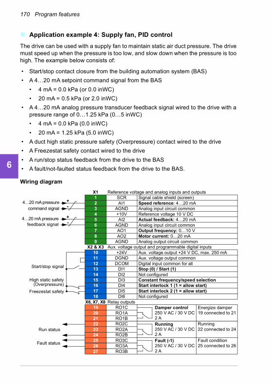
170 Program features
1
2
3
4
5
6
7
8
9
10
11
12
13
14
Application example 4: Supply fan, PID control
The drive can be used with a supply fan to maintain static air duct pressure. The drive must speed up when the pressure is too low, and slow down when the pressure is too high. The example below consists of:
• Start/stop contact closure from the building automation system (BAS)
• A 4…20 mA setpoint command signal from the BAS
• 4 mA = 0.0 kPa (or 0.0 inWC)
• 20 mA = 0.5 kPa (or 2.0 inWC)
• A 4…20 mA analog pressure transducer feedback signal wired to the drive with a pressure range of 0…1.25 kPa (0…5 inWC)
• 4 mA = 0.0 kPa (0.0 inWC)
• 20 mA = 1.25 kPa (5.0 inWC)
• A duct high static pressure safety (Overpressure) contact wired to the drive
• A Freezestat safety contact wired to the drive
• A run/stop status feedback from the drive to the BAS
• A fault/not-faulted status feedback from the drive to the BAS.
Wiring diagram
Run status
Fault status
feedback signal -4…20 mA pressure +
X1 Reference voltage and analog inputs and outputs1 SCR Signal cable shield (screen)2 AI1 Speed reference: 4…20 mA3 AGND Analog input circuit common4 +10V Reference voltage 10 V DC5 AI2 Actual feedback: 4…20 mA6 AGND Analog input circuit common7 AO1 Output frequency: 0…10 V8 AO2 Motor current: 0…20 mA9 AGND Analog output circuit common
X2 & X3 Aux. voltage output and programmable digital inputs10 +24V Aux. voltage output +24 V DC, max. 250 mA11 DGND Aux. voltage output common12 DCOM Digital input common for all13 DI1 Stop (0) / Start (1) 14 DI2 Not configured15 DI3 Constant frequency/speed selection16 DI4 Start interlock 1 (1 = allow start)17 DI5 Start interlock 2 (1 = allow start)18 DI6 Not configured
X6, X7, X8 Relay outputs19 RO1C Damper control
250 V AC / 30 V DC2 A
20 RO1A21 RO1B22 RO2C Running
250 V AC / 30 V DC 2 A
23 RO2A24 RO2B25 RO3C Fault (-1)
250 V AC / 30 V DC2 A
26 RO3A27 RO3B
Start/stop signal
High static safety(Overpressure)
Freezestat safety
command signal4…20 mA pressure +
-
Running22 connected to 24
Fault condition25 connected to 26
Energize damper19 connected to 21

Program features 171
1
2
3
4
5
6
7
8
9
10
11
12
13
Quick steps – Programming summary
Settings listed below are changed relative to the drive’s factory defaults to meet the application requirements:
Menu > Primary settings > Start, stop, reference > Interlocks/permissives
• ☑ Use start interlock 1
• Edit Description text: Overpressure
• Select ☑ Use start interlock 2
• Edit Description text: Freezestat
Menu > Primary settings > PID control
• Select ☑ Use PID control
• Edit Start/stop/dir from: DI1 start/stop
• Edit ☑ Unit: kPa (or inWC)
Menu > Primary settings > PID control > Feedback
• Edit Source: AI2 Scaled
Menu > Primary settings > PID control > Feedback > AI2 Scaling
• Edit Range: 4…20 mA
• Edit Scaled min: 0 kPa (or 0 inWC)
• Edit Scaled max: 1.25 kPa (or 5.0 inWC)
Menu > Primary settings > PID control > Setpoint
• Edit Source: AI1 scaled
Menu > Primary settings > PID control > Setpoint > AI1 Scaling
• Edit Range: 4…20 mA
• Edit Scaled min: 0.0 kPa (or 0.0 inWC)
• Edit Scaled max: 0.5 kPa (or 2.0 inWC)
Menu > Primary settings > PID control
• Tuning (adjust the gain and integration time of the PID, as needed for the application)
14
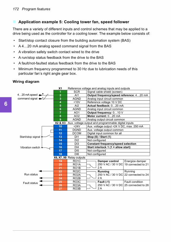
172 Program features
1
2
3
4
5
6
7
8
9
10
11
12
13
14
Application example 5: Cooling tower fan, speed follower
There are a variety of different inputs and control schemes that may be applied to a drive being used as the controller for a cooling tower. The example below consists of:
• Start/stop contact closure from the building automation system (BAS)
• A 4…20 mA analog speed command signal from the BAS
• A vibration safety switch contact wired to the drive
• A run/stop status feedback from the drive to the BAS
• A fault/not-faulted status feedback from the drive to the BAS
• Minimum frequency programmed to 30 Hz due to lubrication needs of this particular fan’s right angle gear box.
Wiring diagram
X1 Reference voltage and analog inputs and outputs1 SCR Signal cable shield (screen)2 AI1 Output frequency/speed reference: 4…20 mA3 AGND Analog input circuit common4 +10V Reference voltage 10 V DC5 AI2 Actual feedback: 0…20 mA6 AGND Analog input circuit common7 AO1 Output frequency: 0…10 V8 AO2 Motor current: 0…20 mA9 AGND Analog output circuit common
X2 & X3 Aux. voltage output and programmable digital inputs10 +24V Aux. voltage output +24 V DC, max. 250 mA11 DGND Aux. voltage output common12 DCOM Digital input common for all13 DI1 Stop (0) / Start (1) 14 DI2 Not configured15 DI3 Constant frequency/speed selection16 DI4 Start interlock 1 (1 = allow start)17 DI5 Not configured18 DI6 Not configured
X6, X7, X8 Relay outputs19 RO1C Damper control
250 V AC / 30 V DC2 A
20 RO1A21 RO1B22 RO2C Running
250 V AC / 30 V DC 2 A
23 RO2A24 RO2B25 RO3C Fault (-1)
250 V AC / 30 V DC2 A
26 RO3A27 RO3B
Start/stop signal
Vibration switch
Run status
Fault status
command signal4…20 mA speed +
-
Running22 connected to 24
Fault condition25 connected to 26
Energize damper19 connected to 21

Program features 173
1
2
3
4
5
6
7
8
9
10
11
12
13
Quick steps – Programming summary
Settings listed below are changed relative to the drive’s factory defaults to meet the application requirements:
Menu > Primary settings > Start, stop, reference > Primary auto control location > AI1 scaling
• Edit Range: 4…20 mA
Primary settings > Start, stop, reference > Interlocks/permissives
• ☑ Use start interlock 1
• Edit Description text: Vibration switch
Primary setting > Limits
• Edit Minimum frequency: 30.00 Hz
14

174 Program features
1
2
3
4
5
6
7
8
9
10
11
12
13
14
Application example 6: Cooling tower, PID
There are a variety of different inputs and control schemes that may be applied to a drive being used as the controller for a Cooling tower. The example below consists of:
• Start/stop contact closure from the building automation system (BAS)
• Water temperature setpoint fixed at 24 °C (75 °F). The drive speeds up the fan when the temperature is too warm, and slows it down when the temperature is too cool
• A 4…20 mA analog water temperature transducer feedback signal wired directly to the drive with a temperature range of -30…50 °C (-22…122 °F)
• 4 mA = -30 °C (-22 °F)
• 20 mA = 50 °C (122 °F)
• A vibration safety switch contact wired to the drive
• A run/stop status feedback from the drive to the BAS
• A fault/not-faulted status feedback from the drive to the BAS
• Minimum frequency programmed to 20 Hz due to lubrication needs of this particular fan’s right angle gear box
• The drive stops the fan and enters sleep mode when the motor speed drops below 25 Hz for more than 30 seconds
• The drive wakes up from sleep mode when the water temperature increases above 26 °C (79 °F), which is also a deviation of 2 °C (4 °F) above the setpoint of 24 °C (75 °F)

Program features 175
1
2
3
4
5
6
7
8
9
10
11
12
13
Wiring diagram
Run status
Fault status
X1 Reference voltage and analog inputs and outputs1 SCR Signal cable shield (screen)2 AI1 Output frequency/speed reference: 0…10 V3 AGND Analog input circuit common4 +10V Reference voltage 10 V DC5 AI2 Actual feedback: 4…20 mA6 AGND Analog input circuit common7 AO1 Output frequency: 0…10 V8 AO2 Motor current: 0…20 mA9 AGND Analog output circuit common
X2 & X3 Aux. voltage output and programmable digital inputs10 +24V Aux. voltage output +24 V DC, max. 250 mA11 DGND Aux. voltage output common12 DCOM Digital input common for all13 DI1 Stop (0) / Start (1) 14 DI2 Not configured15 DI3 Constant frequency/speed selection16 DI4 Start interlock 1 (1 = allow start)17 DI5 Not configured18 DI6 Not configured
X6, X7, X8 Relay outputs19 RO1C Damper control
250 V AC / 30 V DC2 A
20 RO1A21 RO1B22 RO2C Running
250 V AC / 30 V DC 2 A
23 RO2A24 RO2B25 RO3C Fault (-1)
250 V AC / 30 V DC2 A
26 RO3A27 RO3B
feedback signal4…20 mA temp. +
-
Start/stop signal
Vibration switch
Running22 connected to 24
Fault condition25 connected to 26
Energize damper19 connected to 21
14

176 Program features
1
2
3
4
5
6
7
8
9
10
11
12
13
14
Quick steps – Programming summary
Settings listed below are changed relative to the drive’s factory defaults to meet the application requirements:
Menu > Primary settings > Start, stop, reference > Interlocks/permissives
• ☑ Use Start interlock 1
• Edit Description text: Vibration switch
Menu > Primary settings > Limits
• Edit Minimum frequency: 20 Hz
Menu > Primary settings > PID control
• Select ☑ Use PID control
• Edit Start/stop/dir from: DI1 start/stop
• Edit Unit: °C (or °F)
Menu > Primary Settings > PID control > Feedback
• Edit Source: AI2 Scaled
Menu > Primary Settings > PID control > Feedback > AI2 Scaling
• Edit Range: 4…20 mA
• Edit Scaled min: -30.0°C (or -22°F)
• Edit Scaled max: 50.0°C (or 122°F)
Menu > Primary Settings > PID control > Setpoint
• Edit Source: Constant setpoint
• Edit Constant setpoint 1: 24.0°C (or 75.0°F)
Menu > Primary Settings > PID control >
• Tuning (adjust the gain and integration time of the PID, as needed for the application)
• Edit Increase output: Feedback > setpoint
Menu > Primary Settings > PID control > Sleep function
• Select ☑ Use sleep function
• Edit Activation level: 25 Hz
• Edit Delay: 30.0 s
• Edit Wake-up deviation: 2 °C (or 4 °F)

Program features 177
1
2
3
4
5
6
7
8
9
10
11
12
13
14

178 Program features
1
2
3
4
5
6
7
8
9
10
11
12
13
14
Application example 7: Chilled water pump
There are a variety of different inputs and control schemes that may be applied to the drive being used on a chilled water pump. The example below consists of:
• Start/stop contact closure from the building automation system (BAS)
• A 0…10 V DC analog speed command signal from the BAS
• A run/stop status feedback from the drive to the BAS
• A fault/not-faulted status feedback from the drive to the BAS
• A 4…20 mA analog output signal from the drive, to indicate drive output current, to the BAS
• When a stop command is received, the drive shall ramp the motor to a stop to prevent water hammer.
Wiring diagram
Run status
Fault status
output current -4…20 mA +
X1 Reference voltage and analog inputs and outputs1 SCR Signal cable shield (screen)2 AI1 Output frequency/speed reference: 0…10 V3 AGND Analog input circuit common4 +10V Reference voltage 10 V DC5 AI2 Actual feedback: 0…20 mA6 AGND Analog input circuit common7 AO1 Output frequency: 0…10 V8 AO2 Motor current: 4…20 mA9 AGND Analog output circuit common
X2 & X3 Aux. voltage output and programmable digital inputs10 +24V Aux. voltage output +24 V DC, max. 250 mA11 DGND Aux. voltage output common12 DCOM Digital input common for all13 DI1 Stop (0) / Start (1) 14 DI2 Not configured15 DI3 Constant frequency/speed selection16 DI4 Not configured17 DI5 Not configured18 DI6 Not configured
X6, X7, X8 Relay outputs19 RO1C Damper control
250 V AC / 30 V DC2 A
20 RO1A21 RO1B22 RO2C Running
250 V AC / 30 V DC 2 A
23 RO2A24 RO2B25 RO3C Fault (-1)
250 V AC / 30 V DC2 A
26 RO3A27 RO3B
Start/stop signal
reference signal0…10 V DC speed +
-
Running22 connected to 24
Fault condition25 connected to 26
Energize damper19 connected to 21

Program features 179
1
2
3
4
5
6
7
8
9
10
11
12
13
Quick steps – Programming summary
Settings listed below are changed relative to the drive’s factory defaults to meet the application requirements:
Menu > I/O > AO2
• Edit Range: 4…20 mA
Menu > Primary settings > Ramps
• Edit Stop mode: Ramp
Menu > Primary settings > Start, stop, reference > Interlocks/permissives
• Unselect Use start interlock 1
14

180 Program features
1
2
3
4
5
6
7
8
9
10
11
12
13
14
Application example 8: Condenser water pump
There are a variety of different inputs and control schemes that may be applied to a drive being used on a condenser water pump. The example below consists of:
• Start/stop contact closure from the building automation system (BAS)
• A 4…20 mA analog speed command signal from the BAS
• A run/stop status feedback from the drive to the BAS
• A fault/not-faulted status feedback from the drive to the BAS
• When a stop command is received, the drive ramps the motor to a stop to prevent water hammer
• Minimum frequency set to 20 Hz.
Wiring diagram
Run status
Fault status
X1 Reference voltage and analog inputs and outputs1 SCR Signal cable shield (screen)2 AI1 Output frequency/speed reference: 4…20 mA 3 AGND Analog input circuit common4 +10V Reference voltage 10 V DC5 AI2 Actual feedback: 0…20 mA6 AGND Analog input circuit common7 AO1 Output frequency: 0…10 V8 AO2 Motor current: 4…20 mA9 AGND Analog output circuit common
X2 & X3 Aux. voltage output and programmable digital inputs10 +24V Aux. voltage output +24 V DC, max. 250 mA11 DGND Aux. voltage output common12 DCOM Digital input common for all13 DI1 Stop (0) / Start (1) 14 DI2 Not configured15 DI3 Constant frequency/speed selection16 DI4 Not configured17 DI5 Not configured18 DI6 Not configured
X6, X7, X8 Relay outputs19 RO1C Damper control
250 V AC / 30 V DC2 A
20 RO1A21 RO1B22 RO2C Running
250 V AC / 30 V DC 2 A
23 RO2A24 RO2B25 RO3C Fault (-1)
250 V AC / 30 V DC2 A
26 RO3A27 RO3B
reference signal4…20 mA speed +
-
Start/stop signal
Running22 connected to 24
Fault condition25 connected to 26
Energize damper19 connected to 21
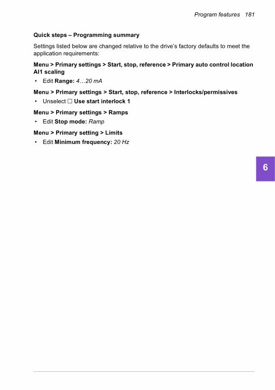
Program features 181
1
2
3
4
5
6
7
8
9
10
11
12
13
Quick steps – Programming summary
Settings listed below are changed relative to the drive’s factory defaults to meet the application requirements:
Menu > Primary settings > Start, stop, reference > Primary auto control location AI1 scaling
• Edit Range: 4…20 mA
Menu > Primary settings > Start, stop, reference > Interlocks/permissives
• Unselect Use start interlock 1
Menu > Primary settings > Ramps
• Edit Stop mode: Ramp
Menu > Primary setting > Limits
• Edit Minimum frequency: 20 Hz
14
182 Program features
1
2
3
4
5
6
7
8
9
10
11
12
13
14
Energy efficiency
Energy optimization
The function optimizes the motor flux so that total energy consumption and motor noise level are reduced when the drive operates below the nominal load. The total efficiency (motor and drive) can be improved by 1…20% depending on load torque and speed. Energy optimization is enabled by default.
Note: With permanent magnet and synchronous reluctance motors, energy optimization is always enabled.
Settings
• Menu > Energy efficiency
• Parameter 45.11 Energy optimizer (page 517).
Energy saving calculators
This feature consists of the following functionalities:
• An energy optimizer that adjusts the motor flux in such a way that the total system efficiency is maximized
• A counter that monitors used and saved energy by the motor and displays them in kWh, currency or volume of CO2 emissions, and
• A load analyzer showing the load profile of the drive (see separate section on page 183).
In addition, there are counters that show energy consumption in kWh of the current and previous hour as well as the current and previous day.
The amount of energy that has passed through the drive (in either direction) is counted and shown as full GWh, MWh and kWh. The cumulative energy is also shown as full kWh. All these counters are resettable.
Note: The accuracy of the energy savings calculation is directly dependent on the accuracy of the reference motor power given in parameter 45.19 Comparison power.
Settings
• Menu > Energy efficiency
• Parameter group 45 Energy efficiency (page 515)
• Parameters 01.50 Current hour kWh, 01.51 Previous hour kWh, 01.52 Current day kWh and 01.53 Previous day kWh on page 344.
• Parameters 01.55 Inverter GWh counter (resettable), 01.56 Inverter MWh counter (resettable), 01.57 Inverter kWh counter (resettable) and 01.58 Cumulative inverter energy (resettable).

Program features 183
1
2
3
4
5
6
7
8
9
10
11
12
13
Load analyzer
Peak value logger
The user can select a signal to be monitored by a peak value logger. The logger records the peak value of the signal along with the time the peak occurred, as well as motor current, DC voltage and motor speed at the time of the peak. The peak value is sampled at 2 ms intervals.
Amplitude loggers
The control program has two amplitude loggers.
For amplitude logger 2, the user can select a signal to be sampled at 200 ms intervals, and specify a value that corresponds to 100%. The collected samples are sorted into 10 read-only parameters according to their amplitude. Each parameter represents an amplitude range 10 age points wide, and displays the age of the collected samples that have fallen within that range.
You can view this graphically with the assistant panel or the Drive composer PC tool.
Amplitude logger 1 is fixed to monitor motor current, and cannot be reset. With amplitude logger 1, 100% corresponds to the maximum output current of the drive (Imax), which is listed in the Hardware manual of the drive. The measured current is logged continuously. The distribution of samples is shown by parameters 36.20…36.29.
Age
of s
amp
les
0…10
%
10…
20%
20…
30%
30…
40%
40…
50%
50…
60%
60…
70%
70…
80%
80…
90%
>90
%
Amplitude ranges (parameters 36.40…36.49)
14

184 Program features
1
2
3
4
5
6
7
8
9
10
11
12
13
14
Settings
• Menu > Diagnostics > Load profile
• Parameter group 36 Load analyzer (page 488).

Program features 185
1
2
3
4
5
6
7
8
9
10
11
12
13
Managing settings
User parameter sets
The drive supports four user parameter sets that can be saved to the permanent memory and recalled using drive parameters. It is also possible to use digital inputs to switch between user parameter sets.
A user parameter set contains all editable values in parameter groups 10…99 except
• forced I/O values such as parameters 10.03 DI force selection and 10.04 DI forced data
• I/O extension module settings (group 15)• data storage parameters (group 47)• fieldbus communication enable parameter (50.01 FBA A enable)
• other fieldbus communication settings (groups 51…53 and 58)
• some hardware settings in group 95 HW configuration (for example parameter 95.01 Supply voltage,
• user set selection parameters 96.11…96.13.
As the motor settings are included in the user parameter sets, make sure the settings correspond to the motor used in the application before recalling a user set. In an application where different motors are used with the drive, the motor ID run needs to be performed with each motor and the results saved to different user sets. The appropriate set can then be recalled when the motor is switched.
If no parameter sets have been saved, attempting to load a set will create all sets from the currently active parameter settings.
Switching between sets is only possible with the drive stopped.
Settings
• Menu > Primary settings > Advanced functions > User sets
• Parameters 96.10…96.13 (page 571).
14
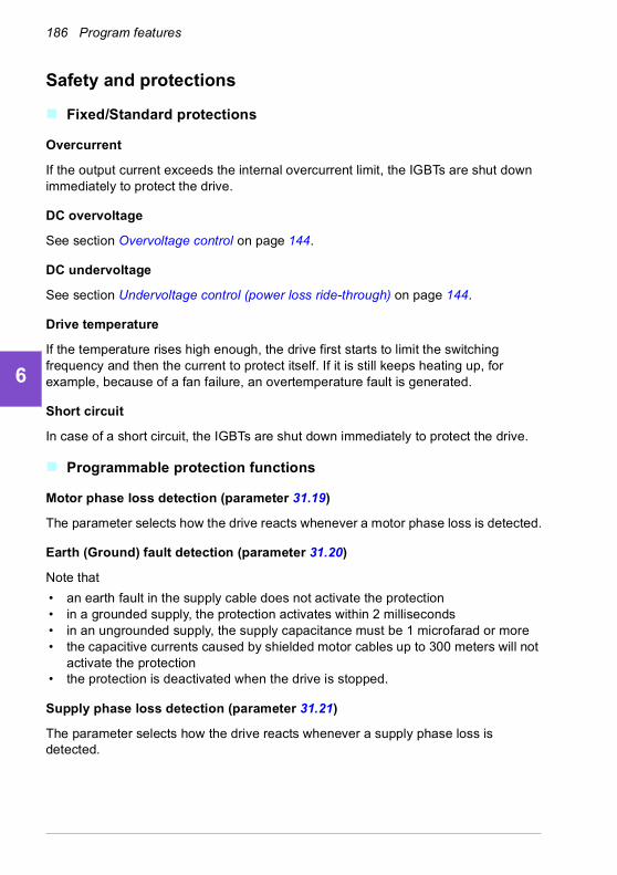
186 Program features
1
2
3
4
5
6
7
8
9
10
11
12
13
14
Safety and protections
Fixed/Standard protections
Overcurrent
If the output current exceeds the internal overcurrent limit, the IGBTs are shut down immediately to protect the drive.
DC overvoltage
See section Overvoltage control on page 144.
DC undervoltage
See section Undervoltage control (power loss ride-through) on page 144.
Drive temperature
If the temperature rises high enough, the drive first starts to limit the switching frequency and then the current to protect itself. If it is still keeps heating up, for example, because of a fan failure, an overtemperature fault is generated.
Short circuit
In case of a short circuit, the IGBTs are shut down immediately to protect the drive.
Programmable protection functions
Motor phase loss detection (parameter 31.19)
The parameter selects how the drive reacts whenever a motor phase loss is detected.
Earth (Ground) fault detection (parameter 31.20)
Note that
• an earth fault in the supply cable does not activate the protection• in a grounded supply, the protection activates within 2 milliseconds• in an ungrounded supply, the supply capacitance must be 1 microfarad or more• the capacitive currents caused by shielded motor cables up to 300 meters will not
activate the protection• the protection is deactivated when the drive is stopped.
Supply phase loss detection (parameter 31.21)
The parameter selects how the drive reacts whenever a supply phase loss is detected.

Program features 187
1
2
3
4
5
6
7
8
9
10
11
12
13
Safe torque off detection (parameter 31.22)
The drive monitors the status of the Safe torque off input, and this parameter selects which indications are given when the signals are lost. (The parameter does not affect the operation of the Safe torque off function itself.) For more information on the Safe torque off function, see chapter Planning the electrical installation, section Implementing the Safe torque off function in the Hardware manual of the drive.
Swapped supply and motor cabling (parameter 31.23)
The drive can detect if the supply and motor cables have accidentally been swapped (for example, if the supply is connected to the motor connection of the drive). The parameter selects if a fault is generated or not.
Stall protection (parameters 31.24…31.28)
The drive protects the motor in a stall situation. It is possible to adjust the supervision limits (current, frequency and time) and choose how the drive reacts to a motor stall condition.
Overspeed protection (parameter 31.30…31.31)
The user can set overspeed and overfrequency limits by specifying a margin that is added to the currently-used maximum and minimum speed or frequency limits.
Local control loss detection (parameter 49.05)
The parameter selects how the drive reacts to a control panel or PC tool communication break.
AI supervision (parameters 12.03…12.04)
The parameters select how the drive reacts when an analog input signal moves out of the minimum and/or maximum limits specified for the input. This can be due to broken I/O wiring or sensor.
Emergency stop
The emergency stop signal is connected to the input selected by parameter 21.05 Emergency stop source. An emergency stop can also be generated through fieldbus (parameter 06.01 Main control word, bits 0…2).
The mode of the emergency stop is selected by parameter 21.04 Emergency stop mode. The following modes are available:
• Off1: Stop along the standard deceleration ramp defined for the particular reference type in use
• Off2: Stop by coasting• Off3: Stop by the emergency stop ramp defined by parameter 23.23 Emergency
stop time.
• Stop torque.
14

188 Program features
1
2
3
4
5
6
7
8
9
10
11
12
13
14
With Off1 or Off3 emergency stop modes, the ramp-down of the motor speed can be supervised by parameters 31.32 Emergency ramp supervision and 31.33 Emergency ramp supervision delay.
Notes:
• The installer of the equipment is responsible for installing the emergency stop devices and all additional devices needed for the emergency stop function to fulfill the required emergency stop categories. For more information, contact your local ABB representative.
• After an emergency stop signal is detected, the emergency stop function cannot be canceled even though the signal is canceled.
• If the minimum (or maximum) torque limit is set to 0%, the emergency stop function may not be able to stop the drive.
Settings
• Parameters 21.04 Emergency stop mode (page 407), 21.05 Emergency stop source (page 407), 23.23 Emergency stop time (page 424), 31.32 Emergency ramp supervision (page 460) and 31.33 Emergency ramp supervision delay (page 461).
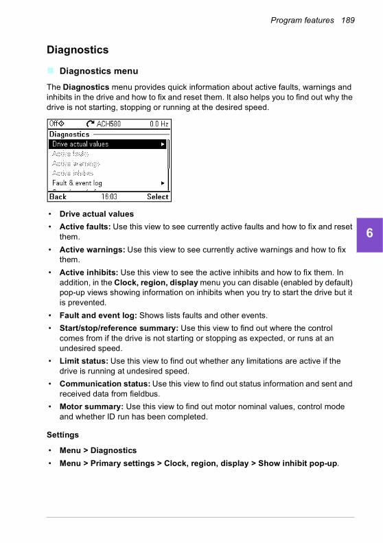
Program features 189
1
2
3
4
5
6
7
8
9
10
11
12
13
Diagnostics
Diagnostics menu
The Diagnostics menu provides quick information about active faults, warnings and inhibits in the drive and how to fix and reset them. It also helps you to find out why the drive is not starting, stopping or running at the desired speed.
• Drive actual values
• Active faults: Use this view to see currently active faults and how to fix and reset them.
• Active warnings: Use this view to see currently active warnings and how to fix them.
• Active inhibits: Use this view to see the active inhibits and how to fix them. In addition, in the Clock, region, display menu you can disable (enabled by default) pop-up views showing information on inhibits when you try to start the drive but it is prevented.
• Fault and event log: Shows lists faults and other events.
• Start/stop/reference summary: Use this view to find out where the control comes from if the drive is not starting or stopping as expected, or runs at an undesired speed.
• Limit status: Use this view to find out whether any limitations are active if the drive is running at undesired speed.
• Communication status: Use this view to find out status information and sent and received data from fieldbus.
• Motor summary: Use this view to find out motor nominal values, control mode and whether ID run has been completed.
Settings
• Menu > Diagnostics
• Menu > Primary settings > Clock, region, display > Show inhibit pop-up.
14

190 Program features
1
2
3
4
5
6
7
8
9
10
11
12
13
14
Miscellaneous
Backup and restore
You can make backups of the settings manually to the assistant panel. The assistant panel also keeps one automatic backup. You can restore a backup to another drive, or a new drive replacing a faulty one. You can make backups and restore on the panel or with the Drive composer PC tool.
Backup
Manual backup
Make a backup when necessary, for example, after you have started up the drive or when you want to copy the settings to another drive.
Parameter changes from fieldbus interfaces are ignored unless you have forced parameter saving with parameter 96.07 Parameter save manually.
Automatic backup
The assistant panel has a dedicated space for one automatic backup. An automatic backup is created two hours after the last parameter change. After completing the backup, the panel waits for 24 hours before checking if there are additional parameter changes. If there are, it creates a new backup overwriting the previous one when two hours have passed after the latest change.
You cannot adjust the delay time or disable the automatic backup function.
Parameter changes from fieldbus interfaces are ignored unless you have forced parameter saving with parameter 96.07 Parameter save manually.
Restore
The backups are shown on the panel. Automatic backups are marked with icon and manual backups with . To restore a backup, select it and press . In the following display you can view backup contents and restore all parameters or select a subset to be restored.
Note: To restore a backup, the drive has to be in Local control.

Program features 191
1
2
3
4
5
6
7
8
9
10
11
12
13
Note: There is a risk of removing the QR code menu entry permanently if a backup from a drive with an old firmware or old panel firmware is restored to a drive with a new firmware from October 2014 or later.
Settings
• Menu > Backups
• Parameter 96.07 Parameter save manually (page 570).
Data storage parameters
Twelve (eight 32-bit, four 16-bit) parameters are reserved for data storage. These parameters are unconnected by default and can be used for linking, testing and commissioning purposes. They can be written to and read from using other parameters’ source or target selections.
Settings
• Parameter group 47 Data storage (page 523).
Parameter checksum calculation
Two parameter checksums, A and B, can be calculated from a set of parameters to monitor changes in the drive configuration. The sets are different for checksums A and B. Each of these checksum is compared to the corresponding reference checksum; in case of a mismatch, an event (a pure event, warning or fault) is generated. The calculated checksum can be set as the new reference checksum.
The set of parameters for checksum A does not include fieldbus settings.
The parameters included in the checksum A calculation are user editable parameters in parameter groups 10…13, 15, 19…25, 28, 30…32, 34…37, 40…41, 43, 45…46, 70…74, 76, 80, 94…99.
The set of parameters for checksum B does not include
• fieldbus settings
• motor data settings
• energy data settings.
14

192 Program features
1
2
3
4
5
6
7
8
9
10
11
12
13
14
The parameters included in the checksum B calculation are user editable parameters in parameter groups 10…13, 15, 19…25, 28, 30…32, 34, 35…37, 40…41, 43, 46, 70…74, 76, 80, 94…97.
Settings
• Parameters 96.54…96.69, 96.71…96.72 (page 573).

Program features 193
1
2
3
4
5
6
7
8
9
10
11
12
13
User lock
For improved cybersecurity, it is highly recommended that you set a master pass code to prevent, for example, the changing of parameter values and/or the loading of firmware and other files.
WARNING! ABB will not be liable for damages or losses caused by the failure to activate the user lock using a new pass code. See Cybersecurity disclaimer
(page 22).
• To activate the user lock for the first time:
• Enter the default pass code, 10000000, into 96.02 Pass code. This will make parameters 96.100…96.102 visible.
• Enter a new pass code into 96.100 Change user pass code. Always use eight digits; if using Drive composer PC tool, finish with Enter.
• Confirm the new pass code in 96.100 Change user pass code.
WARNING! Store the pass code in a safe place – the user lock cannot be opened even by ABB if the pass code is lost.
• In 96.102 User lock functionality, define the actions that you want to prevent (we recommend you select all the actions unless otherwise required by the application).
• Enter an invalid pass code into 96.02 Pass code.
• Activate 96.08 Control board boot, or cycle the power to the drive.
• Check that parameters 96.100…96.102 are hidden. If they are not, enter another random pass code into 96.02.
To reopen the lock, enter your pass code into 96.02 Pass code. This will again make parameters 96.100…96.102 visible.
Settings
• Parameters 96.02 (page 569) and 96.100…96.102 (page 575).
Sine filter support
The control program has a setting that enables the use of ABB sine filters (available separately). With a sine filter connected to the output of the drive, bit 1 of 95.15 Special HW settings must be switched on. The setting forces the drive to use the scalar motor control mode, and limits the switching and output frequencies to
• prevent the drive from operating at filter resonance frequencies, and
• protect the filter from overheating.
14

194 Program features
1
2
3
4
5
6
7
8
9
10
11
12
13
14
Contact your local ABB representative before connecting a sine filter from another manufacturer.
Settings
• Parameter 95.15 Special HW settings (page 564).

Fault tracing 195
1
2
3
4
5
6
7
8
9
10
11
12
13
7Fault tracing
What this chapter contains
The chapter lists the warning and fault messages including possible causes and corrective actions. The causes of most warnings and faults can be identified and corrected using the information in this chapter. If not, contact an ABB service representative. If you have a possibility to use the Drive composer PC tool, send the Support package created by the Drive composer to the ABB service representative.
Warnings and faults are listed below in separate tables. Each table is sorted by warning/fault code.
Safety
WARNING! Only qualified electricians are allowed to service the drive. Read the instructions in chapter Safety instructions at the beginning of the Hardware
manual of the drive before working on the drive.
Indications
Warnings and faults
Warnings and faults indicate an abnormal drive status. The codes and names of active warnings and faults are displayed on the control panel of the drive as well as in the Drive composer PC tool. Only the codes of warnings and faults are available over fieldbus.
Warnings do not need to be reset; they stop showing when the cause of the warning ceases. Warnings do not trip the drive and it will continue to operate the motor.
14

196 Fault tracing
1
2
3
4
5
6
7
8
9
10
11
12
13
14
Faults latch inside the drive and cause the drive to trip, and the motor stops. After the cause of a fault has been removed, the fault can be reset from the panel or from a selectable source (parameter 31.11 Fault reset selection) such as the digital inputs of the drive. Reseting the fault creates an event 64FF Fault reset. After the reset, the drive can be restarted.
Note that some faults require a reboot of the control unit either by switching the power off and on, or using parameter 96.08 Control board boot – this is mentioned in the fault listing wherever appropriate.
Pure events
In addition to warnings and faults, there are pure events that are only recorded in the event log of the drive. The codes of these events are included in the Warning messages table on page 198.
Editable messages
For external events, the action (fault or warning), name and the message text can be edited. To specify external events, select Menu > Primary settings > Advanced functions > External events.
Contact information can also be included and the text edited. To specify contact information, select Menu > Primary settings > Clock, region, display > Contact info view.
Warning/fault history
Event log
All indications are stored in the event log with a time stamp and other information. The event log stores information on
• the last 8 fault recordings, that is, faults that tripped the drive or fault resets
• the last 10 warnings or pure events that occurred.
See section Viewing warning/fault information on page 197.
To clear the fault and event logger, select Menu > Primary settings > Reset to defaults > Reset fault and event logs, or set parameter 96.51 Clear fault and event logger to value Clear.
Auxiliary codes
Some events generate an auxiliary code that often helps in pinpointing the problem. On the control panel, the auxiliary code is stored as part of the details of the event; in the Drive composer PC tool, the auxiliary code is shown in the event listing.

Fault tracing 197
1
2
3
4
5
6
7
8
9
10
11
12
13
Viewing warning/fault information
The drive is able to store a list of the active faults actually causing the drive to trip at the present time. The drive also stores a list of faults and warnings that have previously occurred.
For each stored fault, the panel shows the fault code, time and values of nine parameters (actual signals and status words) stored at the time of the fault. The values of the parameters for the latest fault are in parameters 05.80…05.89.
For active faults and warnings, see
• Menu > Diagnostics > Active faults
• Menu > Diagnostics > Active warnings
• parameters in group 04 Warnings and faults (page 348).
For previously occurred faults and warnings, see
• Menu > Diagnostics > Fault & event log
• parameters in group 04 Warnings and faults (page 348).
The event log can also be accessed (and reset) using the Drive composer PC tool. See Drive composer PC tool user’s manual (3AUA0000094606 [English]).
QR code generation for mobile service application
A QR code (or a series of QR codes) can be generated by the drive for display on the control panel. The QR code contains drive identification data, information on the latest events, and values of status and counter parameters. The code can be read with a mobile device containing the ABB service application, which then sends the data to ABB for analysis. For more information on the application, contact your local ABB service representative.
To generate the QR code, select Menu > System info > QR code.
Note: If a control panel which does not support QR code generation (version older than v.6.4x) is used, the QR code menu entry will disappear totally and will not be available any longer either with control panels supporting the QR code generation.
Note: There is a risk of removing the QR code menu permanently if a backup from a drive with an old firmware or old panel firmware is restored to a drive with a new firmware from October 2014 or later.
14

198 Fault tracing
1
2
3
4
5
6
7
8
9
10
11
12
13
14
Warning messages
Note: The list also contains events that only appear in the Event log.
Code (hex) Warning / Aux. code Cause What to do
64FF Fault reset A fault has been reset from the panel, Drive composer PC tool, fieldbus or I/O.
Event. Informative only.
A2B1 Overcurrent Output current has exceeded internal fault limit.In addition to an actual overcurrent situation, this warning may also be caused by an earth fault or supply phase loss.
Check motor load.Check acceleration times in parameter group 23 Speed reference ramp (speed control) or 28 Frequency reference chain (frequency control). Also check parameters 46.01 Speed scaling, 46.02 Frequency scaling and 46.03 Torque scaling.Check motor and motor cable (including phasing and delta/star connection).Check for an earth fault in motor or motor cables by measuring the insulation resistances of motor and motor cable. See chapter Electrical installation, section Checking the insulation of the assembly in the Hardware manual of the drive.Check there are no contactors opening and closing in motor cable.Check that the start-up data in parameter group 99 Motor data corresponds to the motor rating plate.Check that there are no power factor correction capacitors or surge absorbers in motor cable.
A2B3 Earth leakage Drive has detected load unbalance typically due to earth fault in motor or motor cable.
Check there are no power factor correction capacitors or surge absorbers in motor cable.Check for an earth fault in motor or motor cables by measuring the insulation resistances of motor and motor cable. See chapter Electrical installation, section Checking the insulation of the assembly in the Hardware manual of the drive. If an earth fault is found, fix or change the motor cable and/or motor. If no earth fault can be detected, contact your local ABB representative.

Fault tracing 199
1
2
3
4
5
6
7
8
9
10
11
12
13
A2B4 Short circuit Short-circuit in motor cable(s) or motor.
Check motor and motor cable for cabling errors.Check motor and motor cable (including phasing and delta/star connection).Check for an earth fault in motor or motor cables by measuring the insulation resistances of motor and motor cable. See chapter Electrical installation, section Checking the insulation of the assembly in the Hardware manual of the drive.Check there are no power factor correction capacitors or surge absorbers in motor cable.
A2BA IGBT overload Excessive IGBT junction to case temperature. This warning protects the IGBT(s) and can be activated by a short circuit in the motor cable.
Check motor cable.Check ambient conditions.Check air flow and fan operation.Check heatsink fins for dust pick-up.Check motor power against drive power.
A3A1 DC link overvoltage Intermediate circuit DC voltage too high (when the drive is stopped).
Check the supply voltage setting (parameter 95.01 Supply voltage). Note that the wrong setting of the parameter may cause the motor to rush uncontrollably, or may overload the brake chopper or resistor.Check the supply voltage.If the problem persists, contact your local ABB representative.
A3A2 DC link undervoltage Intermediate circuit DC voltage too low (when the drive is stopped).
A3AA DC not charged The voltage of the intermediate DC circuit has not yet risen to operating level.
A490 Incorrect temperature sensor setup
Temperature cannot be supervised due to incorrect adapter setup.
Check the settings of temperature source parameters 35.11 and 35.21.
A491 External temperature 1(Editable message text)
Measured temperature 1 has exceeded warning limit.
Check the value of parameter 35.02 Measured temperature 1.Check the cooling of the motor (or other equipment whose temperature is being measured).Check the value of 35.13 Temperature 1 warning limit.
A492 External temperature 2(Editable message text)
Measured temperature 2 has exceeded warning limit.
Check the value of parameter 35.03 Measured temperature 2.Check the cooling of the motor (or other equipment whose temperature is being measured).Check the value of 35.23 Temperature 2 warning limit.
A4A0 Control board temperature
Control board temperature is too high.
Check the auxiliary code. See actions for each code below.
(none) Temperature above warning limit
Check ambient conditions.Check air flow and fan operation.Check heatsink fins for dust pick-up.
1 Thermistor broken Contact an ABB service representative for control board replacement.
Code (hex)
Warning / Aux. code Cause What to do
14
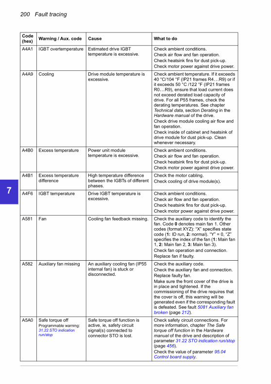
200 Fault tracing
1
2
3
4
5
6
7
8
9
10
11
12
13
14
A4A1 IGBT overtemperature Estimated drive IGBT temperature is excessive.
Check ambient conditions.Check air flow and fan operation.Check heatsink fins for dust pick-up.Check motor power against drive power.
A4A9 Cooling Drive module temperature is excessive.
Check ambient temperature. If it exceeds 40 °C/104 °F (IP21 frames R4…R9) or if it exceeds 50 °C /122 °F (IP21 frames R0…R9), ensure that load current does not exceed derated load capacity of drive. For all P55 frames, check the derating temperatures. See chapter Technical data, section Derating in the Hardware manual of the drive.Check drive module cooling air flow and fan operation.Check inside of cabinet and heatsink of drive module for dust pick-up. Clean whenever necessary.
A4B0 Excess temperature Power unit module temperature is excessive.
Check ambient conditions.Check air flow and fan operation.Check heatsink fins for dust pick-up.Check motor power against drive power.
A4B1 Excess temperature difference
High temperature difference between the IGBTs of different phases.
Check the motor cabling.Check cooling of drive module(s).
A4F6 IGBT temperature Drive IGBT temperature is excessive.
Check ambient conditions.Check air flow and fan operation.Check heatsink fins for dust pick-up.Check motor power against drive power.
A581 Fan Cooling fan feedback missing. Check the auxiliary code to identify the fan. Code 0 denotes main fan 1. Other codes (format XYZ): “X” specifies state code (1: ID run, 2: normal). “Y” = 0, “Z” specifies the index of the fan (1: Main fan 1, 2: Main fan 2, 3: Main fan 3).Check fan operation and connection.Replace fan if faulty.
A582 Auxiliary fan missing An auxiliary cooling fan (IP55 internal fan) is stuck or disconnected.
Check the auxiliary code.Check the auxiliary fan and connection.Replace faulty fan.Make sure the front cover of the drive is in place and tightened. If the commissioning of the drive requires that the cover is off, this warning will be generated even if the corresponding fault is defeated. See fault 5081 Auxiliary fan broken (page 212).
A5A0 Safe torque offProgrammable warning: 31.22 STO indication run/stop
Safe torque off function is active, ie, safety circuit signal(s) connected to connector STO is lost.
Check safety circuit connections. For more information, chapter The Safe torque off function in the Hardware manual of the drive and description of parameter 31.22 STO indication run/stop (page 456).Check the value of parameter 95.04 Control board supply.
Code (hex)
Warning / Aux. code Cause What to do

Fault tracing 201
1
2
3
4
5
6
7
8
9
10
11
12
13
A5EA Measurement circuit temperature
Problem with internal temperature measurement of the drive.
Contact your local ABB representative.
A5EB PU board powerfail Power unit power supply failure.
Contact your local ABB representative.
A5ED Measurement circuit ADC
Measurement circuit fault. Contact your local ABB representative.
A5EE Measurement circuit DFF
Measurement circuit fault. Contact your local ABB representative.
A5EF PU state feedback State feedback from output phases does not match control signals.
Contact your local ABB representative.
A5F0 Charging feedback Charging feedback signal missing.
Check the feedback signal coming from the charging system.
A682 Flash erase speed exceeded
The flash memory (in the memory unit) has been erased too frequently, compromising the lifetime of the memory.
Avoid forcing unnecessary parameter saves by parameter 96.07 or cyclic parameter writes (such as user logger triggering through parameters).Check the auxiliary code (format XYYY YZZZ). “X” specifies the source of warning (1: generic flash erase supervision). “ZZZ” specifies the flash subsector number that generated the warning.
A686 Checksum mismatchProgrammable warning: 96.54 Checksum action
The calculated parameter checksum does not match any enabled reference checksum.
Check that all necessary approved (reference) checksums (96.71…96.72) are enabled in 96.55 Checksum control word.Check the parameter configuration. Using 96.55 Checksum control word, enable a checksum parameter and copy the actual checksum into that parameter.
A687 Checksum configuration
An action has been defined for a parameter checksum mismatch but the feature has not been configured.
Contact your local ABB representative for configuring the feature, or disable the feature in 96.54 Checksum action.
A6A4 Motor nominal value The motor parameters are set incorrectly.
Check the auxiliary code. See actions for each code below.
The drive is not dimensioned correctly.
Code (hex)
Warning / Aux. code Cause What to do
14

202 Fault tracing
1
2
3
4
5
6
7
8
9
10
11
12
13
14
0001 Slip frequency is too small. Check the settings of the motor configuration parameters in groups 98 and 99.Check that the drive is sized correctly for the motor.
0002 Synchronous and nominal speeds differ too much.
0003 Nominal speed is higher than synchronous speed with 1 pole pair.
0004 Nominal current is outside limits
0005 Nominal voltage is outside limits.
0006 Nominal power is higher than apparent power.
0007 Nominal power not consistent with nominal speed and torque.
A6A5 No motor data Parameters in group 99 have not been set.
Check that all the required parameters in group 99 have been set.Note: It is normal for this warning to appear during the start-up and continue until the motor data is entered.
A6A6 Voltage category unselected
The voltage category has not been defined.
Set voltage category in parameter 95.01 Supply voltage.
A6A7 System time not set System time is not set. Timed functions cannot be used and fault log dates are not correct.
Set the system time manually or connect the panel to the drive to synchronize the clock. If basic panel is used, synchronize the clock through the EFB or a fieldbus module.Set parameter 34.10 Timed functions enable to Disabled to disable the timed functions if they are not used.
A6B0 User lock is open The user lock is open, ie, user lock configuration parameters 96.100…96.102 are visible.
Close the user lock by entering an invalid pass code in parameter 96.02 Pass code. See section Parameter checksum calculation (page 191).
A6B1 User pass code not confirmed
A new user pass code has been entered in parameter 96.100 but not confirmed in 96.101.
Confirm the new pass code by entering the same code in 96.101. To cancel, close the user lock without confirming the new code. See section Parameter checksum calculation (page 191).
A6D1 FBA A parameter conflict
The drive does not have a functionality requested by a PLC, or requested functionality has not been activated.
Check PLC programming.Check settings of parameter groups 50 Fieldbus adapter (FBA).
Code (hex)
Warning / Aux. code Cause What to do

Fault tracing 203
1
2
3
4
5
6
7
8
9
10
11
12
13
A6E5 AI parametrization The current/voltage hardware setting of an analog input does not correspond to parameter settings.
Check the event log for an auxiliary code. The code identifies the analog input whose settings are in conflict.Adjust either the hardware setting (on the drive control unit) or parameter 12.15/12.25.Note: Control board reboot (either by cycling the power or through parameter 96.08 Control board boot) is required to validate any changes in the hardware settings.
A6E6 ULC configuration User load curve configuration error.
Check the auxiliary code (format XXXX ZZZZ). “ZZZZ” indicates the problem (see actions for each code below).
0000 Speed points inconsistent. Check that each speed point (parameters 37.11…37.15) has a higher value than the previous point.
0001 Frequency points inconsistent. Check that each frequency point (37.20…37.16) has a higher value than the previous point.
0002 Underload point above overload point.
Check that each overload point (37.31…37.35) has a higher value than the corresponding underload point (37.21…37.25).0003 Overload point below
underload point.
A780 Motor stallProgrammable warning: 31.24 Stall function
Motor is operating in stall region because of, for example, excessive load or insufficient motor power.
Check motor load and drive ratings.Check fault function parameters.
A783 Motor overload Motor current is too high. Check for overloaded motor.Adjust the parameters used for the motor overload function (35.51…35.53) and 35.55…35.56.
A792 Brake resistor wiring Brake resistor short circuit or brake chopper control fault. For drive frames R6 or larger.
Check brake chopper and brake resistor connection.Ensure brake resistor is not damaged.
A793 BR excess temperature
Brake resistor temperature has exceeded warning limit defined by parameter 43.12 Brake resistor warning limit.
Stop drive. Let resistor cool down. Check resistor overload protection function settings (parameter group 43 Brake chopper.Check warning limit setting, parameter 43.12 Brake resistor warning limit.Check that the resistor has been dimensioned correctly.Check that braking cycle meets allowed limits.
A794 BR data Brake resistor data has not been given.
One or more of the resistor data settings (parameters 43.08…43.10) is incorrect. The parameter is specified by the auxiliary code.
0000 0001 Resistance value too low. Check value of 43.10.
0000 0002 Thermal time constant not given.
Check value of 43.08.
Code (hex)
Warning / Aux. code Cause What to do
14

204 Fault tracing
1
2
3
4
5
6
7
8
9
10
11
12
13
14
0000 0003 Maximum continuous power not given.
Check value of 43.09.
A79C BC IGBT excess temperature
Brake chopper IGBT temperature has exceeded internal warning limit.
Let chopper cool down.Check for excessive ambient temperature.Check for cooling fan failure.Check for obstructions in the air flow.Check the dimensioning and cooling of the cabinet.Check resistor overload protection function settings (parameters 43.06…43.10).Check minimum allowed resistor value for the chopper being used.Check that braking cycle meets allowed limits.Check that drive supply AC voltage is not excessive.
A7AB Extension I/O configuration failure
Installed CMOD module is not the same as configured.
Check that the installed module (shown by parameter 15.02 Detected extension module) is the same as selected by parameter 15.01 Extension module type.
A7C1 FBA A communicationProgrammable warning: 50.02 FBA A comm loss func
Cyclical communication between drive and fieldbus adapter module A or between PLC and fieldbus adapter module A is lost.
Check status of fieldbus communication. See user documentation of fieldbus interface.Check settings of parameter groups 50 Fieldbus adapter (FBA), 51 FBA A settings, 52 FBA A data in and 53 FBA A data out.Check cable connections.Check if communication master is able to communicate.
A7CE EFB comm lossProgrammable warning: 58.14 Communication loss action
Communication break in embedded fieldbus (EFB) communication.
Check the status of the fieldbus master (online/offline/error etc.).Check cable connections to the EIA-485/X5 terminals 29, 30 and 31 on the control unit.
A7EE Panel lossProgrammable warning:49.05 Communication loss action
Control panel or PC tool selected as active control location for drive has ceased communicating.
Check PC tool or control panel connection.Check control panel connector.Check mounting platform if being used.Disconnect and reconnect the control panel.
A88F Cooling fan Maintenance timer limit exceeded.
Consider changing the cooling fan. Parameter 05.04 Fan on-time counter shows the running time of the cooling fan.
A8A0 AI supervisionProgrammable warning:12.03 AI supervision function
An analog signal is outside the limits specified for the analog input.
Check signal level at the analog input.Check the wiring connected to the input.Check the minimum and maximum limits of the input in parameter group 12 Standard AI.
Code (hex)
Warning / Aux. code Cause What to do
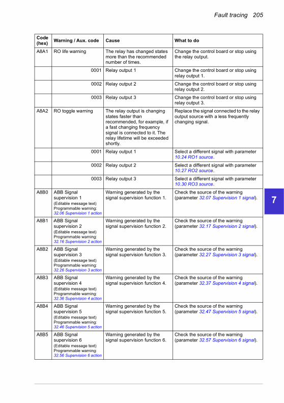
Fault tracing 205
1
2
3
4
5
6
7
8
9
10
11
12
13
A8A1 RO life warning The relay has changed states more than the recommended number of times.
Change the control board or stop using the relay output.
0001 Relay output 1 Change the control board or stop using relay output 1.
0002 Relay output 2 Change the control board or stop using relay output 2.
0003 Relay output 3 Change the control board or stop using relay output 3.
A8A2 RO toggle warning The relay output is changing states faster than recommended, for example, if a fast changing frequency signal is connected to it. The relay lifetime will be exceeded shortly.
Replace the signal connected to the relay output source with a less frequently changing signal.
0001 Relay output 1 Select a different signal with parameter 10.24 RO1 source.
0002 Relay output 2 Select a different signal with parameter 10.27 RO2 source.
0003 Relay output 3 Select a different signal with parameter 10.30 RO3 source.
A8B0 ABB Signal supervision 1(Editable message text)Programmable warning:32.06 Supervision 1 action
Warning generated by the signal supervision function 1.
Check the source of the warning (parameter 32.07 Supervision 1 signal).
A8B1 ABB Signal supervision 2(Editable message text)Programmable warning:32.16 Supervision 2 action
Warning generated by the signal supervision function 2.
Check the source of the warning (parameter 32.17 Supervision 2 signal).
A8B2 ABB Signal supervision 3(Editable message text)Programmable warning:32.26 Supervision 3 action
Warning generated by the signal supervision function 3.
Check the source of the warning (parameter 32.27 Supervision 3 signal).
A8B3 ABB Signal supervision 4(Editable message text)Programmable warning:32.36 Supervision 4 action
Warning generated by the signal supervision function 4.
Check the source of the warning (parameter 32.37 Supervision 4 signal).
A8B4 ABB Signal supervision 5(Editable message text)Programmable warning:32.46 Supervision 5 action
Warning generated by the signal supervision function 5.
Check the source of the warning (parameter 32.47 Supervision 5 signal).
A8B5 ABB Signal supervision 6(Editable message text)Programmable warning:32.56 Supervision 6 action
Warning generated by the signal supervision function 6.
Check the source of the warning (parameter 32.57 Supervision 6 signal).
Code (hex)
Warning / Aux. code Cause What to do
14

206 Fault tracing
1
2
3
4
5
6
7
8
9
10
11
12
13
14
A8BE ULC overload warningProgrammable fault:37.03 ULC overload actions
Selected signal has exceeded the user overload curve.
Check for any operating conditions increasing the monitored signal (for example, the loading of the motor if the torque or current is being monitored).Check the definition of the load curve (parameter group 37 User load curve).
A8BF ULC underload warningProgrammable fault:37.04 ULC underload actions
Selected signal has fallen below the user underload curve.
Check for any operating conditions decreasing the monitored signal (for example, loss of load if the torque or current is being monitored).Check the definition of the load curve (parameter group 37 User load curve).
A981 External warning 1(Editable message text)Programmable warning:31.01 External event 1 source31.02 External event 1 type
Fault in external device 1. Check the external device.Check setting of parameter 31.01 External event 1 source.
A982 External warning 2(Editable message text)Programmable warning:31.03 External event 2 source31.04 External event 2 type
Fault in external device 2. Check the external device.Check setting of parameter 31.03 External event 2 source.
A983 External warning 3(Editable message text)Programmable warning:31.05 External event 3 source31.06 External event 3 type
Fault in external device 3. Check the external device.Check setting of parameter 31.05 External event 3 source.
A984 External warning 4(Editable message text)Programmable warning:31.07 External event 4 source31.08 External event 4 type
Fault in external device 4. Check the external device.Check setting of parameter 31.07 External event 4 source.
A985 External warning 5(Editable message text)Programmable warning:31.09 External event 5 source31.10 External event 5 type
Fault in external device 5. Check the external device.Check setting of parameter 31.09 External event 5 source.
AF80 INU-LSU comm lossProgrammable warning: 60.79 INU-LSU comm loss function
DDCS (fiber optic) communication between converters (for example, the inverter unit and the supply unit) is lost.Note that the inverter unit will continue operating based on the status information that was last received from the other converter.
Only for ACH580-31.Check status of other converter (parameters 06.36 and 06.39).Check settings of parameter group 60 DDCS communication.Check the corresponding settings in the control program of the other converter.Check cable connections. If necessary, replace cables.
Code (hex)
Warning / Aux. code Cause What to do

Fault tracing 207
1
2
3
4
5
6
7
8
9
10
11
12
13
AF85 Line side unit warning The supply unit (or other converter) has generated a warning.
Only for ACH580-31.The auxiliary code specifies the original warning code in the supply unit control program. See chapter Fault tracing in ACS880 IGBT supply control program firmware manual (3AUA0000131562[English]).
AF88 Season configuration warning
You have configured a season which starts before the previous season.
Configure the seasons with increasing start dates, see parameters 34.60 Season 1 start date…34.63 Season 4 start date.
AF8C Process PID sleep mode
The drive is entering sleep mode.
Informative warning. See section Sleep and boost functions for process PID control (page 152), and parameters 40.43…40.48.
AFAA Autoreset A fault is about to be autoreset. Informative warning. See the settings in parameter group 31 Fault functions.
AFE1 Emergency stop (off2) Drive has received an emergency stop (mode selection off2) command.
Check that it is safe to continue operation. Then return emergency stop push button to normal position. Restart drive.If the emergency stop was unintentional, check the source selected by parameter 21.05 Emergency stop source.
AFE2 Emergency stop (off1 or off3)
Drive has received an emergency stop (mode selection off1 or off3) command.
AFE9 Start delay The start delay is active and the drive will start the motor after a predefined delay.
Informative warning. See parameter 21.22 Start delay.
AFED Run permissive Run permissive is keeping the drive from running the motor.
Check the setting of (and source selected by) parameter 20.40 Run permissive.
AFEE Start interlock 1 Start interlock 1 is keeping the drive from starting.
Check the signal source selected for parameter 20.41 Start interlock 1.
AFEF Start interlock 2 Start interlock 2 is keeping the drive from starting.
Check the signal source selected for parameter 20.42 Start interlock 2.
AFF0 Start interlock 3 Start interlock 3 is keeping the drive from starting.
Check the signal source selected for parameter 20.43 Start interlock 3.
AFF1 Start interlock 4 Start interlock 4 is keeping the drive from starting.
Check the signal source selected for parameter 20.44 Start interlock 4.
AFF2 Run permissive forced warning
A forced DI is used as a source for parameter 20.40 Run permissive.
If 20.40 Run permissive uses DIx as the source, check if the bit corresponding to DIx in parameter 10.03 DI force selection is 1.
AFF3 Start interlock forced warning
One or more forced DIs is used as a source for one or more of parameters 20.41 Start interlock 1 … 20.44 Start interlock 4.
Check all parameters 20.41 Start interlock 1 … 20.44 Start interlock 4. If any of these parameters uses DIx as the source, check if the bit corresponding to DIx in parameter 10.03 DI force selection is 1.
AFF5 Override new start required
The Safe torque off function was active and has been reset while in Override.
A new start signal is required to start the drive again.
AFF6 Identification run Motor ID run will occur at next start.
Informative warning.
Code (hex)
Warning / Aux. code Cause What to do
14
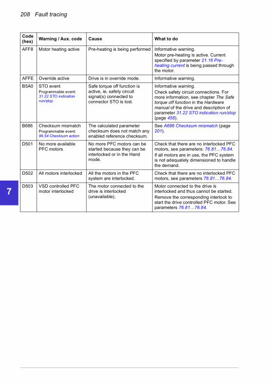
208 Fault tracing
1
2
3
4
5
6
7
8
9
10
11
12
13
14
AFF8 Motor heating active Pre-heating is being performed Informative warning.Motor pre-heating is active. Current specified by parameter 21.16 Pre-heating current is being passed through the motor.
AFFE Override active Drive is in override mode. Informative warning.
B5A0 STO eventProgrammable event: 31.22 STO indication run/stop
Safe torque off function is active, ie, safety circuit signal(s) connected to connector STO is lost.
Informative warning.Check safety circuit connections. For more information, see chapter The Safe torque off function in the Hardware manual of the drive and description of parameter 31.22 STO indication run/stop (page 456).
B686 Checksum mismatchProgrammable event: 96.54 Checksum action
The calculated parameter checksum does not match any enabled reference checksum.
See A686 Checksum mismatch (page 201).
D501 No more available PFC motors
No more PFC motors can be started because they can be interlocked or in the Hand mode.
Check that there are no interlocked PFC motors, see parameters: 76.81…76.84.If all motors are in use, the PFC system is not adequately dimensioned to handle the demand.
D502 All motors interlocked All the motors in the PFC system are interlocked.
Check that there are no interlocked PFC motors, see parameters 76.81…76.84.
D503 VSD controlled PFC motor interlocked
The motor connected to the drive is interlocked (unavailable).
Motor connected to the drive is interlocked and thus cannot be started.Remove the corresponding interlock to start the drive controlled PFC motor. See parameters 76.81…76.84.
Code (hex)
Warning / Aux. code Cause What to do
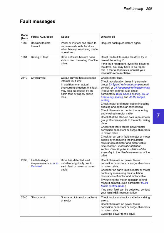
Fault tracing 209
1
2
3
4
5
6
7
8
9
10
11
12
13
Fault messages
Code(hex) Fault / Aux. code Cause What to do
1080 Backup/Restore timeout
Panel or PC tool has failed to communicate with the drive when backup was being made or restored.
Request backup or restore again.
1081 Rating ID fault Drive software has not been able to read the rating ID of the drive.
Reset the fault to make the drive try to reread the rating ID. If the fault reappears, cycle the power to the drive. You may have to be repeat this. If the fault persists, contact your local ABB representative.
2310 Overcurrent Output current has exceeded internal fault limit.In addition to an actual overcurrent situation, this fault may also be caused by an earth fault or supply phase loss.
Check motor load.Check acceleration times in parameter group 23 Speed reference ramp (speed control) or 28 Frequency reference chain (frequency control). Also check parameters 46.01 Speed scaling, 46.02 Frequency scaling and 46.03 Torque scaling.Check motor and motor cable (including phasing and delta/star connection).Check there are no contactors opening and closing in motor cable.Check that the start-up data in parameter group 99 corresponds to the motor rating plate.Check that there are no power factor correction capacitors or surge absorbers in motor cable.Check for an earth fault in motor or motor cables by measuring the insulation resistances of motor and motor cable. See chapter Electrical installation, section Checking the insulation of the assembly in the Hardware manual of the drive.
2330 Earth leakageProgrammable fault: 31.20 Earth fault
Drive has detected load unbalance typically due to earth fault in motor or motor cable.
Check there are no power factor correction capacitors or surge absorbers in motor cable.Check for an earth fault in motor or motor cables by measuring the insulation resistances of motor and motor cable.Try running the motor in scalar control mode if allowed. (See parameter 99.04 Motor control mode.)If no earth fault can be detected, contact your local ABB representative.
2340 Short circuit Short-circuit in motor cable(s) or motor
Check motor and motor cable for cabling errors.Check there are no power factor correction capacitors or surge absorbers in motor cable.Cycle the power to the drive.
14

210 Fault tracing
1
2
3
4
5
6
7
8
9
10
11
12
13
14
0080 State feedback from output phases does not match control signals.For frames R6 and R7.
2381 IGBT overload Excessive IGBT junction to case temperature. This fault protects the IGBT(s) and can be activated by a short circuit in the motor cable.
Check motor cable.Check ambient conditions.Check air flow and fan operation.Check heatsink fins for dust pick-up.Check motor power against drive power.
3130 Input phase lossProgrammable fault: 31.21 Supply phase loss
Intermediate circuit DC voltage is oscillating due to missing input power line phase or blown fuse.
Check input power line fuses.Check for loose power cable connections.Check for input power supply imbalance.
3181 Wiring or earth faultProgrammable fault: 31.23 Wiring or earth fault
Incorrect input power and motor cable connection (ie. input power cable is connected to drive motor connection).
Check input power connections.
3210 DC link overvoltage Excessive intermediate circuit DC voltage.
Check that overvoltage control is on (parameter 30.30 Overvoltage control).Check that the supply voltage matches the nominal input voltage of the drive.Check the supply line for static or transient overvoltage.Check brake chopper and resistor (if present).Check deceleration time.Use coast-to-stop function (if applicable).Retrofit drive with brake chopper and brake resistor.Check that the brake resistor is dimensioned properly and the resistance is between acceptable range for the drive.
3220 DC link undervoltage Intermediate circuit DC voltage is not sufficient because of a missing supply phase, blown fuse or fault in the rectifier bridge.
Check supply cabling, fuses and switchgear.
3381 Output phase lossProgrammable fault: 31.19 Motor phase loss
Motor circuit fault due to missing motor connection (all three phases are not connected).
Connect motor cable.
4110 Control board temperature
Control board temperature is too high.
Check proper cooling of the drive.Check the auxiliary cooling fan.
4210 IGBT overtemperature Estimated drive IGBT temperature is excessive.
Check ambient conditions.Check air flow and fan operation.Check heatsink fins for dust pick-up.Check motor power against drive power.
Code(hex)
Fault / Aux. code Cause What to do
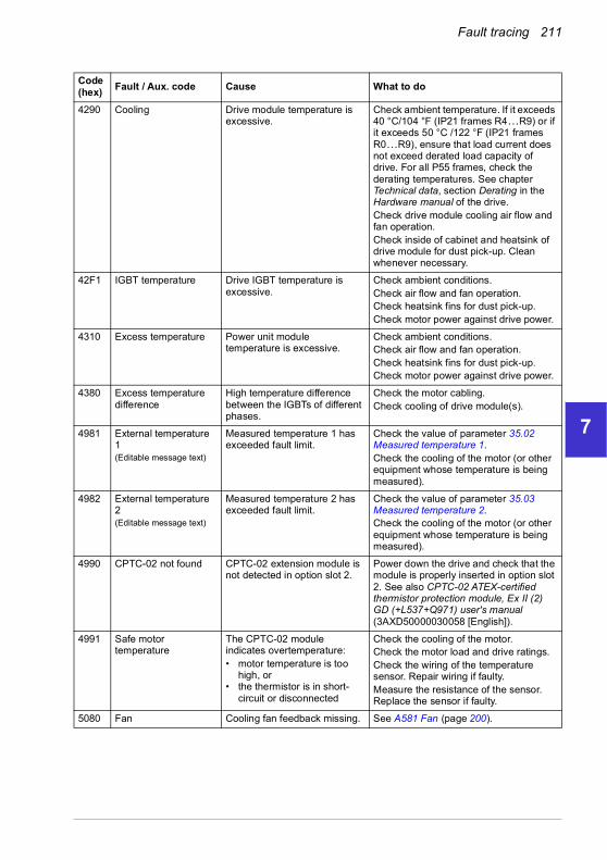
Fault tracing 211
1
2
3
4
5
6
7
8
9
10
11
12
13
4290 Cooling Drive module temperature is excessive.
Check ambient temperature. If it exceeds 40 °C/104 °F (IP21 frames R4…R9) or if it exceeds 50 °C /122 °F (IP21 frames R0…R9), ensure that load current does not exceed derated load capacity of drive. For all P55 frames, check the derating temperatures. See chapter Technical data, section Derating in the Hardware manual of the drive.Check drive module cooling air flow and fan operation.Check inside of cabinet and heatsink of drive module for dust pick-up. Clean whenever necessary.
42F1 IGBT temperature Drive IGBT temperature is excessive.
Check ambient conditions.Check air flow and fan operation.Check heatsink fins for dust pick-up.Check motor power against drive power.
4310 Excess temperature Power unit module temperature is excessive.
Check ambient conditions.Check air flow and fan operation.Check heatsink fins for dust pick-up.Check motor power against drive power.
4380 Excess temperature difference
High temperature difference between the IGBTs of different phases.
Check the motor cabling.Check cooling of drive module(s).
4981 External temperature 1(Editable message text)
Measured temperature 1 has exceeded fault limit.
Check the value of parameter 35.02 Measured temperature 1.Check the cooling of the motor (or other equipment whose temperature is being measured).
4982 External temperature 2(Editable message text)
Measured temperature 2 has exceeded fault limit.
Check the value of parameter 35.03 Measured temperature 2.Check the cooling of the motor (or other equipment whose temperature is being measured).
4990 CPTC-02 not found CPTC-02 extension module is not detected in option slot 2.
Power down the drive and check that the module is properly inserted in option slot 2. See also CPTC-02 ATEX-certified thermistor protection module, Ex II (2) GD (+L537+Q971) user's manual (3AXD50000030058 [English]).
4991 Safe motor temperature
The CPTC-02 module indicates overtemperature:• motor temperature is too
high, or• the thermistor is in short-
circuit or disconnected
Check the cooling of the motor.Check the motor load and drive ratings.Check the wiring of the temperature sensor. Repair wiring if faulty.Measure the resistance of the sensor. Replace the sensor if faulty.
5080 Fan Cooling fan feedback missing. See A581 Fan (page 200).
Code(hex)
Fault / Aux. code Cause What to do
14

212 Fault tracing
1
2
3
4
5
6
7
8
9
10
11
12
13
14
5081 Auxiliary fan broken An auxiliary cooling fan (connected to the fanconnectors on the control unit) is stuck or disconnected.
Check the auxiliary code. Check auxiliary fan(s) and connection(s).Replace fan if faulty.Make sure the front cover of the drive is in place and tightened.If the commissioning of the drive requires th the cover is off, activate parameter 31.36 Aux fan fault function within 2 min from control unit reboot to temporarily suppress the fault.Reboot the control unit (using parameter 96.08 Control board boot or by cycling power.
0001 Auxiliary fan 1 broken.
0002 Auxiliary fan 2 broken.
5090 STO hardware failure STO hardware diagnostics has detected hardware failure.
Contact your local ABB representative for hardware replacement.
5091 Safe torque offProgrammable fault: 31.22 STO indication run/stop
Safe torque off function is active, ie, safety circuit signal(s) connected to connector STO is broken during start or run.
Check safety circuit connections. For more information, see chapter The Safe torque off function in the Hardware manual of the drive and description of parameter 31.22 STO indication run/stop (page 456).Check the value of parameter 95.04 Control board supply.
5092 PU logic error Power unit memory has cleared.
Contact your local ABB representative.
5093 Rating ID mismatch The hardware of the drive does not match the information stored in the memory. This may occur, for example, after a firmware update.
Cycle the power to the drive. You may have to be repeat this.
5094 Measurement circuit temperature
Problem with internal temperature measurement of the drive.
Contact your local ABB representative.
5098 I/O communication loss
Internal standard I/O communication failure.
Try resetting the fault or reboot the drive.
50A0 Fan Cooling fan stuck or disconnected.
Check fan operation and connection.Replace fan if faulty.
5681 PU communication Communication errors detected between the drive control unit and the power unit.
Check the connection between the drive control unit and the power unit. Check the value of parameter 95.04 Control board supply.
5682 Power unit lost Connection between the drive control unit and the power unit is lost.
Check the connection between the control unit and the power unit.
5691 Measurement circuit ADC
Measurement circuit fault. Contact your local ABB representative.
5692 PU board powerfail Power unit power supply failure.
Contact your local ABB representative.
5693 Measurement circuit DFF
Measurement circuit fault. Contact your local ABB representative.
Code(hex)
Fault / Aux. code Cause What to do
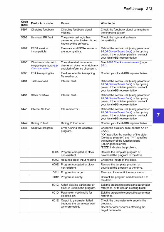
Fault tracing 213
1
2
3
4
5
6
7
8
9
10
11
12
13
5697 Charging feedback Charging feedback signal missing.
Check the feedback signal coming from the charging system
5698 Unknown PU fault The power unit logic has generated a fault which is not known by the software.
Check the logic and software compatibility.
6181 FPGA version incompatible
Firmware and FPGA versions are incompatible.
Reboot the control unit (using parameter 96.08 Control board boot) or by cycling power. If the problem persists, contact your local ABB representative
6200 Checksum mismatchProgrammable fault: 96.54 Checksum action
The calculated parameter checksum does not match any enabled reference checksum.
See A686 Checksum mismatch (page 201).
6306 FBA A mapping file Fieldbus adapter A mapping file read error.
Contact your local ABB representative.
6481 Task overload Internal fault. Reboot the control unit (using parameter 96.08 Control board boot) or by cycling power. If the problem persists, contact your local ABB representative
6487 Stack overflow Internal fault. Reboot the control unit (using parameter 96.08 Control board boot) or by cycling power. If the problem persists, contact your local ABB representative
64A1 Internal file load File read error. Reboot the control unit (using parameter 96.08 Control board boot) or by cycling power. If the problem persists, contact your local ABB representative
64A4 Rating ID fault Rating ID load error. Contact your local ABB representative.
64A6 Adaptive program Error running the adaptive program.
Check the auxiliary code (format XXYY ZZZZ). “XX” specifies the number of the state (00=base program) and “YY” specifies the number of the function block (0000=generic error).”ZZZZ” indicates the problem.
000A Program corrupted or block non-existent
Restore the template program or download the program to the drive.
000C Required block input missing Check the inputs of the block.
000E Program corrupted or block non-existent
Restore the template program or download the program to the drive.
0011 Program too large. Remove blocks until the error stops.
0012 Program is empty. Correct the program and download it to the drive.
001C A non-existing parameter or block is used in the program.
Edit the program to correct the parameter reference, or to use an existing block.
001D Parameter type invalid for selected pin.
Edit the program to correct the parameter reference.
001E Output to parameter failed because the parameter was write-protected.
Check the parameter reference in the program.Check for other sources affecting the target parameter.
Code(hex)
Fault / Aux. code Cause What to do
14
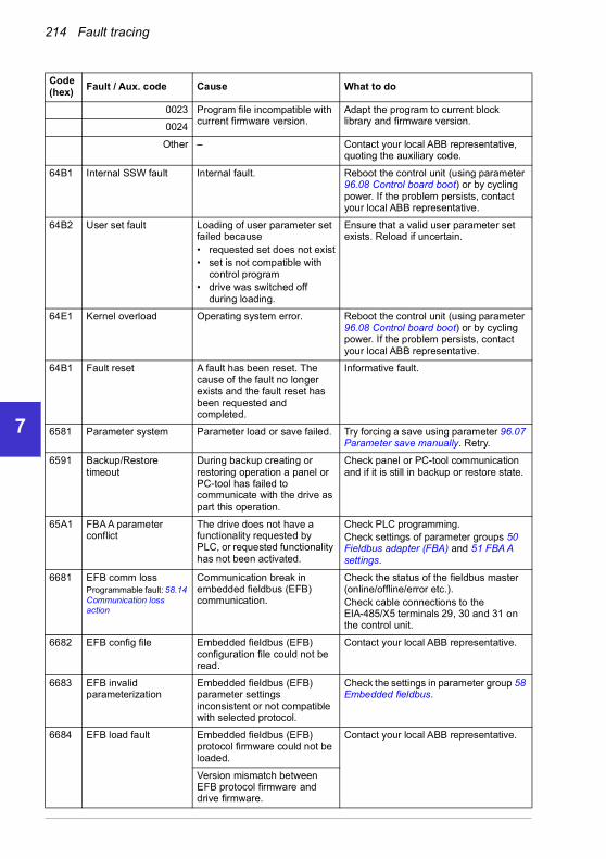
214 Fault tracing
1
2
3
4
5
6
7
8
9
10
11
12
13
14
0023 Program file incompatible with current firmware version.
Adapt the program to current block library and firmware version.
0024
Other – Contact your local ABB representative, quoting the auxiliary code.
64B1 Internal SSW fault Internal fault. Reboot the control unit (using parameter 96.08 Control board boot) or by cycling power. If the problem persists, contact your local ABB representative.
64B2 User set fault Loading of user parameter set failed because• requested set does not exist• set is not compatible with
control program• drive was switched off
during loading.
Ensure that a valid user parameter set exists. Reload if uncertain.
64E1 Kernel overload Operating system error. Reboot the control unit (using parameter 96.08 Control board boot) or by cycling power. If the problem persists, contact your local ABB representative.
64B1 Fault reset A fault has been reset. The cause of the fault no longer exists and the fault reset has been requested and completed.
Informative fault.
6581 Parameter system Parameter load or save failed. Try forcing a save using parameter 96.07 Parameter save manually. Retry.
6591 Backup/Restore timeout
During backup creating or restoring operation a panel or PC-tool has failed to communicate with the drive as part this operation.
Check panel or PC-tool communication and if it is still in backup or restore state.
65A1 FBA A parameter conflict
The drive does not have a functionality requested by PLC, or requested functionality has not been activated.
Check PLC programming.Check settings of parameter groups 50 Fieldbus adapter (FBA) and 51 FBA A settings.
6681 EFB comm lossProgrammable fault: 58.14 Communication loss action
Communication break in embedded fieldbus (EFB) communication.
Check the status of the fieldbus master (online/offline/error etc.).Check cable connections to the EIA-485/X5 terminals 29, 30 and 31 on the control unit.
6682 EFB config file Embedded fieldbus (EFB) configuration file could not be read.
Contact your local ABB representative.
6683 EFB invalid parameterization
Embedded fieldbus (EFB) parameter settings inconsistent or not compatible with selected protocol.
Check the settings in parameter group 58 Embedded fieldbus.
6684 EFB load fault Embedded fieldbus (EFB) protocol firmware could not be loaded.
Contact your local ABB representative.
Version mismatch between EFB protocol firmware and drive firmware.
Code(hex)
Fault / Aux. code Cause What to do

Fault tracing 215
1
2
3
4
5
6
7
8
9
10
11
12
13
6685 EFB fault 2 Fault reserved for the EFB protocol application.
Check the documentation of the protocol.
6686 EFB fault 3 Fault reserved for the EFB protocol application.
Check the documentation of the protocol.
6882 Text 32-bit table overflow
Internal fault. Reset the fault. Contact your local ABB representative if the fault persists.
6885 Text file overflow Internal fault. Reset the fault. Contact your local ABB representative if the fault persists.
7081 Control panel lossProgrammable fault: 49.05 Communication loss action
Control panel or PC tool selected as active control location for drive has ceased communicating.
Check PC tool or control panel connection.Check control panel connector.Disconnect and reconnect the control panel.
7085 Incompatible option module
Fieldbus option module not supported.
Replace the module with a supported type.
7100 Excitation current Excitation current feedback low or missing
7121 Motor stallProgrammable fault: 31.24 Stall function
Motor is operating in stall region because of, for example, excessive load or insufficient motor power.
Check motor load and drive ratings.Check fault function parameters.
7122 Motor overload Motor current is too high. Check for overloaded motor.Adjust the parameters used for the motor overload function (35.51…35.53) and 35.55…35.56.
7181 Brake resistor Brake resistor broken or not connected.
Check that a brake resistor has been connected.Check the condition of the brake resistor.Check the dimensioning of the brake resistor.
7183 BR excess temperature
Brake resistor temperature has exceeded fault limit defined by parameter 43.11 Brake resistor fault limit.
Stop drive. Let resistor cool down. Check resistor overload protection function settings (parameter group 43 Brake chopper).Check fault limit setting, parameter 43.11 Brake resistor fault limit.Check that braking cycle meets allowed limits.
7184 Brake resistor wiring Brake resistor short circuit or brake chopper control fault.
Check brake chopper and brake resistor connection.Ensure brake resistor is not damaged.
7191 BC short circuit Short circuit in brake chopper IGBT.
Ensure brake resistor is connected and not damaged.Check the electrical specifications of the brake resistor against chapter Resistor braking in the Hardware manual of the drive.Replace brake chopper (if replaceable).
Code(hex)
Fault / Aux. code Cause What to do
14

216 Fault tracing
1
2
3
4
5
6
7
8
9
10
11
12
13
14
7192 BC IGBT excess temperature
Brake chopper IGBT temperature has exceeded internal fault limit.
Let chopper cool down.Check for excessive ambient temperature.Check for cooling fan failure.Check for obstructions in the air flow.Check resistor overload protection function settings (parameter group 43 Brake chopper).Check that braking cycle meets allowed limits.Check that drive supply AC voltage is not excessive.
7310 Overspeed Motor is turning faster than highest allowed speed due to incorrectly set minimum/maximum speed, insufficient braking torque or changes in load when using torque reference.
Check minimum/maximum speed settings, parameters 30.11 Minimum speed and 30.12 Maximum speed.Check adequacy of motor braking torque.Check applicability of torque control.Check need for brake chopper and resistor(s).
73B0 Emergency ramp failed
Emergency stop did not finish within expected time.
Check the settings of parameters 31.32 Emergency ramp supervision and 31.33 Emergency ramp supervision delay.Check the predefined ramp times (23.11…23.15 for mode Off1, 23.23 for mode Off3).
73F0 Overfrequency Maximum allowed output frequency exceeded.
Check the auxiliary code.
00FA Motor is turning faster than the highest allowed frequency due to incorrectly set minimum/maximum frequency or the motor rushes because of too high supply voltage or incorrect supply voltage selection in parameter 95.01 Supply voltage.
Check minimum/maximum frequency settings, parameters 31.13 Minimum frequency and 31.14 Maximum frequency.Check used supply voltage and voltage selection parameter 95.01 Supply voltage.
Other – Contact your local ABB representative, quoting the auxiliary code.
Code(hex)
Fault / Aux. code Cause What to do

Fault tracing 217
1
2
3
4
5
6
7
8
9
10
11
12
13
7510 FBA A communicationProgrammable fault: 50.02 FBA A comm loss func
Cyclical communication between drive and fieldbus adapter module A or between PLC and fieldbus adapter module A is lost.
Check status of fieldbus communication. See user documentation of fieldbus interface.Check settings of parameter groups 50 Fieldbus adapter (FBA), 51 FBA A settings, 52 FBA A data in and 53 FBA A data out.Check cable connections.Check if communication master is able to communicate.
7580 INU-LSU comm lossProgrammable fault: 60.79 INU-LSU comm loss function
DDCS communication between the inverter unit and the supply unit is lost.
Check status of the supply unit (parameter group 06 Control and status words).Check settings of parameter group 60 DDCS communication. Check the corresponding settings in the control program of the supply unit.Check cable connections. If necessary, replace cables.
7583 Line side unit faulted The supply unit connected to the inverter unit has generated a fault.
The auxiliary code specifies the original fault code in the supply unit control program. See chapter Fault tracing in ACS880 IGBT supply control program firmware manual (3AUA0000131562[English]).
7584 LSU charge failed The supply unit was not ready (ie. the main contactor/breaker could not be closed) within expected time.
Check settings of parameter 94.10 LSU max charging time. Check that parameter 60.71 INU-LSU communication port is set to DDCS via BC. Check that the supply unit is enabled, allowed to start, and can be controlled by the inverter unit (eg. not in local control mode).
8001 ULC underload fault User load curve: Signal has been too long under the underload curve.
See parameter 37.04 ULC underload actions.
8002 ULC overload fault User load curve: Signal has been too long over the overload curve.
See parameter 37.03 ULC overload actions.
80A0 AI supervisionProgrammable fault:12.03 AI supervision function
An analog signal is outside the limits specified for the analog input.
Check signal level at the analog input.Check the auxiliary code.Check the wiring connected to the input.Check the minimum and maximum limits of the input in parameter group 12 Standard AI.
0001 AI1LessMIN
0002 AI1GreaterMAX
0003 AI2LessMIN.
0004 AI2GreaterMAX
80B0 Signal supervision 1(Editable message text)Programmable fault:32.06 Supervision 1 action
Fault generated by the signal supervision function 1.
Check the source of the fault (parameter 32.07 Supervision 1 signal).
Code(hex)
Fault / Aux. code Cause What to do
14

218 Fault tracing
1
2
3
4
5
6
7
8
9
10
11
12
13
14
80B1 Signal supervision 2(Editable message text)Programmable fault:32.16 Supervision 2 action
Fault generated by the signal supervision function 2.
Check the source of the fault (parameter 32.17 Supervision 2 signal).
80B2 Signal supervision 3(Editable message text)Programmable fault:32.26 Supervision 3 action
Fault generated by the signal supervision function 3.
Check the source of the fault (parameter 32.27 Supervision 3 signal).
80B3 Signal supervision 4(Editable message text)Programmable fault:32.36 Supervision 4 action
Fault generated by the signal supervision function 4.
Check the source of the fault (parameter 32.37 Supervision 4 signal).
80B4 Signal supervision 5(Editable message text)Programmable fault:32.46 Supervision 5 action
Fault generated by the signal supervision function 5.
Check the source of the fault (parameter 32.47 Supervision 5 signal).
80B5 Signal supervision 6(Editable message text)Programmable fault:,32.56 Supervision 6 action
Fault generated by the signal supervision function 6.
Check the source of the fault (parameter 32.57 Supervision 6 signal).
9081 External fault 1(Editable message text)Programmable fault: 31.01 External event 1 source, 31.02 External event 1 type
Fault in external device 1. Check the external device.Check setting of parameter 31.01 External event 1 source.
9082 External fault 2(Editable message text)Programmable fault: 31.03 External event 2 source, 31.04 External event 2 type
Fault in external device 2. Check the external device.Check setting of parameter 31.03 External event 2 source.
9083 External fault 3(Editable message text)Programmable fault: 31.05 External event 3 source, 31.06 External event 3 type
Fault in external device 3. Check the external device.Check setting of parameter 31.05 External event 3 source.
9084 External fault 4(Editable message text)Programmable fault: 31.07 External event 4 source, 31.08 External event 4 type
Fault in external device 4. Check the external device.Check setting of parameter 31.07 External event 4 source.
9085 External fault 5(Editable message text)Programmable fault: 31.09 External event 5 source, 31.10 External event 5 type
Fault in external device 5. Check the external device.Check setting of parameter 31.09 External event 5 source.
FA81 Safe torque off 1 Safe torque off function is active, ie, STO circuit 1 is broken.
Check safety circuit connections. For more information, see chapter The Safe torque off function in the Hardware manual of the drive and description of parameter 31.22 STO indication run/stop (page 456).Check the value of parameter 95.04 Control board supply.
FA82 Safe torque off 2 Safe torque off function is active, ie, STO circuit 2 is broken.
Code(hex)
Fault / Aux. code Cause What to do

Fault tracing 219
1
2
3
4
5
6
7
8
9
10
11
12
13
FF61 ID run Motor ID run was not completed successfully.
Check the nominal motor values in parameter group 99 Motor data.Check that no external control system is connected to the drive.Cycle the power to the drive (and its control unit, if powered separately).Check that no operation limits prevent the completion of the ID run. Restore parameters to default settings and try again.Check that the motor shaft is not locked.Check the auxiliary code. The second number of the code indicates the problem (see actions for each code below).
0001 Maximum current limit too low. Check settings of parameters 99.06 Motor nominal current and 30.17 Maximum current. Make sure that 30.17 > 99.06.Check that the drive is dimensioned correctly according to the motor.
0002 Maximum speed limit or calculated field weakening point too low.
Check settings of parameters• 30.11 Minimum speed• 30.12 Maximum speed• 99.07 Motor nominal voltage• 99.08 Motor nominal frequency• 99.09 Motor nominal speed.Make sure that• 30.12 > (0.55 × 99.09) >
(0.50 × synchronous speed)• 30.11 < 0, and• supply voltage > (0.66 × 99.07.
0003 Maximum torque limit too low. Check settings of parameter 99.12 Motor nominal torque, and the torque limits in group 30 Limits.Make sure that the maximum torque limit in force is greater than 100%.
0004 Current measurement calibration did not finish within reasonable time
Contact your local ABB representative.
0005…0008 Internal error. Contact your local ABB representative.
0009 (Asynchronous motors only)Acceleration did not finish within reasonable time.
Contact your local ABB representative.
000A (Asynchronous motors only)Deceleration did not finish within reasonable time.
Contact your local ABB representative.
000B (Asynchronous motors only)Speed dropped to zero during ID run.
Contact your local ABB representative.
000C (Permanent magnet motors only) First acceleration did not finish within reasonable time.
Contact your local ABB representative.
Code(hex)
Fault / Aux. code Cause What to do
14

220 Fault tracing
1
2
3
4
5
6
7
8
9
10
11
12
13
14
000D (Permanent magnet motors only) Second acceleration did not finish within reasonable time.
Contact your local ABB representative.
000E…0010 Internal error. Contact your local ABB representative.
0011 (Synchronous reluctance motors only)Pulse test error.
Contact your local ABB representative.
0012 Motor too large for advanced standstill ID run.
Check that the motor and drive sizes are compatible.Contact your local ABB representative.
0013 (Asynchronous motors only) Motor data error.
Check that the motor nominal value settings in the drive are the same as in the motor nameplate.Contact your local ABB representative.
FF63 STO diagnostics failure.
SW internal malfunction. Reboot the control unit (using parameter 96.08 Control board boot) or by cycling power.
FF81 FB A force trip A fault trip command has been received through fieldbus adapter A.
Check the fault information provided by the PLC.
FF8E EFB force trip A fault trip command has been received through the embedded fieldbus interface.
Check the fault information provided by the PLC.
Code(hex)
Fault / Aux. code Cause What to do

Fault tracing 221
1
2
3
4
5
6
7
8
9
10
11
12
13
Warnings and faults from the LSU supply unit
For ACH580-31 only.
For the parameters, see FW Part 2
Warning messages
Code (hex)
Warning / Aux. code Cause What to do
AE01 Overcurrent Output current has exceeded internal fault limit.
Check supply voltage.Check that there are no power factor correction capacitors or surge absorbers in supply cable.Check motor load and acceleration times.Check power semiconductors (IGBTs) and current transducers.
AE02 Earth leakage IGBT supply has detected load unbalance.
Check AC fuses.Check for earth leakages.Check supply cabling.Check power modules.Check there are no power factor correction capacitors or surge absorbers in supply cable.
AE03 Short circuit IGBT supply has detected short circuit.
Check supply cable.Check there are no power factor correction capacitors or surge absorbers in supply cable.
AE04 IGBT overload Excessive IGBT junction to case temperature.
Check supply cable.
AE09 DC link overvoltage Excessive intermediate circuit DC voltage.Note: This warning can be shown only when the IGBT supply unit is not modulating.
Check that parameter 95.01 Supply voltage is set according to the supply voltage in use.
AE0A DC link undervoltage Intermediate circuit DC voltage is not sufficient due to missing phase in supply voltage, blown fuse or rectifier bridge internal fault.Note: This warning can be shown only when the IGBT supply unit is not modulating.
Check supply and fuses.
AE0B DC not charged The voltage of the intermediate DC circuit has not yet risen to operating level.
Check the input voltage setting in parameter 95.01 Supply voltage.Check the input voltage.If the problem persists, contact your local ABB representative.
AE14 Excess temperature High temperature difference between the IGBTs of different phases.
Check ambient conditions.Check air flow and fan operation.Check heatsink fins for dust pick-up.Check motor power against IGBT supply unit power.
14

222 Fault tracing
1
2
3
4
5
6
7
8
9
10
11
12
13
14
Fault messages
AE24 Voltage category unselected
The supply voltage range has not been defined.
Define the supply voltage range (parameter 95.01 Supply voltage).
AE3E Panel loss Control panel or PC tool selected as active control location has ceased communicating.
Check PC tool or control panel connection.Check control panel connector.Replace control panel in mounting platform.
AE78 Net lost Net lost is detected. Resynchronize the IGBT supply unit to the grid after net lost.
AE79 Power fail saving Power fail saving is requested too frequently. Due to the limited saving interval some of the requests do not trigger the saving and power fail data may be lost. This may be caused by DC voltage oscillation.
Check the supply voltage.
Code (hex)
Fault / Aux. code Cause What to do
2E00 Overcurrent Output current has exceeded internal fault limit.
Check supply voltage.Check that there are no power factor correction capacitors or surge absorbers in supply cable.Check motor load and acceleration times.Check power semiconductors (IGBTs) and current transducers.
2E01 Earth leakage IGBT supply unit has detected an earth fault.
Check AC fuses.Check for earth leakages.Check supply cabling.Check power modules.Check there are no power factor correction capacitors or surge absorbers in supply cable.If no earth fault can be detected, contact your local ABB representative.
2E02 Short circuit IGBT supply unit has detected short circuit.
Check supply cable.Check there are no power factor correction capacitors or surge absorbers in supply cable
2E04 IGBT overload Excessive IGBT junction to case temperature.
Check the load.
3E00 Input phase loss Input phase loss detected by the IGBT bridge.
Check the AC fuses.Check for input power supply imbalance.
3E04 DC link overvoltage Excessive intermediate circuit DC voltage.
Check that parameter 95.01 Supply voltage is set according to the supply voltage in use.
3E05 DC link undervoltage Intermediate circuit DC voltage is not sufficient because of a missing supply phase or blown fuse.
Check supply cabling, fuses and switchgear.
Code (hex)
Warning / Aux. code Cause What to do
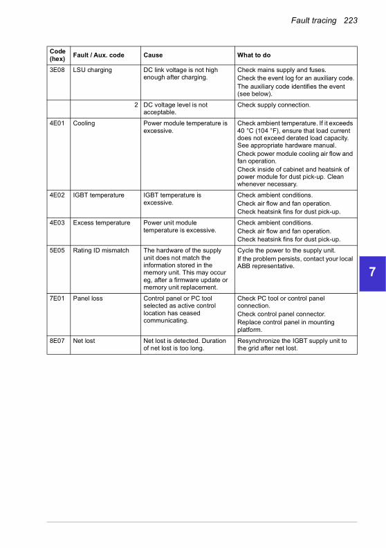
Fault tracing 223
1
2
3
4
5
6
7
8
9
10
11
12
13
3E08 LSU charging DC link voltage is not high enough after charging.
Check mains supply and fuses.Check the event log for an auxiliary code.The auxiliary code identifies the event (see below).
2 DC voltage level is not acceptable.
Check supply connection.
4E01 Cooling Power module temperature is excessive.
Check ambient temperature. If it exceeds 40 °C (104 °F), ensure that load current does not exceed derated load capacity. See appropriate hardware manual.Check power module cooling air flow and fan operation.Check inside of cabinet and heatsink of power module for dust pick-up. Clean whenever necessary.
4E02 IGBT temperature IGBT temperature is excessive.
Check ambient conditions.Check air flow and fan operation.Check heatsink fins for dust pick-up.
4E03 Excess temperature Power unit module temperature is excessive.
Check ambient conditions.Check air flow and fan operation.Check heatsink fins for dust pick-up.
5E05 Rating ID mismatch The hardware of the supply unit does not match the information stored in the memory unit. This may occur eg, after a firmware update or memory unit replacement.
Cycle the power to the supply unit.If the problem persists, contact your local ABB representative.
7E01 Panel loss Control panel or PC tool selected as active control location has ceased communicating.
Check PC tool or control panel connection.Check control panel connector.Replace control panel in mounting platform.
8E07 Net lost Net lost is detected. Duration of net lost is too long.
Resynchronize the IGBT supply unit to the grid after net lost.
Code (hex)
Fault / Aux. code Cause What to do
14

224 Fault tracing
1
2
3
4
5
6
7
8
9
10
11
12
13
14
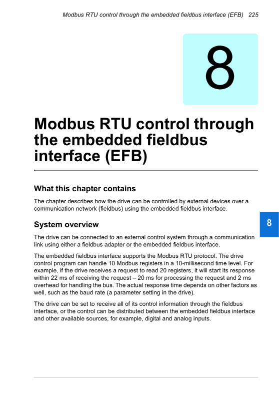
Modbus RTU control through the embedded fieldbus interface (EFB) 225
1
2
3
4
5
6
7
8
9
10
11
12
13
8Modbus RTU control through the embedded fieldbus interface (EFB)
What this chapter contains
The chapter describes how the drive can be controlled by external devices over a communication network (fieldbus) using the embedded fieldbus interface.
System overview
The drive can be connected to an external control system through a communication link using either a fieldbus adapter or the embedded fieldbus interface.
The embedded fieldbus interface supports the Modbus RTU protocol. The drive control program can handle 10 Modbus registers in a 10-millisecond time level. For example, if the drive receives a request to read 20 registers, it will start its response within 22 ms of receiving the request – 20 ms for processing the request and 2 ms overhead for handling the bus. The actual response time depends on other factors as well, such as the baud rate (a parameter setting in the drive).
The drive can be set to receive all of its control information through the fieldbus interface, or the control can be distributed between the embedded fieldbus interface and other available sources, for example, digital and analog inputs.
14

226 Modbus RTU control through the embedded fieldbus interface (EFB)
1
2
3
4
5
6
7
8
9
10
11
12
13
14
Connecting the drive to the fieldbus
Connect terminal block X5 with B+, A- and DGND terminals on the control unit of the drive to the fieldbus. The connection diagram is shown below.
See also chapter BACnet MS/TP control through the embedded fieldbus interface (EFB), section Hardware installation (page 256).
Drive
ON
TE
RM
ON
BIA
S
X5
Termination ON1)
Bias ON2)
Drive
ON
TE
RM
ON
BIA
SX5
Termination OFFBias OFF
Process I/O (cyclic)
Service messages (acyclic)
Data flowControl Word (CW)
References
Status Word (SW)Actual values
Parameter R/Wrequests/responses
Fieldbus controller
Fieldbus
Drive
ON
TE
RM
ON
BIA
S
X5
Termination OFFBias OFF
Termination ON1)
1) The device at both ends on the fieldbus must have termination on.2) One device, preferably at either end on the fieldbus must have bias on.

Modbus RTU control through the embedded fieldbus interface (EFB) 227
1
2
3
4
5
6
7
8
9
10
11
12
13
Use preferably three conductors and a shield for the connection.
Building automation controller
B +
Po
sitiv
e
A -
Neg
ativ
e
DG
ND
ON
TERM
ON
BIASSC
R s
hiel
d (S
cree
n)
1
Terminal block X5 EFBTerminal block X1
Drive control unit
- +RG
1) If the device is at either end of the fieldbus, set switch termination (S4) to ON.One device, preferably at either end on the fieldbus, must have bias on, that is, set switch bias (S5) to ON. If the device is not at the end of the fieldbus, set switches termination (S4) and bias (S5) to OFF.The bias is typically sourced by the controller.
2) Tie shield conductors together at the drive – Do NOT terminate at SCR.
3) Terminate shield ONLY at the “Ground” terminal in the building automation controller.
4) Terminate DGND conductor at the “Reference” terminal in the building automation controller.
S4 S529 30 31
Ground 3)
Reference 4)
Shield 2)
1)
14
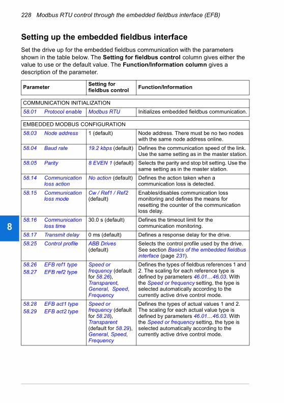
228 Modbus RTU control through the embedded fieldbus interface (EFB)
1
2
3
4
5
6
7
8
9
10
11
12
13
14
Setting up the embedded fieldbus interface
Set the drive up for the embedded fieldbus communication with the parameters shown in the table below. The Setting for fieldbus control column gives either the value to use or the default value. The Function/Information column gives a description of the parameter.
ParameterSetting forfieldbus control
Function/Information
COMMUNICATION INITIALIZATION
58.01 Protocol enable Modbus RTU Initializes embedded fieldbus communication.
EMBEDDED MODBUS CONFIGURATION
58.03 Node address 1 (default) Node address. There must be no two nodes with the same node address online.
58.04 Baud rate 19.2 kbps (default) Defines the communication speed of the link. Use the same setting as in the master station.
58.05 Parity 8 EVEN 1 (default) Selects the parity and stop bit setting. Use the same setting as in the master station.
58.14 Communication loss action
No action (default) Defines the action taken when a communication loss is detected.
58.15 Communication loss mode
Cw / Ref1 / Ref2 (default)
Enables/disables communication loss monitoring and defines the means for resetting the counter of the communication loss delay.
58.16 Communication loss time
30.0 s (default) Defines the timeout limit for the communication monitoring.
58.17 Transmit delay 0 ms (default) Defines a response delay for the drive.
58.25 Control profile ABB Drives (default)
Selects the control profile used by the drive. See section Basics of the embedded fieldbus interface (page 231).
58.2658.27
EFB ref1 typeEFB ref2 type
Speed or frequency (default for 58.26), Transparent, General, Speed, Frequency
Defines the types of fieldbus references 1 and 2. The scaling for each reference type is defined by parameters 46.01…46.03. With the Speed or frequency setting, the type is selected automatically according to the currently active drive control mode.
58.2858.29
EFB act1 typeEFB act2 type
Speed or frequency (default for 58.28), Transparent (default for 58.29), General, Speed, Frequency
Defines the types of actual values 1 and 2. The scaling for each actual value type is defined by parameters 46.01…46.03. With the Speed or frequency setting, the type is selected automatically according to the currently active drive control mode.

Modbus RTU control through the embedded fieldbus interface (EFB) 229
1
2
3
4
5
6
7
8
9
10
11
12
13
The new settings will take effect when the drive is powered up the next time, or when they are validated by parameter 58.06 Communication control (Refresh settings).
Setting the drive control parameters
After the embedded fieldbus interface has been set up, check and adjust the drive control parameters listed in the table below. The Setting for fieldbus control column gives the value or values to use when the embedded fieldbus signal is the desired source or destination for that particular drive control signal. The Function/Information column gives a description of the parameter.
58.3158.32
EFB act1 transparent sourceEFB act2 transparent source
Not selected Defines the source of actual values 1 and 2 when the 58.26 EFB ref1 type (58.27 EFB ref2 type) is set to Transparent.
58.33 Addressing mode
Mode 0 (default) Defines the mapping between parameters and holding registers in the 400001…465536 (100…65535) Modbus register range.
58.34 Word order LO-HI (default) Defines the order of the data words in the Modbus message frame.
58.101…58.114
Data I/O 1…Data I/O 14
For example, the default settings (I/Os 1…6 contain the control word, the status word, two references and two actual values)
Defines the address of the drive parameter which the Modbus master accesses when it reads from or writes to the register address corresponding to Modbus In/Out parameters. Select the parameters that you want to read or write through the Modbus I/O words.
RO/DIO control word, AO1 data storage, AO2 data storage, Feedback data storage, Setpoint data storage
These settings write the incoming data into storage parameters 10.99 RO/DIO control word, 13.91 AO1 data storage, 13.92 AO2 data storage, 40.91 Feedback data storage or 40.92 Setpoint data storage.
58.06 Communication control
Refresh settings Validates the settings of the configuration parameters.
Parameter Setting forfieldbus control
Function/Information
CONTROL COMMAND SOURCE SELECTION
20.01 Ext1 commands
Embedded fieldbus Selects fieldbus as the source for the start and stop commands when EXT1 is selected as the active control location.
ParameterSetting forfieldbus control
Function/Information
14

230 Modbus RTU control through the embedded fieldbus interface (EFB)
1
2
3
4
5
6
7
8
9
10
11
12
13
14
20.06 Ext2 commands
Embedded fieldbus Selects fieldbus as the source for the start and stop commands when EXT2 is selected as the active control location.
SPEED REFERENCE SELECTION
22.11 Ext1 speed ref1 EFB ref1 Selects a reference received through the embedded fieldbus interface as speed reference 1.
22.18 Ext2 speed ref1 EFB ref1 Selects a reference received through the embedded fieldbus interface as speed reference 2.
FREQUENCY REFERENCE SELECTION
28.11 Ext1 frequency ref1
EFB ref1 Selects a reference received through the embedded fieldbus interface as frequency reference 1.
28.15 Ext2 frequency ref1
EFB ref1 Selects a reference received through the embedded fieldbus interface as frequency reference 2.
OTHER SELECTIONS
EFB references can be selected as the source at virtually any signal selector parameter by selecting Other, then either 03.09 EFB reference 1 or 03.10 EFB reference 2.
SYSTEM CONTROL INPUTS
96.07 Parameter save manually
Save (reverts to Done)
Saves parameter value changes (including those made through fieldbus control) to permanent memory.
ParameterSetting forfieldbus control
Function/Information

Modbus RTU control through the embedded fieldbus interface (EFB) 231
1
2
3
4
5
6
7
8
9
10
11
12
13
Basics of the embedded fieldbus interface
The cyclic communication between a fieldbus system and the drive consists of 16-bit data words or 32-bit data words (with a transparent control profile).
The diagram below illustrates the operation of the embedded fieldbus interface. The signals transferred in the cyclic communication are explained further below the diagram.
CW
REF1
REF2
SW
ACT1
ACT2
I/O 1
I/O 2
I/O 3
…
I/O 69
EFB CW
03.09 EFB reference 1
03.10 EFB reference 2
EFB SW
Actual 1
Actual 2
Par. 01.01…255.255
1. See also other parameters which can be controlled through fieldbus.2. Data conversion if parameter 58.25 Control profile is set to ABB Drives. See section About the control
profiles (page 234).
1)
Fieldbus network
Data I/O selection
EXT1/2Start commands
Reference selection
Groups22/26/28/40 etc.
Cyclic communication
Acyclic communication
58.25
SEL
2)
Parameter table
0123
58.25
SEL0
123
2)
EFB profile
Reference selection
Groups22/26/28/40 etc.
58.101…
58.114
20.0120.06
14

232 Modbus RTU control through the embedded fieldbus interface (EFB)
1
2
3
4
5
6
7
8
9
10
11
12
13
14
Control word and Status word
The Control Word (CW) is a 16-bit or 32-bit packed boolean word. It is the principal means of controlling the drive from a fieldbus system. The CW is sent by the fieldbus controller to the drive. With drive parameters, the user selects the EFB CW as the source of drive control commands (such as start/stop, emergency stop, selection between external control locations 1/2, or fault reset). The drive switches between its states according to the bit-coded instructions of the CW.
The fieldbus CW is either written to the drive as it is or the data is converted. See section About the control profiles (page 234).
The fieldbus Status Word (SW) is a 16-bit or 32-bit packed boolean word. It contains status information from the drive to the fieldbus controller. The drive SW is either written to the fieldbus SW as it is or the data is converted. See section About the control profiles (page 234).
References
EFB references 1 and 2 are 16-bit or 32-bit signed integers. The contents of each reference word can be used as the source of virtually any signal, such as the speed, frequency, torque or process reference. In embedded fieldbus communication, references 1 and 2 are displayed by 03.09 EFB reference 1 and 03.10 EFB reference 2 respectively. Whether the references are scaled or not depends on the settings of 58.26 EFB ref1 type and 58.27 EFB ref2 type. See section About the control profiles (page 234).
Actual values
Fieldbus actual signals (ACT1 and ACT2) are 16-bit or 32-bit signed integers. They convey selected drive parameter values from the drive to the master. Whether the actual values are scaled or not depends on the settings of 58.28 EFB act1 type and 58.29 EFB act2 type. See section About the control profiles (page 234).
Data input/outputs
Data input/outputs are 16-bit or 32-bit words containing selected drive parameter values. Parameters 58.101 Data I/O 1 … 58.114 Data I/O 14 define the addresses from which the master either reads data (input) or to which it writes data (output).
Register addressing
The address field of Modbus requests for accessing holding registers is 16 bits. This allows the Modbus protocol to support addressing of 65536 holding registers.
Historically, Modbus master devices used 5-digit decimal addresses from 40001 to 49999 to represent holding register addresses. The 5-digit decimal addressing limited to 9999 the number of holding registers that could be addressed.

Modbus RTU control through the embedded fieldbus interface (EFB) 233
1
2
3
4
5
6
7
8
9
10
11
12
13
Modern Modbus master devices typically provide a means to access the full range of 65536 Modbus holding registers. One of these methods is to use 6-digit decimal addresses from 400001 to 465536. This manual uses 6-digit decimal addressing to represent Modbus holding register addresses.
Modbus master devices that are limited to the 5-digit decimal addressing may still access registers 400001 to 409999 by using 5-digit decimal addresses 40001 to 49999. Registers 410000-465536 are inaccessible to these masters.
See parameter 58.33 Addressing mode.
Note: Register addresses of 32-bit parameters cannot be accessed by using 5-digit register numbers.
14

234 Modbus RTU control through the embedded fieldbus interface (EFB)
1
2
3
4
5
6
7
8
9
10
11
12
13
14
About the control profiles
A control profile defines the rules for data transfer between the drive and the fieldbus master, for example:
• if packed boolean words are converted and how
• if signal values are scaled and how
• how drive register addresses are mapped for the fieldbus master.
You can configure the drive to receive and send messages according to one of the two profiles:
• ABB Drives
• DCU Profile.
For the ABB Drives profile, the embedded fieldbus interface of the drive converts the fieldbus data to and from the native data used in the drive. The DCU Profile involves no data conversion or scaling. The figure below illustrates the effect of the profile selection.
Profile selection
Control profile selection with parameter 58.25 Control profile is:• (0) ABB Drives• (5) DCU Profile.
58.25
SELData conversion &
scaling0
5Fieldbus Drive58.26…58.29

Modbus RTU control through the embedded fieldbus interface (EFB) 235
1
2
3
4
5
6
7
8
9
10
11
12
13
Control Word
Control Word for the ABB Drives profile
The table below shows the contents of the fieldbus Control Word for the ABB Drives control profile. The embedded fieldbus interface converts this word to the form in which it is used in the drive. The upper case boldface text refers to the states shown in State transition diagram for the ABB Drives profile on page 242.
Bit Name Value STATE/Description
0 OFF1_CONTROL
1 Proceed to READY TO OPERATE.
0 Stop along currently active deceleration ramp. Proceed to OFF1 ACTIVE; proceed to READY TO SWITCH ON unless other interlocks (OFF2, OFF3) are active.
1 OFF2_CONTROL
1 Continue operation (OFF2 inactive).
0 Emergency OFF, coast to stop.Proceed to OFF2 ACTIVE, proceed to SWITCH-ON INHIBITED.
2 OFF3_CONTROL
1 Continue operation (OFF3 inactive).
0 Emergency stop, stop within time defined by drive parameter. Proceed to OFF3 ACTIVE; proceed to SWITCH-ON INHIBITED.Warning: Ensure that the motor and driven machine can be stopped using this stop mode.
3 INHIBIT_OPERATION
1 Proceed to OPERATION ENABLED.Note: Run permissive signal must be active; see the drive documentation. If the drive is set to receive the Run permissive signal from the fieldbus, this bit activates the signal.
0 Inhibit operation. Proceed to OPERATION INHIBITED.
4 RAMP_OUT_ZERO
1 Normal operation. Proceed to RAMP FUNCTION GENERATOR: OUTPUT ENABLED.
0 Force Ramp Function Generator output to zero. Drive ramps to stop (current and DC voltage limits in force).
5 RAMP_HOLD 1 ramp function. Proceed to RAMP FUNCTION GENERATOR: ACCELERATOR ENABLED.
0 Halt ramping (Ramp Function Generator output held).
6 RAMP_IN_ZERO
1 Normal operation. Proceed to OPERATING.Note: This bit is effective only if the fieldbus interface is set as the source for this signal by drive parameters.
0 Force Ramp Function Generator input to zero.
7 RESET 0=>1 Fault reset if an active fault exists. Proceed to SWITCH-ON INHIBITED.Note: This bit is effective only if the fieldbus interface is set as the source for this signal by drive parameters.
0 Continue normal operation.
14

236 Modbus RTU control through the embedded fieldbus interface (EFB)
1
2
3
4
5
6
7
8
9
10
11
12
13
14
Control Word for the DCU Profile
The embedded fieldbus interface writes the fieldbus Control Word as is to the drive Control Word bits 0 to 15. Bits 16 to 32 of the drive Control Word are not in use.
8 Reserved
9 Reserved
10 REMOTE_CMD
1 Fieldbus control d.
0 Control Word <> 0 or Reference <> 0: Retain last Control Word and Reference.Control Word = 0 and Reference = 0: Fieldbus control d. Reference and deceleration/acceleration ramp are locked.
11 EXT_CTRL_LOC
1 Select External Control Location EXT2. Effective if the control location is parameterized to be selected from the fieldbus.
0 Select External Control Location EXT1. Effective if the control location is parameterized to be selected from the fieldbus.
12 USER_0 Writable control bits that can be combined with drive logic for application-specific functionality.13 USER_1
14 USER_2
15 USER_3
Bit Name Value State/Description
0 STOP 1 Stop according to the Stop Mode parameter or the stop mode request bits (bits 7…9).
0 (no op)
1 START 1 Start the drive.
0 (no op)
2 REVERSE 1 Reverse direction of motor rotation.
0 Direction of motor rotation depends on the sign of reference:Positive reference: ForwardNegative reference: Reverse.
3 Reserved
4 RESET 0=>1 Fault reset if an active fault exists.
0 (no op)
5 EXT2 1 Select External control location EXT2. Effective if the control location is parameterized to be selected from the fieldbus.
0 Select External control location EXT1. Effective if the control location is parameterized to be selected from the fieldbus.
Bit Name Value STATE/Description

Modbus RTU control through the embedded fieldbus interface (EFB) 237
1
2
3
4
5
6
7
8
9
10
11
12
13
6 RUN_DISABLE 1 Run disable. If the drive is set to receive the run enable signal from the fieldbus, this bit deactivates the signal.
0 Run enable. If the drive is set to receive the run enable signal from the fieldbus, this bit activates the signal.
7 STOPMODE_RAMP
1 Normal ramp stop mode
0 (no op) Default to parameter stop mode if bits 7…9 are all 0.
8 STOPMODE_EMERGENCY_RAMP
1 Emergency ramp stop mode.
0 (no op) Default to parameter stop mode if bits 7…9 are all 0.
9 STOPMODE_COAST
1 Coast stop mode.
0 (no op) Default to parameter stop mode if bits 7…9 are all 0.
10 RAMP_PAIR _2 1 Select ramp set 2 (Acceleration time 2 / Deceleration time 2) when parameter 23.11 Ramp set selection is set to EFB DCU CW bit 10.
0 Select ramp set 1 (Acceleration time 1 / Deceleration time 1) when parameter 23.11 Ramp set selection is set to EFB DCU CW bit 10.
11 RAMP_OUT_ZERO
1 Force Ramp Function Generator output to zero. Drive ramps to stop (current and DC voltage limits in force).
0 Normal operation.
12 RAMP_HOLD 1 Halt ramping (Ramp Function Generator output held).
0 Normal operation.
13 RAMP_IN_ZERO 1 Force Ramp Function Generator input to zero.
0 Normal operation.
14 REQ_LOCAL_LOCK
1 Drive does not switch to local control mode (see parameter 19.18 HAND/OFF disable source.
0 Drive can switch between local and external control modes.
15 TORQ_LIM_PAIR_2
1 Select torque limit set 2 (Minimum torque 2 / Maximum torque 2) when parameter 30.18 Torq lim sel is set to EFB.
0 Select torque limit set 1 (Minimum torque 1 / Maximum torque 1) when parameter 30.18 Torq lim sel is set to EFB.
16 FB_LOCAL_CTL 1 Local mode for control from the fieldbus is requested. Steal control from the active source.
0 (no op)
17 FB_LOCAL_REF 1 Local mode for reference from the fieldbus is requested. Steal reference from the active source.
0 (no op)
18 Reserved for RUN_DISABLE_1
Not yet implemented.
Bit Name Value State/Description
14
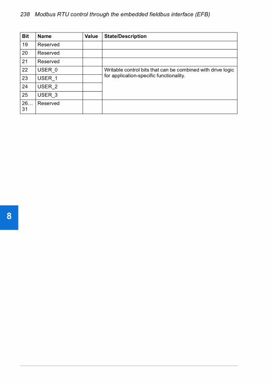
238 Modbus RTU control through the embedded fieldbus interface (EFB)
1
2
3
4
5
6
7
8
9
10
11
12
13
14
19 Reserved
20 Reserved
21 Reserved
22 USER_0 Writable control bits that can be combined with drive logic for application-specific functionality.23 USER_1
24 USER_2
25 USER_3
26…31
Reserved
Bit Name Value State/Description
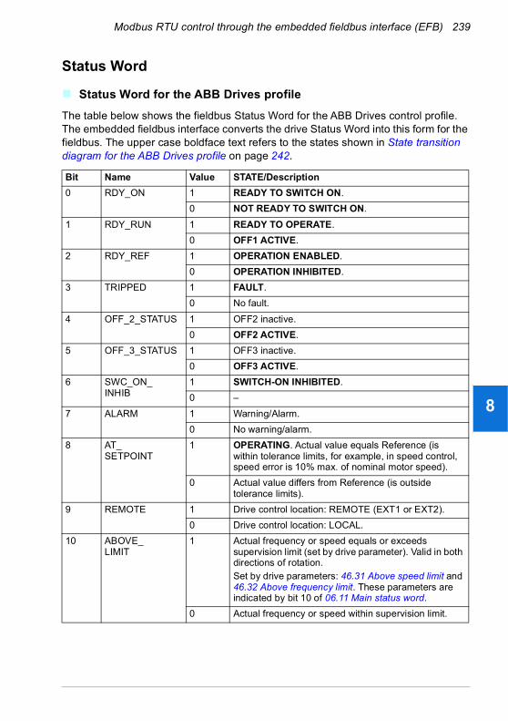
Modbus RTU control through the embedded fieldbus interface (EFB) 239
1
2
3
4
5
6
7
8
9
10
11
12
13
Status Word
Status Word for the ABB Drives profile
The table below shows the fieldbus Status Word for the ABB Drives control profile. The embedded fieldbus interface converts the drive Status Word into this form for the fieldbus. The upper case boldface text refers to the states shown in State transition diagram for the ABB Drives profile on page 242.
Bit Name Value STATE/Description
0 RDY_ON 1 READY TO SWITCH ON.
0 NOT READY TO SWITCH ON.
1 RDY_RUN 1 READY TO OPERATE.
0 OFF1 ACTIVE.
2 RDY_REF 1 OPERATION ENABLED.
0 OPERATION INHIBITED.
3 TRIPPED 1 FAULT.
0 No fault.
4 OFF_2_STATUS 1 OFF2 inactive.
0 OFF2 ACTIVE.
5 OFF_3_STATUS 1 OFF3 inactive.
0 OFF3 ACTIVE.
6 SWC_ON_INHIB
1 SWITCH-ON INHIBITED.
0 –
7 ALARM 1 Warning/Alarm.
0 No warning/alarm.
8 AT_SETPOINT
1 OPERATING. Actual value equals Reference (is within tolerance limits, for example, in speed control, speed error is 10% max. of nominal motor speed).
0 Actual value differs from Reference (is outside tolerance limits).
9 REMOTE 1 Drive control location: REMOTE (EXT1 or EXT2).
0 Drive control location: LOCAL.
10 ABOVE_LIMIT
1 Actual frequency or speed equals or exceeds supervision limit (set by drive parameter). Valid in both directions of rotation.Set by drive parameters: 46.31 Above speed limit and 46.32 Above frequency limit. These parameters are indicated by bit 10 of 06.11 Main status word.
0 Actual frequency or speed within supervision limit.
14

240 Modbus RTU control through the embedded fieldbus interface (EFB)
1
2
3
4
5
6
7
8
9
10
11
12
13
14
Status Word for the DCU Profile
The embedded fieldbus interface writes the drive Status Word bits 0 to 15 to the fieldbus Status Word as is. Bits 16 to 32 of the drive Status Word are not in use.
11 USER_0 Status bits that can be combined with drive logic for application-specific functionality.12 USER_1
13 USER_2
14 USER_3
15 Reserved
Bit Name Value State/Description
0 READY 1 Drive is ready to receive the start command.
0 Drive is not ready.
1 ENABLED 1 Run permissive and all start interlocks are active.
0 Run permissive and all start interlocks are not active.
2 STARTED 1 Drive has received start command.
0 Drive has not received start command.
3 RUNNING 1 Drive is modulating.
0 Drive is not modulating.
4 ZERO_SPEED 1 Drive is at zero speed.
0 Drive is not at zero speed.
5 ACCELERATING 1 Drive speed is increasing.
0 Drive speed is not increasing.
6 DECELERATING 1 Drive speed is decreasing.
0 Drive speed is not decreasing.
7 AT_SETPOINT 1 Drive is at setpoint.
0 Drive is not at setpoint.
8 LIMIT 1 Drive operation is limited.
0 Drive operation is not limited.
9 SUPERVISION 1 Actual value (speed, frequency or torque) is above a limit. Limit is set with parameters 46.31…46.
0 Actual value (speed, frequency or torque) is within limits.
10 REVERSE_REF 1 Drive reference is in the reverse direction.
0 Drive reference is in the forward direction
11 REVERSE_ACT 1 Drive is running in the reverse direction
0 Drive is running in the forward direction
12 PANEL_LOCAL 1 Panel/keypad (or PC tool) is in local control mode.
0 Panel/keypad (or PC tool) is not in local control mode.
Bit Name Value STATE/Description

Modbus RTU control through the embedded fieldbus interface (EFB) 241
1
2
3
4
5
6
7
8
9
10
11
12
13
13 FIELDBUS_LOCAL
1 Fieldbus is in local control mode.
0 Fieldbus is not in local control mode.
14 EXT2_ACT 1 External control location EXT2 is active.
0 External control location EXT1 is active.
15 FAULT 1 Drive is faulted.
0 Drive is not faulted.
16 ALARM 1 Warning/Alarm is active.
0 No warning/alarm.
17 Reserved
18 DIRLOCK 1 Direction lock is ON. (Direction change is locked out.)
0 Direction lock is OFF.
19 LOCALLOCK 1 Local mode lock is ON. (Local mode is locked out.)
0 Local mode lock is OFF.
20 Reserved
21 Reserved
22 USER_0 Status bits that can be combined with drive logic for application-specific functionality.23 USER_1
24 USER_2
25 USER_3
26 REQ_CTL 1 Control has been granted to this channel.
0 Control has not been granted to this channel.
27 REQ_REF1 1 Reference 1 has been requested in this channel.
0 Reference 1 has not been requested in this channel.
28 REQ_REF2 1 Reference 2 has been requested in this channel.
0 Reference 2 has not been requested in this channel.
29… 31
Reserved
Bit Name Value State/Description
14

242 Modbus RTU control through the embedded fieldbus interface (EFB)
1
2
3
4
5
6
7
8
9
10
11
12
13
14
State transition diagrams
State transition diagram for the ABB Drives profile
The diagram below shows the state transitions in the drive when the drive is using the ABB Drives profile and the drive is configured to follow the commands of the control word from the embedded fieldbus interface. The upper case texts refer to the states which are used in the tables representing the fieldbus Control and Status words. See sections Control Word for the ABB Drives profile on page 235 and Status Word for the ABB Drives profile on page 239.

Modbus RTU control through the embedded fieldbus interface (EFB) 243
1
2
3
4
5
6
7
8
9
10
11
12
13
MAINS OFF
Power ON (CW Bit0=0)
(SW Bit6=1)
(SW Bit0=0)
from any state
(CW=xxxx x1xx xxxx x110)
(SW Bit1=1)
n(f)=0 / I=0
(SW Bit2=0)
A B C D
(CW Bit3=0)
operationinhibited
OFF1 (CW Bit0=0)
(SW Bit1=0)
(SW Bit0=1)
(CW Bit3=1and
SW Bit12=1)
C D
(CW Bit5=0)
(SW Bit2=1)
(SW Bit5=0)
from any state from any state
Emergency StopOFF3 (CW Bit2=0)
n(f)=0 / I=0
Emergency OFFOFF2 (CW Bit1=0)
(SW Bit4=0)
B
B C D
(CW Bit4=0)
(CW=xxxx x1xx xxx1 1111)
(CW=xxxx x1xx xx11 1111)
D
(CW Bit6=0)
A
C(CW=xxxx x1xx x111 1111)
(SW Bit8=1)D
from any state
Fault
(SW Bit3=1)
(CW Bit7=1)
(CW=xxxx x1xx xxxx x111)
(CW=xxxx x1xx xxxx 1111and SW Bit12=1)
CW = Control WordSW = Status Word
n = SpeedI = Input Current
RFG = Ramp FunctionGenerator
f = Frequency
ABB Drives profileSWITCH-ON INHIBITED
NOT READY TO SWITCH ON
READY TO SWITCH ON
READY TO OPERATE
OPERATION INHIBITED
OFF1 ACTIVE
OPERATION ENABLED
RFG: OUTPUT ENABLED
RFG: ACCELERATOR ENABLED
OPERATION
OFF2 ACTIVE
FAULT
OFF3 ACTIVE
STATE
condition
rising edge of the bit
14

244 Modbus RTU control through the embedded fieldbus interface (EFB)
1
2
3
4
5
6
7
8
9
10
11
12
13
14
The start and stop sequences are given below.
Control word:
Start:
• 1150 (476h) –> NOT READY TO SWITCH ON
• If MSW bit 0 = 1 then
• 1150 (47Eh) –> READY TO SWITCH ON (Stopped)
• 1151 (47Fh) –> OPERATION (Running)
Stop:
• 1150 (47Eh) = OFF1 ramp stop (Note: uninterruptable ramp stop)
• 1149 (47Dh) = coast to stop
• 1147 (47Bh) = emergency stop
Fault reset:
• Rising edge of MCW bit 7
Start after STO:
• If 31.22 STO indication run/stop is not Fault/ Fault, check that 06.18 Start inhibit status word, bit 7 STO = 0 before giving a start command.
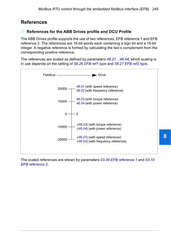
Modbus RTU control through the embedded fieldbus interface (EFB) 245
1
2
3
4
5
6
7
8
9
10
11
12
13
References
References for the ABB Drives profile and DCU Profile
The ABB Drives profile supports the use of two references, EFB reference 1 and EFB reference 2. The references are 16-bit words each containing a sign bit and a 15-bit integer. A negative reference is formed by calculating the two’s complement from the corresponding positive reference.
The references are scaled as defined by parameters 46.01…46.04; which scaling is in use depends on the setting of 58.26 EFB ref1 type and 58.27 EFB ref2 type.
The scaled references are shown by parameters 03.09 EFB reference 1 and 03.10 EFB reference 2.
46.01 (with speed reference)46.02 (with frequency reference)
0
-20000
20000
DriveFieldbus
0
10000
-10000
46.03 (with torque reference)46.04 (with power reference)
-(46.01) (with speed reference)-(46.02) (with frequency reference)
-(46.03) (with torque reference)-(46.04) (with power reference)
14

246 Modbus RTU control through the embedded fieldbus interface (EFB)
1
2
3
4
5
6
7
8
9
10
11
12
13
14
Actual values
Actual values for the ABB Drives profile and DCU Profile
The ABB Drives profile supports the use of two fieldbus actual values, ACT1 and ACT2. The actual values are 16-bit words each containing a sign bit and a 15-bit integer. A negative value is formed by calculating the two’s complement from the corresponding positive value.
The actual values are scaled as defined by parameters 46.01…46.04; which scaling is in use depends on the setting of parameters 58.28 EFB act1 type and 58.29 EFB act2 type.
46.01 (with speed reference)46.02 (with frequency reference)
0
-20000
20000
DriveFieldbus
0
10000
-10000
46.03 (with torque reference)46.04 (with power reference)
-(46.01) (with speed reference)-(46.02) (with frequency reference)
-(46.03) (with torque reference)-(46.04) (with power reference)

Modbus RTU control through the embedded fieldbus interface (EFB) 247
1
2
3
4
5
6
7
8
9
10
11
12
13
Modbus holding register addresses
Modbus holding register addresses for the ABB Drives profile and DCU Profile
The table below shows the default Modbus holding register addresses for the drive data with the ABB Drives profile. This profile provides a converted 16-bit access to the drive data.
Note: Only the 16 least significant bits of the drive’s 32-bit Control and Status Words can be accessed.
Note: Bits 16 through 32 of the DCU Control/Status word are not in use if 16-bit control/status word is used with the DCU Profile.
Register address Register data (16-bit words)
400001 Default: Control word (CW 16bit). See sections Control Word for the ABB Drives profile (page 235) and Control Word for the DCU Profile (page 236).The selection can be changed using parameter 58.101 Data I/O 1.
400002 Default: Reference 1 (Ref1 16bit).The selection can be changed using parameter 58.102 Data I/O 2.
400003 Default: Reference 2 (Ref2 16bit).The selection can be changed using parameter 58.103 Data I/O 3.
400004 Default: Status Word (SW 16bit). See sections Status Word for the ABB Drives profile (page 239) and Status Word for the DCU Profile (page 240). The selection can be changed using parameter 58.104 Data I/O 4.
400005 Default: Actual value 1 (Act1 16bit).The selection can be changed using parameter 58.105 Data I/O 5.
400006 Actual value 2 (Act2 16bit).The selection can be changed using parameter 58.106 Data I/O 6.
400007…400014 Data in/out 7…14.Selected by parameters 58.107 Data I/O 7…58.114 Data I/O 14.
400015…400089 Unused
400090…400100 Error code access. See section Error code registers (holding registers 400090…400100) (page 254).
400101…465536 Parameter read/write.Parameters are mapped to register addresses according to parameter 58.33 Addressing mode.
14

248 Modbus RTU control through the embedded fieldbus interface (EFB)
1
2
3
4
5
6
7
8
9
10
11
12
13
14
Modbus function codes
The table below shows the Modbus function codes supported by the embedded fieldbus interface.
Code Function name Description
01h Read Coils Reads the 0/1 status of coils (0X references).
02h Read Discrete Inputs Reads the 0/1 status of discrete inputs (1X references).
03h Read Holding Registers Reads the binary contents of holding registers (4X references).
05h Write Single Coil Forces a single coil (0X reference) to 0 or 1.
06h Write Single Register Writes a single holding register (4X reference).
08h Diagnostics Provides a series of tests for checking the communication, or for checking various internal error conditions.Supported subcodes:• 00h Return Query Data: Echo/loopback test.• 01h Restart Comm Option: Restarts and initializes
the EFB, clears communications event counters.• 04h Force Listen Only Mode• 0Ah Clear Counters and Diagnostic Register• 0Bh Return Bus Message Count• 0Ch Return Bus Comm. Error Count• 0Dh Return Bus Exception Error Count• 0Eh Return Slave Message Count• 0Fh Return Slave No Response Count• 10h Return Slave NAK (negative acknowledge)
Count• 11h Return Slave Busy Count• 12h Return Bus Character Overrun Count• 14h Clear Overrun Counter and Flag
0Bh Get Comm Event Counter
Returns a status word and an event count.
0Fh Write Multiple Coils Forces a sequence of coils (0X references) to 0 or 1.
10h Write Multiple Registers Writes the contents of a contiguous block of holding registers (4X references).
16h Mask Write Register Modifies the contents of a 4X register using a combination of an AND mask, an OR mask, and the register’s current contents.
17h Read/Write Multiple Registers
Writes the contents of a contiguous block of 4X registers, then reads the contents of another group of registers (the same or different than those written) in a server device.
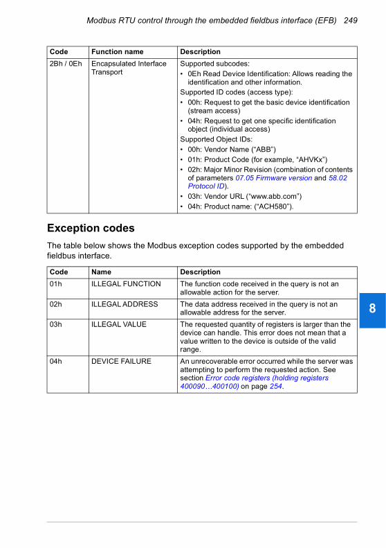
Modbus RTU control through the embedded fieldbus interface (EFB) 249
1
2
3
4
5
6
7
8
9
10
11
12
13
Exception codes
The table below shows the Modbus exception codes supported by the embedded fieldbus interface.
2Bh / 0Eh Encapsulated Interface Transport
Supported subcodes:• 0Eh Read Device Identification: Allows reading the
identification and other information.Supported ID codes (access type):• 00h: Request to get the basic device identification
(stream access)• 04h: Request to get one specific identification
object (individual access)Supported Object IDs:• 00h: Vendor Name (“ABB”)• 01h: Product Code (for example, “AHVKx”)• 02h: Major Minor Revision (combination of contents
of parameters 07.05 Firmware version and 58.02 Protocol ID).
• 03h: Vendor URL (“www.abb.com”)• 04h: Product name: (“ACH580”).
Code Name Description
01h ILLEGAL FUNCTION The function code received in the query is not an allowable action for the server.
02h ILLEGAL ADDRESS The data address received in the query is not an allowable address for the server.
03h ILLEGAL VALUE The requested quantity of registers is larger than the device can handle. This error does not mean that a value written to the device is outside of the valid range.
04h DEVICE FAILURE An unrecoverable error occurred while the server was attempting to perform the requested action. See section Error code registers (holding registers 400090…400100) on page 254.
Code Function name Description
14

250 Modbus RTU control through the embedded fieldbus interface (EFB)
1
2
3
4
5
6
7
8
9
10
11
12
13
14
Coils (0xxxx reference set)
Coils are 1-bit read/write values. Control Word bits are exposed with this data type. The table below summarizes the Modbus coils (0xxxx reference set). Note that the references are 1-based index which match the address transmitted on the wire.
Reference ABB Drives profile DCU Profile
000001 OFF1_CONTROL STOP
000002 OFF2_CONTROL START
000003 OFF3_CONTROL Reserved
000004 INHIBIT_OPERATION Reserved
000005 RAMP_OUT_ZERO RESET
000006 RAMP_HOLD EXT2
000007 RAMP_IN_ZERO RUN_DISABLE
000008 RESET STOPMODE_RAMP
000009 Not for ACH580 STOPMODE_EMERGENCY_RAMP
000010 Not for ACH580 STOPMODE_COAST
000011 REMOTE_CMD Reserved
000012 EXT_CTRL_LOC RAMP_OUT_ZERO
000013 USER_0 RAMP_HOLD
000014 USER_1 RAMP_IN_ZERO
000015 USER_2 Reserved
000016 USER_3 Reserved
000017 Reserved FB_LOCAL_CTL
000018 Reserved FB_LOCAL_REF
000019 Reserved Reserved
000020 Reserved Reserved
000021 Reserved Reserved
000022 Reserved Reserved
000023 Reserved USER_0
000024 Reserved USER_1
000025 Reserved USER_2
000026 Reserved USER_3
000027 Reserved Reserved
000028 Reserved Reserved
000029 Reserved Reserved
000030 Reserved Reserved
000031 Reserved Reserved
000032 Reserved Reserved
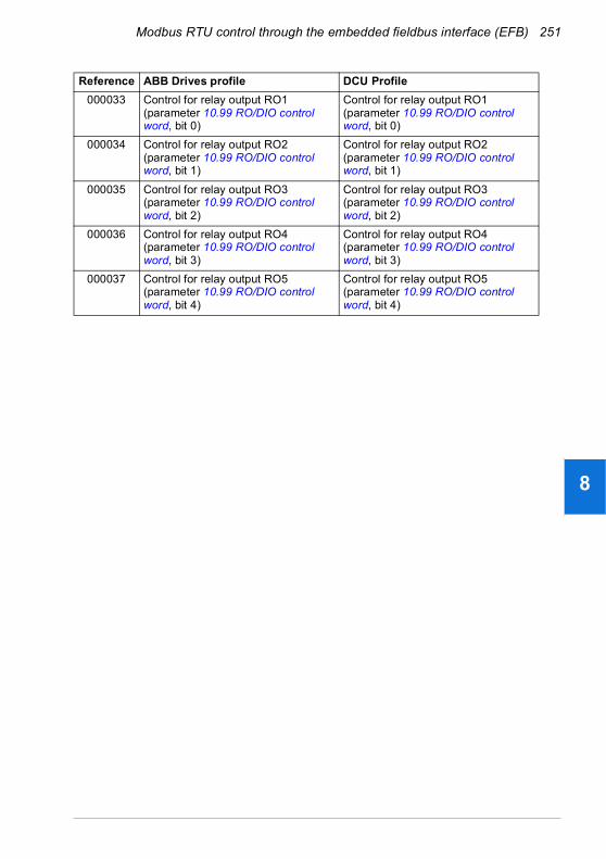
Modbus RTU control through the embedded fieldbus interface (EFB) 251
1
2
3
4
5
6
7
8
9
10
11
12
13
000033 Control for relay output RO1 (parameter 10.99 RO/DIO control word, bit 0)
Control for relay output RO1 (parameter 10.99 RO/DIO control word, bit 0)
000034 Control for relay output RO2 (parameter 10.99 RO/DIO control word, bit 1)
Control for relay output RO2 (parameter 10.99 RO/DIO control word, bit 1)
000035 Control for relay output RO3 (parameter 10.99 RO/DIO control word, bit 2)
Control for relay output RO3 (parameter 10.99 RO/DIO control word, bit 2)
000036 Control for relay output RO4 (parameter 10.99 RO/DIO control word, bit 3)
Control for relay output RO4 (parameter 10.99 RO/DIO control word, bit 3)
000037 Control for relay output RO5 (parameter 10.99 RO/DIO control word, bit 4)
Control for relay output RO5 (parameter 10.99 RO/DIO control word, bit 4)
Reference ABB Drives profile DCU Profile
14
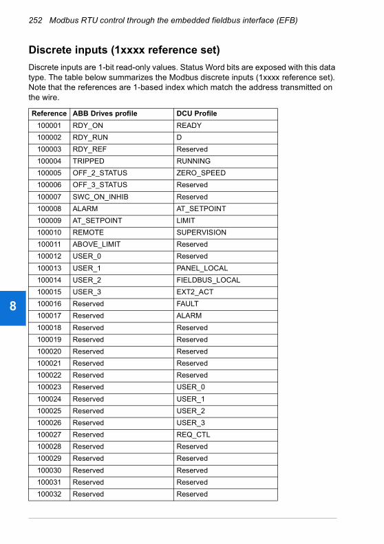
252 Modbus RTU control through the embedded fieldbus interface (EFB)
1
2
3
4
5
6
7
8
9
10
11
12
13
14
Discrete inputs (1xxxx reference set)
Discrete inputs are 1-bit read-only values. Status Word bits are exposed with this data type. The table below summarizes the Modbus discrete inputs (1xxxx reference set). Note that the references are 1-based index which match the address transmitted on the wire.
Reference ABB Drives profile DCU Profile
100001 RDY_ON READY
100002 RDY_RUN D
100003 RDY_REF Reserved
100004 TRIPPED RUNNING
100005 OFF_2_STATUS ZERO_SPEED
100006 OFF_3_STATUS Reserved
100007 SWC_ON_INHIB Reserved
100008 ALARM AT_SETPOINT
100009 AT_SETPOINT LIMIT
100010 REMOTE SUPERVISION
100011 ABOVE_LIMIT Reserved
100012 USER_0 Reserved
100013 USER_1 PANEL_LOCAL
100014 USER_2 FIELDBUS_LOCAL
100015 USER_3 EXT2_ACT
100016 Reserved FAULT
100017 Reserved ALARM
100018 Reserved Reserved
100019 Reserved Reserved
100020 Reserved Reserved
100021 Reserved Reserved
100022 Reserved Reserved
100023 Reserved USER_0
100024 Reserved USER_1
100025 Reserved USER_2
100026 Reserved USER_3
100027 Reserved REQ_CTL
100028 Reserved Reserved
100029 Reserved Reserved
100030 Reserved Reserved
100031 Reserved Reserved
100032 Reserved Reserved

Modbus RTU control through the embedded fieldbus interface (EFB) 253
1
2
3
4
5
6
7
8
9
10
11
12
13
100033 Delayed status of digital input DI1 (parameter 10.02 DI delayed status, bit 0)
Delayed status of digital input DI1 (parameter 10.02 DI delayed status, bit 0)
100034 Delayed status of digital input DI2 (parameter 10.02 DI delayed status, bit 1)
Delayed status of digital input DI2 (parameter 10.02 DI delayed status, bit 1)
100035 Delayed status of digital input DI3 (parameter 10.02 DI delayed status, bit 2)
Delayed status of digital input DI3 (parameter 10.02 DI delayed status, bit 2)
100036 Delayed status of digital input DI4 (parameter 10.02 DI delayed status, bit 3)
Delayed status of digital input DI4 (parameter 10.02 DI delayed status, bit 3)
100037 Delayed status of digital input DI5 (parameter 10.02 DI delayed status, bit 4)
Delayed status of digital input DI5 (parameter 10.02 DI delayed status, bit 4)
100038 Delayed status of digital input DI6 (parameter 10.02 DI delayed status, bit 5)
Delayed status of digital input DI6 (parameter 10.02 DI delayed status, bit 5)
Reference ABB Drives profile DCU Profile
14

254 Modbus RTU control through the embedded fieldbus interface (EFB)
1
2
3
4
5
6
7
8
9
10
11
12
13
14
Error code registers (holding registers 400090…400100)
These registers contain information about the last query. The error register is cleared when a query has finished successfully.
Reference Name Description
400090 Reset Error Registers 1 = Reset internal error registers (91…95). 0 = Do nothing.
400091 Error Function Code Function code of the failed query.
400092 Error Code Set when exception code 04h is generated (see table above).• 00h No error• 02h Low/High limit exceeded• 03h Faulty Index: Unavailable index of an array
parameter• 05h Incorrect Data Type: Value does not match the
data type of the parameter• 65h General Error: Undefined error when handling
query
400093 Failed Register The last register (discrete input, coil, input register or holding register) that failed to be read or written.
400094 Last Register Written Successfully
The last register (discrete input, coil, input register or holding register) that was written successfully.
400095 Last Register Read Successfully
The last register (discrete input, coil, input register or holding register) that was read successfully.

BACnet MS/TP control through the embedded fieldbus interface (EFB) 255
1
2
3
4
5
6
7
8
9
10
11
12
13
9BACnet MS/TP control through the embedded fieldbus interface (EFB)
Contents of this chapter
The chapter describes BACnet MS/TP control through the embedded fieldbus interface (EFB): supported functionality, services and objects as well as how to configure the BACnet through the Primary settings menu and with parameters.
BACnet overview
BACnet is an open standard for data communication that enables interoperability between different building systems (eg fire, security, lighting, HVAC, elevator, etc.) and devices in building automation and control applications. It enables data sharing among different types of devices from a broad set of suppliers.
You will find BACnet Protocol Implementation Conformance Statement (PICS) (3AXD10000387059 [English]) for the ACH580 in the ABB Document library on the Internet.
14
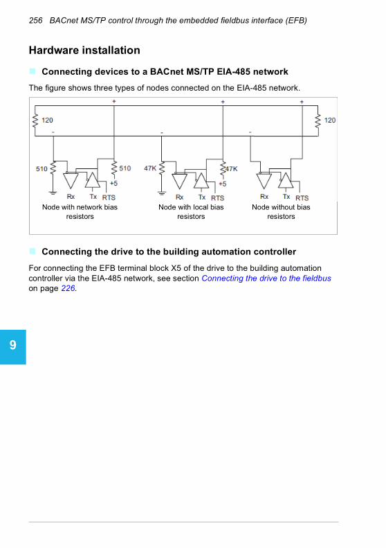
256 BACnet MS/TP control through the embedded fieldbus interface (EFB)
1
2
3
4
5
6
7
8
9
10
11
12
13
14
Hardware installation
Connecting devices to a BACnet MS/TP EIA-485 network
The figure shows three types of nodes connected on the EIA-485 network.
Connecting the drive to the building automation controller
For connecting the EFB terminal block X5 of the drive to the building automation controller via the EIA-485 network, see section Connecting the drive to the fieldbus on page 226.
Node with network bias resistors
Node with local bias resistors
Node without bias resistors

BACnet MS/TP control through the embedded fieldbus interface (EFB) 257
1
2
3
4
5
6
7
8
9
10
11
12
13
Starting up BACnet communication through the Primary settings menu
The Primary settings menu enables easy programming of the most common settings for the drive including BACnet communication settings.
Commissioning
To start up fieldbus communication select Menu > Primary settings > Communication.
Select Embedded fieldbus > Communication setup.
14
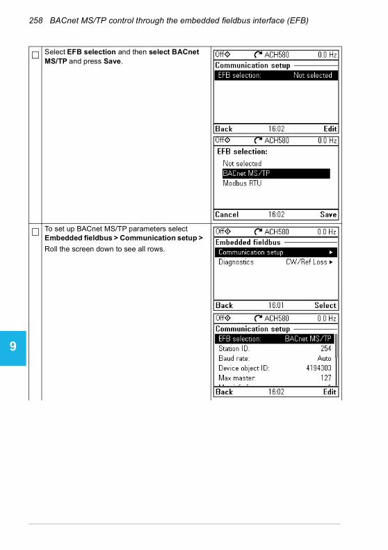
258 BACnet MS/TP control through the embedded fieldbus interface (EFB)
1
2
3
4
5
6
7
8
9
10
11
12
13
14
Select EFB selection and then select BACnet MS/TP and press Save.
To set up BACnet MS/TP parameters select Embedded fieldbus > Communication setup > Roll the screen down to see all rows.

BACnet MS/TP control through the embedded fieldbus interface (EFB) 259
1
2
3
4
5
6
7
8
9
10
11
12
13
After setting all necessary parameters, select Apply settings to embedded fieldbus to validate your settings.
After validating the settings, press Back twice until you see Pass through I/O on the Communication menu.
Select Pass through I/O and then Drive control setup.
14
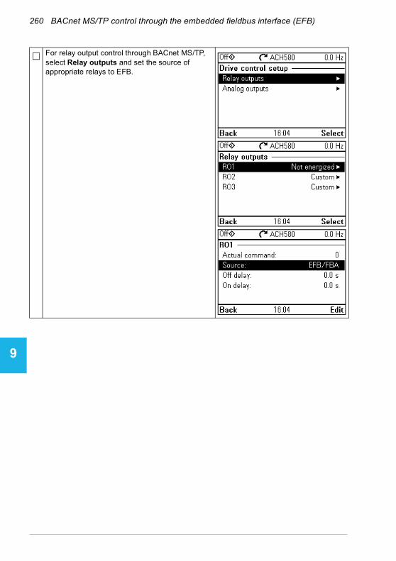
260 BACnet MS/TP control through the embedded fieldbus interface (EFB)
1
2
3
4
5
6
7
8
9
10
11
12
13
14
For relay output control through BACnet MS/TP, select Relay outputs and set the source of appropriate relays to EFB.
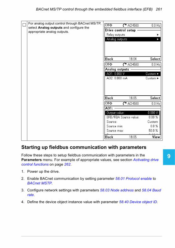
BACnet MS/TP control through the embedded fieldbus interface (EFB) 261
1
2
3
4
5
6
7
8
9
10
11
12
13
Starting up fieldbus communication with parameters
Follow these steps to setup fieldbus communication with parameters in the Parameters menu. For example of appropriate values, see section Activating drive control functions on page 262.
1. Power up the drive.
2. Enable BACnet communication by setting parameter 58.01 Protocol enable to BACnet MSTP.
3. Configure network settings with parameters 58.03 Node address and 58.04 Baud rate.
4. Define the device object instance value with parameter 58.40 Device object ID.
For analog output control through BACnet MS/TP, select Analog outputs and configure the appropriate analog outputs.
14
262 BACnet MS/TP control through the embedded fieldbus interface (EFB)
1
2
3
4
5
6
7
8
9
10
11
12
13
14
Note: The object instance value should be unique and in the range 1…4194303.
5. Define communication loss function to detect communication loss between EFB and the drive:
• Set the communication loss mode and communication loss time with parameters 58.15 Communication loss mode and 58.16 Communication loss time.
• Select how the drive reacts to an EFB communication break with parameter 58.14 Communication loss action.
6. Save the valid parameter values to permanent memory by setting parameter 96.07 Parameter save manually to Save.
7. Validate the settings made in parameter group 58 Embedded fieldbus by setting parameter 58.06 Communication control to Refresh settings.
8. You can use parameters 58.07…58.13 for diagnostics. You can reset counters 58.08…58.12 by setting the parameter value to 0.
9. Set the relevant drive control parameters to control the drive according to the application.
Note: You find all embedded fieldbus parameters in group 58 Embedded fieldbus on page 531.
Activating drive control functions
Drive control
To enable fieldbus control of various drive functions through BACnet MS/TP, do the following:
• Configure the drive to accept embedded fieldbus communication by enabling BACnet communication and defining the node address and device id for the drive.
• Select the individual control functions to use the embedded fieldbus as a source. This makes the input source come from the corresponding BACnet object.
Note: Change those parameter of the functions that you want to control through BACnet MS/TP. All other parameters can remain as factory default values.
Start/stop direction control
For Start/stop direction control through fieldbus, configure the following drive parameters and set the fieldbus controller supplied command(s) in the appropriate location:
Drive parameter Value Description BACnet object
20.01 Ext1 commands Embedded fieldbus
Start/stop by fieldbus with Ext1 selected
BV10
20.07 Ext2 commands Embedded fieldbus
Start/stop by fieldbus with Ext2 selected
BV10
BACnet MS/TP control through the embedded fieldbus interface (EFB) 263
1
2
3
4
5
6
7
8
9
10
11
12
13
Input reference select
The tables below show how to use the BACnet embedded fieldbus to select the drive input references for frequency and speed control modes
• For frequency control, set parameter 99.04 Motor control mode = Scalar (default value for ACH580). See section Frequency reference on page 263 and parameter group 28 Frequency reference chain on page 431.
• For speed control, set parameter 99.04 Motor control mode = Vector. See section Speed reference on page 263 and parameter group 22 Speed reference selection on page 413.
Vector control has better accuracy than scalar control, but vector control cannot be used in all situations. See parameter 99.04 Motor control mode.
Frequency reference
For using the BACnet embedded fieldbus to provide input frequency references to the drive, configure the following drive parameters and set the fieldbus controller supplied reference word(s) in the appropriate location:
Speed reference
For using the BACnet embedded fieldbus to provide input speed references to the drive, configure the following drive parameters and set the fieldbus controller supplied reference word(s) in the appropriate location:
20.21 Direction Request Direction by fieldbus, if required BV11
Drive parameter Value Description BACnet object
19.11 Ext1/Ext2 selection
32 = EFB MCW bit 11
Reference set selection by fieldbus BV13
28.11 Ext1 frequency ref1
8 = EFB ref1 1) Frequency reference source 1 AV16Input Reference1
28.15 Ext2 frequency ref1
9 =EFB ref2 1) Frequency reference source 2 AV17Input Reference 2
46.02 Frequency scaling 50.00 Hz 1) 16-bit scaling of frequency-related parameters
No direct BACnet object
1) As an example
Drive parameter Value Description BACnet object
19.11 Ext1/Ext2 selection
32 =EFB MCW bit 11
Reference set selection by fieldbus BV13
22.11 Ext1 speed ref1 8 = EFB ref1 1) Speed reference source 1 AV16Input Reference1
22.18 Ext2 speed ref1 9 = EFB ref2 1) Speed reference source 2 AV17Input Reference 2
46.01 Speed scaling 1500 rpm 1) 16-bit scaling of speed-related parameters
No direct BACnet object
1) As an example
Drive parameter Value Description BACnet object
14
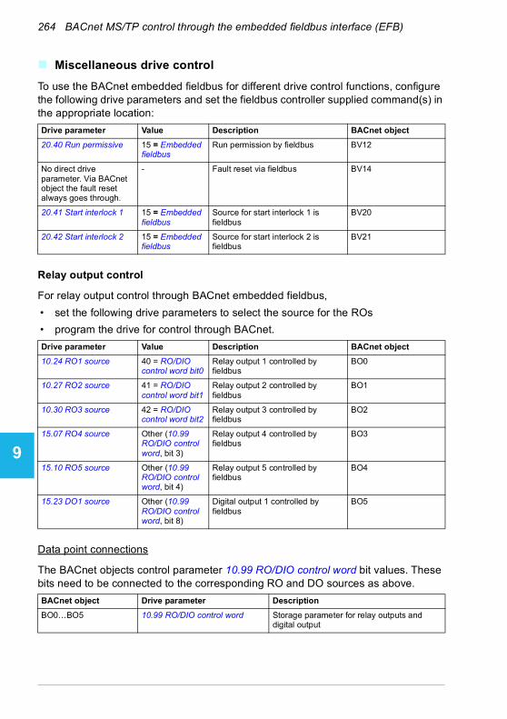
264 BACnet MS/TP control through the embedded fieldbus interface (EFB)
1
2
3
4
5
6
7
8
9
10
11
12
13
14
Miscellaneous drive control
To use the BACnet embedded fieldbus for different drive control functions, configure the following drive parameters and set the fieldbus controller supplied command(s) in the appropriate location:
Relay output control
For relay output control through BACnet embedded fieldbus,
• set the following drive parameters to select the source for the ROs
• program the drive for control through BACnet.
Data point connections
The BACnet objects control parameter 10.99 RO/DIO control word bit values. These bits need to be connected to the corresponding RO and DO sources as above.
Drive parameter Value Description BACnet object
20.40 Run permissive 15 = Embedded fieldbus
Run permission by fieldbus BV12
No direct drive parameter. Via BACnet object the fault reset always goes through.
- Fault reset via fieldbus BV14
20.41 Start interlock 1 15 = Embedded fieldbus
Source for start interlock 1 is fieldbus
BV20
20.42 Start interlock 2 15 = Embedded fieldbus
Source for start interlock 2 is fieldbus
BV21
Drive parameter Value Description BACnet object
10.24 RO1 source 40 = RO/DIO control word bit0
Relay output 1 controlled by fieldbus
BO0
10.27 RO2 source 41 = RO/DIO control word bit1
Relay output 2 controlled by fieldbus
BO1
10.30 RO3 source 42 = RO/DIO control word bit2
Relay output 3 controlled by fieldbus
BO2
15.07 RO4 source Other (10.99 RO/DIO control word, bit 3)
Relay output 4 controlled by fieldbus
BO3
15.10 RO5 source Other (10.99 RO/DIO control word, bit 4)
Relay output 5 controlled by fieldbus
BO4
15.23 DO1 source Other (10.99 RO/DIO control word, bit 8)
Digital output 1 controlled by fieldbus
BO5
BACnet object Drive parameter Description
BO0…BO5 10.99 RO/DIO control word Storage parameter for relay outputs and digital output

BACnet MS/TP control through the embedded fieldbus interface (EFB) 265
1
2
3
4
5
6
7
8
9
10
11
12
13
Analog output control
For analog output control through BACnet embedded fieldbus, configure the following drive parameters and set the fieldbus controller supplied analog value(s) in the appropriate location:
Data point connections
The BACnet objects control parameters 13.91 AO1 data storage and 13.92 AO2 data storage values. These values need to be connected to the corresponding AO sources as above.
PID control
For PID control through BACnet embedded fieldbus, configure the following drive parameters and set the fieldbus controller supplied PID value(s) in the appropriate location:
Drive parameter Value Description BACnet object
13.12 AO1 source 37 = AO1 data storage
Analog output 1 controlled by fieldbus
AO0
13.22 AO2 source 38 = AO2 data storage
Analog output 2 controlled by fieldbus
AO1
13.17 AO1 source min 0.0 1) Minimum value of signal selected by parameter 13.12 AO1 source
No direct BACnet object
13.18 AO1 source max 100.0 1) Maximum value of signal selected by parameter 13.12 AO1 source
No direct BACnet object
13.27 AO2 source min 0.0 1) Minimum value of signal selected by parameter 13.22 AO2 source
No direct BACnet object
13.28 AO2 source max 100.0 1) Maximum value of signal selected by parameter 13.22 AO2 source
No direct BACnet object
1) As an example
BACnet object Drive parameter Description
AO0 13.91 AO1 data storage Storage parameter for AO1
AO1 13.92 AO2 data storage Storage parameter for AO2
Drive parameter Value Description BACnet object
40.08 Set 1 feedback 1 source
10 = Feedback data storage
Feedback 1 source data storage AV43
40.09 Set 1 feedback 2 source
10 = Feedback data storage
Feedback 2 source data storage AV43
40.16 Set 1 setpoint 1 source
24 = Setpoint data storage
Setpoint 1 source data storage AV42
40.17 Set 1 setpoint 2 source
24 = Setpoint data storage
Setpoint 2 source data storage AV42
14

266 BACnet MS/TP control through the embedded fieldbus interface (EFB)
1
2
3
4
5
6
7
8
9
10
11
12
13
14
Data point connections
The BACnet objects control parameters 40.91 Feedback data storage and 40.92 Setpoint data storage. These values need to be connected to the corresponding PID setpoint and feedback values as above.
Communication fault
BACnet has no built-in feature to detect communication timeout, because it is not a synchronous protocol. If communication timeouts are needed, you can use the following parameters to detect timeouts based on different packets and specifying the drive action.
Drive feedback
The inputs to the BMS controller (drive output signals) have pre-defined content. These drive feedback signals do not require any additional drive configuration. The following table lists a subset of the supported feedback data. For a complete listing, see the Protocol Implementation Conformance Statement (PICS) (3AXD10000387059 [English]), which you can find in the ABB Document library on the Internet.
BACnet object Drive parameter Description
AV43 40.91 Feedback data storage Storage parameter for process feedback value
AV42 40.92 Setpoint data storage Storage parameter for process setpoint value
Drive parameter Value Description
58.15 Communication loss mode
1 = Any message2 = Cw / Ref1 / Ref2
Defines which message types reset the timeout counter for detecting an EFB communication loss.
58.14 Communication loss action
0 = No action1 = Fault2 = Last speed3 = Speed ref safe4 = Fault always5 = Warning
Selects how the drive reacts to an EFB communication break. Changes to this parameter take effect after the control unit is rebooted or the new settings are validated by parameter 58.06 Communication control (1 = Refresh settings).
58.16 Communication loss time
0.0…6000.0 s Sets a timeout for EFB communication. If a communication break lasts longer than the timeout, the action specified by parameter 58.16 Communication loss time is taken.
Drive parameter Description BACnet object
01.01 Motor speed used Estimated motor speed (rpm) AV0
01.06 Output frequency Estimated drive output frequency (Hz) AV1
01.11 DC voltage DC link voltage (V) AV2
01.13 Output voltage Calculated motor voltage (V AC) AV3
01.07 Motor current Measured (absolute) motor current (A) AV4
01.10 Motor torque Motor torque in percent of the nominal motor torque (%)
AV5

BACnet MS/TP control through the embedded fieldbus interface (EFB) 267
1
2
3
4
5
6
7
8
9
10
11
12
13
The actual output values of the drive can be read from AV0…AV6, AV31 and AV32:
01.14 Output power Drive output power (kW) AV6
05.11 Inverter temperature
Estimated drive temperature in percent of fault limit (%)
AV7
01.20 Inverter kWh counter
Amount of energy that has passed through the drive (in either direction) in full kilowatthours.Whenever the counter rolls over, 01.19 Inverter MWh counter is incremented. The minimum value is zero.
AV9
35.01 Motor estimated temperature
Displays the motor temperature (°C or °F) as estimated by the internal motor thermal protection model. The unit is selected by parameter 96.16 Unit selection.
AV15
01.03 Motor speed % Motor speed in percent of the synchronous motor speed.
AV31
40.01 Process PID output actual
PID controller output AV44
40.04 Process PID deviation actual
PID deviation AV49
01.50 Current hour kWh Current day energy consumption. This is the energy of the last 24 hours (not necessarily continuous) the drive has been running, not the energy of a calendar day. If the power is cycled, after the drive is again up and running, the parameter value is set to the value it had before the power cycle.
AV130
01.51 Previous hour kWh
Previous hour energy consumption. The value 01.50 Current hour kWh is stored here when its values has been cumulated for 60 minutes. If the power is cycled, after the drive is again up and running, the parameter value is set to the value it had before the power cycle.
AV131
01.52 Current day kWh Current day energy consumption. This is the energy of the last 24 hours (not necessarily continuous) the drive has been running, not the energy of a calendar day. If the power is cycled, after the drive is again up and running, the parameter value is set to the value it had before the power cycle.
AV132
01.53 Previous day kWh Previous day energy consumption. The value 01.52 Current day kWh is stored here when its value has been cumulated for 24 hours. If the power is cycled, after the drive is again up and running, the parameter value is set to the value it had before the power cycle.
AV133
04.01 Tripping fault Fault that caused the current trip (active fault) AV18
04.11 Latest fault Previous fault (non-active) AV19
04.12 2nd latest fault Fault before the previous fault (non-active) AV20
Object ID Default object name
Description Min/max present value
Unit Present value access type
AV0 Output-RPM Motor speed 0, nominal speed rpm R
AV1 Output-Freq Output frequency -500, 500 Hz R
Drive parameter Description BACnet object
14

268 BACnet MS/TP control through the embedded fieldbus interface (EFB)
1
2
3
4
5
6
7
8
9
10
11
12
13
14
AV2 DC-Voltage DC link voltage 0, 2000 V R
AV3 Output-Voltage AC output voltage 0, 2000 V R
AV4 Output-Current Output current of drive 0, nominal current A R
AV5 Output-Torque Output torque of motor as a percentage of nominal torque
-1600, 1600 % R
AV6 Output-Power Output power in kW nominal power (+/-)
kW R
AV31 Output-Speed Actual motor speed -200, 200 % R
AV32 Output-Current-Range
Actual motor current 0, 200 % R
Object ID Default object name
Description Min/max present value
Unit Present value access type
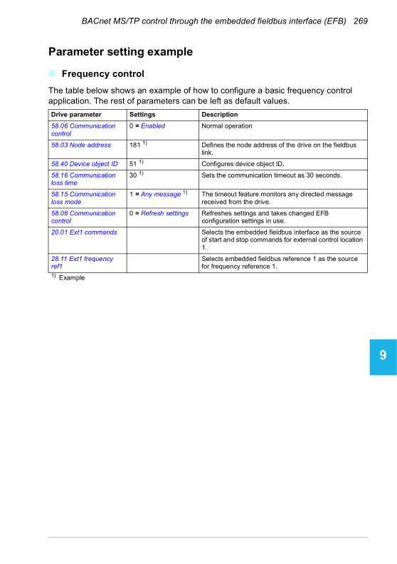
BACnet MS/TP control through the embedded fieldbus interface (EFB) 269
1
2
3
4
5
6
7
8
9
10
11
12
13
Parameter setting example
Frequency control
The table below shows an example of how to configure a basic frequency control application. The rest of parameters can be left as default values.
Drive parameter Settings Description
58.06 Communication control
0 = Enabled Normal operation
58.03 Node address 181 1) Defines the node address of the drive on the fieldbus link.
58.40 Device object ID 51 1) Configures device object ID.
58.16 Communication loss time
30 1) Sets the communication timeout as 30 seconds.
58.15 Communication loss mode
1 = Any message 1) The timeout feature monitors any directed message received from the drive.
58.06 Communication control
0 = Refresh settings Refreshes settings and takes changed EFB configuration settings in use.
20.01 Ext1 commands Selects the embedded fieldbus interface as the source of start and stop commands for external control location 1.
28.11 Ext1 frequency ref1
Selects embedded fieldbus reference 1 as the source for frequency reference 1.
1) Example
14
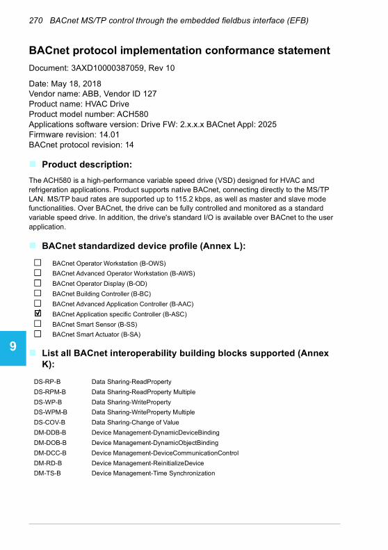
270 BACnet MS/TP control through the embedded fieldbus interface (EFB)
1
2
3
4
5
6
7
8
9
10
11
12
13
14
BACnet protocol implementation conformance statement
Document: 3AXD10000387059, Rev 10
Date: May 18, 2018Vendor name: ABB, Vendor ID 127Product name: HVAC DriveProduct model number: ACH580Applications software version: Drive FW: 2.x.x.x BACnet Appl: 2025Firmware revision: 14.01BACnet protocol revision: 14
Product description:
The ACH580 is a high-performance variable speed drive (VSD) designed for HVAC and refrigeration applications. Product supports native BACnet, connecting directly to the MS/TP LAN. MS/TP baud rates are supported up to 115.2 kbps, as well as master and slave mode functionalities. Over BACnet, the drive can be fully controlled and monitored as a standard variable speed drive. In addition, the drive's standard I/O is available over BACnet to the user application.
BACnet standardized device profile (Annex L):
List all BACnet interoperability building blocks supported (Annex K):
BACnet Operator Workstation (B-OWS)
BACnet Advanced Operator Workstation (B-AWS)
BACnet Operator Display (B-OD)
BACnet Building Controller (B-BC)
BACnet Advanced Application Controller (B-AAC)
BACnet Application specific Controller (B-ASC)
BACnet Smart Sensor (B-SS)
BACnet Smart Actuator (B-SA)
DS-RP-B Data Sharing-ReadProperty
DS-RPM-B Data Sharing-ReadProperty Multiple
DS-WP-B Data Sharing-WriteProperty
DS-WPM-B Data Sharing-WriteProperty Multiple
DS-COV-B Data Sharing-Change of Value
DM-DDB-B Device Management-DynamicDeviceBinding
DM-DOB-B Device Management-DynamicObjectBinding
DM-DCC-B Device Management-DeviceCommunicationControl
DM-RD-B Device Management-ReinitializeDevice
DM-TS-B Device Management-Time Synchronization

BACnet MS/TP control through the embedded fieldbus interface (EFB) 271
1
2
3
4
5
6
7
8
9
10
11
12
13
Segmentation capability:
Standard object types supported:
Object instantiation is static, i.e. objects cannot be created or deleted. Refer to tables at end of this document for object details.
Data link layer options:
Device address binding:
Is static device binding supported? (This is currently necessary for two-way communication with MS/TP slaves and certain other devices.) Yes No
Networking options:
Able to transmit segmented messages Window size: -
Able to receive segmented messages Window size: -
BACnet IP, (Annex J)
BACnet IP, (Annex J), foreign device
ISO 8802-3, Ethernet (Clause 7)
ATA 878.1, 2.5 Mb. ARCNET (Clause 8)
ATA 878.1, EIA-485 ARCNET (Clause 8), baud rate(s) ____________
MS/TP master (Clause 9), baud rate(s): 9.6k, 19.2k, 38.4k, 76.8k, 115.2k
MS/TP slave (Clause 9), baud rate(s): 9.6k, 19.2k, 38.4k, 76.8k, 115.2k
Point-to-point, EIA 232 (Clause 10), baud rate(s):__________
Point-to-point, modem, (Clause 10), baud rate(s):__________
LonTalk, (Clause 11), medium: __________
BACnet/ZigBee (ANNEX O)
Other: __________
Router, Clause 6
BACnet/IP to MS/TP
BACnet/ ISO 8802-3, Ethernet to MS/TP
BACnet/IP to BACnet/ ISO 8802-3, Ethernet
BACnet/IP to BACnet/ ISO 8802-3, Ethernet to MS/TP
Annex H, BACnet tunneling router over IP
BACnet/IP broadcast management device (BBMD)
Does the BBMD support registrations by foreign devices? Yes No
Max BDT (Broadcast distribution table)-entries:
Does the BBMD support network address translation? Yes No
14
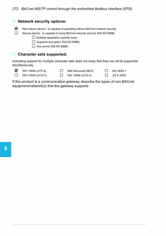
272 BACnet MS/TP control through the embedded fieldbus interface (EFB)
1
2
3
4
5
6
7
8
9
10
11
12
13
14
Network security options:
Character sets supported:
Indicating support for multiple character sets does not imply that they can all be supported simultaneously.
If this product is a communication gateway, describe the types of non-BACnet equipment/network(s) that the gateway supports:
Non-secure device - is capable of operating without BACnet network security
Secure device - is capable of using BACnet network security (NS-SD BIBB)
Multiple application-specific keys:
Supports encryption (NS-ED BIBB)
Key server (NS-KS BIBB)
ISO 10646 (UTF-8) IBM /Microsoft DBCS ISO 8859-1
ISO 10646 (UCS-2) ISO 10646 (UCS-4) JIS X 0208

BACnet MS/TP control through the embedded fieldbus interface (EFB) 273
1
2
3
4
5
6
7
8
9
10
11
12
13
Object/Property support matrix
The following table summarizes the object types/properties supported and default values:
Device object instance summary
The following table summarizes the device object supported:
PropertyObject type
Binaryinput
Binaryoutput
Binaryvalue
Analoginput
Analogoutput
Analogvalue
Multistatevalue
Loop
Object identifier R R R R R R R R
Object name W, P W, P R W, P W, P R(1) R W,P
Object type R R R R R R R R
Present value R C C R C C R R
Status flags R R R R R R R R
Event state R R R R R R R R
Out-of-service W W W W W W W W
Polarity W, P W, P
Active text R R R
Inactive text R R R
Units R R R
Min present value R R R
Max present value R R R
Priority array R R R R
Relinquish default W, P W,P W, P W, P
COV increment W,P W,P W,P
Number of states R
State text R
Property list R R R R R R R R
• R = Read only, W = Writable, C = Commandable, P = Persist• AV16, AV17, AV21, AV22, AV40- AV44, AV55, AV56, AV59, AV120-
129 have W, P• Max length of writable object names is 25 characters
Device object
Property Flag Type Default value
Object identifier W, P OID 4194303
Object name W, P CharString,max length 25
AC Drive 4194303
Object type R Enum DEV (8)
System status R Enum
Vendor name R CharString ABB
Vendor identifier R Unsigned 127
Model name R CharString ACH580
14

274 BACnet MS/TP control through the embedded fieldbus interface (EFB)
1
2
3
4
5
6
7
8
9
10
11
12
13
14
Binary input object instance summary
The following table summarizes the binary input objects supported:
Firmware revision R CharString 14.01
Application software revision R CharString
Description W, P CharString, max length 100
“ACH580 is a high-performance variable speed drive designed for
HVAC and refrigeration applications.”
Location W, P CharString,max length 50
“(not set)”
Protocol version R Unsigned 1
Protocol revision R Unsigned 14
Protocol services supported R BitString
Protocol object types supported
R BitString
Object list R Array of OID
Max APDU length accepted R Unsigned 480
Segmentation supported R Enum No segmentation (3)
Local time R BACnetTime
Local date R BACnetDate
APDU timeout W, P Unsigned 10000 ms
Number of APDU retries W, P Unsigned 3
Max master W, P Unsigned 127
Max info frames W, P Unsigned 1
Device address binding R List of Struct
Database revision R, P Unsigned
Active COV subscriptions R Array of BACnetCOVSubscription
Serial number R CharString
Property list R Array of Unsigned
Flags: R = Read only, W = Writable, C = Commandable, P = Persist
Object ID Object name Description Active/Inactive text
Present valueaccess type
BI0 RO1-Monitor Status of relay output 1 On / Off R
BI1 RO2-Monitor Status of relay output 2 On / Off R
BI2 RO3-Monitor Status of relay output 3 On / Off R
BI3 RO4-Monitor Status of relay output 4 On / Off R
BI4 RO5-Monitor Status of relay output 5 On / Off R
BI5 DO1-Monitor Status of digital output 1 On / Off R
BI6 DI1-Monitor Status of digital input 1 On / Off R
BI7 DI2-Monitor Status of digital input 2 On / Off R
BI8 DI3-Monitor Status of digital input 3 On / Off R

BACnet MS/TP control through the embedded fieldbus interface (EFB) 275
1
2
3
4
5
6
7
8
9
10
11
12
13
Note: For present value access types, R = Read-only, W = Writeable, C = Commandable. Commandable values support priority arrays & relinquish defaults.
Binary output object instance summary
The following table summarizes the binary output objects supported:
Note: For present value access types, R = Read-only, W = Writeable, C = Commandable. Commandable values support priority arrays & relinquish defaults.
Binary value object instance summary
The following table summarizes the binary value objects supported:
BI9 DI4-Monitor Status of digital input 4 On / Off R
BI10 DI5-Monitor Status of digital input 5 On / Off R
BI11 DI6-Monitor Status of digital input 6 On / Off R
Object ID Object name Description Active/Inactive text
Present valueaccess type
BO0 RO1-Command Output state of relay 1 On / Off C
BO1 RO2-Command Output state of relay 2 On / Off C
BO2 RO3-Command Output state of relay 3 On / Off C
BO3 RO4-Command Output state of relay 4 On / Off C
BO4 RO5-Command Output state of relay 5 On / Off C
BO5 DO1-Command Output state of digital output 1 On / Off C
Object ID Object name Description Active/Inactive text
Present valueaccess type
BV0 RUN-STOP-Monitor
Drive’s run status Run / Stop R
BV1 Direction-Monitor
Rotational direction of the motor Reverse / Forward R
BV2 OK-FAULT-Monitor
Actual fault status of drive Fault / OK R
BV3 EXT1-EXT2-Monitor
Actual control source Ext2 / Ext1 R
BV4 HAND-AUTO-Monitor
Actual operating mode. Hand / Auto R
BV5 Warning-Monitor
Actual warning status Warning / OK R
BV7 Ready-Monitor Actual ready status Ready / Not-Ready R
BV8 At-Setpoint-Monitor
Actual at setpoint status Yes / No R
BV9 Enabled-Monitor
Actual run enabled status Enable / Disable R
Object ID Object name Description Active/Inactive text
Present valueaccess type
14

276 BACnet MS/TP control through the embedded fieldbus interface (EFB)
1
2
3
4
5
6
7
8
9
10
11
12
13
14
BV10 RUN-STOP-Command
Command to start drive Run / Stop C
BV11 Direction-Command
Command to rotational direction Reverse / Forward C
BV12 Run-Permissive-Command
Command to run permissive command
Enable / Disable C
BV13 EXT1-EXT2-Command
Commanded to external 1 or external 2 selection
Ext2 / Ext1 C
BV14 Fault-Reset-Command
Commanded to fault reset Reset / No W
BV15-BV16 <Reserved>
BV17 Lock-Parameters
Actual status of parameter lock. Lock / Unlock R
BV18 Control-Override-Command
Command the drive into BACnet control override. In this mode, BACnet acquires drive control
from its normal source. Note that HAND mode of the panel has priority over BACnet Control
Override.
On / Off C
BV19 Control-Override-Monitor
Indicates if drive has been placed in BACnet control override by
commanding BV18. In this mode, BACnet acquires drive control
from its normal source. Note that HAND mode of the panel has priority over BACnet control
override.
On / Off R
BV20 Start-Interlock-1-Command
Command to start enable 1 Enable / Disable C
BV21 Start-Interlock-2-Command
Command to start enable 2 Enable / Disable C
BV24 Started-Monitor Actual start status Started / Not-Started
R
BV25 Safe-Torque-Off-Monitor
Actual status of Safe Torque Off Active / OK R
BV26 Underload-Monitor
Indicates if ULC signal is lower than the Underload curve
Underload / OK R
BV27 Overload-Monitor
Indicates if ULC signal is higher than the overload curve
Overload / OK R
BV28 Motor-Heating-Command
Command to motor heating mode On / Off W
BV29 Motor-Heating-Monitor
Actual status of motor heating mode
On / Off R
BV30 User0-Monitor Actual status of “User bit0” in drive status word
On / Off R
BV31 User1-Monitor Actual status of “User bit1” in drive status word
On / Off R
BV32 User2-Monitor Actual status of “User bit2” in drive status word
On / Off R
Object ID Object name Description Active/Inactive text
Present valueaccess type

BACnet MS/TP control through the embedded fieldbus interface (EFB) 277
1
2
3
4
5
6
7
8
9
10
11
12
13
Note: For present value access types, R = Read-only, W = Writeable, C = Commandable. Commandable values support priority arrays & relinquish defaults.
Analog input object instance summary
The following table summarizes the analog input objects supported:
Note: For present value access types, R = Read-only, W = Writeable, C = Commandable. Commandable values support priority arrays & relinquish defaults.
Analog output object instance summary
The following table summarizes the analog output objects supported:
BV33 User3-Monitor Actual status of “User bit3” in drive status word
On / Off R
BV34 User0-Command
Commands “User bit0” in drive status word
On / Off C
BV35 User1-Command
Commands “User bit1” in drive status word
On / Off C
BV36 User2-Command
Commands “User bit2” in drive status word
On / Off C
BV37 User3-Command
Commands “User bit3” in drive status word
On / Off C
BV38 <Reserved>
BV39 Parameter-Save-Command
Command to save drive parameters and BACnet property
data (properties marked as ‘P=Persist’)
Save / No W
BV40 PID-Set-Select Command to Process PID set1 or Process PID set2 selection
Set1 / Set2 W
Object ID Default object name
Description Min / Max present value
Units Present valueaccess type
AI0 AI1-Monitor Indicates the input level of analog input
1.
0…100 Percent (%) R
AI1 AI2-Monitor Indicates the input level of analog input
2.
0…100 Percent (%) R
Object ID Default object name
Description Min / Max present value
Units Present valueaccess type
AO0 AO1-Command Controls analog output 1 (drive must
be configured for BACnet control).
0…100 Percent C
AO1 AO2-Command Controls analog output 2 (drive must
be configured for BACnet control).
0…100 Percent C
Object ID Object name Description Active/Inactive text
Present valueaccess type
14

278 BACnet MS/TP control through the embedded fieldbus interface (EFB)
1
2
3
4
5
6
7
8
9
10
11
12
13
14
Note: For present value access types, R = Read-only, W = Writeable, C = Commandable. Commandable values support priority arrays & relinquish defaults.
Analog value object instance summary
The following table summarizes the analog value objects supported:
Object ID Default object name
Description Min / Max present value
Units Present valueaccess type
AV0 Output-RPM Motor speed 0, nominal speed rpm R
AV1 Output-Freq Output frequency -500, 500 Hz R
AV2 DC-Voltage DC bus voltage 0,2000
V R
AV3 Output-Voltage AC output voltage 0,2000
V R
AV4 Output-Current Output current of drive 0,nominal current
A R
AV5 Output-Torque Output torque of motor as a percentage of
nominal torque
-1600,1600
% R
AV6 Output-Power Output power in kW nominal power (+/-)
kW R
AV7 Operating-Temp-Range
Heatsink temperature -40,160
% R
AV8 Kilowatt-Hour-Meter-R
Drive’s cumulative energy usage. This value is resettable.
0,65535 kWh W
AV9 Kilowatt-Hour-Meter-NR
Drive’s cumulative energy usage. This
value is not resettable.
0,65535999999
kWh R
AV10 Process-PID-Feedback
This object is the process PID feedback
signal.
0,100
% R
AV11 Process-PID-Deviation
This object is the process PID output
signal’s deviation from its setpoint.
0,100
% R
AV12 External-PID-Feedback
This object is the external PID feedback
signal.
0,100
% R
AV13 External-PID-Deviation
This object is the external PID output
signal’s deviation from its setpoint.
0,100
% R
AV14 Running-Hours Drive’s resettable run time (reset by writing
0).
0,3.40282347e38
hours R
AV15 Motor-Temp-Degrees-C
Motor temperature -10,200
°C R
AV16 Input-Reference-1
Speed setpoint 1 -150,150
% C
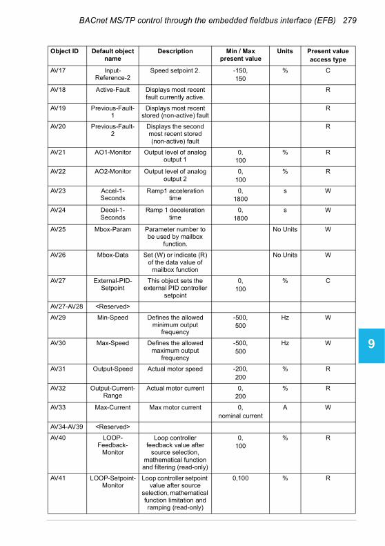
BACnet MS/TP control through the embedded fieldbus interface (EFB) 279
1
2
3
4
5
6
7
8
9
10
11
12
13
AV17 Input-Reference-2
Speed setpoint 2. -150,150
% C
AV18 Active-Fault Displays most recent fault currently active.
R
AV19 Previous-Fault-1
Displays most recent stored (non-active) fault
R
AV20 Previous-Fault-2
Displays the second most recent stored (non-active) fault
R
AV21 AO1-Monitor Output level of analog output 1
0,100
% R
AV22 AO2-Monitor Output level of analog output 2
0,100
% R
AV23 Accel-1-Seconds
Ramp1 acceleration time
0,1800
s W
AV24 Decel-1-Seconds
Ramp 1 deceleration time
0,1800
s W
AV25 Mbox-Param Parameter number to be used by mailbox
function.
No Units W
AV26 Mbox-Data Set (W) or indicate (R) of the data value of
mailbox function
No Units W
AV27 External-PID-Setpoint
This object sets the external PID controller
setpoint
0,100
% C
AV27-AV28 <Reserved>
AV29 Min-Speed Defines the allowed minimum output
frequency
-500,500
Hz W
AV30 Max-Speed Defines the allowed maximum output
frequency
-500,500
Hz W
AV31 Output-Speed Actual motor speed -200,200
% R
AV32 Output-Current-Range
Actual motor current 0,200
% R
AV33 Max-Current Max motor current 0,nominal current
A W
AV34-AV39 <Reserved>
AV40 LOOP-Feedback-
Monitor
Loop controller feedback value after
source selection, mathematical function and filtering (read-only)
0,100
% R
AV41 LOOP-Setpoint-Monitor
Loop controller setpoint value after source
selection, mathematical function limitation and ramping (read-only)
0,100 % R
Object ID Default object name
Description Min / Max present value
Units Present valueaccess type
14

280 BACnet MS/TP control through the embedded fieldbus interface (EFB)
1
2
3
4
5
6
7
8
9
10
11
12
13
14
AV42 LOOP-Setpoint Command to store loop controller setpoint
value used as input for the process
0,100 % C
AV43 LOOP-Feedback
Stores the feedback value for loop controller
0,100
% W
AV44 LOOP-Output Loop controller output 0,100
% R
AV45 LOOP- Gain Loop controller gain 0.1,100
No Units W
AV46 LOOP-Integration-
Time
Loop controller integration time
0,3600
s W
AV47-AV48 <Reserved>
AV49 LOOP-Deviation-
Monitor
Loop controller deviation
0,100
% R
AV50-AV52 <Reserved>
AV53 LOOP-1-Gain Loop controller gain (set 2)
0.1,100
No Units W
AV54 LOOP-1-Integration-
Time
Loop controller integration time (set 2)
0,3600
s W
AV55 LOOP-2-Feedback-
Monitor
External loop controller feedback value after
source selection, mathematical function and filtering (read-only)
0,100
% R
AV56 LOOP-2-Setpoint-Monitor
External loop controller setpoint value after source selection,
mathematical function limitation and ramping
(read-only)
0,100
% R
AV57-AV58 <Reserved>
AV59 LOOP-2-Output External loop controller output
0,100
% R
AV60 LOOP-2-Gain External loop controller gain
0.1,100
No Units W
AV61 LOOP-2-Integration-
Time
External loop controller integration time
0,3600
s W
AV62-AV63 <Reserved>
AV64 LOOP-2-Deviation-
Monitor
External loop controller deviation
0,100
% R
AV65-119 <Reserved> No Units W
Object ID Default object name
Description Min / Max present value
Units Present valueaccess type
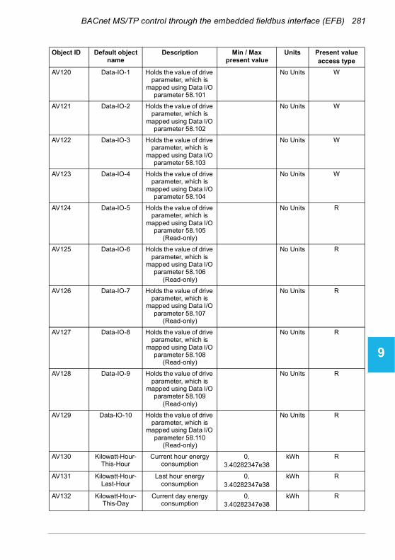
BACnet MS/TP control through the embedded fieldbus interface (EFB) 281
1
2
3
4
5
6
7
8
9
10
11
12
13
AV120 Data-IO-1 Holds the value of drive parameter, which is
mapped using Data I/O parameter 58.101
No Units W
AV121 Data-IO-2 Holds the value of drive parameter, which is
mapped using Data I/O parameter 58.102
No Units W
AV122 Data-IO-3 Holds the value of drive parameter, which is
mapped using Data I/O parameter 58.103
No Units W
AV123 Data-IO-4 Holds the value of drive parameter, which is
mapped using Data I/O parameter 58.104
No Units W
AV124 Data-IO-5 Holds the value of drive parameter, which is
mapped using Data I/O parameter 58.105
(Read-only)
No Units R
AV125 Data-IO-6 Holds the value of drive parameter, which is
mapped using Data I/O parameter 58.106
(Read-only)
No Units R
AV126 Data-IO-7 Holds the value of drive parameter, which is
mapped using Data I/O parameter 58.107
(Read-only)
No Units R
AV127 Data-IO-8 Holds the value of drive parameter, which is
mapped using Data I/O parameter 58.108
(Read-only)
No Units R
AV128 Data-IO-9 Holds the value of drive parameter, which is
mapped using Data I/O parameter 58.109
(Read-only)
No Units R
AV129 Data-IO-10 Holds the value of drive parameter, which is
mapped using Data I/O parameter 58.110
(Read-only)
No Units R
AV130 Kilowatt-Hour-This-Hour
Current hour energy consumption
0,3.40282347e38
kWh R
AV131 Kilowatt-Hour-Last-Hour
Last hour energy consumption
0,3.40282347e38
kWh R
AV132 Kilowatt-Hour-This-Day
Current day energy consumption
0,3.40282347e38
kWh R
Object ID Default object name
Description Min / Max present value
Units Present valueaccess type
14

282 BACnet MS/TP control through the embedded fieldbus interface (EFB)
1
2
3
4
5
6
7
8
9
10
11
12
13
14
Note: For present value access types, R = Read-only, W = Writeable, C = Commandable. Commandable values support priority arrays & relinquish defaults.
Multistate value object instance summary
The following table summarizes the multistate value objects supported:
AV133 Kilowatt-Hour-Last-Day
Last day energy consumption
0,3.40282347e38
kWh R
Object ID Object name Description State text Present valueaccess type
MSV0 HAND-AUTO-Reference
Indicates whether the drive is under Hand or
Auto control, or if override mode is active.
Off,Hand,Auto,
Override
R
MSV1 Active-Fault-1 Enumerated type of the most recent fault currently active
None,Comm-Error,Overcurrent,
Overtemperature,Overspeed,Overvoltage,Undervoltage,Short-Circuit,Ground-Fault,
Motor-Overload,Inverter-Overload,Motor-Underload,
External-Fault,Operator-Interface-Error,
Config-Error,Feedback-Failure,Output-Phase-Loss
Motor-Stall,Power-Unit-Error,Input-Phase-Fault,
Internal-Failure,STO-Active,
Other
R
Object ID Default object name
Description Min / Max present value
Units Present valueaccess type
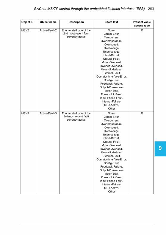
BACnet MS/TP control through the embedded fieldbus interface (EFB) 283
1
2
3
4
5
6
7
8
9
10
11
12
13
MSV2 Active-Fault-2 Enumerated type of the 2nd most recent fault
currently active
None,Comm-Error,Overcurrent,
Overtemperature,Overspeed,Overvoltage,Undervoltage,Short-Circuit,Ground-Fault,
Motor-Overload,Inverter-Overload,Motor-Underload,
External-Fault,Operator-Interface-Error,
Config-Error,Feedback-Failure,Output-Phase-Loss
Motor-Stall,Power-Unit-Error,Input-Phase-Fault,
Internal-Failure,STO-Active,
Other
R
MSV3 Active-Fault-3 Enumerated type of the 3rd most recent fault
currently active
None,Comm-Error,Overcurrent,
Overtemperature,Overspeed,Overvoltage,Undervoltage,Short-Circuit,Ground-Fault,
Motor-Overload,Inverter-Overload,Motor-Underload,
External-Fault,Operator-Interface-Error,
Config-Error,Feedback-Failure,Output-Phase-Loss
Motor-Stall,Power-Unit-Error,Input-Phase-Fault,
Internal-Failure,STO-Active,
Other
R
Object ID Object name Description State text Present valueaccess type
14
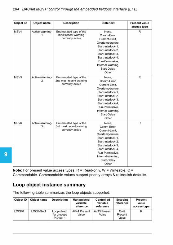
284 BACnet MS/TP control through the embedded fieldbus interface (EFB)
1
2
3
4
5
6
7
8
9
10
11
12
13
14
Note: For present value access types, R = Read-only, W = Writeable, C = Commandable. Commandable values support priority arrays & relinquish defaults.
Loop object instance summary
The following table summarizes the loop objects supported:
MSV4 Active-Warning-1
Enumerated type of the most recent warning
currently active
None,Comm-Error,Current-Limit,
Overtemperature,Start-Interlock-1,Start-Interlock-2,Start-Interlock-3,Start-Interlock-4,Run-Permissive,Internal-Warning,
Start-Delay,Other
R
MSV5 Active-Warning-2
Enumerated type of the 2nd most recent warning
currently active
None,Comm-Error,Current-Limit,
Overtemperature,Start-Interlock-1,Start-Interlock-2,Start-Interlock-3,Start-Interlock-4,Run-Permissive,Internal-Warning,
Start-Delay,Other
R
MSV6 Active-Warning-3
Enumerated type of the 3rd most recent warning
currently active
None,Comm-Error,Current-Limit,
Overtemperature,Start-Interlock-1,Start-Interlock-2,Start-Interlock-3,Start-Interlock-4,Run-Permissive,Internal-Warning,
Start-Delay,Other
R
Object ID Object name Description Manipulated variable
reference
Controlled variable
reference
Setpoint reference
Present value
access type
LOOP0 LOOP-Set1 Loop object for process PID set 1
AV44 Present Value
AV43 Present Value
AV42 Present Value
R
Object ID Object name Description State text Present valueaccess type

BACnet MS/TP control through the embedded fieldbus interface (EFB) 285
1
2
3
4
5
6
7
8
9
10
11
12
13
Note: For present value access types, R = Read-only, W = Writeable, C = Commandable. Commandable values support priority arrays & relinquish defaults.
Mailbox function
The drive provides a Mailbox function to access parameters that have not been pre-defined by the protocol. Using mailbox, any drive parameter can be identified and read. Mailbox can also be used to adjust parameter settings by writing a value to any parameter identified. The following table shows the mailbox objects.
To use the Mailbox function, write the parameter address to the Mbox-Param object as a floating point value. The three lowest digits in the integer part are used for the parameter index within the parameter group.
Example: For parameter 47.01, write the address as 47001.00 to the Mbox-Param object. For parameter 47.999, write the address as 47999.00 to the Mbox-Param object.
Read or write the value to the Mbox-Data object as a floating point value. If the parameter is a decimal type parameter it’s value is shown as a decimal number. The value of an integer type parameter is shown as an integer number.
Example: If parameter 47.01 has value 12.554 it is shown just as it is. If parameter 47.21 has value 125, it is shown just like that, without a decimal part.
LOOP1 LOOP-Set2 Loop object for process PID set 2
AV44 Present Value
AV43 Present Value
AV42 Present Value
R
Object ID Default object name
Description Min/max present value
Unit Present value access type
AV25 Mbox-Param Parameter number to be used by mailbox function.
No units
W
AV26 Mbox-Data Set (W) or indicate (R) of the data value of mailbox function
W
Object ID Object name Description Manipulated variable
reference
Controlled variable
reference
Setpoint reference
Present value
access type
14

286 BACnet MS/TP control through the embedded fieldbus interface (EFB)
1
2
3
4
5
6
7
8
9
10
11
12
13
14
N2 control through the embedded fieldbus interface (EFB) 287
1
2
3
4
5
6
7
8
9
10
11
12
13
10N2 control through the embedded fieldbus interface (EFB)
Contents of this chapter
The chapter describes N2 control through the embedded fieldbus interface (EFB): supported functionality, services and objects as well as how to configure the N2 with parameters.
N2 overview
The N2 fieldbus connection to the drive is based on an industry standard RS-485 physical interface. The N2 fieldbus protocol is a master-slave type, serial communication protocol, used by the Johnson Controls Metasys® system. In the Metasys architecture the N2 fieldbus connects object interfaces and remote controllers to network control units (NCUs).
The N2 fieldbus can also be used to connect the drives to the Metasys Companion product line.
This section describes the use of the N2 fieldbus with the drive’s connection and does not describe the protocol in detail.
14

288 N2 control through the embedded fieldbus interface (EFB)
1
2
3
4
5
6
7
8
9
10
11
12
13
14
Supported features
In the N2 fieldbus protocol the drive appears as a “virtual object”.
A virtual object is made up of:
• analog inputs
• binary inputs
• analog outputs
• binary outputs
• internal values for floating point, integer, and byte values.
The drive does not support N2 fieldbus communication “internal values”.
All of the analog and binary I/O objects are listed below, starting with N2 analog input objects.
Analog input - the analog input objects support the following features:
• analog input actual value in engineering units
• low alarm limit
• low warning limit
• high warning limit
• high alarm limit
• differential value for the hysteresis of the alarms and warnings
• change of state (COS) enabled
• alarm enabled
• warning enabled
• override value is received, but there is no action taken.
Analog inputs
Binary inputs
Analog outputs
Binary outputs
Internal values, float, integer, byte
Note: Metasys inputs are drive outputs and drive inputs are Metasys outputs.
MetasysDrive

N2 control through the embedded fieldbus interface (EFB) 289
1
2
3
4
5
6
7
8
9
10
11
12
13
Binary input - the binary input objects support the following features:
• binary input actual value
• normal / alarm state specification
• alarm enabled
• change of state (COS) enabled
• override value is received, but there is no action taken.
Analog output - the analog output objects support the following features:
• analog output value in engineering units
• override value is used to change the analog output value. It is not possible to return to the previous value by removing the override. The override feature is used only to change the value.
Binary output - the binary output objects support the following features:
• binary output value
• override value is used to change the binary output value. It is not possible to return to the previous value by removing the override. The override feature is used only to change the value.
Metasys integration
The following diagram shows the drives' integration to the Johnson Controls Metasys system.
N1LAN
N2 fieldbusNCU
Drive Drive
14
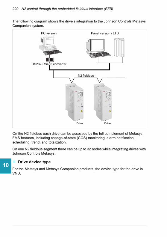
290 N2 control through the embedded fieldbus interface (EFB)
1
2
3
4
5
6
7
8
9
10
11
12
13
14
The following diagram shows the drive’s integration to the Johnson Controls Metasys Companion system.
On the N2 fieldbus each drive can be accessed by the full complement of Metasys FMS features, including change-of-state (COS) monitoring, alarm notification, scheduling, trend, and totalization.
On one N2 fieldbus segment there can be up to 32 nodes while integrating drives with Johnson Controls Metasys.
Drive device type
For the Metasys and Metasys Companion products, the device type for the drive is VND.
Panel version / LTDPC version
RS232-RS485 converter
N2 fieldbus
Drive Drive

N2 control through the embedded fieldbus interface (EFB) 291
1
2
3
4
5
6
7
8
9
10
11
12
13
Hardware installation
Connecting devices to a N2 EIA-485 network
The figure shows three types of nodes connected on the EIA-485 network.
Connecting the drive to the building automation controller
For connecting the EFB terminal block X5 of the drive to the building automation controller via the EIA-485 network, see section Connecting the drive to the fieldbus on page 226.
N2 analog input objects
The following table lists the N2 analog input objects defined for the drive.
N2 analog inputs
No Object Drive parameter Scale factor
Units Range Notes
AI1 OUTPUT FREQUENCY
01.06 Output frequency
100 Hz 0…250
AI2 RATED SPEED 01.62 Abs motor speed %
100 % 0…100
AI3 SPEED 01.01 Motor speed used
100 rpm 0…9999
AI4 CURRENT 01.07 Motor current
100 A 0…9999
AI5 TORQUE 01.10 Motor torque
100 % -200…200
AI6 POWER 01.17 Motor shaft power
10 kW 0…9999
AI7 DRIVE TEMPERATURE
05.11 Inverter temperature
10 % -40…160
Node with network bias resistors
Node with local bias resistors
Node without bias resistors
14

292 N2 control through the embedded fieldbus interface (EFB)
1
2
3
4
5
6
7
8
9
10
11
12
13
14
AI8 KILOWATT HOURS 01.58 Cumulative inverter energy (resettable)
10 kW 0…65535
AI9 MEGAWATT HOURS Derived value 10000 MWh 0…65535 Parameter 01.54 Cumulative inverter energy / 1000
AI10 RUN TIME 05.03 Hours run 10 h 0…65535
A11 DC BUS VOLTAGE 01.11 DC voltage 100 V 0…999
AI12 OUTPUT VOLTAGE 01.13 Output voltage
1 V 0…999
AI13 PRC PID FEEDBACK 40.97 Process PID feedback %
100 % 0…100
AI14 PRC PID DEVIATION 40.99 Process PID deviation %
100 % 0…100
AI15 EXT PID FEEDBACK Derived value 10 % 0…100 = 71.02 Feedback act value * 1000 / 71.14 Setpoint scaling
AI16 EXT PID DEVIATION Derived value 10 % 0…100 = 71.04 Deviation act value * 1000 / 71.14 Setpoint scaling
AI17 LAST FAULT Derived value 1 fault code Most recent fault
AI18 PREV FAULT Derived value 1 fault code Second most recent fault
AI19 OLDEST FAULT Derived value 1 fault code Third most recent fault
AI20 AI 1 ACTUAL 12.101 AI1 percent value
100 % 0…100
AI21 AI 2 ACTUAL 12.102 AI2 percent value
100 % 0…100
AI22 AO 1 ACTUAL 13.11 AO1 actual value
1000 mA 0…20
AI23 AO 2 ACTUAL 13.21 AO2 actual value
1000 mA 0…20
AI24 MOTOR TEMP Derived value 1 °C 0…200 Value is derived from 35.01, 35.02 and 35.03: • If 35.11 and 35.21 are
both non-zero, the temperature is the maximum value of 35.02 and 35.03.
• If only 35.11 is non-zero, the temperature is value of 35.02.
• If only 35.21 is non-zero, the temperature is value of 35.03.
• If both 35.11 and 35.21 are zero, the value is as 35.01.
N2 analog inputs
No Object Drive parameter Scale factor
Units Range Notes

N2 control through the embedded fieldbus interface (EFB) 293
1
2
3
4
5
6
7
8
9
10
11
12
13
N2 binary input objects
The following table lists the N2 binary input objects defined for the drive.
N2 binary inputs
No Object Drive parameter Range
BI1 STOP/RUN Status Word, bit 2 0 = Drive received start command1 = Drive has not received start command
BI2 FORWARD/REVERSE Status Word, bit 11 0 = Forward, 1 = Reverse
BI3 FAULT STATUS Status Word, bit 15 0 = OK, 1 = Drive fault
BI4 RELAY 1 STATUS 10.21 RO status, bit 0 0 = Off, 1 = On
BI5 RELAY 2 STATUS 10.21 RO status, bit 1 0 = Off, 1 = On
BI6 RELAY 3 STATUS 10.21 RO status, bit 2 0 = Off, 1 = On
BI7 RELAY 4 STATUS 15.04 RO/DO status, bit 0
0 = Off, 1 = On
BI8 RELAY 5 STATUS 15.04 RO/DO status, bit 1
0 = Off, 1 = On
BI9 DIGITAL OUTPUT1 STATUS 15.04 RO/DO status, bit 2
0 = Off, 1 = On
BI10 INPUT 1 STATUS 10.02 DI delayed status, bit 0
0 = Off, 1 = On
BI11 INPUT 2 STATUS 10.02 DI delayed status, bit 1
0 = Off, 1 = On
BI12 INPUT 3 STATUS 10.02 DI delayed status, bit 2
0 = Off, 1 = On
BI13 INPUT 4 STATUS 10.02 DI delayed status, bit 3
0 = Off, 1 = On
BI14 INPUT 5 STATUS 10.02 DI delayed status, bit 4
0 = Off, 1 = On
BI15 INPUT 6 STATUS 10.02 DI delayed status, bit 5
0 = Off, 1 = On
BI16 EXTERNAL 2 SELECT DCU Status Word, bit 14
0 = EXT1 active, 1 = EXT2 active
BI17 HAND/AUTO DCU Status Word, bit 12
0 = AUTO, 1 = HAND
BI18 ALARM DCU Status Word, bit 16
0 = OK, 1 = Warning/alarm
BI20 DRIVE READY DCU Status Word, bit 0
0 = Not ready, 1 = Ready
BI21 AT SETPOINT DCU Status Word, bit 7
0 = No, 1 = At setpoint
BI22 RUN ENABLED DCU Status Word, bit 1
0 = Not enabled, 1 = Enabled
BI23 N2 LOCAL MODE DCU Status Word, bit 13
0 = Auto, 1 = N2 local
BI24 N2 CONTROL SRC DCU Status Word, bit 26
0 = No, 1 = Yes
BI25 N2 REF1 SRC DCU Status Word, bit 27
0 = No, 1 = Yes
14
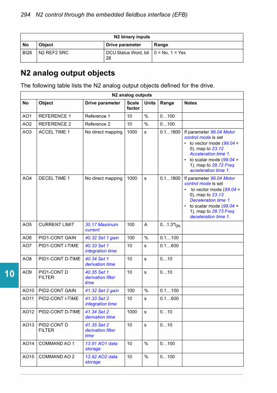
294 N2 control through the embedded fieldbus interface (EFB)
1
2
3
4
5
6
7
8
9
10
11
12
13
14
N2 analog output objects
The following table lists the N2 analog output objects defined for the drive.
BI26 N2 REF2 SRC DCU Status Word, bit 28
0 = No, 1 = Yes
N2 analog outputs
No Object Drive parameter Scale factor
Units Range Notes
AO1 REFERENCE 1 Reference 1 10 % 0…100
AO2 REFERENCE 2 Reference 2 10 % 0…100
AO3 ACCEL TIME 1 No direct mapping 1000 s 0.1…1800 If parameter 99.04 Motor control mode is set• to vector mode (99.04 =
0), map to 23.12 Acceleration time 1.
• to scalar mode (99.04 = 1), map to 28.72 Freq acceleration time 1.
AO4 DECEL TIME 1 No direct mapping 1000 s 0.1…1800 If parameter 99.04 Motor control mode is set• to vector mode (99.04 =
0), map to 23.13 Deceleration time 1
• to scalar mode (99.04 = 1), map to 28.73 Freq deceleration time 1.
AO5 CURRENT LIMIT 30.17 Maximum current
100 A 0…1.3*I2N
AO6 PID1-CONT GAIN 40.32 Set 1 gain 100 % 0.1…100
AO7 PID1-CONT I-TIME 40.33 Set 1 integration time
10 s 0.1…600
AO8 PID1-CONT D-TIME 40.34 Set 1 derivation time
10 s 0…10
AO9 PID1-CONT D FILTER
40.35 Set 1 derivation filter time
10 s 0…10
AO10 PID2-CONT GAIN 41.32 Set 2 gain 100 % 0.1…100
AO11 PID2-CONT I-TIME 41.33 Set 2 integration time
10 s 0.1…600
AO12 PID2-CONT D-TIME 41.34 Set 2 derivation time
1000 s 0…10
AO13 PID2-CONT D FILTER
41.35 Set 2 derivation filter time
10 s 0…10
AO14 COMMAND AO 1 13.91 AO1 data storage
10 % 0…100
AO15 COMMAND AO 2 13.92 AO2 data storage
10 % 0…100
N2 binary inputs
No Object Drive parameter Range
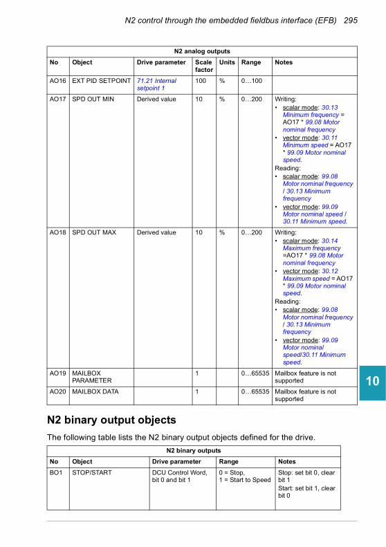
N2 control through the embedded fieldbus interface (EFB) 295
1
2
3
4
5
6
7
8
9
10
11
12
13
N2 binary output objects
The following table lists the N2 binary output objects defined for the drive.
AO16 EXT PID SETPOINT 71.21 Internal setpoint 1
100 % 0…100
AO17 SPD OUT MIN Derived value 10 % 0…200 Writing: • scalar mode: 30.13
Minimum frequency = AO17 * 99.08 Motor nominal frequency
• vector mode: 30.11 Minimum speed = AO17 * 99.09 Motor nominal speed.
Reading:• scalar mode: 99.08
Motor nominal frequency / 30.13 Minimum frequency
• vector mode: 99.09 Motor nominal speed / 30.11 Minimum speed.
AO18 SPD OUT MAX Derived value 10 % 0…200 Writing: • scalar mode: 30.14
Maximum frequency =AO17 * 99.08 Motor nominal frequency
• vector mode: 30.12 Maximum speed = AO17 * 99.09 Motor nominal speed.
Reading:• scalar mode: 99.08
Motor nominal frequency / 30.13 Minimum frequency
• vector mode: 99.09 Motor nominal speed/30.11 Minimum speed.
AO19 MAILBOX PARAMETER
1 0…65535 Mailbox feature is not supported
AO20 MAILBOX DATA 1 0…65535 Mailbox feature is not supported
N2 binary outputs
No Object Drive parameter Range Notes
BO1 STOP/START DCU Control Word, bit 0 and bit 1
0 = Stop, 1 = Start to Speed
Stop: set bit 0, clear bit 1Start: set bit 1, clear bit 0
N2 analog outputs
No Object Drive parameter Scale factor
Units Range Notes
14

296 N2 control through the embedded fieldbus interface (EFB)
1
2
3
4
5
6
7
8
9
10
11
12
13
14
BO2 FORWARD/REVERSE DCU Control Word, bit 12
0 = Forward, 1 = Reverse
BO3 PANEL LOCK Derived 0 = Open, 1 = Locked
Derived from 96.03 Access level status, bit 14 parameter lock
BO4 RUN ENABLE Derived value 0 = Enable, 1 = Disable
Invert DCU control word bit 6, RUN_DISABLE
BO5 REF1/REF2 SELECT DCU Control Word, bit 5, EXT
0 = Ref1, 1 = Ref2
BO6 FAULT RESET DCU Control Word, bit 4, RESET
Change 0 -> 1 Resets
BO7 COMMAND RO 1 10.99 RO/DIO control word, bit 0
0 = Off, 1 = On
BO8 COMMAND RO 2 10.99 RO/DIO control word, bit 1
0 = Off, 1 = On
BO9 COMMAND RO 3 10.99 RO/DIO control word, bit 2
0 = Off, 1 = On
BO10 COMMAND RO 4 10.99 RO/DIO control word, bit 3
0 = Off, 1 = On
BO11 COMMAND RO 5 10.99 RO/DIO control word, bit 4
0 = Off, 1 = On
BO12 COMMAND RO 6 10.99 RO/DIO control word, bit 5
0 = Off, 1 = On
BO13 RESET RUN TIME Indirectly mapping 0 = N/A, 1 = On (Reset run rime, 05.03 Hours run)
BO14 RESET KWH COUNT Indirectly mapping 0 = N/A, 1 = On (Reset kWh count 01.58 Cumulative inverter energy (resettable))
BO15 PRC PID SELECT 40.57 PID set1/set2 selection (indirectly)
0 = SET1, 1 = SET2
If BO15 = 0, 40.57 PID set1/set2 selection is set to PID Set1 (1).If BO15 = 1, 40.57 PID set1/set2 selection is set to PID Set2 (2).
BO16 N2 LOCAL CTL 1) DCU Control Word, bit 16
0 = Auto, 1 = N2
BO17 N2 LOCAL REF 1) DCU Control Word, bit 17
0 = Auto, 1 = N2
BO18 SAVE PARAMETERS 96.07 Parameter save manually (indirectly)
0 = N/A, 1 = On (Save Parameters)
BO19 READ MAILBOX 0 = No, 1 = Yes Mailbox feature is not supported
N2 binary outputs
No Object Drive parameter Range Notes
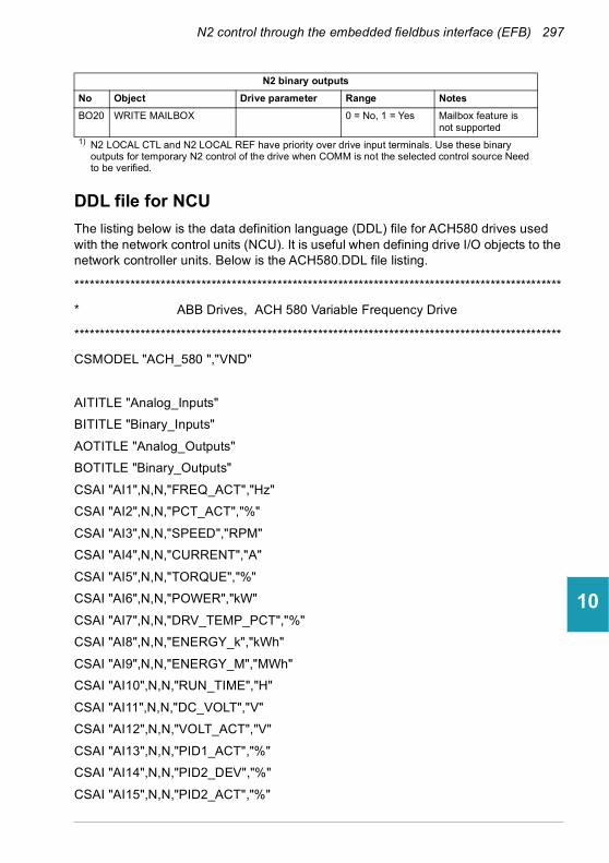
N2 control through the embedded fieldbus interface (EFB) 297
1
2
3
4
5
6
7
8
9
10
11
12
13
DDL file for NCU
The listing below is the data definition language (DDL) file for ACH580 drives used with the network control units (NCU). It is useful when defining drive I/O objects to the network controller units. Below is the ACH580.DDL file listing.
************************************************************************************************
* ABB Drives, ACH 580 Variable Frequency Drive
************************************************************************************************
CSMODEL "ACH_580 ","VND"
AITITLE "Analog_Inputs"
BITITLE "Binary_Inputs"
AOTITLE "Analog_Outputs"
BOTITLE "Binary_Outputs"
CSAI "AI1",N,N,"FREQ_ACT","Hz"
CSAI "AI2",N,N,"PCT_ACT","%"
CSAI "AI3",N,N,"SPEED","RPM"
CSAI "AI4",N,N,"CURRENT","A"
CSAI "AI5",N,N,"TORQUE","%"
CSAI "AI6",N,N,"POWER","kW"
CSAI "AI7",N,N,"DRV_TEMP_PCT","%"
CSAI "AI8",N,N,"ENERGY_k","kWh"
CSAI "AI9",N,N,"ENERGY_M","MWh"
CSAI "AI10",N,N,"RUN_TIME","H"
CSAI "AI11",N,N,"DC_VOLT","V"
CSAI "AI12",N,N,"VOLT_ACT","V"
CSAI "AI13",N,N,"PID1_ACT","%"
CSAI "AI14",N,N,"PID2_DEV","%"
CSAI "AI15",N,N,"PID2_ACT","%"
BO20 WRITE MAILBOX 0 = No, 1 = Yes Mailbox feature is not supported
1) N2 LOCAL CTL and N2 LOCAL REF have priority over drive input terminals. Use these binary outputs for temporary N2 control of the drive when COMM is not the selected control source Need to be verified.
N2 binary outputs
No Object Drive parameter Range Notes
14
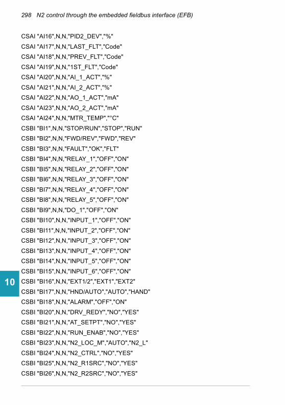
298 N2 control through the embedded fieldbus interface (EFB)
1
2
3
4
5
6
7
8
9
10
11
12
13
14
CSAI "AI16",N,N,"PID2_DEV","%"
CSAI "AI17",N,N,"LAST_FLT","Code"
CSAI "AI18",N,N,"PREV_FLT","Code"
CSAI "AI19",N,N,"1ST_FLT","Code"
CSAI "AI20",N,N,"AI_1_ACT","%"
CSAI "AI21",N,N,"AI_2_ACT","%"
CSAI "AI22",N,N,"AO_1_ACT","mA"
CSAI "AI23",N,N,"AO_2_ACT","mA"
CSAI "AI24",N,N,"MTR_TEMP","°C"
CSBI "BI1",N,N,"STOP/RUN","STOP","RUN"
CSBI "BI2",N,N,"FWD/REV","FWD","REV"
CSBI "BI3",N,N,"FAULT","OK","FLT"
CSBI "BI4",N,N,"RELAY_1","OFF","ON"
CSBI "BI5",N,N,"RELAY_2","OFF","ON"
CSBI "BI6",N,N,"RELAY_3","OFF","ON"
CSBI "BI7",N,N,"RELAY_4","OFF","ON"
CSBI "BI8",N,N,"RELAY_5","OFF","ON"
CSBI "BI9",N,N,"DO_1","OFF","ON"
CSBI "BI10",N,N,"INPUT_1","OFF","ON"
CSBI "BI11",N,N,"INPUT_2","OFF","ON"
CSBI "BI12",N,N,"INPUT_3","OFF","ON"
CSBI "BI13",N,N,"INPUT_4","OFF","ON"
CSBI "BI14",N,N,"INPUT_5","OFF","ON"
CSBI "BI15",N,N,"INPUT_6","OFF","ON"
CSBI "BI16",N,N,"EXT1/2","EXT1","EXT2"
CSBI "BI17",N,N,"HND/AUTO","AUTO","HAND"
CSBI "BI18",N,N,"ALARM","OFF","ON"
CSBI "BI20",N,N,"DRV_REDY","NO","YES"
CSBI "BI21",N,N,"AT_SETPT","NO","YES"
CSBI "BI22",N,N,"RUN_ENAB","NO","YES"
CSBI "BI23",N,N,"N2_LOC_M","AUTO","N2_L"
CSBI "BI24",N,N,"N2_CTRL","NO","YES"
CSBI "BI25",N,N,"N2_R1SRC","NO","YES"
CSBI "BI26",N,N,"N2_R2SRC","NO","YES"

N2 control through the embedded fieldbus interface (EFB) 299
1
2
3
4
5
6
7
8
9
10
11
12
13
CSAO "AO1",Y,Y,"REF_1","%"
CSAO "AO2",Y,Y,"REF_2","%"
CSAO "AO3",Y,Y,"ACCEL_1","s"
CSAO "AO4",Y,Y,"DECEL_1","s"
CSAO "AO5",Y,Y,"CURR_LIM","A"
CSAO "AO6",Y,Y,"PID1_GN","%"
CSAO "AO7",Y,Y,"PID1_I","s"
CSAO "AO8",Y,Y,"PID1_D","s"
CSAO "AO9",Y,Y,"PID1_FLT","s"
CSAO "AO10",Y,Y,PID2_GN","%"
CSAO "AO11",Y,Y,"PID2_I","s"
CSAO "AO12",Y,Y,"PID2_D","s"
CSAO "AO13",Y,Y,"PID2_FLT","s"
CSAO "AO14",Y,Y,"CMD_AO_1","%"
CSAO "AO15",Y,Y,"CMD_AO_2","%"
CSAO "AO16",Y,Y,"PI2_STPT","%"
CSAO "AO17",Y,Y,"MIN_SPD","%"
CSAO "AO18",Y,Y,"MAX_SPD","%"
CSAO "AO19",Y,Y,"MB_PARAM",""
CSAO "AO20",Y,Y,"MB_DATA",""
CSBO "BO1",Y,Y,"START","STOP","START"
CSBO "BO2",Y,Y,"REVERSE","FWD","REV"
CSBO "BO3",Y,Y,"PAN_LOCK","OPEN","LOCKED"
CSBO "BO4",Y,Y,"RUN_ENAB","ENABLE","DISABLE"
CSBO "BO5",Y,Y,"R1/2_SEL","EXT_1","EXT_2"
CSBO "BO6",Y,Y,"FLT_RSET","-","RESET"
CSBO "BO7",Y,Y,"CMD_RO_1","OFF","ON"
CSBO "BO8",Y,Y,"CMD_RO_2","OFF","ON"
CSBO "BO9",Y,Y,"CMD_RO_3","OFF","ON"
CSBO "BO10",Y,Y,"CMD_RO_4","OFF","ON"
CSBO "BO11",Y,Y,"CMD_RO_5","OFF","ON"
CSBO "BO12",Y,Y,"CMD_RO_6","OFF","ON"
CSBO "BO13",Y,Y,"RST_RTIM","OFF","RESET"
CSBO "BO14",Y,Y,"RST_KWH","OFF","RESET"
14

300 N2 control through the embedded fieldbus interface (EFB)
1
2
3
4
5
6
7
8
9
10
11
12
13
14
CSBO "BO15",Y,Y,"PID_SEL","SET1","SET2"
CSBO "BO16",Y,Y,"N2_LOC_C","AUTO","N2"
CSBO "BO17",Y,Y,"N2_LOC_R","AUTO","N2"
CSBO "BO18",Y,Y,"SAV_PRMS","OFF","SAVE"
CSBO "BO19",Y,Y,"READ_MB","NO","READ"
CSBO "BO20",Y,Y,"WRITE_MB","NO","WRITE"

Fieldbus control through a fieldbus adapter 301
1
2
3
4
5
6
7
8
9
10
11
12
13
11Fieldbus control through a fieldbus adapter
What this chapter contains
This chapter describes how the drive can be controlled by external devices over a communication network (fieldbus) through an optional fieldbus adapter module.
The fieldbus control interface of the drive is described first, followed by a configuration example.
System overview
The drive can be connected to an external control system through an optional fieldbus adapter (“fieldbus adapter A” = FBA A) mounted onto the control unit of the drive. The drive can be configured to receive all of its control information through the fieldbus interface, or the control can be distributed between the fieldbus interface and other available sources such as digital and analog inputs, depending on how control locations EXT1 and EXT2 are configured.
14
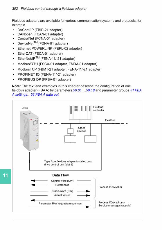
302 Fieldbus control through a fieldbus adapter
1
2
3
4
5
6
7
8
9
10
11
12
13
14
Fieldbus adapters are available for various communication systems and protocols, for example
• BACnet/IP (FBIP-21 adapter)• CANopen (FCAN-01 adapter)• ControlNet (FCNA-01 adapter)
• DeviceNetTM (FDNA-01 adapter)
• Ethernet POWERLINK (FEPL-02 adapter)
• EtherCAT (FECA-01 adapter)
• EtherNet/IPTM (FENA-11/-21 adapter)
• Modbus/RTU (FSCA-01 adapter, FMBA-01 adapter)
• ModbusTCP (FBMT-21 adapter, FENA-11/-21 adapter)
• PROFINET IO (FENA-11/-21 adapter)
• PROFIBUS DP (FPBA-01 adapter)
Note: The text and examples in this chapter describe the configuration of one fieldbus adapter (FBA A) by parameters 50.01 …50.18 and parameter groups 51 FBA A settings…53 FBA A data out.
Data Flow
Process I/O (cyclic)
Process I/O (cyclic) or Service messages (acyclic)
Control word (CW)
References
Fieldbus controller
Parameter R/W requests/responses
Status word (SW)
Actual values
Fieldbus
Other devices
Drive
Type Fxxx fieldbus adapter installed onto drive control unit (slot 1)
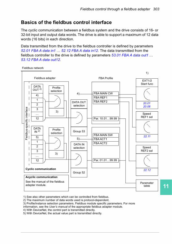
Fieldbus control through a fieldbus adapter 303
1
2
3
4
5
6
7
8
9
10
11
12
13
Basics of the fieldbus control interface
The cyclic communication between a fieldbus system and the drive consists of 16- or 32-bit input and output data words. The drive is able to support a maximum of 12 data words (16 bits) in each direction.
Data transmitted from the drive to the fieldbus controller is defined by parameters 52.01 FBA A data in1 … 52.12 FBA A data in12. The data transmitted from the fieldbus controller to the drive is defined by parameters 53.01 FBA A data out1 … 53.12 FBA A data out12.
DATAOUT 2)
4)
1
2
3
…
12
DATAIN 2)
5)
1
2
3
…
12
FBA MAIN SW
FBA ACT1
FBA ACT2
Par. 01.01…99.99
FBA MAIN CW
FBA REF1
FBA REF2
Par. 10.01…99.99
1) See also other parameters which can be controlled from fieldbus.2) The maximum number of data words used is protocol-dependent.3) Profile/instance selection parameters. Fieldbus module specific parameters. For more information, see the User’s manual of the appropriate fieldbus adapter module.4) With DeviceNet, the control part is transmitted directly.5) With DeviceNet, the actual value part is transmitted directly.
3)
3)
Parameter table
4)
5)
1)
Fieldbus network
Fieldbus adapter
Fie
ldbu
s-sp
ecifi
c in
terf
ace
Profile selection
Profile selection
DATA OUT selection
Group 53
DATA IN selection
Group 52
FBA ProfileEXT1/2
Start func
20.0120.06
SpeedREF1 sel
22.11
SpeedREF2 sel
22.12Cyclic communication
Acyclic communication
See the manual of the fieldbus adapter module.
14
304 Fieldbus control through a fieldbus adapter
1
2
3
4
5
6
7
8
9
10
11
12
13
14
Control word and Status word
The Control word is the principal means for controlling the drive from a fieldbus system. It is sent by the fieldbus master station to the drive through the adapter module. The drive switches between its states according to the bit-coded instructions in the Control word, and returns status information to the master in the Status word.
For the ABB Drives communication profile, the contents of the Control word and the Status word are detailed on pages 307 and 308, respectively. The drive states are presented in the state diagram (page 309). For other fieldbus-specific communication profiles, see the User’s manual of the fieldbus adapter.
Debugging the network words
If parameter 50.12 FBA A debug mode is set to Fast, the Control word received from the fieldbus is shown by parameter 50.13 FBA A control word, and the Status word transmitted to the fieldbus network by 50.16 FBA A status word. This “raw” data is very useful to determine if the fieldbus master is transmitting the correct data before handing control to the fieldbus network.

Fieldbus control through a fieldbus adapter 305
1
2
3
4
5
6
7
8
9
10
11
12
13
References
References are 16-bit words containing a sign bit and a 15-bit integer. A negative reference (indicating reversed direction of rotation) is formed by calculating the two’s complement from the corresponding positive reference.
ABB drives can receive control information from multiple sources including analog and digital inputs, the drive control panel and a fieldbus adapter module. In order to have the drive controlled through the fieldbus, the module must be defined as the source for control information such as reference. This is done using the source selection parameters in groups 22 Speed reference selection and 28 Frequency reference chain.
Debugging the network words
If parameter 50.12 FBA A debug mode is set to Fast, the references received from the fieldbus are displayed by 50.14 FBA A reference 1 and 50.15 FBA A reference 2.
Scaling of references
Note: The scalings described below are for the ABB Drives communication profile. Fieldbus-specific communication profiles may use different scalings. For more information, see the User’s manual of the fieldbus adapter.
The references are scaled as defined by parameters 46.01…46.04; which scaling is in use depends on the setting of 50.04 FBA A ref1 type and 50.05 FBA A ref2 type.
The scaled references are shown by parameters 03.05 FB A reference 1 and 03.06 FB A reference 2.
46.01 (with speed reference)46.02 (with frequency reference)
0
-20000
20000
DriveFieldbus
0
10000
-10000
46.03 (with torque reference)
-(46.01) (with speed reference)-(46.02) (with frequency reference)
-(46.03) (with torque reference)
14

306 Fieldbus control through a fieldbus adapter
1
2
3
4
5
6
7
8
9
10
11
12
13
14
Actual values
Note: The scalings described below are for the ABB Drives communication profile. Fieldbus-specific communication profiles may use different scalings. For more information, see the User’s manual of the fieldbus adapter.
Actual values are 16-bit words containing information on the operation of the drive. The types of the monitored signals are selected by parameters 50.07 FBA A actual 1 type and 50.08 FBA A actual 2 type.
Debugging the network words
If parameter 50.12 FBA A debug mode is set to Fast, the actual values sent to the fieldbus are displayed by 50.17 FBA A actual value 1 and 50.18 FBA A actual value 2.
Scaling of actual values
The actual values are scaled as defined by parameters 46.01…46.04; which scaling is in use depends on the setting of parameters 50.07 FBA A actual 1 type and 50.08 FBA A actual 2 type.
46.01 (with speed reference)46.02 (with frequency reference)
0
-20000
20000
DriveFieldbus
0
10000
-10000
46.03 (with torque reference)
-(46.01) (with speed reference)-(46.02) (with frequency reference)
-(46.03) (with torque reference)

Fieldbus control through a fieldbus adapter 307
1
2
3
4
5
6
7
8
9
10
11
12
13
Contents of the fieldbus Control word (ABB Drives profile)
The upper case boldface text refers to the states shown in the state diagram (page 309).
Bit Name Value STATE/Description
0 Off1 control 1 Proceed to READY TO OPERATE.0 Stop along currently active deceleration ramp. Proceed to OFF1
ACTIVE; proceed to READY TO SWITCH ON unless other interlocks (OFF2, OFF3) are active.
1 Off2 control 1 Continue operation (OFF2 inactive).0 Emergency OFF, coast to a stop.
Proceed to OFF2 ACTIVE, proceed to SWITCH-ON INHIBITED.2 Off3 control 1 Continue operation (OFF3 inactive).
0 Emergency stop, stop within time defined by drive parameter. Proceed to OFF3 ACTIVE; proceed to SWITCH-ON INHIBITED.
WARNING: Ensure motor and driven machine can be stopped using this stop mode.
3 Run 1 Proceed to OPERATION ENABLED.Note: Run permissive signal must be active; see the drive documentation. If the drive is set to receive the Run permissive signal from the fieldbus, this bit activates the signal.See also parameter 06.18 Start inhibit status word.
0 Inhibit operation. Proceed to OPERATION INHIBITED.4 Ramp out zero 1 Normal operation. Proceed to RAMP FUNCTION GENERATOR:
OUTPUT ENABLED.0 Force Ramp function generator output to zero. The drive will
immediately decelerate to zero speed (observing the torque limits).5 Ramp hold 1 ramp function.
Proceed to RAMP FUNCTION GENERATOR: ACCELERATOR ENABLED.
0 Halt ramping (Ramp Function Generator output held).6 Ramp in zero 1 Normal operation. Proceed to OPERATING.
Note: This bit is effective only if the fieldbus interface is set as the source for this signal by drive parameters.
0 Force Ramp function generator input to zero.7 Reset 0=>1 Fault reset if an active fault exists. Proceed to SWITCH-ON
INHIBITED.Note: This bit is effective only if the fieldbus interface is set as the source of the reset signal by drive parameters.
0 Continue normal operation.8…9 Reserved10 Remote cmd 1 Fieldbus control enabled.
0 Control word and reference not getting through to the drive, except for bits 0…2.
11 Ext ctrl loc 1 Select External Control Location EXT2. Effective if control location is parameterized to be selected from fieldbus.
0 Select External Control Location EXT1. Effective if control location is parameterized to be selected from fieldbus.
12 User bit 0 1 User configurable 0
13 User bit 1 10
14 User bit 2 10
15 User bit 3 10
14

308 Fieldbus control through a fieldbus adapter
1
2
3
4
5
6
7
8
9
10
11
12
13
14
Contents of the fieldbus Status word (ABB Drives profile)
The upper case boldface text refers to the states shown in the state diagram (page 309).
Bit Name Value STATE/Description
0 Ready to switch ON
1 READY TO SWITCH ON.0 NOT READY TO SWITCH ON.
1 Ready run 1 READY TO OPERATE.0 OFF1 ACTIVE.
2 Ready ref 1 OPERATION ENABLED.0 OPERATION INHIBITED.
See also parameter 06.18 Start inhibit status word.3 Tripped 1 FAULT.
0 No fault.4 Off 2 inactive 1 OFF2 inactive.
0 OFF2 ACTIVE.5 Off 3 inactive 1 OFF3 inactive.
0 OFF3 ACTIVE.6 Switch-on inhibited 1 SWITCH-ON INHIBITED.
0 –7 Warning 1 Warning active.
0 No warning active.8 At setpoint 1 OPERATING. Actual value equals reference = is within tolerance
limits (see parameters 46.21…46.22).0 Actual value differs from reference = is outside tolerance limits.
9 Remote 1 Drive control location: REMOTE (EXT1 or EXT2).0 Drive control location: LOCAL.
10 Above limit - See bit 10 of 06.17 Drive status word 2.11 User bit 0 - See parameter 06.30 MSW bit 11 selection.12 User bit 1 - See parameter 06.31 MSW bit 12 selection.13 User bit 2 - See parameter 06.32 MSW bit 13 selection.14 User bit 3 - See parameter 06.33 MSW bit 14 selection.15 Reserved
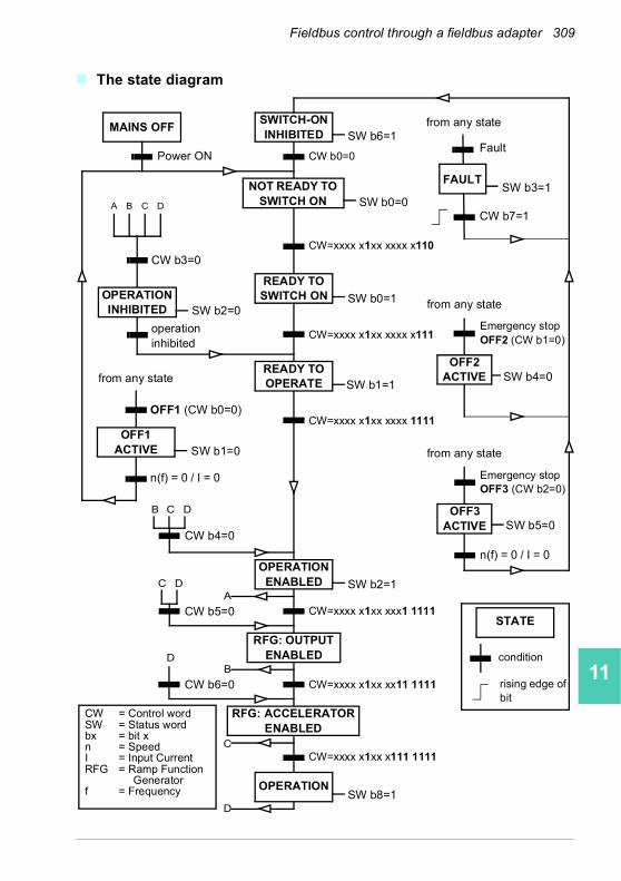
Fieldbus control through a fieldbus adapter 309
1
2
3
4
5
6
7
8
9
10
11
12
13
The state diagram
A B C D
C D
B
B C D
D
A
C
D
SWITCH-ON INHIBITED
NOT READY TO SWITCH ON
READY TO SWITCH ON
READY TO OPERATE
OPERATION INHIBITED
OFF1ACTIVE
OPERATION ENABLED
RFG: OUTPUT ENABLED
RFG: ACCELERATOR ENABLED
OPERATION
OFF2 ACTIVE
FAULT
OFF3 ACTIVE
MAINS OFFSW b6=1
SW b0=0
CW b0=0
CW=xxxx x1xx xxxx x110
SW b0=1
SW b1=1
CW=xxxx x1xx xxxx 1111
CW=xxxx x1xx xxxx x111
CW = Control wordSW = Status wordbx = bit xn = SpeedI = Input CurrentRFG = Ramp Function
Generatorf = Frequency
SW b2=0
from any state
Fault
from any state
from any state
SW b1=0
n(f) = 0 / I = 0
SW b5=0
Emergency stopOFF3 (CW b2=0)
SW b2=1
CW=xxxx x1xx xxx1 1111
CW=xxxx x1xx xx11 1111
CW b4=0
CW b5=0
CW b6=0
OFF1 (CW b0=0)
from any state
CW b3=0
n(f) = 0 / I = 0
STATE
condition
rising edge of bit
operation inhibited
Power ON
SW b3=1
CW b7=1
Emergency stopOFF2 (CW b1=0)
SW b4=0
SW b8=1
CW=xxxx x1xx x111 1111
14
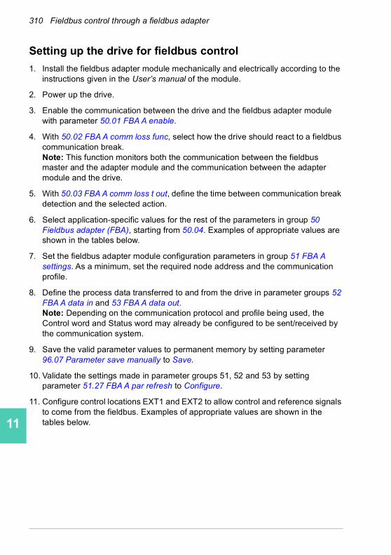
310 Fieldbus control through a fieldbus adapter
1
2
3
4
5
6
7
8
9
10
11
12
13
14
Setting up the drive for fieldbus control
1. Install the fieldbus adapter module mechanically and electrically according to the instructions given in the User’s manual of the module.
2. Power up the drive.
3. Enable the communication between the drive and the fieldbus adapter module with parameter 50.01 FBA A enable.
4. With 50.02 FBA A comm loss func, select how the drive should react to a fieldbus communication break.Note: This function monitors both the communication between the fieldbus master and the adapter module and the communication between the adapter module and the drive.
5. With 50.03 FBA A comm loss t out, define the time between communication break detection and the selected action.
6. Select application-specific values for the rest of the parameters in group 50 Fieldbus adapter (FBA), starting from 50.04. Examples of appropriate values are shown in the tables below.
7. Set the fieldbus adapter module configuration parameters in group 51 FBA A settings. As a minimum, set the required node address and the communication profile.
8. Define the process data transferred to and from the drive in parameter groups 52 FBA A data in and 53 FBA A data out.Note: Depending on the communication protocol and profile being used, the Control word and Status word may already be configured to be sent/received by the communication system.
9. Save the valid parameter values to permanent memory by setting parameter 96.07 Parameter save manually to Save.
10. Validate the settings made in parameter groups 51, 52 and 53 by setting parameter 51.27 FBA A par refresh to Configure.
11. Configure control locations EXT1 and EXT2 to allow control and reference signals to come from the fieldbus. Examples of appropriate values are shown in the tables below.
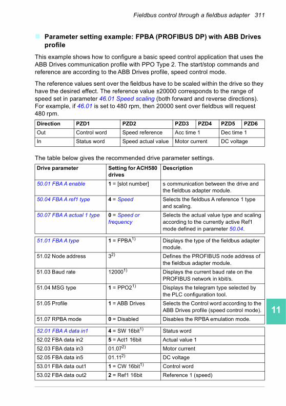
Fieldbus control through a fieldbus adapter 311
1
2
3
4
5
6
7
8
9
10
11
12
13
Parameter setting example: FPBA (PROFIBUS DP) with ABB Drives profile
This example shows how to configure a basic speed control application that uses the ABB Drives communication profile with PPO Type 2. The start/stop commands and reference are according to the ABB Drives profile, speed control mode.
The reference values sent over the fieldbus have to be scaled within the drive so they have the desired effect. The reference value ±20000 corresponds to the range of speed set in parameter 46.01 Speed scaling (both forward and reverse directions). For example, if 46.01 is set to 480 rpm, then 20000 sent over fieldbus will request 480 rpm.
The table below gives the recommended drive parameter settings.
Direction PZD1 PZD2 PZD3 PZD4 PZD5 PZD6
Out Control word Speed reference Acc time 1 Dec time 1
In Status word Speed actual value Motor current DC voltage
Drive parameter Setting for ACH580 drives
Description
50.01 FBA A enable 1 = [slot number] s communication between the drive and the fieldbus adapter module.
50.04 FBA A ref1 type 4 = Speed Selects the fieldbus A reference 1 type and scaling.
50.07 FBA A actual 1 type 0 = Speed or frequency
Selects the actual value type and scaling according to the currently active Ref1 mode defined in parameter 50.04.
51.01 FBA A type 1 = FPBA1) Displays the type of the fieldbus adapter module.
51.02 Node address 32) Defines the PROFIBUS node address of the fieldbus adapter module.
51.03 Baud rate 120001) Displays the current baud rate on the PROFIBUS network in kbit/s.
51.04 MSG type 1 = PPO21) Displays the telegram type selected by the PLC configuration tool.
51.05 Profile 1 = ABB Drives Selects the Control word according to the ABB Drives profile (speed control mode).
51.07 RPBA mode 0 = Disabled Disables the RPBA emulation mode.
52.01 FBA A data in1 4 = SW 16bit1) Status word
52.02 FBA data in2 5 = Act1 16bit Actual value 1
52.03 FBA data in3 01.072) Motor current
52.05 FBA data in5 01.112) DC voltage
53.01 FBA data out1 1 = CW 16bit1) Control word
53.02 FBA data out2 2 = Ref1 16bit Reference 1 (speed)
14

312 Fieldbus control through a fieldbus adapter
1
2
3
4
5
6
7
8
9
10
11
12
13
14
53.03 FBA data out3 23.122) Acceleration time 1
53.05 FBA data out5 23.132) Deceleration time 1
51.27 FBA A par refresh 1 = Configure Validates the configuration parameter settings.
20.01 Ext1 commands 12 = Fieldbus A Selects fieldbus adapter A as the source of the start and stop commands for external control location EXT1.
20.02 Ext1 start trigger type 1 = Level Selects a level-triggered start signal for external control location EXT1.
22.11 Ext1 speed ref1 4 = FB A ref1 Selects fieldbus A reference 1 as the source for speed reference 1.
1) Read-only or automatically detected/set2) Example
Drive parameter Setting for ACH580 drives
Description

Fieldbus control through a fieldbus adapter 313
1
2
3
4
5
6
7
8
9
10
11
12
13
Parameter setting example: FPBA (PROFIBUS DP) with PROFIdrive profile
This example shows how to configure a basic speed control application that uses the PROFIdrive communication profile with PPO Type 2. The start/stop commands and reference are according to the PROFIdrive profile, speed control mode.
The reference values sent over the fieldbus have to be scaled within the drive so they have the desired effect. The reference value ±16384 (4000h) corresponds to the range of speed set in parameter 46.01 Speed scaling (both forward and reverse directions). For example, if 46.01 is set to 480 rpm, then 4000h sent over fieldbus will request 480 rpm.
The table below gives the recommended drive parameter settings.
Direction PZD1 PZD2 PZD3 PZD4 PZD5 PZD6
Out Control word Speed reference Acc time 1 Dec time 1
In Status word Speed actual value Motor current DC voltage
Drive parameter Setting for ACH580 drives
Description
50.01 FBA A enable 1 = [slot number] s communication between the drive and the fieldbus adapter module.
50.04 FBA A ref1 type 4 = Speed Selects the fieldbus A reference 1 type and scaling.
50.07 FBA A actual 1 type 0 = Speed or frequency
Selects the actual value type and scaling according to the currently active Ref1 mode defined in parameter 50.04.
51.01 FBA A type 1 = FPBA1) Displays the type of the fieldbus adapter module.
51.02 Node address 32) Defines the PROFIBUS node address of the fieldbus adapter module.
51.03 Baud rate 120001) Displays the current baud rate on the PROFIBUS network in kbit/s.
51.04 MSG type 1 = PPO21) Displays the telegram type selected by the PLC configuration tool.
51.05 Profile 0 = PROFIdrive Selects the Control word according to the PROFIdrive profile (speed control mode).
51.07 RPBA mode 0 = Disabled Disables the RPBA emulation mode.
52.01 FBA A data in1 4 = SW 16bit1) Status word
52.02 FBA data in2 5 = Act1 16bit Actual value 1
52.03 FBA data in3 01.072) Motor current
52.05 FBA data in5 01.112) DC voltage
53.01 FBA data out1 1 = CW 16bit1) Control word
53.02 FBA data out2 2 = Ref1 16bit Reference 1 (speed)
14

314 Fieldbus control through a fieldbus adapter
1
2
3
4
5
6
7
8
9
10
11
12
13
14
The start and stop sequences for the parameter examples above are given below.
Control word:
Start:
• 1150 (476h) –> NOT READY TO SWITCH ON
• If MSW bit 0 = 1 then
• 1150 (47Eh) –> READY TO SWITCH ON (Stopped)
• 1151 (47Fh) –> OPERATION (Running)
Stop:
• 1150 (47Eh) = OFF1 ramp stop (Note: uninterruptable ramp stop)
• 1149 (47Dh) = coast to stop
• 1147 (47Bh) = emergency stop
Fault reset:
• Rising edge of MCW bit 7
Start after STO:
• If 31.22 STO indication run/stop is not Fault/ Fault, check that 06.18 Start inhibit status word, bit 7 STO = 0 before giving a start command.
53.03 FBA data out3 23.122) Acceleration time 1
53.05 FBA data out5 23.132) Deceleration time 1
51.27 FBA A par refresh 1 = Configure Validates the configuration parameter settings.
20.01 Ext1 commands 12 = Fieldbus A Selects fieldbus adapter A as the source of the start and stop commands for external control location EXT1.
20.02 Ext1 start trigger type
1 = Level Selects a level-triggered start signal for external control location EXT1.
22.11 Ext1 speed ref1 4 = FB A ref1 Selects fieldbus A reference 1 as the source for speed reference 1.
1) Read-only or automatically detected/set2) Example
Drive parameter Setting for ACH580 drives
Description

Fieldbus control through a fieldbus adapter 315
1
2
3
4
5
6
7
8
9
10
11
12
13
Automatic drive configuration for fieldbus control
The parameters set on module detection are shown in the table below. See also parameters 07.35 Drive configuration and 07.36 Drive configuration 2.
Option 10.24 RO1 source
10.27 RO2 source
10.30 RO3 source
20.01 Ext1 commands
20.03 Ext1 in1 source
20.04 Ext1 in2 source
FENA-21 - - - 12 (Fieldbus A)
0 0
FECA-01 - - - 12 (Fieldbus A)
0 0
FPBA-01 - - - 12 (Fieldbus A)
0 0
FCAN-01 - - - 12 (Fieldbus A)
0 0
FSCA-01 - - - 12 (Fieldbus A)
0 0
FEIP-21 - - - 12 (Fieldbus A)
0 0
FMBT-21 - - - 12 (Fieldbus A)
0 0
FBIP-21 40 (RO/DIO) control work
bit 0
41 (RO/DIO) control work
bit 1
HVAC: 42 (RO/DIO)
control work bit 2
12 (Fieldbus A)
0 0
FPNO-21 - - - 12 (Fieldbus A)
0 0
FEPL-02 - - - 12 (Fieldbus A)
0 0
FLON-01 40 (RO/DIO) control work
bit 0
41 (RO/DIO) control work
bit 1
42 (RO/DIO) control work
bit 2
12 (Fieldbus A)
0 0
FDNA-01 - - - 12 (Fieldbus A)
0 0
FCNA-01 - - - 12 (Fieldbus A)
0 0
Option 20.05 Ext1 in3 source
20.12 Run enable 1
22.11 Ext1 speed ref1
22.22 Constant
speed sel1
22.23 Constant
speed sel2
22.71 Motor potentiometer function
FENA-21 0 1 (Selected) 4 (FB A ref1) 0 0 0FECA-01 0 1 (Selected) 4 (FB A ref1) 0 0 0FPBA-01 0 1 (Selected) 4 (FB A ref1) 0 0 0FCAN-01 0 1 (Selected) 4 (FB A ref1) 0 0 0FSCA-01 0 1 (Selected) 4 (FB A ref1) 0 0 0FEIP-21 0 1 (Selected) 4 (FB A ref1) 0 0 0FMBT-21 0 1 (Selected) 4 (FB A ref1) 0 0 0FBIP-21 0 1 (Selected) 4 (FB A ref1) 0 0 0FPNO-21 0 1 (Selected) 4 (FB A ref1) 0 0 0FEPL-02 0 1 (Selected) 4 (FB A ref1) 0 0 0FLON-01 0 1 (Selected) 4 (FB A ref1) 0 0 0
14
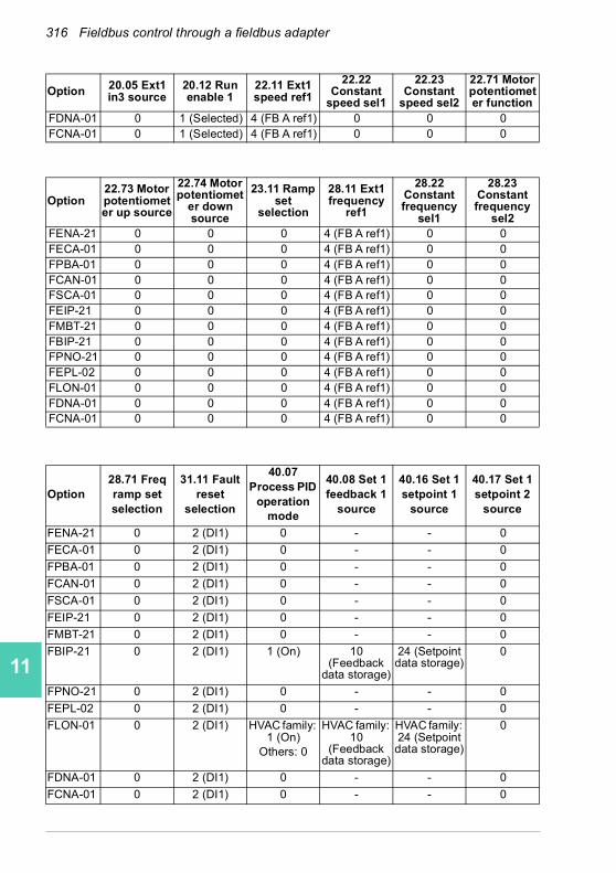
316 Fieldbus control through a fieldbus adapter
1
2
3
4
5
6
7
8
9
10
11
12
13
14
FDNA-01 0 1 (Selected) 4 (FB A ref1) 0 0 0FCNA-01 0 1 (Selected) 4 (FB A ref1) 0 0 0
Option22.73 Motor potentiometer up source
22.74 Motor potentiomet
er down source
23.11 Ramp set
selection
28.11 Ext1 frequency
ref1
28.22 Constant frequency
sel1
28.23 Constant frequency
sel2FENA-21 0 0 0 4 (FB A ref1) 0 0FECA-01 0 0 0 4 (FB A ref1) 0 0FPBA-01 0 0 0 4 (FB A ref1) 0 0FCAN-01 0 0 0 4 (FB A ref1) 0 0FSCA-01 0 0 0 4 (FB A ref1) 0 0FEIP-21 0 0 0 4 (FB A ref1) 0 0FMBT-21 0 0 0 4 (FB A ref1) 0 0FBIP-21 0 0 0 4 (FB A ref1) 0 0FPNO-21 0 0 0 4 (FB A ref1) 0 0FEPL-02 0 0 0 4 (FB A ref1) 0 0FLON-01 0 0 0 4 (FB A ref1) 0 0FDNA-01 0 0 0 4 (FB A ref1) 0 0FCNA-01 0 0 0 4 (FB A ref1) 0 0
Option28.71 Freq ramp set selection
31.11 Fault reset
selection
40.07 Process PID
operation mode
40.08 Set 1 feedback 1
source
40.16 Set 1 setpoint 1
source
40.17 Set 1 setpoint 2
source
FENA-21 0 2 (DI1) 0 - - 0
FECA-01 0 2 (DI1) 0 - - 0
FPBA-01 0 2 (DI1) 0 - - 0
FCAN-01 0 2 (DI1) 0 - - 0
FSCA-01 0 2 (DI1) 0 - - 0
FEIP-21 0 2 (DI1) 0 - - 0
FMBT-21 0 2 (DI1) 0 - - 0
FBIP-21 0 2 (DI1) 1 (On) 10 (Feedback
data storage)
24 (Setpoint data storage)
0
FPNO-21 0 2 (DI1) 0 - - 0
FEPL-02 0 2 (DI1) 0 - - 0
FLON-01 0 2 (DI1) HVAC family: 1 (On)
Others: 0
HVAC family: 10
(Feedback data storage)
HVAC family: 24 (Setpoint data storage)
0
FDNA-01 0 2 (DI1) 0 - - 0
FCNA-01 0 2 (DI1) 0 - - 0
Option 20.05 Ext1 in3 source
20.12 Run enable 1
22.11 Ext1 speed ref1
22.22 Constant
speed sel1
22.23 Constant
speed sel2
22.71 Motor potentiometer function
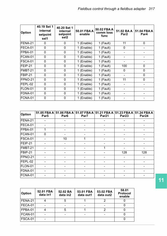
Fieldbus control through a fieldbus adapter 317
1
2
3
4
5
6
7
8
9
10
11
12
13
Option
40.19 Set 1 internal setpoint
sel1
40.20 Set 1 internal setpoint
sel2
50.01 FBA A enable
50.02 FBA A comm loss
func
51.02 BA A Par2
51.04 FBA A Par4
FENA-21 0 0 1 (Enable) 1 (Fault) 11 0
FECA-01 0 0 1 (Enable) 1 (Fault) 0 -
FPBA-01 0 0 1 (Enable) 1 (Fault) - -
FCAN-01 0 0 1 (Enable) 1 (Fault) - -
FSCA-01 0 0 1 (Enable) 1 (Fault) - -
FEIP-21 0 0 1 (Enable) 1 (Fault) 100 0
FMBT-21 0 0 1 (Enable) 1 (Fault) 0 0
FBIP-21 0 0 1 (Enable) 1 (Fault) - 0
FPNO-21 0 0 1 (Enable) 1 (Fault) 11 0
FEPL-02 0 0 1 (Enable) 1 (Fault) - -
FLON-01 0 0 1 (Enable) 1 (Fault) - -
FDNA-01 0 0 1 (Enable) 1 (Fault) - -
FCNA-01 0 0 1 (Enable) 1 (Fault) - -
Option 51.05 FBA A Par5
51.06 FBA A Par6
51.07 FBA A Par7
51.21 FBA A Par21
51.23 FBA A Par23
51.24 FBA A Par24
FENA-21 - - - - - -
FECA-01 - - - - - -
FPBA-01 1 - - - - -
FCAN-01 0 - - - - -
FSCA-01 - 10 1 - - -
FEIP-21 - - - - - -
FMBT-21 - - - 1 - -
FBIP-21 - - - - 128 128
FPNO-21 - - - - - -
FEPL-02 - - - - - -
FLON-01 - - - - - -
FDNA-01 - - - - - -
FCNA-01 - - - - - -
Option52.01 FBA data in1
52.02 BA data in2
53.01 FBA data out1
53.02 FBA data out2
58.01 Protocol enable
FENA-21 4 5 1 2 0
FECA-01 - - - - 0
FPBA-01 4 5 1 2 0
FCAN-01 - - - - 0
FSCA-01 - 0
14

318 Fieldbus control through a fieldbus adapter
1
2
3
4
5
6
7
8
9
10
11
12
13
14
FEIP-21 - - - - 0
FMBT-21 - - - - 0
FBIP-21 - - - - 0
FPNO-21 4 5 1 2 0
FEPL-02 - - - - 0
FLON-01 - - - - 0
FDNA-01 - - - - 0
FCNA-01 - - - - 0
Option 52.01 FBA data in1
52.02 BA data in2
53.01 FBA data out1
53.02 FBA data out2
58.01 Protocol enable

Control chain diagrams 319
1
2
3
4
5
6
7
8
9
10
11
12
13
12Control chain diagrams
Contents of this chapter
The chapter presents the reference chains of the drive. The control chain diagrams can be used to trace how parameters interact and where parameters have an effect within the drive parameter system.
For a more general diagram, see section Operating modes of the drive (page 93).
14

320 Control chain diagrams
1
2
3
4
5
6
7
8
9
10
11
12
13
14
Frequency reference selection
28
.41 F
requ
ency r
ef
sa
fe
Fre
qu
ency r
efe
ren
ce
safe
com
ma
nd
Netw
ork
refe
ren
ce
03.0
1 P
anel re
fere
nce
28.9
6 F
req
uen
cy r
ef act7
28
.92 F
requ
en
cy r
ef
act 3
Va
lue
Fie
ldbus:
OD
VA
CIP™
Va
lue
Se
lectio
n
28.1
1 E
xt1
fre
qu
en
cy r
ef1
28.1
2 E
xt1
fre
quen
cy r
ef2
19
.11 E
xt1
/Ext2
se
lectio
nS
ele
ctio
n
AN
D
AN
D
OR
Pa
nel com
m loss a
ctive
Pa
nel a
s local co
ntr
ol d
evic
e
Fie
ldbu
s c
om
m loss a
ctive
Con
trol fr
om
Fie
ldbus a
ctive
49.0
5 C
om
munic
ation
lo
ss a
ction =
Spe
ed r
ef safe
50.0
2 F
BA
A c
om
m loss f
unc =
Spee
d r
ef safe
Se
lectio
n
Va
lue
Va
lue
28
.13 E
xt1
fre
que
ncy fun
ction
Se
lectio
n
MU
L
AD
D
SUB
MIN
MA
X
Se
lectio
n
28.1
5E
xt2
fre
qu
en
cy r
ef1
Se
lectio
n
28
.17
Ext2
fre
qu
ency fun
ction
Se
lectio
n
MU
L
AD
D
SUB
MIN
MA
X2
8.1
6E
xt2
fre
qu
en
cy r
ef2
6.1
6 b
it 9
Netw
ork
con
trol
Va
lue
Va
lue
06
.16
bit 8
Local con
trol
Con
sta
nt fr
eque
ncy c
om
ma
nd
Con
sta
nt fr
eque
ncy r
ef
28.2
2 C
on
sta
nt fr
eque
ncy
sel1
28.2
3 C
on
sta
nt fr
eque
ncy
sel2
28.2
4 C
on
sta
nt fr
eque
ncy
sel3
28.2
6 C
onsta
nt fr
equ
en
cy
1
28.3
2 C
onsta
nt fr
equ
en
cy
7
28.3
1 C
onsta
nt fr
equ
en
cy
6
28.2
9 C
onsta
nt fr
equ
en
cy
4
28.2
7 C
onsta
nt fr
equ
en
cy
2
28.3
0 C
onsta
nt fr
equ
en
cy
5
28.2
8 C
onsta
nt fr
equ
en
cy
3
Se
lectio
n28
.21 C
onst fr
eque
ncy
fun
ction V
alu
e
Va
lue
Va
lue
Va
lue
Va
lue
Va
lue
Se
lectio
n
Se
lectio
n
Se
lectio
n
Va
lue
CO
NS
TA
NT
FR
EQ
UE
NC
Y
SE
LE
CT
ION 0
Dire
ction
Lo
ck
Va
lue
70
.1 b
it 1
Ove
rrid
e A
ctive
Ove
rrid
ere
fere
nce

Control chain diagrams 321
1
2
3
4
5
6
7
8
9
10
11
12
13
Frequency reference modification
28
.51 C
ritical fr
eq
ue
ncy f
unction
30.1
3 M
inim
um
fre
que
ncy
30.1
4 M
axim
um
fre
quen
cy
28.7
2 F
req
accele
ratio
n tim
e1
28.7
4 F
req a
ccele
ration
tim
e2
Va
lue
Va
lue
Va
lue
28.9
7 F
req
ref u
nlim
ited
2
8.9
6 F
req
uen
cy r
ef
act7
28
.76 F
req r
am
p in z
ero
sou
rce
Se
lectio
n
Va
lue
Va
lue
Va
lue
Va
lue
Va
lue
28.7
1 F
req
ram
p s
et
se
lectio
n
Se
lectio
n
28.5
2 C
ritical fr
eq
uen
cy 1
low
Se
lectio
n
28.5
3 C
ritical fr
eq
ue
ncy 1
hig
h
28.5
4 C
ritical fr
eq
uen
cy 2
low
28.5
5 C
ritical fr
eq
ue
ncy 2
hig
h
28.5
6 C
ritical fr
eq
uen
cy 3
low
28.5
7 C
ritical fr
eq
ue
ncy 3
hig
h
Va
lue
Va
lue
Va
lue
Va
lue
Va
lue
Va
lue
CR
ITIC
AL
FR
EQ
OR
Va
lue
Va
lue
28.0
2 F
req
ue
ncy r
ef ra
mp
ou
tput
Va
lue
0
Va
lue
6.1
bit 6
Ra
mp in z
ero
6.1
bit 5
Ram
p h
old 6.1
bit 4
Ra
mp o
ut zero
RA
MP
28.0
1 F
req
uen
cy r
ef ra
mp inp
ut
28.7
3F
req
decele
ratio
n tim
e1
28.7
5F
req
decele
ration
tim
e2
Va
lue
Va
lue
0
14
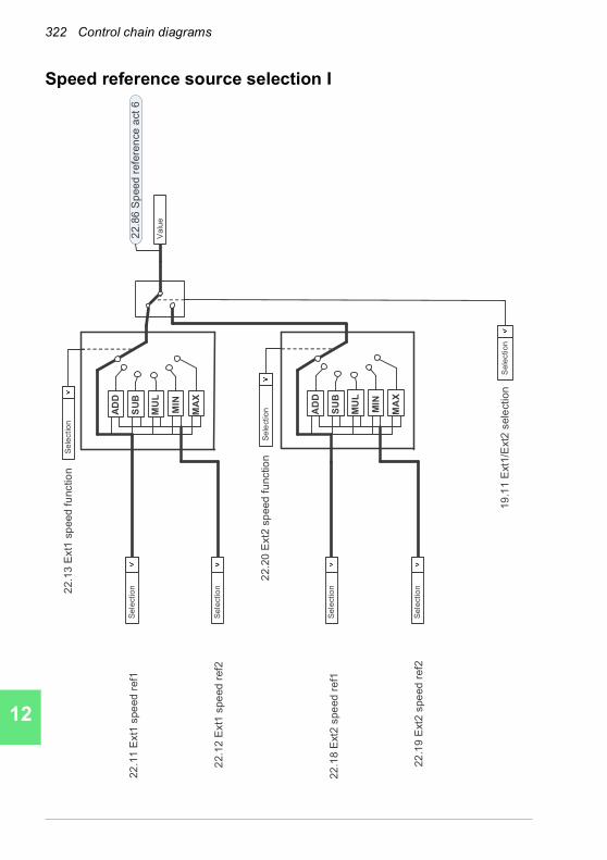
322 Control chain diagrams
1
2
3
4
5
6
7
8
9
10
11
12
13
14
Speed reference source selection I
22
.11 E
xt1
spe
ed
ref1
19
.11 E
xt1
/Ext2
sele
ction
22.1
3 E
xt1
sp
eed
fu
nctio
nS
ele
ctio
n
22.8
6 S
peed
refe
ren
ce
act
6
Va
lue
22.1
2 E
xt1
spe
ed
ref2
Se
lectio
n
22
.18
Ext2
spe
ed r
ef1
22.2
0E
xt2
sp
eed
fu
nctio
nS
ele
ctio
n
22
.19
Ext2
spe
ed r
ef2
MU
L
AD
D
SUB
MIN
MA
X
Se
lectio
n
Se
lectio
n
Se
lectio
n
Se
lectio
n
MU
L
AD
D
SU
B
MIN
MA
X

Control chain diagrams 323
1
2
3
4
5
6
7
8
9
10
11
12
13
Speed reference source selection II2
2.8
6 S
pe
ed
re
f a
ct
6
22
.52
Cri
tica
l sp
ee
d1
lo
w
22
.51
Cri
tica
l sp
ee
d f
un
ctio
n
22
.41
Sp
ee
d r
ef
sa
fe
Sp
ee
d r
ef
sa
fe c
om
ma
nd
Ne
two
rk r
efe
ren
ce
22
.01
Sp
ee
d r
ef
un
lim
ite
d
Va
lue
Va
lue
Va
lue
Va
lue
Va
lue
CR
ITIC
AL
SP
EE
DS
Se
lectio
n
Va
lue
Va
lue
Va
lue
Va
lue
Va
lue
Va
lue
22
.53
Cri
tica
l sp
ee
d1
hig
h
22
.54
Cri
tica
l sp
ee
d2
lo
w
22
.55
Cri
tica
l sp
ee
d2
hig
h
22
.56
Cri
tica
l sp
ee
d3
lo
w
22
.57
Cri
tica
l sp
ee
d3
hig
h
22
.87
Sp
ee
d r
efe
ren
ce
act
7
Fie
ldb
us:
OD
VA
CIP™
AN
D
AN
D
OR
49
.05
Co
mm
un
ica
tio
n lo
ss
actio
n =
Sp
ee
d r
ef
sa
fe
Pa
ne
l co
mm
lo
ss a
ctive
Pa
ne
l a
s lo
ca
l co
ntr
ol d
evic
e
50
.02
FB
A A
co
mm
lo
ss f
un
c =
Sp
ee
d r
ef
sa
fe
Fie
ldb
us c
om
m lo
ss a
ctive
Co
ntr
ol fr
om
Fie
ldb
us a
ctive
Va
lue
Va
lue
6.1
6 b
it 9
Ne
two
rk c
on
tro
l
3.0
1 P
an
el re
fere
nce
6.1
6 b
it 8
Lo
ca
l co
ntr
ol
22
.22
Co
nsta
nt
sp
ee
d s
el1
22
.23
Co
nsta
nt
sp
ee
d s
el2
22
.24
Co
nsta
nt
sp
ee
d s
el3
22
.26
Co
nsta
nt
sp
ee
d 1
22
.32
Co
nsta
nt
sp
ee
d 7
22
.31
Co
nsta
nt
sp
ee
d 6
22
.29
Co
nsta
nt
sp
ee
d 4
22
.27
Co
nsta
nt
sp
ee
d 2
22
.30
Co
nsta
nt
sp
ee
d 5
22
.28
Co
nsta
nt
sp
ee
d 3
Se
lectio
n2
2.2
1 C
on
sta
nt
sp
ee
d f
un
ctio
n
Va
lue
Va
lue
Va
lue
Va
lue
Va
lue
Va
lue
Se
lectio
n
Se
lectio
n
Se
lectio
n
Va
lue
CO
NS
TA
NT
SP
EE
D
SE
LE
CT
ION 0
Direction
Lo
ck
Va
lue
70
.1 b
it 1
Ove
rrid
e A
ctive
Ove
rrid
ere
fere
nce
14
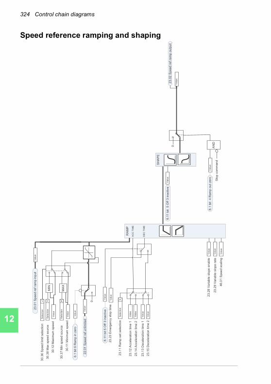
324 Control chain diagrams
1
2
3
4
5
6
7
8
9
10
11
12
13
14
Speed reference ramping and shaping
0
0
23.2
3 E
me
rgency s
top t
ime
23
.12 A
ccele
ratio
n tim
e1
23
.13 D
ecele
ration
tim
e1
23
.14 A
ccele
ration
tim
e2
23.1
5 D
ecele
ration
tim
e2
23.2
8 V
ariab
le s
lope
enab
le
23
.29 V
aria
ble
slo
pe r
ate
46
.01 S
pee
d s
ca
ling
SH
AP
E
23
.01 S
pee
d r
ef ra
mp inp
ut
Se
lectio
n
Va
lue
Va
lue
Va
lue
Va
lue
Va
lue
Va
lue
Va
lue
Va
lue
Va
lue
23.0
2 S
peed
ref
ram
p o
utp
ut
Va
lue
23.1
1 R
am
p s
et
sele
ction
AN
DS
top c
om
man
d
Va
lue
Va
lue
Va
lue
Va
lue
22.0
1 S
pe
ed
ref u
nlim
ited
6.1
1 b
it 5
Off 3
inactive
Va
lue
6.1
bit 6
Ra
mp in z
ero
6.1
1 b
it 5
Off 3
ina
ctive
6.1
bit 4
Ram
p o
ut
ze
ro
RA
MP
AC
C T
IME
DE
C T
IME
Va
lue
Va
lue
30.1
1 M
inim
um
sp
ee
d
30
.12 M
axim
um
spe
ed
Se
lectio
n3
0.3
6 S
peed
lim
it s
ele
ctio
n
Se
lectio
n30
.38 M
ax s
pee
d s
ourc
e
Se
lectio
n30
.37 M
in s
pee
d s
ourc
e
MIN
MA
X

Control chain diagrams 325
1
2
3
4
5
6
7
8
9
10
11
12
13
Speed error calculation
24.1
1 S
pee
d c
orr
ectio
n
24.1
2 S
pe
ed
err
or
filte
r tim
e
TA
ccC
om
25
.06 A
cc c
om
p d
erivation t
ime
25.0
7 A
cc c
om
p filt
er
tim
e
d dt
24.0
3 S
pe
ed
err
or
filte
red
25.5
6 T
orq
ue
acc c
om
pe
nsation
24.0
1 U
sed s
pe
ed r
efe
rence
23.0
2 S
pee
d r
ef ra
mp o
utp
ut
Va
lue
Va
lue
Va
lue
Va
lue
Va
lue
Va
lue
-
Va
lue
Va
lue
+
24.0
4 S
pe
ed
err
or
invert
ed
Va
lue
x-1
24
.02 U
se
d s
peed
fe
edb
ack
Va
lue
14
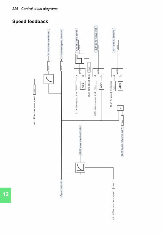
326 Control chain diagrams
1
2
3
4
5
6
7
8
9
10
11
12
13
14
Speed feedback
46.2
1 A
t sp
ee
d h
yste
resis
AB
S
Spe
ed
estim
ate
21.0
6 Z
ero
sp
eed
lim
itt
21
.07 Z
ero
sp
ee
d d
ela
y
AB
S
46.3
1 A
bo
ve
sp
eed
lim
it
AB
S
22.8
7 S
peed
refe
ren
ce
act
7
24.0
2 U
sed s
pee
d f
eed
ba
ck
a>
b
a b
a>
ba b
Va
lue
a>
b
a b-
Va
lue
Va
lue
Va
lue
Va
lue
01
.01 M
oto
r sp
eed
use
d
01
.02 M
oto
r sp
eed
estim
ate
d
46.1
1 F
ilter
tim
e m
oto
r sp
ee
dV
alu
e
Va
lue
Va
lue
Va
lue
Va
lue
Va
lue
Va
lue
46.1
1 F
ilter
tim
e m
oto
r sp
ee
d
6.1
9 b
it 0
Ze
ro s
pe
ed
6.1
1 b
it 1
0 A
bo
ve
lim
it
6.1
1 b
it 8
At
se
tpoin
t

Control chain diagrams 327
1
2
3
4
5
6
7
8
9
10
11
12
13
Speed controller
25.0
4 S
pe
ed
deri
va
tio
n tim
e
25.0
5 D
eri
va
tio
n filt
er
tim
e
25.0
2 S
pe
ed
pro
port
iona
l g
ain
25.1
5 P
ropo
rtio
nal gain
em
sto
p
25
.54 T
orq
ue
inte
gra
lre
fere
nce
25.5
5 T
orq
ue
deri
vre
fere
nce
25
.56 T
orq
ue a
cc c
om
pe
nsation
Va
lue
Va
lue
Va
lue
Va
lue
Va
lue
Va
lue
Va
lue
25.0
3 S
pe
ed
in
tegra
tion t
ime
Va
lue
30.1
9 M
inim
um
to
rque
Va
lue
PID
Va
lue
25
.53 T
orq
ue
pro
p r
efe
rence
Sp
eed
reg
ula
tor
Va
lue
24
.03 S
pe
ed e
rro
r filte
red
25.0
1 T
orq
ue r
efe
rence s
pee
d c
ontr
ol
Va
lue
30
.21
Min
torq
ue
2so
urc
e
30.1
8 T
orq
lim
sel
Va
lue
30.2
0 M
axim
um
to
rqu
eV
alu
e
30.2
2M
ax t
orq
ue
2sou
rce
30
.18 T
orq
lim
se
lV
alu
e
Se
lectio
n
Se
lectio
n
14

328 Control chain diagrams
1
2
3
4
5
6
7
8
9
10
11
12
13
14
Torque limitation
30
.30 O
verv
olta
ge c
ontr
olV
alu
e
Va
lue
DC
voltag
e
limiter
30
.31
Unde
rvol
tage
con
trol
Va
lue
Pow
er
limiter
To
rque lim
iter
24.0
2 U
se
d s
pee
d f
eed
back
Va
lue
30.2
6 Po
wer
mot
orin
g lim
it
30.2
7 Po
wer
gen
erat
ing
limit
Va
lue
Va
lue
01
.10
Moto
r to
rqu
e
Cu
rrent
limite
rLo
ad a
ngle
limita
tio
n
Mo
tor
pu
ll-ou
t
limitation
30
.17 M
axim
um
curr
en
tV
alu
e
30
.02 T
orq
ue lim
it s
tatu
s
Va
lue
30.0
2 T
orq
ue lim
it s
tatu
s
Bit N
am
e
0 =
Und
erv
olta
ge
1 =
Ove
rvoltag
e
2 =
Min
imum
torq
ue
3 =
Ma
xim
um
to
rqu
e
4 =
Inte
rna
l curr
ent
5 =
Loa
d a
ng
le
6 =
Mo
tor
pu
ll-o
ut
7 =
Reserv
ed
8 =
Th
erm
al
9 =
Ma
xcurr
en
t
10 =
User
cu
rre
nt
11 =
The
rma
l IG
BT
12 =
13 =
14 =
15 =
25
.01 T
orq
ue
refe
ren
ce
spe
ed
con
trol
Torq
ue
Reg
ula
tor
30
.19 M
inim
um
to
rqu
eV
alu
e
30.2
1M
in to
rqu
e 2
sourc
e
30.1
8 T
orq
lim
se
lV
alu
e
Se
lectio
n
30.2
0 M
axim
um
torq
ue
Va
lue
Se
lectio
n30
.22
Max
torq
ue 2
sourc
e

Control chain diagrams 329
1
2
3
4
5
6
7
8
9
10
11
12
13
PID flow calculation
80.1
1F
low
fee
db
ack 1
sou
rce
Se
lectio
n
80.0
1F
low
actu
alvalu
eV
alu
e
80.1
4 F
low
fe
ed
back m
ultip
ler
Va
lue
10
0%
/
Ma
xim
um
Flo
w
80
.02 F
low
actu
al%
Va
lue
80
.15
Maxim
um
flo
w
Va
lue
80
.13
Flo
w c
alc
ula
tio
n m
od
eS
ele
ctio
n
Add
In 1
In 2 In1
In1-
In2
x
80.1
2F
low
fee
dba
ck 2
so
urc
e
Se
lectio
nV
alu
e
14
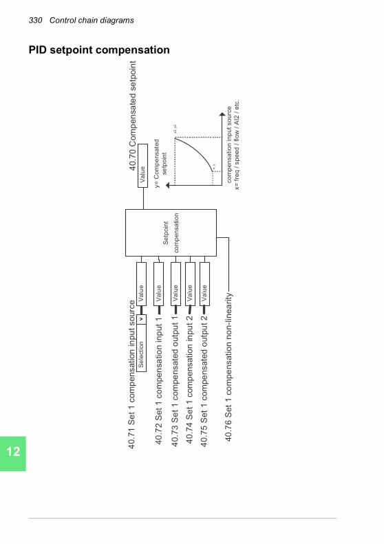
330 Control chain diagrams
1
2
3
4
5
6
7
8
9
10
11
12
13
14
PID setpoint compensation
40.7
1S
et1 c
om
pensation
inpu
t sourc
eS
ele
ctio
nV
alu
e
Va
lue
40
.72
Set1
co
mpen
sa
tio
n inp
ut 1
40.7
0C
om
pen
sa
ted s
etp
oin
tV
alu
e
Se
tpo
int
co
mp
en
sa
tio
n
40
.76
Set
1co
mpe
nsation n
on-l
inea
rityVa
lue
40.7
5S
et
1com
pe
nsate
d o
utp
ut 2
Va
lue
40.7
4S
et1 c
om
pensation
in
pu
t 2
Va
lue
40.7
3S
et1 c
om
pe
nsate
do
utp
ut 1
x,
y
x2
, y2
co
mp
en
sa
tio
n in
pu
t so
urc
e
x=
fre
q /
sp
ee
d /
flo
w /
AI2
/ e
tc.
y=
Co
mp
en
sa
ted
se
tpo
int

Control chain diagrams 331
1
2
3
4
5
6
7
8
9
10
11
12
13
Process PID setpoint and feedback source selection
40.2
6 S
et 1
setp
oin
t m
in
40.2
7 S
et 1 s
etp
oin
t m
ax
40
.18 S
et
1 s
etp
oin
t fu
nction
40
.10 S
et
1 fe
ed
back fun
ction
40.1
1 S
et 1 f
ee
dba
ck filt
er
tim
e
40.2
8 S
et 1 s
etp
oin
t in
cre
ase
tim
e
40.2
9 S
et 1
setp
oin
t decre
ase t
ime
Va
lue
40
.16 S
et 1
setp
oin
t 1 s
ourc
e
Se
lectio
nV
alu
e
40.1
7 S
et 1 s
etp
oin
t 2
sou
rce
40
.21 S
et
1 inte
rnal setp
oin
t 1
40
.22
Set
1 inte
rnal setp
oin
t 2
40
.23 S
et
1 inte
rnal setp
oin
t 3
Se
lectio
n
Va
lue
Va
lue
Va
lue
Va
lue
Va
lue
40
.30 S
et
1 s
etp
oin
t fr
ee
ze
ena
ble
Se
lectio
n
Va
lue
40
.08 S
et
1 fe
ed
back 1
sou
rce
Se
lectio
n
Va
lue
40
.09 S
et
1 fe
ed
back 2
sou
rce
Se
lectio
n
Se
lectio
n
40.0
2 P
rocess P
ID f
ee
dba
ck a
ctu
al
Va
lue
Va
lue
Mul
Add
Feed
back
1
AD
D
SUB
MU
L
DIV
MIN
MA
X
AVE a a-
b
a+b
a +
b
Mul
Add
Setp
oint
1
AD
D
SUB
MU
L
DIV
MIN
MA
X
AVE a a-
ba+
b
40.4
5 S
et 1
sle
ep b
oo
st
tim
eV
alu
e
40
.46 S
et 1
sle
ep b
oost ste
pV
alu
e
0
RA
MP
40
.03 P
rocess P
ID s
etp
oin
t actu
al
Va
lue
Va
lue
Va
lue
a +
b
+
Va
lue
Puls
e
Note
! P
rocess P
ID p
ara
mete
r set
2 is a
lso a
vaila
ble
. S
ee p
ara
mete
r g
roup 4
1.
Va
lue
40
.62
PID
inte
rna
l setp
oin
t a
ctu
al
Va
lue
40
.06 P
roce
ss P
ID s
tatu
s w
ord
: bit 4
PID
sle
ep m
od
e
40
.19 S
et
1 inte
rnal setp
oin
t sel1
40.2
0 S
et 1 inte
rna
l setp
oin
t se
l2
BIN
TO
INT
SE
L
b0 b1
0
Se
lectio
n
Se
lectio
nO
UT
1 2
3
0
Fe
ed
ba
ck
Sca
le
40
.90
Set 1
fe
edb
ack m
ultip
lier
Va
lue
Se
tpo
int
Sca
le
40.8
9S
et
1 s
etp
oin
tm
ultip
lier
Va
lue
40.2
4S
et 1
in
tern
al se
tpoin
t 0
Va
lue
14

332 Control chain diagrams
1
2
3
4
5
6
7
8
9
10
11
12
13
14
Process PID controller
40
.32 S
et 1
gain
40.3
6 S
et
1 o
utp
ut m
in
40
.37 S
et
1 o
utp
ut m
ax
40
.43 S
et
1 s
leep leve
l
40.4
4 S
et 1
sle
ep d
ela
y
40.4
7 S
et
1 w
ake-u
p d
evia
tio
n
40.4
8 S
et 1
wake-u
p d
ela
y
1 -1
40.3
4 S
et 1
deri
va
tio
n tim
e
40
.35 S
et 1
deri
va
tio
n f
ilte
r tim
e
40.3
3 S
et
1 inte
gra
tio
n tim
e
40.3
1 S
et
1 d
evia
tio
n invers
ion
40.0
3 P
rocess P
ID s
etp
oin
t a
ctu
al
Va
lue
40.0
2 P
rocess P
ID f
ee
dba
ck a
ctu
al
Se
lectio
n
Va
lue
Va
lue
Va
lue
Va
lue
Va
lue
-In
pu
t
Sca
le
40
.43 S
et
1 s
leep level
40.0
1 P
rocess P
ID O
utp
ut a
ctu
al
Va
lue
Va
lue
Va
lue
Va
lue
Va
lue
Va
lue
Slee
p Fu
nctio
n
Va
lue
40
.49 S
et 1
tra
ckin
g m
od
eS
ele
ctio
n
40.5
0 S
et 1
tra
ckin
g r
ef
se
lectio
n
Va
lue
Va
lue
PR
OC
ES
S P
ID F
UN
CT
ION
40.0
4 P
rocess P
ID d
evia
tio
n a
ctu
al
x 40.0
7 S
et
1 P
ID o
pera
tio
n m
od
eV
alu
e
Va
lue
40.0
6 b
it 3
Sle
ep m
od
e
40
.46 S
et
1 s
leep b
oost ste
pV
alu
e
Va
lue
40.4
5 S
et 1 s
lee
p b
oo
st
tim
e
40
.06 P
rocess P
ID s
tatu
s w
ord
Pro
ce
ss
PID
sta
tus
Va
lue
40.0
6 b
it 4
Sle
ep b
oost
40.5
8 S
et 1 incre
ase p
reven
tatio
nV
alu
e
40.5
9 S
et 1
Decre
ase p
reventa
tio
nV
alu
e
Va
lue
40.1
4S
et 1
setp
oin
t scalin
g
Ou
tpu
t
Sca
le
Va
lue
40.1
5S
et 1 o
utp
ut
scalin
g
40.9
7P
rocess P
ID f
eed
ba
ck %
Va
lue
40.9
8P
roce
ss P
ID s
etp
oin
t%
Va
lue
40.9
9P
rocess P
ID D
evia
tio
n %
Va
lue
10
0%
% s
ca
lin
g
% s
ca
ling
PID
40.8
0S
et 1 o
utp
ut
min
so
urc
e
Se
lectio
n
40.8
1S
et 1 o
utp
ut
max s
ourc
e
Se
lectio
n
40
.38 O
utp
ut fr
eeze
Se
lectio
n
40
.39 D
ead
ban
d r
ang
eV
alu
e
40.4
0 D
eadb
an
d d
ela
yV
alu
e
Co
mp
are
De
lay
OR
AB
S

Control chain diagrams 333
1
2
3
4
5
6
7
8
9
10
11
12
13
External PID setpoint and feedback source selection
71
.26 S
etp
oin
t m
in
71.2
7 S
etp
oin
t m
ax
71
.11 F
ee
db
ack f
ilte
r tim
e
Va
lue
71.1
6 S
etp
oin
t 1 s
ourc
e
71.2
1 In
tern
al se
tpoin
t 1
71.2
2In
tern
al se
tpoin
t 2
71.2
3 In
tern
al se
tpoin
t 3
Se
lectio
n
Va
lue
Va
lue
Va
lue
71.0
8 F
ee
dba
ck 1
so
urc
e
Se
lectio
n71
.02 F
ee
db
ack a
ct valu
e
Va
lue
Va
lue
71.0
3 S
etp
oin
t act valu
e
Va
lue
Va
lue
Va
lue
Va
lue
71.6
2P
ID in
tern
al se
tpoin
t actu
al
Va
lue
71.1
9 Inte
rna
l setp
oin
t se
l1
71.2
0 Inte
rna
l setp
oin
t se
l2
BIN
TO
INT
SE
L
b0 b1
0
Se
lectio
n
Se
lectio
nO
UT
01 2
3
0
14

334 Control chain diagrams
1
2
3
4
5
6
7
8
9
10
11
12
13
14
External PID controller
71.3
2 G
ain
71
.36 O
utp
ut m
in
71
.37 O
utp
ut
max
1 -1
71.3
4 D
eri
va
tio
n t
ime
71.3
5 D
erivation
filt
er
tim
e
71.3
3 Inte
gra
tio
n t
ime
71.3
1 D
evia
tio
n invers
ion
71.0
3 S
etp
oin
t act valu
eV
alu
e
71.0
2 F
eedb
ack a
ct
va
lue
Se
lectio
n
Va
lue
Va
lue
Va
lue
Va
lue
Va
lue
-S
ca
le
71.0
1 E
xte
rnal P
ID a
ct valu
e
71.3
8 O
utp
ut fr
ee
ze
Se
lectio
n
Va
lue
Va
lue
Va
lue
Va
lue
PID
71.0
4 D
evia
tio
n a
ct valu
e
x
71.0
7 P
ID o
pera
tion
mo
de
Va
lue
71.0
6 P
ID s
tatu
s w
ord
Exte
rna
l
PID
sta
tus
Va
lue
71
.14 S
etp
oin
t sca
ling
Va
lue
71.1
5 O
utp
ut sca
ling
Va
lue
71.3
9 D
eadb
an
d r
an
ge
Va
lue
71.4
0 D
ea
dba
nd
dela
yV
alu
e
71.5
8 I
ncre
ase p
revention
Va
lue
71.5
9 D
ecre
ase p
revention
Va
lue
Co
mp
are
De
lay
OR
AB
S

Control chain diagrams 335
1
2
3
4
5
6
7
8
9
10
11
12
13
Direction lock
Ou
tpu
t re
fere
nce
Inp
ut
refe
ren
ce
20
.21
Direction
= R
equ
est
AN
D
OR
Re
fere
nce f
rom
FB
Re
fere
nce
fro
m M
oto
r p
ote
ntio
mete
r
La
st/
Safe
re
fere
nce
Consta
nt re
fere
nce
Refe
ren
ce
fro
m A
P p
rog
ram
Re
fere
nce f
rom
PID
Refe
rence f
rom
Pan
el
Re
fere
nce
fro
m A
I
OR
Refe
rence f
rom
FB
Re
fere
nce fro
m M
oto
r pote
ntiom
ete
r
Refe
rence f
rom
Pan
el
Last/S
afe
refe
rence
Refe
rence
fro
m A
IR
efe
rence fro
m A
P p
rogra
m
OR
20
.21
Dir
ectio
n=
Revers
e
AN
D
20
.21
Dir
ectio
n=
Re
qu
est
Re
ve
rse c
om
man
d a
ctive
X
MA
X
X-1
-10
AN
D
20.2
1D
ire
ction
= R
eq
ue
st
Revers
e c
om
ma
nd a
ctive
Inp
ut
refe
ren
ce
> 0
Refe
rence
fro
m N
etw
ork
14

336 Control chain diagrams
1
2
3
4
5
6
7
8
9
10
11
12
13
14
Override
Va
lue
20.4
0R
un
perm
issiv
e
70.0
2 O
ve
rrid
een
able
70.0
3O
verr
ide
activation
sou
rce
70.1
0 b
it 0
Use r
un p
erm
issiv
e
Se
lectio
n
Se
lectio
n
70
.06
Ove
rrid
efr
eq
ue
ncy
12
.22
An
alo
g s
ca
led
2
40
.01
PID
Ou
tpu
t a
ct
Va
lue
Va
lue
0.0
22
.80
Mo
tor
po
t a
ct
12
.12
An
alo
g s
ca
led
1
Va
lue
Va
lue
Va
lue
Se
lectio
n7
0.0
4O
ve
rrid
ere
f so
urc
e
70
.1 b
it 2
Ove
rrid
e d
ire
ctio
n is f
orw
ard
70
.1 b
it 3
Ove
rrid
e d
ire
ctio
n is r
eve
rse
Sto
p
AN
D7
0.1
bit 0
Ove
rrid
e E
na
ble
d
70
.1 b
it 1
Ove
rrid
e A
ctive
OR
Se
lectio
n7
0.1
bit 7
Ru
n p
erm
issiv
e
Va
lue
20.4
4S
tart
inte
rlock 4
70.1
0 b
it 4
Use S
tart
in
terlo
ck 4
OR
Se
lectio
n7
0.1
bit 1
1 S
tart
in
terl
ock 4
Va
lue
20.4
3S
tart
in
terlock 3
70
.10 b
it 3
Use S
tart
inte
rlo
ck 3
OR
Se
lectio
n7
0.1
bit 1
0 S
tart
in
terl
ock 3
Va
lue
20.4
2S
tart
in
terlock 2
70
.10 b
it 2
Use S
tart
inte
rlo
ck 2
OR
Se
lectio
n7
0.1
bit 9
Sta
rt in
terl
ock 2
Va
lue
20.4
1S
tart
in
terlock 1
70
.10 b
it 1
Use S
tart
inte
rlo
ck 1
OR
Se
lectio
n7
0.1
bit 8
Sta
rt in
terl
ock 1
Co
nsta
nt
sp
ee
d d
efin
ed
by g
rou
p 2
2
Co
nsta
nt
fre
qu
en
cy d
efin
ed
by g
rou
p 2
8
99
.04
Mo
tor
co
ntr
ol m
od
eV
alu
e
70
.07
Ove
rrid
esp
ee
d
Va
lue
0
70.0
5O
ve
rrid
edir
ectio
nS
ele
ctio
n
Ove
rrid
e
refe
ren
ce
Co
mp
are
AB
S-1
sca
lar
vecto
r
sca
lar
vecto
r

13. Parameters
14. Additional parameter data
ACH580HVAC control program
Firmware manualPart 2 Parameters

2019 ABB Oy. All Rights Reserved.Corresponds to3AXD50000209828 Rev BENEFFECTIVE: 2019-01-11

Parameters 339
1
2
3
4
5
6
7
8
9
10
11
12
13
13Parameters
What this chapter contains
The chapter describes the parameters, including actual signals, of the control program. At the end of the chapter, on page 589, there is a separate list of the parameters whose default values are different between 50 Hz and 60 Hz supply frequency settings.
14
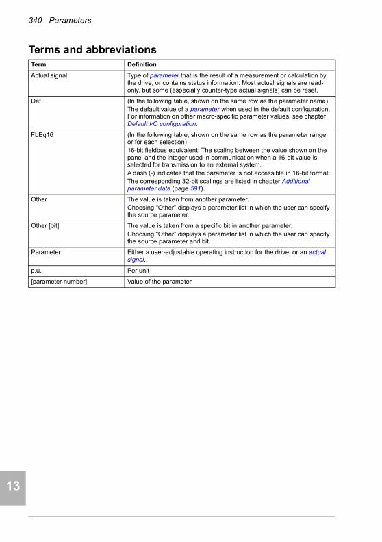
340 Parameters
1
2
3
4
5
7
8
9
9
10
11
12
13
14
Terms and abbreviationsTerm Definition
Actual signal Type of parameter that is the result of a measurement or calculation by the drive, or contains status information. Most actual signals are read-only, but some (especially counter-type actual signals) can be reset.
Def (In the following table, shown on the same row as the parameter name)The default value of a parameter when used in the default configuration. For information on other macro-specific parameter values, see chapter Default I/O configuration.
FbEq16 (In the following table, shown on the same row as the parameter range, or for each selection)16-bit fieldbus equivalent: The scaling between the value shown on the panel and the integer used in communication when a 16-bit value is selected for transmission to an external system.A dash (-) indicates that the parameter is not accessible in 16-bit format.The corresponding 32-bit scalings are listed in chapter Additional parameter data (page 591).
Other The value is taken from another parameter.Choosing “Other” displays a parameter list in which the user can specify the source parameter.
Other [bit] The value is taken from a specific bit in another parameter.Choosing “Other” displays a parameter list in which the user can specify the source parameter and bit.
Parameter Either a user-adjustable operating instruction for the drive, or an actual signal.
p.u. Per unit
[parameter number] Value of the parameter
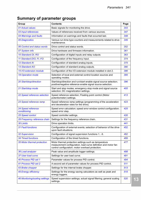
Parameters 341
1
2
3
4
5
6
7
8
9
10
11
12
13
Summary of parameter groupsGroup Contents Page
01 Actual values Basic signals for monitoring the drive. 343
03 Input references Values of references received from various sources. 347
04 Warnings and faults Information on warnings and faults that occurred last. 348
05 Diagnostics Various run-time-type counters and measurements related to drive maintenance.
349
06 Control and status words Drive control and status words. 352
07 System info Drive hardware and firmware information. 361
10 Standard DI, RO Configuration of digital inputs and relay outputs. 363
11 Standard DIO, FI, FO Configuration of the frequency input. 374
12 Standard AI Configuration of standard analog inputs. 375
13 Standard AO Configuration of standard analog outputs. 380
15 I/O extension module Configuration of the I/O extension module installed in slot 2. 386
19 Operation mode Selection of local and external control location sources and operating modes.
395
20 Start/stop/direction Start/stop/direction and run/start enable signal source selection; positive/negative reference enable signal source selection.
396
21 Start/stop mode Start and stop modes; emergency stop mode and signal source selection; DC magnetization settings.
405
22 Speed reference selection Speed reference selection; Floating point control (Motor potentiometer) settings.
413
23 Speed reference ramp Speed reference ramp settings (programming of the acceleration and deceleration rates for the drive).
423
24 Speed reference conditioning
Speed error calculation; speed error window control configuration; speed error step.
425
25 Speed control Speed controller settings. 426
28 Frequency reference chain Settings for the frequency reference chain. 431
30 Limits Drive operation limits. 441
31 Fault functions Configuration of external events; selection of behavior of the drive upon fault situations.
452
32 Supervision Configuration of signal supervision functions 1…6. 462
34 Timed functions Configuration of the timed functions. 469
35 Motor thermal protection Motor thermal protection settings such as temperature measurement configuration, load curve definition and motor fan control configuration; motor overload protection.
477
36 Load analyzer Peak value and amplitude logger settings. 488
37 User load curve Settings for user load curve. 491
40 Process PID set 1 Parameter values for process PID control. 494
41 Process PID set 2 A second set of parameter values for process PID control. 511
43 Brake chopper Settings for the internal brake chopper. 513
45 Energy efficiency Settings for the energy saving calculators as well as peak and energy loggers.
515
46 Monitoring/scaling settings Speed supervision settings; actual signal filtering; general scaling settings.
520
14

342 Parameters
1
2
3
4
5
7
8
9
9
10
11
12
13
14
47 Data storage Data storage parameters that can be written to and read from using other parameters’ source and target settings.
523
49 Panel port communication Communication settings for the control panel port on the drive. 524
50 Fieldbus adapter (FBA) Fieldbus communication configuration. 525
51 FBA A settings Fieldbus adapter A configuration. 529
52 FBA A data in Selection of data to be transferred from drive to fieldbus controller through fieldbus adapter A.
530
53 FBA A data out Selection of data to be transferred from fieldbus controller to drive through fieldbus adapter A.
531
58 Embedded fieldbus Configuration of the embedded fieldbus (EFB) interface. 531
60 DDCS communication DCS communication configuration. 540
61 D2D and DDCS transmit data
Defines the data sent to the DDCS link. 540
62 D2D and DDCS receive data
Defines the data sent to the DDCS link. 541
70 Override Enabling/disabling of override function, override activation signal and override speed/frequency.
541
71 External PID1 Configuration of external PID. 546
72 External PID2 Configuration of external PID2. 547
73 External PID3 Configuration of external PID3. 549
74 External PID4 Configuration of external PID4. 551
76 PFC configuration PFC (Pump and fan control) and Autochange configuration parameters.
554
77 PFC maintenance and monitoring
PFC (Pump and fan control) maintenance and monitoring parameters.
561
80 Flow calculation and protection
Actual flow calculation. 562
94 LSU control Control of the supply unit of the drive, such as DC voltage and reactive power reference.
563
95 HW configuration Various hardware-related settings. 564
96 System Language selection; access levels; macro selection; parameter save and restore; control unit reboot; user parameter sets; unit selection; parameter checksum calculation; user lock.
567
97 Motor control Switching frequency; slip gain; voltage reserve; flux braking; anti-cogging (signal injection); IR compensation.
577
98 User motor parameters Motor values supplied by the user that are used in the motor model.
581
99 Motor data Motor configuration settings. 583
Group Contents Page

Parameters 343
1
2
3
4
5
6
7
8
9
10
11
12
13
Parameter listingNo. Name/Value Description Def/FbEq16
0101 Actual values Basic signals for monitoring the drive.
All parameters in this group are read-only unless otherwise noted.Note: Values of these actual signals are filtered with the filter time defined in group 46 Monitoring/scaling settings. The selection lists for parameters in other groups mean the raw value of the actual signal instead. For example, if a selection is “Output frequency” it does not point to the value of parameter 01.06 Output frequency but to the raw value.
01.01 Motor speed used Estimated motor speed. A filter time constant for this signal can be defined by parameter 46.11 Filter time motor speed.
-
-30000.00… 30000.00 rpm
Estimated motor speed. See par. 46.01
01.02 Motor speed estimated
Estimated motor speed in rpm. A filter time constant for this signal can be defined by parameter 46.11 Filter time motor speed.
-
-30000.00… 30000.00 rpm
Estimated motor speed. See par. 46.01
01.03 Motor speed % Motor speed in percent of the synchronous motor speed. -
-1000.00… 1000.00%
Motor speed. 10 = 1%
01.06 Output frequency Estimated drive output frequency in Hz. A filter time constant for this signal can be defined by parameter 46.12 Filter time output frequency.
-
-500.00…500.00 Hz
Estimated output frequency. See par. 46.02
01.07 Motor current Measured (absolute) motor current in A. -
0.00…30000.00 A Motor current. See par. 46.05
01.08 Motor current % of motor nom
Motor current (drive output current) in percent of the nominal motor current.
-
0.0…1000.0% Motor current. 1 = 1%
01.09 Motor current % of drive nom
Motor current (drive output current) in percent of the nominal drive current.
-
0.0…1000.0% Motor current. 1 = 1%
01.10 Motor torque Motor torque in percent of the nominal motor torque. See also parameter 01.30 Nominal torque scale.A filter time constant for this signal can be defined by parameter 46.13 Filter time motor torque.
-
-1600.0…1600.0% Motor torque. See par. 46.03
01.11 DC voltage Measured DC link voltage. -
0.00…2000.00 V DC link voltage. 10 = 1 V
01.13 Output voltage Calculated motor voltage in V AC. -
0…2000 V Motor voltage. 1 = 1 V
14
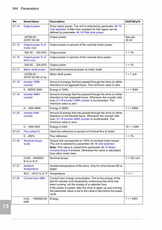
344 Parameters
1
2
3
4
5
7
8
9
9
10
11
12
13
14
01.14 Output power Drive output power. The unit is selected by parameter 96.16 Unit selection. A filter time constant for this signal can be defined by parameter 46.14 Filter time power.
-
-32768.00… 32767.00 kW
Output power. See par. 46.04
01.15 Output power % of motor nom
Output power in percent of the nominal motor power. -
-300.00… 300.00% Output power. 1 = 1%
01.16 Output power % of drive nom
Output power in percent of the nominal drive power. -
-300.00… 300.00% Output power. 1 = 1%
01.17 Motor shaft power Estimated mechanical power at motor shaft. -
-32768.00… 32767.00 kW or hp
Motor shaft power. 1 = 1 unit
01.18 Inverter GWh counter
Amount of energy that has passed through the drive (in either direction) in full gigawatt-hours. The minimum value is zero.
-
0…65535 GWh Energy in GWh. 1 = 1 GWh
01.19 Inverter MWh counter
Amount of energy that has passed through the drive (in either direction) in full megawatt-hours. Whenever the counter rolls over, 01.18 Inverter GWh counter is incremented. The minimum value is zero.
-
0…1000 MWh Energy in MWh. 1 = 1 MWh
01.20 Inverter kWh counter
Amount of energy that has passed through the drive (in either direction) in full kilowatt-hours. Whenever the counter rolls over, 01.19 Inverter MWh counter is incremented. The minimum value is zero.
-
0…1000 kWh Energy in kWh. 10 = 1 kWh
01.24 Flux actual % Used flux reference in percent of nominal flux of motor. -
0…200% Flux reference. 1 = 1%
01.30 Nominal torque scale
Torque that corresponds to 100% of nominal motor torque. The unit is selected by parameter 96.16 Unit selection.Note: This value is copied from parameter 99.12 Motor nominal torque if entered. Otherwise the value is calculated from other motor data.
-
0.000…4000000 N·m or lb·ft
Nominal torque. 1 = 100 unit
01.31 Ambient temperature
Ambient temperature of the drive. Only for drive frames R6 or larger.
-
40.0…120.0 °C or °F Temperature. 1 = 1 °
01.50 Current hour kWh Current hour energy consumption. This is the energy of the last 60 minutes (not necessarily continuous) the drive has been running, not the energy of a calendar hour.If the power is cycled, after the drive is again up and running, the parameter value is set to the value it had before the power cycle.
-
0.00 … 1000000.00 kWh
Energy. 1 = 1 kWh
No. Name/Value Description Def/FbEq16
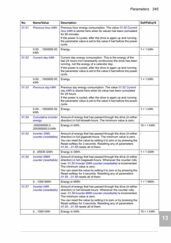
Parameters 345
1
2
3
4
5
6
7
8
9
10
11
12
13
01.51 Previous hour kWh Previous hour energy consumption. The value 01.50 Current hour kWh is stored here when its values has been cumulated for 60 minutes.If the power is cycled, after the drive is again up and running, the parameter value is set to the value it had before the power cycle.
-
0.00… 1000000.00 kWh
Energy. 1 = 1 kWh
01.52 Current day kWh Current day energy consumption. This is the energy of the last 24 hours (not necessarily continuous) the drive has been running, not the energy of a calendar day.If the power is cycled, after the drive is again up and running, the parameter value is set to the value it had before the power cycle.
-
0.00… 1000000.00 kWh
Energy. 1 = 1 kWh
01.53 Previous day kWh Previous day energy consumption. The value 01.52 Current day kWh is stored here when its value has been cumulated for 24 hours.If the power is cycled, after the drive is again up and running, the parameter value is set to the value it had before the power cycle.
-
0.00… 1000000.00 kWh
Energy. 1 = 1 kWh
01.54 Cumulative inverter energy
Amount of energy that has passed through the drive (in either direction) in full kilowatt-hours. The minimum value is zero.
-
-200000000.0…200000000.0 kWh
Energy in kWh. 10 = 1 kWh
01.55 Inverter GWh counter (resettable)
Amount of energy that has passed through the drive (in either direction) in full gigawatt-hours. The minimum value is zero.You can reset the value by setting it to zero or by pressing the Reset softkey for 3 seconds. Resetting any of parameters 01.55…01.58 resets all of them.
-
0…65535 GWh Energy in GWh. 1 = 1 GWh
01.56 Inverter MWh counter (resettable)
Amount of energy that has passed through the drive (in either direction) in full megawatt-hours. Whenever the counter rolls over, 01.55 Inverter GWh counter (resettable) is incremented. The minimum value is zero.You can reset the value by setting it to zero or by pressing the Reset softkey for 3 seconds. Resetting any of parameters 01.55…01.58 resets all of them.
-
0…1000 MWh Energy in MWh. 1 = 1 MWh
01.57 Inverter kWh counter (resettable)
Amount of energy that has passed through the drive (in either direction) in full kilowatt-hours. Whenever the counter rolls over, 01.56 Inverter MWh counter (resettable) is incremented. The minimum value is zero.You can reset the value by setting it to zero or by pressing the Reset softkey for 3 seconds. Resetting any of parameters 01.55…01.58 resets all of them.
-
0…1000 kWh Energy in kWh. 10 = 1 kWh
No. Name/Value Description Def/FbEq16
14

346 Parameters
1
2
3
4
5
7
8
9
9
10
11
12
13
14
01.58 Cumulative inverter energy (resettable)
Amount of energy that has passed through the drive (in either direction) in full kilowatt-hours. The minimum value is zero.You can reset the value by setting it to zero or by pressing the Reset softkey for 3 seconds. Resetting any of parameters 01.55…01.58 resets all of them.
-
-200000000.0…200000000.0 kWh
Energy in kWh. 10 = 1 kWh
01.61 Abs motor speed used
Absolute value of parameter 01.01 Motor speed used. -
0.00… 30000.00 rpm
Estimated motor speed. See par. 46.01
01.62 Abs motor speed % Absolute value of parameter 01.03 Motor speed %. -
0.00… 1000.00% Estimated motor speed. 10 = 1%
01.63 Abs output frequency
Absolute value of parameter 01.06 Output frequency. -
0.00…500.00 Hz Estimated output frequency. See par. 46.02
01.64 Abs motor torque Absolute value of parameter 01.10 Motor torque. -
0.0…1600.0% Motor torque. See par. 46.03
01.65 Abs output power Absolute value of parameter 01.14 Output power. -
0.00… 32767.00 kW
Output power. 1 = 1 kW
01.66 Abs output power % motor nom
Absolute value of parameter 01.15 Output power % of motor nom.
-
0.00… 300.00% Output power. 1 = 1%
01.67 Abs output power % drive nom
Absolute value of parameter 01.16 Output power % of drive nom.
-
0.00… 300.00% Output power. 1 = 1%
01.68 Abs motor shaft power
Absolute value of parameter 01.17 Motor shaft power. -
0.00… 32767.00 kW or hp
Motor shaft power. 1 = 1 unit
01.102 Line current (Only visible for ACH580-31).Estimated line current flowing through the supply unit.
-
0.00 … 30000.00 A Estimated line current. See par. 46.05
01.104 Active current (Only visible for ACH580-31).Estimated active current flowing through the supply unit.
-
0.00 … 30000.00 A Estimated active current. See par. 46.05
01.106 Reactive current (Only visible for ACH580-31).Estimated reactive current flowing through the supply unit.
-
0.00 … 30000.00 A Estimated reactive current. See par. 46.05
No. Name/Value Description Def/FbEq16

Parameters 347
1
2
3
4
5
6
7
8
9
10
11
12
13
01.108 Grid frequency (Only visible for ACH580-31).Estimated frequency of the power supply network.
-
0.00 … 100.00 Hz Estimated supply frequency. See par. 46.02
01.109 Grid voltage (Only visible for ACH580-31).Estimated voltage of the power supply network.
-
0.00 … 2000.00 V Estimated supply voltage. 10 = 1 V
01.110 Grid apparent power
(Only visible for ACH580-31).Estimated apparent power being transferred through the supply unit.
-
-30000.00 … 30000.00 kVA
Estimated apparent power. See par. 46.04
01.112 Grid power (Only visible for ACH580-31).Estimated power being transferred through the supply unit.
-
-30000.00 … 30000.00 kW
Estimated supply power. See par. 46.04
01.114 Grid reactive power (Only visible for ACH580-31).Estimated reactive power being transferred through the supply unit.
-
-30000.00 … 30000.00 kvar
Estimated reactive power. 10 = 1 kvar
01.116 LSU cos Phi (Only visible for ACH580-31).Power factor of the supply unit.
-
-1.00 … 1.00 Power factor. 100 = 1
01.164 LSU nominal power (Only visible for ACH580-31).Nominal power of the supply unit.
-
0…30000 kW Nominal power. 1 = 1 kW
0303 Input references Values of references received from various sources.
All parameters in this group are read-only unless otherwise noted.
03.01 Panel reference Reference 1 given from the control panel or PC tool. -
-100000.00… 100000.00
Control panel or PC tool reference. 1 = 10
03.02 Panel reference remote
Reference 2 given from the control panel or PC tool. -
-100000.00… 100000.00
Control panel or PC tool reference. 1 = 10
03.05 FB A reference 1 Reference 1 received through fieldbus adapter A.See also chapter Fieldbus control through a fieldbus adapter
-
-100000.00… 100000.00
Reference 1 from fieldbus adapter A. 1 = 10
03.06 FB A reference 2 Reference 2 received through fieldbus adapter A. -
-100000.00… 100000.00
Reference 2 from fieldbus adapter A. 1 = 10
No. Name/Value Description Def/FbEq16
14
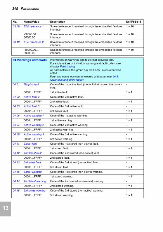
348 Parameters
1
2
3
4
5
7
8
9
9
10
11
12
13
14
03.09 EFB reference 1 Scaled reference 1 received through the embedded fieldbus interface.
1 = 10
-30000.00… 30000.00
Scaled reference 1 received through the embedded fieldbus interface.
1 = 10
03.10 EFB reference 2 Scaled reference 2 received through the embedded fieldbus interface.
1 = 10
-30000.00… 30000.00
Scaled reference 2 received through the embedded fieldbus interface.
1 = 10
0404 Warnings and faults Information on warnings and faults that occurred last.
For explanations of individual warning and fault codes, see chapter Fault tracing.All parameters in this group are read-only unless otherwise noted.Fault and event logs can be cleared with parameter 96.51 Clear fault and event logger.
04.01 Tripping fault Code of the 1st active fault (the fault that caused the current trip).
-
0000h…FFFFh 1st active fault. 1 = 1
04.02 Active fault 2 Code of the 2nd active fault. -
0000h…FFFFh 2nd active fault. 1 = 1
04.03 Active fault 3 Code of the 3rd active fault. -
0000h…FFFFh 3rd active fault. 1 = 1
04.06 Active warning 1 Code of the 1st active warning. -
0000h…FFFFh 1st active warning. 1 = 1
04.07 Active warning 2 Code of the 2nd active warning. -
0000h…FFFFh 2nd active warning. 1 = 1
04.08 Active warning 3 Code of the 3rd active warning. -
0000h…FFFFh 3rd active warning. 1 = 1
04.11 Latest fault Code of the 1st stored (non-active) fault. -
0000h…FFFFh 1st stored fault. 1 = 1
04.12 2nd latest fault Code of the 2nd stored (non-active) fault. -
0000h…FFFFh 2nd stored fault. 1 = 1
04.13 3rd latest fault Code of the 3rd stored (non-active) fault. -
0000h…FFFFh 3rd stored fault. 1 = 1
04.16 Latest warning Code of the 1st stored (non-active) warning. -
0000h…FFFFh 1st stored warning. 1 = 1
04.17 2nd latest warning Code of the 2nd stored (non-active) warning. -
0000h…FFFFh 2nd stored warning. 1 = 1
04.18 3rd latest warning Code of the 3rd stored (non-active) warning. -
0000h…FFFFh 3rd stored warning. 1 = 1
No. Name/Value Description Def/FbEq16

Parameters 349
1
2
3
4
5
6
7
8
9
10
11
12
13
04.40 Event word 1 User-defined event word. This word collects the status of the events (warnings, faults or pure events) selected by parameters 04.41…04.71.This parameter is read-only.
-
0000h…FFFFh User-defined event word. 1 = 1
04.41 Event word 1 bit 0 code
Selects the hexadecimal code of an event (warning, fault or pure event) whose status is shown as bit 0 of 04.40 Event word 1. The event codes are listed in chapter Fault tracing (page 195).
0000h
0000h…FFFFh Code of event. 1 = 1
04.43 Event word 1 bit 1 code
Selects the hexadecimal code of an event (warning, fault or pure event) whose status is shown as bit 1 of 04.40 Event word 1. The event codes are listed in chapter Fault tracing (page 195).
0000h
0000h…FFFFh Code of event. 1 = 1
04.45, 04.47,04.49,…
… … …
04.71 Event word 1 bit 15 code
Selects the hexadecimal code of an event (warning, fault or pure event) whose status is shown as bit 15 of 04.40 Event word 1. The event codes are listed in chapter Fault tracing (page 195).
0000h
0000h…FFFFh Code of event. 1 = 1
0505 Diagnostics Various run-time-type counters and measurements related to
drive maintenance.All parameters in this group are read-only unless otherwise noted.
05.01 On-time counter On-time counter. The counter runs when the drive is powered.
-
0…65535 d On-time counter. 1 = 1 d
05.02 Run-time counter Motor run-time counter in full days. The counter runs when the inverter modulates.
-
0…65535 d Motor run-time counter. 1 = 1 d
05.03 Hours run Corresponding parameter to 05.02 Run-time counter in hours, that is, 24 * 05.02 value + fractional part of a day.
-
0.0…429496729.5 h
Hours. 1 = 1 h
05.04 Fan on-time counter
Running time of the drive cooling fan. Can be reset from the control panel by pressing the Reset softkey for 3 seconds.
-
0…65535 d Cooling fan run-time counter. 1 = 1 d
No. Name/Value Description Def/FbEq16
Bit Name Description
0 User bit 0 1 = Event selected by parameter 04.41 is active
1 User bit 1 1 = Event selected by parameter 04.43 is active
… … …
15 User bit 15 1 = Event selected by parameter 04.71 is active
14
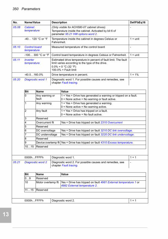
350 Parameters
1
2
3
4
5
7
8
9
9
10
11
12
13
14
05.08 Cabinet temperature
(Only visible for ACH580-07 cabinet drives).Temperature inside the cabinet. Activated by bit 6 of parameter 95.21 HW options word 2.
-
-40… 120 °C or °F Temperature inside the cabinet in degrees Celsius or Fahrenheit.
1 = unit
05.10 Control board temperature
Measured temperature of the control board -
-100… 300 °C or °F Control board temperature in degrees Celsius or Fahrenheit. 1 = unit
05.11 Inverter temperature
Estimated drive temperature in percent of fault limit. The fault limit varies according to the type of the drive.0.0% = 0 °C (32 °F)100.0% = Fault limit
-
-40.0…160.0% Drive temperature in percent. 1 = 1%
05.20 Diagnostic word 1 Diagnostic word 1. For possible causes and remedies, see chapter Fault tracing.
-
0000h…FFFFh Diagnostic word 1. 1 = 1
05.21 Diagnostic word 2 Diagnostic word 2. For possible causes and remedies, see chapter Fault tracing.
-
0000h…FFFFh Diagnostic word 2. 1 = 1
No. Name/Value Description Def/FbEq16
Bit Name Value
0 Any warning or fault
1 = Yes = Drive has generated a warning or tripped on a fault.0 = None active = No warning or fault active.
1 Any warning 1 = Yes = Drive has generated a warning.0 = None active = No warning active.
2 Any fault 1 = Yes = Drive has tripped on a fault.0 = None active = No fault active.
3 Reserved
4 Overcurrent flt Yes = Drive has tripped on fault 2310 Overcurrent
5 Reserved
6 DC overvoltage Yes = Drive has tripped on fault 3210 DC link overvoltage.
7 DC undervoltage Yes = Drive has tripped on fault 3220 DC link undervoltage.
8 Reserved
9 Device overtemp flt Yes = Drive has tripped on fault 4310 Excess temperature.
10…15 Reserved
Bit Name Value
0…9 Reserved
10 Motor overtemp flt Yes = Drive has tripped on fault 4981 External temperature 1 or 4982 External temperature 2.
11…15 Reserved

Parameters 351
1
2
3
4
5
6
7
8
9
10
11
12
13
05.22 Diagnostic word 3 Diagnostic word 3. -
0000h…FFFFh Diagnostic word 3. 1 = 1
05.80 Motor speed at fault Copy of parameter 01.01 Motor speed used at the occurrence of the latest fault. Parameters 05.80…05.89 are shown for each fault in the fault log.
-
-30000.00…30000.00 rpm
Estimated motor speed.
05.81 Output frequency at fault
Copy of parameter 01.06 Output frequency at the occurrence of the latest fault.
-
-500.00…500.00 Hz
Estimated output frequency.
05.82 DC voltage at fault Copy of parameter 01.11 DC voltage at the occurrence of the latest fault.
-
0.00…2000.00 V DC link voltage. 10 = 1 V
05.83 Motor current at fault
Copy of parameter 01.07 Motor current at the occurrence of the latest fault.
-
0.00…30000.00 A Motor current. 10 = 1 V
05.84 Motor torque at fault Copy of parameter 01.10 Motor torque at the occurrence of the latest fault.
-
-1600.0…1600.0% Motor torque.
05.85 Main status word at fault
Copy of parameter 06.11 Main status word at the occurrence of the latest fault.
-
0000h…FFFFh Main status word. 1 = 1
05.86 DI delayed status at fault
Copy of parameter 10.02 DI delayed status at the occurrence of the latest fault.
-
0000h…FFFFh Delayed status for digital inputs. 1 = 1
05.87 Inverter temperature at fault
Copy of parameter 05.11 Inverter temperature at the occurrence of the latest fault.
-
-40…160 °C Drive temperature in °C. 1 = 1
05.88 Reference used at fault
Copy of parameter 28.01 Frequency ref ramp input (in scalar control mode) or 23.01 Speed ref ramp input (in speed control mode) at the occurrence of the latest fault.
-
-500.00…500.00 Hz or
-30000.00…30000.00 rpm
Frequency or speed reference 1 = 1
05.89 HVAC status word at fault
Copy of parameter 06.22 HVAC status word at the occurrence of the latest fault.
-
0000h…FFFFh 1 = 1
No. Name/Value Description Def/FbEq16
Bit Name Value
0…8 Reserved
9 kWh pulse Yes = kWh pulse is active.
10 Reserved
11 Fan command On = Drive fan is rotating above idle speed.
12…15 Reserved
14
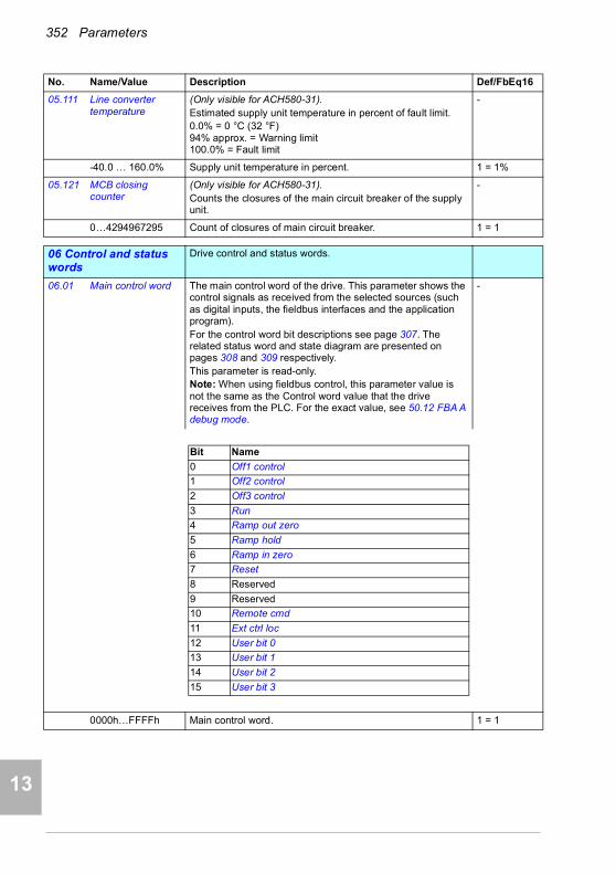
352 Parameters
1
2
3
4
5
7
8
9
9
10
11
12
13
14
05.111 Line converter temperature
(Only visible for ACH580-31).Estimated supply unit temperature in percent of fault limit.0.0% = 0 °C (32 °F)94% approx. = Warning limit100.0% = Fault limit
-
-40.0 … 160.0% Supply unit temperature in percent. 1 = 1%
05.121 MCB closing counter
(Only visible for ACH580-31).Counts the closures of the main circuit breaker of the supply unit.
-
0…4294967295 Count of closures of main circuit breaker. 1 = 1
0606 Control and status words
Drive control and status words.
06.01 Main control word The main control word of the drive. This parameter shows the control signals as received from the selected sources (such as digital inputs, the fieldbus interfaces and the application program).For the control word bit descriptions see page 307. The related status word and state diagram are presented on pages 308 and 309 respectively.This parameter is read-only.Note: When using fieldbus control, this parameter value is not the same as the Control word value that the drive receives from the PLC. For the exact value, see 50.12 FBA A debug mode.
-
0000h…FFFFh Main control word. 1 = 1
No. Name/Value Description Def/FbEq16
Bit Name
0 Off1 control
1 Off2 control
2 Off3 control
3 Run
4 Ramp out zero
5 Ramp hold
6 Ramp in zero
7 Reset
8 Reserved
9 Reserved
10 Remote cmd
11 Ext ctrl loc
12 User bit 0
13 User bit 1
14 User bit 2
15 User bit 3
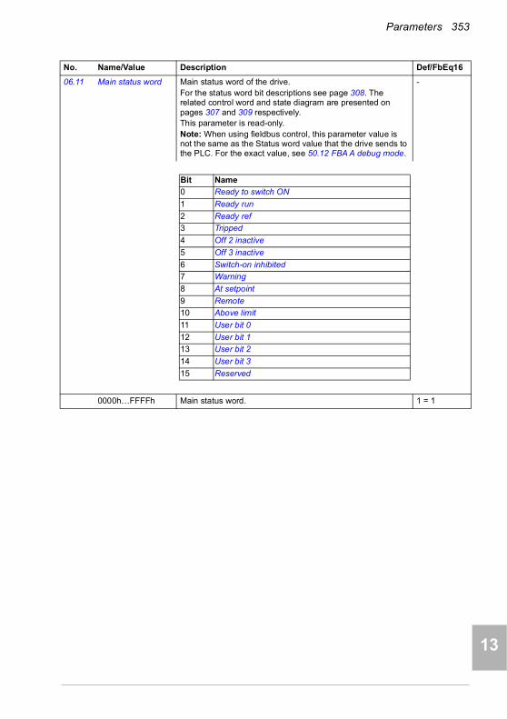
Parameters 353
1
2
3
4
5
6
7
8
9
10
11
12
13
06.11 Main status word Main status word of the drive.For the status word bit descriptions see page 308. The related control word and state diagram are presented on pages 307 and 309 respectively.This parameter is read-only.Note: When using fieldbus control, this parameter value is not the same as the Status word value that the drive sends to the PLC. For the exact value, see 50.12 FBA A debug mode.
-
0000h…FFFFh Main status word. 1 = 1
No. Name/Value Description Def/FbEq16
Bit Name
0 Ready to switch ON
1 Ready run
2 Ready ref
3 Tripped
4 Off 2 inactive
5 Off 3 inactive
6 Switch-on inhibited
7 Warning
8 At setpoint
9 Remote
10 Above limit
11 User bit 0
12 User bit 1
13 User bit 2
14 User bit 3
15 Reserved
14

354 Parameters
1
2
3
4
5
7
8
9
9
10
11
12
13
14
06.16 Drive status word 1 Drive status word 1.This parameter is read-only.
-
0000h…FFFFh Drive status word 1. 1 = 1
No. Name/Value Description Def/FbEq16
Bit Name Description
0 Enabled 1 = If start interlock signals (par. 20.41…20.44) signals are all present.Note: This bit is not affected by the presence of a fault.
1 Inhibited 1 = Start inhibited. To start the drive, the inhibiting signal (see par. 06.18) must be removed and the start signal cycled.
2 DC charged 1 = DC circuit has been charged
3 Ready to start 1 = Drive is ready to receive a start command
4 Following reference
1 = Drive is ready to follow given reference
5 Started 1 = Drive has been started
6 Modulating 1 = Drive is modulating (output stage is being controlled)
7 Limiting 1 = Any operating limit (speed, torque, etc.) is active
8 Local control 1 = Drive is in local control
9 Network control 1 = Drive is in network control (see page 22).
10 Ext1 active 1 = Control location EXT1 active
11 Ext2 active 1 = Control location EXT2 active
12 Reserved
13 Start request 1 = If Start requested. 0 = When Run permissive signal (see par. 20.40) is 0.
14 Running 1 = Drive is controlling speed or frequency, in PID sleep or pre-magnetization.
15 Reserved
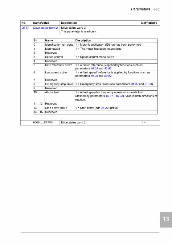
Parameters 355
1
2
3
4
5
6
7
8
9
10
11
12
13
06.17 Drive status word 2 Drive status word 2.This parameter is read-only.
-
0000h…FFFFh Drive status word 2. 1 = 1
No. Name/Value Description Def/FbEq16
Bit Name Description
0 Identification run done 1 = Motor identification (ID) run has been performed
1 Magnetized 1 = The motor has been magnetized
2 Reserved
3 Speed control 1 = Speed control mode active
4 Reserved
5 Safe reference active 1 = A “safe” reference is applied by functions such as parameters 49.05 and 50.02
6 Last speed active 1 = A “last speed” reference is applied by functions such as parameters 49.05 and 50.02
7 Reserved
8 Emergency stop failed 1 = Emergency stop failed (see parameters 31.32 and 31.33)
9 Reserved
10 Above limit 1 = Actual speed or frequency equals or exceeds limit(defined by parameters 46.31…46.32). Valid in both directions ofrotation.
11…12 Reserved
13 Start delay active 1 = Start delay (par. 21.22) active.
14…15 Reserved
14
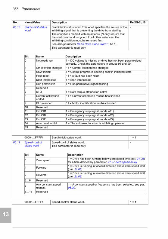
356 Parameters
1
2
3
4
5
7
8
9
9
10
11
12
13
14
06.18 Start inhibit status word
Start inhibit status word. This word specifies the source of the inhibiting signal that is preventing the drive from starting.The conditions marked with an asterisk (*) only require that the start command is cycled. In all other instances, the inhibiting condition must be removed first.See also parameter 06.16 Drive status word 1, bit 1.This parameter is read-only.
-
0000h…FFFFh Start inhibit status word. 1 = 1
06.19 Speed control status word
Speed control status word.This parameter is read-only.
-
0000h…FFFFh Speed control status word. 1 = 1
No. Name/Value Description Def/FbEq16
Bit Name Description
0 Not ready run 1 = DC voltage is missing or drive has not been parametrized correctly. Check the parameters in groups 95 and 99.
1 Ctrl location changed * 1 = Control location has changed
2 SSW inhibit 1 = Control program is keeping itself in inhibited state
3 Fault reset * 1 = A fault has been reset
4 Start interlocked 1 = Start interlocked
5 Run permissive 1 = Run permissive signal missing
6 Reserved
7 STO 1 = Safe torque off function active
8 Current calibration ended
* 1 = Current calibration routine has finished
9 ID run ended * 1 = Motor identification run has finished
10 Reserved
11 Em Off1 1 = Emergency stop signal (mode off1)
12 Em Off2 1 = Emergency stop signal (mode off2)
13 Em Off3 1 = Emergency stop signal (mode off3)
14 Auto reset inhibit 1 = The autoreset function is inhibiting operation
15 Reserved
Bit Name Description
0 Zero speed1 = Drive has been running below zero speed limit (par. 21.06) for a time defined by parameter 21.07 Zero speed delay
1 Forward1 = Drive is running in forward direction above zero speed limit (par. 21.06)
2 Reverse1 = Drive is running in reverse direction above zero speed limit (par. 21.06)
3…6 Reserved
7Any constant speed request
1 = A constant speed or frequency has been selected; see par. 06.20.
8…15 Reserved
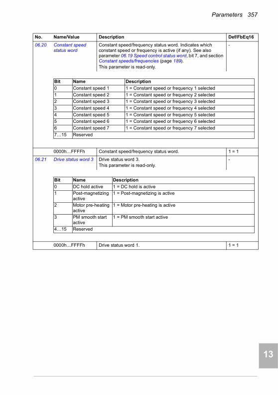
Parameters 357
1
2
3
4
5
6
7
8
9
10
11
12
13
06.20 Constant speed status word
Constant speed/frequency status word. Indicates which constant speed or frequency is active (if any). See also parameter 06.19 Speed control status word, bit 7, and section Constant speeds/frequencies (page 189).This parameter is read-only.
-
0000h…FFFFh Constant speed/frequency status word. 1 = 1
06.21 Drive status word 3 Drive status word 3.This parameter is read-only.
-
0000h…FFFFh Drive status word 1. 1 = 1
No. Name/Value Description Def/FbEq16
Bit Name Description
0 Constant speed 1 1 = Constant speed or frequency 1 selected
1 Constant speed 2 1 = Constant speed or frequency 2 selected
2 Constant speed 3 1 = Constant speed or frequency 3 selected
3 Constant speed 4 1 = Constant speed or frequency 4 selected
4 Constant speed 5 1 = Constant speed or frequency 5 selected
5 Constant speed 6 1 = Constant speed or frequency 6 selected
6 Constant speed 7 1 = Constant speed or frequency 7 selected
7…15 Reserved
Bit Name Description
0 DC hold active 1 = DC hold is active
1 Post-magnetizing active
1 = Post-magnetizing is active
2 Motor pre-heating active
1 = Motor pre-heating is active
3 PM smooth start active
1 = PM smooth start active
4…15 Reserved
14
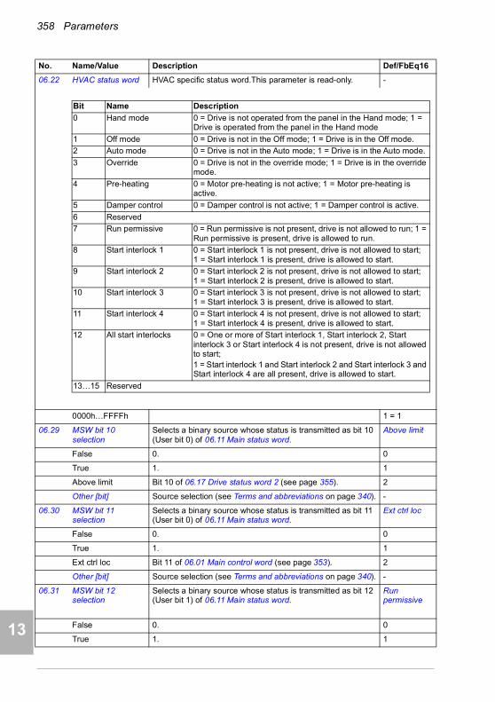
358 Parameters
1
2
3
4
5
7
8
9
9
10
11
12
13
14
06.22 HVAC status word HVAC specific status word.This parameter is read-only. -
0000h…FFFFh 1 = 1
06.29 MSW bit 10 selection
Selects a binary source whose status is transmitted as bit 10 (User bit 0) of 06.11 Main status word.
Above limit
False 0. 0
True 1. 1
Above limit Bit 10 of 06.17 Drive status word 2 (see page 355). 2
Other [bit] Source selection (see Terms and abbreviations on page 340). -
06.30 MSW bit 11 selection
Selects a binary source whose status is transmitted as bit 11 (User bit 0) of 06.11 Main status word.
Ext ctrl loc
False 0. 0
True 1. 1
Ext ctrl loc Bit 11 of 06.01 Main control word (see page 353). 2
Other [bit] Source selection (see Terms and abbreviations on page 340). -
06.31 MSW bit 12 selection
Selects a binary source whose status is transmitted as bit 12 (User bit 1) of 06.11 Main status word.
Run permissive
False 0. 0
True 1. 1
No. Name/Value Description Def/FbEq16
Bit Name Description
0 Hand mode 0 = Drive is not operated from the panel in the Hand mode; 1 = Drive is operated from the panel in the Hand mode
1 Off mode 0 = Drive is not in the Off mode; 1 = Drive is in the Off mode.
2 Auto mode 0 = Drive is not in the Auto mode; 1 = Drive is in the Auto mode.
3 Override 0 = Drive is not in the override mode; 1 = Drive is in the override mode.
4 Pre-heating 0 = Motor pre-heating is not active; 1 = Motor pre-heating is active.
5 Damper control 0 = Damper control is not active; 1 = Damper control is active.
6 Reserved
7 Run permissive 0 = Run permissive is not present, drive is not allowed to run; 1 = Run permissive is present, drive is allowed to run.
8 Start interlock 1 0 = Start interlock 1 is not present, drive is not allowed to start; 1 = Start interlock 1 is present, drive is allowed to start.
9 Start interlock 2 0 = Start interlock 2 is not present, drive is not allowed to start; 1 = Start interlock 2 is present, drive is allowed to start.
10 Start interlock 3 0 = Start interlock 3 is not present, drive is not allowed to start; 1 = Start interlock 3 is present, drive is allowed to start.
11 Start interlock 4 0 = Start interlock 4 is not present, drive is not allowed to start; 1 = Start interlock 4 is present, drive is allowed to start.
12 All start interlocks 0 = One or more of Start interlock 1, Start interlock 2, Start interlock 3 or Start interlock 4 is not present, drive is not allowed to start; 1 = Start interlock 1 and Start interlock 2 and Start interlock 3 and Start interlock 4 are all present, drive is allowed to start.
13…15 Reserved

Parameters 359
1
2
3
4
5
6
7
8
9
10
11
12
13
Run permissive Status of the external run permissive signal (see parameter 20.40 Run permissive).
3
Other [bit] Source selection (see Terms and abbreviations on page 340). -
06.32 MSW bit 13 selection
Selects a binary source whose status is transmitted as bit 13 (User bit 2) of 06.11 Main status word.
False
False 0. 0
True 1. 1
Other [bit] Source selection (see Terms and abbreviations on page 340). -
06.33 MSW bit 14 selection
Selects a binary source whose status is transmitted as bit 14 (User bit 3) of 06.11 Main status word.
False
False 0. 0
True 1. 1
Other [bit] Source selection (see Terms and abbreviations on page 340). -
06.36 LSU Status word (Only visible for ACH580-31).Shows the status of the supply unit.See also section Control of a supply unit (LSU) (page 100), and parameter group 60 DDCS communication.This parameter is read-only.
-
0000h…FFFFh Supply unit status word. 1 = 1
No. Name/Value Description Def/FbEq16
Bit Name Description
0 Ready on 1 = Ready to switch on
1 Ready run 1 = Ready to operate, DC link charged
2 Ready ref 1 = Operation enabled
3 Tripped 1 = A fault is active
4…6 Reserved
7 Warning 1 = A warning is active
8 Modulating 1 = The supply unit is modulating
9 Remote 1 = Remote control (EXT1 or EXT2)0 = Local control
10 Net ok 1 = Supply network voltage OK
11…12 Reserved
13 Charging or ready run
1 = Bit 1 or bit 14 active
14 Charging 1 = Charging circuit is active0 = Charging circuit is not active
15 Reserved
14

360 Parameters
1
2
3
4
5
7
8
9
9
10
11
12
13
14
06.39 Internal state machine LSU CW
(Only visible for ACH580-31).Shows the control word sent to the supply unit from the INU-LSU (inverter unit/supply unit) state machine.This parameter is read-only.
-
0000h…FFFFh Supply unit control word. 1 = 1
06.116 LSU drive status word 1
(Only visible for ACH580-31).Drive status word 1 received from the supply unit.See also section Control of a supply unit (LSU) (page 100), and parameter group 60 DDCS communication.This parameter is read-only.
-
0000h…FFFFh Drive status word 1. 1 = 1
No. Name/Value Description Def/FbEq16
Bit Name Description
0 ON/OFF 1 = Start charging0 = Open main contactor (switch power off)
1 OFF 2 0 = Emergency stop (Off2)
2 OFF 3 0 = Emergency stop (Off3)
3 START 1 = Start modulating0 = Stop modulating
4…6 Reserved
7 RESET 0 -> 1 = Reset an active fault. A fresh start command is required after reset.
8…15 Reserved
Bit Name Description
0 Enabled 1 = Run enable and start enable signals are present
1 Inhibited 1 = Start inhibited (see bit 1 of parameter 06.16 Drive status word 1)
2 Operation allowed
1 = Drive is ready to operate
3 Ready to start 1 = Drive is ready to receive a start command
4 Running 1 = Drive is ready to follow given reference
5 Started 1 = Drive has been started
6 Modulating 1 = Drive is modulating (output stage is being controlled)
7 Limiting 1 = Any operating limit is active
8 Local control 1 = Drive is in local control
9 Network control
1 = Drive is in network control
10 Ext1 active 1 = Control location EXT1 active
11 Ext2 active 1 = Control location EXT2 active
12 Charging active
1 = Charging circuit is active0 = Charging circuit is not active
13 MCB relay 1 = MCB relay is closed
14…15 Reserved

Parameters 361
1
2
3
4
5
6
7
8
9
10
11
12
13
06.118 LSU start inhibit status word
(Only visible for ACH580-31).This word specifies the source of the inhibiting condition that is preventing the supply unit from starting.See also section Control of a supply unit (LSU) (page 100), and parameter group 60 DDCS communication.This parameter is read-only.
-
0000h…FFFFh Start inhibit status word of supply unit. 1 = 1
0707 System info Drive hardware and firmware information.
All parameters in this group are read-only.
07.03 Drive rating id Type of the drive. (Rating ID in brackets.) -
07.04 Firmware name Firmware identification. -
07.05 Firmware version Version number of the firmware. -
07.06 Loading package name
Name of the firmware loading package. -
07.07 Loading package version
Version number of the firmware loading package. -
07.10 The language file set (language package) in use, see parameter 96.01 Language.The language file set value is written to this parameter after the first start-up, and it is available in this parameter through power-ups.
-
Not known No language file set in use. 0
Global Global language file set in use. 1
European European language file set in use. 2
Asian Asian language file set in use. 3
07.11 Cpu usage Microprocessor load in percent. -
0…100% Microprocessor load. 1 = 1%
07.25 Customization package name
First five ASCII letters of the name given to the customizationpackage. The full name is visible under System info on thecontrol panel or the Drive composer PC tool._N/A_ = None.
-
No. Name/Value Description Def/FbEq16
Bit Name
0 Not ready run
1 Ctrl location changed
2 SSW inhibit
3 Fault reset
4 Lost start enable
5 Lost run enable
6…8 Reserved
9 Charging overload
10…11 Reserved
12 Em Off2
13 Em Off3
14 Auto reset inhibit
15 Reserved
14

362 Parameters
1
2
3
4
5
7
8
9
9
10
11
12
13
14
07.26 Customization package version
Customization package version number. Also visible underSystem info on the control panel or the Drive composer PCtool.
-
07.30 Adaptive program status
Shows the status of the adaptive program.See section Adaptive programming (page 95).
-
0000h…FFFFh Adaptive program status. 1 = 1
07.31 AP sequence state Shows the number of the active state of the sequence program part of the adaptive program (AP). If adaptive programming is not running, or it does not contain a sequence program, the parameter is zero.
0…20 1 = 1
07.35 Drive configuration Plug ‘n’ play configuration. Performs HW initialization, and shows the detected module configuration of the drive. During the HW initialization, if the drive is not able to detect any module, the value is set to 1, Base unit.For information on automatic setting of parameters after detecting a module, see section Automatic drive configuration for fieldbus control on page 315.
0000h
0000h…FFFFh Drive configuration. 1 = 1
No. Name/Value Description Def/FbEq16
Bit Name Description
0 Initialized 1 = Adaptive program initialized
1 Editing 1 = Adaptive program is being edited
2 Edit done 1 = Editing of adaptive program finished
3 Running 1 = Adaptive program running
4…13 Reserved
14 State changing 1 = State change in progress in adaptive programming engine
15 Faulted 1 = Error in adaptive program
Bit Name Description
0 Not initialized 1 = Drive configuration has not been initialized
1 Base unit 1 = Drive has not detected any modules.
2 Reserved
3 FENA-21 1 = FENA-21 Two-port Ethernet adapter module included
4 FECA-01 1 = FECA-01 EtherCAT adapter module included
5 FPBA-01 1 = FPBA-01 PROFIBUS DP adapter module included
6 FCAN-01 1 = FCAN-01 CANopen adapter module included
7…9 Reserved
10 FSCA-01 1 = FSCA-01 Modbus/RTU adapter module included
11 FEIP-21 1 = FEIP-21 Two-port EtherNet/IP adapter module included
12 FMBT-21 1 = FMBT-21 Two-port Modbus/TCP adapter module included
13 FBIP-21 1 = FBIP-21 BACnet/IP (2-port) adapter module included
14 FBNO-21 1 = FPNO-21 Two-port PROFINET IO adapter module included
15 FEPL-02 1 = FEPL-02 Ethernet POWERLINK adapter module included
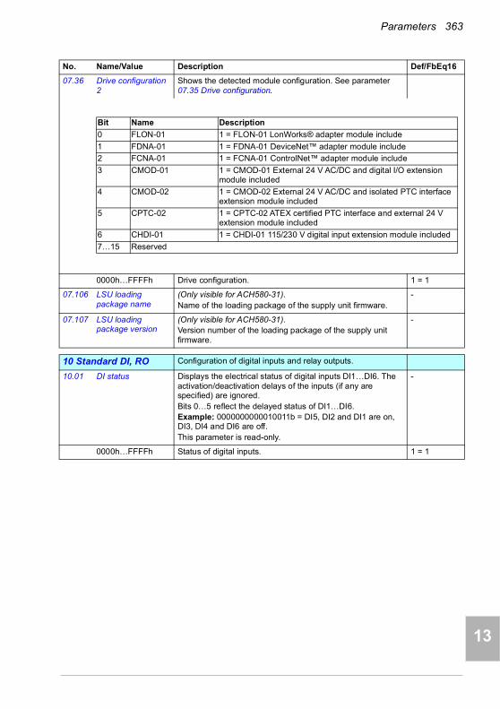
Parameters 363
1
2
3
4
5
6
7
8
9
10
11
12
13
07.36 Drive configuration 2
Shows the detected module configuration. See parameter 07.35 Drive configuration.
0000h…FFFFh Drive configuration. 1 = 1
07.106 LSU loading package name
(Only visible for ACH580-31).Name of the loading package of the supply unit firmware.
-
07.107 LSU loading package version
(Only visible for ACH580-31).Version number of the loading package of the supply unit firmware.
-
1010 Standard DI, RO Configuration of digital inputs and relay outputs.
10.01 DI status Displays the electrical status of digital inputs DI1…DI6. The activation/deactivation delays of the inputs (if any are specified) are ignored.Bits 0…5 reflect the delayed status of DI1…DI6. Example: 0000000000010011b = DI5, DI2 and DI1 are on, DI3, DI4 and DI6 are off.This parameter is read-only.
-
0000h…FFFFh Status of digital inputs. 1 = 1
No. Name/Value Description Def/FbEq16
Bit Name Description
0 FLON-01 1 = FLON-01 LonWorks® adapter module include
1 FDNA-01 1 = FDNA-01 DeviceNet™ adapter module include
2 FCNA-01 1 = FCNA-01 ControlNet™ adapter module include
3 CMOD-01 1 = CMOD-01 External 24 V AC/DC and digital I/O extension module included
4 CMOD-02 1 = CMOD-02 External 24 V AC/DC and isolated PTC interface extension module included
5 CPTC-02 1 = CPTC-02 ATEX certified PTC interface and external 24 V extension module included
6 CHDI-01 1 = CHDI-01 115/230 V digital input extension module included
7…15 Reserved
14
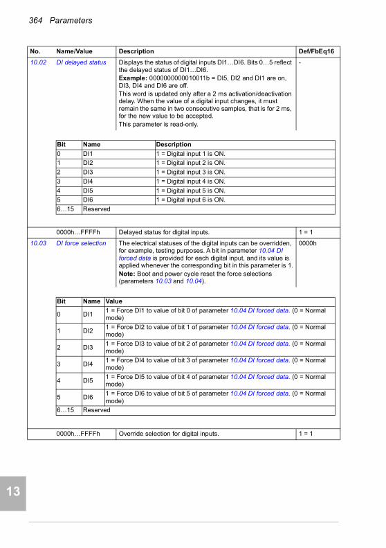
364 Parameters
1
2
3
4
5
7
8
9
9
10
11
12
13
14
10.02 DI delayed status Displays the status of digital inputs DI1…DI6. Bits 0…5 reflect the delayed status of DI1…DI6. Example: 0000000000010011b = DI5, DI2 and DI1 are on, DI3, DI4 and DI6 are off.This word is updated only after a 2 ms activation/deactivation delay. When the value of a digital input changes, it must remain the same in two consecutive samples, that is for 2 ms, for the new value to be accepted. This parameter is read-only.
-
0000h…FFFFh Delayed status for digital inputs. 1 = 1
10.03 DI force selection The electrical statuses of the digital inputs can be overridden, for example, testing purposes. A bit in parameter 10.04 DI forced data is provided for each digital input, and its value is applied whenever the corresponding bit in this parameter is 1.Note: Boot and power cycle reset the force selections (parameters 10.03 and 10.04).
0000h
0000h…FFFFh Override selection for digital inputs. 1 = 1
No. Name/Value Description Def/FbEq16
Bit Name Description
0 DI1 1 = Digital input 1 is ON.
1 DI2 1 = Digital input 2 is ON.
2 DI3 1 = Digital input 3 is ON.
3 DI4 1 = Digital input 4 is ON.
4 DI5 1 = Digital input 5 is ON.
5 DI6 1 = Digital input 6 is ON.
6…15 Reserved
Bit Name Value
0 DI11 = Force DI1 to value of bit 0 of parameter 10.04 DI forced data. (0 = Normal mode)
1 DI21 = Force DI2 to value of bit 1 of parameter 10.04 DI forced data. (0 = Normal mode)
2 DI31 = Force DI3 to value of bit 2 of parameter 10.04 DI forced data. (0 = Normal mode)
3 DI41 = Force DI4 to value of bit 3 of parameter 10.04 DI forced data. (0 = Normal mode)
4 DI51 = Force DI5 to value of bit 4 of parameter 10.04 DI forced data. (0 = Normal mode)
5 DI61 = Force DI6 to value of bit 5 of parameter 10.04 DI forced data. (0 = Normal mode)
6…15 Reserved
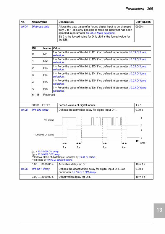
Parameters 365
1
2
3
4
5
6
7
8
9
10
11
12
13
10.04 DI forced data Allows the data value of a forced digital input to be changed from 0 to 1. It is only possible to force an input that has been selected in parameter 10.03 DI force selection.Bit 0 is the forced value for DI1; bit 5 is the forced value for the DI6.
0000h
0000h…FFFFh Forced values of digital inputs. 1 = 1
10.05 DI1 ON delay Defines the activation delay for digital input DI1. 0.00 s
tOn = 10.05 DI1 ON delaytOff = 10.06 DI1 OFF delay*Electrical status of digital input. Indicated by 10.01 DI status.**Indicated by 10.02 DI delayed status.
0.00 … 3000.00 s Activation delay for DI1. 10 = 1 s
10.06 DI1 OFF delay Defines the deactivation delay for digital input DI1. See parameter 10.05 DI1 ON delay.
0.00 s
0.00 … 3000.00 s Deactivation delay for DI1. 10 = 1 s
No. Name/Value Description Def/FbEq16
Bit Name Value
0 DI11 = Force the value of this bit to D1, if so defined in parameter 10.03 DI force selection.
1 DI21 = Force the value of this bit to D3, if so defined in parameter 10.03 DI force selection.
2 DI31 = Force the value of this bit to D3, if so defined in parameter 10.03 DI force selection.
3 DI41 = Force the value of this bit to D4, if so defined in parameter 10.03 DI force selection.
4 DI51 = Force the value of this bit to D5, if so defined in parameter 10.03 DI force selection.
5 DI61 = Force the value of this bit to D6, if so defined in parameter 10.03 DI force selection.
6…15 Reserved
1
0
1
0
tOn tOff tOn tOff
*DI status
**Delayed DI status
Time
14
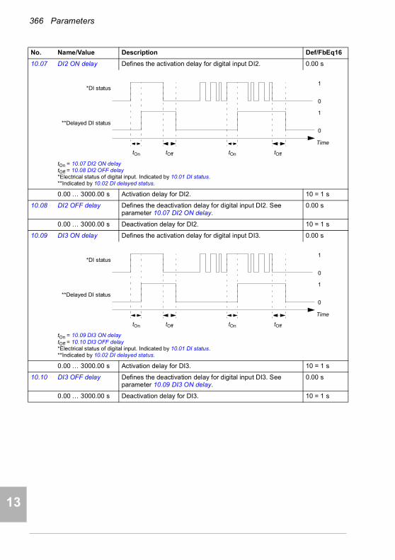
366 Parameters
1
2
3
4
5
7
8
9
9
10
11
12
13
14
10.07 DI2 ON delay Defines the activation delay for digital input DI2. 0.00 s
tOn = 10.07 DI2 ON delaytOff = 10.08 DI2 OFF delay*Electrical status of digital input. Indicated by 10.01 DI status.**Indicated by 10.02 DI delayed status.
0.00 … 3000.00 s Activation delay for DI2. 10 = 1 s
10.08 DI2 OFF delay Defines the deactivation delay for digital input DI2. See parameter 10.07 DI2 ON delay.
0.00 s
0.00 … 3000.00 s Deactivation delay for DI2. 10 = 1 s
10.09 DI3 ON delay Defines the activation delay for digital input DI3. 0.00 s
tOn = 10.09 DI3 ON delaytOff = 10.10 DI3 OFF delay*Electrical status of digital input. Indicated by 10.01 DI status.**Indicated by 10.02 DI delayed status.
0.00 … 3000.00 s Activation delay for DI3. 10 = 1 s
10.10 DI3 OFF delay Defines the deactivation delay for digital input DI3. See parameter 10.09 DI3 ON delay.
0.00 s
0.00 … 3000.00 s Deactivation delay for DI3. 10 = 1 s
No. Name/Value Description Def/FbEq16
1
0
1
0
tOn tOff tOn tOff
*DI status
**Delayed DI status
Time
1
0
1
0
tOn tOff tOn tOff
*DI status
**Delayed DI status
Time

Parameters 367
1
2
3
4
5
6
7
8
9
10
11
12
13
10.11 DI4 ON delay Defines the activation delay for digital input DI4. 0.00 s
tOn = 10.11 DI4 ON delaytOff = 10.12 DI4 OFF delay*Electrical status of digital input. Indicated by 10.01 DI status.**Indicated by 10.02 DI delayed status.
0.00 … 3000.00 s Activation delay for DI4. 10 = 1 s
10.12 DI4 OFF delay Defines the deactivation delay for digital input DI4. See parameter 10.11 DI4 ON delay.
0.00 s
0.00 … 3000.00 s Deactivation delay for DI4. 10 = 1 s
10.13 DI5 ON delay Defines the activation delay for digital input DI5. 0.00 s
tOn = 10.13 DI5 ON delaytOff = 10.14 DI5 OFF delay*Electrical status of digital input. Indicated by 10.01 DI status.**Indicated by 10.02 DI delayed status.
0.00 … 3000.00 s Activation delay for DI5. 10 = 1 s
10.14 DI5 OFF delay Defines the deactivation delay for digital input DI5. See parameter 10.13 DI5 ON delay.
0.00 s
0.00 … 3000.00 s Deactivation delay for DI5. 10 = 1 s
No. Name/Value Description Def/FbEq16
1
0
1
0
tOn tOff tOn tOff
*DI status
**Delayed DI status
Time
1
0
1
0
tOn tOff tOn tOff
*DI status
**Delayed DI status
Time
14
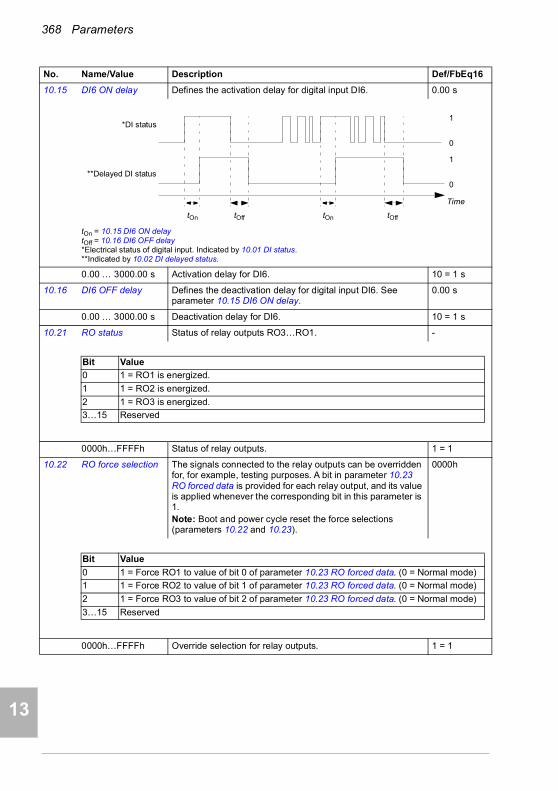
368 Parameters
1
2
3
4
5
7
8
9
9
10
11
12
13
14
10.15 DI6 ON delay Defines the activation delay for digital input DI6. 0.00 s
tOn = 10.15 DI6 ON delaytOff = 10.16 DI6 OFF delay*Electrical status of digital input. Indicated by 10.01 DI status.**Indicated by 10.02 DI delayed status.
0.00 … 3000.00 s Activation delay for DI6. 10 = 1 s
10.16 DI6 OFF delay Defines the deactivation delay for digital input DI6. See parameter 10.15 DI6 ON delay.
0.00 s
0.00 … 3000.00 s Deactivation delay for DI6. 10 = 1 s
10.21 RO status Status of relay outputs RO3…RO1. -
0000h…FFFFh Status of relay outputs. 1 = 1
10.22 RO force selection The signals connected to the relay outputs can be overridden for, for example, testing purposes. A bit in parameter 10.23 RO forced data is provided for each relay output, and its value is applied whenever the corresponding bit in this parameter is 1.Note: Boot and power cycle reset the force selections (parameters 10.22 and 10.23).
0000h
0000h…FFFFh Override selection for relay outputs. 1 = 1
No. Name/Value Description Def/FbEq16
1
0
1
0
tOn tOff tOn tOff
*DI status
**Delayed DI status
Time
Bit Value
0 1 = RO1 is energized.
1 1 = RO2 is energized.
2 1 = RO3 is energized.
3…15 Reserved
Bit Value
0 1 = Force RO1 to value of bit 0 of parameter 10.23 RO forced data. (0 = Normal mode)
1 1 = Force RO2 to value of bit 1 of parameter 10.23 RO forced data. (0 = Normal mode)
2 1 = Force RO3 to value of bit 2 of parameter 10.23 RO forced data. (0 = Normal mode)
3…15 Reserved

Parameters 369
1
2
3
4
5
6
7
8
9
10
11
12
13
10.23 RO forced data Contains the values of relay outputs that are used instead of the connected signals if selected in parameter 10.22 RO force selection. Bit 0 is the forced value for RO1.
0000h
0000h…FFFFh Forced RO values. 1 = 1
10.24 RO1 source Selects a drive signal to be connected to relay output RO1. Damper control
Not energized Output is not energized. 0
Energized Output is energized. 1
Ready run Bit 1 of 06.11 Main status word (see page 353). 2
Enabled Bit 0 of 06.16 Drive status word 1 (see page 354). 4
Started Bit 5 of 06.16 Drive status word 1 (see page 354). 5
Magnetized Bit 1 of 06.17 Drive status word 2 (see page 355). 6
Running Bit 6 of 06.16 Drive status word 1 (see page 354). 7
Ready ref Bit 2 of 06.11 Main status word (see page 353). 8
At setpoint Bit 8 of 06.11 Main status word (see page 353). 9
Reverse Bit 2 of 06.19 Speed control status word (see page 356). 10
Zero speed Bit 0 of 06.19 Speed control status word (see page 356). 11
Above limit Bit 10 of 06.17 Drive status word 2 (see page 355). 12
Warning Bit 7 of 06.11 Main status word (see page 353). 13
Fault Bit 3 of 06.11 Main status word (see page 353). 14
Fault (-1) Inverted bit 3 of 06.11 Main status word (see page 353). 15
Fault/Warning Bit 3 of 06.11 Main status word OR bit 7 of 06.11 Main status word (see page 353).
16
Overcurrent Fault 2310 Overcurrent has occurred. 17
Overvoltage Fault 3210 DC link overvoltage has occurred. 18
Drive temp Fault 2381 IGBT overload, 4110 Control board temperature, 4210 IGBT overtemperature, 4290 Cooling, 42F1 IGBT temperature, 4310 Excess temperature or 4380 Excess temperature difference has occurred.
19
Undervoltage Fault 3220 DC link undervoltage has occurred. 20
Motor temp Fault 4981 External temperature 1 or 4982 External temperature 2 has occurred.
21
Reserved 22
Ext2 active Bit 11 of 06.16 Drive status word 1 (see page 354). 23
Remote control Bit 9 of 06.11 Main status word (see page 353). 24
No. Name/Value Description Def/FbEq16
Bit Value
0 1 = Force the value of this bit to RO1, if so defined in parameter 10.22 RO force selection.
1 1 = Force the value of this bit to RO2, if so defined in parameter 10.22 RO force selection.
2 1 = Force the value of this bit to RO3, if so defined in parameter 10.22 RO force selection.
3…15 Reserved
14
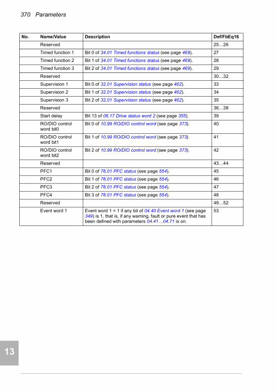
370 Parameters
1
2
3
4
5
7
8
9
9
10
11
12
13
14
Reserved 25…26
Timed function 1 Bit 0 of 34.01 Timed functions status (see page 469). 27
Timed function 2 Bit 1 of 34.01 Timed functions status (see page 469). 28
Timed function 3 Bit 2 of 34.01 Timed functions status (see page 469). 29
Reserved 30…32
Supervision 1 Bit 0 of 32.01 Supervision status (see page 462). 33
Supervision 2 Bit 1 of 32.01 Supervision status (see page 462). 34
Supervision 3 Bit 2 of 32.01 Supervision status (see page 462). 35
Reserved 36…38
Start delay Bit 13 of 06.17 Drive status word 2 (see page 355). 39
RO/DIO control word bit0
Bit 0 of 10.99 RO/DIO control word (see page 373). 40
RO/DIO control word bit1
Bit 1 of 10.99 RO/DIO control word (see page 373). 41
RO/DIO control word bit2
Bit 2 of 10.99 RO/DIO control word (see page 373). 42
Reserved 43…44
PFC1 Bit 0 of 76.01 PFC status (see page 554). 45
PFC2 Bit 1 of 76.01 PFC status (see page 554). 46
PFC3 Bit 2 of 76.01 PFC status (see page 554). 47
PFC4 Bit 3 of 76.01 PFC status (see page 554). 48
Reserved 49…52
Event word 1 Event word 1 = 1 if any bit of 04.40 Event word 1 (see page 349) is 1, that is, if any warning, fault or pure event that has been defined with parameters 04.41…04.71 is on.
53
No. Name/Value Description Def/FbEq16

Parameters 371
1
2
3
4
5
6
7
8
9
10
11
12
13
Damper control See the figure below. 54
Run permissive Bit 7 of 06.22 HVAC status word. 55
Start interlock 1 Bit 8 of 06.22 HVAC status word. 56
No. Name/Value Description Def/FbEq16
Motor status
Run permissive signal from the damper end switch when the damper is fully opened. (parameter 20.41)
Start interlock signal(parameters20.41…20.44)
Damper controlrelay status(Group10 Standard DI, RO)
Start/stop command(Group20 Start/stop/direction)
Damper status
Damper open
Damper closing
time
Damper closed
Relay energized
Damper closed
Acceleration time
(par 23.12)
Damper opening time
Drive started
Relayde-
energized
Drive coasts to a stop
14

372 Parameters
1
2
3
4
5
7
8
9
9
10
11
12
13
14
Start interlock 2 Bit 9 of 06.22 HVAC status word. 57
Start interlock 3 Bit 10 of 06.22 HVAC status word. 58
Start interlock 4 Bit 11 of 06.22 HVAC status word. 59
All start interlocks Bit 12 of 06.22 HVAC status word. 60
User load curve Bit 3 (Outside load limit) of 37.01 ULC output status word (see page 491).
61
RO/DIO control word
For 10.24 RO1 source: Bit 0 (RO1) of 10.99 RO/DIO control word (see page 373).For 10.27 RO2 source: Bit 1 (RO2) of 10.99 RO/DIO control word (see page 373).For 10.30 RO3 source: Bit 2 (RO3) of 10.99 RO/DIO control word (see page 373).
62
Other [bit] Source selection (see Terms and abbreviations on page 340). -
10.25 RO1 ON delay Defines the activation delay for relay output RO1. 0.0 s
tOn = 10.25 RO1 ON delaytOff = 10.26 RO1 OFF delay
0.0 … 3000.0 s Activation delay for RO1. 10 = 1 s
10.26 RO1 OFF delay Defines the deactivation delay for relay output RO1. See parameter 10.25 RO1 ON delay.
0.0 s
0.0 … 3000.0 s Deactivation delay for RO1. 10 = 1 s
10.27 RO2 source Selects a drive signal to be connected to relay output RO2.For the available selections, see parameter 10.24 RO1 source.
Running
10.28 RO2 ON delay Defines the activation delay for relay output RO2. 0.0 s
tOn = 10.28 RO2 ON delaytOff = 10.29 RO2 OFF delay
0.0 … 3000.0 s Activation delay for RO2. 10 = 1 s
No. Name/Value Description Def/FbEq16
1
0
1
0
tOn tOff tOn tOff
Status of selectedsource
RO status
Time
1
0
1
0
tOn tOff tOn tOff
Status of selectedsource
RO status
Time

Parameters 373
1
2
3
4
5
6
7
8
9
10
11
12
13
10.29 RO2 OFF delay Defines the deactivation delay for relay output RO2. See parameter 10.28 RO2 ON delay.
0.0 s
0.0 … 3000.0 s Deactivation delay for RO2. 10 = 1 s
10.30 RO3 source Selects a drive signal to be connected to relay output RO3.For the available selections, see parameter 10.24 RO1 source.
Fault (-1)
10.31 RO3 ON delay Defines the activation delay for relay output RO3. 0.0 s
tOn = 10.31 RO3 ON delaytOff = 10.32 RO3 OFF delay
0.0 … 3000.0 s Activation delay for RO3. 10 = 1 s
10.32 RO3 OFF delay Defines the deactivation delay for relay output RO3. See parameter 10.31 RO3 ON delay.
0.0 s
0.0 … 3000.0 s Deactivation delay for RO3. 10 = 1 s
10.99 RO/DIO control word
Storage parameter for controlling the relay outputs, for example, through the embedded fieldbus interface. To control the relay outputs (RO) of the drive, send a control word with the bit assignments shown below as Modbus I/O data. Set the target selection parameter of that particular data (58.101…58.114) to RO/DIO control word. In the source selection parameter of the desired output, select the appropriate bit of this word.
0000h
0000h…FFFFh RO/DIO control word. 1 = 1
10.101 RO1 toggle counter Displays the number of times relay output RO1 has changed states.Can be reset from the control panel by pressing the Reset softkey for 3 seconds.
5
0…4294967000 State change count. 1 = 1
No. Name/Value Description Def/FbEq16
1
0
1
0
tOn tOff tOn tOff
Status of selectedsource
RO status
Time
Bit Name Description
0 RO1 Source bits for relay outputs RO1…RO3. See parameters 10.24, 10.27 and 10.30. 1 RO2
2 RO3
3 RO4 Source bits for relay outputs RO4…RO5 with a CHDI-01 or CMOD-01 extension module. See parameters 15.07 and.15.10.4 RO5
5…7 Reserved
8 DIO1 Source bit for digital output DO1 with a CMOD-01 extension module. See parameter 15.23.
9…15 Reserved
14
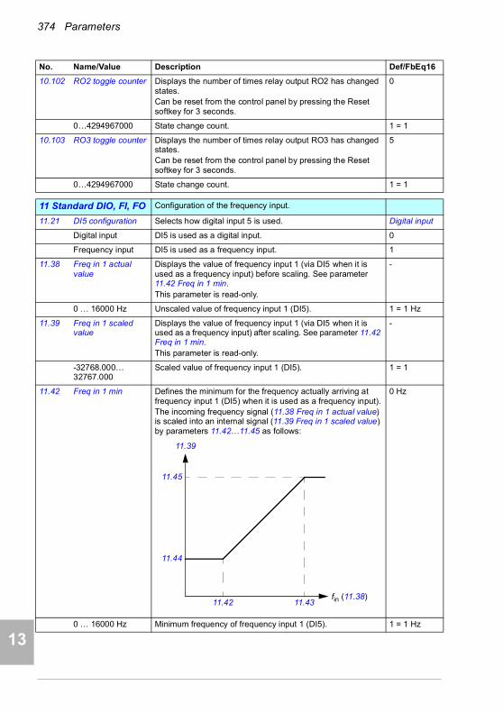
374 Parameters
1
2
3
4
5
7
8
9
9
10
11
12
13
14
10.102 RO2 toggle counter Displays the number of times relay output RO2 has changed states.Can be reset from the control panel by pressing the Reset softkey for 3 seconds.
0
0…4294967000 State change count. 1 = 1
10.103 RO3 toggle counter Displays the number of times relay output RO3 has changed states.Can be reset from the control panel by pressing the Reset softkey for 3 seconds.
5
0…4294967000 State change count. 1 = 1
1111 Standard DIO, FI, FO Configuration of the frequency input.
11.21 DI5 configuration Selects how digital input 5 is used. Digital input
Digital input DI5 is used as a digital input. 0
Frequency input DI5 is used as a frequency input. 1
11.38 Freq in 1 actual value
Displays the value of frequency input 1 (via DI5 when it is used as a frequency input) before scaling. See parameter 11.42 Freq in 1 min.This parameter is read-only.
-
0 … 16000 Hz Unscaled value of frequency input 1 (DI5). 1 = 1 Hz
11.39 Freq in 1 scaled value
Displays the value of frequency input 1 (via DI5 when it is used as a frequency input) after scaling. See parameter 11.42 Freq in 1 min.This parameter is read-only.
-
-32768.000… 32767.000
Scaled value of frequency input 1 (DI5). 1 = 1
11.42 Freq in 1 min Defines the minimum for the frequency actually arriving at frequency input 1 (DI5) when it is used as a frequency input).The incoming frequency signal (11.38 Freq in 1 actual value) is scaled into an internal signal (11.39 Freq in 1 scaled value) by parameters 11.42…11.45 as follows:
0 Hz
0 … 16000 Hz Minimum frequency of frequency input 1 (DI5). 1 = 1 Hz
No. Name/Value Description Def/FbEq16
11.43
11.45
11.42
11.39
fin (11.38)
11.44

Parameters 375
1
2
3
4
5
6
7
8
9
10
11
12
13
11.43 Freq in 1 max Defines the maximum for the frequency actually arriving at frequency input 1 (DI5) when it is used as a frequency input). See parameter 11.42 Freq in 1 min.
16000 Hz
0 … 16000 Hz Maximum frequency for frequency input 1 (DI5). 1 = 1 Hz
11.44 Freq in 1 at scaled min
Defines the value that is required to correspond internally to the minimum input frequency defined by parameter 11.42 Freq in 1 min. See diagram at parameter 11.42 Freq in 1 min.
0.000
-32768.000… 32767.000
Value corresponding to minimum of frequency input 1. 1 = 1
11.45 Freq in 1 at scaled max
Defines the value that is required to correspond internally to the maximum input frequency defined by parameter 11.43 Freq in 1 max. See diagram at parameter 11.42 Freq in 1 min.
1500.000; 1800.000(95.20 b0)
-32768.000… 32767.000
Value corresponding to maximum of frequency input 1. 1 = 1
1212 Standard AI Configuration of standard analog inputs.
12.02 AI force selection The true readings of the analog inputs can be overridden, for example, for testing purposes. A forced value parameter is provided for each analog input, and its value is applied whenever the corresponding bit in this parameter is 1.Notes: • AI filter times (parameters 12.16 AI1 filter time and 12.26
AI2 filter time) have no effect on forced AI values (parameters 12.13 AI1 forced value and 12.23 AI2 forced value).
• Boot and power cycle reset the force selections (parameters 12.02 and 12.03).
0000h
0000h…FFFFh Forced values selector for analog inputs AI1 and AI2. 1 = 1
12.03 AI supervision function
Selects how the drive reacts when an analog input signal moves out of the minimum and/or maximum limits specified for the input.The supervision applies a margin of 0.5 V or 1.0 mA to the limits. For example, if the maximum limit for the input is 7.000 V, the maximum limit supervision activates at 7.500 V.The inputs and the limits to be observed are selected by parameter 12.04 AI supervision selection.
No action
No action No action taken. 0
Fault Drive trips on fault 80A0 AI supervision. 1
Warning Drive generates warning A8A0 AI supervision. 2
Last speed Drive generates warning A8A0 AI supervision and freezes the speed (or frequency) to the level the drive was operating at. The speed/frequency is determined on the basis of actual speed using 850 ms low-pass filtering.
WARNING! Make sure that it is safe to continue operation in case of a communication break.
3
No. Name/Value Description Def/FbEq16
Bit Name Value
0 AI1 1 = Force AI1 to value of parameter 12.13 AI1 forced value.
1 AI2 1 = Force AI2 to value of parameter 12.23 AI2 forced value.
2…15 Reserved
14
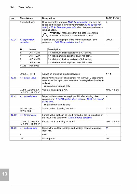
376 Parameters
1
2
3
4
5
7
8
9
9
10
11
12
13
14
Speed ref safe Drive generates warning A8A0 AI supervision and sets the speed to the speed defined by parameter 22.41 Speed ref safe (or 28.41 Frequency ref safe when frequency reference is being used).
WARNING! Make sure that it is safe to continue operation in case of a communication break.
4
12.04 AI supervision selection
Specifies the analog input limits to be supervised. See parameter 12.03 AI supervision function.
0000h
0000h…FFFFh Activation of analog input supervision. 1 = 1
12.11 AI1 actual value Displays the value of analog input AI1 in mA or V (depending on whether the input is set to current or voltage by a hardware setting).This parameter is read-only.
-
0.000…22.000 mA or 0.000…11.000 V
Value of analog input AI1. 1000 = 1 unit
12.12 AI1 scaled value Displays the value of analog input AI1 after scaling. See parameters 12.19 AI1 scaled at AI1 min and 12.20 AI1 scaled at AI1 max.This parameter is read-only.
-
-32768.000… 32767.000
Scaled value of analog input AI1. 1 = 1
12.13 AI1 forced value Forced value that can be used instead of the true reading of the input. See parameter 12.02 AI force selection.
-
0.000…22.000 mA or 0.000…11.000 V
Forced value of analog input AI1. 1000 = 1 unit
12.15 AI1 unit selection Selects the unit for readings and settings related to analog input AI1.
V
V Volts. 2
mA Milliamperes. 10
No. Name/Value Description Def/FbEq16
Bit Name Description
0 AI1 < MIN 1 = Minimum limit supervision of AI1 active.
1 AI1 > MAX 1 = Maximum limit supervision of AI1 active.
2 AI2 < MIN 1 = Minimum limit supervision of AI2 active.
3 AI2 > MAX 1 = Maximum limit supervision of AI2 active.
4…15 Reserved

Parameters 377
1
2
3
4
5
6
7
8
9
10
11
12
13
12.16 AI1 filter time Defines the filter time constant for analog input AI1.
Note: The signal is also filtered due to the signal interface hardware (approximately 0.25 ms time constant). This cannot be changed by any parameter.
0.100 s
0.000…30.000 s Filter time constant. 1000 = 1 s
12.17 AI1 min Defines the minimum site value for analog input AI1.Set the value actually sent to the drive when the analog signal from plant is wound to its minimum setting.See also parameter 12.19 AI1 scaled at AI1 min.
4.000 mA or 0.000 V
0.000…22.000 mA or 0.000…11.000 V
Minimum value of AI1. 1000 = 1 unit
12.18 AI1 max Defines the maximum site value for analog input AI1.Set the value actually sent to the drive when the analog signal from plant is wound to its maximum setting.See also parameter 12.19 AI1 scaled at AI1 min.
20.000 mA or 10.000 V
0.000…22.000 mA or 0.000…11.000 V
Maximum value of AI1. 1000 = 1 unit
No. Name/Value Description Def/FbEq16
63
%
100
Tt
O = I × (1 - e-t/T)
I = filter input (step)O = filter outputt = timeT = filter time constant
Unfiltered signal
Filtered signal
14

378 Parameters
1
2
3
4
5
7
8
9
9
10
11
12
13
14
12.19 AI1 scaled at AI1 min
Defines the real internal value that corresponds to the minimum analog input AI1 value defined by parameter 12.17 AI1 min. (Changing the polarity settings of 12.19 and 12.20 can effectively invert the analog input.)
0.000
-32768.000… 32767.000
Real value corresponding to minimum AI1 value. 1 = 1
12.20 AI1 scaled at AI1 max
Defines the real internal value that corresponds to the maximum analog input AI1 value defined by parameter 12.18 AI1 max. See the drawing at parameter 12.19 AI1 scaled at AI1 min.
50.000; 60.000 (95.20 b0)
-32768.000… 32767.000
Real value corresponding to maximum AI1 value. 1 = 1
12.21 AI2 actual value Displays the value of analog input AI2 in mA or V (depending on whether the input is set to current or voltage by a hardware setting).This parameter is read-only.
-
0.000…22.000 mA or 0.000…11.000 V
Value of analog input AI2. 1000 = 1 unit
12.22 AI2 scaled value Displays the value of analog input AI2 after scaling. See parameters 12.29 AI2 scaled at AI2 min and 12.101 AI1 percent value.This parameter is read-only.
-
-32768.000… 32767.000
Scaled value of analog input AI2. 1 = 1
12.23 AI2 forced value Forced value that can be used instead of the true reading of the input. See parameter 12.02 AI force selection.
-
0.000…22.000 mA or 0.000…11.000 V
Forced value of analog input AI2. 1000 = 1 unit
12.25 AI2 unit selection Selects the unit for readings and settings related to analog input AI2.
mA
V Volts. 2
mA Milliamperes. 10
12.26 AI2 filter time Defines the filter time constant for analog input AI2. See parameter 12.16 AI1 filter time.
0.100 s
0.000…30.000 s Filter time constant. 1000 = 1 s
No. Name/Value Description Def/FbEq16
12.20
12.18
12.17
12.19
AIin (12.11)
AIscaled (12.12)
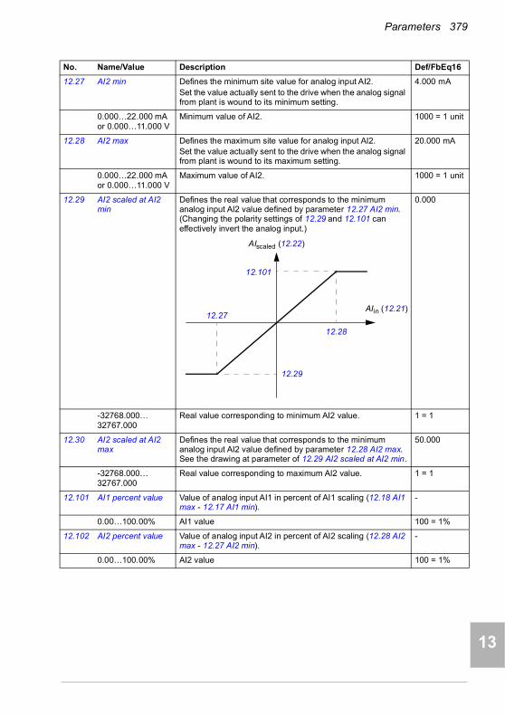
Parameters 379
1
2
3
4
5
6
7
8
9
10
11
12
13
12.27 AI2 min Defines the minimum site value for analog input AI2.Set the value actually sent to the drive when the analog signal from plant is wound to its minimum setting.
4.000 mA
0.000…22.000 mA or 0.000…11.000 V
Minimum value of AI2. 1000 = 1 unit
12.28 AI2 max Defines the maximum site value for analog input AI2.Set the value actually sent to the drive when the analog signal from plant is wound to its maximum setting.
20.000 mA
0.000…22.000 mA or 0.000…11.000 V
Maximum value of AI2. 1000 = 1 unit
12.29 AI2 scaled at AI2 min
Defines the real value that corresponds to the minimum analog input AI2 value defined by parameter 12.27 AI2 min. (Changing the polarity settings of 12.29 and 12.101 can effectively invert the analog input.)
0.000
-32768.000… 32767.000
Real value corresponding to minimum AI2 value. 1 = 1
12.30 AI2 scaled at AI2 max
Defines the real value that corresponds to the minimum analog input AI2 value defined by parameter 12.28 AI2 max. See the drawing at parameter of 12.29 AI2 scaled at AI2 min.
50.000
-32768.000… 32767.000
Real value corresponding to maximum AI2 value. 1 = 1
12.101 AI1 percent value Value of analog input AI1 in percent of AI1 scaling (12.18 AI1 max - 12.17 AI1 min).
-
0.00…100.00% AI1 value 100 = 1%
12.102 AI2 percent value Value of analog input AI2 in percent of AI2 scaling (12.28 AI2 max - 12.27 AI2 min).
-
0.00…100.00% AI2 value 100 = 1%
No. Name/Value Description Def/FbEq16
12.101
12.28
12.27
12.29
AIin (12.21)
AIscaled (12.22)
14

380 Parameters
1
2
3
4
5
7
8
9
9
10
11
12
13
14
1313 Standard AO Configuration of standard analog outputs.
13.02 AO force selection The source signals of the analog outputs can be overridden, for example, for testing purposes. A forced value parameter is provided for each analog output, and its value is applied whenever the corresponding bit in this parameter is 1.Note: Boot and power cycle reset the force selections (parameters 13.02 and 13.11).
0000h
0000h…FFFFh Forced values selector for analog outputs AO1 and AO2. 1 = 1
13.11 AO1 actual value Displays the value of AO1 in mA or V.This parameter is read-only.
-
0.000…11.000 V Value of AO1. 1 = 1 mA
13.12 AO1 source Selects a signal to be connected to analog output AO1. Output frequency
Zero None. 0
Motor speed used 01.01 Motor speed used (page 343). 1
Reserved 2
Output frequency 01.06 Output frequency (page 343). 3
Motor current 01.07 Motor current (page 343). 4
Motor current % of motor nominal
01.08 Motor current % of motor nom (page 343). 5
Motor torque 01.10 Motor torque (page 343). 6
DC voltage 01.11 DC voltage (page 343). 7
Output power 01.14 Output power (page 344). 8
Reserved 9
Speed ref ramp in 23.01 Speed ref ramp input (page 423). 10
Speed ref ramp out 23.02 Speed ref ramp output (page 423). 11
Speed ref used 24.01 Used speed reference (page 425). 12
Reserved 13
Freq ref used 28.02 Frequency ref ramp output (page 431). 14
Reserved 15
Process PID out 40.01 Process PID output actual (page 494). 16
Reserved 17…19
Temp sensor 1 excitation
The output is used to feed an excitation current to the temperature sensor 1, see parameter 35.11 Temperature 1 source. See also section Programmable protection functions (page 186).
20
No. Name/Value Description Def/FbEq16
Bit Name Value
0 AO1 1 = Force AO1 to value of parameter 13.13 AO1 forced value. (0 = Normal mode)
1 AO2 1 = Force AO2 to value of parameter 13.23 AO2 forced value. (0 = Normal mode)
2…15 Reserved

Parameters 381
1
2
3
4
5
6
7
8
9
10
11
12
13
Temp sensor 2 excitation
The output is used to feed an excitation current to the temperature sensor 2, see parameter 35.21 Temperature 2 source. See also section Programmable protection functions (page 186).
21
Reserved 21…25
Abs motor speed used
01.61 Abs motor speed used (page 346). 26
Abs motor speed % 01.62 Abs motor speed % (page 346). 27
Abs output frequency
01.63 Abs output frequency (page 346). 28
Reserved 29
Abs motor torque 01.64 Abs motor torque (page 346). 30
Abs output power 01.65 Abs output power (page 346). 31
Abs motor shaft power
01.68 Abs motor shaft power (page 346). 32
External PID1 out 71.01 External PID act value (page 546). 33
External PID2 out 72.01 External PID act value (page 547). 34
External PID3 out 73.01 External PID act value (page 549). 35
External PID4 out 74.01 External PID act value (page 551). 36
AO1 data storage 13.91 AO1 data storage (page 386). 37
AO2 data storage 13.92 AO2 data storage (page 386). 38
Other Source selection (see Terms and abbreviations on page 340). -
13.13 AO1 forced value Forced value that can be used instead of the selected output signal. See parameter 13.02 AO force selection.
0.000 V
0.000…22.000 mA /0.000…11.000 V
Forced value for AO1. 1 = 1 unit
13.15 AO1 unit selection Selects the unit for readings and settings related to analog input AO1.
V
V Volts. 2
mA Milliamperes. 10
No. Name/Value Description Def/FbEq16
14
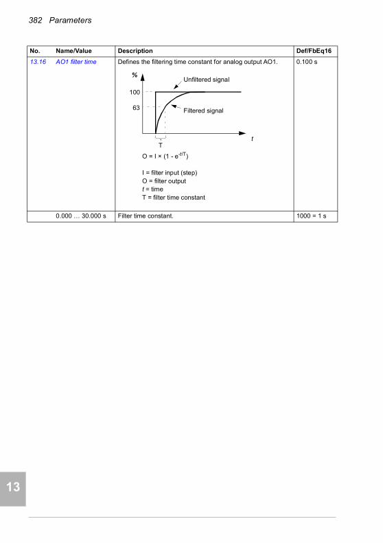
382 Parameters
1
2
3
4
5
7
8
9
9
10
11
12
13
14
13.16 AO1 filter time Defines the filtering time constant for analog output AO1. 0.100 s
0.000 … 30.000 s Filter time constant. 1000 = 1 s
No. Name/Value Description Def/FbEq16
63
%
100
Tt
O = I × (1 - e-t/T)
I = filter input (step)O = filter outputt = timeT = filter time constant
Unfiltered signal
Filtered signal
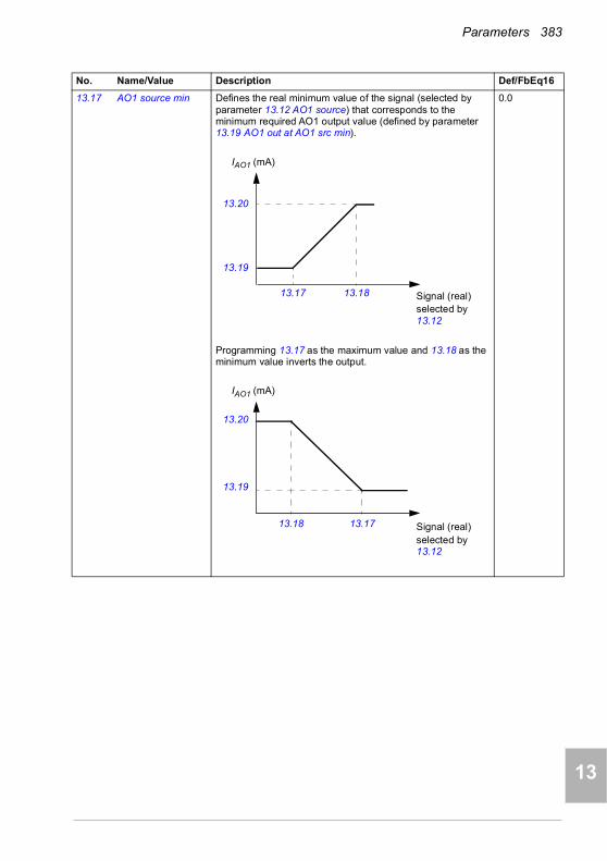
Parameters 383
1
2
3
4
5
6
7
8
9
10
11
12
13
13.17 AO1 source min Defines the real minimum value of the signal (selected by parameter 13.12 AO1 source) that corresponds to the minimum required AO1 output value (defined by parameter 13.19 AO1 out at AO1 src min).
Programming 13.17 as the maximum value and 13.18 as the minimum value inverts the output.
0.0
No. Name/Value Description Def/FbEq16
13.1813.17
13.20
13.19
IAO1 (mA)
Signal (real)selected by 13.12
IAO1 (mA)
13.20
13.19
13.18 13.17 Signal (real)selected by 13.12
14

384 Parameters
1
2
3
4
5
7
8
9
9
10
11
12
13
14
AO has automatic scaling. Every time the source for the AO is changed, the scaling range is changed accordingly. User given minimum and maximum values override the automatic values.
-32768.0…32767.0 Real signal value corresponding to minimum AO1 output value.
1 = 1
13.18 AO1 source max Defines the real maximum value of the signal (selected by parameter 13.12 AO1 source) that corresponds to the maximum required AO1 output value (defined by parameter 13.20 AO1 out at AO1 src max). See parameter 13.17 AO1 source min.
50.0;60.0 (95.20 b0)
-32768.0…32767.0 Real signal value corresponding to maximum AO1 output value.
1 = 1
13.19 AO1 out at AO1 src min
Defines the minimum output value for analog output AO1.See also drawing at parameter 13.17 AO1 source min.
0.000 V
0.000…22.000 mA /0.000…11.000 V
Minimum AO1 output value. 1000 = 1 unit
13.20 AO1 out at AO1 src max
Defines the maximum output value for analog output AO1.See also drawing at parameter 13.17 AO1 source min.
10.000 V
0.000…22.000 mA /0.000…11.000 V
Maximum AO1 output value. 1000 = 1 unit
No. Name/Value Description Def/FbEq16
13.12 AO1 source, 13.22 AO2 source
13.17 AO1 source min,13.27 AO2 source min
13.18 AO1 source max,13.28 AO2 source max
0 Zero N/A (Output is constant zero.)
1 Motor speed used 0 46.01 Speed scaling
3 Output frequency 0 46.02 Frequency scaling
4 Motor current 0 30.17 Maximum current
5 Motor current % of motor nominal
0% 100%
6 Motor torque 0 46.03 Torque scaling
7 DC voltage Min. value of 01.11 DC voltage
Max. value of 01.11 DC voltage
8 Output power 0 46.04 Power scaling
10 Speed ref ramp in 0 46.01 Speed scaling
11 Speed ref ramp out 0 46.01 Speed scaling
12 Speed ref used 0 46.01 Speed scaling
14 Freq ref used 0 46.02 Frequency scaling
16 Process PID out Min. value of 40.01 Process PID output actual
Max. value of 40.01 Process PID output actual
20 Temp sensor 1 excitation N/A (Analog output is not scaled; it is determined by the sensor’s triggering voltage.)21 Temp sensor 2 excitation
26 Abs motor speed used 0 46.01 Speed scaling
27 Abs motor speed % 0 46.01 Speed scaling
28 Abs output frequency 0 46.02 Frequency scaling
30 Abs motor torque 0 46.03 Torque scaling
31 Abs output power 0 46.04 Power scaling
32 Abs motor shaft power 0 46.04 Power scaling
33 External PID1 out Min. value of 71.01 External PID act value
Max. value of 71.01 External PID act value
Other Min. value of the selected parameter
Max. value of the selected parameter

Parameters 385
1
2
3
4
5
6
7
8
9
10
11
12
13
13.21 AO2 actual value Displays the value of AO2 in mA.This parameter is read-only.
-
0.000 … 22.000 mA Value of AO2. 1000 = 1 mA
13.22 AO2 source Selects a signal to be connected to analog output AO2. Alternatively, sets the output to excitation mode to feed a constant current to a temperature sensor.For the selections, see parameter 13.12 AO1 source.
Motor current
13.23 AO2 forced value Forced value that can be used instead of the selected output signal. See parameter 13.02 AO force selection.
0.000 mA
0.000 … 22.000 mA Forced value for AO2. 1000 = 1 mA
13.26 AO2 filter time Defines the filtering time constant for analog output AO2. See parameter 13.16 AO1 filter time.
0.100 s
0.000 … 30.000 s Filter time constant. 1000 = 1 s
13.27 AO2 source min Defines the real minimum value of the signal (selected by parameter 13.22 AO2 source) that corresponds to the minimum required AO2 output value (defined by parameter 13.29 AO2 out at AO2 src min). See parameter 13.17 AO1 source min about the AO automatic scaling.
Programming 13.27 as the maximum value and 13.28 as the minimum value inverts the output.
0.0
-32768.0…32767.0 Real signal value corresponding to minimum AO2 output value.
1 = 1
No. Name/Value Description Def/FbEq16
13.2813.27
13.30
13.29
IAO2 (mA)
Signal (real)selected by 13.22
IAO2 (mA)
13.30
13.29
13.28 13.27 Signal (real)selected by 13.22
14
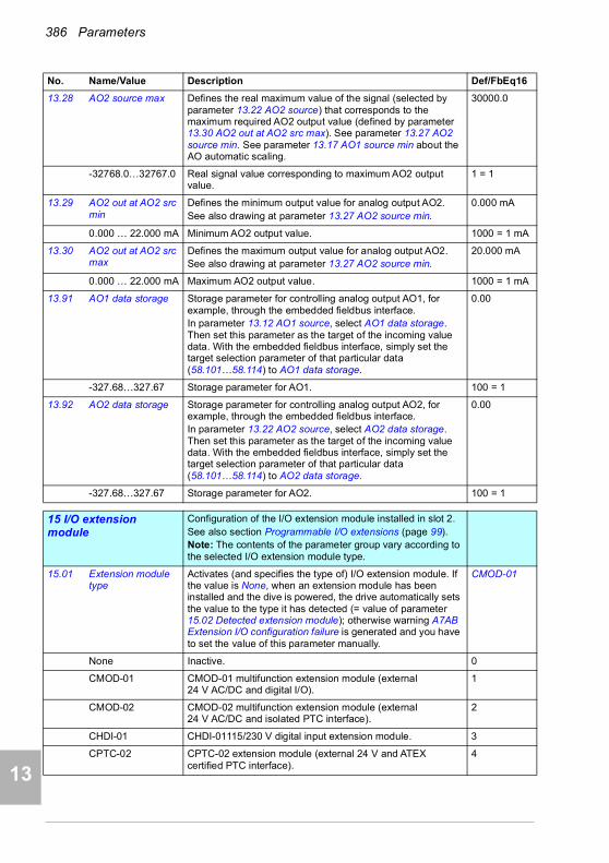
386 Parameters
1
2
3
4
5
7
8
9
9
10
11
12
13
14
13.28 AO2 source max Defines the real maximum value of the signal (selected by parameter 13.22 AO2 source) that corresponds to the maximum required AO2 output value (defined by parameter 13.30 AO2 out at AO2 src max). See parameter 13.27 AO2 source min. See parameter 13.17 AO1 source min about the AO automatic scaling.
30000.0
-32768.0…32767.0 Real signal value corresponding to maximum AO2 output value.
1 = 1
13.29 AO2 out at AO2 src min
Defines the minimum output value for analog output AO2.See also drawing at parameter 13.27 AO2 source min.
0.000 mA
0.000 … 22.000 mA Minimum AO2 output value. 1000 = 1 mA
13.30 AO2 out at AO2 src max
Defines the maximum output value for analog output AO2.See also drawing at parameter 13.27 AO2 source min.
20.000 mA
0.000 … 22.000 mA Maximum AO2 output value. 1000 = 1 mA
13.91 AO1 data storage Storage parameter for controlling analog output AO1, for example, through the embedded fieldbus interface.In parameter 13.12 AO1 source, select AO1 data storage. Then set this parameter as the target of the incoming value data. With the embedded fieldbus interface, simply set the target selection parameter of that particular data (58.101…58.114) to AO1 data storage.
0.00
-327.68…327.67 Storage parameter for AO1. 100 = 1
13.92 AO2 data storage Storage parameter for controlling analog output AO2, for example, through the embedded fieldbus interface.In parameter 13.22 AO2 source, select AO2 data storage. Then set this parameter as the target of the incoming value data. With the embedded fieldbus interface, simply set the target selection parameter of that particular data (58.101…58.114) to AO2 data storage.
0.00
-327.68…327.67 Storage parameter for AO2. 100 = 1
1515 I/O extension module
Configuration of the I/O extension module installed in slot 2.See also section Programmable I/O extensions (page 99).Note: The contents of the parameter group vary according to the selected I/O extension module type.
15.01 Extension module type
Activates (and specifies the type of) I/O extension module. If the value is None, when an extension module has been installed and the dive is powered, the drive automatically sets the value to the type it has detected (= value of parameter 15.02 Detected extension module); otherwise warning A7AB Extension I/O configuration failure is generated and you have to set the value of this parameter manually.
CMOD-01
None Inactive. 0
CMOD-01 CMOD-01 multifunction extension module (external 24 V AC/DC and digital I/O).
1
CMOD-02 CMOD-02 multifunction extension module (external 24 V AC/DC and isolated PTC interface).
2
CHDI-01 CHDI-01115/230 V digital input extension module. 3
CPTC-02 CPTC-02 extension module (external 24 V and ATEX certified PTC interface).
4
No. Name/Value Description Def/FbEq16
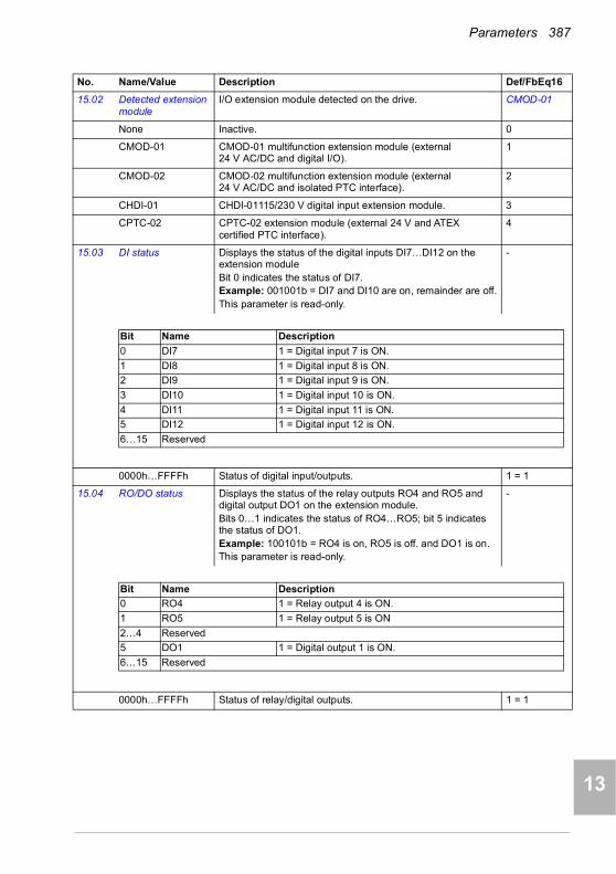
Parameters 387
1
2
3
4
5
6
7
8
9
10
11
12
13
15.02 Detected extension module
I/O extension module detected on the drive. CMOD-01
None Inactive. 0
CMOD-01 CMOD-01 multifunction extension module (external 24 V AC/DC and digital I/O).
1
CMOD-02 CMOD-02 multifunction extension module (external 24 V AC/DC and isolated PTC interface).
2
CHDI-01 CHDI-01115/230 V digital input extension module. 3
CPTC-02 CPTC-02 extension module (external 24 V and ATEX certified PTC interface).
4
15.03 DI status Displays the status of the digital inputs DI7…DI12 on the extension moduleBit 0 indicates the status of DI7.Example: 001001b = DI7 and DI10 are on, remainder are off.This parameter is read-only.
-
0000h…FFFFh Status of digital input/outputs. 1 = 1
15.04 RO/DO status Displays the status of the relay outputs RO4 and RO5 and digital output DO1 on the extension module.Bits 0…1 indicates the status of RO4…RO5; bit 5 indicates the status of DO1.Example: 100101b = RO4 is on, RO5 is off. and DO1 is on.This parameter is read-only.
-
0000h…FFFFh Status of relay/digital outputs. 1 = 1
No. Name/Value Description Def/FbEq16
Bit Name Description
0 DI7 1 = Digital input 7 is ON.
1 DI8 1 = Digital input 8 is ON.
2 DI9 1 = Digital input 9 is ON.
3 DI10 1 = Digital input 10 is ON.
4 DI11 1 = Digital input 11 is ON.
5 DI12 1 = Digital input 12 is ON.
6…15 Reserved
Bit Name Description
0 RO4 1 = Relay output 4 is ON.
1 RO5 1 = Relay output 5 is ON
2…4 Reserved
5 DO1 1 = Digital output 1 is ON.
6…15 Reserved
14

388 Parameters
1
2
3
4
5
7
8
9
9
10
11
12
13
14
15.05 RO/DO force selection
The electrical statuses of the relay/digital outputs can be overridden, for example, for testing purposes. A bit in parameter 15.06 RO/DO forced data is provided for each relay or digital output, and its value is applied whenever the corresponding bit in this parameter is 1.Note: Boot and power cycle reset the force selections (parameters 15.05 and 15.06).
0000h
0000h…FFFFh Override selection for relay/digital outputs. 1 = 1
15.06 RO/DO forced data Allows the data value of a forced relay or digital output to be changed from 0 to 1. It is only possible to force an output that has been selected in parameter 15.05 RO/DO force selection.Bits 0…1 are the forced values for RO4…RO5; bit 5 is the forced value for DO1.
0000h
0000h…FFFFh Forced values of relay/digital outputs. 1 = 1
15.07 RO4 source Selects a drive signal to be connected to relay output RO4. Not energized
Not energized Output is not energized. 0
Energized Output is energized. 1
Ready run Bit 1 of 06.11 Main status word (see page 353). 2
Reserved 3
Enabled Bit 0 of 06.16 Drive status word 1 (see page 354). 4
Started Bit 5 of 06.16 Drive status word 1 (see page 354). 5
Magnetized Bit 1 of 06.17 Drive status word 2 (see page 355). 6
Running Bit 6 of 06.16 Drive status word 1 (see page 354). 7
Ready ref Bit 2 of 06.11 Main status word (see page 353). 8
At setpoint Bit 8 of 06.11 Main status word (see page 353). 9
No. Name/Value Description Def/FbEq16
Bit Name Value
0 RO4 1 = Force RO4 to value of bit 0 of parameter 15.06 RO/DO forced data. (0 = Normal mode)
1 RO5 1 = Force RO5 to value of bit 1 of parameter 15.06 RO/DO forced data. (0 = Normal mode)
2…4 Reserved
5 DO1 1 = Force DO1 to value of bit 5 of parameter 15.06 RO/DO forced data. (0 = Normal mode)
6…15 Reserved
Bit Name Description
0 RO4 1 = Force the value of this bit to RO4, if so defined in parameter 15.05 RO/DO force selection.
1 RO5 1 = Force the value of this bit to RO5, if so defined in parameter 15.05 RO/DO force selection.
2…4 Reserved
5 DO1 1 = Force the value of this bit to DO1 if so defined in parameter 15.05 RO/DO force selection.
6…15 Reserved

Parameters 389
1
2
3
4
5
6
7
8
9
10
11
12
13
Reverse Bit 2 of 06.19 Speed control status word (see page 356). 10
Zero speed Bit 0 of 06.19 Speed control status word (see page 356). 11
Above limit Bit 10 of 06.17 Drive status word 2 (see page 355). 12
Warning Bit 7 of 06.11 Main status word (see page 353). 13
Fault Bit 3 of 06.11 Main status word (see page 353). 14
Fault (-1) Inverted bit 3 of 06.11 Main status word (see page 353). 15
Fault/Warning Bit 3 of 06.11 Main status word OR bit 7 of 06.11 Main status word (see page 353).
16
Overcurrent Fault 2310 Overcurrent has occurred. 17
Overvoltage Fault 3210 DC link overvoltage has occurred. 18
Drive temp Fault 2381 IGBT overload, 4110 Control board temperature, 4210 IGBT overtemperature, 4290 Cooling, 42F1 IGBT temperature, 4310 Excess temperature or 4380 Excess temperature difference has occurred.
19
Undervoltage Fault 3220 DC link undervoltage has occurred. 20
Motor temp Fault 4981 External temperature 1 or 4982 External temperature 2 has occurred.
21
Reserved 22
Ext2 active Bit 11 of 06.16 Drive status word 1 (see page 354). 23
Remote control Bit 9 of 06.11 Main status word (see page 353). 24
Reserved 25…26
Timed function 1 Bit 0 of 34.01 Timed functions status (see page 469). 27
Timed function 2 Bit 1 of 34.01 Timed functions status (see page 469). 28
Timed function 3 Bit 2 of 34.01 Timed functions status (see page 469). 29
Reserved 30…32
Supervision 1 Bit 0 of 32.01 Supervision status (see page 462). 33
Supervision 2 Bit 1 of 32.01 Supervision status (see page 462). 34
Supervision 3 Bit 2 of 32.01 Supervision status (see page 462). 35
Reserved 36…38
Start delay Bit 13 of 06.17 Drive status word 2 (see page 355). 39
RO/DIO control word bit0
Bit 0 of 10.99 RO/DIO control word (see page 373). 40
RO/DIO control word bit1
Bit 1 of 10.99 RO/DIO control word (see page 373). 41
RO/DIO control word bit2
Bit 2 of 10.99 RO/DIO control word (see page 373). 42
Reserved 43…44
PFC1 Bit 0 of 76.01 PFC status (see page 554). 45
PFC2 Bit 1 of 76.01 PFC status (see page 554). 46
PFC3 Bit 2 of 76.01 PFC status (see page 554). 47
PFC4 Bit 3 of 76.01 PFC status (see page 554). 48
Bit 4 of 76.01 PFC status (see page 554). 49
Bit 5 of 76.01 PFC status (see page 554). 50
Reserved 49…52
No. Name/Value Description Def/FbEq16
14
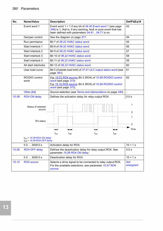
390 Parameters
1
2
3
4
5
7
8
9
9
10
11
12
13
14
Event word 1 Event word 1 = 1 if any bit of 04.40 Event word 1 (see page 349) is 1, that is, if any warning, fault or pure event that has been defined with parameters 04.41…04.71 is on.
53
Damper control See the diagram on page 371. 54
Run permissive Bit 7 of 06.22 HVAC status word. 55
Start interlock 1 Bit 8 of 06.22 HVAC status word. 56
Start interlock 2 Bit 9 of 06.22 HVAC status word. 57
Start interlock 3 Bit 10 of 06.22 HVAC status word. 58
Start interlock 4 Bit 11 of 06.22 HVAC status word. 59
All start interlocks Bit 12 of 06.22 HVAC status word. 60
User load curve Bit 3 (Outside load limit) of 37.01 ULC output status word (see page 491).
61
RO/DIO control word
For 15.07 RO4 source: Bit 3 (RO4) of 10.99 RO/DIO control word (see page 373).For 15.10 RO5 source: Bit 4 (RO5) of 10.99 RO/DIO control word (see page 373).
62
Other [bit] Source selection (see Terms and abbreviations on page 340). -
15.08 RO4 ON delay Defines the activation delay for relay output RO4. 0.0 s
tOn = 15.08 RO4 ON delaytOff = 15.09 RO4 OFF delay
0.0 … 3000.0 s Activation delay for RO4. 10 = 1 s
15.09 RO4 OFF delay Defines the deactivation delay for relay output RO4. See parameter 15.08 RO4 ON delay.
0.0 s
0.0 … 3000.0 s Deactivation delay for RO4. 10 = 1 s
15.10 RO5 source Selects a drive signal to be connected to relay output RO5.For the available selections, see parameter 15.07 RO4 source.
Not energized
No. Name/Value Description Def/FbEq16
1
0
1
0
tOn tOff tOn tOff
Status of selectedsource
RO status
Time
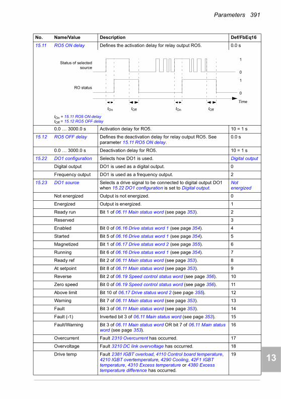
Parameters 391
1
2
3
4
5
6
7
8
9
10
11
12
13
15.11 RO5 ON delay Defines the activation delay for relay output RO5. 0.0 s
tOn = 15.11 RO5 ON delaytOff = 15.12 RO5 OFF delay
0.0 … 3000.0 s Activation delay for RO5. 10 = 1 s
15.12 RO5 OFF delay Defines the deactivation delay for relay output RO5. See parameter 15.11 RO5 ON delay.
0.0 s
0.0 … 3000.0 s Deactivation delay for RO5. 10 = 1 s
15.22 DO1 configuration Selects how DO1 is used. Digital output
Digital output DO1 is used as a digital output. 0
Frequency output DO1 is used as a frequency output. 2
15.23 DO1 source Selects a drive signal to be connected to digital output DO1 when 15.22 DO1 configuration is set to Digital output.
Not energized
Not energized Output is not energized. 0
Energized Output is energized. 1
Ready run Bit 1 of 06.11 Main status word (see page 353). 2
Reserved 3
Enabled Bit 0 of 06.16 Drive status word 1 (see page 354). 4
Started Bit 5 of 06.16 Drive status word 1 (see page 354). 5
Magnetized Bit 1 of 06.17 Drive status word 2 (see page 355). 6
Running Bit 6 of 06.16 Drive status word 1 (see page 354). 7
Ready ref Bit 2 of 06.11 Main status word (see page 353). 8
At setpoint Bit 8 of 06.11 Main status word (see page 353). 9
Reverse Bit 2 of 06.19 Speed control status word (see page 356). 10
Zero speed Bit 0 of 06.19 Speed control status word (see page 356). 11
Above limit Bit 10 of 06.17 Drive status word 2 (see page 355). 12
Warning Bit 7 of 06.11 Main status word (see page 353). 13
Fault Bit 3 of 06.11 Main status word (see page 353). 14
Fault (-1) Inverted bit 3 of 06.11 Main status word (see page 353). 15
Fault/Warning Bit 3 of 06.11 Main status word OR bit 7 of 06.11 Main status word (see page 353).
16
Overcurrent Fault 2310 Overcurrent has occurred. 17
Overvoltage Fault 3210 DC link overvoltage has occurred. 18
Drive temp Fault 2381 IGBT overload, 4110 Control board temperature, 4210 IGBT overtemperature, 4290 Cooling, 42F1 IGBT temperature, 4310 Excess temperature or 4380 Excess temperature difference has occurred.
19
No. Name/Value Description Def/FbEq16
1
0
1
0
tOn tOff tOn tOff
Status of selectedsource
RO status
Time
14
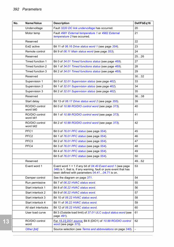
392 Parameters
1
2
3
4
5
7
8
9
9
10
11
12
13
14
Undervoltage Fault 3220 DC link undervoltage has occurred. 20
Motor temp Fault 4981 External temperature 1 or 4982 External temperature 2 has occurred.
21
Reserved 22
Ext2 active Bit 11 of 06.16 Drive status word 1 (see page 354). 23
Remote control Bit 9 of 06.11 Main status word (see page 353). 24
Reserved 25…26
Timed function 1 Bit 0 of 34.01 Timed functions status (see page 469). 27
Timed function 2 Bit 1 of 34.01 Timed functions status (see page 469). 28
Timed function 3 Bit 2 of 34.01 Timed functions status (see page 469). 29
Reserved 30…32
Supervision 1 Bit 0 of 32.01 Supervision status (see page 462). 33
Supervision 2 Bit 1 of 32.01 Supervision status (see page 462). 34
Supervision 3 Bit 2 of 32.01 Supervision status (see page 462). 35
Reserved 36…38
Start delay Bit 13 of 06.17 Drive status word 2 (see page 355). 39
RO/DIO control word bit0
Bit 0 of 10.99 RO/DIO control word (see page 373). 40
RO/DIO control word bit1
Bit 1 of 10.99 RO/DIO control word (see page 373). 41
RO/DIO control word bit2
Bit 2 of 10.99 RO/DIO control word (see page 373). 42
PFC1 Bit 0 of 76.01 PFC status (see page 554). 45
PFC2 Bit 1 of 76.01 PFC status (see page 554). 46
PFC3 Bit 2 of 76.01 PFC status (see page 554). 47
PFC4 Bit 3 of 76.01 PFC status (see page 554). 48
Bit 4 of 76.01 PFC status (see page 554). 49
Bit 5 of 76.01 PFC status (see page 554). 50
Reserved 49…52
Event word 1 Event word 1 = 1 if any bit of 04.40 Event word 1 (see page 349) is 1, that is, if any warning, fault or pure event that has been defined with parameters 04.41…04.71 is on.
53
Damper control See the diagram on page 371. 54
Run permissive Bit 7 of 06.22 HVAC status word. 55
Start interlock 1 Bit 8 of 06.22 HVAC status word. 56
Start interlock 2 Bit 9 of 06.22 HVAC status word. 57
Start interlock 3 Bit 10 of 06.22 HVAC status word. 58
Start interlock 4 Bit 11 of 06.22 HVAC status word. 59
All start interlocks Bit 12 of 06.22 HVAC status word. 60
User load curve Bit 3 (Outside load limit) of 37.01 ULC output status word (see page 491).
61
RO/DIO control word
For 15.23 DO1 source: Bit 8 (DIO1) of 10.99 RO/DIO control word (see page 373).
62
Other [bit] Source selection (see Terms and abbreviations on page 340). -
No. Name/Value Description Def/FbEq16

Parameters 393
1
2
3
4
5
6
7
8
9
10
11
12
13
15.24 DO1 ON delay Defines the activation delay for digital output DO1 when 15.22 DO1 configuration is set to Digital output.
0.0 s
tOn = 15.24 DO1 ON delaytOff = 15.25 DO1 OFF delay
0.0 … 3000.0 s Activation delay for DO1. 10 = 1 s
15.25 DO1 OFF delay Defines the deactivation delay for relay output DO1 when 15.22 DO1 configuration is set to Digital output. See parameter 15.24 DO1 ON delay.
0.0 s
0.0 … 3000.0 s Deactivation delay for DO1. 10 = 1 s
15.32 Freq out 1 actual value
Displays the value of frequency output 1 at digital output DO1 when 15.22 DO1 configuration is set to Frequency output.This parameter is read-only.
-
0 … 16000 Hz Value of frequency output 1. 1 = 1 Hz
15.33 Freq out 1 source Selects a signal to be connected to digital output DO1 when 15.22 DO1 configuration is set to Frequency output. Alternatively, sets the output to excitation mode to feed a constant current to a temperature sensor.
Motor speed used
Not selected None. 0
Motor speed used 01.01 Motor speed used (page 343). 1
Output frequency 01.06 Output frequency (page 343). 3
Motor current 01.07 Motor current (page 343). 4
Motor torque 01.10 Motor torque (page 343). 6
DC voltage 01.11 DC voltage (page 343). 7
Output power 01.14 Output power (page 344). 8
Speed ref ramp in 23.01 Speed ref ramp input (page 423). 10
Speed ref ramp out 23.02 Speed ref ramp output (page 423). 11
Speed ref used 24.01 Used speed reference (page 425). 12
Reserved 13
Freq ref used 28.02 Frequency ref ramp output (page 431). 14
Reserved 15
Process PID out 40.01 Process PID output actual (page 494). 16
Other Source selection (see Terms and abbreviations on page 340). -
No. Name/Value Description Def/FbEq16
1
0
1
0
tOn tOff tOn tOff
Status of selectedsource
DO status
Time
14
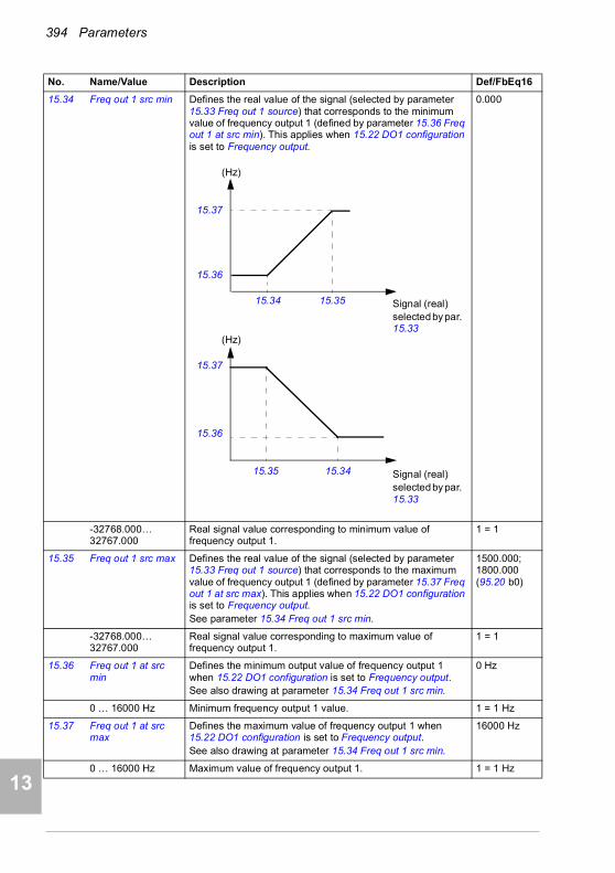
394 Parameters
1
2
3
4
5
7
8
9
9
10
11
12
13
14
15.34 Freq out 1 src min Defines the real value of the signal (selected by parameter 15.33 Freq out 1 source) that corresponds to the minimum value of frequency output 1 (defined by parameter 15.36 Freq out 1 at src min). This applies when 15.22 DO1 configuration is set to Frequency output.
0.000
-32768.000… 32767.000
Real signal value corresponding to minimum value of frequency output 1.
1 = 1
15.35 Freq out 1 src max Defines the real value of the signal (selected by parameter 15.33 Freq out 1 source) that corresponds to the maximum value of frequency output 1 (defined by parameter 15.37 Freq out 1 at src max). This applies when 15.22 DO1 configuration is set to Frequency output.See parameter 15.34 Freq out 1 src min.
1500.000; 1800.000 (95.20 b0)
-32768.000… 32767.000
Real signal value corresponding to maximum value of frequency output 1.
1 = 1
15.36 Freq out 1 at src min
Defines the minimum output value of frequency output 1 when 15.22 DO1 configuration is set to Frequency output.See also drawing at parameter 15.34 Freq out 1 src min.
0 Hz
0 … 16000 Hz Minimum frequency output 1 value. 1 = 1 Hz
15.37 Freq out 1 at src max
Defines the maximum value of frequency output 1 when 15.22 DO1 configuration is set to Frequency output.See also drawing at parameter 15.34 Freq out 1 src min.
16000 Hz
0 … 16000 Hz Maximum value of frequency output 1. 1 = 1 Hz
No. Name/Value Description Def/FbEq16
15.37
15.36
15.35 15.34
15.3515.34
15.37
15.36
Signal (real)selected by par. 15.33
Signal (real)selected by par. 15.33
(Hz)
(Hz)
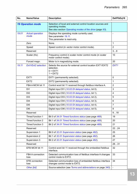
Parameters 395
1
2
3
4
5
6
7
8
9
10
11
12
13
1919 Operation mode Selection of local and external control location sources and
operating modes.See also section Operating modes of the drive (page 93).
19.01 Actual operation mode
Displays the operating mode currently used.See parameter 19.11.This parameter is read-only.
-
Zero None. 1
Speed Speed control (in vector motor control mode). 2
Reserved 3…9
Scalar (Hz) Frequency control in scalar motor control mode (in scalar motor control mode).
10
Forced magn. Motor is in magnetizing mode. 20
19.11 Ext1/Ext2 selection Selects the source for external control location EXT1/EXT2 selection.0 = EXT11 = EXT2
EXT1
EXT1 EXT1 (permanently selected). 0
EXT2 EXT2 (permanently selected). 1
FBA A MCW bit 11 Control word bit 11 received through fieldbus interface A. 2
DI1 Digital input DI1 (10.02 DI delayed status, bit 0). 3
DI2 Digital input DI2 (10.02 DI delayed status, bit 1). 4
DI3 Digital input DI3 (10.02 DI delayed status, bit 2). 5
DI4 Digital input DI4 (10.02 DI delayed status, bit 3). 6
DI5 Digital input DI5 (10.02 DI delayed status, bit 4). 7
DI6 Digital input DI6 (10.02 DI delayed status, bit 5). 8
Reserved 9…18
Timed function 1 Bit 0 of 34.01 Timed functions status (see page 469). 19
Timed function 2 Bit 1 of 34.01 Timed functions status (see page 469). 20
Timed function 3 Bit 2 of 34.01 Timed functions status (see page 469). 21
Reserved 22…24
Supervision 1 Bit 0 of 32.01 Supervision status (see page 462). 25
Supervision 2 Bit 1 of 32.01 Supervision status (see page 462). 26
Supervision 3 Bit 2 of 32.01 Supervision status (see page 462). 27
Reserved 28…31
EFB MCW bit 11 Control word bit 11 received through the embedded fieldbus interface.
32
FBA A connection loss
Detected communication loss of fieldbus interface A changes control mode to EXT2.
33
EFB connection loss
Detected communication loss of embedded fieldbus interface changes control mode to EXT2.
34
Other [bit] Source selection (see Terms and abbreviations on page 340). -
No. Name/Value Description Def/FbEq16
14
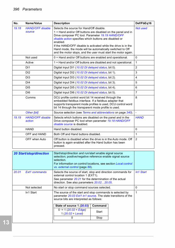
396 Parameters
1
2
3
4
5
7
8
9
9
10
11
12
13
14
19.18 HAND/OFF disable source
Selects the source for Hand/Off disable.1 = Hand and/or Off buttons are disabled on the panel and in Drive composer PC tool. Parameter 19.19 HAND/OFF disable action specifies which buttons are disabled or enabled.If the HAND/OFF disable is activated while the drive is in the Hand mode, the mode will be automatically switched to Off and the motor stops, and the user must start the motor again.
Not used
Not used 0 = Hand and/or Off buttons are enabled and operational. 0
Active 1 = Hand and/or Off buttons are disabled and not operational. 1
DI1 Digital input DI1 (10.02 DI delayed status, bit 0). 2
DI2 Digital input DI2 (10.02 DI delayed status, bit 1). 3
DI3 Digital input DI3 (10.02 DI delayed status, bit 2). 4
DI4 Digital input DI4 (10.02 DI delayed status, bit 3). 5
DI5 Digital input DI5 (10.02 DI delayed status, bit 4). 6
DI6 Digital input DI6 (10.02 DI delayed status, bit 5). 7
Comms DCU profile control word bit 14 received through the embedded fieldbus interface. If a fieldbus adapter that supports transparent mode profiles is used, DCU control word bit 14 through the transparent mode profile is used.
8
Other [bit] Source selection (see Terms and abbreviations on page 340). -
19.19 HAND/OFF disable action
Selects which buttons are disabled on the panel and in the Drive composer PC tool when parameter 19.18 HAND/OFF disable source is disabled.
HAND
HAND Hand button disabled. 0
OFF and HAND Both Off and Hand buttons disabled. 1
OFF when Auto Off button is disabled when the drive is in the Auto mode. Off button is again enabled after the Hand button has been pressed.
2
2020 Start/stop/direction Start/stop/direction and run/start enable signal source
selection; positive/negative reference enable signal source selection.For information on control locations, see section Local control vs. external control (page 89).
20.01 Ext1 commands Selects the source of start, stop and direction commands for external control location 1 (EXT1).See parameter 20.21 for the determination of the actual direction. See also parameters 20.02…20.05.
In1 Start
Not selected No start or stop command sources selected. 0
In1 Start The source of the start and stop commands is selected by parameter 20.03 Ext1 in1 source. The state transitions of the source bits are interpreted as follows:
1
No. Name/Value Description Def/FbEq16
State of source 1 (20.03) Command
0 -> 1 (20.02 = Edge)1 (20.02 = Level)
Start
0 Stop

Parameters 397
1
2
3
4
5
6
7
8
9
10
11
12
13
In1 Start; In2 Dir The source selected by 20.03 Ext1 in1 source is the start signal; the source selected by 20.04 Ext1 in2 source determines the direction. The state transitions of the source bits are interpreted as follows:
2
In1 Start fwd; In2 Start rev
The source selected by 20.03 Ext1 in1 source is the forward start signal; the source selected by 20.04 Ext1 in2 source is the reverse start signal. The state transitions of the source bits are interpreted as follows:
3
In1P Start; In2 Stop The sources of the start and stop commands are selected by parameters 20.03 Ext1 in1 source and 20.04 Ext1 in2 source. The state transitions of the source bits are interpreted as follows:
Notes:• Parameter 20.02 Ext1 start trigger type only has an effect
at startup of the drive with this setting. If the start input is ON and 20.02 = Level (1) when the drive starts up, the motor will restart. Parameter 20.02 has no effect at any other time.
• When source 2 is 0, the Start and Stop keys on the control panel are disabled.
4
No. Name/Value Description Def/FbEq16
State of source 1 (20.03)
State of source 2 (20.04)
Command
0 Any Stop
0 -> 1 (20.02 = Edge)1 (20.02 = Level)
0 Start forward
1 Start reverse
State of source 1 (20.03)
State of source 2 (20.04)
Command
0 0 Stop
0 -> 1 (20.02 = Edge)1 (20.02 = Level)
0 Start forward
00 -> 1 (20.02 = Edge)
1 (20.02 = Level)Start reverse
1 1 Stop
State of source 1 (20.03)
State of source 2 (20.04)
Command
0 -> 1 1 Start
Any 0 Stop
14
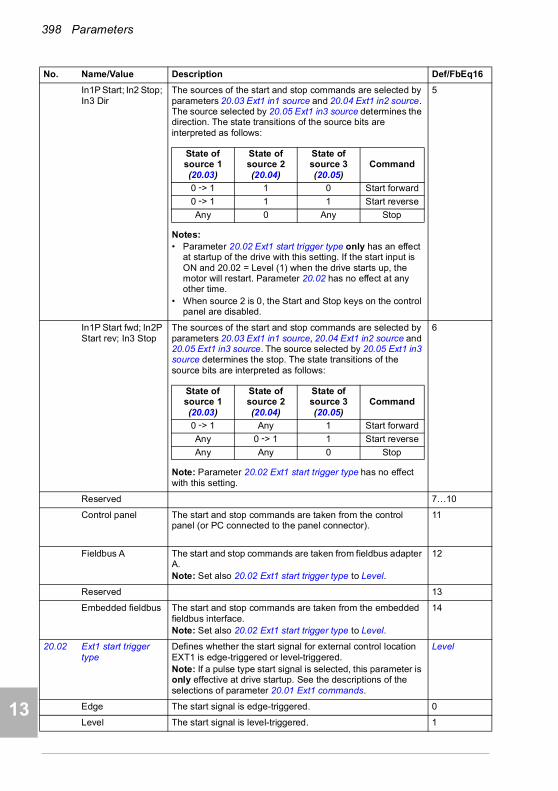
398 Parameters
1
2
3
4
5
7
8
9
9
10
11
12
13
14
In1P Start; In2 Stop; In3 Dir
The sources of the start and stop commands are selected by parameters 20.03 Ext1 in1 source and 20.04 Ext1 in2 source. The source selected by 20.05 Ext1 in3 source determines the direction. The state transitions of the source bits are interpreted as follows:
Notes:• Parameter 20.02 Ext1 start trigger type only has an effect
at startup of the drive with this setting. If the start input is ON and 20.02 = Level (1) when the drive starts up, the motor will restart. Parameter 20.02 has no effect at any other time.
• When source 2 is 0, the Start and Stop keys on the control panel are disabled.
5
In1P Start fwd; In2P Start rev; In3 Stop
The sources of the start and stop commands are selected by parameters 20.03 Ext1 in1 source, 20.04 Ext1 in2 source and 20.05 Ext1 in3 source. The source selected by 20.05 Ext1 in3 source determines the stop. The state transitions of the source bits are interpreted as follows:
Note: Parameter 20.02 Ext1 start trigger type has no effect with this setting.
6
Reserved 7…10
Control panel The start and stop commands are taken from the control panel (or PC connected to the panel connector).
11
Fieldbus A The start and stop commands are taken from fieldbus adapter A.Note: Set also 20.02 Ext1 start trigger type to Level.
12
Reserved 13
Embedded fieldbus The start and stop commands are taken from the embedded fieldbus interface.Note: Set also 20.02 Ext1 start trigger type to Level.
14
20.02 Ext1 start trigger type
Defines whether the start signal for external control location EXT1 is edge-triggered or level-triggered.Note: If a pulse type start signal is selected, this parameter is only effective at drive startup. See the descriptions of the selections of parameter 20.01 Ext1 commands.
Level
Edge The start signal is edge-triggered. 0
Level The start signal is level-triggered. 1
No. Name/Value Description Def/FbEq16
State of source 1 (20.03)
State of source 2 (20.04)
State of source 3 (20.05)
Command
0 -> 1 1 0 Start forward
0 -> 1 1 1 Start reverse
Any 0 Any Stop
State of source 1 (20.03)
State of source 2 (20.04)
State of source 3 (20.05)
Command
0 -> 1 Any 1 Start forward
Any 0 -> 1 1 Start reverse
Any Any 0 Stop
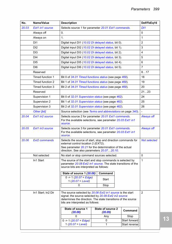
Parameters 399
1
2
3
4
5
6
7
8
9
10
11
12
13
20.03 Ext1 in1 source Selects source 1 for parameter 20.01 Ext1 commands. DI1
Always off 0. 0
Always on 1. 1
DI1 Digital input DI1 (10.02 DI delayed status, bit 0). 2
DI2 Digital input DI2 (10.02 DI delayed status, bit 1). 3
DI3 Digital input DI3 (10.02 DI delayed status, bit 2). 4
DI4 Digital input DI4 (10.02 DI delayed status, bit 3). 5
DI5 Digital input DI5 (10.02 DI delayed status, bit 4). 6
DI6 Digital input DI6 (10.02 DI delayed status, bit 5). 7
Reserved 8…17
Timed function 1 Bit 0 of 34.01 Timed functions status (see page 469). 18
Timed function 2 Bit 1 of 34.01 Timed functions status (see page 469). 19
Timed function 3 Bit 2 of 34.01 Timed functions status (see page 469). 20
Reserved 21…23
Supervision 1 Bit 0 of 32.01 Supervision status (see page 462). 24
Supervision 2 Bit 1 of 32.01 Supervision status (see page 462). 25
Supervision 3 Bit 2 of 32.01 Supervision status (see page 462). 26
Other [bit] Source selection (see Terms and abbreviations on page 340). -
20.04 Ext1 in2 source Selects source 2 for parameter 20.01 Ext1 commands.For the available selections, see parameter 20.03 Ext1 in1 source.
Always off
20.05 Ext1 in3 source Selects source 3 for parameter 20.01 Ext1 commands.For the available selections, see parameter 20.03 Ext1 in1 source.
Always off
20.06 Ext2 commands Selects the source of start, stop and direction commands for external control location 2 (EXT2).See parameter 20.21 for the determination of the actual direction. See also parameters 20.07…20.10.
Not selected
Not selected No start or stop command sources selected. 0
In1 Start The source of the start and stop commands is selected by parameter 20.08 Ext2 in1 source. The state transitions of the source bits are interpreted as follows:
1
In1 Start; In2 Dir The source selected by 20.08 Ext2 in1 source is the start signal; the source selected by 20.09 Ext2 in2 source determines the direction. The state transitions of the source bits are interpreted as follows:
2
No. Name/Value Description Def/FbEq16
State of source 1 (20.08) Command
0 -> 1 (20.07 = Edge)1 (20.07 = Level)
Start
0 Stop
State of source 1 (20.08)
State of source 2 (20.09) Command
0 Any Stop
0 -> 1 (20.07 = Edge)1 (20.07 = Level)
0 Start forward
1 Start reverse
14
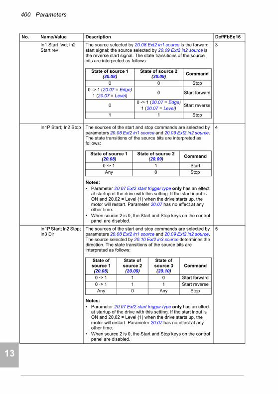
400 Parameters
1
2
3
4
5
7
8
9
9
10
11
12
13
14
In1 Start fwd; In2 Start rev
The source selected by 20.08 Ext2 in1 source is the forward start signal; the source selected by 20.09 Ext2 in2 source is the reverse start signal. The state transitions of the source bits are interpreted as follows:
3
In1P Start; In2 Stop The sources of the start and stop commands are selected by parameters 20.08 Ext2 in1 source and 20.09 Ext2 in2 source. The state transitions of the source bits are interpreted as follows:
Notes:• Parameter 20.07 Ext2 start trigger type only has an effect
at startup of the drive with this setting. If the start input is ON and 20.02 = Level (1) when the drive starts up, the motor will restart. Parameter 20.07 has no effect at any other time.
• When source 2 is 0, the Start and Stop keys on the control panel are disabled.
4
In1P Start; In2 Stop; In3 Dir
The sources of the start and stop commands are selected by parameters 20.08 Ext2 in1 source and 20.09 Ext2 in2 source. The source selected by 20.10 Ext2 in3 source determines the direction. The state transitions of the source bits are interpreted as follows:
Notes:• Parameter 20.07 Ext2 start trigger type only has an effect
at startup of the drive with this setting. If the start input is ON and 20.02 = Level (1) when the drive starts up, the motor will restart. Parameter 20.07 has no effect at any other time.
• When source 2 is 0, the Start and Stop keys on the control panel are disabled.
5
No. Name/Value Description Def/FbEq16
State of source 1 (20.08)
State of source 2 (20.09)
Command
0 0 Stop
0 -> 1 (20.07 = Edge)1 (20.07 = Level)
0 Start forward
00 -> 1 (20.07 = Edge)
1 (20.07 = Level)Start reverse
1 1 Stop
State of source 1 (20.08)
State of source 2 (20.09)
Command
0 -> 1 1 Start
Any 0 Stop
State of source 1 (20.08)
State of source 2 (20.09)
State of source 3 (20.10)
Command
0 -> 1 1 0 Start forward
0 -> 1 1 1 Start reverse
Any 0 Any Stop

Parameters 401
1
2
3
4
5
6
7
8
9
10
11
12
13
In1P Start fwd; In2P Start rev; In3 Stop
The sources of the start and stop commands are selected by parameters 20.08 Ext2 in1 source, 20.09 Ext2 in2 source and 20.10 Ext2 in3 source. The source selected by 20.10 Ext2 in3 source determines the direction. The state transitions of the source bits are interpreted as follows:
Note: Parameter 20.07 Ext2 start trigger type has no effect with this setting.
6
Reserved 7…10
Control panel The start and stop commands are taken from the control panel (or PC connected to the panel connector).
11
Fieldbus A The start and stop commands are taken from fieldbus adapter A.Note: Set also 20.07 Ext2 start trigger type to Level.
12
Reserved 13
Embedded fieldbus The start and stop commands are taken from the embedded fieldbus interface.Note: Set also 20.07 Ext2 start trigger type to Level.
14
20.07 Ext2 start trigger type
Defines whether the start signal for external control location EXT2 is edge-triggered or level-triggered.Note: If a pulse type start signal is selected, this parameter is only effective at drive startup. See the descriptions of the selections of parameter 20.06 Ext2 commands.
Level
Edge The start signal is edge-triggered. 0
Level The start signal is level-triggered. 1
20.08 Ext2 in1 source Selects source 1 for parameter 20.06 Ext2 commands.For the available selections, see parameter 20.03 Ext1 in1 source.
Always off
20.09 Ext2 in2 source Selects source 2 for parameter 20.06 Ext2 commands.For the available selections, see parameter 20.03 Ext1 in1 source.
Always off
20.10 Ext2 in3 source Selects source 3 for parameter 20.06 Ext2 commands.For the available selections, see parameter 20.03 Ext1 in1 source.
Always off
No. Name/Value Description Def/FbEq16
State of source 1 (20.08)
State of source 2 (20.09)
State of source 3 (20.10)
Command
0 -> 1 Any 1 Start forward
Any 0 -> 1 1 Start reverse
Any Any 0 Stop
14

402 Parameters
1
2
3
4
5
7
8
9
9
10
11
12
13
14
20.21 Direction Reference direction lock. Defines the direction of the drive rather than the sign of the reference, except in some cases.In the table the actual drive rotation is shown as a function of parameter 20.21 Direction and Direction command (from parameter 20.01 Ext1 commands or 20.06 Ext2 commands).
Forward
Request In external control the direction is selected by a direction command (parameter 20.01 Ext1 commands or 20.06 Ext2 commands).If the reference comes from Constant (constant speeds/frequencies), Floating point control (Motor potentiometer), PID, Speed ref safe, Last speed reference or Panel reference, the reference is used as is.If the reference comes from a fieldbus:• if the direction command is forward, the reference is used
as is• if the direction command is reverse, the reference is
multiplied by -1.
0
Forward Motor rotates forward regardless of the sign of the external reference. (Negative reference values are replaced by zero. Positive reference values are used as is.)
1
Reverse Motor rotates reverse regardless of the sign of the external reference. (Negative reference values are replaced by zero. Positive reference values are multiplied by -1.)
2
20.40 Run permissive Selects the source of the Run permissive signal.Value 0 of the source deactivates the Run permissive and prevents running.Value 1 of the source activates the Run permissive and permits running.
Not used
Not used 0. 0
Not used 1. 1
DI1 Digital input DI1 (10.02 DI delayed status, bit 0). 2
DI2 Digital input DI2 (10.02 DI delayed status, bit 1). 3
No. Name/Value Description Def/FbEq16
Direction command =Forward
Direction command =Reverse
Direction command not defined
Par. 20.21 Direction = Forward
Forward Forward Forward
Par. 20.21 Direction = Reverse
Reverse Reverse Reverse
Par. 20.21 Direction = Request
Forward, but• If reference from
Constant, Floating point control (Motor potentiometer), PID, Safe speed, Last or Panel reference, reference used as is.
• If reference from the network, reference used as is.
Reverse, but• If reference from
Constant or PID, reference used as is.
• If reference from the network, Panel, Analog input, Floating point control (Motor potentiometer), Safe speed or Last reference, reference multiplied by -1.
Forward
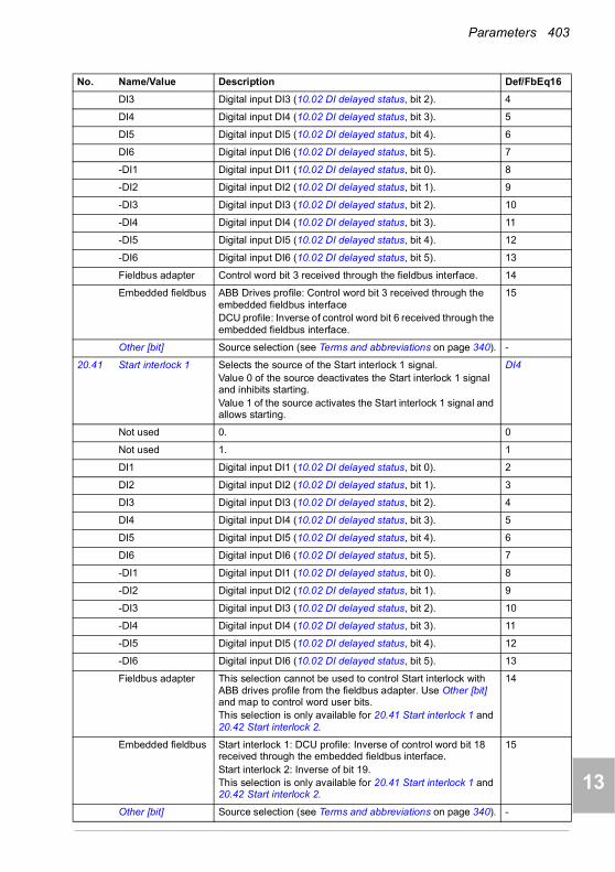
Parameters 403
1
2
3
4
5
6
7
8
9
10
11
12
13
DI3 Digital input DI3 (10.02 DI delayed status, bit 2). 4
DI4 Digital input DI4 (10.02 DI delayed status, bit 3). 5
DI5 Digital input DI5 (10.02 DI delayed status, bit 4). 6
DI6 Digital input DI6 (10.02 DI delayed status, bit 5). 7
-DI1 Digital input DI1 (10.02 DI delayed status, bit 0). 8
-DI2 Digital input DI2 (10.02 DI delayed status, bit 1). 9
-DI3 Digital input DI3 (10.02 DI delayed status, bit 2). 10
-DI4 Digital input DI4 (10.02 DI delayed status, bit 3). 11
-DI5 Digital input DI5 (10.02 DI delayed status, bit 4). 12
-DI6 Digital input DI6 (10.02 DI delayed status, bit 5). 13
Fieldbus adapter Control word bit 3 received through the fieldbus interface. 14
Embedded fieldbus ABB Drives profile: Control word bit 3 received through the embedded fieldbus interface DCU profile: Inverse of control word bit 6 received through the embedded fieldbus interface.
15
Other [bit] Source selection (see Terms and abbreviations on page 340). -
20.41 Start interlock 1 Selects the source of the Start interlock 1 signal.Value 0 of the source deactivates the Start interlock 1 signal and inhibits starting.Value 1 of the source activates the Start interlock 1 signal and allows starting.
DI4
Not used 0. 0
Not used 1. 1
DI1 Digital input DI1 (10.02 DI delayed status, bit 0). 2
DI2 Digital input DI2 (10.02 DI delayed status, bit 1). 3
DI3 Digital input DI3 (10.02 DI delayed status, bit 2). 4
DI4 Digital input DI4 (10.02 DI delayed status, bit 3). 5
DI5 Digital input DI5 (10.02 DI delayed status, bit 4). 6
DI6 Digital input DI6 (10.02 DI delayed status, bit 5). 7
-DI1 Digital input DI1 (10.02 DI delayed status, bit 0). 8
-DI2 Digital input DI2 (10.02 DI delayed status, bit 1). 9
-DI3 Digital input DI3 (10.02 DI delayed status, bit 2). 10
-DI4 Digital input DI4 (10.02 DI delayed status, bit 3). 11
-DI5 Digital input DI5 (10.02 DI delayed status, bit 4). 12
-DI6 Digital input DI6 (10.02 DI delayed status, bit 5). 13
Fieldbus adapter This selection cannot be used to control Start interlock with ABB drives profile from the fieldbus adapter. Use Other [bit] and map to control word user bits.This selection is only available for 20.41 Start interlock 1 and 20.42 Start interlock 2.
14
Embedded fieldbus Start interlock 1: DCU profile: Inverse of control word bit 18 received through the embedded fieldbus interface.Start interlock 2: Inverse of bit 19.This selection is only available for 20.41 Start interlock 1 and 20.42 Start interlock 2.
15
Other [bit] Source selection (see Terms and abbreviations on page 340). -
No. Name/Value Description Def/FbEq16
14
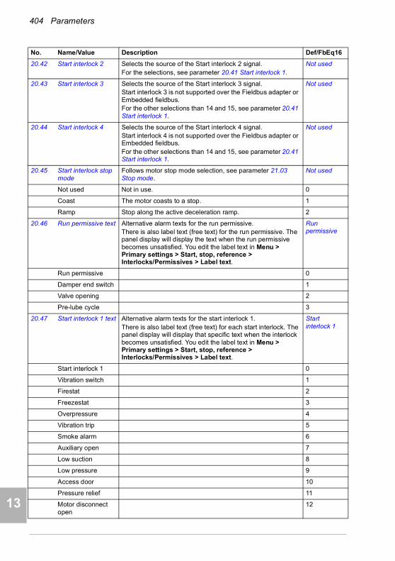
404 Parameters
1
2
3
4
5
7
8
9
9
10
11
12
13
14
20.42 Start interlock 2 Selects the source of the Start interlock 2 signal.For the selections, see parameter 20.41 Start interlock 1.
Not used
20.43 Start interlock 3 Selects the source of the Start interlock 3 signal.Start interlock 3 is not supported over the Fieldbus adapter or Embedded fieldbus.For the other selections than 14 and 15, see parameter 20.41 Start interlock 1.
Not used
20.44 Start interlock 4 Selects the source of the Start interlock 4 signal.Start interlock 4 is not supported over the Fieldbus adapter or Embedded fieldbus.For the other selections than 14 and 15, see parameter 20.41 Start interlock 1.
Not used
20.45 Start interlock stop mode
Follows motor stop mode selection, see parameter 21.03 Stop mode.
Not used
Not used Not in use. 0
Coast The motor coasts to a stop. 1
Ramp Stop along the active deceleration ramp. 2
20.46 Run permissive text Alternative alarm texts for the run permissive.There is also label text (free text) for the run permissive. The panel display will display the text when the run permissive becomes unsatisfied. You edit the label text in Menu > Primary settings > Start, stop, reference > Interlocks/Permissives > Label text.
Run permissive
Run permissive 0
Damper end switch 1
Valve opening 2
Pre-lube cycle 3
20.47 Start interlock 1 text Alternative alarm texts for the start interlock 1.There is also label text (free text) for each start interlock. The panel display will display that specific text when the interlock becomes unsatisfied. You edit the label text in Menu > Primary settings > Start, stop, reference > Interlocks/Permissives > Label text.
Start interlock 1
Start interlock 1 0
Vibration switch 1
Firestat 2
Freezestat 3
Overpressure 4
Vibration trip 5
Smoke alarm 6
Auxiliary open 7
Low suction 8
Low pressure 9
Access door 10
Pressure relief 11
Motor disconnect open
12
No. Name/Value Description Def/FbEq16

Parameters 405
1
2
3
4
5
6
7
8
9
10
11
12
13
20.48 Start interlock 2 text Alternative alarm texts for the start interlock 2. See parameter 20.47 Start interlock 1 text.
Start interlock 2
Start interlock 2 For other selections, see parameter 20.47 Start interlock 1 text.
0
20.49 Start interlock 3 text Alternative alarm texts for the start interlock 3. See parameter 20.47 Start interlock 1 text.
Start interlock 3
Start interlock 3 For other selections, see parameter 20.47 Start interlock 1 text.
0
20.50 Start interlock 4 text Alternative alarm texts for the start interlock 4. See parameter 20.47 Start interlock 1 text.
Start interlock 4
Start interlock 4 For other selections, see parameter 20.47 Start interlock 1 text.
0
20.51 Start interlock condition
Selects the condition for start interlock function.This parameter determines if the start command is needed before start interlock warnings are displayed.
Start command ignored
Start command ignored
Start interlock warnings are displayed if the interlocks are missing.
0
Start command required
Start command must be present before the start interlock warnings are displayed if the interlocks are missing.
1
2121 Start/stop mode Start and stop modes; emergency stop mode and signal
source selection; DC magnetization settings.
21.01 Start mode Selects the motor start function for the vector motor control mode, ie, when 99.04 Motor control mode is set to Vector.Notes:• The start function for the scalar motor control mode is
selected by parameter 21.19 Scalar start mode.• Starting into a rotating motor is not possible when DC
magnetizing is selected (Fast or Const time).• With permanent magnet motors, Automatic start mode
must be used.• This parameter cannot be changed while the drive is
running.See also section Start methods – DC magnetization (page 131).
Automatic
Fast The drive pre-magnetizes the motor before start. The pre-magnetizing time is determined automatically, being typically 200 ms to 2 s depending on motor size. This mode should be selected if a high break-away torque is required.
0
Const time The drive pre-magnetizes the motor before start. The pre-magnetizing time is defined by parameter 21.02 Magnetization time. This mode should be selected if constant pre-magnetizing time is required (for example, if the motor start must be synchronized with the release of a mechanical brake). This setting also guarantees the highest possible break-away torque when the pre-magnetizing time is set long enough.
WARNING! The drive will start after the set magnetizing time has passed even if motor magnetization is not completed. In applications where
a full break-away torque is essential, ensure that the constant magnetizing time is long enough to allow generation of full magnetization and torque.
1
No. Name/Value Description Def/FbEq16
14

406 Parameters
1
2
3
4
5
7
8
9
9
10
11
12
13
14
Automatic Automatic start guarantees optimal motor start in most cases. It includes the flying start function (starting into a rotating motor) and the automatic restart function. The drive motor control program identifies the flux as well as the mechanical state of the motor and starts the motor instantly under all conditions.Note: If parameter 99.04 Motor control mode is set to Scalar, no flying start or automatic restart is possible unless parameter 21.19 Scalar start mode is set to Automatic.
2
21.02 Magnetization time Defines the pre-magnetization time when• parameter 21.01 Start mode is set to Const time (in vector
motor control mode), or• parameter 21.19 Scalar start mode is set to Const time (in
scalar motor control mode).After the start command, the drive automatically premagnetizes the motor for the set time. To ensure full magnetizing, set this parameter to the same value as, or higher than, the rotor time constant. If not known, use the rule-of-thumb value given in the table below:
Note: This parameter cannot be changed while the drive is running.
500 ms
0…10000 ms Constant DC magnetizing time. 1 = 1 ms
21.03 Stop mode Selects the way the motor is stopped when a stop command is received.Additional braking is possible by selecting flux braking (see parameter 97.05 Flux braking).
Coast
Coast Stop by switching off the output semiconductors of the drive. The motor coasts to a stop.
WARNING! If a mechanical brake is used, ensure it is safe to stop the drive by coasting.
0
Ramp Stop along the active deceleration ramp. See parameter group 23 Speed reference ramp on page 423 or 28 Frequency reference chain on page 431.
1
Torque limit Stop according to torque limits (parameters 30.19 and 30.20). This mode is only possible in vector motor control mode.
2
No. Name/Value Description Def/FbEq16
Motor rated power Constant magnetizing time
< 1 kW > 50 to 100 ms
1 to 10 kW > 100 to 200 ms
10 to 200 kW > 200 to 1000 ms
200 to 1000 kW > 1000 to 2000 ms
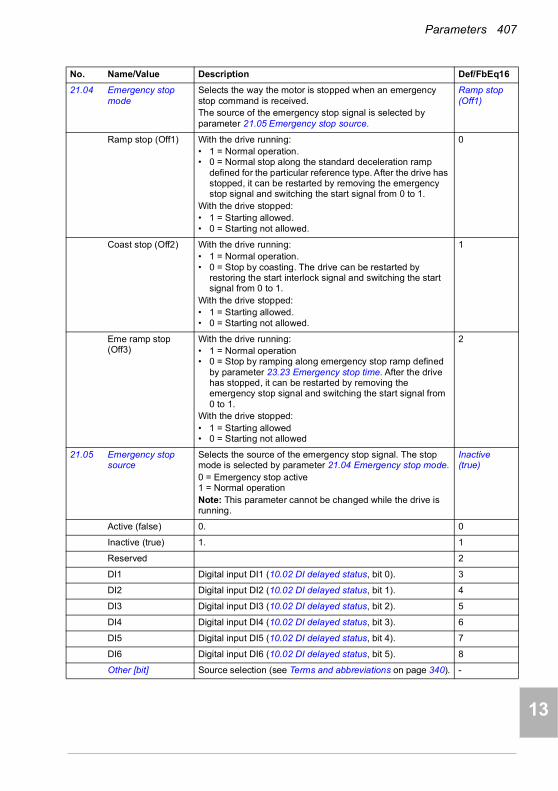
Parameters 407
1
2
3
4
5
6
7
8
9
10
11
12
13
21.04 Emergency stop mode
Selects the way the motor is stopped when an emergency stop command is received.The source of the emergency stop signal is selected by parameter 21.05 Emergency stop source.
Ramp stop (Off1)
Ramp stop (Off1) With the drive running:• 1 = Normal operation.• 0 = Normal stop along the standard deceleration ramp
defined for the particular reference type. After the drive has stopped, it can be restarted by removing the emergency stop signal and switching the start signal from 0 to 1.
With the drive stopped:• 1 = Starting allowed.• 0 = Starting not allowed.
0
Coast stop (Off2) With the drive running:• 1 = Normal operation.• 0 = Stop by coasting. The drive can be restarted by
restoring the start interlock signal and switching the start signal from 0 to 1.
With the drive stopped:• 1 = Starting allowed.• 0 = Starting not allowed.
1
Eme ramp stop (Off3)
With the drive running:• 1 = Normal operation• 0 = Stop by ramping along emergency stop ramp defined
by parameter 23.23 Emergency stop time. After the drive has stopped, it can be restarted by removing the emergency stop signal and switching the start signal from 0 to 1.
With the drive stopped:• 1 = Starting allowed• 0 = Starting not allowed
2
21.05 Emergency stop source
Selects the source of the emergency stop signal. The stop mode is selected by parameter 21.04 Emergency stop mode.0 = Emergency stop active1 = Normal operationNote: This parameter cannot be changed while the drive is running.
Inactive (true)
Active (false) 0. 0
Inactive (true) 1. 1
Reserved 2
DI1 Digital input DI1 (10.02 DI delayed status, bit 0). 3
DI2 Digital input DI2 (10.02 DI delayed status, bit 1). 4
DI3 Digital input DI3 (10.02 DI delayed status, bit 2). 5
DI4 Digital input DI4 (10.02 DI delayed status, bit 3). 6
DI5 Digital input DI5 (10.02 DI delayed status, bit 4). 7
DI6 Digital input DI6 (10.02 DI delayed status, bit 5). 8
Other [bit] Source selection (see Terms and abbreviations on page 340). -
No. Name/Value Description Def/FbEq16
14

408 Parameters
1
2
3
4
5
7
8
9
9
10
11
12
13
14
21.06 Zero speed limit Defines the zero speed limit. The motor is stopped along a speed ramp (when ramped stop is selected or emergency stop time is used) until the defined zero speed limit is reached. After the zero speed delay, the motor coasts to a stop.
30.00 rpm
0.00…30000.00 rpm
Zero speed limit. See par. 46.01
21.07 Zero speed delay Defines the delay for the zero speed delay function. The function is useful in applications where a smooth and quick restarting is essential. During the delay, the drive knows the rotor position accurately.
0 ms
Without zero speed delay:The drive receives a stop command and decelerates along a ramp. When actual motor speed falls below the value of parameter 21.06 Zero speed limit, inverter modulation is stopped and the motor coasts to a standstill.
With zero speed delay:The drive receives a stop command and decelerates along a ramp. When actual motor speed falls below the value of parameter 21.06 Zero speed limit, the zero speed delay function activates. During the delay the function keeps the speed controller live: the inverter modulates, motor is magnetized and the drive is ready for a quick restart.
0…30000 ms Zero speed delay. 1 = 1 ms
No. Name/Value Description Def/FbEq16
Speed controller switched off: Motor coasts to a stop.
21.06 Zero speed limit
Speed
Time
Speed controller remains active. Motor is decelerated to true zero speed.
21.06 Zero speed limit
Speed
TimeDelay

Parameters 409
1
2
3
4
5
6
7
8
9
10
11
12
13
21.08 DC current control Activates/deactivates the DC hold and post-magnetization functions. See section Start methods – DC magnetization (page 131).Note: DC magnetization causes the motor to heat up. In applications where long DC magnetization times are required, externally ventilated motors should be used. If the DC magnetization period is long, DC magnetization cannot prevent the motor shaft from rotating if a constant load is applied to the motor.
0000b
0000b…0011b DC magnetization selection. 1 = 1
21.09 DC hold speed Defines the DC hold speed in speed control mode. See parameter 21.08 DC current control, and section DC hold (page 132).
5.00 rpm
0.00…1000.00 rpm DC hold speed. See par. 46.01
21.10 DC current reference
Defines the DC hold current in percent of the motor nominal current. See parameter 21.08 DC current control, and section Start methods – DC magnetization (page 131).After 100 s post-magnetization time, the maximum magnetization current is limited to the magnetization current corresponding to the actual flux reference.
30.0%
0.0…100.0% DC hold current. 1 = 1%
21.11 Post magnetization time
Defines the length of time for which post-magnetization is active after stopping the motor. The magnetization current is defined by parameter 21.10 DC current reference.See parameter 21.08 DC current control.
0 s
0…3000 s Post-magnetization time. 1 = 1 s
21.14 Pre-heating input source
Selects the source for controlling pre-heating for the motor. The status of the pre-heating is shown as bit 2 of 06.21 Drive status word 3.Notes: • The heating function requires that STO is not triggered. • The heating function requires that the drive is not faulted.
Off
Off 0. Pre-heating is always deactivated. 0
On 1. Pre-heating is always activated when the drive is stopped. 1
DI1 Digital input DI1 (10.02 DI delayed status, bit 0). 2
DI2 Digital input DI2 (10.02 DI delayed status, bit 1). 3
DI3 Digital input DI3 (10.02 DI delayed status, bit 2). 4
DI4 Digital input DI4 (10.02 DI delayed status, bit 3). 5
DI5 Digital input DI5 (10.02 DI delayed status, bit 4). 6
No. Name/Value Description Def/FbEq16
Bit Name Value
0 DC hold 1 = Enable DC hold. See section DC hold (page 132).Note: The DC hold function has no effect if the start signal is switched off.
1 Post magnetization
1 = Enable post-magnetization. See section Settings (page 133).Note: Post-magnetization is only available when ramping is the selected stop mode (see parameter 21.03 Stop mode).
2…15 Reserved
14
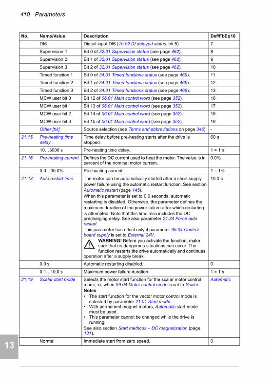
410 Parameters
1
2
3
4
5
7
8
9
9
10
11
12
13
14
DI6 Digital input DI6 (10.02 DI delayed status, bit 5). 7
Supervision 1 Bit 0 of 32.01 Supervision status (see page 462). 8
Supervision 2 Bit 1 of 32.01 Supervision status (see page 462). 9
Supervision 3 Bit 2 of 32.01 Supervision status (see page 462). 10
Timed function 1 Bit 0 of 34.01 Timed functions status (see page 469). 11
Timed function 2 Bit 1 of 34.01 Timed functions status (see page 469). 12
Timed function 3 Bit 2 of 34.01 Timed functions status (see page 469). 13
MCW user bit 0 Bit 12 of 06.01 Main control word (see page 352). 16
MCW user bit 1 Bit 13 of 06.01 Main control word (see page 352). 17
MCW user bit 2 Bit 14 of 06.01 Main control word (see page 352). 18
MCW user bit 3 Bit 15 of 06.01 Main control word (see page 352). 19
Other [bit] Source selection (see Terms and abbreviations on page 340). -
21.15 Pre-heating time delay
Time delay before pre-heating starts after the drive is stopped.
60 s
10…3000 s Pre-heating time delay. 1 = 1 s
21.16 Pre-heating current Defines the DC current used to heat the motor. The value is in percent of the nominal motor current.
0.0%
0.0…30.0% Pre-heating current. 1 = 1%
21.18 Auto restart time The motor can be automatically started after a short supplypower failure using the automatic restart function. See sectionAutomatic restart (page 145).When this parameter is set to 0.0 seconds, automaticrestarting is disabled. Otherwise, the parameter defines themaximum duration of the power failure after which restartingis attempted. Note that this time also includes the DC precharging delay. See also parameter 21.34 Force auto restart.This parameter has effect only if parameter 95.04 Control board supply is set to External 24V.
WARNING! Before you activate the function, make sure that no dangerous situations can occur. The function restarts the drive automatically and continues
operation after a supply break.
10.0 s
0.0 s Automatic restarting disabled. 0
0.1…10.0 s Maximum power failure duration. 1 = 1 s
21.19 Scalar start mode Selects the motor start function for the scalar motor control mode, ie, when 99.04 Motor control mode is set to Scalar.Notes:• The start function for the vector motor control mode is
selected by parameter 21.01 Start mode.• With permanent magnet motors, Automatic start mode
must be used.• This parameter cannot be changed while the drive is
running.See also section Start methods – DC magnetization (page 131).
Automatic
Normal Immediate start from zero speed. 0
No. Name/Value Description Def/FbEq16

Parameters 411
1
2
3
4
5
6
7
8
9
10
11
12
13
Const time The drive pre-magnetizes the motor before start. The pre-magnetizing time is defined by parameter 21.02 Magnetization time. This mode should be selected if constant pre-magnetizing time is required (for example, if the motor start must be synchronized with the release of a mechanical brake). This setting also guarantees the highest possible break-away torque when the pre-magnetizing time is set long enough.Note: This mode cannot be used to start into a rotating motor.
WARNING! The drive will start after the set pre-magnetizing time has passed even if motor magnetization is not completed. In applications where
a full break-away torque is essential, ensure that the constant magnetizing time is long enough to allow generation of full magnetization and torque.
1
Automatic The drive automatically selects the correct output frequency to start a rotating motor. This is useful for flying starts: if the motor is already rotating, the drive will start smoothly at the current frequency.Note: Cannot be used in multimotor systems.
2
Torque boost The drive pre-magnetizes the motor before the start. The pre-magnetizing time is defined by parameter 21.02 Magnetization time.Torque boost is applied at start. Torque boost is stopped when output frequency exceeds 40% of nominal frequency or when it is equal to the reference value. See parameter 21.26 Torque boost current.This mode should selected if a high break-away torque is required.Note: This mode cannot be used to start into a rotating motor.
WARNING! The drive will start after the set pre-magnetizing time has passed even if motor magnetization is not completed. In applications where
a full break-away torque is essential, ensure that the constant magnetizing time is long enough to allow generation of full magnetization and torque.
3
Automatic+boost Automatic start with torque boost.Automatic start is performed first and the motor is magnetized. If the speed is found to be zero, torque boost is applied.
4
Flying start The drive automatically selects the correct output frequency to start a rotating motor. If the motor is already rotating, drive will start smoothly at the current frequency. – The mode will start the motor with vector control and switch to scalar control on the fly when the motor speed has been found.Compared to the Automatic start mode, Flying start detects the motor speed faster. Flying start requires more accurate information about motor model. Therefore standstill ID run is done automatically when the drive is started for the first time after selecting Flying start. Motor plate values should be accurate. Wrong plate values may decrease the starting performance
5
Flying start+boost Flying start with torque boost.Flying start is performed first and the motor is magnetized. If the speed is found to be zero, torque boost is applied.
6
No. Name/Value Description Def/FbEq16
14

412 Parameters
1
2
3
4
5
7
8
9
9
10
11
12
13
14
21.21 DC hold frequency Defines the DC hold frequency, which is used instead of parameter 21.09 DC hold speed when the motor is in scalar frequency mode. See parameter 21.08 DC current control, and section DC hold (page 132).
5.00 Hz
0.00…1000.00 Hz DC hold frequency. 1 = 1 Hz
21.22 Start delay Defines the start delay. After the conditions for start have been fulfilled, the drive waits until the delay has elapsed and then starts the motor. During the delay, warning AFE9 Start delay is shown.Start delay can be used with all start modes.
0.00 s
0.00…60.00 s Start delay 1 = 1 s
21.23 Smooth start Selects the forced current vector rotation mode at low speeds. When the smooth start mode is selected, the rate of acceleration is limited by the acceleration and deceleration ramp times. If the process driven by the permanent magnet synchronous motor has high inertia, slow ramp times are recommended.Can be used for permanent magnet synchronous motors only.
Disabled
Disabled Disabled. 0
Enabled always Enabled always. 1
Start only Enabled when starting the motor. 2
21.24 Smooth start current
Current used in the current vector rotation at low speeds. Increase the smooth start current if the application requires motor shaft swinging needs to be minimized. Note that accurate torque control is not possible in the current vector rotation mode.Can be used for permanent magnet synchronous motors only.
50.0%
10.0…100.0% Value in percent of the nominal motor current. 1 = 1%
21.25 Smooth start speed Output frequency up to which the current vector rotation is used. See parameter 21.19 Scalar start mode.Can be used for permanent magnet synchronous motors only.
10.0%
2.0…100.0% Value as a percentage of the nominal motor frequency. 1 = 1%
21.26 Torque boost current
Defines the maximum supplied current to motor when (21.19 Scalar start mode is set to Torque boost (see page 411). Parameter value is in percent of the motor nominal current. Nominal value of the parameter is 100.0%.Torque boost is only applied at start, ending when output frequency exceeds 40% of nominal frequency or when output frequency is equal to reference.Can be used in scalar mode only.
100.0%
15.0…300.0% Value in percent of the nominal motor current. 1 = 1%
21.30 Speed compensated stop mode
Selects the method used to stop the drive.Speed compensated stop is active only if• the operation mode is not torque, and
• parameter 21.03 Stop mode is Ramp.
Off
Off Stop according parameter 21.03 Stop mode, no speed compensated stop.
0
No. Name/Value Description Def/FbEq16
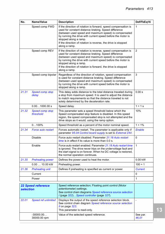
Parameters 413
1
2
3
4
5
6
7
8
9
10
11
12
13
Speed comp FWD If the direction of rotation is forward, speed compensation is used for constant distance braking. Speed difference (between used speed and maximum speed) is compensated by running the drive with current speed before the motor is stopped along a ramp.If the direction of rotation is reverse, the drive is stopped along a ramp.
1
Speed comp REV If the direction of rotation is reverse, speed compensation is used for constant distance braking. Speed difference (between used speed and maximum speed) is compensated by running the drive with current speed before the motor is stopped along a ramp.If the direction of rotation is forward, the drive is stopped along a ramp.
2
Speed comp bipolar Regardless of the direction of rotation, speed compensation is used for constant distance braking. Speed difference (between used speed and maximum speed) is compensated by running the drive with current speed before the motor is stopped along a ramp.
3
21.31 Speed comp stop delay
This delay adds distance to the total distance traveled during a stop from maximum speed. It is used to adjust the distance to match requirements so that the distance traveled is not solely determined by the deceleration rate.
0.00 s
0.00…1000.00 s Speed delay. 1 = 1 s
21.32 Speed comp stop threshold
This parameter sets a speed threshold below which the Speed compensated stop feature is disabled. In this speed region, the speed compensated stop is not attempted and the drive stops as it would, using the ramp option.
10%
0…100% Speed threshold as a percent of the motor nominal speed. 1 = 1%
21.34 Force auto restart Forces automatic restart. The parameter is applicable only if parameter 95.04 Control board supply is set to External 24V.
Enable
Disable Force auto restart disabled. Parameter 21.18 Auto restart time is in effect if its value is more than 0.0 s.
0
Enable Force auto restart enabled. Parameter 21.18 Auto restart time is ignored. The drive never trips on the undervoltage fault and the start signal is on forever. When he DC voltage is restored, the normal operation continues.
1
21.35 Preheating power Defines the power used to heat the motor. 0.00 kW
0.00 … 10.00 kW Preheating power. 100 = 1
21.36 Preheating unit Defines if preheating is specified as current or power. Current
Current 0
Power 1
2222 Speed reference selection
Speed reference selection; Floating point control (Motor potentiometer) settings.See control chain diagrams Speed reference source selection I (page 322)…Speed controller (page 327).
22.01 Speed ref unlimited Displays the output of the speed reference selection block. See control chain diagram Speed reference source selection II on page 323.This parameter is read-only.
-
-30000.00… 30000.00 rpm
Value of the selected speed reference. See par. 46.01
No. Name/Value Description Def/FbEq16
14
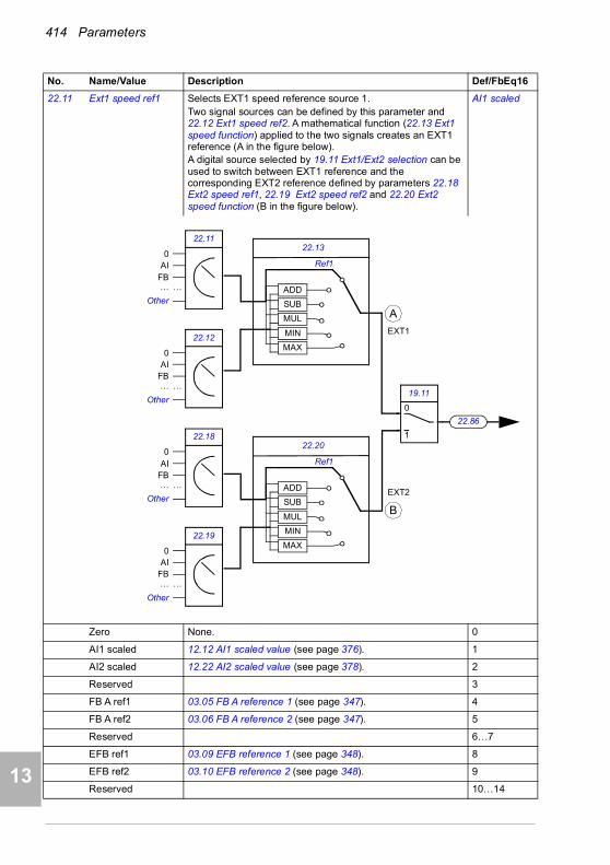
414 Parameters
1
2
3
4
5
7
8
9
9
10
11
12
13
14
22.11 Ext1 speed ref1 Selects EXT1 speed reference source 1.Two signal sources can be defined by this parameter and 22.12 Ext1 speed ref2. A mathematical function (22.13 Ext1 speed function) applied to the two signals creates an EXT1 reference (A in the figure below). A digital source selected by 19.11 Ext1/Ext2 selection can be used to switch between EXT1 reference and the corresponding EXT2 reference defined by parameters 22.18 Ext2 speed ref1, 22.19 Ext2 speed ref2 and 22.20 Ext2 speed function (B in the figure below).
AI1 scaled
Zero None. 0
AI1 scaled 12.12 AI1 scaled value (see page 376). 1
AI2 scaled 12.22 AI2 scaled value (see page 378). 2
Reserved 3
FB A ref1 03.05 FB A reference 1 (see page 347). 4
FB A ref2 03.06 FB A reference 2 (see page 347). 5
Reserved 6…7
EFB ref1 03.09 EFB reference 1 (see page 348). 8
EFB ref2 03.10 EFB reference 2 (see page 348). 9
Reserved 10…14
No. Name/Value Description Def/FbEq16
19.11
1
0
22.13
MUL
SUB
ADD
MIN
MAX
22.11
22.12
22.86
0AI
FB…
Other
…
0AI
FB…
Other
…
Ref1
22.20
MUL
SUB
ADD
MIN
MAX
22.18
22.19
0AI
FB…
Other
…
0AI
FB…
Other
…
Ref1
A
B
EXT1
EXT2
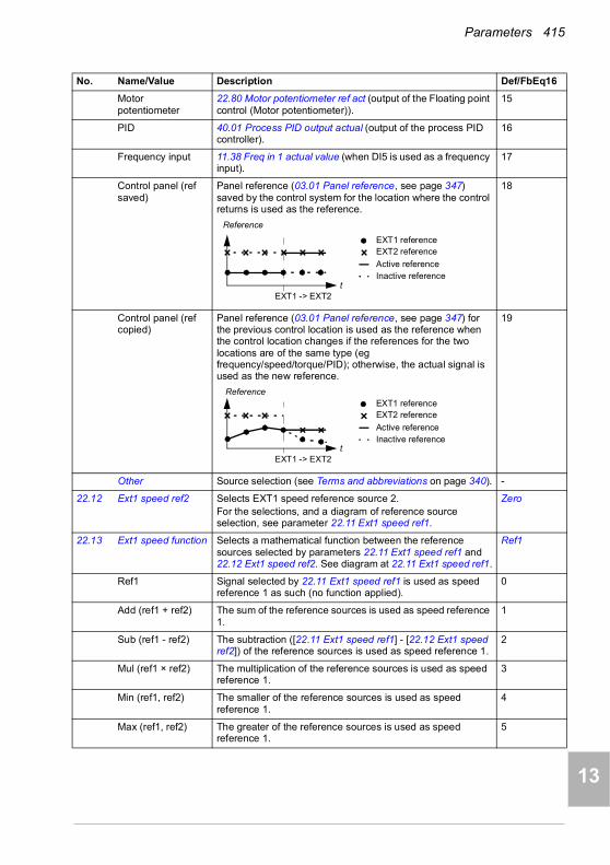
Parameters 415
1
2
3
4
5
6
7
8
9
10
11
12
13
Motor potentiometer
22.80 Motor potentiometer ref act (output of the Floating point control (Motor potentiometer)).
15
PID 40.01 Process PID output actual (output of the process PID controller).
16
Frequency input 11.38 Freq in 1 actual value (when DI5 is used as a frequency input).
17
Control panel (ref saved)
Panel reference (03.01 Panel reference, see page 347) saved by the control system for the location where the control returns is used as the reference.
18
Control panel (ref copied)
Panel reference (03.01 Panel reference, see page 347) for the previous control location is used as the reference when the control location changes if the references for the two locations are of the same type (eg frequency/speed/torque/PID); otherwise, the actual signal is used as the new reference.
19
Other Source selection (see Terms and abbreviations on page 340). -
22.12 Ext1 speed ref2 Selects EXT1 speed reference source 2.For the selections, and a diagram of reference source selection, see parameter 22.11 Ext1 speed ref1.
Zero
22.13 Ext1 speed function Selects a mathematical function between the reference sources selected by parameters 22.11 Ext1 speed ref1 and 22.12 Ext1 speed ref2. See diagram at 22.11 Ext1 speed ref1.
Ref1
Ref1 Signal selected by 22.11 Ext1 speed ref1 is used as speed reference 1 as such (no function applied).
0
Add (ref1 + ref2) The sum of the reference sources is used as speed reference 1.
1
Sub (ref1 - ref2) The subtraction ([22.11 Ext1 speed ref1] - [22.12 Ext1 speed ref2]) of the reference sources is used as speed reference 1.
2
Mul (ref1 × ref2) The multiplication of the reference sources is used as speed reference 1.
3
Min (ref1, ref2) The smaller of the reference sources is used as speed reference 1.
4
Max (ref1, ref2) The greater of the reference sources is used as speed reference 1.
5
No. Name/Value Description Def/FbEq16
EXT1 -> EXT2t
Reference
EXT1 referenceEXT2 reference
Active referenceInactive reference
EXT1 -> EXT2
EXT1 referenceEXT2 reference
Active reference
t Inactive reference
Reference
14
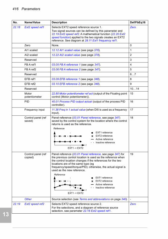
416 Parameters
1
2
3
4
5
7
8
9
9
10
11
12
13
14
22.18 Ext2 speed ref1 Selects EXT2 speed reference source 1.Two signal sources can be defined by this parameter and 22.19 Ext2 speed ref2. A mathematical function (22.20 Ext2 speed function) applied to the two signals creates an EXT2 reference. See diagram at 28.11 Ext1 frequency ref1.
Zero
Zero None. 0
AI1 scaled 12.12 AI1 scaled value (see page 376). 1
AI2 scaled 12.22 AI2 scaled value (see page 378). 2
Reserved 3
FB A ref1 03.05 FB A reference 1 (see page 347). 4
FB A ref2 03.06 FB A reference 2 (see page 347). 5
Reserved 6…7
EFB ref1 03.09 EFB reference 1 (see page 348). 8
EFB ref2 03.10 EFB reference 2 (see page 348). 9
Reserved 10…14
Motor potentiometer
22.80 Motor potentiometer ref act (output of the Floating point control (Motor potentiometer)).
15
PID 40.01 Process PID output actual (output of the process PID controller).
16
Frequency input 11.38 Freq in 1 actual value (when DI5 is used as a frequency input).
17
Control panel (ref saved)
Panel reference (03.01 Panel reference, see page 347) saved by the control system for the location where the control returns is used as the reference.
18
Control panel (ref copied)
Panel reference (03.01 Panel reference, see page 347) for the previous control location is used as the reference when the control location changes if the references for the two locations are of the same type (eg frequency/speed/torque/PID); otherwise, the actual signal is used as the new reference.
19
Other Source selection (see Terms and abbreviations on page 340). -
22.19 Ext2 speed ref2 Selects EXT2 speed reference source 2.For the selections, and a diagram of reference source selection, see parameter 22.18 Ext2 speed ref1.
Zero
No. Name/Value Description Def/FbEq16
EXT1 -> EXT2t
Reference
EXT1 referenceEXT2 reference
Active referenceInactive reference
EXT1 -> EXT2
EXT1 referenceEXT2 reference
Active reference
t Inactive reference
Reference

Parameters 417
1
2
3
4
5
6
7
8
9
10
11
12
13
22.20 Ext2 speed function Selects a mathematical function between the reference sources selected by parameters 22.18 Ext2 speed ref1 and 22.19 Ext2 speed ref2. See diagram at 22.18 Ext2 speed ref1.
Ref1
Ref1 Signal selected by Ext2 speed ref1 is used as speed reference 1 as such (no function applied).
0
Add (ref1 + ref2) The sum of the reference sources is used as speed reference 1.
1
Sub (ref1 - ref2) The subtraction ([22.11 Ext1 speed ref1] - [22.12 Ext1 speed ref2]) of the reference sources is used as speed reference 1.
2
Mul (ref1 × ref2) The multiplication of the reference sources is used as speed reference 1.
3
Min (ref1, ref2) The smaller of the reference sources is used as speed reference 1.
4
Max (ref1, ref2) The greater of the reference sources is used as speed reference 1.
5
22.21 Constant speed function
Determines how constant speeds are selected, and whether the rotation direction signal is considered or not when applying a constant speed.
0000b
0000h…FFFFh Constant speed configuration word. 1 = 1
No. Name/Value Description Def/FbEq16
Bit Name Information
0 Constant speed mode
1 = Packed: 7 constant speeds are selectable using the three sources defined by parameters 22.22, 22.23 and 22.24.
0 = Separate: Constant speeds 1, 2 and 3 are separately activated by the sources defined by parameters 22.22, 22.23 and 22.24 respectively. In case of conflict, the constant speed with the smaller number takes priority.
1 Direction enable
1 = Start dir: To determine running direction for a constant speed, the sign of the constant speed setting (parameters 22.26…22.32) is multiplied by the direction signal (forward: +1, reverse: -1). This effectively allows the drive to have 14 (7 forward, 7 reverse) constant speeds if all values in 22.26…22.32 are positive.
WARNING: If the direction signal is reverse and the active constant speed is negative, the drive will run in the forward direction.
0 = According to Par: The running direction for the constant speed is determined by the sign of the constant speed setting (parameters 22.26…22.32).
2…15 Reserved
14
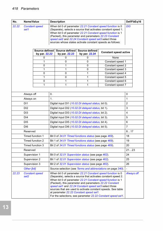
418 Parameters
1
2
3
4
5
7
8
9
9
10
11
12
13
14
22.22 Constant speed sel1
When bit 0 of parameter 22.21 Constant speed function is 0 (Separate), selects a source that activates constant speed 1.When bit 0 of parameter 22.21 Constant speed function is 1 (Packed), this parameter and parameters 22.23 Constant speed sel2 and 22.24 Constant speed sel3 select three sources whose states activate constant speeds as follows:
DI3
Always off 0. 0
Always on 1. 1
DI1 Digital input DI1 (10.02 DI delayed status, bit 0). 2
DI2 Digital input DI2 (10.02 DI delayed status, bit 1). 3
DI3 Digital input DI3 (10.02 DI delayed status, bit 2). 4
DI4 Digital input DI4 (10.02 DI delayed status, bit 3). 5
DI5 Digital input DI5 (10.02 DI delayed status, bit 4). 6
DI6 Digital input DI6 (10.02 DI delayed status, bit 5). 7
Reserved 8…17
Timed function 1 Bit 0 of 34.01 Timed functions status (see page 469). 18
Timed function 2 Bit 1 of 34.01 Timed functions status (see page 469). 19
Timed function 3 Bit 2 of 34.01 Timed functions status (see page 469). 20
Reserved 21…23
Supervision 1 Bit 0 of 32.01 Supervision status (see page 462). 24
Supervision 2 Bit 1 of 32.01 Supervision status (see page 462). 25
Supervision 3 Bit 2 of 32.01 Supervision status (see page 462). 26
Other [bit] Source selection (see Terms and abbreviations on page 340). -
22.23 Constant speed sel2
When bit 0 of parameter 22.21 Constant speed function is 0 (Separate), selects a source that activates constant speed 2.When bit 0 of parameter 22.21 Constant speed function is 1 (Packed), this parameter and parameters 22.22 Constant speed sel1 and 22.24 Constant speed sel3 select three sources that are used to activate constant speeds. See table at parameter 22.22 Constant speed sel1.For the selections, see parameter 22.22 Constant speed sel1.
Always off
No. Name/Value Description Def/FbEq16
Source defined by par. 22.22
Source defined by par. 22.23
Source defined by par. 22.24
Constant speed active
0 0 0 None
1 0 0 Constant speed 1
0 1 0 Constant speed 2
1 1 0 Constant speed 3
0 0 1 Constant speed 4
1 0 1 Constant speed 5
0 1 1 Constant speed 6
1 1 1 Constant speed 7

Parameters 419
1
2
3
4
5
6
7
8
9
10
11
12
13
22.24 Constant speed sel3
When bit 0 of parameter 22.21 Constant speed function is 0 (Separate), selects a source that activates constant speed 3.When bit 0 of parameter 22.21 Constant speed function is 1 (Packed), this parameter and parameters 22.22 Constant speed sel1 and 22.23 Constant speed sel2 select three sources that are used to activate constant speeds. See table at parameter 22.22 Constant speed sel1.For the selections, see parameter 22.22 Constant speed sel1.
Always off
22.26 Constant speed 1 Defines constant speed 1 (the speed the motor will turn when constant speed 1 is selected).
300.00 rpm; 360.00 rpm (95.20 b0)
-30000.00… 30000.00 rpm
Constant speed 1. See par. 46.01
22.27 Constant speed 2 Defines constant speed 2. 600.00 rpm; 720.00 rpm (95.20 b0)
-30000.00… 30000.00 rpm
Constant speed 2. See par. 46.01
22.28 Constant speed 3 Defines constant speed 3. 900.00 rpm; 1080.00 rpm (95.20 b0)
-30000.00… 30000.00 rpm
Constant speed 3. See par. 46.01
22.29 Constant speed 4 Defines constant speed 4. 1200.00 rpm; 1440.00 rpm (95.20 b0)
-30000.00… 30000.00 rpm
Constant speed 4. See par. 46.01
22.30 Constant speed 5 Defines constant speed 5. 1500.00 rpm; 1800.00 rpm (95.20 b0)
-30000.00… 30000.00 rpm
Constant speed 5. See par. 46.01
22.31 Constant speed 6 Defines constant speed 6. 2400.00 rpm; 2880.00 rpm (95.20 b0)
-30000.00… 30000.00 rpm
Constant speed 6. See par. 46.01
22.32 Constant speed 7 Defines constant speed 7. 3000.00 rpm; 3600.00 rpm (95.20 b0)
-30000.00… 30000.00 rpm
Constant speed 7. See par. 46.01
22.41 Speed ref safe Defines a safe speed reference value that is used with supervision functions such as• 12.03 AI supervision function• 49.05 Communication loss action• 50.02 FBA A comm loss func.
0.00 rpm
-30000.00… 30000.00 rpm
Safe speed reference. See par. 46.01
No. Name/Value Description Def/FbEq16
14

420 Parameters
1
2
3
4
5
7
8
9
9
10
11
12
13
14
22.51 Critical speed function
Enables/disables the critical speeds function. Also determines whether the specified ranges are effective in both rotating directions or not.See also section Critical speeds/frequencies (page 125).
0000b
0000b…0011b Critical speeds configuration word. 1 = 1
22.52 Critical speed 1 low Defines the low limit for critical speed range 1.Note: This value must be less than or equal to the value of 22.53 Critical speed 1 high.
0.00 rpm
-30000.00… 30000.00 rpm
Low limit for critical speed 1. See par. 46.01
22.53 Critical speed 1 high
Defines the high limit for critical speed range 1.Note: This value must be greater than or equal to the value of 22.52 Critical speed 1 low.
0.00 rpm
-30000.00… 30000.00 rpm
High limit for critical speed 1. See par. 46.01
22.54 Critical speed 2 low Defines the low limit for critical speed range 2.Note: This value must be less than or equal to the value of 22.55 Critical speed 2 high.
0.00 rpm
-30000.00… 30000.00 rpm
Low limit for critical speed 2. See par. 46.01
22.55 Critical speed 2 high
Defines the high limit for critical speed range 2.Note: This value must be greater than or equal to the value of 22.54 Critical speed 2 low.
0.00 rpm
-30000.00… 30000.00 rpm
High limit for critical speed 2. See par. 46.01
22.56 Critical speed 3 low Defines the low limit for critical speed range 3.Note: This value must be less than or equal to the value of 22.57 Critical speed 3 high.
0.00 rpm
-30000.00… 30000.00 rpm
Low limit for critical speed 3. See par. 46.01
22.57 Critical speed 3 high
Defines the high limit for critical speed range 3.Note: This value must be greater than or equal to the value of 22.56 Critical speed 3 low.
0.00 rpm
-30000.00… 30000.00 rpm
High limit for critical speed 3. See par. 46.01
No. Name/Value Description Def/FbEq16
Bit Name Information
0 Enable 1 = Enable: Critical speeds enabled.
0 = Disable: Critical speeds disabled.
1 Sign mode 1 = Signed: The signs of parameters 22.52…22.57 are taken into account.
0 = Absolute: Parameters 22.52…22.57 are handled as absolute values. Each range is effective in both directions of rotation.
2…15 Reserved

Parameters 421
1
2
3
4
5
6
7
8
9
10
11
12
13
22.71 Motor potentiometer function
Activates and selects the mode of the Floating point control (Motor potentiometer).
Disabled
Disabled Floating point control (Motor potentiometer) is disabled and the Floating point control (Motor potentiometer) counter value set to 0.
0
Enabled (init at stop /power-up)
When enabled, the Floating point control (Motor potentiometer) counter first adopts the value defined by parameter 22.72 Motor potentiometer initial value. The value can then be adjusted from the up and down sources defined by parameters 22.73 Motor potentiometer up source and 22.74 Motor potentiometer down source.A stop or a power cycle will reset the counter to the initial value (22.72).
1
Enabled (resume always)
As Enabled (init at stop /power-up), but the Floating point control (Motor potentiometer) counter is retained over a power cycle.
2
Enabled (init to actual)
Whenever another reference source is selected, the value of the Floating point control (Motor potentiometer) counter follows that reference. After the source of reference returns to the Floating point control (Motor potentiometer) counter, its value can again be changed by the up and down sources (defined by 22.73 and 22.74).
3
22.72 Motor potentiometer initial value
Defines an initial value (starting point) for the Floating point control (Motor potentiometer) counter. See the selections of parameter 22.71 Motor potentiometer function.
0.00
-32768.00… 32767.00
Initial value for the counter. 1 = 1
22.73 Motor potentiometer up source
Selects the source of Floating point control (Motor potentiometer) counter up signal.0 = No change1 = Increase Floating point control (Motor potentiometer) counter value. (If both the up and down sources are on, the potentiometer value will not change.)Note: Floating point control (Motor potentiometer) function up/down source control speed or frequency from zero to maximum speed or frequency. The running direction can be changed with parameter 20.04 Ext1 in2 source. See the figure in section Floating point control (Motor potentiometer) on page 142.
Not used
Not used 0. 0
Not used 1. 1
DI1 Digital input DI1 (10.02 DI delayed status, bit 0). 2
DI2 Digital input DI2 (10.02 DI delayed status, bit 1). 3
DI3 Digital input DI3 (10.02 DI delayed status, bit 2). 4
DI4 Digital input DI4 (10.02 DI delayed status, bit 3). 5
DI5 Digital input DI5 (10.02 DI delayed status, bit 4). 6
DI6 Digital input DI6 (10.02 DI delayed status, bit 5). 7
Reserved 8…17
Timed function 1 Bit 0 of 34.01 Timed functions status (see page 469). 18
Timed function 2 Bit 1 of 34.01 Timed functions status (see page 469). 19
No. Name/Value Description Def/FbEq16
14

422 Parameters
1
2
3
4
5
7
8
9
9
10
11
12
13
14
Timed function 3 Bit 2 of 34.01 Timed functions status (see page 469). 20
Reserved 21…23
Supervision 1 Bit 0 of 32.01 Supervision status (see page 462). 24
Supervision 2 Bit 1 of 32.01 Supervision status (see page 462). 25
Supervision 3 Bit 2 of 32.01 Supervision status (see page 462). 26
Other [bit] Source selection (see Terms and abbreviations on page 340). -
22.74 Motor potentiometer down source
Selects the source of Floating point control (Motor potentiometer) counter down signal.0 = No change1 = Decrease Floating point control (Motor potentiometer) counter value. (If both the up and down sources are on, the counter value will not change.)Note: Floating point control (Motor potentiometer) function up/down source control speed or frequency from zero to maximum speed or frequency. The running direction can be changed with parameter 20.04 Ext1 in2 source. See the figure in section Floating point control (Motor potentiometer) on page 142.For the selections, see parameter 22.73 Motor potentiometer up source.
Not used
22.75 Motor potentiometer ramp time
Defines the change rate of the Floating point control (Motor potentiometer) counter. This parameter specifies the time required for the Floating point control (Motor potentiometer) to change from minimum (22.76) to maximum (22.77). The same change rate applies in both directions.
40.0 s
0.0…3600.0 s Counter change time. 10 = 1 s
22.76 Motor potentiometer min value
Defines the minimum value of the Floating point control (Motor potentiometer) counter.Note: If vector control mode is used, value of this parameter must be changed.
-50.00
-32768.00… 32767.00
Counter minimum. 1 = 1
22.77 Motor potentiometer max value
Defines the maximum value of the Floating point control (Motor potentiometer) counter.Note: If vector control mode is used, value of this parameter must be changed.
50.00
-32768.00… 32767.00
Counter maximum. 1 = 1
22.80 Motor potentiometer ref act
The output of the Floating point control (Motor potentiometer) function. (The meter is configured using parameters 22.71…22.74.)This parameter is read-only.
-
-32768.00… 32767.00
Value of the Floating point control (Motor potentiometer) counter.
1 = 1
22.86 Speed reference act 6
Displays the value of the speed reference (EXT1 or EXT2) that has been selected by 19.11 Ext1/Ext2 selection. See diagram at 22.11 Ext1 speed ref1 or control chain diagram Speed reference source selection I on page 322.This parameter is read-only.
-
-30000.00… 30000.00 rpm
Speed reference after additive 2. See par. 46.01
No. Name/Value Description Def/FbEq16
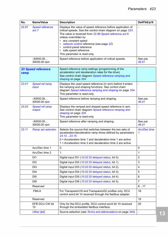
Parameters 423
1
2
3
4
5
6
7
8
9
10
11
12
13
22.87 Speed reference act 7
Displays the value of speed reference before application of critical speeds. See the control chain diagram on page 323.The value is received from 22.86 Speed reference act 6 unless overridden by• any constant speed• network control reference (see page 22)• control panel reference• safe speed reference.This parameter is read-only.
-
-30000.00… 30000.00 rpm
Speed reference before application of critical speeds. See par. 46.01
2323 Speed reference ramp
Speed reference ramp settings (programming of the acceleration and deceleration rates for the drive).See control chain diagram Speed reference ramping and shaping on page 324.
23.01 Speed ref ramp input
Displays the used speed reference (in rpm) before it enters the ramping and shaping functions. See control chain diagram Speed reference ramping and shaping on page 324.This parameter is read-only.
-
-30000.00… 30000.00 rpm
Speed reference before ramping and shaping. See par. 46.01
23.02 Speed ref ramp output
Displays the ramped and shaped speed reference in rpm. See control chain diagram Speed reference ramping and shaping on page 324.This parameter is read-only.
-
-30000.00… 30000.00 rpm
Speed reference after ramping and shaping. See par. 46.01
23.11 Ramp set selection Selects the source that switches between the two sets of acceleration/deceleration ramp times defined by parameters 23.12…23.15.0 = Acceleration time 1 and deceleration time 1 are active1 = Acceleration time 2 and deceleration time 2 are active
Acc/Dec time 1
Acc/Dec time 1 0. 0
Acc/Dec time 2 1. 1
DI1 Digital input DI1 (10.02 DI delayed status, bit 0). 2
DI2 Digital input DI2 (10.02 DI delayed status, bit 1). 3
DI3 Digital input DI3 (10.02 DI delayed status, bit 2). 4
DI4 Digital input DI4 (10.02 DI delayed status, bit 3). 5
DI5 Digital input DI5 (10.02 DI delayed status, bit 4). 6
DI6 Digital input DI6 (10.02 DI delayed status, bit 5). 7
Reserved 8…17
FBA A For Transparent16 and Transparent32 profiles only. DCU control word bit 10 received through the fieldbus adapter.
18
Reserved 19
EFB DCU CW bit 10
Only for the DCU profile. DCU control word bit 10 received through the embedded fieldbus interface.
20
Other [bit] Source selection (see Terms and abbreviations on page 340). -
No. Name/Value Description Def/FbEq16
14
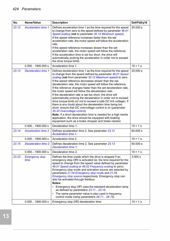
424 Parameters
1
2
3
4
5
7
8
9
9
10
11
12
13
14
23.12 Acceleration time 1 Defines acceleration time 1 as the time required for the speed to change from zero to the speed defined by parameter 46.01 Speed scaling (not to parameter 30.12 Maximum speed).If the speed reference increases faster than the set acceleration rate, the motor speed will follow the acceleration rate.If the speed reference increases slower than the set acceleration rate, the motor speed will follow the reference.If the acceleration time is set too short, the drive will automatically prolong the acceleration in order not to exceed the drive torque limits.
20.000 s
0.000…1800.000 s Acceleration time 1. 10 = 1 s
23.13 Deceleration time 1 Defines deceleration time 1 as the time required for the speed to change from the speed defined by parameter 46.01 Speed scaling (not from parameter 30.12 Maximum speed) to zero.If the speed reference decreases slower than the set deceleration rate, the motor speed will follow the reference.If the reference changes faster than the set deceleration rate, the motor speed will follow the deceleration rate.If the deceleration rate is set too short, the drive will automatically prolong the deceleration in order not to exceed drive torque limits (or not to exceed a safe DC link voltage). If there is any doubt about the deceleration time being too short, ensure that DC overvoltage control is on (parameter 30.30 Overvoltage control).Note: If a short deceleration time is needed for a high inertia application, the drive should be equipped with braking equipment such as a brake chopper and brake resistor.
20.000 s
0.000…1800.000 s Deceleration time 1. 10 = 1 s
23.14 Acceleration time 2 Defines acceleration time 2. See parameter 23.12 Acceleration time 1.
60.000 s
0.000…1800.000 s Acceleration time 2. 10 = 1 s
23.15 Deceleration time 2 Defines deceleration time 2. See parameter 23.13 Deceleration time 1.
60.000 s
0.000…1800.000 s Deceleration time 2. 10 = 1 s
23.23 Emergency stop time
Defines the time inside which the drive is stopped if an emergency stop Off3 is activated (ie. the time required for the speed to change from the speed value defined by parameter 46.01 Speed scaling or 46.02 Frequency scaling to zero). Emergency stop mode and activation source are selected by parameters 21.04 Emergency stop mode and 21.05 Emergency stop source respectively. Emergency stop can also be activated through fieldbus. Notes: • Emergency stop Off1 uses the standard deceleration ramp
as defined by parameters 23.11…23.15.• The same parameter value is also used in frequency
control mode (ramp parameters 28.71…28.75).
3.000 s
0.000…1800.000 s Emergency stop Off3 deceleration time. 10 = 1 s
No. Name/Value Description Def/FbEq16

Parameters 425
1
2
3
4
5
6
7
8
9
10
11
12
13
23.28 Variable slope enable
Activates the variable slope function, which controls the slope of the speed ramp during a speed reference change. This allows for a constantly variable ramp rate to be generated, instead of just the standard two ramps normally available.If the update interval of the signal from an external control system and the variable slope rate (23.29 Variable slope rate) are equal, speed reference (23.02 Speed ref ramp output) is a straight line.
This function is only active in external control.
Off
Off Variable slope disabled. 0
On Variable slope enabled (not available in local control). 1
23.29 Variable slope rate Defines the rate of the speed reference change when variable slope is enabled by parameter 23.28 Variable slope enable.For the best result, enter the reference update interval into this parameter.
50 ms
2…30000 ms Variable slope rate. 1 = 1 ms
2424 Speed reference conditioning
Speed error calculation; speed error window control configuration; speed error step.See control chain diagram Speed error calculation on page 325.
24.01 Used speed reference
Displays the ramped and corrected speed reference (before speed error calculation). See control chain diagram Speed error calculation on page 325.This parameter is read-only.
-
-30000.00… 30000.00 rpm
Speed reference used for speed error calculation. See par. 46.01
24.02 Used speed feedback
Displays the speed feedback used for speed error calculation. See control chain diagram Speed error calculation on page 325.This parameter is read-only.
-
-30000.00… 30000.00 rpm
Speed feedback used for speed error calculation. See par. 46.01
No. Name/Value Description Def/FbEq16
t
Speedreference
23.02 Speed ref ramp output
Speed reference
Time
A
t = update interval of signal from an external control systemA = speed reference change during t
14

426 Parameters
1
2
3
4
5
7
8
9
9
10
11
12
13
14
24.03 Speed error filtered Displays the filtered speed error. See control chain diagram Speed error calculation on page 325.This parameter is read-only.
-
-30000.00… 30000.00 rpm
Filtered speed error. See par. 46.01
24.04 Speed error inverted
Displays the inverted (unfiltered) speed error. See control chain diagram Speed error calculation on page 325.This parameter is read-only.
-
-30000.0… 30000.0 rpm
Inverted speed error. See par. 46.01
24.11 Speed correction Defines a speed reference correction, ie, a value added to the existing reference between ramping and limitation. This is useful to trim the speed if necessary, for example, to adjust draw between sections of a paper machine.See control chain diagram Speed error calculation on page 325.
0.00 rpm
-10000.00… 10000.00 rpm
Speed reference correction. See par. 46.01
24.12 Speed error filter time
Defines the time constant of the speed error low-pass filter.If the used speed reference changes rapidly, the possible interferences in the speed measurement can be filtered with the speed error filter. Reducing the ripple with this filter may cause speed controller tuning problems. A long filter time constant and fast acceleration time contradict one another. A very long filter time results in unstable control.
0 ms
0…10000 ms Speed error filtering time constant. 0 = filtering disabled. 1 = 1 ms
2525 Speed control Speed controller settings.
See control chain diagram Speed error calculation on page 325.
25.01 Torque reference speed control
Displays the speed controller output that is transferred to the torque controller. See control chain diagram Speed error calculation on page 325.This parameter is read-only.
-
-1600.0…1600.0% Limited speed controller output torque. See par. 46.03
No. Name/Value Description Def/FbEq16

Parameters 427
1
2
3
4
5
6
7
8
9
10
11
12
13
25.02 Speed proportional gain
Defines the proportional gain (Kp) of the speed controller. Too high a gain may cause speed oscillation. The figure below shows the speed controller output after an error step when the error remains constant.
10.00
If gain is set to 1, a 10% change in error value (reference - actual value) causes the speed controller output to change by 10%, ie, the output value is input × gain.
0.00…250.00 Proportional gain for speed controller. 100 = 1
No. Name/Value Description Def/FbEq16
Gain = Kp = 1TI = Integration time = 0TD= Derivation time = 0
%
Controlleroutput = Kp × e
Time
e = Error value
Controller output
Error value
14

428 Parameters
1
2
3
4
5
7
8
9
9
10
11
12
13
14
25.03 Speed integration time
Defines the integration time of the speed controller. The integration time defines the rate at which the controller output changes when the error value is constant and the proportional gain of the speed controller is 1. The shorter the integration time, the faster the continuous error value is corrected. This time constant must be set to the same order of magnitude as the time constant (time to respond) of the actual mechanical system being controlled, otherwise instability will result.Setting the integration time to zero disables the I-part of the controller. This is useful to do when tuning the proportional gain; adjust the proportional gain first, then return the integration time.Anti-windup (the integrator just integrates up to 100%) stops the integrator if the controller output is limited.The figure below shows the speed controller output after an error step when the error remains constant.
2.50 s
0.00…1000.00 s Integration time for speed controller. 10 = 1 s
No. Name/Value Description Def/FbEq16
Kp × e
Kp × e
%
e = Error value
Time
Gain = Kp = 1TI = Integration time > 0TD= Derivation time = 0
Controller output
TI

Parameters 429
1
2
3
4
5
6
7
8
9
10
11
12
13
25.04 Speed derivation time
Defines the derivation time of the speed controller. Derivative action boosts the controller output if the error value changes. The longer the derivation time, the more the speed controller output is boosted during the change. If the derivation time is set to zero, the controller works as a PI controller, otherwise as a PID controller. The derivation makes the control more responsive for disturbances. For simple applications, derivative time is not normally required and should be left at zero.The speed error derivative must be filtered with a low pass filter to eliminate disturbances.The figure below shows the speed controller output after an error step when the error remains constant.
0.000 s
0.000…10.000 s Derivation time for speed controller. 1000 = 1 s
25.05 Derivation filter time Defines the derivation filter time constant. See parameter 25.04 Speed derivation time.
8 ms
0…10000 ms Derivation filter time constant. 1 = 1 ms
No. Name/Value Description Def/FbEq16
Gain = Kp = 1TI = Integration time > 0TD= Derivation time > 0Ts= Sample time period = 250 µse = Error value change between two samples
Kp × TD × e
Ts
Controller output
e = Error value
Error value
TimeTI
Kp × e
Kp × e
%
14
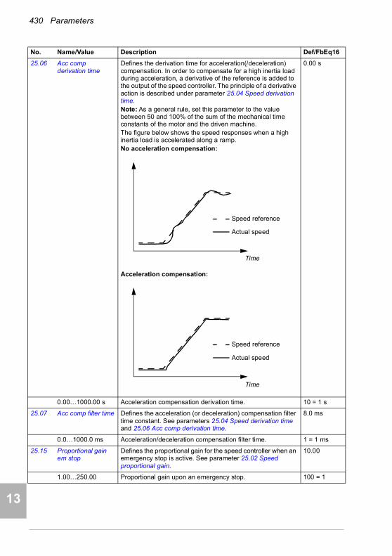
430 Parameters
1
2
3
4
5
7
8
9
9
10
11
12
13
14
25.06 Acc comp derivation time
Defines the derivation time for acceleration(/deceleration) compensation. In order to compensate for a high inertia load during acceleration, a derivative of the reference is added to the output of the speed controller. The principle of a derivative action is described under parameter 25.04 Speed derivation time.Note: As a general rule, set this parameter to the value between 50 and 100% of the sum of the mechanical time constants of the motor and the driven machine.The figure below shows the speed responses when a high inertia load is accelerated along a ramp.No acceleration compensation:
Acceleration compensation:
0.00 s
0.00…1000.00 s Acceleration compensation derivation time. 10 = 1 s
25.07 Acc comp filter time Defines the acceleration (or deceleration) compensation filter time constant. See parameters 25.04 Speed derivation time and 25.06 Acc comp derivation time.
8.0 ms
0.0…1000.0 ms Acceleration/deceleration compensation filter time. 1 = 1 ms
25.15 Proportional gain em stop
Defines the proportional gain for the speed controller when an emergency stop is active. See parameter 25.02 Speed proportional gain.
10.00
1.00…250.00 Proportional gain upon an emergency stop. 100 = 1
No. Name/Value Description Def/FbEq16
Time
Speed reference
Actual speed
Time
Speed reference
Actual speed
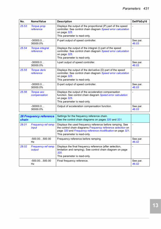
Parameters 431
1
2
3
4
5
6
7
8
9
10
11
12
13
25.53 Torque prop reference
Displays the output of the proportional (P) part of the speed controller. See control chain diagram Speed error calculation on page 325.This parameter is read-only.
-
-30000.0… 30000.0%
P-part output of speed controller. See par. 46.03
25.54 Torque integral reference
Displays the output of the integral (I) part of the speed controller. See control chain diagram Speed error calculation on page 325.This parameter is read-only.
-
-30000.0… 30000.0%
I-part output of speed controller. See par. 46.03
25.55 Torque deriv reference
Displays the output of the derivative (D) part of the speed controller. See control chain diagram Speed error calculation on page 325.This parameter is read-only.
-
-30000.0… 30000.0%
D-part output of speed controller. See par. 46.03
25.56 Torque acc compensation
Displays the output of the acceleration compensation function. See control chain diagram Speed error calculation on page 325.This parameter is read-only.
-
-30000.0… 30000.0%
Output of acceleration compensation function. See par. 46.03
2828 Frequency reference chain
Settings for the frequency reference chain.See the control chain diagrams on pages 320 and 321.
28.01 Frequency ref ramp input
Displays the used frequency reference before ramping. See the control chain diagrams Frequency reference selection on page 320 and Frequency reference modification on page 321.This parameter is read-only.
-
-500.00…500.00 Hz
Frequency reference before ramping. See par. 46.02
28.02 Frequency ref ramp output
Displays the final frequency reference (after selection, limitation and ramping). See control chain diagram on page 320.This parameter is read-only.
-
-500.00…500.00 Hz
Final frequency reference. See par. 46.02
No. Name/Value Description Def/FbEq16
14
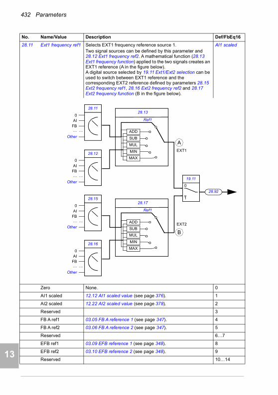
432 Parameters
1
2
3
4
5
7
8
9
9
10
11
12
13
14
28.11 Ext1 frequency ref1 Selects EXT1 frequency reference source 1.Two signal sources can be defined by this parameter and 28.12 Ext1 frequency ref2. A mathematical function (28.13 Ext1 frequency function) applied to the two signals creates an EXT1 reference (A in the figure below). A digital source selected by 19.11 Ext1/Ext2 selection can be used to switch between EXT1 reference and the corresponding EXT2 reference defined by parameters 28.15 Ext2 frequency ref1, 28.16 Ext2 frequency ref2 and 28.17 Ext2 frequency function (B in the figure below).
AI1 scaled
Zero None. 0
AI1 scaled 12.12 AI1 scaled value (see page 376). 1
AI2 scaled 12.22 AI2 scaled value (see page 378). 2
Reserved 3
FB A ref1 03.05 FB A reference 1 (see page 347). 4
FB A ref2 03.06 FB A reference 2 (see page 347). 5
Reserved 6…7
EFB ref1 03.09 EFB reference 1 (see page 348). 8
EFB ref2 03.10 EFB reference 2 (see page 348). 9
Reserved 10…14
No. Name/Value Description Def/FbEq16
19.11
1
0
28.13
MUL
SUB
ADD
MIN
MAX
28.11
28.12
28.92
0AI
FB…
Other
…
0AI
FB…
Other
…
Ref1
28.17
MUL
SUB
ADD
MIN
MAX
28.15
28.16
0AI
FB…
Other
…
0AI
FB…
Other
…
Ref1
A
B
EXT1
EXT2
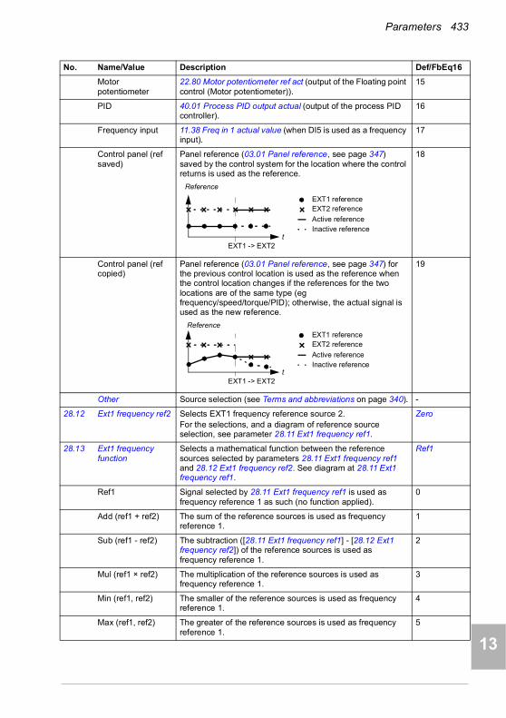
Parameters 433
1
2
3
4
5
6
7
8
9
10
11
12
13
Motor potentiometer
22.80 Motor potentiometer ref act (output of the Floating point control (Motor potentiometer)).
15
PID 40.01 Process PID output actual (output of the process PID controller).
16
Frequency input 11.38 Freq in 1 actual value (when DI5 is used as a frequency input).
17
Control panel (ref saved)
Panel reference (03.01 Panel reference, see page 347) saved by the control system for the location where the control returns is used as the reference.
18
Control panel (ref copied)
Panel reference (03.01 Panel reference, see page 347) for the previous control location is used as the reference when the control location changes if the references for the two locations are of the same type (eg frequency/speed/torque/PID); otherwise, the actual signal is used as the new reference.
19
Other Source selection (see Terms and abbreviations on page 340). -
28.12 Ext1 frequency ref2 Selects EXT1 frequency reference source 2.For the selections, and a diagram of reference source selection, see parameter 28.11 Ext1 frequency ref1.
Zero
28.13 Ext1 frequency function
Selects a mathematical function between the reference sources selected by parameters 28.11 Ext1 frequency ref1 and 28.12 Ext1 frequency ref2. See diagram at 28.11 Ext1 frequency ref1.
Ref1
Ref1 Signal selected by 28.11 Ext1 frequency ref1 is used as frequency reference 1 as such (no function applied).
0
Add (ref1 + ref2) The sum of the reference sources is used as frequency reference 1.
1
Sub (ref1 - ref2) The subtraction ([28.11 Ext1 frequency ref1] - [28.12 Ext1 frequency ref2]) of the reference sources is used as frequency reference 1.
2
Mul (ref1 × ref2) The multiplication of the reference sources is used as frequency reference 1.
3
Min (ref1, ref2) The smaller of the reference sources is used as frequency reference 1.
4
Max (ref1, ref2) The greater of the reference sources is used as frequency reference 1.
5
No. Name/Value Description Def/FbEq16
EXT1 -> EXT2t
Reference
EXT1 referenceEXT2 reference
Active referenceInactive reference
EXT1 -> EXT2
EXT1 referenceEXT2 reference
Active reference
t Inactive reference
Reference
14

434 Parameters
1
2
3
4
5
7
8
9
9
10
11
12
13
14
28.15 Ext2 frequency ref1 Selects EXT2 frequency reference source 1.Two signal sources can be defined by this parameter and 28.16 Ext2 frequency ref2. A mathematical function (28.17 Ext2 frequency function) applied to the two signals creates an EXT2 reference. See diagram at 28.11 Ext1 frequency ref1.
Zero
Zero None. 0
AI1 scaled 12.12 AI1 scaled value (see page 376). 1
AI2 scaled 12.22 AI2 scaled value (see page 378). 2
Reserved 3
FB A ref1 03.05 FB A reference 1 (see page 347). 4
FB A ref2 03.06 FB A reference 2 (see page 347). 5
Reserved 6…7
EFB ref1 03.09 EFB reference 1 (see page 348). 8
EFB ref2 03.10 EFB reference 2 (see page 348). 9
Reserved 10…14
Motor potentiometer
22.80 Motor potentiometer ref act (output of the Floating point control (Motor potentiometer)).
15
PID 40.01 Process PID output actual (output of the process PID controller).
16
Frequency input 11.38 Freq in 1 actual value (when DI5 is used as a frequency input).
17
Control panel (ref saved)
Panel reference (03.01 Panel reference, see page 347) saved by the control system for the location where the control returns is used as the reference.
18
Control panel (ref copied)
Panel reference (03.01 Panel reference, see page 347) for the previous control location is used as the reference when the control location changes if the references for the two locations are of the same type (eg frequency/speed/torque/PID); otherwise, the actual signal is used as the new reference.
19
Other Source selection (see Terms and abbreviations on page 340). -
28.16 Ext2 frequency ref2 Selects EXT2 frequency reference source 2.For the selections, and a diagram of reference source selection, see parameter 28.15 Ext2 frequency ref1.
Zero
No. Name/Value Description Def/FbEq16
EXT1 -> EXT2t
Reference
EXT1 referenceEXT2 reference
Active referenceInactive reference
EXT1 -> EXT2
EXT1 referenceEXT2 reference
Active reference
t Inactive reference
Reference

Parameters 435
1
2
3
4
5
6
7
8
9
10
11
12
13
28.17 Ext2 frequency function
Selects a mathematical function between the reference sources selected by parameters 28.15 Ext2 frequency ref1 and 28.16 Ext2 frequency ref2. See diagram at 28.15 Ext2 frequency ref1.
Ref1
Ref1 Signal selected by 28.15 Ext2 frequency ref1 is used as frequency reference 1 as such (no function applied).
0
Add (ref1 + ref2) The sum of the reference sources is used as frequency reference 1.
1
Sub (ref1 - ref2) The subtraction ([28.15 Ext2 frequency ref1] - [28.16 Ext2 frequency ref2]) of the reference sources is used as frequency reference 1.
2
Mul (ref1 × ref2) The multiplication of the reference sources is used as frequency reference 1.
3
Min (ref1, ref2) The smaller of the reference sources is used as frequency reference 1.
4
Max (ref1, ref2) The greater of the reference sources is used as frequency reference 1.
5
28.21 Constant frequency function
Determines how constant frequencies are selected, and whether the rotation direction signal is considered or not when applying a constant frequency.
0000b
0000b…0011b Constant frequency configuration word. 1 = 1
No. Name/Value Description Def/FbEq16
Bit Name Information
0 Const freq mode
1 = Packed: 7 constant frequencies are selectable using the three sources defined by parameters 28.22, 28.23 and 28.24.
0 = Separate: Constant frequencies 1, 2 and 3 are separately activated by the sources defined by parameters 28.22, 28.23 and 28.24 respectively. In case of conflict, the constant frequency with the smaller number takes priority.
1 Direction enable
1 = Start dir: To determine running direction for a constant speed, the sign of the constant speed setting (parameters 22.26…22.32) is multiplied by the direction signal (forward: +1, reverse: -1). This effectively allows the drive to have 14 (7 forward, 7 reverse) constant speeds if all values in 22.26…22.32 are positive.
WARNING: If the direction signal is reverse and the active constant speed is negative, the drive will run in the forward direction.
0 = According to Par: The running direction for the constant speed is determined by the sign of the constant speed setting (parameters 22.26…22.32).
2…15 Reserved
14
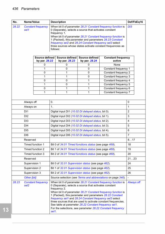
436 Parameters
1
2
3
4
5
7
8
9
9
10
11
12
13
14
28.22 Constant frequency sel1
When bit 0 of parameter 28.21 Constant frequency function is 0 (Separate), selects a source that activates constant frequency 1.When bit 0 of parameter 28.21 Constant frequency function is 1 (Packed), this parameter and parameters 28.23 Constant frequency sel2 and 28.24 Constant frequency sel3 select three sources whose states activate constant frequencies as follows:
DI3
Always off 0. 0
Always on 1. 1
DI1 Digital input DI1 (10.02 DI delayed status, bit 0). 2
DI2 Digital input DI2 (10.02 DI delayed status, bit 1). 3
DI3 Digital input DI3 (10.02 DI delayed status, bit 2). 4
DI4 Digital input DI4 (10.02 DI delayed status, bit 3). 5
DI5 Digital input DI5 (10.02 DI delayed status, bit 4). 6
DI6 Digital input DI6 (10.02 DI delayed status, bit 5). 7
Reserved 8…17
Timed function 1 Bit 0 of 34.01 Timed functions status (see page 469). 18
Timed function 2 Bit 1 of 34.01 Timed functions status (see page 469). 19
Timed function 3 Bit 2 of 34.01 Timed functions status (see page 469). 20
Reserved 21…23
Supervision 1 Bit 0 of 32.01 Supervision status (see page 462). 24
Supervision 2 Bit 1 of 32.01 Supervision status (see page 462). 25
Supervision 3 Bit 2 of 32.01 Supervision status (see page 462). 26
Other [bit] Source selection (see Terms and abbreviations on page 340). -
28.23 Constant frequency sel2
When bit 0 of parameter 28.21 Constant frequency function is 0 (Separate), selects a source that activates constant frequency 2.When bit 0 of parameter 28.21 Constant frequency function is 1 (Packed), this parameter and parameters 28.22 Constant frequency sel1 and 28.24 Constant frequency sel3 select three sources that are used to activate constant frequencies. See table at parameter 28.22 Constant frequency sel1.For the selections, see parameter 28.22 Constant frequency sel1.
Always off
No. Name/Value Description Def/FbEq16
Source defined by par. 28.22
Source defined by par. 28.23
Source defined by par. 28.24
Constant frequency active
0 0 0 None
1 0 0 Constant frequency 1
0 1 0 Constant frequency 2
1 1 0 Constant frequency 3
0 0 1 Constant frequency 4
1 0 1 Constant frequency 5
0 1 1 Constant frequency 6
1 1 1 Constant frequency 7

Parameters 437
1
2
3
4
5
6
7
8
9
10
11
12
13
28.24 Constant frequency sel3
When bit 0 of parameter 28.21 Constant frequency function is 0 (Separate), selects a source that activates constant frequency 3.When bit 0 of parameter 28.21 Constant frequency function is 1 (Packed), this parameter and parameters 28.22 Constant frequency sel1 and 28.23 Constant frequency sel2 select three sources that are used to activate constant frequencies. See table at parameter 28.22 Constant frequency sel1.For the selections, see parameter 28.22 Constant frequency sel1.
Always off
28.26 Constant frequency 1
Defines constant frequency 1 (the frequency the motor will turn when constant frequency 1 is selected).
5.00 Hz; 6.00 Hz (95.20 b0)
-500.00…500.00 Hz
Constant frequency 1. See par. 46.02
28.27 Constant frequency 2
Defines constant frequency 2. 10.00 Hz; 12.00 Hz (95.20 b0)
-500.00…500.00 Hz
Constant frequency 2. See par. 46.02
28.28 Constant frequency 3
Defines constant frequency 3. 15.00 Hz; 18.00 Hz (95.20 b0)
-500.00…500.00 Hz
Constant frequency 3. See par. 46.02
28.29 Constant frequency 4
Defines constant frequency 4. 20.00 Hz; 24.00 Hz (95.20 b0)
-500.00…500.00 Hz
Constant frequency 4. See par. 46.02
28.30 Constant frequency 5
Defines constant frequency 5. 25.00 Hz; 30.00 Hz (95.20 b0)
-500.00…500.00 Hz
Constant frequency 5. See par. 46.02
28.31 Constant frequency 6
Defines constant frequency 6. 40.00 Hz; 48.00 Hz (95.20 b0)
-500.00…500.00 Hz
Constant frequency 6. See par. 46.02
28.32 Constant frequency 7
Defines constant frequency 7. 50.00 Hz; 60.00 Hz (95.20 b0)
-500.00…500.00 Hz
Constant frequency 7. See par. 46.02
28.41 Frequency ref safe Defines a safe frequency reference value that is used with supervision functions such as• 12.03 AI supervision function• 49.05 Communication loss action• 50.02 FBA A comm loss func.
0.00 Hz
-500.00…500.00 Hz
Safe frequency reference. See par. 46.02
No. Name/Value Description Def/FbEq16
14

438 Parameters
1
2
3
4
5
7
8
9
9
10
11
12
13
14
28.51 Critical frequency function
Enables/disables the critical frequencies function. Also determines whether the specified ranges are effective in both rotating directions or not.See also section Critical speeds/frequencies (page 125).
0000b
0000b…0011b Critical frequencies configuration word. 1 = 1
28.52 Critical frequency 1 low
Defines the low limit for critical frequency 1.Note: This value must be less than or equal to the value of 28.53 Critical frequency 1 high.
0.00 Hz
-500.00…500.00 Hz
Low limit for critical frequency 1. See par. 46.02
28.53 Critical frequency 1 high
Defines the high limit for critical frequency 1.Note: This value must be greater than or equal to the value of 28.52 Critical frequency 1 low.
0.00 Hz
-500.00…500.00 Hz
High limit for critical frequency 1. See par. 46.02
28.54 Critical frequency 2 low
Defines the low limit for critical frequency 2.Note: This value must be less than or equal to the value of 28.55 Critical frequency 2 high.
0.00 Hz
-500.00…500.00 Hz
Low limit for critical frequency 2. See par. 46.02
28.55 Critical frequency 2 high
Defines the high limit for critical frequency 2.Note: This value must be greater than or equal to the value of 28.54 Critical frequency 2 low.
0.00 Hz
-500.00…500.00 Hz
High limit for critical frequency 2. See par. 46.02
28.56 Critical frequency 3 low
Defines the low limit for critical frequency 3.Note: This value must be less than or equal to the value of 28.57 Critical frequency 3 high.
0.00 Hz
-500.00…500.00 Hz
Low limit for critical frequency 3. See par. 46.02
28.57 Critical frequency 3 high
Defines the high limit for critical frequency 3.Note: This value must be greater than or equal to the value of 28.56 Critical frequency 3 low.
0.00 Hz
-500.00…500.00 Hz
High limit for critical frequency 3. See par. 46.02
28.71 Freq ramp set selection
Selects a source that switches between the two sets of acceleration/deceleration times defined by parameters 28.72…28.75.0 = Acceleration time 1 and deceleration time 1 are in force1 = Acceleration time 2 and deceleration time 2 are in force
Acc/Dec time 1
Acc/Dec time 1 0. 0
No. Name/Value Description Def/FbEq16
Bit Name Information
0 Crit freq 1 = Enable: Critical frequencies enabled.
0 = Disable: Critical frequencies disabled.
1 Sign mode 1 = According to par: The signs of parameters 28.52…28.57 are taken into account.
0 = Absolute: Parameters 28.52…28.57 are handled as absolute values. Each range is effective in both directions of rotation.

Parameters 439
1
2
3
4
5
6
7
8
9
10
11
12
13
Acc/Dec time 2 1. 1
DI1 Digital input DI1 (10.02 DI delayed status, bit 0). 2
DI2 Digital input DI2 (10.02 DI delayed status, bit 1). 3
DI3 Digital input DI3 (10.02 DI delayed status, bit 2). 4
DI4 Digital input DI4 (10.02 DI delayed status, bit 3). 5
DI5 Digital input DI5 (10.02 DI delayed status, bit 4). 6
DI6 Digital input DI6 (10.02 DI delayed status, bit 5). 7
Reserved 8…17
FBA A For Transparent16 and Transparent32 profiles only. DCU control word bit 10 received through the fieldbus adapter.
18
Reserved 19
EFB DCU CW bit 0 Only for the DCU profile. DCU control word bit 10 received through the embedded fieldbus interface.
20
Other [bit] Source selection (see Terms and abbreviations on page 340). -
28.72 Freq acceleration time 1
Defines acceleration time 1 as the time required for the frequency to change from zero to the frequency defined by parameter 46.02 Frequency scaling. After this frequency has been reached, the acceleration continues with the same rate to the value defined by parameter 30.14 Maximum frequency. If the reference increases faster than the set acceleration rate, the motor will follow the acceleration rate.If the reference increases slower than the set acceleration rate, the motor frequency will follow the reference.If the acceleration time is set too short, the drive will automatically prolong the acceleration in order not to exceed the drive torque limits.
30.000 s
0.000…1800.000 s Acceleration time 1. 10 = 1 s
28.73 Freq deceleration time 1
Defines deceleration time 1 as the time required for the frequency to change from the frequency defined by parameter 46.02 Frequency scaling (not from parameter 30.14 Maximum frequency) to zero.If there is any doubt about the deceleration time being too short, ensure that DC overvoltage control (30.30 Overvoltage control) is on.Note: If a short deceleration time is needed for a high inertia application, the drive should be equipped with braking equipment such as a brake chopper and brake resistor.
30.000 s
0.000…1800.000 s Deceleration time 1. 10 = 1 s
28.74 Freq acceleration time 2
Defines acceleration time 2. See parameter 28.72 Freq acceleration time 1.
60.000 s
0.000…1800.000 s Acceleration time 2. 10 = 1 s
28.75 Freq deceleration time 2
Defines deceleration time 2. See parameter 28.73 Freq deceleration time 1.
60.000 s
0.000…1800.000 s Deceleration time 2. 10 = 1 s
28.76 Freq ramp in zero source
Selects a source that forces the frequency reference to zero.0 = Force frequency reference to zero1 = Normal operation
Inactive
Active 0. 0
Inactive 1. 1
No. Name/Value Description Def/FbEq16
14

440 Parameters
1
2
3
4
5
7
8
9
9
10
11
12
13
14
DI1 Digital input DI1 (10.02 DI delayed status, bit 0). 2
DI2 Digital input DI2 (10.02 DI delayed status, bit 1). 3
DI3 Digital input DI3 (10.02 DI delayed status, bit 2). 4
DI4 Digital input DI4 (10.02 DI delayed status, bit 3). 5
DI5 Digital input DI5 (10.02 DI delayed status, bit 4). 6
DI6 Digital input DI6 (10.02 DI delayed status, bit 5). 7
Other [bit] Source selection (see Terms and abbreviations on page 340). -
28.92 Frequency ref act 3 Displays the frequency reference after the function applied by parameter 28.13 Ext1 frequency function (if any), and after selection (19.11 Ext1/Ext2 selection). See control chain diagram Frequency reference selectionon page 320.This parameter is read-only.
-
-500.00…500.00 Hz
Frequency reference after selection. See par. 46.02
28.96 Frequency ref act 7 Displays the frequency reference after application of constant frequencies, control panel reference, etc. See control chain diagram Frequency reference selectionon page 320.This parameter is read-only.
-
-500.00…500.00 Hz
Frequency reference 7. See par. 46.02
28.97 Frequency ref unlimited
Displays the frequency reference after application of critical frequencies, but before ramping and limiting. See control chain diagram Frequency reference modification on page 321.This parameter is read-only.
-
-500.00…500.00 Hz
Frequency reference before ramping and limiting. See par. 46.02
No. Name/Value Description Def/FbEq16
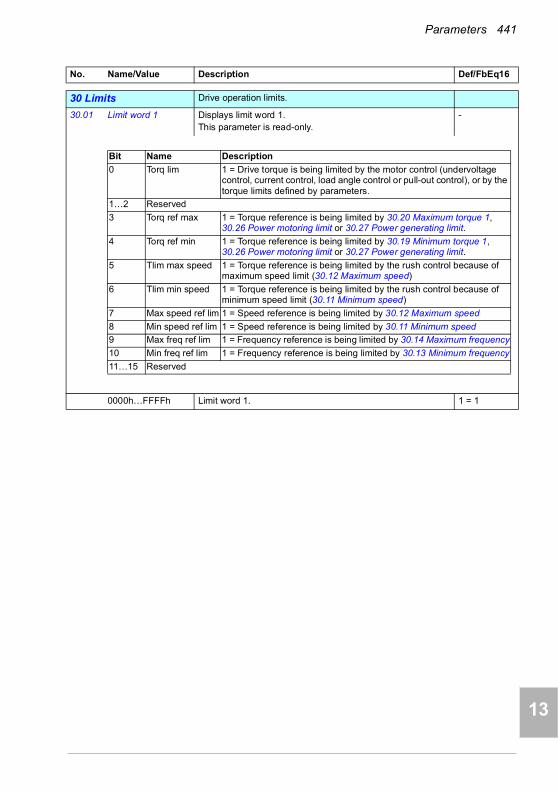
Parameters 441
1
2
3
4
5
6
7
8
9
10
11
12
13
3030 Limits Drive operation limits.
30.01 Limit word 1 Displays limit word 1.This parameter is read-only.
-
0000h…FFFFh Limit word 1. 1 = 1
No. Name/Value Description Def/FbEq16
Bit Name Description
0 Torq lim 1 = Drive torque is being limited by the motor control (undervoltage control, current control, load angle control or pull-out control), or by the torque limits defined by parameters.
1…2 Reserved
3 Torq ref max 1 = Torque reference is being limited by 30.20 Maximum torque 1, 30.26 Power motoring limit or 30.27 Power generating limit.
4 Torq ref min 1 = Torque reference is being limited by 30.19 Minimum torque 1, 30.26 Power motoring limit or 30.27 Power generating limit.
5 Tlim max speed 1 = Torque reference is being limited by the rush control because of maximum speed limit (30.12 Maximum speed)
6 Tlim min speed 1 = Torque reference is being limited by the rush control because of minimum speed limit (30.11 Minimum speed)
7 Max speed ref lim 1 = Speed reference is being limited by 30.12 Maximum speed
8 Min speed ref lim 1 = Speed reference is being limited by 30.11 Minimum speed
9 Max freq ref lim 1 = Frequency reference is being limited by 30.14 Maximum frequency
10 Min freq ref lim 1 = Frequency reference is being limited by 30.13 Minimum frequency
11…15 Reserved
14

442 Parameters
1
2
3
4
5
7
8
9
9
10
11
12
13
14
30.02 Torque limit status Displays the torque controller limitation status word.This parameter is read-only.
-
0000h…FFFFh Torque limitation status word. 1 = 1
No. Name/Value Description Def/FbEq16
Bit Name Description
0 Undervoltage *1 = Intermediate DC circuit undervoltage
1 Overvoltage *1 = Intermediate DC circuit overvoltage
2 Minimum torque *1 = Torque is being limited by 30.19 Minimum torque 1, 30.26 Power motoring limit or 30.27 Power generating limit
3 Maximum torque *1 = Torque is being limited by 30.20 Maximum torque 1, 30.26 Power motoring limit or 30.27 Power generating limit
4 Internal current 1 = An inverter current limit (identified by bits 8…11) is active
5 Load angle (With permanent magnet motors and reluctance motors only)1 = Load angle limit is active, ie, the motor cannot produce any more torque
6 Motor pullout (With asynchronous motors only)Motor pull-out limit is active, ie, the motor cannot produce any more torque
7 Reserved
8 Thermal 1 = Input current is being limited by the main circuit thermal limit
9 Max current *1 = Maximum output current (IMAX) is being limited
10 User current *1 = Output current is being limited by 30.17 Maximum current
11 Thermal IGBT *1 = Output current is being limited by a calculated thermal current value
12…15 Reserved
*Only one out of bits 0…3, and one out of bits 9…11 can be on simultaneously. The bit typically indicates the limit that is exceeded first.

Parameters 443
1
2
3
4
5
6
7
8
9
10
11
12
13
30.11 Minimum speed Defines together with 30.12 Maximum speed the allowed speed range. See the figure below.A positive or zero minimum speed value defines two ranges, one positive and one negative.A negative minimum speed value defines one range.
WARNING! The absolute value of 30.11 Minimum speed must not be higher than the absolute value of 30.12 Maximum speed.WARNING! In speed control mode only. In frequency control mode, use frequency limits (30.13 and 30.14).
0.00 rpm
-30000.00… 30000.00 rpm
Minimum allowed speed. See par. 46.01
30.12 Maximum speed Defines together with 30.11 Minimum speed the allowed speed range. See parameter 30.11 Minimum speed.Note: This parameter does not affect the speed acceleration and deceleration ramp times. See parameter 46.01 Speed scaling.
1500.00 rpm; 1800.00 rpm (95.20 b0)
-30000.00… 30000.00 rpm
Maximum speed. See par. 46.01
No. Name/Value Description Def/FbEq16
0
30.12
Time
Speed
30.11
0
30.12
Time
Speed
-(30.11)
Speed range allowedSpeed range allowed
Speed range allowed-(30.12)
30.11
30.11 value < 0 30.11 value >= 020.21 value = Request
0
30.12
Time
Speed
-(30.11)
Speed range allowed
-(30.12)
30.11
30.11 value >= 020.21 value = Forward
14

444 Parameters
1
2
3
4
5
7
8
9
9
10
11
12
13
14
30.13 Minimum frequency Defines together with 30.14 Maximum frequency the allowed frequency range. See the figure.A positive or zero minimum frequency value defines two ranges, one positive and one negative.
WARNING! The absolute value of 30.13 Minimum frequency must not be higher than the absolute value of 30.14 Maximum frequency.WARNING! in frequency control mode only.
0.00 Hz
-500.00…500.00 Hz
Minimum frequency. See par. 46.02
30.14 Maximum frequency
Defines together with 30.13 Minimum frequency the allowed frequency range. See parameter 30.13 Minimum frequency.Note: This parameter does not affect the frequency acceleration and deceleration ramp times. See parameter 46.02 Frequency scaling.
50.00 Hz; 60.00 Hz (95.20 b0)
-500.00…500.00 Hz
Maximum frequency. See par. 46.02
30.17 Maximum current Defines the maximum allowed motor current. This depends on the drive type; it is automatically determined on the basis of the rating.The system sets the default value to 90% of the rated current so you can increase the parameter value by 10% if needed (not valid for ACH580-01-12A7-4 drive type).
0.00 A
0.00…30000.00 A Maximum motor current. 1 = 1 A
No. Name/Value Description Def/FbEq16
0
30.14
Time
Frequency
30.13
0
30.14
Time
Frequency
-(30.13)
Frequency range allowedFrequency range allowed
Frequency range allowed-(30.14)
30.13
30.13 value < 0 30.13 value >= 020.21 value = Request
0
30.14
Time
Frequency
-(30.13)
Frequency range allowed
-(30.14)
30.13
30.13 value >= 020.21 value = Forward

Parameters 445
1
2
3
4
5
6
7
8
9
10
11
12
13
30.18 Torq lim sel Selects a source that switches between two different predefined minimum torque limit sets.0 = minimum torque limit defined by 30.19 and maximum torque limit defined by 30.20 are active1 = minimum torque limit selected by 30.21 and maximum torque limit defined by 30.22 are activeThe user can define two sets of torque limits, and switch between the sets using a binary source such as a digital input.The first set of limits is defined by parameters 30.19 and 30.20. The second set has selector parameters for both the minimum (30.21) and maximum (30.22) limits that allows the use of a selectable analog source (such as an analog input).
Note: In addition to the user-defined limits, torque may be limited for other reasons (such as power limitation). See block diagram Torque limitation on page 328.
Torque limit set 1
Torque limit set 1 0 (minimum torque limit defined by 30.19 and maximum torque limit defined by 30.20 are active).
0
Torque limit set 2 1 (minimum torque limit selected by 30.21 and maximum torque limit defined by 30.22 are active).
1
DI1 Digital input DI1 (10.02 DI delayed status, bit 0). 2
DI2 Digital input DI2 (10.02 DI delayed status, bit 1). 3
DI3 Digital input DI3 (10.02 DI delayed status, bit 2). 4
DI4 Digital input DI4 (10.02 DI delayed status, bit 3). 5
DI5 Digital input DI5 (10.02 DI delayed status, bit 4). 6
DI6 Digital input DI6 (10.02 DI delayed status, bit 5). 7
Reserved 8…10
EFB Only for the DCU profile. DCU control word bit 15 received through the embedded fieldbus interface.
11
Other [bit] Source selection (see Terms and abbreviations on page 340). -
No. Name/Value Description Def/FbEq16
30.21
User-defined minimum torque
limit
0AI1AI2PID
30.23Other
0AI1AI2PID
30.24Other
30.19
30.22
30.18
0
1
30.20
30.18
0
1
User-defined maximum torque
limit
14
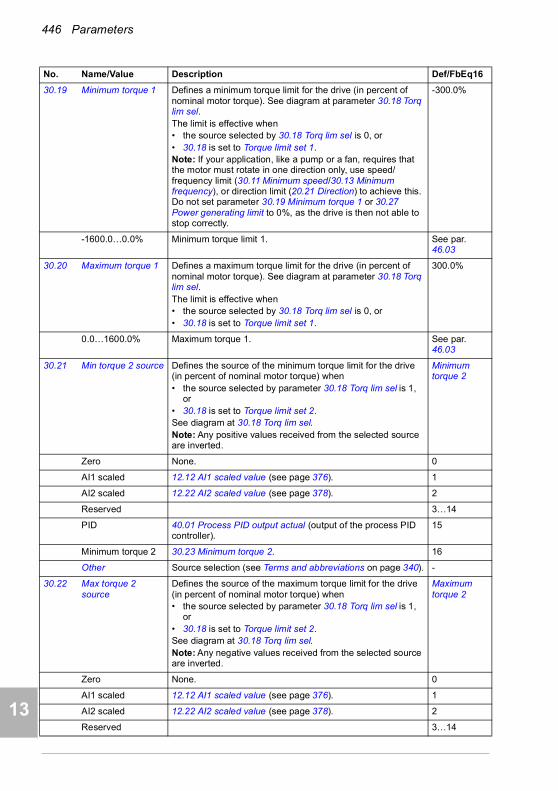
446 Parameters
1
2
3
4
5
7
8
9
9
10
11
12
13
14
30.19 Minimum torque 1 Defines a minimum torque limit for the drive (in percent of nominal motor torque). See diagram at parameter 30.18 Torq lim sel.The limit is effective when• the source selected by 30.18 Torq lim sel is 0, or• 30.18 is set to Torque limit set 1.Note: If your application, like a pump or a fan, requires that the motor must rotate in one direction only, use speed/ frequency limit (30.11 Minimum speed/30.13 Minimum frequency), or direction limit (20.21 Direction) to achieve this. Do not set parameter 30.19 Minimum torque 1 or 30.27 Power generating limit to 0%, as the drive is then not able to stop correctly.
-300.0%
-1600.0…0.0% Minimum torque limit 1. See par. 46.03
30.20 Maximum torque 1 Defines a maximum torque limit for the drive (in percent of nominal motor torque). See diagram at parameter 30.18 Torq lim sel.The limit is effective when• the source selected by 30.18 Torq lim sel is 0, or• 30.18 is set to Torque limit set 1.
300.0%
0.0…1600.0% Maximum torque 1. See par. 46.03
30.21 Min torque 2 source Defines the source of the minimum torque limit for the drive (in percent of nominal motor torque) when• the source selected by parameter 30.18 Torq lim sel is 1,
or• 30.18 is set to Torque limit set 2.See diagram at 30.18 Torq lim sel.Note: Any positive values received from the selected source are inverted.
Minimum torque 2
Zero None. 0
AI1 scaled 12.12 AI1 scaled value (see page 376). 1
AI2 scaled 12.22 AI2 scaled value (see page 378). 2
Reserved 3…14
PID 40.01 Process PID output actual (output of the process PID controller).
15
Minimum torque 2 30.23 Minimum torque 2. 16
Other Source selection (see Terms and abbreviations on page 340). -
30.22 Max torque 2 source
Defines the source of the maximum torque limit for the drive (in percent of nominal motor torque) when• the source selected by parameter 30.18 Torq lim sel is 1,
or• 30.18 is set to Torque limit set 2.See diagram at 30.18 Torq lim sel.Note: Any negative values received from the selected source are inverted.
Maximum torque 2
Zero None. 0
AI1 scaled 12.12 AI1 scaled value (see page 376). 1
AI2 scaled 12.22 AI2 scaled value (see page 378). 2
Reserved 3…14
No. Name/Value Description Def/FbEq16

Parameters 447
1
2
3
4
5
6
7
8
9
10
11
12
13
PID 40.01 Process PID output actual (output of the process PID controller).
15
Maximum torque 2 30.24 Maximum torque 2. 16
Other Source selection (see Terms and abbreviations on page 340). -
30.23 Minimum torque 2 Defines the minimum torque limit for the drive (in percent of nominal motor torque) when• the source selected by 30.18 Torq lim sel is 1, or• 30.18 is set to Torque limit set 2and• 30.21 Min torque 2 source is set to Minimum torque 2.See diagram at 30.18 Torq lim sel.
-300.0%
-1600.0…0.0% Minimum torque limit 2. See par. 46.03
30.24 Maximum torque 2 Defines the maximum torque limit for the drive (in percent of nominal motor torque) whenThe limit is effective when• the source selected by 30.18 Torq lim sel is 1, or• 30.18 is set to Torque limit set 2and• 30.22 Max torque 2 source is set to Maximum torque 2.See diagram at 30.18 Torq lim sel.
300.0%
0.0…1600.0% Maximum torque limit 2. See par. 46.03
30.26 Power motoring limit
Defines the maximum allowed power fed by the inverter to the motor in percent of nominal motor power.
300.00%
0.00…600.00% Maximum motoring power. 1 = 1%
30.27 Power generating limit
Defines the maximum allowed power fed by the motor to the inverter in percent of nominal motor power.Note: If your application, like a pump or a fan, requires that the motor must rotate in one direction only, use speed/ frequency limit (30.11 Minimum speed/30.13 Minimum frequency), or direction limit (20.21 Direction) to achieve this. Do not set parameter 30.19 Minimum torque 1 or 30.27 Power generating limit to 0%, as the drive is then not able to stop correctly.
-300.00%
-600.00…0.00% Maximum generating power. 1 = 1%
30.30 Overvoltage control Enables the overvoltage control of the intermediate DC link. Fast braking of a high inertia load causes the voltage to rise to the overvoltage control limit. To prevent the DC voltage from exceeding the limit, the overvoltage controller automatically decreases the braking torque.Note: If the drive is equipped with a brake chopper and resistor, or a regenerative supply unit, the controller must be disabled.
Enable
Disable Overvoltage control disabled. 0
Enable Overvoltage control enabled. 1
No. Name/Value Description Def/FbEq16
14
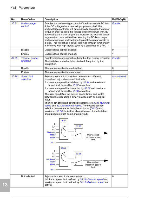
448 Parameters
1
2
3
4
5
7
8
9
9
10
11
12
13
14
30.31 Undervoltage control
Enables the undervoltage control of the intermediate DC link. If the DC voltage drops due to input power cut off, the undervoltage controller will automatically decrease the motor torque in order to keep the voltage above the lower limit. By decreasing the motor torque, the inertia of the load will cause regeneration back to the drive, keeping the DC link charged and preventing an undervoltage trip until the motor coasts to a stop. This will act as a power-loss ride-through functionality in systems with high inertia, such as a centrifuge or a fan.
Enable
Disable Undervoltage control disabled. 0
Enable Undervoltage control enabled. 1
30.35 Thermal current limitation
Enables/disables temperature-based output current limitation.The limitation should only be disabled if required by the application.
Enable
Disable Thermal current limitation disabled. 0
Enable Thermal current limitation enabled. 1
30.36 Speed limit selection
Selects a source that switches between two different predefined adjustable speed limit sets.0 = minimum speed limit defined by 30.11 and maximum
speed limit defined by 30.12 are active1 = minimum speed limit selected by 30.37 and maximum
speed limit defined by 30.38 are active.The user can define two sets of speed limits, and switch between the sets using a binary source such as a digital input.The first set of limits is defined by parameters 30.11 Minimum speed and 30.12 Maximum speed. The second set has selector parameters for both the minimum (30.37) and maximum (30.38) limits that allows the use of a selectable analog source (such as an analog input).
Not selected
Not selected Adjustable speed limits are disabled.(Minimum speed limit defined by 30.11 Minimum speed and maximum speed limit defined by 30.12 Maximum speed are active).
0
No. Name/Value Description Def/FbEq16
30.37
User-defined minimum speed
limit
0AI1AI2
MinimumspeedOther
0AI1AI2
MaximumspeedOther
30.11
30.38
30.36
0
1
30.12
30.36
0
1
User-defined maximum speed
limit

Parameters 449
1
2
3
4
5
6
7
8
9
10
11
12
13
Selected Adjustable speed limits are enabled.(Minimum speed limit defined by 30.37 Minimum speed source and maximum speed limit defined by 30.38 Maximum speed source are active).
1
Ext1 active Adjustable speed limits are enabled if EXT1 is active. 2
Ext2 active Adjustable speed limits are enabled if EXT2 is active. 3
Reserved 4
DI1 Digital input DI1 (10.02 DI delayed status, bit 0). 5
DI2 Digital input DI2 (10.02 DI delayed status, bit 1). 6
DI3 Digital input DI3 (10.02 DI delayed status, bit 2). 7
DI4 Digital input DI4 (10.02 DI delayed status, bit 3). 8
DI5 Digital input DI5 (10.02 DI delayed status, bit 4). 9
DI6 Digital input DI6 (10.02 DI delayed status, bit 5). 10
Reserved 11
Other [bit] Source selection (see Terms and abbreviations on page 340). -
30.37 Minimum speed source
Defines the source of a minimum speed limit for the drive when the source is selected by 30.36 Speed limit selection.Note: In vector motor control mode only. In scalar motor control mode, use frequency limits 30.13 and 30.14.
Minimum speed
Zero None. 0
AI1 scaled 12.12 AI1 scaled value (see page 376). 1
AI2 scaled 12.22 AI2 scaled value (see page 378). 2
Reserved 3…10
Minimum speed 30.11 Minimum speed. 11
Other Source selection (see Terms and abbreviations on page 340). -
30.38 Maximum speed source
Defines the source of a maximum speed limit for the drive when the source is selected by 30.36 Speed limit selection.Note: In vector motor control mode only. In scalar motor control mode, use frequency limits 30.13 and 30.14.
Maximum speed
Zero None. 0
AI1 scaled 12.12 AI1 scaled value (see page 376). 1
AI2 scaled 12.22 AI2 scaled value (see page 378). 2
Reserved 3…11
Maximum speed 30.12 Maximum speed. 12
Other Source selection (see Terms and abbreviations on page 340). -
No. Name/Value Description Def/FbEq16
14

450 Parameters
1
2
3
4
5
7
8
9
9
10
11
12
13
14
30.101 LSU limit word 1 (Only visible for ACH580-31)Displays limit word 1 of the supply unit.This parameter is read-only.
-
0000h…FFFFh Supply unit limit word 1. 1 = 1
30.102 LSU limit word 2 (Only visible for ACH580-31)Displays limit word 2 of the supply unit.This parameter is read-only.
-
0000h…FFFFh Supply unit limit word 2. 1 = 1
No. Name/Value Description Def/FbEq16
Bit Name Description
0 P user ref max 1 = Power reference is being limited by supply control program parameters1 P user ref min
2 P user max 1 = Power is being limited by parameter 30.149
3 Reserved
4 P cooling overtemp
1 = Power reference is being limited because of coolant overtemperature
5 P power unit overtemp
1 = Power reference is being limited because of supply unit overtemperature
6…15 Reserved
Bit Name Description
0 Q user ref max 1 = Reactive power reference is being limited
1 Q user ref min
2 Q cooling overtemp
1 = Reactive power reference is being limited because of coolant overtemperature
3 Reserved
4 AC overvoltage 1 = AC overvoltage protection
5…6 Reserved
7 AC diff max 1 = (When AC voltage-type reactive power reference is being used) Input of AC control is being limited8 AC diff min
9…15 Reserved

Parameters 451
1
2
3
4
5
6
7
8
9
10
11
12
13
30.103 LSU limit word 3 (Only visible for ACH580-31)Displays limit word 3 of the supply unit.This parameter is read-only.
-
0000h…FFFFh Supply unit limit word 3. 1 = 1
30.104 LSU limit word 4 (Only visible for ACH580-31)Displays limit word 4 of the supply unit.This parameter is read-only.
-
0000h…FFFFh Supply unit limit word 4. 1 = 1
30.149 LSU maximum power limit
(Only visible for ACH580-31)Defines a maximum power limit for the supply unit.
130.0%
0.0 … 200.0% Maximum power limit for supply unit. 1 = 1%
No. Name/Value Description Def/FbEq16
Bit Name Description
0 Undervoltage limit
1 = Power is being limited by the undervoltage controller
1 Overvoltage limit 1 = Power is being limited by the overvoltage controller
2 Motoring power 1 = Power is being limited by temperature or user power limits (see parameter 30.149)
3 Reserved
4 Active current limit
1 = Active current is being limited. For details, see bits 6…9 and 14…15.
5 Reactive current limit
1 = Reactive current is being limited. For details, see bits 12…13.
6 Thermal limit 1 = Active current is being limited by internal main circuit thermal limit
7 SOA limit 1 = Active current is being limited by internal safe operation area limit
8 User current limit 1 = Active current is being limited by current limit set by supply control program parameters
9 Thermal IGBT 1 = Active current is being limited based on internal maximum thermal IGBT stress limit
10…11 Reserved
12 Q act neg 1 = Negative reactive current is being limited by maximum total current
13 Q act pos 1 = Positive reactive current is being limited by maximum total current
14 P act neg 1 = Negative active current is being limited by maximum total current
15 P act pos 1 = Positive reactive current is being limited by maximum total current
Bit Name Description
0 Udc ref max 1 = DC reference is being limited by supply control program parameters1 Udc ref min
2 User I max 1 = Current is being limited by supply control program parameters
3 Temp I max 1 = Current is being limited based on temperature
4…15 Reserved
14

452 Parameters
1
2
3
4
5
7
8
9
9
10
11
12
13
14
3131 Fault functions Configuration of external events; selection of behavior of the
drive upon fault situations.
31.01 External event 1 source
Defines the source of external event 1.See also parameter 31.02 External event 1 type.0 = Trigger event1 = Normal operation
Inactive (true)
Active (false) 0. 0
Inactive (true) 1. 1
Reserved 2
DI1 Digital input DI1 (10.02 DI delayed status, bit 0). 3
DI2 Digital input DI2 (10.02 DI delayed status, bit 1). 4
DI3 Digital input DI3 (10.02 DI delayed status, bit 2). 5
DI4 Digital input DI4 (10.02 DI delayed status, bit 3). 6
DI5 Digital input DI5 (10.02 DI delayed status, bit 4). 7
DI6 Digital input DI6 (10.02 DI delayed status, bit 5). 8
Other [bit] Source selection (see Terms and abbreviations on page 340). -
31.02 External event 1 type
Selects the type of external event 1. Fault
Fault The external event generates a fault. 0
Warning The external event generates a warning. 1
31.03 External event 2 source
Defines the source of external event 2. See also parameter 31.04 External event 2 type.For the selections, see parameter 31.01 External event 1 source.
Inactive (true)
31.04 External event 2 type
Selects the type of external event 2. Fault
Fault The external event generates a fault. 0
Warning The external event generates a warning. 1
31.05 External event 3 source
Defines the source of external event 3. See also parameter 31.06 External event 3 type.For the selections, see parameter 31.01 External event 1 source.
Inactive (true)
31.06 External event 3 type
Selects the type of external event 3. Fault
Fault The external event generates a fault. 0
Warning The external event generates a warning. 1
31.07 External event 4 source
Defines the source of external event 4. See also parameter 31.08 External event 4 type.For the selections, see parameter 31.01 External event 1 source.
Inactive (true)
31.08 External event 4 type
Selects the type of external event 4. Fault
Fault The external event generates a fault. 0
Warning The external event generates a warning. 1
No. Name/Value Description Def/FbEq16

Parameters 453
1
2
3
4
5
6
7
8
9
10
11
12
13
31.09 External event 5 source
Defines the source of external event 5. See also parameter 31.10 External event 5 type.For the selections, see parameter 31.01 External event 1 source.
Inactive (true)
31.10 External event 5 type
Selects the type of external event 5. Fault
Fault The external event generates a fault. 0
Warning The external event generates a warning. 1
31.11 Fault reset selection
Selects the source of an external fault reset signal. The signal resets the drive after a fault trip if the cause of the fault no longer exists.0 -> 1 = ResetNote: A fault reset from the fieldbus interface is always observed regardless of this parameter.
Not used
Not used 0. 0
Not used 1. 1
DI1 Digital input DI1 (10.02 DI delayed status, bit 0). 2
DI2 Digital input DI2 (10.02 DI delayed status, bit 1). 3
DI3 Digital input DI3 (10.02 DI delayed status, bit 2). 4
DI4 Digital input DI4 (10.02 DI delayed status, bit 3). 5
DI5 Digital input DI5 (10.02 DI delayed status, bit 4). 6
DI6 Digital input DI6 (10.02 DI delayed status, bit 5). 7
Reserved 8…17
Timed function 1 Bit 0 of 34.01 Timed functions status (see page 469). 18
Timed function 2 Bit 1 of 34.01 Timed functions status (see page 469). 19
Timed function 3 Bit 2 of 34.01 Timed functions status (see page 469). 20
Reserved 21…23
Supervision 1 Bit 0 of 32.01 Supervision status (see page 462). 24
Supervision 2 Bit 1 of 32.01 Supervision status (see page 462). 25
Supervision 3 Bit 2 of 32.01 Supervision status (see page 462). 26
Other [bit] Source selection (see Terms and abbreviations on page 340). -
No. Name/Value Description Def/FbEq16
14

454 Parameters
1
2
3
4
5
7
8
9
9
10
11
12
13
14
31.12 Autoreset selection Selects faults that are automatically reset. The parameter is a 16-bit word with each bit corresponding to a fault type. Whenever a bit is set to 1, the corresponding fault is automatically reset.Note: Infinite reset trials are executed if parameter 70.02 Override enable is set to value On, critical.
WARNING! Before you activate the function, make sure that no dangerous situations can occur. The function restarts the drive automatically and continues
operation after a fault.The bits of this binary number correspond to the following faults:
000Ch (00…1100b)
0000h…FFFFh Automatic reset configuration word. 1 = 1
31.13 Selectable fault Defines the fault that can be automatically reset using parameter 31.12 Autoreset selection, bit 10.Faults are listed in chapter Fault tracing (page 209).
0000h
0000h…FFFFh Fault code. 10 = 1
31.14 Number of trials Defines the maximum number of automatic resets that the drive is allowed to attempt within the time specified by 31.15 Total trials time.If the fault persists, subsequent reset attempts will be made at intervals defined by 31.16 Delay time.The faults to be automatically reset are defined by 31.12 Autoreset selection.
0
0…5 Number of automatic resets. 10 = 1
31.15 Total trials time Defines a time window for automatic fault resets. The maximum number of attempts made during any period of this length is defined by 31.14 Number of trials.Note: If the fault condition remains and cannot be reset, each reset attempt will generate an event and start a new time window. In practice, if the specified number of resets (31.14) at specified intervals (31.16) take longer than the value of 31.15, the drive will continue to attempt resetting the fault until the cause is eventually removed.
30.0 s
1.0…600.0 s Time for automatic resets. 10 = 1 s
No. Name/Value Description Def/FbEq16
Bit Fault
0 Overcurrent
1 Overvoltage
2 Undervoltage
3 AI supervision fault
4…9 Reserved
10 Selectable fault (see parameter 31.13 Selectable fault)
11 External fault 1 (from source selected by parameter 31.01 External event 1 source)
12 External fault 2 (from source selected by parameter 31.03 External event 2 source)
13 External fault 3 (from source selected by parameter 31.05 External event 3 source)
14 External fault 4 (from source selected by parameter 31.07 External event 4 source)
15 External fault 5 (from source selected by parameter 31.09 External event 5 source)
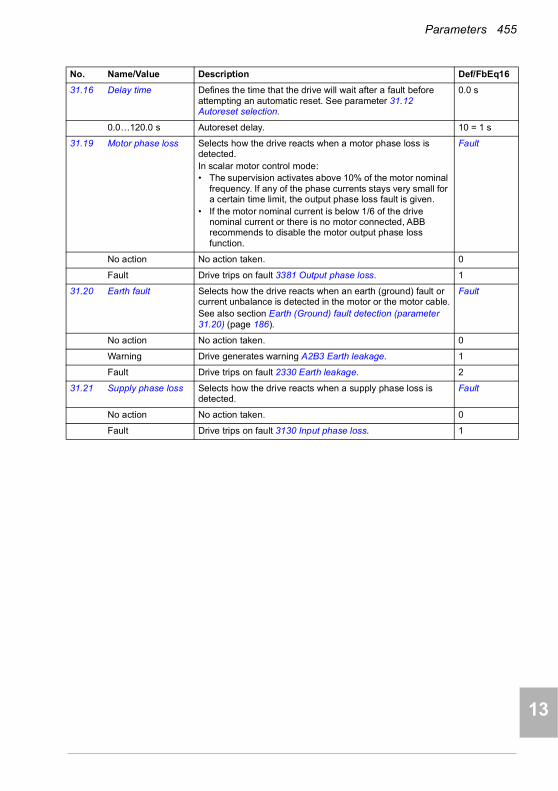
Parameters 455
1
2
3
4
5
6
7
8
9
10
11
12
13
31.16 Delay time Defines the time that the drive will wait after a fault before attempting an automatic reset. See parameter 31.12 Autoreset selection.
0.0 s
0.0…120.0 s Autoreset delay. 10 = 1 s
31.19 Motor phase loss Selects how the drive reacts when a motor phase loss is detected.In scalar motor control mode:• The supervision activates above 10% of the motor nominal
frequency. If any of the phase currents stays very small for a certain time limit, the output phase loss fault is given.
• If the motor nominal current is below 1/6 of the drive nominal current or there is no motor connected, ABB recommends to disable the motor output phase loss function.
Fault
No action No action taken. 0
Fault Drive trips on fault 3381 Output phase loss. 1
31.20 Earth fault Selects how the drive reacts when an earth (ground) fault or current unbalance is detected in the motor or the motor cable.See also section Earth (Ground) fault detection (parameter 31.20) (page 186).
Fault
No action No action taken. 0
Warning Drive generates warning A2B3 Earth leakage. 1
Fault Drive trips on fault 2330 Earth leakage. 2
31.21 Supply phase loss Selects how the drive reacts when a supply phase loss is detected.
Fault
No action No action taken. 0
Fault Drive trips on fault 3130 Input phase loss. 1
No. Name/Value Description Def/FbEq16
14

456 Parameters
1
2
3
4
5
7
8
9
9
10
11
12
13
14
31.22 STO indication run/stop
Selects which indications are given when one or both Safe torque off (STO) signals are switched off or lost. The indications also depend on whether the drive is running or stopped when this occurs.The tables at each selection below show the indications generated with that particular setting.Notes:• This parameter does not affect the operation of the STO
function itself. The STO function will operate regardless of the setting of this parameter: a running drive will stop upon removal of one or both STO signals, and will not start until both STO signals are restored and all faults reset.
• The loss of only one STO signal always generates a fault as it is interpreted as a malfunction.
• With the CPTC-02 ATEX-certified thermistor protection module, follow the instructions given in the CPTC-02 ATEX-certified thermistor protection module, Ex II (2) GD (+L537+Q971) user's manual (3AXD50000030058 [English]).
For more information on the STO, see chapter The Safe torque off function in the Hardware manual of the drive.
Fault/Fault
Fault/Fault 0
Fault/Warning 1
No. Name/Value Description Def/FbEq16
InputsIndication (running or stopped)
IN1 IN2
0 0 Fault 5091 Safe torque off
0 1Faults 5091 Safe torque off
and FA81 Safe torque off 1
1 0Faults 5091 Safe torque off
and FA82 Safe torque off 2
1 1 (Normal operation)
Inputs Indication
IN1 IN2 Running Stopped
0 0Fault 5091 Safe torque
offWarning A5A0 Safe
torque off
0 1
Faults 5091 Safe torque off
and FA81 Safe torque off 1
Warning A5A0 Safe torque off and fault
FA81 Safe torque off 1
1 0
Faults 5091 Safe torque off
and FA82 Safe torque off 2
Warning A5A0 Safe torque off and fault
FA82 Safe torque off 2
1 1 (Normal operation)

Parameters 457
1
2
3
4
5
6
7
8
9
10
11
12
13
Fault/Event 2
Warning/Warning 3
Event/Event 4
No indication/No indication
5
31.23 Wiring or earth fault Selects how the drive reacts to incorrect input power and motor cable connection (ie. input power cable is connected to drive motor connection).Note: For ACH580-31 this parameter is write protected and its value is No action.
Fault
No action No action taken. 0
No. Name/Value Description Def/FbEq16
Inputs Indication
IN1 IN2 Running Stopped
0 0Fault 5091 Safe torque
off Event B5A0 STO event
0 1Faults 5091 Safe
torque off and FA81 Safe torque off 1
Event B5A0 STO event and fault FA81 Safe
torque off 1
1 0
Faults 5091 Safe torque off
and FA82 Safe torque off 2
Event B5A0 STO event and fault FA82 Safe
torque off 2
1 1 (Normal operation)
InputsIndication (running or stopped)
IN1 IN2
0 0 Warning A5A0 Safe torque off
0 1Warning A5A0 Safe torque off and fault FA81
Safe torque off 1
1 0Warning A5A0 Safe torque off and fault FA82
Safe torque off 2
1 1 (Normal operation)
InputsIndication (running or stopped)
IN1 IN2
0 0 Event B5A0 STO event
0 1Event B5A0 STO event and fault FA81 Safe
torque off 1
1 0Event B5A0 STO event and fault FA82 Safe
torque off 2
1 1 (Normal operation)
InputsIndication (running or stopped)
IN1 IN2
0 0 None
0 1 Fault FA81 Safe torque off 1
1 0 Fault FA82 Safe torque off 2
1 1 (Normal operation)
14
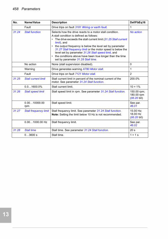
458 Parameters
1
2
3
4
5
7
8
9
9
10
11
12
13
14
Fault Drive trips on fault 3181 Wiring or earth fault. 1
31.24 Stall function Selects how the drive reacts to a motor stall condition.A stall condition is defined as follows:• The drive exceeds the stall current limit (31.25 Stall current
limit), and• the output frequency is below the level set by parameter
31.27 Stall frequency limit or the motor speed is below the level set by parameter 31.26 Stall speed limit, and
• the conditions above have been true longer than the time set by parameter 31.28 Stall time.
No action
No action None (stall supervision disabled). 0
Warning Drive generates warning A780 Motor stall. 1
Fault Drive trips on fault 7121 Motor stall. 2
31.25 Stall current limit Stall current limit in percent of the nominal current of the motor. See parameter 31.24 Stall function.
200.0%
0.0…1600.0% Stall current limit. 10 = 1%
31.26 Stall speed limit Stall speed limit in rpm. See parameter 31.24 Stall function. 150.00 rpm; 180.00 rpm (95.20 b0)
0.00…10000.00 rpm
Stall speed limit. See par. 46.01
31.27 Stall frequency limit Stall frequency limit. See parameter 31.24 Stall function.Note: Setting the limit below 10 Hz is not recommended.
15.00 Hz; 18.00 Hz (95.20 b0)
0.00…1000.00 Hz Stall frequency limit. See par. 46.02
31.28 Stall time Stall time. See parameter 31.24 Stall function. 20 s
0…3600 s Stall time. 1 = 1 s
No. Name/Value Description Def/FbEq16
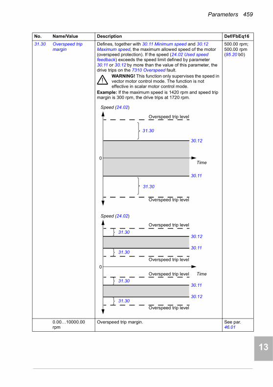
Parameters 459
1
2
3
4
5
6
7
8
9
10
11
12
13
31.30 Overspeed trip margin
Defines, together with 30.11 Minimum speed and 30.12 Maximum speed, the maximum allowed speed of the motor (overspeed protection). If the speed (24.02 Used speed feedback) exceeds the speed limit defined by parameter 30.11 or 30.12 by more than the value of this parameter, the drive trips on the 7310 Overspeed fault.
WARNING! This function only supervises the speed in vector motor control mode. The function is not effective in scalar motor control mode.
Example: If the maximum speed is 1420 rpm and speed trip margin is 300 rpm, the drive trips at 1720 rpm.
500.00 rpm; 500.00 rpm (95.20 b0)
0.00…10000.00 rpm
Overspeed trip margin. See par. 46.01
No. Name/Value Description Def/FbEq16
Speed (24.02)
Time
30.12
30.11
31.30
Overspeed trip level
Overspeed trip level
31.30
0
Speed (24.02)
Time
30.1231.30
Overspeed trip level
0
30.11
Overspeed trip level
31.30
30.1131.30
30.1231.30
Overspeed trip level
Overspeed trip level
14
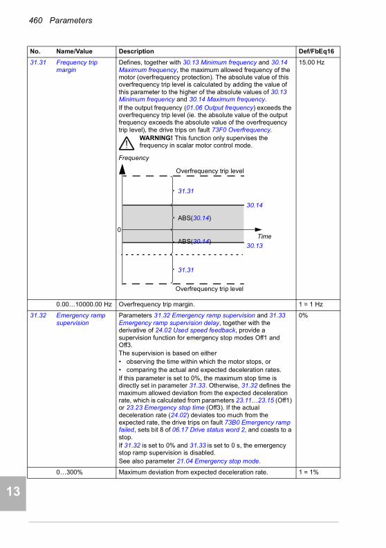
460 Parameters
1
2
3
4
5
7
8
9
9
10
11
12
13
14
31.31 Frequency trip margin
Defines, together with 30.13 Minimum frequency and 30.14 Maximum frequency, the maximum allowed frequency of the motor (overfrequency protection). The absolute value of this overfrequency trip level is calculated by adding the value of this parameter to the higher of the absolute values of 30.13 Minimum frequency and 30.14 Maximum frequency. If the output frequency (01.06 Output frequency) exceeds the overfrequency trip level (ie. the absolute value of the output frequency exceeds the absolute value of the overfrequency trip level), the drive trips on fault 73F0 Overfrequency.
WARNING! This function only supervises the frequency in scalar motor control mode.
15.00 Hz
0.00…10000.00 Hz Overfrequency trip margin. 1 = 1 Hz
31.32 Emergency ramp supervision
Parameters 31.32 Emergency ramp supervision and 31.33 Emergency ramp supervision delay, together with the derivative of 24.02 Used speed feedback, provide a supervision function for emergency stop modes Off1 and Off3.The supervision is based on either• observing the time within which the motor stops, or• comparing the actual and expected deceleration rates.If this parameter is set to 0%, the maximum stop time is directly set in parameter 31.33. Otherwise, 31.32 defines the maximum allowed deviation from the expected deceleration rate, which is calculated from parameters 23.11…23.15 (Off1) or 23.23 Emergency stop time (Off3). If the actual deceleration rate (24.02) deviates too much from the expected rate, the drive trips on fault 73B0 Emergency ramp failed, sets bit 8 of 06.17 Drive status word 2, and coasts to a stop.If 31.32 is set to 0% and 31.33 is set to 0 s, the emergency stop ramp supervision is disabled.See also parameter 21.04 Emergency stop mode.
0%
0…300% Maximum deviation from expected deceleration rate. 1 = 1%
No. Name/Value Description Def/FbEq16
Frequency
Time
30.14
30.13
31.31
Overfrequency trip level
Overfrequency trip level
ABS(30.14)
ABS(30.14)
31.31
0

Parameters 461
1
2
3
4
5
6
7
8
9
10
11
12
13
31.33 Emergency ramp supervision delay
If parameter 31.32 Emergency ramp supervision is set to 0%, this parameter defines the maximum time an emergency stop (mode Off1 or Off3) is allowed to take. If the motor has not stopped when the time elapses, the drive trips on fault 73B0 Emergency ramp failed, sets bit 8 of 06.17 Drive status word 2, and coasts to a stop.If 31.32 is set to a value other than 0%, this parameter defines a delay between the receipt of the emergency stop command and the activation of the supervision. It is recommended to specify a short delay to allow the speed change rate to stabilize.
0 s
0…100 s Maximum ramp-down time, or supervision activation delay. 1 = 1 s
31.36 Aux fan fault function
Selects how the drive reacts when an auxiliary fan problem is detected.Certain drive types (especially those protected to IP55) have an auxiliary fan built into the front cover as standard.You can temporarily use setting Warning to only generate a warning, for example, if it is necessary to operate the drive without the front cover (for example, during commissioning).Notes: • This parameter applies to frames R6 and larger.• The parameter applies to fan(s) connected in FAN1 or
FAN2 connector of the control unit.
Fault
Fault The drive trips on fault 5081 Auxiliary fan broken. The fault is suppressed for two minutes after power-up.
0
Warning The drive generates warning A582 Auxiliary fan missing. The warning is suppressed for two minutes after power-up.
1
31.120 LSU earth fault (Only visible for ACH580-31)Selects how the supply unit reacts when an earth fault or current unbalance is detected.
Fault
No action No action taken. 0
Warning The supply unit generates warning AE02 Earth leakage. 1
Fault The supply unit trips on fault 2E01 Earth leakage. 2
31.121 LSU supply phase loss
(Only visible for ACH580-31)Selects how the supply unit reacts when a supply phase loss is detected.
Fault
No action No action taken. 0
Fault The supply unit trips on fault 3E00 Input phase loss. 1
No. Name/Value Description Def/FbEq16
14

462 Parameters
1
2
3
4
5
7
8
9
9
10
11
12
13
14
3232 Supervision Configuration of signal supervision functions 1…6.
Six values can be chosen to be monitored; a warning or fault is generated whenever predefined limits are exceeded.See also section Diagnostics menu (page 189).
32.01 Supervision status Signal supervision status word.Indicates whether the values monitored by the signal supervision functions are within or outside their respective limits.Note: This word is independent of the drive actions defined by parameters 32.06, 32.16, 32.26, 32.36, 32.46 and 32.56.
0000b
0000h…FFFFh Signal supervision status word. 1 = 1
32.05 Supervision 1 function
Selects the mode of signal supervision function 1. Determines how the monitored signal (see parameter 32.07) is compared to its lower and upper limits (32.09 and 32.10 respectively). The action to be taken when the condition is fulfilled is selected by 32.06.
Disabled
Disabled Signal supervision 1 not in use. 0
Low Action is taken whenever the signal falls below its lower limit. 1
High Action is taken whenever the signal rises above its upper limit.
2
Abs low Action is taken whenever the absolute value of the signal falls below its (absolute) lower limit.
3
Abs high Action is taken whenever the absolute value of the signal rises above its (absolute) upper limit.
4
Both Action is taken whenever the signal falls below its low limit or rises above its high limit.
5
Abs both Action is taken whenever the absolute value of the signal falls below its (absolute) low limit or rises above its (absolute) high limit.
6
Hysteresis See parameter 32.11 Supervision 1 hysteresis. 7
32.06 Supervision 1 action
Selects whether the drive generates a fault, warning or neither when the value monitored by signal supervision 1 exceeds its limits.Note: This parameter does not affect the status indicated by 32.01 Supervision status.
No action
No action No warning or fault generated. 0
Warning Drive generates warning A8B0 ABB Signal supervision 1. 1
Fault Drive trips on fault 80B0 Signal supervision 1. 2
Fault if running If running, the drive trips on fault 80B0 Signal supervision 1. 3
No. Name/Value Description Def/FbEq16
Bit Name Description
0 Supervision 1 active 1 = Signal selected by 32.07 is outside its limits.
1 Supervision 2 active 1 = Signal selected by 32.17 is outside its limits.
2 Supervision 3 active 1 = Signal selected by 32.27 is outside its limits.
3 Supervision 4 active 1 = Signal selected by 32.37 is outside its limits.
4 Supervision 5 active 1 = Signal selected by 32.47 is outside its limits.
5 Supervision 6 active 1 = Signal selected by 32.27 is outside its limits.
6…15 Reserved
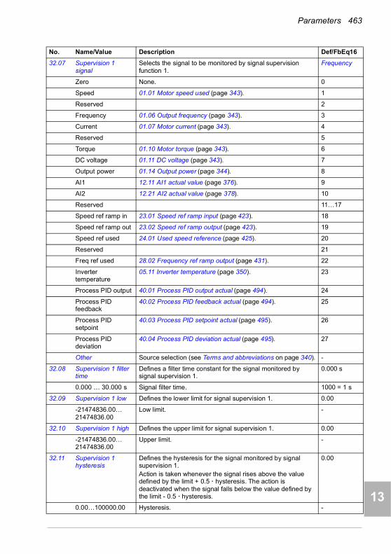
Parameters 463
1
2
3
4
5
6
7
8
9
10
11
12
13
32.07 Supervision 1 signal
Selects the signal to be monitored by signal supervision function 1.
Frequency
Zero None. 0
Speed 01.01 Motor speed used (page 343). 1
Reserved 2
Frequency 01.06 Output frequency (page 343). 3
Current 01.07 Motor current (page 343). 4
Reserved 5
Torque 01.10 Motor torque (page 343). 6
DC voltage 01.11 DC voltage (page 343). 7
Output power 01.14 Output power (page 344). 8
AI1 12.11 AI1 actual value (page 376). 9
AI2 12.21 AI2 actual value (page 378). 10
Reserved 11…17
Speed ref ramp in 23.01 Speed ref ramp input (page 423). 18
Speed ref ramp out 23.02 Speed ref ramp output (page 423). 19
Speed ref used 24.01 Used speed reference (page 425). 20
Reserved 21
Freq ref used 28.02 Frequency ref ramp output (page 431). 22
Inverter temperature
05.11 Inverter temperature (page 350). 23
Process PID output 40.01 Process PID output actual (page 494). 24
Process PID feedback
40.02 Process PID feedback actual (page 494). 25
Process PID setpoint
40.03 Process PID setpoint actual (page 495). 26
Process PID deviation
40.04 Process PID deviation actual (page 495). 27
Other Source selection (see Terms and abbreviations on page 340). -
32.08 Supervision 1 filter time
Defines a filter time constant for the signal monitored by signal supervision 1.
0.000 s
0.000 … 30.000 s Signal filter time. 1000 = 1 s
32.09 Supervision 1 low Defines the lower limit for signal supervision 1. 0.00
-21474836.00… 21474836.00
Low limit. -
32.10 Supervision 1 high Defines the upper limit for signal supervision 1. 0.00
-21474836.00… 21474836.00
Upper limit. -
32.11 Supervision 1 hysteresis
Defines the hysteresis for the signal monitored by signal supervision 1. Action is taken whenever the signal rises above the value defined by the limit + 0.5 · hysteresis. The action is deactivated when the signal falls below the value defined by the limit - 0.5 · hysteresis.
0.00
0.00…100000.00 Hysteresis. -
No. Name/Value Description Def/FbEq16
14

464 Parameters
1
2
3
4
5
7
8
9
9
10
11
12
13
14
32.15 Supervision 2 function
Selects the mode of signal supervision function 2. Determines how the monitored signal (see parameter 32.17) is compared to its lower and upper limits (32.19 and 32.20 respectively). The action to be taken when the condition is fulfilled is selected by 32.16.
Disabled
Disabled Signal supervision 2 not in use. 0
Low Action is taken whenever the signal falls below its lower limit. 1
High Action is taken whenever the signal rises above its upper limit.
2
Abs low Action is taken whenever the absolute value of the signal falls below its (absolute) lower limit.
3
Abs high Action is taken whenever the absolute value of the signal rises above its (absolute) upper limit.
4
Both Action is taken whenever the signal falls below its low limit or rises above its high limit.
5
Abs both Action is taken whenever the absolute value of the signal falls below its (absolute) low limit or rises above its (absolute) high limit.
6
Hysteresis See parameter 32.21 Supervision 2 hysteresis. 7
32.16 Supervision 2 action
Selects whether the drive generates a fault, warning or neither when the value monitored by signal supervision 2 exceeds its limits.Note: This parameter does not affect the status indicated by 32.01 Supervision status.
No action
No action No warning or fault generated. 0
Warning Drive generates warning A8B1 ABB Signal supervision 2. 1
Fault Drive trips on fault 80B1 Signal supervision 2. 2
Fault if running If running, the drive trips on fault 80B1 Signal supervision 2. 3
32.17 Supervision 2 signal
Selects the signal to be monitored by signal supervision function 2.For the available selections, see parameter 32.07 Supervision 1 signal.
Current
32.18 Supervision 2 filter time
Defines a filter time constant for the signal monitored by signal supervision 2.
0.000 s
0.000 … 30.000 s Signal filter time. 1000 = 1 s
32.19 Supervision 2 low Defines the lower limit for signal supervision 2. 0.00
-21474836.00… 21474836.00
Low limit. -
32.20 Supervision 2 high Defines the upper limit for signal supervision 2. 0.00
-21474836.00… 21474836.00
Upper limit. -
32.21 Supervision 2 hysteresis
Defines the hysteresis for the signal monitored by signal supervision 2.Action is taken whenever the signal rises above the value defined by the limit + 0.5 · hysteresis. The action is deactivated when the signal falls below the value defined by the limit - 0.5 · hysteresis.
0.00
0.00…100000.00 Hysteresis. -
No. Name/Value Description Def/FbEq16
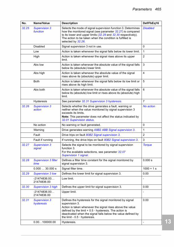
Parameters 465
1
2
3
4
5
6
7
8
9
10
11
12
13
32.25 Supervision 3 function
Selects the mode of signal supervision function 3. Determines how the monitored signal (see parameter 32.27) is compared to its lower and upper limits (32.29 and 32.30 respectively). The action to be taken when the condition is fulfilled is selected by 32.26.
Disabled
Disabled Signal supervision 3 not in use. 0
Low Action is taken whenever the signal falls below its lower limit. 1
High Action is taken whenever the signal rises above its upper limit.
2
Abs low Action is taken whenever the absolute value of the signal falls below its (absolute) lower limit.
3
Abs high Action is taken whenever the absolute value of the signal rises above its (absolute) upper limit.
4
Both Action is taken whenever the signal falls below its low limit or rises above its high limit.
5
Abs both Action is taken whenever the absolute value of the signal falls below its (absolute) low limit or rises above its (absolute) high limit.
6
Hysteresis See parameter 32.31 Supervision 3 hysteresis. 7
32.26 Supervision 3 action
Selects whether the drive generates a fault, warning or neither when the value monitored by signal supervision 3 exceeds its limits.Note: This parameter does not affect the status indicated by 32.01 Supervision status.
No action
No action No warning or fault generated. 0
Warning Drive generates warning A8B2 ABB Signal supervision 3. 1
Fault Drive trips on fault 80B2 Signal supervision 3. 2
Fault if running If running, the drive trips on fault 80B2 Signal supervision 3. 3
32.27 Supervision 3 signal
Selects the signal to be monitored by signal supervision function 3.For the available selections, see parameter 32.07 Supervision 1 signal.
Torque
32.28 Supervision 3 filter time
Defines a filter time constant for the signal monitored by signal supervision 3.
0.000 s
0.000 … 30.000 s Signal filter time. 1000 = 1 s
32.29 Supervision 3 low Defines the lower limit for signal supervision 3. 0.00
-21474836.00… 21474836.00
Low limit. -
32.30 Supervision 3 high Defines the upper limit for signal supervision 3. 0.00
-21474836.00… 21474836.00
Upper limit. -
32.31 Supervision 3 hysteresis
Defines the hysteresis for the signal monitored by signal supervision 3.Action is taken whenever the signal rises above the value defined by the limit + 0.5 · hysteresis. The action is deactivated when the signal falls below the value defined by the limit - 0.5 · hysteresis.
0.00
0.00…100000.00 Hysteresis. -
No. Name/Value Description Def/FbEq16
14

466 Parameters
1
2
3
4
5
7
8
9
9
10
11
12
13
14
32.35 Supervision 4 function
Selects the mode of signal supervision function 4. Determines how the monitored signal (see parameter 32.37) is compared to its lower and upper limits (32.39 and 32.30 respectively). The action to be taken when the condition is fulfilled is selected by 32.36.
Disabled
Disabled Signal supervision 4 not in use. 0
Low Action is taken whenever the signal falls below its lower limit. 1
High Action is taken whenever the signal rises above its upper limit.
2
Abs low Action is taken whenever the absolute value of the signal falls below its (absolute) lower limit.
3
Abs high Action is taken whenever the absolute value of the signal rises above its (absolute) upper limit.
4
Both Action is taken whenever the signal falls below its low limit or rises above its high limit.
5
Abs both Action is taken whenever the absolute value of the signal falls below its (absolute) low limit or rises above its (absolute) high limit.
6
Hysteresis See parameter 32.41 Supervision 4 hysteresis. 7
32.36 Supervision 4 action
Selects whether the drive generates a fault, warning or neither when the value monitored by signal supervision 4 exceeds its limits.Note: This parameter does not affect the status indicated by 32.01 Supervision status.
No action
No action No warning or fault generated. 0
Warning Drive generates warning A8B3 ABB Signal supervision 4. 1
Fault Drive trips on fault 80B3 Signal supervision 4. 2
Fault if running Drive trips on fault 80B3 Signal supervision 4 if the motor is running.
3
32.37 Supervision 4 signal
Selects the signal to be monitored by signal supervision function 4.For the available selections, see parameter 32.07 Supervision 1 signal.
Zero
32.38 Supervision 4 filter time
Defines a filter time constant for the signal monitored by signal supervision 4.
0.000 s
0.000 … 30.000 s Signal filter time. 1000 = 1 s
32.39 Supervision 4 low Defines the lower limit for signal supervision 4. 0.00
-21474836.00… 21474836.00
Low limit. -
32.40 Supervision 4 high Defines the upper limit for signal supervision 4. 0.00
-21474836.00… 21474836.00
Upper limit. -
32.41 Supervision 4 hysteresis
Defines the hysteresis for the signal monitored by signal supervision 4.Action is taken whenever the signal rises above the value defined by the limit + 0.5 · hysteresis. The action is deactivated when the signal falls below the value defined by the limit - 0.5 · hysteresis.
0.00
0.00…100000.00 Hysteresis. -
No. Name/Value Description Def/FbEq16

Parameters 467
1
2
3
4
5
6
7
8
9
10
11
12
13
32.45 Supervision 5 function
Selects the mode of signal supervision function 5. Determines how the monitored signal (see parameter 32.47) is compared to its lower and upper limits (32.49 and 32.40 respectively). The action to be taken when the condition is fulfilled is selected by 32.46.
Disabled
Disabled Signal supervision 5 not in use. 0
Low Action is taken whenever the signal falls below its lower limit. 1
High Action is taken whenever the signal rises above its upper limit.
2
Abs low Action is taken whenever the absolute value of the signal falls below its (absolute) lower limit.
3
Abs high Action is taken whenever the absolute value of the signal rises above its (absolute) upper limit.
4
Both Action is taken whenever the signal falls below its low limit or rises above its high limit.
5
Abs both Action is taken whenever the absolute value of the signal falls below its (absolute) low limit or rises above its (absolute) high limit.
6
Hysteresis See parameter 32.51 Supervision 5 hysteresis. 7
32.46 Supervision 5 action
Selects whether the drive generates a fault, warning or neither when the value monitored by signal supervision 5 exceeds its limits.Note: This parameter does not affect the status indicated by 32.01 Supervision status.
No action
No action No warning or fault generated. 0
Warning Drive generates warning A8B4 ABB Signal supervision 5. 1
Fault Drive trips on fault 80B4 Signal supervision 5. 2
Fault if running Drive trips on fault 80B4 Signal supervision 5 if the motor is running.
3
32.47 Supervision 5 signal
Selects the signal to be monitored by signal supervision function 5.For the available selections, see parameter 32.07 Supervision 1 signal.
Zero
32.48 Supervision 5 filter time
Defines a filter time constant for the signal monitored by signal supervision 5.
0.000 s
0.000 … 30.000 s Signal filter time. 1000 = 1 s
32.49 Supervision 5 low Defines the lower limit for signal supervision 5. 0.00
-21474836.00… 21474836.00
Low limit. -
32.50 Supervision 5 high Defines the upper limit for signal supervision 5. 0.00
-21474836.00… 21474836.00
Upper limit. -
32.51 Supervision 5 hysteresis
Defines the hysteresis for the signal monitored by signal supervision 5.Action is taken whenever the signal rises above the value defined by the limit + 0.5 · hysteresis. The action is deactivated when the signal falls below the value defined by the limit - 0.5 · hysteresis.
0.00
0.00…100000.00 Hysteresis. -
No. Name/Value Description Def/FbEq16
14

468 Parameters
1
2
3
4
5
7
8
9
9
10
11
12
13
14
32.55 Supervision 6 function
Selects the mode of signal supervision function 6. Determines how the monitored signal (see parameter 32.57) is compared to its lower and upper limits (32.59 and 32.50 respectively). The action to be taken when the condition is fulfilled is selected by 32.56.
Disabled
Disabled Signal supervision 6 not in use. 0
Low Action is taken whenever the signal falls below its lower limit. 1
High Action is taken whenever the signal rises above its upper limit.
2
Abs low Action is taken whenever the absolute value of the signal falls below its (absolute) lower limit.
3
Abs high Action is taken whenever the absolute value of the signal rises above its (absolute) upper limit.
4
Both Action is taken whenever the signal falls below its low limit or rises above its high limit.
5
Abs both Action is taken whenever the absolute value of the signal falls below its (absolute) low limit or rises above its (absolute) high limit.
6
Hysteresis See parameter 32.61 Supervision 6 hysteresis. 7
32.56 Supervision 6 action
Selects whether the drive generates a fault, warning or neither when the value monitored by signal supervision 6 exceeds its limits.Note: This parameter does not affect the status indicated by 32.01 Supervision status.
No action
No action No warning or fault generated. 0
Warning Drive generates warning A8B5 ABB Signal supervision 6. 1
Fault Drive trips on fault 80B5 Signal supervision 6 is generated. 2
Fault if running Drive trips on fault 80B5 Signal supervision 6 is generated if the motor is running.
3
32.57 Supervision 6 signal
Selects the signal to be monitored by signal supervision function 6.For the available selections, see parameter 32.07 Supervision 1 signal.
Zero
32.58 Supervision 6 filter time
Defines a filter time constant for the signal monitored by signal supervision 6.
0.000 s
0.000 … 30.000 s Signal filter time. 1000 = 1 s
32.59 Supervision 6 low Defines the lower limit for signal supervision 6. 0.00
-21474836.00… 21474836.00
Low limit. -
32.60 Supervision 6 high Defines the upper limit for signal supervision 6. 0.00
-21474836.00… 21474836.00
Upper limit. -
32.61 Supervision 6 hysteresis
Defines the hysteresis for the signal monitored by signal supervision 6.Action is taken whenever the signal rises above the value defined by the limit + 0.5 · hysteresis. The action is deactivated when the signal falls below the value defined by the limit - 0.5 · hysteresis.
0.00
0.00…100000.00 Hysteresis. -
No. Name/Value Description Def/FbEq16
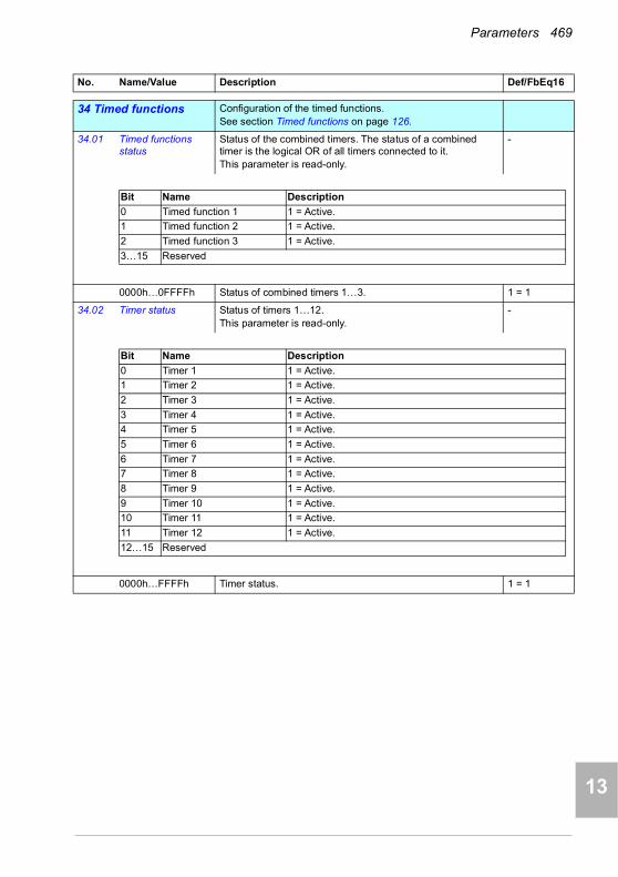
Parameters 469
1
2
3
4
5
6
7
8
9
10
11
12
13
3434 Timed functions Configuration of the timed functions.
See section Timed functions on page 126.
34.01 Timed functions status
Status of the combined timers. The status of a combined timer is the logical OR of all timers connected to it.This parameter is read-only.
-
0000h…0FFFFh Status of combined timers 1…3. 1 = 1
34.02 Timer status Status of timers 1…12.This parameter is read-only.
-
0000h…FFFFh Timer status. 1 = 1
No. Name/Value Description Def/FbEq16
Bit Name Description
0 Timed function 1 1 = Active.
1 Timed function 2 1 = Active.
2 Timed function 3 1 = Active.
3…15 Reserved
Bit Name Description
0 Timer 1 1 = Active.
1 Timer 2 1 = Active.
2 Timer 3 1 = Active.
3 Timer 4 1 = Active.
4 Timer 5 1 = Active.
5 Timer 6 1 = Active.
6 Timer 7 1 = Active.
7 Timer 8 1 = Active.
8 Timer 9 1 = Active.
9 Timer 10 1 = Active.
10 Timer 11 1 = Active.
11 Timer 12 1 = Active.
12…15 Reserved
14
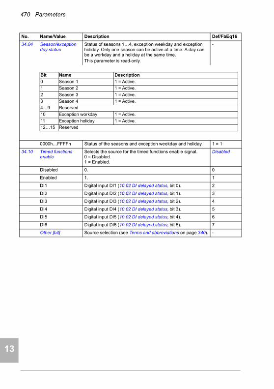
470 Parameters
1
2
3
4
5
7
8
9
9
10
11
12
13
14
34.04 Season/exception day status
Status of seasons 1…4, exception weekday and exception holiday. Only one season can be active at a time. A day can be a workday and a holiday at the same time.This parameter is read-only.
-
0000h…FFFFh Status of the seasons and exception weekday and holiday. 1 = 1
34.10 Timed functions enable
Selects the source for the timed functions enable signal.0 = Disabled.1 = Enabled.
Disabled
Disabled 0. 0
Enabled 1. 1
DI1 Digital input DI1 (10.02 DI delayed status, bit 0). 2
DI2 Digital input DI2 (10.02 DI delayed status, bit 1). 3
DI3 Digital input DI3 (10.02 DI delayed status, bit 2). 4
DI4 Digital input DI4 (10.02 DI delayed status, bit 3). 5
DI5 Digital input DI5 (10.02 DI delayed status, bit 4). 6
DI6 Digital input DI6 (10.02 DI delayed status, bit 5). 7
Other [bit] Source selection (see Terms and abbreviations on page 340). -
No. Name/Value Description Def/FbEq16
Bit Name Description
0 Season 1 1 = Active.
1 Season 2 1 = Active.
2 Season 3 1 = Active.
3 Season 4 1 = Active.
4…9 Reserved
10 Exception workday 1 = Active.
11 Exception holiday 1 = Active.
12…15 Reserved
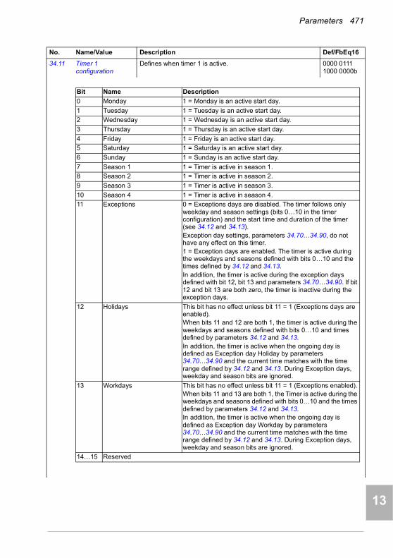
Parameters 471
1
2
3
4
5
6
7
8
9
10
11
12
13
34.11 Timer 1 configuration
Defines when timer 1 is active. 0000 0111 1000 0000b
No. Name/Value Description Def/FbEq16
Bit Name Description
0 Monday 1 = Monday is an active start day.
1 Tuesday 1 = Tuesday is an active start day.
2 Wednesday 1 = Wednesday is an active start day.
3 Thursday 1 = Thursday is an active start day.
4 Friday 1 = Friday is an active start day.
5 Saturday 1 = Saturday is an active start day.
6 Sunday 1 = Sunday is an active start day.
7 Season 1 1 = Timer is active in season 1.
8 Season 2 1 = Timer is active in season 2.
9 Season 3 1 = Timer is active in season 3.
10 Season 4 1 = Timer is active in season 4.
11 Exceptions 0 = Exceptions days are disabled. The timer follows only weekday and season settings (bits 0…10 in the timer configuration) and the start time and duration of the timer (see 34.12 and 34.13).Exception day settings, parameters 34.70…34.90, do not have any effect on this timer.1 = Exception days are enabled. The timer is active during the weekdays and seasons defined with bits 0…10 and the times defined by 34.12 and 34.13.In addition, the timer is active during the exception days defined with bit 12, bit 13 and parameters 34.70…34.90. If bit 12 and bit 13 are both zero, the timer is inactive during the exception days.
12 Holidays This bit has no effect unless bit 11 = 1 (Exceptions days are enabled).When bits 11 and 12 are both 1, the timer is active during the weekdays and seasons defined with bits 0…10 and times defined by parameters 34.12 and 34.13. In addition, the timer is active when the ongoing day is defined as Exception day Holiday by parameters 34.70…34.90 and the current time matches with the time range defined by 34.12 and 34.13. During Exception days, weekday and season bits are ignored.
13 Workdays This bit has no effect unless bit 11 = 1 (Exceptions enabled).When bits 11 and 13 are both 1, the Timer is active during the weekdays and seasons defined with bits 0…10 and the times defined by parameters 34.12 and 34.13. In addition, the timer is active when the ongoing day is defined as Exception day Workday by parameters 34.70…34.90 and the current time matches with the time range defined by 34.12 and 34.13. During Exception days, weekday and season bits are ignored.
14…15 Reserved
14

472 Parameters
1
2
3
4
5
7
8
9
9
10
11
12
13
14
Examples of how the timer configuration defines when the Timer is active are shown below.
0000h…FFFFh Configuration of timer 1. 1 = 1
34.12 Timer 1 start time Defines the daily start time of timer 1. The time can be changed in second steps. The timer can be started at an other time than the start time. For example, if the timer's duration is more than one day and the active session starts during the time, the timer is started at 00:00 and stopped when there is no duration left.
00:00:00
00:00:00…23:59:59 Daily start time of the timer. 1 = 1
No. Name/Value Description Def/FbEq16
Bits of parameter34.11 Timer 1 configuration
1 1 1 1 1 1 1 1 1 1 1 0 0 0 Example 1: Timer is active during the times of the day defined by other parameters every Weekday and every Season. Exception day settings (34.70…34.90) do not have any effect on the Timer.
1 1 1 1 1 0 0 1 1 1 1 0 0 0 Example 2: Timer is active during the times of the day defined by other parameters from Mon to Fri, every Season.Exception day settings (34.70…34.90) do not have any effect on the Timer.
1 1 1 1 1 0 0 0 0 1 0 0 0 0 Example 3: Timer is active during the times of the day defined by other parameters from Mon to Fri, only during Season 3 (can be configured as, eg, summer).Exception day settings (34.70…34.90) do not have any effect on the Timer.
1 1 1 1 1 0 0 1 1 1 1 1 1 0 Example 4: Timer is active during the times of the day defined by other parameters from Mon to Fri, every Season. In addition, the Timer is active every Exception day Holidays, regardless what is the day or season.
1 0 1 0 1 0 1 1 1 0 0 1 0 1 Example 5: Timer is active during the times of the day defined by other parameters on Mon, Wed, Fri and Sun, during Season1 and Season 2. In addition, the Timer is active every Exception day Workdays, regardless what is the day or season.
1 1 1 1 1 1 1 1 1 1 1 1 0 0 Example 6: Timer is active during the times of the day defined by other parameters every Weekday and every Season.The Timer is inactive during all Exception days.
Mo
nday
Tue
sday
We
dnes
day
Thu
rsda
yF
riday
Sat
urd
ayS
unda
yS
easo
n1S
easo
n2S
easo
n3S
easo
n4E
xcep
tion
sH
olid
ays
Wo
rkda
ys

Parameters 473
1
2
3
4
5
6
7
8
9
10
11
12
13
34.13 Timer 1 duration Defines the duration of timer 1. The duration can be changed in minute steps. The duration can extend over the change of the day but if an exception day becomes active, the period is interrupted at midnight. In the same way the period started on an exception day stays active only until the end of the day, even if the duration is longer. The timer will continue after a break if there is duration left.
00 00:00
00 00:00…07 00:00 Timer duration. 1 = 1
34.14 Timer 2 configuration
See 34.11 Timer 1 configuration. 0000 0111 1000 0000b
34.15 Timer 2 start time See 34.12 Timer 1 start time. 00:00:00
34.16 Timer 2 duration See 34.13 Timer 1 duration. 00 00:00
34.17 Timer 3 configuration
See 34.11 Timer 1 configuration. 0000 0111 1000 0000b
34.18 Timer 3 start time See 34.12 Timer 1 start time. 00:00:00
34.19 Timer 3 duration See 34.13 Timer 1 duration. 00 00:00
34.20 Timer 4 configuration
See 34.11 Timer 1 configuration. 0000 0111 1000 0000b
34.21 Timer 4 start time See 34.12 Timer 1 start time. 00:00:00
34.22 Timer 4 duration See 34.13 Timer 1 duration. 00 00:00
34.23 Timer 5 configuration
See 34.11 Timer 1 configuration. 0000 0111 1000 0000b
34.24 Timer 5 start time See 34.12 Timer 1 start time. 00:00:00
34.25 Timer 5 duration See 34.13 Timer 1 duration. 00 00:00
34.26 Timer 6 configuration
See 34.11 Timer 1 configuration. 0000 0111 1000 0000b
34.27 Timer 6 start time See 34.12 Timer 1 start time. 00:00:00
34.28 Timer 6 duration See 34.13 Timer 1 duration. 00 00:00
34.29 Timer 7 configuration
See 34.11 Timer 1 configuration. 0000 0111 1000 0000b
34.30 Timer 7 start time See 34.12 Timer 1 start time. 00:00:00
34.31 Timer 7 duration See 34.13 Timer 1 duration. 00 00:00
34.32 Timer 8 configuration
See 34.11 Timer 1 configuration. 0000 0111 1000 0000b
34.33 Timer 8 start time See 34.12 Timer 1 start time. 00:00:00
34.34 Timer 8 duration See 34.13 Timer 1 duration. 00 00:00
34.35 Timer 9 configuration
See 34.11 Timer 1 configuration. 0000 0111 1000 0000b
34.36 Timer 9 start time See 34.12 Timer 1 start time. 00:00:00
34.37 Timer 9 duration See 34.13 Timer 1 duration. 00 00:00
34.38 Timer 10 configuration
See 34.11 Timer 1 configuration. 0000 0111 1000 0000b
34.39 Timer 10 start time See 34.12 Timer 1 start time. 00:00:00
34.40 Timer 10 duration See 34.13 Timer 1 duration. 00 00:00
34.41 Timer 11 configuration
See 34.11 Timer 1 configuration. 0000 0111 1000 0000b
No. Name/Value Description Def/FbEq16
14

474 Parameters
1
2
3
4
5
7
8
9
9
10
11
12
13
14
34.42 Timer 11 start time See 34.12 Timer 1 start time. 00:00:00
34.43 Timer 11 duration See 34.13 Timer 1 duration. 00 00:00
34.44 Timer 12 configuration
See 34.11 Timer 1 configuration. 0000 0111 1000 0000b
34.45 Timer 12 start time See 34.12 Timer 1 start time. 00:00:00
34.46 Timer 12 duration See 34.13 Timer 1 duration. 00 00:00
34.60 Season 1 start date Defines the start date of season 1 in format dd.mm, where dd is the number of the day and mm is the number of the month.The season changes at midnight. One season can be active at a time. Timers are started on exception days even if they are not inside the active season.The season start dates (1…4) must be given in increasing order to use all seasons. The default value is interpreted that the season is not configured. If the season start dates are not in increasing order and the value is something else than the default value, a season configuration warning is given.
01.01.
01.01…31.12 Season start date.
34.61 Season 2 start date Defines the start date of season 2.See 34.60 Season 1 start date.
01.01.
34.62 Season 3 start date Defines the start date of season 3.See 34.60 Season 1 start date.
01.01.
34.63 Season 4 start date Defines the start date of season 4.See 34.60 Season 1 start date.
01.01.
34.70 Number of active exceptions
Defines how many of the exceptions are active by specifying the last active one. All preceding exceptions are active. Exceptions 1…3 are periods (duration can be defined) and exceptions 4…16 are days (duration is always 24 hours).Example: If the value is 4, exceptions 1…4 are active, and exceptions 5…16 are not active.
3
0…16 Number of active exception periods or days. -
No. Name/Value Description Def/FbEq16

Parameters 475
1
2
3
4
5
6
7
8
9
10
11
12
13
34.71 Exception types Defines the types of exceptions 1…16 as workday or holiday.Exceptions 1…3 are periods (duration can be defined) and exceptions 4…16 are days (duration is always 24 hours).
0000 0000 0000 0000b
0000h…FFFFh Types of exception period or days. 1 = 1
34.72 Exception 1 start Defines the start date of the exception period in format dd.mm, where dd is the number of the day and mm is the number of the month.The timer started on an exception day is always stopped at 23:59:59 even if it has duration left.The same date can be configured to be holiday and workday. The date is active if any of exception days are active.
01.01.
01.01.…31.12. Start date of exception period 1.
34.73 Exception 1 length Defines the length of the exception period in days.Exception period is handled the same as a number of consecutive exception days.
0 d
0…60 d Length of exception period 1. 1 = 1
34.74 Exception 2 start See 34.72 Exception 1 start. 01.01.
34.75 Exception 2 length See 34.73 Exception 1 length. 0 d
34.76 Exception 3 start See 34.72 Exception 1 start. 01.01.
34.77 Exception 3 length See 34.73 Exception 1 length. 0 d
34.78 Exception day 4 Defines the date of exception day 4. 01.01.
01.01.…31.12. Start date of exception day 4. The timer started on an exception day is always stopped at 23:59:59 even if it has duration left.
34.79 Exception day 5 See 34.79 Exception day 4. 01.01
34.80 Exception day 6 See 34.79 Exception day 4. 01.01
34.81 Exception day 7 See 34.79 Exception day 4 01.01
34.82 Exception day 8 See 34.79 Exception day 4. 01.01
No. Name/Value Description Def/FbEq16
Bit Name Description
0 Exception 1 0 = Workday. 1 = Holiday
1 Exception 2 0 = Workday. 1 = Holiday
2 Exception 3 0 = Workday. 1 = Holiday
3 Exception 4 0 = Workday. 1 = Holiday
4 Exception 5 0 = Workday. 1 = Holiday
5 Exception 6 0 = Workday. 1 = Holiday
6 Exception 7 0 = Workday. 1 = Holiday
7 Exception 8 0 = Workday. 1 = Holiday
8 Exception 9 0 = Workday. 1 = Holiday
9 Exception 10 0 = Workday. 1 = Holiday
10 Exception 11 0 = Workday. 1 = Holiday
11 Exception 12 0 = Workday. 1 = Holiday
12 Exception 13 0 = Workday. 1 = Holiday
13 Exception 14 0 = Workday. 1 = Holiday
14 Exception 15 0 = Workday. 1 = Holiday
15 Exception 16 0 = Workday. 1 = Holiday
14
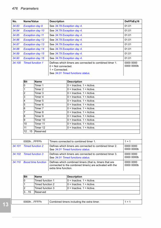
476 Parameters
1
2
3
4
5
7
8
9
9
10
11
12
13
14
34.83 Exception day 9 See 34.79 Exception day 4. 01.01
34.84 Exception day 10 See 34.79 Exception day 4. 01.01
34.85 Exception day 11 See 34.79 Exception day 4. 01.01
34.86 Exception day 12 See 34.79 Exception day 4. 01.01
34.87 Exception day 13 See 34.79 Exception day 4. 01.01
34.88 Exception day 14 See 34.79 Exception day 4. 01.01
34.89 Exception day 15 See 34.79 Exception day 4. 01.01
34.90 Exception day 16 See 34.79 Exception day 4. 01.01
34.100 Timed function 1 Defines which timers are connected to combined timer 1.0 = Not connected. 1 = Connected. See 34.01 Timed functions status.
0000 0000 0000 0000b
0000h…FFFFh Timers connected to combined timer 1. 1 = 1
34.101 Timed function 2 Defines which timers are connected to combined timer 2.See 34.01 Timed functions status.
0000 0000 0000 0000b
34.102 Timed function 3 Defines which timers are connected to combined timer 3.See 34.01 Timed functions status.
0000 0000 0000 0000b
34.110 Boost time function Defines which combined timers (that is, timers that are connected to the combined timers) are activated with the extra time function.
0000 0000 0000 0000b
0000h…FFFFh Combined timers including the extra timer. 1 = 1
No. Name/Value Description Def/FbEq16
Bit Name Description
0 Timer 1 0 = Inactive. 1 = Active.
1 Timer 2 0 = Inactive. 1 = Active.
2 Timer 3 0 = Inactive. 1 = Active.
3 Timer 4 0 = Inactive. 1 = Active.
4 Timer 5 0 = Inactive. 1 = Active.
5 Timer 6 0 = Inactive. 1 = Active.
6 Timer 7 0 = Inactive. 1 = Active.
7 Timer 8 0 = Inactive. 1 = Active.
8 Timer 9 0 = Inactive. 1 = Active.
9 Timer 10 0 = Inactive. 1 = Active.
10 Timer 11 0 = Inactive. 1 = Active.
11 Timer 12 0 = Inactive. 1 = Active.
12…15 Reserved
Bit Name Description
0 Timed function 1 0 = Inactive. 1 = Active.
1 Timed function 2 0 = Inactive. 1 = Active.
2 Timed function 3 0 = Inactive. 1 = Active.
3…15 Reserved
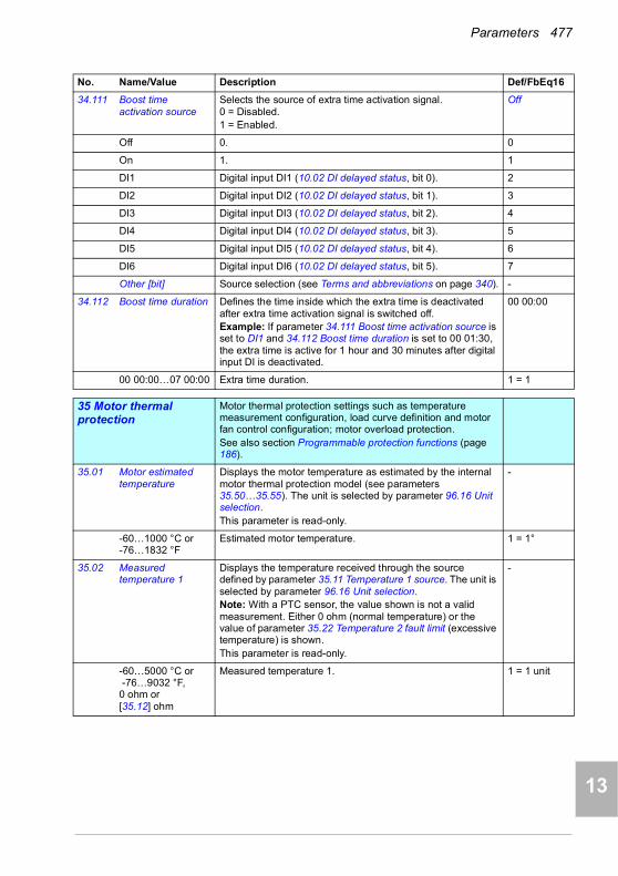
Parameters 477
1
2
3
4
5
6
7
8
9
10
11
12
13
34.111 Boost time activation source
Selects the source of extra time activation signal.0 = Disabled.1 = Enabled.
Off
Off 0. 0
On 1. 1
DI1 Digital input DI1 (10.02 DI delayed status, bit 0). 2
DI2 Digital input DI2 (10.02 DI delayed status, bit 1). 3
DI3 Digital input DI3 (10.02 DI delayed status, bit 2). 4
DI4 Digital input DI4 (10.02 DI delayed status, bit 3). 5
DI5 Digital input DI5 (10.02 DI delayed status, bit 4). 6
DI6 Digital input DI6 (10.02 DI delayed status, bit 5). 7
Other [bit] Source selection (see Terms and abbreviations on page 340). -
34.112 Boost time duration Defines the time inside which the extra time is deactivated after extra time activation signal is switched off. Example: If parameter 34.111 Boost time activation source is set to DI1 and 34.112 Boost time duration is set to 00 01:30, the extra time is active for 1 hour and 30 minutes after digital input DI is deactivated.
00 00:00
00 00:00…07 00:00 Extra time duration. 1 = 1
3535 Motor thermal protection
Motor thermal protection settings such as temperature measurement configuration, load curve definition and motor fan control configuration; motor overload protection.See also section Programmable protection functions (page 186).
35.01 Motor estimated temperature
Displays the motor temperature as estimated by the internal motor thermal protection model (see parameters 35.50…35.55). The unit is selected by parameter 96.16 Unit selection.This parameter is read-only.
-
-60…1000 °C or-76…1832 °F
Estimated motor temperature. 1 = 1°
35.02 Measured temperature 1
Displays the temperature received through the source defined by parameter 35.11 Temperature 1 source. The unit is selected by parameter 96.16 Unit selection.Note: With a PTC sensor, the value shown is not a valid measurement. Either 0 ohm (normal temperature) or the value of parameter 35.22 Temperature 2 fault limit (excessive temperature) is shown.This parameter is read-only.
-
-60…5000 °C or -76…9032 °F, 0 ohm or [35.12] ohm
Measured temperature 1. 1 = 1 unit
No. Name/Value Description Def/FbEq16
14
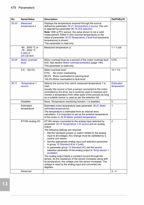
478 Parameters
1
2
3
4
5
7
8
9
9
10
11
12
13
14
35.03 Measured temperature 2
Displays the temperature received through the source defined by parameter 35.21 Temperature 2 source. The unit is selected by parameter 96.16 Unit selection.Note: With a PTC sensor, the value shown is not a valid measurement. Either 0 ohm (normal temperature) or the value of parameter 35.22 Temperature 2 fault limit (excessive temperature) is shown.This parameter is read-only.
-
-60…5000 °C or-76…9032 °F, 0 ohm or [35.22] ohm
Measured temperature 2. 1 = 1 unit
35.05 Motor overload level
Motor overload level as a percent of the motor overload fault limit. See section Motor overload protection (page 140).This parameter is read-only.
0.0%
0.0…100.0% Motor overload level.0.0% No motor overloading88.0% Motor overloaded to warning level100.0% Motor overloaded to fault level.
10 = 1%
35.11 Temperature 1 source
Selects the source from which measured temperature 1 is read.Usually this source is from a sensor connected to the motor controlled by the drive, but it could be used to measure and monitor a temperature from other parts of the process as long as a suitable sensor is used as per the selection list.
Estimated temperature
Disabled None. Temperature monitoring function 1 is disabled. 0
Estimated temperature
Estimated motor temperature (see parameter 35.01 Motor estimated temperature).The temperature is estimated from an internal drive calculation. It is important to set up the ambient temperature of the motor in 35.50 Motor ambient temperature.
1
KTY84 analog I/O KTY84 sensor connected to the analog input selected by parameter 35.14 Temperature 1 AI source and an analog output. The following settings are required:• Set the hardware jumper or switch related to the analog
input to U (voltage). Any change must be validated by a control unit reboot.
• Set the appropriate analog input unit selection parameter in group 12 Standard AI to V (volt).
• In parameter group 13 Standard AO, set the source selection parameter of the analog output to Temp sensor 1 excitation.
The analog output feeds a constant current through the sensor. As the resistance of the sensor increases along with its temperature, the voltage over the sensor increases. The voltage is read by the analog input and converted into degrees.
2
Reserved 3…4
No. Name/Value Description Def/FbEq16
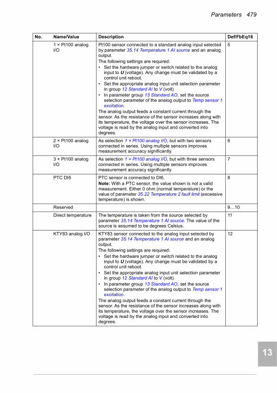
Parameters 479
1
2
3
4
5
6
7
8
9
10
11
12
13
1 × Pt100 analog I/O
Pt100 sensor connected to a standard analog input selected by parameter 35.14 Temperature 1 AI source and an analog output.The following settings are required:• Set the hardware jumper or switch related to the analog
input to U (voltage). Any change must be validated by a control unit reboot.
• Set the appropriate analog input unit selection parameter in group 12 Standard AI to V (volt).
• In parameter group 13 Standard AO, set the source selection parameter of the analog output to Temp sensor 1 excitation.
The analog output feeds a constant current through the sensor. As the resistance of the sensor increases along with its temperature, the voltage over the sensor increases. The voltage is read by the analog input and converted into degrees.
5
2 × Pt100 analog I/O
As selection 1 × Pt100 analog I/O, but with two sensors connected in series. Using multiple sensors improves measurement accuracy significantly.
6
3 × Pt100 analog I/O
As selection 1 × Pt100 analog I/O, but with three sensors connected in series. Using multiple sensors improves measurement accuracy significantly.
7
PTC DI6 PTC sensor is connected to DI6.Note: With a PTC sensor, the value shown is not a valid measurement. Either 0 ohm (normal temperature) or the value of parameter 35.22 Temperature 2 fault limit (excessive temperature) is shown.
8
Reserved 9…10
Direct temperature The temperature is taken from the source selected by parameter 35.14 Temperature 1 AI source. The value of the source is assumed to be degrees Celsius.
11
KTY83 analog I/O KTY83 sensor connected to the analog input selected by parameter 35.14 Temperature 1 AI source and an analog output. The following settings are required:• Set the hardware jumper or switch related to the analog
input to U (voltage). Any change must be validated by a control unit reboot.
• Set the appropriate analog input unit selection parameter in group 12 Standard AI to V (volt).
• In parameter group 13 Standard AO, set the source selection parameter of the analog output to Temp sensor 1 excitation.
The analog output feeds a constant current through the sensor. As the resistance of the sensor increases along with its temperature, the voltage over the sensor increases. The voltage is read by the analog input and converted into degrees.
12
No. Name/Value Description Def/FbEq16
14

480 Parameters
1
2
3
4
5
7
8
9
9
10
11
12
13
14
1 × Pt1000 analog I/O
Pt1000 sensor connected to a standard analog input selected by parameter 35.14 Temperature 1 AI source and an analog output.The following settings are required:• Set the hardware jumper or switch related to the analog
input to U (voltage). Any change must be validated by a control unit reboot.
• Set the appropriate analog input unit selection parameter in group 12 Standard AI to V (volt).
• In parameter group 13 Standard AO, set the source selection parameter of the analog output to Temp sensor 1 excitation.
The analog output feeds a constant current through the sensor. As the resistance of the sensor increases along with its temperature, the voltage over the sensor increases. The voltage is read by the analog input and converted into degrees.
13
2 × Pt1000 analog I/O
As selection 1 × Pt1000 analog I/O, but with two sensors connected in series. Using multiple sensors improves measurement accuracy significantly.
14
3 × Pt1000 analog I/O
As selection 1 × Pt1000 analog I/O, but with three sensors connected in series. Using multiple sensors improves measurement accuracy significantly.
15
Ni1000 Ni1000 sensor connected to the analog input selected by parameter 35.14 Temperature 1 AI source and an analog output. The following settings are required:• Set the hardware jumper or switch related to the analog
input to U (voltage). Any change must be validated by a control unit reboot.
• Set the appropriate analog input unit selection parameter in group 12 Standard AI to V (volt).
• In parameter group 13 Standard AO, set the source selection parameter of the analog output to Temp sensor 1 excitation.
The analog output feeds a constant current through the sensor. As the resistance of the sensor increases along with its temperature, the voltage over the sensor increases. The voltage is read by the analog input and converted into degrees.
16
Reserved 17…18
PTC extension module
PTC is connected to the CMOD-02 multifunction extension module, which is installed in drive slot 2. See chapter Optional I/O extension modules, section CMOD-02 multifunction extension module (external 24 V AC/DC and isolated PTC interface) in the Hardware manual of the drive).
19
Reserved 20
Therm(0) PTC sensor or a normally closed thermistor relay connected to digital input DI6. The motor is overheated when the digital input is 0.
21
Therm(1) Normally open thermistor relay connected to digital input DI6. The motor is overheated when the digital input is 1.
22
No. Name/Value Description Def/FbEq16
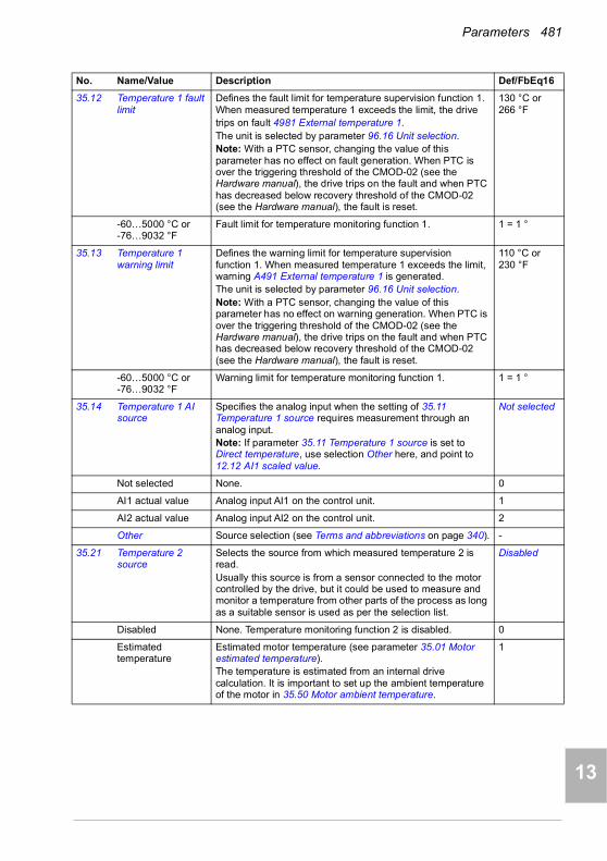
Parameters 481
1
2
3
4
5
6
7
8
9
10
11
12
13
35.12 Temperature 1 fault limit
Defines the fault limit for temperature supervision function 1. When measured temperature 1 exceeds the limit, the drivetrips on fault 4981 External temperature 1.The unit is selected by parameter 96.16 Unit selection.Note: With a PTC sensor, changing the value of this parameter has no effect on fault generation. When PTC is over the triggering threshold of the CMOD-02 (see the Hardware manual), the drive trips on the fault and when PTC has decreased below recovery threshold of the CMOD-02 (see the Hardware manual), the fault is reset.
130 °C or 266 °F
-60…5000 °C or -76…9032 °F
Fault limit for temperature monitoring function 1. 1 = 1 °
35.13 Temperature 1 warning limit
Defines the warning limit for temperature supervision function 1. When measured temperature 1 exceeds the limit, warning A491 External temperature 1 is generated.The unit is selected by parameter 96.16 Unit selection.Note: With a PTC sensor, changing the value of this parameter has no effect on warning generation. When PTC is over the triggering threshold of the CMOD-02 (see the Hardware manual), the drive trips on the fault and when PTC has decreased below recovery threshold of the CMOD-02 (see the Hardware manual), the fault is reset.
110 °C or 230 °F
-60…5000 °C or -76…9032 °F
Warning limit for temperature monitoring function 1. 1 = 1 °
35.14 Temperature 1 AI source
Specifies the analog input when the setting of 35.11 Temperature 1 source requires measurement through an analog input.Note: If parameter 35.11 Temperature 1 source is set to Direct temperature, use selection Other here, and point to 12.12 AI1 scaled value.
Not selected
Not selected None. 0
AI1 actual value Analog input AI1 on the control unit. 1
AI2 actual value Analog input AI2 on the control unit. 2
Other Source selection (see Terms and abbreviations on page 340). -
35.21 Temperature 2 source
Selects the source from which measured temperature 2 is read.Usually this source is from a sensor connected to the motor controlled by the drive, but it could be used to measure and monitor a temperature from other parts of the process as long as a suitable sensor is used as per the selection list.
Disabled
Disabled None. Temperature monitoring function 2 is disabled. 0
Estimated temperature
Estimated motor temperature (see parameter 35.01 Motor estimated temperature).The temperature is estimated from an internal drive calculation. It is important to set up the ambient temperature of the motor in 35.50 Motor ambient temperature.
1
No. Name/Value Description Def/FbEq16
14

482 Parameters
1
2
3
4
5
7
8
9
9
10
11
12
13
14
KTY84 analog I/O KTY84 sensor connected to the analog input selected by parameter 35.24 Temperature 2 AI source and an analog output. The following settings are required:• Set the hardware jumper or switch related to the analog
input to U (voltage). Any change must be validated by a control unit reboot.
• Set the appropriate analog input unit selection parameter in group 12 Standard AI to V (volt).
• In parameter group 13 Standard AO, set the source selection parameter of the analog output to Temp sensor 2 excitation.
The analog output feeds a constant current through the sensor. As the resistance of the sensor increases along with its temperature, the voltage over the sensor increases. The voltage is read by the analog input and converted into degrees.
2
Reserved 3…4
1 × Pt100 analog I/O
Pt100 sensor connected to a standard analog input selected by parameter 35.24 Temperature 2 AI source and an analog output.The following settings are required:• Set the hardware jumper or switch related to the analog
input to U (voltage). Any change must be validated by a control unit reboot.
• Set the appropriate analog input unit selection parameter in group 12 Standard AI to V (volt).
• In parameter group 13 Standard AO, set the source selection parameter of the analog output to Temp sensor 2 excitation.
The analog output feeds a constant current through the sensor. As the resistance of the sensor increases along with its temperature, the voltage over the sensor increases. The voltage is read by the analog input and converted into degrees.
5
2 × Pt100 analog I/O
As selection 1 × Pt100 analog I/O, but with two sensors connected in series. Using multiple sensors improves measurement accuracy significantly.
6
3 × Pt100 analog I/O
As selection 1 × Pt100 analog I/O, but with three sensors connected in series. Using multiple sensors improves measurement accuracy significantly.
7
PTC DI6 PTC sensor is connected to DI6.Note: With a PTC sensor, the value shown is not a valid measurement. Either 0 ohm (normal temperature) or the value of parameter 35.22 Temperature 2 fault limit (excessive temperature) is shown.
8
Reserved 9…10
Direct temperature The temperature is taken from the source selected by parameter 35.24 Temperature 2 AI source. The value of the source is assumed to be degrees Celsius.
11
No. Name/Value Description Def/FbEq16

Parameters 483
1
2
3
4
5
6
7
8
9
10
11
12
13
KTY83 analog I/O KTY83 sensor connected to the analog input selected by parameter 35.14 Temperature 1 AI source and an analog output. The following settings are required:• Set the hardware jumper or switch related to the analog
input to U (voltage). Any change must be validated by a control unit reboot.
• Set the appropriate analog input unit selection parameter in group 12 Standard AI to V (volt).
• In parameter group 13 Standard AO, set the source selection parameter of the analog output to Temp sensor 2 excitation.
The analog output feeds a constant current through the sensor. As the resistance of the sensor increases along with its temperature, the voltage over the sensor increases. The voltage is read by the analog input and converted into degrees.
12
1 × Pt1000 analog I/O
Pt1000 sensor connected to a standard analog input selected by parameter 35.14 Temperature 1 AI source and an analog output.The following settings are required:• Set the hardware jumper or switch related to the analog
input to U (voltage). Any change must be validated by a control unit reboot.
• Set the appropriate analog input unit selection parameter in group 12 Standard AI to V (volt).
• In parameter group 13 Standard AO, set the source selection parameter of the analog output to Temp sensor 2 excitation.
The analog output feeds a constant current through the sensor. As the resistance of the sensor increases along with its temperature, the voltage over the sensor increases. The voltage is read by the analog input and converted into degrees.
13
2 × Pt1000 analog I/O
As selection 1 × Pt1000 analog I/O, but with two sensors connected in series. Using multiple sensors improves measurement accuracy significantly.
14
3 × Pt1000 analog I/O
As selection 1 × Pt1000 analog I/O, but with three sensors connected in series. Using multiple sensors improves measurement accuracy significantly.
15
Ni1000 Ni1000 sensor connected to the analog input selected by parameter 35.14 Temperature 1 AI source and an analog output. The following settings are required:• Set the hardware jumper or switch related to the analog
input to U (voltage). Any change must be validated by a control unit reboot.
• Set the appropriate analog input unit selection parameter in group 12 Standard AI to V (volt).
• In parameter group 13 Standard AO, set the source selection parameter of the analog output to Temp sensor 2 excitation.
The analog output feeds a constant current through the sensor. As the resistance of the sensor increases along with its temperature, the voltage over the sensor increases. The voltage is read by the analog input and converted into degrees.
16
No. Name/Value Description Def/FbEq16
14
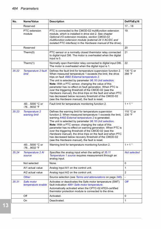
484 Parameters
1
2
3
4
5
7
8
9
9
10
11
12
13
14
Reserved 17…18
PTC extension module
PTC is connected to the CMOD-02 multifunction extension module, which is installed in drive slot 2. See chapter Optional I/O extension modules, section CMOD-02 multifunction extension module (external 24 V AC/DC and isolated PTC interface) in the Hardware manual of the drive).
19
Reserved 20
Therm(0) PTC sensor or a normally closed thermistor relay connected to digital input DI6. The motor is overheated when the digital input is 0.
21
Therm(1) Normally open thermistor relay connected to digital input DI6. The motor is overheated when the digital input is 1.
22
35.22 Temperature 2 fault limit
Defines the fault limit for temperature supervision function 2. When measured temperature 1 exceeds the limit, the drive trips on fault 4982 External temperature 2.The unit is selected by parameter 96.16 Unit selection.Note: With a PTC sensor, changing the value of this parameter has no effect on fault generation. When PTC is over the triggering threshold of the CMOD-02 (see the Hardware manual), the drive trips on the fault and when PTC has decreased below recovery threshold of the CMOD-02 (see the Hardware manual), the fault is reset.
130 °C or 266 °F
-60…5000 °C or -76…9032 °F
Fault limit for temperature monitoring function 2. 1 = 1 °
35.23 Temperature 2 warning limit
Defines the warning limit for temperature supervision function 2. When measured temperature 1 exceeds the limit, warning A492 External temperature 2 is generated.The unit is selected by parameter 96.16 Unit selection.Note: With a PTC sensor, changing the value of this parameter has no effect on warning generation. When PTC is over the triggering threshold of the CMOD-02 (see the Hardware manual), the drive trips on the fault and when PTC has decreased below recovery threshold of the CMOD-02 (see the Hardware manual), the fault is reset.
110 °C or 230 °F
-60…5000 °C or -76…9032 °F
Warning limit for temperature monitoring function 2. 1 = 1 °
35.24 Temperature 2 AI source
Specifies the analog input when the setting of 35.11 Temperature 1 source requires measurement through an analog input.
Not selected
Not selected None. 0
AI1 actual value Analog input AI1 on the control unit. 1
AI2 actual value Analog input AI2 on the control unit. 2
Other Source selection (see Terms and abbreviations on page 340). -
35.31 Safe motor temperature enable
Activates or deactivates the Safe motor temperature (SMT) fault indication 4991 Safe motor temperature.Automatically activated when the CPTC-02 ATEX-certified thermistor protection module is connected to the drive.
Off
Off Activated. 0
On Deactivated. 1
No. Name/Value Description Def/FbEq16
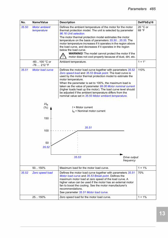
Parameters 485
1
2
3
4
5
6
7
8
9
10
11
12
13
35.50 Motor ambient temperature
Defines the ambient temperature of the motor for the motor thermal protection model. The unit is selected by parameter 96.16 Unit selection.The motor thermal protection model estimates the motor temperature on the basis of parameters 35.50…35.55. The motor temperature increases if it operates in the region above the load curve, and decreases if it operates in the region below the load curve.
WARNING! The model cannot protect the motor if the motor does not cool properly because of dust, dirt, etc.
20 °C or 68 °F
-60…100 °C or -76 … 212 °F
Ambient temperature. 1 = 1°
35.51 Motor load curve Defines the motor load curve together with parameters 35.52 Zero speed load and 35.53 Break point. The load curve is used by the motor thermal protection model to estimate the motor temperature.When the parameter is set to 100%, the maximum load is taken as the value of parameter 99.06 Motor nominal current (higher loads heat up the motor). The load curve level should be adjusted if the ambient temperature differs from the nominal value set in 35.50 Motor ambient temperature.
110%
50…150% Maximum load for the motor load curve. 1 = 1%
35.52 Zero speed load Defines the motor load curve together with parameters 35.51 Motor load curve and 35.53 Break point. Defines the maximum motor load at zero speed of the load curve. A higher value can be used if the motor has an external motor fan to boost the cooling. See the motor manufacturer's recommendations.See parameter 35.51 Motor load curve.
70%
25…150% Zero speed load for the motor load curve. 1 = 1%
No. Name/Value Description Def/FbEq16
50
100
150
35.51
35.53
35.52
I/IN(%) I = Motor current
IN = Nominal motor current
Drive outputfrequency
14

486 Parameters
1
2
3
4
5
7
8
9
9
10
11
12
13
14
35.53 Break point Defines the motor load curve together with parameters 35.51 Motor load curve and 35.52 Zero speed load. Defines the break point frequency of the load curve, ie, the point at which the motor load curve begins to decrease from the value of parameter 35.51 Motor load curve towards the value of parameter 35.52 Zero speed load. See parameter 35.51 Motor load curve.
45.00 Hz
1.00…500.00 Hz Break point for the motor load curve. See par. 46.02
35.54 Motor nominal temperature rise
Defines the temperature rise of the motor above ambient when the motor is loaded with nominal current. See the motor manufacturer's recommendations.The unit is selected by parameter 96.16 Unit selection.
80 °C or 176 °F
0…300 °C or 32…572 °F
Temperature rise. 1 = 1°
No. Name/Value Description Def/FbEq16
Motor nominaltemperature rise
Temperature
Time
Ambient temperature
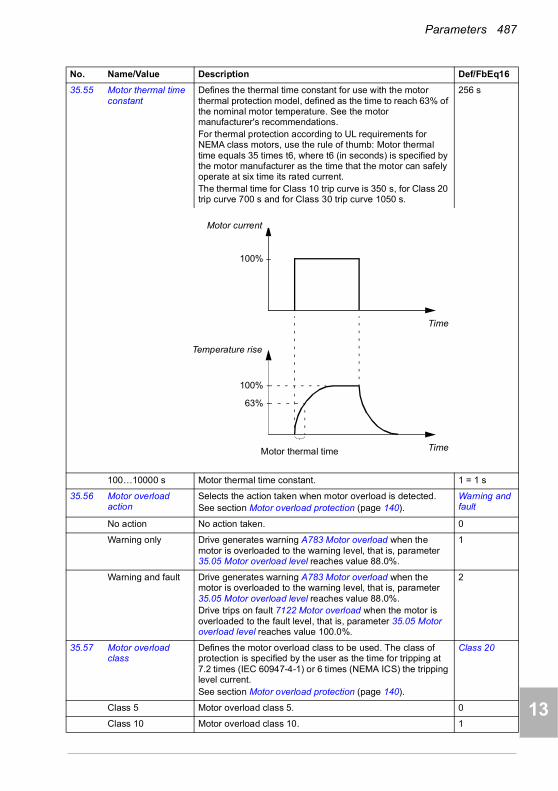
Parameters 487
1
2
3
4
5
6
7
8
9
10
11
12
13
35.55 Motor thermal time constant
Defines the thermal time constant for use with the motor thermal protection model, defined as the time to reach 63% of the nominal motor temperature. See the motor manufacturer's recommendations.For thermal protection according to UL requirements for NEMA class motors, use the rule of thumb: Motor thermal time equals 35 times t6, where t6 (in seconds) is specified by the motor manufacturer as the time that the motor can safely operate at six time its rated current.The thermal time for Class 10 trip curve is 350 s, for Class 20 trip curve 700 s and for Class 30 trip curve 1050 s.
256 s
100…10000 s Motor thermal time constant. 1 = 1 s
35.56 Motor overload action
Selects the action taken when motor overload is detected.See section Motor overload protection (page 140).
Warning and fault
No action No action taken. 0
Warning only Drive generates warning A783 Motor overload when the motor is overloaded to the warning level, that is, parameter 35.05 Motor overload level reaches value 88.0%.
1
Warning and fault Drive generates warning A783 Motor overload when the motor is overloaded to the warning level, that is, parameter 35.05 Motor overload level reaches value 88.0%.Drive trips on fault 7122 Motor overload when the motor is overloaded to the fault level, that is, parameter 35.05 Motor overload level reaches value 100.0%.
2
35.57 Motor overload class
Defines the motor overload class to be used. The class of protection is specified by the user as the time for tripping at 7.2 times (IEC 60947-4-1) or 6 times (NEMA ICS) the tripping level current.See section Motor overload protection (page 140).
Class 20
Class 5 Motor overload class 5. 0
Class 10 Motor overload class 10. 1
No. Name/Value Description Def/FbEq16
100%
63%
100%
Time
Time
Motor thermal time
Motor current
Temperature rise
14

488 Parameters
1
2
3
4
5
7
8
9
9
10
11
12
13
14
Class 20 Motor overload class 20. 2
Class 30 Motor overload class 30. 3
Class 40 Motor overload class 40. 4
3636 Load analyzer Peak value and amplitude logger settings.
See also section Load analyzer (page 183).
36.01 PVL signal source Selects the signal to be monitored by the peak value logger.The signal is filtered using the filtering time specified by parameter 36.02 PVL filter time.The peak value is stored, along with other pre-selected signals at the time, into parameters 36.10…36.15.The peak value logger can be reset using parameter 36.09 Reset loggers. The logger is also reset whenever the signal source is changed. The date and time of the last reset are stored into parameters 36.16 and 36.17 respectively.
Motor current
Not selected None (peak value logger disabled). 0
Motor speed used 01.01 Motor speed used (page 343). 1
Reserved 2
Output frequency 01.06 Output frequency (page 343). 3
Motor current 01.07 Motor current (page 343). 4
Reserved 5
Motor torque 01.10 Motor torque (page 343). 6
DC voltage 01.11 DC voltage (page 343). 7
Output power 01.14 Output power (page 344). 8
Reserved 9
Speed ref ramp in 23.01 Speed ref ramp input (page 423). 10
Speed ref ramp out 23.02 Speed ref ramp output (page 423). 11
Speed ref used 24.01 Used speed reference (page 425). 12
Reserved 13
Freq ref used 28.02 Frequency ref ramp output (page 431). 14
Reserved 15
Process PID out 40.01 Process PID output actual (page 494). 16
Other Source selection (see Terms and abbreviations on page 340). -
36.02 PVL filter time Peak value logger filtering time. See parameter 36.01 PVL signal source.
2.00 s
0.00…120.00 s Peak value logger filtering time. 100 = 1 s
No. Name/Value Description Def/FbEq16
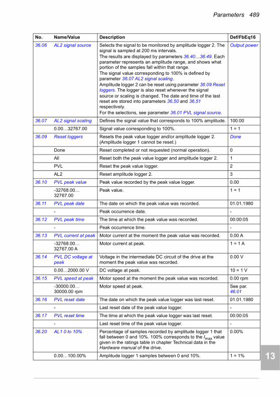
Parameters 489
1
2
3
4
5
6
7
8
9
10
11
12
13
36.06 AL2 signal source Selects the signal to be monitored by amplitude logger 2. The signal is sampled at 200 ms intervals.The results are displayed by parameters 36.40…36.49. Each parameter represents an amplitude range, and shows what portion of the samples fall within that range.The signal value corresponding to 100% is defined by parameter 36.07 AL2 signal scaling.Amplitude logger 2 can be reset using parameter 36.09 Reset loggers. The logger is also reset whenever the signalsource or scaling is changed. The date and time of the last reset are stored into parameters 36.50 and 36.51 respectively.For the selections, see parameter 36.01 PVL signal source.
Output power
36.07 AL2 signal scaling Defines the signal value that corresponds to 100% amplitude. 100.00
0.00…32767.00 Signal value corresponding to 100%. 1 = 1
36.09 Reset loggers Resets the peak value logger and/or amplitude logger 2. (Amplitude logger 1 cannot be reset.)
Done
Done Reset completed or not requested (normal operation). 0
All Reset both the peak value logger and amplitude logger 2. 1
PVL Reset the peak value logger. 2
AL2 Reset amplitude logger 2. 3
36.10 PVL peak value Peak value recorded by the peak value logger. 0.00
-32768.00… 32767.00
Peak value. 1 = 1
36.11 PVL peak date The date on which the peak value was recorded. 01.01.1980
- Peak occurrence date. -
36.12 PVL peak time The time at which the peak value was recorded. 00:00:05
- Peak occurrence time. -
36.13 PVL current at peak Motor current at the moment the peak value was recorded. 0.00 A
-32768.00… 32767.00 A
Motor current at peak. 1 = 1 A
36.14 PVL DC voltage at peak
Voltage in the intermediate DC circuit of the drive at the moment the peak value was recorded.
0.00 V
0.00…2000.00 V DC voltage at peak. 10 = 1 V
36.15 PVL speed at peak Motor speed at the moment the peak value was recorded. 0.00 rpm
-30000.00… 30000.00 rpm
Motor speed at peak. See par. 46.01
36.16 PVL reset date The date on which the peak value logger was last reset. 01.01.1980
- Last reset date of the peak value logger. -
36.17 PVL reset time The time at which the peak value logger was last reset. 00:00:05
- Last reset time of the peak value logger. -
36.20 AL1 0 to 10% Percentage of samples recorded by amplitude logger 1 that fall between 0 and 10%. 100% corresponds to the Imax value given in the ratings table in chapter Technical data in the Hardware manual of the drive.
0.00%
0.00…100.00% Amplitude logger 1 samples between 0 and 10%. 1 = 1%
No. Name/Value Description Def/FbEq16
14

490 Parameters
1
2
3
4
5
7
8
9
9
10
11
12
13
14
36.21 AL1 10 to 20% Percentage of samples recorded by amplitude logger 1 that fall between 10 and 20%.
0.00%
0.00…100.00% Amplitude logger 1 samples between 10 and 20%. 1 = 1%
36.22 AL1 20 to 30% Percentage of samples recorded by amplitude logger 1 that fall between 20 and 30%.
0.00%
0.00…100.00% Amplitude logger 1 samples between 20 and 30%. 1 = 1%
36.23 AL1 30 to 40% Percentage of samples recorded by amplitude logger 1 that fall between 30 and 40%.
0.00%
0.00…100.00% Amplitude logger 1 samples between 30 and 40%. 1 = 1%
36.24 AL1 40 to 50% Percentage of samples recorded by amplitude logger 1 that fall between 40 and 50%.
0.00%
0.00…100.00% Amplitude logger 1 samples between 40 and 50%. 1 = 1%
36.25 AL1 50 to 60% Percentage of samples recorded by amplitude logger 1 that fall between 50 and 60%.
0.00%
0.00…100.00% Amplitude logger 1 samples between 50 and 60%. 1 = 1%
36.26 AL1 60 to 70% Percentage of samples recorded by amplitude logger 1 that fall between 60 and 70%.
0.00%
0.00…100.00% Amplitude logger 1 samples between 60 and 70%. 1 = 1%
36.27 AL1 70 to 80% Percentage of samples recorded by amplitude logger 1 that fall between 70 and 80%.
0.00%
0.00…100.00% Amplitude logger 1 samples between 70 and 80%. 1 = 1%
36.28 AL1 80 to 90% Percentage of samples recorded by amplitude logger 1 that fall between 80 and 90%.
0.00%
0.00…100.00% Amplitude logger 1 samples between 80 and 90%. 1 = 1%
36.29 AL1 over 90% Percentage of samples recorded by amplitude logger 1 that exceed 90%.
0.00%
0.00…100.00% Amplitude logger 1 samples over 90%. 1 = 1%
36.40 AL2 0 to 10% Percentage of samples recorded by amplitude logger 2 that fall between 0 and 10%.
0.00%
0.00…100.00% Amplitude logger 2 samples between 0 and 10%. 1 = 1%
36.41 AL2 10 to 20% Percentage of samples recorded by amplitude logger 2 that fall between 10 and 20%.
0.00%
0.00…100.00% Amplitude logger 2 samples between 10 and 20%. 1 = 1%
36.42 AL2 20 to 30% Percentage of samples recorded by amplitude logger 2 that fall between 20 and 30%.
0.00%
0.00…100.00% Amplitude logger 2 samples between 20 and 30%. 1 = 1%
36.43 AL2 30 to 40% Percentage of samples recorded by amplitude logger 2 that fall between 30 and 40%.
0.00%
0.00…100.00% Amplitude logger 2 samples between 30 and 40%. 1 = 1%
36.44 AL2 40 to 50% Percentage of samples recorded by amplitude logger 2 that fall between 40 and 50%.
0.00%
0.00…100.00% Amplitude logger 2 samples between 40 and 50%. 1 = 1%
36.45 AL2 50 to 60% Percentage of samples recorded by amplitude logger 2 that fall between 50 and 60%.
0.00%
0.00…100.00% Amplitude logger 2 samples between 50 and 60%. 1 = 1%
No. Name/Value Description Def/FbEq16
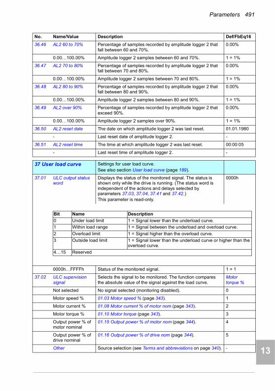
Parameters 491
1
2
3
4
5
6
7
8
9
10
11
12
13
36.46 AL2 60 to 70% Percentage of samples recorded by amplitude logger 2 that fall between 60 and 70%.
0.00%
0.00…100.00% Amplitude logger 2 samples between 60 and 70%. 1 = 1%
36.47 AL2 70 to 80% Percentage of samples recorded by amplitude logger 2 that fall between 70 and 80%.
0.00%
0.00…100.00% Amplitude logger 2 samples between 70 and 80%. 1 = 1%
36.48 AL2 80 to 90% Percentage of samples recorded by amplitude logger 2 that fall between 80 and 90%.
0.00%
0.00…100.00% Amplitude logger 2 samples between 80 and 90%. 1 = 1%
36.49 AL2 over 90% Percentage of samples recorded by amplitude logger 2 that exceed 90%.
0.00%
0.00…100.00% Amplitude logger 2 samples over 90%. 1 = 1%
36.50 AL2 reset date The date on which amplitude logger 2 was last reset. 01.01.1980
- Last reset date of amplitude logger 2. -
36.51 AL2 reset time The time at which amplitude logger 2 was last reset. 00:00:05
- Last reset time of amplitude logger 2. -
3737 User load curve Settings for user load curve.
See also section User load curve (page 189).
37.01 ULC output status word
Displays the status of the monitored signal. The status is shown only while the drive is running. (The status word is independent of the actions and delays selected by parameters 37.03, 37.04, 37.41 and 37.42.)This parameter is read-only.
0000h
0000h…FFFFh Status of the monitored signal. 1 = 1
37.02 ULC supervision signal
Selects the signal to be monitored. The function compares the absolute value of the signal against the load curve.
Motor torque %
Not selected No signal selected (monitoring disabled). 0
Motor speed % 01.03 Motor speed % (page 343). 1
Motor current % 01.08 Motor current % of motor nom (page 343). 2
Motor torque % 01.10 Motor torque (page 343). 3
Output power % of motor nominal
01.15 Output power % of motor nom (page 344). 4
Output power % of drive nominal
01.16 Output power % of drive nom (page 344). 5
Other Source selection (see Terms and abbreviations on page 340). -
No. Name/Value Description Def/FbEq16
Bit Name Description
0 Under load limit 1 = Signal lower than the underload curve.
1 Within load range 1 = Signal between the underload and overload curve.
2 Overload limit 1 = Signal higher than the overload curve.
3 Outside load limit 1 = Signal lower than the underload curve or higher than the overload curve.
4…15 Reserved
14

492 Parameters
1
2
3
4
5
7
8
9
9
10
11
12
13
14
37.03 ULC overload actions
Selects how the drive reacts if the absolute value of the monitored signal stays continuously above the overload curve for longer than the value of 37.41 ULC overload timer.
Disabled
Disabled No action taken. 0
Warning Drive generates warning A8BE ULC overload warning. 1
Fault Drive trips on fault 8002 ULC overload fault. 2
Warning/Fault Drive generates warning A8BE ULC overload warning if the signal stays continuously above the overload curve for half of the time defined by parameter 37.41 ULC overload timer.Drive trips on fault 8002 ULC overload fault if the signal stays continuously above the overload curve for a time defined by parameter 37.41 ULC overload timer.
3
37.04 ULC underload actions
Selects how the drive reacts if the absolute value of the monitored signal stays continuously above the overload curve for longer than the value of 37.42 ULC underload timer.
Disabled
Disabled No action taken. 0
Warning Drive generates warning A8BF ULC underload warning. 1
Fault Drive trips on fault 8001 ULC underload fault. 2
Warning/Fault Drive generates warning A8BF ULC underload warning if the signal stays continuously below the underload curve for half of the time defined by parameter 37.41 ULC overload timer.Drive trips on fault 8001 ULC underload fault if the signal stays continuously above the underload curve for a time defined by parameter 37.42 ULC underload timer.
3
37.11 ULC speed table point 1
Defines the first of the five speed points on the X-axis of the user load curve. Speed points are used if parameter 99.04 Motor control mode is set to Vector or if 99.04 Motor control mode is set to Scalar and the reference unit is rpm.The five points must be in order from lowest to highest. The points are defined as positive values, but the range is symmetrically effective also in the negative direction. The monitoring is not active outside these two areas.
150.0 rpm
-30000.0…30000.0 rpm
Speed. 1 = 1 rpm
37.12 ULC speed table point 2
Defines the second speed point.See parameter 37.11 ULC speed table point 1.
750.0 rpm
-30000.0…30000.0 rpm
Speed. 1 = 1 rpm
37.13 ULC speed table point 3
Defines the third speed point.See parameter 37.11 ULC speed table point 1.
1290.0 rpm
-30000.0…30000.0 rpm
Speed. 1 = 1 rpm
37.14 ULC speed table point 4
Defines the fourth speed point.See parameter 37.11 ULC speed table point 1.
1500.0 rpm
-30000.0…30000.0 rpm
Speed. 1 = 1 rpm
37.15 ULC speed table point 5
Defines the fifth speed point.See parameter 37.11 ULC speed table point 1.
1800.0 rpm
-30000.0…30000.0 rpm
Speed. 1 = 1 rpm
No. Name/Value Description Def/FbEq16

Parameters 493
1
2
3
4
5
6
7
8
9
10
11
12
13
37.16 ULC frequency table point 1
Defines the first of the five frequency points on the X-axis of the user load curve. Frequency points are used if parameter 99.04 Motor control mode is set to Scalar and the reference unit is Hz.The five points must be in order from lowest to highest. The points are defined as positive values, but the range is symmetrically effective also in the negative direction. The monitoring is not active outside these two areas.
5.0 Hz
-500.0…500.0 Hz Frequency. 1 = 1 Hz
37.17 ULC frequency table point 2
Defines the second frequency point.See parameter 37.16 ULC frequency table point 1.
25.0 Hz
-500.0…500.0 Hz Frequency. 1 = 1 Hz
37.18 ULC frequency table point 3
Defines the third frequency point.See parameter 37.16 ULC frequency table point 1.
43.0 Hz
-500.0…500.0 Hz Frequency. 1 = 1 Hz
37.19 ULC frequency table point 4
Defines the fourth frequency point.See parameter 37.16 ULC frequency table point 1.
50.0 Hz
-500.0…500.0 Hz Frequency. 1 = 1 Hz
37.20 ULC frequency table point 5
Defines the fifth frequency point.See parameter 37.16 ULC frequency table point 1.
60.0 Hz
-500.0…500.0 Hz Frequency. 1 = 1 Hz
37.21 ULC underload point 1
Defines the first of the five points on the Y-axis that together with the corresponding point on the X-axis (37.11 ULC speed table point 1…37.15 ULC speed table point 5 or 37.15 ULC speed table point 5…37.20 ULC frequency table point 5) define the underload (lower) curve.Each point of the underload curve must have a lower value than the corresponding overload point.
10.0%
-1600.0…1600.0% Underload point. 1 = 1%
37.22 ULC underload point 2
Defines the second underload point.See parameter 37.21 ULC underload point 1.
15.0%
-1600.0…1600.0% Underload point. 1 = 1%
37.23 ULC underload point 3
Defines the third underload point.See parameter 37.21 ULC underload point 1
25.0%
-1600.0…1600.0% Underload point. 1 = 1%
37.24 ULC underload point 4
Defines the fourth underload point.See parameter 37.21 ULC underload point 1
30.0%
-1600.0…1600.0% Underload point. 1 = 1%
37.25 ULC underload point 5
Defines the fifth underload point.See parameter 37.21 ULC underload point 1
30.0%
-1600.0…1600.0% Underload point. 1 = 1%
37.31 ULC overload point 1
Defines the first of the five points on the Y-axis that together with the corresponding point on the X-axis (37.11 ULC speed table point 1…37.15 ULC speed table point 5 or 37.15 ULC speed table point 5…37.20 ULC frequency table point 5) define the overload (higher) curve.Each point of the overload curve must have a higher value than the corresponding underload point.
300.0%
-1600.0…1600.0% Overload point. 1 = 1%
No. Name/Value Description Def/FbEq16
14
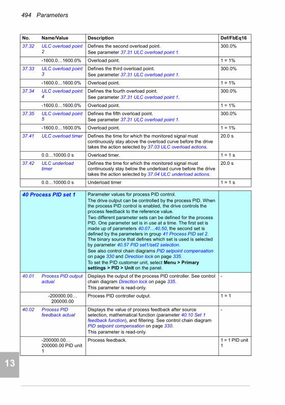
494 Parameters
1
2
3
4
5
7
8
9
9
10
11
12
13
14
37.32 ULC overload point 2
Defines the second overload point.See parameter 37.31 ULC overload point 1.
300.0%
-1600.0…1600.0% Overload point. 1 = 1%
37.33 ULC overload point 3
Defines the third overload point.See parameter 37.31 ULC overload point 1.
300.0%
-1600.0…1600.0% Overload point. 1 = 1%
37.34 ULC overload point 4
Defines the fourth overload point.See parameter 37.31 ULC overload point 1.
300.0%
-1600.0…1600.0% Overload point. 1 = 1%
37.35 ULC overload point 5
Defines the fifth overload point.See parameter 37.31 ULC overload point 1.
300.0%
-1600.0…1600.0% Overload point. 1 = 1%
37.41 ULC overload timer Defines the time for which the monitored signal must continuously stay above the overload curve before the drive takes the action selected by 37.03 ULC overload actions.
20.0 s
0.0…10000.0 s Overload timer. 1 = 1 s
37.42 ULC underload timer
Defines the time for which the monitored signal must continuously stay below the underload curve before the drive takes the action selected by 37.04 ULC underload actions.
20.0 s
0.0…10000.0 s Underload timer 1 = 1 s
4040 Process PID set 1 Parameter values for process PID control.
The drive output can be controlled by the process PID. When the process PID control is enabled, the drive controls the process feedback to the reference value. Two different parameter sets can be defined for the process PID. One parameter set is in use at a time. The first set is made up of parameters 40.07…40.50, the second set is defined by the parameters in group 41 Process PID set 2. The binary source that defines which set is used is selected by parameter 40.57 PID set1/set2 selection.See also control chain diagrams PID setpoint compensation on page 330 and Direction lock on page 335.To set the PID customer unit, select Menu > Primary settings > PID > Unit on the panel.
40.01 Process PID output actual
Displays the output of the process PID controller. See control chain diagram Direction lock on page 335.This parameter is read-only.
-
-200000.00…200000.00
Process PID controller output. 1 = 1
40.02 Process PID feedback actual
Displays the value of process feedback after source selection, mathematical function (parameter 40.10 Set 1 feedback function), and filtering. See control chain diagram PID setpoint compensation on page 330.This parameter is read-only.
-
-200000.00…200000.00 PID unit 1
Process feedback. 1 = 1 PID unit 1
No. Name/Value Description Def/FbEq16

Parameters 495
1
2
3
4
5
6
7
8
9
10
11
12
13
40.03 Process PID setpoint actual
Displays the value of process PID setpoint after source selection, mathematical function (40.18 Set 1 setpoint function), limitation and ramping. See control chain diagram PID setpoint compensation on page 330.This parameter is read-only.
-
-200000…200000 PID unit 1
Setpoint for process PID controller. 1 = 1 PID unit 1
40.04 Process PID deviation actual
Displays the process PID deviation. By default, this value equals setpoint - feedback, but deviation can be inverted by parameter 40.31 Set 1 deviation inversion. See control chain diagram Process PID controller on page 332.This parameter is read-only.
-
-200000.00…200000.00 PID unit 1
PID deviation. 1 = 1 PID unit 1
40.06 Process PID status word
Displays status information on process PID control.This parameter is read-only.
-
0000h…FFFFh Process PID control status word. 1 = 1
40.07 Process PID operation mode
Activates/deactivates process PID control.Note: Process PID control is only available in external control; see section Local control vs. external control (page 89).
Off
Off Process PID control inactive. 0
On Process PID control active. 1
On when drive running
Process PID control is active when the drive is running. 2
40.08 Set 1 feedback 1 source
Selects the primary source of process feedback. See control chain diagram PID setpoint compensation on page 330.
AI2 scaled
Not selected None. 0
AI1 scaled 12.12 AI1 scaled value (see page 376). 1
AI2 scaled 12.22 AI2 scaled value (see page 378). 2
No. Name/Value Description Def/FbEq16
Bit Name Value
0 PID active 1 = Process PID control active.
1 Setpoint frozen 1 = Process PID setpoint frozen.
2 Output frozen 1 = Process PID controller output frozen.
3 PID sleep mode 1 = Sleep mode active.
4 Sleep boost 1 = Sleep boost active.
5 Reserved
6 Tracking mode 1 = Tracking function active.
7 Output limit high 1 = PID output is being limited by par. 40.37.
8 Output limit low 1 = PID output is being limited by par. 40.36.
9 Deadband active 1 = Feedback value is in the deadband range (40.39).
10 PID set 0 = Parameter set 1 in use. 1 = Parameter set 2 in use.
11 Reserved
12 Internal setpoint active
1 = Internal setpoint active (see par. 40.16…40.23)
13…15 Reserved
14

496 Parameters
1
2
3
4
5
7
8
9
9
10
11
12
13
14
Freq in scaled 11.39 Freq in 1 scaled value (see page 374). 3
Reserved 4…7
AI1 percent 12.101 AI1 percent value (see page 379). 8
AI2 percent 12.102 AI2 percent value (see page 379). 9
Feedback data storage
40.91 Feedback data storage (see page 510).(Selection not available for parameter 71.08 Feedback 1 source.)
10
Actual flow Parameter 80.01 Actual flow. 11
Actual flow % Parameter 80.02 Actual flow. 12
Other Source selection (see Terms and abbreviations on page 340). -
40.09 Set 1 feedback 2 source
Selects the second source of process feedback. The second source is used only if the setpoint function requires two inputs.For the selections, see parameter 40.08 Set 1 feedback 1 source.
Not selected
40.10 Set 1 feedback function
Defines how process feedback is calculated from the two feedback sources selected by parameters 40.08 Set 1 feedback 1 source and 40.09 Set 1 feedback 2 source.The result of the function (for any selection) is multiplied by parameter 40.90 Set 1 feedback multiplier. (That is why in selections 12 and 13, the multiplier k is constant 1.)
In1
In1 Source 1. 0
In1+In2 Sum of sources 1 and 2. 1
In1-In2 Source 2 subtracted from source 1. 2
In1*In2 Source 1 multiplied by source 2. 3
In1/In2 Source 1 divided by source 2. 4
MIN(In1,In2) Smaller of the two sources. 5
MAX(In1,In2) Greater of the two sources. 6
AVE(In1,In2) Average of the two sources. 7
sqrt(In1) Square root of source 1. 8
sqrt(In1-In2) Square root of (source 1 - source 2). 9
sqrt(In1+In2) Square root of (source 1 + source 2). 10
sqrt(In1)+sqrt(In2) Square root of source 1 + square root of source 2. 11
k*sqrt(In1) Square root of source 1. (k = 1) 12
k*sqrt(In1-In2) Square root of (source 1 - source 2). (k = 1) 13
40.11 Set 1 feedback filter time
Defines the filter time constant for process feedback. 0.000 s
0.000…30.000 s Feedback filter time. 1 = 1 s
No. Name/Value Description Def/FbEq16

Parameters 497
1
2
3
4
5
6
7
8
9
10
11
12
13
40.14 Set 1 setpoint scaling
Defines, together with parameter 40.15 Set 1 output scaling, a general scaling factor for the process PID control chain.If the parameter is set to zero, automatic setpoint scaling is activated, where suitable setpoint scale is calculated according to selected setpoint source. Actual setpoint scale is shown in parameter 40.61 Setpoint scaling actual.The scaling can be utilized when, for example, the process setpoint is input in Hz, and the output of the PID controller is used as an rpm value in speed control. In this case, this parameter might be set to 50, and parameter 40.15 to the nominal motor speed at 50 Hz.In effect, the output of the PID controller = [40.15] whendeviation (setpoint - feedback) = [40.14] and [40.32] = 1.Note: The scaling is based on the ratio between 40.14 and 40.15. For example, the values 50 and 1500 would produce the same scaling as 1 and 30.
0.00
-200000.00…200000.00
Process setpoint base. 1 = 1
40.15 Set 1 output scaling See parameter 40.14 Set 1 setpoint scaling.If the parameter is set to zero, scaling is automatic:
0.00
-200000.00…200000.00
Process PID controller output base. 1 = 1
40.16 Set 1 setpoint 1 source
Selects the primary source of process PID setpoint. See the control chain diagram on page 330.
AI1 percent
Not selected None. 0
Reserved 1
Internal setpoint Internal setpoint. See parameter 40.19 Set 1 internal setpoint sel1.
2
AI1 scaled 12.12 AI1 scaled value (see page 376). 3
AI2 scaled 12.22 AI2 scaled value (see page 378). 4
Reserved 5…7
Motor potentiometer
22.80 Motor potentiometer ref act (output of the Floating point control (Motor potentiometer)).
8
Reserved 9
Freq in scaled 11.39 Freq in 1 scaled value (see page 374). 10
AI1 percent 12.101 AI1 percent value (see page 379) 11
AI2 percent 12.102 AI2 percent value (see page 379) 12
No. Name/Value Description Def/FbEq16
Operation mode (see par. 19.01)
Scaling
Speed control 46.01 Speed scaling
Frequency control 46.02 Frequency scaling
14
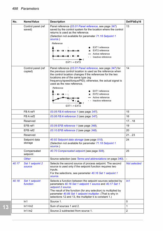
498 Parameters
1
2
3
4
5
7
8
9
9
10
11
12
13
14
Control panel (ref saved)
Panel reference (03.01 Panel reference, see page 347) saved by the control system for the location where the control returns is used as the reference.(Selection not available for parameter 71.16 Setpoint 1 source.)
13
Control panel (ref copied)
Panel reference (03.01 Panel reference, see page 347) for the previous control location is used as the reference when the control location changes if the references for the two locations are of the same type (eg frequency/speed/torque/PID); otherwise, the actual signal is used as the new reference.
14
FB A ref1 03.05 FB A reference 1 (see page 347). 15
FB A ref2 03.06 FB A reference 2 (see page 347). 16
Reserved 17…18
EFB ref1 03.09 EFB reference 1 (see page 348). 19
EFB ref2 03.10 EFB reference 2 (see page 348). 20
Reserved 21…23
Setpoint data storage
40.92 Setpoint data storage (see page 510).(Selection not available for parameter 71.16 Setpoint 1 source.)
24
Compensated setpoint
40.70 Compensated setpoint (see page 508). 25
Other Source selection (see Terms and abbreviations on page 340). -
40.17 Set 1 setpoint 2 source
Selects the second source of process setpoint. The second source is used only if the setpoint function requires two inputs.For the selections, see parameter 40.16 Set 1 setpoint 1 source.
Not selected
40.18 Set 1 setpoint function
Selects a function between the setpoint sources selected by parameters 40.16 Set 1 setpoint 1 source and 40.17 Set 1 setpoint 2 source.The result of the function (for any selection) is multiplied by parameter 40.89 Set 1 setpoint multiplier. (That is why in selections 12 and 13, the multiplier k is constant 1.)
In1
In1 Source 1. 0
In1+In2 Sum of sources 1 and 2. 1
In1-In2 Source 2 subtracted from source 1. 2
No. Name/Value Description Def/FbEq16
EXT1 -> EXT2t
Reference
EXT1 referenceEXT2 reference
Active referenceInactive reference
EXT1 -> EXT2
EXT1 referenceEXT2 reference
Active reference
t Inactive reference
Reference

Parameters 499
1
2
3
4
5
6
7
8
9
10
11
12
13
In1*In2 Source 1 multiplied by source 2. 3
In1/In2 Source 1 divided by source 2. 4
MIN(In1,In2) Smaller of the two sources. 5
MAX(In1,In2) Greater of the two sources. 6
AVE(In1,In2) Average of the two sources. 7
sqrt(In1) Square root of source 1. 8
sqrt(In1-In2) Square root of (source 1 - source 2). 9
sqrt(In1+In2) Square root of (source 1 + source 2). 10
sqrt(In1)+sqrt(In2) Square root of source 1 + square root of source 2. 11
k*sqrt(In1) Square root of source 1. (k = 1) 12
k*sqrt(In1-In2) Square root of (source 1 - source 2). (k = 1) 13
40.19 Set 1 internal setpoint sel1
Selects together with 40.20 Set 1 internal setpoint sel2 the internal setpoint out of the presets defined by parameters 40.21…40.24.Note: Parameters 40.16 Set 1 setpoint 1 source and 40.17 Set 1 setpoint 2 source must be set to Internal setpoint.
Not selected
Not selected 0. 0
Selected 1. 1
DI1 Digital input DI1 (10.02 DI delayed status, bit 0). 2
DI2 Digital input DI2 (10.02 DI delayed status, bit 1). 3
DI3 Digital input DI3 (10.02 DI delayed status, bit 2). 4
DI4 Digital input DI4 (10.02 DI delayed status, bit 3). 5
DI5 Digital input DI5 (10.02 DI delayed status, bit 4). 6
DI6 Digital input DI6 (10.02 DI delayed status, bit 5). 7
Reserved 8…17
Timed function 1 Bit 0 of 34.01 Timed functions status (see page 469). 18
Timed function 2 Bit 1 of 34.01 Timed functions status (see page 469). 19
Timed function 3 Bit 2 of 34.01 Timed functions status (see page 469). 20
Supervision 1 Bit 0 of 32.01 Supervision status (see page 462). 21
Supervision 2 Bit 1 of 32.01 Supervision status (see page 462). 22
Supervision 3 Bit 2 of 32.01 Supervision status (see page 462). 23
Other [bit] Source selection (see Terms and abbreviations on page 340). -
40.20 Set 1 internal setpoint sel2
Selects together with 40.19 Set 1 internal setpoint sel1 the internal setpoint used out of the three internal setpoints defined by parameters 40.21…40.23. See table at 40.19 Set 1 internal setpoint sel1.
Not selected
Not selected 0. 0
No. Name/Value Description Def/FbEq16
Source defined by par. 40.19
Source defined by par. 40.20
Setpoint preset active
0 0 0 (par. 40.24)
1 0 1 (par. 40.21)
0 1 2 (par. 40.22)
1 1 3 (par. 40.23)
14
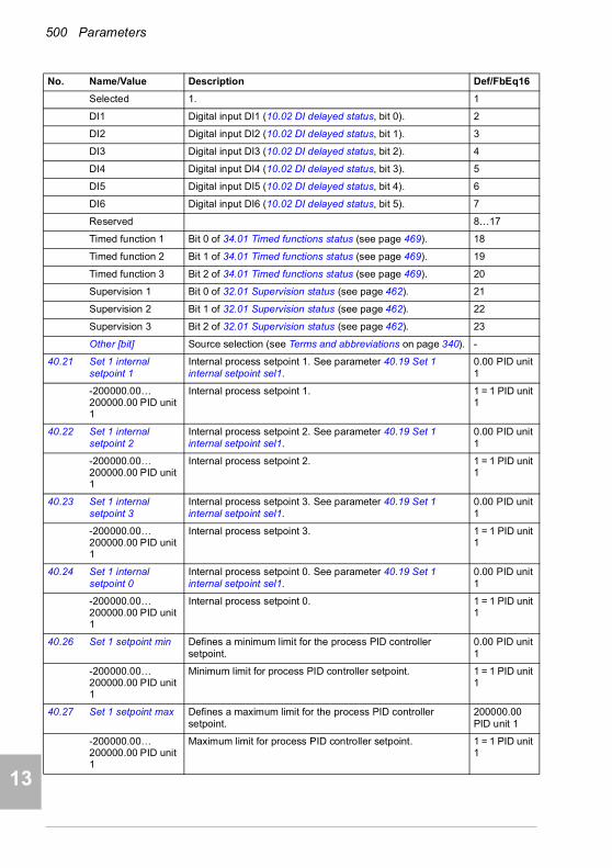
500 Parameters
1
2
3
4
5
7
8
9
9
10
11
12
13
14
Selected 1. 1
DI1 Digital input DI1 (10.02 DI delayed status, bit 0). 2
DI2 Digital input DI2 (10.02 DI delayed status, bit 1). 3
DI3 Digital input DI3 (10.02 DI delayed status, bit 2). 4
DI4 Digital input DI4 (10.02 DI delayed status, bit 3). 5
DI5 Digital input DI5 (10.02 DI delayed status, bit 4). 6
DI6 Digital input DI6 (10.02 DI delayed status, bit 5). 7
Reserved 8…17
Timed function 1 Bit 0 of 34.01 Timed functions status (see page 469). 18
Timed function 2 Bit 1 of 34.01 Timed functions status (see page 469). 19
Timed function 3 Bit 2 of 34.01 Timed functions status (see page 469). 20
Supervision 1 Bit 0 of 32.01 Supervision status (see page 462). 21
Supervision 2 Bit 1 of 32.01 Supervision status (see page 462). 22
Supervision 3 Bit 2 of 32.01 Supervision status (see page 462). 23
Other [bit] Source selection (see Terms and abbreviations on page 340). -
40.21 Set 1 internal setpoint 1
Internal process setpoint 1. See parameter 40.19 Set 1 internal setpoint sel1.
0.00 PID unit 1
-200000.00…200000.00 PID unit 1
Internal process setpoint 1. 1 = 1 PID unit 1
40.22 Set 1 internal setpoint 2
Internal process setpoint 2. See parameter 40.19 Set 1 internal setpoint sel1.
0.00 PID unit 1
-200000.00…200000.00 PID unit 1
Internal process setpoint 2. 1 = 1 PID unit 1
40.23 Set 1 internal setpoint 3
Internal process setpoint 3. See parameter 40.19 Set 1 internal setpoint sel1.
0.00 PID unit 1
-200000.00…200000.00 PID unit 1
Internal process setpoint 3. 1 = 1 PID unit 1
40.24 Set 1 internal setpoint 0
Internal process setpoint 0. See parameter 40.19 Set 1 internal setpoint sel1.
0.00 PID unit 1
-200000.00…200000.00 PID unit 1
Internal process setpoint 0. 1 = 1 PID unit 1
40.26 Set 1 setpoint min Defines a minimum limit for the process PID controller setpoint.
0.00 PID unit 1
-200000.00…200000.00 PID unit 1
Minimum limit for process PID controller setpoint. 1 = 1 PID unit 1
40.27 Set 1 setpoint max Defines a maximum limit for the process PID controller setpoint.
200000.00 PID unit 1
-200000.00…200000.00 PID unit 1
Maximum limit for process PID controller setpoint. 1 = 1 PID unit 1
No. Name/Value Description Def/FbEq16
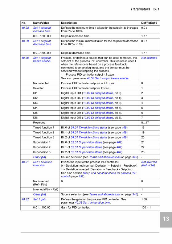
Parameters 501
1
2
3
4
5
6
7
8
9
10
11
12
13
40.28 Set 1 setpoint increase time
Defines the minimum time it takes for the setpoint to increase from 0% to 100%.
0.0 s
0.0…1800.0 s Setpoint increase time. 1 = 1
40.29 Set 1 setpoint decrease time
Defines the minimum time it takes for the setpoint to decrease from 100% to 0%.
0.0 s
0.0…1800.0 s Setpoint decrease time. 1 = 1
40.30 Set 1 setpoint freeze enable
Freezes, or defines a source that can be used to freeze, the setpoint of the process PID controller. This feature is useful when the reference is based on a process feedback connected to an analog input, and the sensor must be serviced without stopping the process.1 = Process PID controller setpoint frozenSee also parameter 40.38 Set 1 output freeze enable.
Not selected
Not selected Process PID controller setpoint not frozen. 0
Selected Process PID controller setpoint frozen. 1
DI1 Digital input DI1 (10.02 DI delayed status, bit 0). 2
DI2 Digital input DI2 (10.02 DI delayed status, bit 1). 3
DI3 Digital input DI3 (10.02 DI delayed status, bit 2). 4
DI4 Digital input DI4 (10.02 DI delayed status, bit 3). 5
DI5 Digital input DI5 (10.02 DI delayed status, bit 4). 6
DI6 Digital input DI6 (10.02 DI delayed status, bit 5). 7
Reserved 8…17
Timed function 1 Bit 0 of 34.01 Timed functions status (see page 469). 18
Timed function 2 Bit 1 of 34.01 Timed functions status (see page 469). 19
Timed function 3 Bit 2 of 34.01 Timed functions status (see page 469). 20
Supervision 1 Bit 0 of 32.01 Supervision status (see page 462). 21
Supervision 2 Bit 1 of 32.01 Supervision status (see page 462). 22
Supervision 3 Bit 2 of 32.01 Supervision status (see page 462). 23
Other [bit] Source selection (see Terms and abbreviations on page 340). -
40.31 Set 1 deviation inversion
Inverts the input of the process PID controller.0 = Deviation not inverted (Deviation = Setpoint - Feedback)1 = Deviation inverted (Deviation = Feedback - Setpoint)See also section Sleep and boost functions for process PID control (page 152).
Not inverted (Ref - Fbk)
Not inverted (Ref - Fbk)
0. 0
Inverted (Fbk - Ref) 1. 1
Other [bit] Source selection (see Terms and abbreviations on page 340). -
40.32 Set 1 gain Defines the gain for the process PID controller. See parameter 40.33 Set 1 integration time.
1.00
0.01…100.00 Gain for PID controller. 100 = 1
No. Name/Value Description Def/FbEq16
14
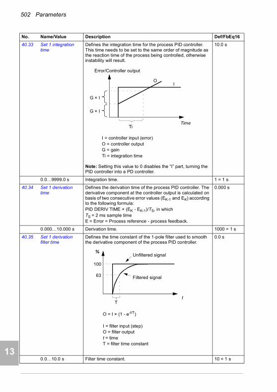
502 Parameters
1
2
3
4
5
7
8
9
9
10
11
12
13
14
40.33 Set 1 integration time
Defines the integration time for the process PID controller. This time needs to be set to the same order of magnitude as the reaction time of the process being controlled, otherwise instability will result.
Note: Setting this value to 0 disables the “I” part, turning the PID controller into a PD controller.
10.0 s
0.0…9999.0 s Integration time. 1 = 1 s
40.34 Set 1 derivation time
Defines the derivation time of the process PID controller. The derivative component at the controller output is calculated on basis of two consecutive error values (EK-1 and EK) according to the following formula:PID DERIV TIME × (EK - EK-1)/TS, in which TS = 2 ms sample timeE = Error = Process reference - process feedback.
0.000 s
0.000…10.000 s Derivation time. 1000 = 1 s
40.35 Set 1 derivation filter time
Defines the time constant of the 1-pole filter used to smooth the derivative component of the process PID controller.
0.0 s
0.0…10.0 s Filter time constant. 10 = 1 s
No. Name/Value Description Def/FbEq16
Ti
OI
G × I
G × I
I = controller input (error)O = controller outputG = gainTi = integration time
Time
Error/Controller output
63
%
100
Tt
O = I × (1 - e-t/T)
I = filter input (step)O = filter outputt = timeT = filter time constant
Unfiltered signal
Filtered signal

Parameters 503
1
2
3
4
5
6
7
8
9
10
11
12
13
40.36 Set 1 output min Defines the minimum limit for the process PID controller output. Using the minimum and maximum limits, it is possible to restrict the operation range.
0.00
-200000.00…200000.00
Minimum limit for process PID controller output. 1 = 1
40.37 Set 1 output max Defines the maximum limit for the process PID controller output. See parameter 40.36 Set 1 output min.
100.00
-200000.00…200000.00
Maximum limit for process PID controller output. 1 = 1
40.38 Set 1 output freeze enable
Freezes (or defines a source that can be used to freeze) the output of the process PID controller, keeping the output at the value it was before freeze was enabled. This feature can be used when, for example, a sensor providing process feedback must to be serviced without stopping the process.1 = Process PID controller output frozenSee also parameter 40.30 Set 1 setpoint freeze enable.
Not selected
Not selected Process PID controller output not frozen. 0
Selected Process PID controller output frozen. 1
DI1 Digital input DI1 (10.02 DI delayed status, bit 0). 2
DI2 Digital input DI2 (10.02 DI delayed status, bit 1). 3
DI3 Digital input DI3 (10.02 DI delayed status, bit 2). 4
DI4 Digital input DI4 (10.02 DI delayed status, bit 3). 5
DI5 Digital input DI5 (10.02 DI delayed status, bit 4). 6
DI6 Digital input DI6 (10.02 DI delayed status, bit 5). 7
Reserved 8…17
Timed function 1 Bit 0 of 34.01 Timed functions status (see page 469). 18
Timed function 2 Bit 1 of 34.01 Timed functions status (see page 469). 19
Timed function 3 Bit 2 of 34.01 Timed functions status (see page 469). 20
Supervision 1 Bit 0 of 32.01 Supervision status (see page 462). 21
Supervision 2 Bit 1 of 32.01 Supervision status (see page 462). 22
Supervision 3 Bit 2 of 32.01 Supervision status (see page 462). 23
Other [bit] Source selection (see Terms and abbreviations on page 340). -
No. Name/Value Description Def/FbEq16
14

504 Parameters
1
2
3
4
5
7
8
9
9
10
11
12
13
14
40.39 Set 1 deadband range
Defines a deadband around the setpoint. Whenever process feedback enters the deadband, a delay timer starts. If the feedback remains within the deadband longer than the delay (40.40 Set 1 deadband delay), the PID controller output is frozen. Normal operation resumes after the feedback value leaves the deadband.
0.0 bar
0.0……200000.0 Deadband range. 1 = 1
40.40 Set 1 deadband delay
Delay for the deadband. See parameter 40.39 Set 1 deadband range.
0.0 s
0.0 … 3600.0 s Delay for deadband area. 1 = 1 s
40.43 Set 1 sleep level Defines the start limit for the sleep function. If the value is 0.0, set 1 sleep mode is disabled.The sleep function compares PID output (parameter 40.01 Process PID output actual) to the value of this parameter. If PID output remains below this value longer than the sleep delay defined by 40.44 Set 1 sleep delay, the drive enters the sleep mode and stops the motor.
0.0
0.0…200000.0 Sleep start level. 1 = 1
40.44 Set 1 sleep delay Defines a delay before the sleep function actually becomes enabled, to prevent nuisance sleeping.The delay timer starts when the sleep mode is enabled by parameter 40.43 Set 1 sleep level, and resets when the sleep mode is disabled.
60.0 s
0.0…3600.0 s Sleep start delay. 1 = 1 s
40.45 Set 1 sleep boost time
Defines a boost time for the sleep boost step. See parameter 40.46 Set 1 sleep boost step.
0.0 s
0.0…3600.0 s Sleep boost time. 1 = 1 s
40.46 Set 1 sleep boost step
When the drive is entering sleep mode, the process setpoint is increased by this value for the time defined by parameter 40.45 Set 1 sleep boost time.If active, sleep boost is aborted when the drive wakes up.
0.0 PID unit 1
0.0…200000.0 PID unit 1
Sleep boost step. 1 = 1 PID unit 1
No. Name/Value Description Def/FbEq16
Setpoint
Time
Feedback
PID controlleroutput
40.39 Set 1deadband range
40.40 Set 1 deadband delay
PID controller output frozen

Parameters 505
1
2
3
4
5
6
7
8
9
10
11
12
13
40.47 Set 1 wake-up deviation
Defines the wake-up level as deviation between process setpoint and feedback.When the deviation exceeds the value of this parameter, and remains there for the duration of the wake-up delay (40.48 Set 1 wake-up delay), the drive wakes up.See also parameter 40.31 Set 1 deviation inversion.
0.00 PID unit 1
-200000.00…200000.00 PID unit 1
Wake-up level (as deviation between process setpoint and feedback).
1 = 1 PID unit 1
40.48 Set 1 wake-up delay
Defines a wake-up delay for the sleep function to prevent nuisance wake-ups. See parameter 40.47 Set 1 wake-up deviation.The delay timer starts when the deviation exceeds the wake-up level (40.47 Set 1 wake-up deviation), and resets if the deviation falls below the wake-up level.
0.50 s
0.00…60.00 s Wake-up delay. 1 = 1 s
40.49 Set 1 tracking mode Activates (or selects a source that activates) tracking mode. In tracking mode, the value selected by parameter 40.50 Set 1 tracking ref selection is substituted for the PID controller output. See also section Tracking (page 153).1 = Tracking mode enabled
Not selected
Not selected 0. 0
Selected 1. 1
DI1 Digital input DI1 (10.02 DI delayed status, bit 0). 2
DI2 Digital input DI2 (10.02 DI delayed status, bit 1). 3
DI3 Digital input DI3 (10.02 DI delayed status, bit 2). 4
DI4 Digital input DI4 (10.02 DI delayed status, bit 3). 5
DI5 Digital input DI5 (10.02 DI delayed status, bit 4). 6
DI6 Digital input DI6 (10.02 DI delayed status, bit 5). 7
Reserved 8…17
Timed function 1 Bit 0 of 34.01 Timed functions status (see page 469). 18
Timed function 2 Bit 1 of 34.01 Timed functions status (see page 469). 19
Timed function 3 Bit 2 of 34.01 Timed functions status (see page 469). 20
Supervision 1 Bit 0 of 32.01 Supervision status (see page 462). 21
Supervision 2 Bit 1 of 32.01 Supervision status (see page 462). 22
Supervision 3 Bit 2 of 32.01 Supervision status (see page 462). 23
Other [bit] Source selection (see Terms and abbreviations on page 340). -
40.50 Set 1 tracking ref selection
Selects the value source for tracking mode. See parameter 40.49 Set 1 tracking mode.
Not selected
Not selected None. 0
AI1 scaled 12.12 AI1 scaled value (see page 376). 1
AI2 scaled 12.22 AI2 scaled value (see page 378). 2
FB A ref1 03.05 FB A reference 1 (see page 347). 3
FB A ref2 03.06 FB A reference 2 (see page 347). 4
Other Source selection (see Terms and abbreviations on page 340). -
No. Name/Value Description Def/FbEq16
14
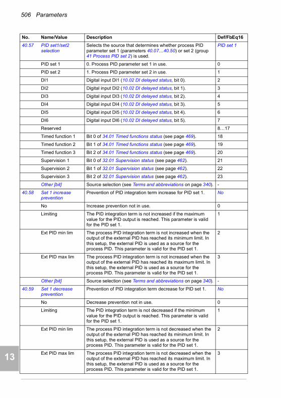
506 Parameters
1
2
3
4
5
7
8
9
9
10
11
12
13
14
40.57 PID set1/set2 selection
Selects the source that determines whether process PID parameter set 1 (parameters 40.07…40.50) or set 2 (group 41 Process PID set 2) is used.
PID set 1
PID set 1 0. Process PID parameter set 1 in use. 0
PID set 2 1. Process PID parameter set 2 in use. 1
DI1 Digital input DI1 (10.02 DI delayed status, bit 0). 2
DI2 Digital input DI2 (10.02 DI delayed status, bit 1). 3
DI3 Digital input DI3 (10.02 DI delayed status, bit 2). 4
DI4 Digital input DI4 (10.02 DI delayed status, bit 3). 5
DI5 Digital input DI5 (10.02 DI delayed status, bit 4). 6
DI6 Digital input DI6 (10.02 DI delayed status, bit 5). 7
Reserved 8…17
Timed function 1 Bit 0 of 34.01 Timed functions status (see page 469). 18
Timed function 2 Bit 1 of 34.01 Timed functions status (see page 469). 19
Timed function 3 Bit 2 of 34.01 Timed functions status (see page 469). 20
Supervision 1 Bit 0 of 32.01 Supervision status (see page 462). 21
Supervision 2 Bit 1 of 32.01 Supervision status (see page 462). 22
Supervision 3 Bit 2 of 32.01 Supervision status (see page 462). 23
Other [bit] Source selection (see Terms and abbreviations on page 340). -
40.58 Set 1 increase prevention
Prevention of PID integration term increase for PID set 1. No
No Increase prevention not in use. 0
Limiting The PID integration term is not increased if the maximum value for the PID output is reached. This parameter is valid for the PID set 1.
1
Ext PID min lim The process PID integration term is not increased when the output of the external PID has reached its minimum limit. In this setup, the external PID is used as a source for the process PID. This parameter is valid for the PID set 1.
2
Ext PID max lim The process PID integration term is not increased when the output of the external PID has reached its maximum limit. In this setup, the external PID is used as a source for the process PID. This parameter is valid for the PID set 1.
3
Other [bit] Source selection (see Terms and abbreviations on page 340). -
40.59 Set 1 decrease prevention
Prevention of PID integration term decrease for PID set 1. No
No Decrease prevention not in use. 0
Limiting The PID integration term is not decreased if the minimum value for the PID output is reached. This parameter is valid for the PID set 1.
1
Ext PID min lim The process PID integration term is not decreased when the output of the external PID has reached its minimum limit. In this setup, the external PID is used as a source for the process PID. This parameter is valid for the PID set 1.
2
Ext PID max lim The process PID integration term is not decreased when the output of the external PID has reached its maximum limit. In this setup, the external PID is used as a source for the process PID. This parameter is valid for the PID set 1.
3
No. Name/Value Description Def/FbEq16

Parameters 507
1
2
3
4
5
6
7
8
9
10
11
12
13
Other [bit] Source selection (see Terms and abbreviations on page 340). -
40.60 Set 1 PID activation source
Selects a source that enables/disables process PID control.See also parameter 40.07 Process PID operation mode.0 = Process PID control disabled.1 = Process PID control enabled.
On
Off 0. 0
On 1. 1
Follow Ext1/Ext2 selection
Process PID control is disabled when external control location EXT1 is active, and enabled when external control location EXT2 is active.See also parameter 19.11 Ext1/Ext2 selection.
2
DI1 Digital input DI1 (10.02 DI delayed status, bit 0). 3
DI2 Digital input DI2 (10.02 DI delayed status, bit 1). 4
DI3 Digital input DI3 (10.02 DI delayed status, bit 2). 5
DI4 Digital input DI4 (10.02 DI delayed status, bit 3). 6
DI5 Digital input DI5 (10.02 DI delayed status, bit 4). 7
DI6 Digital input DI6 (10.02 DI delayed status, bit 5). 8
Other [bit] Source selection (see Terms and abbreviations on page 340). -
40.61 Setpoint scaling actual
Actual setpoint scaling. See parameter 40.14 Set 1 setpoint scaling.
100.00
-200000.00…200000.00
Scaling. 1 = 1
40.62 PID internal setpoint actual
Displays the value of the internal setpoint. See control chain diagram PID setpoint compensation on page 330.This parameter is read-only.
-
-200000.00…200000.00 PID unit 1
Process PID internal setpoint. 1 = 1 PID unit 1
No. Name/Value Description Def/FbEq16
14
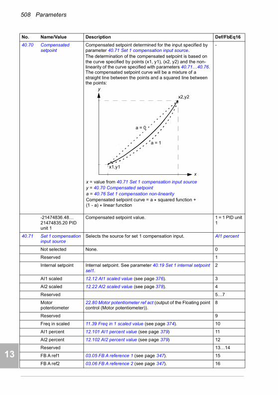
508 Parameters
1
2
3
4
5
7
8
9
9
10
11
12
13
14
40.70 Compensated setpoint
Compensated setpoint determined for the input specified by parameter 40.71 Set 1 compensation input source.The determination of the compensated setpoint is based on the curve specified by points (x1, y1), (x2, y2) and the non-linearity of the curve specified with parameters 40.71…40.76. The compensated setpoint curve will be a mixture of a straight line between the points and a squared line between the points:
-
-21474836.48…21474835.20 PID unit 1
Compensated setpoint value. 1 = 1 PID unit 1
40.71 Set 1 compensation input source
Selects the source for set 1 compensation input. AI1 percent
Not selected None. 0
Reserved 1
Internal setpoint Internal setpoint. See parameter 40.19 Set 1 internal setpoint sel1.
2
AI1 scaled 12.12 AI1 scaled value (see page 376). 3
AI2 scaled 12.22 AI2 scaled value (see page 378). 4
Reserved 5…7
Motor potentiometer
22.80 Motor potentiometer ref act (output of the Floating point control (Motor potentiometer)).
8
Reserved 9
Freq in scaled 11.39 Freq in 1 scaled value (see page 374). 10
AI1 percent 12.101 AI1 percent value (see page 379) 11
AI2 percent 12.102 AI2 percent value (see page 379) 12
Reserved 13…14
FB A ref1 03.05 FB A reference 1 (see page 347). 15
FB A ref2 03.06 FB A reference 2 (see page 347). 16
No. Name/Value Description Def/FbEq16
x2,y2
x1,y1
x
y
x = value from 40.71 Set 1 compensation input sourcey = 40.70 Compensated setpointa = 40.76 Set 1 compensation non-linearityCompensated setpoint curve = a * squared function + (1 - a) * linear function
a = 1
a = 0
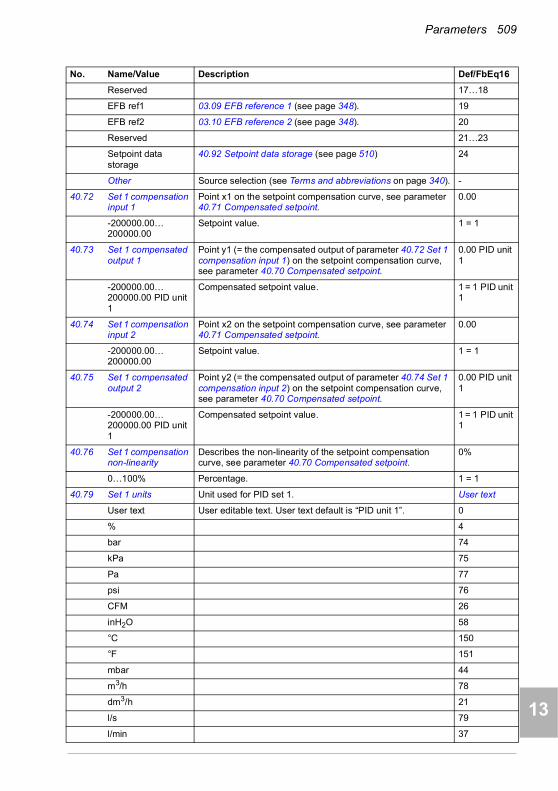
Parameters 509
1
2
3
4
5
6
7
8
9
10
11
12
13
Reserved 17…18
EFB ref1 03.09 EFB reference 1 (see page 348). 19
EFB ref2 03.10 EFB reference 2 (see page 348). 20
Reserved 21…23
Setpoint data storage
40.92 Setpoint data storage (see page 510) 24
Other Source selection (see Terms and abbreviations on page 340). -
40.72 Set 1 compensation input 1
Point x1 on the setpoint compensation curve, see parameter 40.71 Compensated setpoint.
0.00
-200000.00…200000.00
Setpoint value. 1 = 1
40.73 Set 1 compensated output 1
Point y1 (= the compensated output of parameter 40.72 Set 1 compensation input 1) on the setpoint compensation curve, see parameter 40.70 Compensated setpoint.
0.00 PID unit 1
-200000.00…200000.00 PID unit 1
Compensated setpoint value. 1 = 1 PID unit 1
40.74 Set 1 compensation input 2
Point x2 on the setpoint compensation curve, see parameter 40.71 Compensated setpoint.
0.00
-200000.00…200000.00
Setpoint value. 1 = 1
40.75 Set 1 compensated output 2
Point y2 (= the compensated output of parameter 40.74 Set 1 compensation input 2) on the setpoint compensation curve, see parameter 40.70 Compensated setpoint.
0.00 PID unit 1
-200000.00…200000.00 PID unit 1
Compensated setpoint value. 1 = 1 PID unit 1
40.76 Set 1 compensation non-linearity
Describes the non-linearity of the setpoint compensation curve, see parameter 40.70 Compensated setpoint.
0%
0…100% Percentage. 1 = 1
40.79 Set 1 units Unit used for PID set 1. User text
User text User editable text. User text default is “PID unit 1”. 0
% 4
bar 74
kPa 75
Pa 77
psi 76
CFM 26
inH2O 58
°C 150
°F 151
mbar 44
m3/h 78
dm3/h 21
l/s 79
l/min 37
No. Name/Value Description Def/FbEq16
14
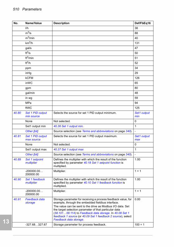
510 Parameters
1
2
3
4
5
7
8
9
9
10
11
12
13
14
l/h 38
m3/s 88
m3/min 40
km3/h 131
gal/s 47
ft3/s 50
ft3/min 51
ft3/h 52
ppm 34
inHg 29
kCFM 126
inWC 65
gpm 80
gal/min 48
in wg 59
MPa 94
ftWC 125
40.80 Set 1 PID output min source
Selects the source for set 1 PID output minimum. Set1 output min
None Not selected. 0
Set1 output min 40.36 Set 1 output min. 1
Other [bit] Source selection (see Terms and abbreviations on page 340). -
40.81 Set 1 PID output max source
Selects the source for set 1 PID output maximum. Set1 output max
None Not selected. 0
Set1 output max 40.37 Set 1 output max 1
Other [bit] Source selection (see Terms and abbreviations on page 340). -
40.89 Set 1 setpoint multiplier
Defines the multiplier with which the result of the function specified by parameter 40.18 Set 1 setpoint function is multiplied.
1.00
-200000.00…200000.00
Multiplier. 1 = 1
40.90 Set 1 feedback multiplier
Defines the multiplier with which the result of the function specified by parameter 40.10 Set 1 feedback function is multiplied.
1.00
-200000.00…200000.00
Multiplier. 1 = 1
40.91 Feedback data storage
Storage parameter for receiving a process feedback value, for example, through the embedded fieldbus interface.The value can be sent to the drive as Modbus I/O data. Set the target selection parameter of that particular data (58.101…58.114) to Feedback data storage. In 40.08 Set 1 feedback 1 source (or 40.09 Set 1 feedback 2 source), select Feedback data storage.
0.00
-327.68…327.67 Storage parameter for process feedback. 100 = 1
No. Name/Value Description Def/FbEq16

Parameters 511
1
2
3
4
5
6
7
8
9
10
11
12
13
40.92 Setpoint data storage
Storage parameter for receiving a process setpoint value, for example, through the embedded fieldbus interface. The value can be sent to the drive as Modbus I/O data. Set the target selection parameter of that particular data (58.101…58.114)) to Setpoint data storage. In 40.16 Set 1 setpoint 1 source (or 40.17 Set 1 setpoint 2 source), select Setpoint data storage.
0.00
-327.68…327.67 Storage parameter for process setpoint. 100 = 1
40.96 Process PID output %
Percentage scaled signal of parameter 40.01 Process PID feedback actual.
0.00%
-100.00…100.00% Percentage. 100 = 1%
40.97 Process PID feedback %
Percentage scaled signal of parameter 40.02 Process PID feedback actual.
0.00%
-100.00…100.00% Percentage. 100 = 1%
40.98 Process PID setpoint %
Percentage scaled signal of parameter 40.03 Process PID setpoint actual.
0.00%
-100.00…100.00% Percentage. 100 = 1%
40.99 Process PID deviation %
Percentage scaled signal of parameter 40.04 Process PID deviation actual.
0.00%
-100.00…100.00% Percentage. 100 = 1%
4141 Process PID set 2 A second set of parameter values for process PID control.
The selection between this set and first set (parameter group 40 Process PID set 1) is made by parameter 40.57 PID set1/set2 selection.See also parameters 40.01…40.06, and control chain diagrams PID setpoint compensation and Direction lock on pages 330 and 335, respectively.
41.08 Set 2 feedback 1 source
See parameter 40.08 Set 1 feedback 1 source. AI2 percent
41.09 Set 2 feedback 2 source
See parameter 40.09 Set 1 feedback 2 source. Not selected
41.10 Set 2 feedback function
See parameter 40.10 Set 1 feedback function. In1
41.11 Set 2 feedback filter time
See parameter 40.11 Set 1 feedback filter time. 0.000 s
41.14 Set 2 setpoint scaling
See parameter 40.14 Set 1 setpoint scaling. 0.00
41.15 Set 2 output scaling See parameter 40.15 Set 1 output scaling. 0.00
41.16 Set 2 setpoint 1 source
See parameter 40.16 Set 1 setpoint 1 source. AI1 percent
41.17 Set 2 setpoint 2 source
See parameter 40.17 Set 1 setpoint 2 source. Not selected
41.18 Set 2 setpoint function
See parameter 40.18 Set 1 setpoint function. In1
41.19 Set 2 internal setpoint sel1
See parameter 40.19 Set 1 internal setpoint sel1. Not selected
41.20 Set 2 internal setpoint sel2
See parameter 40.20 Set 1 internal setpoint sel2. Not selected
No. Name/Value Description Def/FbEq16
14
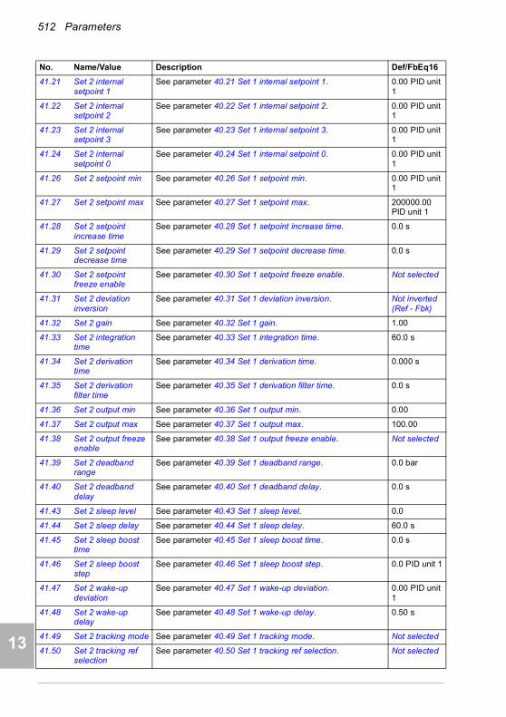
512 Parameters
1
2
3
4
5
7
8
9
9
10
11
12
13
14
41.21 Set 2 internal setpoint 1
See parameter 40.21 Set 1 internal setpoint 1. 0.00 PID unit 1
41.22 Set 2 internal setpoint 2
See parameter 40.22 Set 1 internal setpoint 2. 0.00 PID unit 1
41.23 Set 2 internal setpoint 3
See parameter 40.23 Set 1 internal setpoint 3. 0.00 PID unit 1
41.24 Set 2 internal setpoint 0
See parameter 40.24 Set 1 internal setpoint 0. 0.00 PID unit 1
41.26 Set 2 setpoint min See parameter 40.26 Set 1 setpoint min. 0.00 PID unit 1
41.27 Set 2 setpoint max See parameter 40.27 Set 1 setpoint max. 200000.00 PID unit 1
41.28 Set 2 setpoint increase time
See parameter 40.28 Set 1 setpoint increase time. 0.0 s
41.29 Set 2 setpoint decrease time
See parameter 40.29 Set 1 setpoint decrease time. 0.0 s
41.30 Set 2 setpoint freeze enable
See parameter 40.30 Set 1 setpoint freeze enable. Not selected
41.31 Set 2 deviation inversion
See parameter 40.31 Set 1 deviation inversion. Not inverted (Ref - Fbk)
41.32 Set 2 gain See parameter 40.32 Set 1 gain. 1.00
41.33 Set 2 integration time
See parameter 40.33 Set 1 integration time. 60.0 s
41.34 Set 2 derivation time
See parameter 40.34 Set 1 derivation time. 0.000 s
41.35 Set 2 derivation filter time
See parameter 40.35 Set 1 derivation filter time. 0.0 s
41.36 Set 2 output min See parameter 40.36 Set 1 output min. 0.00
41.37 Set 2 output max See parameter 40.37 Set 1 output max. 100.00
41.38 Set 2 output freeze enable
See parameter 40.38 Set 1 output freeze enable. Not selected
41.39 Set 2 deadband range
See parameter 40.39 Set 1 deadband range. 0.0 bar
41.40 Set 2 deadband delay
See parameter 40.40 Set 1 deadband delay. 0.0 s
41.43 Set 2 sleep level See parameter 40.43 Set 1 sleep level. 0.0
41.44 Set 2 sleep delay See parameter 40.44 Set 1 sleep delay. 60.0 s
41.45 Set 2 sleep boost time
See parameter 40.45 Set 1 sleep boost time. 0.0 s
41.46 Set 2 sleep boost step
See parameter 40.46 Set 1 sleep boost step. 0.0 PID unit 1
41.47 Set 2 wake-up deviation
See parameter 40.47 Set 1 wake-up deviation. 0.00 PID unit 1
41.48 Set 2 wake-up delay
See parameter 40.48 Set 1 wake-up delay. 0.50 s
41.49 Set 2 tracking mode See parameter 40.49 Set 1 tracking mode. Not selected
41.50 Set 2 tracking ref selection
See parameter 40.50 Set 1 tracking ref selection. Not selected
No. Name/Value Description Def/FbEq16

Parameters 513
1
2
3
4
5
6
7
8
9
10
11
12
13
41.58 Set 2 increase prevention
See parameter 40.58 Set 1 increase prevention. No
41.59 Set 2 decrease prevention
See parameter 40.59 Set 1 decrease prevention. No
41.60 Set 2 PID activation source
See parameter 40.60 Set 1 PID activation source. On
41.71 Set 2 compensation input source
See parameter 40.71 Set 1 compensation input source. AI1 percent
41.72 Set 2 compensation input 1
See parameter 40.72 Set 1 compensation input 1. 0.00
41.73 Set 2 compensated output 1
See parameter 40.73 Set 1 compensated output 1. 0.00 PID unit 1
41.74 Set 2 compensation input 2
See parameter 40.74 Set 1 compensation input 2. 0.00
41.75 Set 2 compensated output 2
See parameter 40.75 Set 1 compensated output 2. 0.00 PID unit 1
41.76 Set 2 compensation non-linearity
See parameter 40.76 Set 1 compensation non-linearity. 0%
41.79 Set 2 units See parameter 40.79 Set 1 units. bar
41.80 Set 2 PID output min source
Selects the source for set 2 PID output minimum. Set2 output min
None None. 0
Set2 output min 41.36 Set 2 output min 1
Other [bit] Source selection (see Terms and abbreviations on page 340). -
41.81 Set 2 PID output max source
Selects the source for set 2 PID output maximum. Set2 output max
None None. 0
Set2 output max 41.37 Set 2 output max 1
Other [bit] Source selection (see Terms and abbreviations on page 340). -
41.89 Set 2 setpoint multiplier
See parameter 40.89 Set 1 setpoint multiplier. 1.00
41.90 Set 2 feedback multiplier
Defines the multiplier k used in formulas of parameter 41.10 Set 2 feedback function. See parameter 40.90 Set 1 feedback multiplier.
1.00
4343 Brake chopper Settings for the internal brake chopper.
43.01 Braking resistor temperature
Displays the estimated temperature of the brake resistor, or how close the brake resistor is to being too hot.The value is given in percent where 100% is the eventual temperature the resistor would reach when loaded long enough with its rated maximum load capacity (43.09 Brake resistor Pmax cont).The temperature calculation is based on the values of parameters 43.08, 43.09 and 43.10, and on the assumption that the resistor is installed as instructed by the manufacturer (ie it cools down as expected). This parameter is read-only.
-
0.0…120.0% Estimated brake resistor temperature. 1 = 1%
No. Name/Value Description Def/FbEq16
14

514 Parameters
1
2
3
4
5
7
8
9
9
10
11
12
13
14
43.06 Brake chopper function
Enables brake chopper control and selects the brake resistor overload protection method (calculation or measurement).Note: Before enabling brake chopper control, ensure that• a brake resistor is connected• overvoltage control is switched off (parameter 30.30
Overvoltage control)• the supply voltage range (parameter 95.01 Supply voltage)
has been selected correctly.
Disabled
Disabled Brake chopper control disabled. 0
Enabled with thermal model
Brake chopper control enabled with brake resistor protection based on the thermal model. If you select this, you must also specify the values needed by the model, ie, parameters 43.08… 43.12. See the resistor data sheet.
1
Enabled without thermal model
Brake chopper control enabled without resistor overload protection based on the thermal model. This setting can be used, for example, if the resistor is equipped with a thermal switch that is wired to open the main contactor of the drive if the resistor overheats.For more information, see chapter Resistor braking in the Hardware manual of the drive.
2
Overvoltage peak protection
Brake chopper control enabled in an overvoltage condition.This setting is intended for situations where• the braking chopper is not needed for runtime operation,
ie, to dissipate the inertial energy of the motor,• the motor is able to store a considerable amount magnetic
energy in its windings, and• the motor might, deliberately or inadvertently, be stopped
by coasting.In such a situation, the motor would potentially discharge enough magnetic energy towards the drive to cause damage. To protect the drive, the brake chopper can be used with a small resistor dimensioned merely to handle the magnetic energy (not the inertial energy) of the motor. With this setting, the brake chopper is activated only whenever the DC voltage exceeds the overvoltage limit. During normal use, the brake chopper is not operating.
3
43.07 Brake chopper run enable
Selects the source for quick brake chopper on/off control.0 = Brake chopper IGBT pulses are cut off1 = Normal brake chopper IGBT modulation allowed.
On
Off 0. 0
On 1. 1
Other [bit] Source selection (see Terms and abbreviations on page 340). -
43.08 Brake resistor thermal tc
Defines§ the thermal time constant for the brake resistor thermal model.
0 s
0…10000 s Brake resistor thermal time constant, ie, the rated time to achieve 63% temperature.
1 = 1 s
No. Name/Value Description Def/FbEq16
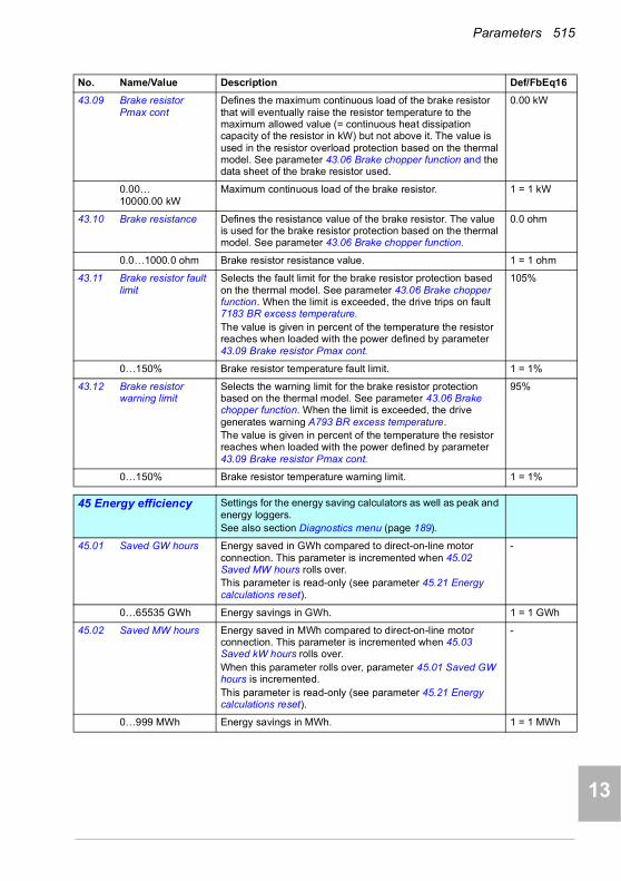
Parameters 515
1
2
3
4
5
6
7
8
9
10
11
12
13
43.09 Brake resistor Pmax cont
Defines the maximum continuous load of the brake resistor that will eventually raise the resistor temperature to the maximum allowed value (= continuous heat dissipation capacity of the resistor in kW) but not above it. The value is used in the resistor overload protection based on the thermal model. See parameter 43.06 Brake chopper function and the data sheet of the brake resistor used.
0.00 kW
0.00… 10000.00 kW
Maximum continuous load of the brake resistor. 1 = 1 kW
43.10 Brake resistance Defines the resistance value of the brake resistor. The value is used for the brake resistor protection based on the thermal model. See parameter 43.06 Brake chopper function.
0.0 ohm
0.0…1000.0 ohm Brake resistor resistance value. 1 = 1 ohm
43.11 Brake resistor fault limit
Selects the fault limit for the brake resistor protection based on the thermal model. See parameter 43.06 Brake chopper function. When the limit is exceeded, the drive trips on fault 7183 BR excess temperature.The value is given in percent of the temperature the resistor reaches when loaded with the power defined by parameter 43.09 Brake resistor Pmax cont.
105%
0…150% Brake resistor temperature fault limit. 1 = 1%
43.12 Brake resistor warning limit
Selects the warning limit for the brake resistor protection based on the thermal model. See parameter 43.06 Brake chopper function. When the limit is exceeded, the drive generates warning A793 BR excess temperature.The value is given in percent of the temperature the resistor reaches when loaded with the power defined by parameter 43.09 Brake resistor Pmax cont.
95%
0…150% Brake resistor temperature warning limit. 1 = 1%
4545 Energy efficiency Settings for the energy saving calculators as well as peak and
energy loggers.See also section Diagnostics menu (page 189).
45.01 Saved GW hours Energy saved in GWh compared to direct-on-line motor connection. This parameter is incremented when 45.02 Saved MW hours rolls over.This parameter is read-only (see parameter 45.21 Energy calculations reset).
-
0…65535 GWh Energy savings in GWh. 1 = 1 GWh
45.02 Saved MW hours Energy saved in MWh compared to direct-on-line motor connection. This parameter is incremented when 45.03 Saved kW hours rolls over.When this parameter rolls over, parameter 45.01 Saved GW hours is incremented.This parameter is read-only (see parameter 45.21 Energy calculations reset).
-
0…999 MWh Energy savings in MWh. 1 = 1 MWh
No. Name/Value Description Def/FbEq16
14
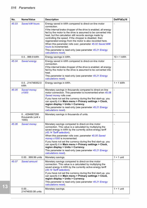
516 Parameters
1
2
3
4
5
7
8
9
9
10
11
12
13
14
45.03 Saved kW hours Energy saved in kWh compared to direct-on-line motor connection.If the internal brake chopper of the drive is enabled, all energy fed by the motor to the drive is assumed to be converted into heat, but the calculation still records savings made by controlling the speed. If the chopper is disabled, then regenerated energy from the motor is also recorded here.When this parameter rolls over, parameter 45.02 Saved MW hours is incremented.This parameter is read-only (see parameter 45.21 Energy calculations reset).
-
0.0…999.9 kWh Energy savings in kWh. 10 = 1 kWh
45.04 Saved energy Energy saved in kWh compared to direct-on-line motor connection.If the internal brake chopper of the drive is enabled, all energy fed by the motor to the drive is assumed to be converted into heat.This parameter is read-only (see parameter 45.21 Energy calculations reset).
-
0.0…214748352.0 kWh
Energy savings in kWh. 1 = 1 kWh
45.05 Saved money x1000
Monetary savings in thousands compared to direct-on-line motor connection. This parameter is incremented when 45.06 Saved money rolls over.If you have not set the currency during the first start-up, you can specify it in Main menu > Primary settings > Clock, region display > Units > Currency. This parameter is read-only (see parameter 45.21 Energy calculations reset).
-
0…4294967295 thousands (unit x 1000)
Monetary savings in thousands of units. -
45.06 Saved money Monetary savings compared to direct-on-line motor connection. This value is a calculated by multiplying the saved energy in kWh by the currently active energy tariff (45.14 Tariff selection).When this parameter rolls over, parameter 45.05 Saved money x1000 is incremented.If you have not set the currency during the first start-up, you can specify it in Main menu > Primary settings > Clock, region display > Units > Currency. This parameter is read-only (see parameter 45.21 Energy calculations reset).
-
0.00…999.99 units Monetary savings. 1 = 1 unit
45.07 Saved amount Monetary savings compared to direct-on-line motor connection. This value is a calculated by multiplying the saved energy in kWh by the currently active energy tariff (45.14 Tariff selection).If you have not set the currency during the first start-up, you can specify it in Main menu > Primary settings > Clock, region display > Units > Currency. This parameter is read-only (see parameter 45.21 Energy calculations reset).
-
0.00… 21474830.08 units
Monetary savings. 1 = 1 unit
No. Name/Value Description Def/FbEq16
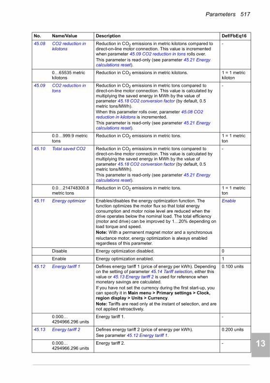
Parameters 517
1
2
3
4
5
6
7
8
9
10
11
12
13
45.08 CO2 reduction in kilotons
Reduction in CO2 emissions in metric kilotons compared to direct-on-line motor connection. This value is incremented when parameter 45.09 CO2 reduction in tons rolls over.This parameter is read-only (see parameter 45.21 Energy calculations reset).
-
0…65535 metric kilotons
Reduction in CO2 emissions in metric kilotons. 1 = 1 metric kiloton
45.09 CO2 reduction in tons
Reduction in CO2 emissions in metric tons compared to direct-on-line motor connection. This value is calculated by multiplying the saved energy in MWh by the value of parameter 45.18 CO2 conversion factor (by default, 0.5 metric tons/MWh).When this parameter rolls over, parameter 45.08 CO2 reduction in kilotons is incremented.This parameter is read-only (see parameter 45.21 Energy calculations reset).
-
0.0…999.9 metric tons
Reduction in CO2 emissions in metric tons. 1 = 1 metric ton
45.10 Total saved CO2 Reduction in CO2 emissions in metric tons compared to direct-on-line motor connection. This value is calculated by multiplying the saved energy in MWh by the value of parameter 45.18 CO2 conversion factor (by default, 0.5 metric tons/MWh).This parameter is read-only (see parameter 45.21 Energy calculations reset).
-
0.0…214748300.8 metric tons
Reduction in CO2 emissions in metric tons. 1 = 1 metric ton
45.11 Energy optimizer Enables/disables the energy optimization function. The function optimizes the motor flux so that total energy consumption and motor noise level are reduced when the drive operates below the nominal load. The total efficiency (motor and drive) can be improved by 1…20% depending on load torque and speed.Note: With a permanent magnet motor and a synchronousreluctance motor, energy optimization is always enabled regardless of this parameter.
Enable
Disable Energy optimization disabled. 0
Enable Energy optimization enabled. 1
45.12 Energy tariff 1 Defines energy tariff 1 (price of energy per kWh). Depending on the setting of parameter 45.14 Tariff selection, either this value or 45.13 Energy tariff 2 is used for reference when monetary savings are calculated.If you have not set the currency during the first start-up, you can specify it in Main menu > Primary settings > Clock, region display > Units > Currency. Note: Tariffs are read only at the instant of selection, and are not applied retroactively.
0.100 units
0.000… 4294966.296 units
Energy tariff 1. -
45.13 Energy tariff 2 Defines energy tariff 2 (price of energy per kWh).See parameter 45.12 Energy tariff 1.
0.200 units
0.000… 4294966.296 units
Energy tariff 2. -
No. Name/Value Description Def/FbEq16
14
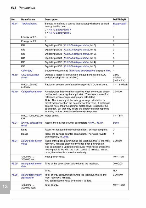
518 Parameters
1
2
3
4
5
7
8
9
9
10
11
12
13
14
45.14 Tariff selection Selects (or defines a source that selects) which pre-defined energy tariff is used.0 = 45.12 Energy tariff 11 = 45.13 Energy tariff 2
Energy tariff 1
Energy tariff 1 0. 0
Energy tariff 2 1. 1
DI1 Digital input DI1 (10.02 DI delayed status, bit 0). 2
DI2 Digital input DI2 (10.02 DI delayed status, bit 1). 3
DI3 Digital input DI3 (10.02 DI delayed status, bit 2). 4
DI4 Digital input DI4 (10.02 DI delayed status, bit 3). 5
DI5 Digital input DI5 (10.02 DI delayed status, bit 4). 6
DI6 Digital input DI6 (10.02 DI delayed status, bit 5). 7
Other [bit] Source selection (see Terms and abbreviations on page 340). -
45.18 CO2 conversion factor
Defines a factor for conversion of saved energy into CO2 emissions (kg/kWh or tn/MWh).
0.500 tn/MWh (metric ton)
0.000…65.535 tn/MWh
Factor for conversion of saved energy into CO2 emissions. 1 = 1 tn/MWh
45.19 Comparison power Actual power that the motor absorbs when connected direct-on-line and operating the application. The value is used for reference when energy savings are calculated.Note: The accuracy of the energy savings calculation is directly dependent on the accuracy of this value. If nothing is entered here, then the nominal motor power is used by the calculation, but that may inflate the energy savings reported as many motors do not absorb nameplate power.
0.75 kW
0.00…10000000.00 kW
Motor power. 1 = 1 kW
45.21 Energy calculations reset
Resets the savings counter parameters 45.01…45.10. Done
Done Reset not requested (normal operation), or reset complete. 0
Reset Reset the savings counter parameters. The value reverts automatically to Done.
1
45.24 Hourly peak power value
Value of the peak power during the last hour, that is, the most recent 60 minutes after the drive has been powered up.The parameter is updated once every 10 minutes unless the hourly peak is found in the most recent 10 minutes. In that case, the values is shown immediately.
0.00 kW
-3000.00 … 3000.00 kW
Peak power value. 10 = 1 kW
45.25 Hourly peak power time
Time of the peak power value during the last hour. 00:00:00
Time. N/A
45.26 Hourly total energy (resettable)
Total energy consumption during the last hour, that is, the most recent 60 minutes.You can reset the value by setting it to zero.
0.00 kWh
-3000.00 … 3000.00 kWh
Total energy. 10 = 1 kWh
No. Name/Value Description Def/FbEq16

Parameters 519
1
2
3
4
5
6
7
8
9
10
11
12
13
45.27 Daily peak power value (resettable)
Value of the peak power since midnight of the present day.You can reset the value by setting it to zero.
0.00 kW
-3000.00 … 3000.00 kW
Peak power value. 10 = 1 kW
45.28 Daily peak power time
Time of the peak power since midnight of the present day. 00:00:00
Time. N/A
45.29 Daily total energy (resettable)
Total energy consumption since midnight of the present day.You can reset the value by setting it to zero.
0.00 kWh
-30000.00 … 30000.00 kWh
Total energy. 1 = 1 kWh
45.30 Last day total energy
Total energy consumption during the previous day, that is, between midnight of the previous day and midnight of the present day
0.00 kWh
-30000.00 … 30000.00 kWh
Total energy. 1 = 1 kWh
45.31 Monthly peak power value (resettable)
Value of the peak power during the present month, that is, since midnight of the first day of the present month.You can reset the value by setting it to zero.
0.00 kW
-3000.00 … 3000.00 kW
Peak power value. 10 = 1 kW
45.32 Monthly peak power date
Date of the peak power during the present month. 1.1.1980
Date. N/A
45.33 Monthly peak power time
Time of the peak power during the present month. 00:00:00
Time. N/A
45.34 Monthly total energy (resettable)
Total energy consumption from the beginning of the present month.You can reset the value by setting it to zero.
0.00 kWh
-1000000.00 … 1000000.00 kWh
Total energy. 0.01 = 1 kWh
45.35 Last month total energy
Total energy consumption during the previous month, that is, between midnight of the first day or the previous month and midnight of the first day of the present month.
0.00 kWh
-1000000.00 … 1000000.00 kWh
0.01 = 1 kWh
45.36 Lifetime peak power value
Value of the peak power over the drive lifetime. 0.00 kW
-3000.00 … 3000.00 kW
Peak power value. 10 = 1 kW
45.37 Lifetime peak power date
Date of the peak power over the drive lifetime. 1.1.1980
Date. N/A
45.38 Lifetime peak power time
Time of the peak power over the drive lifetime. 00:00:00
Time. N/A
No. Name/Value Description Def/FbEq16
14

520 Parameters
1
2
3
4
5
7
8
9
9
10
11
12
13
14
4646 Monitoring/scaling settings
Speed supervision settings; actual signal filtering; general scaling settings.
46.01 Speed scaling Defines the maximum speed value used to define the acceleration ramp rate and the initial speed value used to define the deceleration ramp rate (see parameter group 23 Speed reference ramp). The speed acceleration and deceleration ramp times are therefore related to this value (not to parameter 30.12 Maximum speed).Also defines the 16-bit scaling of speed-related parameters. The value of this parameter corresponds to 20000, for example, in fieldbus communication.
1500.00 rpm; 1800.00 rpm (95.20 b0)
0.10…30000.00 rpm
Acceleration/deceleration terminal/initial speed. 1 = 1 rpm
46.02 Frequency scaling Defines the maximum frequency value used to define the acceleration ramp rate and the initial frequency value used to define deceleration ramp rate (see parameter group 28 Frequency reference chain). The frequency acceleration and deceleration ramp times are therefore related to this value (not to parameter 30.14 Maximum frequency).Also defines the 16-bit scaling of frequency-related parameters. The value of this parameter corresponds to20000, for example, in fieldbus communication.
50.00 Hz; 60.00 Hz (95.20 b0)
0.10…1000.00 Hz Acceleration/deceleration terminal/initial frequency. 10 = 1 Hz
46.03 Torque scaling Defines the 16-bit scaling of torque parameters. The value of this parameter (in percent of nominal motor torque) corresponds to 10000, for example, in fieldbus communication.
100.0%
0.1…1000.0% Torque corresponding to 10000 on fieldbus. 10 = 1%
46.04 Power scaling Defines the 16-bit scaling of power parameters. The value of this parameter corresponds to 10000, for example, in fieldbus communication.The unit is selected by parameter 96.16 Unit selection.For 32-bit scaling see parameter 46.43 Power decimals.
1000.00 kW or hp
0.10 … 30000.00 kW or0.10 … 40214.48 hp
Power corresponding to 1000 on fieldbus. 1 = 1 unit
46.05 Current scaling Defines the 16-bit scaling of current parameters. The value of this parameter corresponds to 10000, for example, in fieldbus communication.For 32-bit scaling see parameter 46.44 Current decimals.
10000 A
0…30000 A 1 = 1 A
46.06 Speed ref zero scaling
Defines a speed corresponding to a zero reference received from fieldbus (either the embedded fieldbus interface, or interface FBA A). For example, with a setting of 500, the fieldbus reference range of 0…20000 would correspond to a speed of 500…[46.01] rpm.Note: This parameter is effective only with the ABB Drives communication profile.
0.00 rpm
0.00 … 30000.00 rpm
Speed corresponding to minimum fieldbus reference. 1 = 1 rpm
No. Name/Value Description Def/FbEq16
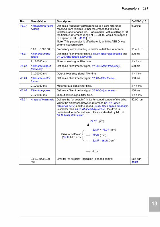
Parameters 521
1
2
3
4
5
6
7
8
9
10
11
12
13
46.07 Frequency ref zero scaling
Defines a frequency corresponding to a zero reference received from fieldbus (either the embedded fieldbus interface, or interface FBA). For example, with a setting of 30, the fieldbus reference range of 0…20000 would correspond to a speed of 30…[46.02] Hz.Note: This parameter is effective only with the ABB Drives communication profile.
0.00 Hz
0.00 … 1000.00 Hz Frequency corresponding to minimum fieldbus reference. 10 = 1 Hz
46.11 Filter time motor speed
Defines a filter time for signals 01.01 Motor speed used and 01.02 Motor speed estimated.
500 ms
2…20000 ms Motor speed signal filter time. 1 = 1 ms
46.12 Filter time output frequency
Defines a filter time for signal 01.06 Output frequency. 500 ms
2…20000 ms Output frequency signal filter time. 1 = 1 ms
46.13 Filter time motor torque
Defines a filter time for signal 01.10 Motor torque. 100 ms
2…20000 ms Motor torque signal filter time. 1 = 1 ms
46.14 Filter time power Defines a filter time for signal 01.14 Output power. 100 ms
2…20000 ms Output power signal filter time. 1 = 1 ms
46.21 At speed hysteresis Defines the “at setpoint” limits for speed control of the drive.When the difference between reference (22.87 Speed reference act 7) and the speed (24.02 Used speed feedback) is smaller than 46.21 At speed hysteresis, the drive is considered to be “at setpoint”. This is indicated by bit 8 of 06.11 Main status word.
50.00 rpm
0.00…30000.00 rpm
Limit for “at setpoint” indication in speed control. See par. 46.01
No. Name/Value Description Def/FbEq16
24.02 (rpm)
0 rpm
22.87 + 46.21 (rpm)
22.87 (rpm)
22.87 - 46.21 (rpm)
Drive at setpoint(06.11 bit 8 = 1)
14

522 Parameters
1
2
3
4
5
7
8
9
9
10
11
12
13
14
46.22 At frequency hysteresis
Defines the “at setpoint” limits for frequency control of the drive. When the absolute difference between reference (28.96 Frequency ref ramp input) and actual frequency (01.06 Output frequency) is smaller than 46.22 At frequency hysteresis, the drive is considered to be “at setpoint”. This is indicated by bit 8 of 06.11 Main status word.
2.00 Hz
0.00…1000.00 Hz Limit for “at setpoint” indication in frequency control. See par. 46.02
46.31 Above speed limit Defines the trigger level for “above limit” indication in speed control. When actual speed exceeds the limit, bit 10 of 06.17 Drive status word 2 is set.This is also indicated by bit 10 in 06.11 Main status word.
1500.00 rpm; 1800.00 rpm (95.20 b0)
0.00…30000.00 rpm
“Above limit” indication trigger level for speed control. See par. 46.01
46.32 Above frequency limit
Defines the trigger level for “above limit” indication in frequency control. When actual frequency exceeds the limit, bit 10 of 06.17 Drive status word 2 is set.This is also indicated by bit 10 in 06.11 Main status word.
50.00 Hz; 60.00 Hz (95.20 b0)
0.00…1000.00 Hz “Above limit” indication trigger level for frequency control. See par. 46.02
46.41 kWh pulse scaling Defines the trigger level for the “kWh pulse” on for 50 ms. The output of the pulse is bit 9 of 05.22 Diagnostic word 3.
1.000 kWh
0.001… 1000.000 kWh
“kWh pulse” on trigger level. 1 = 1 kWh
46.43 Power decimals Defines the number of decimals shown for parameter 99.10 Motor nominal power on the panel and Drive composer PC tool. It also defines 32-bit scaling of power parameters.The value of this parameter corresponds to the number of decimals assumed in the 32-bit integer fieldbus communication.For 16-bit scaling, see parameter 46.04 Power scaling.
2
0…3 Number of decimals. 1 = 1
46.44 Current decimals Defines the number of decimals shown for parameter 99.06 Motor nominal current on the panel and Drive composer PC tool. It also defines 32-bit scaling of current parameters.The value of this parameter corresponds to the number of decimals assumed in the 32-bit integer fieldbus communication.For 16-bit scaling, see parameter 46.05 Current scaling.
1
0…3 Number of decimals. 1 = 1
No. Name/Value Description Def/FbEq16
01.06 (Hz)
0 Hz
28.96 + 46.22 (Hz)
28.96 (Hz)
28.96 - 46.22 (Hz)
Drive at setpoint(06.11 bit 8 = 1)

Parameters 523
1
2
3
4
5
6
7
8
9
10
11
12
13
4747 Data storage Data storage parameters that can be written to and read from
using other parameters’ source and target settings.Note that there are different storage parameters for different data types.See also section Data storage parameters (page 191).
47.01 Data storage 1 real32
Data storage parameter 1. 0.000
-2147483.000… 2147483.000
32-bit data. -
47.02 Data storage 2 real32
Data storage parameter 2. 0.000
-2147483.000… 2147483.000
32-bit data. -
47.03 Data storage 3 real32
Data storage parameter 3. 0.000
-2147483.000… 2147483.000
32-bit data. -
47.04 Data storage 4 real32
Data storage parameter 4. 0.000
-2147483.000… 2147483.000
32-bit data. -
47.11 Data storage 1 int32
Data storage parameter 9. 0
-2147483648… 2147483647
32-bit data. -
47.12 Data storage 2 int32
Data storage parameter 10. 0
-2147483648… 2147483647
32-bit data. -
47.13 Data storage 3 int32
Data storage parameter 11. 0
-2147483648… 2147483647
32-bit data. -
47.14 Data storage 4 int32
Data storage parameter 12. 0
-2147483648… 2147483647
32-bit data. -
47.21 Data storage 1 int16
Data storage parameter 17. 0
-32768…32767 16-bit data. 1 = 1
47.22 Data storage 2 int16
Data storage parameter 18. 0
-32768…32767 16-bit data. 1 = 1
47.23 Data storage 3 int16
Data storage parameter 19. 0
-32768…32767 16-bit data. 1 = 1
No. Name/Value Description Def/FbEq16
14

524 Parameters
1
2
3
4
5
7
8
9
9
10
11
12
13
14
47.24 Data storage 4 int16
Data storage parameter 20. 0
-32768…32767 16-bit data. 1 = 1
4949 Panel port communication
Communication settings for the control panel port on the drive.
49.01 Node ID number Defines the node ID of the drive. All devices connected to the network must have a unique node ID.Note: For networked drives, it is advisable to reserve ID 1 for spare/replacement drives.
1
1…32 Node ID. 1 = 1
49.03 Baud rate Defines the transfer rate of the link. 115.2 kbps
38.4 kbps 38.4 kbit/s. 1
57.6 kbps 57.6 kbit/s. 2
86.4 kbps 86.4 kbit/s. 3
115.2 kbps 115.2 kbit/s. 4
230.4 kbps 230.4 kbit/s. 5
49.04 Communication loss time
Sets a timeout for control panel (or PC tool) communication. If a communication break lasts longer than the timeout, the action specified by parameter 49.05 Communication loss action is taken.
10.0 s
0.3…3000.0 s Panel/PC tool communication timeout. 10 = 1 s
49.05 Communication loss action
Selects how the drive reacts to a control panel (or PC tool) communication break.
Fault
No action No action taken. 0
Fault Drive trips on fault 7081 Control panel loss. 1
Last speed Drive generates warning A7EE Panel loss and freezes the speed to the level the drive was operating at. The speed is determined on the basis of actual speed using 850 ms low-pass filtering.
WARNING! Make sure that it is safe to continue operation in case of a communication break.
2
Speed ref safe Drive generates warning A7EE Panel loss and sets the speed to the speed defined by parameter 22.41 Speed ref safe (or 28.41 Frequency ref safe when frequency reference is being used).
WARNING! Make sure that it is safe to continue operation in case of a communication break.
3
49.06 Refresh settings Applies the settings of parameters 49.01…49.05.Note: Refreshing may cause a communication break, so reconnecting the drive may be required.
Done
Done Refresh done or not requested. 0
Configure Refresh parameters 49.01…49.05. The value reverts automatically to Done.
1
No. Name/Value Description Def/FbEq16
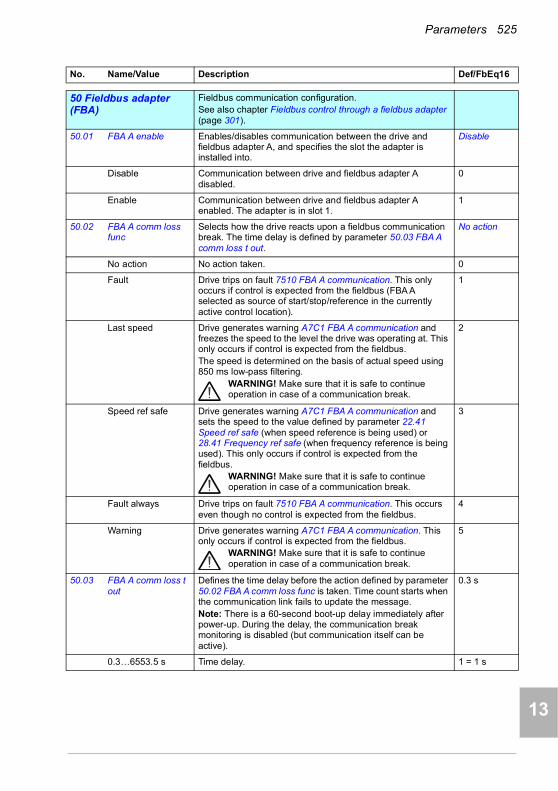
Parameters 525
1
2
3
4
5
6
7
8
9
10
11
12
13
5050 Fieldbus adapter (FBA)
Fieldbus communication configuration.See also chapter Fieldbus control through a fieldbus adapter (page 301).
50.01 FBA A enable Enables/disables communication between the drive and fieldbus adapter A, and specifies the slot the adapter is installed into.
Disable
Disable Communication between drive and fieldbus adapter A disabled.
0
Enable Communication between drive and fieldbus adapter A enabled. The adapter is in slot 1.
1
50.02 FBA A comm loss func
Selects how the drive reacts upon a fieldbus communication break. The time delay is defined by parameter 50.03 FBA A comm loss t out.
No action
No action No action taken. 0
Fault Drive trips on fault 7510 FBA A communication. This only occurs if control is expected from the fieldbus (FBA A selected as source of start/stop/reference in the currently active control location).
1
Last speed Drive generates warning A7C1 FBA A communication and freezes the speed to the level the drive was operating at. This only occurs if control is expected from the fieldbus.The speed is determined on the basis of actual speed using 850 ms low-pass filtering.
WARNING! Make sure that it is safe to continue operation in case of a communication break.
2
Speed ref safe Drive generates warning A7C1 FBA A communication and sets the speed to the value defined by parameter 22.41 Speed ref safe (when speed reference is being used) or 28.41 Frequency ref safe (when frequency reference is being used). This only occurs if control is expected from the fieldbus.
WARNING! Make sure that it is safe to continue operation in case of a communication break.
3
Fault always Drive trips on fault 7510 FBA A communication. This occurs even though no control is expected from the fieldbus.
4
Warning Drive generates warning A7C1 FBA A communication. This only occurs if control is expected from the fieldbus.
WARNING! Make sure that it is safe to continue operation in case of a communication break.
5
50.03 FBA A comm loss t out
Defines the time delay before the action defined by parameter 50.02 FBA A comm loss func is taken. Time count starts when the communication link fails to update the message.Note: There is a 60-second boot-up delay immediately after power-up. During the delay, the communication break monitoring is disabled (but communication itself can be active).
0.3 s
0.3…6553.5 s Time delay. 1 = 1 s
No. Name/Value Description Def/FbEq16
14
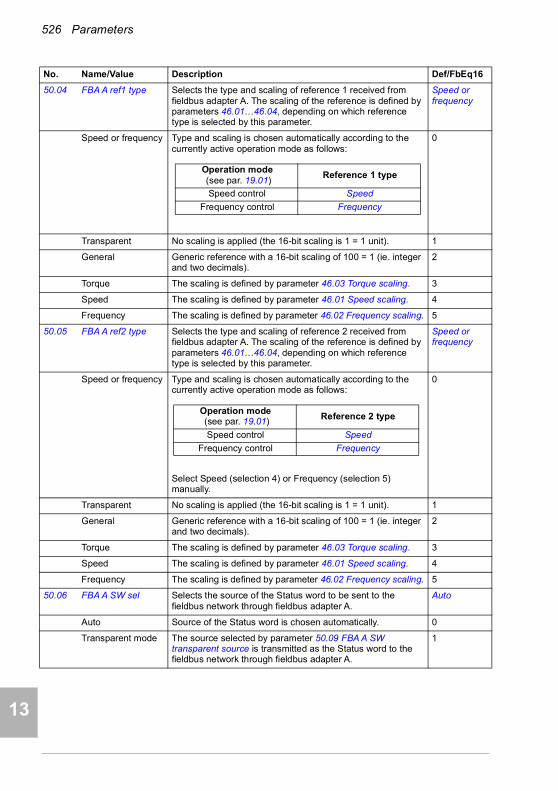
526 Parameters
1
2
3
4
5
7
8
9
9
10
11
12
13
14
50.04 FBA A ref1 type Selects the type and scaling of reference 1 received from fieldbus adapter A. The scaling of the reference is defined by parameters 46.01…46.04, depending on which reference type is selected by this parameter.
Speed or frequency
Speed or frequency Type and scaling is chosen automatically according to the currently active operation mode as follows:
0
Transparent No scaling is applied (the 16-bit scaling is 1 = 1 unit). 1
General Generic reference with a 16-bit scaling of 100 = 1 (ie. integer and two decimals).
2
Torque The scaling is defined by parameter 46.03 Torque scaling. 3
Speed The scaling is defined by parameter 46.01 Speed scaling. 4
Frequency The scaling is defined by parameter 46.02 Frequency scaling. 5
50.05 FBA A ref2 type Selects the type and scaling of reference 2 received from fieldbus adapter A. The scaling of the reference is defined by parameters 46.01…46.04, depending on which reference type is selected by this parameter.
Speed or frequency
Speed or frequency Type and scaling is chosen automatically according to the currently active operation mode as follows:
Select Speed (selection 4) or Frequency (selection 5) manually.
0
Transparent No scaling is applied (the 16-bit scaling is 1 = 1 unit). 1
General Generic reference with a 16-bit scaling of 100 = 1 (ie. integer and two decimals).
2
Torque The scaling is defined by parameter 46.03 Torque scaling. 3
Speed The scaling is defined by parameter 46.01 Speed scaling. 4
Frequency The scaling is defined by parameter 46.02 Frequency scaling. 5
50.06 FBA A SW sel Selects the source of the Status word to be sent to the fieldbus network through fieldbus adapter A.
Auto
Auto Source of the Status word is chosen automatically. 0
Transparent mode The source selected by parameter 50.09 FBA A SW transparent source is transmitted as the Status word to the fieldbus network through fieldbus adapter A.
1
No. Name/Value Description Def/FbEq16
Operation mode (see par. 19.01)
Reference 1 type
Speed control Speed
Frequency control Frequency
Operation mode (see par. 19.01) Reference 2 type
Speed control Speed
Frequency control Frequency

Parameters 527
1
2
3
4
5
6
7
8
9
10
11
12
13
50.07 FBA A actual 1 type Selects the type and scaling of actual value 1 transmitted to the fieldbus network through fieldbus adapter A. The scaling of the value is defined by parameters 46.01…46.04, depending on which actual value type is selected by this parameter.
Speed or frequency
Speed or frequency Type and scaling is chosen automatically according to the currently active operation mode as follows:
0
Transparent The value selected by parameter 50.10 FBA A act1 transparent source is sent as actual value 1. No scaling is applied (the 16-bit scaling is 1 = 1 unit).
1
General The value selected by parameter 50.10 FBA A act1 transparent source is sent as actual value 1 with a 16-bit scaling of 100 = 1 unit (ie. integer and two decimals).
2
Torque The scaling is defined by parameter 46.03 Torque scaling. 3
Speed 01.01 Motor speed used is sent as actual value 1. The scaling is defined by parameter 46.01 Speed scaling.
4
Frequency 01.06 Output frequency is sent as actual value 1. The scaling is defined by parameter 46.02 Frequency scaling.
5
50.08 FBA A actual 2 type Selects the type and scaling of actual value 2 transmitted to the fieldbus network through fieldbus adapter A. The scaling of the value is defined by parameters 46.01…46.04, depending on which actual value type is selected by this parameter.
Speed or frequency
Speed or frequency Type and scaling is chosen automatically according to the currently active operation mode as follows:
Select Speed (selection 4) or Frequency (selection 5) manually.
0
Transparent The value selected by parameter 50.10 FBA A act1 transparent source is sent as actual value 1. No scaling is applied (the 16-bit scaling is 1 = 1 unit).
1
General The value selected by parameter 50.10 FBA A act1 transparent source is sent as actual value 1 with a 16-bit scaling of 100 = 1 unit (ie. integer and two decimals).
2
Torque 01.10 Motor torque is sent as actual value 1. The scaling is defined by parameter 46.03 Torque scaling.
3
Speed 01.01 Motor speed used is sent as actual value 1. The scaling is defined by parameter 46.01 Speed scaling.
4
Frequency 01.06 Output frequency is sent as actual value 1. The scaling is defined by parameter 46.02 Frequency scaling.
5
No. Name/Value Description Def/FbEq16
Operation mode (see par. 19.01)
Actual value 1 type
Speed control Speed
Frequency control Frequency
Operation mode (see par. 19.01)
Actual value 2 type
Speed control Speed
Frequency control Frequency
14

528 Parameters
1
2
3
4
5
7
8
9
9
10
11
12
13
14
50.09 FBA A SW transparent source
Selects the source of the fieldbus status word when parameter 50.06 FBA A SW sel is set to Transparent mode.
Not selected
Not selected No source selected. -
Other Source selection (see Terms and abbreviations on page 340). -
50.10 FBA A act1 transparent source
When parameter 50.07 FBA A actual 1 type is set to Transparent, this parameter selects the source of actual value 1 transmitted to the fieldbus network through fieldbus adapter A.
Not selected
Not selected No source selected. -
Other Source selection (see Terms and abbreviations on page 340). -
50.11 FBA A act2 transparent source
When parameter 50.08 FBA A actual 2 type is set to Transparent, this parameter selects the source of actual value 2 transmitted to the fieldbus network through fieldbus adapter A.
Not selected
Not selected No source selected. -
Other Source selection (see Terms and abbreviations on page 340). -
50.12 FBA A debug mode This parameter enables debug mode. Displays raw (unmodified) data received from and sent to fieldbus adapter A in parameters 50.13…50.18.
Disable
Disable Debug mode disabled. 0
Fast Debug mode enabled. Cyclical data update is as fast as possible which increases CPU load on the drive.
1
50.13 FBA A control word Displays the raw (unmodified) control word sent by the master (PLC) to fieldbus adapter A if debugging is enabled by parameter 50.12 FBA A debug mode.This parameter is read-only.
-
00000000h… FFFFFFFFh
Control word sent by master to fieldbus adapter A. -
50.14 FBA A reference 1 Displays raw (unmodified) reference REF1 sent by the master (PLC) to fieldbus adapter A if debugging is enabled by parameter 50.12 FBA A debug mode.This parameter is read-only.
-
-2147483648… 2147483647
Raw REF1 sent by master to fieldbus adapter A. -
50.15 FBA A reference 2 Displays raw (unmodified) reference REF2 sent by the master (PLC) to fieldbus adapter A if debugging is enabled by parameter 50.12 FBA A debug mode.This parameter is read-only.
-
-2147483648… 2147483647
Raw REF2 sent by master to fieldbus adapter A. -
50.16 FBA A status word Displays the raw (unmodified) status word sent by fieldbus adapter A to the master (PLC) if debugging is enabled by parameter 50.12 FBA A debug mode.This parameter is read-only.
-
00000000h… FFFFFFFFh
Status word sent by fieldbus adapter A to master. -
No. Name/Value Description Def/FbEq16
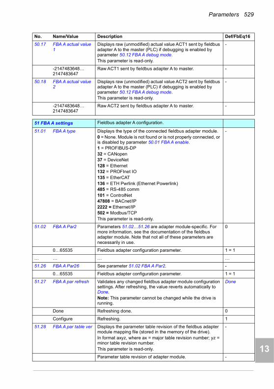
Parameters 529
1
2
3
4
5
6
7
8
9
10
11
12
13
50.17 FBA A actual value 1
Displays raw (unmodified) actual value ACT1 sent by fieldbus adapter A to the master (PLC) if debugging is enabled by parameter 50.12 FBA A debug mode.This parameter is read-only.
-
-2147483648… 2147483647
Raw ACT1 sent by fieldbus adapter A to master. -
50.18 FBA A actual value 2
Displays raw (unmodified) actual value ACT2 sent by fieldbus adapter A to the master (PLC) if debugging is enabled by parameter 50.12 FBA A debug mode.This parameter is read-only.
-
-2147483648… 2147483647
Raw ACT2 sent by fieldbus adapter A to master. -
5151 FBA A settings Fieldbus adapter A configuration.
51.01 FBA A type Displays the type of the connected fieldbus adapter module.0 = None. Module is not found or is not properly connected, or is disabled by parameter 50.01 FBA A enable.1 = PROFIBUS-DP 32 = CANopen 37 = DeviceNet128 = Ethernet132 = PROFInet IO135 = EtherCAT 136 = ETH Pwrlink (Ethernet Powerlink)485 = RS-485 comm101 = ControlNet47808 = BACnet/IP2222 = Ethernet/IP502 = Modbus/TCPThis parameter is read-only.
-
51.02 FBA A Par2 Parameters 51.02…51.26 are adapter module-specific. For more information, see the documentation of the fieldbus adapter module. Note that not all of these parameters are necessarily in use.
0
0…65535 Fieldbus adapter configuration parameter. 1 = 1
… … … …
51.26 FBA A Par26 See parameter 51.02 FBA A Par2. -
0…65535 Fieldbus adapter configuration parameter. 1 = 1
51.27 FBA A par refresh Validates any changed fieldbus adapter module configuration settings. After refreshing, the value reverts automatically to Done.Note: This parameter cannot be changed while the drive is running.
Done
Done Refreshing done. 0
Configure Refreshing. 1
51.28 FBA A par table ver Displays the parameter table revision of the fieldbus adapter module mapping file (stored in the memory of the drive).In format axyz, where ax = major table revision number; yz = minor table revision number.This parameter is read-only.
-
Parameter table revision of adapter module. -
No. Name/Value Description Def/FbEq16
14

530 Parameters
1
2
3
4
5
7
8
9
9
10
11
12
13
14
51.29 FBA A drive type code
Displays the drive type code in the fieldbus adapter module mapping file (stored in the memory of the drive).This parameter is read-only.
-
0…65535 Drive type code stored in the mapping file. 1 = 1
51.30 FBA A mapping file ver
Displays the fieldbus adapter module mapping file revision stored in the memory of the drive in decimal format.This parameter is read-only.
-
0…65535 Mapping file revision. 1 = 1
51.31 D2FBA A comm status
Displays the status of the fieldbus adapter module communication
Not configured
Not configured Adapter is not configured. 0
Initializing Adapter is initializing. 1
Time out A timeout has occurred in the communication between the adapter and the drive.
2
Configuration error Adapter configuration error: mapping file not found in the file system of the drive, or mapping file upload has failed more than three times.
3
Off-line Fieldbus communication is off-line. 4
On-line Fieldbus communication is on-line, or fieldbus adapter has been configured not to detect a communication break. For more information, see the documentation of the fieldbus adapter.
5
Reset Adapter is performing a hardware reset. 6
51.32 FBA A comm SW ver
Displays the common program revision of the adapter module in format axyz, where a = major revision number, xy = minor revision number, z = correction number or letter.Example: 190A = revision 1.90A.
Common program revision of adapter module. -
51.33 FBA A appl SW ver Displays the application program revision of the adapter module in format axyz, where a = major revision number, xy = minor revision number, z = correction number or letter.Example: 190A = revision 1.90A.
Application program version of adapter module. -
5252 FBA A data in Selection of data to be transferred from drive to fieldbus
controller through fieldbus adapter A.Note: 32-bit values require two consecutive parameters. Whenever a 32-bit value is selected in a data parameter, the next parameter is automatically reserved.
52.01 FBA A data in1 Parameters 52.01…52.12 select data to be transferred from the drive to the fieldbus controller through fieldbus adapter A.
None
None None. 0
CW 16bit Control Word (16 bits) 1
Ref1 16bit Reference REF1 (16 bits) 2
Ref2 16bit Reference REF2 (16 bits) 3
SW 16bit Status Word (16 bits) 4
Act1 16bit Actual value ACT1 (16 bits) 5
Act2 16bit Actual value ACT2 (16 bits) 6
No. Name/Value Description Def/FbEq16

Parameters 531
1
2
3
4
5
6
7
8
9
10
11
12
13
Reserved 7…10
CW 32bit Control Word (32 bits) 11
Ref1 32bit Reference REF1 (32 bits) 12
Ref2 32bit Reference REF2 (32 bits) 13
SW 32bit Status Word (32 bits) 14
Act1 32bit Actual value ACT1 (32 bits) 15
Act2 32bit Actual value ACT2 (32 bits) 16
Reserved 17…23
SW2 16bit Status Word 2 (16 bits) 24
Other Source selection (see Terms and abbreviations on page 340). -
… … … …
52.12 FBA A data in12 See parameter 52.01 FBA A data in1. None
5353 FBA A data out Selection of data to be transferred from fieldbus controller to
drive through fieldbus adapter A.Note: 32-bit values require two consecutive parameters. Whenever a 32-bit value is selected in a data parameter, the next parameter is automatically reserved.
53.01 FBA A data out1 Parameters 53.01…53.12 select data to be transferred from the fieldbus controller to the drive through fieldbus adapter A.
None
None None. 0
CW 16bit Control Word (16 bits) 1
Ref1 16bit Reference REF1 (16 bits) 2
Ref2 16bit Reference REF2 (16 bits) 3
Reserved 7…10
CW 32bit Control Word (32 bits) 11
Ref1 32bit Reference REF1 (32 bits) 12
Ref2 32bit Reference REF2 (32 bits) 13
Reserved 14…20
CW2 16bit Control Word 2 (16 bits) 21
Other Source selection (see Terms and abbreviations on page 340). -
… … … …
53.12 FBA A data out12 See parameter 53.01 FBA A data out1. None
5858 Embedded fieldbus Configuration of the embedded fieldbus (EFB) interface.
See also chapter Modbus RTU control through the embedded fieldbus interface (EFB) (page 225).
58.01 Protocol enable Enables/disables the embedded fieldbus interface and selects the protocol to use.
None
None None (communication disabled). 0
Modbus RTU Embedded fieldbus interface is enabled and uses the Modbus RTU protocol.
1
BACnet MSTP Embedded fieldbus interface is enabled and uses the BACnet MS/TP protocol.
2
Reserved 3…4
No. Name/Value Description Def/FbEq16
14

532 Parameters
1
2
3
4
5
7
8
9
9
10
11
12
13
14
N2 Embedded fieldbus interface is enabled and uses the N2 protocol.
5
58.02 Protocol ID Displays the protocol ID and revision. First 4 bits specify the protocol ID and last 12 bits specify the revision.This parameter is read-only.
-
Protocol ID and revision. 1 = 1
58.03 Node address Defines the node address of the drive on the fieldbus link.Values 1…247 are allowable. Also called Station ID, MAC Address or Device Address. Two devices with the same address are not allowed on-line.Changes to this parameter take effect after the control unit is rebooted or the new settings validated by parameter 58.06 Communication control (Refresh settings).
1
0…255 Node address (values 1…247 are allowed). 1 = 1
58.04 Baud rate Selects the transfer rate of the fieldbus link.When using selection Autodetect, the parity setting of the bus must be known and configured in parameter 58.05 Parity. When parameter 58.04 Baud rate is set to Autodetect, the EFB settings must be refreshed with parameter 58.06. The bus is monitored for a period of time and the detected baud rate is set as the value of this parameter.Changes to this parameter take effect after the control unit is rebooted or the new settings validated by parameter 58.06 Communication control (Refresh settings).
Modbus RTU: 19.2 kbpsBACnet MS/TP: AutodetectN2: 9.6 kbps
Autodetect Baud rate detected automatically. 0
4.8 kbps 4.8 kbit/s. 1
9.6 kbps 9.6 kbit/s. 2
19.2 kbps 19.2 kbit/s. 3
38.4 kbps 38.4 kbit/s. 4
57.6 kbps 57.6 kbit/s. 5
76.8 kbps 76.8 kbit/s. 6
115.2 kbps 115.2 kbit/s. 7
58.05 Parity Modbus RTU, N2 only: Selects the type of parity bit and number of stop bits.Changes to this parameter take effect after the control unit is rebooted or the new settings validated by parameter 58.06 Communication control (Refresh settings).Note: For BACnet MS/TP, the BACnet standard defines the parity as 8 NONE 1.
8 EVEN 1
8 NONE 1 Eight data bits, no parity bit, one stop bit. 0
8 NONE 2 Eight data bits, no parity bit, two stop bits. 1
8 EVEN 1 Eight data bits, even parity bit, one stop bit. 2
8 ODD 1 Eight data bits, odd parity bit, one stop bit. 3
58.06 Communication control
Takes changed EFB settings in use, or activates silent mode. Enabled
Enabled Normal operation. 0
Refresh settings Refreshes settings (parameters 58.01…58.05, 58.14…58.17, 58.25, 58.28…58.34) and takes changed EFB configuration settings in use. Reverts automatically to Enabled.
1
No. Name/Value Description Def/FbEq16
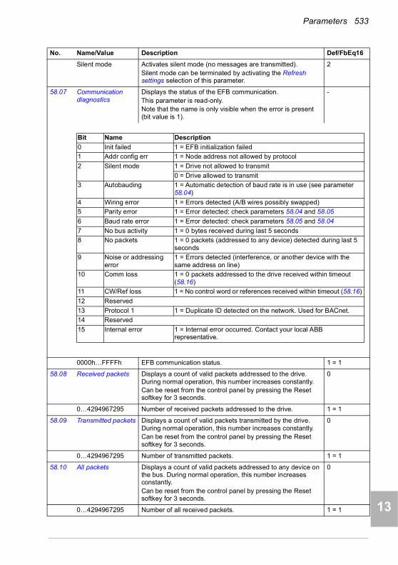
Parameters 533
1
2
3
4
5
6
7
8
9
10
11
12
13
Silent mode Activates silent mode (no messages are transmitted).Silent mode can be terminated by activating the Refresh settings selection of this parameter.
2
58.07 Communication diagnostics
Displays the status of the EFB communication.This parameter is read-only.Note that the name is only visible when the error is present (bit value is 1).
-
0000h…FFFFh EFB communication status. 1 = 1
58.08 Received packets Displays a count of valid packets addressed to the drive. During normal operation, this number increases constantly.Can be reset from the control panel by pressing the Reset softkey for 3 seconds.
0
0…4294967295 Number of received packets addressed to the drive. 1 = 1
58.09 Transmitted packets Displays a count of valid packets transmitted by the drive. During normal operation, this number increases constantly.Can be reset from the control panel by pressing the Reset softkey for 3 seconds.
0
0…4294967295 Number of transmitted packets. 1 = 1
58.10 All packets Displays a count of valid packets addressed to any device on the bus. During normal operation, this number increases constantly.Can be reset from the control panel by pressing the Reset softkey for 3 seconds.
0
0…4294967295 Number of all received packets. 1 = 1
No. Name/Value Description Def/FbEq16
Bit Name Description
0 Init failed 1 = EFB initialization failed
1 Addr config err 1 = Node address not allowed by protocol
2 Silent mode 1 = Drive not allowed to transmit
0 = Drive allowed to transmit
3 Autobauding 1 = Automatic detection of baud rate is in use (see parameter 58.04)
4 Wiring error 1 = Errors detected (A/B wires possibly swapped)
5 Parity error 1 = Error detected: check parameters 58.04 and 58.05
6 Baud rate error 1 = Error detected: check parameters 58.05 and 58.04
7 No bus activity 1 = 0 bytes received during last 5 seconds
8 No packets 1 = 0 packets (addressed to any device) detected during last 5 seconds
9 Noise or addressing error
1 = Errors detected (interference, or another device with the same address on line)
10 Comm loss 1 = 0 packets addressed to the drive received within timeout (58.16)
11 CW/Ref loss 1 = No control word or references received within timeout (58.16)
12 Reserved
13 Protocol 1 1 = Duplicate ID detected on the network. Used for BACnet.
14 Reserved
15 Internal error 1 = Internal error occurred. Contact your local ABB representative.
14

534 Parameters
1
2
3
4
5
7
8
9
9
10
11
12
13
14
58.11 UART errors Displays a count of character errors received by the drive. An increasing count indicates a configuration problem on the bus.Can be reset from the control panel by pressing the Reset softkey for 3 seconds.
0
0…4294967295 Number of UART errors. 1 = 1
58.12 CRC errors Displays a count of packets with a CRC error received by the drive. An increasing count indicates interference on the bus.Can be reset from the control panel by pressing the Reset softkey for 3 seconds.
0
0…4294967295 Number of CRC errors. 1 = 1
58.13 Token counter BACnet MS/TP only: Contains a count of the number of times this device has received the token. Used for diagnostic purposes.
0
0…4294967295 Counter 1 = 1
58.14 Communication loss action
Selects how the drive reacts to an EFB communication break.Changes to this parameter take effect after the control unit is rebooted or the new settings validated by parameter 58.06 Communication control (Refresh settings).See also parameters 58.15 Communication loss mode and 58.16 Communication loss time.
No action
No action No action taken (monitoring disabled). 0
Fault Drive monitors communication loss when start/stop is expected from the EFB on the currently active control location. The drive trips on fault 6681 EFB comm loss if control in the currently active control location is expected from the EFB or reference is coming from the EFB, and the communication is lost.
1
Last speed Drive generates warning A7CE EFB comm loss and freezes the speed to the level the drive was operating at. The speed is determined on the basis of actual speed using 850 ms low-pass filtering. This occurs if control or reference is expected from the EFB.
WARNING! Make sure that it is safe to continue operation in case of a communication break.
2
Speed ref safe Drive generates warning A7CE EFB comm loss and sets the speed to the speed defined by parameter 22.41 Speed ref safe (or 28.41 Frequency ref safe when frequency reference is being used). This occurs if control or reference is expected from the EFB.
WARNING! Make sure that it is safe to continue operation in case of a communication break.
3
Fault always Drive continuously monitors for communication loss. Drive trips on fault 6681 EFB comm loss. This happens even though the drive is in a control location where the EFB start/stop or reference is not used.
4
Warning Drive generates warning A7CE EFB comm loss. This occurs even though no control is expected from the EFB.
WARNING! Make sure that it is safe to continue operation in case of a communication break.
5
No. Name/Value Description Def/FbEq16

Parameters 535
1
2
3
4
5
6
7
8
9
10
11
12
13
58.15 Communication loss mode
Defines which message types reset the timeout counter for detecting an EFB communication loss.Changes to this parameter take effect after the control unit is rebooted or the new settings validated by parameter 58.06 Communication control (Refresh settings).See also parameters 58.14 Communication loss action and 58.16 Communication loss time.
Cw / Ref1 / Ref2
Any message Any message addressed to the drive resets the timeout. 1
Cw / Ref1 / Ref2 A write of the control word or a reference resets the timeout. 2
58.16 Communication loss time
Sets a timeout for EFB communication. If a communication break lasts longer than the timeout, the action specified by parameter 58.14 Communication loss action is taken.Changes to this parameter take effect after the control unit is rebooted or the new settings validated by parameter 58.06 Communication control (Refresh settings).See also parameter 58.15 Communication loss mode.Note: There is a 30-second boot-up delay immediately after power-up.
30.0 s
0.0…6000.0 s EFB communication timeout. 1 = 1
58.17 Transmit delay Modbus RTU, N2 only: Defines a minimum response delay in addition to any fixed delay imposed by the protocol.Changes to this parameter take effect after the control unit is rebooted or the new settings validated by parameter 58.06 Communication control (Refresh settings).
0 ms
0…65535 ms Minimum response delay. 1 = 1
58.18 EFB control word Modbus RTU, BACnet MS/TP only: Displays the raw (unmodified) control word sent by the Modbus controller to the drive. For debugging purposes.This parameter is read-only.
-
00000000h…FFFFFFFFh
Control word sent by Modbus controller to the drive. 1 = 1
58.19 EFB status word Modbus RTU, BACnet MS/TP only: Displays the raw (unmodified) status word for debugging purposes.This parameter is read-only.
-
00000000h…FFFFFFFFh
Status word sent by the drive to the Modbus controller. 1 = 1
58.25 Control profile Modbus RTU only: Defines the communication profile used by the Modbus protocol.Changes to this parameter take effect after the control unit is rebooted or the new settings validated by parameter 58.06 Communication control (Refresh settings).See section About the control profiles on page 234.
ABB Drives
ABB Drives ABB Drives control profile (with a 16-bit control word) 0
DCU Profile DCU control profile (with a 16 or 32-bit control word) 5
No. Name/Value Description Def/FbEq16
14
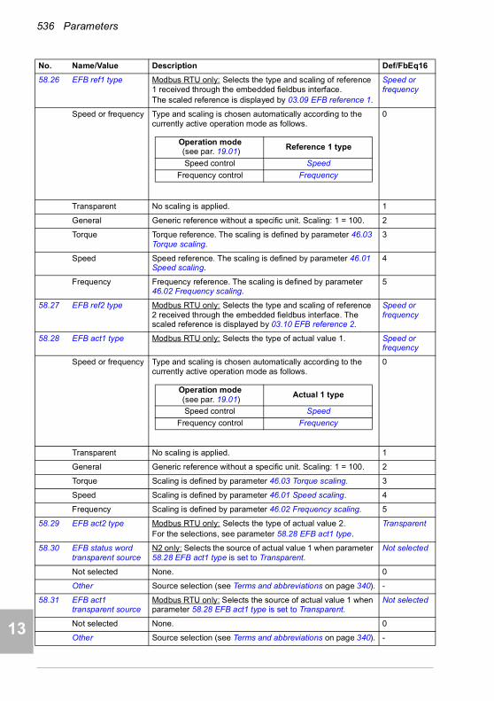
536 Parameters
1
2
3
4
5
7
8
9
9
10
11
12
13
14
58.26 EFB ref1 type Modbus RTU only: Selects the type and scaling of reference 1 received through the embedded fieldbus interface. The scaled reference is displayed by 03.09 EFB reference 1.
Speed or frequency
Speed or frequency Type and scaling is chosen automatically according to the currently active operation mode as follows.
0
Transparent No scaling is applied. 1
General Generic reference without a specific unit. Scaling: 1 = 100. 2
Torque Torque reference. The scaling is defined by parameter 46.03 Torque scaling.
3
Speed Speed reference. The scaling is defined by parameter 46.01 Speed scaling.
4
Frequency Frequency reference. The scaling is defined by parameter 46.02 Frequency scaling.
5
58.27 EFB ref2 type Modbus RTU only: Selects the type and scaling of reference 2 received through the embedded fieldbus interface. The scaled reference is displayed by 03.10 EFB reference 2.
Speed or frequency
58.28 EFB act1 type Modbus RTU only: Selects the type of actual value 1. Speed or frequency
Speed or frequency Type and scaling is chosen automatically according to the currently active operation mode as follows.
0
Transparent No scaling is applied. 1
General Generic reference without a specific unit. Scaling: 1 = 100. 2
Torque Scaling is defined by parameter 46.03 Torque scaling. 3
Speed Scaling is defined by parameter 46.01 Speed scaling. 4
Frequency Scaling is defined by parameter 46.02 Frequency scaling. 5
58.29 EFB act2 type Modbus RTU only: Selects the type of actual value 2.For the selections, see parameter 58.28 EFB act1 type.
Transparent
58.30 EFB status word transparent source
N2 only: Selects the source of actual value 1 when parameter 58.28 EFB act1 type is set to Transparent.
Not selected
Not selected None. 0
Other Source selection (see Terms and abbreviations on page 340). -
58.31 EFB act1 transparent source
Modbus RTU only: Selects the source of actual value 1 when parameter 58.28 EFB act1 type is set to Transparent.
Not selected
Not selected None. 0
Other Source selection (see Terms and abbreviations on page 340). -
No. Name/Value Description Def/FbEq16
Operation mode (see par. 19.01) Reference 1 type
Speed control Speed
Frequency control Frequency
Operation mode (see par. 19.01)
Actual 1 type
Speed control Speed
Frequency control Frequency

Parameters 537
1
2
3
4
5
6
7
8
9
10
11
12
13
58.32 EFB act2 transparent source
Modbus RTU, N2 only: Selects the source of actual value 2 when parameter 58.29 EFB act2 type is set to Transparent.
Not selected
Not selected None. 0
Other Source selection (see Terms and abbreviations on page 340). -
58.33 Addressing mode Modbus RTU only: Defines the mapping between parameters and holding registers in the 400101…465535 Modbus register range.Changes to this parameter take effect after the control unit is rebooted or the new settings validated by parameter 58.06 Communication control (Refresh settings).
Mode 0
Mode 0 16-bit values (groups 1…99, indexes 1…99):Register address = 400000 + 100 × parameter group + parameter index. For example, parameter 22.80 would be mapped to register 400000 + 2200 + 80 = 402280.32-bit values (groups 1…99, indexes 1…99):Register address = 420000 + 200 × parameter group + 2 × parameter index. For example, parameter 22.80 would be mapped to register 420000 + 4400 + 160 = 424560.
0
Mode 1 16-bit values (groups 1…255, indexes 1…255):Register address = 400000 + 256 × parameter group + parameter index. For example, parameter 22.80 would be mapped to register 400000 + 5632 + 80 = 405712.
1
Mode 2 32-bit values (groups 1…127, indexes 1…255):Register address = 400000 + 512 × parameter group + 2 × parameter index. For example, parameter 22.80 would be mapped to register 400000 + 11264 + 160 = 411424.
2
58.34 Word order Modbus RTU only: Selects in which order 16-bit registers of 32-bit parameters are transferred.For each register, the first byte contains the high order byte and the second byte contains the low order byte.Changes to this parameter take effect after the control unit is rebooted or the new settings validated by parameter 58.06 Communication control (Refresh settings).
LO-HI
HI-LO The first register contains the high order word, the second contains the low order word.
0
LO-HI The first register contains the low order word, the second contains the high order word.
1
58.40 Device object ID BACnet MS/TP only: The Device object ID must be unique across all BACnet devices in the building network. Valid values are in range 0…4194303 The default Device object ID (4194303) is invalid per the BACnet specification.Changes to this parameter take effect after the control unit is rebooted or the new settings validated by parameter 58.06 Communication control (Refresh settings).
4194303
0…4194303 ID.
58.41 Max master BACnet MS/TP only: The highest master address for devices on the BACnet MS/TP bus.Changes to this parameter take effect after the control unit is rebooted or the new settings validated by parameter 58.06 Communication control (Refresh settings).
127
0…127 Address. 1 = 1
No. Name/Value Description Def/FbEq16
14

538 Parameters
1
2
3
4
5
7
8
9
9
10
11
12
13
14
58.42 Max info frames BACnet MS/TP only: The maximum number of information frames the device may transmit before it must pass the token.Changes to this parameter take effect after the control unit is rebooted or the new settings validated by parameter 58.06 Communication control (Refresh settings).
1
0…10 Maximum number information frames. 1 = 1
58.43 Max APDU retries BACnet MS/TP only: Number of retries to send when no response is seen to confirmed requests.Changes to this parameter take effect after the control unit is rebooted or the new settings validated by parameter 58.06 Communication control (Refresh settings).
3
0…10 Number of retries. 1 = 1
58.44 APDU timeout BACnet MS/TP only: The amount of time in seconds between retransmissions when an expected acknowledgement has not been received.Changes to this parameter take effect after the control unit is rebooted or the new settings validated by parameter 58.06 Communication control (Refresh settings).
10 s
0…60 s Timeout. 1 = 1
58.101 Data I/O 1 Modbus RTU, BACnet MS/TP only: Defines the address in the drive which the Modbus master accesses when it reads from or writes to the register address corresponding to Modbus register 1 (400001).The master defines the type of the data (input or output). The value is transmitted in a Modbus frame consisting of two 16-bit words. If the value is 16-bit, it is transmitted in the LSW (least significant word). If the value is 32-bit, the subsequent parameter is also reserved for it and must be set to None.
CW 16bit
None No mapping, register is always zero. 0
CW 16bit ABB Drives profile: 16-bit ABB drives control word; DCU Profile: lower 16 bits of the DCU control word
1
Ref1 16bit Reference REF1 (16 bits) 2
Ref2 16bit Reference REF2 (16 bits) 3
SW 16bit ABB Drives profile: 16-bit ABB drives status word; DCU Profile: lower 16 bits of the DCU status word
4
Act1 16bit Actual value ACT1 (16 bits) 5
Act2 16bit Actual value ACT2 aha(16 bits) 6
Reserved 7…10
CW 32bit Control Word (32 bits) 11
Ref1 32bit Reference REF1 (32 bits) 12
Ref2 32bit Reference REF2 (32 bits) 13
SW 32bit Status Word (32 bits) 14
Act1 32bit Actual value ACT1 (32 bits) 15
Act2 32bit Actual value ACT2 (32 bits) 16
Reserved 17…20
CW2 16bit ABB Drives profile: not used; DCU Profile: upper 16 bits of the DCU control word
21
SW2 16bit ABB Drives profile: not used / always zero; DCU Profile: upper 16 bits of the DCU status word
24
No. Name/Value Description Def/FbEq16

Parameters 539
1
2
3
4
5
6
7
8
9
10
11
12
13
Reserved 25…30
RO/DIO control word
Parameter 10.99 RO/DIO control word. 31
AO1 data storage Parameter 13.91 AO1 data storage. 32
AO2 data storage Parameter 13.92 AO2 data storage. 33
Reserved 34…39
Feedback data storage
Parameter 40.91 Feedback data storage. 40
Setpoint data storage
Parameter 40.92 Setpoint data storage. 41
Other Source selection (see Terms and abbreviations on page 340). -
58.102 Data I/O 2 Modbus RTU, BACnet MS/TP only: Defines the address in the drive which the Modbus master accesses when it reads from or writes to register address 400002.For the selections, see parameter 58.101 Data I/O 1.
Ref1 16bit
58.103 Data I/O 3 Modbus RTU, BACnet MS/TP only: Defines the address in the drive which the Modbus master accesses when it reads from or writes to register address 400003.For the selections, see parameter 58.101 Data I/O 1.
Ref2 16bit
58.104 Data I/O 4 Modbus RTU, BACnet MS/TP only: Defines the address in the drive which the Modbus master accesses when it reads from or writes to register address 400004.For the selections, see parameter 58.101 Data I/O 1.
SW 16bit
58.105 Data I/O 5 Modbus RTU, BACnet MS/TP only: Defines the address in the drive which the Modbus master accesses when it reads from or writes to register address 400005.For the selections, see parameter 58.101 Data I/O 1.
Act1 16bit
58.106 Data I/O 6 Modbus RTU, BACnet MS/TP only: Defines the address in the drive which the Modbus master accesses when it reads from or writes to register address 400006.For the selections, see parameter 58.101 Data I/O 1.
Act2 16bit
58.107 Data I/O 7 Modbus RTU, BACnet MS/TP only: Parameter selector for Modbus register address 400007.For the selections, see parameter 58.101 Data I/O 1.
None
… … … …
58.114 Data I/O 14 Modbus RTU, BACnet MS/TP only: Parameter selector for Modbus register address 400014.For the selections, see parameter 58.101 Data I/O 1.
None
No. Name/Value Description Def/FbEq16
14
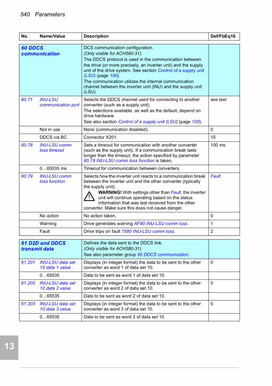
540 Parameters
1
2
3
4
5
7
8
9
9
10
11
12
13
14
6060 DDCS communication
DCS communication configuration.(Only visible for ACH580-31).The DDCS protocol is used in the communication betweenthe drive (or more precisely, an inverter unit) and the supply unit of the drive system. See section Control of a supply unit (LSU) (page 100).The communication utilizes the internal communication channel between the inverter unit (INU) and the supply unit (LSU).
60.71 INU-LSU communication port
Selects the DDCS channel used for connecting to another converter (such as a supply unit).The selections available, as well as the default, depend on drive hardware.See also section Control of a supply unit (LSU) (page 100).
see text
Not in use None (communication disabled). 0
DDCS via BC Connector X201. 15
60.78 INU-LSU comm loss timeout
Sets a timeout for communication with another converter (such as the supply unit). If a communication break lasts longer than the timeout, the action specified by parameter 60.79 INU-LSU comm loss function is taken.
100 ms
0…65535 ms Timeout for communication between converters.
60.79 INU-LSU comm loss function
Selects how the inverter unit reacts to a communication break between the inverter unit and the other converter (typically the supply unit).
WARNING! With settings other than Fault, the inverter unit will continue operating based on the status information that was last received from the other
converter. Make sure this does not cause danger.
Fault
No action No action taken. 0
Warning Drive generates warning AF80 INU-LSU comm loss. 1
Fault Drive trips on fault 7580 INU-LSU comm loss. 2
6161 D2D and DDCS transmit data
Defines the data sent to the DDCS link.(Only visible for ACH580-31).See also parameter group 60 DDCS communication.
61.201 INU-LSU data set 10 data 1 value
Displays (in integer format) the data to be sent to the other converter as word 1 of data set 10.
0
0…65535 Data to be sent as word 1 of data set 10.
61.202 INU-LSU data set 10 data 2 value
Displays (in integer format) the data to be sent to the other converter as word 2 of data set 10.
0
0…65535 Data to be sent as word 2 of data set 10.
61.203 INU-LSU data set 10 data 3 value
Displays (in integer format) the data to be sent to the other converter as word 3 of data set 10.
0
0…65535 Data to be sent as word 3 of data set 10.
No. Name/Value Description Def/FbEq16

Parameters 541
1
2
3
4
5
6
7
8
9
10
11
12
13
6262 D2D and DDCS receive data
Defines the data sent to the DDCS link.(Only visible for ACH580-31).See also parameter group 60 DDCS communication.
62.201 INU-LSU data set 11 data 1 value
Displays (in integer format) the data to be sent to the other converter as word 1 of data set 10.
0
0…65535 Data to be sent as word 1 of data set 10.
7070 Override Enabling/disabling of override function, override activation
signal and override speed/frequency.See control chain diagram Override on page 336
70.01 Override status Shows the override status.This parameter is read-only.
-
70.02 Override enable Enables the override function. For override with ACH580-31, see section LSU Override on page 101.
Off
Off Override disabled. 0
On Override enabled. 1
On, critical Allows for an infinite number of fault resets. To be able use this selection, first set parameter 70.20 Override fault handling to value Autoreset.
2
70.03 Override activation source
Selects the source of the override activation.Value 0 of the source deactivates the override.Value 1 of the source activates the override.
Not used
Not used 0. 0
DI1 Digital input DI1 (10.02 DI delayed status, bit 0). 1
DI2 Digital input DI2 (10.02 DI delayed status, bit 1). 2
DI3 Digital input DI3 (10.02 DI delayed status, bit 2). 3
DI4 Digital input DI4 (10.02 DI delayed status, bit 3). 4
DI5 Digital input DI5 (10.02 DI delayed status, bit 4). 5
DI6 Digital input DI6 (10.02 DI delayed status, bit 5). 6
No. Name/Value Description Def/FbEq16
Bit Name Description
0 Override enabled 0 = Override is disabled; 1 = Override is enabled.
1 Override active 0 = Override is inactive; 1 = Drive is active.
2 Override direction is forward
0 = Override direction is not forward; 1 = Override direction is forward.
3 Override direction is reverse
0 = Override direction is not reverse; 1 = Override direction is reverse.
4 Override stop mode is active
0 = Override stop mode is not active; 1 = Override stop mode is active.
5…6 Reserved
7 Run permissive 0 = Prevents running; 1 = Permits running.
8 Start interlock 1 0 = Prevents starting; 1 = Permits starting.
9 Start interlock 2 0 = Prevents starting; 1 = Permits starting.
10 Start interlock 3 0 = Prevents starting; 1 = Permits starting.
11 Start interlock 4 0 = Prevents starting; 1 = Permits starting.
12…15 Reserved
14
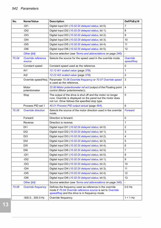
542 Parameters
1
2
3
4
5
7
8
9
9
10
11
12
13
14
-DI1 Digital input DI1 (10.02 DI delayed status, bit 0). 7
-DI2 Digital input DI2 (10.02 DI delayed status, bit 1). 8
-DI3 Digital input DI3 (10.02 DI delayed status, bit 2). 9
-DI4 Digital input DI4 (10.02 DI delayed status, bit 3). 10
-DI5 Digital input DI5 (10.02 DI delayed status, bit 4). 11
-DI6 Digital input DI6 (10.02 DI delayed status, bit 5). 12
Other [bit] Source selection (see Terms and abbreviations on page 340). -
70.04 Override reference source
Selects the source for the speed used in the override mode. Override speed/freq
Constant speed Constant speed used as the reference. 0
AI1 12.12 AI1 scaled value (page 376). 1
AI2 12.22 AI2 scaled value (page 378). 2
Override speed/freq Parameter 70.06 Override frequency or 70.07 Override speed is used as the reference.
3
Motor potentiometer
22.80 Motor potentiometer ref act (output of the Floating point control (Motor potentiometer)).
4
Stop The output of the drive is shut off and the motor no longer runs. Override is displayed on the panel but the motor does not run. Drive follows the specified stop type.
5
Process PID set 1 40.01 Process PID output actual (page 494). 6
70.05 Override direction Selects the source of the motor direction used in the override mode.
Forward
Forward Direction is forward. 0
Reverse Direction is reverse. 1
DI1 Digital input DI1 (10.02 DI delayed status, bit 0). 2
DI2 Digital input DI2 (10.02 DI delayed status, bit 1). 3
DI3 Digital input DI3 (10.02 DI delayed status, bit 2). 4
DI4 Digital input DI4 (10.02 DI delayed status, bit 3). 5
DI5 Digital input DI5 (10.02 DI delayed status, bit 4). 6
DI6 Digital input DI6 (10.02 DI delayed status, bit 5). 7
-DI1 Digital input DI1 (10.02 DI delayed status, bit 0). 8
-DI2 Digital input DI2 (10.02 DI delayed status, bit 1). 9
-DI3 Digital input DI3 (10.02 DI delayed status, bit 2). 10
-DI4 Digital input DI4 (10.02 DI delayed status, bit 3). 11
-DI5 Digital input DI5 (10.02 DI delayed status, bit 4). 12
-DI6 Digital input DI6 (10.02 DI delayed status, bit 5). 13
Other [bit] Source selection (see Terms and abbreviations on page 340). -
70.06 Override frequency Defines the frequency used as reference in the override mode if 70.04 Override reference source is set to Override speed/freq and the drive is in frequency mode.
0.0 Hz
-500.0…500.0 Hz Override frequency. 1 = 1 Hz
No. Name/Value Description Def/FbEq16

Parameters 543
1
2
3
4
5
6
7
8
9
10
11
12
13
70.07 Override speed Defines the speed used in as reference the override mode if 70.04 Override reference source is set to Override speed/freq and the drive is in speed mode.
0.0 Hz
30000.0…30000.0 rpm
Override speed. 1 = rpm
70.10 Override enables selection
Selects which start interlock and run permissive input signals configured in the drive parameters will not allow the override function to run the motor or will stop running the motor. The drive remains in override mode nevertheless.
00000b
70.20 Override fault handling
Faults are grouped into high priority faults and low priority faults. The following faults are high priority, and they are displayed and they will stop the drive:2310 Overcurrent, 2330 Earth leakage, 2340 Short circuit, 3210 DC link overvoltage, 5090 STO hardware failure, 5091 Safe torque off, FA81 Safe torque off 1, FA82 Safe torque off 2. Other faults are low priority faults. Active low priority faults are reset when the drive enters override mode. Low priority faults are ignored when the drive is in override mode.
Fault on high priority
Fault on high priority
Fault on high priority faults. The fault must be reset from the control panel or from a digital input.
0
Autoreset Fault on high priority faults (except STO related faults) with automatic fault reset and run. See the list of high priority faults above.See parameter 70.21 Override auto reset trials.
1
70.21 Override auto reset trials
Defines the number of automatic fault resets the drive performs during override operation.When the parameter is set to 0, reset trials are made continuously during the override operation. A value of 1…5 defines a specific number of automatic reset trials.
5
0…5 Number of automatic reset trials. 1 = 1
70.22 Override auto reset time
Defines the time the drive will wait after a fault before attempting an automatic fault reset.
5.0 s
5.0…120.0 s Auto reset delay time. 10 = 1 s
No. Name/Value Description Def/FbEq16
Bit Name Description
0 Run permissive 1 = The override is not allowed to run the motor or the motor will be stopped, if the source defined by parameter 20.40 Run permissive is 0.
1 Start interlock 1 1 = The override is not allowed to start the motor or the motor will be stopped, if the source defined by parameter 20.41 Start interlock 1 is 0.
2 Start interlock 2 1 = The override is not allowed to start the motor or the motor will be stopped, if the source defined by parameter 20.42 Start interlock 2 is 0.
3 Start interlock 3 1 = The override is not allowed to start the motor or the motor will be stopped, if the source defined by parameter 20.43 Start interlock 3 is 0.
4 Start interlock 4 1 = The override is not allowed to start the motor or the motor will be stopped, if the source defined by parameter 20.44 Start interlock 4 is 0.
5…15 Reserved
14

544 Parameters
1
2
3
4
5
7
8
9
9
10
11
12
13
14
70.40 Override log 1 start date
Displays the start date of the last Override activation. 01.01.1980
Start date.
70.41 Override log 1 start time
Displays the start time of the last Override activation. 00:00:00
Start time.
70.42 Override log 1 end date
Displays the end date of the last Override situation.If the drive is in Override mode, the parameter shows the current date.
01.01.1980
End date.
70.43 Override log 1 end time
Displays the end time of the last Override situation.If the drive is in Override mode, the parameter shows the current time.
00:00:00
End time.
70.44 Override log 1 fault 1
Displays the last fault, if any, that occurred during the last operation of override.
0
Fault description.
70.45 Override log 1 fault 2
Displays the second last fault, if any, that occurred during the last operation of override.
0
Fault description.
70.46 Override log 1 fault 3
Displays the third last fault, if any, that occurred during the last operation of override.
0
Fault description.
70.47 Override log 1 warning 1
Displays the last warning, if any, that occurred during the last operation of override.
0
Warning description.
70.48 Override log 1 warning 2
Displays the second last warning, if any, that occurred during the last operation of override.
0
Warning description.
70.49 Override log 1 warning 3
Displays the third last warning, if any, that occurred during the last operation of override.
0
Warning description.
70.50 Override log 2 start date
Displays the start date of the second last Override activation. 01.01.1980
Start date.
70.51 Override log 2 start time
Displays the start time of the second last Override activation. 00:00:00
Start time.
70.52 Override log 2 end date
Displays the end date of the second last Override situation. 01.01.1980
End date.
70.53 Override log 2 end time
Displays the end time of the second last Override situation. 00:00:00
End time.
No. Name/Value Description Def/FbEq16
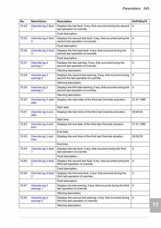
Parameters 545
1
2
3
4
5
6
7
8
9
10
11
12
13
70.54 Override log 2 fault 1
Displays the last fault, if any, that occurred during the second last operation of override.
0
Fault description.
70.55 Override log 2 fault 2
Displays the second last fault, if any, that occurred during the second last operation of override.
0
Fault description.
70.56 Override log 2 fault 3
Displays the third last fault, if any, that occurred during the second last operation of override.
0
Fault description.
70.57 Override log 2 warning 1
Displays the last warning, if any, that occurred during the second last operation of override.
0
Warning description.
70.58 Override log 2 warning 2
Displays the second last warning, if any, that occurred during second the last operation of override.
0
Warning description.
70.59 Override log 2 warning 3
Displays the third last warning, if any, that occurred during the second last operation of override.
0
Warning description.
70.60 Override log 3 start date
Displays the start date of the third last Override activation. 01.01.1980
Start date.
70.61 Override log 3 end date
Displays the start time of the third last Override activation. 00:00:00
Start time.
70.62 Override log 3 end time
Displays the end date of the third last Override situation. 01.01.1980
End date.
70.63 Override log 3 end time
Displays the end time of the third last Override situation. 00:00:00
End time.
70.64 Override log 3 fault 1
Displays the last fault, if any, that occurred during the third last operation of override.
0
Fault description.
70.65 Override log 3 fault 2
Displays the second last fault, if any, that occurred during the third last operation of override.
0
Fault description.
70.66 Override log 3 fault 3
Displays the third last fault, if any, that occurred during the third last operation of override.
0
Fault description.
70.67 Override log 3 warning 1
Displays the last warning, if any, that occurred during the third last operation of override.
0
Warning description.
70.68 Override log 3 warning 2
Displays the second last warning, if any, that occurred during third the last operation of override.
0
Warning description.
No. Name/Value Description Def/FbEq16
14
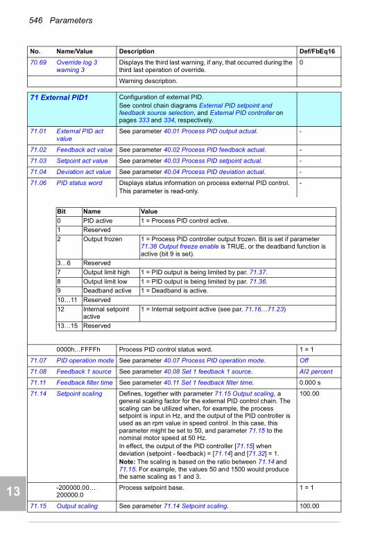
546 Parameters
1
2
3
4
5
7
8
9
9
10
11
12
13
14
70.69 Override log 3 warning 3
Displays the third last warning, if any, that occurred during the third last operation of override.
0
Warning description.
7171 External PID1 Configuration of external PID.
See control chain diagrams External PID setpoint and feedback source selection, and External PID controller on pages 333 and 334, respectively.
71.01 External PID act value
See parameter 40.01 Process PID output actual. -
71.02 Feedback act value See parameter 40.02 Process PID feedback actual. -
71.03 Setpoint act value See parameter 40.03 Process PID setpoint actual. -
71.04 Deviation act value See parameter 40.04 Process PID deviation actual. -
71.06 PID status word Displays status information on process external PID control.This parameter is read-only.
-
0000h…FFFFh Process PID control status word. 1 = 1
71.07 PID operation mode See parameter 40.07 Process PID operation mode. Off
71.08 Feedback 1 source See parameter 40.08 Set 1 feedback 1 source. AI2 percent
71.11 Feedback filter time See parameter 40.11 Set 1 feedback filter time. 0.000 s
71.14 Setpoint scaling Defines, together with parameter 71.15 Output scaling, a general scaling factor for the external PID control chain. The scaling can be utilized when, for example, the process setpoint is input in Hz, and the output of the PID controller is used as an rpm value in speed control. In this case, this parameter might be set to 50, and parameter 71.15 to the nominal motor speed at 50 Hz.In effect, the output of the PID controller [71.15] when deviation (setpoint - feedback) = [71.14] and [71.32] = 1.Note: The scaling is based on the ratio between 71.14 and 71.15. For example, the values 50 and 1500 would produce the same scaling as 1 and 3.
100.00
-200000.00…200000.0
Process setpoint base. 1 = 1
71.15 Output scaling See parameter 71.14 Setpoint scaling. 100.00
No. Name/Value Description Def/FbEq16
Bit Name Value
0 PID active 1 = Process PID control active.
1 Reserved
2 Output frozen 1 = Process PID controller output frozen. Bit is set if parameter 71.38 Output freeze enable is TRUE, or the deadband function is active (bit 9 is set).
3…6 Reserved
7 Output limit high 1 = PID output is being limited by par. 71.37.
8 Output limit low 1 = PID output is being limited by par. 71.36.
9 Deadband active 1 = Deadband is active.
10…11 Reserved
12 Internal setpoint active
1 = Internal setpoint active (see par. 71.16…71.23)
13…15 Reserved

Parameters 547
1
2
3
4
5
6
7
8
9
10
11
12
13
-200000.00…200000.0
Process PID controller output base. 1 = 1
71.16 Setpoint 1 source See parameter 40.16 Set 1 setpoint 1 source. AI1 percent
71.19 Internal setpoint sel1
See parameter 40.19 Set 1 internal setpoint sel1. Not selected
71.20 Internal setpoint sel2
See parameter 40.20 Set 1 internal setpoint sel2. Not selected
71.21 Internal setpoint 1 See parameter 40.21 Set 1 internal setpoint 1. 0.00%
71.22 Internal setpoint 2 See parameter 40.22 Set 1 internal setpoint 2. 0.00%
71.23 Internal setpoint 3 See parameter 40.23 Set 1 internal setpoint 3. 0.00%
71.26 Setpoint min See parameter 40.26 Set 1 setpoint min. 0.00%
71.27 Setpoint max See parameter 40.27 Set 1 setpoint max. 200000.00%
71.31 Deviation inversion See parameter 40.31 Set 1 deviation inversion. Not inverted (Ref - Fbk)
71.32 Gain See parameter 40.32 Set 1 gain. 1.00
71.33 Integration time See parameter 40.33 Set 1 integration time. 60.0 s
71.34 Derivation time See parameter 40.34 Set 1 derivation time. 0.000 s
71.35 Derivation filter time See parameter 40.35 Set 1 derivation filter time. 0.0 s
71.36 Output min See parameter 40.36 Set 1 output min. -200000.00%
71.37 Output max See parameter 40.37 Set 1 output max. 200000.00%
71.38 Output freeze enable
See parameter 40.38 Set 1 output freeze enable. Not selected
71.39 Deadband range The control program compares the absolute value of parameter 71.04 Deviation act value to the deadband range defined by this parameter. If the absolute value is within the deadband range for the time period defined by parameter 71.40 Deadband delay, PID's deadband mode is activated and 71.06 PID status word bit 9 Deadband active is set. Then PID's output is frozen and 71.06 PID status word bit 2 Output frozen is set.If the absolute value is equal or greater than the deadband range, PID's deadband mode is deactivated.
0.0%
0.0…200000.0 Range 1 = 1
71.40 Deadband delay Defines the deadband delay for the deadband function. See parameter 71.39 Deadband range.
0.0 s
0.0…3600.0 s Delay 1 = 1 s
71.58 Increase prevention See parameter 40.58 Set 1 increase prevention. No
71.59 Decrease prevention
See parameter 40.59 Set 1 decrease prevention. No
71.62 Internal setpoint actual
See parameter 40.62 PID internal setpoint actual. 0.00%
71.79 External PID units Unit used for external PID. %
See parameter 40.79 Set 1 units.
7272 External PID2 Configuration of external PID2.
72.01 External PID act value
See parameter 40.01 Process PID output actual. -
No. Name/Value Description Def/FbEq16
14

548 Parameters
1
2
3
4
5
7
8
9
9
10
11
12
13
14
72.02 Feedback act value See parameter 40.02 Process PID feedback actual. -
72.03 Setpoint act value See parameter 40.03 Process PID setpoint actual. -
72.04 Deviation act value See parameter 40.04 Process PID deviation actual. -
72.06 PID status word Displays status information on process external PID control.This parameter is read-only.
-
0000h…FFFFh Process PID control status word. 1 = 1
72.07 PID operation mode See parameter 40.07 Process PID operation mode. Off
72.08 Feedback 1 source See parameter 40.08 Set 1 feedback 1 source. AI1 scaled
72.11 Feedback filter time See parameter 40.11 Set 1 feedback filter time. 0.000 s
72.14 Setpoint scaling Defines, together with parameter 72.15 Output scaling, a general scaling factor for the external PID control chain. The scaling can be utilized when, for example, the process setpoint is input in Hz, and the output of the PID controller is used as an rpm value in speed control. In this case, this parameter might be set to 50, and parameter 72.15 to the nominal motor speed at 50 Hz.In effect, the output of the PID controller [72.15] when deviation (setpoint - feedback) = [72.14] and [72.32] = 1.Note: The scaling is based on the ratio between 72.14 and 72.15. For example, the values 50 and 1500 would produce the same scaling as 1 and 3.
100.00
-200000.00…200000.00
Process setpoint base. 1 = 1
72.15 Output scaling See parameter 72.14 Setpoint scaling. 100.00
-200000.00…200000.00
Process PID controller output base. 1 = 1
72.16 Setpoint 1 source See parameter 40.16 Set 1 setpoint 1 source. AI2 scaled
72.19 Internal setpoint sel1
See parameter 40.19 Set 1 internal setpoint sel1. Not selected
72.20 Internal setpoint sel2
See parameter 40.20 Set 1 internal setpoint sel2. Not selected
No. Name/Value Description Def/FbEq16
Bit Name Value
0 PID active 1 = Process PID control active.
1 Reserved
2 Output frozen 1 = Process PID controller output frozen. Bit is set if parameter 72.38 Output freeze enable is TRUE, or the deadband function is active (bit 9 is set).
3…6 Reserved
7 Output limit high 1 = PID output is being limited by par. 72.37.
8 Output limit low 1 = PID output is being limited by par. 72.36.
9 Deadband active 1 = Deadband is active.
10…11 Reserved
12 Internal setpoint active
1 = Internal setpoint active (see par. 72.16…72.23)
13…15 Reserved

Parameters 549
1
2
3
4
5
6
7
8
9
10
11
12
13
72.21 Internal setpoint 1 See parameter 40.21 Set 1 internal setpoint 1. 0.00 PID Ext2 customer unit
72.22 Internal setpoint 2 See parameter 40.22 Set 1 internal setpoint 2. 0.00 PID Ext2 customer unit
72.23 Internal setpoint 3 See parameter 40.23 Set 1 internal setpoint 3. 0.00 PID Ext2 customer unit
72.26 Setpoint min See parameter 40.26 Set 1 setpoint min. 0.00
72.27 Setpoint max See parameter 40.27 Set 1 setpoint max. 200000.00
72.31 Deviation inversion See parameter 40.31 Set 1 deviation inversion. Not inverted (Ref - Fbk)
72.32 Gain See parameter 40.32 Set 1 gain. 1.00
72.33 Integration time See parameter 40.33 Set 1 integration time. 60.0 s
72.34 Derivation time See parameter 40.34 Set 1 derivation time. 0.000 s
72.35 Derivation filter time See parameter 40.35 Set 1 derivation filter time. 0.0 s
72.36 Output min See parameter 40.36 Set 1 output min. -200000.00
72.37 Output max See parameter 40.37 Set 1 output max. 200000.00
72.38 Output freeze enable
See parameter 40.38 Set 1 output freeze enable. Not selected
72.39 Deadband range The control program compares the absolute value of parameter 72.04 Deviation act value to the deadband range defined by this parameter. If the absolute value is within the deadband range for the time period defined by parameter 72.40 Deadband delay, PID's deadband mode is activated and 72.06 PID status word bit 9 Deadband active is set. Then PID's output is frozen and 72.06 PID status word bit 2 Output frozen is set.If the absolute value is equal or greater than the deadband range, PID's deadband mode is deactivated.
0.0
0.0…200000.0 Range 1 = 1
72.40 Deadband delay Defines the deadband delay for the deadband function. See parameter 72.39 Deadband range.
0.0 s
0.0…3600.0 s Delay 1 = 1 s
72.58 Increase prevention See parameter 40.58 Set 1 increase prevention. No
72.59 Decrease prevention
See parameter 40.59 Set 1 decrease prevention. No
72.62 Internal setpoint actual
See parameter 40.62 PID internal setpoint actual. 0.00 PID Ext2 customer unit
7373 External PID3 Configuration of external PID3.
73.01 External PID act value
See parameter 40.01 Process PID output actual. -
73.02 Feedback act value See parameter 40.02 Process PID feedback actual. -
73.03 Setpoint act value See parameter 40.03 Process PID setpoint actual. -
73.04 Deviation act value See parameter 40.04 Process PID deviation actual. -
No. Name/Value Description Def/FbEq16
14

550 Parameters
1
2
3
4
5
7
8
9
9
10
11
12
13
14
73.06 PID status word Displays status information on process external PID control.This parameter is read-only.
-
0000h…FFFFh Process PID control status word. 1 = 1
73.07 PID operation mode See parameter 40.07 Process PID operation mode. Off
73.08 Feedback 1 source See parameter 40.08 Set 1 feedback 1 source. AI1 scaled
73.11 Feedback filter time See parameter 40.11 Set 1 feedback filter time. 0.000 s
73.14 Setpoint scaling Defines, together with parameter 73.15 Output scaling, a general scaling factor for the external PID control chain. The scaling can be utilized when, for example, the process setpoint is input in Hz, and the output of the PID controller is used as an rpm value in speed control. In this case, this parameter might be set to 50, and parameter 73.15 to the nominal motor speed at 50 Hz.In effect, the output of the PID controller [73.15] when deviation (setpoint - feedback) = [73.14] and [73.32] = 1.Note: The scaling is based on the ratio between 73.14 and 73.15. For example, the values 50 and 1500 would produce the same scaling as 1 and 3.
100.00
-200000.00…200000.00
Process setpoint base. 1 = 1
73.15 Output scaling See parameter 73.14 Setpoint scaling. 100.00
-200000.00…200000.00
Process PID controller output base. 1 = 1
73.16 Setpoint 1 source See parameter 40.16 Set 1 setpoint 1 source. AI2 scaled
73.19 Internal setpoint sel1
See parameter 40.19 Set 1 internal setpoint sel1. Not selected
73.20 Internal setpoint sel2
See parameter 40.20 Set 1 internal setpoint sel2. Not selected
73.21 Internal setpoint 1 See parameter 40.21 Set 1 internal setpoint 1. 0.00 PID Ext3 customer unit
73.22 Internal setpoint 2 See parameter 40.22 Set 1 internal setpoint 2. 0.00 PID Ext3 customer unit
No. Name/Value Description Def/FbEq16
Bit Name Value
0 PID active 1 = Process PID control active.
1 Reserved
2 Output frozen 1 = Process PID controller output frozen. Bit is set if parameter 73.38 Output freeze enable is TRUE, or the deadband function is active (bit 9 is set).
3…6 Reserved
7 Output limit high 1 = PID output is being limited by par. 73.37.
8 Output limit low 1 = PID output is being limited by par. 73.36.
9 Deadband active 1 = Deadband is active.
10…11 Reserved
12 Internal setpoint active
1 = Internal setpoint active (see par. 73.16…73.21)
13…15 Reserved
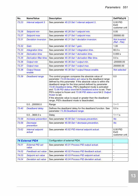
Parameters 551
1
2
3
4
5
6
7
8
9
10
11
12
13
73.23 Internal setpoint 3 See parameter 40.23 Set 1 internal setpoint 3. 0.00 PID Ext3 customer unit
73.26 Setpoint min See parameter 40.26 Set 1 setpoint min. 0.00
73.27 Setpoint max See parameter 40.27 Set 1 setpoint max. 200000.00
73.31 Deviation inversion See parameter 40.31 Set 1 deviation inversion. Not inverted (Ref - Fbk)
73.32 Gain See parameter 40.32 Set 1 gain. 1.00
73.33 Integration time See parameter 40.33 Set 1 integration time. 60.0 s
73.34 Derivation time See parameter 40.34 Set 1 derivation time. 0.000 s
73.35 Derivation filter time See parameter 40.35 Set 1 derivation filter time. 0.0 s
73.36 Output min See parameter 40.36 Set 1 output min. -200000.00
73.37 Output max See parameter 40.37 Set 1 output max. 200000.00
73.38 Output freeze enable
See parameter 40.38 Set 1 output freeze enable. Not selected
73.39 Deadband range The control program compares the absolute value of parameter 73.04 Deviation act value to the deadband range defined by this parameter. If the absolute value is within the deadband range for the time period defined by parameter 73.40 Deadband delay, PID's deadband mode is activated and 73.06 PID status word bit 9 Deadband active is set. Then PID's output is frozen and 73.06 PID status word bit 2 Output frozen is set.If the absolute value is equal or greater than the deadband range, PID's deadband mode is deactivated.
0.0
0.0…200000.0 Range 1 = 1
73.40 Deadband delay Defines the deadband delay for the deadband function. See parameter 73.39 Deadband range.
0.0 s
0.0…3600.0 s Delay 1 = 1 s
73.58 Increase prevention See parameter 40.58 Set 1 increase prevention. No
73.59 Decrease prevention
See parameter 40.59 Set 1 decrease prevention. No
73.62 Internal setpoint actual
See parameter 40.62 PID internal setpoint actual. 0.00 PID Ext3 customer unit
7474 External PID4 Configuration of external PID4.
74.01 External PID act value
See parameter 40.01 Process PID output actual. -
74.02 Feedback act value See parameter 40.02 Process PID feedback actual. -
74.03 Setpoint act value See parameter 40.03 Process PID setpoint actual. -
74.04 Deviation act value See parameter 40.04 Process PID deviation actual. -
No. Name/Value Description Def/FbEq16
14
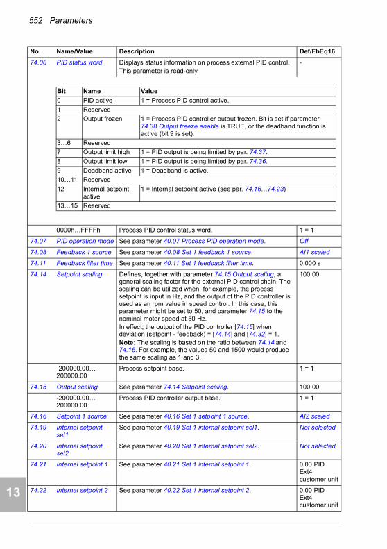
552 Parameters
1
2
3
4
5
7
8
9
9
10
11
12
13
14
74.06 PID status word Displays status information on process external PID control.This parameter is read-only.
-
0000h…FFFFh Process PID control status word. 1 = 1
74.07 PID operation mode See parameter 40.07 Process PID operation mode. Off
74.08 Feedback 1 source See parameter 40.08 Set 1 feedback 1 source. AI1 scaled
74.11 Feedback filter time See parameter 40.11 Set 1 feedback filter time. 0.000 s
74.14 Setpoint scaling Defines, together with parameter 74.15 Output scaling, a general scaling factor for the external PID control chain. The scaling can be utilized when, for example, the process setpoint is input in Hz, and the output of the PID controller is used as an rpm value in speed control. In this case, this parameter might be set to 50, and parameter 74.15 to the nominal motor speed at 50 Hz.In effect, the output of the PID controller [74.15] when deviation (setpoint - feedback) = [74.14] and [74.32] = 1.Note: The scaling is based on the ratio between 74.14 and 74.15. For example, the values 50 and 1500 would produce the same scaling as 1 and 3.
100.00
-200000.00…200000.00
Process setpoint base. 1 = 1
74.15 Output scaling See parameter 74.14 Setpoint scaling. 100.00
-200000.00…200000.00
Process PID controller output base. 1 = 1
74.16 Setpoint 1 source See parameter 40.16 Set 1 setpoint 1 source. AI2 scaled
74.19 Internal setpoint sel1
See parameter 40.19 Set 1 internal setpoint sel1. Not selected
74.20 Internal setpoint sel2
See parameter 40.20 Set 1 internal setpoint sel2. Not selected
74.21 Internal setpoint 1 See parameter 40.21 Set 1 internal setpoint 1. 0.00 PID Ext4 customer unit
74.22 Internal setpoint 2 See parameter 40.22 Set 1 internal setpoint 2. 0.00 PID Ext4 customer unit
No. Name/Value Description Def/FbEq16
Bit Name Value
0 PID active 1 = Process PID control active.
1 Reserved
2 Output frozen 1 = Process PID controller output frozen. Bit is set if parameter 74.38 Output freeze enable is TRUE, or the deadband function is active (bit 9 is set).
3…6 Reserved
7 Output limit high 1 = PID output is being limited by par. 74.37.
8 Output limit low 1 = PID output is being limited by par. 74.36.
9 Deadband active 1 = Deadband is active.
10…11 Reserved
12 Internal setpoint active
1 = Internal setpoint active (see par. 74.16…74.23)
13…15 Reserved
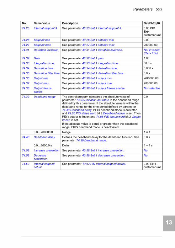
Parameters 553
1
2
3
4
5
6
7
8
9
10
11
12
13
74.23 Internal setpoint 3 See parameter 40.23 Set 1 internal setpoint 3. 0.00 PID Ext4 customer unit
74.26 Setpoint min See parameter 40.26 Set 1 setpoint min. 0.00
74.27 Setpoint max See parameter 40.27 Set 1 setpoint max. 200000.00
74.31 Deviation inversion See parameter 40.31 Set 1 deviation inversion. Not inverted (Ref - Fbk)
74.32 Gain See parameter 40.32 Set 1 gain. 1.00
74.33 Integration time See parameter 40.33 Set 1 integration time. 60.0 s
74.34 Derivation time See parameter 40.34 Set 1 derivation time. 0.000 s
74.35 Derivation filter time See parameter 40.35 Set 1 derivation filter time. 0.0 s
74.36 Output min See parameter 40.36 Set 1 output min. -200000.00
74.37 Output max See parameter 40.37 Set 1 output max. 200000.00
74.38 Output freeze enable
See parameter 40.38 Set 1 output freeze enable. Not selected
74.39 Deadband range The control program compares the absolute value of parameter 74.04 Deviation act value to the deadband range defined by this parameter. If the absolute value is within the deadband range for the time period defined by parameter 74.40 Deadband delay, PID's deadband mode is activated and 74.06 PID status word bit 9 Deadband active is set. Then PID's output is frozen and 74.06 PID status word bit 2 Output frozen is set.If the absolute value is equal or greater than the deadband range, PID's deadband mode is deactivated.
0.0
0.0…200000.0 Range 1 = 1
74.40 Deadband delay Defines the deadband delay for the deadband function. See parameter 74.39 Deadband range.
0.0 s
0.0…3600.0 s Delay 1 = 1 s
74.58 Increase prevention See parameter 40.58 Set 1 increase prevention. No
74.59 Decrease prevention
See parameter 40.59 Set 1 decrease prevention. No
74.62 Internal setpoint actual
See parameter 40.62 PID internal setpoint actual. 0.00 Ext4 customer unit
No. Name/Value Description Def/FbEq16
14
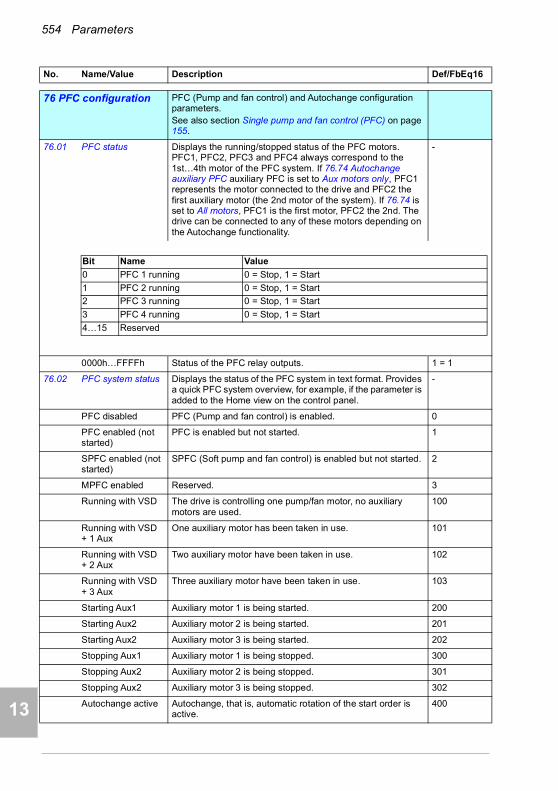
554 Parameters
1
2
3
4
5
7
8
9
9
10
11
12
13
14
7676 PFC configuration PFC (Pump and fan control) and Autochange configuration
parameters. See also section Single pump and fan control (PFC) on page 155.
76.01 PFC status Displays the running/stopped status of the PFC motors. PFC1, PFC2, PFC3 and PFC4 always correspond to the 1st…4th motor of the PFC system. If 76.74 Autochange auxiliary PFC auxiliary PFC is set to Aux motors only, PFC1 represents the motor connected to the drive and PFC2 the first auxiliary motor (the 2nd motor of the system). If 76.74 is set to All motors, PFC1 is the first motor, PFC2 the 2nd. The drive can be connected to any of these motors depending on the Autochange functionality.
-
0000h…FFFFh Status of the PFC relay outputs. 1 = 1
76.02 PFC system status Displays the status of the PFC system in text format. Provides a quick PFC system overview, for example, if the parameter is added to the Home view on the control panel.
-
PFC disabled PFC (Pump and fan control) is enabled. 0
PFC enabled (not started)
PFC is enabled but not started. 1
SPFC enabled (not started)
SPFC (Soft pump and fan control) is enabled but not started. 2
MPFC enabled Reserved. 3
Running with VSD The drive is controlling one pump/fan motor, no auxiliary motors are used.
100
Running with VSD + 1 Aux
One auxiliary motor has been taken in use. 101
Running with VSD + 2 Aux
Two auxiliary motor have been taken in use. 102
Running with VSD + 3 Aux
Three auxiliary motor have been taken in use. 103
Starting Aux1 Auxiliary motor 1 is being started. 200
Starting Aux2 Auxiliary motor 2 is being started. 201
Starting Aux2 Auxiliary motor 3 is being started. 202
Stopping Aux1 Auxiliary motor 1 is being stopped. 300
Stopping Aux2 Auxiliary motor 2 is being stopped. 301
Stopping Aux2 Auxiliary motor 3 is being stopped. 302
Autochange active Autochange, that is, automatic rotation of the start order is active.
400
No. Name/Value Description Def/FbEq16
Bit Name Value
0 PFC 1 running 0 = Stop, 1 = Start
1 PFC 2 running 0 = Stop, 1 = Start
2 PFC 3 running 0 = Stop, 1 = Start
3 PFC 4 running 0 = Stop, 1 = Start
4…15 Reserved

Parameters 555
1
2
3
4
5
6
7
8
9
10
11
12
13
No auxiliary motors available to be started
No auxiliary motors are available to be started, for example, all are already running, or a motor in not available due to maintenance.
500
Regulator bypass active
Direct-on-line pumps are automatically started and stopped. 600
MPFC connection ok
Reserved. 700
PID sleep PID sleep is in use, and the pump can be stopped in during low demand.
800
PID sleep boost PID sleep with extended sleep time is in use, and the pump can be stopped in during low demand.
801
Invalid configuration PFC configuration is invalid. 4
PFC inactive (local control)
PFC is inactive because the drive is in local control. 5
PFC inactive (invalid operation mode)
PFC is inactive because of an invalid operation mode. 6
Drive motor interlocked
The motor connected to the drive is interlocked (not available). Warning D503 VSD controlled PFC motor interlocked (page 208) is generated.
7
All motors interlocked
All motors are interlocked (not available). Warning D502 All motors interlocked (page 208) is generated.
8
PFC inactive (ext1 active)
PFC is inactive because external control location EXT1 is in use. PFC is supported in EXT2 only.
9
76.11 Pump/fan status 1 Shows the status of pump or fan 1. -
0000h…FFFFh Status of pump or fan 1. 1 = 1
76.12 Pump/fan status 2 See parameter 76.11 Pump/fan status 1 -
76.13 Pump/fan status 3 See parameter 76.11 Pump/fan status 1 -
76.14 Pump/fan status 4 See parameter 76.11 Pump/fan status 1 -
76.21 PFC configuration Selects the multi-pump/fan control (PFC) mode. Off
Off PFC disabled. 0
Reserved 1
No. Name/Value Description Def/FbEq16
Bit Name Value
0 Ready 0 = False, 1 = True
1 Reserved
2 Running 0 = False, 1 = True
3…4 Reserved
5 In PFC control 0 = False, 1 = True
6…10 Reserved
11 Interlocked 0 = False, 1 = True
12…15 Reserved
14

556 Parameters
1
2
3
4
5
7
8
9
9
10
11
12
13
14
PFC PFC enabled. One pump at a time is controlled by the drive. The remaining pumps are direct-on-line pumps that are started and stopped by the drive logicThe frequency (group 28 Frequency reference chain) / speed (group 22 Speed reference selection) reference must be defined as PID for the PFC functionality to work properly.
2
SPFC SPFC enabled. See section Settings on page162. 3
76.25 Number of motors Total number of motors used in the application, including the motor connected directly to the drive.
1
1…4 Number of motors. 1 = 1
76.26 Min number of motors allowed
Minimum number of motors running simultaneously. 1
0…4 Minimum number of motors. 1 = 1
76.27 Max number of motors allowed
Maximum number of motors running simultaneously. 1
1…4 Maximum number of motors. 1 = 1
No. Name/Value Description Def/FbEq16

Parameters 557
1
2
3
4
5
6
7
8
9
10
11
12
13
76.30 Start point 1 Defines the start speed (Hz/rpm) for the first auxiliary motor. As the motor speed or frequency exceeds the limit defined by this parameter, a new auxiliary motor is started.To avoid nuisance starts of the second auxiliary motor, the speed of the variable speed motor should be higher than the start speed for the duration defined by parameter 76.55 Start delay. If the speed decreases below the start speed, the auxiliary motor is not started.To maintain the process conditions during the start of the second auxiliary motor, a speed hold on time can be defined with parameter 76.57 Speed hold on. Certain pump types do not produce significant flow with low frequencies. The speed hold on time can be used to compensate the time needed to accelerate the second auxiliary motor to a speed where it produces flow. The start of the second auxiliary motor is not aborted if the speed of the first auxiliary motor decreases
Vector: 1300 rpm; Scalar 48 Hz; 58 Hz (95.20 b0
0.00…32767.00 rpm/Hz
Speed/frequency 1 = 1 unit
76.31 Start point 2 Defines the start speed (Hz/rpm) for the second auxiliary motor. See parameter 76.31 Start point 1.
Vector: 1300 rpm; Scalar 48 Hz; 58 Hz (95.20 b0)
76.32 Start point 3 Defines the start speed (Hz/rpm) for the third auxiliary motor. See parameter 76.31 Start point 1.
Vector: 1300 rpm; Scalar 48 Hz; 58 Hz (95.20 b0)
No. Name/Value Description Def/FbEq16
76.30
Increasing flow
Speed
Time
Stop
Start
Decreasing flow
Aux
. pum
p 1
Sto
p/S
tart ON
ON
OFF
OFF
Min. speed
Max. speed
76.41
76.55
76.57
76.56
76.58
14

558 Parameters
1
2
3
4
5
7
8
9
9
10
11
12
13
14
76.41 Stop point 1 Defines the stop speed (Hz/rpm) for the first auxiliary motor. When the speed of the motor connected directly to the drive falls below this value and one auxiliary motor is running, the stop delay defined by parameter 76.56 Stop delay is started. If the speed is still at the same level or lower when the stop delay elapses, the first auxiliary motor stops.The running speed of the drive is increased by [Start point 1 - Stop point 1] after the auxiliary motor stops.
Vector: 800 rpm; Scalar 25 Hz; 30 Hz (95.20 b0)
0.00…32767.00 rpm/Hz
Speed/frequency 1 = 1 unit
76.42 Stop point 2 Defines the stop speed (Hz/rpm) for the second auxiliary motor. See parameter 76.41 Stop point 1.
Vector: 800 rpm; Scalar 25 Hz; 30 Hz (95.20 b0)
76.43 Stop point 3 Defines the stop speed (Hz/rpm) for the third auxiliary motor. See parameter 76.41 Stop point 1.
Vector: 800 rpm; Scalar 25 Hz; 30 Hz (95.20 b0)
76.55 Start delay Defines the delay time for starting the auxiliary motors. See parameter 76.31 Start point 1.
10.00 s
0.00…12600.00 s Time delay. 1 = 1 s
76.56 Stop delay Defines the delay time for starting the auxiliary motors. See parameter 76.31 Stop point 1.
10.00 s
0.00…12600.00 s Time delay. 1 = 1 s
76.57 Speed hold on Hold time for auxiliary motor switch-on. See parameter 76.31 Start point 1.
0.00 s
0.00…1000.00 s Time. 1 = 1 s
76.58 Speed hold off Hold time for auxiliary motor switch-off. See parameter 76.31 Stop point 1.
0.00 s
0.00…1000.00 s Time. 1 = 1 s
76.59 PFC contactor delay
Start delay for the motor that is directly controlled by the drive. This does not affect the starting of the auxiliary motors.
WARNING! There must always be a delay set if the motors are equipped with star-delta starters. The delay must be set longer than the time setting of the
starter. After the motor is switched on by the relay output of the drive, there must be enough time for the star-delta starter to first switch to star and then back to delta before the motor is connected to the drive.
0.50 s
0.20…600.00 s Time delay. 1 = 1 s
76.60 PFC ramp acceleration time
Defines the acceleration time for the drive motor speed compensation, when an auxiliary motor is stopped. This ramp time is also used for the drive motor to accelerate after an autochange has occurred.The parameter sets the ramp-up time as seconds from zero to maximum frequency (not from the previous reference to the new reference).
1.00 s
0.00…1800.00 s Time. 1 = 1 s
No. Name/Value Description Def/FbEq16

Parameters 559
1
2
3
4
5
6
7
8
9
10
11
12
13
76.61 PFC ramp deceleration time
Defines the deceleration time for the drive motor speed compensation, when an auxiliary motor is started. This ramp time is also used for the drive motor to decelerate after an autochange has occurred.The parameter sets the ramp-up time as seconds from maximum to zero frequency (not from the previous reference to the new reference).
1.00 s
0.00…1800.00 s Time. 1 = 1 s
76.70 Autochange Defines the way the autochange is triggered. In all cases except Even wear, the start order is moved one step forward each time the autochange occurs. If the start order initially is 1-2-3-4, after the first autochange the order will be 2-3-4-1, etc. For Even wear, the start order will be determined so that the running times of all motors remain within the defined limit.Note: Autochange only occurs when the speed of the drive is below the speed defined by parameter 76.73 Autochange level.See also section Autochange on page 158.
Not selected
Not selected Autochange disabled. 0
Selected Rising edge starts the autochange if autochange conditions are met.
1
DI1 Autochange triggered by the rising edge of digital input DI1 (10.02 DI delayed status, bit 0).
2
DI2 Autochange triggered by the rising edge of digital input DI2 (10.02 DI delayed status, bit 1).
3
DI3 Autochange triggered by the rising edge of digital input DI3 (10.02 DI delayed status, bit 2).
4
DI4 Autochange triggered by the rising edge of digital input DI4 (10.02 DI delayed status, bit 3).
5
DI5 Autochange triggered by the rising edge of digital input DI5 (10.02 DI delayed status, bit 4).
6
DI6 Autochange triggered by the rising edge of digital input DI6 (10.02 DI delayed status, bit 5).
7
Timed function 1 Autochange triggered by timed function 1 (bit 0 of 34.01 Timed functions status (see page 469)).
8
Timed function 2 Autochange triggered by timed function 2 (bit 1 of 34.01 Timed functions status (see page 469)).
9
Timed function 3 Autochange triggered by timed function 3 (bit 2 of 34.01 Timed functions status (see page 469)).
10
Fixed interval Autochange is done when the interval determined in the parameter 76.71 Autochange interval has elapsed.
11
All stop Autochange is done when all the motors are stopped.The PID sleep feature (parameters 40.43 Set 1 sleep level … 40.48 Set 1 wake-up delay) must be used for the drive to stop when the process demand is low.
12
No. Name/Value Description Def/FbEq16
14
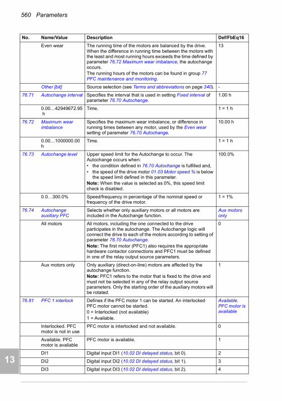
560 Parameters
1
2
3
4
5
7
8
9
9
10
11
12
13
14
Even wear The running time of the motors are balanced by the drive. When the difference in running time between the motors with the least and most running hours exceeds the time defined by parameter 76.72 Maximum wear imbalance, the autochange occurs.The running hours of the motors can be found in group 77 PFC maintenance and monitoring.
13
Other [bit] Source selection (see Terms and abbreviations on page 340). -
76.71 Autochange interval Specifies the interval that is used in setting Fixed interval of parameter 76.70 Autochange.
1.00 h
0.00…42949672.95h
Time. 1 = 1 h
76.72 Maximum wear imbalance
Specifies the maximum wear imbalance, or difference in running times between any motor, used by the Even wear setting of parameter 76.70 Autochange.
10.00 h
0.00…1000000.00h
Time. 1 = 1 h
76.73 Autochange level Upper speed limit for the Autochange to occur. The Autochange occurs when:• the condition defined in 76.70 Autochange is fulfilled and,• the speed of the drive motor 01.03 Motor speed % is below
the speed limit defined in this parameter.Note: When the value is selected as 0%, this speed limit check is disabled.
100.0%
0.0…300.0% Speed/frequency in percentage of the nominal speed or frequency of the drive motor.
1 = 1%
76.74 Autochange auxiliary PFC
Selects whether only auxiliary motors or all motors are included in the Autochange function.
Aux motors only
All motors All motors, including the one connected to the drive participates in the autochange. The Autochange logic will connect the drive to each of the motors according to setting of parameter 76.70 Autochange.Note: The first motor (PFC1) also requires the appropriate hardware contactor connections and PFC1 must be defined in one of the relay output source parameters.
0
Aux motors only Only auxiliary (direct-on-line) motors are affected by the autochange function.Note: PFC1 refers to the motor that is fixed to the drive and must not be selected in any of the relay output source parameters. Only the starting order of the auxiliary motors will be rotated.
1
76.81 PFC 1 interlock Defines if the PFC motor 1 can be started. An interlocked PFC motor cannot be started.0 = Interlocked (not available)1 = Available.
Available. PFC motor is available
Interlocked. PFC motor is not in use
PFC motor is interlocked and not available. 0
Available. PFC motor is available
PFC motor is available. 1
DI1 Digital input DI1 (10.02 DI delayed status, bit 0). 2
DI2 Digital input DI2 (10.02 DI delayed status, bit 1). 3
DI3 Digital input DI3 (10.02 DI delayed status, bit 2). 4
No. Name/Value Description Def/FbEq16
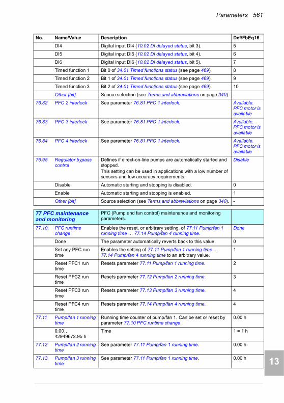
Parameters 561
1
2
3
4
5
6
7
8
9
10
11
12
13
DI4 Digital input DI4 (10.02 DI delayed status, bit 3). 5
DI5 Digital input DI5 (10.02 DI delayed status, bit 4). 6
DI6 Digital input DI6 (10.02 DI delayed status, bit 5). 7
Timed function 1 Bit 0 of 34.01 Timed functions status (see page 469). 8
Timed function 2 Bit 1 of 34.01 Timed functions status (see page 469). 9
Timed function 3 Bit 2 of 34.01 Timed functions status (see page 469). 10
Other [bit] Source selection (see Terms and abbreviations on page 340). -
76.82 PFC 2 interlock See parameter 76.81 PFC 1 interlock. Available. PFC motor is available
76.83 PFC 3 interlock See parameter 76.81 PFC 1 interlock. Available. PFC motor is available
76.84 PFC 4 interlock See parameter 76.81 PFC 1 interlock. Available. PFC motor is available
76.95 Regulator bypass control
Defines if direct-on-line pumps are automatically started and stopped.This setting can be used in applications with a low number of sensors and low accuracy requirements.
Disable
Disable Automatic starting and stopping is disabled. 0
Enable Automatic starting and stopping is enabled. 1
Other [bit] Source selection (see Terms and abbreviations on page 340). -
7777 PFC maintenance and monitoring
PFC (Pump and fan control) maintenance and monitoring parameters.
77.10 PFC runtime change
Enables the reset, or arbitrary setting, of 77.11 Pump/fan 1 running time … 77.14 Pump/fan 4 running time.
Done
Done The parameter automatically reverts back to this value. 0
Set any PFC run time
Enables the setting of 77.11 Pump/fan 1 running time … 77.14 Pump/fan 4 running time to an arbitrary value.
1
Reset PFC1 run time
Resets parameter 77.11 Pump/fan 1 running time. 2
Reset PFC2 run time
Resets parameter 77.12 Pump/fan 2 running time. 3
Reset PFC3 run time
Resets parameter 77.13 Pump/fan 3 running time. 4
Reset PFC4 run time
Resets parameter 77.14 Pump/fan 4 running time. 4
77.11 Pump/fan 1 running time
Running time counter of pump/fan 1. Can be set or reset by parameter 77.10 PFC runtime change.
0.00 h
0.00…42949672.95 h
Time 1 = 1 h
77.12 Pump/fan 2 running time
See parameter 77.11 Pump/fan 1 running time. 0.00 h
77.13 Pump/fan 3 running time
See parameter 77.11 Pump/fan 1 running time. 0.00 h
No. Name/Value Description Def/FbEq16
14
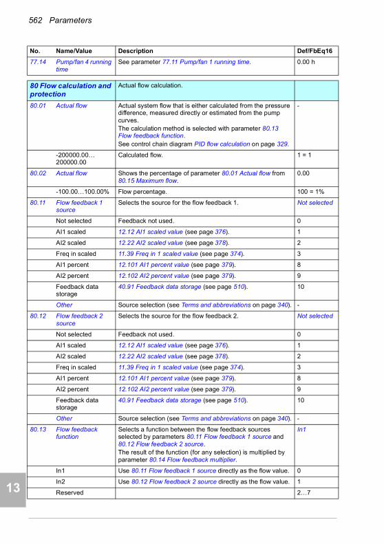
562 Parameters
1
2
3
4
5
7
8
9
9
10
11
12
13
14
77.14 Pump/fan 4 running time
See parameter 77.11 Pump/fan 1 running time. 0.00 h
8080 Flow calculation and protection
Actual flow calculation.
80.01 Actual flow Actual system flow that is either calculated from the pressure difference, measured directly or estimated from the pump curves. The calculation method is selected with parameter 80.13 Flow feedback function.See control chain diagram PID flow calculation on page 329.
-
-200000.00… 200000.00
Calculated flow. 1 = 1
80.02 Actual flow Shows the percentage of parameter 80.01 Actual flow from 80.15 Maximum flow.
0.00
-100.00…100.00% Flow percentage. 100 = 1%
80.11 Flow feedback 1 source
Selects the source for the flow feedback 1. Not selected
Not selected Feedback not used. 0
AI1 scaled 12.12 AI1 scaled value (see page 376). 1
AI2 scaled 12.22 AI2 scaled value (see page 378). 2
Freq in scaled 11.39 Freq in 1 scaled value (see page 374). 3
AI1 percent 12.101 AI1 percent value (see page 379). 8
AI2 percent 12.102 AI2 percent value (see page 379). 9
Feedback data storage
40.91 Feedback data storage (see page 510). 10
Other Source selection (see Terms and abbreviations on page 340). -
80.12 Flow feedback 2 source
Selects the source for the flow feedback 2. Not selected
Not selected Feedback not used. 0
AI1 scaled 12.12 AI1 scaled value (see page 376). 1
AI2 scaled 12.22 AI2 scaled value (see page 378). 2
Freq in scaled 11.39 Freq in 1 scaled value (see page 374). 3
AI1 percent 12.101 AI1 percent value (see page 379). 8
AI2 percent 12.102 AI2 percent value (see page 379). 9
Feedback data storage
40.91 Feedback data storage (see page 510). 10
Other Source selection (see Terms and abbreviations on page 340). -
80.13 Flow feedback function
Selects a function between the flow feedback sources selected by parameters 80.11 Flow feedback 1 source and 80.12 Flow feedback 2 source.The result of the function (for any selection) is multiplied by parameter 80.14 Flow feedback multiplier.
In1
In1 Use 80.11 Flow feedback 1 source directly as the flow value. 0
In2 Use 80.12 Flow feedback 2 source directly as the flow value. 1
Reserved 2…7
No. Name/Value Description Def/FbEq16

Parameters 563
1
2
3
4
5
6
7
8
9
10
11
12
13
sqrt(In1) Flow is calculated as a square root of a differential pressure measurement:
The differential pressure value is selected with 80.11 Flow feedback 1 source.
8
sqrt(In1-In2) Flow is calculated as a square root of two measured absolute pressure measurements:
The pressure measurement sources are selected with 80.11 Flow feedback 1 source and 80.12 Flow feedback 2 source.
9
80.14 Flow feedback multiplier
Defines the multiplier (k) used with the flow calculation The output value of 80.13 Flow feedback function is multiplied by this value.
1.00
-200000.00… 200000.00
Multiplier. 1 = 1
80.15 Maximum flow Defines the nominal maximum flow of the system. This value is used to calculate the actual flow percentage value so that the value 100% for 80.02 corresponds to the value of this parameter.
1000.00
-200000.00… 200000.00
Limit for maximum flow protection. 1 = 1
9494 LSU control Control of the supply unit of the drive, such as DC voltage and
reactive power reference.(Only visible for ACH580-31).Note that the references defined here must also be selected as the reference source in the supply control program to be effective.See also section Control of a supply unit (LSU) (page 100).
94.01 LSU control Enables/disables the internal INU-LSU state machine.When the state machine is enabled, the inverter unit (INU) controls the supply unit (LSU) and prevents the inverter unit from starting until the supply unit is ready.When the state machine is disabled, the status of the supply unit (LSU) is ignored by the inverter unit.
On
Off INU-LSU state machine disabled. 0
On INU-LSU state machine enabled. 1
94.02 LSU panel communication
Enables/disables control panel and PC tool access to the supply unit (line-side converter) via the inverter unit (motor-side converter).Note: This feature is only supported by ACH580-31
Disable
Disable Direct control panel and PC tool access to supply unit control board via inverter unit is disabled. Drive acts as single inverter on the panel bus.
0
Enable Direct control panel and PC tool access to supply unit control board via inverter unit is enabled. Drive unit shows as two separate units (inverter and supply unit) on the panel bus.
1
94.10 LSU max charging time
Defines the maximum time the supply unit (LSU) is allowed for charging before fault 7584 LSU charge failed is generated.
15 s
0…65535 s Maximum charging time. 1 = 1 s
No. Name/Value Description Def/FbEq16
k P
k P1 P2–
14
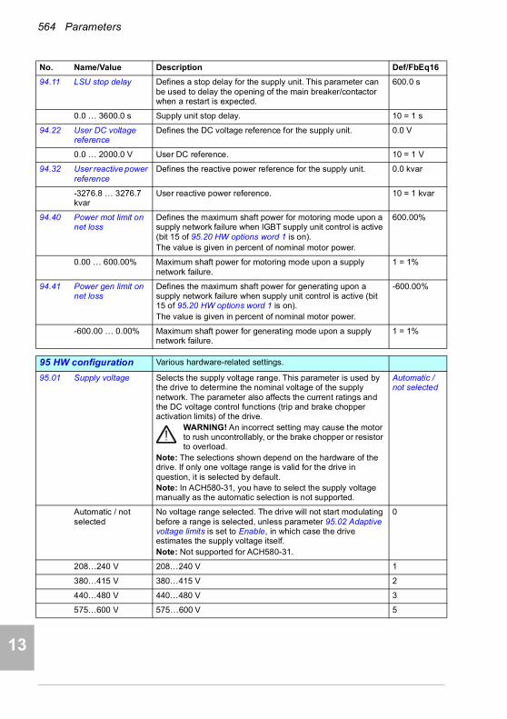
564 Parameters
1
2
3
4
5
7
8
9
9
10
11
12
13
14
94.11 LSU stop delay Defines a stop delay for the supply unit. This parameter can be used to delay the opening of the main breaker/contactor when a restart is expected.
600.0 s
0.0 … 3600.0 s Supply unit stop delay. 10 = 1 s
94.22 User DC voltage reference
Defines the DC voltage reference for the supply unit. 0.0 V
0.0 … 2000.0 V User DC reference. 10 = 1 V
94.32 User reactive power reference
Defines the reactive power reference for the supply unit. 0.0 kvar
-3276.8 … 3276.7 kvar
User reactive power reference. 10 = 1 kvar
94.40 Power mot limit on net loss
Defines the maximum shaft power for motoring mode upon a supply network failure when IGBT supply unit control is active (bit 15 of 95.20 HW options word 1 is on).The value is given in percent of nominal motor power.
600.00%
0.00 … 600.00% Maximum shaft power for motoring mode upon a supply network failure.
1 = 1%
94.41 Power gen limit on net loss
Defines the maximum shaft power for generating upon a supply network failure when supply unit control is active (bit 15 of 95.20 HW options word 1 is on).The value is given in percent of nominal motor power.
-600.00%
-600.00 … 0.00% Maximum shaft power for generating mode upon a supply network failure.
1 = 1%
9595 HW configuration Various hardware-related settings.
95.01 Supply voltage Selects the supply voltage range. This parameter is used by the drive to determine the nominal voltage of the supply network. The parameter also affects the current ratings and the DC voltage control functions (trip and brake chopper activation limits) of the drive.
WARNING! An incorrect setting may cause the motor to rush uncontrollably, or the brake chopper or resistor to overload.
Note: The selections shown depend on the hardware of the drive. If only one voltage range is valid for the drive in question, it is selected by default.Note: In ACH580-31, you have to select the supply voltage manually as the automatic selection is not supported.
Automatic / not selected
Automatic / not selected
No voltage range selected. The drive will not start modulating before a range is selected, unless parameter 95.02 Adaptive voltage limits is set to Enable, in which case the drive estimates the supply voltage itself.Note: Not supported for ACH580-31.
0
208…240 V 208…240 V 1
380…415 V 380…415 V 2
440…480 V 440…480 V 3
575…600 V 575…600 V 5
No. Name/Value Description Def/FbEq16

Parameters 565
1
2
3
4
5
6
7
8
9
10
11
12
13
95.02 Adaptive voltage limits
Enables adaptive voltage limits.Adaptive voltage limits can be used if, for example, an IGBT supply unit is used to raise the DC voltage level. If the communication between the inverter and IGBT supply unit is active, the voltage limits are related to the DC voltage reference from the IGBT supply unit. Otherwise the limits are calculated based on the measured DC voltage at the end of the pre-charging sequence.This function is also useful if the AC supply voltage to the drive is high, as the warning levels are raised accordingly.
Enable
Disable Adaptive voltage limits disabled. 0
Enable Adaptive voltage limits enabled. 1
95.03 Estimated AC supply voltage
AC supply voltage estimated by calculation. Estimation is done every time the drive is powered up and is based on the rise speed of voltage level of the DC bus while the drive charges the DC bus.Note: This parameter is not used for ACH580-31. The supply voltage is shown by parameter 01.109 Grid voltage.
-
0…65535 V Voltage. 10 = 1 V
95.04 Control board supply
Specifies how the control board of the drive is powered. Internal 24V
Internal 24V The drive control board is powered from the drive power unit it is connected to.
0
External 24V The drive control board is powered from an external power supply.
1
95.15 Special HW settings
Contains hardware-related settings that can be enabled and disabled by toggling the specific bits.Notes: • The installation of the hardware specified by this
parameter may require derating of drive output, or impose other limitations. Refer to (ATEX) the hardware manual of the drive.
• With the CPTC-02 ATEX-certified thermistor protection module, follow the instructions given in the CPTC-02 ATEX-certified thermistor protection module, Ex II (2) GD (+L537+Q971) user's manual (3AXD50000030058 [English]).
00000000h
00000000h…FFFFFFFFh
Hardware options configuration word. 1 = 1
No. Name/Value Description Def/FbEq16
Bit Name Information
0 EX motor 1 = The driven motor is an Ex (ATEX) motor provided by ABB for potentially explosive atmospheres. This sets the required minimum switching frequency for ABB Ex (ATEX) motors.Notes: • For non-ABB Ex (ATEX) motors, use parameters 97.01 and 97.02
to define the correct minimum switching frequency.• If you have a multimotor system, contact your local ABB
representative.
1 ABB Sine filter 1 = An ABB sine filter is connected to the output of the drive.
2…15 Reserved
14

566 Parameters
1
2
3
4
5
7
8
9
9
10
11
12
13
14
95.20 HW options word 1 Specifies hardware-related options that require differentiated parameter defaults.This parameter is not affected by a parameter restore.
-
0000h…FFFFh Hardware options configuration word. 1 = 1
95.21 HW options word 2 Specifies more hardware-related options that require differentiated parameter defaults. See parameter 95.20 HW options word 1.
WARNING! After switching any bits in this word, recheck the values of the affected parameters.
-
0000b…0101b Hardware options configuration word 2. 1 = 1
95.200 Cooling fan mode Cooling fan operation mode. Auto
Auto Fan runs normally: Fan on/off, fan speed reference can autochange according to the drive state.
0
Always on Fan always runs at 100% speed reference. 1
No. Name/Value Description Def/FbEq16
Bit Name Value
0 Supply frequency 60 Hz
See section Differences in the default values between 50 Hz and 60 Hz supply frequency settings on page 589.0 = 50 Hz.1 = 60 Hz.
1…12 Reserved
13 du/dt filter activation
When active, an external du/dt filter is connected to the drive/inverter output. The setting will limit the output switching frequency, and force the fan of the drive/inverter module to full speed.0 = du/dt filter inactive.1 = du/dt filter active.
14 Reserved
15 INU-ISU communication
*1 = IGBT supply unit control by inverter unit active. Makes several parameters visible in groups 01, 05, 06, 07, 30, 31, 60, 61, 62, 94 and 96.
*See section Control of a supply unit (LSU) (page 100)Control of a supply unit (LSU) (FW Part 1, chapter Program features).
Bit Name Information
0…4 Reserved
5 Bypass present 1 = Bypass is used.
6 Cabinet drive 0 = Inactive, 1 = Active.
7 Cabinet fan 0 = Inactive, 1 = Active.
6…15 Reserved

Parameters 567
1
2
3
4
5
6
7
8
9
10
11
12
13
9696 System Language selection; access levels; macro selection;
parameter save and restore; control unit reboot; user parameter sets; unit selection; parameter checksum calculation; user lock.
96.01 Language Selects the language of the parameter interface and other displayed information when viewed on the control panel.
Drive supports multiple languages. The languages are divided in three firmware packages: Global, European and Asian.The default package is Global package that supports languages marked with X and G. European delta supports languages marked with X and E. Asian delta supports languages marked with X and A.
English
No. Name/Value Description Def/FbEq16
Language Global package
European Asian
English X X X
German X X X
Spanish X X X
Portuguese X X X
French X X X
Chinese (Simplified) X X X
Dutch G
Italian G
Danish G
Finnish G
Swedish G
Russian G
Turkish G
Polish E
Czech E
Greek (Ellinika) E
Hungarian (Magyar) E
Hebrew (E)
Korean A
Japanese A
Thai A
X = Common language, available in all packagesG = Available in Global package onlyE = Available in European package only(E) = Will be available laterA = Available in Asian package only
14

568 Parameters
1
2
3
4
5
7
8
9
9
10
11
12
13
14
The drives include the language package corresponding to the order's geographical location. No plus code or other actions are needed. Examples:• If the order is placed in Sweden, the drives will be
delivered with the Global package (default package).• If the order is placed in Poland, the drives will be updated
with European package before the delivery.• If the order is placed in Japan, the drives will be updated
with Asian package before the delivery.All the language package variants are available from your local drives support.Notes: • Not all languages listed below are necessarily supported.• This parameter does not affect the languages visible in the
Drive composer PC tool. (Those are specified under View > Settings > Drive default language.)
Not selected None. 0
English English. Included in all packages. 1033
Deutsch German. Included in all packages. 1031
Italiano Italian. Included in Global package. 1040
Español Spanish. Included in all packages. 3082
Portugues Portuguese. Included in all packages. 2070
Nederlands Dutch. Included in Global package. 1043
Français French. Included in all packages. 1036
Dansk Danish. Included in Global package. 1030
Suomi Finnish. Included in Global package. 1035
Svenska Swedish. Included in Global package. 1053
Russki Russian. Included in Global package. 1049
Polski Polish. Included in European package. 1045
Türkçe Turkish. Included in Global package. 1055
Chinese (Simplified, PRC)
Simplified Chinese. Included in all packages. 2052
Greek Greek. Included in European package. 1032
Magyar Hungarian. Included in European package. 1038
Korean Korean. Included in Asian package. 1042
Japanese Japanese. Included in Asian package. 1041
Thai Thai. Included in Asian package. 1054
No. Name/Value Description Def/FbEq16

Parameters 569
1
2
3
4
5
6
7
8
9
10
11
12
13
96.02 Pass code Pass codes can be entered into this parameter to activate further access levels (see parameter 96.03 Access level status) or to configure the user lock.Entering “358” toggles the parameter lock, which prevents the changing of all other parameters through the control panel or the Drive composer PC tool.Entering the user pass code (by default, “10000000”) enables parameters 96.100…96.102, which can be used to define a new user pass code and to select the actions that are to be prevented.Entering an invalid pass code will close the user lock if open, ie, hide parameters 96.100…96.102. After entering the code, check that the parameters are in fact hidden. If they are not, enter another (random) pass code.Note: You must change the default user pass code to maintain a high level of cybersecurity. Store the code in a safe place – THE PROTECTION CANNOT BE DISABLED EVEN BY ABB if the code is lost.See also section Parameter checksum calculation (page 191).
0…99999999 Pass code. -
96.03 Access level status Shows which access levels have been activated by pass codes entered into parameter 96.02 Pass code.
0001b
00000000h…FFFFFFFFh
Active access levels. -
96.04 Macro select Selects the control macro. See chapter Default I/O configuration (page 83) for more information.After a selection is made, the parameter reverts automatically to Done.
Done
Done Macro selection complete; normal operation. 0
HVAC default Factory default (page 85). For scalar motor control. You cannot select HVAC default with this parameter but only in the Primary settings menu, see page 83.
1
96.05 Macro active Shows which control macro is currently selected. See chapter Default I/O configuration (page 83) for more information.To change the macro, use parameter 96.04 Macro select.
HVAC default
HVAC default Factory default (page 85). For scalar motor control. 1
No. Name/Value Description Def/FbEq16
Bit Name
0 End user
1 Service
2 Advanced programmer
3…9 Reserved
10 Override parameter lock
11 OEM access level 1
12 OEM access level 2
13 OEM access level 3
14 Parameter lock
15 Reserved
14
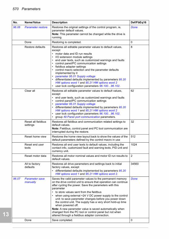
570 Parameters
1
2
3
4
5
7
8
9
9
10
11
12
13
14
96.06 Parameter restore Restores the original settings of the control program, ie, parameter default values.Note: This parameter cannot be changed while the drive is running.
Done
Done Restoring is completed. 0
Restore defaults Restores all editable parameter values to default values, except• motor data and ID run results• I/O extension module settings• end user texts, such as customized warnings and faults • control panel/PC communication settings• fieldbus adapter settings• control macro selection and the parameter defaults
implemented by it• parameter 95.01 Supply voltage• differentiated defaults implemented by parameters 95.20
HW options word 1 and 95.21 HW options word 2• user lock configuration parameters 96.100…96.102.
8
Clear all Restores all editable parameter values to default values, except• end user texts, such as customized warnings and faults • control panel/PC communication settings • parameter 95.01 Supply voltage• differentiated defaults implemented by parameters 95.20
HW options word 1 and 95.21 HW options word 2• user lock configuration parameters 96.100…96.102.• group 49 Panel port communication parameters.
62
Reset all fieldbus settings
Restores all fieldbus and communication related settings to default values.Note: Fieldbus, control panel and PC tool communication are interrupted during the restore.
32
Reset home view Restores the home view layout back to show the values of the default parameters defined by the control macro in use
512
Reset end user texts
Restores all end user texts to default values, including the contact info, customized fault and warning texts, PID unit and currency unit.
1024
Reset motor data Restores all motor nominal values and motor ID run results to default values.
2
All to factory defaults
Restores all drive parameters and settings back to initial factory values, except• differentiated defaults implemented by parameters 95.20
HW options word 1 and 95.21 HW options word 2.
34560
96.07 Parameter save manually
Saves the valid parameter values to the permanent memory on the drive control unit to ensure that operation can continue after cycling the power. Save the parameters with this parameter• to store values sent from the fieldbus• when using external +24 V DC power supply to the control
unit: to save parameter changes before you power down the control unit. The supply has a very short hold-up time when powered off.
Note: A new parameter value is saved automatically when changed from the PC tool or control panel but not when altered through a fieldbus adapter connection.
Done
Done Save completed. 0
No. Name/Value Description Def/FbEq16
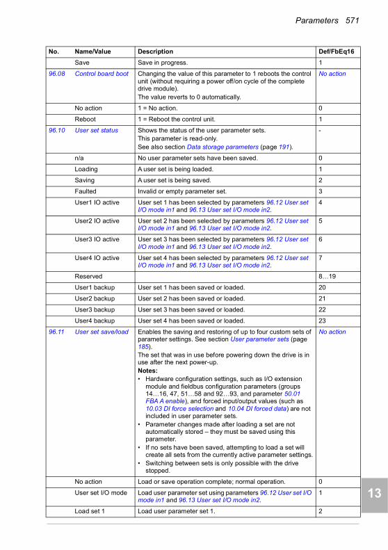
Parameters 571
1
2
3
4
5
6
7
8
9
10
11
12
13
Save Save in progress. 1
96.08 Control board boot Changing the value of this parameter to 1 reboots the control unit (without requiring a power off/on cycle of the complete drive module).The value reverts to 0 automatically.
No action
No action 1 = No action. 0
Reboot 1 = Reboot the control unit. 1
96.10 User set status Shows the status of the user parameter sets.This parameter is read-only.See also section Data storage parameters (page 191).
-
n/a No user parameter sets have been saved. 0
Loading A user set is being loaded. 1
Saving A user set is being saved. 2
Faulted Invalid or empty parameter set. 3
User1 IO active User set 1 has been selected by parameters 96.12 User set I/O mode in1 and 96.13 User set I/O mode in2.
4
User2 IO active User set 2 has been selected by parameters 96.12 User set I/O mode in1 and 96.13 User set I/O mode in2.
5
User3 IO active User set 3 has been selected by parameters 96.12 User set I/O mode in1 and 96.13 User set I/O mode in2.
6
User4 IO active User set 4 has been selected by parameters 96.12 User set I/O mode in1 and 96.13 User set I/O mode in2.
7
Reserved 8…19
User1 backup User set 1 has been saved or loaded. 20
User2 backup User set 2 has been saved or loaded. 21
User3 backup User set 3 has been saved or loaded. 22
User4 backup User set 4 has been saved or loaded. 23
96.11 User set save/load Enables the saving and restoring of up to four custom sets of parameter settings. See section User parameter sets (page 185).The set that was in use before powering down the drive is in use after the next power-up.Notes:• Hardware configuration settings, such as I/O extension
module and fieldbus configuration parameters (groups 14…16, 47, 51…58 and 92…93, and parameter 50.01 FBA A enable), and forced input/output values (such as 10.03 DI force selection and 10.04 DI forced data) are not included in user parameter sets.
• Parameter changes made after loading a set are not automatically stored – they must be saved using this parameter.
• If no sets have been saved, attempting to load a set will create all sets from the currently active parameter settings.
• Switching between sets is only possible with the drive stopped.
No action
No action Load or save operation complete; normal operation. 0
User set I/O mode Load user parameter set using parameters 96.12 User set I/O mode in1 and 96.13 User set I/O mode in2.
1
Load set 1 Load user parameter set 1. 2
No. Name/Value Description Def/FbEq16
14

572 Parameters
1
2
3
4
5
7
8
9
9
10
11
12
13
14
Load set 2 Load user parameter set 2. 3
Load set 3 Load user parameter set 3. 4
Load set 4 Load user parameter set 4. 5
Reserved 6…17
Save to set 1 Save user parameter set 1. 18
Save to set 2 Save user parameter set 2. 19
Save to set 3 Save user parameter set 3. 20
Save to set 4 Save user parameter set 4. 21
96.12 User set I/O mode in1
When parameter 96.11 User set save/load is set to User set I/O mode, selects the user parameter set together with parameter 96.13 User set I/O mode in2 as follows:
Not selected
Not selected 0. 0
Selected 1. 1
DI1 Digital input DI1 (10.02 DI delayed status, bit 0). 2
DI2 Digital input DI2 (10.02 DI delayed status, bit 1). 3
DI3 Digital input DI3 (10.02 DI delayed status, bit 2). 4
DI4 Digital input DI4 (10.02 DI delayed status, bit 3). 5
DI5 Digital input DI5 (10.02 DI delayed status, bit 4). 6
DI6 Digital input DI6 (10.02 DI delayed status, bit 5). 7
Reserved 8…17
Timed function 1 Bit 0 of 34.01 Timed functions status (see page 469). 18
Timed function 2 Bit 1 of 34.01 Timed functions status (see page 469). 19
Timed function 3 Bit 2 of 34.01 Timed functions status (see page 469). 20
Reserved 21…23
Supervision 1 Bit 0 of 32.01 Supervision status (see page 462). 24
Supervision 2 Bit 1 of 32.01 Supervision status (see page 462). 25
Supervision 3 Bit 2 of 32.01 Supervision status (see page 462). 26
Other [bit] Source selection (see Terms and abbreviations on page 340). -
96.13 User set I/O mode in2
See parameter 96.12 User set I/O mode in1. Not selected
No. Name/Value Description Def/FbEq16
Status of source defined by par.
96.12
Status of source defined by par.
96.13
User parameter set selected
0 0 Set 1
1 0 Set 2
0 1 Set 3
1 1 Set 4
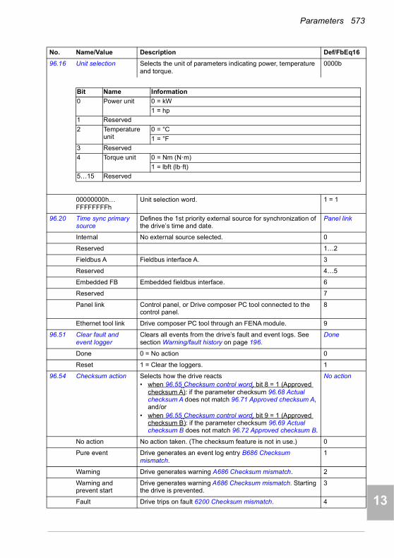
Parameters 573
1
2
3
4
5
6
7
8
9
10
11
12
13
96.16 Unit selection Selects the unit of parameters indicating power, temperature and torque.
0000b
00000000h…FFFFFFFFh
Unit selection word. 1 = 1
96.20 Time sync primary source
Defines the 1st priority external source for synchronization of the drive’s time and date.
Panel link
Internal No external source selected. 0
Reserved 1…2
Fieldbus A Fieldbus interface A. 3
Reserved 4…5
Embedded FB Embedded fieldbus interface. 6
Reserved 7
Panel link Control panel, or Drive composer PC tool connected to the control panel.
8
Ethernet tool link Drive composer PC tool through an FENA module. 9
96.51 Clear fault and event logger
Clears all events from the drive’s fault and event logs. See section Warning/fault history on page 196.
Done
Done 0 = No action 0
Reset 1 = Clear the loggers. 1
96.54 Checksum action Selects how the drive reacts • when 96.55 Checksum control word, bit 8 = 1 (Approved
checksum A): if the parameter checksum 96.68 Actual checksum A does not match 96.71 Approved checksum A, and/or
• when 96.55 Checksum control word, bit 9 = 1 (Approved checksum B): if the parameter checksum 96.69 Actual checksum B does not match 96.72 Approved checksum B.
No action
No action No action taken. (The checksum feature is not in use.) 0
Pure event Drive generates an event log entry B686 Checksum mismatch.
1
Warning Drive generates warning A686 Checksum mismatch. 2
Warning and prevent start
Drive generates warning A686 Checksum mismatch. Starting the drive is prevented.
3
Fault Drive trips on fault 6200 Checksum mismatch. 4
No. Name/Value Description Def/FbEq16
Bit Name Information
0 Power unit 0 = kW
1 = hp
1 Reserved
2 Temperature unit
0 = °C
1 = °F
3 Reserved
4 Torque unit 0 = Nm (N·m)
1 = lbft (lb·ft)
5…15 Reserved
14
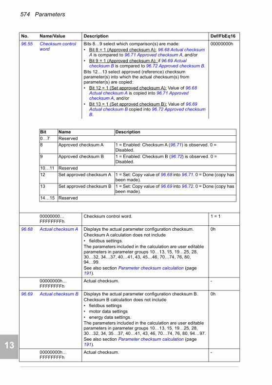
574 Parameters
1
2
3
4
5
7
8
9
9
10
11
12
13
14
96.55 Checksum control word
Bits 8…9 select which comparison(s) are made:• Bit 8 = 1 (Approved checksum A): 96.68 Actual checksum
A is compared to 96.71 Approved checksum A, and/or• Bit 9 = 1 (Approved checksum A): if 96.69 Actual
checksum B is compared to 96.72 Approved checksum B.Bits 12…13 select approved (reference) checksum parameter(s) into which the actual checksum(s) from parameter(s) are copied:• Bit 12 = 1 (Set approved checksum A): Value of 96.68
Actual checksum A is copied into 96.71 Approved checksum A, and/or
• Bit 13 = 1 (Set approved checksum B): Value of 96.69 Actual checksum B copied into 96.72 Approved checksum B.
00000000h
00000000…FFFFFFFFh
Checksum control word. 1 = 1
96.68 Actual checksum A Displays the actual parameter configuration checksum.Checksum A calculation does not include • fieldbus settings.The parameters included in the calculation are user editable parameters in parameter groups 10…13, 15, 19…25, 28, 30…32, 34…37, 40…41, 43, 45…46, 70…74, 76, 80, 94…99.See also section Parameter checksum calculation (page 191).
0h
00000000h…FFFFFFFFh
Actual checksum. -
96.69 Actual checksum B Displays the actual parameter configuration checksum B.Checksum B calculation does not include • fieldbus settings• motor data settings• energy data settings.The parameters included in the calculation are user editable parameters in parameter groups 10…13, 15, 19…25, 28, 30…32, 34, 35…37, 40…41, 43, 46, 70…74, 76, 80, 94…97.See also section Parameter checksum calculation (page 191).
0h
00000000h…FFFFFFFFh
Actual checksum. -
No. Name/Value Description Def/FbEq16
Bit Name Description
0…7 Reserved
8 Approved checksum A 1 = Enabled: Checksum A (96.71) is observed. 0 = Disabled.
9 Approved checksum B 1 = Enabled: Checksum B (96.72) is observed. 0 = Disabled.
10…11 Reserved
12 Set approved checksum A 1 = Set: Copy value of 96.68 into 96.71. 0 = Done (copy has been made).
13 Set approved checksum B 1 = Set: Copy value of 96.69 into 96.72. 0 = Done (copy has been made).
14…15 Reserved

Parameters 575
1
2
3
4
5
6
7
8
9
10
11
12
13
96.70 Disable adaptive program
Enables/disables the adaptive program (if present).See also section Adaptive programming (page 95).
Yes
No Adaptive program enabled. 0
Yes Adaptive program disabled. 1
96.71 Approved checksum A
Approved (reference) checksum A. 0h
00000000h…FFFFFFFFh
Approved checksum A. -
96.72 Approved checksum B
Approved (reference) checksum B. 0h
00000000h…FFFFFFFFh
Approved checksum B. -
96.78 550 Compatibility mode
Enables/disables a Modbus user to access a select set of parameters using 550 register numbering.
Disable
Disable 1 = Using 550 register numbering disabled. 0
Enable 0 = Using 550 register numbering enabled. 1
96.100 Change user pass code
(Visible when user lock is open)To change the current user pass code, enter a new code into this parameter as well as 96.101 Confirm user pass code. A warning will be active until the new pass code is confirmed. To cancel changing the pass code, close the user lock without confirming. To close the lock, enter an invalid pass code in parameter 96.02 Pass code, activate parameter 96.08 Control board boot, or cycle the power.See also section Parameter checksum calculation (page 191).
10000000
10000000…99999999
New user pass code. -
96.101 Confirm user pass code
(Visible when user lock is open)Confirms the new user pass code entered in 96.100 Change user pass code.
10000000…99999999
Confirmation of new user pass code. -
No. Name/Value Description Def/FbEq16
14
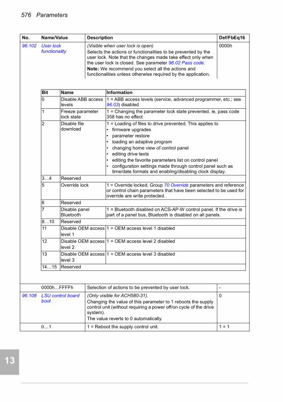
576 Parameters
1
2
3
4
5
7
8
9
9
10
11
12
13
14
96.102 User lock functionality
(Visible when user lock is open)Selects the actions or functionalities to be prevented by the user lock. Note that the changes made take effect only when the user lock is closed. See parameter 96.02 Pass code.Note: We recommend you select all the actions and functionalities unless otherwise required by the application.
0000h
0000h…FFFFh Selection of actions to be prevented by user lock. -
96.108 LSU control board boot
(Only visible for ACH580-31).Changing the value of this parameter to 1 reboots the supply control unit (without requiring a power off/on cycle of the drive system).The value reverts to 0 automatically.
0
0…1 1 = Reboot the supply control unit. 1 = 1
No. Name/Value Description Def/FbEq16
Bit Name Information
0 Disable ABB access levels
1 = ABB access levels (service, advanced programmer, etc.; see 96.03) disabled
1 Freeze parameter lock state
1 = Changing the parameter lock state prevented, ie, pass code 358 has no effect
2 Disable file download
1 = Loading of files to drive prevented. This applies to• firmware upgrades• parameter restore• loading an adaptive program• changing home view of control panel• editing drive texts• editing the favorite parameters list on control panel• configuration settings made through control panel such as
time/date formats and enabling/disabling clock display.
3…4 Reserved
5 Override lock 1 = Override locked. Group 70 Override parameters and reference or control chain parameters that have been selected to be used for override are write protected.
6 Reserved
7 Disable panel Bluetooth
1 = Bluetooth disabled on ACS-AP-W control panel. If the drive is part of a panel bus, Bluetooth is disabled on all panels.
8…10 Reserved
11 Disable OEM accesslevel 1
1 = OEM access level 1 disabled
12 Disable OEM accesslevel 2
1 = OEM access level 2 disabled
13 Disable OEM accesslevel 3
1 = OEM access level 3 disabled
14…15 Reserved

Parameters 577
1
2
3
4
5
6
7
8
9
10
11
12
13
9797 Motor control Switching frequency; slip gain; voltage reserve; flux braking;
anti-cogging (signal injection); IR compensation.
97.01 Switching frequency reference
Defines the switching frequency of the drive that is used as long as the drive stays below the thermal limit.Higher switching frequency results in lower acoustic motor noise. Lower switching frequency generates less switching losses and reduce EMC emissions.Notes: • If you have a multimotor system, contact your local ABB
representative.• With the CPTC-02 ATEX-certified thermistor protection
module, follow the instructions given in the CPTC-02 ATEX-certified thermistor protection module, Ex II (2) GD (+L537+Q971) user's manual (3AXD50000030058 [English]).
• With an ABB EX motor, follow the instructions given in the ABB EX motor documentation.
4 kHz
2 kHz 2 kHz. 2
4 kHz 4 kHz. 4
8 kHz 8 kHz. 8
12 kHz 12 kHz. 12
97.02 Minimum switching frequency
Lowest switching frequency value that is allowed. Depends on the frame size.When drive is reaching the thermal limit, it will automatically start to reduce the switching frequency until the minimum allowed value is reached. Once the minimum has been reached, the drive will automatically start limiting the output current to keep the temperature below the thermal limit.Inverter temperature is shown by parameter 05.11 Inverter temperature.Notes:• With the CPTC-02 ATEX-certified thermistor protection
module, follow the instructions given in the CPTC-02 ATEX-certified thermistor protection module, Ex II (2) GD (+L537+Q971) user's manual (3AXD50000030058 [English]).
• With an ABB EX motor, follow the instructions given in the ABB EX motor documentation.
2 kHz
1.5 kHz 1.5 kHz. Not for all frame sizes. 1
2 kHz 2 kHz. 2
4 kHz 4 kHz. 4
8 kHz 8 kHz. 8
12 kHz 12 kHz. 12
No. Name/Value Description Def/FbEq16
14
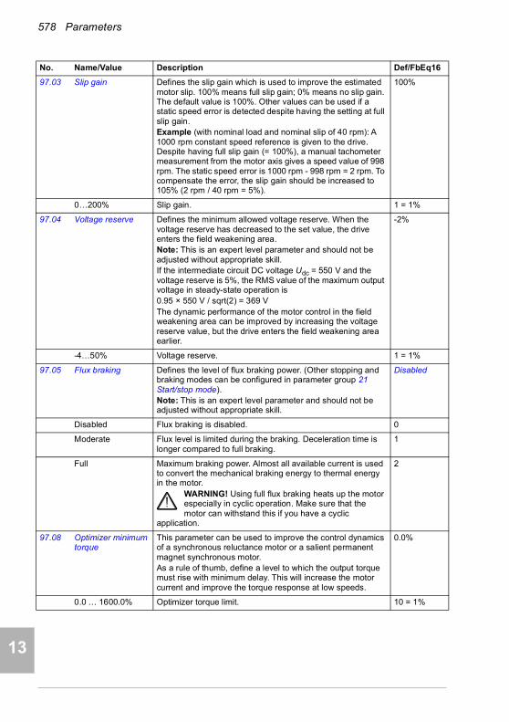
578 Parameters
1
2
3
4
5
7
8
9
9
10
11
12
13
14
97.03 Slip gain Defines the slip gain which is used to improve the estimated motor slip. 100% means full slip gain; 0% means no slip gain. The default value is 100%. Other values can be used if a static speed error is detected despite having the setting at full slip gain.Example (with nominal load and nominal slip of 40 rpm): A 1000 rpm constant speed reference is given to the drive. Despite having full slip gain (= 100%), a manual tachometer measurement from the motor axis gives a speed value of 998 rpm. The static speed error is 1000 rpm - 998 rpm = 2 rpm. To compensate the error, the slip gain should be increased to 105% (2 rpm / 40 rpm = 5%).
100%
0…200% Slip gain. 1 = 1%
97.04 Voltage reserve Defines the minimum allowed voltage reserve. When the voltage reserve has decreased to the set value, the drive enters the field weakening area.Note: This is an expert level parameter and should not be adjusted without appropriate skill.If the intermediate circuit DC voltage Udc = 550 V and the voltage reserve is 5%, the RMS value of the maximum output voltage in steady-state operation is 0.95 × 550 V / sqrt(2) = 369 VThe dynamic performance of the motor control in the field weakening area can be improved by increasing the voltage reserve value, but the drive enters the field weakening area earlier.
-2%
-4…50% Voltage reserve. 1 = 1%
97.05 Flux braking Defines the level of flux braking power. (Other stopping and braking modes can be configured in parameter group 21 Start/stop mode).Note: This is an expert level parameter and should not be adjusted without appropriate skill.
Disabled
Disabled Flux braking is disabled. 0
Moderate Flux level is limited during the braking. Deceleration time is longer compared to full braking.
1
Full Maximum braking power. Almost all available current is used to convert the mechanical braking energy to thermal energy in the motor.
WARNING! Using full flux braking heats up the motor especially in cyclic operation. Make sure that the motor can withstand this if you have a cyclic
application.
2
97.08 Optimizer minimum torque
This parameter can be used to improve the control dynamics of a synchronous reluctance motor or a salient permanent magnet synchronous motor.As a rule of thumb, define a level to which the output torque must rise with minimum delay. This will increase the motor current and improve the torque response at low speeds.
0.0%
0.0 … 1600.0% Optimizer torque limit. 10 = 1%
No. Name/Value Description Def/FbEq16
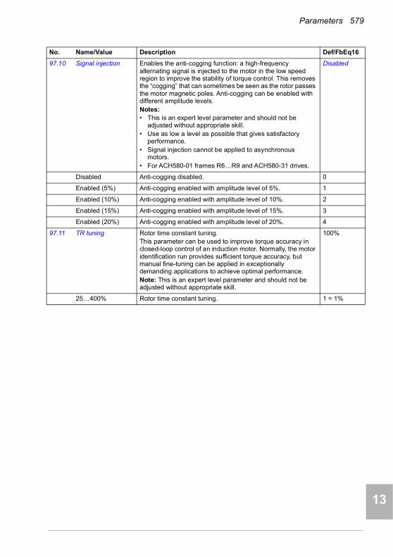
Parameters 579
1
2
3
4
5
6
7
8
9
10
11
12
13
97.10 Signal injection Enables the anti-cogging function: a high-frequency alternating signal is injected to the motor in the low speed region to improve the stability of torque control. This removes the “cogging” that can sometimes be seen as the rotor passes the motor magnetic poles. Anti-cogging can be enabled with different amplitude levels.Notes:• This is an expert level parameter and should not be
adjusted without appropriate skill.• Use as low a level as possible that gives satisfactory
performance.• Signal injection cannot be applied to asynchronous
motors.• For ACH580-01 frames R6…R9 and ACH580-31 drives.
Disabled
Disabled Anti-cogging disabled. 0
Enabled (5%) Anti-cogging enabled with amplitude level of 5%. 1
Enabled (10%) Anti-cogging enabled with amplitude level of 10%. 2
Enabled (15%) Anti-cogging enabled with amplitude level of 15%. 3
Enabled (20%) Anti-cogging enabled with amplitude level of 20%. 4
97.11 TR tuning Rotor time constant tuning.This parameter can be used to improve torque accuracy in closed-loop control of an induction motor. Normally, the motor identification run provides sufficient torque accuracy, but manual fine-tuning can be applied in exceptionally demanding applications to achieve optimal performance.Note: This is an expert level parameter and should not be adjusted without appropriate skill.
100%
25…400% Rotor time constant tuning. 1 = 1%
No. Name/Value Description Def/FbEq16
14

580 Parameters
1
2
3
4
5
7
8
9
9
10
11
12
13
14
97.13 IR compensation Defines the relative output voltage boost at zero speed (IR compensation). The function is useful in applications with a high break-away torque where vector control cannot be applied.
Typical IR compensation values are shown below.
See also section IR compensation for scalar motor control on page 129).
Type specific (%)
0.00…50.00% Voltage boost at zero speed in percent of nominal motor voltage.
1 = 1%
97.15 Motor model temperature adaptation
Enables the motor model temperature adaptation. Estimated motor temperature can be used to adapt temperature dependent parameters (for example, resistances) of motor model.
Disabled
Disabled Temperature adaptation disabled. 0
Estimated temperature
Temperature adaptation with motor temperature estimate (parameter 35.01 Motor estimated temperature).
1
97.16 Stator temperature factor
Tunes the motor temperature dependence of stator parameters (stator resistance).
50%
0…200% Tuning factor. 1 = 1%
97.17 Rotor temperature factor
Tunes the motor temperature dependence of rotor parameters (eg. rotor resistance).
100%
0…200% Tuning factor. 1 = 1%
No. Name/Value Description Def/FbEq16
U / UN(%)
f (Hz)Field weakening point
Relative output voltage. No IR compensation.
Relative output voltage. IR compensation set to 15%.
15%
100%
50% of nominal frequency
3-phase UN = 400 V (380…415 V) drives
PN (kW) 3 7.5 15 37 132
IR compensation (%) 2.3 1.7 1.3 1.1 0.6
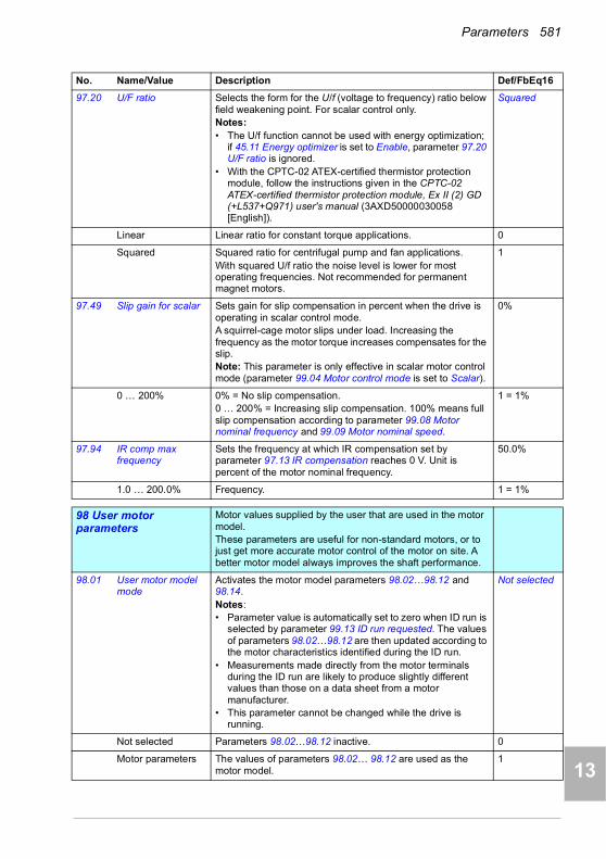
Parameters 581
1
2
3
4
5
6
7
8
9
10
11
12
13
97.20 U/F ratio Selects the form for the U/f (voltage to frequency) ratio below field weakening point. For scalar control only.Notes: • The U/f function cannot be used with energy optimization;
if 45.11 Energy optimizer is set to Enable, parameter 97.20 U/F ratio is ignored.
• With the CPTC-02 ATEX-certified thermistor protection module, follow the instructions given in the CPTC-02 ATEX-certified thermistor protection module, Ex II (2) GD (+L537+Q971) user's manual (3AXD50000030058 [English]).
Squared
Linear Linear ratio for constant torque applications. 0
Squared Squared ratio for centrifugal pump and fan applications.With squared U/f ratio the noise level is lower for most operating frequencies. Not recommended for permanent magnet motors.
1
97.49 Slip gain for scalar Sets gain for slip compensation in percent when the drive is operating in scalar control mode.A squirrel-cage motor slips under load. Increasing the frequency as the motor torque increases compensates for the slip.Note: This parameter is only effective in scalar motor control mode (parameter 99.04 Motor control mode is set to Scalar).
0%
0 … 200% 0% = No slip compensation.0 … 200% = Increasing slip compensation. 100% means full slip compensation according to parameter 99.08 Motor nominal frequency and 99.09 Motor nominal speed.
1 = 1%
97.94 IR comp max frequency
Sets the frequency at which IR compensation set by parameter 97.13 IR compensation reaches 0 V. Unit is percent of the motor nominal frequency.
50.0%
1.0 … 200.0% Frequency. 1 = 1%
9898 User motor parameters
Motor values supplied by the user that are used in the motor model.These parameters are useful for non-standard motors, or to just get more accurate motor control of the motor on site. A better motor model always improves the shaft performance.
98.01 User motor model mode
Activates the motor model parameters 98.02…98.12 and 98.14.Notes:• Parameter value is automatically set to zero when ID run is
selected by parameter 99.13 ID run requested. The values of parameters 98.02…98.12 are then updated according to the motor characteristics identified during the ID run.
• Measurements made directly from the motor terminals during the ID run are likely to produce slightly different values than those on a data sheet from a motor manufacturer.
• This parameter cannot be changed while the drive is running.
Not selected
Not selected Parameters 98.02…98.12 inactive. 0
Motor parameters The values of parameters 98.02… 98.12 are used as the motor model.
1
No. Name/Value Description Def/FbEq16
14
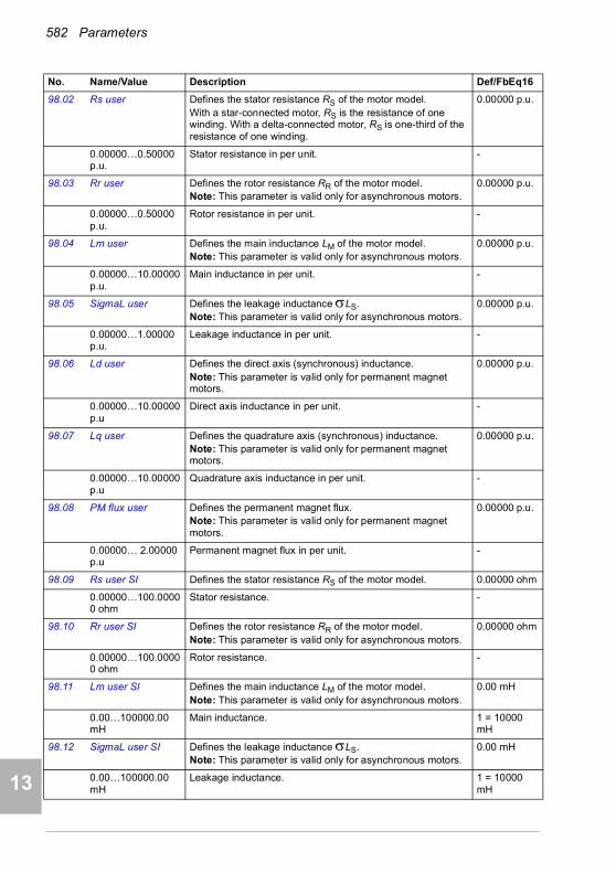
582 Parameters
1
2
3
4
5
7
8
9
9
10
11
12
13
14
98.02 Rs user Defines the stator resistance RS of the motor model.With a star-connected motor, RS is the resistance of one winding. With a delta-connected motor, RS is one-third of the resistance of one winding.
0.00000 p.u.
0.00000…0.50000 p.u.
Stator resistance in per unit. -
98.03 Rr user Defines the rotor resistance RR of the motor model. Note: This parameter is valid only for asynchronous motors.
0.00000 p.u.
0.00000…0.50000 p.u.
Rotor resistance in per unit. -
98.04 Lm user Defines the main inductance LM of the motor model.Note: This parameter is valid only for asynchronous motors.
0.00000 p.u.
0.00000…10.00000 p.u.
Main inductance in per unit. -
98.05 SigmaL user Defines the leakage inductance LS.Note: This parameter is valid only for asynchronous motors.
0.00000 p.u.
0.00000…1.00000 p.u.
Leakage inductance in per unit. -
98.06 Ld user Defines the direct axis (synchronous) inductance.Note: This parameter is valid only for permanent magnet motors.
0.00000 p.u.
0.00000…10.00000 p.u
Direct axis inductance in per unit. -
98.07 Lq user Defines the quadrature axis (synchronous) inductance.Note: This parameter is valid only for permanent magnet motors.
0.00000 p.u.
0.00000…10.00000 p.u
Quadrature axis inductance in per unit. -
98.08 PM flux user Defines the permanent magnet flux.Note: This parameter is valid only for permanent magnet motors.
0.00000 p.u.
0.00000… 2.00000 p.u
Permanent magnet flux in per unit. -
98.09 Rs user SI Defines the stator resistance RS of the motor model. 0.00000 ohm
0.00000…100.00000 ohm
Stator resistance. -
98.10 Rr user SI Defines the rotor resistance RR of the motor model.Note: This parameter is valid only for asynchronous motors.
0.00000 ohm
0.00000…100.00000 ohm
Rotor resistance. -
98.11 Lm user SI Defines the main inductance LM of the motor model.Note: This parameter is valid only for asynchronous motors.
0.00 mH
0.00…100000.00 mH
Main inductance. 1 = 10000 mH
98.12 SigmaL user SI Defines the leakage inductance LS.Note: This parameter is valid only for asynchronous motors.
0.00 mH
0.00…100000.00 mH
Leakage inductance. 1 = 10000 mH
No. Name/Value Description Def/FbEq16
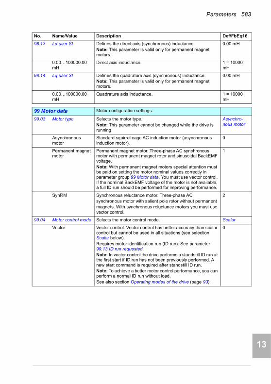
Parameters 583
1
2
3
4
5
6
7
8
9
10
11
12
13
98.13 Ld user SI Defines the direct axis (synchronous) inductance.Note: This parameter is valid only for permanent magnet motors.
0.00 mH
0.00…100000.00 mH
Direct axis inductance. 1 = 10000 mH
98.14 Lq user SI Defines the quadrature axis (synchronous) inductance.Note: This parameter is valid only for permanent magnet motors.
0.00 mH
0.00…100000.00 mH
Quadrature axis inductance. 1 = 10000 mH
9999 Motor data Motor configuration settings.
99.03 Motor type Selects the motor type.Note: This parameter cannot be changed while the drive is running.
Asynchro-nous motor
Asynchronous motor
Standard squirrel cage AC induction motor (asynchronous induction motor).
0
Permanent magnet motor
Permanent magnet motor. Three-phase AC synchronous motor with permanent magnet rotor and sinusoidal BackEMF voltage.Note: With permanent magnet motors special attention must be paid on setting the motor nominal values correctly in parameter group 99 Motor data. You must use vector control. If the nominal BackEMF voltage of the motor is not available, a full ID run should be performed for improving performance.
1
SynRM Synchronous reluctance motor. Three-phase ACsynchronous motor with salient pole rotor without permanentmagnets. With synchronous reluctance motors you must use vector control.
2
99.04 Motor control mode Selects the motor control mode. Scalar
Vector Vector control. Vector control has better accuracy than scalar control but cannot be used in all situations (see selection Scalar below).Requires motor identification run (ID run). See parameter 99.13 ID run requested.Note: In vector control the drive performs a standstill ID run at the first start if ID run has not been previously performed. A new start command is required after standstill ID run.Note: To achieve a better motor control performance, you can perform a normal ID run without load.See also section Operating modes of the drive (page 93).
0
No. Name/Value Description Def/FbEq16
14
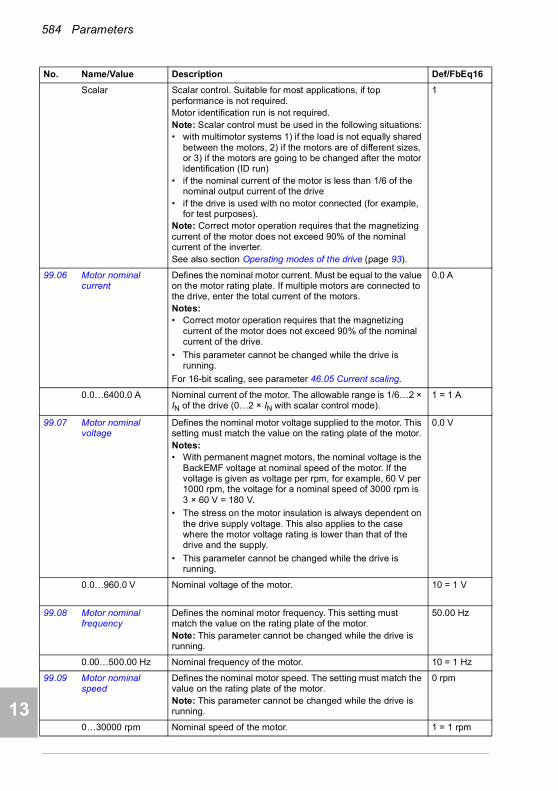
584 Parameters
1
2
3
4
5
7
8
9
9
10
11
12
13
14
Scalar Scalar control. Suitable for most applications, if top performance is not required.Motor identification run is not required.Note: Scalar control must be used in the following situations:• with multimotor systems 1) if the load is not equally shared
between the motors, 2) if the motors are of different sizes, or 3) if the motors are going to be changed after the motor identification (ID run)
• if the nominal current of the motor is less than 1/6 of the nominal output current of the drive
• if the drive is used with no motor connected (for example, for test purposes).
Note: Correct motor operation requires that the magnetizing current of the motor does not exceed 90% of the nominal current of the inverter.See also section Operating modes of the drive (page 93).
1
99.06 Motor nominal current
Defines the nominal motor current. Must be equal to the value on the motor rating plate. If multiple motors are connected to the drive, enter the total current of the motors.Notes:• Correct motor operation requires that the magnetizing
current of the motor does not exceed 90% of the nominal current of the drive.
• This parameter cannot be changed while the drive is running.
For 16-bit scaling, see parameter 46.05 Current scaling.
0.0 A
0.0…6400.0 A Nominal current of the motor. The allowable range is 1/6…2 × IN of the drive (0…2 × IN with scalar control mode).
1 = 1 A
99.07 Motor nominal voltage
Defines the nominal motor voltage supplied to the motor. This setting must match the value on the rating plate of the motor.Notes:• With permanent magnet motors, the nominal voltage is the
BackEMF voltage at nominal speed of the motor. If the voltage is given as voltage per rpm, for example, 60 V per 1000 rpm, the voltage for a nominal speed of 3000 rpm is 3 × 60 V = 180 V.
• The stress on the motor insulation is always dependent on the drive supply voltage. This also applies to the case where the motor voltage rating is lower than that of the drive and the supply.
• This parameter cannot be changed while the drive is running.
0.0 V
0.0…960.0 V Nominal voltage of the motor. 10 = 1 V
99.08 Motor nominal frequency
Defines the nominal motor frequency. This setting must match the value on the rating plate of the motor.Note: This parameter cannot be changed while the drive is running.
50.00 Hz
0.00…500.00 Hz Nominal frequency of the motor. 10 = 1 Hz
99.09 Motor nominal speed
Defines the nominal motor speed. The setting must match the value on the rating plate of the motor.Note: This parameter cannot be changed while the drive is running.
0 rpm
0…30000 rpm Nominal speed of the motor. 1 = 1 rpm
No. Name/Value Description Def/FbEq16
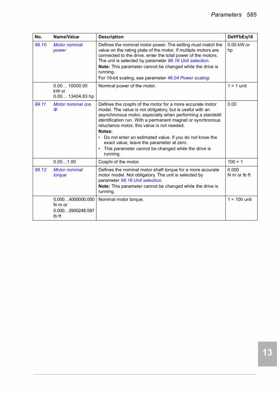
Parameters 585
1
2
3
4
5
6
7
8
9
10
11
12
13
99.10 Motor nominal power
Defines the nominal motor power. The setting must match the value on the rating plate of the motor. If multiple motors are connected to the drive, enter the total power of the motors. The unit is selected by parameter 96.16 Unit selection.Note: This parameter cannot be changed while the drive is running.For 16-bit scaling, see parameter 46.04 Power scaling.
0.00 kW or hp
0.00… 10000.00 kW or 0.00… 13404.83 hp
Nominal power of the motor. 1 = 1 unit
99.11 Motor nominal cos Φ
Defines the cosphi of the motor for a more accurate motor model. The value is not obligatory, but is useful with an asynchronous motor, especially when performing a standstill identification run. With a permanent magnet or synchronous reluctance motor, this value is not needed.Notes: • Do not enter an estimated value. If you do not know the
exact value, leave the parameter at zero.• This parameter cannot be changed while the drive is
running.
0.00
0.00…1.00 Cosphi of the motor. 100 = 1
99.12 Motor nominal torque
Defines the nominal motor shaft torque for a more accurate motor model. Not obligatory. The unit is selected by parameter 96.16 Unit selection.Note: This parameter cannot be changed while the drive is running.
0.000N·m or lb·ft
0.000…4000000.000N·m or 0.000…2950248.597lb·ft
Nominal motor torque. 1 = 100 unit
No. Name/Value Description Def/FbEq16
14

586 Parameters
1
2
3
4
5
7
8
9
9
10
11
12
13
14
99.13 ID run requested Selects the type of the motor identification routine (ID run) performed at the next start of the drive. During the ID run, the drive will identify the characteristics of the motor for optimum motor control.If no ID run has been performed yet (or if default parameter values have been restored using parameter 96.06 Parameter restore), this parameter is automatically set to Standstill, signifying that an ID run must be performed.After the ID run, the drive stops and this parameter is automatically set to None.Notes:• To ensure that the ID run can work properly, the drive limits
in group 30 (maximum speed and minimum speed, and maximum torque and minimum torque) must to be large enough (the range specified by the limits must be wide enough. If, for example, speed limits are less than the motor nominal speed, the ID run cannot be completed.
• For the Advanced ID run, the machinery must always be de-coupled from the motor.
• With a permanent magnet or synchronous reluctance motor, a Normal, Reduced or Standstill ID run requires that the motor shaft is NOT locked and the load torque is less than 10%.
• With scalar control mode (99.04 Motor control mode = Scalar), the ID run is not requested automatically. However, an ID run can be performed for more accurate torque estimation.
• Once the ID run is activated, it can be canceled by stopping the drive.
• The ID run must be performed every time any of the motor parameters (99.04, 99.06…99.12) have been changed.
• Ensure that the Safe Torque Off and emergency stop circuits (if any) are closed during the ID run.
• Mechanical brake (if present) is not opened by the logic for the ID run.
• This parameter cannot be changed while the drive is running.
None
None No motor ID run is requested. This mode can be selected only if the ID run (Normal / Reduced / Standstill / Advanced) has already been performed once.
0
Normal Normal ID run. Guarantees good control accuracy for all cases. The ID run takes about 90 seconds. This mode should be selected whenever it is possible.Notes:• If the load torque will be higher than 20% of motor nominal
torque, or if the machinery is not able to withstand the nominal torque transient during the ID run, then the driven machinery must be de-coupled from the motor during a Normal ID run.
• Check the direction of rotation of the motor before starting the ID run. During the run, the motor will rotate in the forward direction.
WARNING! The motor will run at up to approximately 50…100% of the nominal speed during the ID run. ENSURE THAT IT IS SAFE TO RUN THE MOTOR
BEFORE PERFORMING THE ID RUN!
1
No. Name/Value Description Def/FbEq16

Parameters 587
1
2
3
4
5
6
7
8
9
10
11
12
13
Reduced Reduced ID run. This mode should be selected instead of the Normal or Advanced ID Run if• mechanical losses are higher than 20% (ie. the motor
cannot be de-coupled from the driven equipment), or if• flux reduction is not allowed while the motor is running (ie.
in case of a motor with an integrated brake supplied from the motor terminals).
With this ID run mode, the resultant motor control in the field weakening area or at high torques is not necessarily as accurate as motor control following a Normal ID run. Reduced ID run is completed faster than the Normal ID Run (< 90 seconds).Note: Check the direction of rotation of the motor before starting the ID run. During the run, the motor will rotate in the forward direction.
WARNING! The motor will run at up to approximately 50…100% of the nominal speed during the ID run. ENSURE THAT IT IS SAFE TO RUN THE MOTOR
BEFORE PERFORMING THE ID RUN!
2
Standstill Standstill ID run. The motor is injected with DC current. With an AC induction (asynchronous) motor, the motor shaft is not rotated. With a permanent magnet motor, the shaft can rotate up to half a revolution.Note: This mode should be selected only if the Normal, Reduced or Advanced ID run is not possible due to the restrictions caused by the connected mechanics (for example, with lift or crane applications).
3
Reserved 4…5
Advanced Advanced ID run. Only for frames R6…R11 and ACH580-31.Guarantees the best possible control accuracy. The ID run takes a very long time to complete. This mode should be selected when top performance is needed across the whole operating area.Note: The driven machinery must be de-coupled from the motor because of high torque and speed transients that are applied.
WARNING! The motor may run at up to the maximum (positive) and minimum (negative) allowed speed during the ID run. Several accelerations and
decelerations are done. The maximum torque, current and speed allowed by the limit parameters may be utilized. ENSURE THAT IT IS SAFE TO RUN THE MOTOR BEFORE PERFORMING THE ID RUN!
6
Reserved 7
Adaptive Adaptive ID run. Improves the motor model accuracy during normal operation of the drive.The drive performs a Standstill ID run first. Motor parameters are then updated with better accuracy during an adaptation sequence when following user’s driving profile. When the adaptation is complete, parameters 99.14 Last ID run performed changes from Standstill to Adaptive. Motor parameters are updated automatically and the user is not required to update any other parameter.Note: For vector control only.
8
No. Name/Value Description Def/FbEq16
14

588 Parameters
1
2
3
4
5
7
8
9
9
10
11
12
13
14
99.14 Last ID run performed
Shows the type of ID run that was performed last. For more information about the different modes, see the selections of parameter 99.13 ID run requested.
None
None No ID run has been performed. 0
Normal Normal ID run. 1
Reduced Reduced ID run. 2
Standstill Standstill ID run. 3
Reserved 4…5
Advanced Advanced ID run. 6
Reserved 7
Adaptive Adaptive ID run 8
99.15 Motor polepairs calculated
Calculated number of pole pairs in the motor. 0
0…1000 Number of pole pairs. 1 = 1
99.16 Motor phase order Switches the rotation direction of motor. This parameter can be used if the motor turns in the wrong direction (for example, because of the wrong phase order in the motor cable), and correcting the cabling is considered impractical.Note:• Changing this parameter does not affect speed reference
polarities, so positive speed reference will rotate the motor forward. The phase order selection just ensures that “forward” is in fact the correct direction.
U V W
U V W Normal. 0
U W V Reversed rotation direction. 1
No. Name/Value Description Def/FbEq16

Parameters 589
1
2
3
4
5
6
7
8
9
10
11
12
13
Differences in the default values between 50 Hz and 60 Hz supply frequency settings
Parameter 95.20 HW options word 1 bit 0 Supply frequency 60 Hz changes the drive parameter default values according to the supply frequency, 50 Hz or 60 Hz. The bit is set according to the market before the drive is delivered.
If you need to change from 50 Hz to 60 Hz, or vice versa, change the value of the bit and then do a complete reset to the drive. After that you have to reselect the macro to be used.
The table below shows the parameters whose default values depend on the supply frequency setting. The supply frequency setting, with the type designation of the drive, also affects Group 99 Motor data parameter values though these parameters are not listed in the table.
No. Name 95.20 HW options word 1 bit Supply frequency 60 Hz = 50 Hz
95.20 HW options word 1 bit Supply frequency 60 Hz = 60 Hz
11.45 Freq in 1 at scaled max 1500.000 1800.000
15.35 Freq out 1 src max 1500.000 1800.000
12.20 AI1 scaled at AI1 max 50.000 60.000
13.18 AO1 source max 50.0 60.0
22.26 Constant speed 1 300.00 rpm 360.00 rpm
22.27 Constant speed 2 600.00 rpm 720.00 rpm
22.28 Constant speed 3 900 .00 rpm 1080.00 rpm
22.29 Constant speed 4 1200.00 rpm 1440.00 rpm
22.30 Constant speed 5 1500.00 rpm 1800.00 rpm
22.31 Constant speed 6 2400.00 rpm 2880.00 rpm
22.32 Constant speed 7 3000.00 rpm 3600.00 rpm
28.26 Constant frequency 1 5.00 Hz 6.00 Hz
28.27 Constant frequency 2 10.00 Hz 12.00 Hz
28.28 Constant frequency 3 15.00 Hz 18.00 Hz
28.29 Constant frequency 4 20.00 Hz 24.00 Hz
28.30 Constant frequency 5 25.00 Hz 30.00 Hz
28.31 Constant frequency 6 40.00 Hz 48.00 Hz
28.32 Constant frequency 7 50.00 Hz 60.00 Hz
14
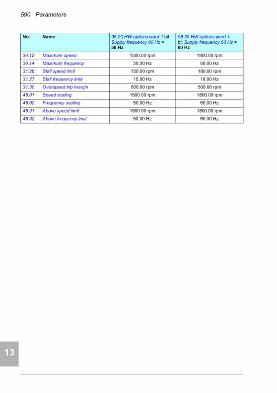
590 Parameters
1
2
3
4
5
7
8
9
9
10
11
12
13
14
30.12 Maximum speed 1500.00 rpm 1800.00 rpm
30.14 Maximum frequency 50.00 Hz 60.00 Hz
31.26 Stall speed limit 150.00 rpm 180.00 rpm
31.27 Stall frequency limit 15.00 Hz 18.00 Hz
31.30 Overspeed trip margin 500.00 rpm 500.00 rpm
46.01 Speed scaling 1500.00 rpm 1800.00 rpm
46.02 Frequency scaling 50.00 Hz 60.00 Hz
46.31 Above speed limit 1500.00 rpm 1800.00 rpm
46.32 Above frequency limit 50.00 Hz 60.00 Hz
No. Name 95.20 HW options word 1 bit Supply frequency 60 Hz = 50 Hz
95.20 HW options word 1 bit Supply frequency 60 Hz = 60 Hz

Additional parameter data 591
1
2
3
4
5
6
7
8
9
10
11
12
13
14Additional parameter data
What this chapter contains
This chapter lists the parameters with some additional data such as their ranges and 32-bit fieldbus scaling. For parameter descriptions, see chapter Parameters (page 339).
Terms and abbreviations
Term Definition
Actual signal Signal measured or calculated by the drive. Usually can only be monitored but not adjusted; some counter-type signals can however be reset.
Analog src Analog source: the parameter can be set to the value of another parameter by choosing “Other”, and selecting the source parameter from a list.
In addition to the “Other” selection, the parameter may offer other pre-selected settings.
Binary src Binary source: the value of the parameter can be taken from a specific bit in another parameter value (“Other”). Sometimes the value can be fixed to 0 (false) or 1 (true). In addition, the parameter may offer other pre-selected settings.
Data Data parameter
FbEq32 32-bit fieldbus equivalent: The scaling between the value shown on the panel and the integer used in communication when a 32-bit value is selected for transmission to an external system.
The corresponding 16-bit scalings are listed in chapter Parameters (page 339).
List Selection list.
14

592 Additional parameter data
1
2
3
4
5
6
7
8
9
10
11
12
13
14
Fieldbus addresses
Refer to the User’s manual of the fieldbus adapter.
No. Parameter number.
PB Packed Boolean (bit list).
Real Real number.
Type Parameter type. See Analog src, Binary src, List, PB, Real.
Term Definition

Additional parameter data 593
1
2
3
4
5
6
7
8
9
10
11
12
13
Parameter groups 1…9No. Name Type Range Unit FbEq32
01 Actual values
01.01 Motor speed used Real -30000.00…30000.00 rpm 100 = 1 rpm
01.02 Motor speed estimated Real -30000.00…30000.00 rpm 100 = 1 rpm
01.03 Motor speed % Real -1000.00…1000.00 % 100 = 1%
01.06 Output frequency Real -500.00…500.00 Hz 100 = 1 Hz
01.07 Motor current Real 0.00…30000.00 A 100 = 1 A
01.08 Motor current % of motor nom Real 0.0…1000.0 % 10 = 1%
01.09 Motor current % of drive nom Real 0.0…1000.0 % 10 = 1%
01.10 Motor torque Real -1600.0…1600.0 % 10 = 1%
01.11 DC voltage Real 0.00…2000.00 V 100 = 1 V
01.13 Output voltage Real 0…2000 V 1 = 1 V
01.14 Output power Real -32768.00…32767.00 kW 100 = kW
01.15 Output power % of motor nom Real -300.00…300.00 % 100 = 1%
01.16 Output power % of drive nom Real -300.00…300.00 % 100 = 1%
01.17 Motor shaft power Real -32768.00…32767.00 kW or hp 100 = 1 unit
01.18 Inverter GWh counter Real 0…65535 GWh 1 = 1 GWh
01.19 Inverter MWh counter Real 0…1000 MWh 1 = 1 MWh
01.20 Inverter kWh counter Real 0…1000 kWh 1 = 1 kWh
01.24 Flux actual % Real 0…200 % 1 = 1%
01.30 Nominal torque scale Real 0.000…4000000 N·m or lb·ft
1000 = 1 unit
01.31 Ambient temperature Real -40.0…120.0 °C or °F 10 = 1 °
01.50 Current hour kWh Real 0.00…1000000.00 kWh 100 = 1 kWh
01.51 Previous hour kWh Real 0.00…1000000.00 kWh 100 = 1 kWh
01.52 Current day kWh Real 0.00…1000000.00 kWh 100 = 1 kWh
01.53 Previous day kWh Real 0.00…1000000.00 kWh 100 = 1 kWh
01.54 Cumulative inverter energy Real -200000000.0…200000000.0
kWh 1 = 1 kWh
01.55 Inverter GWh counter (resettable)
Real 0…65535 GWh 1 = 1 GWh
01.56 Inverter MWh counter (resettable)
Real 0…1000 MWh 1 = 1 MWh
01.57 Inverter kWh counter (resettable)
Real 0…1000 kWh 1 = 1 kWh
01.58 Cumulative inverter energy (resettable)
Real -200000000.0…200000000.0
kWh 1 = 1 kWh
01.61 Abs motor speed used 0.00…30000.00 rpm 100 = 1 rpm
01.62 Abs motor speed % 0.00…1000.00% % 100 = 1%
01.63 Abs output frequency 0.00…500.00 Hz Hz 100 = 1 Hz
01.64 Abs motor torque 0.0…1600.0 % 10 = 1%
01.65 Abs output power 0.00…32767.00 kW 100 = 1 kW
01.66 Abs output power % motor nom 0.00…300.00 % 100 = 1%
14

594 Additional parameter data
1
2
3
4
5
6
7
8
9
10
11
12
13
14
01.67 Abs output power % drive nom 0.00…300.00 % 100 = 1%
01.68 Abs motor shaft power 0.00…32767.00 kW or hp 100 = 1 unit
(Parameters 01.102…01.164 only visible for ACH580-31)
01.102 Line current Real 0.00 … 30000.00 A 100 = 1 A
01.104 Active current Real 0.00 … 30000.00 A 100 = 1 A
01.106 Reactive current Real 0.00 … 30000.00 A 100 = 1 A
01.108 Grid frequency Real 0.00 … 100.00 Hz 100 = 1 Hz
01.109 Grid voltage Real 0.00 … 2000.00 V 100 = 1 V
01.110 Grid apparent power Real -30000.00 … 30000.00 kVA 100 = 1 kVA
01.112 Grid power Real -30000.00 … 30000.00 kW 100 = 1 kW
01.114 Grid reactive power Real -30000.00 … 30000.00 kvar 100 = 1 kvar
01.116 LSU cos Phi Real -1.00 … 1.00 - 100 = 1
01.164 LSU nominal power Real 0…30000 kW 1 = 1 kW
03 Input references
03.01 Panel reference Real -100000.00…100000.00 - 100 = 1
03.02 Panel reference remote Real -100000.00…100000.00 - 100 = 1
03.05 FB A reference 1 Real -100000.00…100000.00 - 100 = 1
03.06 FB A reference 2 Real -100000.00…100000.00 - 100 = 1
03.09 EFB reference 1 Real -30000.00…30000.00 - 100 = 1
03.10 EFB reference 2 Real -30000.00…30000.00 - 100 = 1
04 Warnings and faults
04.01 Tripping fault Data 0000h…FFFFh - 1 = 1
04.02 Active fault 2 Data 0000h…FFFFh - 1 = 1
04.03 Active fault 3 Data 0000h…FFFFh - 1 = 1
04.06 Active warning 1 Data 0000h…FFFFh - 1 = 1
04.07 Active warning 2 Data 0000h…FFFFh - 1 = 1
04.08 Active warning 3 Data 0000h…FFFFh - 1 = 1
04.11 Latest fault Data 0000h…FFFFh - 1 = 1
04.12 2nd latest fault Data 0000h…FFFFh - 1 = 1
04.13 3rd latest fault Data 0000h…FFFFh - 1 = 1
04.16 Latest warning Data 0000h…FFFFh - 1 = 1
04.17 2nd latest warning Data 0000h…FFFFh - 1 = 1
04.18 3rd latest warning Data 0000h…FFFFh - 1 = 1
04.40 Event word 1 PB 0000h…FFFFh - 1 = 1
04.41 Event word 1 bit 0 code Data 0000h…FFFFh - 1 = 1
04.43 Event word 1 bit 1 code Data 0000h…FFFFh - 1 = 1
04.45, 04,47,04,49,…
… … … …
04.71 Event word 1 bit 15 code Data 0000h…FFFFh - 1 = 1
No. Name Type Range Unit FbEq32

Additional parameter data 595
1
2
3
4
5
6
7
8
9
10
11
12
13
05 Diagnostics
05.01 On-time counter Real 0…65535 d 1 = 1 d
05.02 Run-time counter Real 0…65535 d 1 = 1 d
05.03 Hours run Real 0.0…429496729.5 h 10 = 1 h
05.04 Fan on-time counter Real 0…65535 d 1 = 1 d
05.08 Cabinet temperature Real -40…120 °C or °F 10 = 1 °
05.10 Control board temperature Real -100…300 °C or °F 10 = 1 °
05.11 Inverter temperature Real -40.0…160.0 % 10 = 1%
05.20 Diagnostic word 1 PB 0000h…FFFFh -
05.21 Diagnostic word 2 PB 0000h…FFFFh -
05.22 Diagnostic word 3 PB 0000h…FFFFh -
05.80 Motor speed at fault Real -30000…30000.00 rpm 100 = 1 rpm
05.81 Output frequency at fault Real -500.00…500.00 Hz 100 = 1 Hz
05.82 DC voltage at fault Real 0.00…2000.00 V 100 = 1 V
05.83 Motor current at fault Real 0.00…30000.00 A 100 = 1 A
05.84 Motor torque at fault Real -1600.0…1600.0 % 10 = 1%
05.85 Main status word at fault PB 0000h…FFFFh - 1 = 1
05.86 DI delayed status at fault PB 0000h…FFFFh - 1 = 1
05.87 Inverter temperature at fault Real -40.0…160.0 % 10 = 1%
05.88 Reference used at fault Real -500.00…500.00 or-30000.00…30000.00
Hz or rpm
100 = 1 unit
05.89 HVAC status word at fault PB 0000h…FFFFh - 1 = 1
(Parameters 05.111…05.121 only visible for ACH580-31)
05.111 Line converter temperature Real -40.0 … 160.0 % 10 = 1%
05.121 MCB closing counter Real 0…4294967295 % 1 = 1
06 Control and status words
06.01 Main control word PB 0000h…FFFFh - 1 = 1
06.11 Main status word PB 0000h…FFFFh - 1 = 1
06.16 Drive status word 1 PB 0000h…FFFFh - 1 = 1
06.17 Drive status word 2 PB 0000h…FFFFh - 1 = 1
06.18 Start inhibit status word PB 0000h…FFFFh - 1 = 1
06.19 Speed control status word PB 0000h…FFFFh - 1 = 1
06.20 Constant speed status word PB 0000h…FFFFh - 1 = 1
06.21 Drive status word 3 PB 0000h…FFFFh - 1 = 1
06.22 HVAC status word PB 0000h…FFFFh - 1 = 1
06.29 MSW bit 10 selection Binary src
- - 1 = 1
06.30 MSW bit 11 selection Binary src
- - 1 = 1
06.31 MSW bit 12 selection Binary src
- - 1 = 1
06.32 MSW bit 13 selection Binary src
- - 1 = 1
No. Name Type Range Unit FbEq32
14

596 Additional parameter data
1
2
3
4
5
6
7
8
9
10
11
12
13
14
06.33 MSW bit 14 selection Binary src
- - 1 = 1
(Parameters 06.36…06.118 only visible for ACH580-31)
06.36 LSU Status word PB 0000h…FFFFh - 1 = 1
06.39 Internal state machine LSU CW
PB 0000h…FFFFh - 1 = 1
06.116 LSU drive status word 1 PB 0000h…FFFFh - 1 = 1
06.118 LSU start inhibit status word PB 0000h…FFFFh - 1 = 1
07 System info
07.03 Drive rating id List 0…999 - 1 = 1
07.04 Firmware name List - - 1 = 1
07.05 Firmware version Data - - 1 = 1
07.06 Loading package name List - - 1 = 1
07.07 Loading package version Data - - 1 = 1
07.10 List - - 1 = 1
07.11 Cpu usage Real 0…100 % 1 = 1%
07.25 Customization package name Data - - 1 = 1
07.26 Customization package version
Data - - 1 = 1
07.30 Adaptive program status PB 0000h…FFFFh - 1 = 1
07.31 AP sequence state Data 0…20 - 1 = 1
07.35 Drive configuration 0000h…FFFFh
07.36 Drive configuration 2 0000h…FFFFh
(Parameters 07.106…07.107 only visible for ACH580-31)
07.106 LSU loading package name List - - 1 = 1
07.107 LSU loading package version Data - - 1 = 1
No. Name Type Range Unit FbEq32

Additional parameter data 597
1
2
3
4
5
6
7
8
9
10
11
12
13
Parameter groups 10…99
No. Name Type Range Unit FbEq32
10 Standard DI, RO
10.01 DI status PB 0000h…FFFFh - 1 = 1
10.02 DI delayed status PB 0000h…FFFFh - 1 = 1
10.03 DI force selection PB 0000h…FFFFh - 1 = 1
10.04 DI forced data PB 0000h…FFFFh - 1 = 1
10.05 DI1 ON delay Real 0.0 … 3000.0 s 10 = 1 s
10.06 DI1 OFF delay Real 0.0 … 3000.0 s 10 = 1 s
10.07 DI2 ON delay Real 0.0 … 3000.0 s 10 = 1 s
10.08 DI2 OFF delay Real 0.0 … 3000.0 s 10 = 1 s
10.09 DI3 ON delay Real 0.0 … 3000.0 s 10 = 1 s
10.10 DI3 OFF delay Real 0.0 … 3000.0 s 10 = 1 s
10.11 DI4 ON delay Real 0.0 … 3000.0 s 10 = 1 s
10.12 DI4 OFF delay Real 0.0 … 3000.0 s 10 = 1 s
10.13 DI5 ON delay Real 0.0 … 3000.0 s 10 = 1 s
10.14 DI5 OFF delay Real 0.0 … 3000.0 s 10 = 1 s
10.15 DI6 ON delay Real 0.0 … 3000.0 s 10 = 1 s
10.16 DI6 OFF delay Real 0.0 … 3000.0 s 10 = 1 s
10.21 RO status PB 0000h…FFFFh - 1 = 1
10.22 RO force selection PB 0000h…FFFFh - 1 = 1
10.23 RO forced data PB 0000h…FFFFh - 1 = 1
10.24 RO1 source Binary src
- - 1 = 1
10.25 RO1 ON delay Real 0.0…3000.0 s 10 = 1 s
10.26 RO1 OFF delay Real 0.0…3000.0 s 10 = 1 s
10.27 RO2 source Binary src
- - 1 = 1
10.28 RO2 ON delay Real 0.0…3000.0 s 10 = 1 s
10.29 RO2 OFF delay Real 0.0…3000.0 s 10 = 1 s
10.30 RO3 source Binary src
- - 1 = 1
10.31 RO3 ON delay Real 0.0…3000.0 s 10 = 1 s
10.32 RO3 OFF delay Real 0.0…3000.0 s 10 = 1 s
10.99 RO/DIO control word PB 0000h…FFFFh - 1 = 1
10.101 RO1 toggle counter Real 0…4294967000 - 1 = 1
10.102 RO2 toggle counter Real 0…4294967000 - 1 = 1
10.103 RO3 toggle counter Real 0…4294967000 - 1 = 1
11 Standard DIO, FI, FO
11.21 DI5 configuration List 0…1 - 1 = 1
11.38 Freq in 1 actual value Real 0…16000 Hz 1 = 1 Hz
11.39 Freq in 1 scaled value Real -32768.000…32767.000 - 1000 = 1
14
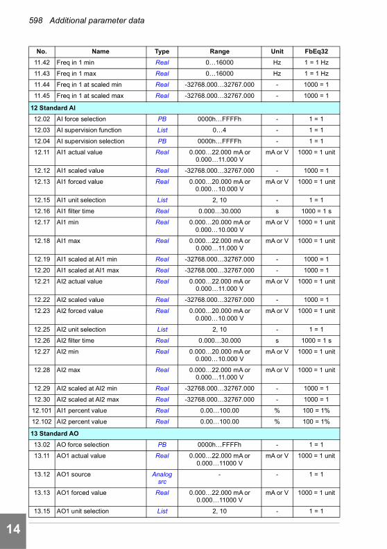
598 Additional parameter data
1
2
3
4
5
6
7
8
9
10
11
12
13
14
11.42 Freq in 1 min Real 0…16000 Hz 1 = 1 Hz
11.43 Freq in 1 max Real 0…16000 Hz 1 = 1 Hz
11.44 Freq in 1 at scaled min Real -32768.000…32767.000 - 1000 = 1
11.45 Freq in 1 at scaled max Real -32768.000…32767.000 - 1000 = 1
12 Standard AI
12.02 AI force selection PB 0000h…FFFFh - 1 = 1
12.03 AI supervision function List 0…4 - 1 = 1
12.04 AI supervision selection PB 0000h…FFFFh - 1 = 1
12.11 AI1 actual value Real 0.000…22.000 mA or 0.000…11.000 V
mA or V 1000 = 1 unit
12.12 AI1 scaled value Real -32768.000…32767.000 - 1000 = 1
12.13 AI1 forced value Real 0.000…20.000 mA or 0.000…10.000 V
mA or V 1000 = 1 unit
12.15 AI1 unit selection List 2, 10 - 1 = 1
12.16 AI1 filter time Real 0.000…30.000 s 1000 = 1 s
12.17 AI1 min Real 0.000…20.000 mA or 0.000…10.000 V
mA or V 1000 = 1 unit
12.18 AI1 max Real 0.000…22.000 mA or 0.000…11.000 V
mA or V 1000 = 1 unit
12.19 AI1 scaled at AI1 min Real -32768.000…32767.000 - 1000 = 1
12.20 AI1 scaled at AI1 max Real -32768.000…32767.000 - 1000 = 1
12.21 AI2 actual value Real 0.000…22.000 mA or 0.000…11.000 V
mA or V 1000 = 1 unit
12.22 AI2 scaled value Real -32768.000…32767.000 - 1000 = 1
12.23 AI2 forced value Real 0.000…20.000 mA or 0.000…10.000 V
mA or V 1000 = 1 unit
12.25 AI2 unit selection List 2, 10 - 1 = 1
12.26 AI2 filter time Real 0.000…30.000 s 1000 = 1 s
12.27 AI2 min Real 0.000…20.000 mA or 0.000…10.000 V
mA or V 1000 = 1 unit
12.28 AI2 max Real 0.000…22.000 mA or 0.000…11.000 V
mA or V 1000 = 1 unit
12.29 AI2 scaled at AI2 min Real -32768.000…32767.000 - 1000 = 1
12.30 AI2 scaled at AI2 max Real -32768.000…32767.000 - 1000 = 1
12.101 AI1 percent value Real 0.00…100.00 % 100 = 1%
12.102 AI2 percent value Real 0.00…100.00 % 100 = 1%
13 Standard AO
13.02 AO force selection PB 0000h…FFFFh - 1 = 1
13.11 AO1 actual value Real 0.000…22.000 mA or0.000…11000 V
mA or V 1000 = 1 unit
13.12 AO1 source Analog src
- - 1 = 1
13.13 AO1 forced value Real 0.000…22.000 mA or0.000…11000 V
mA or V 1000 = 1 unit
13.15 AO1 unit selection List 2, 10 - 1 = 1
No. Name Type Range Unit FbEq32
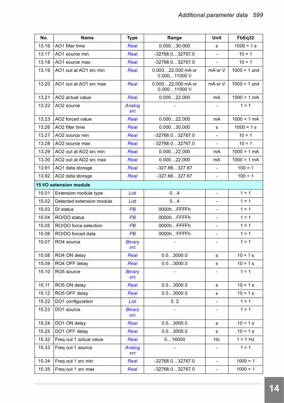
Additional parameter data 599
1
2
3
4
5
6
7
8
9
10
11
12
13
13.16 AO1 filter time Real 0.000…30.000 s 1000 = 1 s
13.17 AO1 source min Real -32768.0…32767.0 - 10 = 1
13.18 AO1 source max Real -32768.0…32767.0 - 10 = 1
13.19 AO1 out at AO1 src min Real 0.000…22.000 mA or0.000…11000 V
mA or V 1000 = 1 unit
13.20 AO1 out at AO1 src max Real 0.000…22.000 mA or0.000…11000 V
mA or V 1000 = 1 unit
13.21 AO2 actual value Real 0.000…22.000 mA 1000 = 1 mA
13.22 AO2 source Analog src
- - 1 = 1
13.23 AO2 forced value Real 0.000…22.000 mA 1000 = 1 mA
13.26 AO2 filter time Real 0.000…30.000 s 1000 = 1 s
13.27 AO2 source min Real -32768.0…32767.0 - 10 = 1
13.28 AO2 source max Real -32768.0…32767.0 - 10 = 1
13.29 AO2 out at AO2 src min Real 0.000…22.000 mA 1000 = 1 mA
13.30 AO2 out at AO2 src max Real 0.000…22.000 mA 1000 = 1 mA
13.91 AO1 data storage Real -327.68…327.67 - 100 = 1
13.92 AO2 data storage Real -327.68…327.67 - 100 = 1
15 I/O extension module
15.01 Extension module type List 0…4 - 1 = 1
15.02 Detected extension module List 0…4 - 1 = 1
15.03 DI status PB 0000h…FFFFh - 1 = 1
15.04 RO/DO status PB 0000h…FFFFh - 1 = 1
15.05 RO/DO force selection PB 0000h…FFFFh - 1 = 1
15.06 RO/DO forced data PB 0000h…FFFFh - 1 = 1
15.07 RO4 source Binary src
- - 1 = 1
15.08 RO4 ON delay Real 0.0…3000.0 s 10 = 1 s
15.09 RO4 OFF delay Real 0.0…3000.0 s 10 = 1 s
15.10 RO5 source Binary src
- - 1 = 1
15.11 RO5 ON delay Real 0.0…3000.0 s 10 = 1 s
15.12 RO5 OFF delay Real 0.0…3000.0 s 10 = 1 s
15.22 DO1 configuration List 0, 2 - 1 = 1
15.23 DO1 source Binary src
- - 1 = 1
15.24 DO1 ON delay Real 0.0…3000.0 s 10 = 1 s
15.25 DO1 OFF delay Real 0.0…3000.0 s 10 = 1 s
15.32 Freq out 1 actual value Real 0…16000 Hz 1 = 1 Hz
15.33 Freq out 1 source Analog src
- - 1 = 1
15.34 Freq out 1 src min Real -32768.0…32767.0 - 1000 = 1
15.35 Freq out 1 src max Real -32768.0…32767.0 - 1000 = 1
No. Name Type Range Unit FbEq32
14

600 Additional parameter data
1
2
3
4
5
6
7
8
9
10
11
12
13
14
15.36 Freq out 1 at src min Real 0…16000 Hz 1 = 1 Hz
15.37 Freq out 1 at src max Real 0…16000 Hz 1 = 1 Hz
19 Operation mode
19.01 Actual operation mode List 1…6, 10, 20 - 1 = 1
19.11 Ext1/Ext2 selection Binary src
- - 1 = 1
19.18 HAND/OFF disable source Binary src
- - 1 = 1
19.19 HAND/OFF disable action List 0…2 - 1 = 1
20 Start/stop/direction
20.01 Ext1 commands List 0…6, 11…12, 14 - 1 = 1
20.02 Ext1 start trigger type List 0…1 - 1 = 1
20.03 Ext1 in1 source Binary src
- - 1 = 1
20.04 Ext1 in2 source Binary src
- - 1 = 1
20.05 Ext1 in3 source Binary src
- - 1 = 1
20.06 Ext2 commands List 0…6, 11…12, 14 - 1 = 1
20.07 Ext2 start trigger type List 0…1 - 1 = 1
20.08 Ext2 in1 source Binary src
- - 1 = 1
20.09 Ext2 in2 source Binary src
- - 1 = 1
20.10 Ext2 in3 source Binary src
- - 1 = 1
20.21 Direction List 0…2 - 1 = 1
20.40 Run permissive Binary src
- - 1 = 1
20.41 Start interlock 1 Binary src
- - 1 = 1
20.42 Start interlock 2 Binary src
- - 1 = 1
20.43 Start interlock 3 Binary src
- - 1 = 1
20.44 Start interlock 4 Binary src
- - 1 = 1
20.45 Start interlock stop mode Binary src
- - 1 = 1
20.46 Run permissive text Binary src
- - 1 = 1
20.47 Start interlock 1 text Binary src
- - 1 = 1
20.48 Start interlock 2 text Binary src
- - 1 = 1
20.49 Start interlock 3 text Binary src
- - 1 = 1
No. Name Type Range Unit FbEq32

Additional parameter data 601
1
2
3
4
5
6
7
8
9
10
11
12
13
20.50 Start interlock 4 text Binary src
- - 1 = 1
20.51 Start interlock condition Binary src
- - 1 = 1
21 Start/stop mode
21.01 Start mode List 0…2 - 1 = 1
21.02 Magnetization time Real 0…10000 ms 1 = 1 ms
21.03 Stop mode List 0…2 - 1 = 1
21.04 Emergency stop mode List 0…2 - 1 = 1
21.05 Emergency stop source Binary src
- - 1 = 1
21.06 Zero speed limit Real 0.00…30000.00 rpm 100 = 1 rpm
21.07 Zero speed delay Real 0…30000 ms 1 = 1 ms
21.08 DC current control PB 0000b…0011b - 1 = 1
21.09 DC hold speed Real 0.00…1000.00 rpm 100 = 1 rpm
21.10 DC current reference Real 0.0…100.0 % 10 = 1%
21.11 Post magnetization time Real 0…3000 s 1 = 1 s
21.14 Pre-heating input source Binary src
- - 1 = 1
21.15 Pre-heating time delay Real 0…3000 s 1 = 1 s
21.16 Pre-heating current Real 0.0…30.0 % 10 = 1%
21.18 Auto restart time Real 0.0, 0.1…10.0 s 10 = 1 s
21.19 Scalar start mode List 0…6 - 1 = 1
21.21 DC hold frequency Real 0.00…1000.00 Hz 100 = 1 Hz
21.22 Start delay Real 0.00…60.00 s 100 = 1 s
21.23 Smooth start Real 0…2 - 1 = 1
21.24 Smooth start current Real 10.0…100.0 % 100 = 1%
21.25 Smooth start speed Real 2.0…100.0 % 100 = 1%
21.26 Torque boost current Real 15.0…300.0 % 100 = 1%
21.30 Speed compensated stop mode
Real 0…3 - 1 = 1
21.31 Speed comp stop delay Real 0.00…1000.00 s 100 = 1 s
21.32 Speed comp stop threshold Real 0…100 % 1 = 1%
21.34 Force auto restart List 0…1 - 1 = 1
21.35 Preheating power Real 0.00 … 10.00 kW 100 = 1
21.36 Preheating unit List 0…1 - 1 = 1
22 Speed reference selection
22.01 Speed ref unlimited Real -30000.00…30000.00 rpm 100 = 1 rpm
22.11 Ext1 speed ref1 Analog src
- - 1 = 1
22.12 Ext1 speed ref2 Analog src
- - 1 = 1
22.13 Ext1 speed function List 0…5 - 1 = 1
No. Name Type Range Unit FbEq32
14

602 Additional parameter data
1
2
3
4
5
6
7
8
9
10
11
12
13
14
22.18 Ext2 speed ref1 Analog src
- - 1 = 1
22.19 Ext2 speed ref2 Analog src
- - 1 = 1
22.20 Ext2 speed function List 0…5 - 1 = 1
22.21 Constant speed function PB 0000h…FFFFh - 1 = 1
22.22 Constant speed sel1 Binary src
- - 1 = 1
22.23 Constant speed sel2 Binary src
- - 1 = 1
22.24 Constant speed sel3 Binary src
- - 1 = 1
22.26 Constant speed 1 Real -30000.00…30000.00 rpm 100 = 1 rpm
22.27 Constant speed 2 Real -30000.00…30000.00 rpm 100 = 1 rpm
22.28 Constant speed 3 Real -30000.00…30000.00 rpm 100 = 1 rpm
22.29 Constant speed 4 Real -30000.00…30000.00 rpm 100 = 1 rpm
22.30 Constant speed 5 Real -30000.00…30000.00 rpm 100 = 1 rpm
22.31 Constant speed 6 Real -30000.00…30000.00 rpm 100 = 1 rpm
22.32 Constant speed 7 Real -30000.00…30000.00 rpm 100 = 1 rpm
22.41 Speed ref safe Real -30000.00…30000.00 rpm 100 = 1 rpm
22.51 Critical speed function PB 00b…11b - 1 = 1
22.52 Critical speed 1 low Real -30000.00…30000.00 rpm 100 = 1 rpm
22.53 Critical speed 1 high Real -30000.00…30000.00 rpm 100 = 1 rpm
22.54 Critical speed 2 low Real -30000.00…30000.00 rpm 100 = 1 rpm
22.55 Critical speed 2 high Real -30000.00…30000.00 rpm 100 = 1 rpm
22.56 Critical speed 3 low Real -30000.00…30000.00 rpm 100 = 1 rpm
22.57 Critical speed 3 high Real -30000.00…30000.00 rpm 100 = 1 rpm
22.71 Motor potentiometer function List 0…3 - 1 = 1
22.72 Motor potentiometer initial value
Real -32768.00…32767.00 - 100 = 1
22.73 Motor potentiometer up source Binary src
- - 1 = 1
22.74 Motor potentiometer down source
Binary src
- - 1 = 1
22.75 Motor potentiometer ramp time Real 0.0…3600.0 s 10 = 1 s
22.76 Motor potentiometer min value Real -32768.00…32767.00 - 100 = 1
22.77 Motor potentiometer max value
Real -32768.00…32767.00 - 100 = 1
22.80 Motor potentiometer ref act Real -32768.00…32767.00 - 100 = 1
22.86 Speed reference act 6 Real -30000.00…30000.00 rpm 100 = 1 rpm
22.87 Speed reference act 7 Real -30000.00…30000.00 rpm 100 = 1 rpm
23 Speed reference ramp
23.01 Speed ref ramp input Real -30000.00…30000.00 rpm 100 = 1 rpm
23.02 Speed ref ramp output Real -30000.00…30000.00 rpm 100 = 1 rpm
No. Name Type Range Unit FbEq32
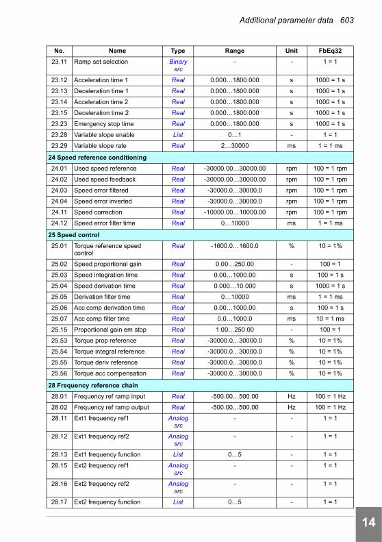
Additional parameter data 603
1
2
3
4
5
6
7
8
9
10
11
12
13
23.11 Ramp set selection Binary src
- - 1 = 1
23.12 Acceleration time 1 Real 0.000…1800.000 s 1000 = 1 s
23.13 Deceleration time 1 Real 0.000…1800.000 s 1000 = 1 s
23.14 Acceleration time 2 Real 0.000…1800.000 s 1000 = 1 s
23.15 Deceleration time 2 Real 0.000…1800.000 s 1000 = 1 s
23.23 Emergency stop time Real 0.000…1800.000 s 1000 = 1 s
23.28 Variable slope enable List 0…1 - 1 = 1
23.29 Variable slope rate Real 2…30000 ms 1 = 1 ms
24 Speed reference conditioning
24.01 Used speed reference Real -30000.00…30000.00 rpm 100 = 1 rpm
24.02 Used speed feedback Real -30000.00…30000.00 rpm 100 = 1 rpm
24.03 Speed error filtered Real -30000.0…30000.0 rpm 100 = 1 rpm
24.04 Speed error inverted Real -30000.0…30000.0 rpm 100 = 1 rpm
24.11 Speed correction Real -10000.00…10000.00 rpm 100 = 1 rpm
24.12 Speed error filter time Real 0…10000 ms 1 = 1 ms
25 Speed control
25.01 Torque reference speed control
Real -1600.0…1600.0 % 10 = 1%
25.02 Speed proportional gain Real 0.00…250.00 - 100 = 1
25.03 Speed integration time Real 0.00…1000.00 s 100 = 1 s
25.04 Speed derivation time Real 0.000…10.000 s 1000 = 1 s
25.05 Derivation filter time Real 0…10000 ms 1 = 1 ms
25.06 Acc comp derivation time Real 0.00…1000.00 s 100 = 1 s
25.07 Acc comp filter time Real 0.0…1000.0 ms 10 = 1 ms
25.15 Proportional gain em stop Real 1.00…250.00 - 100 = 1
25.53 Torque prop reference Real -30000.0…30000.0 % 10 = 1%
25.54 Torque integral reference Real -30000.0…30000.0 % 10 = 1%
25.55 Torque deriv reference Real -30000.0…30000.0 % 10 = 1%
25.56 Torque acc compensation Real -30000.0…30000.0 % 10 = 1%
28 Frequency reference chain
28.01 Frequency ref ramp input Real -500.00…500.00 Hz 100 = 1 Hz
28.02 Frequency ref ramp output Real -500.00…500.00 Hz 100 = 1 Hz
28.11 Ext1 frequency ref1 Analog src
- - 1 = 1
28.12 Ext1 frequency ref2 Analog src
- - 1 = 1
28.13 Ext1 frequency function List 0…5 - 1 = 1
28.15 Ext2 frequency ref1 Analog src
- - 1 = 1
28.16 Ext2 frequency ref2 Analog src
- - 1 = 1
28.17 Ext2 frequency function List 0…5 - 1 = 1
No. Name Type Range Unit FbEq32
14

604 Additional parameter data
1
2
3
4
5
6
7
8
9
10
11
12
13
14
28.21 Constant frequency function PB 00b…11b - 1 = 1
28.22 Constant frequency sel1 Binary src
- - 1 = 1
28.23 Constant frequency sel2 Binary src
- - 1 = 1
28.24 Constant frequency sel3 Binary src
- - 1 = 1
28.26 Constant frequency 1 Real -500.00…500.00 Hz 100 = 1 Hz
28.27 Constant frequency 2 Real -500.00…500.00 Hz 100 = 1 Hz
28.28 Constant frequency 3 Real -500.00…500.00 Hz 100 = 1 Hz
28.29 Constant frequency 4 Real -500.00…500.00 Hz 100 = 1 Hz
28.30 Constant frequency 5 Real -500.00…500.00 Hz 100 = 1 Hz
28.31 Constant frequency 6 Real -500.00…500.00 Hz 100 = 1 Hz
28.32 Constant frequency 7 Real -500.00…500.00 Hz 100 = 1 Hz
28.41 Frequency ref safe Real -500.00…500.00 Hz 100 = 1 Hz
28.51 Critical frequency function PB 00b…11b - 1 = 1
28.52 Critical frequency 1 low Real -500.00…500.00 Hz 100 = 1 Hz
28.53 Critical frequency 1 high Real -500.00…500.00 Hz 100 = 1 Hz
28.54 Critical frequency 2 low Real -500.00…500.00 Hz 100 = 1 Hz
28.55 Critical frequency 2 high Real -500.00…500.00 Hz 100 = 1 Hz
28.56 Critical frequency 3 low Real -500.00…500.00 Hz 100 = 1 Hz
28.57 Critical frequency 3 high Real -500.00…500.00 Hz 100 = 1 Hz
28.71 Freq ramp set selection Binary src
- - 1 = 1
28.72 Freq acceleration time 1 Real 0.000…1800.000 s 1000 = 1 s
28.73 Freq deceleration time 1 Real 0.000…1800.000 s 1000 = 1 s
28.74 Freq acceleration time 2 Real 0.000…1800.000 s 1000 = 1 s
28.75 Freq deceleration time 2 Real 0.000…1800.000 s 1000 = 1 s
28.76 Freq ramp in zero source Binary src
- - 1 = 1
28.92 Frequency ref act 3 Real -500.00…500.00 Hz 100 = 1 Hz
28.96 Frequency ref act 7 Real -500.00…500.00 Hz 100 = 1 Hz
28.97 Frequency ref unlimited Real -500.00…500.00 Hz 100 = 1 Hz
30 Limits
30.01 Limit word 1 PB 0000h…FFFFh - 1 = 1
30.02 Torque limit status PB 0000h…FFFFh - 1 = 1
30.11 Minimum speed Real -30000.00…30000.00 rpm 100 = 1 rpm
30.12 Maximum speed Real -30000.00…30000.00 rpm 100 = 1 rpm
30.13 Minimum frequency Real -500.00…500.00 Hz 100 = 1 Hz
30.14 Maximum frequency Real -500.00…500.00 Hz 100 = 1 Hz
30.17 Maximum current Real 0.00…30000.00 A 100 = 1 A
30.18 Torq lim sel Binary src
- - 1 = 1
No. Name Type Range Unit FbEq32

Additional parameter data 605
1
2
3
4
5
6
7
8
9
10
11
12
13
30.19 Minimum torque 1 Real -1600.0…0.0 % 10 = 1%
30.20 Maximum torque 1 Real 0.0…1600.0 % 10 = 1%
30.21 Min torque 2 source Analog src
- - 1 = 1
30.22 Max torque 2 source Analog src
- - 1 = 1
30.23 Minimum torque 2 Real -1600.0…0.0 % 10 = 1%
30.24 Maximum torque 2 Real 0.0…1600.0 % 10 = 1%
30.26 Power motoring limit Real 0.00…600.00 % 100 = 1%
30.27 Power generating limit Real -600.00…0.00 % 100 = 1%
30.30 Overvoltage control List 0…1 - 1 = 1
30.31 Undervoltage control List 0…1 - 1 = 1
30.35 Thermal current limitation List 0…1 - 1 = 1
30.36 Speed limit selection Binary src
- - 1 = 1
30.37 Minimum speed source Analog src
- - 1 = 1
30.38 Maximum speed source Analog src
- - 1 = 1
(Parameters 30.101…30.149 only visible for ACH580-31)
30.101 LSU limit word 1 PB 0000h…FFFFh - 1 = 1
30.102 LSU limit word 2 PB 0000h…FFFFh - 1 = 1
30.103 LSU limit word 3 PB 0000h…FFFFh - 1 = 1
30.104 LSU limit word 4 PB 0000h…FFFFh - 1 = 1
30.149 LSU maximum power limit Real 0.0 … 200.0 % 10 = 1%
31 Fault functions
31.01 External event 1 source Binary src
- - 1 = 1
31.02 External event 1 type List 0…1 - 1 = 1
31.03 External event 2 source Binary src
- - 1 = 1
31.04 External event 2 type List 0…1 - 1 = 1
31.05 External event 3 source Binary src
- - 1 = 1
31.06 External event 3 type List 0…1 - 1 = 1
31.07 External event 4 source Binary src
- - 1 = 1
31.08 External event 4 type List 0…1 - 1 = 1
31.09 External event 5 source Binary src
- - 1 = 1
31.10 External event 5 type List 0…1 - 1 = 1
31.11 Fault reset selection Binary src
- - 1 = 1
31.12 Autoreset selection PB 0000h…FFFFh - 1 = 1
31.13 Selectable fault Real 0000h…FFFFh - 1 = 1
No. Name Type Range Unit FbEq32
14
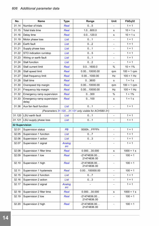
606 Additional parameter data
1
2
3
4
5
6
7
8
9
10
11
12
13
14
31.14 Number of trials Real 0…5 - 1 = 1
31.15 Total trials time Real 1.0…600.0 s 10 = 1 s
31.16 Delay time Real 0.0…120.0 s 10 = 1 s
31.19 Motor phase loss List 0…1 - 1 = 1
31.20 Earth fault List 0…2 - 1 = 1
31.21 Supply phase loss List 0…1 - 1 = 1
31.22 STO indication run/stop List 0…5 - 1 = 1
31.23 Wiring or earth fault List 0…1 - 1 = 1
31.24 Stall function List 0…2 - 1 = 1
31.25 Stall current limit Real 0.0…1600.0 % 10 = 1%
31.26 Stall speed limit Real 0.00…10000.00 rpm 100 = 1 rpm
31.27 Stall frequency limit Real 0.00…1000.00 Hz 100 = 1 Hz
31.28 Stall time Real 0…3600 s 1 = 1 s
31.30 Overspeed trip margin Real 0.00…10000.00 rpm 100 = 1 rpm
31.31 Frequency trip margin Real 0.00…10000.00 Hz 100 = 1 Hz
31.32 Emergency ramp supervision Real 0…300 % 1 = 1%
31.33 Emergency ramp supervision delay
Real 0…100 s 1 = 1 s
31.36 Aux fan fault function List 0…1 - 1 = 1
(Parameters 31.120…31.121 only visible for ACH580-31)
31.120 LSU earth fault List 0…1 - 1 = 1
31.121 LSU supply phase loss List 0…1 - 1 = 1
32 Supervision
32.01 Supervision status PB 0000h…FFFFh - 1 = 1
32.05 Supervision 1 function List 0…7 - 1 = 1
32.06 Supervision 1 action List 0…3 - 1 = 1
32.07 Supervision 1 signal Analog src
- - 1 = 1
32.08 Supervision 1 filter time Real 0.000…30.000 s 1000 = 1 s
32.09 Supervision 1 low Real -21474836.00… 21474836.00
- 100 = 1
32.10 Supervision 1 high Real -21474836.00… 21474836.00
- 100 = 1
32.11 Supervision 1 hysteresis Real 0.00…100000.00 - 100 = 1
32.15 Supervision 2 function List 0…7 - 1 = 1
32.16 Supervision 2 action List 0…3 - 1 = 1
32.17 Supervision 2 signal Analog src
- - 1 = 1
32.18 Supervision 2 filter time Real 0.000…30.000 s 1000 = 1 s
32.19 Supervision 2 low Real -21474836.00… 21474836.00
- 100 = 1
32.20 Supervision 2 high Real -21474836.00… 21474836.00
- 100 = 1
No. Name Type Range Unit FbEq32

Additional parameter data 607
1
2
3
4
5
6
7
8
9
10
11
12
13
32.21 Supervision 2 hysteresis Real 0.00…100000.00 - 100 = 1
32.25 Supervision 3 function List 0…7 - 1 = 1
32.26 Supervision 3 action List 0…3 - 1 = 17
32.27 Supervision 3 signal Analog src
- - 1 = 1
32.28 Supervision 3 filter time Real 0.000…30.000 s 1000 = 1 s
32.29 Supervision 3 low Real -21474836.00… 21474836.00
- 100 = 1
32.30 Supervision 3 high Real -21474836.00… 21474836.00
- 100 = 1
32.31 Supervision 3 hysteresis Real 0.00…100000.00 - 100 = 1
32.35 Supervision 4 function List 0…7 - 1 = 1
32.36 Supervision 4 action List 0…3 - 1 = 1
32.37 Supervision 4 signal Analog src
- - 1 = 1
32.38 Supervision 4 filter time Real 0.000…30.000 s 1000 = 1 s
32.39 Supervision 4 low Real -21474836.00… 21474836.00
- 100 = 1
32.40 Supervision 4 high Real -21474836.00… 21474836.00
- 100 = 1
32.41 Supervision 4 hysteresis Real 0.00…100000.00 - 100 = 1
32.45 Supervision 5 function List 0…7 - 1 = 1
32.46 Supervision 5 action List 0…3 - 1 = 1
32.47 Supervision 5 signal Analog src
- - 1 = 1
32.48 Supervision 5 filter time Real 0.000…30.000 s 1000 = 1 s
32.49 Supervision 5 low Real -21474836.00… 21474836.00
- 100 = 1
32.50 Supervision 5 high Real -21474836.00… 21474836.00
- 100 = 1
32.51 Supervision 5 hysteresis Real 0.00…100000.00 - 100 = 1
32.55 Supervision 6 function List 0…7 - 1 = 1
32.56 Supervision 6 action List 0…3 - 1 = 1
32.57 Supervision 6 signal Analog src
- - 1 = 1
32.58 Supervision 6 filter time Real 0.000…30.000 s 1000 = 1 s
32.59 Supervision 6 low Real -21474836.00… 21474836.00
- 100 = 1
32.60 Supervision 6 high Real -21474836.00… 21474836.00
- 100 = 1
32.61 Supervision 6 hysteresis Real 0.00…100000.00 - 100 = 1
34 Timed functions
34.01 Timed functions status PB 0000h…FFFFh - 1 = 1
34.02 Timer status PB 0000h…FFFFh - 1 = 1
34.04 Season/exception day status PB 0000h…FFFFh - 1 = 1
No. Name Type Range Unit FbEq32
14

608 Additional parameter data
1
2
3
4
5
6
7
8
9
10
11
12
13
14
34.10 Timed functions enable Binary src
- - 1 = 1
34.11 Timer 1 configuration PB 0000h…FFFFh - 1 = 1
34.12 Timer 1 start time Time 00:00:00…23:59:59 s 1 = 1 s
34.13 Timer 1 duration Duration 00 00:00…07 00:00 min 1 = 1 min
34.14 Timer 2 configuration PB 0000h…FFFFh - 1 = 1
34.15 Timer 2 start time Time 00:00:00…23:59:59 s 1 = 1 s
34.16 Timer 2 duration Duration 00 00:00…07 00:00 min 1 = 1 min
34.17 Timer 3 configuration PB 0000h…FFFFh - 1 = 1
34.18 Timer 3 start time Time 00:00:00…23:59:59 s 1 = 1 s
34.19 Timer 3 duration Duration 00 00:00…07 00:00 min 1 = 1 min
34.20 Timer 4 configuration PB 0000h…FFFFh - 1 = 1
34.21 Timer 4 start time Time 00:00:00…23:59:59 s 1 = 1 s
34.22 Timer 4 duration Duration 00 00:00…07 00:00 min 1 = 1 min
34.23 Timer 5 configuration PB 0000h…FFFFh - 1 = 1
34.24 Timer 5 start time Time 00:00:00…23:59:59 s 1 = 1 s
34.25 Timer 5 duration Duration 00 00:00…07 00:00 min 1 = 1 min
34.26 Timer 6 configuration PB 0000h…FFFFh - 1 = 1
34.27 Timer 6 start time Time 00:00:00…23:59:59 s 1 = 1 s
34.28 Timer 6 duration Duration 00 00:00…07 00:00 min 1 = 1 min
34.29 Timer 7 configuration PB 0000h…FFFFh - 1 = 1
34.30 Timer 7 start time Time 00:00:00…23:59:59 s 1 = 1 s
34.31 Timer 7 duration Duration 00 00:00…07 00:00 min 1 = 1 min
34.32 Timer 8 configuration PB 0000h…FFFFh - 1 = 1
34.33 Timer 8 start time Time 00:00:00…23:59:59 s 1 = 1 s
34.34 Timer 8 duration Duration 00 00:00…07 00:00 min 1 = 1 min
34.35 Timer 9 configuration PB 0000h…FFFFh - 1 = 1
34.36 Timer 9 start time Time 00:00:00…23:59:59 s 1 = 1 s
34.37 Timer 9 duration Duration 00 00:00…07 00:00 min 1 = 1 min
34.38 Timer 10 configuration PB 0000h…FFFFh - 1 = 1
34.39 Timer 10 start time Time 00:00:00…23:59:59 s 1 = 1 s
34.40 Timer 10 duration Duration 00 00:00…07 00:00 min 1 = 1 min
34.41 Timer 11 configuration PB 0000h…FFFFh - 1 = 1
34.42 Timer 11 start time Time 00:00:00…23:59:59 s 1 = 1 s
34.43 Timer 11 duration Duration 00 00:00…07 00:00 min 1 = 1 min
34.44 Timer 12 configuration PB 0000h…FFFFh - 1 = 1
34.45 Timer 12 start time Time 00:00:00…23:59:59 s 1 = 1 s
34.46 Timer 12 duration Duration 00 00:00…07 00:00 min 1 = 1 min
34.60 Season 1 start date Date 01.01…31.12 d 1 = 1 d
34.61 Season 2 start date Date 01.01…31.12 d 1 = 1 d
34.62 Season 3 start date Date 01.01…31.12 d 1 = 1 d
No. Name Type Range Unit FbEq32
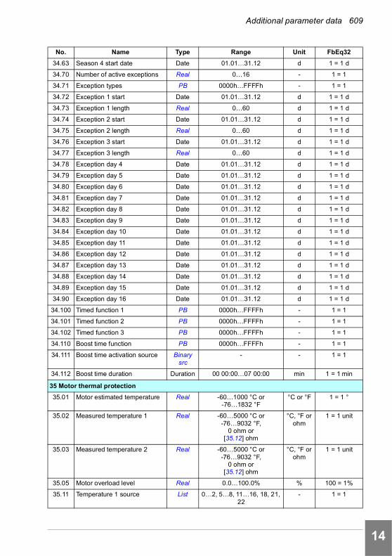
Additional parameter data 609
1
2
3
4
5
6
7
8
9
10
11
12
13
34.63 Season 4 start date Date 01.01…31.12 d 1 = 1 d
34.70 Number of active exceptions Real 0…16 - 1 = 1
34.71 Exception types PB 0000h…FFFFh - 1 = 1
34.72 Exception 1 start Date 01.01…31.12 d 1 = 1 d
34.73 Exception 1 length Real 0…60 d 1 = 1 d
34.74 Exception 2 start Date 01.01…31.12 d 1 = 1 d
34.75 Exception 2 length Real 0…60 d 1 = 1 d
34.76 Exception 3 start Date 01.01…31.12 d 1 = 1 d
34.77 Exception 3 length Real 0…60 d 1 = 1 d
34.78 Exception day 4 Date 01.01…31.12 d 1 = 1 d
34.79 Exception day 5 Date 01.01…31.12 d 1 = 1 d
34.80 Exception day 6 Date 01.01…31.12 d 1 = 1 d
34.81 Exception day 7 Date 01.01…31.12 d 1 = 1 d
34.82 Exception day 8 Date 01.01…31.12 d 1 = 1 d
34.83 Exception day 9 Date 01.01…31.12 d 1 = 1 d
34.84 Exception day 10 Date 01.01…31.12 d 1 = 1 d
34.85 Exception day 11 Date 01.01…31.12 d 1 = 1 d
34.86 Exception day 12 Date 01.01…31.12 d 1 = 1 d
34.87 Exception day 13 Date 01.01…31.12 d 1 = 1 d
34.88 Exception day 14 Date 01.01…31.12 d 1 = 1 d
34.89 Exception day 15 Date 01.01…31.12 d 1 = 1 d
34.90 Exception day 16 Date 01.01…31.12 d 1 = 1 d
34.100 Timed function 1 PB 0000h…FFFFh - 1 = 1
34.101 Timed function 2 PB 0000h…FFFFh - 1 = 1
34.102 Timed function 3 PB 0000h…FFFFh - 1 = 1
34.110 Boost time function PB 0000h…FFFFh - 1 = 1
34.111 Boost time activation source Binary src
- - 1 = 1
34.112 Boost time duration Duration 00 00:00…07 00:00 min 1 = 1 min
35 Motor thermal protection
35.01 Motor estimated temperature Real -60…1000 °C or-76…1832 °F
°C or °F 1 = 1 °
35.02 Measured temperature 1 Real -60…5000 °C or -76…9032 °F,
0 ohm or [35.12] ohm
°C, °F or ohm
1 = 1 unit
35.03 Measured temperature 2 Real -60…5000 °C or -76…9032 °F,
0 ohm or [35.12] ohm
°C, °F or ohm
1 = 1 unit
35.05 Motor overload level Real 0.0…100.0% % 100 = 1%
35.11 Temperature 1 source List 0…2, 5…8, 11…16, 18, 21, 22
- 1 = 1
No. Name Type Range Unit FbEq32
14

610 Additional parameter data
1
2
3
4
5
6
7
8
9
10
11
12
13
14
35.12 Temperature 1 fault limit Real -60…5000 °C or -76…9032 °F
°C, °F or ohm
1 = 1 unit
35.13 Temperature 1 warning limit Real -60…5000 °C or -76…9032 °F
°C, °F or ohm
1 = 1 unit
35.14 Temperature 1 AI source Analog src
- - 1 = 1
35.21 Temperature 2 source List 0…2, 5…8, 11…16, 18 - 1 = 1
35.22 Temperature 2 fault limit Real -60…5000 °C or -76…9032 °F
°C, °F or ohm
1 = 1 unit
35.23 Temperature 2 warning limit Real -60…5000 °C or -76…9032 °F
°C, °F or ohm
1 = 1 unit
35.24 Temperature 2 AI source Analog src
- - 1 = 1
35.31 Safe motor temperature enable
List 0…1 - 1 = 1
35.50 Motor ambient temperature Real -60…100 °C or -76 … 212 °F
°C 1 = 1 °
35.51 Motor load curve Real 50…150 % 1 = 1%
35.52 Zero speed load Real 25…150 % 1 = 1%
35.53 Break point Real 1.00 … 500.00 Hz 100 = 1 Hz
35.54 Motor nominal temperature rise
Real 0…300 °C or 32…572 °F °C or °F 1 = 1 °
35.55 Motor thermal time constant Real 100…10000 s 1 = 1 s
35.56 Motor overload action List 0…2 - 1 = 1
35.57 Motor overload class List 0…5 - 1 = 1
36 Load analyzer
36.01 PVL signal source Analog src
- - 1 = 1
36.02 PVL filter time Real 0.00…120.00 s 100 = 1 s
36.06 AL2 signal source Analog src
- - 1 = 1
36.07 AL2 signal scaling Real 0.00…32767.00 - 100 = 1
36.09 Reset loggers List 0…3 - 1 = 1
36.10 PVL peak value Real -32768.00…32767.00 - 100 = 1
36.11 PVL peak date Data - - 1 = 1
36.12 PVL peak time Data - - 1 = 1
36.13 PVL current at peak Real -32768.00…32767.00 A 100 = 1 A
36.14 PVL DC voltage at peak Real 0.00…2000.00 V 100 = 1 V
36.15 PVL speed at peak Real -30000.00… 30000.00 rpm 100 = 1 rpm
36.16 PVL reset date Data - - 1 = 1
36.17 PVL reset time Data - - 1 = 1
36.20 AL1 0 to 10% Real 0.00…100.00 % 100 = 1%
36.21 AL1 10 to 20% Real 0.00…100.00 % 100 = 1%
36.22 AL1 20 to 30% Real 0.00…100.00 % 100 = 1%
36.23 AL1 30 to 40% Real 0.00…100.00 % 100 = 1%
No. Name Type Range Unit FbEq32

Additional parameter data 611
1
2
3
4
5
6
7
8
9
10
11
12
13
36.24 AL1 40 to 50% Real 0.00…100.00 % 100 = 1%
36.25 AL1 50 to 60% Real 0.00…100.00 % 100 = 1%
36.26 AL1 60 to 70% Real 0.00…100.00 % 100 = 1%
36.27 AL1 70 to 80% Real 0.00…100.00 % 100 = 1%
36.28 AL1 80 to 90% Real 0.00…100.00 % 100 = 1%
36.29 AL1 over 90% Real 0.00…100.00 % 100 = 1%
36.40 AL2 0 to 10% Real 0.00…100.00 % 100 = 1%
36.41 AL2 10 to 20% Real 0.00…100.00 % 100 = 1%
36.42 AL2 20 to 30% Real 0.00…100.00 % 100 = 1%
36.43 AL2 30 to 40% Real 0.00…100.00 % 100 = 1%
36.44 AL2 40 to 50% Real 0.00…100.00 % 100 = 1%
36.45 AL2 50 to 60% Real 0.00…100.00 % 100 = 1%
36.46 AL2 60 to 70% Real 0.00…100.00 % 100 = 1%
36.47 AL2 70 to 80% Real 0.00…100.00 % 100 = 1%
36.48 AL2 80 to 90% Real 0.00…100.00 % 100 = 1%
36.49 AL2 over 90% Real 0.00…100.00 % 100 = 1%
36.50 AL2 reset date Data - - 1 = 1
36.51 AL2 reset time Data - - 1 = 1
37 User load curve
37.01 ULC output status word PB 0000h…FFFFh - 1 = 1
37.02 ULC supervision signal Analog src
- - 1 = 1
37.03 ULC overload actions List 0…3 - 1 = 1
37.04 ULC underload actions List 0…3 - 1 = 1
37.11 ULC speed table point 1 Real -30000.0…30000.0 rpm 10 = 1 rpm
37.12 ULC speed table point 2 Real -30000.0…30000.0 rpm 10 = 1 rpm
37.13 ULC speed table point 3 Real -30000.0…30000.0 rpm 10 = 1 rpm
37.14 ULC speed table point 4 Real -30000.0…30000.0 rpm 10 = 1 rpm
37.15 ULC speed table point 5 Real -30000.0…30000.0 rpm 10 = 1 rpm
37.16 ULC frequency table point 1 Real -500.0…500.0 Hz 10 = 1 Hz
37.17 ULC frequency table point 2 Real -500.0…500.0 Hz 10 = 1 Hz
37.18 ULC frequency table point 3 Real -500.0…500.0 Hz 10 = 1 Hz
37.19 ULC frequency table point 4 Real -500.0…500.0 Hz 10 = 1 Hz
37.20 ULC frequency table point 5 Real -500.0…500.0 Hz 10 = 1 Hz
37.21 ULC underload point 1 Real -1600.0…1600.0 % 10 = 1%
37.22 ULC underload point 2 Real -1600.0…1600.0 % 10 = 1%
37.23 ULC underload point 3 Real -1600.0…1600.0 % 10 = 1%
37.24 ULC underload point 4 Real -1600.0…1600.0 % 10 = 1%
37.25 ULC underload point 5 Real -1600.0…1600.0 % 10 = 1%
37.31 ULC overload point 1 Real -1600.0…1600.0 % 10 = 1%
37.32 ULC overload point 2 Real -1600.0…1600.0 % 10 = 1%
No. Name Type Range Unit FbEq32
14

612 Additional parameter data
1
2
3
4
5
6
7
8
9
10
11
12
13
14
37.33 ULC overload point 3 Real -1600.0…1600.0 % 10 = 1%
37.34 ULC overload point 4 Real -1600.0…1600.0 % 10 = 1%
37.35 ULC overload point 5 Real -1600.0…1600.0 % 10 = 1%
37.41 ULC overload timer Real 0.0…10000.0 s 10 = 1 s
37.42 ULC underload timer Real 0.0…10000.0 s 10 = 1 s
40 Process PID set 1
40.01 Process PID output actual Real -200000.00…200000.00 % 100 = 1 %
40.02 Process PID feedback actual Real -200000.00…200000.00 PID unit 1
100 = 1 PID unit 1
40.03 Process PID setpoint actual Real -200000…200000 PID unit 1
100 = 1 PID unit 1
40.04 Process PID deviation actual Real -200000.00…200000.00 PID unit 1
100 = 1 PID unit 1
40.06 Process PID status word PB 0000h…FFFFh - 1 = 1
40.07 Process PID operation mode List 0…2 - 1 = 1
40.08 Set 1 feedback 1 source Analog src
- - 1 = 1
40.09 Set 1 feedback 2 source Analog src
- - 1 = 1
40.10 Set 1 feedback function List 0…13 - 1 = 1
40.11 Set 1 feedback filter time Real 0.000…30.000 s 1000 = 1 s
40.14 Set 1 setpoint scaling Real -200000.00…200000.00 - 100 = 1
40.15 Set 1 output scaling Real -200000.00…200000.00 - 100 = 1
40.16 Set 1 setpoint 1 source Analog src
- - 1 = 1
40.17 Set 1 setpoint 2 source Analog src
- - 1 = 1
40.18 Set 1 setpoint function List 0…13 - 1 = 1
40.19 Set 1 internal setpoint sel1 Binary src
- - 1 = 1
40.20 Set 1 internal setpoint sel2 Binary src
- - 1 = 1
40.21 Set 1 internal setpoint 1 Real -200000.00…200000.00 PID unit 1
100 = 1 PID unit 1
40.22 Set 1 internal setpoint 2 Real -200000.00…200000.00 PID unit 1
100 = 1 PID unit 1
40.23 Set 1 internal setpoint 3 Real -200000.00…200000.00 PID unit 1
100 = 1 PID unit 1
40.24 Set 1 internal setpoint 0 Real -200000.00…200000.00 PID unit 1
100 = 1 PID unit 1
40.26 Set 1 setpoint min Real -200000.00…200000.00 PID unit 1
100 = 1 PID unit 1
40.27 Set 1 setpoint max Real -200000.00…200000.00 PID unit 1
100 = 1 PID unit 1
40.28 Set 1 setpoint increase time Real 0.0…1800.0 s 10 = 1 s
40.29 Set 1 setpoint decrease time Real 0.0…1800.0 s 10 = 1 s
No. Name Type Range Unit FbEq32

Additional parameter data 613
1
2
3
4
5
6
7
8
9
10
11
12
13
40.30 Set 1 setpoint freeze enable Binary src
- - 1 = 1
40.31 Set 1 deviation inversion Binary src
- - 1 = 1
40.32 Set 1 gain Real 0.10…100.00 - 100 = 1
40.33 Set 1 integration time Real 0.0…9999.0 s 10 = 1 s
40.34 Set 1 derivation time Real 0.000…10.000 s 1000 = 1 s
40.35 Set 1 derivation filter time Real 0.0…10.0 s 10 = 1 s
40.36 Set 1 output min Real -200000.00…200000.00 - 100 = 1
40.37 Set 1 output max Real -200000.00…200000.00 - 100 = 1
40.38 Set 1 output freeze enable Binary src
- - 1 = 1
40.39 Set 1 deadband range Real 0……200000.0 - 10 = 1
40.40 Set 1 deadband delay Real 0.0 … 3600.0 s 10 = 1 s
40.43 Set 1 sleep level Real 0.0…200000.0 - 10 = 1
40.44 Set 1 sleep delay Real 0.0…3600.0 s 10 = 1 s
40.45 Set 1 sleep boost time Real 0.0…3600.0 s 10 = 1 s
40.46 Set 1 sleep boost step Real 0.0…200000.0 PID unit 1
10 = 1 PID unit 1
40.47 Set 1 wake-up deviation Real -200000.00…200000.00 PID unit 1
100 = 1 PID unit 1
40.48 Set 1 wake-up delay Real 0.00…60.00 s 100 = 1 s
40.49 Set 1 tracking mode Binary src
- - 1 = 1
40.50 Set 1 tracking ref selection Analog src
- - 1 = 1
40.57 PID set1/set2 selection Binary src
- - 1 = 1
40.58 Set 1 increase prevention Binary src
- - 1 = 1
40.59 Set 1 decrease prevention Binary src
- - 1 = 1
40.60 Set 1 PID activation source Binary src
- - 1 = 1
40.61 Setpoint scaling actual Real -200000.00…200000.00 - 100 = 1
40.62 PID internal setpoint actual Real -200000.00…200000.00 PID unit 1
100 = 1 PID unit 1
40.70 Compensated setpoint Real -21474836.48…21474835.20
PID unit 1
100 = 1 PID unit 1
40.71 Set 1 compensation input source
List 0, 2…4, 8, 10…12, 15…16, 19…20, 24
- 1 = 1
40.72 Set 1 compensation input 1 Real -200000.00…200000.00 - 100 = 1
40.73 Set 1 compensated output 1 Real -200000.00…200000.00 - 100 = 1
40.74 Set 1 compensation input 2 Real -200000.00…200000.00 - 100 = 1
40.75 Set 1 compensated output 2 Real -200000.00…200000.00 - 100 = 1
No. Name Type Range Unit FbEq32
14

614 Additional parameter data
1
2
3
4
5
6
7
8
9
10
11
12
13
14
40.76 Set 1 compensation non-linearity
Real 0…100 % 1= 1%
40.79 Set 1 units List - 1 = 1
40.80 Set 1 PID output min source List 0…1 - 1 = 1
40.81 Set 1 PID output max source List 0…1 - 1 = 1
40.89 Set 1 setpoint multiplier Real -200000.00…200000.00 - 100 = 1
40.90 Set 1 feedback multiplier Real -200000.00…200000.00 - 100 = 1
40.91 Feedback data storage Real -327.68…327.67 - 100 = 1
40.92 Setpoint data storage Real -327.68…327.67 - 100 = 1
40.96 Process PID output % Real -100.00…100.00 % 100 = 1%
40.97 Process PID feedback % Real -100.00…100.00 % 100 = 1%
40.98 Process PID setpoint % Real -100.00…100.00 % 100 = 1%
40.99 Process PID deviation % Real -100.00…100.00 % 100 = 1%
41 Process PID set 2
41.08 Set 2 feedback 1 source Analog src
- - 1 = 1
41.09 Set 2 feedback 2 source Analog src
- - 1 = 1
41.10 Set 2 feedback function List 0…13 - 1 = 1
41.11 Set 2 feedback filter time Real 0.000…30.000 s 1000 = 1 s
41.14 Set 2 setpoint scaling Real -200000.00…200000.00 - 100 = 1
41.15 Set 2 output scaling Real -200000.00…200000.00 - 100 = 1
41.16 Set 2 setpoint 1 source Analog src
- - 1 = 1
41.17 Set 2 setpoint 2 source Analog src
- - 1 = 1
41.18 Set 2 setpoint function List 0…13 - 1 = 1
41.19 Set 2 internal setpoint sel1 Binary src
- - 1 = 1
41.20 Set 2 internal setpoint sel2 Binary src
- - 1 = 1
41.21 Set 2 internal setpoint 1 Real -200000.00…200000.00 PID unit 1
100 = 1 PID unit 1
41.22 Set 2 internal setpoint 2 Real -200000.00…200000.00 PID unit 1
100 = 1 PID unit 1
41.23 Set 2 internal setpoint 3 Real -200000.00…200000.00 PID unit 1
100 = 1 PID unit 1
41.24 Set 2 internal setpoint 0 Real -200000.00…200000.00 PID unit 1
100 = 1 PID unit 1
41.26 Set 2 setpoint min Real -200000.00…200000.00 PID unit 1
100 = 1 PID unit 1
41.27 Set 2 setpoint max Real -200000.00…200000.00 PID unit 1
100 = 1 PID unit 1
41.28 Set 2 setpoint increase time Real 0.0…1800.0 s 10 = 1 s
41.29 Set 2 setpoint decrease time Real 0.0…1800.0 s 10 = 1 s
No. Name Type Range Unit FbEq32
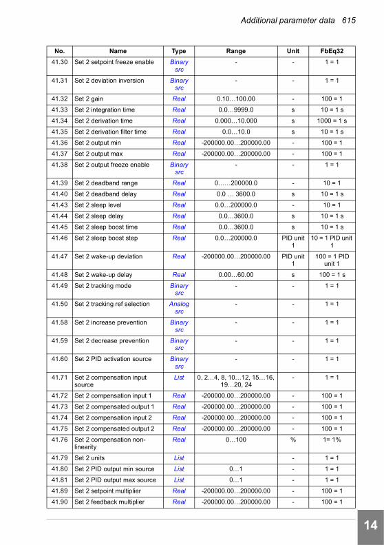
Additional parameter data 615
1
2
3
4
5
6
7
8
9
10
11
12
13
41.30 Set 2 setpoint freeze enable Binary src
- - 1 = 1
41.31 Set 2 deviation inversion Binary src
- - 1 = 1
41.32 Set 2 gain Real 0.10…100.00 - 100 = 1
41.33 Set 2 integration time Real 0.0…9999.0 s 10 = 1 s
41.34 Set 2 derivation time Real 0.000…10.000 s 1000 = 1 s
41.35 Set 2 derivation filter time Real 0.0…10.0 s 10 = 1 s
41.36 Set 2 output min Real -200000.00…200000.00 - 100 = 1
41.37 Set 2 output max Real -200000.00…200000.00 - 100 = 1
41.38 Set 2 output freeze enable Binary src
- - 1 = 1
41.39 Set 2 deadband range Real 0……200000.0 - 10 = 1
41.40 Set 2 deadband delay Real 0.0 … 3600.0 s 10 = 1 s
41.43 Set 2 sleep level Real 0.0…200000.0 - 10 = 1
41.44 Set 2 sleep delay Real 0.0…3600.0 s 10 = 1 s
41.45 Set 2 sleep boost time Real 0.0…3600.0 s 10 = 1 s
41.46 Set 2 sleep boost step Real 0.0…200000.0 PID unit 1
10 = 1 PID unit 1
41.47 Set 2 wake-up deviation Real -200000.00…200000.00 PID unit 1
100 = 1 PID unit 1
41.48 Set 2 wake-up delay Real 0.00…60.00 s 100 = 1 s
41.49 Set 2 tracking mode Binary src
- - 1 = 1
41.50 Set 2 tracking ref selection Analog src
- - 1 = 1
41.58 Set 2 increase prevention Binary src
- - 1 = 1
41.59 Set 2 decrease prevention Binary src
- - 1 = 1
41.60 Set 2 PID activation source Binary src
- - 1 = 1
41.71 Set 2 compensation input source
List 0, 2…4, 8, 10…12, 15…16, 19…20, 24
- 1 = 1
41.72 Set 2 compensation input 1 Real -200000.00…200000.00 - 100 = 1
41.73 Set 2 compensated output 1 Real -200000.00…200000.00 - 100 = 1
41.74 Set 2 compensation input 2 Real -200000.00…200000.00 - 100 = 1
41.75 Set 2 compensated output 2 Real -200000.00…200000.00 - 100 = 1
41.76 Set 2 compensation non-linearity
Real 0…100 % 1= 1%
41.79 Set 2 units List - 1 = 1
41.80 Set 2 PID output min source List 0…1 - 1 = 1
41.81 Set 2 PID output max source List 0…1 - 1 = 1
41.89 Set 2 setpoint multiplier Real -200000.00…200000.00 - 100 = 1
41.90 Set 2 feedback multiplier Real -200000.00…200000.00 - 100 = 1
No. Name Type Range Unit FbEq32
14
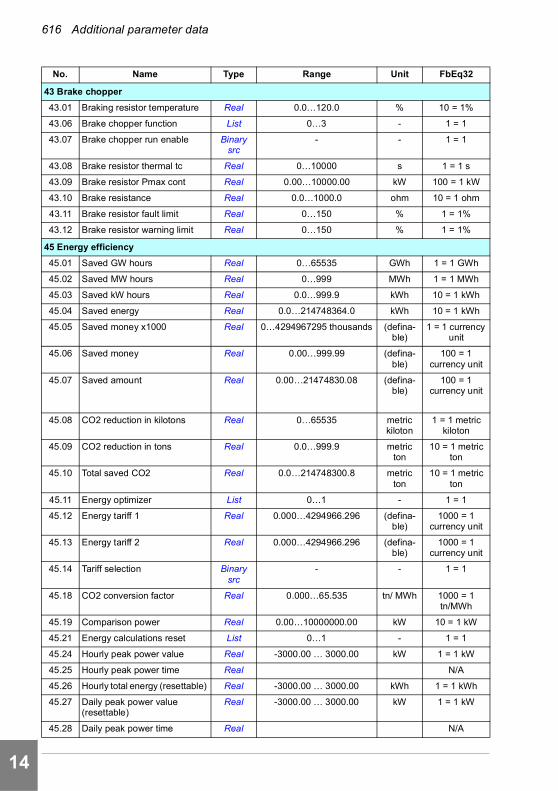
616 Additional parameter data
1
2
3
4
5
6
7
8
9
10
11
12
13
14
43 Brake chopper
43.01 Braking resistor temperature Real 0.0…120.0 % 10 = 1%
43.06 Brake chopper function List 0…3 - 1 = 1
43.07 Brake chopper run enable Binary src
- - 1 = 1
43.08 Brake resistor thermal tc Real 0…10000 s 1 = 1 s
43.09 Brake resistor Pmax cont Real 0.00…10000.00 kW 100 = 1 kW
43.10 Brake resistance Real 0.0…1000.0 ohm 10 = 1 ohm
43.11 Brake resistor fault limit Real 0…150 % 1 = 1%
43.12 Brake resistor warning limit Real 0…150 % 1 = 1%
45 Energy efficiency
45.01 Saved GW hours Real 0…65535 GWh 1 = 1 GWh
45.02 Saved MW hours Real 0…999 MWh 1 = 1 MWh
45.03 Saved kW hours Real 0.0…999.9 kWh 10 = 1 kWh
45.04 Saved energy Real 0.0…214748364.0 kWh 10 = 1 kWh
45.05 Saved money x1000 Real 0…4294967295 thousands (defina-ble)
1 = 1 currency unit
45.06 Saved money Real 0.00…999.99 (defina-ble)
100 = 1 currency unit
45.07 Saved amount Real 0.00…21474830.08 (defina-ble)
100 = 1 currency unit
45.08 CO2 reduction in kilotons Real 0…65535 metric kiloton
1 = 1 metric kiloton
45.09 CO2 reduction in tons Real 0.0…999.9 metric ton
10 = 1 metric ton
45.10 Total saved CO2 Real 0.0…214748300.8 metric ton
10 = 1 metric ton
45.11 Energy optimizer List 0…1 - 1 = 1
45.12 Energy tariff 1 Real 0.000…4294966.296 (defina-ble)
1000 = 1 currency unit
45.13 Energy tariff 2 Real 0.000…4294966.296 (defina-ble)
1000 = 1 currency unit
45.14 Tariff selection Binary src
- - 1 = 1
45.18 CO2 conversion factor Real 0.000…65.535 tn/ MWh 1000 = 1 tn/MWh
45.19 Comparison power Real 0.00…10000000.00 kW 10 = 1 kW
45.21 Energy calculations reset List 0…1 - 1 = 1
45.24 Hourly peak power value Real -3000.00 … 3000.00 kW 1 = 1 kW
45.25 Hourly peak power time Real N/A
45.26 Hourly total energy (resettable) Real -3000.00 … 3000.00 kWh 1 = 1 kWh
45.27 Daily peak power value (resettable)
Real -3000.00 … 3000.00 kW 1 = 1 kW
45.28 Daily peak power time Real N/A
No. Name Type Range Unit FbEq32

Additional parameter data 617
1
2
3
4
5
6
7
8
9
10
11
12
13
45.29 Daily total energy (resettable) Real -30000.00 … 30000.00 kWh 1 = 1 kWh
45.30 Last day total energy Real -30000.00 … 30000.00 kWh 1 = 1 kWh
45.31 Monthly peak power value (resettable)
Real -3000.00 … 3000.00 kW 1 = 1 kW
45.32 Monthly peak power date Real N/A
45.33 Monthly peak power time Real N/A
45.34 Monthly total energy (resettable)
Real -1000000.00 … 1000000.00 kWh 1 = 1 kWh
45.35 Last month total energy Real -1000000.00 … 1000000.00 kWh 1 = 1 kWh
45.36 Lifetime peak power value Real -3000.00 … 3000.00 kW 1 = 1 kW
45.37 Lifetime peak power date Real N/A
45.38 Lifetime peak power time Real N/A
46 Monitoring/scaling settings
46.01 Speed scaling Real 0.00…30000.00 rpm 100 = 1 rpm
46.02 Frequency scaling Real 0.10…1000.00 Hz 100 = 1 Hz
46.03 Torque scaling Real 0.1…1000.0 % 10 = 1%
46.04 Power scaling Real 0.10…30000.00 kW or hp kW or hp 10 = 1 unit
46.05 Current scaling Real 0…30000 A 1 = 1 A
46.06 Speed ref zero scaling Real 0.00 … 30000.00 rpm 100 = 1 rpm
46.07 Frequency ref zero scaling Real 0.00…1000.00 Hz 100 = 1 Hz
46.11 Filter time motor speed Real 2…20000 ms 1 = 1 ms
46.12 Filter time output frequency Real 2…20000 ms 1 = 1 ms
46.13 Filter time motor torque Real 2…20000 ms 1 = 1 ms
46.14 Filter time power Real 2…20000 ms 1 = 1 ms
46.21 At speed hysteresis Real 0.00…30000.00 rpm 100 = 1 rpm
46.22 At frequency hysteresis Real 0.00…1000.00 Hz 100 = 1 Hz
46.31 Above speed limit Real 0.00…30000.00 rpm 100 = 1 rpm
46.32 Above frequency limit Real 0.00…1000.00 Hz 100 = 1 Hz
46.41 kWh pulse scaling Real 0.001…1000.000 kWh 1000 = 1 kWh
46.43 Power decimals Real 0…3 - 1 = 1
46.44 Current decimals Real 0…3 - 1 = 1
47 Data storage
47.01 Data storage 1 real32 Real -2147483.000… 2147483.000
- 1000 = 1
47.02 Data storage 2 real32 Real -2147483.000… 2147483.000
- 1000 = 1
47.03 Data storage 3 real32 Real -2147483.000… 2147483.000
- 1000 = 1
47.04 Data storage 4 real32 Real -2147483.000… 2147483.000
- 1000 = 1
47.11 Data storage 1 int32 Real -2147483648… 2147483647
- 1 = 1
47.12 Data storage 2 int32 Real -2147483648… 2147483647
- 1 = 1
No. Name Type Range Unit FbEq32
14
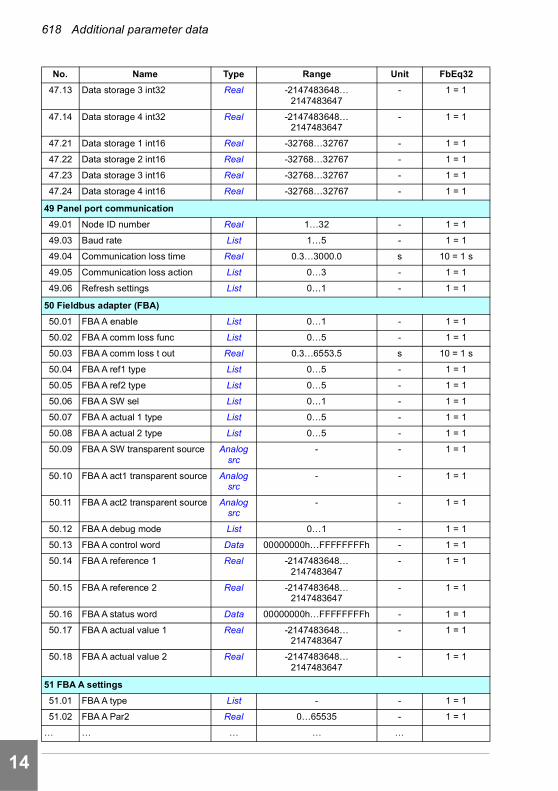
618 Additional parameter data
1
2
3
4
5
6
7
8
9
10
11
12
13
14
47.13 Data storage 3 int32 Real -2147483648… 2147483647
- 1 = 1
47.14 Data storage 4 int32 Real -2147483648… 2147483647
- 1 = 1
47.21 Data storage 1 int16 Real -32768…32767 - 1 = 1
47.22 Data storage 2 int16 Real -32768…32767 - 1 = 1
47.23 Data storage 3 int16 Real -32768…32767 - 1 = 1
47.24 Data storage 4 int16 Real -32768…32767 - 1 = 1
49 Panel port communication
49.01 Node ID number Real 1…32 - 1 = 1
49.03 Baud rate List 1…5 - 1 = 1
49.04 Communication loss time Real 0.3…3000.0 s 10 = 1 s
49.05 Communication loss action List 0…3 - 1 = 1
49.06 Refresh settings List 0…1 - 1 = 1
50 Fieldbus adapter (FBA)
50.01 FBA A enable List 0…1 - 1 = 1
50.02 FBA A comm loss func List 0…5 - 1 = 1
50.03 FBA A comm loss t out Real 0.3…6553.5 s 10 = 1 s
50.04 FBA A ref1 type List 0…5 - 1 = 1
50.05 FBA A ref2 type List 0…5 - 1 = 1
50.06 FBA A SW sel List 0…1 - 1 = 1
50.07 FBA A actual 1 type List 0…5 - 1 = 1
50.08 FBA A actual 2 type List 0…5 - 1 = 1
50.09 FBA A SW transparent source Analog src
- - 1 = 1
50.10 FBA A act1 transparent source Analog src
- - 1 = 1
50.11 FBA A act2 transparent source Analog src
- - 1 = 1
50.12 FBA A debug mode List 0…1 - 1 = 1
50.13 FBA A control word Data 00000000h…FFFFFFFFh - 1 = 1
50.14 FBA A reference 1 Real -2147483648… 2147483647
- 1 = 1
50.15 FBA A reference 2 Real -2147483648… 2147483647
- 1 = 1
50.16 FBA A status word Data 00000000h…FFFFFFFFh - 1 = 1
50.17 FBA A actual value 1 Real -2147483648… 2147483647
- 1 = 1
50.18 FBA A actual value 2 Real -2147483648… 2147483647
- 1 = 1
51 FBA A settings
51.01 FBA A type List - - 1 = 1
51.02 FBA A Par2 Real 0…65535 - 1 = 1
… … … … …
No. Name Type Range Unit FbEq32
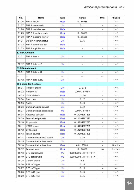
Additional parameter data 619
1
2
3
4
5
6
7
8
9
10
11
12
13
51.26 FBA A Par26 Real 0…65535 - 1 = 1
51.27 FBA A par refresh List 0…1 - 1 = 1
51.28 FBA A par table ver Data - - 1 = 1
51.29 FBA A drive type code Real 0…65535 - 1 = 1
51.30 FBA A mapping file ver Real 0…65535 - 1 = 1
51.31 D2FBA A comm status List 0…6 - 1 = 1
51.32 FBA A comm SW ver Data - - 1 = 1
51.33 FBA A appl SW ver Data - - 1 = 1
52 FBA A data in
52.01 FBA A data in1 List - - 1 = 1
… … … … …
52.12 FBA A data in12 List - - 1 = 1
53 FBA A data out
53.01 FBA A data out1 List - - 1 = 1
… … … … …
53.12 FBA A data out12 List - - 1 = 1
58 Embedded fieldbus
58.01 Protocol enable List 0…2, 5 - 1 = 1
58.02 Protocol ID Real 0000h…FFFFh - 1 = 1
58.03 Node address Real 0…255 - 1 = 1
58.04 Baud rate List 0…7 - 1 = 1
58.05 Parity List 0…3 - 1 = 1
58.06 Communication control List 0…2 - 1 = 1
58.07 Communication diagnostics PB 0000h…FFFFh - 1 = 1
58.08 Received packets Real 0…4294967295 - 1 = 1
58.09 Transmitted packets Real 0…4294967295 - 1 = 1
58.10 All packets Real 0…4294967295 - 1 = 1
58.11 UART errors Real 0…4294967295 - 1 = 1
58.12 CRC errors Real 0…4294967295 - 1 = 1
58.13 Token counter Real 0…4294967295 - 1 = 1
58.14 Communication loss action List 0…5 - 1 = 1
58.15 Communication loss mode List 1…2 - 1 = 1
58.16 Communication loss time Real 0.0…6000.0 s 10 = 1 s
58.17 Transmit delay Real 0…65535 ms 1 = 1 ms
58.18 EFB control word PB 00000000h…FFFFFFFFh - 1 = 1
58.19 EFB status word PB 00000000h…FFFFFFFFh - 1 = 1
58.25 Control profile List 0, 5 - 1 = 1
58.26 EFB ref1 type List 0…5 - 1 = 1
58.27 EFB ref2 type List 0…5 - 1 = 1
58.28 EFB act1 type List 0…5 - 1 = 1
58.29 EFB act2 type List 0…5 - 1 = 1
No. Name Type Range Unit FbEq32
14
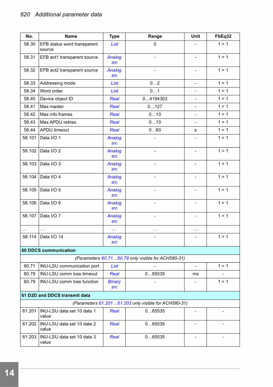
620 Additional parameter data
1
2
3
4
5
6
7
8
9
10
11
12
13
14
58.30 EFB status word transparent source
List 0 - 1 = 1
58.31 EFB act1 transparent source Analog src
- - 1 = 1
58.32 EFB act2 transparent source Analog src
- - 1 = 1
58.33 Addressing mode List 0…2 - 1 = 1
58.34 Word order List 0…1 - 1 = 1
58.40 Device object ID Real 0…4194303 - 1 = 1
58.41 Max master Real 0…127 - 1 = 1
58.42 Max info frames Real 0…10 - 1 = 1
58.43 Max APDU retries Real 0…10 - 1 = 1
58.44 APDU timeout Real 0…60 s 1 = 1
58.101 Data I/O 1 Analog src
- - 1 = 1
58.102 Data I/O 2 Analog src
- - 1 = 1
58.103 Data I/O 3 Analog src
- - 1 = 1
58.104 Data I/O 4 Analog src
- - 1 = 1
58.105 Data I/O 5 Analog src
- - 1 = 1
58.106 Data I/O 6 Analog src
- - 1 = 1
58.107 Data I/O 7 Analog src
- - 1 = 1
… … … … …
58.114 Data I/O 14 Analog src
- - 1 = 1
60 DDCS communication
(Parameters 60.71…60.79 only visible for ACH580-31)
60.71 INU-LSU communication port List - - 1 = 1
60.78 INU-LSU comm loss timeout Real 0…65535 ms -
60.79 INU-LSU comm loss function Binary src
- - 1 = 1
61 D2D and DDCS transmit data
(Parameters 61.201…61.203 only visible for ACH580-31)
61.201 INU-LSU data set 10 data 1 value
Real 0…65535 - -
61.202 INU-LSU data set 10 data 2 value
Real 0…65535 - -
61.203 INU-LSU data set 10 data 3 value
Real 0…65535 - -
No. Name Type Range Unit FbEq32
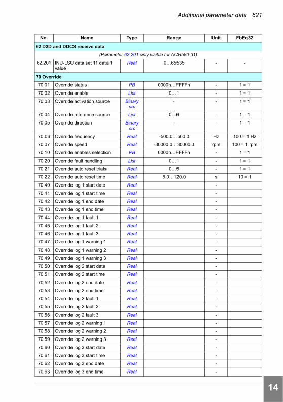
Additional parameter data 621
1
2
3
4
5
6
7
8
9
10
11
12
13
62 D2D and DDCS receive data
(Parameter 62.201 only visible for ACH580-31)
62.201 INU-LSU data set 11 data 1 value
Real 0…65535 - -
70 Override
70.01 Override status PB 0000h…FFFFh - 1 = 1
70.02 Override enable List 0…1 - 1 = 1
70.03 Override activation source Binary src
- - 1 = 1
70.04 Override reference source List 0…6 - 1 = 1
70.05 Override direction Binary src
- - 1 = 1
70.06 Override frequency Real -500.0…500.0 Hz 100 = 1 Hz
70.07 Override speed Real -30000.0…30000.0 rpm 100 = 1 rpm
70.10 Override enables selection PB 0000h…FFFFh - 1 = 1
70.20 Override fault handling List 0…1 - 1 = 1
70.21 Override auto reset trials Real 0…5 - 1 = 1
70.22 Override auto reset time Real 5.0…120.0 s 10 = 1
70.40 Override log 1 start date Real -
70.41 Override log 1 start time Real -
70.42 Override log 1 end date Real -
70.43 Override log 1 end time Real -
70.44 Override log 1 fault 1 Real -
70.45 Override log 1 fault 2 Real -
70.46 Override log 1 fault 3 Real -
70.47 Override log 1 warning 1 Real -
70.48 Override log 1 warning 2 Real -
70.49 Override log 1 warning 3 Real -
70.50 Override log 2 start date Real -
70.51 Override log 2 start time Real -
70.52 Override log 2 end date Real -
70.53 Override log 2 end time Real -
70.54 Override log 2 fault 1 Real -
70.55 Override log 2 fault 2 Real -
70.56 Override log 2 fault 3 Real -
70.57 Override log 2 warning 1 Real -
70.58 Override log 2 warning 2 Real -
70.59 Override log 2 warning 3 Real -
70.60 Override log 3 start date Real -
70.61 Override log 3 start time Real -
70.62 Override log 3 end date Real -
70.63 Override log 3 end time Real -
No. Name Type Range Unit FbEq32
14

622 Additional parameter data
1
2
3
4
5
6
7
8
9
10
11
12
13
14
70.64 Override log 3 fault 1 Real -
70.65 Override log 3 fault 2 Real -
70.66 Override log 3 fault 3 Real -
70.67 Override log 3 warning 1 Real -
70.68 Override log 3 warning 2 Real -
70.69 Override log 3 warning 3 Real -
71 External PID1
71.01 External PID act value Real -200000.00…200000.00 % 100 = 1%
71.02 Feedback act value Real -200000.00…200000.00 PID unit 1
100 = 1 PID unit 1
71.03 Setpoint act value Real -200000.00…200000.00 PID unit 1
100 = 1 PID unit 1
71.04 Deviation act value Real -200000.00…200000.00 PID unit 1
100 = 1 PID unit 1
71.06 PID status word PB 0000h…FFFFh - 1 = 1
71.07 PID operation mode List 0…2 - 1 = 1
71.08 Feedback 1 source Analog src
- - 1 = 1
71.11 Feedback filter time Real 0.000…30.000 s 1000 = 1 s
71.14 Setpoint scaling Real -200000.00…200000.00 - 100 = 1
71.15 Output scaling Real -200000.00…200000.00 - 100 = 1
71.16 Setpoint 1 source Analog src
- - 1 = 1
71.19 Internal setpoint sel1 Binary src
- - 1 = 1
71.20 Internal setpoint sel2 Binary src
- - 1 = 1
71.21 Internal setpoint 1 Real -200000.00…200000.00 PID unit 1
100 = 1 PID unit 1
71.22 Internal setpoint 2 Real -200000.00…200000.00 PID unit 1
100 = 1 PID unit 1
71.23 Internal setpoint 3 Real -200000.00…200000.00 PID unit 1
100 = 1 PID unit 1
71.26 Setpoint min Real -200000.00…200000.00 - 100 = 1
71.27 Setpoint max Real -200000.00…200000.00 - 100 = 1
71.31 Deviation inversion Binary src
- - 1 = 1
71.32 Gain Real 0.10…100.00 - 100 = 1
71.33 Integration time Real 0.0…9999.0 s 10 = 1 s
71.34 Derivation time Real 0.000…10.000 s 1000 = 1 s
71.35 Derivation filter time Real 0.0…10.0 s 10 = 1 s
71.36 Output min Real -200000.00…200000.00 - 10 = 1
71.37 Output max Real -200000.00…200000.00 - 10 = 1
71.38 Output freeze enable Binary src
- - 1 = 1
No. Name Type Range Unit FbEq32

Additional parameter data 623
1
2
3
4
5
6
7
8
9
10
11
12
13
71.39 Deadband range Real 0.0…200000.0 - 10 = 1
71.40 Deadband delay Real 0.0…3600.0 s 10 = 1 s
71.58 Increase prevention Binary src
- - 1 = 1
71.59 Decrease prevention Binary src
- - 1 = 1
71.62 Internal setpoint actual Real -200000.00…200000.00 PID unit 1
100 = 1 PID unit 1
71.79 External PID units List - 1 = 1
72 External PID2
72.01 External PID act value Real -200000.00…200000.00 % 100 = 1%
72.02 Feedback act value Real -200000.00…200000.00 PID Ext2 customer
unit
100 = 1 PID Ext2 customer
unit
72.03 Setpoint act value Real -200000.00…200000.00 PID Ext2 customer
unit
100 = 1 PID Ext2 customer
unit
72.04 Deviation act value Real -200000.00…200000.00 PID Ext2 customer
unit
100 = 1 PID Ext2 customer
unit
72.06 PID status word PB 0000h…FFFFh - 1 = 1
72.07 PID operation mode List 0…2 - 1 = 1
72.08 Feedback 1 source Analog src
- - 1 = 1
72.11 Feedback filter time Real 0.000…30.000 s 1000 = 1 s
72.14 Setpoint scaling Real -200000.00…200000.00 - 100 = 1
72.15 Output scaling Real -200000.00…200000.00 - 100 = 1
72.16 Setpoint 1 source Analog src
- - 1 = 1
72.19 Internal setpoint sel1 Binary src
- - 1 = 1
72.20 Internal setpoint sel2 Binary src
- - 1 = 1
72.21 Internal setpoint 1 Real -200000.00…200000.00 PID Ext2 customer
unit
100 = 1 PID Ext2 customer
unit
72.22 Internal setpoint 2 Real -200000.00…200000.00 PID Ext2 customer
unit
100 = 1 PID Ext2 customer
unit
72.23 Internal setpoint 3 Real -200000.00…200000.00 PID Ext2 customer
unit
100 = 1 PID Ext2 customer
unit
72.26 Setpoint min Real -200000.00…200000.00 - 100 = 1
72.27 Setpoint max Real -200000.00…200000.00 - 100 = 1
72.31 Deviation inversion Binary src
- - 1 = 1
72.32 Gain Real 0.10…100.00 - 100 = 1
72.33 Integration time Real 0.0…9999.0 s 10 = 1 s
No. Name Type Range Unit FbEq32
14
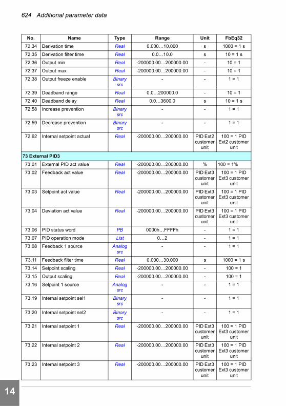
624 Additional parameter data
1
2
3
4
5
6
7
8
9
10
11
12
13
14
72.34 Derivation time Real 0.000…10.000 s 1000 = 1 s
72.35 Derivation filter time Real 0.0…10.0 s 10 = 1 s
72.36 Output min Real -200000.00…200000.00 - 10 = 1
72.37 Output max Real -200000.00…200000.00 - 10 = 1
72.38 Output freeze enable Binary src
- - 1 = 1
72.39 Deadband range Real 0.0…200000.0 - 10 = 1
72.40 Deadband delay Real 0.0…3600.0 s 10 = 1 s
72.58 Increase prevention Binary src
- - 1 = 1
72.59 Decrease prevention Binary src
- - 1 = 1
72.62 Internal setpoint actual Real -200000.00…200000.00 PID Ext2 customer
unit
100 = 1 PID Ext2 customer
unit
73 External PID3
73.01 External PID act value Real -200000.00…200000.00 % 100 = 1%
73.02 Feedback act value Real -200000.00…200000.00 PID Ext3 customer
unit
100 = 1 PID Ext3 customer
unit
73.03 Setpoint act value Real -200000.00…200000.00 PID Ext3 customer
unit
100 = 1 PID Ext3 customer
unit
73.04 Deviation act value Real -200000.00…200000.00 PID Ext3 customer
unit
100 = 1 PID Ext3 customer
unit
73.06 PID status word PB 0000h…FFFFh - 1 = 1
73.07 PID operation mode List 0…2 - 1 = 1
73.08 Feedback 1 source Analog src
- - 1 = 1
73.11 Feedback filter time Real 0.000…30.000 s 1000 = 1 s
73.14 Setpoint scaling Real -200000.00…200000.00 - 100 = 1
73.15 Output scaling Real -200000.00…200000.00 - 100 = 1
73.16 Setpoint 1 source Analog src
- - 1 = 1
73.19 Internal setpoint sel1 Binary src
- - 1 = 1
73.20 Internal setpoint sel2 Binary src
- - 1 = 1
73.21 Internal setpoint 1 Real -200000.00…200000.00 PID Ext3 customer
unit
100 = 1 PID Ext3 customer
unit
73.22 Internal setpoint 2 Real -200000.00…200000.00 PID Ext3 customer
unit
100 = 1 PID Ext3 customer
unit
73.23 Internal setpoint 3 Real -200000.00…200000.00 PID Ext3 customer
unit
100 = 1 PID Ext3 customer
unit
No. Name Type Range Unit FbEq32

Additional parameter data 625
1
2
3
4
5
6
7
8
9
10
11
12
13
73.26 Setpoint min Real -200000.00…200000.00 - 100 = 1
73.27 Setpoint max Real -200000.00…200000.00 - 100 = 1
73.31 Deviation inversion Binary src
- - 1 = 1
73.32 Gain Real 0.10…100.00 - 100 = 1
73.33 Integration time Real 0.0…9999.0 s 10 = 1 s
73.34 Derivation time Real 0.000…10.000 s 1000 = 1 s
73.35 Derivation filter time Real 0.0…10.0 s 10 = 1 s
73.36 Output min Real -200000.00…200000.00 - 10 = 1
73.37 Output max Real -200000.00…200000.00 - 10 = 1
73.38 Output freeze enable Binary src
- - 1 = 1
73.39 Deadband range Real 0.0…200000.0 - 10 = 1
73.40 Deadband delay Real 0.0…3600.0 s 10 = 1 s
73.58 Increase prevention Binary src
- - 1 = 1
73.59 Decrease prevention Binary src
- - 1 = 1
73.62 Internal setpoint actual Real -200000.00…200000.00 PID Ext3 customer
unit
100 = 1 PID Ext3 customer
unit
74 External PID4
74.01 External PID act value Real -200000.00…200000.00 % 100 = 1%
74.02 Feedback act value Real -200000.00…200000.00 PID Ext4 customer
unit
100 = 1 PID Ext4 customer
unit
74.03 Setpoint act value Real -200000.00…200000.00 PID Ext4 customer
unit
100 = 1 PID Ext4 customer
unit
74.04 Deviation act value Real -200000.00…200000.00 PID Ext4 customer
unit
100 = 1 PID Ext4 customer
unit
74.06 PID status word PB 0000h…FFFFh - 1 = 1
74.07 PID operation mode List 0…2 - 1 = 1
74.08 Feedback 1 source Analog src
- - 1 = 1
74.11 Feedback filter time Real 0.000…30.000 s 1000 = 1 s
74.14 Setpoint scaling Real -200000.00…200000.00 - 100 = 1
74.15 Output scaling Real -200000.00…200000.00 - 100 = 1
74.16 Setpoint 1 source Analog src
- - 1 = 1
74.19 Internal setpoint sel1 Binary src
- - 1 = 1
74.20 Internal setpoint sel2 Binary src
- - 1 = 1
No. Name Type Range Unit FbEq32
14

626 Additional parameter data
1
2
3
4
5
6
7
8
9
10
11
12
13
14
74.21 Internal setpoint 1 Real -200000.00…200000.00 PID Ext4 customer
unit
100 = 1 PID Ext4 customer
unit
74.22 Internal setpoint 2 Real -200000.00…200000.00 PID Ext4 customer
unit
100 = 1 PID Ext4 customer
unit
74.23 Internal setpoint 3 Real -200000.00…200000.00 PID Ext4 customer
unit
100 = 1 PID Ext4 customer
unit
74.26 Setpoint min Real -200000.00…200000.00 - 100 = 1
74.27 Setpoint max Real -200000.00…200000.00 - 100 = 1
74.31 Deviation inversion Binary src
- - 1 = 1
74.32 Gain Real 0.10…100.00 - 100 = 1
74.33 Integration time Real 0.0…9999.0 s 10 = 1 s
74.34 Derivation time Real 0.000…10.000 s 1000 = 1 s
74.35 Derivation filter time Real 0.0…10.0 s 10 = 1 s
74.36 Output min Real -200000.00…200000.00 - 10 = 1
74.37 Output max Real -200000.00…200000.00 - 10 = 1
74.38 Output freeze enable Binary src
- - 1 = 1
74.39 Deadband range Real 0.0…200000.0 - 10 = 1
74.40 Deadband delay Real 0.0…3600.0 s 10 = 1 s
74.58 Increase prevention Binary src
- - 1 = 1
74.59 Decrease prevention Binary src
- - 1 = 1
74.62 Internal setpoint actual Real -200000.00…200000.00 PID Ext4 customer
unit
100 = 1 PID Ext4 customer
unit
76 PFC configuration
76.01 PFC status PB 0000h…FFFFh - 1 = 1
76.02 PFC system status List 0…3, 100…103, 200…202, 300…302, 400, 500, 600,
700, 800…801, 4…9
- 1 = 1
76.11 Pump/fan status 1 PB 0000h…FFFFh - 1 = 1
76.12 Pump/fan status 2 PB 0000h…FFFFh - 1 = 1
76.13 Pump/fan status 3 PB 0000h…FFFFh - 1 = 1
76.14 Pump/fan status 4 PB 0000h…FFFFh - 1 = 1
76.21 PFC configuration List 0, 2…3 - 1 = 1
76.25 Number of motors Real 1…4 - 1 = 1
76.26 Min number of motors allowed Real 0…4 - 1 = 1
76.27 Max number of motors allowed Real 1…4 - 1 = 1
76.30 Start point 1 Real 0.00…32767.00 rpm/Hz 1 = 1 unit
76.31 Start point 2 Real 0.00…32767.00 rpm/Hz 1 = 1 unit
76.32 Start point 3 Real 0.00…32767.00 rpm/Hz 1 = 1 unit
No. Name Type Range Unit FbEq32

Additional parameter data 627
1
2
3
4
5
6
7
8
9
10
11
12
13
76.41 Stop point 1 Real 0.00…32767.00 rpm/Hz 1 = 1 unit
76.42 Stop point 2 Real 0.00…32767.00 rpm/Hz 1 = 1 unit
76.43 Stop point 3 Real 0.00…32767.00 rpm/Hz 1 = 1 unit
76.55 Start delay Real 0.00…12600.00 s 100 = 1 s
76.56 Stop delay Real 0.00…12600.00 s 100 = 1 s
76.57 Speed hold on Real 0.00…1000.00 s 100 = 1 s
76.58 Speed hold off Real 0.00…1000.00 s 100 = 1 s
76.59 PFC contactor delay Real 0.20…600.00 s 100 = 1 s
76.60 PFC ramp acceleration time Real 0.00…1800.00 s 100 = 1 s
76.61 PFC ramp deceleration time Real 0.00…1800.00 s 100 = 1 s
76.70 Autochange List 0…13 - 1 = 1
76.71 Autochange interval Real 0.00…42949672.95 h 100 = 1 h
76.72 Maximum wear imbalance Real 0.00…1000000.00 h 100 = 1 h
76.73 Autochange level Real 0.0…300.0 % 10 = 1%
76.74 Autochange auxiliary PFC List 0…1 - 1 = 1
76.81 PFC 1 interlock List 0…10 - 1 = 1
76.82 PFC 2 interlock List 0…10 - 1 = 1
76.83 PFC 3 interlock List 0…10 - 1 = 1
76.84 PFC 4 interlock List 0…10 - 1 = 1
76.95 Regulator bypass control Binary src
- - -
77 PFC maintenance and monitoring
77.10 PFC runtime change List 0…5 - 1 = 1
77.11 Pump/fan 1 running time Real 0.00…42949672.95 h 100 = 1 h
77.12 Pump/fan 2 running time Real 0.00…42949672.95 h 100 = 1 h
77.13 Pump/fan 3 running time Real 0.00…42949672.95 h 100 = 1 h
77.14 Pump/fan 4 running time Real 0.00…42949672.95 h 100 = 1 h
80 Flow calculation and protection
80.01 Actual flow Real -10000.00…10000.00 - 100 = 1
80.02 Actual flow percentage Real -100.00…100.00 % 100 = 1
80.11 Flow feedback 1 source List 0…3, 8…10, - 1 = 1
80.12 Flow feedback 2 source List 0…3, 8…10, - 1 = 1
80.13 Flow feedback function List 0…1, 8…9, - 1 = 1
80.14 Flow feedback multiplier Real -200000.00…200000.00 - 100 = 1
80.15 Maximum flow Real -200000.00…200000.00 - 100 = 1
94 LSU control
(Parameters 94.01…94.41 only visible for ACH580-31)
94.01 LSU control List 0…1 - 1 = 1
94.02 LSU panel communication List 0…1 - 1 = 1
94.10 LSU max charging time Real 0…65535 s 1 = 1 s
No. Name Type Range Unit FbEq32
14
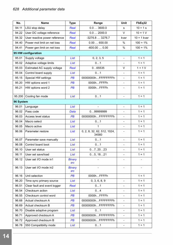
628 Additional parameter data
1
2
3
4
5
6
7
8
9
10
11
12
13
14
94.11 LSU stop delay Real 0.0 … 3600.0 s 10 = 1 s
94.22 User DC voltage reference Real 0.0 … 2000.0 V 10 = 1 V
94.32 User reactive power reference Real -3276.8 … 3276.7 kvar 10 = 1 kvar
94.40 Power mot limit on net loss Real 0.00 … 600.00 % 100 = 1%
94.41 Power gen limit on net loss Real -600.00 … 0.00 % 100 = 1%
95 HW configuration
95.01 Supply voltage List 0, 2, 3, 5 - 1 = 1
95.02 Adaptive voltage limits List 0…1 - 1 = 1
95.03 Estimated AC supply voltage Real 0…65535 V 1 = 1 V
95.04 Control board supply List 0…1 - 1 = 1
95.15 Special HW settings PB 00000000h…FFFFFFFFh - 1 = 1
95.20 HW options word 1 PB 0000h…FFFFh - 1 = 1
95.21 HW options word 2 PB 0000h…FFFFh - 1 = 1
95.200 Cooling fan mode List 0…1 - 1 = 1
96 System
96.01 Language List - - 1 = 1
96.02 Pass code Data 0…99999999 - 1 = 1
96.03 Access level status PB 00000000h…FFFFFFFFh - 1 = 1
96.04 Macro select List 0…1 - 1 = 1
96.05 Macro active List 1 - 1 = 1
96.06 Parameter restore List 0, 2, 8, 32, 62, 512, 1024, 34560
- 1 = 1
96.07 Parameter save manually List 0…1 - 1 = 1
96.08 Control board boot List 0…1 - 1 = 1
96.10 User set status List 0…7, 20…23 - 1 = 1
96.11 User set save/load List 0…5, 18…21 - 1 = 1
96.12 User set I/O mode in1 Binary src
- - -
96.13 User set I/O mode in2 Binary src
- - -
96.16 Unit selection PB 0000h…FFFFh 1 = 1
96.20 Time sync primary source List 0, 3, 6, 8, 9 - 1 = 1
96.51 Clear fault and event logger Real 0…1 - 1 = 1
96.54 Checksum action List 0…4 - 1 = 1
96.55 Checksum control word PB 0000h…FFFFh - 1 = 1
96.68 Actual checksum A PB 00000000h…FFFFFFFFh - 1 = 1
96.69 Actual checksum B PB 00000000h…FFFFFFFFh - 1 = 1
96.70 Disable adaptive program List 0…1 - 1 = 1
96.71 Approved checksum A PB 00000000h…FFFFFFFFh - 1 = 1
96.72 Approved checksum B PB 00000000h…FFFFFFFFh - 1 = 1
96.78 550 Compatibility mode List 0…1 - 1 = 1
No. Name Type Range Unit FbEq32

Additional parameter data 629
1
2
3
4
5
6
7
8
9
10
11
12
13
96.100 Change user pass code Data 10000000…99999999 - 1 = 1
96.101 Confirm user pass code Data 10000000…99999999 - 1 = 1
96.102 User lock functionality PB 0000h…FFFFh - 1 = 1
(Parameter 96.108 only visible only visible for ACH580-31)
96.108 LSU control board boot Real 0…1 - 1 = 1
97 Motor control
97.01 Switching frequency reference List 2, 4, 8, 12 kHz 1 = 1 kHz
97.02 Minimum switching frequency List 1.5, 2, 4, 8, 12 kHz 1 = 1 kHz
97.03 Slip gain Real 0…200 % 1 = 1%
97.04 Voltage reserve Real -4…50 % 1 = 1%
97.05 Flux braking List 0…2 - 1 = 1
97.08 Optimizer minimum torque Real 0.0 … 1600.0 % 10 = 1%
97.10 Signal injection List 0…4 - 1 = 1
97.11 TR tuning Real 25…400 % 1 = 1%
97.13 IR compensation Real 0.00…50.00 % 100 = 1%
97.15 Motor model temperature adaptation
List 0…1 - 1 = 1
97.16 Stator temperature factor Real 0…200 % 1 = 1%
97.17 Rotor temperature factor Real 0…200 % 1 = 1%
97.20 U/F ratio List 0…1 - 1 = 1
97.49 Slip gain for scalar Real 0 …200 % 1 = 1%
97.94 IR comp max frequency Real 1.0 …200.0 % 1 = 1%
98 User motor parameters
98.01 User motor model mode List 0…1 - 1 = 1
98.02 Rs user Real 0.0000…0.50000 p.u. 100000 = 1 p.u.
98.03 Rr user Real 0.0000…0.50000 p.u. 100000 = 1 p.u.
98.04 Lm user Real 0.00000…10.00000 p.u. 100000 = 1 p.u.
98.05 SigmaL user Real 0.00000…1.00000 p.u. 100000 = 1 p.u.
98.06 Ld user Real 0.00000…10.00000 p.u. 100000 = 1 p.u.
98.07 Lq user Real 0.00000…10.00000 p.u. 100000 = 1 p.u.
98.08 PM flux user Real 0.00000…2.00000 p.u. 100000 = 1 p.u.
98.09 Rs user SI Real 0.00000…100.00000 ohm 100000 = 1 p.u.
98.10 Rr user SI Real 0.00000…100.00000 ohm 100000 = 1 p.u.
98.11 Lm user SI Real 0.00…100000.00 mH 100 = 1 mH
98.12 SigmaL user SI Real 0.00…100000.00 mH 100 = 1 mH
No. Name Type Range Unit FbEq32
14

630 Additional parameter data
1
2
3
4
5
6
7
8
9
10
11
12
13
14
98.13 Ld user SI Real 0.00…100000.00 mH 100 = 1 mH
98.14 Lq user SI Real 0.00…100000.00 mH 100 = 1 mH
99 Motor data
99.03 Motor type List 0…2 - 1 = 1
99.04 Motor control mode List 0…1 - 1 = 1
99.06 Motor nominal current Real 0.0…6400.0 A 10 = 1 A
99.07 Motor nominal voltage Real 0.0…960.0 V 10 = 1 V
99.08 Motor nominal frequency Real 0.00 … 500.00 Hz 100 = 1 Hz
99.09 Motor nominal speed Real 0 … 30000 rpm 1 = 1 rpm
99.10 Motor nominal power Real 0.00…10000.00 kW or 0.00 … 13404.83 hp
kW or hp 100 = 1 unit
99.11 Motor nominal cos Φ Real 0.00 … 1.00 - 100 = 1
99.12 Motor nominal torque Real 0.000…4000000.000 N·m or0.000…2950248.597 lb·ft
N·m or lb·ft
1000 = 1 unit
99.13 ID run requested List 0…3, 6, 8 - 1 = 1
99.14 Last ID run performed List 0…3, 6, 8 - 1 = 1
99.15 Motor polepairs calculated Real 0…1000 - 1 = 1
99.16 Motor phase order List 0…1 - 1 = 1
No. Name Type Range Unit FbEq32
Further information
Product and service inquiries
Address any inquiries about the product to your local ABB representative, quoting the type designation and serial number of the unit in question. A listing of ABB sales, support and service contacts can be found by navigating to www.abb.com/searchchannels.
Product training
For information on ABB product training, navigate to new.abb.com/service/training.
Providing feedback on ABB Drives manuals
Your comments on our manuals are welcome. Navigate to new.abb.com/drives/manuals-feedback-form.
Document library on the Internet
You can find manuals and other product documents in PDF format on the Internet at www.abb.com/drives/documents.

abb.com/drives
© Copyright 2019 ABB. All rights reserved.Specifications subject to change without notice. 3A
XD
500
00
027
537
Rev
E (
EN
) 20
19-0
1-11