en 300 744 - v1.4.1 - digital video broadcasting (dvb ... · digital video broadcasting (dvb);...
TRANSCRIPT

ETSI EN 300 744 V1.4.1 (2001-01)European Standard (Telecommunications series)
Digital Video Broadcasting (DVB);Framing structure, channel coding and
modulation for digital terrestrial television
European Broadcasting Union Union Européenne de Radio-Télévision
EBU·UER
ETSI
ETSI EN 300 744 V1.4.1 (2001-01)2
ReferenceREN/JTC-DVB-111
KeywordsDVB, digital, video, broadcasting, terrestrial,
MPEG, TV, audio, data
ETSI
650 Route des LuciolesF-06921 Sophia Antipolis Cedex - FRANCE
Tel.: +33 4 92 94 42 00 Fax: +33 4 93 65 47 16
Siret N° 348 623 562 00017 - NAF 742 CAssociation à but non lucratif enregistrée à laSous-Préfecture de Grasse (06) N° 7803/88
Important notice
Individual copies of the present document can be downloaded from:http://www.etsi.org
The present document may be made available in more than one electronic version or in print. In any case of existing orperceived difference in contents between such versions, the reference version is the Portable Document Format (PDF).
In case of dispute, the reference shall be the printing on ETSI printers of the PDF version kept on a specific network drivewithin ETSI Secretariat.
Users of the present document should be aware that the document may be subject to revision or change of status.Information on the current status of this and other ETSI documents is available at http://www.etsi.org/tb/status/
If you find errors in the present document, send your comment to:[email protected]
Copyright Notification
No part may be reproduced except as authorized by written permission.The copyright and the foregoing restriction extend to reproduction in all media.
© European Telecommunications Standards Institute 2001.© European Broadcasting Union 2001.
All rights reserved.

ETSI
ETSI EN 300 744 V1.4.1 (2001-01)3
Contents
Intellectual Property Rights ..........................................................................................................................5
Foreword......................................................................................................................................................5
1 Scope..................................................................................................................................................6
2 References ..........................................................................................................................................6
3 Definitions, symbols and abbreviations ...............................................................................................63.1 Definitions .................................................................................................................................................. 63.2 Symbols ...................................................................................................................................................... 73.3 Abbreviations.............................................................................................................................................. 8
4 Baseline system ..................................................................................................................................94.1 General considerations ................................................................................................................................ 94.2 Interfacing................................................................................................................................................. 104.3 Channel coding and modulation................................................................................................................. 114.3.1 Transport multiplex adaptation and randomization for energy dispersal................................................. 114.3.2 Outer coding and outer interleaving...................................................................................................... 114.3.3 Inner coding......................................................................................................................................... 134.3.4 Inner interleaving................................................................................................................................. 144.3.4.1 Bit-wise interleaving....................................................................................................................... 144.3.4.2 Symbol interleaver.......................................................................................................................... 184.3.5 Signal constellations and mapping........................................................................................................ 204.4 OFDM frame structure .............................................................................................................................. 244.5 Reference signals ...................................................................................................................................... 264.5.1 Functions and derivation ...................................................................................................................... 264.5.2 Definition of reference sequence .......................................................................................................... 264.5.3 Location of scattered pilot cells ............................................................................................................ 274.5.4 Location of continual pilot carriers ....................................................................................................... 284.5.5 Amplitudes of all reference information................................................................................................ 284.6 Transmission Parameter Signalling (TPS) .................................................................................................. 294.6.1 Scope of the TPS.................................................................................................................................. 294.6.2 TPS transmission format ...................................................................................................................... 304.6.2.1 Initialization ................................................................................................................................... 304.6.2.2 Synchronization.............................................................................................................................. 304.6.2.3 TPS length indicator ....................................................................................................................... 304.6.2.4 Frame number ................................................................................................................................ 314.6.2.5 Constellation .................................................................................................................................. 314.6.2.6 Hierarchy information..................................................................................................................... 314.6.2.7 Code rates ...................................................................................................................................... 314.6.2.8 Guard Intervals............................................................................................................................... 324.6.2.9 Transmission mode......................................................................................................................... 324.6.2.10 Cell identifier ................................................................................................................................. 324.6.2.11 Error protection of TPS................................................................................................................... 334.6.3 TPS modulation ................................................................................................................................... 334.7 Number of RS-packets per OFDM super-frame.......................................................................................... 334.8 Spectrum characteristics and spectrum mask.............................................................................................. 344.8.1 Spectrum characteristics....................................................................................................................... 344.8.2 Out-of-band spectrum mask (for 8 MHz channels)................................................................................ 354.8.3 Centre frequency of RF signal (for 8 MHz UHF channels).................................................................... 38

ETSI
ETSI EN 300 744 V1.4.1 (2001-01)4
Annex A (informative): Simulated system performance for 8 MHz channels ................................39
Annex B (informative): Definition of P1 and F1 ...............................................................................41
Annex C (informative): Interleaving example .................................................................................43
Annex D (informative): Guidelines to implementation of the emitted signal..................................44
D.1 Use of the FFT..................................................................................................................................44
D.2 Choice of "baseband" centre frequency .............................................................................................45
D.3 Other potential difficulties ................................................................................................................45
Annex E (normative): Values for 6 MHz and 7 MHz channels.....................................................46
History .......................................................................................................................................................49
ETSI
ETSI EN 300 744 V1.4.1 (2001-01)5
Intellectual Property RightsIPRs essential or potentially essential to the present document may have been declared to ETSI. The informationpertaining to these essential IPRs, if any, is publicly available for ETSI members and non-members, and can be foundin ETSI SR 000 314: "Intellectual Property Rights (IPRs); Essential, or potentially Essential, IPRs notified to ETSI inrespect of ETSI standards", which is available from the ETSI Secretariat. Latest updates are available on the ETSI Webserver (http://www.etsi.org/ipr).
Pursuant to the ETSI IPR Policy, no investigation, including IPR searches, has been carried out by ETSI. No guaranteecan be given as to the existence of other IPRs not referenced in ETSI SR 000 314 (or the updates on the ETSI Webserver) which are, or may be, or may become, essential to the present document.
ForewordThis European Standard (Telecommunications series) has been produced by Joint Technical Committee (JTC) of theEuropean Broadcasting Union (EBU), Comité Européen de Normalisation Electrotechnique (CENELEC) and theEuropean Telecommunications Standards Institute (ETSI).
NOTE: The EBU/ETSI JTC Broadcast was established in 1990 to co-ordinate the drafting of standards in thespecific field of broadcasting and related fields. Since 1995 the JTC Broadcast became a tripartite bodyby including in the Memorandum of Understanding also CENELEC, which is responsible for thestandardization of radio and television receivers. The EBU is a professional association of broadcastingorganizations whose work includes the co-ordination of its members' activities in the technical, legal,programme-making and programme-exchange domains. The EBU has active members in about 60countries in the European broadcasting area; its headquarters is in Geneva.
European Broadcasting UnionCH-1218 GRAND SACONNEX (Geneva)SwitzerlandTel: +41 22 717 21 11Fax: +41 22 717 24 81
Founded in September 1993, the DVB Project is a market-led consortium of public and private sector organizations inthe television industry. Its aim is to establish the framework for the introduction of MPEG-2 based digital televisionservices. Now comprising over 200 organizations from more than 25 countries around the world, DVB fostersmarket-led systems, which meet the real needs, and economic circumstances, of the consumer electronics and thebroadcast industry.
National transposition dates
Date of adoption of this EN: 29 December 2000
Date of latest announcement of this EN (doa): 31 March 2001
Date of latest publication of new National Standardor endorsement of this EN (dop/e): 30 September 2001
Date of withdrawal of any conflicting National Standard (dow): 30 September 2001
ETSI
ETSI EN 300 744 V1.4.1 (2001-01)6
1 ScopeThe present document describes a baseline transmission system for digital terrestrial TeleVision (TV) broadcasting. Itspecifies the channel coding/modulation system intended for digital multi-programme LDTV/SDTV/EDTV/HDTVterrestrial services.
The scope is as follows:
- it gives a general description of the Baseline System for digital terrestrial TV;
- it identifies the global performance requirements and features of the Baseline System, in order to meet theservice quality targets;
- it specifies the digitally modulated signal in order to allow compatibility between pieces of equipment developedby different manufacturers. This is achieved by describing in detail the signal processing at the modulator side,while the processing at the receiver side is left open to different implementation solutions.However, it is necessary in this text to refer to certain aspects of reception.
2 ReferencesThe following documents contain provisions which, through reference in this text, constitute provisions of the presentdocument.
• References are either specific (identified by date of publication, edition number, version number, etc.) ornon-specific.
• For a specific reference, subsequent revisions do not apply.
• For a non-specific reference, the latest version applies.
• A non-specific reference to an ETS shall also be taken to refer to later versions published as an EN with the samenumber.
[1] ISO/IEC 13818: "Information technology - Generic coding of moving pictures and associatedaudio information - Parts 1 (Systems), 2 (Video) and 3 (Audio)".
[2] ETSI EN 300 421: "Digital Video Broadcasting (DVB); Framing structure, channel coding andmodulation for 11/12 GHz satellite services".
[3] ETSI EN 300 429: "Digital Video Broadcasting (DVB); Framing structure, channel coding andmodulation for cable systems".
[4] ETSI EN 300 468: "Digital Video Broadcasting (DVB); Specification for Service Information (SI)in DVB systems".
3 Definitions, symbols and abbreviations
3.1 DefinitionsFor the purposes of the present document, the following definition applies:
constraint length: number of delay elements +1 in the convolutional coder

ETSI
ETSI EN 300 744 V1.4.1 (2001-01)7
3.2 SymbolsFor the purposes of the present document, the following symbols apply:
A(e) output vector from inner bit interleaver eae,w bit number w of inner bit interleaver output stream e
α constellation ratio which determines the QAM constellation for the modulation for hierarchicaltransmission
B(e) input vector to inner bit interleaver ebe,w bit number w of inner bit interleaver input steam ebe,do output bit number do of demultiplexed bit stream number e of the inner interleaver demultiplexer
bi bit number i of the cell identifier
cm,l,k complex cell for frame m in OFDM symbol l at carrier k
C'k Complex modulation for a reference signal at carrier k
C'l,k Complex modulation for a TPS signal at carrier k in symbol lC/N Carrier-to-Noise ratio∆ time duration of the guard intervaldfree convolutional code free distance
fc centre frequency of the emitted signalG1, G2 convolutional code Generator polynomials
g(x) Reed-Solomon code generator polynomialh(x) BCH code generator polynomialH(q) inner symbol interleaver permutationHe(w) inner bit interleaver permutationi priority stream indexI Interleaving depth of the outer convolutional interleaverI0,I1,I2,I3,I4,I5 inner Interleaversj branch index of the outer interleaverk carrier number index in each OFDM symbolK number of active carriers in the OFDM symbolKmin, Kmax carrier number of the lower and largest active carrier respectively in the OFDM signall OFDM symbol number index in an OFDM framem OFDM frame number indexm' OFDM super-frame number indexM convolutional interleaver branch depth for j = 1, M = N/In transport stream sync byte numberN length of error protected packet in bytesNmax inner symbol interleaver block sizep scattered pilot insertion indexp(x) RS code field generator polynomialPk(f) Power spectral density for carrier k
P(n) interleaving Pattern of the inner symbol interleaverri code rate for priority level isi TPS bit index
t number of bytes which can be corrected by the Reed-Solomon decoderT elementary Time periodTS duration of an OFDM symbolTF Time duration of a frame
TU Time duration of the useful (orthogonal) part of a symbol, without the guard interval
u bit numbering indexv number of bits per modulation symbolwk value of reference PRBS sequence applicable to carrier k
xdi input bit number di to the inner interleaver demultiplexer
x'di high priority input bit number di to the inner interleaver demultiplexerx"di low priority input bit number di to the inner interleaver demultiplexer

ETSI
ETSI EN 300 744 V1.4.1 (2001-01)8
Y output vector from inner symbol interleaverY' intermediate vector of inner symbol interleaveryq bit number q of output from inner symbol interleaver
y'q bit number q of intermediate vector of inner symbol interleaverz complex modulation symbol* complex conjugate
3.3 AbbreviationsFor the purposes of the present document, the following abbreviations apply:
ACI Adjacent Channel InterferenceBCH Bose - Chaudhuri - Hocquenghem codeBER Bit Error RatioDBPSK Differential Binary Phase Shift KeyingDFT Discrete Fourier TransformDVB Digital Video BroadcastingDVB-T DVB-TerrestrialEDTV Enhanced Definition TeleVisionFFT Fast Fourier TransformFIFO First-In, First-Out shift registerHDTV High Definition TeleVisionHEX HEXadecimal notationHP High Priority bit streamIF Intermediate FrequencyIFFT Inverse Fast Fourier TransformLDTV Limited Definition TeleVisionLP Low Priority bit streamMPEG Moving Picture Experts GroupMSB Most Significant BitMUX MUltipleXNICAM Near-Instantaneous Companded Audio MultiplexOCT OCTal notationOFDM Orthogonal Frequency Division MultiplexingPAL Phase Alternating LinePRBS Pseudo-Random Binary SequenceQAM Quadrature Amplitude ModulationQEF Quasi Error FreeQPSK Quaternary Phase Shift KeyingRF Radio FrequencyRS Reed-SolomonSDTV Standard Definition TeleVisionSECAM Système Sequentiel Couleur A MémoireSFN Single Frequency NetworkTPS Transmission Parameter SignallingTV TeleVisionUHF Ultra-High FrequencyVHF Very-High Frequency

ETSI
ETSI EN 300 744 V1.4.1 (2001-01)9
4 Baseline system
4.1 General considerationsThe system is defined as the functional block of equipment performing the adaptation of the baseband TV signals fromthe output of the MPEG-2 transport multiplexer, to the terrestrial channel characteristics. The following processes shallbe applied to the data stream (see figure 1):
- transport multiplex adaptation and randomization for energy dispersal;
- outer coding (i.e. Reed-Solomon code);
- outer interleaving (i.e. convolutional interleaving);
- inner coding (i.e. punctured convolutional code);
- inner interleaving;
- mapping and modulation;
- Orthogonal Frequency Division Multiplexing (OFDM) transmission.
The system is directly compatible with MPEG-2 coded TV signals ISO/IEC 13818 [1].
Since the system is being designed for digital terrestrial television services to operate within the existing VHF and UHF(see note) spectrum allocation for analogue transmissions, it is required that the System provides sufficient protectionagainst high levels of Co-Channel Interference (CCI) and Adjacent-Channel Interference (ACI) emanating fromexisting PAL/SECAM/NTSC services. It is also a requirement that the System allows the maximum spectrumefficiency when used within the VHF and UHF bands; this requirement can be achieved by utilizing Single FrequencyNetwork (SFN) operation.
NOTE: The OFDM system in the present document is specified for 8 MHz, 7 MHz and 6 MHz channel spacing.The basic specification is the same for the three bandwidths except for the parameter elementary period T,which is unique for the respective bandwidths. From an implementation point of view the elementaryperiod T can normally be seen as the inverse of the nominal system clock rate. By adjusting the systemclock rate the bandwidth and bit rate are modified accordingly.
To achieve these requirements an OFDM system with concatenated error correcting coding is being specified.To maximize commonality with the Satellite baseline specification (see EN 300 421 [2]) and Cable baselinespecifications (see EN 300 429 [3]) the outer coding and outer interleaving are common, and the inner coding iscommon with the Satellite baseline specification. To allow optimal trade off between network topology and frequencyefficiency, a flexible guard interval is specified. This will enable the system to support different network configurations,such as large area SFN and single transmitter, while keeping maximum frequency efficiency.
Two modes of operation are defined: a "2K mode" and an "8K mode". The "2K mode" is suitable for single transmitteroperation and for small SFN networks with limited transmitter distances. The "8K mode" can be used both for singletransmitter operation and for small and large SFN networks.
The system allows different levels of QAM modulation and different inner code rates to be used to trade bit rate versusruggedness. The system also allows two level hierarchical channel coding and modulation, including uniform and multi-resolution constellation. In this case the functional block diagram of the system shall be expanded to include themodules shown dashed in figure 1. The splitter separates the incoming transport stream into two independent MPEGtransport streams, referred to as the high-priority and the low-priority stream. These two bitstreams are mapped onto thesignal constellation by the Mapper and Modulator which therefore has a corresponding number of inputs.
To guarantee that the signals emitted by such hierarchical systems may be received by a simple receiver the hierarchicalnature is restricted to hierarchical channel coding and modulation without the use of hierarchical source coding.

ETSI
ETSI EN 300 744 V1.4.1 (2001-01)10
A programme service can thus be "simulcast" as a low-bit-rate, rugged version and another version of higher bit rateand lesser ruggedness. Alternatively, entirely different programmes can be transmitted on the separate streams withdifferent ruggedness. In either case, the receiver requires only one set of the inverse elements: inner de-interleaver,inner decoder, outer de-interleaver, outer decoder and multiplex adaptation. The only additional requirement thus placedon the receiver is the ability for the demodulator/de-mapper to produce one stream selected from those mapped at thesending end.
The price for this receiver economy is that reception can not switch from one layer to another (e.g. to select the morerugged layer in the event of reception becoming degraded) while continuously decoding and presenting pictures andsound. A pause is necessary (e.g. video freeze frame for approximately 0,5 seconds, audio interruption forapproximately 0,2 seconds) while the inner decoder and the various source decoders are suitably reconfigured andreacquire lock.
Figure 1: Functional block diagram of the System
4.2 InterfacingThe Baseline System as defined in the present document is delimited by the following interfaces:
Table 1: Interfaces for the Baseline System
Location Interface Interface type ConnectionTransmit Station Input MPEG-2 transport stream(s) multiplex from MPEG-2 multiplexer
Output RF signal to aerialReceive Installation Input RF from aerial
Output MPEG-2 transport stream multiplex to MPEG-2 demultiplexer

ETSI
ETSI EN 300 744 V1.4.1 (2001-01)11
4.3 Channel coding and modulation
4.3.1 Transport multiplex adaptation and randomization for energydispersal
The System input stream shall be organized in fixed length packets (see figure 3), following the MPEG-2 transportmultiplexer. The total packet length of the MPEG-2 transport multiplex (MUX) packet is 188 bytes.This includes 1 sync-word byte (i.e. 47HEX). The processing order at the transmitting side shall always start from theMSB (i.e. "0") of the sync-word byte (i.e. 01 000 111). In order to ensure adequate binary transitions, the data of theinput MPEG-2 multiplex shall be randomized in accordance with the configurations depicted in figure 2.
Figure 2: Scrambler/descrambler schematic diagram
The polynomial for the Pseudo Random Binary Sequence (PRBS) generator shall be (see note):
1 + X14 + X15
NOTE: The polynomial description given here is in the form taken from the Satellite baseline specificationEN 300 421 [2]. Elsewhere, in both the Satellite baseline specification and in the present document, adifferent polynomial notation is used which conforms with the standard textbook of Peterson and Weldon(Error correcting codes, second edition, MIT Press, 1972).
Loading of the sequence "100101010000000" into the PRBS registers, as indicated in figure 2, shall be initiated at thestart of every eight transport packets. To provide an initialization signal for the descrambler, the MPEG-2 sync byte of
the first transport packet in a group of eight packets is bit-wise inverted from 47HEX (SYNC) to B8HEX ( SYNC ).This process is referred to as "transport multiplex adaptation" (see figure 3b).
The first bit at the output of the PRBS generator shall be applied to the first bit (i.e. MSB) of the first byte following theinverted MPEG-2 sync byte (i.e. B8HEX). To aid other synchronization functions, during the MPEG-2 sync bytes of thesubsequent 7 transport packets, the PRBS generation shall continue, but its output shall be disabled, leaving these bytesunrandomized. Thus, the period of the PRBS sequence shall be 1 503 bytes.
The randomization process shall be active also when the modulator input bit-stream is non-existent, or when it isnon-compliant with the MPEG-2 transport stream format (i.e. 1 sync byte + 187 packet bytes).
4.3.2 Outer coding and outer interleaving
The outer coding and interleaving shall be performed on the input packet structure (see figure 3a).
Reed-Solomon RS (204,188, t = 8) shortened code (see note 1), derived from the original systematic RS (255,239, t = 8)code, shall be applied to each randomized transport packet (188 byte) of figure 3b to generate an error protected packet(see figure 3c). Reed-Solomon coding shall also be applied to the packet sync byte, either non-inverted (i.e. 47HEX) orinverted (i.e. B8HEX).

ETSI
ETSI EN 300 744 V1.4.1 (2001-01)12
NOTE 1: The Reed-Solomon code has length 204 bytes, dimension 188 bytes and allows to correct up to 8 randomerroneous bytes in a received word of 204 bytes.
Code Generator Polynomial: g(x) = (x+λ0)(x+λ1)(x+λ2)...(x+λ15), where λ = 02HEX
Field Generator Polynomial: p(x) = x8 + x4 + x3 + x2 + 1
The shortened Reed-Solomon code may be implemented by adding 51 bytes, all set to zero, before the informationbytes at the input of an RS (255,239, t = 8) encoder. After the RS coding procedure these null bytes shall be discarded,leading to a RS code word of N = 204 bytes.
Following the conceptual scheme of figure 4, convolutional byte-wise interleaving with depth I = 12 shall be applied tothe error protected packets (see figure 3c). This results in the interleaved data structure (see figure 3d).
The convolutional interleaving process shall be based on the Forney approach which is compatible with the Ramseytype III approach, with I = 12. The interleaved data bytes shall be composed of error protected packets and shall bedelimited by inverted or non-inverted MPEG-2 sync bytes (preserving the periodicity of 204 bytes).
The interleaver may be composed of I = 12 branches, cyclically connected to the input byte-stream by the input switch.Each branch j shall be a First-In, First-Out (FIFO) shift register, with depth j × M cells where M = 17 = N/I, N = 204.The cells of the FIFO shall contain 1 byte, and the input and output switches shall be synchronized.
For synchronization purposes, the SYNC bytes and the SYNC bytes shall always be routed in the branch "0" of theinterleaver (corresponding to a null delay).
NOTE 2: The deinterleaver is similar in principle, to the interleaver, but the branch indices are reversed(i.e. j = 0 corresponds to the largest delay). The deinterleaver synchronization can be carried out by
routeing the first recognized sync (SYNC or SYNC ) byte in the "0" branch.
SYNCn: Non randomized sync byte, n = 2, 3, ..., 8
d) Data structure after outer interleaving; interleaving depth I = 12 bytes
Figure 3: Steps in the process of adaptation, energy dispersal, outer coding and interleaving

ETSI
ETSI EN 300 744 V1.4.1 (2001-01)13
SYNC1 is the non randomized complemented sync byte and SYNCn is the non randomized sync byte, n = 2, 3, ..., 8.
Figure 4: Conceptual diagram of the outer interleaver and deinterleaver
4.3.3 Inner coding
The system shall allow for a range of punctured convolutional codes, based on a mother convolutional code ofrate 1/2 with 64 states. This will allow selection of the most appropriate level of error correction for a given service ordata rate in either non-hierarchical or hierarchical transmission mode. The generator polynomials of the mother code areG1 = 171OCT for X output and G2 = 133OCT for Y output (see figure 5).
If two level hierarchical transmission is used, each of the two parallel channel encoders can have its own code rate.In addition to the mother code of rate 1/2 the system shall allow punctured rates of 2/3, 3/4, 5/6 and 7/8.
The punctured convolutional code shall be used as given in table 3. See also figure 5. In this table X and Y refer to thetwo outputs of the convolutional encoder.
Table 2: Puncturing pattern and transmitted sequence after parallel-to-serial conversion for thepossible code rates
Code Rates r Puncturing pattern Transmitted sequence(after parallel-to-serial conversion)
1/2 X: 1Y: 1
X 1Y1
2/3 X: 1 0Y: 1 1
X1 Y1 Y2
3/4 X: 1 0 1Y: 1 1 0
X1 Y1 Y2 X3
5/6 X: 1 0 1 0 1Y: 1 1 0 1 0
X1 Y1 Y2 X3 Y4 X5
7/8 X: 1 0 0 0 1 0 1Y: 1 1 1 1 0 1 0
X1 Y1 Y2 Y3 Y4 X5 Y6 X7
X1 is sent first. At the start of a super-frame the MSB of SYNC or SYNC shall lie at the point labelled "data input" infigure 5. The super-frame is defined in subclause 4.4.
The first convolutionally encoded bit of a symbol always corresponds to X1.

ETSI
ETSI EN 300 744 V1.4.1 (2001-01)14
Figure 5: The mother convolutional code of rate 1/2
Figure 6: Inner coding and interleaving
4.3.4 Inner interleaving
The inner interleaving consists of bit-wise interleaving followed by symbol interleaving. Both the bit-wise interleavingand the symbol interleaving processes are block-based.
4.3.4.1 Bit-wise interleaving
The input, which consists of up to two bit streams, is demultiplexed into v sub-streams, where v = 2 for QPSK, v = 4 for16-QAM, and v = 6 for 64-QAM. In non-hierarchical mode, the single input stream is demultiplexed into v sub-streams.In hierarchical mode the high priority stream is demultiplexed into two sub-streams and the low priority stream isdemultiplexed into v-2 sub-streams. This applies in both uniform and non-uniform QAM modes. See figures 7a and 7b.
The demultiplexing is defined as a mapping of the input bits, xdi onto the output bits be,do.
In non-hierarchical mode:
xdi = b[di(mod)v](div)(v/2)+2[di(mod)(v/2)],di(div)v

ETSI
ETSI EN 300 744 V1.4.1 (2001-01)15
In hierarchical mode:
x'di = bdi(mod)2,di(div)2
x"di = b[di(mod)(v-2)](div)((v-2)/2)+2[di(mod)((v-2)/2)]+2,di(div)(v-2)
Where: xdi is the input to the demultiplexer in non-hierarchical mode;
x'di is the high priority input to the demultiplexer;
x"di is the low priority input, in hierarchical mode;
di is the input bit number;
be,do is the output from the demultiplexer;
e is the demultiplexed bit stream number (0 ≤ e < v);
do is the bit number of a given stream at the output of the demultiplexer;
mod is the integer modulo operator;
div is the integer division operator.
The demultiplexing results in the following mapping:
QPSK: x0 maps to b0,0
x1 maps to b1,0
16-QAM non-hierarchical transmission: 16-QAM hierarchical transmission:
x0 maps to b0,0
x1 maps to b2,0
x2 maps to b1,0
x3 maps to b3,0
x'0 maps to b0,0
x'1 maps to b1,0
x"0 maps to b2,0
x"1 maps to b3,0
64-QAM non-hierarchical transmission: 64-QAM hierarchical transmission:
x0 maps to b0,0
x1 maps to b2,0
x2 maps to b4,0
x3 maps to b1,0
x4 maps to b3,0
x5 maps to b5,0
x'0 maps to b0,0
x'1 maps to b1,0
x"0 maps to b2,0
x"1 maps to b4,0
x"2 maps to b3,0
x"3 maps to b5,0

ETSI
ETSI EN 300 744 V1.4.1 (2001-01)16
Figure 7a: Mapping of input bits onto output modulation symbols, for non-hierarchicaltransmission modes

ETSI
ETSI EN 300 744 V1.4.1 (2001-01)17
Figure 7b: Mapping of input bits onto output modulation symbols, for hierarchicaltransmission modes
Each sub-stream from the demultiplexer is processed by a separate bit interleaver. There are therefore up to sixinterleavers depending on v, labelled I0 to I5. I0 and I1 are used for QPSK, I0 to I3 for 16-QAM and I0 to I5 for64-QAM.
Bit interleaving is performed only on the useful data. The block size is the same for each interleaver, but theinterleaving sequence is different in each case. The bit interleaving block size is 126 bits. The block interleavingprocess is therefore repeated exactly twelve times per OFDM symbol of useful data in the 2K mode and forty-eighttimes per symbol in the 8K mode.
For each bit interleaver, the input bit vector is defined by:
B(e) = (be,0, be,1, be,2, ..., be,125)
where e ranges from 0 to v-1.
The interleaved output vector A(e) = (ae,0, ae,1, ae,2, ..., ae,125) is defined by:
ae,w = be,He(w) w = 0, 1, 2, ..., 125
where He(w) is a permutation function which is different for each interleaver.

ETSI
ETSI EN 300 744 V1.4.1 (2001-01)18
He(w) is defined as follows for each interleaver:
I0: H0(w) = w
I1: H1(w) = (w + 63) mod 126
I2: H2(w) = (w + 105) mod 126
I3: H3(w) = (w + 42) mod 126
I4: H4(w) = (w + 21) mod 126
I5: H5(w) = (w + 84) mod 126
The outputs of the v bit interleavers are grouped to form the digital data symbols, such that each symbol of v bits willconsist of exactly one bit from each of the v interleavers. Hence, the output from the bit-wise interleaver is a v bit wordy' that has the output of I0 as its most significant bit, i.e.:
y'w = (a0,w, a1,w, ..., av-1,w)
4.3.4.2 Symbol interleaver
The purpose of the symbol interleaver is to map v bit words onto the 1 512 (2K mode) or 6 048 (8K mode) activecarriers per OFDM symbol. The symbol interleaver acts on blocks of 1 512 (2K mode) or 6 048 (8K mode) datasymbols.
Thus in the 2K mode, 12 groups of 126 data words from the bit interleaver are read sequentially into a vectorY' = (y'0, y'1, y'2, ...y'1511). Similarly in the 8K mode, a vector Y' = (y'0, y'1, y'2, ...y'6047) is assembled from 48 groups
of 126 data words.
The interleaved vector Y = (y0, y1, y2, ...yNmax-1) is defined by:
yH(q) = y'q for even symbols for q = 0, ..., Nmax-1
yq = y'H(q) for odd symbols for q = 0, ..., Nmax-1
where Nmax = 1 512 in the 2K mode and Nmax = 6 048 in the 8K mode.
The symbol index, defining the position of the current OFDM symbol in the OFDM frame, is defined in subclause 4.4.
H(q) is a permutation function defined by the following.
An (Nr - 1) bit binary word R'i is defined, with Nr = log2 Mmax, where Mmax = 2 048 in the 2K mode and Mmax = 8 192in the 8K mode, where R'i takes the following values:
i = 0,1: R'i [Nr-2, Nr-3, ..., 1, 0] = 0, 0, ..., 0, 0
i = 2: R'i [Nr-2, Nr-3, ..., 1, 0] = 0, 0, ..., 0, 1
2 < i < Mmax: { R'i [Nr-3, Nr-4, ..., 1, 0] = R'i-1 [Nr -2, Nr -3, ..., 2, 1];
in the 2K mode: R'i [9] = R'i-1 [0] ⊕ R'i-1 [3]
in the 8K mode: R'i [11] = R'i-1 [0] ⊕ R'i-1 [1] ⊕ R'i-1[4] ⊕ R'i-1 [6] }
A vector Ri is derived from the vector R'i by the bit permutations given in tables 3a and 3b.

ETSI
ETSI EN 300 744 V1.4.1 (2001-01)19
Table 3a: Bit permutations for the 2K mode
R'i bit positions 9 8 7 6 5 4 3 2 1 0
Ri bit positions 0 7 5 1 8 2 6 9 3 4
Table 3b: Bit permutations for the 8K mode
R'i bit positions 11 10 9 8 7 6 5 4 3 2 1 0
Ri bit positions 5 11 3 0 10 8 6 9 2 4 1 7
The permutation function H(q) is defined by the following algorithm:
q = 0;
for (i = 0; i < Mmax; i = i + 1)
{ j2N
0j
i1N 2(j)R2mod2)(iH(q)
r
r ⋅+⋅= ∑−
=
− ;
if (H(q)<Nmax) q = q+1; }
A schematic block diagram of the algorithm used to generate the permutation function is represented in figure 8a for the2K mode and in figure 8b for the 8K mode.
MSB
wires permutation
addresscheck
10
11
toggle
T
ControlUnit
skip
0123456789
H(q)
R'
R
Figure 8a: Symbol interleaver address generation scheme for the 2K mode

ETSI
ETSI EN 300 744 V1.4.1 (2001-01)20
MSB
wires permutation
addresscheck
12
13
toggle
T
ControlUnit
skip
01234567891011
H(q)
R'
R
Figure 8b: Symbol interleaver address generation scheme for the 8K mode
In a similar way to y', y is made up of v bits:
yq' = (y0,q', y1,q',..., yv-1,q')
where q' is the symbol number at the output of the symbol interleaver.
These values of y are used to map the data into the signal constellation, as described in subclause 4.3.5.
4.3.5 Signal constellations and mapping
The system uses Orthogonal Frequency Division Multiplex (OFDM) transmission. All data carriers in one OFDMframe are modulated using either QPSK, 16-QAM, 64-QAM, non-uniform 16-QAM or non-uniform 64-QAMconstellations. The constellations, and the details of the Gray mapping applied to them, are illustrated in figure 9.
The exact proportions of the constellations depend on a parameter α, which can take the three values 1, 2 or 4, therebygiving rise to the three diagrams figures 9a to 9c. α is the minimum distance separating two constellation pointscarrying different HP-bit values divided by the minimum distance separating any two constellation points.Non-hierarchical transmission uses the same uniform constellation as the case with α = 1, i.e. figure 9a.
The exact values of the constellation points are z ∈ {n + j m} with values of n, m given below for the variousconstellations:
QPSK
n ∈ {-1, 1}, m ∈ {-1, 1}
16-QAM (non-hierarchical and hierarchical with αααα = 1)
n ∈ {-3, -1, 1, 3}, m ∈ {-3, -1, 1, 3}
Non-uniform 16-QAM with αααα = 2
n ∈ {-4, -2, 2, 4}, m ∈ {-4, -2, 2, 4}
Non-uniform 16-QAM with αααα = 4
n ∈ {-6, -4, 4, 6}, m ∈ {-6, -4, 4, 6}
64-QAM (non-hierarchical and hierarchical with αααα = 1)
n ∈ {-7, -5, -3, -1, 1, 3, 5, 7}, m ∈ {-7, -5, -3, -1, 1, 3, 5, 7}
Non-uniform 64-QAM with αααα = 2
n ∈ {-8, -6, -4, -2, 2, 4, 6, 8}, m ∈ {-8, -6, -4, -2, 2, 4, 6, 8}

ETSI
ETSI EN 300 744 V1.4.1 (2001-01)21
Non-uniform 64-QAM with αααα = 4
n ∈ {-10, -8, -6, -4, 4, 6, 8, 10}, m ∈ {-10, -8, -6, -4, 4, 6, 8, 10}
Figure 9a: The QPSK, 16-QAM and 64-QAM mappings and the corresponding bit patterns(non-hierarchical, and hierarchical with αααα = 1)

ETSI
ETSI EN 300 744 V1.4.1 (2001-01)22
The yu,q' denote the bits representing a complex modulation symbol z.
Figure 9b: Non-uniform 16-QAM and 64-QAM mappings with αααα = 2

ETSI
ETSI EN 300 744 V1.4.1 (2001-01)23
The yu,q' denote the bits representing a complex modulation symbol z.
Figure 9c: Non-uniform 16-QAM and 64-QAM mappings with αααα = 4

ETSI
ETSI EN 300 744 V1.4.1 (2001-01)24
The yu,q' denote the bits representing a complex modulation symbol z.
Non-hierarchical transmission:
The data stream at the output of the inner interleaver consists of v bit words. These are mapped onto acomplex number z, according to figure 9a.
Hierarchical transmission:
In the case of hierarchical transmission, the data streams are formatted as shown in figure 7b, and then the mappings asshown in figures 9a, 9b, or 9c are applied, as appropriate.
For hierarchical 16-QAM:
The high priority bits are the y0,q' and y1,q' bits of the inner interleaver output words. The low priority bits are the y2,q'and y3,q' bits of the inner interleaver output words. The mappings of figures 9a, 9b or 9c are applied, as appropriate.For example, the top left constellation point, corresponding to 1 000 represents y0,q' = 1, y1,q' = y2,q' = y3,q' = 0.
If this constellation is decoded as if it were QPSK, the high priority bits, y0,q', y1,q' will be deduced. To decode the low
priority bits, the full constellation shall be examined and the appropriate bits (y2,q', y3,q') extracted fromy0,q', y1,q', y2,q', y3,q'.
For hierarchical 64-QAM:
The high priority bits are the y0,q' and y1,q' bits of the inner interleaver output words. The low priority bits are they2,q', y3,q', y4,q' and y5,q' bits of the inner interleaver output words. The mappings of figures 9a, 9b or 9c are applied, as
appropriate. If this constellation is decoded as if it were QPSK, the high priority bits, y0,q', y1,q' will be deduced.
To decode the low priority bits, the full constellation shall be examined and the appropriate bits (y2,q', y3,q', y4,q', y5,q',)extracted from y0,q', y1,q', y2,q', y3,q', y4,q', y5,q'.
4.4 OFDM frame structureThe transmitted signal is organized in frames. Each frame has a duration of TF, and consists of 68 OFDM symbols.
Four frames constitute one super-frame. Each symbol is constituted by a set of K = 6 817 carriers in the 8K mode andK = 1 705 carriers in the 2K mode and transmitted with a duration TS. It is composed of two parts: a useful part with
duration TU and a guard interval with a duration ∆. The guard interval consists in a cyclic continuation of the useful
part, TU, and is inserted before it. Four values of guard intervals may be used according to table 5.
The symbols in an OFDM frame are numbered from 0 to 67. All symbols contain data and reference information.
Since the OFDM signal comprises many separately-modulated carriers, each symbol can in turn be considered to bedivided into cells, each corresponding to the modulation carried on one carrier during one symbol.
In addition to the transmitted data an OFDM frame contains:
- Scattered pilot cells;
- Continual pilot carriers;
- TPS carriers.
The pilots can be used for frame synchronization, frequency synchronization, time synchronization, channel estimation,transmission mode identification and can also be used to follow the phase noise.
The carriers are indexed by k ∈ [Kmin; Kmax] and determined by Kmin = 0 and Kmax = 1 704 in 2K mode and 6 816 in8K mode respectively. The spacing between adjacent carriers is 1/TU while the spacing between carriers Kmin and Kmaxare determined by (K-1)/TU. The numerical values for the OFDM parameters for the 8K and 2K modes are given intables 4 and 5 for 8 MHz channels and in tables E.1 to E.4 for 6 MHz and 7 MHz channels. The values for the varioustime-related parameters are given in multiples of the elementary period T and in microseconds. The elementary periodT is 7/64 µs for 8 MHz channels, 1/8 µs for 7 MHz channels and 7/48 µs for 6 MHz channels.

ETSI
ETSI EN 300 744 V1.4.1 (2001-01)25
Table 4: Numerical values for the OFDM parameters for the 8K and 2K modes for 8 MHz channels
Parameter 8K mode 2K modeNumber of carriers K 6 817 1 705
Value of carrier number Kmin 0 0
Value of carrier number Kmax 6 816 1 704
Duration TU (note 2) 896 µs 224 µs
Carrier spacing 1/TU (note 1) (note 2) 1 116 Hz 4 464 Hz
Spacing between carriers Kmin and Kmax (K-1)/TU (note 2) 7,61 MHz 7,61 MHz
NOTE 1: Values in italics are approximate values.NOTE 2: Values for 8 MHz channels. Values for 6 MHz and 7 MHz channels are given in annex E, tables E.1
and E.2.
The emitted signal is described by the following expression:
×= ∑∑∑
∞
= = =0
67
0
,,,,2
max
min
)(Re)(m l
K
Kk
klmklmtfj tcets c ψπ
where
=××−×−∆−
0)(
)68(2
,,
k'ssUT
TmTltj
klmet
πψ ( )
else
TmltTml SS ×+×+≤≤××+ 168)68(
where:
k denotes the carrier number;
l denotes the OFDM symbol number;
m denotes the transmission frame number;
K is the number of transmitted carriers;
TS is the symbol duration;
TU is the inverse of the carrier spacing;
∆ is the duration of the guard interval;
fc is the central frequency of the RF signal;
k' is the carrier index relative to the centre frequency, k' = k - (Kmax + Kmin) / 2;
cm,0,k complex symbol for carrier k of the Data symbol no. 1 in frame number m;
cm,1,k complex symbol for carrier k of the Data symbol no. 2 in frame number m;
...
cm,67,k complex symbol for carrier k of the Data symbol no. 68 in frame number m.

ETSI
ETSI EN 300 744 V1.4.1 (2001-01)26
Table 5: Duration of symbol part for the allowed guard intervals for 8 MHz channels
Mode 8K mode 2K modeGuard interval∆€/ TU
1/4 1/8 1/16 1/32 1/4 1/8 1/16 1/32
Duration of symbolpart TU
8 192 × T896 µs (note)
2 048 × T224 µs (note)
Duration of guardinterval ∆
2 048 × T224 µs
1 024 × T112 µs
512 × T56 µs
256 × T28 µs
512 × T56 µs
256 × T28 µs
128 × T14 µs
64 × T7 µs
Symbol durationTS = ∆ + TU
10 240 × T1 120 µs
9 216 × T1 008 µs
8 704 × T952 µs
8 448 × T924 µs
2 560 × T280 µs
2 304 × T252 µs
2 176 × T238 µs
2 112 × T231 µs
NOTE: Values for 8 MHz channels. Values for 6 MHz and 7 MHz channels are given in annex E, tables E.3 and E.4.
The cm,l,k values are normalized modulation values of the constellation point z (see figure 9) according to the
modulation alphabet used for the data. The normalization factors yield E[c × c*] = 1 and are shown in table 6.
Table 6: Normalization factors for data symbols
Modulation scheme Normalization factorQPSK c = z/√2
16-QAM α = 1 c = z/√10α = 2 c = z/√20α = 4 c = z/√52
64-QAM α = 1 c = z/√42α = 2 c = z/√60α = 4 c = z/√108
4.5 Reference signals
4.5.1 Functions and derivation
Various cells within the OFDM frame are modulated with reference information whose transmitted value is known tothe receiver. Cells containing reference information are transmitted at "boosted" power level (see subclause 4.5.5).The information transmitted in these cells are scattered or continual pilot cells.
Each continual pilot coincides with a scattered pilot every fourth symbol; the number of useful data carriers is constantfrom symbol to symbol: 1 512 useful carriers in 2K mode and 6 048 useful carriers in 8K mode.
The value of the scattered or continual pilot information is derived from a PRBS (Pseudo Random Binary Sequence)which is a series of values, one for each of the transmitted carriers (see subclause 4.5.2).
4.5.2 Definition of reference sequence
The continual and scattered pilots are modulated according to a PRBS sequence, wk, corresponding to their respective
carrier index k. This sequence also governs the starting phase of the TPS information (described in subclause 4.6).
The PRBS sequence is generated according to figure 10.
The PRBS is initialized so that the first output bit from the PRBS coincides with the first active carrier. A new value isgenerated by the PRBS on every used carrier (whether or not it is a pilot).

ETSI
ETSI EN 300 744 V1.4.1 (2001-01)27
Initializationsequence
1-bitdelay
1-bitdelay
1-bitdelay
11111111111
PRBS sequence starts: 1111111111100...
1-bitdelay
1-bitdelay
1-bitdelay
1-bitdelay
1-bitdelay
1-bitdelay
1-bitdelay
1-bitdelay
Figure 10: Generation of PRBS sequence
The polynomial for the Pseudo Random Binary Sequence (PRBS) generator shall be:
X11 + X2 + 1 (see figure 10)
4.5.3 Location of scattered pilot cells
Reference information, taken from the reference sequence, is transmitted in scattered pilot cells in every symbol.Scattered pilot cells are always transmitted at the "boosted" power level (see subclause 4.5.5). Thus the correspondingmodulation is given by:
Re{cm,l,k} = 4 / 3 × 2 (1/2 - wk)
Im{cm,l,k,} = 0
Where m is the frame index, k is the frequency index of the carriers and l is the time index of the symbols.
For the symbol of index l ( ranging from 0 to 67), carriers for which index k belongs to the subset{k = Kmin + 3 × (l mod 4) + 12p p integer, p ≥ 0, k ∈ [Kmin; Kmax] } are scattered pilots.
Where p is an integer that takes all possible values greater than or equal to zero, provided that the resultingvalue for k does not exceed the valid range [Kmin; Kmax].
The pilot insertion pattern is shown in figure 11.
symbol 3
symbol 1
TPS pilots and continual pilots between K min and Kmax are not indicated
boosted pilotdata
Kmax = 1 704 if 2K
symbol 2
symbol 0symbol 67.....
.....
.....
.....
..........
.....
.....
.....
.....
.....
.....
.....
.....
.....
.....
..........
.....
.....
.....
.....
Kmax = 6 816 if 8KKmin = 0
Figure 11: Frame structure

ETSI
ETSI EN 300 744 V1.4.1 (2001-01)28
4.5.4 Location of continual pilot carriers
In addition to the scattered pilots described above, 177 continual (see note) pilots in the 8K mode and 45 in the 2Kmode, are inserted according to table 7.
NOTE: Where "continual" means that they occur on all symbols.
Table 7: Carrier indices for continual pilot carriers
Continual pilot carrier positions (index number k)2K mode 8K mode
0 48 54 87 141 156 192 201 255 279 282 333 432 450483 525 531 618 636 714 759 765 780 804 873 888 918939 942 969 984 1050 1101 1107 1110 1137 1140 11461206 1269 1323 1377 1491 1683 1704
0 48 54 87 141 156 192 201 255 279 282 333 432 450483 525 531 618 636 714 759 765 780 804 873 888918 939 942 969 984 1050 1101 1107 1110 1137 11401146 1206 1269 1323 1377 1491 1683 1704 1752 17581791 1845 1860 1896 1905 1959 1983 1986 2037 21362154 2187 2229 2235 2322 2340 2418 2463 2469 24842508 2577 2592 2622 2643 2646 2673 2688 2754 28052811 2814 2841 2844 2850 2910 2973 3027 3081 31953387 3408 3456 3462 3495 3549 3564 3600 3609 36633687 3690 3741 3840 3858 3891 3933 3939 4026 40444122 4167 4173 4188 4212 4281 4296 4326 4347 43504377 4392 4458 4509 4515 4518 4545 4548 4554 46144677 4731 4785 4899 5091 5112 5160 5166 5199 52535268 5304 5313 5367 5391 5394 5445 5544 5562 55955637 5643 5730 5748 5826 5871 5877 5892 5916 59856000 6030 6051 6054 6081 6096 6162 6213 6219 62226249 6252 6258 6318 6381 6435 6489 6603 6795 6816
All continual pilots are modulated according to the reference sequence, see subclause 4.5.2.
The continual pilots are transmitted at "boosted" power level.
Thus the corresponding modulation is given by:
Re{cm,l,k} = 4 / 3 × 2 (1/2 - wk)
Im{cm,l,k} = 0
4.5.5 Amplitudes of all reference information
As explained in subclause 4.4 the modulation of all data cells is normalized so that E[c × c∗] = 1.
All cells which are continual or scattered pilots, i.e. they are members of the sets defined in subclauses 4.5.3 or 4.5.4,are transmitted at boosted power so that for these E[c × c∗] = 16/9.

ETSI
ETSI EN 300 744 V1.4.1 (2001-01)29
4.6 Transmission Parameter Signalling (TPS)The TPS carriers are used for the purpose of signalling parameters related to the transmission scheme, i.e. to channelcoding and modulation. The TPS is transmitted in parallel on 17 TPS carriers for the 2K mode and on 68 carriers for the8K mode. Every TPS carrier in the same symbol conveys the same differentially encoded information bit. Thefollowing carrier indices contain TPS carriers:
Table 8: Carrier indices for TPS carriers
2K mode 8K mode34 50 209 346 413 569 595 688 790 9011073 1219 1262 1286 1469 1594 1687
34 50 209 346 413 569 595 688 790 901 1073 1219 1262 1286 14691594 1687 1738 1754 1913 2050 2117 2273 2299 2392 2494 26052777 2923 2966 2990 3173 3298 3391 3442 3458 3617 3754 38213977 4003 4096 4198 4309 4481 4627 4670 4694 4877 5002 50955146 5162 5321 5458 5525 5681 5707 5800 5902 6013 6185 63316374 6398 6581 6706 6799
The TPS carriers convey information on:
a) modulation including the α value of the QAM constellation pattern (see note);
b) hierarchy information;
c) guard interval (not for initial acquisition but for supporting initial response of the receiver in case ofreconfiguration);
d) inner code rates;
e) transmission mode (2K or 8K, not for the initial acquisition but for supporting initial response of the receiver incase of reconfiguration);
f) frame number in a super-frame;
g) cell identification.
NOTE: The α value defines the modulation based on the cloud spacing of a generalized QAM constellation.It allows specification of uniform and non-uniform modulation schemes, covering QPSK, 16-QAM, and64-QAM.
4.6.1 Scope of the TPS
The TPS is defined over 68 consecutive OFDM symbols, referred to as one OFDM frame. Four consecutive framescorrespond to one OFDM super-frame.
The reference sequence corresponding to the TPS carriers of the first symbol of each OFDM frame are used to initializethe TPS modulation on each TPS carrier (see subclause 4.6.3).
Each OFDM symbol conveys one TPS bit. Each TPS block (corresponding to one OFDM frame) contains 68 bits,defined as follows:
- 1 initialization bit;
- 16 synchronization bits;
- 37 information bits;
- 14 redundancy bits for error protection.
Of the 37 information bits, 31 are used at present. The remaining 6 bits are reserved for future use, and should be set tozero.

ETSI
ETSI EN 300 744 V1.4.1 (2001-01)30
4.6.2 TPS transmission format
The transmission parameter information shall be transmitted as shown in table 9.
The mapping of each of the transmission parameters: constellation characteristics, α value, code rate(s), super-frameindicator and guard interval onto the bit combinations is performed according to subclauses 4.6.2.1 to 4.6.2.8.The left most bit is sent first.
Table 9: TPS signalling information and format
Bit number Format Purpose/Contents0 see subclause 4.6.2.1 Initialization
s1- s16 0011010111101110 or1100101000010001
Synchronization word
s17 - s22 010 111 Length indicator
s23, s24 see table 10 Frame number
s25, s26 see table 11 Constellation
s27, s28, s29 see table 12 Hierarchy information
s30, s31, s32 see table 13 Code rate, HP stream
s33, s34, s35 see table 13 Code rate, LP stream
s36, s37 see table 14 Guard interval
s38, s39 see table 15 Transmission mode
s40 - s47 see subclause 4.6.2.10 Cell identifier
s40 - s53 all set to "0" Reserved for future use
s54 - s67 BCH code Error protection
The TPS information transmitted in super-frame m' bits s25 - s39 always apply to super-frame m' + 1, whereas all other
bits refer to super-frame m'.
4.6.2.1 Initialization
The first bit, s0, is an initialization bit for the differential 2-PSK modulation. The modulation of the TPS initialization
bit is derived from the PRBS sequence defined in subclause 4.5.2. This process is described in subclause 4.6.3.
4.6.2.2 Synchronization
Bits 1 to 16 of the TPS is a synchronization word.
The first and third TPS block in each super-frame have the following synchronization word:
s1 - s16 = 0011010111101110.
The second and fourth TPS block have the following synchronization word:
s1 - s16 = 1100101000010001.
4.6.2.3 TPS length indicator
The first 6 bits of the TPS information is used as a TPS length indicator (binary count) to signal the number of used bitsof the TPS. At present this length indicator has the value s17 - s22 = 010111 if the cell identification (see subclause
4.6.2.10) is not supported and the value s17 - s22 = 011111 if the cell identification is supported.

ETSI
ETSI EN 300 744 V1.4.1 (2001-01)31
4.6.2.4 Frame number
Four frames constitute one super-frame. The frames inside the super-frame are numbered from 0 to 3 according totable 10.
Table 10: Signalling format for frame number
Bits s23,s24 Frame number
00 Frame number 1 in the super-frame01 Frame number 2 in the super-frame10 Frame number 3 in the super-frame11 Frame number 4 in the super-frame
4.6.2.5 Constellation
The constellation shall be signalled by 2 bits according to table 11. In order to determine the modulation scheme, thereceiver shall also decode the hierarchy information given in table 12.
Table 11: Signalling format for the possible constellation patterns
Bits s25, s26 Constellation characteristics
00 QPSK01 16-QAM10 64-QAM11 reserved
4.6.2.6 Hierarchy information
The hierarchy information specifies whether the transmission is hierarchical and, if so, what the α value is. The QAMconstellation diagrams which correspond to various α values are shown in figures 9a/b/c. Where α is signalled by threebits according to table 12.
Table 12: Signalling format for the αααα values
Bits s27, s28, s29 αααα value
000 Non hierarchical001 α = 1010 α = 2011 α = 4100 reserved101 reserved110 reserved111 reserved
4.6.2.7 Code rates
Non-hierarchical channel coding and modulation requires signalling of one code rate r. In this case, three bits specifyingthe code rate according to table 13 are followed by another three bits of value 000.Two different code rates may be applied to two different levels of the modulation with the aim of achieving hierarchy.Transmission then starts with the code rate for the HP level (r1) of the modulation and ends with the one for the LP level(r2). Each code rate shall be signalled according to table 13.

ETSI
ETSI EN 300 744 V1.4.1 (2001-01)32
Table 13: Signalling format for each of the code rates
Bitss30, s31, s32 (HP stream)
s33, s34, s35 (LP stream)
Code rate
000 1/2001 2/3010 3/4011 5/6100 7/8101 reserved110 reserved111 reserved
4.6.2.8 Guard Intervals
The value of the guard interval is signalled according to table 14:
Table 14: Signalling format for each of the guard interval values
Bits s36, s37 Guard interval values (∆∆∆∆/TU)
00 1/3201 1/1610 1/811 1/4
4.6.2.9 Transmission mode
Two bits are used to signal the transmission mode (2K mode or 8K mode).
Table 15: Signalling format for transmission mode
Bits s38, s39 Transmission mode
00 2K mode01 8K mode10 reserved11 reserved
4.6.2.10 Cell identifier
The eight bits s40 to s47 are used to identify the cell from which the signal comes from. The most significant byte of the
cell_id [4], i.e. b15 - b8, shall be transmitted in super-frames with the frame number 1 and 3. The least significant byteof the cell_id, i.e. b7 - b0, shall be transmitted in super-frames with the frame number 2 and 4. The mapping of bits is
according to Table 18. If the provision of the cell_id is not foreseen the eight bits shall be set to zero.

ETSI
ETSI EN 300 744 V1.4.1 (2001-01)33
Table 15a: Mapping of the cell_id on the TPS bits
TPS bit number Frame number 1 or 3 Frame number 2 or 4s40 cell_id b15 cell_id b7s41 cell_id b14 cell_id b6s42 cell_id b13 cell_id b5s43 cell_id b12 cell_id b4s44 cell_id b11 cell_id b3s45 cell_id b10 cell_id b2s46 cell_id b9 cell_id b1s47 cell_id b8 cell_id b0
4.6.2.11 Error protection of TPS
The 53 bits containing the TPS synchronization and information (bits s1 - s53) are extended with 14 parity bits of the
BCH (67,53, t = 2) shortened code, derived from the original systematic BCH (127,113, t = 2) code.
Code generator polynomial:
h(x) = x14 + x9 + x8 + x6 + x5 + x4 + x2 + x + 1.
The shortened BCH code may be implemented by adding 60 bits, all set to zero, before the information bits input of anBCH(127,113, t = 2) encoder. After the BCH encoding these null bits shall be discarded, leading to a BCH code wordof 67 bits.
4.6.3 TPS modulation
TPS cells are transmitted at the "normal" power level, i.e. they are transmitted with energy equal to that of the mean ofall data cells, i.e. E[c × c∗] = 1.
Every TPS carrier is DBPSK modulated and conveys the same message. The DBPSK is initialized at the beginning ofeach TPS block.
The following rule applies for the differential modulation of carrier k of symbol l ( l > 0 ) in frame m:
- if sl = 0, then Re{cm,l,k} = Re{cm,l-1,k}; Im{cm,l,k} = 0;
- if sl = 1, then Re{cm,l,k} = -Re{cm,l-1,k}; Im{cm,l,k} = 0.
The absolute modulation of the TPS carriers in the first symbol in a frame is derived from the reference sequence wk as
follows:
Re{cm,l,k} = 2 (1/2 - wk)
Im{cm,l,k} = 0
4.7 Number of RS-packets per OFDM super-frameThe OFDM frame structure allows for an integer number of Reed-Solomon 204 byte packets to be transmitted in anOFDM super-frame, and therefore avoids the need for any stuffing, whatever the constellation, the guard intervallength, the coding rate or the channel bandwidth may be. See table 16.
The first data byte transmitted in an OFDM super-frame shall be one of the SYNC/ SYNC bytes.

ETSI
ETSI EN 300 744 V1.4.1 (2001-01)34
Table 16: Number of Reed-Solomon packets per OFDM super-frame for all combinations of guardinterval, code rates and modulation forms
Coderate
QPSK 16-QAM 64-QAM
2K mode 8K mode 2K mode 8K mode 2K mode 8K mode1/2 252 1008 504 2016 756 30242/3 336 1344 672 2688 1008 40323/4 378 1512 756 3024 1134 45365/6 420 1680 840 3360 1260 50407/8 441 1764 882 3528 1323 5292
Table 17: Useful bitrate (Mbit/s) for all combinations of guard interval, constellation and code rate fornon-hierarchical systems for 8 MHz channels
Modulation Code rate Guard interval1/4 1/8 1/16 1/32
1/2 4,98 5,53 5,85 6,032/3 6,64 7,37 7,81 8,04
QPSK 3/4 7,46 8,29 8,78 9,055/6 8,29 9,22 9,76 10,057/8 8,71 9,68 10,25 10,561/2 9,95 11,06 11,71 12,062/3 13,27 14,75 15,61 16,09
16-QAM 3/4 14,93 16,59 17,56 18,105/6 16,59 18,43 19,52 20,117/8 17,42 19,35 20,49 21,111/2 14,93 16,59 17,56 18,102/3 19,91 22,12 23,42 24,13
64-QAM 3/4 22,39 24,88 26,35 27,145/6 24,88 27,65 29,27 30,167/8 26,13 29,03 30,74 31,67
NOTE: Figures in italics are approximate values for 8 MHz channels. Values for 6 MHz and 7 MHz channelsare given in annex E, tables E.5 and E.6.For the hierarchical schemes the useful bit rates can be obtained from table 17 as follows:
HP stream: figures from QPSK columns;LP stream, 16-QAM: figures from QPSK columns;LP stream, 64-QAM: figures from 16-QAM columns.
4.8 Spectrum characteristics and spectrum mask
4.8.1 Spectrum characteristics
The OFDM symbols constitute a juxtaposition of equally-spaced orthogonal carriers. The amplitudes and phases of thedata cell carriers are varying symbol by symbol according to the mapping process described in subclause 4.3.5.
The power spectral density Pk (f) of each carrier at frequency:
)2
1
2
1(;
−≤−−+= Kk
K
T
kff
uck
is defined by the following expression:
2
)(
)(sin)(
−−=
sk
skk Tff
TfffP
ππ

ETSI
ETSI EN 300 744 V1.4.1 (2001-01)35
The overall power spectral density of the modulated data cell carriers is the sum of the power spectral densities of allthese carriers. A theoretical DVB transmission signal spectrum is illustrated in figure 12 (for 8 MHz channels). Becausethe OFDM symbol duration is larger than the inverse of the carrier spacing, the main lobe of the power spectral densityof each carrier is narrower than twice the carrier spacing. Therefore the spectral density is not constant within thenominal bandwidth of 7,608 259 MHz for the 8K mode or 7,611 607 MHz for the 2K mode (see note).
NOTE: Values in italics are approximate values.
-60
-50
-40
-30
-20
-10
0
10
-8 -7 -6 -5 -4 -3 -2 -1 0 1 2 3 4 5 6 7 8
frequency relative to centre frequency f c
pow
ersp
ectr
umde
nsity
MHz
dB
2 k mode
8 k mode
Figure 12: Theoretical DVB transmission signal spectrum for guard interval ∆∆∆∆ = Tu /4(for 8 MHz channels)
4.8.2 Out-of-band spectrum mask (for 8 MHz channels)
The level of the spectrum at frequencies outside the nominal bandwidth can be reduced by applying appropriatefiltering.
Spectrum masks for cases where a transmitter for digital terrestrial television is co-sited with, and operating on achannel adjacent to, a transmitter for analogue television are given in figure 13 and table 18 for the following analoguetelevision systems:
G / PAL / A2 and G / PAL / NICAM;
I / PAL / NICAM;
K / SECAM and K / PAL;
L / SECAM / NICAM.
The masks shown in figure 13 cover the minimum protection needed for analogue television where the analogue and thedigital television transmitters are co-sited and are applicable for cases where:
- no polarization discrimination between digital and analogue television is used; and
- the radiated power from both transmitters is the same (analogue sync-peak power equal to total power from thedigital television transmitter).

ETSI
ETSI EN 300 744 V1.4.1 (2001-01)36
If the radiated powers from the two transmitters are not identical, proportional correction can be applied as follows:
correction = minimum analogue erp - maximum digital erp.
Corrected breakpoints equal reference breakpoints plus correction (dB).
Power level measured in a 4 kHz bandwidth,
where 0 dB corresponds to the total output power.
-100
-90
-80
-70
-60
-50
-40
-30
-20
-10
0
-12 -10 -8 -6 -4 -2 0
dB
-100
-90
-80
-70
-60
-50
-40
-30
-20
-10
0
0 2 4 6 8 10 12
dB
Frequency relative to centre of DVB-T channel (MHz)
-12 -10 -8 -6 -4 -2 0 2 4 6 8 10 12System G / PAL / NICAM System G / PAL / A2 System I / PAL / NICAM
System K / SECAM and K / PAL System L / SECAM / NICAM
Figure 13: Spectrum masks for a digital terrestrial television transmitter operating on a lower orhigher adjacent channel to a co-sited analogue television transmitter

ETSI
ETSI EN 300 744 V1.4.1 (2001-01)37
Table 18: Breakpoints for spectrum mask
BreakpointsG/PAL / NICAM G/PAL / A2 I/PAL / NICAM K/SECAM K/PAL L/SECAM / NICAM
see notes rel. freq. rel. level rel. freq. rel. level rel. freq. rel. level rel. freq. rel. level rel. freq. rel. levelbelow MHz dB MHz dB MHz dB MHz dB MHz dB
1 -12 -100 -12 -100 -12 -100 -12 -100 -12 -1002 -10,75 -76,9 -10,75 -76,9 -10,75 -76,9 -10,75 -78,7 -10,75 -72,43 -9,75 -76,9 -9,75 -76,9 -9,75 -76,9 -9,75 -78,7 -9,75 -72,44 -5,75 -74,2 -5,75 -74,2 -5,75 -70,9 -4,75 -73,6 -4,75 -60,95 -5,185 -60,9 -5,185 n.a. -4,685 -59,9 -4,185 -59,9 -4,185 -79,96 n.a. n.a. -4,94 -69,9 n.a. n.a. n.a. n.a. n.a. n.a.7 -4,65 -56,9 n.a. n.a. -3,925 -56,9 n.a. n.a. -4,65 n.a.8 -3,9 -32,8 -3,9 -32,8 -3,9 -32,8 -3,9 -32,8 -3,9 -32,89 +3,9 -32,8 +3,9 -32,8 +3,9 -32,8 +3,9 -32,8 +3,9 -32,8
10 +4,25 -64,9 +4,25 -64,9 +4,25 -66,9 +4,25 -66,1 +4,25 -59,911 +5,25 -76,9 +5,25 -76,9 +5,25 -76,2 +5,25 -78,7 +5,25 -69,912 +6,25 -76,9 +6,25 -76,9 +6,25 -76,9 +6,25 -78,7 +6,25 -72,413 +10,25 -76,9 +10,25 -76,9 +10,25 -76,9 +11,25 -78,7 +11,25 -72,414 +12 -100 +12 -100 +12 -100 +12 -100 +12 -100
NOTE 1: Lower end of lower adjacent channel.NOTE 2: Vision carrier in lower adjacent channel.NOTE 3: Vision carrier + 1 MHz in lower adjacent channel.NOTE 4: Upper end of video sideband in lower adjacent channel.NOTE 5: Upper end of the RF bandwidth of the first soundcarrier in lower adjacent channel.NOTE 6: Upper end of the RF bandwidth of the A2 second soundcarrier in lower adjacent channel.NOTE 7: Upper end of the RF bandwidth of the NICAM signal in the lower adjacent channel.NOTE 8: Lower end of the RF bandwidth of the DVB-T signal.NOTE 9: Upper end of the RF bandwidth of the DVB-T signal.NOTE 10: Lower video sideband (vision carrier - 1 MHz) in upper adjacent channel.NOTE 11: Vision carrier in upper adjacent channel.NOTE 12: Vision carrier + 1 MHz in upper adjacent channel.NOTE 13: Upper end of video sideband in upper adjacent channel.NOTE 14: Upper end of upper adjacent channel.
Cells marked "n.a." in table 18 indicates that this part of the analogue television signal does not exist or has no influenceon the shape of the spectrum mask.
For critical cases such as television channels adjacent to other services (low power or receive only) a spectrum maskwith higher of out-of-channel attenuation may be needed. A spectrum mask for critical cases is shown in figure 14.Breakpoints for the critical mask are given in table 19.

ETSI
ETSI EN 300 744 V1.4.1 (2001-01)38
Power level measured in a 4 kHz bandwidth,
where 0 dB corresponds to the total output power.
-120
-110
-100
-90
-80
-70
-60
-50
-40
-30
-20
-10
0
-12 -10 -8 -6 -4 -2 0
dB
-120
-110
-100
-90
-80
-70
-60
-50
-40
-30
-20
-10
0
0 2 4 6 8 10 12
dB
Frequency relative to centre of DVB-T channel (MHz)
Figure 14: Spectrum mask for critical cases
Table 19: Breakpoints for spectrum mask for critical cases
Breakpointsrelative frequency
(MHz)relative level
(dB)-12 -120-6 -95
-4,2 -83-3,8 -32,8+3,8 -32,8+4,2 -83+6 -95+12 -120
4.8.3 Centre frequency of RF signal (for 8 MHz UHF channels)
The nominal centre frequency fc of the RF signal is given by:
470 MHz + 4 MHz + i1 × 8 MHz, i1 = 0, 1, 2, 3, ....
This is exactly the centre frequency of the UHF channel in use. This centre frequency may be offset to improvespectrum sharing.

ETSI
ETSI EN 300 744 V1.4.1 (2001-01)39
Annex A (informative):Simulated system performance for 8 MHz channelsTables A.1, A.2 and A.3 give simulated performance anticipating "perfect channel estimation and without phase noise"of channel coding and modulation combinations, and are subject to confirmation by testing.
These results are given for the Gaussian channel, Ricean channel (F1) and Rayleigh channel (P1), when the centre
carrier of the DVB-T signal is positioned at 32/7 MHz. F1 and P1 are described in annex B.
Associated useful bit rates available are also indicated as a function of the guard interval to active symbol duration forthe four different values of guard interval.
Table A.1: Required C/N for non-hierarchical transmission to achieve a BER = 2 ×××× 10-4 after theViterbi decoder for all combinations of coding rates and modulation types.
The net bit rates after the Reed-Solomon decoder are also listed
Required C/N forBER = 2 ×××× 10-4 after ViterbiQEF after Reed-Solomon
Bitrate (Mbit/s)
Modu-lation
Coderate
Gaussianchannel
Riceanchannel
(F1)
Rayleighchannel
(P1)
∆/Τ∆/Τ∆/Τ∆/ΤU = 1/4
∆/Τ∆/Τ∆/Τ∆/ΤU = 1/8
∆/Τ∆/Τ∆/Τ∆/ΤU = 1/16
∆/Τ∆/Τ∆/Τ∆/ΤU = 1/32
QPSK 1/2 3,1 3,6 5,4 4,98 5,53 5,85 6,03QPSK 2/3 4,9 5,7 8,4 6,64 7,37 7,81 8,04QPSK 3/4 5,9 6,8 10,7 7,46 8,29 8,78 9,05QPSK 5/6 6,9 8,0 13,1 8,29 9,22 9,76 10,05QPSK 7/8 7,7 8,7 16,3 8,71 9,68 10,25 10,56
16-QAM 1/2 8,8 9,6 11,2 9,95 11,06 11,71 12,0616-QAM 2/3 11,1 11,6 14,2 13,27 14,75 15,61 16,0916-QAM 3/4 12,5 13,0 16,7 14,93 16,59 17,56 18,1016-QAM 5/6 13,5 14,4 19,3 16,59 18,43 19,52 20,1116-QAM 7/8 13,9 15,0 22,8 17,42 19,35 20,49 21,1164-QAM 1/2 14,4 14,7 16,0 14,93 16,59 17,56 18,1064-QAM 2/3 16,5 17,1 19,3 19,91 22,12 23,42 24,1364-QAM 3/4 18,0 18,6 21,7 22,39 24,88 26,35 27,1464-QAM 5/6 19,3 20,0 25,3 24,88 27,65 29,27 30,1664-QAM 7/8 20,1 21,0 27,9 26,13 29,03 30,74 31,67
NOTE: Figures in italics are approximate values.Quasi Error Free (QEF) means less than one uncorrected error event per hour, corresponding toBER = 10-11 at the input of the MPEG-2 demultiplexer.

ETSI
ETSI EN 300 744 V1.4.1 (2001-01)40
Table A.2: Required C/N for hierarchical transmission to achieve a BER = 2 ×××× 10-4
after Viterbi decoder
Required C/N forBER = 2 ×××× 10-4 after ViterbiQEF after Reed-Solomon
Bitrate (Mbit/s)
Modu-lation
CodeRate
αααα
GaussianChannel
RiceanChannel
(F1)
RayleighChannel
(P1)
∆/Τ∆/Τ∆/Τ∆/ΤU = 1/4
∆/Τ∆/Τ∆/Τ∆/ΤU = 1/8
∆/Τ∆/Τ∆/Τ∆/ΤU = 1/16
∆/Τ∆/Τ∆/Τ∆/ΤU = 1/32
1/2 4,8 5,4 6,9 4,98 5,53 5,85 6,03QPSK 2/3 7,1 7,7 9,8 6,64 7,37 7,81 8,04
3/4 8,4 9,0 11,8 7,46 8,29 8,78 9,05in 2 +
1/2 13,0 13,3 14,9 4,98 5,53 5,85 6,03non- 2/3 15,1 15,3 17,9 6,64 7,37 7,81 8,04
uniform 3/4 16,3 16,9 20,0 7,46 8,29 8,78 9,0516-QAM 5/6 16,9 17,8 22,4 8,29 9,22 9,76 10,05
7/8 17,9 18,7 24,1 8,71 9,68 10,25 10,561/2 3,8 4,4 6,0 4,98 5,53 5,85 6,03
QPSK 2/3 5,9 6,6 8,6 6,64 7,37 7,81 8,043/4 7,1 7,9 10,7 7,46 8,29 8,78 9,05
in 4 +1/2 17,3 17,8 19,6 4,98 5,53 5,85 6,03
non- 2/3 19,1 19,6 22,3 6,64 7,37 7,81 8,04uniform 3/4 20,1 20,8 24,2 7,46 8,29 8,78 9,0516-QAM 5/6 21,1 22,0 26,0 8,29 9,22 9,76 10,05
7/8 21,9 22,8 28,5 8,71 9,68 10,25 10,56NOTE: Figures in italics are approximate values.
Table A.3: Required C/N for hierarchical transmission to achieve a BER = 2 x 10⁻⁴
after Viterbi decoder
Required C/N forBER = 2 x 10⁻⁴ after ViterbiQEF after Reed-Solomon
Bitrate (Mbit/s)
Modu-lation
CodeRate
αααα
GaussianChannel
RiceanChannel
(F1)
RayleighChannel
(P1)
∆/Τ∆/Τ∆/Τ∆/ΤU = 1/4
∆/Τ∆/Τ∆/Τ∆/ΤU = 1/8
∆/Τ∆/Τ∆/Τ∆/ΤU = 1/16
∆/Τ∆/Τ∆/Τ∆/ΤU = 1/32
1/2 8,9 9,5 11,4 4,98 5,53 5,85 6,03QPSK 2/3 12,1 12,7 14,8 6,64 7,37 7,81 8,04
3/4 13,7 14,3 17,5 7,46 8,29 8,78 9,05in 1 +
1/2 14,6 14,9 16,4 9,95 11,06 11,71 12,06uniform 2/3 16,9 17,6 19,4 13,27 14,75 15,61 16,0964-QAM 3/4 18,6 19,1 22,2 14,93 16,59 17,56 18,10
5/6 20,1 20,8 25,8 16,59 18,43 19,52 20,117/8 21,1 22,2 27,6 17,42 19,35 20,49 21,111/2 6,5 7,1 8,7 4,98 5,53 5,85 6,03
QPSK 2/3 9,0 9,9 11,7 6,64 7,37 7,81 8,043/4 10,8 11,5 14,5 7,46 8,29 8,78 9,05
in 2 +1/2 16,3 16,7 18,2 9,95 11,06 11,71 12,06
non- 2/3 18,9 19,5 21,7 13,27 14,75 15,61 16,09uniform 3/4 21,0 21,6 24,5 14,93 16,59 17,56 18,1064-QAM 5/6 21,9 22,7 27,3 16,59 18,43 19,52 20,11
7/8 22,9 23,8 29,6 17,42 19,35 20,49 21,11NOTE: Figures in italics are approximate values.
Results for QPSK in non-uniform 64-QAM with α = 4 are not included due to the poor performance ofthe 64-QAM signal.

ETSI
ETSI EN 300 744 V1.4.1 (2001-01)41
Annex B (informative):Definition of P1 and F1
The performance of the system has been simulated with two channel models for fixed reception -F1 and portable
reception -P1, respectively.
The channel models have been generated from the following equations where x(t) and y(t) are input and output signalsrespectively:
a) Fixed reception F1:
∑
∑
=
=
− −+
=N
i
i
N
i
ij
i txetx
ty
i
0
2
1
0 )()(
)(
ρ
τρρ θ
where:
- the first term before the sum represents the line of sight ray;
- N is the number of echoes equals to 20;
- θi is the phase shift from scattering of the i'th path - listed in table B.1;
- ρi is the attenuation of the i'th path - listed in table B.1;
- τi is the relative delay of the i'th path - listed in table B.1.
The Ricean factor K (the ratio of the power of the direct path (the line of sight ray) to the reflected paths) is given as:
∑=
=N
ii
K
1
2
20
ρ
ρ
In the simulations a Ricean factor K = 10 dB has been used. In this case:
∑=
=N
i
io
1
210 ρρ
b) Portable reception, Rayleigh fading (P1):
∑=
− −=N
i
ij
i txekty i
1
)()( τρ θ where
∑=
=N
i
i
k
1
2
1
ρ
θi, ρi and τi are given in table B.1.
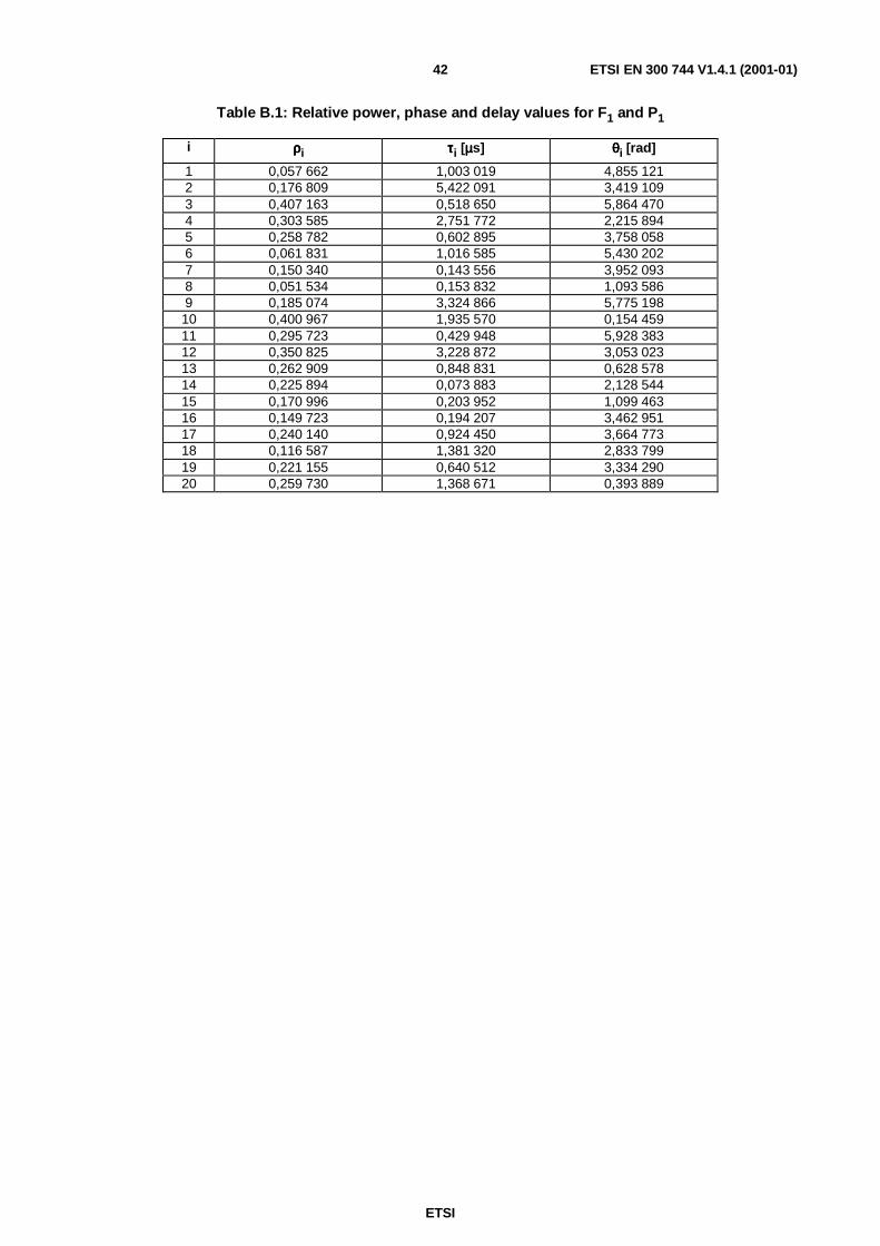
ETSI
ETSI EN 300 744 V1.4.1 (2001-01)42
Table B.1: Relative power, phase and delay values for F1 and P1
i ρρρρi ττττi [µµµµs] θθθθi [rad]
1 0,057 662 1,003 019 4,855 1212 0,176 809 5,422 091 3,419 1093 0,407 163 0,518 650 5,864 4704 0,303 585 2,751 772 2,215 8945 0,258 782 0,602 895 3,758 0586 0,061 831 1,016 585 5,430 2027 0,150 340 0,143 556 3,952 0938 0,051 534 0,153 832 1,093 5869 0,185 074 3,324 866 5,775 19810 0,400 967 1,935 570 0,154 45911 0,295 723 0,429 948 5,928 38312 0,350 825 3,228 872 3,053 02313 0,262 909 0,848 831 0,628 57814 0,225 894 0,073 883 2,128 54415 0,170 996 0,203 952 1,099 46316 0,149 723 0,194 207 3,462 95117 0,240 140 0,924 450 3,664 77318 0,116 587 1,381 320 2,833 79919 0,221 155 0,640 512 3,334 29020 0,259 730 1,368 671 0,393 889

ETSI
ETSI EN 300 744 V1.4.1 (2001-01)43
Annex C (informative):Interleaving exampleThe bit interleaving and symbol interleaving rules and the corresponding mapping onto carriers are illustrated intable C.1 for the first symbol in a superframe (i.e. even symbol), 2K mode, 64-QAM, non-hierarchical transmission.
Table C.1 shows the input bit indices to the mapping block, shown in figure 7a, when the input bits to the bit interleaverare numbered 0 to 9 071, and the corresponding carrier number. The indices corresponds to the interleaver input bitnumbers.
Table C.1: Mapping of input bits.
Input to mapping blockyq' = y0q', y1q', y2q', y3q', y4q', y5q'
Carriernumber k
pilot 00, 381, 631, 256, 128, 509 1
4602, 4983, 5233, 4858, 4730, 5111 236, 417, 667, 292, 164, 545 3
4656, 5037, 5287, 4912, 4784, 5165 448, 429, 679, 304, 176, 557 5
2376, 2757, 3007, 2632, 2504, 2885 6780, 1161, 1411, 1036, 908, 1289 7
6906, 7287, 7537, 7162, 7034, 7415 84590, 4971, 5221, 4846, 4718, 5099 95286, 4911, 5161, 4786, 4658, 5039 102364, 2745, 2995, 2620, 2492, 2873 11
pilot 124788, 5169, 4663, 5044, 4916, 4541 13
.....4194, 3819, 4069, 4450, 4322, 3947 1 691
pilot 1 6927782, 8163, 7657, 8038, 7910, 8291 1 6936624, 6249, 6499, 6124, 6752, 6377 1 6943402, 3027, 3277, 3658, 3530, 3155 1 695
546, 171, 421, 46, 674, 299 1 6968574, 8955, 8449, 8830, 8702, 8327 1 6978376, 8757, 9007, 8632, 8504, 8885 1 6981680, 2061, 1555, 1936, 1808, 2189 1 6997620, 8001, 8251, 7876, 7748, 8129 1 7005700, 5325, 5575, 5956, 5828, 5453 1 7018826, 8451, 8701, 8326, 8954, 8579 1 7028724, 8349, 8599, 8980, 8852, 8477 1 703
pilot 1 704

ETSI
ETSI EN 300 744 V1.4.1 (2001-01)44
Annex D (informative):Guidelines to implementation of the emitted signalThe present document serves to define only the emitted signal (which is all that needs to be standardized) and thus doesnot consider aspects of implementation. In particular, no mention is made of the Fast Fourier Transform (FFT) which isthe expected means of generating and demodulating an OFDM signal. This informative annex explains how to avoidcertain pitfalls which may be encountered when the FFT is used.
D.1 Use of the FFTThe emitted signal is unambiguously specified, for every OFDM symbol of every transmission frame, by the equationsof subclause 4.4. The apparent complexity of these equations can be simplified if it is noted that the waveform emittedduring each transmitted symbol period depends solely on the K complex values cm,l,k which define the complex
amplitude of the K active carriers for that period. Each symbol can thus be considered in isolation; for example, thesignal for the period from t 0 to t TS= = is given by:
( ) ( )
( ) 2with
,Re
minmax
2,0,0
2 max
min
KKkk
ecetsK
Kk
Ttkjk
tfj UC
+−=′
∑==
∆−′ππ
There is a clear resemblance between this and the inverse Discrete Fourier Transform (DFT) (see note 1):
∑−
=
=1
0
/21N
q
Nqnjqn eX
Nx π
NOTE 1: This is the definition of the inverse DFT in common use in the Engineering Sciences.The corresponding forward DFT has –j in the exponent.Mathematicians, however, sometimes use the opposite notation, so that their forward transform has -j, andtheir inverse transform has +j, in the exponent.Symbols used in this formula follow common nomenclature in engineering and mathematics.They do not represent the symbols used elsewhere in the present document.
Since various efficient Fast Fourier Transform algorithms exist to perform the DFT and its inverse, it is a convenientform of implementation to use the inverse FFT (IFFT) in a DVB-T modulator (see note 2) to generate N samples xn
corresponding to the useful part, TU long, of each symbol. The guard interval is added by taking copies of the last
N TU∆ of these samples and appending them in front. This process is then repeated for each symbol in turn, producinga continuous stream of samples which constitute a complex baseband representation of the DVB-T signal.A subsequent up-conversion process then gives the real signal ( )s t centred on the frequency f C .
However, care is needed in mapping the K values cm,l,k to the N IFFT coefficients Xq .
NOTE 2: The forward FFT may similarly be used in a demodulator.
ETSI
ETSI EN 300 744 V1.4.1 (2001-01)45
D.2 Choice of "baseband" centre frequencyThe basis function for the middle emitted carrier ( ′ =k 0 ) is constant throughout each symbol,
( ) 12,, minmax=+KKlmψ .
This carrier is therefore emitted at the centre frequency fC and has no phase discontinuities when modulated with the
same value in every symbol.
It follows that the data for this middle carrier shall be mapped to an IFFT coefficient X q of index q such that the
corresponding inverse DFT basis function Nqnje π2 has a whole number of cycles within the guard interval, regardlessof which of the possible guard-interval lengths (1/32, 1/16, 1/8 or 1/4 of the "useful" symbol period TU ) may be in use.The index q chosen for the middle carrier shall therefore be a multiple of 32.
In particular, either of the following alternatives is recommended as they satisfy this requirement while leading to asimple implementation:
a) assign the middle carrier to the half-way index 2Nq = , i.e. the half-sampling-frequency term; or
b) assign the middle carrier to index 0=q , i.e. the DC or zero-frequency term.
D.3 Other potential difficultiesThe conversion process by which the complex baseband signal produced by the IFFT is translated to a real signalcentred on the desired centre frequency similarly requires care to ensure that the result complies with the specification.
In particular:
a) The spectrum of the emitted signal shall not be inverted compared with the specification,i.e. the highest-frequency radiated carrier shall convey the modulation
max,, Klmc .
b) The emitted signal shall not have an "inverted imaginary axis" compared with the specification.This would happen if, in the expression for the emitted signal ( )s t , the klmc ,, were replaced by the
complex-conjugate values ∗klmc ,, .
Some possible causes of such error are:
c) Incorrect complex-to-real conversion may cause inversion of both the spectrum and the imaginary axis.
d) Using a forward FFT instead of the inverse FFT will cause inversion of the imaginary axis.
e) If the signal is shifted in frequency by some heterodyning process that causes inversion of the spectrum, theninversion of the imaginary axis will also occur.If such a process is repeated, the resulting signal will comply with the specification.
If case e) occurs as a natural consequence of the choices of intermediate frequency(ies), it may be compensated for inthe detail of the complex-to-real conversion, or by using a forward FFT to correct for the inversion of the imaginaryaxis while feeding it with the coefficients in reverse order to correct for inversion of the spectrum.
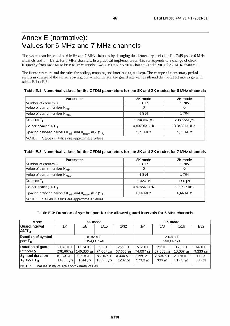
ETSI
ETSI EN 300 744 V1.4.1 (2001-01)46
Annex E (normative):Values for 6 MHz and 7 MHz channelsThe system can be scaled to 6 MHz and 7 MHz channels by changing the elementary period to T = 7/48 µs for 6 MHzchannels and T = 1/8 µs for 7 MHz channels. In a practical implementation this corresponds to a change of clockfrequency from 64/7 MHz for 8 MHz channels to 48/7 MHz for 6 MHz channels and 8 MHz for 7 MHz channels.
The frame structure and the rules for coding, mapping and interleaving are kept. The change of elementary periodresults in change of the carrier spacing, the symbol length, the guard interval length and the useful bit rate as given intables E.1 to E.6.
Table E.1: Numerical values for the OFDM parameters for the 8K and 2K modes for 6 MHz channels
Parameter 8K mode 2K modeNumber of carriers K 6 817 1 705Value of carrier number Kmin 0 0
Value of carrier number Kmax 6 816 1 704
Duration TU 1194,667 µs 298,6667 µs
Carrier spacing 1/TU 0,837054 kHz 3,348214 kHz
Spacing between carriers Kmin and Kmax, (K-1)/TU 5,71 MHz 5,71 MHz
NOTE: Values in italics are approximate values.
Table E.2: Numerical values for the OFDM parameters for the 8K and 2K modes for 7 MHz channels
Parameter 8K mode 2K modeNumber of carriers K 6 817 1 705Value of carrier number Kmin 0 0
Value of carrier number Kmax 6 816 1 704
Duration TU 1 024 µs 256 µs
Carrier spacing 1/TU 0,976563 kHz 3,90625 kHz
Spacing between carriers Kmin and Kmax, (K-1)/TU 6,66 MHz 6,66 MHz
NOTE: Values in italics are approximate values.
Table E.3: Duration of symbol part for the allowed guard intervals for 6 MHz channels
Mode 8K mode 2K modeGuard interval∆€/∆€/∆€/∆€/ TU
1/4 1/8 1/16 1/32 1/4 1/8 1/16 1/32
Duration of symbolpart TU
8192 × T1194,667 µs
2048 × T298,667 µs
Duration of guardinterval ∆∆∆∆
2 048 × T298,667µs
1 024 × T149,333 µs
512 × T74,667 µs
256 × T37,333 µs
512 × T74,667 µs
256 × T37,333 µs
128 × T18,667 µs
64 × T9,333 µs
Symbol durationTS = ∆∆∆∆ + TU
10 240 × T1493,3 µs
9 216 × T1344 µs
8 704 × T1269,3 µs
8 448 × T1232 µs
2 560 × T373,3 µs
2 304 × T336 µs
2 176 × T317,3 µs
2 112 × T308 µs
NOTE: Values in italics are approximate values.

ETSI
ETSI EN 300 744 V1.4.1 (2001-01)47
Table E.4: Duration of symbol part for the allowed guard intervals for 7 MHz channels
Mode 8K mode 2K modeGuard interval∆€/∆€/∆€/∆€/ TU
1/4 1/8 1/16 1/32 1/4 1/8 1/16 1/32
Duration of symbolpart TU
8 192 × T1024 µs
2 048 × T256 µs
Duration of guardinterval ∆∆∆∆
2 048 × T256 µs
1 024 × T128 µs
512 × T64 µs
256 × T32 µs
512 × T64 µs
256 × T32 µs
128 × T16 µs
64 × T8 µs
Symbol durationTS = ∆∆∆∆ + TU
10 240 × T1280 µs
9 216 × T1152 µs
8 704 × T1088 µs
8 448 × T1056 µs
2 560 × T320 µs
2 304 × T288 µs
2 176 × T272 µs
2 112 × T264 µs
Table E.5: Useful bitrate (Mbit/s) for all combinations of guard interval, constellation and code ratefor non-hierarchical systems for 6 MHz channels
Modulation Code rate Guard interval1/4 1/8 1/16 1/32
1/2 3,732 4,147 4,391 4,5242/3 4,976 5,529 5,855 6,032
QPSK 3/4 5,599 6,221 6,587 6,7865/6 6,221 6,912 7,318 7,5407/8 6,532 7,257 7,684 7,9171/2 7,465 8,294 8,782 9,0482/3 9,953 11,059 11,709 12,064
16-QAM 3/4 11,197 12,441 13,173 13,5725/6 12,441 13,824 14,637 15,0807/8 13,063 14,515 15,369 15,8341/2 11,197 12,441 13,173 13,5722/3 14,929 16,588 17,564 18,096
64-QAM 3/4 16,796 18,662 19,760 20,3585/6 18,662 20,735 21,955 22,6207/8 19,595 21,772 23,053 23,751
NOTE: Figures in italics are approximate values.For the hierarchical schemes the useful bit rates can be obtained from table E..5 as follows:
HP stream: figures from QPSK columns;LP stream, 16-QAM: figures from QPSK columns;LP stream, 64-QAM: figures from 16-QAM columns.

ETSI
ETSI EN 300 744 V1.4.1 (2001-01)48
Table E.6: Useful bitrate (Mbit/s) for all combinations of guard interval, constellation and code ratefor non-hierarchical systems for 7 MHz channels
Modulation Code rate Guard interval1/4 1/8 1/16 1/32
1/2 4,354 4,838 5,123 5,2782/3 5,806 6,451 6,830 7,037
QPSK 3/4 6,532 7,257 7,684 7,9175/6 7,257 8,064 8,538 8,7977/8 7,620 8,467 8,965 9,2371/2 8,709 9,676 10,246 10,5562/3 11,612 12,902 13,661 14,075
16-QAM 3/4 13,063 14,515 15,369 15,8345/6 14,515 16,127 17,076 17,5947/8 15,240 16,934 17,930 18,4731/2 13,063 14,515 15,369 15,8342/3 17,418 19,353 20,491 21,112
64-QAM 3/4 19,595 21,772 23,053 23,7515/6 21,772 24,191 25,614 26,3907/8 22,861 25,401 26,895 27,710
NOTE: Figures in italics are approximate values.For the hierarchical schemes the useful bit rates can be obtained from table E.6 as follows:HP stream: figures from QPSK columns;LP stream, 16-QAM: figures from QPSK columns;LP stream, 64-QAM: figures from 16-QAM columns.

ETSI
ETSI EN 300 744 V1.4.1 (2001-01)49
History
Document history
Edition 1 March 1997 Publication as ETS 300 744
V1.1.2 August 1997 Publication
V1.2.1 July 1999 Publication
V1.3.1 August 2000 One-step Approval Procedure OAP 20001229: 2000-08-30 to 2000-12-29(withdrawn and replaced by V1.4.1)
V1.4.1 August 2000 One-step Approval Procedure OAP 20001229: 2000-08-30 to 2000-12-29
V1.4.1 January 2001 Publication