en 300 296-1 - v1.4.1 - electromagnetic compatibility and radio
TRANSCRIPT

ETSI EN 300 296-1 V1.4.1 (2013-08)
Electromagnetic compatibility and Radio spectrum Matters (ERM);
Land Mobile Service; Radio equipment using integral antennas intended primarily for analogue speech;
Part 1: Technical characteristics and methods of measurement
European Standard

ETSI
ETSI EN 300 296-1 V1.4.1 (2013-08) 2
Reference REN/ERM-TGDMR-302
Keywords analogue, mobile, PMR, radio, speech
ETSI
650 Route des Lucioles F-06921 Sophia Antipolis Cedex - FRANCE
Tel.: +33 4 92 94 42 00 Fax: +33 4 93 65 47 16
Siret N° 348 623 562 00017 - NAF 742 C
Association à but non lucratif enregistrée à la Sous-Préfecture de Grasse (06) N° 7803/88
Important notice
Individual copies of the present document can be downloaded from: http://www.etsi.org
The present document may be made available in more than one electronic version or in print. In any case of existing or perceived difference in contents between such versions, the reference version is the Portable Document Format (PDF).
In case of dispute, the reference shall be the printing on ETSI printers of the PDF version kept on a specific network drive within ETSI Secretariat.
Users of the present document should be aware that the document may be subject to revision or change of status. Information on the current status of this and other ETSI documents is available at
http://portal.etsi.org/tb/status/status.asp
If you find errors in the present document, please send your comment to one of the following services: http://portal.etsi.org/chaircor/ETSI_support.asp
Copyright Notification
No part may be reproduced except as authorized by written permission. The copyright and the foregoing restriction extend to reproduction in all media.
© European Telecommunications Standards Institute 2013.
All rights reserved.
DECTTM, PLUGTESTSTM, UMTSTM and the ETSI logo are Trade Marks of ETSI registered for the benefit of its Members. 3GPPTM and LTE™ are Trade Marks of ETSI registered for the benefit of its Members and
of the 3GPP Organizational Partners. GSM® and the GSM logo are Trade Marks registered and owned by the GSM Association.
ETSI
ETSI EN 300 296-1 V1.4.1 (2013-08) 3
Contents
Intellectual Property Rights ................................................................................................................................ 6
Foreword ............................................................................................................................................................. 6
1 Scope ........................................................................................................................................................ 7
2 References ................................................................................................................................................ 7
2.1 Normative references ......................................................................................................................................... 7
2.2 Informative references ........................................................................................................................................ 7
3 Definitions, symbols and abbreviations ................................................................................................... 8
3.1 Definitions .......................................................................................................................................................... 8
3.2 Symbols .............................................................................................................................................................. 9
3.3 Abbreviations ..................................................................................................................................................... 9
4 General ................................................................................................................................................... 10
4.1 Selection of equipment for testing purposes ..................................................................................................... 10
4.2 Mechanical and electrical design ...................................................................................................................... 10
4.2.1 General ........................................................................................................................................................ 10
4.2.2 Controls ...................................................................................................................................................... 10
4.2.3 Transmitter shut-off facility ........................................................................................................................ 10
4.2.4 Push-to-talk facility..................................................................................................................................... 10
5 Test conditions, power sources and ambient temperatures .................................................................... 10
5.1 Normal and extreme test conditions ................................................................................................................. 10
5.2 Test power source ............................................................................................................................................. 11
5.3 Normal test conditions ...................................................................................................................................... 11
5.3.1 Normal temperature and humidity .............................................................................................................. 11
5.3.2 Normal test power source ........................................................................................................................... 11
5.3.2.1 Mains voltage ........................................................................................................................................ 11
5.3.2.2 Regulated lead-acid battery power sources used on vehicles ................................................................ 11
5.3.2.3 Other power sources .............................................................................................................................. 11
5.4 Extreme test conditions .................................................................................................................................... 12
5.4.1 Extreme temperatures ................................................................................................................................. 12
5.4.2 Extreme test source voltages ....................................................................................................................... 12
5.4.2.1 Mains voltage ........................................................................................................................................ 12
5.4.2.2 Regulated lead-acid battery power sources used on vehicles ................................................................ 12
5.4.2.3 Power sources using other types of batteries ......................................................................................... 12
5.4.2.4 Other power sources .............................................................................................................................. 12
5.5 Procedure for tests at extreme temperatures ..................................................................................................... 13
5.5.1 Procedure for equipment designed for continuous transmission................................................................. 13
5.5.2 Procedure for equipment designed for intermittent transmission ............................................................... 13
6 General test conditions ........................................................................................................................... 13
6.1 Test signals ....................................................................................................................................................... 13
6.2 Receiver mute or squelch facility ..................................................................................................................... 14
6.3 Artificial antenna .............................................................................................................................................. 14
6.4 Test sites and general arrangements for radiated measurements ...................................................................... 14
6.5 Arrangement for test signals at the input of the transmitter ............................................................................. 14
6.6 Receiver rated audio output power ................................................................................................................... 14
6.7 Reference for degradation measurements ......................................................................................................... 14
6.7.1 Definition .................................................................................................................................................... 14
6.7.2 Procedures for measurements using the test fixture .................................................................................... 15
6.7.3 Procedures for measurements using the test site ......................................................................................... 15
7 Technical characteristics of the transmitter ............................................................................................ 15
7.1 Frequency error ................................................................................................................................................ 15
7.1.1 Definition .................................................................................................................................................... 15
7.1.2 Method of measurement ............................................................................................................................. 16
7.1.3 Limits .......................................................................................................................................................... 16

ETSI
ETSI EN 300 296-1 V1.4.1 (2013-08) 4
7.2 Effective radiated power .................................................................................................................................. 16
7.2.1 Definition .................................................................................................................................................... 16
7.2.2 Method of measurement ............................................................................................................................. 17
7.2.2.1 Maximum effective radiated power under normal test conditions ........................................................ 17
7.2.2.2 Average effective radiated power under normal test conditions ........................................................... 18
7.2.2.3 Method of measurements of maximum and average effective radiated power under extreme test conditions .............................................................................................................................................. 19
7.2.3 Limits .......................................................................................................................................................... 19
7.3 Maximum permissible frequency deviation ..................................................................................................... 20
7.3.1 Definition .................................................................................................................................................... 20
7.3.2 Method of measurement ............................................................................................................................. 20
7.3.2.1 Maximum permissible frequency deviation .......................................................................................... 21
7.3.2.2 Response of the transmitter to modulation frequencies above 3 kHz ................................................... 21
7.3.3 Limits .......................................................................................................................................................... 21
7.3.3.1 Maximum permissible frequency deviation .......................................................................................... 21
7.3.3.2 Response of the transmitter to modulation frequencies above 3 kHz ................................................... 21
7.4 Adjacent and alternate channel power .............................................................................................................. 22
7.4.1 Definition .................................................................................................................................................... 22
7.4.2 Method of measurement ............................................................................................................................. 22
7.4.3 Limits .......................................................................................................................................................... 24
7.5 Radiated unwanted emissions in the spurious domain ...................................................................................... 24
7.5.1 Definition .................................................................................................................................................... 24
7.5.2 Method of measurement ............................................................................................................................. 25
7.5.3 Limits .......................................................................................................................................................... 26
7.6 Voice Operated Transmitter ............................................................................................................................. 27
7.6.1 Definition .................................................................................................................................................... 27
7.6.2 Method of measurement ............................................................................................................................. 27
7.6.3 Limits .......................................................................................................................................................... 27
7.7 Maximum transmission time ............................................................................................................................ 28
7.7.1 Definition .................................................................................................................................................... 28
7.7.2 Method of measurement ............................................................................................................................. 28
7.7.3 Limits .......................................................................................................................................................... 28
8 Technical characteristics of the receiver ................................................................................................ 28
8.1 Average usable sensitivity (field strength, speech) .......................................................................................... 28
8.1.1 Definition .................................................................................................................................................... 28
8.1.2 Methods of measurement ............................................................................................................................ 28
8.1.2.1 Method of measurement under normal test conditions ......................................................................... 28
8.1.2.2 Method of measurement under extreme test conditions ........................................................................ 30
8.1.3 Limits .......................................................................................................................................................... 30
8.2 Spurious radiations ........................................................................................................................................... 31
8.2.1 Definition .................................................................................................................................................... 31
8.2.2 Method of measurement ............................................................................................................................. 32
8.2.3 Limits .......................................................................................................................................................... 33
8.3 Co-channel rejection......................................................................................................................................... 34
8.3.1 Definition .................................................................................................................................................... 34
8.3.2 Method of measurement ............................................................................................................................. 34
8.3.3 Limits .......................................................................................................................................................... 35
8.4 Adjacent channel selectivity ............................................................................................................................. 35
8.4.1 Definition .................................................................................................................................................... 35
8.4.2 Method of measurement ............................................................................................................................. 35
8.4.3 Limits .......................................................................................................................................................... 36
8.5 Spurious response rejection .............................................................................................................................. 36
8.5.1 Definition .................................................................................................................................................... 36
8.5.2 Method of measurement ............................................................................................................................. 37
8.5.2.1 Introduction to the method of measurement .......................................................................................... 37
8.5.2.2 Measurement arrangement .................................................................................................................... 38
8.5.2.3 Method of the search ............................................................................................................................. 38
8.5.2.4 Measurement ......................................................................................................................................... 39
8.5.3 Limits .......................................................................................................................................................... 40
8.6 Intermodulation response rejection .................................................................................................................. 40
8.6.1 Definition .................................................................................................................................................... 40

ETSI
ETSI EN 300 296-1 V1.4.1 (2013-08) 5
8.6.2 Method of measurement ............................................................................................................................. 40
8.6.3 Limits .......................................................................................................................................................... 41
8.6.3.1 Limits for low power equipment ........................................................................................................... 41
8.6.3.2 Limits for other equipment .................................................................................................................... 42
8.7 Blocking or desensitization .............................................................................................................................. 42
8.7.1 Definition .................................................................................................................................................... 42
8.7.2 Method of measurement ............................................................................................................................. 42
8.7.3 Limits .......................................................................................................................................................... 43
9 Measurement uncertainty ....................................................................................................................... 44
Annex A (normative): Radiated measurement .................................................................................. 45
A.1 Test sites and general arrangements for measurements involving the use of radiated fields ................. 45
A.1.1 Anechoic chamber ............................................................................................................................................ 45
A.1.2 Anechoic chamber with a conductive ground plane ......................................................................................... 46
A.1.3 Open Area Test Site (OATS) ........................................................................................................................... 47
A.1.4 Test antenna ...................................................................................................................................................... 48
A.1.5 Substitution antenna ......................................................................................................................................... 48
A.1.6 Measuring antenna ........................................................................................................................................... 49
A.2 Guidance on the use of radiation test sites ............................................................................................. 49
A.2.1 Verification of the test site ............................................................................................................................... 49
A.2.2 Preparation of the EUT ..................................................................................................................................... 49
A.2.3 Power supplies to the EUT ............................................................................................................................... 49
A.2.4 Volume control setting for analogue speech tests ............................................................................................ 49
A.2.5 Range length ..................................................................................................................................................... 50
A.2.6 Site preparation ................................................................................................................................................ 50
A.3 Coupling of signals ................................................................................................................................. 51
A.3.1 General ............................................................................................................................................................. 51
A.3.2 Data Signals...................................................................................................................................................... 51
A.3.3 Speech and analogue signals ............................................................................................................................ 51
A.3.3.1 Acoustic coupler description....................................................................................................................... 51
A.3.3.2 Calibration .................................................................................................................................................. 52
A.4 Test fixture ............................................................................................................................................. 52
A.4.1 Description ....................................................................................................................................................... 52
A.4.2 Calibration ........................................................................................................................................................ 53
A.4.3 Mode of use ...................................................................................................................................................... 53
Annex B (normative): Specifications for adjacent channel power measurement arrangements .................................................................................................. 54
B.1 Power measuring receiver specification ................................................................................................. 54
B.1.1 General ............................................................................................................................................................. 54
B.1.2 IF filter ............................................................................................................................................................. 54
B.1.3 Oscillator and amplifier .................................................................................................................................... 56
B.1.4 Attenuation indicator ........................................................................................................................................ 56
B.1.5 Level indicators ................................................................................................................................................ 56
B.1.5.1 Rms level indicator ..................................................................................................................................... 56
B.1.5.2 Peak level indicator ..................................................................................................................................... 56
B.2 Spectrum analyzer for adjacent channel power measurement ................................................................ 56
Annex C (normative): Spectrum Analyzer ........................................................................................ 58
C.1 Adjacent Channel Power Measurement ................................................................................................. 58
C.2 Unwanted Emissions Measurement ....................................................................................................... 58
Annex D (normative): Band-stop filter (for SINAD meter) ............................................................. 59
Annex E (informative): Bibliography ................................................................................................... 60
History .............................................................................................................................................................. 61
ETSI
ETSI EN 300 296-1 V1.4.1 (2013-08) 6
Intellectual Property Rights IPRs essential or potentially essential to the present document may have been declared to ETSI. The information pertaining to these essential IPRs, if any, is publicly available for ETSI members and non-members, and can be found in ETSI SR 000 314: "Intellectual Property Rights (IPRs); Essential, or potentially Essential, IPRs notified to ETSI in respect of ETSI standards", which is available from the ETSI Secretariat. Latest updates are available on the ETSI Web server (http://ipr.etsi.org).
Pursuant to the ETSI IPR Policy, no investigation, including IPR searches, has been carried out by ETSI. No guarantee can be given as to the existence of other IPRs not referenced in ETSI SR 000 314 (or the updates on the ETSI Web server) which are, or may be, or may become, essential to the present document.
Foreword This European Standard (EN) has been produced by ETSI Technical Committee Electromagnetic compatibility and Radio spectrum Matters (ERM).
The present document is part 1 of a multi-part deliverable covering the Land Mobile Service; Radio equipment using integral antennas intended primarily for analogue speech, as identified below:
Part 1: "Technical characteristics and methods of measurement";
Part 2: "Harmonized EN covering the essential requirements of article 3.2 of the R&TTE Directive".
National transposition dates
Date of adoption of this EN: 13 August 2013
Date of latest announcement of this EN (doa): 30 November 2013
Date of latest publication of new National Standard or endorsement of this EN (dop/e):
31 May 2014
Date of withdrawal of any conflicting National Standard (dow): 31 May 2014
ETSI
ETSI EN 300 296-1 V1.4.1 (2013-08) 7
1 Scope The present document covers the minimum characteristics considered necessary in order to avoid harmful interference and to make acceptable use of the available frequencies.
The present document applies to equipment with integral antennas, used in angle modulation systems in the land mobile service, operating on radio frequencies between 30 MHz and 1 000 MHz, with channel separations of 12,5 kHz, 20 kHz and 25 kHz, and is intended primarily for analogue speech.
In the present document different requirements are given for the different radio frequency bands, channel separations, environmental conditions and types of equipment, where appropriate.
The present document is complementary to EN 300 086 [i.7], which covers radio equipment with an internal or external RF connector, for use in the land mobile service.
The present document may apply to PMR446 equipment as defined in [i.8]. Note that PMR446 equipment has a requirement to incorporate a receiver and may have requirements for 180 s maximum transmission time and VOX.
2 References References are either specific (identified by date of publication and/or edition number or version number) or non-specific. For specific references, only the cited version applies. For non-specific references, the latest version of the reference document (including any amendments) applies.
Referenced documents which are not found to be publicly available in the expected location might be found at http://docbox.etsi.org/Reference.
NOTE: While any hyperlinks included in this clause were valid at the time of publication, ETSI cannot guarantee their long term validity.
2.1 Normative references The following referenced documents are necessary for the application of the present document.
[1] ETSI TR 100 028 (V1.4.1) (all parts): "Electromagnetic compatibility and Radio spectrum Matters (ERM); Uncertainties in the measurement of mobile radio equipment characteristics".
[2] ANSI C63.5 (2006): "American National Standard for Calibration of Antennas Used for Radiated Emission Measurements in Electro Magnetic Interference".
2.2 Informative references The following referenced documents are not necessary for the application of the present document but they assist the user with regard to a particular subject area.
[i.1] CEPT/ERC/REC 74-01E: "Unwanted emissions in the spurious domain" (Siófok 1998, Nice 1999, Sesimbra 2002; Hradec Kralove 2005).
[i.2] ETSI EN 300 793 (V1.1.1): "Electromagnetic compatibility and Radio spectrum Matters (ERM); Land mobile service; Presentation of equipment for type testing".
[i.3] ETSI TR 102 273 (V1.2.1) (all parts): "Electromagnetic compatibility and Radio spectrum Matters (ERM); Improvement on Radiated Methods of Measurement (using test site) and evaluation of the corresponding measurement uncertainties".
[i.4] IEC 60489-3 (1988): "Methods of measurement for radio equipment used in the mobile services; Part 3: Receivers for A3E or F3E emissions".
[i.5] Recommendation ITU-T O.41 (1994): "Psophometer for use on telephone-type circuits".
ETSI
ETSI EN 300 296-1 V1.4.1 (2013-08) 8
[i.6] Void.
[i.7] ETSI EN 300 086 (all parts): "Electromagnetic compatibility and Radio spectrum Matters (ERM); Land Mobile Service; Radio equipment with an internal or external RF connector intended primarily for analogue speech".
[i.8] CEPT/ERC/DEC(98)25: "The Harmonised frequency band designated for analogue PMR446".
3 Definitions, symbols and abbreviations
3.1 Definitions For the purposes of the present document, the following terms and definitions apply:
50 Ω: 50 ohm non-reactive impedance
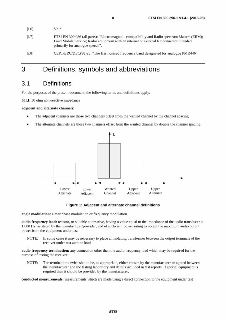
adjacent and alternate channels:
• The adjacent channels are those two channels offset from the wanted channel by the channel spacing.
• The alternate channels are those two channels offset from the wanted channel by double the channel spacing.
fc
LowerAlternate
UpperAlternate
LowerAdjacent
UpperAdjacent
WantedChannel
Figure 1: Adjacent and alternate channel definitions
angle modulation: either phase modulation or frequency modulation
audio frequency load: resistor, or suitable alternative, having a value equal to the impedance of the audio transducer at 1 000 Hz, as stated by the manufacturer/provider, and of sufficient power rating to accept the maximum audio output power from the equipment under test
NOTE: In some cases it may be necessary to place an isolating transformer between the output terminals of the receiver under test and the load.
audio frequency termination: any connection other than the audio frequency load which may be required for the purpose of testing the receiver
NOTE: The termination device should be, as appropriate, either chosen by the manufacturer or agreed between the manufacturer and the testing laboratory and details included in test reports. If special equipment is required then it should be provided by the manufacturer.
conducted measurements: measurements which are made using a direct connection to the equipment under test

ETSI
ETSI EN 300 296-1 V1.4.1 (2013-08) 9
integral antenna: antenna designed to be connected to the equipment without the use of a 50 Ω external connector and considered to be part of the equipment
NOTE: An integral antenna may be fitted internally or externally to the equipment.
low power equipment: equipment that has a transmitter effective radiated power, as measured in clause 7.2, of not more than 500 mW
psophometric weighting network: psophometric weighting network is described in Recommendation ITU-T O.41 [i.5]
radiated measurements: measurements which involve the absolute measurement of a radiated field
SINAD Meter: measurement instrument used to measure SND/ND using a band-stop filter
NOTE: As defined in annex D.
3.2 Symbols For the purposes of the present document, the following symbols apply:
dBc dB relative to the carrier power fI1 1st intermediate frequency
fI2 2nd intermediate frequency
fIn nth intermediate frequency
fl frequency of the limited frequency range
fLO Local oscillator frequency
Vmin Minimum extreme test voltage
Vmax Maximum extreme test voltage
Tmin Minimum extreme test temperature
Tmax Maximum extreme test temperature
3.3 Abbreviations For the purposes of the present document, the following abbreviations apply:
AF Audio Frequency CEPT European Conference of Postal and Telecommunications Administrations CSP Channel separation CTCSS Continuous Tone Controlled Squelch System CW Continuous Wave DC Direct Current DCS Digital Controlled Squelch EC European Community emf electro-motive force EUT Equipment Under Test IF Intermediate Frequency MPFD Maximum Permissible Frequency Deviation OATS Open Area Test Site PTT Push To Talk RBW Resolution BandWidth RF Radio Frequency rms root mean squared Rx Receiver SINAD Received signal quality based on (Signal + Noise + Distortion) / (Noise + Distortion) SND/ND (signal + noise + distortion)/(noise + distortion) SR Switching Range Tx Transmitter

ETSI
ETSI EN 300 296-1 V1.4.1 (2013-08) 10
VOX Voice Operated Transmitter VSWR Voltage Standing Wave Ratio
4 General
4.1 Selection of equipment for testing purposes Each equipment to be tested shall fulfil the requirements of the present document on all frequencies over which it is intended to operate.
The provider or manufacturer shall declare the frequency ranges, the range of operating conditions and power requirements as applicable, to establish the appropriate test conditions.
Guidance on the presentation of equipment is also given in EN 300 793 [i.2].
4.2 Mechanical and electrical design
4.2.1 General
The equipment shall be designed, constructed and manufactured in accordance with sound engineering practice, and with the aim of minimizing harmful interference to other equipment and services.
4.2.2 Controls
Those controls which if maladjusted might increase the interfering potentialities of the equipment shall not be easily accessible to the user.
4.2.3 Transmitter shut-off facility
When a timer for an automatic shut-off facility is operative, at the moment of the time-out the transmitter shall automatically be switched off. The activation of the PTT shall reset the timer.
A shut-off facility shall be inoperative for the duration of the measurements unless it has to remain operative to protect the equipment. If the shut-off facility is left operative the status of the equipment shall be indicated.
4.2.4 Push-to-talk facility
Equipment fitted with a manually activated control to enable transmission shall deem to have PTT operation. If the transmitter can continue transmission without the control being consciously held by the operator then the PTT operation shall be considered being capable of being latched on.
5 Test conditions, power sources and ambient temperatures
5.1 Normal and extreme test conditions Testing shall be performed under normal test conditions, and also, where stated, under extreme test conditions.
The test conditions and procedures shall be as specified in clauses 5.2 to 5.5.
ETSI
ETSI EN 300 296-1 V1.4.1 (2013-08) 11
5.2 Test power source During testing the power source of the equipment shall be replaced by a test power source capable of producing normal and extreme test voltages as specified in clauses 5.3.2 and 5.4.2. The internal impedance of the test power source shall be low enough for its effect on the test results to be negligible. For the purpose of tests, the voltage of the power source shall be measured at the input terminals of the equipment.
For battery operated equipment the battery shall be removed and the test power source shall be applied as close to the battery terminals as practicable.
During tests of DC powered equipment the power source voltages shall be maintained within a tolerance of < ±1 % relative to the voltage at the beginning of each test. The value of this tolerance is critical for power measurements. Using a smaller tolerance will provide better measurement uncertainty values.
5.3 Normal test conditions
5.3.1 Normal temperature and humidity
The normal temperature and humidity conditions for tests shall be any convenient combination of temperature and humidity within the following ranges:
• temperature: +15 °C to +35 °C;
• relative humidity: 20 % to 75 %.
When it is impracticable to carry out the tests under these conditions, a note to this effect, stating the ambient temperature and relative humidity during the tests, shall be added to the test report.
5.3.2 Normal test power source
5.3.2.1 Mains voltage
The normal test voltage for equipment to be connected to the mains shall be the nominal mains voltage. For the purpose of the present document, the nominal voltage shall be the declared voltage or any of the declared voltages for which the equipment was designed.
The frequency of the test power source corresponding to the ac mains shall be between 49 Hz and 51 Hz.
5.3.2.2 Regulated lead-acid battery power sources used on vehicles
When the radio equipment is intended for operation from the usual types of regulated lead-acid battery power source used on vehicles the normal test voltage shall be 1,1 times the nominal voltage of the battery (for nominal voltages of 6 V and 12 V, these are 6,6 V and 13,2 V respectively).
5.3.2.3 Other power sources
For operation from other power sources or types of battery (primary or secondary), the normal test voltage shall be that declared by the equipment manufacturer.
ETSI
ETSI EN 300 296-1 V1.4.1 (2013-08) 12
5.4 Extreme test conditions
5.4.1 Extreme temperatures
For tests at extreme temperatures, measurements shall be made in accordance with the procedures specified in clause 5.5, at the upper and lower temperatures of one of the following two ranges:
• -20 °C to +55 °C; All mobile and handportable equipment. Base stations for outdoor/uncontrolled climate conditions.
• 0 °C to +40 °C; Base stations for indoor/controlled climate conditions.
In the case of base station equipment, the manufacturer shall declare which conditions the equipment is intended to be installed in.
5.4.2 Extreme test source voltages
5.4.2.1 Mains voltage
The extreme test voltage for equipment to be connected to an ac mains source shall be the nominal mains voltage ±10 %.
5.4.2.2 Regulated lead-acid battery power sources used on vehicles
When the equipment is intended for operation from the usual types of regulated lead-acid battery power sources used on vehicles the extreme test voltages shall be 1,3 and 0,9 times the nominal voltage of the battery (for a nominal voltage of 6 V, these are 7,8 V and 5,4 V respectively and for a nominal voltage of 12 V, these are 15,6 V and 10,8 V respectively).
5.4.2.3 Power sources using other types of batteries
The lower extreme test voltages for equipment with power sources using batteries shall be as follows:
- for the nickel metal-hydride, leclanché or lithium type: 0,85 times the nominal battery voltage;
- for the mercury or nickel-cadmium type: 0,9 times the nominal battery voltage.
No upper extreme test voltages apply.
In the case where no upper extreme test voltage the nominal voltage is applicable, the corresponding four extreme test conditions are:
• Vmin/Tmin, Vmin/Tmax;
• (Vmax = nominal)/Tmin, (Vmax = nominal)/Tmax.
5.4.2.4 Other power sources
For equipment using other power sources, or capable of being operated from a variety of power sources, the extreme test voltages shall be those declared by the equipment manufacturer.
ETSI
ETSI EN 300 296-1 V1.4.1 (2013-08) 13
5.5 Procedure for tests at extreme temperatures Before measurements are made the equipment shall have reached thermal balance in the test chamber. The equipment shall be switched off during the temperature stabilizing period.
In the case of equipment containing temperature stabilization circuits designed to operate continuously, the temperature stabilization circuits may be switched on for 15 minutes after thermal balance has been obtained, and the equipment shall then meet the specified requirements. For such equipment the manufacturer shall provide for the power source circuit feeding the crystal oven to be independent of the power source for the rest of the equipment.
If the thermal balance is not checked by measurements, a temperature stabilizing period of at least one hour, or a longer period as may be decided by the testing laboratory, shall be allowed. The sequence of measurements shall be chosen, and the humidity content in the test chamber shall be controlled so that excessive condensation does not occur.
5.5.1 Procedure for equipment designed for continuous transmission
If the manufacturer states that the equipment is designed for continuous transmission, the test procedure shall be as follows.
Before tests at the upper extreme temperature, the equipment shall be placed in the test chamber, and left until thermal balance is attained. The equipment shall then be switched on in the transmit condition for a period of half an hour, after which the equipment shall meet the specified requirements.
Before tests at the lower extreme temperature, the equipment shall be left in the test chamber until thermal balance is attained, then switched to the standby or receive condition for a period of one minute, after which the equipment shall meet the specified requirements.
5.5.2 Procedure for equipment designed for intermittent transmission
If the manufacturer states that the equipment is designed for intermittent transmission, the test procedure shall be as follows.
Before tests at the upper extreme temperature, the equipment shall be placed in the test chamber, and left until thermal balance is attained. The equipment shall then be switched on for one minute in the transmit condition, followed by four minutes in the receive condition, after which the equipment shall meet the specified requirements.
For tests at the lower extreme temperature, the equipment shall be left in the test chamber until thermal balance is attained, then switched to the standby or receive condition for one minute, after which the equipment shall meet the specified requirements.
6 General test conditions
6.1 Test signals The test modulation signals are baseband signals that modulate a carrier or signal generator. They are dependent upon the type of equipment under test and also the measurement to be performed.
Test modulating signals are:
- A-M1: a 1 000 Hz tone at a level which produces a deviation of 12 % of the channel separation;
- A-M2: a 1 250 Hz tone at a level which produces a deviation of 12 % of the channel separation;
- A-M3: a 400 Hz tone at a level which produces a deviation of 12 % of the channel separation. This signal is used as an unwanted signal.
For normal test modulation, the modulation frequency shall be 1 kHz and the resultant frequency deviation shall be 60 % of the maximum permissible frequency deviation for the clause 7.3.3.
The test signal shall be substantially free from amplitude modulation.
ETSI
ETSI EN 300 296-1 V1.4.1 (2013-08) 14
Sources of test signals for application to the receiver input shall be connected in such a way that the source impedance presented to the receiver input is 50 Ω (non-reactive, clause 6.3).
This requirement shall be met irrespective of whether one or more signals using a combining network are applied to the receiver simultaneously.
The levels of the test signals at the receiver input terminals (RF connector) shall be expressed in terms of emf.
The effects of any intermodulation products and noise produced in the test signal sources shall be negligible.
6.2 Receiver mute or squelch facility If the receiver is equipped with a mute or squelch circuit, this shall be made inoperative for the duration of the measurements.
6.3 Artificial antenna Tests shall be carried out using an artificial antenna, which shall be a substantially non-reactive non-radiating load of 50 Ω connected to the antenna connector.
6.4 Test sites and general arrangements for radiated measurements
For guidance on radiation test sites see annex A. Detailed descriptions of the radiated measurement arrangements are included in this annex.
6.5 Arrangement for test signals at the input of the transmitter For the purpose of the present document, the transmitter audio frequency modulation signal shall be applied to the microphone input terminals with the internal microphone disconnected, unless otherwise stated.
6.6 Receiver rated audio output power The rated audio output power shall be the maximum power, declared by the manufacturer, for which all the requirements of the present document are met. With normal test modulation, the audio output power shall be measured in a resistive load simulating the load with which the receiver normally operates. The value of this load shall be declared by the manufacturer.
6.7 Reference for degradation measurements
6.7.1 Definition
Degradation measurements are those measurements which are made on the receiver to establish the degradation of the performance of the receiver due to the presence of (an) unwanted (interfering) signal(s). For such measurements, the level of the wanted signal shall be adjusted to the level of the limit of the average usable sensitivity.
Degradation measurements are in two categories:
a) those carried out on a test site (see clauses 8.5 (spurious response rejection), 8.7 (blocking or desensitization), and A.1);
b) those carried out using a test fixture (see clauses 8.3 (co-channel rejection), 8.4 (adjacent channel selectivity), 8.6 (intermodulation response rejection) and A.4).

ETSI
ETSI EN 300 296-1 V1.4.1 (2013-08) 15
The test fixture is only used for those tests where the difference in frequency between the wanted and the unwanted test signals is very small in relation to the actual frequency, so that the coupling loss is the same for the wanted and unwanted test signals fed into the test fixture.
6.7.2 Procedures for measurements using the test fixture
The test fixture is coupled to the signal generators via a combining network to provide the wanted and unwanted test input signals to the receiver in the test fixture. It is necessary therefore to establish the output level of the wanted test signal from the signal generator that results in a signal at the receiver (in the test fixture), which corresponds with the average usable sensitivity (radiated) as specified in clause 8.1.3.
This test output level from the signal generator for the wanted test signal is then used for all the receiver measurements using the test fixture.
The method for determining the test output level from the signal generator is as follows:
a) the actual average usable sensitivity of the receiver is measured in accordance with clause 8.1.2.1 i) and expressed as a field strength;
b) the difference between the limit of the average usable sensitivity specified in clause 8.1.3 and this actual average usable sensitivity, expressed in dB, is noted;
c) the receiver is then mounted in the test fixture:
- the signal generator providing the wanted input signal is coupled to the test fixture via a combining network. All other input ports of the combining network are terminated in 50 Ω loads;
- the output from the signal generator with normal test modulation A-M1 (see clause 6.1) is adjusted so that a SINAD ratio of 20 dB is obtained (with a psophometric filter). This output level is then increased by an amount corresponding to the difference expressed in dB calculated in clause 6.7.2 b);
- the output level of the signal generator is defined as being the level equivalent to the limit of the average usable sensitivity, for the category of equipment used, expressed as a field strength (see clause 8.1.3).
6.7.3 Procedures for measurements using the test site
When measurements are carried out on a test site, the wanted and unwanted signals shall be calibrated in terms of dBμV/m at the location of the equipment under test.
For measurements according to clauses 8.5 (spurious response rejection), 8.7 (blocking or desensitization) and A.2, the height of the test antenna and the direction (angle) of the equipment under test shall be that recorded in clause 8.1.2.1 j) (reference direction).
7 Technical characteristics of the transmitter
7.1 Frequency error
7.1.1 Definition
The frequency error of the transmitter is the difference between the measured carrier frequency in the absence of modulation and the nominal frequency of the transmitter.
ETSI
ETSI EN 300 296-1 V1.4.1 (2013-08) 16
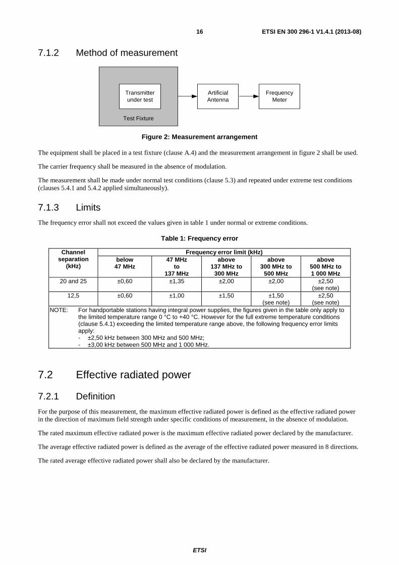
7.1.2 Method of measurement
Artificial Antenna
Transmitter under test
Frequency Meter
Test Fixture
Figure 2: Measurement arrangement
The equipment shall be placed in a test fixture (clause A.4) and the measurement arrangement in figure 2 shall be used.
The carrier frequency shall be measured in the absence of modulation.
The measurement shall be made under normal test conditions (clause 5.3) and repeated under extreme test conditions (clauses 5.4.1 and 5.4.2 applied simultaneously).
7.1.3 Limits
The frequency error shall not exceed the values given in table 1 under normal or extreme conditions.
Table 1: Frequency error
Channel separation
(kHz)
Frequency error limit (kHz) below
47 MHz 47 MHz
to 137 MHz
above 137 MHz to
300 MHz
above 300 MHz to
500 MHz
above 500 MHz to 1 000 MHz
20 and 25 ±0,60 ±1,35 ±2,00 ±2,00 ±2,50 (see note)
12,5 ±0,60 ±1,00 ±1,50 ±1,50 (see note)
±2,50 (see note)
NOTE: For handportable stations having integral power supplies, the figures given in the table only apply to the limited temperature range 0 °C to +40 °C. However for the full extreme temperature conditions (clause 5.4.1) exceeding the limited temperature range above, the following frequency error limits apply:
- ±2,50 kHz between 300 MHz and 500 MHz; - ±3,00 kHz between 500 MHz and 1 000 MHz.
7.2 Effective radiated power
7.2.1 Definition
For the purpose of this measurement, the maximum effective radiated power is defined as the effective radiated power in the direction of maximum field strength under specific conditions of measurement, in the absence of modulation.
The rated maximum effective radiated power is the maximum effective radiated power declared by the manufacturer.
The average effective radiated power is defined as the average of the effective radiated power measured in 8 directions.
The rated average effective radiated power shall also be declared by the manufacturer.
ETSI
ETSI EN 300 296-1 V1.4.1 (2013-08) 17
7.2.2 Method of measurement
The measurements shall be made under normal test conditions, clause 5.3, and extreme test conditions, clauses 5.4.1 and 5.4.2 applied simultaneously.
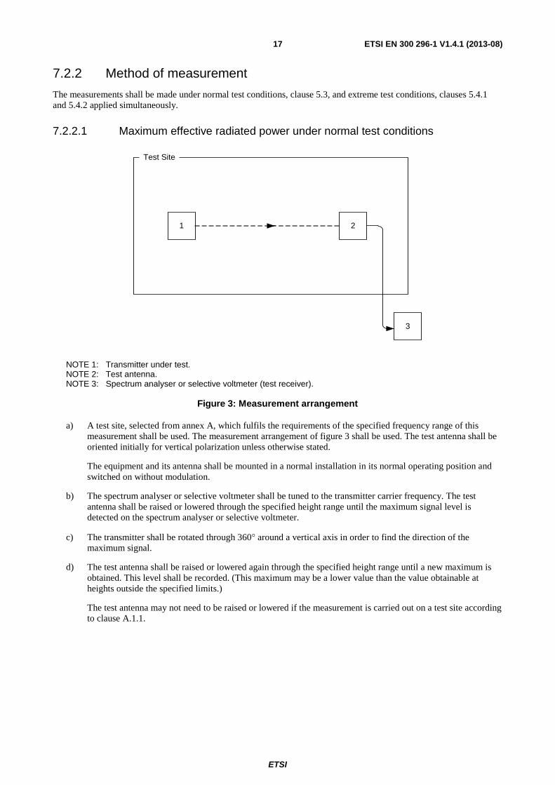
7.2.2.1 Maximum effective radiated power under normal test conditions
1 2
3
Test Site
NOTE 1: Transmitter under test. NOTE 2: Test antenna. NOTE 3: Spectrum analyser or selective voltmeter (test receiver).
Figure 3: Measurement arrangement
a) A test site, selected from annex A, which fulfils the requirements of the specified frequency range of this measurement shall be used. The measurement arrangement of figure 3 shall be used. The test antenna shall be oriented initially for vertical polarization unless otherwise stated.
The equipment and its antenna shall be mounted in a normal installation in its normal operating position and switched on without modulation.
b) The spectrum analyser or selective voltmeter shall be tuned to the transmitter carrier frequency. The test antenna shall be raised or lowered through the specified height range until the maximum signal level is detected on the spectrum analyser or selective voltmeter.
c) The transmitter shall be rotated through 360° around a vertical axis in order to find the direction of the maximum signal.
d) The test antenna shall be raised or lowered again through the specified height range until a new maximum is obtained. This level shall be recorded. (This maximum may be a lower value than the value obtainable at heights outside the specified limits.)
The test antenna may not need to be raised or lowered if the measurement is carried out on a test site according to clause A.1.1.
ETSI
ETSI EN 300 296-1 V1.4.1 (2013-08) 18
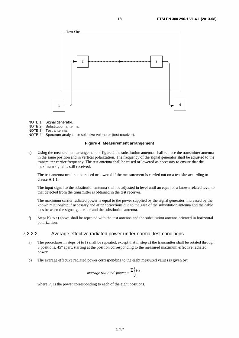
2 3
4
Test Site
1
NOTE 1: Signal generator. NOTE 2: Substitution antenna. NOTE 3: Test antenna. NOTE 4: Spectrum analyser or selective voltmeter (test receiver).
Figure 4: Measurement arrangement
e) Using the measurement arrangement of figure 4 the substitution antenna, shall replace the transmitter antenna in the same position and in vertical polarization. The frequency of the signal generator shall be adjusted to the transmitter carrier frequency. The test antenna shall be raised or lowered as necessary to ensure that the maximum signal is still received.
The test antenna need not be raised or lowered if the measurement is carried out on a test site according to clause A.1.1.
The input signal to the substitution antenna shall be adjusted in level until an equal or a known related level to that detected from the transmitter is obtained in the test receiver.
The maximum carrier radiated power is equal to the power supplied by the signal generator, increased by the known relationship if necessary and after corrections due to the gain of the substitution antenna and the cable loss between the signal generator and the substitution antenna.
f) Steps b) to e) above shall be repeated with the test antenna and the substitution antenna oriented in horizontal polarization.
7.2.2.2 Average effective radiated power under normal test conditions
a) The procedures in steps b) to f) shall be repeated, except that in step c) the transmitter shall be rotated through 8 positions, 45° apart, starting at the position corresponding to the measured maximum effective radiated power.
b) The average effective radiated power corresponding to the eight measured values is given by:
8
P = power radiated average n
81∑
where Pn is the power corresponding to each of the eight positions.

ETSI
ETSI EN 300 296-1 V1.4.1 (2013-08) 19
7.2.2.3 Method of measurements of maximum and average effective radiated power under extreme test conditions
Test LoadTransmitter under test
RF Power Meter
Test Fixture
Figure 5: Measurement arrangement
a) The measurement specified in clause 7.2.2 shall also be performed under extreme test conditions. Due to the impossibility of repeating the measurement on a test site under extreme temperature conditions, a relative measurement is performed, using the test fixture (clause A.4) and the measurement arrangement of figure 5.
b) The power delivered to the test load is measured under normal test conditions (clause 5.3) and extreme test conditions (clauses 5.4.1 and 5.4.2 applied simultaneously), and the difference in dB is noted. This difference is algebraically added to the average effective radiated power under normal test conditions, in order to obtain the average effective radiated power under extreme test conditions.
c) A similar calculation will provide the maximum effective radiated power.
d) Additional uncertainties can occur under extreme test conditions due to the calibration of the test fixture.
7.2.3 Limits
The maximum effective radiated power under normal test conditions shall be within df from the rated maximum
effective radiated power.
The average effective radiated power under normal test conditions shall also be within df from the rated average
effective radiated power.
The allowance for the characteristics of the equipment (±1,5 dB) shall be combined with the actual measurement uncertainty in order to provide df, as follows:
- df2 = dm
2 + de2;
where uncertainty:
- dm is the actual measurement uncertainty;
- de is the allowance for the equipment (±1,5 dB);
- df is the final difference;
- all values shall be expressed in linear terms.
The variation of power due to the change of temperature and voltage for the measurements under extreme test conditions shall not exceed +2 dB or -3 dB (the measurements shall be performed using the test fixture).
In all cases the actual measurement uncertainty shall comply with clause 9.

ETSI
ETSI EN 300 296-1 V1.4.1 (2013-08) 20
Example of the calculation of df:
- dm = 6 dB (value acceptable, as indicated in the table of maximum uncertainties);
= 3,98 in linear terms;
- de = 1,5 dB (fixed value for all equipment fulfilling the requirements of the present
document);
= 1,41 in linear terms;
- df2 = [3,98]2 + [1,41]2;
- Therefore df = 4,22 in linear terms, or 6,25 dB.
This calculation shows that in this case df is in excess of 0,25 dB compared to dm, the actual measurement uncertainty
(6 dB).
NOTE: It is assumed that the appropriate National Administration will state the maximum permitted transmitter radiated output power.
7.3 Maximum permissible frequency deviation
7.3.1 Definition
The frequency deviation is the maximum difference between the instantaneous frequency of the modulated radio frequency signal and the carrier frequency in the absence of modulation.
For equipment supporting continuous signalling systems such as CTCSS and DCS the frequency deviation is the total deviation caused by speech modulation and the signalling system.
The maximum permissible frequency deviation is the maximum value of frequency deviation stated for the relevant channel separation.
7.3.2 Method of measurement
Artificial Antenna
Transmitter under test
Deviation Meter
Test Fixture
Modulating Signal
Generator
Figure 6: Measurement arrangement
The transmitter shall be placed in the test fixture (clause A.4) connected as shown in figure 6. The frequency deviation shall be measured by means of a deviation meter capable of measuring the maximum permissible frequency deviation, including that due to any harmonics and intermodulation products, which may be produced in the transmitter. The deviation meter bandwidth shall be suitable to accommodate the highest modulating frequency and to achieve the required dynamic range.
The transmitter shall be operated under normal test conditions, clause 5.3.
ETSI
ETSI EN 300 296-1 V1.4.1 (2013-08) 21
7.3.2.1 Maximum permissible frequency deviation
a) The modulation frequency shall be varied between the lowest frequency considered to be appropriate and f2
(see note). The level of this test signal shall be 20 dB above the level of the normal test modulation (clause 6.1).
b) The maximum (positive or negative) frequency deviation shall be measured by means of the deviation meter.
NOTE: f2 is equal to 3 kHz, for transmitters intended for 20 kHz and 25 kHz channel separation, or to 2,55 kHz
for transmitters intended for 12,5 kHz channel separations.
c) For equipment supporting continuous signalling systems (e.g. CTCSS and DCS) this shall be enabled and steps a) to b) repeated for each signalling system supported by the equipment.
The manufacturer/provider shall select and record the tone or code used by each signalling system during the tests, it is only necessary to test with one tone or code for each signalling system.
7.3.2.2 Response of the transmitter to modulation frequencies above 3 kHz
a) The modulation frequency shall be varied between f2 (see note) and a frequency equal to the channel
separation for which the equipment is intended. The level of this signal shall correspond to a deviation at 1 000 Hz of 12 % of the channel separation.
b) The maximum (positive or negative) frequency deviation shall be measured by means of the deviation meter.
NOTE: f2 is equal to 3 kHz, for transmitters intended for 20 kHz and 25 kHz channel separation, or to 2,55 kHz
for transmitters intended for 12,5 kHz channel separations.
7.3.3 Limits
7.3.3.1 Maximum permissible frequency deviation
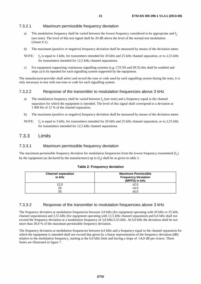
The maximum permissible frequency deviation for modulation frequencies from the lowest frequency transmitted (f1)
by the equipment (as declared by the manufacturer) up to (f2) shall be as given in table 2.
Table 2: Frequency deviation
Channel separation in kHz
Maximum Permissible Frequency Deviation
(MPFD) in kHz 12,5 20 25
±2,5 ±4,0 ±5,0
7.3.3.2 Response of the transmitter to modulation frequencies above 3 kHz
The frequency deviation at modulation frequencies between 3,0 kHz (for equipment operating with 20 kHz or 25 kHz channel separations) and 2,55 kHz (for equipment operating with 12,5 kHz channel separation) and 6,0 kHz shall not exceed the frequency deviation at a modulation frequency of 3,0 kHz/2,55 kHz. At 6,0 kHz the deviation shall be not more than 30,0 % of the maximum permissible frequency deviation.
The frequency deviation at modulation frequencies between 6,0 kHz and a frequency equal to the channel separation for which the equipment is intended shall not exceed that given by a linear representation of the frequency deviation (dB) relative to the modulation frequency, starting at the 6,0 kHz limit and having a slope of -14,0 dB per octave. These limits are illustrated in figure 7.

ETSI
ETSI EN 300 296-1 V1.4.1 (2013-08) 22
Figure 7: Template showing deviation response versus modulation frequencies
Where:
- f1 lowest appropriate frequency;
- f2 3,0 kHz (for 20 kHz or 25 kHz channel separation); or
- 2,55 kHz (for 12,5 kHz channel separation);
- A measured frequency deviation at f2;
- fcs frequency equal to channel separation.
7.4 Adjacent and alternate channel power
7.4.1 Definition
The adjacent channel power is that part of the total power output of a transmitter under defined conditions of modulation, which falls within a specified pass-band centred on the nominal frequency of either of the adjacent channels. This power is the sum of the mean power produced by the modulation, hum and noise of the transmitter.
The alternate channel power is that part of the total power output of a transmitter under defined conditions of modulation, which falls within a specified pass-band centred on the nominal frequency of either of the alternate channels. This power is the sum of the mean power produced by the modulation, hum and noise of the transmitter.
7.4.2 Method of measurement
The adjacent channel power and the alternate channel power may be measured with a power measuring receiver or spectrum analyzer, which conforms to the requirements given in clause B.2.
MPFDA
30 % MPFD
f f 6 kHz f1 2 cs
Frequency deviation Audio frequency
-14 dB/oct
-14 dB/oct
ETSI
ETSI EN 300 296-1 V1.4.1 (2013-08) 23
Artificial Antenna
Transmitter under test
Power Measuring Receiver
orSpectrum Analyzer
Test Fixture
Modulating Signal
Generator
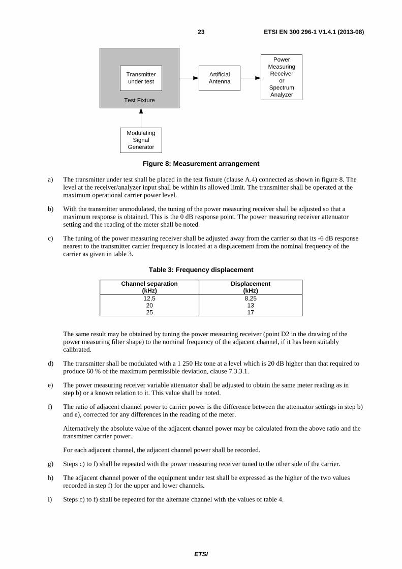
Figure 8: Measurement arrangement
a) The transmitter under test shall be placed in the test fixture (clause A.4) connected as shown in figure 8. The level at the receiver/analyzer input shall be within its allowed limit. The transmitter shall be operated at the maximum operational carrier power level.
b) With the transmitter unmodulated, the tuning of the power measuring receiver shall be adjusted so that a maximum response is obtained. This is the 0 dB response point. The power measuring receiver attenuator setting and the reading of the meter shall be noted.
c) The tuning of the power measuring receiver shall be adjusted away from the carrier so that its -6 dB response nearest to the transmitter carrier frequency is located at a displacement from the nominal frequency of the carrier as given in table 3.
Table 3: Frequency displacement
Channel separation (kHz)
Displacement (kHz)
12,5 20 25
8,25 13 17
The same result may be obtained by tuning the power measuring receiver (point D2 in the drawing of the power measuring filter shape) to the nominal frequency of the adjacent channel, if it has been suitably calibrated.
d) The transmitter shall be modulated with a 1 250 Hz tone at a level which is 20 dB higher than that required to produce 60 % of the maximum permissible deviation, clause 7.3.3.1.
e) The power measuring receiver variable attenuator shall be adjusted to obtain the same meter reading as in step b) or a known relation to it. This value shall be noted.
f) The ratio of adjacent channel power to carrier power is the difference between the attenuator settings in step b) and e), corrected for any differences in the reading of the meter.
Alternatively the absolute value of the adjacent channel power may be calculated from the above ratio and the transmitter carrier power.
For each adjacent channel, the adjacent channel power shall be recorded.
g) Steps c) to f) shall be repeated with the power measuring receiver tuned to the other side of the carrier.
h) The adjacent channel power of the equipment under test shall be expressed as the higher of the two values recorded in step f) for the upper and lower channels.
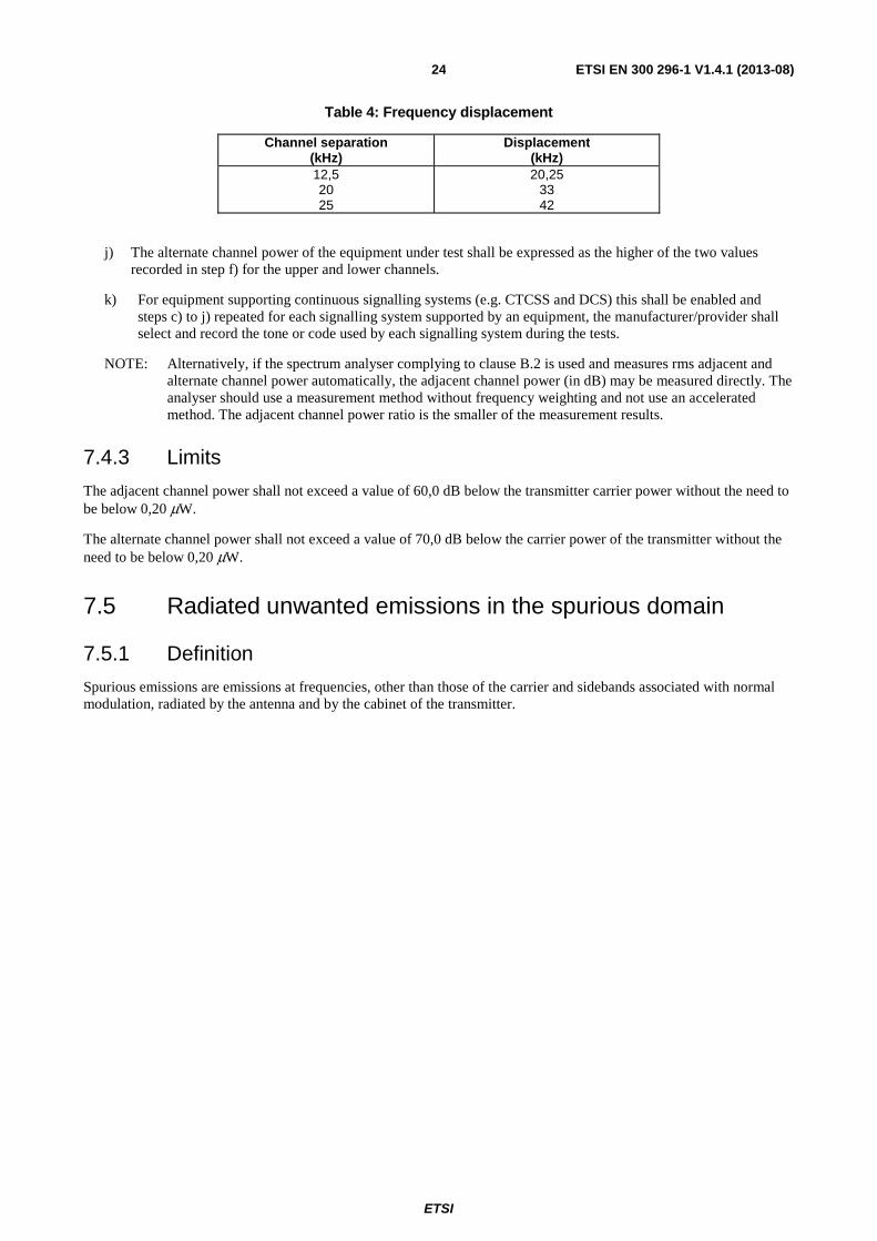
i) Steps c) to f) shall be repeated for the alternate channel with the values of table 4.
ETSI
ETSI EN 300 296-1 V1.4.1 (2013-08) 24
Table 4: Frequency displacement
Channel separation (kHz)
Displacement (kHz)
12,5 20 25
20,25 33 42
j) The alternate channel power of the equipment under test shall be expressed as the higher of the two values recorded in step f) for the upper and lower channels.
k) For equipment supporting continuous signalling systems (e.g. CTCSS and DCS) this shall be enabled and steps c) to j) repeated for each signalling system supported by an equipment, the manufacturer/provider shall select and record the tone or code used by each signalling system during the tests.
NOTE: Alternatively, if the spectrum analyser complying to clause B.2 is used and measures rms adjacent and alternate channel power automatically, the adjacent channel power (in dB) may be measured directly. The analyser should use a measurement method without frequency weighting and not use an accelerated method. The adjacent channel power ratio is the smaller of the measurement results.
7.4.3 Limits
The adjacent channel power shall not exceed a value of 60,0 dB below the transmitter carrier power without the need to be below 0,20 μW.
The alternate channel power shall not exceed a value of 70,0 dB below the carrier power of the transmitter without the need to be below 0,20 μW.
7.5 Radiated unwanted emissions in the spurious domain
7.5.1 Definition
Spurious emissions are emissions at frequencies, other than those of the carrier and sidebands associated with normal modulation, radiated by the antenna and by the cabinet of the transmitter.

ETSI
ETSI EN 300 296-1 V1.4.1 (2013-08) 25
7.5.2 Method of measurement
1 2
3
Test Site
4
NOTE 1: Transmitter under test. NOTE 2: Test antenna. NOTE 3: High "Q" (notch) or high pass filter. NOTE 4: Spectrum analyser or selective voltmeter (test receiver).
Figure 9: Measurement arrangement
The measurement arrangement in figure 9 shall be used.
The measurement procedure shall be as follows:
a) On a test site, fulfilling the requirements of annex A, the sample shall be placed at the specified height on the support.
b) The transmitter shall be operated at the transmitter power as specified under clause 7.2, delivered to the integral antenna.
c) If possible, the measurement shall be made with the transmitter unmodulated. If this is not possible, the transmitter shall be modulated by the normal test signal as appropriate (see clause 6.1).
The transmitter shall be set in continuous transmission mode. If this is not possible, this fact shall be stated in the test report and precautions shall be taken to ensure that all spurious emissions are correctly detected and measured.
The resolution bandwidth of the measuring instrument shall be the smallest bandwidth available which is greater than the spectral width of the spurious component being measured. This shall be considered to be achieved when the next highest bandwidth causes less than 1 dB increase in amplitude.
As a general rule, the resolution bandwidth of the measuring receiver should be equal to the reference bandwidth.
"To improve measurement accuracy, sensitivity and efficiency, the resolution bandwidth can be different from the reference bandwidth. When the resolution bandwidth is smaller than the reference bandwidth, the result should be integrated over the reference bandwidth. When the resolution bandwidth is greater than the reference bandwidth, the result for broadband spurious emissions should be normalized to the bandwidth ratio. For discrete spur, normalization is not applicable, while integration over the reference bandwidth is still applicable." (extract from CEPT/ERC/REC 74-01 [i.1], recommend 4, page 5).
The conditions used in the relevant measurements shall be reported in the test report.

ETSI
ETSI EN 300 296-1 V1.4.1 (2013-08) 26
d) The radiation of any spurious components shall be detected by the test antenna and receiver, over the frequency range 30 MHz to 4 GHz, For equipment operating on frequencies above 470 MHz the measurements shall also be performed over the frequency range 4 GHz to 12,75 GHz if emissions are detected within 10 dB of the of the specified limit between 1,5 GHz and 4 GHz.
The measurements are performed excluding the five contiguous channels centred on the channel on which the transmitter is intended to operate.
e) At each frequency at which a component is detected, the sample shall be rotated to obtain maximum response and the effective radiated power of that component determined by a substitution measurement, using the measurement arrangement of figure 10.
f) The value of the effective radiated power of that component shall be recorded.
g) The measurements shall be repeated with the test antenna in the orthogonal polarization plane.
h) The measurements shall be repeated with the transmitter in the "stand-by" position.
2 3
4
Test Site
1
NOTE 1: Signal generator. NOTE 2: Substitution antenna. NOTE 3: Test antenna. NOTE 4: Spectrum analyser or selective voltmeter (test receiver).
Figure 10: Measurement arrangement
7.5.3 Limits
The power of any spurious emission shall not exceed the values given in table 5a.
Table 5a: Radiated emissions
Frequency range Tx operating Tx standby 30 MHz to 1 GHz 0,25 μW (-36 dBm) 2,0 nW (-57 dBm)
Above 1 GHz to 4 GHz, or
above 1 GHz to 12,75 GHz (see clause 7.5.2)
1,00 μW (-30 dBm) 20 nW (-47 dBm)
ETSI
ETSI EN 300 296-1 V1.4.1 (2013-08) 27
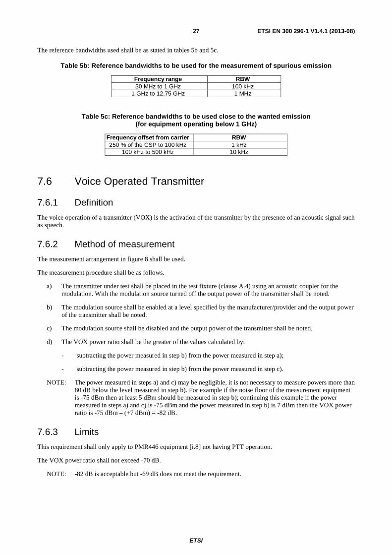
The reference bandwidths used shall be as stated in tables 5b and 5c.
Table 5b: Reference bandwidths to be used for the measurement of spurious emission
Frequency range RBW 30 MHz to 1 GHz 100 kHz
1 GHz to 12,75 GHz 1 MHz
Table 5c: Reference bandwidths to be used close to the wanted emission (for equipment operating below 1 GHz)
Frequency offset from carrier RBW 250 % of the CSP to 100 kHz 1 kHz
100 kHz to 500 kHz 10 kHz
7.6 Voice Operated Transmitter
7.6.1 Definition
The voice operation of a transmitter (VOX) is the activation of the transmitter by the presence of an acoustic signal such as speech.
7.6.2 Method of measurement
The measurement arrangement in figure 8 shall be used.
The measurement procedure shall be as follows.
a) The transmitter under test shall be placed in the test fixture (clause A.4) using an acoustic coupler for the modulation. With the modulation source turned off the output power of the transmitter shall be noted.
b) The modulation source shall be enabled at a level specified by the manufacturer/provider and the output power of the transmitter shall be noted.
c) The modulation source shall be disabled and the output power of the transmitter shall be noted.
d) The VOX power ratio shall be the greater of the values calculated by:
- subtracting the power measured in step b) from the power measured in step a);
- subtracting the power measured in step b) from the power measured in step c).
NOTE: The power measured in steps a) and c) may be negligible, it is not necessary to measure powers more than 80 dB below the level measured in step b). For example if the noise floor of the measurement equipment is -75 dBm then at least 5 dBm should be measured in step b); continuing this example if the power measured in steps a) and c) is -75 dBm and the power measured in step b) is 7 dBm then the VOX power ratio is -75 dBm – (+7 dBm) = -82 dB.
7.6.3 Limits
This requirement shall only apply to PMR446 equipment [i.8] not having PTT operation.
The VOX power ratio shall not exceed -70 dB.
NOTE: -82 dB is acceptable but -69 dB does not meet the requirement.

ETSI
ETSI EN 300 296-1 V1.4.1 (2013-08) 28
7.7 Maximum transmission time
7.7.1 Definition
The maximum transmission time is the total transmission time following an activation by either PTT, VOX control or any other mechanism.
7.7.2 Method of measurement
The measurement arrangement in figure 8 shall be used.
The measurement procedure shall be as follows:
a) the transmitter under test shall be activated;
b) the output power shall be monitored;
c) the time between the start of transmission and the end of the transmission, shall be noted.
NOTE 1: The start of transmission is taken as the time when the measured power has increased from a value at least 70 dB below the value measured in clause 7.2 to not less than 3 dB below the value measured in clause 7.2.
NOTE 2: The end of transmission is taken as the time when the measured power has reduced by at least 70 dB below the value measured in clause 7.2.
7.7.3 Limits
The maximum transmission time shall be less than 180 seconds.
This requirement only applies to PMR446 equipment [i.8] having Push-To-Talk (PTT) functionality capable of being latched 'on' or no PTT functionality.
8 Technical characteristics of the receiver
8.1 Average usable sensitivity (field strength, speech)
8.1.1 Definition
The average usable sensitivity expressed as field strength is the average field strength, expressed in dBμV/m, produced by a carrier at the nominal frequency of the receiver, modulated with the normal test signal (see clause 6.1) which will, without interference, produce after demodulation a SINAD ratio of 20 dB measured through a psophometric weighting network. The average is calculated from eight measurements of field strength when the receiver is rotated in 45° increments starting at a particular orientation.
NOTE: The average usable sensitivity mostly differs only by a small amount from the maximum usable sensitivity to be found in a particular direction. This is due to the properties of the averaging process as used in the formula in clause 8.1.2.1 g). For instance, an error not exceeding 1,2 dB can be found if the sensitivity is equal in seven directions and is extremely bad in the eighth direction. For the same reason the starting direction (or angle) can be selected randomly.
8.1.2 Methods of measurement
8.1.2.1 Method of measurement under normal test conditions
Arrangements shall be made to couple the equipment under test to the SINAD meter by a method which does not affect the radiated field (clause A.3.3).

ETSI
ETSI EN 300 296-1 V1.4.1 (2013-08) 29
On a test site, selected from annex A, the equipment shall be placed at the specified height on a non-conducting support and in the position closest to normal use as declared by the manufacturer.
The test antenna shall be orientated for vertical polarization and the length of the test antenna shall be chosen to correspond to the frequency of the receiver.
3 4
5
Test Site
21
NOTE 1: SINAD meter and psophometric weighting network. NOTE 2: AF load/acoustic coupler. NOTE 3: Receiver under test. NOTE 4: Test antenna. NOTE 5: Signal generator.
Figure 11: Measurement arrangement
The receiver under test shall be placed on the support at a suitable height in a random orientation. A distortion factor meter incorporating a 1 000 Hz band-stop filter (see annex D), (or a SINAD meter) shall be connected to the receiver output terminals via a psophometric filter and an audio frequency load or by an acoustic coupler (see clause A.3.3) in order to avoid disturbing the electromagnetic field in the vicinity of the equipment (see figure 11).
The measurement procedure shall be as follows:
a) A signal generator shall be connected to the test antenna:
- the signal generator shall be at the nominal frequency of the receiver and shall be modulated by the normal test modulation A-M1 (see clause 6.1).
b) Where possible, the receiver volume control shall be adjusted to give at least 50 % of the rated output power, clause 6.6, or, in the case of stepped volume controls, to the first step that provides an output power of at least 50 % of the rated output power:
- the SINAD ratio shall be monitored.
c) The level of the signal generator shall be adjusted until a psophometrically weighted SINAD ratio (or its acoustic equivalent) of 20 dB is obtained.
d) The test antenna shall be raised or lowered through the specified height range to find the best psophometrically weighted SINAD ratio (or its acoustic equivalent).
e) The level of the signal generator shall be re-adjusted until a SINAD ratio of 20 dB is obtained.
f) The minimum signal generator level from step d) shall be noted.
g) Steps c) to f) shall be repeated for the remaining seven positions 45° apart of the receiver and the corresponding values of the signal generator output which produces the psophometrically weighted SINAD ratio of 20 dB again (or its acoustic equivalent) shall be determined and noted.

ETSI
ETSI EN 300 296-1 V1.4.1 (2013-08) 30
h) The input signal level to the test antenna shall be maintained.
The receiver shall be replaced by a substitution antenna as defined in clause A.1.5.
The substitution antenna shall be orientated for vertical polarization and the length of the substitution antenna shall be adjusted to correspond to the frequency of the receiver.
The substitution antenna shall be connected to a calibrated measuring receiver.
The test antenna shall be raised and lowered through the specified range of height to ensure that the maximum signal is received.
The signal level measured with the calibrated measuring receiver shall be recorded as the field strength in dBμV/m.
Calculate and record the eight field strengths Xi (i = 1,...8) in μV/m corresponding to the levels of the signal
generator noted above.
i) The average usable sensitivity expressed as field strength Emean (dBμV/m) is given by:
⎟⎟⎟⎟⎟⎟
⎠
⎞
⎜⎜⎜⎜⎜⎜
⎝
⎛
⎟⎟⎟⎟⎟
⎠
⎞
⎜⎜⎜⎜⎜
⎝
⎛
Χ
=Ε
∑=
=
8
1 2
18
log20I
Ii
mean
- where Xi represents each of the eight field strengths calculated in step h).
j) The reference direction is defined as the direction at which the maximum sensitivity (i.e. corresponding to the minimum field strength recorded during the measurement) occurred in the eight position measurement:
- the corresponding direction, height (where applicable) and this reference field strength value shall be recorded.
8.1.2.2 Method of measurement under extreme test conditions
Using the test fixture in the measurement arrangement of figure 12, the measurement of the average usable sensitivity shall also be performed under extreme test conditions.
AF Load / Acoustic Coupler
Receiver under test
Psophometric weighting
network and SINAD meter
Test Fixture
Signal Generator
Figure 12: Measurement arrangement
The test signal input level providing a psophometrically weighted SINAD ratio of 20 dB (or its acoustic equivalent) shall be determined under extreme and under normal test conditions and the difference in dB shall be calculated. This difference shall be added to the average usable sensitivity to radiated fields expressed in dBμV/m, as calculated in clause 8.1.2.1 step i), under normal test conditions, to obtain the sensitivity under extreme test conditions.
8.1.3 Limits
For the average usable sensitivity limits, four categories of equipment are defined as follows:
Category A: equipment having an integral antenna fully within the case.

ETSI
ETSI EN 300 296-1 V1.4.1 (2013-08) 31
Category B: equipment having an extractable or fixed integral antenna, with an antenna length not exceeding 20 cm external to the case.
Category C: equipment having an extractable or fixed integral antenna, with an antenna length exceeding 20 cm external to the case.
Category D: equipment not covered by category A, B or C.
Under normal test conditions, the average usable sensitivity shall not exceed the following field strength values.
Table 6a: Sensitivity limits for Categories A and D
Frequency band (MHz)
Average usable sensitivity in dB relative to 1μV/m
30 to 400 > 400 to 750
> 750 to 1 000
30,0 31,5 33,0
Table 6b: Sensitivity limits for Category B
Frequency band (MHz)
Average usable sensitivity in dB relative to 1μV/m
30 to 130 > 130 to 300 > 300 to 440 > 440 to 600 > 600 to 800
> 800 to 1 000
21,0 22,5 24,5 26,5 28,5 31,0
Category C
At frequencies greater than 375 MHz the limits shall be as specified in table 6b.
In the case of frequencies less than or equal to 375 MHz a correction factor K shall be subtracted from the specified field strengths in table 5b.
- K = 20 log10 [(l + 20)/40];
- where l is the external part of the antenna in cm.
This correction only applies if the antenna length external to the case is less than (15 000/fo - 20) in cm, where fo is the
frequency in MHz.
For all categories of equipment, add 6 dB to the limit under normal test conditions to obtain the limit under extreme test conditions.
8.2 Spurious radiations
8.2.1 Definition
Unwanted emissions from the receiver are components at any frequency radiated by the equipment and its antenna.

ETSI
ETSI EN 300 296-1 V1.4.1 (2013-08) 32
8.2.2 Method of measurement
1 2
3
Test Site
NOTE 1: Receiver under test. NOTE 2: Test antenna. NOTE 3: Spectrum analyser or selective voltmeter (test receiver).
Figure 13: Measurement arrangement
The measurement procedure shall be as follows (see figure 13):
a) A test site, which fulfils the requirements of the specified frequency range of this measurement selected from annex A, shall be used.
The test antenna shall be oriented for vertical polarization and connected to a spectrum analyser or a selective voltmeter with reference bandwidth as stated in table 5b.
b) The receiver under test shall be placed on the support at a suitable height. The radiation of any spurious component shall be detected by the test antenna and spectrum analyser or selective voltmeter over the frequency range 30 MHz to 4 GHz. In addition, for equipment operating on frequencies above 470 MHz, measurements shall be repeated over the frequency range 4 GHz to 12,75 GHz.
The frequency of each spurious component shall be recorded.
c) At each frequency at which a component has been detected, the spectrum analyser or selective voltmeter shall be tuned and the test antenna shall be raised or lowered through the specified height range until the maximum signal level is detected on the spectrum analyser or selective voltmeter.
d) The receiver shall be rotated through 360° around a vertical axis, until higher maximum signal is received.
e) The test antenna shall be raised or lowered again through the specified height range until a maximum is obtained. This level shall be recorded.

ETSI
ETSI EN 300 296-1 V1.4.1 (2013-08) 33
2 3
4
Test Site
1
NOTE 1: Signal generator. NOTE 2: Substitution antenna. NOTE 3: Test antenna. NOTE 4: Spectrum analyser or selective voltmeter (test receiver).
Figure 14: Measurement arrangement
f) Using the measurement arrangement in figure 14, the substitution antenna shall replace the receiver antenna in the same position and in vertical polarization. It shall be connected to the signal generator.
g) For each frequency at which a component has been detected, the signal generator and spectrum analyser or selective voltmeter shall be tuned and the test antenna shall be raised or lowered through the specified height range until the maximum signal level is detected on the spectrum analyser or selective voltmeter.
The test antenna may not need to be raised or lowered if the measurement is carried out on a test site according to clause A.1.1.
The level of the signal generator giving the same signal level on the spectrum analyser or selective voltmeter as in step e) shall be recorded. This value, after correction due to the gain of the substitution antenna and the cable loss between the signal generator and the substitution antenna, is the radiated spurious component at this frequency.
h) Measurements of steps b) to g) shall be repeated with the test antenna oriented in horizontal polarization.
8.2.3 Limits
The power of any spurious radiation shall not exceed the values given in tables 7a and 7b.
Table 7a: Radiated components
Frequency range 30 MHz to 1 GHz above 1 GHz to 12,75 GHz Limit 2,0 nW (-57,0 dBm) 20,0 nW (-47,0 dBm)
Table 7b: Reference bandwidths to be used for the measurement of unwanted radiations
Frequency range RBW 30 MHz to 1 GHz 100 kHz
1 GHz to 12,75 GHz 1 MHz
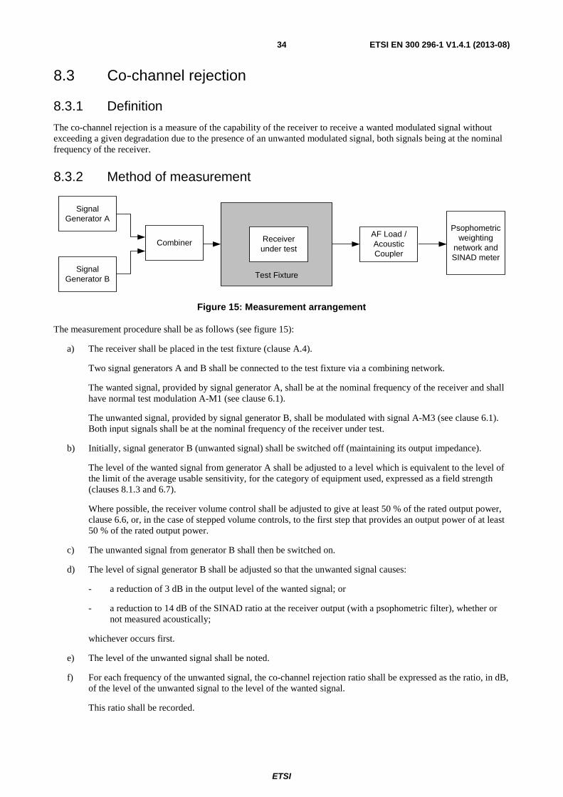
ETSI
ETSI EN 300 296-1 V1.4.1 (2013-08) 34
8.3 Co-channel rejection
8.3.1 Definition
The co-channel rejection is a measure of the capability of the receiver to receive a wanted modulated signal without exceeding a given degradation due to the presence of an unwanted modulated signal, both signals being at the nominal frequency of the receiver.
8.3.2 Method of measurement
AF Load / Acoustic Coupler
Receiver under test
Psophometric weighting
network and SINAD meter
Test Fixture
Combiner
Signal Generator A
Signal Generator B
Figure 15: Measurement arrangement
The measurement procedure shall be as follows (see figure 15):
a) The receiver shall be placed in the test fixture (clause A.4).
Two signal generators A and B shall be connected to the test fixture via a combining network.
The wanted signal, provided by signal generator A, shall be at the nominal frequency of the receiver and shall have normal test modulation A-M1 (see clause 6.1).
The unwanted signal, provided by signal generator B, shall be modulated with signal A-M3 (see clause 6.1). Both input signals shall be at the nominal frequency of the receiver under test.
b) Initially, signal generator B (unwanted signal) shall be switched off (maintaining its output impedance).
The level of the wanted signal from generator A shall be adjusted to a level which is equivalent to the level of the limit of the average usable sensitivity, for the category of equipment used, expressed as a field strength (clauses 8.1.3 and 6.7).
Where possible, the receiver volume control shall be adjusted to give at least 50 % of the rated output power, clause 6.6, or, in the case of stepped volume controls, to the first step that provides an output power of at least 50 % of the rated output power.
c) The unwanted signal from generator B shall then be switched on.
d) The level of signal generator B shall be adjusted so that the unwanted signal causes:
- a reduction of 3 dB in the output level of the wanted signal; or
- a reduction to 14 dB of the SINAD ratio at the receiver output (with a psophometric filter), whether or not measured acoustically;
whichever occurs first.
e) The level of the unwanted signal shall be noted.
f) For each frequency of the unwanted signal, the co-channel rejection ratio shall be expressed as the ratio, in dB, of the level of the unwanted signal to the level of the wanted signal.
This ratio shall be recorded.

ETSI
ETSI EN 300 296-1 V1.4.1 (2013-08) 35
g) The measurement shall be repeated for displacements of the unwanted signal of ±6 % and ±12 % of the channel separation.
h) The co-channel rejection of the equipment under test shall be expressed as the lowest of the five values expressed in dB, recorded in step f).
The value of the co-channel rejection ratio, expressed in dB, is generally negative (therefore, for example, -12 dB is lower than -8 dB).
8.3.3 Limits
The value of the co-channel rejection ratio, expressed in dB, at any frequency of the unwanted signal within the specified range, shall be between:
• -8,0 dB and 0 dB for channel separations of 20 kHz and 25 kHz;
• -12,0 dB and 0 dB for a channel separation of 12,5 kHz.
8.4 Adjacent channel selectivity
8.4.1 Definition
The adjacent channel selectivity is a measure of the capability of the receiver to receive a wanted modulated signal without exceeding a given degradation due to the presence of an unwanted signal which differs in frequency from the wanted signal by an amount equal to the adjacent channel separation for which the equipment is intended.
8.4.2 Method of measurement
AF Load / Acoustic Coupler
Receiver under test
Psophometric weighting
network and SINAD meter
Test Fixture
Combiner
Signal Generator A
Signal Generator B
Figure 16: Measurement arrangement
The measurement procedure shall be as follows (see figure 16):
a) The receiver shall be placed in the test fixture (clause A.4).
Two signal generators A and B shall be connected to the test fixture via a combining network.
The wanted signal, provided by signal generator A, shall be at the nominal frequency of the receiver and shall have normal test modulation A-M1 (see clause 6.1).
The unwanted signal, provided by signal generator B, shall be modulated with signal A-M3 (see clause 6.1) and shall be at the frequency of the channel immediately above that of the wanted signal.
b) Initially, signal generator B (unwanted signal) shall be switched off (maintaining the output impedance).
The level of the wanted signal from generator A shall be adjusted to the level which is equivalent to the level of the limit of the average usable sensitivity, for the category of equipment used, expressed as a field strength (clauses 8.1.3 and 6.7).
Where possible, the receiver volume control shall be adjusted to give at least 50 % of the rated output power, clause 6.6, or, in the case of stepped volume controls, to the first step that provides an output power of at least 50 % of the rated output power.

ETSI
ETSI EN 300 296-1 V1.4.1 (2013-08) 36
c) The unwanted signal from signal generator B shall then be switched on.
d) The level of signal generator B shall be adjusted so that the unwanted signal causes:
- a reduction of 3 dB in the output level of the wanted signal; or
- a reduction to 14 dB of the SINAD ratio at the receiver output (with a psophometric filter), whether or not measured acoustically;
whichever occurs first.
e) The level of the unwanted signal shall be noted.
f) For each adjacent channel, the selectivity shall be expressed as the ratio in dB of level of the unwanted signal to the level of the wanted signal.
It shall then be converted back into field strengths of the unwanted signals at the receiver location and expressed in dBμV/m.
This value shall be recorded.
g) The measurement shall be repeated with the unwanted signal at the frequency of the channel below that of the wanted signal.
h) The adjacent channel selectivity of the equipment under test shall be expressed as the lower of the two values calculated in step f) for the upper and lower channels nearest to the receiving channel.
i) The measurement shall be repeated under extreme test conditions (clauses 5.4.1 and 5.4.2 applied simultaneously), with the level of the wanted signal adjusted to a level which is equivalent to the level of the limit of the average usable sensitivity (under extreme test conditions), for the category of equipment used, expressed as a field strength (see clauses 8.1.3 and 6.7).
8.4.3 Limits
The adjacent channel selectivity of the equipment shall be such that under the specified test conditions, the given degradation shall not be exceeded for levels of the unwanted signal up to those given in table 8.
Table 8: Adjacent channel selectivity
Channel Separation
(kHz)
Adjacent channel selectivity limit (dBμV/m) Unwanted frequencies ≤ 68 MHz Unwanted frequencies > 68 MHz Normal test conditions
Extreme test conditions
Normal test conditions Extreme test conditions
20 and 25 75 65 20 log10(f) + 38,3 20 log10(f) + 28,3
12,5 65 55 20 log10(f) + 28,3 20 log10(f) + 18,3
NOTE: f is the carrier frequency in MHz.
8.5 Spurious response rejection
8.5.1 Definition
The spurious response rejection is a measure of the capability of the receiver to receive a wanted modulated signal without exceeding a given degradation due to the presence of an unwanted modulated signal at any other frequency, at which a response is obtained.
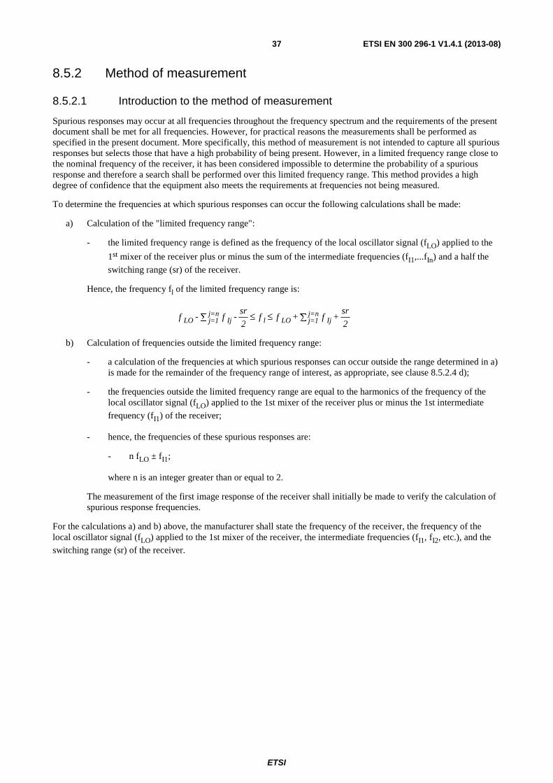
ETSI
ETSI EN 300 296-1 V1.4.1 (2013-08) 37
8.5.2 Method of measurement
8.5.2.1 Introduction to the method of measurement
Spurious responses may occur at all frequencies throughout the frequency spectrum and the requirements of the present document shall be met for all frequencies. However, for practical reasons the measurements shall be performed as specified in the present document. More specifically, this method of measurement is not intended to capture all spurious responses but selects those that have a high probability of being present. However, in a limited frequency range close to the nominal frequency of the receiver, it has been considered impossible to determine the probability of a spurious response and therefore a search shall be performed over this limited frequency range. This method provides a high degree of confidence that the equipment also meets the requirements at frequencies not being measured.
To determine the frequencies at which spurious responses can occur the following calculations shall be made:
a) Calculation of the "limited frequency range":
- the limited frequency range is defined as the frequency of the local oscillator signal (fLO) applied to the
1st mixer of the receiver plus or minus the sum of the intermediate frequencies (fI1,...fIn) and a half the
switching range (sr) of the receiver.
Hence, the frequency fl of the limited frequency range is:
2
sr + f + f f
2
sr - f - f Ij
n=j1=jLOlIj
n=j1=jLO ∑≤≤∑
b) Calculation of frequencies outside the limited frequency range:
- a calculation of the frequencies at which spurious responses can occur outside the range determined in a) is made for the remainder of the frequency range of interest, as appropriate, see clause 8.5.2.4 d);
- the frequencies outside the limited frequency range are equal to the harmonics of the frequency of the local oscillator signal (fLO) applied to the 1st mixer of the receiver plus or minus the 1st intermediate
frequency (fI1) of the receiver;
- hence, the frequencies of these spurious responses are:
- n fLO ± fI1;
where n is an integer greater than or equal to 2.
The measurement of the first image response of the receiver shall initially be made to verify the calculation of spurious response frequencies.
For the calculations a) and b) above, the manufacturer shall state the frequency of the receiver, the frequency of the local oscillator signal (fLO) applied to the 1st mixer of the receiver, the intermediate frequencies (fI1, fI2, etc.), and the
switching range (sr) of the receiver.
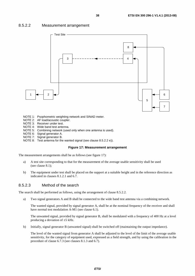
ETSI
ETSI EN 300 296-1 V1.4.1 (2013-08) 38
8.5.2.2 Measurement arrangement
3 4
5
Test Site
21
8
7
6
NOTE 1: Psophometric weighting network and SINAD meter. NOTE 2: AF load/acoustic coupler. NOTE 3: Receiver under test. NOTE 4: Wide band test antenna. NOTE 5: Combining network (used only when one antenna is used). NOTE 6: Signal generator A. NOTE 7: Signal generator B. NOTE 8: Test antenna for the wanted signal (see clause 8.5.2.2 e)).
Figure 17: Measurement arrangement
The measurement arrangements shall be as follows (see figure 17):
a) A test site corresponding to that for the measurement of the average usable sensitivity shall be used (see clause 8.1);
b) The equipment under test shall be placed on the support at a suitable height and in the reference direction as indicated in clauses 8.1.2.1 and 6.7.
8.5.2.3 Method of the search
The search shall be performed as follows, using the arrangement of clause 8.5.2.2.
a) Two signal generators A and B shall be connected to the wide band test antenna via a combining network.
The wanted signal, provided by signal generator A, shall be at the nominal frequency of the receiver and shall have normal test modulation A-M1 (see clause 6.1).
The unwanted signal, provided by signal generator B, shall be modulated with a frequency of 400 Hz at a level producing a deviation of ±5 kHz.
b) Initially, signal generator B (unwanted signal) shall be switched off (maintaining the output impedance).
The level of the wanted signal from generator A shall be adjusted to the level of the limit of the average usable sensitivity, for the category of equipment used, expressed as a field strength, and by using the calibration in the procedure of clause 6.7.3 (see clauses 8.1.3 and 6.7).

ETSI
ETSI EN 300 296-1 V1.4.1 (2013-08) 39
c) The unwanted signal from generator B shall then be switched on.
The level of signal generator B shall be adjusted to provide a field strength which is at least 10 dB above the limit of the spurious response rejection (see clause 8.5.3) measured at the receiver location, even when on some types of test sites the level of the unwanted signal varies considerably with the frequency due to ground reflections.
The frequency of the unwanted signal shall be varied in increments of 10 kHz over the limited frequency range (see clause 8.5.2.1 a)) and over the frequencies in accordance with the calculations outside of this frequency range (see clause 8.5.2.1 b)).
d) The SINAD ratio shall be monitored.
e) If the SINAD ratio is better than 20 dB then no spurious response effects have been detected and the measurement shall be continued on the next increment of frequency.
f) If the SINAD ratio is worse than 20 dB then the level of the unwanted signal shall be reduced in steps of 1 dB until a SINAD ratio of 20 dB or better is obtained.
g) In the case where a reflective ground floor is used the antenna height shall be varied as appropriate, at each change of unwanted signal level in an attempt to obtain a SINAD ratio of 20 dB or better.
The test antenna may not need to be raised or lowered if a test site according to clause A.1.1 is used, or if the ground floor reflection can effectively be eliminated.
h) The frequency of any spurious response detected during the search, and the antenna position and its height shall be recorded for the use in the measurements in accordance with clause 8.5.2.4.
8.5.2.4 Measurement
At each frequency where a spurious response has been found, within and outside the limited frequency range, the measurement shall be performed as follows.
a) The measurement arrangement is identical to that in clause 8.5.2.3.
Two signal generators A and B shall be connected to the wide band test antenna via a combining network.
The wanted signal, provided by signal generator A, shall be at the nominal frequency of the receiver and shall have normal test modulation A-M1 (see clause 6.1).
The unwanted signal, provided by signal generator B, shall be modulated with a frequency of 400 Hz with a deviation of 12 % of the channel separation (A-M3).
b) Initially, signal generator B (unwanted signal) shall be switched off (maintaining the output impedance).
The level of the wanted signal from signal generator A shall be adjusted to the level of the limit of the average usable sensitivity (see clause 6.7), for the category of equipment used (see clause 8.1.3), expressed in field strength when measured at the receiver location.
Where possible, the receiver volume control shall be adjusted to give at least 50 % of the rated output power, clause 6.6, or, in the case of stepped volume controls, to the first step that provides an output power of at least 50 % of the rated output power.
c) The unwanted signal from generator B shall then be switched on.
d) The SINAD ratio shall be monitored.
e) The level of the unwanted signal shall be adjusted until a SINAD ratio of 14 dB with a psophometric filter is obtained.
The level of the unwanted signal shall then be noted.

ETSI
ETSI EN 300 296-1 V1.4.1 (2013-08) 40
f) The frequency of the unwanted signal shall be stepped up and down in increments of 20 % of the channel separation and step e) shall be repeated until the lowest level is found.
For each frequency, the spurious response rejection shall be expressed as the level in dBμV of the field strength of the unwanted signal at the receiver location, corresponding to the lowest value noted during step e).
This value shall be recorded.
g) The measurement shall be repeated at all spurious response frequencies found during the search over the limited frequency range, clause 8.5.2.1, and at frequencies calculated for the remainder of the spurious response frequencies in the frequency range fRx/3,2 MHz or 30 MHz, whichever is higher to 3,2 х fRx, where
fRx is the nominal frequency of the receiver, with the antenna position and height noted in clause 8.5.2.3 h).
h) The spurious response rejection of the equipment under test shall be expressed as the level in dBμV/m of the field strength of the unwanted signal, at the receiver location, corresponding to the lowest value recorded in step f).
8.5.3 Limits
The spurious response rejection of the equipment shall be such that under the specified test conditions, the given degradation shall not be exceeded for levels of the unwanted signal up to:
- 75 dBμV/m for unwanted signal frequencies ≤ 68 MHz;
- (20 log10 (f) + 38,3) dBμV/m for unwanted signal frequencies > 68 MHz;
- where f is the frequency in MHz.
8.6 Intermodulation response rejection
8.6.1 Definition
The intermodulation response rejection is a measure of the capability of the receiver to receive a wanted modulated signal, without exceeding a given degradation due to the presence of two or more unwanted signals with a specific frequency relationship to the wanted signal frequency.
8.6.2 Method of measurement
AF Load / Acoustic Coupler
Receiver under test
Psophometric weighting
network and SINAD meter
Test Fixture
Combiner
Signal Generator A
Signal Generator C
Signal Generator B
Figure 18: Measurement arrangement
The measurement procedure shall be as follows (see figure 18):
a) The receiver shall be placed in a test fixture (clause A.4).
Three signal generators, A, B and C shall be connected to the test fixture via a combining network.
ETSI
ETSI EN 300 296-1 V1.4.1 (2013-08) 41
The wanted signal, provided by signal generator A, shall be at the nominal frequency of the receiver and shall have normal test modulation A-M1 (see clause 6.1).
The first unwanted signal, provided by signal generator B, shall be unmodulated and adjusted to the frequency 50 kHz above the nominal frequency of the receiver.
The second unwanted signal, provided by signal generator C, shall be modulated with signal A-M3 (see clause 6.1) and adjusted to a frequency 100 kHz above the nominal frequency of the receiver.
b) Initially, signal generators B and C (unwanted signals) shall be switched off (maintaining the output impedances).
The level of the wanted signal from generator A shall be adjusted to a level which is equivalent to the level of the limit of the average usable sensitivity, for the category of equipment used, expressed as a field strength (clauses 8.1.3 and 6.7).
Where possible, the receiver volume control shall be adjusted to give at least 50 % of the rated output power, clause 6.6, or, in the case of stepped volume controls, to the first step that provides an output power of at least 50 % of the rated output power.
c) The two unwanted signals from signal generators B and C shall then be switched on.
d) Their levels shall be maintained equal and shall be adjusted so that the unwanted signal causes:
- a reduction of 3 dB in the output level of the wanted signal; or
- a reduction to 14 dB of the SINAD ratio at the receiver output (with a psophometric filter) whether or not measured acoustically;
whichever occurs first.
e) The level of the unwanted signals shall be noted.
f) For each configuration of the unwanted signals, the intermodulation response rejection shall be expressed as the ratio in dB of the level of the unwanted signals to the level of the wanted signal.
It shall then be converted back into field strength of the unwanted signals at the receiver location and expressed in dBμV/m.
This value shall be recorded.
g) The measurement shall be repeated with the unwanted signal generator B at the frequency 50 kHz below that of the wanted signal and the frequency of the unwanted signal generator C at the frequency 100 kHz below that of the wanted signal.
h) The intermodulation response rejection of the equipment under test shall be expressed as the lower of the two values recorded in step f).
8.6.3 Limits
8.6.3.1 Limits for low power equipment
The intermodulation response rejection of low power equipment shall be such that under the specified test conditions, the given degradation shall not be exceeded for levels of the unwanted signal up to:
- 60 dBμV/m for unwanted signal frequencies ≤ 68 MHz;
- (20 log10 (f) + 23,6) dBμV/m for unwanted signal frequencies > 68 MHz;
- where f is the frequency in MHz.
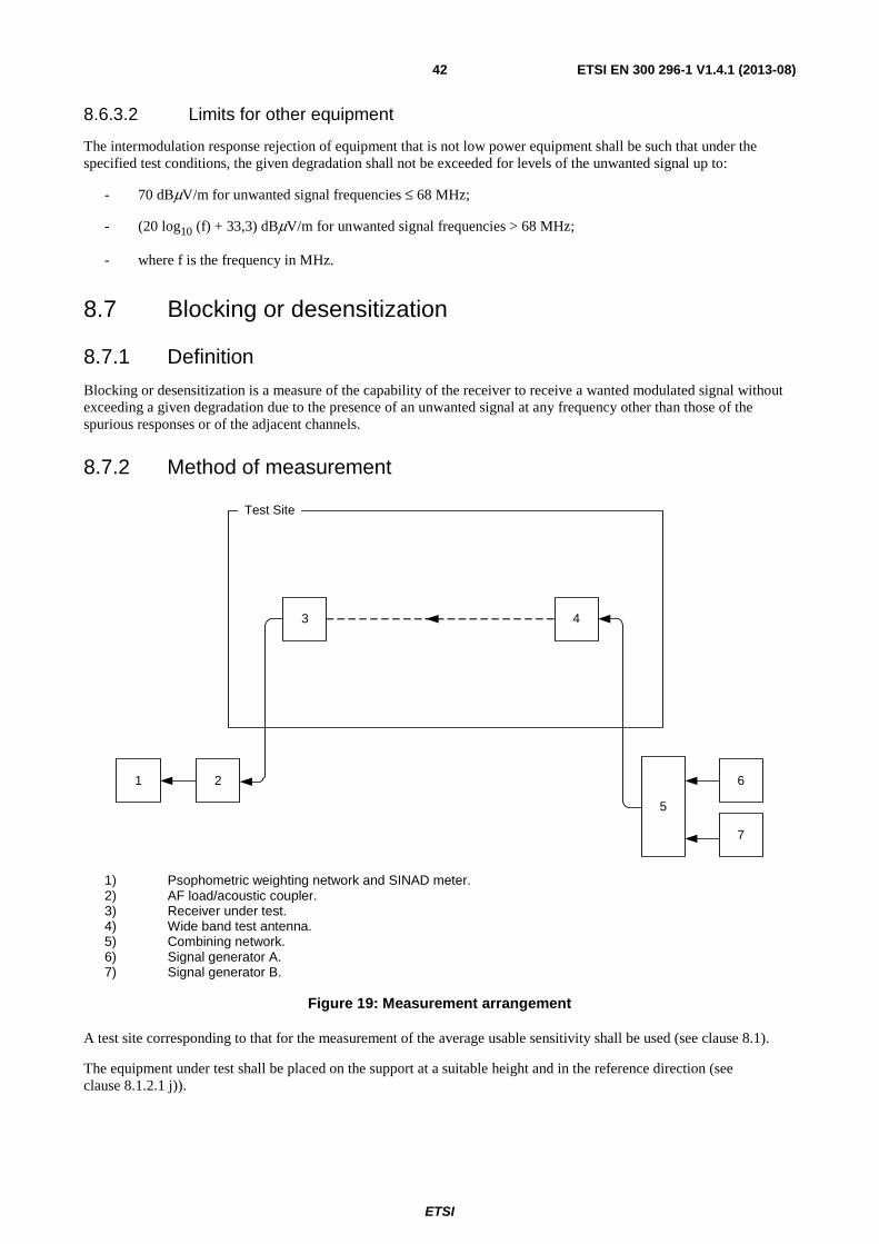
ETSI
ETSI EN 300 296-1 V1.4.1 (2013-08) 42
8.6.3.2 Limits for other equipment
The intermodulation response rejection of equipment that is not low power equipment shall be such that under the specified test conditions, the given degradation shall not be exceeded for levels of the unwanted signal up to:
- 70 dBμV/m for unwanted signal frequencies ≤ 68 MHz;
- (20 log10 (f) + 33,3) dBμV/m for unwanted signal frequencies > 68 MHz;
- where f is the frequency in MHz.
8.7 Blocking or desensitization
8.7.1 Definition
Blocking or desensitization is a measure of the capability of the receiver to receive a wanted modulated signal without exceeding a given degradation due to the presence of an unwanted signal at any frequency other than those of the spurious responses or of the adjacent channels.
8.7.2 Method of measurement
3 4
5
Test Site
21
7
6
1) Psophometric weighting network and SINAD meter. 2) AF load/acoustic coupler. 3) Receiver under test. 4) Wide band test antenna. 5) Combining network. 6) Signal generator A. 7) Signal generator B.
Figure 19: Measurement arrangement
A test site corresponding to that for the measurement of the average usable sensitivity shall be used (see clause 8.1).
The equipment under test shall be placed on the support at a suitable height and in the reference direction (see clause 8.1.2.1 j)).
ETSI
ETSI EN 300 296-1 V1.4.1 (2013-08) 43
The measurement procedure shall be as follows (see figure 19):
a) Two signals generators A and B shall be connected to the wideband test antenna via a combining network.
The wanted signal, provided by signal generator A, shall be at the nominal frequency of the receiver and shall have normal test modulation A-M1, (see clause 6.1).
The unwanted signal, provided by signal generator B, shall be unmodulated and shall be at a frequency from 1 MHz to 10 MHz away from the nominal frequency of the receiver.
For practical reasons the measurements shall be carried out at frequencies of the unwanted signal at approximately ±1 MHz, ±2 MHz, ±5 MHz and ±10 MHz, avoiding those frequencies at which spurious responses occur (see clause 8.5).
b) Initially, signal generator B (unwanted signal) shall be switched off (maintaining the output impedance):
- the level of the wanted signal from generator A shall be adjusted to the level of the limit of the average usable sensitivity expressed as a field strength (see clauses 8.1.3 and 6.7);
- where possible, the receiver volume control shall be adjusted to give at least 50 % of the rated output power, clause 6.6, or, in the case of stepped volume controls, to the first step that provides an output power of at least 50 % of the rated output power. The obtained audio output level shall be noted.
c) The unwanted signal from generator B shall then be switched on.
d) The level of generator B shall be adjusted so that the unwanted signal causes:
- a reduction of 3 dB in the output level of the wanted signal; or
- a reduction to 14 dB of the SINAD ratio at the receiver output (with a psophometric filter), whether or not measured acoustically;
whichever occurs first.
e) The level of the unwanted signal shall be noted.
f) For each frequency, the blocking or desensitization shall be expressed as the level in dBμV/m of the field strength of the unwanted signal at the receiver location.
This value shall be recorded.
g) The measurement shall be repeated for all the remaining frequencies of the list given in step a).
h) The blocking or desensitization of the equipment under test shall be expressed as the level in dBμV/m of the field strength of the unwanted signal, at the receiver location, corresponding to the lowest value recorded in step f).
8.7.3 Limits
The blocking level, for any frequency within the specified ranges, shall be:
- ≥ 89 dBμV/m for unwanted signal frequencies ≤ 68 MHz;
- ≥ (20 log10 (f) + 52,3) dBμV/m for unwanted signal frequencies > 68 MHz;
- where f is the frequency in MHz.

ETSI
ETSI EN 300 296-1 V1.4.1 (2013-08) 44
9 Measurement uncertainty The interpretation of the results recorded in the test report for the measurements described in the present document shall be as follows:
- the measured value related to the corresponding limit shall be used to decide whether an equipment meets the requirements of the present document;
- the value of the measurement uncertainty for the measurement of each parameter shall be separately included in the test report;
- the value of the measurement uncertainty shall be, for each measurement, equal to or lower than the figures in table 9.
Table 9: Absolute measurement uncertainties: maximum values
Parameter Uncertainty Radio Frequency ±1 x 10⁻⁷ Conducted RF power variation using a test fixture ±0,75 dB Radiated RF power ±6 dB Maximum frequency deviation: - within 300 Hz to 6 kHz of audio frequency - within 6 kHz to 25 kHz of audio frequency
±5 % ±3 dB
Deviation limitation ±5 % Adjacent and alternate channel power ±5 dB Sensitivity at 20 dB SINAD ±3 dB Two-signal measurement, valid up to 4 GHz (using a test fixture)
±4 dB
Two-signal measurement, valid up to 4 GHz (using radiated fields)
±6 dB
Three-signal measurement (using a test fixture) ±3 dB Radiated emission of the transmitter, valid up to 12,75 GHz
±6 dB
Radiated emission of receiver, valid up to 12,75 GHz
±6 dB
Temperature ±1 °C Humidity ±10 %
For the test methods, according to the present document, the measurement uncertainty figures shall be calculated in accordance with TR 100 028 [1] and shall correspond to an expansion factor (coverage factor) k = 1,96 or k = 2 (which provide confidence levels of respectively 95 % and 95,45 % in the case where the distributions characterizing the actual measurement uncertainties are normal (Gaussian)).
The values given in table 9 are based on such expansion factors.
The particular expansion factor used for the evaluation of the measurement uncertainty shall be stated.
TR 102 273 [i.3] provides further information concerning the usage of test sites.
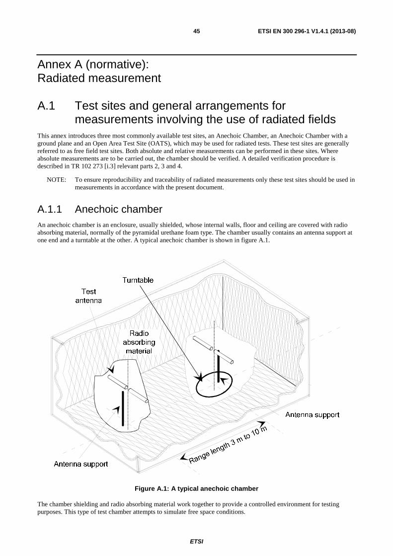
ETSI
ETSI EN 300 296-1 V1.4.1 (2013-08) 45
Annex A (normative): Radiated measurement
A.1 Test sites and general arrangements for measurements involving the use of radiated fields
This annex introduces three most commonly available test sites, an Anechoic Chamber, an Anechoic Chamber with a ground plane and an Open Area Test Site (OATS), which may be used for radiated tests. These test sites are generally referred to as free field test sites. Both absolute and relative measurements can be performed in these sites. Where absolute measurements are to be carried out, the chamber should be verified. A detailed verification procedure is described in TR 102 273 [i.3] relevant parts 2, 3 and 4.
NOTE: To ensure reproducibility and traceability of radiated measurements only these test sites should be used in measurements in accordance with the present document.
A.1.1 Anechoic chamber An anechoic chamber is an enclosure, usually shielded, whose internal walls, floor and ceiling are covered with radio absorbing material, normally of the pyramidal urethane foam type. The chamber usually contains an antenna support at one end and a turntable at the other. A typical anechoic chamber is shown in figure A.1.
Turntable
Test
antenna
Antenna support
Radio
absorbing
material
Range length 3 m to 10 m
Antenna support
Figure A.1: A typical anechoic chamber
The chamber shielding and radio absorbing material work together to provide a controlled environment for testing purposes. This type of test chamber attempts to simulate free space conditions.
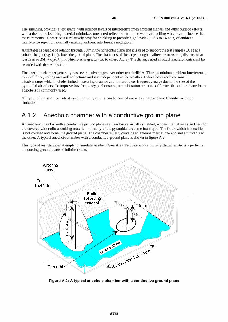
ETSI
ETSI EN 300 296-1 V1.4.1 (2013-08) 46
The shielding provides a test space, with reduced levels of interference from ambient signals and other outside effects, whilst the radio absorbing material minimizes unwanted reflections from the walls and ceiling which can influence the measurements. In practice it is relatively easy for shielding to provide high levels (80 dB to 140 dB) of ambient interference rejection, normally making ambient interference negligible.
A turntable is capable of rotation through 360° in the horizontal plane and it is used to support the test sample (EUT) at a suitable height (e.g. 1 m) above the ground plane. The chamber shall be large enough to allow the measuring distance of at least 3 m or 2(d1 + d2)2/λ (m), whichever is greater (see to clause A.2.5). The distance used in actual measurements shall be
recorded with the test results.
The anechoic chamber generally has several advantages over other test facilities. There is minimal ambient interference, minimal floor, ceiling and wall reflections and it is independent of the weather. It does however have some disadvantages which include limited measuring distance and limited lower frequency usage due to the size of the pyramidal absorbers. To improve low frequency performance, a combination structure of ferrite tiles and urethane foam absorbers is commonly used.
All types of emission, sensitivity and immunity testing can be carried out within an Anechoic Chamber without limitation.
A.1.2 Anechoic chamber with a conductive ground plane An anechoic chamber with a conductive ground plane is an enclosure, usually shielded, whose internal walls and ceiling are covered with radio absorbing material, normally of the pyramidal urethane foam type. The floor, which is metallic, is not covered and forms the ground plane. The chamber usually contains an antenna mast at one end and a turntable at the other. A typical anechoic chamber with a conductive ground plane is shown in figure A.2.
This type of test chamber attempts to simulate an ideal Open Area Test Site whose primary characteristic is a perfectly conducting ground plane of infinite extent.
Turntable
Test
antenna
1,5 m
Antenna
mast
Radio
absorbing
material
Range
length
3 mo 10
mrGround plane
Figure A.2: A typical anechoic chamber with a conductive ground plane

ETSI
ETSI EN 300 296-1 V1.4.1 (2013-08) 47
In this facility the ground plane creates the wanted reflection path, such that the signal received by the receiving antenna is the sum of the signals from both the direct and reflected transmission paths. This creates a unique received signal level for each height of the transmitting antenna (or EUT) and the receiving antenna above the ground plane.
The antenna mast provides a variable height facility (from 1 m to 4 m) so that the position of the test antenna can be optimized for maximum coupled signal between antennas or between a EUT and the test antenna.
A turntable is capable of rotation through 360° in the horizontal plane and it is used to support the test sample (EUT) at a specified height, usually 1,5 m above the ground plane. The chamber shall be large enough to allow the measuring distance of at least 3 m or 2(d1 + d2)2/λ (m), whichever is greater (see clause A.2.5). The distance used in actual measurements shall
be recorded with the test results.
Emission testing involves firstly "peaking" the field strength from the EUT by raising and lowering the receiving antenna on the mast (to obtain the maximum constructive interference of the direct and reflected signals from the EUT) and then rotating the turntable for a "peak" in the azimuth plane. At this height of the test antenna on the mast, the amplitude of the received signal is noted. Secondly the EUT is replaced by a substitution antenna (positioned at the EUT's phase or volume centre) which is connected to a signal generator. The signal is again "peaked" and the signal generator output adjusted until the level, noted in stage one, is again measured on the receiving device.
Receiver sensitivity tests over a ground plane also involve "peaking" the field strength by raising and lowering the test antenna on the mast to obtain the maximum constructive interference of the direct and reflected signals, this time using a measuring antenna which has been positioned where the phase or volume centre of the EUT will be during testing. A transform factor is derived. The test antenna remains at the same height for stage two, during which the measuring antenna is replaced by the EUT. The amplitude of the transmitted signal is reduced to determine the field strength level at which a specified response is obtained from the EUT.
A.1.3 Open Area Test Site (OATS) An Open Area Test Site comprises a turntable at one end and an antenna mast of variable height at the other end above a ground plane which, in the ideal case, is perfectly conducting and of infinite extent. In practice, while good conductivity can be achieved, the ground plane size has to be limited. A typical Open Area Test Site is shown in figure A.3.
Range length 3 or 10 m
Turntable
Ground plane
Dipole antennas
Antenna mast
Figure A.3: A typical Open Area Test Site
The ground plane creates a wanted reflection path, such that the signal received by the receiving antenna is the sum of the signals received from the direct and reflected transmission paths. The phasing of these two signals creates a unique received level for each height of the transmitting antenna (or EUT) and the receiving antenna above the ground plane.

ETSI
ETSI EN 300 296-1 V1.4.1 (2013-08) 48
Site qualification concerning antenna positions, turntable, measurement distance and other arrangements are same as for anechoic chamber with a ground plane. In radiated measurements an OATS is also used by the same way as anechoic chamber with a ground plane.
Typical measuring arrangement common for ground plane test sites is presented in the figure A.4.
T e s t a n t e n n a
T u r n t a b l e
P o w e r s u p p l y u n i t
D i g i t a l v o l t m e t e r
R e c e i v i n g d e v i c e
E U T
1 0 d B a t t e n u a t o r
Figure A.4: Measuring arrangement on ground plane test site (OATS set-up for spurious emission testing)
A.1.4 Test antenna A test antenna is always used in radiated test methods. In emission tests (i.e. frequency error, effective radiated power, spurious emissions and adjacent channel power) the test antenna is used to detect the field from the EUT in one stage of the measurement and from the substitution antenna in the other stage. When the test site is used for the measurement of receiver characteristics (i.e. sensitivity and various immunity parameters) the antenna is used as the transmitting device.
The test antenna should be mounted on a support capable of allowing the antenna to be used in either horizontal or vertical polarization which, on ground plane sites (i.e. Anechoic Chambers with ground planes and Open Area Test Sites), should additionally allow the height of its centre above the ground to be varied over the specified range (usually 1 metre to 4 metres).
In the frequency band 30 MHz to 1 000 MHz, dipole antennas (constructed in accordance with ANSI C63.5 [2]) are generally recommended. For frequencies of 80 MHz and above, the dipoles should have their arm lengths set for resonance at the frequency of test. Below 80 MHz, shortened arm lengths are recommended. For spurious emission testing, however, a combination of biconical antennas (commonly termed "bicones" and log periodic dipole array antennas (commonly termed "log periodics") could be used to cover the entire 30 MHz to 1 000 MHz band. Above 1 000 MHz, waveguide horns are recommended although, again, log periodics could be used.
NOTE: The gain of a horn antenna is generally expressed relative to an isotropic radiator.
A.1.5 Substitution antenna The substitution antenna is used to replace the EUT for tests in which a transmitting parameter (i.e. frequency error, effective radiated power, spurious emissions and adjacent channel power) is being measured. For measurements in the frequency band 30 MHz to 1 000 MHz, the substitution antenna should be a dipole antenna (constructed in accordance with ANSI C63.5 [2]). For frequencies of 80 MHz and above, the dipoles should have their arm lengths set for resonance at the frequency of test. Below 80 MHz, shortened arm lengths are recommended. For measurements above 1 000 MHz, a waveguide horn is recommended. The centre of this antenna should coincide with either the phase centre or volume centre.

ETSI
ETSI EN 300 296-1 V1.4.1 (2013-08) 49
A.1.6 Measuring antenna The measuring antenna is used in tests on a EUT in which a receiving parameter (i.e. sensitivity and various immunity tests) is being measured. Its purpose is to enable a measurement of the electric field strength in the vicinity of the EUT. For measurements in the frequency band 30 MHz to 1 000 MHz, the measuring antenna should be a dipole antenna (constructed in accordance with ANSI C63.5 [2]). For frequencies of 80 MHz and above, the dipoles should have their arm lengths set for resonance at the frequency of test. Below 80 MHz, shortened arm lengths are recommended. The centre of this antenna should coincide with either the phase centre or volume centre (as specified in the test method) of the EUT.
A.2 Guidance on the use of radiation test sites This clause details procedures, test equipment arrangements and verification that should be carried out before any of the radiated test are undertaken. These schemes are common to all types of test sites described in annex A.
A.2.1 Verification of the test site No test should be carried out on a test site which does not possess a valid certificate of verification. The verification procedures for the different types of test sites described in annex A (i.e. Anechoic Chamber, Anechoic Chamber with a ground plane and Open Area Test Site) are given in TR 102 273 [i.3] Parts 2, 3 and 4, respectively.
A.2.2 Preparation of the EUT The manufacturer should supply information about the EUT covering the operating frequency, polarization, supply voltage(s) and the reference face. Additional information, specific to the type of EUT should include, where relevant, carrier power, channel separation, whether different operating modes are available (e.g. high and low power modes) and if operation is continuous or is subject to a maximum test duty cycle (e.g. 1 minute on, 4 minutes off).
Where necessary, a mounting bracket of minimal size should be available for mounting the EUT on the turntable. This bracket should be made from low conductivity, low relative dielectric constant (i.e. less than 1,5) material(s) such as expanded polystyrene, balsawood, etc.
A.2.3 Power supplies to the EUT All tests should be performed using power supplies wherever possible, including tests on EUT designed for battery-only use. In all cases, power leads should be connected to the EUT's supply terminals (and monitored with a digital voltmeter) but the battery should remain present, electrically isolated from the rest of the equipment, possibly by putting tape over its contacts.
The presence of these power cables can, however, affect the measured performance of the EUT. For this reason, they should be made to be "transparent" as far as the testing is concerned. This can be achieved by routing them away from the EUT and down to the either the screen, ground plane or facility wall (as appropriate) by the shortest possible paths. Precautions should be taken to minimize pick-up on these leads (e.g. the leads could be twisted together, loaded with ferrite beads at 0,15 m spacing or otherwise loaded).
A.2.4 Volume control setting for analogue speech tests Unless otherwise stated, in all receiver measurements for analogue speech the receiver volume control where possible, should be adjusted to give at least 50 % of the rated audio output power. In the case of stepped volume controls, the volume control should be set to the first step that provides an output power of at least 50 % of the rated audio output power. This control should not be readjusted between normal and extreme test conditions in tests.
ETSI
ETSI EN 300 296-1 V1.4.1 (2013-08) 50
A.2.5 Range length The range length for all these types of test facility should be adequate to allow for testing in the far-field of the EUT i.e. it should be equal to or exceed:
( )2 1 2
2d d+
λ
where:
• d1 is the largest dimension of the EUT/dipole after substitution (m);
• d2 is the largest dimension of the test antenna (m);
• λ is the test frequency wavelength (m).
It should be noted that in the substitution part of this measurement, where both test and substitution antennas are half wavelength dipoles, this minimum range length for far-field testing would be:
2λ
It should be noted in test reports when either of these conditions is not met so that the additional measurement uncertainty can be incorporated into the results.
NOTE 1: For the fully anechoic chamber, no part of the volume of the EUT should, at any angle of rotation of the turntable, fall outside the "quiet zone" of the chamber at the nominal frequency of the test.
NOTE 2: The "quiet zone" is a volume within the Anechoic Chamber (without a ground plane) in which a specified performance has either been proven by test, or is guaranteed by the designer/manufacturer. The specified performance is usually the reflectivity of the absorbing panels or a directly related parameter (e.g. signal uniformity in amplitude and phase). It should be noted however that the defining levels of the quiet zone tend to vary.
NOTE 3: For the anechoic chamber with a ground plane, a full height scanning capability, i.e. 1 metre to 4 metres, should be available for which no part of the test antenna should come within 1 m of the absorbing panels. For both types of Anechoic Chamber, the reflectivity of the absorbing panels should not be worse than -5 dB.
NOTE 4: For both the anechoic chamber with a ground plane and the Open Area Test Site, no part of any antenna should come within 0,25 m of the ground plane at any time throughout the tests. Where any of these conditions cannot be met, measurements should not be carried out.
A.2.6 Site preparation The cables for both ends of the test site should be routed horizontally away from the testing area for a minimum of 2 m (unless, in the case both types of anechoic chamber, a back wall is reached) and then allowed to drop vertically and out through either the ground plane or screen (as appropriate) to the test equipment. Precautions should be taken to minimize pick up on these leads (e.g. dressing with ferrite beads, or other loading). The cables, their routing and dressing should be identical to the verification set-up.
NOTE: For ground reflection test sites (i.e. anechoic chambers with ground planes and Open Area Test Sites) which incorporate a cable drum with the antenna mast, the 2 m requirement may be impossible to comply with.
Calibration data for all items of test equipment should be available and valid. For test, substitution and measuring antennas, the data should include gain relative to an isotropic radiator (or antenna factor) for the frequency of test. Also, the VSWR of the substitution and measuring antennas should be known.
The calibration data on all cables and attenuators should include insertion loss and VSWR throughout the entire frequency range of the tests. All VSWR and insertion loss figures should be recorded in the log book results sheet for the specific test.

ETSI
ETSI EN 300 296-1 V1.4.1 (2013-08) 51
Where correction factors/tables are required, these should be immediately available.
For all items of test equipment, the maximum errors they exhibit should be known along with the distribution of the error e.g.:
• cable loss: ±0,5 dB with a rectangular distribution;
• measuring receiver: 1,0 dB (standard deviation) signal level accuracy with a Gaussian error distribution.
At the start of measurements, system checks should be made on the items of test equipment used on the test site.
A.3 Coupling of signals
A.3.1 General The presence of leads in the radiated field may cause a disturbance of that field and lead to additional measurement uncertainty. These disturbances can be minimized by using suitable coupling methods, offering signal isolation and minimum field disturbance (e.g. optical and acoustic coupling).
A.3.2 Data Signals Isolation can be provided by the use of optical, ultrasonic or infra-red means. Field disturbance can be minimized by using a suitable fibre optic connection. ultrasonic or infra-red radiated connections require suitable measures for the minimization of ambient noise.
A.3.3 Speech and analogue signals Where an audio output socket is not available an acoustic coupler should be used.
When using the acoustic coupler, care should be exercised that possible ambient noise does not influence the test result.
A.3.3.1 Acoustic coupler description
The acoustic coupler comprises a plastic funnel, an acoustic pipe and a microphone with a suitable amplifier. The materials used to fabricate the funnel and pipe should be of low conductivity and of low relative dielectric constant (i.e. less than 1,5).
• The acoustic pipe should be long enough to reach from the EUT to the microphone which should be located in a position that will not disturb the RF field. The acoustic pipe should have an inner diameter of about 6 mm and a wall thickness of about 1,5 mm and should be sufficiently flexible so as not to hinder the rotation of the turntable.
• The plastic funnel should have a diameter appropriate to the size of the loudspeaker in the EUT, with soft foam rubber glued to its edge, it should be fitted to one end of the acoustic pipe and the microphone should be fitted to the other end. It is very important to fix the centre of the funnel in a reproducible position relative to the EUT, since the position of the centre has a strong influence on the frequency response that will be measured. This can be achieved by placing the EUT in a close fitting acoustic mounting jig, supplied by the manufacturer, of which the funnel is an integral part.
• The microphone should have a response characteristic flat within 1 dB over a frequency range of 50 Hz to 20 kHz, a linear dynamic range of at least 50 dB. The sensitivity of the microphone and the receiver audio output level should be suitable to measure a signal to noise ratio of at least 40 dB at the nominal audio output level of the EUT. Its size should be sufficiently small to couple to the acoustic pipe.
• The frequency correcting network should correct the frequency response of the acoustic coupler so that the acoustic SINAD measurement is valid (see IEC 60489-3 [i.4], appendix F).

ETSI
ETSI EN 300 296-1 V1.4.1 (2013-08) 52
A.3.3.2 Calibration
The aim of the calibration of the acoustic coupler is to determine the acoustic SINAD ratio which is equivalent to the SINAD ratio at the receiver output.
MicrophoneReceiver under test
Amplifier and filter
Test Fixture
Signal Generator
acoustic pipe
SINAD meter
1 2
Figure A.5: Measuring arrangement for calibration
a) The acoustic coupler shall be mounted to the equipment, if necessary using a test fixture. A direct electrical connection to the terminals of the output transducer will be made. A signal generator shall be connected to the receiver input (or to the test fixture input). The signal generator shall be at the nominal frequency of the receiver and shall be modulated by the normal test modulation.
b) Where possible, the receiver volume control shall be adjusted to give at least 50 % of the rated audio output power and, in the case of stepped volume controls, to the first step that provides an output power of at least 50 % of the rated audio output power.
c) The test signal input level shall be reduced until an electrical SINAD ratio of 20 dB is obtained, the connection being in position 1. The signal input level shall be recorded.
d) With the same signal input level, the acoustic equivalent SINAD ratio shall be measured and recorded, the connection being in position 2.
e) Steps c) and d) above shall be repeated for an electrical SINAD ratio of 14 dB, and the acoustic equivalent SINAD ratio measured and recorded.
A.4 Test fixture
A.4.1 Description The test fixture is a radio frequency coupling device associated with an integral antenna equipment for coupling the integral antenna to a 50 Ω radio frequency terminal at the working frequencies of the equipment under test. This allows certain measurements to be performed using the conducted measurement methods. Only relative measurements may be performed and only those at or near frequencies for which the test fixture has been calibrated.
In addition, the test fixture shall provide:
a) a connection to an external power supply;
b) an audio interface either by direct connection or by an acoustic coupler.
The test fixture normally shall be provided by the manufacturer.

ETSI
ETSI EN 300 296-1 V1.4.1 (2013-08) 53
The performance characteristics of the test fixture shall conform to the following basic parameters:
a) the coupling loss shall not be greater than 30 dB;
b) a coupling loss variation over the frequency range used in the measurement which does not exceed 2 dB;
c) circuitry associated with the RF coupling shall contain no active or non linear devices;
d) the VSWR at the 50 Ω socket shall not be greater than 1,5 over the frequency range of the measurements;
e) the coupling loss shall be independent of the position of the test fixture and be unaffected by the proximity of surrounding objects or people. The coupling loss shall be reproducible when the equipment under test is removed and replaced;
f) the coupling loss shall remain substantially constant when the environmental conditions are varied.
In the case of measurements to be performed by a third party, the performance characteristics of the test fixture shall be approved by the testing laboratory.
The characteristics and calibration shall be included in test reports.
A.4.2 Calibration The calibration of the test fixture establishes a relationship between the output of the signal generator and the field strength applied to the equipment inside the test fixture.
The calibration is valid only at a given frequency and for a given polarization of the reference field.
AF load / acoustic coupler
Receiver under test
Distortion factor / audio level meter
and psophometric
filterTest Fixture
Signal Generator
a) Using the method described in clause 8.1.2.1, measure the sensitivity expressed as field strength, and note the value of this field strength in dBµV/m and the polarization used.
b) The receiver is now placed in the test fixture which is connected to the signal generator. The level of the signal generator producing a SINAD of 20 dB shall be noted.
c) The calibration of the test fixture is thus the linear relationship between the field strength in dBµV/m and the signal generator level in dBµV emf or dBm.
Figure A.6: Measuring arrangement for calibration
A.4.3 Mode of use For the transmitter measurements calibration is not required.
For the receiver measurements calibration is necessary.
To apply the specified wanted signal level expressed in field strength, convert it into the signal generator level (emf) using the calibration of the test fixture. Apply this value with the signal generator.

ETSI
ETSI EN 300 296-1 V1.4.1 (2013-08) 54
Annex B (normative): Specifications for adjacent channel power measurement arrangements
B.1 Power measuring receiver specification
B.1.1 General The power measuring receiver is used for the measurement of the transmitter adjacent channel power. It consists of a mixer and oscillator, an IF filter, an amplifier, a variable attenuator and a level indicator as shown below (figure B.1).
Amplifier / Attenuator
Level Indicator
Mixer
Oscillator
Filter
Input
Figure B.1: Power measuring receiver
Instead of the Variable attenuator with the rms value indicator it is also possible to use a rms voltmeter calibrated in dB. The technical characteristics of the power measuring receiver are given in clauses B.1.1 to B.1.5.
B.1.2 IF filter The IF filter shall be within the limits of the selectivity characteristics given in the following diagram (figure B.2). Depending on the channel separation, the selectivity characteristics shall keep the frequency separations and tolerances given in tables B.1, B.2, B.3 and B.4. The minimum attenuation of the filter outside the 90 dB attenuation points shall be equal to or greater than 90 dB.
NOTE: A symmetrical filter can be used provided that each side meets the tighter tolerances and the D2 points have been calibrated relative to the -6 dB response. When a non-symmetrical filter is used the receiver should be designed such that the tighter tolerance is used close to the carrier.
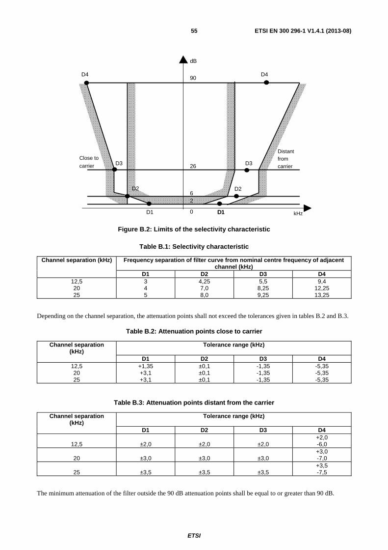
ETSI
ETSI EN 300 296-1 V1.4.1 (2013-08) 55
D4
D3
D2
D1D1 D1
D2
D3
dB
90
26
62
0
D4
Close to
carrier
Distantfromcarrier
kHz
Figure B.2: Limits of the selectivity characteristic
Table B.1: Selectivity characteristic
Channel separation (kHz) Frequency separation of filter curve from nominal centre frequency of adjacent channel (kHz)
D1 D2 D3 D4 12,5 20 25
3 4 5
4,25 7,0 8,0
5,5 8,25 9,25
9,4 12,25 13,25
Depending on the channel separation, the attenuation points shall not exceed the tolerances given in tables B.2 and B.3.
Table B.2: Attenuation points close to carrier
Channel separation (kHz)
Tolerance range (kHz)
D1 D2 D3 D4 12,5 20 25
+1,35 +3,1 +3,1
±0,1 ±0,1 ±0,1
-1,35 -1,35 -1,35
-5,35 -5,35 -5,35
Table B.3: Attenuation points distant from the carrier
Channel separation (kHz)
Tolerance range (kHz)
D1 D2 D3 D4
12,5
±2,0
±2,0
±2,0 +2,0 -6,0
20
±3,0
±3,0
±3,0
+3,0 -7,0
25
±3,5
±3,5
±3,5
+3,5 -7,5
The minimum attenuation of the filter outside the 90 dB attenuation points shall be equal to or greater than 90 dB.

ETSI
ETSI EN 300 296-1 V1.4.1 (2013-08) 56
Table B.4: Frequency displacement
Channel separation (kHz)
Specified necessary bandwidth (kHz)
Displacement from the -6 dB point (kHz)
12,5 20 25
8,5 14 16
8,25 13 17
The tuning of the power measuring receiver shall be adjusted away from the carrier so that the -6 dB response nearest to the transmitter carrier frequency is located at a displacement from the nominal carrier frequency as given in table B.4.
B.1.3 Oscillator and amplifier The measurement of the reference frequencies and the setting of the local oscillator frequency shall be within ±50 Hz.
The mixer, oscillator and the amplifier shall be designed in such a way that the measurement of the adjacent channel power of an unmodulated test signal source, whose noise has a negligible influence on the measurement result, yields a measured value of ≤ -90 dB for channel separation of 20 kHz and 25 kHz and of ≤ -80 dB for a channel separation of 12,5 kHz referred to the level of the test signal source.
The linearity of the amplifier shall be such that an error in the reading of no more than 1,5 dB will be obtained over an input level variation of 100 dB.
B.1.4 Attenuation indicator The attenuation indicator shall have a minimum range of 80 dB and a resolution of 1 dB.
B.1.5 Level indicators Two level indicators are required to cover the rms and the peak transient measurement.
B.1.5.1 Rms level indicator
The rms level indicator shall accurately indicate non-sinusoidal signals within a ratio of 10:1 between peak value and rms value.
B.1.5.2 Peak level indicator
The peak level indicator shall accurately indicate and store the peak power level. For the transient power measurement the indicator bandwidth shall be greater than twice the channel separation.
A storage oscilloscope or a spectrum analyser may be used as a peak level indicator.
B.2 Spectrum analyzer for adjacent channel power measurement
An alternative to the power measuring receiver shall be a spectrum analyser with a resolution bandwidth of 100 Hz and integrating the power of all the 100 Hz sub-band measurements, over a total bandwidth of ±D2 (see table B.1).
Spectrum analyser should use the rms measurement mode.
The characteristics of the spectrum analyser shall meet at least the following requirements:
- the reading accuracy of the frequency marker shall be within ±100 Hz;
- the accuracy of relative amplitude measurements shall be within ±3,5 dB.

ETSI
ETSI EN 300 296-1 V1.4.1 (2013-08) 57
It shall be possible to adjust the spectrum analyser to allow the separation on its screen of two equal amplitude components with a frequency difference of 200 Hz.
For statistically distributed modulations, the spectrum analyser and the integrating device (when appropriate) needs to allow determination of the power spectral density (energy per time and bandwidth), which has to be integrated over the bandwidth in question. It shall be possible to sum the effective power of all discrete components, the spectral power density and the noise power in the selected bandwidth and to measure this as a ratio relative to the carrier power.
The spectrum analyser should have a dynamic range greater than 90 dB and the average phase noise in the adjacent and alternate channels shall be such that measurement of adjacent and alternate channel power is not limited by phase noise. In order to confirm this, the selected measurement technique of clause 7.4.2 shall be used to measure the adjacent and alternate channel power with a CW signal source with phase noise of less than -120 dBc/Hz in the centre of the adjacent channel and -130 dBc/Hz in the centre of the alternate channel. The following performance shall be achieved:
• the maximum adjacent channel power observed with these conditions shall not exceed -70 dBc;
• the maximum alternate channel power measured with these conditions shall not exceed -80 dBc.
NOTE: A resolution bandwidth of 500 Hz may be used for this measurement as an alternative to the usual 100 Hz to reduce measurement time.

ETSI
ETSI EN 300 296-1 V1.4.1 (2013-08) 58
Annex C (normative): Spectrum Analyzer
C.1 Adjacent Channel Power Measurement See clause B.2 for details.
C.2 Unwanted Emissions Measurement The specification shall include the following requirements.
It shall be possible, using a resolution bandwidth of 1 kHz, to measure the amplitude of a signal, or noise at a level 3 dB or more above the noise level of the spectrum analyser, as displayed on the screen, to an accuracy of ±2 dB in the presence of the wanted signal.
The accuracy of relative amplitude measurements shall be within ±1 dB.
For statistically distributed modulations, the spectrum analyser and the integrating device (when appropriate) shall allow determination of the real spectral power density (energy per time and bandwidth), which has to be integrated over the bandwidth in question.
ETSI
ETSI EN 300 296-1 V1.4.1 (2013-08) 59
Annex D (normative): Band-stop filter (for SINAD meter) The characteristics of the band-stop filter used in the audio distortion factor meter and SINAD meter should be such that at the output the 1 000 Hz tone will be attenuated by at least 40 dB and at 2 000 Hz the attenuation will not exceed 0,6 dB. The filter characteristic shall be flat within 0,6 dB over the ranges 20 Hz to 500 Hz and 2 000 Hz to 4 000 Hz. In the absence of modulation the filter shall not cause more than 1 dB attenuation of the total noise power of the audio frequency output of the receiver under test.

ETSI
ETSI EN 300 296-1 V1.4.1 (2013-08) 60
Annex E (informative): Bibliography
• Directive 1999/5/EC of the European Parliament and of the Council of 9 March 1999 on radio equipment and telecommunications terminal equipment and the mutual recognition of their conformity (R&TTE Directive).

ETSI
ETSI EN 300 296-1 V1.4.1 (2013-08) 61
History
Document history
Edition 1 December 1994 Publication as ETS 300 296
Amendment 1 March 1997 Amendment 1 to 1st Edition of ETS 300 296
V1.1.1 March 2001 Publication
V1.2.1 February 2009 Publication
V1.3.1 July 2010 Publication
V1.4.1 July 2012 One-step Approval Procedure OAP 20121115: 2012-07-18 to 2012-11-15 (Withdrawn)
V1.4.1 July 2012 Public Enquiry PE 20121117: 2012-07-20 to 2012-11-19
V1.4.1 June 2013 Vote V 20130813: 2013-06-14 to 2013-08-13
V1.4.1 August 2013 Publication