en 1997-1 eurocode 7 · eurocode 7 workshop brussels 20th february 2008. brussels, 18-20 february...
TRANSCRIPT

Brussels, 18-20 February 2008 – Dissemination of information workshop 1
EUROCODESBackground and Applications EN 1997–1: Sections 3 and 6 Your
logo
EN 1997-1 Eurocode 7
Section 3 – Geotechnical DataSection 6 – Spread Foundations
Trevor L.L. OrrTrinity College Dublin
Ireland
Eurocode 7 Workshop Brussels 20th February 2008

Brussels, 18-20 February 2008 – Dissemination of information workshop 2
EUROCODESBackground and Applications Section 3
EN 1997-1: Section 3
Geotechnical Data
Brussels, 18-20 February 2008 – Dissemination of information workshop 3
EUROCODESBackground and Applications Section 3 – Overview
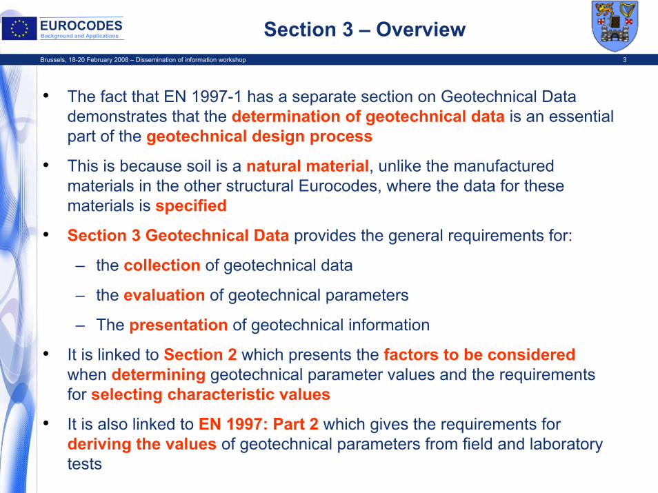
• The fact that EN 1997-1 has a separate section on Geotechnical Data demonstrates that the determination of geotechnical data is an essential part of the geotechnical design process
• This is because soil is a natural material, unlike the manufactured materials in the other structural Eurocodes, where the data for these materials is specified
• Section 3 Geotechnical Data provides the general requirements for:
– the collection of geotechnical data
– the evaluation of geotechnical parameters
– The presentation of geotechnical information
• It is linked to Section 2 which presents the factors to be consideredwhen determining geotechnical parameter values and the requirements for selecting characteristic values
• It is also linked to EN 1997: Part 2 which gives the requirements for deriving the values of geotechnical parameters from field and laboratory tests
Brussels, 18-20 February 2008 – Dissemination of information workshop 4
EUROCODESBackground and Applications Geotechnical Investigations
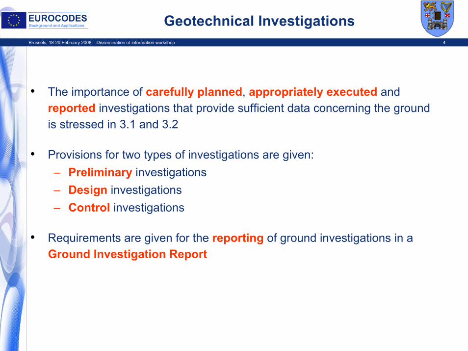
• The importance of carefully planned, appropriately executed and reported investigations that provide sufficient data concerning the ground is stressed in 3.1 and 3.2
• Provisions for two types of investigations are given:– Preliminary investigations– Design investigations– Control investigations
• Requirements are given for the reporting of ground investigations in a Ground Investigation Report

Brussels, 18-20 February 2008 – Dissemination of information workshop 5
EUROCODESBackground and Applications Stages in Determining Parameter Values
• The procedures involved in determining the design values of geotechnical parameters from field or laboratory test results may be considered as consisting of three stages or steps (Frank et al. 2004)
• The first step is to go from measured values, taking account of the test conditions, and assess the geotechnical parameter values (i.e. the properties of soil or rock at a particular location in the ground) – 2.4.3 and 3.3
• The second step is to take account of the design situation and assess the characteristic value as a cautious estimate of the geotechnical parameter values affecting the occurrence the limit state – 2.4.5.2
• The third step is to obtain the design parameter value by applying a partial factor to the characteristic value – 2.4.7.3.3

Brussels, 18-20 February 2008 – Dissemination of information workshop 6
EUROCODESBackground and Applications Characteristic Values from Measured Values
Measured ValuesStep 1Covered by:EN 1997-1,Clauses 2.4.3, 3.3andEN 1997-2 Test Results
Results of field tests at particular points in the ground or locations on a site or laboratory tests on particular
specimens
Test related correction, independent of any further analysis
Theory, empirical relationships or correlations to obtain Derived valuesAssessment of influence of test and design conditions on parameter value
Selection of relevant test results e.g. peak or constant volume strengths
Geotechnical Parameter ValuesQuantified for design calculations
Cautious estimate of geotechnical parameter value taking account of: • Test conditions, Nature of ground• Particular limit state, Nature of structure
Characteristic Parameter Value
Step 2Covered byEN 1997-1, Clause 2.4 5.2

Brussels, 18-20 February 2008 – Dissemination of information workshop 7
EUROCODESBackground and Applications Evaluation of Geotechnical Parameters
• The factors to be considered when evaluating soil and rock parameters are given in the following sub-sections of 3.3:– Characteristics of soil and rock types– Weight density– Density index– Degree of compaction– Soil shear strength– Soil stiffness– Quality and properties of rock masses– Permeability and consolidation parameters of soil and rock– Geotechnical parameters from field tests:
CPTSPTVane testWeight sounding testPressuremeter testDilatometer testCompactability test

Brussels, 18-20 February 2008 – Dissemination of information workshop 8
EUROCODESBackground and Applications Ground Investigation Report
• Section 3 states that the results of a geotechnical investigation shall be presented in a Ground Investigation Report
• The Ground Investigation Report should form part of the Geotechnical Design Report
• A comprehensive list of items to be included in this report is provided
• The Ground Investigation Report should normally include:– A presentation of all the geotechnical information – i.e. a factual
report– A geotechnical evaluation of the information, stating the
assumptions made in the interpretation of the test results – i.e. an interpretative report
Brussels, 18-20 February 2008 – Dissemination of information workshop 9
EUROCODESBackground and Applications Section 6
EN 1997-1: Section 6
Spread Foundations

Brussels, 18-20 February 2008 – Dissemination of information workshop 10
EUROCODESBackground and Applications Limit States
• Provisions apply to pads, strip and raft foundations• Relevant to foundations for gravity retaining walls and bridges as
well as buildings• List of limit states to be considered and compiled is given:
– Loss of overall stability– Bearing resistance failure– Failure by sliding– Combined failure in ground and structure– Structural failure due to ground movement– Excessive settlements– Excessive heave due to swelling frost heave and other causes– Unacceptable vibrations
• Some of above are ultimate limit states and some are serviceability limit states – both need to be considered
• Note term “bearing resistance” is used instead of “bearing capacity”• Failure by overturning is not a relevant limit state – failure by
bearing resistance will occur first
Brussels, 18-20 February 2008 – Dissemination of information workshop 11
EUROCODESBackground and Applications Controlling Limit State
0
200
400
600
800
1000
1200
0.5 1 1.5 2 2.5 3
Foundation width (m)
Des
ign
bear
ing
pres
sure
(kP
a)
ULS
SLS
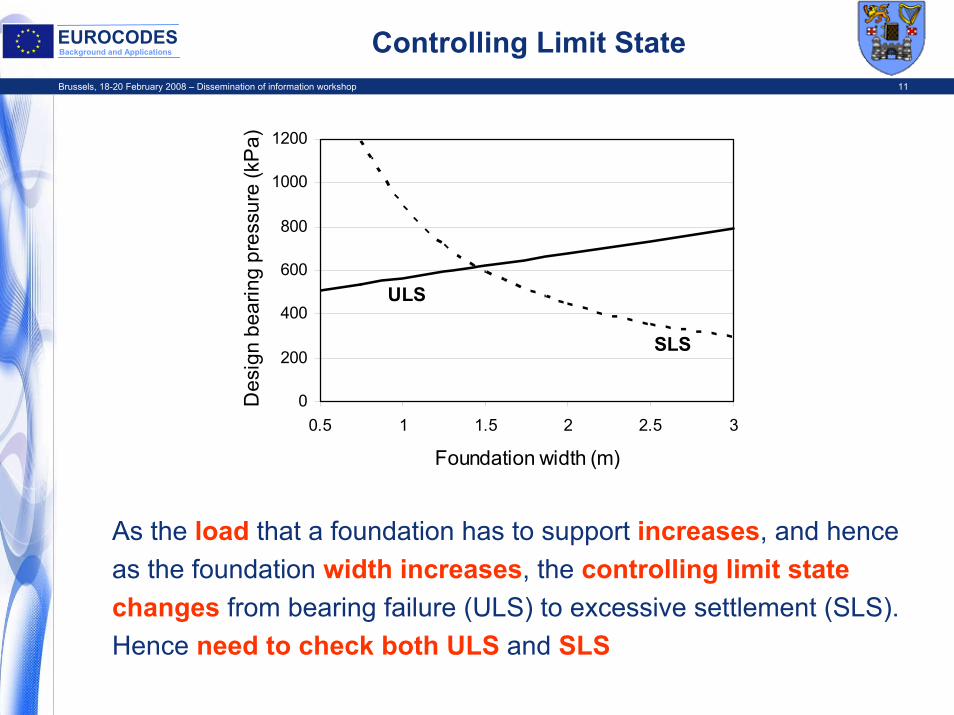
As the load that a foundation has to support increases, and hence as the foundation width increases, the controlling limit state changes from bearing failure (ULS) to excessive settlement (SLS). Hence need to check both ULS and SLS

Brussels, 18-20 February 2008 – Dissemination of information workshop 12
EUROCODESBackground and Applications Calculation Model
• Equilibrium Equation to be satisfied Fd ≤ Rd
• Equation is in terms of forces, not ensuring stresses do not exceed the allowable stress, as in traditional design
• Hence the model for bearing resistance failure is a rectangular plastic stress block at the limiting stress beneath the foundation, similar to the plastic stress block in the ultimate limit state design of a concrete beam
• The design bearing resistance force, Rd acts through the centre of this stress block over effective foundation area, A’
• Need to consider both drained and undrained conditions
FV, FH M,
W1W2
Rd
AV
PVd
AH
from Frank et al.

Brussels, 18-20 February 2008 – Dissemination of information workshop 13
EUROCODESBackground and Applications Design Method
Direct Method• Carry out a separate analysis for each limit state. Calculation method shall
model as closely as possible the failure mechanism envisaged, e.g. – Bearing resistance model for ULS– Settlement calculation for SLS
Indirect Method• Using comparable experience and field or laboratory measurements or
observations, chosen in relation to SLS loads, so as satisfy the requirements of all limit states
• Example: considering SLS for conventional structures founded on clays, the ratio between the bearing resistance of the ground, at its initial characteristic shear strength, to the applied serviceability loading, Ru,k / Fk, should be calculated (6.6.2(16)):
– If Ru,k / Fk < 3, calculation of settlements should always be undertaken– If Ru,k / Fk < 2, calculation of settlements should take account of non-
linear stiffness effects of the ground

Brussels, 18-20 February 2008 – Dissemination of information workshop 14
EUROCODESBackground and Applications Spread Foundation Example
Design Situation:Square pad foundation for a building, 0.8m embedment depth; groundwater level at base of foundation. Central vertical load. Allowable settlement is 25mm.
Characteristic values of actions:Permanent vertical load = 900 kN + weight of foundationVariable vertical load = 600 kNConcrete weight density = 24 kN/m3.
Ground Properties:Overconsolidated glacial till, cu;k = 200 kPa, c'k = 0kPa, ϕ'k = 35o, γk = 22kN/m3
SPT N = 40, mv;k = 0.015 m2/MN.
Require foundation width, BTo satisfy both ULS (drained and undrained conditions) and SLSUsing recommended partial factors values
Gk = 900kN, Qk = 600kN
GWL
B = ?
d = 0.8 m▼

Brussels, 18-20 February 2008 – Dissemination of information workshop 15
EUROCODESBackground and Applications Direct Method
ULS calculations for 3 Design Approaches
• DA1 - Combination 1Combination 2
• DA2• DA3
For:– Undrained Conditions– Drained Conditions
SLS calculation

Brussels, 18-20 February 2008 – Dissemination of information workshop 16
EUROCODESBackground and Applications Undrained Conditions
General Equation for undrained design bearing resistance Ru;d / A’ for all Design Approaches
Annex D - Eqn. D.1:Ru;d / A’ = ((π + 2) cu;d bc sc ic + qd) / γR
= ((π + 2)(cu,k/γcu ) bc sc ic + γγ qk) /γR
= ((π + 2)(cu;k/γcu ) bc sc ic + γγ γ d) /γR
where : cu;k, cu;d = characteristic and design values of cubc = 1.0 for a horizontal foundation basesc = 1.2 for a square foundation andic = 1.0 for a vertical load
` γ = 22.0 = weight density of the soilγcu = partial factor on cuγγ = partial factor on soil weight density, always = 1.0γR = partial resistance factor
Substituting known values in Eqn. D.1:Ru;d / A’ = (5.14 x (200 / γcu ) x 1.0 x 1.2 x 1.0 + 1.0 x 22 x 0.8) /γR
= (6.17 x 200 / γcu + 17.6) /γR
General Equation: Ru;d/A’ = (1234.0 / γcu + 17.6) /γR
Brussels, 18-20 February 2008 – Dissemination of information workshop 17
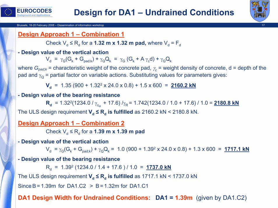
EUROCODESBackground and Applications Design for DA1 – Undrained Conditions
Design Approach 1 – Combination 1Check Vd ≤ Rd for a 1.32 m x 1.32 m pad, where Vd = Fd
- Design value of the vertical actionVd = γG(Gk + Gpad;k) + γQQk = γG (Gk + A γcd) + γQQk
where Gpad;k = characteristic weight of the concrete pad, γc = weight density of concrete, d = depth of the pad and γQ = partial factor on variable actions. Substituting values for parameters gives:
Vd = 1.35 (900 + 1.322 x 24.0 x 0.8) + 1.5 x 600 = 2160.2 kN
- Design value of the bearing resistanceRd = 1.322(1234.0 / γcu
+ 17.6) /γR = 1.742(1234.0 / 1.0 + 17.6) / 1.0 = 2180.8 kNThe ULS design requirement Vd ≤ Rd is fulfilled as 2160.2 kN < 2180.8 kN.
Design Approach 1 – Combination 2Check Vd ≤ Rd for a 1.39 m x 1.39 m pad
- Design value of the vertical actionVd = γG(Gk + Gpad;k) + γQQk = 1.0 (900 + 1.392 x 24.0 x 0.8) + 1.3 x 600 = 1717.1 kN
- Design value of the bearing resistanceRd = 1.392 (1234.0 / 1.4 + 17.6 ) / 1.0 = 1737.0 kN
The ULS design requirement Vd ≤ Rd is fulfilled as 1717.1 kN < 1737.0 kN
Since B = 1.39m for DA1.C2 > B = 1.32m for DA1.C1
DA1 Design Width for Undrained Conditions: DA1 = 1.39m (given by DA1.C2)

Brussels, 18-20 February 2008 – Dissemination of information workshop 18
EUROCODESBackground and Applications Designs for DA2 and DA3 – Undrained Conditions
Design Approach 2Check Vd ≤ Rd for a 1.57 m x 1.57 m pad
- Design value of the vertical actionVd = γG (Gk + A γcd) + γQQk
Vd = 1.35 (900 + 1.572 x 24.0 x 0.8) + 1.5 x 600 = 2178.9 kN
- Design value of the bearing resistanceRd = 1.572(1234.0 / γcu
+ 17.6) /γR = 2.465(1234.0 / 1.0 + 17.6) / 1.4 = 2203.6 kNThe ULS design requirement Vd ≤ Rd is fulfilled as 2178.9 kN < 2203.6 kN.
DA2 Design Width for Undrained Conditions: DA2 = 1.57m
Design Approach 3Check Vd ≤ Rd for a 1.56 m x 1.56 m pad
- Design value of the vertical actionVd = γG(Gk + Gpad;k) + γQQk = 1.35 (900 + 1.562 x 24.0 x 0.8) + 1.5 x 600 = 2178.1 kN
- Design value of the bearing resistanceRd = 1.562 (1234.0 / 1.4 + 17.6 ) / 1.0 = 2187.8 kN
The ULS design requirement Vd ≤ Rd is fulfilled as 2178.1 kN < 2187.8 kN
DA3 Design Width for Undrained Conditions: DA3 = 1.56m
Brussels, 18-20 February 2008 – Dissemination of information workshop 19
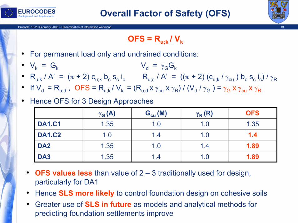
EUROCODESBackground and Applications Overall Factor of Safety (OFS)
OFS = Ru;k / Vk
• For permanent load only and undrained conditions:• Vk = Gk Vd = γGGk
• Ru;k / A’ = (π + 2) cu;k bc sc ic Ru;d / A’ = ((π + 2) (cu;k / γcu ) bc sc ic) / γR
• If Vd = Ru;d , OFS = Ru;k / Vk = (Ru;d x γcu x γR) / (Vd / γG ) = γG x γcu x γR
• Hence OFS for 3 Design ApproachesγG (A) Gcu (M) γR (R) OFS
DA1.C1 1.35 1.0 1.0 1.35DA1.C2 1.0 1.4 1.0 1.4DA2 1.35 1.0 1.4 1.89DA3 1.35 1.4 1.0 1.89
• OFS values less than value of 2 – 3 traditionally used for design, particularly for DA1
• Hence SLS more likely to control foundation design on cohesive soils• Greater use of SLS in future as models and analytical methods for
predicting foundation settlements improve

Brussels, 18-20 February 2008 – Dissemination of information workshop 20
EUROCODESBackground and Applications
General Equation for drained design bearing resistance Rd;d / A’ for all Design Approaches
Annex D, Eqn. D.2:Rd;d/A’ = (c’dNc;dbc;dsc;dic;d + q’dNq;dbq;dsq;diq;d + 0.5 γ’d B’ Nγ;dbγ;dsγ;diγ;d ) / γR
Where all parameters are design values and c terms ignored as c’ = 0:A’ = effective foundation area (reduced area with load acting through its centre)Nq;d = eπtanφ‘d tan2(π/4 + φ‘d/2) Nγ;d = 2 (Nq - 1) tanφ’dsq;d = 1 + sin φ'dsγ;d = 0.7
Rd = A’ (q’dNq;dsq;d + 0.5 γ’dB’Nγ;d sγ;d) / γR
φ'd = tan-1(tan φ'k) / γM = tan-1(tan35/1.25) = 29.3o
Bearing resistance checked for ground water level at ground surface. If γw = 9.81 kN/m3:γ’d = (22.0 x 1.0 – 9.81) x 1.0 = 12.19 kN/m3
q’d = γ’dd = 12.19 x 1.0 x 0.8 = 9.75 kPa
Drained Conditions
Brussels, 18-20 February 2008 – Dissemination of information workshop 21
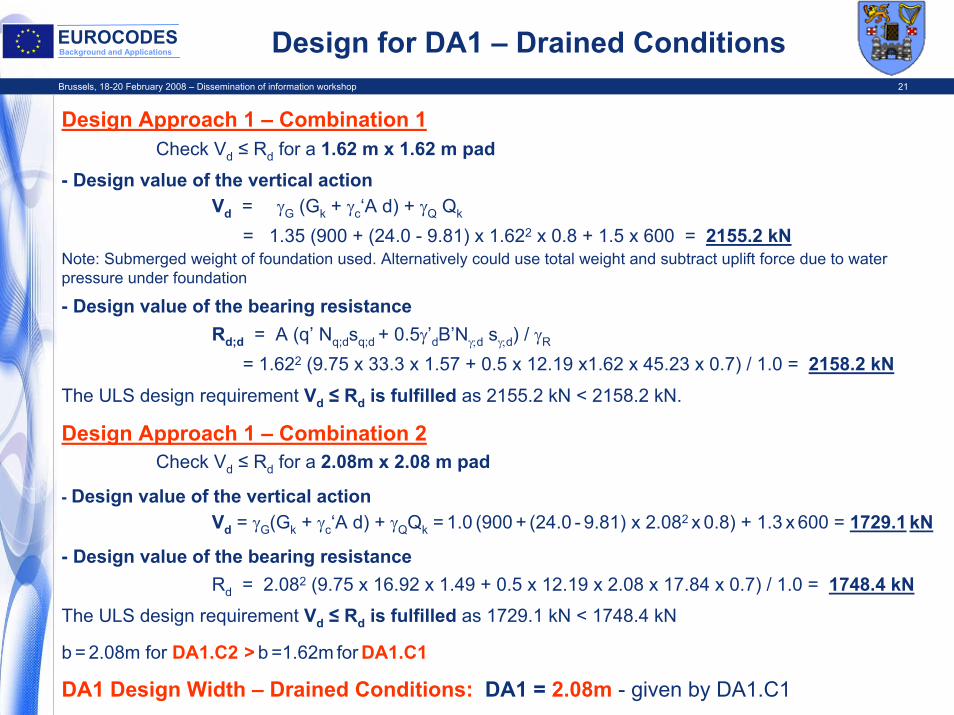
EUROCODESBackground and Applications Design for DA1 – Drained Conditions
Design Approach 1 – Combination 1Check Vd ≤ Rd for a 1.62 m x 1.62 m pad
- Design value of the vertical actionVd = γG (Gk + γc‘A d) + γQ Qk
= 1.35 (900 + (24.0 - 9.81) x 1.622 x 0.8 + 1.5 x 600 = 2155.2 kNNote: Submerged weight of foundation used. Alternatively could use total weight and subtract uplift force due to water pressure under foundation
- Design value of the bearing resistanceRd;d = A (q’ Nq;dsq;d + 0.5γ’dB’Nγ;d sγ;d) / γR
= 1.622 (9.75 x 33.3 x 1.57 + 0.5 x 12.19 x1.62 x 45.23 x 0.7) / 1.0 = 2158.2 kNThe ULS design requirement Vd ≤ Rd is fulfilled as 2155.2 kN < 2158.2 kN.
Design Approach 1 – Combination 2Check Vd ≤ Rd for a 2.08m x 2.08 m pad
- Design value of the vertical actionVd = γG(Gk + γc‘A d) + γQQk = 1.0 (900 + (24.0 - 9.81) x 2.082 x 0.8) + 1.3 x 600 = 1729.1 kN
- Design value of the bearing resistanceRd = 2.082 (9.75 x 16.92 x 1.49 + 0.5 x 12.19 x 2.08 x 17.84 x 0.7) / 1.0 = 1748.4 kN
The ULS design requirement Vd ≤ Rd is fulfilled as 1729.1 kN < 1748.4 kN
b = 2.08m for DA1.C2 > b =1.62m for DA1.C1
DA1 Design Width – Drained Conditions: DA1 = 2.08m - given by DA1.C1

Brussels, 18-20 February 2008 – Dissemination of information workshop 22
EUROCODESBackground and Applications Designs for DA2 and DA3 – Drained Conditions
Design Approach 2Check Vd ≤ Rd for a 1.87 m x 1.87 m pad
- Design value of the vertical actionVd = γG (Gk + γc’A d) + γQQk
Vd = 1.35 (900 + (24.0 – 9.81) x 1.872 x 0.8) + 1.5 x 600 = 2168.6 kN
- Design value of the bearing resistanceRd = 1.872 (9.75 x 33.3 x 1.57 + 0.5 x 12.19 x 1.87 x 45.23 x 0.7) / 1.4 = 2174.6 kN
The ULS design requirement Vd ≤ Rd is fulfilled as 2178.6 kN < 2203.6 kN.
DA2 Design Width for Undrained Conditions: DA2 = 1.57m
Design Approach 3Check Vd ≤ Rd for a 2.29 m x 2.29 m pad
- Design value of the vertical actionVd = γG(Gk + γc’A d) + γQQk = 1.35 (900 + (24.0 – 9.81) x 2.292 x 0.8) + 1.5 x 600 = 2195.4 kN
- Design value of the bearing resistanceRd = 2.292 (9.75 x 16.92 x 1.49 + 0.5 x 12.19 x 2.29 x 17.84 x 0.7)/1.0 = 2203.1 kN
The ULS design requirement Vd ≤ Rd is fulfilled as 2195.4 < 2203.1 kN
DA3 Design Width for Undrained Conditions: DA3 = 2.29m

Brussels, 18-20 February 2008 – Dissemination of information workshop 23
EUROCODESBackground and Applications SLS Design
• Calculate settlement using adjusted elasticity methods = p B f / Em
• Em = design value of the modulus of elasticity
• f = settlement coefficient
• p = bearing pressure
• Assume Em = E’ = 1.5N = 1.5 x 40 = 60 MPa
• f = (1 – ν2) I where ν = 0.25 and I = 0.95 for square foundation
• Then f = (1 – 0.252) x 0.95 = 0.89
• p = (Gk + Qk)/B2 = (900 + 600) / 2.082 = 346.7 kPa for smallest foundation
• Hence settlement:
s = p B f / Em = 346.7 x 2.08 x 0.89 x1000 / 60000 = 10.7 mm
• As s < 25 mm, SLS condition satisfied
Brussels, 18-20 February 2008 – Dissemination of information workshop 24
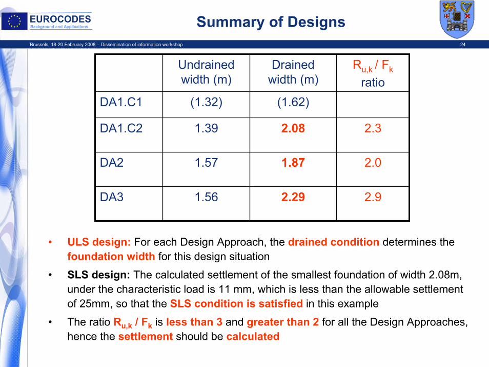
EUROCODESBackground and Applications Summary of Designs
Undrainedwidth (m)
Drainedwidth (m)
Ru,k / Fk
ratioDA1.C1 (1.32) (1.62)
DA1.C2 1.39 2.08 2.3
DA2 1.57 1.87 2.0
DA3 1.56 2.29 2.9
• ULS design: For each Design Approach, the drained condition determines the foundation width for this design situation
• SLS design: The calculated settlement of the smallest foundation of width 2.08m, under the characteristic load is 11 mm, which is less than the allowable settlement of 25mm, so that the SLS condition is satisfied in this example
• The ratio Ru,k / Fk is less than 3 and greater than 2 for all the Design Approaches, hence the settlement should be calculated
Brussels, 18-20 February 2008 – Dissemination of information workshop 25
EUROCODESBackground and Applications Conclusions
• Section 3 provides the requirements for the collection, evaluation and presentation of geotechnical data as an integral part of the geotechnical design process
• Section 6 provides a comprehensive framework with the principles for design of spread foundations
• The designer of spread foundations is explicitly required to:– Consider all relevant limit states– Consider both ULS and SLS– Consider both drained and undrained conditions (where relevant)– Distinguish between actions on the foundation and resistances– Treat appropriately:
Forces from supported structure (permanent or variable)Forces due to water pressure (actions not resistances)
• Since overall factors of safety for ULS design are generally lower than traditionally used for foundation design, it is likely that settlement considerations and hence SLS requirements will control more foundation designs, particularly on cohesive soils and when using DA1

Brussels, 18-20 February 2008 – Dissemination of information workshop 26
EUROCODESBackground and Applications
Thank YouThank You