emerging cfd technologies and aerospace vehicle design … · emerging cfd technologies and...
TRANSCRIPT

/ N95- 28746
EMERGING CFD TECHNOLOGIES AND AEROSPACE VEHICLE DESIGN
Michael J. Aftosmis
US Air Force Wright-Laboratory / NASA AmesMoffett Field, California
OVERVIEW
With the recent focus on the needs of design and applications CFD, research groups have begun to address
the traditional bottlenecks of grid generation and surface modeling. Now, a host of emerging technologiespromise to shortcut or dramatically simplify the simulation process. This paper discusses the current status
of these emerging technologies. It will argue that some tools are already available which can have positiveimpact on portions of the design cycle. However, in most cases, these tools need to be integrated into
specific engineering systems and process cycles to be used effectively. The rapidly maturing status of
unstructured and Cartesian approaches for Inviscid simulations makes suggests the possibility of highlyautomated Euler-boundary layer simulations with application to loads estimation and even preliminary
design. Similarly, technology is available to link block structured mesh generation algorithms with topology
libraries to avoid tedious re-meshing of topologically similar configurations. Work in algorithmic based
auto-blocking suggests that domain decomposition and point placement operations in multi-block mesh
generation may be properly posed as problems in Computational Geometry, and following this approachmay lead to robust algorithmic processes for automatic mesh generation.
I. INTRODUCTION
Over the past 20 years, Computational Fluid Dynamics has made significant progress toward generating
accurate simulations of flows around realistically complex aerospace configurations. While pundits are
quick to point out that there exist multitudes of topologically simple model problems which quickly reveal
shortcomings in turbulence models, dissipation models or advection schemes, a widening class of problemshas moved within reach. Thus, although some regions of the flight envelope remain outside the realm of
affordable and reliable numerical simulation, a growing body of evidence suggests that many critical
situations may be predicted with accuracy. As a result of this increased confidence, the past decade has
witnessed a shift in the focus of the CFD community from studying flow physics on topologically simple
model problems toward ever more bold attempts at simulating vehicles in flight. This shift is evident
throughout the military laboratories, NASA and industry as new codes are developed with increasingattention to generality and utility.
I.A Computational Fluid Dynamics in Aerospace Design
From the first studies of numerical techniques for solving the Euler equations by Courantlll Lax and
Friedrichs[ 21, and the landmark calculations by MacCormack[31, CFD development has centered on issues ofaccurately solving the governing equations of fluid mechanics. This work set the tone for much of the
subsequent development. Implicit schemes for centered spatial operators were presented in the mid 70's by
Briley (1975)I41, and Beam and Warming (1976)151. Jameson et all61 introduced a very successful finite
volume Runge-Kutta scheme in 1981 at about the same time that Enquist and Osher171, Osher[81 and
Roel9],[lOl were beginning development of approximate Riemann solvers which lead to many successfulupwind methods in the years that followed.
This brief chronology highlights a major point when one considers CFD applied to the design cycle. While
Steger had begun to consider complex configurations as early as 1978 II, development did not begin toconcentrate on design or applications CFD before the mid 1980's. In 1985 Benek, Buning and Steger[m21
mmnllu iI, luilt ml359
https://ntrs.nasa.gov/search.jsp?R=19950022325 2018-07-13T13:17:37+00:00Z
introduceda 3D chimeraschemefor applicationto problemswith realisticgeometriccomplexity. Thisoccurredat approximatelythe sametime as other segmentsof the communitypursuedmulti-blockstructuredsolversandtriangularmeshschemesfor confrontingthesameissues[13],D4].
Euler[14]andNavier-StokesllS],[]6],DTlcomputationsof flow aroundcompleteaircraftbeganto appearinthe latterhalf of the 1980's. While theserepresentedstunningachievements,they alsoservedasomenswhich,it maybeargued,thecommunitywasslowto identify andactupon. Grid systemsfor someof theseearly calculationsconsistedof singleblock mesheswhich literally took man-yearsto develop115],[16|,[171.Multi-block approachesfor Navier-Stokessimulationsof completeconfigurationsappearedin 1987118].However,whilemulti-blockwasa significantstepforward,theseeffortswerealsolargelysingularanddidnot directlyfocuson streamliningthegrid generationor surfacemodelingstepsin theprocess.
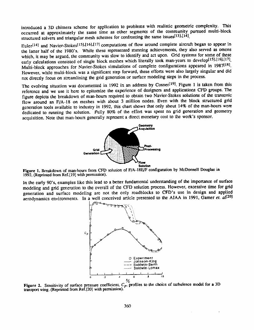
The evolvingsituationwasdocumentedin 1992in an addressby CosnerD91.Figure1 is takenfrom thisreferenceandwe useit hereto epitomizetheexperienceof designersandapplicationsCFD groups.Thefiguredepictsthebreakdownof man-hoursrequiredto obtaintwo Navier-Stokessolutionsof the transonicflow aroundan F/A-18 on mesheswith about 3 million nodes.Evenwith the block structuredgridgenerationtoolsavailableto industryin 1992,this chartshowsthatonly about14%of theman-hourswerededicatedto runningthe solution. Fully 80%of the effort wasspenton grid generationandgeometryacquisition.Note thatman-hoursgenerallyrepresenta directmonetarycostto thework'ssponsor.
GridGeneration
_ Processl ng
_"FlowSolution
Figure 1. Breakdown of man-hours from CFD solution of F/A-18F_JF configuration by McDonnell Douglas in1992. (Reprinted from Ref.[19] with permission).
In the early 90's, examples like this lead to a better fundamental understanding of the importance of surface
modeling and grid generation to the overall of the CFD solution process. However, excessive time for grid
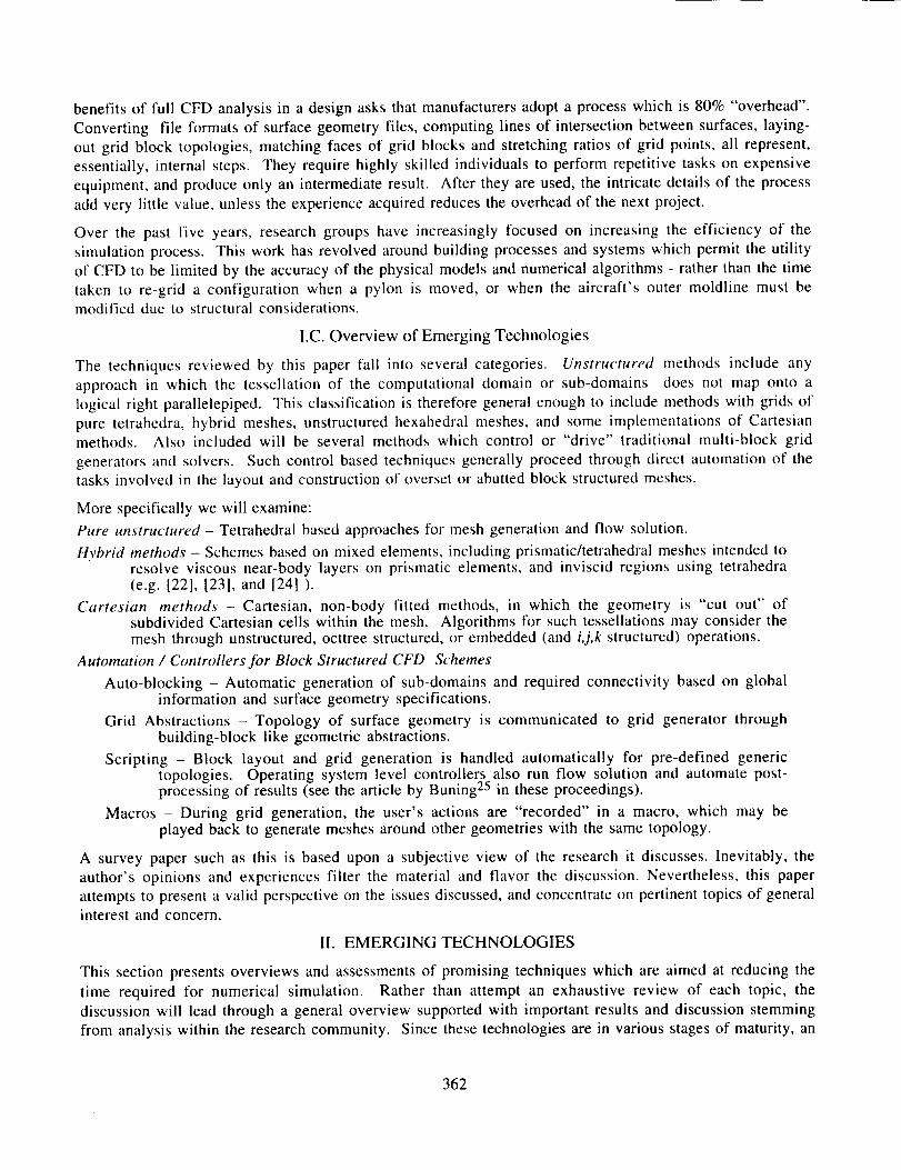
generation and surface modeling are not the only roadblocks to CFD's use in design and appliedaerodynamics environments. In a well conceived article presented to the AIAA in 1991, Garner et. a/i201
_:.
0 E:<periment-- Johnson-King---- Baldwin- Barth
...... Balclwln- Lomax
l I t I I ! I I I J.2 .'_ 6 .I t.O
Figure 2. Sensitivity of surface pressure coefficient, Cp, profiles to the choice of turbulence model for a 3Dtransport wing. (Reprinted from Ref.[20] with permission).
360

highlightedseveralfundamentalobstaclesfacingCFD'susewithin a designprocess.Figure2 is anexcerptfrom this report.Thesedatadepicttheresultof threeseparatethin-layerNavier-Stokessolutionsaroundawing, varyingonly the turbulencemodel. The figure comparesthe distributionof the surfacepressurecoefficient,Cp, resulting from these calculations. In examining these figures, the designer becomes aware ofthe tremendous sensitivity of the shock location to turbulence model (nearly 10%c variation over the 3
models). Subsequent improvements in the models may reduce this variation somewhat, but the essential
problem of discrete solution sensitivity to turbulence model remains.
A similar situation is shown in Figure 3 - excerpted from the same report. This figure highlights the
sensitivity of surface pressure to grid resolution at the trailing edge of the wing. These results emphasize
that simply generating a mesh (even automatically) is not sufficient. The grid must accurately resolve not
only the geometry, but also the physics of the flow. Of course, if a grid system takes weeks to setup, then
designers cannot be expected to iterate through multiple cycles of grid generation and flow solution.
%/© Experiment
-- Fine trailing edge grid..... Coarse trailing edge grid
! ! ] ! 1 I [ 1 I I
2 .4 .6 S 1.0
%
Figure 3. Effects of trailing edge mesh resolution on surface Cp profiles for a 3D transport wing. (Reprinted fromRef.[20] with permission).
I.B. Efficiency of the Numerical Simulation Process
The preceding three figures summarize the main difficulties historically associated with CFD in design;setup time, cycle time, physical modeling, and risks associated with inexpert generation of grids or setting of
parameters within codes. These factors all raise the risks (and expense) associated with CFD's incorporation
into aerospace design.
The aspect of time deserves special emphasis, both as measured in calendar time and in man-hours. For
example, reducing the simulation time could allow multiple cycles to be run and therefore lower the risk
involved in the process. Since this cycle is dominated by the human efforts of engineers and scientists,
shortening the process generally equates to automation. Such increased automation opens the door for
engineers with less specialized training. As a result, motivation exists on many levels to decrease simulationcycle times.
Other aspects of the impact of cycle time on design and applications CFD are less obvious from the
perspective of a research environment. In a thoughtful review article presented to the AIAA in 1994,
Rubbert [21] presents an economic model of the aircraft industry which further emphasizes the fundamental
importance of time within the design cycle. This model is used to demonstrate that market share is inversely
proportional to the time required to produce an aircraft of fixed specifications. Initially it seems intuitive
that a company with a slow design cycle will loose market share to quicker, more flexible manufacturers of
comparable products. However, the example documented in Figure 1 shows that the promise of reaping the
361
benefitsof full CFD analysis in a design asks that manufacturers adopt a process which is 80% "overhead".
Converting file formats of surface geometry files, computing lines of intersection between surfaces, laying-
out grid block topologies, matching faces of grid blocks and stretching ratios of grid points, all represent,
essentially, internal steps. They require highly skilled individuals to perform repetitive tasks on expensive
equipment, and produce only an intermediate result. After they are used, the intricate details of the process
add very little value, unless the experience acquired reduces the overhead of the next project.
Over the past five years, research groups have increasingly focused on increasing the efficiency of the
simulation process. This work has revolved around building processes and systems which permit the utilityof CFD to be limited by the accuracy of the physical models and numerical algorithms - rather than the time
taken to re-grid a configuration when a pylon is moved, or when the aircraft's outer moldline must bemodified due to structural considerations.
I.C. Overview of Emerging Technologies
The techniques reviewed by this paper fall into several categories. Unstructured methods include any
approach in which the tessellation of the computational domain or sub-domains does not map onto a
logical right parallelepiped. This classification is therefore general enough to include methods with grids of
pure tetrahedra, hybrid meshes, unstructured hexahedral meshes, and some implementations of Cartesianmethods. Also included will be several methods which control or "drive" traditional multi-block grid
generators and solvers. Such control based techniques generally proceed through direct automation of thetasks involved in the layout and construction of overset or abutted block structured meshes.
More specifically we will examine:
Pure unstructured - Tetrahedral based approaches for mesh generation and flow solution.
Hybrid methods - Schemes based on mixed elements, including prismatic/tetrahedral meshes intended toresolve viscous near-body layers on prismatic elements, and inviscid regions using tetrahedra(e.g. [22], [23], and [24] ).
Cartesian methods - Cartesian, non-body fitted methods, in which the geometry is "cut out" ofsubdivided Cartesian cells within the mesh. Algorithms for such tessellations may consider themesh through unstructured, octtree structured, or embedded (and i,j,k structured) operations.
Automation / Controllers for Block Structured CFD Schemes
Auto-blocking - Automatic generation of sub-domains and required connectivity based on globalinformation and surface geometry specifications.
Grid Abstractions - Topology of surface geometry is communicated to grid generator throughbuilding-block like geometric abstractions.
Scripting - Block layout and grid generation is handled automatically for pre-defined generictopologies. Operating system level controllers also run flow solution and automate post-processing of results (see the article by Buning 25 in these proceedings).
Macros - During grid generation, the user's actions are "recorded" in a macro, which may beplayed back to generate meshes around other geometries with the same topology.
A survey paper such as this is based upon a subjective view of the research it discusses. Inevitably, the
author's opinions and experiences filter the material and flavor the discussion. Nevertheless, this paper
attempts to present a valid perspective on the issues discussed, and concentrate on pertinent topics of generalinterest and concern.
lI. EMERGING TECHNOLOGIES
This section presents overviews and assessments of promising techniques which are aimed at reducing the
time required for numerical simulation. Rather than attempt an exhaustive review of each topic, the
discussion will lead through a general overview supported with important results and discussion stemming
from analysis within the research community. Since these technologies are in various stages of maturity, an
362

attempt has been made to document the current status and summarize the potential outcome of future
research. Subsequent sections will use this information to investigate ways in x_,hich these methods can be
effectively used within the design and applications CFD environment.
II.A. Pure Unstructured Methods
Techniques involving unstructured grids composed of triangles (in 2D) or tetrahcdra (in 3D) have been
applied to the Euler and Navier-Stokes equations since the mid- 1980's.[261 Based upon theoreticalfoundations developed largely in the late 1970's[27],[6], such methods have been attractive from the outset
since their spatial discretization operators avoid unnecessary, assumptions about global mesh topology.
Thus, solvers view the mesh as an unstructured collection of cells, with some explicitly, defined connectivity.
The grid generation task reduces to the more general problem of generating and tessellating coordinate databetween prescribed boundaries, and is therefore more amenable to automation. This section will detail the
current state of such research and discuss approaches for flow simulation and mesh generalion fi)r inviscidand viscous simulations.
I1.A.I Unstructured Flow Solvers
Unstructured simulations using central difference finite volume techniques were applied to the inviscid
simulation of a complete aircraft as early as 19861261. The short span of time from inception to application
on such complex configurations provided significant motivation for their continued development. Several
outstanding reviews and summaries exist to track development of these methods over the past decade.
Excellent articles have been prepared by Venkatakrishnan[ 28] and Mavriplis[291 chronicling progress in both
flow solver development and mesh generation. In addition, the proceedings in reference [30] provide a
detailed description of a variety of unstructured methods with supporting theory and applications, including
domain decomposition for parallel architectures, implicit time integration, and a host of mesh generationstrategies.
The first flow solvers of Jameson and Mavriplis [26] operated in a cell-centered finite volume environment.
In the subsequent 3D work, which appeared in 1986, Jameson et al. [14] extended these ideas to permit
vertex based formulations and related the central difference finite volume framework to a Galerkin finite
element approach with linear basis functions. Desideri and Dervieuxl311 presented one of the first higher-
order accurate upwind schemes for triangular meshes in 1988. This work relied upon van Leer's
MUSCL[ 321 scheme to construct a node-based upwind method on meshes composed of simplices. Since
unstructured meshes have no dominant coordinate direction, some ambiguity existed in the implementation
of one-dimensional limiting ideas and the use of directional operator splitting on unstructured meshes[331.
This shortcoming was overcome when Barth and Jespersen[341 presented an unstructured upwind method
based on a central difference gradient estimation that obeyed multi-directional monotonicity principles.
In the past five years, a host of improvements have been proposed to many of these algorithms. Just as
importantly, however, theoretical frameworks have been introduced which give insight into commonalty
between various schemes and aide in developing efficient implementations. For example, reference [35]
proposed the use of edge-based formulas and data structures which have since become one of the major
contributions of the research. Since that time, a variety of authors have invoked minimal storage andcomputational complexity arguments to further support the use of such structures in node based schemes[351,1361,I371.
Most unstructured Navier-Stokes work has adopted either central difference finite volume or finite element
discretizations of the diffusive terms in the governing equations (see for ex. [35], [38], [39], [40], among
others). Like the convective terms, these operators are also amenable to edge-based data structures which
permit compact construction and storage. Reference [28] provides additional sources of discussion
concerning recent developments in unstructured Navier-Stokes solvers.
363
II.A.2 Mesh Generation
Initial efforts with unstructured techniques generally relied upon meshes constructed from quadrilateralstructured meshes through the addition of a diagonal spanning each ce111261. In their initial complete
aircraft calculations, however, Jameson et al.fl4] began to invoke principles of Delaunay triangulation in
tessellating point data and related techniques have become commonplace in subsequent mesh generation
strategies. This initial work identifies the main strength of unstructured approaches - that is, the ability to
automate generation of a volume mesh from an initial triangulation of the domain boundaries. Thus, the
tedious, ambiguous, and often complex process of decomposing the computational domain into regularhexahedral blocks is avoided.
A Delaunay triangulation of coordinate data is one in which the circumcircle through the vertices of each
triangle does not contain any other vertex in the mesh[ 411. Most approaches can be classified as either
Delaunay, advancing front1421,1431, or a combination of the twol441,I451,[461. Recent research in this field has
produced a variety of Steiner Triangulation techniques[ 471, in which new sites are incrementally inserted into
existing, usually Delaunay, triangulations148],1491,1501. Such methods appeal to the unique properties of
Delaunay triangulationsl511 to produce meshes with mathematically provable control over maximum angles
and mesh quality. For example, a Delaunay triangulation of a planar point data satisfies the min-max
criterion, i.e. it leads to a unique graph which minimizes the maximum angle of any triangle in the mesh.
Exploitation of this property, taken in conjunction with a circumcenter site insertion strategy permits
advocates of Steiner triangulation techniques to produce triangulations which guarantee that all angles in the
final mesh will lie between prescribed minima and maximal521.
The phenomenal success of references [42], [44], [53], and others, attests to the fact that two and three
dimensional meshes of isotropic triangular or tetrahedral elements can be robustly generated with welldocumented methods. Current research is therefore directed at generation meshes containing stretched
elements in a similarly reliable manner146],149],[501,I541. Although many techniques have been proposed,
this topic remains one of the pacing items in the application of unstructured Navier-Stokes solvers to
complex configurations.
II.A.3 Current Status
The recent literature has witnessed a virtual explosion of research in unstructured methods. However,
looking with an emphasis on design and applications CFD, we are able to consider a smaller subset of this
work which is restricted to 3D applications. Within this subset, several classifications still exist. Research
pursuing efficient and accurate Navier-Stokes solution represents a large body of work and several
competing methods are being debated. Nevertheless, applications are not yet commonplace, and one mayargue that this work is still formative. Similarly, despite some impressive results1551,1561,1571 time dependent
adaptive schemes and re-meshing algorithms such as those for unsteady flows and moving body problems,
is also largely a research topic. Excluding these topics we are left with work which presents applications of
unstructured methods to 3D steady flow fields.
This process of narrowing down and classifying ongoing research is instructive. It emphasizes the point thatalthough the research community exerts considerable resources in unstructured flow solvers and mesh
generation, only a small fraction of this effort is dedicated to working problems directly related to thegeneric application of these methods. Relatively few researchers focus directly on issues surrounding
efficient implementation and routine application. Such work is, perhaps, almost unattractive in an
environment which rewards novelty and fundamental concepts. However, from an industrial or applications
CFD point of view, the automation of routine processes is of paramount importance, and in this polarity liesa serious conundrum.
Within the subset of steady, inviscid applications, huge progress has been made since the first complete
aircraft simulations of reference [14]. Good examples of relatively efficient codes may be found
364
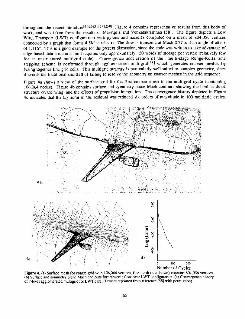
throughoutthe recentliterature[4°l,[43].[37]'[581.Figure4 containsrepresentativeresultsfrom this bodyofwork, andwastakenfrom the resultsof Mavriplis andVenkatakrishnan[58]. The figure depictsa LowWing Transport(LWT) configurationwith pylonsandnacellescomputedon a meshof 804,056verticesconnectedby a graphthatforms4.5M tetrahedra.The flow is transonicat Mach0.77andanangleof attackof 1.116°. This is a goodexamplefor thepresentdiscussion,sincethecodewaswrittento takeadvantageofedge-baseddatastructures,andrequiresonly approximately150wordsof storagepervertex(relativelyfewfor an unstructuredmultigrid code). Convergenceaccelerationof the multi-stageRunge-Kuttatimesteppingschemeis performedthroughagglomerationmultigrid[58] which generatescoarsermeshesbyfusingtogetherfinegrid cells. Thismultigridstrategyis particularlywell suitedto complexgeometry,sinceit avoidsthetraditionalshortfallof failingto resolvethegeometryoncoarsermeshesin thegrid sequence.
Figure4a showsa view of the surfacegrid for the first coarsermeshin the multigrid cycle (containing106,064nodes).Figure4bcontainssurfaceandsymmetryplaneMachcontoursshowingthelambdashockstructureon thewing,andtheeffectsof propulsionintegration.Theconvergencehistorydepictedin Figure4c indicatesthattheL2 normof theresidualwasreducedsix ordersof magnitudein 100multigridcycles.
/
4b.
I ',,i, L "" 0
,f
4C.1 I
0 100 200
Number of Cycles
Figure 4. (a) Surface mesh for coarse grid with 106,1364 vertices, fine mesh (not shown) contains 804,056 vertices.(b) Surface and symmetry plane Mach contours for transonic flow over LWT configuration. (c) Convergence historyof 7-level agglomerated multigrid for LWT case. (Frames reprinted from reference [58] with permission).
365
The simulation required 96MW of memory and 90 minutes of single processor CPU on a Cray Y-MP.
These results are representative of the CPU and memory requirements of modern, well-written unstructuredsolvers.
II.A.4
Surface
Unresolved Issues and On-going Research
modeling - In the context of unstructured methods, surface modeling plays two importantroles. First, an initial triangulation (which is constrained to the surface geometry) must be supplied
to the volume mesher for generation of the initial mesh. Secondly, if flow field driven adaptation ispermitted, new sites may be inserted on the boundary and these too must conform to the actualsurface geometry. Generation of such a constrained initial surface triangulation is non-trivial whenone considers that the surface may be originally described through CAD data, loftings, naturalNURBS, trimmed NURBS, patches or surface grids. Edges in this triangulation must follow leadingedges, trailing edges, junctures between components, and may not be allowed to swap (if edgeswapping will produce faces which no longer coincide with the surface description). Generation ofthis surface triangulation is typically the most time consuming and user-intensive operation in themesh generation procedure. While volume meshing may take minutes, or tens of minutes on anengineering workstation, the initial triangulation may take hours to days. Moreover, if the surfacetriangulation is computed with a preprocessor or commercial software package, the true geometrydescription may be unavailable for later use, and adaptation becomes a clumsy process.
Anisotropic Mesh Generation - Several approaches have been proposed for creating meshes with highaspect elements suitable for Navier-Stokes including those in references [54], [59], [46], and [50]among others. However, research involving the retention of angular control while still retaining asufficiently smooth blending of anisotropic viscous cells with isotropic Euler elements continues. Inaddition, the insertion of high aspect ratio tetrahedra into general unstructured meshes increases thelikelihood of generating "sliver" elements, non-tetrahedralizable regions, etc. Such effects have adetrimental effect on the robustness of viscous grid generators. Finally, even with the addition of
solution based adaptation, difficulties exist concerning meshing wakes and other free shear layerswith sufficient resolution[ 541.
Counting Arguments - A variety of authors have raised concerns about the total numbers of cells andedges required to fill volume space with high aspect ratio tetrahedra. As an example, suppose weseek to grid the boundary layer region around a single element 3D wing at elevated Reynoldsnumber. A structured surface mesh may contain 200 vertices around the chord and perhaps 50
spanwise stations. Spanning an expected attached boundary layer with 25 stations would permit sitesat y+ of around unity with reasonable grid stretching. Thus the boundary layer portion of the meshwould consist of 200x50x25 = N = 250,000 vertices, and hexahedral cells made up of 750,000
edges (assuming we remain away from mesh boundaries). Tessellating this structured region withright tetrahedra would lead to dissecting each hexahedral cell into 0t = 5 tetrahedra (best case). Thisleads to 1.25M tetrahedrals and (a+l)N = 1.5M edges. Thus, for an explicit, edge-based, code wehave doubled the storage and per sweep CPU requirements simply by virtue of the tessellation. Inan implicit code the edges must still be stored, but now the additional connectivity implies a fullermatrix for inversion. Moreover, recent analysis and numerical experiments suggest that for certainclasses of schemes, the additional diagonal edges do not necessarily lead to greater accuracy[ 6°1. (Infact, Ref. [61] has actually demonstrated improved discrete solutions through choosing controlvolumes which de-emphasize the contributions of such diagonal edges.)
II.B Hybrid Methods
The counting arguments, accuracy concerns and other issues in the preceding paragraphs have promptedseveral groups to consider alternatives to pure unstructured methods [22],[231,[24],[621,[63]. For example,
reference [60] suggested that diagonal edges found in semi-structured viscous layers of triangular ortetrahedral meshes could be deleted to leave triangular, hexahedral or prismatic elements. Such edges incur
a memory penalty with no apparent accuracy advantage and thus degrade the efficiency of the method. The
366

Figure 5. (left) Unstructured mesh near the first and second elements of a multi-element airfoil discretization.(right) Mixed element mesh where 11,544 triangles were collapsed to form 5,772 quadrilateral elements. (Framesreprinted from reference [46] with permission).
extension of edge-based unstructured flow solvers to accept hybrid elements is relatively straight forward
and the idea has been investigated by several authors. Figure 5 contains two figures excerpted from thework of Marcum[ 46] and shows just such an approach. Sites forming triangles in the semi-structured wall
boundary region near the leading edge of a muti-element airfoil have been re-tessellated as quadrilateral
elements. In this example, 11,544 triangles near the wall were collapsed to form 5,772 quadrilaterals
through removal of the unnecessary diagonals. In addition, reference [46] has investigated collapsing
tetrahedral elements to form prisms in semi-structured regions of the mesh, but final results have not yetbeen presented.
II.B.1 Prismatic and Hybrid Meshes
The use of prismatic elements for efficiently discretizing viscous layers, or even entire domains has received
increased attention since the late 1980's. Prismatic mesh generation ideas have been presented byreferences [23], [24] and [62] among others. The methods proposed by Nakahashi[23] and Kallinderis162]
are based on algebraic construction principles that begin with a surface triangulation of the geometry.
Families of mesh lines spawn from mesh vertices in the surface triangulation. The mesh is constructed layerby layer in a manner which is analogous to an inflation of the surface triangulation. This construction
technique permits a semi-structured interpretation of the mesh. The lines emanating from vertices on the
body are continuous, and nodes along each of these are vertices of fixed degree. This local structure
permits straight forward implementations of semi-implicit multigrid, or even semi-coarsened multigridconvergence acceleration[24].[64].
The algebraic marching procedure described here clearly has the character of a hyperbolic algorithm for
the positioning of sites on subsequent layers of the mesh. Recognizing this, PandyaI241 has proposed
alternative construction schemes based on solving hyperbolic partial differential equations for determiningthe vertex locations on successive mesh layers.
One criticism of early prismatic mesh generation techniques was that the extension to multiple bodyconfigurations was unclear, since there appears to be no clearly defined manner in which to prevent multiple
prismatic meshes to fuse together as they grow. To address this issue, recent work presented byKallinderis [221 proposed constructing layers of prismatic elements only near the wall boundaries to resolve
viscous layers, and then discretizting the rest of the domain using an advancing front technique, filling the
space with isotropic tetrahedra. If prismatic layers from multiple elements overlap, then they are locally"receded", and the space in between may be filled with tetrahedral elements during the advancing front
step. Reference [22] presents a variety of viscous multi-body meshes constructed following this procedure.
367
II.B.2 Current Status and Unresolved Issues
As compared with unstructured tetrahedral techniques, research into prismatic and other hybrid methods is
relatively new. As a result, a smaller body of work exists to highlight their strengths or document potential
shortfalls. Research in these methods has shown great promise, however there are still relatively few detailed
computations on sufficiently fine grids.
Hybrid methods were developed in direct response to the concerns about anisotropic tetrahedra and
counting arguments documented above, and they have successfully overcome many these obstacles. The
research community has been quick to respond to criticisms concerning multi-body and meshing concavedomains and is similarly working to resolve most outstanding issues. A partial list of potential roadblocksincludes:
Surface modeling - Like pure unstructured methods, prismatic techniques and most other hybridmethods generally employ a surface triangulation to begin the mesh generation process. Thus, suchmethods inherit the difficulties associated with generation of such a triangulation that werepresented, above, in section II.A.4
Adaptation - In hybrid techniques that rely upon the semi-structured nature of prismatic regions, theincorporation of adaptive mesh algorithms can become unclear. Parthasarathy et a/.1641 have
presented some promising work addressing this topic in their consideration of viscous flow around asphere. In this work, the sphere was encased in a prismatic mesh to capture viscous phenomena anda tetrahedral mesh was employed away from the body. The hybrid adaptation scheme included h-refinement and mesh re-distribution. Nevertheless, the flexibility of mesh re-distribution algorithms
on more general topologies remains an open question. Additionally, if a tetrahedral cell at theprism-tet interface is h-refined the entire stack of prismatic elements between this cell and the bodymust also be h-refined if one is to preserve the semi-structured nature of the prismatic layers. Such astrategy raises efficiency concerns. Of course, if the solver does not make use of the structure in theprismatic layers, and considers the mesh simply as an unstructured collection of mixed elementtypes, the restrictions on adaptation largely disappear. Finally, we note that since prismatic mesheshave an O-O topology, mesh adaptation to resolve wakes and/or free shear layers within the flow
may present a problem
II.C Cartesian Mesh Methods
Cartesian approaches differ from those presented in the previous sections by virtue of the fact that theymake use of a non-body fitted mesh system to discretize the computational domain. The hexahedral cells in
the domain are a set of right parallelepipeds and the original grid system may extend through solid wall
boundaries in the computational domain. The process then removes any fully internal cells, flags cells
which intersect the body and treats remaining cells as general volume mesh control volumes. The promise
of the technique stems from the fact that it trades the case specific problem of generating a body fitted mesh
(unstructured, structured, blocked, etc.) with a more general problem of computing and characterizing
geometric intersections between Cartesian flow field cells and the surface geometry. Thus, all difficulties
associated with meshing a particular geometry are restricted to a lower order manifold which constitutes the
outer shell of the geometry - rather than occurring throughout the computational domain. Recent research
has demonstrated that these mesh generation operations readily lend themselves toward automation and themethod can be applied to extremely complex geometries[ 651,166h167h[681.1691. Since solid wall boundaries
may cut arbitrarily through the layer of "cut cells" encasing the body, surface boundary conditions are of
obvious importance in Cartesian schemes.
Cartesian approaches fall into two general categories. Either they consider the mesh to be an unstructured(or octree structured) collection of h-refined hexahedra, or they operate by embedding structured sub-grids
within existing structured blocks. In unstructured or octree methods, volume meshing of the computational
domain relies on a simple and robust procedure of cell division. Beginning with a coarse background grid,
368
or even a single root cell, the hexahedral elements are recursively subdivided in order to resolve the
geometry and evolving flow features. The final mesh is a collection of cells at various levels of refinement,
viewed as either entirely unstructured or as having an underlying octree connectivity. Structured approaches
embed i,j,k structured sub-grids similarly aimed at resolving geometric and flow field features. Successful
2D and 3D solution procedures have been proposed following both implementations[ 651,1671,[7°1,171I.
II.C.1 Development of Cartesian Approaches
Although three dimensional applications to complex geometry have only recently become commonplace,Cartesian approaches have been evaluated since the late 1970's. Work by Purvis and Burkhalter[ 721 solved
the full potential equation on 2D Cartesian meshes using a finite volume method. Solution of the Eulerequations was pursued in the mid-1980's by a variety of researchers[731,[741, and the first three dimensional
inviscid solutions appeared in the late 1980's by Gaffney, Hassan and Salas175].
Cartesian approaches have been successfully utilized in industrial applications including Boeing'sTRANAIR code which solves the full potential equation, and the commercially available MGAEROI76]
package for Euler simulations. These applications are notable because they provide close links with surface
modeling and provide a wide base of experience with large-scale computations using Cartesian methods.
MGAERO, for example, adopts a component based approach to complex geometries[ 771,[7_1. Similar
approaches have been adopted within the research documented in References [66],[67] and [79].
The cut cells necessarily present in Cartesian discretizations present unique problems in the implementation
of accurate boundary conditions. References [80],[81],[82] and others present insight into the importantissues involved.
The isotropic elements stemming from h-refinement of Cartesian hexahedra are well suited to resolving flow
structures in inviscid simulations. However, use of such elements to capture boundary layers and other stiff
viscous phenomena would be grossly inefficient[83],[84]. Recently, a variety of authors have proposed
alternate techniques for extending inviscid Cartesian approaches to viscous f]ow168],[84]. Historically, the
lack of a clear extension to viscous simulations has been a weak link and the recently proposed venues offerthe possibility of further research.
II.C.2 Current Status
In the recent literature, one finds a multitude of work stemming from Cartesian mesh methods. Many
notable 3D computations have investigated the flow around complex geometries. The 3D Reynolds
averaged Navier-Stokes results which use prismatic meshes near the body in reference [68] are particularly
promising. However, such examples are still formative, and the technology has not spread across the
community for independent confirmation. The target of most Cartesian work is a role within the inviscid
design/analysis cycle. Appropriately, this section restricts its attention to the discussion of 3D Eulerapplications similar to those found in [67],[69],[78].
While unstructured and structured CFD approaches both involve surface modeling issues, the static nature of
their surface description permits these techniques to develop sufficient surface meshes in preparatory steps.
A notable exception, of course, are unstructured adaptive algorithms which must interrogate the surface
database during each mesh adaptation phase. For similar reasons, Cartesian approaches demand that the
mesh generation and adaptation algorithms be closely coupled with the geometric database. Throughout the
mesh generation process, Cartesian cells must be constantly tested against the surface database. Again duringadaptation, new cut cells are clipped against the surface, and fully internal cells are eliminated. In reference
[66], tests were performed with direct inquiries to a NURBS description of the body. However, speed,
robustness and other issues motivated a return to the use of a surface triangulation database in later research.Important differences exist between the surface triangulations required for Cartesian and fully unstructured
or prismatic approaches. In Cartesian approaches, individual components of the geometry may be
independently triangulated into closed polyhedra, without regard to overlap or intersection of the
369
componenttriangulations.Thus, the techniqueavoidscomputationof surface-surfaceintersections,andsinceCartesiancells may cut arbitrarily throughthegeometry,they may intersectthe triangulationsofseveral different componentswithout special handling. In essence,the actual topology of the full
configuration need never be communicated to the grid generation routines, and herein lies the fundamental
difference with structured of unstructured techniques. This single factor is perhaps the key inunderstanding Cartesian claims for rapid tum-around and automation. Within many mesh generation codes,
it is relatively easy to obtain surface grids or triangulations for individual components if one does not worry
about intersections with other parts of the overall geometry. As a result, the geometric modeling is
substantially quicker for many applications.
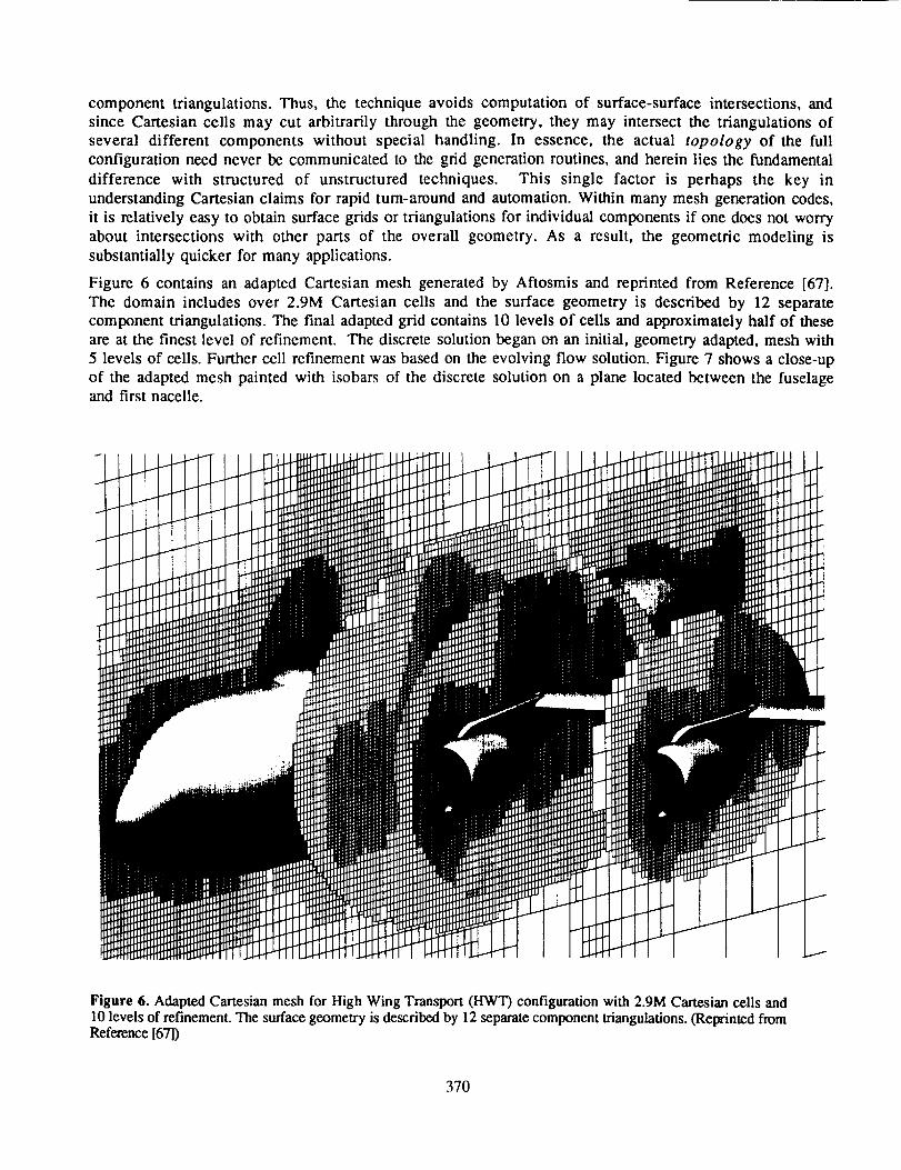
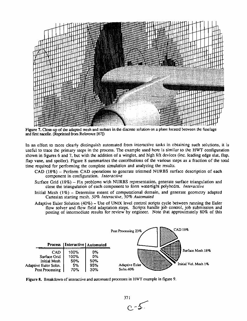
Figure 6 contains an adapted Cartesian mesh generated by Aftosmis and reprinted from Reference [67].
The domain includes over 2.9M Cartesian cells and the surface geometry is described by 12 separatecomponent triangulations. The final adapted grid contains 10 levels of cells and approximately half of these
are at the finest level of refinement. The discrete solution began on an initial, geometry adapted, mesh with
5 levels of ceils. Further cell refinement was based on the evolving flow solution. Figure 7 shows a close-up
of the adapted mesh painted with isobars of the discrete solution on a plane located between the fuselageand first nacelle.
Figure 6. Adapted Cartesian mesh for High Wing Transport (HWT) configuration with 2.9M Cartesian cells and10 levels of refinement. The surface geometry is described by 12 separate component triangulations. (Reprinted fromReference [67])
370
::::ii.............._
!iiii!i!!iiiiiiiiiii!i
;iii i i iiiiiiiii!ill
iFigure 7. Close-up of the adapted mesh and isobars in the discrete solution on a plane located between the fuselageand f'wst nacelle. (Reprinted from Reference [67])
In an effort to more clearly distinguish automated from interactive tasks in obtaining such solutions, it is
useful to trace the primary steps in the process. The example used here is similar to the HWT configuration
shown in figures 6 and 7, but with the addition of a winglet, and high lift devices (inc. leading edge slat, flap,
flap vane, and spoiler). Figure 8 summarizes the contributions of the various steps as a fraction of the total
time required for performing the complete simulation and analyzing the results.
CAD (18%) - Perform CAD operations to generate trimmed NURBS surface description of eachcomponent in configuration. Interactive
Surface Grid (18%) - Fix problems with NURBS representation, generate surface triangulation andclose the triangulation of each component to form watertight polyhedra. Interactive
Initial Mesh (1%) - Determine extent of computational domain, and generate geometry adaptedCartesian starting mesh. 50% Interactive, 50% Automated
Adaptive Euler Solution (40%) - Use of UNIX level control scripts cycle between running the Eulerflow solver and flow field adaptation steps. Scripts handle job control, job submission and
posting of intermediate results for review by engineer. Note that approximately 80% of this
Process
CADSurface GridInitial Mesh
Adaptive Euler Soltn.Post Processing
Interactive
100%100%
50%5%
70%
AutomatedPost Processing 23_
0%0%
50%95% Adaptive Eule30% Soltn.40%
CAD 18%
Surface Mesh 18%
Initial Vol. Mesh 1%
Figure 8. Breakdown of interactive and automated processes in HWT example in figure 9.
time is dedicated to waiting for jobs in queue and not CPU. Also, this code is essentiallyunaccelerated and therefore converges slowly. 5% Interactive, 95% Automated.
Post Processing (23%)- Post processing of results to extract surface pressure, cutting planes,streamlines in solution and other structures in flow. Surface pressures and cutting planes areextracted automatically. 70% Interactive, 30% Automated.
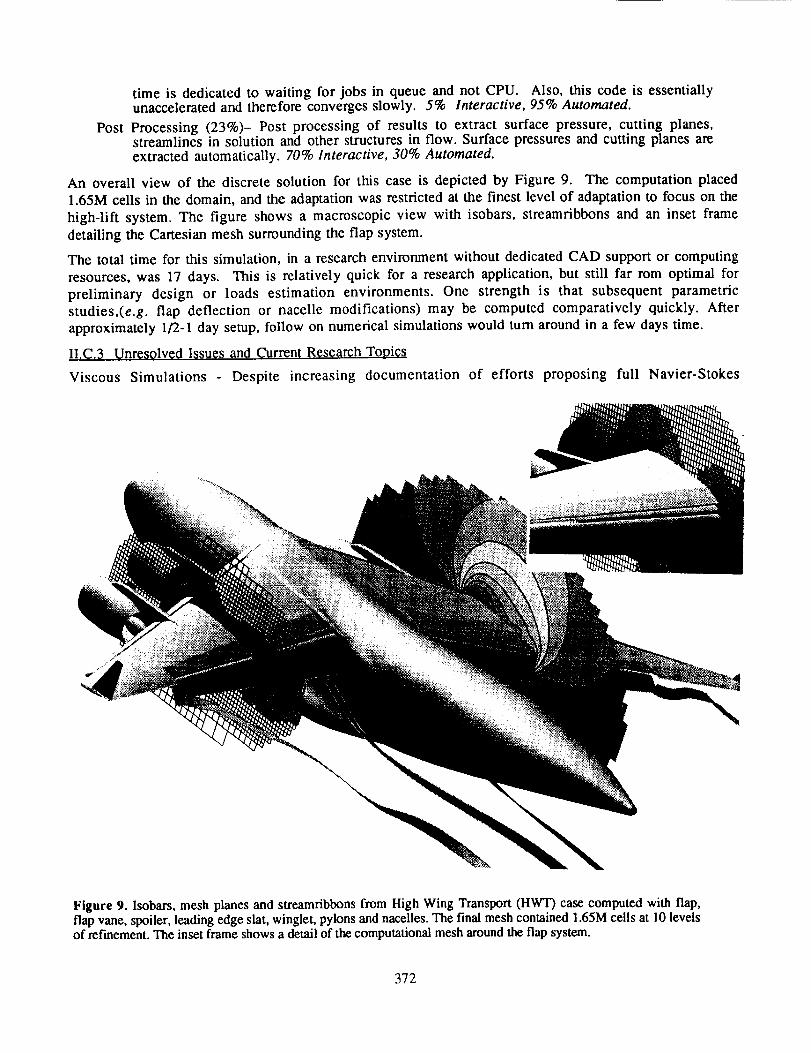
An overall view of the discrete solution for this case is depicted by Figure 9. The computation placed
1.65M cells in the domain, and the adaptation was restricted at the finest level of adaptation to focus on the
high-lift system. The figure shows a macroscopic view with isobars, streamribbons and an inset frame
detailing the Cartesian mesh surrounding the flap system.
The total time for this simulation, in a research environment without dedicated CAD support or computing
resources, was 17 days. This is relatively quick for a research application, but still far rom optimal for
preliminary design or loads estimation environments. One strength is that subsequent parametricstudies,(e.g, flap deflection or nacelle modifications) may be computed comparatively quickly. After
approximately 1/2-1 day setup, follow on numerical simulations would turn around in a few days time.
II.C._ Unresolved Issues and Current; Research Topics
Viscous Simulations Despite increasing documentation of efforts proposing full Navier-Stokes
Figure 9. Isobars, mesh planes and streamribbons from High Wing Transport (HWT) case computed with flap,flap vane, spoiler, leading edge slat, winglet, pylons and nacelles. The final mesh contained 1.65M cells at 10 levelsof refinement. The inset frame shows a detail of the computational mesh around the flap system.
372
simulations1681,1831,[841,openquestionsexistconcerningefficientlyconstructedmethodsfor viscoussolutionsonCartesianmeshes.Resolvingboundary-layerswith isotropicCartesiancellsis inherentlyinefficient.Theuseof prismaticgridsnearbodiesinheritsthedifficultiesassociatedwith prismaticmethodswhile addingthe complexityof coupling the Cartesianand prismatic cells. As newtechniquesfor constructingsurfacetriangulationsfor entireconfigurationsbecomemoreaccessible,this pathmay prove fruitful. However,adaptingCartesianmeshesto wakesand otherviscousphenomenawill continueto beaproblem. NearertermresultsmaycomethroughthecouplingofCartesiansolverswith3Dboundarylayermodels.
SurfaceModeling- Althoughsurfacemodelingproblemswith Cartesianmethodsaresomewhatalleviatedby working directly from NURBS or triangulationsof individual components,the examplepresentedaboveshowsthatthisprocedurestill demandsconsiderableeffort.DedicatedCADsystemsdependon experiencedusers.Appropriatesurfacetriangulationsof various componentsaresimilarlynon-trivialandrequirespecializedsoftware.Althoughnoserioustechnicalroadblocksexistin thisprocess,thetopicrequiresadditionalresearchattentionandincreasedautomation.
Accuracyat Boundaries- Oneviewof Cartesianmethodsis thattheytakeadvantageof simplerflow fielddiscretizationstencilsbut sufferfrom increasedboundarycomplexity.The intersectionof thebodywith thegrid maybeveryarbitrarytherebymakingtheimplementationof accurateandconservativeboundaryconditionsmoredifficult. Althougha varietyof implementationshavebeenreported,definitive formulationshavebeenelusive. Most work hasresultedin implementationsthat arebetweenfirst andsecond-orderaccuratel711,[791,I811,[82].
II.D. Automationof BlockStructuredMeshGeneration
Evenwith recentadvancementsin unstructured,hybrid,andCartesiantechnology,thevastmajorityof CFDapplicationsare computedwith structuredCFD schemes.This is especially true for Navier-Stokessimulationswherethe robustness,speed,andaccuracyof unstructuredviscousapproacheshaveyet to beconvincinglydemonstrated.Thebasicparadigmof multi-blockapproachesbeginswith a decompositionofthe computationaldomain in to a collectionof deformedhexahedralblocks with either matchingoroverlappedfaces.Duringtheflow solution,thesolverprocessestheseblocksindependentlyandthenpassesinformationto neighboringblocksasboundaryconditions.Modificationsof thisbasicmodelexistfor bothparallelmachinesandtimedependentsimulations.
In a recentpaper,Dannenhoffer1851separatesthedevelopmentof 3-Dblockstructuredgrid generationintothreestagesof evolution.Initially, grid generationresearchfocusedonoperationswithin eachmeshblock.Conformallymapped,elliptic andhyperbolicmethodsweredevelopedfor creatingmeshblock,werewidelyused[86],1871,I881.Block-to-blockpointers,commonedges,andall otherconnectivityor controlinformationwas input by hand. Suchsystemstypically operatedin batchmode.With the fundamentalalgorithmsidentified,researchfocusthenshiftedtowarduseability. Secondgenerationmeshgeneratorsreplacedthetediousand error-proneprocessof typed-incontrol informationwith input througha GraphicalUserInterface(GUI) andsuchsystemsmakeup thebulk of currentlyavailablegrid generators.Suchinterfacesaredesignedto give feedbackto theuserwhile aidingin visualizingthe grid creationprocess.Theendresult,however,is essentiallythesameuser-specifiedlocationandconnectivityinformationrequiredby thefirst generationsystems.Third generationsystemsinvolveautomatingthe blockingand meshgenerationprocessto reducethedependenceonhumaninputanddecisionmaking.
In the pastdecade,a numberof approacheshavebeenpresentedfor automatingthe meshgenerationprocess. Theseattemptsmay be generallycategorizedas either interactive, knowledge-based, oralgorithmic1891, and this section presents a sampling of the current state of research in each of thesedirections.
373
II.D.l Automation of Interactive Processes
The most direct approach toward automation of structured grid generation is through automation of the
processes which exist in current gridding strategies. This implies that the user must still ultimately convey
the topology of the body and block connectivity, and improvements stem from reducing the clutter of trivial
tasks. Bookkeeping and obvious choices may be made automatically by the system, leaving the user free to
work on the core problems of mesh and surface topology. One basic algorithm for interactive construction
of blocked grids might be as follows:
Algorithm I: a. Generate and link curves to form block edges.b. Construct block faces from edges.c. Distribute points on block edges and enumerate block connectivity.d. Generate volume mesh within each block.
Some current systems take small steps toward automating this process by automatically dimensioning and
distributing points on matching block faces, or by using geometric proximity to infer a topology and/or
connectivity. However, even with such subtle streamlining, the process remains highly interactive and
cumbersome. The essence of the problem is detail. As long as it requires an engineer to specify each curve
of every block, the process will be labor intensive for complex configurations with many hundreds of
blocks.
One solutions to this problem of excessive detail comes through the classical process of abstraction. Using a
technique pioneered by Allwrightlg01 the user focuses on generating a blocked abstraction of the geometry
which then communicates the topology of the configuration to the mesh generation system. Reference [85]
has extended these ideas and applied them to a variety of published examples. One approach uses
hypercube building blocks to construct "squared-up" abstractions of the configuration in three-
dimensions. The use of the hypercube - which is simply the volume between two nested cubes - was first
proposed by Allwright and applied to Euler simulations of a complete business jet as early as 19881901.
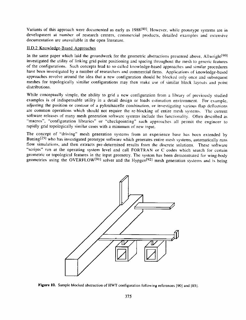
Figure I0 shows a sample abstraction for the HWT configuration of Figures 6 and 7.
Once such an abstraction is formed, the blocking process occurs automatically following pre-set rules and
point distribution algorithms. Next the surfaces of the abstraction may be deformed to match their
counterparts in the real geometry. These deformations are distributed throughout the blocking, and thus the
final block locations and topology are established. The last stage of mesh generation creates the volume
grid within each block, using standard techniques.
The fundamental simplification in this approach is that the mesh topology is generated from an abstraction
and not the actual geometry. This construction communicates only the essential geometric and topological
information required to layout the mesh blocks. In addition, the process of forcing the user to construct the
configuration out of pre-defined building blocks links certain surfaces with specific block layouts. In this
way, the system guides the user, interactively, through the steps necessary to layout the mesh blocks. It is
not clear if the procedure described will always lead to the most efficient blocking for any given
configuration. However, the strength of the technique is that it will reliably lead to a decomposition.
Ultimately this robustness and agility may provide shorter complete cycle times and yield a more efficient
CFD process.
374
Variants of this approach were documented as early as 198819°1. However, while prototype systems are in
development at number of research centers, commercial products, detailed examples and extensivedocumentation are unavailable in the open literature.
II.D.2 Knowledge-Based Approaches
In the same paper which laid the groundwork for the geometric abstractions presented above, Allwrightl901
investigated the utility of linking grid point positioning and spacing throughout the mesh to generic features
of the configurations. Such concepts lead to so-called knowledge-based approaches and similar procedures
have been investigated by a number of researchers and commercial firms. Applications of knowledge-based
approaches revolve around the idea that a new configuration should be blocked only once and subsequent
meshes for topologically similar configurations may then make use of similar block layouts and pointdistributions.
While conceptually simple, the ability to grid a new configuration from a library of previously studied
examples is of indispensable utility in a detail design or loads estimation environment. For example,
adjusting the position or contour of a pylon/nacelle combination, or investigating various flap deflections
are common operations which should not require the re-blocking of entire mesh systems. The current
software releases of many mesh generation software systems include this functionality. Often described as
"macros", "configuration libraries" or "checkpointing" such approaches all permit the engineer torapidly grid topologically similar cases with a minimum of new input.
The concept of "driving" mesh generation systems from an experience base has been extended byBuning[ 251 who has investigated prototype software which generates entire mesh systems, automatically runs
flow simulations, and then extracts pre-determined results from the discrete solutions. These software"scripts" run at the operating system level and call FORTRAN or C codes which search for certain
geometric or topological features in the input geometry. The system has been demonstrated for wing-bodygeometries using the OVERFLOWl91I solver and the Hypgen[921 mesh generation systems and is being
Figure 10. Sample blocked abstraction of HWT configuration following references [90] and I85].
375
consideredfor extensionto moregeneralclassesof problems.
Extensionsof theseconceptshavemotivatedresearchinto controllingtheblockingandpoint distributionprocesswith expertsystemsor artificial intelligence.Preliminarywork in thisdirectionwasperformedbyDannenhofferin 19911931andthe topic wasre-visitedin a NASA sponsoredworkshopin late 19941941.Within sucha framework,expert systemswould either choosefrom libraries of pre-definedblockingstrategies,or createnewblocklayoutsaccordingto apre-definedrulebase.
II.D.3 Algorithmic Approaches
In the introduction of a paper which proposes a possible theoretical framework for formalizing the problem
of multiple block structured grid generation, Cordova1891 poses the following question:
"Could it be that human intervention is necessary for solving the blocking problem?"
When one considers that unstructured mesh generators routinely operate with only minimal user input, the
obvious answer to this question must be that such intervention can not be necessary. This argument is
illuminating because it highlights the difference between our approach to multi-block gridding andtechniques for unstructured mesh generation. Just as mesh blocking is a domain decomposition into
hexabedra, unstructured mesh generation is a decomposition into tetrahedra.
Following this reasoning, Cordova suggests viewing structured grid blocking as a problem in Topological
Graph Theory1951. Within this framework, one seeks a hexahedral tessellation of the computational domain,
in which each cell constitutes a grid block - or even a further decomposition to yield individual grid cells.
Using the language of Computational Geometry (CG), the unstructured and structured mesh generation
problems may be phrased as follows:1891
Unstructured Mesh Generation - Decompose a region bounded by algebraic surfaces of degree = 1
into tetrahedra.
Block Structured Mesh Generation - Decompose a region bounded by algebraic surfaces of degree > 1 into deformed hexahedra.
The inequality in the second statement recognizes that a block on a wall boundary will not necessarily have
planar faces. We note in passing that unlike tetrahedra, hexahedra are not rigid figures (polyhedra). This
property,, and the inequality in the second statement leads to the observation that while the CG problem oftetrahedral meshing is linear, the block structuring problem is non-linear, and solution strageties may
require linearization steps.
With these definitions, Ref. [89] suggests the following algorithm for approaching multiple block grid
generation:
Algorithm II: a. Approximate the configuration with polyhedra.b. Decompose surrounding space into convex polyhedra.c. Construct computational space.d. Set boundary conditions in each blocke. Solve elliptic equations globally over computational space.
Before examining this algorithm, we return to a brief analysis of the complexity of operations involved in
the construction of tetrahedral grids as discussed in section II.A. The process of triangulating given
coordinate data has linear complexity - that is to say that the operation count required to triangulate N
vertices scales linearly with the number of vertices. Sorting N vertices requires O(NlogN) operations andprocedures such as clipping or the removal of hidden surfaces have quadratic complexity (O(N2)). Such
processes are in the class P since they may be performed in polynomial time. Other processes cannot beperformed in polynomial time, and in fact their complexity is undetermined. These problems are said to
belong to the class NP if candidate solutions may be verified in polynomial time18911961. A problem is
376
terrmedNP-completewhenonecanshowthatif it could be solved in polynomial time then all similar NPproblems could also be solved with similar complexity.
In applying the decomposition step (b) of Algorithm II to 2-D blocking problems, one finds that
decomposition of a multiply connected region (a polygon with polygonal holes in it) into quadrilateral
regions is NP-complete[97}. It is interesting to note that if the region hapens to be simply connected (no
holes) it may be quadrilateralized in polynomial time. However, NP-completeness does not imply that the
problem is unsolvable, simply that one must search for a novel algorithm for generating candidate solutions.
For example, a novel algorithm for quadrilateral decompositions in the plane may be obtained by first
obtaining a candidate solution through a Delaunay triangulation of the coordinate data (possible in lineartime). Then one simply inserts new sites at the centroids of each triangle, and connects them to new sites
inserted at the midpoint of each edge. The result will always be a quadrilateral decomposition of the region,
despite the problem's inherent difficulty due to its NP-completenesslgSl. Unfortunately, decompositionsconstructed through this method are unlikely to meet the requirements of mesh smoothness that are
imposed by the relatively low-order (linear) elements used by most CFD solvers.
In reference [99] Cordova suggests pursuing similar novel algorithms for solving the blocking problem. In
addition the work in references [89] and [100] show that the framework and strategies of computational
geometry and the theory of NP-completeness may be applied to the problem of point placement which is
necessary to construct the computational space (step c, algorithm II) for a given mesh.
These examples demonstrate that while research in algorithmic approaches to solving the blocking and point
placement problems is still formative, the work is promising and worthy of pursuit. Significant theoretical
resources have been developed in the fields of Topological Graph Theory and Computational Geometrywhich are directly applicable to the problems of constructing structured multi-block meshes. Such
approaches offer the possibility of replacing the heuristics of interactive mesh generation with robust,provable techniques.
III. OPPORTUNITIES IN DESIGN AND APPLIED AERODYNAMICS
With the partial review of emerging CFD tools in the preceding section, focus now shifts to the application
of these techniques within design and applied aerodynamics environments. Throughout this discussion a
recurring theme will be the appropriateness of physical modeling and numerical tools as measured by the
temporal requirements of the process. The examples and arguments in the introduction (sect. I), point out
that various aspects of design and applied aerodynamics require a different balance of speed and accuracy.
In reference [21] Rubbert uses an economic model of the aircraft industry to make a strong case that often a
faster, but more approximate, process may lead to a higher level of functional "goodness" if that process istime constrained. In economic terms, he notes that maximum market share is generally achieved before a
process has had time to reach its asymptotic level of functional goodness. Ultimately, the time asymptoticlevel of goodness achievable by a given process may mean very little if it takes to long to get close to that
level. In the context of numerical simulations, the speed of a process is related to set-up time, CPU/memoryrequirements and post processing of discrete solutions.
As various CFD technologies mature, set-up and execution times will content to decrease. Thus,
increasingly sophisticated physical modeling will become available progressively earlier in the design cycle.
The discussion in this section is intended, therefore, to reflect the status of CFD research and computinghardware that currently exists.
III.A Inviscid Techniques
Since they require minimal set-up, and avoid the problems of laying out and constructing a block structured
mesh, unstructured and Cartesian approaches currently offer an attractive method for computing inviscidsimulations. For example the unstructured, LWT simulation that was presented in figure 4 demonstrated that
377

a one million node Euler simulations currently require between one and two hours of supercomputer CPU.
Alternatively, 200,000 vertex simulations currently converge in less than an hour on modern engineering
workstations. The documented success of these methods suggests that 3D unstructured or Cartesian Euler
solvers could be coupled with strip boundary layer modeling to provide an extremely flexible platform for
rapid aerodynamic analysis. Such a system may be of greater immediate use than a full unstructured Navier-Stokes scheme, since inviscid solutions require approximately an order of magnitude fewer nodes, and 5-1(I
times less storage and CPU. Moreover, the discussion in section I1 points out that there are many unresolved
issues remaining in the extension of these techniques to viscous simulations, while the inviscid technology is
relatively mature.
Readily accessible inviscid, or mviscid and boundary-layer analysis is extremely valuable in various aspects
of design and applications aerodynamics. The task of preliminary loads estimation is followed in series by
that of structural analysis. This serial connection, and the importance of the follow-on task makes load
estimation an example of a time critical process which would benefit greatly from improved physical
modeling. Ahhough it is true that many critical loading conditions occur in regions of the flight envelope in
which Euler and boundary layer modeling may not be entirely sufficient, the approach offers great
improvements over current approaches which are largely based on panel and potential codes. With the
ability to capture non-linear features in the flow, Euler modeling permits prediction of vortex trajectories
and shock structures which impact component loads over a wide range of conditions. With finer mesh
resolution or solution adaptation, the same system would also provide a valuable method for getting
preliminary results for detailed design or propulsion integration (Pl) studies. With much of the set-up
already completed during loads estimation, these fine mesh runs would guide PI teams in developing high
quality block structured grid systems for full Navier-Stokes simulations. This preliminary analysis would
alert design engineers to possible unfavorable shock or vortex interactions and permit a priori tailoring of
the viscous mesh.
A critical aspect of such an approach is integration. Many manufacturers already use some kind of Euler-
boundary layer modeling, but typically such systems are constrained by excessive overhead and are
frequently poorly integrated. Automated mesh generation, macros for running angle of attack sweeps,
automated post-processing, etc. are all features central to the usefulness of such a system. The engineer must
be given quick access to the important data and the ability to assess the quality of the discrete solutions.
III.B Surface Modeling and Preliminary Design
In surveying the techniques discussed in Section II, deficiencies in surface modeling emerged as an
impediment to nearly all techniques for applied CFD. In this context, "surface modeling" refers to the
process of generating an accurate representation of the true geometry in a form directly amenable to mesh
generation. Unstructured, Cartesian and prismatic approaches require constrained triangulations of either the
aircraft's surface or individual components. Block structured solvers require i,j ordered surface meshes.
Robust techniques for generating these descriptions have been documented in the literature, and are
generally coupled with mesh generation software. However, transilioning this task to preliminary design or
CAD software may offer significant advantages. Multi-disciplinary preliminary design and CAI) systems
contain a complete description of the geometry, and provide access to this infornlation for all subsequent
disciplines in the analysis cycle. Importing a CAD file into a mesh generation system places the burden of
surface modeling nut only on the mesh generator, but also tin the CAD engineer. Since it is unlikely thal the
CFD model will include the myriad of details that the full CAD model includes, the model will need to be
"cleaned-up" within the CAD system. Moreover, if a configuration originates in a preliminary design
system, this model must first be transhtled to a dedicated CAD system before production of a model for grid
generation. The intermediate step is unnecessary. With surface triangulations or surface grids directly
awtilable as output options form preliminary design or CAD software the current, updated geometry would
be immediately available for aerodynamic analysis.
378

Preliminary design is an inherently multi-disciplinary process. A variety of software is in use, and many
include multi-disciplinary optimization strategies that "fly" candidate vehicle designs through specified
mission profiles, permitting multi-point optimization and trade-off analysis[lOll,[1021,[1031. Physical
modeling in these systems is based on an internal representation of the geometry, and includes approximate
methods for structures, manufacturing and aerodynamics. The requirement for speed drives such systems to
use handbook, or panel methods for approximate aerodynamic analysis. If such systems were extended to
output constrained surface triangulations it would then be possible to also spawn coarse grid, Euler or full-
potential CFD solutions using either unstructured or Cartesian meshes. Critical points within the flight
envelope could be identified and run within the preliminary design environment, offering improved
physical modeling. Preliminary design could then operate further from its experience base to explore novelconfigurations while simultaneously increasing the confidence in the results obtained with lower ordermethods.
III.C Navier-Stokes Analysis
Processes such as wing optimization, propulsion integration, and high-lift system design ultimately require
full Navier-Stokes analysis. Although the technology is constantly changing, block structured techniquescurrently appear to offer the most confidence and efficiency for such analysis. Many recent research
programs have been dedicated to improving the efficiency of the grid generation process. The review of
current and prospective block structuring techniques in Section II permits general statements concerningstructured grid generation. Specifically, while developers strive for general algorithmic solutions to domain
decomposition and point placement problems, interactive approaches have yielded remarkable success for
specific topologies. Various research efforts have produced streamlined interactive procedures which guideeven novice users through the block generation process using minimalist descriptions of complex aerospace
geometries. Such approaches have demonstrated mesh set-up times on the order of hours using engineering
workstations. Meanwhile, experience with these and more traditional mesh generation systems has resulted
in a large knowledge base, or library, linking various mesh block arrangements to specific surface
topologies. Work has also explored using this knowledge base to mesh new configurations by deforming
topologically similar blockings from previous, or generic configurations. Clearly the possibility exists to
combine these factors into grid generation systems which are vastly improved over those currently available.
If surface meshes were available directly from CAD products, or from prior steps in design, such mesh
generation systems would offer greatly reduced set-up times. Even if appropriate surface meshes are not
available, the use of abstractions discussed in Section II would permit block layout to be performed in
parallel with surface mesh preparation - reducing at least the calendar time required for multi-blockstructured analysis.
Off-design analysis, wing optimization, and various tasks in applied CFD require the consideration of a
variety of specific cases. This fact underscores the necessity of integrated CFD software to acceptmacroscopic automation. Automated control of job submittal, job monitoring and routine post-processingwould again lead to more efficient processes.
IV. CONCLUSIONS
This paper has reviewed the progress of a variety of emerging technologies against the issues which limit
CFD's usefulness in design and applied aerodynamics. In doing so, the discussion has concentrated on
approaches which intend to reduce the overhead associated with flow simulations around complexconfigurations. The discussion examined the current status of unstructured, hybrid, and Cartesian
approaches as well as techniques for automating traditional multi-block mesh generation schemes. These
methods were evaluated with special consideration of the differences that exist between research and designenvironments.
379

Therapidlymaturingstateof unstructuredandCartesianbasedtechniquessuggeststhepossibilityof highlyautomatedEuler-boundarylayersolversfor usein loadsestimationandothertime-criticalprocesseswithinthe designcycle. Meshgenerationfor thesetechniquesis largelyautomatedand it requiresonly thegenerationof constrainedtriangulationsfor surfacemodelingasan input. Similarly,opportunitiesexist toincreasethelevelof automationin theconstructionof blockedmeshesfor usewith structuredNavier-Stokessolvers.Strategieswhich link block structuredmeshgenerationalgorithmswith librariesof prior examplesareparticularlyattractive,sincetheyavoidrepeatedmeshingof topologicallysimilarconfigurations.Theinteractiveapproachof buildinggrid abstractionsis alsopromisingsinceit permitstheblockingprocesstogo on in parallelwith surfacemodelingefforts. Work in algorithmicbasedauto-blockingsuggeststhatdomaindecompositionandpoint placementoperationsin multi-blockmeshgenerationmaybe properlyposedas problemsin ComputationalGeometry.This approachis unifying sinceit describesbothmulti-blockstructuredmethodsandunstructuredmeshmethodswithin a commonframework.
V. REFERENCELIST
1 Courant,R., Isaacson,E., and Reeves,M. "On the Solutionof NonlinearHyperbolicDifferentialEquationsby FiniteDifferences,"Comm. Pure and Applied Mathematics, 5:243-55, 1952.
2 Lax, P.D., and Friedrichs. "Weak Solutions of Non-Linear Hyperbolic Equation and Their NumericalComputation," Comm. Pure and Applied Mathematics, 7:159-93, 1954.
3 MacCormack, R.W., "The Effect of Viscosity in Hypervelocity Impact Cratering," AIAA Paper 69-354,1969.
4 Briley, W.R., McDonald, H. "Solution of the Three-Dimensional Navier-Stokes Equations by an ImplicitTechnique," Proc. Fourth International Conference on Numerical Methods in Fluid Dynamics,Lecture Notes in Physics, 35, Berlin: Springer.
5 Beam, R.M., and Warming, R.F., "An Implicit Finite-Difference Algorithm for Hyperbolic Systems inConservation Law Form," J. of Computational Physics, 22:87-109. 1976.
6 Jameson, A., Schmidt, W., and Turkel, E. "Numerical Simulation of the Euler Equations by FiniteVolume Methods Using Runge-Kutta Time Stepping Schemes," AIAA Paper 81-1259, AIAA 5thComputational Fluid Dynamics Conference. 1981.
7 Engquist, B., and Osher, S. "Stable and Entropy Satisfying Approximations for Transonic FlowCalculations," Mathematics of Computation, 34:45-75. 1980.
8 Osher, S., "Riemann Solvers, the Entropy Condition, and Difference Approximations," SIAM J.Numerical Analysis, 21:955-84, 1984.
9 Roe, P.L. "The Use of the Riemann Problem in Finite Difference Schemes," Lecture Notes in Physics,141:354-359, Berlin: Springer-Verlag, 1981.
l0 Roe, P.L. "Approximate Riemann Solvers, Parameter Vectors and Difference Schemes," J."Computational Physics, 43:357-72. 1981.
1 1 Steger, J.L., "Implicit Finite Difference Simulation of Flow About Arbitrary 2-D Geometry," AIAA J.,17:679-686, 1978.
12 Benek, J.A., Buning, P.G., and Steger, J.L., "A 3-D Chimera Grid Embedding Technique," AIAA Paper85-1523-CP, AIAA 7th Computational Fluid Dynamics Conference, Cincinnati OH, July, 1985.
13 Augraud, F., and Dervieux, A., "Some Explicit Triangular Finite Element Schemes for the EulerEquations," Int. J. Numerical Methods in Fluids, 4:749-64, 1984.
14 Jameson, A., Baker, T.J., and Weatherill, N.P., "Calculation of lnviscid Transonic Flow Over a CompleteAircraft," AIAA Paper 86-0103, 1986.
15 Shang, J.S., and Scherr, S.J., "Navier-Stokes Solution for a Complete Re-entry Configuration," J. ofAircraft, 23(12):881-888, 1986. also AIAA Paper 85-1509, July, 1985.
380
16 Huband,G.W.,Rizetta,D.P., andShang,J.S.,"NumericalSimulationof theNavier-StokesEquationsforan F-16A Configuration," J. of Aircraft, 26(7):634-640, 1989. also AIAA Paper 88-2507. June,1988.
17 Huband, G.W., Shang, J.S., and Aftosmis, M.J., "Numerical Simulation of an F-16A at Angle of Attack,"J. of Aircraft, Vol. 27, 10:886-892, 1990., also AIAA Paper 90-0100, Jan., 1990.
18 Flores, J., and Chaderjian, N.C., "A Zonal Navier-Stokes Methodology for Flow Simulation About aComplete Aircraft.," AIAA Paper 88-2507, Jun., 1988.
19 Cosner, R. "Issues in Aerospace Application of CFD Analysis," AIAA Paper 94-0464, Jan., 1994.
20 Garner, P.L., Meredith, P.T., and Stoner, R.C., "Areas for Future CFD Development as Illustrated byTransport Aircraft Applications," AIAA Paper 91-1527-CP, Jun., 1991.
21 Rubbert, P.E., "CFD and the Changing World of Airplane Design," AIAA Wright Brothers Lecture,Anaheim, CA, Sep. 1994.
22 Kallinderis, Y., Khawaja, A., and McMorris H., "Hybrid Prismatic/Tetrahedral Grid generation forcomplex Geometries," AIAA Paper 95-0211, Jan., 1995.
23 Nakahashi, K., "External Viscous Flow Computations Using Prismatic Grid," Lecture Notes in Physics414, Thirteenth Int. Conf. on Num. Meth. in Fluid Dynam., Springer-Verlag, Berlin, pp. 280-284,1993.
24 Pandya, S.A., and Hafez M.M., "A Semi-Implicit Finite volume scheme for Solution of Euler Equationson 3-D Prismatic Grids," AIAA 93-3431, Aug., 1993.
25 Buning, P.G., "CFD Process Automation Using Overset Grids," NASA Workshop on Surface Modeling,Grid Generation, and Related Issues in CFD Solutions, May, 1995.
26 Jameson, A., and Mavriplis, D.J., "Finite Volume solution of the Two-Dimensional Euler Equations on aRegular Triangular Mesh," AIAA J., 24:611-618, 1986.
27 Lerat, A., and Sides, J., "Numerical Simulation of Unsteady Transonic Flows Using the Euler Equationsin Integral Form," Israel J. Tech., 17:302-310, 1979.
28 Venkatakrishnan, V., "Perspectives on Unstructured Grid Flow Solvers," AIAA Paper 95-0667. Jan.,1995.
29 Mavriplis, D.J., "Mesh Generation and Adaptivity for Complex Geometries," Handbook o fComputational Fluid Mechanics, Academic Press, Inc., San Diego, CA., 1995.
30 Special Course on Unstructured Grid Methods for Advection Dominated Flows, AGARD-R-787, May,1992.
31 Desideri, J.A., and Dervieux, A., "Compressible Flow Solvers Using Unstructured Grids," VKI LectureSeries, 1988-05m pp.l-115, 1988.
32 van Leer, B., "Towards the Ultimate Conservative Difference Scheme V. A Second Order Sequel toGodunov's Method," J. of Comp. Phys., 32:01-136, 1979.
33 Durlofsky, L.J., Engquist, B., and Osher, S., "Triangle-Based Adaptive stencils for the Solution ofHyperbolic Conservation Laws," J. of Comp. Phys., 98:64-73, 1992.
34 Barth T.J., Jespersen, D.C., "The Design and Application of Upwind Schemes on Unstructured Meshes,"AIAA Paper 89-0366, Jan., 1989.
35 Barth, T.J., "Numerical Aspects of Computing Viscous High Reynolds Number flows on UnstructuredMeshes," AIAA Paper 91-0721, Jan. 1991.
36 Mavriplis, D.J., "Three Dimensional Multigrid for the Euler Equations," AIAA J., 30:1753-1761, 1992.
37 Luo, H., Baum J.D., L6hner, R., and Cabello, J., "Adaptive Edge-Based Finite Element Schemes for theEuler and Navier-Stokes Equations on Unstructured Grids," AIAA Paper 93-0336, Jan. 1993.
381

38 L6hner,R., Morgan,K., Peraire,andVahdati,M., "Finite ElementFlux-CorrectedTransport(FCT) fortheEulerandNavier-StokesEquations,"International J. for Numerical Methods in Fluid Mechanics, 7,1987.
39 Mavriplis, D.J., Jameson, A., and Martinelli, L., "Multigrid Solution of the Navier-Stokes Equations onTriangular Meshes," ICASE Report 89-11, NASA CR 1817686, Feb. 1989.
40 Frink, N.T., "Recent Progress toward a Three-Dimensional Unstructured Navier-Stokes Flow Solver,"AIAA Paper 94-0061, Jan. 1994.
41 Delaunay, B., "Sur ia Sphere Vide," Bulletin of the Academy of Sciences of the USSR VII: Class. Sci.Mat. Nat., 7(6):793-800, 1934.
42 Peraire J., Vahdati, M., Morgan, K., and Zienkiewicz, O.C., "Adaptive Remeshing for Compressible FlowComputations," J. of Computational Physics, 72:449-466, 1987.
43 Peraire J., Peir6, J. Formaggia, L., Morgan, K., and Zienkiewicz, O.C., "Finite Element EulerComputations in three Dimensions," Int. J.. Num. Meth. in Engn., 26, 1988.
44 Mavriplis, D.J., "An Advancing Front Delaunay Triangulation Algorithm Designed for Robustness,"AIAA Paper 93-0671, Jan., 1993.
45 Rebay, S., "Efficient Unstructured Mesh Generation by Means of Delaunay Triangulation and Bowyer-Watson Algorithm," J. Comp. Physics, 106(1): 125-138, 1993.
46 Marcum, D.L., "Generation of Unstructured Grids for Viscous Flow Applications," AIAA Paper 95-0212, Jan., 1995.
47 Bern, M., and Epstein, D., "Mesh Generation and Optimal Triangulation," Technic. .,r CSL-92-1,Xerox PARC, Mar., 1992.
48 Green, P., and Sibson, R., "Computing the Dirichlet Tessellation in the Plane," The Computer J.,21(2):168-173, 1977.
49 Miiiler, J.D., Roe, P.L., and Deconinck, H., "A Frontal Approach for Internal node Generation inDelaunay Triangulations," Internat. J. of Num. Meth. in Fhdds, 17, No. 3, pp.241-256, 1993.
50 Barth, T.J., "Steiner Triangulation for Isotropic and Stretched Elements," AIAA Paper 95-0213, Jan.1995.
51 Barth, T.J., "Aspects of Unstructured Grids and Finite volume Solvers for the Euler and Navier-StokesEquations," Special Course on Unstructured Grid Methods for Advection Dominated Flows,AGARD-R-787, pp.6.1-6.61, May, 1992.
52 Chew, L.P., "Guaranteed-Quality Triangular Meshes," Technical Report TR 89-983, Cornell Univ. Dept.of Comp. Sci., Mar., 1989.
53 Marcum, D.L., "Unstructured Grid Generation Using lterative Point Insertion and Local Reconnection,"AIAA Paper 94-1926, Jun., 1994.
54 L6hner, R., "Matching Semi-Structured and Unstructured Grids for Navier-Stokes Calculations," AIAAPaper 93-3349, Jun., 1993.
55 L6hner, R., "An Adaptive Finite Element Scheme for Transient Problems in CFD," Comp. Meth. Appl.Mech. Eng., 61:323-338, 1987.
56 Baum J.D., and L6hner, R., "Numerical simulation of Shock Interaction with a Modern Main Battlefield
Tank," AIAA Paper 91-1666, Jun., 1991.
57 Baum, J.D., Luo, H., and L6hner, R., "Numerical Simulation of Blast in the World Trade Center," AIAAPaper 95-0085, Jan., 1995.
58 Venkatakrishnan, V., "Agglomeration Multigrid for the Three-Dimensional Euler Equations," AIAAPaper 94-0069, Jan., 1994.
59 Mtiller, J.D., "Quality Estimates and Stretched Meshes Based on Delaunay Triangulations," AIAA J.,32(12):2372-2379, Dec., 1994.
382
60 Aftosmis.M.J., Gaitonde,D.G., andTavares,T.S., "On the Accuracy,Stability and MonotonicityofVariousReconstructionAlgorithmsfor UnstructuredMeshes,"AIAA Paper 94-0415, Jan., 1994.
61 Barth, T.J., "Aspects of Unstructured Grids and Finite-Volume Solvers for the Euler and Navier-StokesEquations," yon Karman Inst. for Fluid Dynam., Lect. Ser., 1994-05, Mar., 1994.
62 Kallinderis, Y., and Ward, S., "Prismatic Grid Generation for 3-D Complex Geometries," AIAA J.,31(10):1850-1856, Oct., 1993.
63 Aftosmis, M.J., "Upwind Method for Simulation of Viscous Flow on Adaptively Refined Meshes," AIAAJ., 32(2):268-277, 1994.
64 Parthasarathy, V., Kallinderis, Y., and Nakajima, K., "Hybrid Adaptation Method and Directional ViscousMultigrid with Prismatic-Tetrahedral Meshes," AIAA Paper 95-0670, Jan. 1995.
65 Quirk, J., "An Adaptive Grid Algorithm for Computational shock Hydrodynamics," PhD. Thesis,Cranfield Institute of Technology, 1991.
66 Melton, J.E., Enomoto, F.Y., and Berger, M.J., "3D Automatic Cartesian Grid Generation for EulerFlows," AIAA Paper-93-3386-CP, Jul., 1993.
67 Melton, J.E., Berger, M.J., Aftosmis, M.J., and Wong, M.D., "3D Applications of a Cartesian Grid EulerMethod," AIAA Paper 95-0853, Jan., 1995.
68 Karman, S.L.Jr., "SPLITFLOW: A 3D Unstructured Cartesian/Prismatic Grid CFD Code for ComplexGeometries," AIAA 95-0343, Jan., 1995.
69 Welterlen, T.J., and Karman, S.L.Jr., "Rapid Assessment of F-16 Store Trajectories Using UnstructuredCFD," AIAA 95-0354, Jan., 1995.
70 De Zeeuw, D., and Poweli, K., "An Adaptively-Refined Cartesian Mesh Solver for the Euler Equations,"A1AA Paper 91-1542, 1991.
71 Berger, M., and Melton, J.E., "An Accuracy Test of a Cartesian Grid Method for Steady flow in ComplexGeometries," Proc. 8thrlntl. Conf. Hyp. Problems, Uppsala, Stonybrook, NY, Jun., 1995.
72 Purvis, J., and Burkhalter, J., "Prediction of Critical Mach Number for Store Configurations", AIAA J.17(11), 1979.
73 D. Clarke, M. Salas, and H. Hassan, "Euler Calculations for Multi-Element Airfoils using Cartesian Grids,"AIAA J.l, 24, 1986.
74 Grossman, B., and Whitaker, D., "Supersonic Flow Computations using a Rectangular-Coordinate Finite-Volume Method," AIAA Paper 86-0442, Jan., 1986.
75 Gaffney, R., Hassan, H., and Salas, M., "Euler Calculations for Wings Using Cartesian Grids," AIAA Paper87-0356, Jan.,1987.
76 Tidd, D. M., Strash, D. J., Epstein, B., Luntz, A., Nachson, A., and Rubin, T., "Application of an Efficient3-D Multigrid Euler Method (MGAERO) to Complete Aircraft Configurations", AIAA Paper 91-3236, Jun., 1991.
77 Lednicer, D., Tidd, D., and Birch, N., "Analysis of a Close Coupled Nacelle Installation using a PanelMethod (VSAERO) and a Multigrid Euler Method (MGAERO)," ICAS-94-2.2.1, 1994.
78 Levy, D., Wariner, D., and Nelson, E., "Validation of Computational Euler Solutions for a High SpeedBusiness Jet", AIAA 94-1843, Jun., 1994.
79 Aftosmis, M.J., Melton, J.E., and Berger, M.J., "Adaptation and Surface Modeling for Cartesian MeshMethods," AIAA Paper 95-1725-CP, Jun., 1995.
80 Berger, M., and LeVeque, R., "Cartesian Meshes and Adaptive Mesh Refinement for Hyperbolic PartialDifferential Equations", Proc. 3rd Intl. Conf. Hyp. Problems, Uppsala, Sweden, 1990.
81 Berger, M., and LeVeque, R., "Stable Boundary Conditions for Cartesian Grid Calculations", ICASEReport No. 90-37, 1990.
383
82
83
84
85
86
87
88
89
90
91
92
93
94
9596
97
98
99
100
101
102
103
Coirier,W. J., and Powell, K. G., "An Accuracy Assessment of Cartesian-Mesh Approaches for the EulerEquations", AIAA Paper 93-3335-CP, July, 1993.
Gooch, C.F., "Solution of the Navier-Stokes Equations on Locally-Refined Cartesian Meshes," PhD.Dissertation, Dept. of Aero. Astro. Stanford Univ., Dec., 1993.
Coirier, W.J., "An Adaptively-Refined, Cartesian, Cell-Based Scheme for the Euler Equations," NASATM-106754, Oct., 1994. also Ph.D. Thesis, Univ. of Mich., Dept. of Aero. and Astro. Engr., 1994.
Dannenhoffer, J.F.III, "A new Method for Creating Grid Abstractions for Complex Configurations,"AIAA Paper 93-0428, Jan., 1993.
Thompson, J.F., Warsi, Z.U.A., and Mastin, C.W., Numerical Grid Generation. Foundations andApplications, Elsevier Science Publishing Co., Inc., New York., 1985.
Sorenson, R.L., "The 3DGRAPE Book: Theory, User's Manual, Examples," NASA TM-102224, Jul.,1989.
Steger, J.L., and Rizk, U.M., "Generation of Three-dimensional Body-Fitted Coordinates UsingHyperbolic Partial Differential Equations," NASA TM-86753, 1985.
Cordova, J.Q., "Towards a Theory of Automated Elliptic Mesh Generation," NASA Workshop onSoftware Sys. for Surf Modeling and Grid Gen., Langley VA, Apr., 1992.
Ailwright, S.E., "Techniques in Multiblock Domain Decomposition and Surface Grid Generation,"Numerical Grid Generation in Computational Fluid Mechanics '88, Pineridge Press, 1988.
Buning, P.G., Chan, W.M., Renze, K.J., Sondak, D.L., Chiu, I.T., and Slotnick, J.P., "OVERFLOW User'sManual, Version 1.6ap, 23 March 1994," NASA Ames Research Center, Moffett Field, CA, Mar.,1994.
Chan, W.M., Chiu, I.-T., and Buning, P.G., "User's Manual for the HYPGEN Hyperbolic Grid Generatorand HGU1 Graphical User Interface," NASA TM 108791, Oct., 1993.
Dannenhoffer, J.F.III., "Computer-Aided block Structuring Through the Use of Optimization andExpert System Techniques," A1AA Paper 94-1565, Jun., 1991.
Improving the Computational Fluid Dynamics Design Process, Conf. Proceedings, NASA Ames ResearchCenter., Nov., 8-9, 1994.
Gross, J.L., and Tucker, J.L., Topological Graph Theory, Wiley Interscience, 1987.
Garey, M.R., and Johnson, D.S., Computers and Intractability: A Guide to the Theory of NP-Completeness, W.H. Freeman and Co., 1979.
Keil, M.J., and Sack, J.R., "Minimum Decomposition of Polygonal Objects," Computational Geometry,G. Toussaint, Ed., Elsevier Science, 1985.
Lubiw, A., "Decomposing Polygonal Regions Into Convex Quadrilaterals," Proc. 1st Symp. on Comp.Geom., ACM, 1985.
Cordova, J.Q., "Computational Geometric Aspects of Automated Mesh Generation," Int. J. Comp.Geom. and App., 1992.
Nobel, S.S., and Cordova, J.Q., "Blocking Algorithms for Structured Mesh Generation," AIAA Paper92-0659, Jan., 1992.
Gregory, T.J., "Computerized Preliminary Design at the Early Stages of Vehicle Defination,"AGARD CP- 147-1(147):6.1-6.8.,
Myklebust, A., and Gelhausen, P., "Improving Aircraft Conceptual Design Tools - New Enhancementsto ACYSNT," AIAA Paper 93-3970, Aug., 1993.
Rivera, F. Jr., and Jayaram, S., "An Object Oriented Method for the Defination of Mission Profiles forAircraft Design," AIAA Paper 94-0867, Jan. 1994.
384