emc gddr for srdf - dell emc russia · pdf fileemc® gddr for srdf ®/a version 4.1 ......
TRANSCRIPT

EMC® GDDR for SRDF®/AVersion 4.1
Product GuideP/N 300-013-593REV 01

EMC GDDR Version 4.1 Product Guide2
Copyright © 2013 EMC Corporation. All rights reserved. Published in the USA.
Published April, 2013
EMC believes the information in this publication is accurate as of its publication date. The information is subject to change without notice.
The information in this publication is provided as is. EMC Corporation makes no representations or warranties of any kind with respect to the information in this publication, and specifically disclaims implied warranties of merchantability or fitness for a particular purpose. Use, copying, and distribution of any EMC software described in this publication requires an applicable software license.
EMC2, EMC, and the EMC logo are registered trademarks or trademarks of EMC Corporation in the United States and other countries. All other trademarks used herein are the property of their respective owners.
For the most up-to-date regulatory document for your product line, go to the technical documentation and advisories section on the EMC online support website.

CONTENTS
Preface
Chapter 1 Product Overview
What is EMC GDDR? .................................................................................... 20 Major features............................................................................................. 20
Situational awareness .......................................................................... 20Survivor recognition .............................................................................. 21Restart coordination.............................................................................. 21Additional capabilities .......................................................................... 21Types of environment............................................................................ 21
Supported business continuity configurations............................................. 22SRDF/A configuration ............................................................................ 23
EMC GDDR fundamentals ........................................................................... 24Control systems .................................................................................... 24Workload location ................................................................................. 25Managed workloads.............................................................................. 25External workloads................................................................................ 25Excluded systems ................................................................................. 26HMC-only systems................................................................................. 26HMC Bypass feature .............................................................................. 26EMC GDDR processes ............................................................................ 26
EMC GDDR components .............................................................................. 27Parameters............................................................................................ 27User interface........................................................................................ 27Events................................................................................................... 27Monitors ............................................................................................... 28Message interception rules ................................................................... 28
EMC GDDR supported scripts ...................................................................... 29Planned event management.................................................................. 29Test event management ........................................................................ 30Unplanned event management ............................................................. 30Resumption of replication after SRDF link outages................................. 30 Special actions..................................................................................... 31
Parameter Load wizard: Telling EMC GDDR what to manage ......................... 31
Chapter 2 Installing EMC GDDR
Preinstallation tasks ................................................................................... 34Mainframe environment requirements................................................... 34Minimum software requirements........................................................... 34Minimum hardware requirements.......................................................... 35DASD support ....................................................................................... 35
Installation procedure ................................................................................. 36Before you begin ................................................................................... 36Gather EMC GDDR installation information ............................................ 36Install EMC GDDR .................................................................................. 37Run the installation jobs ....................................................................... 42
Post-installation tasks................................................................................. 43
EMC GDDR Version 4.1 Product Guide 3

Contents
Chapter 3 Integrating EMC GDDR
Overview of EMC GDDR-managed system types ........................................... 46Production or test systems and their optional contingency systems ...... 46Excluded systems ................................................................................. 46HMC only systems................................................................................. 47External workload systems.................................................................... 47
Integration tasks ......................................................................................... 47 GDDR installation and user BPX authorization (optional) ............................. 48 HFS file and directory customization ........................................................... 48 Update system parameter files.................................................................... 49
SYS1.PARMLIB( BPXPRMxx ) customization ........................................... 49SYS1.PARMLIB(IKJTSOxx) customization................................................ 50TSO logon customization....................................................................... 51APF authorization.................................................................................. 51LINKLIB and REXX parameter file installation ......................................... 51Customize LINKLIST............................................................................... 51Customize REXX parameter files ............................................................ 52
Create parameter members for SRDF Host Component on C-Systems ........... 53 Edit SCF initialization parameters................................................................ 53 Specify EMC GDDR security ......................................................................... 54
EMC GDDR RACF functional groups ........................................................ 54Summary of RACF permissions .............................................................. 54EMC GDDR user interface security.......................................................... 56RACF authorization for HMC LPAR actions .............................................. 58Mainframe Enablers EMCSAFI security interface authorization............... 59Authorized module and RACF-protected resource authorization verification............................................................................................ 59
Define EMC GDDR datasets ......................................................................... 64Define global variable datasets ............................................................. 64Allocate the parameter management datasets....................................... 64
Install EMC GDDR started procedures .......................................................... 65Install EMC GDDR Licensed Feature Code .............................................. 66Customize GDDRMAIN parameters ........................................................ 66Specify GDDR data in virtual dataset names .......................................... 70Worker parameters................................................................................ 70COMM parameters ................................................................................ 71CSYSSITE parameters ............................................................................ 71CPC parameters..................................................................................... 72SYMM parameters................................................................................. 72Customize member GDDRPROC ............................................................. 74Customize the GDDR ISPF user interface invocation REXX exec .............. 74
Configure EMC GDDR................................................................................... 75Step 1: Update your personal GDDR ISPF profile .................................... 75Step 2: Define initial site, system, storage, utility, and GDDR option parameters ........................................................................................... 76Step 3: Modify EMC GDDR user exits (optional) ..................................... 79
Optional configuration features................................................................... 80GDDR support for external devices ........................................................ 80CPC Recovery - LPAR Recovery features.................................................. 80
Chapter 4 Using EMC GDDR Online Facilities
Primary Options Menu ................................................................................ 84 Option P: Profile—Update Personal GDDR ISPF Profile.................................. 86 Option M: Maintenance—GDDR Setup and Maintenance ............................. 87
4 EMC GDDR Version 4.1 Product Guide
Contents
Option P: Manage GDDR Parameters ..................................................... 88Option D: Message, Debug and Trace Options..................................... 158Option Q: Manage GDDR Internal Command Queue............................. 159Option H: Perform HMC Discovery........................................................ 160Option R: Refresh GDDR Message Table............................................... 161Option S: Manage GDDR System Variables .......................................... 162Option T: Transfer Master C-System..................................................... 164
Option G: GDDR Config—View GDDR Configuration .................................... 165 Option C: Checkup—Perform Pre-script Checkup ....................................... 166
Health Check monitoring..................................................................... 169GDDR Event monitoring exception notification..................................... 170Additional pre-script environment checks ........................................... 171
Option S: Scripts — Run GDDR Scripts ....................................................... 173 Option T: Timing—View GDDR Script Statistics........................................... 176 Option A: Actions—Perform GDDR Actions ................................................. 177
Option H: Perform HMC Discovery........................................................ 178Option L: Perform HMC LPAR Actions ................................................... 179Option CBU: Perform HMC CBU actions................................................ 185Option S: Manage Couple Datasets ..................................................... 186
Option E: EzSM - Run EMC z/OS Storage Manager ..................................... 186
Chapter 5 Performing Script Operations
Running scripts ......................................................................................... 190Call overrides ...................................................................................... 193Rerunning a script ............................................................................... 195WTOR messages.................................................................................. 195
Planned script operations ......................................................................... 196Automated Configuration Check - DASD - GDDRPCCD........................... 196Abandon Site DC1 (site swap) - GDD2P17A ......................................... 196Restart production at DC2 after site swap - GDD2P18A ....................... 196
Test operations ......................................................................................... 197Perform test IPL from BCVs at DC3 - GDD2P01A ................................... 197Resume after test IPL from BCVs at DC3 - GDD2P02A ........................... 197
Unplanned script operations..................................................................... 198Recover after loss of DC1 (RDR) - GDD2U12A ....................................... 198Resume replication after loss of DC1 - GDD2PA0A ............................... 198
Resumption operations............................................................................. 199Resume SRDF/A after link loss - GDDRPA29 (internally known as GDDRPM29) ........................................................................................ 199
Special operations .................................................................................... 200Transfer Master C System to <DCx> - GDDRPXMC .................................. 200Global Variable Backup - GDDRPGVB................................................... 200Move systems to alternate CPC - GDDRMCPC ....................................... 200
Chapter 6 Handling Unplanned Events
Introduction.............................................................................................. 202 Regional disaster operations..................................................................... 202
Confirm loss of DC1............................................................................. 202 System failure operations ......................................................................... 203
EMC GDDR C-System failure................................................................. 203Production system failure.................................................................... 204
EMC GDDR Master Function transfer .......................................................... 206
EMC GDDR Version 4.1 Product Guide 5

Contents
Chapter 7 Performing Maintenance Procedures
Setting up a new EMC GDDR C-System....................................................... 208 Renaming an existing EMC GDDR C-System................................................ 208 Changing the GDDR C-System or GDDR managed system IP address .......... 209 Changing the GDDR C-System or GDDR managed system IP port ................ 209 Adding a new system or sysplex to EMC GDDR........................................... 210 Changing the MSC group name ................................................................. 211 Adding new RDF groups to EMC GDDR ....................................................... 212 Adding new devices to EMC GDDR............................................................. 215 Removing an RDF group from EMC GDDR control........................................ 216 Removing devices from EMC GDDR control ................................................ 217 Removing a system or a sysplex from EMC GDDR ....................................... 217 Changing the global variable DIV dataset or WORKER parameters.............. 218 Special cases............................................................................................ 219
Page datasets ..................................................................................... 219Non-LOGR couple datasets.................................................................. 219Standalone dump considerations........................................................ 220
Chapter 8 Troubleshooting
Detecting and resolving problems ............................................................. 222 Using the GDDRXCMD batch utility ............................................................ 222
To print the current queue ................................................................... 222To clear the current queue................................................................... 222
Troubleshooting........................................................................................ 222
Appendix A EMC GDDR User Exits
User exit programming considerations ...................................................... 226Sample procedure to use interpreted REXX user exits .......................... 226Built-in routines available to exits ....................................................... 226
Exit specifications..................................................................................... 227GDDRUX01.......................................................................................... 227GDDRUX02.......................................................................................... 227GDDRUX03.......................................................................................... 228GDDRUX04.......................................................................................... 228
Appendix B Using GDDRMAIN
Stopping GDDRMAIN................................................................................. 232Stop command (P) .............................................................................. 232
GDDRMAIN subtasks and dependent address spaces................................ 232 GDDRMAIN console commands ................................................................. 233
START.................................................................................................. 235STOP................................................................................................... 235RESTART.............................................................................................. 235CANCEL ............................................................................................... 235TASKS ................................................................................................. 236LOCK ................................................................................................... 236COMM................................................................................................. 236DLM .................................................................................................... 236GVB..................................................................................................... 237MPARM ............................................................................................... 237RDFREFR.............................................................................................. 238WORKER.............................................................................................. 238
6 EMC GDDR Version 4.1 Product Guide

Contents
MSGS.................................................................................................. 239BC and BR ........................................................................................... 239SCRIPT ................................................................................................ 240
GDDRMAIN EXEC parameters..................................................................... 240 GDDRGVX utility ........................................................................................ 240
DSPLIST .............................................................................................. 241DIVLIST ............................................................................................... 241DSPSAVE............................................................................................. 241RELOAD............................................................................................... 241
EMC GDDR system variable integrity and access ........................................ 241Index lock ........................................................................................... 242Update lock......................................................................................... 243Dynamic LPA ....................................................................................... 243Dynamic exits...................................................................................... 243
Remote command processing ................................................................... 244 GDDR script submission operator command.............................................. 244
Authorization ...................................................................................... 245Keywords for options........................................................................... 245Examples ............................................................................................ 247
Appendix C Automated Configuration Utilities
Automated Configuration Discovery for DASD (GDDRACDD) ....................... 250Prerequisites....................................................................................... 250Procedure ........................................................................................... 250Implementation .................................................................................. 251Sample JCL.......................................................................................... 251Arguments .......................................................................................... 252Optional DD-cards............................................................................... 256Parameters (ACDDPARM DD statement)............................................... 257Output ................................................................................................ 263Exception reporting ............................................................................. 281
GDDR RDF Director Overview utility (GDDRDIRS) ........................................ 283 SRDF device and BCV status reporting utilities .......................................... 288
Appendix D BCPii Interface
Introduction to the BCPii interface............................................................. 290 BCPii HMC Networking capabilities and requirements ............................... 291 GDDMPARM CPC parameter entries ........................................................... 291
CPC parameter requirements............................................................... 291CPC parameter LAN network ID requirements ...................................... 291CPC parameter SE/HMC control requirements ..................................... 292
Security changes required to use BCPii...................................................... 294BCPii facility classes ........................................................................... 295
SYS1.PARMLIB changes required for BCPii................................................. 295 GDDRBPCI BCPii test job for C-Systems ...................................................... 296
Appendix E SMP/E Post-Maintenance Procedure
Introduction.............................................................................................. 300 The GDDRPMNT job ................................................................................... 300
To access the updated panels ............................................................. 301
Glossary
EMC GDDR Version 4.1 Product Guide 7

Contents
8 EMC GDDR Version 4.1 Product Guide

Title Page
FIGURES
1 SRDF/A environment ................................................................................................... 232 EMC JCL customization utility ...................................................................................... 413 EMC JCL customization utility completed panel ........................................................... 424 GDDECHK input parameters......................................................................................... 615 Validation of GDDR$ADM group access by facility ....................................................... 626 Validation of specific calls from GDDR modules........................................................... 637 Primary Options Menu................................................................................................. 848 Change GDDR ISPF Profile Variable Values panel ......................................................... 869 Setup and Maintenance Menu..................................................................................... 8710 Parameter Management Options Menu ....................................................................... 8811 GDDR parameter management .................................................................................... 8912 Parameter Load wizard work flow — step 1 .................................................................. 9113 Parameter Load wizard work flow — step 2 .................................................................. 9214 Parameter Load wizard work flow — step 3 .................................................................. 9215 Parameter Load wizard work flow — step 4 .................................................................. 9316 Parameter Load wizard work flow — step 5 .................................................................. 9317 Parameter Load wizard work flow — step 6 .................................................................. 9418 Select Parameter Input Dataset for parameter review................................................... 9519 Reviewer's version of the Parameter Management Options Menu ................................ 9620 Manage GDDR Parameter Backups panel..................................................................... 9721 Select Dataset for GDDR Parameter Backup ................................................................. 9922 Select Parameter Input Dataset panel........................................................................ 10023 Prepare Work Dataset for Parameter Load confirmation panel ................................... 10224 Prepare Work Dataset status panel............................................................................ 10225 Parameter Management Options Menu with parameter load input selection.............. 10326 Select Parameter Input Dataset panel with Edit-in-Progress serialization lock -
User 1 ....................................................................................................................... 10427 Select Parameter Input Dataset panel with Edit-in-Progress FORCE authorization -
User 2 ....................................................................................................................... 10528 GDDR Parameter Wizard panel after FORCE of Edit-in-Progress serialization lock -
User 1 ....................................................................................................................... 10629 Select Parameter Input Dataset panel after FORCE of Edit-in-Progress serialization
lock -User 1 ............................................................................................................... 10630 Define Configuration Basics panel............................................................................. 10731 Define GDDR Configuration Features.......................................................................... 10932 Define Configuration Features panel, configuration-specific options.......................... 10933 Define C-Systems panel ............................................................................................ 11034 Define GDDR Datasets panel ..................................................................................... 11235 Define Site Roles and Groups panel .......................................................................... 11336 Define Data Storage Objects panel ............................................................................ 11437 Define SRDF Device Ranges panel ............................................................................. 11538 Define TimeFinder Device Ranges panel .................................................................... 11739 Define SDDF Clean Utility Gatekeepers panel............................................................. 11840 Define DLm Devices panel ......................................................................................... 11841 Define DLm Devices - ACP Details panel .................................................................... 11942 Define Host Objects panel......................................................................................... 12043 Define Managed Systems panel ................................................................................ 12144 Define Managed LPARs panel .................................................................................... 12345 Define System Recovery Attributes panel................................................................... 12546 Define Managed CPCs panel...................................................................................... 127
EMC GDDR Version 4.1 Product Guide 9

Title Page
Figures
47 Define IPL Parameters panel...................................................................................... 12848 Define HMC Load Activation Profiles.......................................................................... 13049 Define Managed HMCs panel .................................................................................... 13150 Define HMC Community Names panel ....................................................................... 13251 Define Managed Couple Datasets panel 1 of 2 .......................................................... 13352 Define Managed Couple Datasets panel 2 of 2 .......................................................... 13453 Define Managed CF Structures panel 1 of 2 ............................................................... 13554 Define Managed CF Structures panel 2 of 2 ............................................................... 13655 Define External Workloads panel............................................................................... 13756 Define EMC Mainframe Enablers STCs panel.............................................................. 13857 Specify GDDR Options panel ..................................................................................... 14058 Specify Default Script Call Overrides panel (1 of 2) .................................................... 14159 Specify Default Script Call Overrides panel (2 of 2) .................................................... 14160 Script Sysplex Options panel..................................................................................... 14261 Script JCL Parameters panel....................................................................................... 14362 Utility Parameters panel ............................................................................................ 14563 Messaging Options panel.......................................................................................... 14764 Specify GDDR Tuning Values panel ............................................................................ 14865 Define GDDR User Labels panel ................................................................................. 15066 Validate GDDR Parameter Set panel .......................................................................... 15267 Activate GDDR Parameter Set panel........................................................................... 15468 Parameter Load Activation status panel 1 of 2........................................................... 15769 Parameter Load Activation status panel 2 of 2........................................................... 15770 Set Output Message Levels by Program panel ........................................................... 15871 Add Program to MsgLevel/Debug/Trace List panel..................................................... 15972 Manage GDDR Internal Command Queue panel ......................................................... 15973 HMC object discovery panel ...................................................................................... 16074 HMC Discovery Results panel .................................................................................... 16175 Message table refresh indicator ................................................................................ 16176 Manage GDDR System Variables panel 1 of 3 ............................................................ 16277 Manage GDDR System Variables panel 2 of 3 ............................................................ 16378 Manage GDDR System Variables panel 3 of 3 ............................................................ 16379 Transfer Master C-System panel ................................................................................ 16480 View GDDR Configuration panel................................................................................. 16581 Perform Health Check panel ...................................................................................... 16682 GDDRMAIN System Details panel............................................................................... 16883 Select Script to Run panel (at DC1) ............................................................................ 17384 Select Script to Run panel (following the Abandon Site DC1 script at DC3.................. 17385 Script Selection for Status panel ............................................................................... 17686 GDDR Actions Menu .................................................................................................. 17787 HMC object discovery panel ...................................................................................... 17888 HMC Discovery Results panel .................................................................................... 17889 Perform HMC LPAR Actions panel .............................................................................. 17990 Confirm Reset of System panel .................................................................................. 18291 Confirm Activate panel .............................................................................................. 18392 Confirm Load panel ................................................................................................... 18393 Confirm IPL Recovery of System panel ....................................................................... 18494 Confirm Toggle Desired State of System panel........................................................... 18495 Confirm CPC Swap panel ........................................................................................... 18596 Perform CBU Actions panel........................................................................................ 18597 Manage Couple Datasets panel ................................................................................. 18698 EMC z/OS Storage Manager Product Home menu ...................................................... 18799 Specify Parameters for Initial Script Run panel .......................................................... 190
10 EMC GDDR Version 4.1 Product Guide

Figures
100 Specify Call Overrides panel (screen 1 of 2)............................................................... 191101 Specify Call Overrides panel (screen 2 of 2)............................................................... 191102 Confirm Job Submission panel .................................................................................. 192103 Display of module maintenance data ........................................................................ 223104 SRDF/A ACDD parameter example ............................................................................. 263105 GDDR SRDF directors overview for ALL RDF groups, 1 of 2 .......................................... 284106 GDDR SRDF directors overview for ALL RDF groups, 2 of 2 .......................................... 285107 RDF groups by director by Symmetrix by site, Site: DC1 ............................................. 286108 RDF groups by director by Symmetrix by site, Site: DC2 ............................................. 287109 RDF groups by director by Symmetrix by site, Site: DC3 and Site UNK ........................ 288110 Primary Options Menu Help panel with "M" Command Line entry .............................. 301111 GDDR Applied PTF Maintenance —One of multiple panels showing SMP/E details ..... 302
EMC GDDR Version 4.1 Product Guide 11

Figures
12 EMC GDDR Version 4.1 Product Guide

Title Page
TABLES
1 Mainframe environment requirements......................................................................... 342 Minimum hardware requirements................................................................................ 353 Installation tasks ........................................................................................................ 364 RIMLIB library contents ............................................................................................... 405 SRDF Host Component parameter members ................................................................ 536 RACF functional groups ............................................................................................... 547 RACF permissions........................................................................................................ 548 RACF permissions, OPERCMDS class ........................................................................... 569 Summary of GDDR ISPF RACF permissions ................................................................... 5610 SAMPLIB inventory ...................................................................................................... 6411 Defining Managed Couple Datasets........................................................................... 13412 Monitored events ...................................................................................................... 16913 Script generation status messages............................................................................ 17414 EMC GDDR call overrides ........................................................................................... 19315 GDDRMAIN subtasks ................................................................................................. 23216 Dependent address spaces ....................................................................................... 23317 GDDRMAIN console command summary.................................................................... 23418 Possible lock states .................................................................................................. 24219 Script keywords ........................................................................................................ 24520 Control keywords ...................................................................................................... 246
EMC GDDR Version 4.1 Product Guide 13

Tableses
14 EMC GDDR Version 4.1 Product Guide

PREFACE
As part of an effort to improve its product lines, EMC periodically releases revisions of its software and hardware. Therefore, some functions described in this document might not be supported by all versions of the software or hardware currently in use. The product release notes provide the most up-to-date information on product features.
Contact your EMC representative if a product does not function properly or does not function as described in this document.
Note: This document was accurate at publication time. New versions of this document might be released in EMC Online Support. Check EMC Online Support to ensure that you are using the latest version of this document.
PurposeThis guide describes the basic concepts of EMC Geographically Dispersed Disaster Restart (EMC GDDR), how to install it, and how to implement its major features and facilities.
AudienceThis document is part of the EMC Geographically Dispersed Disaster Restart (EMC GDDR) documentation set, and is intended for use by EMC GDDR systems administrators and computer operators.
Readers of this document are expected to be familiar with the following topics:
◆ IBM z/OS operating environments
◆ IBM parallel sysplex
◆ EMC software: SRDF, ResourcePak Base, Consistency Group, and AutoSwap
Related documentationThe following publications provide additional information:
◆ EMC GDDR Release Notes
◆ EMC GDDR Message Guide
◆ EMC Mainframe Enablers Installation and Customization Guide
◆ EMC ResourcePak Base for z/OS Product Guide
◆ EMC Symmetrix SRDF Host Component for z/OS Product Guide
◆ EMC Symmetrix Remote Data Facility Product Guide
◆ EMC AutoSwap for z/OS Product Guide
◆ EMC Consistency Group for z/OS Product Guide
◆ EMC TimeFinder/Mirror for z/OS Product Guide
◆ EMC TimeFinder/Clone Mainframe Snap Facility Product Guide
◆ EMC REXX Interface Programmer’s Reference Guide
EMC GDDR Version 4.1 Product Guide 15

Preface
Conventions used in this document EMC uses the following conventions for special notices:
A caution contains information essential to avoid data loss or damage to the system or equipment. The caution may apply to hardware or software.
IMPORTANT
An important notice contains information essential to software or hardware operation.
Note: A note presents information that is important, but not hazard-related.
Typographical conventions
EMC uses the following type style conventions in this document:
Normal Used in running (nonprocedural) text for:• Names of interface elements, such as names of windows, dialog boxes,
buttons, fields, and menus• Names of resources, attributes, pools, Boolean expressions, buttons,
DQL statements, keywords, clauses, environment variables, functions, and utilities
• URLs, pathnames, filenames, directory names, computer names, links, groups, service keys, file systems, and notifications
Bold Used in running (nonprocedural) text for names of commands, daemons, options, programs, processes, services, applications, utilities, kernels, notifications, system calls, and man pages
Used in procedures for:• Names of interface elements, such as names of windows, dialog boxes,
buttons, fields, and menus• What the user specifically selects, clicks, presses, or types
Italic Used in all text (including procedures) for:• Full titles of publications referenced in text• Emphasis, for example, a new term• Variables
Courier Used for:• System output, such as an error message or script• URLs, complete paths, filenames, prompts, and syntax when shown
outside of running text
Courier bold Used for specific user input, such as commands
Courier italic Used in procedures for:• Variables on the command line• User input variables
< > Angle brackets enclose parameter or variable values supplied by the user
[ ] Square brackets enclose optional values
| Vertical bar indicates alternate selections — the bar means “or”
{ } Braces enclose content that the user must specify, such as x or y or z
... Ellipses indicate nonessential information omitted from the example
16 EMC GDDR Version 4.1 Product Guide

Preface
Where to get helpEMC support, product, and licensing information can be obtained though EMC Online Support as described next.
Note: To open a service request through EMC Online Support, you must have a valid support agreement. Contact your EMC sales representative for details about obtaining a valid support agreement or to answer any questions about your account.
Product information
For documentation, release notes, software updates, or for information about EMC products, licensing, and service, go to EMC Online Support (registration required) at:
https://support.EMC.com
Technical support
EMC offers a variety of support options.
Support by Product — EMC offers consolidated, product-specific information on the Web at:
https://support.EMC.com/products
The Support by Product web pages offer quick links to Documentation, White Papers, Advisories (such as frequently used Knowledgebase articles), and Downloads, as well as more dynamic content, such as presentations, discussions, relevant Customer Support Forum entries, and a link to EMC Live Chat.
EMC Live Chat — Open a Chat or instant message session with an EMC Support Engineer.
eLicensing support
To activate your entitlements and obtain your Symmetrix license files, visit the Service Center on https://support.EMC.com, as directed on your License Authorization Code (LAC) letter emailed to you.
For help with missing or incorrect entitlements after activation (that is, expected functionality remains unavailable because it is not licensed), contact your EMC Account Representative or Authorized Reseller.
For help with any errors applying license files through Solutions Enabler, contact the EMC Customer Support Center.
If you are missing a LAC letter, or require further instructions on activating your licenses through EMC Online Support, contact EMC's worldwide Licensing team at [email protected] or call:
◆ North America, Latin America, APJK, Australia, New Zealand: SVC4EMC (800-782-4362) and follow the voice prompts.
◆ EMEA: +353 (0) 21 4879862 and follow the voice prompts.
Your commentsYour suggestions will help us continue to improve the accuracy, organization, and overall quality of the user publications. Send your opinions of this document to:
EMC GDDR Version 4.1 Product Guide 17

Preface
18 EMC GDDR Version 4.1 Product Guide

CHAPTER 1Product Overview
This chapter presents an overview of EMC GDDR and its capabilities.
◆ What is EMC GDDR? ................................................................................................ 20◆ Major features......................................................................................................... 20◆ Supported business continuity configurations......................................................... 22◆ EMC GDDR fundamentals ........................................................................................ 24◆ EMC GDDR components .......................................................................................... 27◆ EMC GDDR supported scripts .................................................................................. 29◆ Parameter Load wizard: Telling EMC GDDR what to manage ..................................... 31
Product Overview 19

Product Overview
What is EMC GDDR?EMC® Geographically Dispersed Disaster Restart (EMC GDDR) is a mainframe software product that automates business recovery following both planned outages and disaster situations, including the total loss of a data center. EMC GDDR achieves this goal by providing monitoring, automation, and quality controls to many EMC and third-party hardware and software products required for business restart.
Because EMC GDDR restarts managed systems following disasters, it does not reside on the same z/OS systems that it is seeking to protect. EMC GDDR resides in separate logical partitions (LPARs) from the host z/OS systems that run your application workloads.
You install EMC GDDR on a control z/OS system at each site. Each EMC GDDR node is aware of the other EMC GDDR nodes through network connections between each site. This awareness allows EMC GDDR to:
◆ Detect disasters
◆ Identify survivors
To achieve the task of business restart, EMC GDDR automation extends well beyond the disk level and into the host operating system level. It is at this level that sufficient controls and access to third party software and hardware products exist to enable EMC to provide automated recovery capabilities.
EMC GDDR’s main activities include:
◆ Managing planned site swaps (workload and DASD) between the primary and secondary sites.
◆ Managing the recovery of the SRDF environment and restarting SRDF®/A (asynchronous remote replication) in the event of an unplanned site swap.
◆ Active monitoring of the managed environment and responding to exception conditions.
◆ Reset/IPL of z/OS systems at remote site.
◆ Testing disaster recovery from BCVs at remote site.
Major featuresEMC GDDR successfully undertakes these activities by exploiting the following major features:
◆ Situational awareness
◆ Survivor recognition
Situational awareness
EMC GDDR can distinguish normal operational disruptions from disasters and respond accordingly. For example, EMC GDDR is able to distinguish between network outages (SRDF link drop) and real disasters. This awareness is achieved by periodic exchange of dual-direction heartbeats between the EMC GDDR Control Systems (C-Systems).
20 EMC GDDR Version 4.1 Product Guide

Product Overview
Survivor recognition
EMC GDDR can determine which sites and systems have survived a disaster. Unlike the foundation technologies (such as TimeFinder®/Mirror or TimeFinder/Clone Mainframe Snap Facility), EMC GDDR has built-in intelligence to monitor other EMC GDDR systems. EMC GDDR constantly checks for disaster situations and constantly ensures that other GDDR systems are “healthy.” This checking allows EMC GDDR to recognize and act on potential disaster situations, even if only one EMC GDDR system survives.
“Split brain” problems associated with cluster technologies are avoided through operator prompts. Upon the initial recognition stage, EMC GDDR issues messages to the operator console seeking confirmation of the event and confirmation of restart actions required.
Restart coordination
If a primary site disaster occurs, the EMC GDDR Master Control System (C-System) located at the secondary site will execute the recovery. The EMC GDDR Master C-System operates in a Master Owner/ No-Owner role for other EMC GDDR C-Systems.
Changes to EMC GDDR configuration information can only be made on the EMC GDDR Master Control System (C-System). EMC GDDR propagates these changes to the GDDR-managed systems using the GDDR inter-system communications feature.
Restart procedures following disasters are coordinated from the EMC GDDR Master C-System.
EMC GDDR coordinates and executes predetermined processes to:
◆ Restart the enterprise at the desired surviving site in the event of a disaster
◆ Automate a planned site swap
Additional capabilities
As part of the planned site swap process and as part of the recovery process after an unplanned site swap, EMC GDDR can optionally perform the following tasks:
◆ Trigger stopping or starting distributed workloads
◆ Trigger stopping or starting z/OS workloads in multiple sysplexes in parallel
Types of environment
EMC GDDR can manage environments that are comprised of the following elements:
◆ Multiple z/OS systems
◆ Multiple sysplexes
◆ Multiple Symmetrix® controllers
◆ Intermix of CKD and FBA/FBAM DASD and BCVs
Major features 21

Product Overview
Supported business continuity configurationsAn EMC GDDR site is a physical location, housing CPU or DASD or both, where:
◆ Data Center DC1 is part of all supported EMC GDDR configurations
◆ DC3 is a site connected to DC1 with SRDF/A, either actively or as a recovery connection
EMC GDDR is available in the following configurations:
SRDF/S with ConGroup — The 2-site SRDF/S with ConGroup configuration provides disaster restart capabilities at site DC2.
SRDF/S with AutoSwap — The 2-site SRDF/S with AutoSwap configuration provides for near-continuous availability through device failover between DC1 and DC2.
SRDF/A — The 2-site SRDF/A configuration provides disaster restart capabilities at site DC3.
SRDF/Star — The 3-site SRDF/Star configuration provides disaster restart capabilities at either DC2 or DC3. Concurrent and cascaded SRDF support further minimize the DC3 recovery time objective.
SRDF/Star with AutoSwap — The 3-site SRDF/Star with AutoSwap configuration provides for near-continuous availability through device failover between DC1 and DC2 as well as disaster restart capabilities at DC3. Concurrent and cascaded SRDF support further minimize the DC3 recovery time objective.
Note: Cascaded SRDF/ Star configurations, with or without AutoSwap, can be dynamically reconfigured back and forth between concurrent and cascaded data flow, and can have R22 devices at DC3.
SRDF/SQAR with AutoSwap — The 4-site SRDF/SQAR with AutoSwap configuration provides for near-continuous availability through device failover between DC1 and DC2, within Region 1; as well as disaster restart capabilities at Region 2 with DC3 and DC4 located an extended geographical distance away from Region 1. SRDF concurrent or cascaded replication protects data originating from the recovery site following a primary region outage.
EMC GDDR has been designed to be customized to operate in any of these configurations. EMC GDDR functionality is controlled by a parameter library. During EMC GDDR implementation, this parameter library is customized to reflect:
◆ The prerequisite software stack
◆ The desired data center topology (two, three, or four sites, synchronous or asynchronous). The data centers are referred to as sites DC1 and DC3.
EMC GDDR is able to control multiple sysplexes from a single GDDR Control System.
This document discusses the EMC GDDR SRDF/A configuration. Documentation for other EMC GDDR configurations is available on the EMC Online Support site.
22 EMC GDDR Version 4.1 Product Guide

Product Overview
SRDF/A configuration
The 2-site SRDF/A configuration provides disaster restart capabilities at site DC3.
Note: In the description below, the primary and secondary site roles are interchangeable.
Figure 1 illustrates EMC GDDR operation in the SRDF/A environment.
Figure 1 SRDF/A environment
As Figure 1 shows, sites DC1 and DC3 are the primary and secondary data centers of critical production applications and data. DC1 is the primary site, with SRDF/A data replication to the secondary site, DC3. These sites are considered fully equivalent for strategic production applications, connected with highly redundant direct network links. Both open systems (FBA) and mainframe (CKD) disk images can be replicated.
Each SRDF/A environment can manage one Multi-Session Consistency (MSC) group. An MSC group is a named group, consisting of multiple RDF groups operating in SRDF/A mode, managed by the EMC MSC control software feature as a single unit. These groups can be on multiple Symmetrix units. Figure 1 shows the two EMC GDDR C-Systems with their heartbeat communication paths, separate from the production disk and computer facilities.
EMC GDDR does not have a requirement to “freeze” I/O to obtain a point of consistency. Multi-Session Consistency and SRDF/A provide the mechanism. At the point that EMC GDDR receives notification of an unplanned or failure event, a point of consistency is already achieved through these foundation technologies.
In this environment, EMC GDDR can do the following:
◆ Manage planned site swaps
◆ Restart processing at the secondary site following unplanned primary site events
◆ Perform standard operational tasks
• IPL, system reset, activate, deactivate
GDDR heartbeat communication
Active Escon/Ficon channels
Active SRDF links
Standby Escon/Ficon channels
R1
EMCGDDR
R2
EMCGDDR
DC3DC1
SRDF/A
SYM-002224
Supported business continuity configurations 23

Product Overview
• Trigger stop/start of business workloads
◆ Actively monitor for unplanned/failure events
• Sites
• Systems
• Loss of SRDF/A
• Inter-site communication failure
EMC GDDR fundamentalsThis section discusses:
◆ Control systems
◆ Workload location
◆ Managed workloads
◆ EMC GDDR processes
Control systems
The EMC GDDR control systems are more commonly referred to as EMC GDDR C-Systems. One EMC GDDR C-System is located at each site (DC1 and DC3).
C-Systems must be configured as standalone systems by specifying either XCFLOCAL or MONOPLEX in PARMLIB's IEASYS PLEXCFG parameter (XCFLOCAL is recommended). This enables the C systems to avoid SFM sysplex timer failure recovery operations and allows the C systems to continue operations during sysplex timer recovery operations. Each EMC GDDR C-System runs as a standalone z/OS system from local DASD. EMC suggests that you locate the C-System DASD on separate controllers from the production DASD. Because the EMC software applications run from local C-System volumes, this separation ensures that the C-Systems are not affected by any events that may impact the availability of the managed systems.
The main functions of a EMC GDDR C-System are to:
◆ Control the recovery after an outage
◆ Control a planned site swap
EMC GDDR C-Systems do not run any production workload.
One of the C-Systems is the Master C-System. During normal operations, the Master C-System is the central control point for all EMC GDDR activities. The Master C-System is located at the primary DASD site. In the event of the loss of the primary DASD site, EMC GDDR transfers the Master C-System to the secondary site, for completion of the restart coordination.
Some EMC GDDR functions can only be carried out by the Master C-System, for example:
◆ Running planned processes
◆ Updating EMC GDDR parameters
All EMC GDDR C-Systems are potential candidates to takeover as the Master C-System.
24 EMC GDDR Version 4.1 Product Guide
Product Overview
Workload location
In an EMC GDDR Complex, the business or production workload runs at a single site; that is, one side of the sysplex. This is the same location as the primary DASD site.
Production systemA production system is a managed system that normally runs the site’s workload and updates the primary DASD. Production systems and primary DASD must always be at the same site in the configuration.
Contingency or standby systemA contingency or standby system is a system that replaces production system capacity in the event of a loss of use of the primary site. A contingency system:
◆ May be used for expendable workload which is displaced by business workload following the loss of a primary site
◆ May be cold (not powered up), or warm (powered up but not IPLed) systems reserved for business workload restart and testing of restart processes, but not in support of any meaningful day-to-day workload
Contingency or standby systems are located at an appropriate distance from the primary systems to minimize risks from geographic and infrastructure exposures which may negatively impact primary systems availability.
Recovery LPARAs previously described, contingency systems provide a way to move a workload from one system to a different system. Recovery LPARs provide a way to run the same system in two different locations at different times. A recovery LPAR is located on the same CPC, or on a different CPC, at the same site or at a different site. If a system is defined with a recovery LPAR then an additional recovery option is presented to the operators when such a system is lost. Managed systems can have a contingency system as well as a recovery LPAR.
Managed systemsAny production or contingency/standby system defined to EMC GDDR is known as an EMC GDDR managed system.
Managed workloads
EMC GDDR can trigger the stop and restart of production workloads on:
◆ z/OS systems
◆ Distributed systems
External workloads
External workloads run in mainframe systems which do not have their DASD in the managed Symmetrix units.
EMC GDDR can coordinate Stop and Start of the workload on these "non-managed" mainframe systems with the workload Stop and Start for managed systems.
EMC GDDR fundamentals 25

Product Overview
Excluded systems
EMC GDDR can be configured to exclude certain systems from workload management, although these systems have their DASD in the managed Symmetrix units.
HMC-only systems
EMC GDDR can be configured to limit IPL and CBU actions for certain systems to the online interface. No other actions or automation are performed for these systems.
Note: “Overview of EMC GDDR-managed system types” on page 46 provides more information about how systems are specified.
HMC Bypass feature
If the site where GDDR is running is under management of a third-party facility provider, GDDR offers the HMC Bypass feature, by site and by LPAR to prevent GDDR HMC interaction with all or selected LPARs at that site.
EMC GDDR processes
An EMC GDDR process is a predetermined sequence of function calls. Generally one function call corresponds to one action. An EMC GDDR process is started by calling EMC GDDR provided routines, either from a batch job or as a result of specific messages being issued.
There are two types of EMC GDDR processes:
Planned process
An EMC GDDR planned process is initiated through the EMC GDDR interface to perform a planned task. The planned process encompasses planned swap, reconfiguration, resumption, and test processes.
Unplanned process/takeover process
The EMC GDDR unplanned process or takeover process can only be initiated following an error that results in a possible takeover situation. Takeover processes are initiated as a result of certain messages being issued or specific events occurring.
The messages or events that trigger an unplanned or takeover process can originate on any system, either a C-System or a production system. They only take place on the current Master C-System.
They are invoked following operator confirmation of any of the following types of failure or loss:
◆ Sites
◆ DASD
◆ Systems
◆ Loss of SRDF link
◆ Loss of host channels
26 EMC GDDR Version 4.1 Product Guide

Product Overview
Process restartThe return codes from the function calls that make up an EMC GDDR process are saved in GDDR global variables. For functions that issue EMC SRDF Host Component commands, the return code of the commands is also saved. If multiple commands are issued from one function, the return codes from each command are saved in GDDR global variables.
After the cause of the original failure has been identified and resolved, the EMC GDDR process can be rerun. EMC GDDR uses the saved return codes to establish the point of restart; that is, the point of the previous failure. This ensures that no modifications to the supplied EMC GDDR process jobs are required in order to rerun after a failure.
EMC GDDR componentsEMC GDDR is comprised of a number of components:
◆ Parameters
◆ User interface
◆ Events
◆ Monitors
◆ Message rules
Parameters
EMC GDDR parameters define the environment and configuration that it manages. The parameters can modify the sequence of function calls that is an EMC GDDR process.
User interface
The EMC GDDR user interface is an ISPF application. It is available only on EMC GDDR C-Systems.
Events
An EMC GDDR event is a change in state of a component part of the environment that EMC GDDR is actively monitoring. Examples of EMC GDDR events include:
◆ SRA — SRDF/A link is down
◆ MHB — missing C-System heartbeat
The event can have a state of either TRUE or FALSE. If the event has a state of TRUE, it has occurred or is currently occurring. If the event has a state of FALSE, it is no longer occurring.
An event that is TRUE is considered an exception.
EMC GDDR events are used by the GDDR event monitor and GDDR processes to determine environment state. A change in state can then:
◆ Request operator confirmation of the event and present the relevant actions
◆ Prevent a planned process from running
EMC GDDR components 27

Product Overview
Monitors
There are two monitors on each EMC GDDR C-System:
◆ The EMC GDDR event monitor
◆ The EMC GDDR heartbeat monitor
Event monitorThe EMC GDDR event monitor runs on each C-System and is used to analyze event state changes in which EMC GDDR is interested. On detecting the occurrence of selected events, the event monitor determines what action to take and prompts operators with the appropriate choices.
For example: EMC GDDR detects that a production system has failed and prompts the operators with the following options:
◆ IPL:ssss — EMC GDDR to restart ssss at current location DCn.
◆ SYSSITEn — EMC GDDR to start business applications at site DCn.
◆ SYSRESET — EMC GDDR to system reset ssss at site DCn only.
◆ Ignore — EMC GDDR to do nothing.
Heartbeat monitorThe EMC GDDR heartbeat monitor aids the event monitor in determining the status of the EMC GDDR managed environment. The lack of a heartbeat from a particular C-System is used to determine the state of a C-System and the site.
Message interception rules
EMC GDDR is supplied with message interception rules to be installed on the GDDR C-Systems and GDDR-managed systems.
The message interception rules have two primary functions:
◆ To detect events that EMC GDDR is interested in and set the appropriate EMC GDDR event TRUE or FALSE.
◆ To detect events that EMC GDDR processes have to wait for (WTOR), and reply as to the success or failure of the waited for event. This will determine if an EMC GDDR process proceeds or terminates.
EMC GDDR uses the z/OS MCSOPER facility to monitor the GDDR-managed systems for messages of interest. The GDDRMAIN tasks which are installed on the EMC GDDR C-Systems and the GDDR-managed systems perform the communication function to route message traffic to or from production systems. You or EMC service personnel can use the arrival of a message at the target production system to trigger an automation rule (for example using Computer Associates OPS/MVS® Event Management and Automation, IBM Tivoli NetView®, or BMC Control-M®). Such rules can be used to start or shut down workloads on the appropriate systems.
DYNAPI interfaceThe EMC GDDR interface to EMC DYNAPI allows EMC GDDR to run dynamic SRDF commands in parallel.
28 EMC GDDR Version 4.1 Product Guide

Product Overview
EMC GDDR supported scriptsEMC GDDR provides a number of scripts that allow you to perform any of the following actions:
◆ Planned event management
◆ Test event management
◆ Unplanned event management
◆ Resumption of replication after SRDF link outages
◆ Special actions
Planned event management
Operations personnel can handle planned event management scenarios by running any of the following scripts.
Note: DC1 and DC3 represent the current primary DASD site or current secondary DASD site. When these representations are shown in italic type in script titles, this indicates the values are interchangeable. The descriptions assume that DC1 is the Primary DASD site and Primary site at the beginning of the script.
Automated Configuration Check - DASD - GDDRPCCD
Use this script as part of the pre-script checkup before any GDDR script is run. Review the GDDRPCCD script joblog for GDDP4** 'E' level messages, and resolve reported discrepancies before starting a planned, test or resumption script. This script performs the following actions:
◆ Discovers Symmetrix devices in a set of defined Symmetrix units and RDF groups
◆ Validates existing RDF.DEVICES and DLM.DEVICES parameters and other configuration global variables against the discovered DASD configuration and against GDDMPARM information
Abandon Site DC1 (site swap) - GDD2P17A
◆ Stops the business workload at the primary DASD site
◆ Waits for the stop of all business applications
◆ Resets clear all production systems managed by EMC GDDR
Restart production at DC3 after site swap - GDD2P18A
This script performs the following actions after the loss of the primary site:
◆ Attempts reset clear of all systems at the primary DASD site
◆ Activates CBU (if required)
◆ Activates all needed LPARs at the secondary DASD site
◆ Creates a consistency point at the secondary DASD site
◆ Prepares the SRDF environment
◆ IPLs all needed production systems
EMC GDDR supported scripts 29

Product Overview
Test event management
Perform test IPL from BCVs at DC3 - GDD2P01A
◆ Splits BCVs, makes them R/W
◆ Activates LPARs and loads test z/OS systems using BCV volumes
Resume after test IPL from BCVs at DC3 - GDD2P02A
◆ Stops test business workload, if applicable
◆ Reset clears test system LPARs
◆ Reestablishes the BCVs
Unplanned event management
Operations personnel can manage unplanned events in one of two ways:
◆ The EMC GDDR Event Monitor prompts the operator for management confirmation of trigger events which indicate a site or DASD outage. The operator replies to the prompt in the affirmative and the GDDR recovery script is started.
◆ The operator may start the appropriate unplanned script and respond to prompts. The script initiates and validates that the state of the current host and storage environments matches the script prerequisites before proceeding.
Recover after loss of DC1 (RDR) - GDD2U12A
◆ Confirms that an MSC drop occurred
◆ Confirms that SRDF links failed
◆ Confirms that a regional disaster (RDR) event occurred
◆ Shuts down applications at the primary site, if applicable
◆ Splits BCVs and conditions R2s at secondary site for restart
◆ Activates contingency systems
◆ Restarts applications
Resume replication after loss of DC1 - GDD2PA0A
◆ Confirms SRDF/A links are down
◆ Splits BCVs at the secondary site, if applicable
◆ Issues MSC cleanup and SRDF/A restart commands
◆ Reestablishes BCVs at the secondary site
Resumption of replication after SRDF link outages
Operations personnel can resume operations after planned or unplanned outages by running any of the following scripts.
Resume SRDF/A after link loss - GDDRPA29
This script restores the SRDF/A links after a planned or unplanned stop of SRDF/A.
30 EMC GDDR Version 4.1 Product Guide
Product Overview
Special actions
Transfer Master C System to <DCx> - GDDRPXMC
Global Variable Backup - GDDRPGVB
Move systems to alternate CPC - GDDRMCPC
Parameter Load wizard: Telling EMC GDDR what to manageThe environment that EMC GDDR manages is described to EMC GDDR through a collection of common variables. The EMC GDDR Parameter Load wizard groups these variables in a series of ISPF panels, each backed by a member in a PDS. For the initial setup of EMC GDDR, it is strongly recommended that you go through the entire series of panels at least once to become familiar with all the required and optional features of EMC GDDR, and to ensure that all defined elements are in agreement with the desired behavior of the product.
The variable groups include the following:
◆ Configuration-defining variables
These variables define the type of managed configuration, the C-systems, the initial role for each site, the consistency group names and the MSC group names.
◆ Storage object variables
These variables define the actual SRDF and TimeFinder devices, SRDF groups, and gatekeeper devices that form the configuration that EMC GDDR will manage.
◆ Host object variables
These variables define the managed, external and HMC-only systems, and their LPARs, system recovery attributes, IPL-parameters and CPCs. Host object variables also define HMC consoles, sysplex objects and EMC Mainframe Enablers started tasks.
◆ GDDR option variables
These variables define user-selectable values for a variety of actions taken in the course of GDDR automation sequences. GDDR option variables also define site defaults for JCL and utilities used by GDDR, messaging options, and tuning values.
Parameter Load wizard: Telling EMC GDDR what to manage 31

Product Overview
32 EMC GDDR Version 4.1 Product Guide

CHAPTER 2Installing EMC GDDR
Invisible Body Tag
This chapter describes the EMC GDDR installation procedure.
◆ Preinstallation tasks ............................................................................................... 34◆ Installation procedure ............................................................................................. 36◆ Post-installation tasks............................................................................................. 43
Installing EMC GDDR 33

Installing EMC GDDR
Preinstallation tasksBefore you begin installing EMC GDDR, review the hardware and software requirements listed next.
Mainframe environment requirements
The basic infrastructure must support SRDF/A. In addition to this, EMC GDDR has the following specific infrastructure requirements:
◆ There must be network connectivity between all C-Systems.
◆ An HMC (Hardware Management Console) must be available at each site that can be accessed from each C-System (access to these HMCs can be protected by means of a private VLAN).
EMC GDDR has the mainframe environment requirements listed in Table 1. Before you install EMC GDDR, make sure your environment meets these requirements.
Minimum software requirements
The minimum software prerequisites needed to run EMC GDDR 4.1 are as follows:
◆ z/OS
◆ SRDF/Host Component
◆ ResourcePak® Base with SRDF/A multi-session consistency (MSC)
◆ BCPii
The IBM Base Control Program internal interface (BCPii) is supported if the GDDR C-Systems are using z/OS 1.10 or a later release. In addition, the CPC must be a z9 or higher (BC or EC). Appendix E, “BCPii Interface,” provides additional information.
The z/OS level of the managed systems is not a consideration for the use of BCPii for HMC operations. All HMC operations using the BCPii method are performed through the CPC which hosts a C-System.
Note: The MCL levels that must be met are explained in the BCPii chapter of the MVS Programming Callable Services for High Level Languages document (SA22-7613).
Note: The EMC GDDR Release Notes provide information regarding supported software release levels for the previous items.
Table 1 Mainframe environment requirements
Item Requirements
Processor hardware configuration
Any system that supports current IBM mainframe operating systems
DASD hardware configuration Any supported Symmetrix DASD model at an Enginuity level specified in the EMC GDDR Release Notes
Software Any currently supported IBM operating system
34 EMC GDDR Version 4.1 Product Guide

Installing EMC GDDR
You can find installation procedures for the EMC software products in the EMC Mainframe Enablers Installation and Customization Guide.
Additional configuration requirementsSRDF/A — Please refer to the EMC SRDF Host Component for z/OS Product Guide for information on configuring an SRDF/A environment.
Note: EMC GDDR is compatible with SRDF Automated Recovery functionality.
SRDF/A MSC has the following additional gatekeeper requirement:
◆ There must be one or more gatekeeper devices for each MSC-controlled RDF group. These gatekeeper devices must be in OS configuration as OFFLINE at IPL- as regular local devices (not BCV, SRDF, SAV, and so forth).
Minimum hardware requirements
Table 2 describes the recommended minimum processor and I/O configuration for an EMC GDDR C-System .
DASD support
EMC GDDR supports and can manage the following combinations of DASD:
◆ Single EMC Symmetrix controllers configured with any of the following:
• All CKD devices
• All FBA and FBA-META devices
• Any combination of CKD, FBA and FBA-META devices
◆ Multiple EMC Symmetrix controllers configured with any of the following:
• All CKD devices
• All FBA and FBA-META devices
• Any combination of CKD, FBA and FBA-META devices
Table 2 Minimum hardware requirements
Item Requirements
Logical processors 1 (2 are recommended)
MSU 15 on a IBM 2084-306 (or equivalent)
Storage 512 MB
Logical paths to own local DASD devices 4
Logical paths to managed DASD devices
Note: EMC recommends separate channels for EMC GDDR-managed storage gatekeepers and production gatekeeper functions.
4
Preinstallation tasks 35

Installing EMC GDDR
Management and monitoring of both CKD and FBA/FBA-META devices is performed from the z/OS platform where the EMC GDDR application resides. From the EMC GDDR point of view, CKD and FBA/FBA-META Symmetrix devices are the same; that is, each is treated no differently than the other. They are all command targets of SRDF Host Component configuration commands using local, remote or GNS syntax.
EMC GDDR requires that if even only one device in an RDF group is defined to GDDR, then all devices in that group must be defined to GDDR. Most GDDR actions are directed at the RDF group level (although in some cases, GDDR will act on device ranges if that is appropriate).
EMC GDDR has no limitations on the number of EMC Symmetrix controllers/devices that can be managed. Any limitations are subject to restrictions in EMC hardware and software.
Installation procedureThis section describes how to install EMC GDDR. The EMC GDDR installation kit is provided as an electronic download from EMC Online Support.
Before you begin
The procedure for the EMC GDDR installation is as follows for each EMC GDDR C-System:
Gather EMC GDDR installation information
Before beginning the EMC GDDR installation, you need to gather information in preparation for the installation. Identify or decide upon the following items:
CLIST library and EDIT macro
Determine a name for the edit macro created by the installation dialog. You also need to determine the name of a CLIST library where you can store the edit macro.
Product dataset name prefix
Choose the dataset prefix you will use to install EMC GDDR. Names for the product datasets consist of a final qualifier, such as LINKLIB, and a dataset prefix. For example, if you choose a dataset prefix of EMC.GDDRvrm, the LINKLIB dataset will be named EMC.GDDRvrm.LINKLIB.
Ensure that you have RACF ALTER authority (or the equivalent from another security manager) for the datasets created with this dataset prefix.
Table 3 Installation tasks
Task Reference
1. Review pre-installation information
“Preinstallation tasks” on page 34 and “Gather EMC GDDR installation information” on page 36
2. Install EMC GDDR “Install EMC GDDR” on page 37
36 EMC GDDR Version 4.1 Product Guide

Installing EMC GDDR
Note: Throughout this guide, datasets created using this dataset prefix are referred to as if they had been created with the suggested value. The actual fmid for your installation may be different.
ResourcePak Base dataset name prefix
Specify the dataset name prefix you used when you install ResourcePak Base. EMC recommends that you use EMC.fmid if it agrees with your site standards.
SMP/E dataset name prefix
Choose the name prefix for the SMP/E datasets into which you installed EMC GDDR. If you have installed another EMC product using SMP/E, you should install EMC GDDR into the same CSI.
If you are installing an EMC SMP/E maintained product for the first time, EMC recommends using “EMC.SMPE.”
SMP/E datasets volser
Choose the disk volume onto which you will install the distribution libraries required by SMP/E. This may be the same volume you use for the product libraries. However, many customer sites prefer to keep SMP/E-related datasets on separate volumes from product libraries. An amount of space similar to that needed for the product libraries is required.
Install-to-disk volser
Determine the disk volume onto which you will install the target (that is, runtime) datasets. The space required is nominal. EMC suggests that you use EMC.fmid if it agrees with your site standards.
Disk unit name
Decide upon a disk unit name for the above volumes. For many users, “SYSDA” will suffice. However, use whatever generic or esoteric name your local standards require.
Install EMC GDDR
The EMC GDDR kit consists of a PDS containing TSO TRANSMIT images of files needed to perform an SMP/E indirect-library installation. This PDS is packaged on CD or as an electronic download from EMC Online Support.
To install EMC GDDR on an EMC GDDR control system, take the following steps:
1. Load the TSO TRANSMIT file, GDDRvrm.XMITLIB, to the mainframe disk.
2. Run GDDRvrm.XMITLIB(#EXTRACT) to extract ds-prefix.RIMLIB and the SMP/E indirect libraries.
3. Customize the RIMLIB JCL.
4. Run the installation jobs.
5. Perform cleanup.
6. Apply maintenance updates.
The following sections describe these steps in more detail.
Installation procedure 37

Installing EMC GDDR
Load GDDRvrm.XMITFILE to disk1. Take one of the following steps:
• If you are installing EMC GDDR from a CD, complete the following steps:
a. Mount the CD on an open system host.
b. Allocate a working directory on the open system for the installation.
c. Copy the contents of the CD to the working directory.
• If you are installing EMC GDDR from an EMC Online Support download, complete the following steps:
a. Log in to a privileged account on an open systems host (root on UNIX or administrator on Windows).
b. Allocate a working directory on the open system for the installation.
c. Log on to EMC Online Support.
d. Navigate to Downloads > Geographically Dispersed Disaster Restart (GDDR).
Note: If you are not able to access this location, you may not have registered your software or registered it incorrectly. Follow the prompts to register your software, correct your registration, or contact EMC in the event of a problem.
e. Click the product version you want to download. The product version consists of a zip file that contains the installation kit and the installation instructions.
f. Download the installation kit into the working directory.
2. If your current host is a Windows system, unzip the file in the working directory. If your current host is a UNIX system, unzip and untar the file into the working directory.
3. Locate GDDRvrm.XMITFILE.
This file is in TSO TRANSMIT format and contains a flattened copy of GDDRvrm.XMITLIB, a PDS that holds other TRANSMIT images, the JCL to extract them, and necessary SMP/E installation files.
4. On the target mainframe, allocate a file to which you can FTP GDDRvrm.XMITFILE.
Use the dataset name prefix you intend to use for product installation. The final qualifier must be XMITFILE. For example, if you intend to install the product with a dataset name prefix of EMC.GDDRvrm, name the file EMC.GDDRvrm.XMITFILE.
Allocate the dataset with the following characteristics:
LRECL=80
BLKSIZE=3120
DSORG=PS
SPACE=(CYL,(44,2))
Note: The SPACE parameter assumes that you are allocating the dataset on a 3390 device.
5. FTP the file to the mainframe in binary format.
38 EMC GDDR Version 4.1 Product Guide

Installing EMC GDDR
Your FTP session may look something like the following:
ftp hostname
(username and password prompts)
cd ..
25 “’’” is working directory name prefix
binary
200 Representation type is image
put GDDRvrm.XMITFILE EMC.GDDRvrm.XMITFILE
6. Use TSO RECEIVE to receive the file into a PDS.
The PDS is created by the RECEIVE command and does not have to be pre allocated. However, you must specify a dataset name using the DA[taset] parameter or the file will be allocated using your TSO prefix (usually your logonid). The dataset name specified must have the final qualifier of XMITLIB.
For example:
receive indataset(‘EMC.GDDRvrm.XMITFILE’)INMR901I Dataset EMC.GDDRvrm.XMITLIB from userid on nodenameINMR906A Enter restore parameters or ‘DELETE’ or ‘END’ +da(‘EMC.GDDRvrm.XMITFILE’)
If you did not specify “DA(…)” as above, the dataset would be allocated as userid.XMITLIB.
Run GDDRvrm.XMITLIB(#EXTRACT)Now run GDDRvrm.XMITLIB(#EXTRACT) to extract ds-preface.RIMLIB and the SMP/E indirect libraries. Take the following steps:
1. Edit the #EXTRACT member of the newly RECEIVED library.
You can edit the #EXTRACT job by running the SETUP REXX program you can find in the XMITLIB dataset. The SETUP REXX program prompts you for all of the information needed to edit the job.
If you wish to edit the job manually, make the following changes:
• Change the JOB card to one that conforms to your standards.
• Globally change ds-prefix to the dataset prefix of this library (which will be the dataset prefix for the product libraries).
• Globally change DVOL to the disk volser onto which you want to place the extracted libraries.
• Globally change DISK-UNIT to an esoteric unit name such as “SYSDA” that is appropriate for your site.
2. Submit #EXTRACT. Step completion codes should be 0, except for the DELETE step, which will have a step completion code of 8 unless the job is a rerun.
Installation procedure 39

Installing EMC GDDR
Customize the RIMLIB JCLThe RIMLIB library (<ds-prefix>.RIMLIB) is a PDS containing JCL to install the product. After you extract the RIMLIB PDS, you find that RIMLIB has the contents shown in Table 4.
Complete the following steps to customize the installation JCL using the automated dialog:
1. Edit the RIMLIB library (ds-prefix.RIMLIB).
2. Locate the member named SETUP on the member selection list and type EX in the selection column next to it and press Enter.
Menu Functions Confirm Utilities Help ------------------------------------------------------------------------------ EDIT EMC.GDDRvrm.RIMLIB Row 00001 of 00013 Command ===> Scroll ===> CSR Name Prompt Size Created Changed ID _________ #01ALLOC 45 yyyy/mm/dd yyyy/mm/dd hh:mm:ss idstring_________ #02DDDEF 51 yyyy/mm/dd yyyy/mm/dd hh:mm:ss idstring_________ #03RECEV 22 yyyy/mm/dd yyyy/mm/dd hh:mm:ss idstring_________ #04APPLY 22 yyyy/mm/dd yyyy/mm/dd hh:mm:ss idstring_________ #05ACCPT 22 yyyy/mm/dd yyyy/mm/dd hh:mm:ss idstring_________ #06CLEAN 53 yyyy/mm/dd yyyy/mm/dd hh:mm:ss idstring_________ #91HFS 33 yyyy/mm/dd yyyy/mm/dd hh:mm:ss idstring_________ #92CMHFS 48 yyyy/mm/dd yyyy/mm/dd hh:mm:ss idstring_________ #93HWMCA 45 yyyy/mm/dd yyyy/mm/dd hh:mm:ss idstring_________ #99MAINT 27 yyyy/mm/dd yyyy/mm/dd hh:mm:ss idstring_________ GDRJCL 206 yyyy/mm/dd yyyy/mm/dd hh:mm:ss idstring_________ GDRWIN1 51 yyyy/mm/dd yyyy/mm/dd hh:mm:ss idstringex_______ SETUP 13 yyyy/mm/dd yyyy/mm/dd hh:mm:ss idstring **End**
Table 4 RIMLIB library contents
File Contents
#01ALLOC Allocate target and distribution libraries
#02DDDEF Add or replace product library DDDEFS to SMP/E CSI
#03RECEV SMP/E RECEIVE function into global zone
#04APPLY SMP/E APPLY function into target zone
#05ACCPT SMP/E ACCEPT product sysmods into distribution zone
#06CLEAN Deletes indirect libraries and DDDEFs used for them
#91HFS Allocate and MOUNT the HFS dataset
#92CMHFS Copy the USSEXEC modules to the HFS dataset and set the proper attributes ofeach module
#93HWMCA Copy the HWMCAAPI file downloaded from IBM to the GDDR HFS dataset
#99MAINT SMP/E RECEIVE and APPLY service
GDRJCL REXX to customize the install process
GDRWIN1 ISPF panel used in REXX install process
SETUP REXX to simplify the customization process
40 EMC GDDR Version 4.1 Product Guide

Installing EMC GDDR
Result: The panel shown in Figure 2 appears.
Figure 2 EMC JCL customization utility
3. Enter or change the following information on the panel shown in Figure 2 to customize your installation:
a. The CLIST library field is set by default to the name of the RIMLIB library. This field should contain the name of a library in which you want the edit macro created by this dialog to be stored.
The default value is fine for most users and need not be changed.
b. In the Edit macro name field, either:
– Accept the default name displayed.
or
– If necessary, change the name of the edit macro.
Note: Normally, you should not have to change the name.
Result: The edit macro is created in the CLIST library from the data entered on this panel and applied to all members of RIMLIB that start with a # character.
c. In the Product dsname prefix field, enter the dataset name prefix you want to use for the target datasets. EMC suggests hlq.GDDRvrm.
d. In the SMP/E dsname prefix field, enter the dataset name prefix of the SMP/E datasets into which you installed EMC GDDR.
For example, if you called the SMPSCDS dataset EMC.SMPE.SMPSCDS, enter EMC.SMPE.
e. In the SMP/E datasets volser field, enter the six-character volume serial number of the disk volume on which you want to allocate the SMP/E distribution libraries for EMC GDDR.
This volume may be the same as the volume you specify in the next step, or you may elect to keep these datasets on a separate volume.
f. In the Install-to disk volser field, enter the six-character volume serial number of the disk volume to which you want to install the EMC GDDR libraries.
+---------------------- EMC JCL Customization Utility ----------------------+ | COMMAND ==> _____________________________________________________________ | | | | Type EXEC on the command line and press ENTER to proceed, or PF3 to exit. | | | | CLIST library ==> 'hlq.GDDRvrm.RIMLIB' | | Edit macro name ==> GDR | | Product dsname prefix ==> hlq.GDDRvrm | | Mainframe Enablers | | dsname prefix ==> hlq.MFEvrm | | SMP/E dsname prefix ==> EMC.SMPE | | SMP/E datasets volser ==> ______ | | Install-to disk volser==> ______ Disk unit name ==> SYSDA | | | | Enter your job card below ('%MEMBER%' will be replaced by member name): | | => //%MEMBER% JOB MSGCLASS=A,CLASS=A,MSGLEVEL=(1,1) | +---------------------------------------------------------------------------+
Installation procedure 41

Installing EMC GDDR
g. In the Disk unit name field, you can specify an esoteric disk name that is appropriate to your site. SYSDA is the default, but you can overtype it with another esoteric disk name.
h. Enter a site-appropriate job card.
The job card is initially set to a value which may be suitable to many users. The first seven characters of the job name is set to your TSO userid, plus “X.”
You can set the job name to %MEMBER%. This causes the edit macro to set each job name equal to the JCL member name (that is, #01ALLOC, #02DDDEF, and so forth).
Do not use any parameter that contains an ampersand (&), such as NOTIFY=&SYSUID. An ampersand in the job card can cause edit macro errors.
Figure 3 shows an example of a completed panel as the user is about to press Enter and complete the dialog.
Figure 3 EMC JCL customization utility completed panel
4. When you are satisfied with your entries, type exec on the command line and press Enter.
Result: If the dialog completes successfully, you see something similar to the following:
BUILDING AN EDIT MACRO(GD) IN 'EMC.GDDRvrm.RIMLIB'PROCESSING MEMBER: #01ALLOCPROCESSING MEMBER: #02DDDEFPROCESSING MEMBER: #03RECEVPROCESSING MEMBER: #04APPLYPROCESSING MEMBER: #05ACCPTPROCESSING MEMBER: #06CLEANPROCESSING MEMBER: #91HFSPROCESSING MEMBER: #92CMHFSPROCESSING MEMBER: #93HWMCAPROCESSING MEMBER: #99MAINT***
Run the installation jobs
Carefully examine each job before you submit it to make sure that it was customized the way you intended.
+---------------------- EMC JCL Customization Utility ----------------------+ | COMMAND ==> _____________________________________________________________ | | | | Type EXEC on the command line and press ENTER to proceed, or PF3 to exit. | | | | CLIST library ==> 'EMC.GDDR410.RIMLIB' | | Edit macro name ==> GDR | | Product dsname prefix ==> EMC.GDDR410 | | Mainframe Enablers | | dsname prefix ==> EMC.MFE740 | | SMP/E dsname prefix ==> EMC.SMPE | | SMP/E datasets volser ==> ______ | | Install-to disk volser==> AAP005 Disk unit name ==> SYSDA | | | | Enter your job card below ('%MEMBER%' will be replaced by member name): | | => //%MEMBER% JOB MSGCLASS=A,CLASS=A,MSGLEVEL=(1,1) | +---------------------------------------------------------------------------+
42 EMC GDDR Version 4.1 Product Guide

Installing EMC GDDR
Submit the customized jobs in the following order, making sure that each job completes successfully before submitting the next one:
1. #01ALLOC
2. #02DDDEF
3. #03RECEV
4. #04APPLY
You should expect completion codes of 0 (zero) for all jobs except for #02DDDEF, where 04 is acceptable if this is a new installation rather than an upgrade.
If your testing results are positive, run #05ACCPT to update the distribution libraries and zone. The #05ACCPT job completes with an RC=04. This is normal for the SMP/E ACCEPT process. You can ignore it.
SMP/E installation is now complete.
CleanupAfter you are satisfied that EMC GDDR is correctly installed and functioning properly, run the #06CLEAN job to delete datasets and DDDEFs used during the installation process that are no longer needed.
Apply maintenance updatesIf you have received maintenance cover letters from EMC or have instructions to apply maintenance from EMC support personnel, use the supplied job #99MAINT. This job receives and applies APARs and PTFs. This job may require further customization before you run it, depending on the nature of the maintenance.
Note: Do not attempt to apply maintenance until the EMC GDDR ACCEPT job has completed successfully and then only if instructed to do so by EMC Customer Service.
Complete the maintenance update by running the GDDR SMP/E post-maintenance job. The post-maintenance job interrogates the SMP/E CSI dataset, extracts the PTF name, and builds a replacement GDDR Primary Options Menu panel containing the PTF number in the maintenance level of the GDDR Release.Version.Maintenance variable. A replacement GDDR Primary Options Menu Help panel provides the means to display detailed information about the contents of the maintenance release. Refer to Appendix F, “SMP/E Post-Maintenance Procedure,” for assistance.
Post-installation tasksHaving completed the SMP/E installation steps, several more tasks remain to complete the installation of EMC GDDR. These tasks are described in detail in Chapter 3, “Integrating EMC GDDR.”
Post-installation tasks 43

Installing EMC GDDR
44 EMC GDDR Version 4.1 Product Guide
CHAPTER 3Integrating EMC GDDR
This chapter describes customization procedures for EMC GDDR.
◆ Overview of EMC GDDR-managed system types ....................................................... 46◆ Integration tasks ..................................................................................................... 47◆ GDDR installation and user BPX authorization (optional) ......................................... 48◆ HFS file and directory customization ....................................................................... 48◆ Update system parameter files................................................................................ 49◆ Create parameter members for SRDF Host Component on C-Systems ....................... 53◆ Edit SCF initialization parameters............................................................................ 53◆ Specify EMC GDDR security ..................................................................................... 54◆ Define EMC GDDR datasets ..................................................................................... 64◆ Install EMC GDDR started procedures ...................................................................... 65◆ Configure EMC GDDR............................................................................................... 75◆ Optional configuration features............................................................................... 80
Integrating EMC GDDR 45

Integrating EMC GDDR
Overview of EMC GDDR-managed system typesIn addition to C-Systems, there are four different types of systems defined to EMC GDDR:
◆ Production or test systems and their optional contingency systems
◆ Excluded systems
◆ HMC only systems
◆ External workload systems
These systems are referred to as EMC GDDR-managed systems within this document.
Production or test systems and their optional contingency systems
These systems benefit from the full set of EMC GDDR systems management features, and require that GDDRMAIN be running on these systems at all times:
◆ These systems run from the EMC GDDR-managed DASD.
◆ EMC GDDR triggers the start and stop of the business workload during GDDR scripts.
◆ EMC GDDR performs Stop/Start ConGroup operations on these systems if Call_Override bytes 08/09 are true.
◆ These systems can be IPLed, reset, activated, or deactivated during certain scripts.
◆ These systems can be protected using the LPAR Recovery feature and can participate in CPC (Central Processor Complex) swaps.
◆ These systems can be managed from the Perform HMC LPAR Actions panel.
◆ EMC GDDR can perform CBU actions, in scripts or in panels, for the CPCs on which these systems run.
◆ EMC GDDR can manage Couple Datasets and CF Structures for these systems, if they are in a sysplex.
Note the following requirements:
◆ These systems must be specified in GDDMPARM COMM parameters.
◆ The Define Managed Systems panel must have an entry for each system.
◆ These systems must have CPC and LPAR defined for them.
◆ These systems must have IPL parameters defined for them.
◆ These systems must have Mainframe Enabler STCs defined for them.
Excluded systems
These are mainframe systems running from the EMC GDDR-managed DASD.
◆ EMC GDDR performs Stop/Start ConGroup on these systems if Call_Override bytes 08/09 are true.
◆ EMC GDDR does not trigger Start/Stop of workload for these systems.
◆ EMC GDDR does not perform HMC LPAR actions for these systems during scripts, but they are listed on the GDDR HMC LPAR Actions panel.
46 EMC GDDR Version 4.1 Product Guide

Integrating EMC GDDR
The excluded systems appear on the Define Managed Systems panel as "Manage Workload=NO".
◆ These systems can be specified in GDDMPARM COMM parameters.
◆ These systems can have CPC and LPAR defined for them.
◆ These systems can have Mainframe Enabler STCs defined for them.
Note: The above three items are required if you intend to use the ConGroup Stop/Start method (Call_Override bytes 08/09 = 1).
You can add or delete these systems from the Define Managed Systems panel, unless they are specified in GDDMPARM COMM parameters.
HMC only systems
The only functionality for these systems is ACT/DEACT/LOAD/RESET actions performed from within the GDDR HMC LPAR Actions panel. To facilitate auto-discovery, EMC recommends that these systems be defined in GDDMPARM.
◆ These systems must have CPC and LPAR defined.
◆ These systems must have IPL parameters defined.
◆ You can add or delete these systems from the Define Managed Systems panel, unless they are specified in GDDMPARM COMM parameters.
External workload systems
This category of systems appears on the Define External Workloads panel. These systems have very limited support. These are mainframe systems; they are not running from the EMC GDDR-managed DASD. However, when EMC GDDR triggers stop/start workload for managed systems, these systems will be included as well.
Integration tasksOnce you have completed the SMP/E installation steps, complete the tasks described in the following sections before using EMC GDDR:
◆ “GDDR installation and user BPX authorization (optional)” on page 48
◆ “HFS file and directory customization” on page 48
◆ “Update system parameter files” on page 49
◆ “Create parameter members for SRDF Host Component on C-Systems” on page 53
◆ “Edit SCF initialization parameters” on page 53
◆ “Specify EMC GDDR security” on page 54
◆ “Define EMC GDDR datasets” on page 64
◆ “Install EMC GDDR started procedures” on page 65
Integration tasks 47

Integrating EMC GDDR
◆ “Configure EMC GDDR” on page 75
These changes, with the exception of the GDDR-managed system security definitions and started task installation, are made on the EMC GDDR C-Systems only.
GDDR installation and user BPX authorization (optional)If your site has previously secured BPX for OMVS usage, the following authorizations are required to complete the steps shown in “HFS file and directory customization” and to allow EMC GDDR users to perform operations that use OMVS facilities.
Use of the OMVS extended attribute command (extattr) requires authorization as described by the following RACF commands:
RDEFINE FACILITY BPX.FILEATTR.PROGCTL UACC(NONE)PERMIT BPX.FILEATTR.PROGCTL CLASS(FACILITY) ID(your-user-ID) ACCESS(READ)
Where your-user-ID is the ID of the installer. Access to this facility is needed to set the extended attributes on the gddrc* OMVS programs. This is completed at installation by the job in the #91HFS RIMLIB member. This command is included in the SAMPLIB(GDDCRACF) member.
HFS file and directory customization1. Customize and submit #91HFS RIMLIB job. This job allocates the Hierarchical File
System (HFS) and creates the GDDR USS directories.
2. Customize and submit the #92CMHFS RIMLIB job. In #92CMHFS, the variable name ‘USS-PATH’ is the USS module installation path which is also supplied on the GDDR Utility Parameters panel, USS module installation path field. If not supplied during the parameter load process, the default is /usr/gddr. This job copies the USS executables from the installation USSEXEC data set to the directory created by step 1 above. On completion of the job, check that the p attribute (program-controlled) has been added to the USS executables by listing the directory file contents - ls -l.
Note: RIMLIB jobs #91HFS, #92CMHFS, and #93HWMCA require appropriate user authorization to create root-level OMVS directories and to modify USS executable attributes.
3. From www.ibm.com select Support & Downloads > Support by product >Systems and servers, url = http://www-947.ibm.com/systems/support/.
a. Select System z.
b. Sign on with a valid IBM Resource Link userid and password.
c. Select "Services".
d. Under the heading "Servers; Mainframe", select API.
e. Under the heading "API Code Library by Platform", select z/OS.
f. Select and download IBM Hardware Management Console (HMC) API.
48 EMC GDDR Version 4.1 Product Guide
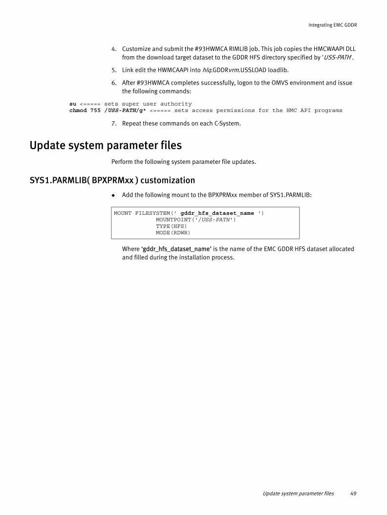
Integrating EMC GDDR
4. Customize and submit the #93HWMCA RIMLIB job. This job copies the HMCWAAPI DLL from the download target dataset to the GDDR HFS directory specified by 'USS-PATH'.
5. Link edit the HWMCAAPI into hlq.GDDRvrm.USSLOAD loadlib.
6. After #93HWMCA completes successfully, logon to the OMVS environment and issue the following commands:
su <===== sets super user authoritychmod 755 /USS-PATH/g* <===== sets access permissions for the HMC API programs
7. Repeat these commands on each C-System.
Update system parameter filesPerform the following system parameter file updates.
SYS1.PARMLIB( BPXPRMxx ) customization
◆ Add the following mount to the BPXPRMxx member of SYS1.PARMLIB:
Where ‘gddr_hfs_dataset_name’ is the name of the EMC GDDR HFS dataset allocated and filled during the installation process.
MOUNT FILESYSTEM(' gddr_hfs_dataset_name ') MOUNTPOINT('/USS-PATH') TYPE(HFS) MODE(RDWR)
Update system parameter files 49

Integrating EMC GDDR
SYS1.PARMLIB(IKJTSOxx) customization
1. Confirm that the following entries exist in AUTHCMD, AUTHPGM, and AUTHTSF lists. Add any missing entries to the IKJTSOxx member of SYS1.PARMLIB of each C-System.
To AUTHCMD add entries:SCFRDFME SCFRDFM6 EHCMSCM9SCFRDFM9EHCMSCMEEHCMSCM6
To AUTHPGM add entries:GDDFLISTGDDRDAP1 GDDRDAP3 GDDRXCMDGDDRSTATGDDRSSVIGDDRQFCNGDDRCGTPGDDRSTOK GDDRQRY5GDDRQRY6 SCFRDFMESCFRDFM6 EHCMSCM9 EMCTF ECGCLEAN EHCMSCM6 EHCMSCME SCFRDFM9ECGUTIL
To AUTHTSF add entries:GDDBCPC2 GDDBCPC3 GDDBCPD2 GDDBCPE2 GDDBCPL2 GDDBCPQ2 GDDBCPS2 GDDRXMPSGDDRAWTZGDDRFC1XGDDRINF2GDDRMCS1GDDRXYZ2 GDDRQDE2 GDDRQDE3 GDDRQDE4 GDDRQDE5 GDDRQDE6GDDRQDE7 GDDRQDE8 GDDRQDE9 GDDRQDEA GDDRQDEB GDDRQDEC GDDRQDED GDDRQDEE
/* EMC ME utility /* EMC M6 utility /* EMC M9 utility/* EMC M9 utility/* EMC ME utility /* EMC M6 utility
/* SDDF list utility/* GDDR /* GDDR /* GDDR /* GDDR check for presence of an active task/* Initialize GDDR command queue /* Manipulate GDDR command queue /* GDDR - ConGroup communication /* GDDR/* GDDR/* GDDR/* EMC ME utility /* EMC M6 utility /* EMC M9 utility /* EMC TimeFinder Mirror /* EMC ConGroup cleanup utility/* EMC M6 MSC cleanup utility /* EMC ME MSC cleanup utility /* EMC M9 utility /* EMC ConGroup 6.4 cleanup utility
/* BCPII AUTH CONNECT /* BCPII AUTH COMMAND /* BCPII AUTH DISCONNECT /* BCPII AUTH EVENT /* BCPII AUTH LIST /* BCPII AUTH QUERY /* BCPII AUTH SET /* GDDR/* GDDR/* GDDR/* GDDR/* GDDR/* GDDR/* GDDR/* GDDR/* GDDR/* GDDR/* GDDR/* GDDR/* GDDR/* GDDR/* GDDR/* GDDR/* GDDR/* GDDR/* GDDR
*/ +*/ +*/ +*/ +*/ +*/ +
*/ +*/ +*/ +*/ +*/ +*/ +*/ +*/ +*/ +*/ +*/ +*/ +*/ +*/ +*/ +*/ +*/ +*/ +*/ +*/ +
*/ +*/ +*/ +*/ +*/ +*/ +*/ +*/ +*/ +*/ +*/ +*/ +*/ +*/ +*/ +*/ +*/ +*/ +*/ +*/ +*/ +*/ +*/ +*/ +*/ +*/
50 EMC GDDR Version 4.1 Product Guide

Integrating EMC GDDR
2. Activate this change using an IPL or dynamically change by using the TSO PARMLIB UPDATE(xx) command.
TSO logon customization
1. You may need to increase the region size of TSO logon procedures that use the GDDR user interface and batch jobs that run GDDR scripts. EMC recommends allocating a TSO logon proc region of 2,100,000, as a starting point.
2. Ensure that TSO logon procs of all TSO users who wish to run the GDDR ISPF user interface contain a SYSEXEC DD which points to hlq.GDDRvrm.RCXFE. This library is allocated during installation.
APF authorization
APF-authorize the hlq.MFEvrm.LINKLIB, hlq.GDDRvrm.LINKLIB, and hlq.GDDRvrm.USSLOAD libraries.
LINKLIB and REXX parameter file installation
Note: If your site prefers to reference hlq.GDDRvrm.LINKLIB and hlq.MFEvrm.LINKLIB by using STEPLIB DD statements, then you can skip the LINKLIST and REXX parameter file customization procedures.
EMC GDDR version 4.1 uses a REXX function package named GDDFUSER with an alias of IRXFUSER. IRXFUSER is a placeholder in SYS1.LINKLIB, providing flexibility for customization of REXX function packages. You have several choices for installation, depending on whether you have applications using previously customized REXX function packages on GDDR C-Systems and GDDR-managed systems. These instructions apply to each C-System and each GDDR-managed system on which GDDRMAIN is to be installed.
If no applications use previously customized REXX function packages, or there are applications which use STEPLIB DD statements to reference a customized REXX function package module, then only follow the directions provided with “Customize LINKLIST” below. If customized REXX function packages named IRXFUSER accessed via the LINKLIST exist on one or more GDDR-managed systems or C-Systems, perform the steps listed in “Customize LINKLIST” below and “Customize REXX parameter files” on page 52.
Customize LINKLIST
1. Delete the placeholder IRXFUSER module from SYS1.LINKLIB.
2. Add hlq.MFEvrm.LINKLIB, hlq.GDDRvrm.LINKLIB, and hlq.GDDRvrm.USSLOAD to the LINKLIST using one of the following methods:
• Add the following LNKLST entries in a PROGxx member:
or
LNKLST ADD NAME(LNKLST) DSN(hlq.MFEvrm.LINKLIB)LNKLST ADD NAME(LNKLST) DSN(hlq.GDDRvrm.LINKLIB)LNKLST ADD NAME(LNKLST) DSN(hlq.GDDRvrm.USSLOAD)
Update system parameter files 51
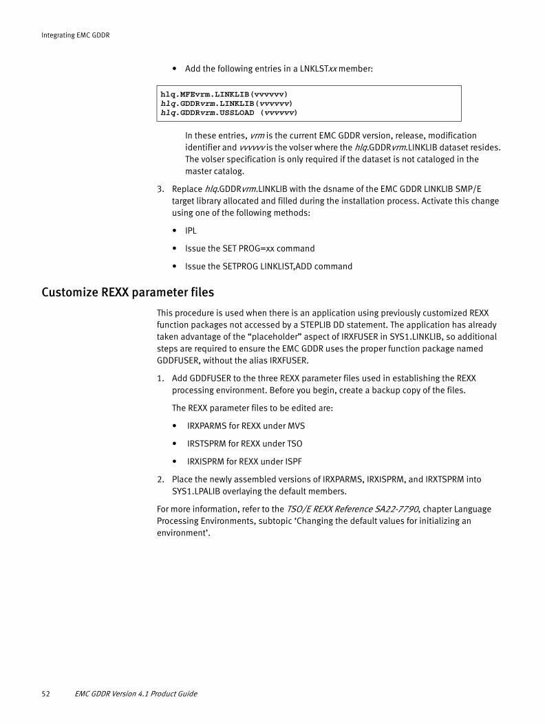
Integrating EMC GDDR
• Add the following entries in a LNKLSTxx member:
In these entries, vrm is the current EMC GDDR version, release, modification identifier and vvvvvv is the volser where the hlq.GDDRvrm.LINKLIB dataset resides. The volser specification is only required if the dataset is not cataloged in the master catalog.
3. Replace hlq.GDDRvrm.LINKLIB with the dsname of the EMC GDDR LINKLIB SMP/E target library allocated and filled during the installation process. Activate this change using one of the following methods:
• IPL
• Issue the SET PROG=xx command
• Issue the SETPROG LINKLIST,ADD command
Customize REXX parameter files
This procedure is used when there is an application using previously customized REXX function packages not accessed by a STEPLIB DD statement. The application has already taken advantage of the “placeholder” aspect of IRXFUSER in SYS1.LINKLIB, so additional steps are required to ensure the EMC GDDR uses the proper function package named GDDFUSER, without the alias IRXFUSER.
1. Add GDDFUSER to the three REXX parameter files used in establishing the REXX processing environment. Before you begin, create a backup copy of the files.
The REXX parameter files to be edited are:
• IRXPARMS for REXX under MVS
• IRSTSPRM for REXX under TSO
• IRXISPRM for REXX under ISPF
2. Place the newly assembled versions of IRXPARMS, IRXISPRM, and IRXTSPRM into SYS1.LPALIB overlaying the default members.
For more information, refer to the TSO/E REXX Reference SA22-7790, chapter Language Processing Environments, subtopic ‘Changing the default values for initializing an environment’.
hlq.MFEvrm.LINKLIB(vvvvvv)hlq.GDDRvrm.LINKLIB(vvvvvv)hlq.GDDRvrm.USSLOAD (vvvvvv)
52 EMC GDDR Version 4.1 Product Guide

Integrating EMC GDDR
Create parameter members for SRDF Host Component on C-Systems
During planned and unplanned Swap scripts, EMC GDDR uses a utility named in the Utility.IEBGENER GDDR parameter to copy the appropriate parameter member over the currently used SRDF Host Component RDFPARM member.
Note: The hlq.GDDR.vrm.SAMPLIB members with the names listed below must be created in the PDS pointed to by the RDF entries within the Define EMC Mainframe Enablers STCs panel, “Option E: Define EMC MF Enablers STCs” on page 138. These members contain complete and identical SRDF Host Component initialization parameters, but are different with respect to MSC group definition, as described in Table 5.Many of these members define MSC gatekeeper devices. Avoid using these gatekeepers elsewhere in the GDDR-managed configuration.
Note: The members listed above must be created on each C-system, in a PDS pointed to on the Define Mainframe Enablers STCs GDDR Parameter Load wizard panel. This panel defines one additional member (default: SRDFSTAR) which is actively used by the Host Component instance on the specified C-system.
Edit SCF initialization parametersOn each EMC GDDR-managed host and C-System, make sure the following SCF parameter is set correctly:
◆ Ensure that SCF.CSC.VERBOSE is set to YES. This setting enables additional messaging required for the proper detection of the loss of an EMC GDDR-managed system.
Table 5 SRDF Host Component parameter members
Member Description
SITEUDC1 Used during a swap from DC3 to DC1. Defines an MSC group in MSC-only mode, with the R1 devices at DC1 and WF=0.
Note: WF indicates the MSC weight factor. The primary server is the server running with MSC_WEIGHT_FACTOR = 0.
SITEUDC3 Used during a swap from DC1 to DC3. Defines an MSC group in MSC-only mode, with the R1 devices at DC3 and WF=0.
Create parameter members for SRDF Host Component on C-Systems 53
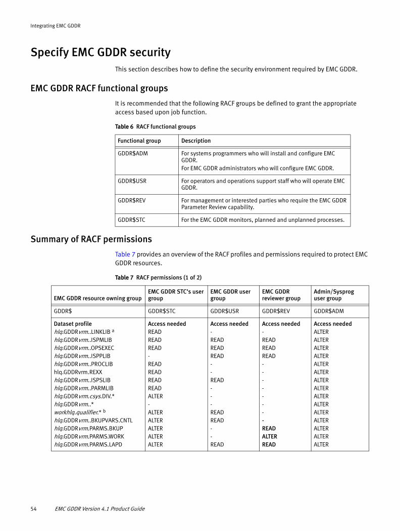
Integrating EMC GDDR
Specify EMC GDDR securityThis section describes how to define the security environment required by EMC GDDR.
EMC GDDR RACF functional groups
It is recommended that the following RACF groups be defined to grant the appropriate access based upon job function.
Summary of RACF permissions
Table 7 provides an overview of the RACF profiles and permissions required to protect EMC GDDR resources.
Table 6 RACF functional groups
Functional group Description
GDDR$ADM For systems programmers who will install and configure EMC GDDR.For EMC GDDR administrators who will configure EMC GDDR.
GDDR$USR For operators and operations support staff who will operate EMC GDDR.
GDDR$REV For management or interested parties who require the EMC GDDR Parameter Review capability.
GDDR$STC For the EMC GDDR monitors, planned and unplanned processes.
Table 7 RACF permissions (1 of 2)
EMC GDDR resource owning groupEMC GDDR STC’s user group
EMC GDDR user group
EMC GDDR reviewer group
Admin/Sysprog user group
GDDR$ GDDR$STC GDDR$USR GDDR$REV GDDR$ADM
Dataset profilehlq.GDDRvrm..LINKLIB a
hlq.GDDRvrm..ISPMLIBhlq.GDDRvrm..OPSEXEChlq.GDDRvrm..ISPPLIBhlq.GDDRvrm..PROCLIBhlq.GDDRvrm.REXXhlq.GDDRvrm..ISPSLIBhlq.GDDRvrm..PARMLIBhlq.GDDRvrm.csys.DIV.*hlq.GDDRvrm..*workhlq.qualifier.* b
hlq.GDDRvrm..BKUPVARS.CNTLhlq.GDDRvrm.PARMS.BKUPhlq.GDDRvrm.PARMS.WORKhlq.GDDRvrm.PARMS.LAPD
Access neededREADREADREAD-READREADREADREADALTER-ALTERALTERALTERALTERALTER
Access needed-READREADREAD--READ---READREAD--READ
Access needed-READREADREAD--------READALTERREAD
Access neededALTERALTERALTERALTERALTERALTERALTERALTERALTERALTERALTERALTERALTERALTERALTER
54 EMC GDDR Version 4.1 Product Guide

Integrating EMC GDDR
All EMC GDDR RACF non-generic profiles should have a universal access (UACC) of NONE.
Note: Use the JCL provided in hlq.GDDRvrm.SAMPLIB member GDDCRACJ to define RACF authorizations for GDDR C-Systems using hlq.GDDRvrm.SAMPLIB member GDDCRACF. For managed systems, GDDPRACF. SAMPLIB members GDDCRACD and GDDPRACD are provided for ease of deleting RACF authorization definitions from systems.
GDDR$ GDDR$STC GDDR$USR GDDR$REV GDDR$ADM
FACILITY profileGDDR.HMC.LISTOBJECTSGDDR.HMC.GETMSGSGDDR.GLOBAL.VARIABLE.ACCESS HWI.APPLNAME.HWISERV HWI.TARGET.netid.nau#1 HWI.TARGET.netid.nau#2 HWI.TARGET.netid.nau#n HWI.TARGET.netid.nau#1.image#1HWI.TARGET.netid.nau#1.image#2 HWI.TARGET.netid.nau#2.image#1HWI.TARGET.netid.nau#2.image#2 HWI.TARGET.netid.ima*.*HWI.TARGET.netid.nau.*
Access neededREADREADUPDATEREADALTERALTERALTERALTERALTERALTERALTERALTERALTER
Access neededREADREADREADREADALTERALTERALTERALTERALTERALTERALTERALTERALTER
Access needed-------------
Access neededREADREADUPDATEREADALTERALTERALTERALTERALTERALTERALTERALTERALTER
TSOAUTH profileOPER
Access neededREAD
Access needed-
Access needed-
SURROGAT profileuserid.SUBMIT c
Access neededREAD
Access neededREAD
Access neededREAD
JESSPOOL profileJes2node.GDDR.*.*.*.* d
Access needed-
Access neededREAD
Access neededALTER
a. hlq is any dataset high level qualifier, if one is used.
b. workhlq.qualifier.* is defined using Option J: Script JCL Parameters panel, field 'Work HLQ' as shown on page 143. The default value for workhlq is "GDDR". The Userids assigned to GDDR started tasks, as well as Userids authorized to submit GDDR scripts must be authorized with ALTER to this HLQ.
c. userid is the Surrogate User ID defined on the Script JCL Parameters panel.
d. Jes2node is the JES2 node name of the EMC GDDR C-System. The JES2 node name can be determined by issuing the JES2 console command $DNODE,OWNNODE=YES on the appropriate EMC GDDR C-System. The output of the JES2 command is as follows:$HASP826 NODE(1) $HASP826 NODE(1) NAME=MFSYS3,STATUS=(OWNNODE),AUTH=(DEVICE=YES,$HASP826 JOB=YES,NET=NO,SYSTEM=YES),TRANSMIT=BOTH, $HASP826 RECEIVE=BOTH,HOLD=NONE,PENCRYPT=NO, $HASP826 SIGNON=COMPAT,DIRECT=NO,ENDNODE=NO,REST=0,$HASP826 SENTREST=ACCEPT,COMPACT=0,LINE=0,LOGMODE=, $HASP826 LOGON=0,NETSRV=0,OWNNODE=YES,$HASP826 PASSWORD=(VERIFY=(NOTSET),SEND=(NOTSET)), $HASP826 PATHMGR=YES,PRIVATE=NO,SUBNET=,TRACE=YES
The actual JES2 node name is identified on the NAME=output statement.
Table 7 RACF permissions (2 of 2)
EMC GDDR resource owning groupEMC GDDR STC’s user group
EMC GDDR user group
EMC GDDR reviewer group
Admin/Sysprog user group
Specify EMC GDDR security 55

Integrating EMC GDDR
OPERCMDS class resource definitions (optional)If command authorization checking is in place, refer to the following OPERCMDS class resource definitions in Table 8. Sample commands are supplied in &hlq.GDDR&vrm.SAMPLIB(GDDCRACF).
Apply the RACF RDEFINE and PERMIT commands for the MVS.MCSOPER facility class which are contained in hlq.GDDRvrm.SAMPLIB(GDDCRACF).
IBM z/OS apar OA26369, which is contained in PTF UA48307 for z/OS 1.9, UA48308 for z/OS 1.10 and UA48309 for z/OS 1.11 enforces the authorization check on facility class MVS.MCSOPER.
EMC GDDR user interface security
You may choose to implement role-based access controls with EMC GDDR user interface facility profiles. Your site's security authorization product is used to control access to the entire EMC GDDR user interface, to selected menus, and to selected actions within menus.
Table 8 RACF permissions, OPERCMDS class
EMC GDDR resource owning group
CLASS OPERCMDS Command/keyword GDDR$STC GDDR$USR GDDR$ADM
MVS.REPLY REPLY READ READ
MVS.MODIFY.STC.*.* MODIFY jobnameMODIFY jobname.idMODIFY id
UPDATE UPDATE -
Table 9 Summary of GDDR ISPF RACF permissions (1 of 3)
Facility profile Panel-ID[Function-Description]GDDR$ADMgroup
GDDR$USRgroup
GDDR$REV group
GDDRISPF.ACCESS GDDRPRIM [GDDR Primary Options Menu] READ READ READ
GDDRISPF.SETUP.* GDDRMNT0 [All Setup and Maintenance Actions]
GDDRISPF.SETUP.ACCESS GDDRMNT0 [Setup and Maintenance Submenus]
READ READ
GDDRISPF.SETUP.PARMS.* Authorizes all Parameter Edit, Validate and Activate actions
GDDRISPF.SETUP.PARMS.ACCESS GDDRMNT0 [Perform GDDR Setup and Maintenance Functions]
READ READ READ
GDDRISPF.SETUP.PARMS.BACKUP GDDRPRM0 [Manage GDDR Parameter backups]
READ
56 EMC GDDR Version 4.1 Product Guide
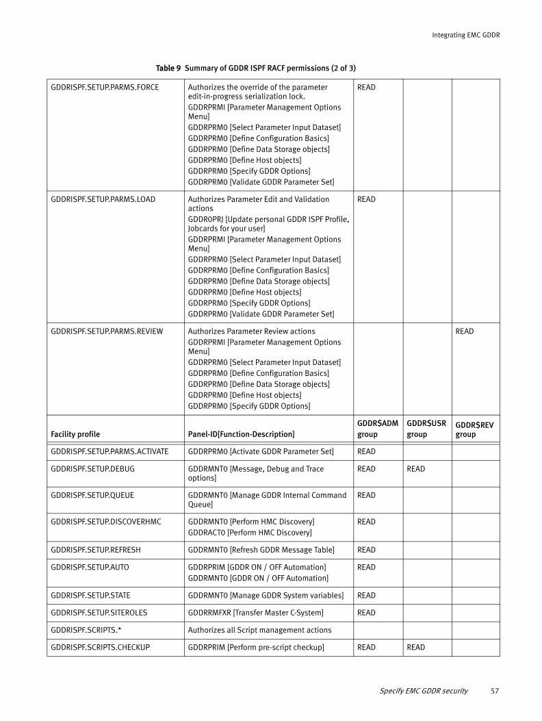
Integrating EMC GDDR
GDDRISPF.SETUP.PARMS.FORCE Authorizes the override of the parameter edit-in-progress serialization lock. GDDRPRMI [Parameter Management Options Menu] GDDRPRM0 [Select Parameter Input Dataset] GDDRPRM0 [Define Configuration Basics]GDDRPRM0 [Define Data Storage objects]GDDRPRM0 [Define Host objects]GDDRPRM0 [Specify GDDR Options]GDDRPRM0 [Validate GDDR Parameter Set]
READ
GDDRISPF.SETUP.PARMS.LOAD Authorizes Parameter Edit and Validation actionsGDDR0PRJ [Update personal GDDR ISPF Profile,Jobcards for your user]GDDRPRMI [Parameter Management Options Menu]GDDRPRM0 [Select Parameter Input Dataset]GDDRPRM0 [Define Configuration Basics]GDDRPRM0 [Define Data Storage objects]GDDRPRM0 [Define Host objects]GDDRPRM0 [Specify GDDR Options]GDDRPRM0 [Validate GDDR Parameter Set]
READ
GDDRISPF.SETUP.PARMS.REVIEW Authorizes Parameter Review actionsGDDRPRMI [Parameter Management Options Menu]GDDRPRM0 [Select Parameter Input Dataset]GDDRPRM0 [Define Configuration Basics]GDDRPRM0 [Define Data Storage objects]GDDRPRM0 [Define Host objects]GDDRPRM0 [Specify GDDR Options]
READ
Facility profile Panel-ID[Function-Description]GDDR$ADMgroup
GDDR$USRgroup
GDDR$REV group
GDDRISPF.SETUP.PARMS.ACTIVATE GDDRPRM0 [Activate GDDR Parameter Set] READ
GDDRISPF.SETUP.DEBUG GDDRMNT0 [Message, Debug and Trace options]
READ READ
GDDRISPF.SETUP.QUEUE GDDRMNT0 [Manage GDDR Internal Command Queue]
READ
GDDRISPF.SETUP.DISCOVERHMC GDDRMNT0 [Perform HMC Discovery]GDDRACT0 [Perform HMC Discovery]
READ
GDDRISPF.SETUP.REFRESH GDDRMNT0 [Refresh GDDR Message Table] READ
GDDRISPF.SETUP.AUTO GDDRPRIM [GDDR ON / OFF Automation]GDDRMNT0 [GDDR ON / OFF Automation]
READ
GDDRISPF.SETUP.STATE GDDRMNT0 [Manage GDDR System variables] READ
GDDRISPF.SETUP.SITEROLES GDDRRMFXR [Transfer Master C-System] READ
GDDRISPF.SCRIPTS.* Authorizes all Script management actions
GDDRISPF.SCRIPTS.CHECKUP GDDRPRIM [Perform pre-script checkup] READ READ
Table 9 Summary of GDDR ISPF RACF permissions (2 of 3)
Specify EMC GDDR security 57

Integrating EMC GDDR
Member GDDIRACF in hlq.GDDRvrm.SAMPLIB list the RACF commands used for EMC GDDR ISPF permissions. These commands are optionally used to protect EMC GDDR functions.
RACF authorization for HMC LPAR actions
The facility profile GDDRISPF.ACTIONS.HMC.system_name provides for site-specific authorization of EMC GDDR LPAR processing. Authorization is enabled through the EMC GDDR panel “Option L: Perform HMC LPAR Actions” shown on page 179. Following your specification of GDDRISPF.ACTIONS.HMC facility profiles, the Perform HMC LPAR Actions panel will only list the system names for actions by authorized EMC GDDR users. Unprotected system names will display for any EMC GDDR user.
The value of system_name corresponds to the name found in the system field of the Define Managed LPARs panel shown on page 123. You can use generic or discrete system names in the facility profile.
The following rules apply to generic profile names, where valid generic characters are *, %, and **:
◆ Specify % in the profile name to match any single non-blank character (except a period) in the same position of the system ID name.
◆ Specify * or ** in the profile name to match more than one character in the same position of the system ID name.
The z/OS Security Server RACF Command Language Reference, SA22-7687, provides detailed descriptions and examples that illustrate how to specify generic profile names.
Note: The sample GDDRISPF.ACTIONS.HMC facility profile definition, supplied with hlq.GDDRvrm.SAMPLIB member GDDIRACF authorizes all systems to users who are connected to the GDDR$USR group.
GDDRISPF.SCRIPTS.RUN.ACCESS GDDRPRIM [Run GDDR Scripts] READ
GDDRISPF.SCRIPTS.MANAGE.JCL GDDR0PRJ [Jobcards for your user] READ READ
GDDRISPF.SCRIPTS.VIEWSTATS GDDRPRIM [View GDDR Script Statistics] READ
GDDRISPF.VIEW.CONFIG GDDRPRIM [View GDDR configuration] READ READ
GDDRISPF.ACTIONS.* Authorizes all GDDR CBU, HMC and SYSPLEX actions
GDDRISPF.ACTIONS.ACCESS GDDRPRIM [Perform GDDR Actions] READ READ
GDDRISPF.ACTIONS.CBU.ACCESS GDDRACT0 [Perform HMC CBU actions] READ READ
GDDRISPF.ACTCBU.site.cpc Authorizes CBU actions by SITE and CPC READ READ
GDDRISPF.ACTIONS.HMC.ACCESS GDDRACT0 [Perform HMC LPAR actions] READ READ
GDDRISPF.ACTIONS.HMC.system_name
Authorizes HMC actions by system name READ READ
GDDRISPF.ACTIONS.SYSPLEX GDDRACT0 [Manage Couple Datasets] READ READ
GDDRISPF.EZSM.ACCESS EC0RLGON [EzSM Product Home Menu] READ
Table 9 Summary of GDDR ISPF RACF permissions (3 of 3)
58 EMC GDDR Version 4.1 Product Guide

Integrating EMC GDDR
Examples The following examples demonstrate the use of the GDDRISPF.ACTIONS.HMC facility profile:
Example 1 RDEFINE FACILITY GDDRISPF.ACTIONS.HMC.** UACC(NONE) OWNER(GDDR$ADM)PERMIT GDDRISPF.ACTIONS.HMC.ZOSESYS* CLASS(FACILITY) ACCESS(READ) ID(GDDR)
In the above example, the GDDR HMC LPAR Actions panel at a given EMC GDDR C-System will display all system names defined in the System field of the Define Managed LPARs panel that match the generic name 'ZOSESYS*' for all users connected to the group 'GDDR'. System names which do not match 'ZOSESYS*' are protected and will not be displayed on any GDDR HMC LPAR Actions panel.
Example 2 RDEFINE FACILITY GDDRISPF.ACTIONS.HMC.ZOSESYS1 UACC(NONE) OWNER(GDDR$ADM)PERMIT GDDRISPF.ACTIONS.HMC.ZOSESYS1 CLASS(FACILITY) ACCESS(READ) ID(SYSPGM1)
In the above example, the GDDR HMC LPAR Actions panel at a given EMC GDDR C-System will display only system name ZOSESYS1 for user SYSPGM1. All other systems defined in the System field of the Define Managed LPARs panel are not protected and therefore will be displayed on the GDDR HMC LPAR Actions panel.
Mainframe Enablers EMCSAFI security interface authorization
If you have protected access to Consistency Group and SRDF Host Component commands, authorize the GDDR userid and the GDDR$STC group with SAF profiles described in the Configuration chapters of the EMC Consistency Groups for z/OS Product Guide and EMC SRDF Host Component for z/OS Product Guide.
If TimeFinder/Mirror for z/OS and TimeFinder/Mirror clone emulation are in use and commands are protected, the GDDR userid and the GDR$STC group also require authorization.
Similarly, if devices to be managed by EMC GDDR have been protected using the EMCSAFI security interface of EMC ResourcePak Base for z/OS, authorization must be added for the GDDR userid and the GDDR$STC group.
The EMC Mainframe Enablers Installation and Configuration Guide provides information about the security interface and the class and resource names used.
Authorized module and RACF-protected resource authorization verification
After completing the steps listed in “SYS1.PARMLIB(IKJTSOxx) customization” on page 50 and in “Specify EMC GDDR security” on page 54, check that GDDR load modules are properly authorized and accessible and that RACF resources have been properly defined and authorized using member GDDRECHK in hlq.GDDRvrm.SAMPLIB.
The RACF-protected resource authorization verification utility (jobname GDDRECHK) provides a means for the RACF administrator to verify that the site's security rules have been properly defined for support of GDDR processing. The utility validates authorizations using a control statement specifying group, (GDDR$STC, GDDR$ADM, and GDDR$USR), site, CPC, and LPAR. The GDDRECHK job validates authorization of the user associated with the job against the RACF definitions on the system where the job is run. Therefore, the GDDRECHK job must be submitted on each C-System and managed system. EMC recommends use of the USERID jobcard parameter with the GDDRECHK job when the security administrator validates authorization for GDDR administrators and operations personnel.
Specify EMC GDDR security 59

Integrating EMC GDDR
“RACF-protected resource authorization and verification SAMPLIB inventory” on page 64 lists the members provided for use in defining and validating security authorization.
Using GDDRECHKPerform the following steps to use the GDDRECHK job:
1. Customize the jobcard to match your site's requirements. If the verification is to be performed for a userid other than the submitter, include jobcard parameter USERID=, to specify the desired userid.
2. Specify a value for GRP= from those documented in Table 7, “RACF permissions,” on page 54.
For example:
GRP=GDDR$ADM for GDDR administrators
GRP=GDDR$USR for GDDR operations users
GRP=GDDR$STC for GDDR started tasks
GRP=GDDR$REV for GDDR review users (optional)
GRP= for non-GDDR users to check all GDDR resources have been properly protected.
Note: Steps 3, 4, 5, and 6 and the substitution value for MFEPFX in step 7 are not applicable to managed systems.
3. Specify the CP1= value that was used from SAMPLIB(GDDIRACF), or specify a list of CPC names.
4. Specify the CP2= value that was used from SAMPLIB(GDDIRACF), or specify a list of CPC names.
5. Specify the CP3= value that was used from SAMPLIB(GDDIRACF), or specify a list of CPC names.
6. Specify the SYS= value that was used from SAMPLIB(GDDIRACF), or specify a list of system names.
7. Specify dataset name prefixes, as used to define dataset profiles in SAMPLIB(GDDCRACF):
8. Run the GDDRECHK job on each C-System and managed system to verify RACF definitions.
Returns: 0 - Check the output in SYSTSPRT for RACF error messages
Figure 4 provides an example of the parameter statements.
Name Description Example
GDDRPFX= dsname prefix for GDDR installed datasets EMC.GDDR410
MFEPFX= dsname prefix for EMC Mainframe Enablers installed datasets
EMC.MFE740
60 EMC GDDR Version 4.1 Product Guide

Integrating EMC GDDR
//jobname JOB (EMC),'GDDRECHK',CLASS=A,MSGCLASS=X,MSGLEVEL=(1,1), // NOTIFY=&SYSUID //GDDCHECK PROC GRP=GDDR$ADM, <=== GDDR$ADM/GDDR$USR/GDDR$STC // CP1=CPC1, <=== CPC NAMES TO CHECK AT DC1 // CP2=CPC2, <=== CPC NAMES TO CHECK AT DC2 // CP3=CPC3, <=== CPC NAMES TO CHECK AT DC3 // SYS=VC1B, <=== SYSTEM NAMES TO CHECK // GDDRPFX=EMC.GDDR410, <=== GDDR DSN PREFIX // MFEPFX=EMC.MFE740 <=== MF ENABLERS DSN PREFIX //********************************************************************* //*
Figure 4 GDDECHK input parameters
GDDRECHK produces a listing which shows the result of GDDR SAF authorizations by OPERCMDS, SURROGAT, TSOAUTH, JESJOBS, and FACILITY classes. The GDDRECHK program is used to check that the security rules (RACF/ACF2) have been set up correctly for a given security ID (specified on the job card USER= parameter, or defaulted to the TSO user submitting the job) and a given GDDR security role (specified in the PARM='GROUP(GDDR$xxx)' field). GDDRECHK needs to be run separately for every combination of GROUP(GDDR$xxx) and user ID, to verify all security has been implemented correctly.
Figure 5, “Validation of GDDR$ADM group access by facility,” and Figure 6, “Validation of specific calls from GDDR modules,” on page 63 provide examples of the GDDRECHK program. The following fields are displayed in the output:
◆ CLASS
This column specifies a valid class name defined in the RACF class descriptor table associated with the RESOURCE NAME. The GDDRECHK utility expects DATASET or FACILITY.
◆ RESOURCE NAME
For a particular GDDR security role, shown in the report at the top on the line 'Testing GDDR$xxx group access', this column specifies the discrete or generic DATASET or FACILITY profile name to be validated.
◆ ACCESS
The ACCESS column shows what access the user SHOULD have ('READ', 'UPDATE', 'NONE').
◆ GDDSECUR RESULT
The GDDSECUR RESULT column shows the response from the security system (a SAF call) to an inquiry to check the indicated ACCESS for the indicated resource (FACILITY and RESOURCE NAME). This can be 'ALLOW', 'DENY', or 'RESOURCE NOT PROTECTED'.
◆ COMMENT
The comment column shows the value 'Ok' if the access is correct (security system correctly allowed or denied access), or *** ERROR *** if the access is not correct (the user has too much or too little access).
If the user has too much access, ***ERROR** will be reported when either:
1. The resource is not protected at all
Specify EMC GDDR security 61
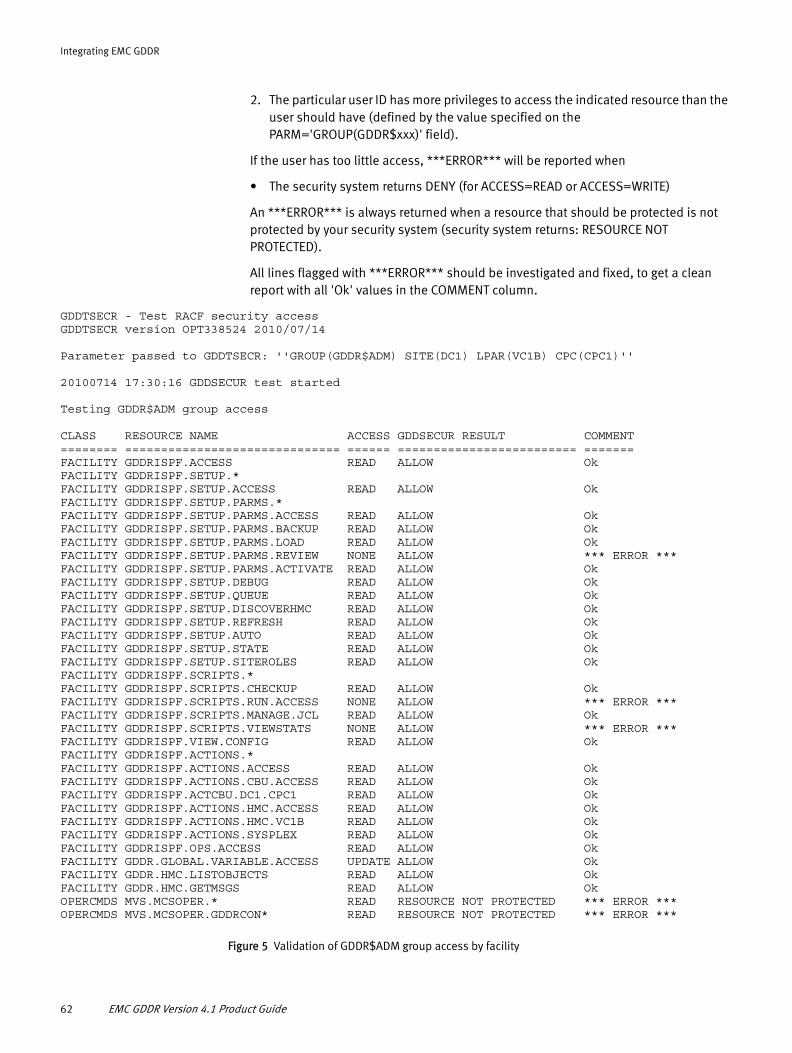
Integrating EMC GDDR
2. The particular user ID has more privileges to access the indicated resource than the user should have (defined by the value specified on the PARM='GROUP(GDDR$xxx)' field).
If the user has too little access, ***ERROR*** will be reported when
• The security system returns DENY (for ACCESS=READ or ACCESS=WRITE)
An ***ERROR*** is always returned when a resource that should be protected is not protected by your security system (security system returns: RESOURCE NOT PROTECTED).
All lines flagged with ***ERROR*** should be investigated and fixed, to get a clean report with all 'Ok' values in the COMMENT column.
GDDTSECR - Test RACF security access GDDTSECR version OPT338524 2010/07/14 Parameter passed to GDDTSECR: ''GROUP(GDDR$ADM) SITE(DC1) LPAR(VC1B) CPC(CPC1)''
20100714 17:30:16 GDDSECUR test started Testing GDDR$ADM group access CLASS RESOURCE NAME ACCESS GDDSECUR RESULT COMMENT ======== ============================== ====== ========================= ======= FACILITY GDDRISPF.ACCESS READ ALLOW Ok FACILITY GDDRISPF.SETUP.* FACILITY GDDRISPF.SETUP.ACCESS READ ALLOW Ok FACILITY GDDRISPF.SETUP.PARMS.* FACILITY GDDRISPF.SETUP.PARMS.ACCESS READ ALLOW Ok FACILITY GDDRISPF.SETUP.PARMS.BACKUP READ ALLOW Ok FACILITY GDDRISPF.SETUP.PARMS.LOAD READ ALLOW Ok FACILITY GDDRISPF.SETUP.PARMS.REVIEW NONE ALLOW *** ERROR ***FACILITY GDDRISPF.SETUP.PARMS.ACTIVATE READ ALLOW Ok FACILITY GDDRISPF.SETUP.DEBUG READ ALLOW Ok FACILITY GDDRISPF.SETUP.QUEUE READ ALLOW Ok FACILITY GDDRISPF.SETUP.DISCOVERHMC READ ALLOW Ok FACILITY GDDRISPF.SETUP.REFRESH READ ALLOW Ok FACILITY GDDRISPF.SETUP.AUTO READ ALLOW Ok FACILITY GDDRISPF.SETUP.STATE READ ALLOW Ok FACILITY GDDRISPF.SETUP.SITEROLES READ ALLOW Ok FACILITY GDDRISPF.SCRIPTS.* FACILITY GDDRISPF.SCRIPTS.CHECKUP READ ALLOW Ok FACILITY GDDRISPF.SCRIPTS.RUN.ACCESS NONE ALLOW *** ERROR ***FACILITY GDDRISPF.SCRIPTS.MANAGE.JCL READ ALLOW Ok FACILITY GDDRISPF.SCRIPTS.VIEWSTATS NONE ALLOW *** ERROR ***FACILITY GDDRISPF.VIEW.CONFIG READ ALLOW Ok FACILITY GDDRISPF.ACTIONS.* FACILITY GDDRISPF.ACTIONS.ACCESS READ ALLOW Ok FACILITY GDDRISPF.ACTIONS.CBU.ACCESS READ ALLOW Ok FACILITY GDDRISPF.ACTCBU.DC1.CPC1 READ ALLOW Ok FACILITY GDDRISPF.ACTIONS.HMC.ACCESS READ ALLOW Ok FACILITY GDDRISPF.ACTIONS.HMC.VC1B READ ALLOW Ok FACILITY GDDRISPF.ACTIONS.SYSPLEX READ ALLOW Ok FACILITY GDDRISPF.OPS.ACCESS READ ALLOW Ok FACILITY GDDR.GLOBAL.VARIABLE.ACCESS UPDATE ALLOW Ok FACILITY GDDR.HMC.LISTOBJECTS READ ALLOW OkFACILITY GDDR.HMC.GETMSGS READ ALLOW Ok OPERCMDS MVS.MCSOPER.* READ RESOURCE NOT PROTECTED *** ERROR ***OPERCMDS MVS.MCSOPER.GDDRCON* READ RESOURCE NOT PROTECTED *** ERROR ***
Figure 5 Validation of GDDR$ADM group access by facility
62 EMC GDDR Version 4.1 Product Guide

Integrating EMC GDDR
Testing specific calls from GDDR modules CLASS RESOURCE NAME ACCESS GDDSECUR RESULT COMMENT ======== ============================== ====== ========================= ======= FACILITY GDDRISPF.ACTIONS.ACCESS READ ALLOW Ok (GDDIACT0) FACILITY GDDRISPF.SETUP.DISCOVERHMC READ ALLOW Ok (GDDIACT0) FACILITY GDDRISPF.ACTIONS.HMC.ACCESS READ ALLOW Ok (GDDIACT0) FACILITY GDDRISPF.ACTIONS.CBU.ACCESS READ ALLOW Ok (GDDIACT0) FACILITY GDDRISPF.ACTIONS.SYSPLEX READ ALLOW Ok (GDDIACT0) FACILITY GDDRISPF.SETUP.ACCESS READ ALLOW Ok (GDDIMNT0) FACILITY GDDRISPF.SETUP.PARMS.ACCESS READ ALLOW Ok (GDDIMNT0) FACILITY GDDRISPF.SETUP.DEBUG READ ALLOW Ok (GDDIMNT0) FACILITY GDDRISPF.SETUP.QUEUE READ ALLOW Ok (GDDIMNT0) FACILITY GDDRISPF.SETUP.DISCOVERHMC READ ALLOW Ok (GDDIMNT0) FACILITY GDDRISPF.SETUP.REFRESH READ ALLOW Ok (GDDIMNT0) FACILITY GDDRISPF.SETUP.AUTO READ ALLOW Ok (GDDIMNT0) FACILITY GDDRISPF.SETUP.STATE READ ALLOW Ok (GDDIMNT0) FACILITY GDDRISPF.SETUP.PARMS.BACKUP READ ALLOW Ok (GDDIPRBU) FACILITY GDDRISPF.SETUP.PARMS.LOAD READ ALLOW Ok (GDDIPRMI) FACILITY GDDRISPF.SETUP.PARMS.REVIEW NONE ALLOW *** ERROR *** (GDDIPRMI) FACILITY GDDRISPF.SETUP.PARMS.ACCESS READ ALLOW Ok (GDDIPRM0) FACILITY GDDRISPF.SETUP.PARMS.BACKUP READ ALLOW Ok (GDDIPRM0) FACILITY GDDRISPF.SETUP.PARMS.LOAD READ ALLOW Ok (GDDIPRM0) FACILITY GDDRISPF.SETUP.PARMS.REVIEW NONE ALLOW *** ERROR *** (GDDIPRM0) FACILITY GDDRISPF.SETUP.PARMS.ACTIVATE READ ALLOW Ok (GDDIPRM0) FACILITY GDDRISPF.SETUP.SITEROLES READ ALLOW Ok (GDDIROLO) FACILITY GDDRISPF.ACCESS READ ALLOW Ok (GDDISTRT) FACILITY GDDRISPF.SETUP.ACCESS READ ALLOW Ok (GDDISTRT) FACILITY GDDRISPF.VIEW.CONFIG READ ALLOW Ok (GDDISTRT) FACILITY GDDRISPF.SETUP.AUTO READ ALLOW Ok (GDDISTRT) FACILITY GDDRISPF.SETUP.SITEROLES READ ALLOW Ok (GDDISTRT) FACILITY GDDRISPF.SCRIPTS.CHECKUP READ ALLOW Ok (GDDISTRT) FACILITY GDDRISPF.SCRIPTS.RUN.ACCESS NONE ALLOW *** ERROR *** (GDDISTRT) FACILITY GDDRISPF.SCRIPTS.VIEWSTATS NONE ALLOW *** ERROR *** (GDDISTRT) FACILITY GDDRISPF.ACTIONS.ACCESS READ ALLOW Ok (GDDISTRT) FACILITY GDDRISPF.OPS.ACCESS READ ALLOW Ok (GDDISTRT) FACILITY GDDRISPF.SETUP.DISCOVERHMC READ ALLOW Ok (GDDRHMCD) FACILITY GDDRISPF.SETUP.PARMS.LOAD READ ALLOW Ok (GDDRPROF) FACILITY GDDRISPF.SCRIPTS.MANAGE.JCL READ ALLOW Ok (GDDRPROF) FACILITY GDDR.HMC.LISTOBJECTS READ ALLOW Ok (GDDRC002)FACILITY GDDR.HMC.GETMSGS READ ALLOW Ok (GDDRC009) FACILITY GDDR.GLOBAL.VARIABLE.ACCESS UPDATE ALLOW Ok (--------) 20100714 17:31:28 GDDSECUR test ended - MAXRC=12 Elapsed=71.785423 seconds GDDTSECR ending - maximum RC=12
Figure 6 Validation of specific calls from GDDR modules
Specify EMC GDDR security 63

Integrating EMC GDDR
RACF-protected resource authorization and verification SAMPLIB inventoryTable 10 provides an inventory of hlq.GDDRvrm.SAMPLIB members used for defining and validating EMC GDDR security controls.
Define EMC GDDR datasetsEMC GDDR C-Systems utilize permanent global variable data-in-virtual (DIV) and parameter backup and parameter wizard work datasets. Catalog these datasets on each C-System using the jobs supplied in hlq.GDDRvrm.SAMPLIB.
Define global variable datasets
Define a VSAM linear dataset to manage global variables on each C-system. The recommended dataset name convention is hlq.GDDRvrm.csys.DIV. JCL has been provided in hlq.GDDRvrm.SAMPLIB(GDDIVDEF).
Allocate the parameter management datasets
Note: EMC recommends the use of two parameter backup datasets—one for parameter management functions and the other for backups performed when the Heartbeat Monitor initializes.
1. Customize and run the job in member GDDRABDS in hlq.GDDRvrm.SAMPLIB. Ensure it has run successfully.
• The parameter backup dataset name to be used for parameter management functions is defined to GDDR in your personal GDDR ISPF Profile, Option P on the GDDR Primary Options Menu. This dataset is used when you create a backup of GDDR parameters using the GDDR ISPF Interface, Option B, Manage GDDR Parameter backups, from the GDDR Parameter Management Options menu. It also used for the implicit backups created before and after the update of GDDR parameters during an Activate. Refer to “Option P: Profile—Update Personal GDDR ISPF Profile” on page 86 for assistance.
Table 10 SAMPLIB inventory
Member Description
GDDCRACF Define RACF C-System resources
GDDCRACD Delete RACF C-System resources
GDDCRACJ JCL to delete/define C-System resources
GDDIRACF Define RACF GDDR ISPF resources
GDDIRACD Delete RACF GDDR ISPF resources
GDDIRACJ JCL to delete/define GDDR ISPF resources
GDDPRACF Define RACF P-System resources
GDDPRACD Delete RACF P-System resources
GDDPRACJ JCL to delete/define P-System resources
GDDRECHK Verify GDDR load module authorizations and RACF access authorizations
64 EMC GDDR Version 4.1 Product Guide

Integrating EMC GDDR
• The parameter backup dataset to be used for Heartbeat Initialization backups is defined to EMC GDDR in the Define GDDR Datasets panel using the BKUPVARS field type. Refer to “Option D: Define GDDR Datasets” on page 112 for details.
• The parameter wizard work dataset for your userid is a PDS with the same attributes as a parameter backup dataset, which serves as a temporary store for EMC GDDR parameters in preparation of a GDDR parameter activation.
• The parameter wizard work dataset must be allocated as a PDS, with attributes FB and LRECL=80.
• The last activated parameter dataset has the same allocation parameters as the parameter wizard work dataset and contains a copy of the work PDS used during the most recent activation.
2. Allocate or choose a PDS, FB, LRECL=80, to store GDDRMAIN parameters. You could use hlq.GDDRvrm.PARMLIB for this purpose.
Install EMC GDDR started proceduresThe EMC GDDRMAIN and Event Monitor tasks must be started and remain running on the EMC GDDR C-Systems at all times. Also, GDDRMAIN tasks must be started and remain running on all EMC GDDR managed systems at all times. Before using EMC GDDR, you must customize these started procedures and make them available. On GDDR C-Systems, GDDRMAIN will automatically start GDDRWORK and GDDREVM started tasks.
Note: Use automation to start the EMC GDDR procedures on the EMC GDDR C-Systems at system startup. No EMC GDDR started tasks are to be started SUB=MSTR.
1. Update members GDDRMAIN, GDDRWORK, and GDDREVM in hlq.GDDR.vrm.PROCLIB so the following DD statements point to the datasets resulting from your SMP/E installation: ISPPLIB, ISPMLIB, ISPSLIB, and SYSTSIN.
2. Update member GDDRMAIN in hlq.GDDR.vrm.PROCLIB so the GDDREXEC DD statement points to the hlq.GDDRvrm.REXX dataset resulting from your SMP/E installation, and the GDDMPARM DD points to the GDDRMAIN parameter dataset (as described in step 2 on page 65).
3. Make the EMC GDDR started procedures available to the C-Systems by copying members GDDRMAIN, GDDRWORK, and GDDREVM from hlq.GDDRvrm.PROCLIB to SYS1.PROCLIB or equivalent library for started tasks.
4. Copy member GDDREVMP from hlq.GDDRvrm.PARMLIB to the parmlib you have referenced in your GDDREVM started procedure member.
5. Make the GDDRMAIN started procedure available to the GDDR-managed systems by copying member GDDRMAIN from hlq.GDDRvrm.PROCLIB to SYS1.PROCLIB or equivalent library for started tasks on the respective system.
6. If you plan to use customized versions of GDDR user exits, include a SYSEXEC DD statement referencing your user RCXFE library in the GDDREVM started procedure member.
Install EMC GDDR started procedures 65

Integrating EMC GDDR
Note: “Sample procedure to use interpreted REXX user exits” on page 226 provides more information.
7. Ensure GDDR started tasks connect to the appropriate SCF instance.
The GDDRMAIN, GDDRWORK, and GDDREVM started tasks must be associated with a specific SCF instance. This is accomplished by providing an identical //SCF$xxxx DD DUMMY statement in the started procedure of the SCF started task and each of the GDDR started tasks. The value substituted for xxxx is a user-supplied value that is unique to the SCF instance and the GDDR started procedures.
Note: The default procs supplied for GDDRWORK and GDDRPROC refer to the hlq.GDDRvrm.ISPPROF library allocated during installation. Even though GDDR does not use or save any ISPF profile variables, this ISPPROF library is necessary to be able to run ISPF in batch, as ISPF will not start without a //ISPPROF DD statement pointing to a PDS.
Install EMC GDDR Licensed Feature Code
To use GDDR, you must install a Licensed Feature Code (LFC). An LFC is a 16-character alphanumeric string that is attached to product or a feature within a product. The LFC is provided on the Licensed Feature Authorization Card included with GDDR. Enter the key in the initialization parameters file of ResourcePak Base as described in the ResourcePak Base for z/OS Product Guide. For additional support, email [email protected].
Customize GDDRMAIN parameters
The GDDRMAIN parameters are the global variable data in virtual (DIV) datasets, C-System system names and sites, communication parameters, CPC and SYMM parameters, and worker tasks. These parameters are defined in GDDMPARM members, and propagated to be available to C-Systems and EMC GDDR-managed systems at installation.
GDDRMAIN parameters must also be maintained as environment changes occur. Environment changes which impact GDDRMAIN are IP address and IP port changes (COMM parameters), adding or removing storage controllers (SYMM parameters), and adding or removing a system (CSYSSITE and CPC parameters). See Chapter 7, “Performing Maintenance Procedures,” for assistance with these changes.
IMPORTANT
GDDMPARM consistency—GDDMPARM contents are crucial to GDDRMAIN operation. If systems have different values for system names or IP addresses, communication between GDDRMAIN instances may be impossible. Therefore, GDDRMAIN takes steps to ensure that the GDDMPARM dataset in use by all systems is identical.
GDDMPARM installationGDDMPARM installation must be completed before attempting to use the GDDR ISPF interface. In general, GDDR-managed systems do not have DASD which is shared by all systems. Some systems may have common DASD (such as production systems at one
66 EMC GDDR Version 4.1 Product Guide

Integrating EMC GDDR
site), but none are required to. In a typical installation, C-Systems may not share DASD with managed systems within a site. Therefore, you will maintain multiple copies of GDDMPARM.
The following installation procedure describes how to define and maintain systems so that they all reference consistent copies of GDDMPARM.
1. Create a GDDMPARM member in the designated parameter library on one system by editing the sample provided.
Include a DIV data set definition for each C-System (GVDIVDSN), a definition of each C system (CSYSSITE), an IP communications definition for every system (COMM), CPC parameters for every CPC where C-systems or GDDR managed systems may run, SYMM parameters for all GDDR-managed Symmetrix systems, and optionally, any WORKER statements needed. Refer to the requirements for each of these parameters in “Worker parameters” on page 70, “COMM parameters” on page 71, “CSYSSITE parameters” on page 71, “CPC parameters” on page 72, and “SYMM parameters” on page 72.
2. When the initial dataset is ready, start GDDRMAIN on the system where you created the dataset.
3. Check for any parameter error messages at startup. If there are any messages, stop GDDRMAIN and correct the dataset.
4. Once GDDRMAIN starts without problem, issue the F GDDRMAIN,COMM command and check the list of systems and IP addresses and ports displayed to be sure the list is complete and all addresses are correct.
The following example shows COMM command output:
GDDM127I Communications Status Sys PRD1 , IP nnn.nnn.nnn.nnn,9876 Last *NEVER* Sys PRD2 , IP nnn.nnn.nnn.nnn,9876 Last *NEVER* Sys PRD3 , IP nnn.nnn.nnn.nnn,9876 Last *NEVER* Sys SYS3 (DC3), IP nnn.nnn.nnn.nnn,9876 Last *NEVER* Sys SYS1 (DC1), IP nnn.nnn.nnn.nnn,9876 Last *NEVER*
5. When the COMM command output is correct, propagate the GDDMPARM dataset to all managed systems (C and P systems).
If you have systems which have common DASD, you do not have to propagate the dataset to each system, but each system must have a copy that is accessible. EMC recommends that you use an FTP job or exec to accomplish this, and keep the job or exec for future use.
6. Start GDDRMAIN on all the other systems.
7. Check for parameter error messages at startup. If there are error messages, stop GDDRMAIN on all systems and go back to step 2.
8. Once all GDDRMAIN instances start without error, issue F GDDRMAIN,MPARM on any system.
• Check the command output to be sure that a valid data line is shown for each system (no occurrences of “unable to communicate”). On each line, be sure that the values shown for in-use and dataset are the same. Check that those values are the same on each line for every system.
Install EMC GDDR started procedures 67
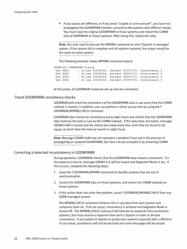
Integrating EMC GDDR
• If any values are different, or if any show “unable to communicate”, you have not propagated the GDDMPARM member correctly to the systems with different values. You must copy the original GDDMPARM to those systems and restart the COMM task of GDDRMAIN on those systems. After doing this, repeat this step.
Note: You only need to execute the MPARM command on one C-System or managed system. If the system list is complete and all systems respond, the output would be the same on every system.
The following example shows MPARM command output:
GDDM140I GDDMPARM Status Sys PRD1 : In-use 0C63D749, Dataset 0F3F7372, Consistency Y Sys SYS3 : In-use 0C63D749, Dataset 0F3F7372, Consistency Y Sys SYS2 : In-use 0C63D749, Dataset 0F3F7372, Consistency Y Sys SYS1 : In-use 0C63D749, Dataset 0F3F7372, Consistency Y
At this point, all GDDRMAIN instances are up and are consistent.
Timed GDDMPARM consistency checksGDDRMAIN will check the consistency of the GDDMPARM data in use every time the COMM subtask is started. In addition, you can perform a check at any time by using the F GDDRMAIN,MPARM,CHECK command.
GDDRMAIN also checks for consistency every eight hours and checks that the GDDMPARM data matches the data in use by the COMM subtask. If the data does not match, message GDDM144W is issued and the checks are made every hour until they are found to be equal, at which time the interval reverts to eight hours.
Note: Message GDDM144W may not represent a problem if you are in the process of propagating an updated GDDMPARM, but have not yet activated it by restarting COMM.
Correcting a detected inconsistency in GDDMPARMDuring operation, GDDRMAIN checks that the GDDMPARM data remains consistent. If a discrepancy is found, message GDDM141E will be issued and Degraded Mode is set. If this occurs, complete the following steps:
1. Issue the F GDDRMAIN,MPARM command to identify systems that are out of synchronization.
2. Correct the GDDMPARM data on those systems, and restart the COMM subtask on those systems.
3. If this action does not solve the problem, issue F GDDRMAIN,MPARM,CHECK from any GDDR-managed system.
The MPARM,CHECK command retrieves the in-use data from each system and compares them all. If all are equal, consistency is restored and Degraded Mode is turned off. The MPARM,CHECK command will tolerate no response from production systems, but must receive a response from each C-System in order to declare consistency. If any system (C-System or production system) responds with a different in-use value, consistency will not be declared and error messages will be issued.
68 EMC GDDR Version 4.1 Product Guide

Integrating EMC GDDR
The warning for inconsistent GDDMPARM data, indicated by message GDDM141E is as follows:
RESPONSE=O016 GDDM141E GDDMPARM Inconsistency detected, System O01E is RESPONSE=inconsistent
GDDRMAIN BC (Broadcast) and BR (Broadcast and Response) console commandGDDRMAIN allows you to broadcast an operator command from any EMC GDDR-managed system (where GDDRMAIN is running and in communication with other instances of GDDRMAIN) to all or selected EMC GDDR systems.
The syntax is as follows:
F GDDRMAIN,BC[BR],<to>,<cmd>
Where <to> is one of the following:
<cmd> is the command to be executed on the system.
BC does not return any output of the executed command. It also does not indicate if the system actually received or processed the command. It does provide a message for each system to which it sends the command. BR returns the output of the executed command.
In the case of IP port change above, COMM restart can be handled via the F GDDRMAIN,BC,*Z,F GDDRMAIN,RESTART COMM command. (If GDDRMAIN is the name of the GDDRMAIN address space on all systems.) Note that *Z is required, because the command cannot be broadcast from the system where it is issued if that system is already using the new ports and the other systems are not.
When adding a new system, COMM restart can be handled by issuing F GDDRMAIN,BC,*X,F GDDRMAIN,RESTART,COMM from the new system.
When deleting a system, COMM restart can be handled by issuing F GDDRMAIN,BC,*,F GDDRMAIN,RESTART COMM. Note that *1 or *Z could be used here as well. For example:
BC,*,D T GDDM145I Command sent to system VC1D GDDM145I Command sent to system VC19 GDDM145I Command sent to system O01E GDDM145I Command sent to system VC1A GDDM145I Command sent to system O016 GDDM149I Issuing D T for system VC1A Job GDDRMAIN (STC05841) D T IEE136I LOCAL: TIME=04.25.36 DATE=2010.033 UTC: TIME=09.25.36 DATE=2010.033
On each system receiving a command via BC, message GDDM149I is issued to identify the source of the broadcast. The following is the result on system O016:
GDDM149I Issuing D T for system VC1A Job GDDRMAIN (STC05841) D T
System-name The system on which cmd is to be executed
Site-name The site on which cmd is to be executed
* All EMC GDDR-managed systems
*C All C-Systems
*P All production systems
*1 All EMC GDDR systems, this system first
*X All EMC GDDR systems except this system
*Z All EMC GDDR systems, this system last
Install EMC GDDR started procedures 69

Integrating EMC GDDR
IEE136I LOCAL: TIME=04.25.36 DATE=2010.033 UTC: TIME=09.25.36 DATE=2010.033
Specify GDDR data in virtual dataset names
The DIV dataset names are conveyed to GDDRMAIN via the GVDIVDSN parameter statement of the GDDMPARM member. The DIV datasets serve as a permanent store of GDDR global variables.
If you need to change the DIV dataset, refer to the instructions in paragraph “Changing the global variable DIV dataset or WORKER parameters” on page 218.
◆ Add a line to the GDDMPARM member of hlq.GDDRvrm.PARMLIB defining the DIV dataset name for the system and GDDR instance.
The format of the lines in GDDMPARM is as follows:
For example:
GVDIVDSN -SYSTEM- GDDR -DIV DATA SET NAME--------------------------GVDIVDSN SYS1 GDDR HLQ.GDDRVRM.SYS1.DIVGVDIVDSN SYS2 GDDR HLQ.GDDRVRM.SYS2.DIVGVDIVDSN SYS3 GDDR HLQ.GDDRVRM.SYS3.DIV
Worker parameters
Worker parameters supplied in GDDMPARM specify the names of the worker tasks and the minimum and maximum number of worker tasks per system.
If you need to change any worker parameters, refer to the instructions in paragraph “Changing the global variable DIV dataset or WORKER parameters” on page 218.
Worker parameter names and their functions are as follows:
Column Description
1-8 The 8-character GVDIVDSN constant. Statements with an asterisk (*) in column 1 are comments and are ignored.
10-17 The -character MVS system name of an EMC GDDR C-System which is specified using the SYSNAME=system-name statement in SYS1.PARMLIB(IEASYS00) or equivalent parameter file. Note that this is not the SMF id of the system (although it could be the same).
19-22 The 1 to 4-character left-justified name of the GDDR instance to which this applies. This supports multiple GDDR instances on a single C-System. This field will always contain GDDR.
24-67 The left-justified dataset name of the DIV.
GDDWDV Storage device worker
GDDWXH REXX hardware management console interaction
GDDWXQ Host Component command queue processing
GDDWGV Global variable processing
GDDWXR Message interception rule processing
GDDWST Status or information retrieval
GDDWSX Restricted status processing
GDDWCM Console message processing
GDDWCO Command processing
70 EMC GDDR Version 4.1 Product Guide
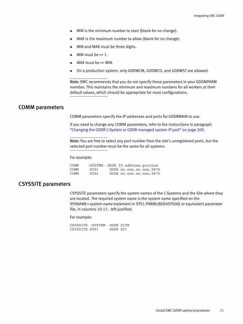
Integrating EMC GDDR
◆ MIN is the minimum number to start (blank for no change).
◆ MAX is the maximum number to allow (blank for no change).
◆ MIN and MAX must be three digits.
◆ MIN must be >= 1.
◆ MAX must be >= MIN.
◆ On a production system, only GDDWCM, GDDWCO, and GDDWST are allowed.
Note: EMC recommends that you do not specify these parameters in your GDDMPARM member. This maintains the minimum and maximum numbers for all workers at their default values, which should be appropriate for most configurations.
COMM parameters
COMM parameters specify the IP addresses and ports for GDDRMAIN to use.
If you need to change any COMM parameters, refer to the instructions in paragraph “Changing the GDDR C-System or GDDR managed system IP port” on page 209.
Note: You are free to select any port number from the site's unregistered ports, but the selected port number must be the same for all systems.
For example:
COMM -SYSTEM- GDDR IP-address,portnumCOMM SYS1 GDDR nn.nnn.nn.nnn,9876COMM SYS2 GDDR nn.nnn.nn.nnn,9876
CSYSSITE parameters
CSYSSITE parameters specify the system names of the C-Systems and the Site where they are located. The required system name is the system name specified on the SYSNAME=system-name statement in SYS1.PARMLIB(IEASYS00) or equivalent parameter file, in columns 10-17, left-justified.
For example:
CSYSSITE -SYSTEM- GDDR SITECSYSSITE SYS1 GDDR DC1
Install EMC GDDR started procedures 71

Integrating EMC GDDR
CPC parameters
The primary purpose of the GDDMPARM CPC parameter is to specify the fully qualified CPC name in the format netid.nau for GDDR managed systems, and to provide the 'NETID' literal associated with each GDDR C-System. The syntax of the CPC parameter statement is as follows:
For example:
12345678CPC SYSTEM GDDR DCx,CPC Name,HMC Interface CPC SYS1 GDDR DC1,nnnnnnnn.nnnnnnnn,BCPII CPC SYS2 GDDR DCn,nnn.nnnnnn,BCPII CPC SYS3 GDDR DC3,nnnnnnnn.nnnnnnnn,BCPII
Note: If a change is required to CPC parameters, refer to “GDDMPARM CPC parameter entries” on page 291 for detailed instructions.
SYMM parameters
SYMM parameters define Symmetrix controllers to GDDRMAIN. The syntax of the statement is as follows:
Columns Contents
1-8 CPC
10-17 System, left-justified, uppercase characters. The 8-character MVS system name of an EMC GDDR C-System which is specified using the SYSNAME=system-name statement in SYS1.PARMLIB(IEASYS00) or equivalent parameter file. Note that this is not the SMF ID of the system (although it could be the same).
19-22 GDDR. The 1 to 4-character left-justified name of the GDDR instance to which this applies. This field will always contain GDDR.
24-26 Site. DC1 or DC3
27 ,
28-nn CPC name. The full CPC name in the format netid.nau: netid (1-8 characters), nau (1-8 characters), separated by a '.'. The full CPCNAME is followed by a comma.BCPII HMC Interface, literal 'BCPII'
Columns Contents
1-4 SYMM
10-12 Site. DC1 or DC3
13-15 (H) optional, indicates home or physical location of the Symmetrix controller.
19-22 GDDR. The 1 to 4-character left-justified name of the GDDR instance to which this applies. This field will always contain GDDR.
24-35 12-digit Symmetrix controller serial number.
36 ,
37 A list of gatekeepers (individual unit addresses, ranges of unit addresses, or a combination).
72 EMC GDDR Version 4.1 Product Guide
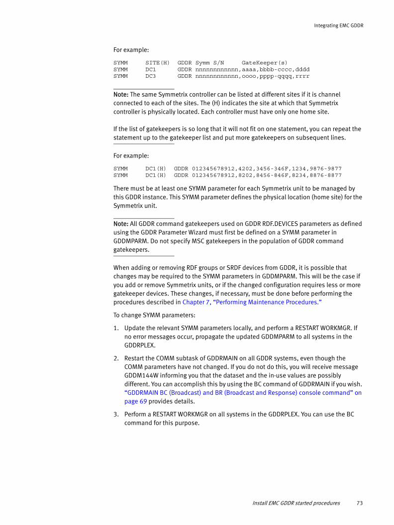
Integrating EMC GDDR
For example:
SYMM SITE(H) GDDR Symm S/N GateKeeper(s) SYMM DC1 GDDR nnnnnnnnnnnn,aaaa,bbbb-cccc,dddd SYMM DC3 GDDR nnnnnnnnnnnn,oooo,pppp-qqqq,rrrr
Note: The same Symmetrix controller can be listed at different sites if it is channel connected to each of the sites. The (H) indicates the site at which that Symmetrix controller is physically located. Each controller must have only one home site.
If the list of gatekeepers is so long that it will not fit on one statement, you can repeat the statement up to the gatekeeper list and put more gatekeepers on subsequent lines.
For example:
SYMM DC1(H) GDDR 012345678912,4202,3456-346F,1234,9876-9877SYMM DC1(H) GDDR 012345678912,8202,8456-846F,8234,8876-8877
There must be at least one SYMM parameter for each Symmetrix unit to be managed by this GDDR instance. This SYMM parameter defines the physical location (home site) for the Symmetrix unit.
Note: All GDDR command gatekeepers used on GDDR RDF.DEVICES parameters as defined using the GDDR Parameter Wizard must first be defined on a SYMM parameter in GDDMPARM. Do not specify MSC gatekeepers in the population of GDDR command gatekeepers.
When adding or removing RDF groups or SRDF devices from GDDR, it is possible that changes may be required to the SYMM parameters in GDDMPARM. This will be the case if you add or remove Symmetrix units, or if the changed configuration requires less or more gatekeeper devices. These changes, if necessary, must be done before performing the procedures described in Chapter 7, “Performing Maintenance Procedures.”
To change SYMM parameters:
1. Update the relevant SYMM parameters locally, and perform a RESTART WORKMGR. If no error messages occur, propagate the updated GDDMPARM to all systems in the GDDRPLEX.
2. Restart the COMM subtask of GDDRMAIN on all GDDR systems, even though the COMM parameters have not changed. If you do not do this, you will receive message GDDM144W informing you that the dataset and the in-use values are possibly different. You can accomplish this by using the BC command of GDDRMAIN if you wish. “GDDRMAIN BC (Broadcast) and BR (Broadcast and Response) console command” on page 69 provides details.
3. Perform a RESTART WORKMGR on all systems in the GDDRPLEX. You can use the BC command for this purpose.
Install EMC GDDR started procedures 73
Integrating EMC GDDR
Customize member GDDRPROC
Customize member GDDRPROC in hlq.GDDRvrm.PROCLIB used to run EMC GDDR scripts to your environment.
1. Update the STEPLIB DD statement to include the following load libraries:
• hlq.GDDRvrm.LINKLIB resulting from your EMC GDDR SMP/E installation
• Your EMC Mainframe Enablers load library
2. Make sure the following DD statements refer to the EMC GDDR datasets resulting from your GDDR SMP/E installation:
• ISPPLIB• ISPMLIB• ISPSLIB
3. If you plan to use customized versions of GDDR user exits, refer to “Sample procedure to use interpreted REXX user exits” on page 226.
Customize the GDDR ISPF user interface invocation REXX exec
Customize the GDDR ISPF user interface invocation REXX exec for your installation. A sample REXX exec is supplied in hlq.GDDRvrm.SAMPLIB, member GDDREXC.
◆ Set ggdrpfx to the initial qualifiers of your EMC GDDR installation's dataset names.
An extract from the sample GDDREXC member is shown below:
/**********************************************************************//* Initialize custom variables *//**********************************************************************/gddrpfx = "EMC.GDDR410."
Calling the GDDR ISPF user interface from an ISPF selection panel
To start the GDDR ISPF user interface by entering an option character from the ISPF primary options menu panel (ISR@PRIM) or from any other ISPF selection menu panel, add an option in the )PROC section for that panel that issues the following SELECT service call:
'CMD(GDDREXC) NEWAPPL(GDDR) MODE(FSCR)'
Calling the GDDR ISPF panel from any ISPF panel with TSO GDDR command
To start the GDDR ISPF user interface from any ISPF panel, by issuing the command TSO GDDR from any ISPF panel's primary command line, you must create a new a REXX exec by the name GDDR with the following contents:
/* REXX */ address ISPEXEC "SELECT CMD(GDDREXC) NEWAPPL(GDDR) MODE(FSCR)"
It is important that you use the NEWAPPL(GDDR) keyword to ensure that all profile variables are stored properly in the same ISPF application profile.
74 EMC GDDR Version 4.1 Product Guide

Integrating EMC GDDR
Configure EMC GDDRUse the EMC GDDR online facilities to complete the tasks described in this section.
Note: Review the introductory procedures described in Chapter 4, “Using EMC GDDR Online Facilities” prior to performing the tasks listed in this section.
The Parameter Management Options Menu shown in Figure 10 on page 88 presents parameter input panels which conditionally prompt for required parameter values based on your particular disaster restart topography and EMC SRDF configuration. The systems, devices, and EMC GDDR options defined during the parameter input task specify how EMC GDDR handles conditions requiring the use of EMC recovery and business continuity facilities.
Step 1: Update your personal GDDR ISPF profile
When you complete the EMC GDDR software installation, dependent software installation, and related user-authorization definitions, the GDDR Primary Options Menu displays:
Note: This panel may vary based on relevant user authorizations.
Before you can perform any GDDR Setup and Maintenance actions, you must populate your ISPF profile dataset with basic information.
1. On the GDDR Primary Options Menu, select Option P, Update Personal GDDR ISPF Profile.
------------------------ GDDR - Primary Options Menu ------------------------- Option ===> P rofile Update personal GDDR ISPF Profile This System: SYS2 M aintenance GDDR Setup and Maintenance This Site: DC2 Master-C: SYS2 Primary Site: DC1 Primary DASD: DC1 Automation: ON Planned script: None Unplanned script: None EMC Geographically Dispersed Disaster Restart 04.01.00 Copyright © 2007-2012 EMC Corporation. Select an option and press <Enter> Press <F3> to Terminate GDDR ISPF
Configure EMC GDDR 75

Integrating EMC GDDR
The Change GDDR ISPF Profile Variable Values panel displays as follows:
2. Complete the panel fields as follows:
• GDDR Subsystem Name — No action required. This field defaults to GDDR and is not editable.
• JCL dataset — Specify the name of the PROCLIB dataset holding the GDDRPROC customized during the GDDR integration procedure “Customize member GDDRPROC” on page 74.
• ISPF skeleton dataset — Specify the name of a dataset containing the GDDR file tailoring skeletons created when you downloaded the install cartridge.
• Global variable backup — Specify the name of the parameter backup dataset to be used for parameter management functions, defined during the EMC GDDR integration procedure “Define EMC GDDR datasets” on page 64.
• Jobcards — This field displays if you are authorized to activate parameter changes and to manage GDDR scripts. The JOBCARD information you enter here applies only to the current user and is used for parameter activate and script submission tasks. Always include the REGION=0M jobcard parameter.
For example:
===>//JOBNAME JOB (acct-number),gddr-job,CLASS=A,REGION=0M,===>// MSGCLASS=A,USER=GDDR,NOTIFY=GDDR===>/*JOBPARM LINES=999999===>//*
3. Press F3 to save the changes and return to the GDDR Primary Options Menu.
Step 2: Define initial site, system, storage, utility, and GDDR option parameters
The EMC GDDR parameter management process uses an existing backup of parameter values as the starting point for subsequent updates. To facilitate the parameter customization associated with a new EMC GDDR implementation, initial parameter definitions are populated from the GDDMPARM parameters supplied during installation as described in “GDDMPARM installation” on page 66.
--------------- GDDR - Change GDDR ISPF Profile Variable Values --------------- Command ===> GDDR Subsystem Name ===> GDDR JCL dataset ===> ISPF skeleton dataset ===> Global variable backup ===> Jobcards for your user: // // // // Press ENTER to apply updates Press <F3> when finished Enter CANCEL to return without changing any profile variable values Enter CLEAR to set all values to null and exit Enter RESET to restore the values as they were upon entry
76 EMC GDDR Version 4.1 Product Guide

Integrating EMC GDDR
Note: Subsequent parameter changes will be applied to a copy of your parameters, created as a backup dataset at the time the existing parameters were applied, or any later time.
To perform an initial parameter activation:
1. From the GDDR Primary Options Menu, select Option M, Setup and Maintenance, then select Option P, Manage GDDR Parameters.
Because there are no existing parameters, Option P displays a Select Parameter Input Dataset panel as follows:
2. To begin parameter definition with an initial parameter set, type S in the Action field associated with the entry described 'GDDR parameter load from scratch', member name '--NONE--' and press Enter.
The panel displays a message requesting that you provide a work dataset name and a parameter load description:
3. Supply a parameter load work dataset and parameter load description.
------------------- GDDR - Select Parameter Input Dataset ---- Row 1 to 1 of 1 Parameter input dataset ===> JABCDE1.GDDR410.PARMS Selected Member ===> Unselect? ===> N (Y/N) Parameter Load work-dataset ===> ____________________________________________ Parameter Load description ===> _______________________________________ Currently activated GDDR Parameter source - *** Unknown *** - - No description found - Select '--NONE--' or choose a different GDDR Parameter Load input dataset. Press <F3> to return to the Parameter Management Options Menu Line commands: S elect, U nselect, B rowse, E dit ----------------------- Parameter Input Member Selection ---------------------- Act Member Date Time Userid Description --- -------- -------- ----- -------- ------------------------------------------ _ --NONE-- 09/05/27 11:04 JABCDE1 GDDR parameter load from scratch ******************************* Bottom of data ********************************
Command ===>
------------------ GDDR - Select Parameter Input Dataset ------ Row 1 to 2 of 2 Parameter input dataset ===> EMC.GDDR410.PARMS Selected Member ===> --NONE----------------- Unselect? ===> N (Y/N) Parameter Load work-dataset ===> EMC.GDDR410.PARMS.WORK______________________ Parameter Load description ===> _______________________________________ Currently activated GDDR Parameter source - *** Unknown *** - - No description found - Please provide a work-dataset name and a description for this Parameter load. Press <F3> to return to the Parameter Management Options Menu Line commands: S elect, U nselect, B rowse, E dit ----------------------- Parameter Input Member Selection ---------------------- Act Member Date Time Userid Description --- -------- -------- ----- -------- ------------------------------------------ _ --NONE-- 09/05/27 11:13 JABCDE1 GDDR parameter load from scratch ******************************* Bottom of data ********************************
Configure EMC GDDR 77

Integrating EMC GDDR
Enter the parameter load work dataset that was defined earlier in “Allocate the parameter management datasets” on page 64. This dataset contains your 'work-in-process', enabling you to assemble a complete parameter set by saving your input data from each of the parameter definition panels, and returning to the task at a later time.
Note: The parameter input dataset and the parameter load work dataset must be two different datasets. This is because the contents of the parameter load work dataset are overwritten when exiting the Select Parameter Input Dataset panel in step 6.
The parameter load work dataset must also be different from the dataset that is defined to GDDR as the "Last Activated Parameter Dataset".
4. Press F3 to exit.
Upon exiting from the Select Parameter Input Dataset panel, the work dataset is initialized with PDS members which are associated with each of the parameter load function panels. Messages associated with the work dataset initialization are returned to your TSO session as follows:
OPS0996I Preparing Work Dataset OPS0996I OPS0996I Validating Input variables: OPS0996I ===> CONFIG OPS0996I OPS0996I Writing work members: OPS0996I OPS0996I ==== > A01FEATR OPS0996I ==== > A02CSYST OPS0996I ==== > A03GDDDS OPS0996I ==== > C01ROLES OPS0996I ==== > E01CNTRL OPS0996I ==== > E02GDDGK OPS0996I ==== > E03MSCGK OPS0996I ==== > E04SRDFD OPS0996I ==== > E05TFDEV OPS0996I ==== > E06SDDF0 OPS0996I ==== > E07GNS00 OPS0996I ==== > H01SYSTS OPS0996I ==== > H02LPARS OPS0996I ==== > H03CPC00 OPS0996I ==== > H04IPL00
78 EMC GDDR Version 4.1 Product Guide

Integrating EMC GDDR
5. Upon selection of the initial parameter backup member and completion of the work dataset initialization process, the Parameter Management Options Menu displays with the complete list of parameter load functions as follows:
You can complete customizing the contents of the parameter work dataset with your site-specific values using the Parameter Load functions on the Parameter Management Options Menu. This process is identical for an initial parameter customization or for any subsequent customization. “Option P: Manage GDDR Parameters” on page 88 provides details on this process.
Step 3: Modify EMC GDDR user exits (optional)
EMC GDDR provides exit points that you may use to augment EMC GDDR facilities. Sample exits are provided in the hlq.GDDRvrm.SAMPLIB distribution library. You may modify these exits, or write your own, following the guidelines presented in Appendix A, “EMC GDDR User Exits.” The exit points are the following:
◆ GDDRUX01 is called from planned or unplanned event scripts at a point appropriate for starting production mainframe workloads.
◆ GDDRUX02 is called from planned or unplanned scripts at a point appropriate for shutting down production mainframe workloads.
◆ GDDRUX03 is called from planned or unplanned scripts at a point appropriate for starting distributed production workloads.
◆ GDDRUX04 is called from planned or unplanned scripts at a point appropriate for stopping distributed production workloads.
------------------- GDDR - Parameter Management Options Menu ------------------ Option ===> B ackup Manage GDDR Parameter backups This System: SYS2 This Site: DC1 .---------- Parameter Load functions ----------. Master-C: SYS2 | I nput Select Parameter Input Dataset | Primary Site: DC1 | C onfig Define Configuration basics | Primary DASD: DC1 | D ASD Define Data Storage objects | | H ost Define Host objects | Automation: ON | O ptions Specify GDDR Options | Planned script: None | V alidate Validate GDDR Parameter Set | Unplanned script: None | A ctivate Activate GDDR Parameter Set | |______________________________________________| Current work data set RGHIJK1.GDDR.V410.PARMS.WORK EMC Geographically Dispersed Disaster Restart 04.01.00 Copyright © 2007-2012 EMC Corporation. Select an option and press <Enter> Press <F3> to return to the GDDR Setup and Maintenance Menu
Configure EMC GDDR 79
Integrating EMC GDDR
Optional configuration featuresThe following topics describe optional features which may be configured.
GDDR support for external devices
GDDR always manages devices under consistency protection. This can be ConGroup protection, MSC protection, or SRDF/Star protection. GDDR support for “external” devices adds appropriate commands to GDDR scripts to manage RDF groups outside of the GDDR-managed consistency protection.
GDDR support for external devices enhances automated restart at a site which is an SRDF/A or SRDF/S target by adding management of various types of volumes (for example, page volumes and temp pool volumes) which are not typically replicated with consistency protection, due to various considerations such as bandwidth constraints or the fact that they simply do not have the consistency requirement and should not trigger Swap or Trip events. The SRDF device actions to be performed on the external devices are “make R2 R/W” or “make R1 TNR”, depending on the script and the site role.
The addition of external devices to GDDR typically requires changes to SYMM parameters in GDDMPARM, as additional gatekeeper devices will usually be needed. You must make the updates to the SYMM parameters before completing the implementation procedure described below. Refer to “SYMM parameters” on page 72 for more information on how to change SYMM parameters in GDDMPARM.
Implementation1. Run utility GDDRACDD to discover all devices to be managed by GDDR. Refer to
“Automated Configuration Discovery for DASD (GDDRACDD)” on page 250 for detailed instructions. Alternatively, define the external devices and set the External field on the Define SRDF Devices panel, as described on page 116 to 'YES'.
2. From “Option O: Default Script Call Overrides” on page 141, set Manage External devices to Y.
GDDR support for the external devices is as follows:
◆ Planned Site Swap (GDD2P17A / GDD2P18A)
The external devices are RDF-SUSPended in GDD2P17A and in GDD2P18A they are SWAPped and RDF-RSUMed.
◆ Resume replication after loss of primary (GDD2PA0A)
The non-SRDF/A devices are SWAPped, set to ADCOPY-DISK, RDF-RSUMed.
CPC Recovery - LPAR Recovery features
CPC Recovery and LPAR Recovery features deliver system recovery capabilities for Central Processor Complexes (CPC), protecting a single system or all systems within the complex. CPC Recovery is enabled for all or selected processor complexes within a site as soon as LPAR Recovery is defined for one of the systems which has an LPAR defined with the CPC. Protection is accomplished through monitoring for system outage trigger messages indicating a system has unregistered from a common communication facility, in this case, EMC's Symmetrix Control Facility (SCF).
80 EMC GDDR Version 4.1 Product Guide
Integrating EMC GDDR
The CPC Recovery functionality complements the production/contingency protection mechanism and entails the following:
◆ Contingency systems are no longer required to be defined for GDDR-managed systems.
◆ A GDDR-managed system can have either a contingency system or a recovery LPAR defined, or both.
◆ A C-System can have a recovery LPAR defined.
◆ A system protected with LPAR Recovery is specified with a "home" and "recovery" LPAR location ("away").
◆ An LPAR within a CPC can be either the normal LPAR or a recovery LPAR for a system, or both (normal LPAR for system A, recovery LPAR for system B).
◆ The recovery LPAR can be in the same CPC hosting the system at home.
◆ The recovery LPAR can be in a different CPC in the system’s "home" data center.
◆ If the LPAR location of a system A is the recovery LPAR of a system B, then system A cannot have a recovery LPAR defined.
◆ If a system A has an LPAR defined for it which is the recovery LPAR for a system B, then system A cannot be a contingency system.
◆ If a system is protected with a recovery LPAR, then only one LPAR parameter for that system is allowed, specifying a CPC on the home site for that system.
◆ If a system is not protected with LPAR recovery, then it can have one LPAR parameter defined for each site in the configuration.
◆ The SITE.<sysname> parameters for systems which do not have a recovery LPAR defined change when these systems are IPL'd in an LPAR on a different site. For systems protected with LPAR Recovery, the site does not change, but a separate DCN.LOCATION.<sysname> parameter is toggled between values "Home" and "Away".
Optional configuration features 81

Integrating EMC GDDR
82 EMC GDDR Version 4.1 Product Guide

CHAPTER 4Using EMC GDDR Online Facilities
This chapter describes the EMC GDDR online interface.
◆ Primary Options Menu ............................................................................................ 84◆ Option P: Profile—Update Personal GDDR ISPF Profile.............................................. 86◆ Option M: Maintenance—GDDR Setup and Maintenance ......................................... 87◆ Option G: GDDR Config—View GDDR Configuration ................................................ 165◆ Option C: Checkup—Perform Pre-script Checkup ................................................... 166◆ Option S: Scripts — Run GDDR Scripts ................................................................... 173◆ Option T: Timing—View GDDR Script Statistics....................................................... 176◆ Option A: Actions—Perform GDDR Actions ............................................................. 177◆ Option E: EzSM - Run EMC z/OS Storage Manager ................................................. 186
Using EMC GDDR Online Facilities 83

Using EMC GDDR Online Facilities
Primary Options MenuEMC GDDR online facilities permit z/OS system programmers to perform configuration and administration tasks and operators to perform operator functions. To use the EMC GDDR online facilities interface, invoke the GDDR invocation REXX exec which was customized in “Customize the GDDR ISPF user interface invocation REXX exec” on page 74. The following panel appears:
Figure 7 Primary Options Menu
Control fieldsAt the right side of the panel, the GDDR Primary Options menu displays the current settings for several EMC GDDR control values.
Note: The fields described below also appear on a number of other EMC GDDR panels.
This System
Specifies the current system.
This Site
Specifies the current site.
This Region
Specifies the current region.
Master-C
Shows the name of the C-System that currently owns the EMC GDDR master function. In environments supported by cross-site host-DASD channels, the master C-System is located at the opposite site from the business applications. Where cross-site host-DASD channels are not available, the master C-System will be the C-System at the site where the
------------------ GDDR - Primary Options Menu for GDDRPLEX -------------------- Option ===> P rofile Update personal GDDR ISPF Profile This System: SYS1 M aintenance GDDR Setup and Maintenance This Site: DC1 G DDR Config View GDDR configuration This Region: RG1 C heckup Perform pre-script checkup Master-C: SYS1 S cripts Run GDDR Scripts Primary Site: DC1 T iming View GDDR Script Statistics Primary DASD: DC1 A ctions Perform GDDR Actions E zSM Run EMC z/OS Storage Manager Automation: ON Planned script: None Unplanned script: None EMC Geographically Dispersed Disaster Restart 04.01.00 Copyright © 2007-2012 EMC Corporation. Select an option and press <Enter> Press <F3> to Terminate GDDR ISPF
84 EMC GDDR Version 4.1 Product Guide
Using EMC GDDR Online Facilities
business applications are hosted.Thus, if the business applications are running at site DC1, the master C-System will be the C-System at site DC1. Most EMC GDDR actions are allowed only when logged onto the master C-System.
Primary Site
Indicates the site where the business applications are currently running.
Primary DASD
Indicates the site at which the R1 DASD currently reside. Generally, the sites indicated by Primary Site and Primary DASD should be the same.
Automation
Indicates the current availability of EMC GDDR automation functionality. You can change the automation state by typing GDDR ON or GDDR OFF in the Option line of the Primary Options Menu. The displayed value of the automation setting on the right of the panel reflects the change immediately.
Note: The GDDR ON/OFF command is valid only on the master C-System.
◆ When you specify GDDR OFF to turn EMC GDDR automation off, the EMC GDDR Event Monitor does not respond to events that would normally indicate a storage or system failure. Therefore, the OFF automation status should be used only when system availability may be impacted by scheduled maintenance activities.
After you enter GDDR OFF, messages similar to the following appear:
GDDR373I GDDR Broadcasting new value for AUTOMATION.FLAGGDDR739I GDDR -> Set GDDR Broadcasting new value for AUTOMATION.FLAG at SYS1GDDR739I GDDR -> Set GDDR Broadcasting new value for AUTOMATION.FLAG at SYS3
◆ When you specify GDDR ON to turn EMC GDDR automation on, EMC GDDR operators will be able to run both Planned and Unplanned scripts.
Planned Script
Indicates which Planned script, if any, is currently in progress. A Planned script is considered to be in progress if it has been started but has not yet completed successfully; in this case, it is eligible for restart. If no Planned script is currently in progress, ‘None’ displays in this field.
Unplanned Script
Indicates which Unplanned script, if any, is currently in progress. An Unplanned script is considered to be in progress if it has been started but has not yet completed successfully; in this case, it is eligible for restart. If no Unplanned script is currently in progress, ‘None’ displays in this field.
Note: In the version number displayed after EMC Geographically Dispersed Disaster Restart at the bottom of the panel, nn reflects the latest maintenance level and ptfname is the name of the latest PTF, when the GDDR SMP/E Post-Maintenance procedure is used.
Primary Options Menu 85
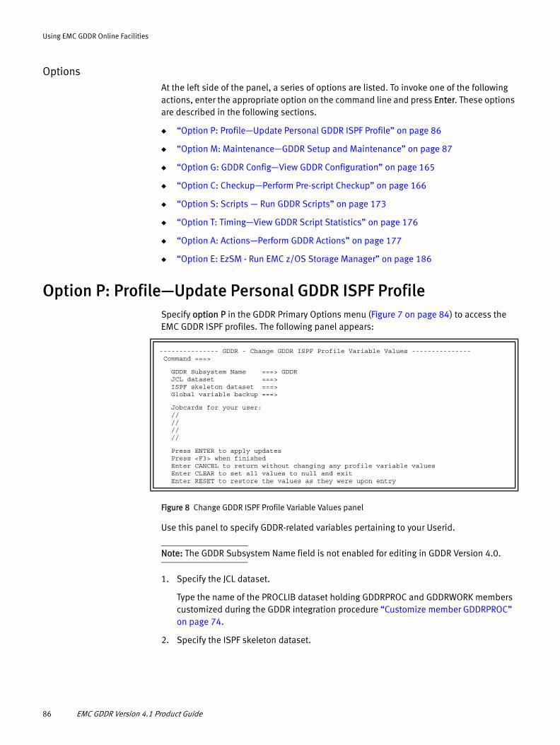
Using EMC GDDR Online Facilities
OptionsAt the left side of the panel, a series of options are listed. To invoke one of the following actions, enter the appropriate option on the command line and press Enter. These options are described in the following sections.
◆ “Option P: Profile—Update Personal GDDR ISPF Profile” on page 86
◆ “Option M: Maintenance—GDDR Setup and Maintenance” on page 87
◆ “Option G: GDDR Config—View GDDR Configuration” on page 165
◆ “Option C: Checkup—Perform Pre-script Checkup” on page 166
◆ “Option S: Scripts — Run GDDR Scripts” on page 173
◆ “Option T: Timing—View GDDR Script Statistics” on page 176
◆ “Option A: Actions—Perform GDDR Actions” on page 177
◆ “Option E: EzSM - Run EMC z/OS Storage Manager” on page 186
Option P: Profile—Update Personal GDDR ISPF ProfileSpecify option P in the GDDR Primary Options menu (Figure 7 on page 84) to access the EMC GDDR ISPF profiles. The following panel appears:
Figure 8 Change GDDR ISPF Profile Variable Values panel
Use this panel to specify GDDR-related variables pertaining to your Userid.
Note: The GDDR Subsystem Name field is not enabled for editing in GDDR Version 4.0.
1. Specify the JCL dataset.
Type the name of the PROCLIB dataset holding GDDRPROC and GDDRWORK members customized during the GDDR integration procedure “Customize member GDDRPROC” on page 74.
2. Specify the ISPF skeleton dataset.
--------------- GDDR - Change GDDR ISPF Profile Variable Values --------------- Command ===>
GDDR Subsystem Name ===> GDDR JCL dataset ===> ISPF skeleton dataset ===> Global variable backup ===>
Jobcards for your user: // // // //
Press ENTER to apply updates Press <F3> when finished Enter CANCEL to return without changing any profile variable values Enter CLEAR to set all values to null and exit Enter RESET to restore the values as they were upon entry
86 EMC GDDR Version 4.1 Product Guide

Using EMC GDDR Online Facilities
Type the name of a dataset containing the GDDR file tailoring skeletons created when you downloaded the install cartridge. This dataset is used to retrieve ISPF file tailoring skeletons for the parameter activation, when done in background mode and when scripts are submitted.
3. Specify the global variable backup.
Type the name of the parameter backup dataset to be used for parameter management functions, defined during the EMC GDDR integration procedure “Allocate the parameter management datasets” on page 64.
Note: Whenever a dataset name is required, you must specify a fully-qualified dataset name. TSO prefixing does not apply to any dataset name specified within EMC GDDR.
4. Enter jobcard information.
This field is displayed conditionally for EMC GDDR users who are authorized to activate parameter changes and to manage GDDR scripts. The jobcard information entered here applies only to the current user and is used for parameter activate and script submission tasks. Always include the REGION=0M jobcard parameter. For example:
===>//JOBNAME JOB (acct-number),gddr-job,CLASS=A,REGION=0M,===>// MSGCLASS=A,USER=GDDR,NOTIFY=GDDR===>/*JOBPARM LINES=999999===>//*
5. Press F3 to save the values and return to the Primary Options Menu.
Option M: Maintenance—GDDR Setup and MaintenanceSpecify option M on the GDDR Primary Options menu (Figure 7 on page 84) to access the EMC GDDR setup and maintenance functions. The following panel appears:
Figure 9 Setup and Maintenance Menu
The following sections describe the Setup and Maintenance Menu options.
--------------------- GDDR - Setup and Maintenance Menu ---------------------- Option ===> P arms Manage GDDR Parameters This System: SYS1 D ebug Message, Debug and Trace options This Site: DC1 Q ueue Manage GDDR Internal Command Queue Master-C: SYS1 H MC Perform HMC Discovery Primary Site: DC1 R efresh Refresh GDDR Message Table Primary DASD: DC1 S ystem Manage GDDR System variables T ransfer Transfer Master C-System Automation: ON Planned script: None Unplanned script: None EMC Geographically Dispersed Disaster Restart 04.01.00 Copyright © 2007-2012 EMC Corporation. Select an option and press <Enter> Press <F3> to return to the GDDR Primary Options Menu
Option M: Maintenance—GDDR Setup and Maintenance 87

Using EMC GDDR Online Facilities
◆ “Option P: Manage GDDR Parameters” on page 88
◆ “Option D: Message, Debug and Trace Options” on page 158
◆ “Option Q: Manage GDDR Internal Command Queue” on page 159
◆ “Option H: Perform HMC Discovery” on page 160
◆ “Option R: Refresh GDDR Message Table” on page 161
◆ “Option S: Manage GDDR System Variables” on page 162
◆ “Option T: Transfer Master C-System” on page 164
Option P: Manage GDDR Parameters
Specify option P in the Setup and Maintenance Menu (Figure 9 on page 87) to access the GDDR parameter management functions. The following panel appears:
Figure 10 Parameter Management Options Menu
Note: The options initially displayed in this panel may vary. The panel does not show options C,D,H,O,V,A until the actions described in “To prepare to edit the current GDDR parameter set:” on page 99 are completed.
The menu options allow you to manage GDDR parameter backups and define and maintain GDDR parameters using the Parameter Load wizard.
The following sections describe the Parameter Management Menu functions:
◆ “Option B: Manage GDDR Parameter Backups” on page 96
◆ “Option I: Select Parameter Input Dataset” on page 100
◆ “Option C: Define Configuration Basics” on page 107
◆ “Option D: Define Data Storage Objects” on page 114
◆ “Option H: Define Host Objects” on page 120
◆ “Option O: Specify GDDR Options” on page 140
-------------------- GDDR - Parameter Management Options Menu ------------------ Option ===> B ackup Manage GDDR Parameter backups This System: SYS1 This Site: DC1 .---------- Parameter Load functions ----------. Master-C: SYS1 | I nput Select Parameter Input Dataset | Primary Site: DC1 | C onfig Define Configuration basics | Primary DASD: DC1 | D ASD Define Data Storage object | | H ost Define Host objects | Automation: ON | O ptions Specify GDDR Options | Planned script: None | V alidate Validate GDDR Parameter Set | Unplanned script: None | A ctivate Activate GDDR Parameter Set | |______________________________________________| Current work data set RGHIJK1.GDDR.V410.PARMS.WORK EMC Geographically Dispersed Disaster Restart 04.01.00 Copyright © 2007-2012 EMC Corporation. Select an option and press <Enter> Press <F3> to return to the GDDR Setup and Maintenance Menu
88 EMC GDDR Version 4.1 Product Guide

Using EMC GDDR Online Facilities
◆ “Option V: Validate GDDR Parameter Set” on page 151
◆ “Option A: Activate GDDR Parameter Set” on page 153
Understanding the Parameter Load wizard workflowThe maintenance and initial definition of GDDR global variables (parameters) is performed using the Parameter Load wizard, which is based on an iterative change process. Changes are applied initially to a consistent work copy of the active GDDR global variables. These changes are then applied to the active GDDR global variables in an Activation step (preceded by an implicit or explicit Validation).
Figure 11 describes the parameter backup, edit serialization, validation and activation process, and the relationship with GDDRMAIN and its dependent address spaces. These operations are represented in the GDDR Parameter Load wizard work flow beginning with Figure 12 on page 91.
Figure 11 GDDR parameter management
C-System
GDDRMAINAddress Space
GDDREVMEvent Monitor
Address SpaceRecycled during
ACTIVATE
Data Space 1(Global Variables)
GVT subtask
DIV
Dependent Address Space (controlled by GDDRMAIN)
Load/maintain global vars in DIV
GLV BackupsBACKUP
Parm Work Data Set
PREP
ARE
GDDR Parm Wizard
TSO User
1
25
(VALIDATE)4
EDIT3
LAPD
Activate
1 BACKUP
PREPARE
EDIT
(VALIDATE)
ACTIVATE
2
3
4
5
From PREP to ACT
Edit-in-Progress
even if TSO user is not logged on
}
HBM subtaskHeart Beat MonitorRecycled during
ACTIVATE
Option M: Maintenance—GDDR Setup and Maintenance 89

Using EMC GDDR Online Facilities
Using the Auto-Discovery feature
The Parameter Load wizard helps you define and maintain the parameters that describe your particular disaster restart topography and EMC SRDF configuration by populating values available through the Auto-Discovery feature.
System parameter changes which are necessitated by changes to the definitions of C-Systems or GDDR-managed systems are initiated by performing the changes to the CSYSSITE and COMM parameters in the GDDMPARM member, as described in Chapter 7, “Performing Maintenance Procedures.” After performing the parameter changes required in the GDDMPARM member, the changes are propagated to the active GDDR parameter set by use of the Parameter Load wizard.
The Auto-Discovery feature requires that the GDDRMAIN tasks have been started on each C-System and GDDR-managed system before you start the Parameter Load wizard using the Select Parameter Input Dataset panel, shown on page 100.
Using the Parameter Load function panels
The series of Parameter Load function panels enable you to display or define parameter values organized by object category. The panels use function keys as follows so that fields are presented in data dependency order:
◆ F5 returns you to the immediate preceding panel in the series.
◆ F6 takes you to the next panel in the series.
◆ F3 returns you to the menu panel for objects of the same type.
Each Parameter Load display and definition panel does the following:
◆ Displays values for named parameters from the selected parameter dataset member subject to the precedence rules that apply to data returned to the wizard from the Auto-Discovery feature.
◆ Displays values which were saved at a previous Parameter Load panel.
If no value is supplied for a field by the selected parameter dataset member, the first time a value for that field is specified as panel input and saved to the Work dataset, the value is propagated to all succeeding panels which contain the same field.
Changes to field values in parameter display and definition panels are saved to your Work dataset when you type SAVE on the Command line of the panel. If after editing the values in the panel and before you use the SAVE command, you wish to restore the original values displayed in the panel, type LOAD in the panel. If you have 'Saved' interim changes for values on the current panel, then the Load command restores the last saved values.
Note: Each panel in which you use the SAVE command will be utilized for a partial parameter activation, whether or not you performed changes on the panel.
Parameter Load wizard prerequisites
The following items are required for use of the Parameter Load wizard:
◆ GDDMPARM has been defined with C-System and production system COMM statements and is consistent on all systems.
90 EMC GDDR Version 4.1 Product Guide

Using EMC GDDR Online Facilities
◆ GDDRMAIN tasks must be active and communicating on all C-Systems and optionally also on GDDR-managed systems (recommended).
◆ Parameter backup and parameter work datasets are allocated on all C-Systems.
• Parameter backup datasets are populated by HBM on all C-Systems.
• Parameter work datasets are populated during Parameter Load wizard use.
◆ One“Last Activated Parm Dataset” is pre-allocated on all C-Systems.
◆ Parameter Validate/Activate is performed on the C-System which is the intended Master C-System for the configuration being defined (exception for missing C-System communication).
◆ The following rules are true for confirming your intended Master C-System on initial parameter load:
• The Master C-System must be on the secondary DASD site for AutoSwap configurations, and on the primary DASD site for non-AutoSwap configurations.
• The Validate operation queries the storage environment using the site, system, gatekeeper, RDF group, and device ranges presented as Parameter Load wizard input. The presence of R1 devices determines the current primary DASD site. If the query is unable to find R1 devices, validation uses the primary DASD site found in the parameter input deck.
Step 1
Initial definition of global variables is performed using no prior backup, with automation which populates system parameters available from the GDDMPARM parameters defined during GDDRMAIN installation.
Maintenance of global variables is applied using a current global variable backup as the base.
Figure 12 Parameter Load wizard work flow — step 1
Step 2
Parameter Load wizard usage is limited to one active session at a time.
When you signal the intent to update parameters by performing the Prepare command, access to the Parameter Load wizard panels by other users is prevented. You can review the EMC GDDR configuration parameters at any time using the Review command.
GDDR Global Variables
Backup member
Perform GDDR Variable Backup
Option M: Maintenance—GDDR Setup and Maintenance 91

Using EMC GDDR Online Facilities
Serialization of the panels is held until you have completed an Activate. (An emergency procedure is available in case this serialization creates a problem.)
Figure 13 Parameter Load wizard work flow — step 2
Step 3
The Parameter Load wizard updates the parameter work dataset which was specified at the time the Prepare (or Review) command was issued. It does this by storing each global variable found in the selected input dataset to the appropriate work dataset member.
Figure 14 Parameter Load wizard work flow — step 3
Step 4
Each Parameter Load Wizard panel allows user input for the GDDR global variables found in the corresponding work dataset member. Selected Parameter Load wizard panels are populated with data from GDDMPARM parameters, either directly or by usage of discovery functions.
Backup member
Parm Work - PDS
Perform GDDR Variable Backup
Select Backup as Input Prepare Work PDS
SerializationSerialization
GDDR Global Variables
Backup member
Parm Work - PDS
Member3A01FEATR Member4Member2 Member … Z97NOPNL
Perform GDDR Variable Backup
Select Backup as Input Prepare Work PDS
Z99UNK00 Z98ALL00
SerializationSerialization
GDDR Global Variables
92 EMC GDDR Version 4.1 Product Guide

Using EMC GDDR Online Facilities
When discrepancies exist between GDDMPARM derived data and data which is provided from the ‘base’ global variable backup, the difference is indicated in the panels by displaying this data in yellow font.
Figure 15 Parameter Load wizard work flow — step 4
Step 5
The Validate function assembles panel-bound work PDS members as well as the Z97NOPNL member into the Z00PARMS member and presents that to the validation engine.
When using the FULL option, all panel-bound members are included. When using the PARTIAL option, only updated members are included. When using the EVENT(RESET) option, the Z97NOPNL member is ignored.
The Validate function performs live queries against the storage environment. Error messages are reported in the Z00VOUT member of the parameter work dataset. The VIEW command on the Validate panel can be used to review these messages.
Figure 16 Parameter Load wizard work flow — step 5
Backup member
Parm Work - PDS
Member3A01FEATR Member4Member2 Member … Z97NOPNL
Panel 3Panel 1 Panel 4Panel 2 Panel …
Perform GDDR Variable Backup
Select Backup as Input Prepare Work PDS
GDDMPARMGDDMPARM
Z99UNK00 Z98ALL00
SerializationSerialization
GDDR Global Variables
Backup member
Parm Work - PDS
Member3A01FEATR Member4Member2 Member … Z97NOPNL
Panel 3Panel 1 Panel 4Panel 2 Panel …
Z00PARMS
Perform GDDR Variable Backup
Select Backup as Input Prepare Work PDS
Z00VOUT
GDDMPARMGDDMPARM
Validate
Z99UNK00 Z98ALL00
SerializationSerialization
GDDR Global Variables
Option M: Maintenance—GDDR Setup and Maintenance 93

Using EMC GDDR Online Facilities
Step 6
The Activate function assembles panel-bound work PDS members as well as the Z97NOPNL member into the Z00PARMS member and presents that to the validation engine. If this implicit validation succeeds, it proceeds to the Activation steps, which include taking a global variable backup both before and after the Activation.
When using the FULL option, all panel-bound members are included. When using the PARTIAL option, only updated members are included. When using the EVENT(RESET) option, the Z97NOPNL member is ignored.
The implicit Validate performed during the Activate function performs live queries against the storage environment.
Error messages are reported in the Z00AOUT member of the parameter work dataset.
The VIEW command on the Activate panel can be used to review these messages.
The Activate function copies your parameter work dataset to the Last Activated Parm Dataset and makes the new parameter set active on all C-Systems. Activate provides options to reset GDDR event variables and clear the GDDR command queue both locally and on other C-Systems.
If the GDDR Heartbeat Monitor and Event Monitor are running, Activate will automatically stop them, and restart them when Activate is complete.
Figure 17 Parameter Load wizard work flow — step 6
Using the parameter review functionsEMC GDDR makes the current parameters available for review through the GDDR - Parameter Management Options Menu, without the Validate and Activate capabilities. For example, an audit of your disaster restart operations may include a review
Backup member
Parm Work - PDS
Member3A01FEATR Member4Member2 Z99UNK00Member … Z97NOPNL
Panel 3Panel 1 Panel 4Panel 2 Panel …
Z00PARMS
Perform GDDR Variable Backup
Select Backup as Input Prepare Work PDS
ValidateZ00VOUT
ActivateZ00AOUT
GDDMPARMGDDMPARM
Last ActivatedParm Dataset
Z98ALL00
SerializationSerialization
GDDR Global Variables
94 EMC GDDR Version 4.1 Product Guide

Using EMC GDDR Online Facilities
of GDDR parameters.The EMC GDDR parameters review capability enables a third-party reviewer to access a current parameter backup with no exposure from unwanted changes to the active parameter values.
Authority to use the GDDR parameters review capability is granted to members of the GDDR$REV RACF group with READ access to the GDDRISPF.ACCESS, GDDRISPF.SETUP.ACCESS, and the GDDRISPF.SETUP.PARMS.REVIEW facility profiles, as described in Table 9 on page 56. When authority has been granted, the GDDR Parameter Management Options Menu is displayed without the Validate and Activate Parameter Load functions as shown in Figure 19 on page 96.
The parameter review is performed by making a backup of the current parameters, using “Option B: Manage GDDR Parameter Backups” on page 96. The reviewer selects the backup member to be used to prepare the reviewer's parameter work dataset as shown in Figure 18 on page 95 and described in detail in “Option I: Select Parameter Input Dataset” on page 100.
Figure 18 Select Parameter Input Dataset for parameter review
Within the Select Parameter Input Dataset panel, after you select a backup member which will be used to populate your parameter work dataset, the following message appears:
Ready to start preparation of the work dataset. Press <F3> to proceed.
To display the reviewer's version of the GDDR - Parameter Management Options Menu, type review in the Command field of the Select Parameter Input Dataset panel, rather than pressing <F3> to proceed, as the message directs.
-------------------- GDDR - Select Parameter Input Dataset --- Row 1 to 6 of 12 Command ===> review Parameter input dataset ===> HLQ.GDDR410.BACKUP.PARMS Selected Member ===> I5LG1613 Unselect? ===> N (Y/N) Parameter Load work-dataset ===> HLQ.REVIEW.PARMS.WORK Parameter Load description ===> Currently activated GDDR Parameter source: HLQ.GDDR410.BACKUP.PARMS(I5PG4124) on SYS1 Parameter Change @090926 (User RGHIJK1 09/09/26 14:30) Ready to start preparation of the work dataset. Press <F3> to proceed. Press <F3> to return to the Parameter Management Options Menu Line commands: S elect, U nselect, B rowse, E dit ----------------------- Parameter Input Member Selection ---------------------- Act Member Date Time Userid Description --- -------- -------- ----- -------- ------------------------------------------ _ I5LG6613 09/09/30 16:16 RGHIJK1 Backup for DR Ops Review _ I5PG4125 09/09/26 14:30 RGHIJK1 A:Change control @090926 _ I5PG4124 09/09/26 14:30 RGHIJK1 B:Change control @090926 _ I5PE3024 09/08/22 16:19 PQRSTU1 A:Change control @090822 _ I5LG1928 09/08/22 16:19 PQRSTU1 B:Change control @090822 _ I5LG1852 09/07/25 16:16 OPQRST1 A:Change control @090725
Option M: Maintenance—GDDR Setup and Maintenance 95

Using EMC GDDR Online Facilities
The reviewer's version of the Parameter Management Options Menu is displayed as shown in Figure 19.
Figure 19 Reviewer's version of the Parameter Management Options Menu
The Parameter load functions listed in the reviewer's version of the Parameter Management Options Menu display the parameter values of the current backup member.
The parameters are described in the following sections:
◆ “Option I: Select Parameter Input Dataset” on page 100
◆ “Option C: Define Configuration Basics” on page 107
◆ “Option D: Define Data Storage Objects” on page 114
◆ “Option H: Define Host Objects” on page 120
◆ “Option O: Specify GDDR Options” on page 140
Option B: Manage GDDR Parameter BackupsEMC GDDR automatically creates GDDR parameter backups before and after parameters are activated and during Heartbeat Monitor initialization. However, there may be other times when it is necessary to back up the EMC GDDR parameters. For example, you can create a backup to be used as input to your next parameter definition. The Manage GDDR Parameter Backups option allows you to do this.
------------------- GDDR - Parameter Management Options Menu ------------------Option ===> B ackup Manage GDDR Parameter backups This System: SYS3 This Site: DC2 .---------- Parameter Review functions --------. Master-C: SYS3 | I nput Select Parameter Input Dataset | Primary Site: DC1 | C onfig Define Configuration basics | Primary DASD: DC1 | D ASD Define Data Storage objects | | H ost Define Host objects | Automation: ON | O ptions Specify GDDR Options | Planned script: None | | Unplanned script: None | | |______________________________________________| Current work data set RGHIJK1.GDDR.V410.PARMS.WORK EMC Geographically Dispersed Disaster Restart 04.01.00 Copyright © 2007-2012 EMC Corporation. Select an option and press <Enter> Press <F3> to return to the GDDR Setup and Maintenance Menu
96 EMC GDDR Version 4.1 Product Guide

Using EMC GDDR Online Facilities
When you specify option B in the Parameter Management Options Menu shown in Figure 10 on page 88, the following panel appears:
Figure 20 Manage GDDR Parameter Backups panel
The following fields are provided on the Manage GDDR Parameter Backups panel:
◆ Backup Dataset
The backup dataset name can be one of the following:
• The GDDR Variable backup dataset name specified in your GDDR ISPF Profile Variable Values panel shown in Figure 8 on page 86.
• The dataset name associated with the BKUPVARS dataset type in the Define GDDR Datasets panel shown in Figure 34 on page 112.
• Any PDS or PDSE dataset name you type in this field.
◆ Backup description
Use this field to describe the circumstances regarding the backup.
◆ Backup consistency
Use this field to enforce the consistency of the parameter set being backed up. EMC GDDR global variable backup consistency is enforced by activating a dynamic exit which protects global variables from updates in the time between the start and the completion of the backup. Refer to “Dynamic exits” on page 243 for more information about this exit.
EMC recommends that you perform all parameter backups with consistency. If you take a backup without consistency, you should manually quiesce EMC GDDR activity to prevent global variable changes during the time it takes to perform the backup. If backups fail regularly due to concurrent activity, specify a number from 1 to 9 to increase the number of retries.
------------------- GDDR - Manage GDDR Parameter Backups ---- Row 1 to 9 of 11 Command ===> B Backup Create new GDDR Parameter Backup Backup Dataset ===> JABCDE1.GDDR410.BACKUP.PARMS Backup description ===> __________________________________________ Backup consistency ===> Y (Y/N/1-9) Press <F3> to return to the GDDR Parameter Management Options Menu Line commands: B rowse, E dit, D elete, M odify description S elect for Parameter Load ------------------------------- Previous Backups ------------------------------ Act Member Date Time Userid Description --- -------- -------- ----- -------- ------------------------------------------ _ I5PE3025 09/05/25 14:30 PQRSTU1 A:testing _ I5PE3024 09/05/25 14:30 PQRSTU1 B:testing _ I5LG1928 09/05/21 16:19 OPQRST1 B:ptw test _ I5LG1852 09/05/21 16:18 OPQRST1 B:ptw test _ I5LG1613 09/05/21 16:16 OPQRST1 B:ptw test _ I5LG1152 09/05/21 16:11 OPQRST1 B:ptw test _ I5LG0448 09/05/21 16:04 OPQRST1 B:ptw test _ I5JF4346 09/05/19 15:43 RGHIJK1 ******************************* Bottom of data ********************************
Option M: Maintenance—GDDR Setup and Maintenance 97

Using EMC GDDR Online Facilities
◆ Previous Backups
Parameter backup dataset members are used as input by the parameter definition process. New members are created by the Heartbeat Monitor at initialization, by the user using the GDDR ISPF interface, and during Activate to capture a "Before" and "After" image of the existing parameters. In the example shown in Figure 20, there is a list of dataset members that had been created by previous parameter activations, where "B" indicates Before and "A" indicates After.
◆ Member
For either automatic or requested backups, the member name is generated automatically by the EMC GDDR parameter backup processor. It encodes the time of the backup (including year, month, day, hour, minute, and second).
◆ Line commands
Line commands enable the following actions in the Action (Act) column in the Previous Backups member list:
• B Browse
Enter the ISPF browse mode for the dataset and member.
• D Delete
Delete the dataset member.
• E Edit
Enter ISPF edit mode for the dataset and member.
• M Modify the member description
Edit the parameter backup member description.
• S Select for Parameter Load
Select a member. The selected member is displayed in the Selected Member field of the Select Parameter Input Dataset shown in Figure 22 on page 100.
Using the parameter backup feature
Backups of all parameters are automatically taken during Heartbeat Monitor initialization and as part of EMC GDDR parameter set Activation. A parameter backup is also taken when you specifically request a backup using option B on the EMC GDDR Parameter Management Options menu, or when you use the GDDRMAIN GVB console command with the dw(hhmm), *(hhmm), or NOW operand as described in Table 17, “GDDRMAIN console command summary,” on page 234.
For the automatic and GDDRMAIN GVB initiated backups, the dataset to which the backup is written is obtained from the Dataset Name field of the Define GDDR Datasets panel, dataset type of BKUPVARS. See Figure 34, “Define GDDR Datasets panel,” on page 112. For requested backups, the dataset name of dataset type BKUPVARS is presented as a default, but another backup dataset may be specified.
98 EMC GDDR Version 4.1 Product Guide

Using EMC GDDR Online Facilities
To create a new GDDR parameter backup:
1. Specify option B Backup on the Parameter Management Options Menu (Figure 10 on page 88).
If the Global variable backup dataset name specified in your GDDR ISPF Profile variable values differs from the dataset associated with BKUPVARS in the Define GDDR Datasets panel shown in Figure 34 on page 112, then the Select Dataset for GDDR Parameter Backup panel shown in Figure 21 initially displays. This panel presents you with both datasets so you may choose the one to use for parameter backup:
Figure 21 Select Dataset for GDDR Parameter Backup
2. Select a dataset name and press Enter to proceed to the Manage GDDR Parameter Backups panel shown in Figure 20 on page 97.
3. Specify a dataset name in the Backup Dataset field.
4. Type B (Backup) in the command line in the Manage GDDR Parameter Backups panel and press Enter.
When the parameter backup processing completes, the following messages display:
To prepare to edit the current GDDR parameter set:
The Manage GDDR Parameter Backups panel also lets you prepare to edit the current (most recent) GDDR parameter set. You do this when you select an existing member of the parameter backup dataset which is displayed.
1. Type S (Select) next to the desired member in the Previous Backups list displayed in the Manage GDDR Parameter Backups panel shown in Figure 20 on page 97 and press Enter.
2. The Select Parameter Input Dataset panel displays. Specify the panel options as described in “Option I: Select Parameter Input Dataset”.
------------- GDDR - Select Dataset for GDDR Parameter Backup ------------------ Command ===> Select a dataset name by entering < S > in the appropriate row _ From User Profile ===> JABCDE1.GDDR410.BACKUP.PARMS _ From GDDR Parameters ===> EMC.GDDR410.BACKUP.PARMS.SYS2 Press <Enter> to proceed to the Manage GDDR Parameter Backups panel Press <F3> to return to the GDDR Parameter Management Options Menu
GDDR721I GDDR Starting GDDR Global Variable Backup GDDP304I Backup successful, 503 lines written to PARMOUT GDDR639I GDDR Completed GDDR Global Variable Backup with rc 0 ***
Option M: Maintenance—GDDR Setup and Maintenance 99

Using EMC GDDR Online Facilities
Option I: Select Parameter Input DatasetWhen you specify option I in the Parameter Management Options Menu shown in Figure 10 on page 88, the following panel appears.
Figure 22 Select Parameter Input Dataset panel
The following fields are provided on the Select Parameter Input Dataset panel:
◆ Parameter Input Dataset
Specify the parameter backup dataset name. It can be one of the following:
• The Global Variable backup dataset name specified in your GDDR ISPF Profile Variable Values panel shown in Figure 8 on page 86.
• The dataset name associated with the BKUPVARS dataset type in the Define GDDR Datasets panel shown in Figure 34 on page 112.
• Any PDS or PDSE dataset name you type in this field.
◆ Selected Member (display only)
Indicates the currently selected backup member.
◆ Parameter Load Work-dataset
Enter the parameter load work dataset that was defined in “Allocate the parameter management datasets” on page 64. This dataset contains your in-process work, enabling you to assemble a complete parameter set by saving your input data from each of the parameter definition panels, and returning to the task at a later time.
Note: The parameter input dataset and the parameter load work dataset must be two different datasets. This is because the contents of the parameter load work dataset are overwritten when exiting the Select Parameter Input Dataset panel.
The parameter load work dataset must also be different from the dataset that is defined to GDDR as the "Last Activated Parameter Dataset".
-------------------- GDDR - Select Parameter Input Dataset -- Row 1 to 3 of 3 Command ===> Parameter input dataset ===> HLQ.GDDR410.PARMS.BKUP Selected Member ===> Unselect? ===> N (Y/N) Parameter Load work-dataset ===> HLQ.GDDR410.PARMS.WORK Parameter Load description ===> Change control @090926 Currently activated GDDR Parameter source: HLQ.GDDR410.PARMS.BKUP(I5LG1852) on SYS1 load 38 (User: OPQRST1 10/03/08 03:25) Please select a member from the list below. Press <F3> to return to the Parameter Management Options Menu Line commands: S elect, U nselect, B rowse, E dit ----------------------- Parameter Input Member Selection ----------------------Act Member Date Time Userid Description --- -------- -------- ----- -------- ------------------------------------------ _ --NONE-- 10/03/08 06:44 PQRSTU1 GDDR parameter load from scratch _ J2R90530 10/02/27 09:05 PQRSTU1 A: Change control @100227 _ J2R90501 10/02/27 09:05 PQRSTU1 B: Change control @100227 ******************************* Bottom of data ********************************
100 EMC GDDR Version 4.1 Product Guide
Using EMC GDDR Online Facilities
◆ Parameter Load Description
Use this field to describe the circumstances for the parameter load or update.
◆ Currently activated GDDR Parameter source
Indicates which work dataset or parameter backup dataset was used for the last Activate, the system where the last Activate was done, the timestamp for that activation, the Userid, and the circumstances of the update.
◆ Parameter Input Member Selection
Displays the current parameter members.
◆ Line commands
Line commands enable the following actions in the Action (Act) column in the Parameter Input Member Selection list:
• S Select
Specify the Select command to display the Select Parameter Input Dataset panel for the dataset and member.
• U Unselect
Specify the Unselect command to remove the member.
• B Browse
Specify the Browse command to enter the ISPF browse mode for the member.
• E Edit
Specify the Edit command to enter ISPF edit mode for the member.
Note: The parameter backup member information shown in the Select Parameter Input Dataset panel is maintained in GDDR variables for all parameter backups created by GDDR— either as an impromptu user backup, as a backup created before and after a parameter set activation, or as a backup created by the Heartbeat Monitor during initialization. These actions are referred to as registered backups. Where the backup description starts with B: or A: this reflects parameter backups taken by a previous Activate process, where B indicates "Before" and A indicates "After" the actual update of GDDR parameters.
Unregistered or outside parameter backup members may be copied into your backup dataset containing registered parameter backups to facilitate configuration of additional EMC GDDR complexes or reconfiguration of existing GDDR-managed environments. Unregistered parameter backup members are displayed when you enter the 'showall' command on the command line of the Select Parameter Input Dataset panel. The showall command updates the Parameter Input Member Selection list with members which you have previously copied to your specified parameter input dataset.
To edit the current GDDR parameter set:
1. In the Select Parameter Input Dataset panel, press F3 to edit your GDDR parameter set by copying the contents of the selected parameter backup member to your parameter work dataset.
Option M: Maintenance—GDDR Setup and Maintenance 101

Using EMC GDDR Online Facilities
This operation overwrites the contents of your parameter work dataset.
A confirmation panel requests you to confirm the operation:
Figure 23 Prepare Work Dataset for Parameter Load confirmation panel
2. Enter CONTINUE to proceed and overwrite the contents of the work dataset with the selected member of the parameter input dataset.
A panel similar to the following displays the status of the operation:
Figure 24 Prepare Work Dataset status panel
Following completion of the Prepare Work Dataset process, message GDDI172I confirms that your work dataset has been populated with the parameter dataset member you selected using Option I, Select Parameter Input dataset, as shown in Figure 22 on page 100.
-------------------- GDDR - Select Parameter Input Dataset -- Row 1 to 5 of 5 C +-----------------------------------------------------------------------+ | ---------- GDDR - Prepare Work Dataset for Parameter Load ---------- | | Command ===> | | | P | Warning: The contents of the work dataset will be erased. | | Selected Dataset : JABCDE1.GDDR410.PARMS.WORK | | | | Enter one of the following commands: | | <CONTINUE> to proceed and erase all members in work dataset. | | <CANCEL> to return to the Parameter Management Options Menu | | | R | | P | | L +-----------------------------------------------------------------------+ ----------------------- Parameter Input Member Selection ---------------------- Act Member Date Time Userid Description --- -------- -------- ----- -------- ------------------------------------------ _ --NONE-- 09/06/02 09:07 JABCDE1 GDDR parameter load from scratch _ I5PE2318 09/05/25 14:23 PQRSTU1 SYS1: Still 2-Site SRDF/A _ I5CG2419 09/05/12 16:24 PQRSTU1 SYS1: 2-Site SRDF/A _ I5B41951 09/05/11 04:19 PQRSTU1 GDDR BU 01 _ I59B2428 09/05/09 11:24 PQRSTU1 SYS1: 2-Site SRDF/A ******************************* Bottom of data ********************************
------- ------------ GDDR - Select Parameter Input Dataset -- Row 1 to 5 of 5 C +-------------------------------------------------------------+ | --------- GDDR - Prepare Work Dataset - Status ------------ | | | | Validating Input variables: | (Y/N) P | ===> TEMPVAR | | ===> TIMEFINDER | | ===> USEROPT | | ===> UTILITY | | | | *** PLEASE WAIT *** | | | R | | eed. P | | L +-------------------------------------------------------------+ ----------------------- Parameter Input Member Selection ---------------------- Act Member Date Time Userid Description --- -------- -------- ----- -------- ------------------------------------------ _ --NONE-- 09/06/02 09:07 JABCDE1 GDDR parameter load from scratch _ I5PE2318 09/05/25 14:23 PQRSTU1 SYS1: Still 2-Site SRDF/A _ I5CG2419 09/05/12 16:24 PQRSTU1 SYS1: 2-Site SRDF/A _ I5B41951 09/05/11 04:19 PQRSTU1 GDDR BU 01 _ I59B2428 09/05/09 11:24 PQRSTU1 SYS1: 2-Site SRDF/A ******************************* Bottom of data ********************************
102 EMC GDDR Version 4.1 Product Guide
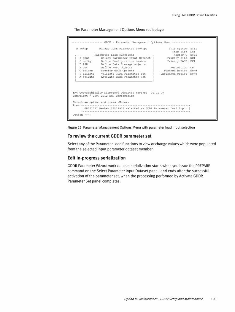
Using EMC GDDR Online Facilities
The Parameter Management Options Menu redisplays:
Figure 25 Parameter Management Options Menu with parameter load input selection
To review the current GDDR parameter set
Select any of the Parameter Load functions to view or change values which were populated from the selected input parameter dataset member.
Edit in-progress serialization
GDDR Parameter Wizard work dataset serialization starts when you issue the PREPARE command on the Select Parameter Input Dataset panel, and ends after the successful activation of the parameter set, when the processing performed by Activate GDDR Parameter Set panel completes.
------------------- GDDR - Parameter Management Options Menu ------------------ B ackup Manage GDDR Parameter backups This System: SYS1 This Site: DC1 .---------- Parameter Load functions ----------. Master-C: SYS1 | I nput Select Parameter Input Dataset | Primary Site: DC1 | C onfig Define Configuration basics | Primary DASD: DC1 | D ASD Define Data Storage objects | | H ost Define Host objects | Automation: ON | O ptions Specify GDDR Options | Planned script: None | V alidate Validate GDDR Parameter Set | Unplanned script: None | A ctivate Activate GDDR Parameter Set | |______________________________________________| EMC Geographically Dispersed Disaster Restart 04.01.00 Copyright © 2007-2012 EMC Corporation. Select an option and press <Enter> Pres +----------------------------------------------------------------+ | GDDI172I Member I6L13905 selected as GDDR Parameter Load Input | +----------------------------------------------------------------+ Option ===>
Option M: Maintenance—GDDR Setup and Maintenance 103

Using EMC GDDR Online Facilities
While editing of the parameter work dataset is in progress, informational message GDDI010I is issued on entry to the Select Parameter Input Dataset panel as shown in Figure 26.
Figure 26 Select Parameter Input Dataset panel with Edit-in-Progress serialization lock - User 1
The GDDI010I message indicates the name of the work dataset, the TSO ID of the user editing (if no user ID is shown in the message, the current TSO user is the one with the Edit-in-Progress serialization lock), the C-System name of the system on which the parameter edit is in progress, as well as the site (DCx) and the time and date that the edit started.
The serialization can be overridden by another user with proper authority, when the user issues another PREPARE command. Note that the other user must have 'READ' authority to facility profile GDDRISPF.SETUP.PARMS.FORCE, as described in “EMC GDDR user interface security” on page 56.
-------------------- GDDR - Select Parameter Input Dataset Row 1 to 6 of 528 Command ===> Parameter input dataset ===> GDDR.GDDR410.BKUPVARS.CNTL Selected Member ===> A1OC0338 Unselect? ===> N (Y/N) Parameter Load work-dataset ===> PQRSTU1.GDDR.V410.PARMS.WORK Parameter Load description ===> SYS2 Parm Load Desc Currently activated GDDR Parameter source: RGHIJK1.GDDR.V410.PARMS.WORK on SYS2 Initial parm edit (User: RGHIJK1 10/12/30 01:51) Work dataset already prepared for A1OC0338. Enter <PREPARE> to force a re-run. Press <F3> to return to the Parameter Management Options Menu Line commands: S elect, U nselect, B rowse, E dit ----------------------- Parameter Input Member Selection ----------------------Act Member Date Time Userid Description --- -------- -------- ----- -------- ------------------------------------------ _ --NONE-- 11/02/01 12:52 RGHIJK1 GDDR parameter load from scratch +---------------------------------------------------------------+-------+ | GDDI010I Edit in progress RGHIJK1.GDDR.V410.PARMS.WORK by RGHIJK1 on | | SYS2 at DC2 2011/01/27 16:42:32 EST | +-----------------------------------------------------------------------+ _ A1VC4712 11/01/31 12:47 GDDR HBM - Initialization
104 EMC GDDR Version 4.1 Product Guide

Using EMC GDDR Online Facilities
When issuing a PREPARE while an edit is in progress, the new user with 'FORCE' authority is presented with the FORCE option displayed on the popup panel shown in Figure 27.
Figure 27 Select Parameter Input Dataset panel with Edit-in-Progress FORCE authorization - User 2
If the FORCE command is entered, the TSO user id associated with the serialization lock is changed to the second TSO user's ID, and a new edit session effectively begins. The TSO user who originally held the serialization lock will then receive the GDDB010E message with the prompt to indicate they can no longer proceed with their edit session either with message 'Reverting to REVIEW mode', as shown in Figure 28 on page 106 or with message 'Reverting to initial state', as shown in Figure 29 on page 106. Following the display of message GDDB010E, the original TSO user's session displays the Parameter Management Options Menu in Review mode, shown in Figure 19 on page 96.
Note: After a successful FORCE, the previous TSO user's session state will either:
- Revert to the initial state (where only the Backup and Input options are shown)- Revert to the REVIEW mode state
If the second PREPARE command issued by the other user references the same parameter work dataset name that was being edited by the first user, then the first user reverts to initial state. If the second PREPARE command issued by the other user references a different parameter work dataset name, then the first user reverts to REVIEW mode on the parameter work dataset. Message GDDI010E will appear on the Parameter Wizard panel currently displayed by first user's TSO session.
C +------------------------------------------------------------------+ | -------------------- Parameter Edit Warning -------------------- | | Command ===> | | | P | Warning: User RGHIJK1 is currently editing GDDR parameter | | work data set RGHIJK1.GDDR.V410.PARMS.WORK | | on SYS2 at DC2 starting 2011/01/27 16:42:32 EST | | | | | | Enter FORCE to abandon changes and start a new EDIT session | | Enter CANCEL or press <F3> to return to the previous panel. | W | | re-run. P | | L +------------------------------------------------------------------+ ----------------------- Parameter Input Member Selection ----------------------Act Member Date Time Userid Description --- -------- -------- ----- -------- ------------------------------------------ _ --NONE-- 11/02/01 12:54 RGHIJK1 GDDR parameter load from scratch _ A21B0929 11/02/01 11:09 GDDR HBM - Master wrong site (SYS3 - DC3) _ A1VE1512 11/01/31 14:15 GDDR HBM - Initialization _ A1VD4743 11/01/31 13:47 GDDR HBM - Initialization _ A1VD3957 11/01/31 13:39 GDDR HBM - Initialization _ A1VC4712 11/01/31 12:47 GDDR HBM - Initialization
Option M: Maintenance—GDDR Setup and Maintenance 105

Using EMC GDDR Online Facilities
Figure 28 GDDR Parameter Wizard panel after FORCE of Edit-in-Progress serialization lock - User 1
Figure 29 Select Parameter Input Dataset panel after FORCE of Edit-in-Progress serialization lock -User 1
To release the Edit-In-Progress serialization lock (same user)
Complete the following steps to release the Edit-in-Progress serialization lock by the TSO user who started it, without completing an Activate of the parameter set:
1. Enter the REVIEW line command on the GDDR Select Parameter Input Dataset panel.
2. The Parameter Wizard responds by prompting you for a FORCE command to abandon your changes.
3. Reply FORCE to abandon the EDIT session and start the REVIEW session, which ends the Edit-In-Progress serialization lock.
---------------------- GDDR - Define Configuration Basics ---------------------Option ===> F Define Configuration Features This System: SYS2 C Define C-Systems This Site: DC2 D Define GDDR Datasets Master-C: SYS2 R Define Site Roles and Groups Primary Site: DC1 Primary DASD: DC1 Automation: ON Planned script: None Unplanned script: None Select an option and press <Enter> +-----------------------------------------------------------------------------+ | GDDI010E Edit in progress RGHIJK1.GDDR.V410.PARMS.WORK FORCEd by PQRSTU1 on | | Q312 at DC2 2011/02/01 16:29:28. Reverting to REVIEW mode. | +-----------------------------------------------------------------------------+
------------------- GDDR - Parameter Management Options Menu -----------------Option ===> B ackup Manage GDDR Parameter backups This System: SYS2 This Site: DC2 .---------- Parameter Load functions ----------. Master-C: SYS2 | I nput Select Parameter Input Dataset | Primary Site: DC1 | | Primary DASD: DC1 | | | | Automation: ON | | Planned script: None | | Unplanned script: None | | |______________________________________________| Current work data set RGHIJK1.GDDR.V410.PARMS.WORK EMC Geographically Dispersed Disaster Restart 04.01.00 Copyright © 2007-2012 EMC Corporation. +---------------------------------------------------------------------------+ | GDDI010E Edit in progress RGHIJK1.GDDR.V410.PARMS.WORK FORCEd by PQRSTU1 | | on SYS1 at DC1. 2011/02/01 13:12:50. Reverting to initial state. | +---------------------------------------------------------------------------+
106 EMC GDDR Version 4.1 Product Guide

Using EMC GDDR Online Facilities
Option C: Define Configuration Basics
IMPORTANT
This series of Define Configuration Basics panels is used once during initial installation of EMC GDDR, and is unlikely to be used again. Most changes performed here will require a FULL parameter activation as well as edits to GDDMPARM parameters. The following changes can be done with a PARTIAL parameter activation:
- Option F: Setting FBA Devices toY/N- Option D: Changing dataset names
When you specify option C in the Parameter Management Options Menu shown in Figure 10 on page 88, the Define Configuration Basics panel appears:
Figure 30 Define Configuration Basics panel
Complete the following options listed in this panel to define your configuration:
◆ “Option F: Define Configuration Features” on page 109
◆ “Option C: Define C-Systems” on page 110
◆ “Option D: Define GDDR Datasets” on page 112
◆ “Option R: Define Site Roles and Groups” on page 113
------------------------- GDDR - Define Configuration Basics ------------------------- Option ===> F Define Configuration Features This System: SYS1 C Define C-Systems This Site: DC1 D Define GDDR Datasets Master-C: SYS1 R Define Site Roles and Groups Primary Site: DC1 Primary DASD: DC1 Automation: ON Planned script: None Unplanned script: None
Select an option and press <Enter> <F5> Parameter Management Options Menu <F6> Define Configuration Features Press <F3> to return to the GDDR Parameter Management Options Menu
Option M: Maintenance—GDDR Setup and Maintenance 107

Using EMC GDDR Online Facilities
IMPORTANT
As you complete each option panel, save your input to ensure that you can return to the task with no loss of data. If you attempt to exit a panel before a save has been completed, you are reminded with the following message.
IMPORTANT
Note that the "Save unsaved changes?" confirmation pop-up may occur even when you have not manually entered data on the current panel. The GDDR Parameter Load wizard is a series of panels with a specific sequence. Panels earlier in the sequence may necessitate adding new information to panels later in the sequence. This occurs frequently in the subset of panels under "Define Host Objects".
If the GDDR-managed systems are changed (added/deleted/replaced), EMC recommends that you step through the entire sequence of Host Object wizard panels. Where GDDR expects additional information, the wizard will insert new lines on the panel. These are usually shown initialized with underscores, and sometimes with template information or with discovered information. This creates a difference between the panel content and the work PDS. When an attempt is then made to step to the next wizard panel, the “Save unsaved changes?” confirmation pop-up will be displayed as a signal that you need to confirm or complete the information added by the wizard.
--------------------- SAVE unsaved changes? -------------------- Command ===> Warning: You may have unsaved changes. Enter SAVE to save your work and continue to the next panel. Enter CANCEL to return to the panel you were on. Press <F3> key to continue and lose unsaved changes.
108 EMC GDDR Version 4.1 Product Guide

Using EMC GDDR Online Facilities
Option F: Define Configuration Features
The Define Configuration Features panel displays the Site list option from the GDDMPARM member you customized during “GDDMPARM installation” on page 66. When you specify option F in the Define Configuration Basics panel, the following panel appears:
Figure 31 Define GDDR Configuration Features
◆ To proceed, select a Configuration and press Enter. The panel updates to display configuration-specific options:
Figure 32 Define Configuration Features panel, configuration-specific options
This panel displays the configurations that are valid selections for the Site list.
1. To proceed, enter:
a. Y or N next to FBA Devices to indicate whether Fixed Block Address (FBA) devices will also be managed by GDDR (CKD devices are always managed by GDDR by default).
b. Y or N next to DLm support to specify whether DLm virtual tape drives will be managed by GDDR. The valid values are 'Y', indicating DLm virtual tape drives are to be managed, or 'N'.
----------------- GDDR - Define GDDR Configuration features - Row 1 to 3 of 3 Command ===> Site list: DC1 DC3 FBA Devices: N (Y/N) Select a configuration from the list below. Press <Enter> to Validate. Press <F3> to return to the GDDR Define Configuration Basics Menu <F6> Define C-Systems Type SAVE to save, LOAD to restart from last saved values. Sel Configuration --- --------------------------------------------------------- _ 2-site SRDF/A _ 2-site SRDF/Star with R22 support _ Cascaded SRDF/Star w/Extended Distance Protection & R22 ***End of configuration list***
----------------- GDDR - Define GDDR Configuration features - Row 1 to 3 of 3 Command ===> Site list: DC1 DC3 FBA Devices: N (Y/N) DLm support: N (Y/N) Select a configuration from the list below. Press <Enter> to Validate. Press <F3> to return to the GDDR Define Configuration Basics Menu <F6> Define C-Systems Type SAVE to save, LOAD to restart from last saved values. Sel Configuration --- --------------------------------------------------------- S *** 2-site SRDF/A <===Selected _ 2-site SRDF/Star with R22 support _ Cascaded SRDF/Star w/Extended Distance Protection & R22 ***End of configuration list***
Option M: Maintenance—GDDR Setup and Maintenance 109

Using EMC GDDR Online Facilities
c. S in the SEL column of one of the rows to select the name of the configuration which matches your site's storage replication environment.
2. Press Enter to validate the selected configuration.
3. Type SAVE to save your selection.
4. Press F6 to proceed to the Define C-Systems panel shown in Figure 33 to confirm the C-System management parameters that are specific to your selected configuration.
Option C: Define C-Systems
When you specify option C in the Define Configuration Basics panel shown in Figure 30 on page 107, the following panel appears:
Figure 33 Define C-Systems panel
1. The System Name, SMFID, IPL parameters, Central Processor Complex (CPC) name, and LPAR fields of the Define C-Systems panel are automatically discovered using CSYSSITE parameter values furnished during installation, as described in “GDDMPARM installation” on page 66.
The color font that displays in these fields indicates the precedence rules that apply to data returned to the Parameter Load wizard from the Auto-Discovery feature when validated against the contents of your parameter work dataset.
• Green — Display only. Auto-Discovery had no conflict with input.
• Red — User input allowed. Not restricted by Auto-Discovery, or impossible to discover at this time.
• Yellow — Display only. Restricted by Auto-Discovery, conflict with input.
Note: You can only change values displayed in red font via the panel. Within the Define C-Systems panel, the only values you can change are the IPL parameters.
The values that are displayed may be confirmed or changed using the information provided with each field described below, subject to the Auto-Discovery data precedence rules described above.
--------------------------- GDDR - Define C-Systems --------------------------- Command ===> Press <F3> to return to the GDDR Define Configuration Basics Menu <F5> Define Configuration Features <F6> Define GDDR Datasets Type SAVE to save, LOAD to restart from last saved values. System IPL Site Name SMFID Parameters CPC (netid.nau) LPAR ---- -------- -------- --------------- ----------------- -------- DC1 SYS1 SYS1 7084 , 708499M1 IBM390PS.Q3 ZOSESYS1 DC3 SYS3 SYS3 70B8 , 709899M1 IBM390PS.C ZOSESYS3 *--------------------------- Auto-Discovery Legend ---------------------------* * Green - Display only. Auto-Discovery had no conflict with input. * * Yellow - Display only. Restricted by Auto-Discovery, conflict with input. * * Red - User input allowed. Not restricted by Auto-Discovery, * * or impossible to discover at this time. * *-----------------------------------------------------------------------------*
110 EMC GDDR Version 4.1 Product Guide

Using EMC GDDR Online Facilities
• Site
Indicates the ID of the site location being specified. Site values are populated from the Site List in the Define GDDR Configuration Features panel. Valid values are DC1 or DC3. This field reflects the GDDMPARM CSYSSITE parameter for the listed C-System.
• System
The MVS system name of an EMC GDDR C-System which is specified using the SYSNAME=system-name statement in SYS1.PARMLIB(IEASYS00) or equivalent parameter file. This field reflects the GDDMPARM CSYSSITE parameter for the listed C-System.
• SMFID
The SMFID of the C-System identified by System name. This field cannot be edited, unless Auto-Discovery fails for the listed remote C-System.
• IPL Parameters
Specifies the IPL parameters that EMC GDDR may use to IPL the C-Systems at sites DC1 and DC3 in the following format:
ssss,iiiixxmn
Where
– ssss is the Sysres device address– iiii is the IODF device address– xx is the LOADxx member suffix– m is the IMSI Field– n is the IEANUC0n suffix
You can locate IPL parameters using the D IPLINFO MVS console command, as shown in the following sample output:
RESPONSE=SYSBIEE254I 21.14.59 IPLINFO DISPLAY 860SYSTEM IPLED AT 15.59.20 ON 02/02/2009RELEASE z/OS 01.10.00 LICENSE = z/OSeUSED LOAD02 IN SYS1.IPLPARM ON 0A26ARCHLVL = 2 MTLSHARE = NIEASYM LIST = B0IEASYS LIST = B0 (OP)IODF DEVICE 0A26IPL DEVICE 0A1D VOLUME RESB14
• CPC (Central Processor Complex)
Specify the name of the central processor where the C-System z/OS system is defined. This field cannot be edited, as it is fully determined by the GDDMPARM CPC parameter of type NETID for the listed C-System.
• LPAR (Logical Partition)
Specify the name of the LPAR within which this system runs at the specified site. This field cannot be edited, unless Auto-Discovery fails for the listed remote C-System. You can find the CPC and LPAR names using the D M=CPU MVS console command, as shown in the following sample output:
Option M: Maintenance—GDDR Setup and Maintenance 111

Using EMC GDDR Online Facilities
RESPONSE=SYSB IEE174I 20.59.34 DISPLAY M 781 PROCESSOR STATUS ID CPU SERIAL 0 02F94E2096 1 02F94E2096 2 02F94E2096 CPC ND = 002096.S07.IBM.83.00000008F94E CPC SI = 2096.N03.IBM.83.000000000008F94E CPC ID = 00 CPC NAME = C LP NAME = ZOSESYSB LP ID = 2 CSS ID = 0 MIF ID = 2 ONLINE - OFFLINE . DOES NOT EXIST W WLM-MANAGED N NOT AVAILABLE CPC ND CENTRAL PROCESSING COMPLEX NODE DESCRIPTOR CPC SI SYSTEM INFORMATION FROM STSI INSTRUCTION CPC ID CENTRAL PROCESSING COMPLEX IDENTIFIER CPC NAME CENTRAL PROCESSING COMPLEX NAME LP NAME LOGICAL PARTITION NAME
2. Type Save on the command line and press Enter.
3. Press F6 to proceed to the Define GDDR Datasets panel shown in Figure 34.
Option D: Define GDDR Datasets
When you specify option D in the Define Configuration Basics panel shown in Figure 30 on page 107, the following panel appears:
Figure 34 Define GDDR Datasets panel
1. Type Add in the Option field at the top of the panel to display a new line for entry of values.
2. Insert additional datasets by typing R (Repeat) in the command field to the left of an existing entry and overtyping the existing data.
3. Type D (Delete) in the command field to the left of an existing entry to remove it.
------------------------- GDDR - Define GDDR Datasets ------ Row 1 to 12 of 12 Command ===> Press <F3> to return to the GDDR Define Configuration Basics Menu <F5> Define C-systems <F6> Define Site Roles and Groups Type SAVE to save, LOAD to restart from last saved values. Line commands: A dd, D elete, R epeat CMD C-system DS Type Seq Dataset Name --- -------- -------- --- -------------------------------------------- _ SYS3 BKUPVARS GDDR.GDDR410.BKUPVARS.CNTL _ SYS1 BKUPVARS GDDR.GDDR410.BKUPVARS.CNTL _ SYS3 LAPD GDDR.GDDR410.PARMS.LAPD _ SYS1 LAPD GDDR.GDDR410.PARMS.LAPD _ SYS3 PROCLIB 1 SYS2.GDDR410.PROCLIB _ SYS1 PROCLIB 2 SYS2.GDDR410.PROCLIB _ SYS3 SKELETON 1 GDDR.GDDR410.ISPSLIB _ SYS1 SKELETON 2 GDDR.GDDR410.ISPSLIB ******************************* Bottom of data ********************************
112 EMC GDDR Version 4.1 Product Guide

Using EMC GDDR Online Facilities
4. Complete the required information for each dataset type.
• BKUPVARS
Specify the name of the dataset into which the backups produced by EMC GDDR Heartbeat monitor initialization should be saved. This dataset was allocated during the procedure described in “Allocate the parameter management datasets” on page 64.
• LAPD
Specify the name of the last activated parameter dataset. This dataset was allocated during the procedure described in “Allocate the parameter management datasets” on page 64. It cannot be the same dataset as your current work dataset.
• PROCLIB
Specify the name of the library on the C-Systems which contains the EMC GDDRPROC member. This library was selected during the procedure described in “Customize member GDDRPROC” on page 74.
• SKELETON
Specify the name of the GDDR ISPSLIB library that resulted from your SMP/E installation.
• Seq
Specify a sequence number for the dataset. The sequence number enables the Proclib and Skeleton libraries to be assigned sequentially across C-Systems.
5. If you made any changes, type Save on the command line and press Enter.
6. Press F6 to proceed to the Define Site Roles and Groups panel shown in Figure 35 on page 113.
Option R: Define Site Roles and Groups
When you specify option R in the Define Configuration Basics panel shown in Figure 30 on page 107, the Define Site Roles and Groups panel appears.
Figure 35 Define Site Roles and Groups panel
-------- ------------ GDDR - Define Site Roles and Groups --------------------- Option ===> Press <F3> to return to the GDDR Define Configuration Basics Menu <F5> Define GDDR Datasets <F6> Define Data Storage Objects Type <SAVE> to save, <LOAD> to restart from last saved values. Enter the required information. Press <Enter> to Validate. Primary DASD Site: DC1 Select DC1 or DC3 Primary Site: DC1 Consistency Group Name DC1: Not Applicable Consistency Group Name DC2:
MSC Group Name DC1: ________ MSC Group Name DC2: N/A MSC Group Name DC3: ________ ******************************* Bottom of Data ******************************
Option M: Maintenance—GDDR Setup and Maintenance 113

Using EMC GDDR Online Facilities
The Define Site Roles and Groups panel defines your Consistency Group and MSC Group names as EMC GDDR global variables.
Note: In SRDF/A environments, Consistency Group names are not used. This is indicated by the 'Not Applicable' note to the right of the Consistency Group Name fields.
1. Complete the following fields in the panel:
• Primary DASD Site
Specify the site where the source (R1) DASD is located.
• Primary Site
Specify the site where the production workload is located.
• MSC Group Name DC1
Specify the name of the managed MSC group when the Primary Site is DC1.
• MSC Group Name DC3
Specify the name of the managed MSC group when the Primary Site is DC3.
Note: If the RESET option is specified during GDDR parameter activation, EMC GDDR will dynamically determine the correct Primary DASD site based on a discovery process of the managed configuration; this may override the value specified on this panel.
2. If you made any changes, type Save on the command line and press Enter.
3. Press F6 to proceed to the Define Data Storage Objects panel shown in Figure 36.
Option D: Define Data Storage ObjectsWhen you specify option D in the Parameter Management Options Menu shown in Figure 10 on page 88, the Define Data Storage Objects panel appears:
Figure 36 Define Data Storage Objects panel
Complete the following options listed in this panel to define your configuration:
--------------------- GDDR - Define Data Storage Objects --------------------- Option ===> S Define SRDF Device ranges This System: SYS2 T Define TimeFinder Device ranges This Site: DC2 G Define SDDF Gatekeepers Master-C: SYS2 D Define DLm Devices Primary DASD: DC1 Automation: ON Planned script: None Unplanned script: None Select an option and press <Enter> <F5> Define Site Roles and Groups <F6> Define SRDF Device Ranges Press <F3> to return to the GDDR Parameter Management Options Menu
114 EMC GDDR Version 4.1 Product Guide

Using EMC GDDR Online Facilities
◆ “Option S: Define SRDF Device Ranges” on page 115
◆ “Option T: Define TimeFinder Device Ranges” on page 117
◆ “Option G: Define SDDF Gatekeepers” on page 118
◆ “Option D: Define DLm Devices” on page 118
Option S: Define SRDF Device Ranges
When you specify option S in the Define Data Storage Objects panel, the following panel appears:
Figure 37 Define SRDF Device Ranges panel
If the panel is not pre-populated with existing SRDF Device Range entries, run the GDDRACDD utility to discover all SRDF devices to be managed by GDDR, both consistency protected and 'external' devices. Refer to “Automated Configuration Discovery for DASD (GDDRACDD)” on page 250 for detailed instructions. Alternatively, follow the steps described below to manually define the SRDF device configuration to GDDR.
1. Type Add in the Command field at the top of the panel to display a new line for entry of SitePair and SRDF Device Range values.
2. Insert additional Site Pairs by typing R (Repeat) in the command field to the left of an existing SitePair.
3. Complete the fields as follows:
• SitePair
Specify the EMC GDDR SRDF replication pairs in the format:
DCm-DCn
Where m is the lower site number, and n is the higher site number. Valid pairings of DCm and DCn are DC1-DC3.
• SRDF Device Range
Specify contiguous Symmetrix device ranges which are common to the specified Site Pair in the format:
gkdm,ra,dddd-eeee,ffff-gggg,ra,gkdn
Where:
gkdm is aDCm SRDF gatekeeper
----------------------- GDDR - Define SRDF Device Ranges ----- Row 1 to 2 of 2 Command ===> Press <F3> to return to the GDDR Define Data Storage objects Menu <F5> Define Data Storage Objects Menu <F6> Define TimeFinder Device ranges Type <SAVE> to save, <LOAD> to restart from last saved values. Line commands: A dd, D elete, R epeat CMD SitePair SRDF Device Range External DLM --- ------- ----------------------------------- -------- --- _ DC1-DC3 gkd1,ra,dddd-eeee,ffff-gggg,ra,gkd3 NO NO _ DC3-DC1 gkd3,ra,dddd-eeee,ffff-gggg,ra,gkd1 NO NO ******************************* Bottom of data ********************************
Option M: Maintenance—GDDR Setup and Maintenance 115

Using EMC GDDR Online Facilities
gkdn is a DCn SRDF gatekeeper
ra is an RA group spanning the specified site pair and to which the defined device ranges belong
dddd-eeee is a range of contiguous Symmetrix devices at site DCm
ffff-gggg is a range of contiguous Symmetrix devices at site DCn
Note: 1. The 4-character gatekeeper masks, gkdm and gkdn, represent MVS volume addresses used to uniquely identify the site DCm or DCn Symmetrix control unit where the volume [gatekeeper] resides. Therefore, the gatekeepers associated with the SRDF device ranges confer three pieces of information used in the processing of commands: the Site, the Symmetrix Control Unit at a Site, and the gatekeeper address. All MVS addresses used here MUST be specified on SYMM parameters in GDDMPARM. The addresses must be unique within a site.
2. The Symmetrix device number ranges at DCm and DCn must contain the same number of devices.
3. If a site is not configured with MVS systems, for example, DC2 in the diskless cascaded configuration, then dummy MVS addresses must be specified as gatekeeper devices for that site.
• External
“GDDR support for external devices” on page 80 provides more information about external devices.
YES or NO indicates whether these devices are external to the consistency-protected environment.
• DLM
When the Automated Configuration Discovery utility is used with the DLM(Y) argument, GDDRACDD will generate RDF.DEVICES parameters for all devices in all included groups, and DLM.DEVICES parameters for devices in groups included with DLM sub-parameter.
‘Yes’ in the DLM column indicates that a given RDF.DEVICES range is also a DLm backend device range. “DLM(Y)” on page 253 provides more information about DLM device range selection.
4. If you made any changes, type Save on the command line and press Enter.
5. Press F6 to proceed to the Define TimeFinder Device Ranges panel shown in Figure 38.
116 EMC GDDR Version 4.1 Product Guide

Using EMC GDDR Online Facilities
Option T: Define TimeFinder Device Ranges
When you specify option T in the Define Data Storage Objects panel shown in “Define Data Storage Objects panel” on page 114, the following panel appears:
Figure 38 Define TimeFinder Device Ranges panel
1. If the panel is not pre-populated with existing TimeFinder Device Range entries, run the GDDRACDD utility to discover all TimeFinder devices to be managed by GDDR, both consistency protected and 'external' devices. Refer to “Automated Configuration Discovery for DASD (GDDRACDD)” on page 250 for detailed instructions. Alternatively, follow the steps described here to manually define the SRDF device configuration to GDDR.
2. Type Add in the Command field at the top of the panel to display a new line for entry of Site and TimeFinder Device Range.
3. Insert additional Sites by entering R (Repeat) in the command field to the left of an existing entry and overtype the existing data.
4. Complete the fields as follows:
• Site
Specify the site location of the BCV devices being defined, either DC1 or DC3.
• TimeFinder Device Range
Specify contiguous Symmetrix device ranges which are common to the indicated site in the format shown below:
gkdn,dddd-eeee
gkdn is an MVS address for the a Symmetrix system located at the specified site containing the specified devices.
dddd-eeee is the Symmetrix device number range of the BCVs being managed. It can be either a single Symmetrix device address or a range of addresses (the low address of the range followed by a hyphen and the high address of the range).
------------------- GDDR - Define TimeFinder Device Ranges --Row 1 to 12 of 12 Command ===> Press <F3> to return to the GDDR Define Data Storage objects Menu <F5> Define SRDF Device ranges <F6> Define SDDF GateKeepers Type <SAVE> to save, <LOAD> to restart from last saved values. Line commands: A dd, D elete, R epeat TimeFinder CMD Site Device Range --- ---- -------------- _ DC1 100C,03C0-03FF _ DC1 100D,0ED0-0F0F _ DC1 100E,2F3C-2F7B _ DC1 500C,0ED0-0F0F _ DC1 500D,2F3C-2F7B _ DC1 500E,03C0-03FF _ DC3 100C,03C0-03FF _ DC3 100D,0ED0-0F0F _ DC3 100E,2F3C-2F7B _ DC3 100C,0340-037F _ DC3 100D,0E50-0E8F _ DC3 100E,2EBC-2EFB ******************************* Bottom of data ********************************
Option M: Maintenance—GDDR Setup and Maintenance 117

Using EMC GDDR Online Facilities
5. If you made any changes, type Save on the command line and press Enter.
6. Press F6 to proceed to the Define SDDF Gatekeepers panel shown in Figure 39.
Option G: Define SDDF Gatekeepers
When you specify option G in the Define Data Storage Objects panel shown in Figure 36 on page 114, the following panel appears:
Figure 39 Define SDDF Clean Utility Gatekeepers panel
The SDDF Clean Utility GateKeeper parameters are not used in the SRDF/A configuration. Press F6 to proceed to the Define Host Objects panel.
Option D: Define DLm Devices
When you specify option D in the Define Data Storage Objects panel shown in Figure 36 on page 114, the following panel appears:
Figure 40 Define DLm Devices panel
Each line represents a single DLm ACP (Access Control Point). Each ACP can control multiple VTECs (virtual tape emulation controllers).
Use the 'A', 'D' or 'R' line commands to add, delete or repeat ACP entries.
----------------- GDDR - Define SDDF Clean Utility GateKeepers Row 1 to 3 of 3 Command ===> Press <F3> to return to the GDDR Define Data Storage Objects Menu <F5> Define TimeFinder Device Ranges <F6> Define Host Objects Type <SAVE> to save, <LOAD> to restart from last saved values. Line commands: A dd, D elete, R epeat CMD Site GK --- ---- ----
******************************* Bottom of data ********************************
-------------------------- GDDR - Define DLm Devices ---------------- Row 1 of 4 Command ===> Press <F3> to return to the GDDR Define Data Storage objects Menu <F5> Define SDDF Gatekeepers <F6> Define Host Objects Type <SAVE> to save, <LOAD> to restart from last saved values. Line commands: A dd, D elete, R epeat, S erialNos Vary online ===> AUTOSWITCH (AUTOSWITCH or NONE) Vary offline ===> BOTH (PRIMARY or BOTH or NONE) Sel Site IP address (IPv4 or IPv6) Port SerialNos Slave? --- ---- ------------------------------ ----- --------- ------ _ DC1 nnn.nnn.nnn.nnn nnnn 12345678+ Y _ DC1 nnn.nnn.nnn.nnn nnnn 23456789+ N _ DC3 nnn:nnn:nnn:nnn:nnn:nnn:nnn:nnn nnnn ALL N ******************************* Bottom of data ********************************
118 EMC GDDR Version 4.1 Product Guide

Using EMC GDDR Online Facilities
Use the 'S' line command to display all serial numbers or revise the list of serial numbers associated with an ACP using the ACP Details panel shown in Figure 41.
Figure 41 Define DLm Devices - ACP Details panel
Use the ACP Details panel to add or edit the FICON adapter serial numbers associated with the selected ACP, as well as to revise other fields describing an ACP entry. You can specify the word ALL (for all adapters) or specify a list of FICON adapter serial numbers. Press <F3> to save your updates and return to the Define DLm Devices panel, or CANCEL to return without saving any updates.
For the Define DLm Devices panel, provide the following information:
◆ SiteIndicates at which site (DC1 or DC3) this DLm storage controller is located.
◆ IP addressThe IP address of the ACP for this DLm, used to send commands from GDDR to the DLm. The format of the IP address can be either IPv4 or IPv6:
• xxx.xxx.xxx.xxx for IPv4
• xxx:xxx:xxx:xxx:xx:xxx:xxx:xxx for IPv6
where xxx are numbers between 0 and 255 inclusive.
◆ PortThe IP port (at the indicated IP address), to send commands to the DLm.
◆ SerialNosThe FICON adapter serial number(s) associated with the DLm storage controller being described by this entry. Multiple serial numbers for an ACP are indicated by a '+' suffix. Enter the 'S' line command to display all serial numbers or revise the list of serial numbers associated with an ACP using the ACP Details panel shown in Figure 41 on page 119.
-------------------------- GDDR - Define DLm Devices -----------------Row 1 of 4 C +--------------------- ACP Details -----------------------+ | Command ===> | P | | enu < | Site IP address (IPv4 or IPv6) Port Slave? | ts T | ---- ------------------------------ ----- ------ | | DC1 nnn.nnn.nnn.nnn nnnn Y | L | | | . . . . . . . FICON adapter serial numbers . . . . . . | V | 11077099 12345678 87654321 ________ ________ ________ | V | ________ ________ ________ ________ ________ ________ | | ________ ________ ________ ________ ________ ________ | S | ________ ________ ________ ________ ________ ________ | Slave? - | ________ ________ ________ ________ ________ ________ | ------ | | Y | Press <F3> key to save your updates and return | N | Enter CANCEL to return without saving any updates | N | | N * +---------------------------------------------------------+ *****************
Option M: Maintenance—GDDR Setup and Maintenance 119

Using EMC GDDR Online Facilities
Note: The serial number is optional and is not used by GDDR.
◆ SlaveY or N. The default is N. Use this field only if you have MDLs (not DLms), to specify which MDLs are slaves (Y) and which are masters (N). If you have DLms only, always use N (the default), as all DLms should be treated as masters by GDDR.
◆ Vary online/offlineGDDR controls the state of managed tape drives using the following options.
• Vary online
AUTOSWITCH causes GDDR scripts to vary online only those managed tape devices that have been set to AUTOSWITCH in z/OS.
NONE causes GDDR scripts to bypass vary online AUTOSWITCH and vary offline the managed tape drives. These operations are expected to be performed outside of GDDR control.
• Vary offline
PRIMARY causes GDDR scripts to vary offline only the managed tape drives at the primary site. You must manually vary offline GDDR managed tape drives at the secondary site, if so desired.
BOTH causes GDDR scripts to vary offline managed tape drives at the primary and the secondary site.
NONE causes GDDR scripts to bypass vary online AUTOSWITCH and vary offline the managed tape drives. These operations are expected to be performed outside of GDDR control.
Option H: Define Host ObjectsWhen you specify option H in the Parameter Management Options Menu shown in Figure 10 on page 88, the Define Host Objects panel appears:
Figure 42 Define Host Objects panel
-------------------------- GDDR - Define Host Objects -------------------------Option ===> S Define Managed Systems This System: SYS1 L Define Managed LPARs This Site: DC1 R Define System Recovery Attributes Master-C: SYS2 P Define Managed CPCs Primary Site: DC1 I Define IPL Parameters Primary DASD: DC1 A Define HMC Load Activation Profiles Automation: ON H Define Managed HMCs Planned script: None C Define HMC Community Names Unplanned script: None D Define Managed Couple Datasets CF Define Managed CF Structures W Define External Workloads E Define EMC MF Enabler STCs Select an option and press <Enter> <F5> Define SDDF Clean GateKeepers <F6> Define Managed Systems Press <F3> to return to the GDDR Parameter Management Options Menu
120 EMC GDDR Version 4.1 Product Guide

Using EMC GDDR Online Facilities
Complete the following options listed in this panel to define your host objects configuration:
◆ “Option S: Define Managed Systems” on page 121
◆ “Option L: Define Managed LPARs” on page 123
◆ “Option R: Define System Recovery Attributes” on page 125
◆ “Option P: Define Managed CPC CBU Options” on page 127
◆ “Option I: Define IPL Parameters” on page 128
◆ “Option A: Define HMC Load Activation Profiles” on page 130
◆ “Option H: Define Managed HMCs” on page 131
◆ “Option C: Define HMC Community Names” on page 132
◆ “Option D: Define Managed Couple Datasets” on page 133
◆ “Option CF: Define Managed CF Structures” on page 135
◆ “Option W: Define External Workloads” on page 137
◆ “Option E: Define EMC MF Enablers STCs” on page 138
Option S: Define Managed Systems
When you specify option S in the Define Host Objects panel, the Define Managed Systems panel appears:
Figure 43 Define Managed Systems panel
Note: Changes to this panel and Figure 44, “Define Managed LPARs panel” are likely to require changes to COMM or CPC parameters in GDDMPARM. If necessary, those changes must be completed before using the GDDR Parameter Wizard.
Use the managed system parameters to define mainframe systems to EMC GDDR and indicate the extent to which they will be managed by EMC GDDR, either using the online interface or during automation sequences. Do not include C-systems here, as those have been defined to EMC GDDR earlier as described in “Option C: Define C-Systems” on page 110. Managed system parameters are defined for every EMC GDDR-managed system to enable HMC functions and workload management.
------------------------ GDDR - Define Managed Systems ------- Row 1 to 6 of 6 Command ===> Press <F3> to return to the GDDR Define Host Objects Menu <F5> Define Host Objects <F6> Define Managed LPARs Type SAVE to save, LOAD to restart from last saved values. Line commands: A dd, D elete, R epeat Manage HMC CMD Site System Sysplex Workload Only --- --- -------- ------------- -------- ---- _ DC1 PRD1 _____________ YES NO _ DC1 TST1 _____________ YES NO _ DC1 TST2 _____________ YES NO _ DC3 CNT1 _____________ YES NO _ DC3 TST2 _____________ NO NO _ DC3 TST1 _____________ NO NO ******************************* Bottom of data ********************************
Option M: Maintenance—GDDR Setup and Maintenance 121

Using EMC GDDR Online Facilities
The first time you use this panel (when you have never issued a SAVE command), the Auto-discovery feature will populate this panel with GDDR-managed system names along with related sysplexes, if available. The auto-discovered list of systems is determined by the presence of GDDMPARM COMM parameters for non C-Systems. After you have issued a SAVE command, the previously saved information will be displayed on the panel whenever you return to it.
If changes to GDDMPARM parameters are performed as a result of the various maintenance procedures described in Chapter 7, “Performing Maintenance Procedures,” those changes will be displayed upon re-entry to this panel.
1. If the panel is not pre-populated with existing entries, type Add in the Command field at the top of the panel to display a new line for field entry.
2. Insert additional systems by entering R (Repeat) in the command field to the left of an existing entry and overtype the existing data.
3. Confirm or change the values that are displayed by using the information provided with each field described below, subject to the precedence rules that apply to data returned to the Parameter Load wizard by the Auto-Discovery feature:
• Site
Specify the ID of the site location being specified. It can have the value DC1 or DC3.
• System
Specify the z/OS system name of an EMC GDDR-managed system which resides at the specified site. You can find the system name on the SYSNAME=system-name statement in SYS1.PARMLIB(IEASYS00) or the equivalent parameter file.
• Sysplex (optional)
When defining managed systems to EMC GDDR, specify a sysplex name for those systems where couple facility structure and couple facility dataset management actions are to be performed by GDDR.
Couple Facility dataset and structure management is controlled for planned and unplanned scripts by the Rebuild CF Dataset, Rebuild CF Structure, and the CF Rebuild Timeout fields described in “Option S: Script Sysplex Options” on page 142, by selections made under “Option D: Define Managed Couple Datasets” on page 133, and under “Option CF: Define Managed CF Structures” on page 135.
The format of this field is: <name>,<type>, where:
– name is either the name of the Sysplex to which the defined system belongs or "NONE"
– If a name is specified then type is either "PLEX", "MONO", or "NONE"
This entry is used to simplify data entry on the Sysplex Object management related panels of the GDDR Parameter Load wizard.
Note: For this release, the Sysplex Object Management features are enabled only for systems which have been defined here with <name>,"PLEX".
122 EMC GDDR Version 4.1 Product Guide

Using EMC GDDR Online Facilities
• Manage Workload
Indicates whether EMC GDDR will trigger start/stop of the workload for the listed system. Type YES to cause EMC GDDR to trigger the stop and start of applications when EMC GDDR takes planned or unplanned actions that impact the managed systems.
• HMC Only
Indicates whether the specified system is external to the population of systems managed by EMC GDDR scripts. HMC Only 'YES' Systems may be managed using the GDDR HMC LPAR Actions panel. Type YES to bypass EMC GDDR parameter validation for the specified system. Type NO to specify that the system is to be managed by EMC GDDR.
4. If you made any changes, type Save on the command line and press Enter.
5. Press F6 to proceed to the Define Managed LPARs panel shown in Figure 44.
Option L: Define Managed LPARs
When you specify option L in the Define Host Objects panel shown in Figure 42 on page 120, the following panel appears:
Figure 44 Define Managed LPARs panel
Note: Changes to this panel and Figure 43, “Define Managed Systems panel” are likely to require changes to COMM or CPC parameters in GDDMPARM. If necessary, those changes must be completed before using the GDDR Parameter Wizard.
EMC GDDR HMC command requests are directed to HMC using the LPAR name and the processor name where the LPAR is defined. To enable HMC functions (IPL, CBU, and so forth), these variables must be defined for every GDDR-managed system and GDDR C-System. Auto-Discovery populates this panel with a list of LPARs, which has at least one LPAR for each system defined on the Define Managed systems panel, for the home site of that system.
1. If the panel is not pre-populated with existing entries, type Add in the Command field at the top of the panel to display a new line for field entry.
----------------------- GDDR - Define Managed LPARs ------- Row 1 to 7 of 7 Command ===> Press <F3> to return to the GDDR Define Host Objects Menu <F5> Define Managed Systems <F6> Define System Recovery Attributes Type SAVE to save, LOAD to restart from last saved values. Line commands: A dd, D elete, R epeat Bypass CMD Site System CPC Name LPAR HMC --- --- -------- ----------------- -------- --- _ DC1 PRD1 IBM390PS.PRD1 LPARPRD1 NO _ DC1 TST1 IBM390PS.TST1 LPARTST1 NO _ DC1 TST2 IBM390PS.TST2 LPARTST2 YES _ DC1 TST5 IBM390PS.TST5 LPARTST5 YES _ DC1 TST6 IBM390PS.TST6 LPARTST6 YES _ DC3 CNT1 IBM390PS.CP3 LPARCNT3 NO _ DC3 PRD1 IBM390PS.CP3 LPARPRD3 NO ******************************* Bottom of data ********************************
Option M: Maintenance—GDDR Setup and Maintenance 123

Using EMC GDDR Online Facilities
2. Insert additional systems by entering R (Repeat) in the command field to the left of an existing entry and overtype the existing data.
3. Confirm or change the values that are displayed using the information provided with each field described below, subject to the precedence rules that apply to data returned to the Parameter Load wizard by the Auto-Discovery feature.
• Site
Indicates the site location of the LPAR being defined. Site values are initially populated from the Define Managed Systems panel. Valid values are DC1 or DC3. For each system, you can add one LPAR per site in the configuration, except for systems protected with LPAR_RECOVERY as described under “Option R: Define System Recovery Attributes” on page 125. LPAR_RECOVERY protected systems can have one LPAR defined at the home site, plus one at DC3 in 3-site configurations. They cannot have an alternate LPAR defined, neither at the home site, nor at the site of the Recovery LPAR location.
• System
This field is populated from the System name supplied in the Define Managed Systems panel, one row per system, for the site which is the home site for that system.
Note: If the field has not been pre-filled, this is the z/OS system name of an EMC GDDR-managed system or an EMC GDDR C-System which resides at the specified site. The name may be found on the SYSNAME=system-name statement in SYS1.PARMLIB(IEASYS00) or the equivalent parameter file.
Add rows for each additional site housing a CPC where a populated system can be IPL'd.
• Central Processor Complex (CPC)
Specify the name of the central processor where the managed LPAR is defined. Auto-Discovery cannot determine the NETID portion of the CPC name, therefore you must provide this information on this panel.
• Logical Partition (LPAR)
Specify the name of the LPAR within which this system runs at the specified site.
You can find the CPC and LPAR names using the D M=CPU MVS console command, as shown in the following sample output:
RESPONSE=SYSB IEE174I 20.59.34 DISPLAY M 781 PROCESSOR STATUS ID CPU SERIAL 0 02F94E2096 1 02F94E2096 2 02F94E2096 CPC ND = 002096.S07.IBM.83.00000008F94E CPC SI = 2096.N03.IBM.83.000000000008F94E CPC ID = 00 CPC NAME = C LP NAME = ZOSESYSB LP ID = 2 CSS ID = 0
124 EMC GDDR Version 4.1 Product Guide

Using EMC GDDR Online Facilities
MIF ID = 2 ONLINE - OFFLINE . DOES NOT EXIST W WLM-MANAGED N NOT AVAILABLE CPC ND CENTRAL PROCESSING COMPLEX NODE DESCRIPTOR CPC SI SYSTEM INFORMATION FROM STSI INSTRUCTION CPC ID CENTRAL PROCESSING COMPLEX IDENTIFIER CPC NAME CENTRAL PROCESSING COMPLEX NAME LP NAME LOGICAL PARTITION NAME
• Bypass HMC
Identifies the LPARs where hardware management console actions should be bypassed. When YES, this bypass affects all HMC actions for the specified LPARs. This includes Load, Reset, Activate, Deactivate, manual and automatic CBU Activate and Undo, Couple DS Realignment, and CF Structure Rebuild. Set this field to NO for EMC GDDR-managed LPARs.
If you set this field to * for any LPAR at site DCm, then on the next Save command, HMC Bypass will be in effect for ALL LPARs at site DCm. This is visible once you issue a LOAD after that Save.
4. If you made any changes, type Save on the command line and press Enter.
5. Press F6 to proceed to the Define System Recovery Attributes panel shown in Figure 45.
Option R: Define System Recovery Attributes
When you specify option R in the Define Host Objects panel shown in Figure 42 on page 120, the Define System Recovery Attributes panel appears:
Figure 45 Define System Recovery Attributes panel
1. If the panel is not pre-populated with existing entries, type Add in the Command field at the top of the panel to display a new line for field entry.
2. Insert additional sites by entering R (Repeat) in the command field to the left of an existing entry and overtype the existing data.
3. Complete the Define System Recovery Attributes panel fields as follows:
----------------- GDDR - Define System Recovery Attributes - Row 1 to 7 of 7 Command ===> Press <F3> to return to the GDDR Define Host Objects Menu <F5> Define Managed LPARs <F6> Define Managed CPCs Type SAVE to save, LOAD to restart from last saved values. Home Contingency Recovery----------------- System Type Site System Site CPC Name LPAR -------- - --- -------- --- ----------------- -------- CNT1 P DC3 PRD3 P DC3 PRD4 P DC3 SYS1 C DC1 N/A SYS2 C DC3 N/A PRD1 P DC1 PRD4 DC3 IBM390PS.O ZOSEPRD4 PRD2 P DC1 PRD3 DC3 IBM390PS.O ZOSEPRD3 ******************************* Bottom of data ********************************
Option M: Maintenance—GDDR Setup and Maintenance 125

Using EMC GDDR Online Facilities
• System
The System name is populated from the System name supplied in the Define Managed Systems panel, one row per system.
• Type
C indicates C-System, P indicates production system.
• Home Site
The Site ID of the site where the system normally runs.
• Contingency System
A system at a remote site on which applications can run if a primary managed system fails. A contingency system may be specified for each GDDR-managed system running at DC1 or DC3. A contingency system for a system located at site DC3 must be located at DC1.
The GDDR-managed system and contingency system pairing is exclusive, meaning that the home LPAR location of a contingency system cannot also be a target LPAR for CPC/LPAR Recovery purposes.
The field may be left blank, as contingency systems are not required.
The following Recovery Site, CPC and LPAR values must either all be specified or must all be omitted. They indicate the Site, CPC, and LPAR where the failing system should be IPL'd if it fails in its normal location. If another system is running in the Recovery LPAR, it will be reset-cleared and the failing system will be IPL'd in its place. LPARs which are the home of a system with LPAR recovery defined may not be the target of recovery for a different system.
• Recovery Site
The site at which the recovery CPC is located. If this is different from the Home site, the configuration must include AutoSwap.
• Central Processor Complex (CPC)
The name of the central processor where the LPAR is defined.
• Logical Partition (LPAR)
The name of the LPAR that this system runs in at the specified site. The CPC and LPAR names can be found using the D M=CPU MVS console command, as shown in the sample output on page 124.
4. If you made any changes, type Save on the command line and press Enter.
5. Press F6 to proceed to the Define Managed CPCs panel shown in Figure 46.
126 EMC GDDR Version 4.1 Product Guide

Using EMC GDDR Online Facilities
Option P: Define Managed CPC CBU Options
When you specify option P in the Define Host Objects panel shown in Figure 42 on page 120, the following panel appears:
Figure 46 Define Managed CPCs panel
Auto-Discovery pre-populates this panel with a list of unique CPC names resulting from:
◆ CPCs for C-System LPARs
◆ CPCs for Managed LPARs
◆ CPCs for LPAR_RECOVERY LPARs
The AUTOCBU Options allow script control of capacity backup activation by cpcname and site. The presence of this parameter invokes script automation to activate licensed processing capacity on specified central processing complexes (CPCs) at the recovery site specified by site in preparation for restart of workload.
Operator control of capacity backup activation is performed using the Perform GDDR Actions menu. The option to cancel capacity backup following an activation is only available from the Perform HCM CBU Actions panel, using the Undo CBU option. “Option CBU: Perform HMC CBU actions” on page 185 provides more information.
1. If the panel is not pre-populated with existing entries, type Add in the Command field at the top of the panel to display a new line for field entry.
2. Insert additional CPCs by entering R (Repeat) in the command field to the left of an existing entry and overtype the existing data.
3. Confirm or change the values that are displayed using the information provided with each field described below, subject to the precedence rules that apply to data returned to the Parameter Load wizard by the Auto-Discovery feature.
• Site
Indicates the ID of the site location being specified. Valid values are DC1 or DC3.
• Central Processor Complex (CPC)
Indicates the name of the central processor where the managed LPAR is defined. There are no limits on the number of CPC name entries per site.
-------------------------- GDDR - Define Managed CPCs -------- Row 1 to 6 of 6 Command ===> Press <F3> to return to the GDDR Define Host Objects Menu <F5> Define System Recovery Attributes <F6> Define IPL Parameters Type SAVE to save, LOAD to restart from last saved values. Line commands: A dd, D elete, R epeat ----- AUTOCBU ------ (REAL, TEST or NONE) CMD Site CPC Name CBU Planned Unplanned --- --- ----------------- --- ------- --------- _ DC1 IBM390PS.PRD NO TEST NONE _ DC1 IBM390PS.TST1 YES NONE TEST _ DC3 IBM390PS.CP3 NO TEST TEST ******************************* Bottom of data ********************************
Option M: Maintenance—GDDR Setup and Maintenance 127

Using EMC GDDR Online Facilities
• Capacity Backup (CBU)
Defines whether Capacity Backup Upgrade is enabled from the GDDR ISPF interface for the named CPC. Specify YES or NO. If YES is specified, CBU actions will be allowed using the GDDR ISPF interface.
• AUTOCBU options for Planned and Unplanned scripts
– Planned: Valid values are REAL, TEST, or NONE.
When REAL, capacity backup licenses will be activated as a part of planned script processing.
When TEST, capacity backup capacity will be simulated as part of planned script processing.
When NONE, no capacity backup automation actions are performed. This is the default value.
– Unplanned: Valid values are REAL, TEST, or NONE.
When REAL, capacity backup licenses will be activated as a part of unplanned script processing.
When TEST, capacity backup capacity will be simulated as part of unplanned script processing.
When NONE, no capacity backup automation actions are performed. This is the default value.
4. If you made any changes, type Save on the command line and press Enter.
5. Press F6 to proceed to the Define IPL Parameters panel shown in Figure 47.
Option I: Define IPL Parameters
When you specify option I in the Define Host Objects panel shown in Figure 42 on page 120, the following panel appears:
Figure 47 Define IPL Parameters panel
------------------------- GDDR - Define IPL Parameters ----------- Row 1 of 12 Command ===> Press <F3> to return to the GDDR Define Host Objects Menu <F5> Define Managed CPCs <F6> Define Managed HMCs Type <SAVE> to save, <LOAD> restart from last saved values. Line commands: A dd, D elete, R epeat STD RES IPL STD ALT IPL BCV IPL HMC CMD Site System Parameters Parameters Parameters Only --- --- -------- ------------- ------------- ------------- --- _ DC1 X05 042A,0442X0M1 043A,0432X0M1 _____________ NO _ DC1 X06 042A,0442X0M1 043A,0432X0M1 _____________ NO _ DC1 X07 042A,0442X0M1 043A,0432X0M1 _____________ NO _ DC1 X08 042A,0442X0M1 043A,0432X0M1 _____________ NO _ DC1 X17 042A,0442X0M1 043A,0432X0M1 _____________ NO _ DC1 X18 042D,0442X0M1 043D,0432X0M1 _____________ NO _ DC3 X05 042A,0442X0M1 043A,0432X0M1 _____________ NO _ DC3 X06 042A,0442X0M1 043A,0432X0M1 _____________ NO _ DC3 X07 042A,0442X0M1 043A,0432X0M1 _____________ NO _ DC3 X08 042A,0442X0M1 043A,0432X0M1 _____________ NO _ DC3 X17 042A,0442X0M1 043A,0432X0M1 _____________ NO _ DC3 X18 042D,0442X0M1 043D,0432X0M1 _____________ NO ******************************** Bottom of data *******************************
128 EMC GDDR Version 4.1 Product Guide

Using EMC GDDR Online Facilities
The Define IPL parameters panel specifies the IPL parameters that EMC GDDR may use to IPL an EMC GDDR-managed system at the primary DASD site. The following statements describe requirements for production systems:
◆ An STD IPL Parameter is required for each site where the listed system has an LPAR defined.
◆ ALT IPL and BCV IPL parameters are optional.
1. If the panel is not pre-populated with existing entries, type Add in the Command field at the top of the panel to display a new line for field entry.
2. Insert additional sites by entering R (Repeat) in the command field to the left of an existing entry and overtype the existing data.
3. Confirm or change the values that are displayed using the information provided with each field described below, subject to the precedence rules that apply to data returned to the Parameter Load wizard by the Auto-Discovery feature.
• Site
Indicates the site location of the IPL parameters being defined. Valid values are DC1 or DC3. This is the site location of the DASD devices reflected in the LOAD address portion of the IPL parameters. During GDDR scripts, GDDR will select STD or BCV IPL parameters based on the type of script and on which site is current primary DASD site, or DC3 when running at DC3 in Star configurations.
• System
This field is populated from the System name supplied in the Define Managed Systems panel, one row per system, for the site which is the home site for that system.
Note: If the field has not been pre-filled, this is the z/OS system name of an EMC GDDR-managed system or an EMC GDDR C-System which resides at the specified site. The name may be found on the SYSNAME=system-name statement in SYS1.PARMLIB(IEASYS00) or the equivalent parameter file.
Add rows for each additional site housing a CPC where a populated system can be IPL'd.
• STD RES IPL Parameters
• STD ALT IPL Parameters
• BCV IPL Parameters
In the format: ssss,iiiixxmn
Where
ssss is the Sysres device address
iiii is the IODF device address
xx is the LOADxx member suffix
m is the IMSI Field
n is the IEANUC0n suffix
Option M: Maintenance—GDDR Setup and Maintenance 129

Using EMC GDDR Online Facilities
• HMC Only
Indicates if the specified system is external to the population of systems managed by EMC GDDR in scripts. HMC Only 'YES' Systems may be managed using the GDDR HMC LPAR Actions panel. EMC GDDR parameter validation is bypassed for systems defined YES in the HMC Only field. This field is not editable.
You can locate IPL parameters using the D IPLINFO MVS console command, as shown in the following sample output:
RESPONSE=SYSB IEE254I 21.14.59 IPLINFO DISPLAY 860 SYSTEM IPLED AT 15.59.20 ON 02/02/2009 RELEASE z/OS 01.10.00 LICENSE = z/OSe USED LOAD02 IN SYS1.IPLPARM ON 0A26 ARCHLVL = 2 MTLSHARE = N IEASYM LIST = B0 IEASYS LIST = B0 (OP) IODF DEVICE 0A26 IPL DEVICE 0A1D VOLUME RESB14
4. If you made any changes, type Save on the command line and press Enter.
5. Press F6 to proceed to the Define HMC Load Activation Profiles panel shown in Figure 49.
Option A: Define HMC Load Activation Profiles
When you specify option A in the Define Host Objects panel shown in Figure 42 on page 120, the following panel appears:
Figure 48 Define HMC Load Activation Profiles
The Define HMC Load Activation Profiles panel is not applicable in sites where cross-site host-DASD channels are not available.
Press F6 to proceed to the Define Managed HMCs panel shown in Figure 49.
------------------ GDDR - Define HMC Load Activation Profiles ---- Row 1 to 7 of 7 Command ===> Press <F3> to return to the GDDR Define Host Objects Menu <F5> Define IPL Parameters <F6> Define Managed HMCs Type SAVE to save, LOAD to restart from last saved values. Enter the required information. Press <Enter> to Validate. Load Site System C/P Load type HMC Load Profile Parameters ---- -------- --- --------- ---------------- ------------- DC1 PRD1 P STANDARD PRD1STDPROF1 70FD,70FDQ3M1 DC1 TST1 P STANDARD ________________ 70FD,70FDQ3M1 DC1 SYS1 C STANDARD SYS1STDPROF1 72FD,72FDQ3M1 DC1 TST2 P STANDARD ________________ 71FD,71FDQ3M1 DC3 PRD3 P STANDARD PRD3STDPROF1 C1FD,C1FDQ3M1 DC3 TST3 P STANDARD ________________ C1FD,C1FDQ3M1 DC3 SYS3 C STANDARD SYS3STDPROF3 C1FD,C1FDQ3M1 ******************************** Bottom of data ********************************
130 EMC GDDR Version 4.1 Product Guide
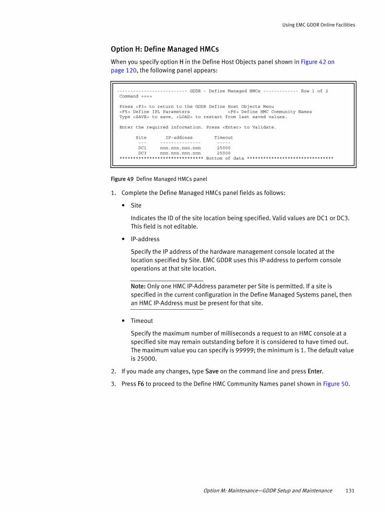
Using EMC GDDR Online Facilities
Option H: Define Managed HMCs
When you specify option H in the Define Host Objects panel shown in Figure 42 on page 120, the following panel appears:
Figure 49 Define Managed HMCs panel
1. Complete the Define Managed HMCs panel fields as follows:
• Site
Indicates the ID of the site location being specified. Valid values are DC1 or DC3. This field is not editable.
• IP-address
Specify the IP address of the hardware management console located at the location specified by Site. EMC GDDR uses this IP-address to perform console operations at that site location.
Note: Only one HMC IP-Address parameter per Site is permitted. If a site is specified in the current configuration in the Define Managed Systems panel, then an HMC IP-Address must be present for that site.
• Timeout
Specify the maximum number of milliseconds a request to an HMC console at a specified site may remain outstanding before it is considered to have timed out. The maximum value you can specify is 99999; the minimum is 1. The default value is 25000.
2. If you made any changes, type Save on the command line and press Enter.
3. Press F6 to proceed to the Define HMC Community Names panel shown in Figure 50.
-------------------------- GDDR - Define Managed HMCs ------------- Row 1 of 2 Command ===> Press <F3> to return to the GDDR Define Host Objects Menu <F5> Define IPL Parameters <F6> Define HMC Community Names Type <SAVE> to save, <LOAD> to restart from last saved values. Enter the required information. Press <Enter> to Validate. Site IP-address Timeout --- --------------- ----- DC1 nnn.nnn.nnn.nnn 25000 DC3 nnn.nnn.nnn.nnn 25000 ******************************* Bottom of data ********************************
Option M: Maintenance—GDDR Setup and Maintenance 131

Using EMC GDDR Online Facilities
Option C: Define HMC Community Names
When you specify option C in the Define Host Objects panel shown in Figure 42 on page 120, the following panel appears:
Figure 50 Define HMC Community Names panel
1. If the panel is not pre-populated with existing entries, type Add in the Command field at the top of the panel to display a new line for field entry.
2. Insert additional sites by entering R (Repeat) in the command field to the left of an existing entry and overtype the existing data.
3. Complete the panel fields as follows:
• HMC Site
Indicates the site location of the HMC being defined. Site values are populated from the Define Managed Systems panel. Valid values are DC1 or DC3.
• C-System
Indicates the system name of a C-System. C-System values are populated from the GDDMPARM CSYSSITE parameters. There will be one row per HMC per C-system in the configuration.
• HMC Community Name
Specify a case-sensitive community name to be used to allow the named C-system access to the HMC on the indicated site. The default community name for each C-System/site combination is the system name in lowercase. If you provide a different community name, EMC GDDR uses the specified name in place of the default name when an LPAR initiates a command to the HMC console.
Note: The maximum length of the community name for the HMC is established by the HWMCA MAX COMMUNITY LEN parameter for the site. For more information, refer to the System z Application Programming Interfaces manual, SB10-7030-11, Data exchange APIs and commands API structures and definitions topic. The current maximum is 16 characters.
4. If you made any changes, type Save on the command line and press Enter.
5. Press F6 to proceed to the Define Managed Couple Datasets panel shown in Figure 51.
---------------------- GDDR - Define HMC Community Names ----- Row 1 to 9 of 9 Command ===> Press <F3> to return to the GDDR Define Host Objects Menu <F5> Define Managed HMCs <F6> Define Managed Couple DS (1/2) Type SAVE to save, LOAD to restart from last saved values. Line commands: A dd, D elete HMC HMC CMD Site C-System Community Name --- --- -------- ---------------- _ DC1 SYS3 zosesys3 _ DC1 SYS1 zosesys1 _ DC3 SYS3 zosesys3 _ DC3 SYS1 zosesys1 ******************************* Bottom of data ********************************
132 EMC GDDR Version 4.1 Product Guide

Using EMC GDDR Online Facilities
Option D: Define Managed Couple Datasets
When you specify option D in the Define Host Objects panel shown in Figure 42 on page 120, the following panel appears:
Figure 51 Define Managed Couple Datasets panel 1 of 2
The use of Couple Datasets is dependent on the site's exploitation of sysplex architecture. If no managed systems are part of a sysplex, the following message is returned upon opening this panel:
GDDI371W No sysplexes defined, please either assign systems to a sysplex or proceed to the next panel.
The fields in panel 1 of the Define Managed Couple Datasets option indicate the types of couple datasets that are used on a specified sysplex.
1. View, define, or modify the panel 1 fields as follows:
• Sysplex
Indicates the sysplex name, if applicable. Sysplex values are populated from the Define Managed Systems panel.
• Couple Dataset Types: ARM BPX CFR LOGR SFM SYS WLM
Type YES or NO under each dataset type to indicate whether or not you want EMC GDDR to ensure correct couple dataset placement for that type during planned and unplanned site swap scripts for a specified sysplex.
Couple Facility dataset and structure management is further controlled for planned and unplanned scripts by the Rebuild CF Dataset, Rebuild CF Structure, and the CF Rebuild Timeout fields described in “Option S: Script Sysplex Options” on page 142.
2. If you made any changes, type Save on the command line and press Enter.
----------------- GDDR - Define Managed Couple Datasets (1/2) Row 1 to 1 of 1 Command ===> Press <F3> to return to the GDDR Define Host Objects Menu <F5> Define HMC Community Names <F6> Define Managed Couple DS (2/2) Type SAVE to save, LOAD to restart from last saved values. Indicate (Yes/No) for which types you want GDDR Couple Dataset management. Sysplex ARM BPX CFR LOGR SFM SYS WLM -------- --- --- --- --- --- --- --- ******************************* Bottom of data ********************************
Option M: Maintenance—GDDR Setup and Maintenance 133

Using EMC GDDR Online Facilities
3. Press F6 to complete the couple dataset definitions as shown in the following panel:
Figure 52 Define Managed Couple Datasets panel 2 of 2
The fields in panel 2 of the Define Managed Couple Datasets option indicate the names of primary and alternate couple datasets of the specified type to be used on the systems belonging to the specified sysplex.
Note: Each couple dataset must be catalogued on all systems in the sysplex.
There must be a primary and an alternate couple dataset each sysplex, for each of the possible primary DASD sites, and for each couple dataset type being used.
EMC GDDR ensures that the primary couple datasets are located wherever the primary DASD currently resides. If the secondary DASD site is available, EMC GDDR ensures that an alternate couple dataset is used on the secondary DASD site. If the secondary DASD site is unavailable, and valid dataset names have been provided for DSN3 and DSN4 as described in Table 11 below, EMC GDDR ensures that an alternate couple dataset is used at the primary DASD site.
Four lines display for each sysplex and managed type, one line for each dataset's role (P or A) for both sites DC1 and DC2. For each type and role within a sysplex, specify the dataset names that are cataloged at DC1 and DC2 as shown in Table 11.
---------------- GDDR - Define Managed Couple Datasets (2/2) ------------------ Option ===> Press <F3> to return to the GDDR Define Host Objects Menu <F5> Define Managed Couple DS (1/2) <F6> Define Managed CF Structures Type <SAVE> to save, <LOAD> to restart from last saved values. Line commands: A dd, D elete, R epeat CMD Sysplex TYPE SITE ROLE Couple Dataset Name --- -------- ---- --- - -------------------------------------------- ******************************* Bottom of data ********************************
+----------------------------------------------------------------------------+ | No sysplexes defined, please either assign systems to a sysplex or proceed | | to the next panel. | +----------------------------------------------------------------------------+
Table 11 Defining Managed Couple Datasets
Sysplex TYPE SITE ROLE Couple Dataset Name
TESTPLX1 ARM DC1 P DSN1: used as Primary when DC1 is Primary and used as Alternate when DC1 is Secondary
A DSN3: used as Alternate when DC1 is Primary and DC2 is unavailable
DC2 P DSN2: used as Primary when DC2 is Primary and used as Alternate when DC2 is Secondary
A DSN4: used as Alternate when DC2 is Primary and DC1 is unavailable
134 EMC GDDR Version 4.1 Product Guide

Using EMC GDDR Online Facilities
1. View, define, or modify the fields displayed in panel 2 as follows:
• Sysplex
Indicates the sysplex name. Sysplex values are populated with the list of sysplexes which have at least one managed couple dataset type, as specified on panel 1.
• Type
Indicates the couple dataset type as specified on panel 1. Valid values are ARM, BPX, CFR, LOGR, SFM, SYS, or WLM.
• Site
Indicates the ID of the site location.
• Role
Indicates the role of the dataset. Valid values are P for primary or A for Alternate.
• Couple Dataset Name
Specify the dataset names that are cataloged at DC1 and DC2.
2. If you made any changes, type Save on the command line and press Enter.
3. Press F6 to proceed to the Define Managed CF Structures panel shown in Figure 53.
Option CF: Define Managed CF Structures
When you specify option CF in the Define Host Objects panel shown in Figure 42 on page 120, the following panels appear:
Figure 53 Define Managed CF Structures panel 1 of 2
--------------------- GDDR - Define Managed CF Structures -- Row 1 to 16 of 28 Command ===> Press <F3> to return to the GDDR Define Host Objects Menu <F5> Define Managed Couple DS (2/2) <F6> Define External Workloads Type <SAVE> to save, <LOAD> to restart from last saved values. Line commands: A dd, D elete, R epeat CMD Sysplex Structure Name CF-Site Eligible Coupling Facility Names --- -------- ---------------- --- ----------------------------------- _ PROD DSNDB2I_GBP0 DC1 C15 _ PROD DSNDB2I_GBP0 DC2 O15 _ PROD DSNDB2I_GBP14 DC1 C15 _ PROD DSNDB2I_GBP14 DC2 O15 _ PROD DSNDB2I_GBP32K DC1 C15 _ PROD DSNDB2I_GBP32K DC2 O15 _ PROD DSNDB2I_LOCK1 DC1 C15 _ PROD DSNDB2I_LOCK1 DC2 O15 _ PROD DSNDB2I_SCA DC1 C15 _ PROD DSNDB2I_SCA DC2 O15 _ PROD EMCP_RRS_STR_1 DC1 C15,O15 _ PROD EMCP_RRS_STR_1 DC2 O15,C15 _ PROD EMCP_RRS_STR_2 DC1 C15,O15 _ PROD EMCP_RRS_STR_2 DC2 O15,C15 _ PROD IEFAUTOS DC1 C15 _ PROD IEFAUTOS DC2 O15
Option M: Maintenance—GDDR Setup and Maintenance 135

Using EMC GDDR Online Facilities
Figure 54 Define Managed CF Structures panel 2 of 2
Note: If the EMC GDDR-managed systems are not members of a sysplex, the following message is displayed in the panel:
No sysplexes defined, please either assign systems to a sysplex or proceed to the next panel.
During Planned and Unplanned Swap scripts, EMC GDDR will issue Display XCF commands for the CF Structures identified in the Define Managed CF Structures panel and determine if they are currently located in the preferred couple facility. If a structure is found in a different couple facility than the one which is first in the list for the current primary DASD site, EMC GDDR will issue REBUILD commands and verify the results. Verification is repeated until all structures are located in one of the acceptable couple facilities.
Couple Facility structure management is controlled for planned and unplanned scripts by the Rebuild CF Structure and the CF Rebuild Timeout fields described in “Option S: Script Sysplex Options” on page 142.
1. View, define, or modify the panel fields as follows:
• Sysplex
Indicates the sysplex name, if applicable. Sysplex values are populated from the Define Managed Systems panel.
If the panel is not pre-populated with existing Sysplex name entries, type Add in the Command field at the top of the panel to display a new line for an entry. Insert additional Sysplex names by entering R in the command field to the left of an existing Sysplex entry.
• Structure Name
Provide a Couple Facility Structure name or names for each specified Sysplex using the following guidelines:
– Length: 1-16 characters
--------------------- GDDR - Define Managed CF Structures - Row 17 to 28 of 28 Command ===> Press <F3> to return to the GDDR Define Host Objects Menu <F5> Define Managed Couple DS (2/2) <F6> Define External Workloads Type <SAVE> to save, <LOAD> to restart from last saved values. Line commands: A dd, D elete, R epeat CMD Sysplex Structure Name CF-Site Eligible Coupling Facility Names --- -------- ---------------- --- ----------------------------------- _ PROD ISGLOCK DC1 C15 _ PROD ISGLOCK DC2 O15 _ PROD IXCLIST1 DC1 C15 _ PROD IXCLIST1 DC2 O15 _ PROD IXCLIST2 DC1 C15 _ PROD IXCLIST2 DC2 O15 _ PROD LOGREC DC1 C15 _ PROD LOGREC DC2 O15 _ PROD OPERLOG DC1 C15 _ PROD OPERLOG DC2 O15 _ PROD SYSZWLM_360E20 DC1 C15 _ PROD SYSZWLM_360E20 DC2 O15 ******************************* Bottom of data ********************************
136 EMC GDDR Version 4.1 Product Guide

Using EMC GDDR Online Facilities
– Position 1: Uppercase alphabetic – Positions 2-16: Uppercase alphabetic, numeric, or _, @, $, #
• CF Site
The ID of the site location being specified. Site values are populated from the Define Managed Systems panel. This is the site which is the primary DASD site when the listed sequence of Eligible Coupling Facility names should be used to determine correct location of CF Structures.
• Eligible Coupling Facility Names
Provide up to 4 Couple Facility names, delimited by commas, using the following guidelines:
– Length: 1-8 characters – Position 1: Uppercase alphabetic – Position 2-8: Uppercase alphabetic, numeric, or _, @, $, #
2. If you made any changes, type Save on the command line and press Enter.
3. Press F6 to proceed to the Define External Workloads panel shown in Figure 55.
Option W: Define External Workloads
External workloads run in mainframe systems which do not have their DASD in the managed Symmetrix systems. EMC GDDR can coordinate Stop and Start of the workload on these “non-managed” mainframe systems with the workload Stop and Start for managed systems. When EMC GDDR takes planned or unplanned actions that impact the managed systems, it has the capability to trigger the stop or start of external workloads through a user-exit.
Note: The definition of external workloads is optional. If no external workloads are to be Stopped or Started in sequence with managed systems, press F6 to proceed to the Define EMC Mainframe Enablers Started Tasks panel.
When you specify option W in the Define Host Objects panel shown in Figure 42 on page 120, the following panel appears:
Figure 55 Define External Workloads panel
1. Type Add in the Command field at the top of the panel to display a new line for an entry.
----------------------- GDDR - Define External Workloads ----- Row 1 to 2 of 2 Command ===> Press <F3> to return to the GDDR Define Host Objects Menu <F5> Define Managed CF Structures <F6> Define EMC Mainframe Enabler STCs Type <SAVE> to save, <LOAD> to restart from last saved values. Line commands: A dd, D elete, R epeat CMD Site System --- --- -------- _ DC1 SYS8 _ DC3 SYSB ******************************* Bottom of data ********************************
Option M: Maintenance—GDDR Setup and Maintenance 137

Using EMC GDDR Online Facilities
2. View, define, or modify the panel fields as follows:
• Site
Indicates the ID of the specified site location.
• System
Indicates the system names which host external workload requiring coordination with system actions performed by EMC GDDR.
Note: If you are using the user exits provided with EMC GDDR, then communication to the targeted systems requires that message interception rules GDDX191I and GDDX291I be enabled. Use the following GDDRMAIN console commands to enable these rules: F GDDRMAIN,MSGS,GDDX191I,ENABLEF GDDRMAIN,MSGS,GDDX291I,ENABLE
3. If you made any changes, type Save on the command line and press Enter.
4. Press F6 to proceed to the Define EMC MF Enablers STCs panel shown in Figure 56.
Option E: Define EMC MF Enablers STCs
EMC GDDR uses information about the site's installation parameters to communicate with EMC Mainframe Enablers started tasks that reside on EMC GDDR-managed systems and EMC GDDR C-Systems.
When you specify option E in the Define Host Objects panel shown in Figure 42 on page 120, the following panel appears:
Figure 56 Define EMC Mainframe Enablers STCs panel
1. Type Add in the Command field at the top of the panel to display a new line for an entry.
------------------- GDDR - Define EMC Mainframe Enablers STCs Row 1 to 7 of 10Command ===> Press <F3> to return to the GDDR Define Host Objects Menu <F5> Define External Workloads <F6> Specify GDDR Options Type <SAVE> to save, <LOAD> to restart from last saved values. Line commands: A dd, D elete, R epeat
STC SUB CMD System Type Name MSTR Parameter Dataset and Member(s) --- -------- ---- -------- ---- -------------------------------------------- _ SYS1 RDF N/A NO EMC.GDDR410.CUSTOM.PARMLIB SRDFSTAR _ SYS2 RDF N/A NO EMC.GDDR410.CUSTOM.PARMLIB SRDFSTAR _ SYS3 RDF N/A NO EMC.GDDR410.CUSTOM.PARMLIB SRDFSTAR _ SYS1 SCF GDDRSCF NO N/A N/A _ SYS2 SCF GDDRSCF NO N/A N/A _ SYS3 SCF GDDRSCF NO N/A N/A ******************************* Bottom of data ********************************
138 EMC GDDR Version 4.1 Product Guide

Using EMC GDDR Online Facilities
2. The pre-populated fields are:
• System
Indicates the z/OS system name of an EMC GDDR-managed system or an EMC GDDR C-System which resides at the specified site. System Name values are populated from the Define Managed Systems panel.
• Type
Indicates the Mainframe Enablers application. Valid abbreviations for Type are:
– SCF: Symmetrix Control Facility (ResourcePak Base)
– RDF: SRDF Host Component
– CG: Consistency Group
• Parameter Dataset and Member(s)
Provides the name of the partitioned dataset and members containing the customization parameters for the specified started task.
Note: “Install EMC GDDR started procedures” on page 65 provides more information.
3. Requirements for EMC GDDR-managed systems:
• SCF: STC name, SUB=MSTR YES
Parameter Dataset and Member name are not applicable.
Note: SUB=MSTR is ignored for SCF entries.
4. Requirements for C-Systems:
• RDF: STC name, SUB=MSTR NO
Parameter dataset and member pointed to by the HC STC RDFPARM DD statement. Required.
• SCF: STC name, SUB=MSTR NO
Parameter Dataset and Member name are not applicable.
Note: SUB=MSTR is ignored for SCF entries.
5. If you made any changes, type Save on the command line and press Enter.
6. Press F6 to proceed to the Specify GDDR Options panel.
Option M: Maintenance—GDDR Setup and Maintenance 139
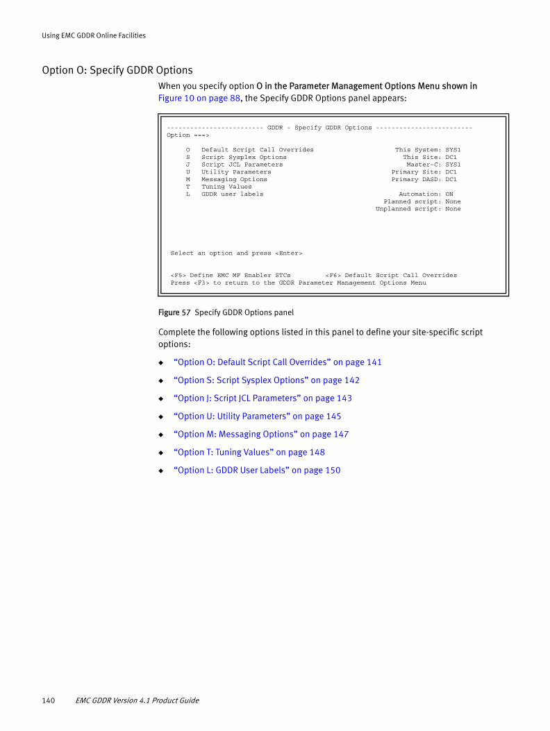
Using EMC GDDR Online Facilities
Option O: Specify GDDR OptionsWhen you specify option O in the Parameter Management Options Menu shown in Figure 10 on page 88, the Specify GDDR Options panel appears:
Figure 57 Specify GDDR Options panel
Complete the following options listed in this panel to define your site-specific script options:
◆ “Option O: Default Script Call Overrides” on page 141
◆ “Option S: Script Sysplex Options” on page 142
◆ “Option J: Script JCL Parameters” on page 143
◆ “Option U: Utility Parameters” on page 145
◆ “Option M: Messaging Options” on page 147
◆ “Option T: Tuning Values” on page 148
◆ “Option L: GDDR User Labels” on page 150
------------------------- GDDR - Specify GDDR Options -------------------------Option ===> O Default Script Call Overrides This System: SYS1 S Script Sysplex Options This Site: DC1 J Script JCL Parameters Master-C: SYS1 U Utility Parameters Primary Site: DC1 M Messaging Options Primary DASD: DC1 T Tuning Values L GDDR user labels Automation: ON Planned script: None Unplanned script: None Select an option and press <Enter> <F5> Define EMC MF Enabler STCs <F6> Default Script Call Overrides Press <F3> to return to the GDDR Parameter Management Options Menu
140 EMC GDDR Version 4.1 Product Guide
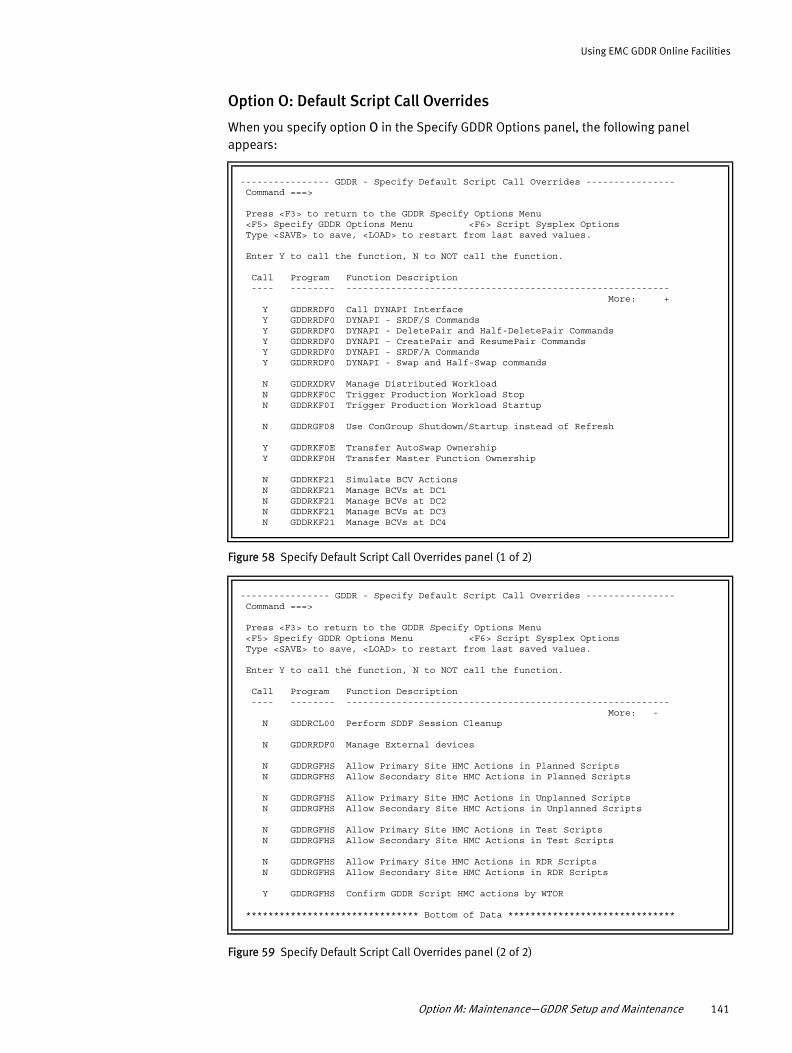
Using EMC GDDR Online Facilities
Option O: Default Script Call Overrides
When you specify option O in the Specify GDDR Options panel, the following panel appears:
Figure 58 Specify Default Script Call Overrides panel (1 of 2)
Figure 59 Specify Default Script Call Overrides panel (2 of 2)
---------------- GDDR - Specify Default Script Call Overrides ---------------- Command ===> Press <F3> to return to the GDDR Specify Options Menu <F5> Specify GDDR Options Menu <F6> Script Sysplex Options Type <SAVE> to save, <LOAD> to restart from last saved values. Enter Y to call the function, N to NOT call the function. Call Program Function Description ---- -------- ---------------------------------------------------------- More: + Y GDDRRDF0 Call DYNAPI Interface Y GDDRRDF0 DYNAPI - SRDF/S Commands Y GDDRRDF0 DYNAPI - DeletePair and Half-DeletePair Commands Y GDDRRDF0 DYNAPI - CreatePair and ResumePair Commands Y GDDRRDF0 DYNAPI - SRDF/A Commands Y GDDRRDF0 DYNAPI - Swap and Half-Swap commands N GDDRXDRV Manage Distributed Workload N GDDRKF0C Trigger Production Workload Stop N GDDRKF0I Trigger Production Workload Startup N GDDRGF08 Use ConGroup Shutdown/Startup instead of Refresh Y GDDRKF0E Transfer AutoSwap Ownership Y GDDRKF0H Transfer Master Function Ownership N GDDRKF21 Simulate BCV Actions N GDDRKF21 Manage BCVs at DC1 N GDDRKF21 Manage BCVs at DC2 N GDDRKF21 Manage BCVs at DC3 N GDDRKF21 Manage BCVs at DC4
---------------- GDDR - Specify Default Script Call Overrides ---------------- Command ===> Press <F3> to return to the GDDR Specify Options Menu <F5> Specify GDDR Options Menu <F6> Script Sysplex Options Type <SAVE> to save, <LOAD> to restart from last saved values. Enter Y to call the function, N to NOT call the function. Call Program Function Description ---- -------- ---------------------------------------------------------- More: - N GDDRCL00 Perform SDDF Session Cleanup N GDDRRDF0 Manage External devices N GDDRGFHS Allow Primary Site HMC Actions in Planned Scripts N GDDRGFHS Allow Secondary Site HMC Actions in Planned Scripts N GDDRGFHS Allow Primary Site HMC Actions in Unplanned Scripts N GDDRGFHS Allow Secondary Site HMC Actions in Unplanned Scripts N GDDRGFHS Allow Primary Site HMC Actions in Test Scripts N GDDRGFHS Allow Secondary Site HMC Actions in Test Scripts N GDDRGFHS Allow Primary Site HMC Actions in RDR Scripts N GDDRGFHS Allow Secondary Site HMC Actions in RDR Scripts Y GDDRGFHS Confirm GDDR Script HMC actions by WTOR ******************************* Bottom of Data ******************************
Option M: Maintenance—GDDR Setup and Maintenance 141
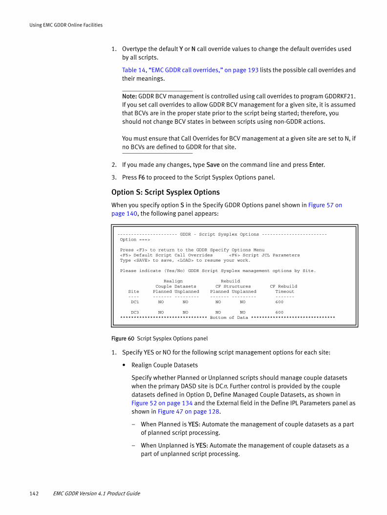
Using EMC GDDR Online Facilities
1. Overtype the default Y or N call override values to change the default overrides used by all scripts.
Table 14, “EMC GDDR call overrides,” on page 193 lists the possible call overrides and their meanings.
Note: GDDR BCV management is controlled using call overrides to program GDDRKF21. If you set call overrides to allow GDDR BCV management for a given site, it is assumed that BCVs are in the proper state prior to the script being started; therefore, you should not change BCV states in between scripts using non-GDDR actions.
You must ensure that Call Overrides for BCV management at a given site are set to N, if no BCVs are defined to GDDR for that site.
2. If you made any changes, type Save on the command line and press Enter.
3. Press F6 to proceed to the Script Sysplex Options panel.
Option S: Script Sysplex Options
When you specify option S in the Specify GDDR Options panel shown in Figure 57 on page 140, the following panel appears:
Figure 60 Script Sysplex Options panel
1. Specify YES or NO for the following script management options for each site:
• Realign Couple Datasets
Specify whether Planned or Unplanned scripts should manage couple datasets when the primary DASD site is DCn. Further control is provided by the couple datasets defined in Option D, Define Managed Couple Datasets, as shown in Figure 52 on page 134 and the External field in the Define IPL Parameters panel as shown in Figure 47 on page 128.
– When Planned is YES: Automate the management of couple datasets as a part of planned script processing.
– When Unplanned is YES: Automate the management of couple datasets as a part of unplanned script processing.
---------------------- GDDR - Script Sysplex Options ------------------------ Option ===> Press <F3> to return to the GDDR Specify Options Menu <F5> Default Script Call Overrides <F6> Script JCL Parameters Type <SAVE> to save, <LOAD> to resume your work. Please indicate (Yes/No) GDDR Script Sysplex management options by Site. Realign Rebuild Couple Datasets CF Structures CF Rebuild Site Planned Unplanned Planned Unplanned Timeout ---- ------- --------- ------- --------- ------- DC1 NO NO NO NO 600
DC3 NO NO NO NO 600 ******************************** Bottom of Data *******************************
142 EMC GDDR Version 4.1 Product Guide

Using EMC GDDR Online Facilities
• Rebuild CF Structures
Specify whether Planned or Unplanned scripts should manage Coupling Facility (CF) Structures at site DCn. Further control is provided by the PSTR.* parameters, and the System Exclude list.
– When Planned is YES: Automate the management of Coupling Facility Structures as a part of planned script processing.
– When Unplanned is YES: Automate the management of Coupling Facility Structures as a part of unplanned script processing.
• CF Rebuild Timeout
Specify the number of seconds to allow for the processing required to rebuild Coupling Facility structures. Valid values are 1-3600. The default value is 600.
2. If you made any changes, type Save on the command line and press Enter.
3. Press F6 to proceed to the Script JCL Parameters panel.
Option J: Script JCL Parameters
GDDR Planned and Unplanned automation sequences run as MVS batch jobs. The Script JCL Parameters panel provides the customization required for those batch jobs to run successfully in your MVS environment. For GDDR scripts started internally by EMC GDDR, this panel is the only place where this information can be provided. The jobcard information can be overridden as part of the script submission started from the Select Script to Run panel as shown in “Option S: Scripts — Run GDDR Scripts” on page 173.
When you specify option J in the Specify GDDR Options panel shown in Figure 57 on page 140, the following panel appears:
Figure 61 Script JCL Parameters panel
1. View, define, or modify the panel fields as follows:
• Site - C-System (display only)
Script JCL values are maintained for each C-System. Complete the values for the first displayed C-System, and scroll to the next C-System using F8.
------------------------- GDDR - Script JCL Parameters ------- Row 1 to 1 of 3 Command ===> Press <F3> to return to the Specify GDDR Options Menu <F5> Script Sysplex Options <F6> Utility Parameters Type <SAVE> to save, <LOAD> to restart from last saved values. Enter the required information. Use <Up> or <Down> to scroll through C-Systems. Site: DC1 C-System: SYS1 HC-Prefix: # SCF-Suffix: V730 Work Unit: SYSALLDA Jobname Prefix: GDD Enforce: YES Work HLQ: _________________ Surrogate User ID: ________ Enforce: NO Enter jobcards: //GDDRSCRP JOB (ACCT-NUMBER),'GDDR-JOB',CLASS=A,MSGCLASS=A,MSGLEVEL=(1,1), // REGION=0M,USER=GDDR,NOTIFY=&SYSUID /*JOBPARM LINES=999999 //*
Option M: Maintenance—GDDR Setup and Maintenance 143

Using EMC GDDR Online Facilities
• HC-Prefix
Specifies the prefix that will be used for SRDF Host Component API commands. The default value set by EMC GDDR is null, and must be replaced by a valid prefix during EMC GDDR customization.
• SCF-Suffix
Specifies the suffix appended to 'SCF$' to form the DDname on a DD statement in unplanned script jobs and GDDRMAIN and the Console and Heartbeat monitors, associating these with an SCF subsystem. The default value set by EMC GDDR is "EMC" which is suitable only if you want EMC GDDR scripts to connect to an SCF instance which either does not specify an SCF subsystem ID, or also specifies "EMC".
• Work Unit
Indicates the user-specified device esoteric value that represents the storage device type to be used when EMC GDDR dynamically allocates temporary datasets. The default value is SYSALLDA.
Note: If you wish to change the default from SYSALLDA, ensure that the replacement device esoteric is not defined to z/OS using the 'VIO' attribute.
• Jobname Prefix and Enforce
Specifies a 3-character prefix that is used as the first three characters of EMC GDDR jobnames. When you provide the jobname prefix and enter Y in the Enforce field, EMC GDDR internally-submitted jobs will use the jobname prefix specified in this panel. Any attempts to start a script from the Select Script to Run panel using a different jobname prefix will fail.
• Work HLQ
Specifies a dataset high-level-qualifier with a maximum length of 17 characters that is used for work datasets. The default is GDDR. Table 7, “RACF permissions,” on page 54 provides recommended authorizations for this HLQ.
• Surrogate User ID and Enforce
Specifies the user ID that has been authorized to all of the resources required by EMC GDDR processes. EMC recommends specifying the user ID provided in the ADDUSER statement of the GDDCRACF C-System RACF definitions, as described in “Specify EMC GDDR security” on page 54.
When you provide the user ID and enter Y in the Enforce field, EMC GDDR internally-submitted jobs will use the surrogate user ID specified in this panel. Any attempts to start a script from the Select Script to Run panel using a different user ID will fail.
• Enter Jobcards
These fields specify the jobcards that will be used when a job is submitted internally by EMC GDDR. Always include the REGION=0M jobcard parameter.
2. If you made any changes, type Save on the command line and press Enter.
3. Press F6 to proceed to the Utility Parameters panel.
144 EMC GDDR Version 4.1 Product Guide

Using EMC GDDR Online Facilities
Option U: Utility Parameters
EMC GDDR script processing sometimes requires invoking external utilities, which have their own space allocation requirements and control settings. This is done using values supplied by the EMC GDDR Utility Parameters panel.
When you specify option U in the Specify GDDR Options panel shown in Figure 57 on page 140, the following panel appears:
Figure 62 Utility Parameters panel
1. View, define, or modify the panel fields as follows:
• EMCGROUP Allocation Parameters
– SYSIN: Recommended allocation is TRACKS,1,1
– REPORT: Recommended allocation is CYLINDERS,1,1
– SYSPRINT: Recommended allocation is CYLINDERS,1,1
• EMCTF Parameters
– SYSIN: Recommended allocation is TRACKS,5,2
– SYSOUT: Recommended allocation is TRACKS,50,50
– MAXREQ: Recommended value is 20000
• RPTOUT Allocation Parameters
– SCFRDFME: Recommended allocation is TRACKS,5,2
– SCFRDFM6: Recommended allocation is TRACKS,5,2
– SCFRDFM9: Recommended allocation is TRACKS,5,2
-------------------------- GDDR - Utility Parameters -------------------------- Command ===> Press <F3> to return to the Specify GDDR Options Menu <F5> Script JCL Parameters <F6> Messaging Options Type <SAVE> to save, <LOAD> to restart from last saved values. Enter the required information. Press <Enter> to Validate.
EMCGROUP Allocation Parameters EMCTF Parameters - SYSIN : TRACKS,1,1 - SYSIN : TRACKS,5,2 - REPORT : CYLINDERS,1,1 - SYSOUT : TRACKS,50,50 - SYSPRINT : CYLINDERS,1,1 - MAXREQ : 20000 RPTOUT Allocation Parameters ECGUTIL Parameters - SCFRDFME : TRACKS,5,2 - COMMAND allocation: CYLINDERS,10,10 - SCFRDFM6 : TRACKS,5,2 - Number of Tasks : 22 - SCFRDFM9 : TRACKS,5,2 - Message Level : 5 Utility Names HMC Optional settings - IEBGENER : IEBGENER - Use Direct Initialize : N - SDDF Cleanup : GDDFCLN1 - Security check on Discover : Y - SDDF List : GDDFLIST USS module installation path: ( Default: /usr/gddr ) /usr/gddr EzSM exec dsname for GDDR exec: ( Default: EZSM.RUN.INSTALL(GDDR) ) _____________________________________________________ ******************************** Bottom of Data *******************************
Option M: Maintenance—GDDR Setup and Maintenance 145

Using EMC GDDR Online Facilities
• ECGUTIL Parameters
– COMMAND: Recommended allocation is CYLINDERS,10,10
– Number of Tasks: Recommended value is 22
– MSGLEVEL: Recommended value is 5
• Utility Names
– IEBGENER: IEBGENER
– SDDF Cleanup: GDDFCLN1
– SDDF List: GDDFLIST
• HMC Optional settings
– Use Direct Initialize: Enter Y or N.
Direct Initialize is an HMC API option that directs HMC API communication to use port 3161. This option is useful for installations where a firewall exists between EMC GDDR and the HMC console. Specifying Y allows an installation to open a particular port (port 3161) in the firewall.
– Security check on Discover: Recommended value is Y.
This is a customer preference with regards to daily usage. With regards to installing the product, suppressing the security check may be required to verify that the HMC setup steps are completed successfully.
• USS module installation path
This is the file system path which is used by EMC GDDR to locate the GDDR USS directories.
• EzSM exec dsname for GDDR exec
This is the full name of the exec to be executed when Option E: EZSM is selected on the GDDR Primary Options Menu. This item is required when EMC z/OS Storage Manager is installed on the EMC GDDR C-Systems.
2. If you made any changes, type Save on the command line and press Enter.
3. Press F6 to proceed to the Messaging and SMF Options panel.
146 EMC GDDR Version 4.1 Product Guide

Using EMC GDDR Online Facilities
Option M: Messaging Options
When you specify option M in the Specify GDDR Options panel shown in Figure 57 on page 140, the following panel appears:
Figure 63 Messaging Options panel
1. View, define, or modify the panel fields as follows:
• Include MSGID in messages issued via SAY
Y or N indicates whether to include the 8-character message ID with messages generated from program SAY functions. SAY functions are foreground operations. The default value is N.
• Include Time in messages issued via SAY
Y or N indicates whether to include the system time in hh:mm:ss format with messages generated from program SAY functions. SAY functions are foreground operations. The default value is N.
2. If you made any changes, type Save on the command line and press Enter.
3. Press F6 to proceed to the Tuning Values panel.
-------------------------- GDDR - Messaging Options -------------------------- Command ===> Press <F3> to return to the Specify GDDR Options Menu <F5> Utility Parameters <F6> GDDR Tuning Values Type <SAVE> to save, <LOAD> to restart from last saved values. Enter the required information. Press <Enter> to Validate. Include MSGID in messages issued via SAY : N Include Time in messages issued via SAY : N ******************************** Bottom of Data *******************************
Option M: Maintenance—GDDR Setup and Maintenance 147
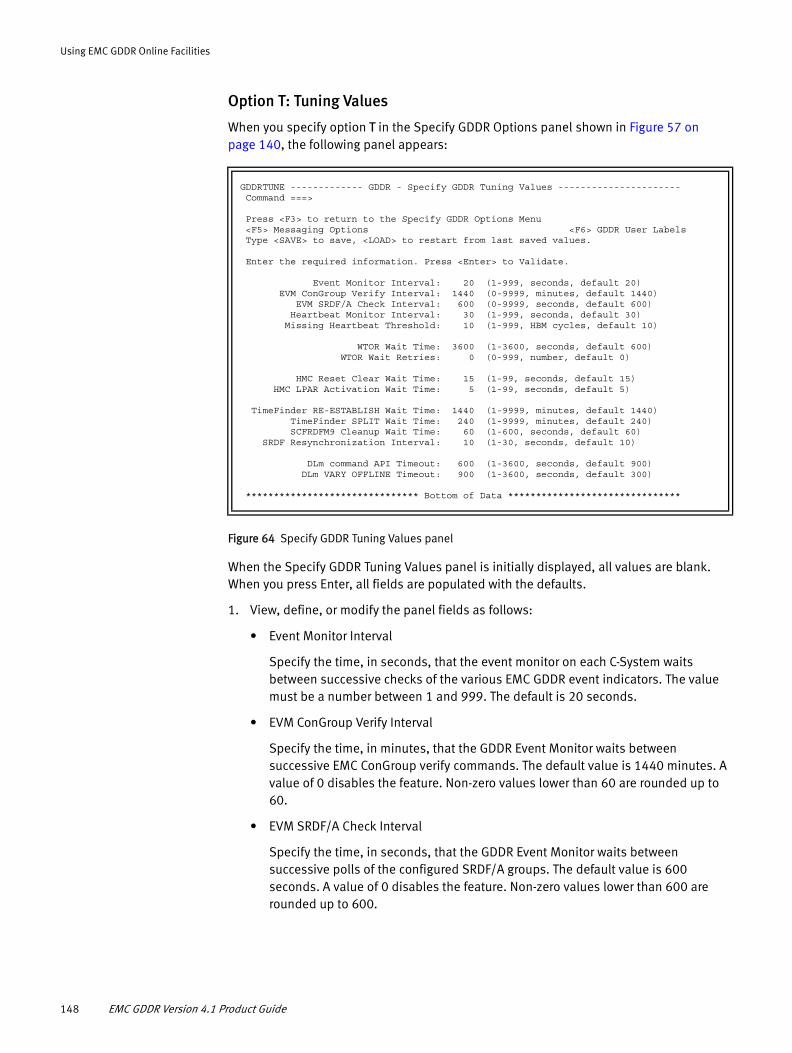
Using EMC GDDR Online Facilities
Option T: Tuning Values
When you specify option T in the Specify GDDR Options panel shown in Figure 57 on page 140, the following panel appears:
Figure 64 Specify GDDR Tuning Values panel
When the Specify GDDR Tuning Values panel is initially displayed, all values are blank. When you press Enter, all fields are populated with the defaults.
1. View, define, or modify the panel fields as follows:
• Event Monitor Interval
Specify the time, in seconds, that the event monitor on each C-System waits between successive checks of the various EMC GDDR event indicators. The value must be a number between 1 and 999. The default is 20 seconds.
• EVM ConGroup Verify Interval
Specify the time, in minutes, that the GDDR Event Monitor waits between successive EMC ConGroup verify commands. The default value is 1440 minutes. A value of 0 disables the feature. Non-zero values lower than 60 are rounded up to 60.
• EVM SRDF/A Check Interval
Specify the time, in seconds, that the GDDR Event Monitor waits between successive polls of the configured SRDF/A groups. The default value is 600 seconds. A value of 0 disables the feature. Non-zero values lower than 600 are rounded up to 600.
GDDRTUNE ------------- GDDR - Specify GDDR Tuning Values ---------------------- Command ===> Press <F3> to return to the Specify GDDR Options Menu <F5> Messaging Options <F6> GDDR User Labels Type <SAVE> to save, <LOAD> to restart from last saved values. Enter the required information. Press <Enter> to Validate. Event Monitor Interval: 20 (1-999, seconds, default 20) EVM ConGroup Verify Interval: 1440 (0-9999, minutes, default 1440) EVM SRDF/A Check Interval: 600 (0-9999, seconds, default 600) Heartbeat Monitor Interval: 30 (1-999, seconds, default 30) Missing Heartbeat Threshold: 10 (1-999, HBM cycles, default 10) WTOR Wait Time: 3600 (1-3600, seconds, default 600) WTOR Wait Retries: 0 (0-999, number, default 0) HMC Reset Clear Wait Time: 15 (1-99, seconds, default 15) HMC LPAR Activation Wait Time: 5 (1-99, seconds, default 5) TimeFinder RE-ESTABLISH Wait Time: 1440 (1-9999, minutes, default 1440) TimeFinder SPLIT Wait Time: 240 (1-9999, minutes, default 240) SCFRDFM9 Cleanup Wait Time: 60 (1-600, seconds, default 60) SRDF Resynchronization Interval: 10 (1-30, seconds, default 10) DLm command API Timeout: 600 (1-3600, seconds, default 900) DLm VARY OFFLINE Timeout: 900 (1-3600, seconds, default 300) ******************************* Bottom of Data *******************************
148 EMC GDDR Version 4.1 Product Guide

Using EMC GDDR Online Facilities
• Heartbeat Monitor Interval
Specify the time, in seconds, that the heartbeat monitor on each C-System waits before setting and propagating its new heartbeat value. The value must be a number between 1 and 999. The default is 30 seconds.
• Missing Heartbeat Threshold
Specify the number of times a heartbeat monitor on a C-System will need to detect no change in the heartbeat value of another C-System, upon awakening from its own wait interval, before it will declare the other C-System dead. The value must be a number from 1 to 999. The default value is 10.
• WTOR Wait Time
Specify the number of seconds that an EMC GDDR script will wait for an operator reply to a WTOR it has issued. When the specified interval has expired, the WTOR is deleted and the script proceeds as if the operator had replied 'N' or 'CANCEL' depending upon the particular message.
This parameter is optional. If not specified, the default value of 600 is used, which is equivalent to 10 minutes.
• WTOR Wait Retries:
Specify the number of times to re-issue the same WTOR. This optional parameter allows you to prolong the time EMC GDDR has to wait for a certain event.
The EMC GDDR WTOR module accept the RETRIES argument, which specifies the number of times to re-issue the same WTOR when intercepting a timeout condition. You can end the wait by replying negatively to the WTOR message. By default (WTOR Wait Retries=0) the WTOR will be issued just once, resulting in script termination with RC=32 if a timeout occurs.
Note: With EMC GDDR Version 4.1, this parameter is used during all MSC State changing operations.
• HMC Reset Clear Wait Time
Specify the number of seconds that the HMC LPAR Reset Clear command will wait for confirmation that the operation completed. The value must be a number between 1 and 99. The default is 15 seconds.
• HMC LPAR Activation Wait Time
Specify the number of seconds that the HMC LPAR Activation command will wait for confirmation that the operation completed. The value must be a number between 1 and 99. The default is 5 seconds.
• TimeFinder Re-Establish Wait Time
Specify the number of minutes that are used when TimeFinder Establish commands specify a WAIT parameter. The default is 1440 minutes.
• TimeFinder Split Wait Time
Specify the number of minutes that are used when TimeFinder Split commands specify a WAIT parameter. The default is 240 minutes.
Option M: Maintenance—GDDR Setup and Maintenance 149

Using EMC GDDR Online Facilities
• SCFRDFM9 Cleanup Wait Time
Specify the number of seconds that GDDR waits for SRDF/A cleanup to complete after the SCFRDFM9 utility completes. The value must be a number between 1 and 600. The default is 60 seconds.
• SRDF Resynchronization Wait Time
Specify the number of minutes that GDDR waits for invalids to synchronize. The value must be a number between 1 and 30. The default is 10 minutes.
• DLm command API Timeout
Specify the number of seconds that GDDR is to wait for a response to a command to sent to a DLm Access Control Point (ACP) via the TCP/IP command API. The default is 900 seconds.
• DLm VARY OFFLINE Timeout
Specify the number of seconds that GDDR is to wait for all DLm virtual tape drives to be varied offline. The default is 300 seconds.
2. If you made any changes, type Save on the command line and press Enter.
3. Press F6 to proceed to the Define GDDR User Labels panel.
Option L: GDDR User Labels
When you specify option L in the Specify GDDR Options panel shown in Figure 57 on page 140, the following panel appears:
Figure 65 Define GDDR User Labels panel
This panel accepts user-specified names for the GDDR Complex, Regions, and Site list.
1. To proceed, enter the following values:
◆ GDDR Complex name
A name assigned by the user to the entire complex of C-Systems and GDDR managed systems, using the following guidelines:
------------------------ GDDR - Define GDDR User Labels -----------------------Command ===> Press <F3> to return to the GDDR Options Menu <F5> Tuning Values <F6> Parameter Management Options Menu Type SAVE to save, LOAD to restart from last saved values. GDDR Complex name ===> ________ (default: GDDRPLEX) Site User label (uuuuuuu) Region User Label (uuuuuuu) ---- ---------- ------ ---------- DC1 _______ (7 chars max) RG1 _______ (7 chars max) DC3 _______ RG2 _______ DISPLAY FORMAT: User site display format ===> 0 User region display format ===> 0 Format Template: Example: Format Template: Example: 0 - DC# DC1 (default) 0 - RG# RG1 (default) 1 - uuuuuuu# London1 1 - uuuuuuu# Europe1 2 - #uuuuuuu 1London 2 - #uuuuuuu 1Europe 3 - DC#-uuuu DC1-Lond 3 - RG#-uuuu RG1-Euro 4 - uuuu-DC# Lond-DC1 4 - uuuu-RG# Euro-RG1
150 EMC GDDR Version 4.1 Product Guide
Using EMC GDDR Online Facilities
• Format: 8 characters, alphanumeric
• If no name is specified, the default is 'GDDRPLEX'
◆ User site label
Provide site names, using the following guidelines:
• Length: 1-7 characters, alphanumeric
• If no names are specified, Format '0' is assumed; sites will be displayed as DC1 and DC3
◆ User site label format
Specify the number of the template which will determine how site user labels will be shown in panels and messages.
◆ User region label
Provide region names, using the following guidelines:
• Length: 1-7 characters, alphanumeric
• If no names are specified, Format '0' is assumed; Regions will be displayed as RG1 and RG2.
◆ User region label format
Specify the number of the template which will determine how region user labels will be shown in panels and messages.
2. If you made any changes, type Save on the command line and press Enter.
3. Press F6 to return to the Parameter Management Options Menu.
Option V: Validate GDDR Parameter SetEMC GDDR parameter validation processing determines that your proposed changes to parameter values are consistent and relationally correct. The validation operations are similar to the activation operations described in “Option A: Activate GDDR Parameter Set” on page 153, but do not update any GDDR variables.
Option M: Maintenance—GDDR Setup and Maintenance 151

Using EMC GDDR Online Facilities
When you specify option V in the Parameter Management Options Menu shown in Figure 10 on page 88, the Validate GDDR Parameter Set panel appears:
Figure 66 Validate GDDR Parameter Set panel
Complete the options listed in this panel to validate your parameter set.
1. View, define, or modify the panel fields as follows:
• Validation in Foreground or Background
– FORE: Processing occurs in TSO foreground.
– BACK: Processing occurs in background as a batch job. A panel is displayed containing the jobcard and the PROCLIB and SKELETON libraries previously specified in your personal GDDR ISPF Profile.
Modify these settings if needed and then press Enter.
• Specify GDDR Parameter Load Type
– PARTIAL: Validate only the changed work-pds members. There is one work-pds member per parameter definition panel. Validation does not include contents of other members.
Note: Partial validation is not currently supported to implement a change in the names or the number of managed systems or LPARs.
– FULL: Validate the entire set of GDDR parameters. This is the recommended setting.
• Specify GDDR State Variables Action
– RESET: Reset all state variables to a neutral (non-error) state. This is the recommended setting.
– ASIS: Set all state variables to the values found in the input.
– NOUPDATE: Do not update any state variables. This option is invalid with Parameter Load type "FULL".
• Propagate to Other C-systems
– YES: Send the updates to other C-systems. If any other C-system cannot be contacted, the action will fail. This is the recommended setting.
--------------------- GDDR - Validate GDDR Parameter Set --------------------- Option ===> Options below in effect for VALIDATION Specify Options for this Parameter Set Validation : Validation in Foreground or Background : FORE (FORE,BACK) Specify GDDR Parameter Load Type : _______ (PARTIAL,FULL) Specify GDDR State Variables Action : ________ (RESET, ASIS, NOUPDATE) Propagate to Other C-systems : ___ (YES/NO/TRY) Issue one of the following commands: SAVE : Save options above as the default for your userid CANCEL : <F3> return to the GDDR Parameter Management Options Menu VAL : Proceed with GDDR Parameter Validation using options above
152 EMC GDDR Version 4.1 Product Guide
Using EMC GDDR Online Facilities
– NO: Do not send the updates to other C-systems.
– TRY: Try to send the updates to other C-systems, but if they cannot be contacted, continue.
2. After specifying the requested options, type the Save command to save your validation options to your TSO profile.
3. Type VAL to validate the proposed parameter definitions, or CANCEL to return to the GDDR Parameter Management Options Menu.
If Background mode is selected, the following confirmation message displays:
GDDI116I Job for Parameter Validation submitted successfully
4. Following a successful validation, press F3 to return to the Parameter Management Options Menu.
Option A: Activate GDDR Parameter SetTo complete the parameter definition and load process, you need to activate the GDDR parameter set.
IMPORTANT
Parameters required by the GDDR Event Monitor (EVM) and GDDR Heartbeat Monitor may be changed during parameter activate processing. For this reason, GDDRMAIN will stop the Event Monitor and Heartbeat Monitor if they are not already stopped before you perform a GDDR parameter set activation. If they were started before the parameter site activation, GDDRMAIN will restart the Event and Heartbeat Monitors after the activation completes. Refer to Appendix B, “Using GDDRMAIN,” for information about how GDDRMAIN controls the stop/start of the Event and Heartbeat Monitors.
The parameter set activation process performs the following actions:
◆ If a Planned or Unplanned script is running, then only an Activate of type Partial is allowed, and only if the script job is not currently running.
◆ Locks variables for integrity and consistency on local system.
◆ Performs and implicit backup and validate before activation.
◆ Updates variables and propagates them to other C-systems, depending on the Activate panel setting.
◆ Performs an implicit backup after activation.
◆ Clears the command queue if requested.
◆ Releases the variables.
◆ Copies the parameter work dataset to the last activated parameter dataset.
IMPORTANT
If you are running the parameter set activate batch job with CONSISTENCY(ENFORCE) and you cancel it after it has started the load, then you may need to disable the dynamic exit called GDDREXG1GDDR. The same is true for a parameter backup job if you are running with any CONSISTENCY option other than IGNORE. “Dynamic exits” on page 243 describes
Option M: Maintenance—GDDR Setup and Maintenance 153

Using EMC GDDR Online Facilities
how to manually disable the GDDREXG1GDDR dynamic exit.
Specify option A in the Parameter Management Options Menu shown in Figure 10 on page 88. The Activate GDDR Parameter Set panel appears:
Figure 67 Activate GDDR Parameter Set panel
Complete the options listed in this panel to activate your parameter set.
1. View, define, or modify the panel fields as follows:
• Validation in Foreground or Background
– FORE: Processing occurs in TSO foreground. Activation processing messages are displayed in the Parameter Load Activation status pop-up panels shown in Figure 68 and Figure 69 on page 157.
– BACK: Processing occurs in background as a batch job. This is the recommended setting. A panel is displayed containing the jobcard and the PROCLIB and SKELETON libraries previously specified in your personal GDDR ISPF Profile. Modify these settings if needed and then press Enter.
• Specify GDDR Parameter Load Type
– PARTIAL: Activates only the changed work-pds members. There is one work-pds member per parameter definition panel. Activation does not include contents of other members.
Note: Partial validation is not currently supported to implement a change in the names or the number of managed systems or LPARs.
– FULL: Deletes all global variables and activates the entire EMC GDDR parameter set. This is the recommended setting.
• Clear the GDDR Command Queue
– YES: The command queue is cleared if the parameter load is successful. Use this choice for a full parameter load. This is the recommended setting.
– NO: The command queue is not cleared. This choice may be appropriate for a partial parameter load.
--------------------- GDDR - Activate GDDR Parameter Set --------------------- Option ===> Options below in effect for ACTIVATION Specify Options for this Parameter Set Activation : Activation in Foreground or Background : BACK (FORE,BACK) Specify GDDR Parameter Load Type : FULL (PARTIAL,FULL) Clear the GDDR Command Queue ? YES (YES/NO) Specify GDDR State Variables Action : RESET (RESET, ASIS, NOUPDATE) Propagate to Other C-systems : YES (YES/NO/TRY) Enforce consistency : RETRY=5_ (YES/NO/RETRY(1-5) Ignore Backup Failure : NO_ (YES/NO) Issue one of the following commands: SAVE : Save options above as the default for your userid CANCEL : <F3> return to the GDDR Parameter Management Options Menu ACT : Proceed with GDDR Parameter Activation using options above
154 EMC GDDR Version 4.1 Product Guide

Using EMC GDDR Online Facilities
Note: Clearing the command queue is attempted on all C-Systems if Propagate to Other C-Systems option is 'Yes' or 'Try' and all C-Systems are in communication with one another. If the choice is to clear the command queue, but communication between the C-Systems is temporarily interrupted, please use the "Manage GDDR Internal Command Queue" panel shown in Figure 72 on page 159 to clear it on the other C-systems, or use the GDDRCLRQ job provided in hlq.GDDRvrm.SAMPLIB.
If no script is in progress, the recommendation is to clear the command queue. If a script is in progress, please consult EMC GDDR Solution Support.
• Specify GDDR State Variables Action
– RESET: Reset all state variables to a neutral (non-error) state. This is the recommended setting.
– ASIS: Set all state variables to the values found in the input.
– NOUPDATE: Do not update any state variables. This option is invalid with Parameter Load type "FULL".
• Propagate to Other C-systems
– YES: Send the updates to other C-systems. If any other C-system cannot be contacted, the action will fail. This is the recommended setting.
– NO: Do not send the updates to other C-systems.
– TRY: Try to send the updates to other C-systems, but if they cannot be contacted, continue.
• Enforce consistency
– YES: Any updates to global variables other than by parameter activate will be blocked while the backup or parameter activate is in progress. This is the recommended setting.
– NO: Outside updates to globals will be ignored.
– RETRY (1-5): If an outside update occurs while parameter backup is running, the backup will be retried the indicated number of times.
• Ignore Backup Failure
– YES: If the parameter backup which is done before the parameter load fails, the parameter load will continue.
– NO: If the parameter backup which is done before the parameter load fails, the parameter load will not be done. This is the recommended setting.
2. After specifying the requested options, type the SAVE command to save your activation options to your TSO profile.
3. Type ACT to activate the proposed parameter definitions, or CANCEL to return to the GDDR Parameter Management Options Menu.
If you already have started an activation job that did not complete yet, or was cancelled, aborted, or never was run, you will not be able to submit another job (see the message below). In this case you must either wait for the activation job to complete, or you can issue either the ACT FORCE command to force a resubmission of
Option M: Maintenance—GDDR Setup and Maintenance 155
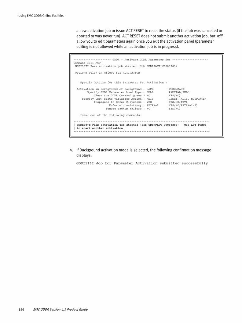
Using EMC GDDR Online Facilities
a new activation job or issue ACT RESET to reset the status (if the job was cancelled or aborted or was never run). ACT RESET does not submit another activation job, but will allow you to edit parameters again once you exit the activation panel (parameter editing is not allowed while an activation job is in progress).
4. If Background activation mode is selected, the following confirmation message displays:
GDDI116I Job for Parameter Activation submitted successfully
---------------------- GDDR - Activate GDDR Parameter Set ---------------------Command ===> ACT GDDI387I Parm activation job started (Job GDDRPACT J0003283) Options below in effect for ACTIVATION Specify Options for this Parameter Set Activation : Activation in Foreground or Background : BACK (FORE,BACK) Specify GDDR Parameter Load Type : FULL (PARTIAL,FULL) Clear the GDDR Command Queue ? NO (YES/NO) Specify GDDR State Variables Action : ASIS (RESET, ASIS, NOUPDATE) Propagate to Other C-systems : YES (YES/NO/TRY) Enforce consistency : RETRY=5 (YES/NO/RETRY=1-5) Ignore Backup Failure : NO (YES/NO) Issue one of the following commands: +------------------------------------------------------------------------------+| GDDR387E Parm activation job started (Job GDDRPACT J0003283) - Use ACT FORCE || to start another activation |+------------------------------------------------------------------------------+
156 EMC GDDR Version 4.1 Product Guide
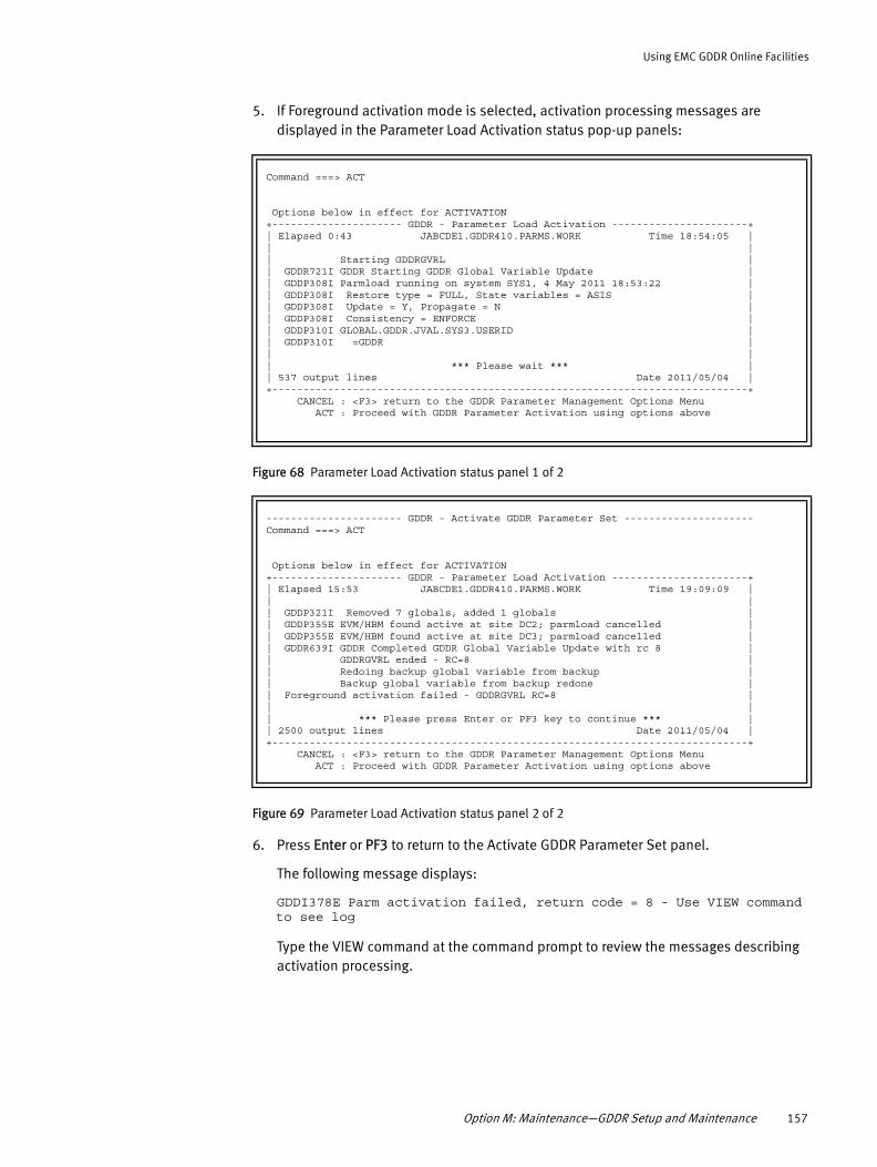
Using EMC GDDR Online Facilities
5. If Foreground activation mode is selected, activation processing messages are displayed in the Parameter Load Activation status pop-up panels:
Figure 68 Parameter Load Activation status panel 1 of 2
Figure 69 Parameter Load Activation status panel 2 of 2
6. Press Enter or PF3 to return to the Activate GDDR Parameter Set panel.
The following message displays:
GDDI378E Parm activation failed, return code = 8 - Use VIEW command to see log
Type the VIEW command at the command prompt to review the messages describing activation processing.
Command ===> ACT Options below in effect for ACTIVATION +--------------------- GDDR - Parameter Load Activation ----------------------+| Elapsed 0:43 JABCDE1.GDDR410.PARMS.WORK Time 18:54:05 || || Starting GDDRGVRL || GDDR721I GDDR Starting GDDR Global Variable Update || GDDP308I Parmload running on system SYS1, 4 May 2011 18:53:22 || GDDP308I Restore type = FULL, State variables = ASIS || GDDP308I Update = Y, Propagate = N || GDDP308I Consistency = ENFORCE || GDDP310I GLOBAL.GDDR.JVAL.SYS3.USERID || GDDP310I =GDDR || || *** Please wait *** || 537 output lines Date 2011/05/04 |+-----------------------------------------------------------------------------+ CANCEL : <F3> return to the GDDR Parameter Management Options Menu ACT : Proceed with GDDR Parameter Activation using options above
---------------------- GDDR - Activate GDDR Parameter Set ---------------------Command ===> ACT Options below in effect for ACTIVATION +--------------------- GDDR - Parameter Load Activation ----------------------+| Elapsed 15:53 JABCDE1.GDDR410.PARMS.WORK Time 19:09:09 || || GDDP321I Removed 7 globals, added 1 globals || GDDP355E EVM/HBM found active at site DC2; parmload cancelled || GDDP355E EVM/HBM found active at site DC3; parmload cancelled || GDDR639I GDDR Completed GDDR Global Variable Update with rc 8 || GDDRGVRL ended - RC=8 || Redoing backup global variable from backup || Backup global variable from backup redone || Foreground activation failed - GDDRGVRL RC=8 || || *** Please press Enter or PF3 key to continue *** || 2500 output lines Date 2011/05/04 |+-----------------------------------------------------------------------------+ CANCEL : <F3> return to the GDDR Parameter Management Options Menu ACT : Proceed with GDDR Parameter Activation using options above
Option M: Maintenance—GDDR Setup and Maintenance 157

Using EMC GDDR Online Facilities
Option D: Message, Debug and Trace Options
When you specify option D in the Setup and Maintenance menu shown in Figure 9 on page 87, the following panel appears:
Figure 70 Set Output Message Levels by Program panel
This panel enables you to individually customize message, debug, and trace settings for a selected Userid and GDDR module.
◆ HMC Simulation
Performs operations up to the point of the actual submit of BCPii interface functions from the Perform HMC LPAR Actions panel or from within a script. The BCPii interface functions exploited by EMC GDDR are LIST, QUERY, COMMAND, SET, CONNECT and DISCONNECT.
◆ BCPii Tracing
When set to 'Y', detailed BCPii diagnostic information will be written to the primary sysout dataset for the GDDRWORK address space on the appropriate C-System. Keep in mind this might not be the C-System on which the original task was initiated (either via scripting, batch work, or the ISPF interface). This is the system upon which the task is executed. This can be very useful when trying to diagnose a problem with HMC management.
The defaults for these options are the settings EMC recommends for your production environment. You may be asked to make changes to the defaults if diagnostic information is needed as a result of a question or problem.
--------- GDDR - Set Output Message Levels By Program -------- Option ===> Scroll ===> CSR This panel shows the message, debug and trace output levels in effect for user shown. Levels on each line apply to program on that line only, while levels in parentheses are defaults applying to any program not found in the list. You may change the defaults or the levels for specific programs by overtyping. Use ADD to add a new program to the list with initial output levels. Press <F3> to save changes and return to previous panel Press <F1> for a complete description of available actions on this panel Program Msg ( 1 ) Debug ( 0 ) Trace ( 0 ) For userid: JABCD1 - -------- --- ----- ----- HMC Simulation? N ( Y or N ) BCPii Tracing? N ( Y or N )******************************* Bottom of data ********************************
158 EMC GDDR Version 4.1 Product Guide

Using EMC GDDR Online Facilities
Use the ADD command to make changes to the default settings. The following panel appears:
Figure 71 Add Program to MsgLevel/Debug/Trace List panel
This panel allows the program names provided by EMC Customer Service to be specified with the requested message level, debug, or trace flags.
If the program name is less than 8 characters, extend the name with "$" signs up to a length of 8 characters.
Option Q: Manage GDDR Internal Command Queue
When you specify option Q in the Setup and Maintenance menu shown in Figure 9 on page 87, the following panel appears:
Figure 72 Manage GDDR Internal Command Queue panel
The GDDR Manage Internal Command Queue panel provides the capability to alter EMC GDDR processing. EMC advises against use of this panel unless specifically directed by EMC GDDR Customer Support.
The following command line commands are available:
◆ Refresh — Display from the actual command queue elements
◆ Clear Queue — Clears the entire queue
--------------- GDDR - Add Program to MsgLevel/Debug/Trace List ------ Command ===> Program ===> ________ MsgLevel ===> 1 Debug Level ===> 0 Trace Level ===> 0 Enter program name (required) You may overtype default message, debug and trace levels Press <Enter> when ready to add new program to the list and return Press <F3> to return without adding a program to the MDT list
---------------------- GDDR - Manage Internal Command Queue -- Row 1 to 2 of 2 Option ===> Scroll ===> CSR
WARNING: Do not use unless instructed to do so by EMC Support
Total elements: 2 Active elements: 0 Maximum active: 35 Entries listed in order by script name (A)
Press <F3> to return to the GDDR Setup and Maintenance Menu
Sel No RetCode Script Created Updated --- -- ------- -------- ----------------- --------------------- _ 1 152 GDDRPA07 0530201106023291 0530201110255782 SC VOL,LCL(BA14,18),HSWAP(FORCE,STAR,GDDR),ALL _ 2 152 GDDRPA07 0530201106023320 0530201110255163 SC VOL,LCL(CC12,20),HSWAP(FORCE,STAR,GDDR),ALL ******************************* Bottom of data ********************************
Option M: Maintenance—GDDR Setup and Maintenance 159

Using EMC GDDR Online Facilities
◆ SORT NUM D[A] — Sort by command number, Ascending [Descending]
◆ SORT SCR A[D] — Sort by script name, Ascending [Descending]
◆ SORT CRE A[D] — Sort by date/time created, Ascending [Descending]
◆ SORT UPD A[D] — Sort by last update date/time, Ascending [Descending]
◆ SORT QUE A[D] — Sort by queue order, Ascending [Descending]
The initial sort order is Command number, Descending.
The following message is issued if the command is not valid: GDDI041E Invalid sort key sort-key.
The display is kept in sync with actions; there is no need to refresh the display after a delete.
Option H: Perform HMC Discovery
To discover HMC objects accessible to EMC GDDR, specify option H from the Setup and Maintenance menu shown in Figure 9 on page 87. A ‘please wait’ pop-up dialog such as the following appears and HMC object discovery is activated:
Figure 73 HMC object discovery panel
---------------------- GDDR - Setup and Maintenance Menu ----------------------- Option ===> P arms Manage GDDR Parameters This System: SYS1 D ebug Message, Debug and Trace options This Site: DC1 Q ueue Manage GDDR Internal Command Queue Master-C: SYS1 H MC Perform HMC Discovery Primary Site: DC1 R efresh Refresh GDDR Message Table Primary DASD: DC1 S ystem Man +------- Discovering HMC Objects ---------+ | | omation: ON | Discovering HMC objects at site DC1 | script: None | | script: None | *** PLEASE WAIT *** | | | +-----------------------------------------+ EMC Geographically Dispersed Disaster Restart 04.01.00 Copyright © 2007-2012 EMC Corporation. All rights reserved. Select an option and press <Enter> Press <F3> to return to the GDDR Primary Options Menu
160 EMC GDDR Version 4.1 Product Guide

Using EMC GDDR Online Facilities
When the discovery operation completes, an HMC Discovery Results panel containing a scrollable display such as the following appears:
Figure 74 HMC Discovery Results panel
When you are finished examining the results of the discovery operation, press F3 to return to the Setup and Maintenance menu shown in Figure 9 on page 87.
Option R: Refresh GDDR Message Table
When you specify option R in the Setup and Maintenance menu shown in Figure 9 on page 87, the GDDRMSG table is refreshed and the message 'GDDRMSG Table refreshed' displays in the panel:
Figure 75 Message table refresh indicator
------------------------ GDDR - HMC Discovery Results ---- Row 1 to 20 of 104 Command ===> Enter <F3> to return to the previous menu ------------------------------------------------------------------------------ GDDR STARTING DISCOVER HMC OBJECTS GDDR HMC COMMUNICATION WITH DC1 USING BCPII GDDR MANAGING THE FOLLOWING LPAR-SYSTEM PAIRS FOR SITE DC1 > IBM390PS.Q3,ZOSEQ311:Q311 > IBM390PS.C,ZOSEC11:T101 > > GDDR DISCOVERY INFORMATION FOR CPC : IBM390PS.Q3 > > GDDR CURRENT ACTIVATION PROFILE : DEFAULT > GDDR LAST USED ACTIVATION PROFILE : DEFAULT > GDDR CPU MODEL : E10 > GDDR CPU TYPE : 2098 > GDDR CPU SERIAL NUMBER : 0000200F3FA4 > GDDR # GENERAL PURPOSE PROCESSORS : 00000005 > GDDR # SERVICE ASSIST PROCESSORS : 00000002 > GDDR # INTEGRATED FACILITY FOR APPLS : 00000000 > GDDR # INTEGRATED FACILITY FOR LINUX : 00000000 > GDDR # INTERNAL COUPLING FACILITY : 00000000 > GDDR # INTEGRATED INFORMATION PROCESSORS : 00000000 >
---------------------- GDDR - Setup and Maintenance Menu ---------------------- Option ===> P arms Manage GDDR Parameters This System: SYS1 D ebug Message, Debug and Trace options This Site: DC1 Q ueue Manage GDDR Internal Command Queue Master-C: SYS1 H MC Perform HMC Discovery Primary Site: DC1 R efresh Refresh GDDR Message Table Primary DASD: DC1 S ystem Manage GDDR System variables Automation: ON Planned script: None Unplanned script: None
EMC Geographically Dispersed Disaster Restart 04.01.00 Copyright © 2007-2012 EMC Corporation. Select an option and press <Enter> Press <F3> to retur +----------------------------------+ | GDDI146I GDDRMSG Table refreshed | +----------------------------------+
Option M: Maintenance—GDDR Setup and Maintenance 161
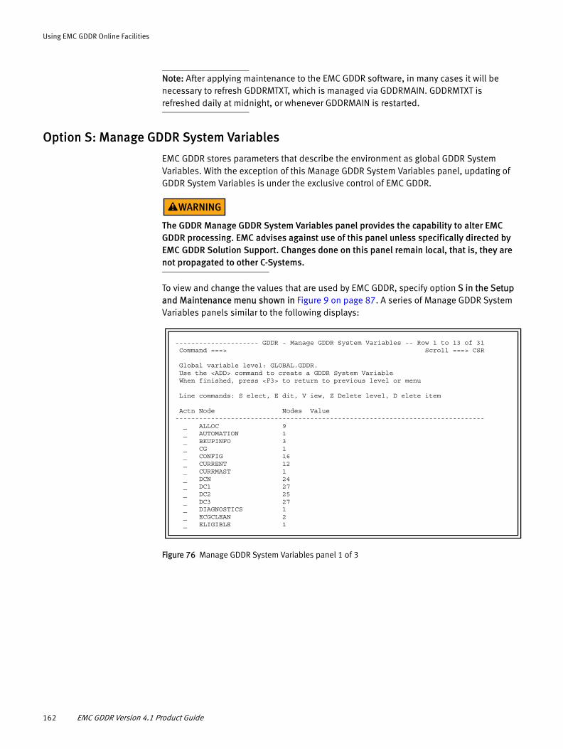
Using EMC GDDR Online Facilities
Note: After applying maintenance to the EMC GDDR software, in many cases it will be necessary to refresh GDDRMTXT, which is managed via GDDRMAIN. GDDRMTXT is refreshed daily at midnight, or whenever GDDRMAIN is restarted.
Option S: Manage GDDR System Variables
EMC GDDR stores parameters that describe the environment as global GDDR System Variables. With the exception of this Manage GDDR System Variables panel, updating of GDDR System Variables is under the exclusive control of EMC GDDR.
The GDDR Manage GDDR System Variables panel provides the capability to alter EMC GDDR processing. EMC advises against use of this panel unless specifically directed by EMC GDDR Solution Support. Changes done on this panel remain local, that is, they are not propagated to other C-Systems.
To view and change the values that are used by EMC GDDR, specify option S in the Setup and Maintenance menu shown in Figure 9 on page 87. A series of Manage GDDR System Variables panels similar to the following displays:
Figure 76 Manage GDDR System Variables panel 1 of 3
--------------------- GDDR - Manage GDDR System Variables -- Row 1 to 13 of 31 Command ===> Scroll ===> CSR Global variable level: GLOBAL.GDDR. Use the <ADD> command to create a GDDR System Variable When finished, press <F3> to return to previous level or menu Line commands: S elect, E dit, V iew, Z Delete level, D elete item Actn Node Nodes Value ------------------------------------------------------------------------------ _ ALLOC 9 _ AUTOMATION 1 _ BKUPINFO 3 _ CG 1 _ CONFIG 16 _ CURRENT 12 _ CURRMAST 1 _ DCN 24 _ DC1 27 _ DC2 25 _ DC3 27 _ DIAGNOSTICS 1 _ ECGCLEAN 2 _ ELIGIBLE 1
162 EMC GDDR Version 4.1 Product Guide

Using EMC GDDR Online Facilities
Figure 77 Manage GDDR System Variables panel 2 of 3
Figure 78 Manage GDDR System Variables panel 3 of 3
View, define, or modify the panel fields as follows:
◆ Global variable level
Specifies the name of the global variable, including the stem name of 'GLOBAL.GDDR'.
◆ Add
Type Add in the Command line at the top of the panel to display the Create GDDR System Variable panel. This panel allows you to create new variables under the direction of EMC GDDR Solution Support.
◆ Node
Global variables may have a variable number of subnodes. The Node field displays information about subnodes, such as the number of subnodes and for the lowest level nodes, their value.
------------------- GDDR - Manage GDDR System Variables -- Row 14 to 26 of 31 Command ===> Scroll ===> CSR Global variable level: GLOBAL.GDDR. Use the <ADD> command to create a GDDR System Variable When finished, press <F3> to return to previous level or menu Line commands: S elect, E dit, V iew, Z Delete level, D elete item Actn Node Nodes Value ------------------------------------------------------------------------------ _ EVENT 3 _ EZSM 1 _ GDDR 1 _ HEARTBEAT 1 _ HMC 7 _ JVAL 24 _ LASTLOAD_DESC 0 _ LASTLOAD_SOURCE 0 hlq.GDDR410.PARMS.WORK(Z00PARMS) on + _ MISSING 1 _ PARMS 92 _ PROTECTION 1 _ TEMPVAR 1 _ TIMEFINDER 1
------------------- GDDR - Manage GDDR System Variables -- Row 27 to 31 of 31 Command ===> Scroll ===> CSR Global variable level: GLOBAL.GDDR. Use the <ADD> command to create a GDDR System Variable When finished, press <F3> to return to previous level or menu Line commands: S elect, E dit, V iew, Z Delete level, D elete item Actn Node Nodes Value ------------------------------------------------------------------------------ _ USERLABEL 5 _ USEROPT 2 _ UTILITY 3 _ WAIT_INTERVAL 13 _ WTOR_WAIT_INTER+ 0 3600 ******************************* Bottom of data ********************************
Option M: Maintenance—GDDR Setup and Maintenance 163

Using EMC GDDR Online Facilities
◆ Actn
For each node listed in the Node field, you can specify the following line commands in the Action field:
• S—Select
If there are subnodes to the specified node, specifying the Select command shows the next level subnode.
• E—Edit
Allows the variable at the existing level to be changed.
• V—View
Displays information about the creation, update, and last access for the global variable.
• Z—Delete level
Deletes of all variables at or under the level shown.
• D—Delete item
Deletes just the variable at the existing level.
Option T: Transfer Master C-System
Selecting the Transfer Master C-System option returns the following panel:
Figure 79 Transfer Master C-System panel
Based on the current EMC GDDR parameters, site DC1 is the current master C-System and is the recommended site for the master C-System based on the parameters. Note that * Here * indicates the current local system.
No action is recommended. Press F3 to return to the Setup and Maintenance panel.
--------------------- GDDR - Transfer Master C-System ------ Row 1 to 2 of 2 Command ===> Press <F3> to return to the Setup and Maintenance panel Select a row to transfer the Master C-System to that site/system. CMD SIte C-System Link MHB Notes --- -------- -------- ---- --- ------------------------------------------ _ DC1 SYS1 0 0 Current and Recommended Master, *Here* _ DC3 SYS3 0 0 ******************************* Bottom of data ********************************
164 EMC GDDR Version 4.1 Product Guide

Using EMC GDDR Online Facilities
Option G: GDDR Config—View GDDR ConfigurationSpecify option G in the Primary Options menu (Figure 7 on page 84) to view your configuration settings.
Note: In the View GDDR Configuration panel, the RG1 and RG2 region names and the DC1 and DC3 site names may reflect user-specified names for the GDDR Complex, Regions, and Site list as defined in the Define GDDR User Labels panel. See “Option L: GDDR User Labels” on page 150 for more details.
The following panel appears:
Figure 80 View GDDR Configuration panel
----------------- GDDR - View GDDR Configuration for CitiPlex -----------------Command ===> GDDR complex name: CitiPlex Regions: RG1-West, RG2-East Sites: DC1-Lond, DC3-Rome Features: SRDF/A, No FBA Devices Region: Site: C-System: RG1 (WestEur) DC1 (London) SYS1 RG2 (EastEur) DC3 (Rome) SYS3 Press <F3> to return to the previous menu
Option G: GDDR Config—View GDDR Configuration 165

Using EMC GDDR Online Facilities
Option C: Checkup—Perform Pre-script CheckupSpecify Option C in the Primary Options menu (Figure 7 on page 84) to invoke the EMC GDDR on-demand Health Check. A panel similar to the following displays the items that are validated.
Figure 81 Perform Health Check panel
The Perform Health Check panel returns the following information:
◆ Active Events
Indicates any exceptions to conditions monitored by the EMC GDDR Event monitor. Events MHB, MIM, MFS, and MXS do not appear in the health check panel.
◆ Degraded Mode
This is a YES|NO field. YES indicates that one or more of the following conditions are met:
• A C-System has a Missing Heartbeat event (MHB). This will be visible in the “Active Events” field.
• GDDRMAIN is not running on a C-System (will be shown as Inactive under GDDRMAIN Status).
• A GDDRMAIN subtask or worker is not running on a C-System (will be shown as Degraded under GDDRMAIN Status).
• The MPARM results are inconsistent.
Note: In certain circumstances, Degraded Mode may indicate NO, but the System Communication Status shows GDDRMAIN Status as Inactive or Degraded for one or more managed systems (PSYS).
◆ MPARM
Displays the result of the most recent GDDMPARM consistency check.
----------------- GDDR - Perform Health Check --------------- Row 1 to 5 of 5 Command ===> Scroll ===> CSR Active Events: None Degraded Mode: YES MPARM: Consistent Command Queue Status Job Count Active Free Max ------- -------- ------ ------ ------ ------ Empty 0 0 0 35 System Communication Status: Home System GDDRMAIN HMC Date and Time of Sel Site Name Type Status Status status check --- ---- -------- ---- -------- -------- ----------------------- _ DC3 SYS3 CSYS Degraded Operating 02/01/11 13:52:01 _ DC1 PRD3 PSYS Inactive Operating 02/01/11 17:09:33 _ DC1 SYS1 CSYS Active Operating 02/01/11 17:10:18 _ DC1 PRD2 PSYS Active Operating 02/01/11 08:52:23 _ DC3 PRD4 PSYS Inactive Operating 02/01/11 17:10:44 ******************************* Bottom of data *********************************
166 EMC GDDR Version 4.1 Product Guide

Using EMC GDDR Online Facilities
◆ Command Queue
Indicates the current command queue status and size. EMC GDDR uses an internal command queue to perform operations.
◆ System Communication Status
• Line Commands
– S (select) queries the system and replaces the initial Status value of 'Unknown' with one of three values: Active, Inactive, or Degraded.
– R (refresh) redrives the Status query. You can get updated status for all systems by entering the command SYSTEMS at the command prompt.
– D (detail) displays the GDDRMAIN System Details panel containing information about the state of GDDRMAIN subtasks, dependent address spaces, and worker tasks. The GDDRMAIN System Details panel is shown in Figure 82 on page 168.
• Home Site
The Site ID of the site where the system normally runs.
• System Name
The System names are the C-Systems and managed systems defined in the GDDMPARM parameters.
• Type
– CSYS indicates a C-System
– PSYS indicates a GDDR-managed production or test system
• GDDRMAIN Status
GDDRMAIN communicates between C-Systems and the GDDR managed systems. This field shows the status of that communication. Initially, all systems except the C-System where you are will show a status of "Unknown". Status values are as follows:
– Active
Indicates that GDDRMAIN is up and fully functional.
– Inactive
Indicates that GDDRMAIN on the system where this is running is unable to communicate with GDDRMAIN on the target system.
– Degraded
Indicates that GDDRMAIN is up on the target system, but not all subtasks or workers are active. The conditions considered when Degraded Status is set are displayed in the System Details panel as shown in Figure 82 on page 168. You can display this panel by typing D (detail) in the Sel field associated with a system.
Option C: Checkup—Perform Pre-script Checkup 167

Using EMC GDDR Online Facilities
Degraded status reflected by one or more inactive subtasks may be a transitory state, not a cause for concern. For example, the parameter Activate process requires that Event and Heartbeat Monitors be stopped. If the Activate option of 'FULL' is selected, then GDDRMAIN will stop Event and Heartbeat Monitors on all C-Systems, causing Degraded status to be reported for each C-System.
• HMC Status
HMC Status indicates the HMC communication status. HMC Status values are as follows:
– Operating
Indicates HMC functions are supported.
– Error
Indicates the HMC communication query failed.
– n/a
Displays for the C-System where you are.
EMC GDDR uses the z/OS Hardware Management Console (HMC) to maintain and view its managed systems, issue operator commands, and to discover HMC objects.
• Date and Time of Status Check
The meaning of the date and time shown vary depending on the value of GDDRMAIN status. If status is "Active" or "Degraded", the date and time reflect the last time that health check queried that system and received a response. If the status is "Unknown" or "Inactive", the date and time specify the last time any communication was received.
Figure 82 shows the GDDRMAIN System Details panel. This panel provides GDDRMAIN status information which may identify conditions that cause a Degraded Mode of 'Yes' on the Perform Health Check panel.
Figure 82 GDDRMAIN System Details panel
The following fields are populated from the Perform Health Check panel.
◆ Site
◆ System
+------------------------------------------------------------------------------+| --------------------- GDDR - GDDRMAIN System Details ---------------------- | | Command ==> || || Site: DC3 || System: SYS3 || Type: CSYS Status Date: 02/01/11 || IP: nnn.nnn.nnn.nnn 13:55:08 || || GDDRMAIN Status: Degraded || CONSOLE: Y COMM: Y MISC: Y MCSOPER: Y WORKMGR: Y GVT: Y EVM: Y HBM: Y || Workers: GDDWCM: 2 GDDWCO: 5 GDDWST: 6 GDDWGV: 1 GDDWXR: 2 || GDDWDV: 0 || HMC Status: n/a |+------------------------------------------------------------------------------+
168 EMC GDDR Version 4.1 Product Guide

Using EMC GDDR Online Facilities
◆ Type
◆ Status Date
◆ GDDRMAIN Status
◆ HMC Status
The IP address field is populated from the GDDRMAIN parameters defined in GDDMPARM.
The next three lines provide the status of GDDRMAIN subtasks and worker tasks. GDDRMAIN subtasks are either shown as active with 'Y' or inactive with 'N'. The workers are represented with the count of active worker tasks. The number of worker tasks is configured during the GDDRMAIN installation procedures as shown in “Allocate the parameter management datasets” on page 64.
EMC GDDR-managed systems will show subtasks GVT, EVM, and HBM with 'N' and workers GDDWGV and GDDWXR with '0' if these subtasks and workers are not applicable to managed systems.
The GDDRMAIN System Details panel shows all subtasks for C-Systems as 'Y', except when a parameter Activate is performed. GDDRMAIN stops EVM and HBM when a parameter Activate function is performed. Further, when the Activate operands 'FULL' and Propagate 'Y' are selected, HBM and EVM will be stopped on all C-Systems. During this time, the Perform Health Check panel and the GDDRMAIN System Details panel show GDDRMAIN Status as Degraded. A GDDRMAIN Status of Degraded also triggers the GDDR Event monitoring mode of Degraded, as shown on the Perform Health Check panel under the Active Events field.
C-Systems must have a minimum of one instance of all worker tasks active. If the worker manager encounters three unexpected worker task failures within a one minute period, the worker manager sets the MAX for that worker to '0', sets the GDDRMAIN Status to 'Degraded' and writes message GDDM150E (Worker worker-name has repeatedly failed, maximum reset to 0).
You must take action to resolve the cause of the failing worker task, and then change the MAX value for the task to the recommended non-zero value. Change the worker task MAX value by issuing F GDDRMAIN, WORKER[,name[,MIN=min|MAX=max]]. “GDDRMAIN console commands” on page 233 provides more information.
Note: You cannot set the worker MAX value to 0; at least one instance of each worker must be available.
Health Check monitoring
The GDDR Event monitor checks for the following storage and system environment events:
Table 12 Monitored events (1 of 2)
Event Description
DLM: Missing DLm Heartbeat One or more DLm ACP systems has failed to respond to a heartbeat request in a specified time window.
ECA: Enginuity Consistency Assist ConGroup has cleared ECA flags.
LNK.DCmVDCn: RDF Link Down The RDF link between the specified sites is unavailable.
Option C: Checkup—Perform Pre-script Checkup 169

Using EMC GDDR Online Facilities
When the GDDR Event Monitor detects any of the events listed in Table 12 and a GDDR Planned script is not running, it issues the following message:
GDDS027E GDDR Error: Event full_event_id detected, value event_value
For example:
GDDS027E GDDR Error: Event GLOBAL.GDDR.DCN.Unplanned.C>> detected, value 1
Message GDDS027E is issued every EVM cycle for each unplanned event which was detected during this or any previous EVM cycle, for each previously set event which has not been cleared. Message GDDS027W indicates a transient cause, based on actions performed during Planned script processing.
GDDR Event monitoring exception notification
Notification of Event monitoring or GDDRMAIN status exceptions can easily be implemented using a number of third-party system management software products which perform event notification tasks.
Messages that are candidates for user event notification or alerts are:
◆ GDDS027E — Cause: The GDDR Event Monitor has set an event.
◆ GDDR650W — Cause: The named director is offline, inoperable, or has no ports.
MHB: Missing Heartbeat One or more C-Systems has failed to issue a heartbeat in a specific time window.
MSC: SRDF/A Multi-Session Consistency The EVM SRDF/A check found MSC inactive or not consistent, or found SRDF/A inactive or an MSC group is in an unexpected status as reported by GDDR818I. The recommended response is to review the status of SRDF/A groups. Activate SRDF/A if necessary, then activate MSC.The Event monitor monitors for successful MSC initialization, which then clears the MSC event. If the above action fails to resolve the issue, check GDDREVM SYSTSPRT, SCF log, and HC log for additional messages.
MSF: GDDRMAIN COMM Link Down Communication to the system is not available.
RDF.DCm.DCn: RDF Directors offline A GDDR-managed RDF group defined by sitepair DCm.DCn has been found to have all directors offline. Look for the following messages:• GDDR650W — Cause: The named director is offline,
inoperable, or has no ports.• GDDR649E — Cause: All directors for the named RDF
group are either inoperable or offline or disconnected, to determine which directors or RDF groups are affected.
RDR: Regional Disaster DC1 outage has occurred.
SRA: SRDF/A Link Down SRDF/A has been disabled.
Table 12 Monitored events (2 of 2)
Event Description
170 EMC GDDR Version 4.1 Product Guide

Using EMC GDDR Online Facilities
◆ GDDR649E — Cause: All directors for the named RDF group are either inoperable, offline, or disconnected.
The EMC z/OS Storage Manager product (EzSM), offers event notification through its Alert Definitions capability.
Do the following to set EzSM to configure an alert on the occurrence of a GDDR event exception:
◆ Establish Notification Directory entries for individuals or groups that are to be notified when an exception occurs. These entries include:
• First and last name
• TSO ID
• Email address
• Short Message Service (SMS) ID
Note: Alerts may be established for a variety of other GDDR message IDs which indicate changes in GDDR operating state. Consult GDDR Solution Support for assistance.
When creating the Alert, the contact information for the individuals or groups who are to be notified must be in the Notification Directory. The Alert Definitions topic in the EMC z/OS Storage Manager Product Guide provides additional details.
Additional pre-script environment checks
Before you initiate any planned swap scenarios, EMC recommends that you make the following manual checks:
◆ Validate that GDDR managed storage matches the RDF device population.
◆ Verify SRDF/A is active and cycling
The initial check is also performed automatically by EMC GDDR.
EMC recommends that you perform these checks manually before you run any EMC GDDR swap scripts to make sure that everything is active. The checks are designed to avoid possible problems later.
The following sections discuss these checks.
Validate that GDDR managed storage matches the RDF device populationSelect the Automated Configuration Check - DASD script from the Planned script section of the Select Script to run panel, as shown in “Option S: Scripts — Run GDDR Scripts” on page 173.
Review the GDDRPCCD script joblog for GDDP400E and GDDP420E error messages. Resolve discrepancies by revising the RDF.DEVICES parameters before proceeding.
Option C: Checkup—Perform Pre-script Checkup 171

Using EMC GDDR Online Facilities
Verify SRDF/A is active and cycling
Note: The EMC GDDR Event Monitor will automatically verify that SRDF/A is running in configurations where this is applicable, and set SRA and MSC events based on its findings. This monitoring is done on a cyclic basis, under control of the "EVM SRDF/A Check Interval" GDDR tuning option as shown in “Option T: Tuning Values” on page 148.
Enter the following command from the EMC GDDR Master C-System:
>SQ SRDFA,uuuu
where:
>
Represents the SRDF/Host Component command character.
uuuu
Represents the gatekeeper UCB address for any controller at the primary DASD site.
IMPORTANT
The >SQ SRDFA, uuuu command displays data about the entire SRDF/A configuration in the Symmetrix® unit; that is, the display will be for all RDF groups found with SRDF/A. Use >SQ SRDFA,LCL or >SQ SRDFA,RMT to display data about the single RDF group.
Expected output
The following example shows the expected output of this operation.
What to look for
To ensure that SRDF/A is active and cycling, the following fields should all be set to Y:
◆ Secondary consistent
◆ MSC active
◆ Global consistency
◆ Star recovery available
The time since last cycle switch should generally be around the number of seconds specified in the Host Component initialization parameter, MSC_CYCLE_TARGET. A large number would indicate that SRDF/A has stopped cycling. Subsequent displays should also show the Capture and Transmit tags incrementing.
What to do if SRDF/A is not active and cycling
Take the following actions if any of the previous checks fail:
◆ Report the problem to your z/OS systems programming support group.
◆ Do not start the swap.
172 EMC GDDR Version 4.1 Product Guide

Using EMC GDDR Online Facilities
Option S: Scripts — Run GDDR ScriptsWhen you specify option S in the Primary Options Menu shown in Figure 7 on page 84, the Select Script to Run panel displays:
DC1 and DC3 represent the current primary DASD site or current secondary DASD site. When these representations are shown in italic type in script titles, this indicates the values are interchangeable. The descriptions assume that DC1 is the Primary DASD site and Primary site at the beginning of the script.
In the Select Script to Run panel, the DC1 and DC3 Site names may reflect user-specified names for the sites as defined in the Define GDDR User Labels panel. See “Option L: GDDR User Labels” on page 150 for more details.
Figure 83 Select Script to Run panel (at DC1)
Figure 84 Select Script to Run panel (following the Abandon Site DC1 script at DC3
------------ GDDR - Select Script to Run on GDDRPLEX --------- Row 1 to 6 of 6 Command ===> Scroll ===> CSR Enter S next to script to run and press <Enter> Current Master: SYS1 Press <F3> to return to previous menu Primary Site: DC1 Press <F1> to view all available commands Primary DASD: DC1 Configuration: 2 SITES, SRDF/A Automation: ON > Sel ----------------------- Scripts ---------------------- ----- Status ------ ============ Scripts for PLANNED Actions =========== _ Automated Configuration Check - DASD......... GDDRPCCD _ Abandon Site DC1 (site swap)................. GDD2P17A ============ Scripts for TEST Actions =========== _ Perform test IPL from BCVs at DC3............ GDD2P01A ============ Scripts for RESUME Actions =========== _ Resume SRDF/A after link loss................ GDDRPM29 *SRA is OFF ============ Scripts for SPECIAL Actions =========== _ Transfer Master C System to DC3.............. GDDRPXMC _ Global Variable Backup....................... GDDRPGVB ******************************* Bottom of data ********************************
------------ GDDR - Select Script to Run on GDDRPLEX --------- Row 1 to 6 of 6 Command ===> Scroll ===> CSR Enter S next to script to run and press <Enter> Current Master: SYS3 Press <F3> to return to previous menu Primary Site: DC1 Press <F1> to view all available commands Primary DASD: DC1 Configuration: 2 SITES, SRDF/A Automation: ON Previous script: GDD2P17A ran on SYS1 Job GDDRP17A (JOB05025) - 01/28/2013 13:15:01 > Sel ----------------------- Scripts ---------------------- ----- Status ------ ============ Scripts for PLANNED Actions =========== _ Automated Configuration Check - DASD......... GDDRPCCD _ Restart production at DC3 after site swap.... GDD2P18A ============ Scripts for TEST Actions =========== _ Perform test IPL from BCVs at DC3............ GDD2P01A ============ Scripts for UNPLANNED Actions =========== _ Recover after loss of DC1 (RDR).............. GDD2U12A *RDR event is OFF ============ Scripts for SPECIAL Actions =========== _ Transfer Master C System to DC1.............. GDDRPXMC _ Global Variable Backup....................... GDDRPGVB ******************************* Bottom of data ********************************
Option S: Scripts — Run GDDR Scripts 173

Using EMC GDDR Online Facilities
The Select Script to Run panel is a dynamic display. It lists EMC GDDR scripts that are eligible to run based on the current state of the configuration, while providing script generation status messages about events which affect script eligibility. The panel also specifies configuration information and scripts that are in progress, if any. Depending on the location of the primary site and primary DASD locations, the panel is customized to display valid choices. Scripts that you cannot use at your current site do not appear.
The eligible scripts are grouped by category reflecting usage:
◆ Planned actions
◆ Test actions
◆ Unplanned actions
◆ Resumption actions
◆ Special actions
S – To request that a script be run or rerun, type S next to the row describing the script you want to run and press Enter.
D – Use the Display Script Details command to return the program name for the script and the name of the script skeleton. Type D next to the row describing the script and press Enter.
The following fields are provided on the Select Script to Run panel:
Configuration
This field indicates the features of your configuration that EMC GDDR takes into account when determining which scripts are eligible to run and hence which are present in the list of scripts displayed on your panel.
Scripts listed
For a header row, the scripts field contains a description of the category of scripts which follow. For a script row, this field contains a description of the script.
Status
This field displays script generation status events and dependencies. Each time you select a script to be submitted from the Select Script to Run panel, the script prerequisites are compared to the state of the environment. In cases when conflicts are identified or event prerequisites have not been satisfied, the messages shown in Table 13 are returned to the Status field.
Note: Refer to Table 12, “Monitored events,” on page 169 for all event descriptions and related actions.
Table 13 Script generation status messages (1 of 3)
Message Description
Only after P17A Valid only after prerequisite GDD2P17A is complete
Only Sec.DASD site Valid only at the secondary DASD site
Only Pri.DASD site Valid only at the primary DASD site
174 EMC GDDR Version 4.1 Product Guide

Using EMC GDDR Online Facilities
Only on Pri. MSC Valid only at the primary MSC server site
LDR is OFF Requires the LDR event
Invalid for state Not valid for current state
SRA is ON Not allowed when there is an SRA event
RDF is ON Not allowed when there is an RDF event
MSC is ON Not allowed when there is an MSC event
STR event is on Not allowed when there is an STR event
CFG event is on Not allowed when there is a CFG event
Requires LDR @ DC1 Requires an LDR event at DC1
Data precedence Not allowed because the site with the most recent data is not appropriate
Needs prot. pref. Requires user-specified protection preference
DLM is ON Not allowed when there is a DLM event
SRA is OFF Only allowed if there is an SRA event
LDR is on for DC1 Not allowed if there is an LDR event for DC1
Sec.DASD site only Valid only at the secondary DASD site
Star-HA state inv. The SRDF/Star with HA configuration is in an invalid state
CGT is ON Not allowed when there is a CGT event
Only on Sec. MSC Valid only at the secondary MSC server site
Only at DC3 Valid only at DC3
Not at $DC3 Not valid at DC3
MHB ON @ Sec. site Missing Heartbeat Event is on at the secondary site
Unpl. scr. running An unplanned script is running
CG Verify running The GDDR Event Monitor has started a Congroup Verify process
Degraded mode ON GDDRMAIN Degraded mode is set. Refer to the System Details panel in Option C: Checkup Perform Pre-script checkup for assistance.
MSF is ON Not valid if there is an MSF event
Plan. scr. running A planned script is running
Passed site prim. Not allowed for the primary DASD site
Needs RDF+CGT ON Requires both an RDF and a CGT event
ECA is ON Not allowed when there is an ECA event
CGD is ON Not allowed when there is a CGD event
LDR is OFF Requires an LDR event
LDR is OFF @ csds Requires an LDR event for the secondary DASD site
RDR event is OFF Requires an RDR event
Table 13 Script generation status messages (2 of 3)
Option S: Scripts — Run GDDR Scripts 175

Using EMC GDDR Online Facilities
Option T: Timing—View GDDR Script StatisticsWhen you specify option T in the Primary Options Menu shown in Figure 7 on page 84, the panel that appears depends on the current status of the selected script.
If a script is currently running, a panel similar to the following appears:
Figure 85 Script Selection for Status panel
Type S next to a script to select it for viewing:
◆ If the selected script is currently running, a panel similar to the following appears:
DC3 is down Not allowed when DC3 is down
Requires LDR event Requires the LDR event
MSC is OFF Requires an MSC event
CGT is OFF Requires a CGT event
Last unpl.scr. NOK Can only run after a specific previous script
Table 13 Script generation status messages (3 of 3)
-------------- Script Selection for Status Vi Row 1 to 4 of 4 Option ===> Enter S next to a script to select it for viewing Press <F3> to return to Primary Option Menu Last planned: Resume SRDF/A after link loss Last unplanned: (none) Script - ------------------------------------------------------------ _ GDD2P17A - Abandon Site DC1 (site swap) _ GDD2P18A - Restart production at DC3 after site swap S GDDRPA29 - Resume SRDF/A after link loss.......................Last planned ******************************* Bottom of data ********************************
------------------- View Script Step Results Row 1 to 7 of 37 Option ===> Script: GDDRPA29: Resume SRDF/A after link loss Initial: 11/20/2007 at 09:06:29.96 Iterations: 2 Maximum return code: 0 Last run started 11/20/2007 at 10:09:27.44 and still running Function Subfunction RC Step start/end Cnt -------- ------------------------- -- ---------------------- --- GDDRGF0F Verify Planned script env 0 at at GDDRGF0L broadcast variables 0 at at GDDRGF0L Confirm SRDF/A Resumption 0 at at GDDRGF0Q Run ME-MSC_Cleanup 0 at at GDDRKF21 Manage BCVs - SPLIT 0 at at GDDRGF3J Make R2s R/O 0 at at GDDRKF0G Disable Congroups 0 at
176 EMC GDDR Version 4.1 Product Guide
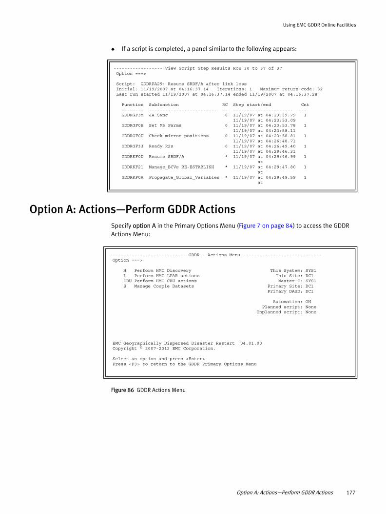
Using EMC GDDR Online Facilities
◆ If a script is completed, a panel similar to the following appears:
Option A: Actions—Perform GDDR ActionsSpecify option A in the Primary Options Menu (Figure 7 on page 84) to access the GDDR Actions Menu:
Figure 86 GDDR Actions Menu
------------------ View Script Step Results Row 30 to 37 of 37 Option ===> Script: GDDRPA29: Resume SRDF/A after link loss Initial: 11/19/2007 at 04:16:37.14 Iterations: 1 Maximum return code: 32 Last run started 11/19/2007 at 04:16:37.14 ended 11/19/2007 at 04:16:37.28 Function Subfunction RC Step start/end Cnt -------- ------------------------- -- ---------------------- --- GDDRGF3M JA Sync 0 11/19/07 at 04:23:39.79 1 11/19/07 at 04:23:53.09 GDDRGF0H Set M6 Parms 0 11/19/07 at 04:23:53.78 1 11/19/07 at 04:23:58.11 GDDRGF0U Check mirror positions 0 11/19/07 at 04:23:58.81 1 11/19/07 at 04:26:48.71 GDDRGF3J Ready R2s 0 11/19/07 at 04:26:49.40 1 11/19/07 at 04:29:46.31 GDDRKF0D Resume SRDF/A * 11/19/07 at 04:29:46.99 1 at GDDRKF21 Manage_BCVs RE-ESTABLISH * 11/19/07 at 04:29:47.80 1 at GDDRKF0A Propagate_Global_Variables * 11/19/07 at 04:29:49.59 1 at
---------------------------- GDDR - Actions Menu ----------------------------- Option ===> H Perform HMC Discovery This System: SYS1 L Perform HMC LPAR actions This Site: DC1 CBU Perform HMC CBU actions Master-C: SYS1 S Manage Couple Datasets Primary Site: DC1 Primary DASD: DC1 Automation: ON Planned script: None Unplanned script: None EMC Geographically Dispersed Disaster Restart 04.01.00 Copyright © 2007-2012 EMC Corporation. Select an option and press <Enter> Press <F3> to return to the GDDR Primary Options Menu
Option A: Actions—Perform GDDR Actions 177

Using EMC GDDR Online Facilities
Option H: Perform HMC Discovery
To discover HMC objects accessible to EMC GDDR, specify option H from the GDDR Actions menu. A ‘please wait’ pop-up dialog such as the following appears and HMC object discovery is activated:
Figure 87 HMC object discovery panel
When the discovery operation completes, an HMC Discovery Results panel containing a scrollable display such as the following appears:
Figure 88 HMC Discovery Results panel
When you are finished examining the results of the discovery operation, press F3 to return to the GDDR Actions menu.
----------------------------- GDDR - Actions Menu ----------------------------- Option ===> H Perform HMC Discovery This System: SYS1 L Perform HMC LPAR actions This Site: DC1 CBU Perform HMC CBU actions Master-C: SYS1 S Manage Couple Datasets Primary Site: DC1 Primary DASD: DC1 +------- Discovering HMC Objects ---------+ | | omation: ON | Discovering HMC objects at site DC1 | script: None | | script: None | *** PLEASE WAIT *** | | | +-----------------------------------------+ EMC Geographically Dispersed Disaster Restart 04.01.00 Copyright © 2007-2012 EMC Corporation. All rights reserved. Select an option and press <Enter> Press <F3> to return to the GDDR Primary Options Menu
------------------------ GDDR - HMC Discovery Results ---- Row 1 to 20 of 104 Command ===> Enter <F3> to return to the previous menu ------------------------------------------------------------------------------ GDDR STARTING DISCOVER HMC OBJECTS GDDR HMC COMMUNICATION WITH DC1 USING BCPII GDDR MANAGING THE FOLLOWING LPAR-SYSTEM PAIRS FOR SITE DC1 > IBM390PS.Q3,ZOSEQ311:Q311 > IBM390PS.C,ZOSEC11:T101 > > GDDR DISCOVERY INFORMATION FOR CPC : IBM390PS.Q3 > > GDDR CURRENT ACTIVATION PROFILE : DEFAULT > GDDR LAST USED ACTIVATION PROFILE : DEFAULT > GDDR CPU MODEL : E10 > GDDR CPU TYPE : 2098 > GDDR CPU SERIAL NUMBER : 0000200F3FA4 > GDDR # GENERAL PURPOSE PROCESSORS : 00000005 > GDDR # SERVICE ASSIST PROCESSORS : 00000002 > GDDR # INTEGRATED FACILITY FOR APPLS : 00000000 > GDDR # INTEGRATED FACILITY FOR LINUX : 00000000 > GDDR # INTERNAL COUPLING FACILITY : 00000000 > GDDR # INTEGRATED INFORMATION PROCESSORS : 00000000 >
178 EMC GDDR Version 4.1 Product Guide
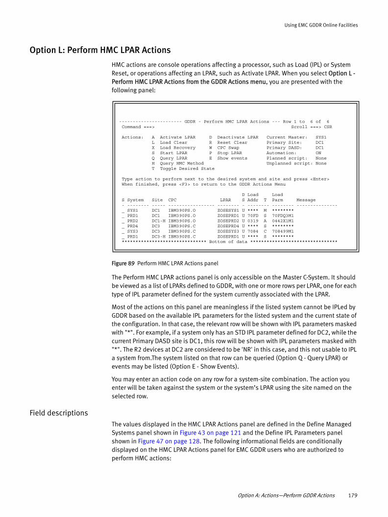
Using EMC GDDR Online Facilities
Option L: Perform HMC LPAR Actions
HMC actions are console operations affecting a processor, such as Load (IPL) or System Reset, or operations affecting an LPAR, such as Activate LPAR. When you select Option L - Perform HMC LPAR Actions from the GDDR Actions menu, you are presented with the following panel:
Figure 89 Perform HMC LPAR Actions panel
The Perform HMC LPAR actions panel is only accessible on the Master C-System. It should be viewed as a list of LPARs defined to GDDR, with one or more rows per LPAR, one for each type of IPL parameter defined for the system currently associated with the LPAR.
Most of the actions on this panel are meaningless if the listed system cannot be IPLed by GDDR based on the available IPL parameters for the listed system and the current state of the configuration. In that case, the relevant row will be shown with IPL parameters masked with "*". For example, if a system only has an STD IPL parameter defined for DC2, while the current Primary DASD site is DC1, this row will be shown with IPL parameters masked with "*". The R2 devices at DC2 are considered to be 'NR' in this case, and this not usable to IPL a system from.The system listed on that row can be queried (Option Q - Query LPAR) or events may be listed (Option E - Show Events).
You may enter an action code on any row for a system-site combination. The action you enter will be taken against the system or the system’s LPAR using the site named on the selected row.
Field descriptionsThe values displayed in the HMC LPAR Actions panel are defined in the Define Managed Systems panel shown in Figure 43 on page 121 and the Define IPL Parameters panel shown in Figure 47 on page 128. The following informational fields are conditionally displayed on the HMC LPAR Actions panel for EMC GDDR users who are authorized to perform HMC actions:
----------------------- GDDR - Perform HMC LPAR Actions --- Row 1 to 6 of 6 Command ===> Scroll ===> CSR Actions: A Activate LPAR D Deactivate LPAR Current Master: SYS1 L Load Clear R Reset Clear Primary Site: DC1 X Load Recovery W CPC Swap Primary DASD: DC1 S Start LPAR P Stop LPAR Automation: ON Q Query LPAR E Show events Planned script: None H Query HMC Method Unplanned script: None T Toggle Desired State Type action to perform next to the desired system and site and press <Enter> When finished, press <F3> to return to the GDDR Actions Menu D Load Load S System Site CPC LPAR S Addr T Parm Message - -------- ----- ----------------- -------- - -------- -------- --------------- _ SYS1 DC1 IBM390PS.O ZOSESYS1 U **** M ******** _ PRD1 DC1 IBM390PS.O ZOSEPRD1 U 70FD S 70FDQ3M1 _ PRD2 DC1-H IBM390PS.O ZOSEPRD2 U 0319 A 0442X1M1 _ PRD4 DC3 IBM390PS.C ZOSEPRD4 U **** S ******** _ SYS3 DC3 IBM390PS.C ZOSESYS3 U 7084 C 708499M1 _ PRD1 DC3-H IBM390PS.C ZOSEPRD1 U **** S ******** ******************************* Bottom of data ********************************
Option A: Actions—Perform GDDR Actions 179

Using EMC GDDR Online Facilities
Sel
Specify the action code for the action you want to perform for the system-site combination appearing on the row.
System
Indicates the name of the system associated with the LPAR shown on the table row.
Site
Identifies the site location of the LPAR shown on the row. This value displays as DCn-H for LPAR_RECOVERY protected systems if they are at their 'Home' location. This value displays as DCn-A for LPAR_RECOVERY protected systems if they are at their 'Away' location.
CPC
Central Processor Complex. This is the name of the central processor where the LPAR is defined.
LPAR
Logical Partition. The name of the LPAR that this system runs in at the specified site.
DS
Desired State. The state of a system, type U (up) or D (down). This allows you to inform EMC GDDR that the indicated system is intended to be down and that no action should be taken to bring it back up.
Load address
Contains the MVS device address of the load device that will be used if you specify an action which performs a Load as part of its operation (for example, Load-Clear). The load address values are masked with asterisks for the Master C-System, to prevent accidental IPL and for managed systems STP IPL parameters that are not currently usable to perform a LOAD action against the LPAR listed on the row. A STD IPL parameter is considered usable if it specifies a LOAD address on the primary DASD site, and the LPAR shown on the row is supposed to have channel connectivity to the primary DASD site.
T
Specifies the type of IPL parameters.
S indicates standard (normal) IPL parameters
OS indicates HMC-only system STD IPL parameter
A indicates alternate IPL parameters
OA indicates HMC-only system alternate IPL parameter
B indicates BCV IPL parameters
C indicates IPL parameters for a C-system
M indicates Master C-System
Load parms
Contains the parameter used for the Load if you specify an action which performs a Load as part of its operation (for example, Load-Clear). The load parameter values are masked with asterisks if the Load address is masked with asterisks.
180 EMC GDDR Version 4.1 Product Guide

Using EMC GDDR Online Facilities
Message
Messages are active events for the listed system. Table 12, “Monitored events,” on page 169 provides a description of all events.
Actions you can requestTo request an HMC action, enter the action code on the command line and press Enter.
A - Activate LPAR
To activate the LPAR of the selected system, type A next to the selected system and press Enter. A confirmation pop-up will be displayed. Confirm the request by entering Y and pressing Enter, or cancel the request by pressing F3.
D- Deactivate LPAR
To deactivate the LPAR the selected system runs in, type D next to the selected system and press Enter. A confirmation pop-up will be displayed. Confirm the request by typing Y and pressing Enter, or cancel the request by pressing F3.
L - Load Clear
To clear and load a selected system using the displayed load address and load parameters, type L next to the selected system and press Enter after ensuring the value of the Desired State field (DS) is consistent with the Load action. A confirmation pop-up will be displayed. Confirm the request by typing Y and pressing Enter, or cancel the request by pressing F3.
The following rules apply to IPLs using STD GDDR-managed volumes:
◆ By default, use the site selected for the IPL action.
◆ For test-IPL scripts, always use the selected site.
For other scripts and IPL actions, for C-Systems, use the home site of the C-System, unless the system has LPAR Recovery protection and is in its 'Away' location.
R - Reset Clear
To reset and clear a selected system, type R next to the selected system and press Enter after ensuring the value of the Desired State field (DS) is consistent with the Reset action. A confirmation pop-up will be displayed. Confirm the request by typing Y and pressing Enter, or cancel the request by pressing F3.
X - Load Recovery
To IPL at the system's alternate location, type X next to the selected system and press Enter. If this option is available, the Site value will display a fourth character after DCx; either H or A, meaning the system is currently running at DCx in its home (H) location or its alternate (A) location.
The following rules apply to IPLs using STD GDDR-managed volumes:
◆ By default use the site selected for the IPL action.
◆ For test IPL scripts always use the selected site.
For other scripts and IPL actions, for C-Systems, use the home site of the C-System, unless the system has LPAR Recovery protection and is in its 'Away' location.
Option A: Actions—Perform GDDR Actions 181

Using EMC GDDR Online Facilities
W- CPC Swap
To perform a planned CPC swap, type W next to the selected system and press Enter.
S - Start LPAR
To start a selected system, type S next to the selected system and press Enter. A confirmation pop-up will be displayed. Confirm the request by typing Y and pressing Enter, or cancel the request by pressing F3.
P - Stop LPAR
To stop a selected system, type P next to the selected system and press Enter. A confirmation pop-up will be displayed. Confirm the request by typing Y and pressing Enter, or cancel the request by pressing F3.
Q - Query LPAR
To query the LPAR of the selected system, type Q next to the selected system and press Enter. A confirmation pop-up will be displayed. Confirm the request by typing Y and pressing Enter, or cancel the request by pressing F3.
E - Show Events
To show any relevant active events for the system in the Message field, type E next to the selected system and press Enter. System related events are IPL, (planned IPL), MXS, (unplanned MXS), and MHB, (unplanned MHB). Table 12, “Monitored events,” on page 169 provides additional information about these events.
T - Toggle desired state (U to D or D to U)
To toggle the state of a system, type U (up) or D (down). The default value is U. You must set this parameter when doing a Load or Reset (or you can manually set it).
Perform HMC LPAR Actions confirmation panels This section describes the confirmation panels which display following various HMC actions.
Confirm Reset
When a Reset action is requested, the following panel displays:
Figure 90 Confirm Reset of System panel
Reply Y or N to either continue or discontinue the Reset action.
+------------ Confirm Reset of System PRD1 -------------+| Command ===> || || Please confirm Reset request of System PRD1 || || System: PRD1 Load address: 70FC || CPC: IBM390PS.P LPAR: ZOSEPRD1 || || Proceed? ===> N Reply Y or N || || |+-------------------------------------------------------|
182 EMC GDDR Version 4.1 Product Guide
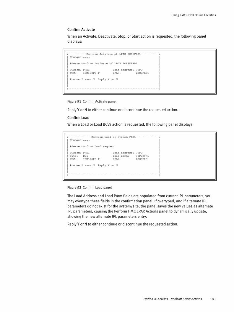
Using EMC GDDR Online Facilities
Confirm Activate
When an Activate, Deactivate, Stop, or Start action is requested, the following panel displays:
Figure 91 Confirm Activate panel
Reply Y or N to either continue or discontinue the requested action.
Confirm Load
When a Load or Load BCVs action is requested, the following panel displays:
Figure 92 Confirm Load panel
The Load Address and Load Parm fields are populated from current IPL parameters, you may overtype these fields in the confirmation panel. If overtyped, and if alternate IPL parameters do not exist for the system/site, the panel saves the new values as alternate IPL parameters, causing the Perform HMC LPAR Actions panel to dynamically update, showing the new alternate IPL parameters entry.
Reply Y or N to either continue or discontinue the requested action.
+---------- Confirm Activate of LPAR ZOSEPRD1 ----------+| Command ===> || || Please confirm Activate of LPAR ZOSSEPRD1 || || System: PRD1 Load address: 70FC || CPC: IBM390PS.P LPAR: ZOSEPRD1 || || Proceed? ===> N Reply Y or N || || |+-------------------------------------------------------|
+------------- Confirm Load of System PRD1 -------------+| Command ===> || || Please confirm Load request || || System: PRD1 Load address: 70FC || Site: DC1 Load parm: 70FC99M1 || CPC: IBM390PS.P LPAR: ZOSEPRD1 || || Proceed? ===> N Reply Y or N || || |+-------------------------------------------------------|
Option A: Actions—Perform GDDR Actions 183

Using EMC GDDR Online Facilities
Confirm IPL Recovery
When in LPAR Recovery mode, and the IPL Recovery action is requested, the following panel displays:
Figure 93 Confirm IPL Recovery of System panel
The Load Address and Load Parm fields are populated from current IPL parameters, you may overtype these fields in the confirmation panel. If overtyped, and if alternate IPL parameters do not exist for the system/site, the panel saves the new values as alternate IPL parameters, causing the Perform HMC LPAR Actions panel to dynamically update, showing the new alternate IPL parameters entry.
Reply Y or N to either continue or discontinue the requested action.
Confirm Toggle Desired State
When the Toggle Desired State action is requested, the following panel displays:
Figure 94 Confirm Toggle Desired State of System panel
Reply Y or N to either continue or discontinue the requested action.
+-------- Confirm IPL Recovery of System PRD1 ----------+| Command ===> || || Please confirm IPL Recovery of System PRD1 || || System: PRD1 Load address: 70FC || Site: DC1 Load parm: 70FC99M1 || CPC: IBM390PS.P LPAR: ZOSEPRD1 || New Site: DC3 || New CPC:IBM390PS.C New LPAR: ZOSEPRD2 || || Proceed? ===> N Reply Y or N || || |+-------------------------------------------------------|
+---- Confirm Toggle Desired State of System PRD1 ------+| Command ===> || || Please confirm Toggle Desired State of System PRD1 || || System: PRD1 New Desired State: D || || Proceed? ===> N Reply Y or N || || |+-------------------------------------------------------|
184 EMC GDDR Version 4.1 Product Guide
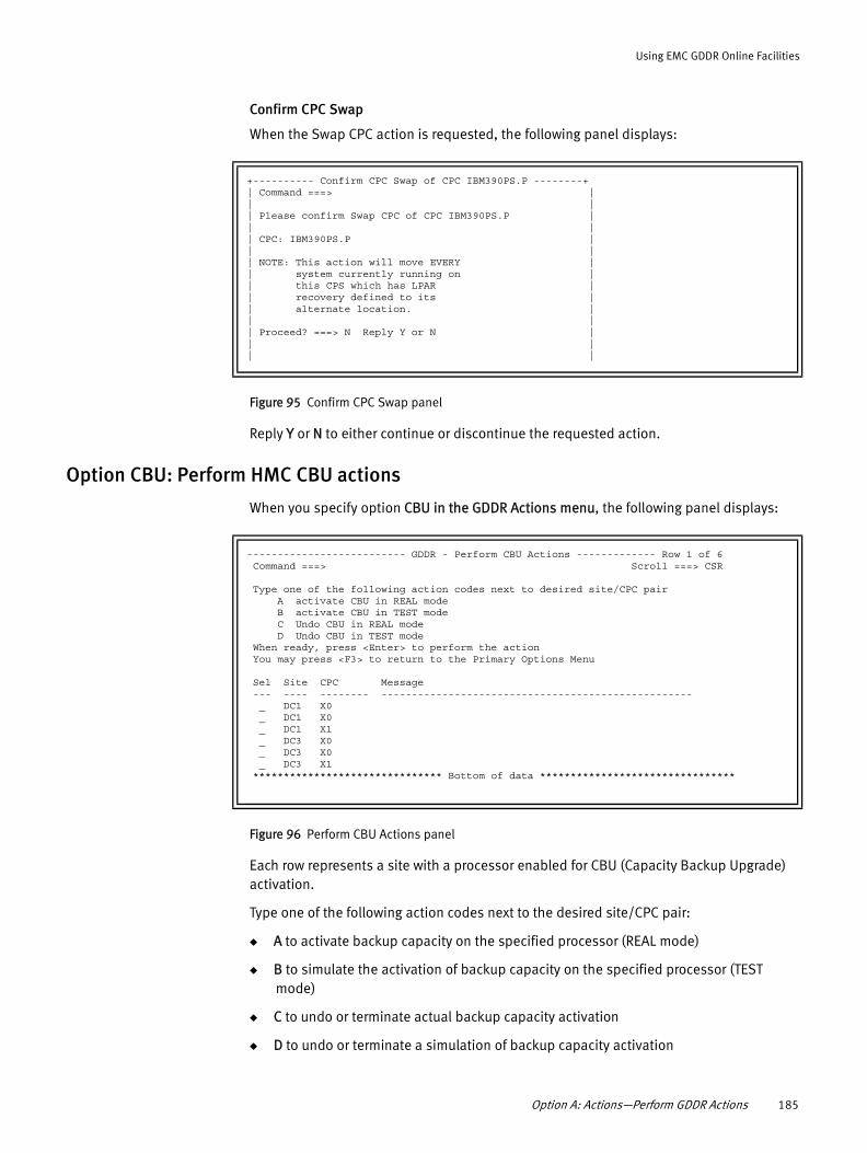
Using EMC GDDR Online Facilities
Confirm CPC Swap
When the Swap CPC action is requested, the following panel displays:
Figure 95 Confirm CPC Swap panel
Reply Y or N to either continue or discontinue the requested action.
Option CBU: Perform HMC CBU actions
When you specify option CBU in the GDDR Actions menu, the following panel displays:
Figure 96 Perform CBU Actions panel
Each row represents a site with a processor enabled for CBU (Capacity Backup Upgrade) activation.
Type one of the following action codes next to the desired site/CPC pair:
◆ A to activate backup capacity on the specified processor (REAL mode)
◆ B to simulate the activation of backup capacity on the specified processor (TEST mode)
◆ C to undo or terminate actual backup capacity activation
◆ D to undo or terminate a simulation of backup capacity activation
+---------- Confirm CPC Swap of CPC IBM390PS.P --------+| Command ===> || || Please confirm Swap CPC of CPC IBM390PS.P || || CPC: IBM390PS.P || || NOTE: This action will move EVERY || system currently running on || this CPS which has LPAR || recovery defined to its || alternate location. || || Proceed? ===> N Reply Y or N || || |
-------------------------- GDDR - Perform CBU Actions ------------- Row 1 of 6 Command ===> Scroll ===> CSR Type one of the following action codes next to desired site/CPC pair A activate CBU in REAL mode B activate CBU in TEST mode C Undo CBU in REAL mode D Undo CBU in TEST mode When ready, press <Enter> to perform the action You may press <F3> to return to the Primary Options Menu Sel Site CPC Message --- ---- -------- --------------------------------------------------- _ DC1 X0 _ DC1 X0 _ DC1 X1 _ DC3 X0 _ DC3 X0 _ DC3 X1 ******************************* Bottom of data ********************************
Option A: Actions—Perform GDDR Actions 185

Using EMC GDDR Online Facilities
Option S: Manage Couple Datasets
When you specify option S in the GDDR Actions menu, the following panel displays:
Figure 97 Manage Couple Datasets panel
In environments with geographically dispersed sysplexes supported by cross-site host-DASD channels, this function can be used to drive the process of checking the couple dataset configurations on all systems. Currently used couple datasets are compared against those specified in the panel shown in Figure 52, “Define Managed Couple Datasets panel 2 of 2,” on page 134. If discrepancies are found, SETXCF commands are issued to bring couple dataset usage in line with EMC GDDR parameter specifications.
Note: Site Swap scripts also include steps to align the couple datasets with managed couple dataset parameters. The Define Manage Couple Datasets panel provides the capability to adjust couple datasets when it is not suitable to run a Site Swap script.
Option E: EzSM - Run EMC z/OS Storage ManagerWhen EzSM is optionally installed on an EMC GDDR C-System, the Symmetrix Device Management functions can be used to maintain your Symmetrix environment. When EzSM is used for this purpose, ensure that disruption of SRDF/A protection and impact to synchronization of Symmetrix groups with GDDR storage parameters is minimized by utilizing the GDDR maintenance procedures available in Chapter 7, “Performing Maintenance Procedures.”
------------------------ GDDR - Manage Couple Datasets ------------------------ Command ===> Specify the site for which couple datasets are to be configured. Site ===> _ Use 1 for site DC1, 2 for site DC2 Specify the type of script for which the couple datasets are intended. Script type ===> _ Use P for planned scripts, U for unplanned scripts Enter or change the job statement: //JABCDE1I JOB (0),'PARMVAL',MSGLEVEL=(1,1),CLASS=A,MSGCLASS=X, // NOTIFY=&SYSUID /*JOBPARM LINES=999999 // Press <Enter> when ready. Press <F3> to return without submitting job.
186 EMC GDDR Version 4.1 Product Guide

Using EMC GDDR Online Facilities
Specify option E in the Primary Options Menu (Figure 7 on page 84) to access the EMC z/OS Storage Manager Product Home menu:
Figure 98 EMC z/OS Storage Manager Product Home menu
Refer to the EMC z/OS Storage Manager Product Guide for details on operating EzSM.
Utilities ------------------------------------------------------------------------------- (SYS2-EC0RLGON) EMC z/OS Storage Manager Product Home Select One Item Command ===> Scroll ===> CSR =============================================================================== Select a function category o 1 Symmetrix Device Management o 2 DLm Management o 3 Logical Devices o 4 Data Sets o 5 Current Alert Messages o 6 z/OS Commands o 7 HSM o 8 SMS Information o 25 Framework Administration o 26 Batch API JCL Generator
Option E: EzSM - Run EMC z/OS Storage Manager 187

Using EMC GDDR Online Facilities
188 EMC GDDR Version 4.1 Product Guide

CHAPTER 5Performing Script Operations
This chapter describes the scripts that you can run from the EMC GDDR Operator Interface.
◆ Running scripts ..................................................................................................... 190◆ Planned script operations ..................................................................................... 196◆ Test operations ..................................................................................................... 197◆ Unplanned script operations................................................................................. 198◆ Resumption operations......................................................................................... 199◆ Special operations ................................................................................................ 200
Performing Script Operations 189

Performing Script Operations
Running scriptsEMC GDDR allows you to run the following types of scripts:
◆ Planned actions
◆ Test actions
◆ Unplanned actions
◆ Resumption actions
Take the following steps to use any of these scripts:
1. Navigate to the Select Script to Run panel as shown in “Option S: Scripts — Run GDDR Scripts” on page 173.
2. Select the script you want by typing S next to the script and pressing Enter.
Note: If another script is currently in progress, a message similar to the following appears on the Select Script to Run panel:
Script GDDRPA29 is in progress. Only the script in progress may be submitted at this time.
3. If no script is in progress, the Specify Parameters for Initial Script Run panel appears:
Figure 99 Specify Parameters for Initial Script Run panel
4. You can then confirm or clear any of the call overrides that apply to this script by entering Y in “Specify call override changes for this script?”
--------------- GDDR - Specify Parameters For Initial Script Run --------------- Command ===> Selected script: Swap production from DC3 to DC1 Enter or change the job statement below: //* //* //* //*
Specify call override changes for this script? ===> N Enter Y or N Press <Enter> when ready to submit script job Press <F3> to return to menu without submitting job
190 EMC GDDR Version 4.1 Product Guide

Performing Script Operations
The Specify Call Overrides panels appear:
Figure 100 Specify Call Overrides panel (screen 1 of 2)
Figure 101 Specify Call Overrides panel (screen 2 of 2)
The Specify Call Overrides panel provides help information (accessed by pressing PF1) that describes the function of each program. Use PF3 to return to the Specify Call Overrides panel.
Note: All call overrides do not apply to all scripts. For any script you run, you normally see a subset of the possible call overrides.
You can overtype the default "Y" or "N" call override values for this script. (Table 14 on page 193 lists the possible call overrides and their meanings.)
------------ GDDR - Specify Call Overrides for Script ------ Row 1 to 11 of 18 Command ===> Script: Restart production at DC2 after site swap Current Master: SYS4 For each row, you may change the call indicator: Primary Site: DC2 Enter Y to call the function Primary DASD: DC2 Enter N to not call the function Automation: ON When ready, press <F3> to continue the script submit process Enter CANCEL and press <Enter> to terminate the script submit process Call? Program Function ----- -------- ------------------------------------------------- N GDDRXDRV Manage Distributed Workload Y GDDRRDF0 Call DYNAPI Interface Y GDDRRDF0 DYNAPI - SRDF/S Commands Y GDDRRDF0 DYNAPI - DeletePair and Half-DeletePair Commands Y GDDRRDF0 DYNAPI - CreatePair and ResumePair Commands Y GDDRRDF0 DYNAPI - SRDF/A Commands Y GDDRRDF0 DYNAPI - Swap and Half-Swap Commands N GDDRGF08 Use ConGroup Shutdown/Startup instead of Refresh N GDDRKF0C Trigger Production System Shutdown N GDDRKF0I Trigger Production System Startup N GDDRKF21 (Scan Mode) - Manage_BCVs
------------ GDDR - Specify Call Overrides for Script ----- Row 12 to 18 of 18 Command ===> Script: Restart production at DC2 after site swap Current Master: SYS4 For each row, you may change the call indicator: Primary Site: DC2 Enter Y to call the function Primary DASD: DC2 Enter N to not call the function Automation: ON When ready, press <F3> to continue the script submit process Enter CANCEL and press <Enter> to terminate the script submit process Call? Program Function ----- -------- ------------------------------------------------- N GDDRTNG1 GDDRTNG1 Y GDDRKF0H Transfer Master Function Ownership N GDDRKF21 (DC1) - Manage_BCVs N GDDRKF21 (DC2) - Manage_BCVs Y GDDRKF21 (DC3) - Manage_BCVs N GDDRCL00 Perform SDDF Session Cleanup N GDDRRDF0 Manage External Devices ******************************* Bottom of data ********************************
Running scripts 191

Performing Script Operations
Note: You can specify call overrides only once for each execution of a script. If a script terminates before completion, you can rerun the script (as discussed in “Rerunning a script” on page 195), but any changes you make to the call overrides will be ignored. However, when you execute the same script again after it successfully completes, you can specify call overrides for it.
5. When you are finished, press F3 to return to the Specify Parameters for Initial Script Run panel. Then press Enter to continue.
Result: A pop-up similar to the following appears and you are prompted twice to confirm job submission.
Figure 102 Confirm Job Submission panel
6. At each prompt, reply Yes to confirm or No to terminate job submission.
Result: After EMC GDDR receives both confirmations, it submits the job to start the selected planned script. Upon starting, you are prompted (through WTOR) to confirm that you want to run the script.
7. Reply Yes to allow the script to continue or No to terminate the script.
+----------- Please Confirm Job Submission -----------+| Command ===> || || Abandon Site DC1 (site swap)........................|| || Please confirm submit of this script || || Submit script? ===> N Reply Y or N || |+-----------------------------------------------------+
192 EMC GDDR Version 4.1 Product Guide

Performing Script Operations
Call overrides
Table 14 lists the call overrides that you may see when running a script. All call overrides do not apply to all scripts. For any script you run, you normally see a subset of the possible call overrides.
Table 14 EMC GDDR call overrides (1 of 2)
Program Function
GDDRRDF0 Call_DYNAPI_Interface Call Override byte 2Specify Y to: • Perform SRDF device action commands using the GDDR command queue,
enabling parallel command execution limited to the number of Symmetrix systems involved.
• Perform CreatePair, ResumePair, DeletePair, Half-DeletePair, Swap, Half-Swap, R22SWTCH, MovePair, Half-MovePair, and composite (CAS-xx) commands in parallel at the Symmetrix system level.
Call Overrides 3-7 further control GDDR command queue usage by command type.Specify N to suppress all GDDR command queue usage. Commands will be issued one at a time. Call Overrides 3-7 are ignored.
GDDRRDF0 DYNAPI - DeletePair and Half-DeletePair commandsCall override byte 4Specify Y to perform DeletePair and Half-DeletePair commands using the GDDR command queue. They will be executed in parallel at the Symmetrix unit level.Specify N to suppress GDDR command queue usage for all DeletePair and Half-DeletePair commands. They will be executed one command at a time.
GDDRRDF0 DYNAPI - CreatePair and ResumePair commandsCall Override byte 5Specify Y to perform CreatePair and ResumePair commands using the GDDR Command queue. They will be executed in parallel at the Symmetrix unit level.Specify N to suppress GDDR command queue usage for all CreatePair and ResumePair commands. They will be executed one command at a time.
GDDRRDF0 DYNAPI - SRDF/A commandsCall override byte 6Specify Y to perform SRDF device actions against SRDF/A devices using the GDDR command queue.Specify N to suppress usage of the GDDR command queue for SRDF/A devices.In both cases, call overrides 4 and 7 further control GDDR command queue usage.
GDDRKF0C TRIGGER_PRODUCTION_SYSTEM_SHUTDOWNCalls user exit GDDRXDRV to synchronously stop all production system application workloads.
GDDRKF0I TRIGGER_PRODUCTION_SYSTEM_STARTUPCalls user exit GDDRXDRV to asynchronously start all production system application workloads.
GDDRKF21 (Scan Mode) - Manage_BCVsPerform BCV actions in simulation mode.
GDDRTNG1 GDDRTNG1Generates an OPS/MVS alert and call GDDRXDRV exit with message.
GDDRKF0H TRANSFER_MASTER_FUNCTION_OWNERSHIPAdd a step to Site Swap scripts to transfer the Master-C role to the appropriate site.
Running scripts 193

Performing Script Operations
GDDRKF21 (DC1) - Manage_BCVsPerforms TimeFinder/Mirror action SPLIT or RE-ESTABLISH to BCVs at the site value passed to this routine. The TimeFinder/Mirror action is also specified by the caller. Set this to N if you do not have BCVs configured at DC1.
GDDRKF21 (DC3) - Manage_BCVsPerforms TimeFinder/Mirror action SPLIT or RE-ESTABLISH to BCVs at site DC3. The TimeFinder/Mirror action is also specified by the caller. Set this to N if you do not have BCVs configured at DC3.
GDDRRDF0 Manage external devicesSupport for external devices enables automated restart at a site which is an SRDF/A target by supporting page volumes and the TEMP pool volumes not replicated with SRDF/A due to bandwidth constraints.
GDDRGFHS Allow Primary Site HMC Actions in Unplanned ScriptsAllows the listed script to perform a RESET and DEACTIVATE of LPARs currently defined at the Primary DASD site.U12A Recover after loss of DC1 (LDR)
GDDRGFHS Allow Secondary Site HMC Actions in Unplanned ScriptsAllows the listed script to perform an ACTIVATE and LOAD of LPARs currently defined at the Secondary DASD site.U12A Recover after loss of DC1 (LDR)
GDDRGFHS Allow Primary Site HMC Actions in Test ScriptsAllows the listed scripts to perform an ACTIVATE and LOAD of LPARs at the DC3 site, for systems currently defined at the Primary DASD site. P01A Perform test IPL from BCVs at DC3
Allows the listed scripts to perform a RESET and DEACTIVATE of LPARs at the DC3 site, for systems currently defined at the Primary DASD site.P02A Resume after test IPL from BCVs at DC3
GDDRGFHS Allow Secondary Site HMC Actions in Test Scripts Allows the listed scripts to perform an ACTIVATE and LOAD of LPARs at the DC3 site, for systems currently defined at the Secondary DASD site. P01A Perform test IPL from BCVs at DC3Allows the listed scripts to perform a RESET and DEACTIVATE of LPARs at the DC3 site, for systems currently defined at the Secondary DASD site. P02A Resume after test IPL from BCVs at DC3
GDDRGFHS Confirm GDDR Script HMC actions by WTOR When GDDR HMC actions in scripts are allowed per the GDDRGFHS call overrides above, a WTOR will be issued for each action so the operator can allow or deny the action. Specify N for this call override to suppress these WTORs, thus automatically allowing all GDDR HMC actions in scripts, within the confines determined by the GDDRGFHS call overrides above.
Recommendation: Leave this call override as Y, until you are comfortable that GDDR has been configured correctly and takes the expected HMC actions to meet your requirements.
Table 14 EMC GDDR call overrides (2 of 2)
Program Function
194 EMC GDDR Version 4.1 Product Guide

Performing Script Operations
Rerunning a script
If any step of a script completes with a nonzero return code, the script terminates. The reason for the failure must be investigated and resolved. You can find a description of the GDDR639I message you receive and the return codes that can accompany it in the EMC GDDR Message and Code Guide.
After the cause of the failure has been resolved, submit the script again. No JCL changes are required. EMC GDDR determines the correct step from which to resume scripting.
Depending on how the issue was resolved, it may be necessary to skip the failing step. The GDDR Solution Support team will assist you in making this decision and taking appropriate action.
WTOR messages
During execution of a script, EMC GDDR displays WTOR messages for each of the steps required to execute a site swap.
No operator reply is required for GDDB-prefixed WTOR messages, as these will be replied to automatically by GDDR message interception rules.
An operator reply is required for GDDR-prefixed WTOR messages, unless site-specific automation handles these messages.
Running scripts 195

Performing Script Operations
Planned script operationsThis section describes each planned script operation that you can run from the EMC GDDR Primary Options menu, Option S, Scripts, Run GDDR Scripts. You choose the script you want to run from the Scripts for Planned Actions list in the Select Script to Run panel.
Note: DC1 and DC3 represent the current primary DASD site or current secondary DASD site. When these representations are shown in italic type in script titles, this indicates the values are interchangeable. The descriptions assume that DC1 is the Primary DASD site and Primary site at the beginning of the script.
Automated Configuration Check - DASD - GDDRPCCD
Usage Validate that GDDR managed storage matches the RDF device population at any time.
Review the GDDRPCCD script joblog for GDDP400E and GDDP420E error messages.
Resolve discrepancies by revising the RDF.DEVICES parameters before proceeding.
Abandon Site DC1 (site swap) - GDD2P17A
Usage This script is used to shut down the single site workload at the primary site in preparation for the restart of processing at the secondary site.
Restrictions Before starting, the script verifies that the script is running from the Master C-System at the primary site. If these checks fail, the script terminates with GDDR926E script generation error. For details, refer to the EMC GDDR Message Guide.
Restart production at DC2 after site swap - GDD2P18A
Usage TThis script is used to restart the single site workload after the 'Abandon Site DC1 (site swap)'script has completed successfully.
Restrictions The script can only start after the Master C-System has transferred from the original primary site to the secondary (new primary) site. The Master C-System function is automatically transferred when the 'Abandon Site DC1 (site swap)' script completes successfully. If these checks fail, the script terminates with a nonzero return code and error message GDDR639I. For details, refer to the EMC GDDR Message Guide.
196 EMC GDDR Version 4.1 Product Guide
Performing Script Operations
Test operations
Perform test IPL from BCVs at DC3 - GDD2P01A
Usage This script is used to IPL contingency systems at site DC3 using BCV devices.
Restrictions The script can only be run from the current Master C-System.
Resume after test IPL from BCVs at DC3 - GDD2P02A
Usage This script is used to reset clear contingency systems after a test at DC3.
Restrictions The script can only be run from the current Master C-System.
The following precondition must also be met before running the script:
◆ All DC3 testing is complete.
Test operations 197

Performing Script Operations
Unplanned script operationsThis section describes EMC GDDR unplanned script processes which are invoked by one of two methods:
◆ The EMC GDDR Event Monitor prompts the operator to request management confirmation of a trigger event or events which may indicate an outage before the script is permitted to start.
◆ The operator submits a script from the Unplanned Actions list in the Select Script to Run panel.
EMC GDDR validates the status of the current host and storage environment against script rules before the script is allowed to begin processing. The steps you need to take to run these scripts are described in “Running scripts” on page 190.
Recover after loss of DC1 (RDR) - GDD2U12A
Usage This script is used to restart the single site workload after the GDDR Event Monitor has detected an SRDF/A link down event and the GDDR Heartbeat Monitor has timed out. These events occurring concurrently are viewed by EMC GDDR as a regional disaster.
Restrictions The script can only be run from the current Master C-System.
Resume replication after loss of DC1 - GDD2PA0A
Usage This script is used to resume the SRDF/A link to the secondary site after a primary site disaster.
Restrictions The script appears in the 'Select Script to Run' panel of the current Master C-System after completion of the ‘Recover after loss of DC1 (RLDR)’ script.
If the ‘Recover after loss of DC1 (RLDR)’ script failed to complete the transfer of the Master C-System to the new primary site, complete the transfer using GDDR Setup and Maintenance menu option T, Transfer Master C-System, before starting this script.
198 EMC GDDR Version 4.1 Product Guide

Performing Script Operations
Resumption operationsThis section describes each resumption script that you can run from the EMC GDDR Primary Options menu, Option S, Scripts, Run GDDR Scripts. You choose the script you want to run from the Scripts for Resumption list on the Select Script to Run panel. The steps you need to take to run these scripts are described in “Running scripts” on page 190.
Resume SRDF/A after link loss - GDDRPA29 (internally known as GDDRPM29)
Usage This script is used to restore the SRDF/A link after a loss of the link.
Restrictions The script can only be run from the current Master C-System.
The following precondition must also be met before running the script:
◆ The link service must be restored.
Resumption operations 199

Performing Script Operations
Special operations
Transfer Master C System to <DCx> - GDDRPXMC
◆ Broadcast global variables
◆ Transfer Master to the site specified
One GDDRPXMC script is shown for each site in the configuration which is not currently the Master C-system site.
Global Variable Backup - GDDRPGVB
Perform adhoc backup from the current Master C-System.
Move systems to alternate CPC - GDDRMCPC
Usage The Move systems to alternate CPC script performs a planned CPC swap. This script is also available for use as Option W, CPC Swap on the Perform HMC LPAR Actions panel shown in Figure 89 on page 179.
Restrictions A planned CPC swap is much more restrictive than unplanned CPC recovery, and if the following conditions are not met, the swap will not occur:
1. There must be at least one recoverable system on the input CPC.
2. The recoverable systems on the input CPC must all have recovery defined to the same CPC (the target CPC). See the Recovery Site, CPC, and LPAR parameter descriptions on page 126.
3. The recoverable systems on the input CPC must all be either at home or must all be away; no mixture.
4. The recoverable systems on the target CPC (if there are any), must all have recovery defined to the input CPC.
5. The recoverable systems on the target CPC must all either be at home or away; no mixture.
In addition, workload is not stopped prior to the swap and is not restarted once the swap is complete. This is a user responsibility.
200 EMC GDDR Version 4.1 Product Guide

CHAPTER 6Handling Unplanned Events
This chapter discusses how to deal with unplanned events.
◆ Introduction.......................................................................................................... 202◆ Regional disaster operations................................................................................. 202◆ System failure operations...................................................................................... 203◆ EMC GDDR Master Function transfer ...................................................................... 206
Handling Unplanned Events 201

Handling Unplanned Events
IntroductionMore crucial to your enterprise than operations that can be handled by scripts are those tasks you need to undertake to handle unplanned events. This chapter describes some unplanned events you may need to deal with and the steps you need to take to deal with them. The events include:
◆ Regional disaster operations
◆ System failure operations
◆ Master function transfer operations
Regional disaster operationsEMC GDDR declares a regional disaster (RDR) when the SRDF/A link down condition occurs concurrently with a heartbeat timeout (HBM). A regional disaster may occur as:
◆ The instantaneous loss of DC1 (primary site).
◆ A rolling disaster that eventually leads to the loss of the DC1 site.
In either case, a regional disaster is only detected and reported by the EMC GDDR C-System running at the DC3 site.
Confirm loss of DC1
When the EMC GDDR C-System at DC3 detects the loss of the DC1 site, the following panel is displayed. You are requested to confirm the loss of DC1.
IMPORTANT
Reply only after you have management approval.
Note: The use of DC1 [DC3] indicates that the value is supplied for the primary site, whether it is DC1 or DC3.
A reply of No terminates the dialog. A reply of Yes displays a confirmation message on the system console (and in the SYSLOG). After you have confirmed the regional disaster (RDR), EMC GDDR takes the following steps:
◆ Makes the C-System at DC3 the Master C-System.
◆ Attempts to RESET_CLEAR all z/OS systems at the DC1[DC3] site.
* * * R D R D e t e c t e d * * * * * * R D R D e t e c t e d * * * Please Confirm Loss of Site DC1[DC3] Seek Management Approval Before Replying Seek Management Approval Before Replying *nn Please Confirm Management Approval (Yes/No):
202 EMC GDDR Version 4.1 Product Guide

Handling Unplanned Events
System failure operationsThe following section details how EMC GDDR handles individual system failures and how you should respond to the EMC GDDR prompts.
EMC GDDR distinguishes between the following types of systems:
◆ An EMC GDDR C-System
◆ EMC GDDR-managed z/OS systems
EMC GDDR C-System failure
When EMC GDDR detects that a C-System has failed at a particular site, the following WTOR message is displayed on the system console:
This condition could be because of some type of disaster at DC1, but more likely, is caused by some type of network problem that has caused a C-System heartbeat timeout which has resulted in EMC GDDR declaring the C-System at DC1 "dead". Therefore, before replying, you must confirm the status of the EMC GDDR C-System that has been reported as failed.
EMC GDDR to restart sssss at current location DCnTo have EMC GDDR restart the failed C-System (at its present location), reply:
R nn,IPL:ssss
where:
nn is the WTOR ID number.
ssss is the z/OS system name of the failed GDDR C-System.
EMC GDDR performs a LOAD CLEAR on the failed system. You are prompted to confirm the load address and load parameters.
EMC GDDR to take no actionTo have EMC GDDR take no further action for the failed C-System, reply:
R nn,I
where:
nn is the WTOR ID number.
GDDR Unplanned Event ===> > GDDR Detects C-System SYS1 has Failed at Site DC1, > You have the following choices... > > Reply IPL:SYS1 - GDDR to restart SYS5 at Current Location DC1 > Ignore - GDDR to Do Nothing. > *nn Enter desired Option...IPL:SYS1 or I:
System failure operations 203

Handling Unplanned Events
Production system failure
EMC GDDR declares a managed system failure when one of the messages listed below occurs on any EMC GDDR-managed system and both of the following conditions are true for the managed system:
◆ GDDRMAIN is found not active on the EMC GDDR managed system.
◆ An HMC query either is unable to determine system status or returns a status different from "Operating".
◆ SCF0646W CSC (ccccccc-ccccc) HOST system-name (hhhhhhhhhhhhhhhh) REMOVED, MISSING HEART BEAT FOR ssssssss SECONDS
◆ SCF0696W CSC (ccccccc-ccccc) HOST system-name (hhhhhhhhhhhhhhhh) HAS BEEN UNREGISTERED BY HOST system-name (hhhhhhhhhhhhhhhh)
The following WTOR message is displayed on the system console:
IMPORTANT
Before making any reply, confirm the status of the GDDR-managed system that has been reported as failed.
z/OS SFM sysplex timer failures have the potential for expressing themselves to GDDR as system failures. You should review all z/OS systems consoles including the HMC's system consoles for STP failure WTORs.
IPL the system in the LPAR in which it was runningTo have EMC GDDR restart the failed system (at its present location), reply:
R nn,IPL:sssswhere:
nn is the WTOR ID number.
ssss is the z/OS system name of the failed system.
EMC GDDR performs a LOAD CLEAR on the failed system. You are prompted to confirm the load address and load parameters.
GDDR Unplanned Event ===> > > GDDR Detects Production System SYS2 has Failed at Site DC1, > You have the following choices... > > Reply IPL:SYS2 - IPL the system in the LPAR in which it was running. > SYSRESET — RESET CLEAR the system and leave it down. > SYSRECOV — Recover the system on its recovery LPAR. > SYSSITEn — IPL the contingency system for the failed system. > I — Ignore the event and take no action. >*nn Enter desired Option...IPL:SYS2, SYSRESET,SYSRECOV, SYSSITEn or I:
204 EMC GDDR Version 4.1 Product Guide

Handling Unplanned Events
IPL the contingency system for the failed systemTo have EMC GDDR restart the business applications at the opposite site to the failed production system, reply:
R nn,SYSSITEnwhere:
nn is the WTOR ID number.
EMC GDDR performs a RESET_CLEAR of the failed managed system, then triggers the restart of the business applications on the system that is the contingency partner for the failed managed system.
RESET CLEAR the system and leave it downTo have EMC GDDR do a system reset for the failed managed system, reply:
R nn,SYSRESET
where:
nn is the WTOR ID number.
EMC GDDR performs a RESET_CLEAR of the failed system. It performs no other actions.
Recover the system on its recovery LPARTo have EMC GDDR recover the failed system in it's recovery LPAR, reply:
R nn,SYSRECOV
where:
nn is the WTOR ID number.
Ignore the event and take no actionTo have EMC GDDR take no further action for the failed managed system, reply:
R nn,I
where
nn is the WTOR ID number.
System failure operations 205

Handling Unplanned Events
EMC GDDR Master Function transferIf the EMC GDDR Heartbeat Monitor detects that the C-System that owns the Master Function is no longer updating its heartbeat and has been declared dead, EMC GDDR transfers Master Function ownership to another C-System.
EMC GDDR issues the following message to the system console requesting confirmation of EMC GDDR Master Function ownership transfer:
IMPORTANT
Before replying, check with your z/OS systems programming support group to confirm what to reply.
EMC GDDR to transfer Master Function ownershipTo have EMC GDDR complete the transfer of Master Function ownership, reply:
R nn,yes
where:
nn is the WTOR ID number.
EMC GDDR to take no actionTo prevent EMC GDDR from transferring the Master Function ownership, reply:
R nn,no
where:
nn is the WTOR ID number.
GDDR Confirmation ===>
Please Confirm C -System Master Transfer
From System : SYS3 to System : SYS5
Reason: CSYSDEAD
* nn Please Confirm Transfer Master Function (Yes/No):
206 EMC GDDR Version 4.1 Product Guide

CHAPTER 7Performing Maintenance Procedures
This chapter describes various maintenance procedures for EMC GDDR.
◆ Setting up a new EMC GDDR C-System................................................................... 208◆ Renaming an existing EMC GDDR C-System............................................................ 208◆ Changing the GDDR C-System or GDDR managed system IP address ...................... 209◆ Changing the GDDR C-System or GDDR managed system IP port ............................ 209◆ Adding a new system or sysplex to EMC GDDR....................................................... 210◆ Adding new RDF groups to EMC GDDR ................................................................... 212◆ Adding new devices to EMC GDDR......................................................................... 215◆ Removing an RDF group from EMC GDDR control.................................................... 216◆ Removing devices from EMC GDDR control ............................................................ 217◆ Removing a system or a sysplex from EMC GDDR ................................................... 217◆ Changing the global variable DIV dataset or WORKER parameters.......................... 218◆ Special cases........................................................................................................ 219
Performing Maintenance Procedures 207

Performing Maintenance Procedures
Setting up a new EMC GDDR C-SystemComplete the following steps to set up a new EMC GDDR C-System:
1. Ensure that correct system software is installed.
a. Ensure that the operating system meets the requirements for running EMC GDDR.
b. Ensure that ResourcePak Base, SRDF Host Component, and (optionally) TimeFinder are installed at required release and maintenance levels.
2. Follow the procedures relevant to C-Systems in “Integration tasks” on page 47, and particularly those described in “GDDMPARM installation” on page 66. Confirm that the new C-System is communicating with the other systems in the GDDR complex using the F GDDRMAIN,MPARM command described in Step 8 on page 67.
3. Perform the necessary updates to GDDMPARM CPC parameters. Refer to “GDDMPARM CPC parameter entries” on page 291 for detailed instructions.
4. Verify that parameters describing the new C-System are populated correctly in the Option C; Define C-Systems panel on page 110.
5. Update Symmetrix Control Facility and Consistency Group started task names for the specified C-System name using the Define EMC MF Enablers STCs panel shown in Figure 56 on page 138.
6. During an appropriate maintenance window, Validate and Activate the parameter changes using the procedures described in “Option V: Validate GDDR Parameter Set” on page 151 and “Option A: Activate GDDR Parameter Set” on page 153.
Specify the following Validate and Activate parameters:
Specify GDDR Parameter Load Type : FULL (PARTIAL,FULL)Specify GDDR State Variables Action : RESET (RESET, ASIS, NOUPDATE)Propagate to Other C-systems : YES (YES/NO/TRY)Clear the GDDR Command Queue ? YES (YES/NO)Enforce consistency : RETRY=5 (YES/NO/RETRY(1-5)Ignore Backup Failure : NO (YES/NO)
Renaming an existing EMC GDDR C-SystemComplete the following steps to rename an existing EMC GDDR C-System:
1. Replace the old C System system name with the new C-System system name using the procedures described in “GDDMPARM installation” on page 66.
2. Perform the necessary updates to GDDMPARM CPC parameters. Refer to “GDDMPARM CPC parameter entries” on page 291 for detailed instructions.
3. Confirm that the new C-System is communicating with the other systems in the GDDR complex using the F GDDRMAIN,MPARM command described in Step 8 on page 66.
4. Confirm the SMFID, IPL Parameters, CPC and LPAR name are populated as needed using the Define C-Systems panel shown in Figure 33 on page 110.
5. Replace the existing C-System system name for the Symmetrix Control Facility and Consistency Group started task names using the Define EMC MF Enablers STCs panel shown in Figure 56 on page 138.
208 EMC GDDR Version 4.1 Product Guide

Performing Maintenance Procedures
6. During an appropriate maintenance window, Validate and Activate the parameter changes using the procedures described in “Option V: Validate GDDR Parameter Set” on page 151 and “Option A: Activate GDDR Parameter Set” on page 153.
Specify the following Validate and Activate parameters:
Specify GDDR Parameter Load Type : FULL (PARTIAL,FULL)Specify GDDR State Variables Action : RESET (RESET, ASIS, NOUPDATE)Propagate to Other C-systems : YES (YES/NO/TRY)Clear the GDDR Command Queue ? YES (YES/NO)Enforce consistency : RETRY=5 (YES/NO/RETRY(1-5)Ignore Backup Failure : NO (YES/NO)
Changing the GDDR C-System or GDDR managed system IP address
If it becomes necessary to change the IP address of one or more systems on which GDDRMAIN runs, you must update GDDMPARM in synchronization with the IP address change. Complete the following steps:
1. Stop the COMM subtask of GDDRMAIN on all systems which are having an IP address change.
2. Edit a GDDMPARM dataset to reflect the new IP addresses.
3. Once the new IP addresses are in use, start the COMM subtask on one of the changed systems.
Note: This will result in message GDDM103W being issued from systems on which COMM was not stopped; ignore these messages.
4. Verify that the new GDDMPARM does not cause any parameter initialization errors. If it does, stop COMM, correct the problem, and repeat step 3.
5. Propagate the new GDDMPARM to all GDDR C-Systems and managed systems. Keep in mind the requirement for consistency, as discussed in “GDDMPARM installation” on page 66.
6. Start COMM on systems where it is not running; restart the COMM subtask of GDDRMAIN on systems where it was left running. Once again, verify that there are no parameter error messages on any system. If there are, correct them and go back to step 3.
7. Verify connectivity and consistency for all systems as described in step 6 of “GDDMPARM installation” on page 66.
Changing the GDDR C-System or GDDR managed system IP portThis is similar to an IP address change, except that the change will affect all copies of GDDRMAIN on all GDDR systems because the port number must be the same for all systems. Complete the following steps:
1. Edit a GDDMPARM dataset, changing the port number on all COMM statements.
2. Propagate the dataset to all GDDR systems.
Changing the GDDR C-System or GDDR managed system IP address 209

Performing Maintenance Procedures
3. Issue the F GDDRMAIN,MPARM command on any GDDR system and verify that the value shown for dataset is the same for every system. If it is not, propagate the new GDDMPARM to all systems where a difference is shown.
4. Restart the COMM subtask of GDDRMAIN on all GDDR systems. When COMM restarts, GDDRMAIN waits one minute before broadcasting its in-use MPARM data.
• If you restart the COMM subtask on all GDDRMAIN copies within a minute, the process should complete successfully.
• If more than one minute elapses between the first COMM restart and the last, you will probably receive GDDM103W messages (which can be ignored) and GDDM141E messages with resultant setting of degraded mode. This should resolve itself when all COMM subtasks have been restarted. Alternatively, you can stop COMM on each system and then start COMM on each system after all are down. You can restart COMM on all systems by using the BC command of GDDRMAIN. “GDDRMAIN BC (Broadcast) and BR (Broadcast and Response) console command” on page 69 provides details.
5. Verify connectivity and consistency for all systems as described in step 6 of “GDDMPARM installation” on page 66.
Adding a new system or sysplex to EMC GDDRUse the following procedure when adding a new system or sysplex to the Enterprise Consistency Group, and thereby placing them under the management of EMC GDDR.
1. Ensure that ResourcePak Base is set up using common parameter definitions already used by the other systems in the Enterprise Consistency Group.
2. Edit a GDDMPARM dataset accessible by the new system and either add the COMM statement for a new system or remove the COMM statement for a system being removed.
3. Perform the necessary updates to GDDMPARM CPC parameters. Refer to “GDDMPARM CPC parameter entries” on page 291 for detailed instructions.
4. Start GDDRMAIN on the new system and verify that no parameter initialization error messages occur. Note that GDDM103W messages will occur on other systems; these can be ignored.
5. Once the new GDDMPARM is satisfactory, propagate it to all GDDR systems.
6. Verify the propagation as described in step 3 of the “Changing the GDDR C-System or GDDR managed system IP port” on page 209.
7. Restart the COMM subtask on all GDDR systems except the new system.
See the comments in step 4 of “Changing the GDDR C-System or GDDR managed system IP port” on page 209. You can accomplish this by using the BC command of GDDRMAIN. “GDDRMAIN BC (Broadcast) and BR (Broadcast and Response) console command” on page 69 provides details.
8. Verify connectivity and consistency for all systems as done in step 6 of “GDDMPARM installation” on page 66.
210 EMC GDDR Version 4.1 Product Guide

Performing Maintenance Procedures
9. Verify that the parameters describing the new system are populated correctly in the "Option H: Define Host Objects" panel series, beginning on page 120.
10. During an appropriate maintenance window, Validate and Activate the parameter changes using the procedures described in “Option V: Validate GDDR Parameter Set” on page 151 and “Option A: Activate GDDR Parameter Set” on page 153.
Specify the following Validate and Activate parameters:
Specify GDDR Parameter Load Type : FULL (PARTIAL,FULL)Specify GDDR State Variables Action : RESET (RESET, ASIS, NOUPDATE)Propagate to Other C-systems : YES (YES/NO/TRY)Clear the GDDR Command Queue ? YES (YES/NO)Enforce consistency : RETRY=5 (YES/NO/RETRY(1-5)Ignore Backup Failure : NO (YES/NO)
Changing the MSC group nameTo change the name of the MSC group, perform the following steps:
1. Replace the old MSC group name using the Define Configuration Basics menu, “Option R: Define Site Roles and Groups” on page 113.
2. During an appropriate maintenance window, Validate and Activate the parameter changes using the procedures described in “Option V: Validate GDDR Parameter Set” on page 151 and “Option A: Activate GDDR Parameter Set” on page 153.
Specify the following Validate and Activate parameters:
Specify GDDR Parameter Load Type : FULL (PARTIAL,FULL)Specify GDDR State Variables Action : RESET (RESET, ASIS, NOUPDATE)Propagate to Other C-systems : YES (YES/NO/TRY)Clear the GDDR Command Queue ? YES (YES/NO)Enforce consistency : RETRY=5 (YES/NO/RETRY(1-5)Ignore Backup Failure : NO (YES/NO)
3. Load the updated parameters, following the procedure described in “Option P: Profile—Update Personal GDDR ISPF Profile” on page 86.
4. Update MSC group parameters on all systems to reflect the new MSC group name.
5. Update RDF Manager parameter members to reflect the MSC group name.
6. Update the RDFPARM member associated with the RDF entry for affected C-Systems within the Define EMC Mainframe Enablers STCs panel, “Option E: Define EMC MF Enablers STCs” on page 138 with the new MSC group name.
7. Bring the new RDF group(s) into the live SRDF/A environment by performing the following actions:
a. Stop the SRDF/A with MSC environment by entering the MSC,PENDDROP command.
b. Restart SRDF/A.
Changing the MSC group name 211

Performing Maintenance Procedures
Adding new RDF groups to EMC GDDRThis section describes how to add new DASD to an existing SRDF/A environment by adding one or more new RDF groups to EMC GDDR and including the new devices in the new RDF groups.
When adding new RDF groups to GDDR, it is possible that changes are required to the SYMM parameters in GDDMPARM. This will be the case if you add new Symmetrix units, or if the expanded configuration requires additional gatekeeper devices. These changes must be done before performing the procedure described below. Refer to “SYMM parameters” on page 72 for more information on how to change SYMM parameters in GDDMPARM.
1. Ensure the following:
• The RDF groups have been defined.
• The SRDF/A createpairs have been done and the devices are synchronized.
Note: The procedure for defining dynamic RDF groups and creating device pairs is provided in the EMC SRDF Host Component for z/OS Product Guide.
2. Create new GNS groups by specifying the new RDF group with the EMCGROUP utility, or add the new RDF group to an existing enterprise GNS group.
Note: The procedure for creating or modifying GNS groups is found in the Group Name Service description in the EMC ResourcePak Base for z/OS Product Guide.
The GNS group(s) defined can be named according to the following convention:
GDDRn_ddd_xxxxx_RGRP_nn_JA
where:
For each new RDF group, two GNS groups must be defined: one for DC1 and one for DC3.
3. Define or modify MSC GNS groups, or add gatekeeper and RDF groups in the RDF manager parameter members (SITEUDC1 and SITEUDC3) referenced in step 5 on page 213.
Depending on whether you are adding a new controller or just new RDF group(s) in one or more existing controllers, you will need to define new MSC GNS groups or update existing MSC GNS group definitions:
• If adding new controllers, go to step 4 on page 213.
• If adding new RDF groups to an existing controller, go to step 6 on page 214.
n has the value 1 or 2, used to identify which group to use depending upon the location of the primary DASD, either DC1 or DC3.
ddd has the value CKD or FBA, depending upon what type of DASD is defined in the GNS group.
xxxxx is the last five (5) digits of the Symmetrix controller serial number.nn is the new RDF group.
212 EMC GDDR Version 4.1 Product Guide

Performing Maintenance Procedures
4. If adding new controller(s):
If adding a new DASD controller(s) then the following types of MSC GNS groups will need to be defined:
• Gatekeeper
• RDF group
For each type, one GNS group is required for DC1 and one for DC3. Create the new GNS groups using the EMCGROUP utility. The EMC ResourcePak Base for z/OS Product Guide describes how to create GNS groups.
The GNS group(s) defined may adhere to the following naming convention:
c. Define MSC mode MSC GNS groups.
The following GNS groups must be defined for starting SRDF/A in MSC mode. These are the same as groups GDDRn_MSC_ddd_xxxxx_RAGRPn, except that they have no associated recovery RDF group in the GNS group definition:
– GDDR1_MSC_ddd_xxxxx_RAGRPn_NOSTAR– GDDR2_MSC_ddd_xxxxx_RAGRPn_NOSTAR
5. Add GNS group(s) to MSC parameter members.
Add the appropriate GNS group(s) to the RDF manager parameter members for each site:
a. SITEDC1
To the site DC1 RDF manager parameter member SITEDC1, when adding one or more new controller(s), add a new MSC session for each pair of MSC GNS groups using control statements such as the following:
MSC_INCLUDE_SESSION = SCFG(GDDR1_MSC_ddd_xxxxx_GKn, GDDR1_MSC_ddd_xxxxx_RAGRPn)
These must be added to the MSC_GROUP_NAME definition.
b. SITEDC3
To the site DC3 RDF manager parameter member SITEDC3, when adding one or more new controllers, add a new MSC session for each pair of MSC GNS groups using control statements such as the following:
MSC_INCLUDE_SESSION = SCFG(GDDR2_MSC_ddd_xxxxx_GKn, GDDR2_MSC_ddd_xxxxx_RAGRPn)
GDDRn_MSC_ddd_xxxxx_GKn – for MSC GatekeepersGDDRn_MSC_ddd_xxxxx_RAGRPn – SRDF/Star ragroup pairsGDDRn_MSC_ddd_xxxxx_RAGRPn_NOSTAR – for MSC-only RDF groups
where:n – has the value 1 or 3, used to identify which group to use depending upon the location of the primary DASD, either DC1 or DC3ddd – has the value CKD or FBA, depending upon what type of DASD is defined in the GNS groupxxxxx - is the last five(5) digits of the Symmetrix Controller Serial Numbern – is a number, starting at 1
Adding new RDF groups to EMC GDDR 213

Performing Maintenance Procedures
These must be added to the MSC_GROUP_NAME definition.
c. SITEUDC1
To the site DC1 RDF manager parameter member SITEUDC1, when running SRDF/A in MSC mode and adding one or more new controllers, add a new MSC session for each pair of MSC GNS groups using control statements such as the following:
MSC_INCLUDE_SESSION = SCFG(GDDR1_MSC_ddd_xxxxx_GKn, GDDR1_MSC_ddd_xxxxx_RAGRPn_NOSTAR)
These must be added to the MSC_GROUP_NAME definition.
d. SITEUDC3
To the site DC3 RDF manager parameter member SITEUDC3, when running SRDF/A in MSC mode and adding one or more new controllers, add a new MSC session for each pair of MSC GNS groups using control statements such as the following:
MSC_INCLUDE_SESSION = SCFG(GDDR2_MSC_ddd_xxxxx_GKn, GDDR2_MSC_ddd_xxxxx_RAGRPn_NOSTAR)
These must be added to the MSC_GROUP_NAME definition.
6. If adding new RDF group(s) to an existing controller(s):
If adding one or more new RDF groups to an existing controller, existing MSC GNS groups will have to be extended to add the new RDF group(s) and to add the new gatekeeper devices.
a. Add the new RDF group(s) to the following GNS groups:
– GDDR1_MSC_ddd_xxxxx_RAGRPn
– GDDR2_MSC_ddd_xxxxx_RAGRPn
b. Add the new MSC gatekeepers to the following MSC GNS groups:
– GDDR1_MSC_ddd_xxxxx_GKn
– GDDR2_MSC_ddd_xxxxx_GKn
c. Add the new RDF group(s) for starting SRDF/A in MSC mode to the following GNS groups:
– GDDR1_MSC_ddd_xxxxx_RAGRPn_NOSTAR
– GDDR2_MSC_ddd_xxxxx_RAGRPn_NOSTAR
7. Perform EMC GDDR parameter updates:
a. If any of the standard devices in the RDF groups being added are to have an associated BCV, add the necessary device ranges using the Define Data Storage Objects menu, “Option T: Define TimeFinder Device Ranges” on page 117.
b. Run GDDRACDD to discover the updated SRDF device configuration and automatically create RDF.DEVICES parameters. Refer to Appendix D, “Automated Configuration Utilities,” for detailed instructions.
8. Distribute the changed EMC parameter members to all systems participating in the SRDF/A environment.
214 EMC GDDR Version 4.1 Product Guide

Performing Maintenance Procedures
9. Bring the new RDF group(s) into the live SRDF/A environment by performing the following actions:
a. Stop the SRDF/A with MSC environment by entering the MSC,PENDDROP command.
b. Restart SRDF/A.
10. During an appropriate maintenance window, Validate and Activate the parameter changes using the procedures described in “Option V: Validate GDDR Parameter Set” on page 151 and “Option A: Activate GDDR Parameter Set” on page 153.
Specify the following Validate and Activate parameters:
Specify GDDR Parameter Load Type : FULL (PARTIAL,FULL)Specify GDDR State Variables Action : RESET (RESET, ASIS, NOUPDATE)Propagate to Other C-systems : YES (YES/NO/TRY)Clear the GDDR Command Queue ? YES (YES/NO)Enforce consistency : RETRY=5 (YES/NO/RETRY(1-5)Ignore Backup Failure : NO (YES/NO)
Adding new devices to EMC GDDRThis section describes how to add new DASD to an existing EMC GDDR environment by adding the devices to one or more existing RDF groups.
When adding new devices to GDDR, it is possible that changes are required to the SYMM parameters in GDDMPARM. This will be the case if the expanded configuration requires additional gatekeeper devices. These changes must be done before performing the procedure described below. Refer to “SYMM parameters” on page 72 for more information on how to change SYMM parameters in GDDMPARM.
1. Stop the EMC GDDR Event Monitor and Heartbeat Monitor.
2. Stop SRDF/A with MSC by entering the MSC,REFRESH command.
3. Create SRDF/A device pairs.
Add the new devices to one or more existing RDF groups using the #SC VOL CREATEPAIR command. Details on how to use this command can be found in the SRDF Host Component for z/OS Product Guide.
4. Make the following EMC GDDR parameter changes:
• If any of the standard devices being added are to have an associated BCV, create appropriate BCV device ranges for the MSC groups using the Define Data Storage Objects menu, “Option T: Define TimeFinder Device Ranges” on page 117.
• Run GDDRACDD to discover the updated SRDF device configuration and automatically create RDF.DEVICES parameters. Refer to “Automated Configuration Discovery for DASD (GDDRACDD)” on page 250 for detailed instructions.
5. Add the devices to the your existing EMC GDDR-protected GNS device groups.
6. Remove or update any SCF.DEV.EXCLUDE.LIST SCF initialization parameters which would exclude the devices you wish to add.
7. Issue the SCF,GNS,REFRESH command.
8. Restart SRDF/A.
Adding new devices to EMC GDDR 215

Performing Maintenance Procedures
9. During an appropriate maintenance window, Validate and Activate the parameter changes using the procedures described in “Option V: Validate GDDR Parameter Set” on page 151 and “Option A: Activate GDDR Parameter Set” on page 153.
Specify the following Validate and Activate parameters:
Specify GDDR Parameter Load Type : FULL (PARTIAL,FULL)Specify GDDR State Variables Action : RESET (RESET, ASIS, NOUPDATE)Propagate to Other C-systems : YES (YES/NO/TRY)Clear the GDDR Command Queue ? YES (YES/NO)
Removing an RDF group from EMC GDDR controlWhen removing RDF groups from GDDR, it is possible that changes are required to the SYMM parameters in GDDMPARM. This will be the case if you remove Symmetrix units, or if the reduced configuration requires less gatekeeper devices. These changes must be done before performing the procedure described below. Refer to “SYMM parameters” on page 72 for more information on how to change SYMM parameters in GDDMPARM.
Complete the following steps to remove an RDF group from EMC GDDR control:
1. Ensure that the RDF groups to be removed from the control of EMC GDDR have been removed from any relevant MSC GNS group.
2. Make the following EMC GDDR parameter changes:
• Delete all BCV devices associated with the standard devices being removed using the Define Data Storage Objects menu, “Option T: Define TimeFinder Device Ranges” on page 117.
• Run GDDRACDD to discover the updated SRDF device configuration and automatically create RDF.DEVICES parameters. Refer to “Automated Configuration Discovery for DASD (GDDRACDD)” on page 250 for detailed instructions.
3. Stop the SRDF/A environment.
• Stop the environment by entering the MSC,PENDDROP command.
4. Restart SRDF/A protection.
Once successfully restarted, check to ensure that the RDF group(s) being deleted are no longer part of the MSCgroups.
5. During an appropriate maintenance window, Validate and Activate the parameter changes using the procedures described in “Option V: Validate GDDR Parameter Set” on page 151 and “Option A: Activate GDDR Parameter Set” on page 153.
Specify the following Validate and Activate parameters:
Specify GDDR Parameter Load Type : FULL (PARTIAL,FULL)Specify GDDR State Variables Action : RESET (RESET, ASIS, NOUPDATE)Propagate to Other C-systems : YES (YES/NO/TRY)Clear the GDDR Command Queue ? YES (YES/NO)Enforce consistency : RETRY=5 (YES/NO/RETRY(1-5)Ignore Backup Failure : NO (YES/NO)
216 EMC GDDR Version 4.1 Product Guide

Performing Maintenance Procedures
Removing devices from EMC GDDR controlWhen removing devices from GDDR, it is possible that changes are required to the SYMM parameters in GDDMPARM. This will be the case if the reduced configuration requires less gatekeeper devices. These changes must be done before performing the procedure described below. Refer to “SYMM parameters” on page 72 for more information on how to change SYMM parameters in GDDMPARM.
Complete the following steps to remove devices from EMC GDDR control.
Note: Ensure that the devices to be removed from the control of EMC GDDR are not gatekeeper devices.
1. Stop SRDF/A by entering the MSC,PENDDROP command.
2. Delete the SRDF/A relationships for the devices being removed.
3. Update your GNS device group definitions so they no longer include the devices being removed from EMC GDDR control.
4. Issue a GNS,REFRESH command.
5. Issue a ConGroup REFRESH,FORCE command.
6. Restart SRDF/A.
7. Update EMC GDDR parameters:
• If any of the standard devices being removed have an associated BCV, remove the associated BCV devices or device ranges using the Define Data Storage Objects menu, “Option T: Define TimeFinder Device Ranges” on page 117.
• Run GDDRACDD to discover the updated SRDF device configuration and automatically create RDF.DEVICES parameters. Refer to “Automated Configuration Discovery for DASD (GDDRACDD)” on page 250 for detailed instructions.
8. During an appropriate maintenance window, Validate and Activate the parameter changes using the procedures described in “Option V: Validate GDDR Parameter Set” on page 151 and “Option A: Activate GDDR Parameter Set” on page 153.
Specify the following Validate and Activate parameters:
Specify GDDR Parameter Load Type : FULL (PARTIAL,FULL)Specify GDDR State Variables Action : RESET (RESET, ASIS, NOUPDATE)Propagate to Other C-systems : YES (YES/NO/TRY)Clear the GDDR Command Queue ? YES (YES/NO)Enforce consistency : RETRY=5 (YES/NO/RETRY(1-5)Ignore Backup Failure : NO (YES/NO)
Removing a system or a sysplex from EMC GDDR
Note: On the system or systems being removed, ensure that the ResourcePak Basestarted procedures have been stopped and will no longer be used.
1. Edit a GDDMPARM dataset accessible by any remaining system and remove the COMM statement for a system being removed.
Removing devices from EMC GDDR control 217
Performing Maintenance Procedures
2. Perform the necessary updates to GDDMPARM CPC parameters. Refer to “GDDMPARM CPC parameter entries” on page 291 for detailed instructions.
3. Start GDDRMAIN on any remaining system and verify that no parameter initialization error messages occur. Note that GDDM103W messages will occur on other systems; these can be ignored.
4. Once the new GDDMPARM is satisfactory, propagate it to all C-Systems and GDDR-managed systems.
5. Verify the propagation as described in step 3 of “Changing the GDDR C-System or GDDR managed system IP port” on page 209.
6. Restart the COMM subtask on all GDDR managed systems.
See the comments in step 4 of “Changing the GDDR C-System or GDDR managed system IP port” on page 209. You can accomplish this by using the BC command of GDDRMAIN. “GDDRMAIN BC (Broadcast) and BR (Broadcast and Response) console command” on page 69 provides details.
7. Verify connectivity and consistency for all systems as described in step 6 of “GDDMPARM installation” on page 66.
8. Delete remaining parameters describing the system(s) being removed using the Parameter Management Options Menu, “Option H: Define Host Objects” on page 120.
9. During an appropriate maintenance window, Validate and Activate the parameter changes using the procedures described in “Option V: Validate GDDR Parameter Set” on page 151 and “Option A: Activate GDDR Parameter Set” on page 153.
Specify the following Validate and Activate parameters:
Specify GDDR Parameter Load Type : FULL (PARTIAL,FULL)Specify GDDR State Variables Action : RESET (RESET, ASIS, NOUPDATE)Propagate to Other C-systems : YES (YES/NO/TRY)Clear the GDDR Command Queue ? YES (YES/NO)Enforce consistency : RETRY=5 (YES/NO/RETRY(1-5)Ignore Backup Failure : NO (YES/NO)
Changing the global variable DIV dataset or WORKER parameters To change the global variable DIV dataset definition or WORKER parameters, complete the following steps:
1. Edit a GDDMPARM dataset and make the needed changes on one C-System.
2. Propagate the modified GDDMPARM to all GDDR C-Systems and managed systems. Keep in mind the requirement for consistency, discussed in “GDDMPARM installation” on page 66.
3. Verify the propagation as described in step 3 of “Changing the GDDR C-System or GDDR managed system IP port” on page 209.
4. Restart the COMM subtask of GDDRMAIN on all GDDR systems, even though the COMM parameters have not changed. If you do not do this, you will receive message GDDM144W informing you that the dataset and the in-use values are possibly different. You can accomplish this by using the BC command of GDDRMAIN if you wish. “GDDRMAIN BC (Broadcast) and BR (Broadcast and Response) console command” on page 69 provides details.
218 EMC GDDR Version 4.1 Product Guide

Performing Maintenance Procedures
5. Restart the other GDDRMAIN subtasks related to the changed parameters on the systems affected by the changes (GVT for DIV dataset definitions, WORKMGR for WORKER parameters).
You do not need to restart these tasks on systems unaffected by the changes. Note that you can use the BC command to do this.
Special casesIn an SRDF/A environment, special consideration must be given to devices that are not SRDF/A linked to DC3, specifically volumes containing the following system data:
◆ Page datasets
◆ Non-LOGR couple datasets
These datasets are not managed by the EMC GDDR restart process. EMC GDDR management of these volumes is limited to couple dataset realignment during site swap scripts, ensuring the primary couple dataset is on the primary DASD site, with an alternate on the secondary DASD Site. These devices can be defined to EMC GDDR as external devices. “GDDR support for external devices” on page 80 provides more information.
Use of the “Perform test IPL from BCVs at DC3” script requires no manual actions. EMC GDDR will control the BCV SPLIT operations for volumes outside of EMC GDDR control.
To avoid this problem, the following procedures needed to be adopted.
Page datasets
All volumes containing page datasets must be paired up (using an adaptive copy RDF group defined specifically for this purpose) to appropriate DC3volumes and allowed to synch up. Once in synch, the pairs must be suspended. This action must be carried out any time paging volumes are added or moved in the configuration.
Volumes used for page datasets must be dedicated volumes, that is, they must contain no other system or user data.
Non-LOGR couple datasets
All volumes containing non-LOGR couple datasets must be paired up (using an adaptive copy RDF group defined specifically for this purpose) to appropriate R2 volumes and allowed to synch up. Once in synch, the pairs must be suspended.
This action must be carried out any time non-LOGR couple dataset volumes are added or moved in the configuration. Additionally, after any policy management the relevant couple datasets must be resynched with the corresponding volume(s) at R2 to ensure the latest changes will be available in the event of a regional disaster.
Volumes used for couple datasets must be dedicated volumes, that is, they must contain no other system or user data.
Special cases 219

Performing Maintenance Procedures
Standalone dump considerations
Special considerations for SADMP IPL volumes and DASD DUMP volumes should be made for each site in a GDDR infrastructure. Many SADMP generation options and the definitions of the DASD DUMP volumes embed device addresses for use by SADMP operations after the IPL of SADMP. It is very likely that these addresses have no meaning in a mirrored environment (SRDF/S or SRDF/A), resulting in unpredictable SADMP operations at the recovery sites.
In addition, the contents of the SADMP DASD DUMP volumes is of very little consequence at DC3 and the mirroring only slows down SADMP's operation. Consequently, you should review your SADMP generation procedures and business continuance operations and consider maintaining separate SADMP IPL and DASD DUMP volumes at DC1 and DC3.
220 EMC GDDR Version 4.1 Product Guide
CHAPTER 8Troubleshooting
This chapter documents how to resolve problems you may encounter while running EMC GDDR scripts.
◆ Detecting and resolving problems ......................................................................... 222◆ Using the GDDRXCMD batch utility ........................................................................ 222◆ Troubleshooting.................................................................................................... 222
Troubleshooting 221

Troubleshooting
Detecting and resolving problemsKeep the following points in mind:
◆ EMC GDDR scripts should always end with return code=0. This indicates that the desired action has been completed successfully.
◆ If an EMC GDDR script does not complete with return code=0, you need to identify the problem. First, examine the JOBLOG of the job that ran the script. Then, examine the SYSTSPRT and SYSPRINT DDs for any error messages and nonzero return codes.
◆ Look up EMC GDDR error messages in the EMC GDDR Message and Code Guide. Follow the actions recommended in that document.
Using the GDDRXCMD batch utilityAs part of troubleshooting or correcting EMC GDDR issues, you may need to print or clear the queue. To do so, use GDDRXCMD, a batch utility that can perform these tasks.
Customize examples below to your site's requirements.
To print the current queue
//QPRINT EXEC PGM=GDDRXCMD,PARM=PRINT//SYSPRINT DD SYSOUT=*
The result will be a hexadecimal + character printout of the current records in the queue.
To clear the current queue
//QCLEAR EXEC PGM=GDDRXCMD,PARM=BOTH//SYSPRINT DD SYSOUT=*
The job must end with RC=0. Run another print job to verify that the queue has indeed been cleared.
IMPORTANT
Only clear the queue if you have been advised to do so by EMC Customer Support.
TroubleshootingAfter maintenance has been applied, you can verify that your GDDR environment is using the latest version of selected modules. Once in the GDDR user interface, you can type TSO GDDMODLS on the command line from any panel.
This will display a list of module names with their last maintenance dates and change number preceded with 'OPT'.
MODULE OPTxxxxxx ModuleDate GDDR$STD Version --------- --------- ---------- ----------------- GDDEXPRN OPT321670 2010/11/02 GDDR$STD='OPT334898 2010/11/01 V01.36' GDDIACT0 OPT334898 2010/09/30 GDDR$STD='OPT334898 2010/11/09 V01.37' GDDICFG0 OPT334898 2010/09/21 GDDR$STD='OPT334898 2010/11/09 V01.37' GDDIHCD1 OPT355502 2010/12/08 GDDR$STD='OPT334898 2010/11/09 V01.37' GDDIHCD2 OPT355502 2010/12/20 GDDR$STD='OPT334898 2010/11/09 V01.37'
222 EMC GDDR Version 4.1 Product Guide

Troubleshooting
GDDIHCFS OPT334898 2010/10/12 GDDR$STD='OPT334898 2010/11/09 V01.37' GDDIHCMN OPT334898 2010/10/12 GDDR$STD='OPT334898 2010/11/09 V01.37' GDDIHCPC OPT334898 2010/09/28 GDDR$STD='OPT334898 2010/11/09 V01.37' GDDIHHMC OPT350394 2010/10/11 GDDR$STD='OPT334898 2010/11/09 V01.37'---
Figure 103 Display of module maintenance data
Troubleshooting 223

Troubleshooting
224 EMC GDDR Version 4.1 Product Guide

APPENDIX AEMC GDDR User Exits
This appendix describes GDDR user exit routines.
◆ User exit programming considerations .................................................................. 226◆ Exit specifications................................................................................................. 227
EMC GDDR User Exits 225

EMC GDDR User Exits
User exit programming considerationsUser exits must be written in TSO/E REXX. Consult the z/OS V1R11.0 TSO/E REXX Reference, SA22-7790-08, for programming assistance.
In the exit descriptions that follow, all parameters are positional within a single REXX argument. That is, the arguments are accessed by a REXX instruction such as:
parse arg parm1 parm2 . . .
Sample procedure to use interpreted REXX user exits
1. Create a user-partitioned dataset patterned after the hlq.GDDRvrm.RCXFE library to contain user-customized exit modules.
2. Concatenate this new library behind the hlq.GDDRvrm.RCXFE library referenced by the SYSEXEC DD statements in the GDDRPROC and GDDREVM JCL procedures.
3. Rename the existing exit module(s) in hlq.GDDRvrm.LINKLIB to allow the system to use your customized exit modules in your user partitioned dataset. This will allow you to rename the LINKLIB member back to its original name should you decide to no longer use the exit override.
Built-in routines available to exits
Exit routines may save and retain values across separate invocations using built-in routines as follows:
GDDRUXSV
GDDRUXSV allows you to save a value in a specified durable variable, creating the variable if necessary.
Invocation format is:
call gddruxsv variable-name variable-value
The return code is found in REXX variable ‘result’. Any return code other than 0 indicates an error.
GDDRUXGV
GDDRUXGV allows you to retrieve a value previously saved by GDDRUXSV.
Invocation format is:
call gddruxgv variable-name
The value is returned in REXX variable ‘result’. If no value is available, the ‘result’ variable is dropped and consequently becomes ‘RESULT’ when evaluated.
226 EMC GDDR Version 4.1 Product Guide

EMC GDDR User Exits
GDDRUXDV
GDDRUXDV allows you to delete a durable variable previously created by GDDRUXSV.
Invocation format is:
call gddruxsv variable-name variable-value
The return code is found in REXX variable ‘result’. Any return code other than 0 indicates an error.
Exit specifications
GDDRUX01
This exit is called from Planned or Unplanned scripts at a point appropriate for starting production mainframe workloads. The exit must be named GDDRUX01.
Parameters
1. Mode:
• SYNCH — Caller will wait for result
• ASYNC — Caller will not wait for result
2. System ID on which to start workload
3. Number of this system in the list of systems for which user exit 1 will be called
4. Number of systems in the list of systems for which user exit 1 will be called
Return code
If zero, the exit will not be called on a script rerun. If non-zero, the exit will be called on a script rerun.
Example
An example of how user exit 1 could be programmed is provided in the EMC GDDR SAMPLIB distribution library member GDDRUX01.
GDDRUX02
This exit is called from Planned or Unplanned scripts at a point appropriate for stopping production mainframe workloads. The exit must be named GDDRUX02.
Parameters
1. Mode:
• SYNCH — Caller will wait for result
• ASYNC — Caller will not wait for result
2. System ID on which to stop workload
Exit specifications 227

EMC GDDR User Exits
3. Number of this system in the list of systems for which user exit 2 will be called
4. Number of systems in the list of systems for which user exit 2 will be called
Return code
If zero, the exit will not be called on a script rerun. If non-zero, the exit will be called on a script rerun.
Example
An example of how user exit 2 could be programmed is provided in the EMC GDDR SAMPLIB distribution library member GDDRUX02.
GDDRUX03
This exit is called from Planned or Unplanned scripts at a point appropriate for starting production open systems workloads. The exit must be named GDDRUX03.
Parameters
1. Mode:
• SYNCH — Caller will wait for result
• ASYNC — Caller will not wait for result
2. Source (site moving from)
3. Target (site moving to)
4. Context (reason for call - values are swap, rdr, tdc3, ldr)
Return code
If zero, the exit will not be called on a script rerun. If non-zero, the exit will be called on a script rerun.
Example
An example of how user exit 3 could be programmed is provided in the EMC GDDR SAMPLIB distribution library member GDDRUX03.
GDDRUX04
This exit is called from Planned or Unplanned scripts at a point appropriate for stopping production open systems workloads. The exit must be named GDDRUX04.
Parameters
1. Mode:
• SYNCH — Caller will wait for result
• ASYNC — Caller will not wait for result
2. Source (site moving from)
228 EMC GDDR Version 4.1 Product Guide

EMC GDDR User Exits
3. Target (site moving to)
4. Context (reason for call–values are swap, rdr, tdc3, ldr)
Return code
If zero, the exit will not be called on a script rerun. If non-zero, the exit will be called on a script rerun.
Example
An example of how user exit 4 could be programmed is provided in the EMC GDDR SAMPLIB distribution library member GDDRUX04.
Exit specifications 229

EMC GDDR User Exits
230 EMC GDDR Version 4.1 Product Guide

APPENDIX BUsing GDDRMAIN
This appendix describes the use of GDDRMAIN.
◆ Stopping GDDRMAIN............................................................................................. 232◆ GDDRMAIN subtasks and dependent address spaces............................................ 232◆ GDDRMAIN console commands ............................................................................. 233◆ GDDRMAIN EXEC parameters................................................................................. 240◆ GDDRGVX utility .................................................................................................... 240◆ EMC GDDR system variable integrity and access .................................................... 241◆ Remote command processing ............................................................................... 244◆ GDDR script submission operator command.......................................................... 244
Using GDDRMAIN 231

Using GDDRMAIN
Stopping GDDRMAIN GDDRMAIN accepts the z/OS modify command (F) and stop command (P).
Stop command (P)
To stop GDDRMAIN, issue a P GDDRMAIN (or use the current jobname, if different).
Do not cancel GDDRMAIN except in an emergency. Although GDDRMAIN has a TERM=YES ESTAE, actions by the ESTAE exit routine are limited when a cancel is used.
When a P command is issued, GDDRMAIN will stop all subtasks except GVT, then stop GVT. If GVT is not running or if it is unable to write the DIV for any reason, a WTOR will be issued to allow saving the data space if that is desired (see GDDRGVX DSPSAVE).
GDDRMAIN subtasks and dependent address spacesGDDRMAIN controls EMC GDDR global variable management, message interception, and communication between C-Systems and managed systems, and manages remote command processing using the subtasks described in Table 15.
Table 15 GDDRMAIN subtasks
GDDRMAIN subtask name C-Systems
Managed systems Function
CONSOLE Yes Yes Console command processing
COMM Yes Yes Inter-system communication
GVT Yes No Global variable data management — load from and save to DIV
HBM Yes No Heartbeat Monitor
MCSOPERMCSOCART
YesYes
YesYes
Console message interceptionConsole command response processor
MISC Yes Yes Recurring timed functions
WORKMGRGDDWSTnnGDDWDVnn GDDWGVnnGDDWCOnnGDDWCMnnGDDWSXnn
YesYesYesYesYesYesYes
YesYesNoNoYesYesYes
Worker task managementStatus or information retrievalStorage device status processingGlobal variable functionsIssue console commandsProcess console messagesRestricted status worker
232 EMC GDDR Version 4.1 Product Guide

Using GDDRMAIN
The GDDR Event and Heartbeat Monitors are also managed as dependent address spaces, as described in Table 16.
Dependent address spaces are started, restarted, and stopped/cancelled by GDDRMAIN.
Note: Certain scripts perform actions on a C-System other than the Master C-System. When script actions are performed on another C-System, the output for those steps appears in the joblog of a GDDRWORK address space on the targeted system.
Event Monitor administration
If the Event Monitor is running at midnight, it is automatically restarted. The EVM output (SYSTSPRT) will be spun off and purged to avoid filling up the spool.
GDDRMAIN console commandsGDDRMAIN accepts z/OS console commands in the form “F GDDRMAIN,verb operand”, where verb operand is one of the following:
◆ START◆ STOP◆ RESTART◆ CANCEL◆ TASKS◆ LOCK◆ COMM◆ MPARM◆ WORKER◆ MSGS◆ BC◆ BR◆ SCRIPT◆ DLM◆ GVB◆ RDFREFR
Table 16 Dependent address spaces
Dependent address spaces C-Systems
Managed systems Function
GDDRWORKGDDWXHnn GDDWXQnn GDDWXRnn
YesYesYesYes
NoNoNoNo
Worker task management in separate address spaces
HMC worker in separate address space Command queue worker in separate address spaceREXX (external address space(s)
EVM Yes No Event Monitor
GDDRMAIN console commands 233

Using GDDRMAIN
Table 17 summarizes the GDDRMAIN console commands.
Table 17 GDDRMAIN console command summary (page 1 of 2)
Command Usage Syntax
START Start subtasks F GDDRMAIN,START name
STOP Stop subtasks F GDDRMAIN,STOP name
RESTART Restart subtasks F GDDRMAIN,RESTART name
CANCEL Cancel subtasks CANCEL of GDDRMAIN internal subtasks now requires a previous STOP command. CANCEL works immediately for WORKERS in external address spaces.Cancels worker subtasks in external address spaces individually using the 8-character worker name, or all external worker subtasks which match a 1-7 character name mask.
TASKS Display subtasks F GDDRMAIN,TASKS
LOCK Administer locks F GDDRMAIN,LOCKF GDDRMAIN,LOCK,lock-nameF GDDRMAIN,LOCK,lock-name,cmdwhere lock-name is INDEX, UPDATE, or BOTH and cmd is DISPLAY or CLEAR. The default value for lock-name is BOTH and the default command is DISPLAY.
COMM Communicationstatus display
F GDDRMAIN,COMM
MPARM MPARM checksum display, resynchronization
F GDDRMAIN,MPARM F GDDRMAIN,MPARM,CHECK
WORKER Worker display and customization (min and max limits)
F GDDRMAIN, WORKER[,name[,MIN=min|MAX=max]] F GDDRMAIN,WORKER,GDDWST
MSGS Message rule administration
F GDDRMAIN, MSGS[,msgid[,ENABLE|DISABLE]]
BC Broadcast GDDRMAIN console commands
/F GDDRMAIN,BC,*C,START EVM/F GDDRMAIN,BC,*C,START HBMF GDDRMAIN,BC,<to>,<cmd> Where <to> is one of:
System-name - where cmd is to be executedSite-ID - where cmd is to be executed* - all GDDR managed systems*C - all C-Systems*P - all production systems*1 - all GDDR systems, this system first*X - all GDDR systems except this system*Z - all GDDR systems, this system last
<cmd> is the command to be executed on the system(s)
BR Broadcast with response
Syntactically identical to BC
SCRIPT Execute a script F GDDRMAIN,SCRIPT,<name>,<option1,option2,optionn>Provides externally accessible script execution capability.
234 EMC GDDR Version 4.1 Product Guide

Using GDDRMAIN
START
Use START to start a subtask which is not currently running. The syntax is “F GDDRMAIN,START name” where name is the name of the subtask. Issue the TASKS command to see the names of the subtasks.
STOP
Use STOP to stop a subtask which is currently running. The syntax is “F GDDRMAIN,STOP name” where name is the name of the subtask. STOP will post the subtask to end, but if it does not end, you can use CANCEL to stop it.
RESTART
Use RESTART to stop a subtask which is running and restart it immediately. The syntax is “F GDDRMAIN,RESTART name” where name is the name of the subtask. RESTART will post the subtask to end, but if it does not end, you can use CANCEL to stop it. If you use CANCEL, the automatic restart will not occur, but you can use START to restart the subtask.
CANCEL
Use CANCEL to stop one or more running subtasks. The syntax is "F GDDRMAIN,CANCEL name" where name is a 1-8 character name mask.
For example, F GDDRMAIN,CANCEL GDDWXQ will cancel every GDDRWXQ worker (GDDWXQ00, GDDWXQ01, GDDWXQnn)
CANCEL works immediately for WORKERS in external address spaces. For GDDRMAIN internal subtasks, CANCEL is not accepted without a prior STOP command.
DLM Display status of DLm ACP systems
F GDDRMAIN,DLM
GVB Administer Global Variable Backup processes
F GDDRMAIN,GVB No value returns the currently scheduled backup day and time.F GDDRMAIN,GVB[=value] where value is one of:
dw(hhmm)*(hhmm)NONENOW
dw is a day of the week (first two letters). Use of the * for dw specifies every day.hhmm is a time (hour and minutes, 24 hour clock)
RDFREFR Refresh GDDRMAIN RDF link map
F GDDRMAIN,RDFREFR
Table 17 GDDRMAIN console command summary (page 2 of 2)
Command Usage Syntax
GDDRMAIN console commands 235
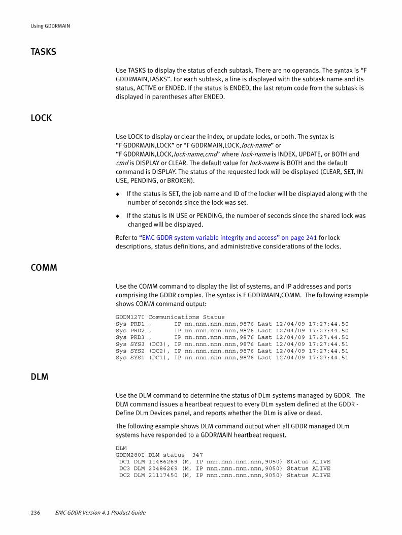
Using GDDRMAIN
TASKS
Use TASKS to display the status of each subtask. There are no operands. The syntax is “F GDDRMAIN,TASKS”. For each subtask, a line is displayed with the subtask name and its status, ACTIVE or ENDED. If the status is ENDED, the last return code from the subtask is displayed in parentheses after ENDED.
LOCK
Use LOCK to display or clear the index, or update locks, or both. The syntax is “F GDDRMAIN,LOCK” or “F GDDRMAIN,LOCK,lock-name” or “F GDDRMAIN,LOCK,lock-name,cmd” where lock-name is INDEX, UPDATE, or BOTH and cmd is DISPLAY or CLEAR. The default value for lock-name is BOTH and the default command is DISPLAY. The status of the requested lock will be displayed (CLEAR, SET, IN USE, PENDING, or BROKEN).
◆ If the status is SET, the job name and ID of the locker will be displayed along with the number of seconds since the lock was set.
◆ If the status is IN USE or PENDING, the number of seconds since the shared lock was changed will be displayed.
Refer to “EMC GDDR system variable integrity and access” on page 241 for lock descriptions, status definitions, and administrative considerations of the locks.
COMM
Use the COMM command to display the list of systems, and IP addresses and ports comprising the GDDR complex. The syntax is F GDDRMAIN,COMM. The following example shows COMM command output:
GDDM127I Communications StatusSys PRD1 , IP nn.nnn.nnn.nnn,9876 Last 12/04/09 17:27:44.50Sys PRD2 , IP nn.nnn.nnn.nnn,9876 Last 12/04/09 17:27:44.50Sys PRD3 , IP nn.nnn.nnn.nnn,9876 Last 12/04/09 17:27:44.50Sys SYS3 (DC3), IP nn.nnn.nnn.nnn,9876 Last 12/04/09 17:27:44.51Sys SYS2 (DC2), IP nn.nnn.nnn.nnn,9876 Last 12/04/09 17:27:44.51Sys SYS1 (DC1), IP nn.nnn.nnn.nnn,9876 Last 12/04/09 17:27:44.51
DLM
Use the DLM command to determine the status of DLm systems managed by GDDR. The DLM command issues a heartbeat request to every DLm system defined at the GDDR - Define DLm Devices panel, and reports whether the DLm is alive or dead.
The following example shows DLM command output when all GDDR managed DLm systems have responded to a GDDRMAIN heartbeat request.
DLM GDDM280I DLM status 347 DC1 DLM 11486269 (M, IP nnn.nnn.nnn.nnn,9050) Status ALIVE DC3 DLM 20486269 (M, IP nnn.nnn.nnn.nnn,9050) Status ALIVE DC2 DLM 21117450 (M, IP nnn.nnn.nnn.nnn,9050) Status ALIVE
236 EMC GDDR Version 4.1 Product Guide

Using GDDRMAIN
GVB
Global variable backup is accomplished by running a script (GDDRPGVB) in a local REXX worker (GDDWXR). The backup is made into the dataset named in the global variable GLOBAL.GDDR.PARMS.GDDRVAR_BACKUP.<system>.
The GVB command is used to schedule a regular backup of global variables or to perform a backup on demand. If entered with no value, the current global variable backup scheduled day and time is displayed. A value of NONE causes backups to not be scheduled. A value of NOW causes an immediate backup.
When the scheduled time comes, the backup will be postponed if a script is in progress.
The default value for GVB is NONE. This default can be overridden via the JCL PARM of GDDRMAIN. The syntax for GVB in the GDDRMAIN parameter is the same as above, except that NOW cannot be specified and a value must be specified.
MPARM
Use the MPARM command to display GDDMPARM checksums which indicate when the copies of GDDMPARM referenced by GDDRMAIN on each system are consistent. The MPARM command output lists each system with which GDDRMAIN can possibly communicate. The display shows each system name, the checksum of the GDDMPARM data in use, the checksum of the contents of the GDDMPARM dataset, and whether or not the system has found different GDDMPARM data from other systems. If GDDRMAIN cannot communicate with the system, the "unable to communicate" variant is displayed.
The following example shows MPARM command output when all GDDRMAIN tasks are consistent and capable of communicating:
GDDM140I GDDMPARM StatusSys PRD1 : In-use 0C63D749, Dataset 0F3F7372, Consistency YSys PRD2 : In-use 0C63D749, Dataset 0F3F7372, Consistency YSys PRD2 : In-use 0C63D749, Dataset 0F3F7372, Consistency YSys SYS3 : In-use 0C63D749, Dataset 0F3F7372, Consistency YSys SYS2 : In-use 0C63D749, Dataset 0F3F7372, Consistency YSys SYS1 : In-use 0C63D749, Dataset 0F3F7372, Consistency Y
Use MPARM,CHECK command to force a return to synchronization if the GDDMPARM data in use everywhere is synchronized. The MPARM,CHECK command retrieves the GDDMPARM in-use checksum from each system and compares them all. If all are equal, consistency is restored and degraded status is turned off. MPARM,CHECK will tolerate no response from GDDR-managed systems, but must get a response from each C-System in order to declare consistency. If any system (C-System or production system) responds with a different in-use checksum value, consistency will not be declared.
Sample output:
GDDM142I GDDMPARM Consistency set globally GDDM142I GDDMPARM Consistency set locally
The ‘GDDMPARM Consistency set locally’ version of the message will appear in the system log of each system with successful communication.
If any C-System cannot be reached the output is:
GDDM141E GDDMPARM Inconsistency detected, C-System SYS1 is down
GDDRMAIN console commands 237

Using GDDRMAIN
If any system has a different in-use checksum, the output is:
GDDM141E GDDMPARM Inconsistency detected, System SYS1 is inconsistent
RDFREFR
GDDRMAIN creates a map of RDF links between Symmetrix systems when the WORKMGR subtask starts. If an RDF group is added or removed, this map can be out of synch with reality. The RDFREFR command reconstructs this map. Previously, it was necessary to restart WORKMGR to reconstruct the RDF link map.
WORKER
Use the WORKER command to display WORKER subtasks and dynamically change the minimum and maximum number of worker tasks of a particular type.
The syntax is F GDDRMAIN, WORKER,name and F GDDRMAIN, WORKER[,name[,MIN=min|MAX=max]]
Sample output of WORKER command is as follows:
GDDM128I Worker Status GDDWCO Type S, Act 1, Min 1, Max 1 Name GDDWCO00, Status Waiting GDDWCM Type S, Act 1, Min 1, Max 1 Name GDDWCM00, Status Waiting GDDWST Type S, Act 1, Min 1, Max 1 Name GDDWST00, Status Waiting GDDWXR Type A, Act 1, Min 1, Max 1 Name GDDWXR00, Status Waiting GDDWGV Type S, Act 1, Min 1, Max 1 Name GDDWGV00, Status Waiting
You can restrict the display to a single worker type by using WORKER,GDDWST:
GDDM128I Worker Status GDDWST Type S, Act 1, Min 1, Max 1 Name GDDWST00, Status Waiting
You can modify the minimum and maximum settings for a worker type as follows:
WORKER,GDDWST,MIN=2GDDM128I Worker Status GDDWST Type S, Act 1, Min 2, Max 2 Name GDDWST00, Status Waiting
(Note that maximum value was also set to 2.)
WORKER,GDDWST,MAX=1GDDM128I Worker Status GDDWST Type S, Act 2, Min 1, Max 1 Name GDDWST01, Status Waiting Name GDDWST00, Status Waiting
(Note that the minimum value was also set to 1.)
Note: WORKMGR monitors the backlog of requests to the Storage device worker and the Status worker. When the backlog grows, additional tasks are started. When the backlog has been processed, idle worker tasks are stopped.
238 EMC GDDR Version 4.1 Product Guide

Using GDDRMAIN
MSGS
Use the MSGS command to enable or disable GDDR message rules which are message IDs that indicate changes in storage or system status, delivered in hlq.GDDRvrm.LINKLIB(GDDRMMSG). The syntax is F GDDRMAIN, MSGS[,msgid[,ENABLE|DISABLE]].
Sample MSGS command output:
GDDM130I Message Status BPXM023I, E/D E, Int 0 *NEVER*, Proc 0 *NEVER* CGRP005E, E/D E, Int 0 *NEVER*, Proc 0 *NEVER* CGRP051I, E/D E, Int 0 *NEVER*, Proc 0 *NEVER* CGRP056I, E/D E, Int 0 *NEVER*, Proc 0 *NEVER* CGRP093E, E/D E, Int 0 *NEVER*, Proc 0 *NEVER* CGRP095E, E/D E, Int 0 *NEVER*, Proc 0 *NEVER* CGRP100E, E/D E, Int 0 *NEVER*, Proc 0 *NEVER*
◆ The value of E/D indicates if interception of the message is enabled (E) or disabled(D).
◆ Int indicates the number of times and the last date and time (GMT) when the message was intercepted on this system.
◆ Proc indicates the number of times and the last date and time (GMT) when the message was processed on this system.
To display a particular message, use MSGS,EMCGM9EE:
GDDM130I Message Status EMCGM9EE, E/D E, Int 1 01/07/10 20:44:53.61, Proc 1 01/07/10 20:44:53.
To enable or disable interception of a particular message, use MSGS,EMCGM9EE,DISABLE:
GDDM130I Message Status EMCGM9EE, E/D D, Int 1 01/07/10 20:44:53.61, Proc 1 01/07/10 20:44:53.
BC and BR
BC (broadcast) and BR (broadcast with response) send a command to any, all, or some GDDR-managed systems. The syntax is F GDDRMAIN,BC[BR],<to>,<cmd>.
to can be the name of a specific system, or one of the following:
* — send to all systems (including the local system)
*C — send to all C-Systems
*P — send to all production systems
*1 — send to all systems, but send to local system first
*Z — send to all systems, but send to local system last
*X — send to all systems except local system
cmd is the command to be sent to the indicated systems.
For example, BC,*,D T sends a D T command to every GDDR system:
GDDM145I Command sent to system X19 GDDM145I Command sent to system X118 GDDM145I Command sent to system X99 GDDM145I Command sent to system X117
GDDRMAIN console commands 239
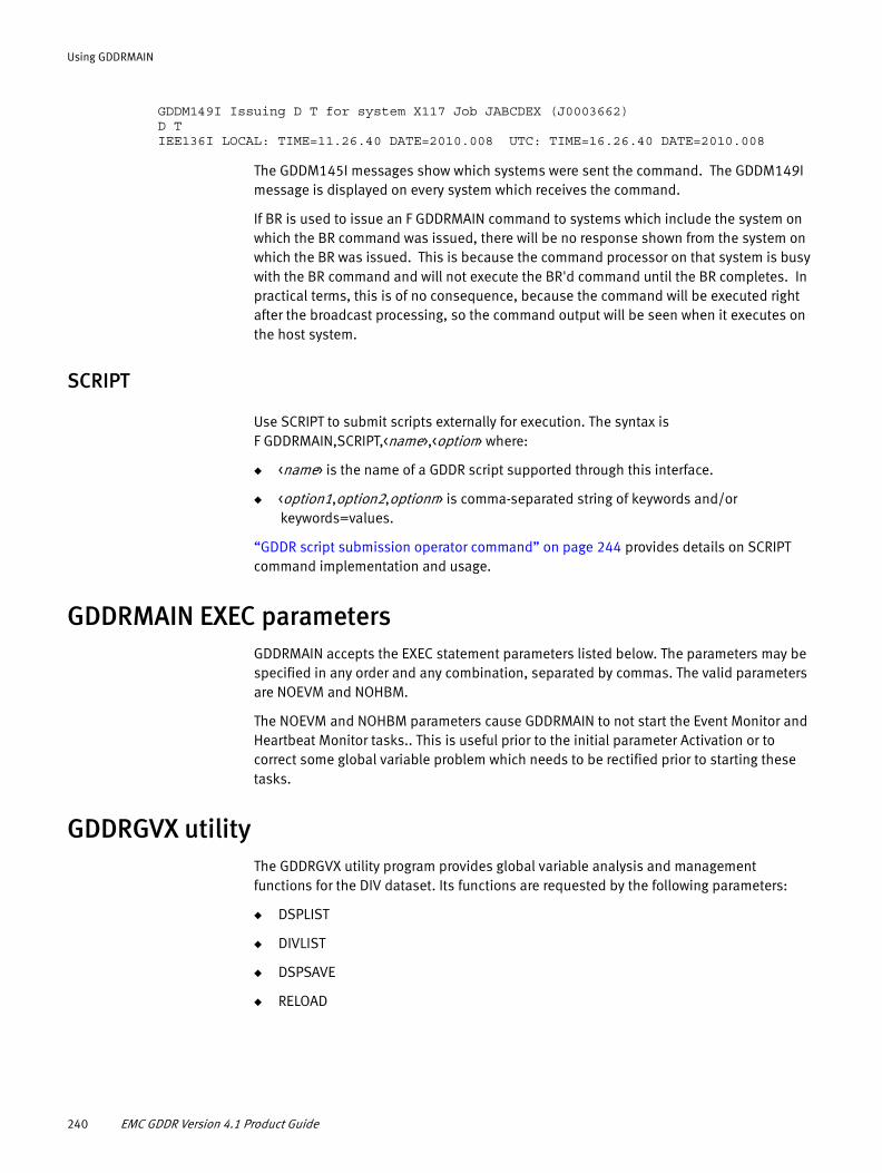
Using GDDRMAIN
GDDM149I Issuing D T for system X117 Job JABCDEX (J0003662) D T IEE136I LOCAL: TIME=11.26.40 DATE=2010.008 UTC: TIME=16.26.40 DATE=2010.008
The GDDM145I messages show which systems were sent the command. The GDDM149I message is displayed on every system which receives the command.
If BR is used to issue an F GDDRMAIN command to systems which include the system on which the BR command was issued, there will be no response shown from the system on which the BR was issued. This is because the command processor on that system is busy with the BR command and will not execute the BR'd command until the BR completes. In practical terms, this is of no consequence, because the command will be executed right after the broadcast processing, so the command output will be seen when it executes on the host system.
SCRIPT
Use SCRIPT to submit scripts externally for execution. The syntax is F GDDRMAIN,SCRIPT,<name>,<option> where:
◆ <name> is the name of a GDDR script supported through this interface.
◆ <option1,option2,optionn> is comma-separated string of keywords and/or keywords=values.
“GDDR script submission operator command” on page 244 provides details on SCRIPT command implementation and usage.
GDDRMAIN EXEC parametersGDDRMAIN accepts the EXEC statement parameters listed below. The parameters may be specified in any order and any combination, separated by commas. The valid parameters are NOEVM and NOHBM.
The NOEVM and NOHBM parameters cause GDDRMAIN to not start the Event Monitor and Heartbeat Monitor tasks.. This is useful prior to the initial parameter Activation or to correct some global variable problem which needs to be rectified prior to starting these tasks.
GDDRGVX utilityThe GDDRGVX utility program provides global variable analysis and management functions for the DIV dataset. Its functions are requested by the following parameters:
◆ DSPLIST
◆ DIVLIST
◆ DSPSAVE
◆ RELOAD
240 EMC GDDR Version 4.1 Product Guide

Using GDDRMAIN
DSPLIST
The DSPLIST parameter produces a formatted list of the contents of the global variable data space.
DIVLIST
The DIVLIST parameter produces a formatted list of the contents of the DIV. This parameter may only be used when GDDRMAIN is not active. The output format is identical to DSPLIST. The utility JCL requires a GDDRGVDS DD pointing to the DIV dataset.
DSPSAVE
The DSPSAVE parameter copies the contents of the global variable data space to a sequential dataset. The dataset is pointed to by a //GVSAVE DD statement. The output dataset can be used by IDCAMS REPRO to populate a new DIV dataset.
RELOAD
The RELOAD parameter copies global variables from an old DIV to a new DIV. The reason to use reload instead of IDCAMS REPRO is that reload will not copy deleted variables. Also, any "gas" in the DIV will be removed. To use the RELOAD parameter, GDDRMAIN must be running. The old DIV is pointed to by a //GDDRGVDS DD statement in the utility JCL, while the //GDDRGVDS DD statement in GDDRMAIN must be pointing to another (empty) DIV.
EMC GDDR system variable integrity and accessTwo locks are used when managing EMC GDDR system variable integrity: the index lock and the update lock. Both locks allow you to record, without serialization, when you are using the index or doing an update, and allow exclusive control by a single user when no use is in progress. If either lock becomes "stuck", it can have negative implications for global variable access.
EMC GDDR system variable integrity and access 241

Using GDDRMAIN
The lock consists of two words; the first is the exclusive lock, the second is the shared lock. If both words are zero, the lock is completely open. This is the normal state. The lock words can have the combinations of values listed in Table 18.
You can display the locks with GDDRGVX DSPLIST. GDDRGVX DSPLIST displays the time when the exclusive lock was set, as well as the job which set it. There is no display of jobs which set the shared lock, but GDDRGVX DSPLIST indicates the last time the shared lock was changed. You can also use the LOCK command to display this information.
You can clear a stuck or broken lock by using the LOCK command.
Index lock
The index lock indicates that the global variable index is in use or is being rebuilt. If the index is being rebuilt, it cannot be used by anyone.
If the exclusive lock becomes stuck, no one will be able to use the index and performance will suffer greatly. However, no functions will fail. If the exclusive lock is set for more than 5 seconds and a task tries to use the index, a message is issued.
If the shared lock becomes stuck, the index will not be able to be rebuilt when it needs to be done and performance will suffer, but not as severely as a stuck exclusive lock. Again, no functions will fail. A message is issued if a reindex is desired but cannot be done because the shared lock is not zero. If this message occurs with any frequency, investigate and consider manually clearing the lock.
Table 18 Possible lock states
First word - exclusive value
Second word - shared value State
0 0 The lock is open. There is no shared or exclusive use of the resource.
0 positive value The resource is in use by one or more non-exclusive users. The shared value is the number of users. No one is requesting exclusive use.
1 positive value The resource is in use by one or more non-exclusive users, but one user is waiting for exclusive use. If the shared word does not go to zero within a very short period of time, the lock is stuck. This is referred to as 'shared lock stuck'.
1 1 The lock is locked, or set. One task has exclusive use of the resource and any other task which wants to use it must wait or take alternative action. If the exclusive word does not go to 0 within a very short period of time, the lock is stuck. This is referred to as 'exclusive lock stuck'.
other than 0 or 1
any value The lock is broken. The exclusive word should only have the value 0 or 1.
0 or 1 negative value The lock is broken. The shared word should only have non-negative values.
242 EMC GDDR Version 4.1 Product Guide

Using GDDRMAIN
Update lock
The update lock is used (shared) when updates to global variables are made which change the structure of the data space. The exclusive lock is used by GVT when it writes the data space out to the DIV.
If the exclusive lock becomes stuck, no updates to global variables which require structural changes can be made (adding a new variable, changing a value to a longer value). If this occurs, requests will fail and messages will be issued.
If the shared lock becomes stuck, GVT will not be able to write the data space out to the DIV. However, if GVT is unable to obtain the update exclusive lock, it will force it (that is, set the lock words to 1,0) after some period of trying to obtain the lock. A stuck shared update lock will automatically be unstuck if GVT is active and if a DIV write needs to be done. Note that there is no impact of a stuck shared update lock except in these conditions.
Dynamic LPA
When GDDRMAIN starts, it loads module GDDRXG1A into dynamic LPA. If the module is already loaded, GDDRMAIN does not reload it. Therefore, if maintenance occurs to that module, it has to be deleted from LPA by using operator command SETPROG LPA,DELETE,MODNAME=GDDRXG1A,FORCE=YES.
After the module is deleted, you can either restart GDDRMAIN so that it will reload it, or add it to LPA manually by issuing operator command SETPROG LPA,ADD,MODNAME=GDDRXG1A,DSNAME=gddr-linklib.
IMPORTANT
Before deleting the module you should be sure that the dynamic exit GDDREXG1GDDR (the last four characters are the GDDR subsystem name) is inactive as described in “Dynamic exits” below.
Dynamic exits
When GDDRMAIN starts, it creates a dynamic exit called GDDREXG1GDDR (the final four GDDR characters are variable and represent the GDDR subsystem name). LPA module GDDRXG1A (see “Dynamic LPA” above) is associated with this exit.
If consistency is requested for global variable backup or restore, the exit is activated. Should the backup or restore end abnormally (for example, by being cancelled), it is possible that the exit will be left active and may block or complain about global variable updates. If this occurs, the exit can be manually deactivated by issuing SETPROG EXIT,MODIFY,EXITNAME=GDDREXG1GDDR,MODNAME=GDDRXG1A,STATE=INACTIVE.
EMC GDDR system variable integrity and access 243

Using GDDRMAIN
Remote command processingRemote command processing issues commands to EMC GDDR-managed systems in parallel and asynchronously acknowledges the completion status of each command. When the WTOR associated with a remote command is issued, the command processor waits for a response to the WTOR and also waits for the command to end. If the command ends, the command processor cancels the associated WTOR.
GDDR script submission operator commandThe GDDR script submission operation command is F GDDRMAIN,SCRIPT,name,option.
◆ <name> is the name of a GDDR script supported through this interface.
◆ <option1,option2,optionn> is comma-separated string of keywords that are described in detail in “Keywords for options” on page 245.
All keywords after SCRIPT are optional. However, if options are specified, then name must first be specified. If script name is going to be supplied via a LOAD keyword, the script name can be specified as *.
Use of the SCRIPT command results in work being sent to the GDDWXR worker to run module GDDRMCSS under ISPF under the TMP. This is so that file tailoring is available. No JCL modifications are required for any GDDR procs. File tailoring (if done) uses the ISPSLIB DD in the GDDRWORK proc. The skeleton to be used (GDDRXSUB) is very similar to GDDRXACT. It can be in a different dataset (still in the ISPSLIB DD concatenation) so that the contents can be user-controlled. However, it does not have to be in a different dataset and will ship in ISPSLIB.
The general flow (which can be modified by various keywords) is as follows:
F GDDRMAIN,SCRIPT,GDDRPA99GDDM251I Script command work submitted
This is followed by a WTOR issued by a GDDRWORK address space:
GDDM252A Enter script parameters
The response to this is a comma-separated string of keywords as shown below. If CANCEL is entered, the process ends with no script generation or submission. The message is repeated until either END or CANCEL is entered or implied.
When END is entered, the following message is displayed showing all the options in effect:
GDDM253I Script GDDRPA99 parameters:Site - DC1System - *...Submit - YES
This is followed by the following message:
GDDM255A Confirm script generation (Y/N/CANCEL)
◆ If N is entered, return to the GDDM252A message.
◆ If CANCEL is entered, the process ends at this point with no further action.
244 EMC GDDR Version 4.1 Product Guide

Using GDDRMAIN
◆ If Y is entered, the script is generated (file tailored). The resultant JCL is saved if JCLSAVE was specified, and is submitted if SUBMIT was specified.
If a job is submitted, the following message occurs:
GDDM266I Script GDDRPA99 submitted, JOB jobname (jobid)
Authorization
Skeleton member GDDRXSUB supports secure access to GDDR scripts run through the SCRIPT console command. You may concatenate a PDS containing customized JCL skeleton GDDRXSUB to the GDDRMAIN ISPSLIB DD statement. This skeleton must provide a job-card.
As scripts will be submitted by GDDRMAIN, they would normally run with GDDRMAIN authorizations. The job-card provided in skeleton GDDRXSUB may have a USER= keyword. The named user would then be the only one with all the authorizations that are required to run a GDDR script. GDDRMAIN would only need SURROGAT authority to that Userid.
Keywords for options
Table 19 Script keywords (page 1 of 2)
ALLOWHMC Value is 3 characters (Y or N for each character). Default taken from globals.
CALLOVER Value is 20 character string of 0 or 1. Default taken from global.
NONSTAR Value is YES or NO (any substring of YES or NO beginning with the first letter is allowed). Default taken from global.
PRISWAP Value is name of primary AutoSwap group. Default taken from global.
GDDR script submission operator command 245

Using GDDRMAIN
PARM Allows specification of the script parameter. In general, there is no script parameter. However, in some cases, a parameter is required in order to identify that a 4-site script is being requested or to convey additional information. If the configuration is 4-site, the default parameter is set to 4SITE; if the configuration is 2-site, the default parameter is set to 2SITE.• GDDRPA0A
Value is UP31 if the last run unplanned script was GDDRUP31; null otherwise.• GDDRPA05
Value is SRDFS if in a 4-site configuration and SRDF/S replication to the other site in the recovery region is desired; null otherwise.
• GDDRPA06In 4-site configurations, the value is CON if concurrent SRDF is desired and CAS if cascaded SRDF is desired. In other than 4-site configurations, the value is null.
• GDDRPA07In 4-site configurations, the value is CON if concurrent SRDF is desired and CAS if cascaded SRDF is desired. In 2-site configurations, the value is 2SITE (default).In 3-site configurations, the value is null (default).
• GDDRPA36RESTART if an MSC server is being restarted, null otherwise.
• GDDRPF29 In configurations without AutoSwap, must be NCAX; null (default) in all other cases.
• GDDRPM29In 2-site configurations, the value is 2SITE (default); in all other configurations, the value is null (default).
RRSKIP Value is YES or NO (any substring of YES or NO beginning with the first letter is allowed). No value implies YES. Default is NO.
SCRIPT Value is the script name (same as first positional parameter on SCRIPT command).
SDDFCLN Value is YES or NO (any substring of YES or NO beginning with the first letter is allowed). Default taken from global.
SECSWAP Value is name of secondary AutoSwap group. Default taken from global.
SITE Value is site name (DCx). Default is *
SYSTEM Value is system name. Default is *
USER Value is user ID. Can have no value, implying no user ID is to be set in script job. Default is blank (no value).
Table 20 Control keywords (page 1 of 2)
AUTO Value is ON of OFF. No value implies ON. ON means that no further WTORs should be issued and the process should proceed as if every WTOR were answered in the affirmative. Default is OFF.
CANCEL No value. Indicates that the script submission process should end immediately.
END No value. Indicates that the entering of arguments is complete and the process should proceed to confirmation.
Table 19 Script keywords (page 2 of 2)
246 EMC GDDR Version 4.1 Product Guide

Using GDDRMAIN
Examples
User input is shown in italics.
F GDDRMAIN,SCRIPT,GDDRPA99,JCLSUB=USERID1.WORK.CNTL(PA21)GDDM251I Script command work submittedGDDM266I Script GDDRPA99 submitted, JOB GDDRPA21 (J1234567)GDDM267I GDDR Script command for GDDRPA99 ended
F GDDRMAIN,SCRIPT,GDDRPA99GDDM251I Script command work submittedGDDM252A Enter script parametersSITE=DC1,CALLOVER=01010101010101010101,SUBMIT=YES,USER=USERID1GDDM252A Enter script parametersJCLSAVE=USERID1.WORK.CNTL(PA21),NONSTAR=YES,ALLOWHMC=YYN,ENDGDDM253I Script GDDRPA99 Parameters
SITE=DC1SYSTEM=*PRISWAP=SWAP1SECSWAP=SWAP2CALLOVER=01010101010101010101USER=USERID1SDDFCLN=NONONSTAR=YESALLOWHMC=YYNRRSKIP=NOSUBMIT=YESJCLSAVE=USERID1.WORK.CNTL(PA21)
GDDM255A Confirm script generation (Y/N/CANCEL)YGDDM266I Script GDDRPA99 submitted, JOB GDDRPA99 (J1234567)GDDM267I GDDR Script command for GDDRPA99 ended
F GDDRMAIN,SCRIPT,GDDRPA99GDDM251I Script command work submittedGDDM252A Enter script parametersLOAD=USERID1.WORK.CNTL(PA21),SITE=DC2,ENDGDDM253I Script GDDRPA99 Parameters
SITE=DC2SYSTEM=*
JCLSAVE Value is DSN(MEMBER). This is the dataset to save the file tailored JCL. Can have no value to indicate that file tailored JCL is not be saved. Default is no value (no JCL saved). The value (if any) must be a partitioned data set name and member; save to a sequential dataset is not allowed (ISPF restriction).
JCLSUB Value is DSN[(MEMBER)]. This is the dataset to be submitted without file tailoring. This parameter supercedes all script parameters except RRSKIP. Implies AUTO, END, SUBMIT.
LOAD Value is DSN[(MEMBER)]. This is a data set containing arguments which are to be loaded into current arg values. Any particular dataset/member can be used for LOAD only 1 time per LOAD. That is, dataset A cannot contain a LOAD of dataset A; dataset A cannot contain a LOAD of dataset B if B contains a LOAD of dataset A.
SAVE Value is DSN[(MEMBER)]. This is a dataset into which the current script (not control) argument values (plus JCLSAVE if specified) will be saved.
SUBMIT Value is YES or NO (any substring of YES or NO beginning with the first letter is allowed). No value implies YES. This indicates the resultant JCL should or should not be submitted. Default is YES.
Table 20 Control keywords (page 2 of 2)
GDDR script submission operator command 247

Using GDDRMAIN
PRISWAP=SWAP1SECSWAP=SWAP2CALLOVER=01010101010101010101USER=USERID1SDDFCLN=NONONSTAR=YESALLOWHMC=YYNRRSKIP=NOSUBMIT=YES
GDDM255A Confirm script generation (Y/N/CANCEL)YGDDM266I Script GDDRPA99 submitted, JOB GDDRPA21 (J1234567)GDDM267I GDDR Script command for GDDRPA99 ended
F GDDRMAIN,SCRIPT,GDDRPA21,LOAD=USERID1.WORK.CNTL(PA21),SITE=DC2,AUTOGDDM251I Script command work submittedGDDM253I Script GDDRPA99 Parameters
SITE=DC2SYSTEM=*PRISWAP=SWAP1SECSWAP=SWAP2CALLOVER=01010101010101010101USER=USERID1SDDFCLN=NONONSTAR=YESALLOWHMC=YYNRRSKIP=NOSUBMIT=YES
GDDM266I Script GDDRPA99 submitted, JOB GDDRPA21 (J1234567)GDDM267I GDDR Script command for GDDRPA99 ended
F GDDRMAIN,SCRIPT,GDDRPA99GDDM251I Script command work submittedGDDM252A Enter script parametersSITE=DC1,CALLOVER=01010101010101010101,SUBMIT=YES,USER=USERID1GDDM252A Enter script parametersCANCELGDDM257I GDDR Script command for GDDRPA99 cancelled
248 EMC GDDR Version 4.1 Product Guide
APPENDIX DAutomated Configuration Utilities
This appendix describes the GDDR Automated Configuration Discovery (GDDRACDD) and GDDR RDF Director Overview (GDDRDIRS) utilities.
◆ Automated Configuration Discovery for DASD (GDDRACDD) ................................... 250◆ GDDR RDF Director Overview utility (GDDRDIRS) .................................................... 283
Automated Configuration Utilities 249

Automated Configuration Utilities
Automated Configuration Discovery for DASD (GDDRACDD)The GDDR Automated Configuration Discovery for DASD utility (GDDRACDD) is designed to be run at any site in any GDDR configuration, and serves the following purposes:
◆ Discovers Symmetrix SRDF and TimeFinder as well as DLm backend devices in a set of defined Symmetrix units and RDF groups
◆ Generates parameters usable to define the discovered devices to GDDR
◆ Validates the discovered configuration
◆ Validates existing RDF.DEVICES and DLM.DEVICES parameters and other configuration global variables against the discovered DASD configuration and against GDDMPARM information
◆ Produces a set of reports to describe the configuration:
• SYMMDEVS: lists contiguous device ranges
• RDFGROUP: lists RDF groups connecting GDDR-managed Symmetrix systems
• CREPAIR: lists SC VOL CREATEPAIR commands usable to create the GDDR-managed device pairs
• FBAMETA: lists FBA-meta devices and RDF relationships
The ACDD utility is supported with REXX module GDDRACDD and sample JCL in hlq.GDDRvrm.SAMPLIB (GDDRACDD). Member GDDRPACD in hlq.GDDRvrm.PARMLIB provides parameters.
Prerequisites
The prerequisites to run GDDRACDD are the following:
◆ GDDRSCF up and running with any currently supported version of Mainframe Enablers.
◆ GDDRACDD supports any Symmetrix Enginuity level currently supported with Mainframe Enablers.
◆ GDDRMAIN up and running, unless the COMP(Y) argument is specified.
Procedure
1. Ensure that the GDDR and prerequisite host software installation is complete on the C-System where you also have GDDRSCF running.
2. Use the GDDR Parameter wizard to navigate to the Define SRDF Devices panel.
3. When you reach the Define SRDF Devices panel, run GDDRACDD as a batch job. When GDDRACDD completes, return to the wizard.
4. Issue a LOAD command on the Define SRDF Device Ranges panel. This refreshes the panel with the generated RDF.Devices data.
5. Review and, where necessary, modify the RDF.DEVICES parameters created by GDDRACDD.
250 EMC GDDR Version 4.1 Product Guide
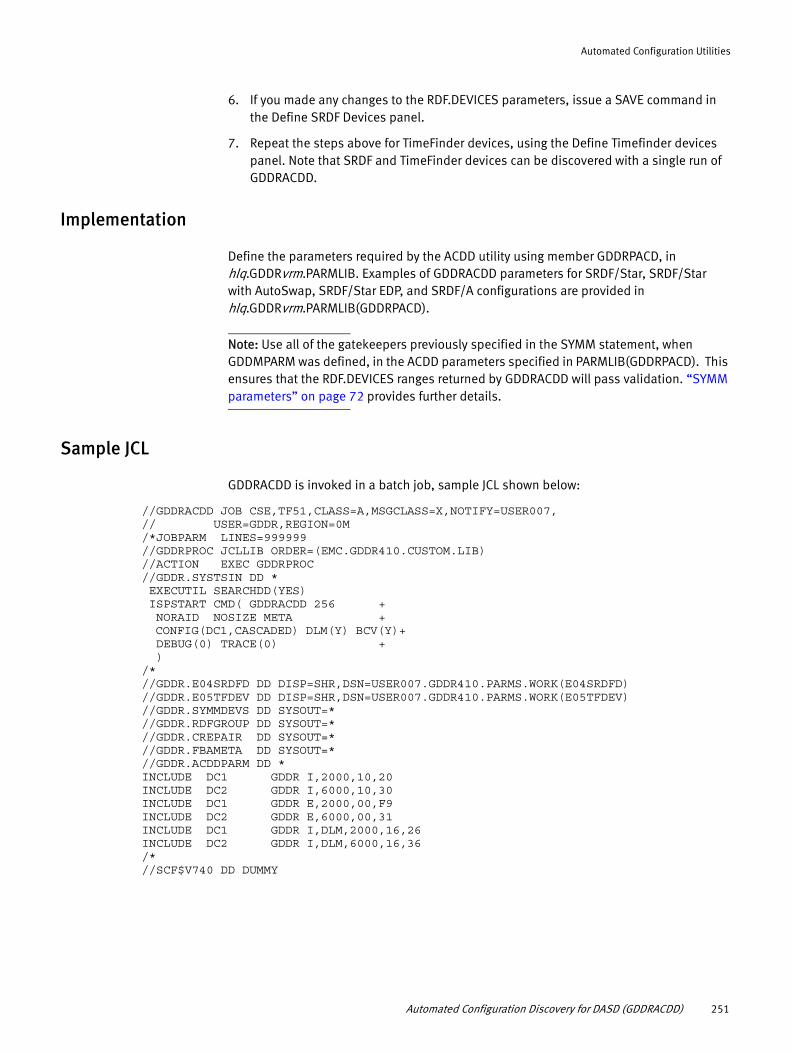
Automated Configuration Utilities
6. If you made any changes to the RDF.DEVICES parameters, issue a SAVE command in the Define SRDF Devices panel.
7. Repeat the steps above for TimeFinder devices, using the Define Timefinder devices panel. Note that SRDF and TimeFinder devices can be discovered with a single run of GDDRACDD.
Implementation
Define the parameters required by the ACDD utility using member GDDRPACD, in hlq.GDDRvrm.PARMLIB. Examples of GDDRACDD parameters for SRDF/Star, SRDF/Star with AutoSwap, SRDF/Star EDP, and SRDF/A configurations are provided in hlq.GDDRvrm.PARMLIB(GDDRPACD).
Note: Use all of the gatekeepers previously specified in the SYMM statement, when GDDMPARM was defined, in the ACDD parameters specified in PARMLIB(GDDRPACD). This ensures that the RDF.DEVICES ranges returned by GDDRACDD will pass validation. “SYMM parameters” on page 72 provides further details.
Sample JCL
GDDRACDD is invoked in a batch job, sample JCL shown below:
//GDDRACDD JOB CSE,TF51,CLASS=A,MSGCLASS=X,NOTIFY=USER007, // USER=GDDR,REGION=0M /*JOBPARM LINES=999999 //GDDRPROC JCLLIB ORDER=(EMC.GDDR410.CUSTOM.LIB)//ACTION EXEC GDDRPROC//GDDR.SYSTSIN DD * EXECUTIL SEARCHDD(YES) ISPSTART CMD( GDDRACDD 256 + NORAID NOSIZE META + CONFIG(DC1,CASCADED) DLM(Y) BCV(Y)+ DEBUG(0) TRACE(0) + ) /* //GDDR.E04SRDFD DD DISP=SHR,DSN=USER007.GDDR410.PARMS.WORK(E04SRDFD) //GDDR.E05TFDEV DD DISP=SHR,DSN=USER007.GDDR410.PARMS.WORK(E05TFDEV) //GDDR.SYMMDEVS DD SYSOUT=* //GDDR.RDFGROUP DD SYSOUT=* //GDDR.CREPAIR DD SYSOUT=* //GDDR.FBAMETA DD SYSOUT=* //GDDR.ACDDPARM DD * INCLUDE DC1 GDDR I,2000,10,20 INCLUDE DC2 GDDR I,6000,10,30 INCLUDE DC1 GDDR E,2000,00,F9 INCLUDE DC2 GDDR E,6000,00,31INCLUDE DC1 GDDR I,DLM,2000,16,26 INCLUDE DC2 GDDR I,DLM,6000,16,36 /*//SCF$V740 DD DUMMY
Automated Configuration Discovery for DASD (GDDRACDD) 251

Automated Configuration Utilities
Arguments
All GDDRACDD arguments are optional. If no arguments are specified, GDDRACDD will run with “256 ALIGN RAID SIZE META GLOBALS(NONE) DLM(N) BCV(N) CONFIG(DC1,CONCURRENT) SORT GROUPS(NOBREAK) NOFORCE DEBUG(0) TRACE(0) GDDRPFX(GDDR)”.
range_size
Default: 256
Defines the maximum number of contiguous devices to be listed as a single range in the Symmetrix device ranges report and in RDF.DEVICES parameters.
Supported range_size values are 0 to 4096. The recommended range_size is the default value of 256. You can use a very small value for example, in a test environment to force ACDD to generate a lot of RDF.DEVICES parameters. Larger range sizes (> 512) are intended for code testing purposes.
If you want to specify range_size, it must be the first argument. If you specify any other arguments, you must also specify a range_size. The other arguments can be specified in any order.
Note: For FBA-meta devices, a hard-coded maximum range_size of 128 is enforced, but you can use a smaller value.
ALIGN
This argument can be specified as ALIGN or NOALIGN. If ALIGN is specified (or defaulted), then device ranges will be aligned on boundaries defined by range_size. Alignment is supported on 256-, 512-, 1024-, 2048-, and 4096-device boundaries. If a range_size smaller than a supported alignment size is specified, range_size is rounded up to the next alignment size. GDDRACDD informs you about a range size override if this happens.
Note: If ALIGN is specified or defaulted, and GDDRACDD discovers an asymmetrical configuration, it will issue a warning message (GDDP415W) and change to NOALIGN automatically, as of the moment that the asymmetry is detected.
ALIGN examples
ACDD 256 ALIGN
Will show 003F-00FF then start a new range going from 0100-013F.
ACDD 16 ALIGN
Will force the range_size to 256, and align as described above.
NOALIGN example
If NOALIGN is specified, then device ranges will not require alignment to boundaries defined by range_size, allowing device ranges to span alignment boundaries.
ACDD 256 NOALIGN
Could show a range going from 003F to 013F as a single contiguous range.
252 EMC GDDR Version 4.1 Product Guide

Automated Configuration Utilities
DLM(Y)
Performs discovery / validation of DLm Backend Devices. Default: DLM(N).
When DLM(Y) is specified, GDDRACDD will perform the same discovery and validation functions for DLM Backend Devices as it does for other GDDR-managed RDF devices.
The DLM Backend Devices are identified to ACDD by INCLUDE arguments with the DLM keyword. Refer to the description of the INCLUDE parameter for more information.
BCV(Y)
Perform discovery of TimeFinder Devices. Default: BCV(N).
When BCV(Y) is specified, GDDRACDD will discover TimeFinder devices in all or selected Symmetrix systems and generate GDDR BCV parameters for them. Symmetrix systems can be selected using TFINDER parameters in the ACDDPARM deck.
NOSIZE, NORAID, NOMETA
These parameters do not affect the Symmetrix device ranges report, they solely affect the generation of RDF.DEVICES parameters.
NOSIZE can be absent or specified as NOSIZE
NORAID can be absent or specified as NORAID.
NOMETA can be absent or specified as NOMETA.
By default, GDDRACDD will generate a new device range, and consequently a new RDF.DEVICES parameter, every time any of the following attributes of the discovered SRDF devices changes:
◆ CKD versus FBA, meta-device versus regular device, STD device versus BCV.
◆ Non-contiguous other-side or hopped other-side devices. (All discovered RDF groups between Symmetrix systems defined to ACDD are considered.)
◆ Different number of cylinders.
◆ Different local RAID-scheme (RAID-0, RAID-1, RAID-5, RAID-6, none).
If NOSIZE, NORAID and/or NOMETA are specified, then a difference in cylinder count or local protection scheme, or meta-type will still generate a new device range in the Symmetrix device ranges report, but will no longer cause an additional RDF.DEVICES parameter to be generated.
GLOBALS(CHECK)
When specified, runs ACDD in “validation mode”. The default setting is GLOBALS(NONE), which runs ACDD in “discovery mode”.
This argument incorporates the obsolete GDDRACCD utility into GDDRACDD. Validation includes:
◆ Internal consistency of existing global variables against each other
◆ Consistency of global variables against GDDMPARM information
◆ Consistency of global variables against the discovered Symmetrix configuration
Automated Configuration Discovery for DASD (GDDRACDD) 253

Automated Configuration Utilities
◆ Discovered devices are defined and are the correct R1/R2 type
◆ Discovered devices are Link-Blocked where expected (internal groups only)
◆ Discovered devices are not Link-Blocked where not expected (internal groups only)
◆ Defined devices are discovered and are the correct R1/R2 type
If GLOBALS(CHECK) is specified, GDDRMAIN must be up, and running version GDDR 4.0 or higher. COMP(Y) is mutually exclusive with GLOBALS(CHECK).
If GLOBALS(CHECK) is specified, ACDDPARM content is ignored with the exception of PATH parameters. ACDD will use CSYSSITE and SYMM parameters from GDDMPARM and fabricate INCLUDE and GENERATE parameters as required, using information from the existing RDF.DEVICES parameters. These fabricated INCLUDE and GENERATE parameters are echoed to the joblog prefixed with ‘SIM:’
COMP(Y|N)
COMP(Y) indicates compatibility mode. The default is COMP(N). The purpose of this argument is to facilitate GDDR upgrades from earlier versions, as well as to run GDDRACDD for a configuration which is different from the one known to the running GDDRMAIN instance.
With COMP(Y), GDDRACDD will run without using GDDRMAIN services. COMP(Y) is mutually exclusive with GLOBALS(CHECK).
The requirements to run GDDRACDD without GDDRMAIN are:
◆ SCF running
◆ Proper SCF$nnnn DD DUMMY card in the GDDRACDD JCL
◆ IKJTSOxx must have all required GDDRQDEx entries as specified in “SYS1.PARMLIB(IKJTSOxx) customization” on page 50.
◆ gddrhlq.LINKLIB must be available to the job running ACDD.
◆ Specify CSYSSITE and SYMM parameters in ACDDPARM.
SCAN
Indicates SCAN mode. Can be absent, or specified as SCAN.
If the SCAN argument is specified, GDDRACDD will perform a validation of the arguments and parameters, as well as a limited infrastructure validation (RDF group status). It will not proceed to Symmetrix device discovery.
FORCE
Can be specified as FORCE or NOFORCE (default).
By default GDDRACDD will stop immediately if certain configuration errors are found.
See message GDDP420E in the GDDR Message Guide for a description of the types of errors detected. Cases where RC=8 is set can be rerun with FORCE, but there is no guarantee that the generated RDF.DEVICES parameters (if any) will be usable by GDDR.
254 EMC GDDR Version 4.1 Product Guide

Automated Configuration Utilities
CONFIG(<cpds>,<topology>)
Default: CONFIG(<my-site>,CONCURRENT)
The CONFIG argument only affects the syntax of the CREATEPAIR commands generated by GDDRACDD. It has no effect on configuration validation or generation of RDF.DEVICES parameters.
It informs GDDRACDD about the intended Primary DASD site (CPDS) and, for 3-Site configurations only, about the intended topology (Concurrent or Cascaded). Topology is ignored for 2-site and 4-site configurations.
By default, GDDRACDD will use the site where it is running as CPDS. In 3-site configurations the default GDDRACDD topology is Concurrent. In all other configurations, topology is ignored.
NOSORT
Suppresses sorting of generated parameters. Can be specified as NOSORT or SORT (default).
By default, GDDRACDD sorts the generated RDF.DEVICES parameters in turn over the available Symmetrix systems. Internal RDF groups are sorted separately from external RDF groups.
Sorting enhances GDDR script performance by increasing parallel processing over available resources. It provides the most benefit for users with multiple Symmetrix systems per site.
Note the following:
◆ If one site of a site pair has a lower number of Symmetrix systems than the other site, the sort algorithm will do the distribution using the site with the lowest number. This avoids cases where a site with low "parallel processing" capabilities would get overrun by parallel processing initiated from the other site.
◆ This sorting of generated parameters does not force a strict sequence of execution of script commands in the desired round-robin fashion, but it increases the likelihood of an optimal sequence.
◆ If the managed configuration has an uneven distribution of device ranges across the Symmetrix systems there will be a "tail-end" effect where the remaining commands are all targeting the same Symmetrix system.
GROUPS(BREAK)
Default: GROUPS(NOBREAK)
Discovered Symmetrix device ranges can be paired in multiple RDF groups, currently limited to two by Enginuity. By default, GDDRACDD generates RDF.DEVICES parameters for each site pair independently of device pairing for other site pairs.
If GROUPS(BREAK) is specified, then if a range needs to be split due to an interruption in the device pairing in one RDF group, it will also cause a split in RDF.DEVICES parameters for the other RDF group. As a result there will be a higher total number of RDF.DEVICES parameters. This number will be higher than necessary for GDDR scripts to succeed. However, the generated RDF.DEVICES parameters will be "symmetrical" in nature when looking at parameters for different site pairs.
Automated Configuration Discovery for DASD (GDDRACDD) 255

Automated Configuration Utilities
DEBUG(n)TRACE([name,]n)
GDDRACDD does not use the GDDR standard method to set DEBUG and TRACE levels, as those require GDDRMAIN services for global variable access. The DEBUG and TRACE arguments close this gap.
DEBUG can be specified as 0, 1, or 2. Default: DEBUG(0)
Use TRACE only under instruction from the GDDR Solution Support Team. Tracing of GDDRACDD can produce enormous amounts of output in the SYSTSPRT dataset, and could consume all available spool space. The default value is TRACE(0).
The syntax for TRACE is (<sub-routine-name>,<trace-level>). Subroutine-names are provided by the GDDR Solution support team. The default subroutine name is "ALL". TRACE level can be 0, 1, 2, or 3 and translates to REXX tracing values of "O", "R", "I", and "A" respectively.
GDDRPFX(GDDn)
Reserved for future use. Indicates the target GDDR subsystem. The default is GDDRPFX(GDDR).
Optional DD-cards
Besides the arguments, there are six optional DD-cards in the GDDRACDD JCL which slightly affect GDDRACDD behavior. If these DD-cards are not present, the affected report is not written.
E04SRDFD
The E04SRDFD dataset contains the generated RDF.DEVICES parameters. It is necessary for proper integration of GDDRACDD with the GDDR Parameter Wizard.
E05TFDEV
The E05TFDEV dataset contains the generated BCV.DCn.ONLY parameters. It is necessary for proper integration of GDDRACDD with the GDDR Parameter Wizard.
SYMMDEVS
Contains the Symmetrix device ranges report. This used to be part of the joblog, but is now written to its own separate dataset. This provides better visibility to various warning and error messages written to the joblog. EMC recommends having this DD card in the JCL.
256 EMC GDDR Version 4.1 Product Guide

Automated Configuration Utilities
RDFGROUP
Contains the following sections:
◆ A listing of all GDDR groups found in Symmetrix systems defined on SYMM parameters. Indicates whether a group is included as regular DASD is DLM Backend, internal, external or not at all, whether the group is OFFLINE, and whether the group is Virtual.
◆ A listing of included groups by type and site pair, with associated gatekeepers.
CREPAIR
Contains the Host Component CREATEPAIR commands which can be used to create the configuration as it will be defined to GDDR, from scratch, in cases where it got deleted. The CREATEPAIR commands are generated according to the intended configuration specification in the CONFIG argument.
FBAMETA
The FBAMETA report contains an overview of FBA meta-devices in the GDDR-managed configuration. It shows head-member relationships and SRDF device pairing information.
Parameters (ACDDPARM DD statement)
ACDD supports the following parameters to control its actions:
◆ SYMM
◆ CSYSSITE
◆ INCLUDE
◆ GENERATE
◆ PATH
◆ TFINDER
◆ VGROUP
All ACDD parameters are optional, except for the INCLUDE parameter. If GDDRMAIN is not running, and/or the COMP(Y) argument is specified, then CSYSSITE and SYMM parameters are required. If CSYSSITE or SYMM parameters are specified in ACDDPARM, then GDDRACDD will use those parameters, even if GDDRMAIN is running. All ACDDPARM parameters, except PATH, are ignored when running ACDD in “validation mode” (GLOBALS(CHECK) argument).
Parameter rules
ACDDPARM has specific syntax rules. All parameters are column-sensitive. You can specify ACDD parameters in any sequence.
Parameter structure (columns 1-70 useable):
0000000000111111111122222222223333333333444444444455555555556666666666712345567890123456789012345678901234567890123456789012345678901234567890PARMNAME REF-id GDDR value
Automated Configuration Discovery for DASD (GDDRACDD) 257
Automated Configuration Utilities
◆ Parameter name goes in columns 1-8.
◆ System name or a Site name or a Group number, goes in columns 10-17.
◆ GDDR goes in column 19-22. This is the targeted GDDR subsystem. Fixed at 'GDDR'.
◆ Parameter values go in columns 24-71.
CSYSSITE
The CSYSSITE parameter links a system name to a site.
For example:
CSYSSITE O016 GDDR DC1
The CSYSSITE parameter tells ACDD the site on which it is running. ACDD needs to know this, to be able to properly construct createpair commands, if requested, and to select appropriate PATH parameters if any are specified.
ACDD will refuse to run on a system that is not named in a CSYSSITE parameter.
The recommendation is to code one CSYSSITE parameter for every C-System in your configuration. This makes your ACDD parameter deck “portable”. However, ACDD will work with only one CSYSSITE coded; the one for the system where you intend to run ACDD next.
CSYSSITE parameters in ACDDPARM are entirely optional if GDDRMAIN is running and you are satisfied with the CSYSSITE parameters in GDDMPARM. They are required if you specify COMP(Y) in the arguments.
If you specify any CSYSSITE parameter in ACDDPARM, then any CSYSSITE parameter in GDDMPARM is ignored.
SYMM
The SYMM parameter defines a Symmetrix system to GDDRACDD, as well as the pool of gatekeeper addresses to be distributed by GDDRACDD over the generated RDF.DEVICES parameters.
For example:
SYMM DC1(H) GDDR 000292601023,2000-200F
ACDD requires one SYMM parameter with (H) Home indicator in the site-id column, for every Symmetrix system in the GDDR-managed configuration. You can code as many SYMM parameters as you need for the definition of the gatekeeper pools. These can be lists of single devices or device ranges, as needed. Gatekeeper addresses need to be unique at a site.
SYMM parameters in ACDDPARM are entirely optional if GDDRMAIN is running and you are satisfied with the SYMM parameters in GDDMPARM. They are required if you specify COMP(Y) in the arguments.
Note: SYMM parameters are only available in GDDMPARM with GDDR Version 4.0 or higher.
258 EMC GDDR Version 4.1 Product Guide

Automated Configuration Utilities
If you code SYMM parameters in ACDDPARM, you can copy and paste all SYMM parameters from GDDMPARM. SYMM parameters without the (H) Home indicator in the site-id column are only used by ACDD if they refer to the site where ACDD is running. In that case, ACDD will use the first gatekeeper listed as a discovery path for the named Symmetrix, unless there is an explicit PATH parameter for the same Symmetrix system.
If you specify any SYMM parameter in ACDDPARM, then any SYMM parameter in GDDMPARM is ignored.
PATH
By default ACDD will determine the discovery path for every defined Symmetrix system automatically. This is true whether the SYMM parameters are taken from ACDDPARM or from GDDMPARM. The algorithm selects the path with the fewest possible hops. For remote Symmetrix systems, the selected path is the one with the highest number of online local and remote RDF directors.
If for any reason the automatically selected path is unacceptable, a PATH parameter can be specified in ACDDPARM to force usage of the specified path for discovery.
For example:
PATH DC1 GDDR 123456789014,A000.10.30
The site specified on PATH parameters, or “from” site, determines whether or not the PATH parameter will be used. ACDD determines the site where it is running based on CSYSSITE parameters. Any PATH parameter referring to a different site is ignored. This again allows for a “portable” ACDDPARM parameter deck.
The PATH parameters further specify a target Symmetrix system by serial number, and finally the discovery “path”. This path is made up of a gatekeeper address, which must be usable at the “from” site, followed by as many “hops” as required to reach the target Symmetrix system, in a dot-separated list. The number of hops that can be specified is limited to eight.
INCLUDE
The mandatory INCLUDE parameter instructs ACDD about whether to include discovered SRDF devices in the generation of GDDR RDF.DEVICES or DLM.DEVICES parameters. Inclusion is done at the RDF group level and can include consistency protected (internal) RDF groups as well as RDF groups outside of the consistency protection (external groups) both for “regular” DASD devices and for DLm Backend Devices.
Examples:
INCLUDE DC1 GDDR I,2000,10,20 INCLUDE DC2 GDDR I,6000,30 INCLUDE DC1 GDDR E,2000,00,F9 INCLUDE DC2 GDDR E,6000,31 INCLUDE DC1 GDDR I,DLM,2000,16,26 INCLUDE DC2 GDDR I,DLM,6000,36
Note: The INCLUDE parameter limits the creation of RDF.DEVICES and DLM.DEVICES parameters to included groups. It has no effect on the discovery process. GDDRACDD will always perform a complete discovery of all devices in all Symmetrix systems defined to it
Automated Configuration Discovery for DASD (GDDRACDD) 259

Automated Configuration Utilities
on SYMM parameters. The discovery is also not limited by SCF.CNTRL.EXCLUDE.LIST parameters in SCFINI. SCF.DEV.EXCLUDE.LIST parameters in SCFINI should be considered for the selection of discovery paths specified on PATH parameters.
INCLUDE parameters are required and ACDD will not run if no INCLUDE parameters are found in ACDDPARM. If ACDD runs in validation mode, it ignores any INCLUDE parameters in ACDDPARM and generates syntactically valid INCLUDE parameters, based on the existing RDF.DEVICES and DLM.DEVICES parameters. Every group for which RDF.DEVICES or DLM.DEVICES parameters are needed must have an INCLUDE parameter. There is only one exception to this, which is discussed in “GENERATE” on page 261.
Note: Each RDF group connects two Symmetrix systems, but only one INCLUDE is necessary per group, as the “other end” is automatically included.
Each INCLUDE parameter must specify
◆ An include-type, which is either 'I' (Internal) or 'E' (External)
◆ A “gatekeeper” address: this is any MVS address that locates the intended Symmetrix system and was specified in the relevant gatekeeper pool-set on a SYMM parameter either in ACDDPARM or GDDMPARM.
◆ A comma-separated list of RDF groups contained in the Symmetrix system located by the specified gatekeeper. This can be any mixture of SRDF/S and SRDF/A groups.
INCLUDE parameters can optionally have a DLM keyword, which identifies them for generation of DLM.DEVICES parameters as opposed to RDF.DEVICES parameters. If specified, the DLM keyword must follow the Include-type ('I' or 'E') immediately.
Note: The RDF.DEVICES GDDR variables include both regular DASD devices as well as the DLm backend devices. The DLM.DEVICES variables include only the DLm backend devices. This allows GDDR to manage DLm backend devices in one and the same script step as the regular DASD devices, as well as managing them separately for those actions that do not apply to regular DASD devices. At this time, no need has been identified to exclude DLm backend devices from processing in any GDDR script step.
Rules for GDDR-managed RDF groups:
1. All RDF groups known to GDDR must be “pure”: either all consistency protected devices or all external devices; no mixture is allowed within the same RDF group. Either regular DASD or DLm Backend, no mixture is allowed within the same RDF group.
2. Star rule: Internal SRDF/A leg devices must be concurrent or cascaded with an SRDF/S leg RDF group which must be an internal RDF group.
3. SQAR rule: All SQAR devices (these are in internal groups by definition) must be protected in RDF groups so that they form closed “squares” at the device level.
4. External SRDF/S-leg devices can be concurrent or cascaded with an SRDF/A leg RDF group, which must also be an external RDF group.
5. External SRDF/A-leg devices can be concurrent or cascaded with an SRDF/S leg RDF group, which can be an external RDF group or a consistency protected RDF group.
260 EMC GDDR Version 4.1 Product Guide
Automated Configuration Utilities
GENERATE
The optional GENERATE parameter is a comma-separated list of pairs of RDF groups. It is required only in 3-site configurations and only if the devices at DC3 are only paired in one RDF group, and there is a need for ACDD to create RDF.DEVICES parameters for non-existing device pairs in one of the groups at DC3.
GENERATE parameters are ignored in 2-site configurations. They are currently allowed in 4-site configurations to enable generation of RDF.DEVICES parameters and createpair commands for the “cross-hair” RDF groups connecting DC1 to DC4 and DC2 to DC3. GDDR support for SRDF/SQAR in release 4.1 does not include usage of these “cross-hair” connections.
The site specified on GENERATE parameters must be DC3.
In 4-site configurations it can be DC3 or DC4.
Examples:
GENERATE DC3 GDDR I,A000,(20,30),(70,60)GENERATE DC3 GDDR E,A000,(F9,31),(61,71)
Each GENERATE parameter must further specify:
◆ A type, which is either 'I' (Internal) or 'E' (External). This type must match the INCLUDE type of one the paired groups
◆ A “gatekeeper” address: this is any MVS address that locates the intended Symmetrix system and was specified in the relevant gatekeeper pool-set on a SYMM parameter either in ACDDPARM or GDDMPARM.
◆ A list of pairs of RDF groups. Within each pair, at least one group must have been previously specified on an INCLUDE parameter with the same type as specified on the GENERATE parameter. The second group is automatically included, if it was not included earlier. One of the groups must have existing device pairs. Only one of the paired groups can be a Virtual Group (see “VGROUP” on page 262).
3-Site configurations — Generation for non-existing device pairs DC2-DC3 requires existing device pairs DC1-DC3 and DC1-DC2. Generation for non-existing device pairs DC1-DC3 requires existing device pairs DC2-DC3 and DC2-DC1. Generation for non-existing device pairs DC1-DC2 is not supported.
4-Site configurations — Generation for non-existing device pairs DC2-DC3 requires existing device pairs DC1-DC3 and DC1-DC2. Generation for non-existing device pairs DC1-DC4 requires existing device pairs DC2-DC4 and DC2-DC1. Generation for non-existing device pairs DC1-DC2, DC1-DC3, DC2-DC4 and DC3-DC4 is not supported.
TFINDER
The optional TFINDER parameter serves the following purposes:
◆ Limits discovery of TimeFinder devices to specified sites and Symmetrix systems
◆ Enforces selection of the gatekeeper address to be used by GDDR on TimeFinder commands for the listed Symmetrix system
If GDDRACDD is invoked with BCV(Y), and no TFINDER parameters are specified in the ACDDPARM deck, then all TimeFinder devices in all Symmetrix systems at all sites will be included in the generated BCV parameters. GDDRACDD will use the first gatekeeper
Automated Configuration Discovery for DASD (GDDRACDD) 261

Automated Configuration Utilities
defined on a SYMM parameter for each Symmetrix. You can use the GDDR Parameter Wizard “Define TimeFinder Devices” panel to remove unwanted entries. If any TFINDER parameters are specified, then only the listed sites and Symmetrix systems will have BCV parameters generated for discovered TimeFinder devices.
For example:
TFINDER DC3 GDDR 8B08TFINDER DC4 GDDR 9408
Each TFINDER parameter must specify a gatekeeper or a list of gatekeepers, identifying Symmetrix units located at the indicated site.
VGROUP
The VGROUP parameter defines a “Virtual RDF group” to ACDD.
For example:
VGROUP 50 GDDR 123456789012,123456789013
These “virtual groups” have no meaning outside of ACDD, and their use is limited to situations where ACDD needs to run in an incomplete configuration. More precisely, in a 3-site configuration, if there is SRDF-connectivity from DC1 to DC2 (required) and from DC1 to DC3 (required), then the VGROUP parameter allows ACDD to generate correct parameters even if there is no connectivity from DC2 to DC3. (The roles of DC1 and DC2 can be inverted above)
VGROUP parameters are ignored in 2-site configurations. They are allowed in 4-site configurations with the same caveats as noted for the GENERATE parameter.
Virtual groups can only be referenced on GENERATE parameters.
Each VGROUP parameter specifies an RDF group number, and a pair of Symmetrix systems to be considered connected by the specified RDF group number. The group cannot exist in either of the Symmetrix systems. In 3-site configurations, only one of the connected Symmetrix systems must be located at DC3. In 4-site configurations, the virtual group must connect either DC1-DC4 or DC2-DC3.
Parameter examples
This section provides examples illustrating the use of the ACDD parameters.
Example 2-Site SRDF/A
CSYSSITE O016 GDDR DC1 CSYSSITE O01E GDDR DC3
SYMM DC1(H) GDDR 123456789011,1000-100FSYMM DC3(H) GDDR 123456789033,5000-500F
INCLUDE DC1 GDDR I,1008,13INCLUDE DC1 GDDR E,1007,E3
Comments:
ACDD will be allowed to run on systems named O016, and O01E. If ACDD detects it is running on O01E it knows it is running at DC3
Two Symmetrix systems are defined for discovery, one at each site.
262 EMC GDDR Version 4.1 Product Guide
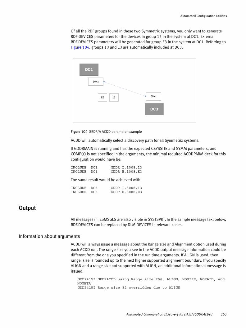
Automated Configuration Utilities
Of all the RDF groups found in these two Symmetrix systems, you only want to generate RDF-DEVICES parameters for the devices in group 13 in the system at DC1. External RDF.DEVICES parameters will be generated for group E3 in the system at DC1. Referring to Figure 104, groups 13 and E3 are automatically included at DC3.
Figure 104 SRDF/A ACDD parameter example
ACDD will automatically select a discovery path for all Symmetrix systems.
If GDDRMAIN is running and has the expected CSYSSITE and SYMM parameters, and COMP(Y) is not specified in the arguments, the minimal required ACDDPARM deck for this configuration would have be:
INCLUDE DC1 GDDR I,1008,13INCLUDE DC1 GDDR E,1008,E3
The same result would be achieved with:
INCLUDE DC3 GDDR I,5008,13INCLUDE DC3 GDDR E,5008,E3
Output
All messages in JESMSGLG are also visible in SYSTSPRT. In the sample message text below, RDF.DEVICES can be replaced by DLM.DEVICES in relevant cases.
Information about arguments
ACDD will always issue a message about the Range size and Alignment option used during each ACDD run. The range size you see in the ACDD output message information could be different from the one you specified in the run time arguments. If ALIGN is used, then range_size is rounded up to the next higher supported alignment boundary. If you specify ALIGN and a range size not supported with ALIGN, an additional informational message is issued:
GDDP415I GDDRACDD using Range size 256, ALIGN, NOSIZE, NORAID, and NOMETAGDDP415I Range size 32 overridden due to ALIGN
DC1
DC3
10xx
50xx13E3
Automated Configuration Discovery for DASD (GDDRACDD) 263

Automated Configuration Utilities
Depending on the presence/absence of the optional NOSIZE argument:
GDDP415I GDDRACDD RDF.DEVICES parameters will span different device sizesGDDP415I GDDRACDD RDF.DEVICES parameters will not span different device sizes
Depending on the presence/absence of the optional NORAID argument:
GDDP415I GDDRACDD RDF.DEVICES parameters will span different protection typesGDDP415I GDDRACDD RDF.DEVICES parameters will not span different protection types
Depending on the presence/absence of the optional NOMETA argument:
GDDP415I GDDRACDD RDF.DEVICES parameters will span meta and non-meta devicesGDDP415I GDDRACDD RDF.DEVICES parameters will not span meta and non-meta devices
If COMP(Y) is specified:
GDDP415I GDDRACDD running in Compatibility mode
If GLOBALS(CHECK) is specified:
GDDP415I GDDRACDD will perform validation of existing RDF.DEVICES parameters
Depending on whether GROUPS(BREAK) is specified:
GDDP415I Device range breaks in one ra-group will [not] affect device ranges in a second group
If FORCE is specified:
GDDP415I RDF.DEVICES parms will be generated, even if configuration errors are found
If NOSORT is specified:
GDDP415I RDF.DEVICES parms will NOT be sorted for optimal performance
If SCAN is specified:
GDDP415I GDDRACDD will stop after validation of parameters
Depending on the CONFIG(<site>,<topology>) argument:
GDDP415I Using Configuration description: <site>,<topology>
Recognized ACDDPARM statements
Recognized ACDDPARM statements, information retrieved from GDDMPARM, global variables used for “validation mode”, and discovery path information
All recognized ACDDPARM statements are echoed here, grouped by type. Please verify that this matches the input deck you thought you coded. This section also shows ACDDPARM lines that were ignored (except comments).
GDDP415W The following lines in ACDDPARM were ignored:GDDP415W STORAGE DC1 GDDR 1008 1008 5008,30
GDDP415I GDDMPARM: Sitelist: DC1 DC3GDDP415I GDDMPARM: and C-systems: CRKB CRKD
264 EMC GDDR Version 4.1 Product Guide

Automated Configuration Utilities
GDDP415IGDDP415I GDDRACDD running at DC1GDDP415IGDDP415I ACDDPARM: SYMM DC1(H) GDDR 000292601023,2000-200FGDDP415I ACDDPARM: SYMM DC2(H) GDDR 000292601156,6000-600FGDDP415I ACDDPARM: SYMM DC3(H) GDDR 000292601024,A000-A00FGDDP415IGDDP415I Selected Discovery pathsGDDP415I Site Symmetrix PathGDDP415I DC1 000292601023 2000GDDP415I DC2 000292601156 2000.10GDDP415I DC3 000292601024 2000.F9GDDP415IGDDP415I ACDDPARM: INCLUDE DC1 GDDR I,2000,10,20GDDP415I ACDDPARM: INCLUDE DC2 GDDR I,6000,10,30GDDP415I ACDDPARM: INCLUDE DC1 GDDR E,2000,00,F9GDDP415I ACDDPARM: INCLUDE DC2 GDDR E,6000,00,31GDDP415IGDDP415I ACDDPARM: GENERATE DC3 GDDR I,A000,(20,30)GDDP415I ACDDPARM: GENERATE DC3 GDDR E,A000,(F9,31)GDDP415I
If GENERATE parameters are present for a 2-site configuration, a warning message is issued:
GDDP415W GENERATE parameters ignored with 2-site configurations
If ACDD runs with GLOBALS(CHECK) it echoes the relevant existing global variables:
GDDP415I GDDP415I CONFIG: CONFIG.SRDFS=1GDDP415I CONFIG: CONFIG.AUTOSWAP=1GDDP415I CONFIG: CONFIG.SRDFA=1GDDP415I CONFIG: CONFIG.STAR=1GDDP415I CONFIG: CONFIG.R22=1GDDP415I CONFIG: CONFIG.SQAR=0GDDP415I CONFIG: Dasd Sitelist = DC1 DC2 DC3GDDP415I CONFIG: C-Sitelist = DC1 DC2 DC3GDDP415I CONFIG: Master C-system = VC1AGDDP415I CONFIG: Primary DASD Site = DC1GDDP415I CONFIG: Secondary DASD Site = DC2GDDP415I CONFIG: Current Topology = ConcurrentGDDP415I CONFIG: SRDF/Star with AutoSwapGDDP415I CONFIG: Expecting Link-Block at DC3 (from DC2)GDDP415I CONFIG: Expected SRDF Device Pairing:GDDP415I CONFIG: DC1-DC2: R1GDDP415I CONFIG: DC1-DC3: R1GDDP415I CONFIG: DC2-DC1: R2GDDP415I CONFIG: DC2-DC3: R1GDDP415I CONFIG: DC3-DC1: R2GDDP415I CONFIG: DC3-DC2: R2GDDP415I CONFIG: Existing RDF.DEVICES parameters [can be repeated for DLM]GDDP415I DC1-DC2GDDP415I PARMS.RDF.DEVICES.DC1.DC2.1 =2000,10,009E-00CF,009E-00CF,10,6000,0 GDDP415I PARMS.RDF.DEVICES.DC1.DC2.2 =2001,10,00D4-015B,00D4-015B,10,6001,0 GDDP415I PARMS.RDF.DEVICES.DC1.DC2.3 =2002,10,0174-017B,0174-017B,10,6002,0 GDDP415I PARMS.RDF.DEVICES.DC1.DC2.4 =2003,10,0194-019B,0194-019B,10,6003,0 GDDP415I PARMS.RDF.DEVICES.DC1.DC2.5 =2004,10,01B4-01BB,01B4-01BB,10,6004,0 GDDP415I PARMS.RDF.DEVICES.DC1.DC2.6 =2005,10,0200-0220,0200-0220,10,6005,0 GDDP415I PARMS.RDF.DEVICES.DC1.DC2.7 =2006,10,0223-0223,0224-0224,10,6006,0 GDDP415I PARMS.RDF.DEVICES.DC1.DC2.8 =2007,10,0228-0230,0228-0230,10,6007,0GDDP415I PARMS.RDF.DEVICES.DC1.DC2.9 =2008,10,0233-0233,0234-0234,10,6008,0 GDDP415I PARMS.RDF.DEVICES.DC1.DC2.10=2009,10,0238-024C,0238-024C,10,6009,0 GDDP415I PARMS.RDF.DEVICES.DC1.DC2.11=200A,10,024D-024D,024F-024F,10,600A,0
Automated Configuration Discovery for DASD (GDDRACDD) 265

Automated Configuration Utilities
If ACDD runs with GLOBALS(CHECK) it fabricates INCLUDE and GENERATE parameters as necessary. Those are echoed to the joblog:
GDDP415I (SIM) ACDDPARM: INCLUDE DC1 GDDR I,2000,10GDDP415I (SIM) ACDDPARM: INCLUDE DC1 GDDR I,2000,20GDDP415I (SIM) ACDDPARM: INCLUDE DC2 GDDR I,6000,10GDDP415I (SIM) ACDDPARM: INCLUDE DC2 GDDR I,6000,30GDDP415I (SIM) ACDDPARM: INCLUDE DC1 GDDR E,2000,00GDDP415I (SIM) ACDDPARM: INCLUDE DC1 GDDR E,2000,F9GDDP415I (SIM) ACDDPARM: INCLUDE DC2 GDDR E,6000,00GDDP415I (SIM) ACDDPARM: INCLUDE DC2 GDDR E,6000,31GDDP415IGDDP415I (SIM) ACDDPARM: GENERATE DC3 GDDR I,A000,(20,30)GDDP415I (SIM) ACDDPARM: GENERATE DC3 GDDR E,A000,(F9,31)
Several types of input errors are flagged by GDDP400E messages:
(RDF.DEVICES can be replaced by DLM.DEVICES where relevant)
GDDP400E Validation error: <text><text> can be one of the following: - GDDRMAIN not active. Please rerun with COMP(Y)- GDDRPFX must be length 4- Parameter not defined: <parameter>- GDDRACDD not supported at <siteid> (not a configured site)- No RDF.DEVICES parameters for site pair <site>-<site>- Different number of RDF.DEVICES parameters for site pair <site1>-<site2> versus
<site2>-<site1>- Parameter <n> for <site1>-<site2> is not a mirror image of <parameter value>- Parameter <n> for <site1>-<site2> is of a different type than <parameter value>- ACDDPARM not allocated- Failed to open ACDDPARM (<mode>) with RC=<rc>- No parameters in ACDDPARM- Running in compatibility mode but there are no [CSYSSITE] [SYMM] parameters in
ACDDPARM- Running while GDDRMAIN is down but there are no [CSYSSITE] [SYMM] parameters in
ACDDPARM- Running in compatibility mode but global variable validation is requested- Running while GDDRMAIN is down but global variable validation is requested- Parameter not defined: <parameter name>- C-system site <site> from GDDMPARM is not known in CONFIG.SITELIST: <list>- Duplicate definition of C-system <systemname>- Duplicate definition of C-system site <siteid>- 2, 3 or 4 C-systems required. Sitelist: <sitelist>- DC1 is a required site. Sitelist: <sitelist>- One of sites DC2, DC3 is required. Sitelist: <sitelist>- 3-Site config requires both DC2 and DC3. Sitelist: <sitelist>- Site DC4 is required in a 4-Site config. Sitelist: <sitelist>- Current system: <sysname> not defined in csyslist: <list>- Duplicate usage of gatekeeper <gk> at site <siteid> in [GDDMPARM] [ACDDPARM]- Invalid sitenumber ([not numeric] [>4] [<1]) in <line>- Duplicate definition for Symmetrix Unit <serial> at Site <siteid>- Site DC1 must have storage defined. Sitelist: <list>- CSYSSITE <siteid> has no SYMM in [ACDDPARM] [GDDMPARM]- Too many sites in SYMM-list in [ACDDPARM] [GDDMPARM]- One of sites DC2, DC3 must have storage defined. Sitelist: <list> from [ACDDPARM]
[GDDMPARM]- DC4 must have storage defined. Sitelist: <list> from [ACDDPARM] [GDDMPARM]- Both sites DC2 and DC3 must have storage defined. Sitelist: <list> from [ACDDPARM]
[GDDMPARM]- Gatekeeper <gk> in <site1>-<site2> parameter <value> is not known in any <site1>
SYMM parameter in GDDMPARM- No GK Pool defined for Symmetrix <serial> (<gk>) at Site <siteid>- Unknown Site <site> specified as CPDS - DC3 not supported as Primary DASD Site
266 EMC GDDR Version 4.1 Product Guide

Automated Configuration Utilities
- Unknown Site referenced on <line>- Unknown Symmetrix serial number referenced on <line>- Gatekeeper <gk> unknown at site <siteid> on <line>- Group <rag> in discovery path <path> for Symmetrix <serial> does not exist in
Symmetrix <serial>- Discovery path <path> locates Symmetrix <serial>. Expected to find <serial>- Discovery Path <path> for Symmetrix <serial> is not functional at point <part>- Unable to determine a Discovery path for Symmetrix <serial>. Please specify a
path in ACDDPARM- Invalid ra-group <rag> on <line>. Must be 2 chars long- Invalid character <char> in ra-group <rag> on <line>. Expected one of
0123456789ABCDEF"- Expected two serial numbers on <line>. Found: <text>- One of <serial1> <serial2> on <line> must be located at DC3. Found <site1> and
<site2>- Only one of <serial1> <serial2> on <line> must be located at DC3- Virtual group must connect DC1-DC4 or DC2-DC3. Found <site1>-<site2> on <line>- Unknown Symmetrix <serial> on <line>- Virtual group <rag> cannot be an existing group in <serial> on <line>- No INCLUDE parameters found in ACDDPARM- Invalid type (not E or I) on <line>- GK <gk> on <line> does not locate a Symmetrix at <site>- Invalid ra-group <rag> on <line>. [Must be length 2] [Not found in Symmetrix
<serial> at <site>] [Connects to same-site Symmetrix <serial>] [Connects DC1 to DC4 Symmetrixes, <serial> and <serial>] [Connects DC2 to DC3 Symmetrixes, <serial> and <serial>] [Connects to ra-group <rag> in <serial>. Asymmetrical ra-groups are not currently supported with GDDR.]
- Invalid external ra-group <rag> on <line>. [Connects DC1 to DC2 Symmetrixes, <serial> and <serial>] [Connects DC3 to DC4 Symmetrixes, <serial> and <serial>]
- Invalid char <char> in ra-group <rag> on <line>- INCLUDE of virtual group <rag> on <line> not allowed. (GENERATE parameters only)- Inclusion of <rag> as <type> on <line> conflicts with earlier inclusion as <type>- Invalid site on <line>. Expected one of <list>- Ra-groups on <line> must be specified as pairs- Only one of <rag>,<rag> is allowed to be virtual on <line>- One of <rag> and <rag> on <line> requires an INCLUDE- GENERATE type <type> on <line> conflicts with INCLUDE type <type> for group <rag>- Invalid ra-group <rag> on <line>. Should connect <site> to DC1 or DC2, not <site>- Invalid ra-groups <rag>,<rag> on <line>. Both connect <site> to <site>- No includes refer to Symmetrix <serial> at <site>- No includes connect Symmetrixes for site-pair <site>-<site>- Different number of RDF STAR ra-groups DC3-DC1 (nn) versus DC3-DC2 (nn)- Different number of RDF SQAR ra-groups DC1-DC3 (nn) versus DC2-DC4 (nn)- Larger number of RDF SQAR ra-groups <site1>-<site2> (nn) than <site3>-<site1>
(nn) in Symmetrix <serial> at <site1>
GDDRACDD site awareness
Based on the detected system name and the CSYSSITE parameters in ACDDPARM, GDDRACDD is able to determine which GDDR site it runs on, and issues the following message:
GDDP415I GDDRACDD running at DC2
GDDP400E will be issued in one of two formats (depending on when the error is caught), if the current system does not match one of the system names listed in CSYSSITE parameters:
GDDP400E Validation error: Current system: VC1A not defined in csyslist: O016 VC1B O01E
GDDP400E Validation error: GDDRACDD not supported at <siteid> (not a configured site)
Automated Configuration Discovery for DASD (GDDRACDD) 267

Automated Configuration Utilities
Wizard integration
If the JCL used to run GDDRACDD does not have an E04SRDFD or E05TFDEV DD statement, one or both of the following messages will be issued:
GDDP415I E04SRDFD not allocated, RDF.DEVICES parameters will not be available to GDDR Parameter Wizard
GDDP415I E05TFDEV not allocated, BCV.DCn.ONLYparameters will not be available to GDDR Parameter Wizard
If the JCL used to run ACDD has some or all of the optional DD-cards, but ACDD fails to open one of them, the following message will be issued:
GDDP415W Failed to open <ddname> (<mode>) with RC=<rc>
Messages related to Symmetrix discovery
Symmetrix device discovery is done one site at a time, one Symmetrix system at a time.
The GDDRACDD JESMSGLG shows progress messages as each Symmetrix system is being discovered:
GDDP402I Beginning Discovery of Symmetrix unitsGDDP410I Site: DC1 - Device ranges in Symm: 000292601023 (5875) GK:
2000GDDP402I Site: DC1 Symm: 000292601023 SP132 usage: 1786384GDDP410I Site: DC2 - Device ranges in Symm: 000292601156 (5875) GK:
2000.10GDDP402I Site: DC2 Symm: 000292601156 SP132 usage: 1781264GDDP410I Site: DC3 - Device ranges in Symm: 000292601024 (5875) GK:
2000.F9GDDP402I Site: DC3 Symm: 000292601024 SP132 usage: 1778504
Message GDDP410I identifies the site-location of the discovered Symmetrix system, its serial number and Enginuity level, as well as its discovery path from the site where ACDD is running. It signals the start of discovery for the listed Symmetrix system.
Message GDDP402I shows the amount of virtual storage used for this Symmetrix system. It signals the completion of discovery for the listed Symmetrix system.
Generated RDF.DEVICES and DLM.DEVICES parameters
The final section of the JESMSGLG is a complete listing of the RDF.DEVICES and DLM.DEVICES parameters generated for the discovered Symmetrix systems. The parameters are listed by site-pair, once in each direction.
GDDP419I RDF.DEVICES Parameters for Discovered SymmetrixesGDDP419IGDDP419I Site pair DC1-DC2GDDP419I PARMS.RDF.DEVICES.DC1.DC2.1 =2000,10,009E-00CF,009E-00CF,10,6000,0 ( 50 CS )GDDP419I PARMS.RDF.DEVICES.DC1.DC2.2 =2001,10,00D4-015B,00D4-015B,10,6001,0 ( 136 CS )GDDP419I PARMS.RDF.DEVICES.DC1.DC2.3 =2002,10,0174-017B,0174-017B,10,6002,0 ( 8 CS )GDDP419I PARMS.RDF.DEVICES.DC1.DC2.4 =2003,10,0194-019B,0194-019B,10,6003,0 ( 8 CS )GDDP419I PARMS.RDF.DEVICES.DC1.DC2.5 =2004,10,01B4-01BB,01B4-01BB,10,6004,0 ( 8 CS )GDDP419I PARMS.RDF.DEVICES.DC1.DC2.6 =2005,10,0200-0220,0200-0220,10,6005,0 ( 33 FS )GDDP419I PARMS.RDF.DEVICES.DC1.DC2.7 =2006,10,0223-0223,0224-0224,10,6006,0 ( 1 FS )GDDP419I PARMS.RDF.DEVICES.DC1.DC2.8 =2007,10,0228-0230,0228-0230,10,6007,0 ( 9 FS )GDDP419I PARMS.RDF.DEVICES.DC1.DC2.9 =2008,10,0233-0233,0234-0234,10,6008,0 ( 1 FS )GDDP419I PARMS.RDF.DEVICES.DC1.DC2.10=2009,10,0238-024C,0238-024C,10,6009,0 ( 21 FS )GDDP419I PARMS.RDF.DEVICES.DC1.DC2.11=200A,10,024D-024D,024F-024F,10,600A,0 ( 1 FS )GDDP419I PARMS.RDF.DEVICES.DC1.DC2.12=200B,10,024E-024E,024E-024E,10,600B,0 ( 1 FS )GDDP419I PARMS.RDF.DEVICES.DC1.DC2.13=200C,10,024F-024F,024D-024D,10,600C,0 ( 1 FS )
268 EMC GDDR Version 4.1 Product Guide

Automated Configuration Utilities
GDDP419I PARMS.RDF.DEVICES.DC1.DC2.14=200D,10,0270-0270,0270-0270,10,600D,0 ( 1 FS )GDDP419I PARMS.RDF.DEVICES.DC1.DC2.15=200E,10,0300-030F,0300-030F,10,600E,0 ( 16 CS )GDDP419I PARMS.RDF.DEVICES.DC1.DC2.16=200F,10,0340-034F,0340-034F,10,600F,0 ( 16 CS )GDDP419I PARMS.RDF.DEVICES.DC1.DC2.17=2000,10,0380-038F,0380-038F,10,6000,0 ( 16 CS )GDDP419I PARMS.RDF.DEVICES.DC1.DC2.18=2001,10,03C0-03CF,03C0-03CF,10,6001,0 ( 16 CS )GDDP419I PARMS.RDF.DEVICES.DC1.DC2.19=2002,10,0400-040F,0400-040F,10,6002,0 ( 16 CS )GDDP419I PARMS.RDF.DEVICES.DC1.DC2.20=2003,10,0440-044F,0440-044F,10,6003,0 ( 16 CS )GDDP419I PARMS.RDF.DEVICES.DC1.DC2.21=2004,10,0480-048F,0480-048F,10,6004,0 ( 16 CS )GDDP419I PARMS.RDF.DEVICES.DC1.DC2.22=2005,10,04C0-04CF,04C0-04CF,10,6005,0 ( 16 CS )GDDP419I PARMS.RDF.DEVICES.DC1.DC2.23=2006,10,0500-057F,0500-057F,10,6006,0 ( 128 CS )GDDP419I PARMS.RDF.DEVICES.DC1.DC2.27=200A,00,01E0-01FF,01E0-01FF,00,600A,1 ( 32 FS )….
Messages in SYSTSPRT
All messages visible in JESMSGLG are also echoed to SYSTSPRT. SYSTSPRT has some additional messages, not visible in JESMSGLG. The following sections discuss those elements in SYSTSPRT not visible in JESMSGLG.
Initial device range discovery
Messages in this section could be used to piece together RDF.DEVICES or DLM.DEVICES parameters if the actual device parameter generation by ACDD fails for some reason. The same information is reported in several stages of discovery.
SRDF device pairs by site pair and by group as seen from either side
GDDR DC1-DC2 RDF device pairs in group 000292601023.10 as seen from DC1009E-009E ===> 009E-009E009F-00CF ===> 009F-00CF00D4-0113 ===> 00D4-01130114-0153 ===> 0114-01530154-015B ===> 0154-015B0174-017B ===> 0174-017B…GDDR DC1-DC2 RDF device pairs in group 000292601156.10 as seen from DC2009E-00CF <=== 009E-00CF00D4-0113 <=== 00D4-01130114-0153 <=== 0114-01530154-015B <=== 0154-015B0174-017B <=== 0174-017B
Discovered ranges
Discovered RDF device rangesRDF device ranges for site-pair DC1-DC2 > 000292601023 Group: 10 ---> 000292601156 1 009E-009E <---> 009E-009E 1 (CS) (CS) Groups: (10 ) (10 ) 2 009F-00CF <---> 009F-00CF 49 (CS) (CS) Groups: (10 20) (10 ) 3 00D4-0113 <---> 00D4-0113 64 (CS) (CS) Groups: (10 20) (10 ) 4 0114-0153 <---> 0114-0153 64 (CS) (CS) Groups: (10 20) (10 ) 5 0154-015B <---> 0154-015B 8 (CS) (CS) Groups: (10 20) (10 ) 6 0174-017B <---> 0174-017B 8 (CS) (CS) Groups: (10 20) (10 ) 7 0194-019B <---> 0194-019B 8 (CS) (CS) Groups: (10 20) (10 ) 8 01B4-01BB <---> 01B4-01BB 8 (CS) (CS) Groups: (10 20) (10 )…RDF device ranges for site-pair DC1-DC3 > 000292601023 Group: 20 ---> 000292601024 1 009F-00CF <---> 009F-00CF 49 (CS) (CS) Groups: (10 20) (20 ) 2 00D4-0113 <---> 00D4-0113 64 (CS) (CS) Groups: (10 20) (20 ) 3 0114-0153 <---> 0114-0153 64 (CS) (CS) Groups: (10 20) (20 ) 4 0154-015B <---> 0154-015B 8 (CS) (CS) Groups: (10 20) (20 ) 5 0174-017B <---> 0174-017B 8 (CS) (CS) Groups: (10 20) (20 ) 6 0194-019B <---> 0194-019B 8 (CS) (CS) Groups: (10 20) (20 ) 7 01B4-01BB <---> 01B4-01BB 8 (CS) (CS) Groups: (10 20) (20 )
Automated Configuration Discovery for DASD (GDDRACDD) 269

Automated Configuration Utilities
8 0200-0213 <---> 0200-0213 20 (FS) (FS) Groups: (10 20) (20 )…RDF device ranges for site-pair DC2-DC3 > 000292601156 Group: 30 ---> 000292601024 > 000292601156 Group: 31 ---> 000292601024
Discovered and generated ranges
Discovered and generated RDF device rangesRDF device ranges for site-pair DC1-DC2 > 000292601023 Group: 10 ---> 000292601156 1 009E-009E <---> 009E-009E 1 (CS) (CS) Groups: (10 ) (10 ) 2 009F-00CF <---> 009F-00CF 49 (CS) (CS) Groups: (10 20) (10 30) 3 00D4-0113 <---> 00D4-0113 64 (CS) (CS) Groups: (10 20) (10 30) 4 0114-0153 <---> 0114-0153 64 (CS) (CS) Groups: (10 20) (10 30) 5 0154-015B <---> 0154-015B 8 (CS) (CS) Groups: (10 20) (10 30) 6 0174-017B <---> 0174-017B 8 (CS) (CS) Groups: (10 20) (10 30) 7 0194-019B <---> 0194-019B 8 (CS) (CS) Groups: (10 20) (10 30) 8 01B4-01BB <---> 01B4-01BB 8 (CS) (CS) Groups: (10 20) (10 30) 9 0200-0213 <---> 0200-0213 20 (FS) (FS) Groups: (10 20) (10 30) 10 0214-021F <---> 0214-021F 12 (FS) (FS) Groups: (10 20) (10 30)…RDF device ranges for site-pair DC1-DC3 > 000292601023 Group: 20 ---> 000292601024 1 009F-00CF <---> 009F-00CF 49 (CS) (CS) Groups: (10 20) (20 30) 2 00D4-0113 <---> 00D4-0113 64 (CS) (CS) Groups: (10 20) (20 30) 3 0114-0153 <---> 0114-0153 64 (CS) (CS) Groups: (10 20) (20 30) 4 0154-015B <---> 0154-015B 8 (CS) (CS) Groups: (10 20) (20 30) 5 0174-017B <---> 0174-017B 8 (CS) (CS) Groups: (10 20) (20 30) 6 0194-019B <---> 0194-019B 8 (CS) (CS) Groups: (10 20) (20 30) 7 01B4-01BB <---> 01B4-01BB 8 (CS) (CS) Groups: (10 20) (20 30) 8 0200-0213 <---> 0200-0213 20 (FS) (FS) Groups: (10 20) (20 30) 9 0214-021F <---> 0214-021F 12 (FS) (FS) Groups: (10 20) (20 30) 10 0220-0220 <---> 0220-0220 1 (FS) (FS) Groups: (10 20) (20 30)…RDF device ranges for site-pair DC2-DC3 > 000292601156 Group: 30 ---> 000292601024 1 009F-00CF <---> 009F-00CF 49 (CS) (CS) Groups: (10 30) (20 30) 2 00D4-0113 <---> 00D4-0113 64 (CS) (CS) Groups: (10 30) (20 30) 3 0114-0153 <---> 0114-0153 64 (CS) (CS) Groups: (10 30) (20 30) 4 0154-015B <---> 0154-015B 8 (CS) (CS) Groups: (10 30) (20 30) 5 0174-017B <---> 0174-017B 8 (CS) (CS) Groups: (10 30) (20 30) 6 0194-019B <---> 0194-019B 8 (CS) (CS) Groups: (10 30) (20 30) 7 01B4-01BB <---> 01B4-01BB 8 (CS) (CS) Groups: (10 30) (20 30) 8 0200-0213 <---> 0200-0213 20 (FS) (FS) Groups: (10 30) (20 30) 9 0214-021F <---> 0214-021F 12 (FS) (FS) Groups: (10 30) (20 30) 10 0220-0220 <---> 0220-0220 1 (FS) (FS) Groups: (10 30) (20 30)
RDF.DEVICES parameters
Messages in this section could be used to piece together RDF.DEVICES parameters if the actual device parameter generation by ACDD fails for some reason. The same information is reported in several stages of parameter generation. Each of these messages can be repeated for DLM.DEVICES parameters, if applicable.
Initial RDF.DEVICES parameters
Initial RDF.DEVICES Parameters Site pair DC1-DC2PARMS.RDF.DEVICES.DC1.DC2.1 =2000,10,009E-00CF,009E-00CF,10,6000,0 ( 50 CS )PARMS.RDF.DEVICES.DC1.DC2.2 =2000,10,00D4-015B,00D4-015B,10,6000,0 ( 136 CS )PARMS.RDF.DEVICES.DC1.DC2.3 =2000,10,0174-017B,0174-017B,10,6000,0 ( 8 CS )PARMS.RDF.DEVICES.DC1.DC2.4 =2000,10,0194-019B,0194-019B,10,6000,0 ( 8 CS )PARMS.RDF.DEVICES.DC1.DC2.5 =2000,10,01B4-01BB,01B4-01BB,10,6000,0 ( 8 CS )PARMS.RDF.DEVICES.DC1.DC2.6 =2000,00,01E0-01FF,01E0-01FF,00,6000,1 ( 32 FS )PARMS.RDF.DEVICES.DC1.DC2.7 =2000,10,0200-0220,0200-0220,10,6000,0 ( 33 FS )
270 EMC GDDR Version 4.1 Product Guide

Automated Configuration Utilities
PARMS.RDF.DEVICES.DC1.DC2.8 =2000,10,0223-0223,0224-0224,10,6000,0 ( 1 FS )PARMS.RDF.DEVICES.DC1.DC2.9 =2000,10,0228-0230,0228-0230,10,6000,0 ( 9 FS )PARMS.RDF.DEVICES.DC1.DC2.10=2000,10,0233-0233,0234-0234,10,6000,0 ( 1 FS )
Sorted RDF.DEVICES parameters
Sorted RDF.DEVICES parametersPARMS.RDF.DEVICES.DC1.DC2.1 =2000,10,009E-00CF,009E-00CF,10,6000,0 ( 50 CS )PARMS.RDF.DEVICES.DC1.DC2.2 =2000,10,00D4-015B,00D4-015B,10,6000,0 ( 136 CS )PARMS.RDF.DEVICES.DC1.DC2.3 =2000,10,0174-017B,0174-017B,10,6000,0 ( 8 CS )PARMS.RDF.DEVICES.DC1.DC2.4 =2000,10,0194-019B,0194-019B,10,6000,0 ( 8 CS )PARMS.RDF.DEVICES.DC1.DC2.5 =2000,10,01B4-01BB,01B4-01BB,10,6000,0 ( 8 CS )PARMS.RDF.DEVICES.DC1.DC2.6 =2000,00,01E0-01FF,01E0-01FF,00,6000,1 ( 32 FS )PARMS.RDF.DEVICES.DC1.DC2.7 =2000,10,0200-0220,0200-0220,10,6000,0 ( 33 FS )PARMS.RDF.DEVICES.DC1.DC2.8 =2000,10,0223-0223,0224-0224,10,6000,0 ( 1 FS )PARMS.RDF.DEVICES.DC1.DC2.9 =2000,10,0228-0230,0228-0230,10,6000,0 ( 9 FS )PARMS.RDF.DEVICES.DC1.DC2.10=2000,10,0233-0233,0234-0234,10,6000,0 ( 1 FS )
RDF.DEVICES parameters with gatekeepers from pools
RDF.DEVICES Parameters with GateKeepers from pools Site pair DC1-DC2PARMS.RDF.DEVICES.DC1.DC2.1 =2000,10,009E-00CF,009E-00CF,10,6000,0 ( 50 CS )PARMS.RDF.DEVICES.DC1.DC2.2 =2001,10,00D4-015B,00D4-015B,10,6001,0 ( 136 CS )PARMS.RDF.DEVICES.DC1.DC2.3 =2002,10,0174-017B,0174-017B,10,6002,0 ( 8 CS )PARMS.RDF.DEVICES.DC1.DC2.4 =2003,10,0194-019B,0194-019B,10,6003,0 ( 8 CS )PARMS.RDF.DEVICES.DC1.DC2.5 =2004,10,01B4-01BB,01B4-01BB,10,6004,0 ( 8 CS )PARMS.RDF.DEVICES.DC1.DC2.6 =2005,10,0200-0220,0200-0220,10,6005,0 ( 33 FS )PARMS.RDF.DEVICES.DC1.DC2.7 =2006,10,0223-0223,0224-0224,10,6006,0 ( 1 FS )PARMS.RDF.DEVICES.DC1.DC2.8 =2007,10,0228-0230,0228-0230,10,6007,0 ( 9 FS )PARMS.RDF.DEVICES.DC1.DC2.9 =2008,10,0233-0233,0234-0234,10,6008,0 ( 1 FS )PARMS.RDF.DEVICES.DC1.DC2.10=2009,10,0238-024C,0238-024C,10,6009,0 ( 21 FS )
Messages in SYMMDEVS
If the SYMMDEVS DD card is present in the GDDRACDD JCL, it contains the Symmetrix Device ranges report as created during discovery of the devices. It consists of a sequence of the following messages:
GDDP410I Site: DC3 - Device ranges in DMX: 000192601313 (5874) GK: B219.19GDDP411I LDEV-HDEV-COUNT-HTM-MBR- CYLS -MR- RDF-RDFGROUPS GDDP412I … as many as required, multiline for concurrent/cascaded devicesGDDP402I Site: DC3 DMX: 000192601313 SP132 usage: 7347200
Message GDDP410I identifies the site-location of the discovered Symmetrix system, its serial number and Enginuity level, as well as its discovery path from the site where ACDD is running.
Message GDDP411I is a header preceding the GDDP412I messages.
Message GDDP402I shows the amount of virtual storage used for this Symmetrix system.
Message GDDP412I has the following content:
◆ LDEV-HDEV
This is the low and high device for the discovered device range in the Symmetrix system identified by message GDDP410I. These are the “local” devices, as seen from the perspective of that Symmetrix system.
◆ COUNT
The number of Symmetrix devices in the reported range. For FBA-meta devices, this includes both the meta-heads and the meta-member devices in this range.
Automated Configuration Discovery for DASD (GDDRACDD) 271

Automated Configuration Utilities
◆ HTM
This is the local device type, reported as three flags:
• H Host-type: C for CKD devices, F for FBA devices, A for AS/400 devices, S for special devices
The following special devices are recognized:
– SVC: VCMDB devices – SIB:Internal BCV devices – SWO: WORM devices – SFI: Symmetrix File-system devices – SVA: Symmetrix Vaulting devices – SDU: Dummy devices – STH: Thin Backend devices
• T TimeFinder-type: B for BCV-devices, S for standard devices
• M Meta-type: H for meta-heads, M for meta-members, - for non-meta devices
Note: For FBA-meta-devices, an 'FSH' or 'FBH' range typically includes meta-heads and meta-members.
◆ MBR
For meta-devices, this is the number of Symmetrix devices making up each meta-device. This number includes the meta-head. Reported as '---' for non-meta devices.
◆ CYLS
This is the number of cylinders per device. For meta-head devices, this is the total number of cylinders summed over all devices in the meta. For meta-members, this is the number of cylinders per member.
◆ MR
This is the local protection type for the reported range. It is reported as:
• '--': device has no local protection• '-0': RAID-0 device (striping, not a protection level really)• '-5': RAID-5 device (can be 3+1 or 7+1)• '-6': RAID-6 device (can be 6+2 or 14+2)• '-1': RAID-1 device (local mirroring)
Note: For RAID-10, also known as CKD-Meta devices (striped by definition), if they are RAID-1, the current code shows this as '-1', not '10'.
◆ RDF
This is the local (that is, in the Symmetrix system being discovered) SRDF personality of the devices in the reported range. It is reported as:
• '----': not an SRDF device • 'R1--': R1 device • 'R2--': R2 device • 'R11-': Concurrent SRDF device, R1 in both reported RA-groups.
272 EMC GDDR Version 4.1 Product Guide

Automated Configuration Utilities
• 'R12-': R21 device which is R1 in first RA-group, R2 in second RA-group• 'R21-': R21 device which is R2 in first RA-group, R1 in second RA-group• 'R22-': R22 device
◆ RDFGROUPS
Because of the RDFGROUPS portion, the GDDP412I message can be spread over 2 lines, as shown in the following example. There will be 1 line per RDF group to which the reported device range belongs. The RDF groups are always listed in ascending order. (groups 25 and 28 below):
LDEV-HDEV-COUNT-HTM-MBR- CYLS -MR- RDF-RDFGROUPS 0078-007F- 8-CSH- 4- 10017--0-R11--25/----/T----/--W-/--------/192601314/0070-0077 28/----/T--D-/--W-/--------/192601313/007C-0083
Automated Configuration Discovery for DASD (GDDRACDD) 273

Automated Configuration Utilities
The RDFGROUPS part of the GDDP412I message consists of 7 fields, separated by '/'.
Messages in RDFGROUP
If the RDFGROUP DD card is present in the GDDRACDD JCL, it contains a summary report at the RDF group level. The report is presented in two parts:
◆ Part 1: List of RDF groups linking GDDR-managed Symmetrix systems
◆ Part 2: Unique GDDR RDF groups by site-pair and type
Part 1lists all RDF groups between Symmetrix systems for which a SYMM parameter is found, organized by site-pair. For each group an indication is given of its inclusion type (Internal or External or None). If applicable, the report indicates that a group is for DLm backend devices ("- DLm"). Offline groups are marked as "<<< OFFLINE <<<". Virtual groups are marked "- VIRTUAL". Groups connecting same-site Symmetrix systems are marked "- ignored".
NN/CETC/SAMDB/UNRI/tttttttt/sssssssss/LDEV-HDEV
NN 2-digit RDF group number
CEUTC This field reflects the CG-status, reported as 4 (future 5) flags
C CG-flag '-' if no CG flag
E ECA-flag '-' if no ECA flag
U UNR-on-Timeout flag '-' if no UNR-on-Timeout flag
T CG Trip occurred ‘-' if no CG trip occurred
C represents the ECA-window statusO ECA-window is openC ECA-window is closed normallyT ECA-window is closed due to a timeout
SAMDB This field reflects the SRDF status/mode, reported as 5 flags
S SRDF replication status
T if the devices are TNR '-' if not
A if active in SRDF/A '-' if not
M MSC-mode, reported as:'-' if not in MSC mode"0" "8" "C" "E" "F" = MSC-Cycle Tag
D Adaptive Copy Disk Mode '-' if not
B Link-Blocked '-' if not
UNRI This field reflects the host-availability status, reported as 4 flags
U UNR '-' if not
N NR '-' if not (applies to R2 only)
R RNR '-' if not
I ITA-attribute '-' if not
tttttttt This field has different meanings for SRDF/S versus SRDF/A devices
SRDF/S CG Hash code
SRDF/A MSC Group name
sssssssss Symmetrix serial number on the other side of this RA-group
LDEV-HDEV Low and high Symmetrix device number at the other side
274 EMC GDDR Version 4.1 Product Guide

Automated Configuration Utilities
Part 1 example:
GDDP417IGDDP417I List of RDFgroups linking GDDR Managed SymmetrixesGDDP417IGDDP417I Symmetrix units at DC1GDDP417IGDDP417I Site pair DC1-DC2GDDP417I 2000 000292601023 (5875) <--00 --> 000292601156 (5875) (6000) (External)GDDP417I 2000 000292601023 (5875) <--02 --> 000292601156 (5875) (6000) (Non-GDDR)GDDP417I 2000 000292601023 (5875) <--03 --> 000292601156 (5875) (6000) (Non-GDDR)GDDP417I 2000 000292601023 (5875) <--04 --> 000292601156 (5875) (6000) (Non-GDDR)GDDP417I 2000 000292601023 (5875) <--05 --> 000292601156 (5875) (6000) (Non-GDDR)GDDP417I 2000 000292601023 (5875) <--06 --> 000292601156 (5875) (6000) (Non-GDDR)GDDP417I 2000 000292601023 (5875) <--07 --> 000292601156 (5875) (6000) (Non-GDDR)…GDDP417I 2000 000292601023 (5875) <--0D --> 000292601156 (5875) (6000) (Non-GDDR)GDDP417I 2000 000292601023 (5875) <--0E --> 000292601156 (5875) (6000) (Non-GDDR)GDDP417I 2000 000292601023 (5875) <--0F --> 000292601156 (5875) (6000) (Non-GDDR)GDDP417I 2000 000292601023 (5875) <--10 --> 000292601156 (5875) (6000) (Internal)…GDDP417I 2000 000292601023 (5875) <--F5 --> 000292601156 (5875) (6000) (Non-GDDR)GDDP417I 2000 000292601023 (5875) <--F6 --> 000292601156 (5875) (6000) (Non-GDDR)GDDP417I 2000 000292601023 (5875) <--F7 --> 000292601156 (5875) (6000) (Non-GDDR)GDDP417I 2000 000292601023 (5875) <--F8 --> 000292601156 (5875) (6000) (Non-GDDR)GDDP417IGDDP417I Site pair DC1-DC3GDDP417I 2000 000292601023 (5875) <--16 --> 000292601024 (5875) (A000) (Non-GDDR)GDDP417I 2000 000292601023 (5875) <--17 --> 000292601024 (5875) (A000) (Non-GDDR)GDDP417I 2000 000292601023 (5875) <--20 --> 000292601024 (5875) (A000) (Internal)GDDP417I 2000 000292601023 (5875) <--60 --> 000292601024 (5875) (A000) (Non-GDDR)GDDP417I 2000 000292601023 (5875) <--78 --> 000292601024 (5875) (A000) (Non-GDDR)GDDP417I 2000 000292601023 (5875) <--D1 --> 000292601024 (5875) (A000) (Non-GDDR)GDDP417I 2000 000292601023 (5875) <--F1 --> 000292601024 (5875) (A000) (Non-GDDR)GDDP417I 2000 000292601023 (5875) <--F9 --> 000292601024 (5875) (A000) (External)GDDP417IGDDP417I Symmetrix units at DC2GDDP417IGDDP417I Site pair DC2-DC1GDDP417I 6000 000292601156 (5875) <--00 --> 000292601023 (5875) (2000) (External)GDDP417I 6000 000292601156 (5875) <--02 --> 000292601023 (5875) (2000) (Non-GDDR)GDDP417I 6000 000292601156 (5875) <--03 --> 000292601023 (5875) (2000) (Non-GDDR)GDDP417I 6000 000292601156 (5875) <--04 --> 000292601023 (5875) (2000) (Non-GDDR)GDDP417I 6000 000292601156 (5875) <--05 --> 000292601023 (5875) (2000) (Non-GDDR)GDDP417I 6000 000292601156 (5875) <--06 --> 000292601023 (5875) (2000) (Non-GDDR)GDDP417I 6000 000292601156 (5875) <--07 --> 000292601023 (5875) (2000) (Non-GDDR)…GDDP417I Site pair DC2-DC3GDDP417I 6000 000292601156 (5875) <--30 --> 000292601024 (5875) (A000) (Internal)GDDP417I 6000 000292601156 (5875) <--31 --> 000292601024 (5875) (A000) (External)GDDP417I 6000 000292601156 (5875) <--D2 --> 000292601024 (5875) (A000) (Non-GDDR)GDDP417I 6000 000292601156 (5875) <--E2 --> 000292601024 (5875) (A000) (Non-GDDR)GDDP417I 6000 000292601156 (5875) <--F2 --> 000292601024 (5875) (A000) (Non-GDDR)GDDP417IGDDP417I Symmetrix units at DC3GDDP417IGDDP417I Site pair DC3-DC1GDDP417I A000 000292601024 (5875) <--16 --> 000292601023 (5875) (2000) (Non-GDDR)GDDP417I A000 000292601024 (5875) <--17 --> 000292601023 (5875) (2000) (Non-GDDR)GDDP417I A000 000292601024 (5875) <--20 --> 000292601023 (5875) (2000) (Internal)GDDP417I A000 000292601024 (5875) <--60 --> 000292601023 (5875) (2000) (Non-GDDR)GDDP417I A000 000292601024 (5875) <--78 --> 000292601023 (5875) (2000) (Non-GDDR)GDDP417I A000 000292601024 (5875) <--D1 --> 000292601023 (5875) (2000) (Non-GDDR)GDDP417I A000 000292601024 (5875) <--F1 --> 000292601023 (5875) (2000) (Non-GDDR)GDDP417I A000 000292601024 (5875) <--F9 --> 000292601023 (5875) (2000) (External)GDDP417I
Automated Configuration Discovery for DASD (GDDRACDD) 275

Automated Configuration Utilities
GDDP417I Site pair DC3-DC2GDDP417I A000 000292601024 (5875) <--30 --> 000292601156 (5875) (6000) (Internal)GDDP417I A000 000292601024 (5875) <--31 --> 000292601156 (5875) (6000) (External)GDDP417I A000 000292601024 (5875) <--D2 --> 000292601156 (5875) (6000) (Non-GDDR)GDDP417I A000 000292601024 (5875) <--E2 --> 000292601156 (5875) (6000) (Non-GDDR)GDDP417I A000 000292601024 (5875) <--F2 --> 000292601156 (5875) (6000) (Non-GDDR)GDDP417I…
Part 2 lists all INCLUDE-d RDF groups, first the internal groups and then the external groups. For each type, the list is organized by site-pair.
Part 2 example:
GDDP417I Unique GDDR ra-groups by site-pair and typeGDDP417IGDDP417I RA-groups of type InternalGDDP417IGDDP417I DC1 GK RA GK DC2 ( DC1 Symm - DC2 Symm )GDDP417I 2000 10 6000 (000292601023-000292601156)GDDP417IGDDP417I DC1 GK RA GK DC3 ( DC1 Symm - DC3 Symm )GDDP417I 2000 20 A000 (000292601023-000292601024)GDDP417IGDDP417I DC2 GK RA GK DC3 ( DC2 Symm - DC3 Symm )GDDP417I 6000 30 A000 (000292601156-000292601024)GDDP417IGDDP417I RA-groups of type ExternalGDDP417IGDDP417I DC1 GK RA GK DC2 ( DC1 Symm - DC2 Symm )GDDP417I 2000 00 6000 (000292601023-000292601156)GDDP417IGDDP417I DC1 GK RA GK DC3 ( DC1 Symm - DC3 Symm )GDDP417I 2000 F9 A000 (000292601023-000292601024)GDDP417IGDDP417I DC2 GK RA GK DC3 ( DC2 Symm - DC3 Symm )GDDP417I 6000 31 A000 (000292601156-000292601024)
Messages in CREPAIR
If the CREPAIR DD card is present in the GDDRACDD JCL, it contains a set of createpair commands which could be used the reconstruct the GDDR-managed environment from scratch. The content of the report is influenced by the CONFIG(…) argument.
Example:
GDDP418IGDDP418I Createpair commands by site-pair and typeGDDP418IGDDP418I >>> Intended configuration: 3-site, CASCADED, Primary DASD site: DC1GDDP418IGDDP418I RA-groups of type InternalGDDP418IGDDP418I Sitepair DC1-DC2GDDP418I Use these commands from a host with channel access to the Symmetrix unit at DC1GDDP418I Caution: use LCLISR2 if you want the devices at DC1 to be R2 devicesGDDP418I SC VOL,LCL(2000,10),CREATEPAIR(ADCOPY-DISK,SUSPEND,STAR,LCLISR1),009E-00CF,009EGDDP418I SC VOL,LCL(2001,10),CREATEPAIR(ADCOPY-DISK,SUSPEND,STAR,LCLISR1),00D4-015B,00D4GDDP418I SC VOL,LCL(2002,10),CREATEPAIR(ADCOPY-DISK,SUSPEND,STAR,LCLISR1),0174-017B,0174…GDDP418I SC VOL,LCL(2007,10),CREATEPAIR(ADCOPY-DISK,SUSPEND,STAR,LCLISR1),1200-13FF,1200GDDP418I SC VOL,LCL(2008,10),CREATEPAIR(ADCOPY-DISK,SUSPEND,STAR,LCLISR1),1400-15FF,1400GDDP418I SC VOL,LCL(2009,10),CREATEPAIR(ADCOPY-DISK,SUSPEND,STAR,LCLISR1),4240-42FF,4210GDDP418IGDDP418I Sitepair DC2-DC1
276 EMC GDDR Version 4.1 Product Guide

Automated Configuration Utilities
GDDP418I Use these commands from a host with channel access to the Symmetrix unit at DC2GDDP418I Caution: use LCLISR1 if you want the devices at DC2 to be R1 devicesGDDP418I SC VOL,LCL(6000,10),CREATEPAIR(ADCOPY-DISK,SUSPEND,STAR,LCLISR2),009E-00CF,009EGDDP418I SC VOL,LCL(6001,10),CREATEPAIR(ADCOPY-DISK,SUSPEND,STAR,LCLISR2),00D4-015B,00D4GDDP418I SC VOL,LCL(6002,10),CREATEPAIR(ADCOPY-DISK,SUSPEND,STAR,LCLISR2),0174-017B,0174…GDDP418I SC VOL,LCL(6007,10),CREATEPAIR(ADCOPY-DISK,SUSPEND,STAR,LCLISR2),1200-13FF,1200GDDP418I SC VOL,LCL(6008,10),CREATEPAIR(ADCOPY-DISK,SUSPEND,STAR,LCLISR2),1400-15FF,1400GDDP418I SC VOL,LCL(6009,10),CREATEPAIR(ADCOPY-DISK,SUSPEND,STAR,LCLISR2),4210-42CF,4240GDDP418IGDDP418I Sitepair DC1-DC3GDDP418I Use these commands from a host with channel access to the Symmetrix unit at DC1GDDP418I to create an R22 configurationGDDP418I Caution: use LCLISR2 if you want the devices at DC1 to be R2 devicesGDDP418I SC VOL,LCL(2000,20),CREATEPAIR(ADCOPY-DISK,SUSPEND,STAR,LCLISR1),009F-00CF,009FGDDP418I SC VOL,LCL(2001,20),CREATEPAIR(ADCOPY-DISK,SUSPEND,STAR,LCLISR1),00D4-015B,00D4GDDP418I SC VOL,LCL(2002,20),CREATEPAIR(ADCOPY-DISK,SUSPEND,STAR,LCLISR1),0174-017B,0174…GDDP418I SC VOL,LCL(2005,20),CREATEPAIR(ADCOPY-DISK,SUSPEND,STAR,LCLISR1),1200-13FF,1200GDDP418I SC VOL,LCL(2006,20),CREATEPAIR(ADCOPY-DISK,SUSPEND,STAR,LCLISR1),1400-15FF,1400GDDP418I SC VOL,LCL(2007,20),CREATEPAIR(ADCOPY-DISK,SUSPEND,STAR,LCLISR1),4240-42FF,41F0GDDP418IGDDP418I Sitepair DC3-DC1GDDP418I Use these commands from a host with channel access to the Symmetrix unit at DC3GDDP418I to create an R22 configurationGDDP418I Caution: use LCLISR1 if you want the devices at DC3 to be R1 devicesGDDP418I SC VOL,LCL(A000,20),CREATEPAIR(ADCOPY-DISK,SUSPEND,STAR,LCLISR2),009F-00CF,009FGDDP418I SC VOL,LCL(A001,20),CREATEPAIR(ADCOPY-DISK,SUSPEND,STAR,LCLISR2),00D4-015B,00D4GDDP418I SC VOL,LCL(A002,20),CREATEPAIR(ADCOPY-DISK,SUSPEND,STAR,LCLISR2),0174-017B,0174…GDDP418I SC VOL,LCL(A005,20),CREATEPAIR(ADCOPY-DISK,SUSPEND,STAR,LCLISR2),1200-13FF,1200GDDP418I SC VOL,LCL(A006,20),CREATEPAIR(ADCOPY-DISK,SUSPEND,STAR,LCLISR2),1400-15FF,1400GDDP418I SC VOL,LCL(A007,20),CREATEPAIR(ADCOPY-DISK,SUSPEND,STAR,LCLISR2),41F0-42AF,4240GDDP418IGDDP418I Sitepair DC2-DC3GDDP418I Use these commands from a host with channel access to the Symmetrix unit at DC2GDDP418I Caution: use LCLISR2 if you want the devices at DC2 to be R2 devicesGDDP418I SC VOL,LCL(6000,30),CREATEPAIR(ADCOPY-DISK,SUSPEND,STAR,LCLISR1),009F-00CF,009FGDDP418I SC VOL,LCL(6001,30),CREATEPAIR(ADCOPY-DISK,SUSPEND,STAR,LCLISR1),00D4-015B,00D4GDDP418I SC VOL,LCL(6002,30),CREATEPAIR(ADCOPY-DISK,SUSPEND,STAR,LCLISR1),0174-017B,0174…GDDP418I SC VOL,LCL(6004,30),CREATEPAIR(ADCOPY-DISK,SUSPEND,STAR,LCLISR1),1200-13FF,1200GDDP418I SC VOL,LCL(6005,30),CREATEPAIR(ADCOPY-DISK,SUSPEND,STAR,LCLISR1),1400-15FF,1400GDDP418I SC VOL,LCL(6006,30),CREATEPAIR(ADCOPY-DISK,SUSPEND,STAR,LCLISR1),4210-42CF,41F0GDDP418IGDDP418I Sitepair DC3-DC2GDDP418I Use these commands from a host with channel access to the Symmetrix unit at DC3GDDP418I Caution: use LCLISR1 if you want the devices at DC3 to be R1 devicesGDDP418I SC VOL,LCL(A000,30),CREATEPAIR(ADCOPY-DISK,SUSPEND,STAR,LCLISR2),009F-00CF,009FGDDP418I SC VOL,LCL(A001,30),CREATEPAIR(ADCOPY-DISK,SUSPEND,STAR,LCLISR2),00D4-015B,00D4GDDP418I SC VOL,LCL(A002,30),CREATEPAIR(ADCOPY-DISK,SUSPEND,STAR,LCLISR2),0174-017B,0174…GDDP418I SC VOL,LCL(A004,30),CREATEPAIR(ADCOPY-DISK,SUSPEND,STAR,LCLISR2),1200-13FF,1200GDDP418I SC VOL,LCL(A005,30),CREATEPAIR(ADCOPY-DISK,SUSPEND,STAR,LCLISR2),1400-15FF,1400GDDP418I SC VOL,LCL(A006,30),CREATEPAIR(ADCOPY-DISK,SUSPEND,STAR,LCLISR2),41F0-42AF,4210GDDP418IGDDP418I RA-groups of type ExternalGDDP418IGDDP418I Sitepair DC1-DC2GDDP418I Use these commands from a host with channel access to the Symmetrix unit at DC1GDDP418I Caution: use LCLISR2 if you want the devices at DC1 to be R2 devicesGDDP418I SC VOL,LCL(200A,00),CREATEPAIR(ADCOPY-DISK,SUSPEND,STAR,LCLISR1),01E0-01FF,01E0GDDP418I SC VOL,LCL(200B,00),CREATEPAIR(ADCOPY-DISK,SUSPEND,STAR,LCLISR1),0254-0254,0256GDDP418I SC VOL,LCL(200C,00),CREATEPAIR(ADCOPY-DISK,SUSPEND,STAR,LCLISR1),0255-0255,0252…GDDP418I SC VOL,LCL(2002,00),CREATEPAIR(ADCOPY-DISK,SUSPEND,STAR,LCLISR1),43FD-43FD,43CA
Automated Configuration Discovery for DASD (GDDRACDD) 277
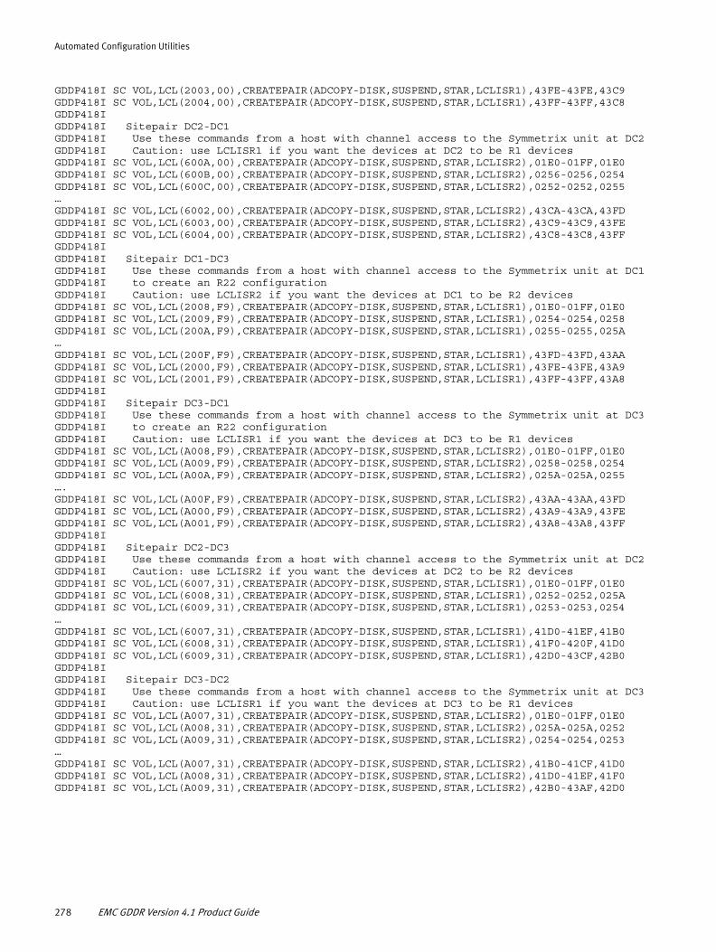
Automated Configuration Utilities
GDDP418I SC VOL,LCL(2003,00),CREATEPAIR(ADCOPY-DISK,SUSPEND,STAR,LCLISR1),43FE-43FE,43C9GDDP418I SC VOL,LCL(2004,00),CREATEPAIR(ADCOPY-DISK,SUSPEND,STAR,LCLISR1),43FF-43FF,43C8GDDP418IGDDP418I Sitepair DC2-DC1GDDP418I Use these commands from a host with channel access to the Symmetrix unit at DC2GDDP418I Caution: use LCLISR1 if you want the devices at DC2 to be R1 devicesGDDP418I SC VOL,LCL(600A,00),CREATEPAIR(ADCOPY-DISK,SUSPEND,STAR,LCLISR2),01E0-01FF,01E0GDDP418I SC VOL,LCL(600B,00),CREATEPAIR(ADCOPY-DISK,SUSPEND,STAR,LCLISR2),0256-0256,0254GDDP418I SC VOL,LCL(600C,00),CREATEPAIR(ADCOPY-DISK,SUSPEND,STAR,LCLISR2),0252-0252,0255…GDDP418I SC VOL,LCL(6002,00),CREATEPAIR(ADCOPY-DISK,SUSPEND,STAR,LCLISR2),43CA-43CA,43FDGDDP418I SC VOL,LCL(6003,00),CREATEPAIR(ADCOPY-DISK,SUSPEND,STAR,LCLISR2),43C9-43C9,43FEGDDP418I SC VOL,LCL(6004,00),CREATEPAIR(ADCOPY-DISK,SUSPEND,STAR,LCLISR2),43C8-43C8,43FFGDDP418IGDDP418I Sitepair DC1-DC3GDDP418I Use these commands from a host with channel access to the Symmetrix unit at DC1GDDP418I to create an R22 configurationGDDP418I Caution: use LCLISR2 if you want the devices at DC1 to be R2 devicesGDDP418I SC VOL,LCL(2008,F9),CREATEPAIR(ADCOPY-DISK,SUSPEND,STAR,LCLISR1),01E0-01FF,01E0GDDP418I SC VOL,LCL(2009,F9),CREATEPAIR(ADCOPY-DISK,SUSPEND,STAR,LCLISR1),0254-0254,0258GDDP418I SC VOL,LCL(200A,F9),CREATEPAIR(ADCOPY-DISK,SUSPEND,STAR,LCLISR1),0255-0255,025A…GDDP418I SC VOL,LCL(200F,F9),CREATEPAIR(ADCOPY-DISK,SUSPEND,STAR,LCLISR1),43FD-43FD,43AAGDDP418I SC VOL,LCL(2000,F9),CREATEPAIR(ADCOPY-DISK,SUSPEND,STAR,LCLISR1),43FE-43FE,43A9GDDP418I SC VOL,LCL(2001,F9),CREATEPAIR(ADCOPY-DISK,SUSPEND,STAR,LCLISR1),43FF-43FF,43A8GDDP418IGDDP418I Sitepair DC3-DC1GDDP418I Use these commands from a host with channel access to the Symmetrix unit at DC3GDDP418I to create an R22 configurationGDDP418I Caution: use LCLISR1 if you want the devices at DC3 to be R1 devicesGDDP418I SC VOL,LCL(A008,F9),CREATEPAIR(ADCOPY-DISK,SUSPEND,STAR,LCLISR2),01E0-01FF,01E0GDDP418I SC VOL,LCL(A009,F9),CREATEPAIR(ADCOPY-DISK,SUSPEND,STAR,LCLISR2),0258-0258,0254GDDP418I SC VOL,LCL(A00A,F9),CREATEPAIR(ADCOPY-DISK,SUSPEND,STAR,LCLISR2),025A-025A,0255….GDDP418I SC VOL,LCL(A00F,F9),CREATEPAIR(ADCOPY-DISK,SUSPEND,STAR,LCLISR2),43AA-43AA,43FDGDDP418I SC VOL,LCL(A000,F9),CREATEPAIR(ADCOPY-DISK,SUSPEND,STAR,LCLISR2),43A9-43A9,43FEGDDP418I SC VOL,LCL(A001,F9),CREATEPAIR(ADCOPY-DISK,SUSPEND,STAR,LCLISR2),43A8-43A8,43FFGDDP418IGDDP418I Sitepair DC2-DC3GDDP418I Use these commands from a host with channel access to the Symmetrix unit at DC2GDDP418I Caution: use LCLISR2 if you want the devices at DC2 to be R2 devicesGDDP418I SC VOL,LCL(6007,31),CREATEPAIR(ADCOPY-DISK,SUSPEND,STAR,LCLISR1),01E0-01FF,01E0GDDP418I SC VOL,LCL(6008,31),CREATEPAIR(ADCOPY-DISK,SUSPEND,STAR,LCLISR1),0252-0252,025AGDDP418I SC VOL,LCL(6009,31),CREATEPAIR(ADCOPY-DISK,SUSPEND,STAR,LCLISR1),0253-0253,0254…GDDP418I SC VOL,LCL(6007,31),CREATEPAIR(ADCOPY-DISK,SUSPEND,STAR,LCLISR1),41D0-41EF,41B0GDDP418I SC VOL,LCL(6008,31),CREATEPAIR(ADCOPY-DISK,SUSPEND,STAR,LCLISR1),41F0-420F,41D0GDDP418I SC VOL,LCL(6009,31),CREATEPAIR(ADCOPY-DISK,SUSPEND,STAR,LCLISR1),42D0-43CF,42B0GDDP418IGDDP418I Sitepair DC3-DC2GDDP418I Use these commands from a host with channel access to the Symmetrix unit at DC3GDDP418I Caution: use LCLISR1 if you want the devices at DC3 to be R1 devicesGDDP418I SC VOL,LCL(A007,31),CREATEPAIR(ADCOPY-DISK,SUSPEND,STAR,LCLISR2),01E0-01FF,01E0GDDP418I SC VOL,LCL(A008,31),CREATEPAIR(ADCOPY-DISK,SUSPEND,STAR,LCLISR2),025A-025A,0252GDDP418I SC VOL,LCL(A009,31),CREATEPAIR(ADCOPY-DISK,SUSPEND,STAR,LCLISR2),0254-0254,0253…GDDP418I SC VOL,LCL(A007,31),CREATEPAIR(ADCOPY-DISK,SUSPEND,STAR,LCLISR2),41B0-41CF,41D0GDDP418I SC VOL,LCL(A008,31),CREATEPAIR(ADCOPY-DISK,SUSPEND,STAR,LCLISR2),41D0-41EF,41F0GDDP418I SC VOL,LCL(A009,31),CREATEPAIR(ADCOPY-DISK,SUSPEND,STAR,LCLISR2),42B0-43AF,42D0
278 EMC GDDR Version 4.1 Product Guide

Automated Configuration Utilities
Messages in FBAMETA
If the FBAMETA DD card is present in the GDDRACDD JCL, it contains an overview of GDDR-managed FBA meta devices. It shows meta-head versus meta-member relations as well as SRDF device pairing information for FBA meta devices.
Example:
GDDP422IGDDP422I FBA Meta Devices in GDDR managed ra-groupsGDDP422IGDDP422I RA-groups of type InternalGDDP422IGDDP422I Site: DC1GDDP422I Symmetrix: 000292601023GDDP422I Head: 0220 Members: 0224 0221 0222GDDP422I Group: 10 0220 0221 0222 0223GDDP422I Group: 20 0220 0221 0222 0223GDDP422I Head: 0223 Members: 0226 0225 0227GDDP422I Group: 10 0224 0225 0226 0227GDDP422I Group: 20 0224 0225 0226 0227GDDP422I Head: 0228 Members: 0229 022A 022BGDDP422I Group: 10 0228 0229 022A 022BGDDP422I Group: 20 0228 0229 022A 022BGDDP422I Head: 022C Members: 022E 022D 022FGDDP422I Group: 10 022C 022D 022E 022FGDDP422I Group: 20 022C 022D 022E 022FGDDP422I Head: 0230 Members: 0234 0231 0232GDDP422I Group: 10 0230 0231 0232 0233GDDP422I Group: 20 0230 0231 0232 0233GDDP422I Head: 0233 Members: 0236 0235 0237GDDP422I Group: 10 0234 0235 0236 0237GDDP422I Group: 20 0234 0235 0236 0237GDDP422I Head: 0238 Members: 0239 023A 023BGDDP422I Group: 10 0238 0239 023A 023BGDDP422I Group: 20 0238 0239 023A 023BGDDP422I Head: 023C Members: 023E 023D 023FGDDP422I Group: 10 023C 023D 023E 023FGDDP422I Group: 20 023C 023D 023E 023FGDDP422I Head: 0240 Members: 0244 0241 0242 0243 0246 0247 0249 0245 0248 024A 024B 0250 0251 0252 0253GDDP422I Group: 10 0240 0241 0242 0243 0248 0249 024A 024B 0244 0245 0246 0247 0250 0251 0254 0255GDDP422I Group: 20 0240 0241 0242 0243 0246 0247 024A 024B 0244 0245 0248 0249 024C 024D 024E 024FGDDP422I Head: 0270 Members: 0272 0271 0273GDDP422I Group: 10 0270 0271 0272 0273GDDP422I Group: 20 0270 0271 0272 0273GDDP422IGDDP422I Site: DC2GDDP422I Symmetrix: 000292601156GDDP422I Head: 0220 Members: 0221 0222 0223GDDP422I Group: 10 0220 0224 0221 0222GDDP422I Group: 30 0220 0221 0222 0223GDDP422I Head: 0224 Members: 0225 0226 0227GDDP422I Group: 10 0223 0226 0225 0227GDDP422I Group: 30 0224 0225 0226 0227GDDP422I Head: 0228 Members: 0229 022A 022BGDDP422I Group: 10 0228 0229 022A 022BGDDP422I Group: 30 0228 0229 022A 022BGDDP422I Head: 022C Members: 022D 022E 022FGDDP422I Group: 10 022C 022E 022D 022FGDDP422I Group: 30 022C 022D 022E 022FGDDP422I Head: 0230 Members: 0231 0232 0233GDDP422I Group: 10 0230 0234 0231 0232GDDP422I Group: 30 0230 0231 0232 0233
Automated Configuration Discovery for DASD (GDDRACDD) 279
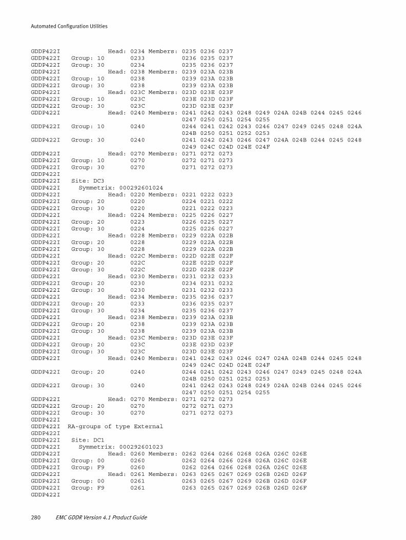
Automated Configuration Utilities
GDDP422I Head: 0234 Members: 0235 0236 0237GDDP422I Group: 10 0233 0236 0235 0237GDDP422I Group: 30 0234 0235 0236 0237GDDP422I Head: 0238 Members: 0239 023A 023BGDDP422I Group: 10 0238 0239 023A 023BGDDP422I Group: 30 0238 0239 023A 023BGDDP422I Head: 023C Members: 023D 023E 023FGDDP422I Group: 10 023C 023E 023D 023FGDDP422I Group: 30 023C 023D 023E 023FGDDP422I Head: 0240 Members: 0241 0242 0243 0248 0249 024A 024B 0244 0245 0246 0247 0250 0251 0254 0255GDDP422I Group: 10 0240 0244 0241 0242 0243 0246 0247 0249 0245 0248 024A 024B 0250 0251 0252 0253GDDP422I Group: 30 0240 0241 0242 0243 0246 0247 024A 024B 0244 0245 0248 0249 024C 024D 024E 024FGDDP422I Head: 0270 Members: 0271 0272 0273GDDP422I Group: 10 0270 0272 0271 0273GDDP422I Group: 30 0270 0271 0272 0273GDDP422IGDDP422I Site: DC3GDDP422I Symmetrix: 000292601024GDDP422I Head: 0220 Members: 0221 0222 0223GDDP422I Group: 20 0220 0224 0221 0222GDDP422I Group: 30 0220 0221 0222 0223GDDP422I Head: 0224 Members: 0225 0226 0227GDDP422I Group: 20 0223 0226 0225 0227GDDP422I Group: 30 0224 0225 0226 0227GDDP422I Head: 0228 Members: 0229 022A 022BGDDP422I Group: 20 0228 0229 022A 022BGDDP422I Group: 30 0228 0229 022A 022BGDDP422I Head: 022C Members: 022D 022E 022FGDDP422I Group: 20 022C 022E 022D 022FGDDP422I Group: 30 022C 022D 022E 022FGDDP422I Head: 0230 Members: 0231 0232 0233GDDP422I Group: 20 0230 0234 0231 0232GDDP422I Group: 30 0230 0231 0232 0233GDDP422I Head: 0234 Members: 0235 0236 0237GDDP422I Group: 20 0233 0236 0235 0237GDDP422I Group: 30 0234 0235 0236 0237GDDP422I Head: 0238 Members: 0239 023A 023BGDDP422I Group: 20 0238 0239 023A 023BGDDP422I Group: 30 0238 0239 023A 023BGDDP422I Head: 023C Members: 023D 023E 023FGDDP422I Group: 20 023C 023E 023D 023FGDDP422I Group: 30 023C 023D 023E 023FGDDP422I Head: 0240 Members: 0241 0242 0243 0246 0247 024A 024B 0244 0245 0248 0249 024C 024D 024E 024FGDDP422I Group: 20 0240 0244 0241 0242 0243 0246 0247 0249 0245 0248 024A 024B 0250 0251 0252 0253GDDP422I Group: 30 0240 0241 0242 0243 0248 0249 024A 024B 0244 0245 0246 0247 0250 0251 0254 0255GDDP422I Head: 0270 Members: 0271 0272 0273GDDP422I Group: 20 0270 0272 0271 0273GDDP422I Group: 30 0270 0271 0272 0273GDDP422IGDDP422I RA-groups of type ExternalGDDP422IGDDP422I Site: DC1GDDP422I Symmetrix: 000292601023GDDP422I Head: 0260 Members: 0262 0264 0266 0268 026A 026C 026EGDDP422I Group: 00 0260 0262 0264 0266 0268 026A 026C 026EGDDP422I Group: F9 0260 0262 0264 0266 0268 026A 026C 026EGDDP422I Head: 0261 Members: 0263 0265 0267 0269 026B 026D 026FGDDP422I Group: 00 0261 0263 0265 0267 0269 026B 026D 026FGDDP422I Group: F9 0261 0263 0265 0267 0269 026B 026D 026FGDDP422I
280 EMC GDDR Version 4.1 Product Guide

Automated Configuration Utilities
GDDP422I Site: DC2GDDP422I Symmetrix: 000292601156GDDP422I Head: 0260 Members: 0262 0264 0266 0268 026A 026C 026EGDDP422I Group: 00 0260 0262 0264 0266 0268 026A 026C 026EGDDP422I Group: 31 0260 0262 0264 0266 0268 026A 026C 026EGDDP422I Head: 0261 Members: 0263 0265 0267 0269 026B 026D 026FGDDP422I Group: 00 0261 0263 0265 0267 0269 026B 026D 026FGDDP422I Group: 31 0261 0263 0265 0267 0269 026B 026D 026FGDDP422IGDDP422I Site: DC3GDDP422I Symmetrix: 000292601024GDDP422I Head: 0260 Members: 0262 0264 0266 0268 026A 026C 026EGDDP422I Group: F9 0260 0262 0264 0266 0268 026A 026C 026EGDDP422I Group: 31 0260 0262 0264 0266 0268 026A 026C 026EGDDP422I Head: 0261 Members: 0263 0265 0267 0269 026B 026D 026FGDDP422I Group: F9 0261 0263 0265 0267 0269 026B 026D 026FGDDP422I Group: 31 0261 0263 0265 0267 0269 026B 026D 026F
Exception reporting
Asymmetrical configurations
If GDDRACDD discovers asymmetry in the Symmetrix device numbers and the ALIGN option is specified, an warning message is issued:
GDDP415WGDDP415W ALIGN was specified or defaulted, but an asymmetrical device configuration was discoveredGDDP415W Generated RDF.DEVICES parameters may not be alignedGDDP415W
This message is issued to explain why generated parameters may not be aligned, which may be unexpected if you requested them to be aligned. It is of no further consequence.
Configuration validation
The following configuration errors are flagged with message GDDP420E. Some of these cause RC=8 and others cause a higher return code. See the following list.
Note: Items flagged with RC=8 may lead to the generation of RDF.DEVICES parameters, if ACDD is run with the FORCE argument. There is no guarantee of any kind that the generated parameters are usable or even correct.
GDDP420E Error: <text><text> can be one of the following: - No device pairs discovered for <site>-<site> group <rag> in Symmetrix <serial> at <site>- No device pairs discovered for <site>-<site> group <rag> in Symmetrix <serial> at <site> and no other group associated in a GENERATE parameter- No device pairs discovered for <site>-<site> group <rag> in Symmetrix <serial> at <site> and associated group <rag>- Site pair <site>-<site> has device pairs in some groups, but group <rag> in Symmetrix <serial> at <site> has no device pairs- Device pairs discovered for groups <rag> and <rag> in Symmetrix <serial> at <site>- Different device pairs discovered for groups <rag> and <rag> in Symmetrix <serial> at <site> - Device range <symmdev>-<symmdev> in Symmetrix <serial> is paired <DCm>-DC3 but not <DCn>-DC3, and no GENERATE parameter for <rag>- All devices paired <DCm>-DC3 in group <rag> in Symmetrix <serial> should be paired <DCn>-DC3 in the same group. Found <rag> and <rag>- Device pairs discovered for <site>-<site> group <rag> in Symmetrix <serial>
Automated Configuration Discovery for DASD (GDDRACDD) 281

Automated Configuration Utilities
- Device <symmdev> in Symmetrix <serial> at <site> is paired with device <symmdev> in Symmetrix <serial> at <site>, but the remote device is paired with <symmdev> in <rag>- Required <site>-<site> replication not found for device <symmdev> RA(<rag>) in Symmetrix <serial> at <site>. Check device <symmdev> in Symmetrix <serial> at <site>- Replication for device <symmdev> RA(<rag>) in Symmetrix <serial> at <site> does not form a [triplet] [quadruplet]. Device <symmdev> in Symmetrix <serial> at <site> is paired with <symmdev> in Symmetrix <serial>- Invalid SRDF/Star configuration: <site>-<site> device range <symmdev>-<symmdev> in Symmetrix <serial> has no <site>-<site> protection.- Expected Link-Block not found for devices <dev1>-<dev2> in ra-group <group> in Symmetrix <serial> at <site>- Unexpected Link-Block found for devices <dev1>-<dev2> in ra-group <group> in Symmetrix <serial> at <site>- Devices <dev1>-<dev2> in ra-group <group> in Symmetrix <serial> at <site> are not defined to GDDR- Expected rdf-type <type1> for devices <dev1>-<dev2> in ra-group <group> in Symmetrix <serial> at <site>. Found <type2>- Device <dev#> is defined to GDDR in range <dev1>-<dev2>, but could not be found in ra-group <group> in Symmetrix <serial> at <site>- Device <dev#> is <type1> in ra-group <group> in Symmetrix <serial> at <site>. Expected <type2>- Unable to generate <site>-<site> device pair for range <symmdev>-<symmdev> in Symmetrix <serial> (GK <gk>) at <site>. No <site>-<site> ra-group found for range <symmdev>-<symmdev> in Symmetrix <serial> (GK <gk>) at <site>. (Groups found: <rag-list>)- Unable to generate <site>-<site> device pair for range <symmdev>-<symmdev> in Symmetrix <serial> (GK <gk>) at <site>. Found ra-group <rag> for range <symmdev>-<symmdev> in Symmetrix <serial> (GK <gk>) at <site>. Expected ra-group <rag>- Site: <siteid> Symm: <serial> Meta-member: <symmdev> has different ra-groups than head <symmdev> (<mbr-groups> versus <head-groups>)- Site: <siteid> Symm: <serial> Meta-member: <symmdev> has different RAID-level than head <symmdev> (<mbr-level> versus <head-level>)- Site: <siteid> Symm: <serial> Meta-member: <symmdev> has different RDFtype than head <symmdev> (<mbr-type> versus <head-type>)
The following configuration issues are flagged with message GDDP421W, and cause RC=4. These messages should be reviewed as they could either result in incorrect RDF.DEVICES parameters or cause issues during GDDR scripts.
GDDP421W Warning: <text><text> can be one of the following:- Site: <siteid> Symm: <serial> Meta-member: <symmdev> has different RDF-mirror flags than head <symmdev> (<mbr-flags versus <head-flags)- Site: <siteid> Symm: <serial> Meta-member: <symmdev> has different ADCOPY flag than head <symmdev> (<mbr-flag versus <head-flag)- Site: <siteid> Symm: <serial> Meta-member: <symmdev> has different CG flags than head <symmdev> (<mbr-flags versus <head-flags)- Site: <siteid> Symm: <serial> GK: <gk> RA: <rag>. NON-GDDR group <rag> found for GDDR-managed device range <dev1>-<dev2>
282 EMC GDDR Version 4.1 Product Guide

Automated Configuration Utilities
GDDR RDF Director Overview utility (GDDRDIRS)The GDDR RDF Director Overview Utility is designed to be run at any site with a GDDR configuration, and provides an overview of the currently configured directors used for SRDF in Symmetrix systems known to GDDR.
GDDRDIRS reports are available in two formats:
◆ The default format provides RDF director status for all directors used by all RDF groups in Symmetrix systems defined to GDDR.
◆ Use of the optional GDDR argument limits the report output to only the directors and RDF groups defined in GDDR RDF.DEVICES parameters (this includes the consistency protected RDF groups as well as the external RDF groups).
Sample JCL for the GDDRDIRS utility is in hlq.GDDRvrm.SAMPLIB (GDDRDIRS).
This sample report has been edited for brevity. The sections of interest are
◆ GDDR SRDF directors overview for ALL RDF groups Figure 105 on page 284 and Figure 106 on page 285
◆ RDF groups by director by Symmetrix by site, Site: DC1, Figure 107 on page 286
◆ RDF groups by director by Symmetrix by site, Site: DC2, Figure 108 on page 287
◆ RDF groups by director by Symmetrix by site, Site: DC3 and Site UNK, Figure 109 on page 288
GDDR RDF Director Overview utility (GDDRDIRS) 283
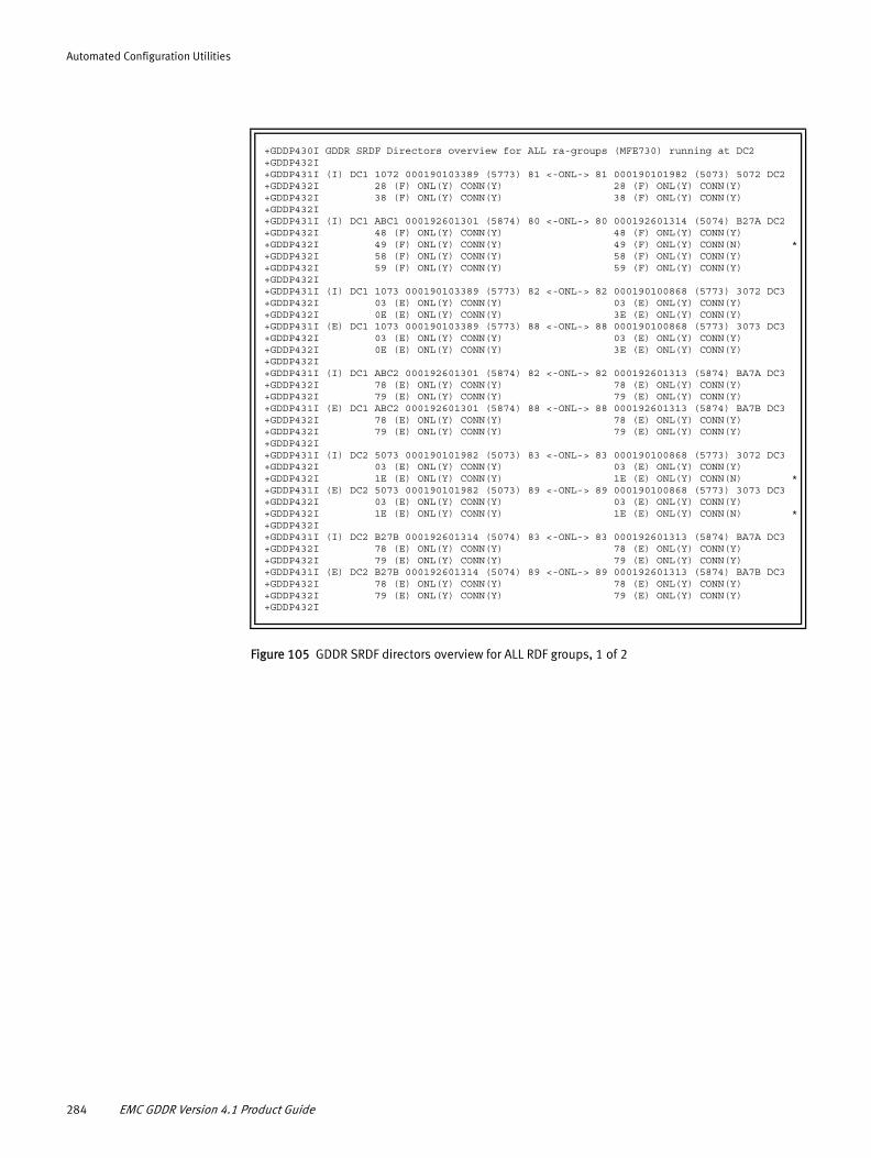
Automated Configuration Utilities
Figure 105 GDDR SRDF directors overview for ALL RDF groups, 1 of 2
+GDDP430I GDDR SRDF Directors overview for ALL ra-groups (MFE730) running at DC2+GDDP432I +GDDP431I (I) DC1 1072 000190103389 (5773) 81 <-ONL-> 81 000190101982 (5073) 5072 DC2+GDDP432I 28 (F) ONL(Y) CONN(Y) 28 (F) ONL(Y) CONN(Y)+GDDP432I 38 (F) ONL(Y) CONN(Y) 38 (F) ONL(Y) CONN(Y)+GDDP432I +GDDP431I (I) DC1 ABC1 000192601301 (5874) 80 <-ONL-> 80 000192601314 (5074) B27A DC2+GDDP432I 48 (F) ONL(Y) CONN(Y) 48 (F) ONL(Y) CONN(Y)+GDDP432I 49 (F) ONL(Y) CONN(Y) 49 (F) ONL(Y) CONN(N) *+GDDP432I 58 (F) ONL(Y) CONN(Y) 58 (F) ONL(Y) CONN(Y)+GDDP432I 59 (F) ONL(Y) CONN(Y) 59 (F) ONL(Y) CONN(Y)+GDDP432I +GDDP431I (I) DC1 1073 000190103389 (5773) 82 <-ONL-> 82 000190100868 (5773) 3072 DC3+GDDP432I 03 (E) ONL(Y) CONN(Y) 03 (E) ONL(Y) CONN(Y)+GDDP432I 0E (E) ONL(Y) CONN(Y) 3E (E) ONL(Y) CONN(Y)+GDDP431I (E) DC1 1073 000190103389 (5773) 88 <-ONL-> 88 000190100868 (5773) 3073 DC3+GDDP432I 03 (E) ONL(Y) CONN(Y) 03 (E) ONL(Y) CONN(Y)+GDDP432I 0E (E) ONL(Y) CONN(Y) 3E (E) ONL(Y) CONN(Y)+GDDP432I +GDDP431I (I) DC1 ABC2 000192601301 (5874) 82 <-ONL-> 82 000192601313 (5874) BA7A DC3+GDDP432I 78 (E) ONL(Y) CONN(Y) 78 (E) ONL(Y) CONN(Y)+GDDP432I 79 (E) ONL(Y) CONN(Y) 79 (E) ONL(Y) CONN(Y)+GDDP431I (E) DC1 ABC2 000192601301 (5874) 88 <-ONL-> 88 000192601313 (5874) BA7B DC3+GDDP432I 78 (E) ONL(Y) CONN(Y) 78 (E) ONL(Y) CONN(Y)+GDDP432I 79 (E) ONL(Y) CONN(Y) 79 (E) ONL(Y) CONN(Y)+GDDP432I +GDDP431I (I) DC2 5073 000190101982 (5073) 83 <-ONL-> 83 000190100868 (5773) 3072 DC3+GDDP432I 03 (E) ONL(Y) CONN(Y) 03 (E) ONL(Y) CONN(Y)+GDDP432I 1E (E) ONL(Y) CONN(Y) 1E (E) ONL(Y) CONN(N) *+GDDP431I (E) DC2 5073 000190101982 (5073) 89 <-ONL-> 89 000190100868 (5773) 3073 DC3+GDDP432I 03 (E) ONL(Y) CONN(Y) 03 (E) ONL(Y) CONN(Y)+GDDP432I 1E (E) ONL(Y) CONN(Y) 1E (E) ONL(Y) CONN(N) *+GDDP432I +GDDP431I (I) DC2 B27B 000192601314 (5074) 83 <-ONL-> 83 000192601313 (5874) BA7A DC3+GDDP432I 78 (E) ONL(Y) CONN(Y) 78 (E) ONL(Y) CONN(Y)+GDDP432I 79 (E) ONL(Y) CONN(Y) 79 (E) ONL(Y) CONN(Y)+GDDP431I (E) DC2 B27B 000192601314 (5074) 89 <-ONL-> 89 000192601313 (5874) BA7B DC3+GDDP432I 78 (E) ONL(Y) CONN(Y) 78 (E) ONL(Y) CONN(Y)+GDDP432I 79 (E) ONL(Y) CONN(Y) 79 (E) ONL(Y) CONN(Y)+GDDP432I
284 EMC GDDR Version 4.1 Product Guide

Automated Configuration Utilities
Figure 106 GDDR SRDF directors overview for ALL RDF groups, 2 of 2
+GDDP431I (N) DC1 1072 000190103389 (5773) 01 <-ONL-> 01 000190101982 (5073) 5072 DC2+GDDP432I 28 (F) ONL(Y) CONN(Y) 28 (F) ONL(Y) CONN(Y)+GDDP432I 38 (F) ONL(Y) CONN(Y) 38 (F) ONL(Y) CONN(Y)+GDDP431I (N) DC1 1072 000190103389 (5773) 05 <-ONL-> 05 000190101982 (5073) 5072 DC2+GDDP432I 28 (F) ONL(Y) CONN(Y) 28 (F) ONL(Y) CONN(Y)+GDDP432I 38 (F) ONL(Y) CONN(Y) 38 (F) ONL(Y) CONN(Y)+GDDP431I (N) DC1 1072 000190103389 (5773) 10 <-ONL-> 10 000190101982 (5073) 5072 DC2+GDDP432I 28 (F) ONL(Y) CONN(Y) 28 (F) ONL(Y) CONN(Y)+GDDP432I 38 (F) ONL(Y) CONN(Y) 38 (F) ONL(Y) CONN(Y)+GDDP431I (N) DC1 1072 000190103389 (5773) 11 <-ONL-> 11 000190101982 (5073) 5072 DC2+GDDP432I 28 (F) ONL(Y) CONN(Y) 28 (F) ONL(Y) CONN(Y)+GDDP432I 38 (F) ONL(Y) CONN(Y) 38 (F) ONL(Y) CONN(Y)+GDDP431I (N) DC1 1072 000190103389 (5773) 15 <-ONL-> 15 000190101982 (5073) 5072 DC2+GDDP432I 28 (F) ONL(Y) CONN(Y) 28 (F) ONL(Y) CONN(Y)+GDDP432I 38 (F) ONL(Y) CONN(Y) 38 (F) ONL(Y) CONN(Y)+GDDP431I (N) DC1 1072 000190103389 (5773) 16 <-ONL-> 16 000190101982 (5073) 5072 DC2+GDDP432I 28 (F) ONL(Y) CONN(Y) 28 (F) ONL(Y) CONN(Y)+GDDP432I 38 (F) ONL(Y) CONN(Y) 38 (F) ONL(Y) CONN(Y)+GDDP431I (N) DC1 1072 000190103389 (5773) 18 <-ONL-> 18 000190101982 (5073) 5072 DC2+GDDP432I 28 (F) ONL(Y) CONN(Y) 28 (F) ONL(Y) CONN(Y)+GDDP432I 38 (F) ONL(Y) CONN(Y) 38 (F) ONL(Y) CONN(Y)+GDDP431I (N) DC1 1072 000190103389 (5773) 19 <-ONL-> 19 000190101982 (5073) 5072 DC2+GDDP432I 28 (F) ONL(Y) CONN(Y) 28 (F) ONL(Y) CONN(Y)+GDDP432I 38 (F) ONL(Y) CONN(Y) 38 (F) ONL(Y) CONN(Y)+GDDP431I (N) DC1 1072 000190103389 (5773) 1A <-ONL-> 1A 000190101982 (5073) 5072 DC2+GDDP432I 28 (F) ONL(Y) CONN(Y) 28 (F) ONL(Y) CONN(Y)+GDDP432I 38 (F) ONL(Y) CONN(Y) 38 (F) ONL(Y) CONN(Y)+GDDP431I (N) DC1 1072 000190103389 (5773) 3C <-ONL-> 3C 000190101982 (5073) 5072 DC2+GDDP432I 28 (F) ONL(Y) CONN(Y) 28 (F) ONL(Y) CONN(Y)+GDDP431I (N) DC1 1072 000190103389 (5773) 3D <-ONL-> 3D 000190101982 (5073) 5072 DC2+GDDP432I 28 (F) ONL(Y) CONN(Y) 28 (F) ONL(Y) CONN(Y)+GDDP431I (N) DC1 1072 000190103389 (5773) 3E <-ONL-> 3E 000190101982 (5073) 5072 DC2+GDDP432I 28 (F) ONL(Y) CONN(Y) 28 (F) ONL(Y) CONN(Y)+GDDP431I (N) DC1 1072 000190103389 (5773) 3F <-ONL-> 3F 000190101982 (5073) 5072 DC2+GDDP432I 28 (F) ONL(Y) CONN(Y) 28 (F) ONL(Y) CONN(Y)+GDDP431I (N) DC1 1072 000190103389 (5773) 40 <-ONL-> 40 000190101982 (5073) 5072 DC2+GDDP432I 28 (F) ONL(Y) CONN(Y) 28 (F) ONL(Y) CONN(Y)+GDDP432I 38 (F) ONL(Y) CONN(Y) 38 (F) ONL(Y) CONN(Y)+GDDP431I (N) DC1 1072 000190103389 (5773) 4C <-ONL-> 4C 000190101982 (5073) 5072 DC2+GDDP432I 28 (F) ONL(Y) CONN(Y) 28 (F) ONL(Y) CONN(Y)+GDDP432I 38 (F) ONL(Y) CONN(Y) 38 (F) ONL(Y) CONN(Y)+GDDP431I (N) DC1 1072 000190103389 (5773) 5A <-ONL-> 5A 000190101982 (5073) 5072 DC2+GDDP432I 28 (F) ONL(Y) CONN(Y) 28 (F) ONL(Y) CONN(Y)+GDDP431I (N) DC1 1072 000190103389 (5773) 70 <-ONL-> 70 000190101982 (5073) 5072 DC2+GDDP432I 28 (F) ONL(Y) CONN(Y) 28 (F) ONL(Y) CONN(Y)+GDDP432I 38 (F) ONL(Y) CONN(Y) 38 (F) ONL(Y) CONN(Y)+GDDP431I (N) DC1 1072 000190103389 (5773) 80 <-ONL-> 80 000190101982 (5073) 5072 DC2
GDDR RDF Director Overview utility (GDDRDIRS) 285

Automated Configuration Utilities
Figure 107 RDF groups by director by Symmetrix by site, Site: DC1
+GDDP431I (N) DC3 3072 000190100868 (5773) 42 <-OFF-> FF 000192601314 (5074) B27A DC2 *+GDDP432I 03 (E) ONL(Y) CONN(Y) -- (---) ------ -------+GDDP432I 0E (E) ONL(Y) CONN(N) -- (---) ------ ------- *+GDDP432I 1E (E) ONL(Y) CONN(N) -- (---) ------ ------- *+GDDP432I +GDDP435I Site: DC1+GDDP436I Symmetrix: 000190103389 (5773) - GK: 1072 Path: 5072.01+GDDP437I Director: 28 (F) ONL(Y) CONN(Y)+GDDP438I RA-groups: (I) 81+GDDP438I RA-groups: (E)+GDDP438I RA-groups: (N) 01 05 10 11 15 16 18 19 1A 3C 3D 3E 3F 40 4C 5A 70 80 B1 E1 +GDDP437I Director: 38 (F) ONL(Y) CONN(Y)+GDDP438I RA-groups: (I) 81+GDDP438I RA-groups: (E)+GDDP438I RA-groups: (N) 01 05 10 11 15 16 18 19 1A 40 4C 70 80 B1 E1 F1 F4+GDDP437I Director: 03 (E) ONL(Y) CONN(Y)+GDDP438I RA-groups: (I) 82+GDDP438I RA-groups: (E) 88+GDDP438I RA-groups: (N) 02 04 06 1B 20 21 25 36 B3 E2 E8 F2 F6+GDDP437I Director: 0E (E) ONL(Y) CONN(Y)+GDDP438I RA-groups: (I) 82+GDDP438I RA-groups: (E) 88+GDDP438I RA-groups: (N) 02 04 06 1B 20 21 25 36 B3 E2 E8 F2 F6+GDDP437I Director: 2E (E) ONL(Y) CONN(Y)+GDDP438I RA-groups: (I)+GDDP438I RA-groups: (E)+GDDP438I RA-groups: (N) 02 06 20 21 5B E2+GDDP437I Director: 13 (E) ONL(Y) CONN(Y)+GDDP438I RA-groups: (I)+GDDP438I RA-groups: (E)+GDDP438I RA-groups: (N) 20 21+GDDP437I Director: 33 (E) ONL(Y) CONN(N) *+GDDP438I RA-groups: (I)+GDDP438I RA-groups: (E)+GDDP438I RA-groups: (N) 21+GDDP438I +GDDP436I Symmetrix: 000192601301 (5874) - GK: ABC1 Path: B27A.00+GDDP437I Director: 48 (F) ONL(Y) CONN(Y)+GDDP438I RA-groups: (I) 80+GDDP438I RA-groups: (E)+GDDP438I RA-groups: (N) 00 03 10 15 1A 1F 25 2A 41 60 70 A0 B1 C1 D0 E4 F0 F4 05 5A +GDDP437I Director: 49 (F) ONL(Y) CONN(Y)+GDDP438I RA-groups: (I) 80+GDDP438I RA-groups: (E)
286 EMC GDDR Version 4.1 Product Guide

Automated Configuration Utilities
Figure 108 RDF groups by director by Symmetrix by site, Site: DC2
+GDDP435I Site: DC2+GDDP436I Symmetrix: 000190101982 (5073) - GK: 5072 Path: 5072+GDDP437I Director: 28 (F) ONL(Y) CONN(Y)+GDDP438I RA-groups: (I) 81+GDDP438I RA-groups: (E)+GDDP438I RA-groups: (N) 01 05 10 11 15 16 18 19 1A 3C 3D 3E 3F 40 4C 5A 70 80 B1 E1 +GDDP437I Director: 38 (F) ONL(Y) CONN(Y)+GDDP438I RA-groups: (I) 81+GDDP438I RA-groups: (E)+GDDP438I RA-groups: (N) 01 05 10 11 15 16 18 19 1A 40 4C 70 80 B1 E1 F1 F4 50+GDDP437I Director: 03 (E) ONL(Y) CONN(Y)+GDDP438I RA-groups: (I) 83+GDDP438I RA-groups: (E) 89+GDDP438I RA-groups: (N) 03 07 1C 26 30 31 35 B2 E3 F3 F5+GDDP437I Director: 1E (E) ONL(Y) CONN(Y)+GDDP438I RA-groups: (I) 83+GDDP438I RA-groups: (E) 89+GDDP438I RA-groups: (N) 03 07 08 1C 26 30 31 35 B2 E3 F3 F5+GDDP437I Director: 0E (E) ONL(Y) CONN(N) *+GDDP438I RA-groups: (I)+GDDP438I RA-groups: (E)+GDDP438I RA-groups: (N) 03 07 31+GDDP437I Director: 33 (E) ONL(Y) CONN(Y)+GDDP438I RA-groups: (I)+GDDP438I RA-groups: (E)+GDDP438I RA-groups: (N) 03 07 31 E3+GDDP437I Director: 23 (E) ONL(Y) CONN(Y)+GDDP438I RA-groups: (I)+GDDP438I RA-groups: (E)+GDDP438I RA-groups: (N) 08 31+GDDP438I +GDDP436I Symmetrix: 000192601314 (5074) - GK: B27A Path: B27A+GDDP437I Director: 48 (F) ONL(Y) CONN(Y)+GDDP438I RA-groups: (I) 80+GDDP438I RA-groups: (E)+GDDP438I RA-groups: (N) 00 03 10 15 1A 1F 25 2A 41 60 70 A0 B1 C1 D0 E4 F0 F4 50 06+GDDP437I Director: 49 (F) ONL(Y) CONN(N) *+GDDP438I RA-groups: (I) 80+GDDP438I RA-groups: (E)+GDDP438I RA-groups: (N) 00 03 10 15 1A 1F 25 60 70 A0 C1 F0 F4 50+GDDP437I Director: 58 (F) ONL(Y) CONN(Y)+GDDP438I RA-groups: (I) 80+GDDP438I RA-groups: (E)+GDDP438I RA-groups: (N) 03 1A 5B A0 B1 C1 D0 E1 E4 F4+GDDP437I Director: 59 (F) ONL(Y) CONN(Y)+GDDP438I RA-groups: (I) 80+GDDP438I RA-groups: (E)
GDDR RDF Director Overview utility (GDDRDIRS) 287

Automated Configuration Utilities
Figure 109 RDF groups by director by Symmetrix by site, Site: DC3 and Site UNK
SRDF device and BCV status reporting utilitiesBatch utilities which interrogate Symmetrix devices for their local or remote replication status:
◆ GDDRTF00, which can be used to check BCV status
◆ GDDRSC06, which can be used to check SRDF device status.
Refer to the same named SAMPLIB members for usage instructions.
+GDDP435I Site: DC3+GDDP436I Symmetrix: 000190100868 (5773) - GK: 3072 Path: 5072.03+GDDP437I Director: 03 (E) ONL(Y) CONN(Y)+GDDP438I RA-groups: (I) 82 83+GDDP438I RA-groups: (E) 88 89+GDDP438I RA-groups: (N) 02 04 06 1B 20 21 25 36 B3 E2 F2 F6 03 07 1C 26 30 31 35 B2 +GDDP437I Director: 3E (E) ONL(Y) CONN(Y)+GDDP438I RA-groups: (I) 82+GDDP438I RA-groups: (E) 88+GDDP438I RA-groups: (N) 02 06 20 21 25 36 5B B3 E2 E8 F2 F6 03 07 08 26 31 35 B2 E3 +GDDP437I Director: 1E (E) ONL(Y) CONN(N) *+GDDP438I RA-groups: (I) 83+GDDP438I RA-groups: (E) 89+GDDP438I RA-groups: (N) 1B 20 21 03 07 1C 30 31 32 42+GDDP437I Director: 23 (E) ONL(Y) CONN(N) *+GDDP438I RA-groups: (I)+GDDP438I RA-groups: (E)+GDDP438I RA-groups: (N) 02 04 06 20 21 E2 E8 03 07 08 31 E3+GDDP437I Director: 0E (E) ONL(Y) CONN(N) *+GDDP438I RA-groups: (I)+GDDP438I RA-groups: (E)+GDDP438I RA-groups: (N) 21 31 32 42+GDDP438I +GDDP436I Symmetrix: 000192601313 (5874) - GK: BA7A Path: B27A.02+GDDP437I Director: 78 (E) ONL(Y) CONN(Y)+GDDP438I RA-groups: (I) 82 83+GDDP438I RA-groups: (E) 88 89+GDDP438I RA-groups: (N) 01 04 14 18 1B 1D 20 28 2B 2F 42 61 A1 B2 C3 D1 D2 E5 F1 F3 +GDDP438I RA-groups: (N) 63 A2 B3 C2 E2 E6 F2 F6+GDDP437I Director: 79 (E) ONL(Y) CONN(Y)+GDDP438I RA-groups: (I) 82 83+GDDP438I RA-groups: (E) 88 89+GDDP438I RA-groups: (N) 01 04 14 18 1B 1D 20 28 2F 61 71 A1 B2 C3 E5 F1 F3 F5 02 19 +GDDP438I RA-groups: (N) E6 F2 F6+GDDP438I +GDDP438I +GDDP435I Site: UNK+GDDP436I Symmetrix: 000187940471 (5671) - GK: ---- Path: 5072.01.03+GDDP437I Director: 31 (F) ONL(Y) CONN(Y)+GDDP438I RA-groups: (I)+GDDP438I RA-groups: (E)+GDDP438I RA-groups: (N) 03+GDDP438I +GDDP436I Symmetrix: 000187720450 (----) - GK: ---- Path: No path found+GDDP438I +GDDP436I Symmetrix: 000190103189 (----) - GK: ---- Path: No path found+GDDP438I +GDDP438I
288 EMC GDDR Version 4.1 Product Guide

APPENDIX EBCPii Interface
This appendix describes the IBM BCPii interface.
◆ Introduction to the BCPii interface......................................................................... 290◆ BCPii HMC Networking capabilities and requirements ........................................... 291◆ GDDMPARM CPC parameter entries ....................................................................... 291◆ Security changes required to use BCPii.................................................................. 294◆ SYS1.PARMLIB changes required for BCPii............................................................. 295◆ GDDRBPCI BCPii test job for C-Systems .................................................................. 296
BCPii Interface 289
BCPii Interface
Introduction to the BCPii interfaceThe Base Control Program internal interface (BCPii) is the interface to the IBM Mainframe Service Element (SE) and the Hardware Management Console (HMC) used to communicate with the Central Processing Complex (CPC) SE. Prior to version 4.0, EMC GDDR's sole HMC communication method with the CPC, Images, and other system objects has been via the z Series API utilized via the Computer Associates OPS/MVS product. BCPii is similar in functionality but, unlike the OPS/MVS interface which communicates directly with a system's HMC via TCP/IP, BCPii provides for a direct link via the operating system to the SE associated with the local CPC or to a remote CPC via the existing HMC LAN Network as described in “BCPii HMC Networking capabilities and requirements” on page 291. BCPii support is added with the release of EMC GDDR V4.0.
In order to use BCPii, a number of requirements must be met. One requirement is that the z/OS operating system be at level 1.11 or higher (BCPii can run under z/OS 1.10 with the installed BCPii deliverable however not all functionality is available at the 1.10 level). In addition, the CPC must be a z9 or higher (BC or EC). There are certain MCL levels that must be met which are explained in the BCPii chapter of the MVS Programming Callable Services for High Level Languages document (SA22-7613). Additionally there are specific actions that must be performed on the SE/HMC for each CPC in order to enable BCPii to run on that CPC. This will be referred to as LIC Enabled status for the HMC in reference to the SE/CPC.
The BCPii interface provides a Connect and Disconnect function to objects associated with the mainframe CPC. Various functions can then be performed against those objects across the established connections. The relevant object types are CPC, Image, Capacity Record, and the major HMC profile types of Image, Load, and Reset. The connection type determines the functions available to the caller. BCPii also provides a Command function allowing z/OS HMC command functions to be entered against the connected-to object. For example, for a CPC connection, command options such as Activate and Deactivate can be requested. For an Image connection, command options such as Load, Reset Clear, z/OS Operating System Commands, and others can be issued.
The BCPii interface also provides List and Query functionality against the object it is connected to, allowing retrieved information to be used in determining the logic path followed in GDDR. The List function lists all objects of a given type associated with the HMC network. A list of CPCs can be obtained that are within the HMC Grouping associated with the local CPC on whose image/LPAR the BCPii List functions are executed. “BCPii HMC Networking capabilities and requirements” on page 291 provides more information on this topic. A list of Images associated with a connected-to CPC can also be requested. Similar lists are available for the other connection types. The Query function returns setting and information specific to the connected-to object allowing the caller to query setup and operational settings for the CPC, the Image, the Profiles, and all other object types. Complementing this Query function is the Set function allowing modification of certain settings within the object. Load parameters for an Image can be changed. LPAR weightings within a CPC can be changed. There are many options available for modification.
290 EMC GDDR Version 4.1 Product Guide

BCPii Interface
BCPii HMC Networking capabilities and requirementsThe Service Element (SE) is a specialized laptop in the CPC used to setup, maintain, and control system objects on that CPC. The HMC is an external PC running specialized code that communicates with the SE for all affiliated CPCs allowing, for the most part, the same level of control against the objects associated with any listed CPC but without requiring physical proximity to the CPC. An HMC can control more than a single CPC, thus introducing the concept of CPC grouping. A CPC group is a defined list of CPCs that an HMC can address.
BCPii works with the local SE. All requests that may be resolved locally do not involve any HMC with LIC Enabled status. Each SE affiliates with an HMC which introduces that SE to the CPC group. If more than one HMC has the SE in the CPC group, and all such HMCs have LIC Enabled status, then, for a remote HMC request, the first HMC to get the tap from the SE is the one BCPii communicates with.
BCPii can only talk to those remote SE/CPCs that are defined in the CPC group on the HMC with which the local SE is affiliated. If multiple HMCs are defined to the Data Center LAN, it is up to that Data Center to ensure all SE/CPCs are defined to the CPC group for each HMC. If all CPCs are defined in each CPC group, that is, each HMC knows about all CPCs in the Network, then BCPii on one system may reach any SE in the network. Contrary to this, the Data Center may wish to fence certain SE/CPCs from BCPii interaction using separate HMCs with unique CPC groupings. Basically the routing for a remote BCPii request involves sending the request to the local SE, then on to an affiliated HMC and then on to the SE of the remote CPC for which the original BCPii request was created. Routing for a local request is directly to the SE for that local CPC and no further.
GDDMPARM CPC parameter entries
CPC parameter requirements
A CPC parameter entry is required in GDDMPARM for each GDDR C-System specifying the LAN network ID associated with the HMC that is affiliated to the SE within the GDDR C-System's CPC. This is explained in the following sections.
A CPC parameter entry is required in GDDMPARM for each GDDR-managed CPC (this is any CPC where a GDDR C-System or a GDDR managed system can run), designating a C-System to specify the network ID (NETID) of the HMC network which is appended to the CPC name that z/OS is aware. See “CPC parameter LAN network ID requirements” below for details. A minimum of one CPC parameter entry per managed CPC is required. Multiple entries for the same CPC are allowed, with a maximum of one per C-System in the configuration. Routing of this responsibility to another GDDR C-System is allowed and is explained in the following sections.
CPC parameter LAN network ID requirements
One of the tasks within the GDDR Parameter Wizard process involves setting up the GDDR C-Systems whose values include the CPC and LPAR names along with LOAD PARM data associated with the Image. As the CPC is affiliated with an HMC network, this part of the CPC name is also referred to as the Network Addressable Unit (NAU). There is another
BCPii HMC Networking capabilities and requirements 291
BCPii Interface
component to the CPC name, external to z/OS, which is required in order to address the SE associated with the CPC. This 1-8 character Network ID (NETID) is combined with the NAU (separated by a period) to create a fully qualified CPC name capable of establishing the communications link between the BCPii address space on the GDDR C-System and the SE affiliated with the target of the BCPii request.
Consequently, this NETID component of the CPC name has been added to all GDDR interfaces (ISPF screen, control blocks, and so forth). When the time comes to perform an HMC function against the LPAR/CPC, the fully qualified CPC name (NETID.NAU) is used.
EMC GDDR requires the NETID in the C-Systems Parameter Wizard setup as this fully qualified CPC name is stored in a global variable used throughout GDDR. This requires that each C-System have a self-defining NETID entry in the CPC area of GDDMPARM. The format for the CPC NETID record is identical to that of the CPC HMC method record, with the exception that in place of the HMC method at the end of the parameter records, the literal "NETID" is substituted. As an example the CPC NETID record for the C-System at DC1 running on CPCA would be as follows:
CPC CSYS1 GDDR DC1,IBM390PS.CPCA,NETID
IBM390PS in the above CPC record represents the NETID, and CPCA the NAU. The example Network ID (NETID) IBM390PS used here may be in use at your facility; however, this value may not be IBM390PS. Check with your systems programmer.
CPC parameter SE/HMC control requirements
A key point when discussing BCPii revolves around where BCPii is actually required. The system on which the BCPii activity is initiated is where the BCPII address space is required in order to communicate with the SE of the local CPC and, if necessary, the HMC for remote SE requests. The target systems do not need to be running the BCPii address space in order for the functions to work as BCPii is communicating with the SE (remote SE via the affiliated HMC if necessary), not the images running on those systems. As long as the GDDR C-System is running a new enough version of z/OS on a new enough CPC, it can manage z/OS images back to the earliest level of z/OS supported on the required CPC level (again, z9 and higher). BCPii is supported if at least one of the CPCs on which a C-System is running meets the requirements and that C-System has network connectivity to the HMC/SE associated with all other CPCs.
During GDDRMAIN startup, the CPC entries within GDDMPARM are read and validated. Updates can be made to the CPC entries within GDDMPARM if changes are desired. Those changes are applied to the running GDDRMAIN by issuing a restart of the MISC task (F GDDRMAIN,RESTART MISC). As the GDDMPARM members are required to be in sync across the GDDRMAIN tasks running, the Broadcast command option (BC) can be used to restart the MISC task on all GDDR C-Systems.
All HMC tasks are now done as external work within the REXX worker (GDDRWORK tasks GDDWXH and/or GDDWXR). All information related to the HMC task including, if requested, tracing information, can be found in the SYSTSPRT sysout stream associated with the GDDRWORK address space on the appropriate C system. Again, keep in mind this might not be the C-System on which the original task was initiated (either via scripting, batch work, or the ISPF interface). This is the system upon which the task is executed.
292 EMC GDDR Version 4.1 Product Guide
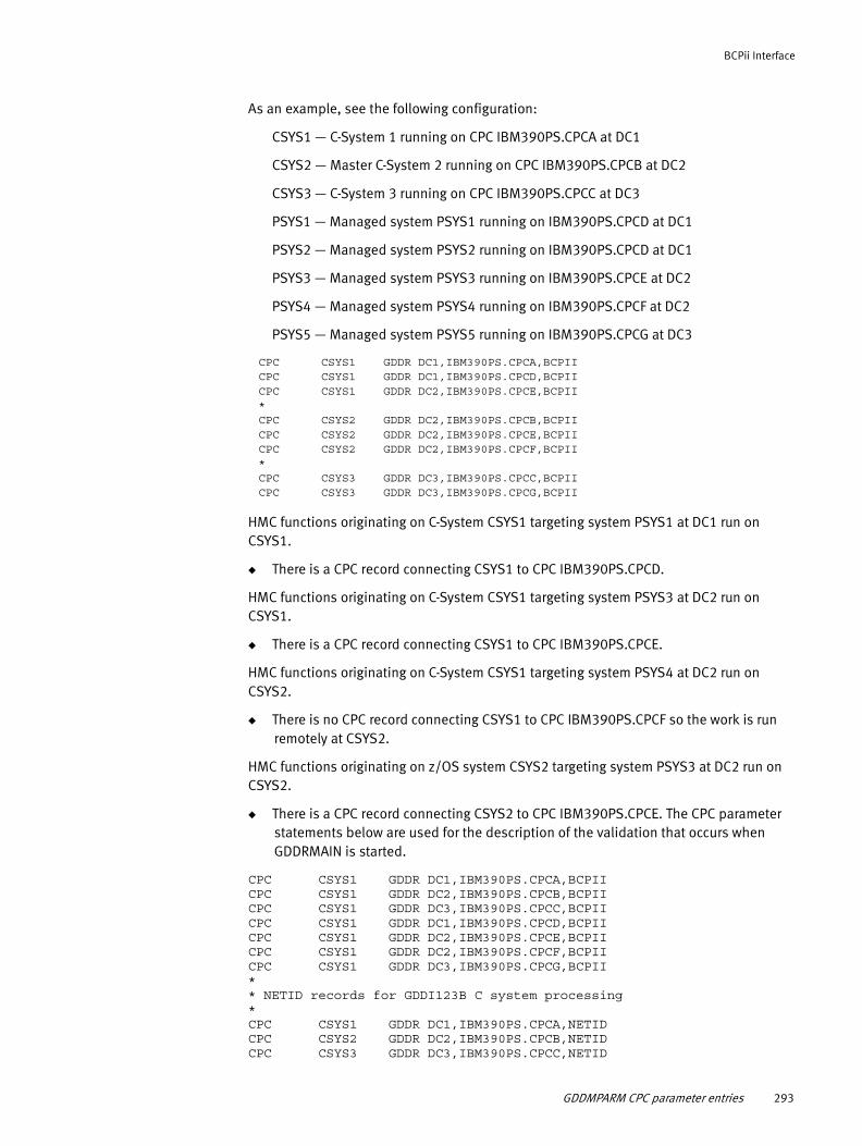
BCPii Interface
As an example, see the following configuration:
CSYS1 — C-System 1 running on CPC IBM390PS.CPCA at DC1
CSYS2 — Master C-System 2 running on CPC IBM390PS.CPCB at DC2
CSYS3 — C-System 3 running on CPC IBM390PS.CPCC at DC3
PSYS1 — Managed system PSYS1 running on IBM390PS.CPCD at DC1
PSYS2 — Managed system PSYS2 running on IBM390PS.CPCD at DC1
PSYS3 — Managed system PSYS3 running on IBM390PS.CPCE at DC2
PSYS4 — Managed system PSYS4 running on IBM390PS.CPCF at DC2
PSYS5 — Managed system PSYS5 running on IBM390PS.CPCG at DC3
CPC CSYS1 GDDR DC1,IBM390PS.CPCA,BCPIICPC CSYS1 GDDR DC1,IBM390PS.CPCD,BCPIICPC CSYS1 GDDR DC2,IBM390PS.CPCE,BCPII*CPC CSYS2 GDDR DC2,IBM390PS.CPCB,BCPIICPC CSYS2 GDDR DC2,IBM390PS.CPCE,BCPIICPC CSYS2 GDDR DC2,IBM390PS.CPCF,BCPII*CPC CSYS3 GDDR DC3,IBM390PS.CPCC,BCPIICPC CSYS3 GDDR DC3,IBM390PS.CPCG,BCPII
HMC functions originating on C-System CSYS1 targeting system PSYS1 at DC1 run on CSYS1.
◆ There is a CPC record connecting CSYS1 to CPC IBM390PS.CPCD.
HMC functions originating on C-System CSYS1 targeting system PSYS3 at DC2 run on CSYS1.
◆ There is a CPC record connecting CSYS1 to CPC IBM390PS.CPCE.
HMC functions originating on C-System CSYS1 targeting system PSYS4 at DC2 run on CSYS2.
◆ There is no CPC record connecting CSYS1 to CPC IBM390PS.CPCF so the work is run remotely at CSYS2.
HMC functions originating on z/OS system CSYS2 targeting system PSYS3 at DC2 run on CSYS2.
◆ There is a CPC record connecting CSYS2 to CPC IBM390PS.CPCE. The CPC parameter statements below are used for the description of the validation that occurs when GDDRMAIN is started.
CPC CSYS1 GDDR DC1,IBM390PS.CPCA,BCPIICPC CSYS1 GDDR DC2,IBM390PS.CPCB,BCPIICPC CSYS1 GDDR DC3,IBM390PS.CPCC,BCPIICPC CSYS1 GDDR DC1,IBM390PS.CPCD,BCPIICPC CSYS1 GDDR DC2,IBM390PS.CPCE,BCPIICPC CSYS1 GDDR DC2,IBM390PS.CPCF,BCPIICPC CSYS1 GDDR DC3,IBM390PS.CPCG,BCPII** NETID records for GDDI123B C system processing*CPC CSYS1 GDDR DC1,IBM390PS.CPCA,NETIDCPC CSYS2 GDDR DC2,IBM390PS.CPCB,NETIDCPC CSYS3 GDDR DC3,IBM390PS.CPCC,NETID
GDDMPARM CPC parameter entries 293
BCPii Interface
The CPC entries for CSYS1, CSYS2, and CSYS3 which specify NETID are populated on the Define C-Systems panel by Auto-Discovery, using the Parameter Wizard. GDDRMAIN startup or refresh of the MISC task will check and ensure a valid NETID CPC record exists for each C-System specified in the GDDMPARM member. If not found, GDDR error message GDDM194E is displayed in the GDDRMAIN output to alert the user. All HMC functions against the managed systems PSYS1 through PSYS5 will be routed to C-System CSYS1 and run on that system.
When GDDRMAIN is started on each C-System, an attempt is made to verify BCPii connectivity to the indicated CPC (NETID.NAU). Failure during this check will result in the display of GDDR error message GDDM195E to alert the user to a networking problem.
Security changes required to use BCPiiBCPii security is controlled both at the SE for each CPC holding z/OS Images that will participate in BCPii communications and also within the security product running on each of the participating z/OS systems. Examples will illustrate configuration using the IBM Security Server (RACF) product only.
At the SE side, follow the instructions in the MVS Programming Callable Services for High Level Languages document (SA22-7613) in the Callable Service chapter section “Base Control Program Internal Interface” under the heading BCPii Setup and Installation. Essentially, for each z/OS Image on a CPC that will participate, cross-partition authority must be enabled through the SE. Additionally, an SNMP Community Name for each CPC must be established. Due to restrictions with the security products on z/OS, the Community Name cannot contain any lowercase characters. Again, refer to the documentation for specific steps to follow to establish the connection between authorized applications and the Service Element.
At the z/OS Security Product side, the section entitled “Setting up Authority to Use BCPii” outlines the steps required to update your security product to allow the connection to BCPii.
The HWIBCPII address space under z/OS is the pathway between the authorized applications and the Service Element when communicating via BCPii. If everything is configured properly, this address space will come up automatically during IPL and remain available for the life of the Image. There are instructions for shutting this address space down and restarting if necessary.
It is extremely important that all of the setup and requirements outlined in the BCPii chapter in MVS Programming Callable Services for High Level Languages are understood. This will ensure the security configuration meets your specific needs in a safe and straightforward fashion.
294 EMC GDDR Version 4.1 Product Guide

BCPii Interface
BCPii facility classes
This section provides an overview of the pertinent BCPii facility classes as related to GDDR.
HWI.APPLNAME.HWISERV
HWI.APPLNAME.HWISERV in the Facility Resource Class controls which applications can use BCPii services. A minimum of READ access is required and BCPii requires that the Facility Resource Class be RACLISTED. See the Callable Services Guide for an example of creating, using and refreshing this profile.
HWI.TARGET.netid.nau
HWI.TARGET.netid.nau in the Facility Resource Class controls access to a specified CPC using the full format name comprised of network ID netid followed by a period followed by the CPC name nau (network addressable unit). netid and nau can be up to 8 characters in length each, so that the netid.nau field can be from 3 to 17 characters total length. The APPLICATION DATA field for this facility class must match exactly the community name entered in the SE for the CPC during BCPii setup. This is the connection between the security product and access to the desired CPC. This facility class is also used to control access to any Activation Profiles stored on the CPC (image, load or reset).
HWI.TARGET.netid.nau.imagename
HWI.TARGET.netid.nau.imagename in the Facility Resource Class controls access to the specified image on the specified CPC. imagename can be up to 8 characters in length.
Note: @RACF allows for the use of generic facility classes. This can facilitate setup for the site. Keep in mind that RACF determines which profile to use when more than one applies by using the more specific class. For example, you define HWI.TARGET.IBM390PS.C.* as a generic Facility class to cover access to all LPARs on the C CPC. You also define HWI.TARGET.IBM390PS.* as a generic Facility class to cover access to all LPARs regardless of CEC. If you are working with an LPAR on the C CPC, RACF will use HWI.TARGET.IBM390PS.C.* otherwise HWI.TARGET.IBM390PS.* will be used.
SYS1.PARMLIB changes required for BCPiiAuthority to run the new EMC GDDR BCPii API functions requires changes to the AUTHTSF section of IKJTSO00 in SYS1.PARMLIB. The following entries must be added on all GDDR C-Systems:
GDDBCPC2 /* BCPII AUTH CONNECT */ + GDDBCPC3 /* BCPII AUTH COMMAND */ + GDDBCPD2 /* BCPII AUTH DISCONNECT */ + GDDBCPE2 /* BCPII AUTH EVENT */ + GDDBCPL2 /* BCPII AUTH LIST */ + GDDBCPQ2 /* BCPII AUTH QUERY */ + GDDBCPS2 /* BCPII AUTH SET */ +
SYS1.PARMLIB changes required for BCPii 295

BCPii Interface
GDDRBPCI BCPii test job for C-SystemsA new batch job, GDDRBPCI, is distributed with GDDR 4.0. The run JCL for GDDRBCPI is provided in SAMPLIB. This small program will, from each of the GDDR C-Systems, verify connectivity to all CPCs visible through the HMC grouping. Note that this does not mean each of the GDDR C-Systems will be able to connect to all CPCs visible via CPC grouping. The purpose of this job is to ensure those CPCs defined to GDDR can be interrogated for information. Further, for each CPC that BCPii can connect to, a list of Images on each is obtained and a BCPii connection attempted to each of those images to ensure all GDDR systems under BCPii management are ready for GDDR.
For those systems not eligible for BCPii connectivity from a GDDR C-System, error messages will be generated. If connection problems are encountered, the error messages will help diagnose why. This GDDRBPCI job should be run after all hardware requirements in the MVS Programming Callable Services for High Level Languages have been met and all RACF updates creating the specific Facility Classes and setting the required Permits are made.
Sample output from job GDDRBCPI follows. This job was run from a test GDDR setup at EMC. As this output shows, the local C-System running on the Q3 CPC has visibility to three other CPCs (C, O, and X1) but has authority to only one other CPC (X1). The error message section at the start is used to diagnose any problems or to highlight issues that might be ignored (for instance, non-authorized CPCs). The BCPii Connection Report shows a list of the CPCs that were visible during processing and also a list of all Images on the CPCs to which the job found authorization. BCPii authority to a CPC is separate from its authority to an image on that CPC (that is, not all images on a CPC may be available for BCPii communication). The JES job log also contains further diagnostic information that EMC support personnel can use to diagnose at a deeper level.
BCPii Connection Test beginning... 4 Feb 2011 08:00:56 These messages may be ignored: Error 746: EVALBLOCK too small, retrying for larger Default area for data returned from BCPii call is not large enough. A larger area is automatically obtained Error 539: BCPII Connection Error - rc 00000F02 rsn FFFFFFFF F02 indicates a lack of SAF Authority to the object of call to BCPii. This may require investigation
rc XXXXXXXX can be found in the error section in the BCPii section of MVS Programming Callable Services for High Level Languages for each of the BCPii Call types (CONNECT, DISCONNECT, LIST, QUERY, etc). Each call type has a set of specific errors as shown in the above error msg showing F02 as a SAF AUTH error during CONNECT attempt. BCPii Checking CPC/LPAR Connectivity... 4 Feb 2011 08:00:56 BCPii Processing messages follow. See BCPii Connection Report below for results of BCPii Connectivity testing GDDR992E Error 539 in GDDBCPCO: BCPII Connection Error - rc 00000101 rsn FFFFFFFF GDDR992E Error 539 in GDDBCPCO: BCPII Connection Error - rc 00000101 rsn FFFFFFFF GDDR992E Error 746 in GDDBCPLS: EVALBLOCK too small, retrying for larger BCPii Connection Report for 4 identified CPCs 4 Feb 2011 08:01:32
296 EMC GDDR Version 4.1 Product Guide

BCPii Interface
CPC 001 is IBM390PS.C Connection Not Made - Check RACF Facility Classes CPC 002 is IBM390PS.O Connection Not Made - Check RACF Facility Classes CPC 003 is IBM390PS.Q3 Connection Complete - Will Check Image Connection <-- Local CPCCPC 004 is IBM390PS.X1 Connection Complete - Will Check Image Connection BCPii LPAR Connectivity Report 4 Feb 2011 08:01:32 CPC IBM390PS.Q3 Image Q31D Connection Established CPC IBM390PS.Q3 Image Q319 Connection Established CPC IBM390PS.Q3 Image ZOSEQ31A Connection Established CPC IBM390PS.Q3 Image ZOSEQ31B Connection Established CPC IBM390PS.Q3 Image ZOSEQ31C Connection Established CPC IBM390PS.Q3 Image ZOSEQ31E Connection Established CPC IBM390PS.Q3 Image ZOSEQ31F Connection Established CPC IBM390PS.Q3 Image ZOSEQ311 Connection Established CPC IBM390PS.Q3 Image ZOSEQ312 Connection Established CPC IBM390PS.Q3 Image ZOSEQ313 Connection Established CPC IBM390PS.Q3 Image ZOSEQ314 Connection Established CPC IBM390PS.Q3 Image ZOSEQ315 Connection Established CPC IBM390PS.Q3 Image ZOSEQ316 Connection Established CPC IBM390PS.Q3 Image ZOSEQ317 Connection Established CPC IBM390PS.Q3 Image ZOSEQ318 Connection Established CPC IBM390PS.Q3 Image ZOSEQ84 Connection Established CPC IBM390PS.Q3 Image ZOSEQ85 Connection Established CPC IBM390PS.Q3 Image ZOSEQ86 Connection Established CPC IBM390PS.Q3 Image ZOSEQ87 Connection Established CPC IBM390PS.X1 Image X10A Connection Established CPC IBM390PS.X1 Image X10B Connection Established CPC IBM390PS.X1 Image X10C Connection Established CPC IBM390PS.X1 Image X10D Connection Established CPC IBM390PS.X1 Image X10E Connection Established CPC IBM390PS.X1 Image X10F Connection Established CPC IBM390PS.X1 Image X101 Connection Established CPC IBM390PS.X1 Image X102 Connection Established CPC IBM390PS.X1 Image X103 Connection Established CPC IBM390PS.X1 Image X104 Connection Established CPC IBM390PS.X1 Image X105 Connection Established CPC IBM390PS.X1 Image X106 Connection Established CPC IBM390PS.X1 Image X107 Connection Established CPC IBM390PS.X1 Image X108 Connection Established CPC IBM390PS.X1 Image X109 Connection Established CPC IBM390PS.X1 Image X11A Connection Established CPC IBM390PS.X1 Image X11B Connection Established CPC IBM390PS.X1 Image X11C Connection Established CPC IBM390PS.X1 Image X11D Connection Established CPC IBM390PS.X1 Image X11E Connection Established CPC IBM390PS.X1 Image X11F Connection Established CPC IBM390PS.X1 Image X111 Connection Established CPC IBM390PS.X1 Image X112 Connection Established CPC IBM390PS.X1 Image X113 Connection Established CPC IBM390PS.X1 Image X118 Connection Established CPC IBM390PS.X1 Image X119 Connection Established BCPii Connection Report Completed READY END
GDDRBPCI BCPii test job for C-Systems 297

BCPii Interface
298 EMC GDDR Version 4.1 Product Guide

APPENDIX FSMP/E Post-Maintenance Procedure
This appendix describes the EMC GDDR SMP/E post-maintenance procedure.
◆ Introduction.......................................................................................................... 300◆ The GDDRPMNT job ............................................................................................... 300
SMP/E Post-Maintenance Procedure 299

SMP/E Post-Maintenance Procedure
Introduction Following a maintenance upgrade, you can use the EMC GDDR SMP/E post-maintenance job to populate the GDDR Primary Options Menu and the GDDR Applied PTF Maintenance panels with information describing the highest level of maintenance applied on an EMC GDDR C-System. The EMC GDDR SMP/E post-maintenance job is located in hlq.GDDRvrm.SAMPLIB(GDDRPMNT).
Typically, the job is run on the LPAR where SMP/E maintenance is performed for EMC GDDR. Whenever maintenance is applied to EMC GDDR via SMP/E, you should rerun the GDDRPMNT job and copy the updated output panel lib members to the GDDR ISPPLIB libraries on all C-Systems.
The GDDRPMNT jobTo run the GDDRPMNT job, retrieve and customize the JCL from hlq.GDDRvrm.SAMPLIB(GDDRPMNT) as follows:
1. In the SMP/E step, EMC recommends that you specify 'LIST ALLZONES' as follows:
• //SMPCSI DD references the SMP/E CSI data set used for GDDR
• //SMPCNTL DD *
• SET BOUNDARY (EMCTGT)
• LIST ALLZONES PTFS FORFMID(GDDR410) SYSMOD
2. In the SCANLIST step:
• //SYSPROC DD references your hlq.GDDRvrm.SAMPLIB library
• The //SMPLIST DD references the listing produced by the previous SMP/E step
• //SMPLIST DD references the output listing from the SMP/E LIST step above.
• The //NEWRPRIM and //NEWHPMNT DD cards reference the hlq.GDDRvrm.ISPPLIB member names for the generated GDDRPRIM and GDDHPMNT members
Perform the following steps after the job completes successfully:
1. Copy the new GDDRPRIM and GDDHPMNT members to the GDDR panel libraries on each C-System, replacing existing members GDDRPRIM and GDDHPMNT.
2. Do a VLF refresh to update the Virtual Lookaside Facility cache (if VLF is in use).
3. Exit ISPF and then re-enter ISPF to make the new panels visible in your ISPF session (ISPF caches panels by default and new copies of panels are not necessarily re-read from disk automatically).
4. Open the Help panel for GDDR Primary Options Menu, 'Help' or 'F1'.
The GDDR Primary Options Menu Help panel includes a new "M" selection/option.
5. Enter M on the command line and press Enter. This displays the GDDHPMNT panel.
300 EMC GDDR Version 4.1 Product Guide

SMP/E Post-Maintenance Procedure
To access the updated panels
The GDDR Primary Options Menu panel displays the GDDR version release and modification level in the form vv.rr.mm. The mm number reflects the highest applied PTF number found in the SMP/E listing by the SMP/E post-maintenance job GDDRPMNT. For example, GDDR 04.00.05 indicates that PTF 5 for GDDR 4.0 has been applied. Note that this does not necessarily mean that PTFs 1 through 4 have been applied.
Perform the following steps to find out exactly which PTFs have been applied:
1. Open the Help panel for GDDR Primary Options Menu, 'Help' or 'F1'.
The GDDR Primary Options Menu help panel includes a new "M" selection/option.
2. Enter M on the command line and press Enter.
Figure 110 Primary Options Menu Help panel with "M" Command Line entry
The result displays a series of GDDR Applied PTF Maintenance panels which show all maintenance applied to GDDR as shown in Figure 111 on page 302.
Help -------------------- Primary Options Menu Help --------------------- Help COMMAND ===> M More: + This is help for the Primary Options Menu panel. Press End to return to ISPF. Enter M on the command line above to see maintenance applied to GDDR. The options you see are dependent on your security permissions as follows: - If you are presented with message "GDDI002E User not authorized", contact your security administrator. Your userid must have READ security access to the RACF Facility ID GDDRISPF.ACCESS. - Below is a list of menu items that you may be authorized to use. If you are not authorized, you will not see a particular menu item. Following each menu item description below, you may see a Security ID. If your installation has established that Security ID as a RACF Facility Class, your user id must have READ access in order for the menu item to be displayed. The following is a list of all possible menu items that can be displayed. Type one characters in the OPTION ===> field or more
The GDDRPMNT job 301

SMP/E Post-Maintenance Procedure
Figure 111 GDDR Applied PTF Maintenance —One of multiple panels showing SMP/E details
Help -------------------- GDDR Applied PTF Maintenance ------------------ Help COMMAND ===> More: - + ----------------------------------------------------------------------------- NOW SET TO TARGET ZONE EMCTGT ------------------ Date: 04/09/11 17:14:57 Page 1 SMP/E version 35.22 LIST ALLZONES PTFS FORFMID(GDDR410) SYSMOD. 000550 GDDIHSRA GDDIHSYS GDDIHWKL GDDIOACB GDDIOCOV GDDIOJCL GDDIOPLX GDDIOSMF GDDIOUTI GDDIPACT GDDIPRMI GDDIPVAL GDDIROGR GDDISDGK GDDISGNS GDDISRDD GDDISTFD GDDITUNE GDDI123A GDDI123B GDDI123C GDDRCBU2 GDDREM01 GDDRGFCS GDDRGFHS GDDRGFLR GDDRGVAL GDDRGVRL GDDRHB01 GDDRHMC2 GDDRKF0E GDDRKF2W GDDROPS2 GDDROPS3 GDDROPS4 GDDRUP03 GDDRXACT MOD = GDDRMTXT GDDRXKB PARM = GDDMPARM PNL = GDDHSTFD GDDRPRMI GDDRSTFD GDDR0PH3 GDDR123C SAMP = GDDIVDEF GD41002 TYPE = PTF STATUS = REC REWORK = 2011098 JCLIN = YES DATE/TIME REC = 11.098 16:23:41
302 EMC GDDR Version 4.1 Product Guide

GLOSSARY
This glossary contains terms related EMC GDDR and to disk storage subsystems.
A
API Application Programming Interface, a set of routines that an application program uses to request and execute tasks performed by a computer’s operating system.
B
BCV Business Continuance Volume, a standard Symmetrix device with special attributes that allow it to independently support applications and processes, such as backup operations, restore operations, decision support operations, and application testing. BCV devices are available through the EMC TimeFinder/Mirror software.
BCV device A standard Symmetrix device with special attributes that allow it to independently support applications and processes.
BCV mirror A standard device mirror (one of M2, M3, or M4) that is assigned to the BCV device upon establishing or re-establishing a BCV pair.
BCV pair A standard device and a BCV device attached together.
C
C-System A EMC GDDR C-System is the controlling LPAR for each of the EMC GDDR sites. The main functions of a EMC GDDR C-System are to:
◆ Control the recovery after an outage
◆ Control a planned site swap
The EMC GDDR C-Systems do not run any production workload.
C-System master function The C-System that is currently responsible for monitoring DASD status and DASD mirroring. It is also responsible for taking action when problems with DASD and DASD mirroring are detected.
C1 Abbreviation for EMC GDDR C-System at the DC1 site.
C2 Abbreviation for EMC GDDR C-System at the DC2 site.
C3 Abbreviation for EMC GDDR C-System at the DC3 site.
EMC GDDR Version 4.1 Product Guide 303

Glossary
cache Random access electronic storage used to retain frequently used data for faster access by the channel.
cache slot Unit of cache equivalent to one track.
cascaded SRDF The ability for a remote volume of a synchronously mirrored pair to simultaneously be the local volume of an asynchronously mirrored pair. Data from a primary site is synchronously replicated to a secondary site, where the volume at the secondary site is the primary volume from which data is asynchronously replicated to a tertiary site.
channel director The component in the Symmetrix subsystem that interfaces between the host channels and data storage. It transfers data between the channel and cache.
CKD Count-key-data, a data recording format employing self-defining record formats in which each record is represented by a count area that identifies the record and specifies its format, an optional key area that may be used to identify the data area contents, and a data area that contains the user data for the record. CKD can also refer to a set of channel commands that are accepted by a device that employs the CKD recording format.
concurrent SRDF The ability for a single primary volume to be remotely mirrored to two secondary volumes concurrently. Concurrent SRDF requires that each remote mirror operate in the same primary mode, either both synchronous or both semi-synchronous, but allows either (or both) volumes to be placed into one of the adaptive copy modes.
ConGroup Short name for EMC Consistency Group for z/OS. An EMC mainframe application designed to ensure the consistency of the data remotely copied by the Symmetrix SRDF microcode feature in the event of a rolling disaster.
consistency group The consistency group is the key to ConGroup. The consistency group is a named group of source (R1) volumes that ConGroup treats as a unit. The volumes can be on multiple Symmetrix units and can include both mainframe and open systems devices.
When ConGroup detects any I/O to a volume in a consistency group that cannot communicate with its mirror, ConGroup suspends the remote mirroring for all volumes defined for that consistency group before completing the intercepted I/O, and returns control to the writing application. In this way, the ConGroup utility prevents dependent I/O from being issued by the application. This ensures the integrity and consistency of the data at the remote site.
D
DASD Direct access storage device, a device that provides nonvolatile storage of computer data and random access to that data.
data availability Access to any and all user data by the application.
dataset In a mainframe system, a collection of data in one of several prescribed arrangements and described by control information in the volume label or the catalog. A dataset may be equivalent to a file in some cases, as in physical sequential files, or several datasets may make up the components of a file.
DDNAME Data definition name, the logical name of a file within an application.
304 EMC GDDR Version 4.1 Product Guide

Glossary
delayed fast write There is no room in cache for the data presented by the write operation.
dependent write A write that is not issued by an application unless some prior I/O operation has completed. An example of a dependent write is a database update. When updating a database, a database management system (DBMS) takes the following steps:
1. The DBMS writes to the disk containing the transaction log.
2. The DBMS writes the data to the actual database dataset.
3. The DBMS writes again to the log volume to indicate that the database update was successfully made.
device A uniquely addressable part of the Symmetrix subsystem that consists of a set of access arms, the associated disk surfaces, and the electronic circuitry required to locate, read, and write data.
device address The hexadecimal value that uniquely defines a physical I/O device on a channel path in an z/OS environment. See also ”unit address.”
device number The value that logically identifies a disk device in a string.
diagnostics System level tests or firmware designed to inspect, detect, and correct failing components. These tests are comprehensive and self-invoking.
director The component in the Symmetrix subsystem that allows Symmetrix to transfer data between the host channels and disk devices. See also ”channel director.”
disk director The component in the Symmetrix subsystem that interfaces between cache and the disk devices.
DSN Dataset name. A DSN consists of a series of dot-delimited qualifiers, each of which comprises a maximum of eight characters (for example, PAYROLL.DSN1.ESDS). A DSN has a maximum of 44 characters. When referencing the member of a partitioned dataset, the maximum length is 54 bytes, including 44 bytes for the name of the PDS, and up to eight bytes for the member name, enclosed in parentheses.
E
Enginuity Enginuity is the operating environment for EMCs Symmetrix Enterprise Storage Platforms. Enginuity provides functional services for both its host Symmetrix systems as well as for a large suite of EMC Storage Application software.
ESA Enterprise System Architecture (mainframe systems only).
ESCON Enterprise Systems Connection, a set of IBM and vendor products that connect mainframe computers with each other and with attached storage, locally attached workstations, and other devices using optical fiber technology and dynamically modifiable switches called ESCON directors.
ESCON director Device that provides a dynamic switching function and extended link path lengths (with XDF capability) when attaching an ESCON channel to a Symmetrix serial channel interface.
EMC GDDR Version 4.1 Product Guide 305

Glossary
ESP Enterprise Storage Platform, the software for EMC Symmetrix storage subsystems. It allows storage of and access to mainframe and open systems data that is stored on the same Symmetrix storage subsystem.
F
fast write In Symmetrix, a write operation at cache speed that does not require immediate transfer of data to disk. The data is written directly to cache and is available for later destaging.
FB record Fixed block record, a fixed-length, blocked record in a mainframe dataset. The dataset can contain truncated (short) blocks.
FBA Fixed Block Architecture, a data record format that uses data blocks of fixed size. The blocks are addressed by block numbers relative to the beginning of the particular file. FBA is used by open systems computers while a different scheme, CKD, is used by mainframe computers.
FBAM Fixed Block Architecture, Meta-volume.
FICON Fibre Connectivity, a high-speed I/O interface for mainframe computer connections to storage devices. FICON channels increase I/O capacity to make them up to eight times as efficient as ESCON channels.
file In z/OS terminology, a file is an abstraction that represents a collection of data at the application level. In some cases, such as physical sequential files, a dataset and a file may be considered equivalent. In other cases, several datasets may be presented to the application as a single logical file. In a partitioned dataset, a subset of the dataset, called a member, is considered a file.
G
gatekeeper A small logical volume on a Symmetrix storage subsystem used to pass commands from a host to the Symmetrix storage subsystem. Gatekeeper devices are configured on standard Symmetrix disks.
GDDR Acronym for Geographically Dispersed Disaster Restart.
GDDR Complex An EMC GDDR Complex is a two-site cluster of GDDR systems. Each GDDR Complex can manage one MSC group. See “MSC.”
GDG Generation Data Group, a collection of physical sequential files that are logically related by their content, and usually represent a history of the data over some period of time. The group is created through use of administrative utilities, and individual datasets in the group called generation datasets (GDS) are created by running user programs.
GDS Generation Data Set, elements of a generation data group referred to by a GDG base name, followed by a number enclosed in parentheses. The number indicates the relative chronological position of each GDS.
306 EMC GDDR Version 4.1 Product Guide

Glossary
GNS Group Name Service. GNS is the Symmetrix group definition sharing facility. GNS allows you to define a group of devices (and the controllers on which they reside) once, in one place, and then use that single definition across multiple EMC products on multiple platforms. That is, you can use group definitions created through GNS on a mainframe system with EMC software products running on open systems hosts.
GNS group A Group Name Service group. Each GNS group is a list of controllers and devices that reside on those controllers. The controllers and devices may reside on one Symmetrix storage subsystem or on different Symmetrix storage subsystems. If a GNS group spans more than one Symmetrix storage subsystem, each Symmetrix unit holds only its portion of that single definition.
Each group is a collection of controllers, and the devices that reside on those controllers. For groups that span Symmetrix storage subsystems, the definition is stored as a set of components on different Symmetrix storage subsystems. Each Symmetrix storage subsystem holds its portion of that single definition.
gigabyte (GB) 109 bytes.
I
ID Identifier, a sequence of bits or characters that identifies a program, device, controller, or system.
I/O device An addressable input/output unit, such as a disk device.
K
K Kilobyte, 1024 bytes.
L
local volume A Symmetrix logical volume that is not participating in SRDF operations. All CPUs attached to the Symmetrix may access it for read/write operations. It is available for local mirroring or dynamic sparing operations to the Symmetrix unit in which it resides only.
logical volume A user-addressable unit of storage. In the Symmetrix subsystem, the user can define multiple logical volumes on a single physical disk device.
LPAR Logical partitioning, a system of splitting a mainframe computer‘s total resources into smaller units. Some of the computer's resources must be partitioned for exclusive use, such as memory; other resources such as IO channels can be shared. The units essentially act as separate machines. Each unit can run with its own instance of the operating system and applications. The units, however, can communicate with each other.
M
MB Megabyte, 106 bytes.
mirrored pair A logical volume with all data recorded twice, once on each of two different physical devices.
EMC GDDR Version 4.1 Product Guide 307

Glossary
mirroring The Symmetrix maintains two identical copies of a designated volume on separate disks. Each volume automatically updates during a write operation. If one disk device fails, Symmetrix automatically uses the other disk device.
multi-site workloadconfiguration
In a multi-site workload configuration, the production workload runs at both the primary and secondary sites. See also “primary site” and “secondary site.”
MSC MSC (Multi-Session Consistency) is an EMC technology that provides consistency across multiple SRDF groups within the same Symmetrix subsystem or multiple Symmetrix subsystems.
P
PDS Partitioned Dataset, a composite mainframe dataset that is much like a directory in UNIX containing files, for example, source files. The members in a PDS are usually of the same type of data, for example, C language source files or header files.
physical ID Physical identification number of the Symmetrix director for EREP usage. This value automatically increments by one for each director installed in Symmetrix. This number must be unique in the mainframe system. It should be an even number. This number is referred to as the SCU_ID.
primary site The primary site is the site where the production workload is located. The primary site is typically the same as the primary DASD site.
primary DASD site The primary DASD site is the site where the source (R1) DASD is located. The primary DASD site is typically the same as the primary site.
R
R1 See “source volume (R1).”
R2 See “target volume (R2).”
R21 A dual-role SRDF R2/R1 device on the secondary site which acts as both an R2 to the primary site and an R1 to the tertiary site.
rolling disaster A rolling disaster is more common than an immediate catastrophic failure. A rolling disaster is a series of events happening over a period of time that lead to data corruption until a catastrophic failure finally occurs. Each rolling disaster is delimited by two fixed points: the time when the first failure occurs and the time when the disaster is complete. The period between these two times is the rolling disaster.
RPO Recovery Point Objective. The Recovery Point Objective is a point of consistency to which a user wants to recover or restart. It is measured in the amount of time from when the point of consistency was created or captured to the time the disaster occurred. This time equates to the acceptable amount of data loss.
Zero data loss (no loss of committed transactions from the time of the disaster) is the ideal goal, but the high cost of implementing such a solution must be weighed against the business impact and cost of a controlled data loss.
308 EMC GDDR Version 4.1 Product Guide
Glossary
Some organizations like banks have zero data loss requirements. The data base transactions entered at one location must be replicated immediately to another location. This can have an impact on application performance when the two locations are far apart. On the other hand, keeping the two locations close to one another might not protect against a regional disaster like the power outages or hurricanes.
Defining the required RPO is usually a compromise between the needs of the business, the cost of the solution, and the risk of a particular event happening.
S
secondary site The secondary site is the site where the contingency or standby systems are located.
secondary DASD site The secondary DASD site is the site where the target (R2) DASD is located. The secondary DASD site will typically be the same as the secondary site.
single site workloadconfigurations
Single site workload configurations are configurations in which the primary site is the site where the production workload is located. See also ”primary site.”
site DC3 Site DC3 is the secondary data center for critical production applications and data. It is connected with network links to DC1.
Data is replicated asynchronously from the current primary DASD site with an intended RPO in a short number of minutes.
site DC1 Site DC1 is the primary data center for critical production applications and data.
source volume (R1) A Symmetrix logical volume that is participating in SRDF operations. It resides in the “local” Symmetrix unit. All CPUs attached to the Symmetrix may access a source volume for read/write operations. All writes to this volume are mirrored to a “remote” Symmetrix unit. A source volume is not available for local mirroring operations. See also ”target volume (R2).”
SRDF Symmetrix Remote Data Facility. SRDF consists of the microcode and hardware required to support Symmetrix remote mirroring.
SRDF/A SRDF/Asynchronous. SRDF/A provides a long-distance replication solution with minimal performance impact. SRDF/A provides a point-in-time image on the target (R2) device which is only slightly behind the source (R1) device. Data is transferred to a remote Symmetrix storage subsystem in predefined timed cycles called delta sets. This eliminates the redundancy of same track changes being transferred over the link.
storage control unit The component in the Symmetrix subsystem that connects Symmetrix to the host channels. It performs channel commands and communicates with the disk directors and cache. See also ”channel director.”
sysplex System complex. A processor complex which is formed by loosely coupling mainframe processors together into a single unit, using channel-to-channel adapters or ESCON or FICON fiber optic links.
system The word system or systems used in this guide refers to a z/OS image and all systems tasks and applications running in it.
EMC GDDR Version 4.1 Product Guide 309

Glossary
T
target volume (R2) A Symmetrix logical volume that is participating in SRDF operations. It resides in the “remote” Symmetrix unit. It is paired with a source volume in the local Symmetrix unit and receives all write data from its mirrored pair. This volume is not accessed by user applications during normal I/O operations. A target volume is not available for local mirroring or dynamic sparing operations. See also ”source volume (R1).”
U
unit address The hexadecimal value that uniquely defines a physical I/O device on a channel path in an MVS environment. See also ”device address.”
V
volume A general term referring to a storage device. In the Symmetrix subsystem, a volume corresponds to a single device visible to the host. In the context of host-based, volume manager software, a volume is a logical unit of disk storage that may comprise storage on one to many Symmetrix devices.
310 EMC GDDR Version 4.1 Product Guide