emc gddr for srdf /s with autoswap™ - hk.emc.com fileemc corporation corporate headquarters:...
TRANSCRIPT
EMC CorporationCorporate Headquarters:
Hopkinton, MA 01748-9103
1-508-435-1000www.EMC.com
EMC® GDDR for SRDF®/S with AutoSwap™Version 3.0
Concepts and Facilities GuideP/N 300-006-601
REV A04
EMC GDDR Concepts and Facilities Guide 2
Copyright © 2007-2009 EMC Corporation. All rights reserved.
Published January, 2009
EMC believes the information in this publication is accurate as of its publication date. The information is subject to change without notice.
THE INFORMATION IN THIS PUBLICATION IS PROVIDED “AS IS.” EMC CORPORATION MAKES NO REPRESENTATIONS OR WARRANTIES OF ANY KIND WITH RESPECT TO THE INFORMATION IN THIS PUBLICATION, AND SPECIFICALLY DISCLAIMS IMPLIED WARRANTIES OF MERCHANTABILITY OR FITNESS FOR A PARTICULAR PURPOSE.
Use, copying, and distribution of any EMC software described in this publication requires an applicable software license.
For the most up-to-date listing of EMC product names, see EMC Corporation Trademarks on EMC.com.
All other trademarks used herein are the property of their respective owners.
Contents
Preface
Chapter 1 Introduction What is EMC GDDR? ............................................................................................. 14 Major features.......................................................................................................... 15
Situational awareness ..................................................................................... 15Survivor recognition ........................................................................................ 15Restart coordination ......................................................................................... 15Additional capabilities..................................................................................... 16Types of environment ...................................................................................... 16
Chapter 2 EMC GDDR Overview Supported business continuity configurations................................................... 18
SRDF/S with AutoSwap configuration ........................................................ 18 The EMC GDDR Complex .................................................................................... 21 EMC GDDR fundamentals.................................................................................... 22
Control systems ................................................................................................ 22Workload location ............................................................................................ 22Managed workloads......................................................................................... 23EMC GDDR processes ..................................................................................... 23
EMC GDDR components....................................................................................... 25Parameters ......................................................................................................... 25User interface .................................................................................................... 25Events ................................................................................................................. 25Monitors............................................................................................................. 25Message rules .................................................................................................... 26
EMC GDDR supported scripts ............................................................................. 28Planned event management............................................................................ 28Unplanned event management ...................................................................... 29Resumption after planned or unplanned outages....................................... 30
Parameter statements: Telling EMC GDDR what to manage........................... 31 EMC GDDR hardware requirements................................................................... 32
EMC GDDR C-System ..................................................................................... 32 EMC GDDR software requirements..................................................................... 33 EMC GDDR DASD support.................................................................................. 34
Glossary
Index
EMC GDDR Concepts and Facilities Guide 3

Contents
EMC GDDR Concepts and Facilities Guide4

Title Page
Figures
1 SRDF/S with AutoSwap environment .............................................................................. 192 EMC GDDR Complex........................................................................................................... 21
EMC GDDR Concepts and Facilities Guide 5

Figures
EMC GDDR Concepts and Facilities Guide6
Title Page
Tables
1 EMC GDDR C-System minimum hardware requirements ............................................ 32
EMC GDDR Concepts and Facilities Guide 7

Tables
EMC GDDR Concepts and Facilities Guide8

Preface
As part of an effort to improve and enhance the performance and capabilities of its product lines, EMC periodically releases revisions of its hardware and software. Therefore, some functions described in this document may not be supported by all versions of the software or hardware currently in use. For the most up-to-date information on product features, refer to your product release notes.
If a product does not function properly or does not function as described in this document, please contact your EMC representative.
Audience This document is part of the EMC Geographically Dispersed Disaster Restart (EMC GDDR) documentation set, and is intended for use by system administrators and others who need to have an overview of EMC GDDR.
Readers of this document are expected to be familiar with the following topics:
◆ IBM z/OS operating environments
◆ IBM parallel sysplex
◆ EMC software products: SRDF, ResourcePak Base, Consistency Group, and AutoSwap
Relateddocumentation
Related documents include:
◆ EMC GDDR Release Notes
◆ EMC GDDR Product Guide
◆ EMC GDDR Operations Guide
◆ EMC GDDR Message and Code Guide
◆ EMC ResourcePak Base for z/OS Product Guide
◆ EMC SRDF Host Component for z/OS Product Guide
◆ EMC Symmetrix Remote Data Facility Product Guide
◆ EMC AutoSwap Product Guide
◆ EMC Consistency Group for z/OS Product Guide
◆ EMC TimeFinder/Mirror for z/OS Product Guide
◆ EMC TimeFinder/Clone Mainframe SNAP Facility Product Guide
◆ EMC REXX Interface Programmer’s Reference Guide
◆ Unicenter CA-OPS/MVS for EMC Geographically Dispersed Disaster Restart Documentation CD
EMC GDDR Concepts and Facilities Guide 9
Preface
Conventions used inthis document
EMC uses the following conventions for special notices.
Note: A note presents information that is important, but not hazard-related.
CAUTION!A caution contains information essential to avoid data loss or damage to the system or equipment.
IMPORTANT!An important notice contains information essential to operation of the software.
EMC GDDR — This document uses the acronym EMC GDDR in place of full product name, EMC Geographically Dispersed Disaster Restart.
Typographical conventionsEMC uses the following type style conventions in this document:
Normal Used in running (nonprocedural) text for:• Names of interface elements (such as names of windows, dialog boxes, buttons,
fields, and menus)• Names of resources, attributes, pools, Boolean expressions, buttons, DQL
statements, keywords, clauses, environment variables, filenames, functions, utilities
• URLs, pathnames, filenames, directory names, computer names, links, groups, service keys, file systems, notifications
Bold Used in running (nonprocedural) text for:• Names of commands, daemons, options, programs, processes, services,
applications, utilities, kernels, notifications, system calls, man pages
Used in procedures for:• Names of interface elements (such as names of windows, dialog boxes, buttons,
fields, and menus)• What user specifically selects, clicks, presses, or types
Italic Used in all text (including procedures) for:• Full titles of publications referenced in text• Emphasis (for example a new term)• Variables
Courier Used for:• System output, such as an error message or script • URLs, complete paths, filenames, prompts, and syntax when shown outside of
running text
Courier bold Used for:• Specific user input (such as commands)
Courier italic Used in procedures for:• Variables on command line• User input variables
< > Angle brackets enclose parameter or variable values supplied by the user
[ ] Square brackets enclose optional values
| Vertical bar indicates alternate selections - the bar means “or”
{ } Braces indicate content that you must specify (that is, x or y or z)
... Ellipses indicate nonessential information omitted from the example
EMC GDDR Concepts and Facilities Guide10

Preface
Where to get help EMC support, product, and licensing information can be obtained as follows.
Product information — For documentation, release notes, software updates, or for information about EMC products, licensing, and service, go to the EMC Powerlink website (registration required) at:
http://Powerlink.EMC.com
Technical support — For technical support, go to EMC Customer Service on Powerlink. To open a service request through Powerlink, you must have a valid support agreement. Please contact your EMC sales representative for details about obtaining a valid support agreement or to answer any questions about your account.
Your comments Your suggestions will help us continue to improve the accuracy, organization, and overall quality of the user publications. Please send your opinion of this guide to:
If you have issues, comments, or questions about specific information or procedures, please include the title and, if available, the part number, the revision (for example, A01), the page numbers, and any other details that will help us locate the subject you are addressing.
EMC GDDR Concepts and Facilities Guide 11

Preface
EMC GDDR Concepts and Facilities Guide12
1Invisible Body Tag
This chapter presents a brief introduction to EMC GDDR. The topics are:
◆ What is EMC GDDR? .................................................................................................... 14◆ Major features ................................................................................................................. 15
Introduction
Introduction 13
Introduction
What is EMC GDDR?EMC® Geographically Dispersed Disaster Restart (EMC GDDR) is a mainframe software product that automates business recovery following both planned outages and disaster situations, including the total loss of a data center. EMC GDDR achieves this goal by providing monitoring, automation and quality controls to the functionality of many EMC and third-party hardware and software products required for business restart.
Because EMC GDDR restarts production systems following disasters, it does not reside on the same servers that it is seeking to protect. EMC GDDR resides on separate logical partitions (LPARs) from the host servers that run your application workloads.
You install EMC GDDR on a control LPAR at each site. Each EMC GDDR node is aware of the other EMC GDDR nodes through network connections between each site. This awareness allows EMC GDDR to:
◆ Detect disasters
◆ Identify survivors
◆ Recover business at the surviving site
To achieve the task of business restart, EMC GDDR automation extends well beyond the disk level and into the host operating system level. It is at this level that sufficient controls and access to third party software and hardware products exist to enable EMC to provide automated recovery capabilities.
EMC GDDR’s main activities include:
◆ Managing planned site swaps (workload and DASD) between the primary and secondary sites and recovering the SRDF®/S (synchronous remote replication) with AutoSwap environment.
◆ Managing planned site swaps (DASD only) between the primary and secondary sites and recovering the SRDF/S with AutoSwap environment.
◆ Active monitoring of the managed environment and responding to exception conditions.
EMC GDDR Concepts and Facilities Guide14
Introduction
Major featuresEMC GDDR successfully undertakes these activities by exploiting the following major features:
◆ Situational awareness
◆ Survivor recognition
◆ Restart coordination
Situational awareness EMC GDDR can distinguish normal operational disruptions from disasters and respond accordingly. For example, EMC GDDR is able to distinguish between network outages (SRDF link drop) and real disasters. This awareness is achieved by periodic exchange of dual-direction heartbeats between the EMC GDDR LPARs.
Survivor recognitionEMC GDDR can determine which sites and systems have survived a disaster. Unlike the foundation technologies (such as TimeFinder®/Mirror or TimeFinder/Clone Mainframe SNAP Facility), EMC GDDR has built-in intelligence to monitor other EMC GDDR systems. EMC GDDR constantly checks for disaster situations and constantly ensures that other GDDR systems are “healthy.” This checking allows EMC GDDR to recognize, and act on, potential disaster situations, even if only one EMC GDDR system survives.
“Split brain” problems associated with cluster technologies are avoided through operator prompts. Upon the initial recognition stage, EMC GDDR issues messages to the operator console seeking confirmation of the event and, further, confirmation of restart actions required.
Restart coordinationIf a primary site disaster occurs, the EMC GDDR Master C-System located at the secondary site will execute the recovery. The EMC GDDR Master C-System operates in a Master Owner/ No-Owner role for other EMC GDDR control LPARs.
Changes to EMC GDDR configuration information can only be made on the EMC GDDR Master Control System (C-System). EMC GDDR propagates these changes to the subordinate EMC GDDR systems using the CA-OPS/MVS MSF (multi-system facility) inter-system communications feature.
Restart procedures following disasters are coordinated from the EMC GDDR Master C-System.
EMC GDDR coordinates and executes predetermined processes to:
◆ Restart the enterprise at the desired surviving site in the event of a disaster
◆ Automate a planned site swap
Major features 15
Introduction
Additional capabilitiesAs part of the planned site swap process and as part of the recovery process after an unplanned site swap, EMC GDDR can optionally perform the following tasks:
◆ Trigger stopping or starting distributed workloads
◆ Trigger stopping or starting z/OS workloads in multiple sysplexes in parallel
◆ Reconfigure all couple dataset types in multiple sysplexes in parallel
◆ Reconfigure CFRM and SFM policies in multiple sysplexes in parallel
Types of environmentEMC GDDR can manage environments that are comprised of the following elements:
◆ Multiple z/OS systems
◆ Multiple sysplexes
◆ Multiple Symmetrix® controllers
◆ Intermix of CKD and FBA/FBAM DASD BCVs
EMC GDDR Concepts and Facilities Guide16
2Invisible Body Tag
This chapter presents an overview of EMC GDDR and its capabilities. Topics include:
◆ Supported business continuity configurations .......................................................... 18◆ The EMC GDDR Complex............................................................................................ 21◆ EMC GDDR fundamentals ........................................................................................... 22◆ EMC GDDR components .............................................................................................. 25◆ EMC GDDR supported scripts..................................................................................... 28◆ Parameter statements: Telling EMC GDDR what to manage.................................. 31◆ EMC GDDR hardware requirements .......................................................................... 32◆ EMC GDDR software requirements ............................................................................ 33◆ EMC GDDR DASD support ......................................................................................... 34
EMC GDDR Overview
EMC GDDR Overview 17
EMC GDDR Overview
Supported business continuity configurationsEMC GDDR is available in the following configurations:
SRDF/S with ConGroup — The 2-site SRDF/S with ConGroup configuration provides disaster restart capabilities at site DC2.
SRDF/S with AutoSwap — The 2-site SRDF/S with AutoSwap configuration provides for near-continuous availability through device failover between DC1 and DC2.
SRDF/A — The 2-site SRDF/A configuration provides disaster restart capabilities at site DC3.
SRDF/Star — The 3-site SRDF/Star configuration provides disaster restart capabilities at either DC2 or DC3. Concurrent and Cascaded SRDF support further minimize the DC3 recovery time objective.
SRDF/Star with AutoSwap — The 3-site SRDF/Star with AutoSwap configuration provides for near-continuous availability through device failover between DC1 and DC2 as well as disaster restart capabilities at DC3. Concurrent and Cascaded SRDF support further minimize the DC3 recovery time objective.
EMC GDDR has been designed to be customized to operate in any of these configurations. EMC GDDR functionality is controlled by a parameter library. During EMC GDDR implementation, this parameter library is customized to reflect:
◆ The prerequisite software stack
◆ The desired data center topology (two-site versus three-site, synchronous or asynchronous). The data centers are referred to as sites DC1 and DC2. Usage of these data center sites is described in “Sites DC1 and DC2” on page 21.
EMC GDDR is able to control multiple sysplexes from a single control LPAR.
This document discusses the EMC GDDR SRDF/S with AutoSwap configuration. Documentation for other EMC GDDR configurations is available on the EMC Powerlink website at:
http://Powerlink.EMC.com
SRDF/S with AutoSwap configurationThe 2-site SRDF/S with AutoSwap configuration provides for near-continuous availability through device failover between DC1 and DC2.
Figure 1 on page 19 illustrates EMC GDDR operation in the SRDF/S with AutoSwap environment.
EMC GDDR Concepts and Facilities Guide18
EMC GDDR Overview
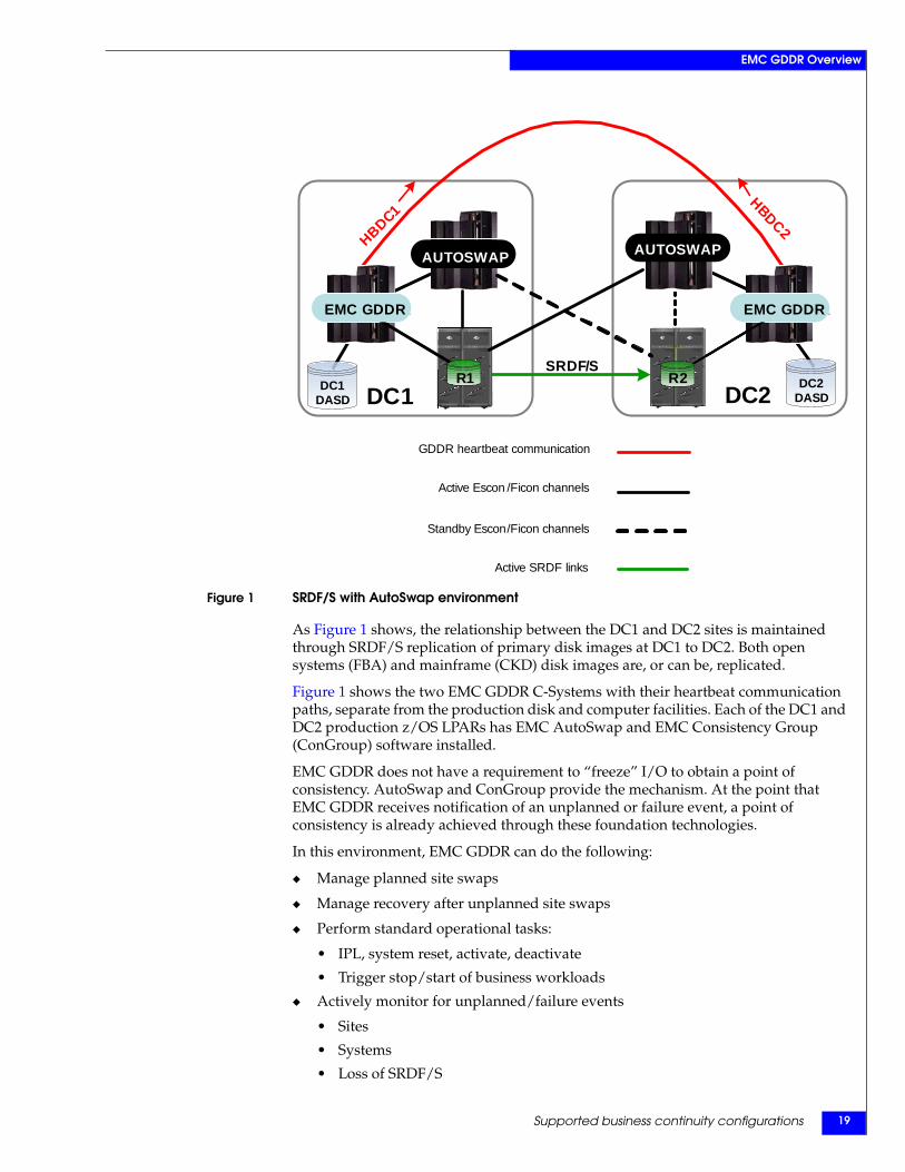
Figure 1 SRDF/S with AutoSwap environment
As Figure 1 shows, the relationship between the DC1 and DC2 sites is maintained through SRDF/S replication of primary disk images at DC1 to DC2. Both open systems (FBA) and mainframe (CKD) disk images are, or can be, replicated.
Figure 1 shows the two EMC GDDR C-Systems with their heartbeat communication paths, separate from the production disk and computer facilities. Each of the DC1 and DC2 production z/OS LPARs has EMC AutoSwap and EMC Consistency Group (ConGroup) software installed.
EMC GDDR does not have a requirement to “freeze” I/O to obtain a point of consistency. AutoSwap and ConGroup provide the mechanism. At the point that EMC GDDR receives notification of an unplanned or failure event, a point of consistency is already achieved through these foundation technologies.
In this environment, EMC GDDR can do the following:
◆ Manage planned site swaps
◆ Manage recovery after unplanned site swaps
◆ Perform standard operational tasks:
• IPL, system reset, activate, deactivate
• Trigger stop/start of business workloads
◆ Actively monitor for unplanned/failure events
• Sites
• Systems
• Loss of SRDF/S
GDDR heartbeat communication
Standby Escon/Ficon channels
Active SRDF links
Active Escon /Ficon channels
EMC GDDR
R1
EMC GDDR
R2
DC1SRDF/S
DC2
HBDC1HBDC2
AUTOSWAP AUTOSWAP
EMC GDDR EMC GDDR
R1 R2DC1DASD
DC2DASD
Supported business continuity configurations 19
EMC GDDR Overview
• ConGroup trip
• Inter-site communication failure
• AutoSwap events
◆ Configure/reconfigure
• Couple datasets
◆ Manage coupling facilities
• Policies
EMC GDDR Concepts and Facilities Guide20

EMC GDDR Overview
The EMC GDDR ComplexAn EMC GDDR Complex consists of EMC GDDR Control Systems (C-Systems), the z/OS and Open Systems hosts, and EMC Symmetrix storage which support an organization's mission-critical workload.
Each GDDR Complex can manage one consistency group. A consistency group is a named group of source (R1) volumes managed by the EMC Consistency Group for z/OS (ConGroup) application as a unit. The volumes can be on multiple Symmetrix units.
Figure 2 depicts a logical view of a typical EMC GDDR Complex.
Figure 2 EMC GDDR Complex
The following are descriptions of the items shown in Figure 2.
BCVs — BCVs (Business Continuance Volumes) can be supported at each of the sites. They may be established at the DC2 site and split at the DC1 site.
Note: The EMC TimeFinder/Mirror for z/OS Product Guide provides more information about BCVs and about the establish and split operations.
C1 and C2 — C1 and C2 are the EMC GDDR Control LPARs at each of the sites.
Primary site — The primary site is the site where the production workload is located.
Primary DASD site — The primary DASD (direct access storage device) site is the site where the source (R1) DASD is located. The primary DASD site is the same as the primary site.
Secondary site — The secondary site is the site where the contingency or stand by systems are located.
Secondary DASD site — The secondary DASD site is the site where the target (R2) DASD is located. The secondary DASD site is the same as the secondary site.
Sites DC1 and DC2 — Sites DC1 and DC2 are the primary and secondary data centers of critical production applications and data. DC1 is the primary site, with SRDF/S data replication to the secondary site, DC2. These sites are considered fully equivalent for strategic production applications, connected with highly redundant direct network links. At all times, all production data is replicated synchronously between the two sites.
Sysplexes — EMC GDDR supports multiple sysplexes.
DC1
Primary site
Sysplex #n
Sysplex #2
Sysplex #1C1
BCV
R1 R2
BCV
Local
C2
Master C
Local
Secondary siteDC2
SRDF/S
Sysplex #n
Sysplex #2
Sysplex #1
The EMC GDDR Complex 21
EMC GDDR Overview
EMC GDDR fundamentalsThis section discusses:
◆ Control systems
◆ Workload location
◆ Managed workloads
◆ EMC GDDR processes
Control systemsThe EMC GDDR control systems are more commonly referred to as EMC GDDR C-Systems. One EMC GDDR C-System is located at each site (DC1 and DC2).
C-Systems can be configured in monoplex mode or as standalone systems. Each EMC GDDR C-System runs in monoplex mode from local DASD. EMC suggests that you locate the C-System DASD on separate controllers from the production DASD. Because the EMC software applications run from local C-System volumes, this separation ensures that the C-Systems are not affected by any events that may impact the availability of the managed systems.
The main functions of a EMC GDDR C-System are to:
◆ Control the recovery after an outage
◆ Control a planned site swap
EMC GDDR C-Systems do not run any production workload.
One of the C-Systems is the Master C-System. During normal operations, the Master C-System is the central control point for all EMC GDDR activities. The Master C-System is located at the primary DASD site. In the event of the loss of the primary DASD site, EMC GDDR transfers the Master C-System to the secondary site, for completion of the restart coordination.
Some EMC GDDR functions can only be carried out by the Master C-System, for example:
◆ Running planned processes
◆ Updating EMC GDDR parameters
All EMC GDDR C-Systems are potential candidates to takeover as the Master C-System.
Workload locationIn an EMC GDDR Complex, the business or production workload can run as either:
◆ A single site workload
All production workload runs at a single site only; that is, one side of the sysplex. This is normally the same location as the primary DASD site.
◆ A multi-site workload
Production workload runs at both the primary and secondary sites.
EMC GDDR Concepts and Facilities Guide22
EMC GDDR Overview
Production systemA production system is a system that normally runs the site’s production workload and updates the primary DASD. Production systems are typically located at the same location as the primary DASD.
Contingency or standby systemA contingency or standby system is a system that normally provides a hot backup to a production system. A contingency system:
◆ Is in the same sysplex as its production system partner
◆ Is IPLed, but runs no business workload
Contingency or standby systems are typically located at the same location as the secondary DASD.
Note: Subsequent references to the term “production system” in this document refer to both production systems and contingency systems.
Managed systemsAny production or contingency/standby system defined to EMC GDDR is known as an EMC GDDR managed system.
Managed workloadsEMC GDDR can trigger the stop and restart of production workloads on:
◆ z/OS systems
◆ Distributed systems
EMC GDDR processesAn EMC GDDR process is a predetermined sequence of function calls. Generally one function call corresponds to one action. An EMC GDDR process is started by calling EMC GDDR provided routines, either from a batch job or as a result of specific messages being issued.
There are two types of EMC GDDR processes:
Planned process
An EMC GDDR planned process is initiated through the EMC GDDR operator interface to perform a planned task.
Unplanned process/takeover process
The EMC GDDR unplanned process or takeover process can only be initiated following an error that results in a possible takeover situation. Takeover processes are initiated as a result of certain messages being issued or specific events occurring.
The messages or events that trigger an unplanned or takeover process can originate on any system, either a C-System or a production system. They only take place on the current Master C-System.
They are invoked automatically after any of the following types of failure or loss are detected:
◆ Sites
◆ DASD
EMC GDDR fundamentals 23
EMC GDDR Overview
◆ Systems
◆ Loss of SRDF link
◆ Loss of host channels
Process restartThe return codes from the function calls that make up an EMC GDDR process are saved in CA-OPS/MVS global variables. In the case of a function that issues EMC SRDF Host Component commands, the return code of the command is also saved. If multiple commands are issued from one function, the return codes from each command are saved in CA-OPS/MVS global variables.
When an EMC GDDR process is rerun, assuming the cause of the original failure has been identified and resolved, EMC GDDR uses the saved return codes to establish the point of restart; that is, the point of the previous failure. This helps ensure that no modifications to the supplied EMC GDDR process jobs are required in order to rerun after a failure.
EMC GDDR Concepts and Facilities Guide24
EMC GDDR Overview
EMC GDDR componentsEMC GDDR is comprised of a number of components:
◆ Parameters
◆ User interface
◆ Events
◆ Monitors
◆ Message rules
ParametersEMC GDDR parameters define the environment and configuration that it manages. The parameters can modify the sequence of function calls that is an EMC GDDR process.
User interfaceThe EMC GDDR user interface is a CA-OPS/MVS user application. It is available only on EMC GDDR C-Systems. The user interface provides interfaces for both the EMC GDDR administrator and the EMC GDDR operator.
Note: The EMC GDDR Product Guide describes the EMC GDDR administrator interface. The EMC GDDR Operations Guide describes the EMC GDDR operator interface.
EventsAn EMC GDDR event is a change in state of a component part of the environment that EMC GDDR is actively monitoring. Examples of EMC GDDR events include:
◆ CGT — ConGroup trip has occurred/state change
◆ CGD — ConGroup group is disabled/state change
◆ MHB — missing C-System heartbeat
The event can have a state of either TRUE or FALSE. If the event has a state of TRUE, it has occurred or is currently occurring. If the event has a state of FALSE, it is no longer occurring.
An event that is TRUE is considered an exception.
EMC GDDR events are used by the GDDR event monitor and GDDR processes to determine environment state. A change in state can then:
◆ Trigger unplanned/takeover processes
◆ Prevent a planned process from running
MonitorsThere are three monitors on each EMC GDDR C-System:
◆ The EMC GDDR event monitor
◆ The EMC GDDR heartbeat monitor
◆ The optional EMC GDDR audit monitor
EMC GDDR components 25
EMC GDDR Overview
Event monitorThe EMC GDDR event monitor runs on each C-System and is used to analyze event state changes in which EMC GDDR is interested. On detecting the occurrence of selected events, the event monitor determines what action to take and prompts operators with the appropriate choices.
For example: EMC GDDR detects that a production system has failed and prompts the operators with the following options:
◆ IPL:ssss — EMC GDDR to restart ssss at current location DCn.
◆ SYSSITEn — EMC GDDR to start business applications at site DCn.
◆ SYSRESET — EMC GDDR to system reset ssss at site DCn only.
◆ Ignore — EMC GDDR to do nothing.
Heartbeat monitorThe EMC GDDR heartbeat monitor aids the event monitor in determining the status of the EMC GDDR managed environment. The lack of a heartbeat from a particular C-System is used to determine the state of a C-System and the site.
Audit monitorThe EMC GDDR audit monitor captures and externalizes data that EMC GDDR automation uses for business continuance processing (BCP) decision criteria and operations. This data includes dates and times of parameter load and backup jobs, global variable updates, override usage, and state changes relevant to EMC GDDR managed systems and storage.
Message rulesThe main purpose of the message rules installed on the production systems is to forward the selected messages to all the C-Systems.
EMC GDDR is supplied with automatic responses for messages that your site can enable, but these are disabled as shipped by EMC to allow for operations training and familiarity before the message handling is automated. There are no AOF (Automated Operations Facility) rules 1 for GDDR messages.
Note: The EMC GDDR Message and Code Guide contains more information about EMC GDDR messages.
The AOF message rules have two primary functions:
◆ To detect events that EMC GDDR is interested in and set the appropriate EMC GDDR event TRUE or FALSE.
◆ To detect events that EMC GDDR processes have to wait for (WTOR), and reply as to the success or failure of the waited for event. This will determine if an EMC GDDR process proceeds or terminates.
1. AOF is a product of Computer Associates. The AOF rules are definitions of monitored events and the responses to those events. Computer Associates’ OPS/MVS AOF Rules User Guide (on the Computer Associates documentation CD listed in the Preface and available to GDDR users on EMC Powerlink™) provides an explanation of AOF rules.
EMC GDDR Concepts and Facilities Guide26
EMC GDDR Overview
EMC GDDR uses the EMC ResourcePak Base Cross System Communication (CSC) facility to route message traffic to production systems that do not run CA-OPS/MVS. You or EMC service personnel can use the arrival of a message at the target production system to trigger an automation rule (for example in IBM Tivoli NetView or BMC Control-M). Such rules can be used to start or shut down workloads on the appropriate systems, even though they do not run CA-OPS/MVS.
DYNAPI interfaceThe EMC GDDR interface to EMC DYNAPI allows EMC GDDR to run dynamic SRDF commands in parallel.
EMC GDDR components 27
EMC GDDR Overview
EMC GDDR supported scriptsThe EMC GDDR Operator Interface contains a number of scripts that allow you to perform any of the following actions:
◆ Planned event management
◆ Unplanned event management
◆ Resumption after planned or unplanned outages
Note: The EMC GDDR Operations Guide contains more information about the EMC GDDR Operator Interface and how to use it.
Planned event management Operations personnel can handle planned event management scenarios by running any of the following scripts.
Note: DC1 and DC2 represent the current primary DASD site or current secondary DASD site. When these representations are shown in italic type in script titles, this indicates the values are interchangeable.
Swap production from DC1 to DC2
This script swaps the single-site workload from the primary DASD site to the secondary DASD site. This script performs the following actions:
◆ Stops the business workload at the primary DASD site
◆ Swaps the DASD to the secondary DASD site (AutoSwap followed by SRDF/S personality swap)
◆ Resumes SRDF/S
◆ Restarts the business workload
Swap DASD from DC1 to DC2
This script swaps only the DASD from the primary DASD site to the secondary DASD site.
Perform test IPL from BCVs at DC2
◆ Splits BCVs, makes them R/W
◆ Activates test LPARs using BCV volumes
◆ Starts test business workload, if applicable
Perform test IPL from R2s at DC2
◆ Confirms that SRDF/S has been stopped normally via a Congroup trip
◆ Activates LPARs using R2 volumes
◆ Starts test business workload, if applicable
EMC GDDR Concepts and Facilities Guide28
EMC GDDR Overview
Unplanned event managementOperations personnel can manage unplanned events in one of two ways:
◆ The EMC GDDR Event Monitor prompts the operator for management confirmation of trigger events which indicate a site or DASD outage. The operator replies to the prompt in the affirmative and the GDDR recovery script is started.
◆ The operator may start the appropriate unplanned script and respond to prompts. The script initiates and validates that the state of the current host and storage environments matches the script prerequisites before proceeding.
Recover after unplanned swap
This script performs the following restart actions after an unplanned swap has completed successfully:
◆ Stops business workload on the old primary site (if applicable)
◆ Splits BCVs at the new primary site
◆ Moves couple datasets to the new primary site (if applicable)
◆ Triggers restart of business workload at the new primary site
◆ Transfers Master C-System to the new secondary site
Recover after loss of DC1 (LDR)
◆ Confirms that a local disaster (LDR) event occurred
◆ Conditions R2s at the secondary site for restart
◆ Shuts down applications at the primary site, if applicable
◆ Splits BCVs at the secondary site
◆ Activates contingency systems
◆ Manages Couple Facility structures and datasets
◆ Restarts applications
Resume replication after unplanned swap
◆ Confirms SRDF/S links are down
◆ Splits BCVs at the secondary site, if applicable
◆ Performs ConGroup cleanup, transfer Autoswap ownership and restart SRDF/S
◆ Manages Couple Facility structures and datasets
◆ Reestablishes BCVs at the secondary site
EMC GDDR supported scripts 29
EMC GDDR Overview
Resumption after planned or unplanned outages Operations personnel can resume operations after planned or unplanned outages by running any of the following scripts.
Resume after test IPL from BCVs at DC2
◆ Stops test business workload, if applicable
◆ Reset clears test LPARs
◆ Reestablishes the BCVs
Resume after test IPL from R2s at DC2
◆ Stops test business workload, if applicable
◆ Reset clears test LPARs
◆ Restart SRDF/S with AutoSwap to DC2
Resume replication after link failure
◆ Confirms SRDF/S links are down
◆ Stops ConGroup on all systems
◆ Splits BCVs at the secondary site, if applicable
◆ Issues ConGroup cleanup and restart commands
◆ Reestablishes BCVs at the secondary site
EMC GDDR Concepts and Facilities Guide30
EMC GDDR Overview
Parameter statements: Telling EMC GDDR what to manageThe environment that EMC GDDR manages is described to EMC GDDR through parameter statements. The parameter statements are defined in members of a PDS and may be grouped together by function. The functions include:
Configuration statements
The configuration statements define the environment and resources to EMC GDDR.
EMC Host Component parameters and device statements
The EMC SRDF Host Component parameters and device statements define the actual devices, SRDF groups, GNS groups, and gatekeeper devices that form the configuration that EMC GDDR will manage.
CA-OPS/MVS configuration statements
The CA-OPS/MVS configuration statements define the CA-OPS/MVS MSF (Multi-System Facility) configuration to EMC GDDR. The CA-OPS/MVS MSF links are used by EMC GDDR to communicate between the EMC GDDR C-Systems.
Parameter statements: Telling EMC GDDR what to manage 31

EMC GDDR Overview
EMC GDDR hardware requirementsThis section details the EMC GDDR hardware requirements.
The basic infrastructure must support the running of SRDF/S with AutoSwap. In addition to this, EMC GDDR has the following specific infrastructure requirements:
◆ There must be network connectivity between all C-Systems and the managed production systems.
◆ An HMC (Hardware Management Console) must be available at each site that can be accessed from each C-System (access to these HMCs can be protected by means of a private VLAN).
EMC GDDR C-System Table 1 describes the recommended minimum processor and I/O configuration for an EMC GDDR C-System.
Table 1 EMC GDDR C-System minimum hardware requirements
Item Requirements
Logical processors 2
MSU The equivalent of 15 MSU on a IBM 2084-306
Storage 512 MB
Logical paths to own local DASD devices 4
Logical paths to Managed DASD devices 4
EMC GDDR Concepts and Facilities Guide32
EMC GDDR Overview
EMC GDDR software requirementsThe minimum software prerequisites needed to run EMC GDDR are as follows:
◆ z/OS
◆ IBM Hardware Management Console (HMC) API
◆ CA-OPS/MVS
◆ SRDF Host Component
◆ ResourcePak Base
◆ Consistency Group
◆ AutoSwap
Note: Software release levels for the above items are listed in the EMC GDDR Release Notes.
EMC GDDR software requirements 33
EMC GDDR Overview
EMC GDDR DASD supportEMC GDDR supports and can manage the following combinations of DASD in a single Enterprise Consistency Group:
◆ Single EMC Symmetrix controllers configured with any of the following:
• All CKD devices
• All FBA and FBA-META devices
• Any combination of CKD, FBA and FBA-META devices
◆ Multiple EMC Symmetrix controllers configured with any of the following:
• All CKD devices
• All FBA and FBA-META devices
• Any combination of CKD, FBA and FBA-META devices
Management and monitoring of both CKD and FBA/FBA-META devices is performed from the z/OS platform where the EMC GDDR application resides. From the EMC GDDR point of view, CKD and FBA/FBA-META Symmetrix devices are the same; that is, each is treated no differently than the other. They are all command targets of SRDF Host Component configuration commands using local, remote or GNS syntax.
All devices are managed at the RDF group level. SRDF Host Component commands target an RDF group rather than individual devices.
EMC GDDR has no limitations on the number of EMC Symmetrix controllers/devices that can be managed. Any limitations are subject to restrictions in EMC hardware and software.
EMC GDDR Concepts and Facilities Guide34
This glossary contains terms related EMC GDDR and to disk storage subsystems.
AAPI Application Programming Interface, a set of routines that an application program
uses to request and execute tasks performed by a computer’s operating system.
BBCV Business Continuance Volume, a standard Symmetrix device with special attributes
that allow it to independently support applications and processes, such as backup operations, restore operations, decision support operations, and application testing. BCV devices are available through the EMC TimeFinder/Mirror software.
BCV device A standard Symmetrix device with special attributes that allow it to independently support applications and processes.
BCV mirror A standard device mirror (one of M2, M3, or M4) that is assigned to the BCV device upon establishing or reestablishing a BCV pair.
BCV pair Consists of a standard device and a BCV device attached together.
CC systems The shorthand name for EMC GDDR C-Systems. A C-System is the controlling LPAR
for each of the EMC GDDR sites. The main functions of a EMC GDDR C-System are to:
◆ Control the recovery after an outage
◆ Control a planned site swap
The EMC GDDR C-Systems do not run any production workload.
C system masterfunction
The C-System that is currently responsible for monitoring DASD status and DASD mirroring. It is also responsible for taking action when problems with DASD and DASD mirroring are detected.
C1 Abbreviation for EMC GDDR C-System at the DC1 site.
C2 Abbreviation for EMC GDDR C-System at the DC2 site.
C3 Abbreviation for EMC GDDR C-System at the DC3 site.
Glossary
EMC GDDR Concepts and Facilities Guide 35
Glossary
CA-OPS/MVS MSF CA-OPS/MVS Multi System Facility (MSF) provides communication between multiple CA-OPA/MVS copies running on different z/OS images.
cache Random access electronic storage used to retain frequently used data for faster access by the channel.
cache slot Unit of cache equivalent to one track.
Cascaded SRDF The ability for a remote volume of a synchronously mirrored pair to simultaneously be the local volume of an asynchronously mirrored pair. Data from a primary site is synchronously replicated to a secondary site, where the volume at the secondary site is the primary volume from which data is asynchronously replicated to a tertiary site.
channel director The component in the Symmetrix subsystem that interfaces between the host channels and data storage. It transfers data between the channel and cache.
CKD Count-key-data, a data recording format employing self-defining record formats in which each record is represented by a count area that identifies the record and specifies its format, an optional key area that may be used to identify the data area contents, and a data area that contains the user data for the record. CKD can also refer to a set of channel commands that are accepted by a device that employs the CKD recording format.
Concurrent SRDF The ability for a single primary volume to be remotely mirrored to two secondary volumes concurrently. Concurrent SRDF requires that each remote mirror operate in the same primary mode, either both synchronous or both semi-synchronous, but allows either (or both) volumes to be placed into one of the adaptive copy modes.
ConGroup Short name for EMC Consistency Group for z/OS. An EMC mainframe application designed to ensure the consistency of the data remotely copied by the Symmetrix SRDF microcode feature in the event of a rolling disaster.
consistency group The consistency group is the key to ConGroup. The consistency group is a named group of source (R1) volumes that ConGroup treats as a unit. The volumes can be on multiple Symmetrix units and can include both mainframe and open systems devices.
When ConGroup detects any I/O to a volume in a consistency group that cannot communicate with its mirror, ConGroup suspends the remote mirroring for all volumes defined for that consistency group before completing the intercepted I/O, and returns control to the writing application. In this way, the ConGroup utility prevents dependent I/O from being issued by the application. This ensures the integrity and consistency of the data at the remote site.
DDASD Direct access storage device, a device that provides nonvolatile storage of computer
data and random access to that data.
data availability Access to any and all user data by the application.
dataset In a mainframe system, a collection of data in one of several prescribed arrangements and described by control information in the volume label and/or the catalog. A dataset may be equivalent to a file in some cases, as in physical sequential files, or several datasets may make up the components of a file.
DDNAME Data definition name, the logical name of a file within an application.
EMC GDDR Concepts and Facilities Guide36
Glossary
delayed fast write There is no room in cache for the data presented by the write operation.
dependent write A write that is not issued by an application unless some prior I/O operation has completed. An example of a dependent write is a database update. When updating a database, a database management system (DBMS) takes the following steps:
1. The DBMS writes to the disk containing the transaction log.
2. The DBMS writes the data to the actual database dataset.
3. The DBMS writes again to the log volume to indicate that the database update was successfully made.
device A uniquely addressable part of the Symmetrix subsystem that consists of a set of access arms, the associated disk surfaces, and the electronic circuitry required to locate, read, and write data.
device address The hexadecimal value that uniquely defines a physical I/O device on a channel path in an z/OS environment. See also “unit address.”
device number The value that logically identifies a disk device in a string.
diagnostics System level tests or firmware designed to inspect, detect, and correct failing components. These tests are comprehensive and self-invoking.
director The component in the Symmetrix subsystem that allows Symmetrix to transfer data between the host channels and disk devices. See also “channel director.”
disk director The component in the Symmetrix subsystem that interfaces between cache and the disk devices.
DSN Dataset name. A DSN consists of a series of dot-delimited qualifiers, each of which comprises a maximum of eight characters (for example, PAYROLL.DSN1.ESDS). A DSN has a maximum of 44 characters. When referencing the member of a partitioned dataset, the maximum length is 54 bytes, including 44 bytes for the name of the PDS, and up to eight bytes for the member name, enclosed in parentheses.
EEnginuity Enginuity is the operating environment for EMCs Symmetrix Enterprise Storage
Platforms. Enginuity provides functional services for both its host Symmetrix systems as well as for a large suite of EMC Storage Application software.
ESA Enterprise System Architecture (mainframe systems only).
ESCON Enterprise Systems Connection, a set of IBM and vendor products that connect mainframe computers with each other and with attached storage, locally attached workstations, and other devices using optical fiber technology and dynamically modifiable switches called ESCON directors.
ESCON director Device that provides a dynamic switching function and extended link path lengths (with XDF capability) when attaching an ESCON channel to a Symmetrix serial channel interface.
ESP Enterprise Storage Platform, the software for EMC Symmetrix storage subsystems. It allows storage of and access to mainframe and open systems data that is stored on the same Symmetrix storage subsystem.
EMC GDDR Concepts and Facilities Guide 37
Glossary
Ffast write In Symmetrix, a write operation at cache speed that does not require immediate
transfer of data to disk. The data is written directly to cache and is available for later destaging.
FB record Fixed block record, a fixed-length, blocked record in a mainframe dataset. The dataset can contain truncated (short) blocks.
FBA Fixed Block Architecture, a data record format that uses data blocks of fixed size. The blocks are addressed by block numbers relative to the beginning of the particular file. FBA is used by open systems computers while a different scheme, CKD, is used by mainframe computers.
FBAM Fixed Block Architecture, Meta-volume.
FICON Fibre Connectivity, a high-speed I/O interface for mainframe computer connections to storage devices. FICON channels increase I/O capacity to make them up to eight times as efficient as ESCON channels.
file In z/OS terminology, a file is an abstraction that represents a collection of data at the application level. In some cases, such as physical sequential files, a dataset and a file may be considered equivalent. In other cases, several datasets may be presented to the application as a single logical file. In a partitioned dataset, a subset of the dataset, called a member, is considered a file.
Ggatekeeper A small logical volume on a Symmetrix storage subsystem used to pass commands
from a host to the Symmetrix storage subsystem. Gatekeeper devices are configured on standard Symmetrix disks.
GDDR Acronym for Geographically Dispersed Disaster Restart.
GDDR Complex An EMC GDDR Complex is a two-site cluster of GDDR systems. Each GDDR Complex can manage one consistency group. See “ConGroup” and “consistency group.”
GDG Generation Data Group, a collection of physical sequential files that are logically related by their content, and usually represent a history of the data over some period of time. The group is created through use of administrative utilities, and individual datasets in the group called generation datasets (GDS) are created by running user programs.
GDS Generation Data Set, elements of a generation data group referred to by a GDG base name, followed by a number enclosed in parentheses. The number indicates the relative chronological position of each GDS.
GNS Group Name Service. GNS is the Symmetrix group definition sharing facility. GNS allows you to define a group of devices (and the controllers on which they reside) once, in one place, and then use that single definition across multiple EMC products on multiple platforms. That is, you can use group definitions created through GNS on a mainframe system with EMC software products running on open systems hosts.
EMC GDDR Concepts and Facilities Guide38
Glossary
GNS group A Group Name Service group. Each GNS group is a list of controllers and devices that reside on those controllers. The controllers and devices may reside on one Symmetrix storage subsystem or on different Symmetrix storage subsystems. If a GNS group spans more than one Symmetrix storage subsystem, each Symmetrix unit holds only its portion of that single definition.
Each group is a collection of controllers, and the devices that reside on those controllers. For groups that span Symmetrix storage subsystems, the definition is stored as a set of components on different Symmetrix storage subsystems. Each Symmetrix storage subsystem holds its portion of that single definition.
gigabyte (GB) 109 bytes.
IID Identifier, a sequence of bits or characters that identifies a program, device, controller,
or system.
I/O device An addressable input/output unit, such as a disk device.
KK Kilobyte, 1024 bytes.
Llocal volume A Symmetrix logical volume that is not participating in SRDF operations. All CPUs
attached to the Symmetrix may access it for read/write operations. It is available for local mirroring or dynamic sparing operations to the Symmetrix unit in which it resides only.
logical volume A user-addressable unit of storage. In the Symmetrix subsystem, the user can define multiple logical volumes on a single physical disk device.
LPAR Logical partitioning, a system of splitting a mainframe computer‘s total resources into smaller units. The units essentially act as separate machines. Each unit can run with its own instance of the operating system and applications. The units, however, can communicate with each other.
MMB Megabyte, 106 bytes.
mirrored pair A logical volume with all data recorded twice, once on each of two different physical devices.
mirroring The Symmetrix maintains two identical copies of a designated volume on separate disks. Each volume automatically updates during a write operation. If one disk device fails, Symmetrix automatically uses the other disk device.
multi-site workloadconfiguration
In a multi-site workload configuration, the production workload runs at both the primary and secondary sites. See also “primary site” and “secondary site.”
EMC GDDR Concepts and Facilities Guide 39
Glossary
Multi-SessionConsistency (MSC)
SRDF/A is supported in configurations where there are multiple primary Symmetrix systems and/or multiple primary Symmetrix SRDF groups connected to multiple secondary Symmetrix systems and/or multiple secondary Symmetrix SRDF groups. This is referred to as SRDF/A Multi-Session Consistency (MSC). SRDF/A MSC configurations can also support mixed open systems and mainframe data controlled within the same SRDF/A MSC session.
PPDS Partitioned Dataset, a composite mainframe dataset that is much like a directory in
UNIX containing files, for example, source files. The members in a PDS are usually of the same type of data, for example, C language source files or header files.
physical ID Physical identification number of the Symmetrix director for EREP usage. This value automatically increments by one for each director installed in Symmetrix. This number must be unique in the mainframe system. It should be an even number. This number is referred to as the SCU_ID.
primary site The primary site is the site where the production workload is located. The primary site is typically the same as the primary DASD site.
primary DASD site The primary DASD site is the site where the source (R1) DASD is located. The primary DASD site is typically the same as the primary site.
RR1 See “source volume (R1).”
R2 See “target volume (R2).”
R21 A dual-role SRDF R2/R1 device on the secondary site which acts as both an R2 to the primary site and an R1 to the tertiary site.
rolling disaster A rolling disaster is more common than an immediate catastrophic failure. A rolling disaster is a series of events happening over a period of time that lead to data corruption until a catastrophic failure finally occurs. Each rolling disaster is delimited by two fixed points: the time when the first failure occurs and the time when the disaster is complete. The period between these two times is the rolling disaster.
RPO Recovery Point Objective. The Recovery Point Objective is a point of consistency to which a user wants to recover or restart. It is measured in the amount of time from when the point of consistency was created or captured to the time the disaster occurred. This time equates to the acceptable amount of data loss.
Zero data loss (no loss of committed transactions from the time of the disaster) is the ideal goal, but the high cost of implementing such a solution must be weighed against the business impact and cost of a controlled data loss.
Some organizations like banks have zero data loss requirements. The data base transactions entered at one location must be replicated immediately to another location. This can have an impact on application performance when the two locations are far apart. On the other hand, keeping the two locations close to one another might not protect against a regional disaster like the power outages or hurricanes.
Defining the required RPO is usually a compromise between the needs of the business, the cost of the solution, and the risk of a particular event happening.
EMC GDDR Concepts and Facilities Guide40
Glossary
Ssecondary site The secondary site is the site where the contingency or standby systems are located.
secondary DASD site The secondary DASD site is the site where the target (R2) DASD is located. The secondary DASD site will typically be the same as the secondary site.
single site workloadconfigurations
Single site workload configurations are configurations in which the primary site is the site where the production workload is located. See also “primary site.”
sites DC1 and DC2 Site DC1 and DC2 are the primary and secondary data centers for critical production applications and data. They are considered fully equivalent for strategic production applications, connected with highly redundant direct network links.
At all times, all production data is replicated synchronously between the two sites.
source volume (R1) A Symmetrix logical volume that is participating in SRDF operations. It resides in the “local” Symmetrix unit. All CPUs attached to the Symmetrix may access a source volume for read/write operations. All writes to this volume are mirrored to a “remote” Symmetrix unit. A source volume is not available for local mirroring operations. See also “target volume (R2).”
SRDF Symmetrix Remote Data Facility. SRDF consists of the microcode and hardware required to support Symmetrix remote mirroring.
SRDF/S SRDF/Synchronous. SRDF/S is a business continuance solution that maintains a real-time (synchronous) copy of data at the logical volume level in Symmetrix or Symmetrix DMX™ systems in the same or separate locations. The SRDF/S operation is transparent to the host operating system and host applications. It does not require additional host software for duplicating data on the participating Symmetrix units.
storage control unit The component in the Symmetrix subsystem that connects Symmetrix to the host channels. It performs channel commands and communicates with the disk directors and cache. See also “channel director.”
sysplex System complex. A processor complex which is formed by loosely coupling mainframe processors together into a single unit, using channel-to-channel adapters or ESCON or FICON fiber optic links.
system The word system or systems used in this guide refers to a z/OS image and all systems tasks and applications running in it.
Ttarget volume (R2) A Symmetrix logical volume that is participating in SRDF operations. It resides in the
“remote” Symmetrix unit. It is paired with a source volume in the local Symmetrix unit and receives all write data from its mirrored pair. This volume is not accessed by user applications during normal I/O operations. A target volume is not available for local mirroring or dynamic sparing operations. See also “source volume (R1).”
trip The action ConGroup takes when it detects that one or more source (R1) devices in a consistency group cannot propagate data to their corresponding target (R2) devices. During a trip, ConGroup suspends all the source (R1) devices in the consistency group. This suspension ensures that:
EMC GDDR Concepts and Facilities Guide 41
Glossary
• The data flow to the target (R2) side is halted.
• The data on the remote side of the configuration is consistent.
Uunit address The hexadecimal value that uniquely defines a physical I/O device on a channel path
in an MVS environment. See also “device address.”
Vvolume A general term referring to a storage device. In the Symmetrix subsystem, a volume
corresponds to a single device visible to the host. In the context of host-based, volume manager software, a volume is a logical unit of disk storage that may comprise storage on one to many Symmetrix devices.
EMC GDDR Concepts and Facilities Guide42
Index
Aanalyzing event state changes 26AOF rules 26audit monitor 26Automated Operations Facility 26
BBCVs 21business continuance volumes 21business restart 14, 28
CCA-OPS/MVS 25
configuration statements 31global variables 24MSF feature 15
CFRM policies 16CGD event 25CGT event 25CKD devices 34configuration statements 31ConGroup disable event 25ConGroup trip event 25consistency groups, definition 21contingency systems 23control LPARs 21C-Systems 22
main functions 22minimum requirements 32
DDASD support 34DC1 site 21
illustration 19DC2 site 21
illustration 19determining environment state 25device statements 31distributed workloads, starting and stopping 16dual-direction heartbeats 15DYNAPI 27
EEMC GDDR
audit monitor 26components 25C-Systems 22DASD support 34event monitor 25events 25hardware requirements 32heartbeat monitor 26message rules 26operator Interface 28processes 23
Enterprise Consistency Groups 34event monitor 25, 26events 25
CGD 25CGT 25MHB 25
FFBA devices 34FBA-META devices 34
GGDDR complexes 22GDDR event monitor 25global variables 24
Hhardware requirements 32heartbeat monitor 26HMC availability 32hot backups 23
Iinfrastructure requirements 32installation
software prerequisites 33
EMC GDDR Concepts and Facilities Guide 43
Index
Mmanaged systems, definition 23Master C-Systems 22message rules 26MHB event 25minimum processor configuration 32minimum software prerequisites 33missing C-System heartbeat 25monitoring events 25monitoring the managed environment 14monoplex mode 22multi-site workloads 22
Nnetwork outages 15
Pparameter statements 31parameters 25planned outages 30planned processes 23planned scenarios 28planned site swaps 22Powerlink website 11primary DASD site 21primary data centers 21primary site, definition 21process restart 24production systems 23production workloads 22
Rrecommended I/O configuration 32recommended minimum processor configuration 32reconfiguring all couple dataset types 16related documents 9restart processing after unplanned swap 29resumption scenarios 30return codes 24
Sscripts
restart processing after unplanned swap 29secondary DASD site 21, 22secondary data centers 21secondary site 21SFM policies 16single site workloads 22software prerequisites 33source (R1) DASD 21standby systems 23starting distributed workloads 16
Ttakeover processes 23target (R2) DASD 21trips, ConGroup 25
Uunplanned event management 29unplanned outages 30unplanned processes, definition 23user interface 25
EMC GDDR Concepts and Facilities Guide44