electronic lubrication control unit · line lubrication systems. timing intervals from 5 seconds to...
TRANSCRIPT
Installation instructions
Model 85307; Dual line system
Electronic lubrication control unit
Date of issue July 2018
Form number 404772
Version 1

ContentsDescription. . . . . . . . . . . . . . . . . . . . . . . 3
Speciications . . . . . . . . . . . . . . . . . . . 3
Features . . . . . . . . . . . . . . . . . . . . . . . . . 3
Safety . . . . . . . . . . . . . . . . . . . . . . . . . . . 4
Operational precautions . . . . . . . . . . . . . 4
Explanation of signal words
for safety . . . . . . . . . . . . . . . . . . . . . . . . . 4
Keypad layout . . . . . . . . . . . . . . . . . . . 5
Panel description . . . . . . . . . . . . . . . . . 6
Dual line system using
two pressure switches and
hydraulic change over valve . . . . . . . . . 10
Run mode . . . . . . . . . . . . . . . . . . . . . . . . 17
Running system (pump run) . . . . . . . . . . 17
Running system (pump pause) . . . . . . . . 18
Running system (vent cycles) . . . . . . . . . 18
Stage 1 . . . . . . . . . . . . . . . . . . . . . . . . . . 19
Stage 2 . . . . . . . . . . . . . . . . . . . . . . . . . . 19
Stage 3 . . . . . . . . . . . . . . . . . . . . . . . . . . 20
Stage 4 . . . . . . . . . . . . . . . . . . . . . . . . . . 20
Stage 5 . . . . . . . . . . . . . . . . . . . . . . . . . . 21
Two pressure switches and
hydraulic change over valve . . . . . . . . 22
Fault indications . . . . . . . . . . . . . . . . . 23
Dual line system using 1/2 cycles
and hydraulic change over valve . . . . . 24
Run mode . . . . . . . . . . . . . . . . . . . . . . . . 27
Running system (pump run) . . . . . . . . . . 27
Running system (pump pause) . . . . . . . . 27
Stage 1 . . . . . . . . . . . . . . . . . . . . . . . . . . 28
Stage 2 . . . . . . . . . . . . . . . . . . . . . . . . . . 28
Stage 3 . . . . . . . . . . . . . . . . . . . . . . . . . . 29
Stage 4 . . . . . . . . . . . . . . . . . . . . . . . . . . 29
Dual line system using 1/2 cycles
and hydraulic change over valve . . . . . 30
Fault indications . . . . . . . . . . . . . . . . . 31
Warranty . . . . . . . . . . . . . . . . . . . . . . . . 32
2

Description
Controller 85307 is a universal electronic
control unit compatible with dual line, single
line parallel and progressive lubrication
systems. It gives lexibility and control over
traditional single line systems.
Controller layout displays what is
happening and quickly diagnoses problems.
Programming controller requires only simple
information so that operator can focus on
particular system in use.
Features
• Runs progressive, single line and dual
line lubrication systems.
• Timing intervals from 5 seconds to
24 hours.
• Cycle counting.
• 10 V to 30 V operation.
• Short circuit/open circuit detection with
audible warning.
• External fault lamp drive (Flash or
steady output).
• Low level reservoir monitoring.
• Two sensor switch inputs.
• Visual and audible fault indication.
• Non-volatile memory.
• Built in “blown fuse” indicator.
• 3 digit LED display indicates exact
status of system.
• Simple setup procedure.
• Test mode allows testing of all circuits
connected to controller.
• Practical housing with mounting
bracket.
Speciications
Voltage 10 V to 30 V Current drain 150 ma maximum (no load) 70 ma nominalPump output 7A rms. maximum
Lamp output 3A maximumSwitching Solid state short circuit protectedFuse 8 Amp fast blow 0.79 in (20 mm) glass
Connection 14 way MOLEX MINIFIT - JRCommunications RS232 TypeDimensions 2.8 in X 5.7 in X 1.5 in (70 mm X 145 mm X 38 mm) 1)
Weight 0.66 lbs (300 g)Protection IP54Temperature range 5 °F to 122 °F (-15 °C to 50 °C)
1) Includes mounting bracket.
3
Safety
Read and carefully observe operating
instructions before unpacking and operating
equipment. Equipment must be operated,
maintained and repaired exclusively by
persons familiar with operating instructions.
Local safety regulations regarding
installation, operation and maintenance
must be followed.
Operate equipment only after safety
instructions and this service manual are
fully understood.
Operational precautions
User must have total understanding of
controller speciications. Never connect any
other voltage supply other than speciied in
manuals contained within.
Operator/owner must ensure installation
or inspections are executed by authorized
personnel who have thoroughly read
operating instruction manual.
Any setting up or work on controller must
be done while machine is off. Machine must
be in position that will not cause harm to any
person should machine be switched on for
setting up of controller. In the event that the
machine needs to be on for setting up of
controller, it must be under condition that
operator or personnel working on machine
are advised.
Never switch machine on without prior
knowledge of operator/owner or somebody
that has full knowledge of machines
operation.
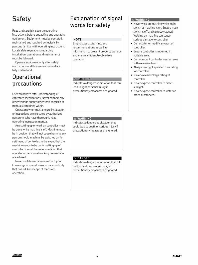
� WARNING
• Never weld on machine while main
switch of machine is on. Ensure main
switch is off and correctly tagged.
Welding on machine can cause
serious damage to controller.
• Do not alter or modify any part of
controller.
• Ensure controller is mounted in
suitable area.
• Do not mount controller near an area
with excessive heat.
• Always use right speciied fuse rating
for controller.
• Never exceed voltage rating of
controller.
• Never expose controller to direct
sunlight.
• Never expose controller to water or
other substances.
Explanation of signal words for safety
NOTE
Emphasizes useful hints and
recommendations as well as
information to prevent property damage
and ensure eficient trouble-free
operation.
� CAUTION
Indicates a dangerous situation that can
lead to light personal injury if
precautionary measures are ignored.
� WARNING
Indicates a dangerous situation that
could lead to death or serious injury if
precautionary measures are ignored.
� DANGER
Indicates a dangerous situation that will
lead to death or serious injury if
precautionary measures are ignored.
4
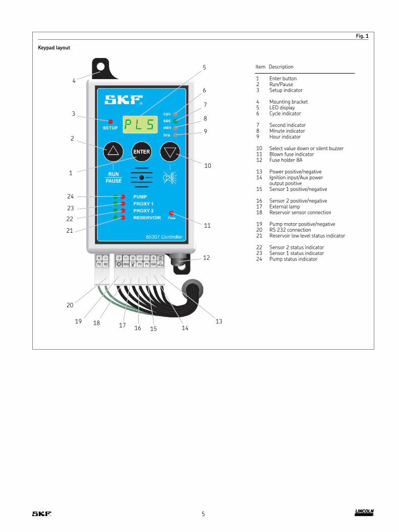
Fig. 1
Keypad layout
Item Description
1 Enter button2 Run/Pause3 Setup indicator
4 Mounting bracket5 LED display6 Cycle indicator
7 Second indicator8 Minute indicator9 Hour indicator
10 Select value down or silent buzzer11 Blown fuse indicator12 Fuse holder 8A
13 Power positive/negative14 Ignition input/Aux power
output positive15 Sensor 1 positive/negative
16 Sensor 2 positive/negative17 External lamp18 Reservoir sensor connection
19 Pump motor positive/negative20 RS 232 connection21 Reservoir low level status indicator
22 Sensor 2 status indicator23 Sensor 1 status indicator24 Pump status indicator
1
2
3
4
5
6
7
8
9
10
11
12
13
14 15 16 17
18 19
20
21
22
23
24
5

Panel description
Fig. 2
sec
min
hrs
cyc
SETUP
Fig. 3
sec
min
hrs
cyc
SETUP
Fig. 4
sec
min
hrs
cyc
SETUP
Fig. 5
sec
min
hrs
cyc
SETUP
Fig. 6
sec
min
hrs
cyc
SETUP
SLS = single line systems
PLS = Progressive line systems
dls = dual line systems
n-O = normally open (sensors)
n-C = normally closed (sensors)
6

Fig. 7
sec
min
hrs
cyc
SETUP
Fig. 8
sec
min
hrs
cyc
SETUP
Fig. 9
sec
min
hrs
cyc
SETUP
L -S = External lamp steady (continues supply)
L -F = External lamp lashing (pulsed supply)
Fig. 10
sec
min
hrs
cyc
SETUP
Fig. 11
sec
min
hrs
cyc
SETUP
nFE = non fatal error (pump continues on Low Level Fault)
r = Run time in cycles
P = Pause time in seconds, minutes or hours
7
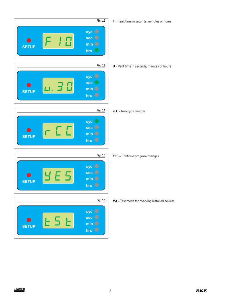
Fig. 12
sec
min
hrs
cyc
SETUP
F = Fault time in seconds, minutes or hours
Fig. 13
sec
min
hrs
cyc
SETUP
Fig. 14
sec
min
hrs
cyc
SETUP
Fig. 15
sec
min
hrs
cyc
SETUP
U = Vent time in seconds, minutes or hours
rCC = Run cycle counter
Fig. 16
sec
min
hrs
cyc
SETUP
YES = Conirms program changes
tSt = Test mode for checking installed devices
8
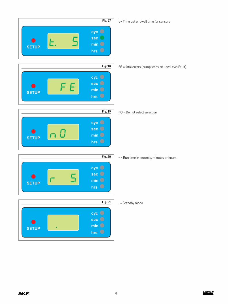
Fig. 17
sec
min
hrs
cyc
SETUP
t = Time out or dwell time for sensors
Fig. 18
sec
min
hrs
cyc
SETUP
FE = fatal errors (pump stops on Low Level Fault)
Fig. 19
sec
min
hrs
cyc
SETUP
nO = Do not select selection
Fig. 20
sec
min
hrs
cyc
SETUP
r = Run time in seconds, minutes or hours
Fig. 21
sec
min
hrs
cyc
SETUP
. = Standby mode
9

Dual line system using 2 pressure switches and hydraulic change over valve
1 To enter setup mode press and hold ENTER while switching on
power source to controller.
2 Release ENTER and red LED next to SETUP illuminates. Green
LED next to PUMP lashes. PLS (progressive line systems)
appears in display (Fig. 22 A).
3 Press Δ to select type of system required. Continue to press until
dLS displays (Fig. 22 B).
4 Press ENTER to conirm use of dual line systems (Fig. 22 C).
Fig. 22
-- --
8AmpP2RES IGNP1
12V24V
M
++++ -
TX RX
sec
min
hrs
cyc
SETUP
Fuse
PROXY 1
PUMP
PROXY 2
RESERVOIR
RUN
PAUSE
ENTER
85307 Controller
-- --
8AmpP2RES IGNP1
12V24V
M
++++ -
TX RX
sec
min
hrs
cyc
SETUP
Fuse
PROXY 1
PUMP
PROXY 2
RESERVOIR
RUN
PAUSE
ENTER
85307 Controller
-- --
8AmpP2RES IGNP1
12V24V
M
++++ -
TX RX
sec
min
hrs
cyc
SETUP
Fuse
PROXY 1
PUMP
PROXY 2
RESERVOIR
RUN
PAUSE
ENTER
85307 Controller
A B C
10

Fig. 23
5 P (pause) appears in display. Press Δ to change time (Fig. 23 A).
LED changes from seconds to minutes to hours. Amount
displayed indicates what pause time functions at when applied.
6 Press ENTER to conirm pause time. In example, pause time of
4 hours is conirmed (Fig. 23 B).
STEP 5
A B
11
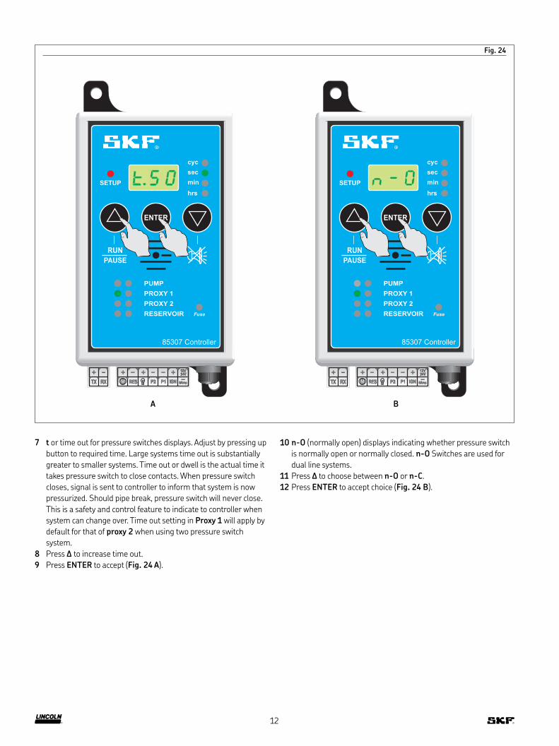
Fig. 24
7 t or time out for pressure switches displays. Adjust by pressing up
button to required time. Large systems time out is substantially
greater to smaller systems. Time out or dwell is the actual time it
takes pressure switch to close contacts. When pressure switch
closes, signal is sent to controller to inform that system is now
pressurized. Should pipe break, pressure switch will never close.
This is a safety and control feature to indicate to controller when
system can change over. Time out setting in Proxy 1 will apply by
default for that of proxy 2 when using two pressure switch
system.
8 Press Δ to increase time out.
9 Press ENTER to accept (Fig. 24 A).
10 n-O (normally open) displays indicating whether pressure switch
is normally open or normally closed. n-O Switches are used for
dual line systems.
11 Press Δ to choose between n-O or n-C.
12 Press ENTER to accept choice (Fig. 24 B).
-- --
8AmpP2RES IGNP1
12V24V
M
++++ -
TX RX
sec
min
hrs
cyc
SETUP
Fuse
PROXY 1
PUMP
PROXY 2
RESERVOIR
RUN
PAUSE
ENTER
85307 Controller
-- --
8AmpP2RES IGNP1
12V24V
M
++++ -
TX RX
sec
min
hrs
cyc
SETUP
Fuse
PROXY 1
PUMP
PROXY 2
RESERVOIR
RUN
PAUSE
ENTER
85307 Controller
A B
12

13 nO displays. Green LED on PROXY 2 illuminates. Because two
pressure switch system is being used, press Δ to select YES.
14 Press ENTER to accept and proceed to next part
of setup (Fig. 25 A).
15 System skips PROXY 2 setup and defaults to settings made in
PROXY 1. Number of cycles dual line system will run for before
going into pause cycle displays. Controller has unique feature of
running multiple cycles because system actually monitors state of
pressure switch, closed or opened, to allow for next cycle to
commence.
16 Press Δ to select number of run (r) cycles.
17 Press ENTER to accept settings (Fig. 25 B).
Fig. 25
-- --
8AmpP2RES IGNP1
12V24V
M
++++ -
TX RX
sec
min
hrs
cyc
SETUP
Fuse
PROXY 1
PUMP
PROXY 2
RESERVOIR
RUN
PAUSE
ENTER
85307 Controller
-- --
8AmpP2RES IGNP1
12V24V
M
++++ -
TX RX
sec
min
hrs
cyc
SETUP
Fuse
PROXY 1
PUMP
PROXY 2
RESERVOIR
RUN
PAUSE
ENTER
85307 Controller
A B
13
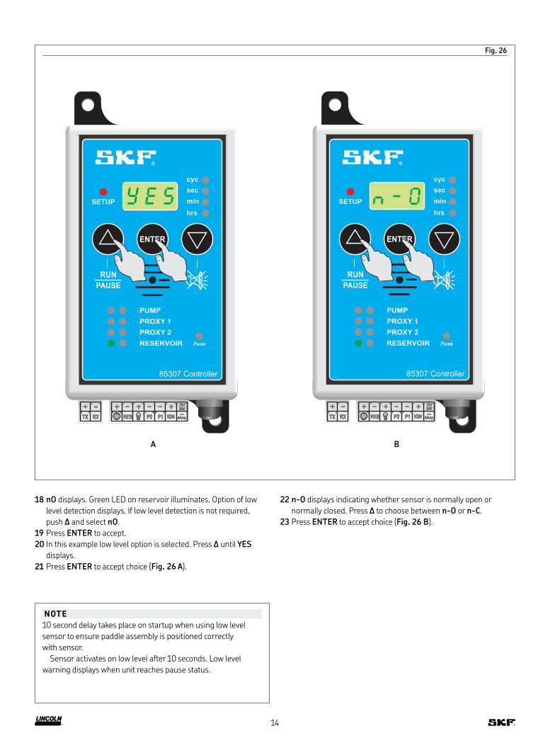
Fig. 26
-- --
8AmpP2RES IGNP1
12V24V
M
++++ -
TX RX
sec
min
hrs
cyc
SETUP
Fuse
PROXY 1
PUMP
PROXY 2
RESERVOIR
RUN
PAUSE
ENTER
85307 Controller
NOTE
10 second delay takes place on startup when using low level
sensor to ensure paddle assembly is positioned correctly
with sensor.
Sensor activates on low level after 10 seconds. Low level
warning displays when unit reaches pause status.
18 nO displays. Green LED on reservoir illuminates. Option of low
level detection displays. If low level detection is not required,
push Δ and select nO.
19 Press ENTER to accept.
20 In this example low level option is selected. Press Δ until YES
displays.
21 Press ENTER to accept choice (Fig. 26 A).
22 n-O displays indicating whether sensor is normally open or
normally closed. Press Δ to choose between n-O or n-C.
23 Press ENTER to accept choice (Fig. 26 B).
-- --
8AmpP2RES IGNP1
12V24V
M
++++ -
TX RX
sec
min
hrs
cyc
SETUP
Fuse
PROXY 1
PUMP
PROXY 2
RESERVOIR
RUN
PAUSE
ENTER
85307 Controller
A B
14
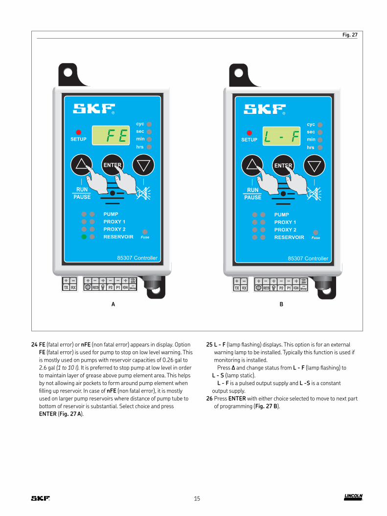
Fig. 27
-- --
8AmpP2RES IGNP1
12V24V
M
++++ -
TX RX
sec
min
hrs
cyc
SETUP
Fuse
PROXY 1
PUMP
PROXY 2
RESERVOIR
RUN
PAUSE
ENTER
85307 Controller
-- --
8AmpP2RES IGNP1
12V24V
M
++++ -
TX RX
sec
min
hrs
cyc
SETUP
Fuse
PROXY 1
PUMP
PROXY 2
RESERVOIR
RUN
PAUSE
ENTER
85307 Controller
24 FE (fatal error) or nFE (non fatal error) appears in display. Option
FE (fatal error) is used for pump to stop on low level warning. This
is mostly used on pumps with reservoir capacities of 0.26 gal to
2.6 gal (1 to 10 l). It is preferred to stop pump at low level in order
to maintain layer of grease above pump element area. This helps
by not allowing air pockets to form around pump element when
illing up reservoir. In case of nFE (non fatal error), it is mostly
used on larger pump reservoirs where distance of pump tube to
bottom of reservoir is substantial. Select choice and press
ENTER (Fig. 27 A).
25 L - F (lamp lashing) displays. This option is for an external
warning lamp to be installed. Typically this function is used if
monitoring is installed.
Press Δ and change status from L - F (lamp lashing) to
L - S (lamp static).
L - F is a pulsed output supply and L -S is a constant
output supply.
26 Press ENTER with either choice selected to move to next part
of programming (Fig. 27 B).
A B
15
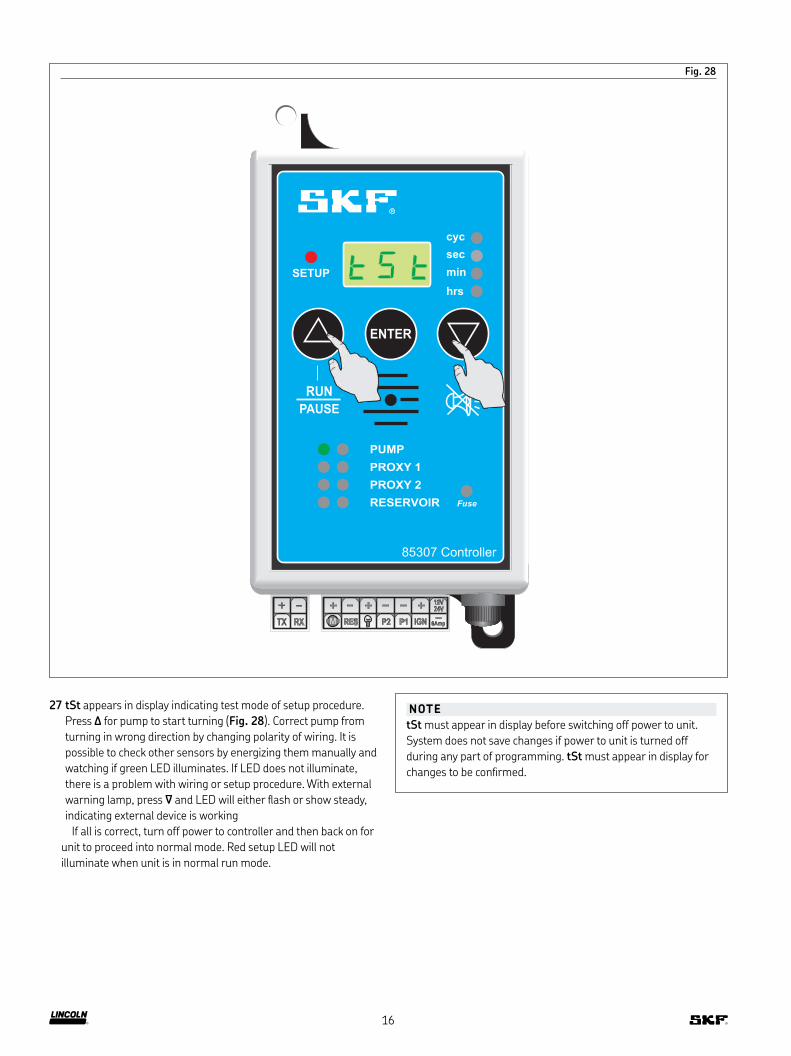
Fig. 28
27 tSt appears in display indicating test mode of setup procedure.
Press Δ for pump to start turning (Fig. 28). Correct pump from
turning in wrong direction by changing polarity of wiring. It is
possible to check other sensors by energizing them manually and
watching if green LED illuminates. If LED does not illuminate,
there is a problem with wiring or setup procedure. With external
warning lamp, press ∇ and LED will either lash or show steady,
indicating external device is working
If all is correct, turn off power to controller and then back on for
unit to proceed into normal mode. Red setup LED will not
illuminate when unit is in normal run mode.
NOTE
tSt must appear in display before switching off power to unit.
System does not save changes if power to unit is turned off
during any part of programming. tSt must appear in display for
changes to be conirmed.
-- --
8AmpP2RES IGNP1
12V24V
M
++++ -
TX RX
sec
min
hrs
cyc
SETUP
Fuse
PROXY 1
PUMP
PROXY 2
RESERVOIR
RUN
PAUSE
ENTER
85307 Controller
16
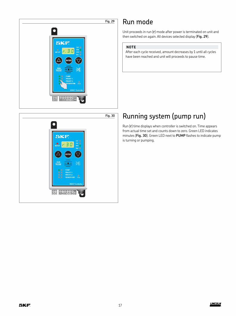
Fig. 29 Run modeUnit proceeds in run (r) mode after power is terminated on unit and
then switched on again. All devices selected display (Fig. 29).
Running system (pump run)Run (r) time displays when controller is switched on. Time appears
from actual time set and counts down to zero. Green LED indicates
minutes (Fig. 30). Green LED next to PUMP lashes to indicate pump
is turning or pumping.
Fig. 30
NOTE
After each cycle received, amount decreases by 1 until all cycles
have been reached and unit will proceeds to pause time.
17
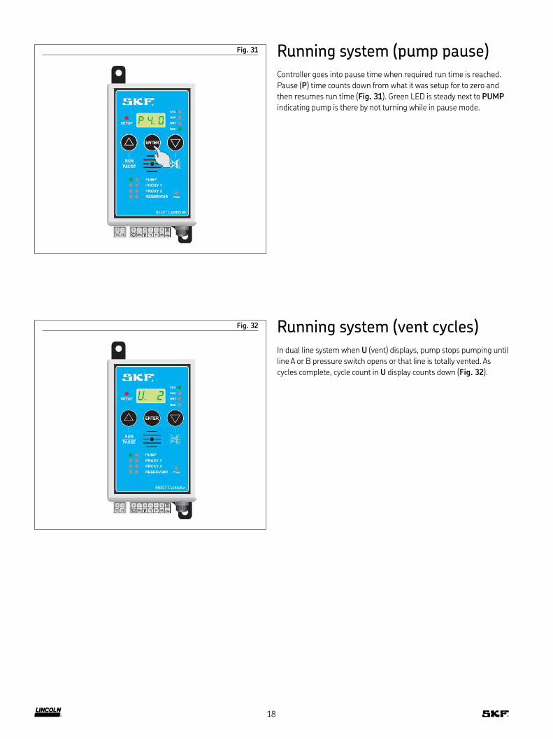
Running system (pump pause)Controller goes into pause time when required run time is reached.
Pause (P) time counts down from what it was setup for to zero and
then resumes run time (Fig. 31). Green LED is steady next to PUMP
indicating pump is there by not turning while in pause mode.
Fig. 31
STEP 5
Running system (vent cycles)In dual line system when U (vent) displays, pump stops pumping until
line A or B pressure switch opens or that line is totally vented. As
cycles complete, cycle count in U display counts down (Fig. 32).
Fig. 32
18

Diagram 1
M
-- --
8AmpP2RES IGNP1
12V24V
M
++++ -
TX RX
sec
min
hrs
cyc
SETUP
Fuse
PROXY 1
PUMP
PROXY 2
RESERVOIR
RUN
PAUSE
ENTER
A A
BBR
P
1)
85307 Controller
2)
Stage 1Cycle begins to pump lubricant through
line B. As line begins to pressurize, pressure
switch closes. Green LED on controller
illuminates. Pump continues to pump until it
reaches pressure set on change over valve.
At this stage, pressure switch remains
closed.
Diagram 2
M
-- --
8AmpP2RES IGNP1
12V24V
M
++++ -TX RX
sec
min
hrs
cyc
SETUP
Fuse
PROXY 1
PUMP
PROXY 2
RESER VOIR
RUN
PAUSE
ENTER
A A
BBR
P
2)1)
85307 Controller
Stage 2As pressure reaches change over valve,
direction of low changes. Grease in line A
begins to pressurize while line B vents. As
line A reaches 290 psi (20 bar), pressure
switch closes and shuts pump off until line B
is totally vented. Pressure switch in line B
must be open before cycle will continue.
Both LEDs illuminate.
1) Set at 5 076 psi (350 bar).2) Set at 290 to 580 psi (20 to 40 bar).
1) Set at 5 076 psi (350 bar).2) Set at 290 to 580 psi (20 to 40 bar).
19
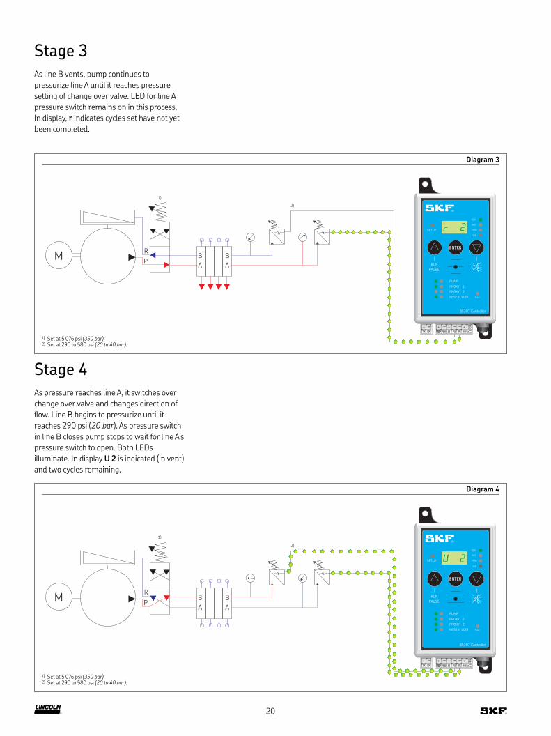
Diagram 3
-- --
8AmpP2RES IGNP1
12V24V
M
++++ -TX RX
sec
min
hrs
cyc
SETUP
Fuse
PROXY 1
PUMP
PROXY 2
RESER VOIR
RUN
PAUSE
ENTER
MA A
BBR
P
1)
2)
85307 Controller
Stage 3As line B vents, pump continues to
pressurize line A until it reaches pressure
setting of change over valve. LED for line A
pressure switch remains on in this process.
In display, r indicates cycles set have not yet
been completed.
Diagram 4
-- --
8AmpP2RES IGNP1
12V24V
M
++++ -TX RX
sec
min
hrs
cyc
SETUP
Fuse
PROXY 1
PUMP
PROXY 2
RESER VOIR
RUN
PAUSE
ENTER
MA A
BBR
P
1)
2)
85307 Controller
Stage 4As pressure reaches line A, it switches over
change over valve and changes direction of
low. Line B begins to pressurize until it
reaches 290 psi (20 bar). As pressure switch
in line B closes pump stops to wait for line A’s
pressure switch to open. Both LEDs
illuminate. In display U 2 is indicated (in vent)
and two cycles remaining.
1) Set at 5 076 psi (350 bar).2) Set at 290 to 580 psi (20 to 40 bar).
1) Set at 5 076 psi (350 bar).2) Set at 290 to 580 psi (20 to 40 bar).
20

Diagram 5
-- --
8AmpP2RES IGNP1
12V24V
M
++++ -TX RX
sec
min
hrs
cyc
SETUP
Fuse
PROXY 1
PUMP
PROXY 2
RESER VOIR
RUN
PAUSE
ENTER
MA A
BBR
P
1)
2)
85307 Controller
Stage 5As line A pressure switch opens, pump
begins to pump again. Display shows one
complete cycle has inished and same
process begins once again. Once last cycle is
reached, pump resumes pause cycle.
NOTE
It is possible to set up as many run
cycles as desired.
21
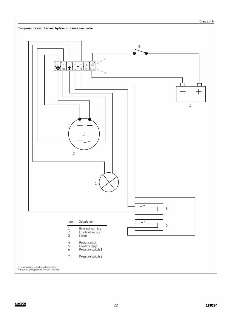
Diagram 6
Two pressure switches and hydraulic change over valve
- - - -
Amp 8 P2 RES IGN P1
V 12 24 V
M + + +
3
3
1
5
2
4
6
1)
2)
Item Description
1 External warning 2 Low level sensor3 Motor
4 Power switch5 Power supply6 Pressure switch 1
7 Pressure switch 2
1) Top row represents back of controller.2) Bottom row represents front of controller.
22

Fig. 33
Fault indications
NOTE
Unit must perform one complete cycle of run and pause to
cancel existing fault out of memory in order for fault to be reset.
Unit is designed to memorize total time of any speciic fault. Unit
must run one complete cycle in order to function correctly
without same fault occurring.
Item Description
1 Press RUN/PAUSE to reset faults.2 Fault indication - counts up from seconds
to minutes to hours indicating how long fault has been active.
3 Press down button to silence buzzer.
4 Blown fuse indication. Replace with 8A fuse.5 Change fuse here. Replace with 8A fuse.6 Low level fault - possible cause, reservoir empty.
7 Proxy 2 fault - either faulty pressure switch or no lube in reservoir, or broken main line.
8 Proxy 1 fault - either faulty pressure switch or no lube in reservoir, or broken main line.
9 Pump faulty - either short circuit or wires have come off.
1
2
3
4
5
6
7
8
9
23

Fig. 34
1 Refer to steps 1-9 on pages 10 through 12.
2 nO displays. Green LED on PROXY 2 illuminates. When using
micro switch monitoring half cycles select nO.
Press ENTER to accept and proceed to next part of
setup (Fig. 34 A).
3 nO appears in display. Green LED on reservoir illuminates. Setup
procedure allows for selection of low level detection. Should low
level detection not be required, push Δ and select nO.
4 Press ENTER to accept.
5 In example shown, low level option is selected. Press Δ until YES
displays.
6 Press ENTER to accept choice (Fig. 34 B).
-- --
8AmpP2RES IGNP1
12V24V
M
++++ -
TX RX
sec
min
hrs
cyc
SETUP
Fuse
PROXY 1
PUMP
PROXY 2
RESERVOIR
RUN
PAUSE
ENTER
85307 Controller
-- --
8AmpP2RES IGNP1
12V24V
M
++++ -
TX RX
sec
min
hrs
cyc
SETUP
Fuse
PROXY 1
PUMP
PROXY 2
RESERVOIR
RUN
PAUSE
ENTER
85307 Controller
NOTE
10 second delay takes place on startup when using low level
sensor to ensure paddle assembly is positioned correctly
with sensor.
Sensor activates on low level after 10 seconds. Low level
warning displays when unit reaches pause status.
Dual line system using 1/2 cycles and hydraulic change over valve
A B
24
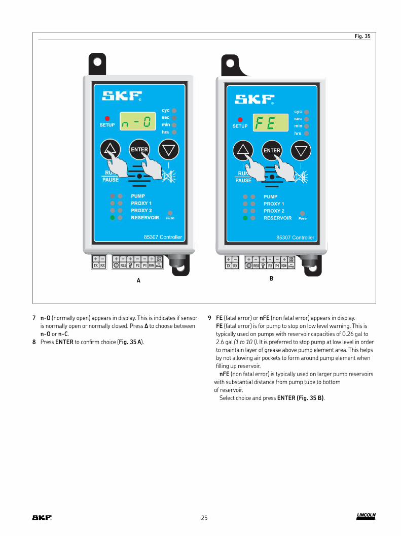
Fig. 35
7 n-O (normally open) appears in display. This is indicates if sensor
is normally open or normally closed. Press Δ to choose between
n-O or n-C.
8 Press ENTER to conirm choice (Fig. 35 A).
9 FE (fatal error) or nFE (non fatal error) appears in display.
FE (fatal error) is for pump to stop on low level warning. This is
typically used on pumps with reservoir capacities of 0.26 gal to
2.6 gal (1 to 10 l). It is preferred to stop pump at low level in order
to maintain layer of grease above pump element area. This helps
by not allowing air pockets to form around pump element when
illing up reservoir.
nFE (non fatal error) is typically used on larger pump reservoirs
with substantial distance from pump tube to bottom
of reservoir.
Select choice and press ENTER (Fig. 35 B).
STEP 9
-- --
8AmpP2RES IGNP1
12V24V
M
++++ -
TX RX
sec
min
hrs
cyc
SETUP
Fuse
PROXY 1
PUMP
PROXY 2
RESERVOIR
RUN
PAUSE
ENTER
85307 Controller
A B
25

Fig. 36
10 L - F (lamp lashing) appears in display. This option is for external
warning lamp to be itted. Typically if monitoring is installed, this
function is used.
Press Δ to change status from L - F (lamp lashing) to
L - S (lamp static). L - F is a pulsed output supply and L -S is a
constant output supply.
11 Press ENTER to move onto next part of programming (Fig. 36 A).
STEP 15
12 tSt appears indicating test mode of setup procedure. Press Δ and
pump starts turning (Fig. 36 B). Correct pump turning in wrong
direction by changing polarity of wiring. It is possible to check all
other sensors by energizing them manually and watching if green
LED illuminates in process. If LED does not illuminate, there is
either problem with wiring or setup procedure. By pressing down
button with external warning lamp, this will either lash or
show steady.
If all is correct, turn off power supply to controller and then back
on for the unit to proceed into normal mode. Red setup LED
illuminates when unit is in normal run mode.
NOTE
tSt must appear before switching off power to unit. System does
not save changes if power to unit is turned off during any part of
programming. tSt must appear in display for changes to be
conirmed.
A B
26
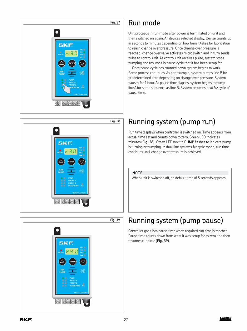
Fig. 37 Run modeUnit proceeds in run mode after power is terminated on unit and
then switched on again. All devices selected display. Devise counts up
in seconds to minutes depending on how long it takes for lubrication
to reach change over pressure. Once change over pressure is
reached, change over valve activates micro switch and in turn sends
pulse to control unit. As control unit receives pulse, system stops
pumping and resumes in pause cycle that it has been setup for.
Once pause cycle has counted down system begins to work.
Same process continues. As per example, system pumps line B for
predetermined time depending on change over pressure. System
pauses for 1 hour. As pause time elapses, system begins to pump
line A for same sequence as line B. System resumes next 1/2 cycle of
pause time.
Running system (pump run)Run time displays when controller is switched on. Time appears from
actual time set and counts down to zero. Green LED indicates
minutes (Fig. 38). Green LED next to PUMP lashes to indicate pump
is turning or pumping. In dual line systems 1/2 cycle mode, run time
continues until change over pressure is achieved.
Running system (pump pause)Controller goes into pause time when required run time is reached.
Pause time counts down from what it was setup for to zero and then
resumes run time (Fig. 39).
Fig. 38
Fig. 39
NOTE
When unit is switched off, on default time of 5 seconds appears.
27
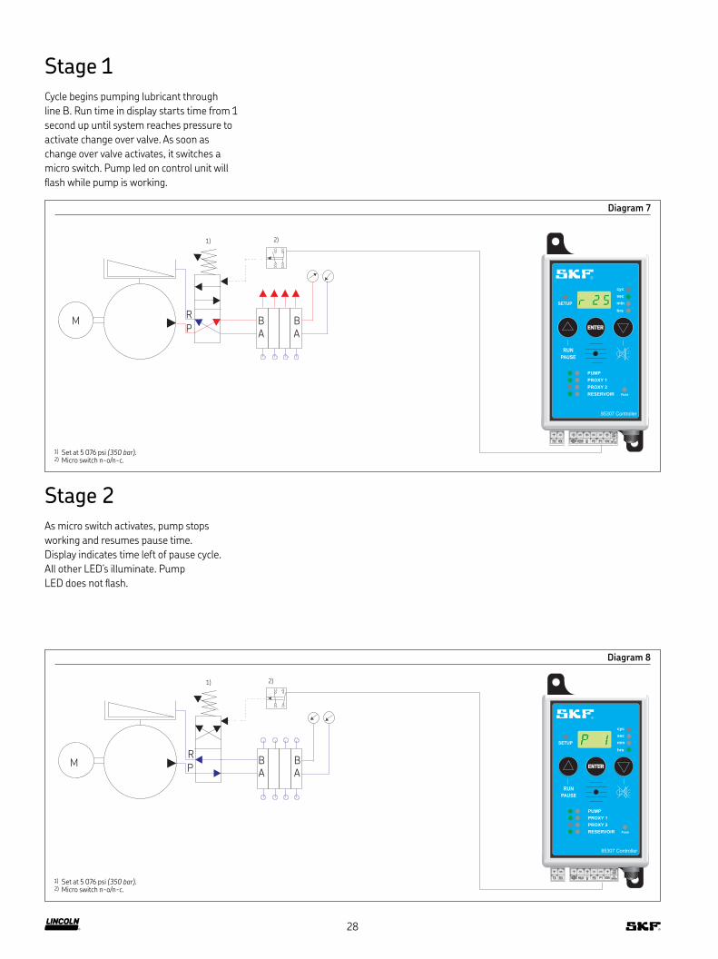
Diagram 7
Stage 1Cycle begins pumping lubricant through
line B. Run time in display starts time from 1
second up until system reaches pressure to
activate change over valve. As soon as
change over valve activates, it switches a
micro switch. Pump led on control unit will
lash while pump is working.
Diagram 8
Stage 2As micro switch activates, pump stops
working and resumes pause time.
Display indicates time left of pause cycle.
All other LED’s illuminate. Pump
LED does not lash.
M
-- --
8AmpP2RES IGNP1
12V24V
M
++++ -
TX RX
sec
min
hrs
cyc
SETUP
Fuse
PROXY 1
PUMP
PROXY 2
RESERVOIR
RUN
PAUSE
ENTER
A ABB
R
P
1)
14 22
2113
2)
85307 Controller
M
-- --
8AmpP2RES IGNP1
12V24V
M
++++ -
TX RX
sec
min
hrs
cyc
SETUP
Fuse
PROXY 1
PUMP
PROXY 2
RESERVOIR
RUN
PAUSE
ENTER
A ABB
R
P
1)
14 22
2113
2)
85307 Controller
1) Set at 5 076 psi (350 bar).2) Micro switch n-o/n-c.
1) Set at 5 076 psi (350 bar).2) Micro switch n-o/n-c.
28

Diagram 9
Stage 3As pause time completes cycle, pump begins
to pump and pressurize line A. Time to reach
pressure setting might vary to that of line B
because of different conigurations that will
effect back pressures. Pump LED lashes
while pump is working.
Diagram 10
Stage 4As pressure in stage 3 is reached, change
over valve activates and changes position of
micro switch. At this point, pump stops and
system resumes its pause cycle. This process
continues as explained above.
MA A
BBRP
1)
14 22
2113
2)
-- --
8AmpP2RES IGNP1
12V24V
M
++++ -
TX RX
sec
min
hrs
cyc
SETUP
Fuse
PROXY 1
PUMP
PROXY 2
RESERVOIR
RUN
PAUSE
ENTER
85307 Controller
MA A
BBRP
1)
14 22
2113
2)
-- --
8AmpP2RES IGNP1
12V24V
M
++++ -
TX RX
sec
min
hrs
cyc
SETUP
Fuse
PROXY 1
PUMP
PROXY 2
RESERVOIR
RUN
PAUSE
ENTER
85307 Controller
1) Set at 5 076 psi (350 bar).2) Micro switch n-o/n-c.
1) Set at 5 076 psi (350 bar).2) Micro switch n-o/n-c.
29
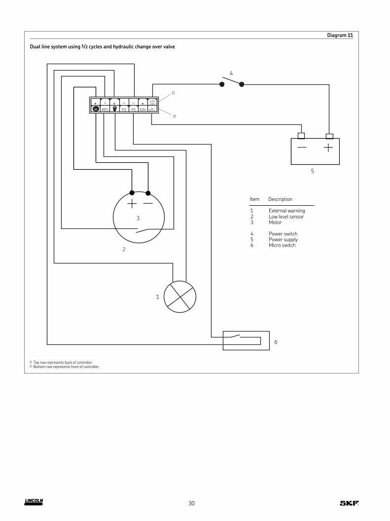
Diagram 11
Dual line system using 1/2 cycles and hydraulic change over valve
- - - -
Amp 8 P2 RES IGN P1
V 12 24 V
M + + +
4
3
1
6
2
5
1)
2)
Item Description
1 External warning 2 Low level sensor3 Motor
4 Power switch5 Power supply6 Micro switch
1) Top row represents back of controller.2) Bottom row represents front of controller.
30
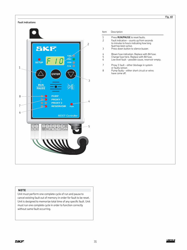
Fig. 40
Fault indications
NOTE
Unit must perform one complete cycle of run and pause to
cancel existing fault out of memory in order for fault to be reset.
Unit is designed to memorize total time of any speciic fault. Unit
must run one complete cycle in order to function correctly
without same fault occurring.
Item Description
1 Press RUN/PAUSE to reset faults.2 Fault indication - counts up from seconds
to minutes to hours indicating how long fault has been active.
3 Press down button to silence buzzer.
4 Blown fuse indication. Replace with 8A fuse.5 Change fuse here. Replace with 8A fuse.6 Low level fault - possible cause, reservoir empty.
7 Proxy 1 fault - either blockage in system or faulty sensor.
8 Pump faulty - either short circuit or wires have come off.
1
2
3
4
5
6
7
8
31
skf.com | lincolnindustrial.com
® SKF and Lincoln are registered trademarks of the SKF Group.
© SKF Group 2018The contents of this publication are the copyright of the publisher and may not be reproduced (even extracts) unless prior written permission is granted. Every care has been taken to ensure the accuracy of the information contained in this publication but no liability can be conirmed for any loss or damage whether direct, indirect or consequential arising out of the use of the information contained herein.
July 2018 · Form 404772 Version 1
Warranty
The instructions do not contain any information on the warranty.
This can be found in the General Conditions of Sales, available at:
www.lincolnindustrial.com/technicalservice or
www.skf.com/lubrication.